
2010-8407 REV E, Service Manual Nuvo Lite - Nidek Medical
35
2010-8407 Rev E April 30, 2018 Page 1 of 35 SERVICE MANUAL Mark 5 Nuvo® Lite Family (Nuvo Lite and Nuvo Lite 3) For models: 520, 525, 535, 920, 925, and 935 And serial numbers beginning 132-XXXXX Nidek Medical Products, Inc. 3949 Valley East Industrial Drive Birmingham, Alabama 35217 USA Telephone: (205) 856-7200 • 24-Hour Fax: (205) 856-0533 Nidek Medical is a trademark of Nidek Medical Products, Inc. Mark 5 Nuvo® is a registered trademark of Nidek Medical Products, Inc
Transcript of 2010-8407 REV E, Service Manual Nuvo Lite - Nidek Medical

2010-8407 Rev E April 30, 2018 Page 1 of 35
SERVICE MANUAL
Mark 5 Nuvo® Lite Family (Nuvo Lite and Nuvo Lite 3)
For models: 520, 525, 535, 920, 925, and 935
And serial numbers beginning 132-XXXXX
Nidek Medical Products, Inc.
3949 Valley East Industrial Drive Birmingham, Alabama 35217 USATelephone: (205) 856-7200 • 24-Hour Fax: (205) 856-0533
Nidek Medical is a trademark of Nidek Medical Products, Inc. Mark 5 Nuvo® is a registered trademark of Nidek Medical Products, Inc

2010-8407 Rev E April 30, 2018 Page 2 of 35
Contents 1.0 General Safety Warnings........................................................................................................................................ 4
2.0 Glossary of Symbols ............................................................................................................................................... 5
3.0 About the Mark 5 Nuvo Lite Family ....................................................................................................................... 6
3.1 Intended Use and Operation ............................................................................................................................. 6
3.2 Installation and Storage ..................................................................................................................................... 6
3.3 Alarms and Safety Features ............................................................................................................................... 7
3.4 Device Performance and Specifications ............................................................................................................. 8
4.0 Service Provider (Home / Clinic / Hospital) ............................................................................................................ 9
4.1 Responsibilities .................................................................................................................................................. 9
4.2 Operational Check .............................................................................................................................................. 9
4.3 Patient / Caregiver Instruction .........................................................................................................................11
5.0 Service Technicians ..............................................................................................................................................11
5.1 Testing and Troubleshooting ...........................................................................................................................11
5.2 Troubleshooting Chart .....................................................................................................................................15
5.3 Component Removal / Replacement Instruction ............................................................................................16
5.3.1 Remove Cabinet Back .................................................................................................................................16
5.3.2 Remove Caster(s) ........................................................................................................................................16
5.3.3 Replace Inlet / Silencer Filter ......................................................................................................................17
5.3.4 Replace Final Product Filter ........................................................................................................................17
5.3.5 Replace Compressor ...................................................................................................................................17
5.3.6 Replace Capacitor .......................................................................................................................................18
5.3.7 Replace Control Valve .................................................................................................................................18
5.3.8 Replace Sieve Module .................................................................................................................................18
5.3.9 Replace Cabinet Fan ....................................................................................................................................19

2010-8407 Rev E April 30, 2018 Page 3 of 35
5.3.10 Replace Circuit Board (OCSI and Pressure) ............................................................................................. 19
5.3.11 Adjust Regulator ...................................................................................................................................... 20
5.3.12 Clean / Rebuild Regulator ........................................................................................................................ 20
5.3.13 Replace Circuit Breaker ........................................................................................................................... 21
5.3.14 Replace Power Switch ............................................................................................................................. 21
5.3.15 Replace Buzzer ........................................................................................................................................ 21
5.3.16 Replace Hour Meter ................................................................................................................................ 21
5.3.17 Replace Flow Valve .................................................................................................................................. 22
5.3.18 Replace Power Cord ................................................................................................................................ 22
5.4 Tools Required - Test Equipment / Gauges Available...................................................................................... 22
6.0 Schematics / Assembly Drawings / Part Callouts ................................................................................................. 23
6.1 Flow Schematic (OCSI models) ........................................................................................................................ 23
6.2 Flow Schematic (Standard models) ................................................................................................................. 23
6.3 Electrical Schematic (all models) ..................................................................................................................... 24
6.4 Compressor Assembly / Parts Callout .............................................................................................................. 25
6.5 Front Cabinet Assembly / Parts Callout ........................................................................................................... 27
6.6 Back Cabinet Assembly / Parts Callout ............................................................................................................ 29
6.5 Module Assembly / Parts Callout..................................................................................................................... 31
Appendix A Service and Maintenance Log ................................................................................................................. 33
Conformity with EN 60601-1 ............................................................................................................................................ 35

2010-8407 Rev E April 30, 2018 Page 4 of 35
1.0 General Safety Warnings
This unit is not a life-support device. Geriatric, pediatric, or any other patient unable to communicate discomfort while using this device should receive additional monitoring.
This device supplies highly concentrated oxygen enriched product gas that promotes rapid burning.
DO NOT allow smoking or open flames within the same room of this device or the administration accessory (cannula).
Failure to observe this warning can result in severe fire, property damage, and / or cause physical injury or death.
Oxygen accelerates the combustion of flammable substances.
DO NOT use oil, grease, petroleum based or other flammable products on the device, the administration accessory (cannula) or the patient’s face / neck.
Only persons who have read and understood this entire manual should be allowed to service the device.
CONTRAINDICATIONS - Those who continue to smoke (because of the increased fire risk and the probability that the poorer prognosis by smoking will offset the treatment benefit).
℞Only
Federal Law (US) restricts this device to sale by, or on the order of, a licensed physician. This oxygen concentrator should be used only under the supervision of a licensed physician.

2010-8407 Rev E April 30, 2018 Page 5 of 35
2.0 Glossary of Symbols
ON (Power switched on)
OFF (Power switched off)
Manufacturer Name and Address
Type B Device
Class II Protection
IPX1 Protection from vertically falling water drops
Do Not Expose to Open Flames
Do Not Expose to Oil or Grease
Tools Required / Technician Only
Refer to Technical Information / Service Manual
Refer to Instructions for Use / User’s Guide
Keep in Vertical Position
FRAGILE – Handle with Care
Visual Alarm Indicator
WARNING – A hazard or unsafe practice that can result in serious injury or death if conditions are not avoided.
Caution - A hazard or unsafe practice that can result in minor injury and / or property damage if conditions are not avoided.
Note – Information important enough to emphasize or repeat

2010-8407 Rev E April 30, 2018 Page 6 of 35
3.0 About the Mark 5 Nuvo Lite Family
3.1 Intended Use and Operation The Mark 5 Nuvo Lite Family (Nuvo Lite and Nuvo Lite 3) Oxygen Concentrators are used as a means of providing continuous oxygen enriched product gas for patients, adolescent to geriatric, suffering from health conditions that cause low levels of oxygen in the blood (hypoxaemia).
The Mark 5 Nuvo Lite Family begins their operation with air being pulled into the external air intake filter. This filtered air enters the compressor via a suction resonator and fine filter. Pressurized air then exits the compressor and passes through a heat exchanger, which reduces the temperature of the compressed air. Next, an electronic valve system directs the air into one of two tubes that contain molecular sieve (sieve beds). The molecular sieve adsorbs (physically attracts) the nitrogen from the air as it is pushed through the sieve beds. This allows the oxygen enriched product gas to pass through before being delivered to the pressure regulator. As one tube is generating the product gas, the other is being purged of the adsorbed nitrogen, this process is called pressure swing adsorption (PSA). After passing through the regulator, the rate of product gas being delivered to the patient is set by the flow meter adjusting valve. Finally, it passes through a fine particle filter and then over a sensor that detects the oxygen concentration of the product gas before it exits the device through a fire resistant outlet.
Make sure during operation and after shut down that the cannula is facing away from soft surfaces and clothing. Excess oxygen can accumulate and cause ignition if exposed to a spark or open flame.
Use the power cord provided. Check that the electrical characteristics of the power outlet used match those indicated on the manufacturer’s technical label on the rear panel of the device.
This unit may be equipped with a polarized plug. That is one blade wider than the other. If it does not fit into the outlet, reverse the plug. If it still does not fit, contact a qualified electrician. Do not defeat this safety feature.
3.2 Installation and Storage The device should be operated in a dry area, with an ambient temperature between 10°C to 40°C (50°F to 105°F) at 15-95% relative humidity. The device can be operated at an altitude of up to 2200m (7500ft) at a temperature of 21°C (70°F) without causing product degradation.
DO NOT use in explosive atmosphere. To avoid risk of fire and explosion the concentrator should be kept away from heat sources, incandescent sources, solvents, Aerosols, etc.
Unit should be placed and operated in a well-ventilated space that is free of pollutants or fumes and protected from the elements with adequate lighting.
Unit should be placed and operated in a space where the position and storage of the mains cable and oxygen tubing do not present a tripping hazard. The mains cable should be easily accessible for disconnection.
For patient safety and benefit, no modification to the equipment is allowed. It is also not recommended to interconnect the device with any equipment or accessories not specified in this guide.
Device must have power to operate. In the event of power loss and for continued operation a backup source is recommended.
Do not use in a specifically magnetic environment (MRI, X-ray, etc.). May cause device malfunction.
We recommend against the use of extension cords and adapters, as they are potential sources of sparks and fire.

2010-8407 Rev E April 30, 2018 Page 7 of 35
Consult your equipment provider for further information regarding altitudes of 2200 m to 4000m (7500 to 13000ft).
The device should be stored in a dry area, with an ambient temperature between -20°C to 60°C (0°F to 140°F) at 15-95% relative humidity. It must be stored, transported and used in the vertical position only.
Oxygen concentration can be affected after prolonged periods of storage – check device before use.
3.3 Alarms and Safety Features Each device is equipped with indicator lights (green and yellow) and auditory indicators to identify various operational modes. Devices manufactured prior to 2018 were equipped with red and yellow indicator lights. The alarm modes are described below:
The device has an audible alarm to warn the user of problems. In order that the alarm may be heard, the maximum distance that the user can move away from it must be determined to suit the surrounding noise level.
If any of the below alarm conditions occur, press the Power Switch to the “O” (OFF) position. Refer to the Troubleshooting Guide in §5.2 for the possible cause and solution.
No voltage detection: In the event of a loss of mains power, an intermittent audible alarm is activated and the green light is no longer illuminated.
Oxygen Concentration Status Indicator: If supplied, in the event that the oxygen concentration falls below the set point percentage, a continuous audible alarm and the yellow indicator light will actuate. The oxygen concentration monitor is an electronic module capable of checking the effective oxygen concentration supplied by the concentrator. When the device is started, the green indicator light will flash until the concentration set point is reached (approximately two minutes).
A solid green indicator light means the power is applied to the concentrator and that it is ready to provide oxygen enriched air to the patient.
No special maintenance is required. The alarm set-point is factory set and the setting cannot be adjusted. All OCSI models are set at 85% ± 3%.
Blocked Cannula detection: If supplied, the device has a Blockage Alarm. A continuous audible alarm and both indicator lights will be lit immediately in the event the flow of oxygen to patient becomes blocked.
Malfunction detection: If low pressure occurs due to a mechanical failure, the indicator light will flash yellow and a continuous audible alarm will actuate.
Thermal safety: The compressor motor is protected by a thermal switch situated in the stator winding (145 ± 5° C). One tubeaxial fan cools the compressor compartment.
Electrical protection:
• A 5A circuit breaker is incorporated into the front cabinet of all 230V models
• A 10A circuit breaker is incorporated into the front cabinet of all 115V models
• Class II devices with insulated casings (EN60601-1 standard)
Safety valve: This is fitted on the compressor outlet and is calibrated to 3.4 bar (50 psig).
Fire Break: This device is fitted with a metal fire break at the Oxygen Product Outlet. This break will keep fire from entering the device.
2010-8407 Rev E April 30, 2018 Page 8 of 35
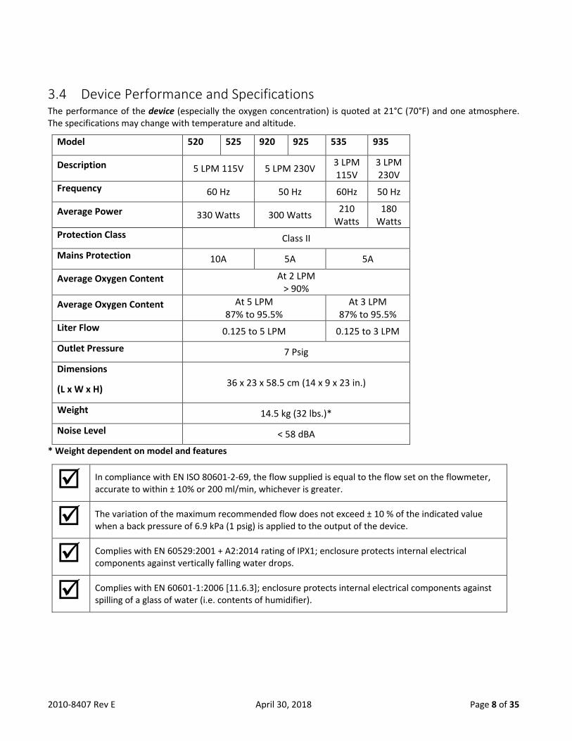
3.4 Device Performance and Specifications The performance of the device (especially the oxygen concentration) is quoted at 21°C (70°F) and one atmosphere. The specifications may change with temperature and altitude.
Model 520 525 920 925 535 935
Description 5 LPM 115V 5 LPM 230V 3 LPM 115V
3 LPM 230V
Frequency 60 Hz 50 Hz 60Hz 50 Hz
Average Power 330 Watts 300 Watts 210
Watts 180
Watts
Protection Class Class II
Mains Protection 10A 5A 5A
Average Oxygen Content At 2 LPM > 90%
Average Oxygen Content At 5 LPM 87% to 95.5%
At 3 LPM 87% to 95.5%
Liter Flow 0.125 to 5 LPM 0.125 to 3 LPM
Outlet Pressure 7 Psig
Dimensions
(L x W x H) 36 x 23 x 58.5 cm (14 x 9 x 23 in.)
Weight 14.5 kg (32 lbs.)*
Noise Level < 58 dBA
* Weight dependent on model and features
In compliance with EN ISO 80601-2-69, the flow supplied is equal to the flow set on the flowmeter, accurate to within ± 10% or 200 ml/min, whichever is greater.
The variation of the maximum recommended flow does not exceed ± 10 % of the indicated value when a back pressure of 6.9 kPa (1 psig) is applied to the output of the device.
Complies with EN 60529:2001 + A2:2014 rating of IPX1; enclosure protects internal electrical components against vertically falling water drops.
Complies with EN 60601-1:2006 [11.6.3]; enclosure protects internal electrical components against spilling of a glass of water (i.e. contents of humidifier).

2010-8407 Rev E April 30, 2018 Page 9 of 35
4.0 Service Provider (Home / Clinic / Hospital)
4.1 Responsibilities Service Providers of the Mark 5 Nuvo Lite Family (Nuvo Lite and Nuvo Lite 3) Oxygen Concentrators must assume responsibilities for handling, operational testing, patient instruction, and maintenance. These responsibilities are outlined below and throughout this manual.
To ensure patient safety, use only after one or more settings have been individually determined or prescribed for the patient at their specific activity levels – AND – only use the accessories that were used when the settings were determined.
While undergoing oxygen therapy, if the patient feels discomfort or experiences a medical emergency, seek medical assistance immediately.
As a Service Provider, you should do all of the following:
• Inspect the condition of each device immediately upon delivery to your location. Note any sign of damage, on the delivery receipt, and immediately report it directly to both the freight company and Nidek Medical Products, Inc.
• Ensure the operation of each device before delivery to a patient by completing the “Operational Check” provided in §4.2.
• Ensure each device has been thoroughly cleaned, the cabinet filter has been cleaned or replaced, and the nasal cannula and tubing has been replaced before delivering the device to a new patient or between patients.
• Deliver device only to patients authorized by a physician’s prescription. The device must not be used as a life-supporting or life sustaining device.
• Ensure a backup supply of oxygen is available.
• Instruct patients and patient caregivers how to use the device in conjunction with the Instructions for Use (PN 2010-8401CE), including required routine maintenance and cleaning of the device and filters. See “Patient / Caregiver Instruction” provided in §4.3.
• Record and notify Nidek Medical of any and all complaints provided by the patient or patient caregiver.
o The FDA defines a complaint as “any written, electronic, or oral communication that alleges deficiencies related to the identity, quality, durability, reliability, safety, effectiveness, or performance of a device after it is released for distribution.”
• Be available to service each patient at any time.
• Keep service records of each device. A form approved by Nidek Medical has been provided in Appendix A.
• Repair components and replace parts only as outlined in this manual. Use only Nidek Medical parts for replacement. Refer to the Product Warranty Statement if parts replacement is required within the warranty period.
4.2 Operational Check Nidek Medical runs each device through a burn in period and tests every device thoroughly after manufacture before releasing it for shipment. As the Service Provider, it is your responsibility to perform the following check to ensure that the device is operational.

2010-8407 Rev E April 30, 2018 Page 10 of 35
1. Plug in the power cord of the unit, following the electrical characteristics noted on the technical label, and set the Power Switch to the I (ON) position. The compressor should begin running.
2. Once the device has been running for approximately ten minutes, verify the concentration is within specifications, the flow is accurate and the alarms are operational. For units equipped with the Oxygen Concentration Status Indicator (OCSI) (models 525, 535, 925, 935), the green indicator light will flash until the oxygen concentration reaches 85% ± 3% (approximately two minutes).
a. Verify oxygen concentration by:
i. Connect a calibrated oxygen concentration analyzer to the oxygen outlet.
1. If an oxygen humidifier bottle is used, remove it from the oxygen outlet. The concentration readings of the product gas after it has passed through a humidifier bottle will be erroneous and can result in damage to your analyzer.
2. Oxygen analyzers are available for purchase from Nidek Medical (see §5.4 for testing equipment part numbers).
ii. Set the flow rate of the device to the prescribed rate of the patient.
iii. Record oxygen concentration readings over a period of several minutes to reduce any cyclic variations. These readings should fall within the specifications provided in §3.4.
1. If not, refer to the troubleshooting chart in §5.2 for possible causes and solutions.
b. Verify the flow is accurate by:
i. Connect a calibrated flow gauge to the oxygen outlet.
1. If an oxygen humidifier bottle is used, remove it from the oxygen outlet.
2. Gauges are available for purchase from Nidek Medical (see §5.4 for testing equipment part numbers).
ii. Turn the flow knob clockwise until it stops (wide open).
iii. The reading should indicate 5 liters/min. (models 520, 525, 920 and 925) or 3 liters/min (models 535 and 935).
1. If not, refer to §5.3.11 for adjusting the regulator, or refer to the troubleshooting chart in §5.2 for other possible causes and solutions.
c. Verify alarms are operational by:
i. No Voltage Alarm
1. Unplug the power cord from the wall outlet.
2. Set the Power Switch to the I (ON) position.
3. This should immediately activate the intermittent audible alarm and there should be no indicator lights actuated.
a. If it does not, refer to the troubleshooting chart in §5.2 for possible causes and solutions.
ii. Blockage Alarm
1. Adjust the Flow Knob to desired flow rate.
2. Block the oxygen flow at the patient outlet
3. This should immediately activate a continuous audible alarm and both indicator lights should be actuated.
a. If it does not, refer to the troubleshooting chart in §5.2 for possible causes and solutions.
2010-8407 Rev E April 30, 2018 Page 11 of 35
4.3 Patient / Caregiver Instruction It is important that the patient and/or caregiver thoroughly understands how to operate their device. This enables proper treatment as prescribed by a qualified, licensed physician. You must explain that the purpose of this therapy is to alleviate symptoms. If the patient experiences any discomfort or the unit alarm sounds, they must notify their Service Provider and/or physician immediately. You, as the Service Provider, are responsible to see that each patient receives the Instructions for Use (IFU) (PN 2010-8401CE) and understands how to operate, clean and maintain their device.
• Refer to §4.2 in the IFU for the Start-Up procedure.
• Refer to §4.3 in the IFU for the Shut Down procedure.
• Refer to §5.1 in the IFU for the Cleaning procedures of the device itself, the filters and the accessories.
• Refer to §5.2 in the IFU for the Maintenance procedure.
Refer to §5.3.3 and §5.3.4 of this manual for instruction on replacing the inlet and final product filters.
5.0 Service Technicians The design of the Mark 5 Nuvo Lite Family (Nuvo Lite and Nuvo Lite 3) allows for easy access and removal of most components. This allows you to perform scheduled maintenance, repair, and replacement of parts with minimal time and effort.
• Refer to §5.2 for the Troubleshooting Chart for a list of problems, possible causes and solutions.
• Keep service records of each device. A form approved by Nidek Medical has been provided in Appendix A.
• Repair components and replace parts only as outlined in this manual. Use only Nidek Medical parts for replacement.
• Refer to the Product Warranty Statement if parts replacement is required within the warranty period.
• Analyzers and gauges are available for purchase from Nidek Medical, see §5.4 for part numbers.
For your safety, be sure to set the Power Switch to O (OFF) position and unplug the power cord before you service the device.
5.1 Testing and Troubleshooting Before reviewing the troubleshooting chart, the following questions may be useful to isolate any malfunctions.
1. Does the concentrator turn on when the switch is activated?
2. Are the filters clean?
3. Connect an oxygen analyzer to the outlet fitting of the device. Set the flow to 2LPM, is the concentration greater than 90%? Set the flow at 5 LPM (or 3LPM for models 535 and 935), is the concentration between 87 and 95.5%?
4. Connect test pressure gauge to the outlet fitting of the unit. Does the pressure read 7.1 psig (49 kPa) ± 20%?
5. Perform an air pressure test (P1). Does the pressure cycle between 10-15 and 25-32 psig approximately (70-103 and 172-220 kPa)?
a. Remove the upper cabinet back (see §5.3.1 for instructions).
b. Remove the air supply tubing going to the control valve and install the test port tee fitting. (See Figures 5.1.1 and 5.1.2 below for Normal Operating Configuration and Test Port Configuration.)
2010-8407 Rev E April 30, 2018 Page 12 of 35
c. Connect the pressure test gauge to the P1 test port.
d. Observe the maximum and minimum readings on the pressure test gauge.
i. Higher than normal operating pressure may indicate a restrictive exhaust muffler, which does not allow the waste (purge) gas to exit the system freely, or contaminated sieve beds.
ii. Lower than normal operating pressure may indicate:
1. A restriction in the suction resonator or inlet air filter, this limits the amount of room air available to the compressor.
a. Disconnect the suction tube at the compressor, then allow the unit to operate without the suction resonator to see if normal operating pressure returns.
2. An improperly operating control valve. Confirm that the control valve does not have a leak.
3. A leak in the unit, which allows system pressure to escape. Leak test the unit.
4. A compressor with reduced output.
6. Are all tubing connections and fittings leak free?
a. Test with a leak testing solution. Protect circuit board from solution and start leak test at the heat exchanger, following the air flow through the unit to the oxygen outlet. Repair all leaks by tightening connections and fittings.
7. Perform a product pressure test (P2). Does the pressure cycle between approximately 9 psig and 32 psig (62 to 220 kPa)?
a. Remove the back cabinet top (see §5.3.1 for instructions).
b. Remove the plug from the regulator test port and install the test gauge tube.
c. Remove the tube from the control valve and install the test port tee. (see Figures 5.1.1 and 5.1.2 below for Normal Operating Configuration and Test Port Configuration.)
d. Connect the pressure test gauge to the P2 test port.
e. Observe the maximum and minimum readings on the pressure test gauge.
i. Higher than normal operating pressure may indicate a restrictive exhaust muffler, which does not allow the waste (purge) gas to exit the system freely, or contaminated sieve beds.
ii. Lower than normal operating pressure may indicate:
1. An inlet air filter that limits the amount of room air available to the compressor.
a. Disconnect the suction tube at the compressor, then allow the unit to operate without the suction resonator to see if normal operating pressure returns.
2. An improperly operating control valve. Confirm that the control valve does not have a leak.
3. A leak in the unit, which allows system pressure to escape. Leak test the unit.
4. A compressor with reduced output.
Refer to the troubleshooting chart in §5.2 if you answered no to any of the above questions. See the Troubleshooting Flow Chart (Figure 5.1.3), for easy reference.

2010-8407 Rev E April 30, 2018 Page 13 of 35
Figure 5.1.1 Normal Operating Configuration
5.1.2 Test Port Configuration
INLET FROM
COMPRESSOR
PRODUCT OUT TO
FLOW CONTROL
VALVE
P2 TEST PORT
P1 TEST PORT

2010-8407 Rev E April 30, 2018 Page 14 of 35
5.1.3 Troubleshooting Flow Chart
Low OxygenConcentration
Verify OxygenFlow Rate
Normal AirPressure
Low Pressure High Pressure
Replace AirInlet Filter
Check for leaks at the:- regulator outlet- product tubing- oxygen outlet
ReplaceMufflerFoams
CheckControlValve
Check forLeaks
Check theCompressor
Measure theOxygen Pressure
Low Pressure High Pressure
Normal Pressure
Check forLeaks
ReplaceMufflerFoams
Check theControlValve
ReplaceSieve
Module
Measure AirPressure

2010-8407 Rev E April 30, 2018 Page 15 of 35
5.2 Troubleshooting Chart
PROBLEMS POSSIBLE CAUSES SOLUTIONS Compressor runs with intermittent high pressure alarm and low oxygen concentration.
Defective sieve beds. Replace sieve beds.
Restriction in exhaust muffler. Replace or clean muffler.
Defective valve. Replace sieve module.
Compressor relief valve releases (popping sound).
Defective control valve. Replace sieve module.
Contaminated sieve beds. Replace sieve module.
Defective relief valve. Replace relief valve.
Constant alarm with Power Switch in ON position. Circuit breaker repeatedly trips.
Defective circuit breaker. Replace circuit breaker.
Defective capacitor. Replace capacitor.
Defective compressor. Replace compressor.
Defective circuit board. Replace circuit board.
Faulty electrical connection. Repair electrical connection.
Alarm does not sound.
Faulty electrical connection. Repair electrical connection.
Defective I/0 (ON/OFF) switch. Replace Power Switch.
Defective buzzer. Replace board.
Defective pressure sensor. Replace and test control board.
Flow fluctuates.
Improperly set or faulty product regulator.
Check regulator setting/clean, repair, or replace regulator.
Leak. Leak test.
Worn compressor. Replace compressor.
Defective flow valve. Replace flow valve.
Kinked tubing. Check tubing that connects the top of the sieve beds.
Cabinet fan does not turn. Defective cabinet fan. Replace cabinet fan.
Defective electrical connections. Check electrical connections.
Limited or Iow flow.
Restriction in humidifier or tubing. Replace humidifier or tubing.
Product regulator set too low. Adjust regulator setting.
Leak. Leak test and repair leak.
Weak compressor. Check system pressure and rebuild or exchange compressor.
Air flow obstruction. Check Filter, suction resonator, and suction tube for obstruction.
2010-8407 Rev E April 30, 2018 Page 16 of 35
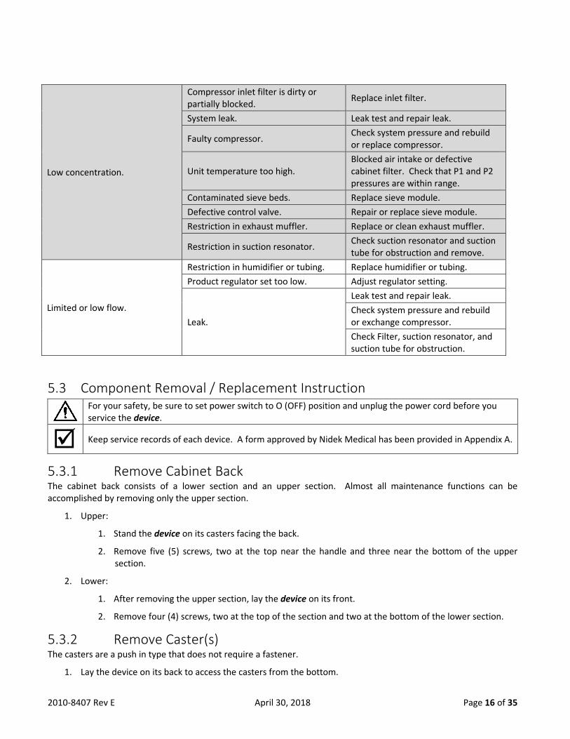
Low concentration.
Compressor inlet filter is dirty or partially blocked.
Replace inlet filter.
System leak. Leak test and repair leak.
Faulty compressor. Check system pressure and rebuild or replace compressor.
Unit temperature too high. Blocked air intake or defective cabinet filter. Check that P1 and P2 pressures are within range.
Contaminated sieve beds. Replace sieve module.
Defective control valve. Repair or replace sieve module.
Restriction in exhaust muffler. Replace or clean exhaust muffler.
Restriction in suction resonator. Check suction resonator and suction tube for obstruction and remove.
Limited or low flow.
Restriction in humidifier or tubing. Replace humidifier or tubing.
Product regulator set too low. Adjust regulator setting.
Leak.
Leak test and repair leak.
Check system pressure and rebuild or exchange compressor.
Check Filter, suction resonator, and suction tube for obstruction.
5.3 Component Removal / Replacement Instruction For your safety, be sure to set power switch to O (OFF) position and unplug the power cord before you service the device.
Keep service records of each device. A form approved by Nidek Medical has been provided in Appendix A.
5.3.1 Remove Cabinet Back The cabinet back consists of a lower section and an upper section. Almost all maintenance functions can be accomplished by removing only the upper section.
1. Upper:
1. Stand the device on its casters facing the back.
2. Remove five (5) screws, two at the top near the handle and three near the bottom of the upper section.
2. Lower:
1. After removing the upper section, lay the device on its front.
2. Remove four (4) screws, two at the top of the section and two at the bottom of the lower section.
5.3.2 Remove Caster(s) The casters are a push in type that does not require a fastener.
1. Lay the device on its back to access the casters from the bottom.
2010-8407 Rev E April 30, 2018 Page 17 of 35
2. Pull the caster straight out away from the bottom.
5.3.3 Replace Inlet / Silencer Filter The inlet air filter requires inspection at each patient visit. The filter should be replaced every 2 years, or more often depending on environment. (The filter may require more frequent cleaning if the device operates in a harsh environment such as a house heated by wood, kerosene, or oil, or one with excessive cooking, cigarette smoke or atmospheric dust.)
1. Remove the cabinet air filter to locate the inlet air filter underneath.
2. Pull the inlet filter straight out away from the back.
3. Replace with a new filter.
4. Reinstall the cabinet air filter.
5.3.4 Replace Final Product Filter The final product filter does not require periodic replacement; it needs to be replaced only if it restricts oxygen flow. It is suggested that it be replaced whenever the sieve module is repaired or replaced and after the compressor is rebuilt.
1. Remove the upper cabinet back (§5.3.1) to locate the final product filter.
Observe the position of the filter (flow direction) before removal.
2. Separate the silicone tubing from both sides of the filter.
3. Install the new filter with the inlet side in the same position as before.
4. Push the tubing together so that it overlaps the barbs of the final product filter connections.
5. Reinstall the upper cabinet back.
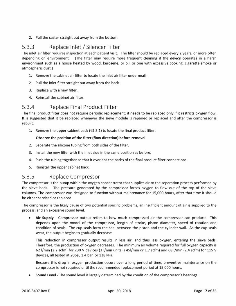
5.3.5 Replace Compressor The compressor is the pump within the oxygen concentrator that supplies air to the separation process performed by the sieve beds. The pressure generated by the compressor forces oxygen to flow out of the top of the sieve columns. The compressor was designed to function without maintenance for 15,000 hours, after that time it should be either serviced or replaced.
The compressor is the likely cause of two potential specific problems, an insufficient amount of air is supplied to the process, and an excessive sound level.
• Air Supply - Compressor output refers to how much compressed air the compressor can produce. This depends upon the model of the compressor, length of stroke, piston diameter, speed of rotation and condition of seals. The cup seals form the seal between the piston and the cylinder wall. As the cup seals wear, the output begins to gradually decrease.
This reduction in compressor output results in less air, and thus less oxygen, entering the sieve beds. Therefore, the production of oxygen decreases. The minimum air volume required for full oxygen capacity is 62 l/min (2.2 scfm) for 230 V devices (3 l/min units is 45l/min or 1.7 scfm) and 68 l/min (2.4 scfm) for 115 V devices, all tested at 20psi, 1.4 bar or 138 kPa.
Because this drop in oxygen production occurs over a long period of time, preventive maintenance on the compressor is not required until the recommended replacement period at 15,000 hours.
• Sound Level - The sound level is largely determined by the condition of the compressor’s bearings.

2010-8407 Rev E April 30, 2018 Page 18 of 35
There are four bearings located within the compressor that allow the inner components of the compressor to rotate. If the bearings wear to the point that they become loose and noisy, the compressor becomes noticeably loud and needs servicing. The life of a compressor is determined primarily by its operating temperature. It is extremely important that the inlet cooling air filters are cleaned and replaced as required.
To remove the compressor assembly for exchange, take the following steps:
1. Remove the both the upper and lower cabinet back sections (§5.3.1).
2. Disconnect the suction tube and the discharge tube.
3. Disconnect the two compressor power cable leads and the two leads to the capacitor.
4. Slide the compressor assembly from the cabinet.
5. Remove compressor from the compressor support frame.
6. If equipped, remove heat exchanger from compressor.
7. If equipped, remove the heat exchanger fitting from the compressor.
8. With a new compressor, perform the steps 1-7 in reverse order.
9. Leak test all connections.
5.3.6 Replace Capacitor The capacitor helps the compressor to start and run more efficiently. If the compressor cannot start, the capacitor may be defective and require replacement. The capacitor should be replaced at each compressor service.
To replace the capacitor, take the following steps:
1. Remove the upper cabinet back (§5.3.1).
2. Disconnect the two leads to the capacitor and clip the tie wrap securing the capacitor.
3. With a new capacitor, connect the leads and install a new tie wrap.
4. Clip excess tie wrap after securing capacitor.
5.3.7 Replace Control Valve The device uses a solenoid powered poppet valve assembly to control the air separation process. There is a feed port that connects to the compressor and an exhaust port that discharges through an integral exhaust muffler. There are three possible valve states as follows:
• Air feed connected to sieve bed A and exhaust connected to sieve bed B.
• Air feed connected to sieve bed B and exhaust connected to sieve bed A.
• Both ports open (this is a very short time period during which air pressure builds in the sieve beds).
The control valve of the device requires no scheduled maintenance. If a valve does not function as required, it is best to replace the complete sieve module (§5.3.8) as it is probable that one or both of the beds has been damaged.
5.3.8 Replace Sieve Module Do not expose molecular sieve (contents of bed) to air for an extended period of time. Prolonged exposure of molecular sieve to the moisture in room air results in contamination and permanent damage to the sieve material. Keep all openings to the sieve beds sealed during periods of storage.

2010-8407 Rev E April 30, 2018 Page 19 of 35
It is recommended to replace the sieve beds and control valve as a complete assembly.
To replace the sieve module, take the following steps:
1. Remove the upper cabinet back (§5.3.1).
2. Disconnect the compressor discharge 5/16” tube from the top of the solenoid valve and the product tube from the regulator.
3. Unplug the solenoid valve electrical leads at the solenoids
4. Lift the module up and out of the cradle.
5. With a new sieve module, perform steps 1-4 in reverse order.
6. Check for leaks.
It is very important to ensure that the tubes are fully inserted into the fittings to eliminate leaks. To check for leaks, take the following steps:
• Plug in the unit.
• Set the unit’s I/0 (ON/OFF) switch to I (ON) for three minutes with the flow meter closed to pressurize the system.
• Apply soapy water around the tubing connections at the valve; check for leaks.
There is an electrical shock hazard with the Power ON. Be careful that no water contacts any of the electrical connections.
Even small leaks can affect concentrator performance and can cause contamination of the sieve. Careful leak testing is important.
5.3.9 Replace Cabinet Fan The cabinet fan for the MARK 5 NUVO Lite is located adjacent to the compressor.
To replace the cabinet fan, take the following steps:
1. Remove the back cabinet (§5.3.1).
2. Disconnect the fan leads, remove the isolation foam.
3. Lift out the fan.
4. With new fan, perform steps 1-3 in reverse order.
5.3.10 Replace Circuit Board (OCSI and Pressure) There is a single printed circuit board within the device. It controls the alarm system functions and also controls the timing logic for the solenoid valves. The high and low pressure alarms are activated by a pressure transducer located on the printed circuit board.
The Printed Circuit board (PCB) contain components that are sensitive to electrostatic discharge (ESD) that can damage the board if not handled properly. As when handling any ESD sensitive PCB, observe standard ESD safety procedures, including:
• Handle the PCB by the edges only. • Work on a grounded ESD mat. • Wear a grounded wrist strap. • Store PCB in anti-static bags only.

2010-8407 Rev E April 30, 2018 Page 20 of 35
The OCSI board is different from the Pressure Monitoring board found in standard units (models 520 and 920).
To replace the circuit board, take the following steps:
1. Remove the upper cabinet back (§5.3.1).
2. Remove the flow control valve (§5.3.17).
3. Disconnect the 7-pin connector from the upper circuit board.
4. IF OCSI BOARD - Disconnect tubing from each end of the black sensor tube, noting their position and orientation.
5. Cut tie-wrap and remove pressure sensor line.
6. Remove the screws that attach the board to the front cabinet.
7. Remove the circuit board.
8. With a new circuit board, perform steps 1-7 in reverse order.
5.3.11 Adjust Regulator The product regulator enables you to set the maximum flow of oxygen output.
To check for proper adjustment of the product regulator, take the following steps:
1. Set the power switch to the I (ON) position.
2. Allow the unit to run for a few minutes.
3. Connect a pressure gauge directly to the patient outlet.
4. The pressure should read 7.1 psig (49 kPa) ± 20%.
5. If it requires adjustment,
a. Remove the upper cabinet back (§5.3.1) and lift out the module (§5.3.8) enough to access the regulator.
b. Set flow to 5LPM.
c. Adjust the regulator as necessary to read 4.9 to 5.1 LPM flow. Turn the knob clockwise to increase the flow or counterclockwise to lower the flow. (Requires a 3/32 hex wrench)
6. Reinsert the sieve module and reinstall the upper cabinet back.
5.3.12 Clean / Rebuild Regulator Clean or rebuild the product regulator if the regulator cannot be adjusted.
To clean / rebuild the regulator, take the following steps:
1. Remove the upper back cabinet (§5.3.1).
2. Remove the regulator from the tee on top of the solenoid valve assembly.
3. Adjust the product regulator fully counterclockwise to unload the spring. This makes disassembly and reassembly easier.
4. Remove the diaphragm. (Clean or replace it.)

2010-8407 Rev E April 30, 2018 Page 21 of 35
5. Use a hex-head screwdriver to unscrew the diaphragm stem guide located in the center of the regulator body to gain access to the seat.
6. Remove the seat. Be careful not to lose the spring located behind the seat.
7. Replace the seat or clean by blowing clean air on and around it.
8. With the spring behind the seat, screw the diaphragm stem guide back into the body of the regulator. Do not over tighten.
9. Install a clean or replacement diaphragm.
10. Put the large spring and slip ring into the bonnet and screw the bonnet onto the regulator body.
11. Reinstall the regulator.
12. Reset the product regulator by adjusting using the steps in §5.3.11.
5.3.13 Replace Circuit Breaker To replace the circuit breaker, take the following steps:
1. Remove the upper cabinet back (§5.3.1).
2. Disconnect the circuit breaker leads.
3. Unscrew the circuit breaker while you apply pressure to the circuit breaker retaining ring.
4. With the new circuit breaker, perform steps 1-3 in reverse order.
5.3.14 Replace Power Switch To replace the power switch, take the following steps:
1. Remove the upper cabinet back (§5.3.1).
2. Disconnect the Power Switch leads from the back of the switch. Be careful to note the position of each.
3. Push on the back of the power switch, while holding in its four retaining tabs, and remove the switch through the front of the control panel.
4. With the new power switch, perform steps 1-3 in reverse order.
5.3.15 Replace Buzzer The buzzer is a fixed component on the circuit board and is not individually replaceable.
See §5.3.10 for instructions on replacing the circuit board.
5.3.16 Replace Hour Meter To replace the hour meter, take the following steps:
1. Remove the upper cabinet back (§5.3.1).
2. Disconnect the hour meter leads.
3. Remove the hour meter from the front cabinet.
4. Install the new hour meter into its mounting location.
Make sure that the hour meter is mounted right side up.
5. Reconnect the hour meter leads.
6. Reinstall the upper cabinet back.

2010-8407 Rev E April 30, 2018 Page 22 of 35
5.3.17 Replace Flow Valve To replace the flow valve, take the following steps:
1. Remove the upper cabinet back (§5.3.1).
2. Remove the two hoses from the back of the flow valve.
3. Remove the knob from the flow valve, and the two Philips screws below the knob.
4. Remove the flow valve.
5. With the new flow valve, perform steps 1-4 in reverse order.
6. Perform a leak test on the connections.
5.3.18 Replace Power Cord To replace the power cord, take the following steps:
1. Remove both the upper and lower cabinet back sections (§5.3.1).
2. Clip the power cord retaining tie wrap.
3. Slide the power cord strain relief reinforcement upwards to remove it from the mounting location at the bottom of the front cabinet.
4. Disconnect the power cord leads from the terminal quick connects.
5. Connect the leads on the new power cord at the terminal quick connects.
6. Reinstall the power cord strain relief into the base of the unit.
7. Reconnect the upper cabinet back and install a new power cord retaining tie wrap.
5.4 Tools Required - Test Equipment / Gauges Available The tools needed for you to properly service the device are listed below:
NO SPECIAL TOOLS - Generally available tools including common pliers, channel lock, wire cutters, needle-nose pliers, slotted-head screwdriver, long Phillips head screwdriver, 8-inch adjustable wrench, 7/16-inch socket, 7/16-inch combination wrench, 5/8-inch combination wrench and 3/8-inch combination wrench.
To check the oxygen concentration levels, Nidek Medical has an oxygen analyzer available for purchase:
PN 6500-04225 – Maxtec UltraMax
An accurate pressure test gauge to take both P-1 and P-2 pressure readings should be kept available at all times. The
following kits / parts are available for purchase from Nidek Medical:
PN 6500-0051 – Testing Kit with gauge (includes 1 gauge, tubing, fittings, connectors and instructions)
PN 6500-0052 – Testing Kit without gauge (includes fittings, tubing and connectors)
PN 6500-0053 – Tool Kit (includes pliers, screwdriver, wrench and Testing Kit with gauge (PN 6500-0051))
PN 6500-4076 – Compressor Flow Test Kit (includes flow meter, gauge, fittings, connectors and instructions)

2010-8407 Rev E April 30, 2018 Page 23 of 35
6.0 Schematics / Assembly Drawings / Part Callouts
6.1 Flow Schematic (OCSI models)
6.2 Flow Schematic (Standard models)

2010-8407 Rev E April 30, 2018 Page 24 of 35
6.3 Electrical Schematic (all models)
Notes:
Compressor Resistance
230V: ~290 Ohms
115V: ~ 10 Ohms
Fan Resistance
230V: ~715 Ohms
115V: ~275 Ohms
Wire Colors
R = Red
BL = Blue
BR = Brown
GR = Green
YL = Yellow
230 V shown with jumper
from terminal 2 to 3 on J2.
For 115 V, place jumpers from
terminal 1 to 2 and terminal 3
to 4.
2010-8407 Rev E April 30, 2018 Page 25 of 35
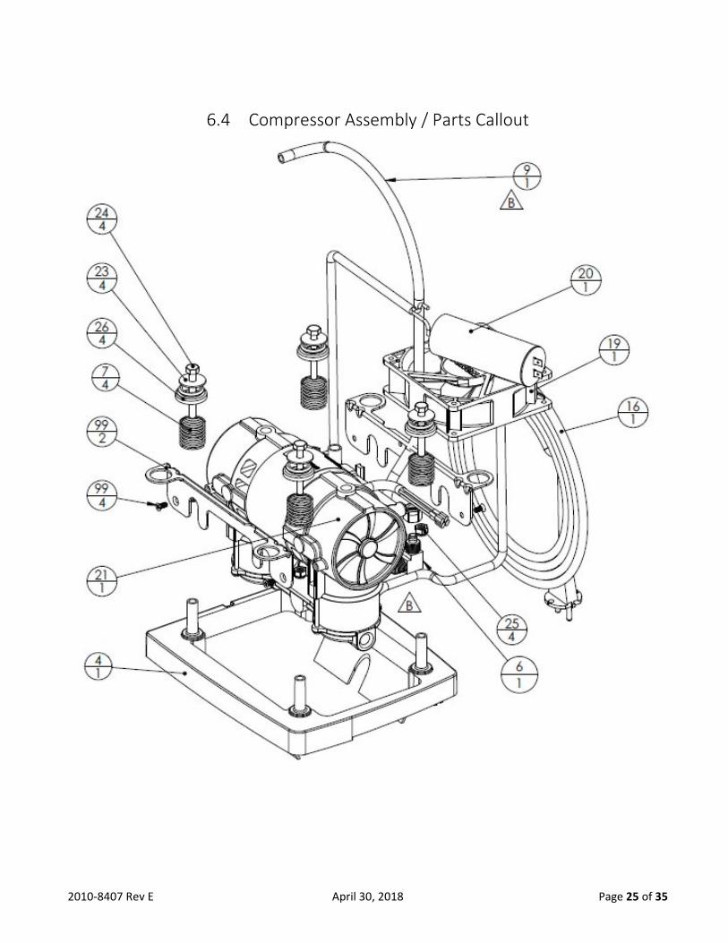
6.4 Compressor Assembly / Parts Callout

2010-8407 Rev E April 30, 2018 Page 26 of 35
Reference I.D. Description No.
Req’d Unit
8400-1513 1 SHUNT, VOLTAGE SELECTION 2 EA
8400-0110 4 BRACKET,COMPRESSOR 1 EA
8400-0154 6 FITTING COMPR to Blue Tube 1 EA
8400-0116 7 SPRING, COMPRESSION 4 EA
8400-2162 9 TUBING, 3/8OD One Formed 90EL 1 EA
9250-1330 16 CORD, POWER, EUROPLUG 230 V 1 EA
9250-1311 16* CORD,POWER, TYPE "K" PLUG, 115 V US 1 EA
8400-1332 16* CORD, POWER, CHINA 230 V 1 EA
8400-1340 16* CORD, POWER, SWISS 230 V 1 EA
8400-1341 16* CORD, POWER, UK 230 V 1 EA
8400-1342 16* CORD, POWER, ISRAEL 230 V 1 EA
8400-1343 16* CORD, POWER, INDIA 230 V 1 EA
8400-1018 17 BREAKER, CIRCUIT 10 AMP (NIDEK 115V) 1 EA
8400-1019 17 BREAKER, CIRCUIT 5 AMP 115/230V 1 EA
8400-1008 18 SWITCH,POWER UNIVERSAL 1 EA
8400-0134 19 FAN, 230V LOW WATTAGE 3LPM 1 EA
8400-1034 19 FAN, 230V HI FLOW 5LPM 1 EA
9250-1023 19 FAN,115V LOW NOISE 5LPM 1 EA
8400-0146 20 CAPACITOR, 230 V 5 μF P2 3LPM 1 EA
8400-1038 20 CAPACITOR, 230 V 10 μF P2 5LPM 1 EA
8400-1044 20 CAPACITOR, 115 V 20 μF P2 5LPM 1 EA
8400-2450 21 COMPR. 2450 115V/60HZ 5LPM 1 EA
8400-2460 21 COMPR. 2450 230V/50HZ 5LPM 1 EA
8400-2466 21 COMPR. 2450 230V/60HZ 3LPM 1 EA
8400-2456 21 COMPR. 2450 230V/60HZ 5LPM 1 EA
8400-2455 21 COMPR. NIDEK, 115V/60HZ 5LPM 1 EA
8400-2465 21 COMPR. NIDEK, 230V/50HZ 5LPM 1 EA
8400-2467 21 COMPR. NIDEK, 230V/50HZ 3LPM 1 EA
PARTS NO LONGER USED
8400-0152 6 FITTING,COMPRESSOR
Replaced by 8400-0154 & 8400-2162 1 EA
8400-1052 6 FITTING, COMPRESSOR (Nidek Compressor)
Replaced by 8400-0154 & 8400-2162 1 EA
8400-0197 8 EXCHANGER, HEAT
Replaced by 8400-0154 & 8400-2162 1 EA
8400-1097 8 EXCHANGER, HEAT (Nidek Compressor)
Replaced by 8400-0154 & 8400-2162 1 EA
8400-1161 9 TUBING,5/16ODx3/16IDx12.5"LG. OLD Replaced by 8400-2162 1 EA
8400-1162 9 TUBING, 3/8OD Two Formed Ends
Replaced by 8400-2162 1 EA
8400-1163 10 FITTING HX (No Longer Used) 1 EA

2010-8407 Rev E April 30, 2018 Page 27 of 35
6.5 Front Cabinet Assembly / Parts Callout

2010-8407 Rev E April 30, 2018 Page 28 of 35
Reference I.D. Description No.
Req’d Unit
8400-0102 1 CABINET, FRONT 1 EA
8400-0104 2 COVER, RESONATOR 1 EA
8400-0107 3 O-RING, RESONATOR COVER 1 EA
8400-1700 4 VALVE, FCV 1/8-5.0 LPM 1 EA
8400-1331 5 KNOB,FLOW 0.125 TO 5.0 FLOW 1 EA
9251-1332 6 RING,LOCK-OUT 1 EA
9251-1335 7 CLIP,D STYLE 1 EA
8400-1020 8 FITTING, OXYGEN OUTLET 1 EA
8400-0128 9 HOSE, COMPRESSOR SUCTION 1 EA
8400-1029 10 NUT 3/8-24 O2 OUTLET LITE 1 EA
7631-1053 11 FILTER, FINAL PRODUCT
(Location of Filter different for various models)2 EA
6956-9674 12 VALVE, CHECK 1/4 HOSE MPC A975 1 EA
8400-1059 13 ADAPTER, FILTER 1 EA
7854-6050 14 HOSE 5/32 X 11/32 X 2” LG SIL 1 EA
7854-6054 16 HOSE 5/32 X 11/32 X 3” LG SIL 1 EA
7854-6055 17 HOSE 5/32 X 11/32 X 7"LG SIL 1 EA
9250-1041 18 HOSE 5/32 X 11/32 X 5” LONG SIL 1 EA
8400-1304 20 BOARD,TIMING OMS NO-FLO 9V 1 EA
8400-1306 20 BOARD,TIMING STANDARD 9V 1 EA
9250-1045 21 SCREW,PLASTITE#4X3/8" PAN.HD 8 EA
8400-1522 22 WIRING HARNESS, UNIVERSAL 1 EA
8400-1523 NS VALVE WIRING HARNESS 1 EA
9250-1062 23 TY-WRAP 14” LG 1 EA
8400-5018 24 HOURMETER 1 EA
8400-1059 25 ADAPTER, FILTER 1 EA
8400-1436 26 SCREW, M3.5 X 0.6 X 8 mm LG 4 EA
8400-1041 27 ISOLATOR, FAN 1 EA
8400-1019 28 BREAKER, CIRCUIT 5 AMP 1 EA
8400-1008 29 SWITCH, POWER, UNIVERSAL 1 EA
8400-0113 30 BUMPER, MODULE 1 EA

2010-8407 Rev E April 30, 2018 Page 29 of 35
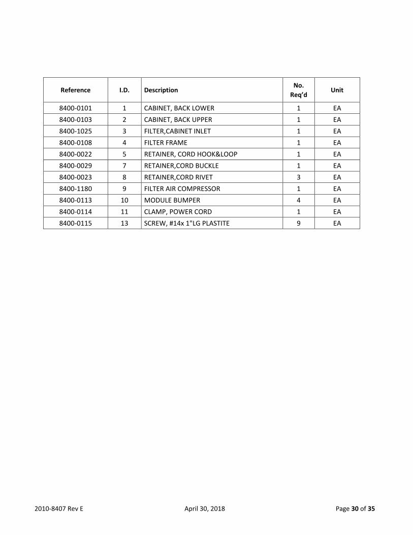
6.6 Back Cabinet Assembly / Parts Callout
2010-8407 Rev E April 30, 2018 Page 30 of 35
Reference I.D. Description No.
Req’d Unit
8400-0101 1 CABINET, BACK LOWER 1 EA
8400-0103 2 CABINET, BACK UPPER 1 EA
8400-1025 3 FILTER,CABINET INLET 1 EA
8400-0108 4 FILTER FRAME 1 EA
8400-0022 5 RETAINER, CORD HOOK&LOOP 1 EA
8400-0029 7 RETAINER,CORD BUCKLE 1 EA
8400-0023 8 RETAINER,CORD RIVET 3 EA
8400-1180 9 FILTER AIR COMPRESSOR 1 EA
8400-0113 10 MODULE BUMPER 4 EA
8400-0114 11 CLAMP, POWER CORD 1 EA
8400-0115 13 SCREW, #14x 1"LG PLASTITE 9 EA
2010-8407 Rev E April 30, 2018 Page 31 of 35
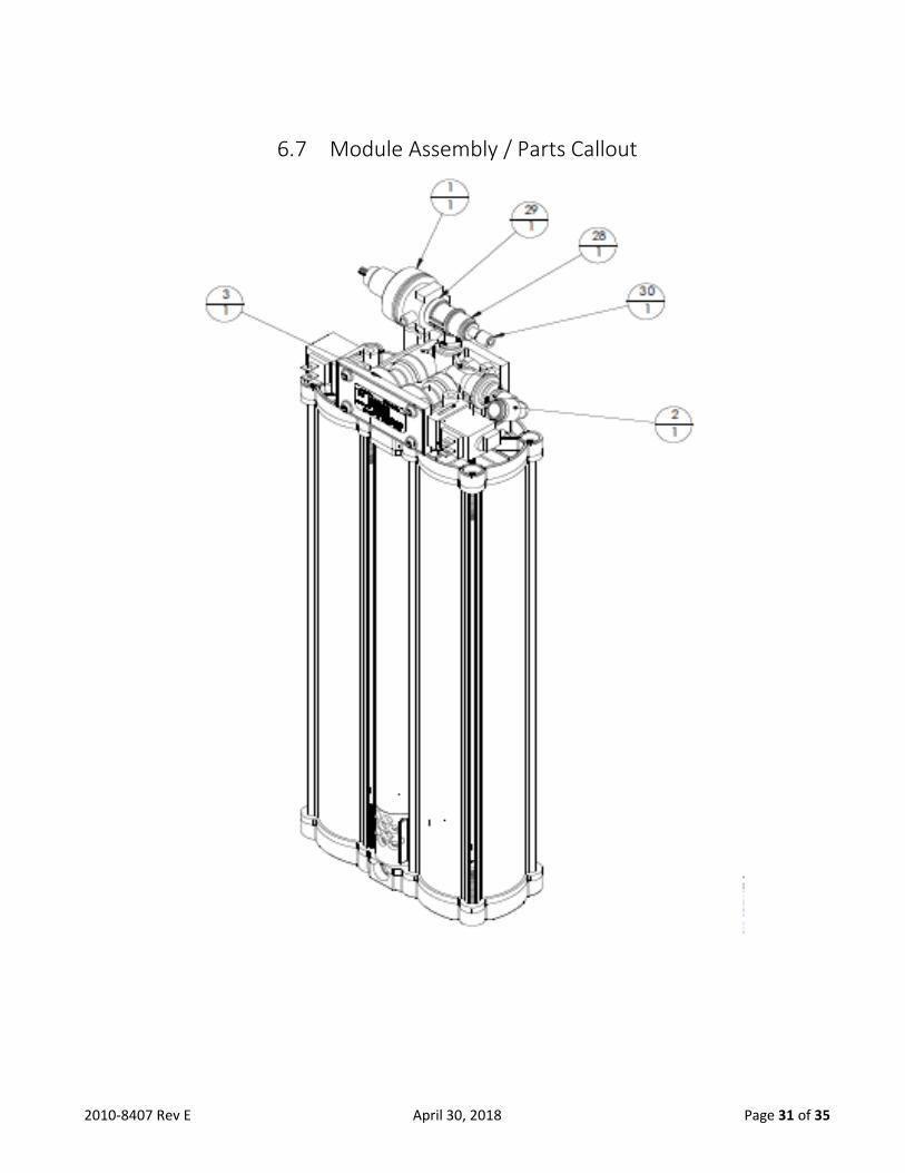
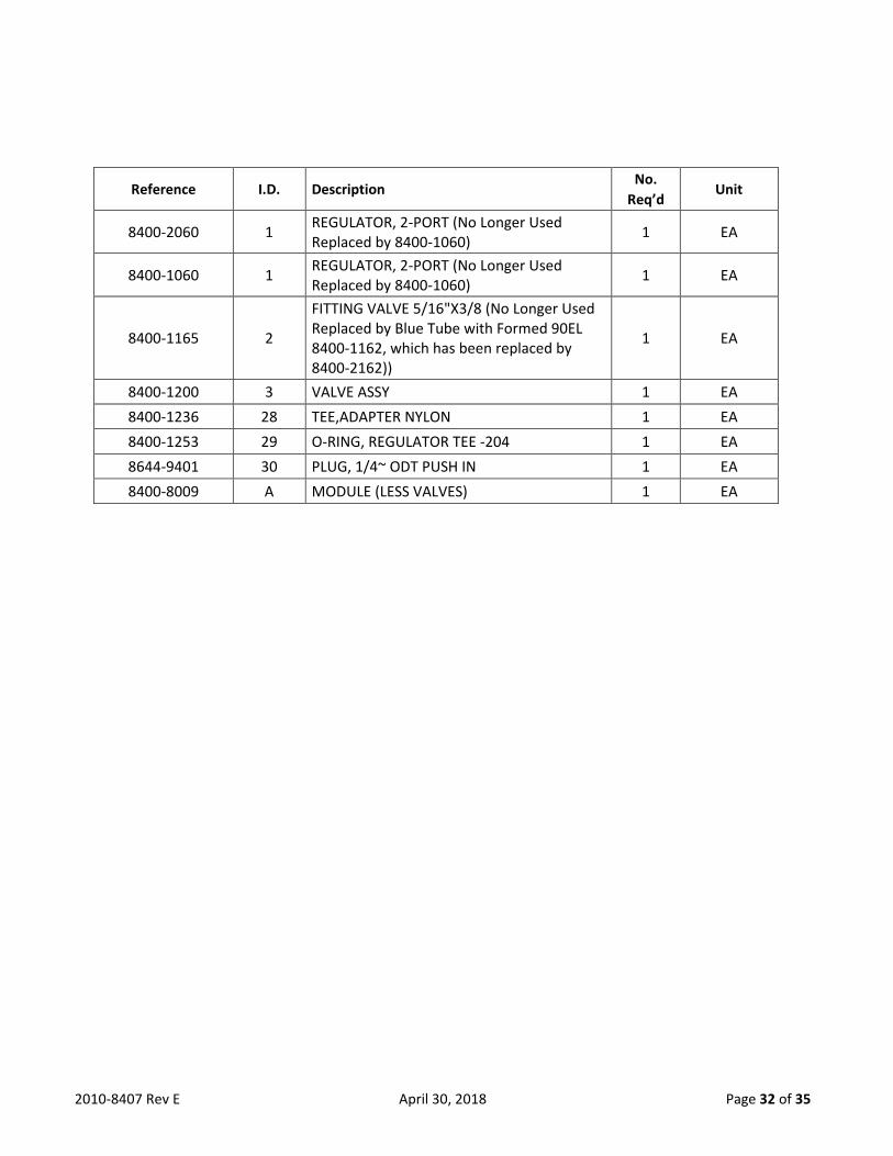
6.7 Module Assembly / Parts Callout
2010-8407 Rev E April 30, 2018 Page 32 of 35
Reference I.D. Description No.
Req’d Unit
8400-2060 1 REGULATOR, 2-PORT (No Longer Used Replaced by 8400-1060)
1 EA
8400-1060 1 REGULATOR, 2-PORT (No Longer Used Replaced by 8400-1060)
1 EA
8400-1165 2
FITTING VALVE 5/16"X3/8 (No Longer Used Replaced by Blue Tube with Formed 90EL 8400-1162, which has been replaced by 8400-2162))
1 EA
8400-1200 3 VALVE ASSY 1 EA
8400-1236 28 TEE,ADAPTER NYLON 1 EA
8400-1253 29 O-RING, REGULATOR TEE -204 1 EA
8644-9401 30 PLUG, 1/4~ ODT PUSH IN 1 EA
8400-8009 A MODULE (LESS VALVES) 1 EA

2010-8407 Rev E April 30, 2018 Page 33 of 35
Appendix A Service and Maintenance Log Nidek Medical Oxygen Concentrator Service and Maintenance Log
Model Number ________________ Serial Number ___________________
Initial Inspection
1. Upon receipt, check the unit for shipping damage.
2. If damaged, notify shipping company.
3. Verify that cabinet air filter and the inlet air filter are in place.
4. Plug the unit into an electrical outlet, turn the unit 'ON,’ and check the audible/visual alarms.
5. Set the flow meter/flow control at the maximum recommended flow rate and allow the unit to run for 15 minutes.
6. Using a calibrated oxygen analyzer, verify concentration is greater than 87 percent.
Routine Service Check
Perform routine servicing as shown in the chart below. Record the activities performed in the log provided on the following page.
1. Record the elapsed usage time in hours.
2. Check oxygen concentration with a calibrated oxygen analyzer.
3. Verify audible alarm and indicator light functions between patients and every two years.
4. Inspect filters (cabinet and inlet filter) and replace or clean as necessary.
Between-Patient Maintenance
1. Remove oxygen tubing, cannula, and humidifier bottle and discard.
2. Wash or replace the humidifier tubing if used.
3. Wash or replace the cabinet air filter.
4. Clean the concentrator cabinet.
5. Check oxygen concentration and flow.
If the unit performs within specification, the final product filter does not need to be replaced between patients.
Patient / Caregiver Maintenance
1. Inspect the Oxygen tubing, cannula, and humidifier bottle - clean as needed according to manufacturer’s instructions.
2. Wash the cabinet air filter weekly with a mild detergent solution. Make sure the filter is completely dry before reinstalling.
Standard Servicing Intervals
The routine service intervals shown below depend on the conditions in which the devices are used. They reflect the minimum recommendation when operated in a clean environment. As conditions can vary widely, the homecare provider or patient caregiver is responsible to determine, the character of the environment in which the concentrator is to operate and a maintenance schedule with intervals based on the environment in which the unit is operating/functioning.
Check Oxygen Concentration (%) OCSI – Every 15,000 hours or 3 years
Standard - Every 5,000 hours or 1 year
Cabinet Filter Wash weekly. Replace as needed.
Inlet / Silencer Filter Inspect at each patient visit.
Replace every 2 years, or more often depending on environment.
Final Product Filter Replace at each compressor service / module replacement
Capacitor Replace at each compressor service / module replacement.

2010-8407 Rev E April 30, 2018 Page 34 of 35
Nidek Medical Oxygen Concentrator Service and Maintenance Log
Please maintain a log of all maintenance activities performed on this unit.
Model _____________
Serial Number___________________
Date Hours % O2 Alarms Check
Additional Information
(Work Done, Filter Changes, Comments, etc)
Inspection Prior to Putting Into Service
In-Service Checks
Medical device regulations require users and service personnel to notify manufacturers of any incidents
that, if repeated, could cause injury to any person.
email: [email protected]
Please update maintenance log information upon each service at www.nidekmedical.com under
the 'Maintenance Log' tab.

2010-8407 Rev E April 30, 2018 Page 35 of 35
Conformity with EN 60601-1 CONFORMITY WITH EN 60601-1 (§ 6.8.2 b):
The manufacturer, assembler, installer or distributor are not considered to be responsible themselves for the
consequences on the safety, reliability and characteristics of a device unless the:
• Assembly, fitting, extensions, adjustments, modifications or repairs have been performed by persons authorized by the party in question.
• Electrical installation of the corresponding premises complies with local electrical codes. (e.g. IEC/NEC)
• Device is used in accordance with the instructions for use. If the replacement parts used for the periodic servicing by an approved technician do not comply with the
manufacturer’s specifications, the manufacturer is not responsible in the event of an accident or non-performance.
This device complies with the requirements of the FDA Quality System Regulation and 93/42/EEC European directive
but its operation may be affected by other devices being used nearby, such as diathermy and high frequency
electrosurgical equipment, mobile telephones, CB and other portable devices, microwave ovens, induction plates or
even remote control toys or any other electromagnetic interferences which exceed the levels specified by the EN
60601-1-2 standard.
Nidek Medical Products, Inc.
3949 Valley East Industrial Drive
Birmingham, Alabama 35217 U.S.A.
Tel: 205-856-7200 Fax: 205-856-0533
EU Representative
mdi Europa GmbH
Langenhagener Str. 71
30855 Hannover-Langenhagen
Germany
Tel: +49-511-39-08 95 30
Fax: +49-511-39-08 95 39
www.mdi-europa.com


![Aditya Birla Nuvo[Nuvo Corporate Presentation May09] 2](https://static.fdocuments.us/doc/165x107/577d399c1a28ab3a6b9a2cfd/aditya-birla-nuvonuvo-corporate-presentation-may09-2.jpg)
