2009 GM Medium Duty Electrical Manual.PDF
411
E LECTR ICAL M ANUA L – 2009 M EDIU M D UTY – C-S ERIE S – C ONVENTIONAL C AB Electrical Manual – 2009 Medium Duty – C Series – Conventional Cab P A G E i OVERVIEW ORGANIZA TION............................................................................................................................................................................. A-1 What’ s New For The 2009 Medium Duty C-Series ................................................................................................................. A-1 Navigation/Viewing.................................................................................................................................................................. A-2 Printing .................................................................................................................................................................................... A-2 SYSTEM OPERA TING INSTRUCTIONS ............................................................................................................................................... A-3 UF3 – Fast Idle Option – Electrical Requirements...................................................................................................................... A-4 OUTLINE ................................................................................................................................................................................. A-4 Overview ......................................................................................................................................................................... A-4 Engine/T ransmission Variations ...................................................................................................................................... A-4 Factory Installed Equipment ........................................................................................................................................... A-4 Upfitter Installed Equipment ........................................................................................................................................... A-5 Operation ........................................................................................................................................................................ A-5 Appendix ......................................................................................................................................................................... A-6 PTO – Power T ake Off Option – Electrical Requirements ......................................................................................................... A-7 OUTLINE ................................................................................................................................................................................. A-7 Overview ......................................................................................................................................................................... A-8 Engine/T ransmission Variations ...................................................................................................................................... A-9 Voc ation/Modes .............................................................................................................................................................. A-9 Factory Installed Equipment ......................................................................................................................................... A-10 Upfitter Ins talled Equipment ......................................................................................................................................... A-10 Operation ...................................................................................................................................................................... A-11 Stationary Preset Mode ........................................................................................................................................... A-12 Stationary Variab le Mode ......................................................................................................................................... A-14 Mobile Variable Mode .............................................................................................................................................. A-16 Index (continued on next page)
Transcript of 2009 GM Medium Duty Electrical Manual.PDF

8/10/2019 2009 GM Medium Duty Electrical Manual.PDF
http://slidepdf.com/reader/full/2009-gm-medium-duty-electrical-manualpdf 1/410
E LECTRICAL M ANUAL – 2009 M EDIUM DUTY – C-S ERIES – CONVENTIONAL C AB
Electrical Manual – 2009 Medium Duty – C Series – Conventional Cab
P A G E
i
OVERVIEW
ORGANIZATION ............................................................................................................................................................................. A-1
What’s New For The 2009 Medium Duty C-Series ................................................................................................................. A-1
Navigation/Viewing.................................................................................................................................................................. A-2
Printing .................................................................................................................................................................................... A-2
SYSTEM OPERATING INSTRUCTIONS ............................................................................................................................................... A-3
UF3 – Fast Idle Option – Electrical Requirements ...................................................................................................................... A-4
OUTLINE ................................................................................................................................................................................. A-4
Overview ......................................................................................................................................................................... A-4
Engine/Transmission Variations ...................................................................................................................................... A-4
Factory Installed Equipment ........................................................................................................................................... A-4
Upfitter Installed Equipment ........................................................................................................................................... A-5
Operation ........................................................................................................................................................................ A-5
Appendix ......................................................................................................................................................................... A-6
PTO – Power Take Off Option – Electrical Requirements ......................................................................................................... A-7
OUTLINE ................................................................................................................................................................................. A-7
Overview ......................................................................................................................................................................... A-8 Engine/Transmission Variations ...................................................................................................................................... A-9
Vocation/Modes .............................................................................................................................................................. A-9
Factory Installed Equipment ......................................................................................................................................... A-10
Upfitter Installed Equipment ......................................................................................................................................... A-10
Operation ...................................................................................................................................................................... A-11
Stationary Preset Mode ........................................................................................................................................... A-12
Stationary Variable Mode ......................................................................................................................................... A-14
Mobile Variable Mode .............................................................................................................................................. A-16
Index
(continued on next page)
8/10/2019 2009 GM Medium Duty Electrical Manual.PDF
http://slidepdf.com/reader/full/2009-gm-medium-duty-electrical-manualpdf 2/410
E LECTRICAL M ANUAL – 2009 M EDIUM DUTY – C-S ERIES – CONVENTIONAL C AB
Electrical Manual – 2009 Medium Duty – C Series – Conventional Cab
P A G E
ii
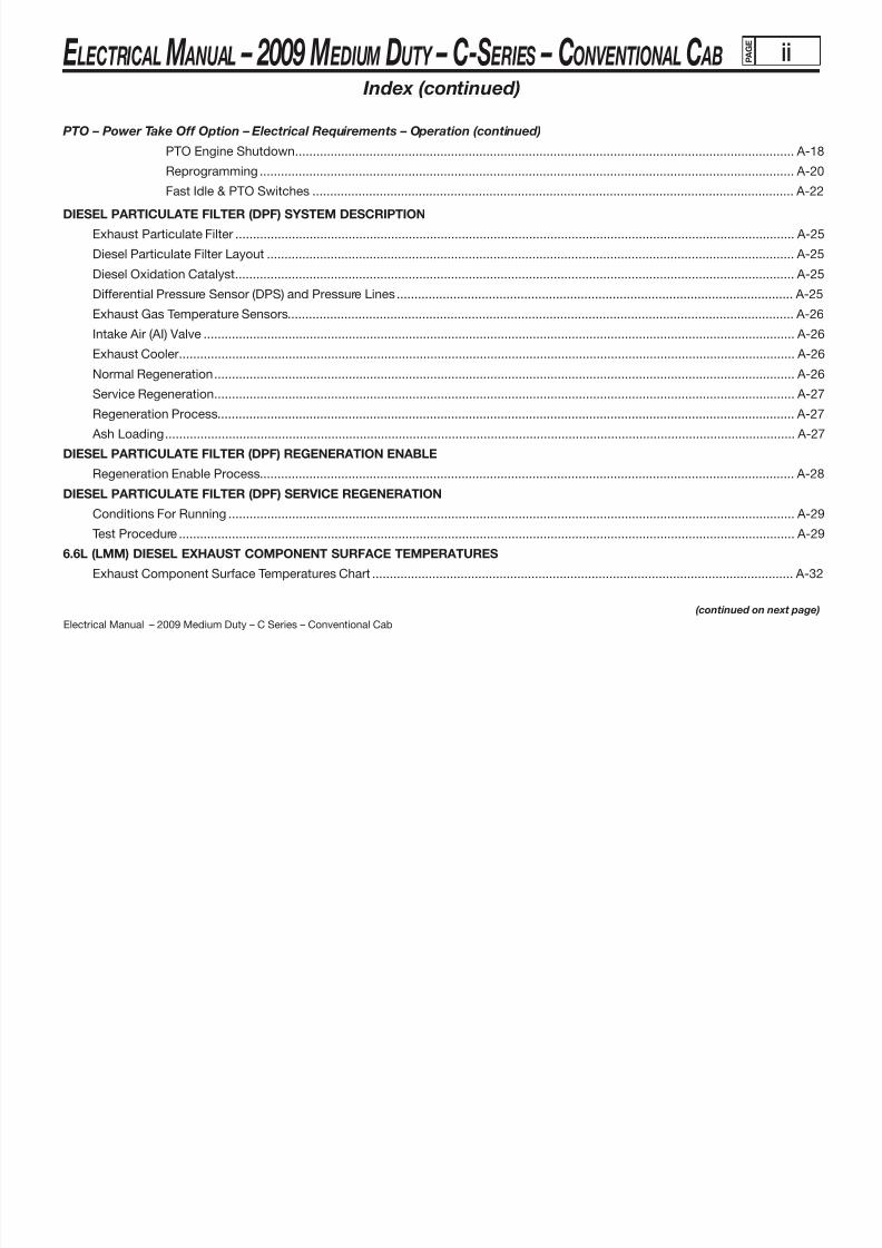
PTO – Power Take Off Option – Electrical Requirements – Operation (continued)
PTO Engine Shutdown ............................................................................................................................................. A-18
Reprogramming ....................................................................................................................................................... A-20
Fast Idle & PTO Switches ........................................................................................................................................ A-22
DIESEL PARTICULATE FILTER (DPF) SYSTEM DESCRIPTION
Exhaust Particulate Filter .............................................................................................................................................................. A-25
Diesel Particulate Filter Layout ..................................................................................................................................................... A-25
Diesel Oxidation Catalyst .............................................................................................................................................................. A-25
Differential Pressure Sensor (DPS) and Pressure Lines ................................................................................................................ A-25
Exhaust Gas Temperature Sensors ............................................................................................................................................... A-26
Intake Air (AI) Valve ....................................................................................................................................................................... A-26
Exhaust Cooler.............................................................................................................................................................................. A-26
Normal Regeneration .................................................................................................................................................................... A-26
Service Regeneration .................................................................................................................................................................... A-27
Regeneration Process ................................................................................................................................................................... A-27
Ash Loading .................................................................................................................................................................................. A-27DIESEL PARTICULATE FILTER (DPF) REGENERATION ENABLE
Regeneration Enable Process ....................................................................................................................................................... A-28
DIESEL PARTICULATE FILTER (DPF) SERVICE REGENERATION
Conditions For Running ................................................................................................................................................................ A-29
Test Procedure .............................................................................................................................................................................. A-29
6.6L (LMM) DIESEL EXHAUST COMPONENT SURFACE TEMPERATURES
Exhaust Component Surface Temperatures Chart ....................................................................................................................... A-32
Index (continued)
(continued on next page)

8/10/2019 2009 GM Medium Duty Electrical Manual.PDF
http://slidepdf.com/reader/full/2009-gm-medium-duty-electrical-manualpdf 3/410
E LECTRICAL M ANUAL – 2009 M EDIUM DUTY – C-S ERIES – CONVENTIONAL C AB
Electrical Manual – 2009 Medium Duty – C Series – Conventional Cab
ELECTRICAL COMPONENT LOCATIONS
Electrical Component Legend ........................................................................................................................................................B-1
Ground Zones ................................................................................................................................................................................. B-2
Underhood Distribution Center ....................................................................................................................................................... B-3
Fuse Block – Underhood (Primary) Label Usage ............................................................................................................................ B-4
Fuse Block – Underhood (Primary) Top View .................................................................................................................................. B-5
Fuse Block – Underhood (Primary) Bottom View ............................................................................................................................ B-6
Fuse Block – Underhood (Primary) Wire Entry ................................................................................................................................ B-7
Fuse Block – Underhood (Secondary) Label .................................................................................................................................. B-9 Fuse Block – Underhood (Secondary) .......................................................................................................................................... B-10
Fuse Block – Underhood (Secondary) Wire Entry ......................................................................................................................... B-11
Fuse Block – I/P 1 Label ............................................................................................................................................................... B-12
Fuse Block – I/P 1 Label Usage .................................................................................................................................................... B-13
Fuse Block – I/P 1 Front View ....................................................................................................................................................... B-15
Fuse Block – I/P 1 Back View ....................................................................................................................................................... B-16
Fuse Block – I/P 1 Wire Entry ....................................................................................................................................................... B-17
Fuse Block – I/P 2 Label ............................................................................................................................................................... B-18
Fuse Block – I/P 2 ......................................................................................................................................................................... B-19
Fuse Block – I/P 2 Wire Entry ....................................................................................................................................................... B-20
Location Views – U/H Fuse Center ............................................................................................................................................... B-22
Location Views – I/P Harness w/I/P-1 & I/P-2 .............................................................................................................................. B-23
Location Views – I/P-2 Fuse Center .............................................................................................................................................. B-24
Turn Signal Flasher ....................................................................................................................................................................... B-25
Index (continued)
P A G E
iii

8/10/2019 2009 GM Medium Duty Electrical Manual.PDF
http://slidepdf.com/reader/full/2009-gm-medium-duty-electrical-manualpdf 4/410
E LECTRICAL M ANUAL – 2009 M EDIUM DUTY – C-S ERIES – CONVENTIONAL C AB
Electrical Manual – 2009 Medium Duty – C Series – Conventional Cab
P A G E
iv
Index (continued)ELECTRICAL AND PIN-OUT ILLUSTRATIONS
12-Way Body Builder Connector .................................................................................................................................................... C-1
Body Builder Connector Location...................................................................................................................................................C-2
10-Way Bus Connector / 2-Way Bus Connector – Family 2 ........................................................................................................... C-3
Bus Connector Location – Family 2 ................................................................................................................................................ C-4
8.1L (L18) Powertrain Control Module (PCM) – Connector C-1 ..................................................................................................... C-6
8.1L (L18) Powertrain Control Module (PCM) – Connector C-2 ..................................................................................................... C-8
7.8L (LF8) Engine Control Module (ECM) – Location .................................................................................................................... C-10
7.8L (LF8) Engine Control Module (ECM) – Connector C-1 .......................................................................................................... C-11
7.8L (LF8) Engine Control Module (ECM) – Connector C-2 .......................................................................................................... C-13 6.6L (LMM) Engine Control Module (ECM) – Location .................................................................................................................. C-15
6.6L (LMM) Engine Control Module (ECM) – Connector C-1 ........................................................................................................ C-16
6.6L (LMM) Engine Control Module (ECM) – Connector C-2 ........................................................................................................ C-19
7.2L (LF6) CAT Engine Control Module (ECM) – Connector C-1 .................................................................................................. C-21
7.2L (LF6) CAT Engine Control Module (ECM) – Connector C-2 .................................................................................................. C-23
16-Way Serial Data Link Connector .............................................................................................................................................. C-26
Serial Data Link Connector Location ............................................................................................................................................ C-27
8-Way Tail Lamp Connector ..........................................................................................................................................................C-28
Tail Lamp Connector Location ...................................................................................................................................................... C-30
7-Way Tractor Connector – Family 3 ............................................................................................................................................ C-31
Tractor Connector – Family 3 Location ......................................................................................................................................... C-32
7-Way Trailer Connector – Family 2 .............................................................................................................................................. C-33
Trailer Connector Location – Family 2 .......................................................................................................................................... C-34
7-Way Trailer Connector – Family 3 .............................................................................................................................................. C-35
Trailer Connector Location – Family 3 .......................................................................................................................................... C-36
(continued on next page)

8/10/2019 2009 GM Medium Duty Electrical Manual.PDF
http://slidepdf.com/reader/full/2009-gm-medium-duty-electrical-manualpdf 5/410
E LECTRICAL M ANUAL – 2009 M EDIUM DUTY – C-S ERIES – CONVENTIONAL C AB
Electrical Manual – 2009 Medium Duty – C Series – Conventional Cab
P A G E
v
Index (continued)
ELECTRICAL AND PIN-OUT ILLUSTRATIONS (continued)
10-Way Transmission Optional Connector ................................................................................................................................... C-37
Transmission Optional Connector Location .................................................................................................................................. C-38
10-Way Upfitter PTO Connector ................................................................................................................................................... C-39
Upfitter PTO Connector Location ................................................................................................................................................. C-40
C127 Engine Chassis Harness to Remote Power Take Off (PTO) (LF8) ....................................................................................... C-41
Right Rear Side of Engine Compartment (LF8) ............................................................................................................................. C-42
(continued on next page)

8/10/2019 2009 GM Medium Duty Electrical Manual.PDF
http://slidepdf.com/reader/full/2009-gm-medium-duty-electrical-manualpdf 6/410
E LECTRICAL M ANUAL – 2009 M EDIUM DUTY – C-S ERIES – CONVENTIONAL C AB
Electrical Manual – 2009 Medium Duty – C Series – Conventional Cab
P A G E
vi
Index (continued)
SUBSYSTEM ELECTRICAL SCHEMATICS
Schematic Description and Navigation Instructions .................................................................................................................D-1
Power Distribution
(L18) 8.1L V8 GMPT VORTEC® - Gas ..................................................................................................................................... D-3
(LMM) 6.6L V8 Isuzu DURAMAX® - Diesel ............................................................................................................................ D-12
(LF8) 7.8L L6 Isuzu 6H - Diesel ............................................................................................................................................. D-21
(LF6) 7.2L L6 Caterpillar® C7 - Diesel....................................................................................................................................D-30
Ground Distribution
(L18) 8.1L V8 GMPT VORTEC®
- Gas – (LMM) 6.6L V8 Isuzu DURAMAX®
- Diesel ............................................................. D-39 (LF8) 7.8L L6 Isuzu 6H - Diesel ............................................................................................................................................. D-51
(LF6) 7.2L L6 Caterpillar® C7 - Diesel....................................................................................................................................D-64
Power Take-Off
(L18) 8.1L V8 GMPT VORTEC® - Gas – (LMM) 6.6L V8 Isuzu DURAMAX® - Diesel –
(LF8) 7.8L L6 Isuzu 6H - Diesel ..................................................................................................................................... D-76
(LF6) 7.2L L6 Caterpillar® C7 - Diesel .................................................................................................................................. D-78
Auxiliary Power............................................................................................................................................................................D-80
Engine Controls
(L18) 8.1L V8 GMPT VORTEC® - Gas ................................................................................................................................... D-81
(LMM) 6.6L V8 Isuzu DURAMAX® - Diesel ............................................................................................................................ D-93
(LF8) 7.8L L6 Isuzu 6H - Diesel ........................................................................................................................................... D-107
(LF6) 7.2L L6 Caterpillar® C7 - Diesel..................................................................................................................................D-119
Fan Control ................................................................................................................................................................................D-131
ETC
(L18) 8.1L V8 GMPT VORTEC® - Gas ................................................................................................................................. D-132
(continued on next page)

8/10/2019 2009 GM Medium Duty Electrical Manual.PDF
http://slidepdf.com/reader/full/2009-gm-medium-duty-electrical-manualpdf 7/410
E LECTRICAL M ANUAL – 2009 M EDIUM DUTY – C-S ERIES – CONVENTIONAL C AB
Electrical Manual – 2009 Medium Duty – C Series – Conventional Cab
P A G E
vii
Index (continued)
SUBSYSTEM ELECTRICAL SCHEMATICS (continued)
Fuel
(L18) 8.1L V8 GMPT VORTEC® - Gas - Family 2 ................................................................................................................ D-134
(L18) 8.1L V8 GMPT VORTEC® - Gas - Family 3 ................................................................................................................ D-136
(LMM) 6.6L V8 Isuzu DURAMAX® - Diesel .......................................................................................................................... D-138
(LF8) 7.8L L6 Isuzu 6H - Diesel - (LF6) 7.2L L6 Caterpillar® C7 - Diesel ............................................................................. D-139
Heated Fuel/Water In Fuel
(LMM) 6.6L V8 Isuzu DURAMAX® - Diesel .......................................................................................................................... D-140
(LF6) 7.2L L6 Caterpillar® C7 - Diesel..................................................................................................................................D-141
(LF8) 7.8L L6 Isuzu 6H - Diesel ........................................................................................................................................... D-142
Automatic Transmissions
LCT Transmission ................................................................................................................................................................ D-143
MD Transmission ................................................................................................................................................................. D-146
Exhaust Brake/Restrictor
(LMM) 6.6L V8 Isuzu DURAMAX® - Diesel – (LF8) 7.8L L6 Isuzu 6H - Diesel –
(LF6) 7.2L L6 Caterpillar® C7 - Diesel .........................................................................................................................D-149
Starting & Charging (L18) 8.1L V8 GMPT VORTEC® - Gas ................................................................................................................................. D-150
(LMM) 6.6L V8 Isuzu DURAMAX® - Diesel .......................................................................................................................... D-153
(LF8) 7.8L L6 Isuzu 6H - Diesel ........................................................................................................................................... D-156
(LF6) 7.2L L6 Caterpillar® C7 - Diesel..................................................................................................................................D-158
Cruise Control
(L18) 8.1L V8 GMPT VORTEC® - Gas – (LMM) 6.6L V8 Isuzu DURAMAX® - Diesel ........................................................... D-160
(LF8) 7.8L L6 Isuzu 6H - Diesel ........................................................................................................................................... D-161
(LF6) 7.2L L6 Caterpillar® C7 - Diesel..................................................................................................................................D-162
(continued on next page)

8/10/2019 2009 GM Medium Duty Electrical Manual.PDF
http://slidepdf.com/reader/full/2009-gm-medium-duty-electrical-manualpdf 8/410
E LECTRICAL M ANUAL – 2009 M EDIUM DUTY – C-S ERIES – CONVENTIONAL C AB
Electrical Manual – 2009 Medium Duty – C Series – Conventional Cab
P A G E
viii
Index (continued)
SUBSYSTEM ELECTRICAL SCHEMATICS (continued)
Batteries (L18) 8.1L V8 GMPT VORTEC® - Gas - Top Post ................................................................................................................ D-163
(L18) 8.1L V8 GMPT VORTEC® - Gas - Side Post ..............................................................................................................D-165
(L18) 8.1L V8 GMPT VORTEC® - Gas - Bus ........................................................................................................................ D-166
(LMM) 6.6L V8 Isuzu DURAMAX® - Diesel .......................................................................................................................... D-167
(LMM) 6.6L V8 Isuzu DURAMAX® - Diesel - Bus ................................................................................................................D-169
(LF8) 7.8L L6 Isuzu 6H - Diesel ........................................................................................................................................... D-170
(LF6) 7.2L L6 Caterpillar® C7 - Diesel..................................................................................................................................D-171
2-Speed Rear Axle
(L18) 8.1L V8 GMPT VORTEC® - Gas – (LF8) 7.8L L6 Isuzu 6H - Diesel ............................................................................ D-172
(LF6) 7.2L L6 Caterpillar® C7 - Diesel..................................................................................................................................D-174
Active Transfer Case ................................................................................................................................................................D-176
Horn ...........................................................................................................................................................................................D-178
Brakes
Hydraulic (C4500 thru C7500) ............................................................................................................................................. D-179
Air (C7500 thru C8500) ....................................................................................................................................................... D-185
Park Brake
Park Brake (Family 2) .......................................................................................................................................................... D-190
Park Brake (Family 3) .......................................................................................................................................................... D-191
SIR ..............................................................................................................................................................................................D-192
Rear Air Suspension .................................................................................................................................................................D-194
(continued on next page)

8/10/2019 2009 GM Medium Duty Electrical Manual.PDF
http://slidepdf.com/reader/full/2009-gm-medium-duty-electrical-manualpdf 9/410
E LECTRICAL M ANUAL – 2009 M EDIUM DUTY – C-S ERIES – CONVENTIONAL C AB
Electrical Manual – 2009 Medium Duty – C Series – Conventional Cab
P A G E
ix
Index (continued)
SUBSYSTEM ELECTRICAL SCHEMATICS (continued)
Serial Data
Data Link Connector ........................................................................................................................................................... D-195
Serial Data Link (Class 2) .................................................................................................................................................... D-198
Serial Data Gateway ............................................................................................................................................................ D-199
Diagnostic Tool Connector .................................................................................................................................................. D-200
J1939 - (L18) 8.1L V8 GMPT VORTEC® - Gas – (LF8) 7.8L L6 Isuzu 6H - Diesel –
(LF6) 7.2L L6 Caterpillar® C7 - Diesel .........................................................................................................................D-201
HVAC Heater Only ......................................................................................................................................................................... D-208
Active - (LMM) 6.6L V8 Isuzu DURAMAX® - Diesel ............................................................................................................. D-209
Passive - (LF8) 7.8L L6 Isuzu 6H - Diesel ........................................................................................................................... D-211
Rear Heater - Crew Cab ...................................................................................................................................................... D-213
Rear Defogger - Crew Cab..................................................................................................................................................D-214
Chime ........................................................................................................................................................................................D-215
Displays
Instrument Panel Cluster (IPC) ............................................................................................................................................ D-216
Tell Tale Module & Gauges .................................................................................................................................................. D-218
Windshield Wiper/Washer ........................................................................................................................................................D-220
Headlamps
Dual Headlamps .................................................................................................................................................................. D-221
Quad Headlamps (Family 2) ................................................................................................................................................ D-222
Daytime Running Lamps (DRL) ................................................................................................................................................D-223
Exterior Lighting ........................................................................................................................................................................D-224
(continued on next page)

8/10/2019 2009 GM Medium Duty Electrical Manual.PDF
http://slidepdf.com/reader/full/2009-gm-medium-duty-electrical-manualpdf 10/410
E LECTRICAL M ANUAL – 2009 M EDIUM DUTY – C-S ERIES – CONVENTIONAL C AB
Electrical Manual – 2009 Medium Duty – C Series – Conventional Cab
P A G E
x
Index (continued)
SUBSYSTEM ELECTRICAL SCHEMATICS (continued)
Interior Lighting .........................................................................................................................................................................D-230
Truck/Trailer Wiring
Truck/Trailer Wiring (Family 2) ............................................................................................................................................. D-235
Truck/Trailer Wiring (Family 3) ............................................................................................................................................. D-236
Tractor Wiring (Family 3) ...................................................................................................................................................... D-238
Body Builder Connector ...........................................................................................................................................................D-240
School Bus Upfitter ...................................................................................................................................................................D-241
Power Windows Power Windows - Regular Cab ........................................................................................................................................... D-242
Power Windows - Crew Cab ............................................................................................................................................... D-243
Power Door Locks ....................................................................................................................................................................D-245
Remote Keyless Entry (RKE) ....................................................................................................................................................D-247
Power Mirrors ............................................................................................................................................................................D-248
Entertainment
Radio ................................................................................................................................................................................... D-250
Speakers ............................................................................................................................................................................. D-251
(continued on next page)

8/10/2019 2009 GM Medium Duty Electrical Manual.PDF
http://slidepdf.com/reader/full/2009-gm-medium-duty-electrical-manualpdf 11/410
E LECTRICAL M ANUAL – 2009 M EDIUM DUTY – C-S ERIES – CONVENTIONAL C AB
Electrical Manual – 2009 Medium Duty – C Series – Conventional Cab
P A G E
xi
UPFITTER’S QUICK REFERENCE
Connector Terminal Contacts
Delphi ...................................................................................................................................................................................... E-1
Bosch ...................................................................................................................................................................................... E-1
Sumitomo ................................................................................................................................................................................ E-1
Power Take-off (PTO)
Description and Operation ...................................................................................................................................................... E-2
Diagnostic Checks
Diagnostic Starting Point – Power Take-Off (PTO) .......................................................................................................... E-7
Symptoms – Power Take-Off (PTO) ................................................................................................................................ E-7
Power Take-off (PTO) Does Not Engage ......................................................................................................................... E-9
Engine RPM Does Not Increase With Power Take-Off (PTO) Engaged ........................................................................ E-13
Power Take-Off (PTO) Indicator Inoperative ................................................................................................................. E-15
Schematics
L18–LMM–LF8 .............................................................................................................................................................. E-17
LF6 ................................................................................................................................................................................ E-19
Vehicle – Diagnostic System Check .......................................................................................................................................... E-20 Checking Aftermarket Accessories .......................................................................................................................................... E-22
Wiring Repairs
Testing for Intermittent Conditions and Poor Connections ................................................................................................... E-23
Flat Wire Repairs ................................................................................................................................................................... E-27
GMLAN Wiring Repairs ......................................................................................................................................................... E-28
High Temperature Wiring Repairs ......................................................................................................................................... E-31
Heated Oxygen Sensor Wiring Repairs................................................................................................................................. E-35
Upfitter’s Quick Reference Index
(continued on next page)

8/10/2019 2009 GM Medium Duty Electrical Manual.PDF
http://slidepdf.com/reader/full/2009-gm-medium-duty-electrical-manualpdf 12/410
E LECTRICAL M ANUAL – 2009 M EDIUM DUTY – C-S ERIES – CONVENTIONAL C AB
Electrical Manual – 2009 Medium Duty – C Series – Conventional Cab
P A G E
xii
UPFITTER’S QUICK REFERENCE (continued)
Wiring Repairs (continued) Splicing Copper Wire Using Splice Clips .............................................................................................................................. E-36
Splicing Copper Wire Using Splice Sleeves.......................................................................................................................... E-38
Splicing Twisted or Shielded Cable ....................................................................................................................................... E-40
Splicing Inline Harness Diodes ............................................................................................................................................. E-41
SIR/SRS Wiring Repairs ........................................................................................................................................................ E-42
Lighting
Separating Stop from Turn Signal Lamps ............................................................................................................................. E-46
Diesel Emissions
CARB Idle Shutdown Requirements (California Only)........................................................................................................... E-48
Engine Idle Control System Description
Idle Shutdown ....................................................................................................................................................................... E-49
Upfitter’s Quick Reference Index (continued)

8/10/2019 2009 GM Medium Duty Electrical Manual.PDF
http://slidepdf.com/reader/full/2009-gm-medium-duty-electrical-manualpdf 13/410
E LECTRICAL M ANUAL – 2009 M EDIUM DUTY – C-S ERIES – CONVENTIONAL C AB
Electrical Manual – 2009 Medium Duty – C Series – Conventional Cab
A-1 P A G E
(continued on next page)
Overview
ORGANIZATION
The 2009 Medium Duty C-Series Electrical Body Builder Manual is organized as follows:
A. System Operation – Description of how things function
B. Components (including Electronic Modules) – Location and Pinouts
C. Connectors – Location and Pinouts
D. Subsystem Schematics – Detailed wiring and electrical schematic information
E. Upfitter’s Quick Reference – Additional information on existing and new features, as well as Frequently Asked Questions
WHAT’S NEW FOR THE 2009 MEDIUM DUTY C-SERIES
Major changes for the 2009 Model Year include:
• The 8.1L (L18) gas engine will no longer be available on C6500/C7500/C8500 models starting in December 2008

8/10/2019 2009 GM Medium Duty Electrical Manual.PDF
http://slidepdf.com/reader/full/2009-gm-medium-duty-electrical-manualpdf 14/410
E LECTRICAL M ANUAL – 2009 M EDIUM DUTY – C-S ERIES – CONVENTIONAL C AB
Electrical Manual – 2009 Medium Duty – C Series – Conventional Cab
A-2 P A G E
NAVIGATION/VIEWING
The Index items are linked to the actual page. Click on the item of interest and you’ll go to the corresponding page.The tab at the top of the page has other options available. From left to right:
• Save
• Previous page
• Next Page
• Page Number (in box)
• Zoom – Decrease Magnification
• Zoom – Increase Magnification
• Percentage Option (with drop-down menu)
• Scroll Through Pages
• Step Through Pages (one at a time)
• Find (with drop down menu)
PRINTING
Specific pages can be printed out. Be careful to select a print range or “current page” otherwise all 411 pages will be printed out.
The information provided in this document is believed to be accurate at time of publication.General Motors reserves the right to change the information contained in this document at any time.
Overview (cont’d)

8/10/2019 2009 GM Medium Duty Electrical Manual.PDF
http://slidepdf.com/reader/full/2009-gm-medium-duty-electrical-manualpdf 15/410
E LECTRICAL M ANUAL – 2009 M EDIUM DUTY – C-S ERIES – CONVENTIONAL C AB
Electrical Manual – 2009 Medium Duty – C Series – Conventional Cab
P A G E
System Operating Instructions
UF3 – Fast Idle Option – Electrical Requirements
OUTLINE• Overview• Engine/Transmission Variations• Factory Installed Equipment• Upfitter Installed Equipment• Operation• Appendix
Reprogramming the PCM / Using the Tech 2 Scan Tool – (Attachment 1)Illustrations
IP Switch Panel (Figure 1)Fast Idle Switch (Figure 2)
A-3

8/10/2019 2009 GM Medium Duty Electrical Manual.PDF
http://slidepdf.com/reader/full/2009-gm-medium-duty-electrical-manualpdf 16/410
E LECTRICAL M ANUAL – 2009 M EDIUM DUTY – C-S ERIES – CONVENTIONAL C AB
Electrical Manual – 2009 Medium Duty – C Series – Conventional Cab
P A G E
A-4
OVERVIEW
The UF3 fast idle option allows the operator to push a switch and raise the engine speed to a predetermined Idle RPM value. This featurecan only be used when the vehicle is stationary. Examples of Fast Idle applications are battery charging, idle operation of High ElectricalLoad vehicles, quick warm ups, and improved AC performance.
Scope
The GM (UF3) option described here is the necessary electrical and electronic content to control the engine idle speed. This is not adescription of how to install these features if not ordered as part of the option. Base factory settings and procedures to change the factorysettings are described here. Responsibility for proper and safe operation for any additional equipment remains with the Upfitter.
(PTO) vs. (UF3) Fast Idle
The (PTO) option allows for increased engine speed operation for increased power output to the PTO unit. The (UF3) fast idle option also
allows for increased engine speed but is used for quick warm up, A/C performance, or battery charging. The (PTO) Power Take Off and(UF3) fast idle options are mutually exclusive on the same vehicle with the L18/LLY/LMM/LG4/LF8 engines.
ENGINE/TRANSMISSION VARIATIONS
The 2009 Medium Duty C Series uses 4 engines as shown below:
FACTORY INSTALLED EQUIPMENT
The UF3 fast idle option includes the Fast Idle Switch, the Fast Idle Indicator Lamp and necessary wiring to the ECM for operation.
• Fast Idle Switch - Use to increase Engine speed to a preset value.
• Fast Idle Indicator Lamp – ECM turns on light to indicate operation in the Fast Idle Mode. This indicator is in the switch.
Engine RPO Engine Description Truck Family Available
L18 8.1L V8 GMPT VORTEC® - Gas 2 & 3
LMM 6.6L V8 Isuzu DURAMAX® - Diesel 2
LF8 7.8L L6 Isuzu 6H - Diesel w/2007i Emissions 3LF6 7.2L L6 Caterpillar® - Diesel 3

8/10/2019 2009 GM Medium Duty Electrical Manual.PDF
http://slidepdf.com/reader/full/2009-gm-medium-duty-electrical-manualpdf 17/410
E LECTRICAL M ANUAL – 2009 M EDIUM DUTY – C-S ERIES – CONVENTIONAL C AB
Electrical Manual – 2009 Medium Duty – C Series – Conventional Cab
UPFITTER INSTALLED EQUIPMENT
No upfitter installed equipment is required to operate the function. Responsibility for proper and safe operation for any additional equipment
remains with the Upfitter.
OPERATION
Description
Vehicles ordered with the UF3 (Fast Idle) option come with a dash mounted switch which allows the user to increase the engine idle speedto a fixed value. The Fast Idle Switch is located to the right of the steering wheel as shown in the illustration (Figure 1). An indicator in theswitch lights to show Fast Idle mode is active.
How To O perate
To enable the Fast Idle, the following conditions must be met:
1. Engine must be running
2. Transmission must be in Park or Neutral
3. Vehicle speed must be less than 5 mph
4. Brake or Clutch must not be depressed.
When the above conditions are met, the operator can activate the Fast Idle mode by pressing the Fast Idle Switch. If the switch is pressed
while the engine is in the Fast Idle mode, the engine will return to normal base idle.
P A G E
A-5

8/10/2019 2009 GM Medium Duty Electrical Manual.PDF
http://slidepdf.com/reader/full/2009-gm-medium-duty-electrical-manualpdf 18/410
E LECTRICAL M ANUAL – 2009 M EDIUM DUTY – C-S ERIES – CONVENTIONAL C AB
Electrical Manual – 2009 Medium Duty – C Series – Conventional Cab
P A G E
A-6
Engine Calibrations
The factory preset and minimum and maximum programmable speeds are shown in the table below for the
L18/LMM/LF8/LF6 engines:
NOITULOSERTNEMTSUJD A EUL A V MUMI X A MEUL A V MUMINIMSGNITTESTLU A FEDELB A MM A RGORP )MPR( )MPR( )MPR( )MPR( SRETEM A R A P
Maximum Fast Idle Speed 1000
Accelerator Disables Fast Idle 2500 Can’t be set below base 520083
Fast Idle Speed Parameters
0031006
Base Idle Speed 1200 Normal engine idle will override Cannot be set above the maximum 25
if higher than Fast Idle. Fast Idle Speed Parameter
Note: The Values shown in the above chart are accurate at the time of publication but may change in time for various reasons including
running changes made to the ECM, Calibrations, Tech 2 programming, software. Etc.
Caterpillar LF6 Engine
Base Fast Idle is set at the Factory to 1000 RPM. Fast Idle can be programmed from 700 to 2640 RPM.
Adjusting the Factory Preset Engine Speed
The Above parameters can be reprogrammed with a GM Tech 2 Diagnostic scan tool for the L18/LMM/LF8/LF6 engines.
The Tech 2 connects to the Data Link Connector under the dash. Information regarding reprogramming with the Tech 2 tool can
(Attachment 1). Reprogramming the LG5 engine requires a Caterpillar electronic service tool.
APPENDIX
Reprogramming the PCM / Using the Tech 2 Scan Tool(Attachment 1)
IllustrationsLocation of Fast Idle Switch and Indicator – (Figure 1)Switch Detail – (Figure 2)
be found in the Appendix.

8/10/2019 2009 GM Medium Duty Electrical Manual.PDF
http://slidepdf.com/reader/full/2009-gm-medium-duty-electrical-manualpdf 19/410
E LECTRICAL M ANUAL – 2009 M EDIUM DUTY – C-S ERIES – CONVENTIONAL C AB
Electrical Manual – 2009 Medium Duty – C Series – Conventional Cab
P A G E
System Operating Instructions
PTO – Power Take Off Option – Electrical Requirements
OUTLINE• Overview• Engine/Transmission Variations• Vocation/Modes• Factory Installed Equipment• Upfitter Installed Equipment• Operation *
Stationary Preset ModeStationary Variable ModeMobile Variable ModePTO Engine Shutdown
Remote Operation• Appendix
Reprogramming the PCM / Using the Tech 2 Scan Tool – (Attachment 1)Illustrations
Location of PTO Switch and Indicator – (Figure 1)PTO Switch Detail – (Figure 3)
Note: *Caterpillar has different programming capability. See your dealer for more information.
A-7

8/10/2019 2009 GM Medium Duty Electrical Manual.PDF
http://slidepdf.com/reader/full/2009-gm-medium-duty-electrical-manualpdf 20/410
E LECTRICAL M ANUAL – 2009 M EDIUM DUTY – C-S ERIES – CONVENTIONAL C AB
Electrical Manual – 2009 Medium Duty – C Series – Conventional Cab
P A G E
OVERVIEW
A Power Take Off (PTO) is a gearbox or mechanical device used to transmit mechanical power from the powertrain, through gears or atransmission, to another mechanical or hydraulic device. Examples of PTO applications are: salt spreaders, refuse equipment, plows,pumps, drills, lifts, wrecker equipment, dump bodies, fire/rescue equipment, etc.
PTO Advantages
• PTO’s are inexpensive, convenient, safe and reliable.
• PTO’s bolt on to the transmission, engine, transfer case or can be incorporated into the accessory belt drive system.
• PTO’s eliminate the need for a complex array of levers, controllers, electric motors, etc., which would be required to duplicatethe operation of a PTO.
Scope
The PTO unit itself is installed by the Upfitter or Specialty Vehicle Assembler on the vehicle. The GM (PTO) option described here is thenecessary electrical and electronic content to control the PTO unit. Responsibility for proper and safe operation remains with the Upfitter.Other PTO related RPO’s such as V66 (mechanical provisions for Front PTO) are not addressed here.
(PTO) vs. (UF3) Fast Idle
The (PTO) option allows for increased engine speed operation for increased power output to the PTO unit. The (UF3) fast idle option alsoallows for increased engine speed but is used for quick warm up, A/C performance, or battery charging. The (PTO) Power Take Off and(UF3) fast idle options are mutually exclusive on the same vehicle with the L18/LMM/LF8/LF6 engines.
A-8

8/10/2019 2009 GM Medium Duty Electrical Manual.PDF
http://slidepdf.com/reader/full/2009-gm-medium-duty-electrical-manualpdf 21/410
E LECTRICAL M ANUAL – 2009 M EDIUM DUTY – C-S ERIES – CONVENTIONAL C AB
Electrical Manual – 2009 Medium Duty – C Series – Conventional Cab
A-9 P A G E
ENGINE/TRANSMISSION VARIATIONS
The 2009 Medium Duty C Series uses 6 engines as shown below:
Many transmissions are available on the 2009 Medium Duty C Series. 13 manual and six automatics are available on Family 3 trucks alone.The Caterpillar engine and some Allison transmissions have dedicated PTO connectors that interface with their control modules. The EngineController and Transmission Controller communicate with each other on a high-speed serial data link. The PTO functions are interfaced tothe ECM on 2009 Medium Duty C Series to reduce variation in wiring and function. The LF6 Caterpillar engine requires different PTO wiring
from the other engine applications but functions in a similar manner. Specific wiring is supplied with the PTO option.
VOCATION/MODES
The primary difference in PTO operation is whether the vehicle is stationary or moving. Stationary operation can have either preset orvariable PTO speeds. Some examples of modes and vocations are:
• Stationary Preset – Three preset high idle speeds – Refuse & Wrecker equipment, Fire truck pumpers,
• Stationary Variable – Variable high idle speeds - Drills, Lifts,
• Mobile Variable – Allows variable PTO speeds while the vehicle is moving – Salt Spreaders, Plows, Street Cleaners.
Note: The ECM can be programmed to only one of these modes at any given time. Caterpillar has different programming capability. Seeyour dealer for more information.
Engine RPO Engine Description Truck Family Available
L18 8.1L V8 GMPT VORTEC® - Gas 2 & 3
LMM 6.6L V8 Isuzu DURAMAX® - Diesel 2
LF8 7.8L L6 Isuzu 6H - Diesel w/2007i Emissions 3
LF6 7.2L L6 Caterpillar® - Diesel 3

8/10/2019 2009 GM Medium Duty Electrical Manual.PDF
http://slidepdf.com/reader/full/2009-gm-medium-duty-electrical-manualpdf 22/410
E LECTRICAL M ANUAL – 2009 M EDIUM DUTY – C-S ERIES – CONVENTIONAL C AB
Electrical Manual – 2009 Medium Duty – C Series – Conventional Cab
FACTORY INSTALLED EQUIPMENT
The PTO option includes the PTO Enable Switch, PTO Relay, K34 Cruise Control Switch, Upfitter Connector to allow optional Upfitterinstalled switches, and necessary wiring.
• PTO Enable Switch – Located on Dash
• PTO Relay – Turned on by ECM, Provides power for Engage Switch and Load Solenoid.
• K34 Cruise Control Switch – Steering column mounted - use to adjust idle speeds under PTO operation.
• Upfitter Connector – allows interconnection of optional Upfitter installed switches.
UPFITTER INSTALLED EQUIPMENT
Optional Upfitter installed equipment includes Remote PTO Up / Down Switches, PTO Load Engage Switch, PTO Load Solenoid, andRemote Kill Switch. All of these devices interface with the Upfitter Connector.
• Remote PTO Up / Down Switches – Same function as Cruise Control Switches, allows operation outside of Cab for Stationary PTOapplications.
• PTO Load Engage Switch – Allows for positive action feedback to ECM for before idle speed is increased. A 5 sec (calibrated) delayoccurs without this feedback.
Note: The Caterpillar ECM does not provide a feedback for PTO operation.
• PTO Load Solenoid – Causes PTO engagement if so equipped.
• Remote Kill Switch – This Normally Closed Switch allows the operator to stop the engine for remote Applications.
A-10 P A G E

8/10/2019 2009 GM Medium Duty Electrical Manual.PDF
http://slidepdf.com/reader/full/2009-gm-medium-duty-electrical-manualpdf 23/410
E LECTRICAL M ANUAL – 2009 M EDIUM DUTY – C-S ERIES – CONVENTIONAL C AB
Electrical Manual – 2009 Medium Duty – C Series – Conventional Cab
A-11 P A G E
OPERATION
Description
The PTO RPO is an option that allows the user to raise the engine speed through the use of designated switches and ECM programming.The ECM can be programmed to one of the following three PTO modes:
• Stationary Preset mode – Three preset high idle speeds. Vehicle must be stationary.
• Stationary Variable mode – Variable high idle speeds. Vehicle must be stationary.
• Mobile Variable mode – Allows variable PTO speeds while vehicle is moving.
These PTO modes are addressed separately and in detail in the following pages.Please note the ECM can be programmed to only one of the three modes at any one time.
PTO Switches
Vehicles ordered with the PTO option come with an IP mounted switch which allows the user to enable the function. The PTO Switch is locatedto the right of the steering wheel as shown in the illustration (Figure 1 & Figure 3). An indicator in the switch lights to show PTO mode isactive. The engine speed can then be changed with either the cruise control switches or upfitter installed remote PTO switches. CruiseControl Switches come with the PTO option on the 2009 Medium Duty C Series. The following chart shows how the switches operate.
PTO SWITCH CONVERSION CHART
noitcnuFnoitarepOhctiwSOTPetomeRnoitarepOhctiwSesiurC / wOTP
elbanEhctiwSesiurC A / NffO / nOesiurC
elbanEOTP A / NelbanEOTP
MPRrewoLnwoDOTPTES
MPResiaRpUOTPSER

8/10/2019 2009 GM Medium Duty Electrical Manual.PDF
http://slidepdf.com/reader/full/2009-gm-medium-duty-electrical-manualpdf 24/410
E LECTRICAL M ANUAL – 2009 M EDIUM DUTY – C-S ERIES – CONVENTIONAL C AB
Electrical Manual – 2009 Medium Duty – C Series – Conventional Cab
P A G E
Stationary Preset Mode
Description
The Stationary Preset Mode allows the user to select from three high idle speeds which are programmed in the ECM. The user can togglebetween three preset speeds using the SET or RES switches or the Remote PTO Switches.
How To Operate
Prior to enabling the Stationary PTO Mode, the following conditions must be met:
1. Engine must be running.
2. Transmission must be in Park or Neutral.
3. Vehicle speed must be less than 5 mph.
4. Brake or Clutch must not be depressed.
When the above conditions are met, the operator can activate the Stationary PTO by the following sequence:
1. Set the Park Brake.
2. Set the Cruise On/Off Switch to the On position – L18 only.
3. Set PTO Enable Switch to On position.
Upon Completion of the above steps, the PTO Stationary Preset Mode will be enabled and the engine speed will increase to the PTO Base
Idle Speed. Toggling the SET and RESume switches will cause the engine RPM to change from normal to either the PTO Preset #1 or PTOPreset #2 speed depending on which switch is pressed first.
Note: LMM/LF8 – ECM enables PTO relay with switch activation. Once on, the ECM won’t turn the relay off until the switch is turned off.
Any changes in the above conditions, including depressing the brake or clutch pedals or shifting an automatic transmission in gear, willdisable the Stationary Preset Mode causing the engine to return to normal base idle.
Note: L18 - Using the Accelerator to raise the engine above the Maximum Fast Idle Speed will result in disabling the PTO StationaryPreset Mode.LMM/LF8 – Engine will be governed to PTO Max engine speed with throttle activation. Engine speed will return to pre-activatio
value after the pedal is released.
A-12

8/10/2019 2009 GM Medium Duty Electrical Manual.PDF
http://slidepdf.com/reader/full/2009-gm-medium-duty-electrical-manualpdf 25/410
E LECTRICAL M ANUAL – 2009 M EDIUM DUTY – C-S ERIES – CONVENTIONAL C AB
Electrical Manual – 2009 Medium Duty – C Series – Conventional Cab
Engine Calibrations
The factory preset and minimum and maximum programmable speeds are shown in the table below for the
NOITULOSERTNEMTSUJD A EUL A V MUMI X A MEUL A V MUMINIMSGNITTESTLU A FEDELB A MM A RGORP )MPR( )MPR( )MPR( )MPR( SRETEM A R A P
Maximum Fast Idle Speed 2500 – L181000
3800 – L18 Accelerator Disables Fast Idle 2200 – LMM/LF8
Can’t be set below base2200 – LMM/LF8
50
Fast Idle Speed Parameters
6001300 – L18
1400 – LMM/LF8 50
Cannot be set above the maximumFast Idle Speed Parameter
1000
05deepSeldItsaFmumixaM
1000Can’t be set below base 05deepSeldItsaFmumixaM
Fast Idle Speed Parameters
05deepSeldItsaFmumixaM006
Note: The Values shown in the above chart are accurate at the time of publication but may change in time for various reasons includingrunning changes made to the ECM, Calibrations, Tech 2 programming, software. Etc.
Caterpillar LF6 Engine
PTO Engine RPM Set Speed is factory set at 1200 rpm. PTO Engine RPM Set Speed can be programmed between 700 and 2640 rpm.
Adjusting the Factor y Preset Engine Speed
The Above parameters can be reprogrammed with a GM Tech 2 Diagnostic scan tool for the L18/LMM/LF6/LF8 engines.
The Tech 2 connects to the Data Link Connector under the dash. Information regarding reprogramming with the Tech 2 tool can
(Attachment 1) . Reprogramming the LF6 engine requires a Caterpillar electronic service tool.
A-13 P A G E
L18/LMM/LF8 engines:
be found in the Appendix
1200 – L18 850 – LMM1000 – LF8
1200 – L18
1250 – LMM1400 – LF8
1000 – LMM /LF8
LMM/LF8

8/10/2019 2009 GM Medium Duty Electrical Manual.PDF
http://slidepdf.com/reader/full/2009-gm-medium-duty-electrical-manualpdf 26/410

8/10/2019 2009 GM Medium Duty Electrical Manual.PDF
http://slidepdf.com/reader/full/2009-gm-medium-duty-electrical-manualpdf 27/410

8/10/2019 2009 GM Medium Duty Electrical Manual.PDF
http://slidepdf.com/reader/full/2009-gm-medium-duty-electrical-manualpdf 28/410
E LECTRICAL M ANUAL – 2009 M EDIUM DUTY – C-S ERIES – CONVENTIONAL C AB
Electrical Manual – 2009 Medium Duty – C Series – Conventional Cab
Adjusting the Factor y Preset Engine Speed
The Above parameters can be reprogrammed with a GM Tech 2 Diagnostic scan tool for the L18/LMM/LF8 engines.
The Tech 2 connects to the Data Link Connector under the dash. Information regarding reprogramming with the Tech 2 tool(Attachment 1). Reprogramming the LG5 engine requires a Caterpillar electronic service tool.
Any changes in the above conditions, including depressing the brake or clutch pedals or shifting an automatic transmission in gear, willdisable the Stationary Variable Preset Mode causing the engine to return to normal base idle. Using the Accelerator to raise the engineabove the Maximum Fast Idle Speed will result in disabling the PTO Stationary Variable Mode.
Mobile Variable Mode
Description
The PTO Mobile Mode allows the driver to maintain a desired engine speed (not vehicle speed) while the vehicle is moving. This feature is
available with both manual and automatic transmissions. The engine speed must be greater than the PTO Base Fast Idle Speed and lowerthan the Maximum Fast Idle Speed. The Vehicle speed must be between the Minimum and Maximum Vehicle Speed Values.
How To O perate
To engage the PTO Mobile Variable Mode, the following conditions must be met in the following order:
1. Engine must be running
2. Transmission must be in gear.
3. Vehicle speed must be between the Minimum and Maximum Vehicle Speeds
4. Brake or Clutch must not be depressed.
5. PTO Enable Switch must be set to the On position
When the above conditions are met, the operator can activate the Mobile Variable mode by the following sequence:
7. Depress the Accelerator Pedal to obtain the desired engine speed.
8. Press the SET button to hold engine at the desired high idle speed.
The SET and RES switches can then be used to adjust the engine speed within the Maximum and Minimum RPM values shown in the Engine
calibration table (Table B). The adjustment increments are 25 RPM (L18/LF8), 100 RPM (LMM).
A-16 P A G E
can be found in the Appendix

8/10/2019 2009 GM Medium Duty Electrical Manual.PDF
http://slidepdf.com/reader/full/2009-gm-medium-duty-electrical-manualpdf 29/410
E LECTRICAL M ANUAL – 2009 M EDIUM DUTY – C-S ERIES – CONVENTIONAL C AB
Electrical Manual – 2009 Medium Duty – C Series – Conventional Cab
P A G E
PTO – MOBILE VARIABLE MODE FUNCTION CHART
SERTESHCTIWS
decrements and will maintain the new engine speed value. Engine increments and will maintain the new engine speed value. Engine
PRESSING speed can be decreased down to the engine base idle speed value. speed can increase up to the maximum fast idle speed value. IfONCE If engine speed is at this value, all SET inputs will be ignored. If the engine speed is at this value, all RES inputs will be ignored. If the
vehicle reaches the Minimum Vehicle Speed Value, PTO mode will vehicle reaches the Maximum Vehicle Speed Value, PTO mode will.degagnesideb.degagnesideb
Decelerates engine down to the engine base idle speed. Increases engine speed up to the maximum fast idle speed value.HELD If the vehicle reaches the Minimum Vehicle Speed Value, If the vehicle reaches the Maximum Vehicle Speed Value,
.degagnesideblliwedomOTP.degagnesideblliwedomOTP
Note: If the Stationary Variable Mode is disabled (i.e., brake depressed), it may be re-enabled by pressing the RES switch. This will causethe engine to resume the speed it was prior to disabling.
TABLE “B” — Engine Calibrations
The factory preset and minimum and maximum programmable speeds are shown in the table below for the L18/LMM/LF8 engines:
NOITULOSERTNEMTSUJD A EUL A V MUMI X A MEUL A V MUMINIMSGNITTESTLU A FEDELB A MM A RGORP )MPR( )MPR( )MPR( )MPR( SRETEM A R A P
Maximum Fast Idle Speed1000
3800 – L18 25 – L18/LF8 Accelerator Disables Fast Idle
Can’t be set below base2200 – LMM/LF8 100 – LMM
Fast Idle Speed Parameters
600 1300 – L18PTO Base Idle Speed
1200 – L18Normal engine idle will override
1400 – LMM/LF8 25 – L18/LF81000 – LMM/LF8
if higher than Fast Idle.Cannot be set above the maximum 100 – LMM
Fast Idle Speed Parameter
Maximum Vehicle Speed20 – L18 30 – L18
Governing MPH80 – LMM 3 MPH 80 – LMM 175 – LF8 255 – LF8
PTO Relay Engage Max Engine Speed 1000 – LMM/LF8 05deepSeldItsaFmumixaM006
Note: The Values shown in the above chart are accurate at the time of publication but may change in time for various reasons includingrunning changes made to the ECM, Calibrations, Tech 2 programming, software. Etc.
A-17
Engine speed will decrease by 25 RPM (L18/LF8), 100 RPM (LMM) Engine speed will increase by 25 RPM (L18/LF8), 100 RPM (LMM)
2500 – L18
2200 – LMM/LF8

8/10/2019 2009 GM Medium Duty Electrical Manual.PDF
http://slidepdf.com/reader/full/2009-gm-medium-duty-electrical-manualpdf 30/410
E LECTRICAL M ANUAL – 2009 M EDIUM DUTY – C-S ERIES – CONVENTIONAL C AB
Electrical Manual – 2009 Medium Duty – C Series – Conventional Cab
Caterpillar LF6 Engine
PTO Engine RPM Set Speed is factory set at 1200 rpm. PTO Engine RPM Set Speed can be programmed between 700 and 2640 rpm. ThePTO bump rate is 50 RPM.
Adjusting the Factor y Preset Engine Speed
The Above parameters can be reprogrammed with a GM Tech 2 Diagnostic scan tool for the L18/LMM/LF8 engines.
The Tech 2 connects to the Data Link Connector under the dash. Information regarding reprogramming with the Tech 2
(Attachment 1). Reprogramming the LF6 engine requires a Caterpillar electronic service tool.
PTO Engine Shutdown
Description
The PTO option includes provisions for PTO engine fault shutdown. This feature allows the operator to stop the engine while in PTO modewith an aftermarket installed switch. If the truck is not in PTO mode, pressing the switch will have no effect on engine operation. ThePTO Upfitter Connector (located on the right side of the engine compartment near the right wheel) Component legend has been providedfor installation of remote PTO controls. The upfitter can access the PTO engine fault shutdown circuits through this connector. The upfittermust provide the mating connector, wiring, and remoter switches shown on the Upfitter (PTO) Connector. To install this feature see theupfitter provisions schematics. Important. If the PTO engine shutdown feature is to be used, it must be turned on in the ECM. If thisfeature is not turned on it will have no effect on the engine.
The Above parameters can be reprogrammed with a GM Tech 2 Diagnostic scan tool for the L18/LMM/LF8 engines.to the Data Link Connector under the dash. Information regarding reprogramming with the Tech 2 tool can
(Attachment 1). Reprogramming the LF6 engine requires a Caterpillar electronic service tool.
Remote Operation
Description
The PTO Upfitter Connector (located on the right side of the engine compartment near the right wheel) Component legend has beenprovided for installation of remote PTO idle controls. The upfitter can access the PTO high idle circuits through this connector. The upfittermust provide the mating connector, wiring, and remoter switches shown on the Upfitter (PTO) Connector. Two momentary switched arerequired to duplicate the operation of the SET and RESume switches in the cab. The schematics showing the switches can be found on theSubsystem Electrical schematics under Upfitter Provisions. PTO UP switches duplicate the RES switch operation and the PTO Down switchduplicates the SET switch operation. Please note that the PTO high idle must still be enabled from the Cruise On/Off and the PTO
enable switches in the cab.
A-18 P A G E
tool can be found in the Appendix
The Tech 2 connectsbe found in the Appendix

8/10/2019 2009 GM Medium Duty Electrical Manual.PDF
http://slidepdf.com/reader/full/2009-gm-medium-duty-electrical-manualpdf 31/410
E LECTRICAL M ANUAL – 2009 M EDIUM DUTY – C-S ERIES – CONVENTIONAL C AB
Electrical Manual – 2009 Medium Duty – C Series – Conventional Cab
APPENDIX
Reprogramming the PCM / Using the Tech 2 Scan Tool – (Attachment 1)
IllustrationsLocation Illustrations
IP Switch Panel (Figure 1)PTO Enable Switch – See Component Locations – (Figure 3)Upfitter PTO Connector is shown in the connector and pin-out illustrations
Connector DrawingsUpfitter Provisions Connector are shown in the connector and pin-out illustrations
Circuit Schematic References (Circuit Schematics are shown in the Subsystem Electrical Schematic portion of the Body Builders Manual)Upfitter Provision Connector – L18/LMM/LF8
Upfitter Provision Connector – LF6L18 Gas EngineDuramax 6.6L and 7.8L Diesel EnginesCaterpillar 7.2L Diesel EnginePTO Operation w/Isuzu 7.8L Diesel Engine
A-19 P A G E

8/10/2019 2009 GM Medium Duty Electrical Manual.PDF
http://slidepdf.com/reader/full/2009-gm-medium-duty-electrical-manualpdf 32/410
E LECTRICAL M ANUAL – 2009 M EDIUM DUTY – C-S ERIES – CONVENTIONAL C AB
Electrical Manual – 2009 Medium Duty – C Series – Conventional Cab
P A G E
ATTACHMENT 1
REPROGRAMMING THE PCM/ECM FOR FAST IDLE/PTO USING THE TECH 2 SCAN TOOL
The Tech 2 scan tool MUST be used to enable the Fast Idle and PTO options and adjust the factory preset parameters to desired settings.The Tech 2 menu driven device is a hand held scan tool that plugs into the datalink connector located underneath the dash near the driver’sseat. Once the Tech 2 is connected, the following chart will guide the user.
TCELESUNEMTNERRUCPETS
SCITSONG A ID:OFNI A M1
ELCIHE VFOR A EYNOIT A CIFITNEDIELCIHE V2
KCURTYTUDMUIDEMNOIT A CIFITNEDIELCIHE V3
NI A RTREWOP:OFNOITCELESMETSYS4
12LRO4PLNOIT A CIFITNEDIELCIHE V5
L A UN A MROCIT A MOTU A NOIT A CIFITNEDIELCIHE V6
SNOITCNUFL A ICEPS:2FNI A RTREWOP7
SNOITPOOTP:3FSNOITCNUFL A ICEPS8
SNOITPOEGN A HCSGNITTESOTPTNERRUC9
E MENU BELOWESSNOITPOOTP01
TO ADJUST THE MODE OF OPERATION:
The PTO OPTIONS MENU will appear with the selections:
FO: FAST IDLE
Fl: STATIONARY PRESET FAST IDLE
F2: STATIONARY VARIABLE FAST IDLE
F3: MOBILE VARIABLE FAST IDLE
A-20

8/10/2019 2009 GM Medium Duty Electrical Manual.PDF
http://slidepdf.com/reader/full/2009-gm-medium-duty-electrical-manualpdf 33/410
E LECTRICAL M ANUAL – 2009 M EDIUM DUTY – C-S ERIES – CONVENTIONAL C AB
Electrical Manual – 2009 Medium Duty – C Series – Conventional Cab
Once the mode of operation is selected the CURRENT PTO SETTINGS menu will appear with the adjustable parameters for the currentmode.
This screen allows the user to increase or decrease engine RPM values using the INCREASE and DECREASE buttons. If the Engine FaultShutdown feature is selected, the YES or NO buttons will determine if this feature is enabled.
After all the settings are adjusted, the user will press the REPROGRAM button and the CURRENT PTO SETTINGS menu will appear withthe changes. The ignition must be turned off for ten seconds to ensure that the program values are stored in the PCM.
SERVICE CONSIDERATIONS
IMPORTANT: Please be aware that UF3 and PTO high idle settings must be reprogrammed in the event that the PCM is replaced. It maybe advisable to provide the PCM settings information to the customer in case the PCM requires servicing during some pointin the life of the vehicle.
A-21 P A G E

8/10/2019 2009 GM Medium Duty Electrical Manual.PDF
http://slidepdf.com/reader/full/2009-gm-medium-duty-electrical-manualpdf 34/410
E LECTRICAL M ANUAL – 2009 M EDIUM DUTY – C-S ERIES – CONVENTIONAL C AB
Electrical Manual – 2009 Medium Duty – C Series – Conventional Cab
IP, Switch Trim Plate, Fast Idle and PTO Switch Location (Figure 1)
A-22 P A G E

8/10/2019 2009 GM Medium Duty Electrical Manual.PDF
http://slidepdf.com/reader/full/2009-gm-medium-duty-electrical-manualpdf 35/410
E LECTRICAL M ANUAL – 2009 M EDIUM DUTY – C-S ERIES – CONVENTIONAL C AB
Electrical Manual – 2009 Medium Duty – C Series – Conventional Cab
Switch – Fast Idle (Figure 2)
A-23 P A G E

8/10/2019 2009 GM Medium Duty Electrical Manual.PDF
http://slidepdf.com/reader/full/2009-gm-medium-duty-electrical-manualpdf 36/410
E LECTRICAL M ANUAL – 2009 M EDIUM DUTY – C-S ERIES – CONVENTIONAL C AB
Electrical Manual – 2009 Medium Duty – C Series – Conventional Cab
PTO Enable Switch (Figure 3)
A-24 P A G E

8/10/2019 2009 GM Medium Duty Electrical Manual.PDF
http://slidepdf.com/reader/full/2009-gm-medium-duty-electrical-manualpdf 37/410
E LECTRICAL M ANUAL – 2009 M EDIUM DUTY – C-S ERIES – CONVENTIONAL C AB
Electrical Manual – 2009 Medium Duty – C Series – Conventional Cab
E LECTRICAL M ANUAL – 2009 M EDIUM DUTY – C-S ERIES – CONVENTIONAL C AB
Electrical Manual – 2009 Medium Duty – C Series – Conventional Cab
P A G E
A-25
Exhaust Particulate Filter
The exhaust particulate filter (EPF) captures diesel exhaust gas
particulates, preventing their release into the atmosphere. Thisis accomplished by forcing particulate-laden exhaust (1) througha filter substrate of porous cells, which removes the particu-lates from the exhaust gas. The exhaust gas enters the filter, butbecause every other cell of the filter is capped at the oppositeend, the exhaust particulates cannot exit the cell. Instead, theexhaust gas passes through the porous walls of the cell leavingthe particulates trapped on the cell wall. The cleaned exhaustgas exits the filter through the adjacent cell. The EPF is capableof reducing more than 90 percent of particulate matter (PM).
Diesel Particulate Filter Layout
(1) Exhaust Gas Temperature (EGT) Sensor 2
(2) Differential Pressure Sensor (DPS)
(3) Diesel Oxidation Catalyst (DOC)
(4) Exhaust Particulate Filter (EPF)
(5) Differential Pressure Sensor (DPS) Pressure Lines
(6) Exhaust Gas Temperature (EGT) Sensor 1
Diesel Oxidation Catalyst
The diesel oxidation catalyst (DOC) (7) has two functions. Onefunction is to reduce emissions of non methane hydro-carbons(NMHC) and carbon monoxide (CO), from the exhaust gases.The other function is to help start a regeneration event by con-verting the fuel-rich exhaust gases to heat. The engine controlmodule (ECM) monitors the functionally of the DOC by determin-ing if the exhaust gas temperature (EGT) sensor 1 (1) reachesa predetermined temperature during a regeneration event. The
Diesel Particulate Filter (DPF) System Description
DOC and the exhaust particulate filter (EPF) (6) are downstreamof the turbocharger, and are two separate components under
the vehicle.Differential Pressure Sensor (DPS) and Pressure Lines
The differential pressure sensor (DPS) (3) measures the pressuredifference between the inlet and outlet of the exhaust particu-late filter (EPF). When pressure difference has increased abovea calibrated threshold, a high particulate loading condition isindicated. The ECM will command a regeneration event in or-der to restore the filter. If the pressure differential continues toincrease across the exhaust filter without a regeneration event,the ECM will illuminate an EPF lamp or send a message to the
driver information center (DIC) referring the customer to cleanthe exhaust filter. To clean the exhaust filter the vehicle must bedriven under the conditions necessary for a regeneration to takeplace. If these lamps and messages are ignored, the ECM willeventually illuminate the malfunction indicator lamp (MIL) andrevert to Reduced Engine Power which will require the vehicle tobe serviced.
The DPS sensor provides a voltage signal to the ECM on a sig-nal circuit relative to the pressure differential changes in the EPF.
The ECM converts the signal voltage input to a pressure value.The DPS pressure lines (2) are connected before and after theEPF. To provide the pressure sensor with accurate back pressuremeasurements, the DPS pressure lines should have a continu-ous downward gradient without any sharp bends.
(continues on next page)

8/10/2019 2009 GM Medium Duty Electrical Manual.PDF
http://slidepdf.com/reader/full/2009-gm-medium-duty-electrical-manualpdf 38/410
E LECTRICAL M ANUAL – 2009 M EDIUM DUTY – C-S ERIES – CONVENTIONAL C AB
Electrical Manual – 2009 Medium Duty – C Series – Conventional Cab
E LECTRICAL M ANUAL – 2009 M EDIUM DUTY – C-S ERIES – CONVENTIONAL C AB
Electrical Manual – 2009 Medium Duty – C Series – Conventional Cab
P A G E
A-26
Exhaust Gas Temperature Sensors
The ECM uses two exhaust gas temperature (EGT) sensors to
measure the temperature of the exhaust gases at the inlet andoutlet of the exhaust particulate filter (EPF). The EGT sensors arevariable resistors, when the EGT sensors are cold, the sensorresistance is low, and as the temperature increases, the sen-sor resistance increases. When sensor resistance is high, theECM detects a high voltage on the signal circuit. When sensorresistance is low, the ECM detects a lower voltage on the signalcircuit. Proper EGTs at the inlet and outlet of the EPF are crucialfor proper operation and for initiating the regeneration process. A temperature that is too high in the EPF will cause the EPF sub-
strate to melt or crack. The ECM monitors the temperatures atthe EPF inlet and outlet to regulate EPF temperatures.
Intake Air (IA) Valve
The intake air (IA) valve is located upstream of the intake airheater, and is normally in the open position. The ECM com-mands the valve to close in order to precisely control combus-tion temperature control during exhaust particulate filter (EPF)regeneration. The IA valve will ensure the temperature of theexhaust gas remains in an efficient range under all operatingconditions. The IA valve system uses a position sensor locatedwithin the valve assembly to monitor the position of the valve.The IA valve uses a motor to move the valve to a closed positionand spring tension returns it to the open position. The motor isoperated through Motor Control 1 and 2 circuits.
Diesel Particulate Filter (DPF) System Description (cont’d)
(continues on next page)
Exhaust Cooler
The exhaust system has been designed to reduce exhaust gas
temperatures during regeneration. The exhaust cooler (4) at the endof the tailpipe draws in cooler air as exhaust gases flow throughits openings. The cooler air mixes with the warmer exhaust gas,reducing exhaust gas temperatures at the tailpipe outlet.
Normal Regeneration
Regeneration is the process of removing the captured particu-lates through incineration within the exhaust particulate filer(EPF). Elevated temperatures are created in the diesel oxidationcatalyst (DOC) through a calibrated strategy in the enginecontrol system.
Regeneration occurs when the ECM calculates that the particu-late level in the filter has reached a calibrated threshold using anumber of different factors, including engine run time, distancetraveled, fuel used since the last regeneration, and the exhaustdifferential pressure. In general, the vehicle will need to be op-erating continuously at speeds above 48 km/h (30 mph) forapproximately 20-30 minutes for a full and effective regenera-tion to complete. During regeneration the exhaust gases reachtemperatures above 550°C (1,022°F). The ECM monitors the
EGT sensors during regeneration. If the sensors indicate thatregeneration temperatures are exceeding a calibrated thresh-old, regeneration will be temporally suspended until the sensorsreturn to a normal temperature. If EGT temperatures fall belowa normal calibrated threshold, regeneration will be terminatedand a corresponding DTC should set. If a regeneration event isinterrupted for any reason, it will continue, including the next keycycle, when the conditions are met for regeneration enablement.Normal regeneration is transparent to the customer.

8/10/2019 2009 GM Medium Duty Electrical Manual.PDF
http://slidepdf.com/reader/full/2009-gm-medium-duty-electrical-manualpdf 39/410
E LECTRICAL M ANUAL – 2009 M EDIUM DUTY – C-S ERIES – CONVENTIONAL C AB
Electrical Manual – 2009 Medium Duty – C Series – Conventional Cab
E LECTRICAL M ANUAL – 2009 M EDIUM DUTY – C-S ERIES – CONVENTIONAL C AB
Electrical Manual – 2009 Medium Duty – C Series – Conventional Cab
P A G E
A-27
Diesel Particulate Filter (DPF) System Description (cont’d)
Service Regeneration
Warning: Tailpipe outlet exhaust temperature will be greater
than 300°C (572°F) during service regeneration.To help prevent personal injury or property damage from fire orburns, perform the following:
1. Do not connect any shop exhaust removal hoses to thevehicle’s tailpipe.
2. Park the vehicle outdoors and keep people, other vehicles,and combustible material away during service regeneration.
3. Do not leave the vehicle unattended.
Warning: To avoid extremely elevated exhaust temperatures,inspect and remove any debris or mud build up at theexhaust cooler located at the tailpipe.
Caution: Due to the elevated engine temperatures createdwhile performing this procedure it is imperative tokeep the front of vehicle in an open environment, withthe hood open, away from any walls or buildings. Thiswill ensure proper airflow across the radiator.
A scan tool is an essential tool that is required for service regen-
eration. Commanding a service regeneration is accomplishedusing the output control function. The vehicle will need to beparked outside the facility and away from nearby objects, suchas other vehicles and buildings, due to the elevated exhaustgas temperature at the tail pipe during regeneration. The serviceregeneration can be terminated by applying the brake pedal,commanding service regeneration OFF using the scan tool, ordisconnecting the scan tool from the vehicle.
A manual regeneration can be accomplished by pressuringthe EPF regeneration switch. Refer to Instrument Panel/Center
Console Component Views and Diesel Particulate Filter WarningIndicator Malfunction.
Regeneration Process
A number of engine components are required to function to-gether for the regeneration process to be performed. Thesecomponents are the fuel injectors, turbocharger, IA valve, fuelpressure control, and the intake air heater (IAH).
The regeneration process consists of several stages:
Warming up the diesel oxidation catalyst (DOC) to 350°C (662°F)
by performing the following:• Reducing air flow with the intake air valve
• Increasing or decreasing boost pressure with the turbo- charger, depending on engine load
• Elevating the engine speed
• Reduce fuel rail pressure
• Retard fuel injection timing
• Add late fuel injection pulses. The added fuel is not combusted but is oxidized by the DOC and exhaustparticulate filter (EPF) to create heat.
Ash Loading
Ash is a non-combustible by product from normal oil con-sumption. Low Ash content engine oil (CJ-4 API) is required forvehicles with the exhaust particulate filter (EPF) system. Ashaccumulation in the EPF will eventually cause a restriction inparticulate filter. Regeneration will not burn off the ash, only par-ticulate matter is burned off. An ash loaded EPF will need to beremoved from the vehicle and cleaned or replaced.

8/10/2019 2009 GM Medium Duty Electrical Manual.PDF
http://slidepdf.com/reader/full/2009-gm-medium-duty-electrical-manualpdf 40/410
E LECTRICAL M ANUAL – 2009 M EDIUM DUTY – C-S ERIES – CONVENTIONAL C AB
Electrical Manual – 2009 Medium Duty – C Series – Conventional Cab
E LECTRICAL M ANUAL – 2009 M EDIUM DUTY – C-S ERIES – CONVENTIONAL C AB
Electrical Manual – 2009 Medium Duty – C Series – Conventional Cab
P A G E
A-28
Diesel Particulate Filter (DPF) Regeneration Enable
1. Ignition ON, clear all DTCs with a scan tool.
2. Select DPF Regeneration Enable within the Special Function menu.
3. Select ON.The selection can be confirmed by the DPF Regeneration Reason parameter indicating Device Control.
4. Exit the Special Function Menu. The scan tool can now be removed.
The vehicle will perform an active Regeneration as soon as the engine running conditions are met.
IMPORTANT
The DPF Regeneration Enable is required when specific service procedures have been performed. Do not perform a DPFRegeneration Enable unless instructed to in the Repair Instruction section of the service procedure. After the system repairperform the following to avoid possible damage to the DPF.

8/10/2019 2009 GM Medium Duty Electrical Manual.PDF
http://slidepdf.com/reader/full/2009-gm-medium-duty-electrical-manualpdf 41/410
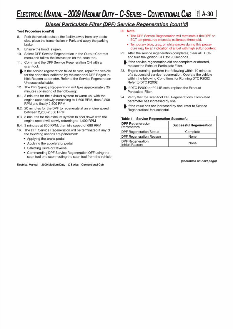
8/10/2019 2009 GM Medium Duty Electrical Manual.PDF
http://slidepdf.com/reader/full/2009-gm-medium-duty-electrical-manualpdf 42/410

8/10/2019 2009 GM Medium Duty Electrical Manual.PDF
http://slidepdf.com/reader/full/2009-gm-medium-duty-electrical-manualpdf 43/410
E LECTRICAL M ANUAL – 2009 M EDIUM DUTY – C-S ERIES – CONVENTIONAL C AB
Electrical Manual – 2009 Medium Duty – C Series – Conventional Cab
E LECTRICAL M ANUAL – 2009 M EDIUM DUTY – C-S ERIES – CONVENTIONAL C AB
Electrical Manual – 2009 Medium Duty – C Series – Conventional Cab
P A G E
A-31
Service Regeneration Unsuccessful
The scan tool DPF Regeneration Inhibit reason parameter will
display a reason for not enabling or aborting the DPF serviceregeneration. Refer to the reasons that are displayed and thecorrective action for each reason.
Diesel Particulate Filter (DPF) Service Regeneration (cont’d)
Table 2. Service Regeneration Unsuccessful
DPF Regeneration Param-eters
Unsuccessful Regeneration– Number of CompletedRegenerations Did NotIncrement By One
Corrective Action For AnUnsuccessful Regeneration
DPF RegenerationInhibit Reason
APP – The APP positionsensor indicated over 1percent
Ensure the acceleratorpedal was not appliedduring the service re-
generation. If the acceleratorpedal was not applied,test the acceleratorpedal position (APP)sensor.
BPP Applied – Thebrake pedal positionindicated Applied.
Ensure that the brakepedal was not appliedduring the service re-generation procedure.
If the brake pedal wasnot applied, test the
brake pedal switch.Important: The scantool must remain con-nected to the data com-munication link (DCL)during the entire serviceregeneration procedure.
Device Control – Thescan tool has interrupedservice regeneration. A loss of communica-tion between the scantool and the vehicle has
occured.
• The scan tool Exit orOFF soft key buttonwas depressed.
• Inspect for a poorconnection at DCL.
• Ignition OFF for 90seconds, the DPFtemperature mustbe less than 752ºF(400ºC). Restart the
service regeneration.
Table 2. Service Regeneration Unsuccessful (cont’d)
DPF RegenerationParameters
Unsuccessful Regeneration– Number of Completed
Regenerations Did NotIncrement By One
Corrective Action For An Unsuc-cessful Regeneration
DPF RegenerationInhibit Reason
DPF Temperature –DPF service regenera-tion temperatures areless than a calibratedthreshold.
• Observe the DTC informa-tion.
• Test for a degraded dieseloxidation catalyst (DOC).
• Test for a skewed exhausttemperature sensor, EGTsensor 1.
EGT 1 High – EGTsensor 1 temperaturerange was greater than
a calibrated thresholdfor greater than 1 sec.
Replace the DPF and per-form the DPF Reset or ForReplace The DPF with a
scan tool.
EGT 2 High – EGTsensor 2 temperaturerange was greater thana calibrated thresholdfor greater than 1 sec.
Replace the DPF and per-form the DPF Reset or ForReplace The DPF with ascan tool.
Ignition Voltage –battery voltage wasless than 10 volts.
Test the battery and chargingsystem for proper opration.
None Refer to the DPF Regenera-tion Status parameter.
Not in Park – Trans-mission gear selectoris not in Park.
Ensure that the transmis-sion gear selector remainedin Park during the ServiceRegeneration procedure.
If the gear selector re-mained in the Park position,test the transmission rangeswitch and circuits.
DPF RegenerationStatus
Required or Active The DPF may be excessivelyrestricted. Replace the DPFand perform the DPF ResetFor replace the DPF with a
scan tool.

8/10/2019 2009 GM Medium Duty Electrical Manual.PDF
http://slidepdf.com/reader/full/2009-gm-medium-duty-electrical-manualpdf 44/410
E LECTRICAL M ANUAL – 2009 M EDIUM DUTY – C-S ERIES – CONVENTIONAL C AB
Electrical Manual – 2009 Medium Duty – C Series – Conventional Cab
E LECTRICAL M ANUAL – 2009 M EDIUM DUTY – C-S ERIES – CONVENTIONAL C AB
Electrical Manual – 2009 Medium Duty – C Series – Conventional Cab
P A G E
A-32
6.6L (LMM) Diesel Exhaust Component Surface Temperatures
Note 1: Shown above are typical maximum exhaust component surface temperatures. The actual temperatures may varybased on ambient temperature, operating conditions, and body applications.
Note 2: The Diesel Oxidation Catalyst (DOC) and Diesel Particulate Filter (DPF) are emission control devices and cannotbe modified or re-positioned.
Note 3: For LMM equipped vehicles with RPO N1B (Side Exit Tailpipe) or RPO N12 (Rear Exit Tailpipe), the Body Builder/ Upfitter is responsible for the required installation of the GM diesel exhaust gas cooler at the end of the tailpipe.

8/10/2019 2009 GM Medium Duty Electrical Manual.PDF
http://slidepdf.com/reader/full/2009-gm-medium-duty-electrical-manualpdf 45/410
E LECTRICAL M ANUAL – 2009 M EDIUM DUTY – C-S ERIES – CONVENTIONAL C AB P A G E
B-1
Electrical Manual – 2009 Medium Duty – C Series – Conventional Cab
ETC- ELECTRONICTHROTTLECONTROL
PRELIM
L18 : GMPT 8.1L V8 GAS
DLC- DATALINKCONNECTOR
TCS- TRACTIONCONTROL SYSTEMTTM - TELL TALEMODULE
IPC- INSTRUMENT PANEL CLUSTERCLASS-2 FAMILY VALUES:
OF
DESCRIPTION
JE3 : HYDRAULICBRAKESPAGE NO.
SDM - SENSING & DIAGNOSTICSMODULE
RADIO - RADIO MODULE
L18 : GMPT 8.1L V8 GAS
LG5 : CATERPILLAR7.2L L6 DIESEL
HVAC- HVACMODULE
CHIME- CHIMEMODULE
DTC- DIAGNOSTICTOOL CONNECTOR
LG4 : DURAMAX7800 7.8L L6 DIESEL
TCM - TRANSMISSIONCONTROL MODULE
MK8/MK9/MKO/MLO/MS9/MUT/MM8 : MANUAL TRANS
PANEL
RELEASE LEVEL EDU- ELECTRONICDRIVERUNIT
RFA- REMOTEFUNCTIONACTUATOR
LCT - LIGHT COMMERCIAL TRANS
ML6 : MANUAL TRANS
II
DATE LESCR
FAMILY
FAMILY
ECU- ENGINECONTROL UNIT - L6
MX4/MTW: LCT 2000/2400 AUTO TRANSWIRE
DRL - DAYTIMERUNNING LAMPS
II:
EBC- ELECTRONICBRAKECONTROLLB7 : DURAMAX6600 6.6L V8 DIESELM74/MTW: LCT 1000/2400 AUTO TRANS
J1939
PCM - POWERTRAINCONTROL MODULE- V8
PROPOSAL
MNK/MNZ/MP8/MTP: MD AUTO TRANS
PPS- PEDAL POSITIONSENSOR
JE4 : AIRBRAKESJE3 : HYDRAULICBRAKES
WTEC- TCM FORMD TRANS
SDG - SERIAL DATAGATEWAY
III
FAMILYIII:
FAMILYGM Proprietary M69/MM7/MPU/MSC/MSG/MT3 : MANUAL TRANSLAST CHANGEDBY
Panel Set:
VERSIONSTAGEREVISIONOBJECT ID ORGANIZATION
7
8
ECU ISZ LG4
7
6
12
18
BODY BUILDER CONNECTOR
CHIME/RADIO
EBC AIR/TCS
18
4
24
25
25
3
14510
LOCATION LEGEND
19
MAXI FUSE CTR.
2
1
TRANS OPTION CONNECTOR
PTO UPFITTER CONNECTOR
TRAILER CONNECTOR FAM 3
24
IP DISTRIBUTION/RELAY CTR.
4
3
2
13
IP DISTRIBUTION CTR.
UNDERHOOD DISTRIBUTION CTR.
1
23
13
14
EDU ISZ LB7
9
10
11
12
ETC/PPS
IPC
HVAC
PCM/LCT TCM/WTEC TCM
23
GROUND BLOCK
16
21
20
11
9
8
15
16
15
17
SDM
RFA
TRAILER CONNECTOR FAM 2
17
19
20
TTM
21
22
ECU ISZ LB7
ECU CAT. LG522
DRL
EBC HYD./TCS
5
6
X
X
1a(REFERENCE)MAJOR MODULE
LOCATIONS
MAJORMODULELOCATIONS
0177
h22m_ref_modulessheet1 710__seludom_fer_m22h / KROWDEVI$citamehcs
9:06:20 am
Wednesday, July 18, 200103 2003 M. D. CSeriesPROJECT
Reference0 2003 Medium Duty C SeriesX
1
PILOTX
PROTO
11
N/A A19OC00
Electrical Component Legend

8/10/2019 2009 GM Medium Duty Electrical Manual.PDF
http://slidepdf.com/reader/full/2009-gm-medium-duty-electrical-manualpdf 46/410
E LECTRICAL M ANUAL – 2009 M EDIUM DUTY – C-S ERIES – CONVENTIONAL C AB P A G E
B-2
Electrical Manual – 2009 Medium Duty – C Series – Conventional Cab
LAST CHANGED BY
Panel Set:
VERSIONSTAGEREVISIONOBJECT ID ORGANIZATION
8
5
1B
BATT NEG
S2
12B
1A3D
7B
4A
6
11
4B 10
2A
9
2B
3C
S1
7A
12A3 A 3 B
Ground Zones
001PILOT B - INITIAL CREATION000560 00ES12GJ3021SE00JG0 3 5 60 0 00 S ta ck ed Gnd Block Conn wi th S2 001
Panel Set: 1
REFERENCE ONLY
B1
seireSCytuDmuideM3002toliP
Ground Zones2 00 3 M . D. C S er ie s X03
Thursday, September 21, 2000
4:14:11 pm
$IVEDWORK/h22009a__003schematic sh eet1h22009a
2003
Ground Zones

8/10/2019 2009 GM Medium Duty Electrical Manual.PDF
http://slidepdf.com/reader/full/2009-gm-medium-duty-electrical-manualpdf 47/410
E LECTRICAL M ANUAL – 2009 M EDIUM DUTY – C-S ERIES – CONVENTIONAL C AB P A G E
B-3
Electrical Manual – 2009 Medium Duty – C Series – Conventional Cab
1
Fuse Block – Underhood (Primary) Label

8/10/2019 2009 GM Medium Duty Electrical Manual.PDF
http://slidepdf.com/reader/full/2009-gm-medium-duty-electrical-manualpdf 48/410

8/10/2019 2009 GM Medium Duty Electrical Manual.PDF
http://slidepdf.com/reader/full/2009-gm-medium-duty-electrical-manualpdf 49/410
E LECTRICAL M ANUAL – 2009 M EDIUM DUTY – C-S ERIES – CONVENTIONAL C AB P A G E
B-5
Electrical Manual – 2009 Medium Duty – C Series – Conventional Cab
Fuse Block – Underhood (Primary) Top View
C S C C

8/10/2019 2009 GM Medium Duty Electrical Manual.PDF
http://slidepdf.com/reader/full/2009-gm-medium-duty-electrical-manualpdf 50/410
E LECTRICAL M ANUAL – 2009 M EDIUM DUTY – C-S ERIES – CONVENTIONAL C AB P A G E
B-6
Electrical Manual – 2009 Medium Duty – C Series – Conventional Cab
Fuse Block – Underhood (Primary) Bottom View
E M 2009 M D C S C C

8/10/2019 2009 GM Medium Duty Electrical Manual.PDF
http://slidepdf.com/reader/full/2009-gm-medium-duty-electrical-manualpdf 51/410
E LECTRICAL M ANUAL – 2009 M EDIUM DUTY – C-S ERIES – CONVENTIONAL C AB P A G E
B-7
Electrical Manual – 2009 Medium Duty – C Series – Conventional Cab
Connector Part Information
OEM: 12146281
Description: 86-Way Electrical Center (BK)
Terminal Part Information
Terminal/Tray: See Terminal Repair Kit
Core/Insulation Crimp: See Terminal Repair Kit
Release Tool/Test Probe: See Terminal Repair Kit
Pin Wire Color Circuit No. Function
A1
PK 339 Ignition 1 Voltage (LF8/LF6)
D-GN/WH 465Fuel Pump Relay Control -
Primary (L18/LMM)
A3
OG 1640Battery Positive Voltage(L18/LMM)
OG 1440Fuel Injection Control
(LF8/LF6)
A4
RD 1042Battery Positive Voltage
(LMM)
PK 439Ignition 1 Voltage
(w/o LMM)
A6 RD 1042 Battery Positive Voltage
A7 PU 806 Crank Voltage
A9 RD 242 Battery Positive Voltage
B1
GY 120Fuel Pump Supply Voltage
(L18/LMM)
PK 2677Battery Positive Voltage
(LF8/LF6)
B2 -- -- Not Used
B3 BK 250 Ground (w/o LF6/LF8)
B4 PU 2000 Ignition 1 Relay Output
B5 -- -- Not Used
Fuse Block – Underhood (Primary) Wire Entry
Pin Wire Color Circuit No. Function
B7 PU 6 Starter Solenoid Crank Voltage
B8 -- -- Not Used
B9 YE 447 Starter Relay Coil Control
C1 OG 740 Battery Positive Voltage
C3 OG 740 Battery Positive Voltage
C4 PK 439 Ignition 1 Voltage
C6 RD 1042 Battery Positive Voltage
D1 D-Gn 29 Horn Control
D2 -- -- Not Used
D3 BK 28 Horn Relay Control
D4 PU 2000 Ignition 1 Relay OutputD5 -- -- Not Used
D6 BK 250 Ground
D7
PK 539 Ignition 1 Voltage (LF6)
L-GN 488PTO On Switch - Signal
(L18/LMM)
OG 488Battery Positive Voltage
(LF8)
D9
PK 239 Ignition 1 Voltage (L18/LMM)
WH 2561 PTO Supply Voltage (LF6)
OG 440 Battery Positive Voltage (LF6/LF8)
E7
BK/WH 1120 Ignition 1 Voltage (LF8)
WH 2561 PTO Supply Voltage (L18/LMM)
D-GN/WH 2665 PTO Supply Voltage (LF6)
E8 -- -- Not Used
E9
L-GN 488 PTO On Switch - Signal (LF6)
L-BU 1121 Battery Relay Output - Coil (LF8)
PU 2562 PTO Control (L18/LMM)
F1 RD 1 Battery Positive Voltage
(continued on next page)
E M 2009 M D C S C C

8/10/2019 2009 GM Medium Duty Electrical Manual.PDF
http://slidepdf.com/reader/full/2009-gm-medium-duty-electrical-manualpdf 52/410
E LECTRICAL M ANUAL – 2009 M EDIUM DUTY – C-S ERIES – CONVENTIONAL C AB P A G E
B-8
Electrical Manual – 2009 Medium Duty – C Series – Conventional Cab
Fuse Block – Underhood (Primary) Wire Entry (continued)(continued from previous page)
Pin Wire Color Circuit No. Function
F3
-- 2000 Ignition Voltage Bus (w/o LG5)
PU 2000 Ignition Voltage (LG5)
F5 -- 2000 Ignition Voltage Bus
F9 L-GN 24 Backup Lamp Supply Voltage (A/T)
F11 GY 1524 Backup Lamp Supply Voltage (A/T)
G2 PU 1093Rear Defog Element Supply
Voltage
G4 PK 239 Ignition 1 Voltage
G6 PK 539 Ignition 1 Voltage (w/o LMM)
G8 OG 440 Battery Positive Voltage
G10 -- -- Not Used
G12 -- -- Not Used
H1 -- -- Not Used
H3 PU 2000 Ignition Voltage
H5 PU 2000 Ignition Voltage
H7 RD 1 Battery Positive Voltage
H9PK 539 Ignition 1 Voltage (Allison® MD)
PK 139 Ignition 1 Voltage (Allison® LCT)
H11 PK 139 Ignition 1 Voltage (Allison® MD)
J2 OG 440 Battery Positive Voltage (LF8)
J4 PK 639 Ignition 1 Voltage (w/o LG5)
J6 PK 339 Ignition 1 Voltage
J8 OG 1440 Battery Positive Voltage (w/o L18)
J10 D-Gn 1433Clutch Start Switch Signal
(Allison® MD)
J12YE 1479 A/T Neutral Signal (Allison® MD)
OG 440 Battery Positive Voltage (LMM)
K1 -- -- Not Used
K3 -- -- Not Used
Pin Wire Color Circuit No. Function
K5 -- -- Not Used
K7 -- -- Not Used
K9 BK 250 Ground (LMM)
K11 WH 2368Cooling Fan Clutch Supply
Voltage (LMM)
L2 -- -- Not Used
L4 -- -- Not Used
L6OG 440 Battery Positive Voltage (LMM)
PK 739 Ignition 1 Voltage (L18)
L8 OG 1240 Battery Positive Voltage
L10 BK 250 Ground (Allison® MD)
L12PU 806 Crank Voltage (Allison® MD)
WH/BK 2366 Colling Fan Clutch Control (LMM)
M1 RD 442 Battery Positive Voltage
M2 RD 1642 Battery Positive Voltage
M3 RD 42 Battery Positive Voltage
M4 RD 1042 Battery Positive Voltage
M5 OG 1840 Battery Positive Voltage
M6OG 740 Battery Positive Voltage
OG 740 Battery Positive Voltage
M7OG 1640 Battery Positive Voltage
(L18/LLY/LMM)
OG 1540 Battery Positive Voltage (LG5
M8 OG 1540 Battery Positive Voltage
N1-N8 -- 1 Battery Positive Voltage Bus
P7 -- 1 Battery Positive Voltage Bus
P8 -- 1 Battery Positive Voltage Bus
R7 -- --Battery Positive Voltage (AUX BODY
B+ Upfitter Provision Stud A)
R8 -- --Battery Positive Voltage (AUX BODY
B+ Upfitter Provision Stud B)
E M 2009 M D C S C C

8/10/2019 2009 GM Medium Duty Electrical Manual.PDF
http://slidepdf.com/reader/full/2009-gm-medium-duty-electrical-manualpdf 53/410
E LECTRICAL M ANUAL – 2009 M EDIUM DUTY – C-S ERIES – CONVENTIONAL C AB P A G E
B-9
Electrical Manual – 2009 Medium Duty – C Series – Conventional Cab
Fuse Block – Underhood (Secondary) Label
No. Device Rating Description
1 IGN 1 Fuse 40A Ignition Switch, Starter Relay, Transfer
Case Shift Control Module (NP1)
2 IGN 2 Fuse 50A Ignition 4 Relay
3 IGN 3 Fuse 60A Ignition Switch
4 BAT/HAZ Fuse 60A Fuse Block - I/P5 HDLP Fuse 40A Headlamp Switch, Fuse Block - I/P
6 LIGHTING Fuse 40A Courtesy Fuse, Park Fuse
7 HVAC Fuse 50A Blower Motor Resistor Assembly
(C40/C60)
8
ELEC BRK/
BRKLP Circuit
Breaker
30A
Brake Lamps (C6/C7/C8)
Electronic Brake Control Module
(EBCM) (C4/C5)
E M 2009 M D C S C CE

8/10/2019 2009 GM Medium Duty Electrical Manual.PDF
http://slidepdf.com/reader/full/2009-gm-medium-duty-electrical-manualpdf 54/410
E LECTRICAL M ANUAL – 2009 M EDIUM DUTY – C-S ERIES – CONVENTIONAL C AB P A G E
B-10
Electrical Manual – 2009 Medium Duty – C Series – Conventional Cab
Fuse Block – Underhood (Secondary)
Top View
Fuse Block – Underhood (Secondary)
Bottom View
E M 2009 M D C S C CE

8/10/2019 2009 GM Medium Duty Electrical Manual.PDF
http://slidepdf.com/reader/full/2009-gm-medium-duty-electrical-manualpdf 55/410
E LECTRICAL M ANUAL – 2009 M EDIUM DUTY – C-S ERIES – CONVENTIONAL C AB P A G E
B-11
Electrical Manual – 2009 Medium Duty – C Series – Conventional Cab
Fuse Block – Underhood (Secondary) Wire Entry
Connector Part Information
OEM: 12092231
Description: 16-Way Fuse Block Component (BK)
Terminal Part Information
Terminal/Tray: See Terminal Repair Kit
Core/Insulation Crimp: See Terminal Repair Kit
Release Tool/Test Probe: See Terminal Repair Kit
Pin Wire Color Circuit No. Function
A1 RD 242 Battery Positive Voltage
A2 RD 1242 Battery Positive Voltage
A3 RD 342 Battery Positive Voltage
A4 RD 142 Battery Positive Voltage
A5 RD 1142 Battery Positive Voltage
A6 RD 1342 Battery Positive Voltage
A7 RD 542 Battery Positive Voltage
A8 RD
642 Battery Positive Voltage (C4/C5)
1542Battery Positive Voltage
(RQ2 & U86/RQ3)
E M 2009 M D C S C CE

8/10/2019 2009 GM Medium Duty Electrical Manual.PDF
http://slidepdf.com/reader/full/2009-gm-medium-duty-electrical-manualpdf 56/410
E LECTRICAL M ANUAL – 2009 M EDIUM DUTY – C-S ERIES – CONVENTIONAL C AB P A G E
B-12
Electrical Manual – 2009 Medium Duty – C Series – Conventional Cab
Fuse Block – I/P-1 Label
E M 2009 M D C S C CE
B 13

8/10/2019 2009 GM Medium Duty Electrical Manual.PDF
http://slidepdf.com/reader/full/2009-gm-medium-duty-electrical-manualpdf 57/410
E LECTRICAL M ANUAL – 2009 M EDIUM DUTY – C-S ERIES – CONVENTIONAL C AB P A G E
B-13
Electrical Manual – 2009 Medium Duty – C Series – Conventional Cab
Fuse
No.Device Rating Description
1 STOP Fuse/Circuit Breaker 20A Stop Lamp Switch, Trailer StopLamp Switch
2 -- -- Not Used
3
PRK LAMPS
Fuse/Circuit
Breaker
20A Headlamp Switch, Transfer Case Shift
Control Switch (NP1)
4PCM-1 Fuse/
Circuit Breaker15A
Electronic Brake Control Module
(EBCM), Powertrain Control Module(PCM) (L18), Engine Control Module
(ECM) (LG4/LG5/LLY), Throttle ActuatorControl (TAC) Module (L18)
5 AUX WIREFuse/Circuit
Breaker
15A HTD MIR Relay, DRL Module, Upfitter
Connector
6HTR/AC Fuse/
Circuit Breaker20A
Air Temperature Actuator (C40/C60),
Vacuum Pump (w/o L18), HVAC
Control Assembly (C40/C60), Blower
Motor Relay - Auxiliary (C36)
7HAZRD Fuse/
Circuit Breaker25A Turn Signal/Multifunction Switch
8
PWR POST
Fuse/CircuitBreaker
20A
Cigar Lighter (DT4), Controller Area
Network (CAN) Connector, Auxiliary
Power Outlet 1, Auxiliary Power Outlet
2, Data Link Connector (DLC)
Fuse Block – I/P-1 Label Usage
Fuse
No.Device Rating Description
9 CTSY LAMPSFuse/Circuit
Breaker
10A Dome Lamps
10GAUGES Fuse/
Circuit Breaker10A
Remote Control Door Lock Receiver
(RCDLR) (AU0), Headlamp Switch, Day-
time Running Lights (DRL) Relay, Gauge
Center, Driver Information Center (DIC),
Instrument Panel Cluster (IPC)
11STRTR Fuse/
Circuit Breaker10A
Starter Relay, Clutch Start Switch
(M/T), Park/Neutral Position (PNP)
Switch(Allison® LCT), Neutral Start Relay
(Allison® MD), Electronic Brake Control
Module (EBCM)
12 AXLE/4WD Fuse/
Circuit Breaker20A Rear Axle Shift Relay - Two Speed (HPZ)
13TRLR Fuse/
Circuit Breaker20A LT TRN TRLR Relay, RT TRN TRLR Relay
14
RDO/CHIME
Fuse/Circuit
Breaker
15A Radio, Chime Module (UL5/UXZ),Instrument Panel Cluster (IPC)
15DRL Fuse/
Circuit Breaker15A Daytime Running Lights (DRL) Diode
16 AIRBAG Fuse/
Circuit Breaker10A
Inflatable Restraint I/P Module (AK5),
Inflatable Restraint Sensing and
Diagnostic Module (SDM) (AJ3/AK5)
(continued on next page)
E M 2009 M D C S C CE
B 14

8/10/2019 2009 GM Medium Duty Electrical Manual.PDF
http://slidepdf.com/reader/full/2009-gm-medium-duty-electrical-manualpdf 58/410
E LECTRICAL M ANUAL – 2009 M EDIUM DUTY – C-S ERIES – CONVENTIONAL C AB P A G E
B-14
Electrical Manual – 2009 Medium Duty – C Series – Conventional Cab
Fuse
No.Device Rating Description
17ILLUM Fuse/
Circuit Breaker10A
IPC, Radio, HVAC Control Assembly,
A/T Shift Lever Position Indicator
18BRK Fuse/
Circuit Breaker10A
A/C Compressor Clutch Relay (C60),
High Idle Switch (UF3). Clutch Pedal
Position (CPP) Switch (M/T), ABS
Relay (JE4), Stop Lamp Switch
19
PWR/ACCY
Fuse/Circuit
Breaker
20A
Blower Motor Relay - Auxiliary (C49),
Outside Rearview Mirror - Driver (DB6/
DB7/DB8), Outside Rearview Mirror
- Passenger (DB6/DB7/DB8), Door Lock
Switch - Driver (AU3), Door Lock Switch
- Passenger (AU3), Remote Control Door
Lock Receiver (RCDLR) (AU0)
20ICN - 4 Fuse/
Circuit Breaker20A
Instrument Panel Cluster (IPC), Wind-
shield Wiper Motor, Turn Signal/
Multifunction Switch, IGN-4 Relay
21MKR LTS Fuse/
Circuit Breaker25A MKR LTS Relay
22
TRN/BCK/UP
Fuse/Circuit
Breaker
15A
Reverse Relay (Allison® MD),Backup
Lamp Switch (M/T), Turn Signal/
Multifunction Switch
23 TRANS Fuse/ Circuit Breaker
10A Instrument Panel Cluster (IPC), SDGModule, TCM, ECM, PCM
24
HYD/AIR BRK
Fuse/Circuit
Breaker
10A
Low Air Pressure Switch, Air Brake
Dryer (JE4/JTU), Traction Control Switch
(NW9), Air Suspension Dump Switch
(G40/G45/GSJ)
A-B -- -- Not Used
(continued from previous page)
Fuse Block – I/P-1 Label Usage (continued)
E M 2009 M D C S C CE
B 15

8/10/2019 2009 GM Medium Duty Electrical Manual.PDF
http://slidepdf.com/reader/full/2009-gm-medium-duty-electrical-manualpdf 59/410
E LECTRICAL M ANUAL – 2009 M EDIUM DUTY – C-S ERIES – CONVENTIONAL C AB P A G E
B-15
Electrical Manual – 2009 Medium Duty – C Series – Conventional Cab
Fuse Block – I/P-1 Front View
E C R C M 2009 M D C S R S CO O C E
B 16

8/10/2019 2009 GM Medium Duty Electrical Manual.PDF
http://slidepdf.com/reader/full/2009-gm-medium-duty-electrical-manualpdf 60/410
E LECTRICAL M ANUAL – 2009 M EDIUM DUTY – C-S ERIES – CONVENTIONAL C AB P A G B-16
Electrical Manual – 2009 Medium Duty – C Series – Conventional Cab
Fuse Block – I/P-1 Back View
ELECTRICAL MANUAL 2009 MEDIUM DUTY C SERIES CONVENTIONAL CABG
E
B 17

8/10/2019 2009 GM Medium Duty Electrical Manual.PDF
http://slidepdf.com/reader/full/2009-gm-medium-duty-electrical-manualpdf 61/410
E LECTRICAL M ANUAL – 2009 M EDIUM DUTY – C-S ERIES – CONVENTIONAL C AB P A G B-17
Electrical Manual – 2009 Medium Duty – C Series – Conventional Cab
Fuse Block – I/P-1 Wire Entry
Pin Wire Color Circuit No. Function
G3 OG 340 Battery Positive Voltage
G5 OG 40 Battery Positive Voltage
G7OG 240 Battery Positive Voltage
BN 241 Ignition 3 Voltage (NP1)
H2 -- 3 Ignition 1 Voltage Bus
H4 PK 3 Ignition 1 Voltage
H6 -- 3 Ignition 1 Voltage Bus
H8 -- 3 Ignition 1 Voltage Bus
J1 PK 139 Ignition 1 Voltage
J3 YE 1139 Ignition 1 Voltage
J5 PK 39 Ignition 1 Voltage
J7 PK 439 Ignition 1 Voltage
K2 WH 1390 Off Run Crank Voltage
K4 D-GN 44Instrument Panel Lamps Dimmer
Switch Signal
K6 YE 5 Crank Voltage
K8 OG 300 Ignition 3 Voltage
L1 PK 1020 Off Run Crank Voltage
L3 GY 8Instrument panel Lamp Supply
Voltage 1
L5 PU 806 Crank Voltage
L7 BN 641 Ignition 3 Voltage
M2 -- 300 Ignition 3 Voltage Bus
M4 OG 300 Ignition 3 Voltage
M6 -- 300 Ignition 3 Voltage Bus
M8 -- 300 Ignition 3 Voltage Bus
N1 BN 541 Ignition 3 Voltage
N3 BN 441 Ignition 3 Voltage
N5 BN 241 Ignition 3 Voltage (C6/C7/C8)
N7 GY 141 Ignition 3 Voltage
Connector Part Information
OEM: 12110746
Description: 48-Way Metri-Pack 280 Series (BK)
Terminal Part Information
Terminal/Tray: See Terminal Repair Kit
Core/Insulation Crimp: See Terminal Repair Kit
Release Tool/Test Probe: See Terminal Repair Kit
Pin Wire Color Circuit No. Function
A2-A3 -- -- Not Used
A6-A7 -- -- Not Used
B2 -- 142 Battery Positive Voltage Bus
B4 RD 142 Battery Positive Voltage
B6 -- 142 Battery Positive Voltage Bus
B8 -- 142 Battery Positive Voltage Bus
C1 OG 540 Battery Positive Voltage
C3 OG 640 Battery Positive Voltage
C5 OG 1040 Battery Positive Voltage
C7 OG 140 Battery Positive Voltage
D2 BN 4 Accessory Voltage
D4 -- 142 Battery Positive Voltage Bus
D6 RD 142 Battery Positive Voltage
D8 -- 142 Battery Positive Voltage Bus
E1 YE 43 Accessory Voltage
E3 OG 1140 Battery Positive Voltage
E5 OG 840 Battery Positive Voltage
E7 -- -- Not Used
F2 -- 1142 Battery Positive Voltage Bus
F4 RD 1142 Battery Positive Voltage
F6 -- 1342 Battery Positive Voltage Bus
F8 RD 1342 Battery Positive Voltage
G1 OG 1340 Battery Positive Voltage
ELECTRICAL MANUAL 2009 MEDIUM DUTY C SERIES CONVENTIONAL CABG
E
B 18

8/10/2019 2009 GM Medium Duty Electrical Manual.PDF
http://slidepdf.com/reader/full/2009-gm-medium-duty-electrical-manualpdf 62/410
E LECTRICAL M ANUAL – 2009 M EDIUM DUTY – C-S ERIES – CONVENTIONAL C AB P A G B-18
Electrical Manual – 2009 Medium Duty – C Series – Conventional Cab
Fuse Block – I/P-2 Label
Device Rating Description
BRK Circuit Breaker 10A Brake Warning Lamp, CHMSL Relay
BRK LAMP Relay -- Trailer Stop Lamps (RQ2/U86/RQ3)
CHMSL Relay --Brake Lamps (C4/C5), Tractor/Trailer Wiring
(C6/C7/C8)
DRL Relay -- Daytime Running Lights (DRL)
ECM Relay -- Engine Control Module (ECM) (w/o LG4)
HTD MIR Relay --
Outside Rearview Mirror - Driver (DB6/DB7/
DB8), Outside Rearview Mirror - Passenger
(DB6/DB7/DB8)
IGN-4 Relay -- Ignition
LT PARK Circuit
Breaker10A Left Parking Lamps
LT REAR TRN/STOP
Circuit Breaker10A Transfer Case Shift Control Switch (NP1)
LT TRN TRLR Relay -- Left Trailer Turn Signal
MKR LTS Relay -- Side Marker and Clearance Lamps
PTO Relay -- Power Take-Off (LG4/PTO)
PWR WNDW
Circuit Breaker25A Power Windows
RDO Circuit
Breaker10A Radio Blunt Cut
RT PARK Circuit
Breaker10A Right Parking Lamps
RT REAR TRN/STOP
Circuit Breaker10A Right Rear Trailer Wiring
RT TRN TRLR
Relay-- Right Trailer Turn Signal
ELECTRICAL MANUAL 2009 MEDIUM DUTY C SERIES CONVENTIONAL CABG
E
B 19

8/10/2019 2009 GM Medium Duty Electrical Manual.PDF
http://slidepdf.com/reader/full/2009-gm-medium-duty-electrical-manualpdf 63/410
E LECTRICAL M ANUAL – 2009 M EDIUM DUTY – C-S ERIES – CONVENTIONAL C AB P A G B-19
Electrical Manual – 2009 Medium Duty – C Series – Conventional Cab
Fuse Block – I/P-2
Front View
Fuse Block – I/P-2
Back View
ELECTRICAL MANUAL 2009 MEDIUM DUTY C SERIES CONVENTIONAL CABG
E
B 20

8/10/2019 2009 GM Medium Duty Electrical Manual.PDF
http://slidepdf.com/reader/full/2009-gm-medium-duty-electrical-manualpdf 64/410
E LECTRICAL M ANUAL – 2009 M EDIUM DUTY – C-S ERIES – CONVENTIONAL C AB P A G B-20
Electrical Manual – 2009 Medium Duty – C Series – Conventional Cab
Connector Part Information
OEM: 12129833
Description: 94-Way F Fuse Block (BK)Terminal Part Information
Terminal/Tray: See Terminal Repair Kit
Core/Insulation Crimp: See Terminal Repair Kit
Release Tool/Test Probe: See Terminal Repair Kit
Pin Wire Color Circuit No. Function
A30 -- -- Not Used
A85 -- -- Not Used
A86 -- -- Not Used
A87 -- -- Not Used
A87A -- -- Not Used
B30 -- -- Not Used
B85 -- -- Not Used
B86 -- -- Not Used
B87 -- -- Not Used
B87A -- -- Not Used
C30 -- -- Not Used
C85 -- -- Not Used
C86 -- -- Not Used
C87 -- -- Not Used
C87A -- -- Not Used
D30 YE 318Left Rear Trailer Stop Turn Lamp
Supply Voltage
D85
YE 618Left Rear Turn Signal Lamp
Supply Voltage (C6/C7/C8)
L-BU 14Left Turn Signal Status Signal
(C6/C7/C8)
D86 BK 450 Ground
Pin Wire Color Circuit No. Function
E30 D-GN 319Right Rear Trailer Stop Turn
Lamp Supply Voltage
E85
D-GN 619Right Rear Turn Signal Lamp
Supply Voltage (C4/C5)
D-GN 15Right Turn Signal Status Signal
(C6/C7/C8)
E86 BK 450 Ground
E87 OG 640 Battery Positive Voltage
E87A -- -- Not Used
F30 OG 267 Heated Mirror Supply Voltage
F85 BK 450 Ground
F86 OG 267 Heated Mirror Supply Voltage
F87 BN 641 Ignition 3 Voltage
F87A -- -- Not Used
G30 WH 17 Stop Lamp Supply Voltage
G85 BK 450 Ground
G86 L-BU 1320 Stop Lamp Supply Voltage
G87 YE 895 Left Rear Stop Lamp Supply Voltage
G87A -- -- Not Used
H30 TN 12
Headlamp Low Beam Supply
Voltage
H85 L-GN/BK 592Daytime Running Lights (DRL)
Relay Control
H86 PK 39 Ignition 1 Voltage
H87 YE 634 DRL Diode Supply Voltage
H87A PU 544Headlamp Low Beam Supply
Voltage
J30BK/WH 1120 ECM Power (w/o LF8)
WH 2561 PRO Supply Voltage (LF8/PTO)
(continued on next page)
Fuse Block – I/P-2 Wire Entry
ELECTRICAL MANUAL 2009 MEDIUM DUTY C SERIES CONVENTIONAL CABG
E
B 21
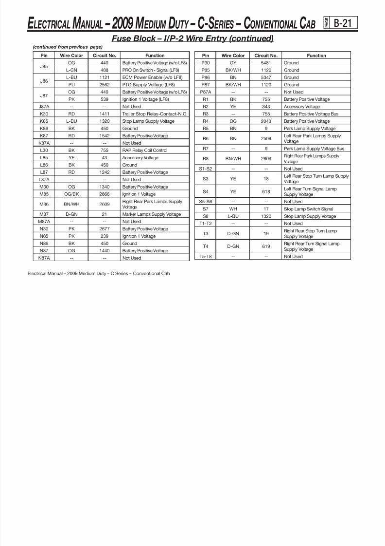
8/10/2019 2009 GM Medium Duty Electrical Manual.PDF
http://slidepdf.com/reader/full/2009-gm-medium-duty-electrical-manualpdf 65/410
E LECTRICAL M ANUAL – 2009 M EDIUM DUTY – C-S ERIES – CONVENTIONAL C AB P A G B-21
Electrical Manual – 2009 Medium Duty – C Series – Conventional Cab
Pin Wire Color Circuit No. Function
J85
OG 440 Battery Positive Voltage (w/o LF8)
L-GN 488 PRO On Switch - Signal (LF8)
J86L-BU 1121 ECM Power Enable (w/o LF8)
PU 2562 PTO Supply Voltage (LF8)
J87OG 440 Battery Positive Voltage (w/o LF8)
PK 539 Ignition 1 Voltage (LF8)
J87A -- -- Not Used
K30 RD 1411 Trailer Stop Relay-Contact-N.O.
K85 L-BU 1320 Stop Lamp Supply Voltage
K86 BK 450 Ground
K87 RD 1542 Battery Positive Voltage
K87A -- -- Not Used
L30 BK 755 RAP Relay Coil Control
L85 YE 43 Accessory Voltage
L86 BK 450 Ground
L87 RD 1242 Battery Positive Voltage
L87A -- -- Not Used
M30 OG 1340 Battery Positive Voltage
M85 OG/BK 2666 Ignition 1 Voltage
M86 BN/WH 2609Right Rear Park Lamps Supply
Voltage
M87 D-GN 21 Marker Lamps Supply Voltage
M87A -- -- Not Used
N30 PK 2677 Battery Positive Voltage
N85 PK 239 Ignition 1 Voltage
N86 BK 450 Ground
N87 OG 1440 Battery Positive Voltage
N87A -- -- Not Used
Pin Wire Color Circuit No. Function
P30 GY 5481 Ground
P85 BK/WH 1120 Ground
P86 BN 5347 Ground
P87 BK/WH 1120 Ground
P87A -- -- Not Used
R1 BK 755 Battery Positive Voltage
R2 YE 343 Accessory Voltage
R3 -- 755 Battery Positive Voltage Bus
R4 OG 2040 Battery Positive Voltage
R5 BN 9 Park Lamp Supply Voltage
R6 BN 2509Left Rear Park Lamps Supply
Voltage
R7 -- 9 Park Lamp Supply Voltage Bus
R8 BN/WH 2609Right Rear Park Lamps Supply
Voltage
S1-S2 -- -- Not Used
S3 YE 18Left Rear Stop Turn Lamp Supply
Voltage
S4 YE 618Left Rear Turn Signal Lamp
Supply VoltageS5-S6 -- -- Not Used
S7 WH 17 Stop Lamp Switch Signal
S8 L-BU 1320 Stop Lamp Supply Voltage
T1-T2 -- -- Not Used
T3 D-GN 19Right Rear Stop Turn Lamp
Supply Voltage
T4 D-GN 619Right Rear Turn Signal Lamp
Supply Voltage
T5-T8 -- -- Not Used
Fuse Block – I/P-2 Wire Entry (continued)(continued from previous page)

8/10/2019 2009 GM Medium Duty Electrical Manual.PDF
http://slidepdf.com/reader/full/2009-gm-medium-duty-electrical-manualpdf 66/410
ELECTRICAL MANUAL 2009 MEDIUM DUTY C SERIES CONVENTIONAL CABG
E
B 23

8/10/2019 2009 GM Medium Duty Electrical Manual.PDF
http://slidepdf.com/reader/full/2009-gm-medium-duty-electrical-manualpdf 67/410
E LECTRICAL M ANUAL – 2009 M EDIUM DUTY – C-S ERIES – CONVENTIONAL C AB P A G B-23
Electrical Manual – 2009 Medium Duty – C Series – Conventional Cab
Location Views – I/P Harness w/IP-1 & IP-2
1963782
I/P Harness
(1) Fuse Block - Underhood (Secondary)
(2) Blower Motor Resistor Assembly (C40/C60)
(3) X207 (30 cavities)
(4) Inflatable Restraint I/P Module (AK5)
(5) Fuse Block - I/P - 1
(6) Fuse Block - I/P - 2
(7) Air Brake Pressure Gauge Lamp (JE4), Differential Lock
Switch Lamp (HNB/HPL/HPN), Inter-Axle Differential
Lock Switch Lamp (Tandem Axle), Rear Axle Driver
Control Switch Lamp - Two Speed (HR1/Automatic
Transmission)
(8) HVAC Control Assembly (C40/C60)
(9) Turn Signal/Hazard Flasher Module (10) Daytime Running Lights (DRL) Diode
(11) Instrument Panel Cluster (IPC)
(12) Headlamp Switch
(13) Daytime Running Lights (DRL) Module
(14) JX 203 (12 cavities)
(15) X201 (48 cavities)
(16) Inflatable Restraint Steering Wheel Module (AJ3/AK5)
(17) X211 (22 cavities)
(18) X215 (8 cavities)
(19) X150 (4 cavities)
(20) Accelerator Pedal Position (APP) Sensor
(21) Radio
(22) Serial Data Gateway (SDG)
(23) Driver Information Center (DIC)
(24) Engine Control Module
(25) X126 (40 cavities)
(26) X109 (40 cavities)
(27) X200
(28) X118
ELECTRICAL MANUAL – 2009 MEDIUM DUTY – C-SERIES – CONVENTIONAL CAB A G E
B 24

8/10/2019 2009 GM Medium Duty Electrical Manual.PDF
http://slidepdf.com/reader/full/2009-gm-medium-duty-electrical-manualpdf 68/410
E LECTRICAL M ANUAL – 2009 M EDIUM DUTY – C-S ERIES – CONVENTIONAL C AB P A B-24
Electrical Manual – 2009 Medium Duty – C Series – Conventional Cab
Location Views – I/P-2 Fuse Center
1964775
Lower Right I/P
(1) I/P Harness(2) Fuse Block - I/P - 2
ELECTRICAL MANUAL – 2009 MEDIUM DUTY – C-SERIES – CONVENTIONAL CAB A G E
B-25
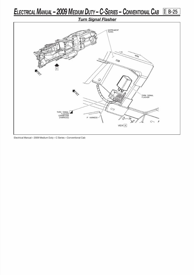
8/10/2019 2009 GM Medium Duty Electrical Manual.PDF
http://slidepdf.com/reader/full/2009-gm-medium-duty-electrical-manualpdf 69/410
E LECTRICAL M ANUAL – 2009 M EDIUM DUTY – C-S ERIES – CONVENTIONAL C AB P A B-25
Electrical Manual – 2009 Medium Duty – C Series – Conventional Cab
Turn Signal Flasher
ELECTRICAL MANUAL – 2009 MEDIUM DUTY – C-SERIES – CONVENTIONAL CAB A G E
C-1

8/10/2019 2009 GM Medium Duty Electrical Manual.PDF
http://slidepdf.com/reader/full/2009-gm-medium-duty-electrical-manualpdf 70/410
E LECTRICAL M ANUAL – 2009 M EDIUM DUTY – C-S ERIES – CONVENTIONAL C AB P A C-1
Electrical Manual – 2009 Medium Duty – C Series – Conventional Cab
Connector
Typical connectorTypical terminal
Typical cable seal
TRUCK SIDE
Packard 280 Series
PPN 15326910 (F)PPN 15304719
PPN 12191221
BODY BUILDER SIDE
PPN 15326915 (M)PPN 15304731
PPN 12191232
Pin Wire Function
Ckt# Color
A 1827 YEL/BLK 128,000 Pulses/Mile*
B 2609 BRN/WHT Right Park Lamp
C 318 YEL Lt Stop/Turn (Fam2), Lt Turn (Fam3)
D 2509 BRN Lt Park Lamp
E 1320 BLU LT Stop
F 641 BRN IGN 3 15A
G 21 GRN DK Marker Lamp 20A
H 350 BLK GND Zone 3B
J TBD – Spare
K 319 GRN DK Rt Stop/Turn (Fam2), Rt Turn (Fam3)
L 24 GRN LT Back Up
M TBD – Spare
SPN 15326915SPN 15304731
SPN 15366065
PPN = Production Part Number
SPN = Service Part Number
*4000 ppm (LF8 and LF6)
12-Way Body Builder Connector
ELECTRICAL MANUAL – 2009 MEDIUM DUTY – C-SERIES – CONVENTIONAL CAB A G E
C-2
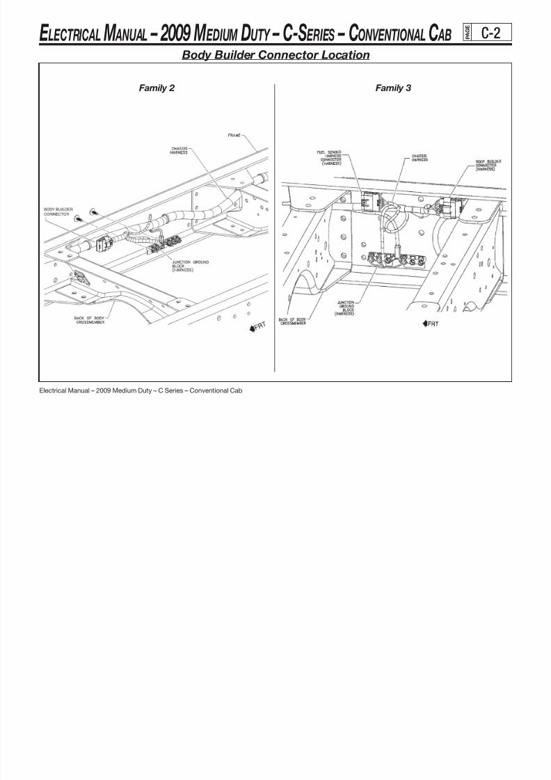
8/10/2019 2009 GM Medium Duty Electrical Manual.PDF
http://slidepdf.com/reader/full/2009-gm-medium-duty-electrical-manualpdf 71/410
E LECTRICAL M ANUAL – 2009 M EDIUM DUTY – C-S ERIES – CONVENTIONAL C AB P A C-2
Electrical Manual – 2009 Medium Duty – C Series – Conventional Cab
3 y l i m a F 2 y l i m a F
Body Builder Connector Location
ELECTRICAL MANUAL – 2009 MEDIUM DUTY – C-SERIES – CONVENTIONAL CAB A G E
C-3

8/10/2019 2009 GM Medium Duty Electrical Manual.PDF
http://slidepdf.com/reader/full/2009-gm-medium-duty-electrical-manualpdf 72/410
E LECTRICAL M ANUAL – 2009 M EDIUM DUTY – C-S ERIES – CONVENTIONAL C AB P A C 3
Electrical Manual – 2009 Medium Duty – C Series – Conventional Cab
TRUCK SIDE BODY BUILDER SIDEConnector Packard GT 280 SeriesTypical connector 15326935 (M) 15326931 (F)
Typical terminal 15304722 15304710
noitcnuFeriWniP
Ckt # Color
A 24 GRN LT Back Up
B 2609 BRN/WHT Right Park
C 318 YEL Left Turn
D 2509 BRN Left Park
E 1320 BLU LT StopF — — Spare
G — — Spare
H 350 BLK Gnd Zone 3B
J — — Spare
K 319 GRN DK Right Turn
TRUCK SIDE BODY BUILDER SIDEConnector Packard MP 280 SeriesTypical connector 15300027 (F) 15300002Typical terminal 12129493 12129497Typical cable seal 15324980 15324980
noitcnuFeriWniP
Ckt # Color
A 24 GRN LT Back Up
B 350 BLK Gnd Zone B
10-Way Bus Connector (top) / 2-Way Bus Connector (bottom) – Family 2
ELECTRICAL MANUAL – 2009 MEDIUM DUTY – C-SERIES – CONVENTIONAL CAB A G E
C-4

8/10/2019 2009 GM Medium Duty Electrical Manual.PDF
http://slidepdf.com/reader/full/2009-gm-medium-duty-electrical-manualpdf 73/410
E LECTRICAL M ANUAL – 2009 M EDIUM DUTY – C-S ERIES – CONVENTIONAL C AB P A C 4
Electrical Manual – 2009 Medium Duty – C Series – Conventional Cab
Bus Connector Location – Family 2
(continued on next page)
ELECTRICAL MANUAL – 2009 MEDIUM DUTY – C-SERIES – CONVENTIONAL CAB A G E
C-5

8/10/2019 2009 GM Medium Duty Electrical Manual.PDF
http://slidepdf.com/reader/full/2009-gm-medium-duty-electrical-manualpdf 74/410
E LECTRICAL M ANUAL 2009 M EDIUM DUTY C S ERIES CONVENTIONAL C AB P A C 5
Electrical Manual – 2009 Medium Duty – C Series – Conventional Cab
Bus Connector Location – Family 2 (continued)
ELECTRICAL MANUAL – 2009 MEDIUM DUTY – C-SERIES – CONVENTIONAL CAB P A G E
C-6

8/10/2019 2009 GM Medium Duty Electrical Manual.PDF
http://slidepdf.com/reader/full/2009-gm-medium-duty-electrical-manualpdf 75/410
E LECTRICAL M ANUAL 2009 M EDIUM DUTY C S ERIES CONVENTIONAL C AB P C 6
Electrical Manual – 2009 Medium Duty – C Series – Conventional Cab
Connector 80-Way F Micro-Pack 100W Sealed (BU)Typical Connector 12191489 (F)
ColorBLU
Typical Terminal – – –Typical Cable Seal – – –
Pin Wire Color Circuit No. Function
1 BK/WH 351 Ground
2 L-GN 1867 12-Volt Reference
3 PK/BK 1746 Fuel Injector 3 Control
4 L-GN/BK 1745 Fuel Injector 2 Control
5-6 — — Not Used
7 GY 705 5-Volt Reference
8-10 — — Not Used11 L-BU 1876 Knock Sensor 2 Signal
12 D-BU/WH 1869 CKP Sensor Signal
13 OG/BK 463 Requested Torque Signal
14 OG/BK 1061 UART Serial Data (Secondary)
15 D-BU/WH 774 UART Serial Data (Tertiary)
16-18 — — Not Used
19 PK 439 Ignition 1 Voltage
20 OG 440 Battery Positive Voltage
21 YE/BK 1868 Low Reference
22 L-GN 488 PTO On Switch Signal23 BK 470 Low Reference
24 BK/WH 251 Ground
25 — — Not Used
26 TN 1677 HO2S Low Signal - Bank 2 Sensor 1
27 BK/WH 251 Ground
28 — — Not Used
29 TN 1664 HO2S Low Signal - Bank 1 Sensor 1
30 L-GN 1478 Coolant Level Switch Signal
31 D-GN 534 High Idle Switch Signal
8.1L (L18) Powertrain Control Module (PCM) – Connector C-1
(continued on next page)
ELECTRICAL MANUAL – 2009 MEDIUM DUTY – C-SERIES – CONVENTIONAL CAB P A G E
C-7

8/10/2019 2009 GM Medium Duty Electrical Manual.PDF
http://slidepdf.com/reader/full/2009-gm-medium-duty-electrical-manualpdf 76/410
E LECTRICAL M ANUAL 2009 M EDIUM DUTY C S ERIES CONVENTIONAL C AB P C 7
Electrical Manual – 2009 Medium Duty – C Series – Conventional Cab
Pin Wire Color Circuit No. Function
32 BK/WH 771Transmission Range Switch Signal A
(Allison® MD)
33 PU 420TCC Brake Switch/Cruise Control
Release Signal
34 WH 776Transmission Range Switch Signal -
Parity Bit (Allison® MD)
35 BN/WH 379 CPP Switch Signal (Manual Trans.)
36 BK 1744 Fuel Injector 1 Control
37 YE/BK 846 Fuel Injector 6 Control
38 — — Not Used
39 YE 447 Starter Relay Coil Control
40 BK/WH 351 Ground
41 PU 719 Low Reference (Manual Trans.)42 — — Not Used
43 RD/BK 877 Fuel Injector 7 Control
44 L-BU/BK 844 Fuel Injector 4 Control
45-47 — — Not Used
48 GY 597 5-Volt Reference
49-50 — — Not Used
51 D-BU 496 Knock Sensor 1 Signal
52 YE 2522 PTO Engage Signal
53 — — Not Used
54 OG/BK 469 Low Reference55-56 — — Not Used
Pin Wire Color Circuit No. Function
57 OG 440 Battery Positive Voltage
58 D-GN 1049 ECM/PCM/VCM Class 2 Serial Data
59-60 — — Not Used
61 PK/BK 632 Low Reference
62 — — Not Used
63 BK 407 Low Reference
64-65 — — Not Used
66 PU 1666 HO2S High Signal - Bank 2 Sensor 1
67-68 — — Not Used
69 PU/WH 1665 HO2S High Signal - Bank 1 Sensor 1
70 BN 1174 Oil Level Switch Signal
71 L-BU 494 Primary Brake Indicator Control
72 YE 772Transmission Range Switch Signal B
(Allison® MD)
73 BN/WH 633 CMP Sensor Signal
74 YE 410 ECT Sensor Signal
75 PK 1020 Off/Run/Crank Voltage
76 BK/WH 845 Fuel Injector 5 Control
77 D-BU/WH 878 Fuel Injector 8 Control
78 PU 2562 PTO Control
79 — — Not Used
80 GY 720 Low Reference
8.1L (L18) Powertrain Control Module (PCM) – Connector C-1 (continued)
ELECTRICAL MANUAL – 2009 MEDIUM DUTY – C-SERIES – CONVENTIONAL CAB P A G E
C-8
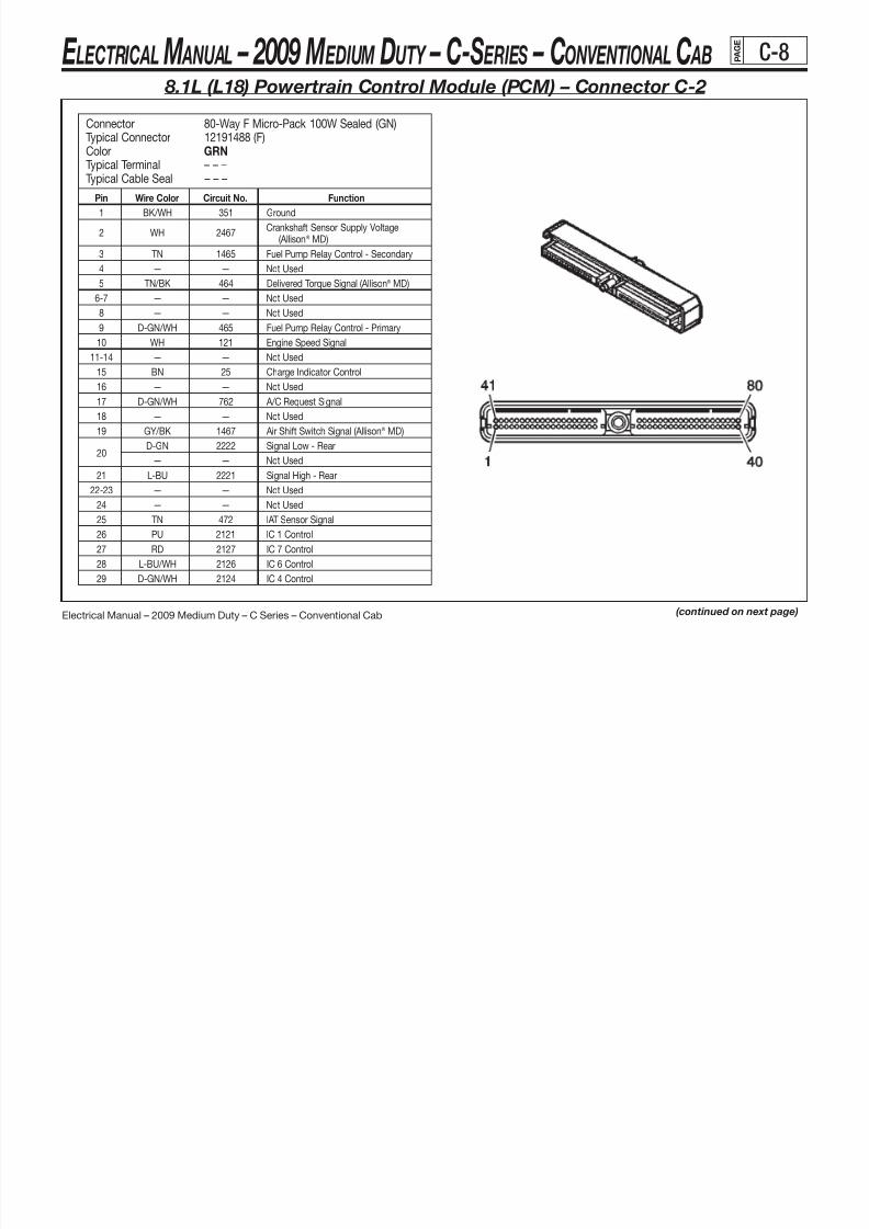
8/10/2019 2009 GM Medium Duty Electrical Manual.PDF
http://slidepdf.com/reader/full/2009-gm-medium-duty-electrical-manualpdf 77/410
E LECTRICAL M ANUAL 2009 M EDIUM DUTY C S ERIES CONVENTIONAL C AB P C 8
Electrical Manual – 2009 Medium Duty – C Series – Conventional Cab
Connector 80-Way F Micro-Pack 100W Sealed (GN)Typical Connector 12191488 (F)
ColorGRN
Typical Terminal – – –Typical Cable Seal – – –
Pin Wire Color Circuit No. Function
1 BK/WH 351 Ground
2 WH 2467Crankshaft Sensor Supply Voltage
(Allison® MD)
3 TN 1465 Fuel Pump Relay Control - Secondary
4 — — Not Used
5 TN/BK 464 Delivered Torque Signal (Allison® MD)
6-7 — — Not Used8 — — Not Used
9 D-GN/WH 465 Fuel Pump Relay Control - Primary
10 WH 121 Engine Speed Signal
11-14 — — Not Used
15 BN 25 Charge Indicator Control
16 — — Not Used
17 D-GN/WH 762 A/C Request Signal
18 — — Not Used
19 GY/BK 1467 Air Shift Switch Signal (Allison® MD)
20 D-GN 2222 Signal Low - Rear— — Not Used
21 L-BU 2221 Signal High - Rear
22-23 — — Not Used
24 — — Not Used
25 TN 472 IAT Sensor Signal
26 PU 2121 IC 1 Control
27 RD 2127 IC 7 Control
28 L-BU/WH 2126 IC 6 Control
29 D-GN/WH 2124 IC 4 Control
8.1L (L18) Powertrain Control Module (PCM) – Connector C-2
(continued on next page)
ELECTRICAL MANUAL – 2009 MEDIUM DUTY – C-SERIES – CONVENTIONAL CAB P A G E
C-9

8/10/2019 2009 GM Medium Duty Electrical Manual.PDF
http://slidepdf.com/reader/full/2009-gm-medium-duty-electrical-manualpdf 78/410
E LECTRICAL M ANUAL 2009 M EDIUM DUTY C S ERIES CONVENTIONAL C AB P C 9
Electrical Manual – 2009 Medium Duty – C Series – Conventional Cab
Pin Wire Color Circuit No. Function
30 — — Not Used
31 YE 492 MAF Sensor Signal32 L-GN 432 MAP Sensor Signal
33 — — Not Used
34 D-GN/WH 428 EVAP Canister Purge Solenoid Control
35-38 — — Not Used
39 RD 631 12-Volt Reference
40 BK/WH 351 Ground
41-42 — — Not Used
43 D-GN/WH 459 A/C Compressor Clutch Relay Control
44 RD 2013 High Idle Indicator Control
45 — — Not Used46 BN/WH 419 MIL Control
47-48 — — Not Used
49 YE/BK 1827 Vehicle Speed Signal
50 D-GN/WH 817 Vehicle Speed Signal
51-53 — — Not Used
54 PU 1589 Fuel Level Sensor Signal - Primary
55 D-GN 603 Low Coolant Indicator Control
56 — — Not Used
Pin Wire Color Circuit No. Function
57 BK 552 Low Reference
58 TN/WH 332 Oil Pressure Sensor Signal59 D-GN 1433 PNP/Clutch Start Switch Signal
60 BN 2129 Low Reference
61 BN/WH 2130 Low Reference
62 GY 773Transmission Range Switch Signal C
(Allison® MD)
63-65 — — Not Used
66 PU/WH 2128 IC 8 Control
67 RD/WH 2122 IC 2 Control
68 D-GN 2125 IC 5 Control
69 L-BU 2123 IC 3 Control
70-71 — — Not Used
72 BK/WH 3213HO2S Heater High Control - Bank 2
Sensor 1
73 D-BU 1936 Fuel Level Sensor Signal - Secondary
74 L-GN 3212HO2S Heater Low Control - Bank 2
Sensor 1
75 GY 23 Generator Field Duty Cycle Signal
76-80 — — Not Used
8.1L (L18) Powertrain Control Module (PCM) – Connector C-2 (continued)
ELECTRICAL MANUAL – 2009 MEDIUM DUTY – C-SERIES – CONVENTIONAL CAB P A G E
C-10

8/10/2019 2009 GM Medium Duty Electrical Manual.PDF
http://slidepdf.com/reader/full/2009-gm-medium-duty-electrical-manualpdf 79/410
E LECTRICAL M ANUAL 2009 M EDIUM DUTY C S ERIES CONVENTIONAL C AB P C 0
Electrical Manual – 2009 Medium Duty – C Series – Conventional Cab
ECM
7.8L (LF8) Engine Control Module (ECM) – Location
ELECTRICAL MANUAL – 2009 MEDIUM DUTY – C-SERIES – CONVENTIONAL CAB P A G E
C-11

8/10/2019 2009 GM Medium Duty Electrical Manual.PDF
http://slidepdf.com/reader/full/2009-gm-medium-duty-electrical-manualpdf 80/410
E LECTRICAL M ANUAL 2009 M EDIUM DUTY C S ERIES CONVENTIONAL C AB P
Electrical Manual – 2009 Medium Duty – C Series – Conventional Cab
Connector Part Information
OEM: 1 928 404 781
Service: 19149311Description: 96-Way F Bosch (BK)
Terminal Part Information
Terminal/Tray: 1928498135/19
Core/Insulation Crimp:
Pins: 1-3, 7-9, 12, 17-18, 20, 22-23, 26-28, 31-33, 37-41, 43, 45-48,
54-56, 62-64, 67-68, 70-71, 76-82, 93-96 : J/J
Core/Insulation Crimp: Pins: 4-5, 49-53, 74-75 : K/K
Release Tool/Test Probe: J-38125-213/J-35616-64B (L-BU)
Pin Wire Color Circuit No. Function1 BK/WH 351 Ground
2 BK/WH 351 Ground
3 BK/WH 351 Ground
4 BK/WH 351 Ground
5 BK/WH 351 Ground
6 -- -- Not used
7 BN 1271 Low Reference
8 PU 1272 Low Reference
9 GY 1273 Low Reference
10-11 -- -- Not Used
12 BK 470 Low Reference
13-16 -- -- Not Used
17 YE 2361 SAE J1939 Serial Data Bus+
18 D-GN 2362 SAE J1939 Serial Data Bus-
19 -- -- Not Used
20 D-GN 1049 ECM Class 2 Serial Data A
7.8L (LF8) Engine Control Module (ECM) – Connector C-1
(continued on next page)
Pin Wire Color Circuit No. Function
24-25 -- -- Not Used
26 BK/WH 351 Ground
27 BK/WH 351 Ground
28 WH 121 Engine Speed Signal
29-30 -- -- Not Used
31 D-Bu 1161 APP Sensor 1 Signal
32 L-BU 1162 APP Sensor 2 Signal
33 D-GN 1163 APP Sensor 3 Signal
9 GY 1273 Low Reference
34-36 -- -- Not Used
37 PU 1589 Fuel Level Signal - Primary
38 D-Bu 1936 Fuel Level Signal - Secondary
39 L-BU 2221Signal High - Rear
(Manual Transmission)
40 D-GN 2222Signal Low - Rear
(Manual Transmission)
ELECTRICAL MANUAL – 2009 MEDIUM DUTY – C-SERIES – CONVENTIONAL CAB P A G E
C-12

8/10/2019 2009 GM Medium Duty Electrical Manual.PDF
http://slidepdf.com/reader/full/2009-gm-medium-duty-electrical-manualpdf 81/410
E LECTRICAL M ANUAL 2009 M EDIUM DUTY C S ERIES CONVENTIONAL C AB
Electrical Manual – 2009 Medium Duty – C Series – Conventional Cab
7.8L (LF8) Engine Control Module (ECM) – Connector C-1 (continued)
Pin Wire Color Circuit No. Function
69 -- -- Not Used
70 L-GN 1478 Coolant Level Switch Signal71 L-GN 24 Backup Lamp Supply Voltage
72-73 -- -- Not Used
74 YE 505 Glow Plug Relay Control
75 PU 2562 PTO Control
76 YE 447 Starter Relay Coil Control
77 PU 2656 Exhaust Brake Relay Control (K40)
78 RD 2013 High Idle Indicator Control
79 D-BU 507 Wait to Start Indicator Control
80 BN/WH 419 MIL Control81 D-GN/WH 817 Vehicle Speed Signal
82 YE/BK 1827 Vehicle Speed Signal
83-92 -- -- Not Used
93 L-GN 488 PTO On Switch-Signal
94 L-BU 494 PTO Engine Kill Switch
95 YE 2522 PTO Engage Signal
96 D-GN 1433 PNP/Clutch Start Switch Signal
Pin Wire Color Circuit No. Function
41 GY 23 Generator Field Duty Cycle Signal
42 -- -- Not Used43 GY/BK 1467 Shift Motor Relay - Control
44 -- -- Not Used
45 D-GN/WH 459 A/C Compressor Clutch
Relay Control
46 GY 397 Cruise Control On Switch Signal
47 GY/BK 87Cruise Control Resume/Accel
Switch Signal
48 D-Bu 84Cruise Control Set/Coast
Switch Signal
49 BK/WH 1120 Ignition 1 Voltage
50 BK/WH 1120 Ignition 1 Voltage
51 OG 440 Battery Positive Voltage
52 L-BU 1121 ECM Power Enable Signal
53 L-BU 1121 ECM Power Enable Signal
54 WH/BK 1164 5-Volt Reference
55 TN 1274 Oil Level Switch Signal
56 YE/BK 1275 5-Volt Reference
57-61 -- -- Not Used
62 L-BU 1320 Stop Lamp Switch Signal
63 PU 420TCC Brake Switch/Cruise
Control Release Signal
64 BN/WH 379CPP Switch Signal
(Manual Transmission)
65-66 -- -- Not Used
67 L-GN 2081Exhaust Brake Request Signal
(K40/NPE)
ELECTRICAL MANUAL – 2009 MEDIUM DUTY – C-SERIES – CONVENTIONAL CAB P A G E
C-13

8/10/2019 2009 GM Medium Duty Electrical Manual.PDF
http://slidepdf.com/reader/full/2009-gm-medium-duty-electrical-manualpdf 82/410
E LECTRICAL M ANUAL 2009 M EDIUM DUTY C S ERIES CONVENTIONAL C AB
Electrical Manual – 2009 Medium Duty – C Series – Conventional Cab
Connector Part Information
OEM: 1 928 404 752
Service: See CatalogDescription: 58-Way F Bosch (BK)
Terminal Part Information
Terminal/Tray: See Terminal Repair Kit
Core/Insulation Crimp: See Terminal Repair Kit
Core/Insulation Crimp: Pins: 4-5, 49-53, 74-75 : K/K
Release Tool/Test Probe: See Terminal Repair Kit
Pin Wire Color Circuit No. Function
1 BK B1Turbocharger Vane Position Con-
trol Solenoid Valve High Control
2 -- -- Not Used
3 WH B3 Injector Positive Voltage Control 1
4 RD B4 Injector Positive Voltage Control 2
5 WH B5 Injector Positive Voltage Control 1
6 RD B6 Injector Positive Voltage Control 2
7 BK/WH B7 EGR Motor U Supply Voltage
8 D-GN B8 EGR Motor V Supply Voltage
9 RD/YE B9 EGR Motor W Supply Voltage
10-11 -- -- Not Used
12 BK B12A Low Reference
13 BK B13A Low Reference
14 BK/YE B14 Low Reference
15 GY B15A Low Reference
16 BK B16A Low Reference
17 WH/BK B17 Ground
18 BK B18A Drain Wire
19 GY B19 Drain Wire
7.8L (LF8) Engine Control Module (ECM) – Connector C-2
(continued on next page)
ELECTRICAL MANUAL – 2009 MEDIUM DUTY – C-SERIES – CONVENTIONAL CAB P A G E
C-14

8/10/2019 2009 GM Medium Duty Electrical Manual.PDF
http://slidepdf.com/reader/full/2009-gm-medium-duty-electrical-manualpdf 83/410
E LECTRICAL M ANUAL 2009 M EDIUM DUTY C S ERIES CONVENTIONAL C AB
Electrical Manual – 2009 Medium Duty – C Series – Conventional Cab
7.8L (LF8) Engine Control Module (ECM) – Connector C-2 (continued)
Pin Wire Color Circuit No. Function
40 YE/RD B40 EGR Motor Position W Signal
41 YE B41 Fuel Temperature Sensor Signal42 RD B42 Low Reference
43 RD B43 Fuel Injector 6 Control
44 BK B44 Fuel Injector 4 Control
45 BK/RD B45 Fuel Injector 5 Control
46 RD B46 5-Volt Reference
47 RD B47 5-Volt Reference
48 WH B48 5-Volt Reference
49 WH B49 5-Volt Reference
50 RD B50 5-Volt Reference51 RD B51 5-Volt Reference
52 D-GN B52 Oil level Switch Signal
53-55 -- -- Not Used
56 WH B56 Fuel injector 3 Control
57 D-BU B57 Fuel injector 2 Control
58 YE B58 Fuel injector 1 Control
Pin Wire Color Circuit No. Function
22-23 -- -- Not Used
24 WH B24 MAP Sensor Signal25 WH B25A Fuel Pressure Sensor Signal
26 WH B26 Fuel Pressure Sensor Signal
27 GY B27 Oil Pressure Sensor Signal
28 WH B28 MAF Sensor Signal
29 WH B29 Turbocharger Vane Position Signal
30 WH B30 CMP Sensor Low
31 WH B31 CKP Sensor High
32 BK B32 CKP Sensor Low
33 WH B33 SCV High Signal34 WH B34 SCV High Signal
35 D-BU/WH B35 ECT Sensor Signal
36 -- -- Not Used
37 D-GN/WH B37 IAT Sensor Signal
38 D-BU/RD B38 EGR Motor Position U Signal
39 WH/RD B39 EGR Motor Position V Signal
E LECTRICAL M ANUAL – 2009 M EDIUM DUTY – C-S ERIES – CONVENTIONAL C AB P A G E
C-15

8/10/2019 2009 GM Medium Duty Electrical Manual.PDF
http://slidepdf.com/reader/full/2009-gm-medium-duty-electrical-manualpdf 84/410
009 C S C C
Electrical Manual – 2009 Medium Duty – C Series – Conventional Cab
ECM
(1) Engine Control Module (ECM)(2) Transmission Control Module (TCM)
6.6L (LMM) Engine Control Module (ECM) Location
E LECTRICAL M ANUAL – 2009 M EDIUM DUTY – C-S ERIES – CONVENTIONAL C AB P A G E
C-16

8/10/2019 2009 GM Medium Duty Electrical Manual.PDF
http://slidepdf.com/reader/full/2009-gm-medium-duty-electrical-manualpdf 85/410
Electrical Manual – 2009 Medium Duty – C Series – Conventional Cab
Connector Part Information
OEM: 15438366
Service: 19149311Description: 96-Way F Mixed Series, Sealed (BK)
Terminal Part Information
Pins: 1-3, 25-27, 48-51, 73-77, 96
Terminal/Tray: 1928498135/19
Core/Insulation Crimp: K/K
Release Tool/Test Probe: J-38125-213/J-35616-64B (L-BU)
Pins: 4-15, 17, 19-21, 23-24, 28, 30-31, 33-45, 47, 56-67-70, 72, 78-80,
84-86, 88, 91-94
Core/Insulation Crimp: J/J
Pin Wire Color Circuit No. Function
1 OG 5421Injector Postive Voltage Control
Group 1
2 D-BU/WH 878 Fuel Injector 8 Control
3 RD/BK 877 Fuel Injector 7 Control
4 D-BU 2364 Cooling Fan Speed Signal
5 YE 492 MAF Sensor Signal
6 OG/BK 469 Low Reference
7 PU 806 Crank Voltage
8 YE 2522 PTO Engage Signal
9 BN 1174 Oil Level Switch Signal
10 GY/BK 87Cruise Control Resume/Accel
Switch Signal
11 Y/BK 6272 Low Reference
12 GY 2704 5-Volt Reference 3
13 TN 5928 5-Volt Reference 3
14 BN/WH 6136 5-Volt Reference 2
6.6L (LMM) Engine Control Module (ECM) – Connector C-1
(continued on next page)
Pin Wire Color Circuit No. Function
18 -- -- Not Used
19 L-GN 432 MAP Sensor Signal
20 YE 5947Turbocharger Vane Position
Sensor Signal
21 L-BU 1162 APP Sensor 2 Signal
22 -- -- Not Used
23 BK 2755 Low Reference
24 PU/WH 2530Fuel Pressure Regulator
Solenoid Supply Voltage
25 PK 5425Injector Positive Voltage Control
Group 4
26 YE/BK 846 Fuel Injector 6 Control
27 PK/BK 1746 Fuel Injector 3 Control
28 WH/BK 2366 Cooling Fan Clutch Control
E LECTRICAL M ANUAL – 2009 M EDIUM DUTY – C-S ERIES – CONVENTIONAL C AB P A G E
C-17

8/10/2019 2009 GM Medium Duty Electrical Manual.PDF
http://slidepdf.com/reader/full/2009-gm-medium-duty-electrical-manualpdf 86/410
Electrical Manual – 2009 Medium Duty – C Series – Conventional Cab
Pin Wire Color Circuit No. Function
29 -- -- Not Used
30 OG/BK 2919 Low Reference31 L-BU 494 PTO Engine Kill Signal
32 -- -- Not Used
33 BK 476 Low Reference
34 D-BU 84Cruise Control Set/Coast Switch
Signal
35 YE/BK 6055 Low Reference
36 BK 2752 Low Reference
37 GY 2702 5-Volt Reference 3
38 TN 1274 5-Volt Reference 239 TN 2917 5-Volt Reference 2
40 PU/WH 6270 5-Volt Reference 1
41 D-BU 6259 5-Volt Reference 1
42 TN 472 IAT Sensor 1 Signal
43 D-BU/WH 6053 Exhaust Pressure Sensor Signal (1)
44 TN/WH 331 Oil Pressure Sensor Signal
45 L-GN 2032Coolant Temperature Sensor
Signal
46 -- -- Not Used
47 BK 2761 Low Reference
48 D-BU 5930Turbocharger Vane Position
Control Solenoid Valve Control
49 PU 5423Injector Positive Voltage Control
Group 3
50 BK/WH 845 Fuel injector 5 Control
51 L-BU 844 Fuel injector 4 Control
52 -- -- Not Used
53 YE/BK 6120 Low Reference
Pin Wire Color Circuit No. Function
54-55 -- -- Not Used
56 D-BU/WH 6265 CMP Sensor Signal57 GY/BK 1694 4WD Low Signal
58 L-GN 1478 Coolant Level Switch Signal
59 D-GN 534 High Idle Switch Signal
60 L-GN 488 PTO On Switch Signal
61 GY 397 Cruise Control On Switch Signal
62 BK 552 Low Reference
63 OG/BK 5929 Low Reference
64 GY 596 5-Volt Reference
65 L-BU 6118 IAT Sensor 2 Signal66 -- -- Not Used
67 BN/WH 5763 EGR Valve Position Signal
68 YE 410 ECT Sensor Signal
69 D-BU 5277Exhaust Gas Temperature
Sensor (1)
70 BN 6782Exhaust Gas Temperature
Sensor (1) Low Reference
71 -- -- No Used
72 YE 2834 Fuel Pressure RegulatorSolenoid Control
73 YE 5422Injector Positive Voltage Control
Group 2
74 BK 1744 Fuel Injector 1 Control
75 L-GN/BK 1745 Fuel injector 2 Control
76 PK 339 Ignition 1 Voltage
77 OG 440 Battery Positive Voltage
78 PU 1272 Low Reference
79 WH/BK 6271 CKP Sensor Signal
6.6L (LMM) Engine Control Module (ECM) – Connector C-1 (continued)
(continued on next page)
E LECTRICAL M ANUAL – 2009 M EDIUM DUTY – C-S ERIES – CONVENTIONAL C AB P A G E
C-18

8/10/2019 2009 GM Medium Duty Electrical Manual.PDF
http://slidepdf.com/reader/full/2009-gm-medium-duty-electrical-manualpdf 87/410
Electrical Manual – 2009 Medium Duty – C Series – Conventional Cab
Pin Wire Color Circuit No. Function
80 D-GN/WH 2523 A/C Request Signal
81-83 -- -- Not Used84 L-GN 24 Backup Lamp Supply Voltage
85 YE/BK 508 Water In Fuel Indicator Control
86 BK 2753 Low Reference
87 -- -- Not Used
88 BN 6266 Low Reference
89-90 -- -- Not Used
91 D-Gn 485 TP Sensor 1 Signal
92 YE 2918 FRP Sensor Signal
93 L-BU 5377 Exhaust Gas TemperatureSensor 2
94 BN/WH 6783 Low Reference
95 -- -- Not Used
96 WH 5931 Low Reference
6.6L (LMM) Engine Control Module (ECM) – Connector C-1 (continued)
E LECTRICAL M ANUAL – 2009 M EDIUM DUTY – C-S ERIES – CONVENTIONAL C AB P A G E
C-19

8/10/2019 2009 GM Medium Duty Electrical Manual.PDF
http://slidepdf.com/reader/full/2009-gm-medium-duty-electrical-manualpdf 88/410
Electrical Manual – 2009 Medium Duty – C Series – Conventional Cab
Connector Part Information
OEM: 15462694
Service: 88988935Description: 58-Way F Mixed Series, Sealed (BK)
Terminal Part Information
Pins: 1-6
Terminal/Tray: 1928498059/24
Core/Insulation Crimp: 2/5
Release Tool/Test Probe: J-38125-561/J-35616-35 (VT)
Pins: 33, 46
Terminal/Tray: 1928498135/19
Core/Insulation Crimp: K/K
Release Tool/Test Probe: J-38125-213/J-35616-64B (L-BU)
Pins: 7, 9, 11-12, 15-26, 28-32, 33, 36, 38-40, 41, 44-45, 47-50, 53-57
Terminal/Tray: 1928498135/19
Core/Insulation Crimp: J/J
Release Tool/Test Probe: J-38125-213/J-35616-64B (L-BU)
Pin Wire Color Circuit No. Function
1 PK 339 Ignition 1 Voltage
2 BK/WH 351 Ground3 PK 339 Ignition 1 Voltage
4 BK/WH 351 Ground
5 PK 339 Ignition 1 Voltage
6 BK/WH 351 Ground
BN BN 582 TAC Motor Control -2
8 -- -- Not Used
9 D-GN 1049 ECM Class 2 Serial Data
10 -- -- Not Used
6.6L (LMM) Engine Control Module (ECM) – Connector C-2
(continued on next page)
Pin Wire Color Circuit No. Function
15 WH/BK 1164 5-Volt Reference 3
16 D-BU 507 Wait To Start Indicator Control
17 RD 2013 High Idle Indicator Control
18 PU 2562 PTO Control
19 GY 2219 IGN B Relay Control20 YE 581 TAC Motor Control - 1
21 PK 439 Ignition 1 Voltage
22 L-BU 1320 Stop Lamp Supply Voltage
23 BN 25 Charge Indicator Control
24 BN 2524Generator 2 Turn On Signal
(K65)
25 D-GN 603 A/C Low Pressure Switch Signal
26 BN/WH 6141 Low Reference
E LECTRICAL M ANUAL – 2009 M EDIUM DUTY – C-S ERIES – CONVENTIONAL C AB P A G E
C-20

8/10/2019 2009 GM Medium Duty Electrical Manual.PDF
http://slidepdf.com/reader/full/2009-gm-medium-duty-electrical-manualpdf 89/410
Electrical Manual – 2009 Medium Duty – C Series – Conventional Cab
6.6L (LMM) Engine Control Module (ECM) – Connector C-2 (continued)
Pin Wire Color Circuit No. Function
27 -- -- Not Used
28 GY 2365 5-Volt Reference 1
29 BN 1271 Low Reference
30 BN/WH 419 MIL Control
31 D-GN/WH 459 A/C Compressor Clutch
Relay Control
32 YE 447 Starter Relay Coil Control
33 OG/BK 5764 EGR Motor High Control
34 BK 470 Low Reference
35 -- -- Not Used
36 PU 1589Fuel Level Sensor Signal -
Primary
37 -- -- Not Used
38 GY 23Generator Field Duty Cycle
Signal
39 OG/BK 1786Park/Neutral Signal
(Automatic Transmission)
40 PU 420TCC Brake Switch/Cruise
Control Release Signal
41 -- -- Not Used
42 D-GN/WH 817 Vehicle Speed Signal
Pin Wire Color Circuit No. Function
43 -- -- Not Used
44 TN 6106 High Speed GMLAN SerialData Bus-
45 L-BU/BK 2221 Signal High - Rear
46 L-GN/BK 5746 EGR Motor Low Control
47 BN 6062 Low Reference
48 YE 1578 Fuel Temperature Signal
49 D-BU 1161 APP Sensor 1 Signal
50 D-BU 1936Fuel Level Sensor Signal -
Secondary
51-52 -- -- Not Used
53 L-GN 2081Engine Exhaust Brake Switch
Control
54 YE/BK 1827 Vehicle Speed Signal
55 WH 121 Engine Speed Signal
56 PK 1020 Ignition 0 Voltage
57 TN/WH 6105High Speed GMLAN Serial
Data Bus+
58 -- -- Not Used
E LECTRICAL M ANUAL – 2009 M EDIUM DUTY – C-S ERIES – CONVENTIONAL C AB P A G E
C-21

8/10/2019 2009 GM Medium Duty Electrical Manual.PDF
http://slidepdf.com/reader/full/2009-gm-medium-duty-electrical-manualpdf 90/410
Electrical Manual – 2009 Medium Duty – C Series – Conventional Cab
Engine Control Module (ECM) – (LF6) C-1
Connector Part Information
OEM: 12 186 584
Service: 12 186 584Description: 70-Way F, Sealed (BK)
Terminal Part Information
Terminal/Tray: See Terminal Repair Kit
Core/Insulation Crimp: See Terminal Repair Kit
Release Tool/Test Probe: See Terminal Repair Kit
Pin Wire Color Circuit No. Function
1-2 -- -- Not Used
3 0.8 BK 470 Low Reference
4 0.8 WH/BK 1164 5-Volt Reference
5 0.8 BK/WH 451 Ground
6 0.8 GY/BK 1467 Shift Motor Relay - Control (HPZ)
7 0.8 L-BU 494 Engine Shut-Off Signal
8 0.8 TN/BK 1921 SAE J1708 Serial Data A
9 Wh/BK 1922 SAE J1708 Serial Data B
10 -- -- Not Used
11 0.8 RD 2013 High Idle Indicator Control
12 BK/WH 1962 Engine Brake Solenoid Feed
13-14 -- -- Not Used
15 0.8 PU 1589 Fuel Level Sensor Signal-Primary
16-18 -- -- Not Used
19 0.8 D-GN/WH 2665 PTO Enable
20-21 -- -- Not Used
22 0.8 BN/WH 379CPP Switch Signal
(Manual Transmission)
23 0.8 L-GN 2081 Exhaust Brake Switch Signal
24-26 -- -- Not Used
(continued on next page)
Pin Wire Color Circuit No. Function
27 0.8 D-BU 1936Fuel Level Sensor Signal
(Secondary)
28 0.8 BN/WH 419 MIL Control
29 -- -- Not Used
30 0.8 BK 750 PTO Lamp Status
31 0.8 YE 447 Starter Relay Coil Control
32 0.8 L-BU 2221Signal High-Rear
(Manual Transmission)
33 0.8 D-GN 2222Signal Low-Rear
(Manual Transmission)
34 0.8 D-GN 2362 SAE J1939 Serial Data Bus -
35 0.8 D-BU 84Cruise Control Set/Coast
Switch Signal
36 0.8 D-GN/WH 817 Vehicle Speed Signal
37 -- -- Not Used

8/10/2019 2009 GM Medium Duty Electrical Manual.PDF
http://slidepdf.com/reader/full/2009-gm-medium-duty-electrical-manualpdf 91/410
E LECTRICAL M ANUAL – 2009 M EDIUM DUTY – C-S ERIES – CONVENTIONAL C AB P A G E
C-23

8/10/2019 2009 GM Medium Duty Electrical Manual.PDF
http://slidepdf.com/reader/full/2009-gm-medium-duty-electrical-manualpdf 92/410
Electrical Manual – 2009 Medium Duty – C Series – Conventional Cab (continued on next page)
Engine Control Module (ECM) – (LF6) C-2
Connector Part Information
OEM: 2645732
Service: --
Description: 120-Way F, Sealed (Caterpillar)
Terminal Part Information
Terminal/Tray: See Terminal Repair Kit
Core/Insulation Crimp: See Terminal Repair Kit
Release Tool/Test Probe: See Terminal Repair Kit
Pin Wire Color Circuit No. Function
1-4 -- -- Not Used
5 0.8 OG F793 Intake Air (IA) Heater Relay Power
6-9 -- -- Not Used
10 0.8 OG C801 ARD Air Control Valve Signal
11-14 -- -- Not Used
15 0.8 PK R746Intake Manifold Air Pressure
Sensor Signal
16 0.8 WH U780Manifold Absolute Pressure
(MAP) Sensor Signal
17 0.8 GN G829 Low Reference
18-19 -- -- Not Used
20 0.8 GY C800 ARD Air Control Valve Return
21-23 -- -- Not Used24 0.8 WH X980 Turbo Speed -
25 0.8 BK E963Camshaft Low Reference
Top CAM -
26 0.8 WH G856 Engine Timing Calibration Probe+
27 -- -- Not Used
28 0.8 GY 994 Oil Pressure Sensor Signal
29 -- -- Not Used
30 0.8 PK G833 Low Reference
Pin Wire Color Circuit No. Function
31 -- -- Not Used
32 0.8 BN C815 VNT Actuator Return
33 -- -- Not Used
34 0.8 YE X981 Turbo Speed +
35 0.8 WH E964Camshaft Sensor Signal
Top CAM+
36 0.8 YE G857Engine Timing Calibration
Probe -
37 -- -- Not Used
38 0.8 GN C829 Ambient Air Temperature
Sensor Signal
39-40 -- -- Not Used
41 0.8 BN C803 ARD Fuel Pilot Pressure
Sensor Signal
42 -- -- Not Used
E LECTRICAL M ANUAL – 2009 M EDIUM DUTY – C-S ERIES – CONVENTIONAL C AB P A G E
C-24

8/10/2019 2009 GM Medium Duty Electrical Manual.PDF
http://slidepdf.com/reader/full/2009-gm-medium-duty-electrical-manualpdf 93/410
Electrical Manual – 2009 Medium Duty – C Series – Conventional Cab
Engine Control Module (ECM) – (LF6) C-2 (continued)
Pin Wire Color Circuit No. Function
43 0.8 GY U775 CGI Actuator Return
44 0.8 GN C814 VNT Actuator Signal
45 0.8 PK Y735 Purge Air Control Signal
46 0.8 YE E966Camshaft Sensor Signal Bottom
CAM+
47 0.8 BU E965 Low Reference Bottom CAM -
48-50 -- -- Not Used
51 0.8 BU U774 CGI Actuator Signal
52 0.8 GY Y738 Low Reference
53 -- -- Not Used
54 0.8 BU G827 Low Reference
55 0.8 PK T846 ARD Turbo Outlet TemperatureSensor Signal
56 0.8 YE Y741Particulate Trap Intake (PTI) Air
Temperature #1
57 0.8 BN U779 Barometric Pressure Signal
58 -- -- Not Used
59 0.8 PU Y733 ARD Fuel Main Pressure
Control Valve
60 0.8 BU Y734 Low Reference
61 0.8 OG C820 Fuel Pump 2 Driver (AFT)
62 -- -- Not Used
63 0.8 OG Y753 ARD Flame Boundary
Temperature Sensor Signal
64-65 -- -- Not Used
66 1.0 PK Y746Particulate Trap Differential (PTD)
Pressure #1
67-68 -- -- Not Used
69 0.8 YE Y737 ARD Fuel Enable Valve
Pin Wire Color Circuit No. Function
70 0.8 PU U773Mass Air Flow (MAF)
Temperature Sensor Signal
71 -- -- Not Used72 0.8 WH G828 5-Volt Reference
73-75 -- -- Not Used
76 0.8 BU C830 Inlet Air Heater Relay Return
77 0.8 BU C818 Fuel Pump 1 Driver (FORE)
78 -- -- Not Used
79 0.8 YE H807 Purge Air Solenoid Return
80 0.8 BN G826 5-Volt Reference
81 0.8 WH Y748 5-Volt Reference
82 1.0 YE U781 5-Volt Reference
83 0.8 GN Y749 Low Reference
84 0.8 BU 995Coolant Temperature Sensor
Signal
85 0.8 BN G849 Fuel Rail Pressure Sensor Signal
86-87 -- -- Not Used
88 0.8 OG Y751 ARD Ignition Coil Return
89 1.0 BN Y747 ARD Fuel Main Pressure Signal
90 -- -- Not Used
91 0.8 OG Y743 ARD Outlet TemperatureSensor Signal
92 -- -- Not Used
93 1.0 PK U782 Low Reference
94 1.0 GN Y742Particulate Trap Outlet (PTO)
Air Temperature #1
95 0.8 BU C967 Intake MAT Sensor Signal
96-98 -- -- Not Used
99 1.0 OG T860 Injector 5 & 6 Return
(continued on next page)
E LECTRICAL M ANUAL – 2009 M EDIUM DUTY – C-S ERIES – CONVENTIONAL C AB P A G E
C-25

8/10/2019 2009 GM Medium Duty Electrical Manual.PDF
http://slidepdf.com/reader/full/2009-gm-medium-duty-electrical-manualpdf 94/410
Electrical Manual – 2009 Medium Duty – C Series – Conventional Cab
Pin Wire Color Circuit No. Function
100-103 -- -- Not Used
104 1.0 GY T858 Injector 1 & 2 Return
105 1.0 WH T962 Fuel Injector 6 Control
106 1.0 BN T959 Fuel Injector 3 Control
107 1.0 GN T961 Fuel Injector 5 Control
108 1.0 BU T960 Fuel Injector 4 Control
109 1.0 YE Y750 ARD Ignition Coil
110 -- -- Not Used
Engine Control Module (ECM) – (LF6) C-2 (continued)
Pin Wire Color Circuit No. Function
111 0.8 PU C819 Fuel Pump 1 Return
112 -- -- Not Used
113 0.8 BN C821 Fuel Pump 2 Return
114 -- -- Not Used
115 1.0 WH T859 Injector 3 & 4 Return
116 1.0 PU T957 Fuel Injector 1 Control
117 -- -- Not Used
118 1.0 YE T958 Fuel Injector 2 Control
119-120 -- -- Not Used
E LECTRICAL M ANUAL – 2009 M EDIUM DUTY – C-S ERIES – CONVENTIONAL C AB P A G E
C-26
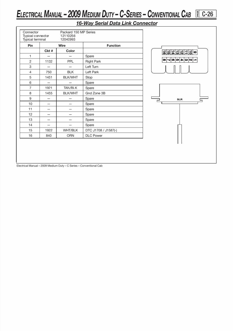
8/10/2019 2009 GM Medium Duty Electrical Manual.PDF
http://slidepdf.com/reader/full/2009-gm-medium-duty-electrical-manualpdf 95/410
Electrical Manual – 2009 Medium Duty – C Series – Conventional Cab
16-Way Serial Data Link Connector
Connector Packard 150 MP SeriesTypical connector 12110256Typical terminal 12040993
noitcnuFeriWniP
Ckt # Color
1 — — Spare
2 1132 PPL Right Park
3 — — Left Turn
4 750 BLK Left Park
5 1451 BLK/WHT Stop
6 — — Spare
7 1921 TAN/BLK Spare
8 1455 BLK/WHT Gnd Zone 3B
9 — — Spare
10 — — Spare
11 — — Spare
12 — — Spare
13 — — Spare14 — — Spare
15 1922 WHT/BLK DTC J1708 / J1587(-)
16 840 ORN DLC Power
E LECTRICAL M ANUAL – 2009 M EDIUM DUTY – C-S ERIES – CONVENTIONAL C AB P A G E
C-27

8/10/2019 2009 GM Medium Duty Electrical Manual.PDF
http://slidepdf.com/reader/full/2009-gm-medium-duty-electrical-manualpdf 96/410
Electrical Manual – 2009 Medium Duty – C Series – Conventional Cab
Serial Data Link Connector Location
E LECTRICAL M ANUAL – 2009 M EDIUM DUTY – C-S ERIES – CONVENTIONAL C AB P A G E
C-28

8/10/2019 2009 GM Medium Duty Electrical Manual.PDF
http://slidepdf.com/reader/full/2009-gm-medium-duty-electrical-manualpdf 97/410
Electrical Manual – 2009 Medium Duty – C Series – Conventional Cab
8-Way Tail Lamp Connector
TRUCK SIDE BODY BUILDER SIDEConnector Packard 280 SeriesTypical connector 15326906 (F) 15326655 (M)
Typical terminal 15304718 15304730Typical cable seal 12191232 12191232
noitcnuFeriWniP
Ckt # Color
A 618 YEL LR Stop/Turn
B 2609 BRN Lt Tail / License
C TBD — Spare
D 2609 BRN/WHT RT Tail
E 619 GRN DK RR Stop/Turn
F 24 GRN LT Back Up
G 350 BLK Gnd Zone 3B
H TBD — Spare
E LECTRICAL M ANUAL – 2009 M EDIUM DUTY – C-S ERIES – CONVENTIONAL C AB P A G E
C-29

8/10/2019 2009 GM Medium Duty Electrical Manual.PDF
http://slidepdf.com/reader/full/2009-gm-medium-duty-electrical-manualpdf 98/410
Electrical Manual – 2009 Medium Duty – C Series – Conventional Cab
Controller Area Network (CAN) Connector (L18 with JE4, LF6/LF8)
Connector Part Information
OEM: 15324337
Service: 15306401
Description: 9-Way F Deutsch HD10-9-1939PE (BK)
Terminal Part Information
Terminal/Tray: See Terminal Repair Kit
Core/Insulation Crimp: See Terminal Repair Kit
Release Tool/Test Probe: See Terminal Repair Kit
Pin Wire Color Circuit No. Function
A 1.0 BK 750 Ground
B 1.0 OG 840 Battery Positive VoltageC 1.0 YE 2361 SAE J1939 Serial Data Bus +
D 1.0 D- 2362 SAW J1939 Serial
E -- -- Not Used
F 1.0 TN/BK 1921SAE J1587 Serial Data
Bus+ Primary
G 1.0 WH/BK 1922SAE J1587 Serial Data
Bus- Primary
H 1.0 PK 1020 Ignition 0 Voltage
J 1.0 BK/WH 351 Ground
E LECTRICAL M ANUAL – 2009 M EDIUM DUTY – C-S ERIES – CONVENTIONAL C AB P A G E
C-30

8/10/2019 2009 GM Medium Duty Electrical Manual.PDF
http://slidepdf.com/reader/full/2009-gm-medium-duty-electrical-manualpdf 99/410
Electrical Manual – 2009 Medium Duty – C Series – Conventional Cab
Tail Lamp Connector Location
E LECTRICAL M ANUAL – 2009 M EDIUM DUTY – C-S ERIES – CONVENTIONAL C AB P A G E
C-31

8/10/2019 2009 GM Medium Duty Electrical Manual.PDF
http://slidepdf.com/reader/full/2009-gm-medium-duty-electrical-manualpdf 100/410
Electrical Manual – 2009 Medium Duty – C Series – Conventional Cab
7-Way Tractor Connector – Family 3
Connector Packard 280/630 Seriesconnector 12077629terminal 15304720 3mm
seal 15366065 5mmterminal 15326004 3mmseal 12191235 5mm
noitcnuFeriWniP
Ckt # Color
1 22 WHT Tractor Gnd Zone 7B
2 1412 BLK Marker Lamp
3 318 YEL Lt Turn/Hazard
4 1411 RED Brake (1)
5 319 GRN DK Rt Turn/Hazard
6 9 BRN Park Lamp
7 1413 BLU DK ABS Power & Multiplexed Signal
NOTES:
(1) 30A maxi fuse. See page B-4.
E LECTRICAL M ANUAL – 2009 M EDIUM DUTY – C-S ERIES – CONVENTIONAL C AB P A G E
C-32

8/10/2019 2009 GM Medium Duty Electrical Manual.PDF
http://slidepdf.com/reader/full/2009-gm-medium-duty-electrical-manualpdf 101/410
Electrical Manual – 2009 Medium Duty – C Series – Conventional Cab
Tractor Connector – Family 3 Location
E LECTRICAL M ANUAL – 2009 M EDIUM DUTY – C-S ERIES – CONVENTIONAL C AB P A G E
C-33

8/10/2019 2009 GM Medium Duty Electrical Manual.PDF
http://slidepdf.com/reader/full/2009-gm-medium-duty-electrical-manualpdf 102/410
Electrical Manual – 2009 Medium Duty – C Series – Conventional Cab
7-Way Trailer Connector – Family 2
Connector Packard 280/630 Seriesconnector 15354653terminal 12119853 3mm
terminal 15317332 5mmseal 12015323
noitcnuFeriWniP
Ckt # Color
7 A 24 GRN LT Back Up
2 B 22 WHT Tractor Gnd Zone 12A
3 C 47 BLU DK Aux Elec Brake (1)
4 D 319 GRN DK Rt Turn/Hazard
5 E 642 RED Electric Brake Power (2)
6 F 9 BRN Park Lamp
1 G 318 YEL Lt Turn/Hazard
NOTES:
(1) Blunt cut end found under hood. See UI Bulletin #66.
(2) 30A maxi fuse. See page B-4.
E LECTRICAL M ANUAL – 2009 M EDIUM DUTY – C-S ERIES – CONVENTIONAL C AB P A G E
C-34
T il C t L ti F il 2

8/10/2019 2009 GM Medium Duty Electrical Manual.PDF
http://slidepdf.com/reader/full/2009-gm-medium-duty-electrical-manualpdf 103/410
Electrical Manual – 2009 Medium Duty – C Series – Conventional Cab
Trailer Connector Location – Family 2
E LECTRICAL M ANUAL – 2009 M EDIUM DUTY – C-S ERIES – CONVENTIONAL C AB P A G E
C-35
7 W T il C t F il 3
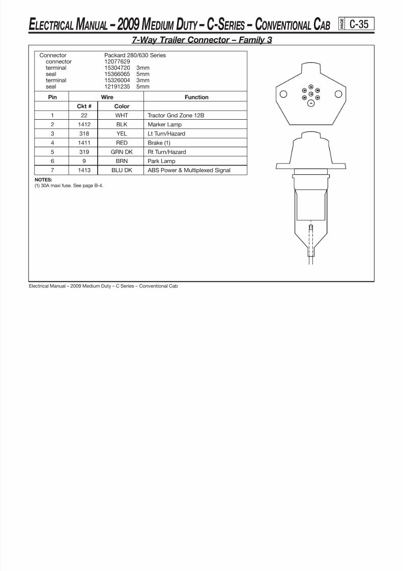
8/10/2019 2009 GM Medium Duty Electrical Manual.PDF
http://slidepdf.com/reader/full/2009-gm-medium-duty-electrical-manualpdf 104/410
Electrical Manual – 2009 Medium Duty – C Series – Conventional Cab
7-Way Trailer Connector – Family 3
Connector Packard 280/630 Seriesconnector 12077629terminal 15304720 3mm
seal 15366065 5mmterminal 15326004 3mmseal 12191235 5mm
noitcnuFeriWniP
Ckt # Color
1 22 WHT Tractor Gnd Zone 12B
2 1412 BLK Marker Lamp
3 318 YEL Lt Turn/Hazard
4 1411 RED Brake (1)
5 319 GRN DK Rt Turn/Hazard
6 9 BRN Park Lamp
7 1413 BLU DK ABS Power & Multiplexed Signal
NOTES:
(1) 30A maxi fuse. See page B-4.
E LECTRICAL M ANUAL – 2009 M EDIUM DUTY – C-S ERIES – CONVENTIONAL C AB P A G E
C-36
T il C t L ti F il 3

8/10/2019 2009 GM Medium Duty Electrical Manual.PDF
http://slidepdf.com/reader/full/2009-gm-medium-duty-electrical-manualpdf 105/410
Electrical Manual – 2009 Medium Duty – C Series – Conventional Cab
Trailer Connector Location – Family 3
E LECTRICAL M ANUAL – 2009 M EDIUM DUTY – C-S ERIES – CONVENTIONAL C AB P A G E
C-37
10-Way Transmission Optional Connector

8/10/2019 2009 GM Medium Duty Electrical Manual.PDF
http://slidepdf.com/reader/full/2009-gm-medium-duty-electrical-manualpdf 106/410
Electrical Manual – 2009 Medium Duty – C Series – Conventional Cab
10-Way Transmission Optional Connector
ALLISON LCT TRANS
noitcnuFeriWniP
Ckt # Color
A 1146 PPL Range Indicator
B 1479 YEL Auto Neutral
C 2522 YEL PTO Status
D N/C — —
E N/C — —
F 1147 TAN Range InhibitG N/C — —
H 407 BLK Analog Gnd
J 476 BLK Digital Gnd
K 1480 BLU LT PTO Output
ALLISON MD TRANS
A 1146 PPL Range Indicator
B 1479 YEL Auto Neutral
C 915 YEL PTO EnableD 1481 YEL Aux Hold
E 1148 GRA Sump Temp
F 1147 TAN Range Inhibit
G N/C — —
H 407 BLK Analog Gnd
J 476 BLK Digital Gnd
K 1480 BLU LT PTO Engage
PPN = Production Part Number SPN = Service Part Number
E LECTRICAL M ANUAL – 2009 M EDIUM DUTY – C-S ERIES – CONVENTIONAL C AB P A G E
C-38
Transmission Optional Connector Location

8/10/2019 2009 GM Medium Duty Electrical Manual.PDF
http://slidepdf.com/reader/full/2009-gm-medium-duty-electrical-manualpdf 107/410
Electrical Manual – 2009 Medium Duty – C Series – Conventional Cab
Transmission Optional Connector Location
E LECTRICAL M ANUAL – 2009 M EDIUM DUTY – C-S ERIES – CONVENTIONAL C AB P A G E
C-39
10 Way Upfitter PTO Connector

8/10/2019 2009 GM Medium Duty Electrical Manual.PDF
http://slidepdf.com/reader/full/2009-gm-medium-duty-electrical-manualpdf 108/410
Electrical Manual – 2009 Medium Duty – C Series – Conventional Cab
10-Way Upfitter PTO Connector
L18/LMM /LF8
noitcnuFeriWniP
Ckt # Color
A N/C — —
B 494 BLU LT PTO Kill
C 488 GRN LT PTO Enable
D 250 BLK GND
E 2663 PPL Tap Up
F 488 GRN LT PTO Enable
G 2522 YEL PTO Feedback
H 2561 WHT Engage
J 2664 TAN Tap Down
K N/C — —
LF6
A 250 BLK GND
B 494 BLU LT PTO Kill Switch
C 2664 TAN Tap Down
D 451 BLK/WHT Engine GND
E 451 BLK/WHT Engine GND
F 2663 PPL Tap Up
G 2522 YEL FEED BACK
H 2561 WHT Engage
J 451 BLK/WHT GND
K N/C — —
PPN = Production Part Number SPN = Service Part Number
E LECTRICAL M ANUAL – 2009 M EDIUM DUTY – C-S ERIES – CONVENTIONAL C AB P A G E
C-40
Upfitter PTO Connector Location
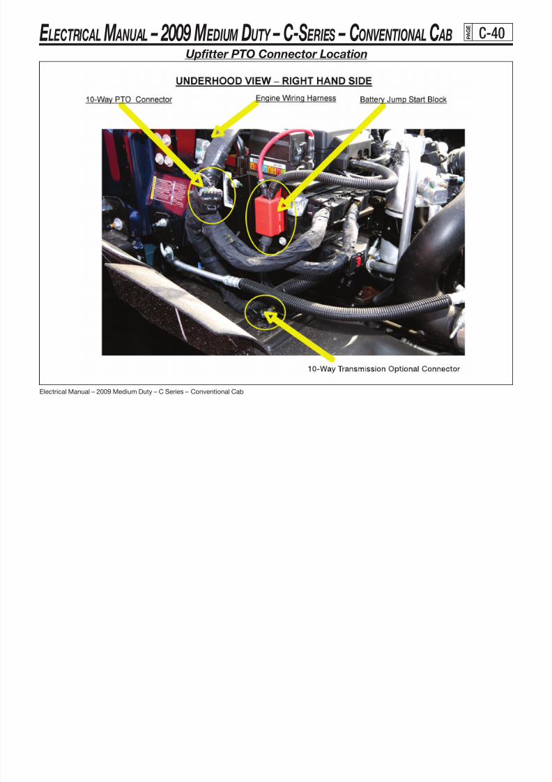
8/10/2019 2009 GM Medium Duty Electrical Manual.PDF
http://slidepdf.com/reader/full/2009-gm-medium-duty-electrical-manualpdf 109/410
Electrical Manual – 2009 Medium Duty – C Series – Conventional Cab
Upfitter PTO Connector Location
E LECTRICAL M ANUAL – 2009 M EDIUM DUTY – C-S ERIES – CONVENTIONAL C AB P A G E
C-41
C127 E i Ch i H t R t P T k ff (PTO) (LF8)
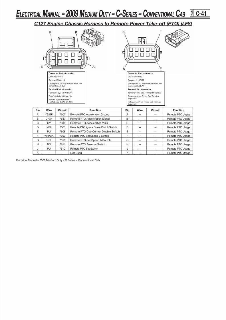
8/10/2019 2009 GM Medium Duty Electrical Manual.PDF
http://slidepdf.com/reader/full/2009-gm-medium-duty-electrical-manualpdf 110/410
Electrical Manual – 2009 Medium Duty – C Series – Conventional Cab
Pin Wire Circuit Function Pin Wire Circuit Function
A YE/BK 7607 Remote PTO Acceleration Ground A -- -- Remote PTO Usage
B D-GN 7637 Remote PTO Acceleration Signal B -- -- Remote PTO Usage
C GY 7606 Remote PTO Acceleration VCC C -- -- Remote PTO Usage
D L-BU 7605 Remote PTO Ignore Brake Clutch Switch D -- -- Remote PTO Usage
E PU 7608 Remote PTO Cab Control Disable Switch E -- -- Remote PTO Usage
F WH/BK 7609 Remote PTO Set Speed B Switch F -- -- Remote PTO Usage
G D-BU 7610 Remote PTO Set Speed A Switch G -- -- Remote PTO Usage
H BN 7611 Remote PTO Resume Switch H -- -- Remote PTO Usage
J PU 7612 Remote PTO Set Switch J -- -- Remote PTO Usage
K -- -- Not Used K -- -- Remote PTO Usage
C127 Engine Chassis Harness to Remote Power Take-off (PTO) (LF8)
Connector Part Information
OEM: 12052189
Service: 12167122
Description: 10-Way M Metri-Pack 150
Series Sealed (GY)
Terminal Part Information
Terminal/Tray: See Terminal Repair Kit
Core/Insulation Crimp: See Terminal
Repair Kit
Release Tool/Test Probe: See Terminal
Repair Kit
Connector Part Information
OEM: 15318071
Service: 15306119
Description: 10-Way F Metri-Pack 150
Series Sealed (GY)
Terminal Part Information
Terminal/Tray: 12191819/8
Core/Insulation Crimp: 2/A
Release Tool/Test Probe:
15315247/J-35616-2A (GY)
E LECTRICAL M ANUAL – 2009 M EDIUM DUTY – C-S ERIES – CONVENTIONAL C AB P A G E
C-42
Right Rear Side Of Engine Compartment (LF8)

8/10/2019 2009 GM Medium Duty Electrical Manual.PDF
http://slidepdf.com/reader/full/2009-gm-medium-duty-electrical-manualpdf 111/410
Electrical Manual – 2009 Medium Duty – C Series – Conventional Cab
Right Rear Side Of Engine Compartment (LF8)
(1) C109
(2) Fuse Block - Primary
(3) C121
(4) C127
E LECTRICAL M ANUAL – 2009 M EDIUM DUTY – C-S ERIES – CONVENTIONAL C AB P A G E
D-1
Schematic Description and Navigation Instructions

8/10/2019 2009 GM Medium Duty Electrical Manual.PDF
http://slidepdf.com/reader/full/2009-gm-medium-duty-electrical-manualpdf 112/410
Electrical Manual – 2009 Medium Duty – C Series – Conventional Cab
Schematic Description and Navigation Instructions
Background
The Schematics included in this document are part of GM’s IVED drawing system. These are the official drawings used to developvehicle programs, produce wire harnesses and develop service documentation. The following information is offered to help youunderstand how they are organized and how to use them.
Organization
It’s impossible to put all the information on only one drawing. The vehicle is broken down by subsystem. The schematics are organizedby subsystem number not by name. That’s why the index doesn’t follow an alphabetical order of the subsystems.
A number has been added on the bottom right of each page that indicates the subsystem number, revision level, and page number.
Example:
The first sheet is H83010a_001_01 (see page D-3)H83010a_001_01 The “ h83010a” is the Object ID on the drawing and represents the sub-system.
H83010a_001_01 The “010” represents the sub-system, in this case Power Distribution.Other examples are “014” for Ground Distribution and “020” for Engine Controls.
H83010a_001_01 The “ a” represents the first or only drawing for that sub-system. In this case multiple Power DistributionSchematics are included. “a” is for L18, “b” for LF8, “c” for LF6, and “d” for LMM engines.
H83010a_001_01 The “001” represents the revision level and is not important for most of your needs.
H83010a_001_01 The “01” represents panel set one on the schematic and indicates the page number. This Schematic hasnine pages for example.
Navigation
Every wire in the vehicle is given a unique circuit number. These numbers are indicated on the schematics in bold type next to the wire. An entire subsystem usually can’t be represented by only one page. How do you determine where a wire is connected to once it leavesthe page? Either the signal is connected somewhere else in the same subsystem or it goes to another subsystem.
(continued on next page)
E LECTRICAL M ANUAL – 2009 M EDIUM DUTY – C-S ERIES – CONVENTIONAL C AB P A G E
D-2
(Overview — continued from previous page)
8/10/2019 2009 GM Medium Duty Electrical Manual.PDF
http://slidepdf.com/reader/full/2009-gm-medium-duty-electrical-manualpdf 113/410
Electrical Manual – 2009 Medium Duty – C Series – Conventional Cab
( p p g )
Arrows and “Home” Plates
An Arrow is used to indicate that the signal stays within the same subsystem. The schematic indicates the circuit number and (page #)next to the arrow. A pointed arrow ( –– ) points to where it’s going to. A receiving arrow ( –– ) shows what page it came from.
A “Baseball Home Plate” or indicates that the signal goes to another subsystem.
Example:
A is shown on the bottom left of the first schematic Power Distribution H63010a_003_01. (see page D-3)This is an eight circuit and the “baseball plate” indicates which subsystem it goes to. It is marked:
Interior LightingDimmer Signal Dist Page 8A-114A-1
The other end of the signal is shown in subsystem drawing 114A page 1. (see page D-226).Two “baseball plates” are shown so you look for the eight circuit to identify the proper circuit.
Fuse protection is shown in the “baseball plate.”
Other Information
Other information on the schematics are wire color and size. The size is shown in square mm. Connector information is indicated fordevices. Terminal assignments are shown for devices. The connector PN is for the harness end not the device.
E LECTRICAL M ANUAL – 2009 M EDIUM DUTY – C-S ERIES – CONVENTIONAL C AB P A G E
D-3
Power Distribution - (L18) 8 1L V8 GMPT VORTEC® - Gas

8/10/2019 2009 GM Medium Duty Electrical Manual.PDF
http://slidepdf.com/reader/full/2009-gm-medium-duty-electrical-manualpdf 114/410
Electrical Manual – 2009 Medium Duty – C Series – Conventional Cab
Power Distribution - (L18) 8.1L V8 GMPT VORTEC - Gas
h83010a
C 12182112
F 12092078
C 12182113
CP
HTR/AC CA
P
C 12182113
F 12092079
P
TRANS
F 12092077
C 12182114C 12182112
F 12092078
A
B
C 12182112
C 12182112
F 12092079C
CP
AGAUGES C
PD
B
A
B
C 12182112
B
AXLE
15A
DPF 12092079
C 12182112
F 12092079D
10A
START
10A
D D
D
A
B
CPD
A
B
C F 12092077
B
F 12092079CP
F 12092077
C 12182114
D
10A
D
A
A
15A
C 12182112
10A
TURN/BACKUP
AUX WIRE RLY
BRAKECP
D
A
10A
ILLUM
20A
P
SIR
20A
A
CP
F 12092075
CPD
IGN4
15A 20A/30A
CHASSIS
D
A
A
B
P
BC 12182113
10A
C
B
B
B
PCM-I
D
10A
C 12182114
F 12092079
A
B
C
F 12092079
F 12092078
LAST CHANGED BY
Panel Set:
VERSIONSTAGEREVISIONOBJECT ID ORGANIZATION
IGNSW
040-1034-1
100-1
26062266 PAGE 8A-
CIRCUIT
CIRCUIT PROTECTION LEGEND
SIR
110-1
DDEVICE
P
047-2
C
091-1
BEAMSW
010-1CRUISE
WIPER
= FAM 2
KEYMNDR 114-3
Panel Set: 1
= FAM 3
HORN
STEERING COLUMN
TRNHZ
PROTECTION
ORN300.
5.0
HVACVacuum Pump
SA300
IGN1
C6
IGN3
D1
CRANK
D2
BATT 2
D5
BATT 1
D6
IGN4/ACCY
S T A R T
R U N
O F F
L O C K
A C C E S S O R Y
Str Col Asm - Ign Sw
C1
IGN0
C5
HVACHvac
.
5.0RED
342
.5YEL
5.0
Dimmer Signal DistINTERIOR LIGHTING
INTERIOR LIGHTSHead Lamp Sw
.300ORN
5.0
SA141
1.0
.141BRN
3.
5.0PNK
5.0
.1390WHT
5.0ORN
300.
.141BRN
1.01.0
.141BRNBRN
141.
1.0BRN
141.
1.0
Rear Heater Rly CoilREAR HEATER
BRN5.0
.4
N3N5N7
K6 K8
L1L3 L5 L7
M4
N1
H4
J1J3J5J7
K2K4 D2
E1
Temperature MotorHVAC REAR DEFOGGER
Rear Defog Cntl
1
Beta Agustin Velazquez GMT5600Power Dist (L18)GMT560 X08
Wednesday, April 19, 2006
12:20:33 pm
$IVEDWORK/h83010a__001s ch ema tic s he et 1
h83010a18
001
1.0
.141BRN
(Page 8)
AXLE_P
241
4 4 D IM ME R
ILLUM8
1139(Page 9)
SIR_P
R_HTR_RLY_P
IGN3_MAXI
(Page 2)
IGN1_MAXI
(Page 2)242
(Page 7)
IGN4_P
43(Page 7)
TRANS_P
1020
PCM-I_P
(Page 8)439
(Page 6)
GAUGES_P
39
TURN_P
(Page 6)139
(Page 6)441
BRAKE_P CHASSIS_P
(Page 8)541
(Page 6)641
AUX_WIRE_P
(Page 6)
START_P
806
HVAC_P TEMP_CNTL_P VAC_PUMP_P HVAC_FOG_P
E LECTRICAL M ANUAL – 2009 M EDIUM DUTY – C-S ERIES – CONVENTIONAL C AB P A G E
D-4
Power Distribution - (L18) 8 1L V8 GMPT VORTEC® - Gas (continued)

8/10/2019 2009 GM Medium Duty Electrical Manual.PDF
http://slidepdf.com/reader/full/2009-gm-medium-duty-electrical-manualpdf 115/410
Electrical Manual – 2009 Medium Duty – C Series – Conventional Cab h83010a
Power Distribution - (L18) 8.1L V8 GMPT VORTEC - Gas (continued)
B12065933
A
40A
HEADLAMP
B
A
12065935
30A
A AIGN1
A
40A
LIGHTING
1207784312065933
40A
12065934
50A
BRAKE LP - FAM 3
B
60A
IGN3
B12065935
A
60A
BATT/HAZ
B12065934
A
B
IGN4
B
ELEC BRK - FAM 2
12065933
A
50A
HVAC
B
DC 12182116
APWR POST
PD
B
CP
TRLR
B
CPD
A
BB
C C
B
D
A
F 12092077
C 12182114
P
A
PD
A
B
D
CHMSLA
DRLCA
CP
TRN/HAZ
F 12092077
ARADIO/CHIME
BB
C
20A25A 20A
PWR ACCY MARKER LP COURTESY
B
CP
15A
STOP
10A20A
20AB
15A
CPD
C 12182114
PD
A
C 12182112
F 12092078CPD
F 12092079
C 12182112C 12182113
10A20A
C 12182114
HAZARDA
PARK
F 12092077D
20AB
A
C 12182114
F 12092078
C 12182113
F 12092077
C 12182114
F 12092076 F 12092077
C 12182114
F 12092079
LAST CHANGED BY
Panel Set:
VERSIONSTAGEREVISIONOBJECT ID ORGANIZATION
DEVICE
= FAM 2CIRCUIT
D
Panel Set: 2
P
CIRCUIT PROTECTION LEGEND
= FAM 3
PROTECTIONC
RED242.
5.0
Head Lamp SwEXTERIOR LIGHT
1140ORN
BrakeTRAILER WIRING
.
0.8
Battery PositiveBATTERIES
5.0
.142RED
HVACBlow Motor Rly
A5 A6 A7 A8
MAXBATT
Maxifuse - Block Asm
A1 A2 A3 A4
SA242
Marker Lp RlyEXTERIOR LIGHT
SA142
Turn Hazard SwEXTERIOR LIGHT
SA1140
RED142.
5.0
RED
.241BRN
0.8
.642
3.0
EXTERIOR LIGHTBrake Lp Rly
.1140ORN
Ipc (Batt)IP CLUSTER
0.8
EXTERIOR LIGHTHead Lamp Sw
Drl DiodeDRL
RED142.
5.05.0RED
242.
Trailer RlysEXTERIOR LIGHT ORN
1140.
0.8
RED3.0
1542.
3.0
.1142RED
ORN1140.
0.8
STARTING & CHARGINGStarter Rly
BMaxi Ring TermA
Wednesday, April 19, 2006
12:20:33 pm
$IVEDWORK/h83010a__001s ch em at ic s he et1
h83010a18
0012
Beta Agustin Velazquez GMT5600Power Dist (L18)GMT560 X08
G7E3 E5 E7
F4 F8
G1G3 G5
B4
C1C3C5C7
D6
Block Asm-Ip Pwr 1
3.0
.1142RED
SA1142
.1340ORN
1.0
RED1342.
3.0
3.0RED
242.
RADIORadio Pwr
CHIME MDLChime Mdl
ACTIVE TRANSFER CASE4WD ATC Mdl
ACTIVE TRANSFER CASE4WD ATC Mdl
BRAKESBrake Switch
242 STARTRLY_P
IGN1_MAXI
(Page 1)
4WD_ATC
MRK_LPS_P340 DRL_BEAM_PRADIO_P
ATCSWP
PARK_P240
IPC1_P CHIME_P
COURTESY_P
(Page 8)40
140 BRK_SW_P HAZ_P1040 TRLR_HAZ_P640 (Page 7)
ACCY_P
540 840
POST
(Page 8)
ABS_TRLR2_P
HVAC_MTR_P
(Page 1)
IGN3_MAXI
342
(Page 5)
IGN4_MAX
1242
TRLR_LP_P
542
1142 HEADLAMP_P
1 MAXICTR_P
E LECTRICAL M ANUAL – 2009 M EDIUM DUTY – C-S ERIES – CONVENTIONAL C AB P A G E
D-5
Power Distribution - (L18) 8 1L V8 GMPT VORTEC® - Gas (continued)

8/10/2019 2009 GM Medium Duty Electrical Manual.PDF
http://slidepdf.com/reader/full/2009-gm-medium-duty-electrical-manualpdf 116/410
Electrical Manual – 2009 Medium Duty – C Series – Conventional Cab h83010a
Power Distribution (L18) 8.1L V8 GMPT VORTEC Gas (continued)
LAST CHANGED BY
Panel Set:
VERSIONSTAGEREVISIONOBJECT ID ORGANIZATION
C 12077842
Maxi
1206593312065932
A
B40A
12065933
20A 20A
Maxi
CPD
CPD
F 12065931ENGINE
B
F 12065931
50A
E/A PUMPABS 1A
ABS 3C 12077842
40A
A
Maxi
HORNA
B
A
Maxi Maxi Maxi Maxi Maxi30A 40AB BB
12065933STUD B
A
B12065932
A
30A
FUEL
Maxi
12065933 1206593440A
STUD A ABS 2
PAGE 8A-
HORN RLY
18A-222A/C-1FUEL PUMP RLY
12146281
30A/E-140A-1
Panel Set: 3
PTO RLY
STARTER RLY
Underhood Distribution Center
1.0
2.0ORN
1640.
.740ORN
A2
3.0RED
442.
30M GTMXD SLDD4
RED1642.
3.0
ORN740.
1.0
EbcHYDRO BRAKES
LB1042
Loop Anchor
Loop Anchor
LA1640
RED1642.
3.0 3.0
.42RED
A4
Fuel Pump Rly
3.0
.1642RED
FUEL HAND & STOR
30F GTMXD SLDD5
30F GTMXD SLDD4
.1042RED
5.0
3.0
.1840ORN
.1642RED
3.0RED
1042.
5.0
Beta Agustin Velazquez GMT5600Power Dist (L18)GMT560 X08
Wednesday, April 19, 2006
12:20:33 pm
$IVEDWORK/h83010a__001s ch em ati c s he et1
h83010a18
0013
A2
BATTERIES
Battery Positive
ORN740.
1.0
D5 30M GTMXD SLD
J1-M5 J1-M6 J1-M7
J2-AJ3-AUHBATT
J1-M1J1-M2 J1-M3 J1-M4A B
2.0
.1640ORN
HYDRO BRAKESEbc
Loop Anchor
LA740
HYDRO BRAKESElec Air Comp
.42RED
Loop Anchor
LB740
3.0 5.0
.1042RED
A4
Ebc / Rly
44C-2
BRAKESHorn RlyHORN
Loop Anchor
LA1042
Horn RlyHORN
.740ORN
1.0
RED1042.
5.0
Trailer WiringTRLR WRG
UHDIST_P1
BUSBAR2_P
(Page 4)(Page 4)
BUSBAR_P
1
FUEL_RLY_PEAC_MTR_P4 42 E BC _PABS_TRLR_P HORN_P HORN_RLY_PEBC2_PHYD_EBC_P
IGN_A_P
(Page 4)
(Page 4)
IGN_B_P
E LECTRICAL M ANUAL – 2009 M EDIUM DUTY – C-S ERIES – CONVENTIONAL C AB P A G E
D-6
Power Distribution - (L18) 8 1L V8 GMPT VORTEC® - Gas (continued)

8/10/2019 2009 GM Medium Duty Electrical Manual.PDF
http://slidepdf.com/reader/full/2009-gm-medium-duty-electrical-manualpdf 117/410
Electrical Manual – 2009 Medium Duty – C Series – Conventional Cab h83010a
Power Distribution (L18) 8.1L V8 GMPT VORTEC Gas (continued)
10A B10A
ENG-1
12092079
10A
ENG-4
15A
A
B B
A
12092079
AA
B
A ENG-2
15092075
B
O2A
12092078
ENG-3
12092079
30A
A
15AB
PCM-B A
B
120920781209207812092079
10A 15A
REAR DEFOGA/C COMP
B
A
IGNA RLY
12193604
IGNB RLY
12088567
LAST CHANGED BY
Panel Set:
VERSIONSTAGEREVISIONOBJECT ID ORGANIZATION
Panel Set: 4
739.
0.8PNK
ENGINE CNTLS
24F GTMXD SLDC4
O2 Snsr Htr A
GND DISTGnd Zone #2B
0.8
2000 PPL5.0
.
.739PNK
Ign Coils (even)ENGINE CNTLS
Enable RlyHVAC
0.8
.339PNK
RED1.
5.0
.2000PPL
5.0
0.8
.1240ORN
C424M GTMXD SLD
PNK539.
0.8
LB2000
Loop Anchor
PPL
2.0
.1093
O2 Snsr Htr BE NG INE CNTLS E NG INE CNTLS
Fuel Inj (even)
J1-K7
J1-L6J1-L8J1-G8
J1-H3 J1-H5J1-H7
J1-J4 J1-J6
J1-K5J1-F3 J1-F5J1-F7
J1-G2 J1-G4 J1-G6
Uh - Block Asm
J1-F1
ENGINE CNTLSIgn Coils (odd)
2000.5.0
PPL
D6
Uh - Ign Rlys
A4 A6
B4B6
C4C6
D4
87
86
85
3086
8785
RED1.
5.0 GND DISTGnd Zone #2B
5.0PPL
2000.
0Power Dist (L18)GMT560 X08
Wednesday, April 19, 2006
12:20:33 pm
$IVEDWORK/h83010a__001s ch em ati c s he et1
h83010a18
0014
Beta Agustin Velazquez GMT560
Rear Defog CntlREAR DEFOGGER ENGINE CNTLS
Fuel Inj (odd)
PPL1093.
2.0
Loop Anchor
LA2000
440(Page 7)
PCM-B_P ENG-4_P
(Page 8)639
3 39 I NJ 2_ P
239
ENG-1_P
(Page 8)
INJ1_P539
250 IGNA_RLY_G
1042
(Page 3)
IGN_B_P439
(Page 8)
IGNB_RLY_P
1042
IGN_A_P
(Page 3)
439
IGNA_RLY_P
(Page 8)
O2_HTRB_PO2_HTRA_P IGN_COIL2_P IGN_COIL1_P
(Page 3)
BUSBAR_P
DEFOG_PHVAC_RLYA_P
250 IGNB_RLY_G(Page 3)
BUSBAR2_P
E LECTRICAL M ANUAL – 2009 M EDIUM DUTY – C-S ERIES – CONVENTIONAL C AB P A G E
D-7
Power Distribution - (L18) 8.1L V8 GMPT VORTEC® - Gas (continued)

8/10/2019 2009 GM Medium Duty Electrical Manual.PDF
http://slidepdf.com/reader/full/2009-gm-medium-duty-electrical-manualpdf 118/410
Electrical Manual – 2009 Medium Duty – C Series – Conventional Cab h83010a
Power Distribution (L18) 8.1L V8 GMPT VORTEC Gas (continued)
LAST CHANGED BY
Panel Set:
VERSIONSTAGEREVISIONOBJECT ID ORGANIZATION
PCPD
10A
DD
ABRAKE ISO
C 12182116 F 12092079
C 12182112
A
B
CPC
10A
RADIO U
B
A A
D
LH PARKLAMPA
10A
F 12092079
C 12182112B
A
B
CA
RH PARKLAMP PWR WINDOW
10A
DPD
R-RR TRUCK
10A
25A
L-RR TRUCK
B
PF 12092079
C 12182112
F 12092079
C 12182112
F 12092079
C 12182112
F 12092079
C 12182112
P
BB
C
15A
ONSTARCPD
F 12092079
C 12182112
A
B
C
10A
= FAM 3
CIRCUITPROTECTION
RH TURN TRAILER RLY
12129833DRL RLY
CHMSL RLYLH TURN TRAILER RLY
I/P Distribution/Relay CenterPAGE 8A-
Panel Set: 5
= FAM 2
CIRCUIT PROTECTION LEGEND
P
102A-1
147B-1
BRAKE LAMP RLY110A-2
HEATED MIRROR RLY110A-4
C
MARKER LAMP RLY
110A-2
DEVICED
110A-2110A-2
SB2609
2509.BRN
1.0
2609.BRN/WHT
40F GTMXD SLDB4
1.0
5
Beta Agustin Velazquez GMT5600Power Dist (L18)GMT560 X08
Wednesday, April 19, 2006
12:20:33 pm
$IVEDWORK/h83010a__001s ch ema ti c s he et 1
h83010a18
001
Window SwitchPOWER WINDOW
INTERIOR LIGHTINGDoor Switch Illum
SE2509
Rh Turn Trailer RlyEXTERIOR LIGHT
ORN2040.
0.8
SH2509
Head Lamp SwEXTERIOR LIGHT
0.5
.2509BRN
LCT TRANSGrade Brk Sw
GND DISTGnd Zone #4B
BODY BLDR/SCH BUSRight Park
BLK755.
5.0
1.0
2609.BRN/WHT
YEL.618
1.0
1.0
2609.BRN/WHT
Left Front ParklampEXTERIOR LIGHTING
Turn Haz SwEXTERIOR LIGHT
1.0
2509.BRN
EXTERIOR LIGHTRr Turn Lp
C12
Left Rear ParklampEXTERIOR LIGHTING
BRAKESBrake Switch
SA618
SA619
BODY BLDR/SCH BUSLeft Park
EXTERIOR LIGHTLh Turn Trailer Rly
BRN.2509
0.8
2509.BRN
1.0
2.0
2509.BRN
Lr Turn Lp
C12
EXTERIOR LIGHTBRN/WHT
.2609
1.0
EXTERIOR LIGHTTurn Haz Sw
SA2609
5.0
LCT TRANSMISSIONOverdrive Defeat Sw Illum
BLK755.
619.GRN DK1.0
1.0
618.YEL
BA2040
Blunt Cut
ACTIVE TRANSFER CASE
4WD ATC Mdl
1.0
.GRN DK1.0
619
618.YEL
BRN/WHT.2609
1.0
S8
T3
T4
R5
R6R8
S3
S4
S5
S6
S7
86
Ignition 4
12193604
L30
L85
L86
L87
R1
R2 R4
Ip2 - Block Asm
85
30
BRN.2509
1.0
BRN/WHT.2609
2.0
EXTERIOR LIGHTINGRight Front Parklamp
Loop Anchor
LA755
Right Rear ParklampEXTERIOR LIGHTING
GRN DK.
BRN/WHT.230
0.8
619
1.0
5.0
.1242RED
0.35BRN/WHT
230.
Marker Lamp RlyEXTERIOR LIGHTING
40M GTMXD SLD B4
INTERIOR LIGHTINGSwitch Illum
2509 DOOR_SW_ILL
43(Page 7)
IGN4_RLY
IGN4_MAX
(Page 2)
BB_R_PARK2609 BB_L_PARK2509
ATCBLTGRDBRK2
BRAKE_ISO_P17
(Page 8)1320
BRAKE_ISO
RR_STOP_LP19
IGN4_RLY_G
WIN_IGN4_P343
9 PARK_LP_P 18 LR_STOP_LP
450
LTURN_RLY_P618ODDS_LP
619 RTURN_RLY_P RR_TURN_P
LR_TURN_P
L_TAIL_PRFR_PARK_PR_TAIL_P LFR_PARK_P
SW_ILLUM
MRK_RLY_P

8/10/2019 2009 GM Medium Duty Electrical Manual.PDF
http://slidepdf.com/reader/full/2009-gm-medium-duty-electrical-manualpdf 119/410
E LECTRICAL M ANUAL – 2009 M EDIUM DUTY – C-S ERIES – CONVENTIONAL C AB P A G E
D-9
Power Distribution - (L18) 8.1L V8 GMPT VORTEC® - Gas (continued)

8/10/2019 2009 GM Medium Duty Electrical Manual.PDF
http://slidepdf.com/reader/full/2009-gm-medium-duty-electrical-manualpdf 120/410
Electrical Manual – 2009 Medium Duty – C Series – Conventional Cab h83010a
Power Distribution (L18) 8.1L V8 GMPT VORTEC Gas (continued)
LAST CHANGED BY
Panel Set:
VERSIONSTAGEREVISIONOBJECT ID ORGANIZATION
Panel Set: 7
22F GTMXDB11
ORN440.
0.8
22M GTMXDB11
.440ORN
1.0
1020PNK
0.8
.
22M GTMXDB11
30F GTMXDA9
TRANSMISSIONTcm Sdg Mdl
C4
SERIAL DATA
30F GTMXD SLD30F GTMXD SLD
A2
SA43
.1020PNK
0.8
0.8ORN.440
PcmENGINE CNTLS
ORN540.
1.0
A230M GTMXD SLD
.540ORN
1.0
1.0
540ORN
1.0
.ORN
540.
SERIAL DATASdg Mdl
YEL43.
1.0
Wiper SwitchWIPER/WASHER
PcmENGINE CNTLS
Pass Dr Lck SwPWR DR LK
ENGINE CNTLSPcm
SB1020
h83010a18
001
1.0
7
Beta Agust in Velazquez GMT5600Power Dist (L18)GMT560 X08
Wednesday, April 19, 2006
12:20:33 pm
$IVEDWORK/h83010a__001s chem at ic s hee t1
.440ORN
Rfa MdlKEYLESS ENTRY
1.0
.43YEL
IpcIP CLUSTER
Wiper MotorWIPER/WASHER
1.0ORN
440.
1.0
.540ORN
TcmTRANSMISSION
540.
1.0ORN
1.0
.540ORN
ORN540.
1.0
SA1020
ORN
540.
1.0
Dr Lk Rly
1.0
.43YEL
PWR DR LK
Drv Dr Lck SwPWR DR LK
1020.
0.8PNK
Tcm
1.0
.540ORN
LCT TRANSMISSION
.1020PNK
0.5
SB540
ORN0.8
.440
POWER MIRRORSMirror Switch
1.0
.43YEL
SA540 SA440
ORN540.
1.0
0.8PNK
1020.
PNK1020.
0.5
IP CLUSTERIpc
SC540
ORN540.
1.0
YEL43.
1.0
30M GTMXD SLDC4
0.5PNK
1020.
B11
0.5
.1020PNK
22F GTMXD
.440ORN
0.5
30M GTMXDA9
ORN540.
1.0
ORN540.
1.0
Rear Heater RlyREAR HEATER
1.0
.540ORN
TCM_BAT_PP2 TCM_BAT_PP
TRANS_P
PCM_IGN0_P
SDG_2_P
LCT_IGN0_P
IPC_IGN_P
(Page 1)
R_HVAC_P
ACCY_P
(Page 2)
DRV_LK_PMIR_SW_P
PASS_LK_P
LK_RLY_P RFA_P
SDG_1_P
(Page 4)
PCM-B_P
PCM_BAT1_PPCM_BAT2_P
IGN4_RLY
(Page 5) IGNSW_D2_P WIPE_PWASH_P
(Page 1)
IGN4_P
E LECTRICAL M ANUAL – 2009 M EDIUM DUTY – C-S ERIES – CONVENTIONAL C AB P A G E
D-10
Power Distribution - (L18) 8.1L V8 GMPT VORTEC® - Gas (continued)

8/10/2019 2009 GM Medium Duty Electrical Manual.PDF
http://slidepdf.com/reader/full/2009-gm-medium-duty-electrical-manualpdf 121/410
Electrical Manual – 2009 Medium Duty – C Series – Conventional Cab h83010a
o e st but o ( 8) 8 8 G O C Gas (co t ued)
LAST CHANGED BY
Panel Set:
VERSIONSTAGEREVISIONOBJECT ID ORGANIZATION
Panel Set: 8
BRN241.
2.0
241.
2.0BRN
PNK0.8
Aux Power #2AUX POWER
.639
HYD BRAKESEbc
0.8
.439
PNK
16F GT280R
439.PNK
0.8
A6
40M GTMXD SLDA6
40F GTMXD SLD
0.8
239.PNK
Wednesday, April 19, 200608 XGMT560
Power Dist (L18)0 GMT560Agustin VelazquezBeta
8
4M MP280 SLDB
00118
h83010asheet1schematic $IVEDWORK/h83010a__001
12:20:33 pm
0.5PNK
239.
16M GT280R
Air MeterENGINE CNTLS
AUX POWERAux Power #1
A1230M GTMXD
639.
0.5PNK
0.8
.439PNK
Tcs LedBRAKES40M GTMXD SLD
C6
8M GT280 SLDG
239.
0.5PNK
ORN1.0
.840
G8F GT280 SLD
Reservoir Air Press SwHYDRO BRAKES
241BRN
2.0
.
BRN541.
0.5
0.8
B5
.439
PNK
0.5PNK
239.
Data Link ConnDATA LINK CONN
.241BRN
2.0
B5
BRN541.
0.5
SA840
30M GTMXD SLDB10
40M GTMXD SLDD3
StopBODY BUILDER/SCHOOL BUS
PNK439.
0.8
840ORN
1.0
.
R
840.
1.0ORN
16F GT280 SLD
A1
PcmENGINE CNTLS
30F GTMXD SLD
0.8
.439PNK
.439PNK
0.8
UPFITTER PROVPto Rly
Cigar Lighter/Rear Aux PowerAUX POWER
SC23930M GTMXD SLD
A4
Cruise Cntl Sw
AIR BRAKESAir Dryer
CRUISE CONTROL
PNK239.
0.5
ELEC THROT CNTLEtc Mdl
REAR AIR SUSPAir Susp Sw
B4F MP280 SLD
BRN
0.5
.541BRN
2.0
.241
1.0ORN
840.
.
2.0BRN
241
ORN1.0
.840
30M GTMXD SLDA1
SD541
SA439
2 SPEED REAR AXLE2Speed Rly
30F GTMXD SLDB10
A12 30F GTMXD
BRN
.439PNK
241.
2.0
0.8
.239PNK
Pto Enable SwUPFITTER PROV
0.5
0.8
.239PNK
439.
0.8PNK
SB439
SA239
1.0
.840ORN
LCT TRANSMISSIONOverdrive Defeat Sw Led
0.8
.239PNK
0.5BRN
541.
Cnstr PurgeENGINE CNTLS
BRN0.5
.541
0.5
.1320BLU LT
Batt +DTC
.
0.5PNK
239
30F GTMXDA8
A4
0.8
.439PNK
30F GTMXD SLD
R
40F GTMXD SLDD3
16M GT280 SLD
2 SPEED REAR AXLEElec 2Sp Sw Led
0.8
.239PNK
.541BRN
0.5
Chmsl Iso Rly EtcELEC THROTTLE CNTRL
BLU LT1320.
0.5
EXTERIOR LIGHT
40F GTMXD SLDC6
0.5
.1320BLU LT
BLU LT1320.
EXTERIOR LIGHTBrake Lp Rly
0.5
SA1320
A8 30M GTMXD
BRK_NO_P1320
(Page 5)
BRAKE_ISO
CHMSL_RLY_PBRKLP_RLY_P
1320 BB_STOP_P
PTO1_RLY_P239
(Page 1)
AXLE_P
2SP_RLY_P
PCM-I_P
(Page 1)
EBC_IGN1_P
(Page 4)
IGNB_RLY_P
IGNA_RLY_P
(Page 4)
PCM_IGN1_PETC_P
DLC_P SERIAL_P
840 CIGAR_P
ODDS_LED_P
POST
(Page 2)
AUX1_P AUX2_P
L18_MAF_P
PTO_SW_P
2SP_LED_P
EAC_RLY_P
PURGE_P
ENG-1_P
(Page 4)
ENG-4_P
(Page 4)
CRUISE_P
AIR_DRY_P541
CHASSIS_P
AIR_SUSP_PTCS_SW_P
(Page 1)
E LECTRICAL M ANUAL – 2009 M EDIUM DUTY – C-S ERIES – CONVENTIONAL C AB P A G E
D-11
Power Distribution - (L18) 8.1L V8 GMPT VORTEC® - Gas (continued)

8/10/2019 2009 GM Medium Duty Electrical Manual.PDF
http://slidepdf.com/reader/full/2009-gm-medium-duty-electrical-manualpdf 122/410
Electrical Manual – 2009 Medium Duty – C Series – Conventional Cab h83010a
( ) ( )
LAST CHANGED BY
Panel Set:
VERSIONSTAGEREVISIONOBJECT ID ORGANIZATION
Panel Set: 9
Driver only Dual SIR
Driver onlyDual SIR
SIRSdm
.40ORN
.YEL
0.5
1139
0.8
YEL0.5
1139.
16F GT280E
0.8
.40ORN
16M GT280C
SIRPsir Delete Resistor
30F GTMXDB6
0.5
1139.YEL
SA11390.8
16F GT280C
ORN40.
ORN40.
0.5
16M GT280E
40.ORN
0.5
.1139
0.5YEL
YEL.1139
0.5
30M GTMXDB6
SB1139
Dome Lamp
INTERIOR LIGHTS
SA40
YEL.1139
0.5
SIRPsir Defeat Sw
1139
0.5YEL.
0Power Dist (L18)GMT560 X08
Wednesday, April 19, 2006
12:20:33 pm
$IVEDWORK/h83010a__001s ch em ati c s he et1
h83010a18
001
INTERIOR LIGHTS
Rear Dome Lamp
9
Beta Agustin Velazquez GMT560
YEL.1139
0.5
SDM_P SIR_OHM_P PSIR_P
SIR_P
(Page 1)
(Page 2)
COURTESY_P
DOME_P RR_DOME_P
E LECTRICAL M ANUAL – 2009 M EDIUM DUTY – C-S ERIES – CONVENTIONAL C AB P A G E
D-12
Power Distribution - (LMM) 6.6L V8 Isuzu DURAMAX ® - Diesel

8/10/2019 2009 GM Medium Duty Electrical Manual.PDF
http://slidepdf.com/reader/full/2009-gm-medium-duty-electrical-manualpdf 123/410
Electrical Manual – 2009 Medium Duty – C Series – Conventional Cab h83010d
( )
LAST CHANGED BY
Panel Set:
VERSIONSTAGEREVISIONOBJECT ID ORGANIZATION
AUX WIRE RLY
CHASSIS
B 10A
10A
10A
PCM-I
12092079
TURN/BACKUP
12092078
15A
12092079 12092079
ILLUM
12092079
12092079
IGN4
20A
15A
12092079
10A
10A
A
BRAKE
B
A
1209207912092078
12092078
12092077
12092077
HTR/ACSIR
10A
A
START
20AB
A
B
A
B
A
B
A A A
A
B
A
B
A
B
TRANS
10A
15A
GAUGES
B B B
HORN
IGNSW
110-1
010-126062266
100-1
STEERING COLUMN
KEYMNDR
034-1
091-1
TRNHZ
040-1
Panel Set: 1
114-3
CRUISE
047-2
BEAMSW
SIRWIPER
PAGE 8A-
BRN141.
1.0
5.0
.3PNK
BRN141.
1.0
HVACTemperature Motor
INTERIOR LIGHTSHead Lamp Sw
SA141
Dimmer Signal DistINTERIOR LIGHTING
Vacuum PumpHVAC
YEL5.
5.0 5.0
.300ORN
HvacHVAC
1.0
Wednesday, April 19, 2006001
5
h83010dsheet1schematic $IVEDWORK/h83010d__001
12:23:07 pm
08 XGMT560
Power Dist (LMM)0 GMT560Agustin VelazquezBeta
1
BRN141.
5.0BRN
4.
RED342.
5.0
REAR HEATERRear Heater Rly Coil
.141BRN
1.0 1.0
.141BRN
L5 L7
M4
N1N3N7J5J7
K2K4 K6 K8
L1L3
H4
J1J3
D2
E1
REAR DEFOGGERRear Defog Cntl
SA300
WHT1390.
5.0
ORN300.
5.0
BATT 2
D5
BATT 1
D6
IGN4/ACCY
O F F
L O C K
A C C E S S O R Y
Str Col Asm - Ign Sw
C1
IGN0
C5
IGN1
C6
IGN3
D1
CRANK
D2
S T A R T
R U N
141.
1.0
5.0
.300ORN
BRN
ILLUM8
DIMMER44
1139(Page 9)
SIR_P
R_HTR_RLY_P
IGN3_MAXI
(Page 2)
IGN1_MAXI
(Page 2)242
T EM P_ CN TL _P V AC _P UM P_ P H VA C_ FO G_ PHVAC_P
START_P
(Page 7)43
IGN4_P
(Page 6)
AUX_WIRE_P
641541
CHASSIS_P
(Page 8)(Page 6)
BRAKE_P
441(Page 7)
1020
TRANS_P
(Page 8)
PCM-I_P
439(Page 6)
39
GAUGES_P
(Page 6)
TURN_P
139(Page 6)
806
E LECTRICAL M ANUAL – 2009 M EDIUM DUTY – C-S ERIES – CONVENTIONAL C AB P A G E
D-13
Power Distribution - (LMM) 6.6L V8 Isuzu DURAMAX ® - Diesel (continued)
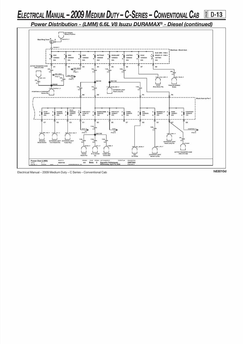
8/10/2019 2009 GM Medium Duty Electrical Manual.PDF
http://slidepdf.com/reader/full/2009-gm-medium-duty-electrical-manualpdf 124/410
Electrical Manual – 2009 Medium Duty – C Series – Conventional Cab h83010d
B12065933
A
40A
HEADLAMP
B
A
12065935
30A
A AIGN1
A
40A
LIGHTING
1207784312065933
40A
12065934
50A
BRAKE LP - FAM 3
B60A
IGN3
B12065935
A
60A
BATT/HAZ
B12065934
A
B
IGN4
B
ELEC BRK - FAM 2
12065933
A
50A
HVAC
B
LAST CHANGED BY
Panel Set:
VERSIONSTAGEREVISIONOBJECT ID ORGANIZATION
PARKHAZARD A
10A
COURTESY
20A
MARKER LP
15AB 20A
DRL
15A20A25A
TRN/HAZ
B 20A
12092077
RADIO/CHIME
12092078 12092078 1209207912092077 1209207912092076
TRLRPWR POST CHMSLPWR ACCY
12182114STOP
B
A
B
A
B
A
B
A
B
A
B
A
B
A A
B 10A20A20A
A A12092077
B
1209207712092077
Panel Set: 2
5.0
.242RED
0.8BRN
241.
Battery PositiveBATTERIES
Blow Motor Rly
BRAKES
Maxi Ring Term AB
HVAC
Brake Switch
3.0RED
1342.
4WD ATC MdlACTIVE TRANSFER CASE
RED642.
3.0
EXTERIOR LIGHTTurn Hazard Sw
SA1140
5.0
Starter RlySTARTING & CHARGING
.242RED
SA142
0.8
A5 A6 A7 A8
MAXBATT
ORN1140.
Maxifuse - Block Asm
A1 A2 A3 A4
.1142RED
3.0
ACTIVE TRANSFER CASE
.242RED
3.0
4WD ATC Mdl
RED142
5.0
.
.1340ORN
1.0
2 Wednesday, April 19, 2006001
5
h83010dsheet1schematic $IVEDWORK/h83010d__001
12:23:07 pm
08 XGMT560
Power Dist (LMM)0 GMT560Agustin VelazquezBeta
3.0
.1142RED
EXTERIOR LIGHTTrailer Rlys
IP CLUSTERIpc
EXTERIOR LIGHTHead Lamp Sw
CHIME MDLChime Mdl
TRAILER WIRING
Brake
SA1142
5.0
.142RED
F8
G1G3 G5G7C7
D6
E3 E5 E7
F4
Block Asm-Ip Pwr 1
B4
C1C3C5
0.8ORN
1140.
EXTERIOR LIGHTMarker Lp Rly
DRLDrl Diode
EXTERIOR LIGHTHead Lamp Sw
Radio PwrRADIO
5.0
.142RED
0.8
.1140ORN
0.8
.1140ORN
SA242
STARTRLY_P242
(Page 1)
IGN1_MAXI
4WD_ATC
340 DRL_BEAM_P MRK_LPS_PIPC1_PRADIO_P CHIME_P
ATCSWP
2 40 P AR K_ P
COURTESY_P
(Page 9)40
1 MAXICTR_P
ABS_TRLR2_P
342
(Page 5)
IGN4_MAX
1242
1142 HEADLAMP_P
542 HVAC_MTR_P
BRK_SW_P140 1040 HAZ_P (Page 8)
POST
840(Page 7)
ACCY_P
540
TRLR_HAZ_P640
(Page 1)
IGN3_MAXI
E LECTRICAL M ANUAL – 2009 M EDIUM DUTY – C-S ERIES – CONVENTIONAL C AB P A G E
D-14
Power Distribution - (LMM) 6.6L V8 Isuzu DURAMAX ® - Diesel (continued)

8/10/2019 2009 GM Medium Duty Electrical Manual.PDF
http://slidepdf.com/reader/full/2009-gm-medium-duty-electrical-manualpdf 125/410
Electrical Manual – 2009 Medium Duty – C Series – Conventional Cab h83010d
LAST CHANGED BY
Panel Set:
VERSIONSTAGEREVISIONOBJECT ID ORGANIZATION
E/A PUMP
50AB
A
Maxi
A
B
A
BMaxi
12065933 20A
12065931
40A Maxi
FUEL
BMaxi
A
B
AABS 1 12065931
12065934
40A
STUD A
B
12065933 20A12065933
HORN
40A
ENGINEABS 3
12065932
B
ABS 2
30A Maxi40A
A
BMaxi
A
MaxiMaxi30A
A
Maxi
A
B
12065932
STUD B
12065933
Panel Set: 3
22A/C-130A/E-1
18A-212146281
FUEL PUMP RLYSTARTER RLY
Underhood Distribution Center
PTO RLY
40A-1HORN RLY
PAGE 8A-
SA1042
3.0
.442RED
30F GTMXD SLDA2
RED
42.
3.0
1.0
ORN740.
1042.
5.0RED
2.0
.1640
ORN3.0
.1642
RED
Horn RlyHORN
A4
Beta Agustin Velazquez GMT5600Power Dist (LMM)GMT560
Loop Anchor
LA1640
X08
12:23:07 pm
$IVEDWORK/h83010d__001s chem at ic s he et 1
h83010d5
001Wednesday, April 19, 20063
1.0ORN
740.
BATTERIESBattery Positive
30M GTMXD SLDA2
.
2.0ORN
1640
RED3.0
.1642
D4
BRAKESEbc / Rly
Loop Anchor
LA740
EbcHYDRO BRAKES
3.0
.1840ORN
5.0
D4
.1042RED
Elec Air CompHYDRO BRAKES
RED1042.
5.0
5.0
.1042RED
740ORN
1.0
.
3.0
.42RED
HORNHorn Rly
FUEL HAND & STORFuel Pump Rly
Loop Anchor
LB740
A4
HYDRO BRAKESEbc
J2-AJ3-AUHBATT
J1-M1J1-M2 J1-M3 J1-M4 J1-M5 J1-M6 J1-M7A B
1.0
.740
ORN
HORN_RLY_PEAC_MTR_P FUEL_RLY_P442 EBC_P
(Page 4)
BUSBAR_P
1 1
BUSBAR2_P
(Page 4)
HYD_EBC_P
IGN_B_P
(Page 4)
EBC2_P HORN_P
UHDIST_P
IGNB_RLY_P
(Page 4)
IGN_A_P
(Page 4)
E LECTRICAL M ANUAL – 2009 M EDIUM DUTY – C-S ERIES – CONVENTIONAL C AB P A G E
D-15
Power Distribution - (LMM) 6.6L V8 Isuzu DURAMAX ® - Diesel (continued)

8/10/2019 2009 GM Medium Duty Electrical Manual.PDF
http://slidepdf.com/reader/full/2009-gm-medium-duty-electrical-manualpdf 126/410
Electrical Manual – 2009 Medium Duty – C Series – Conventional Cab h83010d
LAST CHANGED BY
Panel Set:
VERSIONSTAGEREVISIONOBJECT ID ORGANIZATION
IGNA RLY
12193604
IGNB RLY
12088567
12092077
BB
PCM-BEV FAN
15092081
A
B
A ENG-1
5A
AENG-2
B
ENG-3AA
15092075ENG-4
10A
12092079
B
A
25A
12092076
30A10A B10A
REAR DEFOG
12092079
B 12092075
30A
12092079
A
20A BB
A A/C COMPHTD FUEL
12092079
A
10A
Panel Set: 4
ENG CNTLS
Pcm
2.0
4
Beta Agust in Velazquez GMT5600Power Dist (LMM)GMT560 X08
12:23:07 pm
$IVEDWORK/h83010d__001sche matic sheet1
h83010d5
001
PPL1093.
Wednesday, April 19, 2006
A4 24F GTMXD SLD
440.
0.8ORN
1.0
.1440ORN
PPL2.0
.1093
2000PPL
5.0
.
Rear Defog CntlREAR DEFOGGER
Loop Anchor
LA2000
5.0
.1RED
Loop Anchor
LB2000
24M GTMXD SLDA4
0.8
.1240ORN
5.0PPL
2000.
2000.
5.0PPL
C4 24F GTMXD SLD
FAN CONTROLSEV Fan
5.0
.1RED
A4 A6
B4B6
C4C6
D4 D6
87
86
85
30 3086
8785
Uh - Ign Rlys
Htd Fuel RlyHEATED FUEL
Enable RlyHVAC
ORN1440.
1.0
5.0
.2000PPL
J1-J6J1-J8
J1-K5J1-K7
J1-L6J1-L8J1-G8
J1-H3 J1-H5J1-H7
J1-J2 J1-J4
J1-F1 J1-F3 J1-F5J1-F7
J1-G2 J1-G4 J1-G6
Uh - Block Asm
C4
Gnd Zone #2B
GND DIST
24M GTMXD SLD
FAN_PWR
639
ENG-4_P
(Page 8) (Page 6)
ENG-2_P
BUSBAR2_P
(Page 3)
(Page 7)440
PCM-B_P
HFUEL_3_P HVAC_RLYA_P2 DEFOG_P
ENG-1_P
(Page 8)239 339
BUSBAR_P
(Page 3)250 2219 IGNB_P
439
IGNA_RLY_P
(Page 8)
IGNB_RLY_P
(Page 3)
1042
1042
IGN_A_P
(Page 3)
1042
(Page 3)
IGN_B_P
IGNA_RLY_G
E LECTRICAL M ANUAL – 2009 M EDIUM DUTY – C-S ERIES – CONVENTIONAL C AB P A G E
D-16
Power Distribution - (LMM) 6.6L V8 Isuzu DURAMAX ® - Diesel (continued)

8/10/2019 2009 GM Medium Duty Electrical Manual.PDF
http://slidepdf.com/reader/full/2009-gm-medium-duty-electrical-manualpdf 127/410
Electrical Manual – 2009 Medium Duty – C Series – Conventional Cab h83010d
12092079 12092079 12092079 12092079 12092079
R-RR TRUCKRADIO U
10A
A
B
RH PARKLAMP A
B
L-RR TRUCKA
BB
AONSTAR
10A15A
A
B
12092078
B
AA
B
A
B25A 10A
PWR WINDOW
10A
LH PARKLAMP
10A 10A
BRAKE ISO1218211612092079
LAST CHANGED BY
Panel Set:
VERSIONSTAGEREVISIONOBJECT ID ORGANIZATION
MARKER LAMP RLY
102A-1
Panel Set: 5
110A-4RH TURN TRAILER RLYLH TURN TRAILER RLY
BRAKE LAMP RLY
110A-2110A-2
147B-1
CHMSL RLY
HEATED FUEL RLY
110A-2
PAGE 8A-
DRL RLY
I/P Distribution/Relay Center
23D-1
HEATED MIRROR RLY
12129833
110A-2
0.8
2509.BRN
S5
S6
S7
S8
T3
T4
R1
R2 R4
R5
R6R8
S3
S4
87
12193604
Ignition 4
86 30
85
Ip2 - Block Asm
L30
L85
L86
L87
BRN.2509
2.0
Loop Anchor
LA755
SA618
755.
5.0BLK
1.0
2509.BRN
Rh Turn Trailer RlyEXTERIOR LIGHT
4WD ATC Mdl
B4
ACTIVE TRANSFER CASE
EXTERIOR LIGHTINGMarker Lamp Rly
Lr Turn LpEXTERIOR LIGHT
C12 40M GTMXD SLD
EXTERIOR LIGHTINGLeft Rear Parklamp
SA619
BODY BLDR/SCH BUSRight Park
Head Lamp SwEXTERIOR LIGHT
SE2509
Switch IllumINTERIOR LIGHTING
BRN.2509
1.0
Left Front ParklampEXTERIOR LIGHTING
1.0
2609.BRN/WHT
1.0
2509.BRN
0.8
230.BRN/WHT
1.0YEL.618
B4
5
Beta Agust in Velazquez GMT5600Power Dist (LMM)GMT560 X08
Wednesday, April 19, 2006
12:23:07 pm
$IVEDWORK/h83010d__001sche matic sheet1
h83010d5
001
EXTERIOR LIGHTTurn Haz Sw
EXTERIOR LIGHTRr Turn Lp
EXTERIOR LIGHTINGRight Front Parklamp
Gnd Zone #4BGND DIST
GRN DK.619
1.00.8ORN
2040.
.2509BRN
0.5
LCT TRANSMISSIONOverdrive Defeat Sw Illum
INTERIOR LIGHTING
SH2509
Door Switch Illum
BRN/WHT.2609
1.0
POWER WINDOWWindow Switch
YEL.618
1.0
BRN/WHT.2609
1.0
Grade Brk SwLCT TRANS
BRN/WHT.230
0.35
1.0BRN/WHT
.2609
755.5.0
Blunt CutBA2040
SA2609
BLK
RED1242.
5.0
BRAKESBrake Switch
40F GTMXD SLDC12
2509.BRN1.0 EXTERIOR LIGHT
Lh Turn Trailer Rly
1.0
2609.BRN/WHT
Turn Haz SwEXTERIOR LIGHT
.GRN DK1.0
619
BODY BLDR/SCH BUSLeft Park
.2609
2.0BRN/WHT
SB2609
Right Rear ParklampEXTERIOR LIGHTING
(Page 2)
IGN4_MAX
IGN4_RLY
(Page 7)43
2509 DOOR_SW_ILL
2609 B B_ R_ PA RK 2 50 9 B B_ L_ PA RK
GRDBRK2
ATCBLT
MRK_RLY_P
LR_TURN_P LTURN_RLY_P618
RR_TURN_P
(Page 8)1320
BRAKE_ISO
RR_STOP_LP19
619 RTURN_RLY_P
IGN4_RLY_G
WIN_IGN4_P343
9 PARK_LP_P 18 LR_STOP_LP BRAKE_ISO_P17
SW_ILLUM ODDS_LP
450
R_TAIL_P L_TAIL_PRFR_PARK_P LFR_PARK_P
E LECTRICAL M ANUAL – 2009 M EDIUM DUTY – C-S ERIES – CONVENTIONAL C AB P A G E
D-17
Power Distribution - (LMM) 6.6L V8 Isuzu DURAMAX ® - Diesel (continued)

8/10/2019 2009 GM Medium Duty Electrical Manual.PDF
http://slidepdf.com/reader/full/2009-gm-medium-duty-electrical-manualpdf 128/410
Electrical Manual – 2009 Medium Duty – C Series – Conventional Cab h83010d
LAST CHANGED BY
Panel Set:
VERSIONSTAGEREVISIONOBJECT ID ORGANIZATION
Panel Set: 6
Tt ModuleTELL TALE
E14 Way Black GT150 Sealed F Conn
0.5PNK
39.
BRN641.
0.80.8
.641BRN
30M GTMXD SLDENGD3
B2
ENGINE CNTLSPcm
40M GTMXD SLD
IP CLUSTERIp Cluster
SA339
0.8.139PNK
PNK39.
PNK0.5
.39
0.5
TELL TALETt Module
14 Way Black GT150 Sealed M ConnE
SA441
SA139
BRN441.
0.5
INTERIOR LIGHTSHeadlamp Sw
PNK2.0
.339
PcmENGINE CNTLS
B10
40M GTMXD SLDC9
30F GTMXD
5
0016
Beta Agustin Velazquez GMT5600Power Dist (LMM)GMT560 X08
Wednesday, April 19, 2006
12:23:07 pm
$IVEDWORK/h83010d__001s ch ema ti c s he et 1
h83010d
C2 30M GTMXD SLD
BRN441.
0.5
.
0.8
441BRN
BRN641.
0.8
HVACAc Enable Rly
0.5
.441BRN
ENGINE CNTLSClutch Sw
30F GTMXDB2
0.5
TELL TALETrans Temp Gauge
.39PNK
40F GTMXD SLDB2
BRN641.
0.8
24M GTMXD SLDC8
24F GTMXD SLDC8
30M GTMXDA10
0.5
30F GTMXDA10
KEYLESS ENTRYRfa Mdl
PNK39.
0.5
.39PNK
BRN441.
0.8
PNK139.
HYD BRAKES
0.8
Ebc
441.
0.5
.806PPL
0.8
BRN
30F GTMXDB10
PPL806.
0.8
PNK2.0
.339
Pcm
339.
2.0PNK
PNK3.0
.339
ENGINE CNTLS
641BRN
PcmENGINE CNTLS
0.8
.
SA806
.441BRN
0.8
Brake SwBRAKES
Reverse SwEXTERIOR LIGHT
0.5
.441BRN
0.5PPL
806.
BATTERIESBattery Isolator
0.5PPL
806.
40F GTMXD SLDC9
30M GTMXD SLDC5
30M GTMXDB10
PNK39.
Drl RlyDRL .
0.5
SA39
0.5
PNK39
ENGINE CNTLSStart Neutral
Rev RlyPOWER MIRRORS
Htd Mirror SwLCT TRANSMISSION
.806PPL
0.5
30F GTMXD SLDC5
30F GTMXD SLD
IPD3
30M GTMXDB10
.806PPL
0.5
BRN641.
0.8
ENGINE CNTLSHi Idle Lp
BODY BUILDERIgn 3
Turnhaz SwEXTERIOR LIGHT
STARTING & CHARGINGStarter Rly
SA641
Htd Mirror RlyPOWER MIRRORS DRL
Drl Mdl
.139PNK
0.8
30F GTMXD SLDC2
BRN441.
0.5
.
2.0PNK
30M GTMXDB2
339
PNK139.
0.8
0.8BRN.641
IPC_IGN1_P
(Page 4)
ENG-2_P
VBATT_B VBATT_CVBATT_AVBATT_D
T ELL TA LE _P T EMP _G AG E_ P
HTR_LAMP339
(Page 1)
GAUGES_P
RFA_IGN1_P
ILLUM_PDRL_RLY_P
BU_MAN2_P BU_LCT_P
TCC_P
H_MIR_RLY_P DRL_P
(Page 1)
TURN_P
IGTRNHAZ_P139
STARTRLY2_P 806 C RANK_P
START_P
(Page 1)
EBC_CRANK_P
BB_PH_MIR_SW_P
BAT_ISO_P641
CR_CLU_P
(Page 1)
AUX_WIRE_P
BRAKE_P
(Page 1)
HVAC_R_P
HIS_LED_P
E LECTRICAL M ANUAL – 2009 M EDIUM DUTY – C-S ERIES – CONVENTIONAL C AB P A G E
D-18
Power Distribution - (LMM) 6.6L V8 Isuzu DURAMAX ® - Diesel (continued)

8/10/2019 2009 GM Medium Duty Electrical Manual.PDF
http://slidepdf.com/reader/full/2009-gm-medium-duty-electrical-manualpdf 129/410
Electrical Manual – 2009 Medium Duty – C Series – Conventional Cab h83010d
LAST CHANGED BY
Panel Set:
VERSIONSTAGEREVISIONOBJECT ID ORGANIZATION
Panel Set: 7
.43
1.0YEL
Ip ClusterIP CLUSTER
Wiper MotorWIPER/WASHER
SB1020
0.8PNK
1020.
SA540
1.0ORN
540.
540.
1.0ORN
SC540
TRANSMISSIONTcm
Wiper SwitchWIPER/WASHER
1.0YEL
43.
B1122F GTMXD
43.
1.0YEL
ORN540.
1.0
IP CLUSTERIp Cluster
Pass Dr Lck SwPWR DR LK
A9
30F GTMXDA9
SB1020
30M GTMXD
.540ORN
22M GTMXDB11
1.0
0.5
.1020PNK
1.0
.540ORN
TcmTRANSMISSION
SA43
ORN1.0
.540
YEL43.
1.0
30F GTMXD SLD
IPC4
22M GTMXDB11
ORN440.
1.0
1.0ORN
540.
PWR DR LKDrv Dr Lck Sw
KEYLESS ENTRYRfa Mdl
30M GTMXD SLDENG
C4
.540ORN
1.0
1.0
.540ORN
1.0
.540ORN
Dr Lk RlyPWR DR LK
POWER MIRRORSMirror Switch
PcmENGINE CNTLS
.1020PNK
0.8
YEL43.
1.0
7
Beta Agustin Velazquez GMT5600Power Dist (LMM)GMT560 X08
Wednesday, April 19, 2006
12:23:07 pm
$IVEDWORK/h83010d__001s chem at ic s he et 1
h83010d5
001
SA1020
1.0
.
Rear Heater RlyREAR HEATER
540ORN
0.5
.1020PNK
1020PNK
0.8
ENGINE CNTLSPcm
PNK1020
PcmENGINE CNTLS
.
.
0.8
ORN540.
1.0
1.0
.540ORN
1.0ORN
440.
TcmTRANSMISSION
.1020PNK
0.8
22F GTMXDB11
1.0ORN
440.
ENGINE CNTLSPcm
1020.
0.5PNK
1.0
1.0
.
ORN540.
440ORN
SA440
.540ORN
1.0
PNK0.8
.1020
.
0.8PNK
1020
SB540
TCM_BAT_PP2
(Page 5)
IGN4_RLY
IGNSW_D2_P
IGN4_P
(Page 1)
WA SH_P WIPE_ P
LMM_IGN0_GP LMM_IGN0_GP
TCM_BAT_PP
PASS_LK_P
LK_RLY_P RFA_P
DRV_LK_PMIR_SW_P
(Page 2)
ACCY_P
R_HVAC_P
LCT_IGN0_P LMM_IGN0_P
IPC_IGN_P
(Page 1)
TRANS_P(Page 4)
PCM-B_P
ACTPWR_B
E LECTRICAL M ANUAL – 2009 M EDIUM DUTY – C-S ERIES – CONVENTIONAL C AB P A G E
D-19
Power Distribution - (LMM) 6.6L V8 Isuzu DURAMAX ® - Diesel (continued)

8/10/2019 2009 GM Medium Duty Electrical Manual.PDF
http://slidepdf.com/reader/full/2009-gm-medium-duty-electrical-manualpdf 130/410
Electrical Manual – 2009 Medium Duty – C Series – Conventional Cab h83010d
LAST CHANGED BY
Panel Set:
VERSIONSTAGEREVISIONOBJECT ID ORGANIZATION
Panel Set: 8
DATA LINK CONNData Link Conn
IPB1030F GTMXD SLD
0.5PNK
239.
0.5
.239PNK
BLU LT0.5
.1320
30F GTMXD SLDA4
30M GTMXDB5
IP
30M GTMXDA8
.BRN
541
0.5
CRUISE CONTROLCruise Cntl Sw
0.5
.541BRN
PNK239.
0.8
BODY BLDR/SCH BUS
Stop
AUX POWERAux Power #1
40M GTMXD SLDD3
ORN1.0
.840
Chmsl Iso RlyEXTERIOR LIGHT
SA1320
0.5
.1320BLU LT
EbcHYD BRAKES
239.
0.5PNK
PcmENGINE CNTLS
30M GTMXD SLDENGB10
Maf SenseENGINE CNTLS
HYDRO BRAKESReservoir Air Press Sw
439.
0.8PNK
1320.
0.5BLU LT
0.5
ENG30M GTMXD SLDA1
.239PNK
AUX POWERCigar Lighter
30M GTMXD SLDENGA5
SD541
0.8
.439PNK
Aux Power #2AUX POWER
D340F GTMXD SLD
PcmENGINE CNTLS
0.5
.541BRN
PNK439.
R
0.8
40M GTMXD SLDA6
16F GT280
840.
1.0ORN PNK
0.8
.239
Tcs LedBRAKES
0.5PNK
239.
0.5
.541BRN
ORN840.
1.0
40F GTMXD SLDA6
0.8
.639PNK
SC239
1.0
.840ORN
HEATED FUELHeated Fuel Rly
.439PNK
0.8
B530F GTMXD
A4 ENG30M GTMXD SLD
16M GT280 R
541.
0.5BRN
0.8PNK
239.
PNK639.
SB439
0.5
PNK239.
0.5
IPA5 30F GTMXD SLD
SA239
SA439
B13
IP CLUSTERDPF Switch
B13
8
Beta Agustin Velazquez GMT5600Power Dist (LMM)GMT560 X08
Wednesday, April 19, 2006
12:23:07 pm
$IVEDWORK/h83010d__001s chem at ic s he et 1
h83010d5
001
SA840
A1 IP
30F GTMXD SLD
.
0.8
30F GTMXDA8
PNK439 .439
PNK0.8
ENGINE CNTLSGlow Plug Cntrl
.239PNK
0.5
Pto RlyUPFITTER PROV
PNK0.8
.239
439.
0.8PNK
Overdrive Defeat Sw LedLCT TRANSMISSION
1.0
.
UPFITTER PROVPto Enable Sw
840ORN
BB_STOP_P1320
BRAKE_ISO
(Page 5)
1320 BRK_NO_PCHMSL_RLY_P
541 DPF_LED_P
PTO1_RLY_P239
(Page 1)
PCM-I_P
IGNA_RLY_P
(Page 4) LMM_IGN1_P
EBC_IGN1_P
CIGAR_P840
POST
(Page 2)
AUX2_PAUX1_P DLC_P HTR_RLY_D_P
ODDS_LED_P
HFUEL_R3_P
CRUISE_P
TCS_SW_P
EAC_RLY_P
(Page 1)
CHASSIS_P
ENG-4_P
(Page 4)
PTO_SW_P
ENG-1_P
(Page 4)
LMM_MAF_P
E LECTRICAL M ANUAL – 2009 M EDIUM DUTY – C-S ERIES – CONVENTIONAL C AB P A G E
D-20
Power Distribution - (LMM) 6.6L V8 Isuzu DURAMAX ® - Diesel (continued)

8/10/2019 2009 GM Medium Duty Electrical Manual.PDF
http://slidepdf.com/reader/full/2009-gm-medium-duty-electrical-manualpdf 131/410
Electrical Manual – 2009 Medium Duty – C Series – Conventional Cab h83010d
LAST CHANGED BY
Panel Set:
VERSIONSTAGEREVISIONOBJECT ID ORGANIZATION
Driver only Dual SIR
Driver onlyDual SIR
Panel Set: 9
YEL0.5
1139.
C
Dome Lamp
INTERIOR LIGHTS
16M GT280
0.8
.40ORN
B630F GTMXD
16F GT280
E
SB1139
YEL.1139
0.5
16M GT280E
16F GT280C
ORN40.
0.8
SIRSdm
YEL.1139
0.5
Beta Agustin Velazquez GMT5600Power Dist (LMM)GMT560 X08
Wednesday, April 19, 2006
12:23:07 pm
$IVEDWORK/h83010d__001s ch em ati c s he et1
h83010d5
0019
SIRPsir Defeat Sw
SA40
YEL.1139
0.5
30M GTMXD
B6
.YEL
0.5
1139
Psir Delete Resistor
INTERIOR LIGHTS
Rear Dome Lamp
SIR
1139.YEL
0.5
SA1139
0.5
40.ORN
YEL.1139
0.5
0.8
.40ORN
ORN40.
0.5
YEL.1139
0.5
SIR_OHM_P PSIR_P
SIR_P
(Page 1)
SDM_P
(Page 2)
COURTESY_P
RR_DOME_PDOME_P
E LECTRICAL M ANUAL – 2009 M EDIUM DUTY – C-S ERIES – CONVENTIONAL C AB P A G E
D-21
Power Distribution - (LF8) 7.8L L6 Isuzu 6H - Diesel

8/10/2019 2009 GM Medium Duty Electrical Manual.PDF
http://slidepdf.com/reader/full/2009-gm-medium-duty-electrical-manualpdf 132/410
Electrical Manual – 2009 Medium Duty – C Series – Conventional Cab h83010b
LAST CHANGED BY
Panel Set:
VERSIONSTAGEREVISIONOBJECT ID ORGANIZATION
10A
10A
12182113
12182113
10A
12182112
B
A
START
BB
CHASSIS
BB 20A
12182112
A
A
10A
A
A
B 10A
PCM-I
B
12182114
10A
12182112
BRAKETURN/BACKUP A
12182113 12182112
AUX WIRE RLY
12182114
15A
AXLE
15A
BB
GAUGES
B
10A 20A
A ASIR
A
A
15A
A
B
ILLUM
12182112
TRANS
20A
HTR/AC
B
12182114
12182112 12182112
B
AA
IGN4
SIR
Panel Set: 1
STEERING COLUMN
110-1114-3
100-1
IGNSW
TRNHZ
HORN
091-1
26062266010-1
CRUISE
PAGE 8A-
047-2
KEYMNDR
040-1
BEAMSWWIPER
034-1
INTERIOR LIGHTSHead Lamp Sw
BRN141.
1.0
INTERIOR LIGHTINGDimmer Signal Dist
5.0
.1390WHT
.300ORN
5.0
GMT5600Power Dist (LF8)GMT560 X08
12:19:13 pm
$IVEDWORK/h83010b__001s chem at ic s he et 1
h83010b8
001Wednesday, April 19, 20061
Beta Agustin Velazquez
SA300
.
5.0ORN
300
BRN141.
1.0
HvacHVAC
1.0BRN
141.BRN
1.0
.141
1.0
.141BRN
CRANK
D2
BATT 2
D5
BATT 1
D6
IGN4/ACCY
S T A R T
R U N
O F F
L O C K
A C C E S S O R Y
Str Col Asm - Ign Sw
C1
IGN0
C5
IGN1
C6
IGN3
D1
N5N7
K8
L1L3 L5 L7
M4
N1N3J1J3J5J7
K2K4 K6H4 D2
E1
SA141
141BRN
1.0
.
HVACTemperature Motor
5.0
.5YEL
REAR DEFOGGERRear Defog Cntl
.4BRN
5.05.0PNK
3.
5.0ORN
300.
REAR HEATERRear Heater Rly CoilVacuum Pump
HVAC
5.0RED
342.
DIMMER44
8 ILLUM
1139
SIR_P
(Page 9)
R_HTR_RLY_P
IGN3_MAXI
(Page 2)
IGN1_MAXI
(Page 2)242
HVAC_ P TEMP_CNTL_ P VA C_PUMP_P H VA C_FOG_P
(Page 8)
CHASSIS_P
541
IGN4_P
43(Page 7)(Page 8)
241
AXLE_P
641
AUX_WIRE_P
(Page 6)441
BRAKE_P
(Page 6)
TRANS_P
1020(Page 7)
439
PCM-I_P
(Page 9)
GAUGES_P
39(Page 6)
139
TURN_P
(Page 6)
START_P
806(Page 6)
E LECTRICAL M ANUAL – 2009 M EDIUM DUTY – C-S ERIES – CONVENTIONAL C AB P A G E
D-22
Power Distribution - (LF8) 7.8L L6 Isuzu 6H - Diesel (continued)

8/10/2019 2009 GM Medium Duty Electrical Manual.PDF
http://slidepdf.com/reader/full/2009-gm-medium-duty-electrical-manualpdf 133/410
Electrical Manual – 2009 Medium Duty – C Series – Conventional Cab h83010b
A APARK
1218211412182114
A
B10A
COURTESYA
B B
A
15A
12182113
RADIO/CHIME
B B B
HAZARD
B
AA
10A20A
MARKER LP
12182112
25A
PWR ACCYTRN/HAZ
12182113
20A
12182114
A
B B15A
12182116
STOP
20A
12182114
20A
DRLA
TRLR
12182114 12182114
20A
PWR POST A
20A
12182112
CHMSL
B B
A
LAST CHANGED BY
Panel Set:
VERSIONSTAGEREVISIONOBJECT ID ORGANIZATION
B12065933
A
40A
HEADLAMP
B
A
12065935
30A
A AIGN1
A
40A
LIGHTING
1207784312065933
40A
12065934
50A
BRAKE LP - FAM 3
B60A
IGN3
B12065935
A
60A
BATT/HAZ
B12065934
A
B
IGN4
B
ELEC BRK - FAM 2
12065933
A
50A
HVAC
B
Panel Set: 2
SA1142
Drl DiodeDRL
Starter RlySTARTING & CHARGING
Battery PositiveBATTERIES
Brake SwitchBRAKES
.
5.0
142RED
242RED
5.0
.
EXTERIOR LIGHT
.1340
ORN1.0
Turn Hazard Sw
.1140ORN
0.8
0.8
.1140ORN
Ipc (Batt)IP CLUSTER
Head Lamp SwEXTERIOR LIGHT
CHIME MDLChime Mdl
Head Lamp SwEXTERIOR LIGHT
.1342RED
3.0
SA142
EXTERIOR LIGHTTrailer Rlys
SA242
RED.1542
3.0
Marker Lp RlyEXTERIOR LIGHT
E5 E7
F4 F8
G1G3 G5G7C1C3C5C7
D6
E3
Block Asm-Ip Pwr 1
B4
Blow Motor Rly
HVAC
5.0RED142.
RED142.
5.0
ABMaxi Ring Term
3.0RED1142.
RADIORadio Pwr
RED5.0
.242
1140ORN.
0.8
8
0012
Beta Agust in Velazquez GMT5600Power Dist (LF8)GMT560 X08
Wednesday, April 19, 2006
12:19:13 pm
$IVEDWORK/h83010b__001sch ematic sheet1
h83010b
SA1140
EXTERIOR LIGHT
Brake Lp Rly
ORN1140.
0.8
RED1142.
3.0
A2 A3 A4 A5 A6 A7 A8
MAXBATT
Maxifuse - Block Asm
A1
CHIME_PRADIO_P
MRK_LPS_P
IPC1_P
COURTESY_P
(Page 8)40
HVAC_MTR_P542 TRLR_LP_P
242
(Page 1)
IGN1_MAXI
342
IGN3_MAXI
(Page 1)
1242
IGN4_MAX
(Page 5)
HEADLAMP_P1142
1 MAXICTR_P
STARTRLY_P
840
POST
(Page 8)540
ACCY_P
(Page 7)640 TRLR_HAZ_P DRL_BEAM_P340140 BRK_SW_P HAZ_P1040 PARK_P240
E LECTRICAL M ANUAL – 2009 M EDIUM DUTY – C-S ERIES – CONVENTIONAL C AB P A G E
D-23
Power Distribution - (LF8) 7.8L L6 Isuzu 6H - Diesel (continued)

8/10/2019 2009 GM Medium Duty Electrical Manual.PDF
http://slidepdf.com/reader/full/2009-gm-medium-duty-electrical-manualpdf 134/410
Electrical Manual – 2009 Medium Duty – C Series – Conventional Cab h83010b
ABS 2
20A
12077842
Maxi
HORN
40A
STUD A
40A B
ABS 1
A
B
STUD B
Maxi Maxi Maxi
B
A
B
ENGINE
Maxi
12065933
A
40AB
12065934
Maxi
B50A
ABS 3
12065933
E/A PUMP
30A 30A
A
1206593312065932
A
B12065932
B
A A
12065933
40AMaxi
A
Maxi
LAST CHANGED BY
Panel Set:
VERSIONSTAGEREVISIONOBJECT ID ORGANIZATION
18A-2
HORN RLY
FUEL PUMP RLYSTARTER RLY
40A-1
Panel Set: 3
Underhood Distribution Center
30A/E-1
PTO RLY22A/C-1
PAGE 8A-12146281
Loop Anchor
LB1042
UHBATT
J1-M3 J1-M4 J1-M5 J1-M6
J2-AJ3-A
J1-M1J1-M2A B
LA1042
Horn RlyHORN
Loop Anchor
TRLR WRGTrailer Wiring
1.0ORN
740.
3.0
.1642RED
RED
1042.
5.0
A4
1.0ORN
740.
Loop Anchor
LA740
30M GTMXD SLDD4
5.0
.1042
RED
30M GTMXD SLDD4
D430F GTMXD SLD
RED1642.
3.0
.42
RED3.0
Ebc / RlyBRAKESHYDRO BRAKES
Ebc
5.0
.1042RED
3.0
.42RED
Elec Air CompHYDRO BRAKES
BATTERIESBattery Positive
1042.
5.0RED
3.0
.442RED
A2
3.0RED
1642.
A430F GTMXD SLD
D4
Horn RlyHORN
LB740
Loop Anchor
s c he ma ti c s he et 1
h83010b8
0013
Beta Agustin Velazquez GMT5600Power Dist (LF8)GMT560 X08
Wednesday, April 19, 2006
12:19:13 pm
$IVEDWORK/h83010b__001
RED
ORN1.0
.740
3.0
.1642
.740ORN
1.0
SA1642
1840.
3.0ORN
A2
3.0RED
1642.
EbcHYDRO BRAKES
UHDIST_P
(Page 4)
BUSBAR_P
1 1
BUSBAR2_P
(Page 4)
EBC_P442
(Page 4)
IGN_A_P
IGN_B_P
(Page 4)
EAC_MTR_P
A BS _T RL R_ P H YD _E BC _P
H OR N_ P H OR N_ RL Y_ P
EBC2_P
E LECTRICAL M ANUAL – 2009 M EDIUM DUTY – C-S ERIES – CONVENTIONAL C AB P A G E
D-24
Power Distribution - (LF8) 7.8L L6 Isuzu 6H - Diesel (continued)

8/10/2019 2009 GM Medium Duty Electrical Manual.PDF
http://slidepdf.com/reader/full/2009-gm-medium-duty-electrical-manualpdf 135/410
Electrical Manual – 2009 Medium Duty – C Series – Conventional Cab h83010b
B
HTD FUEL ENG-4
10A12092079
25A
12092078
B
ENG-3
B
AA A
B 10A
12092079 12092078
A
12092079
B
A/C COMP ENG-1
B
PCM-B
15A15A
TCM
12092078
A
B B
A
30A
REAR DEFOG A ENG-2
15092075
A
10A
12092077
B
A
15A20A
12092078
LAST CHANGED BY
Panel Set:
VERSIONSTAGEREVISIONOBJECT ID ORGANIZATION
IGNA RLY
12193604
IGNB RLY
12088567
Panel Set: 4
J1-J8
J1-K5J1-K7
J1-L8
J1-H1 J1-H3 J1-H5J1-H7
J1-J2 J1-J4 J1-J6
J1-F5J1-F7
J1-G2 J1-G4 J1-G6J1-G8
Uh - Block Asm
J1-F1 J1-F3
.2000PPL
5.0
40F GTMXD SLDC7
1.0
.1440ORN
.2000PPL
5.0
.1093PPL
2.0
HVACEnable Rly
ORN440.
3.0
PPL1093.
2.0
GND DIST
Gnd Zone #2B
RED1.
5.0
.
0.8ORN
1240
Loop Anchor
LA1440
C6
D4 D6
85
30 3086
8785
Uh - Ign Rlys
A4 A6
B4B6
C4
Agustin Velazquez GMT5600GMT560 X08
Wednesday, April 19, 2006
12:19:13 pm
$IVEDWORK/h83010b__001s ch em ati c s he et1
h83010b8
001Power Dist (LF8)
4
Beta
87
86
RED1.
5.0
1440.
1.0ORN
40M GTMXD SLDC7
Htd Fuel RlyHTD FUEL/WIF
PPL2000.
5.0
REAR DEFOGGERRear Defog Cntl
GND DIST
Gnd Zone #2B
LA2000
5.0PPL
2000.
Loop Anchor
Loop Anchor
LB2000
440
TCM_P
(Page 7)(Page 7)
PCM-B_P
440
239
ENG-1_P
(Page 8)
ENG-4_P
(Page 8)
ENG-3_P
(Page 5)
539339
(Page 6)
ENG-2_P
639
1042
(Page 3)
IGN_B_P
(Page 3)
BUSBAR_P
(Page 3)
BUSBAR2_P
2 50 I GN A_ RL Y_ G 2 50 I GN B_ RL Y_ G
HVAC_RLYB_PHFUEL_1_P DEFOG_P
439
IGNA_RLY_P
(Page 9)1042
IGN_A_P
(Page 3)
439(Page 9)
IGNB_RLY_P
E LECTRICAL M ANUAL – 2009 M EDIUM DUTY – C-S ERIES – CONVENTIONAL C AB P A G E
D-25
Power Distribution - (LF8) 7.8L L6 Isuzu 6H - Diesel (continued)
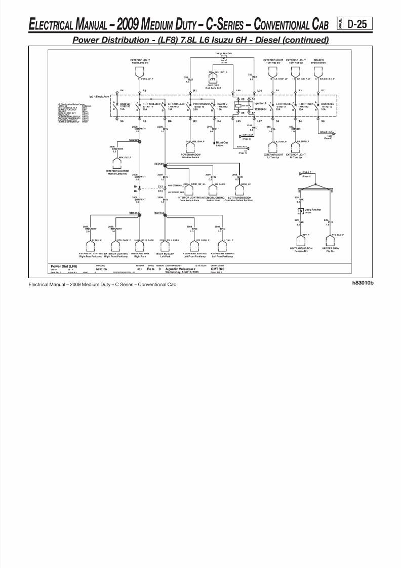
8/10/2019 2009 GM Medium Duty Electrical Manual.PDF
http://slidepdf.com/reader/full/2009-gm-medium-duty-electrical-manualpdf 136/410
Electrical Manual – 2009 Medium Duty – C Series – Conventional Cab h83010b
LAST CHANGED BY
Panel Set:
VERSIONSTAGEREVISIONOBJECT ID ORGANIZATION
A
B
AA
B
12182112 12182112 12182116 12182112
A A
B
A
B 25A
A
BB
ONST AR RH PARKL AMP1218211315A
A
B
LH PARKLAMP
10A
PWR WINDOW RADIO U
10A
BRAKE ISO
10A
L-RR TRUCK
10A12182112 12182112 12182112
10A
R-RR TRUCK
10A B
BRAKE LAMP RLY
MARKER LAMP RLY
CHMSL RLY
110A-2
12129833 PAGE 8A-
HEATED FUEL RLY
HEATED MIRROR RLY
I/P Distribution/Relay Center
110A-2
DRL RLY
Panel Set: 5
LH TURN TRAILER RLY
20B-3
102A-1
RH TURN TRAILER RLY110A-4
110A-2
23B-1ECU CONTROL RLY
110A-2
147B-1
.2509BRN
0.5
8
0015
Beta Agustin Velazquez GMT5600Power Dist (LF8)GMT560 X08
Wednesday, April 19, 2006
12:19:13 pm
$IVEDWORK/h83010b__001s ch em ati c s he et1
h83010b
1.0BRN/WHT
.2609
1.0PNK
539.
Brake SwitchBRAKES
Blunt CutBA2040
Left Front ParklampEXTERIOR LIGHTING
EXTERIOR LIGHTHead Lamp Sw
B4
Window SwitchPOWER WINDOW
2.0
2509.BRN
5.0
.755
BLK
40F GTMXD SLDC12
0.8
.2040ORN
1.0
2609.BRN/WHT
1.0
618.YEL
40M GTMXD SLDC12
1.0
2509.BRN
Gnd Zone #4BGND DIST
1.0
2609.BRN/WHT
BRN.2509
1.0
S6
S7
S8
T3
T4
R1
R2 R4
R5
R6R8
S3
S4
S5
Ip2 - Block Asm
85
3086
Ignition 4
12193604
87
L30
L85
L86
L87
Right Rear ParklampEXTERIOR LIGHTING
1.0
2509.BRN
5.0
.755BLK
INTERIOR LIGHTINGDoor Switch Illum
RED1242.
5.0
Turn Haz SwEXTERIOR LIGHT
Switch Illum
SB2609
INTERIOR LIGHTING
SH2509
BODY BUILDERRight Park
2.0BRN/WHT
.2609
.539PNK
Left Rear ParklampEXTERIOR LIGHTING
1.0
Marker Lamp RlyEXTERIOR LIGHTING
1.0
619.GRN DK
1.0
.539PNK
Turn Haz SwEXTERIOR LIGHT
EXTERIOR LIGHTINGRight Front Parklamp
EXTERIOR LIGHTRr Turn Lp
SA2609
B4
BODY BUILDERLeft Park
Reverse RlyMD TRANSMISSION
Pto RlyUPFITER PROV
1.0
2509.BRN
1.0
2609.BRN/WHT
.2509
0.8BRN
1.0
Lr Turn LpEXTERIOR LIGHT
BRN/WHT.2609
LB539Loop Anchor
Loop Anchor
LA755
LCT TRANSMISSIONOverdrive Defeat Sw Illum
SE2509
IGN4_RLY
(Page 7)43
(Page 2)
IGN4_MAX
2509 DOOR_SW_ILL
PTO_RLY_PREV_P
ENG-3_P
(Page 4)
17 BRAKE_ISO_P
BRAKE_ISO
1320(Page 8)
19 RR_STOP_LP
343 WIN_IGN4_P
PARK_LP_P9 LR_STOP_LP18
IGN4_RLY_G450
MRK_RLY_P
L_TAIL_P2509
ODDS_LPSW_ILLUM
R_TAIL_P BB_L_PARKBB_R_PARK2609 LFR_PARK_P
LR_TURN_P RR_TURN_P
RFR_PARK_P
E LECTRICAL M ANUAL – 2009 M EDIUM DUTY – C-S ERIES – CONVENTIONAL C AB P A G E
D-26
Power Distribution - (LF8) 7.8L L6 Isuzu 6H - Diesel (continued)

8/10/2019 2009 GM Medium Duty Electrical Manual.PDF
http://slidepdf.com/reader/full/2009-gm-medium-duty-electrical-manualpdf 137/410
Electrical Manual – 2009 Medium Duty – C Series – Conventional Cab h83010b
LAST CHANGED BY
Panel Set:
VERSIONSTAGEREVISIONOBJECT ID ORGANIZATION
Panel Set: 6
B240F GTMXD SLD 0.8
.339PNK
Rfa MdlKEYLESS ENTRY
0.8
.806PPL
BRAKESBrake Sw
MD TRANSMISSIONReverse Rly
40M GTMXD SLDENGD1
BRN.641
0.8
DRLDrl Rly
40F GTMXD SLDA6
40M GTMXD SLDC9
.339PNK
0.5
.441BRN
0.8
SA39
BRN641.
0.8
30F GTMXDB10
BRN441.
0.5
PNK0.8
.139
0.8
.806PPL
POWER MIRRORSHtd Mirror Rly
Reverse RlyLCT TRANSMISSION
Clutch SwSTARTING & CHARGING
40F GTMXD SLDIP
D1
ENGD330M GTMXD SLD
Loop Anchor
LA339
139PNK
0.8
.
0.5
.39PNK
SA441DRL
Drl Mdl
0.5
.39PNK
30F GTMXDB10
Exhaust Brake/Rstr SolEXH BRAKE/RSTR
Brake RlyAIR BRAKES
0.5
.441BRN
6F GT280 SLDB
SA339
0.5PNK
39.
0.5PPL
806.
Htd Mirror Sw
PNK339.
0.8
POWER MIRRORS
806.
0.5PPL30F GTMXD SLD
IPD3
40F GTMXD SLDC9
0.5BRN
441.
0.5PNK
39.
139.
0.8PNK
0.8BRN
441.
30M GTMXDA10
B1030M GTMXD
0.8BRN
641.
BRN641.
0.8
BRN441.
0.5
6M GT280 SLDB
.806PPL
0.5
SA641
0.8
PNK139.
0.8
.339PNK
30F GTMXDB2
SA139
PNK39.
0.5
.
0.5
.441BRN
0.5PNK
39
Turnhaz SwEXTERIOR LIGHT
PPL806.
0.5
Reverse SwHYD BRAKES
EbcEXTERIOR LIGHT
0.8PNK
339
40M GTMXD SLDA6
.
Clutch SwENGINE CNTLS
C5ENG30M GTMXD SLD
C5
Crank MD TRANSMISSION
IP30F GTMXD SLD
TELL TALETrans Temp Gauge
HTD FUEL/WIFHeated Fuel Rly
Ign 3BODY BUILDER
0.8
.441BRN
Starter RlySTARTING & CHARGING
30M GTMXDB2
TELL TALETt Module
Hi Idle SwENGINE CNTLS
BRN641.
0.8
30F GTMXDA10
30M GTMXDB10
40M GTMXD SLDB2
Headlamp SwINTERIOR LIGHTS
0.5
.
SA806
6
Beta Agust in Velazquez GMT5600Power Dist (LF8)GMT560 X08
Wednesday, April 19, 2006
12:19:13 pm
$IVEDWORK/h83010b__001sch ematic sheet1
h83010b8
001
39PNK
BRN0.8
.641
0.5
.39PNK
PNK139.
0.8
IpcIP CLUSTER
PNK339.
0.8
0.8
.641BRN
N_START_P806
806 CRANK2_P
ILLUM_P
HFUEL_R1_P
(Page 4)
ENG-2_P
EXHBRAKE_P
STARTRLY2_PBU_MD_P BU_LCT_PBU_MAN3_P
IPC_IGN1_P
EBC_CRANK_P
BB_P
CR_CLU_P
DRL_RLY_ P TELLTALE_ P
H_MIR_SW_P
H_MIR_RLY_PRFA_IGN1_P(Page 1)
BRAKE_P
HIS_LED_P
TCC_P
EBC_IGN3_P
TEMP_GAGE_P
(Page 1)
GAUGES_P
(Page 1)
AUX_WIRE_P
DRL_P
IGTRNHAZ_P139
(Page 1)
TURN_P
(Page 1)
START_P
E LECTRICAL M ANUAL – 2009 M EDIUM DUTY – C-S ERIES – CONVENTIONAL C AB P A G E
D-27
Power Distribution - (LF8) 7.8L L6 Isuzu 6H - Diesel (continued)

8/10/2019 2009 GM Medium Duty Electrical Manual.PDF
http://slidepdf.com/reader/full/2009-gm-medium-duty-electrical-manualpdf 138/410
Electrical Manual – 2009 Medium Duty – C Series – Conventional Cab h83010b
LAST CHANGED BY
Panel Set:
VERSIONSTAGEREVISIONOBJECT ID ORGANIZATION
Panel Set: 7
SL440
.540ORN
1.0
.1020PNK
0.8
GMT560 X08
Wednesday, April 19, 2006
12:19:13 pm
$IVEDWORK/h83010b__001s ch em ati c s he et1
h83010b8
001
1.0
.540ORN
7
Beta Agustin Velazquez GMT5600Power Dist (LF8)
PWR DR LKPass Dr Lck Sw
0.8PNK
1020.
YEL43.
1.0
ORN1.0
30F GTMXD SLD
IPA2
.440
ORN540.
1.0
1.0
.540ORN
KEYLESS ENTRYRfa Mdl
ORN540.
1.0
SERIAL DATASdg Mdl
SA540
.43YEL
1.0
1.0
.440ORN
IP CLUSTER
TcmLCT TRANSMISSION
ORN1.0
Ipc
EcuENGINE CNTLS
.440
EcuENGINE CNTLS
TRANSMISSIONTcm
ORN1.0
.440Dr Lk Rly
PWR DR LK
TcmMD TRANSMISSION
1.0
.540ORN
22M GTMXDB11
PNK1020.
0.50.5
PNK1020.
Tt Module
ORN440.
0.8
TELL TALE
SA440
1.0
.540ORN
ORN440.
3.0
1020PNK
0.8
1.0ORN
440.
.
ORN540.
1.01.0
.540ORN
0.8
.1020PNK
DaMUENGINE CNTLS
0.5
.1020PNK
22F GTMXDB11
30M GTMXD SLDC4 ENG
22F GTMXDB11
0.8PNK
1020.
SA43
TcmTRANSMISSION
1.0
.540ORN
Wiper SwitchWIPER/WASHER
1.0
.43YEL
ENGINE CNTLSEcu
ORN540.
1.0
ORN540.
1.0
IP CLUSTERIpc
SA440
30F GTMXDA9
SC540
0.8PNK
1020.
ENGINE CNTLSEcu
1.0
.440ORN
TcmTRANSMISSION
1.0
.440ORN
Mirror SwitchPOWER MIRRORS
1.0ORN
540.
Rear Heater RlyREAR HEATER
SERIAL DATASdg Mdl
Ignition SenseDTC
YEL43.
1.0
B11 22M GTMXD
A930M GTMXD
.440
3.0ORN
SB540
30M GTMXD SLDENG A2
1.0
.440ORN
Drv Dr Lck SwPWR DR LK
WIPER/WASHERWiper Motor
MD TRANSMISSION
1.0
.440ORN
Tcm
SA1020
440.
1.0ORN
ORN540.
1.0
.1020PNK
0.5
30F GTMXD SLD
IPC4
.1020PNK
MD TRANSMISSIONTcm
0.5
ORN540.
1.0
ORN440.
1.0 SB1020
TRANSMISSIONTcm
YEL43.
1.0
MD_BAT_P
ECU_BATT_P
PCM-B_P
(Page 4)
TCM_BAT_PP2
DAMU_PHTR_LAMP2
ECU_RLY_2ECU_RLY_1TCM_BAT_PSHIFT_BAT_P
(Page 4)
TCM_P
TCM_BAT_PP
MD _CL2 SHIFT_IGN 0_P
DRV_LK_PMIR_SW_P
PASS_LK_P
LK_RLY_P RFA_P
MD_IGN0_P ECU_IGN0_P
IP C_ IG N_ P S DG_ 2_ P
(Page 1)
TRANS_P
LCT_IGN0_P
(Page 2)
ACCY_P
R_HVAC_P
IGN4_RLY
(Page 5)
IGNSW_D2_P
SDG_1_P
WIPE_PWASH_P
(Page 1)
IGN4_P
E LECTRICAL M ANUAL – 2009 M EDIUM DUTY – C-S ERIES – CONVENTIONAL C AB P A G E
D-28
Power Distribution - (LF8) 7.8L L6 Isuzu 6H - Diesel (continued)
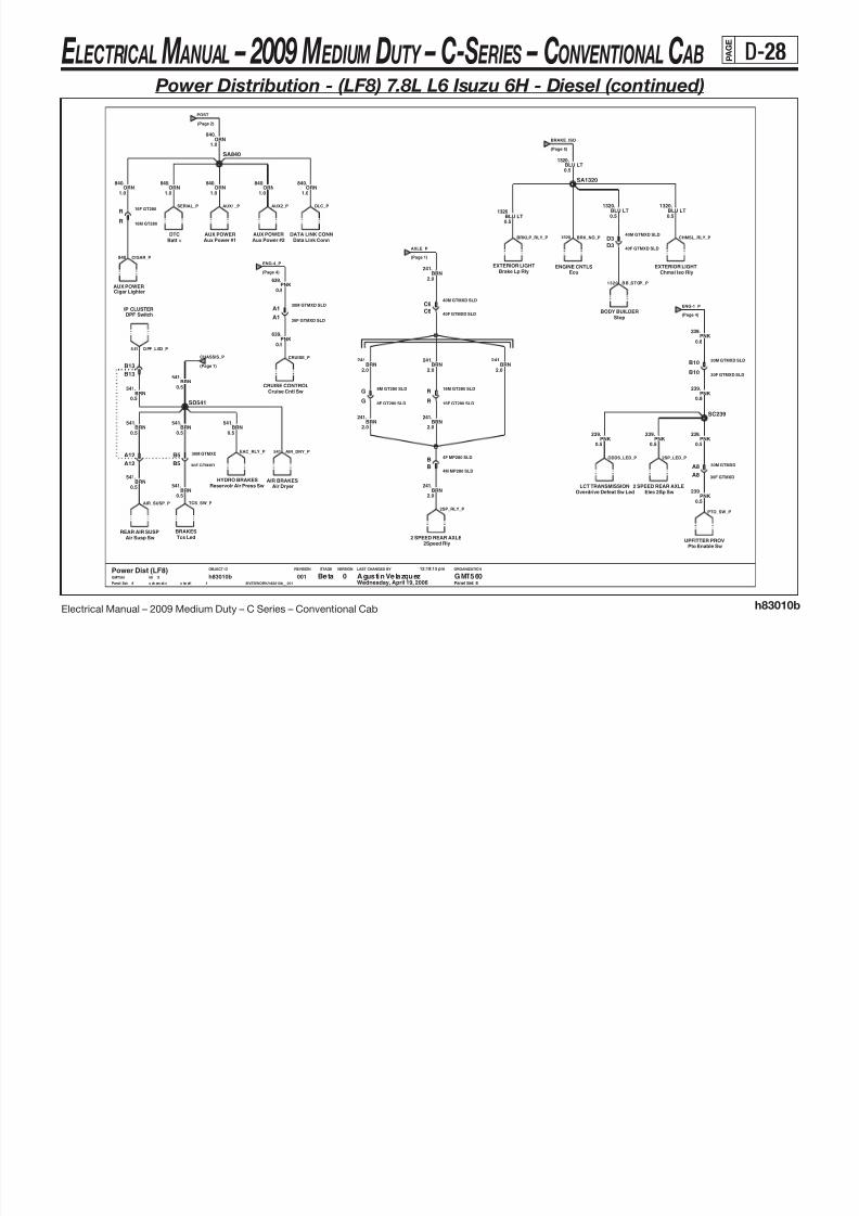
8/10/2019 2009 GM Medium Duty Electrical Manual.PDF
http://slidepdf.com/reader/full/2009-gm-medium-duty-electrical-manualpdf 139/410
Electrical Manual – 2009 Medium Duty – C Series – Conventional Cab h83010b
LAST CHANGED BY
Panel Set:
VERSIONSTAGEREVISIONOBJECT ID ORGANIZATION
Panel Set: 8
0.5
BRN541.
0.5
.541BRN
IP CLUSTERDPF Switch
ORN840.
2.0
.241
1.0
Wednesday, April 19, 2006
12:19:13 pm
$IVEDWORK/h83010b__001s ch em ati c s he et1
h83010b8
001Power Dist (LF8)
BRN
8
Beta Agustin Velazquez GMT5600GMT560 X08
Batt +DTC
2.0
.241BRN
AUX POWERAux Power #2
30F GTMXDA8
0.8PNK
239.
EXTERIOR LIGHTBrake Lp Rly
0.5
0.5
.1320BLU LT
30M GTMXD SLDB10
.1320
BLU LT
1.0
.840ORN
30F GTMXD SLDB10
G8M GT280 SLD
16F GT280R
StopBODY BUILDER
40M GTMXD SLDD3
R
SA1320
16M GT280 SLD
BRN541.
0.5
0.5
.541BRN
DATA LINK CONNData Link Conn
ENGINE CNTLSEcu
.241BRN
2.0
0.5
.239PNK
1320.
0.5BLU LTBLU LT
1320.
0.5
A12
30M GTMXD SLD
A1
840.
1.0ORN
0.5
.239PNK
EXTERIOR LIGHTChmsl Iso Rly
16F GT280 SLDR
ORN840.
1.0
.
1.0ORN
840
B13
8F GT280 SLDG
REAR AIR SUSPAir Susp Sw
239PNK
0.5
.
40F GTMXD SLDD3
A12
SD541
Cigar LighterAUX POWER
2Speed Rly2 SPEED REAR AXLE
B13
PNK639.
HYDRO BRAKESReservoir Air Press Sw
0.8
ORN1.0
.840
4M MP280 SLDB
B5
0.5
.541BRN
30M GTMXD
SA840
Pto Enable SwUPFITTER PROV
40M GTMXD SLDC6
30F GTMXD SLDA1
Tcs LedBRAKES
PNK239.
0.5
4F MP280 SLDB
241BRN
2.0
.
639PNK
0.5
.
SC239
30F GTMXDB5
2.0
Aux Power #1AUX POWER
BRN241.
AIR BRAKESAir Dryer
0.5BRN
541. 2 SPEED REAR AXLEElec 2Sp Sw
R 16M GT280
Cruise Cntl SwCRUISE CONTROL
30M GTMXDA8
LCT TRANSMISSIONOverdrive Defeat Sw Led
241.
2.0BRN
.239PNK
0.8
C6
.541BRN
0.5
40F GTMXD SLD
BRN241.
2.0
CHMSL_RLY_P
1320 BB_STOP_P
1320 BRK_NO_PBRKLP_RLY_P
BRAKE_ISO
(Page 5)
AIR_DRY_P
541 DPF_LED_P
541
SERIAL_P
ENG-1_P
(Page 4)
840 CIGAR_P (Page 1)
AXLE_P
CRUISE_P
(Page 4)
ENG-4_P
ODDS_LED_P
AUX2_P
(Page 2)
POST
AUX1_P DLC_P
2SP_LED_PEAC_RLY_P
CHASSIS_P
(Page 1)
TCS_SW_PAIR_SUSP_P
PTO_SW_P2SP_RLY_P
E LECTRICAL M ANUAL – 2009 M EDIUM DUTY – C-S ERIES – CONVENTIONAL C AB P A G E
D-29
Power Distribution - (LF8) 7.8L L6 Isuzu 6H - Diesel (continued)

8/10/2019 2009 GM Medium Duty Electrical Manual.PDF
http://slidepdf.com/reader/full/2009-gm-medium-duty-electrical-manualpdf 140/410
Electrical Manual – 2009 Medium Duty – C Series – Conventional Cab h83010b
LAST CHANGED BY
Panel Set:
VERSIONSTAGEREVISIONOBJECT ID ORGANIZATION
Panel Set: 9
Dual SIRDriver only
Dual SIR Driver only
SB1139
0.8
.439PNK
PNK0.8
.439
0.5
1139.YEL
PNK439.
0.8
YEL.1139
0.5
1139.YEL
0.5
0.5
1139.YEL
0.5PNK
439.
0.8PNK
439.
0.5
40.ORN
.439PNK
0.5
0.8
.439PNK
16F GT280C
Psir Defeat SwSIR
ORN40.
0.8
16M GT280E
9
Agustin Velazquez GMT5600Power Dist (LF8)GMT560 X08
Wednesday, April 19, 2006
12:19:13 pm
$IVEDWORK/h83010b__001s chem at ic s he et 1
h83010b8
001 Beta
0.8
.439PNK
INTERIOR LIGHTSRear Dome Lamp
16M GT280C
E
0.5
1139.YEL
16F GT280
SA1139
YEL.1139
0.5
ENGINE CNTLSGpcm
A640F GTMXD SLD
PNK439.
0.8
Dome LampINTERIOR LIGHTS
EbcHYD BRAKES
PNK439.
0.8
Psir Delete ResistorSIR
SdmSIR
SA40
ENGINE CNTLSEcu
YEL.1139
0.5
1139.YEL
0.5
IP
30F GTMXD SLDA4
ENG
30M GTMXD SLDA4
.40ORN
0.8
SB439
439.
0.8PNK
40.
0.5ORN
SA439SA439
40M GTMXD SLDA6
30M GTMXDB6
30F GTMXDB6
0.8PNK
439.
PNK439.
0.8
ENGINE CNTLS
DaMU
.40ORN
0.8
DAMU_IGN1
HTR_RLY_D_P2
SIR_OHM_P PSIR_P
(Page 4)
IGNB_RLY_P
(Page 1)
SIR_P
SDM_P
RR_DOME_PDOME_P
(Page 2)
COURTESY_P
IGNA_RLY_P
(Page 4)
ECU_IGN1_P
EBC_IGN1_P
(Page 1)
PCM-I_P
E LECTRICAL M ANUAL – 2009 M EDIUM DUTY – C-S ERIES – CONVENTIONAL C AB P A G E
D-30
Power Distribution - (LF6) 7.2L L6 Caterpillar ® C7 - Diesel

8/10/2019 2009 GM Medium Duty Electrical Manual.PDF
http://slidepdf.com/reader/full/2009-gm-medium-duty-electrical-manualpdf 141/410
Electrical Manual – 2009 Medium Duty – C Series – Conventional Cab h83010c
10A
10A
12182113
12182113
10A
12182112
B
A
10A
START
BB
CHASSIS
BB 20A
12182112
A
A
10A
A
A
B 10A
PCM-I
B
12182114
10A
12182112
BRAKETURN/BACKUP A
12182113 12182112
AUX WIRE RLY
12182114
15A
AXLE
15A
BB
GAUGES
B
20A
A ASIR
A
A
15A
A
B
ILLUM
12182112
TRANS
20A
HTR/AC
B
12182114
12182112 12182112
B
AA
IGN4
LAST CHANGED BY
Panel Set:
VERSIONSTAGEREVISIONOBJECT ID ORGANIZATION
100-1
Panel Set: 1
114-3
IGNSW
040-1
091-1
26062266
110-1TRNHZKEYMNDR
WIPER
034-1
BEAMSW
047-2SIR
PAGE 8A-STEERING COLUMN
CRUISEHORN
010-1
PNK
5.0
.3
L3 L5 L7
M4
N1N3N5N7J3J5J7
K2K4 K6 K8
L1
H4
J1
D2
E1
BRN4.
5.05.0
WHT1390.
C5
IGN1
C6
IGN3
D1
CRANK
D2
BATT 2
D5
BATT 1
D6
IGN4/ACCY
S T A R T
R U N
O F F
L O C K
A C C E S S O R Y
Str Col Asm - Ign Sw
C1
IGN0
HVACHvac
1.0
.141BRN
Rear Heater Rly CoilREAR HEATER
1.0
.141BRN
5.0RED
342.
.
5.0YEL5
BRN141.
1.0 1.0
.141BRN
5.0
.300ORN
Dimmer Signal DistINTERIOR LIGHTING
001Wednesday, April 19, 20061
Beta Agustin Velazquez GMT5600Power Dist (LF6)GMT560 X08
12:21:44 pm
$IVEDWORK/h83010c__001s ch em ati c s he et 1
h83010c7
5.0
.300ORN
.141BRN
1.0
SA141
ORN300.
5.0
SA300
INTERIOR LIGHTSHead Lamp Sw
Temperature MotorHVAC
Rear Defog CntlREAR DEFOGGERHVAC
Vacuum Pump
BRN141.
1.0
ILLUM8
SIR_P
(Page 9)1139
R_HTR_RLY_P
IGN3_MAXI
(Page 2)
IGN1_MAXI
(Page 2)242
HVAC_P TEMP_CNTL_P VAC_PUMP_P HVAC_FOG_P
(Page 6)
TURN_PGAUGES_P
(Page 6)39
(Page 8)
PCM-I_P
439
TRANS_P
(Page 7)1020 441
(Page 6)
BRAKE_P
4 4 D IM ME R
(Page 8)541
CHASSIS_PAXLE_P
241(Page 8)
641(Page 6)
AUX_WIRE_P IGN4_P
(Page 7)43
START_P
(Page 6)806139

8/10/2019 2009 GM Medium Duty Electrical Manual.PDF
http://slidepdf.com/reader/full/2009-gm-medium-duty-electrical-manualpdf 142/410
E LECTRICAL M ANUAL – 2009 M EDIUM DUTY – C-S ERIES – CONVENTIONAL C AB P A G E
D-32
Power Distribution - (LF6) 7.2L L6 Caterpillar ® C7 - Diesel (continued)

8/10/2019 2009 GM Medium Duty Electrical Manual.PDF
http://slidepdf.com/reader/full/2009-gm-medium-duty-electrical-manualpdf 143/410
Electrical Manual – 2009 Medium Duty – C Series – Conventional Cab h83010c
ECM-B
30A 40A
12077842
B
A
Maxi
B40A
A
BB12065933
STUD A ABS 2 15319538A
30AB
Maxi
E/A PUMP
B
ECM-C
25A12065933B
12065933 20A
Maxi
25AB
15319538STUD B
Maxi Maxi Maxi Maxi
B 50A12065932
HORNA
B
Maxi
12065933
A
12065932ABS 3 ABS 1
40A
ENGINE
Maxi
Maxi
A AA
1206593440A
A A
LAST CHANGED BY
Panel Set:
VERSIONSTAGEREVISIONOBJECT ID ORGANIZATION
Panel Set: 3
HORN RLY 40A-1STARTER RLY
22A/C-1FUEL PUMP RLY18A-2PTO RLY
12146281Underhood Distribution Center
30A/E-1
PAGE 8A-
Horn RlyHORN
.
2.0ORN
1540
RED1642.
3.0
Ebc / RlyBRAKES
BATTERIESBattery Positive
D4 30M GTMXD SLD
HYDRO BRAKESEbc
3.0
.1642RED
1540ORN
2.0
.
A4
5.0RED
1042.
3.0
.1642RED
A2
Trailer WiringTRLR WRG
J1-M5 J1-M6 J1-M7 J1-M8
J2-AJ3-AUHBATT
J1-M1J1-M2 J1-M3 J1-M4A B
ORN1840.
3.0
3.0
RED1642.
RED1042.
5.0
LB740
RED42.
3.0
Loop Anchor
ORN740.
1.0
1642.
3.0RED
5.0
.1042RED
.
1.0ORN
740
EcuENGINE CNTLS
0 GMT560Agustin VelazquezBeta3
0017
h83010csheet1schematic $IVEDWORK/h83010c__001
12:21:44 pm
Wednesday, April 19, 200608 XGMT560
Power Dist (LF6)
Elec Air CompHYDRO BRAKES
A2
ENGINE CNTLSEcu
SA1642
Loop Anchor
LA740
HYDRO BRAKESEbc
RED3.0
.442
D430F GTMXD SLD
.42RED
3.0
30F GTMXD SLDD4 A4
.740ORN
1.0
Horn RlyHORN
D4
1.0
.740ORN
30M GTMXD SLD
SA1042
CAT_BA TA_P CAT_BA TB_P
1 1
BUSBAR2_P
(Page 4)
HORN_RLY_PEAC_MTR_P
EBC_P442ABS_TRLR_P
(Page 4)
BUSBAR_P
EBC2_P
(Page 4)
IGN_A_P
IGN_B_P
(Page 4)
HORN_P
UHDIST_P
HYD_EBC_P
E LECTRICAL M ANUAL – 2009 M EDIUM DUTY – C-S ERIES – CONVENTIONAL C AB P A G E
D-33
Power Distribution - (LF6) 7.2L L6 Caterpillar ® C7 - Diesel (continued)

8/10/2019 2009 GM Medium Duty Electrical Manual.PDF
http://slidepdf.com/reader/full/2009-gm-medium-duty-electrical-manualpdf 144/410
Electrical Manual – 2009 Medium Duty – C Series – Conventional Cab h83010c
IGNA RLY
12193604
IGNB RLY
12088567
PCM-B
B
A
15092075
AA/C COMPA
B B
1209207912092079
10A
12092079
A A
B10A
ENG-1
12092078
ENG-3
10A
REAR DEFOG
30AB 15A
LAST CHANGED BY
Panel Set:
VERSIONSTAGEREVISIONOBJECT ID ORGANIZATION
Panel Set: 4
.1RED
5.0
ORN1240.
0.8
.
5.0PPL
2000
Loop Anchor
LB2000
REAR DEFOGGERRear Defog Cntl
GND DISTGnd Zone #2C
J1-K7
J1-L8
J1-H5J1-H7
J1-J4 J1-J6J1-J8
J1-K5J1-F7
J1-G2 J1-G4 J1-G6J1-G8
J1-H3
Uh - Block Asm
J1-F1 J1-F3 J1-F5
A6
B4B6
C4C6
D4 D6
87
86
85
3086
8785
Uh - Ign Rlys
A4
HVACEnable Rly
Loop Anchor
LA2000
1093.
2.0PPL
GND DISTGnd Zone #2C
PPL5.0
.2000
C7
2.0
.1093PPL
40M GTMXD SLD
40F GTMXD SLDC7
2000
PPL5.0
.
4
0017
h83010csheet1schematic $IVEDWORK/h83010c__001
12:21:44 pm
Wednesday, April 19, 200608 XGMT560
Power Dist (LF6)0 GMT560Agustin VelazquezBeta
2000.
5.0PPL
RED5.0
.1
ENG-1_P
239(Page 8)
1042
(Page 3)
IGN_B_P
539(Page 8)
ENG-3_P
2 50 I GN A_ RL Y_ G 2 50 I GN B_ RL Y_ G
439
IGNA_RLY_P
(Page 8)
439(Page 8)
IGNB_RLY_P
1042
IGN_A_P
(Page 3)
(Page 7)440
PCM-B_P
HVAC_RLYB_P
DEFOG_P
BUSBAR_P
(Page 3)
BUSBAR2_P
(Page 3)
E LECTRICAL M ANUAL – 2009 M EDIUM DUTY – C-S ERIES – CONVENTIONAL C AB P A G E
D-34
Power Distribution - (LF6) 7.2L L6 Caterpillar ® C7 - Diesel (continued)
L A h

8/10/2019 2009 GM Medium Duty Electrical Manual.PDF
http://slidepdf.com/reader/full/2009-gm-medium-duty-electrical-manualpdf 145/410
Electrical Manual – 2009 Medium Duty – C Series – Conventional Cab h83010c
A
B
AA
B
12182112 12182112 12182116 12182112
A A
B
A
B 25A
A
BB
O NS TA R R H P AR KL AM P
12182113
15A
A
B
LH PARKLAMP
10A
PWR WINDOW RADIO U
10A
BRAKE ISO
10A
L-RR TRUCK
10A12182112 12182112 12182112
10A
R-RR TRUCK
10A B
LAST CHANGED BY
Panel Set:
VERSIONSTAGEREVISIONOBJECT ID ORGANIZATION
MARKER LAMP RLY 110A-4
LH TURN TRAILER RLY
I/P Distribution/Relay CenterPAGE 8A-
110A-2
DRL RLY
HEATED MIRROR RLY
102A-1
CHMSL RLY
147B-1
RH TURN TRAILER RLY
BRAKE LAMP RLY110A-2110A-2
110A-2
12129833
Panel Set: 5
BA2040
Blunt Cut
SH2509
POWER WINDOWWindow Switch
0.5BRN
2509.
EXTERIOR LIGHTINGRight Front Parklamp
1.0BRN/WHT
.2609
SE2509
1.0
2609.BRN/WHT
Right Rear ParklampEXTERIOR LIGHTING
619
1.0GRN DK
.
SA2609
SB2609
GND DISTGnd Zone #4B
.2509
2.0BRN
YEL.618
1.0
BRN/WHT.2609
1.0
Overdrive Defeat Sw IllumLCT TRANSMISSION
B4
755.5.0
BLK
S5
S6
S7
S8
T3
T4
R1
R2 R4
R5
R6R8
S3
S4
12193604
Ignition 4
86 30
85
Ip2 - Block Asm
L30
L85
L86
L87
Lr Turn LpEXTERIOR LIGHT
EXTERIOR LIGHTINGLeft Front Parklamp
40F GTMXD SLDC12
BRAKESBrake Switch
ORN2040.
0.8
Rr Turn LpEXTERIOR LIGHT
.1242RED
5.0
EXTERIOR LIGHTINGLeft Rear Parklamp
1.0
2509.BRN
0.8
2509.BRN
Head Lamp SwEXTERIOR LIGHT
1.0
2609.BRN/WHT
BODY BUILDERLeft Park
Switch IllumINTERIOR LIGHTING
GMT560Agustin VelazquezBeta5
0017
h83010csheet1schematic $IVEDWORK/h83010c__001
12:21:44 pm
Wednesday, April 19, 200608 XGMT560
Power Dist (LF6)0
Right Park BODY BUILDER
5.0
Turn Haz SwEXTERIOR LIGHT
1.0
BLK755.
BRN.2509
BRN.2509
1.0
1.0
2609.BRN/WHT
Turn Haz SwEXTERIOR LIGHT
40M GTMXD SLDC12B4
Door Switch IllumINTERIOR LIGHTING
BRN/WHT2.0
2609.
Marker Lamp RlyEXTERIOR LIGHTING
BRN.2509
Loop Anchor
LA755
1.0
43(Page 7)
IGN4_RLY
IGN4_MAX
(Page 2)
RR_STOP_LP199 PARK_LP_P 18 LR_STOP_LP BRAKE_ISO_P17
(Page 8)1320
BRAKE_ISO
MRK_RLY_P
450 IGN4_RLY_G
WIN_IGN4_P343
DOOR_SW_ILL2509
BB_L_PARK2609 BB_R_PARK
ODDS_LPSW_ILLUM
2509RFR_PARK_P LFR_PARK_PR_TAIL_P L_TAIL_P
LR_TURN_P RR_TURN_P
E LECTRICAL M ANUAL – 2009 M EDIUM DUTY – C-S ERIES – CONVENTIONAL C AB P A G E
D-35
Power Distribution - (LF6) 7.2L L6 Caterpillar ® C7 - Diesel (continued)

8/10/2019 2009 GM Medium Duty Electrical Manual.PDF
http://slidepdf.com/reader/full/2009-gm-medium-duty-electrical-manualpdf 146/410
Electrical Manual – 2009 Medium Duty – C Series – Conventional Cab h83010c
LAST CHANGED BY
Panel Set:
VERSIONSTAGEREVISIONOBJECT ID ORGANIZATION
Panel Set: 6
0.5
.806PPL
.39PNK
0.5
PPL
0.5
.806
SA806
Clutch Sw
STARTING & CHARGING
BRN0.5
.441
SA441
SA39
0.8
.641BRN
EXTERIOR LIGHTTurnhaz Sw
0017
h83010csheet1schematic $IVEDWORK/h83010c__001
12:21:44 pm
Wednesday, April 19, 200608 XGMT560
Power Dist (LF6)0 GMT560Agustin VelazquezBeta
6
Headlamp SwINTERIOR LIGHTS
40M GTMXD SLD
C9
39PNK
0.5
.
Brake SwAIR BRAKES
A640F GTMXD SLD
PNK39.
0.5
D330M GTMXD SLD
B240F GTMXD SLD
STARTING & CHARGINGNsbu-Start Sw
30F GTMXD SLDD3
0.8
.
0.8
BRN641.
BRN641
0.8BRN
641.
30M GTMXDA10
B240M GTMXD SLD
BRN641.
0.8
.641BRN
0.8
DRLDrl Rly
SA139
Tt ModuleTELL TALE
30F GTMXDB10
0.8
.139PNK
PNK39.
0.5
POWER MIRRORSHtd Mirror Rly
40F GTMXD SLDC9
PNK139.
0.8
0.8BRN
441.
MD TRANSMISSIONReverse Rly
A640M GTMXD SLD
.441BRN
Reverse RlyLCT TRANSMISSION
Rfa Mdl
KEYLESS ENTRY
0.8
D1 40M GTMXD SLD
39.
0.5
.39PNK
0.5PNK
IP CLUSTERIpc
39.
0.5PNK
0.5
.441BRN
PPL806.
0.8
PPL806.
0.5
PNK139.
0.8
EbcHYD BRAKES
TELL TALETrans Temp Gauge
BODY BUILDER
Ign 3
B1030M GTMXD
0.8
.139PNK
40F GTMXD SLD
D1
AIR BRAKESBrake Rly
BRN441.
0.5
PNK139.
0.8
EXTERIOR LIGHTReverse Sw
Htd Mirror Sw
POWER MIRRORS
SA641
A1030F GTMXD
641
0.8BRN.
DRLDrl Mdl
.39PNK
0.5
806 CRANK_C_P
EBC_CRANK_P
START_P
(Page 1)
806 CRANK2_P
(Page 1)
BRAKE_P
TCC_P
(Page 1)
BRAKE_P
BU_MAN3_P
ILLUM_PIPC_IGN1_P
BU_LCT_PBU_MD_P
TURN_P
(Page 1)
BB_P
TEMP_GAGE_P
139 IGTRNHAZ_P
DRL_RLY_P TELLTALE_ P
EBC_IGN3_P
H_MIR_SW_P
(Page 1)
GAUGES_P
(Page 1)
AUX_WIRE_P
DRL_PH_MIR_RLY_P
RFA_IGN1_P
E LECTRICAL M ANUAL – 2009 M EDIUM DUTY – C-S ERIES – CONVENTIONAL C AB P A G E
D-36
Power Distribution - (LF6) 7.2L L6 Caterpillar ® C7 - Diesel (continued)
PCM-B P

8/10/2019 2009 GM Medium Duty Electrical Manual.PDF
http://slidepdf.com/reader/full/2009-gm-medium-duty-electrical-manualpdf 147/410
Electrical Manual – 2009 Medium Duty – C Series – Conventional Cab h83010c
LAST CHANGED BY
Panel Set:
VERSIONSTAGEREVISIONOBJECT ID ORGANIZATION
Panel Set: 7
30M GTMXDA9
SA1020
0.8ORN
440.
YEL43.
1.0
1.0
.540ORN
1.0
.440ORN
PWR DR LKDrv Dr Lck Sw
ORN540.
1.0
30F GTMXD SLDA2 0.5
.1020PNK
440.
1.0
Sdg MdlSERIAL DATA
ORN
1.0
ORN540.
YEL43.
1.0
B11
ORN540.
1.0
YEL43.
1.0
22F GTMXD
30F GTMXD SLDC4
Wiper SwitchWIPER/WASHER
.
1.0ORN
540
Mirror SwitchPOWER MIRRORS
ORN1.0
.540
.540ORN
30F GTMXDA9
1.0
0.5
.1020PNK
MD TRANSMISSIONTcm
Rear Heater RlyREAR HEATER
B11
ORN540.
1.0
22M GTMXD
Dr Lk RlyPWR DR LK
PWR DR LKPass Dr Lck Sw
MD TRANSMISSIONTcm
TcmTRANSMISSION
Sdg MdlSERIAL DATA
SA43
ORN
1.0
.540
1020.
0.5PNK
Ignition SenseDTC
0.5PNK
1020.
ORN540.
1.0
30M GTMXD SLD C4
TcmTRANSMISSION
1.0ORN
440.
22F GTMXDB11
IpcIP CLUSTER
1.0ORN
440.
SC540
TRANSMISSIONTcm
SA440
1.0
.43YEL
.440ORN
0.8
ORN540.
1.0
TcmMD TRANSMISSION
ORN1.0
.540
1.0
ORN440.
Wiper MotorWIPER/WASHER
TRANSMISSIONTcm
0.8PNK
1020.
PNK0.8
.1020
ORN540.
1.0
30M GTMXD SLDA2
0.5
.440ORN
PNK0.5
ORN
.1020
1.0
.540
.440ORN
1.0
YEL43.
1.0
SA540
IP CLUSTERIpc
0017
h83010csheet1schematic $IVEDWORK/h83010c__001
12:21:44 pm
Wednesday, April 19, 200608 XGMT560
Power Dist (LF6)0 GMT560Agustin VelazquezBeta
7
1.0
.540ORN
KEYLESS ENTRYRfa Mdl
0.8
TcmLCT TRANSMISSION
.1020PNK
SB540
22M GTMXDB11
TCM_BAT_PP2TCM_BAT_PP
MD_CL2
SHIFT_BAT_P
TCM_BAT_P
LCT_IGN0_P
MD_IGN0_P
SHIFT_IGN0_P
R_HVAC_P
(Page 2)
ACCY_P
MD_BAT_P
SDG_1_P
_
(Page 4)
MIR_SW_P
PASS_LK_P
LK_RLY_P RFA_P
DRV_LK_P
TRANS_P
(Page 1)
SDG_2_PIPC_IGN_P
WIPE_PWASH_P
(Page 1)
IGN4_P
IGNSW_D2_P
(Page 5)
IGN4_RLY
E LECTRICAL M ANUAL – 2009 M EDIUM DUTY – C-S ERIES – CONVENTIONAL C AB P A G E
D-37
Power Distribution - (LF6) 7.2L L6 Caterpillar ® C7 - Diesel (continued)
POST

8/10/2019 2009 GM Medium Duty Electrical Manual.PDF
http://slidepdf.com/reader/full/2009-gm-medium-duty-electrical-manualpdf 148/410
Electrical Manual – 2009 Medium Duty – C Series – Conventional Cab h83010c
LAST CHANGED BY
Panel Set:
VERSIONSTAGEREVISIONOBJECT ID ORGANIZATION
Panel Set: 8
Htd Air Rly
ENGINE CNTLS
SA539
0.8PNK
539.
Chmsl Iso Rly
UPFITER PROV
Pto Rly
EXTERIOR LIGHT
C640M GTMXD SLD
BRN541.
0.5
0.8
239.
0.5PNK
EXTERIOR LIGHTBrake Lp Rly
.539PNK
0.5
.1320BLU LT
541BRN
0.5
0.5
.1320BLU LT
.
2 SPEED REAR AXLE
840.
1.0ORN
Pto Enable SwUPFITTER PROV
Elec 2Sp Sw
SC239
0.5PNK
239.
PNK439.
0.8
30M GTMXDB5
8F GT280 SLDG
16F GT280 SLDR
PNK0.8
.239PNK
0.5
0.8PNK
539. .539
239.
SA1320
BLU LT1320.
0.5
30M GTMXD SLDB10
0.8PNK
.541BRN
30F GTMXD SLDB10
B13
0.5
B13
0.8
.439PNK
.
1.0ORN
840
MD TRANSMISSIONReverse Rly
Aux Power #1AUX POWER
ENGINE CNTLSEcu
EcuENGINE CNTLS
BRN2.0
.241
BRN
40F GTMXD SLDC6
0.5
.541
8402.0
.241BRN.
1.0ORN
Overdrive Defeat Sw Led
.239PNK
0.5
LCT TRANSMISSION
BRN241.
2.0
Tcs LedBRAKES
PNK439.
0.8
1.0
.840ORN
TELL TALE
Tt Module
0.8
.439
PNK
AIR BRAKESAir Dryer
30F GTMXD SLDC1
30M GTMXD SLDC1
439PNK
0.8
.
30M GTMXD SLDA4
BRN541.
0.5
PNK
439.
0.8
8M GT280 SLDG
BLU LT1320.
0.5
40F GTMXD SLDD3
A12
SB439
SD541
R
16F GT280R
0017
h83010csheet1schematic $IVEDWORK/h83010c__001
12:21:44 pm
Wednesday, April 19, 200608 XGMT560
Power Dist (LF6)0 GMT560Agustin VelazquezBeta
8
16M GT280
D3
StopBODY BUILDER
40M GTMXD SLD
B5 30F GTMXD
2.0
.241
16M GT280 SLDR
BRN
B
4M MP280 SLDB
4F MP280 SLD
PNK539.
0.8
2 SPEED REAR AXLE2Speed Rly
BRN241
2.0
.
.
2.0
SA439
ORN1.0
.840
241BRN
HYDRO BRAKESReservoir Air Press Sw
30F GTMXD SLDA4
A12
PNK439.
0.8
REAR AIR SUSPAir Susp Sw
IP CLUSTER
DPF Switch
HYD BRAKESEbc
40M GTMXD SLDA6
AUX POWERAux Power #2
ORN840.
AUX POWERCigar Lighter
541.
0.5
1.0
BRN
SA840
Data Link ConnDATA LINK CONN
0.8PNK
439.
0.8
.439PNK
Batt +DTC
241.
2.0
.541BRN
BRN
0.5
40F GTMXD SLDA6
HTR_RLY_P
2SP_LED_PPTO_LED_P
REV_P
ODDS_LED_P
539 HTR_LAMP
BB_STOP_P1320
BRKLP_RLY_P
(Page 4)
ENG-3_P
(Page 4)
ENG-1_P
CHMSL_RLY_P
C_PTO_RLY_P
BRAKE_ISO
(Page 5)
1320 BRK_NO_P
541 DPF_LED_P
CHASSIS_P
(Page 1)
AIR_DRY_P541
2SP_RLY_P
AXLE_P
(Page 1)
CIGAR_P840
AUX2_P
(Page 2)
POST
AUX1_P DLC_PSERIAL_P
EAC_RLY_P
(Page 1)
PCM-I_P
AIR_SUSP_P TCS_SW_P
EBC_IGN1_PCAT_IGN1_P
(Page 4)
IGNB_RLY_P
IGNA_RLY_P
(Page 4)
E LECTRICAL M ANUAL – 2009 M EDIUM DUTY – C-S ERIES – CONVENTIONAL C AB P A G E
D-38
Power Distribution - (LF6) 7.2L L6 Caterpillar ® C7 - Diesel (continued)

8/10/2019 2009 GM Medium Duty Electrical Manual.PDF
http://slidepdf.com/reader/full/2009-gm-medium-duty-electrical-manualpdf 149/410
Electrical Manual – 2009 Medium Duty – C Series – Conventional Cab h83010c
LAST CHANGED BY
Panel Set:
VERSIONSTAGEREVISIONOBJECT ID ORGANIZATION
Driver only Dual SIR
Driver onlyDual SIR
Panel Set: 9
YEL.1139
0.5
SIRSdm
08 XGMT560
Power Dist (LF6)0 GMT560Agustin VelazquezBeta
9
0017
h83010csheet1schematic $IVEDWORK/h83010c__001
12:21:44 pm
Wednesday, April 19, 2006
SB1139
YEL.1139
0.5
YEL.1139
0.5
0.5YEL.1139
30F GTMXDB6
YEL.1139
0.5
ORN
ORN.40
0.5
0.8
.40
YEL0.5
1139.
SIRPsir Delete Resistor
0.5
.40ORN
16F GT280E
INTERIOR LIGHTSDome Lamp Rear Dome Lamp
INTERIOR LIGHTS
30M GTMXDB6
ORN40.
0.8
16M GT280C
16M GT280E
0.5
1139.YEL
SIRPsir Defeat Sw
ORN
SA40
40.
0.80.5
1139.YEL
SA1139
16F GT280C
DOME_P RR_DOME_P
COURTESY_P
(Page 2)
SIR_OHM_P PSIR_P
SIR_P
(Page 1)
SDM_P
E LECTRICAL M ANUAL – 2009 M EDIUM DUTY – C-S ERIES – CONVENTIONAL C AB P A G E
D-39
Ground Distribution - (L18) 8.1L V8 GMPT VORTEC® - Gas –
(LMM) 6.6L V8 Isuzu DURAMAX ® - Diesel

8/10/2019 2009 GM Medium Duty Electrical Manual.PDF
http://slidepdf.com/reader/full/2009-gm-medium-duty-electrical-manualpdf 150/410
Electrical Manual – 2009 Medium Duty – C Series – Conventional Cab h83014a
( )
ENG GND
LAST CHANGED BY
Panel Set:
VERSIONSTAGEREVISIONOBJECT ID ORGANIZATION
GND ZONE #S1
L18
Panel Set: 1
ENGINE TO FRAME GND
L18
GND ZONE #2A
STUD
ZONE_S1
ENGINE CNTLSPcm (O2 Snsr Gnd)
.50BLK
50.0
B
BLK/WHT251.
0.8
M12
Gz S1f ClipA
BLK/WHT0.8
.251
Gz S1e Clip
M12
A
B
SB251
Pcm (O2 Snsr Gnd)ENGINE CNTLS
.251BLK/WHT0.8
0 GMT560Agustin VelazquezBeta1 Wednesday, April 19, 2006
00144
h83014asheet1schematic $IVEDWORK/h83014a__001
12:44:40 pm
08 XGMT560
Ground Dist (L18/LMM)
(Page 2)
2A_L18
O2_HTRA_G O2_HTRB_G
(Page 7)
FRAME
E LECTRICAL M ANUAL – 2009 M EDIUM DUTY – C-S ERIES – CONVENTIONAL C AB P A G E
D-40
Ground Distribution - (L18) 8.1L V8 GMPT VORTEC® - Gas –
(LMM) 6.6L V8 Isuzu DURAMAX ® - Diesel (continued)
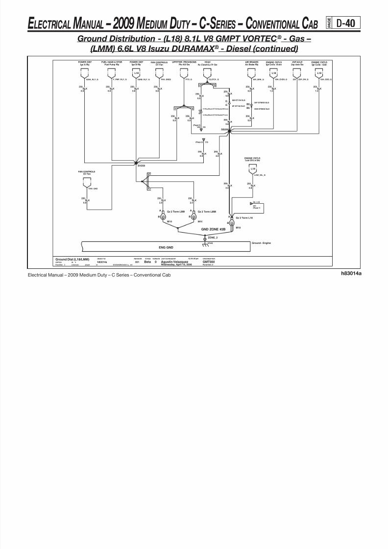
8/10/2019 2009 GM Medium Duty Electrical Manual.PDF
http://slidepdf.com/reader/full/2009-gm-medium-duty-electrical-manualpdf 151/410
Electrical Manual – 2009 Medium Duty – C Series – Conventional Cab h83014a
( ) ( )
ENG GND
LAST CHANGED BY
Panel Set:
VERSIONSTAGEREVISIONOBJECT ID ORGANIZATION
L18
GND ZONE #2B
Panel Set: 2
L18
L18 L18
Ground - EngineSTUD
ZONE_2
.250BLK
0.8
BLK250.
0.8
BLK250.
2.0
EV FanFAN CONTROLS
Gz 2 Term LMM
M10
A
B
2sp Axle Sw2SP AXLE
SV250
ENGINE CNTLSIgn Coils - EvenIgn A Rly
POWER DISTPto Kill Sw
UPFITTER PROVISIONS
0.8BLK
250.
BLK250.
2.0
0.8
.250
BLK
FAN CONTROLSEV Fan
BLK
250.
0.8
0.8
.250BLK
SS250
250.
2.0BLK
.250BLK
0.8
HVACAc Clutch/Lo Pr Sw
M10
Gz 2 Term LMMA
B A
B
250.
0.8BLK
M10
Gz 2 Term L18
30M GTMXD SLDB5
2.0
.250BLK
FUEL HAND & STORFuel Pump Rly
AIR BRAKESAir Brake Rly Ign Coils - Odd
ENGINE CNTLS
BLK0.8
G
.250
8F GT150 SLD
POWER DISTIgn B Rly
G 8M GT150 SLD
14 Way Black GT150 Sealed M ConnG
14 Way Black GT150 Sealed F ConnG
.250BLK
0.8
0.8
.250BLK
30F GTMXD SLDB5
250.
1.0
0.8BLK
250.
BLK BLK1.0
.250
0.8BLK
250.
0.8
.250BLK
ENGINE CNTLSLow Oil Lvl Sw
2
00144
h83014asheet1schematic $IVEDWORK/h83014a__001
12:44:40 pm
Wednesday, April 19, 200608 XGMT560
Ground Dist (L18/LMM)0 GMT560Agustin VelazquezBeta
(Page 2)
FAN_GND
FAN_GND2 CLUTCH_G 250 2SP_SW_G
250 CG
LOW_OIL_G
251
2A_L18
(Page 1)
CG(Page 2)
PTO_GIGNA_RLY_G IGN_ODD_GAIR_BRK_G IGN_EVEN_GIGNB_RLY_GF_PMP_RLY_G
E LECTRICAL M ANUAL – 2009 M EDIUM DUTY – C-S ERIES – CONVENTIONAL C AB P A G E
D-41
Ground Distribution - (L18) 8.1L V8 GMPT VORTEC® - Gas –
(LMM) 6.6L V8 Isuzu DURAMAX ® - Diesel (continued)

8/10/2019 2009 GM Medium Duty Electrical Manual.PDF
http://slidepdf.com/reader/full/2009-gm-medium-duty-electrical-manualpdf 152/410
Electrical Manual – 2009 Medium Duty – C Series – Conventional Cab h83014a
BDY GND
LAST CHANGED BY
Panel Set:
VERSIONSTAGEREVISIONOBJECT ID ORGANIZATION
GND ZONE #7A
Panel Set: 3
GND ZONE #7B
BLK750.
3.0
SC750
16F GT280B
EXTERIOR LIGHTSTurn/Haz/Flash
B12
BLK750.
1.0
1.0
.750BLK
Roof Marker LpsEXTERIOR LIGHTS
Ipc Pwr GndIP CLUSTER
0.5
.750BLK
WIPERSWasher Pump
DPF SwitchIP CLUSTEREXH BRAKE/RSTR
Exhaust Brake Sw
B12
SY750
Elec 2 Speed Sw2 SPEED AXLE
0.5 0.5
.750BLK
750.BLK
Wiper MtrWIPERS
0.5BLK
High Idle SwENGINE CNTRLS
.750
750.
0.5BLK
SD750
Overdrive Defeat Sw IllumLCT TRANSMISSION
750.
0.8BLK
B4
Dlc Pwr GndDLC
Park Brake SwPARK BRAKE
BLK750.
0.8
30F GTMXDB7
TRACTOR WIRINGTractor Conn
0.5
.750BLK
1.0
.750BLK
BLK750.
0.5
M6.3
Gz 7a TermA
B
.750BLK
1.0
0.5BLK
750.
16M GT280B
STUD
ZONE_7
Horn SwitchHORN
B730M GTMXD
BLK750.
0.5
.2250BLK
2.0
.2250BLK
0.35
Pto Enable Sw/LedUPFITTER PROVISION
AUXILLARY PWRCigar Lighter
BLK750.
1.0
SM750
BLK750.
0.8
BLK2.0
.750
750.
0.5BLK
INTERIOR LIGHTSHeadlamp Sw
LCT TRANSMISSIONOverdrive Defeat Sw
Wednesday, April 19, 20063
00144
h83014asheet1schematic $IVEDWORK/h83014a__001
12:44:40 pm
08 XGMT560
Ground Dist (L18/LMM)0 GMT560Agustin VelazquezBeta
Chime MdlCHIME
.750BLK
3.0
B4
BLK750.
0.5
4WD ATC MdlACTIVE TRANSFER CASE
BLK
750.
3.0
BLK750.
1.0
Diff Lk SwTELL TALE
1.0BLK
750.
0.5
.750BLK
BLK750.
1.0
Drl MdlDRL
0.5
.750BLK
.750BLK
0.8
.750
4WD ATC MdlACTIVE TRANSFER CASE
TELL TALETtm - PTO
BLK0.5
Ttm - ExhaustTELL TALE
BLK750.
1.0
WIPERSLow Wash Fluid Sw
2.0
.750BLK
BLK750.
0.5
SN750
PTO_TT_G HIS_G DPF_SW2SP_SW1_G
750
CHI ME _G ODDS_S W_G ODDS_I LL_G
4WDSWG
ATCMDLG
P_BRK_G
TRACTOR_G
HEADLPSW_G
CIGAR_G EXH_TT_G
MARKERS_G
PTO_LED_G(Page 9)
ZONE7A
DRL_G WPR_MTR_G
EXH_SW_G
LOW_WASH_GWSHR_PMP_G
TRNHAZ_G DATA1_GIP_PWR_G
HORN_SW_G DIFF_LK_G
E LECTRICAL M ANUAL – 2009 M EDIUM DUTY – C-S ERIES – CONVENTIONAL C AB P A G E
D-42
Ground Distribution - (L18) 8.1L V8 GMPT VORTEC® - Gas –
(LMM) 6.6L V8 Isuzu DURAMAX ® - Diesel (continued)

8/10/2019 2009 GM Medium Duty Electrical Manual.PDF
http://slidepdf.com/reader/full/2009-gm-medium-duty-electrical-manualpdf 153/410
Electrical Manual – 2009 Medium Duty – C Series – Conventional Cab h83014a
LAST CHANGED BY
Panel Set:
VERSIONSTAGEREVISIONOBJECT ID ORGANIZATION
BDY GND
Panel Set: 4
SAME AS LEFT
OSRVM
550
GND ZONE #5
TXL
RH_MRK_G
2
50
BLK
12065398
.BLK.
0.8
Pass Htd Mir Head8A-
=&DB6/DB8
TXL
=&DB6/DB7
Rh Mirror Mrkr Lp
0.8
R_H_MIR_G
8A-147B
OSRVM
1950
147B 2
8F MP150
-
POWER MIRRORS
OSRVMB
POWER MIRRORS
550
-
19
A
Page Page
SB550
BLK1.0
.550
A
0.5
.550BLK
Drv Htd Mir HeadPOWER MIRRORS
BLK0.5
.550
8F MP150B
POWER MIRRORSMirror Sw
BLK550.
1.0
.550BLK
3.0
POWER WINDOWSPass Win Sw
.550BLK
0.58M MP150
B
POWER WINDOWSDrv Window Sw
1.0
.550BLK
Pass Door Jamb SwINTERIOR LIGHTING
Gz 5 Term
M6.3
A
B
BLK550.
0.5A8M MP150
B
550.
0.8BLK
B822M GTMXD
00144
h83014asheet1schematic $IVEDWORK/h83014a__001
12:44:40 pm
Wednesday, April 19, 200608 XGMT560
Ground Dist (L18/LMM)0 GMT560Agustin VelazquezBeta
4
0.8
.550BLK
POWER DOORSDrv Door Rly
BLK550.
0.5
3.0
.550BLK
STUD
ZONE_5
550.
1.0BLK
22F GTMXDB8
22F GTMXDB8
Gz 5 Term
M6.3
A
B
550.
0.5BLK
SA550
1.0BLK
550.
3.0BLK
550.
B822M GTMXD
A
SC550
POWER DOORS
BLK550.
3.0
Drv Dr Lck Sw
BLK550.
1.0
3.0BLK
550.
0.8
.550BLK
.550BLK
0.5
0.8
1.0
.550BLK
INTERIOR LIGHTINGDrv Door Jamb Sw
.550BLK
Lh Mirror Mrkr LpPOWER MIRRORS
BLK550.
0.8
BLK550.
0.8BLK
550.
0.8
POWER DOORSPass Dr Lck Sw
BLK550.
1.0
KEYLESS ENTRYRfa Mdl
LDOORJAM_G RDOORJAM_GPASS_WIN_G550 DR_WIN_G
(Page 12)
ZONE5
RFA_G
LH_MRK_GL_H_MIR_GDRV_LK_G
LK_RLY_G
PASS_LK_GMIR_SW_G
E LECTRICAL M ANUAL – 2009 M EDIUM DUTY – C-S ERIES – CONVENTIONAL C AB P A G E
D-43
Ground Distribution - (L18) 8.1L V8 GMPT VORTEC® - Gas –
(LMM) 6.6L V8 Isuzu DURAMAX ® - Diesel (continued)

8/10/2019 2009 GM Medium Duty Electrical Manual.PDF
http://slidepdf.com/reader/full/2009-gm-medium-duty-electrical-manualpdf 154/410
Electrical Manual – 2009 Medium Duty – C Series – Conventional Cab h83014a
BDY GND
LAST CHANGED BY
Panel Set:
VERSIONSTAGEREVISIONOBJECT ID ORGANIZATION
FOOT PARK BRAKE CASE GND
Panel Set: 5
GND ZONE #4B
(Family 2) GND ZONE #6
1.0BLK
450.
0.8
.1751BLK/WHT
SH450
.450BLK
0.8
REAR DEFOGGERRear Defog Cntrl
0.5BLK/WHT
1751.
POWER MIRRORSHtd Mirror Rly
BLK450.
0.5
Gz 4b Term
M6.3
A
B
.450BLK
1.0
AUX POWERAux Outlets
SK450
0.8BLK
450.
5.0
.450BLK
BLK1.0
.450BLK
0.5
.450
Foot Park Brake Sw
PARK BRAKE
16M GT280P
BLK450.
0.5
CASE
CASE_P
STUD
ZONE_4 ZONE_6
STUD
TELL TALETrans Temp Gauge Illum
Blower MtrHVAC
Chmsl RlyEXTERIOR LIGHTS
Heated Fuel RlyHTD FUEL/WATER IN FUEL
Gz 6 Term
M6.3
A
B
0.8
.450BLK
AUX POWERAux Outlets
0.5
.450BLK
0 GMT560Agustin VelazquezBeta5
00144
h83014asheet1schematic $IVEDWORK/h83014a__001
12:44:40 pm
Wednesday, April 19, 200608 XGMT560
Ground Dist (L18/LMM)
450.
5.0BLK
0.5BLK
450.
1.0
.450BLK
Brake Lp RlyEXTERIOR LIGHTS POWER DIST
Ign4 Rly
P16F GT280
.450BLK
0.8
Rh Trailer RlyEXTERIOR LIGHTS
2.0
.450
Temp MtrHVAC
BLK
HVACHvac Head
SJ450
SIRSdm
0.8BLK
450.
EXTERIOR LIGHTSLh Trailer Rly
TELL TALESys Air Press Gauge Illum
1.0BLK
450.
SDM_G
(Page 6)
ZONE4A
FOOT_G
AUX2_G HVAC_FOG_G
HFUEL_R3_G
AUX1_G CHMSL_RLY_GGAUGES_G
BRKLP_RLY_G
PNEUTC_GTEMP_CNTL_G RH_HAZ_G LH_HAZ_G
BLWR_RLY_G
H_MIR_RLY_G HVAC_G
IGN4_RLY_G
E LECTRICAL M ANUAL – 2009 M EDIUM DUTY – C-S ERIES – CONVENTIONAL C AB P A G E
D-44
Ground Distribution - (L18) 8.1L V8 GMPT VORTEC® - Gas –
(LMM) 6.6L V8 Isuzu DURAMAX ® - Diesel (continued)

8/10/2019 2009 GM Medium Duty Electrical Manual.PDF
http://slidepdf.com/reader/full/2009-gm-medium-duty-electrical-manualpdf 155/410
Electrical Manual – 2009 Medium Duty – C Series – Conventional Cab h83014a
BDY GND
LAST CHANGED BY
Panel Set:
VERSIONSTAGEREVISIONOBJECT ID ORGANIZATION
GND ZONE #S2
Panel Set: 6
Page
RADIO
RDOANT_G
GND ZONE #4A
8A-150A
GND ZONE #8
-
BODY TO FRAME GND
Antenna Shield1
A
B
M6.3
Gz 8 Term
BLK/WHT1451.
0.8
B
M6.3
Gz 4a TermA
Gz S2b TermA
B
M8
50.0BLK
50.
REAR DEFOGGERRear Defog Grid
1451.
0.8BLK/WHT
751.
0.8BLK/WHT
4WD ATC MdlACTIVE TRANSFER CASE
ZONE_8
STUD
ZONE_S2
STUD Ground-BodyCASE
CASE1_P
Gz S2f Term
M12
A
B
BLK/WHT0.8
.1451
RADIO/CHIMESdgRadio/Chime Module
SERIAL DATA GATEWAY
SB1451
Wednesday, April 19, 2006001
44
h83014asheet1schematic $IVEDWORK/h83014a__001
12:44:40 pm
08 XGMT560
Ground Dist (L18/LMM)0 GMT560Agustin VelazquezBeta
6
.850BLK
2.0
1451BLK/WHT0.8
.
Dlc Sig GndDATA LINK CONN
1.0
.1451BLK/WHT
ZONE_S2
STUD
IP CLUSTERIp Signal Gnd
ACT_4WDG
RADIO_G
ZONE4A
(Page 5)
SDG_GDATA2_GIP_SIGNAL_G
DEFOG_G
E LECTRICAL M ANUAL – 2009 M EDIUM DUTY – C-S ERIES – CONVENTIONAL C AB P A G E
D-45
Ground Distribution - (L18) 8.1L V8 GMPT VORTEC® - Gas –
(LMM) 6.6L V8 Isuzu DURAMAX ® - Diesel (continued)

8/10/2019 2009 GM Medium Duty Electrical Manual.PDF
http://slidepdf.com/reader/full/2009-gm-medium-duty-electrical-manualpdf 156/410
Electrical Manual – 2009 Medium Duty – C Series – Conventional Cab h83014a
LAST CHANGED BY
Panel Set:
VERSIONSTAGEREVISIONOBJECT ID ORGANIZATION
LEFT FRAME GROUND
FRAME GND
GND ZONE #12B (FAM 3)GND ZONE #12A (FAM 2)
GND ZONE #1A
GND ZONE #1B
GND ZONE #B
Panel Set: 7
Bus
Bus Not Bus
Bus Not Bus
Hydromax SwHYDRO BRAKES
B
Right Frame Term
E 1/2
A Gz 1a Term
M12
A
B
E 1/2
Left Frame Term
A
B
Trailer ConnTRAILER WIRING
Fuel Gnd TermA
B
M12
Fuel Pump/Tank FAM 2 FUEL HAND & STOR
SA151
BLK/WHT151.
3.0
EbcHYDRO BRAKES
BLK5.0
.150
SD151
Ground - Left Frame
ZONE_B
STUD
ZONE_B2
STUD
50.
103.0BLK
XGMT560
Ground Dist (L18/LMM)0 GMT560Agustin VelazquezBeta
7 Wednesday, April 19, 2006001
44
h83014asheet1schematic $IVEDWORK/h83014a__001
12:44:40 pm
08
BATTERIESBattery (Neg)
BLK/WHT8.0
.151
3.0
.151BLK/WHT
Gz B Term
M12
A
B
Gnd Stud Conn Term
M12
A
B
BLK/WHT13.0
.151
BLK13.0
.50
FUEL HAND & STORFuel Pump/Tank
M12
A
B
Gz 1b Term
BLK/WHT151.
8.0
Hydromax MtrHYDRO BRAKES
BLK/WHT151.
0.8
SB151
BLK/WHT151.
3.0
EbcAIR BRAKES
B
Fuel Gnd Term
M12
A
ZONE_BZONE_S1
STUD Ground-Frame
GND_CONN
STUD STUD
ZONE_1ZONE_12
STUDSTUD
M12
Gz 1a TermA
B
EbcHYDRO BRAKES
B3D_FUEL_G350
HYD_A_GHYD_B_GHYMAX2_GBATTNEG_G50
350 FUEL_PMP_G
TRAILER_G
HYMAX1_G
(Page 8)
STD_CONN_G
(Page 1)
FRAME
AIR_G
E LECTRICAL M ANUAL – 2009 M EDIUM DUTY – C-S ERIES – CONVENTIONAL C AB P A G E
D-46
Ground Distribution - (L18) 8.1L V8 GMPT VORTEC® - Gas –
(LMM) 6.6L V8 Isuzu DURAMAX ® - Diesel (continued)

8/10/2019 2009 GM Medium Duty Electrical Manual.PDF
http://slidepdf.com/reader/full/2009-gm-medium-duty-electrical-manualpdf 157/410
Electrical Manual – 2009 Medium Duty – C Series – Conventional Cab h83014a
LAST CHANGED BY
Panel Set:
VERSIONSTAGEREVISIONOBJECT ID ORGANIZATION
GND ZONE #3D
GND ZONE #3C
Panel Set: 8
FAM 3
ABS DeleteWith ABS
With Rear Air Susp Without Rear Air Susp
Air BrakesHydro Brakes
With ABSABS Delete
REAR AIR SUSPRear Air Susp Sol
2SPD AXLE
4F MP280 SLDC
2spd Axle Mtr
2.0BLK
350.
2.0
.350BLK
SB350
BUS UPFITTERBack Up Alarm
BLK350.350
BLK2.0
.
2.0
5.0
.350BLK
350.
2.0BLK
S
2.0
.350BLK
16F GT280 SLDS
16M GT280 SLD
BLK350.
2.0
BLK350.
0.8
BATT GND
J3-A
#3CZONE
C
J4-A
ZONE#3D
D
UP
J5-A
FITTER
E
J6-A
UPFITTER
F
J7-AJ7-J6-
Gnd Blk Connector Asm
ZONE
J1-A
#3A
A
J2-A
ZONE#3B
B
1206654512065172
EXTERIOR LIGHTSTail Lamps
BLK2.0
.350
.350BLK
IP CLUSTERLow Air Press Sw - Sec
0.8
C 4M MP280 SLD
2.0
.350BLK
SC350
FUEL HAND & STORFuel Pump/Tank
D
2.0
8F GT280 SLD
.350BLK
00144
h83014asheet1schematic $IVEDWORK/h83014a__001
12:44:40 pm
08
Wednesday, April 19, 2006XGMT560
Ground Dist (L18/LMM)0 GMT560Agustin VelazquezBeta
8
2.0
.350BLK
8M GT280 SLDD
.350BLK
0.8
AIR_SW_G
2SP_MTR_G
TAIL_LP_GBU_G SUSP_SOL_G(Page 11)350
ZONE3B
ZONE3A351
(Page 10)
350 FUEL_SEND_G
STD_CONN_G
(Page 7)50
E LECTRICAL M ANUAL – 2009 M EDIUM DUTY – C-S ERIES – CONVENTIONAL C AB P A G E
D-47
Ground Distribution - (L18) 8.1L V8 GMPT VORTEC® - Gas –
(LMM) 6.6L V8 Isuzu DURAMAX ® - Diesel (continued)

8/10/2019 2009 GM Medium Duty Electrical Manual.PDF
http://slidepdf.com/reader/full/2009-gm-medium-duty-electrical-manualpdf 158/410
Electrical Manual – 2009 Medium Duty – C Series – Conventional Cab h83014a
LAST CHANGED BY
Panel Set:
VERSIONSTAGEREVISIONOBJECT ID ORGANIZATION
CASE GNDENGINE
To: GND ZONE #7A
Panel Set: 9
STARTING & CHARGINGStarter Motor
Mkr Lmp Sw
SB750
SA750
EXTERIOR LIGHTS
EXHAUST BRAKEExh Brk Sw/Illum
ENGINE CNTRLSHi Idle Sw Illum
.750BLK
0.5BLK
750.
0.8
REAR AIR SUSPAir Susp Sw/Led
BLK750.
0.5
BLK2.0
.750
0.5
.750BLK
.750BLK
0.8
L18 ENG CNTLSOdd Knock Sensor
08
12:44:40 pm
$IVEDWORK/h83014a__001sc he ma ti c sh ee t1
h83014a44
001Wednesday, April 19, 20069
Beta Agustin Ve lazquez GMT5600Ground Dist (L18/LMM)GMT560 X
Pneumatic Sw IllumINTERIOR LIGHTS
.
0.5BLK
750
BLK750.
0.5
0.5
.750BLK
.750BLK
0.5
0.5
.750BLK
DPF SwitchIP CLUSTER
Traction Cntrl SwBRAKES REAR AIR SUSP
Air Susp Sw/Illum
L18 ENG CNTLSEven Knock Sensor
BLK0.5
.750
CASE_1 CASE_2 CASE_3 CASE_4 CASE_5 CASE_6 CASE_7 CASE_8 CASE_9
Ground-Engine Case
Pto Enable Sw/IllumUPFITTER PROVISION
POWER MIRRORSHtd Mirr Sw/Led
EXTERIOR LIGHTSMkr Lmp Sw/Illum
BLK750.
0.5
Htd Mirr Sw/IllumPOWER MIRRORS
0.5
.750BLK
2nd Generator GndSTARTING & CHARGING
2 SPEED AXLEElec 2 Speed Sw
Generator GndSTARTING & CHARGING
0.5
.750BLK
SIRPSIR Defeat Sw
750(Page 3)
ZONE7A
DPF_ILL
PSIR_G
TCS_G
PNEU_SW_G 2SP_LP_GPTO_ILL_GMRKR_SW_G
H_MIR_ILL_GSUSP_ILL_G H_MIR_LED_GSUSP_LED_G EXH_ILL_G
MRKR2_SW_G HIS_ILL_G
2ND_GEN_GSTARTER_GODD_KNK_GEVEN_KNK_G GEN_G
E LECTRICAL M ANUAL – 2009 M EDIUM DUTY – C-S ERIES – CONVENTIONAL C AB P A G E
D-48
Ground Distribution - (L18) 8.1L V8 GMPT VORTEC® - Gas –
(LMM) 6.6L V8 Isuzu DURAMAX ® - Diesel (continued)

8/10/2019 2009 GM Medium Duty Electrical Manual.PDF
http://slidepdf.com/reader/full/2009-gm-medium-duty-electrical-manualpdf 159/410
Electrical Manual – 2009 Medium Duty – C Series – Conventional Cab h83014a
FUEL TANK
LAST CHANGED BY
Panel Set:
VERSIONSTAGEREVISIONOBJECT ID ORGANIZATION
FUEL TANK
GND ZONE #9 (SIDE TANKS)
GND ZONE #3A
LMM
GND ZONE #10 (SIDE TANKS)
L18
GND ZONE #11 (MID TANKS)
L18L18L18 L18 L18
LMM
Panel Set: 10
LMM
BLK/WHT351.
0.8
TANK_S
Secondary Fuel Tank
.
0.8BLK/WHT
351
0.8
.351BLK/WHT
BLK/WHT351.
0.8
Pcm Gnd 1
ENGINE CNTLS
D3
SC351
30M GTMXD SLD
0.8
.351BLK/WHT
12:44:40 pm
Wednesday, April 19, 200608 XGMT560
Ground Dist (L18/LMM)0 GMT560Agustin VelazquezBeta
10
00144
h83014asheet1schematic $IVEDWORK/h83014a__001
FUEL HAND & STORSec Tank Static Gnd
0.8
.351BLK/WHT
C
BLK/WHT0.8
.351
6F GT280 SLDC
6M GT280 SLD 12M GT280 SLDG
BLK/WHT351.
0.8BLK/WHT
351.
0.8
3.0
.351BLK/WHT
ENGINE CNTLSPcm Gnd 1
C1
Primary Tank Term
M8
A
B
FUEL HAND & STORPrim Tank Static Gnd
TRANSMISSION
Tcm
ENGINE CNTLS
Low Coolant Sw
2.0
.351BLK/WHT
BLK/WHT351.
1.0
3.0
.351BLK/WHT
0.8
.351BLK/WHT
.
0.8BLK/WHT
351
C1
BLK/WHT351.
3.0
2.0
.351BLK/WHT
Primary Fuel Tank
TANK_P
0.8BLK/WHT
351.
1.0
.351BLK/WHT
Pcm Gnd 1ENGINE CNTLS
.
0.8BLK/WHT
351
ENGINE CNTLS
Pcm Gnd 1
2.0
BLK/WHT351.
1.0
BLK/WHT351.
SA351
12F GT280 SLDG
Etc
ELEC THROT CNTRL
30F GTMXD SLDD3
ENGINE CNTLS
Pcm Gnd 1
TRANSMISSION
Tcm
ENGINE CNTLSPcm Gnd 1
ENGINE CNTLS
Maf Sense Pcm Gnd 1
ENGINE CNTLS
Trans Temp SnsrTELL TALE
Fluid Lvl SwHYDRO BRAKES
SB351
.351BLK/WHT2.0
BLK/WHT351.
0.8
Secondary Tank TermA
B
M8
TCM1_G351
ZONE3A
(Page 8)
TEMP_SNSR_G
SFTANK_G350
LMM_2_G LMM_3_G LMM_4_G
L18_1_G L18_2_G L18_3_G L18_4_GLOW_COOL_GMAF_G
FLS_G
350 PFTAN K_G
ETC_G LCT_GG
E LECTRICAL M ANUAL – 2009 M EDIUM DUTY – C-S ERIES – CONVENTIONAL C AB P A G E
D-49
Ground Distribution - (L18) 8.1L V8 GMPT VORTEC® - Gas –
(LMM) 6.6L V8 Isuzu DURAMAX ® - Diesel (continued)

8/10/2019 2009 GM Medium Duty Electrical Manual.PDF
http://slidepdf.com/reader/full/2009-gm-medium-duty-electrical-manualpdf 160/410
Electrical Manual – 2009 Medium Duty – C Series – Conventional Cab h83014a
LAST CHANGED BY
Panel Set:
VERSIONSTAGEREVISIONOBJECT ID ORGANIZATION
50
2.0
-
.
BEAM_G
19
HEADLAMPS
1.0 50
HI_BEAM_G
.
FWDLP
TXL
100B
FWDLP
RTRNPRK_G
19
Page
GND ZONE #3B
HEADLAMPS
1
BLK
Splice for Ether Injector
1.0
HI_BEAM_G
See: 14C-11
Rf Turn/Park Lmps
5M GT280 SLDR_FWDLP
SAME AS LEFT
PageRight High Beams
SF350
Panel Set: 11
110A1
19TXL
50
BLK
.
-
350
C
Right Headlamp-Page 8A- 18A-
350
100A/B 8A-
FWDLP
TXLBLK
350
350
EXTERIOR LIGHTS
15409273
Vacuum PmpHVAC IP CLUSTER
Low Air Press Sw - PrimHORNSHorns
C
5.0BLK
350.
3F MP280 SLD
2.0
.350
BLK
.
0.8BLK
350
BLK
350.
2.0
350.
1.0BLK
SD350
350.
1.0BLK
A 6M GT280 SLD
Lf Turn/Park LmpsEXTERIOR LIGHTS
1.0
.350BLK
0.8BLK
350.
12F GT280 SLDA
1.0
.350BLK
3.0
3.0
.350BLK
BUS UPFITTERGnd
BLK350.
BLK
HEADLAMPSLeft High Beams
350.
1.0
12:44:40 pm
Wednesday, April 19, 200608 XGMT560
Ground Dist (L18/LMM)0 GMT560Agustin VelazquezBeta
11
00144
h83014asheet1schematic $IVEDWORK/h83014a__001
12M GT280 SLDA
SF350
Air DryerAIR BRAKES
BODY BUILDERGnd
BLK0.8
.350
C5M GT280 SLD
SE350
C5F GT280 SLD
C5F GT280 SLD
BLK350.
2.0
6F GT280 SLDA
HEADLAMPSLeft Headlamp
3.0BLK
350.
3M MP280 SLDC
1.0
.350BLK
350.
1.0BLK
BLK1.0
.350
Elec Air CompHYDRO BRAKES
BB_G
SB_G
EAC_G
VAC_PUMP_G AIR_DRY_G 350 BEAM_GHORN_A_G
(Page 8)
ZONE3B
AIR_PR_SW_G HI_BEAM_G LTRNPRK_G
E LECTRICAL M ANUAL – 2009 M EDIUM DUTY – C-S ERIES – CONVENTIONAL C AB P A G E
D-50
Ground Distribution - (L18) 8.1L V8 GMPT VORTEC® - Gas –
(LMM) 6.6L V8 Isuzu DURAMAX ® - Diesel (continued)

8/10/2019 2009 GM Medium Duty Electrical Manual.PDF
http://slidepdf.com/reader/full/2009-gm-medium-duty-electrical-manualpdf 161/410
Electrical Manual – 2009 Medium Duty – C Series – Conventional Cab h83014a
LAST CHANGED BY
Panel Set:
VERSIONSTAGEREVISIONOBJECT ID ORGANIZATION
2
=&LMM
NONE
IC96
50
BLK
BARE
ISUZU2
ENGINE EARTH A
50
R R Door Jamb Sw
IZ05
ISUZU
9
BLK
50
19
ENGINE CNTLS
8A-
Same as left
550
23D Page
ISUZU
TXL
2.5
-
ISUZU
-
IZ08
1.0
TXL
POWER WINDOWS
20D
.
=&A31&CREWCAB
Glow Plug Cntls
=&LMM
8A-
.
.
120B
Note:
0.8
R R Win Sw Illum
ISUZU
Water In Fuel Snsr
-
Page
ENGINE CNTLS
19
16
50
8A-
=&CREWCAB-A31
NONE
ISUZU
TXL
1.25
REAR_DOOR
550
PNK/YEL
ISUZU2
HFUEL_SW_G
.
-
IC91
0.85
Page
16
.
Rail Press Snsr Shield
Supplied
8A-
BARE
19
.
BLK
TXL
Oil Level Sw
=&LMM
-Page
16
9
=&LMM
RPCV_SH
BARE
.
50
BLK
Page
0.8
=&LMM
ENGINE CNTLS
Page
-
INTERIOR LIGHTS
Panel Set: 12
0.85BARE
ISUZU50
IC469
5050
20D
..
19
ISUZU
=&A31&CREWCAB
.
RR_WIN_G
Isuzu
550
50
YELHB03
20D
16
IZ06
Cam Snsr Shield
- 8A-8 8A-
IZ07
ENGINE EARTH B
ENGINE CNTLS
TXL
50
12
RRDOORJAM_G
=&LMM
GRN LT/WHT
Page
WIF_G
TXL
8A-
ISUZU
REAR_DOOR
TXL
Crank Snsr Shield
Page
Heated Fuel Htr
NONE 0.85
23D
550
TXL
BLK
0.85
SPLICE
TXL
13
LOW_OIL_G
19
8A-
ISUZU2
HEATED FUEL
BLK/GRN DK
20D
15326018
GLO_CNTL_G
-
ENGINE CNTLS
Rpcv Shield
ISUZU
50
19
8A- 20D Page-
NONE
HB403
12M GT280
20D1
REAR_RDOOR
. .
=&LMM
IZ18
.
1
RAIL_SH
50
114A
PNK/YEL
SD550
50
HEATED FUEL
To: GND ZONE #5
ENGINE CNTLS
=&LMM
REAR_DOOR
ENGINE EARTH C
8A-
4
50
-
TXL
REAR_DOOR
=&A31&CREWCAB
1.0
=&LMM
Page
K
CRANK_SH
.
1
CAM_SH
=&LMM
1.0
.550BLK
SF550
1.0BLK
550.
0.8BLK
550.
.550BLK
1.0
K12F GT280
Rear Heater
Rear Heater Relay
44
00112
Beta Agustin Ve lazquez GMT5600Ground Dist (L18/LMM)GMT560 X08
Wednesday, April 19, 2006
12:44:40 pm
$IVEDWORK/h83014a__001sc he mat ic sh ee t1
h83014a
J10F GT280
Rear Heater Motor
Rear Heater
L R Door Jamb SwINTERIOR LIGHTS
1.0
.550BLK
0.8
.550BLK
10M GT280J
Rear Htr Sw Ill
Rear Heater
SD550
BLK1.0
.550BLK
550.
1.0
0.5
.550BLK
12M GT280K
1.0BLK
550.
K 12F GT280
POWER WINDOWSL R Win Sw Illum
R_HVAC_GR_HTR_RLY_G
LRDOORJAM_G
R_HTR_MTR_G
LR_WIN_G
550(Page 4)
ZONE5
E LECTRICAL M ANUAL – 2009 M EDIUM DUTY – C-S ERIES – CONVENTIONAL C AB P A G E
D-51
Ground Distribution (LF8) 7.8L L6 Isuzu 6H - Diesel

8/10/2019 2009 GM Medium Duty Electrical Manual.PDF
http://slidepdf.com/reader/full/2009-gm-medium-duty-electrical-manualpdf 162/410
Electrical Manual – 2009 Medium Duty – C Series – Conventional Cab h83014b
LAST CHANGED BY
Panel Set:
VERSIONSTAGEREVISIONOBJECT ID ORGANIZATION
ENG GND
ENGINE TO FRAME GNDGND ZONE #S1
Panel Set: 1
GMT560 X08
Wednesday, April 19, 2006
12:49:17 pm
$IVEDWORK/h83014b__001s ch em ati c s he et1
h83014b15
0011
Beta Agustin Velazquez GMT5600Ground Dist (LF8)
ZONE_S1
STUD
M12
Gz S1e ClipA
B
BLK50
Gz S1f Clip
M12
A
B.
50.0
FRAME
(Page 7)
E LECTRICAL M ANUAL – 2009 M EDIUM DUTY – C-S ERIES – CONVENTIONAL C AB P A G E
D-52
Ground Distribution (LF8) 7.8L L6 Isuzu 6H - Diesel (continued)
POWER DISTIgn A Rly
2SP AXLE2sp Psi SwIgn B Rly
POWER DIST2sp Axle Sw2 SP AXLE
Ac ClutchHVACAIR BRAKES
Air Brake Rly
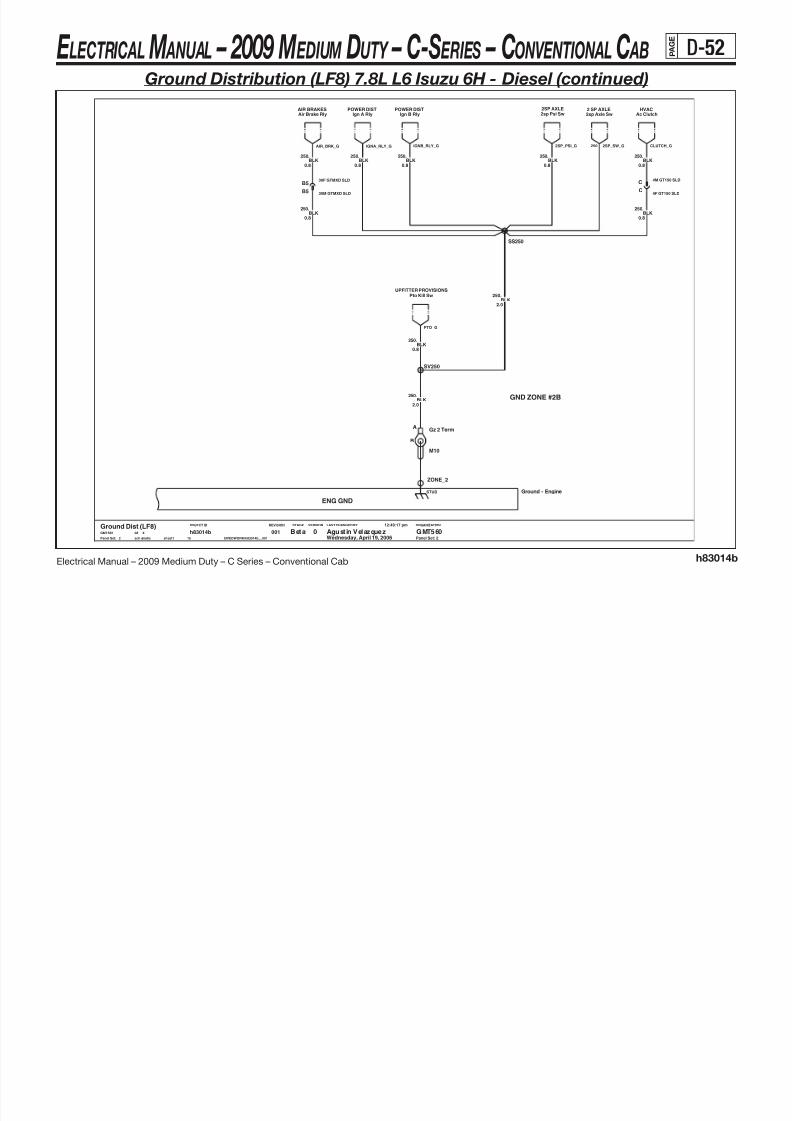
8/10/2019 2009 GM Medium Duty Electrical Manual.PDF
http://slidepdf.com/reader/full/2009-gm-medium-duty-electrical-manualpdf 163/410
Electrical Manual – 2009 Medium Duty – C Series – Conventional Cab h83014b
ENG GND
LAST CHANGED BY
Panel Set:
VERSIONSTAGEREVISIONOBJECT ID ORGANIZATION
Panel Set: 2
GND ZONE #2B
30F GTMXD SLDB5
BLK250.
0.8
.250BLK
BLK250.
0.8
0.8.250BLK
0.8
Gz 2 TermA
B
M10
g y
BLK250.
2.0
SV250
g y
30M GTMXD SLDB5
BLK250.
0.8
ZONE_2
Ground - EngineSTUD
BLK250.0.8
.250BLK0.8
BLK250.
2.0
Pto Kill SwUPFITTER PROVISIONS
$IVEDWORK/h83014b__001sch ematic sheet1
h83014b15
0012
Beta Agust in Velazquez GMT5600Ground Dist (LF8)GMT560 X08
Wednesday, April 19, 2006
12:49:17 pm
C
4F GT150 SLDC
4M GT150 SLD
BLK250.0.8
SS250
y
CLUTCH_G2SP_SW_G250
PTO_G
AIR_BRK_G 2SP_PSI_GIGNA_RLY_G IGNB_RLY_G
E LECTRICAL M ANUAL – 2009 M EDIUM DUTY – C-S ERIES – CONVENTIONAL C AB P A G E
D-53
Ground Distribution (LF8) 7.8L L6 Isuzu 6H - Diesel (continued)
Ttm - PTOTELL TALE
Headlamp SwINTERIOR LIGHTS
Dlc Pwr GndDLCIP CLUSTER
Ipc Pwr GndExhaust Brake Sw
Bat RtnDTC
EXH BRAKE/RSTRElec 2 Speed Sw2 SPEED AXLE
Pto Enable Sw/LedUPFITTER PROVISION
Turn/Haz/FlashEXTERIOR LIGHTS
DPF SwitchIP CLUSTERENGINE CNTRLS
High Idle Sw

8/10/2019 2009 GM Medium Duty Electrical Manual.PDF
http://slidepdf.com/reader/full/2009-gm-medium-duty-electrical-manualpdf 164/410
Electrical Manual – 2009 Medium Duty – C Series – Conventional Cab h83014b
BDY GND
LAST CHANGED BY
Panel Set:
VERSIONSTAGEREVISIONOBJECT ID ORGANIZATION
Panel Set: 3
GND ZONE #7A
GND ZONE #7B
.
0.5BLK
750
SD750
.750BLK
1.0
TELL TALETtm - Exhaust
30F GTMXDB7
0.5
.750BLK
Tractor ConnTRACTOR WIRING
30M GTMXDB7
ZONE_7
STUD
0.5
.750BLK
0.5
.750BLK
.750BLK
2.0
750.
1.0BLK
3.0
.750BLK
SN750
3.0
.750BLK
1.0
.750BLK
CHIMEChime Mdl
0.8
.750BLK
16M GT280
B
BLK750.
0.5
TELL TALEDiff Lk Sw
3.0
BLK0.5
.750
BLK750.
0.5
.750BLK
B12
Overdrive Defeat SwLCT TRANSMISSION
SC750
BLK0.8
.750
Wiper MtrWIPERS
M6.3
A
B
Gz 7a Term
0.5
.750BLK
Drl Mdl
16F GT280B
DRL
.
0.5BLK
750
B4
BLK750.
1.0
BLK0.5
.750BLK
0.5
.750BLK
1.0
.750
B4
B12
WIPERSWasher Pump
1.0
.750BLK
BLK
BLK750.
0.8
0.5
.750
PARK BRAKEPark Brake Sw
SM750
BLK750.
1.0
SY750
1.0BLK
750.
BLK750.
0.5
LCT TRANSMISSIONOverdrive Defeat Sw Illum
0.8
.750BLK
HORNHorn Switch
BLK750.
0.5
sheet1
h83014b15
0013
Beta Agustin Velazquez GMT5600Ground Dist (LF8)GMT560 X08
Wednesday, April 19, 2006
12:49:17 pm
$IVEDWORK/h83014b__001schematic
1.0
.750BLK
2.0BLK
750.
BLK0.5
.750
WIPERSLow Wash Fluid Sw
AUXILLARY PWRCigar Lighter
EXTERIOR LIGHTSRoof Marker Lps
SERIAL_G DPF_SW
PTO_TT_G 750
CHIME_G ODDS_SW_G ODDS_ILL_G
TRACTOR_G
HEADLPSW_G
CIGAR_G MARKERS_G EXH_TT_G
WSHR_PMP_G
TRNHAZ_G DATA1_GIP_PWR_G
750 P_BRK_G
PTO_LED_G 2SP_SW1_GEXH_SW_G
(Page 9)
ZONE7A
HIS_G
WPR_MTR_GDRL_G
DIFF_LK_GHORN_SW_G LOW_WASH_G
E LECTRICAL M ANUAL – 2009 M EDIUM DUTY – C-S ERIES – CONVENTIONAL C AB P A G E
D-54
Ground Distribution (LF8) 7.8L L6 Isuzu 6H - Diesel (continued)
POWER MIRRORSPOWER MIRRORSPass Htd Mir Head Rh Mirror Mrkr LpMirror Sw
POWER MIRRORSPOWER DOORSDrv Dr Lck Sw
INTERIOR LIGHTINGPass Door Jamb Sw
POWER WINDOWSPass Win SwPOWER MIRRORS
Lh Mirror Mrkr LpDrv Window SwPOWER WINDOWS
Pass Dr Lck SwPOWER DOORS
Drv Htd Mir HeadPOWER MIRRORS
Drv Door Jamb SwINTERIOR LIGHTING
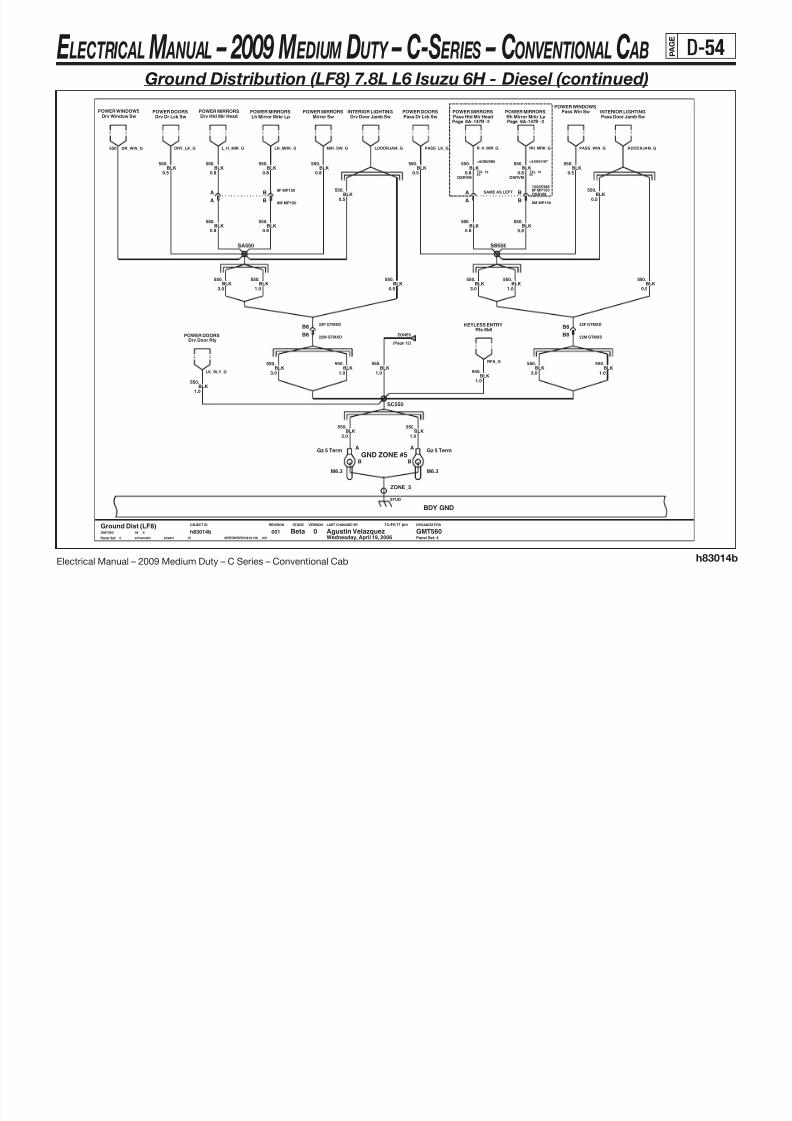
8/10/2019 2009 GM Medium Duty Electrical Manual.PDF
http://slidepdf.com/reader/full/2009-gm-medium-duty-electrical-manualpdf 165/410
Electrical Manual – 2009 Medium Duty – C Series – Conventional Cab h83014b
BDY GND
LAST CHANGED BY
Panel Set:
VERSIONSTAGEREVISIONOBJECT ID ORGANIZATION
8F MP150
TXLBLK
0.8
RH_MRK_G
550 =&DB6/DB8
19
R_H_MIR_G
-
GND ZONE #5
OSRVM
TXL
2
.
8A-PagePass Htd Mir Head
12065398
-
0.8BLK
50
=&DB6/DB7
8A-
OSRVM
Rh Mirror Mrkr Lp
19
550
A
Panel Set: 4
2
50
BSAME AS LEFT
147B 147BPage
.
OSRVM
0.8
.550BLK
0.5
.550BLK
0.8
.550BLK
A
ZONE_5
STUD
0.8
.550BLK
8F MP150B
BLK550.
1.0
8M MP150B
Gz 5 Term
M6.3
A
B
Mirror SwDrv Dr Lck Sw
00115
h83014bsheet1schematic $IVEDWORK/h83014b__001
12:49:17 pm
Wednesday, April 19, 200608 XGMT560
Ground Dist (LF8)0 GMT560Agustin VelazquezBeta
4
0.5
Rfa MdlKEYLESS ENTRY
BLK550.
BLK550.
0.5
Gz 5 Term
M6.3
A
B
Pass Door Jamb Sw
.550BLK
0.5
0.5
.550BLK
0.5BLK
550.
.550BLK
3.0
BLK550.
3.0
3.0
.550BLK
BLK550.
1.0
BLK550.
0.5
BLK550.
1.0
Lh Mirror Mrkr Lp
BLK550.
0.8
A
22M GTMXDB8
22F GTMXDB8
BLK550.
3.0
1.0
.550BLK
B8M MP150
SB550
Drv Door RlyPOWER DOORS
SA550
22F GTMXDB8
Pass Dr Lck Sw
A
SC550
.550BLK
0.80.8BLK
550.
1.0
.550BLK
.550BLK
1.0
550.
0.8BLK
22M GTMXDB8
1.0
.550BLK
BLK1.0
.550
3.0
.550BLK
Drv Door Jamb Sw
RFA_G
ZONE5
(Page 12)
DRV_LK_GDR_WIN_G550 L_H_MIR_G LH_MRK_G LDOORJAM_G PASS_LK_G RDOORJAM_GPASS_WIN_G
LK_RLY_G
MIR_SW_G
E LECTRICAL M ANUAL – 2009 M EDIUM DUTY – C-S ERIES – CONVENTIONAL C AB P A G E
D-55
Ground Distribution (LF8) 7.8L L6 Isuzu 6H - Diesel (continued)
Trans Temp Gauge IllumTELL TALE
Sys Air Press Gauge IllumTELL TALEHVAC
Temp MtrREAR DEFOGRear Defog Ctrl
AUX PWRAuxilary Outlets Lh Trailer Rly
EXTERIOR LIGHTS
Hvac HeadHVAC
Htd Mirror RlyPOWER MIRRORSAUX PWR
Auxilary Outlets
EXTERIOR LIGHTSRh Trailer Rly Chmsl Rly
EXTERIOR LIGHT

8/10/2019 2009 GM Medium Duty Electrical Manual.PDF
http://slidepdf.com/reader/full/2009-gm-medium-duty-electrical-manualpdf 166/410
Electrical Manual – 2009 Medium Duty – C Series – Conventional Cab h83014b
LAST CHANGED BY
Panel Set:
VERSIONSTAGEREVISIONOBJECT ID ORGANIZATION
BDY GND
Panel Set: 5
GND ZONE #6
GND ZONE #4B
BLK450.
1.0
.1751BLK/WHT
15
001
0.5
5
Beta Agustin Velazquez GMT5600Ground Dist (LF8)GMT560 X08
Wednesday, April 19, 2006
12:49:17 pm
$IVEDWORK/h83014b__001s ch ema ti c s he et 1
h83014b
0.5
.450BLK
450.
2.0BLK
CASE_P
CASE
ZONE_4
STUD
ZONE_6
STUD
16F GT280P
SK450
Elec Shift SelMD TRANSMISSION
0.5
.450BLK
Ign4 RlyPOWER DIST
0.5
.450BLK
A
B
M6.3
Gz 6 TermA
B
M6.3
Gz 4b Term
450.
5.0BLK
1.0BLK
450.
16M GT280P
0.8BLK
450.
BLK450.
1.0
450.
0.8BLK
SH450
450.
0.8BLK
.450BLK
0.8 1.0
.450BLK
BLK/WHT1751.
0.8
BLK450.
0.5
SJ450
450BLK
5.0
.
SdmSIR
EXTERIOR LIGHTBrake Lp Rly
BLK450.
0.5
HVACBlower Mtr
0.8
.450BLK
.450BLK
1.0
SDM_G
(Page 6)
ZONE4A
HVAC_FOG_GAUX2_G
SHIFT_LP_G BRKLP_RLY_G
CHMSL_RLY_GTEMP_CNTL_G AUX1_G RH_HAZ_G LH_HAZ_G
BLWR_RLY_G
H_MIR_RLY_G HVAC_G GAUGES_G
IGN4_RLY_G
PNEUTC_G
E LECTRICAL M ANUAL – 2009 M EDIUM DUTY – C-S ERIES – CONVENTIONAL C AB P A G E
D-56
Ground Distribution (LF8) 7.8L L6 Isuzu 6H - Diesel (continued)

8/10/2019 2009 GM Medium Duty Electrical Manual.PDF
http://slidepdf.com/reader/full/2009-gm-medium-duty-electrical-manualpdf 167/410
Electrical Manual – 2009 Medium Duty – C Series – Conventional Cab h83014b
BDY GND
LAST CHANGED BY
Panel Set:
VERSIONSTAGEREVISIONOBJECT ID ORGANIZATION
GND ZONE #S2
RDOANT_G
8A-
GND ZONE #4A
1Antenna Shield
BODY TO FRAME GND
Page 150A -
RADIO
Panel Set: 6Panel Set: 6
GND ZONE #8
BLK/WHT1451.
0.8
.1451BLK/WHT0.5
Rear Defog GridREAR DEFOGGER
STUD
ZONE_S2
Ground-BodyCASE
CASE1_P
STUD
ZONE_8
BLK/WHT1451.
1.0
Dlc Sig GndDATA LINK CONN ENF CNTLS
DaMU
M12
A
BGz S2f Term
Ground Dist (LF8)GMT560 X08
Wednesday, April 19, 2006
12:49:17 pm
$IVEDWORK/h83014b__001s ch em ati c s he et 1
h83014b15
0016
Prod Agustin Velazquez GMT5600
Gz 4a Term
M6.3
A
B
0.8
.1451BLK/WHT
BGz S2b Term
M8
A
ENF CNTLSDaMU
STUD
ZONE_S2
1.0BLK/WHT
1451.
.50BLK
50.0
RADIO/CHIMERadio/Chime Module
850
BLK2.0
.
1451.
0.8BLK/WHT
SB1451
Gz 8 TermA
B
SdgSERIAL DATA GATEWAY
M6.3
Ip Signal GndIP CLUSTER
0.8
.1451BLK/WHT
DAMU_G TRIG_SW_G RADIO_GIP_SIGNAL_G DATA2_G SDG_G
(Page 5)
ZONE4A
DEFOG_G
E LECTRICAL M ANUAL – 2009 M EDIUM DUTY – C-S ERIES – CONVENTIONAL C AB P A G E
D-57
Ground Distribution (LF8) 7.8L L6 Isuzu 6H - Diesel (continued)
EbcAIR BRAKES
EbcHYDRO BRAKES HYDRO BRAKES
Hydromax MtrHYDRO BRAKES
EbcHYDRO BRAKES
Hydromax Sw

8/10/2019 2009 GM Medium Duty Electrical Manual.PDF
http://slidepdf.com/reader/full/2009-gm-medium-duty-electrical-manualpdf 168/410
Electrical Manual – 2009 Medium Duty – C Series – Conventional Cab h83014b
LAST CHANGED BY
Panel Set:
VERSIONSTAGEREVISIONOBJECT ID ORGANIZATION
FRAME GND
Panel Set: 7
GND ZONE #B
GND ZONE #1A
GND ZONE #12B
GND ZONE #1B
M12
Gz 1a TermA
B
A
B
Gz 1b Term
M12
151BLK/WHT3.0
.
Battery (Neg)BATTERIES
Gz 1a Term
M12
A
B
h83014b15
0017
Beta Agustin Velazquez GMT5600Ground Dist (LF8)GMT560 X08
Wednesday, April 19, 2006
12:49:17 pm
$IVEDWORK/h83014b__001s ch em at ic s he et1
M12
Gnd Stud Conn TermA
B
SA151
.151BLK/WHT
8.0
Ground-Frame
GND_CONN
STUD
ZONE_1
STUDSTUD
ZONE_12ZONE_B
STUDSTUD
ZONE_S1
BLK/WHT151.
8.0Fuel Gnd Term
M12
A
B
5.0
.150BLK
13.0BLK
50.
13.0BLK/WHT
151.
151.
3.0BLK/WHT
3.0BLK/WHT
151.
0.8
.151BLK/WHT
SD151 SB151
Fuel Pump/Tank FAM 2 FUEL HAND & STOR
A
B
TRAILER WIRINGFam 3 Trailer Conn
Gz B Term
M12
FUEL_PMP_G
TRAILER_G
350
HYMAX2_G HYMAX1_GHYD_A_GHYD_B_G
BATTNEG_G50
STD_CONN_G
(Page 8)
AIR_G
FRAME
(Page 1)
E LECTRICAL M ANUAL – 2009 M EDIUM DUTY – C-S ERIES – CONVENTIONAL C AB P A G E
D-58
Ground Distribution (LF8) 7.8L L6 Isuzu 6H - Diesel (continued)
2spd Axle Mtr2SPD AXLE

8/10/2019 2009 GM Medium Duty Electrical Manual.PDF
http://slidepdf.com/reader/full/2009-gm-medium-duty-electrical-manualpdf 169/410
Electrical Manual – 2009 Medium Duty – C Series – Conventional Cab h83014b
LAST CHANGED BY
Panel Set:
VERSIONSTAGEREVISIONOBJECT ID ORGANIZATION
Panel Set: 8
GND ZONE #3C
With ABS
GND ZONE #3D
With ABS ABS Delete
Without Rear Air SuspWith Rear Air Susp
Hydro Brakes Air Brakes
ABS Delete
4F MP280 SLDC
4M MP280 SLDC
REAR AIR SUSPRear Air Susp Sol
F
FITTERUP
J6-A
BATT GND
J7-A
B
#3BZONE
J2-A
C
ZONE#3C
J3-A
D
#3DZONE
J4-A
E
FITTER
J5-A
UP
Gnd Blk Connector Asm
J6-J7-
1206517212066545
A
#3A
J1-A
ZONE
BLK350.
2.0
BLK2.0
.350
350.
2.0BLK
BLK350.
SC350
2.0
.
2.0BLK
350
BLK350.
2.0
.350BLK
0.8
.350BLK
BODY BLDRGnd
0.8
IP CLUSTERLow Air Press Sw - Sec
16M GT280 SLDS
.350BLK
2.0
Fuel Tank FUEL HAND & STOR
0Ground Dist (LF8)GMT560 X08
Wednesday, April 19, 2006
12:49:17 pm
$IVEDWORK/h83014b__001s ch em ati c s he et1
h83014b15
001
BLK350.
0.8
8
Beta Agustin Velazquez GMT560
8F GT280 SLDD
8M GT280 SLDD
2.0BLK
350.
5.0
.350BLK
S
2.0
.350BLK
16F GT280 SLD
350.
0.8BLK
Tail LampsEXTERIOR LIGHTS
SB350
2SP_MTR_G
AIR_SW_GBB_G
350
TAIL_LP_G
SUSP_SOL_G
(Page 10)351
ZONE3A
STD_CONN_G
(Page 7)50
ZONE3B
350(Page 11)
FUEL_SEND_G
E LECTRICAL M ANUAL – 2009 M EDIUM DUTY – C-S ERIES – CONVENTIONAL C AB P A G E
D-59
Ground Distribution (LF8) 7.8L L6 Isuzu 6H - Diesel (continued)
POWER MIRRORSH td Mir r Sw /L ed Exh Br k S w/ Ill um
EXHAUST BRAKEAir Susp Sw/LedREAR AIR SUSP
Air Susp Sw/IllumREAR AIR SUSP POWER MIRRORS
Htd Mirr Sw/IllumBRAKES
Traction Cntrl SwIP CLUSTERDPF Switch

8/10/2019 2009 GM Medium Duty Electrical Manual.PDF
http://slidepdf.com/reader/full/2009-gm-medium-duty-electrical-manualpdf 170/410
Electrical Manual – 2009 Medium Duty – C Series – Conventional Cab h83014b
LAST CHANGED BY
Panel Set:
VERSIONSTAGEREVISIONOBJECT ID ORGANIZATION
CASE GNDENGINE
Panel Set: 9
To: GND ZONE #7A
750.
0.5BLK .750BLK
0.8
Wednesday, April 19, 200608 XGMT560
Ground Dist (LF8)0 GMT560Agustin VelazquezBeta
9
00115
h83014bsheet1schematic $IVEDWORK/h83014b__001
12:49:17 pm
Mkr Lmp SwEXTERIOR LIGHTS UPFITTER PROVISION
Pto Enable Sw/Illum
SA750
0.5BLK750.
BLK750.
0.5
750BLK0.5
.
2.0BLK
0.5
.750BLK
750.
Mkr Lmp Sw/IllumEXTERIOR LIGHTS
BLK750.
0.50.8BLK750
2 SPEED AXLE
.
Elec 2 Speed Sw
0.5
.750BLK .
0.5BLK
750
Pneumatic Sw IllumINTERIOR LIGHTS
.750BLK
0.5
STARTING & CHARGINGGenerator Gnd
CASE_5 CASE_6 CASE_7 CASE_8 CASE_9
Ground-Engine Case
CASE_1 CASE_2 CASE_3 CASE_4
Hi Idle Sw IllumENGINE CNTRLS
SB750
BLK750.
0.5
STARTING & CHARGINGStarter Motor
BLK750.
0.5
.
0.5BLK750
PSIR Defeat SwSIR
DPF_ILL
PSIR_G
ZONE7A
(Page 3)750
TCS_G
PTO_ILL_G 2SP_LP_GPNEU_SW_G HIS_ILL_G
H_MIR_ILL_GSUSP_ILL_G H_MIR_LED_GSUSP_LED_G EXH_ILL_G
MRKR2_SW_GMRKR_SW_G
STARTER_G GEN_G
E LECTRICAL M ANUAL – 2009 M EDIUM DUTY – C-S ERIES – CONVENTIONAL C AB P A G E
D-60
Ground Distribution (LF8) 7.8L L6 Isuzu 6H - Diesel (continued)
Trans Temp SnsrTELL TALE
Oem UseDTC HYDRO BRAKES
Fluid Lvl Sw

8/10/2019 2009 GM Medium Duty Electrical Manual.PDF
http://slidepdf.com/reader/full/2009-gm-medium-duty-electrical-manualpdf 171/410
Electrical Manual – 2009 Medium Duty – C Series – Conventional Cab h83014b
FUEL TANKFUEL TANK
LAST CHANGED BY
Panel Set:
VERSIONSTAGEREVISIONOBJECT ID ORGANIZATION
Panel Set: 10
GND ZONE #9GND ZONE #10GND ZONE #3A
30M GTMXD SLDC1
BLK/WHT351.
2.0
40F GTMXD SLDD2
Secondary Fuel Tank
TANK_S
Primary Fuel Tank
TANK_P
M8
Secondary Tank TermA
B
0.8
.351BLK/WHT
BLK/WHT351.
0.8
FUEL HAND & STORPri Tank Static Gnd
0.8BLK/WHT
351.
M8
A
B
Primary Tank Term
G12F GT280 SLD
0.8BLK/WHT
351.
40M GTMXD SLDD2
BLK/WHT0.8
.351
G
C1
12M GT280 SLD
30F GTMXD SLD
Sec Tank Static GndFUEL HAND & STOR
SC351
1.0
.351BLK/WHT
Wednesday, April 19, 200608 XGMT560
Ground Dist (LF8)0 GMT560Agustin VelazquezBeta
10
00115
h83014bsheet1schematic $IVEDWORK/h83014b__001
12:49:17 pm
MD_RTN
3A_ENG
(Page 13)351
PFTANK_G350
(Page 8)
ZONE3A
FLS_GTEMP_SNSR_G
SFTANK_G350
E LECTRICAL M ANUAL – 2009 M EDIUM DUTY – C-S ERIES – CONVENTIONAL C AB P A G E
D-61
Ground Distribution (LF8) 7.8L L6 Isuzu 6H - Diesel (continued)
HEADLAMPSRight Headlamp Rf Turn/Park Lmps
EXTERIOR LIGHTSLeft HeadlampHEADLAMPS
Air DryerAIR BRAKES IP CLUSTER
Low Air Press Sw PrimHVAC
Vacuum Pmp Lf Turn/Park LmpsEXTERIOR LIGHTSHORNS
Horns

8/10/2019 2009 GM Medium Duty Electrical Manual.PDF
http://slidepdf.com/reader/full/2009-gm-medium-duty-electrical-manualpdf 172/410
Electrical Manual – 2009 Medium Duty – C Series – Conventional Cab h83014b
LAST CHANGED BY
Panel Set:
VERSIONSTAGEREVISIONOBJECT ID ORGANIZATION
GND ZONE #3B
C
FWDLP
100A
5M GT280 SLD
-
19
Page
Panel Set: 11
BEAM_G
Splice for Ether Injector
2.0
-
TXL
Page
SAME AS LEFT
SF350
1.0
350
15409273
50
1
RTRNPRK_G
See: 14C-11
TXL
Right Headlamp
FWDLP
.350
BLK
110A8A-Rf Turn/Park Lmps
.
50
18A-
350
BLK
R_FWDLP
19
11
Beta Agust in Velazquez GMT5600Ground Dist (LF8)GMT560 X08
Wednesday, April 19, 2006
12:49:17 pm
$IVEDWORK/h83014b__001sch ematic sheet1
h83014b15
001
0.8
.350BLK
BLK350.
3.0
Left HeadlampAir Dryer Low Air Press Sw - Prim
5M GT280 SLDC
.350BLK
0.8
BLK1.0
.350
2.0
.350BLK
1.0
.350BLK
350.
5.0BLK
12M GT280 SLDA
C5F GT280 SLD
SF350
BLK350.
1.0
5F GT280 SLDC
C 3F MP280 SLD
Vacuum Pmp
SD350
HYDRO BRAKESElec Air Comp
BLK350.
2.0
SE350
350.
BLK350.
1.0
2.0BLK
Lf Turn/Park Lmps
350BLK
3.0
.
Horns
3M MP280 SLDC
A12F GT280 SLD
1.0
.350BLK
LTRNPRK_GBEAM_G350AIR_DRY_G AIR_PR_SW_GVAC_PUMP_G
(Page 8)
ZONE3B
HORN_A_G
EAC_G
E LECTRICAL M ANUAL – 2009 M EDIUM DUTY – C-S ERIES – CONVENTIONAL C AB P A G E
D-62
Ground Distribution (LF8) 7.8L L6 Isuzu 6H - Diesel (continued)

8/10/2019 2009 GM Medium Duty Electrical Manual.PDF
http://slidepdf.com/reader/full/2009-gm-medium-duty-electrical-manualpdf 173/410
Electrical Manual – 2009 Medium Duty – C Series – Conventional Cab h83014b
LAST CHANGED BY
Panel Set:
VERSIONSTAGEREVISIONOBJECT ID ORGANIZATION
REAR_DOOR
R R Win Sw Illum
BLK.
Page
SD550
=&A31&CREWCAB
19
TXL
.1.0
REAR_DOOR
Panel Set: 12
550
TXL
8A-
.
19
.
550
19
1.0
R R Door Jamb Sw
12M GT280
POWER WINDOWS
Page
50
RR_WIN_G
-8A-120B
K
4
0.8
=&A31&CREWCAB
=&A31&CREWCAB
50 50
0.8
BLK
BLK
REAR_RDOOR
To: GND ZONE #5
TXL
Same as left
TXL
550
114A
RRDOORJAM_G
INTERIOR LIGHTS
REAR_DOOR
-
15326018
REAR_DOOR
=&CREWCAB-A31
550BLK
50
2
19
Rear Htr Sw IllRear Heater
550.
0.5BLK
10M GT280J
INTERIOR LIGHTSL R Door Jamb Sw
12M GT280K
SF550
12F GT280K
SD550
BLK550.
1.0
10F GT280J
Rear HeaterRear Heater Relay L R Win Sw Illum
POWER WINDOWS
1.0
.550BLK
0.8
.550BLK
1.0
.550BLK
BLK550.
1.0
BLK550.
0.8
BLK550.
1.0
1.0
.550
BLK
s ch em ati c s he et1
h83014b15
00112
Beta Agustin Velazquez GMT5600Ground Dist (LF8)GMT560 X08
Wednesday, April 19, 2006
12:49:17 pm
$IVEDWORK/h83014b__001
Rear HeaterRear Heater Motor
BLK550.
1.0
12F GT280K
LRDOORJAM_GLR_WIN_G
ZONE5
(Page 4)550
R_HTR_MTR_G R_HVAC_GR_HTR_RLY_G
E LECTRICAL M ANUAL – 2009 M EDIUM DUTY – C-S ERIES – CONVENTIONAL C AB P A G E
D-63
Ground Distribution (LF8) 7.8L L6 Isuzu 6H - Diesel (continued)

8/10/2019 2009 GM Medium Duty Electrical Manual.PDF
http://slidepdf.com/reader/full/2009-gm-medium-duty-electrical-manualpdf 174/410
Electrical Manual – 2009 Medium Duty – C Series – Conventional Cab h83014b
LAST CHANGED BY
Panel Set:
VERSIONSTAGEREVISIONOBJECT ID ORGANIZATION
Panel Set: 13
SE351
SB351
0.8BLK/WHT
351.
BLK/WHT351.
1.0
.351BLK/WHT0.8
0.8
.351BLK/WHT
ENGINE CNTLSEcu
1.0BLK/WHT
351.
ENG CNTLSLow Coolant Sw
BLK/WHT351.
1.0
EcuENGINE CNTLS
BLK/WHT1.0
.351
.
1.0BLK/WHT
351
BLK/WHT0.8
.351
0.8
.351BLK/WHT
SF351
SD351
TcmLCT TRANSMISSION
.351BLK/WHT
00115
h83014bsheet1schematic $IVEDWORK/h83014b__001
12:49:17 pm
Wednesday, April 19, 200608 XGMT560
Ground Dist (LF8)0 GMT560Agustin VelazquezBeta
13
1.0
1.0
.351BLK/WHT
MD TRANSMISSIONTcm
EcuEcuENGINE CNTLS ENGINE CNTLS
BLK/WHT1.0
.351
ENGINE CNTLSEcu
1.0
.351BLK/WHT
TRANSMISSIONTcm
ENGINE CNTLSEcu
LCT_GG
3A_ENG
(Page 10)
ECU_PWR3_G ECU_SNSR2_G ECU_PWR1_G ECU_SNSR1_GECU_PWR2_G
351 TCM1_G MD_G LOW_COOL_G
ECU_PWR4_G
E LECTRICAL M ANUAL – 2009 M EDIUM DUTY – C-S ERIES – CONVENTIONAL C AB P A G E
D-64
Ground Distribution (LF6) 7.2L L6 Caterpillar ® C7 - Diesel

8/10/2019 2009 GM Medium Duty Electrical Manual.PDF
http://slidepdf.com/reader/full/2009-gm-medium-duty-electrical-manualpdf 175/410
Electrical Manual – 2009 Medium Duty – C Series – Conventional Cab h83014c
LAST CHANGED BY
Panel Set:
VERSIONSTAGEREVISIONOBJECT ID ORGANIZATION
ENG GND
Panel Set: 1
GND ZONE #2C
GND ZONE #2A
GND ZONE #2B
GND ZONE #S1ENGINE TO FRAME GND
Gz S1e Clip
M12
A
B
08 XGMT560
Ground Dist (LF6)0 GMT560Agustin VelazquezBeta
1
0018
h83014csheet1schematic $IVEDWORK/h83014c__001
12:51:27 pm
Wednesday, April 19, 2006
.251BLK/WHT2.0
50.0
.50BLK
Ground - Engine
ZONE_2B
STUDSTUD
ZONE_S1
M12
Gz S1f ClipA
B
B
Gz 2b Term
M12
A
2.0
.251BLK/WHT
A
B
Gz 2a Term
E 1/2
Starter MotorSTARTING & CHARGING
M12A
B
Start Gnd Term
ENG CNTLSEcu
50.
62.0BLK
ENG CNTLSEcu
CAT_A_G CAT_B_G
(Page 2)
START_G
START_G
(Page 7)
FRAME
E LECTRICAL M ANUAL – 2009 M EDIUM DUTY – C-S ERIES – CONVENTIONAL C AB P A G E
D-65
Ground Distribution (LF6) 7.2L L6 Caterpillar ® C7 - Diesel (continued)
POWER DISTIgn A Rly
HVACAc ClutchAir Brake Rly
AIR BRAKESIgn B Rly
POWER DIST

8/10/2019 2009 GM Medium Duty Electrical Manual.PDF
http://slidepdf.com/reader/full/2009-gm-medium-duty-electrical-manualpdf 176/410
Electrical Manual – 2009 Medium Duty – C Series – Conventional Cab h83014c
LAST CHANGED BY
Panel Set:
VERSIONSTAGEREVISIONOBJECT ID ORGANIZATION
GND ZONE #2C
Panel Set: 2
Ground Dist (LF6)0 GMT560
SV250
Agustin VelazquezBeta2
0018
h83014csheet1schematic $IVEDWORK/h83014c__001
12:51:27 pm
Wednesday, April 19, 200608 XGMT560
Gz 2c Term
E 1/2
A
B
BLK250.
0.8
.250BLK
0.8
BLK250.
2.0
.0.8
BLK250
30M GTMXD SLDB5
4M GT150 SLDC
.250BLK0.8
UPFITTER PROVISIONSPto Solenoid
B530F GTMXD SLD
SS250
BLK250.0.8
2.0
.250BLK
.250BLK
0.8
4F GT150 SLDC
BLK0.8
.250
(Page 1)
START_G
IGNA_RLY_G IGNB_RLY_G CLUTCH_GAIR_BRK_G
PTO_LOAD_G
E LECTRICAL M ANUAL – 2009 M EDIUM DUTY – C-S ERIES – CONVENTIONAL C AB P A G E
D-66
Ground Distribution (LF6) 7.2L L6 Caterpillar ® C7 - Diesel (continued)
Headlamp SwINTERIOR LIGHTS
Dlc Pwr GndDLC
Turn/Haz/FlashEXTERIOR LIGHTS
Bat RtnDTCIP CLUSTER
Ipc Pwr Gnd

8/10/2019 2009 GM Medium Duty Electrical Manual.PDF
http://slidepdf.com/reader/full/2009-gm-medium-duty-electrical-manualpdf 177/410
Electrical Manual – 2009 Medium Duty – C Series – Conventional Cab h83014c
BDY GND
LAST CHANGED BY
Panel Set:
VERSIONSTAGEREVISIONOBJECT ID ORGANIZATION
Panel Set: 3
GND ZONE #7B
GND ZONE #7A
TELL TALETtm - IAH
0.8
.750BLKBLK
750.
Chime MdlCHIME
0.8
750.
0.8Roof Marker Lps
EXTERIOR LIGHTSBLK
750.
0.5BLK
.750BLK
1.0
SM750
2.0
.750BLK
LCT TRANSMISSIONOverdrive Defeat Sw
Cigar LighterAUXILLARY PWR
B7
0.5
30M GTMXD
1.0
BLK750.
.750BLK
BLK750.
A2
1.0
1.0
.750BLK
Ttm - ExhaustTELL TALE
3.0
.750BLK
0.8
.750BLK
Overdrive Defeat Sw IllumLCT TRANSMISSION
0018
h83014csheet1schematic $IVEDWORK/h83014c__001
12:51:27 pm
Wednesday, April 19, 200608 XGMT560
Ground Dist (LF6)0 GMT560Agustin VelazquezBeta
3
Low Wash Fluid SwWIPERS
Wiper MtrWIPERS
STUD
ZONE_7
0.5BLK
750.
Park Brake SwPARK BRAKE
0.5
.750BLK
HORNHorn Switch
2.0
.750BLK
Diff Lk SwTELL TALE
B
Gz 7a Term
M6.3
A
0.5BLK
750.
30F GTMXDB7
BLK750.
1.0
SN750
Drl MdlDRL
SY750
BLK
750.
3.0
1.0
.750BLK
BLK
16M GT280B
1.0
.750 3.0
.750BLK
BLK750.
0.5
A2
WIPERSWasher Pump
SC750
16F GT280B
0.5BLK
750.
.750BLK
1.0
ENGINE CNTRLS
BLK750.
0.5
Hi Idle Sw Illum
TRACTOR WIRINGTractor Conn
1.0
.750BLK
CHIME_G EXH_TT_G750 IAH_TT_G
MARKERS_G
TRACTOR_G
CIGAR_G
SERIAL_G750
P_BRK_G750
ODDS_SW_GODDS_ILL_G
DATA1_G
WSHR_PMP_GLOW_WASH_G
HIS_LED_G
TRNHAZ_G HEADLPSW_G
WPR_MTR_G
IP_PWR_G
DRL_G
DIFF_LK_G HORN_SW_G
ZONE7A
(Page 9)
E LECTRICAL M ANUAL – 2009 M EDIUM DUTY – C-S ERIES – CONVENTIONAL C AB P A G E
D-67
Ground Distribution (LF6) 7.2L L6 Caterpillar ® C7 - Diesel (continued)
147B
POWER MIRRORS
2147B8A- -8A-Pass Htd Mir Head
PagePageRh Mirror Mrkr Lp
-2
POWER MIRRORS Pass Win SwPOWER WINDOWS
Drv Window SwPOWER WINDOWS
Pass Door Jamb SwINTERIOR LIGHTING
Mirror SwPOWER MIRRORSPOWER MIRRORS
Lh Mirror Mrkr LpPOWER DOORS
Drv Dr Lck Sw Drv Htd Mir HeadPOWER MIRRORS
Pass Dr Lck SwPOWER DOORS
Drv Door Jamb SwINTERIOR LIGHTING

8/10/2019 2009 GM Medium Duty Electrical Manual.PDF
http://slidepdf.com/reader/full/2009-gm-medium-duty-electrical-manualpdf 178/410
Electrical Manual – 2009 Medium Duty – C Series – Conventional Cab h83014c
LAST CHANGED BY
Panel Set:
VERSIONSTAGEREVISIONOBJECT ID ORGANIZATION
BDY GND
550
8F MP150
OSRVM
R_H_MIR_G
TXLBLK
RH_MRK_G
=&DB6/DB7
OSRVM
GND ZONE #5
50
550BLK
A
19TXL
Panel Set: 4
SAME AS LEFT B OSRVM
19
=&DB6/DB8
0.8
.
0.8
.
50
12065398
Drv Door RlyPOWER DOORS
22F GTMXDB8
A
.550BLK
0.8
8
0014
Beta Agustin Velazquez GMT5600Ground Dist (LF6)GMT560 X08
Wednesday, April 19, 2006
12:51:27 pm
$IVEDWORK/h83014c__001s ch em ati c s he et1
h83014c
B8
BLK550.
3.0
22M GTMXD
BLK0.5
.550
22M GTMXDB8
0.8
.550BLK
1.0
.550BLK
0.8
.550BLK
8F MP150B
1.0
.550BLK
M6.3
Gz 5 TermA
B
BLK550.
1.0
BLK550.
0.5
STUD
ZONE_5
BLK550.
1.0
550.
3.0BLK
M6.3
A
B
Gz 5 Term
BLK550.
0.8
3.0
.550BLK
BLK550.
0.8
550BLK
0.5
.
0.8
.550BLK
1.0
.550BLK
SB550
3.0
.550BLK
BLK550.
0.5
BLK550.
0.5
.550
Rfa MdlKEYLESS ENTRY
BLK1.0
3.0
.550BLK
SC550
SA550
BLK550.
0.5
B8
8M MP150B
22F GTMXD
1.0BLK
550.
0.5
.550BLK
A
1.0
.550BLK
8M MP150B
BLK550.
0.8
A
RFA_G
ZONE5
(Page 12)
DRV_LK_GDR_WIN_G550 L_H_MIR_G LH_MRK_G LDOORJAM_G PASS_LK_G RDOORJAM_GPASS_WIN_G
LK_RLY_G
MIR_SW_G
E LECTRICAL M ANUAL – 2009 M EDIUM DUTY – C-S ERIES – CONVENTIONAL C AB P A G E
D-68
Ground Distribution (LF6) 7.2L L6 Caterpillar ® C7 - Diesel (continued)
EXTERIOR LIGHTSRh Trailer RlyTemp Mtr
HVACAuxilary Outlets
AUX PWRRear Defog Cntl
REAR DEFOGGER TELL TALETrans Temp Gauge Illum Chmsl Rly
EXTERIOR LIGHTSLh Trailer Rly
EXTERIOR LIGHTS POWER MIRRORSHtd Mirror Rly
HVACHvac Head
TELL TALESys Air Press Gauge IllumAuxilary Outlets
AUX PWR

8/10/2019 2009 GM Medium Duty Electrical Manual.PDF
http://slidepdf.com/reader/full/2009-gm-medium-duty-electrical-manualpdf 179/410
Electrical Manual – 2009 Medium Duty – C Series – Conventional Cab h83014c
LAST CHANGED BY
Panel Set:
VERSIONSTAGEREVISIONOBJECT ID ORGANIZATION
BDY GND
GND ZONE #6
Panel Set: 5
GND ZONE #4B
BLK0.5
.450
450.
5.0BLK
450.
0.5BLK
0.5
.450BLK
450.
1.0BLK
Gz 6 Term
M6.3
A
B
SK450
0.5
.450BLK
sheet1schematic $IVEDWORK/h83014c__001
12:51:27 pm
Wednesday, April 19, 200608 XGMT560
Ground Dist (LF6)0 GMT560Agustin VelazquezBeta
5
0018
h83014c
BLK450.
1.0
1751BLK/WHT0.5
.
.450BLK
0.8
5.0
.450BLK
BLK1.0
.450
CASE
CASE_P
STUD
ZONE_4 ZONE_6
STUD
SH450
0.8
.450BLK
1.0
.450BLK
HVACBlower Mtr
MD TRANSMISSIONElec Shift Sel
0.5BLK
450.
16M GT280P
POWER DISTIgn4 Rly
0.8
.450BLK
BLK
16F GT280P
2.0
.450
Brake Lp RlyEXTERIOR LIGHTS
450.
0.8BLK
Gz 4b TermA
B
M6.3
0.8
.450BLK
BLK/WHT1751.
0.8
SdmSIR
SJ450
1.0
.450BLK
SDM_G
ZONE4A
(Page 6)
TEMP_CNTL_G HVAC_FOG_GAUX2_G
SHIFT_LP_G
AUX1_G RH_HAZ_G LH_HAZ_G
BRKLP_RLY_G
CHMSL_RLY_G
BLWR_RLY_G
H_MIR_RLY_G HVAC_G GAUGES_G
IGN4_RLY_G
PNEUTC_G
E LECTRICAL M ANUAL – 2009 M EDIUM DUTY – C-S ERIES – CONVENTIONAL C AB P A G E
D-69
Ground Distribution (LF6) 7.2L L6 Caterpillar ® C7 - Diesel (continued)

8/10/2019 2009 GM Medium Duty Electrical Manual.PDF
http://slidepdf.com/reader/full/2009-gm-medium-duty-electrical-manualpdf 180/410
Electrical Manual – 2009 Medium Duty – C Series – Conventional Cab h83014c
LAST CHANGED BY
Panel Set:
VERSIONSTAGEREVISIONOBJECT ID ORGANIZATION
BDY GND
RDOANT_G
GND ZONE #4A-
BODY TO FRAME GND
150A
RADIO
GND ZONE #S2
8A- 1PageAntenna Shield
Panel Set: 6
BLK50.
Ip Signal GndIP CLUSTER
50.0
6
0018
h83014csheet1schematic $IVEDWORK/h83014c__001
12:51:27 pm
Wednesday, April 19, 200608 XGMT560
Ground Dist (LF6)0 GMT560Agustin VelazquezBeta
SdgSERIAL DATA GATEWAY
Gz S2b Term
M8
A
B
RADIO/CHIMERadio/Chime Module
1451.
0.8BLK/WHT
1451.
0.8
Dlc Sig GndDATA LINK CONN
BLK/WHT
Gz 4a Term
M6.3
A
B
ZONE_S2
STUD Ground-Body
CASE1_P
CASESTUD
ZONE_8
0.8
.1451
SB1451
BLK/WHT
ZONE_S2
STUD
BLK850.
2.0
Gz 8 Term
M6.3
A
B
Rear Defog GridREAR DEFOGGER
BLK/WHT1451.
1.0Gz S2f Term
A
B
M12
BLK/WHT0.8
.1451
RADIO_GIP_SIGNAL_G DATA2_G SDG_G
(Page 5)
ZONE4A
DEFOG_G
E LECTRICAL M ANUAL – 2009 M EDIUM DUTY – C-S ERIES – CONVENTIONAL C AB P A G E
D-70
Ground Distribution (LF6) 7.2L L6 Caterpillar ® C7 - Diesel (continued)
EbcHYDRO BRAKES
EbcHYDRO BRAKES
Hydromax SwHYDRO BRAKES
Hydromax MtrHYDRO BRAKESAIR BRAKES
Ebc

8/10/2019 2009 GM Medium Duty Electrical Manual.PDF
http://slidepdf.com/reader/full/2009-gm-medium-duty-electrical-manualpdf 181/410
Electrical Manual – 2009 Medium Duty – C Series – Conventional Cab h83014c
FRAME GND
LAST CHANGED BY
Panel Set:
VERSIONSTAGEREVISIONOBJECT ID ORGANIZATION
Panel Set: 7
GND ZONE #12B
GND ZONE #1A
GND ZONE #1B
GND ZONE #B
5.0
.150BLK
M12
Gz 1b TermA
B
A
B
M12
Gz B Term
0.8
.151BLK/WHT
8.0
.151BLK/WHT
3.0
.151BLK/WHT
13.0BLK
50.
151.
13.0BLK/WHT
ZONE_BZONE_S1
STUD Ground-FrameSTUD
GND_CONN
STUD
ZONE_1ZONE_12
STUDSTUD
SD151
SA151
A
B
Gz 1a Term
M12
Fam 3 Trailer ConnTRAILER WIRING
0 GMT560Agustin VelazquezBeta7
0018
h83014csheet1schematic $IVEDWORK/h83014c__001
12:51:27 pm
Wednesday, April 19, 200608 XGMT560
Ground Dist (LF6)
3.0
.151BLK/WHT
3.0
BATTERIESBattery (Neg)
BLK/WHT151.
Gz 1a Term
M12
A
B
BLK/WHT151.
8.0
Gnd Stud Conn TermA
B
SB151
M12
HYD_A_GHYD_B_GHYMAX2_G
TRAILER_G
50 BATTNEG_G
HYMAX1_G
STD_CONN_G
(Page 8)
AIR_G
(Page 1)
FRAME
E LECTRICAL M ANUAL – 2009 M EDIUM DUTY – C-S ERIES – CONVENTIONAL C AB P A G E
D-71
Ground Distribution (LF6) 7.2L L6 Caterpillar ® C7 - Diesel (continued)
2SPD AXLE2spd Axle Mtr

8/10/2019 2009 GM Medium Duty Electrical Manual.PDF
http://slidepdf.com/reader/full/2009-gm-medium-duty-electrical-manualpdf 182/410
Electrical Manual – 2009 Medium Duty – C Series – Conventional Cab h83014c
LAST CHANGED BY
Panel Set:
VERSIONSTAGEREVISIONOBJECT ID ORGANIZATION
GND ZONE #3C
GND ZONE #3D
Panel Set: 8
ABS DeleteWith ABS
With Rear Air Susp Without Rear Air Susp
Air BrakesHydro Brakes
With ABSABS Delete
350.
2.0BLK
8M GT280 SLDD
BLK2.0
.350
.350BLK
2.0
8
0018
h83014csheet1schematic $IVEDWORK/h83014c__001
12:51:27 pm
Wednesday, April 19, 200608 XGMT560
Ground Dist (LF6)0 GMT560Agustin VelazquezBeta
0.8
.350BLK
4M MP280 SLDC
Rear Air Susp Sol
REAR AIR SUSP
5.0BLK
350.
S
2.0
.350BLK
16M GT280 SLD
Fuel Tank
FUEL HAND & STOR
2.0
.350BLK
BLK350.
0.8
0.8BLK
350.
SB350
2.0
.350BLK
BLK2.0
.350
4F MP280 SLDC
SC350
BODY BLDRGnd
EXTERIOR LIGHTSTail Lamps
S 16F GT280 SLD
BLK350.
2.0
8F GT280 SLDD
BLK350.
2.0
D
#3DZONE
J4-A
E
FITTER
J5-A
UP
F
FITTERUP
J6-A
BATT GND
J7-A
J6-J7-
1206517212066545
A
#3A
J1-A
ZONE
B
#3BZONE
J2-A
C
ZONE#3C
J3-A
Gnd Blk Connector Asm
IP CLUSTERLow Air Press Sw - Sec
0.8
.350BLK
SUSP_SOL_G
2SP_MTR_G
BB_G
AIR_SW_G
(Page 10)351
ZONE3A
350 FUEL_SEND_G
STD_CONN_G
(Page 7)50
ZONE3B
350(Page 11)
TAIL_LP_G
E LECTRICAL M ANUAL – 2009 M EDIUM DUTY – C-S ERIES – CONVENTIONAL C AB P A G E
D-72
Ground Distribution (LF6) 7.2L L6 Caterpillar ® C7 - Diesel (continued)
BRAKESTraction Cntrl Sw Htd Mirr Sw/Led
POWER MIRRORSAir Susp Sw/IllumREAR AIR SUSP POWER MIRRORS
Htd Mirr Sw/IllumREAR AIR SUSP
Exh Brk Sw/IllumEXHAUST BRAKE
Air Susp Sw/Led DPF SwitchIP CLUSTER

8/10/2019 2009 GM Medium Duty Electrical Manual.PDF
http://slidepdf.com/reader/full/2009-gm-medium-duty-electrical-manualpdf 183/410
Electrical Manual – 2009 Medium Duty – C Series – Conventional Cab h83014c
LAST CHANGED BY
Panel Set:
VERSIONSTAGEREVISIONOBJECT ID ORGANIZATION
CASE GNDENGINE
To: GND ZONE #7A
Panel Set: 9
ENGINE CNTRLSHi Idle Sw Illum
BLK
750.
0.5
UPFITTER PROVISIONPto Enable Sw/Illum
BLK
750.
0.5
9
Beta Agust in Velazquez GMT5600Ground Dist (LF6)GMT560 X08
Wednesday, April 19, 2006
12:51:27 pm
$IVEDWORK/h83014c__001sch ematic sheet1
h83014c8
001
Generator GndSTARTING & CHARGING
BLK750.
2.0
BLK
750.
0.5
0.5BLK
750.BLK
750.
0.5
CASE_7 CASE_8 CASE_9
Ground-Engine Case
CASE_1 CASE_2 CASE_3 CASE_4 CASE_5 CASE_6
Mkr Lmp SwEXTERIOR LIGHTS
.750BLK
0.5
0.5
.
Mkr Lmp Sw/IllumEXTERIOR LIGHTS
750
BLK
INTERIOR LIGHTSPneumatic Sw Illum
.750BLK
0.5 0.5
.750BLK
750.
0.5BLK
BLK750.
0.5
SA750
.
0.8BLK
750
0.5
.750BLK
.750
BLK0.8
PSIR Defeat SwSIR
SB750
2 SPEED AXLEElec 2 Speed Sw
DPF_ILL
PSIR_G
ZONE7A
(Page 3)750
TCS_G
MRKR2_SW_GMRKR_SW_G PTO_ILL_G 2SP_LP_GPNEU_SW_G HIS_ILL_G
H_MIR_ILL_GSUSP_ILL_G H_MIR_LED_GSUSP_LED_G EXH_ILL_G
GEN_G
E LECTRICAL M ANUAL – 2009 M EDIUM DUTY – C-S ERIES – CONVENTIONAL C AB P A G E
D-73
Ground Distribution (LF6) 7.2L L6 Caterpillar ® C7 - Diesel (continued)
LCT TRANSMISSIONTcmWif Snsr
HTD FUEL/WATER IN FUEL HYDRO BRAKESFluid Lvl Sw
TRANSMISSIONTcm Tcm
MD TRANSMISSIONTrans Temp Snsr
TELL TALE DTCOem Use

8/10/2019 2009 GM Medium Duty Electrical Manual.PDF
http://slidepdf.com/reader/full/2009-gm-medium-duty-electrical-manualpdf 184/410
Electrical Manual – 2009 Medium Duty – C Series – Conventional Cab h83014c
FUEL TANK
LAST CHANGED BY
Panel Set:
VERSIONSTAGEREVISIONOBJECT ID ORGANIZATION
FUEL TANK
GND ZONE #3A
GND ZONE #9
Panel Set: 10
GND ZONE #10
BLK/WHT0.8
.351
12M GT280 SLDG
0.8BLK/WHT
351.
Primary Fuel Tank
TANK_P
FUEL HAND & STORPri Tank Static Gnd
0.8
.351BLK/WHT BLK/WHT
351.
1.0
G12F GT280 SLD
40F GTMXD SLDD2
SB351
BLK/WHT0.8
.351
M8
Primary Tank TermA
B
BLK/WHT351.
2.0
BLK/WHT351.
0.8
C1 30M GTMXD SLD
8
00110
Beta Agustin Velazquez GMT5600Ground Dist (LF6)GMT560 X08
Wednesday, April 19, 2006
12:51:27 pm
$IVEDWORK/h83014c__001schematic sheet1
h83014c
D2
0.8
.351BLK/WHT
40M GTMXD SLD
BLK/WHT351.
0.8
.351BLK/WHT0.8
Secondary Fuel Tank
TANK_S
30F GTMXD SLDC1
SC351
Secondary Tank Term
M8
A
B
Sec Tank Static GndFUEL HAND & STOR
.351BLK/WHT0.8
MD_RTN
SFTANK_G350PFTANK_G350
WIF_G MD_G LCT_GGTCM1_G351
ZONE3A
(Page 8)
FLS_GTEMP_SNSR_G
E LECTRICAL M ANUAL – 2009 M EDIUM DUTY – C-S ERIES – CONVENTIONAL C AB P A G E
D-74
Ground Distribution (LF6) 7.2L L6 Caterpillar ® C7 - Diesel (continued)
110A-8A- 100A 8A-Page
HEADLAMPS
1PageRight Headlamp Rf Turn/Park Lmps
EXTERIOR LIGHTS
1 -
HEADLAMPSLeft HeadlampLow Air Press Sw - Prim
IP CLUSTERENG CNTLSEther Sol
HVACVacuum Pmp Lf Turn/Park Lmps
EXTERIOR LIGHTSHORNSHorns

8/10/2019 2009 GM Medium Duty Electrical Manual.PDF
http://slidepdf.com/reader/full/2009-gm-medium-duty-electrical-manualpdf 185/410
Electrical Manual – 2009 Medium Duty – C Series – Conventional Cab h83014c
LAST CHANGED BY
Panel Set:
VERSIONSTAGEREVISIONOBJECT ID ORGANIZATION
110A
5M GT280 SLD
.
8A
2.0 TXL
BEAM_G
1.0
=&FAM3
R_FWDLP
100A
Panel Set: 11
350
=&FAM3
350
8A
FWDLP50
Page
19BLK
BLK
1
RTRNPRK_G
19
FWDLP
Page 1
TXL
50
.
350
SF350
SAME AS LEFTC
15409273
.350BLK
0.8
5F GT280 SLDC
2.0
.350BLK
3M MP280 SLDC
3F MP280 SLDC
Air DryerAIR BRAKES
SF350
.
2.0BLK
350
350.
1.0BLK
0.8
.350BLK
1.0
.350BLK
2.0BLK
350.
BLK350.
1.0
SE350
11
0018
h83014csheet1schematic $IVEDWORK/h83014c__001
12:51:27 pm
Wednesday, April 19, 200608 XGMT560
Ground Dist (LF6)0 GMT560Agustin VelazquezBeta
0.8
.350BLK
3.0BLK
350.
350BLK
3.0
.
BLK350.
5.0
12M GT280 SLDA
BLK350.
1.0
HYDRO BRAKESElec Air Comp
1.0
.350BLK
C5M GT280 SLD
C5F GT280 SLD
SD350
12F GT280 SLDA
AIR_PR_SW_G BEAM_G350 LTRNPRK_G
AIR_DRY_G
VAC_PUMP_G ETHER_G
(Page 8)
ZONE3B
HORN_A_G
EAC_G
E LECTRICAL M ANUAL – 2009 M EDIUM DUTY – C-S ERIES – CONVENTIONAL C AB P A G E
D-75
Ground Distribution (LF6) 7.2L L6 Caterpillar ® C7 - Diesel (continued)

8/10/2019 2009 GM Medium Duty Electrical Manual.PDF
http://slidepdf.com/reader/full/2009-gm-medium-duty-electrical-manualpdf 186/410
Electrical Manual – 2009 Medium Duty – C Series – Conventional Cab h83014c
LAST CHANGED BY
Panel Set:
VERSIONSTAGEREVISIONOBJECT ID ORGANIZATION
REAR_RDOOR
-
REAR_DOOR
.
R R Door Jamb Sw
BLK
K
INTERIOR LIGHTS
BLK
4R R Win Sw Illum
50
50
BLK550
12M GT280
Page
1.0
Same as left
15326018
190.8
.
TXL
REAR_DOOR
550
114A
550
POWER WINDOWS
19
REAR_DOOR
TXL
REAR_DOOR
.=&CREWCAB-A310.8
SD550
19
RRDOORJAM_G
50
BLK
.
Page
TXL
8A-
=&A31&CREWCAB
8A-
1.0
To: GND ZONE #5
2
=&A31&CREWCAB
-
=&A31&CREWCAB
RR_WIN_G
19
TXL
550
120B
Panel Set: 12
50
SF550
SD550 BLK550.
0.8
.550BLK
1.0
Rear HeaterRear Heater Motor
10M GT280J
BLK550.
1.0
12F GT280K
BLK550.
1.0
K12M GT280
1.0
.550BLK
L R Win Sw IllumPOWER WINDOWS INTERIOR LIGHTS
L R Door Jamb SwRear Htr Sw IllRear Heater
BLK550.
1.0
BLK550.
1.0
10F GT280J
Rear Heater RelayRear Heater
BLK550.
0.5 0.8
.550BLK
.550BLK
1.0
12F GT280K
12:51:27 pm
Wednesday, April 19, 200608 XGMT560
Ground Dist (LF6)0 GMT560Agustin VelazquezBeta
12
0018
h83014csheet1schematic $IVEDWORK/h83014c__001
R_HTR_MTR_G R_HVAC_GR_HTR_RLY_G LRDOORJAM_G
ZONE5
(Page 4)550
LR_WIN_G
E LECTRICAL M ANUAL – 2009 M EDIUM DUTY – C-S ERIES – CONVENTIONAL C AB P A G E
D-76
Power Take-Off (L18) 8.1L V8 GMPT VORTEC® - Gas –
(LMM) 6.6L V8 Isuzu DURAMAX ® - Diesel – (LF8) 7.8L L6 Isuzu 6H - Diesel
ENGINE CNTLSPcm/EcuPcm/Ecu
ENGINE CNTLS

8/10/2019 2009 GM Medium Duty Electrical Manual.PDF
http://slidepdf.com/reader/full/2009-gm-medium-duty-electrical-manualpdf 187/410
Electrical Manual – 2009 Medium Duty – C Series – Conventional Cab h83018a
LAST CHANGED BY
Panel Set:
VERSIONSTAGEREVISIONOBJECT ID ORGANIZATION
B
001
50
488
UPC
494
50
001
A
.488
2663 2664TXL
UPC
10M MP150 SLDG
2561
PTO_UPFIT
12129589
UPC
5019
50
19
TXL
BLK
BLK
PTO_UPFIT TXL
TXL
.
0.8
0.8
.
FNA
A
TXL0.8
SPLICE
001
B
2522
SPLICE
D
2522
tap_up_sw pto_solenoid
19
Pto Kill Sw
GRN LT
B
.
50
B
0.8
tap_dn_sw
A
H
.
F
2522
PTO_UPFIT
Pto Load
19
TBDFNA
0.8
TXL
PTO_UPFIT
PPL
YEL
BLU LT
12129589
TBD
.
50
PTO_UPFIT10M MP150 SLD
Panel Set: 1
C
YEL
Load Engage Switch
GRN LT
WHT
YEL
Upfitter Supplied
JE
19
pto_killUPC
PTO_UPFIT
TXL
50
0.8
PTO_UPFIT
TXL
PTO_UPFIT
FNA
Tap Up Switch
19
PTO_UPFIT
50
19
0.8
.
PTO_UPFIT
ld_engage_sw
5019
19 19
0.8
.
500.8
001
TXL
TXL
..
TBD
0.8
250
B PTO_UPFIT
A
.
19BLK
Tap Down Switch
0.8
TAN
250
PTO_UPFIT
19
PTO_UPFIT
TXL
TBD
TBD
FNA
PTO_UPFIT
001
0.8
POWER DISTUh - Eng1
10A
.
5050
250
FNA
TXL
UPC
GRN LT0.5
0.5GRN LT
488.
30M GTMXDA1
.488
Gnd Zone #7AGND DIST
30F GTMXDA1
.488GRN LT0.8
J
Pcm/Ecu
B
.2664TAN
0.8
C
0.8GRN LT
488.
.488GRN LT1.0
D
SA488
0.5GRN LT
488.
40M GTMXD SLDC3
TELL TALETt Module
A14
40F GTMXD SLDC3
0.5GRN LT
488.
24M GTMXD SLDC1
.488GRN LT0.5
24F GTMXD SLDC1
.488GRN LT0.8
08
12:53:42 pm
$IVEDWORK/h83018a__001sc he ma ti c sh ee t1
h83018a10
001Wednesday, April 19, 20061
Beta Agustin Ve lazquez GMT5600Pto (L18/LMM/LF8)GMT560
0.8PPL
2663.
F10F MP150 SLD
G
X
0.8GRN LT
488.
CRUISE CNTLCruise Cntl Sw
ENGINE CNTLS
CRUISE CNTLCruise Cntl Sw
Pcm/Ecu
10F MP150 SLDH
GND DISTGnd Zone #2B
E
INTERIOR LIGHTING
Headlamp Illum
0.8GRN LT
488.
D
E
GND GND
F
GND DISTGnd Zone #7A
488.
Pto Enable Switch
IGN
A
B
ILLUM
C
.488GRN LT0.50.5
GRN LT
A14
SB488
488 PTO_ENABLE
PTO_SW_P239
PTO_LP2509
PTO_ILL_G750 750 PTO_LED_G
PTO_TTM
2522 PTO_FEDBACK
(Page 2)
ENBL_RLY
RLY2
(Page 2)
(Page 2)
ENGAGE
PTO_G250SET_COASTRES_ACCEL
494 PTO_ENG_DIS
E LECTRICAL M ANUAL – 2009 M EDIUM DUTY – C-S ERIES – CONVENTIONAL C AB P A G E
D-77
Power Take-Off (L18) 8.1L V8 GMPT VORTEC® - Gas –
(LMM) 6.6L V8 Isuzu DURAMAX ® - Diesel – (LF8) 7.8L L6 Isuzu 6H - Diesel (continued)

8/10/2019 2009 GM Medium Duty Electrical Manual.PDF
http://slidepdf.com/reader/full/2009-gm-medium-duty-electrical-manualpdf 188/410
Electrical Manual – 2009 Medium Duty – C Series – Conventional Cab h83018a
86
87
30
85
12193604
LAST CHANGED BY
Panel Set:
VERSIONSTAGEREVISIONOBJECT ID ORGANIZATION
Panel Set: 2Wednesday, April 19, 2006001
10
h83018asheet1schematic $IVEDWORK/h83018a__001
12:53:42 pm
08 XGMT560
Pto (L18/LMM/LF8)0 GMT560Agustin VelazquezBeta
2
D7D9
E7 E9
40F GTMXD SLDC11
PTO Relay
Uh - Pto Rly
15A
POWER DISTUh - Eng 3
B10
.
1.0
WHT2561.
1.0
40M GTMXD SLDC11
PPL2562
C10
C10
1.0
.2561WHT
.
0.8
10A
Uh - Eng1POWER DIST
WHT2561
B10
1.0PNK
539.
Pcm/EcuENGINE CNTLS
ENGINE CNTLSPcm/Ecu
.239PNK
8630
8587
PTO Relay
12193604
J30
J85
J86
J87
0.8
40M GTMXD SLDB1
IP2 - Pto Rly
40F GTMXD SLDB1
1.0GRN LT
488.
2561
ENGAGE
(Page 1)
PTO1_RLY_P
PTO_ENGAGE2562
(Page 1)488
RLY2
ENBL_RLY
488(Page 1)
539 PTO_RLY_P
(Page 1)
ENGAGE
2561
2562 PTO_ENGAGE_1
E LECTRICAL M ANUAL – 2009 M EDIUM DUTY – C-S ERIES – CONVENTIONAL C AB P A G E
D-78
Power Take-Off (LF6) 7.2L L6 Caterpillar ® C7 - Diesel
ENGINE CNTLSEcu Ecu
ENGINE CNTLS ENGINE CNTLSEcu Body Bldr Trans Conn
TRANSMISSION
10A
Uh - Eng1POWER DIST
EcuENGINE CNTLS

8/10/2019 2009 GM Medium Duty Electrical Manual.PDF
http://slidepdf.com/reader/full/2009-gm-medium-duty-electrical-manualpdf 189/410
Electrical Manual – 2009 Medium Duty – C Series – Conventional Cab h83018c
LAST CHANGED BY
Panel Set:
VERSIONSTAGEREVISIONOBJECT ID ORGANIZATION
0.8
.2522
BLK/WHT250
YEL
ld_engage_sw
E
TXL
TXL 0.8
.
C
PTO_UPFIT
494
.
2663
BLK/WHT
PTO_UPFIT
2664
A
001
.
451
1950
PTO_UPFIT
YELTXL
Load Engage Switchtap_dn_sw
D
19 TXL
TXL
2522
50
0.8TXL
2561
0.8
001
PTO_UPFIT
.
Pto Kill Sw
190.8
451
19
WHT
TAN
J
tap_up_swUPC
Pto Solenoid
19
19
TBD
0.8
0.8
SPLICE
TXL
0.8 50
50
50
0.8
PTO_UPFIT
50
F
UPC
19
B
TXL
PTO_UPFIT
A
PTO_UPFIT
A
50
.
TBDTBD
12129589
G
PTO_UPFIT10M MP150 SLD12129589
H
Panel Set: 1
.
19
UPCUPCpto_solenoid
A
B
B
50
001
TBD
001
BLK
PTO_UPFIT
YEL
Upfitter Supplied.
2522
001Tap Down Switch
10M MP150 SLDB
A
0.8
50
TBDFNA
TXL
B
FNA
19
TXLBLK/WHT
FNAFNA
0.8
.
PTO_UPFIT
D
BLU LT
5050TXL
.
PTO_UPFIT
19 PTO_UPFIT
451
pto_kill
PPL
Tap Up Switch
FNAUPC
PTO_UPFIT
19
.
F
GRN LT488.
0.5GRN LT
488.
0.8
E
0.8GRN LT
488.
10F MP150 SLDG
.2663PPL
0.8 0.8TAN
2664.
A1
WHT
2561.
0.8
40F GTMXD SLDC3
30F GTMXD
Gnd Zone #7AGND DIST ENGINE CNTLS
Ecu
0.5
10F MP150 SLDH
.2522
0.8
.488GRN LT
TRANSMISSIONTcm
SA2522
YEL
10A
EcuENGINE CNTLS
ENGINE CNTLS
A
B
Ecu
30M GTMXDA1A14
.488GRN LT0.5
GND
F
A14
GND
A
B
ILLUM
CD
E
GND
08 XGMT560
Pto (LF6)0 GMT560Agustin VelazquezProd
1
ENGINE CNTLSEcu
Pto Enable Switch
GND DIST
0014
h83018csheet1schematic $IVEDWORK/h83018c__001
1:13:24 pm
Wednesday, April 19, 2006
.2522
0.8
Gnd Zone #2C
40M GTMXD SLDC3
Headlamp IllumINTERIOR LIGHTING YEL
SA488
C
ENGINE CNTLSEcu
2522 TCM_PTOSTAT
J
PTO_LP2509
250 PTO_LOAD_G
239 PTO_LED_P BB_TRANSTAP_UP TAP_DOWN
PTO_SW_PPS239451 PTO_UP_PPS 451 PTO_DN_PPS 451 PTO_KIL_PPS
ENGAGE
(Page 2)
PTO_ILL_G750 PTO_LED750
494 PTO_ENG_DIS
(Page 2)
ENBL_RLY
PTO_ENABLE488
E LECTRICAL M ANUAL – 2009 M EDIUM DUTY – C-S ERIES – CONVENTIONAL C AB P A G E
D-79
Power Take-Off (LF6) 7.2L L6 Caterpillar ® C7 - Diesel (continued)
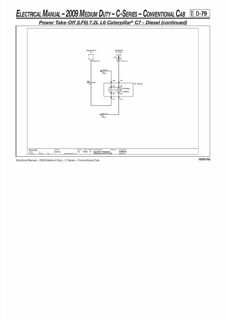
8/10/2019 2009 GM Medium Duty Electrical Manual.PDF
http://slidepdf.com/reader/full/2009-gm-medium-duty-electrical-manualpdf 190/410
Electrical Manual – 2009 Medium Duty – C Series – Conventional Cab h83018c
86
87
30
85
12193604
LAST CHANGED BY
Panel Set:
VERSIONSTAGEREVISIONOBJECT ID ORGANIZATION
Panel Set: 2
PTO Relay
Uh - Pto Rly
D7D9
E7 E9
0.8
GRN DK/WHT2665.
15A
Uh - Eng 3POWER DIST
EcuENGINE CNTLS
Prod Agust in Velazquez GMT5600Pto (LF6)GMT560 X08
Wednesday, April 19, 2006
1:13:24 pm
$IVEDWORK/h83018c__001schematic sheet1
h83018c4
0012
2561
ENBL_RLY
488(Page 1)
C_PTO_RLY_P539ENGAGE_PTO
ENGAGE
(Page 1)
E LECTRICAL M ANUAL – 2009 M EDIUM DUTY – C-S ERIES – CONVENTIONAL C AB P A G E
D-80
Auxiliary Power
POWER DISTPOWER DIST POWER DIST

8/10/2019 2009 GM Medium Duty Electrical Manual.PDF
http://slidepdf.com/reader/full/2009-gm-medium-duty-electrical-manualpdf 191/410
Electrical Manual – 2009 Medium Duty – C Series – Conventional Cab h83019a
LAST CHANGED BY
Panel Set:
VERSIONSTAGEREVISIONOBJECT ID ORGANIZATION
A
BC
has Fuse has Fuse
Family 2
has Fuse
Family 2
Panel Set: 1
Family 2
A
Cigar Lighter
A
BC
Aux Pwr1
POWER DISTIp1 - Pwr Post
20A
2M MP280
B
1.0
.750BLK
Aux Pwr2
A
BC
2M MP280
20A
1.0ORN
840.
Gnd Zone #4BGND DIST
POWER DISTIp1 - Pwr Post
2F MP280B
1.0
.840ORN
Gnd Zone #4B
20A
Ip1 - Pwr PostPOWER DIST
$IVEDWORK/h83019a__001
1:17:48 pm
Wednesday, April 19, 200608 XGMT560
Auxiliary PowerB GMT560Agustin VelazquezPilot
1
Gnd Zone #7AGND DISTGND DIST
CIGAR_P
2F MP280A
0012
h83019asheet1schematic
CIGAR_G750AUX2_G450
AUX2_P840
AUX1_G450
840 AUX1_P
E LECTRICAL M ANUAL – 2009 M EDIUM DUTY – C-S ERIES – CONVENTIONAL C AB P A G E
D-81
Engine Controls (L18) 8.1L V8 GMPT VORTEC® - Gas

8/10/2019 2009 GM Medium Duty Electrical Manual.PDF
http://slidepdf.com/reader/full/2009-gm-medium-duty-electrical-manualpdf 192/410
Electrical Manual – 2009 Medium Duty – C Series – Conventional Cab h83020a
+5V +5V+V +5V
+V
+5V
LAST CHANGED BY
Panel Set:
VERSIONSTAGEREVISIONOBJECT ID ORGANIZATION
Panel Set: 1
GRN LT432.
0.5
J2-7
LINEAREGR
CONTROLHI
J2-58
ENGINEOIL PRESSSENSOR
CONTROLLO
J2-41
LINEAREGR
MAP
J2-32 J2-24
THROTTLE
SENSORPOSITION
5VB SUPPLY
J1-8
1D
J1-80
VREF RTN E
J1-74
ENGINECOOLANT TEMP
5VB SUPPLY
J1-7
1C
J1-63
VREF RTN CVREF RTN D
J1-60J1-54
VREF RTN B
J1-55
LINEAR
POSITIONEGR
5VB SUPPLY1A
J1-48
5VB SUPPLY1B
J1-47J1-41
VREF RTN A
PCM
0.5
.469ORN/BLK
LOW
A
REF
B
PRESS
C
Sen - Oil Press
0013
h83020asheet1schematic $IVEDWORK/h83020a__001
1:18:57 pm
Wednesday, April 19, 200608 XGMT560
Engine Controls (L18)0 GMT560Agustin VelazquezBeta
1
0.8
BLK407.
0.5
GRA720. .705
GRA
0.8
.332TAN/WHT
0.8
.410YEL
0.5
Sen Asm-Cool Temp
A
REF
B
.597GRA
0.5
Sensor - Map
A
REFLOW
B
MAP
C
5VREF
E LECTRICAL M ANUAL – 2009 M EDIUM DUTY – C-S ERIES – CONVENTIONAL C AB P A G E
D-82
Engine Controls (L18) 8.1L V8 GMPT VORTEC® - Gas (continued)
SPEED SNR LOWSpeed Snr
TOSS
Trans Speed Snsr (Man)

8/10/2019 2009 GM Medium Duty Electrical Manual.PDF
http://slidepdf.com/reader/full/2009-gm-medium-duty-electrical-manualpdf 193/410
Electrical Manual – 2009 Medium Duty – C Series – Conventional Cab h83020a
+V+V
LAST CHANGED BY
Panel Set:
VERSIONSTAGEREVISIONOBJECT ID ORGANIZATION
Panel Set: 2
B
J2-42
TRANS MOD RLYSOLENOID/
TCC ENABLE
J2-45
VENT SOLENOIDCANISTER
RELAYSOLENOID
AIR
J2-4J2-34
SOLENOIDCANISTER PURGE
RELAYAIR PUMP
J2-36
TRANS OUTPUT SPEED SENSOR
HI
J2-21
TRANS INPUT SPEED SENSOR
HI
J2-22
LOW
J2-23
LOW
J2-20 J1-79
SKIP SHIFT3-2 SHIFT
PCM
Speed SnrSPEED SNR LOW
EcmECM TOSS LOW
EcmECM TOSS LOW
C6M GT280 SLD
2221.
0.8BLU LT
Wednesday, April 19, 2006
1:18:57 pm
$IVEDWORK/h83020a__001s ch em at ic s he et1
h83020a3
0012
Beta Agustin Velazquez GMT5600Engine Controls (L18)GMT560 X08
Speed SnrSPEED SNR HI
Uh - Eng1
10A
POWER DIST
.428GRN DK/WHT
0.8
TcmTRANSMISSION
2222.
0.8GRN DK
Valve Asm-Cnstr Purge
A
B
EcmECM TOSS HI
EcmECM TOSS HI
SPEED SNR HISpeed Snr
2221.
0.8
BLU LT
2222
Speed SnrSPEED SNR HI
GRN DK0.8
.
ECM TOSS HIEcm
GRN DK0.8
.2222
0.8BLU LT
2221.
B
LO HI
A
BLU LT0.8
.2221
Speed SnrSPEED SNR LOW
EcmECM TOSS LOW
B
SPEED_HI_22221
SPEED_LOW_22222
6F GT280 SLDC
SPEED_LOW
SPEED_LOW_2
SPEED_HI_2
SPEED_HI_2
SPEED_HI
SPEED_LOW SPEED_HI
SPEED_HI2221SPEED_LOW2222
SPEED_LOW_2
REP_TOSS_HI_1
2 39 P UR GE _P
E LECTRICAL M ANUAL – 2009 M EDIUM DUTY – C-S ERIES – CONVENTIONAL C AB P A G E
D-83
Engine Controls (L18) 8.1L V8 GMPT VORTEC® - Gas (continued)
15A
POWER DISTUh - Eng2Uh - Eng3
POWER DIST
15A

8/10/2019 2009 GM Medium Duty Electrical Manual.PDF
http://slidepdf.com/reader/full/2009-gm-medium-duty-electrical-manualpdf 194/410
Electrical Manual – 2009 Medium Duty – C Series – Conventional Cab h83020a
FREQ IN FREQ IN+V
LAST CHANGED BY
Panel Set:
VERSIONSTAGEREVISIONOBJECT ID ORGANIZATION
A A
A
50
B
INJ
19
H
A
F
0.8
50
19
10M MP150 SLD
.
0.8
0.8
Panel Set: 3
AA
pe058332
.
C
0.8
TXL
6M6
.
.
INJ
INJ
pe058332
19
B
PNK
Fuel Inj #8
50
INJ
P NK /B LK B LK /W HT
TXL
TXL50
D
10M MP150 SLD
0.8
INJ
50
.
19
INJ
6M6
539
B
A
19
50
SPLICESPLICE
TXL
X0036
19
12045808
19
6M6
Fuel Inj #7
TXLPNK
0.8
X0036
B
17124607
Fuel Inj #4
19
17200041
5019
191.0
INJ
Fuel Inj #2
19
50
PNK
0.8
.
RED/BLK
X0036
Fuel Inj #5
0.8
B
X0036
pe058332
0.8BLK
.
19
pe058332
TXL
INJ
6M6
TXL
17124607
B
TXL 0.8 TXL
6M6
K
878
Rail Asm - Inkn Fuel
002
BLU LT/BLK
PNK
50
.
INJ
X0036
19TXL
1746
0.8 50
X0036
pe058332
6M8
Fuel Inj #3
.
.
TXL
.539
50
pe058332
339
19
339
A
B
.
INJ
339
INJ
E
X0036
0.8
INJ
002
12045808
TXL
TXL
INJ
BLU DK/WHT
PNK
A
B
PNK
1745
6M6
50 50
GRN LT/BLK
INJ
PNK.
INJ
50
0.8
X0036
0.8
6M6
0.8
12065425
539
B
846
TXL
INJ
.
6M6
845
TXL
0100A 1744
PNK
INJ
1.0
.539
INJ
TXL
.
50
PNK
Fuel Inj #1
YEL/BLK
19 0.8
TXL
. 844877
19
INJ
50
PNK
pe058332
19
pe058332
J
INJ50
.
539 339
19
50
Fuel Inj #6
TXL
G
339
0.5BLK/WHT
845.
J
.
0.8PNK
A
539
MONBAT VOLTAGE
J2-65
DIAGNOSTICEHC
J2-56 J1-9
DIFF FLATKNOCK 1
J1-77
FINJECTOR
J1-76
BINJECTOR
J1-53
VREF RTN FKNOCK 1RTN FLAT
J1-49 J1-50
RTN FLATKNOCK 2
CINJECTOR
J1-43
GINJECTOR
J1-44
DINJECTOR
J1-4
AINJECTOR
J1-36
EINJECTOR
J1-37
INJECTOR
J1-3
H
KNOCK 2DIFF FLAT
J1-10
PCM
C
1745.
0.5GRN LT/BLK
G10F MP150 SLD
B
PNK0.8
.339
Wednesday, April 19, 2006
1:18:57 pm
$IVEDWORK/h83020a__001s chem at ic s he et 1
h83020a3
0013
Beta Agustin Velazquez GMT5600Engine Controls (L18)GMT560 X08
E
0.5YEL/BLK
846.
K
F
10F MP150 SLD
.1746PNK/BLK0.5
HD
0.5BLK
1744. .878BLU DK/WHT
0.5
.877RED/BLK0.5
.844BLU LT/BLK
0.5
INJ1_P INJ2_P
E LECTRICAL M ANUAL – 2009 M EDIUM DUTY – C-S ERIES – CONVENTIONAL C AB P A G E
D-84
Engine Controls (L18) 8.1L V8 GMPT VORTEC® - Gas (continued)

8/10/2019 2009 GM Medium Duty Electrical Manual.PDF
http://slidepdf.com/reader/full/2009-gm-medium-duty-electrical-manualpdf 195/410
Electrical Manual – 2009 Medium Duty – C Series – Conventional Cab h83020a
+V +V+V
LAST CHANGED BY
Panel Set:
VERSIONSTAGEREVISIONOBJECT ID ORGANIZATION
Panel Set: 4
Family 2has Fuse
TRANSMISSIONTcm
BRN/WHT379.
0.5
STARTING & CHARGINGGenerator Assembly
F-TERM MONITORALTERNATOR
J2-75J2-5
DELIVEREDTORQUE
REDUCED ENGINE POWERCRUISE INHIBIT/
J2-37
ENGAGEDCRUISE
J2-13 J2-15
L-TERM MONITORALTERNATOR
J1-62
BRAKE SWITCHEXTENDED TRAVEL
SWITCHBRAKESWITCH
CLUTCH
J1-35
TCC
J1-33
TORQUE
J1-13
REQUESTED
PCM
B630M GTMXD SLD
BRAKES
Brake Sw
30F GTMXDA11
TRANSMISSIONTcm
0.8ORN/BLK
463.
B
Man Cltch Sw Top Of Trvl
A
10A
Ip1 - BrakePOWER DIST
0.5
.420PPL
B630F GTMXD SLD
.464TAN/BLK0.8
.23GRA
0.8BRN/WHT0.5
.379
4
Beta Agust in Velazquez GMT5600Engine Controls (L18)GMT560 X08
Wednesday, April 19, 2006
1:18:57 pm
$IVEDWORK/h83020a__001sche matic sheet1
h83020a3
001
0.5
.379BRN/WHT
STARTING & CHARGINGGenerator Assembly
30M GTMXDA11
25 L_TERM_L18
CR_CLU_P441
TCC_PCMREQ_TORQ
DEL_TORQ F_TERM_MON
E LECTRICAL M ANUAL – 2009 M EDIUM DUTY – C-S ERIES – CONVENTIONAL C AB P A G E
D-85
Engine Controls (L18) 8.1L V8 GMPT VORTEC® - Gas (continued)
POWER DIST IP CLUSTERINTERIOR LIGHTING

8/10/2019 2009 GM Medium Duty Electrical Manual.PDF
http://slidepdf.com/reader/full/2009-gm-medium-duty-electrical-manualpdf 196/410
Electrical Manual – 2009 Medium Duty – C Series – Conventional Cab h83020a
LAST CHANGED BY
Panel Set:
VERSIONSTAGEREVISIONOBJECT ID ORGANIZATION
+V+V +V
Panel Set: 5
has FuseFamily 2
.534GRN DK
A2
0.8
0Engine Controls (L18)GMT560 X08
Wednesday, April 19, 2006
1:18:57 pm
$IVEDWORK/h83020a__001schematic sheet1
h83020a3
0015
Beta Agustin Velazquez GMT560
0.5
.2013RED
GND DIST
0.8
.1827YEL/BLK
Gnd Zone #7A
OUTPUT4 kPPM
J2-50J2-46
INDICATOR LPMALFUNCTION
J2-49
4 kPPM128 kPPM/
OUTPUT
J2-44
HI IDLELAMP
J2-38
LAMPALTERNATOR
J2-35
LEVEL OUTPUTFUEL/OIL
A/C RECIRC
J2-33
CHECK GAUGES LP/ FAN2/
J2-10
TACHOUTPUTENGINE SHUTDOWN
FAN1/
J1-42
LIFT DIVECHG OIL LP
RELAYSTARTER
J1-39J1-38
SWITCHHI IDLE
J1-31
PCM
YEL/BLK1827.
0.8
C2
RED2013.
0.8
GRN DK534.
0.5
B6
IP CLUSTERTachometer (2 Ppr)
24M GTMXD SLDC3
.750BLK
0.5GRN DK
534.
0.5
POWER DISTIp1 - Brake
10A
0.5
.817GRN DK/WHT
30M GTMXD SLDC2
C2
Starter RlySTARTING AND CHARGINGIP CLUSTER
0.5
Mal Ind Lamp
WHT121.
Speedometer (4KPPM)IP CLUSTER
D1
0.5
.419BRN/WHT
Headlamp PowerINTERIOR LIGHTING
B6
BRN/WHT419.
0.5
.447YEL
0.8
B130M GTMXD SLD
WHT0.5
.121
D1 30F GTMXD SLDC2
GRN DK/WHT817.
0.5
LED
LAMP
E F
GND
High Idle Switch
A
GNDGND
B
SW
C
D
24F GTMXD SLDC3
A2
30F GTMXD SLDB1
30F GTMXDA3
30M GTMXDA3
Sec PpmBODY BUILDERGND DIST
Gnd Zone #7A
PCM_START
441 HIS_LED_P
BB_PPM
MAL_IND_LP
HIS_LP2509
HIS_G750 HIS_ILL_G750
TACH
PRIM_PPM
E LECTRICAL M ANUAL – 2009 M EDIUM DUTY – C-S ERIES – CONVENTIONAL C AB P A G E
D-86
Engine Controls (L18) 8.1L V8 GMPT VORTEC® - Gas (continued)

8/10/2019 2009 GM Medium Duty Electrical Manual.PDF
http://slidepdf.com/reader/full/2009-gm-medium-duty-electrical-manualpdf 197/410
Electrical Manual – 2009 Medium Duty – C Series – Conventional Cab h83020a
+V
+V +V+V +V
LAST CHANGED BY
Panel Set:
VERSIONSTAGEREVISIONOBJECT ID ORGANIZATION
has Fuse
has FuseFamily 2
Family 2
Panel Set: 6
MOTOR 1 LOFORCE
J2-8
FORCE
A
J2-63
CRANK
J2-59
REQUEST
J2-6
MOTOR 1 HITEMP SNSR
TRANS
J2-51
etc.SHIFT B SOL
J2-47
SHIFT A
J2-48
SOLENOID
J2-2
SOLENOIDTCC CONTROL
IGN 0
J1-75
WAKEUPSECONDARY
J1-57
BATTERY
J1-17
MANIFOLDPRESSURE SWITCH
C
J1-18
IGN 1
J1-19
RUN/CRANK
BATTERYPRIMARY
J1-20
B
PCM
TcmLCT TRANS STARTING & CHARGING
Clutch Sw
schematic sheet1
h83020a3
0016
Beta Agustin Velazquez GMT5600Engine Controls (L18)GMT560 X08
Wednesday, April 19, 2006
1:18:57 pm
$IVEDWORK/h83020a__001
POWER DISTIp1 - Pcm-I
15A
0.8WHT
2467.
POWER DISTUh - PcmB
10A
POWER DIST
10A
Uh - PcmBPOWER DIST
Uh - PcmB
10A 10A
Ip1 - TransPOWER DIST
0.8PPL
806.
CRANK_P L18_CRANK1433
440 PCM_BAT1_P439 PCM_IGN1_P
PCM_IGN0_P1020 PCM_BAT2_P440UNMAN_TORQ
E LECTRICAL M ANUAL – 2009 M EDIUM DUTY – C-S ERIES – CONVENTIONAL C AB P A G E
D-87
Engine Controls (L18) 8.1L V8 GMPT VORTEC® - Gas (continued)
HIHI HIHI
(BANK 1 SENSOR 1)PRE-OXYGEN SENSOR HEATED
LOW
PRE-OXYGEN SENSOR HEATED(BANK 2 SENSOR 1)
LOW
POST-OXYGEN SENSOR HEATED(BANK 1 SENSOR 2)
LOWLOW
POST-OXYGEN SENSOR HEATED(BANK 2 SENSOR 2)
PCM
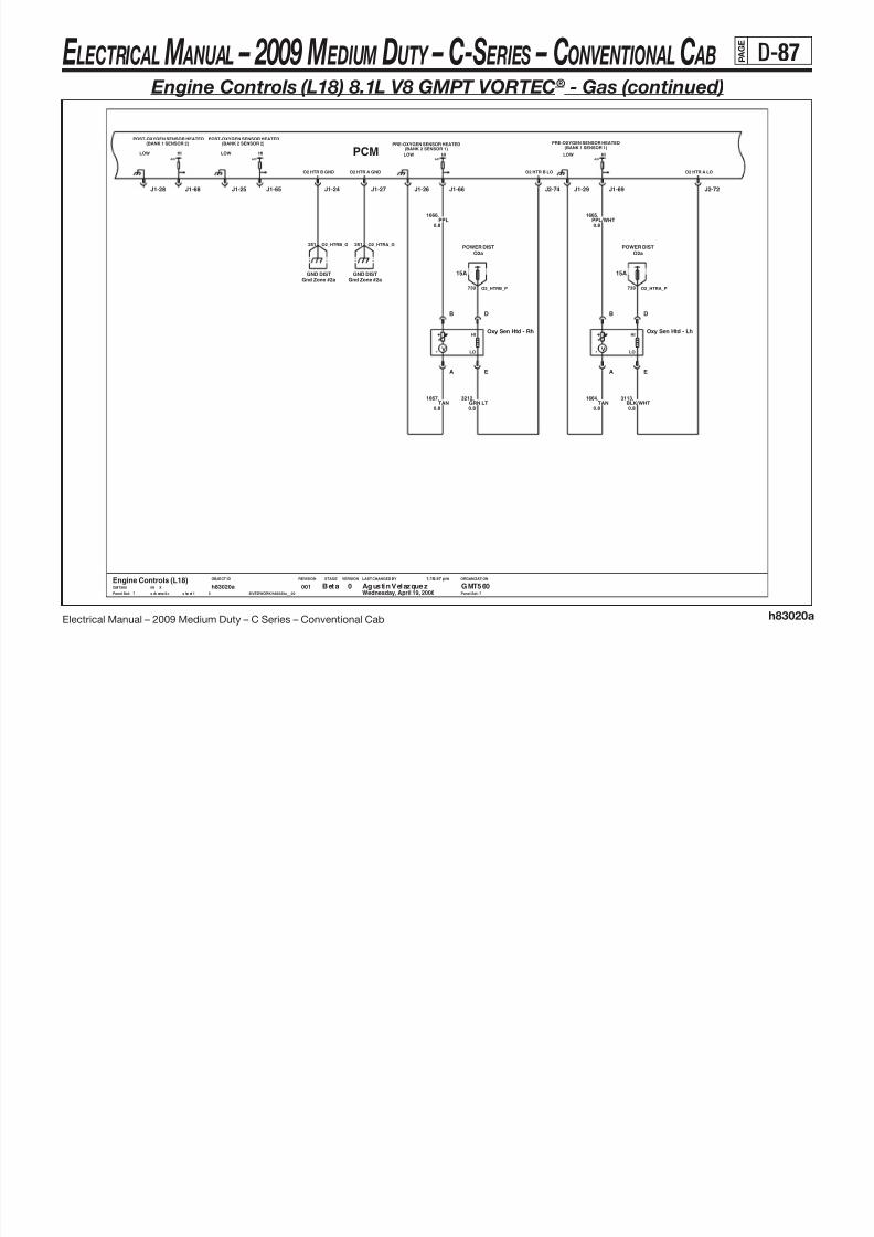
8/10/2019 2009 GM Medium Duty Electrical Manual.PDF
http://slidepdf.com/reader/full/2009-gm-medium-duty-electrical-manualpdf 198/410
Electrical Manual – 2009 Medium Duty – C Series – Conventional Cab h83020a
A/DA/DA/D A/D
LAST CHANGED BY
Panel Set:
VERSIONSTAGEREVISIONOBJECT ID ORGANIZATION
Panel Set: 7
O2 HTR B LO
J2-74 J2-72
O2 HTR A LO
J1-65 J1-66J1-68 J1-69J1-25 J1-26
O2 HTR A GND
J1-27J1-28 J1-29J1-24
O2 HTR B GND
PPL/WHT1665.
0.8
.1664TAN
0.8
.1666PPL
0.8
0.8TAN
1667.
-
A
+
B
HI
D
LO
E
V
Oxy Sen Htd - Rh
GMT560 X08
Wednesday, April 19, 2006
1:18:57 pm
$IVEDWORK/h83020a__001s ch ema ti c s he et 1
h83020a3
0017
Beta Agustin Velazquez GMT5600Engine Controls (L18)
Gnd Zone #2aGND DIST
D
HI
E
LO
Oxy Sen Htd - Lh
V
A
-
B
+
GND DISTGnd Zone #2a
GRN LT3212.
O2a
15A
POWER DIST
0.8
.3113BLK/WHT0.8
O2a
15A
POWER DIST
739
251 O2_HTRB_G
O2_HTRA_P739
O2_HTRA_G251
O2_HTRB_P
E LECTRICAL M ANUAL – 2009 M EDIUM DUTY – C-S ERIES – CONVENTIONAL C AB P A G E
D-88
Engine Controls (L18) 8.1L V8 GMPT VORTEC® - Gas (continued)
INPUTVATS
MAFINLET
AIR TEMPLOW OIL
LVL SWITCHRES KNOCK
ODD PCMEVENRES KNOCK

8/10/2019 2009 GM Medium Duty Electrical Manual.PDF
http://slidepdf.com/reader/full/2009-gm-medium-duty-electrical-manualpdf 199/410
Electrical Manual – 2009 Medium Duty – C Series – Conventional Cab h83020a
FREQ IN FREQ IN+V +V+V+V
LAST CHANGED BY
Panel Set:
VERSIONSTAGEREVISIONOBJECT ID ORGANIZATION
Panel Set: 8
0.5BLK
552.
ELEC THROT CNTLEtc Mdl
ELEC THROT CNTLEtc Mdl
J2-57
RTN GVREF
J2-30 J2-31J2-25J1-70
CLASS 2
J1-58 J1-59 J1-51
DATASERIAL
J1-14J1-15
ETC
PCM
J1-11
30F GTMXD SLDC8
0.8BRN
1174.
Sw Asm - Low Oil Lvl
A
B
492.
0.5YEL
3
0018
Beta Agust in Velazquez GMT5600Engine Controls (L18)GMT560 X08
Wednesday, April 19, 2006
1:18:57 pm
$IVEDWORK/h83020a__001sche matic sheet1
h83020a
30M GTMXD SLDC8
A
TEMP
B
GND
C
IGN
D
MAF
E
GND DISTGnd Zone #2A
MAF SenseLOWREF
GRN DK1049.
0.5
10A
POWER DISTUh - Eng1
Case GndGND DIST
GND DISTCase Gnd
.1049GRN DK0.5
.472TAN
0.5
496.
0.8BLU DK
1
CASE
Sensor - Knock Lh
1
CASE
Sensor - Knock Rh
Gnd Zone #3AGND DIST
Star ConnectorSERIAL DATA LINK
.1876BLU LT0.8
EVEN_KNK_G
ODD_KNK_G
ETC_B774
1061 ETC_A
239 L18_MAF_P
ENG_CL2
MAF_G351
LOW_OIL_G250
E LECTRICAL M ANUAL – 2009 M EDIUM DUTY – C-S ERIES – CONVENTIONAL C AB P A G E
D-89
Engine Controls (L18) 8.1L V8 GMPT VORTEC® - Gas (continued)
+V FREQ OUT FREQ OUT FREQ OUT FREQ OUT+V
EST HSENSOR
FUEL
SECONDARY
LEVELFUEL
SENSORPRESSURE
EST F
EST RTN
TANK
SENSORLEVELFUEL
EST AEST C(SEC)FTPRESS
V5B
PCM 15A
Uh - Eng3POWER DIST

8/10/2019 2009 GM Medium Duty Electrical Manual.PDF
http://slidepdf.com/reader/full/2009-gm-medium-duty-electrical-manualpdf 200/410
Electrical Manual – 2009 Medium Duty – C Series – Conventional Cab h83020a
+V FREQ OUT FREQ OUT FREQ OUT FREQ OUT+V
LAST CHANGED BY
Panel Set:
VERSIONSTAGEREVISIONOBJECT ID ORGANIZATION
1.0
19
TXL
19
F
19
.
IGN
0.8
14B
S
19
BLK
50
A
.
D
-
.
2123
0.8
250
19
539
TXLPNK
.
EST
IGN
SPARK
EST
0.8
IGN
G
IGN
BLK
Odd Ignition Coil & Driver
SPARK
7M MP150 SLD
50
TXL
0.8
2121
2700A
IGN
TXL
.
12047933
D
CASE
IGN
SPARK
50
EST
.
A
50
12F
19
GND
GRN DK
19
C
SPLICE
TXL
2129 2129
19
BLK
PLUG
BRN0.8
0.8
CASE
12162144GND
CASE
250
0.8
A
D
SPARK
19
BLK
.
.
6Y4
50
SPLICE
PNK
19TXL
50
250250
50
BLU LT
Spark Plug
50
250
0.8
IGN0.8
LOW
REDTXL
Spark Plug Case
TXL
C
B
TXL
IGN
12047938
50
2129
2129
19
H
50
539
IGN
50
.
EST
19
IGN
19
19
IGN
IGN
C
TXLBRN
.
50 50
Ign - Left Bank
CYL_5
S
2127
.
50
19
0.8
0.8
PLUG
B
0.8
19
19TXL
B
A
.
IGN
CYL_7
19
BRN
SPLICE
IGN
IGN
GND
IGN
50
0.80.8
IGN
003
50
.
539
TXL
CYL_3
IGN
7M MP150 SLD
PNK
2125
Gnd Dist
TXL
EST
S
IGN
GND
CASE
8A-
X0008
.
PNK
C
PPL
PLUG
TXL
19
.
Panel Set: 9
BLK
539
AA
50
ESTPLUGLOW
A.
0.8IGN
CASE2
EST
0
A
.
CYL_1
IGN
1.0
IGN
EST
BRN
Page
A
B
0.8
15320908
IGN E
B
0.8
IGN
539
C
TXL
TXL
LOW
S
.
6 Y 4 0 02 1A12158637
TXL
LOW
.
12047933
IGN
TXL
D
TXL
50
50PNK
2129BRN
Gnd Zone #2BGND DIST
0.5BLU LT
2123.
RELAYPUMPFUEL
J2-9 J2-69J2-73J2-64 J2-68
EST RTNBANK 1 (ODD)
J2-60J2-54J2-3 J2-26J2-27
FUEL
SECRELAYPUMP
J1-5
V5BRETURN
H
J1-23
FUEL HAND & STORSec Fuel Pump Rly
.465GRN DK/WHT
0.80.5
RED2127.
FUEL HAND & STORPri Fuel Sender
7F MP150 SLD E G
0.5TAN
1465.
0.5BLU DK
1936.
0.5
.2121PPL
F
Sec Fuel SenderFUEL HAND & STOR
B
BLK0.8
.470.1589PPL
0.8
HFUEL HAND & STORFuel Tank Senders
7F MP150 SLDA
9
Beta Agustin Velazquez GMT5600Engine Controls (L18)GMT560 X08
Wednesday, April 19, 2006
1:18:57 pm
$IVEDWORK/h83020a__001s ch em at ic s he et1
h83020a3
001
.2125GRN DK0.50.8
BRN2129.
Fuel Pump RlyFUEL HAND & STOR
C
FUEL_LVL1
FUEL_LVL2 FUEL_RLY2
FUEL_RTN
FUEL_RLY1
IGN_COIL1_P539
IGN_ODD_G250
E LECTRICAL M ANUAL – 2009 M EDIUM DUTY – C-S ERIES – CONVENTIONAL C AB P A G E
D-90
Engine Controls (L18) 8.1L V8 GMPT VORTEC® - Gas (continued)
FREQ OUT IGN FREQ IN IGN FREQ INFREQ OUT FREQ OUT FREQ OUT
EST BEST D
EST RTN
CAM SUPEST EEST G
CAMSHAFTPOSITIONSENSOR SUP
CRANK CRANKPCM
SENSOR
POWER DISTUh - Eng2
15A

8/10/2019 2009 GM Medium Duty Electrical Manual.PDF
http://slidepdf.com/reader/full/2009-gm-medium-duty-electrical-manualpdf 201/410
Electrical Manual – 2009 Medium Duty – C Series – Conventional Cab h83020a
FREQ OUT IGN FREQ IN IGN FREQ INFREQ OUT FREQ OUT FREQ OUT
LAST CHANGED BY
Panel Set:
VERSIONSTAGEREVISIONOBJECT ID ORGANIZATION
D
S
TXL
.
ENG
50
TXL
.
2130
BLU LT/WHT.
Page
CYL_2
TXL
IGN
0.8
50
TXL 0.80.8
IGN
19
8A-
CYL_4
50
PLUG
ENG
15320908
A
TXL
ENG
SPARK
S
50
X0008
TXL
339
A
50
S
339
GND
A
LOW
SPARK
TXL
BLK
.
PNK
TXL
CASE3
LOW
B
TXL
0.8
CASE
GND
PPL/WHT
.
0.8
50
BRN/WHT
TXL
.
EST
.
C
19
E
PLUG
0.8 19
19
PNK
6Y4
Even Ignition Coil & Driver
G12047933
2128
12162144
6Y 4
1.0
PLUG
50
50
B
IGN
EST
50
0.8
A
Panel Set: 10
19
Gnd Dist
2130
PNK
IGN
50
BLK
B
BRN/WHT0.8
19
19
TXL
IGN
.
IGN
0.8
0.8
TXL
GRN DK/WHT
14B
2130
19
IGN
0Spark Plug Case
0.8
EST
CASE
IGN
12047933
.
50
2700A
0.8
0.8
F
.
BRN/WHT
.
50
IGN
339
250
2130
B
C
CYL_8
19
19
C
IGN
50
IGN
H
EST
SPLICE
IGN
0.8
SPARK
2122
0.8
12047938A
50IGN
TXL
250
PLUG
BRN/WHT.
ENG
IGN
SPLICE
7M MP150 SLD
D
.
IGN
339
19
CYL_6
RED/WHT
GND
19
50
TXL
19
50
250
7M MP150 SLD
50
.
PNK
SPLICE
IGN
IGN
Ign - Right Bank
0021A
EST
19
LOW
.
003
A
0.8
B
EST
CASE
C
A
IGN
2130
C
IGN
IGN
12158637
.
EST
SPARK
TXL
LOW
Spark Plug
19
BLK
50
IGN
BRN/WHT
250
PNK
D
BLK BLK
2124
339
CASE
2126
50
S
19 0.8
19
.
-
.
.
EST
19
A
TXL
A
TXL
12F
D
1.0
250
TXL
19
GND
TXL
0.5RED
631.
7F MP150 SLDE
0.5BLU DK/WHT1869.
J2-66J2-67
EST RTNBANK 2
J2-61 J2-39J2-28J2-29 J1-73 J1-61
CAM RTN
J1-21
CRANK RTN
J1-2 J1-16
CRANKPOS 2
J1-12
B
7F MP150 SLDA
YEL/BLK0.5
.1868
A B
SENSORCAM
EFFECT
C
Cam Sensor
G
.2128PPL/WHT0.5
.633BRN/WHT0.5
10
Beta Agustin Velazquez GMT5600Engine Controls (L18)GMT560 X08
Wednesday, April 19, 2006
1:18:57 pm
$IVEDWORK/h83020a__001schematic sheet1
h83020a3
001
C
0.5RED/WHT
2122. .1867GRN LT0.5
F
Crank Sensor
A B
SENSORCRANK
EFFECT
C
0.8BRN/WHT
2130..2124GRN DK/WHT
0.5 0.5BLU LT/WHT
2126.
0.5PNK/BLK
632.
H
GROUND DISTGnd Zone #2B
339 IGN_COIL2_P
IGN_EVEN_G250
E LECTRICAL M ANUAL – 2009 M EDIUM DUTY – C-S ERIES – CONVENTIONAL C AB P A G E
D-91
Engine Controls (L18) 8.1L V8 GMPT VORTEC® - Gas (continued)
+V+V +V+V +V+V+V+V
PRNDL C SWITCHAC PRESS CYC
RELAYCLUTCH
A/CREQ
NUET STARTA/C STATUS/ A/C PRESSURE
SENSOR SWITCH
TRANSFER CASE LO4WD HI-LO
A/CA/C SECONDARYHI PRESS SWITCH
MILREQUESTPRNDL B PRNDL PPRNDL A
PCM

8/10/2019 2009 GM Medium Duty Electrical Manual.PDF
http://slidepdf.com/reader/full/2009-gm-medium-duty-electrical-manualpdf 202/410
Electrical Manual – 2009 Medium Duty – C Series – Conventional Cab h83020a
LAST CHANGED BY
Panel Set:
VERSIONSTAGEREVISIONOBJECT ID ORGANIZATION
+V
Panel Set: 11
ACTIVE TRANSFER CASE4WD ATC Mdl
0013
h83020asheet1schematic $IVEDWORK/h83020a__001
1:18:57 pm
Wednesday, April 19, 200608 XGMT560
Engine Controls (L18)0 GMT560Agustin VelazquezBeta
11
Nsbu - PTRANSMISSION
.762GRN DK/WHT
0.8
24M GTMXD SLDB5
RTN IVREF
J2-80J2-62 J2-55J2-43 J2-17 J2-18 J2-12J2-14 J2-16 J2-11J1-72
V5B SUPPLY 2A
J1-45J1-34J1-32
.1786ORN/BLK0.8 0.5
GRN DK/WHT459.
GRA/BLK0.5
.1694
24F GTMXD SLDB5
.603GRN DK0.5
HVACAc Enable Rly
Low Press SwHVAC
HVACHigh Press Sw
TRNSCAS1694
AC_ENABLE_A
PCM_HI_AC
IMS_NS PCM_LO_AC
E LECTRICAL M ANUAL – 2009 M EDIUM DUTY – C-S ERIES – CONVENTIONAL C AB P A G E
D-92
Engine Controls (L18) 8.1L V8 GMPT VORTEC® - Gas (continued)
2 SPD AXLEPTOPTO ENG PTO COOLANTLOW
PTO
L18Pcm - J1=Blue - J2=Green
PCM

8/10/2019 2009 GM Medium Duty Electrical Manual.PDF
http://slidepdf.com/reader/full/2009-gm-medium-duty-electrical-manualpdf 203/410
Electrical Manual – 2009 Medium Duty – C Series – Conventional Cab h83020a
+V +V
LAST CHANGED BY
Panel Set:
VERSIONSTAGEREVISIONOBJECT ID ORGANIZATION
Panel Set: 12
0.8
2522.YEL
.1478GRN LT
0.8
UPFITTER PROVPto Load
HI
J2-79
IAC BHI
J2-76
LO
J2-77
LO
J2-78
IAC AGND D
J2-40
J2-POWER
J2-19
SWITCH2 SPD AXLE
POWERGND C
J2-1
ENGAGEPTO
J1-78
PTO ENGKILL
J1-71
STATUSPTO
J1-52
POWERGND B
J1-40
J1-
SWITCHCOOLANT
J1-30
ENABLEPTO
J1-22
GND A
J1-1
POWER
PCM
B
YEL.2522
0.8
TRANSMISSIONBody Bldr Trans Conn
Low Coolant Sw
A
1478.
0.8GRN LT
30M GTMXD SLD
B3
0.8
.1478GRN LT
.2522
0.8
YEL
30F GTMXD SLDB9
30F GTMXD SLDB3
UPFITTER PROVPto Rly
.
0.5GRN LT
488
0.8BLK/WHT
451..451BLK/WHT
1478
6F GT280 SLDE
0.8
UPFITTER PROVPto Enable
.
0.5GRN LT
2 SPEED AXLE2Spd Axle Rly
Gnd Zone #3AGND DIST
Pto KillUPFITTER PROV
GRN LT1478.
0.8
11
0013
h83020asheet1schematic $IVEDWORK/h83020a__001
1:18:57 pm
Wednesday, April 19, 200608 XGMT560
Engine Controls (L18)0 GMT560Agustin VelazquezBeta
12M GT280 SLDL
YEL.2522
0.8
GND DISTGnd Zone #3A
12M GT280 SLDJ
Gnd Zone #3AGND DIST
TRANSMISSIONTcm
30M GTMXD SLDB9
.2562PPL
0.5
12F GT280 SLDJ
GND DIST
12F GT280 SLDL
Gnd Zone #3A
E6M GT280 SLD6F GT280 SLD
F
BLK/WHT
GND DISTGnd Zone #3A
0.8
.451
SA2522
6M GT280 SLDF
0.8
.494BLU LT
BLK/WHT451.
0.8
.
0.8GRA/BLK
1467
2522 TCM_PTOSTAT
L18_1_G351
L18_4_G351
L18_3_G351
L18_2_G351
BB_TRANS
351 LOW_COOL_G
PTO_ENG_DIS
PTO_FEDBACK
2SP_AXLEPTO_ENABLE
PTO_ENGAGE
E LECTRICAL M ANUAL – 2009 M EDIUM DUTY – C-S ERIES – CONVENTIONAL C AB P A G E
D-93
Engine Controls (LMM) 6.6L V8 Isuzu DURAMAX ® - Diesel

8/10/2019 2009 GM Medium Duty Electrical Manual.PDF
http://slidepdf.com/reader/full/2009-gm-medium-duty-electrical-manualpdf 204/410
Electrical Manual – 2009 Medium Duty – C Series – Conventional Cab h83020d
LAST CHANGED BY
Panel Set:
VERSIONSTAGEREVISIONOBJECT ID ORGANIZATION
VREFVREFVREF
C2 SAMPLE E35 ECM
-Page
IC469 LOW_OIL_G
GND DISTEngine Earth C
12
12129946REFLOW
Sumitomo:
50
REF
Sensor - Map09373269
.
E
0.5
F
40
7
0.5
.IC71
50
1
Sensor - Oil Pressure
6189-0099
N.O.HELDCLOSED AT
TXLBRN
5V
C
7
GRA
GOLD PLATED TERMINALS
B
J236
BLK
50
Conn 40M GT 150-280 Sld
3
OIL
13551537
J24
LOW
7
188
NORMAL FLUIDLEVEL
0.5
ISUZU
50
7
Sen Asm-IMT
REF
A2
50
7
.
TXL
TXL
ISUZU
LT GRN/WHT0.5
50
ISUZU
TXL
IC188
FNA
TXLGRN LT
7
ISUZU
TXL
.
YEL/BLK
50
FNA
TXL
IC69
A1
IC68
ISUZU
7
ISUZU
FURUKAWA
FW-C-6F-B
5000A
2
BOOST
1
FW-C-6M-B
004
15449029
4000A
REF
LOW
.IC47BLK
50
0.5
E ISUZU
TXLFURUKAWA
2
38F GT MXD
YEL
500.5
178392-6
TXL
ISUZU
TEMP
50
Oil Level Sw
UPC
0.5
12F
.
7
ISUZU
5V
.ORG/BLK
50
0.5
12F
97224993UPC
GRA
REF
0.5ISUZU
CAN_HI(Page 8)
FB CISUZU
50
LOW
HB03
3
500.5
.IC189
FUEL TEMP SENSOR REQUIRES
.
.
FNA
12129140
.
IC94.TXL
REF
B
A
ISUZU
TXL
0.5
15326386Sen Asm-Cool Temp
ISUZU
.
7
PPL/YEL
50
IC43
0.57
UPC97600434
TXL
18
IC93ISUZU
Sensor Asm-Fuel Temp
.
0.5
Conn 38M GT 150-280 Sld29
Conn 38M GT 150-280 Sld13551536
194 8 20
0.5 7
97328879
J1
13551536
27
PRESSURE
2
ISUZU
IMT SENS TERMINALS
Conn 40M GT 150-280 Sld28
IC66
ISUZUIC41
ARE AU PLATED
B
BLU LT
AU
TXLTAN/WHT
13551537
AU AU
AU
A
AU
AU
AUAU
TEMP
IC44BRN
REF
A
IC92
Panel Set: 1
YAZAKI
7282-7020-10
ENG
50
YEL0.5
ISUZU
TXL
7
8A-14A
7
97381182
EARTH C
LOW
TXL
AU
7
7
AU
AU
J1
1
TEMP
A
IC57
YEL.410
0.5
0013
h83020dsheet1schematic $IVEDWORK/h83020d__001
1:28:10 pm
Wednesday, April 19, 200608 XGMT560
Engine Controls (LMM)0 GMT560Agustin VelazquezMule
1
.331TAN/WHT0.5 0.5
BLU LT6118..1578
0.5YEL
20
.432
GRN LT0.5GRA
2705.
0.5
184
.6120YEL/BLK0.5
19Conn 40F GT 150-280 Sld
18 36Conn 40F GT 150-280 Sld
40Conn 40F GT 150-280 Sld
28
.6062BRN0.5
.2755BLK
0.5
F TEMPSENSRTN
J2-47 J2-48
FUEL TEMP
LVL LO
J1-9
ENG OIL
J1-65
COOLANTTEMP
J1-68
INT MANTEMP
J1-6
MAPSENSRTN
IMTSENSRTN
J1-53J1-44
ENG OILPRESS
J1-47
SENSRTNECT
EOP
J1-23
SENSRTN
J1-19
MAP
MAPV5BA
J1-12
EOPV5BA
J1-15
ECM
.1174BRN
0.5
84
469.
0.5ORN/BLK0.5
GRA2704.
278Conn 40F GT 150-280 Sld
2761.
0.5BLK
29
E LECTRICAL M ANUAL – 2009 M EDIUM DUTY – C-S ERIES – CONVENTIONAL C AB P A G E
D-94
Engine Controls (LMM) 6.6L V8 Isuzu DURAMAX ® - Diesel (continued)

8/10/2019 2009 GM Medium Duty Electrical Manual.PDF
http://slidepdf.com/reader/full/2009-gm-medium-duty-electrical-manualpdf 205/410
Electrical Manual – 2009 Medium Duty – C Series – Conventional Cab h83020d
VREF
VBATT
LAST CHANGED BY
Panel Set:
VERSIONSTAGEREVISIONOBJECT ID ORGANIZATION
TXL
Sumitomo
REF
Sen Asm-Cool Temp #2
0.5
50 50
0.5
PWR 6195-0021
Conn 40M GT 150-280 Sld
15449029
13551537
12F
J2
4000A
ISUZU
TXL
EGR DC
ICYEL
0.5
.
TXL
50
ISUZU
MOTOR LO
.
IC140
GRA.
.
0.5ISUZU
AC
0.5
50ISUZU
TXL
A
0.5ISUZU
98006484
IC143
7
IC142GRA BRN/WHT
IC141GRN LT/BLK
MOTOR HIEGR
TXL
IC
BLK
50TXL
. IC144
EGR EGR DC
B
Valve Asm-EGR
.
EGR VALVE DC MOTOR
ORN/BLK0.5
EGR GND
50ISUZU
TXL
B
.
Panel Set: 2
TEMP15326386
50ISUZU
51 3231
F D
3028 29
LOW
.2753BLK
0.5
B5 24M GTMXD SLD
BRN/WHT.5763
0.5
.2221BLU LT
0.8
28
2032GRN LT0.5
.596GRA
0.5
.
1.0
.5746GRN LT/BLK
24F GTMXD SLDB5
1
.5764ORN/BLK1.0
5 2930Conn 40F GT 150-280 Sld
32
.2702GRA
0.5
4WD ATC MdlACTIVE TRANSFER CASE
31
TRANSMISSIONTcm
sheet1
h83020d3
0012
Mule Agust in Velazquez GMT5600Engine Controls (LMM)GMT560 X08
Wednesday, April 19, 2006
1:28:10 pm
$IVEDWORK/h83020d__001schematic
J2-58
TOSS LO
J2-46
A (-)DC MOTOR
J2-45
TOSS HI/ REP TOSS
EGRDC MOTOR
EGR
J2-33
A (+)EGR
SENSRTN
J1-86
FR AXLE SW
J1-82
POS SENS
J1-67
EGR
SENSRTN
J1-64
ECT 2
4WD LO
J1-57
ECT 2
J1-45
EGRV5BA
J1-37
ECM
.
0.5GRA/BLK
1694
1694 TRNSCAS_1
REP_TOSS_HI_1
E LECTRICAL M ANUAL – 2009 M EDIUM DUTY – C-S ERIES – CONVENTIONAL C AB P A G E
D-95
Engine Controls (LMM) 6.6L V8 Isuzu DURAMAX ® - Diesel (continued)
2
Fuel Inj 1 Fuel Inj 7
2 2
Fuel Inj 8
2 2
Fuel Inj 2 Fuel Inj 5 Fuel Inj 3Fuel Inj 4
AUAU AU2 AU AU
Fuel Inj 6
2 2AU AUAU

8/10/2019 2009 GM Medium Duty Electrical Manual.PDF
http://slidepdf.com/reader/full/2009-gm-medium-duty-electrical-manualpdf 206/410
Electrical Manual – 2009 Medium Duty – C Series – Conventional Cab h83020d
LAST CHANGED BY
Panel Set:
VERSIONSTAGEREVISIONOBJECT ID ORGANIZATION
.
TXL
ENG
2.0
PPL
1
Fuel Inj 1
ENG
BLU LT/BLK 50
2.0
50
1
50
BLU DK/WHT
IC17
Fuel Inj 7
Panel Set: 3
ENG
ENG
TXL
50
IC16TAN/WHT
7
ENG
Conn 38M GT 150-280 Sld
.
2.0
50
1
2.0 19
50
ENGIC15
2.0
19
TXLTAN
Fuel Inj 8
1
.IC21
1
ENG
1
7
ENG.
Fuel Inj 2
2.0 TXL
BOSCH
1
Fuel Inj 5
2.0
ORG/BLK
89002368
1 928 403 874
19
50
19
.IC60ORG
.
19
TXL
50
Fuel Inj 3Fuel Inj 4
Conn 40M GT 150-280 Sld13551537
6 J1
13551536
ENG
TXL
J2
IC11
19
AU
19
IC13
AU
352
ORN
7 50
IC12
YEL/BLK2.0IC10
IC13
TXL
50
AUIC19.
1IC22
ENGIC11
ENG
ENG
2.0
ENG
TXL
TXL
.
AU AU
62
IC20ENG.
PNK/BLK
GRN LT/BLK2.0
Conn 38M GT 150-280 Sld
ENGIC60
TXL
.
.
19
35
IC13
TXL
34
19
2.0
2.0
TXL2.0
IC12
50
.
Fuel Inj 6
TXL2.0
13551537
.
PNK
19
TXL
J2
TXL
J134 737
50
PNK
YEL
IC12
2.050
Conn 40M GT 150-280 Sld3
. ENG
IC11
7
.
50
AU AU AU.
2.0
19
IC10
50
13551536
19 PPL
TXL
50
YEL
BLK1744.
1.0
.
1.0
846YEL/BLKBLU LT/BLK
844.
1.0
6 3Conn 40F GT 150-280 Sld
352
.
1.0
1746PNK/BLK
Mule Agustin Velazquez GMT5600Engine Controls (LMM)GMT560 X08
Wednesday, April 19, 2006
1:28:10 pm
$IVEDWORK/h83020d__001s ch em ati c s he et 1
h83020d3
0013
1.0PNK
5425..5422YEL
1.0
2Conn 40F GT 150-280 Sld
634
RED/BLK1.0
.8775421.
1.0ORN
353Conn 40F GT 150-280 Sld
7347Conn 40F GT 150-280 Sld
PPL1.0
.5423
1.0BLK/WHT
845.
J1-75
INJ # 2
J1-73
BANK 2 HSINJ # 1
J1-74
BANK 3 HS
J1-49 J1-50
INJ # 5
J1-51
INJ # 4
J1-3
BANK 4 HS
J1-25
INJ # 6
J1-26 J1-27
INJ # 3INJ # 7 INJ #8
J1-2
ECMBANK 1 HS
J1-1
1.0
878.BLU DK/WHT
.1745GRN LT/BLK
1.0
E LECTRICAL M ANUAL – 2009 M EDIUM DUTY – C-S ERIES – CONVENTIONAL C AB P A G E
D-96
Engine Controls (LMM) 6.6L V8 Isuzu DURAMAX ® - Diesel (continued)

8/10/2019 2009 GM Medium Duty Electrical Manual.PDF
http://slidepdf.com/reader/full/2009-gm-medium-duty-electrical-manualpdf 207/410
Electrical Manual – 2009 Medium Duty – C Series – Conventional Cab h83020d
LAST CHANGED BY
Panel Set:
VERSIONSTAGEREVISIONOBJECT ID ORGANIZATION
VBATTVREF VREF
VNT VNT
0.5ISUZU
B
ISUZU
ORN/BLKIC161
50
Van Position Sensor97603320
BLU DK
ISUZU
12191366
J130
TXL
.
Conn 38M GT 150-280 Sld13551536
131 532
0.5
VNT SOLENOID VALVE
50 0.5
VNT
C
A
EXH TEMP SENSORS REQUIRE GOLD PLATED TERMINALS
Vane Position Sensor
TXL
97387888
B
0.5
.IC170
50
Van Position Sensor REQUIRES GOLD PLATED TERMINALS
.IC162
0.5
IC160
EX-03QRY200040AMP
ISUZU
TXL
YEL
50ISUZU
TAN
AUAU
AU
AU
AU AUAU
AU
AU
AU
AU AU
Panel Set: 4
AU
AU
AU
AU
AUAU
TXL
WHT.IC171
50
.
SENSRTN
A
AU
V5B
TXL
AU AU30
1.0BLU DK
5930
B
.
0.8BLU LT
.5377
48.
0.5GRA
.5277BLU DK0.8
Ip2 - Brake Iso
10A
Man Cltch Sw Top Of Trvl
A
B
POWER DIST
Asm Conn 8F Sealed GT 280A
32 5
POWER DISTIp1 - Brake
10A
0.5ORG/BLK5929.
A1130M GTMXD
0Engine Controls (LMM)GMT560 X08
Wednesday, April 19, 2006
1:28:10 pm
$IVEDWORK/h83020d__001s ch em ati c s he et1
h83020d3
0014
Mule Agustin Velazquez GMT560
B730M GTMXD SLD
0.5
BLU LT1320.
0.5
.1320BLU LT
BRAKES
Brake Sw
1.0WHT
5931.
30M GTMXD SLB6
TransmissionTRANSMISSION
0.5
.48GRA
A1130F GTMXD
PPL420.
30F GTMXD SLD B7
0.5
TAN5928.
0.5
0.5
.48GRA
B
6782.
0.8BRN
Asm Conn 8M Sealed GT 280AC
0.8
.6783DRN/WHT
0.8BLU DK
5277. .6782BRN
0.8
A
B
Sensor Exhaust Temp (Pre DPF)
A
B
Sensor Exhaust Temp #2 (Post DPF)
C
0.8DRN/WHT
6783.
5377.BLU LT0.8
J2-39
NEUT SWPARK
J2-40
BRAKESW #2
BRAKESW #1
J2-22
EXH GAS
J1-93
TEMP 2
EGT #2
J1-94
SENSRTN
J1-96
VAR NOZSOL LO
J1-83
BRAKE APPLYSW
EGTSENSRTN
J1-70
TEMP 1
J1-69
EXH GAS
VNT POS
J1-63
SENSRTNSOL HI
VAR NOZ
J1-48
CRUISE DISABLE
J1-32
CLUTCH SWVAR NOZ
J1-20
TURBO POS
VNT POSV5BG3
J1-13
ECM
D
D
3130F GTMXD SLB6
0.8
ORN/BLK1786.
Conn 40F GT 150-280 Sld1
0.5YEL
5947.
IMS_NS
BRK_NO_P
TCC_PCM
CR_CLU_P441
E LECTRICAL M ANUAL – 2009 M EDIUM DUTY – C-S ERIES – CONVENTIONAL C AB P A G E
D-97
Engine Controls (LMM) 6.6L V8 Isuzu DURAMAX ® - Diesel (continued)

8/10/2019 2009 GM Medium Duty Electrical Manual.PDF
http://slidepdf.com/reader/full/2009-gm-medium-duty-electrical-manualpdf 208/410
Electrical Manual – 2009 Medium Duty – C Series – Conventional Cab h83020d
LAST CHANGED BY
Panel Set:
VERSIONSTAGEREVISIONOBJECT ID ORGANIZATION
VBSWVBSW
VBATT
VBSW
50TXLTXL
ISUZU
Intake Throttle Actuator
ISUZU
AVX
.
SENSRTN
C
YELIC156
97364406
7283-8850-30
INTAKE THROTTLE POSITION
0.5ISUZU
0.5
YAZAKI
BRN
50
TXL
.IC153GRN LT
500.5
Conn 40M GT 150-280 Sld
0.75 AVX
.
ISUZU50
. IC151
AU
AU
AU
10
TV
E
0.75
AU
TV
1112
ISUZU
13551537
J2
.IC150
Panel Set: 5
F
V5B
MOTOR LO
GRA
50
A B
TV
IC154TAN
13
TV
14
AUAU AU AU
AU
MOTOR HI
AU
AU
TV
IP CLUSTER
30F GTMXD SLD B1
Speedometer (4KPPM)
0.8BLU DK
6053.
FAsm Conn 8F Sealed GT 280
E30M GTMXD SLDC2
YEL/BLK0.8
.6055
817GRN DK/WHT
0.5
.
24F GTMXD SLD
B6
0.8YEL/BLK
1827.
0.5
.419BRN/WHT
0.5GRN DK/WHT817.
0.5
.121WHT
IP CLUSTERTachometer (2 Ppr)
.2701GRA
0.5
WHT121.
0.5
Mule Agustin Velazquez GMT5600Engine Controls (LMM)GMT560 X08
Wednesday, April 19, 2006
1:28:10 pm
$IVEDWORK/h83020d__001s ch ema tic s he et 1
h83020d3
0015
485.
0.5GRN DK
Starter RlySTARTING & CHARGING
BN0.8
.6136
BLK0.5
.2752
D1
0.8BRN
6136.
30M GTMXD SLD B1
.6053
BLU DK0.8
IP CLUSTERMal Ind Lamp
0.8.447YEL
FG
0.8YEL/BLK
6055.
.582BRN
0.5
.581YEL
0.5
G
AU
3
5 VREF
AU
SUMITOMO_6189-0099
Sensor - Diff Press Filter
1
REFLO
AU 2
EAsm Conn 8M Sealed GT 280
D1
J2-7
DC MOTOR (-)INT THROT
SECONDARY128KPPM
J2-54
TACH
J2-55
4KPPMPRIMARY
J2-42 J2-32
STARTENABLE RLY
(SES)INDICATOR LPMALFUNCTION
J2-30
DC MOTOR (+)INT THROT
J2-20
TVA
J1-91
ENABLE RLY
J1-71
START
J1-43
DELTA PRESSFILTER
DPF
SENRTN
J1-35
IN AIR THR POS 2SENSRTN
J1-36
IN AIR THR POS
V5B
J1-17
V5BG2
J1-14
DPF
ECM
14 13Conn 40F GT 150-280 Sld
101112
Sec PpmBODY BUILDER
30F GTMXD SLDC2
.1827YEL/BLK
24M GTMXD SLDB6
0.8
BRN/WHT419.
0.5
PRIM_PPM
BB_PPM
MAL_IND_LP
TACH
PCM_START
E LECTRICAL M ANUAL – 2009 M EDIUM DUTY – C-S ERIES – CONVENTIONAL C AB P A G E
D-98
Engine Controls (LMM) 6.6L V8 Isuzu DURAMAX ® - Diesel (continued)

8/10/2019 2009 GM Medium Duty Electrical Manual.PDF
http://slidepdf.com/reader/full/2009-gm-medium-duty-electrical-manualpdf 209/410
Electrical Manual – 2009 Medium Duty – C Series – Conventional Cab h83020d
VBATT
VBATT
VBATT
LAST CHANGED BY
Panel Set:
VERSIONSTAGEREVISIONOBJECT ID ORGANIZATION
Panel Set: 6
POWER DISTIp1 - Trans
10A
POWER DISTIgnB_Rly
30A
POWER DISTUh - PcmB
10A
PPL806.
0.8
30A
IgnB_RlyPOWER DIST
STARTING & CHARGING2nd Generator
0.8GRA/BLK
2219.
15A
Ip1 - Pcm-IPOWER DIST
30A
IgnB_RlyPOWER DIST
.23GRA
0.8
1st GeneratorSTARTING & CHARGING
OUTPUTALT L
J2-8 J2-56
ACCESSORY
J2-5
VBATT 3
ALT F
J2-38
TERMVBATT 2
J2-3
TERM #1
J2-24
TERM #2ALT L
IGN 1
RUN/CRANK
J2-21
ALT L
J2-23 J2-19
POWERTRAINRELAY
BATTERY
J2-1
VBATTA & B
J1-76
ACT PWR
J1-77
BATT FEEDCRANKREQUEST
J1-7
ECM
30A
IgnB_RlyPOWER DIST
Mule Agustin Velazquez GMT5600Engine Controls (LMM)GMT560 X08
Wednesday, April 19, 2006
1:28:10 pm
$IVEDWORK/h83020d__001s ch em at ic s he et1
h83020d3
0016
POWER DISTIp1 - Start
10 A
Ign B RlyPOWER DIST
STARTING & CHARGING1st Generator
VBATT_D
CRANK_P
339
ACTPWR_B440VBATT_C339
339 VBATT_B
VBATT_A339
IGNB_P25 L_TERM_LMM
L2_TERM_LMM2524
F_TERM_MON
439 LMM_IGN1_P
1020 LMM_IGN0_P
E LECTRICAL M ANUAL – 2009 M EDIUM DUTY – C-S ERIES – CONVENTIONAL C AB P A G E
D-99
Engine Controls (LMM) 6.6L V8 Isuzu DURAMAX ® - Diesel (continued)
VREF
PPS1
PPS1SENSRTN
PPS1V5BB
PPS2SENSRTN
ON/OFFCRUISE CRUISE
SET/COASTPPS2V5B
PPS2
ECMCRUISE
RES/ACC
CRUISE

8/10/2019 2009 GM Medium Duty Electrical Manual.PDF
http://slidepdf.com/reader/full/2009-gm-medium-duty-electrical-manualpdf 210/410
Electrical Manual – 2009 Medium Duty – C Series – Conventional Cab h83020d
LAST CHANGED BY
Panel Set:
VERSIONSTAGEREVISIONOBJECT ID ORGANIZATION
Panel Set: 7
A2
.
.BRN
1271
0.5
0.5
1271BRN WHT/BLK
1164
0.5
.
A8
24F GTMXD SLDA6A3
TAN1274
0.5
.
A8
PPL.
0.5
1272
TAN.
0.5
1274
A3
Mule Agust in Velazquez GMT5600Engine Controls (LMM)GMT560 X08
Wednesday, April 19, 2006
1:28:10 pm
$IVEDWORK/h83020d__001schematic sheet1
h83020d3
001
Cruise Cntl SwCRUISE CNTL
7
A2
0.5
1272PPL.
CRUISE CNTLCruise Cntl Sw
1161
0.5
.BLU DK
B1
B2
.BLU LT
1162
0.5
CRUISE CNTLCruise Cntl Sw
B1
PPS 1RTN
PPS 1
E
5V REFPPS 1
F
Pedal Position SensorRTNPPS 2
A
PPS 2
B C
PPS 25V REF
D
24M GTMXD SLDA6
J2-49J2-29 J2-15 J1-78J1-61 J1-38J1-34 J1-21J1-10
0.5
1164WHT/BLK
.
B2
1162
0.5
.BLU LTBLU DK
.
0.5
1161
RES_ACCEL_D87
397 ON_OFF_D
84 SET_COAST_D
E LECTRICAL M ANUAL – 2009 M EDIUM DUTY – C-S ERIES – CONVENTIONAL C AB P A G E
D-100
Engine Controls (LMM) 6.6L V8 Isuzu DURAMAX ® - Diesel (continued)
VREFVREFVBATT
SENSRTNWIF
WIFSW
RAIL PRESS
LO IATSENSRTN
LVLLO CLNT
SENSRTNMAF
VREF
MAF
SENSRTN
MAF
RAIL PRESS
SENSORWIF
HI
V5B
MAF
ECM

8/10/2019 2009 GM Medium Duty Electrical Manual.PDF
http://slidepdf.com/reader/full/2009-gm-medium-duty-electrical-manualpdf 211/410
Electrical Manual – 2009 Medium Duty – C Series – Conventional Cab h83020d
LAST CHANGED BY
Panel Set:
VERSIONSTAGEREVISIONOBJECT ID ORGANIZATION
-
GND DIST
Page 8A-14A
IZ07
Engine Earth C12
RPCV_SH
ISUZU
Conn 40M GT 150-280 Sld37
Rail Press Control Valve
500.5 7TXL
IC32
13551537
J233
AA 928 000 453
97384667UPC FN A
BOSCH
IC31
B
PPL/WHT
HI
LO
YEL
ISUZU
TXL
ALL MAF SENSOR 5 TERMINALS ARE GOLD PLATED
500.5 7
Panel Set: 8
AU
AU
.
0.8GRN LT
1478
Conn 40F GT 150-280 Sld
33
0.5YEL
2834.
E
.472TAN
0.5
37
BLK0.5
Low Coolant Sw
A
B
.476
3
001
BLK/WHT451.
0.8
451BLK/WHT
8
Mule Agustin Velazquez GMT5600Engine Controls (LMM)GMT560 X08
Wednesday, April 19, 2006
1:28:10 pm
$IVEDWORK/h83020d__001s che ma ti c s he et 1
h83020d
0.8
.
GRN LT0.8
.1478
.1478GRN LT0.5
B9
B3 30M GTMXD SLD
0.5YEL
492.
30F GTMXD SLDB3
F
B9
6M GT280 SLD
J2-41 J1-85 J1-72 J1-62
LVL
J1-58 J1-55
MAF
J1-5
IAT
J1-42 J1-33
SENSOR
J1-22 J1-24 J1-16J1-18
MAF
WifHEATED FUEL PPL/WHT
0.5
6F GT280 SLDF
.2530
0.5BLK
552.
TEMP
AU 1
MAF
AU 2
GND
AU 3
IGN
AU 4
REFLOW
AU 5
MAF Sense
GND DISTGnd Zone #3A
E
POWER DISTUh - Eng1
10A
239 LMM_MAF_P
LMM_WIF508
LOW_COOL_G351
E LECTRICAL M ANUAL – 2009 M EDIUM DUTY – C-S ERIES – CONVENTIONAL C AB P A G E
D-101
Engine Controls (LMM) 6.6L V8 Isuzu DURAMAX ® - Diesel (continued)
VBATT
SEN2
FUELLEVEL
SEN1
FUELFUEL LVLSENSRTN
1 & 2LEVEL
WAIT TO START (GP LMP)
RELAYLIFT PUMPF TRANSFER/
IGN0
CAM 4XSENSRTN
FF DIF PRESS
VREF
CRANK 58X
VREF
FF DIF PRESSSENSRTN
VREF
CAM 4X
CRANK 58X
V5BG1
CAM 4XV5B
ECM
CRANK 58X
SENSRTN

8/10/2019 2009 GM Medium Duty Electrical Manual.PDF
http://slidepdf.com/reader/full/2009-gm-medium-duty-electrical-manualpdf 212/410
Electrical Manual – 2009 Medium Duty – C Series – Conventional Cab h83020d
LAST CHANGED BY
Panel Set:
VERSIONSTAGEREVISIONOBJECT ID ORGANIZATION
12
CAM_SHIZ06
CRANK 58X
14A
CRANK_SHIZ05
GND DISTGND DISTEngine Earth B
12-Engine Earth B
-Page
3
Page 8A-
Panel Set: 9
TXL
ISUZU
TXL
8A-14A
7
2526
50ISUZU
0.5
FNA
50ISUZU
TXL
Cam Sensor
.IC27BLU DK/WHT
Crank Sensor
ISUZU
7TXL
97365037
0.5
UPC
6248-5317
3 2
0.5
97365038
1 2 1
CAM 4X
WHT/BLK.
50
1715
UPC FNA
16
IC24BLU DK
.
70.5
.
IC26
24
.
IC25
IC23
J1
13551536
.
PPL/WHT
BRN
50
50ISUZU
TXL0.5 7
6248-5317
IC28
Conn 38M GT 150-280 Sld
ISUZU
GRA/BLK
500.5 7
7
TXL
.1936BLU DK0.5
Fuel Pump RlyFUEL HAND & STOR
0.5
.507BLU DK
0.5
.6259BLU DK
.6266BRN
0.5
.6272GRA/BLK0.5
Sec Fuel SenderFUEL HAND & STOR
507.
0.5BLU DK
6271WHT/BLK0.5
.
0.5BLK
470.
1615Conn 40F GT 150-280 Sld
17
30M GTMXD SLDC3
465.
0.8GRN DK/WHT .6265
BLU DK/WHT0.5
.6270PPL/WHT0.5
TELL TALETtm - Wait Intake Heater
FUEL HAND & STORPri Fuel Sender
FUEL HAND & STORFuel Tank Senders
26
SEN2
J2-50
SEN1
J2-36J2-34 J2-16
RELAY
J2-12 J1-88J1-87
FF DIF PRESS C 58
J1-79J1-54 J1-56
CAM 4X
J1-40J1-41 J1-11
25
$IVEDWORK/h83020d__001sch ematic sheet1
h83020d3
0019
Mule Agust in Velazquez GMT5600Engine Controls (LMM)GMT560 X08
Wednesday, April 19, 2006
1:28:10 pm
24
30F GTMXD SLDC3
0.8PPL
1589.INTAKE_HTR
FUEL_RTN
FUEL_LVL2
FUEL_RLY1
FUEL_LVL1
E LECTRICAL M ANUAL – 2009 M EDIUM DUTY – C-S ERIES – CONVENTIONAL C AB P A G E
D-102
Engine Controls (LMM) 6.6L V8 Isuzu DURAMAX ® - Diesel (continued)
VBATTCLASS 2SERIAL 1
HI TERMINGM LAN
EXH BRK SW
GM LANLO TERMIN
RELAY/LMPEXH BRAKE
VBATT SERIAL 2CLASS 2
SWCLTCH STRT REVERSS GR
SW
ECM

8/10/2019 2009 GM Medium Duty Electrical Manual.PDF
http://slidepdf.com/reader/full/2009-gm-medium-duty-electrical-manualpdf 213/410
Electrical Manual – 2009 Medium Duty – C Series – Conventional Cab h83020d
LAST CHANGED BY
Panel Set:
VERSIONSTAGEREVISIONOBJECT ID ORGANIZATION
Panel Set: 10
0.5BLU LT
6106.
10
Mule Agustin Velazquez GMT5600Engine Controls (LMM)GMT560 X08
Wednesday, April 19, 2006
1:28:10 pm
$IVEDWORK/h83020d__001s ch em at ic s he et1
h83020d3
001
D5 30F GTMXD SLDC8 30M GTMXD SLD
0.5
.1049GRN DK
Splice
0.5.2081GRN LT
ENGINE CTRL
0.5BLU DK
6105.
0.8
.2081GRN LT
30M GTMXD SLDD5
30F GTMXD SLD
C8
Star ConnectorSERIAL DATA LINK
1049.
0.5GRN DK
SpliceENGINE CTRL
Tell TaleEXHAUST BRAKE
J2-9 J2-57 J2-53J2-44J2-10J2-11 J1-89 J1-81
EXH BRAKE/RSTRExhaust Brake Sw
GMLAN_1
GMLAN_2
ENG_CL2
EXH_BRK
EXH_TEL1962
E LECTRICAL M ANUAL – 2009 M EDIUM DUTY – C-S ERIES – CONVENTIONAL C AB P A G E
D-103
Engine Controls (LMM) 6.6L V8 Isuzu DURAMAX ® - Diesel (continued)
VBATT VBATT PRESSAC
V5B
CLUTCHA/C
A/C PRESS
CYCLING SW
SENSRTNEV FAN AC PRESS
V5B
EV FAN GND AC PRESSTRANS
REVERSE SW
REQUESTA/C
A/C HI SIDE
PRESS SW
FEEDBACKEV FAN
FANEV ECM

8/10/2019 2009 GM Medium Duty Electrical Manual.PDF
http://slidepdf.com/reader/full/2009-gm-medium-duty-electrical-manualpdf 214/410
Electrical Manual – 2009 Medium Duty – C Series – Conventional Cab h83020d
LAST CHANGED BY
Panel Set:
VERSIONSTAGEREVISIONOBJECT ID ORGANIZATION
Panel Set: 11Wednesday, April 19, 2006
1:28:10 pm
$IVEDWORK/h83020d__001sch ematic sheet1
h83020d3
00111
Mule Agust in Velazquez GMT5600Engine Controls (LMM)GMT560 X08
HVACAc Enable Rly
Reverse SwEXTERIOR LIGHTING
0.5GRN DK/WHT459.
Low Press SwHVAC
603GRN DK0.5
.
FAN CONTROLEV Fan
EV FanFAN CONTROL
.2365
EV FanFAN CONTROL
GRA0.8
.
0.8BN/WH
6141
J2-35J2-31
CYCLING SW
J2-25J2-26 J2-27J2-28 J2-13J1-84
REVERSE SW
J1-80J1-52
PRESS SW
J1-4 J1-28
2366.
0.8WHT/BLK
.2364BLU DK0.8
24.
0.8GRN LT
FAN CONTROLEV Fan
HVAC
High Press Sw
0.8GRN DK/WHT2523.
EV_FAN_REF
EV_FAN_RTN
EV_FAN_SIGNAL
EV_FAN
PCM_HI_AC2
AC_ENABLE_A2
PCM_LO_AC2
BACK_UP
E LECTRICAL M ANUAL – 2009 M EDIUM DUTY – C-S ERIES – CONVENTIONAL C AB P A G E
D-104
Engine Controls (LMM) 6.6L V8 Isuzu DURAMAX ® - Diesel (continued)
VBATTVREFVBATTPOWER GNDS
321
LED CNTRLHI IDLE SW
RLYENGAGE
PTO
PRESSFR DIFPTO
FEEDBACKHI IDLE SW
ENABLEPTO
FR PRESSV5BA
FR PRESSSENSRTN
ENG DISABLEPTO
ECME35 C2 Sample

8/10/2019 2009 GM Medium Duty Electrical Manual.PDF
http://slidepdf.com/reader/full/2009-gm-medium-duty-electrical-manualpdf 215/410
Electrical Manual – 2009 Medium Duty – C Series – Conventional Cab h83020d
LAST CHANGED BY
Panel Set:
VERSIONSTAGEREVISIONOBJECT ID ORGANIZATION
IZ08
GND DISTEngine Earth C
ISUZU
RAIL_SH
IC40
Page 8A-
ISUZU
TXL50
YEL.
14A
7
12-
TXL
FUEL Rail Pressure SENSORS TERMINALS ARE GOLD PLATED
7TXL 7
IC46.
0.550
ORN/BLK0.50.5
.
5VBOSCH:
RAIL
AU
AU AU
Conn 38M GT 150-280 Sld
3
REF
UPC
J1
1
13551536
23
IC37
FNA
97371617
2
2221
TAN
50
Panel Set: 12
ISUZU
Sensor - Rail Pressure
1 928 403 968
001LOWREF
.534GRN DK0.5
.YEL
0.8
2522
TRANSMISSIONTcm
0.8
2522.YEL
23Conn 40F GT 150-280 Sld
21
.2917TAN
0.5
10A
Ip1 - BrakePOWER DIST
UPFITTER PROVPto Enable
PPL0.5
.2562
GND DISTGnd Zone #3A
UPFITTER PROVPto Load
RED2013.
0.5
2013RED
0.8
.
C2
Gnd Zone #7AGND DIST
24M GTMXD SLD C3
0.8BLU LT
494.
0.5GRN LT
488.
0.5ORG/BLK
2919.
YEL.2522
0.8
Mule Agustin Velazquez GMT5600Engine Controls (LMM)GMT560 X08
Wednesday, April 19, 2006
1:28:10 pm
$IVEDWORK/h83020d__001sc hematic sheet1
h83020d3
00112
0.5
.2918YEL
C2
GND DISTGnd Zone #7A
C3
TRANSMISSIONBody Bldr Trans Conn
Pto Rly
SA2522
24F GTMXD SLD
UPFITTER PROV
0.8YEL
UPFITTER PROVPto Kill
.2522
E
LAMP GND
F
High Idle Switch
GND
AB
GND
C
SW
LED
D
30M GTMXD A2
.534GRN DK0.5
22
30F GTMXD A2
J2-6J2-4J2-17J2-18 J2-2
PRESS
J1-92J1-8
FEEDBACK
J1-60 J1-59J1-39 J1-30J1-31
ENG DISABLE
750.
0.5BLK
Headlamp PowerINTERIOR LIGHTING
GND DISTGnd Zone #3A
A3
GND DISTGnd Zone #3A
A3
GRN DK534.
0.8
2522 TCM_PTOSTAT
PTO_ENABLEPTO_ENG_DIS
3 51 L MM _2 _G
LMM_3_G351
LMM_4_G351
PTO_ENGAGE
PTO_FEDBACK
BB_TRANS
750 HIS_G
HIS_LED_P441
2509 HIS_LP
750 HIS_ILL_G
E LECTRICAL M ANUAL – 2009 M EDIUM DUTY – C-S ERIES – CONVENTIONAL C AB P A G E
D-105
Engine Controls (LMM) 6.6L V8 Isuzu DURAMAX ® - Diesel (continued)
FL
StarterSTARTING AND CHARGING

8/10/2019 2009 GM Medium Duty Electrical Manual.PDF
http://slidepdf.com/reader/full/2009-gm-medium-duty-electrical-manualpdf 216/410
Electrical Manual – 2009 Medium Duty – C Series – Conventional Cab
LAST CHANGED BY
Panel Set:
VERSIONSTAGEREVISIONOBJECT ID ORGANIZATION
50
50
HB13
AVX
12020227
HB15
AESSX-HT AESSX-HT19
AVX
50
.
G P # 4
A
50
HB02
50
WHT/GRN LTHB16
192.0 50
WHT/YEL
IGN1
2.0
PNK
HB14.
19
WAKE UP
2.0 5019
ISUZU
RED/WHT
G P # 1
J1
.
50
WHT/BLU DK2.0 AESSX-HT
.
glow_plug
50
HB11
3340
BLU LT
0.85ISUZU
HB12.
G P # 7
AESSX-HT
G P # 5
FNA
13551536
2.0
A
192.0 50
WHT/GRN
Conn 38M GT 150-280 Sld383937
0.5
HB17RED/BLU
AESSX-HT
50
RED/GRN LT
.
G P # 2
.
001
36
AESSX
ISUZU
.HB05
A
HB18
A
AVX
A
G P # 3
ISUZU
AVX
.
2.0
0.5
IN HI
.
TAN/BLK
50
J2-43
IN LOLAN
A
.HB20
J2-45
OUT LO
J2-44
LAN
J2-46
1
TEMP
0.5
OUT HI
GP # 4
J2-02
GP # 1
DIGITAL
GP # 3
J2-01
GP # 8
J2-04
HEART BEAT
2
ON_OFF
GP # 5
VOLT
GP # 6GP # 2
G P # 6
19
A
.
2.0
Glow Plug # 8
UPC
A
50
HB06
97375410
LAN
GLO_CNTL_GHB03
GND DISTEngine Earth C
-Page 8A-
1919
ON/OFF
6
J2-28
TEMP
.
3
CURRENT
4
AESSX-HT
GP # 7
BLU/YEL
LAN
ALL GPCM TERMINALS ARE SILVER PLATED
HTR SW M
J2-26
HEART BEAT
GP GND
J2-51
AVXTAN
12
0.5ISUZU
14A
5
RED/GRN
J2-03
J2-31
AESSX-HT
J2-52
HB01
RESPONSE
Htr Switching Module
DT-16-6S-K002
Panel Set: 13
J2-53J2-29 J2-30
VOLTRESPONSEDIGITAL IGN 0CURRENT
J2-27
39
.2RED
19
10A
Ip1 - TransPOWER DISTENGINE CTRL
Ecu
EcuENGINE CTRL
SN2
ENGINE CTRLEcu
33
EcuENGINE CTRL
374036
Ring Terminal
M6
A
B
POWER DISTUh - Eng 1
10A
38Conn 40F GT 150-280 Sld
J2-J1-
Gpcm
J1-A
BATT
00113
Mule Agustin Velazquez GMT5600Engine Controls (LMM)GMT560 X08
Wednesday, April 19, 2006
1:28:10 pm
$IVEDWORK/h83020d__001s ch em at ic s he et1
h83020d3
RED2.
8.0
19RED
2.
SX2
GLO_CNTL2
6106
239 HTR_RLY_D_P
LMM_IGN0_GP1020
6105 GMLAN_4
6106 GMLAN_3
6105 GMLAN_2
GMLAN_1
h83020d
E LECTRICAL M ANUAL – 2009 M EDIUM DUTY – C-S ERIES – CONVENTIONAL C AB P A G E
D-106
Engine Controls (LMM) 6.6L V8 Isuzu DURAMAX ® - Diesel (continued)
EcuENGINE CTRL

8/10/2019 2009 GM Medium Duty Electrical Manual.PDF
http://slidepdf.com/reader/full/2009-gm-medium-duty-electrical-manualpdf 217/410
Electrical Manual – 2009 Medium Duty – C Series – Conventional Cab
LAST CHANGED BY
Panel Set:
VERSIONSTAGEREVISIONOBJECT ID ORGANIZATION
Panel Set: 14
TcmTRANSMISSION
BLU LT0.8
.6106
DATA LINK CONNData Conn
D2
EcuENGINE CTRL
D430M GTMXD SLD
ENGINE CTRLEcu
Data ConnDATA LINK CONN
GMT5600Engine Controls (LMM)GMT560 X08
W ed ne sd ay , A pr il 1 9, 2 00 6 1 :2 8: 10 p m$IVEDWORK/h83020d__001s ch em at ic s he et1
h83020d3
00114
X Agustin Velazquez
ENGINE CTRLEcu
0.8BLU DK
6105.
0.8BLU DK
6105.
30F GTMXD SLDD4TRANSMISSION
Tcm
Ecu
.
0.8BLU LT
6106
.6105BLU DK0.8
0.8BLU LT
6106.
D2
GMLAN_3
GMLAN_9
GMLAN_4
GMLAN_10
GMLAN_3
GMLAN_4
GMLAN_5
GMLAN_6
h83020d
E LECTRICAL M ANUAL – 2009 M EDIUM DUTY – C-S ERIES – CONVENTIONAL C AB P A G E
D-107
Engine Controls (LF8) 7.8L L6 Isuzu 6H - Diesel

8/10/2019 2009 GM Medium Duty Electrical Manual.PDF
http://slidepdf.com/reader/full/2009-gm-medium-duty-electrical-manualpdf 218/410
Electrical Manual – 2009 Medium Duty – C Series – Conventional Cab h83020b
LAST CHANGED BY
Panel Set:
VERSIONSTAGEREVISIONOBJECT ID ORGANIZATION
INJECTOR CCYL # 3 CYL # 2
INJECTOR ECYL # 1
J2-58 J2-6 J2-43
INJECTOR D
J2-44
INJ POWER 1
J2-34
SCV INJ POWER 2CYL # 4
INJECTOR B
J2-45
SCVLOW CYL # 6
INJECTOR FCYL # 5
SCV
J2-33 J2-56 J2-57
INJECTOR A
J2-5J2-20 J2-21
SCVLOWHIGH HIGH
X00366M6 X0036
B
Fuel Injector A
6M6
Fuel Injector CCyl # 4
BCyl # 3
Fu el I nj ect or E Fu el I nj ect or BCyl # 5
6M6
Cyl # 6Fuel Injector F
Cyl # 1B
Panel Set: 1
6M6
SCVX0036 X0036
Fuel Injector D
6M6
A
6M6
B BB
X0036X0036
Cyl # 2
Beta Agustin Velazquez GMT5600Engine Controls (LF8)
Wednesday, May 24, 2006GMT560 X07i
7:55:18 am
$IVEDWORK/h83020b__001s ch em ati c s he et1
h83020b13
0011
ECU
E LECTRICAL M ANUAL – 2009 M EDIUM DUTY – C-S ERIES – CONVENTIONAL C AB P A G E
D-108
Engine Controls (LF8) 7.8L L6 Isuzu 6H - Diesel (continued)
BATTERIES
FL
Uh Dist Center (B+)
GLO_RLY1120
GLOW_COIL
2

8/10/2019 2009 GM Medium Duty Electrical Manual.PDF
http://slidepdf.com/reader/full/2009-gm-medium-duty-electrical-manualpdf 219/410
Electrical Manual – 2009 Medium Duty – C Series – Conventional Cab h83020b
LAST CHANGED BY
Panel Set:
VERSIONSTAGEREVISIONOBJECT ID ORGANIZATION
16
FNA
A
FNA
50
Glow Plug #6glow_plug 001
.
UPC
503
503
19
UPC UPC
FUSELINK
A
FNA
glow_plugGlow Plug #1
50
ORN
FNA
16
503 503
001
.ORN
16
503
ISUZU5.0
.ORN
50ISUZU
0.8 FUSELINKORN
50
glow_plug 001
A
503
160.8ISUZU ISUZU
Glow Plug #4
U PC FN A
A
ORN
50
ORN.
glow_plugGlow Plug #5
UPC
A
ISUZU0.8 FUSELINK
TBDTBD
Glow Plug #2glow_plug 001
FUSELINK
503
0.8FUSELINK
ISUZU
.
A
FNA
0.8
001UPC
ISUZU
16
001
.
ISUZU
SPLICE
16
TXL
Glow Plug #3
50
glow_plug
50
ORN.
Panel Set: 2
FUSELINK
1
0.8
001Wednesday, May 24, 20062
Beta Agustin Velazquez GMT5600Engine Controls (LF8)GMT560 X07i
7:55:18 am
$IVEDWORK/h83020b__001s chem at ic s he et 1
h83020b13
J1-59
PLUGGLOW
ECU
ORN.
5.0
503
85
86
87
Glow Plug Relay
30
0.8YEL.505
Yazaki 1 Way Conn1
(Page 3)
E LECTRICAL M ANUAL – 2009 M EDIUM DUTY – C-S ERIES – CONVENTIONAL C AB P A G E
D-109
Engine Controls (LF8) 7.8L L6 Isuzu 6H - Diesel (continued)
MAF
AVNT
(Page 12)
(Page 10)
BODY BUILDERPOWER DIST
POWER DIST
25A
Uh - Pcm-B
BB_PPM
440 ECU_RLY_1

8/10/2019 2009 GM Medium Duty Electrical Manual.PDF
http://slidepdf.com/reader/full/2009-gm-medium-duty-electrical-manualpdf 220/410
Electrical Manual – 2009 Medium Duty – C Series – Conventional Cab h83020b
LAST CHANGED BY
Panel Set:
VERSIONSTAGEREVISIONOBJECT ID ORGANIZATION
86
87
30
85
12193604
ISUZU
19
TBD
0.5
.
0.5
1120BLK/WHT
1120
.
.
ISUZU
(Page 12)
BLK/WHT
TXL
ISUZU
Panel Set: 3
SPLICE
1120
TXL
750
7BLK/WHT
ISUZU
TXL
TBD3
50
500.8
1.0
UPFITTER PROVPto Kill Sw
.BLK/WHT
1120
0.8
1827YEL/BLK
.121WHT.
0.8
.WHT
121
0.5
0.8YEL.2522
.BLK/WHT1120
1.0
J1-94
PTO KILL PTO
J1-95
FEEDBACK4KPPM4KPPM
J1-82 J1-83
SPEED
J1-75
PTO ENGAGE+BPOWER
J1-73
+B
J1-50
POWER
J1-52
M-RELPOWER
M-REL
J1-53
POWER
J1-49
+BPOWER
J1-28
2X TACH SVS-L
J1-25
ECU
PPL
2562.
1.0
ClusterIP CLUSTER
30M GTMXD SLD C2
ClusterIP CLUSTER
SB1120
IP CLUSTERCluster
TcmLCT TRANSMISSION
0.5
817GRN DK/WHT
.
3
Beta Agust in Velazquez GMT5600Engine Controls (LF8)GMT560 X07i
7:55:18 am
$IVEDWORK/h83020b__001sche matic sheet1
h83020b13
001Wednesday, May 24, 2006
Sumitomo 6 Way Conn3
.2522
0.8YEL
Sec PpmBODY BUILDER
DPD ThrECU RELAY
SA1121
Pto Load Engage SwUPFITTER PROV
SA2522
1120
3.0
0.8
2522.YEL
.BLK/WHT
1.0
1121BLU LT.
.1120BLK/WHT0.8
40M GTMXD SLDB8
BRN/WHT.
0.5
419
1120
0.8
.BLK/WHT
0.8
2522.YEL
Body Bldr Trans ConnLCT TRANSMISSION
Pto RlyUPFITTER PROV
25A
Uh - Pcm-B
30F GTMXD SLDB1
30M GTMXD SLDB1D1
30F GTMXD SLDD1
30M GTMXD SLD
BLK/WHT.
.YEL/BLK
1827
0.8
1.0
1120
.494
BLU LT0.8
1.0
1120BLK/WHT. .BLU LT1121
1.0
40F GTMXD SLDB8
1.0
1121BLU LT
.
D9
E7 E9
ECU MAINTAIN
Uh - ECU Rly
D7
.
BRN/WHT
419
0.8
.
GRN DK/WHT
817
0.8
30F GTMXD SLDC2
MAL_IND_LP
(Page 2)
GLOW_COIL
DPD_THR
440 ECU_RLY_2
BB_TRANSPTO_FEDBACK
TCM_PTOSTAT2522
TACH
PTO_ENG_DIS494
PRIM_PPM
PTO_ENGAGE_1
E LECTRICAL M ANUAL – 2009 M EDIUM DUTY – C-S ERIES – CONVENTIONAL C AB P A G E
D-110
Engine Controls (LF8) 7.8L L6 Isuzu 6H - Diesel (continued)
Tt W it I t k HtTELL TALE
I 1 B kPOWER DIST ECU RELAY
DPD Th

8/10/2019 2009 GM Medium Duty Electrical Manual.PDF
http://slidepdf.com/reader/full/2009-gm-medium-duty-electrical-manualpdf 221/410
Electrical Manual – 2009 Medium Duty – C Series – Conventional Cab h83020b
J1939
LAST CHANGED BY
Panel Set:
VERSIONSTAGEREVISIONOBJECT ID ORGANIZATION
Panel Set: 4
0.5
BRN/WHT379.
0.8
379BRN/WHT
.
0.8
.459GRN DK/WHT
0.8
WHT/PPL953.
PLUG
WAIT
J1-79
GLOW
J1-70
DPD-LCLUTCHSW
J1-64 J1-60
DPDSOL
J1-45 J1-42
DPDREG-SW4 WHEEL
J1-44
SWITCHDRIVE
AC REQHI LOW
J1-18
DPDLIM-SW
J1-15
GND
J1-16J1-17
ECU
HVACA/C Status
Ttm - Wait Intake Htr
.BLU DK
507
0.5
4
Beta Agustin Velazquez GMT5600Engine Controls (LF8)GMT560
Wednesday, May 24, 2006X07i
7:55:18 am
$IVEDWORK/h83020b__001s ch ema tic s he et 1
h83020b13
001
J1939J1939
Ip1 - Brake
10A
.
BLU DK
507
0.8
B6
0.5
.379BRN/WHT
30M GTMXD SLDA5
DPD Exhaust Throttle Vlv
A
B
B6
J1939J1939
A530F GTMXD SLD
B
Man Cltch Sw Top Of Trvl
A
A11
30M GTMXD
30F GTMXDA11
DPD Thr
DPD_THR1120
2362 ISU_ECU_J-
ISU_ECU_J+2361
AC_ENABLE_B
441 CR_CLU_P INTAKE_HTR
E LECTRICAL M ANUAL – 2009 M EDIUM DUTY – C-S ERIES – CONVENTIONAL C AB P A G E
D-111
Engine Controls (LF8) 7.8L L6 Isuzu 6H - Diesel (continued)
CRANK FUEL SWWATER IN
TERMLECU SIGNAL
GNDBATTFIELDTERM
ECU SIGNALGND
POWERGND 4
POWERGND 2IGN 0IGN 1
POWERGND 3
POWERGND 1
ECU

8/10/2019 2009 GM Medium Duty Electrical Manual.PDF
http://slidepdf.com/reader/full/2009-gm-medium-duty-electrical-manualpdf 222/410
Electrical Manual – 2009 Medium Duty – C Series – Conventional Cab h83020b
LAST CHANGED BY
Panel Set:
VERSIONSTAGEREVISIONOBJECT ID ORGANIZATION
TBDTBD
TBD
1
Panel Set: 5
TBD
STARTING & CHARGING
Generator Asm
J1939
J1939
0.8
23.GRA
13
BATT
2
HIGH
TRIG
3
5
IGN0
7
GND
8
LOW
J1939
DaMU
GND DISTGnd Zone #4A
GND DISTGnd Zone #3A
15A
Ip1 - Pcm-IPOWER DIST
GND DIST
Gnd Zone #3A
960.
2
1
0.5PU
GND DIST
Gnd Zone #3A
J1-96 J1-72J1-61J1-5J1-51 J1-41J1-4J1-3J1-22J1-23 J1-26 J1-27J1-2
00113
h83020bsheet1schematic $IVEDWORK/h83020b__001
7:55:18 am
07i XGMT560
Engine Controls (LF8)0 GMT560Agustin VelazquezBeta
5 Wednesday, May 24, 2006
Gnd Zone #4AGND DIST
J1939J1939
15A
Ip1 - Pcm 1POWER DIST
Generator AsmSTARTING & CHARGING
Gnd Zone #3AGND DIST
WifHEATED FUEL
Gnd Zone #3AGND DIST
0.8
.806PPL
START & CHARGEStart Sw / Clutch Sw
LF8: 25A
Uh - Pcm BPOWER DIST
POWER DISTIp1 - Start
10A
POWER DISTIp1 - Trans
10A
Gnd Zone #3AGND DIST
POWER DIST
25A
Uh - Pcm-B
L_TERM_MON25LF8_WIF508
1451 TRIG_SW_G
DAMU_G1451
DAMU_J+2361
2362 DAMU_J- DAMU_P440
DAMU_IGN1439
351 ECU_PWR3_G
ECU_IGN1_P4391020 ECU_IGN0_P
351 ECU_PWR1_G
351 ECU_SNSR1_G
ECU_PWR2_G351 ECU_PWR4_G351
440 ECU_BATT_P
ECU_SNSR2_G351
ECU_CRANK1433
N_START_P
F_TERM_MON
E LECTRICAL M ANUAL – 2009 M EDIUM DUTY – C-S ERIES – CONVENTIONAL C AB P A G E
D-112
Engine Controls (LF8) 7.8L L6 Isuzu 6H - Diesel (continued)
GND 3
J1 9J1 84
EV-FAN
SENSOR GNDSPEED
GND 2
J1 8
SENSOR VCC
EV-FAN
J1 81
SPEED
J1 7
GND 1
J1 6
CLUTCHPWM OUT
EV-FAN
J1 54
5V REF 1 5V REF 2
J1 55 J1 56
5V REF 3
J1 57
DPD-VCC
J1 36
POS SIG 1
J1 31 J1 32
POS SIG 2 POS SIG 3
J1 33
DPDP-SIG
EV-FAN
SIGNALSPEED
J1 21J1 13
DPDP-GND
ECU

8/10/2019 2009 GM Medium Duty Electrical Manual.PDF
http://slidepdf.com/reader/full/2009-gm-medium-duty-electrical-manualpdf 223/410
Electrical Manual – 2009 Medium Duty – C Series – Conventional Cab h83020b
LAST CHANGED BY
Panel Set:
VERSIONSTAGEREVISIONOBJECT ID ORGANIZATION
ELECTRONICS
glow_plug_cntlUPCFNA
AU
AU
5
TBD
TBD
J1-12
Panel Set: 6
J1-6
4
AU AU AU
Case Gnd
1
LOW
J1-11
Glow Plug Control
J2-1
005PLUGONJ1939
AU
HIGH IGN1
J1-1
TBD
J1-8 J1-10
AU
AU
AU
J1-7J1-2
ISUZU
J1-5
J1-9
09 447401J1-
GLOW
J1-4J1-3
J1939J1939
GRA.
0.5
1273
0.8GRA
705.
10A
Ip1 - Pcm 1POWER DIST
D2 D640M GTMXD SLD
D7
D4
D8
D8
J1-9J1-84 J1-8J1-81 J1-7J1-6 J1-54 J1-55 J1-56J1-57 J1-36 J1-31 J1-32 J1-33J1-21J1-13
4
D3 D6
6
Beta Agustin Velazquez GMT5600Engine Controls (LF8)GMT560 X07i
7:55:18 am
$IVEDWORK/h83020b__001s ch em ati c s he et1
h83020b13
001Wednesday, May 24, 2006
PPL0.5
1272.
A8
.950PU
0.8
H
PPS 25V REFPPS 2
J
RTN
K
PPS 1
B
CONNECTION
C
NO
D
PPS 15V REF
PPS 1
E
RTNPPS 3
FG
PPS 2RTN
Pedal Position Sensor
A
PPS 35V REFPPS 3
1
J1939J1939
1275.YEL/BLK0.5
.
0.5
1162BLU LT
B3
.PPL
1272
0.8
.GRN DK
1163
0.8
40F GTMXD SLDD7
D5
E
E
0.8
0.8PU
950.
.705GRA
.407BLK
0.8
F
.BLU DK
1161
0.8
0.5
1274.TAN
F
.TAN
1274
0.8
1161
0.5
.BLU DK
WHT/BLK.
0.8
1164
D4
0.8
1271BRN.
0.8
1275YEL/BLK
.
0.5
1163.GRN DK
Asm Conn 8M Sealed GT 280G
0.5
1271BRN.
GAsm Conn 8F Sealed GT 280
D2
0.8
1273GRA.
A8
BLK407.
DPF Press SnrLOWREF
12
SIGNALREF5V
3
0.8
Sumitomo 6 Way Conn5
WHT/BLK.
0.5
1164
D5
0.8
1162BLU LT
.
B3 D3
2362 HTR_RLY_D_P24392361 GLOW_J+GLOW_J-
E LECTRICAL M ANUAL – 2009 M EDIUM DUTY – C-S ERIES – CONVENTIONAL C AB P A G E
D-113
Engine Controls (LF8) 7.8L L6 Isuzu 6H - Diesel (continued)
J1 93
ENABLEPTO
AC CLUTCH RLY
J1 80 J1 78
FAST IDLE LP SWITCH
J1 68
FAST IDLEON/OFF
J1 46
CRUISE
J1 47
RESUME/ ACCEL
SET/
J1 48
COAST
J1 37
FUEL LVL1
J1 38
FUEL LVL2
EXHAUST
THCSFTEMP SIG
THDOC
EXHAUST
J1 29
TEMP SIG
J1 30
COMMON
GNDCASE
J1 1
GNDSENSOR
J1 11
ECU

8/10/2019 2009 GM Medium Duty Electrical Manual.PDF
http://slidepdf.com/reader/full/2009-gm-medium-duty-electrical-manualpdf 224/410
Electrical Manual – 2009 Medium Duty – C Series – Conventional Cab h83020b
LAST CHANGED BY
Panel Set:
VERSIONSTAGEREVISIONOBJECT ID ORGANIZATION
AU
AU
AU
AU
AU
Panel Set: 7
AU
AU
AU
AU
AU
FUEL HAND & STORSec Fuel Sender
Gnd Zone #7AGND DIST
0.8BLU LT
5377.
CRUISE CNTLCruise Cntl Sw
0.5
.GRN DK
534
Cruise Cntl SwCRUISE CNTL
Cruise Cntl SwCRUISE CNTL
0.8BLK
470.
FUEL HAND & STORFuel Senders
488
0.8
.GRN LT
1589
0.8
.PPL
10A
Ip1 - BrakePOWER DIST
30F GTMXDA3
J1-93J1-80 J1-78 J1-68J1-46 J1-47 J1-48J1-37 J1-38J1-29 J1-30 J1-1J1-11
A330M GTMXD
TEMP
2
Exhaust Temp Snr (DOC)
1
0.8
.5277BLU DK0.8
.5377BLU LT
INTERIOR LIGHTINGHeadlamp Power
.GRN DK
534
0.8
.
0.5
C5
2013RED
2
TEMP Exhaust Temp Snr (CSF)
1
0.8
2013RED.
40F GTMXD SLDC4C5
0.8
470BLK.
SA470
0.8BLK
470.
0.8BLU DK
5277.
C4
Pri Fuel SenderFUEL HAND & STOR
40M GTMXD SLD
.750BLK
0.5
E F
GND High Idle Switch
GND
A
GND
B
SW
C
D
LED
LAMP
C
A2
0.8BLK
470.
UPFITTER PROVPto Enable Sw
C
0.5GRN DK
534.
Asm Conn 8M Sealed GT 280A
A2
GND DISTGnd Zone #7A
B
BAsm Conn 8F Sealed GT 280
A
470.
.470BLK
0.8
0.8BLK
SA470
7
Beta Agustin Velazquez GMT5600Engine Controls (LF8)GMT560 X07i
7:55:18 am
$IVEDWORK/h83020b__001s ch ema tic s he et 1
h83020b13
001Wednesday, May 24, 2006
0.8
1936BLU DK
.
397
SET_COAST_B84
87 RES_ACCEL_B
ON_OFF_B
FUEL_LVL2
FUEL_LVL1
FUEL_RTN
PTO_ENABLE
750 HIS_ILL_G 750 HIS_G
441 HIS_LED_P
HIS_LP2509
E LECTRICAL M ANUAL – 2009 M EDIUM DUTY – C-S ERIES – CONVENTIONAL C AB P A G E
D-114
Engine Controls (LF8) 7.8L L6 Isuzu 6H - Diesel (continued)
J1 87
REV SW
J1 76
STARTERENABLE
J1 77
RES REQEXH BRK/
LAMPBRAKE
J1 63
TCC
J1 66
LOWCOOLANT
EXHAUSTBRAKE SW
J1 67
BRAKE
J1 62
2SP AXLE
J1 43
VSS + (MANUAL)
J1 39
REP TOSS HI (AUTO)
J1 40
VSS -
J1 20
CL 2A
J1 12
SHIELDVSS
ECU

8/10/2019 2009 GM Medium Duty Electrical Manual.PDF
http://slidepdf.com/reader/full/2009-gm-medium-duty-electrical-manualpdf 225/410
Electrical Manual – 2009 Medium Duty – C Series – Conventional Cab h83020b
LAST CHANGED BY
Panel Set:
VERSIONSTAGEREVISIONOBJECT ID ORGANIZATION
Panel Set: 8
2sp Axle Sw2SP AXLE
-MWF &MWF
B7
.451BLK/WHT0.8
GRN LT.
0.8
24
EXH BRAKE/RSTRExhaust Brake Sw
12M GT280 SLDL
.2222GRN DK0.8
0.8
1049GRN DK
.PPL.
B9
0.8
420
0.8
.1478GRN LT
POWER DIST
10A
Ip2 - Brake Iso
C
6M GT280 SLDB
D5
GRN LT2081
0.5
.
.1962BLK/WHT0.8
30F GTMXD SLD
GND DISTGnd Zone #3A
BLK/WHT451.
0.8
B9
J1-87J1-76J1-77J1-63 J1-66J1-67J1-62 J1-43 J1-39 J1-40J1-20 J1-12
.
C
GRN LT1478
0.8
.2221BLU LT0.8C8
2081
0.8
6F GT280 SLDB
.GRN LT
GRN LT1478.
0.8
30M GTMXD SLDD5
Reverse RelayMD TRANSMISSION
BLU LT2221
0.8
.
C10
12F GT280 SLD L
BLU LT1320.
0.5
Reverse SwEXTERIOR LIGHTING
XGMT560
Engine Controls (LF8)0 GMT560Agustin VelazquezBeta
8 Wednesday, May 24, 2006001
13
h83020bsheet1schematic $IVEDWORK/h83020b__001
7:55:18 am
07i
2222.
0.8GRN DK
C10
0.8
.GRA/BLK
1467.BLU LT
1320
0.8
Exhaust BRK TTEXH BRAKE/RSTR
LCT TRANSMISSIONTcm
B7
Trans Speed Snsr (Man)
A
HI
TOSS
LO
B
Low Coolant SwA
B
Star ConnSERIAL DATA LINK
YEL.
0.8
447
30F GTMXD SLDB3
BRAKES
30M GTMXD SLD B3
Brake Switch
0.8BLU LT
2221.
C8
J
J
START & CHARGINGStarter Relay
GRN DK.
0.5
1049EXH_TEL
BACK_UP_MD24
420 TCC_ECU
BACK_UP
REP_TOSS_HI_1
2SP_AXLE
ENG_CL2
EXH_BRK
ECU_START
BRK_NO_P
LOW_COOL_G351
E LECTRICAL M ANUAL – 2009 M EDIUM DUTY – C-S ERIES – CONVENTIONAL C AB P A G E
D-115
Engine Controls (LF8) 7.8L L6 Isuzu 6H - Diesel (continued)
J2-29
INTAKE POS SNR VCC
J2-1
INTAKE DC MOT1
J2-16
INTAKE POS SNR GND
IDM2
INTAKE DC MOT2
INT
INTAKE POS SIG
J2-50
INT-VCC IDM1INT-GND
J2-2
SET SPEED
J1-89
B SW
J1-90
SET SPEEDSET SW
J1-91
REMOTE PTORESUME SW
REMOTE PTO
J1-92
CLUTCH SWIGNORE BRK
J1-86
DISABLE SW
J1-88
CAB CONTROLA SW ACCEL VCC
PTO
J1-58 J1-34
ACCEL SIGPTO
ACCEL GND
J1-10
PTO
ECU
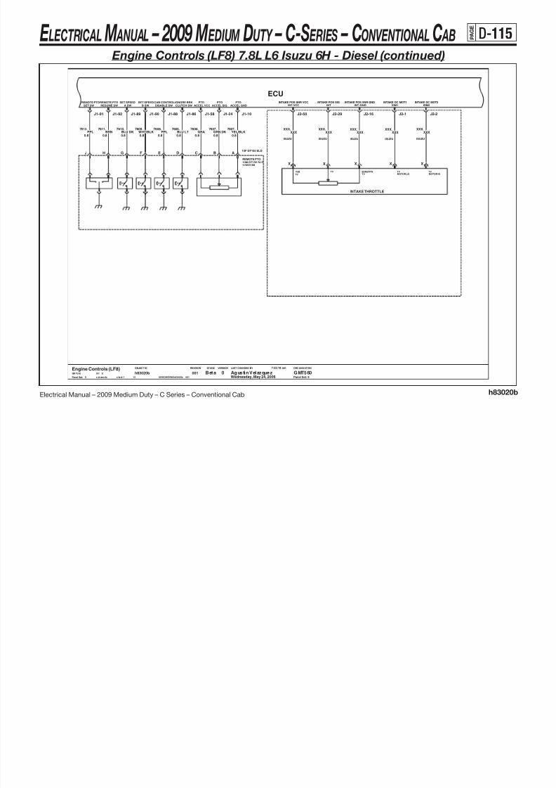
8/10/2019 2009 GM Medium Duty Electrical Manual.PDF
http://slidepdf.com/reader/full/2009-gm-medium-duty-electrical-manualpdf 226/410
Electrical Manual – 2009 Medium Duty – C Series – Conventional Cab h83020b
J2 29 J2 1J2 16J2 50 J2 2
LAST CHANGED BY
Panel Set:
VERSIONSTAGEREVISIONOBJECT ID ORGANIZATION
.
ISUZU
XXX
X
XXXXXX. XXX
ISUZU
TV
.
MOTOR HI
XXX
ISUZU
X
.XXX
V5B
XXX.
SENSRTNTV
ISUZU
X
XXXXXX
INTAKE THROTTLE
TV TVTV
MOTOR LO
10M GT150 SLD
ISUZU
Panel Set: 9
XXX
XREMOTE PTO
12052189
X
PPL.
0.8
7608
0.8
.BLU LT
7605
J1 89 J1 90J1 91 J1 92 J1 86J1 88 J1 58 J1 34 J1 10
0.8PPL
7612. .BRN
7611
0.8 0.8
7610BLU DK
. .YEL/BLK
7607
0.8
FJ GH CE BD
0.8
7637GRN DK
.
A
.GRA
7606
0.8
10F GT150 SLD
9
Beta Agustin Velazquez GMT5600Engine Controls (LF8)GMT560 X07i
Wednesday, May 24, 2006
7:55:18 am
$IVEDWORK/h83020b__001s ch ema tic s he et 1
h83020b13
001
.WHT/BLK
7609
0.8
E LECTRICAL M ANUAL – 2009 M EDIUM DUTY – C-S ERIES – CONVENTIONAL C AB P A G E
D-116
Engine Controls (LF8) 7.8L L6 Isuzu 6H - Diesel (continued)
COMMON AIR
J2-41
TEMP 1
J2-42
EGR GAS TEMP
OIL
VCC
J2-48
OIL
J2-27
SIGNALSIGNAL
MAF
J2-35
TEMPGND
EGR GAS TEMP
SENSOR INLET GND
PRESSURE
OIL
MAF
GND
PRESSURE
J2-28J2-37J2-4
FUEL
SENSOR OUTLET
PRESSURE
TEMP
INTAKE
J2-14J2-15
COOLANT
J2-36
IMT SENSOR
J1-19
ECU

8/10/2019 2009 GM Medium Duty Electrical Manual.PDF
http://slidepdf.com/reader/full/2009-gm-medium-duty-electrical-manualpdf 227/410
Electrical Manual – 2009 Medium Duty – C Series – Conventional Cab h83020b
J2-41 J2-42 J2-48J2-27J2-35 J2-28J2-37J2-4 J2-14J2-15J2-36
LAST CHANGED BY
Panel Set:
VERSIONSTAGEREVISIONOBJECT ID ORGANIZATION
1
6
XXX
IMT Sensor
XXX
XXX
ISUZU
SHIELD
ISUZU
XXX
ISUZU
ISUZU
OIL
Maf & Iat
ISUZU
LOW
XXX
XXX
2
ISUZUTBDTBD
Fuel Temp Snsr 1
XXX
.
ISUZU
XXX
Panel Set: 10
Cool Temp Snsr
XXXXXX
XXX
XXX
.
5V
ISUZU
IGN
XXX
REF
ISUZU
ISUZU
XXX
(Page 3)
XXX
.
XXX
θ
θ
ISUZU
.
2
1
2
MAF
XXX XXX
XXX
MAF
1
XXX
XXX
XXX
.XXX
EGR Temp #1
.
EGR Temp #2
.
XXX
GND
XXX
XXX
ISUZU
ISUZU
.
ISUZU
ISUZU
XXX
REF
XXX
ISUZU
ISUZU
REF LO
XXXPRESSURE
Oil Pressure Sensor
.
.
ISUZU
XXX
XXX
1120
.
ISUZU
TEMP
XXX
XXX
ISUZU
.
.
ISUZU
.
6118.
Sumitomo 6 Way Conn6
0.8BLU LT
J1-19
10
Beta Agustin Velazquez GMT5600Engine Controls (LF8)GMT560 X07i
Wednesday, May 24, 2006
7:55:18 am
$IVEDWORK/h83020b__001s ch ema ti c s he et 1
h83020b13
001
E LECTRICAL M ANUAL – 2009 M EDIUM DUTY – C-S ERIES – CONVENTIONAL C AB P A G E
D-117
Engine Controls (LF8) 7.8L L6 Isuzu 6H - Diesel (continued)
CAMANGLE
RAIL
VCC
LOW OIL
J2-23
SWITCH 2SIGNALPRESSURE
J2-51J2-26
SIGNAL ANGLEGND
J2-13
PRESSUREBOOST
VCCPRESSURE
LOW OIL
J2-22
SWITCH
J2-30
CRANK SIG
J2-24
PRESSURESIGNAL
J2-25
RAILCAM
J2-31
NECRANK VCC
NE-VCC
J2-46 J2-47
GNDPRESSURE
BOOSTPRESSURE
VCC (5V)
J2-12
RAIL
J2-18J2-19
CAM
ANGLE
GNDNE-GND
CRANK-GND LEVEL LEVEL
BOOST RAIL
PRESSURE
J2-32
ECU

8/10/2019 2009 GM Medium Duty Electrical Manual.PDF
http://slidepdf.com/reader/full/2009-gm-medium-duty-electrical-manualpdf 228/410
Electrical Manual – 2009 Medium Duty – C Series – Conventional Cab h83020b
J2 23J2 51J2 26J2 13 J2 22J2 30J2 24 J2 25 J2 31J2 46 J2 47J2 12 J2 18J2 19J2 32
LAST CHANGED BY
Panel Set:
VERSIONSTAGEREVISIONOBJECT ID ORGANIZATION
XXX
UPC FNA
XXX
ISUZU
VRTN
SHIELD.
POS SIG
XXX
12565716
XXX
.
XXX
Panel Set: 11
ISUZU
CAM
.
Cam Sensor
A
ISUZU
.
UPC
GND DIST
ISUZU
.
VREF
XXX
eng_rpm_snsr
14B8A-
boost_prss_sen
ISUZU
UPC
Engine RPM Sensor
ISUZU
VREF
MAGNETIC
VRTN
XXX
XXX
XXX ISUZU
XXX
Boost Pressure Sensor
XXX
XXX
Oil Level Snsr
ISUZU
0
.
SHIELD.
FNA
XXX
XXXXXX
002
-
ISUZU
Page
.
Comm Rail Pressure Sensor
XXX
XXX
X00426Y3PICUP
ISUZU
XXX
OIL_LVL_G
XXX
.
SENSOR
XXX
001
ISUZU
ISUZU
XXX.
ISUZU
XXX
XXX
.
comm_rail_snsr
ISUZU
.
ISUZU
001
.
002POS SIG
.
CASE
.
FNA
SHIELD
Case Gnd
XXX.
ISUZU
UPC
XXX
XXX
B
XXX
FNA
XXXXXX
Beta Agustin Velazquez GMT5600Engine Controls (LF8)GMT560 X07i
Wednesday, May 24, 2006
7:55:18 am
$IVEDWORK/h83020b__001s chem at ic s he et 1
h83020b13
00111
E LECTRICAL M ANUAL – 2009 M EDIUM DUTY – C-S ERIES – CONVENTIONAL C AB P A G E
D-118
Engine Controls (LF8) 7.8L L6 Isuzu 6H - Diesel (continued)
CLOG DETECT SW
FUEL FILTER
SIGNAL M OT OR U S IG NA L
POSITIONEGR - UEGR - W
SIGNAL VCC
POSITIONAVNT EGREGR
MOTOR W
EGR
MOTOR VGND
EGR - V
SIGNAL
EGR
GND
POSITON
DRIVE
POSITIONPOSITION
VCC
EGR
VNTPOS
Eng Cntl Unit (Diesel)
ECU

8/10/2019 2009 GM Medium Duty Electrical Manual.PDF
http://slidepdf.com/reader/full/2009-gm-medium-duty-electrical-manualpdf 229/410
Electrical Manual – 2009 Medium Duty – C Series – Conventional Cab h83020b
LAST CHANGED BY
Panel Set:
VERSIONSTAGEREVISIONOBJECT ID ORGANIZATION
J2-54 J2-7J2-40 J2-49J2-3 J2-8J2-9 J2-39 J2-38J2-53 J2-52J2-11 J2-17
.
AVNT
ISUZU
ISUZU
XXX
Avnt
ISUZU
V
POSITION U
1120
. .XXX
ISUZU
XXX
VNTPOS
XXXXXX XXX.
XXXXXX.
W
.
SIGNAL
U
POSITION V
ECU MAINTAIN RLY
XXX
GNDVCC
XXX XXXXXX
ISUZU
XXXXXX
ISUZU ISUZU
XXX
GNDAVNT
XXXXXX
VCC
(Page 3)
XXX.
AVNT DRIVE
XXX
POSITION W
ISUZU
XXX
EGR Valve
XXX
ISUZU
Panel Set: 12
.
XXX
ISUZU
. . .
ISUZU
XXX
.
ISUZU
XXX
12
Beta Agustin Velazquez GMT5600Engine Controls (LF8)GMT560 X07i
Wednesday, May 24, 2006
7:55:18 am
$IVEDWORK/h83020b__001schematic sheet1
h83020b13
001
E LECTRICAL M ANUAL – 2009 M EDIUM DUTY – C-S ERIES – CONVENTIONAL C AB P A G E
D-119
Engine Controls (LF6) 7.2L L6 Caterpillar ® C7 - Diesel
Air Intake TermA
B
BATTERIES
FL Uh Dist Center (B+)
C6
40M GTMXD SLDC6
TELL TALETtm - Wait Intake Heater
40F GTMXD SLD
1998 HTR_RLY2 HTR_P

8/10/2019 2009 GM Medium Duty Electrical Manual.PDF
http://slidepdf.com/reader/full/2009-gm-medium-duty-electrical-manualpdf 230/410
Electrical Manual – 2009 Medium Duty – C Series – Conventional Cab h83020c
LAST CHANGED BY
Panel Set:
VERSIONSTAGEREVISIONOBJECT ID ORGANIZATION
IN_HTR_G
Injector #1
1539693
B
A
1539693
Injector #2
B
A
Injector #3
1539693
B
A
Air Intake Heater
A
CASE
CAT
Injector #4
GND DIST
0.8 TXL
.C830BU
19
TXL0.8
1539693
B
A
Heated Air Intake Rly
15336745
30
85
86
87
14C8A- - 0Page
Unknown
CAT
19OR
F793.
TXL0.8
SPLICE
CAT
19BUC830.
0.8 TXL
.C830BU
19
CAT
CAT
1950
XXXXXX.
TXL13.0
CAT3F GT150 SLD15326808
BA
1.0
CAT
16 TXL1.0
INJ1CAT
1
INJ12
CAT12
INJ
16GY
T858.
TXL
.T960BUPU
T957.
TXL1.0 1.0 TXL
.T858GY
16
CAT CAT
16YL
T958.
1.0 TXL
.T959BR
16
CAT CAT
16WH
T859.
TXL1.0 1.0 TXL
TXL1.0
16
CAT
1.0 TXL
.T858GY
16
INJ INJ
16WH
T859.
INJ
16
1.0 TXL
.T859WH
16
INJ
TXL1.0
CAT11
1.0
BUT960.
TXL1.01.0 TXL
.T959BR
16
INJINJ
16
YLT958.
1.0
INJ9
CAT
1.0 TXL
.T957PU
16
INJ
CAT
16
GYT858.
TXL1.0
INJ11
TXL
.T858GY
16
CAT
INJ10
CAT10
CAT
16
WHT859.
TXL
2
INJ3
CAT
9
1.0 TXL
.T859WH
16
CAT
SPLICE SPLICE
INJ2
CAT
.
TXL
3
INJ4CAT
4
AIH2CAT
2
0.8 TXL
.C830BU
19
AIH
CAT1AIH
1
AIH
19OR
F793
0.8
CAT
19OR
Panel Set: 1
F793.
TXL0.8
SPLICE
CAT
19ORF793
TXL0.8
IAHRELAY
RTN
J2-76 J2-5
IAHPWR
J2-116
INJECTOR 2
J2-118 J2-115
INJECTOR 3&4RTN
INJECTOR 1 INJECTOR 1&2RTN
J2-104
INJECTOR 3
J2-106
INJECTOR 4
J2-108
CAT ECU
M6
2M GT150 SLDA
BLU LT1998.
0.8
XGMT560
Engine Controls (LF6)0 GMT560Agustin VelazquezProd
1 Wednesday, April 19, 2006001
11
h83020csheet1schematic $IVEDWORK/h83020c__001
1:27:35 pm
07i
E LECTRICAL M ANUAL – 2009 M EDIUM DUTY – C-S ERIES – CONVENTIONAL C AB P A G E
D-120
Engine Controls (LF6) 7.2L L6 Caterpillar ® C7 - Diesel (continued)
DLCJ1587-
J1587-1922

8/10/2019 2009 GM Medium Duty Electrical Manual.PDF
http://slidepdf.com/reader/full/2009-gm-medium-duty-electrical-manualpdf 231/410
Electrical Manual – 2009 Medium Duty – C Series – Conventional Cab h83020c
LAST CHANGED BY
Panel Set:
VERSIONSTAGEREVISIONOBJECT ID ORGANIZATION
1539693
Injector #5
B
A
Injector #6
1539693
B
A
CAT CAT
16
CAT
16GN
T961.
TXL1.0 1.0 TXL
.T860OR
16
.T860OR
WHT962.
TXL1.0
INJ
INJ
16OR
T860.
TXL1.0 1.0 TXL 16
INJ
INJ
16WH
T962.
TXL1.01.0 TXL
.T961GN
16
TXL1.0
INJINJ8
CAT8
CAT
16OR
T860.
7
CAT7
1.0 TXL
.T860OR
16
CAT
SPLICE
INJ5CAT
5
INJ6CAT
6
TXL
.U774
BU19
CAT
Hydraulic CGI Actuator
2407874
1
PWM+ PWM-
2
CAT
GYU775.
TXL0.80.8 19
CAT
CAT10
BU19
CAT
CAT8 SRH
8
11
11
CAT
GYU775.
TXL0.80.8 TXL
.
2407874
1 2
CAT
U774
VNT Actuator
2407874
1
PWM+ PWM-
2
CAT
BRC815.
TXL0.80.8 TXL
.C814GN
CAT
YLX981
SRH
10
4
4
CAT
BRC815.
TXL0.80.8 TXL
.GN
19
CAT
C814
Turbo Speed SNR
YLX981.
TXL0.80.8 TXL
.X980WH
19
CAT
CAT1 SRH
122
.
TXL0.80.8 TXL
.WH
19
CAT
X980
Panel Set: 2
RTNINJECTOR 5&6
J2-99 J2-51
AVNTACTUATORACTUATOR
CGI
J2-43
CGIRTN
J2-44
RTNAVNT
J2-32 J2-34
TURBOSPEED -SPEED +
TURBO
J2-24J2-105
INJECTOR 6
J2-107
INJECTOR 5
J1-8
+DATA LINK
J1587
J1-9
DIAGNOSTIC -
CAT ECU
1:27:35 pm
07i XGMT560
Engine Controls (LF6)0 GMT560Agustin VelazquezProd
2 Wednesday, April 19, 2006001
11
h83020csheet1schematic $IVEDWORK/h83020c__001
J1587+DLC
J1587+1921
E LECTRICAL M ANUAL – 2009 M EDIUM DUTY – C-S ERIES – CONVENTIONAL C AB P A G E
D-121
Engine Controls (LF6) 7.2L L6 Caterpillar ® C7 - Diesel (continued)
PTO TEMP SNR
TBDVRTNPOS SIG
TBDTBD
.
VREF
TBD
.Y745BUY742
LO
TOSS
Trans Speed Snsr (Man)
HI

8/10/2019 2009 GM Medium Duty Electrical Manual.PDF
http://slidepdf.com/reader/full/2009-gm-medium-duty-electrical-manualpdf 232/410
Electrical Manual – 2009 Medium Duty – C Series – Conventional Cab h83020c
LAST CHANGED BY
Panel Set:
VERSIONSTAGEREVISIONOBJECT ID ORGANIZATION
J4AMP
3
.
TXL1.0CAT
19
PTI TEMP SRN
TBDVRTN
TBD
POS SIG
TBD
VREF
TBDY745
BU
BU19
CAT
.WH
19
CAT
Y748
1.0 TXL
.YL
19
CAT
Y741
1.0 TXL
.WH
19
CAT
Y748
1.0 TXL
1.0CAT
19
.
.WH
CAT
Y748
1.0 TXL
(Page 3)
PTI_SPLICE
Y745
1.0 TXL 19
CAT
(Page 3)
PTI_SPLICE
Y745
1.0 TXL
.Y745
TXL
.WH
19
GN
CAT1.0 TXL
3
3
2
2CAT
4 DPF
4
1
1
PTD PRES SRN
2304013VRTN
2
POS SIG
3
VREF
1
Y749GN
.
TXL
J7
AMP
6 4 1
WH19
CAT
Y748
1.0 TXL
.RD
19
CAT
Y746
1.0 TXL
1.0 TXL
.Y745BU
CAT
19
.YL
19
CAT
Y741
1.0
YL
CAT
19 1.0 TXL
CAT
Y748
1.0 TXL
.GN
CAT
1.0 TXL
Y742
19
19
SPLICE SPLICE
SPLICE
1 24 56
WH19
CAT
Y748
1.0 TXL
3
5 2
1.0 TXL
.U782
PK
CAT
19
1.0 TXL
.U782PK
CAT
19
1.0 TXL
.Y741
YL
CAT
19 1.0 TXL
.U781 .Y742
GN
CAT
19 1.0 TXL
.U782
PK
CAT
19
1.0 TXL
.Y746PK
CAT
19SPLICE
Panel Set: 3
Cluster
IP CLUSTER
BLU LT
0.8
.2221
0.8
BLU LT
2222.
0.8
GRN DK
.2222
2221.
GRN DK
0.86 14
IP CLUSTER
Cluster
SENSORFUEL TEMP
J2-93 J2-94
FUEL TEMPSENSOR
J2-82
SENSORFUEL TEMP
SENSORFUEL TEMP
J2-66J2-56
FUEL TEMPSENSOR4 KPPM
SPEED
J1-36
HIGH
2X TACHHIGH
J1-38
HIGHREP TOSS
J1-32
REP TOSSLOW
J1-33
MIL(SES)
J1-28
CAT ECU
BRN/WHT419.
0.80.8 0.8
.817GRN DK/WHT
GRN DK/WHT
WHT121.
.YEL/BLK
1827
0.8
0.8
.817
.BRN/WHT
419
0.5GRN DK/WHT
.
0.5
817
IP CLUSTERCluster
.WHT
121
0.5
Sec PpmBODY BUILDER
D1
D130F GTMXD SLD
B1
30M GTMXD SLDB1
B8
40M GTMXD SLDB8
40F GTMXD SLD
GRN DK/WHT817.
0.8
SA817
6M GT280 SLDC
6F GT280 SLDC
30F GTMXD SLDC2
30M GTMXD SLDC2
3 Wednesday, April 19, 2006001
11
h83020csheet1schematic $IVEDWORK/h83020c__001
1:27:35 pm
07i XGMT560
Engine Controls (LF6)0 GMT560Agustin VelazquezProd
B
B
BA
BAF
F
BN1.0
.6136
B
P43
A
4 1 25
YEL/BLK6055. .6053
BLU DK1.0
.6136
1.0BN
1.0L-BU
1.0D-BU
5277.
.470
1.0BLK
5377.
1.0
.6053BLU DK1.0
1.0YEL/BLK
6055.
1.0D-BU
5277.
1.0L-BU
5377.
1.0BLK
470.
Asm Conn 8F Sealed GT 280C
Asm Conn 8M Sealed GT 280C
P73
ED
ED
25
6
MAL_IND_LP
BB_PPM
TACH PRIM_PPM
E LECTRICAL M ANUAL – 2009 M EDIUM DUTY – C-S ERIES – CONVENTIONAL C AB P A G E
D-122
Engine Controls (LF6) 7.2L L6 Caterpillar ® C7 - Diesel (continued)

8/10/2019 2009 GM Medium Duty Electrical Manual.PDF
http://slidepdf.com/reader/full/2009-gm-medium-duty-electrical-manualpdf 233/410
Electrical Manual – 2009 Medium Duty – C Series – Conventional Cab h83020c
J1939
LAST CHANGED BY
Panel Set:
VERSIONSTAGEREVISIONOBJECT ID ORGANIZATION
TXL0.8CAT
19GY
994.
Oil Pressure Snr
2370227VRTN
2
POS SIG
3
VREF
1
.BR
19
CAT
G826
0.8 TXLTXL0.8
G827
CAT
19BU
.
19
SPLICE
G827BU
0.8 TXL
.BR
19
2304011
Fuel Temp Snsr
REF
LOW
2
TEMP
1
G827BU
.
TXL0.8CAT
VRTNPOS SIGVREF
(Page 4)
BOOST_SPLICE
.
TXL0.8CAT
19
F421YL
.
TXL0.8CAT
19
Fuel Rail Pressure SNR
2304013 VRTN
1
POS SIG
3
VREF
2
.BR
19
CAT
G826
G833
0.8 TXL
CAT
G826
0.8 TXL
.BR
19
CAT
G849
0.8 TXL
(Page 7)
IATM_SPLICE
G833
0.8 TXL
.G833PK
19
CAT
Intake BOOST Pressure SNR
2304013
G826
0.8 TXL
.G826BR
19
CAT
1 3 2
(Page 4)
BOOST_SPLICE
G826
.YL
19
CAT
C822
0.8 TXL
(Page 7)
BOOST2_SPLICE
.G833PK
19
CAT
Panel Set: 4
J2-85
FUEL RAILPRESSURE SNRPOWER
SENSOR
J2-80
GNDSENSOR
J2-54 J2-20J2-28
OILPRESSURE AIR PRESSURE SNR
INTAKE MANIFOLDACENABLERELAY
J1-62
HIGH
J1-50
SHIELD
J1-42
LOW
J1-34
SWITCH
J1-22
CLUTCH
CAT ECU
0.5
0.5
.379BRN/WHT
0.8
BRN/WHT379.
BRN/WHT379.
30F GTMXDA11
30M GTMXDA11
J1939J1939
J1939J1939
Man Cltch Sw Top Of Trvl
A
B
30M GTMXD SLDB6
30F GTMXD SLDB6
GRN DK/WHT459.
1.0
4 Wednesday, April 19, 2006001
11
h83020csheet1schematic $IVEDWORK/h83020c__001
1:27:35 pm
07i XGMT560
Engine Controls (LF6)0 GMT560Agustin VelazquezProd
A/C StatusHVAC
AC_ENABLE_B
2361 CAT_ECU_J+
CAT_ECU_J-2362
441
CLUTCH3_PPS
(Page 9)
E LECTRICAL M ANUAL – 2009 M EDIUM DUTY – C-S ERIES – CONVENTIONAL C AB P A G E
D-123
Engine Controls (LF6) 7.2L L6 Caterpillar ® C7 - Diesel (continued)
CAM +-BOTTOM
CAMPROBE -LOW
OIL SW +-TOP
ENGINE TIMING
+CALIBRATION
IGN 1GND A GND B GND BGND ABATT B BATT A BATT BBATT AETHER
SOLENOID
CAT ECU

8/10/2019 2009 GM Medium Duty Electrical Manual.PDF
http://slidepdf.com/reader/full/2009-gm-medium-duty-electrical-manualpdf 234/410
Electrical Manual – 2009 Medium Duty – C Series – Conventional Cab h83020c
LAST CHANGED BY
Panel Set:
VERSIONSTAGEREVISIONOBJECT ID ORGANIZATION
1003320
.E963BK
CATCAT
19
Cam Snsr
A B
1112416
Crank Sensor
A B
CAT
19WH
E964.
TXL0.80.8 TXL 1 9
CATCAT
19YL
E966.
TXL0.80.8 TXL
.E965BU
19YL
G857.
TXL0.80.8 TXL
.G856WH
19
CAT
Engine Timing Calibration Probe
1552269
1
POS NEG
2
Panel Set: 5
Uh - Ecm-B
20A
15A
Ip1 - PcmIPOWER DIST
POWER DIST
GND DISTGnd Zone #2AGnd Zone #2A
GND DIST
J2-46J2-47 J2-35J2-36J2-33 J2-25J2-26J1-70J1-65 J1-67 J1-69J1-63J1-53 J1-55 J1-48J1-52 J1-10
0.8
.1997TAN
5 Wednesday, April 19, 2006001
11
h83020csheet1schematic $IVEDWORK/h83020c__001
1:27:35 pm
07i XGMT560
Engine Controls (LF6)0 GMT560Agustin VelazquezProd
.1997TAN
12M GT280 SLDK
0.8
0.8
12F GT280 SLDK
C8
30M GTMXD SLDC8
TAN1997.
Gnd Zone #3BGND DIST
30F GTMXD SLD
20A
Uh - Ecm-BPOWER DIST
2.0
SA251 SB251
BLK/WHT251.
.251BLK/WHT
2.0BLK/WHT
251.
2.0
SB1540
.251BLK/WHT2.02.0
.
.
2.0ORN
1540
2.0ORN
1540
1540ORNORN
2.0
.
SA1540
.
1540
Ether Solenoid
A
B1540 CAT_BATA_P
ETHER_G350
CAT_BATB_P1540
439 CAT_IGN1_P
CAT_A_G251 251 CAT_B_G
E LECTRICAL M ANUAL – 2009 M EDIUM DUTY – C-S ERIES – CONVENTIONAL C AB P A G E
D-124
Engine Controls (LF6) 7.2L L6 Caterpillar ® C7 - Diesel (continued)
TEMPERATURECGI MAF
+5VSENSORPOWER
BAROMETRICPRESSURE SENSOR
INLET AIRTEMP SENSORDELTAP PRESS
CGI MAF VENTPOS SIG VRTNVREF
CAT ECU

8/10/2019 2009 GM Medium Duty Electrical Manual.PDF
http://slidepdf.com/reader/full/2009-gm-medium-duty-electrical-manualpdf 235/410
Electrical Manual – 2009 Medium Duty – C Series – Conventional Cabh83020c
LAST CHANGED BY
Panel Set:
VERSIONSTAGEREVISIONOBJECT ID ORGANIZATION
3
VREF
1
2304013
CGI MAF Delta Pressure Sensor
2
VRTN
3
POS SIG
1
VREF
2610524
CGI MAF Temp SensorVRTN
2
POS SIG
TXL
CAT
19
WH
G829.
(Page 7)
CTC_SPLICE
G829
WH0.8 19
CAT
TXL
.G828U773.
TXL
.U780
0.8PK
GN0.8 19
CAT
TXL
.G829 G828.
TXL
CAT
190.8
TXL
CAT
190.8GN WH
0.8 19
CAT
TXL
.G828
WH0.8 19
CAT
SPLICE
SPLICE
.G829 G828
G829
GN0.8
CAT
TXL
GN0.8 19
CAT
TXL
.G829
CAT3
SRH3
6
6
9
9
GN0.8 19
CAT
TXL
5SRH
5
GN0.8
.
TXL
CAT
190.8WH
U773.
TXL
CAT
190.8PU
2407874
Ambient Air Temp Sensor
2
(Page 6)
AAT_SPLICE
G829
1
(Page 6)
AAT_SPLICE
CAT0.8
WHU779.
.G828
CAT7 SRH
7
GN0.8
CAT
TXL
.G828
GN0.8 19
CAT
TXL
.G829
CAT
TXL
.G829
2304013
BARO Pressure SNRVRTN
2
POS SIG
3
VREF
1
GN0.819
CAT
TXL
.G829G828.
TXL TXL
CAT
190.8BR
(Page 7)
ABS_SPLICE
G829
Panel Set: 6
Pedal Position Sensor
A BC
.
0.8
WHT/BLK1164.
0.8
WHT/BLK1164
BLU DK
0.8
.1161BLU DK
0.8
.1161
40M GTMXD SLD B3
40F GTMXD SLDB3
J2-70 J2-72 J2-57 J2-38J2-16 J1-66 J1-5J1-4
A8
A8
6 Wednesday, April 19, 2006001
11
h83020csheet1schematic $IVEDWORK/h83020c__001
1:27:35 pm
07i XGMT560
Engine Controls (LF6)0 GMT560Agustin VelazquezProd
451
PPS_RTN
(Page 9)
(Page 9)
PPS
451
E LECTRICAL M ANUAL – 2009 M EDIUM DUTY – C-S ERIES – CONVENTIONAL C AB P A G E
D-125
Engine Controls (LF6) 7.2L L6 Caterpillar ® C7 - Diesel (continued)
INTAKEMAT
J2 95 J2 84
COOLTEMP
COMMONGND
J2 30 J2 17
SNR RTNANALOG
OFFON/
J1 59
IDLERESUME/ ACCEL
J1 44
HIGH
J1 46
SWITCHSET/
J1 35
COASTSECONDARY
FUEL
J1 27J1 3
FUELCOMMON
RTN
J1 11
LAMPIDLEHIGH
PRIMARYFUEL
J1 15
CAT ECU

8/10/2019 2009 GM Medium Duty Electrical Manual.PDF
http://slidepdf.com/reader/full/2009-gm-medium-duty-electrical-manualpdf 236/410
Electrical Manual – 2009 Medium Duty – C Series – Conventional Cabh83020c
LAST CHANGED BY
Panel Set:
VERSIONSTAGEREVISIONOBJECT ID ORGANIZATION
2304011
Intake Mat Sensor
1
2
TXL0.8
.G829GN
CAT
19BU
995.
SPLICE
0.8 TXL
.G829GN
19
CAT
CAT
19BU
C967.
TXL0.8
0.8 TXL 19
CAT
0.8 TXL
.G833PK
19
CAT
2304011
Cool Temp Snsr
REFLOW
2
TEMP
1
.G833PK
SPLICE
0.8 TXL 19
CAT
(Page 6)
CTS_SPLICE
G829
(Page 7)
ABS_SPLICE
G829
(Page 4)
IATM_SPLICE
G833
(Page 4)
BOOST2_SPLICE
G833
Panel Set: 7
GRN DK.
0.5
534
Headlamp Power
0.5
.RED
2013
B2
B2INTERIOR LIGHTING30M GTMXD
A3
30F GTMXDA3
BRN0.5 0.5
GRN DK534..441
534
0.8
.GRN DK
2013RED.
0.8
Gnd Zone #7AGND DIST
J2-95 J2-84J2-30 J2-17 J1-59 J1-44 J1-46J1-35J1-27J1-3 J1-11J1-15
00111
h83020csheet1schematic $IVEDWORK/h83020c__001
1:27:35 pm
07i XGMT560
Engine Controls (LF6)0 GMT560Agustin VelazquezProd
7 Wednesday, April 19, 2006
C5
GND DISTGnd Zone #7A
C4
C540F GTMXD SLD
C4
40M GTMXD SLD
A
GND
B
GND
C
SWLED
DE
LAMP
GND
F
Cat High Idle Switch
19361589PPL.
0.8 0.8
.BLU DK
CRUISE CNTRL
CRUISE CNTRLCruise Cntrl Sw
Cruise Cntrl SwCruise Cntrl SwCRUISE CNTRL
FUEL HAND & STORFuel Senders
Sec Fuel SenderFUEL HAND & STOR
FUEL HAND & STORPri Fuel Sender
470BLK.
0.8
FUEL_LVL1
FUEL_RTN
FUEL_LVL2
750 HIS_LED_GHIS_ILL_G750
750
HIS_PPS
(Page 9)
HIS_LP2509
SET_COAST_C84
87 RES_ACCEL_C
ON_OFF_C397
E LECTRICAL M ANUAL – 2009 M EDIUM DUTY – C-S ERIES – CONVENTIONAL C AB P A G E
D-126
Engine Controls (LF6) 7.2L L6 Caterpillar ® C7 - Diesel (continued)
N.O.PTOKILL
2 SPEEDAXLE
PTO
RESSWITCH
BRAKESWITCH PTO
ENABLESETPTO
COOLANTLOW BRAKE
SWITCH
BRAKESWITCH
N.C.
EXHAUST
STATUSLAMP STARTER
INHIBIT
PTO
CONTROLBRAKE
EXHAUSTPTO
ENGAGE
Eng Cntl Unit (Caterpilliar)
CAT ECU

8/10/2019 2009 GM Medium Duty Electrical Manual.PDF
http://slidepdf.com/reader/full/2009-gm-medium-duty-electrical-manualpdf 237/410
Electrical Manual – 2009 Medium Duty – C Series – Conventional Cabh83020c
LAST CHANGED BY
Panel Set:
VERSIONSTAGEREVISIONOBJECT ID ORGANIZATION
Panel Set: 8
2 Spd Axle Sw2 SPD AXLE
Brake SwBRAKES
Exhaust Brake SwEXH BRAKE/RSTR
J1-7J1-64 J1-6J1-60 J1-56J1-58J1-49 J1-40J1-45 J1-31J1-30 J1-12J1-19
C10
Pto Enable SwUPFITTER PROV
30F GTMXD SLDC10
30M GTMXD SLD
30M GTMXDB12
750
0.5
.BLK
0.5
30F GTMXDB12
.
0.8
750
.750BLK
UPFITTER PROVPto Kill Sw
BLK
UPFITTER PROVTap Up SwTap Down Sw
UPFITTER PROV
30F GTMXD SLDD5
30M GTMXD SLDD5
447
Starter RlySTART & CHARGE
YEL.
0.8
GRN LT.
0.8
2081
Pto RlyUPFITTER PROV
488
0.8
.GRN LT
30F GTMXD SLDB9
30M GTMXD SLDB9
J
12M GT280 SLDJ
BLK/WHT451.
0.8
12F GT280 SLD
B3
0.8
.451BLK/WHT
B3
L
L
Low Coolant Sw
A
B
1478.
0.8
0.8.1478GRN LT
GRN LT
.
0.8GRN LT
1478
Wednesday, April 19, 200607i XGMT560
Engine Controls (LF6)0 GMT560Agustin VelazquezProd
8
00111
h83020csheet1schematic $IVEDWORK/h83020c__001
1:27:35 pm
UPFITTER PROVPto Enable Led
Ip2 - Brake Iso
10A
B7
30M GTMXD SLDB7
POWER DIST
1320BLU LT
30F GTMXD SLD
BLU LT1320.0.5
0.8
.
.
0.8
494
1467
0.8
.GRA/BLK
BLU LT
GRN LT.
0.5
2081
.1962BLK/WHT0.8
30F GTMXD SLDC7
30M GTMXD SLDC7
BLK/WHT1962.
TELL TALETtm - Exhaust
0.8
0.5
.BLK
SA750
Pto TtTELL TALE
750
BLK.
0.5
750PTO_TT_G
BRK_NO_P
EXH_TT
(Page 9)
COOL_PPS
451 PTO_ENABLE
PTO_ENG_DIS
PTO_LED
TAP_DOWN2664
ENGAGE_PTO2665
2663 TAP_UP
START_CAT
2SP_AXLE
86 NC_CONT
EXH_BRK
E LECTRICAL M ANUAL – 2009 M EDIUM DUTY – C-S ERIES – CONVENTIONAL C AB P A G E
D-127
Engine Controls (LF6) 7.2L L6 Caterpillar ® C7 - Diesel (continued)
Tap Up Sw
UPFITTER PROVISIONS
2 Spd Axle Sw
2 SPEED AXLEUPFITTER PROVISIONS
Tap Down Sw Kill Sw
UPFITTER PROVISIONS
2 Spd Axle Sw
2 SPEED AXLE 2 SPEED AXLE
2 Spd Axle Sw Exhaust Brake Sw
EXH BRAKE/RSTR
IP CLUSTERDPF Switch
0 5
.750
BLK
DPF_SW
HIS_PPS
(Page 7)COOL_PPS
(Page 8)

8/10/2019 2009 GM Medium Duty Electrical Manual.PDF
http://slidepdf.com/reader/full/2009-gm-medium-duty-electrical-manualpdf 238/410
Electrical Manual – 2009 Medium Duty – C Series – Conventional Cabh83020c
LAST CHANGED BY
Panel Set:
VERSIONSTAGEREVISIONOBJECT ID ORGANIZATION
Panel Set: 9Wednesday, April 19, 20069
Prod Agustin Velazquez GMT5600Engine Controls (LF6)GMT560 X07i
1:27:35 pm
$IVEDWORK/h83020c__001s ch ema tic s he et 1
h83020c11
001
.451BLK/WHT
.451BLK/WHT0.8 0.8
BLK/WHT451.
0.8
BLK/WHT
0.8
.451BLK/WHT
0.8
SD451
SF451
0.5
.451
BLK/WHT451.
0.8
BLK/WHT451.
30M GTMXD SLDC5
30F GTMXD SLDC5
Cruise Cntrl Sw
Pto SwUPFITTER PROVISIONS
Tap Up Sw 2 Spd Axle Sw
CRUISE CNTRL
Tap Down Sw Kill Sw
0.5
.451BLK/WHT
0.5
.239PNK
B4
B4
0.8
.451BLK/WHT
B10
BRN441.
0.5
30F GTMXD
B10
30M GTMXD
.451
BLK/WHT451.
0.8
2 Spd Axle Sw
BLK/WHT0.8
0.8BLK/WHT
451.
Brake Sw
BRAKES
.451BLK/WHT0.8 0.5
.750BLK
2 Spd Axle Sw Exhaust Brake Sw
750BLK
0.5
.750BLKBLK
750.
0.5
SD750
0.5
.
BLK/WHT451.
0.5
30M GTMXDA8
30F GTMXDA8
0.5BLK
2SP_A_PPS
PPS
(Page 6)
(Page 4)
CLUTCH3_PPS
EXH_SW_G2SP_SW1_PPS
BR_SW_PPS
(Page 6)
PPS_RTN
2SP_E_PPS451PTO_UP_PPSPTO_DN_PPS PTO_KIL_PPS
CRUISE_PPS
PTO_SW_PPS
E LECTRICAL M ANUAL – 2009 M EDIUM DUTY – C-S ERIES – CONVENTIONAL C AB P A G E
D-128
ARD OUTLET(FLAME DETECT) TEMEPERATURE
J2 91
SENSOR RETURN(ARD SENSORS ACTIVE & PASSIVE)_
J2 83 J2 77
DRIVERFUEL PUMP 1+5V SENSOR POWER
(ARD ACTIVE)
J2 81
ARD FLAME BOUNDARY FUEL PUMP 2DRIVER
J2 61J2 63
TEMP SNSR (FD #2)FUEL PUMP 1DRIVER RTN
J2 111J2 113
DRIVER RTNFUEL PUMP 2
Engine Controls (LF6) 7.2L L6 Caterpillar ® C7 - Diesel (continued)

8/10/2019 2009 GM Medium Duty Electrical Manual.PDF
http://slidepdf.com/reader/full/2009-gm-medium-duty-electrical-manualpdf 239/410
Electrical Manual – 2009 Medium Duty – C Series – Conventional Cab
LAST CHANGED BY
Panel Set:
VERSIONSTAGEREVISIONOBJECT ID ORGANIZATION
ARD Flame Boundary SNR
0.8OR
CAT3
GROUND SI GN AL V OL T ARD Flame Detect SNR VOLT SIGNAL GROUND
2 ARD2
Y749.
Y743.
TXL
ARD
190.8OR
Y753.
TXL
ARD
19
0.8BU
Y749.
ARD3
CAT4ARD
4
Y743.
TXL
CAT
190.8OR
Y748.
TXL
ARD
190.8WH
CAT
BU
(Page 10)
ARD_SPLICE
Y745
(Page 10)
TXL
CAT
190.8GN
Y748.
TXL
ARD
190.8WH
SPLICE
Y745.
TXL
ARD
19
.
TXL
ARD
TXL
CAT
190.8GN
SPLICE
Y745.
TXL
ARD
190.8BU
Y745.
TXL
ARD
190.8
1407339
A B
C818.
ARD_SPLICE
Y745
Y743.
TXL
CAT
190.8OR
CAT1 ARD1
Y748.
TXL
CAT
190.8WH
Y748
0.8OR
C821.
190.8WH
Y748.
TXL
CAT
190.8WH
SPLICE
Y748.
TXL
CAT
190.8WH
SPLICE
Fuel Pump Sol (FORE)
TXL
CAT
190.8BU
C819.
TXL
CAT
190.8PU
Fuel Pump Sol (AFT)
1407339
A B
C820.
TXL
CAT
19 TXL
CAT
190.8BR
(Page 11)
ARD2_SPLICE
Y749
(Page 11)
ARD3_SPLICE
Y748
(Page 11)
ARD4_SPLICE
Y748
Panel Set: 10
J2-91 J2-83 J2-77J2-81 J2-61J2-63 J2-111J2-113
10
X Agustin Velazquez GMT5600Engine Controls (LF6)GMT560 X07i
W ed ne sd ay , Ap ri l 1 9, 2 00 6 1 :2 7:3 5 p m$IVEDWORK/h83020c__001s ch em ati c s he et 1
h83020c11
001
h83020c
E LECTRICAL M ANUAL – 2009 M EDIUM DUTY – C-S ERIES – CONVENTIONAL C AB P A G E
D-129
J2-89
ARD FUEL MAINPRESS SENSOR
ARD TURBO OUTLETEXH TEMP SNSR
J2-55J2-41
PRESS SENSORARD FUEL PILOT ARD AIR PRESS
CONTROL VLV HS
J2-120
ARD AIR PRESS
J2-10
CONTROL VLV RTN
Engine Controls (LF6) 7.2L L6 Caterpillar ® C7 - Diesel (continued)

8/10/2019 2009 GM Medium Duty Electrical Manual.PDF
http://slidepdf.com/reader/full/2009-gm-medium-duty-electrical-manualpdf 240/410
Electrical Manual – 2009 Medium Duty – C Series – Conventional Cab
LAST CHANGED BY
Panel Set:
VERSIONSTAGEREVISIONOBJECT ID ORGANIZATION
2
GROUND
3
SIGNAL
1
VOLTS ARD Main fuel press SNRFUEL TEMP
SENSORSIGNA L FUEL TEMP
SENSOR
ARD TURBO OUTLET TEMP SNRS
0.8WH
Y749.
TXL
CAT
190.8
2304013
Y747.
TXL
CAT
190.8BR
TXL
CAT
190.8GN
Y748.
TXL
CAT
19
(Page 10)
ARD4_SPLICE
Y748
1
1
(Page 10)
ARD2_SPLICE
Y749
(Page 10)
ARD3_SPLICE
Y748
2
GROUND
3
SIGNAL
1
VOLTS ARD Pilot fuel press SNR
2304013
C803.
TXL
CAT
190.8BR
Y749
ARD Air Control Valve
2304011
1 2
GNY748.
TXL
CAT
190.8WH
Y749.
(Page 10)
ARD2_SPLICE
Y749
(Page 10)
ARD3_SPLICE
Y748
TXL
CAT
190.8WH
Y748.
3
3
CAT2ARD
2
TXL
CAT
190.8PK
T846.
TXL
CAT
190.8GN
Y749.(Page 10)
ARD2_SPLICE
C801.
TXL
CAT
190.8OR
C800.
TXL
CAT
190.8GY
J2-89 J2-55J2-41 J2-120J2-10
11
X Agustin Velazquez GMT5600Engine Controls (LF6)GMT560 X07i
W ed ne sd ay , Ap ri l 1 9, 2 00 6 1 :2 7:3 5 p m$IVEDWORK/h83020c__001s ch em ati c s he et 1
h83020c11
001
h83020c
E LECTRICAL M ANUAL – 2009 M EDIUM DUTY – C-S ERIES – CONVENTIONAL C AB P A G E
D-130
ARD IGNITION COIL RTN
ON/OFFARD FUEL ENABLE
CONTROL VALVEARD FUEL MAIN PRESS ARD FUEL MAIN PRESS
CONTROL VALVE RTN VLV ACT RTNARD FUEL ENABLE
ARD IGNITION COIL
Engine Controls (LF6) 7.2L L6 Caterpillar ® C7 - Diesel (continued)

8/10/2019 2009 GM Medium Duty Electrical Manual.PDF
http://slidepdf.com/reader/full/2009-gm-medium-duty-electrical-manualpdf 241/410
Electrical Manual – 2009 Medium Duty – C Series – Conventional Cab
LAST CHANGED BY
Panel Set:
VERSIONSTAGEREVISIONOBJECT ID ORGANIZATION
ARD IGNITION COIL
PUY736.
TXL
2
1
1
CAT2
Pilot Fuel control Vlv
Y733.
TXL
CAT
190.8
1
1
Fuel Enable
CAT1
CAT
190.8PU
Y736.
TXL
CAT
190.8PU
Y734.
TXL
CAT
190.8BU
SPLICE
CAT2ARD
YL
SPARK PLUG
ARD2
1
1
Pilot Fuel control Vlv
Y737.
TXL
CAT
190.8YL
Y738.
TXL
CAT
190.8GY
CAT2ARD
2ARD
1
3
3
2
2
200.
TXL 1 90.8BK
Y751.
TXL0.8OR
Y750.
TXL0.8
J2-88J2-69J2-59 J2-60 J2-52 J2-109
X Agustin Velazquez GMT5600Engine Controls (LF6)GMT560 X07i
We dn es da y, Ap ri l 1 9, 2 00 6 1 :2 7:3 5 p m$IVEDWORK/h83020c__001s ch ema tic s he et 1
h83020c11
00112
h83020c
E LECTRICAL M ANUAL – 2009 M EDIUM DUTY – C-S ERIES – CONVENTIONAL C AB P A G E
D-131
Fan Controls
Ecm
ENGINE CTRL
Fan
ΩA
N
S O L

8/10/2019 2009 GM Medium Duty Electrical Manual.PDF
http://slidepdf.com/reader/full/2009-gm-medium-duty-electrical-manualpdf 242/410
Electrical Manual – 2009 Medium Duty – C Series – Conventional Cabh83031a
LAST CHANGED BY
Panel Set:
VERSIONSTAGEREVISIONOBJECT ID ORGANIZATION
R L Y
R L Y
S S
F A N
D R I V E R
2
4
5
6
S S
S S
S S
R L Y
C O N T R O L
R L Y
Panel Set: 1
N
.
0.8BN/WH
6141
N
M
.2364BLU DK0.8
M
L
0.8GRA
2365.
L
K
.250BLK
0.8
K
J
0.8WHT
2368.
14 Way Black GT150 Sealed F ConnJ
14 Way Black GT150 Sealed M Conn
GND DISTGnd Zone #2B
EcmENGINE CTRL
Gnd Zone #2BGND DISTENGINE CTRL
Ecm
.2368WHT
0.8
Fan Relay
J12
K11 K9
L12
HALL
E
REF
POWER DISTIp1 - Trans
15A
EcmENGINE CTRL
3
001
RTN
A
F A
B
SOLENOID
HALL SENSOR
RTN
CD
EV_FAN_REF
1
X Agustin Velazquez GMT5600Fan Controls: MDD FanGMT560 X08
W ed ne sd ay , Ap ri l 1 9, 2 00 6 1 :4 2:1 6 p m$IVEDWORK/h83031a__001s ch ema ti c s he et 1
h83031a
440 FAN_PWR
250 FAN_GND
EV_FAN2366
FAN_GND22506141 EV_FAN_RTN2364 EV_FAN_SIGNAL2365
E LECTRICAL M ANUAL – 2009 M EDIUM DUTY – C-S ERIES – CONVENTIONAL C AB P A G E
D-132
ETC (L18) 8.1L V8 GMPT VORTEC® - Gas
Family 2
has Fuse
Family 2
has Fuse
PcmENGINE CNTLSENGINE CNTLS
PcmPOWER DIST
10A
Ip2 - Brake Iso
0.5
.1320BLU LT
ETC_A
15A
Ip1 - Pcm IPOWER DIST
BRK_NO_PETC_P439 ETC_B

8/10/2019 2009 GM Medium Duty Electrical Manual.PDF
http://slidepdf.com/reader/full/2009-gm-medium-duty-electrical-manualpdf 243/410
Electrical Manual – 2009 Medium Duty – C Series – Conventional Cabh83021a
LAST CHANGED BY
Panel Set:
VERSIONSTAGEREVISIONOBJECT ID ORGANIZATION
M
Panel Set: 1
774..1061ORN/BLK
0.5BLU DK/WHT
0.5
MOTOR 2
J1-8
5V REF
J1-9
TPS25V REF RTN
J1-3
TPS1
J1-6
BRAKE 2
J1-7
IGN1 UART B
J1-13
J1-15
GND
J1-16
MOTOR 1TPS1
J1-2
Throttle Actuator Control Module
J1-1
TPS1
J1-10
TPS2RTN
J1-11
TPS2
J1-12
UART A
.1688BLU LT/BLK
0.5
Gnd Zone #3AGND DIST
5V REF
H
TPS1
BLK/WHT1704.
0.5
B
RTN
MTR
C
2 RTN
D
TPS1 TPS2
E
5V REF
F
TPS2TPS1
G
Wednesday, April 19, 200608 XGMT560
Etc L180 GMT560Agustin VelazquezPilot
1
Throttle Actuator Cntrl BodyMTR
A
1
TPS2
0012
h83021asheet1schematic $IVEDWORK/h83021a__001
1:31:30 pm
0.5
PPL486.
0.5
.485GRN DK
0.8BLK
452.
0.5YEL
581.
582.
0.8BRN
416GRA
0.5
.
B7
30F GTMXD SLDB7
1320BLU LT
30M GTMXD SLD
0.5
.
ETC_G351
E LECTRICAL M ANUAL – 2009 M EDIUM DUTY – C-S ERIES – CONVENTIONAL C AB P A G E
D-133
ETC (L18) 8.1L V8 GMPT VORTEC® - Gas (continued)
CRUISE CNTL
Set Coast
CRUISE CNTL
Resume/Accel
CRUISE CNTLOn/Off
87

8/10/2019 2009 GM Medium Duty Electrical Manual.PDF
http://slidepdf.com/reader/full/2009-gm-medium-duty-electrical-manualpdf 244/410
Electrical Manual – 2009 Medium Duty – C Series – Conventional Cabh83021a
LAST CHANGED BY
Panel Set:
VERSIONSTAGEREVISIONOBJECT ID ORGANIZATION
Panel Set: 2
PPS 1
J2-J J2-K
TXTOOL
J2-D
RTNPPS 2
J2-E
FWE
J2-F
PPS 1
J2-G
5V REFPPS 1
RTN
J2-A
TOOLRX
PPS 2
J2-B
5V REFPPS 2
J2-C
J1-4
COASTSETRESUME/
ACCEL
J1-5 J1-14
ON/OFF
Throttle Actuator Control Module
Throttle Actuator Cntrl Mdl
.1161BLU DK0.5
2
Pi lo t Agust in Velazquez GMT5600Etc L18GMT560 X08
Wednesday, April 19, 2006
1:31:30 pm
$IVEDWORK/h83021a__001schematic sheet1
h83021a2
001
.1164WHT/BLK
F
TOOL
RX5V REF
PPS 2
GH
PPS 2
J
PPS 2
RTNRTN
PPS 1
K
0.5
Pedal Position Sensor
A
TOOL
TX
FWE
BC
CONNECTION
NO
D
PPS 1
5V REF
PPS 1
E
BRN1271.
0.5
0.5
BLU LT1162.
0.5
PPL1272. .1274
TAN0.5
397 ON_OFF_ASET_COAST_A84RES_ACCEL_A87
E LECTRICAL M ANUAL – 2009 M EDIUM DUTY – C-S ERIES – CONVENTIONAL C AB P A G E
D-134
Fuel (L18) 8.1L V8 GMPT VORTEC® - Gas - Family 2
86 30
30F GTMXD SLDB6
PcmENGINE CNTLS
ENGINE CNTLSPcm
Uh - Fuel Pump Rly
A 1 A 3
POWER DIST
20A Uh - Fuel
ENGINE CNTLSPcm
30M GTMXD SLDB6B7
1589.
B7
1936
FUEL_RLY_P1640465 FUEL_RLY1
FUEL_LVL219361589 FUEL_LVL1

8/10/2019 2009 GM Medium Duty Electrical Manual.PDF
http://slidepdf.com/reader/full/2009-gm-medium-duty-electrical-manualpdf 245/410
Electrical Manual – 2009 Medium Duty – C Series – Conventional Cabh83022a
LAST CHANGED BY
Panel Set:
VERSIONSTAGEREVISIONOBJECT ID ORGANIZATION
12088567
Fuel Pump Rly
85 87
Ω
Ω
M
F: 250
E: 40
Single Tank Dual Tanks
Dual TanksSingle Tank
Panel Set: 1
0.8
0.8
.1936BLU DK
PPL1589.
C4
00116
h83022asheet1schematic $IVEDWORK/h83022a__001
1:31:55 pm
Wednesday, April 19, 200608 XGMT560
Fuel (L18 Family 2)0 GMT560Agustin VelazquezProd
1
30M GTMXD SLD
0.8
.470BLK
8M GT280 SLD B
8M GT280 SLDB
BLK470.
0.8
D
0.8
.1936BLU DK
8F GT280 SLDD
8M GT280 SLD
D
8M GT280 SLDD
0.8
.1589PPL
8F GT280 SLD
B8F GT280 SLD
GRA120.
1.0 2.0
.120GRA
2.0
30F GTMXD SLDD1
B1B3
GRA120.
30M GTMXD SLDD1
2.0GRA120.
8M GT280 SLDF
BLK470.
0.8B
.120GRA
8F GT280 SLD
0.8
0.8
.470BLK
2.0
0.8
SC470
BLK470.
1
23
4
BLK470.
Secondary Tank Fuel Sender
2
4
Sender Asm-Fuel (W/Pmp)
Ground Zone #2BGROUND DIST
120GRA
2.0
.
SC120
8M GT280 SLDF
8F GT280 SLDF
8F GT280 SLDF
0.8PPL
C
C
C
C
GRA120.
2.0
BLU DK0.8
.1936
2.0
.120GRA
C4
PcmENGINE CNTLS
30F GTMXD SLD
(Page 2)
PMP1
350
(Page 2)
2ND_RLY
PMP2
(Page 2)
FUEL_RTN470
F_PMP_RLY_G250
E LECTRICAL M ANUAL – 2009 M EDIUM DUTY – C-S ERIES – CONVENTIONAL C AB P A G E
D-135
30 86
(Page 1)120
PMP2
2ND_RLY
120(Page 1)
Fuel (L18) 8.1L V8 GMPT VORTEC® - Gas - Family 2

8/10/2019 2009 GM Medium Duty Electrical Manual.PDF
http://slidepdf.com/reader/full/2009-gm-medium-duty-electrical-manualpdf 246/410
Electrical Manual – 2009 Medium Duty – C Series – Conventional Cab
M
LAST CHANGED BY
Panel Set:
VERSIONSTAGEREVISIONOBJECT ID ORGANIZATION
Single Plastic Tank
Single Metal Tank
Dual Tanks
Panel Set: 2
Static Ground:Single Metal Tank
.350BLK
2.0
.1465TAN
0.8
30F GTMXD SLDB4
A
B
Secondary Fuel Tank Transfer Pump
A
8F GT280 SLDA
8M GT280 SLD
GND DISTGround Zone #12A
2.0
.350BLK
350.
2.0BLK
350.
2.0BLK
BLK350.
1.0
Secondary Fuel Pump Rly
30
85
86
87
ENGINE CNTLS
Pcm
2.0GRN LT
1058.
A
SJ350
8F GT280 SLDA
8M GT280 SLD
30M GTMXD SLDB4
s ch em ati c s he et 1
h83022a16
001
Gnd Zone #11GND DIST
TAN1465.
0.8
2
Prod Agustin Velazquez GMT5600Fuel (L18 Family 2)GMT560 X08
Wednesday, April 19, 2006
1:31:55 pm
$IVEDWORK/h83022a__001
1465.
0.8TAN
PFTANK_G
1465 FUEL_RLY2
FUEL_PMP_G
PMP1
(Page 1)
h83022a
E LECTRICAL M ANUAL – 2009 M EDIUM DUTY – C-S ERIES – CONVENTIONAL C AB P A G E
D-136
Fuel (L18) 8.1L V8 GMPT VORTEC® - Gas - Family 3
ENGINE CNTLSPcm
30F GTMXD SLDB6
30M GTMXD SLDB6
A 1 A 3
ENGINE CNTLSPcm
POWER DIST
20A Uh - Fuel
B7
B7
PcmENGINE CNTLS
FUEL_LVL1
FUEL_RLY_P1640465 FUEL_RLY1
FUEL_LVL219361589
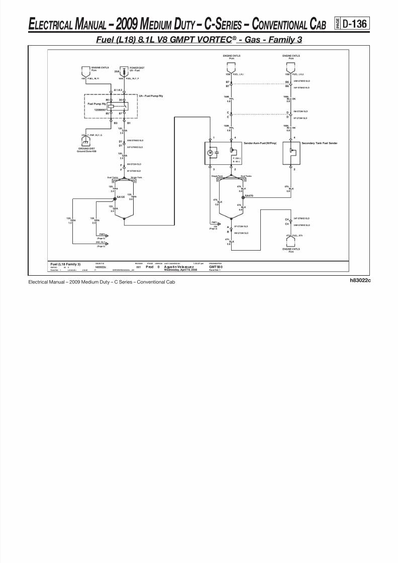
8/10/2019 2009 GM Medium Duty Electrical Manual.PDF
http://slidepdf.com/reader/full/2009-gm-medium-duty-electrical-manualpdf 247/410
Electrical Manual – 2009 Medium Duty – C Series – Conventional Cabh83022c
86
12088567
Fuel Pump Rly
85
30
87
Ω
Ω
M
F: 250
E: 40
LAST CHANGED BY
Panel Set:
VERSIONSTAGEREVISIONOBJECT ID ORGANIZATION
Panel Set: 1
B
Single Tank Dual TanksDual TanksSingle Tank
3
4
Secondary Tank Fuel Sender
2
4
6F GT280 SLD
BLK
SA120
Sender Asm-Fuel (W/Pmp)
1
2
SA470
0.8
.470
D1
30M GTMXD SLDD1
GRA120.
2.0
30F GTMXD SLD
.
GRA120.
2.0
BLK
120GRA
2.0
B1B3
Ground Zone #2B
GROUND DIST
0.8
.470
1936BLU DK
Uh - Fuel Pump Rly
A 1 A 3
0.8
.
6F GT280 SLDD
6M GT280 SLDD
6F GT280 SLDF
6M GT280 SLDF
BLK470.
0.8
.120GRA
1.0
.120GRA
BLU DK0.8
.1936
2.0
Wednesday, April 19, 2006
1:32:27 pm
$IVEDWORK/h83022c__001s ch em ati c s he et1
h83022c17
001Fuel (L18 Family 3)
1
Prod Agustin Velazquez GMT5600GMT560 X08
0.8
.470BLK BLK
470.
C
C
0.8
.120GRA
GRA120.
2.0
2.0
C4
30F GTMXD SLDC4
30M GTMXD SLD
.
0.8
PcmENGINE CNTLS
PPL1589
6M GT280 SLDB
1589.
0.8PPL
(Page 2)
350(Page 2)
PMP1
FUEL_RTN470
(Page 2)
PMP2
2ND_RLY
250 F_PMP_RLY_G
E LECTRICAL M ANUAL – 2009 M EDIUM DUTY – C-S ERIES – CONVENTIONAL C AB P A G E
D-137
30 86
PMP2
120(Page 1)
(Page 1)120
2ND_RLY
Fuel (L18) 8.1L V8 GMPT VORTEC® - Gas - Family 3

8/10/2019 2009 GM Medium Duty Electrical Manual.PDF
http://slidepdf.com/reader/full/2009-gm-medium-duty-electrical-manualpdf 248/410
Electrical Manual – 2009 Medium Duty – C Series – Conventional Cab
LAST CHANGED BY
Panel Set:
VERSIONSTAGEREVISIONOBJECT ID ORGANIZATION
M
Static Ground:
Panel Set: 2
Primary Tank Static Ground:Secondary Tank
6F GT280 SLDA
Agustin VelazquezProd2
Fuel (L18 Family 3)
GND DISTGnd Zone #9
TAN0.8
.1465
00117
h83022csheet1schematic $IVEDWORK/h83022c__001
1:32:27 pm
Wednesday, April 19, 200608 XGMT560 0 GMT560
0.8
.1465TAN
30F GTMXD SLDB4
2.0
.350BLK
Secondary Fuel Pump Rly
8587
SA350
BLK350.
2.0
Gnd Zone #10GND DIST
1.0
.350BLKBLK
350.
1.0
6M GT280 SLDA
2.0
BLK
350.
2.0
.1058GRN LT
Secondary Fuel Tank Transfer Pump
A
B
ENGINE CNTLSPcm
Gnd Zone #3CGND DIST
30M GTMXD SLDB4
(Page 1)
PMP1
FUEL_SEND_GPFTANK_GSFTANK_G
FUEL_RLY21465
h83022c
E LECTRICAL M ANUAL – 2009 M EDIUM DUTY – C-S ERIES – CONVENTIONAL C AB P A G E
D-138
Fuel (LMM) 6.6L V8 Isuzu DURAMAX ® - Diesel
POWER DISTUh - Fuel20A
A1A3
PcmENGINE CNTLS
1936.0.8BLU DK
B7
B7 B6
30M GTMXD SLDB6
30F GTMXD SLD
PPL1589.0.8
PcmENGINE CNTLS
PcmENGINE CNTLS
FUEL_LVL11589 1936 FUEL_LVL2
FUEL_RLY14651640 FUEL_RLY_P

8/10/2019 2009 GM Medium Duty Electrical Manual.PDF
http://slidepdf.com/reader/full/2009-gm-medium-duty-electrical-manualpdf 249/410
Electrical Manual – 2009 Medium Duty – C Series – Conventional Cab
h83022d
LAST CHANGED BY
Panel Set:
VERSIONSTAGEREVISIONOBJECT ID ORGANIZATION
86
12088567
Fuel Pump Rly
85
30
87
M
Static Ground:Single Metal Tank
Splice required for L18
8M GT280 SLDF
Single Metal Tank Dual Tanks
Single Tank Dual Tanks
Panel Set: 1
RPO LEGEND
NJ9/NN4/N23 - FAMILY 2 SINGLE REAR METAL FUEL TANK
NG6 - FAMILY 2 DUAL FUEL TANKS
NK1/NJ2 - FAMILY 2 SINGLE MID-SHIP PLASTIC FUEL TANK
FAM2 - FAMILY 2
D1
8F GT280 SLDF
30F GTMXD SLDD1
30M GTMXD SLD
BLK350.
2.0
Uh - Fuel Pump Rly (Secondary)
A1
B1 B3
2.0
.120GRA
2.0
.120GRA
Ground Zone #2BGROUND DIST
GRA120.
2.0
1
Beta Agustin Velazquez GMT5600Fuel (LMM)GMT560 X08
Wednesday, April 19, 2006
1:32:46 pm
$IVEDWORK/h83022d__001s ch em ati c s he et1
h83022d5
001
Gnd Zone #11GND DIST
1.0
.350BLK
PPL
.470BLK
0.8
Ground Zone #12AGND DIST
0.8
.1589
0.8
.1936BLU DK
C
0.8
C
D
8F GT280 SLDD
8M GT280 SLD
1589PPL
0.8
B
0.8
.
8F GT280 SLDB
8M GT280 SLD
C4
30M GTMXD SLDC4
0.8BLK
470.
30F GTMXD SLD
0.8BLK
470.
BLK
BLK470.
0.8
.470BLK
0.8
.470
4
Primary Tank Fuel Sender
2
4
SC470
0.8
ENGINE CNTLSPcm
Secondary Tank Fuel Sender
2
SJ350
Gnd Zone #11
BLK350.
1.0 1.0
.350BLK
GND DIST
Secondary Fuel Tank Transfer Pump
A
B
GND DISTGround Zone #12A
PFTANK_GFUEL_SEND_G
470 FUEL_RTN
F_PMP_RLY_G250
FUEL_PMP_G PFTANK_G
E LECTRICAL M ANUAL – 2009 M EDIUM DUTY – C-S ERIES – CONVENTIONAL C AB P A G E
D-139
Fuel (LF8) 7.8L L6 Isuzu 6H - Diesel – (LF6) 7.2L L6 Caterpillar ® C7 - Diesel
B7 30F GTMXD SLDB6
B6B7
ENGINE CNTLSEcu
30M GTMXD SLD
ENGINE CNTLSEcu
0.8
.1936BLU DKPPL
1589.
0.8
1589 FUEL_LVL1 FUEL_LVL21936

8/10/2019 2009 GM Medium Duty Electrical Manual.PDF
http://slidepdf.com/reader/full/2009-gm-medium-duty-electrical-manualpdf 250/410
Electrical Manual – 2009 Medium Duty – C Series – Conventional Cab
h83022b
LAST CHANGED BY
Panel Set:
VERSIONSTAGEREVISIONOBJECT ID ORGANIZATION
Static Ground:Primary Tank
Panel Set: 1
Static Ground:
4
BLK470.
0.8
Dual TanksSingle Tank
Secondary Tank
30M GTMXD SLDC4
Primary Tank Fuel Sender
2
GND DISTGnd Zone #10
1
Prod Agust in Velazquez GMT5600Fuel (LF8/LF6)GMT560 X08
Wednesday, April 19, 2006
1:32:11 pm
$IVEDWORK/h83022b__001sch ematic sheet1
h83022b3
001
6M GT280 SLDB
Secondary Tank Fuel Sender
2
4
Gnd Zone #3CGND DIST
6M GT280 SLDD
B
BLK470.
0.8
6F GT280 SLD
6F GT280 SLDD
.350BLK
1.0
.350BLK
C
Gnd Zone #9GND DIST
1.0
EcuENGINE CNTLS
C4
BLK470.
0.8
BLU DK1936.
0.8
30F GTMXD SLD
C
.1589PPL
0.8
0.8
.470BLK
.
1.0
SA350
0.8
.470BLK
FUEL_RTN470
SA470
BLK350
SFTANK_G FUEL_SEND_GPFTANK_G
E LECTRICAL M ANUAL – 2009 M EDIUM DUTY – C-S ERIES – CONVENTIONAL C AB P A G E
D-140
Heated Fuel - Water In Fuel (LMM) 6.6L V8 Isuzu DURAMAX ® - Diesel
Ttm - Water In FuelTELL TALE
Uh - Htd FuelPOWER DIST
Pcm WifLLY ENG CNTLS
20A
POWER DISTUh - Eng 1
10A
LMM_WIF239 HFUEL_R3_P HFUEL_3_P1440 WIF

8/10/2019 2009 GM Medium Duty Electrical Manual.PDF
http://slidepdf.com/reader/full/2009-gm-medium-duty-electrical-manualpdf 251/410
Electrical Manual – 2009 Medium Duty – C Series – Conventional Cab
h83023d
LAST CHANGED BY
Panel Set:
VERSIONSTAGEREVISIONOBJECT ID ORGANIZATION
Engine Earth A
50
GND DIST
J2-A
YEL/BLK
J2-B
GND
TXL
.
Heated/Water In Fuel
8A-
J1-7318-3324-30
IC95
8A-
GND
J1-B
CLOSES FROM -40 C TO 60 C
0.85
Panel Set: 1
GND DIST
J2-7322-1424-40o
PNK161.25
UPC
HFUEL_SW_G
Engine Earth B
FNA
14A
o
1 4A 1 2-Page
97365742WIF
50ISUZU
Conn 40M GT 150-280 Sld13551537
J2279
19
IC91IC96
TXL
12-Page
YEL/BLK
SB508
WIF_G
.
J1-A
ISUZU
HTD FUEL
IC90
150 WATTS
YEL/BLK508.
0.8
0.8
.50824M GTMXD SLD
B8
0.8
24F GTMXD SLDB8
YEL/BLK508.
2677.
1.0
.2677PNK
PNK
A5
Conn 40F GT 150-280 Sld27
1.0
9
A5
YEL/BLK508.
0.8
Ip2 - Heated Fuel Rly
N30
N85
N86
N87
GND DISTGnd Zone #4B
1
Beta Agustin Velazquez GMT5600Heated Fuel/WIF (LMM)GMT560 X08
Wednesday, April 19, 2006
1:34:37 pm
$IVEDWORK/h83023d__001s ch ema ti c s he et 1
h83023d3
001
12088567
Heated Fuel
3086
8785
450 HFUEL_R3_G
E LECTRICAL M ANUAL – 2009 M EDIUM DUTY – C-S ERIES – CONVENTIONAL C AB P A G E
D-141
Heated Fuel - Water In Fuel (LF6) 7.2L L6 Caterpillar ® C7 - Diesel
.508YEL/BLK
Ttm - Water In FuelTELL TALE
WIF

8/10/2019 2009 GM Medium Duty Electrical Manual.PDF
http://slidepdf.com/reader/full/2009-gm-medium-duty-electrical-manualpdf 252/410
Electrical Manual – 2009 Medium Duty – C Series – Conventional Cab
LAST CHANGED BY
Panel Set:
VERSIONSTAGEREVISIONOBJECT ID ORGANIZATION
A
B
Panel Set: 1
NWB/KJK
40F GTMXD SLDA4
Water In Fuel Snsr
0.8
YEL/BLK0.8
Prod1
Gnd Zone #3AGND DIST
.508YEL/BLK
0013
h83023csheet1schematic $IVEDWORK/h83023c__001
1:34:18 pm
Wednesday, April 19, 200608 XGMT560
Heated Fuel/WIF (LF6)0 GMT560Agustin Velazquez
WIF_G351
40M GTMXD SLDA4
h83023c
E LECTRICAL M ANUAL – 2009 M EDIUM DUTY – C-S ERIES – CONVENTIONAL C AB P A G E
D-142
Pcm WifLF8 ENG CNTLS
LF8_WIF
Heated Fuel - Water In Fuel (LF8) 7.8L L6 Isuzu 6H - Diesel

8/10/2019 2009 GM Medium Duty Electrical Manual.PDF
http://slidepdf.com/reader/full/2009-gm-medium-duty-electrical-manualpdf 253/410
Electrical Manual – 2009 Medium Duty – C Series – Conventional Cab
LAST CHANGED BY
Panel Set:
VERSIONSTAGEREVISIONOBJECT ID ORGANIZATION
50
YEL/BLK508.
TXL
2
Yazaki
Panel Set: 1
ISUZUTBDTBD
001
7323-1424-40FNAUPC
wif
Sumitomo 6 Way Conn2
Water In Fuel Snsr
A
B
0.8 19
YEL/BLK0.8
1
Beta Agustin Velazquez GMT5600Heated Fuel/WIF (LF8)GMT560 X08
Wednesday, April 19, 2006
1:34:00 pm
$IVEDWORK/h83023b__001s ch ema ti c s he et 1
h83023b4
001
.508
h83023b
E LECTRICAL M ANUAL – 2009 M EDIUM DUTY – C-S ERIES – CONVENTIONAL C AB P A G E
D-143
Automatic Transmission (LCT) Transmission Control Module
0.8
ORN1983.
POWER DISTIp1 - Trans
10A
Eng Speed Snsr (Tiss)
A
TISS HI
SPEED SENSOR
TRANS INPUT
LO
B B
Turbine Spd Snsr
A
TURS HI
SPEED SENSOR
TURBINE
LO
RED/BLK1230.
0.8
Uh - Pcm BPOWER DIST
15A
15A
POWER DISTUh - Pcm B
B
LO
TRANS OUTPUT
.
0.8PPL/WHT
821
Trans Output Spd SnsrSPEED SENSOR
TOSS HI
A440 TCM_BAT_PP
1020 LCT_IGN0_P

8/10/2019 2009 GM Medium Duty Electrical Manual.PDF
http://slidepdf.com/reader/full/2009-gm-medium-duty-electrical-manualpdf 254/410
Electrical Manual – 2009 Medium Duty – C Series – Conventional Cab h83027a
LAST CHANGED BY
Panel Set:
VERSIONSTAGEREVISIONOBJECT ID ORGANIZATION
Panel Set: 1
L18has FuseFamily 2
C5
0.8TAN/WHT
2678.
24M GTMXD SLD
PcmL18 ENG CNTLS
BLU LT1984.
0.8
.2678TAN/WHT0.5
L18 ENGINE CNTLSPcm
SA2678
GND DISTGnd Zone #3A
GND DISTGnd Zone #3A
GRN LT/BLK822.
0.8
IGN1
DE
ILLUM
F
.2678TAN/WHT0.5
Overdrive Defeat Sw
GND
AB
GND
C
Pcm/EcuENGINE CNTLS
TAN/WHT0.5
.2678
X08
1:35:20 pm
$IVEDWORK/h83027a__001s ch em ati c s he et 1
h83027a19
001Wednesday, April 19, 20061
Pilot Agustin Velazquez GMT560BLCT TransGMT560
J1-80
NT+
GND
J1-9
IGN0
GND
J1-69
J1-70
V_BATT_B NE+
J1-59 J1-60
NO+
DEFEATOVERDRIVE
J1-61
J1-63
TPS
J1-44
CLASS II
J1-46
J1-39
NE-
TRANS INPUT SPEED
J1-40
NO-
TRANS OUTPUT SPEED
UNMANAGEDTORQUE
J1-22J1-12
V5AZERO
CROSSING
J1-18
J1-20
NT-
TURB SPEED
Gnd Zone #7A
LCT TCM
J1-10
V_BATT_A
.
GND DIST
0.5TAN/WHT
2678
Gnd Zone #7A
GND DIST
BLU DK/WHT1231.
0.8
24F GTMXD SLDC5
BLK/WHT0.8
.351
POWER DIST
C12
10A Uh - Eng1
40F GTMXD SLDC12
40M GTMXD SLD
0.8TAN/WHT
2678.
Class 2SERIAL DATA LINK
POWER DIST
10A
Ip2 - Lh Parklamp
TCM_BAT_PP2440
2467 2221 REP_TOSS_HI_1 351 LCT_GG2470 LCT_CL2
DEL_TORQ464
UNMAN_TORQ
ODDS_LP2509
ODDS_LED_P239
ODDS_SW_G750
ODDS_ILL_G750
TCM1_G
E LECTRICAL M ANUAL – 2009 M EDIUM DUTY – C-S ERIES – CONVENTIONAL C AB P A G E
D-144
Automatic Transmission (LCT) Transmission Control Module
S o l e n o i d E
O n / O f f
O n / O f f
P C S 2
S S 1
M A I N
P C S 1
T C C
M a i n S o l e n o i d
N L V B S C E
S o l e n o i d F ( T C C )
N L V B S C E
S o l e n o i d A
N H
V B S O E
TRANS ID
I M S C
Sump I M S B
IMS
I M S P
I M S N S
Pressure Switch Manifold
I M S A
P S 4 ( S w i t c h R )
N o t U s e d
M O D
STS
N o t U s e d
P S 3 ( S w i t c h E )
P S 2 ( S w i t c h D )
S S 2
P S 1 ( S w i t c h C )
Temperature
O n / O f f
S S 3
S o l e n o i d D
S o l e n o i d B
O n / O f f
S o l e n o i d C
78920 21 22 2324 34611 1415161718 192
Allison Trans 4 Gen
1 10
IMS_NS1786

8/10/2019 2009 GM Medium Duty Electrical Manual.PDF
http://slidepdf.com/reader/full/2009-gm-medium-duty-electrical-manualpdf 255/410
Electrical Manual – 2009 Medium Duty – C Series – Conventional Cab h83027a
GM LAN
LAST CHANGED BY
Panel Set:
VERSIONSTAGEREVISIONOBJECT ID ORGANIZATION
Panel Set: 2
ENGINE CNTLSPcm/Ecu
40F GTMXD SLDB9
.773
Ttm - Check Trans
L18 ENG CNTLSPcm
GRA0.8
.1224PNK
0.8
TELL TALE
.2469BRN/WHT0.8
EXTERIOR LIGHTSBack Up Lamps
.772YEL
0.8
0.8PNK
139.
WHT1994.
0.80.8YEL/BLK
2879.
LMM ENG CNTLSGpm
.1234GRA
0.8
.2471PPL
0.8
0.8BRN
323.
.1234GRA
0.8
.2527ORN/WHT0.8
0.5GRA
1234.
30
Reverse
12088567
Uh - Reverse Rly
F11
F9
H11
H9
TCCSol F (TCC)NL VBS CE
J1-78J1-79
PSM D
86
85 87
J1-71
HSD2SOL_COM1+ HI
IMSBIT A
J1-73
Main SolMain Mod
J1-74
NL VBS CE
J1-76
TRANS ID
J1-77
PSMREV
GPO6
J1-64J1-65
REVER WAR
J1-66
HISHIELD
J1-67
J1-57
ANALOG
J1-58
RTN
HI
J1-6
E SWGND
J1-51
C SWGND
J1-52J1-53
BIT BIMS
TEMP
J1-54
SUMP
J1-55
NH VBS OE
PCS 1Solenoid A
PSM E
LO
J1-47
TORQREQ
J1-5
J1-38
TRANS TTCHECK
J1-29
J1-33
GNDD SW
J1-34
BIT PIMS
LOSOL_B
J1-36
IMSNEUTRAL
GPO5
J1-24
Term
J1-26
GMLAN
J1-27
LO
HSD1
J1-14
IMSBIT C PSM C
J1-17
LCT TCM
J1-11
BLK/WHT0.8
GMLAN ConfLCT TRANS
.771
15A
Ip1 - Turn/BackupPOWER DIST
0.8BLU DK
1530.
0.8
.139PNK
0.8
.1226RED
LMM ENG CNTLSGpm
LCT TRANS
0.8GRN DK/WHT2528.
GMLAN Conf
B7
0.8GRN LT/BLK
2529.
24F GTMXD
LCT TRANSGMLAN Conf
SB139
1234.
24M GTMXDB7
0.5GRA
PPL0.8
.898
40M GTMXD SLDB9
ORN/BLK0.8
Wednesday, April 19, 20062
Pi lot Agust in Velazquez GMT560BLCT TransGMT560 X08
1:35:20 pm
$IVEDWORK/h83027a__001schematic sheet1
h83027a19
001
.1786
.776WHT
0.8
.7581PPL
0.8
407.
0.8BLK
.1524
0.8GRA
.1227YEL/BLK0.8
0.8BLU DK
1225.
CHECK_T
GMLAN_6_2
GMLAN_106105
GMLAN_96106
463 REQ_TORQ
6106 GMLAN_5_1
6105 GMLAN_6_1
6105
BU_LCT_P139
BU_LCT_124
E LECTRICAL M ANUAL – 2009 M EDIUM DUTY – C-S ERIES – CONVENTIONAL C AB P A G E
D-145
Automatic Transmission (LCT) Transmission Control Module
SPEED SENSOR
TRANS OUTPUT
Trans Output Spd SnsrEng Speed Snsr (Tiss)SPEED SENSOR
TRANS INPUT

8/10/2019 2009 GM Medium Duty Electrical Manual.PDF
http://slidepdf.com/reader/full/2009-gm-medium-duty-electrical-manualpdf 256/410
Electrical Manual – 2009 Medium Duty – C Series – Conventional Cab h83027b
LAST CHANGED BY
Panel Set:
VERSIONSTAGEREVISIONOBJECT ID ORGANIZATION
Panel Set: 3
GMLAN Conf
LCT TRANS
J1-27
HI
J1-6 J1-26
TermGMLANLO
HI
59
TISSHI
TOSS
60
LOTISS
39 40
TOSSLO
Md Tcm
MD TCM (WTEC)
SA6105
DATA LINK CONNData Conn
DATA LINK CONN
Data Conn
0.8
.6105BLU DK
LCT TRANSGMLAN Conf
A
TOSS HILO
B
LCT TRANSGMLAN Conf
GMLAN ConfLCT TRANS
0016
h83027bsheet1schematic $IVEDWORK/h83027b__001
8:21:32 am
Friday, May 19, 200608 XGMT560
MD Trans (LF8&LF6)0 GMT560Agustin VelazquezBeta
3
0.8
BLU DK6105.
.400YEL
0.8
0.8BLU DK
6105.
.
0.8BLU LT
6106
TISS HI
AB
LO
LCT TRANSGMLAN ConfGMLAN Conf
LCT TRANS
0.8PPL
401..1230
RED/BLK0.80.8
BLU DK/WHT1231.
GMLAN_5_1
GMLAN_8
GMLAN_6_16105
GMLAN_5_16106
GMLAN_6_26105
GMLAN_6_2GMLAN_6_1
GMLAN_7
E LECTRICAL M ANUAL – 2009 M EDIUM DUTY – C-S ERIES – CONVENTIONAL C AB P A G E
D-146
Automatic Transmission (MD) Transmission Control Module
Transmission Optional Connector
0.8
0.8TAN/WHT
981.
G
.980PPL/WHT
HJ
.1148GRA
0.8
2522.
.1481YEL
0.8
.476BLK
0.80.8YEL
0.8YEL
1479.
K
TAN0.8
.1147.1480
BLU LT0.8
POWER DISTIp1 - Trans
10A
POWER DIST
Uh - Pcm B
25A/LF8.1971WHT
10A/LF625A/LF8
Uh - Pcm BPOWER DIST
TEMP
18
SIG
SUMP TEMP OIL LEVEL
GNDANALOG
19 11
(TCC) TCC
12
SIG
SENSOR
OIL LVL
15 16
SENPWR
HSD3
1227.YEL/BLK
10F MP150 SLDFEC DAB
0.8PPL
1146.
GRN DK1531.
440 TCM_BAT_P1020 MD_IGN0_P

8/10/2019 2009 GM Medium Duty Electrical Manual.PDF
http://slidepdf.com/reader/full/2009-gm-medium-duty-electrical-manualpdf 257/410
Electrical Manual – 2009 Medium Duty – C Series – Conventional Cab h83027b
J1939
LAST CHANGED BY
Panel Set:
VERSIONSTAGEREVISIONOBJECT ID ORGANIZATION
P
Panel Set: 1
PPPPPPPPP
70
BATT
58
GND
63
IGN0TEMPSUMP
64
SIGNALSUMP TEMP
54
ANALOGAUX
42
HOLD(INPUT)ENABLE
PTO
43
INDICATOR
45
RANGE
SHIFT SELECTOR DIR SIGNAL
34
TCC
37
REQUEST
3
DIGITALGND
(OUTPUT)ENGAGE
PTO
30
TCCHSD3
31
SIGNALPOWER
OIL LVLSIGNAL
16
NEUTRALAUTO
17 22
PUMPENABLE
23
PUMP MODE
MD TCM (WTEC)
1
RANGEINHIBIT
BATT
10 12
Beta Agustin Velazquez GMT5600GMT560 X08
Friday, May 19, 2006
8:21:32 am
$IVEDWORK/h83027b__001s ch em ati c s he et 1
h83027b6
001
J1939J1939
MD Trans (LF8&LF6)
1
J1939
40F GTMXD SLDA1
J1939
440.
0.8ORN
8
12
IGNPOWER
13
V BAT
14
ShieldLo
15
3
DIM IN
5
GND Hi
Gnd Zone #4BGND DIST
BIT 1DATASHIFT
11
0.8GRN DK
1373.
A1
.598GRA
0.8
40M GTMXD SLD
25A/LF8 WHT0.810A/LF6
.1994WHT
0.8
POWER DIST
A4
10A/LF615A/LF8
Uh - Pcm B
0.8YEL/BLK
A4
0.8
.1373GRN DKINTERIOR LIGHTING
Dimmer Signal Dist
10A POWER DISTIp1 - Trans
10A
0.5GRA
.407BLK
0.8
0.8GRN DK
8.
SHIFT_LP_G450
2362 SHIFT_J- 2361 SHIFT_J+
SHIFT_BAT_P440
SHIFT_IGN0_P1020
SHIFT_DIM
MD_BAT_P440

8/10/2019 2009 GM Medium Duty Electrical Manual.PDF
http://slidepdf.com/reader/full/2009-gm-medium-duty-electrical-manualpdf 258/410
E LECTRICAL M ANUAL – 2009 M EDIUM DUTY – C-S ERIES – CONVENTIONAL C AB P A G E
D-148
Automatic Transmission (MD) Transmission Control Module (continued)
SPEED SENSOR
TRANS OUTPUT
Trans Output Spd SnsrEng Speed Snsr (Tiss)SPEED SENSOR
TRANS INPUT

8/10/2019 2009 GM Medium Duty Electrical Manual.PDF
http://slidepdf.com/reader/full/2009-gm-medium-duty-electrical-manualpdf 259/410
Electrical Manual – 2009 Medium Duty – C Series – Conventional Cab h83027b
LAST CHANGED BY
Panel Set:
VERSIONSTAGEREVISIONOBJECT ID ORGANIZATION
Panel Set: 3
GMLAN Conf
LCT TRANS
J1-27
HI
J1-6 J1-26
TermGMLANLO
HI
59
TISSHI
TOSS
60
LOTISS
39 40
TOSSLO
Md Tcm
MD TCM (WTEC)
SA6105
DATA LINK CONNData Conn
DATA LINK CONN
Data Conn
0.8
.6105BLU DK
LCT TRANSGMLAN Conf
A
TOSS HILO
B
LCT TRANSGMLAN Conf
GMLAN ConfLCT TRANS
0016
h83027bsheet1schematic $IVEDWORK/h83027b__001
8:21:32 am
Friday, May 19, 200608 XGMT560
MD Trans (LF8&LF6)0 GMT560Agustin VelazquezBeta
3
0.8
BLU DK6105.
.400YEL
0.8
0.8BLU DK
6105.
.
0.8BLU LT
6106
TISS HI
AB
LO
LCT TRANSGMLAN ConfGMLAN Conf
LCT TRANS
0.8PPL
401..1230
RED/BLK0.80.8
BLU DK/WHT1231.
GMLAN_5_1
GMLAN_8
GMLAN_6_16105
GMLAN_5_16106
GMLAN_6_26105
GMLAN_6_2GMLAN_6_1
GMLAN_7
E LECTRICAL M ANUAL – 2009 M EDIUM DUTY – C-S ERIES – CONVENTIONAL C AB P A G E
D-149
Exhaust Brake/Restrictor (LMM) 6.6L V8 Isuzu DURAMAX ® - Diesel –
(LF8) 7.8L L6 Isuzu 6H - Diesel – (LF6) 7.2L L6 Caterpillar ® C7 - Diesel
ENGINE CNTLSEcu
Headlamp IllumINTERIOR LIGHTING ENGINE CNTLSEcu/Pcm

8/10/2019 2009 GM Medium Duty Electrical Manual.PDF
http://slidepdf.com/reader/full/2009-gm-medium-duty-electrical-manualpdf 260/410
Electrical Manual – 2009 Medium Duty – C Series – Conventional Cab h83029a
LAST CHANGED BY
Panel Set:
VERSIONSTAGEREVISIONOBJECT ID ORGANIZATION
Panel Set: 1
TELL TALETtm - Exhaust
BLK/WHT1962.
Gnd Zone #7A/EcuGND DIST/CAT ENG CNTLS
0.8BLK/WHT
1962.
0.8
30F GTMXD SLDC7
30M GTMXD SLDC7
B3
30M GTMXDB3
ILLUM
GND
F
Gnd Zone #7AGND DIST
30F GTMXD
Exhaust Brake Sw
A
GND
B
GND
C
SWLED
DE
XGMT560
Exhaust Brake/Rstr (Diesel)0 GMT560Agustin VelazquezBeta
1
.2081GRN LT0.5
2509 EXH_BRK_LP
EXH_ILL_G750
2081 EXH_BRK
EXH_TEL
EXH_TT
EXH_SW_G750
0014
h83029asheet1schematic $IVEDWORK/h83029a__001
1:36:59 pm
Wednesday, April 19, 200608
E LECTRICAL M ANUAL – 2009 M EDIUM DUTY – C-S ERIES – CONVENTIONAL C AB P A G E
D-150
Starting & Charging (L18) 8.1L V8 GMPT VORTEC® - Gas
Family 2 has Fuse
A3
Ip1 - Start
POWER DIST
30F GTMXD SLD
POWER DIST
40A Maxi - Ign1
RED5.0
.242
POWER DISTIp1 - Start10A
STARTRLY_PCRANK2_P

8/10/2019 2009 GM Medium Duty Electrical Manual.PDF
http://slidepdf.com/reader/full/2009-gm-medium-duty-electrical-manualpdf 261/410
Electrical Manual – 2009 Medium Duty – C Series – Conventional Cab h83030a
M
LAST CHANGED BY
Panel Set:
VERSIONSTAGEREVISIONOBJECT ID ORGANIZATION
has FuseFamily 2
Panel Set: 1
A310A
30F GTMXD SLD
5.0
Motor Starter V8
B
B_CASE
S
S_CASE
RED242.
30M GTMXDB9
B12
30F GTMXDB9
87
12193604
Starter Rly
85
3086
A7 A9
B7B9
30F GTMXD
30F GTMXD SLDB2 M5
Start Ring Term 1A
B
Uh - Starter Rly
GRN DK1433.
0.5
PcmENGINE CNTLS
Case GndGND DIST
Battery PositiveBATTERIES
PPL806.
0.5
ENGINE CNTLSPcm
GMT560 X08
Wednesday, April 19, 2006
1:37:34 pm
$IVEDWORK/h83030a__001s ch em at ic s he et1
h83030a19
001
Man Cltch Sw Btm Of Trvl
A
B
1
Beta Agustin Velazquez GMT5600Starting & Charging (L18)
30M GTMXD SLDA3
GRN DK
1433.
0.8
B2
0.5
.1433GRN DK
30M GTMXD SLD
30M GTMXDB12
.6PPL
3.0
PPL0.5
.806
L18_CRANK
STARTRLY2_P806
(Page 2)
START
START
STARTER_G
447 PCM_START
E LECTRICAL M ANUAL – 2009 M EDIUM DUTY – C-S ERIES – CONVENTIONAL C AB P A G E
D-151
Starting & Charging (L18) 8.1L V8 GMPT VORTEC® - Gas (continued)
(Page 3)
SENSE
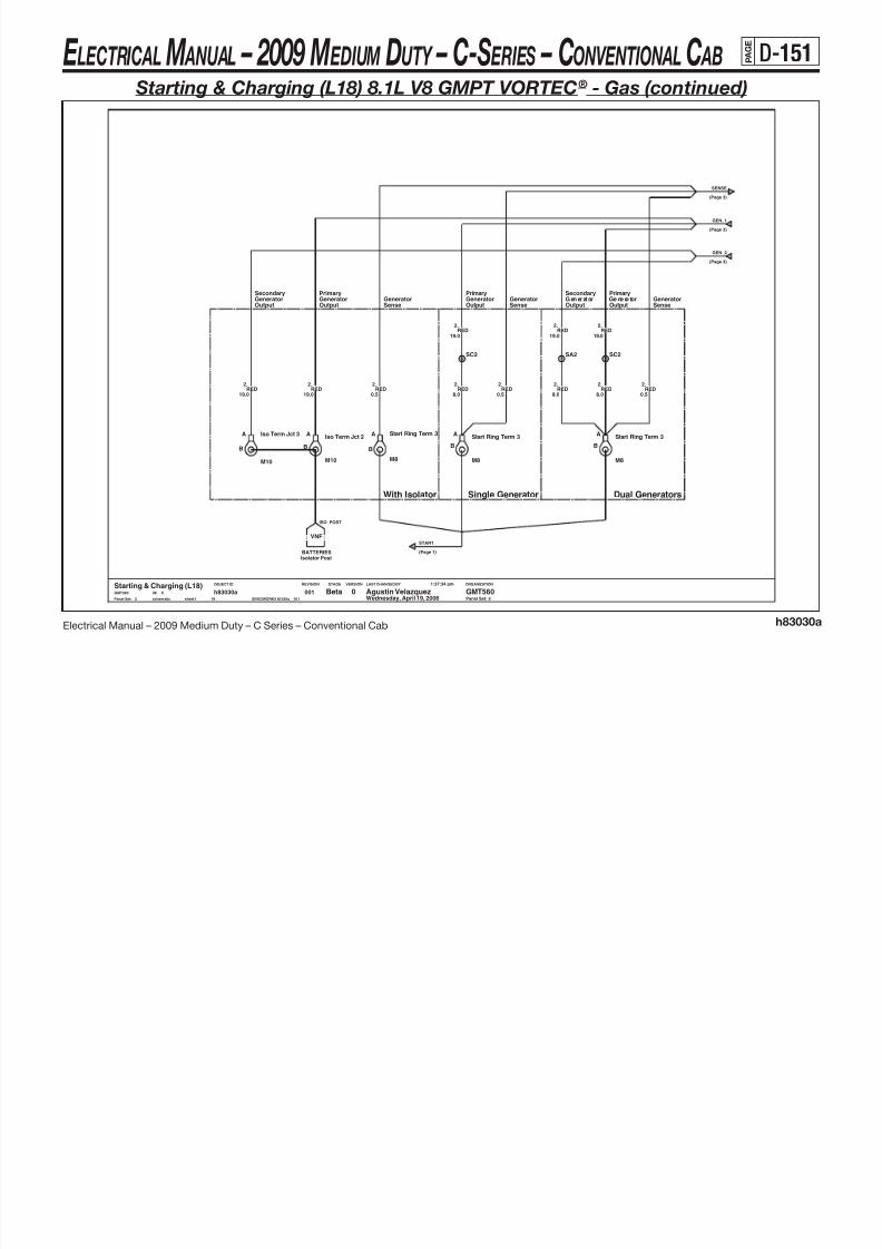
8/10/2019 2009 GM Medium Duty Electrical Manual.PDF
http://slidepdf.com/reader/full/2009-gm-medium-duty-electrical-manualpdf 262/410
Electrical Manual – 2009 Medium Duty – C Series – Conventional Cab h83030a
LAST CHANGED BY
Panel Set:
VERSIONSTAGEREVISIONOBJECT ID ORGANIZATION
Panel Set: 2
G en er at or Ge ne ra torOutput
Secondary
With Isolator Single Generator Dual Generators
VNF
GeneratorSecondary
OutputSenseOutput
Primary
OutputGenerator
RED
SC2
GeneratorPrimary
OutputGeneratorPrimary
SenseGenerator
SenseGenerator
M8
Start Ring Term 3A
B
2
19.0
.
RED2.
0.5
M10
Iso Term Jct 2A
B
8.0
..
19.0
2RED
Start Ring Term 3
M8
A
B
2RED
A
B
SA2
M8
Start Ring Term 3
RED
SC2
RED8.0
.2
0.5
.2.
19.0
2RED
8.0RED
2.
BATTERIESIsolator Post
.
19.0
2RED
Iso Term Jct 3
M10
A
B
Starting & Charging (L18)0 GMT560Agustin VelazquezBeta
2
00119
h83030asheet1schematic $IVEDWORK/h83030a__001
1:37:34 pm
Wednesday, April 19, 200608 XGMT560
2
RED2.
0.5
RED.
19.0
GEN_1
(Page 3)
(Page 3)
GEN_2
ISO_POST
(Page 1)
START
E LECTRICAL M ANUAL – 2009 M EDIUM DUTY – C-S ERIES – CONVENTIONAL C AB P A G
E
D-152
Starting & Charging (L18) 8.1L V8 GMPT VORTEC® - Gas (continued)
SF2SENSE
(Page 2)2
GEN_2
(Page 2)22
(Page 2)
GEN_1

8/10/2019 2009 GM Medium Duty Electrical Manual.PDF
http://slidepdf.com/reader/full/2009-gm-medium-duty-electrical-manualpdf 263/410
Electrical Manual – 2009 Medium Duty – C Series – Conventional Cab h83030a
LAST CHANGED BY
Panel Set:
VERSIONSTAGEREVISIONOBJECT ID ORGANIZATION
CS130 CS130
TBD - KG4; 150 amps
Panel Set: 3
15744911 - K68; 105 ampsTBD - KG4; 150 amps
NOTE:
Family 2: 10480382 - K65; 95 amps
15744912 - K68; 105 amps
DualSingle
Family 3:
Optional Generators:
25.
0.8BRN
19
h83030asheet1schematic $IVEDWORK/h83030a__001
1:37:34 pm
Wednesday, April 19, 200608 XGMT560
Starting & Charging (L18)0 GMT560Agustin VelazquezBeta
3
001
Dual G Ring Term A
B
Gen Ring Term A
B
GND DIST
1.0
.2RED
.25BRN
0.8
Case Gnd
PcmENGINE CNTLS
0.8BRN
25.
0.8
.25BRN
CASE
D
AC SENSE
G3 ~
STATOR
FIELD (ROTOR)
PHASE
DC SENSE
LAMPDRIVER
TURNON INPUT
FIELD
A
B
BAT
C
2nd Generator Asm
CASE
D
DC SENSE
PHASE
FIELD (ROTOR)
STATOR
3 ~G
AC SENSE
Generator Asm
A
B
BAT
C
FIELD
ON INPUTTURN
DRIVERLAMP
PcmENGINE CNTLS
GND DISTCase Gnd
SA25
RED2.
1.0
L_TERM_L18
2ND_GEN_GGEN_G
F_TERM_MON23
E LECTRICAL M ANUAL – 2009 M EDIUM DUTY – C-S ERIES – CONVENTIONAL C AB P A G
E
D-153
Starting & Charging (LMM) 6.6L V8 Isuzu DURAMAX ® - Diesel
Maxi - Ign140A
POWER DIST
5.0
.242RED
STARTRLY_P

8/10/2019 2009 GM Medium Duty Electrical Manual.PDF
http://slidepdf.com/reader/full/2009-gm-medium-duty-electrical-manualpdf 264/410
Electrical Manual – 2009 Medium Duty – C Series – Conventional Cab h83030d
M
LAST CHANGED BY
Panel Set:
VERSIONSTAGEREVISIONOBJECT ID ORGANIZATION
Panel Set: 1
Glow Plug CntrlLMM ENG CNTLS
.6PPL
5.0
RED2
19.0
GND DIST
30F GTMXD SLDA3
.
Battery Positive
Ring Terminal
M8
A
B
Case Gnd
BATTERIES
10A
Ip1 - StartPOWER DIST
B7B9
Uh - Starter Rly
87
12193604
Starter Rly
85
3086
A7 A9
5.0RED
242.
M5
Start Ring Term 1A
B
30M GTMXD SLDA3
X08
Wednesday, April 19, 2006
1:42:00 pm
$IVEDWORK/h83030d__001s ch em ati c s he et1
h83030d4
0011
Prod Agustin Velazquez GMT5600Starting & Charging (LMM)GMT560
B
B_CASE
S
S_CASE
Motor Starter V8
PcmENGINE CNTLS
SB2
8.0
.2RED
GLO_CNTL
START
START
(Page 2)
STARTER_G
STARTRLY2_P806
PCM_START447
E LECTRICAL M ANUAL – 2009 M EDIUM DUTY – C-S ERIES – CONVENTIONAL C AB P A G
E
D-154
Starting & Charging (LMM) 6.6L V8 Isuzu DURAMAX ® - Diesel (continued)
(Page 3)
GEN_1
SENSE
(Page 3)

8/10/2019 2009 GM Medium Duty Electrical Manual.PDF
http://slidepdf.com/reader/full/2009-gm-medium-duty-electrical-manualpdf 265/410
Electrical Manual – 2009 Medium Duty – C Series – Conventional Cab h83030d
LAST CHANGED BY
Panel Set:
VERSIONSTAGEREVISIONOBJECT ID ORGANIZATION
SenseGeneratorGenerator
Output
Panel Set: 2
Primary
With Isolator Single Generator Dual Generators
VNF
OutputGeneratorSecondary
OutputGeneratorSecondary
OutputGenerator
Primary
OutputGeneratorPrimary
SenseGenerator
SenseGenerator
0.5
.2REDRED
2
19.0
.
19.0
.
2.
8.0RED
RED2
RED2
19.0
.RED
8.0
.2
.
19.0
2
RED2.
0.5
SC2
RED
Isolator PostBATTERIES
0014
h83030dsheet1schematic $IVEDWORK/h83030d__001
1:42:00 pm
Wednesday, April 19, 200608 XGMT560
Starting & Charging (LMM)0 GMT560Agustin VelazquezProd
2
RED
0.5
.2RED
SC2
2
19.0
.
8.0RED
2
SA2
Ring TerminalA
B
.
Ring TerminalA
B
M8
Start Ring Term 3
M8
A
B
M10
Iso Term Jct 3A
B
Iso Term Jct 2
M10
A
B
START
(Page 1)
ISO_POST
GEN_2
(Page 3)
E LECTRICAL M ANUAL – 2009 M EDIUM DUTY – C-S ERIES – CONVENTIONAL C AB P A G
E
D-155
Starting & Charging (LMM) 6.6L V8 Isuzu DURAMAX ® - Diesel (continued)
SF2
GEN_2
(Page 2)22
(Page 2)
GEN_1
SENSE
(Page 2)2

8/10/2019 2009 GM Medium Duty Electrical Manual.PDF
http://slidepdf.com/reader/full/2009-gm-medium-duty-electrical-manualpdf 266/410
Electrical Manual – 2009 Medium Duty – C Series – Conventional Cab h83030d
LAST CHANGED BY
Panel Set:
VERSIONSTAGEREVISIONOBJECT ID ORGANIZATION
CS130 CS130
Optional Generators:
15744912 - K65; 95 amps
15744912 - K68; 105 amps
NOTE:
TBD - KG4; 150 amps
Panel Set: 3
2.
1.0RED
BRN25.
0.8
ENGINE CNTLSPcm
0.8
.2524BRN
Dual G Ring Term A
B
PcmENGINE CNTLS
1:42:00 pm
Wednesday, April 19, 200608 XGMT560
Starting & Charging (LMM)0 GMT560Agustin VelazquezProd
3
0014
h83030dsheet1schematic $IVEDWORK/h83030d__001
B
Gen Ring Term A
1.0
.2RED
CASE
D
PHASE
FIELD (ROTOR)
STATOR
3 ~G
AC SENSE
2nd Generator Asm
A
B
BAT
CB
BAT
CCASE
D
FIELD
ON INPUTTURN
DRIVERLAMP
DC SENSE
Generator Asm
AC SENSE
G3 ~
STATOR
FIELD (ROTOR)
PHASE
DC SENSE
LAMPDRIVER
TURNON INPUT
FIELD
A
GND DISTCase GndCase Gnd
GND DISTENGINE CNTLS
Pcm
F_TERM_MON23
2ND_GEN_G
L2_TERM_LMML_TERM_LMM
GEN_G
E LECTRICAL M ANUAL – 2009 M EDIUM DUTY – C-S ERIES – CONVENTIONAL C AB P A G
E
D-156
Starting & Charging (LF8) 7.8L L6 Isuzu 6H - Diesel
5.0RED
242.
Maxi - Ign1
40A
POWER DIST
PPL
30F GTMXDB12
0.5
.806
10A Ip1 - StartPOWER DIST
Ip1 - Start
10A
30F GTMXD SLDA3
POWER DIST
CRANK2_P806 STARTRLY2_P STARTRLY_P

8/10/2019 2009 GM Medium Duty Electrical Manual.PDF
http://slidepdf.com/reader/full/2009-gm-medium-duty-electrical-manualpdf 267/410
Electrical Manual – 2009 Medium Duty – C Series – Conventional Cab h83030b
LAST CHANGED BY
Panel Set:
VERSIONSTAGEREVISIONOBJECT ID ORGANIZATION
M
Panel Set: 1
PPL
GRN DK1433.
0.8
5.0
.242RED
806.
0.5
M5
A
B
Start Ring Term 1
30F GTMXDB9
A7 A9
B7B9
EcuENGINE CNTLS
87
12193604
Starter Rly
85
3086Uh - Starter Rly
S
S_CASE
Motor Starter Isuzu
B
B_CASE
30M GTMXDB9
0.5
.1433GRN DK
0.5
30M GTMXDB12
GRN DK1433.
GND DISTCase Gnd
Battery PositiveBATTERIES
Ecu
Starting & Charging (LF8)001
6
h83030bsheet1schematic $IVEDWORK/h83030b__001
1:39:12 pm
Wednesday, April 19, 200608 XGMT560 0 GMT560Agustin VelazquezBeta
1
Man Cltch Sw Btm Of Trvl
A
B
ENGINE CNTLS
A3 30M GTMXD SLD
.6
30F GTMXD SLDB2
PPL5.0
ECU_CRANK
30M GTMXD SLDB2
START
(Page 2)
START
447 ECU_START
STARTER_G
E LECTRICAL M ANUAL – 2009 M EDIUM DUTY – C-S ERIES – CONVENTIONAL C AB P A G
E
D-157
Starting & Charging (LF8) 7.8L L6 Isuzu 6H - Diesel (continued)

8/10/2019 2009 GM Medium Duty Electrical Manual.PDF
http://slidepdf.com/reader/full/2009-gm-medium-duty-electrical-manualpdf 268/410
Electrical Manual – 2009 Medium Duty – C Series – Conventional Cab h83030b
CS130
LAST CHANGED BY
Panel Set:
VERSIONSTAGEREVISIONOBJECT ID ORGANIZATION
15015182 - KG8; 130 amps
Panel Set: 2
NOTE:Optional Generators:
15015180 - K60; 100 amps
15015181 - KW1; 160 amps
EcuENG CNTLS
Gen Ring Term
M10
A
B
0.8BRN
25.
EcuENG CNTLS
25BRN
0.8
SA25
30M GTMXD SLDB8
Ttm - BatteryTELLTALE
.
30F GTMXD SLDB8
.BRN
25
0.8BRN.
Start Ring Term 3
M10
A
B
SC2
0.5
25
0016
h83030bsheet1schematic $IVEDWORK/h83030b__001
1:39:12 pm
Wednesday, April 19, 200608 XGMT560
Starting & Charging (LF8)0 GMT560Agustin VelazquezBeta
2
D
Case GndGND DIST
ON INPUT
FIELD
Generator Asm
AC SENSE
G
A
B
BAT
CCASE
3 ~
STATOR
FIELD (ROTOR)
PHASE
DC SENSE
LAMPDRIVER
TURN
SF2
1.0
.2RED
0.5RED
2.
8.0
RED19.0
.2
RED2.
L_TERM_TTM
L_TERM_MON
23
GEN_G
START
(Page 1)
F_TERM_MON
E LECTRICAL M ANUAL – 2009 M EDIUM DUTY – C-S ERIES – CONVENTIONAL C AB P A G
E
D-158
Starting & Charging (LF6) 7.2L L6 Caterpillar ® C7 - Diesel
30F GTMXD SLDA3
30M GTMXD SLDA3
POWER DISTIp1 - Start
10A
30F GTMXDB12
0.5
.806PPL
RED242.
RED
Maxi - Ign140A
POWER DIST
5.0
.242
STARTRLY_P
CRANK2_P

8/10/2019 2009 GM Medium Duty Electrical Manual.PDF
http://slidepdf.com/reader/full/2009-gm-medium-duty-electrical-manualpdf 269/410
Electrical Manual – 2009 Medium Duty – C Series – Conventional Cab h83030c
M
LAST CHANGED BY
Panel Set:
VERSIONSTAGEREVISIONOBJECT ID ORGANIZATION
Panel Set: 1
30C-1
PAGE 8A-TBDMOTOR STARTEROVERCRANK SW
30C-130C-1
PAGE 8A-CAT MOTOR STARTER
30C-1OVERCRANK SWMOTOR STARTER
GND ZONE #2C
Start Ring Term 1
&KQR-KQR
CAT MOTOR STARTER
85
Starter Rly
12193604
87
A7 A9
B7B9
ENGINE CNTLSEcu
Uh - Starter Rly86 30
.1433GRN DK0.8
.1433GRN DK0.5
B2
30M GTMXDB12
30F GTMXD SLD
B9
B12
.447YEL
1.0
30M GTMXD
θ
A
B
1M MP280 SLDA
YEL1.0
.447
Overcrank Prot Temp Strtr Sw
1:41:30 pm
Wednesday, April 19, 200608 XGMT560
Starting & Charging (LF6)0 GMT560Agustin VelazquezBeta
1
1F MP280 SLDA
0015
h83030csheet1schematic $IVEDWORK/h83030c__001
Man Cltch Sw Btm Of Trvl
A
B
10A
Ip1 - StartPOWER DIST
B9
0.8PPL
806.
30F GTMXD
PPL806.
0.5
GRN DK1433.
0.5
30M GTMXD SLDB2
A
0.8YEL
447.
1F MP280 SLDA
1M MP280 SLD
.6PPL
5.0
G
S
GND DISTGnd Zone #2B
Battery PositiveBATTERIES
5.0
Starter Motor - Cat
B
START_G
START
START
(Page 2)
CRANK_C_P
START_CAT447
E LECTRICAL M ANUAL – 2009 M EDIUM DUTY – C-S ERIES – CONVENTIONAL C AB P A G
E
D-159
Starting & Charging (LF6) 7.2L L6 Caterpillar ® C7 - Diesel (continued)
2 2

8/10/2019 2009 GM Medium Duty Electrical Manual.PDF
http://slidepdf.com/reader/full/2009-gm-medium-duty-electrical-manualpdf 270/410
Electrical Manual – 2009 Medium Duty – C Series – Conventional Cab h83030c
CS130
LAST CHANGED BY
Panel Set:
VERSIONSTAGEREVISIONOBJECT ID ORGANIZATION
15015182 - KG8; 130 amps
15015181 - KW1; 160 amps
15015180 - K60; 100 amps
Optional Generators:
Panel Set: 2
NOTE:
B
BAT
CCASE
D
B8
G
AC SENSE
Generator Asm
FIELD
ON INPUTTURN
DRIVERLAMP
DC SENSE
PHASE
FIELD (ROTOR)
STATOR
3 ~
A
30F GTMXD SLD
1.0
Ttm - BatteryTELLTALE
RED2.
.2RED
0.5
SC2
2.
19.0RED
E 1/2
Ring TerminalA
B
30M GTMXD SLDB8
Gen Ring Term
M10
A
B
SF2
Case GndGND DIST
8.0
.2RED
BRN
.25
0.8
25
Beta Agustin Velazquez GMT5600Starting & Charging (LF6)GMT560 X08
Wednesday, April 19, 2006
1:41:30 pm
$IVEDWORK/h83030c__001s ch em ati c s he et 1
h83030c5
001
.BRN
0.5
2
(Page 1)
START
GEN_G
L_TERM_TTM
E LECTRICAL M ANUAL – 2009 M EDIUM DUTY – C-S ERIES – CONVENTIONAL C AB P A G
E
D-160
Cruise Control (L18) 8.1L V8 GMPT VORTEC® - Gas –
(LMM) 6.6L V8 Isuzu DURAMAX ® - Diesel
10A
Uh - Eng 4POWER DIST
CRUISE_P639

8/10/2019 2009 GM Medium Duty Electrical Manual.PDF
http://slidepdf.com/reader/full/2009-gm-medium-duty-electrical-manualpdf 271/410
Electrical Manual – 2009 Medium Duty – C Series – Conventional Cab h83034a
LAST CHANGED BY
Panel Set:
VERSIONSTAGEREVISIONOBJECT ID ORGANIZATION
LMM LMM
010-1034-1
PAGE 8A-
HORN 040-1
110-1KEYMNDR 114-3
STEERING COLUMN
WIPER 091-1BEAMSW 100-1
047-2SIR
-100
Panel Set: 1
-100
TRNHZ
GRA/BLK87.
0.5
26062266IGNSWCRUISE
L18L18L18LMM
B5
PcmENGINE CNTLS ELEC THROTTLE CNTL
30M GTMXD SLDB4
.87GRA/BLK0.8
Resume/Accel
0.8GRA/BLK87.
ENGINE CNTLSPcm
0.5
.87GRA/BLK
0.5
UPFITTER PROVTap Down Sw
B5
.84BLU DK
A15
30F GTMXD SLDB9
SA84
Str Col Asm - Cruise Cntl Sw
O N
O F F
R E S U M E / A C C E L
N E U T R A L
S E T / C O A S T
O N / O F F
A12
CRUISE ENABLE
A13
IGN1
A14
Tap Up SwUPFITTER PROV
.84BLU DK0.8
Diode
A
B
Diode
A
B
8784BLU DK0.5
.GRA
397.
0.5GRA/BLK0.5
.
00112
h83034asheet1schematic $IVEDWORK/h83034a__001
1:42:36 pm
Wednesday, April 19, 200608 XGMT560
Cruise Control (L18/LMM)B GMT560Agustin VelazquezPilot
1
On/OffELEC THROTTLE CNTL
30M GTMXD SLDB9
0.5GRA.397
0.5BLU DK
84.
Set/Coast
30F GTMXD SLD B4
84.
0.8BLU DK
ELEC THROTTLE CNTL
.
0.5GRA
397
SA87
2663 RES_ACCEL
PcmENGINE CNTLS
RES_ACCEL_D RES_ACCEL_A ON_OFF_D ON_OFF_ASET_COAST_ASET_COAST_D
2664 SET_COAST
E LECTRICAL M ANUAL – 2009 M EDIUM DUTY – C-S ERIES – CONVENTIONAL C AB P A G
E
D-161
Cruise Control (LF8) 7.8L L6 Isuzu 6H - Diesel
A13
POWER DISTUh - Eng4
10A
639 CRUISE_P

8/10/2019 2009 GM Medium Duty Electrical Manual.PDF
http://slidepdf.com/reader/full/2009-gm-medium-duty-electrical-manualpdf 272/410
Electrical Manual – 2009 Medium Duty – C Series – Conventional Cab h83034b
LAST CHANGED BY
Panel Set:
VERSIONSTAGEREVISIONOBJECT ID ORGANIZATION
Panel Set: 1
-100-100
26062266
CRUISE010-1034-1
IGNSWPAGE 8A-
HORN 040-1SIR 047-2
TRNHZ
CRUISE ENABLE
A12
IGN1
A14 A15
110-1KEYMNDR 114-3
STEERING COLUMN
WIPER 091-1BEAMSW 100-1
B5
O N / O F F
S E T / C O A S T
N E U T R A L
R E S U M E / A C C E L
O F F
O N
Str Col Asm - Cruise Cntl Sw
30F GTMXD SLDB9B5
30M GTMXD SLDB9
30F GTMXD SLDB4
BLU DK84.
0.8GRA
397..87GRA/BLK0.80.8
EcuEcuL6 ENGINE CNTLS L6 ENGINE CNTLS
EcuL6 ENGINE CNTLS
0.8BLU DK
.84BLU DK0.8
Diode
A
B
84.
Diode
A
B
.87GRA/BLK0.8
84
BLU DK0.5
.
SA87
UPFITTER PROVTap Up Sw
UPFITTER PROVTap Down Sw
GRA/BLK0.5
.87
30M GTMXD SLDB4
SA84
0.8GRA/BLK87.
0014
h83034bsheet1schematic $IVEDWORK/h83034b__001
1:42:55 pm
Wednesday, April 19, 200608 XGMT560
Cruise Control (LF8)0 GMT560Agustin VelazquezBeta
1
GRA
397.
0.5
2663 RES_ACCEL2664 SET_COAST
RES_ACCEL_BSET_COAST_B ON_OFF_B
E LECTRICAL M ANUAL – 2009 M EDIUM DUTY – C-S ERIES – CONVENTIONAL C AB P A G
E
D-162
Cruise Control (LF6) 7.2L L6 Caterpillar ® C7 - Diesel
EcuENGINE CNTLSENGINE CNTLS
EcuENGINE CNTLS
Ecu
S ET_ COA ST _C R ES _A CC EL _C ON _OF F_ C

8/10/2019 2009 GM Medium Duty Electrical Manual.PDF
http://slidepdf.com/reader/full/2009-gm-medium-duty-electrical-manualpdf 273/410
Electrical Manual – 2009 Medium Duty – C Series – Conventional Cab h83034c
LAST CHANGED BY
Panel Set:
VERSIONSTAGEREVISIONOBJECT ID ORGANIZATION
110-1KEYMNDR 114-3
STEERING COLUMN
WIPER 091-1BEAMSW 100-1
Panel Set: 1
26062266IGNSWCRUISE
010-1034-1
PAGE 8A-
HORN 040-1SIR 047-2
TRNHZ
BLU DK84.
0.8 0.8
.87GRA/BLK
GND
A13
A14 A15
30F GTMXD SLDB9
Str Col Asm - Cruise Cntl Sw
O N
O F F
R E S U M E / A C C E L
N E U T R A L
S E T / C O A S T
O N / O F F
A12
CRUISE ENABLE
Agustin VelazquezPilot1 Wednesday, April 19, 2006
B5
30M GTMXD SLDB9
0014
h83034csheet1schematic $IVEDWORK/h83034c__001
1:43:17 pm
08 XGMT560
Cruise Control (LF6)0 GMT560
B4
GRA397.
0.8
.87GRA/BLK
B4
0.8
GRA397.
0.8
ENGINE CNTLS
B5
0.8
.84BLU DK
Ecu
451 CRUISE_PPS
E LECTRICAL M ANUAL – 2009 M EDIUM DUTY – C-S ERIES – CONVENTIONAL C AB P A G
E
D-163
Batteries - Top Post (L18) 8.1L V8 GMPT VORTEC® - Gas
.
32.0BLK
2653Iso Pos Term A
A
Pos Term 1A
B
ISO_AUX
(Page 2)
2

8/10/2019 2009 GM Medium Duty Electrical Manual.PDF
http://slidepdf.com/reader/full/2009-gm-medium-duty-electrical-manualpdf 274/410
Electrical Manual – 2009 Medium Duty – C Series – Conventional Cab h83035a
LAST CHANGED BY
Panel Set:
VERSIONSTAGEREVISIONOBJECT ID ORGANIZATION
+
-
+
-
Isolator No Isolator IsolatorNo Isolator
Family 2Family 3
See Page 2 for Bat to Bat cable properties
Aux Batt (&VNF)
Panel Set: 1
(-VNF)
15761789 - TNQ/TNN15761790 - TNL
NOTE:Optional Batteries:
-VNF
2.0RED
2.
5.0RED
2.
SE2
Batt Pos Jct Post
A
B
Bat Jct2 Term
M10A
B
1RED
32.0
.
M6
Uh Ring Term
Iso Pos Term P
AB
Uh - Pwr BusPOWER DIST
RED2.
50.0
62.0
.50
50.0
.2653BLK
Prim Batt 1
BLK
30F GTMXD SLDD2
5.0
.2RED
Bat Jct3 Term
M10A
B
HYDRO BRAKESHydro Rly
0013
h83035asheet1schematic $IVEDWORK/h83035a__001
1:43:36 pm
Wednesday, April 19, 200608 XGMT560
Batteries (L18 Top Post)0 GMT560Agustin VelazquezProd
1
Neg Term 1
A
B
STARTINGStarter (Generator)
GND DISTGnd Zone #B
Bat Jct1 Term
M10
A
B
.
19.0
M8
Start Ring Term 2A
B
A
B
B
RED1
M6
Uh2 Ring Term
Prim Batt 2
30M GTMXD SLDD2
Maxi - Pwr BusPOWER DIST
2(Page 2)
ISO_PRIME
BATTNEG_G HYMAX_PSTART MAXICTR_P UHDIST_P
E LECTRICAL M ANUAL – 2009 M EDIUM DUTY – C-S ERIES – CONVENTIONAL C AB P A G
E
D-164
Batteries - Top Post (L18) 8.1L V8 GMPT VORTEC® - Gas (continued)
Isolator Jct Post30M GTMXD SLD
C10
Ip1 - Aux Wire Rly15A
POWER DIST
BRN641.
1.0
1.0
.641BRN
C10
GeneratorsCHARGING
30F GTMXD SLD
BAT_ISO_P
ISO_POST

8/10/2019 2009 GM Medium Duty Electrical Manual.PDF
http://slidepdf.com/reader/full/2009-gm-medium-duty-electrical-manualpdf 275/410
Electrical Manual – 2009 Medium Duty – C Series – Conventional Cab h83035a
LAST CHANGED BY
Panel Set:
VERSIONSTAGEREVISIONOBJECT ID ORGANIZATION
B
Bat to Bat cable properties
Panel Set: 2
Bat TerminalA
B
Bat Terminal
A
2
19.0
.
A
B
SD2
RED
SG2
RED2.8.0
M8
Iso Term Abat
BLK2653.
Iso Term AA
B
08 XGMT560
Batteries (L18 Top Post)0 GMT560Agustin VelazquezProd
2
32.0
SH2
0013
h83035asheet1schematic $IVEDWORK/h83035a__001
1:43:36 pm
Wednesday, April 19, 2006
2F GT280 SLDA
Battery Isolator
A
ABAT
E
PBAT
SJ2
8.0
Iso Term Pbat
M8A
B
RED.
19.0
2
.2RED
1.0
M8
Iso Term EA
B
2M GT280 SLDA
BRN641.
REDRED.
19.0
2 2
19.0
.
M10
Iso Term Jct 1
A
B
B
Bat Terminal
A
B
BLK50
Bat TerminalA
.50RED
1.
50
ISO_AUX
(Page 1) (Page 1)
ISO_PRIME
E LECTRICAL M ANUAL – 2009 M EDIUM DUTY – C-S ERIES – CONVENTIONAL C AB P A G
E
D-165
Batteries - Side Post (L18) 8.1L V8 GMPT VORTEC® - Gas
2653BLK
32.0
.

8/10/2019 2009 GM Medium Duty Electrical Manual.PDF
http://slidepdf.com/reader/full/2009-gm-medium-duty-electrical-manualpdf 276/410
Electrical Manual – 2009 Medium Duty – C Series – Conventional Cab h83035g
LAST CHANGED BY
Panel Set:
VERSIONSTAGEREVISIONOBJECT ID ORGANIZATION
+
-
Family 2
19001810 - TM119001814 - TM2
Optional Batteries:NOTE:
Panel Set: 1
Bat Jct3 Term
A
B
Hydro RlyHYDRO BRAKES
Family 3
SE2
POWER DISTMaxi - Pwr Bus
M10
5.0
.2RED
2.0
.1RED
.2RED
BLK2653.
50.0
19.0
Start Ring Term 2
M8
A
B
BLK50.
62.0
GND DISTGnd Zone #B
Neg Term 1
A
B
RED
M10
Bat Jct1 TermA
B
Prim Batt
POS
NEG
Batt Pos Jct Post
JCT1
JCT2
50.0
.2
30M GTMXD SLDD2
Starter (Generator)STARTING
B
Prod Agustin Velazquez GMT5600Batteries (L18 Side Post)GMT560 X08
Wednesday, April 19, 2006
1:45:43 pm
$IVEDWORK/h83035g__001s ch ema tic s he et 1
h83035g3
001
Pos Term 1A
POWER DISTUh - Pwr Bus
Uh2 Ring Term
M6
A
B
1
B
.
32.0RED
1
D2
M10
Bat Jct2 Term
A
B
Uh Ring Term
M6
A
RED2.
5.0
30F GTMXD SLD
MAXICTR_P UHDIST_P HYMAX_PSTARTBATTNEG_G
E LECTRICAL M ANUAL – 2009 M EDIUM DUTY – C-S ERIES – CONVENTIONAL C AB P A G
E
D-166
Batteries – Bus (L18) 8.1L V8 GMPT VORTEC® - Gas
Optional Batteries:
&TNQ
15761789 - TNQ/TNN
NOTE:
15761790 - TNL
Pos Term 1A
B
A
50.0
.1RED RED
1.
32.0
T e r m 3

8/10/2019 2009 GM Medium Duty Electrical Manual.PDF
http://slidepdf.com/reader/full/2009-gm-medium-duty-electrical-manualpdf 277/410
Electrical Manual – 2009 Medium Duty – C Series – Conventional Cab h83035e
LAST CHANGED BY
Panel Set:
VERSIONSTAGEREVISIONOBJECT ID ORGANIZATION
+
-
+
-
&TNN/TNL
Panel Set: 1
.2RED
2.0
&TNN/TNL
&TNN/TNL
B
Start Ring Term 2
M8
A
B
62.0
.50BLK
Neg Term 1
ASL2
19.0
.1RED
8.0
.2
School Bus Fuse
SCHOOLBUS UPFIT
A B
Pos Term 2
A B
RED
Gnd Zone #BGND DIST
SM2 N e g T e r m 2
Bat Jct1 Term
M10
A
B
POS
NEG
Batt Pos Jct Post
JCT1
JCT2
POWER DISTUh - Pwr Bus
Prim Batt 2
POS
NEG
Prim Batt 1
Starter (Generator)
0013
h83035esheet1schematic $IVEDWORK/h83035e__001
1:45:03 pm
Wednesday, April 19, 200608 XGMT560
Batteries (L18 Bus)0 GMT560Agustin VelazquezProd
1
STARTING
P o s T
A B
.
32.0RED
1
D2
30M GTMXD SLDD2
RED2.
5.0
30F GTMXD SLD
M6
A
B
Hydro RlyHYDRO BRAKES
Uh Ring Term
M6
A
B
M10
Bat Jct2 Term
A
B
Uh2 Ring Term
POWER DISTMaxi - Pwr Bus
M10
Bat Jct3 Term
A
B
.2RED
5.0
SE2
19.0
.1RED
SCHOOL_P2
MAXICTR_P UHDIST_P HYMAX_P
START
BATTNEG_G
E LECTRICAL M ANUAL – 2009 M EDIUM DUTY – C-S ERIES – CONVENTIONAL C AB P A G
E
D-167
2
Pos Term 3
A
B
2(Page 2)
ISO_AUX
Batteries (LMM) 6.6L V8 Isuzu DURAMAX ® - Diesel

8/10/2019 2009 GM Medium Duty Electrical Manual.PDF
http://slidepdf.com/reader/full/2009-gm-medium-duty-electrical-manualpdf 278/410
Electrical Manual – 2009 Medium Duty – C Series – Conventional Cab h83035d
+
-
+
-
+
-
LAST CHANGED BY
Panel Set:
VERSIONSTAGEREVISIONOBJECT ID ORGANIZATION
Isolator No Isolator IsolatorNo Isolator
&TNR#&TNN&VNF
Optional Batteries:
15761789 - TNN/TNR
NOTE:
Aux Batt (&VNF)(-VNF)
&TNR
Panel Set: 1
Bat Jct1 TermA
B
HYDRO BRAKESHydro Rly
30M GTMXD SLDD2
B
Iso Pos Term AA
B Iso Pos Term P
A
M10
Bat Jct3 Term
A
B
5.0RED
2.
A
B
Uh Ring Term
M6
A
B
SE2
Prim Batt 1
POS
NEG
M10
Bat Jct2 Term
POS
NEG
Neg Term 1
A
B
RED2.
50.0Pos Term 1
A
B
Prim Batt 2Prim Batt 3
POS
NEG
GND DIST
RED2.
62.0
D2
Gnd Zone #B
30F GTMXD SLD
Prod Agustin Velazquez GMT5600Batteries (LMM)GMT560 X08
Wednesday, April 19, 2006
1:44:42 pm
$IVEDWORK/h83035d__001s ch em ati c s he et1
h83035d3
001
Starter (Generator)STARTING
RED1
Maxi - Pwr BusPOWER DIST
1
Pos Term 2
AB
.
32.0
POWER DIST
.
19.0
1RED
5.0
.2RED
Uh - Pwr Bus
RED2.
2.0
M8
Start Ring Term 2A
B
Batt Pos Jct Post
JCT1
JCT2
62.0
.50BLK
M6
Ring Terminal
A
B
62.0
.2RED
HYMAX_PUHDIST_PMAXICTR_P
ISO_PRIME
(Page 2)2
BATTNEG_GSTART
E LECTRICAL M ANUAL – 2009 M EDIUM DUTY – C-S ERIES – CONVENTIONAL C AB P A G
E
D-168
Batteries (LMM) 6.6L V8 Isuzu DURAMAX ® - Diesel (continued)
BRN641.
1.0
30F GTMXD SLDC10
30M GTMXD SLDC10
Generators1.0
.641BRN
CHARGING
15A Ip1 - Aux Wire RlyPOWER DIST
Isolator Jct Post
POST
BAT_ISO_P
ISO_POST

8/10/2019 2009 GM Medium Duty Electrical Manual.PDF
http://slidepdf.com/reader/full/2009-gm-medium-duty-electrical-manualpdf 279/410
Electrical Manual – 2009 Medium Duty – C Series – Conventional Cab
LAST CHANGED BY
Panel Set:
VERSIONSTAGEREVISIONOBJECT ID ORGANIZATION
Panel Set: 2
.
19.0
2REDRED
Iso Term Jct 1
M10A
B
2
19.0
.
.
19.0
2RED
B
RED2.
M8
Iso Term Pbat
A
8.0
BRN
2M GT280 SLDA
1.0
.641
2F GT280 SLDA
SG2
B
2
19.0
.RED
Iso Term E
M8
AIso Term A
A
B
Battery Isolator
A
ABAT
E
PBAT
SJ2
Iso Term Abat
M8 A
B
8.0
.2RED
SH2
32.0
sheet1schematic $IVEDWORK/h83035d__001
1:44:42 pm
Wednesday, April 19, 200608 XGMT560
Batteries (LMM)0 GMT560Agustin VelazquezX
2
.2653BLK
SD2
0013
h83035d
ISO_PRIME
(Page 1)(Page 1)
ISO_AUX
h83035d
E LECTRICAL M ANUAL – 2009 M EDIUM DUTY – C-S ERIES – CONVENTIONAL C AB P A G
E
D-169
Batteries - Bus (LMM) 6.6L V8 Isuzu DURAMAX ® - Diesel
Pos Term 3
A
B1

8/10/2019 2009 GM Medium Duty Electrical Manual.PDF
http://slidepdf.com/reader/full/2009-gm-medium-duty-electrical-manualpdf 280/410
Electrical Manual – 2009 Medium Duty – C Series – Conventional Cab h83035f
+
-
+
-
+
-
LAST CHANGED BY
Panel Set:
VERSIONSTAGEREVISIONOBJECT ID ORGANIZATION
POS
NEG
&TNR
&TNN
&TNR
&TNR
Panel Set: 1
Optional Batteries:
15761789 - TNN/TNR
NOTE:5.0
Prim Batt 1
A B
.2RED
M10A
B
Prim Batt 2
POS
NEG
Pos Term 2
SM2
Ring Terminal
M6A
B
SL2
Bat Jct3 Term
SCHOOLBUS UPFIT
Pos Term 4
A B
A
B
50.0
.1RED
School Bus Fuse
RED1.
62.0
Pos Term 1
A
B
2.
8.0RED
NEG
0013
h83035fsheet1schematic $IVEDWORK/h83035f__001
1:45:22 pm
Wednesday, April 19, 200608 XGMT560
Batteries (LMM Bus)0 GMT560Agustin VelazquezMule
1
Bat Jct1 Term
Prim Batt 3
POS
Hydro RlyHYDRO BRAKES
RED1.
19.0
D2
30M GTMXD SLDD2
RED2.
5.0
30F GTMXD SLD
.2RED
2.0
SE2
Bat Jct2 Term
M10A
B
32.0
.
POWER DISTUh - Pwr Bus
POWER DISTMaxi - Pwr Bus
1REDRED
1
19.0
.1.
62.0
Start Ring Term 2
M8
A
B
Starter (Generator)GND DIST
Gnd Zone #B
RED
M6
Uh Ring TermA
B
STARTING
Neg Term 1
A
B
JCT2
BLK50.
62.0
Batt Pos Jct Post
JCT1
HYMAX_PUHDIST_PMAXICTR_P
STARTBATTNEG_G 2 SCHOOL_P
E LECTRICAL M ANUAL – 2009 M EDIUM DUTY – C-S ERIES – CONVENTIONAL C AB P A G
E
D-170
Batteries (LF8) 7.8L L6 Isuzu 6H - Diesel
Pos Term 1A
B
2653 BLK
A
50.0
.

8/10/2019 2009 GM Medium Duty Electrical Manual.PDF
http://slidepdf.com/reader/full/2009-gm-medium-duty-electrical-manualpdf 281/410
Electrical Manual – 2009 Medium Duty – C Series – Conventional Cab h83035b
+
-
+
-
LAST CHANGED BY
Panel Set:
VERSIONSTAGEREVISIONOBJECT ID ORGANIZATION
+
-
Agustin VelazquezProd1
15761789 - TNN/TNR
15761790 - TNL/TPL
Panel Set: 1
Optional Batteries:NOTE:
&TNR/TPL
&TNR/TPL
STARTINGStarter (Generator)
0013
h83035bsheet1schematic $IVEDWORK/h83035b__001
1:44:02 pm
Wednesday, April 19, 200608 XGMT560
Batteries (LF8)0 GMT560
.2
RED2.
2.0
Prim Batt 2
POS
NEG
RED5.0
Prim Batt 3
POS
NEG
B
62.0
.2653BLK
BPos Term 2
A B
Neg Term 1
A
Bat Jct1 TermA
GND DISTGnd Zone #B
RED2.0
.2RED
5.0
19.0
.1SE2
.2
B
30M GTMXD SLDD2
RED
30F GTMXD SLDD2
Bat Jct3 Term
M10A M10A
B
BLK2653.
62.0
A
B
HYDRO BRAKESHydromax Rly
Bat Jct2 Term
Uh - Pwr BusPOWER DIST
M6
Uh Ring Term
RED1
RED2.
5.0
JCT1
JCT2Prim Batt 1
POS
NEG
.
32.0
Pos Term 3B
Batt Pos Jct Post
ENG CNTLS
SB2
Glow Plug Rly
M10
Start Ring Term 2A
B
Ring Terminal
A
B
Maxi - Pwr BusPOWER DIST
GLO_RLY
62.0
.50BLK
HYMAX_PUHDIST_PMAXICTR_PBATTNEG_G
START
E LECTRICAL M ANUAL – 2009 M EDIUM DUTY – C-S ERIES – CONVENTIONAL C AB P A G
E
D-171
Batteries (LF6) 7.2L L6 Caterpillar ® C7 - Diesel
Optional Batteries:NOTE:
15761789 - TNN/TNR
15761790 - TNL/TPL Pos Term 1A
B
50.0
.2653 BLK
A

8/10/2019 2009 GM Medium Duty Electrical Manual.PDF
http://slidepdf.com/reader/full/2009-gm-medium-duty-electrical-manualpdf 282/410
Electrical Manual – 2009 Medium Duty – C Series – Conventional Cab h83035c
LAST CHANGED BY
Panel Set:
VERSIONSTAGEREVISIONOBJECT ID ORGANIZATION
+
-
+
-
+
-
A
B
&TNR/TPL
&TNR/TPL
Panel Set: 1
103.0
Start Ring Term 2
E 1/2
GMT5600Batteries (LF6)GMT560 X08
Wednesday, April 19, 2006
1:44:25 pm
$IVEDWORK/h83035c__001s ch em ati c s he et1
h83035c3
001
BLK2653.
SE2
5.0
.2RED
1
Prod Agustin V elazquez
2.0RED
2.
Uh - Pwr Bus
5.0RED
2.
D2
Maxi - Pwr BusPOWER DIST POWER DIST
30M GTMXD SLDD2
30F GTMXD SLD
ENG CNTLSAir Intake Htr Rly
Bat Jct2 Term
M10A
B
Pos Term 2
A B
A
B
1RED
32.0
.
Bat Jct1 Term
A
B
1.
19.0RED
Uh Ring Term
M6
A
B
M10
Bat Jct3 Term
13.0
.2
5.0
.2RED
Prim Batt 3
POS
NEG
Pos Term 3A
B
RED
.2653BLK
Prim Batt 2
POS
NEG
SB2
103.0
Prim Batt 1
POS
NEG
Batt Pos Jct Post
GND DISTGnd Zone #B
50BLK
Neg Term 1
A
B
B
Starter (Generator)STARTING
62.0
.
Hydromax RlyHYDRO BRAKES
Ring Terminal
A
UHDIST_P HYMAX_P HTR_P
START
BATTNEG_G MAXICTR_P
E LECTRICAL M ANUAL – 2009 M EDIUM DUTY – C-S ERIES – CONVENTIONAL C AB P A G
E
D-172
2-Speed Rear Axle (L18) 8.1L V8 GMPT VORTEC® - Gas –
(LF8) 7.8L L6 Isuzu 6H - Diesel
&HPZ&MWF/LCT
C1
SA1467
30M GTMXD SLD
1467.
0.8
.1467
GRA/BLKGRA/BLK0.8
Pcm/EcuENG CNTLS
20A
Ip1 - Axle/4wdPOWER DIST
B1240M GTMXD SLD
SC241
1467 2SP_AXLE 2SP_RLY_P241

8/10/2019 2009 GM Medium Duty Electrical Manual.PDF
http://slidepdf.com/reader/full/2009-gm-medium-duty-electrical-manualpdf 283/410
Electrical Manual – 2009 Medium Duty – C Series – Conventional Cab h83037a
LAST CHANGED BY
Panel Set:
VERSIONSTAGEREVISIONOBJECT ID ORGANIZATION
1467.
0.8GRA/BLK
&HPZ&MWW/MWX
Panel Set: 1
&HR1/HR2 &HPZ
0.5
.1467GRA/BLK
GRA/BLK1467.
0.8
GRA/BLK1467.
0.8
2.0
.1466GRN LT
Uh - Eng 1
10A
Gnd Zone #7AGND DIST
POWER DIST
GRA/BLK1467.
0.8
30F GTMXD SLDB8
BRN241.
2.0
GND DISTGnd Zone #3D
0.8
GND DISTGnd Zone #2B
BLK250.
Sw IllumINTERIOR LIGHTING
DYN BRAKE
M
2 Speed Axle Motor
A
B
C
0.5
.1467GRA/BLKGRA/BLK
1467.
0.5
GRA/BLK1467.
0.5
SB1467
1
Beta Agustin Ve lazquez GMT56002 Speed Axle (L18/LF8)GMT560 X08
Wednesday, April 19, 2006
1:46:06 pm
$IVEDWORK/h83037a__001sc he mat ic s he et 1
h83037a8
001
2.0
.241BRN
D
6M GT280 SLDF
6F GT280 SLDD
6M GT280 SLD
4F MP280 SLDA
BLU LT1469.
2.0
2 Speed Axle Rly
30
85
86
87 87A
GRA/BLK
16F GT280 SLDP
GRA/BLK1467.
0.8
0.8
.1467
GND
A
GND
B
C
SW
D
LED
LAMP
E F
GND
30F GTMXD SLDC1
2 Spd Elec Auto Sw
0.8
0.8
.1467GRA/BLK
GRA/BLK1467.
0.5
.239PNK
0.8
.1467GRA/BLK
16M GT280 SLDP
30M GTMXD SLDB8
Gnd Zone #7AGND DIST
0.8
.1467GRA/BLK
6F GT280 SLDF
1467.
0.5
OPEN=LOW
2 Speed Axle Sw
A
B
4M MP280 SLDA
GRA/BLK
B15
BLK0.8
.250
30M GTMXDB15
30F GTMXD
8F GT280 SLDA
30F GTMXDB14
30M GTMXDB14
8M GT280 SLDA
40F GTMXD SLDB12
(Page 2)
AIR
2SP_LP2509
350 2SP_MTR_G
2SP_SW_G
2SP_LP_G750 2SP_SW1_G750
239 2SP_LED_P
E LECTRICAL M ANUAL – 2009 M EDIUM DUTY – C-S ERIES – CONVENTIONAL C AB P A G
E
D-173
2-Speed Rear Axle (L18) 8.1L V8 GMPT VORTEC® - Gas –
(LF8) 7.8L L6 Isuzu 6H - Diesel (continued)
C
(Page 1)
AIR1467

8/10/2019 2009 GM Medium Duty Electrical Manual.PDF
http://slidepdf.com/reader/full/2009-gm-medium-duty-electrical-manualpdf 284/410
Electrical Manual – 2009 Medium Duty – C Series – Conventional Cab h83037a
LAST CHANGED BY
Panel Set:
VERSIONSTAGEREVISIONOBJECT ID ORGANIZATION
Panel Set: 2
30M GTMXD SLDC10
D
2 Spd Axle PSI SwOPEN = LOW
CLOSES ABOVE 5 PSI
F
16M GT280 SLDF
16F GT280 SLD
BLK250.
0.8
8F GT280 SLDF
0.8
.250BLK
30F GTMXD SLDC10
Gnd Zone #2B
0.8
.250BLK
LF8 GND DIST
4M MP280 SLDD
0.8
8M GT280 SLDF
BLK250.
BLK0.8
.250
4F MP280 SLDD
GMT560Agustin VelazquezBeta2
0018
h83037asheet1schematic $IVEDWORK/h83037a__001
1:46:06 pm
Wednesday, April 19, 200608 XGMT560
2 Speed Axle (L18/LF8)0
0.8
.250BLK
250 2SP_PSI_G
E LECTRICAL M ANUAL – 2009 M EDIUM DUTY – C-S ERIES – CONVENTIONAL C AB P A G
E
D-174
2-Speed Axle (LF6) 7.2L L6 Caterpillar ® C7 - Diesel
&HPZ&MWF/LCT
&HPZ&MWW/MWX
20A
Ip1 - Axle/4wdPOWER DIST
40M GTMXD SLDB12
ENG CNTLSEcu
SC241SA1467
0 8
.1467GRA/BLK
40F GTMXD SLDB12
BRN241.
2.0
GRA/BLK0.8
.1467
2.0
.241BRN
2SP_AXLE1467 2SP_RLY_P241

8/10/2019 2009 GM Medium Duty Electrical Manual.PDF
http://slidepdf.com/reader/full/2009-gm-medium-duty-electrical-manualpdf 285/410
Electrical Manual – 2009 Medium Duty – C Series – Conventional Cab h83037c
LAST CHANGED BY
Panel Set:
VERSIONSTAGEREVISIONOBJECT ID ORGANIZATION
&HPZ&HR1/HR2
Panel Set: 1
0.8
.451BLK/WHT
GND DISTGnd Zone #3D
.1467GRA/BLK
INTERIOR LIGHTINGSw Illum
0.8
.1467GRA/BLK
0.8
1467.
0.5
0.5
.1467GRA/BLK
6F GT280 SLDD
GRA/BLK
1467.
0.5
4M MP280 SLDA
GRA/BLK
30F GTMXDB15
PNK239.
0.5
0.8
.1467GRA/BLK
GND DISTGnd Zone #7A
2 Speed Axle Sw
OPEN=LOW
A
B
B15
GRA/BLK0.8
.1467
2 Speed Axle Rly
30
85
86
87 87A
30M GTMXD
B8
250.
0.8BLK
.1467GRA/BLK
30M GTMXD SLD
GRA/BLK1467.
0.8
0.8
8M GT280 SLDA
8F GT280 SLDA
30F GTMXD SLDB8
A
30M GTMXDB14
4F MP280 SLD
1467.
0.8
30F GTMXDB14
GND
SW
C
LED
D
E
LAMP GND
F
GRA/BLKBLU LT
2 Spd Elec Auto Sw
A
GND
B
GRN LT
1466.
2.0
2.0
.1469
6M GT280 SLDF
SB1467
D
6F GT280 SLDF
.1467GRA/BLK
6M GT280 SLD
0.8
0.5
0.8
40F GTMXD SLD
GRA/BLK GRA/BLK1467.
2 Speed Axle Motor
M
DYN BRAKE
A
B
C
0.8
.1467
Prod1
2.0
0013
h83037csheet1schematic $IVEDWORK/h83037c__001
1:46:25 pm
Wednesday, April 19, 200608 XGMT560
2 Speed Axle (LF6)0 GMT560Agustin Velazquez
ENGINE CNTLSEcu
2.0
ENGINE CNTLSEcu
16M GT280 SLDP
16F GT280 SLDP
POWER DISTUh - Eng 1
10A
2SP_E_PPS
239 2SP_LED_P
2509 2SP_LP
AIR
(Page 2)
350 2SP_MTR_G
750 2SP_LP_G 750 2SP_SW1_PPS
E LECTRICAL M ANUAL – 2009 M EDIUM DUTY – C-S ERIES – CONVENTIONAL C AB P A G
E
D-175
2-Speed Axle (LF6) 7.2L L6 Caterpillar ® C7 - Diesel
D
2 Spd Axle PSI SwOPEN = LOW
CLOSES ABOVE 5 PSI
C
1467
AIR
(Page 1)

8/10/2019 2009 GM Medium Duty Electrical Manual.PDF
http://slidepdf.com/reader/full/2009-gm-medium-duty-electrical-manualpdf 286/410
Electrical Manual – 2009 Medium Duty – C Series – Conventional Cab h83037c
LAST CHANGED BY
Panel Set:
VERSIONSTAGEREVISIONOBJECT ID ORGANIZATION
Panel Set: 2
16M GT280 SLDF
D
BLK250.
0.8
4F MP280 SLDD
4M MP280 SLD
8F GT280 SLDF
16F GT280 SLDF
0.8
.250BLK
s ch em ati c s he et1
h83037c3
0012
Prod Agustin Velazquez GMT56002 Speed Axle (LF6)GMT560 X08
Wednesday, April 19, 2006
1:46:25 pm
$IVEDWORK/h83037c__001
D
ENGINE CNTLSEcu
0.8
.250BLK
C10
30M GTMXD SLDC10
30F GTMXD SLD
250.
0.8BLK
250.
0.8BLK
F
BLK250.
0.8
8M GT280 SLD
451 2SP_A_PPS

8/10/2019 2009 GM Medium Duty Electrical Manual.PDF
http://slidepdf.com/reader/full/2009-gm-medium-duty-electrical-manualpdf 287/410
E LECTRICAL M ANUAL – 2009 M EDIUM DUTY – C-S ERIES – CONVENTIONAL C AB P A G E
D-177
Active Transfer Case (continued)
E U T
5 6 0
1 1 5 0
N E U T R A L
7 1 5
2 H I
4 H I
4 L O
3 1 6 0 H
Sw Asm-Trfer Case Set
BC
Back LightingDIMMING CNTL
0.8BRN
241.
SA241
.241BRN
0.8
Park 20AFROM POWER DIST
ATCSWP241
230 ATCBLT

8/10/2019 2009 GM Medium Duty Electrical Manual.PDF
http://slidepdf.com/reader/full/2009-gm-medium-duty-electrical-manualpdf 288/410
Electrical Manual – 2009 Medium Duty – C Series – Conventional Cab h83038a
N E
9090
L I G H T
B A C K
SHUNT
4 L O
2 H I
4 H I
SPARE 1
OUTPUT
SPARE 2
OUTPUT
FSS HIRRSS LO
4L LAMP
ANALOG 1AXLE SWT
NEUTRAL LAMP
AXLE CNTL
2H LAMP
ANALOG 2
IN
AFWD LAMP
+5V DC REG
GROUND
RRSS HI
INPUTSPARE 1
FSS LO
FRONT
MODE SELECT
FRONTELECTRONICS GND
REDUNDANT
1K
ELECTRONICS
4H LAMP
INSPARE 2INPUT
LAST CHANGED BY
Panel Set:
VERSIONSTAGEREVISIONOBJECT ID ORGANIZATION
Panel Set: 2
GJM AD EF
.1563GRN LT/BLK0.35
GND DISTGnd Zone #7a
0.35GRA
596.
Gnd Zone #4aGND DIST
0.35PPL/WHT
1565.
.1560BRN
0.5
.1566TAN/BLK
0.35
00112
h83038asheet1schematic $IVEDWORK/h83038a__001
1:46:50 pm
Wednesday, April 19, 200608 XGMT560
Active Transfer CaseGMT560Agustin VelazquezPROD
2
.1693BLU LT
0.35
J3-
J2-B2
J2-B3J2-B4 J2-B5J2-B6 J2-B7
J2-B8
J1-B8
J2-A1J2-A2
J2-A5
J2-B1 J1-B3 J1-B4
J1-
J1-B7
J2-
J1-A4J1-A5J1-A6
J1-A8
Module Asm-4WD ATC
J1-A2
J1-A3
751 ACT_4WDG
2250 4WDSWG
E LECTRICAL M ANUAL – 2009 M EDIUM DUTY – C-S ERIES – CONVENTIONAL C AB P A G E
D-178
Horn
12088567
3086
8785
HORN RELAY
Family 2
has FuseFamily 2
has Fuse20A
Uh - HornPOWER DIST POWER DIST
Uh - Horn
20A
Horn
C1 C3
HORN_RLY_P740 740 HORN_P

8/10/2019 2009 GM Medium Duty Electrical Manual.PDF
http://slidepdf.com/reader/full/2009-gm-medium-duty-electrical-manualpdf 289/410
Electrical Manual – 2009 Medium Duty – C Series – Conventional Cab h83040a
LAST CHANGED BY
Panel Set:
VERSIONSTAGEREVISIONOBJECT ID ORGANIZATION
12G
Dual Horns25695574
26062266IGNSW
12052644
A
485 Hz
B
405 Hz
0030A
TRNHZ 110-1
CRUISE010-1034-1
PAGE 8A-
HORN 040-1
KEYMNDR 114-3
STEERING COLUMN
WIPER
30F GTMXD SLDC9
&U08-U08
SIR 047-2
100-1BEAMSW
Panel Set: 1
091-1
B10
GND DISTGnd Zone #3B
C9
30M GTMXD SLDC9
30F GTMXD SLD
.28BLK
30F GTMXD SLD
0.5
.28BLK
0.8
GRN DK29.
30M GTMXD SLDB100.8
.28BLK
1.0
SA28
0.5
.28BLK
Str Col Asm - Horn Sw
A11
C2
GND DISTGnd Zone #7A
B15
30M GTMXDB15
28
0.5BLK.
30F GTMXD
Rfa Module
.BLK
0.5
28 28
0.5BLK.
RKE
A
B
D1D3
1
GRN DK29.
1.0
Horn
30M GTMXD SLDC9
0014
h83040asheet1schematic $IVEDWORK/h83040a__001
1:47:12 pm
Wednesday, April 19, 200608 XGMT560
Horn0 GMT560Agustin VelazquezBeta
750 HORN_SW_GHORN_CHIRP 350 HORN_A_G
E LECTRICAL M ANUAL – 2009 M EDIUM DUTY – C-S ERIES – CONVENTIONAL C AB P A G E
D-179 Brakes - Hydraulic (C4500-C7500)
has Fuse
Family 2Family 2
has Fuse
POWER DISTIp1 - Start
10A
RED442.
3.0
POWER DIST
.2769BLU DK
Uh - Abs3
40A
BLU DK2769.
0.5
40F GTMXD SLDB1
Ttm - Auxillary BrakeTELL TALE
40M GTMXD SLD
B1
40A
POWER DISTUh - Abs1
POWER DIST
40A
Uh - Abs2
POWER DIST
15A
Ip1 - Pcm-I
EBC_CRANK_P806 EBC_IGN1_P439
AUX_ABS
EBC_P

8/10/2019 2009 GM Medium Duty Electrical Manual.PDF
http://slidepdf.com/reader/full/2009-gm-medium-duty-electrical-manualpdf 290/410
Electrical Manual – 2009 Medium Duty – C Series – Conventional Cab h83044b
LAST CHANGED BY
Panel Set:
VERSIONSTAGEREVISIONOBJECT ID ORGANIZATION
Panel Set: 1
43
DIAG K
8 9
CRANK
CLASS 2
39
LEVELSWITCH
41
FLUID
PUMP MTR
42
DRIVERPWR 1PWR 2
DRIVERPUMP MTR
HIWSSRF
LOW
31
GND A
29
HI
LFWSS
3
RFWSS
30
LF
LOW
2
20
AUXBRAKE
12
IGN 1
PWRDRIVER
15
MAIN VALVE
WSS
EBC
GND B
1
WHT1909.
0.8
Brake Fluid Level Switch
A
B
0.8BLU DK
0.8
.1903GRN LT
Wednesday, April 19, 2006
1:48:47 pm
$IVEDWORK/h83044b__001schematic sheet1
h83044b15
0011
Prod Agust in Velazquez GMT5600Hydraulic Brakes (C4/5/6/7)GMT560 X08
.1910BRN/WHT0.8
Gnd Zone #1AGND DIST
B
Lf Wheel
A B
Rf Wheel
A
Gnd Zone #1AGND DIST
ORN1904.
0.8
SERIAL DATA LINKStar Conn
PPL
GND DIST
Gnd Zone #3A
0.8
.333
FLS_G351
HYDRO_CL21122
42 EBC2_P HYD_EBC_P1642
151 HYD_A_G
HYD_B_G151
E LECTRICAL M ANUAL – 2009 M EDIUM DUTY – C-S ERIES – CONVENTIONAL C AB P A G E
D-180 Brakes - Hydraulic (C4500-C7500) (continued)
Family 2
has Fuse
BATTERIESUh Dist Center (B+)
FL
30
85
86
87
Hydromax Rly
SA1928
POWER DISTIp1 - Chassis
10A
0.8
.1928BLU LT/BLKTraction Cntrl Switch
W T
R A C T I O N
D I S A B L E
DE
ILLUM
.
5.0ORN
1470
Headlamp IllumINTERIOR LIGHTING
SA1470
TCS_LP2509 HYMAX_P2541 TCS_SW_P
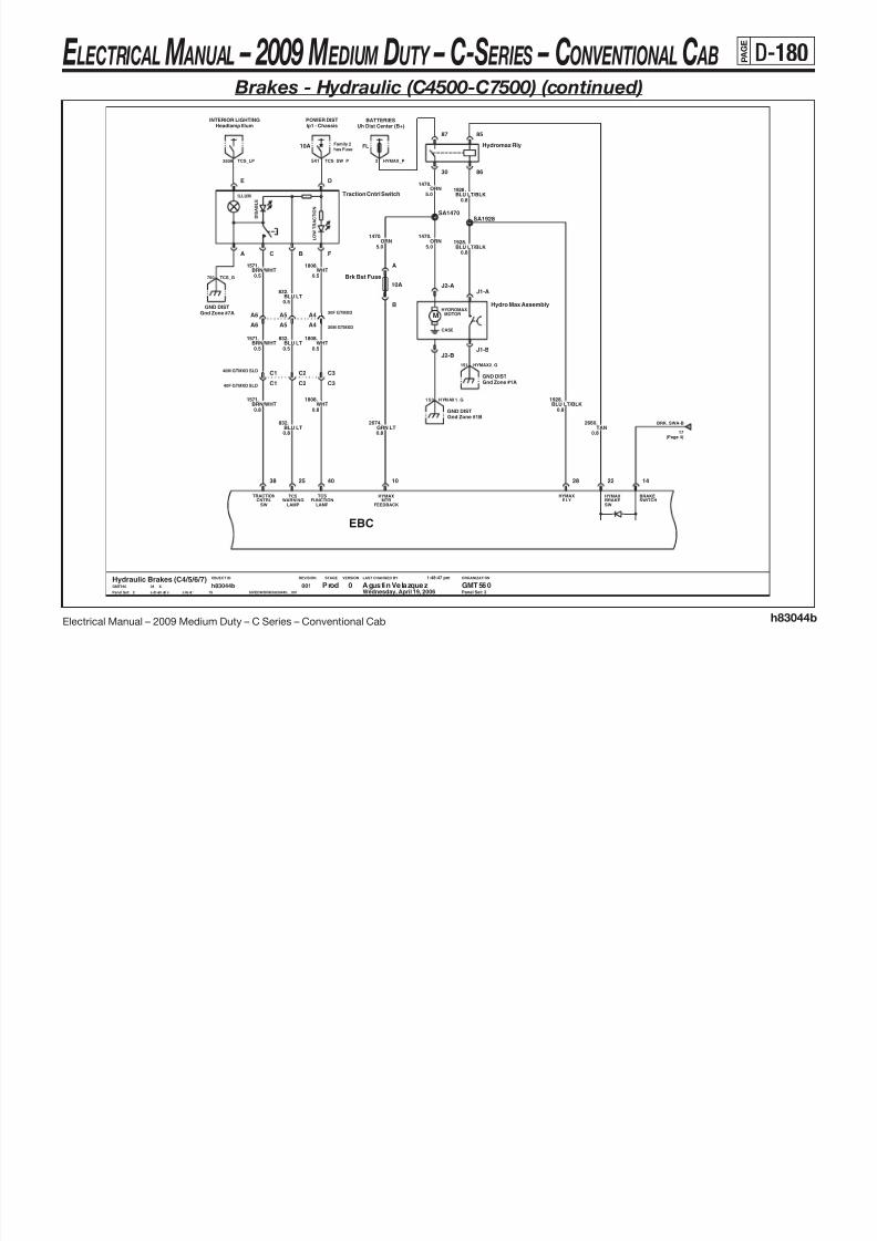
8/10/2019 2009 GM Medium Duty Electrical Manual.PDF
http://slidepdf.com/reader/full/2009-gm-medium-duty-electrical-manualpdf 291/410
Electrical Manual – 2009 Medium Duty – C Series – Conventional Cab h83044b
M
LAST CHANGED BY
Panel Set:
VERSIONSTAGEREVISIONOBJECT ID ORGANIZATION
Panel Set: 2
BRN/WHT1571.
0.8
A
B
10A
Brk Bst Fuse
38
LAMPFUNCTION
TCS
40
SWCNTRL
TRACTIONWARNING RLY
HYMAX
28
SWBRAKE
22
HYMAX
LAMP
25
TCSMTR
FEEDBACK
10
HYMAXSWITCHBRAKE
14
EBC
0.8
.832BLU LT
A6
J2-A
HYDROMAXMOTOR
CASE
J2-B
Hydro Max Assembly
J1-A
J1-B0.5
.1808
WHT0.5
5.0
.1470ORN
BRN/WHT
1571.
BLU LT/BLK1928.
0.8
ORN1470.
5.0
C2
Gnd Zone #7AGND DIST
0.5
.1571BRN/WHT
Gnd Zone #1BGND DIST
A4
C2
30F GTMXD
A5
F
L O W
A BC
C3
0.8
.1928BLU LT/BLK
30M GTMXDA4
TAN2660.
0.8
WHT1808.
0.8
C1
WHT1808.
0.5
40M GTMXD SLD
BLU LT832.
0.5
A6
C3
2
Prod Agustin Velazquez GMT5600Hydraulic Brakes (C4/5/6/7)GMT560 X08
Wednesday, April 19, 2006
1:48:47 pm
$IVEDWORK/h83044b__001s ch em ati c s he et 1
h83044b15
001
.832
BLU LT0.5
GND DISTGnd Zone #1A
40F GTMXD SLD C1
A5
0.8
.2674GRN LT
17(Page 4)
BRK_SWA-B
HYMAX2_G151
150 HYMAX1_G
TCS_G750
E LECTRICAL M ANUAL – 2009 M EDIUM DUTY – C-S ERIES – CONVENTIONAL C AB P A G E
D-181 Brakes - Hydraulic (C4500-C7500) (continued)
RRWSSLOW
WSSRR
HI
LRWSS
HIWSSLR
LOW ACTIVEABS
FRONTPAD WEAR
IND
26
PAD WEARREAR
23
IND
HYDROBOOST
19
EBC
Hydro Ebc

8/10/2019 2009 GM Medium Duty Electrical Manual.PDF
http://slidepdf.com/reader/full/2009-gm-medium-duty-electrical-manualpdf 292/410
Electrical Manual – 2009 Medium Duty – C Series – Conventional Cab h83044b
LAST CHANGED BY
Panel Set:
VERSIONSTAGEREVISIONOBJECT ID ORGANIZATION
Panel Set: 3
G
.1911BLU DK/WHT
8F GT280 SLD
BLU DK/WHT1911.
0.8
0.8
GRN DK/WHT
GRN DK/WHT1912.
0.8
0.8
.1912
0.8
.1916GRN LT/BLK
1917.
0.8
56
BLU LT/WHT
33 34 36
8F GT280 SLDC
BLU DK/WHT1911.
0.8
.1912GRN DK/WHT
8M GT280 SLDH
.1911BLU DK/WHT
0.8
8M GT280 SLD G
0.8
H8F GT280 SLD
0.8
.1912GRN DK/WHT
GRN DK/WHT1912.
0.8
A B
8F GT280 SLDH
Lr Wheel
3
00115
h83044bsheet1schematic $IVEDWORK/h83044b__001
1:48:47 pm
Wednesday, April 19, 200608 XGMT560
Hydraulic Brakes (C4/5/6/7)0 GMT560Agustin VelazquezProd
C
.
0.8
8M GT280 SLD
GRN DK/WHT1912.
0.8
BLU DK/WHT1911
H
0.8
.1911BLU DK/WHT
8M GT280 SLD
Rr Wheel
A B
8F GT280 SLDG
8M GT280 SLDG
E
E
E LECTRICAL M ANUAL – 2009 M EDIUM DUTY – C-S ERIES – CONVENTIONAL C AB P A G E
D-182 Brakes - Hydraulic (C4500-C7500) (continued)
Family 2
has Fuse
has Fuse
Family 2
Ip1 - Brake
10A
POWER DIST
40M GTMXD SLDB11
40F GTMXD SLD B1120A
Ip1 - Stop
POWER DIST
CAT ENGINE CNTLSEcu
86BRN
0.8
.
NC_CONT441 TCC_P
BRK SW PS

8/10/2019 2009 GM Medium Duty Electrical Manual.PDF
http://slidepdf.com/reader/full/2009-gm-medium-duty-electrical-manualpdf 293/410
Electrical Manual – 2009 Medium Duty – C Series – Conventional Cab h83044b
LAST CHANGED BY
Panel Set:
VERSIONSTAGEREVISIONOBJECT ID ORGANIZATION
Brake Switch
-
+
See Page 6 for Brake Switches
Panel Set: 4
x2x2 x2 x2
30M GTMXDB7
D
V8 ENG CNTLSPcm
0.5PPL
420.
1.0
1:48:47 pm
$IVEDWORK/h83044b__001s ch em ati c s he et 1
h83044b15
001
EXTERIOR LIGHTStop Lamps
.17WHT
B13
4
Prod Agustin Velazquez GMT5600Hydraulic Brakes (C4/5/6/7)GMT560 X08
Wednesday, April 19, 2006
B8
E
.140ORN
F
1.0
C
WHT17.
1.0WHT
17.
1.0
SA17
0.8
.451BLK/WHT
0.5PPL
420.
B6
WHT1.0
.17
POWER DISTIp2 - Brake Iso
DA
C
2.0WHT
17.
LF8 ENG CNTLS
30M GTMXD SLDB8
1.0
Ecu
30F GTMXD SLDB8
.140ORN
B5
B
B5
BRN86.
0.8
6F GT280
30F GTMXDB7
40M GTMXD SLDC7
1.0
.17WHT
B13
6M GT280B
B8
CAT ENGINE CNTLSEcu
BRN441.
0.5
A
F
E
40F GTMXD SLD
C7
B14
86.
0.8BRN
B6
PPL420.
0.5
B14
BRAKE_SW1
(Page 6)
BS_17
17420
BS_420
(Page 6)86
BS_86
(Page 6)
TCC_ECU 420 TCC_PCM
140
BS_140
(Page 6)441
BS_441
(Page 6) (Page 6)
BS_451
451
BRAKE_ISO_P
BRK_SW_P
(Page 2)
BRK_SWA-B
451 BR_SW_PPS

8/10/2019 2009 GM Medium Duty Electrical Manual.PDF
http://slidepdf.com/reader/full/2009-gm-medium-duty-electrical-manualpdf 294/410
E LECTRICAL M ANUAL – 2009 M EDIUM DUTY – C-S ERIES – CONVENTIONAL C AB P A G E
D-184 Brakes - Hydraulic (C4500-C7500) (continued)
BS_441 BS_140 BS_441BS_140 BS_451

8/10/2019 2009 GM Medium Duty Electrical Manual.PDF
http://slidepdf.com/reader/full/2009-gm-medium-duty-electrical-manualpdf 295/410
Electrical Manual – 2009 Medium Duty – C Series – Conventional Cab h83044b
LAST CHANGED BY
Panel Set:
VERSIONSTAGEREVISIONOBJECT ID ORGANIZATION
C4 ModelsC5/6/7 ModelsNote: Only contacts A & B are p olarized.
Panel Set: 6
Note: Only contacts E & F are polarized.
1.0ORN
140.
6
Prod Agustin Velazquez GMT5600Hydraulic Brakes (C4/5/6/7)GMT560 X08
Wednesday, April 19, 2006
1:48:47 pm
$IVEDWORK/h83044b__001s ch em ati c s he et1
h83044b15
001
PPL0.5
.420 .420PPL
0.5
D
E
F
.17WHT
1.0
Brake Switch - 3.1:1
-
A
+
B
C
0.8
.451BLK/WHT
1.0WHT
17.
.441BRN
0.5BRN
441.
0.5
BRN86.
0.8
C
D
E
+
F
-
Brake Switch - 6.5:1
A
B
140.
1.0ORN
BS_420
(Page 4)(Page 4)
BS_17
(Page 4)
BS_86 BS_17
(Page 4)
(Page 4) (Page 4) (Page 4)
(Page 4)
BS_420
(Page 4) (Page 4)
E LECTRICAL M ANUAL – 2009 M EDIUM DUTY – C-S ERIES – CONVENTIONAL C AB P A G E
D-185 Brakes - Air (C7500-C8500)
Lf Tcs Modulator
A BC
.
1.0
1906PPL
1.0
.1901GRAGRN DK
1900.
1.0
Rf Tcs Modulator
A BC
1.0TAN
1908..
1.0
1907YEL
.1902BLU LT1.0

8/10/2019 2009 GM Medium Duty Electrical Manual.PDF
http://slidepdf.com/reader/full/2009-gm-medium-duty-electrical-manualpdf 296/410
Electrical Manual – 2009 Medium Duty – C Series – Conventional Cab h83044c
LAST CHANGED BY
Panel Set:
VERSIONSTAGEREVISIONOBJECT ID ORGANIZATION
Panel Set: 1
0.8
.1912GRN DK/WHT
Rr Wheel
A B
0.8
BLK884.
.1917BLU LT/WHT
0.8
WSS
LOW
J3-4
AA LEFT
WSS
HI
J3-5
AA RIGHT
WSS
AA RIGHT
J3-6
LOW
AA LEFT
J3-3
HI
WSSWSS
J2-7
PMV
SA LEFTHOLD
J2-8
RELEASESA LEFT
PMV
HOLDSA RIGHT
PMV
J2-9
WSS
LOW
J2-2
DA LEFT
J2-3
DA RIGHT
WSS
HI
DA RIGHT
J2-4
LOW
J2-13J2-14
PMV
SA RIGHTCOMMON
WSS
J2-10
PMVSA RIGHTRELEASE COMMON
SA LEFTPMV
WSSLOW
J1-7
SA LEFTWSSLOW
J1-8
SA RIGHT DA LEFT
J2-1
HI
SA LEFT
J1-3
HIWSS
SA RIGHT
J1-4
HIWSS
EBC
L16F GT280 SLD
BLU DK/WHT1911.
0.8
M
Lf Wheel
A B
.1903GRN LT0.8
1910BRN/WHT
L Middle Wheel
A B
0.8
.
M
B
0.8
.885
Lr Wheel
A
GRN DK/WHT1912.
0.8
RED
16M GT280 SLDL
0.8WHT
1909.
Rf Wheel
A B A B
R Middle Wheel
GRN LT/BLK1916.
0.8 0.8
.882BRN
0.8WHT
883.1904.
0.8ORN
Air Brakes (C7/8)
1
Agustin Velazquez GMT5600GMT560 X08
Wednesday, April 19, 2006
1:50:11 pm
$IVEDWORK/h83044c__001s ch em ati c s he et1
h83044c11
001 Prod
.1911BLU DK/WHT
0.8
E LECTRICAL M ANUAL – 2009 M EDIUM DUTY – C-S ERIES – CONVENTIONAL C AB P A
G E
D-186 Brakes - Air (C7500-C8500) (continued)
40A Uh - Abs1POWER DIST
DE
ILLUM
F
Traction Cntrl Switch
L O W T
R A C T I O N
D I S A B L E
A BC
WHT1808.
0.5BLU LT832.
0.5
.1571BRN/WHT
Air Brake Relay30
85
86
87
J1939J1939
POWER DISTIp1 - Chassis10A
RED442.
3.0
SD441
10A Ip1 - BrakePOWER DIST
INTERIOR LIGHTINGHeadlamp Illum
Ttm - Trailer AbsTELL TALE
441.
0.8BRN
441 EBC_IGN3_P
AIR_J-2362
541 TCS_SW_P2509 TCS_LP
EBC_P

8/10/2019 2009 GM Medium Duty Electrical Manual.PDF
http://slidepdf.com/reader/full/2009-gm-medium-duty-electrical-manualpdf 297/410
Electrical Manual – 2009 Medium Duty – C Series – Conventional Cab h83044c
J1939
LAST CHANGED BY
Panel Set:
VERSIONSTAGEREVISIONOBJECT ID ORGANIZATION
Panel Set: 2
0.5
.1808WHT
DataDLC
J3-1
TRACTIONOFF
LAMP
J3-12
TCSENGAGE/ DISABLE
J2-5
INPUTBRK SW
J1-6
IGN
J1-9
GND
J1-2
LOW
J1587-A
J1-5
HIABS
TRAILER
J1-11J1-13
LOWTRACTION
LAMP
J1-14
BATT
J1-15
EBC
J1-1
J1587-B
A5
A5 30M GTMXDA4
30F GTMXDA4
0.5
.832BLU LT
0.8
BRN/WHT1571.
0.5
471.
0.5
WHT
471.
WHT
11
001Air Brakes (C7/8)
2
Prod Agustin Velazquez GMT5600GMT560 X08
Wednesday, April 19, 2006
1:50:11 pm
$IVEDWORK/h83044c__001s ch ema ti c s he et 1
h83044c
0.5BLU LT0.5
A6
0.5
A6
Gnd Zone #7AGND DIST
Gnd Zone #1A
C7
GND DISTDLCData
40F GTMXD SLD
0.8
SA1808
0.8
.1571
.1808WHT
C1
C1
BRN/WHT
0.8
.420PPL
GND DISTGnd Zone #2B/C
.
3.0PPL
2661
40M GTMXD SLDC7
BRN0.8
.441
J1939J1939
C2
C2 C3
C3
A3
40M GTMXD SLDA3
40F GTMXD SLD
0.8WHT
1808.0.8
.832BLU LT
TCS_SW
(Page 2)
AIR_BRK_G250
ABS_MOD
1571(Page 2)
TCS_SW
1922 SERIAL_2 AIR_G151SERIAL_11921
2 36 1 A IR _J +
7 50 T CS _G
BRK_SWC-D
(Page 5)420

8/10/2019 2009 GM Medium Duty Electrical Manual.PDF
http://slidepdf.com/reader/full/2009-gm-medium-duty-electrical-manualpdf 298/410
E LECTRICAL M ANUAL – 2009 M EDIUM DUTY – C-S ERIES – CONVENTIONAL C AB P A
G E
D-188 Brakes - Air (C7500-C8500) (continued)
POWER DIST
20A Ip1 - Stop
H 8M MP280
ORN140.
1.0
H8F MP280
CAT ENGINE CNTLSEcu
86BRN
0.8
.
1.0
.140ORN
SA140
ORN140.
1.0
(Page 5)
BRAKE_1420
BRK_SW_P
NC_CONT

8/10/2019 2009 GM Medium Duty Electrical Manual.PDF
http://slidepdf.com/reader/full/2009-gm-medium-duty-electrical-manualpdf 299/410
Electrical Manual – 2009 Medium Duty – C Series – Conventional Cab h83044c
LAST CHANGED BY
Panel Set:
VERSIONSTAGEREVISIONOBJECT ID ORGANIZATION
Panel Set: 4
Note: Only contacts E & F are polarized.
.140ORN
1.0
00111
h83044csheet1schematic $IVEDWORK/h83044c__001
1:50:11 pm
Wednesday, April 19, 200608 XGMT560
Air Brakes (C7/8)0 GMT560Agustin VelazquezProd
4
B8
EXTERIOR LIGHTStop Lamps
10A
POWER DISTIp1 - Brake
B5
40M GTMXD SLD B11
B5
.420PPL
0.5
D
B8
B13
8M MP280G
8F MP280G
30F GTMXDB7
Trailer Stop Sw
A
BBRN
86.
0.8
BRN86.
0.8
WHT17.
1.0
F
B6
B11
D
40F GTMXD SLD
+
F
-
WHT17.
1.0
B13
Brake Switch - 6.5:1
A
B
C
D
E
1.0
WHT17.
C
WHT17.
0.8
.451BLK/WHT
1.0
6M GT280B
BRN441.
0.5
B6
C
1.0
.17WHT
ORN140.
1.0
BRN441.
0.5
.140ORN
1.0
0.5PPL
420.
E
F
B14
E
BRN
A
0.8
.8617.
1.0WHT
B7B14
ORN
30M GTMXD
SA17
1.0
.140
BLK/WHT451.
0.8
6F GT280B
CAT ENGINE CNTLSEcu
Ip2 - Brake Iso
A
POWER DIST
.17WHT
1.0
BRAKE_ISO_PBRAKE_SW1
441 TCC_P
451 BR_SW_PPS
E LECTRICAL M ANUAL – 2009 M EDIUM DUTY – C-S ERIES – CONVENTIONAL C AB P A
G E
D-189 Brakes - Air (C7500-C8500) (continued)
POWER DISTIp1 - Chassis
BRAKE_1
(Page 4)

8/10/2019 2009 GM Medium Duty Electrical Manual.PDF
http://slidepdf.com/reader/full/2009-gm-medium-duty-electrical-manualpdf 300/410
Electrical Manual – 2009 Medium Duty – C Series – Conventional Cab h83044c
LAST CHANGED BY
Panel Set:
VERSIONSTAGEREVISIONOBJECT ID ORGANIZATION
Panel Set: 5
SA420
L18 ENG CNTLSPcm
0.5
.541BRN
BRN
541.
0.8
420.
0.5PPL
40F GTMXD SLDA1
0.5PPL
420.
0.5PPL
420.
10A
30M GTMXD SLDB8
B8 30F GTMXD SLD
A1
Gnd Zone #3BGND DIST
40M GTMXD SLD
5
Prod Agustin Velazquez GMT5600Air Brakes (C7/8)GMT560 X08
Wednesday, April 19, 2006
1:50:11 pm
$IVEDWORK/h83044c__001s ch ema ti c s he et 1
h83044c11
001
PPL0.5
.420
Air Dryer Heater Sw
A
B
LF8 ENG CNTLS
PPL0.5
.420
Ecu
BRK_SWC-D
(Page 2)
350 AIR_DRY_G
420 TCC_PCM
AIR_DRY_P
TCC_ECU
E LECTRICAL M ANUAL – 2009 M EDIUM DUTY – C-S ERIES – CONVENTIONAL C AB P A
G E
D-190 Park Brake (Family 2)
-T62
IP CLUSTERPark Brake
BLU LT1134.
.1134BLU LT0.5
P_BRK
1134 PRK_BRK_SW
DRLDrl Module

8/10/2019 2009 GM Medium Duty Electrical Manual.PDF
http://slidepdf.com/reader/full/2009-gm-medium-duty-electrical-manualpdf 301/410
Electrical Manual – 2009 Medium Duty – C Series – Conventional Cab h83046a
LAST CHANGED BY
Panel Set:
VERSIONSTAGEREVISIONOBJECT ID ORGANIZATION
LCT
Panel Set: 1
Gnd Zone #7AGND DIST
Park Brake Switch - Hydro
Orschelon Hand Brake
A
B
.750BLK
0.5
B
2M GT150B
2M GT150A
2F GT150
Case Gnd
2F GT150A
0.5 SA1134
GND DIST
0.5BLU LT
1134.
0.5
Park Brake Switch - Foot
A
CASE
BLU LT
1134.
BLK0.5
0.5BLU LT
1134.
Wednesday, April 19, 2006001
3
h83046asheet1schematic $IVEDWORK/h83046a__001
1:51:08 pm
08 XGMT560
Park Brake (Family 2)0 GMT560Agustin VelazquezProd
1
.750
P_BRK_G
FOOT_G
E LECTRICAL M ANUAL – 2009 M EDIUM DUTY – C-S ERIES – CONVENTIONAL C AB P A
G E
D-191 Park Brake (Family 3)
&JE4&JE3
SA1134
DRLDrl Module Park Brake
IP CLUSTER
.1134BLU LT0.5
P_BRK1134 PRK_BRK_SW
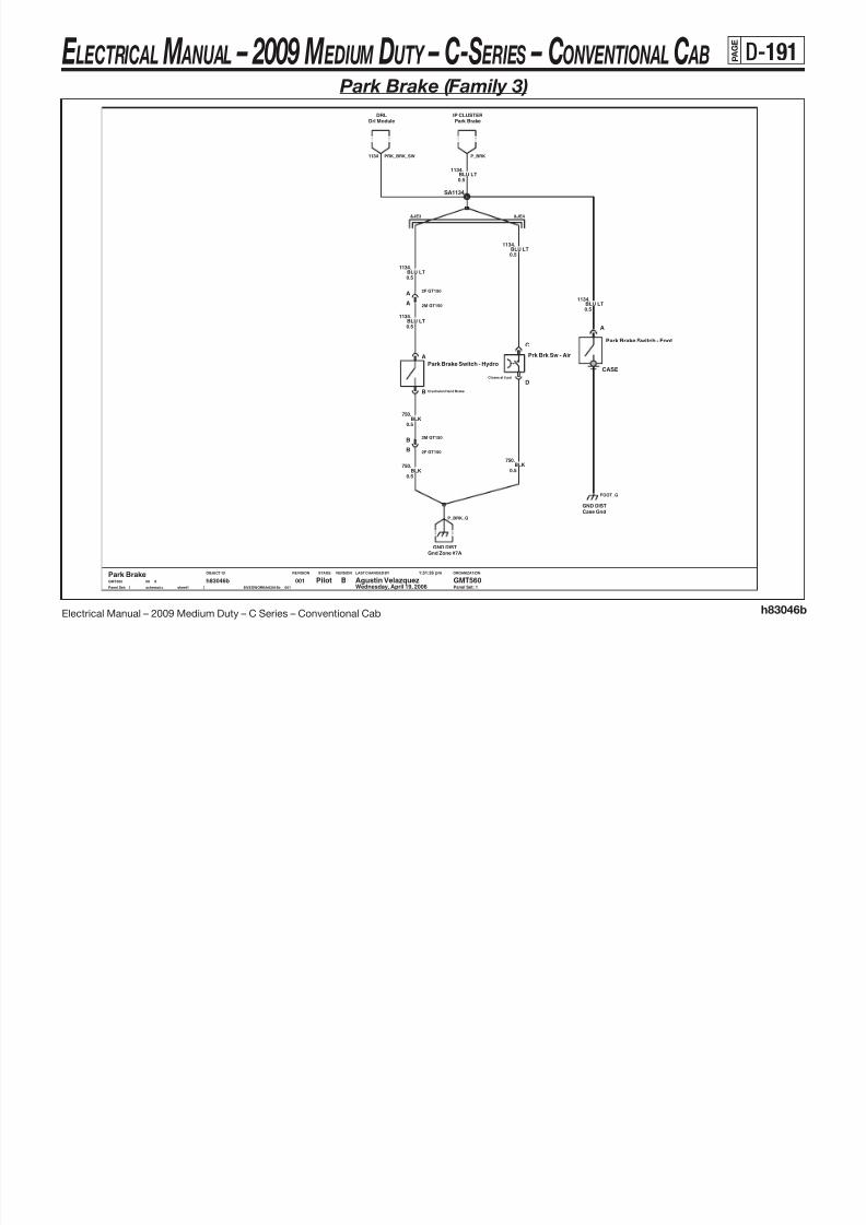
8/10/2019 2009 GM Medium Duty Electrical Manual.PDF
http://slidepdf.com/reader/full/2009-gm-medium-duty-electrical-manualpdf 302/410
Electrical Manual – 2009 Medium Duty – C Series – Conventional Cab h83046b
LAST CHANGED BY
Panel Set:
VERSIONSTAGEREVISIONOBJECT ID ORGANIZATION
.1134BLU LT
Panel Set: 1
Park BrakeB GMT560Agustin VelazquezPilot
1
Park Brake Switch - Foot
A
CASE
0.5
Case GndGND DIST
Wednesday, April 19, 2006001
3
h83046bsheet1schematic $IVEDWORK/h83046b__001
1:51:26 pm
08 XGMT560
0.5BLK
750.
D
0.5BLK
750.
GND DISTGnd Zone #7A
Orschelon Hand Brake
Park Brake Switch - Hydro
A
B
Prk Brk Sw - Air
Closes at 5 psi
C
0.5
0.5BLK
750.
2F GT150A
BLU LT1134.
0.5
2M GT150A
0.5BLU LT
1134.
.1134BLU LT
2F GT150B
FOOT_G
P_BRK_G
2M GT150B

8/10/2019 2009 GM Medium Duty Electrical Manual.PDF
http://slidepdf.com/reader/full/2009-gm-medium-duty-electrical-manualpdf 303/410
E LECTRICAL M ANUAL – 2009 M EDIUM DUTY – C-S ERIES – CONVENTIONAL C AB P A
G E
D-193SIR (continued)
Family 2
has Fuse
has FuseFamily 2
Dual SIRDriver only
has Fuse
Family 2
POWER DISTIp1 - Sir
10A
B C D
PSIR Defeat Switch
Ip1 - Sir
10A
Headlamp Sw - Radio DimmerINTERIOR LIGHTINGPOWER DIST
10A
Dimmer Signal DistINTERIOR LIGHTING
SIR_OHM_P1139
PSIR_DIM8
1382 STEP_DIM1 13 9 P SI R_ P

8/10/2019 2009 GM Medium Duty Electrical Manual.PDF
http://slidepdf.com/reader/full/2009-gm-medium-duty-electrical-manualpdf 304/410
Electrical Manual – 2009 Medium Duty – C Series – Conventional Cab h83047a
ILLUM
OFF
ON
LAST CHANGED BY
Panel Set:
VERSIONSTAGEREVISIONOBJECT ID ORGANIZATION
has FuseFamily 2
Page 2ΩΩ
Page 1
Panel Set: 2
24.7 k
SIR RESISTOR
Driver only Dual SIR
.353PNK
0.5
B3
.2260
0.5GRA
0.5
2260.GRA
J
1834.YEL
0013
h83047asheet1schematic $IVEDWORK/h83047a__001
1:52:03 pm
Wednesday, April 19, 200608 XGMT560
Sir0 GMT560Agustin VelazquezProd
2
10A
Ip1 - SirPOWER DIST
0.8
A7
40M GTMXD SLDA7
353.PNK
40F GTMXD SLD
A11
0.5
AE F
.371
0.5TAN/BLK
PSIR Defeat Switch
K
YEL0.5
1834.
16M GT280K
16F GT280
AB
371.
0.5TAN/BLK
WARN LAMPPRESENCE N.O./
PASSENGER
A9
SATELLITEDRIVER
B5
DRIVERSATELLITE
RTN
B6
Front Sensor
A10
SDM
Airbag ModuleIGN 1
A1
SENSOR
AUTOMATICOCCUPANCY
L
30F GTMXDA10
16F GT280S
B3
YEL.1834
0.5
371.TAN/BLK0.5
L
0.5
353.PNK
D
J
Sir Resist Pack - 4pt7 Kohm
4 .
7
k
Ω
C
16M GT280S
A11
30M GTMXDA10
PNK.353
Gnd Zone #7AGND DIST
0.5
.2260
0.8GRA
SDM_P1139
PSIR_G750
E LECTRICAL M ANUAL – 2009 M EDIUM DUTY – C-S ERIES – CONVENTIONAL C AB P A
G E
D-194 Rear Air Suspension
SA1944
.1944BLU DK0.8
0.8BLU DK
1944.
INTERIOR LIGHTING
10A
Ip1 - ChassisPOWER DIST
0.8
Headlamp Illum
30F GTMXD
A7
.1944
BLU DKA7
30M GTMXD
BD
LED Air Suspension Sw
A
12V ILLUM
AIR_SUSP_P541 AIR_SUSP_LP2509
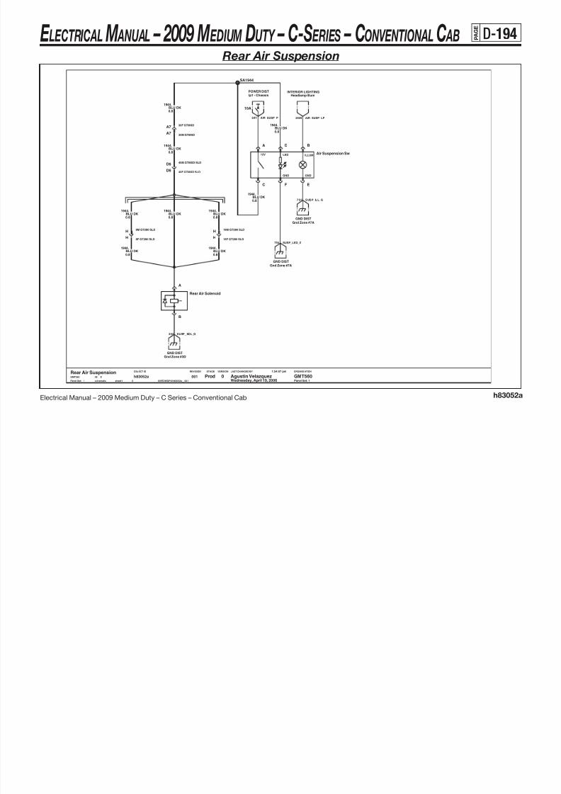
8/10/2019 2009 GM Medium Duty Electrical Manual.PDF
http://slidepdf.com/reader/full/2009-gm-medium-duty-electrical-manualpdf 305/410
Electrical Manual – 2009 Medium Duty – C Series – Conventional Cab h83052a
LAST CHANGED BY
Panel Set:
VERSIONSTAGEREVISIONOBJECT ID ORGANIZATION
.1944BLU DK
Panel Set: 1
8F GT280 SLDH
0.8BLU DK
1944.
0.8BLU DK
16F GT280 SLDH
0.8
.1944
8M GT280 SLDH
16M GT280 SLDH
BLU DK0.8
.1944
40F GTMXD SLDD6
Gnd Zone #7A
GND DIST
GND DISTGnd Zone #3D
GND DISTGnd Zone #7A
.1944BLU DK0.8
0.8BLU DK
B
40M GTMXD SLDD6
1944.
C
GND
EF
GND
Rear Air Solenoid
A
h83052asheet1schematic $IVEDWORK/h83052a__001
1:54:07 pm
Wednesday, April 19, 200608 XGMT560
Rear Air Suspension0 GMT560Agustin VelazquezProd
1
350 SUSP_SOL_G
750 SUSP_ILL_G
SUSP_LED_G750
0015
E LECTRICAL M ANUAL – 2009 M EDIUM DUTY – C-S ERIES – CONVENTIONAL C AB P A
G E
D-195 Data Link Connector
x3
GND DISTGnd Zone #4A
GND DIST
RKERfa Module
STARR CONNECTORClass 2
Gnd Zone #7A
J1587-BAIR BRAKES
SpliceDATA LINK CONN
DTCJ1708+
AIR BRAKESJ1587-A J1708-
DTC
GMLAN_126105
DATA_LOW
CAT_MD-
(P 2)1922
1451 DATA2_G
SERIAL_1SERIAL_2 DATA_HI
DATA1_G750
(Page 1)
DLC+
1921
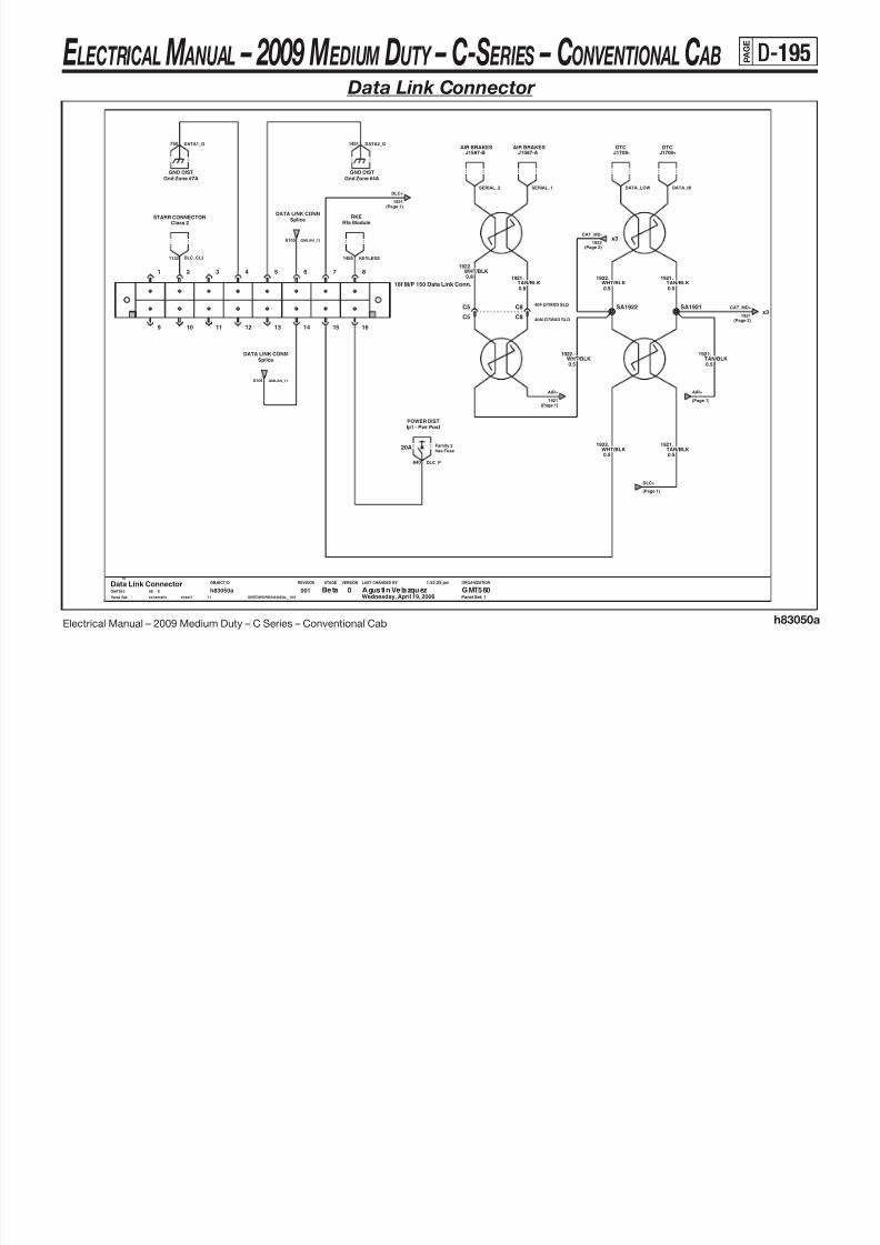
8/10/2019 2009 GM Medium Duty Electrical Manual.PDF
http://slidepdf.com/reader/full/2009-gm-medium-duty-electrical-manualpdf 306/410
Electrical Manual – 2009 Medium Duty – C Series – Conventional Cab h83050a
LAST CHANGED BY
Panel Set:
VERSIONSTAGEREVISIONOBJECT ID ORGANIZATION
x3
Panel Set: 1
N
has FuseFamily 2
C5
POWER DISTIp1 - Pwr Post
20A
WHT/BLK1922.
4 5 6 7 8
9
0.5
12 13 14 15 16
2 3
16f M/P 150 Data Link Conn.
1
10 11
0.5
.1922WHT/BLK
C5
SA1921
0.5
.1921TAN/BLK
WHT/BLK1922.
0.8
Splice
.1922WHT/BLK0.5
DATA LINK CONN
SA1922
0.8
.1921TAN/BLK
C8
sheet1
h83050a11
001
40F GTMXD SLD
Data Link Connector
1
Beta Agustin Velazquez GMT5600GMT560 X08
Wednesday, April 19, 2006
1:52:25 pm
$IVEDWORK/h83050a__001schematic
TAN/BLK1921.
0.5
.1921TAN/BLK0.5
40M GTMXD SLDC8
6106 GMLAN_11
(Page 2)
840 DLC_P
AIR+
(Page 1)
1921
CAT_MD+
(Page 2)
(Page 1)
AIR+
1921
1132 DLC_CL2 1455 KEYLESS
DLC+
(Page 1)
E LECTRICAL M ANUAL – 2009 M EDIUM DUTY – C-S ERIES – CONVENTIONAL C AB P A
G E
D-196 Data Link Connector (continued)
LF6LF6
EcuENGINE CONTROLS ENGINE CONTROLSEcu
J1587- J1587+

8/10/2019 2009 GM Medium Duty Electrical Manual.PDF
http://slidepdf.com/reader/full/2009-gm-medium-duty-electrical-manualpdf 307/410
Electrical Manual – 2009 Medium Duty – C Series – Conventional Cab h83050a
LAST CHANGED BY
Panel Set:
VERSIONSTAGEREVISIONOBJECT ID ORGANIZATION
Panel Set: 2
40M GTMXD SLDB2
C240F GTMXD SLDB2
C2
1922WHT/BLK0.5
.
GMT560
Data Link Connector0 GMT560Agustin VelazquezBeta
2
00111
h83050asheet1schematic $IVEDWORK/h83050a__001
1:52:25 pm
Wednesday, April 19, 200608 X
0.5TAN/BLK
1921.
.1922WHT/BLK0.8 0.8
TAN/BLK1921.
CAT_MD-
(Page 1)
(Page 1)
CAT_MD+
E LECTRICAL M ANUAL – 2009 M EDIUM DUTY – C-S ERIES – CONVENTIONAL C AB P A
G E
D-197 Data Link Connector (continued)
.6106BLU LT
0.8
Tcm
TRANSMISSION
DATA LINK CONNDlc
TRANSMISSION
Tcm Tcm
TRANSMISSION
DlcDATA LINK CONN
TRANSMISSIONTcmGMLAN Terminator
AB
GMLAN_13
GMLAN_146105 6105 GMLAN_8
GMLAN_76106
GMLAN_12
GMLAN_11
6106

8/10/2019 2009 GM Medium Duty Electrical Manual.PDF
http://slidepdf.com/reader/full/2009-gm-medium-duty-electrical-manualpdf 308/410
Electrical Manual – 2009 Medium Duty – C Series – Conventional Cab h83050a
LAST CHANGED BY
Panel Set:
VERSIONSTAGEREVISIONOBJECT ID ORGANIZATION
D2
Panel Set: 3
DATA LINK CONN
GMLAN Conf
DATA LINK CONN
GMLAN Conf
GMLAN Conf
DATA LINK CONN
C330M GTMXD SLD
0.8
.6106BLU LT
0.8
.6105BLU DK
6105.
0.8
BLU DK
GMLAN Conf
DATA LINK CONN
SA6105
DATA LINK CONNGMLAN ConfGMLAN Conf
DATA LINK CONN
SA6106
.6105BLU DK0.8
0.8
BLU DK6105.
3
X Agustin Velazquez GMT5600Data Link ConnectorGMT560 X08
W ed ne sd ay , Ap ri l 1 9, 2 00 6 1 :5 2:2 5 p m$IVEDWORK/h83050a__001s ch em ati c s he et 1
h83050a11
001
D4D230M GTMXD SLD
30F GTMXD SLDC3D2D2
TRANSMISSIONTcm
0.8BLU LT
6106.
BLU LT
DATA LINK CONNGMLAN Conf
6106.
0.8
TcmTRANSMISSION
GMLAN ConfDATA LINK CONN
30F GTMXD SLDD4
GMLAN_5_2 GMLAN_5_1
6106 GMLAN_5_2
GMLAN_56106
GMLAN_6_2
GMLAN_6_26105 6105 GMLAN_6_3
GMLAN_6_3
6105 GMLAN_6
GMLAN_5_16106
E LECTRICAL M ANUAL – 2009 M EDIUM DUTY – C-S ERIES – CONVENTIONAL C AB P A
G E
D-198Serial Data Link (Class 2)
LCT
24702470
SdmSIR
1128
TcmTRANSMISSIONRADIO
TRANSMISSIONTcm
Radio
1122
SERIAL DATA GATEWAYClass 2
SDM_CL2
LCT_CL2
LCT_CL2
HYDRO BRAKESEbc
2673 SDG_CL2 RADIO_CL2 HYDRO_CL2

8/10/2019 2009 GM Medium Duty Electrical Manual.PDF
http://slidepdf.com/reader/full/2009-gm-medium-duty-electrical-manualpdf 309/410
Electrical Manual – 2009 Medium Duty – C Series – Conventional Cab h83055a
LAST CHANGED BY
Panel Set:
VERSIONSTAGEREVISIONOBJECT ID ORGANIZATION
Panel Set: 1
ACTIVE TRANSFER CASE
BLU LT1122.
0.5
YEL
0.5
.2470
4WD ATC Mdl
GRA
30M GTMXD SLDC6
.1133GRN DK/WHT
0.50.5
.1036
YEL2470.
IP CLUSTERClass 2
0.8YEL
2470.
0.8
C6
30M GTMXD SLDC6
CHIME MODULEChime Module
30F GTMXD SLD
BLU DK
30F GTMXD SLDC6
0.5
.1128
Class 2DLC ENGINE CNTLS
Pcm/ Ecu
L M
PPL1132.
0.5
C D E F
G H
J K
Datalink Splice Class2
A B
.2470YEL
0.5
0.8
ORN
BLU LT1122.
0013
h83055asheet1schematic $IVEDWORK/h83055a__001
1:52:48 pm
Wednesday, April 19, 200608 XGMT560
Serial Data Link (Class 2)0 GMT560Agustin VelazquezBeta
1
0.5
.1044
16M GT280H
0.5
16F GT280H40M GTMXD SLD A8
BLU DK1128.
40F GTMXD SLDA8
CL2ATCDLC_CL2 104 9 EN G_CL2
IP_CL2
653 CHIME_CL2
E LECTRICAL M ANUAL – 2009 M EDIUM DUTY – C-S ERIES – CONVENTIONAL C AB P A
G E
D-199Serial Data Gateway
Ip1 - Trans
10A
LF8: 25A
POWER DISTJ1939J1939
L18/LMM/LF6: 10A
Uh - Pcm BPOWER DIST J1939
J1939
SDG_1_P440 2 36 1 S DG _J +
2 36 2 S DG _J -1020 SDG_2_P

8/10/2019 2009 GM Medium Duty Electrical Manual.PDF
http://slidepdf.com/reader/full/2009-gm-medium-duty-electrical-manualpdf 310/410
Electrical Manual – 2009 Medium Duty – C Series – Conventional Cab h83056a
LAST CHANGED BY
Panel Set:
VERSIONSTAGEREVISIONOBJECT ID ORGANIZATION
GND DISTGnd Zone #4A
Panel Set: 1
A2
GND
A4
A6
BATT
A8
CLASS 2
SHIELD
B1
IGN 0
B6
Sdg Module
SDG
A1
LOW
J1939
HI
RED/WHT2673.
0.5
STARR CONNECTOR
1
Beta Agustin Velazquez GMT5600Serial Data GatewayGMT560 X08
Wednesday, April 19, 2006
1:53:23 pm
$IVEDWORK/h83056a__001s ch ema ti c s he et 1
h83056a10
001
Class 2
SDG_G1451 SDG_CL2

8/10/2019 2009 GM Medium Duty Electrical Manual.PDF
http://slidepdf.com/reader/full/2009-gm-medium-duty-electrical-manualpdf 311/410
E LECTRICAL M ANUAL – 2009 M EDIUM DUTY – C-S ERIES – CONVENTIONAL C AB P A
G E
D-201 J1939 - (L18) 8.1L V8 GMPT VORTEC® - Gas – (LF8) 7.8L L6 Isuzu 6H - Diesel –
(LF6) 7.2L L6 Caterpillar ® C7 - Diesel
(Page 1)
DTC-
2362
DTC-
(Page 1)

8/10/2019 2009 GM Medium Duty Electrical Manual.PDF
http://slidepdf.com/reader/full/2009-gm-medium-duty-electrical-manualpdf 312/410
Electrical Manual – 2009 Medium Duty – C Series – Conventional Cab h83057a
LAST CHANGED BY
Panel Set:
VERSIONSTAGEREVISIONOBJECT ID ORGANIZATION
Panel Set: 1
DTC
Dtc
YEL0.5
.2361
Dtc
DTC
2362.
0.5GRN DK
GRN DK2362.
0.8 0.8
.2361YEL
YEL2361.
0.50.5
.2362GRN DK
08 XGMT560
J1939 (l18/Lf8/Lf6)0 GMT560Agustin VelazquezBeta
1
0013
h83057asheet1schematic $IVEDWORK/h83057a__001
1:53:40 pm
Wednesday, April 19, 2006
SB2362
SB2361
YEL0.5GRN DK
2362.
0.5
.2361
AB
J1939 Terminator
(Page 2)
DAMU+DAMU-
(Page 2)
SDG+
(Page 2)(Page 2)
SDG-
(Page 1)
DTC_J- DTC_J+
E LECTRICAL M ANUAL – 2009 M EDIUM DUTY – C-S ERIES – CONVENTIONAL C AB P A
G E
D-202 J1939 - (L18) 8.1L V8 GMPT VORTEC® - Gas – (LF8) 7.8L L6 Isuzu 6H - Diesel –
(LF6) 7.2L L6 Caterpillar ® C7 - Diesel (continued)
YEL2361.
0.5
.2362GRN DK0.5
2362
SHIFT_SEL-
(Page 2)
L6_IP_ENG-
(Page 3) (Page 3)
L6_IP_ENG+
2361
SHIFT_SEL+
(Page 2)
DAMU+
2361
(Page 2)
SDG+SDG-
(Page 2)
2362
DAMU-
(Page 1)
(Page 1)

8/10/2019 2009 GM Medium Duty Electrical Manual.PDF
http://slidepdf.com/reader/full/2009-gm-medium-duty-electrical-manualpdf 313/410
Electrical Manual – 2009 Medium Duty – C Series – Conventional Cab h83057a
LAST CHANGED BY
Panel Set:
VERSIONSTAGEREVISIONOBJECT ID ORGANIZATION
Panel Set: 2
GRN DK2362.
0.5
2361.
0.5
YEL
YEL2361.
0.50.5
.2362GRN DK
YEL0.5
GRN DK2362. .2361
0.5
SR2362
SD2362 SD2361
SH2362 SH23610.5
YEL2361.
0.5
.2362GRN DK
0013
h83057asheet1schematic $IVEDWORK/h83057a__001
1:53:40 pm
Wednesday, April 19, 200608 XGMT560
J1939 (l18/Lf8/Lf6)0 GMT560Agustin VelazquezBeta
2
ENG CTRLSDaMU
ENG CTRLS
0.8
MD TRANSMISSIONTcm
DaMU
YEL2361.
0.5
YEL2361.
0.5
.2362GRN DK
0.5GRN DK
2362. .2361YEL
0.5
Sdg SdgSDGSDG
SR2361
.2362GRN DK
TcmMD TRANSMISSION
0.8
2361
SDG+
(Page 1,2)
(Page 1,2)
SDG-
2362
C_IP_ENG+
(Page 3)(Page 3)
C_IP_ENG-
( g )( g )
SHIFT_J-
SHIFT_J+
DAMU_J+
V8_IP_ENG+
(Page 3)
SDG_J- SDG_J+
(Page 2)
SHIFT_SEL- SHIFT_SEL+
(Page 2)
(Page 3)
V8_IP_ENG-
DAMU_J-
E LECTRICAL M ANUAL – 2009 M EDIUM DUTY – C-S ERIES – CONVENTIONAL C AB P A
G E
D-203 J1939 - (L18) 8.1L V8 GMPT VORTEC® - Gas – (LF8) 7.8L L6 Isuzu 6H - Diesel –
(LF6) 7.2L L6 Caterpillar ® C7 - Diesel (continued)
2362
C_IP_ENG-
(Page 2)
2361
C_IP_ENG+
(Page 2)
(Page 2)
L6_IP_ENG+
2361
(Page 2)
L6_IP_ENG-
2362
2362
V8_IP_ENG-
(Page 2)
2361
V8_IP_ENG+
(Page 2)

8/10/2019 2009 GM Medium Duty Electrical Manual.PDF
http://slidepdf.com/reader/full/2009-gm-medium-duty-electrical-manualpdf 314/410
Electrical Manual – 2009 Medium Duty – C Series – Conventional Cab h83057a
LAST CHANGED BY
Panel Set:
VERSIONSTAGEREVISIONOBJECT ID ORGANIZATION
Panel Set: 3
24F GTMXD SLDC6
24M GTMXD SLDC6
C8
40M GTMXD SLDC8
.2361YEL
40F GTMXD SLD
GRN DK2362.
0.8
0.8
0.8
.
C9
YEL2361.
2362
GRN DK
0.8
C9 C8
C9
40M GTMXD SLD
3
h83057asheet1schematic $IVEDWORK/h83057a__001
1:53:40 pm
Wednesday, April 19, 200608 XGMT560
J1939 (l18/Lf8/Lf6)0 GMT560Agustin VelazquezBeta
3
001
C7
C7
40F GTMXD SLDC8
0.8
C9
.2361YEL
0.8GRN DK
2362.
(Page 5)
BRAKE+
BRAKE-
(Page 5)
ECU-
(Page 7)
(Page 7)
ECU+
ECU-
(Page 7)
(Page 7)
ECU+
2361
TCM+
(Page 4)
2362(Page 4)
TCM-
E LECTRICAL M ANUAL – 2009 M EDIUM DUTY – C-S ERIES – CONVENTIONAL C AB P A
G E
D-204 J1939 - (L18) 8.1L V8 GMPT VORTEC® - Gas – (LF8) 7.8L L6 Isuzu 6H - Diesel –
(LF6) 7.2L L6 Caterpillar ® C7 - Diesel (continued)
23610 8
.2361YEL
2362.
0.8GRN DK
2362
TCM-
GPCM-
(Page 7)
BRAKE-
(Page 7)
GPCM+
BRAKE+
TCM+
(Page 3)(Page 3)

8/10/2019 2009 GM Medium Duty Electrical Manual.PDF
http://slidepdf.com/reader/full/2009-gm-medium-duty-electrical-manualpdf 315/410
Electrical Manual – 2009 Medium Duty – C Series – Conventional Cab h83057a
LAST CHANGED BY
Panel Set:
VERSIONSTAGEREVISIONOBJECT ID ORGANIZATION
Panel Set: 4
YEL2361.
0.8
GRN DK0.8
.2361YEL
2362.
0.8
YEL
TcmLCT TRANSMISSIONLCT TRANSMISSION
Tcm
0.8
.2361
0.8GRN DK
2362.
TcmMD TRANSMISSION
GRN DK2362.
0.8
0.8
0.8
.2362
0.8
.2361YEL
GRN DK
MD TRANSMISSIONTcm
SK2362
SK2361
Wednesday, April 19, 200608 XGMT560
J1939 (l18/Lf8/Lf6)0 GMT560Agustin VelazquezBeta
4
0013
h83057asheet1schematic $IVEDWORK/h83057a__001
1:53:40 pm
2362
BRAKE
(Page 5) (Page 5)
BRAKE+
2362
TCM_2-
(Page 7)2362 2362
TCM_2+
(Page 7)
LCT_J- LCT_J+MD_J+MD_J-
E LECTRICAL M ANUAL – 2009 M EDIUM DUTY – C-S ERIES – CONVENTIONAL C AB P A
G E
D-205 J1939 - (L18) 8.1L V8 GMPT VORTEC® - Gas – (LF8) 7.8L L6 Isuzu 6H - Diesel –
(LF6) 7.2L L6 Caterpillar ® C7 - Diesel (continued)
(Page 3,4,7)
BRAKE+
2361
(Page 3,4,7)
BRAKE-
2362

8/10/2019 2009 GM Medium Duty Electrical Manual.PDF
http://slidepdf.com/reader/full/2009-gm-medium-duty-electrical-manualpdf 316/410
Electrical Manual – 2009 Medium Duty – C Series – Conventional Cab h83057a
LAST CHANGED BY
Panel Set:
VERSIONSTAGEREVISIONOBJECT ID ORGANIZATION
Panel Set: 5
GRN DK0.8
.2362
2362.
0.8GRN DK
2361.
0.8YEL
Wednesday, April 19, 200608 XGMT560
J1939 (l18/Lf8/Lf6)0 GMT560Agustin VelazquezBeta
5
0013
h83057asheet1schematic $IVEDWORK/h83057a__001
1:53:40 pm
30M GTMXD SLDC5
C5 30F GTMXD SLD
C6
C6 2361 YEL0.8
.(Page 6)
AIR+
AIR-
(Page 6)
TERMINATE+
(Page 6)
(Page 6)
TERMINATE-
E LECTRICAL M ANUAL – 2009 M EDIUM DUTY – C-S ERIES – CONVENTIONAL C AB P A
G E
D-206 J1939 - (L18) 8.1L V8 GMPT VORTEC® - Gas – (LF8) 7.8L L6 Isuzu 6H - Diesel –
(LF6) 7.2L L6 Caterpillar ® C7 - Diesel (continued)
x3
x3
TERMINATE-
2362
(Page 5,6)
TERMINATE+
2361
2362
AIR-
(Page 5)
2361
AIR+
(Page 5)

8/10/2019 2009 GM Medium Duty Electrical Manual.PDF
http://slidepdf.com/reader/full/2009-gm-medium-duty-electrical-manualpdf 317/410
Electrical Manual – 2009 Medium Duty – C Series – Conventional Cab h83057a
LAST CHANGED BY
Panel Set:
VERSIONSTAGEREVISIONOBJECT ID ORGANIZATION
Panel Set: 6
J1939 Terminator
AB
YEL2361.
0.8
sheet1schematic $IVEDWORK/h83057a__001
1:53:40 pm
Wednesday, April 19, 200608 XGMT560
J1939 (l18/Lf8/Lf6)0 GMT560Agustin VelazquezBeta
6
0013
h83057a
AIR BRAKESEbc
SU2362 SU2361
2361.
0.8YELGRN DK
0.8
.2362
EbcAIR BRAKES
GRN DK0.8
.2362
(Page 6)
TERMINATE+TERMINATE-
(Page 6)
(Page 5,6)2362
AIR_J- AIR_J+
E LECTRICAL M ANUAL – 2009 M EDIUM DUTY – C-S ERIES – CONVENTIONAL C AB P A
G E
D-207 J1939 - (L18) 8.1L V8 GMPT VORTEC® - Gas – (LF8) 7.8L L6 Isuzu 6H - Diesel –
(LF6) 7.2L L6 Caterpillar ® C7 - Diesel (continued)
.23612362.(Page 7)
GPCM- GPCM+
(Page 7)
TCM_2+
(Page 4)(Page 4)
TCM_2-
2362(Page 3)
ECU-
(Page 3)
ECU+
2361
GPCM-
(Page 4)
BRAKE-

8/10/2019 2009 GM Medium Duty Electrical Manual.PDF
http://slidepdf.com/reader/full/2009-gm-medium-duty-electrical-manualpdf 318/410
Electrical Manual – 2009 Medium Duty – C Series – Conventional Cab h83057a
LAST CHANGED BY
Panel Set:
VERSIONSTAGEREVISIONOBJECT ID ORGANIZATION
Panel Set: 7
GRN DK
EcuLF8 ENGINE CNTLS
0.8YEL
0.8
.2362
LF8 ENGINE CNTLSGpcm
2361.
0.8
.2361YEL
0.8GRN DK
2362.
0.80.8
.2362 YEL2361.
0.8
.2361YEL
GRN DK
2362.
0.8GRN DK
.2361YELSN2362
0.8
SN2361
LF8 ENGINE CNTLSGpcm
LF8 ENGINE CNTLSEcu
LF6 ENGINE CNTLSEcu
GRN DK2362.
0.8
0.8YEL
SY2362
SY2361
0.8GRN DK
s ch em at ic s he et 1
h83057a3
0017
X Agustin Velazquez GMT5600J1939 (l18/Lf8/Lf6)GMT560 X08
W ed nes da y, Ap ri l 19 , 2 00 6 1: 53: 40 pm$IVEDWORK/h83057a__001
0.8
0.8
.2362GRN DK
YEL2361.
LF6 ENGINE CNTLSEcu
( g ) ( g )
(Page 5)
BRAKE-
23622362
BRAKE+
(Page 5)
GLOW_J+
(Page 4)
GPCM+2362(Page 5)
(Page 5)
BRAKE+
2362
GLOW_J-
CAT_ECU_J- CAT_ECU_J+ISU_ECU_J- ISU_ECU_J+
E LECTRICAL M ANUAL – 2009 M EDIUM DUTY – C-S ERIES – CONVENTIONAL C AB P A G E
D-208 HVAC – Heater Only
W I T C H
M O D E
Family 2has FuseFamily 2
has FuseFamily 2
has FuseFamily 2
has Fuse
40F GTMXD SLDB5
40M GTMXD SLDB5
POWER DIST
20A
POWER DISTIp1 - Htr/Ac
20A
Ip1 - Htr/Ac
J2-E J1-C
Hvac - Heater
POWER DIST
20A
Ip1 - Htr/AcINTERIOR LIGHTINGDimmer Signal Dist
10A
HVAC_DIM
141 TEMP_CNTL_P VAC_PUMP_P141
HVAC_P141 8

8/10/2019 2009 GM Medium Duty Electrical Manual.PDF
http://slidepdf.com/reader/full/2009-gm-medium-duty-electrical-manualpdf 319/410
Electrical Manual – 2009 Medium Duty – C Series – Conventional Cab h83060a
THERMAL LIMITERS
M
M
LAST CHANGED BY
Panel Set:
VERSIONSTAGEREVISIONOBJECT ID ORGANIZATION
S W
M A X
H E A T
V E N T
B / L
N O R M
SPEED
FAN D E F
B L E N D
M
O F F
M
0.8
Panel Set: 1
119.
1.0
.733BLU LT
B
HI
GND
C
M1
D
LOW
E F
M2
WHT
50A
Maxi - HvacPOWER DIST
Blower Motor Relay
A
BATT
B
SERVO AMP
Temperature Motor
10
7
8
J2-FJ2-G
6M GT280 SLD
J2-A J2-B J2-C J2-D
1.0
J1-A J1-B
1.0
.63YEL
60.BLU LT
72.
1.0TAN
1.0
.52ORN
XGMT560
HVAC (Heater Only)0 GMT560Agustin VelazquezProd
1
GND DISTGnd Zone #4B
542
Vacuum Pump
A
B
0013
h83060asheet1schematic $IVEDWORK/h83060a__001
1:54:26 pm
Wednesday, April 19, 200608
12M GT280 SLDF
.
5.0RED
12F GT280 SLDF
141.
1.0BRN
BRN1.0
.141
6F GT280 SLDB
BRN1.0
.141
141.
1.0BRN
BLK
GND DISTGnd Zone #3B
1.0
.141BRN
0.8
.450
7
0.8BLU LT
733.
Conn 6F MIC/P 1007
Conn 6M MIC/P 100
Conn 6F MIC/P 1008
Conn 6M MIC/P 1008
Conn 6M MIC/P 10010
Gnd Zone #4BGND DIST
Conn 6F MIC/P 10010
TEMP_CNTL_G450
GND DISTGnd Zone #4B
HVAC_MTR_P
450 BLWR_RLY_G
450 HVAC_G
350 VAC_PUMP_G
E LECTRICAL M ANUAL – 2009 M EDIUM DUTY – C-S ERIES – CONVENTIONAL C AB P A G E
D-209 HVAC - Active (LMM) 6.6L V8 Isuzu DURAMAX ® - Diesel
M O D E
S W I T C H
has Fuse
Family 2
has Fuse
Family 2
has Fuse
Family 2
has Fuse
Family 2
40F GTMXD SLDB5
40M GTMXD SLDB5
20A
Ip1 - Htr/AcPOWER DIST
POWER DISTIp1 - Htr/Ac
20A
IGN3
J2-E
Hvac - Ac
J1-C
ILLUM
Dimmer Signal Dist
10A
INTERIOR LIGHTING
20A
Ip1 - Htr/AcPOWER DIST
141 TEMP_CNTL_P
HVAC_P141
VAC_PUMP_P141
8 HVAC_DIM

8/10/2019 2009 GM Medium Duty Electrical Manual.PDF
http://slidepdf.com/reader/full/2009-gm-medium-duty-electrical-manualpdf 320/410
Electrical Manual – 2009 Medium Duty – C Series – Conventional Cab h83065a
M
SPEED
FAN D E F
B L E N D
H E A T
V E N T
B / L
O F F
O F F
N O R M
M A X
D E F
B L E N D
H E A T
V E N T
B / L
N O R M
M A X
S
THERMAL LIMITERS
M
LAST CHANGED BY
Panel Set:
VERSIONSTAGEREVISIONOBJECT ID ORGANIZATION
M
Panel Set: 1
GND DIST
.
5.0RED
542
Gnd Zone #3B
TAN1.0
.63
BRN
50A
POWER DISTMaxi - Hvac
BLU LT733.
141.
1.0
INPUT
6M GT280 SLDB
0.8
.
1.0
SERVO AMP
Temperature Motor
10
IGN
7
GND
8
YEL60
Gnd Zone #4BGND DIST
450.
0.8
BRN141.
1.0
BLK
.733BLU LT0.8
A
BATT
B
HI
GND
C
M1
D
LOW
E F
M2
6F GT280 SLDB
Blower Motor Relay
.141
BRN1.0
.141
BRN1.0
AC REQ
J2-B J2-C
M2 HI
J2-D J2-F
TEMP
J2-GJ2-H J1-A
GND
J1-BJ2-A
LOW M1
8 12F GT280 SLDF
Conn 6M MIC/P 1007
Conn 6F MIC/P 100
8
Conn 6F MIC/P 1007
Conn 6M MIC/P 100
12M GT280 SLDF
BRN
GND DISTGnd Zone #4B
141.
1.0WHT
119.
1.0 1.0
.52ORN
A
B
Vacuum Pump
10
Conn 6F MIC/P 10010
Conn 6M MIC/P 100
.
1.0
$IVEDWORK/h83065a__001s ch em ati c s he et 1
h83065a15
001
GND DISTGnd Zone #4B
BLU LT72
1
Prod Agustin Velazquez GMT5600HVAC (Active L18/LMM)GMT560 X08
Wednesday, April 19, 2006
1:54:47 pm
450 TEMP_CNTL_G
HVAC_MTR_P
350 VAC_PUMP_G
66
AC_REQ
(Page 2)
BLWR_RLY_G450
HVAC_G450
E LECTRICAL M ANUAL – 2009 M EDIUM DUTY – C-S ERIES – CONVENTIONAL C AB P A G E
D-210 HVAC - Active (LMM) 6.6L V8 Isuzu DURAMAX ® - Diesel (continued)
has Fuse
Family 2
14 Way Black GT150 Sealed F ConnB
0.8ORN
1240.
14 Way Black GT150 Sealed M ConnBENGINE CNTLS
Pcm
POWER DISTUh - A/C Comp
10A
0.8GRN LT
66.
.1240ORN
0.8
8F GT150 SLDB
8M GT150 SLDB
POWER DIST
10A
Ip1 - Brake
PcmENGINE CNTLS
GRN LT0.8
.66
Uh - A/C CompPOWER DIST
0.8
.66GRN LT
10A
B3
30F GTMXD SLDB3
30M GTMXD SLD
PCM_LO_AC2603
HVAC_RLYA_P21240
603 PCM_LO_AC
1240 HVAC_RLYA_P
(Page 1)
AC_REQ
HVAC_R_P441

8/10/2019 2009 GM Medium Duty Electrical Manual.PDF
http://slidepdf.com/reader/full/2009-gm-medium-duty-electrical-manualpdf 321/410
Electrical Manual – 2009 Medium Duty – C Series – Conventional Cab h83065a
LAST CHANGED BY
Panel Set:
VERSIONSTAGEREVISIONOBJECT ID ORGANIZATION
-100
Panel Set: 2
C
14 Way Black GT150 Sealed F ConnC
GRN DK/WHT459.
0.8
14 Way Black GT150 Sealed M Conn
0.8BLK
250.
08 XGMT560
HVAC (Active L18/LMM)0 GMT560Agustin VelazquezProd
2
A
00115
h83065asheet1schematic $IVEDWORK/h83065a__001
1:54:47 pm
Wednesday, April 19, 2006
2523.
0.8
14 Way Black GT150 Sealed M Conn
GRN DK/WHT
B
Ac Clutch - Fam 2
A
H
.59GRN DK0.8
8F GT150 SLDH
8M GT150 SLD
Diode
A
B
14 Way Black GT150 Sealed M Conn
H
0.8
.459GRN DK/WHT
14 Way Black GT150 Sealed F ConnH
GRN DK
GRN LT0.8
.66
0.8
.603
14 Way Black GT150 Sealed F ConnA
PcmENGINE CNTLS
0.8
.762GRN DK/WHT
0.8GRN LT
ENGINE CNTLSPcm
66.
PcmENGINE CNTLS
14 Way Black GT150 Sealed M ConnF
ENGINE CNTLSPcm
14 Way Black GT150 Sealed F Conn
F
SD250
SA59
GND DISTGnd Zone #2B
.59GRN DK0.8
0.8BLK
250.
0.8
.250BLK
A
Ac Clutch - Fam 3
A
B
F
8F GT150 SLD
0.8
0.8GRN DK
59.
Low Pressure SwNormal=Open
Closesat 22-32PSIOpensat 2-9PSI
A
B
GRN DK603.
C
8M GT150 SLDC
8F GT150 SLD
Ac Enable Rly
30
85
86
87
8M GT150 SLDA
CLOSESAT200 (+/-50) PSIOPENSAT430 (+/-20) PSI
NORMAL=CLOSED
High Pressure Sw
A
B
0.8BLK
250.
0.8
.59GRN DK
F
PCM_HI_AC22523
AC_ENABLE_A2459
762 PCM_HI_AC
CLUTCH_G250
459 AC_ENABLE_A
E LECTRICAL M ANUAL – 2009 M EDIUM DUTY – C-S ERIES – CONVENTIONAL C AB P A G E
D-211 HVAC – Passive (LF8) 7.8L L6 Isuzu 6H - Diesel
IGN3
J2-E
Hvac - Ac
J1-C
ILLUM
B5
40F GTMXD SLDB5
40M GTMXD SLD
INTERIOR LIGHTINGDimmer Signal Dist
10A
POWER DISTIp1 - Htr/Ac
20A
POWER DIST
20A
Ip1 - Htr/Ac
20A
POWER DISTIp1 - Htr/Ac
8 HVAC_DIM 141 VAC_PUMP_P141 HVAC_P TEMP_CNTL_P141

8/10/2019 2009 GM Medium Duty Electrical Manual.PDF
http://slidepdf.com/reader/full/2009-gm-medium-duty-electrical-manualpdf 322/410
Electrical Manual – 2009 Medium Duty – C Series – Conventional Cab h83065b
LAST CHANGED BY
Panel Set:
VERSIONSTAGEREVISIONOBJECT ID ORGANIZATION
M
SPEED
FAN D E F
B L E N D
H E A T
V E N T
B / L
O F F
M O D E
O F F
N O R M
M A X
D E F
B L E N D
H E A T
V E N T
B / L
N O R M
M A X
S W I T C H
THERMAL LIMITERS
M
M
Panel Set: 1
TEMP
J2-GJ2-H
AC REQ LOW M1
J2-B J2-C
M2 HI
J2-D
IGN3
J2-FJ1-A
GND
J1-B
ILLUM
J2-A
F
BRN141.
1.0
12M GT280 SLD
A
B
GND DISTGnd Zone #4B Gnd Zone #3B
GND DIST
Vacuum Pump
0013
h83065bsheet1schematic $IVEDWORK/h83065b__001
1:55:14 pm
Wednesday, April 19, 200608 XGMT560
HVAC (Passive LF8/LF6)0 GMT560Agustin VelazquezBeta
1
Gnd Zone #4BGND DIST
TAN1.0
.63
F
1.0
.52ORN
.141BRN
12F GT280 SLD
F
M2
SERVO AMP
Temperature Motor
10
IGN
7
GND
8
INPUT
1.0
Blower Motor Relay
A
BATT
B
HI
GND
C
M1
D
LOW
E
.
5.0RED
542
YEL60.
1.0WHT
119.
1.0BLU LT
72.
1.0
.733BLU LT0.8
Maxi - HvacPOWER DIST
Gnd Zone #4BGND DIST
50A
350 VAC_PUMP_G
66
AC_REQ
(Page 2)
HVAC_MTR_P
450 BLWR_RLY_G TEMP_CNTL_G450
4 50 H VA C_ G
E LECTRICAL M ANUAL – 2009 M EDIUM DUTY – C-S ERIES – CONVENTIONAL C AB P A G E
D-212 HVAC – Passive (LF8) 7.8L L6 Isuzu 6H - Diesel
POWER DISTUh - Ac Comp
10A
B330M GTMXD SLD
GRN LT66.
0.8
B3
.1240ORN
0.8
30F GTMXD SLD
0.8
4M GT150 SLDB
.66GRN LT
4F GT150 SLDB
1240 HVAC_RLYB_P
(Page 1)
AC_REQ

8/10/2019 2009 GM Medium Duty Electrical Manual.PDF
http://slidepdf.com/reader/full/2009-gm-medium-duty-electrical-manualpdf 323/410
Electrical Manual – 2009 Medium Duty – C Series – Conventional Cab h83065b
LAST CHANGED BY
Panel Set:
VERSIONSTAGEREVISIONOBJECT ID ORGANIZATION
BLK250.
0.8
-100
Panel Set: 2
Ac Clutch - Fam 3
A
B
GRN DK59.
0.8
SD250
SA59
GRN DK603.
0.8
BLK
0.8
.250
0.8
.
4F GT150 SLDA
459GRN DK/WHT
GRN LT66.
0.8
.
1.0GRN DK/WHT459
EcuENGINE CNTLS
4M GT150 SLDA
$IVEDWORK/h83065b__001
1:55:14 pm
Wednesday, April 19, 200608 XGMT560
HVAC (Passive LF8/LF6)0 GMT560Agustin VelazquezBeta
2
0013
h83065bsheet1schematic
D
4M GT150 SLDD
SA459
4F GT150 SLD
GRN DK/WHT1.0
.459
High Pressure SwNORMAL =CLOSED
OPENSAT 430(+/-20) PSICLOSESAT 200(+/-50) PSI
A
B
GND DISTGnd Zone #2B/C
86
87
Low Pressure Sw
NORMAL =OPENCUT OUT AT TBDPSI
CUT INAT TBDPSIA
B
0.8
.59GRN DK
AC Enable Rly
30
85
.59GRN DK
Diode
A
B
.250BLK
0.8
AC_ENABLE_B459 CLUTCH_G250
0.8
E LECTRICAL M ANUAL – 2009 M EDIUM DUTY – C-S ERIES – CONVENTIONAL C AB P A G E
D-213 Rear Heater – Crew Cab
has Fuse
Family 2
has Fuse
Family 2
141.
1.0 1.0
.540ORN
.8GRA BRN
C
3F MP280C
0.5
3M MP280
Ip1 - Htr/Ac
20A
A
3086
POWER DIST
A
20A
Ip1 - Pwr AccyPOWER DIST
B
B
INTERIOR LIGHTINGDimmer Signal Dist
10A
R_HVAC_P540141 R_HTR_RLY_P8 R_HVAC_DIM

8/10/2019 2009 GM Medium Duty Electrical Manual.PDF
http://slidepdf.com/reader/full/2009-gm-medium-duty-electrical-manualpdf 324/410
Electrical Manual – 2009 Medium Duty – C Series – Conventional Cab h83066a
LAST CHANGED BY
Panel Set:
VERSIONSTAGEREVISIONOBJECT ID ORGANIZATION
M
Panel Set: 1
Gnd Zone #5GND DIST 1.0
.1923ORN
Rear Heater Relay
85 87
Gnd Zone #5GND DIST
YEL1172.
2.0
Gnd Zone #5GND DIST
WHT1924.
1.0
1926.
1.0 1.0
.1925RED
C
BLU DK
J1-A
J2-A
THERMALCUT-OUT CUT-OUT
THERMALResistor Module
A B
CDE F
G
ILLUM
H
Rear Heater Motor
sheet1
h83066a3
001
H I G H
R E A R
O F F
H I G H
M E D
L O W
R E A R
O F F
L O W
M E D
Rear Heater SwitchMODE SWITCH
AB
1
Prod Agustin Velazquez GMT5600Rear Heater (Crew Cab)GMT560 X08
Wednesday, April 19, 2006
1:55:33 pm
$IVEDWORK/h83066a__001schematic
R_HTR_MTR_G550R_HVAC_G550
550 R_HTR_RLY_G
E LECTRICAL M ANUAL – 2009 M EDIUM DUTY – C-S ERIES – CONVENTIONAL C AB P A G E
D-214 Rear Defogger – Crew Cab
Family 2
HVAC CONTROLER
HEATER ONLY9375785
HVAC060-1065-1
PAGE 8A-
has Fuse
DEFOG
PWR
IGN3
J3-B
POWER DISTIp1 - Htr/Ac
20A
Y T I M E R
Hvac - Rear Defog Cntrls
J3-A
30A
Uh - Rear DefogPOWER DIST
141 HVAC_FOG_P DEFOG_P1093

8/10/2019 2009 GM Medium Duty Electrical Manual.PDF
http://slidepdf.com/reader/full/2009-gm-medium-duty-electrical-manualpdf 325/410
Electrical Manual – 2009 Medium Duty – C Series – Conventional Cab h83061a
LAST CHANGED BY
Panel Set:
VERSIONSTAGEREVISIONOBJECT ID ORGANIZATION
Panel Set: 1
293.
2.0
1F MP480A
GND
J3-C J3-D
GRIDDEFOG
PPL
R E L A Y
Gnd Zone #4BGND DIST GND DIST
Gnd Zone #8
Defogger Grid
J1-A
J2-A
3
001
2.0
.293PPL
1M MP480A
1
Prod Agust in Velazquez GMT5600Rear Defogger (Crew Cab)GMT560 X08
Wednesday, April 19, 2006
1:55:56 pm
$IVEDWORK/h83061a__001schematic sheet1
h83061a
HVAC_FOG_G450 850 DEFOG_G
E LECTRICAL M ANUAL – 2009 M EDIUM DUTY – C-S ERIES – CONVENTIONAL C AB P A G E
D-215Chime
Famil 2
Class 2STAR CONNECTOR POWER DIST
Ip1 - Radio/Chime

8/10/2019 2009 GM Medium Duty Electrical Manual.PDF
http://slidepdf.com/reader/full/2009-gm-medium-duty-electrical-manualpdf 326/410
Electrical Manual – 2009 Medium Duty – C Series – Conventional Cab h83076a
LAST CHANGED BY
Panel Set:
VERSIONSTAGEREVISIONOBJECT ID ORGANIZATION
Panel Set: 1
Family 2has Fuse
GND DISTGnd Zone #7A
ELECTRONICS
CLASS 2A
A1
A12
GND
CLASS 2B
A2 B1
BATT
15A
.653BLU DK/WHT
0.5
SPEAKERINTERNAL
Chime Module
CHIME_CL2
750 CHIME_G
1140 CHIME_P
0012
h83076asheet1schematic $IVEDWORK/h83076a__001
1:56:14 pm
Wednesday, April 19, 200608 XGMT560
Chime0 GMT560Agustin VelazquezProd
1
E LECTRICAL M ANUAL – 2009 M EDIUM DUTY – C-S ERIES – CONVENTIONAL C AB P A G E
D-216 Displays - Instrument Panel Cluster (IPC)
INSTRUMENT CLUSTER LOGIC
FUEL
+
TACHOMETER SPEEDOMETER
-
GND
OILVOLT
IGN1
TEMP

8/10/2019 2009 GM Medium Duty Electrical Manual.PDF
http://slidepdf.com/reader/full/2009-gm-medium-duty-electrical-manualpdf 327/410
Electrical Manual – 2009 Medium Duty – C Series – Conventional Cab h83081a
LAST CHANGED BY
Panel Set:
VERSIONSTAGEREVISIONOBJECT ID ORGANIZATION
A9
Panel Set: 1
A930F GTMXD
B9
30M GTMXDB9 Key Minder SwGnd Zone #4AGND DIST
Gnd Zone #7BGND DIST
INTERIOR LIGHTING40F GTMXD SLDC4 Pcm/Ecu
ENG CNTLS
40M GTMXD SLDC4
2662
0.5
.GRN DK/WHT
sheet1schematic $IVEDWORK/h83081a__001
11:51:02 am
Wednesday, May 24, 200607i XGMT560
Instrument Panel Cluster0 GMT560Agustin VelazquezMVB
MINDER
B7
KEY DOOR
B8
AJAR
1
00116
h83081a
B11
DRL
B12
LO AIRPRESS SWTACHOMETER
B13
4KPPM
B14
GND
B15
SIGNAL
B4
DPF SWITCHLEDSWITCH
A6
FUEL FILTERDIRTY PARK
B10
BRAKE
A13
(SES) MILDPF
A5
GRN DK/WHT.2662
0.8
Lo Air Alarm Sw
A
B
Park Brake SwPARK BRAKE
592.GRN LT/BLK
0.5
Gnd Zone #3BGND DIST
Pcm/Ecu
2662.GRN DK/WHT
ENGINE CNTLS
SA2662
0.8
GRN LT/BLK.
0.5
7656
7657
0.5
.GRN DK/WHT
7656
0.5
.GRN LT/BLK
Gnd Zone #7AGND DIST
GRN DK/WHT.
0.5
7657
Headlamp IllumINTERIOR LIGHTING
TELL TALETtm - Dirty Fuel Filter
.541BRN
10A
Uh - Eng1POWER DIST
GND
C
D
E
ILLUM
F
0.5
Regeneration Switch
GND
AB
Pcm/Ecu
DRLDrl Mdl
Lo Air Alarm Sw
A
B
ENG CNTLS
GND DIST
GRN DK/WHT.2662
0.8
INTERIOR LIGHTINGDoor Jamb Sw
Gnd Zone #3B
AIR_SW_G350
P_BRK1134
7655 DFF_DRV
DPF_ILL750
DPF_SW750
2509 DPF_LP
DPF_LED_P
IP_SIGNAL_G1451 80 KEY_MIND
746 DOOR_OPEN 419 MAL_IND_LP
121 TACH 817 PRIM_PPM
350 AIR_PR_SW_G
IPC_DRL
E LECTRICAL M ANUAL – 2009 M EDIUM DUTY – C-S ERIES – CONVENTIONAL C AB P
A G E
D-217 Displays - Instrument Panel Cluster (IPC) (continued)
Family 2has FuseFamily 2
has FuseFamily 2
has FuseFamily 2
has FuseFamily 2
has Fuse15A
Ip1 - Radio/ChimePOWER DIST
20A
Ip1 - Ign4POWER DIST
Dimmer Signal DistINTERIOR LIGHTING
Head Lamp SwEXTERIOR LIGHTING
Turn/Haz SwEXTERIOR LIGHTING
10A
High Beam LpsHEADLAMPS
POWER DISTTurn/Haz Sw
EXTERIOR LIGHTINGIp1 - Trans
10A
INTERIOR LIGHTINGHeadlamp Sw - Radio Dimmer
STAR CONNECTORClass 2
Ip1 - Gauges
10A
POWER DIST
IPC_IGN_P1020 IGNSW_D2_P43 IPC_DIM8PARADE13821036 IP_CL2 14 LT_TURN_HAZ

8/10/2019 2009 GM Medium Duty Electrical Manual.PDF
http://slidepdf.com/reader/full/2009-gm-medium-duty-electrical-manualpdf 328/410
Electrical Manual – 2009 Medium Duty – C Series – Conventional Cab h83081a
H I G H B E A M
L O W A
I R
R E D U C E D E N G P W R
C H E C K G A U G E S
B R A K E
A B S
S P A R E 1
L E F T T U R N
S P A R E 2
C H A N G E O I L
L O W O
I L L E V E L
S E R V I C E E N G S O O N
B A T T E R Y
S E A T B E L T
INSTRUMENT CLUSTER LOGIC
IGN1
R I G H T T U R N
D R L
A I R B A G
E N G O V E R S P E E D
L O W C
O O L A N T
LAST CHANGED BY
Panel Set:
VERSIONSTAGEREVISIONOBJECT ID ORGANIZATION
has Fuse
Panel Set: 2
has Fuse
GND DISTGnd Zone #7A
IGN0
B5 B6
ACCY PARK
B9
LAMPS
RIGHT
TURN
A7
A8
PWR GND
DIMMER
A9
HIGH IGN1
A12
PARADE
A14
MODE
CLASS 2
A15A4
BATT Ip ClusterLEFT
A10
TURNBEAMS
A11
sheet1schematic $IVEDWORK/h83081a__001
11:51:02 am
Wednesday, May 24, 200607i XGMT560
Instrument Panel Cluster0 GMT560Agustin VelazquezMVB
2
00116
h83081a
9 PARK_LAMP IPC_IGN1_PIPC1_P1140 15 RT_TURN_HAZ
750 IP_PWR_G
IP_HI_BEAM11 39
E LECTRICAL M ANUAL – 2009 M EDIUM DUTY – C-S ERIES – CONVENTIONAL C AB P
A G E
D-218 Displays - Tell Tale Module & Gauges
has Fuse
Family 2
B6
IGN1
A7 A11
EXHAUST
A3
EXHAUST BRAKE
Telltale Module
0.5
Exhaust Brake Rly
15A
BattPOWER DIST
BLU LT1998.
0.5
.39
POWER DISTIp1 - Guages
10A
PNK
CAT ENG CNTLSEcu
Ip1 - Guages
10A
POWER DIST POWER DIST
10A
Ip1 - Guages
HTR_RLY440 HTR_LAMP2
239 PTO_TTM
HTR_LAMP3
TELLTALE_P39 EXH_TT1962

8/10/2019 2009 GM Medium Duty Electrical Manual.PDF
http://slidepdf.com/reader/full/2009-gm-medium-duty-electrical-manualpdf 329/410
Electrical Manual – 2009 Medium Duty – C Series – Conventional Cab h83086a
LAST CHANGED BY
Panel Set:
VERSIONSTAGEREVISIONOBJECT ID ORGANIZATION
JE3JE4LF8/ LF6
LMM/ LF8
Panel Set: 1
Gnd Zone #7A
Generator AsmSTARTING & CHARGING
Tcm
GND DIST
TRANSMISSION GND DISTGnd Zone #7A
TAN185.
0.5
B9
SPARE 2
Auxilary BrakeHYDRO BRAKES
0.5
.2659GRN LT
INTAKEWAIT
HTR
B4
BATTERY
B5
LOCKDIFFRNTL
B7
SPARE 4 TRANS
B8
CHECKPTO
A8
LAMP
A9
FILTERWATER IN FUEL
B10
TRAILERABS
B11
SPARE 1
B3 A10
EXHAUSTGND
A4
BRAKEAUXWASHER
LOW
A5
FLUID
A6
&LMMDIRTY FUEL
AIR BRAKESTrailer Abs Mod
ISUZU ENG CNTLSPcm/Ecu
Low Washer Fluid SwWIPERS
Agustin Velazquez GMT5600Tell Tale Module & GaugesGMT560 X08
Wednesday, May 24, 2006
11:52:04 am
$IVEDWORK/h83086a__001s ch em ati c s he et1
h83086a10
001
GND DISTGnd Zone #7A
1
Prod
0.5
.750BLK Gnd Zone #7AGND DIST
Rear Diff PSI Sw
A
B
Dff DriveIP CLUSTER
7655
0.5
.GRN LT/BLK
0.5
7655
HTD FUEL/WIFWater In Fuel Snsr
750 PTO_TT_G
IP CLUSTERDff Drive
GRN LT/BLK.
DFF_DRV
INTAKE_HTR507
IAH_TT_G
25 L_TERM_TTM AUX_ABS2769ABS_MOD471
DFF_DRV
508 WIF
DIFF_LK_G750LOW_WASH
EXH_TT_G750
1234 CHECK_T
E LECTRICAL M ANUAL – 2009 M EDIUM DUTY – C-S ERIES – CONVENTIONAL C AB P
A G E
D-219 Displays - Tell Tale Module & Gauges (continued)
PNEUMATIC PNEUMATIC
has FuseFamily 2
has FuseFamily 2
has FuseFamily 210A
Dimmer Signal DistINTERIOR LIGHTING INTERIOR LIGHTING
Dimmer Signal Dist
10A10A
Ip1 - GuagesPOWER DIST
J1-FJ2-A
ILLUM Ip Gauge Center
J1-A
ILLUM
TBD
ILLUM
AIR PSI TEMP
GAUGE_DIM28 8 GAUGE_DIM TEMP_GAGE_P39

8/10/2019 2009 GM Medium Duty Electrical Manual.PDF
http://slidepdf.com/reader/full/2009-gm-medium-duty-electrical-manualpdf 330/410
Electrical Manual – 2009 Medium Duty – C Series – Conventional Cab h83086a
Θ
LAST CHANGED BY
Panel Set:
VERSIONSTAGEREVISIONOBJECT ID ORGANIZATION
GAUGEGAUGE
Agustin Velazquez GMT5600Tell Tale Module & GaugesGMT560 X08
Wednesday, May 24, 2006
11:52:04 am
$IVEDWORK/h83086a__001s ch ema ti c s he et 1
h83086a10
001Panel Set: 22
Prod
40F GTMXD SLDC11 TAN/WHT
Trans Temp Sensor
A
B
585.
1.0
Gnd Zone #4BGND DIST
HD 12M GT280 SLD6M GT280 SLD
.585TAN/WHT0.8
TAN/WHT585.
0.8
Gnd Zone #4BGND DIST
6F GT280 SLDD
GND DISTGnd Zone #3A
J2-B
J2-
12F GT280 SLDH
TRANSMISSIONTEMP GAUGE
SYSTEM AIRPRESSURE
AIR FILTERRESERVEDGAUGE
J1-
J1-CJ1-D
40M GTMXD SLDC11
0.8TAN/WHT
585.
.585TAN/WHT1.0
GAUGES_G450PNEUTC_G450 351 TEMP_SNSR_G
E LECTRICAL M ANUAL – 2009 M EDIUM DUTY – C-S ERIES – CONVENTIONAL C AB P
A G E
D-220Windshield Wiper/Washer
Family 2
has FuseFamily 2
has Fuse
POWER DISTIp1 - Ign4
20A
Ip1 - Ign4POWER DIST
20A
PULSEHI
C
MUX
D
Front Wiper Motor
ELECTRONICS
IGN4
B
43 WIPE_P
43 WASH_P

8/10/2019 2009 GM Medium Duty Electrical Manual.PDF
http://slidepdf.com/reader/full/2009-gm-medium-duty-electrical-manualpdf 331/410
Electrical Manual – 2009 Medium Duty – C Series – Conventional Cab h83091a
LAST CHANGED BY
Panel Set:
VERSIONSTAGEREVISIONOBJECT ID ORGANIZATION
M
034-1
100-1
Panel Set: 1
PAGE 8A-
HORN 040-1SIR 047-2
TRNHZ 110-1KEYMNDR 114-3
STEERING COLUMN26062266IGNSWCRUISE
010-1
WIPER 091-1BEAMSW
.92PPL
1.0
GND DISTGnd Zone #7A Gnd Zone #7A
Ttm - Low Washer Fluid
TELL TALE
96.
Gnd Zone #7AGND DIST GND DIST
1.0
1.0BRN
RED228.
Windshield WasherPUMP
A
GND
B
C
LOWFLUID
D
GND
7 0 k
Ω
3 0 k
S W I T C H E S A R E R O T A R Y
6 8 0
L O W
M I S T
O F F
W I P E
I N S T A N T
D E L A Y 1
D E L A Y 2
D E L A Y 3
D E L A Y 4
D E L A Y 5
H I G H
W A S H
Ω680
Ω
HI PULSE
E3
IGN4
E4
MUX
E5PUMP
E
Str Col Asm - Wiper Sw
Ω
4 4 5 k
Ω
2 4 5 k
Ω
1 4 5 k
Ω
GMT560 X08
Wednesday, April 19, 2006
2:02:05 pm
$IVEDWORK/h83091a__001sch ematic sheet1
h83091a4
001
PARK SW
M
MOTORWIPER
GND
A
750 WSHR_PMP_G LOW_WASH_G750WPR_MTR_G750
LOW_WASH185
1
Pilot Agust in Velazquez GMT560BWipers & Washer
E LECTRICAL M ANUAL – 2009 M EDIUM DUTY – C-S ERIES – CONVENTIONAL C AB P
A G E
D-221 Headlamps – Dual
Note: This is the pinout for 12034372.
WIPER 091-1
PAGE 8A-
HORN 040-1047-2
IGNSWCRUISE
010-1
Note: This pinout may not necessarily match the SAW data.
BEAMSW 100-1
034-1
TRNHZ 110-1KEYMNDR 114-3
SIR
STEERING COLUMN26062266
HIGH LOW
E12
E13
B7
Headlamp SwEXTERIOR LIGHTING
Str Col Asm - H/L Beam Sw
E11
B6 40F GTMXD SLD
GRN LT2 0
11.
GRN LT
.11
B7
2.0
B6
1 0
.12TAN
40M GTMXD SLD
AB
C
12
LOWBEAM_SW10 HIGH

8/10/2019 2009 GM Medium Duty Electrical Manual.PDF
http://slidepdf.com/reader/full/2009-gm-medium-duty-electrical-manualpdf 332/410
Electrical Manual – 2009 Medium Duty – C Series – Conventional Cab h83100a
LAST CHANGED BY
Panel Set:
VERSIONSTAGEREVISIONOBJECT ID ORGANIZATION
TXL
16522983R - L/H Beam
.12
19
FWDLP
R_FWDLP
Panel Set: 1
TXL
A
19
BLK350.
50
.11
L O W
8A-Page -11SAME AS LEFT SIDE
14A/B/C
H I G H
Gnd Zone #3B
12C
GND DIST
BEAM_G
501.0FWDLP
002
B C
&8D5&8D5
12034372
A
TAN
&8D5
FWDLP
19
501.0
A
DRL DRL Delete
GRN LT
5M GT280 SLD15409273
B
TXL1.0
0050A
1.0
.350BLK
5F GT280 SLDBA
11.GRN LT1.0
GND DISTGnd Zone #3B
1.0
12.TAN
1.0
5M GT280 SLDB
544PPL.
.TAN
12
Drl Rly
DRLDrl Rly
1.0
.TAN
12
1.0
DRL
SB11
2.0GRN LT
.11
11.GRN LT1.0
Hi BeamIP CLUSTER
0014
h83100asheet1schematic $IVEDWORK/h83100a__001
2:02:20 pm
Wednesday, April 19, 200608 XGMT560
Headlamps (Dual)0 GMT560Agustin VelazquezProd
1
5F GT280 SLDB
SA12
A
GRN LT
2.0
SA11
.11
1.0
1.0
.12TAN
1.01.0TAN
12.
1.0GRN LT
11.
L - L/H Beam
H I G H
L O W
A
B C
LO_BEAM_SW
LO_BEAM
11
HIGH
LOWBEAM_G
IP_HI_BEAM
E LECTRICAL M ANUAL – 2009 M EDIUM DUTY – C-S ERIES – CONVENTIONAL C AB P
A G E
D-222 Headlamps – Quad (Family 2)
IGNSW
BEAMSW 100-1
SIR 047-2
PAGE 8A-
TRNHZ 110-1KEYMNDR 114-3
STEERING COLUMN
WIPER 091-1
010-1CRUISE
040-1
26062266
HORN034-1
40M GTMXD SLDB6B7
B7
EXTERIOR LIGHTING
Str Col Asm - H/L Beam Sw
E11
HIGH LOW
E12
E13
11
Headlamp Sw
2 0
11.GRN LT
GRN LT.11
40F GTMXD SLDB6
2.0
1 0
.12TAN
12
LOWBEAM_SW10 HIGH

8/10/2019 2009 GM Medium Duty Electrical Manual.PDF
http://slidepdf.com/reader/full/2009-gm-medium-duty-electrical-manualpdf 333/410
Electrical Manual – 2009 Medium Duty – C Series – Conventional Cab h830100b
LAST CHANGED BY
Panel Set:
VERSIONSTAGEREVISIONOBJECT ID ORGANIZATION
&HPR
501.0
&HPR.11
1.0
B
Panel Set: 1
11Gnd Zone #3B
TXL
FWDLP
Gnd Zone #3BGND DIST
H I G H
TXL
FWDLP
GRN LT
4 0 W
A
1 2C 0 05 0A
BLK350.
50
11.
8A-
6 0 W
&HPR
&HPR
.12
06288472
R High Beam
0050A12C
&HPR
350
TXL
50
11.GRN LT
501.0GRN LT
B
19
Page - 14A
GND DIST
19
R - L/H Beamheadlamp_a
L O W
06288471
14A8A-
19
FWDLP
B
C
SC11
FWDLP
19
1.0 50
R_FWDLP5M GT280 SLD15409273
DRL DRL Delete
TXL
BEAM_GHI_BEAM_G
hi_beam 003
50W
A
A
1.0
SAME AS LEFT SIDE
TAN19
FWDLP
TXL
003
11-Page
TAN1.01.0
TAN12. .12
1.0GRN LT
11.
SB11
2.0GRN LT
.11
1.0
Hi BeamIP CLUSTER
sheet1schematic $IVEDWORK/h83100b__001
2:02:39 pm
Wednesday, April 19, 200608 XGMT560
Headlamps (Quad Family 2)0 GMT560Agustin VelazquezProd
1
11.GRN LT
.TAN
12
1.0
0014
h83100b
5F GT280 SLDB
GND DISTGnd Zone #3B
A
A
1.0
12.TAN
Gnd Zone #3B
GRN LT.11
1.0
GRN LT.11
1.0
GND DIST
B
SA11
.11
1.0GRN LT
.350BLK
50W
L High Beam
A
2.0
SC11
1.0
5M GT280 SLDB
A
11.GRN LT1.0
C
5F GT280 SLDB
L O W
H I G H
AB
4 0 W
6 0 W
L - L/H Beam
Drl Rly
1.0
544PPL.
1.0
DRLDrl Rly
DRL
.TAN
12
SA12
HIGH
LOW
1.0
IP_HI_BEAM LO_BEAM_SW
LO_BEAM
11
BEAM_GHI_BEAM_G350
E LECTRICAL M ANUAL – 2009 M EDIUM DUTY – C-S ERIES – CONVENTIONAL C AB P
A G E
D-223 Daytime Running Lamps (DRL)
Marker Lp Rly
8630
Family 2
Family 2
has Fuse
has Fuse
Ip2 - Marker Lamp Rly
M30 M86
SA21
GRN DK.21
1.0
Ip1 - Marker LampPOWER DIST
20A
POWER DISTIp2 - Rh Parklamp
10A
0.8
21.GRN DK GRN DK
.21
0.8
MRK_LPS_P1340
2609 MRK_RLY_P

8/10/2019 2009 GM Medium Duty Electrical Manual.PDF
http://slidepdf.com/reader/full/2009-gm-medium-duty-electrical-manualpdf 334/410
Electrical Manual – 2009 Medium Duty – C Series – Conventional Cab h83110a
87 8587A
12193602
LAST CHANGED BY
Panel Set:
VERSIONSTAGEREVISIONOBJECT ID ORGANIZATION
Panel Set: 4
M85M87M87A
E
Mkr Lp Defeat Sw
A
GND
B
GND
C
RLY ILLUM
16F GT280A
16M GT280A
GRN DK.21
0.8
22F GTMXDA4
1.0
21.GRN DK
0.8BLK.750
0.8BLK.750
Roof Mkr #5
A
B
1.0
21.GRN DK
0.8
21.
GND DISTGnd Zone #7A
Right Mirror MarkerPOWER MIRRORS
GRN DK
1.0
21.
0.8BLK.750
GRN DK
Left Mirror MarkerPOWER MIRRORS
A
B
Roof Mkr #2
0.5
2666.ORN/BLK
22M GTMXDA4
0.8
21.GRN DK
GRN DK.21
1.0
30M GTMXD A13
Roof Mkr #4
A
B
0.8
750.BLK
SC21
Marker LampFAM 3 TRAILER WIRING
0.8
21.GRN DK
BODY BUILDERMarker Lamps
22F GTMXDA4
40F GTMXD SLDA2
1.0GRN DK
.21
A730M GTMXD
A
B
21.GRN DK1.0
Roof Mkr #3
A
B
Roof Mkr #1
30F GTMXDA7
A240M GTMXD SLD
21
0.8GRN DK
.
Gnd Zone #7AGND DIST
22M GTMXDA4
GND DISTGnd Zone #7A
08 XGMT560
Exterior Lighting0 GMT560Agustin Velazquez
4
Prod00115
h83110asheet1schematic $IVEDWORK/h83110a__001
2:03:20 pm
Wednesday, April 19, 2006
0.8GRN DK
.21
0.5ORN/BLK
2666.
Headlamp IllumINTERIOR LIGHTING
30F GTMXDA13
MKR_LMP21MARKERS_G750BB_MRKR_LP
LH_MRK RH_MRK
MRKR_SW_G750 750 MRKR2_SW_G
2509 MKR_LP_LP
E LECTRICAL M ANUAL – 2009 M EDIUM DUTY – C-S ERIES – CONVENTIONAL C AB P
A G E
D-224 Exterior Lighting
ELECTRONICS
HAZARDSW
TURNSW
CRUISE
Family 2 has Fuse
034-1010-1
HORN
STEERING COLUMN
114-3
040-1
110-1
WIPER
Family 2 has Fuse
26062266
TRNHZKEYMNDR
100-1
047-2SIR091-1
PAGE 8A-
BEAMSW
IGNSW
2.0ORN.1040
Turn / Hazard Flasher
2
4
5
PNK139.
0.8
STOPSWBRAKEPRIORITY
E2
HAZARDFORBATT
E8
FLASHEROUTPUT
E9
IGN1FOR
TURN
A2
FLASHERTURNPOWER
A3
POWERHAZARDFLASHER
E1
Str Col Asm - Turn Hazard
POWER DIST
1.0
1696.GRA
15A Ip1 - Turn/Backup
SA1696
25A
POWER DISTIp1 - Hazard
1697.PPL
1.0
Gnd Zone #7AGND DIST
YEL895.
1.0
.1696
1.0GRA
GRA.1696
1.0 (Page 2)
CHMSL
(Page 1)
TURN_HAZ
750 TRNHAZ_G
HAZ_P IGTRNHAZ_P
1696
TURN_HAZ
(Page 1)

8/10/2019 2009 GM Medium Duty Electrical Manual.PDF
http://slidepdf.com/reader/full/2009-gm-medium-duty-electrical-manualpdf 335/410
Electrical Manual – 2009 Medium Duty – C Series – Conventional Cab h83110a
LAST CHANGED BY
Panel Set:
VERSIONSTAGEREVISIONOBJECT ID ORGANIZATION
R_FWDLP
A
19
-SAME AS LEFT
121621828160A
B
50
350
R-Fr Turn & Park 15148648
GND DIST
Page
has Fuse
BRN
11
TXL
FWDLP
Family 2
FWDLP
RTRNPRK_G
1.0
2509
Panel Set: 1
Family 2
8A-
19
DE
001
1.0
14BLU LT
T U R N
12C
Gnd Zone #3B
.
5M GT280 SLD
TXL50
15409273
P A R K
.
C
has Fuse
14A/B/C
D740M GTMXD SLD
SA14
X08
Wednesday, April 19, 2006
2:03:20 pm
$IVEDWORK/h83110a__001s ch em at ic s he et1
h83110a15
001 ProdExterior Lighting
1
Agustin Velazquez GMT5600GMT560
POWER DIST
5F GT280 SLDD
Lt Turn HazardIP CLUSTER
Ip2 - R-Rr Truck
E
1.0
15.BLU DK
STOP/TURNRIGHT
E6
LEFTSTOP/TURN
E7A1
TURNRIGHT
A6
TURNLEFT
A7
HAZARDPRIORITY
STOPSW
D
1.0YEL.18
40F GTMXD SLDD7
1.0
15
SA15
POWER DISTIp2 - Rh Parklamp
10A
.BLU DK
BLU LT.14
1.0
1.0
14.
10A
Ip2 - Lh ParklampPOWER DIST
BLU LT
A
B
C
P A R K
L-Fr Turn & Park
Rt Turn HazardIP CLUSTER
T U R N
GND DISTGnd Zone #3B
1.0
19.GRN DK
E 5M GT280 SLD
BRN.2509
1.0
D8
D8
D
BLU LT.14
1.0
.14
1.0BLU LT
1.0
14.BLU LT
POWER DISTIp2 - L-Rr Truck
5F GT280 SLDE
1.0
15.BLU DK
15
1.0BLU DK
.
LTRNPRK_G350
RT_TURN_HAZ
(Page 2)
R_T_RLY
15
2609 RFR_PARK_P
RR_STOP_LP
LR_STOP_LPLT_TURN_HAZ
LFR_PARK_P2509
L_T_RLY
14(Page 2)

8/10/2019 2009 GM Medium Duty Electrical Manual.PDF
http://slidepdf.com/reader/full/2009-gm-medium-duty-electrical-manualpdf 336/410
E LECTRICAL M ANUAL – 2009 M EDIUM DUTY – C-S ERIES – CONVENTIONAL C AB P
A G E
D-226 Exterior Lighting (continued)
has Fuse
Family 2
has FuseFamily 2
has Fuse
Family 2
has Fuse
Family 2
40F GTMXD SLDD5
POWER DIST
10A
Ip2 - R Rr Truck
A130M GTMXD SLD
10A
Ip2 - Rh ParklampPOWER DIST
40M GTMXD SLDD5
POWER DISTIp2 - L Rr Truck
10A
A1 30F GTMXD SLD
618.YEL
POWER DISTIp2 - Lh Parklamp
10A
24.GRN LT
24.GRN LT
.24GRN LT
GND DISTGnd Zone #3D
40F GTMXD SLD D4
GRN LT.24
GRN DK.619
GRN LT.24
2.0
D440M GTMXD SLD
SC24
RR_TURN_P619
24(Page 6)
BU_SW
618 LR_TURN_P
L_TAIL_P2509 R_TAIL_P2609TAIL_LP_G350

8/10/2019 2009 GM Medium Duty Electrical Manual.PDF
http://slidepdf.com/reader/full/2009-gm-medium-duty-electrical-manualpdf 337/410
Electrical Manual – 2009 Medium Duty – C Series – Conventional Cab h83110a
LAST CHANGED BY
Panel Set:
VERSIONSTAGEREVISIONOBJECT ID ORGANIZATION
Panel Set: 3
2.0
2509.
D
BRN
A
GRN LT.24
2.0
Left Tail Lamps
A
UPBACK
B
TAIL/ LICENSETURN
STOP/
C
GND
E
8M GT280 SLDE
SH350
.350
2.0BLK
F
.2609
2.0BRN/WHT
F
BLK2.0
350.
SU350
Back UpSCHOOL BUS UPFITTER
2.0BRN.2509 350.
BLK2.0 2.0
2609.YEL
2.0
618.BRN/WHT
SD24
F
DF 8F GT280 SLDE
BA
SCHOOL BUS UPFITTERBack Up Alarm
A
B
Back Up Alarm Siren
A
.24
2.0GRN LT
2.0
B
BLK.350
2.0
618
2.0
GRN LT
2.0YEL.
2.0
24.
Back UpFAM 2 TRAILER WIRING
Right Tail LampsUPBACK
AB
TAILTURNSTOP/
C
GND
E
8F GT280 SLDE
2.0 2.0
8M GT280 SLDE
350.BLK
BODY BUILDERBack Up
G
2.0 2.0
350.BLK
G
D
B
2.0
24.GRN LT
GRN LT2.0
24.
D
A
SB24
2.0
G
GMT560 0 GMT560Agustin Velazquez3
Exterior Lighting
2.0
Prod00115
h83110asheet1schematic $IVEDWORK/h83110a__001
2:03:20 pm
Wednesday, April 19, 200608 X
G
B
GRN LT.24
2.0
2.0GRN DK
.619
GRN DK2.0
619.
TRLR_BACK24SB_BACK_UPSB_BU_ALARM BB_BACK_UP
24
BU
(Page 3)
BU_ALARM
(Page 3)
BU_ALARM350
(Page 3)
BU
(Page 3)
E LECTRICAL M ANUAL – 2009 M EDIUM DUTY – C-S ERIES – CONVENTIONAL C AB P
A G E
D-227 Exterior Lighting (continued)
Marker Lp Rly
8630
12193602
Family 2
Family 2
has Fuse
has Fuse
Ip2 - Marker Lamp Rly
M30 M86
SA21
GRN DK.21
1.0
Ip1 - Marker LampPOWER DIST
20A
POWER DISTIp2 - Rh Parklamp
10A
0.8
21.GRN DK GRN DK
.21
0.8
MRK_LPS_P1340
2609 MRK_RLY_P

8/10/2019 2009 GM Medium Duty Electrical Manual.PDF
http://slidepdf.com/reader/full/2009-gm-medium-duty-electrical-manualpdf 338/410
Electrical Manual – 2009 Medium Duty – C Series – Conventional Cab h83110a
87 8587A
12193602
LAST CHANGED BY
Panel Set:
VERSIONSTAGEREVISIONOBJECT ID ORGANIZATION
Panel Set: 4
M85M87M87A
E
Mkr Lp Defeat Sw
A
GND
B
GND
C
RLY ILLUM
16F GT280A
16M GT280A
GRN DK.21
0.8
22F GTMXDA4
1.0
21.GRN DK
0.8BLK
.750
0.8BLK
.750
Roof Mkr #5
A
B
1.0
21.GRN DK
0.8
21.
GND DISTGnd Zone #7A
Right Mirror MarkerPOWER MIRRORS
GRN DK
1.0
21.
0.8BLK
.750
GRN DK
Left Mirror MarkerPOWER MIRRORS
A
B
Roof Mkr #2
0.5
2666.ORN/BLK
22M GTMXDA4
0.8
21.GRN DK
GRN DK.21
1.0
30M GTMXD A13
Roof Mkr #4
A
B
0.8
750.
BLK
SC21
Marker LampFAM 3 TRAILER WIRING
0.8
21.GRN DK
BODY BUILDERMarker Lamps
22F GTMXDA4
40F GTMXD SLDA2
1.0GRN DK
.21
A730M GTMXD
A
B
21.GRN DK1.0
Roof Mkr #3
A
B
Roof Mkr #1
30F GTMXDA7
A240M GTMXD SLD
21
0.8GRN DK
.
Gnd Zone #7AGND DIST
22M GTMXDA4
GND DISTGnd Zone #7A
08 XGMT560
Exterior Lighting0 GMT560Agustin Velazquez
4
Prod00115
h83110asheet1schematic $IVEDWORK/h83110a__001
2:03:20 pm
Wednesday, April 19, 2006
0.8GRN DK
.21
0.5ORN/BLK
2666.
Headlamp IllumINTERIOR LIGHTING
30F GTMXD A13
MKR_LMP21MARKERS_G750BB_MRKR_LP
LH_MRK RH_MRK
MRKR_SW_G750 750 MRKR2_SW_G
2509 MKR_LP_LP
E LECTRICAL M ANUAL – 2009 M EDIUM DUTY – C-S ERIES – CONVENTIONAL C AB P
A G E
D-228
Exterior Lighting (continued)
110-5114-5
Family 2
DOME DEFEAT
EXTERIORINTERIOR
114-3
has Fuse
PAGE 8A-HEADLAMP SW
1.0
.240ORN
40A
POWER DISTMaxi - Headlamp
RED1142.
3.0
20A
Ip1 - Park POWER DIST
CH
PARK_P
HEADLAMP_P
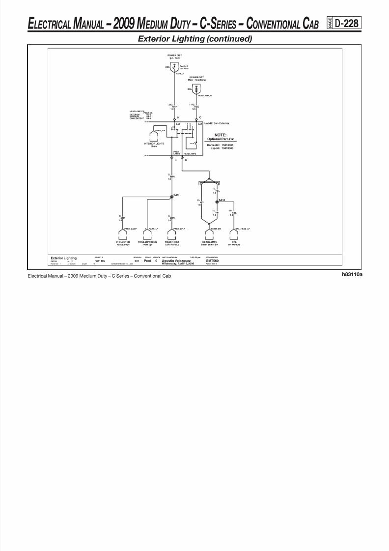
8/10/2019 2009 GM Medium Duty Electrical Manual.PDF
http://slidepdf.com/reader/full/2009-gm-medium-duty-electrical-manualpdf 339/410
Electrical Manual – 2009 Medium Duty – C Series – Conventional Cab h83110a
LAST CHANGED BY
Panel Set:
VERSIONSTAGEREVISIONOBJECT ID ORGANIZATION
15013006Domestic:
Optional Part #’s:
Export:15013005
Panel Set: 5
NOTE:
INTERIOR LIGHTSIllum
.10YEL
1.0
Beam Select SwHEADLAMPS
.9
1.0
BRN
SA9
.10YEL
1.0
2:03:20 pm
$IVEDWORK/h83110a__001sc hematic sheet1
h83110a15
001 Prod5
Agustin Velazquez GMT5600Exterior LightingGMT560 X08
Wednesday, April 19, 2006
1.0
9.BRN
1.0BRN.9
TRAILER WIRINGPark Lp
1.0
.10YEL
1.0
YEL10.
Drl ModuleDRL
SA10
O F F
H E A D L P
P A R K L P
BAT
G
HEADLAMPS
BAT
S
LAMPSPARK
17.1A
Headlp Sw - Exterior
POWER DISTLt/Rt Park LpPark Lamps
IP CLUSTER
PARK_SW
PARK_LP9 DRL_HEAD_LPBEAM_SWPARK_LP_PPARK_LAMP
E LECTRICAL M ANUAL – 2009 M EDIUM DUTY – C-S ERIES – CONVENTIONAL C AB P
A G E
D-229
Exterior Lighting (continued)
Fam 2 Manual Trans Fam 3 Manual Trans
Reverse RelayLCT TRANSMISSION
6M GT280 SLDE
15A
Ip1 - Turn/BackupPOWER DIST
GRN LT.24
0.8
POWER DISTIp1 - Turn/Backup
15A
6F GT280 SLDE
GRN LT.24
0 8A
0.8GRN LT
.24
MD TRANSMISSIONReverse Relay
SA24
0.8
LCT TRANSMISSIONReverse Relay
GRN LT.24
0.8PNK
139.
BU_LCT_1BU_LCT_1
BACK_UP24
139 BU_MAN2_P 139 BU_MAN3_PBU_MD

8/10/2019 2009 GM Medium Duty Electrical Manual.PDF
http://slidepdf.com/reader/full/2009-gm-medium-duty-electrical-manualpdf 340/410
Electrical Manual – 2009 Medium Duty – C Series – Conventional Cab h83110a
LAST CHANGED BY
Panel Set:
VERSIONSTAGEREVISIONOBJECT ID ORGANIZATION
20B-88A-
Panel Set: 6
2 4 B AC K_ UP
Page 20D-11
ISUZU ENG CNTLSEcu/Pcm
/
&L18&FAM2 &LMM &L18/LF6&FAM3&LF8
6M GT280 SLDA
X08
Wednesday, April 19, 2006
2:03:20 pm
$IVEDWORK/h83110a__001sch ematic sheet1
h83110a15
0016
Prod Agust in Velazquez GMT5600Exterior LightingGMT560
0.8
Reverse Sw
B
0.8
6F GT280 SLDA
GRN LT24.
SA24
0.8
.24GRN LT
0.8
24.
0.8
GRN LT24.
GRN LT
0.8.24GRN LT
GRN LT24.
0.8
ISUZU ENG CNTLSEcu/Pcm
BU_SW
(Page 3)

8/10/2019 2009 GM Medium Duty Electrical Manual.PDF
http://slidepdf.com/reader/full/2009-gm-medium-duty-electrical-manualpdf 341/410
E LECTRICAL M ANUAL – 2009 M EDIUM DUTY – C-S ERIES – CONVENTIONAL C AB P
A G E
D-231
Interior Lighting (continued)
Family 2has Fuse
.2509
30M GTMXDA2
0.5BRN
SB2509
30F GTMXDA2
Ip2 - Lh Parklamp
10A
POWER DIST
2509BRN
0.5
.
DOOR_SW_ILL

8/10/2019 2009 GM Medium Duty Electrical Manual.PDF
http://slidepdf.com/reader/full/2009-gm-medium-duty-electrical-manualpdf 342/410
Electrical Manual – 2009 Medium Duty – C Series – Conventional Cab h83114a
LAST CHANGED BY
Panel Set:
VERSIONSTAGEREVISIONOBJECT ID ORGANIZATION
BRN
POWER WINDOWS
RR_WIN_LP
Same
2509
15326018as
7
&A31&CREWCAB
Panel Set: 2
left
Right Rear Window Sw
H REAR_RDOOR
Page 8A-120B
TXL50
REAR_DOOR0.5
-2
.
12M GT280
POWER WINDOWSLeft Rear Window Sw
0.5
2509
SG2509
BRN2509.
0.5
.BRN
0.5BRN
2509.
Passenger Window SwPOWER WINDOWS
2509BRN
0.5
.2509BRN
0.5
.
00115
h83114asheet1schematic $IVEDWORK/h83114a__001
2:04:00 pm
08 X
Wednesday, April 19, 2006GMT560 0 GMT560Agustin VelazquezProd
2
Interior Lighting
0.5
.BRN
0.5
2509
2509.BRN
2509
0.5BRN.
10F GT280H
22M GTMXDA1
22M GTMXDA1
22F GTMXDA122F GTMXDA1 H 10M GT280
12M GT280H
POWER WINDOWSDriver Window Sw
12F GT280H
12F GT280H
LR_WIN_LPPASS_WIN_LPDR_WIN_LP2509
E LECTRICAL M ANUAL – 2009 M EDIUM DUTY – C-S ERIES – CONVENTIONAL C AB P
A G E
D-232
Interior Lighting (continued)
TRNHZ
047-2
PAGE 8A-STEERING COLUMN
AU0
034-1
AU0 114-3KEYMNDR
26062266
091-1
IGNSW
040-1SIR
BEAMSW
CRUISE010-1
B3
B4
HORN
110-1
WIPER100-1
Str Col Asm - Key Minder0.5
.156WHT
A530F GTMXD
ClusterIP CLUSTER
0.5
KEYLESS ENTRYRfa Module
WHT156.
0.5
.80GRN LT
KEYLESS ENTRYRfa Mdl
30M GTMXDA5
IP CLUSTERCluster
746159
Loop Anchor
LA156
RFA_DOME
DOME
(Page 5)
156
KEY_MIND DOOR_OPEN

8/10/2019 2009 GM Medium Duty Electrical Manual.PDF
http://slidepdf.com/reader/full/2009-gm-medium-duty-electrical-manualpdf 343/410
Electrical Manual – 2009 Medium Duty – C Series – Conventional Cab h83114a
LAST CHANGED BY
Panel Set:
VERSIONSTAGEREVISIONOBJECT ID ORGANIZATION
AU0
INTERIOR110-5EXTERIOR114-5
PAGE 8A-HEADLAMP SW
Panel Set: 3
DOME DEFEAT 114-3
GND
D
L F Door Jamb Sw
A
DOME
B
AJARKEY-IN
C
.157GRA
0.5
A1
22F GTMXD B1
30F GTMXD
30M GTMXDA3
BLK/WHT746.
0.5
30F GTMXDA3
328
0.5PPL.
22M GTMXDB1
B2
.PPL
0.5
328
B3
A1 30M GTMXD
746BLK/WHT
Rfa Module
0.5
.
GND DISTGnd Zone #5
B2
.328
0.5PPL
.328
0.5PPL
30F GTMXDB1
Headlp Sw - Dome Defeat
B
L
.159
0.5TAN
.
0.5
SA328
746.
0.5BLK/WHT
BLK/WHT746
0.5BLK/WHT
746.
GND DISTGnd Zone #5
.328
0.5PPL
B3
Wednesday, April 19, 2006001
15
h83114asheet1schematic $IVEDWORK/h83114a__001
2:04:00 pm
08 XGMT560 0 GMT560Agustin VelazquezProd3
Interior Lighting
B2
30M GTMXDB1
PPL0.5
328.
0.5BLK/WHT
.746
B1
WHT156.
0.5
22M GTMXD
0.5
328.PPL
0.5
159.
.TAN
0.5
159
TAN
157.
0.5
B3
GRA
SA746
B2
B3
R F Door Jamb Sw
A
GND
B
KEY-IN
C
AJAR
D
DOME
22F GTMXD B1
(Page 3)
RH_JAM
KEY_DOME
328
REAR_JAM
(Page 4)
550 LDOORJAM_G
(Page 3)
RH_JAM
550 RDOORJAM_G
E LECTRICAL M ANUAL – 2009 M EDIUM DUTY – C-S ERIES – CONVENTIONAL C AB P
A G E
D-233
Interior Lighting (continued)
(Page 3)
REAR_JAM
328

8/10/2019 2009 GM Medium Duty Electrical Manual.PDF
http://slidepdf.com/reader/full/2009-gm-medium-duty-electrical-manualpdf 344/410
Electrical Manual – 2009 Medium Duty – C Series – Conventional Cab h83114a
LAST CHANGED BY
Panel Set:
VERSIONSTAGEREVISIONOBJECT ID ORGANIZATION
&CREWCAB
12
1C5LRIGHT REAR DOOR JAM SWITCH
Gnd Zone #5
rdoor_sw_2
Page
A
R R Door Jam Sw
8A-
15326018
PPL
GND DIST
.
B DC
J
REAR_DOOR
RRDOORJAM_G
328
50
12M GT280
1400A
-
TXL
14A/B/C
550
001
19
Panel Set: 4
REAR_RDOOR
0.8
Same as left
15326559
10F GT280K
0.5
328.PPL
12F GT280J
J 12M GT280
GND DISTGnd Zone #5
h83114a15
0014
Prod Agustin Velazquez GMT5600Interior LightingGMT560 X08
Wednesday, April 19, 2006
2:04:00 pm
$IVEDWORK/h83114a__001s ch ema ti c s he et 1
0.8
328.PPL
SC328
0.5
328.PPL
12F GT280J
PPL.328
0.5
A
DOME
B
AJARKEY-IN
C
GND
D
L R Door Jam Sw
10M GT280K
550 LRDOORJAM_G
E LECTRICAL M ANUAL – 2009 M EDIUM DUTY – C-S ERIES – CONVENTIONAL C AB P
A G E
D-234
Interior Lighting (continued)
has Fuse has FuseFamily 2
has Fuse
Family 2
Family 2
DM
&C95 Front Dome Lp
A
10A
Ip1 - CourtesyPOWER DIST
10A
Ip1 - GaugesPOWER DIST
POWER DISTIp1 - Courtesy
10A
0.5
156.
WHT
Rear Dome Lp&C95
A
(Page 3)
DOME
DOME_P4040 RR_DOME_P
39 ILLUM_P

8/10/2019 2009 GM Medium Duty Electrical Manual.PDF
http://slidepdf.com/reader/full/2009-gm-medium-duty-electrical-manualpdf 345/410
Electrical Manual – 2009 Medium Duty – C Series – Conventional Cab h83114a
LAST CHANGED BY
Panel Set:
VERSIONSTAGEREVISIONOBJECT ID ORGANIZATION
HEADLAMP SW
114-5110-5
Dome Lamp P/N
114-3
EXTERIOR
DOME DEFEAT
-C95 : 15528765
Panel Set: 5
PAGE 8A-
&C95 : 15528767
INTERIOR
WHT156.
0.5
SA156
EXTERIOR LIGHTSParklamps
ILLUM
IGN 1
DIM
E
DOMELAMP
RADIO DIM
N
GND
R
RADIORadio
P A R K
L P
H E A D
L P
O F F
Headlp Sw - Interior
P A R A D E
D O M E
GND DISTGnd Zone #7A
0.8
44
Ip1 - IllumPOWER DIST
.GRN DK
READ
DOME
B
0.5
.156WHT
16M GT280D
0.5
156.WHT
30F GTMXDB8
30M GTMXDB8
.156WHT
0.5
SA1382
1.0PPL/WHT
1382.
.1382
1.0PPL/WHT
1.0
1382.PPL/WHT
PPL/WHT1.0
1382.
DOME
READ
B
WHT156.
0.5
D
00115
h83114asheet1schematic $IVEDWORK/h83114a__001
2:04:00 pm
Wednesday, April 19, 200608 XGMT560
Interior Lighting0 GMT560Agustin VelazquezProd
5
16F GT280
PPL/WHT.1382
1.0
Parade Mode IllumIP CLUSTER SIR
Step Dimmer
750 HEADLPSW_G
R_PARADE
PARK_SW
DIMMERSTEP_DIMPARADE
E LECTRICAL M ANUAL – 2009 M EDIUM DUTY – C-S ERIES – CONVENTIONAL C AB P A G E
D-235
Truck/Trailer Wiring (Family 2)
Blunt CutBA47
9.
3.0BRN
EXTERIOR LIGHTINGEXTERIOR LIGHTINGRh Turn/Haz Trlr Rly Back Up
3.0
.47BLU DK
EXTERIOR LIGHTINGLh Turn/Haz Trlr RlyHeadlamp Sw
EXTERIOR LIGHTINGPOWER DIST
30A
Maxi - Elec Brk
PARK_LP RH_HAZ2 TRLR_BACK LH_HAZ2642 ABS_TRLR2_P

8/10/2019 2009 GM Medium Duty Electrical Manual.PDF
http://slidepdf.com/reader/full/2009-gm-medium-duty-electrical-manualpdf 346/410
Electrical Manual – 2009 Medium Duty – C Series – Conventional Cab h83119a
LAST CHANGED BY
Panel Set:
VERSIONSTAGEREVISIONOBJECT ID ORGANIZATION
B
Panel Set: 1
40M GTMXD SLDC6
M12
Trailer Gnd TermA
40F GTMXD SLDC6
40M GTMXD SLDA4A5
40F GTMXD SLDA4
0012
h83119asheet1schematic $IVEDWORK/h83119a__001
2:04:26 pm
Wednesday, April 19, 200608 XGMT560
Truck Trailer Wiring0 GMT560Agustin VelazquezProd
1
GND DISTGnd Zone #12A
22WHTGRN LT
24.
3.0
A5
5.0
.
3.0
.318YEL
3.0
SA642
5.0
.642RED
47BLU DKBRN
9.
RED642.
3.0
3.0
.
3.0
.319GRN DK
AUX ELEC BRAKE
C
BACK UP
A
LEFT STOP/TURN
G
RIGHT STOP/TURN
D B
PARK LAMP
F
BATTERY
E
GROUND
7F MP280
TRAILER_G
E LECTRICAL M ANUAL – 2009 M EDIUM DUTY – C-S ERIES – CONVENTIONAL C AB P A G E
D-236
Truck/Trailer Wiring (Family 3)
C
.9BRN
Headlamp SwEXTERIOR LIGHTING
3.0
Brake Lp RlyEXTERIOR LIGHTING
8F MP280
Marker Lp RlyEXTERIOR LIGHTING
YEL318.
3.0
EXTERIOR LIGHTINGLh Turn/Haz Trlr Rly
POWER DIST
40A
Uh - Abs2
GRN DK319.
3.0 3.0
.1411RED
3.0
.21GRN DK
EXTERIOR LIGHTINGRh Turn/Haz Trlr Rly
MKR_LMP1642 ABS_TRLR_P PARK_LP RH_HAZ BRAKE_LP LH_HAZ

8/10/2019 2009 GM Medium Duty Electrical Manual.PDF
http://slidepdf.com/reader/full/2009-gm-medium-duty-electrical-manualpdf 347/410
Electrical Manual – 2009 Medium Duty – C Series – Conventional Cab h83119b
LAST CHANGED BY
Panel Set:
VERSIONSTAGEREVISIONOBJECT ID ORGANIZATION
5
50
(Page 2)
5.0
7 TRAILER CONNECTOR
22TRLR_ABS_P WHT
19
TRAILER
U86 - 7 WIRE FULL TRAILER WIRING
1413
.
4 3
TRAILER SUPPLIER ONLYTXL
2
Panel Set: 1
1
RPO LEGEND
6
TRLR_ABS_G
F
C
(Page 2)
GND DISTGnd Zone #12B
7F MPMXD SLD
.1413BLU DK
C
$IVEDWORK/h83119b__001s ch ema ti c s he et 1
h83119b2
001
D
5.0
1
Prod Agustin Velazquez GMT5600Truck Trailer Wiring (Fam 3)GMT560 X08
Wednesday, April 19, 2006
2:04:38 pm
G
3.0
.9BRN
5.0
8F MP280F
WHT22.
.319GRN DK
A
B
3.0
318YELBRN
9.
3.0 3.0
.
7
7M MPMXD SLDF
PARK LAMP
6
BATTERY BRAKE LAMP
4
RIGHT TURN
57F MP280
GROUND
1
BLU DK1413.
5.0
318.
3.0
G
LEFT TURN
3
YEL
E
A
B
BLK1412.
3.0
M12
Trailer Gnd Term
C
RED1411.
5.0
C
GRN DK319.
3.0
A 8M MP280FB D
A D
A
E
MARKER LAMP
2
E
ED
RED1411.
5.0
.1412BLK
TRAILER_G
3.0
E LECTRICAL M ANUAL – 2009 M EDIUM DUTY – C-S ERIES – CONVENTIONAL C AB P A G E
D-237
Truck/Trailer Wiring (Family 3) (continued)
19
WHTTXL
22
SPLICE
.
ABS POWER & MULTIPLEXED SIGNAL
19
.
5.0
.
1950
WHT
TRLR_ABS_P
(Page 1)
5 0
(Page 1)
22
TRLR_ABS_GTRAILER
5 0TXL
22
50
50
BLU DK1413
TXL

8/10/2019 2009 GM Medium Duty Electrical Manual.PDF
http://slidepdf.com/reader/full/2009-gm-medium-duty-electrical-manualpdf 348/410
Electrical Manual – 2009 Medium Duty – C Series – Conventional Cab h83119b
LAST CHANGED BY
Panel Set:
VERSIONSTAGEREVISIONOBJECT ID ORGANIZATION
TRAILER SUPPLIER ONLY
TRAILER ABS P485 ENHANCEMENT
Panel Set: 2
RF Wheel
Speed Sensor
LF Wheel LR Wheel
50
RR Wheel
5.0
TRAILER
TRAILER5.0
Speed Sensor
EBC MULTIPLEXED SIGNAL
50
Speed Sensor
TRAILER
Speed Sensor
Wednesday, April 19, 2006
2:04:38 pm
$IVEDWORK/h83119b__001schematic sheet1
h83119b2
0012
Prod Agust in Velazquez GMT5600Truck Trailer Wiring (Fam 3)GMT560 X08
E LECTRICAL M ANUAL – 2009 M EDIUM DUTY – C-S ERIES – CONVENTIONAL C AB P A G E
D-238
Tractor Wiring (Family 3)
Brake Lp RlyEXTERIOR LIGHTING EXTERIOR LIGHTING
Lh Turn/Haz Trlr RlyHeadlamp SwEXTERIOR LIGHTINGPOWER DIST
40A
Uh - Abs2 Marker Lp RlyEXTERIOR LIGHTINGEXTERIOR LIGHTING
Rh Turn/Haz Trlr Rly
MKR_LMP1642 ABS_TRLR_P PARK_LP RH_HAZ BRAKE_LP LH_HAZ

8/10/2019 2009 GM Medium Duty Electrical Manual.PDF
http://slidepdf.com/reader/full/2009-gm-medium-duty-electrical-manualpdf 349/410
Electrical Manual – 2009 Medium Duty – C Series – Conventional Cab h83119c
LAST CHANGED BY
Panel Set:
VERSIONSTAGEREVISIONOBJECT ID ORGANIZATION
7
50
WHT
45
Panel Set: 1
5.0
.
2
TRACTOR
6
TRLR_ABS_G
TRAILER SUPPLIER ONLY
TXL 1 9
TRACTOR CONNECTOR1
1413(Page 2)
22
(Page 2)
TRLR_ABS_P
3
.319GRN DK
3.0
.9BRN
3
3.0
RED
BLK1412.
3.0
1
Pi lot Agust in Velazquez GMT560BTractor Wrg ( Fam 3)GMT560 X08
Wednesday, April 19, 2006
2:04:51 pm
$IVEDWORK/h83119c__001schematic sheet1
h83119c2
001
5.0
.1411
.318YEL
7
A D
3.0
B
6
C
YEL318.
3.0
5
Gnd Zone #7BGND DIST
7F MP2801
RED1411.
5.05.0
.1413BLU DK
24
BRN9.
3.0
F
GRN DK319.
3.0
8F MP280F
8M MP280
B
21GRN DK
A
5.0
.22WHT
3.0
.
Tractor Gnd TermA
BD E
E
M6.3
TRACTOR_G
C
E LECTRICAL M ANUAL – 2009 M EDIUM DUTY – C-S ERIES – CONVENTIONAL C AB P A G E
D-239
Tractor Wiring (Family 3)
19
22
TRACTOR
19
.
ABS POWER & MULTIPLEXED SIGNAL
505.0
.
(Page 1)
SPLICE
WHT5.0TXL
TRACTOR
WHT5.0
TXL
.
19
50
TRLR_ABS_P
(Page 1) 22
1413
22
BLU DK
50
TRACTOR
TXL
TRLR_ABS_G
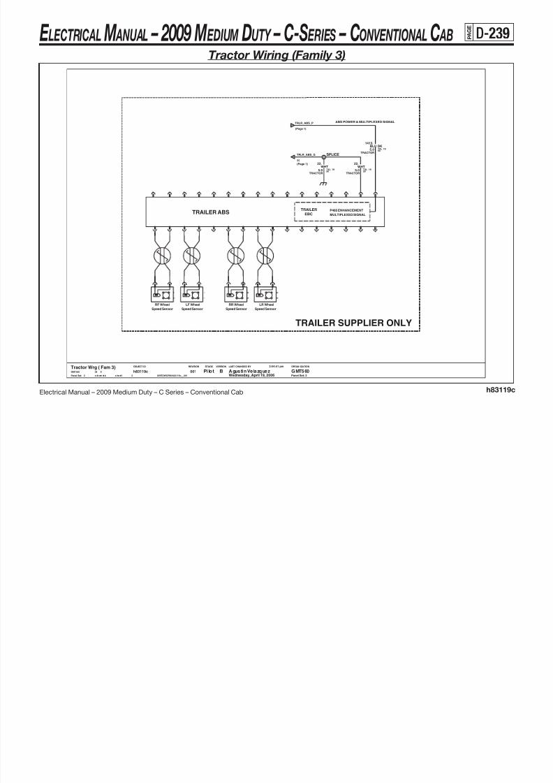
8/10/2019 2009 GM Medium Duty Electrical Manual.PDF
http://slidepdf.com/reader/full/2009-gm-medium-duty-electrical-manualpdf 350/410
Electrical Manual – 2009 Medium Duty – C Series – Conventional Cab h83119c
LAST CHANGED BY
Panel Set:
VERSIONSTAGEREVISIONOBJECT ID ORGANIZATION
Speed Sensor
P485 ENHANCEMENT
MULTIPLEXED SIGNALTRAILER ABS
Panel Set: 2
Speed SensorSpeed SensorSpeed Sensor
LF Wheel
EBC
RF Wheel RR Wheel
TRAILER
TRAILER SUPPLIER ONLY
LR Wheel
2
Pi lo t Agustin Velazquez GMT560BTractor Wrg ( Fam 3)GMT560 X08
Wednesday, April 19, 2006
2:04:51 pm
$IVEDWORK/h83119c__001s ch em at ic s he et1
h83119c2
001
E LECTRICAL M ANUAL – 2009 M EDIUM DUTY – C-S ERIES – CONVENTIONAL C AB P A G E
D-240
Body Builder Connector
POWER DISTIp2 - Brake Iso
EXTERIOR LIGHTSMarker Lamp Rly Back Up Sw
EXTERIOR LIGHTSSecondary PpmENGINE CNTLS POWER DIST
Ip1 - Aux Wire Rly

8/10/2019 2009 GM Medium Duty Electrical Manual.PDF
http://slidepdf.com/reader/full/2009-gm-medium-duty-electrical-manualpdf 351/410
Electrical Manual – 2009 Medium Duty – C Series – Conventional Cab h83119d
LAST CHANGED BY
Panel Set:
VERSIONSTAGEREVISIONOBJECT ID ORGANIZATION
has Fuse
J
Family 2has FuseFamily 2
12M GT280 SLDBDY_BLDRH
0.8
Panel Set: 1
BDY_BLDR
has Fuse
12M GT280 SLDEFG
K
L
C
15326915
D
Family 2
15326915
B
A
10A
1320.BLU LT
L
1.0BRN
.2509
LEFT TURN (&FAM3)
LEFT STOP/TURN (&FAM2)
C
BACK UP
12F GT280 SLD
K
EXTERIOR LIGHTSRh Turn Trailer Rly
Body Builder Connector
1
Prod Agust in Velazquez GMT5600GMT560 X08
Wednesday, April 19, 2006
2:05:02 pm
$IVEDWORK/h83119d__001schematic sheet1
h83119d10
001
RIGHT STOP/TURN (&FAM2)
RIGHT TURN (&FAM3)&TSV/TSW
J H
SECONDARY PPM
A
SEO
MARKER LAMP
G
12F GT280 SLD
GND
Ip2 - Rh Parklamp
10A10A
Ip2 - Lh ParklampPOWER DIST
IGN 3
F
EXTERIOR LIGHTSLh Turn Trailer Rly
POWER DIST
E
STOP
LEFT PARK
D
RIGHT PARK
B
GND DISTGnd Zone #3B
15A
BRN/WHT
.2609
1.0
21 BB_MRKR_LP
BB_G350
BB_L_PARK
BB_STOP_P641 BB_PBB_PPM1827 BB_BACK_UP24
BB_R_PARK319 BB_R_TURN318 BB_L_TURN
E LECTRICAL M ANUAL – 2009 M EDIUM DUTY – C-S ERIES – CONVENTIONAL C AB P A G E
D-241
School Bus Upfitter
EXTERIOR LIGHTSRh Turn Trailer Rly
0.8
2509.BRN
1.01320.BLU LT
Gnd Zone #3BGND DIST
A
1.0
2609.BRN/WHT
2
19.0
.RED
10F GT280H
POWER DIST
E
Ip2 - Brake Iso
10A
Ip2 - Rh Parklamp
10A
POWER DISTPOWER DIST
10A
Ip2 - Lh ParklampEXTERIOR LIGHTSLh Turn Trailer Rly
K
Back Up SwEXTERIOR LIGHTS
BC D
Battery PositiveBATTERIES
FL
SCHOOL_P
SB_G350
BB_R_PARKBB_L_PARKBB_STOP_P 319 SB_R_TURN318 SB_L_TURN SB_BACK_UP24

8/10/2019 2009 GM Medium Duty Electrical Manual.PDF
http://slidepdf.com/reader/full/2009-gm-medium-duty-electrical-manualpdf 352/410
Electrical Manual – 2009 Medium Duty – C Series – Conventional Cab h83119e
LAST CHANGED BY
Panel Set:
VERSIONSTAGEREVISIONOBJECT ID ORGANIZATION
B
TXL19
C
Panel Set: 1
3.0
Back Up Alarm
B
D
BACKUP2M MP280 SLD
TXL
A
E SCHOOLBUSH
BLK
5050
24
SCHOOL BUS SUPPLIED
.350
1400 Hz Tone
15300032
15326935
GRN LT
BACKUP
19
BACKUP
.
10M GT280
SCHOOL BUS SUPPLIED
3.0
0.8BLK
550.
A B
AK
A4
BLK0.8
.550
B10
SA550
A9B9 A10 22F GTMXD
0.8
.1516BLU LT0.8
GRN DK21.
0.8
.1499GRN LT
22F GTMXDB8
.1517YEL
0.8 .267ORN
0.8
2F MP280 SLDB
EXTERIOR LIGHTS
Back Up Sw
GND DISTGnd Zone #3D
BACK UP
A
Littelfuse 100A Mega
B
GROUND
A
FConn 8M M/P 150
HC
STOP
D
RIGHT TURNLEFT TURN LEFT PARK RIGHT PARK
1
Prod Agust in Velazquez GMT5600Bus UpfitterGMT560 X08
Wednesday, April 19, 2006
2:05:28 pm
$IVEDWORK/h83119e__001schematic sheet1
h83119e2
001
G
Littelfuse Term 1
M8
A
B
.550BLK
0.8
24 SB_BU_ALARM 350 BU_G
E LECTRICAL M ANUAL – 2009 M EDIUM DUTY – C-S ERIES – CONVENTIONAL C AB P A G E
D-242
Power Windows (Regular Cab)
.
0.5
POWER DOOR LOCKSDriver Door Lock Sw
BRN2509
2 0YEL
343.
Headlamp IllumINTERIOR LIGHTING
.343YEL
2 0INTERIOR LIGHTING
Passanger Door Lock SwPOWER DOOR LOCKS
A522M GTMXD
B7
POWER DISTIp2 - Pwr Window
25A
30M GTMXDA8
30F GTMXDA8
343.
2.0
.343YEL
2.0YEL
22F GTMXDB7A5
YEL343.
WIN_IGN4_P
P_WIN_SW
343
P_WIN_SWDRV_LK_LP

8/10/2019 2009 GM Medium Duty Electrical Manual.PDF
http://slidepdf.com/reader/full/2009-gm-medium-duty-electrical-manualpdf 353/410
Electrical Manual – 2009 Medium Duty – C Series – Conventional Cab h83120a
Θ
Θ
LAST CHANGED BY
Panel Set:
VERSIONSTAGEREVISIONOBJECT ID ORGANIZATION
A5
Panel Set: 1
Drv Window Mtr
A
B
667.
2.0
22F GTMXD A6
2.0BRN
A
B
2.0
.166BLU LT
A7
Pass Window Mtr
22F GTMXDA7
22M GTMXD
2.0 Headlamp Illum
TAN167.
2.0
Gnd Zone #5GND DIST
A7
2.0
TAN167.
2.0
TAN167.
A60.5
.2509BRN
.166BLU LT
AB
C
ILLUM
D
E
IGN4
F H
2.0
ILLUM
D
EF G
H
IGN4
Pass Window Sw
D O W N
U P
E X P R E S S
D O W N
Driver Window Sw
L H D O W N
R H D O W N
R H U P
L H U P
AB
BRN2509.
0.5
2.0
.166BLU LT
A5
A7
343.
A6
2.0YEL
$IVEDWORK/h83120a__001
2:05:50 pm
Wednesday, April 19, 200608 XGMT560
Power Windows (Reg Cab)0 GMT560Agustin VelazquezProd
1
BRN165.
2.0
0013
h83120asheet1schematic
2.0
.164BLU DK
.550BLK
0.5
.2509BRN
2.0YEL
2.0
2.0
.666BLU DK
Gnd Zone #5
.343YEL
2.0
PASS_LK_LP
PASS_WIN_LP
22M GTMXDA6
GND DIST
550 PASS_WIN_G
DR_WIN_G
DR_WIN_LP
E LECTRICAL M ANUAL – 2009 M EDIUM DUTY – C-S ERIES – CONVENTIONAL C AB P A G E
D-243
Power Windows (Crew Cab)
SA2509
0.5
.2509BRN
.
2.0YEL
343
.
2.0
30F GTMXDA8
YEL343
22F GTMXDA5
A8
Driver Door Lock SwPOWER DOOR LOCKS
0.5
.2509BRN
A5
30M GTMXD
22M GTMXD
INTERIOR LIGHTINGHeadlamp Illum
J1-AJ1-B
.343YEL
2.0
25A Ip2 - Pwr WindowPOWER DIST
BRN2509.
0.5
DRV_LK_LP
DR_WIN_LP
LR_P
(Page 2)
WIN_IGN4_P

8/10/2019 2009 GM Medium Duty Electrical Manual.PDF
http://slidepdf.com/reader/full/2009-gm-medium-duty-electrical-manualpdf 354/410
Electrical Manual – 2009 Medium Duty – C Series – Conventional Cab h83120b
Θ
E X P R E S S
D O W N
LAST CHANGED BY
Panel Set:
VERSIONSTAGEREVISIONOBJECT ID ORGANIZATION
Panel Set: 1
A
B
Drv Window Mtr
22M GTMXDB7
GND DISTGnd Zone #5
2.0
.343YEL
YEL
343.
2.0
2.0
.165BRN
10F GT280E
YEL343.
2.0
SC343
22F GTMXDB7
h83120bsheet1schematic $IVEDWORK/h83120b__001
2:07:12 pm
Wednesday, April 19, 200608 XGMT560
Power Windows (Crew Cab)0 GMT560Agustin VelazquezProd
1
J2-H
DOWN
0013
J2-C
LF LF
J2-D
DOWNUP
J2-E
LR LR
J2-F
DOWNUP
J2-G
RR RRLOCK
J1-D
OUT
J1-E
GNDRF
J2-A
DOWNUP
J2-B
RFUP
UPRIGHTFRONT
LEFTFRONTUP DOWN UP DOWN UP DOWN
Driver Window SwILLUM IGN4
J1 B
BLU DK164.
2.0
J2-J1-
DOWN
10M GT280E
YEL
343.
2.0
YEL343.
2.0
SB343
2.0BLK
550.
2.0
.343YEL
DR_WIN_G
(Page 2)
LR_UP
168
171
RR_DOWN
(Page 2)
(Page 2)
RR_UP
170
(Page 2)
RR_P
(Page 2)
RF_UP
167
343
RF_P
(Page 2)
166
RF_DOWN
(Page 2)
169
LR_DOWN
(Page 2)
E LECTRICAL M ANUAL – 2009 M EDIUM DUTY – C-S ERIES – CONVENTIONAL C AB P A G E
D-244
Power Windows (Crew Cab) (continued)
Headlamp IllumINTERIOR LIGHTING
2.0
.169PPL
4F GT280D
PPL169.
2.0
2.0PPL
171.
2.0
.170GRN LT
B
TAN167.
2.0
B
0.5
.2509BRN
C
CA
GRN DK168.
2.0
2.0
.168GRN DK
4M GT280DA
171.
2.02.0
.170GRN LT PPL
Passanger Door Lock Sw
POWER DOOR LOCKS
22M GTMXDA7
A622F GTMXD
A7
2.0
.166BLU LT
PASS_LK_LP
A6
(Page 1)
LR_UP
RF_P
(Page 1)
(Page 1)
LR_DOWN
(Page 1)
RF_UP
(Page 1)
RF_DOWN
RR_DOWN
(Page 1)
RR_UP
(Page 1)

8/10/2019 2009 GM Medium Duty Electrical Manual.PDF
http://slidepdf.com/reader/full/2009-gm-medium-duty-electrical-manualpdf 355/410
Electrical Manual – 2009 Medium Duty – C Series – Conventional Cab h83120b
Θ
Θ
LAST CHANGED BY
Panel Set:
VERSIONSTAGEREVISIONOBJECT ID ORGANIZATION
Θ 560_win_mtr
R R Window Sw
2.0 TXL
8A-
GRN LT
D O W N
U P
A
FNA1C5A
2509
Gnd Zone #5
BRN671
INTERIOR LIGHTING
550 RR_WIN_G
RR_WIN_LP E
Same as left
Panel Set: 2
502.0
50
19 19
1C5L 1400A
.171
2.0 TXL
REAR_DOOR
PPL
50
12M GT280
Page
170
M12129487
A
114A
G
19
15728437_rr
.670
14A/B/C
001
12064998
8A-
BLU DK
B
C
ILLUM
D
E
F
12
REAR_DOOR
TXL2.0
H
REAR_DOOR
.
TXL
19
.343YEL
50REAR_DOOR
2.0
004
REAR_DOOR
REAR_RDOOR
-2Headlamp Illum
GND DIST
TXL
.
19
R R Window Mtr
B
15326018
12F GT280G
Page -
50
IGN4
F
.169PPL
BLU LT166.
2.0
2.0
2.0
.169PPL
A5
Headlamp Illum
2.0
.167TAN
C
F H
L R Window Sw
D O W N
U P
AB
C
ILLUM
D
E
IGN4
F
Gnd Zone #5GND DIST
F
E
22F GTMXDA7PPL
171.
2.0
.170GRN LT2.0
G
E
12M GT280
E
F
IGN4
H
BRN2509.
0.5
U P
D O W N
Pass Window Sw
AB
ILLUM
C D
GRN DK168.
2.0
G
A6
12F GT280G F
Pass Window Mtr
A
B
INTERIOR LIGHTINGHeadlamp Illum
.343YEL
2.0
G
22M GTMXDA7
A
B
BRN669.
L R Window Mtr
2.0
.668BLU DK
2.0
BLU LT166.
2.0
GND DISTGnd Zone #5
10F GT280F
10M GT280F
2.0
.167TAN
2.0GRN DK
168.
E
D.343YEL
2.0
A6
D
0013
h83120bsheet1schematic $IVEDWORK/h83120b__001
2:07:12 pm
Wednesday, April 19, 200608 XGMT560
Power Windows (Crew Cab)0 GMT560Agustin VelazquezProd
2
A5
2.0YEL
343.
C
BRN2.0
BLU DK666.
2.0
.667
LR_WIN_LP2509
PASS_WIN_LP343
LR_P
(Page 1) (Page 1)
RR_P
343
PASS_WIN_G550
550 LR_WIN_G
E LECTRICAL M ANUAL – 2009 M EDIUM DUTY – C-S ERIES – CONVENTIONAL C AB P A G E
D-245
Power Door Locks
A8
.195BLU LT1.0
KEYLESS ENTRY
A
LOCK
B
GND
ILLUM
C
D
UNLCK
BATT
E
INTERIOR LIGHTINGSw Illum
Pass Dr Lck Sw
LOCK
A
GND
B
C
ILLUM
UNLCK
D
E
BATT
20A
POWER DISTIp1 - Pwr Accy
Driv Dr Lck Sw
1.0WHT
194.
1.0
22F GTMXDB5
WHT194.
A8
20A
Ip1 - Pwr AccyPOWER DIST
Sw IllumINTERIOR LIGHTING
BLU LT1.0
.195
22F GTMXDB5
2509PASS_LK_P5402509 DRV_LK_LP 540 DRV_LK_P
PASS_LK_LP

8/10/2019 2009 GM Medium Duty Electrical Manual.PDF
http://slidepdf.com/reader/full/2009-gm-medium-duty-electrical-manualpdf 356/410
Electrical Manual – 2009 Medium Duty – C Series – Conventional Cab h83130a
LAST CHANGED BY
Panel Set:
VERSIONSTAGEREVISIONOBJECT ID ORGANIZATION
Panel Set: 1
1.0
.194
1
WHT
Wednesday, April 19, 2006001
3
h83130asheet1schematic $IVEDWORK/h83130a__001
2:07:32 pm
08 XGMT560
Power Door Locks0 GMT560Agustin VelazquezProd
22M GTMXDB5A8
SA194
GND DISTGnd Zone #5
1.0WHT
194.
1.0WHT
194.
A8
POWER DIST
20A
Rfa MdlSS
Ip1 - Pwr Accy
GND
E
MTR LOCK
F
SW LOCK Door Lck Rly Asm
A
SW UNLCK
B
MTR UNLCK
C
BATT
D
Gnd Zone #5Gnd Zone #5GND DIST GND DIST
22M GTMXDB5
SA195
KEYLESS ENTRY
Rfa Mdl
1.0
.195BLU LT
1.0.195BLU LT
BLU LT195.
1.0 DOOR_LOCK195
LOCKDOOR_UNLK194
294
MTR_UNLCK
(Page 2)
(Page 2)
MTR_LOCK
295
LK_RLY_P540
LK_RLY_G550
1 95 LO CK
550 DRV_LK_G PASS_LK_G550
E LECTRICAL M ANUAL – 2009 M EDIUM DUTY – C-S ERIES – CONVENTIONAL C AB P A G E
D-246
Power Door Locks (continued)
12F GT280
C
294
1.0TAN.
KEYLESS ENTRY
Rfa Mdl
TAN
.
1.0
294
TAN
294.
1.0 A 10M GT280
A
294
1.0
.
10F GT280
1.0TAN
294.TAN
SA294SB294
.TAN
294
1.0
TAN294.
1.0
TAN294.
1.0
.294TAN
1.0
C 12F GT280
MTR_UNLCK
(Page 1)
DRV_DR_UNLK

8/10/2019 2009 GM Medium Duty Electrical Manual.PDF
http://slidepdf.com/reader/full/2009-gm-medium-duty-electrical-manualpdf 357/410
Electrical Manual – 2009 Medium Duty – C Series – Conventional Cab h83130a
LAST CHANGED BY
Panel Set:
VERSIONSTAGEREVISIONOBJECT ID ORGANIZATION
Θ Θ
Θ Θ 004iso_drlck_mtr
as
REAR_DOOR
295.
A
B
GRA
1.0
1.0REAR_DOOR
TXL
.294
19
&CREWCAB
M
REAR_RDOOR
Panel Set: 2
12M GT28015326018
15300027
19
REAR_RDOOR
TAN
C
50
R R Drlck Mtr
&CREWCAB
50
1C5L 1400A
left
TXL
12M GT28015326018
D
Same
12F GT280D
.294TAN
1.0
1.0
.295GRA
B6
22M GTMXDB4
22M GTMXD
1.0
TAN294.
.294TAN
22M GTMXDB4
1.0
.295GRA
GRA295.
1.0
1.0
22F GTMXDB6
SB295
.295GRA
1.0
.295GRA
1.0
22M GTMXDB6
295.
1.0GRA
295GRA
1.0
.
1.0GRA
295.
12M GT280C
B
10M GT280B
10F GT280
L R Drlck Mtr
M
A
B
1.0
.295GRA
22F GTMXDB6
22F GTMXD B4
GRA295.
1.0
SA295
B
M
Driv Drlck Mtr
A
B
2
Prod Agustin Velazquez GMT5600Power Door LocksGMT560 X08
Wednesday, April 19, 2006
2:07:32 pm
$IVEDWORK/h83130a__001s ch em ati c s he et 1
h83130a3
001
Pass Drlck Mtr
M
A
D
12M GT280D
22F GTMXDB4
12F GT280
(Page 1)
MTR_LOCK
E LECTRICAL M ANUAL – 2009 M EDIUM DUTY – C-S ERIES – CONVENTIONAL C AB P A G E
D-247
Remote Keyless Entry (RKE)
INTERIOR LIGHTSHorn Rly
HORN
has FuseFamily 2
Dome Lamps
10A
Ip1 - GaugesPOWER DIST
LOCK
UNLOCK
Ip1 - Pwr Accy
20A
POWER DIST
39
RFA_DOME156 HORN_CHIRP28540 RFA_P
RFA_IGN1_P

8/10/2019 2009 GM Medium Duty Electrical Manual.PDF
http://slidepdf.com/reader/full/2009-gm-medium-duty-electrical-manualpdf 358/410
Electrical Manual – 2009 Medium Duty – C Series – Conventional Cab h83132a
LAST CHANGED BY
Panel Set:
VERSIONSTAGEREVISIONOBJECT ID ORGANIZATION
Panel Set: 1
1.0
.194WHT
Door Lock DOOR LOCKS
All Door Unlock DOOR LOCKS
ALLDOORLOCK
R
DOME LAMP
S
CHIRPBATT
E
DOORPASSANGER
UNLOCK
H
IGN1
J
DOOR JAMB
K
PROGRAMENABLE
L
GND
N
h83132a3
001
RFA
Remote Function Act
DRIVERDOOR
UNLOCK
A
DOORALL
UNLOCK
B
C
HORN
A4
1
Prod Agust in Velazquez GMT5600Remote Keyless EntryGMT560 X08
Wednesday, April 19, 2006
2:07:53 pm
$IVEDWORK/h83132a__001sche matic sheet1
30M GTMXDA4
30F GTMXD
DOOR LOCKSDriver Door Unlock Dome Defeat Sw
INTERIOR LIGHTING GND DISTGnd Zone #5
Pin 8DLC
.195BLU LT1.0
BLK/WHT1455.
0.5
5 50 R FA _G
0.5
.1455BLK/WHT
DRV_DR_UNLK294
DOOR_LOCKDOOR_UNLKKEYLESS
KEY_DOME157
E LECTRICAL M ANUAL – 2009 M EDIUM DUTY – C-S ERIES – CONVENTIONAL C AB P A G E
D-248
Power Mirrors
30F GTMXDB1
SA267
0.8ORN
267.
E
O W N
W N
I G H T
/ R I G H T
D O W N
U P
R I G H T
L E F T
Mirror Switch
0.8ORN
267.
ORN
0.8
.267
POWER DISTIp1 - Pwr Acc
20A
0.8
.267ORN
0.8
.267ORN
INTERIOR LIGHTINGHeadlamp Illum
30M GTMXDB1
SB267
540 MIR_SW_P
(Page 2)
HTD_MIR_SW
H_MIR_LP2509

8/10/2019 2009 GM Medium Duty Electrical Manual.PDF
http://slidepdf.com/reader/full/2009-gm-medium-duty-electrical-manualpdf 359/410
Electrical Manual – 2009 Medium Duty – C Series – Conventional Cab h83147b
LAST CHANGED BY
Panel Set:
VERSIONSTAGEREVISIONOBJECT ID ORGANIZATION
8785
3086
Htd Mirror
12088567
Family 2
Panel Set: 1
has Fuse
Family 2
has Fuse
GRA90.
0.8
.267ORN
0.8
Gnd Zone #7AGND DIST
GND DISTGnd Zone #7A
Ip1 - Aux Wire
15A
POWER DIST
0.8GRN LT
1499.
GMT560
Power Mirrors0 GMT560Agustin VelazquezProd
1 Wednesday, April 19, 2006001
3
h83147bsheet1schematic $IVEDWORK/h83147b__001
2:08:10 pm
08 X
A BCD FG H
D R I V E R U P / D O
D R I V E R
P A S S
P A S S U P / D O W
P A S S L E F T / R I
D R I V E R L E F T /
B
ILLUM
C D
EF
Htd Mirror Switch
A
YEL0.8
.1517
GND DISTGnd Zone #4B
.1498
1516.
0.8BLU LT
BRN/WHT0.8
15A
Ip1 - Aux WirePOWER DIST
0.8
.1497BLU LT/WHT
GND DISTGnd Zone #5
ORN267.
0.8F86
F87
Ip2 - Htd Mirror Rly
F30
F85
550 MIR_SW_GDRIV_U-D
(Page 2)
(Page 2)
PASS_U-D
(Page 2)
PASS_L-R
(Page 2)
PASS
(Page 2)
DRIV_L-R
(Page 2)
DRIV
450 H_MIR_RLY_G
H_MIR_ILL_G750
750 H_MIR_LED_G
641 H_MIR_RLY_P
H_MIR_SW_P641
E LECTRICAL
M ANUAL
– 2009 M EDIUM
DUTY
– C-S ERIES
– CONVENTIONAL
C AB P
A G E
D-249
Power Mirrors (continued)
ORN0.8
SC267
.267
A9
A6
30M GTMXDA6
30F GTMXD
.90GRA
0.8
.267ORN
0.8
22F GTMXDA9
A10
ORN267.
0.8
B9
0.8
.1497BLU LT/WHT
B9
A10A9
A10
B9
22F GTMXDB10
A922M GTMXD 22M GTMXD
B10
22M GTMXDB10
22F GTMXDB10A10
B9
0.8
.1498BRN/WHT
DRIV_L-R
1516(Page 1)
DRIV_U-D
1517(Page 1)
1499(Page 1)
DRIV
PASS_U-D
(Page 1)1498
1497
PASS
(Page 1)
(Page 1)90
PASS_L-R
267
HTD_MIR_SW
(Page 1)

8/10/2019 2009 GM Medium Duty Electrical Manual.PDF
http://slidepdf.com/reader/full/2009-gm-medium-duty-electrical-manualpdf 360/410
Electrical Manual – 2009 Medium Duty – C Series – Conventional Cab h83147b
MM
LAST CHANGED BY
Panel Set:
VERSIONSTAGEREVISIONOBJECT ID ORGANIZATION
M M
G
MIRRORMARKER
14A/B/C4
HTR
B
GND
&DB6/DB8
OSRVM
-Page
CF D
14A/B/C
θ PTC
50
H
SAME AS
8F MP150
8A-
GND DIST
RH_MRK_G
Gnd Zone #5
15326840
RT/LT
F D
OSRVM
12065398
Panel Set: 2
Gnd Zone #5
50
0.8
R_H_MIR_G
8A- 4
.
550
C
0.8OSRVM
&DB6
50
ORN.
&DB6/DB7
OSRVM
550
TXL
.21GRN DK
A
FNAUPC
Mirror Headmirror 003
GND DIST
19
TXL
LEFT
GRN LT1499.
TXL
Page
G
YEL1517
UP/DN
OSRVM
&DB6
19
-
H
19
19
50
BLU LT1516
PTC: Positive Temperature Coefficient
.
TXL0.8OSRVM
&DB6
1950 0.80.8
TXL267
GND
D HHC
G
8M MP150
0.8
.1517YEL
ORN267.
0.8
MARKERMIRROR
G
HTR
θPTC
H
GND DISTGnd Zone #5
Mirror Head
PTC: Positive Temperature CoefficientGND
AB
GND
CD
UP/DN
F
RT/LT
Gnd Zone #5GND DIST
EXTERIOR LIGHTINGMarker Lamp Rly
BRN/WHT1498.
0.8
C
D
0.8
.267ORN
0013
h83147bsheet1schematic $IVEDWORK/h83147b__001
2:08:10 pm
08 XGMT560
Power Mirrors0 GMT560Agustin VelazquezProd
2 Wednesday, April 19, 2006
8F MP150H
0.8
.1516BLU LT
F
F
.
0.8BLU LT/WHT
1497
G F D
EXTERIOR LIGHTINGMarker Lamp Rly
8M MP150G
C
0.8GRA
90.
GRN DK21.
0.8 0.8
.1499GRN LT
.267ORN
0.8
RH_MRK21
550 LH_MRK_G L_H_MIR_G550
21 LH_MRK
E LECTRICAL
M ANUAL
– 2009 M EDIUM
DUTY
– C-S ERIES
– CONVENTIONAL
C AB P
A G E
D-250
Entertainment - Radio
has Fuse
GND DIST
Page
10136715Family 2
16165011
30M GTMXDA14
6
Family 2
A
has Fuse
Antenna Asm-Radio003
-
Case Gnd
8A-
0900A12L
14A/B/C30F GTMXDA14
GRN DK0.5
0.5GRN DK
117.
.117
Lf SpeakerSPEAKER
A12
SPEAKERRf Speaker
A2
Headlamp Sw - Radio DimmerINTERIOR LIGHTING
22F GTMXDA2
22M GTMXD
0.5GRA
118.
.118GRA
0.5
A12
22F GTMXDA2
22M GTMXDA2
Rr SpeakerSPEAKER
Dimmer Signal DistINTERIOR LIGHTING
POWER DISTIp1 - Radio/Chime
15A
SPEAKERLr Speaker
10A
RR_SPKR-115
RADIO_DIM8
1140 RADIO_P
LR_SPKR-116LF_SPKR-
R_PARADE1382
117 RF_SPKR-118

8/10/2019 2009 GM Medium Duty Electrical Manual.PDF
http://slidepdf.com/reader/full/2009-gm-medium-duty-electrical-manualpdf 361/410
Electrical Manual – 2009 Medium Duty – C Series – Conventional Cab h83150a
LAST CHANGED BY
Panel Set:
VERSIONSTAGEREVISIONOBJECT ID ORGANIZATION
MICRO
VF DISPLAY
BACKLITDIM DRIVER
COMPACT DISCCASSETTE
FM = MHzAM = kHz
RADIO
Panel Set: 1
22M GTMXD
A11
4
h83150asheet1schematic $IVEDWORK/h83150a__001
2:08:30 pm
08 XGMT560
Radio0 GMT560Agustin VelazquezBeta
1 Wednesday, April 19, 2006
0.5TAN
201.
001
.201TAN
0.5
22F GTMXD A11
SPEAKERLr Speaker Rr Speaker
SPEAKER
22M GTMXD
A11
30M GTMXDA15
30F GTMXDA15
0.5GRN LT
200.
Lf SpeakerSPEAKER SPEAKER
Rf Speaker
DIMGNDLR+
J1-B8
LR-
J1-B9
AUX MONO -
J2-L J2-M
AUX MONO +
RF-
J1-B10
RF+
J1-B11
J1-B12
PARK/PARADE BKLIGHT
J1-B4
J1-B5
RR-
J1-A10
J1-A11
RR+ GND
J1-A12J1-A8
LF+
J1-A9
LF- PWR
J1-B1
A13
Radio
ANT
ANT IN
CLASS 2
J1-A1
A13
22F GTMXDA11
GRN LT0.5 STARR CONNECTOR
Gnd Zone #4AGND DIST
.200
RR_SPKR+46
Class 2
199 LR_SPKR+200 RF_SPKR+LF_SPKR+201
RADIO_G14511044 RADIO_CL2
E LECTRICAL M ANUAL – 2009 M EDIUM DUTY – C-S ERIES – CONVENTIONAL C AB P A G E
D-251
Entertainment - Speakers
1532601812M GT280REAR_RDOOR
&CREWCAB
BLU DK0.5
A
.199BRN
.46
12M GT280A
SA201
.199BRN
TANGRN LT200.
0.5
TAN201
201.
0.5
0.5
.201TAN
.
0.50.5TAN
201.
0.5GRN LT
200.
0.5
.200GRN LT
.46BLU DK0.5
B
Radio AsmRadio AsmRADIO RADIO
12F GT280A
12F GT280A
B
D
0.5BRN
199.
4F GT150D
4M GT150
Radio AsmRADIO
0.5BRN
199.
200.
0.5
SA200
GRN LT
RADIORadio Asm
LR_SPKR+RR_SPKR+
LF_SPKR+RF_SPKR+

8/10/2019 2009 GM Medium Duty Electrical Manual.PDF
http://slidepdf.com/reader/full/2009-gm-medium-duty-electrical-manualpdf 362/410
Electrical Manual – 2009 Medium Duty – C Series – Conventional Cab h83154a
LAST CHANGED BY
Panel Set:
VERSIONSTAGEREVISIONOBJECT ID ORGANIZATION
REAR_RDOORB
7
REAR_DOOR
.
TXLYEL
116
Panel Set: 1
001
&CREWCAB
70.5 50
12052832
12L
R R Speaker
10 ohm 6" HSS
-
A
+
B
1532601812M GT280
Sameasleft
TXL
REAR_DOOR
4120A
16230955_rr
BRN
500.5
B
L F Tweeter
8 ohm Tweeter
-
A
+
B
116
YEL0.5
12F GT280
B
12F GT280B
.
12M GT280
4M GT150C
BRN0.5
SA117
Radio AsmRADIO
A
-
B
+
0.5BLU LT
115.
L R Speaker
RADIORadio AsmRadio Asm
RADIO
R F Tweeter
A
-
B
+
C
8 ohm Tweeter
4F GT150
GRA118.
0.5
116.YEL
0.5
A
A
08 XGMT560
Speakers0 GMT560Agustin VelazquezProd
1
0.5
.117GRN DK
0013
h83154asheet1schematic $IVEDWORK/h83154a__001
2:08:49 pm
Wednesday, April 19, 2006
115
117.
0.5GRN DK
YEL.116.
BLU LT0.5
GRA118.
0.5
0.5
0.5
.118GRA
0.5
.117GRN DK
R F Speaker
A
-
B
+
SA118
0.5GRN DK
117.
GRA118.
0.5
B
+
RADIORadio Asm
L F Speaker
A
-
RR_SPKR- LR_SPKR-
LF_SPKR-RF_SPKR-
E LECTRICAL M ANUAL – 2009 M EDIUM DUTY – C-S ERIES – CONVENTIONAL C AB P A G E
E-1
Connector/Terminal Contacts
DelphiDelphi connectors and terminals can purchased via phone by contacting PIONEER at 1-800-PACKARD or on-line through
the Power and Signal website at www.powerandsignal.com
UPFITTER’S QUICK REFERENCE Additional information on existing and new features

8/10/2019 2009 GM Medium Duty Electrical Manual.PDF
http://slidepdf.com/reader/full/2009-gm-medium-duty-electrical-manualpdf 363/410
Electrical Manual – 2009 Medium Duty – C Series – Conventional Cab
Bosch
Bosch connectors and terminals can purchased via phone by contacting CHIEF ENTERPRISES or on-line through their
website at [email protected]
Bob Socha
Chief Enterprises
Chicago, IL
800-831-7294 ext 217
Cell: 847-894-0311
Sumitomo
Sumitomo connectors and terminals can purchased via phone by contacting SUMITOMO ELECTRIC WIRING SYSTEMS
at 270-782-7397 or on-line through their website at www.sewsus.com
E LECTRICAL M ANUAL – 2009 M EDIUM DUTY – C-S ERIES – CONVENTIONAL C AB P A G E
E-2
Power Take-Off (PTO)/Description & Operation
Table 1: PTO – Preset Mode – Factory Default Settings
Table 2: PTO – Preset Mode – Function Table
Table 3: PTO – Variable Mode
Table 4: PTO – Variable Mode Function Table
Table 5: Reprogramming the PCM/ECM for Fast Idle/PTO
The power take-off (PTO) is an upfitter integrated system that
allows the user to create an auxiliary power source that will
drive either a hydraulic pump or a generator. When the op-
erator requests PTO the PTO switch will be turned ON and
The following parts are upfitter supplied and installed:
• The load engage switch
• The PTO solenoid
Voltage is supplied with the ignition switch in RUN and START
through the engine 1 fuse to the secondary side of the PTO
relay and the PTO enable switch. When the PTO switch isturned ON, voltage will be present through the primary side of
the PTO relay and at the PTO ON switch signal circuit at the
PCM. If the PCM sees all of the PTO engage conditions it will
provide a ground for the relay. Current will flow through the
coil in the PTO relay and close the normally open contacts.

8/10/2019 2009 GM Medium Duty Electrical Manual.PDF
http://slidepdf.com/reader/full/2009-gm-medium-duty-electrical-manualpdf 364/410
Electrical Manual – 2009 Medium Duty – C Series – Conventional Cab
the engine RPM will go to a default standby speed. The PTO
solenoid will engage if all of the engage conditions are met. If
any of the PTO engage conditions for the specific operating
mode are no longer valid, the engine controller will exit out of
PTO mode.
The PTO system is integrated with the cruise control and
engine control system. The PTO system utilizes the following
GM parts:
• The PTO enable switch
• The cruise control multi-function switch
• The PTO relay
• The Powertrain Control Module (PCM) with 8.1L gasoline only
• The Engine Control Module (ECM) with 6.6L or
7.8L diesel only
• The Throttle Actuator Control (TAC) module with
8.1L gasoline only
coil in the PTO relay and close the normally open contacts.
This will allow current to flow to the load engage switch. When
the operator closes the load engage switch current will flow
to the PTO solenoid. If the PCM sees all of the PTO engage
conditions the PCM will send a class 2 signal to the TAC mod-
ule. The TAC module will use the TAC motor to increase the
engine RPM to the standby speed. In the event that any of the
PTO requirements are no longer met then the PCM will return
the engine RPM to idle and turn the PTO solenoid OFF.
For diesel applications, engine speed is controlled by the
ECM and the fuel injection control module (FICM).
(continued on next page)
E LECTRICAL M ANUAL – 2009 M EDIUM DUTY – C-S ERIES – CONVENTIONAL C AB P A G E
E-3
PTO Preset Mode Function Table
Present PTO State Pressing Resulting PTO State
PTO Standby Speed SET PTO Set Speed
PTO Standby Speed RESUME PTO Resume Speed
PTO Set Speed SET PTO Standby Speed
PTO Set Speed RESUME PTO Resume Speed
PTO R S d SET PTO S t S d
Power Take-Off (PTO)/Description & Operation (continued)Modes of Operation
PTO–Preset Mode-Factory Default Settings
The PTO preset mode is normally used for stationary ap-
plications. The PTO solenoid will remain engaged while mo-
bile in the preset mode however PTO set and resume speed
controls will be inoperative. The engine RPM will also return
to normal. This mode provides a default standby speed thatvaries depending on the engine and transmission combina-
tion. This mode also provides 2 default PTO control speeds.
Please note that the standby speed is not to be used as a
PTO control speed. All vehicles that have the PTO option
should be equipped with cruise control
PTO Preset Mode Function
The following chart shows how to toggle between the three
PTO speeds through the SET and RESUME switches on the
cruise control multifunction switch.

8/10/2019 2009 GM Medium Duty Electrical Manual.PDF
http://slidepdf.com/reader/full/2009-gm-medium-duty-electrical-manualpdf 365/410
Electrical Manual – 2009 Medium Duty – C Series – Conventional Cab
PTO – Preset Mode-Factory Default Settings
Programmable
Settings
Factory Setting
(RPM)
Minimum
Value (RPM)
Maximum
Value (RPM)PTO Max Engine
Speed2200
L18 - 2100
LMM - 950
L18 - 4200
LMM - 3100
PTO Standby
RPM
F2 Auto/F2
Manual/F3
L18 -
800/850/1200
LMM - 850/850
Normal engine
idle will over-
ride if higher
than requested
PTO base idle
1300
PTO Set Speed All/L18 Fam 3
1250/1400
PTO Set speedcannot be set
below PTO
Standby speed
L18/LMM
4200/3100
PTO Resume Speed SET PTO Set Speed
PTO Resume Speed RESUME PTO Standby Speed
should be equipped with cruise control.
PTO Variable Mode
This PTO speed control mode is used for both stationary and
mobile applications. This mode allows PTO to be controlled
in a fashion similar to cruise control. The operator is able to
hold an engine RPM with the SET switch on the cruise stock.
The operator can tap up to increase engine speed in 100 RPM
increments with the RESUME switch. The operator may also
tap down to decrease engine speed with the SET switch. Vari-
able engine RPM may be obtained by holding either the SETor RESUME switch.
(continued on next page)
E LECTRICAL M ANUAL – 2009 M EDIUM DUTY – C-S ERIES – CONVENTIONAL C AB P A G E
E-4
Power Take-Off (PTO)/Description & Operation (continued)
PTO – Variable Mode
Programmable
Settings
Factory Setting
(RPM)
Minimum
Value (RPM)
Maximum
Value (RPM)
PTO Max Engine
Speed2200
L18 - 2100
LMM - 950
L18 - 4200
LMM - 3100
PTO Standby
RPM
F2 Auto/F2
Manual/F3
L18 -
800/850/1200
LMM 850/850
Normal engine
idle will over-
ride if higher
than requested
PTO base idle
1300
(continued from page E-3) Reprogramming the PCM/ECM for Fast Idle/PTO
Using the Scan Tool
The scan tool must be used to enable the Fast Idle and PTO
options and adjust the factory preset parameters to the de-
sired settings. The scan tool menu driven device is a hand
held scan tool that plugs into the datalink connector located
underneath the dash near the driver’s seat. Once the scan
tool is connected, the following chart will guide the user.
Reprogramming the PCM/ECM for Fast Idle/PTO
Step Current menu Select
1 Main F0: Diagnostics

8/10/2019 2009 GM Medium Duty Electrical Manual.PDF
http://slidepdf.com/reader/full/2009-gm-medium-duty-electrical-manualpdf 366/410
Electrical Manual – 2009 Medium Duty – C Series – Conventional Cab
LMM - 850/850
PTO Variable Mode Function Table
Switch Set Resume (w/Cruise Only)
Pressed Once
Engine speed willdecrease by 100 RPM
increments and will
maintain new engine
speed value. Engine
speed can be de-
creased down to PTO
Standby RPM speed
value, all further SET
inputs will be ignored.
Engine speed will increase by
100 RPM increments and will
maintain new engine speed
value. Engine speed can be
increased up to PTO max engine
speed value, all further RESUME
inputs will be ignored.
Held
Decelerates engine
speed down to thePTO standby speed
value
Increases engine speed up to
the PTO max engine speed
value
1 Main F0: Diagnostics
2 Vehicle Identification Year of Vehicle
3 Vehicle Identification Medium Duty Truck
4 Vehicle Identification Make
5 Vehicle Identification Series
6 Powertrain Engine
7 Powertrain Automatic or Manual
8 Module Setup F3: PTO Options
9 Current PTO Settings Change Options
10 PTO OptionsRefer to the following information for
the PTO options menu selections
(continued on next page)
E LECTRICAL M ANUAL – 2009 M EDIUM DUTY – C-S ERIES – CONVENTIONAL C AB P A G E
E-5
To Adjust the Mode of Operation:
The PTO options menu will appear with the selections:
• F0: Fast Idle
• Preset PTO Speed Control
• Variable PTO Speed Control
Power Take-Off (PTO)/Description & Operation (continued)
Once the mode of operation is selected the Current PTO Set-
tings menu will appear with the adjustable parameters for the
current mode.
This screen allows the user to increase or decrease engine
RPM values using the INCREASE and DECREASE buttons.
PTO Components
PTO Switch
The PTO switch is mounted in the left side of the instrument
panel. The PTO switch has 2 positions, ON and OFF. When the
PTO switch is in the ON position, voltage will be present on
the PTO ON switch signal circuit at the relay and the PCM. ThePTO indicator is an LED and is integral with the switch The in-
dicator will illuminate when the switch is turned ON. The pres-
ence of the indicator being on does not mean that the PTO
solenoid is engaged. The cruise control multi-function switch
must be used in conjunction with the PTO switch. Illumination

8/10/2019 2009 GM Medium Duty Electrical Manual.PDF
http://slidepdf.com/reader/full/2009-gm-medium-duty-electrical-manualpdf 367/410
Electrical Manual – 2009 Medium Duty – C Series – Conventional Cab
RPM values using the INCREASE and DECREASE buttons.
If the Engine Fault Shutdown feature is selected, the YES or
NO Buttons will determine if this feature is enabled.
Important: Please be aware that UF3 and PTO high idle set-
tings must be reprogrammed in the event that the PCM isreplaced. It may be advisable to provide the PCM settings
information to the customer in case the PCM requires servic-
ing during some point in the life of the vehicle.
After all the settings are adjusted, the user will press the
REPROGRAM button and the Current PTO Settings menu will
appear with the changes. The ignition must be turned OFF for
10 seconds to ensure that the program values are stored in
the PCM.
j
of the switch is provided through the dimming circuit.
Cruise Control Multi-Function Switch
Engine speed control of the PTO system must controlled by
the function control switches located on the multifunction turnsignal lever. The cruise control function control switches in-
cludes the ON/OFF, SET/COAST, and RESUME/ACCEL. The
switch assembly provides driver control of the PTO as well as
the cruise control system. The SET/COAST and RESUME/AC-
CEL switches may be used to increase and decrease engine
RPM. See the chart above for recommended speeds.
PTO Relay
The PTO relay is located on the side of the underhood fuse
block. Voltage is supplied with the ignition switch in RUN andSTART through the Engine 1 fuse to the secondary side of the
PTO relay. The PTO switch controls the voltage to the primary
side of the PTO relay while the PCM controls the ground.
(continued on next page)
E LECTRICAL M ANUAL – 2009 M EDIUM DUTY – C-S ERIES – CONVENTIONAL C AB P A G E
E-6
Load Engage Switch
The load engage switch is an upfitter supplied and installed
part. The switch is remote. Voltage is supplied by the PTO
relay to the normally open contacts of the switch. When the
switch is closed current will flow to the PTO solenoid.
PTO Solenoid
The solenoid is an upfitter supplied part and is replaceable
on most PTOs. The PTO solenoid is used on clutch activated
PTOs. The PTO relay supplies the solenoid with voltage
when the relay is energized.
TAC Module
The TAC module is the control center for the electronic
throttle system. The TAC module and the PCM communicate
through a dedicated redundant serial data circuit. The TAC
module and the PCM monitor the commanded throttle po-
sition and compare the commanded position to the actualthrottle position. This is accomplished by monitoring the APP
and the throttle position (TP) sensor. These 2 values must be
within a calibrated value of each other or a DTC may be set.
The TAC module also monitors each individual circuit of the
TP sensor and the APP to verify proper operation. The TAC
Power Take-Off (PTO)/Description & Operation (continued)

8/10/2019 2009 GM Medium Duty Electrical Manual.PDF
http://slidepdf.com/reader/full/2009-gm-medium-duty-electrical-manualpdf 368/410
Electrical Manual – 2009 Medium Duty – C Series – Conventional Cab
PCM
The PCM is the control center of the PTO system. Applica-
tions with a 6.6L or 7.8L diesel use an ECM. The PCM moni-
tors numerous engine and vehicle functions. To engage the
PTO, the PCM must see the following conditions:
• The engine must be running
• The transmission must be in PARK or NEUTRAL
• The park brake must be set for manual transmission only
• The vehicle speed must be zero in Preset Mode only
• The brake or clutch must not be depressed
The PCM constantly looks at the information from various
sensors and other inputs, and controls the systems that af-fect vehicle performance. The PCM also performs a diagnos-
tic test on the electronic throttle control system.
module commands the TAC motor to increase or decrease
the engine RPM.
TAC Motor
The TAC motor is part of the throttle body and controls thepositions of the throttle. The motor is bi-directional and is
controlled by the TAC module. The TAC motor increases or
decreases the engine RPM.
E LECTRICAL M ANUAL – 2009 M EDIUM DUTY – C-S ERIES – CONVENTIONAL C AB P A G E
E-7
Power Take-Off (PTO)/Diagnostic Checks – Diagnostic Starting Point/Symptoms
Diagnostic Starting Point – Power Take-Off (PTO):
Important: The following steps must be completed before
using the symptom tables.
1. Review the system Description and Operation in order
to familiarize yourself with the system functions. Refer to
Power Take-Off (PTO) Description and Operation.2. Perform the Diagnostic System Check - Vehicle before
using the Symptom Tables in order to verify that all of the
following are true:
• There are no Diagnostic Trouble Codes (DTCs) set.
• The control module or modules can communicate via
Symptom List
Refer to a symptom diagnostic procedure from the following
list in order to diagnose the symptom:
• Power Take-Off Does Not Engage
• Engine RPM Does Not Increase With
Power Take-Off Engaged • Power Take-Off Indicator Inoperative
Symptoms – Power Take-Off (PTO):
Important: The following steps must be completed before
sing the s mptom tables
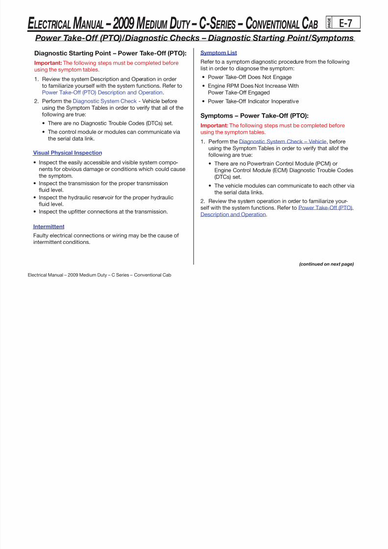
8/10/2019 2009 GM Medium Duty Electrical Manual.PDF
http://slidepdf.com/reader/full/2009-gm-medium-duty-electrical-manualpdf 369/410
Electrical Manual – 2009 Medium Duty – C Series – Conventional Cab
• The control module or modules can communicate via
the serial data link.
Visual Physical Inspection
• Inspect the easily accessible and visible system compo-
nents for obvious damage or conditions which could cause
the symptom.
• Inspect the transmission for the proper transmission
fluid level.
• Inspect the hydraulic reservoir for the proper hydraulic
fluid level.
• Inspect the uptter connections at the transmission.
Intermittent
Faulty electrical connections or wiring may be the cause of
intermittent conditions.
using the symptom tables.
1. Perform the Diagnostic System Check – Vehicle, before
using the Symptom Tables in order to verify that allof the
following are true:
• There are no Powertrain Control Module (PCM) or
Engine Control Module (ECM) Diagnostic Trouble Codes
(DTCs) set.
• The vehicle modules can communicate to each other via
the serial data links.
2. Review the system operation in order to familiarize your-
self with the system functions. Refer to Power Take-Off (PTO)
Description and Operation.
(continued on next page)
E LECTRICAL M ANUAL – 2009 M EDIUM DUTY – C-S ERIES – CONVENTIONAL C AB P A G E
E-8
Power Take-Off (PTO)/Diagnostic Checks – Symptoms (continued)
Visual Physical Inspection
• Inspect the uptter connections of the PTO system. Refer
to Checking Aftermarket Accessories.
• Inspect the easily accessible and the visible system com-
ponents for obvious damage.
• Inspect the transmission and hydraulic pump for the properfluid level.
Intermittent
Faulty electrical connections or wiring may be the cause of
intermittent conditions. Refer to Testing for Intermittent
Conditions and Poor Connections.
Symptom ListRefer to a symptom diagnostic procedure from the following
list in order to diagnose the symptom:
• Power Take-Off Does Not Engage
• Engine RPM Does Not Increase With
Power Take Off Engaged

8/10/2019 2009 GM Medium Duty Electrical Manual.PDF
http://slidepdf.com/reader/full/2009-gm-medium-duty-electrical-manualpdf 370/410
Electrical Manual – 2009 Medium Duty – C Series – Conventional Cab
Power Take-Off Engaged
• Power Take-Off Indicator Inoperative
E LECTRICAL M ANUAL – 2009 M EDIUM DUTY – C-S ERIES – CONVENTIONAL C AB P A G E
E-9
Power Take-Off (PTO)/Diagnostic Checks – PTO Does Not Engage
Circuit Description
This symptom chart will aid in diagnosing a failed Power
Take-Off (PTO) solenoid engagement. This diagnostic will not
expose a mechanical problem with the PTO itself. With the
ignition switch in RUN or START, voltage is supplied through
the Engine 1 fuse to the secondary side of the relay. When the
relay is energized the contacts will close and voltage will bepresent at the load engage switch. When the operator needs
the PTO he will close the load engage switch and current will
flow to the PTO solenoid. The solenoid has its own external
ground. When the operator turns the ignition switch to RUN,
voltage will be present at the PTO enable switch. When the
4. This step tests the Power Distribution circuits.
5. This step tests for voltage to the PTO solenoid.
6. This step tests for continuity on the ground circuit.
7. This step tests for voltage at the Ignition 1 Voltage
and PTO On Switch-Signal circuits.
8. This step tests the PTO control circuit.
9. This step tests for continuity on the PTO control circuit.
10. This step ensures that all of the PCM conditions for
engaging the PTO are met.
11. This step tests for ground on the Ignition 1 Voltage circuit.

8/10/2019 2009 GM Medium Duty Electrical Manual.PDF
http://slidepdf.com/reader/full/2009-gm-medium-duty-electrical-manualpdf 371/410
Electrical Manual – 2009 Medium Duty – C Series – Conventional Cab
PTO enable switch is turned to ON voltage will be present
at the coil of the relay and at the powertrain control module
(PCM). If the PCM sees all of the conditions necessary to en-
gage the solenoid, the PCM will ground the primary circuit of
the relay. The operation of a diesel system is the same except
that diesel engines have an engine control module (ECM) in-
stead of a PCM.
Test Description
The numbers below refer to the step numbers on the
diagnostic table.
2. This step tests engine controls and cruise control for
Diagnostic Trouble Codes (DTCs).3. This step tests for an open Engine 1 fuse.
12. This step tests for a ground on the PTO supply voltage
circuit.
13. This step tests the PTO solenoid for an internal ground.
14. This step tests for ground on the Ignition 1 Voltage circuit.
17. This step tests for voltage at the PTO On Switch-Signal
circuit.
18. This step tests for voltage at the Ignition 1 Voltage circuit.
19. This step tests the PTO Relay.
(continued on next page)
E LECTRICAL M ANUAL – 2009 M EDIUM DUTY – C-S ERIES – CONVENTIONAL C AB P A G E
E-10
Power Take-Off (PTO)/Diagnostic Checks – PTO Does Not Engage (continued)
Schematic Reference: Power take-off (PTO) Schematics
Step Action Yes No
1
Did you review the Power Take-Off(PTO) Description andOperations and perform thenecessary inspections?
Go to
Step 2
Go to Power
Take-Off (PTO)
Description and
Operation
2 Did you perform the DiagnosticSystem Check-Vehicle?
Go toStep 3
Go to DiagnosticSystem Check-
Vehicle
3Inspect the Engine 1 fuse.
Is the fuse open?
Go to
Step 11Go to Step 4
4
1. Turn the ignition switch to RUN.2. With a test lamp test for voltage Go to
Go to Step 24
Schematic Reference: Power take-off (PTO) Schematics (continued)
Step Action Yes No
7
1. Turn all switches OFF.
2. Disconnect the relay connector.
3. Turn the ignition switch to RUN.
4. Turn the PTO enable switch to ON.
Using a test lamp for voltage at theIgnition 1 and PTO On Switch-Signalcircuits at the relay connector.
Does the test lamp light on both tests?
Go to
Step 8Go to Step 16
1. Turn all switches OFF.
2. Connect the PTO relay.
3 T h i i i i h RUN

8/10/2019 2009 GM Medium Duty Electrical Manual.PDF
http://slidepdf.com/reader/full/2009-gm-medium-duty-electrical-manualpdf 372/410
Electrical Manual – 2009 Medium Duty – C Series – Conventional Cab
(continued on next page)
4p g
to the Engine 1 fuse.
Does the test lamp light?Step 5
Go to Step 24
5
1. Ensure that all of the PTO engageconditions are met. Refer to
Power Take-off (PTO) Descriptionand Operation.
2. Turn the PTO enable switch to ON.
3. Turn the load engage switch to ON.
4. With a test lamp for voltage on thePTO Supply-Voltage circuit at thePTO solenoid.
Does the test lamp light?
Go to
Step 6Go to Step 7
6
With a DMM test for continuity
on the ground circuit at the PTO
solenoid.
Do you have continuity?
Go to
Step 29Go to Step 25
8
3. Turn the ignition switch to RUN.
4. Turn the PTO enable switch to ON.
5. Turn the load engage switch to ON.
6. Ensure that all PTO Engage
conditions are met. Refer toPower Take-Off (PTO) Descriptionand Operation.
7. Using a jumper wire ground thePTO Control circuit at the relay.
Does the PTO solenoid engage?
Go to
Step 9Go to Step 19
9
Test for continuity on the PTOControl circuit.
Does the PTO Control circuit havecontinuity?
Go to
Step 10Go to Step 26
10
Ensure that all of the PCM condi-
tions for engaging the PTO aremet. Refer to Power Take-OffDescription and Operation.
Are all of the conditions met?
Go toStep 31
Go to Step 27
E LECTRICAL M ANUAL – 2009 M EDIUM DUTY – C-S ERIES – CONVENTIONAL C AB P A G E
E-11
Power Take-Off (PTO)/Diagnostic Checks – PTO Does Not Engage (continued)
Schematic Reference: Power take-off (PTO) Schematics (continued)
Step Action Yes No
11
1. Remove the Engine 1 fuse.
2. Disconnect the PTO relay.
3. Using a DMM test for ground onthe Ignition 1 Voltage circuit atthe relay connector.
Is the PTO Supply-Voltage circuit grounded?
Go to
Step 22Go to Step 13
12
1. Disconnect the PTO solenoid con-nector.
2. Using a DMM test for ground onthe PTO Supply-Voltage circuit atthe relay connector.
Go to
Step 23Go to Step 29
Schematic Reference: Power take-off (PTO) Schematics (continued)
Step Action Yes No
16Do you have voltage on the Ignition 1
Voltage circuit?Go to
Step 17Go to Step 22
17
1. Remove the PTO enable switchfrom the instrument panel, butleave it connected to the harness.
2. Using a fused jumper wire, jumpfrom the Ignition 1 Voltage circuit tothe PTO On Switch-Signal circuitat the switch.
3. Using a test lamp test for voltageat the PTO On Switch-Signal circuitat the PTO relay connector.
Go to
Step 28Go to Step 18

8/10/2019 2009 GM Medium Duty Electrical Manual.PDF
http://slidepdf.com/reader/full/2009-gm-medium-duty-electrical-manualpdf 373/410
Electrical Manual – 2009 Medium Duty – C Series – Conventional Cab
(continued on next page)
y
Is the PTO Supply-Voltage circuit grounded?
13
1. Disconnect both the positive andnegative leads of the PTO solenoid.
2. Using a DMM test for groundon the positive lead at the PTOsolenoid.
Is positive lead at the PTO solenoid grounded?
Go to
Step 23Go to Step 29
14
1. Remove the Engine 1 fuse.
2. Disconnect the PTO enable switch.
3. Using a DMM test for ground onthe Ignition 1 Voltage circuit atthe switch connector.
Is the Ignition 1 Voltage circuit
grounded?
Go to
Step 21Go to Step 15
15
1. Disconnect the PTO Relay.
2. Using a DMM test for ground onthe PTO On Switch-Signal circuitat the relay connector.
Is PTO On Switch-Signal circuit grounded?
Go to
Step 20Go to Step 28
Do you have voltage?
18
1. Turn the ignition switch OFF.
2. Turn the PTO enable switch OFF.
3. Disconnect the PTO enable switch.
4. Turn the ignition switch to RUN.
5. Using a test lamp test for voltageat the Ignition 1 Voltage circuit atthe switch connector.
Do you have voltage?
Go toStep 20
Go to Step 21
19
1. Disconnect the PTO Relay.
2. Using a fused jumper wire, jumpfrom the Ignition 1 Voltage circuitto the PTO Supply-Voltage cir-cuit at the relay connector.
Does the PTO Solenoid engage?
Go to
Step 30Go to Step 23
20
Repair the PTO on switch-signalcircuit for an open, short to groundor high resistance. Refer to WiringRepairs.
Did you complete the repair?
Go to
Step 32--
E LECTRICAL M ANUAL – 2009 M EDIUM DUTY – C-S ERIES – CONVENTIONAL C AB P A G E
E-12
Power Take-Off (PTO)/Diagnostic Checks – PTO Does Not Engage (continued)
Schematic Reference: Power take-off (PTO) Schematics (continued)
Step Action Yes No
21
Repair the Ignition 1 Voltagecircuit for an open, short toground or high resistance.Refer to Wiring Repairs..
Did you complete the repair?
Go to
Step 32--
22
Repair the Ignition 1 Voltagecircuit for an open, short toground or high resistance.Refer to Wiring Repairs..
Did you complete the repair?
Go to
Step 32--
Repair the PTO supply-voltagecircuit for an open, short to
G t
Schematic Reference: Power take-off (PTO) Schematics (continued)
Step Action Yes No
28
Repair the PTO enable switch.Refer to Upfitter instructions.
Did you complete the repair?
Go to
Step 32--
29
Replace the PTO solenoid. Refer to
Upfitter instructions.Did you complete the repair?
Go to
Step 32 --
30
Replace the PTO relay. Refer toUpfitter instructions.
Did you complete the repair?
Go to
Step 32--
Replace the PCM or ECM. Referto Control Module Referencesf l t t d
Go to

8/10/2019 2009 GM Medium Duty Electrical Manual.PDF
http://slidepdf.com/reader/full/2009-gm-medium-duty-electrical-manualpdf 374/410
Electrical Manual – 2009 Medium Duty – C Series – Conventional Cab
23
p ,ground or high resistance.Refer to Wiring Repairs..
Did you complete the repair?
Go to
Step 32--
24
Repair the affected power distribu-
tion circuit for an open, short toground or high resistance.Refer to Wiring Repairs..
Did you complete the repair?
Go to
Step 32--
25
Repair the ground circuit for anopen, short to ground or high re-sistance. Refer to Wiring Repairs..
Did you complete the repair?
Go to
Step 32--
26
Repair the PTO control circuitfor an open, short to ground orhigh resistance. Refer to
Wiring Repairs..Did you complete the repair?
Go to
Step 32--
27
Repair the malfunctioning PTOsupport circuit.
Did you complete the repair?
Go to
Step 32--
31 for replacement, setup andprogramming.
Did you complete the repair?
Go to
Step 32--
32
Test drive the vehicle and operate
the PTO system as described inthe supporting text.
Does the symptom occur?
Go toStep 2
System OK
E LECTRICAL M ANUAL – 2009 M EDIUM DUTY – C-S ERIES – CONVENTIONAL C AB P A G E
E-13
Power Take-Off (PTO)/Diagnostic Checks –
Engine RPM Does Not Increase with PTO Engaged
Circuit Description
When the power take-off (PTO) enable switch is turned to the
ON position and all PTO engage conditions are met, the en-
gine RPM should increase to the standby speed. When the
powertrain control module (PCM) receives the signal from the
PTO switch the PCM will send a signal to the throttle actuatorcontrol (TAC) module. The TAC module controls the TAC motor
which changes the position of the throttle. Communications
between the 2 modules is monitored and checked for accu-
racy by the PCM. Diagnostic trouble codes (DTCs) may be
recorded in the event of the failure. Diesel engines do not have
Schematic Reference: Power take-off (PTO) Schematics
and Cruise Control Schematics
Step Action Yes No
1
Did you review the PowerTake-Off (PTO) Description andOperation and perform thenecessary inspections
Go toStep 2
Go to
Power
Take-OffDescription
and
Operation
2
Verify the fault is present.
Does the system operate
Go to
Testing for
Intermittent
C diti
Go to
St 3

8/10/2019 2009 GM Medium Duty Electrical Manual.PDF
http://slidepdf.com/reader/full/2009-gm-medium-duty-electrical-manualpdf 375/410
Electrical Manual – 2009 Medium Duty – C Series – Conventional Cab
a TAC system and the engine RPM is strictly controlled by the
engine control module (ECM).
Test DescriptionThe numbers below refer to the step numbers on the
diagnostic table.
2. This step checks for other system DTCs that may affect
the PTO.
6. This step tests the PCM for the PTO Enable signal.
7. This step tests the communication between the PCM
and the TAC module.
8. This step tests the PTO On Switch Signal circuit.9. This step tests the PTO On Switch-Signal circuit for an
open, high resistance or short to ground.
10. This step tests the Serial Data circuits for an open, high
resistance or short to ground.
(continued on next page)
Does the system operate normally?
Conditions
and Poor
Connections
Step 3
3Did you perform the Diag-nostic System Check-Vehicle?
Go to
Step 4
Go to
DiagnosticSystem
Check-
Vehicle
4Does the PTO solenoidengage?
Go to
Step 5
Go to
Power Take-
Off (PTO)
Does Not
Engage
5 Is the engine a diesel?Go to
Step 8Go to Step 6
E LECTRICAL M ANUAL – 2009 M EDIUM DUTY – C-S ERIES – CONVENTIONAL C AB P A G E
E-14
Power Take-Off (PTO)/Diagnostic Checks –
Engine RPM Does Not Increase with PTO Engaged (continued)
Schematic Reference: Power take-off (PTO) Schematics
and Cruise Control Schematics (continued)
Step Action Yes No
6
1. Start the engine.
2. Ensure that all of the PTO en-
gage conditions are met. Re-fer to Power Take-Off (PTO)Description and Operation.
3. Turn the PTO enable switchto ON.
4. Using a test lamp test forvoltage to the PCM on thePTO On Switch Signal circuit.
Go to
Step 7Go to Step 9
Schematic Reference: Power take-off (PTO) Schematics
and Cruise Control Schematics (continued)
Step Action Yes No
10
Test the Serial Data circuits foran open, high resistance or
short to ground. Refer to CruiseControl Schematics.
Did you find and correct thecondition?
Go toStep 13 Go to Step 11
11
Replace the TAC module.Refer to Control ModuleReferences for replacement,setup and programming.
Go to
Step 13--

8/10/2019 2009 GM Medium Duty Electrical Manual.PDF
http://slidepdf.com/reader/full/2009-gm-medium-duty-electrical-manualpdf 376/410
Electrical Manual – 2009 Medium Duty – C Series – Conventional Cab
g
Does the test lamp illuminate?
7
Using the scan tool read theTAC/PCM communicationsignal on the Engine Controls
Data List.Does the scan tool display OK?
Go to
Diganostic
Starting Point– Cruise Control
Go to
Step 10
8
1. Depending on the specificdiesel engine application,disconnect the appropriateconnector at the ECM.
2. Turn the ignition swithcto RUN.
3. Turn the PTO enable switchto ON.
4. Using a test lamp test for volt-
age to the ECM on the PTOOn Switch Signal circuit.
Does the test lamp light?
Go to
Diganostic
Starting Point
– Engine
Controls
for the 6.6L
engine or Diag-
nostic Starting
Point – Engine
Controls for the
7.8L engine
Go to
Step 9
9
Test the PTO On Switch-Signal circuit for an open, highresistance or short to ground.
Did you find and correctthe condition?
Go to
Step 13
Go to
Step 12
p p g g
Did you complete the replacement?
Step 13
12
Replace the PCM or ECM.Refer to Control Module
References for replacement,setup and programming.
Did you complete the replacement?
Go toStep 13
--
13
Test drive the vehicle and oper-ate the PTO system as de-scribed in the supporting text.
Does the symptom occur?
Go to
Step 3System OK
E LECTRICAL M ANUAL – 2009 M EDIUM DUTY – C-S ERIES – CONVENTIONAL C AB P A G E
E-15
Power Take-Off (PTO)/Diagnostic Checks – PTO Indicator Inoperative
Circuit Description
This symptom chart will aid in diagnosing a failed Power Take-
Off (PTO) indicator. This diagnostic assumes that the PTO
solenoid is functional and only the indicator is failing to come
on. When the ignition switch is in RUN, voltage should be
present on the Ignition 1 Voltage circuit. When the PTO switch
is turned to ON, the LED will illuminate. The indicator has itsown ground circuit. The PTO enable switch indicator and PTO
solenoid have different ground circuits. Therefore, the indicator
may be illuminated when the PTO solenoid is disengaged.
Test Description
Schematic Reference: Power take-off (PTO) Schematics
Step Action Yes No
1
Did you review the PowerTake-Off (PTO) Descriptionand Operation and performthe necessary inspections
Go to
Step 2
Go to
Power Take-
Off Descrip-
tion and
Operation
2
Verify the fault is present.
Does the system operate normally?
Go to
Testing for
Intermittent
Conditions
and Poor
Connections
Go to
Step 3

8/10/2019 2009 GM Medium Duty Electrical Manual.PDF
http://slidepdf.com/reader/full/2009-gm-medium-duty-electrical-manualpdf 377/410
Electrical Manual – 2009 Medium Duty – C Series – Conventional Cab
The numbers below refer to the step numbers on the
diagnostic table.
4. This step tests the PTO On switch signal circuit.
5. This step tests the ground circuit.
(continued on next page)
E LECTRICAL M ANUAL – 2009 M EDIUM DUTY – C-S ERIES – CONVENTIONAL C AB P A G E
E-16
Power Take-Off (PTO)/Diagnostic Checks – PTO Indicator Inoperative (continued)
Schematic Reference: Power take-off (PTO) Schematics (continued)
Step Action Yes No
6
Repair the open or high restis-tance in both PTO On switchSignal circuit. Refer to WiringRepairs.
Did you complete the repair?
Go to
Step 9--
7
Repair the open or high re-sistance in the ground circuit.Refer to Wiring Repairs.
Did you complete the repair?
Go to
Step 9--
8
Replace the PTO Enableswitch. Refer to Upfittersinstructions.
Go to
St 9--
Schematic Reference: Power take-off (PTO) Schematics (continued)
Step Action Yes No
3Does the PTO solenoidengage?
Go to
Step 4
Go to
Power
Take-Off
(PTO) Does
Not Engage
1. Turn the ignition switch toRUN.
2. Turn the PTO enable switchto ON.
3. Ensure that the condi-tions for engaging the PTOsolenoid are met. Refer to

8/10/2019 2009 GM Medium Duty Electrical Manual.PDF
http://slidepdf.com/reader/full/2009-gm-medium-duty-electrical-manualpdf 378/410
Electrical Manual – 2009 Medium Duty – C Series – Conventional Cab
8
Did you complete the replacement?
Step 9
9
Test drive the vehicle andoperate the PTO system asdescribed in the supportingtest.
Does the symptom occur?
Go toStep 3
System OK
4
Power Take-Off (PTO) De-scription and Operation.
4. Remove the PTO switch,but leave it connected to
the harness.5. Using a test lamp test for
voltage at the PTO OnSwitch Signal circuit at theswitch.
Does the test lamp illuminate?
Go to
Step 5
Go to
Step 6
5
1. Turn the PTO enable switchto OFF.
2. Turn the ignition switch OFF.
3. Disconnect the switch.
4. Using a DMM test for con-
tinuity on the ground circuitat the switch connector.
Do you have continuity?
Go to
Step 8Go to Step 7

8/10/2019 2009 GM Medium Duty Electrical Manual.PDF
http://slidepdf.com/reader/full/2009-gm-medium-duty-electrical-manualpdf 379/410
E LECTRICAL M ANUAL – 2009 M EDIUM DUTY – C-S ERIES – CONVENTIONAL C AB P A G E
E-18
Power Take-Off (PTO)/Schematics – L18, LMM, LF8 (2 of 2)

8/10/2019 2009 GM Medium Duty Electrical Manual.PDF
http://slidepdf.com/reader/full/2009-gm-medium-duty-electrical-manualpdf 380/410
Electrical Manual – 2009 Medium Duty – C Series – Conventional Cab
E LECTRICAL M ANUAL – 2009 M EDIUM DUTY – C-S ERIES – CONVENTIONAL C AB P A G E
E-19
Power Take-Off (PTO)/Schematics – LF6

8/10/2019 2009 GM Medium Duty Electrical Manual.PDF
http://slidepdf.com/reader/full/2009-gm-medium-duty-electrical-manualpdf 381/410
Electrical Manual – 2009 Medium Duty – C Series – Conventional Cab
E LECTRICAL M ANUAL – 2009 M EDIUM DUTY – C-S ERIES – CONVENTIONAL C AB P A G E
E-20
Vehicle – Diagnostic System Check
1. Before beginning vehicle diagnosis, the following prelimi-
nary inspections/tests must be performed:
• Ensure that the battery is fully charged.
Refer to Battery Inspection/Test.
• Ensure that the battery cables are clean and tight.
• Inspect for any open fuses. Refer to Power DistributionSchematics and Electrical Center Identification Views.
• Ensure that the grounds are clean, tight, and in the correct
location. Refer to Ground Distribution Schematics and
Harness Routing Views.
• Inspect the easily accessible systems or the visible sys-
f b i d di i h
10. Ignition ON, Engine OFF, verify communication with all
of the control modules on the vehicle. Refer to Data Link
References for information on the modules you should
expect to communicate.
If the scan tool does not communicate with one or more of the
expected control modules, refer to Data Link References.
11. Attempt to start the engine. Verify that the engine cranks.
If the engine does not crank, refer to Symptoms -
Engine Electrical.
12. Important: For the 7.2L Caterpillar engine, refer to the
appropriate Caterpillar Service Manual.
13 A h i V if h i

8/10/2019 2009 GM Medium Duty Electrical Manual.PDF
http://slidepdf.com/reader/full/2009-gm-medium-duty-electrical-manualpdf 382/410
Electrical Manual – 2009 Medium Duty – C Series – Conventional Cab
tem components for obvious damage or conditions that
could cause the concern. This would include checking to
ensure that all connections/connectors are fully seated
and secured. • Inspect for aftermarket devices that could affect the
operation of the system. Refer to Checking Aftermarket
Accessories.
• Search for applicable service bulletins.
If the preceding inspections/tests resolve the concern, go to
Diagnostic Repair Verification.
9. Install a scan tool. Verify that the scan tool powers up.
If the scan tool does not power up, refer to Scan Tool DoesNot Power Up.
13. Attempt to start the engine. Verify the engine starts
and idles.
If the engine does not start and idle, refer to one of
the following:
• Engine Cranks but Does Not Run for the
6.6L (LMM) engine
• Engine Cranks but Does Not Run for the
7.8L (LF8) engine
• Engine Cranks but Does Not Run for the
8.1L engine
17. Important: For the 7.2L Caterpillar engine, refer to the
appropriate Caterpillar Service Manual.
18. Important: Do not clear any DTCs unless instructed to
do so by a diagnostic procedure.
(continued on next page)

8/10/2019 2009 GM Medium Duty Electrical Manual.PDF
http://slidepdf.com/reader/full/2009-gm-medium-duty-electrical-manualpdf 383/410
E LECTRICAL M ANUAL – 2009 M EDIUM DUTY – C-S ERIES – CONVENTIONAL C AB P A G E
E-22
Checking Aftermarket Accessories
Do not connect aftermarket accessories into the
following circuits:
Caution: Refer to SIR Caution in the Preface section.
• SIR circuits, all such circuits are indicated on circuit dia-
grams with the SIR symbol.
Notice: The OBD II symbol is used on the circuit diagramsin order to alert the technician that the circuit is essential for
proper OBD II emission control circuit operation. Any circuit
which fails and causes the malfunction indicator lamp (MIL) to
turn ON, or causes emissions-related component damage, is
identified as an OBD II circuit.
• OBD II circuits, all such circuits are indicated on circuit dia-
Possible causes of vehicle problems related to aftermarket
accessories include:
• Power feeds connected to points other than the battery
• Antenna location
• Transceiver wiring located too close to vehicle electronic
modules or wiring• Poor shielding or poor connectors on antenna feed line
• Check for recent service bulletins detailing installation
guidelines for aftermarket accessories.

8/10/2019 2009 GM Medium Duty Electrical Manual.PDF
http://slidepdf.com/reader/full/2009-gm-medium-duty-electrical-manualpdf 384/410
Electrical Manual – 2009 Medium Duty – C Series – Conventional Cab
OBD II circuits, all such circuits are indicated on circuit dia
grams with the OBD II symbol.
Always check for aftermarket accessories (non-OEM) as the
first step in diagnosing electrical problems. If the vehicle is soequipped, disconnect the system to verify that these add-on
accessories are not the cause of the problems.
E LECTRICAL M ANUAL – 2009 M EDIUM DUTY – C-S ERIES – CONVENTIONAL C AB P A G E
E-23
Wiring Repairs/Testing for Intermittent Conditions and Poor Connections
Tools Required
• J 35616 GM-Approved Terminal Test Kit
• J-38125 Terminal Repair Kit
When the condition is not currently present, but is indicated
in DTC history, the cause may be intermittent. An intermittent
may also be the cause when there is a customer complaint,but the symptom cannot be duplicated. Refer to the Symptom
Table of the system that is suspect of causing the condition
before trying to locate an intermittent condition.
Most intermittent conditions are caused by faulty electrical
connections or wiring. Inspect for the following items:
• Wiring broken inside the ins lation
• Refer to Inducing Intermittent Fault Conditions in order to
duplicate the conditions required, in order to verify the
customer concern.
• Refer to Testing for Electrical Intermittents for test
procedures to detect intermittent open, high resistance,
short to ground, and short to voltage conditions.
• Refer to Scan Tool Snapshot Procedure for advanced
intermittent diagnosis and Vehicle Data Recorder operation.
Testing for Proper Terminal Contact
It is important to test terminal contact at the component and
i li t b f l i t t

8/10/2019 2009 GM Medium Duty Electrical Manual.PDF
http://slidepdf.com/reader/full/2009-gm-medium-duty-electrical-manualpdf 385/410
Electrical Manual – 2009 Medium Duty – C Series – Conventional Cab
• Wiring broken inside the insulation
• Poor connection between the male and female terminal
at a connector
• Poor terminal to wire connection--Some conditions which
fall under this description are poor crimps, poor solder
joints, crimping over the wire insulation rather than the wire
itself, and corrosion in the wire to terminal contact area, etc.
• Pierced or damaged insulation can allow moisture to enter
the wiring causing corrosion. The conductor can corrode
inside the insulation, with little visible evidence. Look for
swollen and stiff sections of wire in the suspect circuits.
• Wiring which has been pinched, cut, or its insulation rubbed
through may cause an intermittent open or short as the bare
area touches other wiring or parts of the vehicle.
• Wiring that comes in contact with hot or exhaust
components
any inline connectors before replacing a suspect component.
Mating terminals must be inspected to ensure good terminal
contact. A poor connection between the male and female
terminal at a connector may be the result of contamination ordeformation.
Contamination may be caused by the connector halves being
improperly connected. A missing or damaged connector seal,
damage to the connector itself, or exposing the terminals to
moisture and dirt can also cause contamination. Contamina-
tion, usually in the underhood or underbody connectors, leads
to terminal corrosion, causing an open circuit or intermittently
open circuit.
(continued on next page)
E LECTRICAL M ANUAL – 2009 M EDIUM DUTY – C-S ERIES – CONVENTIONAL C AB P A G E
E-24
Testing for Proper Terminal Contact (continued)
Wiring Repairs/Testing for Intermittent Conditions and Poor Connections (continued)
Deformation is caused by probing the mating side of a con-
nector terminal without the proper adapter. Always use the
J 35616 when probing connectors. Other causes of terminal
deformation are improperly joining the connector halves, or
repeatedly separating and joining the connector halves.
Deformation, usually to the female terminal contact tang, canresult in poor terminal contact causing an open or intermit-
tently open circuit.
Testing for Proper Terminal Contact in
Bussed Electrical Centers (BEC)
It is very important to use the correct test adapter when test-
Flat Wire (Dock and Lock) Connectors
There are no serviceable parts for flat wire (dock and lock)
connectors on the harness side or the component side.
Follow the procedure below in order to test terminal contact:
1. Remove the component in question.
2. Visually inspect each side of the connector for signs of con-tamination. Avoid touching either side of the connector as oil
from your skin may be a source of contamination as well.
3. Visually inspect the terminal bearing surfaces of the flat wire
circuits for splits, cracks, or other imperfections that could
cause poor terminal contact. Visually inspect the component
side connector to ensure that all of the terminals are uniform

8/10/2019 2009 GM Medium Duty Electrical Manual.PDF
http://slidepdf.com/reader/full/2009-gm-medium-duty-electrical-manualpdf 386/410
Electrical Manual – 2009 Medium Duty – C Series – Conventional Cab
ing for proper terminal contact of fuses and relays in a bussed
electrical center (BEC). Use J-35616-35 to test for proper
terminal contact. Failure to use J-35616-35 can result in
improper diagnosis of the BEC.
Follow the procedure below in order to test terminal contact:
1. Separate the connector halves.
2. Visually inspect the connector halves for contamination.
Contamination may result in a white or green build-up within
the connector body or between terminals. This causes high
terminal resistance, intermittent contact, or an open circuit.
An underhood or underbody connector that shows signs of
contamination should be replaced in its entirety: terminals,
seals, and connector body.
3. Using an equivalent male terminal from the J-38125, test
that the retention force is significantly different between a
good terminal and a suspect terminal. Replace the female
terminal in question.
side connector to ensure that all of the terminals are uniform
and free of damage or deformation.
4. Insert the appropriate adapter from the on the flat wire
harness connector in order to test the circuit in question.
Control Module/Component Voltage and Grounds
Poor voltage or ground connections can cause widely varying
symptoms.
• Test all control module voltage supply circuits. Many ve-
hicles have multiple circuits supplying voltage to a control
module. Other components in the system may have sepa-
rate voltage supply circuits that may also need to be tested.Inspect connections at the module/component connectors,
fuses, and any intermediate connections between the volt-
age source and the module/component. A test lamp or a
DMM may indicate that voltage is present, but neither tests
the ability of the circuit to carry sufficient current.
(continued on next page)
E LECTRICAL M ANUAL – 2009 M EDIUM DUTY – C-S ERIES – CONVENTIONAL C AB P A G E
E-25
Ensure that the circuit can carry the current necessary to
operate the component. Refer to Circuit Testing and Power
Distribution Schematics.
• Test all control module ground and system ground circuits.
The control module may have multiple ground circuits. Oth-
er components in the system may have separate grounds
that may also need to be tested. Inspect grounds for cleanand tight connections at the grounding point. Inspect the
connections at the component and in splice packs, where
applicable. Ensure that the circuit can carry the current nec-
essary to operate the component. Refer to Circuit Testing
and Ground Distribution Schematics.
• If the intermittent is related to cold, review the data for
the following:
- Low ambient temperatures--In extremely low
temperatures, ice may form in a connection or
component. Inspect for water intrusion.
- The condition only occurs on a cold start. - The condition goes away when the vehicle warms up.
• Information from the customer may help to determine if the
trouble follows a pattern that is temperature related.
• If temperature is suspected of causing an intermittent fault
condition, attempt to duplicate the condition. Refer to
I d i I t itt t F lt C diti i d t d li t
Wiring Repairs/Testing for Intermittent Conditions and Poor Connections (continued)
8/10/2019 2009 GM Medium Duty Electrical Manual.PDF
http://slidepdf.com/reader/full/2009-gm-medium-duty-electrical-manualpdf 387/410
Electrical Manual – 2009 Medium Duty – C Series – Conventional Cab(continued on next page)
Temperature Sensitivity
• An intermittent condition may occur when a component/ connection reaches normal operating temperature. The
condition may occur only when the component/connection
is cold, or only when the component/connection is hot.
• Freeze Frame, Failure Records, Snapshot, or Vehicle Data
Recorder data may help with this type of intermittent condi-
tion, where applicable.
• If the intermittent is related to heat, review the data for a
relationship with the following:
- High ambient temperatures - Underhood/engine generated heat
- Circuit generated heat due to a poor connection, or
high electrical load
- Higher than normal load conditions, towing, etc.
Inducing Intermittent Fault Conditions in order to duplicate
the conditions required.
Electromagnetic Interference (EMI)and Electrical Noise
Some electrical components/circuits are sensitive to electro-
magnetic interference (EMI) or other types of electrical noise.
Inspect for the following conditions:
• A misrouted harness that is too close to high voltage/high
current devices such as secondary ignition components,
motors, generator etc--These components may induce
electrical noise on a circuit that could interfere with normalcircuit operation.
• Electrical system interference caused by a malfunctioning
relay, or a control module driven solenoid or switch – These
conditions can cause a sharp electrical surge. Normally, the
condition will occur when the malfunctioning component
is operating.
E LECTRICAL M ANUAL – 2009 M EDIUM DUTY – C-S ERIES – CONVENTIONAL C AB P A G E
E-26
Wiring Repairs/Testing for Intermittent Conditions and Poor Connections (continued)
• Improper installation of non-factory or aftermarket add on
accessories such as lights, 2-way radios, amplifiers, electric
motors, remote starters, alarm systems, cell phones, etc-
-These accessories may lead to interference while in use,
but do not fail when the accessories are not in use.
Refer to Checking Aftermarket Accessories.
• Test for an open diode across the A/C compressor clutchand for other open diodes. Some relays may contain a
clamping diode.
• The generator may be allowing AC noise into the
electrical system.
Incorrect Control Module
• There are only a few situations where reprogramming a con-
trol module is appropriate:
- A new service control module is installed.
- A control module from another vehicle is installed.
- Revised software/calibration files have been released
for this vehicle.
Important: DO NOT re-program the control module with the
SAME software/calibration files that are already present in the
control module. This is not an effective repair for any type of
concern.

8/10/2019 2009 GM Medium Duty Electrical Manual.PDF
http://slidepdf.com/reader/full/2009-gm-medium-duty-electrical-manualpdf 388/410
Electrical Manual – 2009 Medium Duty – C Series – Conventional Cab
• Verify that the control module contains the correct software/
calibration. If incorrect programming is found, reprogram the
control module with the most current software/calibration.
Refer to Control Module References for replacement, setup,
and programming.
E LECTRICAL M ANUAL – 2009 M EDIUM DUTY – C-S ERIES – CONVENTIONAL C AB P A G E
E-27
Wiring Repairs/Flat Wire Repairs
Notice: The flat wire within the flex wiring harness is not
serviceable. If an open or short exists within the flex wiring
harness the complete harness must be replaced.
8/10/2019 2009 GM Medium Duty Electrical Manual.PDF
http://slidepdf.com/reader/full/2009-gm-medium-duty-electrical-manualpdf 389/410
Electrical Manual – 2009 Medium Duty – C Series – Conventional Cab
E LECTRICAL M ANUAL – 2009 M EDIUM DUTY – C-S ERIES – CONVENTIONAL C AB P A G E
E-28
Wiring Repairs/GMLAN Wiring Repairs
Tools Required
J-38125 Terminal Repair Kit
The GM Local Area Network (GMLAN) System requires spe-
cial wiring repair procedures due to the sensitive nature of
the circuitry. Follow the specific procedures and instructions
when working on GMLAN connectors and terminals.The tool kit J-38125 contains the following items in order to
repair the GMLAN wiring:
• DuraSeal splice sleeves
• A wire stripping tool
• J 38125-8 Crimping Tool (GM P/N 12085115)
GMLAN Repairs
Important: When making a repair to any GMLAN network,
the original wire length after the repair must be the same
length as before the repair. If the network is a twisted pair, the
twist must be maintained after the repair is completed.
GMLAN has 2 types of networks, low speed and high speed.Low speed GMLAN has a single wire and works at slow
speeds. High speed GMLAN has 2 wires in a twisted pair and
works at higher speeds. For more information on GMLAN,
refer to Data Link Communications Description and Operation.
GMLAN C t T i l R i

8/10/2019 2009 GM Medium Duty Electrical Manual.PDF
http://slidepdf.com/reader/full/2009-gm-medium-duty-electrical-manualpdf 390/410
Electrical Manual – 2009 Medium Duty – C Series – Conventional Cab
J 38125 8 Crimping Tool (GM P/N 12085115)
• J 38125-5 Ultra Torch Special Tool (GM P/N 12085116)
The DuraSeal splice sleeves have the following
2 critical features:
• A special heat shrink sleeve environmentally seals
the splice. The heat shrink sleeve contains a sealing
adhesive inside.
• A cross hatched (knurled) core crimp provides necessary
contact integrity for the sensitive, low energy circuits.
The J-38125 also serves as a generic terminal repair kit.
The kit contains the following items:
• A large sampling of common electrical terminals• The correct tools in order to attach the terminals to
the wires
• The correct tools in order to remove the terminals from
the connectors
(continued on next page)
GMLAN Connector Terminal Repair
Important: A service terminal can be used to replace dam-
aged connector terminals for both high speed and low speedGMLAN systems. When making a connector terminal repair on
a GMLAN high speed system with twisted pair wires, do not
untwist the wires more than necessary to make the repair.
The terminals in the GMLAN system are made of a special
metal. This metal provides the necessary contact integrity for
the sensitive, low energy circuits. These terminals are avail-
able in the J-38125. If the individual terminals are damaged on
any GMLAN connection, use the appropriate connector repair
procedure in order to repair the terminal. Refer to Connector
Repairs for the appropriate connector repair procedure.
E LECTRICAL M ANUAL – 2009 M EDIUM DUTY – C-S ERIES – CONVENTIONAL C AB P A G E
E-29
Wiring Repairs/GMLAN Wiring Repairs (continued)
GMLAN Wire Repair
Important: Refer to Wiring Repairs in order to determine the
correct wire size for the circuit you are repairing. You must
obtain this information in order to ensure circuit integrity.
If a wire is damaged, repair the wire by splicing in a new sec-
tion of wire of the same gage size (0.5 mm, 0.8 mm, 1.0 mm,etc.). Use the DuraSeal splice sleeves and splice crimping tool
from the J-38125. Use the following wiring repair procedures
in order to ensure the integrity of the sealed splice.
Splice Sleeve ColorCrimp Tool Nest
Color
Wire Gage mm2 /
(AWG)
Salmon (Yellow Pink)
• Do not use the DuraSeal splice sleeve to form a splice
with more than 2 wires coming together.
4. Cut as little wire off the harness as possible. You may
need the extra length of wire in order to change the
location of a splice.
Adjust splice locations so that each splice is at least
40 mm (1.5 in) away from the other splices, harnessbranches, or connectors.
5. Strip the insulation:
• When adding a length of wire to the existing harness,
use the same size wire as the original wire.
• Perform one of the following items in order to nd the

8/10/2019 2009 GM Medium Duty Electrical Manual.PDF
http://slidepdf.com/reader/full/2009-gm-medium-duty-electrical-manualpdf 391/410
Electrical Manual – 2009 Medium Duty – C Series – Conventional Cab
(continued on next page)
Salmon (Yellow-Pink)12089189
Red (1) 0.035-0.8/(18-20)
Blue12089190
Blue (2) 1.0-2.0/(14-16)
Yellow12089191
Yellow (3) 3.0-5.0/(10-12)
Green88988379
Red (1) 0.22-0.35/(22-24)
Important: You must perform the following procedures in
the listed order. Repeat the procedure if any wire strands are
damaged. You must obtain a clean strip with all of the wire
strands intact.
1. Open the harness by removing any tape:• Use a sewing seam ripper (available from sewing supply
stores) in order to cut open the harness in order to avoid
wire insulation damage.
• Use the DuraSeal splice sleeves on all types of insulation
except coaxial.
g
correct wire size:
- Find the wire on the schematic and convert the metric
size to the equivalent American wire gage (AWG) size.- Use an AWG wire gage.
- If you are unsure of the wire size, begin with the largest
opening in the wire stripper and work down until achiev-
ing a clean strip of the insulation.
• Strip approximately 7.5 mm (0.313 in) of insulation from
each wire to be spliced.
• Do not nick or cut any of the strands. Inspect the stripped
wire for nicks or cut strands.
• If the wire is damaged, repeat this procedure after remov-
ing the damaged section.
E LECTRICAL M ANUAL – 2009 M EDIUM DUTY – C-S ERIES – CONVENTIONAL C AB P A G E
E-30
13. Select the proper DuraSeal splice sleeve according to
the wire size. Refer to the above table at the beginning of
the repair procedure for the color coding of the DuraSeal
splice sleeves and the crimp tool nests.
16. Insert the wire into the splice sleeve barrel until the
wire hits the barrel stop.
17. Tightly close the handles of the crimp tool until the
crimper handles open when released.
The crimper handles will not open until you apply the
Wiring Repairs/GMLAN Wiring Repairs (continued)

8/10/2019 2009 GM Medium Duty Electrical Manual.PDF
http://slidepdf.com/reader/full/2009-gm-medium-duty-electrical-manualpdf 392/410
Electrical Manual – 2009 Medium Duty – C Series – Conventional Cab
14. Use the Splice Crimp Tool from the J-38125 in order
to position the DuraSeal splice sleeve in the propercolor nest of the Splice Crimp Tool. The crimp tool
has three nests, 1 is for the salmon and green splice
sleeve, 2 is for the blue splice sleeve, and 3 is for the
yellow splice sleeve.
15. Place the DuraSeal splice sleeve in the nest. Ensure that
the crimp falls midway between the end of the barrel and
the stop. The sleeve has a stop (3) in the middle of the
barrel (2) in order to prevent the wire (1) from going fur-
ther. Close the hand crimper handles slightly in order to
firmly hold the DuraSeal splice sleeve in the proper nest.
p p y pp y
proper amount of pressure to the splice sleeve. Repeat
steps 4 and 5 for the opposite end of the splice.
18. Using the heat torch, apply heat to the crimped area
of the barrel.
19. Start in the middle and gradually move the heat barrel tothe open ends of the tubing:
• The tubing will shrink completely as the heat is moved
along the insulation.
• A small amount of sealant will come out of the end of
the tubing when sufficient shrinkage is achieved.
E LECTRICAL M ANUAL – 2009 M EDIUM DUTY – C-S ERIES – CONVENTIONAL C AB P A G E
E-31
Wiring Repairs/High Temperature Wiring Repairs
Tools Required
J-38125 Terminal Repair Kit
High Temperature Wiring
Wiring that is exposed to high temperatures, 135°C (275°F)
or higher, for prolonged periods of time may use materials i.e.wires, connectors, and shielding that has a higher heat rating
than typical wiring. When making a repair in a high tempera-
ture area observe the following:
• Use high temperature bulk wire rated at 150°C (302°F)
continuous temperature to replace any damaged wire.
R l h t hi ldi th t i d
mine if an area is exposed to excessive heat before making
a wiring repair. Obvious areas of consideration would be any
area located near the exhaust manifolds, catalytic converter,
and exhaust pipes.
The J-38125 contains much of the material you will need to
perform repairs on areas exposed to high heat. The kit con-
tains the following items:• DuraSeal splice sleeves to crimp and seal connections
• High temperature SCT1 shrink tubing to protect the splice sleeves
• A large sampling of common electrical terminals
• The correct crimp tool to attach the terminals to the wires
• The correct tools to remove the terminals from the connectors

8/10/2019 2009 GM Medium Duty Electrical Manual.PDF
http://slidepdf.com/reader/full/2009-gm-medium-duty-electrical-manualpdf 393/410
Electrical Manual – 2009 Medium Duty – C Series – Conventional Cab(continued on next page)
• Replace any heat shielding that is removed.
• Cover any DuraSeal splice sleeves with SCT1 shrink tubing
(available in the J-38125 Terminal Repair kit).
• After making a wiring repair, ensure that the location of
the wiring is not moved closer to the heat source.
Identifying High Temperature Wiring
Wiring that is exposed to high temperature, 135°C (275°F)
or higher, for prolonged periods of time need special con-
siderations when making wiring repairs. Areas that may be
exposed to higher temperatures can be identified by heat
resistant materials that are being used in those areas. Thesematerials may include heat reflective tape, moon tape, and
high temperature shrink tubing. Also conduit and other pro-
tective coverings may be used. Because conduit or similar
coverings are used throughout the vehicle regardless of the
temperature, it may be necessary for the technician to deter-
The correct tools to remove the terminals from the connectors
The J-38125 does not contain wire that is suitable to high
temperature exposure. Use high temperature bulk wire rated
at 150°C (302°F) continuous temperature of the same or largergage size as the original wire when repair damage wire. Also
replace any reflective tape that you remove during the repair.
High Temperature Wire Repair
Important: Refer to Wiring Repairs in order to determine the
correct wire size for the circuit you are repairing. You must
obtain this information in order to ensure circuit integrity.
If any wire except the pigtail is damaged, repair the wire bysplicing in a new section of wire rated at 150°C (302°F)
continuous temperature rating of the same gage size
(0.5 mm, 0.8 mm, 1.0 mm etc.).
E LECTRICAL M ANUAL – 2009 M EDIUM DUTY – C-S ERIES – CONVENTIONAL C AB P A G E
E-32
Wiring Repairs/High Temperature Wiring Repairs (continued)
Use the DuraSeal splice sleeves and splice crimping tool from the
J-38125 and then encapsulate the splice sleeve using the high
temperature SCT1 shrink tubing. Use the following wiring repair
procedures in order to ensure the integrity of the sealed splice.
Splice Sleeve ColorCrimp Tool Nest
Color
Wire Gage mm2 /
(AWG)
Salmon (Yellow-Pink)12089189
Red (1) 0.035-0.8/(18-20)
Blue12089190
Blue (2) 1.0-2.0/(14-16)
Yellow12089191
Yellow (3) 3.0-5.0/(10-12)
Green88988379
Red (1) 0.22-0.35/(22-24)
4. Strip the insulation:
• When adding a length of wire to the existing harness,
use the same size wire as the original wire.
• Perform one of the following items in order to nd the
correct wire size:
- Find the wire on the schematic and convert the metric
size to the equivalent american wire gage (AWG) size.
- Use an AWG wire gage.
- If you are unsure of the wire size, begin with the
largest opening in the wire stripper and work down
until achieving a clean strip of the insulation.
• Strip approximately 7.5 mm (0.313 in) of insulation from

8/10/2019 2009 GM Medium Duty Electrical Manual.PDF
http://slidepdf.com/reader/full/2009-gm-medium-duty-electrical-manualpdf 394/410
Electrical Manual – 2009 Medium Duty – C Series – Conventional Cab
(continued on next page)
88988379
Important: You must perform the following procedures in
the order listed. Repeat the procedure if any wire strands are
damaged. You must obtain a clean strip keeping all of the wire
strands intact.
1. Open the harness by removing any tape.
2. Use a sewing seam ripper, available from sewing supply
stores, in order to cut open the harness in order to avoid
wire insulation damage.
3. Cut as little wire off the harness as possible. You may
need the extra length of wire in order to change the
location of a splice. Adjust splice locations so that each splice is at least
40 mm (1.5 in) away from the other splices, harness
branches, or connectors.
Strip approximately 7.5 mm (0.313 in) of insulation from
each wire to be spliced.
• Do not nick or cut any of the strands. Inspect the
stripped wire for nicks or cut strands.
• If the wire is damaged, repeat this procedure after re-
moving the damaged section.
12. Slide a section of high temperature SCT1 shrink tubing
down the length of wire to be spliced. Ensure that the
shrink tubing will not interfere with the splice procedure.
13. Select the proper DuraSeal splice sleeve according to
the wire size. Refer to the above table at the beginning of
the repair procedure for the color coding of the DuraSeal
splice sleeves and the crimp tool nests.
E LECTRICAL M ANUAL – 2009 M EDIUM DUTY – C-S ERIES – CONVENTIONAL C AB P A G E
E-33
Wiring Repairs/High Temperature Wiring Repairs (continued)
14. Use the Splice Crimp Tool from the J-38125 in order to
position the DuraSeal splice sleeve in the proper color
16. Insert the wire into the DuraSeal splice sleeve barrel
until the wire hits the barrel stop.
17. Tightly close the handles of the crimp tool until the
crimper handles open when released.
The crimper handles will not open until you apply the
proper amount of pressure to the splice sleeve. Repeat

8/10/2019 2009 GM Medium Duty Electrical Manual.PDF
http://slidepdf.com/reader/full/2009-gm-medium-duty-electrical-manualpdf 395/410
Electrical Manual – 2009 Medium Duty – C Series – Conventional Cab(continued on next page)
position the DuraSeal splice sleeve in the proper color
nest of the Splice Crimp Tool. The crimp tool has three
nests, 1 is for the salmon and green splice sleeve, 2 is
for the blue splice sleeve, and 3 is for the yellow splicesleeve.
15. Place the DuraSeal splice sleeve in the nest. Ensure that
the crimp falls midway between the end of the barrel and
the stop. The sleeve has a stop (3) in the middle of the
barrel (2) in order to prevent the wire (1) from going fur-
ther. Close the hand crimper handles slightly in order to
firmly hold the DuraSeal splice sleeve in the proper nest.
proper amount of pressure to the splice sleeve. Repeat
steps 4 and 5 for the opposite end of the splice.
18. Using the heat torch, apply heat to the crimped area
of the barrel.
19. Gradually move the heat barrel to the open end ofthe tubing:
• The tubing will shrink completely as the heat is moved
along the insulation.
• A small amount of sealant will come out of the end of
the tubing when sufficient shrinkage is achieved.
E LECTRICAL M ANUAL – 2009 M EDIUM DUTY – C-S ERIES – CONVENTIONAL C AB P A G E
E-34
Wiring Repairs/High Temperature Wiring Repairs (continued)
21.
22. Center the high temperature SCT1 shrink tube over the
DuraSeal splice sleeve.
23. Using the heat torch, apply heat to the high temperature
heat shrink tubing.
24. Gradually move the heat from the center to the open end
of the tubing:
• The tubing will shrink completely as the heat is moved
along the insulation.
• A small amount of sealant will come out of the end of
the tubing when sufficient shrinkage is achieved.
26. Replace any reflective tape and clips that may have been
removed during the repair.

8/10/2019 2009 GM Medium Duty Electrical Manual.PDF
http://slidepdf.com/reader/full/2009-gm-medium-duty-electrical-manualpdf 396/410
Electrical Manual – 2009 Medium Duty – C Series – Conventional Cab
E LECTRICAL M ANUAL – 2009 M EDIUM DUTY – C-S ERIES – CONVENTIONAL C AB P A G E
E-35
Wiring Repairs/Heated Oxygen Sensor Wiring Repairs
Tools Required
J-38125 Terminal Repair Kit
Notice: Do not solder repairs under any circumstances as this
could result in the air reference being obstructed.
If the heated oxygen sensor pigtail wiring, connector, or ter-
minal is damaged the entire oxygen sensor assembly must be
replaced. Do not attempt to repair the wiring, connector, or
terminals. In order for the sensor to function properly it must
have a clean air reference. This clean air reference is obtained
by way of the oxygen sensor signal and heater wires. Any at-
tempt to repair the wires, connectors or terminals could result
in the obstruction of the air reference and degrade oxygen
sensor performance.
The following guidelines should be used when servicing the
heated oxygen sensor:
• Do not apply contact cleaner or other materials to the sen-
sor or vehicle harness connectors. These materials may get
into the sensor, causing poor performance. Also, the sensor
pigtail and harness wires must not be damaged in such a
way that the wires inside are exposed. This could providea path for foreign materials to enter the sensor and cause
performance problems.
• Neither the sensor nor vehicle lead wires should be bent
sharply or kinked. Sharp bends, kinks, etc., could block the
reference air path through the lead wire.
• Do not remove or defeat the oxygen sensor ground wire

8/10/2019 2009 GM Medium Duty Electrical Manual.PDF
http://slidepdf.com/reader/full/2009-gm-medium-duty-electrical-manualpdf 397/410
Electrical Manual – 2009 Medium Duty – C Series – Conventional Cab
sensor performance. yg g
(where applicable). Vehicles that utilize the ground wire sen-
sor may rely on this ground as the only ground contact to
the sensor. Removal of the ground wire will also cause poorengine performance.
• To prevent damage due to water intrusion, be sure that the
peripheral seal remains intact on the vehicle harness con-
nector.
The engine harness may be repaired using the J-38125.
E LECTRICAL M ANUAL – 2009 M EDIUM DUTY – C-S ERIES – CONVENTIONAL C AB P A G E
E-36
Wiring Repairs/Splicing Copper Wire Using Splice Clips
Important: When making a splice in an area that may be ex-
posed to moisture use a crimp and seal splice sleeve instead
of a Splice Clip. Refer to Splicing Copper Wire Using Splice
Sleeves.
Tools Required
J-38125 Terminal Repair Kit
1. Open the harness.
• If the harness is taped, remove the tape.
• To avoid wiring insulation damage, use a sewing ripper in
order to cut open the harness.
• If the harness has a black plastic conduit pull out the
Important: Use cross-linked polyethylene wire to replace
PVC, but do not replace cross-linked polyethylene with PVC.
11. Strip the insulation.
• Select the correct size opening in the wire stripper or work
down from the largest size.
• Strip approximately 7.5 mm (5/16 in) of insulation from
each wire to be spliced.
13. Select the proper clip to secure the splice. Follow the in-
structions in the J-38125 in order to determine the proper
clip size crimp tool and anvil.
14. Overlap the 2 stripped wire ends and hold them between
thumb and forefinger.

8/10/2019 2009 GM Medium Duty Electrical Manual.PDF
http://slidepdf.com/reader/full/2009-gm-medium-duty-electrical-manualpdf 398/410
Electrical Manual – 2009 Medium Duty – C Series – Conventional Cab
• If the harness has a black plastic conduit, pull out the
desired wire.
4. Cut the wire.
• Cut as little wire off the harness as possible.
• Ensure that each splice is at least 40 mm (1.5 in) away
from other splices, harness branches and connectors.
This helps prevent moisture from bridging adjacent
splices and causing damage.
6. Select the proper size and type of wire.
• The wire must be of equal or greater size than the original
(except fusible link).
• The wire insulation must have the same or higher temperature rating.
- Use general purpose insulation for areas that are not
subject to high temperatures.
- Use a cross-linked polyethylene insulated wire for areas
where high temperatures are expected.
15. Center the splice clip (2) over the stripped wires (1)and hold the clip in place.
• Ensure that the wires extend beyond the clip in
each direction.
• Ensure that no insulation is caught under the clip.
(continued on next page)
E LECTRICAL M ANUAL – 2009 M EDIUM DUTY – C-S ERIES – CONVENTIONAL C AB P A G E
E-37
Wiring Repairs/Splicing Copper Wire Using Splice Clips (continued)
17.
21. Apply 60/40 rosin core solder to the opening in the back

8/10/2019 2009 GM Medium Duty Electrical Manual.PDF
http://slidepdf.com/reader/full/2009-gm-medium-duty-electrical-manualpdf 399/410
Electrical Manual – 2009 Medium Duty – C Series – Conventional Cab
18. Center the crimp tool over the splice clip and wires.
19. Apply steady pressure until the crimp tool closes.
Ensure that no strands of wire are cut.
20. Crimp the splice on each end (2).
21. Apply 60/40 rosin core solder to the opening in the back
of the clip. Follow the manufacturer’s instructions for the
solder equipment.
22. Tape the splice. Roll on enough tape in order to duplicate
the thickness of the insulation on the existing wires.
23. Additional tape can be applied to the wire if the wire does
not belong in a conduit or another harness covering. Use
a winding motion in order to cover the first piece of tape.

8/10/2019 2009 GM Medium Duty Electrical Manual.PDF
http://slidepdf.com/reader/full/2009-gm-medium-duty-electrical-manualpdf 400/410
E LECTRICAL M ANUAL – 2009 M EDIUM DUTY – C-S ERIES – CONVENTIONAL C AB P A G E
E-39
Wiring Repairs/Splicing Copper Wire Using Splice Sleeves (continued)
12. Strip the insulation.
• Select the correct size opening in the wire stripper
or work down from the largest size.
• Strip approximately 7.5 mm (5/16 in) of insulation
from each wire to be spliced (1).
14. Select the proper DuraSeal splice sleeve (2) and the
required crimp nest tool. Refer to the Crimp and Seal
Splice Table.
15. Place the DuraSeal splice sleeve in the J-38125-8
(GM P/N 12085115) crimp tool nest so that the crimp
falls at point 1 on the splice.
16. Close the hand crimper handles slightly in order to
hold the DuraSeal splice sleeve firmly in the proper
18. Close the handles of the J-38125-8 (GM P/N 12085115),
until the crimper handles open when released. The
crimper handles will not open until the proper amount
of pressure is applied to the splice sleeve.
19. Shrink the insulation around the splice.
• Using the heat torch, apply heat to the crimped area
of the barrel.
• Gradually move the heat barrel to the open end of
the tubing.
- The tubing will shrink completely as the heat is
moved along the insulation.
- A small amount of sealant will come out of the end
of the tubing when sufficient shrinkage is achieved

8/10/2019 2009 GM Medium Duty Electrical Manual.PDF
http://slidepdf.com/reader/full/2009-gm-medium-duty-electrical-manualpdf 401/410
Electrical Manual – 2009 Medium Duty – C Series – Conventional Cab
hold the DuraSeal splice sleeve firmly in the proper
crimp tool nest.
17. Insert the wires into the DuraSeal splice sleeve until thewire hits the barrel stop. The splice sleeve has a stop in
the middle of the barrel in order to prevent the wire from
passing through the splice (3).
of the tubing when sufficient shrinkage is achieved.
E LECTRICAL M ANUAL – 2009 M EDIUM DUTY – C-S ERIES – CONVENTIONAL C AB P A G E
E-40
Wiring Repairs/Splicing Twisted or Shielded Cable
Twisted/shielded cable is used in order to protect wiring
from electrical noise. Two-conductor cable of this construc-
tion is used between the radio and the Delco-Bose® speaker/
amplifier units and other applications where low level,
sensitive signals must be carried. Follow the instructions
below in order to repair the twisted/shielded cable.
1 Remove the outer jacket (1) Use care not to cut into the
4. Re-assemble the cable.
• Rewrap the conductors with the mylar tape. If the mylar
tape is damaged, use 3M product AL-36FR to replace the
damaged mylar tape.
• Use caution not to wrap the drain wire in the tape (1).
• Follow the splicing instructions for copper wire and splice
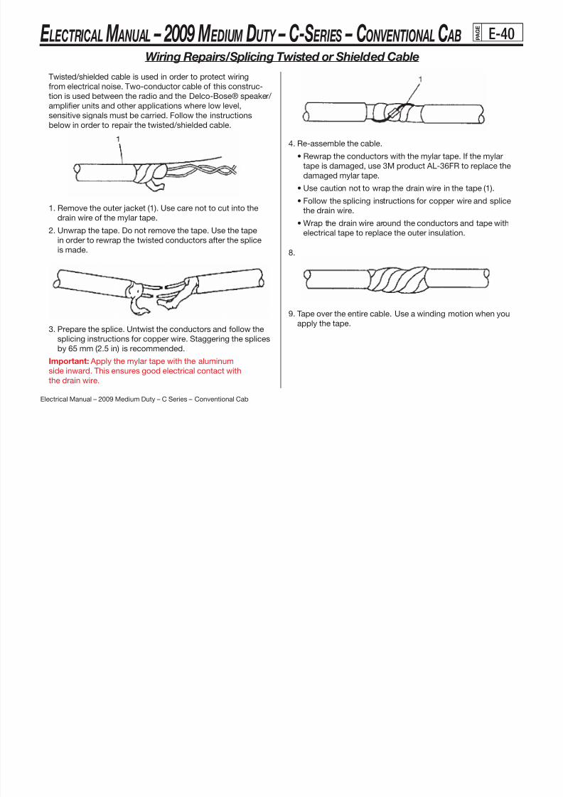
8/10/2019 2009 GM Medium Duty Electrical Manual.PDF
http://slidepdf.com/reader/full/2009-gm-medium-duty-electrical-manualpdf 402/410
Electrical Manual – 2009 Medium Duty – C Series – Conventional Cab
1. Remove the outer jacket (1). Use care not to cut into the
drain wire of the mylar tape.
2. Unwrap the tape. Do not remove the tape. Use the tapein order to rewrap the twisted conductors after the splice
is made.
3. Prepare the splice. Untwist the conductors and follow thesplicing instructions for copper wire. Staggering the splices
by 65 mm (2.5 in) is recommended.
Important: Apply the mylar tape with the aluminum
side inward. This ensures good electrical contact with
the drain wire.
the drain wire.
• Wrap the drain wire around the conductors and tape with
electrical tape to replace the outer insulation.
8.
9. Tape over the entire cable. Use a winding motion when you
apply the tape.

8/10/2019 2009 GM Medium Duty Electrical Manual.PDF
http://slidepdf.com/reader/full/2009-gm-medium-duty-electrical-manualpdf 403/410
E LECTRICAL M ANUAL – 2009 M EDIUM DUTY – C-S ERIES – CONVENTIONAL C AB P A G E
E-42
Wiring Repairs / SIR/SRS Wiring Repairs
Tools Required
J-38125 Terminal Repair Kit
The Supplemental Inflatable Restraint (SIR) System/Supple-
mental Restraint System (SRS) requires special wiring repair
procedures due to the sensitive nature of the circuitry. Follow
the specific procedures and instructions when working with
the SIR/SRS, and the wiring components, such as connectorsand terminals.
Important: Do not use the terminals in the kit in order to
replace damaged SIR/SRS system terminals. Use either an
SIR/SRS pigtail or a terminated lead from the SIR Repair
Kit Tray.
The tool kit J-38125 contains the following items:
The J-38125 also serves as a generic terminal repair kit.
The kit contains the following items:
• A large sampling of common electrical terminals
• The correct tools in order to attach the terminals to
the wires
• The correct tools in order to remove the terminals from
the connectors
SIR/SRS Connector Repair (Plastic Body and Terminal
Metal Pin)
The terminals in the SIR/SRS system are made with a special
plating. This plating provides the necessary contact integrity
for the sensitive low energy circuits Use theJ 38125 SIR/SRS

8/10/2019 2009 GM Medium Duty Electrical Manual.PDF
http://slidepdf.com/reader/full/2009-gm-medium-duty-electrical-manualpdf 404/410
Electrical Manual – 2009 Medium Duty – C Series – Conventional Cab
The tool kit J 38125 contains the following items:
• DuraSeal splice sleeves, in order to repair the SIR/SRS
wiring
• A special crimping tool
• A heat torch
• An instruction manual
The DuraSeal splice sleeves have the following 2
critical features:
• A special heat shrink sleeve environmentally seals the
splice. The heat shrink sleeve contains a sealing adhesive
inside.
• A cross hatched (knurled) core crimp provides the
necessary low resistance contact integrity for these
sensitive, low energy circuits.
(continued on next page)
for the sensitive, low energy circuits. Use theJ-38125 SIR/SRS
Terminal Repair Kit for repairing SIR/SRS terminals and con-
nectors. Do not substitute any other terminals for those in the
repair kit.
The J-38125 SIR/SRS Terminal Repair Kit contains:
• Various terminated leads for sensing and diagnostic mod-
ule (SDM) terminal replacement
• Various connector positive assurance (CPA) locks for
SIR/SRS connectors
• Base of steering column pigtail connectors part number
12085514
• Yellow vinyl electrical tape
E LECTRICAL M ANUAL – 2009 M EDIUM DUTY – C-S ERIES – CONVENTIONAL C AB P A G E
E-43
Wiring Repairs / SIR/SRS Wiring Repairs (continued)
Pigtail repair packs are available for SIR/SRS connectors
with eight or less terminals. Only the connector body is
available for connectors with more than eight terminals.
The terminated leads in the J-38125 SIR/SRS Terminal
Repair Kit can be used to replace damaged terminals when
replacing the connector body.
SIR/SRS Component Wire Pigtail Repair
Important: Do not make wire, connector, or terminal
repairs on components with wire pigtails.
A wire pigtail is a wire or wires attached directly to the de-
vice, not by a connector. If a wiring pigtail is damaged, you
must replace the entire component, with pigtail. The inflat-
Important: You must perform the following procedures in
the listed order. Repeat the procedure if any wire strands are
damaged. You must obtain a clean strip with all of the wire
strands intact
Splice Sleeve ColorCrimp Tool Nest
Color
Wire Gage mm2 /
(AWG)
Salmon (Yellow-Pink)12089189
Red (1) 0.035-0.8/(18-20)
Blue12089190
Blue (2) 1.0-2.0/(14-16)
Yellow
12089191 Yellow (3) 3.0-5.0/(10-12)
Green88988379
Red (1) 0.22-0.35/(22-24)

8/10/2019 2009 GM Medium Duty Electrical Manual.PDF
http://slidepdf.com/reader/full/2009-gm-medium-duty-electrical-manualpdf 405/410
Electrical Manual – 2009 Medium Duty – C Series – Conventional Cab(continued on next page)
p p , p g
able restraint steering wheel module coil is an example of
a pigtail component.
SIR/SRS Wire Repair
Important: Refer to Wiring Repairs in order to determine
the correct wire size for the circuit you are repairing. You
must obtain this information in order to ensure circuit
integrity.
If any wire except the pigtail is damaged, repair the wire
by splicing in a new section of wire of the same gage size
(0.5 mm, 0.8 mm, 1.0 mm etc.). Use the DuraSeal splicesleeves and splice crimping tool from the J-38125 . Use the
following wiring repair procedures in order to ensure the
integrity of the DuraSeal splice sleeves.
strands intact.
1. Open the harness by removing any tape:
• Use a sewing seam ripper, available from sewing supplystores, in order to cut open the harness in order to avoid
wire insulation damage.
• Use the DuraSeal splice sleeves on all types of insulation
except tefzel and coaxial.
• Do not use the crimp and DuraSeal splice sleeve to form a
splice with more than 2 wires coming together.
4. Cut as little wire off the harness as possible. You may need
the extra length of wire in order to change the location of a
splice.
Adjust splice locations so that each splice is at least 40 mm
(1.5 in) away from the other splices, harness branches, or
connectors.
E LECTRICAL M ANUAL – 2009 M EDIUM DUTY – C-S ERIES – CONVENTIONAL C AB P A G E
E-44
Wiring Repairs / SIR/SRS Wiring Repairs (continued)
5. Strip the insulation:
• When adding a length of wire to the existing harness,
use the same size wire as the original wire.
• Perform one of the following items in order to nd the
correct wire size:
- Find the wire on the schematic and convert the metric
size to the equivalent AWG size.
- Use an AWG wire gage.
- If you are unsure of the wire size, begin with the larg-
est opening in the wire stripper and work down until
achieving a clean strip of the insulation.
• Strip approximately 7.5 mm (0.313 in) of insulation from
each wire to be spliced
14. Use the Splice Crimp Tool from the J-38125 to crimp
DuraSeal splice sleeve. In order to position the DuraSeal
splice sleeve in the proper color nest of the Splice Crimp
Tool The crimp tool has three nests 1 is for the salmon

8/10/2019 2009 GM Medium Duty Electrical Manual.PDF
http://slidepdf.com/reader/full/2009-gm-medium-duty-electrical-manualpdf 406/410
Electrical Manual – 2009 Medium Duty – C Series – Conventional Cab(continued on next page)
each wire to be spliced.
• Do not nick or cut any of the strands. Inspect the
stripped wire for nicks or cut strands. • If the wire is damaged, repeat this procedure after re-
moving the damaged section.
13. Select the proper DuraSeal splice sleeve according to
the wire size. Refer to the above table at the beginning of
the repair procedure for the color coding of the DuraSeal
splice sleeves and the crimp tool nests.
Tool. The crimp tool has three nests, 1 is for the salmon
and green splice sleeve, 2 is for the blue splice sleeve,
and 3 is for the yellow splice sleeve.
15. Place the DuraSeal splice sleeve in the nest. Ensure that
the crimp falls midway between the end of the barrel and
the stop. The sleeve has a stop (3) in the middle of the
barrel (2) in order to prevent the wire (1) from going further.
Close the hand crimper handles slightly in order to firmly
hold the DuraSeal splice sleeve in the proper nest.
E LECTRICAL M ANUAL – 2009 M EDIUM DUTY – C-S ERIES – CONVENTIONAL C AB P A G E
E-45
Wiring Repairs / SIR/SRS Wiring Repairs (continued)
16. Insert the wire into the splice sleeve barrel until the wire
hits the barrel stop.
17. Tightly close the handles of the crimp tool until the
crimper handles open when released.
The crimper handles will not open until you apply the
proper amount of pressure to the DuraSeal splice sleeve.
Connector Position Assurance (CPA)
The connector position assurance (CPA) is a small plastic
insert that fits through the locking tabs of a connector. CPAs
are used in all SIR System connectors and also in some con-
nectors of other systems. The CPA ensures that the connector
halves cannot vibrate apart. You must have the CPA in place
in order to ensure good contact between the mating terminalsof a connection.
Terminal Position Assurance (TPA)
The terminal position assurance (TPA) insert resembles the
plastic combs used in the control module connectors. The
TPA keeps the terminal securely seated in the connector body

8/10/2019 2009 GM Medium Duty Electrical Manual.PDF
http://slidepdf.com/reader/full/2009-gm-medium-duty-electrical-manualpdf 407/410
Electrical Manual – 2009 Medium Duty – C Series – Conventional Cab
Repeat steps 4 and 5 for the opposite end of the splice.
18. Using the heat torch, apply heat to the crimped area of
the barrel.
19. Gradually move the heat barrel to the open end of
the tubing:• The tubing will shrink completely as the heat is moved
along the insulation.
• A small amount of sealant will come out of the end of
the tubing when sufficient shrinkage is achieved.
TPA keeps the terminal securely seated in the connector body.
Do not remove the TPA from the connector body unless you
remove a terminal for replacement
E LECTRICAL M ANUAL – 2009 M EDIUM DUTY – C-S ERIES – CONVENTIONAL C AB P A G E
E-46
Lighting/Separating Stop from Turn Signal Lamps
The 2009 Medium Duty C-Series trucks have single red tail-lamp assemblies that function as Stop/Turn/Hazard lamps.Many applications call for separating the brake lamps fromthe Turn/Hazard function or adding additional Amber Turn / Hazard lamps. The procedure for implementing Amber Turn/ Hazard Lamps is outlined below.
1. Remove the CHMSL relay (refer to Fuse Block - I/P-2).Carefully cut off the “87” terminal from the relay to
eliminate the brake function from the existing lightingsystem.
2. Re-install the modified CHMSL relay.
3. Additional Turn lamps can be wired to 318 (Left Turn) andthe 319 (Right Turn) circuits in the 12-Way Body Builder or
Important Notes:
(a) It is the responsibility of the upfitter to meet all FMVSS
lighting requirements. The upfitter must also ensure that
the combined current of any additional lighting does not
exceed the circuit fusing.
(b) Operation without the CHMSL relay installed will disablethe Power Take-Off (PTO) system.
(c) Operation without the CHMSL relay installed eliminates
the Brake Lamp function at the 7-way Family 2 Trailer
Connector.

8/10/2019 2009 GM Medium Duty Electrical Manual.PDF
http://slidepdf.com/reader/full/2009-gm-medium-duty-electrical-manualpdf 408/410
Electrical Manual – 2009 Medium Duty – C Series – Conventional Cab
(continued on next page)
( g ) y yBus Connector.
4. Stop Lamp (only) operation can be re-established bywiring into circuit 1320 (stop lamp) of the 12-Way BodyBuilder Connector.
E LECTRICAL M ANUAL – 2009 M EDIUM DUTY – C-S ERIES – CONVENTIONAL C AB P A G E
E-47
Lighting/Separating Stop from Turn Signal Lamps (continued)

8/10/2019 2009 GM Medium Duty Electrical Manual.PDF
http://slidepdf.com/reader/full/2009-gm-medium-duty-electrical-manualpdf 409/410
Electrical Manual – 2009 Medium Duty – C Series – Conventional Cab
E LECTRICAL M ANUAL – 2009 M EDIUM DUTY – C-S ERIES – CONVENTIONAL C AB P A G E
E-48
California Air Resource Board (CARB) Idle Shutdown Regulations
REGULATION
The California Air Resource Board (CARB) formulated new idle
shutdown requirements applicable to 2008 model year heavy
duty diesel engines operating in vehicles greater than 14,000
lbs. GVW. According to this regulation, all new 2008 and subse-
quent model year heavy duty diesel engines shall be equipped
with an engine shutdown system that automatically shuts downthe engine after 300 seconds of continuous idling operation
once the vehicle is stopped, the transmission is set to “Neu-
tral” or “Park”, and the parking brake is engaged. If the parking
brake is not engaged, then the engine shutdown system will
shut the engine down after 900 seconds of continuous idling
operation once the vehicle is stopped and the transmission is
set to “Neutral” or “Park”.
ENGINE SHUTDOWN SYSTEM OVERRIDE
The engine shutdown system may be overridden to allow the
engine to run continuously at idle, only under the following
conditions:
(1) If the engine is operating in the PTO mode. The PTO system
switch will have a switch to override the engine shutdown
system and will be reset to the “OFF” position every timethe vehicle’s engine is turned “OFF”. This has been accom-
plished by changing the current “ON/OFF” PTO switch to a
momentary PTO switch. Additionally, the PTO switch has
been designed so that if it fails it will always fail in the
“OFF” position.
(2) If the vehicle’s engine coolant temperature is below 60°F.
The engine shutdown system will be automatically activated

8/10/2019 2009 GM Medium Duty Electrical Manual.PDF
http://slidepdf.com/reader/full/2009-gm-medium-duty-electrical-manualpdf 410/410
Electrical Manual – 2009 Medium Duty – C Series – Conventional Cab
The engine shutdown system is tamper resistant and non-pro-
grammable and cannot modify the software/calibration to enable
or disable the engine shutdown system.
DRIVER WARNING
A warning signal (light or sound indicator inside the vehicle
cabin) will be used to alert the driver 30 seconds prior to engine
shutdown. The engine shutdown system is capable of allowing
the driver to reset the engine shutdown timer by momentarily
changing the position of the accelerator, brake, or clutch pedal
or by shifting the transmission out of “Park” or “Neutral”. Oncereset, the engine shutdown system will restart the shutdown
sequence described above and will continue to do so until the
engine shuts down or the vehicle is driven.
The engine shutdown system will be automatically activated
once the coolant temperature reaches 60°F or above. The
engine coolant temperature is measured with the engine’sexisting engine coolant temperature sensor
EXEMPT VEHICLES
Heavy Duty diesel engines to be used in buses as defined in
California Vehicle Code #233, 612 and 642, school buses as
defined in California Vehicle Code #545, and recreational vehicles
as defined in Health and Safety Code18010 are exempt from
these idle shutdown requirements. The idle shutdown system
will not be provided on exempt vehicles and Federal vehicles.
IMPLEMENTATION TIMING
The idle shutdown program was implemented in January, 2008.
E LECTRICAL M ANUAL – 2009 M EDIUM DUTY – C-S ERIES – CONVENTIONAL C AB P A G E
E-49
Engine Idle Control System Description
Idle Shutdown
This feature automatically shuts down the engine after it idles con-
tinuously for five minutes and if the following conditions are met:
• The parking brake is set.
• The vehicle is at a complete stop.
• The automatic transmission is in NEUTRAL (N) or PARK (P).If the parking brake is not engaged, the engine shuts down after
15 minutes of continuous idling operation. The driver can reset
the engine shutdown timer by momentarily changing the posi-
tion of the accelerator, brake, or clutch pedal or by shifting the
transmission out of PARK (P) or NEUTRAL (N). Once reset, the
i idl h td ill t t th h td d
• Service or maintenance is being performed on the engine. The
engine idle shutdown mode can be deactivated by establish-
ing communication with the vehicle through scan tool. A com-
munication link is established by selecting any data list. Once
the scan tool is disconnected from the vehicle, the engine idle
shutdown feature will resume normal operation.
The engine shutdown warning light and chime will stay ON forthe entire duration of the idle shutdown event to inform the driver
that the engine is in idle shutdown mode. After the engine shut-
down occurs, the engine is no longer running, and the ignition
is still in the ON/Run position, all accessories can be used. Turn
the ignition switch to START to restart the engine, or turn it to
LOCK/OFF to prevent the battery from draining.


![1999 Diesel GM Medium Duty Electrical Manual[1]](https://static.fdocuments.us/doc/165x107/577d24dc1a28ab4e1e9d934f/1999-diesel-gm-medium-duty-electrical-manual1.jpg)