2009 Class1 Plumbing Products Catalog
24
Controls • Drains • Piping • Flanges • Couplings • Caps and Plugs • Plumbing Components ®
-
Upload
class-1-inc -
Category
Documents
-
view
334 -
download
3
description
This catalog highlights the common mechanical plumbing products offered by Class1.
Transcript of 2009 Class1 Plumbing Products Catalog

Controls•
Drains•
Piping•
Flanges•
Couplings•
Caps and Plugs•
Plumbing Components
®
Plumbing ComponentsTab le o f Con ten tsLocking Top Mount Control ...................................................................................................... 1Locking Push-Pull Control .......................................................................................................... 1Control Rod Assemblies .............................................................................................................. 1Test Port Assembly ....................................................................................................................... 1Gauge Test Port.............................................................................................................................. 2Push-Pull Handle ........................................................................................................................... 2Tag Adapter/Bezel ........................................................................................................................ 2Automatic Master Drain .............................................................................................................. 2Manual Master Drain .................................................................................................................... 23/4” Automatic Drain ................................................................................................................... 33/4” Lift Handle Drain .................................................................................................................. 3Ball Valve Drains............................................................................................................................. 3Petcock Valve .................................................................................................................................. 33/4” 90o Ball Valve Drain .............................................................................................................. 43/4” Air Operated Drain .............................................................................................................. 4High Pressure Flexible Piping ................................................................................................... 4Non-Assembled High Pressure Flexible Piping and Couplings .................................... 5Assembled High Pressure Flexible Piping ............................................................................ 5HFP Piping Accessories ............................................................................................................... 6Stainless Steel Swivels ................................................................................................................. 6Grooved End Pipe Couplings .................................................................................................... 7Chrome Plated Bezels .................................................................................................................. 7Air Operated Valve Cylinder and Bracket ............................................. ............................... 8115 4-Bolt Flanges ......................................................................................................................... 9Weld/Vic Flanges ........................................................................................................................... 9, 104” Discharge Manifold System .................................................................................................. 10Valve Flanges .................................................................................................................................. 11, 12, 13AP/MP Discharge Manifolds ...................................................................................................... 13Portable Manifolds ........................................................................................................................ 13Midship Discharge Manifolds ................................................................................................... 142433 8-Bolt Flange ........................................................................................................................ 14Foam/CAFS Manifolds and Fittings ........................................................................................ 14Suction Fittings .............................................................................................................................. 152717 8-Bolt Flange ........................................................................................................................ 15D.O.T. Push-On Fittings .............................................................................. ............................... 16, 17Air Brake Tubing ............................................................................................................................ 18Caps, Plugs, and Adapters .......................................................................................................... 19Dimensional Drawings and Specifications .......................................... ............................... 20Specifications .................................................................................................. ............................... 21
i
Tab
le o
f Co
nte
nts
®
Locking Top Mount Control Co
ntro
ls/Co
ntro
l Ro
d A
ssemb
ly
Locking Push-Pull Control
Control Rod Assemblies
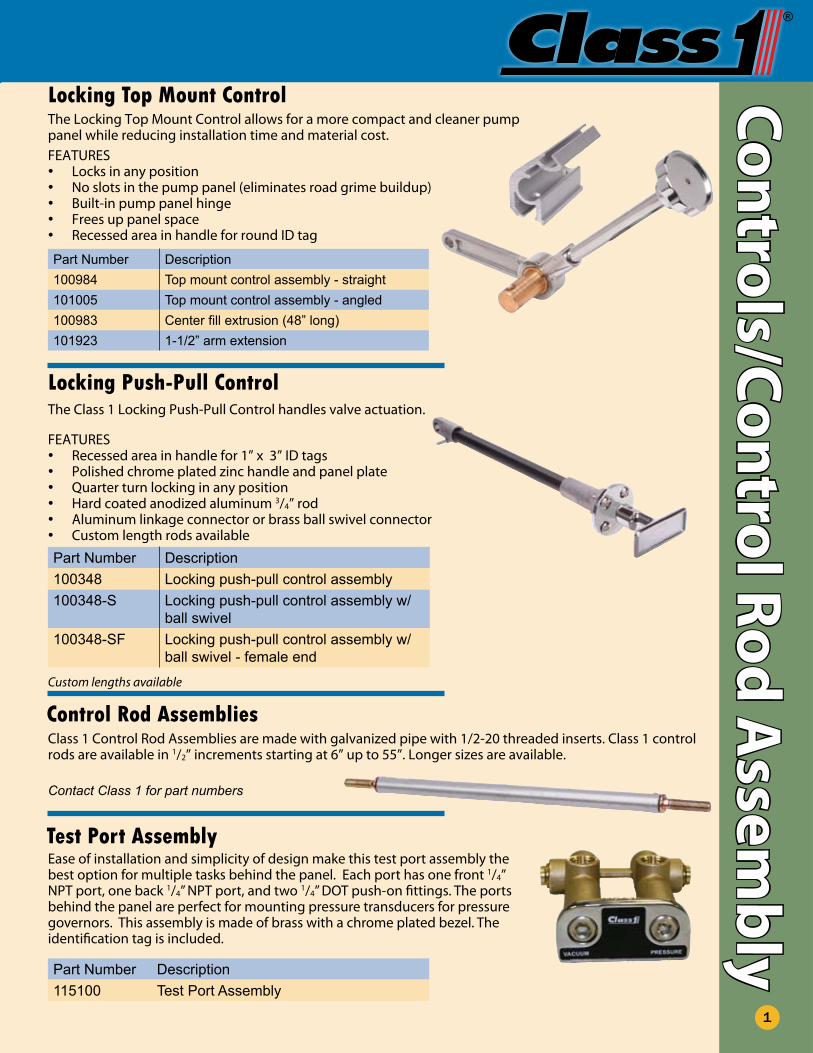
FEATURESLocks in any position•No slots in the pump panel (eliminates road grime buildup)•Built-in pump panel hinge•Frees up panel space•Recessed area in handle for round ID tag•
Part Number Description100984 Top mount control assembly - straight101005 Top mount control assembly - angled100983 Center fill extrusion (48” long)101923 1-1/2” arm extension
The Locking Top Mount Control allows for a more compact and cleaner pump panel while reducing installation time and material cost.
The Class 1 Locking Push-Pull Control handles valve actuation.
FEATURESRecessed area in handle for 1” x 3” ID tags•Polished chrome plated zinc handle and panel plate•Q• uarter turn locking in any positionHard coated anodized aluminum • 3/4” rodAluminum linkage connector or brass ball swivel connector•Custom length rods available•
Part Number Description100348 Locking push-pull control assembly100348-S Locking push-pull control assembly w/
ball swivel100348-SF Locking push-pull control assembly w/
ball swivel - female end
Class 1 Control Rod Assemblies are made with galvanized pipe with 1/2-20 threaded inserts. Class 1 control rods are available in 1/2” increments starting at 6” up to 55”. Longer sizes are available.
Contact Class 1 for part numbers
Custom lengths available
1
Test Port Assembly
Part Number Description115100 Test Port Assembly
Ease of installation and simplicity of design make this test port assembly the best option for multiple tasks behind the panel. Each port has one front 1/4” NPT port, one back 1/4” NPT port, and two 1/4” DOT push-on fittings. The ports behind the panel are perfect for mounting pressure transducers for pressure governors. This assembly is made of brass with a chrome plated bezel. The identification tag is included.
Plumbing ComponentsH
and
le/B
ezel
/Dra
ins
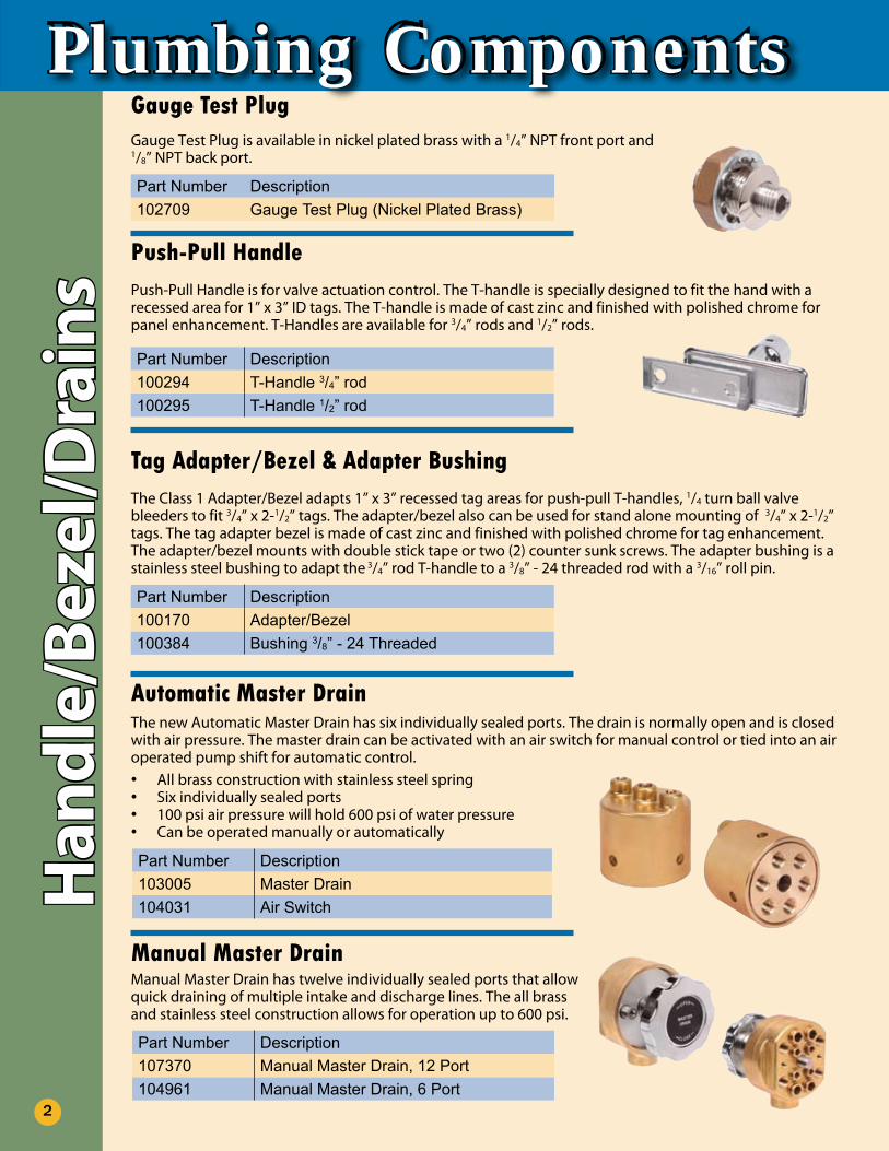
Part Number Description100294 T-Handle 3/4” rod100295 T-Handle 1/2” rod
Part Number Description100170 Adapter/Bezel100384 Bushing 3/8” - 24 Threaded
Tag Adapter/Bezel & Adapter BushingThe Class 1 Adapter/Bezel adapts 1” x 3” recessed tag areas for push-pull T-handles, 1/4 turn ball valve bleeders to fit 3/4” x 2-1/2” tags. The adapter/bezel also can be used for stand alone mounting of 3/4” x 2-1/2” tags. The tag adapter bezel is made of cast zinc and finished with polished chrome for tag enhancement. The adapter/bezel mounts with double stick tape or two (2) counter sunk screws. The adapter bushing is a stainless steel bushing to adapt the 3/4” rod T-handle to a 3/8” - 24 threaded rod with a 3/16” roll pin.
Push-Pull HandlePush-Pull Handle is for valve actuation control. The T-handle is specially designed to fit the hand with a recessed area for 1” x 3” ID tags. The T-handle is made of cast zinc and finished with polished chrome for panel enhancement. T-Handles are available for 3/4” rods and 1/2” rods.
Automatic Master DrainThe new Automatic Master Drain has six individually sealed ports. The drain is normally open and is closed with air pressure. The master drain can be activated with an air switch for manual control or tied into an air operated pump shift for automatic control.
All brass construction with stainless steel spring•Six individually sealed ports•100 psi air pressure will hold 600 psi of water pressure•Can be operated manually or automatically•
Part Number Description103005 Master Drain104031 Air Switch
Manual Master DrainManual Master Drain has twelve individually sealed ports that allow quick draining of multiple intake and discharge lines. The all brass and stainless steel construction allows for operation up to 600 psi.
Part Number Description107370 Manual Master Drain, 12 Port104961 Manual Master Drain, 6 Port
2
Part Number Description102709 Gauge Test Plug (Nickel Plated Brass)
Gauge Test PlugGauge Test Plug is available in nickel plated brass with a 1/4” NPT front port and 1/8” NPT back port.
®
Bezels/D
rains
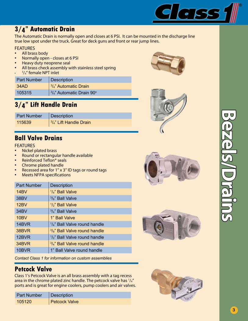
Part Number Description34AD 3/4” Automatic Drain105315 3/4” Automatic Drain 90o
3/4” Automatic DrainThe Automatic Drain is normally open and closes at 6 PSI. It can be mounted in the discharge line true low spot under the truck. Great for deck guns and front or rear jump lines.
FEATURESAll brass body•Normally open - closes at 6 PSI•Heavy duty neoprene seal•All brass check assembly with stainless steel spring•3• /4” female NPT inlet
Ball Valve DrainsFEATURES
Nickel plated brass•Round or rectangular handle available•Reinforced Teflon® seals•Chrome plated handle•Recessed area for 1” x 3” ID tags or round tags•Meets NFPA specifications•
Part Number Description14BV 1/4” Ball Valve38BV 3/8” Ball Valve12BV 1/2” Ball Valve34BV 3/4” Ball Valve10BV 1” Ball Valve 14BVR 1/4” Ball Valve round handle38BVR 3/8” Ball Valve round handle12BVR 1/2” Ball Valve round handle34BVR 3/4” Ball Valve round handle10BVR 1” Ball Valve round handle
Petcock ValveClass 1’s Petcock Valve is an all brass assembly with a tag recess area in the chrome plated zinc handle. The petcock valve has 1/4” ports and is great for engine coolers, pump coolers and air valves.
Part Number Description105120 Petcock Valve
Contact Class 1 for information on custom assemblies
3
Part Number Description115639 3/4” Lift Handle Drain
3/4” Lift Handle Drain
Plumbing ComponentsD
rain
Val
ves/
Pip
ing
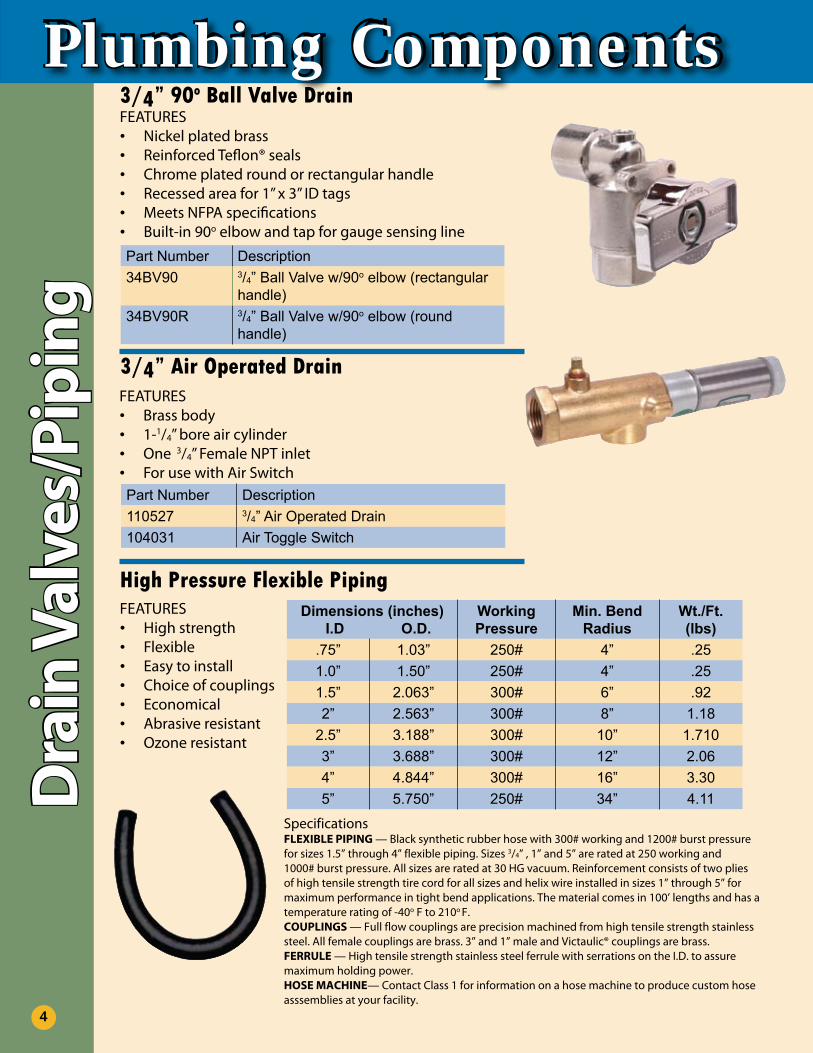
3/4” 90o Ball Valve DrainFEATURES
Nickel plated brass•Reinforced Teflon® seals•Chrome plated round or rectangular handle•Recessed area for 1” x 3” ID tags•Meets NFPA specifications•Built-in 90• o elbow and tap for gauge sensing line
Part Number Description34BV90 3/4” Ball Valve w/90o elbow (rectangular
handle)34BV90R 3/4” Ball Valve w/90o elbow (round
handle)
3/4” Air Operated Drain
Part Number Description110527 3/4” Air Operated Drain104031 Air Toggle Switch
FEATURESBrass body•1-• 1/4” bore air cylinderOne • 3/4” Female NPT inletFor use with Air Switch•
High Pressure Flexible PipingFEATURES
High strength•Flexible•Easy to install•Choice of couplings•Economical•Abrasive resistant•Ozone resistant•
Dimensions (inches) I.D O.D.
Working Pressure
Min. Bend Radius
Wt./Ft. (lbs)
.75” 1.03” 250# 4” .251.0” 1.50” 250# 4” .251.5” 2.063” 300# 6” .922” 2.563” 300# 8” 1.18
2.5” 3.188” 300# 10” 1.7103” 3.688” 300# 12” 2.064” 4.844” 300# 16” 3.305” 5.750” 250# 34” 4.11
SpecificationsFLEXIBLE PIPING — Black synthetic rubber hose with 300# working and 1200# burst pressure for sizes 1.5” through 4” flexible piping. Sizes 3/4” , 1” and 5” are rated at 250 working and 1000# burst pressure. All sizes are rated at 30 HG vacuum. Reinforcement consists of two plies of high tensile strength tire cord for all sizes and helix wire installed in sizes 1” through 5” for maximum performance in tight bend applications. The material comes in 100’ lengths and has a temperature rating of -40o F to 210o F.COUPLINGS — Full flow couplings are precision machined from high tensile strength stainless steel. All female couplings are brass. 3” and 1” male and Victaulic® couplings are brass.FERRULE — High tensile strength stainless steel ferrule with serrations on the I.D. to assure maximum holding power.HOSE MACHINE— Contact Class 1 for information on a hose machine to produce custom hose asssemblies at your facility.
4
®
Piping/Coup
lings
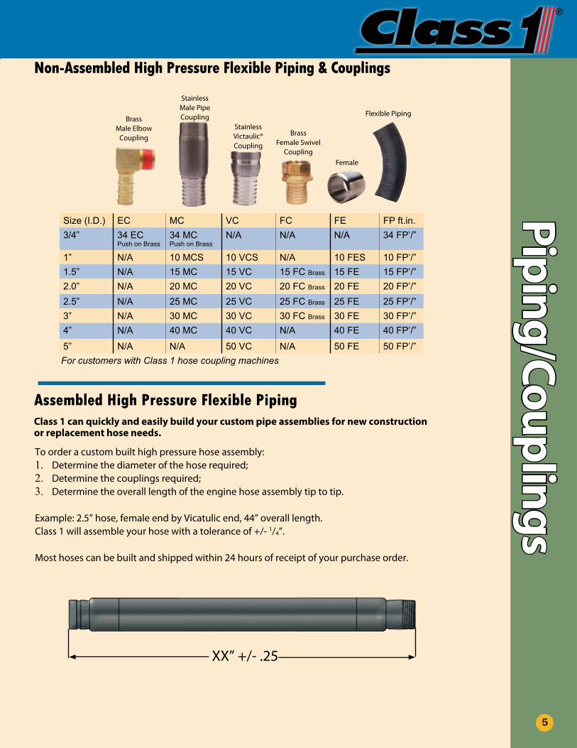
Assembled High Pressure Flexible Piping
Size (I.D.) EC MC VC FC FE FP ft.in.3/4” 34 EC
Push on Brass34 MCPush on Brass
N/A N/A N/A 34 FP’/”
1” N/A 10 MCS 10 VCS N/A 10 FES 10 FP’/”1.5” N/A 15 MC 15 VC 15 FC Brass 15 FE 15 FP’/”2.0” N/A 20 MC 20 VC 20 FC Brass 20 FE 20 FP’/”2.5” N/A 25 MC 25 VC 25 FC Brass 25 FE 25 FP’/”3” N/A 30 MC 30 VC 30 FC Brass 30 FE 30 FP’/”4” N/A 40 MC 40 VC N/A 40 FE 40 FP’/”
5” N/A N/A 50 VC N/A 50 FE 50 FP’/”
Non-Assembled High Pressure Flexible Piping & Couplings
BrassMale Elbow
Coupling
StainlessMale PipeCoupling Flexible Piping
BrassFemale Swivel
Coupling
StainlessVictaulic®Coupling
To order a custom built high pressure hose assembly:Determine the diameter of the hose required;1.Determine the couplings required;2.Determine the overall length of the engine hose assembly tip to tip.3.
Example: 2.5” hose, female end by Vicatulic end, 44” overall length.Class 1 will assemble your hose with a tolerance of +/- 1/4”.
Most hoses can be built and shipped within 24 hours of receipt of your purchase order.
Class 1 can quickly and easily build your custom pipe assemblies for new construction or replacement hose needs.
XX” +/- .25
For customers with Class 1 hose coupling machines
5
Female
Plumbing ComponentsPi
pin
g/Co
uplin
gsPart Number Description
34D 3/4” stainless FNPT couplingSFM Stainless flowminder transmitter mounting
socket154B Stainless base bracket - fits 1-1/2” through 4”20AB Aluminum 2 piece bracket - fits 2”
225SB Aluminum 2 piece bracket - fits 2-1/2”
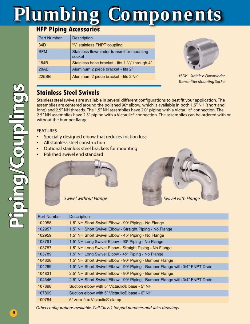
Stainless Steel SwivelsStainless steel swivels are available in several different configurations to best fit your application. The assemblies are centered around the polished 90o elbow, which is available in both 1.5” NH (short and long) and 2.5” NH threads. The 1.5” NH assemblies have 2.0” piping with a Victaulic® connection. The 2.5” NH assemblies have 2.5” piping with a Victaulic® connection. The assemblies can be ordered with or without the bumper flange.
FEATURESSpecially designed elbow that reduces friction loss•All stainless steel construction•Optional stainless steel brackets for mounting•Polished swivel end standard•
Part Number Description102958 1.5” NH Short Swivel Elbow - 90o Piping - No Flange102957 1.5” NH Short Swivel Elbow - Straight Piping - No Flange102959 1.5” NH Short Swivel Elbow - 45o Piping - No Flange103791 1.5” NH Long Swivel Elbow - 90o Piping - No Flange103787 1.5” NH Long Swivel Elbow - Straight Piping - No Flange103789 1.5” NH Long Swivel Elbow - 45o Piping - No Flange104828 1.5” NH Short Swivel Elbow - 90o Piping - Bumper Flange104289 1.5” NH Short Swivel Elbow - 90o Piping - Bumper Flange with 3/4” FNPT Drain
104831 2.5” NH Short Swivel Elbow - 90o Piping - Bumper Flange104346 2.5” NH Short Swivel Elbow - 90o Piping - Bumper Flange with 3/4” FNPT Drain107898 Suction elbow with 5” Victaulic® base - 5” NH107899 Suction elbow with 5” Victaulic® base - 6” NH109784 5” zero-flex Victaulic® clamp
Other configurations available. Call Class 1 for part numbers and sales drawings.
HFP Piping Accessories
#SFM - Stainless Flowminder Transmitter Mounting Socket
Swivel without Flange Swivel with Flange
6
®
Couplings/B
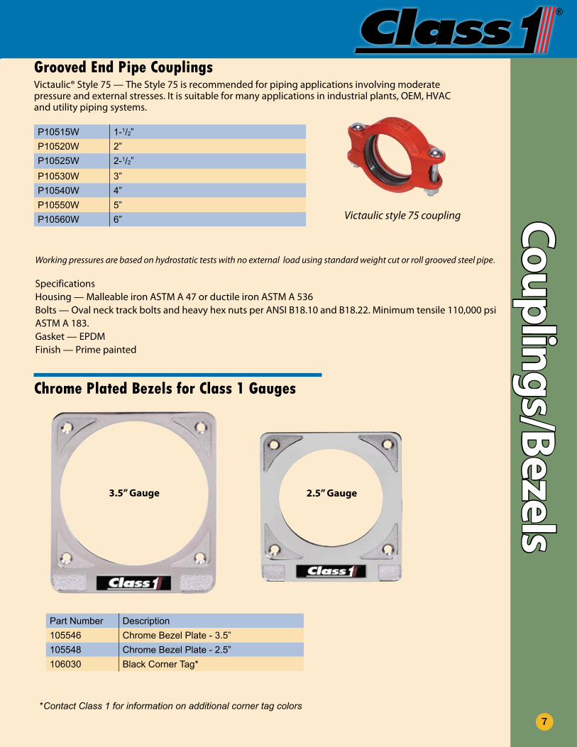
ezelsGrooved End Pipe CouplingsVictaulic® Style 75 — The Style 75 is recommended for piping applications involving moderate pressure and external stresses. It is suitable for many applications in industrial plants, OEM, HVAC and utility piping systems.
P10515W 1-1/2”P10520W 2”P10525W 2-1/2”P10530W 3”P10540W 4”P10550W 5”P10560W 6”
Working pressures are based on hydrostatic tests with no external load using standard weight cut or roll grooved steel pipe.
SpecificationsHousing — Malleable iron ASTM A 47 or ductile iron ASTM A 536Bolts — Oval neck track bolts and heavy hex nuts per ANSI B18.10 and B18.22. Minimum tensile 110,000 psi ASTM A 183.Gasket — EPDMFinish — Prime painted
Victaulic style 75 coupling
Chrome Plated Bezels for Class 1 Gauges
*Contact Class 1 for information on additional corner tag colors
Part Number Description105546 Chrome Bezel Plate - 3.5”105548 Chrome Bezel Plate - 2.5”106030 Black Corner Tag*
7
3.5” Gauge 2.5” Gauge
Plumbing ComponentsA
ir O
per
ated
Val
ve C
ylin
der
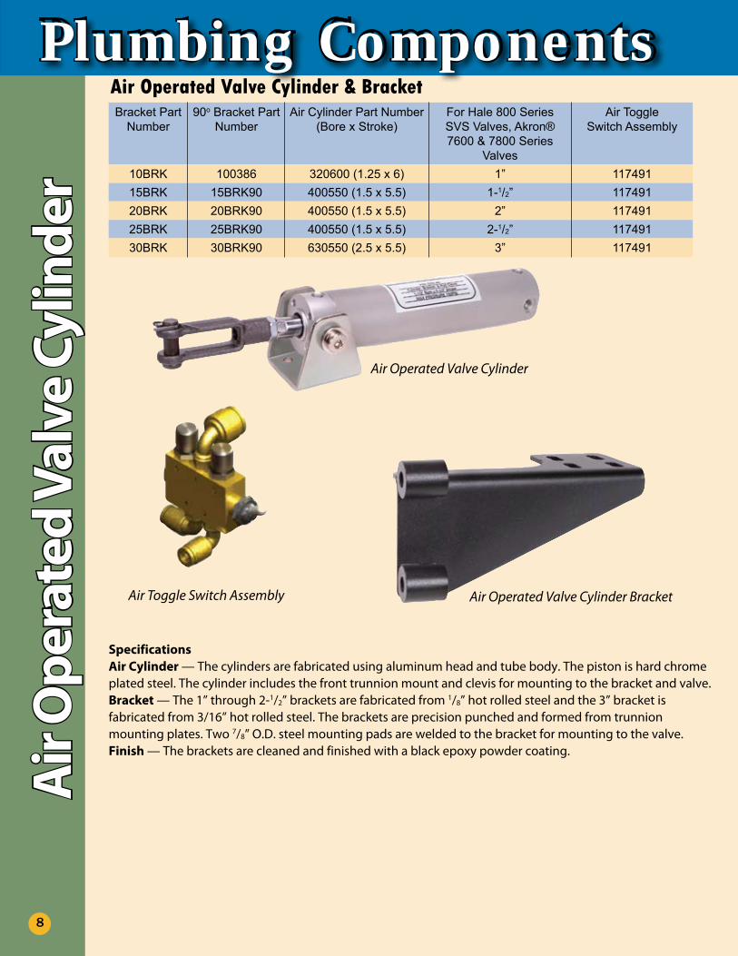
Air Operated Valve Cylinder & BracketBracket Part
Number90o Bracket Part
NumberAir Cylinder Part Number
(Bore x Stroke)For Hale 800 Series SVS Valves, Akron® 7600 & 7800 Series
Valves
Air ToggleSwitch Assembly
10BRK 100386 320600 (1.25 x 6) 1” 11749115BRK 15BRK90 400550 (1.5 x 5.5) 1-1/2” 11749120BRK 20BRK90 400550 (1.5 x 5.5) 2” 11749125BRK 25BRK90 400550 (1.5 x 5.5) 2-1/2” 11749130BRK 30BRK90 630550 (2.5 x 5.5) 3” 117491
SpecificationsAir Cylinder — The cylinders are fabricated using aluminum head and tube body. The piston is hard chrome plated steel. The cylinder includes the front trunnion mount and clevis for mounting to the bracket and valve.Bracket — The 1” through 2-1/2” brackets are fabricated from 1/8” hot rolled steel and the 3” bracket is fabricated from 3/16” hot rolled steel. The brackets are precision punched and formed from trunnion mounting plates. Two 7/8” O.D. steel mounting pads are welded to the bracket for mounting to the valve.Finish — The brackets are cleaned and finished with a black epoxy powder coating.
Air Operated Valve Cylinder
Air Operated Valve Cylinder Bracket
8
Air Toggle Switch Assembly
®
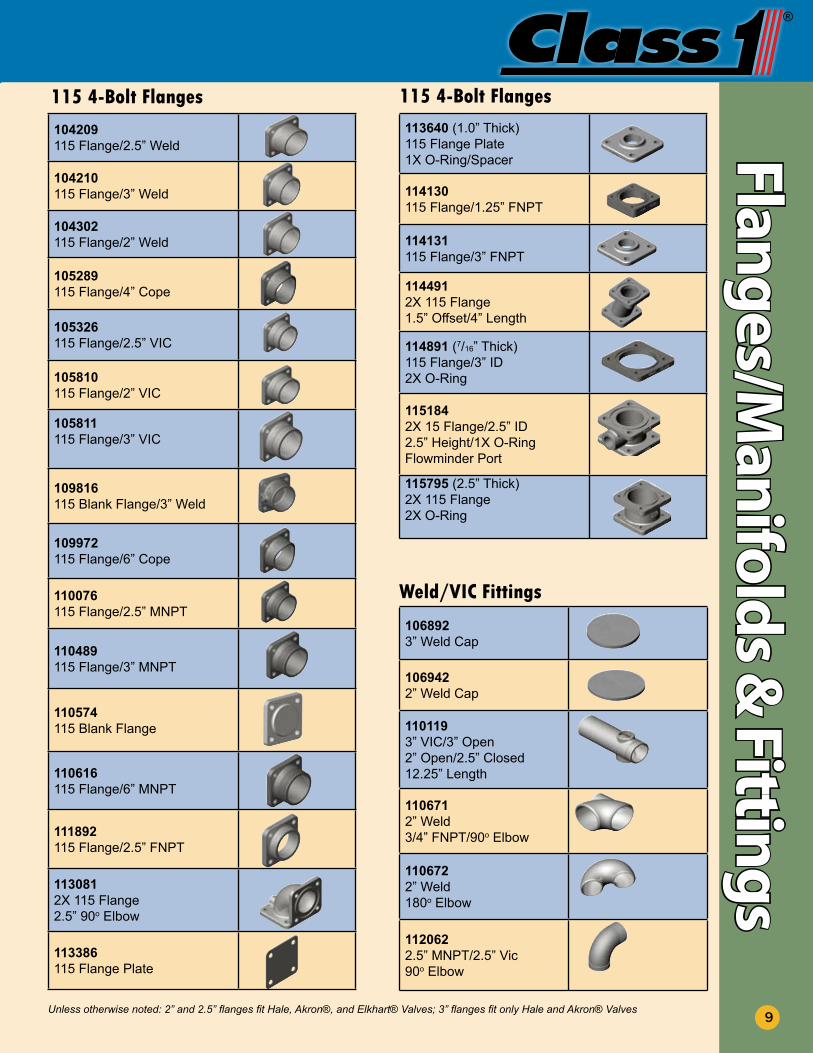
104209 115 Flange/2.5” Weld
104210115 Flange/3” Weld
104302 115 Flange/2” Weld
105289 115 Flange/4” Cope
105326 115 Flange/2.5” VIC
105810 115 Flange/2” VIC
105811 115 Flange/3” VIC
109816115 Blank Flange/3” Weld
109972115 Flange/6” Cope
110076 115 Flange/2.5” MNPT
110489 115 Flange/3” MNPT
110574115 Blank Flange
110616 115 Flange/6” MNPT
111892 115 Flange/2.5” FNPT
1130812X 115 Flange2.5” 90o Elbow
113386115 Flange Plate
115 4-Bolt Flanges113640 (1.0” Thick)115 Flange Plate1X O-Ring/Spacer
114130 115 Flange/1.25” FNPT
114131115 Flange/3” FNPT
114491 2X 115 Flange1.5” Offset/4” Length
114891 (7/16” Thick)115 Flange/3” ID2X O-Ring
115184 2X 15 Flange/2.5” ID2.5” Height/1X O-RingFlowminder Port
115795 (2.5” Thick)2X 115 Flange2X O-Ring
115 4-Bolt FlangesFlanges/M
anifolds &
Fittings
106892 3” Weld Cap
1069422” Weld Cap
110119 3” VIC/3” Open2” Open/2.5” Closed12.25” Length
1106712” Weld3/4” FNPT/90o Elbow
1106722” Weld180o Elbow
1120622.5” MNPT/2.5” Vic90o Elbow
Unless otherwise noted: 2” and 2.5” flanges fit Hale, Akron®, and Elkhart® Valves; 3” flanges fit only Hale and Akron® Valves
Weld/VIC Fittings
9
Plumbing ComponentsFl
ange
s/M
anifo
lds
& F
itti
ngs
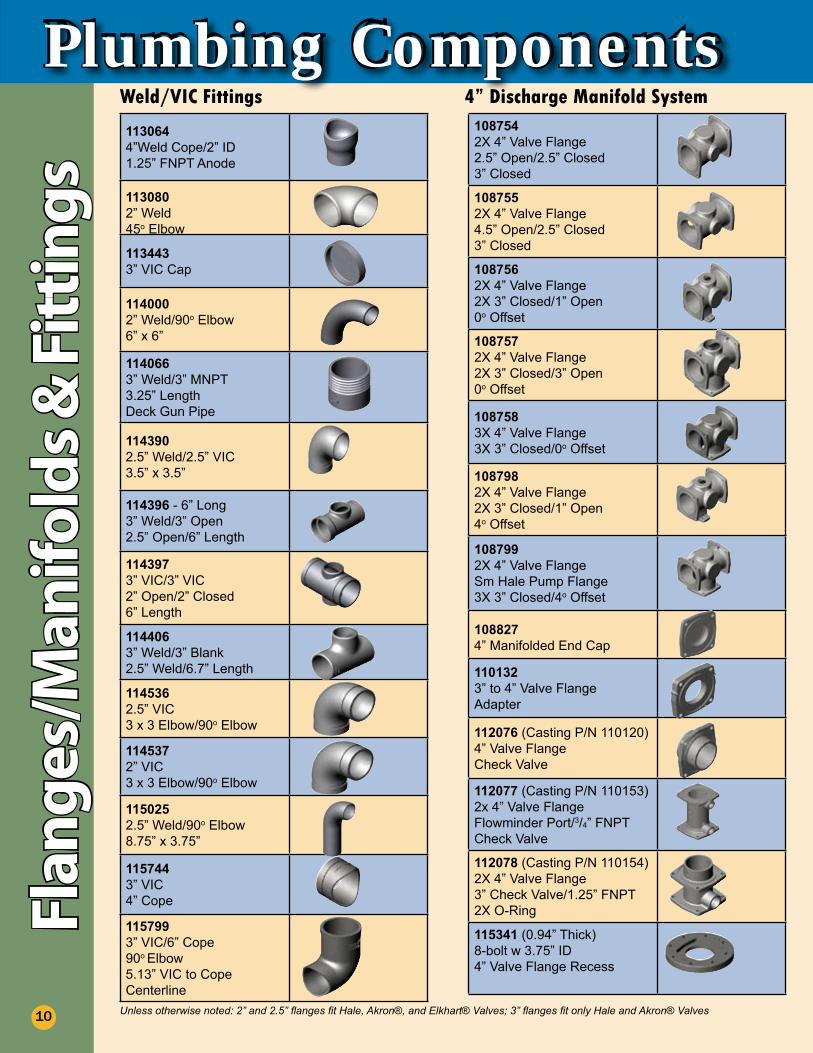
1130644”Weld Cope/2” ID 1.25” FNPT Anode
1130802” Weld45o Elbow
1134433” VIC Cap
1140002” Weld/90o Elbow6” x 6”
1140663” Weld/3” MNPT3.25” LengthDeck Gun Pipe
1143902.5” Weld/2.5” VIC3.5” x 3.5”
114396 - 6” Long3” Weld/3” Open2.5” Open/6” Length
1143973” VIC/3” VIC2” Open/2” Closed6” Length
114406 3” Weld/3” Blank2.5” Weld/6.7” Length
114536 2.5” VIC3 x 3 Elbow/90o Elbow
114537 2” VIC3 x 3 Elbow/90o Elbow
1150252.5” Weld/90o Elbow8.75” x 3.75”
1157443” VIC4” Cope
1157993” VIC/6” Cope90o Elbow5.13” VIC to Cope Centerline
Weld/VIC Fittings1087542X 4” Valve Flange2.5” Open/2.5” Closed3” Closed
1087552X 4” Valve Flange4.5” Open/2.5” Closed3” Closed
1087562X 4” Valve Flange2X 3” Closed/1” Open0o Offset
1087572X 4” Valve Flange2X 3” Closed/3” Open0o Offset
1087583X 4” Valve Flange3X 3” Closed/0o Offset
1087982X 4” Valve Flange2X 3” Closed/1” Open4o Offset
1087992X 4” Valve FlangeSm Hale Pump Flange3X 3” Closed/4o Offset
1088274” Manifolded End Cap
1101323” to 4” Valve FlangeAdapter
112076 (Casting P/N 110120)4” Valve FlangeCheck Valve
112077 (Casting P/N 110153)2x 4” Valve FlangeFlowminder Port/3/4” FNPTCheck Valve
112078 (Casting P/N 110154)2X 4” Valve Flange3” Check Valve/1.25” FNPT2X O-Ring
115341 (0.94” Thick)8-bolt w 3.75” ID4” Valve Flange Recess
4” Discharge Manifold System
10 Unless otherwise noted: 2” and 2.5” flanges fit Hale, Akron®, and Elkhart® Valves; 3” flanges fit only Hale and Akron® Valves
®
Flanges/Manifold
s & Fittings
11
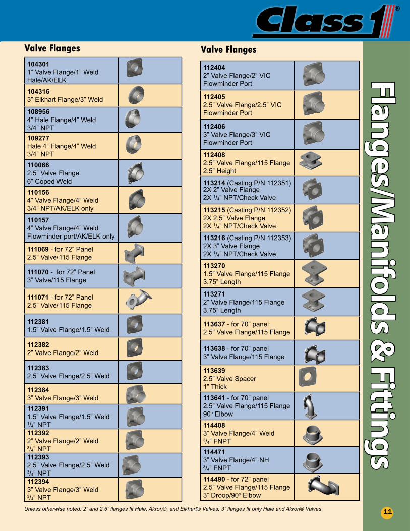
104301 1” Valve Flange/1” WeldHale/AK/ELK
1043163” Elkhart Flange/3” Weld 1089564” Hale Flange/4” Weld3/4” NPT
109277Hale 4” Flange/4” Weld3/4” NPT
1100662.5” Valve Flange6” Coped Weld 1101564” Valve Flange/4” Weld3/4” NPT/AK/ELK only 1101574” Valve Flange/4” WeldFlowminder port/AK/ELK only
111069 - for 72” Panel 2.5” Valve/115 Flange
111070 - for 72” Panel3” Valve/115 Flange
111071 - for 72” Panel2.5” Valve/115 Flange
112381 1.5” Valve Flange/1.5” Weld 112382 2” Valve Flange/2” Weld 112383 2.5” Valve Flange/2.5” Weld
1123843” Valve Flange/3” Weld
112391 1.5” Valve Flange/1.5” Weld1/4” NPT112392 2” Valve Flange/2” Weld3/4” NPT112393 2.5” Valve Flange/2.5” Weld3/4” NPT112394 3” Valve Flange/3” Weld3/4” NPT
112404 2” Valve Flange/2” VICFlowminder Port
112405 2.5” Valve Flange/2.5” VICFlowminder Port
1124063” Valve Flange/3” VICFlowminder Port 1124082.5” Valve Flange/115 Flange2.5” Height
113214 (Casting P/N 112351) 2X 2” Valve Flange2X 1/4” NPT/Check Valve
113215 (Casting P/N 112352)2X 2.5” Valve Flange2X 1/4” NPT/Check Valve
113216 (Casting P/N 112353)2X 3” Valve Flange2X 1/4” NPT/Check Valve
113270 1.5” Valve Flange/115 Flange3.75” Length 113271 2” Valve Flange/115 Flange3.75” Length
113637 - for 70” panel2.5” Valve Flange/115 Flange
113638 - for 70” panel3” Valve Flange/115 Flange
113639 2.5” Valve Spacer1” Thick
113641 - for 70” panel2.5” Valve Flange/115 Flange90o Elbow
1144083” Valve Flange/4” Weld3/4” FNPT1144713” Valve Flange/4” NH3/4” FNPT114490 - for 72” panel2.5” Valve Flange/115 Flange 3” Droop/90o Elbow
Valve Flanges Valve Flanges
Unless otherwise noted: 2” and 2.5” flanges fit Hale, Akron®, and Elkhart® Valves; 3” flanges fit only Hale and Akron® Valves
Plumbing ComponentsFl
ange
s/M
anifo
lds
& F
itti
ngs
12
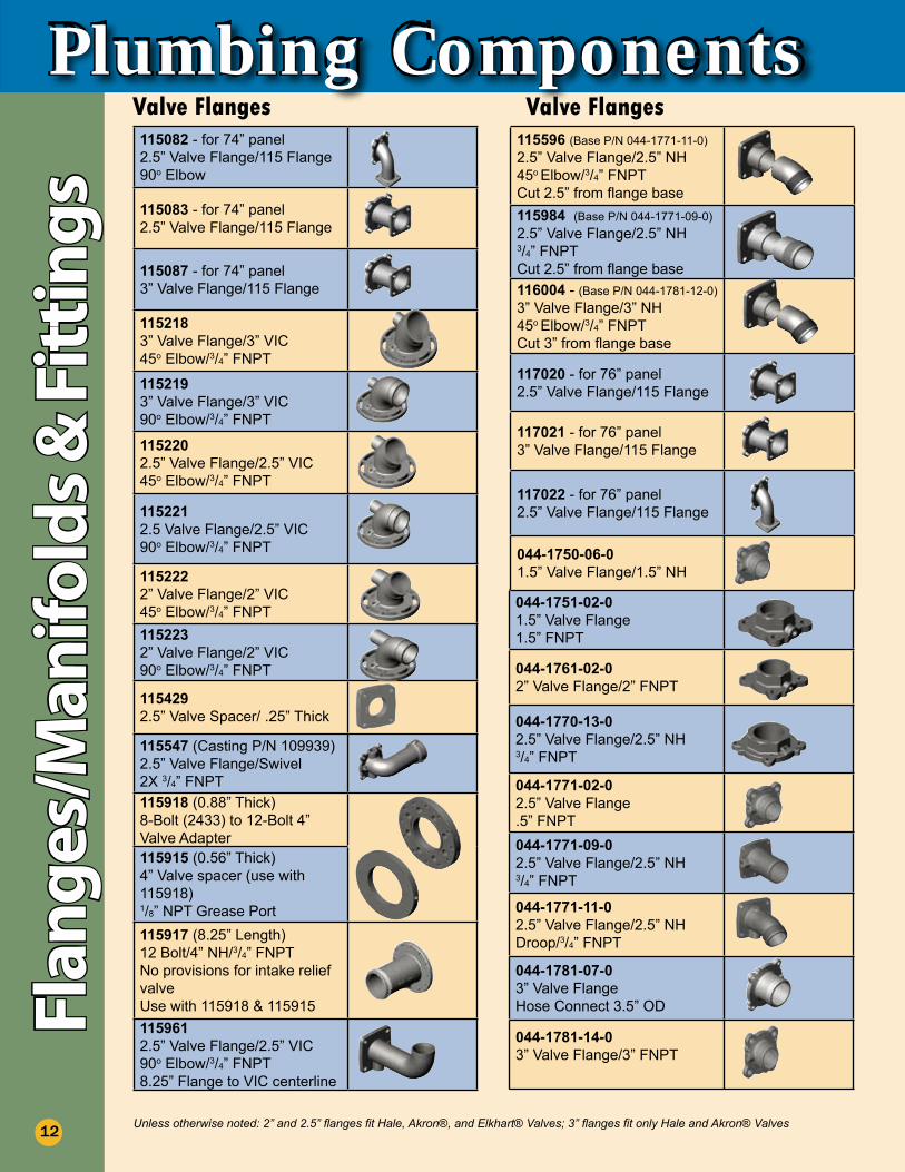
115082 - for 74” panel2.5” Valve Flange/115 Flange90o Elbow
115083 - for 74” panel2.5” Valve Flange/115 Flange
115087 - for 74” panel3” Valve Flange/115 Flange
1152183” Valve Flange/3” VIC45o Elbow/3/4” FNPT
1152193” Valve Flange/3” VIC90o Elbow/3/4” FNPT
1152202.5” Valve Flange/2.5” VIC45o Elbow/3/4” FNPT
1152212.5 Valve Flange/2.5” VIC90o Elbow/3/4” FNPT
1152222” Valve Flange/2” VIC45o Elbow/3/4” FNPT1152232” Valve Flange/2” VIC90o Elbow/3/4” FNPT
1154292.5” Valve Spacer/ .25” Thick
115547 (Casting P/N 109939)2.5” Valve Flange/Swivel2X 3/4” FNPT115918 (0.88” Thick)8-Bolt (2433) to 12-Bolt 4” Valve Adapter115915 (0.56” Thick)4” Valve spacer (use with 115918)1/8” NPT Grease Port115917 (8.25” Length)12 Bolt/4” NH/3/4” FNPTNo provisions for intake relief valveUse with 115918 & 1159151159612.5” Valve Flange/2.5” VIC90o Elbow/3/4” FNPT8.25” Flange to VIC centerline
044-1751-02-01.5” Valve Flange1.5” FNPT
044-1761-02-02” Valve Flange/2” FNPT
044-1770-13-0 2.5” Valve Flange/2.5” NH3/4” FNPT
044-1771-02-02.5” Valve Flange.5” FNPT044-1771-09-0 2.5” Valve Flange/2.5” NH3/4” FNPT
044-1771-11-0 2.5” Valve Flange/2.5” NH Droop/3/4” FNPT
044-1781-07-03” Valve FlangeHose Connect 3.5” OD
044-1781-14-0 3” Valve Flange/3” FNPT
Valve Flanges Valve Flanges115596 (Base P/N 044-1771-11-0)2.5” Valve Flange/2.5” NH45o Elbow/3/4” FNPTCut 2.5” from flange base115984 (Base P/N 044-1771-09-0)2.5” Valve Flange/2.5” NH3/4” FNPTCut 2.5” from flange base116004 - (Base P/N 044-1781-12-0)3” Valve Flange/3” NH45o Elbow/3/4” FNPTCut 3” from flange base
117020 - for 76” panel2.5” Valve Flange/115 Flange
117021 - for 76” panel3” Valve Flange/115 Flange
117022 - for 76” panel2.5” Valve Flange/115 Flange
044-1750-06-0 1.5” Valve Flange/1.5” NH
Unless otherwise noted: 2” and 2.5” flanges fit Hale, Akron®, and Elkhart® Valves; 3” flanges fit only Hale and Akron® Valves
®
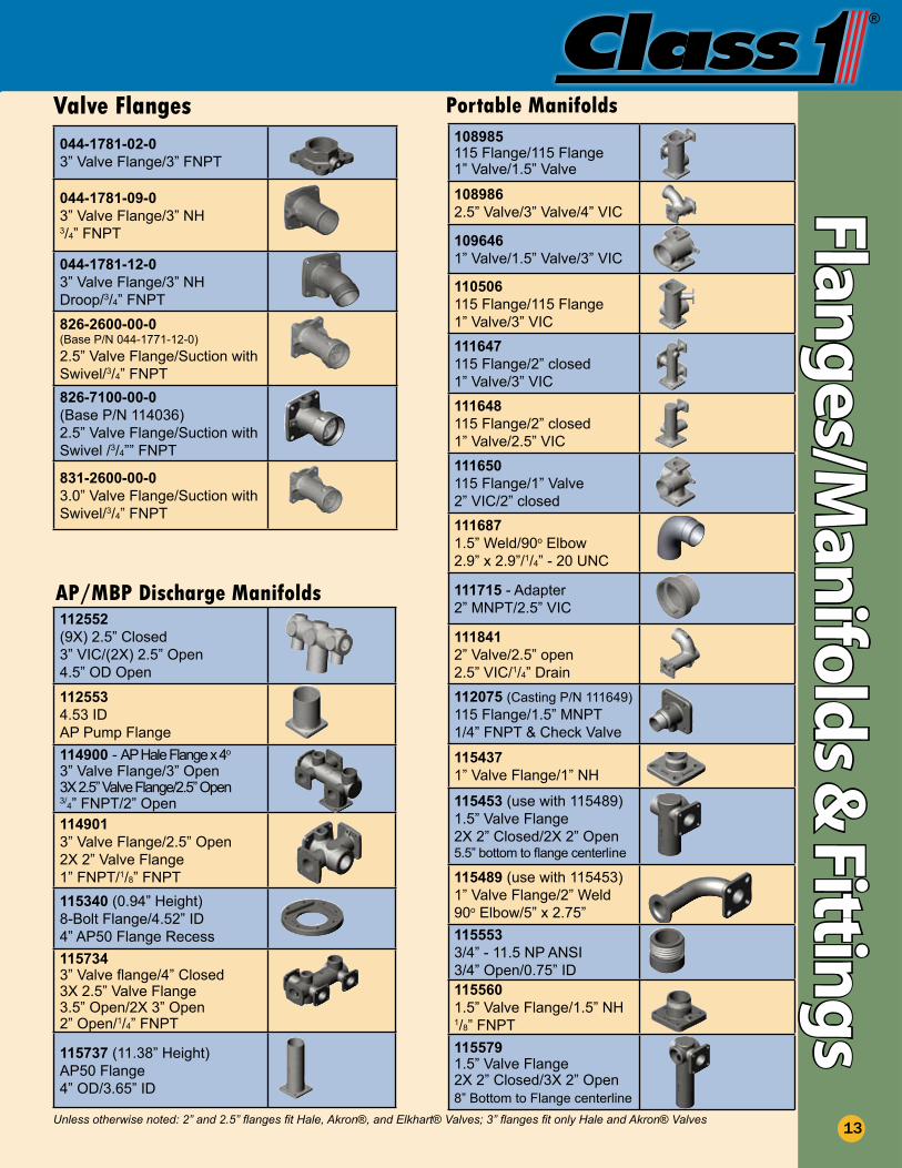
112552(9X) 2.5” Closed3” VIC/(2X) 2.5” Open4.5” OD Open
1125534.53 IDAP Pump Flange 114900 - AP Hale Flange x 4o
3” Valve Flange/3” Open3X 2.5” Valve Flange/2.5” Open3/4” FNPT/2” Open1149013” Valve Flange/2.5” Open2X 2” Valve Flange1” FNPT/1/8” FNPT115340 (0.94” Height)8-Bolt Flange/4.52” ID4” AP50 Flange Recess1157343” Valve flange/4” Closed3X 2.5” Valve Flange3.5” Open/2X 3” Open2” Open/1/4” FNPT
115737 (11.38” Height)AP50 Flange4” OD/3.65” ID
AP/MBP Discharge Manifolds
Flanges/Manifold
s & Fittings
13
Valve Flanges108985115 Flange/115 Flange1” Valve/1.5” Valve
1089862.5” Valve/3” Valve/4” VIC
1096461” Valve/1.5” Valve/3” VIC
110506115 Flange/115 Flange1” Valve/3” VIC
111647115 Flange/2” closed1” Valve/3” VIC
111648115 Flange/2” closed1” Valve/2.5” VIC
111650115 Flange/1” Valve2” VIC/2” closed 1116871.5” Weld/90o Elbow2.9” x 2.9”/1/4” - 20 UNC
111715 - Adapter2” MNPT/2.5” VIC 1118412” Valve/2.5” open2.5” VIC/1/4” Drain
112075 (Casting P/N 111649)115 Flange/1.5” MNPT1/4” FNPT & Check Valve
1154371” Valve Flange/1” NH
115453 (use with 115489)1.5” Valve Flange2X 2” Closed/2X 2” Open5.5” bottom to flange centerline
115489 (use with 115453)1” Valve Flange/2” Weld90o Elbow/5” x 2.75”1155533/4” - 11.5 NP ANSI3/4” Open/0.75” ID1155601.5” Valve Flange/1.5” NH1/8” FNPT1155791.5” Valve Flange2X 2” Closed/3X 2” Open8” Bottom to Flange centerline
Portable Manifolds
044-1781-02-03” Valve Flange/3” FNPT
044-1781-09-0 3” Valve Flange/3” NH3/4” FNPT
044-1781-12-0 3” Valve Flange/3” NH Droop/3/4” FNPT826-2600-00-0 (Base P/N 044-1771-12-0)2.5” Valve Flange/Suction with Swivel/3/4” FNPT
826-7100-00-0 (Base P/N 114036)2.5” Valve Flange/Suction with Swivel /3/4”” FNPT
831-2600-00-0 3.0” Valve Flange/Suction with Swivel/3/4” FNPT
Valve Flanges
Unless otherwise noted: 2” and 2.5” flanges fit Hale, Akron®, and Elkhart® Valves; 3” flanges fit only Hale and Akron® Valves
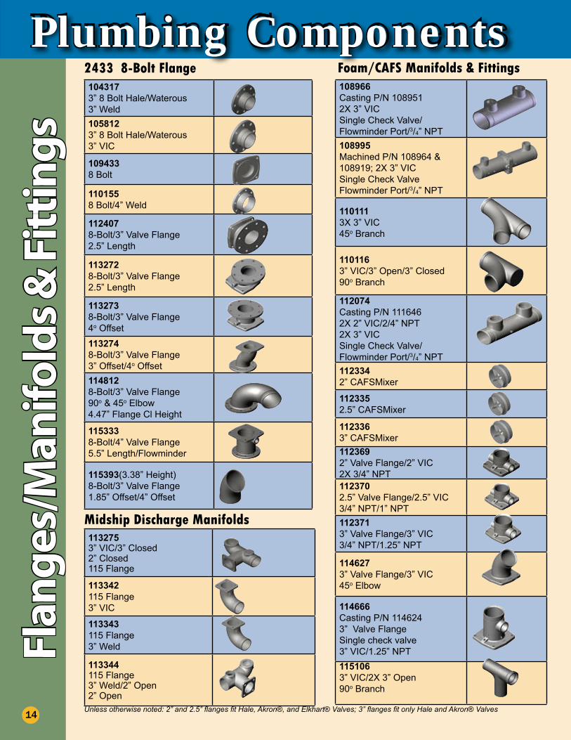
Plumbing Components108966 Casting P/N 1089512X 3” VICSingle Check Valve/Flowminder Port/3/4” NPT108995Machined P/N 108964 & 108919; 2X 3” VICSingle Check ValveFlowminder Port/3/4” NPT
1101113X 3” VIC 45o Branch
1101163” VIC/3” Open/3” Closed90o Branch
112074Casting P/N 1116462X 2” VIC/2/4” NPT2X 3” VICSingle Check Valve/Flowminder Port/3/4” NPT112334 2” CAFSMixer
112335 2.5” CAFSMixer
112336 3” CAFSMixer
1123692” Valve Flange/2” VIC2X 3/4” NPT1123702.5” Valve Flange/2.5” VIC3/4” NPT/1” NPT1123713” Valve Flange/3” VIC3/4” NPT/1.25” NPT
1146273” Valve Flange/3” VIC45o Elbow
114666Casting P/N 1146243” Valve Flange Single check valve3” VIC/1.25” NPT1151063” VIC/2X 3” Open90o Branch
Foam/CAFS Manifolds & Fittings1043173” 8 Bolt Hale/Waterous3” Weld
1058123” 8 Bolt Hale/Waterous3” VIC
1094338 Bolt
1101558 Bolt/4” Weld
112407 8-Bolt/3” Valve Flange2.5” Length
1132728-Bolt/3” Valve Flange2.5” Length
1132738-Bolt/3” Valve Flange4o Offset1132748-Bolt/3” Valve Flange3” Offset/4o Offset1148128-Bolt/3” Valve Flange90o & 45o Elbow4.47” Flange Cl Height
1153338-Bolt/4” Valve Flange5.5” Length/Flowminder
115393(3.38” Height)8-Bolt/3” Valve Flange1.85” Offset/4” Offset
2433 8-Bolt FlangeFl
ange
s/M
anifo
lds
& F
itti
ngs
14
1132753” VIC/3” Closed2” Closed115 Flange
113342 115 Flange3” VIC
113343 115 Flange3” Weld
113344115 Flange3” Weld/2” Open2” Open
Midship Discharge Manifolds
Unless otherwise noted: 2” and 2.5” flanges fit Hale, Akron®, and Elkhart® Valves; 3” flanges fit only Hale and Akron® Valves
®
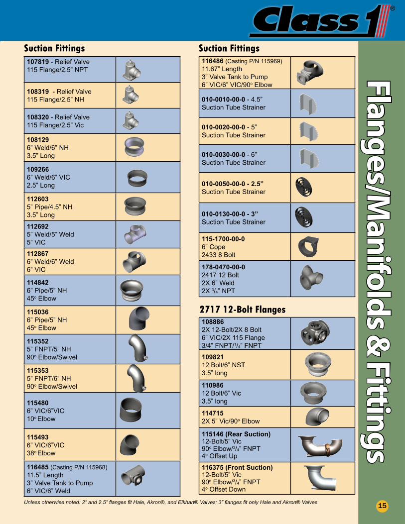
Foam/CAFS Manifolds & Fittings Suction Fittings107819 - Relief Valve115 Flange/2.5” NPT
108319 - Relief Valve115 Flange/2.5” NH
108320 - Relief Valve115 Flange/2.5” Vic
108129 6” Weld/6” NH3.5” Long
109266 6” Weld/6” VIC2.5” Long
112603 5” Pipe/4.5” NH3.5” Long
112692 5” Weld/5” Weld5” VIC
112867 6” Weld/6” Weld6” VIC
1148426” Pipe/5” NH45o Elbow
1150366” Pipe/5” NH45o Elbow
1153525” FNPT/5” NH90o Elbow/Swivel
1153535” FNPT/6” NH90o Elbow/Swivel
1154806” VIC/6”VIC10o Elbow
1154936” VIC/6”VIC38o Elbow
116485 (Casting P/N 115968)11.5” Length3” Valve Tank to Pump6” VIC/6” Weld
116486 (Casting P/N 115969)11.67” Length3” Valve Tank to Pump6” VIC/6” VIC/90o Elbow
010-0010-00-0 - 4.5”Suction Tube Strainer
010-0020-00-0 - 5”Suction Tube Strainer
010-0030-00-0 - 6”Suction Tube Strainer
010-0050-00-0 - 2.5”Suction Tube Strainer
010-0130-00-0 - 3”Suction Tube Strainer
115-1700-00-06” Cope2433 8 Bolt
178-0470-00-02417 12 Bolt2X 6” Weld2X 3/4” NPT
Suction FittingsFlanges/M
anifolds &
Fittings
15
1088862X 12-Bolt/2X 8 Bolt6” VIC/2X 115 Flange3/4” FNPT/1/4” FNPT
109821 12 Bolt/6” NST3.5” long 110986 12 Bolt/6” Vic3.5” long
1147152X 5” Vic/90o Elbow
115146 (Rear Suction)12-Bolt/5” Vic90o Elbow/3/4” FNPT4o Offset Up
116375 (Front Suction)12-Bolt/5” Vic90o Elbow/3/4” FNPT4o Offset Down
2717 12-Bolt Flanges
Unless otherwise noted: 2” and 2.5” flanges fit Hale, Akron®, and Elkhart® Valves; 3” flanges fit only Hale and Akron® Valves
Plumbing ComponentsPu
sh-O
n F
itti
ngs
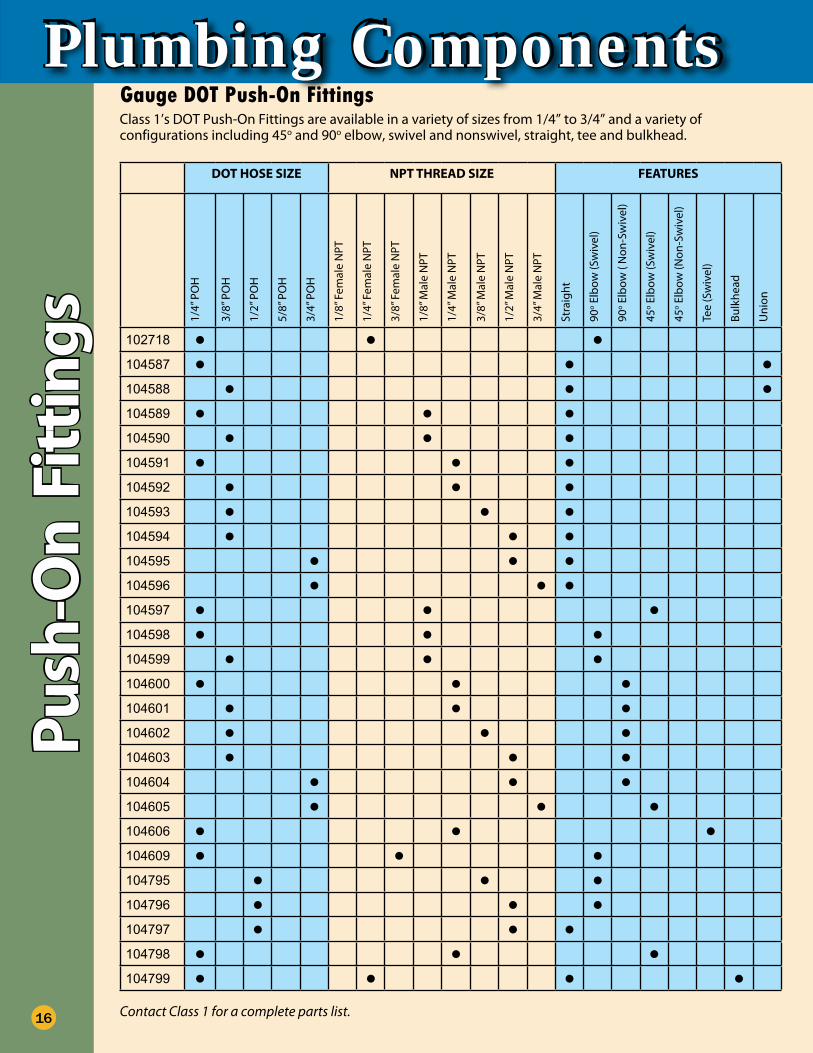
Gauge DOT Push-On FittingsClass 1’s DOT Push-On Fittings are available in a variety of sizes from 1/4” to 3/4” and a variety of configurations including 45o and 90o elbow, swivel and nonswivel, straight, tee and bulkhead.
Contact Class 1 for a complete parts list.16
DOT HOSE SIZE NPT THREAD SIZE FEATURES
1/4”
PO
H
3/8”
PO
H
1/2”
PO
H
5/8”
PO
H
3/4”
PO
H
1/8”
Fem
ale
NPT
1/4”
Fem
ale
NPT
3/8”
Fem
ale
NPT
1/8”
Mal
e N
PT
1/4”
Mal
e N
PT
3/8”
Mal
e N
PT
1/2”
Mal
e N
PT
3/4”
Mal
e N
PT
Stra
ight
90o E
lbow
(Sw
ivel
)
90o E
lbow
( N
on-S
wiv
el)
45o E
lbow
(Sw
ivel
)
45o E
lbow
(Non
-Sw
ivel
)
Tee
(Sw
ivel
)
Bulk
head
Uni
on
102718 • • •104587 • • •104588 • • •104589 • • •104590 • • •104591 • • •104592 • • •104593 • • •104594 • • •104595 • • •104596 • • •104597 • • •104598 • • •104599 • • •104600 • • •104601 • • •104602 • • •104603 • • •104604 • • •104605 • • •104606 • • •104609 • • •104795 • • •104796 • • •104797 • • •104798 • • •104799 • • • •
®
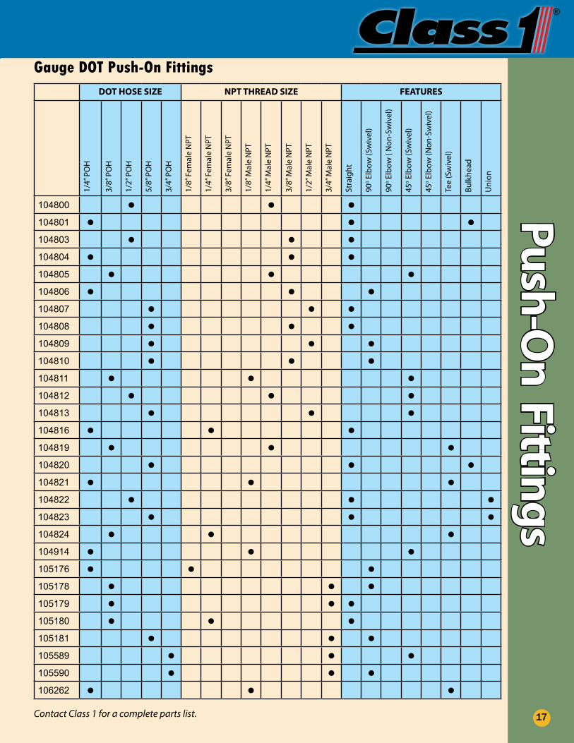
Gauge DOT Push-On FittingsPush-O
n Fittings
17
DOT HOSE SIZE NPT THREAD SIZE FEATURES1/
4” P
OH
3/8”
PO
H
1/2”
PO
H
5/8”
PO
H
3/4”
PO
H
1/8”
Fem
ale
NPT
1/4”
Fem
ale
NPT
3/8”
Fem
ale
NPT
1/8”
Mal
e N
PT
1/4”
Mal
e N
PT
3/8”
Mal
e N
PT
1/2”
Mal
e N
PT
3/4”
Mal
e N
PT
Stra
ight
90o E
lbow
(Sw
ivel
)
90o E
lbow
( N
on-S
wiv
el)
45o E
lbow
(Sw
ivel
)
45o E
lbow
(Non
-Sw
ivel
)
Tee
(Sw
ivel
)
Bulk
head
Uni
on
104800 • • •104801 • • •104803 • • •104804 • • •104805 • • •104806 • • •104807 • • •104808 • • •104809 • • •104810 • • •104811 • • •104812 • • •104813 • • •104816 • • •104819 • • •104820 • • •104821 • • •104822 • • •104823 • • •104824 • • •104914 • • •105176 • • •105178 • • •105179 • • •105180 • • •105181 • • •105589 • • •105590 • • •106262 • • •
Contact Class 1 for a complete parts list.
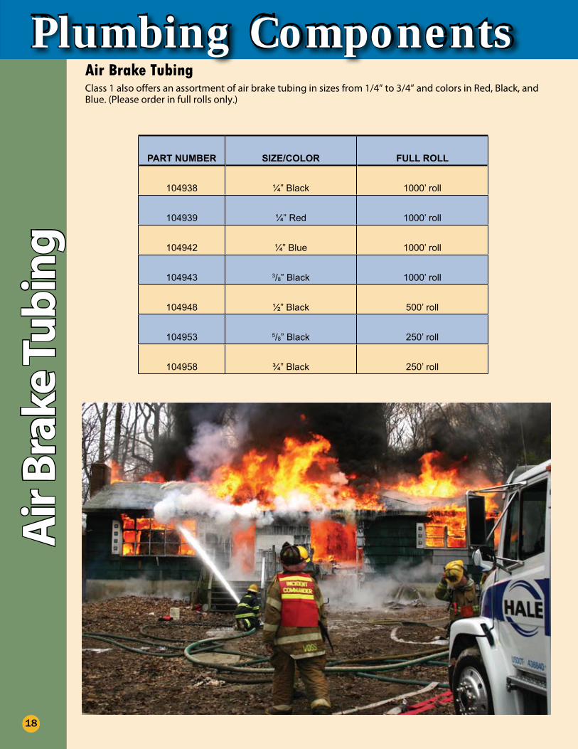
Plumbing ComponentsClass 1 also offers an assortment of air brake tubing in sizes from 1/4” to 3/4” and colors in Red, Black, and Blue. (Please order in full rolls only.)
PART NUMBER SIZE/COLOR FULL ROLL
104938 ¼” Black 1000’ roll
104939 ¼” Red 1000’ roll
104942 ¼” Blue 1000’ roll
104943 3/8” Black 1000’ roll
104948 ½” Black 500’ roll
104953 5/8” Black 250’ roll
104958 ¾” Black 250’ roll
Air Brake TubingA
ir B
rake
Tub
ing
18
®
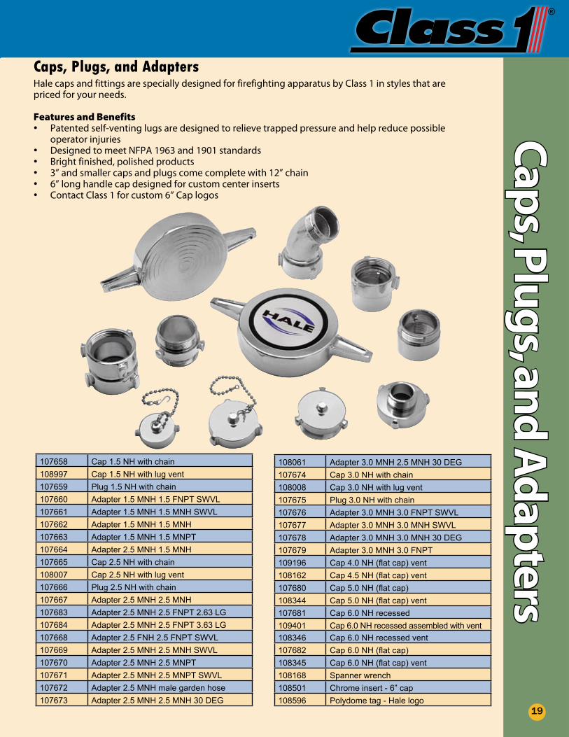
Caps, Plugs, and AdaptersHale caps and fittings are specially designed for firefighting apparatus by Class 1 in styles that are priced for your needs.
Features and BenefitsPatented self-venting lugs are designed to relieve trapped pressure and help reduce possible •operator injuriesDesigned to meet NFPA 1963 and 1901 standards•Bright finished, polished products•3” and smaller caps and plugs come complete with 12” chain•6” long handle cap designed for custom center inserts•Contact Class 1 for custom 6” Cap logos•
107658 Cap 1.5 NH with chain108997 Cap 1.5 NH with lug vent107659 Plug 1.5 NH with chain107660 Adapter 1.5 MNH 1.5 FNPT SWVL107661 Adapter 1.5 MNH 1.5 MNH SWVL107662 Adapter 1.5 MNH 1.5 MNH107663 Adapter 1.5 MNH 1.5 MNPT107664 Adapter 2.5 MNH 1.5 MNH107665 Cap 2.5 NH with chain108007 Cap 2.5 NH with lug vent107666 Plug 2.5 NH with chain107667 Adapter 2.5 MNH 2.5 MNH 107683 Adapter 2.5 MNH 2.5 FNPT 2.63 LG107684 Adapter 2.5 MNH 2.5 FNPT 3.63 LG107668 Adapter 2.5 FNH 2.5 FNPT SWVL107669 Adapter 2.5 MNH 2.5 MNH SWVL107670 Adapter 2.5 MNH 2.5 MNPT107671 Adapter 2.5 MNH 2.5 MNPT SWVL107672 Adapter 2.5 MNH male garden hose107673 Adapter 2.5 MNH 2.5 MNH 30 DEG
108061 Adapter 3.0 MNH 2.5 MNH 30 DEG107674 Cap 3.0 NH with chain108008 Cap 3.0 NH with lug vent107675 Plug 3.0 NH with chain107676 Adapter 3.0 MNH 3.0 FNPT SWVL107677 Adapter 3.0 MNH 3.0 MNH SWVL107678 Adapter 3.0 MNH 3.0 MNH 30 DEG107679 Adapter 3.0 MNH 3.0 FNPT109196 Cap 4.0 NH (flat cap) vent108162 Cap 4.5 NH (flat cap) vent107680 Cap 5.0 NH (flat cap)108344 Cap 5.0 NH (flat cap) vent107681 Cap 6.0 NH recessed109401 Cap 6.0 NH recessed assembled with vent108346 Cap 6.0 NH recessed vent107682 Cap 6.0 NH (flat cap)108345 Cap 6.0 NH (flat cap) vent108168 Spanner wrench108501 Chrome insert - 6” cap108596 Polydome tag - Hale logo
Caps, Plugs, and
Ad
apters
19
AGleaton
Text Box
FNH
AGleaton
Text Box
FNH
AGleaton
Text Box
FNH
AGleaton
Text Box
FNH
AGleaton
Text Box
FNH
AGleaton
Text Box
FNH
AGleaton
Text Box
FNH
AGleaton
Text Box
FNH
AGleaton
Text Box
FNH
AGleaton
Text Box
FNH
AGleaton
Text Box
FNH
AGleaton
Text Box
FNH
AGleaton
Text Box
FNH
Dim
ensi
onal
Dra
win
gs &
Sp
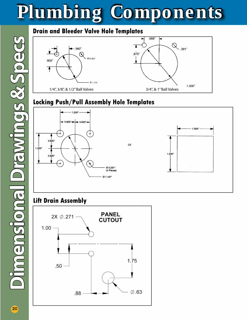
ecs Drain and Bleeder Valve Hole Templates
Locking Push/Pull Assembly Hole Templates
Plumbing Components
20
Lift Drain Assembly
1/4”, 3/8”, & 1/2” Ball Valves 3/4”, & 1” Ball Valves
or
Plumbing Components
Product Warranty
Class 1 warrants that any equipment of our own manufacture (or manufactured for us pursuant to our specifications) found to have defects in material or workmanship during normal use and service will be repaired or replaced (at our option) free of charge provided that written notice of such defect is received by us within two years (three years for liquid-filled gauges) after initial shipment. All equipment requiring repair or replacement under this warranty shall be returned prepaid to Class 1. Such returned equipment shall be examined by us and, if found to be defective as a result of materials failure or workmanship, shall be repaired at no charge.
This warranty shall not apply to any equipment which has been tampered with or altered after leaving our control or which has been repaired by anyone except Class 1. Product which has been subjected to misuse, neglect, ,abuse, or improper application will not be covered under this warranty. Misuse or abuse of the equipment or any part thereof shall include, but not limited to, damage by negligence, overpressure, excess voltage and the like. Operating the equipment with or in a corrosive, explosive, or combustible medium (unless equipment is specifically designed for such service) or exposing it to any other conditions or environment of greater severity than that for which the equipment was designed will void this warranty.
This warranty is given and accepted in lieu of all other warranties, expressed or implied, and of all other obligations or liabilities on our part. In no event shall we be liable for breach of warranty beyond the terms stated above or for any consequential damages in a case. Class l’s liability in all events is limited to the value of the product involved.
In order to ensure prompt exchange or repair service, please contact Class 1 toll free at 800-533-3569 or via e-mail at [email protected] to receive a Return Materials Authorization Number (RMA#) prior to returning the items to Class 1. Please mark the RMA# on the outside of all packages. This will enable our receiving department to quickly route the product to the appropriate repair department. Products received by Class 1 without a RMA# may experience service delays or may be returned to the sender for additional information. All returned items should be prepaid by the customer to Class 1.
Product W
arranty
21
Specifications (see www.class1.com for additional specifications)
Ball Valve Drains for 1/4” - 1”The apparatus shall be equipped with Class 1 ball valve drains to allow draining for the pump and all water carrying lines and accessories. All 2-1/2” or larger discharge outlets shall be equipped with a 3/4” ball valve drain or larger.The 1/4” , 1/2”, and 3/4” drains shall have a nickel plated brass body and 1” drains shall have an all brass body with reinforced Teflon® seals. The drains shall have NPT female inlets on both ends. The handles shall be chrome plated zinc with a recessed area for 1” x 3” I.D. tags.For 3/4” valve drains — The drains shall have 3/4” NPT female inlets on both ends. The pressure inlet side shall have a 90 degree elbow to allow easy access for plumbing. The drains shall also have a 1/4” tap for draining gauge sensing lines.For 3/4” Automatic Drains — The automatic drain shall have an all brass body with stainless steel check assembly. The drain shall be normally open that closes when the pressure is greater than approximately 6 psi.
Top Mount ControlSpecification for apparatus with top mounted pump panel.The apparatus shall be equipped with the Class 1 top mount control system for valve actuation. The handles shall be chrome plated zinc twist-lock handles with a recessed area for 2” diameter round identification tags. The mounting extrusions shall have a built-in pump panel hinge that eliminates the need for slots and trim rings on the pump panel.

607 NW 27th Avenue l Ocala, FL 34475Phone: 352/629-5020 l Fax: 352-629-2902 l 800-533-3569www.class1.com
Class 1® l A Unit of Hale Products
Hale Products Inc. l A Unit of IDEX Corporation 700 Spring Mill Avenue l Conshohocken, PA 19428Phone: 610/825-6300 l Fax: 610/825-6440 l 800-220-4253www.haleproducts.com
Copyright 2008, Class 1, Rev. 2 1/2009Note: Class 1 cannot assume responsibility for product failure resulting from improper maintenance or operation. Class 1 is responsible only to the limits stated in the product warranty. Product information contained in this material is subject to change without notice.
®
®