2009-06-27_114420_0030_-_Function_descriptionKAT.pdf
7
Example model 129 A1p8 Electronic speedometer L2 Inductive road speed sensor, transmission X26/12 Plug connection, interior/transmission (6-pin) a Road speed signal If the following complaint is received "Jerking when vehicle coasting", test the road speed signal. On/off ratio of 60 % output by the KE control unit or fault stored. 1988: The KE control units do not recognize a faulty road speed signal. l) KE resistance trimming plug The KE resistance trimming plug (R17) is located at the KE control unit (N3). Models 124, 129, 201: right of component compartment Model 107: right footwell below floor panel Model 126: right footwell behind side trim panel Location on model 107 Page 25/63 © Daimler AG, 6/27/09, G/05/09 / ra0703ke1d030x / 0030 - Function description: Design and operation D. Functions in the KE control unit - a)-y) KE-injection
-
Upload
alexcus1539 -
Category
Documents
-
view
213 -
download
1
Transcript of 2009-06-27_114420_0030_-_Function_descriptionKAT.pdf
Example model 129
A1p8 Electronic speedometerL2 Inductive road speed sensor, transmissionX26/12 Plug connection, interior/transmission (6-pin)a Road speed signal
If the following complaint is received "Jerking when vehicle coasting", test the road speed signal. On/off ratio of 60 % output by the KE control unit or fault stored.
1988: The KE control units do not recognize a faulty road speed signal.
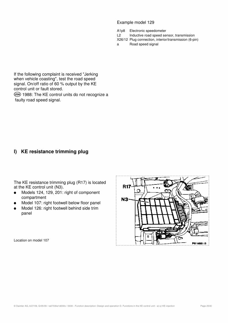
l) KE resistance trimming plug
The KE resistance trimming plug (R17) is located at the KE control unit (N3).
Models 124, 129, 201: right of component compartmentModel 107: right footwell below floor panelModel 126: right footwell behind side trim panel
Location on model 107
Page 25/63© Daimler AG, 6/27/09, G/05/09 / ra0703ke1d030x / 0030 - Function description: Design and operation D. Functions in the KE control unit - a)-y) KE-injection
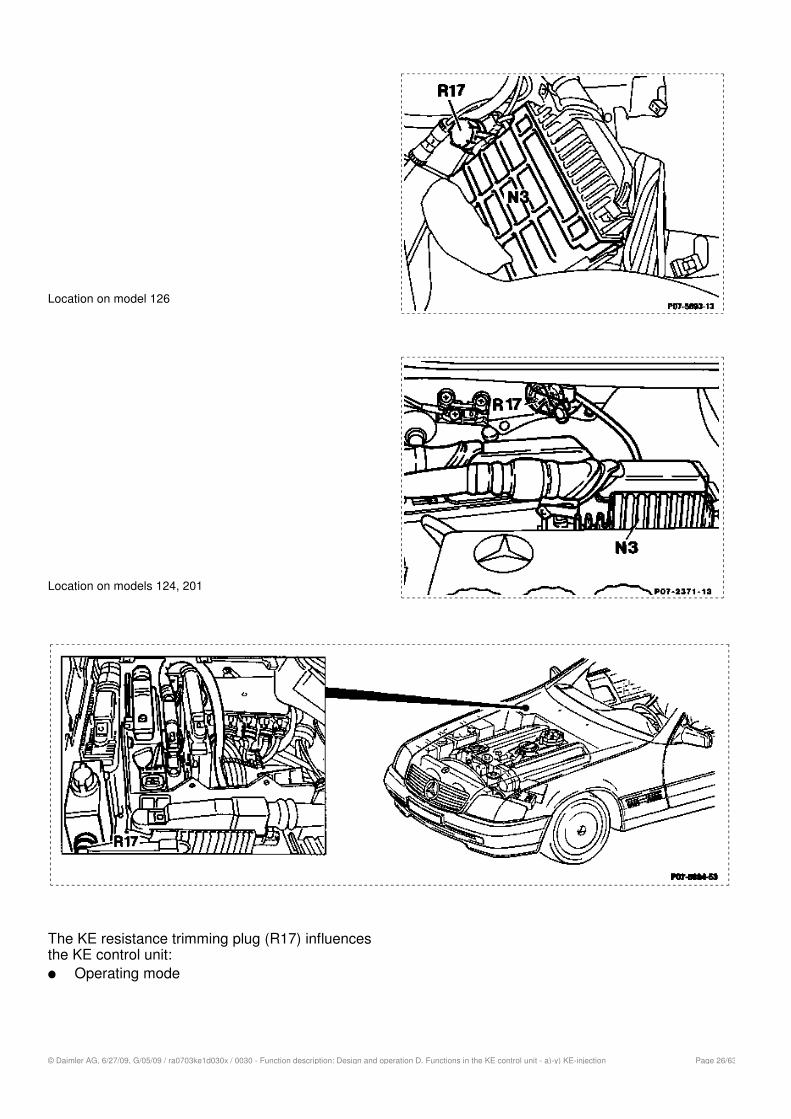
Location on model 126
Location on models 124, 201
The KE resistance trimming plug (R17) influences the KE control unit:
Operating mode
Page 26/63© Daimler AG, 6/27/09, G/05/09 / ra0703ke1d030x / 0030 - Function description: Design and operation D. Functions in the KE control unit - a)-y) KE-injection
With/without lambda closed-loop control is determined by exchanging the KE resistance trimming plug on KE control units in KAT/RÜF version. A certain current exists at the electrohydraulic actuator when the ignition is switched on, depending on the operating mode.Mixture mapIf complaints are received, the system can be tuned in 7 stages. The KE resistance trimming plug is plugged in the other way round for this purpose.
Note
Altering position only permissible if "Testing, adjusting engine" has been performed and driving faults continue to occur. The KE resistance trimming plug must be sealed tamper-proof.
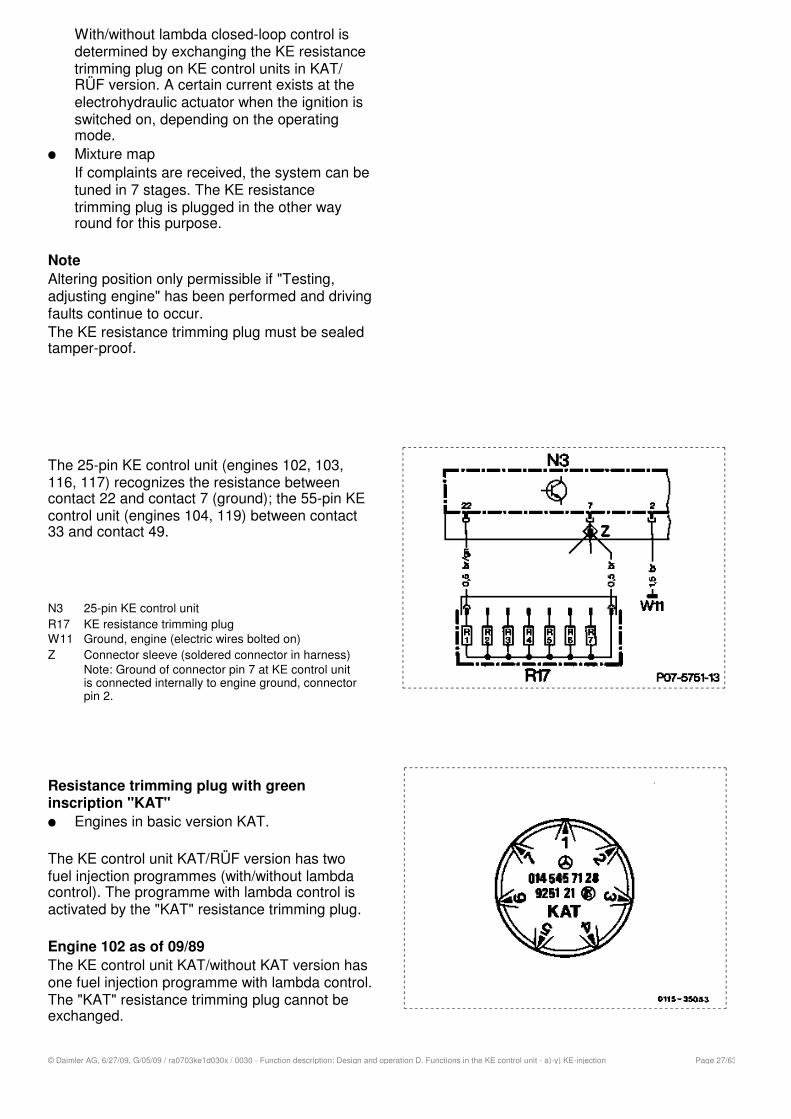
The 25-pin KE control unit (engines 102, 103, 116, 117) recognizes the resistance between contact 22 and contact 7 (ground); the 55-pin KE control unit (engines 104, 119) between contact 33 and contact 49.
N3 25-pin KE control unitR17 KE resistance trimming plugW11 Ground, engine (electric wires bolted on)Z Connector sleeve (soldered connector in harness)
Note: Ground of connector pin 7 at KE control unit is connected internally to engine ground, connector pin 2.
Resistance trimming plug with green inscription "KAT"
Engines in basic version KAT.
The KE control unit KAT/RÜF version has two fuel injection programmes (with/without lambda control). The programme with lambda control is activated by the "KAT" resistance trimming plug.
Engine 102 as of 09/89
The KE control unit KAT/without KAT version has one fuel injection programme with lambda control. The "KAT" resistance trimming plug cannot be exchanged.
Page 27/63© Daimler AG, 6/27/09, G/05/09 / ra0703ke1d030x / 0030 - Function description: Design and operation D. Functions in the KE control unit - a)-y) KE-injection

The resistance trimming plug is installed and sealed tamper-proof in position 1 in the original state. If complaints are received, a tuning of the mixture map can be performed in 7 stages.
Resistance 10%Position No. Complaint
1 953 None (original state)
2 1270 - Slight pickup faults after start >20 °C- Engines 116, 117 as of 09/87 and engine 119: not
assigned
3 1620 - Pickup faults after start >20 °C- Engines 116, 117 as of 09/87 and engine 119: not
assigned
4 2260 Slight pickup faults in warming-up phase
5 3320 Poor throttle response when cold
6 5360 Poor throttle response and pickup in warming-up phase
7 11500 Very poor throttle response when coldDriving faults in warming-up phase
Resistance trimming plug with white inscription "ECE"
Engines in basic version RÜFEngine 117.968 Standard 220 kW
The KE control unit KAT/RÜF version has two fuel injection programmes (with/without lambda control). The programme without lambda control is activated by the "ECE" resistance trimming plug.
The resistance trimming plug is installed in position 1 in original state.If complaints are received, tuning of the mixture map can be performed in 7 stages.
Page 28/63© Daimler AG, 6/27/09, G/05/09 / ra0703ke1d030x / 0030 - Function description: Design and operation D. Functions in the KE control unit - a)-y) KE-injection
Resistance 10%Position No. Complaint
1 51 None (original state)
2 105 Excessive part load consumption when engine at operating temperature
3 169 Pickup faults when engine at operating temperature
4 249 Slight pickup faults in warming-up phase
5 348 Poor throttle response when cold
6 442 Poor throttle response and pickup faults in warming-up phase
7 590 Very poor throttle response when coldDriving faults in warming-up phase
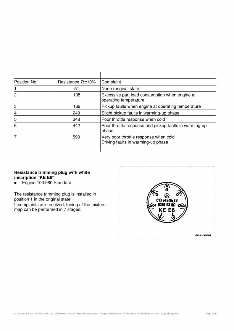
Resistance trimming plug with white inscription "KE E6"
Engine 103.980 Standard
The resistance trimming plug is installed in position 1 in the original state.If complaints are received, tuning of the mixture map can be performed in 7 stages.
Page 29/63© Daimler AG, 6/27/09, G/05/09 / ra0703ke1d030x / 0030 - Function description: Design and operation D. Functions in the KE control unit - a)-y) KE-injection
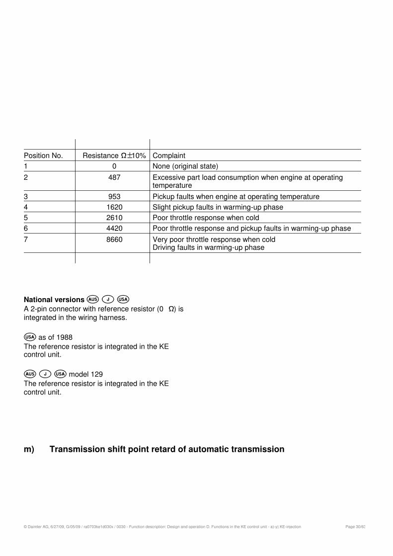
Resistance 10%Position No. Complaint
1 0 None (original state)
2 487 Excessive part load consumption when engine at operating temperature
3 953 Pickup faults when engine at operating temperature
4 1620 Slight pickup faults in warming-up phase
5 2610 Poor throttle response when cold
6 4420 Poor throttle response and pickup faults in warming-up phase
7 8660 Very poor throttle response when coldDriving faults in warming-up phase
National versions A 2-pin connector with reference resistor (0 ) is integrated in the wiring harness.
as of 1988The reference resistor is integrated in the KE control unit.
model 129The reference resistor is integrated in the KE control unit.
m) Transmission shift point retard of automatic transmission
Page 30/63© Daimler AG, 6/27/09, G/05/09 / ra0703ke1d030x / 0030 - Function description: Design and operation D. Functions in the KE control unit - a)-y) KE-injection
To enable the catalytic converter to reach its operating temperature more rapidly, the 2 3 upshift in the automatic transmission is retarded. This means the gearshift is performed at a slightly higher vehicle speed. The retarded upshift is activated for not more than 80 seconds after each engine start.
Further preconditions are:Coolant temperature approx. 0 °C - max. 50 °CRoad speed >10 km/h and <48 km/h
The figures stated for activation are average values which may differ upward or downward depending on engine version.
-Shift point retard by means of solenoid valve up to 05/91
Engine 102.96/98Engine 104 KATEngine 103
Engine 119
Page 31/63© Daimler AG, 6/27/09, G/05/09 / ra0703ke1d030x / 0030 - Function description: Design and operation D. Functions in the KE control unit - a)-y) KE-injection