
20.08032002
9
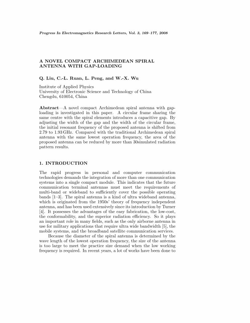
Progress In Electromagnetics Research Letters, Vol. 3, 169–177, 2008 A NOVEL COMPACT ARCHIMEDEAN SPIRAL ANTENNA WITH GAP-LOADING Q. Liu, C.-L. Ruan, L. Peng, and W.-X. Wu Institute of Applied Physics University of Electronic Science and Technology of China Chengdu, 610054, China Abstract—A novel compact Archimedean spiral antenna with gap- loading is investigated in this paper. A circular frame sharing the same centre with the spiral elements introduces a capacitive gap. By adjusting the width of the gap and the width of the circular frame, the initial resonant frequency of the proposed antenna is shifted from 2.79 to 1.93 GHz. Compared with the traditional Archimedean spiral antenna with the same lowest operation frequency, the area of the proposed antenna can be reduced by more than 30simulated radiation pattern results. 1. INTRODUCTION The rapid progress in personal and computer communication technologies demands the integration of more than one communication systems into a single compact module. This indicates that the future communication terminal antennas must meet the requirements of multi-band or wideband to sufficiently cover the possible operating bands [1–3]. The spiral antenna is a kind of ultra wideband antenna, which is originated from the 1950s’ theory of frequency independent antenna, and has been used extensively since its introduction by Turner [4]. It possesses the advantages of the easy fabrication, the low-cost, the conformability, and the superior radiation efficiency. So it plays an important role in many fields, such as the only airborne antenna in use for military applications that require ultra wide bandwidth [5], the mobile systems, and the broadband satellite communication services. Because the diameter of the spiral antenna is determined by the wave length of the lowest operation frequency, the size of the antenna is too large to meet the practice size demand when the low working frequency is required. In recent years, a lot of works have been done to
Transcript of 20.08032002
Progress In Electromagnetics Research Letters, Vol. 3, 169–177, 2008
A NOVEL COMPACT ARCHIMEDEAN SPIRALANTENNA WITH GAP-LOADING
Q. Liu, C.-L. Ruan, L. Peng, and W.-X. Wu
Institute of Applied PhysicsUniversity of Electronic Science and Technology of ChinaChengdu, 610054, China
Abstract—A novel compact Archimedean spiral antenna with gap-loading is investigated in this paper. A circular frame sharing thesame centre with the spiral elements introduces a capacitive gap. Byadjusting the width of the gap and the width of the circular frame,the initial resonant frequency of the proposed antenna is shifted from2.79 to 1.93 GHz. Compared with the traditional Archimedean spiralantenna with the same lowest operation frequency, the area of theproposed antenna can be reduced by more than 30simulated radiationpattern results.
1. INTRODUCTION
The rapid progress in personal and computer communicationtechnologies demands the integration of more than one communicationsystems into a single compact module. This indicates that the futurecommunication terminal antennas must meet the requirements ofmulti-band or wideband to sufficiently cover the possible operatingbands [1–3]. The spiral antenna is a kind of ultra wideband antenna,which is originated from the 1950s’ theory of frequency independentantenna, and has been used extensively since its introduction by Turner[4]. It possesses the advantages of the easy fabrication, the low-cost,the conformability, and the superior radiation efficiency. So it playsan important role in many fields, such as the only airborne antenna inuse for military applications that require ultra wide bandwidth [5], themobile systems, and the broadband satellite communication services.
Because the diameter of the spiral antenna is determined by thewave length of the lowest operation frequency, the size of the antennais too large to meet the practice size demand when the low workingfrequency is required. In recent years, a lot of works have been done to

170 Liu et al.
reduce the antenna size [6–13], however, most of them have not beenextended to spiral antenna [14]. So it is very meaningful to seek waysto minimize the size of the spiral antenna with simple structure andlow cost.
(a) (b)
Figure 1. Geometry of the Archimedean spiral antenna with gap-loading and the traditional Archimedean spiral antenna.
In this paper, a novel compact Archimedean spiral antenna withgap-loading whose geometry shown in Fig. 1(a) is investigated. Here,the technical method of gap-loading [15, 16] is used to lower the initialresonant frequency. Compared with the traditional Archimedean spiralantenna working at the same lowest working frequency, the area of theproposed antenna can be reduced by more than 30%, meanwhile thegain remains almost the same.
2. ANTENNA DESIGN
In this paper, two types of spiral antennas are studied for comparison.One is the Archimedean spiral antenna with gap-loading, and the otheris the traditional Archimedean spiral antenna (TASA) with differentturns. The antennas are fabricated on a substrate with a dielectricconstant of 2.2 and thickness of 0.5 mm. The schematic configurationof the traditional spiral antenna is shown in Fig. 1(b). The spiralarms are spaced at a distance of 1.5 mm, a distance equal to thatof the arm width to produce a self-complementary structure, so theinput impedance is around 180Ω. As the spiral antenna is a balancedstructure, a wideband balun is designed which also can change theimpedance from 50Ω to 180Ω. The balun structure is fabricated on a

Progress In Electromagnetics Research Letters, Vol. 3, 2008 171
substrate with a dielectric constant of 2.2 and thickness of 2 mm. Theinner and outer radius are designed to be r1 = 1 mm, r2 = 20.5 mmfor 3 turns traditional Archimedean spiral antenna and r1 = 1 mm,r2 = 27.5 mm for 4 turns traditional Archimedean spiral antenna.
The proposed Archimedean spiral antenna with gap-loading isillustrated in Fig. 1(a). The spiral element of the proposed antennais the same as the 3 turns Archimedean spiral antenna shown inFig. 1(b). A circular frame sharing the same centre with the spiralelements introduces a capacitive gap to minimize the size of theproposed antenna. The inner and outer radius of the circular frameare designed to be R1 = 22 mm and R2 = 23 mm, so the width of thecircular frame is w = R1 − R2 = 1 mm, and the width of the gap isg = R1 − r2 = 1.5 mm.
3. RESULT
A commercial three-dimension electromagnetic simulator CST basedon the finite integration technology (FIT) is used for all simulation.The prototype of the proposed antenna is fabricated and measured.The measured and simulated S parameters of the proposed antennaare shown in Fig. 2, a good agreement is observed. From Fig. 2, it canbe seen that the proposed antenna has a lower edge fL = 1.93 GHz
Figure 2. Measured and simulated S parameters of the proposedantenna compared to the different turns traditional Archimedean spiralantenna.

172 Liu et al.
Figure 3. Return losses of the proposed antenna with different w.r1 = 1 mm, r2 = 20.5 mm, R1 = 22 mm, and g = 1.5 mm.
Figure 4. Return losses of the proposed antenna with different g.r1 = 1 mm, r2 = 20.5 mm, w = 1 mm.
of the |S11| ≤ −10 dB frequency band, in contrast to 2.79 GHz of thetraditional 3 turns Archimedean spiral antenna without circular frame.The frequency reduction of initial resonant frequency is 860 MHz.However, the total radius of the proposed antenna increases from20.5 mm to 23 mm because of adding the circular frame. To comparewith the proposed antenna with the same lowest working frequency,the 4 turns Archimedean spiral antenna without gap-loading is studied,
Progress In Electromagnetics Research Letters, Vol. 3, 2008 173
and its lower edge frequency is at 2 GHz, which is almost the same withthe proposed gap-loading spiral antenna. The radius of the 4 turnsArchimedean spiral antenna is 27.5 mm and the radius of the proposedantenna is reduced to 23 mm, i.e., decreasing by 16% of radius and30% of area compared with the traditional Archimedean antenna.
The return losses of the proposed antenna for different valuesof circular frame width w are shown in Fig. 3. It is found that theS11 of the antenna is not sensitive to the change in w, so we choosew = 1 mm little narrower than the arm width. Fig. 4 shows the returnlosses of the Archimedean spiral antenna with gap-loading versus thedifferent gap width g. It can be seen that the lowest working frequencydecreases with an increase in gap width g and the return loss at higherfrequency band is almost unchanged. However, there is a practicallimit on increasing the gap width g, and if increased beyond 2.5 mm,the S11 of the antenna become deteriorative, the best return losses isobtained at g = 1.5 mm. It is easy to conclude that, the gap widthg determines the lowest resonant frequency and the intensity of thecoupling between the circular frame and the spiral element, and itmainly leads to the changes at low working frequency.
(a)

174 Liu et al.
(b)
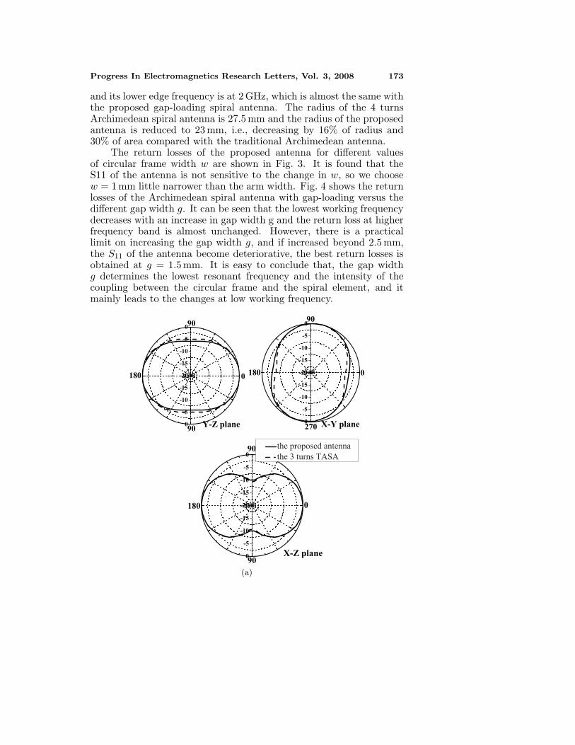
Figure 5. Radiation patterns of the proposed antenna compared withthose of the 3 turns TASA. (a) 3 GHz, (b) 6 GHz.
Fig. 5 shows the simulated radiation patterns of the proposedArchimedean spiral antenna with gap-loading at 3, 6 GHz, respectively.Each pattern is normalized with respect to the peak gain of thecorresponding plane. It is found that the proposed antenna and thetraditional Archimedean spiral antenna have almost the same radiationpatterns.
Fig. 6 shows the current distributions of the proposed antenna at1.93 GHz. It is shown that when a quart of the circular frame is aboutλ/4, a resonant mode appears which can flatten the input impedanceat low frequency band, and, hence, lowers the edge frequency of S11 ≤−10 dB. Because the currents on the circular frame add constructivelyto gain increase in XZ, Y Z plane, the area of the proposed antennacan be reduced by more than 30% without gain compromise across thewhole frequency band [14], which is shown in Fig. 7.

Progress In Electromagnetics Research Letters, Vol. 3, 2008 175
Figure 6. Current distribution on the Archimedean spiral antennawith gap-loading at 1.93 GHz.
Figure 7. Gain in Z-direction of the the Archimedean spiralantenna with gap-loading compared with the different turns traditionalArchimedean spiral antenna.
4. CONCLUSION
A technical method of gap-loading for miniature Archimedean spiralantenna is presented in this paper, which is derived by adding a circularframe. Compared with the traditional Archimedean spiral antennawith the same lowest working frequency, the area of the proposedone can be reduced by more than 30%. The optimum performance

176 Liu et al.
of the spiral antenna with gap-loading can be obtained by adjustingthe gap. This method provides an easy and effective way for spiralantenna miniaturization. Simulated and measured return losses aswell as simulated radiation patterns are presented in this paper.
ACKNOWLEDGMENT
This work was supported by the Youth Foundation of UESTC.
REFERENCES
1. Zaker, R., Ch. Ghobadi, and J. Nourinia, “A modified microstrip-fed two-step tapered monopole antenna for UWB and WLANapplications,” Progress In Electromagnetics Research, PIER 77,137–148, 2007.
2. Sadat, S. and M. Houshmand, “Design of a microstrip square-ring slot antenna filled by an h-shape slot for UWB,” Progress InElectromagnetics Research, PIER 70, 191–198, 2007.
3. Wang, F. J. and J. S. Zhang, “Wide band cavity-backedpatch antenna for PCS/IMI2000/2.4GHz WLAN,” Progress InElectromagnetics Research, PIER 74, 39–46, 2007.
4. Turner, E. M, “Spiral slot antenna,” WADC, Aerial Reconnais-sance Laboratory, Project 4341, Technical note WCLR 55-8, June1955.
5. Wang, J. J. H., “The spiral as a traveling wave structure forbroadband antenna applications,” Electromagnetics, 20–40, July–August 2000.
6. Wang, Y. J. and C. K. Lee, “Compact and broadband microstrippatch antenna for the 3G IMT-2000 handsets applying styrofoamand shorting-posts,” Progress In Electromagnetics Research,PIER 67, 173–179, 2007.
7. Sayem, A. T. M. and M. Ali, “Characteristics of a microstrip-fed miniature printed hilbert slot antenna,” Progress InElectromagnetics Research, PIER 56, 1–18, 2006.
8. Sadat, S., M. Fardis, F. Geran, and G. Dadashzadeh, “A compactmicrostirp square-ring slot antenna for UWB application,”Progress In Electromagnetics Research, PIER 67, 173–179, 2007.
9. Saed, M. and R. Yadla, “Microstrip-fed low profile and compactdielectric resonator antennas,” Progress In ElectromagneticsResearch, PIER 56, 151–162, 2006.
10. Zhao, G., F. S. Zhang, Y. Song, Z. B. Weng, and Y. C. Jiao,

Progress In Electromagnetics Research Letters, Vol. 3, 2008 177
“Compact ring monopole antenna with double meander lines for2.4/5 GHz dual-band operation,” Progress In ElectromagneticsResearch, PIER 67, 173–179, 2007.
11. Naghshvarian-Jahromi, M., “Compact UWB bandnotch antennawith transmission-line-fed,” Progress In Electromagnetics Re-search B, Vol. 3, 283–293, 2008.
12. Hosseini, S. A., Z. Atlasbaf, and K. Forooraghi, “Two newloaded compact planar ultra-band antennas using defected groundstructures,” Progress In Electromagnetics Research B, Vol. 2, 165–176, 2008.
13. Jolani, F. and A. M. Dadgarpour, “Compact m-slot foldedpatch antenna for WLAN,” Progress In Electromagnetics ResearchLetters, Vol. 3, 35–42, 2008.
14. Lee M., B. A. Kramer, C.-C. Chen, and J. L. Volakis, “Broadbandspiral antenna miniaturization limit,” Proc. IEEE Antennas andPropagation Society Int. Symp., 3701–3704, July 2006.
15. Li, R. L., E. M. Tentzeris, J. Laskar, V. F. Fusco, andR. Cahill, “Broadband antenna for DCS-1800/IMT-2000 mobilephone handset,” IEEE Microwave and Wireless ComponentsLetters, Vol. 12, No. 8, August 2002.
16. Qu, S. W., C. L. Ruan, B. Z. Wang, and Q. Xue, “Planar bow-tieantenna embedded in circular aperture within conductive frame,”IEEE Antennas Wireless Propag. Lett., Vol. 5, 2006.


