2008 Saturn OUTLOOK Owner Manual M - Vaden GMPP this Manual Read this owner manual from beginning to...
488
Seats and Restraint Systems ........................... 1-1 Front Seats ............................................... 1-2 Rear Seats .............................................. 1-12 Safety Belts ............................................. 1-18 Child Restraints ....................................... 1-39 Airbag System ......................................... 1-64 Restraint System Check ............................ 1-80 Features and Controls ..................................... 2-1 Keys ........................................................ 2-3 Doors and Locks ...................................... 2-10 Windows ................................................. 2-18 Theft-Deterrent Systems ............................ 2-21 Starting and Operating Your Vehicle ........... 2-25 Mirrors .................................................... 2-39 Object Detection Systems .......................... 2-44 OnStar ® System ...................................... 2-47 Universal Home Remote System ................ 2-50 Storage Areas ......................................... 2-55 Sunroof .................................................. 2-60 Instrument Panel ............................................. 3-1 Instrument Panel Overview .......................... 3-4 Climate Controls ...................................... 3-23 Warning Lights, Gages, and Indicators ........ 3-37 Driver Information Center (DIC) .................. 3-54 Audio System(s) ....................................... 3-82 Driving Your Vehicle ....................................... 4-1 Your Driving, the Road, and the Vehicle ....... 4-2 Towing ................................................... 4-27 Service and Appearance Care .......................... 5-1 Service ..................................................... 5-3 Fuel ......................................................... 5-5 Checking Things Under the Hood ............... 5-11 All-Wheel Drive ........................................ 5-43 Headlamp Aiming ..................................... 5-44 Bulb Replacement .................................... 5-45 Windshield Wiper Blade Replacement ......... 5-48 Tires ...................................................... 5-49 Appearance Care ................................... 5-100 Vehicle Identification ............................... 5-109 Electrical System .................................... 5-110 Capacities and Specifications ................... 5-120 Maintenance Schedule ..................................... 6-1 Maintenance Schedule ................................ 6-2 Customer Assistance Information .................... 7-1 Customer Assistance and Information ........... 7-2 Reporting Safety Defects ........................... 7-15 Vehicle Data Recording and Privacy ........... 7-18 Index ................................................................ 1 2008 Saturn OUTLOOK Owner Manual M
Transcript of 2008 Saturn OUTLOOK Owner Manual M - Vaden GMPP this Manual Read this owner manual from beginning to...

Seats and Restraint Systems ........................... 1-1Front Seats ............................................... 1-2Rear Seats .............................................. 1-12Safety Belts ............................................. 1-18Child Restraints ....................................... 1-39Airbag System ......................................... 1-64Restraint System Check ............................ 1-80
Features and Controls ..................................... 2-1Keys ........................................................ 2-3Doors and Locks ...................................... 2-10Windows ................................................. 2-18Theft-Deterrent Systems ............................ 2-21Starting and Operating Your Vehicle ........... 2-25Mirrors .................................................... 2-39Object Detection Systems .......................... 2-44OnStar® System ...................................... 2-47Universal Home Remote System ................ 2-50Storage Areas ......................................... 2-55Sunroof .................................................. 2-60
Instrument Panel ............................................. 3-1Instrument Panel Overview .......................... 3-4Climate Controls ...................................... 3-23Warning Lights, Gages, and Indicators ........ 3-37Driver Information Center (DIC) .................. 3-54Audio System(s) ....................................... 3-82
Driving Your Vehicle ....................................... 4-1Your Driving, the Road, and the Vehicle ....... 4-2Towing ................................................... 4-27
Service and Appearance Care .......................... 5-1Service ..................................................... 5-3Fuel ......................................................... 5-5Checking Things Under the Hood ............... 5-11All-Wheel Drive ........................................ 5-43Headlamp Aiming ..................................... 5-44Bulb Replacement .................................... 5-45Windshield Wiper Blade Replacement ......... 5-48Tires ...................................................... 5-49Appearance Care ................................... 5-100Vehicle Identification ............................... 5-109Electrical System .................................... 5-110Capacities and Specifications ................... 5-120
Maintenance Schedule ..................................... 6-1Maintenance Schedule ................................ 6-2
Customer Assistance Information .................... 7-1Customer Assistance and Information ........... 7-2Reporting Safety Defects ........................... 7-15Vehicle Data Recording and Privacy ........... 7-18
Index ................................................................ 1
2008 Saturn OUTLOOK Owner Manual M
SATURN, the SATURN Emblem, and the nameOUTLOOK are registered trademarks of SaturnCorporation. GENERAL MOTORS and GM areregistered trademarks of General Motors Corporation.
This manual includes the latest information at thetime it was printed. Saturn reserves the right to makechanges after that time without further notice.
This manual describes features that may or may not beon your specific vehicle.
Keep this manual in the vehicle for quick reference.
Canadian OwnersA French language copy of this manual can be obtainedfrom your dealer/retailer or from:
Helm, IncorporatedP.O. Box 07130Detroit, MI 48207
1-800-551-4123helminc.com
Propriétaires CanadiensOn peut obtenir un exemplaire de ce guide en françaisauprès de concessionnaire ou à l’adresse suivante:
Helm IncorporatedP.O. Box 07130Detroit, MI 48207
1-800-551-4123helminc.com
Litho in U.S.A.Part No. 15861573 B Second Printing ©2007 General Motors Corporation. All Rights Reserved.
ii

Using this ManualRead this owner manual from beginning to end to learnabout the vehicle’s features and controls. Picturesand words work together to explain things.
IndexTo quickly locate information about the vehicle use theIndex in the back of the manual. It is an alphabeticallist of what is in the manual and the page number whereit can be found.
Safety Warnings and SymbolsThere are a number of safety cautions in this book.A box with the word CAUTION is used to tell aboutthings that could hurt you or others if you were toignore the warning.
{CAUTION:
These mean there is something that could hurtyou or other people.
Cautions tell what the hazard is and what to do to avoidor reduce the hazard. Read these cautions.
A circle with a slashthrough it is a safetysymbol which means“Do Not,” “Do Not do this”or “Do Not let this happen.”
iii

Vehicle Damage WarningsNotices are also used in this manual.
Notice: These mean there is something that coulddamage your vehicle.
A notice tells about something that can damage thevehicle. Many times, this damage would not be coveredby the vehicle’s warranty, and it could be costly.The notice tells what to do to help avoid the damage.
When you read other manuals, you might see CAUTIONand NOTICE warnings in different colors or in differentwords.
There are also warning labels on the vehicle which usethe same words, CAUTION or NOTICE.
Vehicle SymbolsThe vehicle has components and labels that usesymbols instead of text. Symbols are shown alongwith the text describing the operation or informationrelating to a specific component, control, message,gage, or indicator.
iv
Front Seats ......................................................1-2Manual Seats ................................................1-2Seat Height Adjuster .......................................1-3Power Seats ..................................................1-3Manual Lumbar ..............................................1-4Power Lumbar ...............................................1-5Heated Seats .................................................1-5Memory Seat and Mirrors ................................1-6Reclining Seatbacks ........................................1-8Head Restraints ............................................1-11
Rear Seats .....................................................1-12Rear Seat Operation .....................................1-12Third Row Seats ...........................................1-14
Safety Belts ...................................................1-18Safety Belts: They Are for Everyone ................1-18How to Wear Safety Belts Properly .................1-23Lap-Shoulder Belt .........................................1-32Safety Belt Use During Pregnancy ..................1-38Safety Belt Extender .....................................1-38
Child Restraints .............................................1-39Older Children ..............................................1-39Infants and Young Children ............................1-42Child Restraint Systems .................................1-45
Where to Put the Restraint .............................1-48Lower Anchors and Tethers for Children
(LATCH) ..................................................1-49Securing a Child Restraint in a
Rear Seat Position ....................................1-57Securing a Child Restraint in the
Right Front Seat Position ............................1-60Airbag System ...............................................1-64
Where Are the Airbags? ................................1-66When Should an Airbag Inflate? .....................1-69What Makes an Airbag Inflate? .......................1-71How Does an Airbag Restrain? .......................1-71What Will You See After an
Airbag Inflates? .........................................1-72Passenger Sensing System ............................1-73Servicing Your Airbag-Equipped Vehicle ...........1-78Adding Equipment to Your Airbag-Equipped
Vehicle ....................................................1-78Restraint System Check ..................................1-80
Checking the Restraint Systems ......................1-80Replacing Restraint System Parts
After a Crash ............................................1-81
Section 1 Seats and Restraint Systems
1-1

Front Seats
Manual Seats
{CAUTION:
You can lose control of the vehicle if you try toadjust a manual driver’s seat while the vehicleis moving. The sudden movement could startleand confuse you, or make you push a pedalwhen you do not want to. Adjust the driver’sseat only when the vehicle is not moving.
A. Manual Seat Adjustment Bar.B. Driver Seat Height Adjuster. See Seat Height
Adjuster on page 1-3.C. Manual Reclining Seatback Lever. See Reclining
Seatbacks on page 1-8.
1-2

If your vehicle has a manual bucket seat you can adjustthe seat forward or rearward with the bar locatedunder the front of the seat cushion.
Lift the bar to unlock the seat. Slide the seat to whereyou want it and release the bar. Try to move theseat with your body to be sure the seat is lockedin place.
Seat Height AdjusterIf your vehicle has a manual driver seat height adjuster,it is located on the outboard side of the seat. See ManualSeats on page 1-2 for more information. To raise theseat, move the lever upward repeatedly until the seat isat the desired height. To lower the seat, move the leverdownward repeatedly until the seat is at the desiredheight.
Power Seats
A. Power Seat Adjustment Control.B. Power Reclining Seatback Control. See Reclining
Seatbacks on page 1-8.C. Power Lumbar Control. See Power Lumbar on
page 1-5.
If the vehicle has power seats, the controls used tooperate them are located on the outboard side of theseats.
Driver’s Seat with Power Seat Control,Power Recline, and Power Lumbar shown
1-3

Move the seat forward or rearward by sliding the controlforward or rearward.
Your vehicle may have additional features to adjust yourvehicle’s power seat:
• Raise or lower the entire seat by moving the entirecontrol up or down.
• Raise or lower the front part of the seat cushion bymoving the front of the control up or down.
• Raise or lower the rear part of the seat cushion bymoving the rear of the control up or down.
Your vehicle may have a memory function which allowsseat settings to be saved and recalled. See MemorySeat and Mirrors on page 1-6 for more information.
Manual Lumbar
If your vehicle has thisfeature, the handle islocated on the inboardside of the seatback.See Manual Seatson page 1-2 for moreinformation.
Turn the handle rearward to decrease lumbar support.Turn the handle forward to increase lumbar support.
Keep in mind that as your seating position changes,as it may during long trips, so should the position ofyour lumbar support. Adjust the seat as needed.
1-4

Power LumbarIf the seats have power lumbar, the controls used tooperate this feature are located on the outboard sideof the seats. See Power Seats on page 1-3 formore information.
• To increase lumbar support, press and hold thefront of the control.
• To decrease lumbar support, press and hold therear of the control.
• To raise the height of the lumbar support, pressand hold the top of the control.
• To lower the height of the lumbar support, pressand hold the bottom of the control.
Release the control when the lower seatback reachesthe desired level of lumbar support.
You may need to adjust the lumbar support wheneveryou change your seating position.
Heated SeatsOn vehicles with heated front seats the controls arelocated on the center console. To operate the heatedseats the engine must be running.
I (Heated Seatback): Press this button to turn on theheated seatback.
J (Heated Seat and Seatback): Press this button toturn on the heated seat and seatback.
The light on the button will come on to indicate that thefeature is working. Press the button to cycle throughthe temperature settings of high, medium, and low andto turn the heat to the seat off. Indicator lights abovethe button will show the level of heat selected: threefor high, two for medium, and one for low.
1-5

The passenger seat may take longer to heat up.
If your vehicle has remote vehicle start and is startedusing the remote keyless entry transmitter, the frontheated seats will be turned on to the high setting if it iscold outside. See “Remote Vehicle Start” under RemoteKeyless Entry (RKE) System Operation on page 2-5.When the key is inserted into the ignition and the ignitionis turned on, the heated seat feature will turn off. To turnthe heated seat feature back on, press the desiredbutton.
Memory Seat and MirrorsYour vehicle may have the memory package.
The controls for this feature are located on the driver’sdoor panel, and are used to program and recall memorysettings for the driver’s seat and outside mirrors.
1-6

To save your positions in memory, do the following:
1. Adjust the driver’s seat, including the seatbackrecliner and lumbar and both outside mirrors toa comfortable position.See Outside Power Mirrors on page 2-41 for moreinformation.Not all mirrors will have the ability to save andrecall the mirror positions.
2. Press and hold button 1 until two beeps let youknow that the position has been stored.
A second seating and mirror position can beprogrammed by repeating the above steps andpressing button 2.
To recall the memory positions, the vehicle must be inPARK (P). Press and release either button 1 or button 2corresponding to the desired driving position. Theseat and outside mirrors will move to the positionpreviously stored. You will hear a single beep.
Using the Remote Keyless Entry (RKE) transmitter toenter your vehicle with the remote recall memory featureon causes automatic seat and mirror adjustment. There isno adjustment when the position has not been changedby another seating position or the easy exit feature.See “MEMORY SEAT RECALL” under DIC VehicleCustomization (With DIC Buttons) on page 3-74 formore information.
To stop recall movement of the memory feature at anytime, press one of the power seat controls, memorybuttons, or power mirror buttons.
If something has blocked the driver’s seat while recallinga memory position, the driver’s seat recall may stopworking. If this happens, press the appropriate control forthe area that is not recalling for two seconds, after theobstruction is removed. Then try recalling the memoryposition again by pressing the appropriate memorybutton. If the memory position is still not being recalled,see your dealer/retailer for service.
1-7

Easy Exit SeatThe control for this feature is located on the driver’sdoor panel between buttons 1 and 2.
With the vehicle in PARK (P), the exit position can berecalled by pressing the exit button. You will heara single beep. The driver’s seat will move back.
If the easy exit seat feature is on in the DriverInformation Center (DIC), automatic seat movementwill occur when the key is removed from the ignition.See “EASY EXIT SEAT” under DIC VehicleCustomization (With DIC Buttons) on page 3-74for more information.
Further programming for the memory seat feature canbe done using the DIC. You can select or cancelthe following:
• The automatic easy exit seat feature.
• The remote memory seat recall feature.
For programming information, see DIC VehicleCustomization (With DIC Buttons) on page 3-74.
Reclining Seatbacks
Manual Reclining Seatbacks
{CAUTION:
You can lose control of the vehicle if you try toadjust a manual driver’s seat while the vehicleis moving. The sudden movement could startleand confuse you, or make you push a pedalwhen you do not want to. Adjust the driver’sseat only when the vehicle is not moving.
1-8

{CAUTION:
If the seatback is not locked, it could moveforward in a sudden stop or crash. That couldcause injury to the person sitting there. Alwayspush and pull on the seatback to be sure it islocked.
In vehicles with seats that have manual recliningseatbacks, the lever used to operate them is locatedon the outboard side of the seat.
To recline the seatback, do the following:
1. Lift the recline lever.
2. Move the seatback to the desired position, thenrelease the lever to lock the seatback in place.
3. Push and pull on the seatback to make sure it islocked.
To return the seatback to an upright position, do thefollowing:
1. Lift the lever fully without applying pressure to theseatback and the seatback will return to the uprightposition.
2. Push and pull on the seatback to make sure it islocked.
1-9
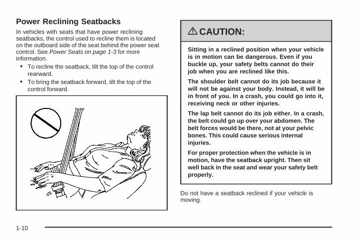
Power Reclining SeatbacksIn vehicles with seats that have power recliningseatbacks, the control used to recline them is locatedon the outboard side of the seat behind the power seatcontrol. See Power Seats on page 1-3 for moreinformation.• To recline the seatback, tilt the top of the control
rearward.• To bring the seatback forward, tilt the top of the
control forward.
{CAUTION:
Sitting in a reclined position when your vehicleis in motion can be dangerous. Even if youbuckle up, your safety belts cannot do theirjob when you are reclined like this.
The shoulder belt cannot do its job because itwill not be against your body. Instead, it will bein front of you. In a crash, you could go into it,receiving neck or other injuries.
The lap belt cannot do its job either. In a crash,the belt could go up over your abdomen. Thebelt forces would be there, not at your pelvicbones. This could cause serious internalinjuries.
For proper protection when the vehicle is inmotion, have the seatback upright. Then sitwell back in the seat and wear your safety beltproperly.
Do not have a seatback reclined if your vehicle ismoving.
1-10

Head Restraints
Adjust the head restraint so that the top of the restraintis at the same height as the top of the occupant’shead. This position reduces the chance of a neckinjury in a crash.
Pull the head restraint upto raise it. To lower thehead restraint, press therelease button, located onthe head restraint post onthe top of the seatback,while you push the headrestraint down.
1-11

Rear Seats
Rear Seat Operation
A. Seat Adjustment Handle.B. Reclining Seatback Strap.C. Sliding Seat Lever.
Entering and Exiting the Third Row
{CAUTION:
Using the third row seating position while thesecond row is folded, or folded and tumbled,could cause injury in a sudden stop or crash.Be sure to return the seat to the passengerseating position. Push and pull on the seatto make sure it is locked into place.
Notice: Folding a rear seat with the safety beltsstill fastened may cause damage to the seat orthe safety belts. Always unbuckle the safety beltsand return them to their normal stowed positionbefore folding a rear seat.
1-12
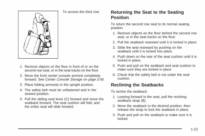
To access the third row:
1. Remove objects on the floor in front of or on thesecond row seat, or in the seat tracks on the floor.
2. Move the front center console armrest completelyforward. See Center Console Storage on page 2-56
3. Place folding armrests in the upright position.
4. The safety belt must be unfastened and in thestowed position.
5. Pull the sliding seat lever (C) forward and move theseatback forward. The seat cushion will fold, andthe entire seat will slide forward.
Returning the Seat to the SeatingPositionTo return the second row seat to its normal seatingposition:
1. Remove objects on the floor behind the second rowseat, or in the seat tracks on the floor.
2. Pull the seatback rearward until it is locked in place.
3. Slide the seat rearward by pushing on theseatback until it is locked into place.
4. Push down on the rear of the seat cushion until it islocked in place.
5. Push and pull on the seatback and seat cushion tomake sure they are locked in place
6. Check that the safety belt is not under the seatcushion.
Reclining the SeatbacksTo recline the seatback:
1. Leaning forward in the seat, pull the recliningseatback strap (B).
2. Move the seatback to the desired position, thenrelease the strap to lock the seatback in place.
3. Push and pull on the seatback to make sure it islocked.
1-13

Folding the Rear SeatTo fold the second row seats:
1. Remove anything on or under the seat.
2. Place the armrest in the upright position, andunfasten the safety belt.
3. Pull forward on the reclining seatback strap (B) andpush down on the seatback.
4. If the headrest hits the front seat, slide the secondrow seat rearward.
To return the seatback to the seating position, lift theupper corner of the seatback and push it rearward untilit locks into place. Push and pull on the seatback tomake sure it is locked.
Adjusting the SeatsTo adjust the second row seats, pull outward on theseat adjustment handle (A). Slide the seat forward orrearward to the desired position. Release the handleand push and pull on the seat to make sure it is locked.
Third Row Seats
{CAUTION:
Using the third row seating position while thesecond row is folded, or pushed forward in theentry position, could cause injury in a suddenstop or crash. Be sure to return the seat to thepassenger seating position. Push and pull onthe seat to make sure it is locked into place.
The third row seats can be folded forward or removed.
Notice: Folding a rear seat with the safety beltsstill fastened may cause damage to the seat orthe safety belts. Always unbuckle the safety beltsand return them to their normal stowed positionbefore folding a rear seat.
1-14

To fold the seatback:
1. Remove anything on or under the seat.
2. Disconnect the rear safety belt mini-latch, usinga key in the slot on the mini-buckle, let the beltretract into the headliner. Stow the mini-latch inthe holder located in the headliner.
3. Pull up on the releaselever located on theback of the seat.The headrest movesforward automatically.
4. Push the seatback forward to lay flat.
1-15

To return the seatback to the seating position:
1. Raise the seatback into place by using the pullstrapfrom the rear of the vehicle, or by pushing it intoplace from inside the vehicle.
2. The headrest must be locked into place beforesitting in the seat.
{CAUTION:
If the seatback is not locked, it could moveforward in a sudden stop or crash. That couldcause injury to the person sitting there. Alwayspush and pull on the seatback to be sure it islocked.
3. Push and pull on the seatback to make sure it islocked in place.
{CAUTION:
A safety belt that is improperly routed, notproperly attached, or twisted will not providethe protection needed in a crash. The personwearing the belt could be seriously injured.After raising the rear seatback, always checkto be sure that the safety belts are properlyrouted and attached, and are not twisted.
4. Reconnect the center safety belt mini-latch to themini-buckle. Do not let it twist.
5. Pull on the safety belt to be sure the mini-latch issecure.
1-16

Removing the Third Row Seats1. Remove the cargo management system, if it is in
the vehicle. See Cargo Management System onpage 2-59.
2. Remove anything on or under the seat.
Notice: Folding a rear seat with the safety beltsstill fastened may cause damage to the seat or thesafety belts. Always unbuckle the safety beltsand return them to their normal stowed positionbefore folding a rear seat.
3. Fold the seatback down. See “Folding the Seatback”earlier in this section.
4. Remove the rear bolts located on the floor on eachside of the seat.
5. Remove the seat by tilting it slightly upward, andthen pulling it out of the rear of the vehicle in onemotion.
6. Put the bolts back into the holes on the floor sothey do not get misplaced.
Installing the Third Row Seats1. Before installing the seat the seatback must be
folded forward. See “Folding the Seatback”earlier in this section.The seats must be placed in the proper locationsfor the legs to attach correctly. The wider seat mustbe installed on the driver side and the narrowerseat on the passenger side. Remove the bolts fromthe holes in the floor before installing the seats.
2. Place the seat on the vehicle floor so that the frontseat hooks are on the vehicle bars.
3. Reinstall the bolts, and torque to 55 Y (41 lb ft).Pull up on the seat to make sure it is locked in place.
4. Raise the seatback to its upright position. Pushand pull on the seatback to make sure it is lockedinto place.
5. Push the headrest up into position. Push andpull on the headrest to make sure it is lockedinto place.
6. Reconnect the center safety belt mini-latch to themini-buckle. Do not let it twist.
1-17

Safety Belts
Safety Belts: They Are for EveryoneThis section of the manual describes how to usesafety belts properly. It also describes some things notto do with safety belts.
{CAUTION:
Do not let anyone ride where he or she cannotwear a safety belt properly. If you are in a crashand you are not wearing a safety belt, yourinjuries can be much worse. You can hit thingsinside the vehicle harder or be ejected from itand be seriously injured or killed. In the samecrash, you might not be, if you are buckled up.Always fasten your safety belt, and check thatyour passenger(s) are restrained properly too.
{CAUTION:
It is extremely dangerous to ride in a cargoarea, inside or outside of a vehicle. In acollision, people riding in these areas are morelikely to be seriously injured or killed. Do notallow people to ride in any area of your vehiclethat is not equipped with seats and safety belts.Be sure everyone in your vehicle is in a seat andusing a safety belt properly.
This vehicle has indicators as a reminder to buckle thesafety belts. See Safety Belt Reminders on page 3-39for additional information.
1-18
In most states and in all Canadian provinces, the lawrequires wearing safety belts. Here is why:
You never know if you will be in a crash. If you do havea crash, you do not know if it will be a serious one.
A few crashes are mild, and some crashes can be soserious that even buckled up, a person would not survive.But most crashes are in between. In many of them,people who buckle up can survive and sometimes walkaway. Without safety belts, they could have been badlyhurt or killed.
After more than 40 years of safety belts in vehicles,the facts are clear. In most crashes buckling up doesmatter... a lot!
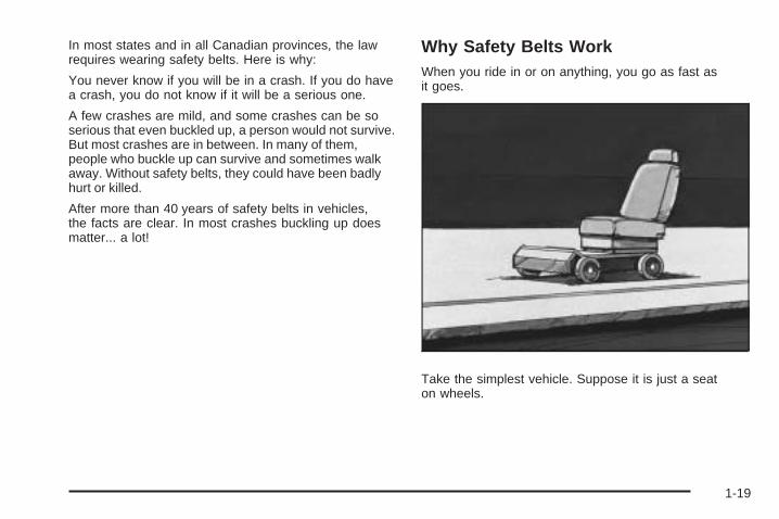
Why Safety Belts WorkWhen you ride in or on anything, you go as fast asit goes.
Take the simplest vehicle. Suppose it is just a seaton wheels.
1-19

Put someone on it. Get it up to speed. Then stop the vehicle. The riderdoes not stop.
1-20

The person keeps going until stopped by something.In a real vehicle, it could be the windshield...
or the instrument panel...
1-21

or the safety belts!
With safety belts, you slow down as the vehicle does.You get more time to stop. You stop over more distance,and your strongest bones take the forces. That is whysafety belts make such good sense.
Questions and Answers About SafetyBelts
Q: Will I be trapped in the vehicle after a crash if Iam wearing a safety belt?
A: You could be — whether you are wearing a safetybelt or not. But your chance of being consciousduring and after an accident, so you can unbuckleand get out, is much greater if you are belted.And you can unbuckle a safety belt, even if youare upside down.
Q: If my vehicle has airbags, why should I have towear safety belts?
A: Airbags are supplemental systems only; so theywork with safety belts — not instead of them.Whether or not an airbag is provided, all occupantsstill have to buckle up to get the most protection.That is true not only in frontal collisions, butespecially in side and other collisions.
1-22

Q: If I am a good driver, and I never drive far fromhome, why should I wear safety belts?
A: You may be an excellent driver, but if you are in acrash — even one that is not your fault — you andyour passenger(s) can be hurt. Being a good driverdoes not protect you from things beyond yourcontrol, such as bad drivers.
Most accidents occur within 25 miles (40 km) ofhome. And the greatest number of serious injuriesand deaths occur at speeds of less than 40 mph(65 km/h).
Safety belts are for everyone.
How to Wear Safety Belts ProperlyThis section is only for people of adult size.
Be aware that there are special things to know aboutsafety belts and children. And there are different rules forsmaller children and infants. If a child will be riding in thevehicle, see Older Children on page 1-39 or Infants andYoung Children on page 1-42. Follow those rules foreveryone’s protection.
It is very important for all occupants to buckle up.Statistics show that unbelted people are hurt more oftenin crashes than those who are wearing safety belts.
Occupants who are not buckled up can be thrown outof the vehicle in a crash. And they can strike othersin the vehicle who are wearing safety belts.
First, before you or your passenger(s) wear a safetybelt, there is important information you should know.
1-23
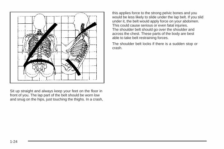
Sit up straight and always keep your feet on the floor infront of you. The lap part of the belt should be worn lowand snug on the hips, just touching the thighs. In a crash,
this applies force to the strong pelvic bones and youwould be less likely to slide under the lap belt. If you slidunder it, the belt would apply force on your abdomen.This could cause serious or even fatal injuries.The shoulder belt should go over the shoulder andacross the chest. These parts of the body are bestable to take belt restraining forces.
The shoulder belt locks if there is a sudden stop orcrash.
1-24

Q: What is wrong with this?
A: The shoulder belt is too loose. It will not give asmuch protection this way.
{CAUTION:
You can be seriously hurt if your shoulderbelt is too loose. In a crash, you would moveforward too much, which could increase injury.The shoulder belt should fit snugly againstyour body.
1-25

Q: What is wrong with this?
A: The lap belt is too loose. It will not give nearly asmuch protection this way.
{CAUTION:
You can be seriously hurt if your lap belt istoo loose. In a crash, you could slide underthe lap belt and apply force on your abdomen.This could cause serious or even fatal injuries.The lap belt should be worn low and snug onthe hips, just touching the thighs.
1-26
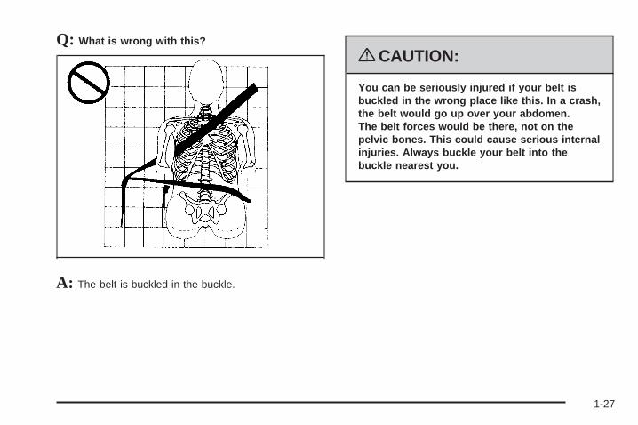
Q: What is wrong with this?
A: The belt is buckled in the buckle.
{CAUTION:
You can be seriously injured if your belt isbuckled in the wrong place like this. In a crash,the belt would go up over your abdomen.The belt forces would be there, not on thepelvic bones. This could cause serious internalinjuries. Always buckle your belt into thebuckle nearest you.
1-27

Q: What is wrong with this?
A: The belt is over an armrest.
{CAUTION:
You can be seriously injured if your belt goesover an armrest like this. The belt would bemuch too high. In a crash, you can slide underthe belt. The belt force would then be appliedon the abdomen, not on the pelvic bones, andthat could cause serious or fatal injuries.Be sure the belt goes under the armrests.
1-28

Q: What is wrong with this?
A: The shoulder belt is worn under the arm. It shouldbe worn over the shoulder at all times.
{CAUTION:
You can be seriously injured if you wear theshoulder belt under your arm. In a crash, yourbody would move too far forward, which wouldincrease the chance of head and neck injury.Also, the belt would apply too much force tothe ribs, which are not as strong as shoulderbones. You could also severely injure internalorgans like your liver or spleen. The shoulderbelt should go over the shoulder and acrossthe chest.
1-29

Q: What is wrong with this?
A: The belt is behind the body.
{CAUTION:
You can be seriously injured by not wearingthe lap-shoulder belt properly. In a crash, youwould not be restrained by the shoulder belt.Your body could move too far forwardincreasing the chance of head and neck injury.You might also slide under the lap belt. Thebelt force would then be applied right on theabdomen. That could cause serious or fatalinjuries. The shoulder belt should go over theshoulder and across the chest.
1-30

Q: What is wrong with this?
A: The belt is twisted across the body.
{CAUTION:
You can be seriously injured by a twisted belt.In a crash, you would not have the full widthof the belt to spread impact forces. If a belt istwisted, make it straight so it can work properly,or ask your dealer/retailer to fix it.
1-31
Lap-Shoulder BeltAll seating positions in the vehicle have alap-shoulder belt.
If you are using a rear seating position with a detachablesafety belt and the safety belt is not attached, seeThird Row Seats on page 1-14 for instruction onreconnecting the safety belt to the mini-buckle.
The following instructions explain how to wear alap-shoulder belt properly.
1. Adjust the seat, if the seat is adjustable, so you cansit up straight. To see how, see “Seats” in the Index.
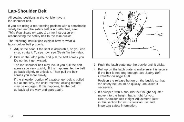
2. Pick up the latch plate and pull the belt across you.Do not let it get twisted.The lap-shoulder belt may lock if you pull the beltacross you very quickly. If this happens, let the beltgo back slightly to unlock it. Then pull the beltacross you more slowly.If the shoulder portion of a passenger belt is pulledout all the way, the child restraint locking featuremay be engaged. If this happens, let the beltgo back all the way and start again.
3. Push the latch plate into the buckle until it clicks.
4. Pull up on the latch plate to make sure it is secure.If the belt is not long enough, see Safety BeltExtender on page 1-38.Position the release button on the buckle so thatthe safety belt could be quickly unbuckled ifnecessary.
5. If equipped with a shoulder belt height adjuster,move it to the height that is right for you.See “Shoulder Belt Height Adjustment” laterin this section for instructions on use andimportant safety information.
1-32

6. To make the lap part tight, pull up on theshoulder belt.It may be necessary to pull the stitching on thesafety belt through the latch plate to fully tightenthe lap belt on smaller occupants.
To unlatch the belt, push the button on the buckle.The belt should return to its stowed position. Slidethe latch plate up the safety belt webbing whenthe safety belt is not in use. The latch plate shouldrest on the stitching on the safety belt, near the guideloop on the side wall.
Before a door is closed, be sure the safety belt is outof the way. If a door is slammed against a safetybelt, damage can occur to both the safety belt andthe vehicle.
1-33

Shoulder Belt Height AdjustmentThe vehicle has a shoulder belt height adjuster for thedriver and right front passenger seating positions.
Adjust the height so that the shoulder portion of the beltis centered on the shoulder. The belt should be awayfrom the face and neck, but not falling off of the shoulder.Improper shoulder belt height adjustment could reducethe effectiveness of the safety belt in a crash.
To move it down, pushdown on the button (A) andmove the height adjusterto the desired position.You can move the heightadjuster up by pushing upon the shoulder belt guide.
After the adjuster is set to the desired position, try tomove it down without pushing the button to make sureit has locked into position.
Safety Belt PretensionersThis vehicle has safety belt pretensioners for thefront outboard occupants. Although the safety beltpretensioners cannot be seen, they are part of the safetybelt assembly. They can help tighten the safety beltsduring the early stages of a moderate to severe frontal,near frontal, or rear crash if the threshold conditions forpretensioner activation are met. And, if the vehicle hasside impact airbags, safety belt pretensioners can helptighten the safety belts in a side crash or a rollover event.
Pretensioners work only once. If the pretensionersactivate in a crash, they will need to be replaced,and probably other new parts for the vehicle’s safetybelt system. See Replacing Restraint System PartsAfter a Crash on page 1-81.
Rear Safety Belt Comfort GuidesRear shoulder belt comfort guides may provide addedsafety belt comfort for older children who have outgrownbooster seats and for some adults. When installed ona shoulder belt, the comfort guide positions the shoulderbelt away from the neck and head.
1-34

There is a guide for each outboard passenger positionin the second row seat and all passenger positionsin the third row. Here is how to install a comfort guideto the safety belt:
1. For the outboard positions, remove the guide fromits storage clip on the interior body.For the third row center position, locate the comfortguide which is located in a storage pocket, atthe top of the seat, under the headrest on the
driver’s side of the vehicle. To access the comfortguide, you will first need to move the headrestforward by pulling on the handle behind theseatback. The comfort guide will now beaccessible.
Pull the comfort guide outof its storage location andthen return the headrestto its upright position.
The elastic cord on the comfort guide is adjustable.You can make it longer or shorter by squeezingboth ends of the plastic adjuster.
Outboard Positions
Third Row CenterPosition
1-35

2. Place the guide over the belt, and insert the twoedges of the belt into the slots of the guide.
3. Be sure that the belt is not twisted and it lies flat.The elastic cord must be under the belt and theguide on top.
1-36

{CAUTION:
A safety belt that is not properly worn maynot provide the protection needed in a crash.The person wearing the belt could be seriouslyinjured. The shoulder belt should go over theshoulder and across the chest. These parts ofthe body are best able to take belt restrainingforces.
4. Buckle, position, and release the safety belt asdescribed previously in this section. Make surethat the shoulder belt crosses the shoulder.
To remove and store the comfort guide, squeeze thebelt edges together so that the safety belt can beremoved from the guide. Slide the guide into its storagelocation or on its storage clip.
1-37

Safety Belt Use During PregnancySafety belts work for everyone, including pregnantwomen. Like all occupants, they are more likely to beseriously injured if they do not wear safety belts.
A pregnant woman should wear a lap-shoulder belt,and the lap portion should be worn as low as possible,below the rounding, throughout the pregnancy.
The best way to protect the fetus is to protect themother. When a safety belt is worn properly, it ismore likely that the fetus will not be hurt in a crash.For pregnant women, as for anyone, the key to makingsafety belts effective is wearing them properly.
Safety Belt ExtenderIf the safety belt will fasten around you, you shoulduse it.
But if a safety belt is not long enough, your dealer/retailer will order you an extender. When you go in toorder it, take the heaviest coat you will wear, so theextender will be long enough for you. To help avoidpersonal injury, do not let someone else use it, and use itonly for the seat it is made to fit. The extender has beendesigned for adults. Never use it for securing child seats.To wear it, attach it to the regular safety belt. For moreinformation, see the instruction sheet that comes withthe extender.
1-38

Child Restraints
Older Children
Older children who have outgrown booster seats shouldwear the vehicle’s safety belts.
The manufacturer’s instructions that come with thebooster seat state the weight and height limitations forthat booster. Use a booster seat with a lap-shoulder beltuntil the child passes the below fit test:
• Sit all the way back on the seat. Do the knees bendat the seat edge? If yes, continue. If no, return tothe booster seat.
• Buckle the lap-shoulder belt. Does the shoulder beltrest on the shoulder? If yes, continue. If no, try usingthe rear safety belt comfort guide. See “Rear SafetyBelt Comfort Guides” under Lap-Shoulder Belt onpage 1-32 for more information. If the shoulder beltstill does not rest on the shoulder, then return to thebooster seat.
• Does the lap belt fit low and snug on the hips,touching the thighs? If yes, continue. If no, returnto the booster seat.
• Can proper safety belt fit be maintained for thelength of the trip? If yes, continue. If no, return tothe booster seat.
1-39

Q: What is the proper way to wear safety belts?
A: An older child should wear a lap-shoulder beltand get the additional restraint a shoulder belt canprovide. The shoulder belt should not cross the faceor neck. The lap belt should fit snugly below the hips,just touching the top of the thighs. This applies beltforce to the child’s pelvic bones in a crash. It shouldnever be worn over the abdomen, which could causesevere or even fatal internal injuries in a crash.
Also see “Rear Safety Belt Comfort Guides” underLap-Shoulder Belt on page 1-32.
According to accident statistics, children and infantsare safer when properly restrained in a child restraintsystem or infant restraint system secured in a rearseating position.
In a crash, children who are not buckled up can strikeother people who are buckled up, or can be thrownout of the vehicle. Older children need to use safetybelts properly.
{CAUTION:
Never do this.
Never allow two children to wear the samesafety belt. The safety belt can not properlyspread the impact forces. In a crash, the twochildren can be crushed together and seriouslyinjured. A safety belt must be used by onlyone person at a time.
1-40

{CAUTION:
Never do this.
Never allow a child to wear the safety belt withthe shoulder belt behind their back. A childcan be seriously injured by not wearing thelap-shoulder belt properly. In a crash, the childwould not be restrained by the shoulder belt.The child could move too far forwardincreasing the chance of head and neck injury.The child might also slide under the lap belt.The belt force would then be applied right onthe abdomen. That could cause serious or fatalinjuries. The shoulder belt should go over theshoulder and across the chest.
1-41
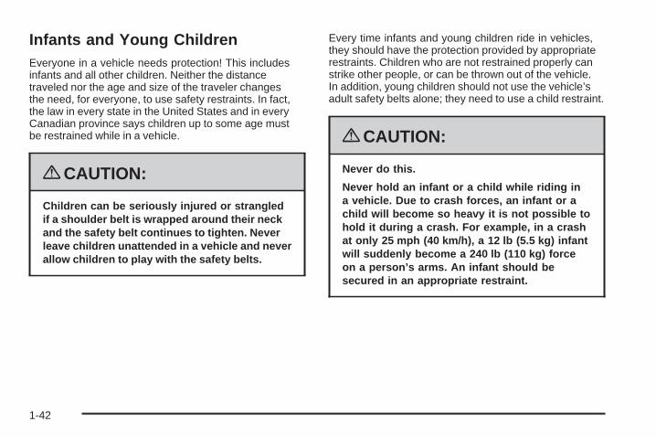
Infants and Young ChildrenEveryone in a vehicle needs protection! This includesinfants and all other children. Neither the distancetraveled nor the age and size of the traveler changesthe need, for everyone, to use safety restraints. In fact,the law in every state in the United States and in everyCanadian province says children up to some age mustbe restrained while in a vehicle.
{CAUTION:
Children can be seriously injured or strangledif a shoulder belt is wrapped around their neckand the safety belt continues to tighten. Neverleave children unattended in a vehicle and neverallow children to play with the safety belts.
Every time infants and young children ride in vehicles,they should have the protection provided by appropriaterestraints. Children who are not restrained properly canstrike other people, or can be thrown out of the vehicle.In addition, young children should not use the vehicle’sadult safety belts alone; they need to use a child restraint.
{CAUTION:
Never do this.
Never hold an infant or a child while riding ina vehicle. Due to crash forces, an infant or achild will become so heavy it is not possible tohold it during a crash. For example, in a crashat only 25 mph (40 km/h), a 12 lb (5.5 kg) infantwill suddenly become a 240 lb (110 kg) forceon a person’s arms. An infant should besecured in an appropriate restraint.
1-42

{CAUTION:
Never do this.
Children who are up against, or very close to,any airbag when it inflates can be seriouslyinjured or killed. Never put a rear-facing childrestraint in the right front seat. Secure a
CAUTION: (Continued)
CAUTION: (Continued)
rear-facing child restraint in a rear seat. It isalso better to secure a forward-facing childrestraint in a rear seat. If you must secure aforward-facing child restraint in the right frontseat, always move the front passenger seat asfar back as it will go.
1-43

Q: What are the different types of add-on childrestraints?
A: Add-on child restraints, which are purchased by thevehicle’s owner, are available in four basic types.Selection of a particular restraint should take intoconsideration not only the child’s weight, height,and age but also whether or not the restraint will becompatible with the motor vehicle in which it willbe used.
For most basic types of child restraints, there aremany different models available. When purchasinga child restraint, be sure it is designed to beused in a motor vehicle. If it is, the restraint willhave a label saying that it meets federal motorvehicle safety standards.
The restraint manufacturer’s instructions thatcome with the restraint state the weight and heightlimitations for a particular child restraint. In addition,there are many kinds of restraints available forchildren with special needs.
{CAUTION:
To reduce the risk of neck and head injuryduring a crash, infants need complete support.This is because an infant’s neck is not fullydeveloped and its head weighs so muchcompared with the rest of its body. In a crash,an infant in a rear-facing child restraint settlesinto the restraint, so the crash forces can bedistributed across the strongest part of aninfant’s body, the back and shoulders. Infantsshould always be secured in rear-facing childrestraints.
1-44

{CAUTION:
A young child’s hip bones are still so smallthat the vehicle’s regular safety belt may notremain low on the hip bones, as it should.Instead, it may settle up around the child’sabdomen. In a crash, the belt would applyforce on a body area that is unprotected byany bony structure. This alone could causeserious or fatal injuries. To reduce the riskof serious or fatal injuries during a crash,young children should always be securedin appropriate child restraints.
Child Restraint Systems
A rear-facing infantseat (A) provides restraintwith the seating surfaceagainst the back ofthe infant.
The harness system holds the infant in place and,in a crash, acts to keep the infant positioned inthe restraint.
1-45
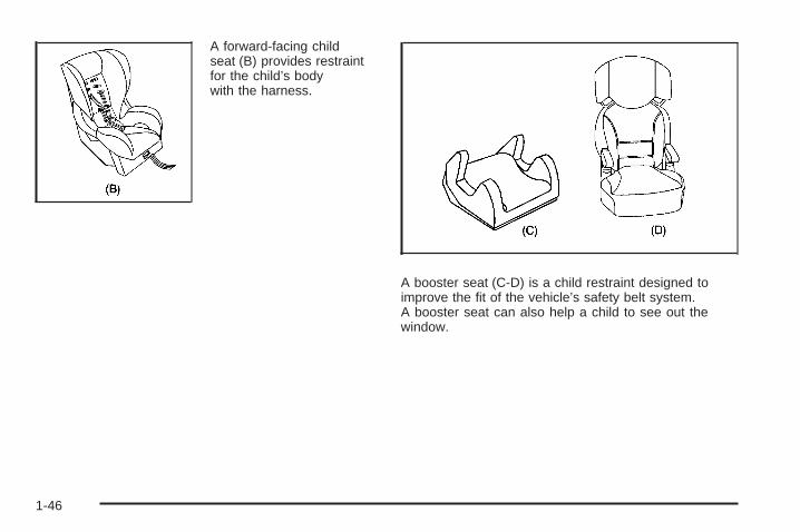
A forward-facing childseat (B) provides restraintfor the child’s bodywith the harness.
A booster seat (C-D) is a child restraint designed toimprove the fit of the vehicle’s safety belt system.A booster seat can also help a child to see out thewindow.
1-46

Securing an Add-On Child Restraint inthe Vehicle
{CAUTION:
A child can be seriously injured or killedin a crash if the child restraint is not properlysecured in the vehicle. Secure the child restraintproperly in the vehicle using the vehicle’ssafety belt or LATCH system, following theinstructions that came with that child restraintand the instructions in this manual.
To help reduce the chance of injury, the child restraintmust be secured in the vehicle. Child restraint systemsmust be secured in vehicle seats by lap belts or thelap belt portion of a lap-shoulder belt, or by the LATCHsystem. See Lower Anchors and Tethers for Children(LATCH) on page 1-49 for more information. A childcan be endangered in a crash if the child restraint isnot properly secured in the vehicle.
When securing an add-on child restraint, refer to theinstructions that come with the restraint which may beon the restraint itself or in a booklet, or both, and to thismanual. The child restraint instructions are important,so if they are not available, obtain a replacementcopy from the manufacturer.
Keep in mind that an unsecured child restraint canmove around in a collision or sudden stop and injurepeople in the vehicle. Be sure to properly secureany child restraint in the vehicle — even when nochild is in it.
Securing the Child Within the ChildRestraint
{CAUTION:
A child can be seriously injured or killed in acrash if the child is not properly secured inthe child restraint. Secure the child properlyfollowing the instructions that came with thatchild restraint.
1-47

Where to Put the RestraintAccording to accident statistics, children and infantsare safer when properly restrained in a child restraintsystem or infant restraint system secured in a rearseating position.
We recommend that children and child restraintsbe secured in a rear seat, including: an infant or achild riding in a rear-facing child restraint; a child ridingin a forward-facing child seat; an older child riding ina booster seat; and children, who are large enough,using safety belts.
A label on the sun visor says, “Never put a rear-facingchild seat in the front.” This is because the risk tothe rear-facing child is so great, if the airbag deploys.
{CAUTION:
A child in a rear-facing child restraint can beseriously injured or killed if the right frontpassenger airbag inflates. This is because theback of the rear-facing child restraint would bevery close to the inflating airbag. A child in aforward-facing child restraint can be seriouslyinjured or killed if the right front passengerairbag inflates and the passenger seat is in aforward position.
Even if the passenger sensing system hasturned off the right front passenger frontalairbag, no system is fail-safe. No one canguarantee that an airbag will not deploy undersome unusual circumstance, even though it isturned off.
CAUTION: (Continued)
1-48

CAUTION: (Continued)
Secure rear-facing child restraints in a rearseat, even if the airbag is off. If you secure aforward-facing child restraint in the right frontseat, always move the front passenger seat asfar back as it will go. It is better to secure thechild restraint in a rear seat.
See Passenger Sensing System on page 1-73for additional information.
When securing a child restraint in a rear seatingposition, study the instructions that came with thechild restraint to make sure it is compatible with thisvehicle.
Wherever a child restraint is installed, be sure to securethe child restraint properly.
Keep in mind that an unsecured child restraint canmove around in a collision or sudden stop and injurepeople in the vehicle. Be sure to properly secureany child restraint in the vehicle — even when nochild is in it.
Lower Anchors and Tethers forChildren (LATCH)The LATCH system holds a child restraint during drivingor in a crash. This system is designed to make installationof a child restraint easier. The LATCH system usesanchors in the vehicle and attachments on the childrestraint that are made for use with the LATCH system.
Make sure that a LATCH-compatible child restraint isproperly installed using the anchors, or use the vehicle’ssafety belts to secure the restraint, following theinstructions that came with that restraint, and alsothe instructions in this manual. When installing a childrestraint with a top tether, you must also use either thelower anchors or the safety belts to properly secure thechild restraint. A child restraint must never be attachedusing only the top tether and anchor.
In order to use the LATCH system in your vehicle,you need a child restraint that has LATCH attachments.The child restraint manufacturer will provide you withinstructions on how to use the child restraint and itsattachments. The following explains how to attach achild restraint with these attachments in your vehicle.
Not all vehicle seating positions or child restraints havelower anchors and attachments or top tether anchorsand attachments.
1-49

Lower Anchors
Lower anchors (A) are metal bars built into the vehicle.There are two lower anchors for each LATCH seatingposition that will accommodate a child restraint withlower attachments (B).
Top Tether Anchor
A top tether (A, C) anchors the top of the child restraintto the vehicle. A top tether anchor is built into the vehicle.The top tether attachment (B) on the child restraintconnects to the top tether anchor in the vehicle in orderto reduce the forward movement and rotation of the childrestraint during driving or in a crash.
Your child restraint may have a single tether (A) or adual tether (C). Either will have a single attachment (B)to secure the top tether to the anchor.
1-50

Some child restraints with top tethers are designed foruse with or without the top tether being attached. Othersrequire the top tether always to be attached. In Canada,the law requires that forward-facing child restraints havea top tether, and that the tether be attached. Be sure toread and follow the instructions for your child restraint.
If the child restraint does not have a top tether, one canbe obtained, in kit form, for many child restraints. Askthe child restraint manufacturer whether or not a kitis available.
Lower Anchor and Top Tether AnchorLocations
i (Top Tether Anchor):Seating positions with toptether anchors.
j (Lower Anchor): Seatingpositions with two loweranchors.
i (Top Tether Anchor):Seating positions with toptether anchors.
j (Lower Anchor): Seatingpositions with two loweranchors.
i (Top Tether Anchor):Seating positions with toptether anchors.
Second Row — Bucket
Second Row — 60/40Bench
Third Row
1-51

To assist you in locatingthe lower anchors, eachsecond row anchor positionhas a label, near the creasebetween the seatback andthe seat cushion.
To assist you in locatingthe top tether anchors, thetop tether anchor symbolis located on the coveror near the anchor. The top tether anchors are located at the bottom rear of
the seatback for each seating position in the second row.Open the cover to access the anchors. Be sure to use ananchor located on the same side of the vehicle as theseating position where the child restraint will be placed.
Second Row — Bucket Shown, Bench Similar
1-52

The third row has one top tether anchor located at thebottom rear of the center seatback. This anchor shouldbe used for the center seating position only. Never installtwo top tethers using the same top tether anchor.
Do not secure a child restraint in a position without a toptether anchor if a national or local law requires that thetop tether be attached, or if the instructions that comewith the child restraint say that the top tether must beattached.
Accident statistics show that children are safer if theyare restrained in the rear rather than the front seat.See Where to Put the Restraint on page 1-48 foradditional information.
Third Row Seat
1-53

Securing a Child Restraint Designed forthe LATCH System
{CAUTION:
If a LATCH-type child restraint is not attachedto anchors, the child restraint will not be ableto protect the child correctly. In a crash, thechild could be seriously injured or killed.Install a LATCH-type child restraint properlyusing the anchors, or use the vehicle’s safetybelts to secure the restraint, following theinstructions that came with the child restraintand the instructions in this manual.
{CAUTION:
Do not attach more than one child restraint toa single anchor. Attaching more than one childrestraint to a single anchor could cause theanchor or attachment to come loose or evenbreak during a crash. A child or others couldbe injured. To reduce the risk of serious orfatal injuries during a crash, attach only onechild restraint per anchor.
{CAUTION:
Children can be seriously injured or strangledif a shoulder belt is wrapped around theirneck and the safety belt continues to tighten.Buckle any unused safety belts behind thechild restraint so children cannot reach them.Pull the shoulder belt all the way out of theretractor to set the lock, if your vehicle hasone, after the child restraint has been installed.
1-54

Notice: Do not let the LATCH attachments rubagainst the vehicle’s safety belts. This may damagethese parts. If necessary, move buckled safetybelts to avoid rubbing the LATCH attachments.
Do not fold the empty rear seat with a safety beltbuckled. This could damage the safety belt orthe seat. Unbuckle and return the safety belt toits stowed position.
1. Attach and tighten the lower attachments to thelower anchors. If the child restraint does not havelower attachments or the desired seating positiondoes not have lower anchors, secure the childrestraint with the top tether and the safety belts.Refer to your child restraint manufacturerinstructions and the instructions in this manual.
1.1. Find the lower anchors for the desiredseating position.
1.2. Recline the seatback to the full reclinedposition.Make sure the second row bench seatbacksare aligned at the same angle before placingthe child restraint on the seat. Make sure thethird row bench seatbacks are both uprightbefore placing the child restraint on the seat.
1.3. Put the child restraint on the seat.1.4. Attach and tighten the lower attachments on
the child restraint to the lower anchors.
2. If the child restraint manufacturer recommends thatthe top tether be attached, attach and tighten thetop tether to the top tether anchor, if the vehicle hasone. Refer to the child restraint instructions andthe following steps:
2.1. Find the top tether anchor.2.2. If the anchor is covered, flip open the cover
to expose the anchor.2.3. Route, attach and tighten the top tether
according to your child restraint instructionsand the following instructions:
If the position you areusing does not have aheadrest or head restraintand you are using asingle tether, route thetether over the seatback.
1-55

If the position you areusing does not have aheadrest or head restraintand you are using a dualtether, route the tether overthe seatback.
If the position you areusing has a fixed headrestor head restraint and youare using a dual tether,route the tether around theheadrest or head restraint.
If the position you areusing has a fixed headrestor head restraint and youare using a single tether,route the tether over theheadrest or head restraint.
3. Push and pull the child restraint in differentdirections to be sure it is secure.
1-56

Securing a Child Restraint in aRear Seat PositionWhen securing a child restraint in a rear seatingposition, study the instructions that came with thechild restraint to make sure it is compatible with thisvehicle.
If the child restraint has the LATCH system, see LowerAnchors and Tethers for Children (LATCH) on page 1-49for how and where to install the child restraint usingLATCH. If a child restraint is secured in the vehicle usinga safety belt and it uses a top tether, see Lower Anchorsand Tethers for Children (LATCH) on page 1-49 for toptether anchor locations.
Do not secure a child seat in a position without a toptether anchor if a national or local law requires thatthe top tether be anchored, or if the instructionsthat come with the child restraint say that the topstrap must be anchored.
In Canada, the law requires that forward-facing childrestraints have a top tether, and that the tether beattached.
If the child restraint does not have the LATCH system,you will be using the safety belt to secure the childrestraint in this position. Be sure to follow the instructionsthat came with the child restraint. Secure the child in thechild restraint when and as the instructions say.
If more than one child restraint needs to be installedin the rear seat, be sure to read Where to Put theRestraint on page 1-48.
1. Put the child restraint on the seat.
2. Pick up the latch plate, and run the lap and shoulderportions of the vehicle’s safety belt through oraround the restraint. The child restraint instructionswill show you how.
1-57

3. Push the latch plate into the buckle until it clicks.Position the release button on the buckle so thatthe safety belt could be quickly unbuckled ifnecessary.
4. Pull the rest of the shoulder belt all the way out ofthe retractor to set the lock.
1-58

5. To tighten the belt, push down on the child restraint,pull the shoulder portion of the belt to tighten the lapportion of the belt and feed the shoulder belt backinto the retractor. When installing a forward-facingchild restraint, it may be helpful to use your kneeto push down on the child restraint as you tightenthe belt.
6. If the child restraint has a top tether, follow the childrestraint manufacturer’s instructions regarding theuse of the top tether. See Lower Anchors andTethers for Children (LATCH) on page 1-49 formore information.
7. Push and pull the child restraint in differentdirections to be sure it is secure.
To remove the child restraint, unbuckle the vehiclesafety belt and let it return to the stowed position.If the top tether is attached to a top tether anchor,disconnect it.
1-59

Securing a Child Restraint in theRight Front Seat PositionYour vehicle has airbags. A rear seat is a safer place tosecure a forward-facing child restraint. See Where toPut the Restraint on page 1-48.
In addition, your vehicle has a passenger sensingsystem which is designed to turn off the right frontpassenger’s frontal airbag and seat-mounted sideimpact airbag under certain conditions. See PassengerSensing System on page 1-73 and Passenger AirbagStatus Indicator on page 3-41 for more informationon this, including important safety information.
A label on your sun visor says, “Never put a rear-facingchild seat in the front.” This is because the risk to therear-facing child is so great, if the airbag deploys.
{CAUTION:
A child in a rear-facing child restraint can beseriously injured or killed if the right frontpassenger airbag inflates. This is because theback of the rear-facing child restraint would bevery close to the inflating airbag. A child in aforward-facing child restraint can be seriouslyinjured or killed if the right front passengerairbag inflates and the passenger seat is ina forward position.
Even if the passenger sensing system hasturned off the right front passenger frontalairbag, no system is fail-safe. No one canguarantee that an airbag will not deploy undersome unusual circumstance, even though it isturned off.
CAUTION: (Continued)
1-60

CAUTION: (Continued)
Secure rear-facing child restraints in a rearseat, even if the airbag is off. If you secure aforward-facing child restraint in the right frontseat, always move the front passenger seat asfar back as it will go. It is better to secure thechild restraint in a rear seat.
See Passenger Sensing System on page 1-73for additional information.
If your child restraint has the LATCH system, see LowerAnchors and Tethers for Children (LATCH) on page 1-49for how to install your child restraint using LATCH. If yousecure a child restraint using a safety belt and it uses atop tether, see Lower Anchors and Tethers for Children(LATCH) on page 1-49 for top tether anchor locations.
Do not secure a child seat in a position without a toptether anchor if a national or local law requires thatthe top tether be anchored, or if the instructionsthat come with the child restraint say that the topstrap must be anchored.
In Canada, the law requires that forward-facing childrestraints have a top tether, and that the tether beattached.
You will be using the lap-shoulder belt to secure thechild restraint in this position. Follow the instructionsthat came with the child restraint.
1. Move the seat as far back as it will go beforesecuring the forward-facing child restraint.When the passenger sensing system has turnedoff the right front passenger’s frontal airbag andseat-mounted side impact airbag, the off indicatoron the passenger airbag status indicator shouldlight and stay lit when you start the vehicle. SeePassenger Airbag Status Indicator on page 3-41.
2. Put the child restraint on the seat.
3. Pick up the latch plate, and run the lap and shoulderportions of the vehicle’s safety belt through oraround the restraint. The child restraint instructionswill show you how.
1-61

4. Push the latch plate into the buckle until it clicks.Make sure the release button is positioned so youwould be able to unbuckle the safety belt quicklyif necessary.
5. Pull the rest of the shoulder belt all the way out ofthe retractor to set the lock.
1-62

6. To tighten the belt, push down on the child restraint,pull the shoulder portion of the belt to tighten the lapportion of the belt and feed the shoulder belt backinto the retractor. If you are using a forward-facingchild restraint, you may find it helpful to use yourknee to push down on the child restraint as youtighten the belt.
7. Push and pull the child restraint in differentdirections to be sure it is secure.
If the airbags are off, the off indicator in the passengerairbag status indicator will come on and stay onwhen the vehicle is started.
If a child restraint has been installed and the onindicator is lit, turn the vehicle off. Remove the childrestraint from the vehicle and reinstall the child restraint.
If, after reinstalling the child restraint and restartingthe vehicle, the on indicator is still lit, check to makesure that the vehicle’s seatback is not pressing the childrestraint into the seat cushion. If this happens, slightlyrecline the vehicle’s seatback and adjust the seatcushion if possible. Also make sure the child restraintis not trapped under the vehicle head restraint.If this happens, adjust the head restraint.
Remove any additional material from the seat suchas blankets, cushions, seat covers, seat heaters orseat massagers before reinstalling or securing thechild restraint.
If the on indicator is still lit, secure the child in the childrestraint in a rear seat position in the vehicle andcheck with your dealer/retailer.
To remove the child restraint, unbuckle the vehicle’ssafety belt and let it go back all the way.
1-63

Airbag SystemYour vehicle has the following airbags:
• A frontal airbag for the driver.
• A frontal airbag for the right front passenger.
• A seat-mounted side impact airbag for the driver.
• A seat-mounted side impact airbag for the right frontpassenger.
• A roof-rail airbag for the driver, passenger seateddirectly behind the driver, and the third rowoutboard passenger position.
• A roof-rail airbag for the right front passenger,passenger seated directly behind the right frontpassenger, and the third row outboard passengerposition.
All of the airbags in your vehicle will have the wordAIRBAG embossed in the trim or on an attached labelnear the deployment opening.
For frontal airbags, the word AIRBAG will appear on themiddle part of the steering wheel for the driver andon the instrument panel for the right front passenger.
With seat-mounted side impact airbags, the wordAIRBAG will appear on the side of the seatbackclosest to the door.
With roof-rail airbags, the word AIRBAG will appearalong the headliner or trim.
Airbags are designed to supplement the protectionprovided by safety belts. Even though today’s airbagsare also designed to help reduce the risk of injuryfrom the force of an inflating bag, all airbags mustinflate very quickly to do their job.
Here are the most important things to know about theairbag system:
{CAUTION:
You can be severely injured or killed in a crashif you are not wearing your safety belt — evenif you have airbags. Wearing your safety beltduring a crash helps reduce your chance ofhitting things inside the vehicle or beingejected from it. Airbags are “supplementalrestraints” to the safety belts. All airbags aredesigned to work with safety belts, but do notreplace them.
1-64

{CAUTION:
Frontal airbags are designed to deploy inmoderate to severe frontal and near frontalcrashes. They are not designed to inflate inrollover, rear crashes, or in many side crashes.
Seat-mounted side impact airbags are designedto inflate in moderate to severe crashes wheresomething hits the side of your vehicle. Theyare not designed to inflate in frontal, in rollover,or in rear crashes. Rollover capable roof-railairbags are designed to inflate in moderate tosevere crashes where something hits the sideof your vehicle, during a vehicle rollover, or in asevere frontal impact. They are not designed toinflate in rear crashes.
Everyone in your vehicle should wear a safetybelt properly — whether or not there is anairbag for that person.
{CAUTION:
Airbags inflate with great force, faster thanthe blink of an eye. Anyone who is up against,or very close to, any airbag when it inflatescan be seriously injured or killed. Do not situnnecessarily close to the airbag, as you wouldbe if you were sitting on the edge of your seat orleaning forward. Safety belts help keep you inposition before and during a crash. Always wearyour safety belt, even with airbags. The drivershould sit as far back as possible while stillmaintaining control of the vehicle.
Occupants should not lean on or sleep againstthe door or side windows in seating positionswith seat-mounted side impact airbags and/orroof-rail airbags.
1-65

{CAUTION:
Airbags plus lap-shoulder belts offer thebest protection for adults, but not for youngchildren and infants. Neither the vehicle’ssafety belt system nor its airbag system isdesigned for them. Young children and infantsneed the protection that a child restraintsystem can provide. Always secure childrenproperly in your vehicle. To read how, seeOlder Children on page 1-39 or Infants andYoung Children on page 1-42.
There is an airbagreadiness light on theinstrument panel cluster,which shows the airbagsymbol.
The system checks the airbag electrical system formalfunctions. The light tells you if there is an electricalproblem. See Airbag Readiness Light on page 3-40for more information.
Where Are the Airbags?
The driver frontal airbag is in the middle of the steeringwheel.
1-66

The right front passenger frontal airbag is in theinstrument panel on the passenger side. The seat-mounted side impact airbags for the driver and
right front passenger are in the side of the seatbacksclosest to the door.
Driver Side shown, Passenger Side similar
1-67

The roof-rail airbags for the driver, right front passenger,passengers behind the driver and right front passenger,and the third row outboard passengers are in theceiling above the side windows.
{CAUTION:
If something is between an occupant and anairbag, the airbag might not inflate properlyor it might force the object into that personcausing severe injury or even death. The pathof an inflating airbag must be kept clear.Do not put anything between an occupant andan airbag, and do not attach or put anythingon the steering wheel hub or on or near anyother airbag covering.
Do not use seat accessories that block theinflation path of a seat-mounted side impactairbag.
Never secure anything to the roof of a vehiclewith roof-rail airbags by routing a rope or tiedown through any door or window opening.If you do, the path of an inflating roof-railairbag will be blocked.
Driver Side shown, Passenger Side similar
1-68

When Should an Airbag Inflate?Frontal airbags are designed to inflate in moderate tosevere frontal or near-frontal crashes to help reduce thepotential for severe injuries mainly to the driver’s or rightfront passenger’s head and chest. However, they are onlydesigned to inflate if the impact exceeds a predetermineddeployment threshold. Deployment thresholds are usedto predict how severe a crash is likely to be in time for theairbags to inflate and help restrain the occupants.
Whether the frontal airbags will or should deploy is notbased on how fast your vehicle is traveling. It dependslargely on what you hit, the direction of the impact,and how quickly your vehicle slows down.
Frontal airbags may inflate at different crash speeds.For example:
• If the vehicle hits a stationary object, the airbagscould inflate at a different crash speed than if thevehicle hits a moving object.
• If the vehicle hits an object that deforms, theairbags could inflate at a different crash speed thanif the vehicle hits an object that does not deform.
• If the vehicle hits a narrow object (like a pole), theairbags could inflate at a different crash speedthan if the vehicle hits a wide object (like a wall).
• If the vehicle goes into an object at an angle, theairbags could inflate at a different crash speedthan if the vehicle goes straight into the object.
Thresholds can also vary with specific vehicle design.
Frontal airbags are not intended to inflate during vehiclerollovers, rear impacts, or in many side impacts.
1-69
In addition, the vehicle has dual-stage frontal airbags.Dual-stage airbags adjust the restraint according tocrash severity. The vehicle has electronic frontalsensors, which help the sensing system distinguishbetween a moderate frontal impact and a more severefrontal impact. For moderate frontal impacts, dual-stageairbags inflate at a level less than full deployment.For more severe frontal impacts, full deployment occurs.
The vehicle has seat-mounted side impact androof-rail airbags. See Airbag System on page 1-64.Seat-mounted side impact and roof-rail airbagsare intended to inflate in moderate to severe sidecrashes. In addition, these roof-rail airbags areintended to inflate during a rollover or in a severefrontal impact. Seat-mounted side impact and roof-railairbags will inflate if the crash severity is above thesystem’s designed threshold level. The thresholdlevel can vary with specific vehicle design.
Seat-mounted side impact airbags are not intended toinflate in frontal impacts, near-frontal impacts, rollovers,or rear impacts. Roof-rail airbags are not intended toinflate in rear impacts. A seat-mounted side impact airbagis intended to deploy on the side of the vehicle that isstruck. Both roof-rail airbags will deploy when either sideof the vehicle is struck, or if the sensing system predictsthat the vehicle is about to roll over, or in a severe frontalimpact.
In any particular crash, no one can say whether anairbag should have inflated simply because of thedamage to a vehicle or because of what the repair costswere. For frontal airbags, inflation is determined by whatthe vehicle hits, the angle of the impact, and how quicklythe vehicle slows down. For seat-mounted side impactand roof-rail airbags, deployment is determined by thelocation and severity of the side impact. In a rolloverevent, roof-rail airbag deployment is determined bythe direction of the roll.
1-70

What Makes an Airbag Inflate?In a deployment event, the sensing system sendsan electrical signal triggering a release of gas from theinflator. Gas from the inflator fills the airbag causing thebag to break out of the cover and deploy. The inflator,the airbag, and related hardware are all part of the airbagmodule.
Frontal airbag modules are located inside thesteering wheel and instrument panel. For vehicleswith seat-mounted side impact airbags, there are airbagmodules in the side of the front seatbacks closest to thedoor. For vehicles with roof-rail airbags, there are airbagmodules in the ceiling of the vehicle, near the sidewindows that have occupant seating positions.
How Does an Airbag Restrain?In moderate to severe frontal or near frontal collisions,even belted occupants can contact the steering wheelor the instrument panel. In moderate to severe sidecollisions, even belted occupants can contact the insideof the vehicle.
Airbags supplement the protection provided bysafety belts.
Frontal airbags distribute the force of the impact moreevenly over the occupant’s upper body, stopping theoccupant more gradually. Seat-mounted side impact androof-rail airbags distribute the force of the impact moreevenly over the occupant’s upper body.
Rollover capable roof-rail airbags are designed to helpcontain the head and chest of occupants in the outboardseating positions in the first, second, and third rows.The rollover capable roof-rail airbags are designed tohelp reduce the risk of full or partial ejection in rolloverevents, although no system can prevent all suchejections.
But airbags would not help in many types of collisions,primarily because the occupant’s motion is not towardthose airbags. See When Should an Airbag Inflate? onpage 1-69 for more information.
Airbags should never be regarded as anything morethan a supplement to safety belts.
1-71

What Will You See After an AirbagInflates?After the frontal airbags and seat-mounted side impactairbags inflate, they quickly deflate, so quickly thatsome people may not even realize an airbag inflated.Roof-rail airbags may still be at least partially inflatedfor some time after they deploy. Some componentsof the airbag module may be hot for several minutes.For location of the airbag modules, see What Makesan Airbag Inflate? on page 1-71.
The parts of the airbag that come into contact with youmay be warm, but not too hot to touch. There maybe some smoke and dust coming from the vents in thedeflated airbags. Airbag inflation does not preventthe driver from seeing out of the windshield or beingable to steer the vehicle, nor does it prevent peoplefrom leaving the vehicle.
{CAUTION:
When an airbag inflates, there may be dustin the air. This dust could cause breathingproblems for people with a history of asthma orother breathing trouble. To avoid this, everyonein the vehicle should get out as soon as it issafe to do so. If you have breathing problemsbut cannot get out of the vehicle after an airbaginflates, then get fresh air by opening a windowor a door. If you experience breathing problemsfollowing an airbag deployment, you shouldseek medical attention.
The vehicle has a feature that may automatically unlockthe doors, turn the interior lamps on, and turn the hazardwarning flashers on when the airbags inflate. You canlock the doors, turn the interior lamps off, and turn thehazard warning flashers off by using the controls forthose features.
1-72
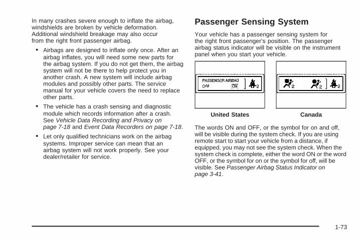
In many crashes severe enough to inflate the airbag,windshields are broken by vehicle deformation.Additional windshield breakage may also occurfrom the right front passenger airbag.
• Airbags are designed to inflate only once. After anairbag inflates, you will need some new parts forthe airbag system. If you do not get them, the airbagsystem will not be there to help protect you inanother crash. A new system will include airbagmodules and possibly other parts. The servicemanual for your vehicle covers the need to replaceother parts.
• The vehicle has a crash sensing and diagnosticmodule which records information after a crash.See Vehicle Data Recording and Privacy onpage 7-18 and Event Data Recorders on page 7-18.
• Let only qualified technicians work on the airbagsystems. Improper service can mean that anairbag system will not work properly. See yourdealer/retailer for service.
Passenger Sensing SystemYour vehicle has a passenger sensing system forthe right front passenger’s position. The passengerairbag status indicator will be visible on the instrumentpanel when you start your vehicle.
The words ON and OFF, or the symbol for on and off,will be visible during the system check. If you are usingremote start to start your vehicle from a distance, ifequipped, you may not see the system check. When thesystem check is complete, either the word ON or the wordOFF, or the symbol for on or the symbol for off, will bevisible. See Passenger Airbag Status Indicator onpage 3-41.
United States Canada
1-73
The passenger sensing system will turn off the rightfront passenger’s frontal airbag and seat-mounted sideimpact airbag under certain conditions. The driver’sairbags are not part of the passenger sensing system.
The passenger sensing system works with sensors thatare part of the right front passenger’s seat. The sensorsare designed to detect the presence of a properly-seatedoccupant and determine if the right front passenger’sfrontal airbag and seat-mounted side impact airbagshould be enabled (may inflate) or not.
Accident statistics show that children are safer if theyare restrained in the rear rather than the front seat.
We recommend that children be secured in a rear seat,including: an infant or a child riding in a rear-facingchild restraint; a child riding in a forward-facing childseat; an older child riding in a booster seat; and children,who are large enough, using safety belts.
A label on your sun visor says, “Never put a rear-facingchild seat in the front.” This is because the risk to therear-facing child is so great, if the airbag deploys.
{CAUTION:
A child in a rear-facing child restraint can beseriously injured or killed if the right frontpassenger airbag inflates. This is because theback of the rear-facing child restraint would bevery close to the inflating airbag. A child in aforward-facing child restraint can be seriouslyinjured or killed if the right front passengerairbag inflates and the passenger seat is in aforward position.
Even if the passenger sensing system hasturned off the right front passenger frontalairbag and seat-mounted side impact airbag(if equipped), no system is fail-safe. No onecan guarantee that an airbag will not deployunder some unusual circumstance, eventhough the airbag(s) are off.
Secure rear-facing child restraints in a rearseat, even if the airbag(s) are off. If you securea forward-facing child restraint in the rightfront seat, always move the front passengerseat as far back as it will go. It is better tosecure the child restraint in a rear seat.
1-74

The passenger sensing system is designed to turnoff the right front passenger’s frontal airbag andseat-mounted side impact airbag if:
• The right front passenger seat is unoccupied.
• The system determines that an infant is present ina rear-facing infant seat.
• The system determines that a small child is presentin a child restraint.
• The system determines that a small child is presentin a booster seat.
• A right front passenger takes his/her weight off ofthe seat for a period of time.
• The right front passenger seat is occupied by asmaller person, such as a child who has outgrownchild restraints.
• Or, if there is a critical problem with the airbagsystem or the passenger sensing system.
When the passenger sensing system has turned off theright front passenger’s frontal airbag and seat-mountedside impact airbag, the off indicator will light andstay lit to remind you that the airbags are off.See Passenger Airbag Status Indicator on page 3-41.
If a child restraint has been installed and the on indicatoris lit, turn the vehicle off. Remove the child restraintfrom the vehicle and reinstall the child restraint following
the child restraint manufacturer’s directions and referto Securing a Child Restraint in the Right FrontSeat Position on page 1-60.
If, after reinstalling the child restraint and restarting thevehicle, the on indicator is still lit, check to make sure thatthe vehicle’s seatback is not pressing the child restraintinto the seat cushion. If this happens, slightly reclinethe vehicle’s seatback and adjust the seat cushion ifpossible. Also make sure the child restraint is not trappedunder the vehicle head restraint. If this happens, adjustthe head restraint. See Head Restraints on page 1-11.
Remove any additional material from the seat such asblankets, cushions, seat covers, seat heaters, or seatmassagers before reinstalling or securing the childrestraint.
If the on indicator is still lit, secure the child in the childrestraint in a rear seat position in the vehicle, andcheck with your dealer/retailer.
The passenger sensing system is designed to enable(may inflate) the right front passenger’s frontal airbag andseat-mounted side impact airbag anytime the systemsenses that a person of adult size is sitting properly inthe right front passenger’s seat. When the passengersensing system has allowed the airbags to be enabled,the on indicator will light and stay lit to remind you thatthe airbags are active.
1-75
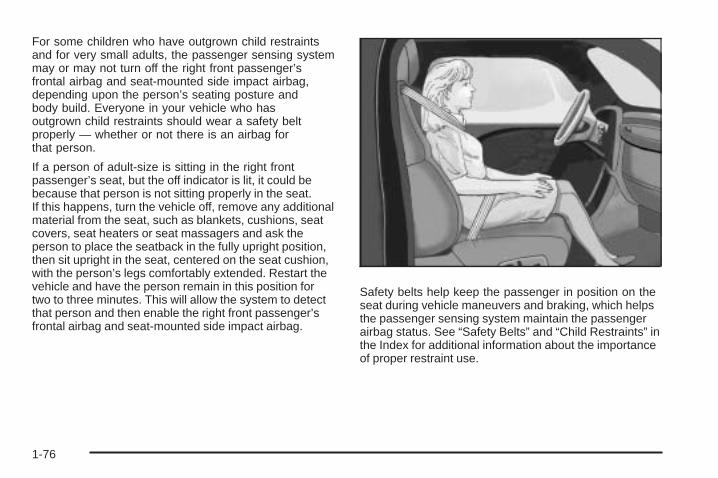
For some children who have outgrown child restraintsand for very small adults, the passenger sensing systemmay or may not turn off the right front passenger’sfrontal airbag and seat-mounted side impact airbag,depending upon the person’s seating posture andbody build. Everyone in your vehicle who hasoutgrown child restraints should wear a safety beltproperly — whether or not there is an airbag forthat person.
If a person of adult-size is sitting in the right frontpassenger’s seat, but the off indicator is lit, it could bebecause that person is not sitting properly in the seat.If this happens, turn the vehicle off, remove any additionalmaterial from the seat, such as blankets, cushions, seatcovers, seat heaters or seat massagers and ask theperson to place the seatback in the fully upright position,then sit upright in the seat, centered on the seat cushion,with the person’s legs comfortably extended. Restart thevehicle and have the person remain in this position fortwo to three minutes. This will allow the system to detectthat person and then enable the right front passenger’sfrontal airbag and seat-mounted side impact airbag.
Safety belts help keep the passenger in position on theseat during vehicle maneuvers and braking, which helpsthe passenger sensing system maintain the passengerairbag status. See “Safety Belts” and “Child Restraints” inthe Index for additional information about the importanceof proper restraint use.
1-76

{CAUTION:
If the airbag readiness light in the instrumentpanel cluster ever comes on and stays on,it means that something may be wrong withthe airbag system. If this ever happens, havethe vehicle serviced promptly, because anadult-size person sitting in the right frontpassenger’s seat may not have the protectionof the airbag(s). See Airbag Readiness Lighton page 3-40 for more on this, includingimportant safety information.
A thick layer of additional material, such as a blanket orcushion, or aftermarket equipment such as seat covers,seat heaters, and seat massagers can affect how well thepassenger sensing system operates. We recommendthat you not use seat covers or other aftermarketequipment other than any that GM has approved foryour specific vehicle. See Adding Equipment to YourAirbag-Equipped Vehicle on page 1-78 for moreinformation about modifications that can affect howthe system operates.
{CAUTION:
Stowing of articles under the passenger seator between the passenger seat cushion andseatback may interfere with the properoperation of the passenger sensing system.
1-77

Servicing Your Airbag-EquippedVehicleAirbags affect how your vehicle should be serviced.There are parts of the airbag system in several placesaround your vehicle. Your dealer/retailer and the servicemanual have information about servicing your vehicleand the airbag system. To purchase a service manual,see Service Publications Ordering Information onpage 7-16.
{CAUTION:
For up to 10 seconds after the ignition isturned off and the battery is disconnected,an airbag can still inflate during improperservice. You can be injured if you are closeto an airbag when it inflates. Avoid yellowconnectors. They are probably part of theairbag system. Be sure to follow properservice procedures, and make sure the personperforming work for you is qualified to do so.
Adding Equipment to YourAirbag-Equipped Vehicle
Q: Is there anything I might add to or changeabout the vehicle that could keep the airbagsfrom working properly?
A: Yes. If you add things that change the vehicle’sframe, bumper system, height, front end or sidesheet metal, they may keep the airbag system fromworking properly. Changing or moving any partsof the front seats, safety belts, the airbag sensingand diagnostic module, steering wheel, instrumentpanel, roof-rail airbag modules, ceiling headlineror pillar garnish trim, front sensors, side impactsensors, rollover sensor module, or airbag wiringcan affect the operation of the airbag system.
1-78

In addition, the vehicle has a passenger sensingsystem for the right front passenger position, whichincludes sensors that are part of the passenger seat.The passenger sensing system may not operateproperly if the original seat trim is replaced withnon-GM covers, upholstery or trim, or with GMcovers, upholstery or trim designed for a differentvehicle. Any object, such as an aftermarket seatheater or a comfort enhancing pad or device,installed under or on top of the seat fabric, couldalso interfere with the operation of the passengersensing system. This could either prevent properdeployment of the passenger airbag(s) or preventthe passenger sensing system from properly turningoff the passenger airbag(s). See Passenger SensingSystem on page 1-73.
If you have questions, call Customer Assistance.The phone numbers and addresses for CustomerAssistance are in Step Two of the CustomerSatisfaction Procedure in this manual. SeeCustomer Satisfaction Procedure on page 7-2.
If the vehicle has rollover roof-rail airbags, seeDifferent Size Tires and Wheels on page 5-67 foradditional important information.
Q: Because I have a disability, I have to get myvehicle modified. How can I find out whetherthis will affect my airbag system?
A: If you have questions, call Customer Assistance.The phone numbers and addresses for CustomerAssistance are in Step Two of the CustomerSatisfaction Procedure in this manual. SeeCustomer Satisfaction Procedure on page 7-2.
In addition, your dealer/retailer and the service manualhave information about the location of the airbag sensors,sensing and diagnostic module and airbag wiring.
1-79
Restraint System Check
Checking the Restraint Systems
Safety BeltsNow and then, check the safety belt reminder light,safety belts, buckles, latch plates, retractors, andanchorages are all working properly.
Look for any other loose or damaged safety belt systemparts. If you see anything that might keep a safety beltsystem from doing its job, have it repaired. Torn or frayedsafety belts may not protect you in a crash. They can ripapart under impact forces. If a belt is torn or frayed, get anew one right away.
Make sure the safety belt reminder light is working.See Safety Belt Reminders on page 3-39 for moreinformation.
Keep safety belts clean and dry. See Care of SafetyBelts on page 5-103.
AirbagsThe airbag system does not need regularly scheduledmaintenance or replacement. Make sure the airbagreadiness light is working. See Airbag Readiness Lighton page 3-40 for more information.
Notice: If an airbag covering is damaged, opened,or broken, the airbag may not work properly.Do not open or break the airbag coverings. If thereare any opened or broken airbag covers, havethe airbag covering and/or airbag module replaced.For the location of the airbag modules, seeWhat Makes an Airbag Inflate? on page 1-71.See your dealer/retailer for service.
1-80

Replacing Restraint System PartsAfter a Crash
{CAUTION:
A crash can damage the restraint systemsin your vehicle. A damaged restraint systemmay not properly protect the person using it,resulting in serious injury or even death ina crash. To help make sure your restraintsystems are working properly after a crash,have them inspected and any necessaryreplacements made as soon as possible.
If you have had a crash, do you need new safety beltsor LATCH system (if equipped) parts?
After a very minor crash, nothing may be necessary.But the safety belt assemblies that were used during anycrash may have been stressed or damaged. See yourdealer/retailer to have the safety belt assembliesinspected or replaced.
If the vehicle has the LATCH system and it was beingused during a crash, you may need new LATCHsystem parts.
New parts and repairs may be necessary even if thesafety belt or LATCH system (if equipped), wasnot being used at the time of the crash.
If an airbag inflates, you will need to replace airbagsystem parts. See the part on the airbag system earlierin this section.
Have the safety belt pretensioners checked if thevehicle has been in a crash, if the airbag readiness lightstays on after the vehicle is started, or while you aredriving. See Airbag Readiness Light on page 3-40.
1-81

✍ NOTES
1-82
Keys ...............................................................2-3Remote Keyless Entry (RKE) System ................2-4Remote Keyless Entry (RKE) System
Operation ...................................................2-5Remote Vehicle Start ......................................2-7
Doors and Locks ............................................2-10Door Locks ..................................................2-10Power Door Locks ........................................2-11Delayed Locking ...........................................2-11Programmable Automatic Door Locks ..............2-11Rear Door Security Locks ..............................2-12Lockout Protection ........................................2-12Liftgate ........................................................2-13Power Liftgate ..............................................2-14
Windows ........................................................2-18Power Windows ............................................2-19Sun Visors ...................................................2-21
Theft-Deterrent Systems ..................................2-21Content Theft-Deterrent .................................2-22PASS-Key® III+ Electronic Immobilizer .............2-23PASS-Key® III+ Electronic Immobilizer
Operation .................................................2-24
Starting and Operating Your Vehicle ................2-25New Vehicle Break-In ....................................2-25Ignition Positions ..........................................2-26Retained Accessory Power (RAP) ...................2-27Starting the Engine .......................................2-27Engine Coolant Heater ..................................2-29Automatic Transmission Operation ...................2-30Tow/Haul Mode ............................................2-33Parking Brake ..............................................2-34Shifting Into Park ..........................................2-35Shifting Out of Park ......................................2-36Parking Over Things That Burn .......................2-37Engine Exhaust ............................................2-37Running the Vehicle While Parked ..................2-38
Mirrors ...........................................................2-39Manual Rearview Mirror with OnStar® ..............2-39Automatic Dimming Rearview Mirror with
OnStar® and Compass ...............................2-39Outside Power Mirrors ...................................2-41Outside Power Foldaway Mirrors .....................2-42Outside Convex Mirror ...................................2-43Outside Heated Mirrors ..................................2-43
Section 2 Features and Controls
2-1

Object Detection Systems ...............................2-44Ultrasonic Rear Parking Assist (URPA) ............2-44Rear Vision Camera (RVC) ............................2-46
OnStar® System .............................................2-47Universal Home Remote System ......................2-50
Universal Home Remote System Operation(With One Triangular LED) ...........................2-51
Storage Areas ................................................2-55Glove Box ...................................................2-55Cupholders ..................................................2-55Instrument Panel Storage ...............................2-55
Center Console Storage .................................2-56Second Row Center Console ..........................2-56Assist Handles .............................................2-57Floor Mats ...................................................2-57Luggage Carrier ...........................................2-58Rear Seat Armrest ........................................2-58Convenience Net ..........................................2-58Cargo Cover ................................................2-59Cargo Tie Downs ..........................................2-59Cargo Management System ...........................2-59
Sunroof .........................................................2-60
Section 2 Features and Controls
2-2

Keys
{CAUTION:
Leaving children in a vehicle with the ignitionkey is dangerous for many reasons, childrenor others could be badly injured or even killed.They could operate the power windows orother controls or even make the vehicle move.The windows will function with the keys in theignition and children could be seriously injuredor killed if caught in the path of a closingwindow. Do not leave the keys in a vehiclewith children.
The key can be used for the ignition and all locks.
The key has a bar-coded key tag that the dealer/retaileror qualified locksmith can use to make new keys.Store this information in a safe place, not in your vehicle.
Notice: If you ever lock your keys in the vehicle,you may have to damage the vehicle to get in.Be sure you have spare keys.
If you are locked out of your vehicle, contact RoadsideAssistance. See Roadside Assistance Program onpage 7-7.
2-3

Remote Keyless Entry (RKE)SystemThe Remote Keyless Entry (RKE) system operates on aradio frequency subject to Federal CommunicationsCommission (FCC) Rules and with Industry Canada.
This device complies with Part 15 of the FCC Rules.Operation is subject to the following two conditions:
1. This device may not cause interference.
2. This device must accept any interference received,including interference that may cause undesiredoperation of the device.
This device complies with RSS-210 of Industry Canada.Operation is subject to the following two conditions:
1. This device may not cause interference.
2. This device must accept any interference received,including interference that may cause undesiredoperation of the device.
Changes or modifications to this system by other thanan authorized service facility could void authorizationto use this equipment.
If there is a decrease in the RKE operating range,try this:
• Check the distance. The transmitter may be toofar from the vehicle. Stand closer during rainyor snowy weather.
• Check the location. Other vehicles or objects maybe blocking the signal. Take a few steps to theleft or right, hold the transmitter higher, andtry again.
• Check the transmitter’s battery. See “BatteryReplacement” later in this section.
• If the transmitter is still not working correctly,see your dealer/retailer or a qualified technicianfor service.
2-4

Remote Keyless Entry (RKE)System OperationThe Remote Keyless Entry (RKE) transmitter functionswill work up to 195 feet (60 m) away. However, theoperating range may be less while the vehicle is running.
There are other conditions which can affect theperformance of the transmitter. See Remote KeylessEntry (RKE) System on page 2-4.
/ (Remote Vehicle Start): If your vehicle has thisfeature, press / to start the engine from outsidethe vehicle using the RKE transmitter. See RemoteVehicle Start on page 2-7 for additional information.
Q (Lock): Press to lock all the doors. If enabled throughthe Driver Information Center (DIC), the parking lampswill flash once to indicate locking has occurred. If enabledthrough the DIC, the horn will chirp when Q is pressedagain within five seconds of the previous press of the lockbutton. See DIC Vehicle Customization (With DICButtons) on page 3-74 for additional information.Pressing Q may arm the content theft-deterrent system.See Content Theft-Deterrent on page 2-22.
" (Unlock): Press to unlock the driver’s door. If " ispressed again within five seconds, all remaining doorswill unlock. The interior lamps will come on and stay onfor 20 seconds or until the ignition is turned on. If enabledthrough the DIC, the parking lamps will flash twice toindicate unlocking has occurred. See DIC VehicleCustomization (With DIC Buttons) on page 3-74.Pressing " on the RKE transmitter will disarm the contenttheft-deterrent system. See Content Theft-Deterrent onpage 2-22.
With Remote Startand Liftgate (Without
Remote Start orLiftgate Similar)
2-5

& (Power Liftgate): Press and hold for about onesecond to open and close the liftgate. The taillamps willflash and a chime will sound to indicate when theliftgate is opening and closing.
L (Vehicle Locator/Panic Alarm): Press and releaseto locate your vehicle. The turn signal lamps will flashand the horn will sound three times.
Press and hold L for more than two seconds toactivate the panic alarm. The turn signal lamps will flashand the horn will sound repeatedly for 30 seconds.The alarm will turn off when the ignition is movedto ON/RUN or L is pressed again. The ignition mustbe in LOCK/OFF for the panic alarm to work.
Matching Transmitter(s) to Your VehicleEach RKE transmitter is coded to prevent anothertransmitter from unlocking your vehicle. If a transmitteris lost or stolen, a replacement can be purchasedthrough your dealer/retailer. All transmitters need to bere-coded to match the new transmitter.
The lost transmitter will no longer work after the newtransmitters are re-coded. The vehicle can have amaximum of eight transmitters matched to it. See“Relearn Remote Key” under DIC Operation andDisplays (With DIC Buttons) on page 3-54 or DICOperation and Displays (Without DIC Buttons) onpage 3-60 for instructions on how to match RKEtransmitters to your vehicle.
Battery ReplacementReplace the battery if the REPLACE BATTERY INREMOTE KEY message displays in the DIC. See“REPLACE BATTERY IN REMOTE KEY” under DICWarnings and Messages on page 3-64 for additionalinformation.
2-6

Notice: When replacing the battery, do not touchany of the circuitry on the transmitter. Staticfrom your body could damage the transmitter.
To replace the battery in the RKE transmitter:
1. Separate the halves of the transmitter with a flat,thin object inserted into the notch on the side.
2. Remove the old battery. Do not use a metal object.
3. Insert the new battery, positive side facing down.Replace with a CR2032 or equivalent battery.
4. Put the transmitter back together tightly.
Remote Vehicle StartYour vehicle may have a remote starting feature thatstarts the engine from outside of the vehicle.
If your vehicle has an automatic climate control system,the climate control system will default to a heating orcooling mode depending on the outside temperatures. Ifyour vehicle does not have an automatic climate controlsystem, the system will turn on at the setting the vehiclewas set to when the vehicle was last turned off.
If your vehicle has an automatic climate control systemand heated seats, the heated seats will turn onduring colder outside temperatures and will shut offwhen the key is turned to ON/RUN. See Heated Seatson page 1-5 for more information.
The rear window defogger and heated mirrors, if yourvehicle has them, will turn on during colder outsidetemperatures and will turn off when the key is turned toON/RUN.
Laws in some communities may restrict the use ofremote starters. For example, some laws may require aperson using the remote start to have the vehicle inview when doing so. Check local regulations forany requirements on remote starting of vehicles.
2-7

If your vehicle has the remote start feature, the RKEtransmitter functions will have an increased rangeof operation. However, the range may be less whilethe vehicle is running.
There are other conditions which can affect theperformance of the transmitter, see Remote KeylessEntry (RKE) System on page 2-4 for additionalinformation.
/ (Remote Start): This button will be on theRKE transmitter if you have remote start.
To start the vehicle:
1. Aim the transmitter at the vehicle.
2. Press and release the transmitter’s lock button, thenimmediately press and hold the transmitter’s remotestart button until the turn signal lights flash. If youcannot see the vehicle’s lights, press and hold theremote start button for at least four seconds. Thevehicle’s doors will lock. Pressing the remote startbutton again, after the vehicle has started, will shutthe vehicle off.When the vehicle starts, the parking lamps will turnon and remain on while the vehicle is running.
3. If it is the first remote start since the vehicle hasbeen driven, repeat these steps while the engineis still running, to extend the time by 10 minutes forthe engine to continue to run. Remote start canbe extended one time.
After entering the vehicle during a remote start, insertand turn the key to the ON/RUN position to drivethe vehicle.
If the vehicle is left running it will automatically shut offafter 10 minutes unless a time extension has been done.
To manually shut off a remote start:
• Aim the RKE transmitter at the vehicle and pressthe remote start button until the parking lampsturn off.
• Turn on the hazard warning flashers.
• Turn the ignition switch on and then off.
The vehicle can be started using the remote start featuretwo separate times between driving sequences. Theengine will run for 10 minutes after each remote start.
Or, you can extend the engine run time by another10 minutes within the first 10 minute remote start timeframe, and before the engine stops.
2-8
For example, if the lock button and then the remotestart buttons are pressed again after the vehiclehas been running for five minutes, 10 minutes areadded, allowing the engine to run for 15 minutes.
The additional 10 minutes are considered a secondremote start.
Once two remote starts, or a single remote start withone time extension has been done, the vehicle must bestarted with the key.
After the key is removed from the ignition, the vehiclecan be started using the remote start feature again.
The vehicle cannot be started using the remotestart feature if the key is in the ignition, the hood isnot closed, or if there is an emission control systemmalfunction.
Also, the engine will turn off during a remote startif the coolant temperature gets too high or if the oilpressure gets low.
Vehicles that have the remote vehicle start featureare shipped from the factory with the remote vehiclestart system enabled. The system may be enabledor disabled through the DIC if your vehicle hasDIC buttons. See “REMOTE START” under DIC VehicleCustomization (With DIC Buttons) on page 3-74 foradditional information. If your vehicle does not haveDIC buttons, see your dealer/retailer to enable or disablethe remote start system.
Remote Start ReadyIf your vehicle does not have the remote start feature,it will have the remote start ready feature. Thisfeature allows your dealer/retailer to add themanufacturer’s remote start feature.
See your dealer/retailer if you would like to add themanufacturer’s remote start feature to your vehicle.
2-9

Doors and Locks
Door Locks
{CAUTION:
Unlocked doors can be dangerous.• Passengers, especially children, can easily
open the doors and fall out of a movingvehicle. When a door is locked, the handlewill not open it. You increase the chanceof being thrown out of the vehicle in acrash if the doors are not locked. So, wearsafety belts properly and lock the doorswhenever you drive.
CAUTION: (Continued)
CAUTION: (Continued)
• Young children who get into unlockedvehicles may be unable to get out. A childcan be overcome by extreme heat and cansuffer permanent injuries or even deathfrom heat stroke. Always lock your vehiclewhenever you leave it.
• Outsiders can easily enter through anunlocked door when you slow down orstop your vehicle. Locking your doors canhelp prevent this from happening.
The vehicle’s doors can be manually locked or unlockedin the following ways:
• From the outside, use the key in the driver’s door.
• From the inside, use the lock control on the door.
2-10

Power Door LocksThe power door lock switches are located on thefront doors.
K (Unlock): Press to unlock the doors.
Q (Lock): Remove the key from the ignition andpress to lock the doors.
Delayed LockingWhen locking the doors with the power lock switchand a door or the liftgate is open, the doors will lockfive seconds after the last door is closed. You willhear three chimes to signal that the delayed lockingfeature is in use.
Pressing the power lock switch twice or the lock buttonon the RKE transmitter twice will override the delayedlocking feature and immediately lock all the doors.
This feature will not operate if the key is in the ignition.
You can program this feature using the DriverInformation Center (DIC). See DELAY DOOR LOCKunder DIC Vehicle Customization (With DIC Buttons) onpage 3-74.
Programmable Automatic DoorLocksVehicles with an automatic lock/unlock feature enableyou to program the vehicle’s power door locks. You canprogram this feature through the Driver InformationCenter (DIC). See DIC Vehicle Customization (With DICButtons) on page 3-74 for more information on DICprogramming.
2-11

Rear Door Security LocksYour vehicle has rear door security locks to preventpassengers from opening the rear doors from the inside.
Open the rear doors toaccess the security lockson the inside edge ofeach door.
To set the locks, insert a key into the slot and turn it tothe horizontal position. The door can only be openedfrom the outside with the door unlocked. To returnthe door to normal operation, turn the slot to the verticalposition.
Lockout ProtectionThis feature protects you from locking the key in thevehicle when the key is in the ignition and a front dooris open.
If the driver’s side power door lock switch is pressedwhen the driver’s door is open and the key is inthe ignition, all of the doors will lock and then the driver’sdoor will unlock.
If the passenger’s side power door lock switch ispressed when the front passenger’s door is open andthe key is in the ignition, all of the doors will lockand then the front passenger’s door will unlock.
2-12

Liftgate
{CAUTION:
It can be dangerous to drive with the liftgateopen because carbon monoxide (CO) gas cancome into your vehicle. You cannot see orsmell CO. It can cause unconsciousness andeven death.
If you must drive with the liftgate open, or ifelectrical wiring or other cable connectionsmust pass through the seal between the bodyand the liftgate:
• Make sure all other windows are shut.• Turn the fan on your heating or cooling
system to its highest speed with therecirculation mode off. That will forceoutside air into your vehicle. See ClimateControl System in the index.
• If you have air outlets on or under theinstrument panel, open them all the way.
• If your vehicle has a power liftgate, disablethe power liftgate function.
See Power Liftgate on page 2-14.
If your vehicle has a power liftgate, see Power Liftgateon page 2-14.
To unlock the liftgate, use the power door lock switch orpress the door unlock button on the Remote KeylessEntry (RKE) transmitter twice. See Remote KeylessEntry (RKE) System Operation on page 2-5.
To open the liftgate, press the touchpad on theunderside of the liftgate handle. The vehicle must be inPARK (P) to open the liftgate. To close the liftgate,use the pull cup or pull strap as an aid.
The liftgate has an electric latch. If the battery isdisconnected or has low voltage, the liftgate will notopen. The liftgate will resume operation when the batteryis reconnected and charged.
If the battery is properly connected and has adequatevoltage, and the liftgate still will not function, your vehicleshould be taken to a dealership for service.
2-13

Power Liftgate
Power Liftgate Operation
{CAUTION:
It can be dangerous to drive with the liftgateopen because carbon monoxide (CO) gas cancome into your vehicle. You cannot see orsmell CO. It can cause unconsciousness andeven death.
If you must drive with the liftgate open, or ifelectrical wiring or other cable connectionsmust pass through the seal between the bodyand the liftgate:
• Make sure all other windows are shut.• Turn the fan on your heating or cooling
system to its highest speed with therecirculation mode off. That will forceoutside air into your vehicle. See ClimateControl System in the index.
CAUTION: (Continued)
CAUTION: (Continued)
• If you have air outlets on or under theinstrument panel, open them all the way.
• If your vehicle has a power liftgate, disablethe power liftgate function.
See Power Liftgate on page 2-14.
Your vehicle may have a power liftgate. The vehiclemust be in PARK (P) to use the power feature.
The taillamps will flash and a chime will sound when thepower liftgate is used.
{CAUTION:
You or others could be injured if caught in thepath of the power liftgate. Make sure there isno one in the way of the liftgate as it isopening and closing.
2-14

Notice: If you open the liftgate without checking foroverhead obstructions such as a garage door, youcould damage the liftgate or the liftgate glass. Alwayscheck to make sure the area above and behind theliftgate is clear before opening it.
The power liftgate can be power opened and closedin the following ways:
• Press and hold the power liftgate button on theRemote Keyless Entry (RKE) transmitter untilthe liftgate starts moving. Remote Keyless Entry(RKE) System Operation on page 2-5 for moreinformation.
• Pressing the liftgatebutton on the centerconsole.
• Pressing the touchpad switch on the outsideliftgate handle.
Pressing the buttons, or touchpad switch a second timewhile the liftgate is moving reverses the direction.
The liftgate can also be closed by pressing the powerliftgate button next to the liftgate latch. Press the buttona second time during liftgate operation to reverse thatoperation.
The power liftgate may be temporarily disabled underextreme temperatures, or under low battery conditions.If this occurs, the liftgate can still be operatedmanually.
Power Liftgate Buttonon Center Console
Power Liftgate Button Near Liftgate Latch
2-15

If you shift the transmission out of PARK (P) while thepower function is in progress, the liftgate power functionwill continue to completion. If you shift the transmissionout of PARK (P) and accelerate before the powerliftgate latches closed, the liftgate may reverse to theopen position. Cargo could fall out of the vehicle. Alwaysmake sure the power liftgate is closed and latchedbefore you drive away.
If you power open the liftgate and the liftgate supportstruts have lost pressure, the lights will flash and achime will sound. The liftgate will stay open temporarily,then slowly close. See your dealer/retailer for servicebefore using the liftgate.
Obstacle Detection FeaturesIf the liftgate encounters an obstacle during a poweropen or close cycle, a warning chime will sound and theliftgate will automatically reverse direction to the fullclosed or open position. After removing the obstruction,
the power liftgate operation can be used again. If theliftgate encounters multiple obstacles on the same powercycle, the power function will deactivate, and youmust manually open or close the liftgate. The LIFTGATEOPEN warning message in the Driver InformationCenter (DIC) will indicate that the liftgate is open. Afterremoving the obstructions, manually open the liftgateto the full open position or close the liftgate to the fullyclosed and latched position. The liftgate will nowresume normal power operation.
Your vehicle has pinch sensors located on the sideedges of the liftgate. If an object is caught between theliftgate and the body and presses against this sensor,the liftgate will reverse direction and open fully.The liftgate will remain open until it is activated again orclosed manually. Do not force the liftgate open orclosed during a power cycle.
2-16

Manual Operation of Power Liftgate
To change the liftgateto manual operation,press the switch onthe center consoleto the OFF position.
With the power liftgate disabled and all of thedoors unlocked, the liftgate can be manuallyopened and closed.
To open the liftgate, press the touchpad on the handleon the outside of the liftgate, and lift the gate open.To close the liftgate, use the pull cup to lower the liftgateand close. The liftgate latch will power close. Alwaysclose the liftgate before driving.
If the RKE button or the power close button on the liftgateis pressed while power operation is disabled, the lightswill flash three times, but the liftgate will not move.
It is not recommended that you drive with the liftgateopen, however, if you must drive with the liftgate open,the liftgate should be set to manual operation bypressing the OFF switch on the center console.
The liftgate has an electric latch. If the battery isdisconnected or has low voltage, the liftgate will notopen. The liftgate will resume operation when the batteryis reconnected and charged.
If the battery is properly connected with adequatevoltage, the switch is not disabled, and the liftgate stillwill not function, your vehicle should be taken to adealer/retailer for service.
2-17

Windows
{CAUTION:
Leaving children, helpless adults, or pets in avehicle with the windows closed is dangerous.They can be overcome by the extreme heatand suffer permanent injuries or even deathfrom heat stroke. Never leave a child, ahelpless adult, or a pet alone in a vehicle,especially with the windows closed in warm orhot weather.
2-18
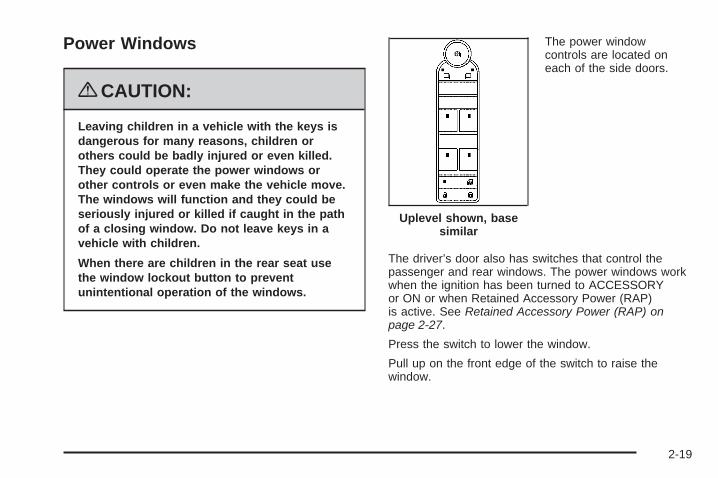
Power Windows
{CAUTION:
Leaving children in a vehicle with the keys isdangerous for many reasons, children orothers could be badly injured or even killed.They could operate the power windows orother controls or even make the vehicle move.The windows will function and they could beseriously injured or killed if caught in the pathof a closing window. Do not leave keys in avehicle with children.
When there are children in the rear seat usethe window lockout button to preventunintentional operation of the windows.
The power windowcontrols are located oneach of the side doors.
The driver’s door also has switches that control thepassenger and rear windows. The power windows workwhen the ignition has been turned to ACCESSORYor ON or when Retained Accessory Power (RAP)is active. See Retained Accessory Power (RAP) onpage 2-27.
Press the switch to lower the window.
Pull up on the front edge of the switch to raise thewindow.
Uplevel shown, basesimilar
2-19

Express-Down WindowsWindows that have the express-down feature allow thewindows to be lowered without holding the switch.Press the window switch fully and release it to activatethe express-down feature. The express mode canbe canceled at any time by briefly pressing, or pullingthe switch.
Express-Up WindowWindows that have the express-up feature allow thewindows to be raised all the way without holding theswitch up. Pull the switch up fully and release it toactivate the express-up feature. The express-upmode can be canceled at any time by brieflypressing, or pulling the switch.
Programming the Power WindowsIf the battery on your vehicle has been recharged,disconnected, or replaced, windows with the express-upfeature need to be reprogrammed for this feature towork. To program the window:
1. With the ignition in the ACCESSORY or ONpositions, or when Retained AccessoryPower (RAP) is active, close all doors. SeeRetained Accessory Power (RAP) on page 2-27.
2. Press and continue to hold the window switch untilthe window is fully open.
3. Pull up and hold the window switch to close thewindow. Continue to hold it briefly after thewindow is fully closed.
4. Repeat for each window that has the express upfeature.
2-20

Anti-Pinch FeatureThe anti-pinch feature is on windows with theexpress-up feature. If an object is in the way of thewindow as it is express-closing, or in certain weatherconditions like severe icing, the window will stopand open to a factory preset position. The windowfunctions normally once the obstruction is removed.
Window Lockout
o (Window Lockout): The window lockout switchis located with the power window switches on thedriver’s door armrest. This feature prevents the rearpassenger windows from operating, except fromthe driver’s position. Press the switch to turn thelockout feature on or off. An indicator light will comeon to show the lockout feature is on.
Sun VisorsPull the sun visor down to block glare. Detach thesun visor from the center mount and slide it along therod from side-to-side to cover the driver or passengerside of the front window. Swing the sun visor to the sideto cover the side window. It can be moved along therod from side-to-side in this position also.
Lighted Visor Vanity MirrorYour vehicle has lighted visor vanity mirrors on both thedriver’s and passenger’s sun visors. Pull the sun visordown and lift the mirror cover to turn the lamps on.
Theft-Deterrent SystemsVehicle theft is big business, especially in some cities.This vehicle has theft-deterrent features, however,they do not make it impossible to steal.
2-21

Content Theft-DeterrentYour vehicle may have a content theft-deterrent alarmsystem.
To activate the theft-deterrent system, do one of thefollowing:
• Press the lock button on the Remote KeylessEntry (RKE) transmitter when any door is open.
The security light should come on and flash. Whenthe door is closed, the security light will stopflashing and stay on solid and then go off afterapproximately 30 seconds. The content theftdeterrent alarm is not armed until the securitylight goes off.If the delayed locking feature is active, the alarm willnot be activated until all doors are closed and thesecurity light goes off.
• Press the lock button on the RKE transmitter whenthe driver door is closed.
The security light will come on solid forapproximately 30 seconds and then go off. Thecontent theft deterrent alarm is not armed until thesecurity light goes off.
If a locked door is opened without using the key in thedriver’s door key cylinder or the RKE transmitter, aten second pre-alarm will occur. The horn will chirp andthe lights will flash. If the key is not placed in theignition and turned to START or the door is not unlockedby pressing the unlock button on the RKE transmitterduring the ten second pre-alarm, the alarm will gooff. Your vehicle’s headlamps will flash and the horn willsound for about two minutes, then will turn off to savethe battery power.
The theft-deterrent system will not activate if the doorsare locked with the vehicle’s key or the manual doorlock. It activates only if you use the power doorlock switch with the door open or the RKE transmitter.You should also remember that you can start yourvehicle with the correct ignition key if the alarm has beenset off.
2-22

Here is how to avoid setting off the alarm by accident:• If you do not want to activate the theft-deterrent
system, the vehicle should be locked with thedoor key after the doors are closed.
• Always unlock a door with the RKE transmitter.Unlocking a door any other way will set off the alarmif the system has been armed.
If you set off the alarm by accident, turn off the alarm bypressing unlock on the RKE transmitter or by placingthe key in the ignition and turning it to START.
Testing the AlarmTo test the alarm:1. From inside the vehicle, lower the driver’s window
and open the driver’s door.2. Activate the system by locking the doors with the
RKE transmitter.3. Get out of the vehicle, close the door and wait for
the security light to go out.4. Then reach in through the window, unlock the door
with the manual door lock and open the door. Thisshould set off the alarm.
If the alarm does not sound when it should, but thevehicle’s headlamps flash, check to see if the hornworks. The horn fuse may be blown. To replace thefuse, see Fuses and Circuit Breakers on page 5-111.If the alarm does not sound or the vehicle’s headlampsdo not flash, see your dealer/retailer for service.
PASS-Key® III+ ElectronicImmobilizerThe PASS-Key III+ system operates on a radiofrequency subject to Federal CommunicationsCommission (FCC) Rules and with Industry Canada.
This device complies with Part 15 of the FCC Rules.Operation is subject to the following two conditions:
1. This device may not cause harmful interference.
2. This device must accept any interference received,including interference that may cause undesiredoperation.
This device complies with RSS-210 of Industry Canada.Operation is subject to the following two conditions:
1. This device may not cause interference.
2. This device must accept any interference received,including interference that may cause undesiredoperation of the device.
Changes or modifications to this system by other thanan authorized service facility could void authorization touse this equipment.
PASS-Key III+ uses a radio frequency transponder inthe key that matches a decoder in the vehicle.
2-23

PASS-Key® III+ ElectronicImmobilizer OperationYour vehicle has PASS-Key® III+ (PersonalizedAutomotive Security System) theft-deterrent system.PASS-Key® III+ is a passive theft-deterrent system.
The system is automatically armed when the keyis removed from the ignition.
The system is automatically disarmed when the key isturned to ON/RUN.
You do not have to manually arm or disarm the system.
The security light will come on if there is a problemwith arming or disarming the theft-deterrent system.
When the PASS-Key® III+ system senses that someoneis using the wrong key, it prevents the vehicle fromstarting. Anyone using a trial-and-error method to startthe vehicle will be discouraged because of the highnumber of electrical key codes.
When trying to start the vehicle if the engine does notstart and the security light on the instrument panelcluster comes on, there may be a problem with yourtheft-deterrent system. Turn the ignition off and try again.
If the engine still does not start, and the key appears tobe not damaged, try another ignition key. At thistime, you may also want to check the fuse, see Fusesand Circuit Breakers on page 5-111. If the enginestill does not start with the other key, your vehicle needsservice. If your vehicle does start, the first key may befaulty. See your dealer/retailer who can service thePASS-Key® III+ to have a new key made. In anemergency, contact Roadside Assistance. See RoadsideAssistance Program on page 7-7.
It is possible for the PASS-Key® III+ decoder to “learn”the transponder value of a new or replacement key.Up to 10 keys may be programmed for the vehicle. Thefollowing procedure is for programming additionalkeys only. If all the currently programmed keys are lostor do not operate, you must see your dealer/retaileror a locksmith who can service PASS-Key® III+ to havekeys made and programmed to the system.
See your dealer/retailer or a locksmith who can servicePASS-Key® III+ to get a new key blank that is cutexactly as the ignition key that operates the system.
2-24

To program the new key:
1. Verify that the new key has a 1 stamped on it.
2. Insert the already programmed key in the ignitionand start the engine. If the engine will not start,see your dealer/retailer for service.
3. After the engine has started, turn the key toLOCK/OFF, and remove the key.
4. Insert the key to be programmed and turn it to theON/RUN position within five seconds of the originalkey being turned to the LOCK/OFF position.The security light will turn off once the key hasbeen programmed.
5. Repeat Steps 1 through 4 if additional keys are tobe programmed.
If you lose or damage your PASS-Key® III+ key, seeyour dealer/retailer or a locksmith who can servicePASS-Key® III+ to have a new key made.
The SERVICE THEFT DETERRENT SYSTEM messagedisplays on the Driver Information Center (DIC) whenthere is a problem with the theft-deterrent system.See DIC Warnings and Messages on page 3-64 foradditional information.
Do not leave the key or device that disarms ordeactivates the theft deterrent system in the vehicle.
Starting and Operating YourVehicle
New Vehicle Break-InNotice: Your vehicle does not need an elaboratebreak-in. But it will perform better in the long run ifyou follow these guidelines:• If you have all-wheel drive, keep your speed at
55 mph (88 km/h) or less for the first 500 miles(805 km).
• Do not drive at any one constant speed, fast orslow, for the first 500 miles (805 km). Do notmake full-throttle starts. Avoid downshifting tobrake or slow the vehicle.
• Avoid making hard stops for the first 200 miles(322 km) or so. During this time the new brakelinings are not yet broken in. Hard stops with newlinings can mean premature wear and earlierreplacement. Follow this breaking-in guidelineevery time you get new brake linings.
• Do not tow a trailer during break-in. See Towing aTrailer on page 4-31 for the trailer towingcapabilities of your vehicle and moreinformation.
Following break-in, engine speed and load can begradually increased.
2-25

Ignition Positions
With the key in the ignition,you can turn it to fourdifferent positions.
In order to shift out of PARK (P), ignition must be inON/RUN or ACC/ACCESSORY and the regular brakepedal must be applied.
Notice: Using a tool to force the key from theignition switch could cause damage or break thekey. Use the correct key and turn the key only withyour hand. Make sure the key is all the way in. Ifnone of this works, then your vehicle needs service.
( (LOCK/OFF): This is the only position in which youcan remove the key. This position locks the ignition andtransmission. If the steering wheel is locked, move it fromright to left and turn the key to ACC/ACCESSORY.If none of this works, then your vehicle needs service.
ACC (ACC/ACCESSORY): This position allows you touse things like the radio and the windshield wiperswhile the engine is off. This position will also allow youto turn off the engine.
R (ON/RUN): This is the position that the switch returnsto after you start your engine and release the key.The switch stays in ON/RUN when the engine isrunning. But even when the engine is not running, youcan use ON/RUN to operate your electrical poweraccessories, and to display some instrument panelwarning lights.
The battery could be drained if you leave the key in theACC/ACCESSORY or ON/RUN position with theengine off. You may not be able to start your vehicle ifthe battery is allowed to drain for an extended periodof time.
/ (START): This position starts the engine. When theengine starts, release the key. The ignition switch willreturn to ON/RUN for normal driving.
2-26

Key In the IgnitionNever leave your vehicle with the keys inside, as it is aneasy target for joy riders or thieves. If you leave thekey in the ignition and park your vehicle, a chimewill sound when you open the driver’s door. Alwaysremember to remove your key from the ignition and takeit with you. This will lock your ignition and transmission.Also, always remember to lock the doors.
The battery could be drained if you leave the key in theignition while your vehicle is parked. You may not beable to start your vehicle after it has been parked for anextended period of time.
Retained Accessory Power (RAP)These vehicle accessories can be used for up to10 minutes after the ignition key is turned off:
• Audio System
• Power Windows
• Sunroof (if equipped)
Power to the windows and sunroof will work up to10 minutes or until a door is opened.
The radio continues to work for 10 minutes or until thedriver’s door is opened.
For an additional 10 minutes of operation, close all thedoors and turn the key to ON/RUN and then backto LOCK/OFF.
All these features will work when the key is in theON/RUN or ACC/ACCESSORY positions.
Starting the EngineMove your shift lever to PARK (P) or NEUTRAL (N).Your engine will not start in any other position – thisis a safety feature. To restart when you are alreadymoving, use NEUTRAL (N) only.
Notice: Do not try to shift to P (Park) if your vehicleis moving. If you do, you could damage thetransmission. Shift to P (Park) only when yourvehicle is stopped.
2-27
Starting Procedure1. With your foot off the accelerator pedal, turn the
ignition key to START. When the engine starts,let go of the key. The idle speed will go down asyour engine gets warm. Do not race the engineimmediately after starting it. Operate the engine andtransmission gently to allow the oil to warm upand lubricate all moving parts.Your vehicle has a Computer-Controlled CrankingSystem. This feature assists in starting the engineand protects components. If the ignition key is turnedto the START position, and then released when theengine begins cranking, the engine will continuecranking for a few seconds or until the vehicle starts.If the engine does not start and the key is held inSTART for many seconds, cranking will be stoppedafter 15 seconds to prevent cranking motor damage.To prevent gear damage, this system also preventscranking if the engine is already running. Enginecranking can be stopped by turning the ignitionswitch to the ACC/ACCESSORY or LOCK/OFFposition.
Notice: Cranking the engine for long periods oftime, by returning the key to the START positionimmediately after cranking has ended, can overheatand damage the cranking motor, and drain thebattery. Wait at least 15 seconds between each try,to let the cranking motor cool down.
2. If the engine does not start after 5-10 seconds,especially in very cold weather (below 0°F or −18°C),it could be flooded with too much gasoline. Trypushing the accelerator pedal all the way to the floorand holding it there as you hold the key in START forup to a maximum of 15 seconds. Wait at least15 seconds between each try, to allow the crankingmotor to cool down. When the engine starts, let go ofthe key and accelerator. If the vehicle starts brieflybut then stops again, do the same thing. This clearsthe extra gasoline from the engine. Do not race theengine immediately after starting it. Operate theengine and transmission gently until the oil warms upand lubricates all moving parts.
Notice: The engine is designed to work with theelectronics in the vehicle. If you add electrical partsor accessories, you could change the way theengine operates. Before adding electrical equipment,check with your dealer/retailer. If you do not, theengine might not perform properly. Any resultingdamage would not be covered by the vehiclewarranty.
2-28

Engine Coolant HeaterThe engine coolant heater, if available, can help in coldweather conditions at or below 0°F (−18°C) for easierstarting and better fuel economy during engine warm-up.Plug in the coolant heater at least four hours beforestarting your vehicle. An internal thermostat in theplug-end of the cord may exist which will preventengine coolant heater operation at temperaturesabove 0°F (−18°C).
To Use the Engine Coolant Heater1. Turn off the engine.
2. Open the hood and unwrap the electrical cord.The cord is located on the driver’s side of theengine compartment, it is routed around thewindshield washer fluid reservoir.
3. Plug the cord into a normal, grounded 110-voltAC outlet.
{CAUTION:
Plugging the cord into an ungrounded outletcould cause an electrical shock. Also, thewrong kind of extension cord could overheatand cause a fire. You could be seriouslyinjured. Plug the cord into a properly groundedthree-prong 110-volt AC outlet. If the cord willnot reach, use a heavy-duty three-prongextension cord rated for at least 15 amps.
4. Before starting the engine, be sure to unplug andstore the cord as it was before to keep it awayfrom moving engine parts. If you do not, it couldbe damaged.
How long should you keep the coolant heater plugged in?The answer depends on the outside temperature, thekind of oil you have, and some other things. Instead oftrying to list everything here, we ask that you contact yourdealer/retailer in the area where you will be parking yourvehicle. The dealer/retailer can give you the best advicefor that particular area.
2-29

Automatic Transmission OperationYour vehicle has an electronic shift position indicatorwithin the instrument panel cluster.
When using the Electronic Range Select Mode anumber will display next to the L, indicating the currentgear that has been selected.
See Electronic Range Select mode in this section formore information.
Your automatic transmission has a shift lever located onthe console between the seats.
PARK (P): This position locks your front wheels. It isthe best position to use when you start your enginebecause your vehicle cannot move easily.
{CAUTION:
It is dangerous to get out of the vehicle if theshift lever is not fully in P (Park) with theparking brake firmly set. The vehicle can roll.Do not leave the vehicle when the engine isrunning unless you have to. If you have left theengine running, the vehicle can move suddenly.You or others could be injured. To be sure thevehicle will not move, even when you are onfairly level ground, always set the parking brakeand move the shift lever to P (Park). See ShiftingInto Park on page 2-35. If you are pulling atrailer, see Towing a Trailer on page 4-31.
Make sure the shift lever is fully in PARK (P) beforestarting the engine. Your vehicle has an automatictransmission shift lock control system. You must fullyapply your regular brake first and then press the shiftlever button before you can shift from PARK (P) when theignition key is in ON. If you cannot shift out of PARK (P),ease pressure on the shift lever, then push the shiftlever all the way into PARK (P) as you maintain brakeapplication. Then press the shift lever button and movethe shift lever into another gear. See Shifting Out of Parkon page 2-36.
2-30

REVERSE (R): Use this gear to back up.
Notice: Shifting to R (Reverse) while the vehicle ismoving forward could damage the transmission.The repairs would not be covered by the vehiclewarranty. Shift to R (Reverse) only after the vehicleis stopped.
To rock your vehicle back and forth to get out of snow,ice or sand without damaging your transmission,see If Your Vehicle is Stuck in Sand, Mud, Ice, or Snowon page 4-21.
NEUTRAL (N): In this position, your engine does notconnect with the wheels. To restart when you arealready moving, use NEUTRAL (N) only. Also, useNEUTRAL (N) when your vehicle is being towed.
{CAUTION:
Shifting into a drive gear while the engine isrunning at high speed is dangerous. Unlessyour foot is firmly on the brake pedal, thevehicle could move very rapidly. You couldlose control and hit people or objects. Do notshift into a drive gear while the engine isrunning at high speed.
Notice: Shifting out of P (Park) or N (Neutral) withthe engine running at high speed may damagethe transmission. The repairs would not be coveredby the vehicle warranty. Be sure the engine isnot running at high speed when shifting the vehicle.
DRIVE (D): This position is for normal driving.It provides the best fuel economy for your vehicle.If you need more power for passing, and you are:
• Going less than 35 mph (56 km/h), push youraccelerator pedal about halfway down.
• Going about 35 mph (56 km/h) or more, push theaccelerator all the way down.
Notice: If your vehicle seems to accelerate slowlyor not shift gears when you go faster, and youcontinue to drive your vehicle that way, you coulddamage the transmission. Have your vehicleserviced right away. You can drive in LOW (L) whenyou are driving less than 35 mph (56 km/h) andDRIVE (D) for higher speeds until then.
LOW (L): This position gives you access to gearranges. This provides more engine braking but lowerfuel economy than DRIVE (D). You can use it onvery steep hills, or in deep snow or mud.
2-31

Electronic Range Select ModeElectronic Range Selector (ERS) mode allows you tochoose the top-gear limit of the vehicle’s transmissionand the vehicle’s speed while driving down hill or towinga trailer.
To use this feature, do the following:
1. Move the shift lever to LOW (L).
2. Press the plus/minusbutton located on theshift lever, to increaseor decrease thegear range availablebased upon yourcurrent drivingconditions and needs.
When you shift from DRIVE (D) to LOW (L), thetransmission will shift to a pre-determined lower gearrange. The highest gear available for this pre-determinedrange is displayed next to the L in the DIC. SeeDriver Information Center (DIC) on page 3-54 and DICOperation and Displays (With DIC Buttons) on
page 3-54 or DIC Operation and Displays (Without DICButtons) on page 3-60 for more information. Thenumber displayed in the DIC is the highest gear that thetransmission will be allowed to operate in. However,your vehicle can automatically shift to lower gearsas required by various driving conditions. This meansthat all gears below that number are available. Forexample, when FOURTH (4) is shown next to the L,FIRST (1) through FOURTH (4) gears are automaticallyshifted by the vehicle. You cannot shift into FIFTH (5)until the plus (+) button is used or you shift backinto DRIVE (D) mode.
While in LOW (L), the transmission will prevent shiftingto a lower gear range if the engine speed is too highfor the gear range you are trying to select. You have abrief period of time to slow the vehicle speed. Ifvehicle speed is not reduced within the timeframeallowed, the lower gear range attempted will not beavailable. The highest possible gear that is allowed forthat engine speed will display next to the L in theDIC. Try again to slow the vehicle speed and press theminus (−) button to the desired lower gear range.
Automatic Engine Grade braking is not available whenthe ERS is active. It is available in DRIVE (D) forboth normal and Tow/Haul mode. While using the ERS,cruise control and the tow/haul mode can be used.See Tow/Haul Mode on page 2-33 for more information.
2-32

Tow/Haul ModeYour vehicle may have a Tow/Haul mode.
The button to turn it on oroff is located on instrumentpanel under the climatecontrols.
Push the button to turn it on, push it again to deactivatethe system. You can use this feature to assist whentowing or hauling a heavy load.
When Tow/Haul is activated the Tow/Haul symbol willcome on the instrument panel cluster. See Tow/HaulMode under Towing a Trailer on page 4-31 formore information.
Automatic Engine Grade BrakingAutomatic Engine Grade Braking assists when drivingon a downhill grade. It maintains the vehicle’s speed byautomatically implementing a shift schedule that usesthe engine and the transmission to slow the vehicle.This reduces wear on the brakes system and increasescontrol of the vehicle. The system constantly monitorsthe vehicle’s speed, acceleration, throttle position,and whether the brake pedal is being pressed, anddetermines when to keep the current vehicle speed or toslow down. The system will then automatically commanddownshifts that reduces the vehicle’s speed, until thebrake pedal is no longer being pressed. This indicatesthe desired vehicle speed has been reached.
While in the Electronic Range Select (ERS) mode,grade braking is deactivated, allowing the driver toselect a range and limiting the highest gear available.Grade braking is available for normal driving and inTow/Haul mode.
See Automatic Transmission Operation on page 2-30.
2-33

Parking Brake
To set the parking brake,push down the parkingbrake pedal downwith your left foot.
If the ignition is on, the brake system warning light willcome on. See Brake System Warning Light onpage 3-45.
Notice: Driving with the parking brake on canoverheat the brake system and cause prematurewear or damage to brake system parts. Make surethat the parking brake is fully released and the brakewarning light is off before driving.
To release the parking brake, hold the regular brakepedal down with your right foot. Push down momentarilyon the parking brake pedal with your left foot until youfeel the pedal release, then slowly pull your foot upoff the park brake pedal. If the parking brake isnot released when you begin to drive, the brake systemwarning light will be on and a chime will soundwarning you that the parking brake is still on.
If you are towing a trailer and are parking on a hill, seeTowing a Trailer on page 4-31.
2-34

Shifting Into Park
{CAUTION:
It can be dangerous to get out of the vehicle ifthe shift lever is not fully in P (Park) with theparking brake firmly set. The vehicle can roll. Ifyou have left the engine running, the vehiclecan move suddenly. You or others could beinjured. To be sure the vehicle will not move,even when you are on fairly level ground, usethe steps that follow. If you are pulling atrailer, see Towing a Trailer on page 4-31.
1. Hold the brake pedal down with your right foot andset the parking brake. See Parking Brake onpage 2-34 for more information.
2. Move the shift lever into PARK (P) by holding in thebutton on the shift lever and pushing the shift leverall the way toward the front of the vehicle.
3. Turn the ignition key to LOCK/OFF.
4. Remove the key and take it with you. If you canleave your vehicle with the ignition key in yourhand, your vehicle is in PARK (P).
Leaving Your Vehicle With the EngineRunning
{CAUTION:
It can be dangerous to leave the vehicle withthe engine running. The vehicle could movesuddenly if the shift lever is not fully inP (Park) with the parking brake firmly set.And, if you leave the vehicle with the enginerunning, it could overheat and even catch fire.You or others could be injured. Do not leavethe vehicle with the engine running.
If you have to leave your vehicle with the enginerunning, be sure your vehicle is in PARK (P) and yourparking brake is firmly set before you leave it. After youhave moved the shift lever into PARK (P), hold theregular brake pedal down. Then, see if you can movethe shift lever away from PARK (P) without first pushingthe button.
If you can, it means that the shift lever was not fullylocked in PARK (P).
2-35
Torque LockIf you are parking on a hill and you do not shift yourtransmission into PARK (P) properly, the weight of thevehicle may put too much force on the parking pawl in thetransmission. You may find it difficult to pull the shift leverout of PARK (P). This is called torque lock. To preventtorque lock, set the parking brake and then shift intoPARK (P) properly before you leave the driver’s seat.To find out how, see Shifting Into Park on page 2-35.
When you are ready to drive, move the shift lever outof PARK (P) before you release the parking brake.
If torque lock does occur, you may need to have anothervehicle push your vehicle a little uphill to take some ofthe pressure from the parking pawl in the transmission,so you can pull the shift lever out of PARK (P).
Shifting Out of ParkThis vehicle is equipped with an electronic shift lockrelease system. The shift lock release is designed to:
• Prevent ignition key removal unless the shiftlever is in PARK (P) with the shift lever buttonfully released, and
• Prevent movement of the shift lever out ofPARK (P), unless the ignition is in ON/RUN orACC/ACCESSORY and the regular brake pedalis applied.
The shift lock release is always functional except in thecase of an uncharged or low voltage (less than 9 volt)battery.
If your vehicle has an uncharged battery or a batterywith low voltage, try charging or jump starting thebattery. See Jump Starting on page 5-38 for moreinformation.
2-36

To shift out of PARK (P) use the following:
1. Apply the brake pedal.
2. Then press the shift lever button.
3. Move the shift lever to the desired position.
If you still are unable to shift out of PARK (P):
1. Fully release the shift lever button.
2. While holding down the brake pedal, press theshift lever button again.
3. Move the shift lever to the desired position.
If you still cannot move the shift lever from PARK (P),consult your dealer/retailer or a professional towingservice.
Parking Over Things That Burn
{CAUTION:
Things that can burn could touch hot exhaustparts under your vehicle and ignite. Do notpark over papers, leaves, dry grass, or otherthings that can burn.
Engine Exhaust
{CAUTION:
Engine exhaust can kill. It contains the gascarbon monoxide (CO), which you cannot see orsmell. It can cause unconsciousness and death.
You might have exhaust coming in if:• The exhaust system sounds strange or
different.• Your vehicle gets rusty underneath.• Your vehicle was damaged in a collision.• Your vehicle was damaged when driving
over high points on the road or over roaddebris.
• Repairs were not done correctly.• Your vehicle or the exhaust system has
been modified improperly.
If you ever suspect exhaust is coming into yourvehicle:
• Drive it only with all the windows down toblow out any CO.
• Have your vehicle fixed immediately.
2-37

Running the Vehicle While ParkedIt is better not to park with the engine running. But if youever have to, here are some things to know.
{CAUTION:
Idling the engine with the climate controlsystem off could allow dangerous exhaust intoyour vehicle. See the earlier caution underEngine Exhaust on page 2-37.
Also, idling in a closed-in place can let deadlycarbon monoxide (CO) into your vehicle even ifthe climate control fan is at the highest setting.One place this can happen is a garage.Exhaust — with CO — can come in easily.NEVER park in a garage with the enginerunning.
Also see “If You Are Caught in a Blizzard”under Winter Driving on page 4-17.
{CAUTION:
It can be dangerous to get out of your vehicleif the shift lever is not fully in PARK (P) withthe parking brake firmly set. Your vehicle canroll. Do not leave your vehicle when the engineis running unless you have to. If you have leftthe engine running, the vehicle can movesuddenly. You or others could be injured. Tobe sure your vehicle will not move, even whenyou are on fairly level ground, always set theparking brake and move the shift lever toPARK (P).
Follow the proper steps to be sure your vehicle will notmove. See Shifting Into Park on page 2-35.
If you are pulling a trailer, see Towing a Trailer onpage 4-31.
2-38

Mirrors
Manual Rearview Mirror withOnStar®
When you are sitting in a comfortable driving position,adjust the mirror so you can see clearly behind yourvehicle. Hold the mirror in the center to move it up ordown and side to side. The day/night adjustment allowsyou to adjust the mirror to avoid glare from the lampsbehind you. Move the lever to the right for nighttime useand to the left for daytime use.
There may also be three OnStar® buttons located at thebottom of the mirror face. See your dealer/retailer formore information on the system and how to subscribe toOnStar®. See OnStar® System on page 2-47 for moreinformation on the services OnStar® provides.
Automatic Dimming Rearview Mirrorwith OnStar® and CompassYour vehicle may have an automatic-dimming rearviewmirror with a compass.
There may be three additional buttons for the OnStar®
system. See your dealer/retailer for more informationon the system and how to subscribe to OnStar®.See OnStar® System on page 2-47 for more informationabout the services OnStar® provides.
O (On/Off): This is the on/off button.
Automatic Dimming Mirror OperationThe automatic dimming mirror comes on each timethe ignition is turned to start. To turn the automaticdimming feature off or back on, press the on/off button.The indicator light on the mirror is lit when theautomatic dimming feature is on.
Compass OperationPress the on/off button once to turn the compass onor off.
There is a compass display in the window in the upperright corner of the mirror face.
2-39
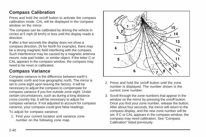
Compass CalibrationPress and hold the on/off button to activate the compasscalibration mode. CAL will be displayed in the compasswindow on the mirror.The compass can be calibrated by driving the vehicle incircles at 5 mph (8 km/h) or less until the display reads adirection.If after a few seconds the display does not show acompass direction, (N for North for example), there maybe a strong magnetic field interfering with the compass.Such interference may be caused by a magnetic antennamount, note pad holder, or similar object. If the letter C orCAL appears in the compass window, the compass mayneed to be reset or calibrated.
Compass VarianceCompass variance is the difference between earth’smagnetic north and true geographic north. The mirror isset to zone eight upon leaving the factory. It will benecessary to adjust the compass to compensate forcompass variance if you live outside zone eight. Undercertain circumstances, such as during a long distancecross-country trip, it will be necessary to adjust forcompass variance. If not adjusted to account for compassvariance, your compass could give false readings.To adjust for compass variance:1. Find your current location and variance zone
number on the following zone map.
2. Press and hold the on/off button until the zonenumber is displayed. The number shown is thecurrent zone number.
3. Scroll through the zone numbers that appear in thewindow on the mirror by pressing the on/off button.Once you find your zone number, release the button.After about four seconds, the mirror will return to thecompass display, and the new zone number will beset. If C or CAL appears in the compass window, thecompass may need calibration. See “CompassCalibration” listed previously.
2-40

Outside Power Mirrors
If your vehicle is equippedwith outside power mirrors,the controls are locatedon the driver door armrest.
Press (A) to select the driver side mirror or (B) to selectthe passenger side mirror. Press either (A) or (B)again to deselect the mirror.
To adjust each mirror, press one of the four arrowslocated on the control pad to move the mirror inthe direction you want it to go. Adjust each outsidemirror to see a little of your vehicle, and the areabehind your vehicle. See Memory Seat and Mirrorson page 1-6 for more information.
Manually fold the mirrors inward to prevent damagewhen going through an automatic car wash. Tofold, push the mirror toward the vehicle. To return themirror to its original position, push outward. Be sureto return both mirrors to their original unfolded positionbefore driving.
The use of hood-mounted air deflectors and add-onconvex mirror attachments may adversely affect mirrorperformance.
Turn Signal IndicatorYour vehicle may have a turn signal indicator on themirror. An arrow on the mirror flashes in the direction ofthe turn or lane change.
2-41

Outside Power Foldaway Mirrors
If your vehicle is equippedwith outside powerfoldaway mirrors, thecontrols are located on thedriver’s door armrest.
• Press (A) to select the driver’s side mirror. Thenpress the arrows located on the four-way controlpad to adjust the mirror. Press (A) again to deselectthe mirror.
• Press (B) to select the passenger’s side mirror.Then press the arrows located on the four-waycontrol pad to adjust the mirror. Press (B) again todeselect the mirror.
• Press (C), to fold the mirrors out to the drivingposition.
• Press (D) to fold the mirrors in to the foldedposition.
If the mirrors are accidentally folded/unfolded manually,they may shake or flutter at normal driving speedsand may not stay in the unfolded position. If thishappens, you will need to reset the mirrors. See“Resetting the Power Foldaway Mirrors” next.
Resetting the Power Foldaway MirrorsYou will need to reset the power foldaway mirrors if thefollowing occurs:
• The mirrors are accidentally obstructed whilefolding.
• They are accidentally manually folded/unfolded.
• The mirrors will not stay in the unfolded position.
• The mirrors shake and flutter at normal drivingspeeds.
To reset the power foldaway mirrors, fold and unfoldthem one time using the mirror controls. This will resetthem to their normal position.
This mirror has the following features.
Automatic DimmingThe driver’s outside mirror will adjust for the glare of theheadlamps behind you. See Automatic DimmingRearview Mirror with OnStar® and Compass onpage 2-39.
2-42

Park Tilt MirrorsIf your vehicle has the memory package, the outsidemirrors are able to perform the park tilt function. Thisfeature may be useful in allowing the driver to view thecurb when parallel parking. This feature will cause thepassenger’s and/or driver’s mirror to tilt to a preselectedposition when the vehicle is in REVERSE (R).
The passenger’s and/or driver’s mirror will return to itsoriginal position when the vehicle is shifted out ofREVERSE (R), or the ignition is turned off or toOFF/LOCK.
This feature can be turned on or off through the DriverInformation Center (DIC). See DIC VehicleCustomization (With DIC Buttons) on page 3-74 andMemory Seat and Mirrors on page 1-6 for moreinformation.
Turn Signal IndicatorYour vehicle may have a turn signal indicator on themirror. An arrow on the mirror will flash in the directionof the turn or lane change.
Outside Convex Mirror
{CAUTION:
A convex mirror can make things (like othervehicles) look farther away than they really are.If you cut too sharply into the right lane, youcould hit a vehicle on your right. Check yourinside mirror or glance over your shoulderbefore changing lanes.
The passenger side mirror is convex shaped. A convexmirror’s surface is curved so more can be seen fromthe driver seat. It also makes things, like other vehicles,look farther away than they really are.
Outside Heated Mirrors
< (Rear Window Defogger): Press to heat themirrors.
See “Rear Window Defogger” under Dual AutomaticClimate Control System on page 3-26 for moreinformation.
2-43
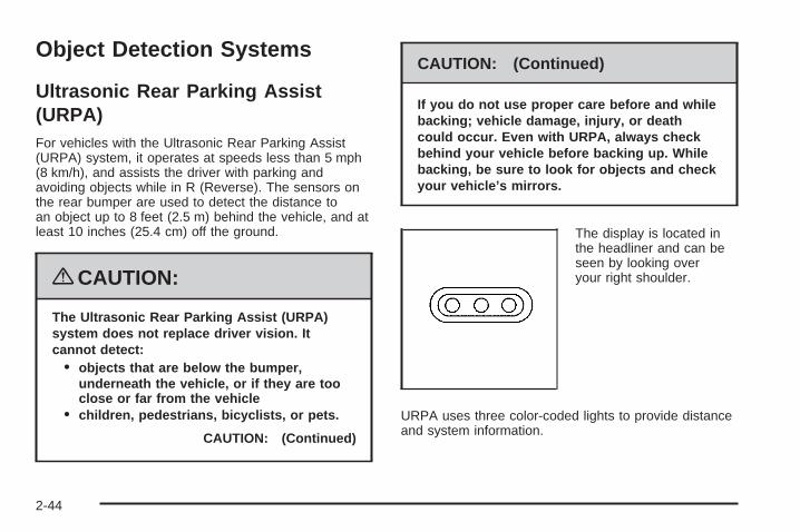
Object Detection Systems
Ultrasonic Rear Parking Assist(URPA)For vehicles with the Ultrasonic Rear Parking Assist(URPA) system, it operates at speeds less than 5 mph(8 km/h), and assists the driver with parking andavoiding objects while in R (Reverse). The sensors onthe rear bumper are used to detect the distance toan object up to 8 feet (2.5 m) behind the vehicle, and atleast 10 inches (25.4 cm) off the ground.
{CAUTION:
The Ultrasonic Rear Parking Assist (URPA)system does not replace driver vision. Itcannot detect:
• objects that are below the bumper,underneath the vehicle, or if they are tooclose or far from the vehicle
• children, pedestrians, bicyclists, or pets.
CAUTION: (Continued)
CAUTION: (Continued)
If you do not use proper care before and whilebacking; vehicle damage, injury, or deathcould occur. Even with URPA, always checkbehind your vehicle before backing up. Whilebacking, be sure to look for objects and checkyour vehicle’s mirrors.
The display is located inthe headliner and can beseen by looking overyour right shoulder.
URPA uses three color-coded lights to provide distanceand system information.
2-44

How the System WorksURPA comes on automatically when the shift lever ismoved into R (Reverse). The rear display brieflyilluminates to indicate the system is working.
URPA operates only at speeds less than 5 mph(8 km/h). If the vehicle is above this speed, the red lighton the rear display will flash.
To be detected, objects must be at least 10 inches(25.4 cm) off the ground and below liftgate level. Objectsmust also be within 8 feet (2.5 m) from the rear bumper.This distance may be less during warmer or humidweather.
A single beep will sound the first time an object isdetected between 20 inches (0.5 m) and 8 feet (2.5 m)away. Beeping will occur for a short time when thevehicle is closer than 1 foot (0.3 m) from the object.
The following describes what will occur with the URPAdisplay as the vehicle gets closer to a detected object:
Description English Metricamber light 8 ft 2.5 m
amber/amber lights 40 in 1.0 mamber/amber/red lights 23 in 0.6 mamber/amber/red lightsflashing and beep for
three seconds1 ft 0.3 m
The system can be disabled through the DriverInformation Center (DIC). See “Park Assist” underDIC Operation and Displays (With DIC Buttons) onpage 3-54 or DIC Operation and Displays (WithoutDIC Buttons) on page 3-60 for more information.
2-45

When the System Does Not Seem toWork ProperlyIf the URPA system will not activate due to a temporarycondition, the message PARKING ASSIST OFF willbe displayed on the DIC and a red light will be shown onthe rear URPA display when the shift lever is movedinto R (Reverse). This occurs under the followingconditions:
• The driver disables the system.
• The parking brake pedal is depressed.
• The ultrasonic sensors are not clean. Keep thevehicle’s rear bumper free of mud, dirt, snow,ice and slush. For cleaning instructions, seeWashing Your Vehicle on page 5-104.
• A trailer was attached to the vehicle, or a bicycle oran object was hanging out of the liftgate during thelast drive cycle, the red light may illuminate inthe rear display. Once the attached object isremoved, URPA will return to normal operation.
• A tow bar is attached to the vehicle.
• The vehicle’s bumper is damaged. Take the vehicleto your dealer/retailer to repair the system.
• Other conditions may affect system performance,such as vibrations from a jackhammer or thecompression of air brakes on a very large truck.
If the system is still disabled, after driving forward atleast 15 mph (25 km/h), take the vehicle to yourdealer/retailer.
Rear Vision Camera (RVC)The vehicle may have a Rear Vision Camera system.Read the entire section before using the system.The rear vision camera system is designed to help thedriver when backing up. See “Rear Vision Camera”in the Index of the navigation manual.
2-46

OnStar® System
OnStar uses several innovative technologies and liveadvisors to provide you with a wide range of safety,security, information, and convenience services. If yourairbags deploy, the system is designed to make anautomatic call to OnStar Emergency advisors who canrequest emergency services be sent to your location.If you lock your keys in the vehicle, call OnStar at1-888-4-ONSTAR and they can send a signal to unlockyour doors. If you need roadside assistance, pressthe OnStar button and they can contact RoadsideService for you.
OnStar service is provided to you subject to the OnStarTerms and Conditions. You may cancel your OnStarservice at any time by contacting OnStar. A completeOnStar Owner’s Guide and the OnStar Terms andConditions are included in the vehicle’s OnStarSubscriber glove box literature. For more information,visit onstar.com or onstar.ca, contact OnStar at1-888-4-ONSTAR (1-888-466-7827) or TTY1-877-248-2080, or press the OnStar button to speakwith an OnStar advisor 24 hours a day, 7 days a week.
Not all OnStar features are available on all vehicles.To check if your vehicle is equipped to provide theservices described below, or for a full description ofOnStar services and system limitations, see the OnStarOwner’s Guide in your glove box or visit onstar.com.
OnStar ServicesFor new vehicles with OnStar, the Safe & Sound Plan,or the Directions & Connections Plan is included forone year from the date of purchase. You can extend thisplan beyond the first year, or upgrade to the Directions& Connections Plan. For more information, pressthe OnStar button to speak with an advisor. SomeOnStar services (such as Remote Door Unlock or StolenVehicle Location Assistance) may not be availableuntil you register with OnStar.
2-47

Available Services with Safe & Sound Plan• Automatic Notification of Airbag Deployment
• Advanced Automatic Crash Notification (AACN)(If equipped)
• Link to Emergency Services
• Roadside Assistance
• Stolen Vehicle Location Assistance
• AccidentAssist
• Remote Door Unlock/Vehicle Alert
• OnStar Vehicle Diagnostics
• GM Goodwrench On Demand Diagnostics
• OnStar Hands-Free Calling with30 complimentary minutes
• OnStar Virtual Advisor (U.S. Only)
Available Services included withDirections & Connections Plan• All Safe and Sound Plan Services
• Driving Directions - Advisor delivered or OnStarTurn-by-Turn Navigation (If equipped)
• RideAssist
• Information and Convenience Services
OnStar Hands-Free CallingOnStar Hands-Free Calling allows eligible OnStarsubscribers to make and receive calls using voicecommands. Hands-Free Calling is fully integrated intothe vehicle, and can be used with OnStar Pre-PaidMinute Packages. Hands-Free Calling may alsobe linked to a Verizon Wireless service plan in the U.S.or a Bell Mobility service plan in Canada, dependingon eligibility. To find out more, refer to the OnStarOwner’s Guide in the vehicle’s glove box, visitwww.onstar.com or www.onstar.ca, or speak with anOnStar advisor by pressing the OnStar button or calling1-888-4-ONSTAR (1-888-466-7827).
2-48

OnStar Virtual AdvisorOnStar Virtual Advisor is a feature of OnStarHands-Free Calling that uses your minutes to accesslocation-based weather, local traffic reports, andstock quotes. By pressing the phone button and givinga few simple voice commands, you can browsethrough the various topics. See the OnStar Owner’sGuide for more information (Only available in thecontinental U.S.).
OnStar Steering Wheel ControlsYour vehicle may have a Talk/Mute button that can beused to interact with OnStar Hands-Free Calling.See Audio Steering Wheel Controls on page 3-126 formore information.
On some vehicles, you may have to hold the button fora few seconds and give the command “ONSTAR” toactivate the OnStar Hands-Free Calling.
On some vehicles, the mute button can be used to dialnumbers into voicemail systems, or to dial phoneextensions. See the OnStar Owner’s Guide for moreinformation.
How OnStar Service WorksYour vehicle’s OnStar system has the capability ofrecording and transmitting vehicle information. Thisinformation is automatically sent to an OnStar CallCenter at the time of an OnStar button press,Emergency button press or if your airbags or AACNsystem deploys. The vehicle information usually includesyour GPS location and, in the event of a crash,additional information regarding the accident that yourvehicle has been involved in (e.g. the direction fromwhich your vehicle was hit). When you use the VirtualAdvisor feature of OnStar Hands-Free Calling, yourvehicle also sends OnStar your GPS location so that wecan provide you with location-based services.
OnStar service cannot work unless your vehicle is in aplace where OnStar has an agreement with a wirelessservice provider for service in that area. OnStarservice also cannot work unless you are in a placewhere the wireless service provider OnStar has hired forthat area has coverage, network capacity and receptionwhen the service is needed, and technology that iscompatible with the OnStar service. Not all services areavailable everywhere, particularly in remote orenclosed areas, or at all times.
2-49
Location information about your vehicle is only availableif the GPS satellite signals are unobstructed andavailable.
Your vehicle must have a working electrical system(including adequate battery power) for the OnStarequipment to operate. There are other problems OnStarcannot control that may prevent OnStar from providingOnStar service to you at any particular time or place.Some examples are damage to important parts of yourvehicle in an accident, hills, tall buildings, tunnels,weather or wireless phone network congestion.
Your ResponsibilityIncrease the radio volume if you cannot hear the OnStaradvisor. If the light next to the OnStar buttons is red,this means that your system is not functioning properlyand should be checked by your dealer/retailer. If thelight appears clear (no light is appearing), your OnStarsubscription has expired. You can always press theOnStar button to confirm that your OnStar equipment isactive.
Universal Home RemoteSystemThe Universal Home Remote System provides a way toreplace up to three hand-held Radio-Frequency (RF)transmitters used to activate devices such as garagedoor openers, security systems, and home lighting.
This device complies with Part 15 of the FCC Rules.Operation is subject to the following two conditions:
1. This device may not cause harmful interference.
2. This device must accept any interference received,including interference that may cause undesiredoperation.
This device complies with RSS-210 of Industry Canada.Operation is subject to the following two conditions:
1. This device may not cause interference.
2. This device must accept any interference received,including interference that may cause undesiredoperation of the device.
Changes or modifications to this system by other thanan authorized service facility could void authorization touse this equipment.
2-50

Universal Home Remote SystemOperation (With One Triangular LED)
If there is one triangular Light Emitting Diode (LED)indicator light above the Universal Home Remotebuttons, follow the instructions below.
This system provides a way to replace up to threeremote control transmitters used to activate devicessuch as garage door openers, security systems,and home automation devices.
Do not use the Universal Home Remote with anygarage door opener that does not have the stop andreverse feature. This includes any garage door openermodel manufactured before April 1, 1982.
Read the instructions completely before attempting toprogram the Universal Home Remote. Because ofthe steps involved, it may be helpful to have anotherperson available to assist you in the programmingthe Universal Home Remote.
Keep the original hand-held transmitter for use in othervehicles as well as for future Universal Home Remoteprogramming. It is also recommended that upon thesale of the vehicle, the programmed Universal HomeRemote buttons should be erased for security purposes.See “Erasing Universal Home Remote Buttons” laterin this section.
When programming a garage door, park outside ofthe garage. Park directly in line with and facingthe garage door opener motor-head or gate motor-head.Be sure that people and objects are clear of thegarage door or gate that is being programmed.
It is recommended that a new battery be installed inyour hand-held transmitter for quicker and moreaccurate transmission of the radio-frequency signal.
2-51
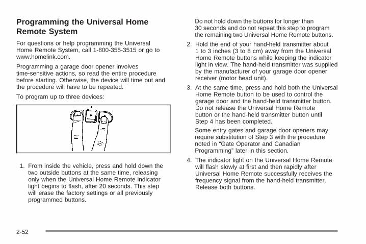
Programming the Universal HomeRemote SystemFor questions or help programming the UniversalHome Remote System, call 1-800-355-3515 or go towww.homelink.com.
Programming a garage door opener involvestime-sensitive actions, so read the entire procedurebefore starting. Otherwise, the device will time out andthe procedure will have to be repeated.
To program up to three devices:
1. From inside the vehicle, press and hold down thetwo outside buttons at the same time, releasingonly when the Universal Home Remote indicatorlight begins to flash, after 20 seconds. This stepwill erase the factory settings or all previouslyprogrammed buttons.
Do not hold down the buttons for longer than30 seconds and do not repeat this step to programthe remaining two Universal Home Remote buttons.
2. Hold the end of your hand-held transmitter about1 to 3 inches (3 to 8 cm) away from the UniversalHome Remote buttons while keeping the indicatorlight in view. The hand-held transmitter was suppliedby the manufacturer of your garage door openerreceiver (motor head unit).
3. At the same time, press and hold both the UniversalHome Remote button to be used to control thegarage door and the hand-held transmitter button.Do not release the Universal Home Remotebutton or the hand-held transmitter button untilStep 4 has been completed.Some entry gates and garage door openers mayrequire substitution of Step 3 with the procedurenoted in “Gate Operator and CanadianProgramming” later in this section.
4. The indicator light on the Universal Home Remotewill flash slowly at first and then rapidly afterUniversal Home Remote successfully receives thefrequency signal from the hand-held transmitter.Release both buttons.
2-52

5. Press and hold the newly-trained Universal HomeRemote button and observe the indicator light.If the indicator light stays on continuously,the programming is complete and the garage doorshould move when the Universal Home Remotebutton is pressed and released. There is no need tocontinue programming Steps 6 through 8.If the Universal Home Remote indicator light blinksrapidly for two seconds and then turns to aconstant light, continue with the programmingSteps 6 through 8.It may be helpful to have another person assist withthe remaining steps.
6. After Steps 1 through 5 have been completed,locate inside the garage the garage door openerreceiver (motor-head unit). Locate the “Learn”or “Smart” button. The name and color of the buttonmay vary by manufacturer.
7. Firmly press and release the “Learn” or “Smart”button. After you press this button, you will have30 seconds to complete Step 8.
2-53

8. Immediately return to the vehicle. Firmly press andhold the Universal Home Remote button, chosen inStep 3 to control the garage door, for two seconds,and then release it. If the garage door does notmove, press and hold the same button a second timefor two seconds, and then release it. Again, if thedoor does not move, press and hold the same buttona third time for two seconds, and then release.The Universal Home Remote should now activatethe garage door.
To program the remaining two Universal Home Remotebuttons, begin with Step 2 of “Programming theUniversal Home Remote System.” Do not repeat Step 1,as this will erase all previous programming from theUniversal Home Remote buttons.
Gate Operator and CanadianProgrammingIf you have questions or need help programming theUniversal Home Remote System, call 1-800-355-3515 orgo to www.homelink.com.
Canadian radio-frequency laws require transmittersignals to time out or quit after several seconds oftransmission. This may not be long enough for UniversalHome Remote to pick up the signal during programming.Similarly, some U.S. gate operators are manufacturedto time out in the same manner.
If you live in Canada, or you are having difficultyprogramming a gate operator or garage door opener byusing the “Programming Universal Home Remote”procedures, regardless of where you live, replaceStep 3 under “Programming Universal Home Remote”with the following:
Continue to press and hold the Universal Home Remotebutton while you press and release every two seconds(cycle) the hand-held transmitter button until thefrequency signal has been successfully accepted by theUniversal Home Remote. The Universal Home Remoteindicator light will flash slowly at first and then rapidly.Proceed with Step 4 under “Programming UniversalHome Remote” to complete.
Using Universal Home RemotePress and hold the appropriate Universal Home Remotebutton for at least half of a second. The indicator lightwill come on while the signal is being transmitted.
2-54

Erasing Universal Home RemoteButtonsThe programmed buttons should be erased when thevehicle is sold or the lease ends.
To erase all programmed buttons on the UniversalHome Remote device:
1. Press and hold down the two outside buttons untilthe indicator light begins to flash, after 20 seconds.
2. Release both buttons.
Reprogramming a Single UniversalHome Remote ButtonTo reprogram any of the three Universal Home Remotebuttons, repeat the programming instructions earlierin this section, beginning with Step 2.
For help or information on the Universal Home RemoteSystem, call the customer assistance phone numberunder Customer Assistance Offices on page 7-6.
Storage Areas
Glove BoxTo open, lift the handle up. Use the key to lockand unlock.
CupholdersThere are two cupholders, with removable liners, locatedin front of the center console. There are cupholderslocated in the second row seat armrest. To access, pullthe armrest down. There are additional cupholderslocated on each side of the third row seat and in eachdoor. There are cupholders located behind the centerconsole. To access, pull down on the handle.
Instrument Panel StorageYour vehicle has an instrument panel storage arealocated above the radio. To open the cover, pressthe button.
2-55

Center Console Storage
The armrest on the center console can slide forwardsand backwards by holding up the lever located onthe front of it. To open the armrest storage area, pressthe button located on the front of the armrest. Thereis additional storage under the armrest. Move thearmrest all the way to the rear position. The tray can beremoved for additional storage.
Second Row Center Console
Your vehicle may have a second row center console.
2-56
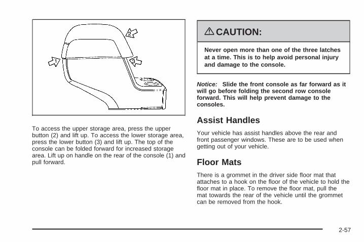
To access the upper storage area, press the upperbutton (2) and lift up. To access the lower storage area,press the lower button (3) and lift up. The top of theconsole can be folded forward for increased storagearea. Lift up on handle on the rear of the console (1) andpull forward.
{CAUTION:
Never open more than one of the three latchesat a time. This is to help avoid personal injuryand damage to the console.
Notice: Slide the front console as far forward as itwill go before folding the second row consoleforward. This will help prevent damage to theconsoles.
Assist HandlesYour vehicle has assist handles above the rear andfront passenger windows. These are to be used whengetting out of your vehicle.
Floor MatsThere is a grommet in the driver side floor mat thatattaches to a hook on the floor of the vehicle to hold thefloor mat in place. To remove the floor mat, pull themat towards the rear of the vehicle until the grommetcan be removed from the hook.
2-57

Luggage Carrier
{CAUTION:
If you try to carry something on top of yourvehicle that is longer or wider than the luggagecarrier — like paneling, plywood, a mattressand so forth — the wind can catch it as youdrive along. This can cause you to losecontrol. What you are carrying could beviolently torn off, and this could cause you orother drivers to have a collision, and of coursedamage your vehicle. You may be able to carrysomething like this inside. But, never carrysomething longer or wider than the luggagecarrier on top of your vehicle.
If you have the luggage carrier, you can load things ontop of your vehicle. Crossrails are not standard onthis vehicle and must be purchased at yourdealer/retailer.
Notice: Loading cargo on the luggage carrier thatweighs more than 200 lbs (91 kg) or hangs overthe rear or sides of the vehicle may damage yourvehicle. Load cargo so that it rests as far forward aspossible and against the side rails, making sureto fasten it securely.
Do not exceed the maximum vehicle capacity whenloading your vehicle. For more information on vehiclecapacity and loading, see Loading the Vehicle onpage 4-22.
To prevent damage or loss of cargo as you are driving,check to make sure the cargo is still securely fastened.
Rear Seat ArmrestYour vehicle may have a rear seat armrest that containstwo cupholders. To access the cupholders, pull thearmrest down from the rear seatback.
Convenience NetThe vehicle may have a convenience net in the rear.Store small loads as far forward as possible. Thenet should not be used to store heavy loads.
2-58

Cargo CoverYour vehicle may have a cargo cover. It can be used tocover items in the rear of the vehicle. To install thecover, place the loops on each corner of the cover onthe four hooks in the rear of the vehicle. The covershould be stored securely when not in use.
Cargo Tie DownsThere are four cargo tie-downs located in the rearcompartment of the vehicle, that can be used to securesmall loads.
Cargo Management SystemYour vehicle has a cargo management system locatedin the rear of the vehicle. To open, pull the handletoward the rear of the vehicle and lift the cover up.
There is an additional storage compartment on each sideof the system. To open, unlatch and lift the panel up.
To remove the cargo management system:
1. Open the lid.
2. Remove the side panels and place inside the bin.
3. Loosen the retaining nuts on each side of thesystem by turning them counterclockwise.
4. Close the lid.
5. Pull up on the system by using the built in handlesand remove it from the vehicle.
2-59
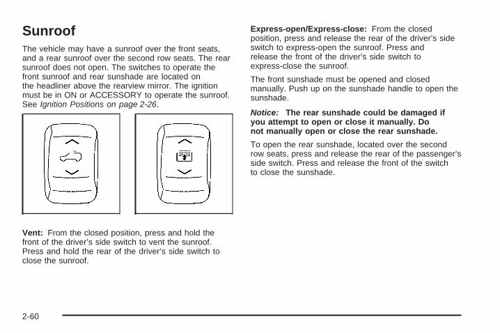
SunroofThe vehicle may have a sunroof over the front seats,and a rear sunroof over the second row seats. The rearsunroof does not open. The switches to operate thefront sunroof and rear sunshade are located onthe headliner above the rearview mirror. The ignitionmust be in ON or ACCESSORY to operate the sunroof.See Ignition Positions on page 2-26.
Vent: From the closed position, press and hold thefront of the driver’s side switch to vent the sunroof.Press and hold the rear of the driver’s side switch toclose the sunroof.
Express-open/Express-close: From the closedposition, press and release the rear of the driver’s sideswitch to express-open the sunroof. Press andrelease the front of the driver’s side switch toexpress-close the sunroof.
The front sunshade must be opened and closedmanually. Push up on the sunshade handle to open thesunshade.
Notice: The rear sunshade could be damaged ifyou attempt to open or close it manually. Donot manually open or close the rear sunshade.
To open the rear sunshade, located over the secondrow seats, press and release the rear of the passenger’sside switch. Press and release the front of the switchto close the sunshade.
2-60

Instrument Panel Overview ...............................3-4Hazard Warning Flashers ................................3-6Other Warning Devices ...................................3-7Horn .............................................................3-7Tilt and Telescopic Steering Wheel ...................3-7Power Tilt Wheel and Telescopic
Steering Column .........................................3-8Turn Signal/Multifunction Lever .........................3-8Turn and Lane-Change Signals ........................3-9Headlamp High/Low-Beam Changer ...................3-9Flash-to-Pass ...............................................3-10Windshield Wipers ........................................3-10Windshield Washer .......................................3-10Rear Window Wiper/Washer ...........................3-11Cruise Control ..............................................3-12Exterior Lamps .............................................3-15Delayed Headlamps ......................................3-16Daytime Running Lamps (DRL)/
Automatic Headlamp System .......................3-16Fog Lamps ..................................................3-17Instrument Panel Brightness ...........................3-17Courtesy Lamps ...........................................3-17Dome Lamps ...............................................3-18Dome Lamp Override ....................................3-18Entry Lighting ...............................................3-18Delayed Entry Lighting ...................................3-19
Delayed Exit Lighting .....................................3-19Parade Dimming ...........................................3-19Reading Lamps ............................................3-20Electric Power Management ...........................3-20Battery Run-Down Protection ..........................3-21Accessory Power Outlet(s) .............................3-21Power Outlet 115 Volt Alternating Current ........3-22
Climate Controls ............................................3-23Climate Control System .................................3-23Dual Automatic Climate Control System ...........3-26Outlet Adjustment .........................................3-34Rear Air Conditioning and Heating System .......3-34Rear Air Conditioning and Heating System
and Electronic Climate Controls ...................3-36Warning Lights, Gages, and Indicators ............3-37
Instrument Panel Cluster ................................3-38Speedometer and Odometer ...........................3-39Tachometer .................................................3-39Safety Belt Reminders ...................................3-39Airbag Readiness Light ..................................3-40Passenger Airbag Status Indicator ...................3-41Charging System Light ..................................3-43Voltmeter Gage ............................................3-44Brake System Warning Light ..........................3-45Antilock Brake System (ABS) Warning Light .....3-46
Section 3 Instrument Panel
3-1
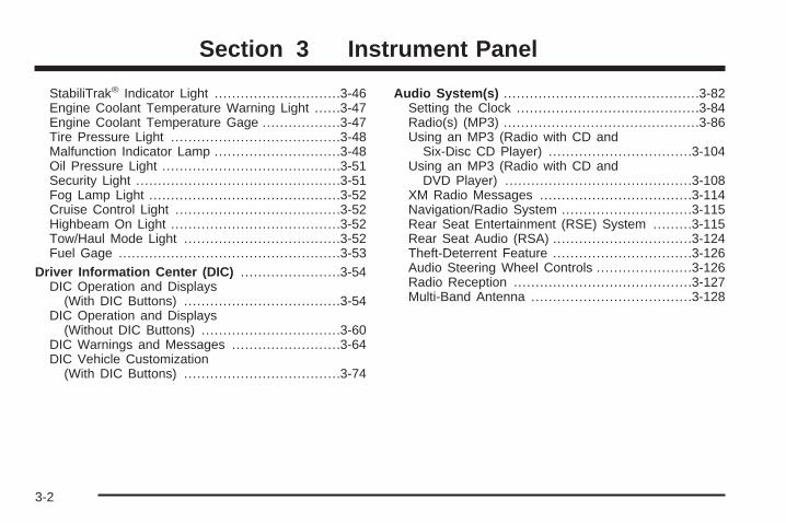
StabiliTrak® Indicator Light .............................3-46Engine Coolant Temperature Warning Light ......3-47Engine Coolant Temperature Gage ..................3-47Tire Pressure Light .......................................3-48Malfunction Indicator Lamp .............................3-48Oil Pressure Light .........................................3-51Security Light ...............................................3-51Fog Lamp Light ............................................3-52Cruise Control Light ......................................3-52Highbeam On Light .......................................3-52Tow/Haul Mode Light ....................................3-52Fuel Gage ...................................................3-53
Driver Information Center (DIC) .......................3-54DIC Operation and Displays
(With DIC Buttons) ....................................3-54DIC Operation and Displays
(Without DIC Buttons) ................................3-60DIC Warnings and Messages .........................3-64DIC Vehicle Customization
(With DIC Buttons) ....................................3-74
Audio System(s) .............................................3-82Setting the Clock ..........................................3-84Radio(s) (MP3) .............................................3-86Using an MP3 (Radio with CD and
Six-Disc CD Player) .................................3-104Using an MP3 (Radio with CD and
DVD Player) ...........................................3-108XM Radio Messages ...................................3-114Navigation/Radio System ..............................3-115Rear Seat Entertainment (RSE) System .........3-115Rear Seat Audio (RSA) ................................3-124Theft-Deterrent Feature ................................3-126Audio Steering Wheel Controls ......................3-126Radio Reception .........................................3-127Multi-Band Antenna .....................................3-128
Section 3 Instrument Panel
3-2

✍ NOTES
3-3

Instrument Panel Overview
3-4

The main components of your instrument panel are listed here:
A. Air Vent. See Outlet Adjustment on page 3-34.B. Multifunction Lever. See Turn Signal/Multifunction
Lever on page 3-8.
Windshield Wipers. See Turn Signal/MultifunctionLever on page 3-8.
C. Instrument Panel Cluster. See Instrument PanelCluster on page 3-38.
D. Driver Information Center (DIC) Buttons. See DriverInformation Center (DIC) on page 3-54.
E. Storage Area. See Instrument Panel Storage onpage 2-55.
F. Audio System. See Audio System(s) on page 3-82.Navigation/Radio System (If Equipped). SeeNavigation/Radio System on page 3-115.
G. Exterior Lamps Control. See Exterior Lamps onpage 3-15.
H. Hood Release. See Hood Release on page 5-11.
I. Dome Lamp Override Button. See Dome LampOverride on page 3-18. Instrument Panel BrightnessControl. See Instrument Panel Brightness onpage 3-17.
J. Cruise Control Buttons. See Cruise Control onpage 3-12.
K. Tilt and Telescopic Steering Wheel. See Tilt andTelescopic Steering Wheel on page 3-7. Power TiltWheel and Telescopic Steering (If Equipped).See Power Tilt Wheel and Telescopic SteeringColumn on page 3-8.
L. Horn. See Horn on page 3-7.M. Audio Steering Wheel Control Buttons. See Audio
Steering Wheel Controls on page 3-126.N. Hazard Warning Flasher Button. See Hazard
Warning Flashers on page 3-6.O. Center Console Shift Lever. See “Console Shift
Lever” under Shifting Into Park on page 2-35.
3-5

P. Rear Window Wiper/Washer. See Rear WindowWiper/Washer on page 3-11. Traction ControlSystem (TCS) Disable Button (If Equipped).See StabiliTrak® System on page 4-6. Tow/HaulSelector Button (If Equipped). See Tow/Haul Modeon page 2-33. Power Liftgate Button (If Equipped).See Power Liftgate on page 2-14.
Q. Accessory Power Outlets. See Accessory PowerOutlet(s) on page 3-21.
R. Heated Seats Button. See Heated Seats on page 1-5.S. Dual Automatic Climate Controls. See Dual
Automatic Climate Control System on page 3-26.T. Passenger Air Bag Status Indicator. See Passenger
Sensing System on page 1-73.U. Glove Box. See Glove Box on page 2-55.
Hazard Warning FlashersThe hazard warning flashers let you warn others.They also let police know you have a problem.The front and rear turn signal lamps will flash onand off.
The hazard warningflasher button is locatedin the center of theinstrument panel, belowthe audio system.
Press the button to make the front and rear turn signallamps flash on and off. Press the button again toturn the flashers off.
The hazard warning flashers work at all times. However,when they are on, the turn signals will not work.
3-6

Other Warning DevicesIf you carry reflective triangles, you can set them up atthe side of the road about 300 feet (100 m) behindyour vehicle.
HornPress near or on the horn symbols on the steeringwheel pad to sound the horn.
Tilt and Telescopic Steering WheelA tilt and telescope wheel lets the steering wheelbe adjusted.
The adjustment lever is located on the left side of thesteering column.
Pull the lever down to move the steering wheel up ordown and in or out. Pull the lever up to lock the steeringwheel in place.
Do not adjust the tilt and telescope lever while driving.
3-7
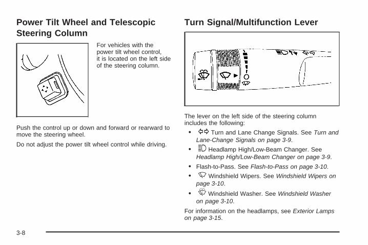
Power Tilt Wheel and TelescopicSteering Column
For vehicles with thepower tilt wheel control,it is located on the left sideof the steering column.
Push the control up or down and forward or rearward tomove the steering wheel.
Do not adjust the power tilt wheel control while driving.
Turn Signal/Multifunction Lever
The lever on the left side of the steering columnincludes the following:
• G Turn and Lane Change Signals. See Turn andLane-Change Signals on page 3-9.
• 3 Headlamp High/Low-Beam Changer. SeeHeadlamp High/Low-Beam Changer on page 3-9.
• Flash-to-Pass. See Flash-to-Pass on page 3-10.
• N Windshield Wipers. See Windshield Wipers onpage 3-10.
• L Windshield Washer. See Windshield Washeron page 3-10.
For information on the headlamps, see Exterior Lampson page 3-15.
3-8

Turn and Lane-Change SignalsThe turn signal has two upward (for right) andtwo downward (for left) positions. These positionsallow you to signal a turn or a lane change.
To signal a turn, move the lever all the way up ordown. When the turn is finished, the lever will returnautomatically.
An arrow on the instrumentpanel cluster will flash inthe direction of theturn or lane change.
To signal a lane change, raise or lower the lever untilthe arrow starts to flash. Hold it there until you completeyour lane change. The lever will return by itself whenyou release it. If you momentarily press and release thelever, the turn signal will flash three times.
If the arrow flashes faster than normal as you signal aturn or a lane change, a signal bulb may be burnedout and other drivers will not see your turn signal.
If a bulb is burned out, replace it to help avoid anaccident. If the arrows do not go on at all when yousignal a turn, check for burned-out bulbs and then checkthe fuse. See Fuses and Circuit Breakers onpage 5-111.
Turn Signal On ChimeIf either one of the turn signals are left on and you havedrove more than 3/4 mile (1.2 km), a chime will sound.
Headlamp High/Low-Beam ChangerTo change the headlamps from low beam to high beam,push the turn signal/multifunction lever toward thefront of the vehicle.
This light on the instrumentpanel cluster comes on ifthe high beam lampsare turned on while theignition is on.
To change the headlamps from high beam to low beam,pull the turn signal lever toward the rear of the vehicle.
3-9
Flash-to-PassWith the turn signal lever in the low-beam position,pull the lever toward you momentarily to switchto high-beam, to signal that you are going to pass.
If the headlamps are on, they will return to low-beamwhen the lever is released.
Windshield WipersThe windshield wiper/washer lever is located on theright side of the steering column.
Turn the band with the wiper symbol to control thewindshield wipers.
8 (Mist): Turn the band to mist for a single wipingcycle and then release. The wipers stop after one wipe.Hold the band on 8 longer, for more wipe cycles.
9 (Off): Turns the wipers off.
6 (Delay): Adjusts the delay time. The delay betweenwiping cycles becomes shorter as the band is moved tothe top of the lever.
1 (Low Speed): For steady wiping at low speed.
2 (High Speed): For steady wiping at high speed.
Clear ice and snow from the wiper blades before usingthem. If the blades are frozen to the windshield,gently loosen or thaw them. If they become damaged,install new blades or blade inserts. See WindshieldWiper Blade Replacement on page 5-48.
Heavy snow or ice can overload the wipers. A circuitbreaker stop them until the motor cools.
Windshield WasherJ (Washer Fluid): Press the button located at theend of the turn signal/multifunction lever, to spraywasher fluid on the windshield. The wipers clear thewindshield and either stop or return to the preset speed.The ignition key must be in ACC/ACCESSORY orON/RUN for this to work. See Windshield Washer Fluidon page 5-33 Windshield Washer Fluid.
{CAUTION:
In freezing weather, do not use your washeruntil the windshield is warmed. Otherwise thewasher fluid can form ice on the windshield,blocking your vision.
3-10

WASHER FLUID LOW ADD FLUID is displayed on theDriver Information Center (DIC) when the washerfluid is low. See DIC Warnings and Messages onpage 3-64.
Heated Windshield WasherFor vehicles with the heated windshield washer fluidsystem, it can be used to help clear ice, snow, tree sap,or bugs from the windshield. This feature only workswith the front wiper system.
The button is located tothe left of the steeringcolumn below theinstrument panelbrightness control knob.
Press the heated washer fluid button to activate theheated windshield washer fluid system. This activationbegins four heated wash/wipe cycles. The first heatedwash/wipe cycle can take up to 40 seconds to occur,depending on outside temperature. After the firstwash/wipe cycle, it can take up to 20 seconds foreach of the remaining cycles. The system turns offautomatically after four wipe cycles or the button can bepressed again to turn it off.
Under certain outside temperature conditions, steammight flow out of the washer nozzles for a short period oftime before washer fluid is sprayed. This is a normal.
WASHER FLUID LOW ADD FLUID is displayed on theDIC when the washer fluid is low. See DIC Warningsand Messages on page 3-64.
Rear Window Wiper/WasherThe rear wiper and rear wash button is located on theinstrument panel below the climate control system.
Z (Rear Wiper): Press to turn the rear wiper on andoff. The wiper speed cannot be changed.
Y (Wash): Press to spray washer fluid on the rearwindow. The window wiper will also come on. Releasethe button when enough fluid has been sprayed onthe window. The rear wiper will run a few more cyclesafter it is released. If the rear wiper function was alreadyon, prior to pressing the wash button, it stays on untilthe wiper button is pressed again.
The rear window washer uses the same fluid that is inthe windshield washer reservoir. See WindshieldWasher Fluid on page 5-33.
3-11

Cruise ControlWith cruise control, a speed of about 25 mph (40 km/h)or more can be maintained without keeping your footon the accelerator. This can really help on longtrips. Cruise control does not work at speeds belowabout 25 mph (40 km/h).
When the brakes are applied, cruise control isturned off.
{CAUTION:
Cruise control can be dangerous where youcannot drive safely at a steady speed. So, donot use your cruise control on winding roadsor in heavy traffic.
Cruise control can be dangerous on slipperyroads. On such roads, fast changes in tiretraction can cause excessive wheel slip, andyou could lose control. Do not use cruisecontrol on slippery roads.
The cruise control buttonsare located on left side ofthe steering wheel.
T (On/Off): Press to turn cruise control on and off.The indicator comes on when cruise control is on.
+ RES (Resume/Accelerate): Press to make thevehicle accelerate or resume to a previously set speed.
SET–: Press to set the speed or make the vehicledecelerate.
[ (Cancel): Press to cancel cruise control.
3-12

Setting Cruise ControlCruise control will not work if the parking brake is set, orif the master cylinder brake fluid level is low.
The cruise control light on the instrument panel clustercomes on after the cruise control has been set tothe desired speed.
{CAUTION:
If you leave your cruise control on when youare not using cruise, you might hit a buttonand go into cruise when you do not want to.You could be startled and even lose control.Keep the cruise control switch off until youwant to use cruise control.
1. Press the I button.
2. Get up to the speed desired.
3. Press and release the SET– button located on thesteering wheel.
4. Take your foot off the accelerator.
Resuming a Set SpeedIf the cruise control is set at a desired speed and thenthe brakes are applied, the cruise control shuts off. But itdoes not need to be reset.
Once the vehicle speed is 25 mph (40 km/h) orgreater, press the +RES button on the steering wheel.The vehicle returns to the previously set speed andstays there.
Increasing Speed While Using CruiseControlThere are two ways to increase the vehicle speed whileusing cruise control:
• Press and hold the +RES button on the steeringwheel until the desired speed is reached, thenrelease it.
• To increase vehicle speed in small increments,press the +RES button briefly. Each time this isdone, the vehicle will go about 1 mph (1.6 km/h)faster.
3-13

Reducing Speed While Using CruiseControlThere are two ways to reduce the vehicle speed whileusing cruise control:
• Press and hold the SET– button on the steeringwheel until the lower speed desired is reached,then release it.
• To slow down in very small amounts, press theSET– button briefly. Each time this is done,the vehicle will go about 1 mph (1.6 km/h)slower.
Passing Another Vehicle While UsingCruise ControlUse the accelerator pedal to increase vehicle speed.When you take your foot off the pedal, the vehiclewill slow down to the previously set cruise speed.
Using Cruise Control on HillsHow well the cruise control will work on hills dependsupon the vehicle speed, load, and the steepness of thehills. When going up steep hills, you might have tostep on the accelerator pedal to maintain the vehiclespeed. When going downhill, you might have to brake orshift to a lower gear to keep the vehicle speed down.When the brakes are applied the cruise control isturned off.
Ending Cruise ControlThere are three ways to end cruise control:
• Step lightly on the brake pedal.
• Press the [ button.
• Press the T button.
Erasing Speed MemoryThe cruise control set speed memory is erased whenthe cruise control or the ignition is turned off.
3-14

Exterior LampsThe exterior lamps controlis located on theinstrument panel to the leftof the steering wheel.
It controls the following systems:
• Headlamps
• Taillamps
• Parking Lamps
• License Plate Lamps
• Instrument Panel Lights
• Fog Lamps (If Equipped)
The exterior lamps control has four positions:
O (Off): Turns the automatic light control on or off.
AUTO (Automatic): Automatically turns on theheadlamps at normal brightness, together with thefollowing:
• Parking Lamps• Taillamps
• License Plate Lamps
• Instrument Panel Lights
; (Parking Lamps): Turns on the parking lampstogether with the following:
• Taillamps
• License Plate Lamps
• Instrument Panel Lights
2 (Headlamps): Turns on the headlamps togetherwith the following lamps listed below. A warning chimewill sound if the driver’s door is opened when theignition switch is off and the headlamps are on.
• Parking Lamps
• Taillamps
• License Plate Lamps
• Instrument Panel Lights
- (Fog Lamps) (If Equipped): Turns on thefog lamps.
See Fog Lamps on page 3-17.
3-15

Delayed HeadlampsThe delayed headlamps feature provides a period ofexterior lighting as you leave the area around yourvehicle. The feature is activated when the headlampsare on due to the automatic headlamps controlfeature described previously in this section, and whenthe ignition is turned off. Your headlamps will thenremain on until the exterior lamps control is moved tothe parking lamps position or until the pre-selecteddelayed headlamp lighting period has ended.
If you turn off the ignition with the headlamps switch inthe parking lamps or headlamps position, the delayedheadlamps cycle will not occur.
To disable the delayed headlamps feature or changethe time of delay, see DIC Vehicle Customization(With DIC Buttons) on page 3-74.
Daytime Running Lamps (DRL)/Automatic Headlamp SystemDaytime Running Lamps (DRL) can make it easier forothers to see the front of your vehicle during the day.Fully functional daytime running lamps are required onall vehicles first sold in Canada.
The DRL system makes the low-beam headlamps comeon at a reduced brightness when the following conditionsare met:
• The ignition is in the ON/RUN position.
• The exterior lamps control is in AUTO.
• The engine is running.
When the DRL are on, the regular headlamps,taillamps, sidemarker, and other lamps will not be on.The instrument panel and cluster will also not be lit.
The headlamps automatically change from DRL to theregular headlamps depending on the darkness ofthe surroundings. The other lamps that come on withthe headlamps will also come on.
3-16

When it is bright enough outside, the headlamps will gooff and the DRL will come on.
The regular headlamp system should be turned onwhen needed.
Do not cover the light sensor on top of the instrumentpanel because it operates the DRL.
Fog Lamps- (Fog Lamps): For vehicles with fog lamps,the button is located on the exterior lamps control.The exterior lamps control is located on the instrumentpanel to the left of the steering column.
The ignition must be in the ON/RUN position for thefog lamps to come on.
Press - to turn the fog lamps on or off. A light willcome on in the instrument panel cluster.
When the headlamps are changed to high-beam,the fog lamps also go off.
Some localities have laws that require the headlamps tobe on along with the fog lamps.
Instrument Panel BrightnessD (Instrument Panel Brightness): The knob with thissymbol on it is located next to the exterior lampscontrol to the left of the steering wheel. Push the knobin all the way until it extends out and then turn theknob clockwise or counterclockwise to brighten or dimthe lights. Push the knob back in when finished.
Courtesy LampsWhen a door is opened, the courtesy lampsautomatically come on. They make it easy for you toenter and leave your vehicle. You can also manuallyturn these lamps on by fully turning the instrument panelbrightness control clockwise.
The reading lamps, located on the headliner above therearview mirror, can be turned on or off independentof the automatic courtesy lamps, when the doorsare closed.
3-17
Dome LampsThe dome lamps automatically come on when a door isopened, unless the dome lamp override button ispressed in.
The lamps can also be turned on and off by turning theinstrument panel brightness control clockwise to thefarthest position.
Dome Lamp OverrideThe dome lamp override button is located next to theexterior lamps control.
The dome lamp override sets the dome lamps to remainoff or come on automatically when a door is opened.
E (Dome Lamp Override): Press the button inand the dome lamps remain off when a door is opened.Press the button again to return it to the extendedposition so that the dome lamps come on when a dooris opened.
Entry LightingFor vehicles with courtesy lamps, they come on andstay on for a set time whenever the unlock symbolis pressed on the Remote Keyless Entry (RKE)Transmitter, if the vehicle has one.
If a door is opened, the lamps stay on while it is openand then turn off automatically about 25 secondsafter the door is closed. If the unlock symbol is pressedand no door is opened, the lamps turn off after about20 seconds.
Entry lighting includes a feature called theater dimming.With theater dimming, the lamps do not turn off atthe end of the delay time. Instead, they slowly dim afterthe delay time until they go out. The delay time iscanceled if the ignition key is turned to ON/RUN or thepower door lock switch is pressed. The lamps willdim right away.
When the ignition is on, illuminated entry is inactive,which means the courtesy lamps will not come on unlessa door is opened.
3-18

Delayed Entry LightingDelayed entry lighting illuminates the interior for aperiod of time after all the doors have been closed.
The ignition must be off for delayed entry lightingto work. Immediately after all the doors have beenclosed, the delayed entry lighting feature will continue towork until one of the following occurs:
• The ignition is in ON/RUN.
• The doors are locked.
• An illumination period of 25 seconds has elapsed.
If during the illumination period a door is opened,the timed illumination period will be canceled and theinterior lamps will remain on because a door is open.
Delayed Exit LightingThis feature illuminates the interior for a period of timeafter the key is removed from the ignition.
The ignition must be off for delayed exit lighting to work.When the key is removed, interior illumination willactivate and remain on until one of the following occurs:
• The ignition is in ON/RUN.
• The power door locks are activated.
• An illumination period of 20 seconds has elapsed.
If during the illumination period a door is opened,the timed illumination period will be canceled and theinterior lamps will remain on because a door is open.
Parade DimmingParade mode automatically prohibits the dimming of theinstrument panel displays during the daylight whilethe headlamps are on so that the displays are still ableto be seen.
3-19

Reading LampsThe vehicle has reading lamps that also act as thedome lamp. Press the button to turn them on and off.
Electric Power ManagementThe vehicle has Electric Power Management (EPM) thatestimates the battery’s temperature and state ofcharge. It then adjusts the voltage for best performanceand extended life of the battery.
When the battery’s state of charge is low, the voltage israised slightly to quickly put the charge back in. Whenthe state of charge is high, the voltage is lowered slightlyto prevent overcharging. If the vehicle has a voltmetergage or a voltage display on the Driver InformationCenter (DIC), you may see the voltage move upor down. This is normal. If there is a problem, an alertwill be displayed.
The battery can be discharged at idle if the electricalloads are very high. This is true for all vehicles.This is because the generator (alternator) may not bespinning fast enough at idle to produce all the power thatis needed for very high electrical loads.
A high electrical load occurs when several of thefollowing loads are on: headlamps, high beams, foglamps, rear window defogger, climate control fan at highspeed, heated seats, engine cooling fans, trailerloads, and loads plugged into accessory power outlets.
EPM works to prevent excessive discharge of thebattery. It does this by balancing the generator’s outputand the vehicle’s electrical needs. It can increaseengine idle speed to generate more power, wheneverneeded. It can temporarily reduce the power demands ofsome accessories.
Normally, these actions occur in steps or levels, withoutbeing noticeable. In rare cases at the highest levelsof corrective action, this action may be noticeable tothe driver. If so, a Driver Information Center (DIC)message might be displayed, such as Battery SaverActive or Service Battery Charging System. If thismessage is displayed, it is recommended that the driverreduce the electrical loads as much as possible.See DIC Warnings and Messages on page 3-64.
3-20

Battery Run-Down ProtectionThis vehicle has a feature to help prevent the batteryfrom being drained, if the interior courtesy lamps,reading/map lamps, visor vanity lamps or trunk lamp areaccidentally left on. If any of these lamps are left on,they automatically turn off after 10 minutes, if the ignitionis off. The lamps will not come back on again untilone of the following occurs:
• The ignition is turned on.
• The exterior lamps control is turned off, then onagain.
The headlamps will timeout after 10 minutes, if they aremanually turned on before the ignition is off.
Accessory Power Outlet(s)Accessory power outlets let you plug in auxiliaryelectrical equipment, such as a cellular phone.
The vehicle may have four accessory power outlets.They are located on the instrument panel belowthe climate controls, inside the front center consolestorage bin, at the rear of the center console, and in therear cargo area.
To use the outlets, remove the cover. When not in use,always cover the outlet with the protective cap.
Notice: Leaving electrical equipment on forextended periods will drain the battery. Always turnoff electrical equipment when not in use and donot plug in equipment that exceeds the maximumamperage rating of 20 amperes.
Certain electrical accessories may not be compatiblewith the accessory power outlets and could resultin blown vehicle or adapter fuses. If you experience aproblem, see your dealer/retailer for additionalinformation on the accessory power outlet.
Notice: Adding any electrical equipment to thevehicle can damage it or keep other componentsfrom working as they should. The repairs would notbe covered by the vehicle warranty. Do not useequipment exceeding maximum amperage rating of20 amperes. Check with your dealer/retailer beforeadding electrical equipment.
When adding electrical equipment, be sure to follow theinstallation instructions included with the equipment.
Notice: Improper use of the power outlet can causedamage not covered by your warranty. Do nothang any type of accessory or accessory bracketfrom the plug because the power outlets aredesigned for accessory power plugs only.
3-21
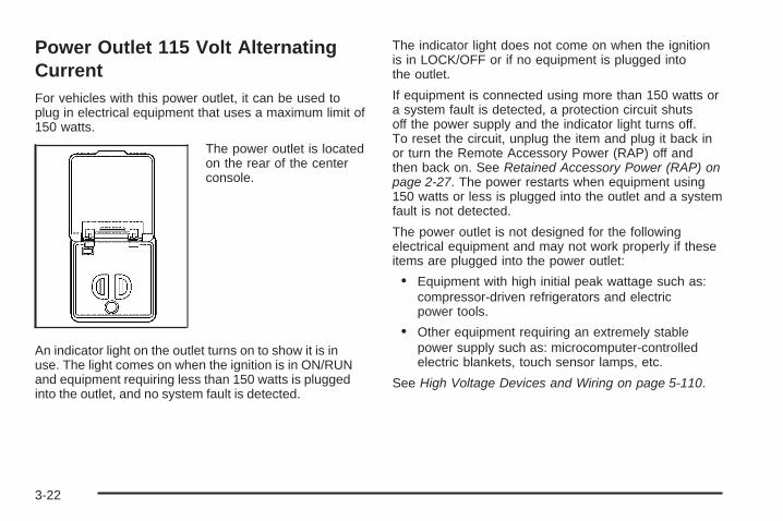
Power Outlet 115 Volt AlternatingCurrentFor vehicles with this power outlet, it can be used toplug in electrical equipment that uses a maximum limit of150 watts.
The power outlet is locatedon the rear of the centerconsole.
An indicator light on the outlet turns on to show it is inuse. The light comes on when the ignition is in ON/RUNand equipment requiring less than 150 watts is pluggedinto the outlet, and no system fault is detected.
The indicator light does not come on when the ignitionis in LOCK/OFF or if no equipment is plugged intothe outlet.
If equipment is connected using more than 150 watts ora system fault is detected, a protection circuit shutsoff the power supply and the indicator light turns off.To reset the circuit, unplug the item and plug it back inor turn the Remote Accessory Power (RAP) off andthen back on. See Retained Accessory Power (RAP) onpage 2-27. The power restarts when equipment using150 watts or less is plugged into the outlet and a systemfault is not detected.
The power outlet is not designed for the followingelectrical equipment and may not work properly if theseitems are plugged into the power outlet:
• Equipment with high initial peak wattage such as:compressor-driven refrigerators and electricpower tools.
• Other equipment requiring an extremely stablepower supply such as: microcomputer-controlledelectric blankets, touch sensor lamps, etc.
See High Voltage Devices and Wiring on page 5-110.
3-22

Climate Controls
Climate Control SystemWith this system you can control the heating, cooling,defrost, defog, and ventilation of the vehicle.
Manual Operation9 (Fan): Turn the left knob clockwise orcounterclockwise to increase or decrease the fan speed.Turn the knob all the way counterclockwise to turn thefront system off.
Temperature Control: Turn the center knob clockwiseor counterclockwise to increase or decrease thetemperature of the air flowing from the system.
Airflow Mode Control: Turn the right knob clockwiseor counterclockwise to direct the airflow inside ofthe vehicle.
To change the current mode, select one of the following:
H (Vent): This mode directs air to the instrumentpanel outlets.
) (Bi-Level): This mode directs about half of theair to the instrument panel outlets and half to the flooroutlets. A little air is directed towards the windshieldand side window outlets. Cooler air is directed tothe upper outlets and warmer air to the floor outlets.
6 (Floor): This mode directs most of the air to the flooroutlets, with some of the air directed to the windshield,side window outlets, and second row floor outlets.In this mode, the system automatically selectsoutside air. Recirculation cannot be selected when inFloor Mode.
The right knob can also be used to select defog ordefrost mode. For more information, see “Defoggingand Defrosting” later in this section.
By positioning the right knob between two modes,a combination of those two modes is selected.
3-23

@ (Recirculation): Press this button to turn therecirculation mode on or off. The indicator light on thebutton turns on when this mode is selected.
This mode keeps outside air from entering the vehicle.It can be used to reduce the outside air and odorsentering the vehicle. Recirculation may also help coolthe air inside the vehicle more quickly once thetemperature inside the vehicle is less than the outsidetemperature.
The recirculation mode can be turned off in vent andbi-level modes by pressing the button again.Recirculation mode automatically turns off when theengine is turned off and must be re-selected when theengine is turned on again.
The recirculation mode cannot be used with floor, defrost,or defogging modes. If you try to select recirculation inone of those modes, the indicator flashes three times andturns off. The air conditioning compressor also comes onwhen this mode is activated unless the outside airtemperature is less than 40°F (4°C). While in recirculationmode the windows may fog when the weather is cold anddamp. To clear the fog, select either the defog or defrostmode and increase the fan speed.
# (Air Conditioning): Press this button on the leftknob to turn the air conditioning system on or off.When A/C is pressed, an indicator light comes on toshow that the air conditioning has been activated.The air conditioning compressor does not operatewhen outside temperatures fall below 40°F (4°C).The indicator light flashes three times and turns off whenoutside conditions affect air conditioning operation.This is normal.
For quicker cool down on hot days, do the following:
1. Open the windows to let hot air escape.
2. Select the vent mode.
3. Select the air conditioner.
4. Select the coolest temperature.
5. Select the highest fan speed.
6. Close the windows after the hot air has escaped.
7. Once the vehicle’s interior temperature is below theoutside temperature, select recirculation mode forbetter cooling.
This helps to reduce the time it takes for the vehicle tocool down. It also helps the system to operate moreefficiently.
3-24

Using recirculation for long periods of time may causethe air inside of the vehicle to become too dry. Toprevent this from happening, after the inside of thevehicle has cooled, turn the recirculation mode off.
The air conditioning system removes moisture from theair, so you might notice a small amount of waterdripping underneath the front center and right rear ofthe vehicle while idling or after turning off the engine.This is normal.
Defogging and DefrostingFog on the inside of the windows is a result of highhumidity (moisture) condensing on the cool windowglass. This can be minimized if the climate controlsystem is used properly. There are two modes to clearfog or frost from the windshield. Turn the right knobclockwise to select the defog or defrost mode.
- (Defog): The defog mode is used to clear thewindows of fog or moisture and warm the passengers.This mode directs air to the windshield, floor outlets,and side window vents. When you select this mode,
the system turns off recirculation and runs the airconditioning compressor unless the outside temperatureis less than 40°F (4°C). The recirculation modecannot be selected while in the defog mode. Do notdrive the vehicle until all the windows are clear.
0 (Defrost): The defrost mode is used to remove fogor frost from the windshield more quickly. This modedirects most of the air to the windshield and side windowvents and some to the floor vents. In this mode, thesystem will automatically force outside air into yourvehicle. The recirculation mode cannot be selected whilein the defrost mode. The air conditioning compressorwill run automatically in this setting, unless the outsidetemperature is less than 40°F (4°C). Do not drivethe vehicle until all the windows are clear.
AUX (Auxiliary): Press this button to turn the rearheating and air conditioning on. See Rear AirConditioning and Heating System on page 3-34 orRear Air Conditioning and Heating System andElectronic Climate Controls on page 3-36.
3-25
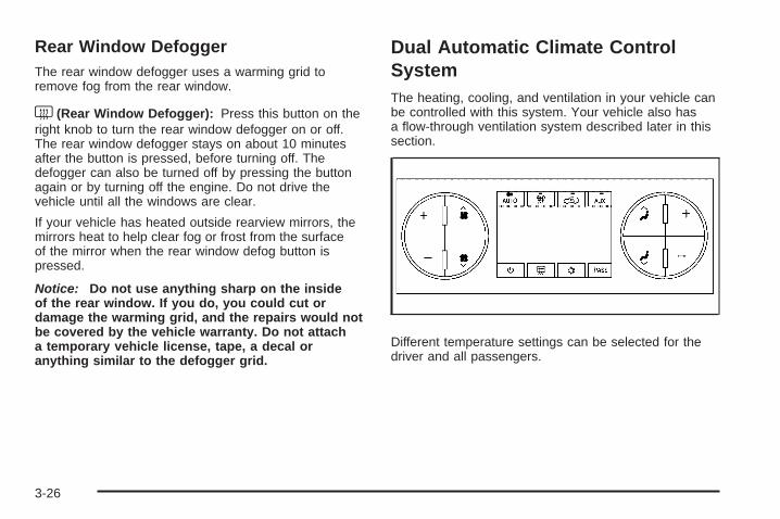
Rear Window DefoggerThe rear window defogger uses a warming grid toremove fog from the rear window.
< (Rear Window Defogger): Press this button on theright knob to turn the rear window defogger on or off.The rear window defogger stays on about 10 minutesafter the button is pressed, before turning off. Thedefogger can also be turned off by pressing the buttonagain or by turning off the engine. Do not drive thevehicle until all the windows are clear.
If your vehicle has heated outside rearview mirrors, themirrors heat to help clear fog or frost from the surfaceof the mirror when the rear window defog button ispressed.
Notice: Do not use anything sharp on the insideof the rear window. If you do, you could cut ordamage the warming grid, and the repairs would notbe covered by the vehicle warranty. Do not attacha temporary vehicle license, tape, a decal oranything similar to the defogger grid.
Dual Automatic Climate ControlSystemThe heating, cooling, and ventilation in your vehicle canbe controlled with this system. Your vehicle also hasa flow-through ventilation system described later in thissection.
Different temperature settings can be selected for thedriver and all passengers.
3-26

Display FunctionEach time the temperature, mode, or fan control buttonsare pressed, the climate control display shows thatfunction along with the inside temperature setting.The outside temperature is displayed on the instrumentpanel cluster.
Driver’s Side Temperature ControlThe driver side temperature buttons are used to adjustthe temperature of the air coming through the systemon the driver side. The temperature can be adjustedeven if the system is turned off. This is possible sinceoutside air will always flow through the system asthe vehicle is moving forward unless it is set torecirculation mode. See “Recirculation” later in thissection.
Press the + or − buttons to increase or decrease thetemperature. The driver side temperature displaywill show the temperature setting decreasing orincreasing.
Passenger’s Side Temperature ControlThe passenger’s temperature buttons can be used tochange the temperature of the air coming throughthe system on the passenger side of the vehicle.The temperature can be adjusted even if the systemis turned off. This is possible since outside air will alwaysflow through the system as the vehicle is movingforward unless it is set to recirculation mode.See “Recirculation” later in this section.
Press the + or − buttons to increase or decrease thetemperature. The passenger side display will show thetemperature setting decreasing or increasing.
The passenger’s temperature setting can be set tomatch the driver’s temperature setting by pressing thePASS button and turning off the PASS indicator.When the passenger’s temperature setting is setdifferent than the driver’s setting, the indicator on thePASS button comes on and both the driver sideand passenger side temperature displays are shown.
3-27

Automatic Operation
AUTO (Automatic): When automatic operation isactive the system controls the inside temperature,the air delivery, and the fan speed.
Use the steps below to place the entire system inautomatic mode:
1. Press the AUTO button.When AUTO is selected, the display shows thecurrent temperature(s) selected and AUTO is on thedisplay. The current delivery mode and fan speedalso display for approximately 5 seconds.When AUTO is selected, the air conditioningoperation and air inlet are automatically controlled.The air conditioning compressor runs when theoutside temperature is over about 40°F (4°C).The air inlet is normally set to outside air. If it is hotoutside, the air inlet can automatically switch torecirculate inside air to help quickly cool down yourvehicle. The light comes on the recirculationbutton while in recirculation.
2. Set the driver’s and passenger’s temperature.To find your comfort setting, start with a 73°F (22°C)temperature setting and allow about 20 minutesfor the system to regulate. Use the driver’s orpassenger’s temperature buttons to adjust thetemperature setting as necessary. If you choosethe temperature setting of 60°F (15°C), the systemremains at the maximum cooling setting. If youchoose the temperature setting of 90°F (32°C),the system remains at the maximum heat setting.Choosing either maximum setting will not cause thevehicle to heat or cool any faster.
Do not cover the solar sensor located on the top of theinstrument panel near the windshield. This sensorregulates air temperature based on sun load and alsoturns on your vehicle’s headlamps. For more informationon the solar sensor, see “Sensors” later in this section.
3-28

To avoid blowing cold air in cold weather, the systemdelays turning on the fan until warm air is available.The length of delay depends on the engine coolanttemperature. Press the fan switch to override this delayand change the fan to a selected speed.
O (On/Off): Press this button to turn off the climatecontrol system. Outside air still enters the vehicle, and isdirected to the floor. This direction can be changed bypressing the mode button. Recirculation can onlybe selected in vent or bi-level mode. The temperaturecan also be adjusted using either temperature button.If you adjust the air delivery mode or temperaturesettings with the system off, the display comes on brieflyto show the settings and then turns off. Press theon/off button or the up down arrows on the fan switch,the defrost button, AUTO button, or the air conditioningbutton to turn the system on when it is off.
Manual OperationThe air delivery mode or fan speed can be manuallyadjusted.
D C (Fan): The buttons with the fan symbols let youmanually adjust the fan speed. Press the up arrowto increase fan speed and the down arrow to decreasefan speed.
Pressing a fan button while the system is off will turnthe system on. Pressing a fan button while in automaticcontrol places the fan under manual control. The fansetting remains displayed, the word AUTO is no longerdisplayed, and the AUTO button indicator light turnsoff. The air delivery mode remains in automatic control.
yN z (Mode): Press the mode up and downbuttons to manually change the direction of the airflowin the vehicle. Repeatedly press the button until thedesired mode appears on the display. Pressing a modebutton while the system is off will change air deliverymode without turning the system on. Pressing oneof these buttons while in automatic control to place themode under manual control.
3-29

The air delivery mode setting remains displayed, theword AUTO is no longer displayed, and the AUTObutton indicator light turns off.
H (Vent): This setting delivers air to the instrumentpanel outlets.
) (Bi-Level): This mode directs air to the instrumentpanel outlets and to the floor outlets. A little air isdirected towards the windshield and side window outlets.Cooler air is directed to the upper outlets and warmerair to the floor outlets.
6 (Floor): This mode directs most of the air to thefloor outlets, with some of the air directed to thewindshield, side window outlets, and second row flooroutlets. In this mode, the system automaticallyselects outside air. Recirculation cannot be selectedin floor mode.
- (Defog): See “Defogging and Defrosting” later inthis section.
@ (Recirculation): Press this button to turn therecirculation mode on. When the button is pressed,an indicator light comes on.
This mode keeps outside air from entering the vehicle.It can be used to reduce outside air and preventodors from entering your vehicle. Recirculation alsohelps to quickly cool the warmer air inside your vehicle.
The recirculation mode cannot be used with floor,defrost, or defogging modes. If you try to selectrecirculation in one of those modes, the indicatorflashes three times and turns off. The air conditioningcompressor also comes on when this mode is activated.While in recirculation mode the windows may fogwhen the weather is cold and damp. To clear the fog,select either the defog or defrost mode and increasethe fan speed.
Press the button again to turn off the recirculationmode. It automatically turns off when the engine isturned off and must be re-selected when the engine isturned on again.
3-30

Air Conditioning
# (Air Conditioning): Press this button to turn the airconditioning (A/C) compressor on and off. When airconditioning is selected, an indicator light comes on toshow that the air conditioning has been activated.
The air conditioning compressor does not work whenoutside temperatures fall below 40°F (4°C). Pressing thisbutton when the outside temperature is too cool makesthe air conditioning indicator flash three times andturn off to let you know the air conditioning mode is notavailable. If the air conditioning is on and the outsidetemperature drops below a temperature which istoo cool for air conditioning to be effective, the airconditioning light turns off to show that the airconditioning mode has been canceled.
On hot days, open the windows long enough to let hotinside air escape. This helps to reduce the time ittakes for the vehicle to cool down. It also helps thesystem to operate more efficiently.
The air conditioning system removes moisture from theair, so a small amount of water may drip underneathyour vehicle while idling or after turning off the engine.This is normal.
Sensors
The solar sensor, located in the defrost grille in themiddle of the instrument panel, monitors the solarradiation. Do not cover the solar sensor or the systemwill not work properly.
3-31
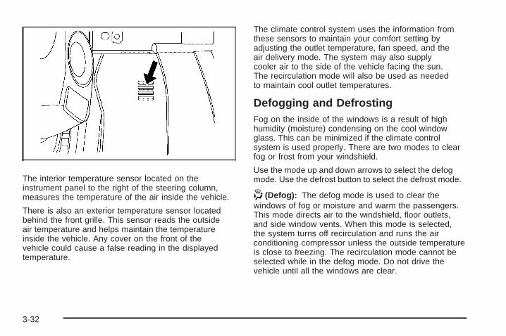
The interior temperature sensor located on theinstrument panel to the right of the steering column,measures the temperature of the air inside the vehicle.
There is also an exterior temperature sensor locatedbehind the front grille. This sensor reads the outsideair temperature and helps maintain the temperatureinside the vehicle. Any cover on the front of thevehicle could cause a false reading in the displayedtemperature.
The climate control system uses the information fromthese sensors to maintain your comfort setting byadjusting the outlet temperature, fan speed, and theair delivery mode. The system may also supplycooler air to the side of the vehicle facing the sun.The recirculation mode will also be used as neededto maintain cool outlet temperatures.
Defogging and DefrostingFog on the inside of the windows is a result of highhumidity (moisture) condensing on the cool windowglass. This can be minimized if the climate controlsystem is used properly. There are two modes to clearfog or frost from your windshield.
Use the mode up and down arrows to select the defogmode. Use the defrost button to select the defrost mode.
- (Defog): The defog mode is used to clear thewindows of fog or moisture and warm the passengers.This mode directs air to the windshield, floor outlets,and side window vents. When this mode is selected,the system turns off recirculation and runs the airconditioning compressor unless the outside temperatureis close to freezing. The recirculation mode cannot beselected while in the defog mode. Do not drive thevehicle until all the windows are clear.
3-32

To clear fog from the rear seat side windows, select thebi-level mode on the rear climate control system anddirect the headliner outlets toward the side windows.
0 (Defrost): Press this button to remove fog or frostfrom the windshield more quickly. This mode directsmost of the air to the windshield and side window ventsand some to the floor vents. In this mode, the systemautomatically forces outside air into the vehicle.The recirculation mode cannot be selected while in thedefrost mode. The air conditioning compressor runsautomatically in this setting, unless the outsidetemperature is close to freezing. Do not drive thevehicle until all the windows are clear.
While in defrost mode, if the PASS button is pressed,the PASS button indicator will flash three times to let youknow that the passenger climate control systemcannot be activated. If the passenger temperaturebuttons are adjusted while in defrost mode, the drivertemperature indicator will change. The passengertemperature will not be displayed.
AUX (Auxiliary): Press this button to turn the rearheating and air conditioning on. See Rear AirConditioning and Heating System on page 3-34 orRear Air Conditioning and Heating System andElectronic Climate Controls on page 3-36.
Rear Window DefoggerThe rear window defogger uses a warming grid toremove fog from the rear window.
< (Rear Window Defogger): Press this button toturn the rear window defogger on or off. The rearwindow defogger stays on for about 10 minutes afterthe button is pressed, before turning off. The defoggercan also be turned off by pressing the button again or byturning off the engine. Do not drive the vehicle until allthe windows are clear.
If your vehicle has heated outside rearview mirrors,the mirrors will heat to help clear fog or frost from thesurface of the mirror when the rear window defog buttonis pressed.
Notice: Do not use a razor blade or sharp objectto clear the inside rear window. Do not adhereanything to the defogger grid lines in the rear glass.These actions may damage the rear defogger.Repairs would not be covered by your warranty.
3-33

Outlet AdjustmentUse the slider switch in the center of the outlet, tochange the direction of the air flow. Use the thumbwheelnear the outlet to control the amount of air flow or toshut off the airflow completely.
Keep all outlets open whenever possible for bestsystem performance.
Operation Tips• Clear away any ice, snow, or leaves from the air
inlets at the base of the windshield that canblock the flow of air into the vehicle.
• Use of non-GM approved hood deflectors canadversely affect the performance of the system.
• Keep the path under all seats clear of objects tohelp circulate the air inside the vehicle moreeffectively.
• If fogging reoccurs while in vent or bi-level modeswith mild temperature throughout the vehicle, turnon the air conditioner to reduce windshield fogging.
Rear Air Conditioning andHeating SystemIf your vehicle has this system, the rear controls arethree knobs located on the rear of the center console.The system can be controlled from the front controlsas well as the rear controls.
To turn the system on, press the AUX button on thefront climate control system, an indicator will belit. Pressing the AUX button the first time will turn therear system on in a mimic mode. In this mode, theairflow in the rear will be approximately the samedirection, temperature, and fan speed as the front.Pressing the AUX button again will turn the rear systemand the indicator off.
If the rear controls are adjusted, the system turns on ina rear independent mode. Airflow in the rear willthen be directed according to the settings of the rearcontrols. The rear system can be turned off by pressingthe AUX button on the front climate control systemand the indicator will turn off. The system can be turnedback on, by adjusting any of the rear air conditioningcontrol knobs.
3-34

Fan KnobTurn the left knob clockwise or counterclockwise toincrease or decrease the fan speed. Turn the knob allthe way counterclockwise to turn the rear system off.
Temperature KnobThe middle knob on the control panel lets you select thetemperature of the air flowing into the passengerarea. Turn the knob clockwise or counterclockwise forwarmer or cooler air.
Mode KnobThe right knob on the control panel lets you choose thedirection of the air flow.
H (Vent): This setting directs the air through theheadliner outlets.
) (Bi-Level): This setting directs the air through therear floor outlets under the third row seat, as well as theheadliner outlets. The flow can be divided betweenheadliner and floor outlets depending upon where theknob is placed between the settings.
6 (Floor): This setting directs the air through the flooroutlets. The rear system floor outlets are locatedunder the third row seats.
3-35

Rear Air Conditioning and HeatingSystem and Electronic ClimateControlsIf your vehicle has this rear climate control systemthere are rear seat audio controls located in thecenter console.
The rear system can be controlled through the AUXbutton on the front climate control panel. Press theAUX button to turn the rear climate control system onor off. An indicator light in the AUX button comeson when the rear climate control system is on.The direction, temperature, and speed of the airflowfor the rear of the vehicle will be the same as thoseset for the front of the vehicle.
Use the controls located in the rear of the front console,to independently control the air flow for the rear ofthe vehicle separately from that of the front of thevehicle. To turn the system on, press any of the rearair conditioning control buttons, except the C button.To turn the system off, press and hold the C button.
Manual Operation
D C (Fan): The fan buttons on the rear seat audiocontrol panel let you manually adjust the fan speed.Press D to increase airflow and C to decrease airflow.
Rear Climate Control with Rear Seat Audio Controls
3-36

+/− (Increase/Decrease Temperature): These buttonsselect the temperature of the air flowing into the rearpassenger area. Press the + button for warmer air andpress the − button for cooler air. The temperature settingswill display in 0-12 increments, going from the coolest (0)to the warmest (12) setting.
N (Mode): Press the mode button to manually changethe direction of the airflow in the vehicle. Repeatedlypress the button until the desired mode appears on thedisplay. Multiple presses cycles through the deliveryselections.
H (Vent): This mode directs air through the headlineroutlets.
) (Bi-Level): This mode directs air through the flooroutlets as well as the headliner outlets. The rear systemfloor outlets are located under the third row seats.
6 (Floor): This mode directs air through the flooroutlets. The rear system floor outlets are located underthe third row seats.
Warning Lights, Gages, andIndicatorsThis section describes the warning lights and gages onthe vehicle.
Warning lights and gages can signal that something iswrong before it becomes serious enough to causean expensive repair or replacement. Paying attention tothe warning lights and gages could prevent injury.
Warning lights come on when there may be or is aproblem with one of the vehicle’s functions. Somewarning lights come on briefly when the engine is startedto indicate they are working.
Gages can indicate when there may be or is a problemwith one of the vehicle’s functions. Often gages andwarning lights work together to indicate a problem withthe vehicle.
When one of the warning lights comes on and stays onwhile driving, or when one of the gages shows theremay be a problem, check the section that explainswhat to do. Follow this manual’s advice. Waiting to dorepairs can be costly and even dangerous.
3-37

Instrument Panel ClusterThe instrument cluster is designed to let you know at a glance how the vehicle is running. You will know how fastyou are going, about how much fuel you have used, and many other things you will need to know to drive safely andeconomically.
United States version shown, Canada similar
3-38

Speedometer and OdometerThe speedometer lets you see your speed in both milesper hour (mph) and kilometers per hour (km/h).
The odometer shows how far your vehicle has beendriven, in either miles or kilometers.
Your vehicle has a tamper-resistant odometer. If yourvehicle needs a new odometer installed, the newone will be set to the mileage total of the old odometer.If this is not possible, it will be set at zero and alabel must be put on the driver’s door to show the oldmileage reading when the new odometer was installed.If the mileage is unknown, the label should thenindicate “previous mileage unknown”.
TachometerThe tachometer displays the engine speed in revolutionsper minute (rpm).
Safety Belt Reminders
Safety Belt Reminder LightWhen the engine is started, a chime comes on forseveral seconds to remind people to fasten their safetybelts, unless the driver’s safety belt is already buckled.
The safety belt light willalso come on and stay onfor several seconds,then it will flash forseveral more.
This chime and light is repeated if the driver remainsunbuckled and the vehicle is in motion. If the driver’s beltis already buckled, neither the chime nor the light willcome on.
3-39

Passenger Safety Belt Reminder LightSeveral seconds after the engine is started, a chimesounds for several seconds to remind the frontpassenger to buckle their safety belt. This would onlyoccur if the passenger airbag is enabled. See PassengerSensing System on page 1-73 for more information.The passenger safety belt light, located on theinstrument panel, will come on and stay on forseveral seconds and then flash for several more.
This chime and light arerepeated if the passengerremains unbuckled andthe vehicle is in motion.
If the passenger safety belt is buckled, neither thechime nor the light comes on.
Airbag Readiness LightThere is an airbag readiness light on the instrumentpanel cluster, which shows the airbag symbol.The system checks the airbag’s electrical system formalfunctions. The light indicates if there is an electricalproblem. The system check includes the airbagsensor, the pretensioners, the airbag modules, thewiring and the crash sensing and diagnostic module.For more information on the airbag system, see AirbagSystem on page 1-64.
This light comes on whenthe vehicle is started, andflashes for a few seconds.The light should go outwhen the system is ready.
If the airbag readiness light stays on after the vehicle isstarted or comes on while driving, the airbag systemmay not work properly. Have your vehicle servicedright away.
3-40

{CAUTION:
If the airbag readiness light stays on after youstart your vehicle, it means the airbag systemmay not be working properly. The airbags inyour vehicle may not inflate in a crash, or theycould even inflate without a crash. To helpavoid injury to yourself or others, have yourvehicle serviced right away.
The airbag readiness light should flash for a few secondswhen the engine is started. If the light does not come onthen, have it fixed immediately. If there is a problem withthe airbag system, an airbag Driver Information Center(DIC) message may also come on. See DIC Warningsand Messages on page 3-64 for more information.
Passenger Airbag Status IndicatorYour vehicle has the passenger sensing system.Your instrument panel has a passenger airbag statusindicator.
When you start the vehicle, the passenger airbag statusindicator will light ON and OFF, or the symbol for onand off, for several seconds as a system check. If youuse remote start to start your vehicle from a distance,if equipped, you may not see the system check.Then, after several more seconds, the status indicatorwill light either ON or OFF, or either the on or off symbolto let you know the status of the right front passenger’sfrontal and seat-mounted side impact airbags.
United States Canada
3-41

If the word ON or the on symbol is lit on the passengerairbag status indicator, it means that the right frontpassenger’s frontal airbag and seat-mounted side impactairbag are enabled (may inflate).
{CAUTION:
If the on indicator comes on when you have arear-facing child restraint installed in the rightfront passenger’s seat, it means that thepassenger sensing system has not turnedoff the passenger’s frontal airbag andseat-mounted side impact airbag (if equipped).A child in a rear-facing child restraint can beseriously injured or killed if the right frontpassenger’s airbag inflates. This is because theback of the rear-facing child restraint would bevery close to the inflating airbag. Do not use arear-facing child restraint in the right frontpassenger’s seat if the airbag is turned on.
{CAUTION:
Even though the passenger sensing system isdesigned to turn off the right front passenger’sfrontal airbag and seat-mounted side impactairbag (if equipped) if the system detects arear-facing child restraint, no system is fail-safe,and no one can guarantee that an airbag will notdeploy under some unusual circumstance, eventhough it is turned off. We recommend thatrear-facing child restraints be secured in a rearseat, even if the airbag is or airbags are off.
If the word OFF or the off symbol is lit on the passengerairbag status indicator, it means that the passengersensing system has turned off the right front passenger’sfrontal airbag and seat-mounted side impact airbag.See Passenger Sensing System on page 1-73 for moreon this, including important safety information.
3-42

If, after several seconds, both status indicator lightsremain on, or if there are no lights at all, there may bea problem with the lights or the passenger sensingsystem. See your dealer/retailer for service.
{CAUTION:
If the airbag readiness light in the instrumentpanel cluster ever comes on and stays on,it means that something may be wrong withthe airbag system. If this ever happens, havethe vehicle serviced promptly, because anadult-size person sitting in the right frontpassenger’s seat may not have the protectionof the airbag(s). See Airbag Readiness Lighton page 3-40 for more on this, includingimportant safety information.
Charging System LightThis light comes on brieflywhen the ignition key isturned, but the engine hasnot started to run, as acheck to show you itis working.
It should go out once the engine starts. If it stays on,or comes on while driving, there could be a problem withthe charging system. A charging system message inthe Driver Information Center (DIC) may also appear.See DIC Warnings and Messages on page 3-64for more information. This light could indicate that thereare problems with a generator drive belt, or thatthere is an electrical problem. Have it checked rightaway. If you must drive a short distance with the light on,be certain to turn off all the accessories, such as theradio and air conditioner.
3-43

Voltmeter GageWhen the engine is notrunning, but the ignition ison, this gage showsthe battery’s state ofcharge in DC volts.
When the engine is running, this gage shows thecondition of the charging system. The vehicle’s chargingsystem regulates voltage based on the state of chargeof the battery. The voltmeter may fluctuate. This isnormal. Readings between the low and high warningzones indicate the normal operating range.
Readings in the low warning zone may occur when alarge number of electrical accessories are operating inthe vehicle and the engine is left idling for anextended period.
If there is a problem with the battery charging system, aSERVICE BATTERY CHARGING SYSTEM messagewill appear in the Driver Information Center (DIC) and/orthe charging system light will come on. See DICWarnings and Messages on page 3-64 and ChargingSystem Light on page 3-43 for more information.
However, readings in either warning zone may indicatea possible problem in the electrical system. Havethe vehicle serviced as soon as possible.
3-44

Brake System Warning LightYour vehicle’s hydraulic brake system is divided intotwo parts. If one part is not working, the other part canstill work and stop you. For good braking, though,you need both parts working well.
If the warning light comes on, there is a brake problem.Have your brake system inspected right away.
This light should come on briefly when you turn theignition key to ON. If it does not come on then, have itfixed so it will be ready to warn you if there is aproblem.
This light may also come on due to low brake fluid.See Brakes on page 5-34 for more information.
When the ignition is on, the brake system warning lightwill also come on when you set your parking brake.The light will stay on if your parking brake doesnot release fully. If it stays on after your parking brakeis fully released, it means you have a brake problem.
If the light comes on while you are driving, pull offthe road and stop carefully. Make sure the parking brakeis fully released. You may notice that the pedal isharder to push or, the pedal may go closer to the floor.It may take longer to stop. If the light is still on, havethe vehicle towed for service. See Towing Your Vehicleon page 4-27.
{CAUTION:
Your brake system may not be working properlyif the brake system warning light is on. Drivingwith the brake system warning light on can leadto an accident. If the light is still on after youhave pulled off the road and stopped carefully,have the vehicle towed for service.
United States Canada
3-45

Antilock Brake System (ABS)Warning Light
For vehicles with theAntilock Brake System(ABS), this light comes onbriefly when the engineis started.
That is normal. If the light does not come on then, have itfixed so it will be ready to warn you if there is a problem.
If the ABS light stays on, turn the ignition off. If the lightcomes on while driving, stop as soon as it is safelypossible and turn the ignition off. Then start the engineagain to reset the system. If the ABS light stays on,or comes on again while driving, the vehicle needsservice. If the regular brake system warning light isnot on, the vehicle still has brakes, but not antilockbrakes. If the regular brake system warning light isalso on, the vehicle does not have antilock brakesand there is a problem with the regular brakes.See Brake System Warning Light on page 3-45.
For vehicles with a Driver Information Center (DIC),see DIC Warnings and Messages on page 3-64 for allbrake related DIC messages.
StabiliTrak® Indicator LightThis warning light shouldcome on briefly when theengine is started.
If the warning light does not come on then, have it fixedso it will be ready to warn you if there is a problem.If it stays on, or comes on when you are driving, theremay be a problem with your StabiliTrak® systemand your vehicle may need service. When this warninglight is on, the system is off and will not limit wheelspin. Adjust your driving accordingly.
This light will also flash when the StabiliTrak® systemis active.
If the StabiliTrak® system warning light comes on andstays on for an extended period of time when the systemis turned on, your vehicle needs service. See StabiliTrak®
System on page 4-6 for more information.
3-46

Engine Coolant TemperatureWarning Light
The engine coolanttemperature warning lightwill come on when theengine has overheated.
If this happens you should pull over and turn off theengine as soon as possible. See Engine Overheating onpage 5-23 for more information.
Notice: Driving with the engine coolant temperaturewarning light on could cause your vehicle tooverheat. See Engine Overheating on page 5-23.Your vehicle could be damaged, and it might not becovered by your warranty. Never drive with theengine coolant temperature warning light on.
This light will also come on briefly when starting yourvehicle. If it does not, have your vehicle serviced.
Engine Coolant Temperature Gage
This gage shows the engine coolant temperature.Under normal driving conditions the gage will read210°F (100 °C) or less. If the gage pointer is near260°F (125 °C), the engine is too hot.
It means that your engine coolant has overheated.If you have been operating your vehicle under normaldriving conditions, you should pull off the road, stop yourvehicle and turn off the engine as soon as possible.
See Engine Overheating on page 5-23 for moreinformation.
United States Canada
3-47

Tire Pressure LightYour vehicle may have atire pressure light.
This light comes on briefly when the engine is startedand provides information about tire pressures andthe Tire Pressure Monitoring System.
When the Light is SolidThis indicates that one or more of your tires aresignificantly underinflated.
A tire pressure message in the Driver InformationCenter (DIC), may accompany the light. See DICWarnings and Messages on page 3-64 for moreinformation. Stop and check your tires as soon as it issafe to do so. If underinflated, inflate to the properpressure. See Tires on page 5-49 for more information.
When the Light Flashes First and Thenis SolidThis indicates that there may be a problem with theTire Pressure Monitor System. The light flashesfor about a minute and stays on solid for the remainderof the ignition cycle. This sequence will repeat withevery ignition cycle. See Tire Pressure Monitor Systemon page 5-58 for more information.
Malfunction Indicator Lamp
Check Engine LightA computer system called OBD II (On-BoardDiagnostics-Second Generation) monitors operation ofthe fuel, ignition, and emission control systems. It makessure that emissions are at acceptable levels for thelife of the vehicle, helping to produce a cleanerenvironment.
The check engine lightcomes on to indicatethat there is an OBD IIproblem and serviceis required.
3-48

This light comes on briefly, as a check to show it isworking, when the ignition is turned to ON/RUN. If thelight does not come on, see your dealer/retailer.
Malfunctions often are indicated by the system beforeany problem is apparent. Heeding the light can preventmore serious damage to your vehicle. This systemassists your service technician in correctly diagnosingany malfunction.
Notice: If you keep driving your vehicle with thislight on, after a while, the emission controlsmight not work as well, your vehicle’s fuel economymight not be as good, and the engine might notrun as smoothly. This could lead to costly repairsthat might not be covered by your warranty.
Notice: Modifications made to the engine,transmission, exhaust, intake, or fuel system ofyour vehicle or the replacement of the original tireswith other than those of the same Tire PerformanceCriteria (TPC) can affect your vehicle’s emissioncontrols and can cause this light to come on.Modifications to these systems could lead to costlyrepairs not covered by your warranty. This couldalso result in a failure to pass a required EmissionInspection/Maintenance test. See Accessoriesand Modifications on page 5-3.
This light comes on during a malfunction in one oftwo ways:
Light Flashing: A misfire condition has been detected.A misfire increases vehicle emissions and coulddamage the emission control system on your vehicle.Diagnosis and service might be required.
The following can prevent more serious damage toyour vehicle:
• Reduce vehicle speed.
• Avoid hard accelerations.
• Avoid steep uphill grades.
• If you are towing a trailer, reduce the amount ofcargo being hauled as soon as it is possible.
If the light continues to flash, when it is safe to do so,stop the vehicle. Find a safe place to park the vehicle.Turn the key off, wait at least 10 seconds, and restartthe engine. If the light is still flashing, follow the previoussteps and see your dealer/retailer for service as soonas possible.
3-49

Light On Steady: An emission control systemmalfunction has been detected on your vehicle.Diagnosis and service might be required.
You might be able to correct the emission systemmalfunction by considering the following:
• Make sure the fuel cap is fully installed. See Fillingthe Tank on page 5-8. The diagnostic system candetermine if the fuel cap has been left off orimproperly installed. A loose or missing fuel capallows fuel to evaporate into the atmosphere.A few driving trips with the cap properly installedshould turn the light off.
• If you just drove through a deep puddle of water,your vehicle’s electrical system might be wet.The condition is usually corrected when theelectrical system dries out. A few driving tripsshould turn the light off.
• If you recently changed brands of fuel, be sure tofuel your vehicle with quality fuel. See GasolineOctane on page 5-5. Poor fuel quality causes theengine not to run as efficiently as designed.You might notice this as stalling after start-up,stalling when you put the vehicle into gear, misfiring,hesitation on acceleration, or stumbling onacceleration — these conditions might go awayonce the engine is warmed up.
If you experience one or more of these conditions,change the fuel brand you use. It will require atleast one full tank of the proper fuel to turn thelight off.
If none of the above have made the light turn off, yourdealer/retailer can check the vehicle. Your dealer/retailerhas the proper test equipment and diagnostic tools tofix any mechanical or electrical problems that might havedeveloped.
Emissions Inspection and MaintenanceProgramsSome state/provincial and local governments have ormight begin programs to inspect the emission controlequipment on your vehicle. Failure to pass thisinspection could prevent getting a vehicle registration.
Here are some things to know to help your vehicle passan inspection:
• Your vehicle will not pass this inspection if thecheck engine light is on or not working properly.
• Your vehicle will not pass this inspection if theOBD (on-board diagnostic) system determinesthat critical emission control systems have not beencompletely diagnosed by the system. The vehiclewould be considered not ready for inspection.This can happen if you have recently replacedthe battery or if the battery has run down.
3-50

The diagnostic system is designed to evaluatecritical emission control systems during normaldriving. This can take several days of routinedriving. If you have done this and your vehicle stilldoes not pass the inspection for lack of OBDsystem readiness, your dealer/retailer can preparethe vehicle for inspection.
Oil Pressure Light
{CAUTION:
Do not keep driving if the oil pressure is low.If you do, your engine can become so hot thatit catches fire. You or others could be burned.Check your oil as soon as possible and haveyour vehicle serviced.
Notice: Lack of proper engine oil maintenance maydamage the engine. The repairs would not becovered by the vehicle warranty. Always follow themaintenance schedule in this manual for changingengine oil.
This light comes on brieflywhen the engine is startedas a check to make sureit works. If it does not,the vehicle needs service.
If the light comes on and stays on, it means that oil isnot flowing through the engine properly. The vehiclecould be low on oil and it might have some other systemproblem.
Security LightThis light flashes whenthe security system isactivated.
For more information, see Theft-Deterrent Systems onpage 2-21.
3-51
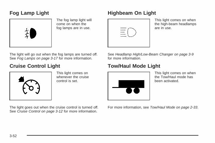
Fog Lamp LightThe fog lamp light willcome on when thefog lamps are in use.
The light will go out when the fog lamps are turned off.See Fog Lamps on page 3-17 for more information.
Cruise Control LightThis light comes onwhenever the cruisecontrol is set.
The light goes out when the cruise control is turned off.See Cruise Control on page 3-12 for more information.
Highbeam On LightThis light comes on whenthe high-beam headlampsare in use.
See Headlamp High/Low-Beam Changer on page 3-9for more information.
Tow/Haul Mode LightThis light comes on whenthe Tow/Haul mode hasbeen activated.
For more information, see Tow/Haul Mode on page 2-33.
3-52

Fuel Gage
When the ignition is on, the fuel gage tells you abouthow much fuel you have left in the fuel tank.
The gage will first indicate empty before you are outof fuel, and you should get more fuel as soon aspossible.
When the fuel tank is low on fuel, the FUEL LEVELLOW message will appear on the Driver InformationCenter (DIC). For more information see DIC Warningsand Messages on page 3-64.
Here are some situations you may experience with yourfuel gage. None of these indicate a problem with thefuel gage.
• At the gas station, the fuel pump shuts off beforethe gage reads full.
• It takes a little more or less fuel to fill up than thefuel gage indicated. For example, the gage mayhave indicated the tank was half full, but it actuallytook a little more or less than half the tank’scapacity to fill the tank.
• The gage goes back to empty when you turn offthe ignition.
United States Canada
3-53
Driver Information Center (DIC)Your vehicle has a Driver Information Center (DIC).
The DIC displays information about your vehicle. It alsodisplays warning messages if a system problem isdetected.
All messages will appear in the DIC display located atthe top of the instrument panel cluster.
The DIC comes on when the ignition is on. After a shortdelay, the DIC will display the information that waslast displayed before the engine was turned off.
The DIC also displays a shift lever position indicatoron the bottom line of the display. See AutomaticTransmission Operation on page 2-30 for moreinformation.
The outside air temperature also displays on the DICwhen viewing the trip and fuel information. The outsideair temperature automatically appears in the top rightcorner of the DIC display. If there is a problem withthe system that controls the temperature display,the numbers will be replaced with dashes. If this occurs,have the vehicle serviced.
If your vehicle has DIC buttons, see “DIC Operation andDisplays (With DIC Buttons)” later in this section andDIC Vehicle Customization (With DIC Buttons) onpage 3-74 for the displays available.
If your vehicle does not have DIC buttons, see “DICOperation and Displays (Without DIC Buttons)” later inthis section for the displays available.
DIC Operation and Displays(With DIC Buttons)If your vehicle has DIC buttons, the information belowexplains the operation of this system.
The DIC has different displays which can be accessedby pressing the DIC buttons located on the instrumentpanel. See Instrument Panel Overview on page 3-4for more information.
The DIC displays trip, fuel, and vehicle systeminformation, and warning messages if a system problemis detected.
3-54

The DIC also allows some features to be customized.See DIC Vehicle Customization (With DIC Buttons)on page 3-74 for more information.
If your vehicle has DIC buttons, you can also use thetrip odometer reset stem to view the odometer andtrip odometers.
DIC Buttons
The buttons are the set/reset, customization, vehicleinformation, and trip/fuel buttons. The button functionsare detailed in the following pages.
V (Set/Reset): Press this button to set or reset certainfunctions and to turn off or acknowledge messageson the DIC.
U (Customization): Press this button to customize thefeature settings on your vehicle. See DIC VehicleCustomization (With DIC Buttons) on page 3-74 for moreinformation.
T (Vehicle Information): Press this button to displaythe oil life, park assist on vehicles with this feature,units, tire pressure readings, and Remote Keyless Entry(RKE) transmitter programming.
3 (Trip/Fuel): Press this button to display theodometer, trip odometers, fuel range, average economy,timer, fuel used, and average speed.
3-55

Vehicle Information Menu ItemsT (Vehicle Information): Press this button to scrollthrough the following menu items:
OIL LIFEPress the vehicle information button until OIL LIFEREMAINING displays. This display shows an estimateof the oil’s remaining useful life. If you see 99% OIL LIFEREMAINING on the display, that means 99% of thecurrent oil life remains. The engine oil life systemwill alert you to change the oil on a schedule consistentwith your driving conditions.
When the remaining oil life is low, the CHANGEENGINE OIL SOON message will appear on the display.See “CHANGE ENGINE OIL SOON” under DICWarnings and Messages on page 3-64. You shouldchange the oil as soon as you can. See Engine Oil onpage 5-13. In addition to the engine oil life systemmonitoring the oil life, additional maintenance isrecommended in the Maintenance Schedule in thismanual. See Scheduled Maintenance on page 6-4 formore information.
Remember, you must reset the OIL LIFE displayyourself after each oil change. It will not reset itself.Also, be careful not to reset the OIL LIFE displayaccidentally at any time other than when the oil has justbeen changed. It cannot be reset accurately until thenext oil change. To reset the engine oil life system,see Engine Oil Life System on page 5-16.
PARK ASSISTIf your vehicle has the Ultrasonic Rear Parking Assist(URPA) system, press the vehicle information buttonuntil PARK ASSIST displays. This display allowsthe system to be turned on or off. Once in this display,press the set/reset button to select between ON orOFF. If you choose ON, the system will be turned on.If you choose OFF, the system will be turned off.The URPA system automatically turns back on aftereach vehicle start. When the URPA system is turned offand the vehicle is shifted out of PARK (P), the DICwill display the PARK ASSIST OFF message asa reminder that the system has been turned off. See DICWarnings and Messages on page 3-64 and UltrasonicRear Parking Assist (URPA) on page 2-44 for moreinformation.
3-56

UNITSPress the vehicle information button until UNITSdisplays. This display allows you to select betweenEnglish or Metric units of measurement. Once in thisdisplay, press the set/reset button to select betweenENGLISH or METRIC units. All of the vehicle informationwill then be displayed in the unit of measurementselected.
FRONT TIRES or REAR TIRESThe pressure for each tire can be viewed in the DIC.The tire pressure will be shown in either poundsper square inch (psi) or kilopascals (kPa). Press thevehicle information button until the DIC displays FRONTTIRES PSI (kPa) LEFT ## RIGHT ##. Press thevehicle information button again until the DIC displaysREAR TIRES PSI (kPa) LEFT ## RIGHT ##.
If a low or high tire pressure condition is detected bythe system while driving, a message advising youto check the pressure in a specific tire will appear in thedisplay. See Inflation - Tire Pressure on page 5-56and DIC Warnings and Messages on page 3-64 for moreinformation.
If the tire pressure display shows dashes instead of avalue, there may be a problem with your vehicle. If thisconsistently occurs, see your dealer/retailer for service.
RELEARN REMOTE KEYThis display allows you to match Remote Keyless Entry(RKE) transmitters to your vehicle. To match an RKEtransmitter to your vehicle:1. Press the vehicle information button until
PRESS V TO RELEARN REMOTE KEY displays.
2. Press the set/reset button until REMOTE KEYLEARNING ACTIVE is displayed.
3. Press and hold the lock and unlock buttons onthe first transmitter at the same time for about15 seconds.On vehicles with memory recall seats, the firsttransmitter learned will match driver 1 andthe second will match driver 2.A chime will sound indicating that the transmitteris matched.
4. To match additional transmitters at this time,repeat Step 3.Each vehicle can have a maximum of eighttransmitters matched to it.
5. To exit the programming mode, you must cycle thekey to LOCK/OFF.
Blank DisplayThis display shows no information.
3-57

Trip/Fuel Menu Items
3 (Trip/Fuel): Press this button to scroll through thefollowing menu items:
ODOMETERPress the trip/fuel button until ODOMETER displays.This display shows the distance the vehicle hasbeen driven in either miles (mi) or kilometers (km).Pressing the trip odometer reset stem will also displaythe odometer.
To switch between English and metric measurements,see “UNITS” later in this section.
TRIP A and TRIP BPress the trip/fuel button until TRIP A or TRIP Bdisplays. This display shows the current distancetraveled in either miles (mi) or kilometers (km) since thelast reset for each trip odometer. Both trip odometerscan be used at the same time. Pressing the tripodometer reset stem will also display the trip odometers.
Each trip odometer can be reset to zero separatelyby pressing the set/reset button or the trip odometerreset stem while the desired trip odometer is displayed.
The trip odometer has a feature called the retro-activereset. This can be used to set the trip odometer tothe number of miles (kilometers) driven since theignition was last turned on. This can be used if the tripodometer is not reset at the beginning of the trip.
To use the retro-active reset feature, press and hold theset/reset button for at least four seconds. The tripodometer will display the number of miles (mi) orkilometers (km) driven since the ignition was last turnedon and the vehicle was moving. Once the vehiclebegins moving, the trip odometer will accumulatemileage. For example, if the vehicle was driven5 miles (8 km) before it is started again, and then theretro-active reset feature is activated, the displaywill show 5 miles (8 km). As the vehicle begins moving,the display will then increase to 5.1 miles (8.2 km),5.2 miles (8.4 km), etc.
If the retro-active reset feature is activated after thevehicle is started, but before it begins moving, thedisplay will show the number of miles (mi) orkilometers (km) that were driven during the lastignition cycle.
3-58

RANGEPress the trip/fuel button until RANGE displays. Thisdisplay shows the approximate number of remainingmiles (mi) or kilometers (km) the vehicle can be drivenwithout refueling. The display will show LOW if thefuel level is low.
The fuel range estimate is based on an average of thevehicle’s fuel economy over recent driving historyand the amount of fuel remaining in the fuel tank.This estimate will change if driving conditions change.For example, if driving in traffic and making frequentstops, this display may read one number, but ifthe vehicle is driven on a freeway, the number maychange even though the same amount of fuel is in thefuel tank. This is because different driving conditionsproduce different fuel economies. Generally, freewaydriving produces better fuel economy than city driving.Fuel range cannot be reset.
AVG (Average) ECONOMYPress the trip/fuel button until AVG ECONOMY displays.This display shows the approximate average milesper gallon (mpg) or liters per 100 kilometers (L/100 km).
This number is calculated based on the number ofmpg (L/100 km) recorded since the last time this menuitem was reset. To reset AVG ECONOMY, press andhold the set/reset button.
TIMERPress the trip/fuel button until TIMER displays.This display can be used as a timer.
To start the timer, press the set/reset button whileTIMER is displayed. The display will show the amountof time that has passed since the timer was lastreset, not including time the ignition is off. Time willcontinue to be counted as long as the ignition ison, even if another display is being shown on the DIC.The timer will record up to 99 hours, 59 minutesand 59 seconds (99:59:59) after which the display willreturn to zero.
To stop the timer, press the set/reset button brieflywhile TIMER is displayed.
To reset the timer to zero, press and hold the set/resetbutton while TIMER is displayed.
3-59

FUEL USEDPress the trip/fuel button until FUEL USED displays.This display shows the number of gallons (gal) orliters (L) of fuel used since the last reset of this menuitem. To reset the fuel used information, press and holdthe set/reset button while FUEL USED is displayed.
AVG (Average) SPEEDPress the trip/fuel button until AVG SPEED displays.This display shows the average speed of the vehicle inmiles per hour (mph) or kilometers per hour (km/h).This average is calculated based on the various vehiclespeeds recorded since the last reset of this value.To reset the value to zero, press and hold the set/resetbutton.
Blank DisplayThis display shows no information.
DIC Operation and Displays(Without DIC Buttons)If your vehicle does not have DIC buttons, theinformation below explains the operation of this system.
The DIC has different displays which can be accessedby pressing the trip odometer reset stem located on theinstrument panel cluster. Pressing the trip odometerreset stem will also turn off, or acknowledge, DICmessages.
The DIC displays trip and vehicle system information,and warning messages if a system problem is detected.
If your vehicle does not have DIC buttons, you canuse the trip odometer reset stem to view the followingdisplays: odometer, trip odometers, oil life, parkassist menu for vehicles with the Ultrasonic RearParking Assist (URPA) system, Remote Keyless Entry(RKE) transmitter programming, units, and displaylanguage.
If your vehicle has DIC buttons, you can use the tripodometer reset stem to view the following displays:odometer and trip odometers.
3-60

Trip Odometer Reset Stem Menu Items
ODOMETERPress the trip odometer reset stem until ODOMETERdisplays. This display shows the distance the vehiclehas been driven in either miles (mi) or kilometers (km).
To switch between English and metric measurements,see “UNITS” later in this section.
TRIP A or TRIP BPress the trip odometer reset stem until TRIP A orTRIP B displays. This display shows the current distancetraveled in either miles (mi) or kilometers (km) sincethe last reset for each trip odometer. Both trip odometerscan be used at the same time.
Each trip odometer can be reset to zero separately bypressing and holding the trip odometer reset stem whilethe desired trip odometer is displayed.
The trip odometer has a feature called the retro-activereset. This can be used to set the trip odometer tothe number of miles (kilometers) driven since theignition was last turned on. This can be used if thetrip odometer is not reset at the beginning of the trip.
To use the retro-active reset feature, press and hold thetrip odometer reset stem for at least four seconds.The trip odometer will display the number of miles (mi)or kilometers (km) driven since the ignition was lastturned on and the vehicle was moving. Once the vehiclebegins moving, the trip odometer will accumulatemileage. For example, if the vehicle was driven5 miles (8 km) before it is started again, and then theretro-active reset feature is activated, the displaywill show 5 miles (8 km). As the vehicle begins moving,the display will then increase to 5.1 miles (8.2 km),5.2 miles (8.4 km), etc.
If the retro-active reset feature is activated after thevehicle is started, but before it begins moving, thedisplay will show the number of miles (mi) orkilometers (km) that were driven during the lastignition cycle.
3-61

OIL LIFETo access this display, the vehicle must be in PARK (P).Press the trip odometer reset stem until OIL LIFEREMAINING displays. This display shows an estimateof the oil’s remaining useful life. If you see 99% OIL LIFEREMAINING on the display, that means 99% of thecurrent oil life remains. The engine oil life systemwill alert you to change the oil on a schedule consistentwith your driving conditions.
When the remaining oil life is low, the CHANGE ENGINEOIL SOON message will appear on the display. See“CHANGE ENGINE OIL SOON” under DIC Warnings andMessages on page 3-64. You should change the oil assoon as you can. See Engine Oil on page 5-13. Inaddition to the engine oil life system monitoring the oil life,additional maintenance is recommended in theMaintenance Schedule in this manual. See ScheduledMaintenance on page 6-4 for more information.
Remember, you must reset the OIL LIFE displayyourself after each oil change. It will not reset itself.Also, be careful not to reset the OIL LIFE displayaccidentally at any time other than when the oil has just
been changed. It cannot be reset accurately until thenext oil change. To reset the engine oil life system,see Engine Oil Life System on page 5-16.
PARK ASSISTTo access this display, the vehicle must be in PARK (P).If your vehicle has the Ultrasonic Rear Parking Assist(URPA) system, press the trip odometer reset stemuntil PARK ASSIST displays. This display allowsthe system to be turned on or off. Once in this display,press and hold the trip odometer reset stem to selectbetween ON or OFF. If you choose ON, the system willbe turned on. If you choose OFF, the system will beturned off. The URPA system automatically turns backon after each vehicle start. When the URPA systemis turned off and the vehicle is shifted out of PARK (P),the DIC will display the PARK ASSIST OFF messageas a reminder that the system has been turned off.See DIC Warnings and Messages on page 3-64 andUltrasonic Rear Parking Assist (URPA) on page 2-44for more information.
3-62

RELEARN REMOTE KEYTo access this display, the vehicle must be in PARK (P).This display allows you to match Remote KeylessEntry (RKE) transmitters to your vehicle. To match anRKE transmitter to your vehicle:
1. Press the trip odometer reset stem until RELEARNREMOTE KEY displays.
2. Press and hold the trip odometer reset stem untilREMOTE KEY LEARNING ACTIVE is displayed.
3. Press and hold the lock and unlock buttons on thefirst transmitter at the same time for about15 seconds.On vehicles with memory recall seats, the firsttransmitter learned will match driver 1 andthe second will match driver 2.A chime will sound indicating that the transmitteris matched.
4. To match additional transmitters at this time,repeat Step 3.Each vehicle can have a maximum of eighttransmitters matched to it.
5. To exit the programming mode, you must cycle thekey to LOCK/OFF.
UNITSTo access this display, the vehicle must be in PARK (P).Press the trip odometer reset stem until UNITSdisplays. This display allows you to select betweenEnglish or Metric units of measurement. Once in thisdisplay, press and hold the trip odometer reset stem toselect between ENGLISH or METRIC units. All of thevehicle information will then be displayed in theunit of measurement selected.
DISPLAY LANGUAGETo access this display, the vehicle must be in PARK (P).This display allows you to select the language inwhich the DIC messages will appear. To select alanguage:
1. Press the trip odometer reset stem until DISPLAYLANGUAGE displays.
2. Continue to press and hold the trip odometer resetstem to scroll through all of the available languages.The available languages are ENGLISH (default),FRANCAIS (French), ESPANOL (Spanish), andNO CHANGE.
3. Once the desired language is displayed, releasethe trip odometer reset stem to set your choice.
3-63

DIC Warnings and MessagesMessages are displayed on the DIC to notify the driverthat the status of the vehicle has changed and thatsome action may be needed by the driver to correct thecondition. Multiple messages may appear one afteranother.
Some messages may not require immediate action, butyou can press any of the DIC buttons on the instrumentpanel or the trip odometer reset stem on the instrumentpanel cluster to acknowledge that you received themessages and to clear them from the display.
Some messages cannot be cleared from the DICdisplay because they are more urgent. These messagesrequire action before they can be cleared. You shouldtake any messages that appear on the display seriouslyand remember that clearing the messages will onlymake the messages disappear, not correct the problem.
The following are the possible messages that can bedisplayed and some information about them.
ALL WHEEL DRIVE OFFIf your vehicle has the All-Wheel Drive (AWD) system,this message displays when there is a compactspare tire on the vehicle, when the Antilock BrakeSystem (ABS) warning light comes on, or when the reardifferential fluid is overheating. This message turnsoff when the differential fluid cools.
The AWD system is disabled until the compact sparetire is replaced by a full-size tire. If the warning messageis still on after putting on the full-size tire, you need toreset the warning message. To reset the warningmessage, turn the ignition off and then back on againafter 30 seconds. If the message stays on, see yourdealer/retailer right away. See All-Wheel Drive (AWD)System on page 4-9 for more information.
AUTOMATIC LIGHT CONTROL OFFThis message displays when the automatic headlampsare turned off. This message clears itself after10 seconds.
3-64

AUTOMATIC LIGHT CONTROL ONThis message displays when the automatic headlampsare turned on. This message clears itself after10 seconds.
BATTERY SAVER ACTIVEThis message displays when the system detects thatthe battery voltage is dropping below expectedlevels. The battery saver system starts reducing certainfeatures of the vehicle that you may be able to notice.At the point that the features are disabled, this messageis displayed. It means that the vehicle is trying tosave the charge in the battery.
Turn off all unnecessary accessories to allow the batteryto recharge.
The normal battery voltage range is 11.5 to 15.5 volts.
CHANGE ENGINE OIL SOONThis message displays when the engine oil needs to bechanged. When you change the engine oil, be sureto reset the CHANGE ENGINE OIL SOON message.See Engine Oil Life System on page 5-16 for informationon how to reset the message. See Engine Oil onpage 5-13 and Scheduled Maintenance on page 6-4 formore information.
CHECK TIRE PRESSUREThis message displays when the pressure in one ormore of the vehicle’s tires needs to be checked.This message also displays LEFT FRONT, RIGHTFRONT, LEFT REAR, or RIGHT REAR to indicate whichtire needs to be checked. You can receive more thanone tire pressure message at a time. To read the othermessages that may have been sent at the sametime, press the set/reset button or the trip odometerreset stem. If a tire pressure message appears on theDIC, stop as soon as you can. Have the tire pressureschecked and set to those shown on the Tire LoadingInformation label. See Tires on page 5-49, Loading theVehicle on page 4-22, and Inflation - Tire Pressureon page 5-56. The DIC also shows the tire pressurevalues. See “DIC Operation and Displays (WithDIC Buttons)” earlier in this section. If the tire pressureis low, the low tire pressure warning light comes on.See Tire Pressure Light on page 3-48.
CRUISE SET TO XXXThis message displays whenever the cruise controlis set. See Cruise Control on page 3-12 for moreinformation.
3-65

DRIVER DOOR OPENThis message displays and a chime sounds if the driverdoor is not fully closed and the vehicle is in a drivegear. Stop and turn off the vehicle, check the door forobstructions, and close the door again. Check tosee if the message still appears on the DIC.
ENGINE HOT A/C(Air Conditioning) OFFThis message displays when the engine coolantbecomes hotter than the normal operating temperature.See Engine Coolant Temperature Gage on page 3-47.To avoid added strain on a hot engine, the airconditioning compressor automatically turns off.When the coolant temperature returns to normal,the air conditioning compressor turns back on. You cancontinue to drive your vehicle.
If this message continues to appear, have the systemrepaired by your dealer/retailer as soon as possibleto avoid damage to the engine.
ENGINE OVERHEATED IDLE ENGINENotice: If you drive your vehicle while the engineis overheating, severe engine damage may occur.If an overheat warning appears on the instrumentpanel cluster and/or DIC, stop the vehicle as soon aspossible. Do not increase the engine speed abovenormal idling speed. See Engine Overheatingon page 5-23 for more information.
This message displays when the engine coolanttemperature is too hot. Stop and allow the vehicle toidle until it cools down. See Engine CoolantTemperature Gage on page 3-47.
See Overheated Engine Protection Operating Mode onpage 5-25 for information on driving to a safe placein an emergency.
ENGINE OVERHEATED STOP ENGINENotice: If you drive your vehicle while the engineis overheating, severe engine damage may occur.If an overheat warning appears on the instrumentpanel cluster and/or DIC, stop the vehicle as soonas possible. See Engine Overheating on page 5-23for more information.
3-66
This message displays and a continuous chimesounds if the engine cooling system reaches unsafetemperatures for operation. Stop and turn off the vehicleas soon as it is safe to do so to avoid severe damage.This message clears when the engine has cooledto a safe operating temperature.
ENGINE POWER IS REDUCEDThis message displays and a chime sounds when thecooling system temperature gets too hot and the enginefurther enters the engine coolant protection mode.See Engine Overheating on page 5-23 for furtherinformation.
This message also displays when the vehicle’s enginepower is reduced. Reduced engine power can affect thevehicle’s ability to accelerate. If this message is on,but there is no reduction in performance, proceedto your destination. The performance may be reducedthe next time the vehicle is driven. The vehicle maybe driven at a reduced speed while this message is on,but acceleration and speed may be reduced. Anytimethis message stays on, the vehicle should be takento your dealer/retailer for service as soon as possible.
FUEL LEVEL LOWThis message displays and a chime sounds if the fuellevel is low. Refuel as soon as possible. See FuelGage on page 3-53 and Fuel on page 5-5 for moreinformation.
HEATED WASH (Washer) FLUIDSYSTEM OFFThis message displays when you manually turn off theheated windshield washer fluid system or when thesystem automatically turns off. See “Heated WindshieldWasher” under Windshield Washer on page 3-10 formore information. This message clears itself after10 seconds.
HEATING WASH (Washer) FLUIDWASH (Washer) WIPES PENDINGThis message displays when you turn on the heatedwindshield washer fluid system. See “Heated WindshieldWasher” under Windshield Washer on page 3-10 formore information.
3-67

HOOD OPENThis message displays and a chime sounds if thehood is not fully closed. Stop and turn off the vehicle,check the hood for obstructions, and close the hoodagain. Check to see if the message still appears onthe DIC.
ICE POSSIBLE DRIVE WITH CAREThis message displays when the outside air temperatureis cold enough to create icy road conditions. Adjust yourdriving accordingly.
LEFT REAR DOOR OPENThis message displays and a chime sounds if the driverside rear door is not fully closed and the vehicle is ina drive gear. Stop and turn off the vehicle, checkthe door for obstructions, and close the door again.Check to see if the message still appears on the DIC.
LIFTGATE OPENThis message displays and a chime sounds if theliftgate is open while the ignition is in ON/RUN. Turn offthe vehicle and check the liftgate. Restart the vehicleand check for the message on the DIC display.
OIL PRESSURE LOW STOP ENGINENotice: If you drive your vehicle while the engineoil pressure is low, severe engine damage mayoccur. If a low oil pressure warning appears on theDriver Information Center (DIC), stop the vehicleas soon as possible. Do not drive the vehicle untilthe cause of the low oil pressure is corrected.See Engine Oil on page 5-13 for more information.
This message displays if low oil pressure levelsoccur. Stop the vehicle as soon as safely possible anddo not operate it until the cause of the low oil pressurehas been corrected. Check the oil as soon as possibleand have your vehicle serviced by your dealer/retailer.See Engine Oil on page 5-13.
PARK ASSIST OFFIf your vehicle has the Ultrasonic Rear Parking Assist(URPA) system, after the vehicle has been startedand shifted out of PARK (P), this message displays toremind the driver that the URPA system has been turnedoff. Press the set/reset button or the trip odometerreset stem to acknowledge this message and clear itfrom the DIC display. To turn the URPA system back on,see Ultrasonic Rear Parking Assist (URPA) onpage 2-44.
3-68

PASSENGER DOOR OPENThis message displays and a chime sounds if thepassenger door is not fully closed and the vehicle is ina drive gear. Stop and turn off the vehicle, checkthe door for obstructions, and close the door again.Check to see if the message still appears on the DIC.
REMOTE KEY LEARNING ACTIVEThis message displays while you are matching aRemote Keyless Entry (RKE) transmitter to your vehicle.See “Matching Transmitter(s) to Your Vehicle” underRemote Keyless Entry (RKE) System Operationon page 2-5 and DIC Operation and Displays (With DICButtons) on page 3-54 or DIC Operation and Displays(Without DIC Buttons) on page 3-60 for moreinformation.
REPLACE BATTERY IN REMOTE KEYThis message displays if a Remote Keyless Entry (RKE)transmitter battery is low. The battery needs to bereplaced in the transmitter. See “Battery Replacement”under Remote Keyless Entry (RKE) System Operationon page 2-5.
RIGHT REAR DOOR OPENThis message displays and a chime sounds if thepassenger side rear door is not fully closed and thevehicle is in a drive gear. Stop and turn off the vehicle,check the door for obstructions, and close the dooragain. Check to see if the message still appears onthe DIC.
SERVICE A/C (Air Conditioning)SYSTEMThis message displays when the electronic sensors thatcontrol the air conditioning and heating systems areno longer working. Have the climate control systemserviced by your dealer/retailer if you notice a drop inheating and air conditioning efficiency.
SERVICE AIR BAGThis message displays if there is a problem with theairbag system. Have your dealer/retailer inspect thesystem for problems. See Airbag Readiness Light onpage 3-40 and Airbag System on page 1-64 formore information.
3-69

SERVICE ALL WHEEL DRIVEIf your vehicle has the All-Wheel Drive (AWD) system,this message displays if there is a problem with thissystem. If this message appears, stop as soon aspossible and turn off the vehicle. Restart the vehicleafter 30 seconds and check for the message on theDIC display. If the message is still displayed or appearsagain when you begin driving, the AWD systemneeds service. See your dealer/retailer.
SERVICE BATTERY CHARGINGSYSTEMOn some vehicles, this message displays if there is aproblem with the battery charging system. Under certainconditions, the charging system light may also turn onin the instrument panel cluster. See Charging SystemLight on page 3-43. Driving with this problem could drainthe battery. Turn off all unnecessary accessories.Have the electrical system checked as soon as possible.See your dealer/retailer.
SERVICE BRAKE SYSTEMThis message displays along with the brake systemwarning light if there is a problem with the brake system.See Brake System Warning Light on page 3-45. If thismessage appears, stop as soon as possible and turn offthe vehicle. Restart the vehicle and check for themessage on the DIC display. If the message is stilldisplayed or appears again when you begin driving,the brake system needs service as soon as possible.See your dealer/retailer.
SERVICE PARK ASSISTIf your vehicle has the Ultrasonic Rear Parking Assist(URPA) system, this message displays if there is aproblem with the URPA system. Do not use this systemto help you park. See Ultrasonic Rear Parking Assist(URPA) on page 2-44 for more information. See yourdealer/retailer for service.
SERVICE POWER STEERINGThis message displays when a problem is detected withthe power steering system. When this message isdisplayed, you may notice that the effort required tosteer the vehicle increases or feels heavier, but you willstill be able to steer the vehicle. Have your vehicleserviced by your dealer/retailer immediately.
3-70

SERVICE STABILITRAKThis message displays if there is a problem with theStabiliTrak® system. If this message appears, tryto reset the system. Stop; turn off the engine for at least15 seconds; then start the engine again. If thismessage still comes on, it means there is a problem.See your dealer/retailer for service. The vehicle is safeto drive, however, you do not have the benefit ofStabiliTrak®, so reduce your speed and driveaccordingly.
SERVICE THEFT DETERRENT SYSTEMThis message displays when there is a problem withthe theft-deterrent system. The vehicle may or may notrestart so you may want to take the vehicle to yourdealer/retailer before turning off the engine. SeePASS-Key® III+ Electronic Immobilizer Operation onpage 2-24 for more information.
SERVICE TIRE MONITOR SYSTEMThis message displays if a part on the Tire PressureMonitor System (TPMS) is not working properly. The tirepressure light also flashes and then remains on duringthe same ignition cycle. See Tire Pressure Light onpage 3-48. Several conditions may cause this messageto appear. See Tire Pressure Monitor Operation onpage 5-59 for more information. If the warning comes onand stays on, there may be a problem with the TPMS.See your dealer/retailer.
SERVICE TRACTION CONTROLThis message displays when there is a problem with theTraction Control System (TCS). When this messageis displayed, the system will not limit wheel spin.Adjust your driving accordingly. See your dealer/retailerfor service. See StabiliTrak® System on page 4-6 formore information.
SERVICE TRANSMISSIONThis message displays when there is a problem with thetransmission. See your dealer/retailer for service.
3-71

SERVICE VEHICLE SOONThis message displays when a non-emissions relatedmalfunction occurs. Have the vehicle serviced byyour dealer/retailer as soon as possible.
SPEED LIMITED TO XXX MPH (KM/H)This message displays when your vehicle speed islimited to 80 mph (128 km/h) because the vehicledetects a problem in the speed variable assiststeering system. Have your vehicle serviced by yourdealer/retailer.
STARTING DISABLED SERVICETHROTTLEThis message displays when your vehicle’s throttlesystem is not functioning properly. Have your vehicleserviced by your dealer/retailer.
THEFT ATTEMPTEDThis message displays if the content theft-deterrentsystem has detected a break-in attempt while you wereaway from your vehicle. See Content Theft-Deterrenton page 2-22 for more information.
TIGHTEN GAS CAPThis message may display along with the check enginelight on the instrument panel cluster if the vehicle’sfuel cap is not tightened properly. See MalfunctionIndicator Lamp on page 3-48. Reinstall the fuel cap fully.See Filling the Tank on page 5-8. The diagnosticsystem can determine if the fuel cap has been left offor improperly installed. A loose or missing fuel capallows fuel to evaporate into the atmosphere. A fewdriving trips with the cap properly installed should turnthis light and message off.
TIRE LEARNING ACTIVEThis message displays when the Tire Pressure MonitorSystem (TPMS) is re-learning the tire positions onyour vehicle. The tire positions must be re-learned afterrotating the tires or after replacing a tire or sensor.See Tire Inspection and Rotation on page 5-63,Tire Pressure Monitor System on page 5-58, andInflation - Tire Pressure on page 5-56 for moreinformation.
3-72

TRACTION CONTROL OFFThis message displays when the Traction ControlSystem (TCS) is turned off. Adjust your drivingaccordingly. See StabiliTrak® System on page 4-6for more information. This message clears itself after10 seconds.
TRANSMISSION HOT IDLE ENGINE
Notice: If you drive your vehicle while thetransmission fluid is overheating and thetransmission temperature warning is displayed onthe instrument panel cluster and/or DIC, youcan damage the transmission. This could lead tocostly repairs that would not be covered byyour warranty. Do not drive your vehicle withoverheated transmission fluid or while thetransmission temperature warning is displayed.
This message displays and a chime sounds if thetransmission fluid in the vehicle gets hot. Driving withthe transmission fluid temperature high can causedamage to the vehicle. Stop the vehicle and let it idle toallow the transmission to cool. This message clearswhen the fluid temperature reaches a safe level.
TURN SIGNAL ONThis message displays and a chime sounds if a turnsignal is left on for 3/4 of a mile (1.2 km). Move the turnsignal/multifunction lever to the off position.
WASHER FLUID LOW ADD FLUIDThis message displays when the windshield washerfluid is low. Fill the windshield washer fluid reservoir assoon as possible. See Engine Compartment Overviewon page 5-12 for the location of the windshieldwasher fluid reservoir. Also, see Windshield WasherFluid on page 5-33 for more information.
3-73

DIC Vehicle Customization(With DIC Buttons)Your vehicle may have customization capabilities thatallow you to program certain features to one preferredsetting. Customization features can only be programmedto one setting on the vehicle and cannot be programmedto a preferred setting for two different drivers.
All of the customization options may not be availableon your vehicle. Only the options available will bedisplayed on the DIC.
The default settings for the customization features wereset when your vehicle left the factory, but may havebeen changed from their default state since then.
The customization preferences are automaticallyrecalled.
To change customization preferences, use thefollowing procedure.
Entering the Feature Settings Menu1. Turn the ignition on and place the vehicle in
PARK (P).To avoid excessive drain on the battery, it isrecommended that the headlamps are turned off.
2. Press the customization button to enter the featuresettings menu.If the menu is not available, FEATURE SETTINGSAVAILABLE IN PARK will display. Before enteringthe menu, make sure the vehicle is in PARK (P).
Feature Settings Menu ItemsThe following are customization features that allow youto program settings to the vehicle:
DISPLAY IN ENGLISHThis feature will only display if a language other thanEnglish has been set. This feature allows you to changethe language in which the DIC messages appear toEnglish.
Press the customization button until the PRESS V TODISPLAY IN ENGLISH screen appears on the DICdisplay. Press the set/reset button once to display allDIC messages in English.
3-74

DISPLAY LANGUAGEThis feature allows you to select the language in whichthe DIC messages will appear.
Press the customization button until the DISPLAYLANGUAGE screen appears on the DIC display. Pressthe set/reset button once to access the settings forthis feature. Then press the customization buttonto scroll through the following settings:
ENGLISH (default): All messages will appear inEnglish.
FRANCAIS: All messages will appear in French.
ESPANOL: All messages will appear in Spanish.
NO CHANGE: No change will be made to this feature.The current setting will remain.
To select a setting, press the set/reset button while thedesired setting is displayed on the DIC.
You can also change the language by pressing thetrip odometer reset stem. See “Language” under DICOperation and Displays (Without DIC Buttons) earlier inthis section for more information.
AUTO DOOR LOCKThis feature allows you to select when the vehicle’sdoors will automatically lock. See ProgrammableAutomatic Door Locks on page 2-11 for moreinformation.
Press the customization button until AUTO DOORLOCK appears on the DIC display. Press the set/resetbutton once to access the settings for this feature.Then press the customization button to scroll throughthe following settings:
SHIFT OUT OF PARK (default): The doors willautomatically lock when the vehicle is shifted out ofPARK (P).
AT VEHICLE SPEED: The doors will automatically lockwhen the vehicle speed is above 8 mph (13 km/h) forthree seconds.
NO CHANGE: No change will be made to this feature.The current setting will remain.
To select a setting, press the set/reset button while thedesired setting is displayed on the DIC.
3-75

AUTO DOOR UNLOCKThis feature allows you to select whether or not to turnoff the automatic door unlocking feature. It alsoallows you to select which doors and when the doorswill automatically unlock. See Programmable AutomaticDoor Locks on page 2-11 for more information.
Press the customization button until AUTO DOORUNLOCK appears on the DIC display. Press theset/reset button once to access the settings for thisfeature. Then press the customization button to scrollthrough the following settings:
OFF: None of the doors will automatically unlock.
DRIVER AT KEY OUT: Only the driver’s door willunlock when the key is taken out of the ignition.
DRIVER IN PARK: Only the driver’s door will unlockwhen the vehicle is shifted into PARK (P).
ALL AT KEY OUT: All of the doors will unlock whenthe key is taken out of the ignition.
ALL IN PARK (default): All of the doors will unlockwhen the vehicle is shifted into PARK (P).
NO CHANGE: No change will be made to this feature.The current setting will remain.
To select a setting, press the set/reset button while thedesired setting is displayed on the DIC.
REMOTE DOOR LOCKThis feature allows you to select the type of feedbackyou will receive when locking the vehicle with theRemote Keyless Entry (RKE) transmitter. You will notreceive feedback when locking the vehicle with the RKEtransmitter if the doors are open. See Remote KeylessEntry (RKE) System Operation on page 2-5 for moreinformation.
Press the customization button until REMOTE DOORLOCK appears on the DIC display. Press the set/resetbutton once to access the settings for this feature.Then press the customization button to scroll throughthe following settings:
OFF: There will be no feedback when you press thelock button on the RKE transmitter.
LIGHTS ONLY: The exterior lamps will flash when youpress the lock button on the RKE transmitter.
HORN ONLY: The horn will sound on the second pressof the lock button on the RKE transmitter.
HORN & LIGHTS (default): The exterior lamps will flashwhen you press the lock button on the RKE transmitter,and the horn will sound when the lock button is pressedagain within five seconds of the previous command.
NO CHANGE: No change will be made to this feature.The current setting will remain.To select a setting, press the set/reset button while thedesired setting is displayed on the DIC.
3-76
REMOTE DOOR UNLOCKThis feature allows you to select the type of feedbackyou will receive when unlocking the vehicle withthe Remote Keyless Entry (RKE) transmitter. You willnot receive feedback when unlocking the vehiclewith the RKE transmitter if the doors are open.See Remote Keyless Entry (RKE) System Operationon page 2-5 for more information.
Press the customization button until REMOTE DOORUNLOCK appears on the DIC display. Press theset/reset button once to access the settings for thisfeature. Then press the customization button to scrollthrough the following settings:
LIGHTS OFF: The exterior lamps will not flash whenyou press the unlock button on the RKE transmitter.
LIGHTS ON (default): The exterior lamps will flashwhen you press the unlock button on the RKEtransmitter.
NO CHANGE: No change will be made to this feature.The current setting will remain.
To select a setting, press the set/reset button while thedesired setting is displayed on the DIC.
DELAY DOOR LOCKThis feature allows you to select whether or not thelocking of the vehicle’s doors and liftgate will be delayed.When locking the doors and liftgate with the powerdoor lock switch and a door or the liftgate is open, thisfeature will delay locking the doors and liftgate untilfive seconds after the last door is closed. You will hearthree chimes to signal that the delayed locking featureis in use. The key must be out of the ignition forthis feature to work. You can temporarily overridedelayed locking by pressing the power door lock switchtwice or the lock button on the RKE transmitter twice.See Delayed Locking on page 2-11 for more information.
Press the customization button until DELAY DOORLOCK appears on the DIC display. Press the set/resetbutton once to access the settings for this feature.Then press the customization button to scroll throughthe following settings:
OFF: There will be no delayed locking of thevehicle’s doors.
ON (default): The doors will not lock until five secondsafter the last door or the liftgate is closed.
NO CHANGE: No change will be made to this feature.The current setting will remain.
To select a setting, press the set/reset button while thedesired setting is displayed on the DIC.
3-77

EXIT LIGHTINGThis feature allows you to select the amount of time youwant the exterior lamps to remain on when it is darkenough outside. This happens after the key is turnedfrom ON/RUN to LOCK/OFF.
Press the customization button until EXIT LIGHTINGappears on the DIC display. Press the set/reset buttononce to access the settings for this feature. Thenpress the customization button to scroll through thefollowing settings:
OFF: The exterior lamps will not turn on.
30 SECONDS (default): The exterior lamps will stay onfor 30 seconds.
1 MINUTE: The exterior lamps will stay on forone minute.
2 MINUTES: The exterior lamps will stay on fortwo minutes.
NO CHANGE: No change will be made to this feature.The current setting will remain.
To select a setting, press the set/reset button while thedesired setting is displayed on the DIC.
APPROACH LIGHTINGThis feature allows you to select whether or not to havethe exterior lights turn on briefly during low lightperiods after unlocking the vehicle using the RemoteKeyless Entry (RKE) transmitter.
Press the customization button until APPROACHLIGHTING appears on the DIC display. Press theset/reset button once to access the settings forthis feature. Then press the customization button toscroll through the following settings:
OFF: The exterior lights will not turn on when youunlock the vehicle with the RKE transmitter.
ON (default): If it is dark enough outside, the exteriorlights will turn on briefly when you unlock the vehiclewith the RKE transmitter.
The lights will remain on for 20 seconds or until the lockbutton on the RKE transmitter is pressed, or the vehicle isno longer off. See Remote Keyless Entry (RKE) SystemOperation on page 2-5 for more information.
NO CHANGE: No change will be made to this feature.The current setting will remain.
To select a setting, press the set/reset button while thedesired setting is displayed on the DIC.
3-78
CHIME VOLUMEThis feature allows you to select the volume level ofthe chime.
Press the customization button until CHIME VOLUMEappears on the DIC display. Press the set/resetbutton once to access the settings for this feature.Then press the customization button to scroll throughthe following settings:
NORMAL: The chime volume will be set to anormal level.
LOUD: The chime volume will be set to a loud level.
NO CHANGE: No change will be made to this feature.The current setting will remain.
There is no default for chime volume. The volume willstay at the last known setting.
To select a setting, press the set/reset button while thedesired setting is displayed on the DIC.
PARK TILT MIRRORSIf your vehicle has this feature, it allows you to selectwhether or not the outside mirror(s) will automatically tiltdown when the vehicle is shifted into REVERSE (R).See Outside Power Foldaway Mirrors on page 2-42 formore information.
Press the customization button until PARK TILTMIRRORS appears on the DIC display. Press theset/reset button once to access the settings forthis feature. Then press the customization button toscroll through the following settings:
OFF (default): Neither outside mirror will be tilted downwhen the vehicle is shifted into REVERSE (R).
DRIVER MIRROR: The driver’s outside mirror will betilted down when the vehicle is shifted intoREVERSE (R).
PASSENGER MIRROR: The passenger’s outsidemirror will be tilted down when the vehicle is shifted intoREVERSE (R).
BOTH MIRRORS: The driver’s and passenger’s outsidemirrors will be tilted down when the vehicle is shiftedinto REVERSE (R).
NO CHANGE: No change will be made to this feature.The current setting will remain.
To select a setting, press the set/reset button while thedesired setting is displayed on the DIC.
3-79

EASY EXIT SEATIf your vehicle has this feature, it allows you to selectyour preference for the automatic easy exit seat feature.See Memory Seat and Mirrors on page 1-6 for moreinformation.
Press the customization button until EASY EXIT SEATappears on the DIC display. Press the set/reset buttononce to access the settings for this feature. Thenpress the customization button to scroll through thefollowing settings:
OFF (default): No automatic seat exit recall will occur.
ON: The driver’s seat will move back when the keyis removed from the ignition.
The automatic easy exit seat movement will only occurone time after the key is removed from the ignition. If theautomatic movement has already occurred, and you putthe key back in the ignition and remove it again, the seatwill stay in the original exit position, unless a memoryrecall took place prior to removing the key again.
NO CHANGE: No change will be made to this feature.The current setting will remain.
To select a setting, press the set/reset button while thedesired setting is displayed on the DIC.
MEMORY SEAT RECALLIf your vehicle has this feature, it allows you to selectyour preference for the remote memory seat recallfeature. See Memory Seat and Mirrors on page 1-6 formore information.
Press the customization button until MEMORY SEATRECALL appears on the DIC display. Press the set/resetbutton once to access the settings for this feature.Then press the customization button to scroll throughthe following settings:
OFF (default): No remote memory seat recall will occur.
ON: The driver’s seat and outside mirrors willautomatically move to the stored driving position whenthe unlock button on the Remote Keyless Entry(RKE) transmitter is pressed. See “Relearn RemoteKey” under DIC Operation and Displays (With DICButtons) on page 3-54 or DIC Operation and Displays(Without DIC Buttons) on page 3-60 for more informationon matching transmitters to driver ID numbers.
NO CHANGE: No change will be made to this feature.The current setting will remain.
To select a setting, press the set/reset button while thedesired setting is displayed on the DIC.
3-80

REMOTE STARTIf your vehicle has this feature, it allows you to turn theremote start off or on. The remote start feature allowsyou to start the engine from outside of the vehicle usingthe Remote Keyless Entry (RKE) transmitter. SeeRemote Vehicle Start on page 2-7 for more information.
Press the customization button until REMOTE STARTappears on the DIC display. Press the set/resetbutton once to access the settings for this feature.Then press the customization button to scroll throughthe following settings:
OFF: The remote start feature will be disabled.
ON (default): The remote start feature will be enabled.
NO CHANGE: No change will be made to thisfeature. The current setting will remain.
To select a setting, press the set/reset button while thedesired setting is displayed on the DIC.
FACTORY SETTINGSThis feature allows you to set all of the customizationfeatures back to their factory default settings.
Press the customization button until FACTORYSETTINGS appears on the DIC display. Press theset/reset button once to access the settings forthis feature. Then press the customization button toscroll through the following settings:
RESTORE ALL (default): The customization featureswill be set to their factory default settings.
DO NOT RESTORE: The customization features willnot be set to their factory default settings.
To select a setting, press the set/reset button while thedesired setting is displayed on the DIC.
3-81

EXIT FEATURE SETTINGSThis feature allows you to exit the feature settings menu.
Press the customization button until FEATURESETTINGS PRESS V TO EXIT appears in the DICdisplay. Press the set/reset button once to exit the menu.
If you do not exit, pressing the customization buttonagain will return you to the beginning of the featuresettings menu.
Exiting the Feature Settings MenuThe feature settings menu will be exited when any ofthe following occurs:
• The vehicle is shifted out of PARK (P).
• The vehicle is no longer in ON/RUN.
• The trip/fuel or vehicle information DIC buttons arepressed.
• The end of the feature settings menu is reachedand exited.
• A 40 second time period has elapsed with noselection made.
Audio System(s)Determine which radio your vehicle has and then readthe pages following to familiarize yourself with itsfeatures.
{CAUTION:
This system provides you with far greateraccess to audio stations and song listings.Giving extended attention to entertainmenttasks while driving can cause a crash and youor others can be injured or killed. Always keepyour eyes on the road and your mind on thedrive — avoid engaging in extended searchingwhile driving.
3-82

Keeping your mind on the drive is important forsafe driving. See Defensive Driving on page 4-2.Here are some ways in which you can help avoiddistraction while driving.
While your vehicle is parked:
• Familiarize yourself with all of its controls.
• Familiarize yourself with its operation.
• Set up your audio system by presetting yourfavorite radio stations, setting the tone, andadjusting the speakers. Then, when drivingconditions permit, you can tune to your favoriteradio stations using the presets and steering wheelcontrols if the vehicle has them.
Notice: Before adding any sound equipment toyour vehicle, such as an audio system, CD player,CB radio, mobile telephone, or two-way radio, makesure that it can be added by checking with yourdealer/retailer. Also, check federal rules coveringmobile radio and telephone units. If soundequipment can be added, it is very important to doit properly. Added sound equipment may interferewith the operation of your vehicle’s engine, radio, orother systems, and even damage them. Yourvehicle’s systems may interfere with the operationof sound equipment that has been added.
Your vehicle has a feature called Retained AccessoryPower (RAP). With RAP, the audio system can beplayed even after the ignition is turned off. See RetainedAccessory Power (RAP) on page 2-27 for moreinformation.
3-83

Setting the Clock
MP3 Radios with a Single CD or aSingle CD and DVD PlayerIf the vehicle has a radio with a single CD or a CD andDVD player, it has a H (clock) button for setting thetime and date.
1. Turn the ignition key to ACC (accessory) or RUN.Press the power knob, located in the center of theradio, to turn the radio on.
2. Press the clock button and the HR, MIN, MM, DD,YYYY (hour, minute, month, day, and year) displays.
3. Press the pushbutton located under any one of thelabels to be changed. Every time the pushbutton ispressed again, the time or the date if selected,increases by one.
• Another way to increase the time or date,is to press the right ¨SEEK arrow or the\ FWD (forward) button.
• To decrease the time or date, press theleft ©SEEK arrow or s REV (reverse) button,or turn the f knob, located on the upper rightside of the radio, to adjust the selected setting.
Changing the Time and Date DefaultSettingsTo change the time default setting from 12 hour to24 hour or to change the date default setting frommonth/day/year to day/month/year, follow theseinstructions:
1. Press the clock button and then the pushbuttonlocated under the forward arrow that is currentlydisplayed on the radio screen until the time12H (hour) and 24H (hour), and the date MM/DD(month and day) and DD/MM (day and month)displays.
2. Press the pushbutton located under the desiredoption.
3. Press the clock button again to apply the selecteddefault, or let the screen time out.
3-84

MP3 Radio with a Six-Disc CD PlayerIf the vehicle has a radio with a six-disc CD player,the radio has a MENU button instead of the H (clock)button to set the time and date.
To set the time and date, follow these instructions:
1. Press the MENU button.
2. Once the clock option displays, press the pushbuttonlocated under that label. The HR, MIN, MM, DD,YYYY displays.
3. Press the pushbutton located under any one of thelabels to be changed. Every time the pushbutton ispressed again, the time or the date if selected,increases by one.
• Another way to increase the time or date,is to press the right ¨SEEK arrow orthe \ FWD (forward) button.
• To decrease the time or date, press theleft SEEK arrow or the REV (reverse) button, orturn the tune knob, located on the upper rightside of the radio, to adjust the selected setting.
Changing the Time and Date DefaultSettingsTo change the time default setting from 12 hour to24 hour or to change the date default setting frommonth/day/year to day/month/year, follow theseinstructions:
1. Press the MENU button. Once the clock optiondisplays, press the pushbutton located under theforward arrow that is currently displayed onthe radio screen until the 12H (hour) and24H (hour), and the date MM/DD (month and day)and DD/MM (day and month) displays.
2. Press the pushbutton located under the desiredoption.
3. Press the MENU button again to apply the selecteddefault, or let the screen time out.
3-85

Radio(s) (MP3)
The vehicle has one of these radios as its audio system.Radio with CD shown, Radio withSix-Disc CD similar
Radio with CD and DVD
3-86

Radios with CD and DVDRadios with CD and DVD have a Bose® SurroundSound System. Some of its features are explainedlater in this section under, “Adjusting the Speakers(Balance/Fade)”.If the vehicle has a Rear Seat Entertainment (RSE)system, it has a CD/DVD radio. See Rear SeatEntertainment (RSE) System on page 3-115 for moreinformation on the vehicle’s RSE system.The DVD player is the top slot on the radio faceplate.The player is capable of reading the DTS programmedDVD Audio or DVD Video media, (DTS and DTSDigital Surround are registered trademarks of DigitalTheater Systems, Inc.).Manufactured under license from Dolby Laboratories.Dolby and the double-D symbol are trademarks ofDolby Laboratories.
Radio Data System (RDS)The Radio Data System (RDS) feature is available foruse only on FM stations that broadcast RDS information.This system relies upon receiving specific informationfrom these stations and only works when the informationis available. While the radio is tuned to an FM-RDSstation, the station name or call letters display. In rarecases, a radio station could broadcast incorrectinformation that causes the radio features to workimproperly. If this happens, contact the radio station.
Playing the RadioO (Power/Volume): Press to turn the system onand off.
Turn clockwise or counterclockwise to increase ordecrease the volume.
Speed Compensated Volume (SCV): The SpeedCompensated Volume (SCV) feature automaticallyadjusts the radio volume to compensate for road andwind noise as the vehicle speeds up or slows down.That way, the volume level should sound aboutthe same.
To activate SCV:
1. Set the radio volume to the desired level.
2. Press the MENU button to display the radiosetup menu.
3. Press the pushbutton under the AUTO VOLUM(automatic volume) label on the radio display.
4. Press the pushbutton under the desired SpeedCompensated Volume setting (OFF, Low, Med,or High) to select the level of radio volumecompensation. Press the pushbutton located belowthe BACK label on the MENU SETUP display or letthe display time out after approximately 10 seconds.Each higher setting allows for more radio volumecompensation at faster vehicle speeds.
3-87

Finding a Station
BAND: Press to switch between AM, FM, or XM™(if equipped). The selection displays.
f (Tune): Turn to select radio stations.
©SEEK ¨: Press the arrows to go to the previous orto the next station and stay there.
To scan stations, press and hold either arrow for afew seconds until a beep sounds. The radio goes to astation, plays for a few seconds, then goes to thenext station. Press either arrow again to stop scanning.
The radio only seeks and scans stations with astrong signal that are in the selected band.
4 (Information) (XM™ Satellite Radio Service, MP3,and RDS Features): Press to display additionaltext information related to the current FM-RDS or XM™station, or MP3 song. A choice of additional informationsuch as: Channel, Song, Artist, and CAT (category)can display. Continue pressing to highlight the desiredlabel, or press the pushbutton positioned under any oneof the labels and the information about that label displays.
When information is not available, No Info displays.
Storing a Radio Station as a FavoriteDrivers are encouraged to set up their radio stationfavorites while the vehicle is in P (Park). Tune to favoritestations using the presets, favorites button, and steeringwheel controls. See Defensive Driving on page 4-2.
FAV (Favorites): A maximum of 36 stations can beprogrammed as favorites using the six pushbuttonspositioned below the radio station frequency labels andby using the radio favorites page button (FAV button).Press to go through up to six pages of favorites,each having six favorite stations available per page.Each page of favorites can contain any combination ofAM, FM, or XM™ (if equipped) stations.
The balance/fade and tone settings that were previouslyadjusted, are stored with the favorite stations.
To store a station as a favorite, perform thefollowing steps:
1. Tune to the desired radio station.
2. Press the FAV button to display the page where tostore the station.
3. Press and hold one of the six pushbuttons until abeep sounds. When that pushbutton is pressedand released, the station that was set, returns.
4. Repeat the steps for each pushbutton radio stationto be stored as a favorite.
3-88
The number of favorites pages can be setup using theMENU button. To setup the number of favorites pages,perform the following steps:1. Press the MENU button to display the radio
setup menu.2. Press the pushbutton located below the
FAV 1-6 label.3. Select the desired number of favorites pages by
pressing the pushbutton located below thedisplayed page numbers.
4. Press the FAV button, or let the menu time out, toreturn to the original main radio screen showing theradio station frequency labels and to begin theprocess of programming favorites for the chosenamount of numbered pages.
Setting the Tone(Bass/Midrange/Treble)BASS/MID/TREB (Bass, Midrange, or Treble): Toadjust bass, midrange, or treble, press the f knob untilthe tone control labels display. Continue pressing tohighlight the desired label, or press the pushbuttonpositioned under the desired label. Turn the f knobclockwise or counterclockwise to adjust the highlighted
setting, or press either SEEK arrow, \ FWD (forward),or s REV (reverse) button until the desired levelsare obtained. If a station’s frequency is weak or if thereis static, decrease the treble.
To quickly adjust bass, midrange, or treble to the middleposition, press the pushbutton positioned under theBASS, MID, or TREB label for more than two seconds.A beep sounds and the level adjusts to the middleposition.
To quickly adjust all tone and speaker controls to themiddle position, press the f knob for more thantwo seconds until a beep sounds.
EQ (Equalization): Press to choose bass and trebleequalization settings designed for different typesof music. The choices are pop, rock, country, talk, jazz,and classical. Selecting MANUAL or changing bassor treble, returns the EQ to the manual bass and treblesettings.
Unique EQ settings can be saved for each source.
If the radio has a Bose® audio system, the EQ settingsare either MANUAL or TALK.
3-89

Adjusting the Speakers (Balance/Fade)
BAL/FADE (Balance/Fade): To adjust balance orfade, press the f knob until the speaker control labelsdisplay. Continue pressing to highlight the desiredlabel, or press the pushbutton positioned underthe desired label. Turn the f knob clockwise orcounterclockwise to adjust the highlighted setting, orpress either SEEK arrow, \ FWD, or s REV buttonuntil the desired levels are obtained.
To quickly adjust balance or fade to the middle position,press the pushbutton positioned under the BAL orFADE label for more than two seconds. A beep soundsand the level adjusts to the middle position.
To quickly adjust all speaker and tone controls to themiddle position, press the f knob for more thantwo seconds until a beep sounds.
Radios with CD and DVD differ when using fade in5.1 Surround. The left front and right front speakers faderearward, leaving the center front speaker unaffecteduntil the last fade step, then all front speakers mute.
If the Rear Seat Audio (RSA) is turned on, the radiodisables FADE and mutes the rear speakers.
Finding a Category (CAT) Station
CAT (Category): The CAT button is used to find XM™stations when the radio is in the XM™ mode. To findXM™ channels within a desired category, performthe following:
1. Press the BAND button until the XM™ frequencydisplays. Press the CAT button to display thecategory labels. Continue pressing the CAT buttonuntil the desired category name displays.
• Radios with CD and DVD can also navigate thecategory list by pressing the s REV button orthe \ FWD button.
2. Press either of the two buttons below the desiredcategory label to immediately tune to the firstXM™ station associated with that category.
3. Turn the f knob, press the buttons below the rightor left arrows displayed, or press either SEEK arrowto go to the previous or to the next XM™ stationwithin the selected category.
4. To exit the category search mode, press theFAV button or BAND button to display thefavorites again.
3-90

Undesired XM™ categories can be removed throughthe setup menu. To remove an undesired category,perform the following:
1. Press the MENU button to display the radiosetup menu.
2. Press the pushbutton located below theXM CAT label.
3. Turn the f knob to display the category to beremoved.
4. Press the pushbutton located under the Removelabel until the category name along with the wordRemoved displays.
5. Repeat the steps to remove more categories.
Removed categories can be restored by pressing thepushbutton under the Add label when a removedcategory is displayed or by pressing the pushbuttonunder the Restore All label.
Categories cannot be removed or added while thevehicle is moving faster than 5 mph (8 km/h).
Radio MessagesCalibration Error: The audio system has beencalibrated for the vehicle from the factory. If CalibrationError displays, it means that the radio has not beenconfigured properly for the vehicle and it must bereturned to your dealer/retailer for service.
Locked: This message displays when the THEFTLOCK®
system has locked up the radio. Take the vehicle to yourdealer/retailer for service.
If any error occurs repeatedly or if an error cannot becorrected, contact your dealer/retailer.
XM™ Satellite Radio ServiceXM™ is a satellite radio service that is based in the48 contiguous United States and 10 Canadian provinces.XM™ Satellite Radio has a wide variety of programmingand commercial-free music, coast-to-coast, and indigital-quality sound. During your trial or when yousubscribe, you will get unlimited access to XM™ RadioOnline for when you are not in your vehicle. A service feeis required to receive the XM™ service. For moreinformation, contact XM™ at www.xmradio.com or call1-800-929-2100 in the U.S. and www.xmradio.ca or call1-877-438-9677 in Canada.
3-91

Radio Messages for XM™ OnlySee XM Radio Messages on page 3-114 later in thissection for further detail.
Playing a CD (Single CD Player)Insert a CD partway into the slot, label side up. Theplayer pulls it in and the CD should begin playing.
Playing a CD(s) (Six-Disc CD Player)
LOAD ^ : Press to load CDs into the CD player.This CD player holds up to six CDs.
To insert one CD, do the following:
1. Press and release the ^ button.
2. Wait for the message to insert the disc.
3. Load a CD. Insert the CD partway into the slot,label side up. The player pulls the CD in.
To insert multiple CDs, do the following:
1. Press and hold the ^ button for two seconds.A beep sounds and Load All Discs displays.
2. Follow the displayed instruction on when to insertthe discs. The CD player takes up to six CDs.
3. Press the ^ button again to cancel loadingmore CDs.
Insert a CD partway into the slot, label side up.The player pulls it in and the CD should begin playing.To insert a CD with the ignition off, first pressthe Z button or the DISP knob.
If the ignition or radio is turned off with a CD in theplayer it stays in the player. When the ignition or radiois turned on, the CD starts to play where it stopped,if it was the last selected audio source.
When the CD is inserted, the CD symbol displays.As each new track starts to play, the track numberdisplays.
3-92

Playing a CD (In Either the DVD orCD Slot)Insert a CD partway into the slot, label side up.The player pulls it in and the CD should begin playing(loading a disc into the system, depending on mediatype and format ranges from 5 to 20 seconds for a CD,and up to 30 seconds for a DVD to begin playing).
If the ignition or radio is turned off, with a CD inthe player, it stays in the player. When the ignition orradio is turned on, the CD starts playing where itstopped, if it was the last selected audio source.The CD is controlled by the buttons on the radiofaceplate or by the RSA unit. See Rear Seat Audio(RSA) on page 3-124 for more information. The DVD/CDdecks, (upper slot is the DVD deck and the lower slotis the CD deck) of the radio are compatible withmost audio CDs, CD-R, CD-RW, and MP3/WMAs.
When a CD is inserted, the text label DVD or CD symboldisplays on the left side of the radio display. As eachnew track starts to play, the track number displays.
Care of CDs and DVDsIf playing a CD-R, the sound quality can be reduceddue to CD-R or CD-RW quality, the method of recording,the quality of the music that has been recorded, andthe way the CD-R or CD-RW has been handled.Handle them carefully. Store CD-R(s) or CD-RW(s) intheir original cases or other protective cases andaway from direct sunlight and dust. The CD or DVDplayer scans the bottom surface of the disc. If thesurface of a CD is damaged, such as cracked, broken,or scratched, the CD does not play properly or notat all. Do not touch the bottom side of a CD whilehandling it; this could damage the surface. Pick up CDsby grasping the outer edges or the edge of the holeand the outer edge.
If the surface of a CD is soiled, take a soft, lint freecloth or dampen a clean, soft cloth in a mild, neutraldetergent solution mixed with water, and clean it.Make sure the wiping process starts from the centerto the edge.
3-93

Care of the CD and DVD PlayerDo not add any label to a CD, it could get caught in theCD or DVD player. If a CD is recorded on a personalcomputer and a description label is needed, try labelingthe top of the recorded CD with a marking pen.
The use of CD lens cleaners for CDs is not advised, dueto the risk of contaminating the lens of the CD optics withlubricants internal to the CD and DVD player mechanism.
Notice: If a label is added to a CD, or more thanone CD is inserted into the slot at a time, or anattempt is made to play scratched or damaged CDs,the CD player could be damaged. While using theCD player, use only CDs in good condition withoutany label, load one CD at a time, and keep theCD player and the loading slot free of foreignmaterials, liquids, and debris.
If an error displays, see “CD Messages” later in thissection.
Z EJECT or CD (Eject): Press and release to ejectthe disc that is currently playing. A CD ejecting froma radio with CD and DVD, ejects from the bottom slot.A beep sounds and Ejecting Disc displays. Once thedisc is ejected, Remove Disc displays. The disc canbe removed. If the disc is not removed, afterseveral seconds, the disc automatically pulls backinto the player.
For the Six-Disc CD player, press and hold fortwo seconds to eject all discs.
Z DVD (Eject): Press and release to eject the discthat is currently playing in the top slot. A beep soundsand Ejecting Disc displays.
If loading and reading of a disc cannot be completed,such as unknown format, etc., and the disc fails to eject,press and hold for more than five seconds to forcethe disc to eject.
f (Tune): Turn to select tracks on the CD that iscurrently playing.
©SEEK ¨: Press the left arrow to go to the start ofthe current track, if more than ten seconds on theCD have played. Press the right arrow to go to thenext track.
For Radios with CD and DVD, Press the left arrow to goto the start of the current track, if more than five secondson the CD have played. If less than five seconds onthe CD have played, the previous track plays. Press theright arrow to go to the next track.
If either arrow is held, or pressed multiple times, theplayer continues moving backward or forward throughthe tracks on the CD.
3-94

s REV (Fast Reverse): Press and hold to reverseplayback quickly within a track. Sound will be heard at areduced volume. Release to resume playing thetrack. The elapsed time of the track displays.
\ FWD (Fast Forward): Press and hold to advanceplayback quickly within a track. Sound will be heard at areduced volume. Release to resume playing thetrack. The elapsed time of the track displays.
RDM (Random): With the random setting, the trackscan be listened to in random, rather than sequentialorder, on one CD or all CDs in a six-disc CD player.To use random, do one of the following:
• Press the CD/AUX button, or for a single CDplayer, insert a disc partway into the slot of the CDplayer. A RDM label displays.
To play the tracks from the single CD in randomorder, press the pushbutton positioned underthe RDM label until Random Current Discdisplays. Press the pushbutton again to turn offrandom play.
• Press the CD/AUX button, or for a six-disc CDplayer, press and hold the ^ button. A beepsounds and Load All Discs displays. Insert one ormore discs partway into the slot of the CD player.To play tracks from all CDs loaded in a six-disc CDplayer in random order, press the pushbuttonpositioned under the RDM label until Randomize AllDiscs displays. Press the same pushbutton againto turn off random play.To play the tracks from a CD loaded in the radiowith CD and DVD, press the DVD/CD AUXbutton when not sourced to the CD, or insert a discpartway into the slot. A RDM label displays.To play tracks from a single CD in random order,press the pushbutton positioned under the RDMlabel until Random Current Disc displays. Press thepushbutton again to turn off random play.
BAND: Press to listen to the radio when a CD is playing.The CD remains inside the radio for future listening.
For the radio with CD and DVD, press to listen to theradio when a CD or DVD is playing. The CD or DVDremains inside the radio for future listening or for viewingentertainment.
3-95

CD/AUX (CD/Auxiliary): Press to play a CD whenlistening to the radio. The CD icon and a messageshowing the disc and/or track number displays when aCD is in the player. Press again and the systemautomatically searches for an auxiliary input device, suchas a portable audio player. If a portable audio player isnot connected, “No Input Device Found” displays.
DVD/CD AUX (Auxiliary): Press this button to cyclethrough DVD, CD, or Auxiliary when listening tothe radio. The DVD/CD text label and a messageshowing the track or chapter number displays when adisc is in either slot. Press this button again andthe system automatically searches for an auxiliary inputdevice, such as a portable audio player. If a portableaudio player is not connected, “No Aux Input Device”displays. If a disc is in both the DVD slot and the CD slotthe DVD/CD AUX button cycles between the twosources and not indicate “No Aux Input Device”. If afront auxiliary device is connected, the DVD/CD AUXbutton cycles through all available options, suchas: DVD slot, CD slot, Front Auxiliary, and Rear Auxiliary(if available). See “Using the Auxiliary Input Jack(s)”later in this section, or “Audio/Video (A/V) Jacks” under,Rear Seat Entertainment (RSE) System on page 3-115for more information.
If a disc is inserted into top DVD slot, the rear seatoperator can turn on the video screen and usethe remote control to navigate the CD (tracks only)through the remote control.
Radios with CD and DVD Audio OutputOnly one audio source can be heard through thespeakers at one time. An audio source is defined asDVD slot, CD slot, XM™, FM/AM, Front Auxiliary Jack,or Rear Auxiliary Jack.
Press the O button to turn the radio on. The radio canbe heard through all of the vehicle speakers.
Front seat passengers can listen to the radio (AM, FM,or XM) by pressing the BAND button or the DVD/CD AUXbutton to select CD slot, DVD slot, front or rear auxiliaryinput (if available).
If a playback device is plugged into the radio’s frontauxiliary input jack or the rear auxiliary jack, the front seatpassengers are able to listen to playback from this sourcethrough the vehicle speakers. See “Using the AuxiliaryInput Jack(s)” later in this section, or “Audio/Video (A/V)Jacks” under, Rear Seat Entertainment (RSE) System onpage 3-115 for more information.
In some vehicles, depending on audio options, the rearspeakers can be muted when the RSA power isturned on. See Rear Seat Audio (RSA) on page 3-124for more information.
3-96

Playing an MP3/WMA CD-R orCD-RW DiscThe radio has the capability of playing an MP3/WMACD-R or CD-RW disc. For more information on how toplay an MP3/WMA CD-R or CD-RW disc, see “Usingan MP3” in the index.
CD Messages
CHECK DISC: Radios with a Single CD player orradios with a Six-Disc player displays CHECK DISCand/or ejects the CD if an error occurs.
Radios with a CD and DVD player may display othermessages when an error occurs:
Optical Error: The disc was inserted upside down.
Disk Read Error: A disc was inserted with an invalidor unknown format.
Player Error: There are disc LOAD or disc EJECTproblems.
• It is very hot. When the temperature returns tonormal, the CD should play.
• The road is very rough. When the road becomessmoother, the CD should play.
• The CD is dirty, scratched, wet, or upside down.
• The air is very humid. If so, wait about an hour andtry again.
• There could have been a problem while burningthe CD.
• The label could be caught in the CD player.
If the CD is not playing correctly, for any other reason,try a known good CD.
Radios with a CD and DVD player displays:
If any error occurs repeatedly or if an error cannot becorrected, contact your dealer/retailer. If the radiodisplays an error message, write it down and provide itto your dealer/retailer when reporting the problem.
3-97

Using the DVD PlayerThe DVD player is controlled by the buttons on theremote control, or by the RSA system, or by the buttonson the radio faceplate. See “Remote Control”, underRear Seat Entertainment (RSE) System on page 3-115and Rear Seat Audio (RSA) on page 3-124 for moreinformation.
The DVD player is only compatible with DVDs of theappropriate region code that is printed on the jacket ofmost DVDs.
The DVD slot of the radio is compatible with mostaudio CDs, CD-R, CD-RW, DVD-Video, DVD-Audio,DVD-R/RW, DVD+R/RW media along with MP3and WMA formats.
If an error message displays on the video screen or theradio, see “DVD Display Error Messages” under,Rear Seat Entertainment (RSE) System on page 3-115and “DVD Radio Error Messages” in this section formore information.
Playing a DVD
DVD/CD AUX (Auxiliary): Press this button to cyclethrough DVD, CD, or Auxiliary when listening tothe radio. The DVD/CD text label and a messageshowing track or chapter number displays when a discis in either slot. Press this button again and thesystem automatically searches for an auxiliary inputdevice, such as a portable audio player. If a portableaudio player is not connected, “No Aux Input Device”displays. If a disc is in both the DVD slot and theCD slot the DVD/CD AUX button cycles between thetwo sources and not indicate “No Aux Input Device”.If a front auxiliary device is connected, the DVD/CD AUXbutton cycles through all available options, such as:DVD slot, CD slot, Front Auxiliary, and Rear Auxiliary(if available). See “Using the Auxiliary Input Jack(s)”later in this section, or “Audio/Video (A/V) Jacks” under,Rear Seat Entertainment (RSE) System on page 3-115for more information.
O (Power): Press to turn the radio on or off. Turnclockwise or counterclockwise to increase or decreasethe volume. Press and hold for more than two secondsto turn off the entire radio and Rear Seat Entertainment(RSE) system and to start the parental control feature.
3-98
Parental control prevents the rear seat occupant fromoperating the Rear Seat Audio (RSA) system orremote control.
A lock symbol displays next to the clock display.The parental control feature remains on until you pressand hold for more than two seconds again, or untilthe driver turns the ignition off and exits the vehicle.
f (Tune): Turn to change tracks on a CD or DVD, tomanually tune a radio station, or to change clock or datesettings, while in the clock or date setting mode. Seethe information given earlier in this section specific to theradio, CD, and the DVD. Also, see “Setting the Clock”in the index, for setting the clock and date.
©SEEK (Previous Track/Chapter): Press the leftSEEK arrow to return to the start of the current track orchapter. Press the left SEEK arrow again to go tothe previous track or chapter. This button might not workwhen the DVD is playing the copyright information orthe previews.
SEEK ¨(Next Track/Chapter): Press the right arrowto go to the next track or chapter. This button mightnot work when the DVD is playing the copyrightinformation or the previews.
s REV (Fast Reverse): Press to quickly reverse theCD or DVD at five times the normal speed. The radiodisplays the elapsed time while in fast reverse. To stopfast reversing, press again. This button might not workwhen the DVD is playing the copyright information orthe previews.
\ FWD (Fast Forward): Press to fast forward the CDor DVD. The radio displays the elapsed time and fastforwards five times the normal speed. To stop fastforwarding, press again. This button might not workwhen the DVD is playing the copyright information orthe previews.
Z (Eject): Press to eject a CD or DVD. If a CDor DVD is ejected, but not removed, the playerautomatically pulls it back in after 15 seconds.
If loading and reading of a CD cannot be completed,because of an unknown format, etc., and the disc fails toeject, press and hold for more than five seconds toforce the disc to eject.
3-99

DVD-V (Video) Display ButtonsOnce a DVD-V is inserted, the radio display menushows several tag options for DVD playing. Press thepushbuttons located under any desired tag option duringDVD playback. See the tag options listed after, formore information.
The rear seat passenger can navigate the DVD-Vmenus and controls through the remote control.See “Remote Control”, under Rear Seat Entertainment(RSE) System on page 3-115 for more information.The Video Screen automatically turns on whenthe DVD-V is inserted into the DVD slot.
r/ j (Play/Pause): Press either the play or pauseicon displayed on the radio system, to toggle betweenpausing or restarting playback of a DVD. If theforward arrow is showing on display, the system is inpause mode. If the pause icon is showing on display, thesystem is in playback mode. If the DVD screen is off,press the play button to turn the screen on.
Some DVDs begin playing after the previews havefinished, although there could be a delay of up to30 seconds. If the DVD does not begin playing the
movie automatically, press the pushbutton locatedunder the play/pause symbol tag displayed on the radio.If the DVD still does not play, refer to the on-screeninstructions, if available.
c (Stop): Press to stop playing, rewinding, or fastforwarding a DVD.
r (Enter): Press to select the choices that arehighlighted in any menu.
y (Menu): Press to access the DVD menu. The DVDmenu is different on every DVD. Use the pushbuttonslocated under the navigation arrows to navigatethe cursor through the DVD menu. After making aselection press this button. This button only operateswhen using a DVD.
Nav (Navigate): Press to display directional arrows fornavigating through the menus.
q (Return): Press to exit the current active menuand return to the previous menu. This button operatesonly when a DVD is playing and a menu is active.
3-100
DVD-A (Audio) Display ButtonsOnce a DVD-A is inserted, radio display menu showsseveral tag options for DVD playing. Press thepushbuttons located under any desired tag optionduring DVD playback. See the tag options listed after,for more information.
The rear seat operator can navigate the DVD-A menusand controls through the remote control. See “RemoteControl”, under Rear Seat Entertainment (RSE) Systemon page 3-115 for more information. The Video Screendoes not automatically power on when the DVD-Ais inserted into the DVD slot. It must be manually turnedon by the rear seat occupant through the remotecontrol power button.
r / j (Play/Pause): Press either the play or pauseicon displayed on the radio system, to toggle betweenpausing or restarting playback of a DVD. If theforward arrow is showing on the display, the system isin pause mode. If the pause icon is showing on thedisplay, the system is in playback mode.
q Group r: Press to cycle through musical groupingson the DVD-A disc.
Nav (Navigate): Press to display directional arrows fornavigating through the menus.
e (Audio Stream): Press to cycle through audiostream formats located on the DVD-A disc. The videoscreen shows the audio stream changing.
Inserting a DiscTo play a disc, gently insert the disc, with the label sideup, into the loading slot. The DVD player might notaccept some paper labeled media. The player startsloading the disc into the system and show “LoadingDisc” on the radio display. At the same time, the radiodisplays a softkey menu of option(s). Some discsautomatically play the movie while others default tothe softkey menu display, which requires the Play, Enter,or Navigation softkeys to be pressed; either by softkeyor by the rear seat passenger using the remotecontrol.
Loading a disc into the system, depending on mediatype and format, ranges from 5 to 20 seconds for a CD,and up to 30 seconds for a DVD.
3-101

Stopping and Resuming PlaybackTo stop playing a DVD without turning off the system,press the c button on the remote control, or press thepushbutton located under the stop or the play/pausesymbol tags displayed on the radio. If the radio head issourced to something other than DVD-V, press theDVD/CD AUX button to make DVD-V the active source.
To resume DVD playback, press the r / j buttonon the remote control, or press the pushbutton locatedunder the play/pause symbol tag displayed on theradio. The DVD should resume play from where it laststopped if the disc has not been ejected and thestop button has not been pressed twice on the remotecontrol. If the disc has been ejected or the stopbutton has been pressed twice on the remote control,the disc resumes playing at the beginning of the disc.
Ejecting a Disc
Press the Z button on the radio to eject the disc.If a disc is ejected from the radio, but not removed,the radio reloads the disc after a short period of time.The disc is stored in the radio. The radio does not
resume play of the disc automatically. If the RSAsystem is sourced to the DVD, the movie when reloadedinto the DVD player begins to play again. In caseloading and reading of a DVD or CD cannot becompleted (unknown format, etc.), and the disc fails toeject, press and hold the DVD Z button more thanfive seconds to force the disc to eject.
DVD Radio Error Messages
Player Error: This message displays when there aredisc load or eject problems.
Disc Format Error: This message displays, if the discis inserted with the disc label wrong side up, or ifthe disc is damaged.
Disc Region Error: This message displays, if the discis not from a correct region.
No Disc Inserted: This message displays, if no disc ispresent when the Z or DVD/CD AUX button ispressed on the radio.
3-102

Using the Auxiliary Input JackThe radio system has an auxiliary input jack located onthe lower right side of the faceplate. This is not an audiooutput; do not plug the headphone set into the frontauxiliary input jack. Connect an external audio devicesuch as an iPod, laptop computer, MP3 player, CDplayer, or cassette tape player, etc. to the auxiliary inputjack for use as another source for audio listening.
Drivers are encouraged to set up any auxiliary devicewhile the vehicle is in P (Park). See DefensiveDriving on page 4-2 for more information on driverdistraction.
To use a portable audio player, connect a 3.5 mm(1/8 inch) cable to the radio’s front auxiliary input jack.When a device is connected, press the radio CD/AUXbutton to begin playing audio from the device overthe vehicle speakers.
O (Power/Volume): Turn clockwise or counterclockwiseto increase or decrease the volume of the portable player.Additional volume adjustments might have to be madefrom the portable device if the volume is not loud orsoft enough.
BAND: Press to listen to the radio when a portableaudio device is playing. The portable audio devicecontinues playing, so you might want to stop it orturn it off.
CD/AUX (CD/Auxiliary): Press to play a CD when aportable audio device is playing. Press again andthe system begins playing audio from the connectedportable audio player. If a portable audio player isnot connected, “No Input Device Found” displays.
DVD/CD AUX (DVD/CD/Auxiliary): Press to cyclethrough DVD, CD, or Auxiliary when listening tothe radio. The DVD/CD text label and a messageshowing track or chapter number displays when adisc is in either slot. Press again and the systemautomatically searches for an auxiliary input device,such as a portable audio player. If a portable audioplayer is not connected, “No Aux Input Device” displays.If a disc is in both the DVD slot and the CD slot theDVD/CD AUX button cycles between the two sourcesand not indicate “No Aux Input Device”. If a frontauxiliary device is connected, the DVD/CD AUX buttoncycles through all available options, such as: DVDslot, CD slot, Front Auxiliary, and Rear Auxiliary(if available). See “Using the Auxiliary Input Jack(s)”later in this section, or “Audio/Video (A/V) Jacks” under,Rear Seat Entertainment (RSE) System on page 3-115for more information.
3-103
Using an MP3 (Radio with CD andSix-Disc CD Player)
MP3/WMA CD-R or CD-RW DiscThe radio plays MP3/WMA files that were recorded on aCD-R or CD-RW disc. The files can be recorded withthe following fixed bit rates: 32 kbps, 40 kbps, 56 kbps,64 kbps, 80 kbps, 96 kbps, 112 kbps, 128 kbps,160 kbps, 192 kbps, 224 kbps, 256 kbps, and 320 kbpsor a variable bit rate. Song title, artist name, andalbum are available for display by the radio whenrecorded using ID3 tags version 1 and 2.
Compressed AudioThe radio also plays discs that contain bothuncompressed CD audio (.CDA files) and MP3/WMAfiles. By default the radio shows the MP3 label onthe left side of the screen but plays both file formats inthe order in which they were recorded to the disc.
MP3/WMA FormatCreating an MP3/WMA disc on a personal computer:
• Make sure the MP3/WMA files are recorded ona CD-R or CD-RW disc.
• Do not mix standard audio and MP3/WMA fileson one disc.
• The CD player is able to read and play a maximumof 50 folders, 15 playlists, and a combined total of512 folders and files.
• Create a folder structure that makes it easy to findsongs while driving. Organize songs by albumsusing one folder for each album. Each folderor album should contain 18 songs or less.
• Avoid subfolders. The system can support up toeight subfolders deep, however, keep the totalnumber of folders to a minimum in order to reducethe complexity and confusion in trying to locatea particular folder during playback.
• Make sure playlists have a .mp3 or .wpl extension(other file extensions might not work).
• Minimize the length of the file, folder, or playlistnames. Long file, folder, or playlist names, or acombination of a large number of files and folders,or playlists could cause the player to be unableto play up to the maximum number of files, folders,playlists, or sessions. To play a large number offiles, folders, playlists or sessions, minimizethe length of the file, folder, or playlist name.Long names also take up more space on thedisplay, potentially getting cut off.
• Finalize the audio disc before burning it. Trying toadd music to an existing disc could cause thedisc not to function in the player.
3-104

Change playlists by using the Sc (previous) andc T (next) folder buttons, the f knob, or theSEEK arrows. An MP3/WMA CD-R or CD-RW that wasrecorded using no file folders can be played. If aCD-R or CD-RW contains more than the maximumof 50 folders, 15 playlists, and a combined total of512 folders and files, the player accesses and navigatesup to the maximum, but all items over the maximumare not accessible.
Root DirectoryThe root directory of the CD-R or CD-RW is treated asa folder. If the root directory has compressed audiofiles, the directory displays as the CD label. Allfiles contained directly under the root directory areaccessed prior to any root directory folders. However,playlists (Px) are always accessed before root foldersor files.
If a disc contains both uncompressed CD audio (.CDA)and MP3/WMA files, a folder under the root directorycalled CD accesses all of the CD audio tracks onthe disc.
Empty Directory or FolderIf a root directory or a folder exists somewhere in thefile structure that contains only folders/subfoldersand no compressed files directly beneath them,the player advances to the next folder in the filestructure that contains compressed audio files.The empty folder does not display.
No FolderWhen the CD-R or CD-RW disc contains onlycompressed files, the files are located under the rootfolder. The next and previous folder function doesnot display on a CD-R or CD-RW disc that was recordedwithout folders or playlists.
When the CD-R or CD-RW disc contains only playlistsand compressed audio files, but no folders, all filesare located under the root folder. The folder down andup buttons search playlists (Px) first and then goesto the root folder.
3-105

Order of PlayTracks recorded to the CD-R or CD-RW disc are playedin the following order:
• Play begins from the first track in the first playlistand continues sequentially through all tracks ineach playlist. When the last track of the last playlisthas played, play continues from the first track ofthe first playlist.
• Play begins from the first track in the first folder andcontinues sequentially through all tracks in eachfolder. When the last track of the last folder hasplayed, play continues from the first track of thefirst folder.
When play enters a new folder, the display does notautomatically show the new folder name unlessthe folder mode is chosen as the default display.The new track name displays.
File System and NamingThe song name that displays is the song name that iscontained in the ID3 tag. If the song name is not presentin the ID3 tag, then the radio displays the file namewithout the extension (such as .mp3) as the track name.
Track names longer than 32 characters or four pagesare shortened. Parts of words on the last page oftext and the extension of the filename does not display.
Preprogrammed PlaylistsPreprogrammed playlists that were created usingWinAmp™, MusicMatch™, or Real Jukebox™ softwarecan be accessed, however, they cannot be editedusing the radio. These playlists are treated as specialfolders containing compressed audio song files.
Playing an MP3/WMAInsert a CD-R or CD-RW disc partway into the slot(Single CD Player), or press the load button and wait forthe message to insert disc (Six-Disc CD Player), labelside up. The player pulls it in, and the CD-R or CD-RWshould begin playing.
Z EJECT: Press and hold this button for two secondsto eject all discs, if one or more discs are loaded.
f (Tune): Turn this knob to select MP3/WMA files onthe CD-R or CD-RW currently playing.
©SEEK ¨: Press the left SEEK arrow to go to thestart of the current MP3/WMA file, if more thanten seconds have played. Press the right SEEK arrowto go to the next MP3/WMA file. If either SEEK arrow isheld or pressed multiple times, the player continuesmoving backward or forward through MP3/WMA fileson the CD.
3-106

Sc (Previous Folder): Press the pushbuttonpositioned under the Folder label to go to the first trackin the previous folder.
cT (Next Folder): Press the pushbutton positionedunder the Folder label to go to the first track in thenext folder.
s REV (Reverse): Press and hold this button toreverse playback quickly within an MP3/WMA file.Sound is heard at a reduced volume. Release thisbutton to resume playing the file. The elapsed time ofthe file displays.
\ FWD (Fast Forward): Press and hold this button toadvance playback quickly within an MP3/WMA file.Sound is heard at a reduced volume. Release thisbutton to resume playing the file. The elapsed time ofthe file displays.
RDM (Random): With the random setting, MP3/WMAfiles on the CD-R or CD-RW can be listened to inrandom, rather than sequential order, on one CD-R orCD-RW disc or all discs in a six-disc CD player. To userandom, do one of the following:
• To play MP3/WMA files from the CD-R or CD-RWin random order, press the pushbutton positionedunder the RDM label until Random Current Discdisplays. Press the same pushbutton again to turnoff random play.
• To play songs from all CDs loaded in a six-disc CDplayer in random order, press the pushbuttonpositioned under the RDM label until Randomize AllDiscs displays. Press the same pushbutton againto turn off random play.
h (Music Navigator): Use the music navigatorfeature to play MP3/WMA files on the CD-R or CD-RWin order by artist or album. Press the pushbuttonlocated below the music navigator label. The playerscans the disc to sort the files by artist and album ID3tag information. It could take several minutes to scan thedisc depending on the number of MP3/WMA filesrecorded to the CD-R or CD-RW disc. The radio canbegin playing while it is scanning the disc in thebackground. When the scan is finished, the CD-R orCD-RW begins playing again.
3-107

Once the disc has scanned, the player defaults toplaying MP3/WMA files in order by artist. The currentartist playing is shown on the second line of the displaybetween the arrows. Once all songs by that artistare played, the player moves to the next artist inalphabetical order on the CD-R or CD-RW and beginsplaying MP3/WMA files by that artist. To listen toMP3/WMA files by another artist, press the pushbuttonlocated below either arrow button. The player goesto the next or previous artist in alphabetical order.Continue pressing either button until the desired artistis displayed.
To change from playback by artist to playback byalbum, press the pushbutton located below the Sort Bylabel. From the sort screen, push one of the buttonsbelow the album button. Press the pushbutton belowthe back label to return to the main music navigatorscreen. Now the album name is displayed on thesecond line between the arrows and songs from thecurrent album begins to play. Once all songs from thatalbum are played, the player moves to the nextalbum in alphabetical order on the CD-R or CD-RW andbegins playing MP3/WMA files from that album.
To exit music navigator mode, press the pushbuttonbelow the Back label to return to normal MP3/WMAplayback.
Using an MP3 (Radio with CD andDVD Player)
MP3/WMA CD-R or CD-RW Disc
Compressed Audio or Mixed Mode DiscsThe radio also plays discs that contain bothuncompressed CD audio (.CDA files) and MP3/WMAfiles depending on which slot the disc is loaded into.By default the radio reads only the uncompressed audio(.CDA) and ignores the MP3/WMA files on the DVDdeck. On the CD deck, pressing the CAT (category)button toggles between compressed and uncompressedaudio format, the default being the uncompressedformat (.CDA).
MP3/WMA FormatTo create an MP3/WMA disc on a personal computer:
• Make sure the MP3/WMA files are recorded ona CD-R or CD-RW disc.
• Do not mix standard audio and MP3/WMA files onone disc.
• The CD player (lower slot) is able to read and playa maximum combination of 512 files and folders.The DVD player (upper slot) is able to read255 folders, 15 playlists and 40 sessions.
3-108

• Create a folder structure that makes it easy to findsongs while driving. Organize songs by albumsusing one folder for each album. Each folderor album should contain 18 songs or less.
• Avoid subfolders. The system can support up toeight subfolders deep, however, keep the totalnumber of folders to a minimum in order to reducethe complexity and confusion in trying to locatea particular folder during playback.
• Make sure playlists have a .m3u, .wpl or .plsextension as other file extensions might not work.
• Minimize the length of the file, folder or playlistnames. Long file, folder, or playlist names, ora combination of a large number of files and folders,or playlists could cause the player to be unable toplay up to the maximum number of files, folders,playlists, or sessions. To play a large numberof files, folders, playlists, or sessions, minimize thelength of the file, folder, or playlist name. Longnames also take up more space on the display,potentially getting cut off.
• Finalize the audio disc before burning it. Trying toadd music to an existing disc could cause thedisc not to function in the player.
Root DirectoryThe root directory of the CD-R or CD-RW disc is treatedas a folder. If the root directory has compressed audiofiles, the directory is displayed as F1 ROOT. All filescontained directly under the root directory are accessedprior to any root directory folders. However, playlists (Px)are always accessed before root folders or files.
Empty Directory or FolderIf a root directory or a folder exists somewhere in thefile structure that contains only folders/subfolders and nocompressed files directly beneath them, the playeradvances to the next folder in the file structurethat contains compressed audio files. The empty folderdoes not display.
No FolderWhen the CD-R or CD-RW disc contains onlycompressed files, the files are located under the rootfolder. The next and previous folder function doesnot function on a CD-R or CD-RW that was recordedwithout folders or playlists. When displaying the name ofthe folder the radio displays ROOT.
3-109

When the CD-R or CD-RW disc contains only playlistsand compressed audio files, but no folders, all filesare located under the root folder. The folder down andthe folder up buttons search playlists (Px) first andthen goes to the root folder. When the radio displaysthe name of the folder the radio displays ROOT.
Order of PlayTracks recorded to the CD-R or CD-RW disc are playedin the following order:
• Play begins from the first track in the first playlistand continues sequentially through all tracks ineach playlist. When the last track of the last playlisthas played, play continues from the first track ofthe first playlist.
• Play begins from the first track in the first folder andcontinues sequentially through all tracks in eachfolder. When the last track of the last folderhas played, play continues from the first track of thefirst folder.
When play enters a new folder, the display does notautomatically show the new folder name unless thefolder mode has been chosen as the default display. Thenew track name displays.
File System and NamingThe song name that is displayed is the song name thatis contained in the ID3 tag. If the song name is notpresent in the ID3 tag, then the radio displays the filename without the extension (such as .mp3) as thetrack name.
Track names longer than 32 characters or four pagesare shortened. Parts of words on the last page oftext and the extension of the filename displays.
Preprogrammed PlaylistsPreprogrammed playlists that were created usingWinAmp™, MusicMatch™, or Real Jukebox™ softwarecan be accessed, however, they cannot be editedusing the radio. These playlists are treated as specialfolders containing compressed audio song files.
3-110

Playing an MP3/WMA (In Either the DVDor CD Slot)Insert a CD-R or CD-RW disc partway into either thetop or bottom slot, label side up. The player pullsit in, and the CD-R or CD-RW should begin playing.Depending on the format of the disc, a softkey menuappears and allows navigation of the disc. The menureads left to right as RDM (Randomize song play order),a Folder icon with left and right arrows (to move up ordown through available folders), a PL tag if the disc hasa Playlist available, and a Music Navigator tag. If aPlaylist tag is shown, toggling this key brings up a Foldersoftkey only or the menu as previously described.If the ignition or radio is turned off with a CD-R orCD-RW disc in the player it stays in the player. Whenthe ignition or radio is turned back on, the CD-R orCD-RW starts to play where it stopped, if it was the lastselected audio source.As each new track starts to play, the track number andsong title displays.
Z CD (Eject): Press and release this button to ejectthe CD-R or CD-RW that is currently playing in thebottom slot. A beep sounds and Ejecting Disc displays.Once the disc is ejected, Remove Disc displays. TheCD-R or CD-RW disc can be removed. If the CD-Ror CD-RW disc is not removed, after several seconds,the CD-R or CD-RW disc automatically pulls backinto the player.
If loading and reading of a CD cannot be completed,such as unknown format, etc., and the disc fails to eject,press and hold this button for more than five secondsto force the disc to eject.
Z DVD (Eject): Press and release this button to ejectthe CD-R or CD-RW that is currently playing in thetop slot. A beep sounds and Ejecting Disc displays.Once the disc is ejected, Remove Disc displays.The CD-R or CD-RW disc can be removed. If the CD-Ror CD-RW disc is not removed, after several seconds,the CD-R or CD-RW disc automatically pulls backinto the player. If loading and reading of a CD cannotbe completed, such as unknown format, etc., and thedisc fails to eject, press and hold this button formore than five seconds to force the disc to eject.
f (Tune): Turn this knob to select MP3/WMA files onthe CD-R or CD-RW that is currently playing.
©SEEK ¨: Press the left SEEK arrow to go to thestart of the current MP3/WMA file, if more thanfive seconds have played. If less than five seconds haveplayed, the previous MP3/WMA file plays. Press theright SEEK arrow to go to the next MP3/WMA file.If either SEEK arrow is held, or pressed multiple times,the player continues moving backward or forwardthrough the MP3/WMA files on the CD.
3-111
Sc (Previous Folder): Press the pushbuttonpositioned under the Folder label to go to the first trackin the previous folder.
cT (Next Folder): Press the pushbutton positionedunder the Folder label to go to the first track in thenext folder.
s REV (Reverse): Press and hold this button toreverse playback quickly within an MP3/WMA file.Sound is heard at a reduced volume. Release thisbutton to resume playing the file. The elapsed time ofthe file displays.
\ FWD (Fast Forward): Press and hold this button toadvance playback quickly within an MP3/WMA file.Sound is heard at a reduced volume. Release thisbutton to resume playing the file. The elapsed time ofthe file displays.
RDM (Random): With the random setting, MP3/WMAfiles on the CD-R or CD-RW can be listened to inrandom, rather than sequential order. To play MP3/WMAfiles from the CD-R or CD-RW in random order, pressthe pushbutton positioned under the RDM label untilRandom Current Disc displays. Press the samepushbutton again to turn off random play.
h (Music Navigator): Use the music navigatorfeature to play MP3/WMA files on the CD-R or CD-RWin order by artist or album. Press the pushbuttonlocated below the music navigator label. The playerscans the disc to sort the files by artist and album ID3tag information. It could take several minutes to scan thedisc depending on the number of MP3/WMA filesrecorded to the CD-R or CD-RW disc.
To cancel music navigator while the player is scanning,press the pushbutton located below the musicnavigator label or eject the disc.
The radio can begin playing while it is scanning the discin the background. When the scan is finished, theCD-R or CD-RW begins playing again.
Once the disc has been scanned, the player defaults toplaying MP3/WMA files in order by artist. The currentartist playing is shown on the second line of the displaybetween the arrows. To listen to MP3/WMA files byanother artist, press the pushbutton located below eitherarrow button. The disc goes to the next or previousartist in alphabetical order. Continue pressing eitherbutton until the desired artist is displayed.
3-112

To change from playback by artist to playback by album,press the pushbutton located below the Sort By label.From the sort screen, push one of the buttons below thealbum button. Press the pushbutton below the back labelto return to the main music navigator screen. Now thealbum name displays on the second line between thearrows and songs from the current album begin to play.Once all songs from that album are played, the playermoves to the next album in alphabetical order on theCD-R or CD-RW and begins playing MP3/WMA filesfrom that album.
To exit music navigator mode, press the pushbuttonbelow the Back label to return to normal MP3/WMAplayback.
BAND: Press this button to listen to the radio when aCD or a DVD is playing. The CD or DVD remains insidethe radio for future listening or viewing entertainment.
DVD/CD AUX (Auxiliary): Press this button to cyclethrough DVD, CD, or Auxiliary when listening tothe radio. The DVD/CD text label and a messageshowing track or chapter number displays when a discis in either slot. Press this button again and thesystem automatically searches for an auxiliary inputdevice, such as a portable audio player. If a portableaudio player is not connected, “No Aux Input Device”displays. If a disc is in both the DVD slot and the CD slotthe DVD/CD AUX button cycles between the twosources and does not indicate “No Aux Input Device”.If a front auxiliary device is connected, the DVD/CD AUXbutton cycles through all available options, such as:DVD slot, CD slot, Front Auxiliary, and Rear Auxiliary(if available). See “Using the Auxiliary Input Jack(s)”later in this section, or “Audio/Video (A/V) Jacks” under,Rear Seat Entertainment (RSE) System on page 3-115for more information.
If a MP3/WMA is inserted into top DVD slot, the rearseat operator can turn on the video screen and use theremote control to navigate the CD (tracks only).
3-113

XM Radio MessagesXL (Explicit Language Channels): These channels, orany others, can be blocked at a customer’s request,by calling 1-800-852-XMXM (9696).
XM Updating: The encryption code in the receiver isbeing updated, and no action is required. This processshould take no longer than 30 seconds.
No XM Signal: The system is functioning correctly, butthe vehicle is in a location that is blocking the XM™signal. When you move into an open area, the signalshould return.
Loading XM: The audio system is acquiring andprocessing audio and text data. No action is needed.This message should disappear shortly.
Channel Off Air: This channel is not currently inservice. Tune to another channel.
Channel Unavail: This previously assigned channel isno longer assigned. Tune to another station. If thisstation was one of the presets, choose another stationfor that preset button.
No Artist Info: No artist information is available at thistime on this channel. The system is working properly.
No Title Info: No song title information is availableat this time on this channel. The system is workingproperly.
No CAT Info: No category information is availableat this time on this channel. The system is workingproperly.
No Information: No text or informational messages areavailable at this time on this channel. The system isworking properly.
CAT Not Found: There are no channels available forthe selected category. The system is working properly.
XM TheftLocked: The XM receiver in the vehiclecould have previously been in another vehicle. Forsecurity purposes, XM receivers cannot be swappedbetween vehicles. If this message appears after havingyour vehicle serviced, check with your dealer/retailer.
XM Radio ID: If tuned to channel 0, this messagealternates with the XM Radio eight digit radio ID label.This label is needed to activate the service.
Unknown: If this message is received when tuned tochannel 0, there could be a receiver fault. Consultwith your dealer/retailer.
Check XM Receivr: If this message does not clearwithin a short period of time, the receiver could have afault. Consult with your dealer/retailer.
XM Not Available: If this message does not clearwithin a short period of time, the receiver could have afault. Consult with your dealer/retailer.
3-114
Navigation/Radio SystemYour vehicle may have a navigation radio system.
The navigation system has built-in features intended tominimize driver distraction. Technology alone, nomatter how advanced, can never replace your ownjudgment. See the Navigation System manual for sometips to help you reduce distractions while driving.
Rear Seat Entertainment (RSE)SystemThe vehicle may have a DVD Rear Seat Entertainment(RSE) system. The RSE system works with thevehicle’s audio system. The DVD player is part of thefront radio. The RSE system includes a radio with aDVD player, a video display screen, audio/video jacks,two wireless headphones, and a remote control.See Radio(s) (MP3) on page 3-86 for more informationon the vehicle’s audio/DVD system.
Before DrivingThe RSE is designed for rear seat passengers only.The driver cannot safely view the video screenwhile driving and should not try to do so.
In severe or extreme weather conditions the RSEsystem might or might not work until the temperature iswithin the operating range. The operating range forthe RSE system is above −4°F (−20°C) or below140°F (60°C). If the temperature of the vehicle isoutside of this range, heat or cool the vehicle until thetemperature is within the operating range of theRSE system.
Parental ControlThe RSE system may have a Parental Control feature,depending on which radio the vehicle has. To enableParental Control, press and hold the radio power buttonfor more than two seconds to stop all system featuressuch as: radio, video screen, RSA, DVD and/or CD.While Parental Control is on, a padlock icon displays.
When the radio is turned back on, Parental Controlis unlocked.
3-115

Headphones
The RSE includes two 2-channel wireless headphonesthat are dedicated to this system. Channel 1 isdedicated to the video screen, while Channel 2 isdedicated to RSA selections. These headphonesare used to listen to media such as CDs, DVDs,MP3/WMAs, DVD-As, radio, any auxiliary sourceconnected to A/V jacks, or the auxiliary input jack, if thevehicle has this feature. The wireless headphoneshave an On/Off button, channel 1/2 switch, and avolume control. Switch the headphones to Off whennot in use.
Push the power button to turn on the headphones.An indicator light located on the headphones comes on.If the light does not come on, the batteries might needto be replaced. Intermittent sound or static on theheadphones can also be an indication of weak batteries.See “Battery Replacement” later in this section formore information.
Infrared transmitters are located at the rear of theRSE overhead console. The headphones shut offautomatically to save the battery power if the RSE systemand RSA are shut off or if the headphones are out ofrange of the transmitters for more than three minutes.Moving too far forward or stepping out of the vehicle,can cause the headphones lose the audio signal.
The headphones automatically turns off after four hoursof continuous use.
To adjust the volume on the headphones, use thevolume control located on the right side.
For optimal audio performance, the headphones mustbe worn correctly. The symbol L (Left) appears onthe upper left side, above the ear pad and should bepositioned on the left ear. The symbol R (Right) appearson the upper right side, above the ear pad and shouldbe positioned on the right ear.
3-116
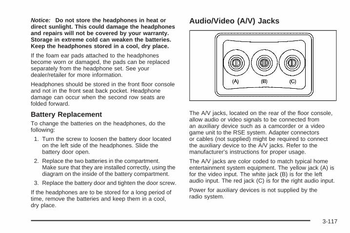
Notice: Do not store the headphones in heat ordirect sunlight. This could damage the headphonesand repairs will not be covered by your warranty.Storage in extreme cold can weaken the batteries.Keep the headphones stored in a cool, dry place.
If the foam ear pads attached to the headphonesbecome worn or damaged, the pads can be replacedseparately from the headphone set. See yourdealer/retailer for more information.
Headphones should be stored in the front floor consoleand not in the front seat back pocket. Headphonedamage can occur when the second row seats arefolded forward.
Battery ReplacementTo change the batteries on the headphones, do thefollowing:
1. Turn the screw to loosen the battery door locatedon the left side of the headphones. Slide thebattery door open.
2. Replace the two batteries in the compartment.Make sure that they are installed correctly, using thediagram on the inside of the battery compartment.
3. Replace the battery door and tighten the door screw.
If the headphones are to be stored for a long period oftime, remove the batteries and keep them in a cool,dry place.
Audio/Video (A/V) Jacks
The A/V jacks, located on the rear of the floor console,allow audio or video signals to be connected froman auxiliary device such as a camcorder or a videogame unit to the RSE system. Adapter connectorsor cables (not supplied) might be required to connectthe auxiliary device to the A/V jacks. Refer to themanufacturer’s instructions for proper usage.
The A/V jacks are color coded to match typical homeentertainment system equipment. The yellow jack (A) isfor the video input. The white jack (B) is for the leftaudio input. The red jack (C) is for the right audio input.
Power for auxiliary devices is not supplied by theradio system.
3-117

To use the auxiliary inputs of the RSE system,connect an external auxiliary device to the color-codedA/V jacks and turn both the auxiliary device and thevideo screen power on. If the video screen is in theDVD player mode, pressing the AUX (auxiliary) buttonon the remote control, switches the video screenfrom the DVD player mode to the auxiliary device.The radio can listen to the audio of the connectedauxiliary device by sourcing to auxiliary. See Radio(s)(MP3) on page 3-86 for more information.
How to Change the RSE Video ScreenSettingsThe screen display mode (normal, full, and zoom),screen brightness, and setup menu language can bechanged from the on screen setup menu. To change anyfeature, do the following:
1. Press the z (display menu) button on the remotecontrol.
2. Use the remote control n ,q, p , o (navigationarrows) and the r (enter) button to use thesetup menu.
3. Press the display menu button again to remove thesetup menu from the screen.
Audio OutputAudio from the DVD player or auxiliary inputs can beheard through the following possible sources:
• Wireless Headphones
• Vehicle Speakers
• Vehicle wired headphone jacks on the rear seataudio system, if the vehicle has this feature.
The RSE system always transmits the audio signal tothe wireless headphones, if there is audio available.See “Headphones” earlier in this section for moreinformation.
The DVD player is capable of outputting audio to thewired headphone jacks on the RSA system, if thevehicle has this feature. The DVD player can beselected as an audio source on the RSA system.See Rear Seat Audio (RSA) on page 3-124 for moreinformation.
When a device is connected to the A/V jacks, or theradio’s auxiliary input jack, if the vehicle has this feature,the rear seat passengers are able to hear audio fromthe auxiliary device through the wireless or wiredheadphones. The front seat passengers are able tolisten to playback from this device through the vehiclespeakers by selecting AUX as the source on the radio.
3-118

Video ScreenThe video screen is located in the overhead console.
To use the video screen, do the following:
1. Push the release button located on the overheadconsole.
2. Move the screen to the desired position.
When the video screen is not in use, push it up into itslocked position.
If a DVD is playing and the screen is raised to its lockedposition, the screen remains on; this is normal, andthe DVD continues to play through the previous audiosource. Use the remote control P button or Z the discto turn off the screen.
The overhead console contains the infrared receiversfor the wireless headphones and the infrared receiversfor the remote control. They are located at the rearof the console.
Notice: Avoid directly touching the video screen,as damage may occur. See “Cleaning the VideoScreen” later in this section for more information.
Remote ControlTo use the remote control, aim it at the transmitterwindow at the rear of the overhead console and pressthe desired button. Direct sunlight or very bright lightcould affect the ability of the RSE transmitter to receivesignals from the remote control. If the remote controldoes not seem to be working, the batteries might needto be replaced. See “Battery Replacement” later inthis section. Objects blocking the line of sight could alsoaffect the function of the remote control.
If a CD or DVD is in the Radio DVD slot, the remotecontrol O button can be used to turn on the videoscreen display and start the disc. The radio can alsoturn on the video screen display. See Radio(s) (MP3) onpage 3-86 for more information.
Notice: Storing the remote control in a hot area orin direct sunlight can damage it, and the repairswill not be covered by your warranty. Storage inextreme cold can weaken the batteries. Keepthe remote control stored in a cool, dry place.
3-119

Remote Control Buttons
O (Power): Press to turn the video screen on and off.
P (Illumination): Press to turn the remote controlbacklight on. The backlight automatically times out afterseven to ten seconds if no other button is pressedwhile the backlight is on.
v (Title): Press to return the DVD to the main menuof the DVD. This function could vary for each disc.
y (Main Menu): Press to access the DVD menu.The DVD menu is different on every DVD. Use thenavigation arrows to move the cursor around the DVDmenu. After making a selection press the enter button.This button only operates when using a DVD.
n,q, p, o (Menu Navigation Arrows): Use thearrow buttons to navigate through a menu.
r (Enter): Press to select the choice that ishighlighted in any menu.
z (Display Menu): Press to adjust the brightness,screen display mode (normal, full, or zoom), and displaythe language menu.
q (Return): Press to exit the current active menuand return to the previous menu. This button operatesonly when the display menu or a DVD menu is active.
c (Stop): Press to stop playing, rewinding, orfast forwarding a DVD. Press twice to return to thebeginning of the DVD.
3-120
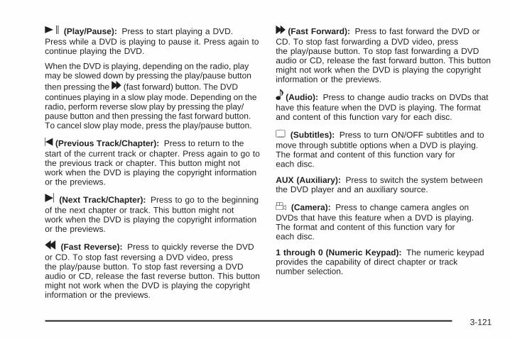
s (Play/Pause): Press to start playing a DVD.Press while a DVD is playing to pause it. Press again tocontinue playing the DVD.
When the DVD is playing, depending on the radio, playmay be slowed down by pressing the play/pause buttonthen pressing the [ (fast forward) button. The DVDcontinues playing in a slow play mode. Depending on theradio, perform reverse slow play by pressing the play/pause button and then pressing the fast forward button.To cancel slow play mode, press the play/pause button.
t (Previous Track/Chapter): Press to return to thestart of the current track or chapter. Press again to go tothe previous track or chapter. This button might notwork when the DVD is playing the copyright informationor the previews.
u (Next Track/Chapter): Press to go to the beginningof the next chapter or track. This button might notwork when the DVD is playing the copyright informationor the previews.
r (Fast Reverse): Press to quickly reverse the DVDor CD. To stop fast reversing a DVD video, pressthe play/pause button. To stop fast reversing a DVDaudio or CD, release the fast reverse button. This buttonmight not work when the DVD is playing the copyrightinformation or the previews.
[ (Fast Forward): Press to fast forward the DVD orCD. To stop fast forwarding a DVD video, pressthe play/pause button. To stop fast forwarding a DVDaudio or CD, release the fast forward button. This buttonmight not work when the DVD is playing the copyrightinformation or the previews.
e (Audio): Press to change audio tracks on DVDs thathave this feature when the DVD is playing. The formatand content of this function vary for each disc.
{ (Subtitles): Press to turn ON/OFF subtitles and tomove through subtitle options when a DVD is playing.The format and content of this function vary foreach disc.
AUX (Auxiliary): Press to switch the system betweenthe DVD player and an auxiliary source.
d (Camera): Press to change camera angles onDVDs that have this feature when a DVD is playing.The format and content of this function vary foreach disc.
1 through 0 (Numeric Keypad): The numeric keypadprovides the capability of direct chapter or tracknumber selection.
3-121

\ (Clear): Press within three seconds after entering anumeric selection, to clear all numerical inputs.
} 10 (Double Digit Entries): Press to select chapteror track numbers greater than nine. Press this buttonbefore entering the number.
If the remote control becomes lost or damaged, a newuniversal remote control can be purchased. If thishappens, make sure the universal remote control uses acode set of Toshiba®.
Battery ReplacementTo change the remote control batteries, do the following:
1. Slide the rear cover back, on the remote control.
2. Replace the two batteries in the compartment.Make sure that they are installed correctly, usingthe diagram on the inside of the batterycompartment.
3. Replace the battery cover.
If the remote control is to be stored for a long period oftime, remove the batteries and keep them in a cool,dry place.
Problem Recommended ActionNo power. The ignition might not be
turned ON/RUN or inACC/ACCESSORY.
The picture does not fillthe screen. There areblack borders on thetop and bottom or onboth sides or it looksstretched out.
Check the display modesettings in the setup menuby pressing the displaymenu button on theremote control.
In auxiliary mode, thepicture moves or scrolls.
Check the auxiliary inputconnections at bothdevices.
The remote control doesnot work.
Check to make sure thereis no obstruction betweenthe remote control and thetransmitter window.Check the batteries tomake sure they are notdead or installedincorrectly.
After stopping the player,I push Play but sometimesthe DVD starts where I leftoff and sometimes at thebeginning.
If the stop button waspressed one time, theDVD player resumesplaying where the DVDwas stopped. If the stopbutton was pressed twotimes the DVD playerbegins to play from thebeginning of the DVD.
3-122

Problem Recommended ActionThe auxiliary source isrunning but there is nopicture or sound.
Check that the RSE videoscreen is in the auxiliarysource mode.Check the auxiliary inputconnections at bothdevices.
Sometimes the wirelessheadphone audio cuts outor buzzes.
Check for obstructions,low batteries, receptionrange, and interferencefrom cellular telephonetowers or by using acellular telephone inthe vehicle.Check that theheadphones are oncorrectly using the L (left)and R (right) on theheadphones.
I lost the remote and/orthe headphones.
See your dealer/retailerfor assistance.
The DVD is playing,but there is no picture orsound.
Check that the RSE videoscreen is sourced to theDVD player.
DVD Display Error MessagesThe DVD display error message depends on whichradio the vehicle has. The video screen might displayone of the following:
Disc Load/Eject Error: This message displays whenthere are disc load or eject problems.
Disc Format Error: This message displays, if the discis inserted with the disc label wrong side up, or ifthe disc is damaged.
Disc Region Error: This message displays, if the discis not from a correct region.
No Disc Inserted: This message displays, if no disc ispresent when the Z EJECT button is pressed onthe radio.
3-123

DVD DistortionVideo distortion can occur when operating cellularphones, scanners, CB radios, Global Position Systems(GPS)*, two-way radios, mobile fax, or walkie talkies.
It might be necessary to turn off the DVD player whenoperating one of these devices in or near the vehicle.
*Excludes the OnStar® System.
Cleaning the RSE Overhead ConsoleWhen cleaning the RSE overhead console surface,use only a clean cloth dampened with clean water.
Cleaning the Video ScreenUse only a clean cloth dampened with clean water.Use care when directly touching or cleaning the screen,as damage could result.
Rear Seat Audio (RSA)This feature allows rear seat passengers to listen to andcontrol any of the music sources: radio, CDs, DVDs,or other auxiliary sources. However, the rear seatpassengers can only control the music sources the frontseat passengers are not listening to (except on someradios where dual control is allowed). For example,rear seat passengers can control a CD and listen to itthrough the headphones, while the driver listens tothe radio through the front speakers. The rear seatpassengers have control of the volume for each set ofheadphones.
The RSA functions operate even when the main radio isoff. The front audio system will display the headphoneicon when the RSA is on, and will disappear fromthe display when it is off.
Audio can be heard through wired headphones(not included) plugged into the jacks on the RSA.If the vehicle has this feature, audio can also be heardon Channel 2 of the wireless headphones.
The audio system mutes the rear speakers when theRSA audio is active through the headphones.
3-124

To listen to an iPod or portable audio device throughthe RSA, attach the iPod or portable audio device to thefront auxiliary input (if available), located on the frontaudio system. Turn the iPod on, then choose thefront auxiliary input with the RSA SRCE button.
P (Power): Press this button to turn the RSA onor off.
Volume: Turn the knob to increase or to decrease thevolume of the wired headphones. The left knob controlsthe left headphones and the right knob controls theright headphones.
SRCE (Source): Press this button to switch betweenthe radio (AM/FM), XM™ (if equipped), CD, and ifthe vehicle has these features, DVD, front auxiliary,and rear auxiliary.
©¨(Seek): When listening to FM, AM, or XM™(if equipped), press either the seek arrows to go to theprevious or to the next station or channels and staythere. This function is inactive, with some radios, if thefront seat passengers are listening to the radio.
Press and hold either seek arrow until the displayflashes, to tune to an individual station. The displaystops flashing after the buttons have not been pushedfor more than two seconds. This function is inactive, withsome radios, if the front seat passengers are listeningto the radio.
While listening to a disc, press the right seek arrow togo to the next track or chapter on the disc. Press the leftseek arrow to go back to the start of the current trackor chapter (if more than ten seconds have played).This function is inactive, with some radios, if the frontseat passengers are listening to the disc.
When a DVD video menu is being displayed, presseither seek arrow to perform a cursor up or down on themenu. Hold either seek arrow to perform a cursor leftor right on the menu.
3-125

PROG (Program): Press this button to go to the nextpreset radio station or channel set on the mainradio. This function is inactive, with some radios, if thefront seat passengers are listening to the radio.
When a CD or DVD audio disc is playing, press thisbutton to go to the beginning of the CD or DVD audio.This function is inactive, with some radios, if thefront seat passengers are listening to the disc.
When a disc is playing in the CD or DVD changer,press this button to select the next disc, if multiple discsare loaded. This function is inactive, with some radios,if the front seat passengers are listening to the disc.
When a DVD video menu is being displayed, press thePROG button to perform the menu function, enter.
Theft-Deterrent FeatureTHEFTLOCK® is designed to discourage theft of thevehicle’s radio. The feature works automatically bylearning a portion of the Vehicle Identification Number(VIN). If the radio is moved to a different vehicle, it doesnot operate and LOC, LOCK, or LOCKED could display.
With THEFTLOCK activated, the radio does not operateif stolen.
Audio Steering Wheel ControlsVehicles with audiosteering wheel controlscould differ depending onyour vehicle’s options.Some audio controls canbe adjusted at the steeringwheel. They include thefollowing:
xw (Next/Previous): Press the down or up arrow togo to the next or to the previous radio station storedas a favorite.
When a CD/DVD is playing, press either arrow to go tothe next or previous track or chapter.
g (Mute/Voice Recognition): Press and release thisbutton to silence the vehicle speakers only. The audioof the wireless and wired headphones, if your vehiclehas these features, does not mute. Press and releasethis button again, to turn the sound on.
3-126
If your vehicle has the navigation system, press andhold this button for longer than one second to initiatevoice recognition. See “Voice Recognition” in theNavigation System manual for more information.
If your vehicle has OnStar®, press and hold this buttonfor longer than one second to interact with theOnStar® system. If your vehicle also has the navigationsystem, press and hold this button for longer thanone second to initiate voice recognition and say “OnStar”to enter OnStar® mode. See the OnStar® System onpage 2-47 in this manual for more information.
SRCE (Source): Press this button to switch betweenthe radio (AM, FM), XM™ (if equipped), CD, and if yourvehicle has these features, DVD, front auxiliary, andrear auxiliary.
+ e − e (Volume): Press the plus or minus volumebutton to increase or to decrease the radio volume.
¨(Seek): Press the seek arrow to go to the next radiostation while in AM, FM, or XM™ (if equipped). Pressthe seek arrow to go to the next track or chapterwhile sourced to the CD or DVD slot. Press the seekarrow to go to the next disc while sourced to a CDplayer, if multiple discs are loaded.
Radio ReceptionFrequency interference and static can occur duringnormal radio reception if items such as cell phonechargers, vehicle convenience accessories, and externalelectronic devices are plugged into the accessorypower outlet. If there is interference or static, unplug theitem from the accessory power outlet.
AMThe range for most AM stations is greater than forFM, especially at night. The longer range can causestation frequencies to interfere with each other.For better radio reception, most AM radio stations boostthe power levels during the day, and then reducethese levels during the night. Static can also occur whenthings like storms and power lines interfere with radioreception. When this happens, try reducing the treble onthe radio.
FM StereoFM stereo gives the best sound, but FM signals onlyreach about 10 to 40 miles (16 to 65 km). Tall buildingsor hills can interfere with FM signals, causing thesound to fade in and out.
3-127

XM™ Satellite Radio ServiceXM Satellite Radio Service gives digital radio receptionfrom coast-to-coast in the 48 contiguous UnitedStates, and in Canada. Just as with FM, tall buildings orhills can interfere with satellite radio signals, causingthe sound to fade in and out. In addition, travelingor standing under heavy foliage, bridges, garages, orthrough tunnels could cause loss of the XM signal for aperiod of time. The radio may display NO XM SIGNALto indicate interference.
Multi-Band AntennaThe multi-band antenna is located on the roof of thevehicle. This type of antenna is used with the AM/FMradio, as well as OnStar® and the XM™ Satellite RadioService System, if the vehicle has these features.Keep this antenna clear of snow and ice build up forclear radio reception. If the vehicle has a sunroof,the performance of the radio system may be affected ifthe sunroof is open. Loading items onto the roof ofthe vehicle can interfere with the performance ofthe radio system and, if the vehicle has this feature,OnStar®. Make sure the multi-band antenna is notobstructed.
3-128

Your Driving, the Road, and the Vehicle ............4-2Defensive Driving ...........................................4-2Drunk Driving .................................................4-2Control of a Vehicle ........................................4-3Braking .........................................................4-4Antilock Brake System (ABS) ...........................4-5Braking in Emergencies ...................................4-6StabiliTrak® System ........................................4-6All-Wheel Drive (AWD) System .........................4-9Steering ........................................................4-9Off-Road Recovery .......................................4-12Passing .......................................................4-12Loss of Control .............................................4-12Driving at Night ............................................4-14
Driving in Rain and on Wet Roads ..................4-14Before Leaving on a Long Trip .......................4-16Highway Hypnosis ........................................4-16Hill and Mountain Roads ................................4-16Winter Driving ..............................................4-17If Your Vehicle is Stuck in Sand, Mud,
Ice, or Snow .............................................4-21Rocking Your Vehicle to Get It Out .................4-22Loading the Vehicle ......................................4-22
Towing ..........................................................4-27Towing Your Vehicle .....................................4-27Recreational Vehicle Towing ...........................4-27Towing a Trailer ...........................................4-31
Section 4 Driving Your Vehicle
4-1

Your Driving, the Road, andthe Vehicle
Defensive DrivingDefensive driving means “always expect theunexpected.” The first step in driving defensively is towear your safety belt — See Safety Belts: They Are forEveryone on page 1-18.
{CAUTION:
Assume that other road users (pedestrians,bicyclists, and other drivers) are going to becareless and make mistakes. Anticipate whatthey might do and be ready. In addition:
• Allow enough following distance betweenyou and the driver in front of you.
• Focus on the task of driving.
Driver distraction can cause collisionsresulting in injury or possible death. Thesesimple defensive driving techniques couldsave your life.
Drunk Driving
{CAUTION:
Drinking and then driving is very dangerous.Your reflexes, perceptions, attentiveness, andjudgment can be affected by even a smallamount of alcohol. You can have a serious — oreven fatal — collision if you drive after drinking.Do not drink and drive or ride with a driver whohas been drinking. Ride home in a cab; or if youare with a group, designate a driver who will notdrink.
Death and injury associated with drinking and driving isa global tragedy.
Alcohol affects four things that anyone needs to drive avehicle: judgment, muscular coordination, vision, andattentiveness.
4-2

Police records show that almost 40 percent of all motorvehicle-related deaths involve alcohol. In most cases,these deaths are the result of someone who was drinkingand driving. In recent years, more than 17,000 annualmotor vehicle-related deaths have been associated withthe use of alcohol, with about 250,000 people injured.
For persons under 21, it is against the law in everyU.S. state to drink alcohol. There are good medical,psychological, and developmental reasons forthese laws.
The obvious way to eliminate the leading highwaysafety problem is for people never to drink alcoholand then drive.
Medical research shows that alcohol in a person’ssystem can make crash injuries worse, especiallyinjuries to the brain, spinal cord, or heart. This meansthat when anyone who has been drinking — driveror passenger — is in a crash, that person’s chance ofbeing killed or permanently disabled is higher than if theperson had not been drinking.
Control of a VehicleThe following three systems help to control your vehiclewhile driving — brakes, steering, and accelerator.At times, as when driving on snow or ice, it is easy toask more of those control systems than the tiresand road can provide. Meaning, you can lose control ofyour vehicle. See StabiliTrak® System on page 4-6.
Adding non-dealer/non-retailer accessories can affectyour vehicle’s performance. See Accessories andModifications on page 5-3.
4-3

BrakingSee Brake System Warning Light on page 3-45.
Braking action involves perception time and reactiontime. First, you have to decide to push on the brakepedal. That is perception time. Then you have to bringup your foot and do it. That is reaction time.
Average reaction time is about three-fourths of asecond. But that is only an average. It might be lesswith one driver and as long as two or three seconds ormore with another. Age, physical condition, alertness,coordination, and eyesight all play a part. So do alcohol,drugs, and frustration. But even in three-fourths of asecond, a vehicle moving at 60 mph (100 km/h) travels66 feet (20 m). That could be a lot of distance in anemergency, so keeping enough space betweenyour vehicle and others is important.
And, of course, actual stopping distances vary greatlywith the surface of the road, whether it is pavement orgravel; the condition of the road, whether it is wet, dry, oricy; tire tread; the condition of the brakes; the weight ofthe vehicle; and the amount of brake force applied.
Avoid needless heavy braking. Some people drive inspurts — heavy acceleration followed by heavybraking — rather than keeping pace with traffic. This isa mistake. The brakes might not have time to coolbetween hard stops. The brakes will wear out muchfaster if you do a lot of heavy braking. If you keep pacewith the traffic and allow realistic following distances,you will eliminate a lot of unnecessary braking.That means better braking and longer brake life.
If your vehicle’s engine ever stops while you are driving,brake normally but do not pump the brakes. If you do,the pedal could get harder to push down. If theengine stops, you will still have some power brakeassist. But you will use it when you brake. Once thepower assist is used up, it can take longer to stop andthe brake pedal will be harder to push.
Adding non-dealer/non-retailer accessories can affectyour vehicle’s performance. See Accessories andModifications on page 5-3.
4-4

Antilock Brake System (ABS)Your vehicle has the Antilock Brake System (ABS), anadvanced electronic braking system that will helpprevent a braking skid.
When you start the engine and begin to drive away,ABS will check itself. You might hear a momentarymotor or clicking noise while this test is going on, andyou might even notice that the brake pedal movesa little. This is normal.
If there is a problem withABS, this warning light willstay on. See Antilock BrakeSystem (ABS) WarningLight on page 3-46.
Let us say the road is wet and you are driving safely.Suddenly, an animal jumps out in front of you. You slamon the brakes and continue braking. Here is whathappens with ABS:
A computer senses that wheels are slowing down.If one of the wheels is about to stop rolling, the computerwill separately work the brakes at each wheel.
ABS can change the brake pressure faster than anydriver could. The computer is programmed to make themost of available tire and road conditions. This canhelp you steer around the obstacle while braking hard.
As you brake, the computer keeps receiving updateson wheel speed and controls braking pressureaccordingly.
Remember: ABS does not change the time you need toget your foot up to the brake pedal or always decreasestopping distance. If you get too close to the vehiclein front of you, you will not have time to apply the brakesif that vehicle suddenly slows or stops. Always leaveenough room up ahead to stop, even though youhave ABS.
Using ABSDo not pump the brakes. Just hold the brake pedaldown firmly and let antilock work for you. You might hearthe antilock pump or motor operate, and feel thebrake pedal pulsate, but this is normal.
4-5

Braking in EmergenciesWith ABS, you can steer and brake at the same time.In many emergencies, steering can help you more thaneven the very best braking.
Panic Brake AssistYour vehicle has a Panic Brake Assist feature designedto assist the driver in stopping or decreasing vehiclespeed in emergency driving conditions. This feature usesthe Electronic Stability Control (ESC) hydraulic brakecontrol module to supplement the power brake systemunder conditions where the driver has quickly andforcefully applied the brake pedal in an attempt to quicklystop or slow down the vehicle. The ESC hydraulic brakecontrol module increases brake pressure at each cornerof the vehicle until the Antilock Brake System (ABS)activates. Minor brake pedal pulsations or pedalmovement during this time is normal and the drivershould continue to apply the brake pedal as the drivingsituation dictates. The Panic Brake Assist feature willautomatically disengage when the brake pedal isreleased or brake pedal pressure is quickly decreased.
StabiliTrak® SystemYour vehicle has the StabiliTrak system which combinesantilock brake, traction and stability control systemsand helps the driver maintain directional control of thevehicle in most driving conditions.
When you first start your vehicle and begin to driveaway, the system performs several diagnostic checks toensure there are no problems. You may hear or feel thesystem working. This is normal and does not mean thereis a problem with your vehicle. The system shouldinitialize before the vehicle reaches 20 mph (32 km/h).In some cases, it may take approximately two miles ofdriving before the system initializes.
If the system fails to turn on or activate, the StabiliTraklight along with one of the following messages will bedisplayed on the Driver Information Center (DIC):TRACTION CONTROL OFF, SERVICE TRACTIONCONTROL, SERVICE STABILITRAK. If you see theseconditions, turn the vehicle off, wait 15 seconds, and thenturn it back on again to reset the system. If any of thesemessages still appear on the Driver Information Center(DIC), your vehicle should be taken in for service. Formore information on the DIC messages, see DriverInformation Center (DIC) on page 3-54.
4-6

The StabiliTrak light willflash on the instrumentpanel cluster whenthe system is both on andactivated.
You may also feel or hear the system working; this isnormal.
The traction control disablebutton is located on theinstrument panel below theclimate controls.
The traction control part of StabiliTrak can be turnedoff by pressing and releasing the traction controldisable button.
Traction control can be turned on by pressing andreleasing the traction control disable button if notautomatically shut off for any other reason.
When the traction control system is turned off, theStabiliTrak light and the appropriate traction control offmessage will be displayed on the DIC to warn thedriver. Your vehicle will still have brake-traction controlwhen traction control is off, but will not be able touse the engine speed management system. See“Traction Control Operation” next for more information.
When the traction control system has been turnedoff, you may still hear system noises as a result of thebrake-traction control coming on.
It is recommended to leave the system on for normaldriving conditions, but it may be necessary to turn thesystem off if your vehicle is stuck in sand, mud, ice orsnow, and you want to “rock” your vehicle to attempt tofree it. It may also be necessary to turn off the systemwhen driving in extreme off-road conditions where highwheel spin is required. See If Your Vehicle is Stuck inSand, Mud, Ice, or Snow on page 4-21.
4-7
Traction Control OperationThe traction control system is part of the StabiliTraksystem. Traction control limits wheel spin byreducing engine power to the wheels (engine speedmanagement) and by applying brakes to each individualwheel (brake-traction control) as necessary.
The traction control system is enabled automaticallywhen you start your vehicle. It will activate and theStabiliTrak light will flash if it senses that any ofthe wheels are spinning or beginning to lose tractionwhile driving. If you turn off traction control, onlythe brake-traction control portion of traction control willwork. The engine speed management will be disabled.In this mode, engine power is not reduced automaticallyand the driven wheels can spin more freely. This cancause the brake-traction control to activate constantly.
Notice: If you allow the wheel(s) of one axle to spinexcessively while the StabiliTrak®, ABS and brakewarning lights and the SERVICE STABILITRAKmessage are displayed, you could damage the
transfer case. The repairs would not be covered byyour warranty. Reduce engine power and do notspin the wheel(s) excessively while these lights andthis message are displayed.
The traction control system may activate on dry orrough roads or under conditions such as heavyacceleration while turning or abrupt upshifts/downshiftsof the transmission. When this happens, you maynotice a reduction in acceleration, or may hear a noiseor vibration. This is normal.
If your vehicle is in cruise control when the systemactivates, the StabiliTrak light will flash and the cruisecontrol will automatically disengage. When roadconditions allow you to use cruise again, you mayre-engage the cruise control. See Cruise Control onpage 3-12.
StabiliTrak may also turn off automatically if itdetermines that a problem exists with the system.If the problem does not clear itself after restarting thevehicle, you should see your dealer/retailer for service.
4-8

All-Wheel Drive (AWD) SystemIf your vehicle has this feature, engine power is sent toall four wheels when extra traction is needed. This islike four-wheel drive, but there is no separate leveror switch to engage or disengage the front axle. It isfully automatic, and adjusts itself as needed forroad conditions.
When using a compact spare tire on your AWDequipped vehicle, the AWD system automatically detectsthe presence of the compact spare and the AWD isdisabled. To restore the AWD operation and preventexcessive wear on the clutch in your AWD system,replace the compact spare with a full-size tire as soonas possible. See Compact Spare Tire on page 5-100 formore information.
Steering
Power SteeringIf you lose power steering assist because the enginestops or the system is not functioning, you can steerbut it will take much more effort.
Variable Effort SteeringIf your vehicle has this steering system, the systemcontinuously adjusts the effort you feel when steeringat all vehicle speeds. It provides ease when parking,yet a firm, solid feel at highway speeds.
4-9
Steering TipsIt is important to take curves at a reasonable speed.
A lot of the “driver lost control” accidents mentioned onthe news happen on curves. Here is why:
Experienced driver or beginner, each of us is subject tothe same laws of physics when driving on curves.The traction of the tires against the road surface makesit possible for the vehicle to change its path whenyou turn the front wheels. If there is no traction, inertiawill keep the vehicle going in the same direction.If you have ever tried to steer a vehicle on wet ice,you will understand this.
Traction in a curve depends on the condition of the tiresand the road surface, the angle at which the curve isbanked, and your speed. While in a curve, speed is theone factor you can control.
Suppose you are steering through a sharp curve.Then you suddenly accelerate. Both controlsystems — steering and acceleration — have to dotheir work where the tires meet the road. Addingthe sudden acceleration can demand too much ofthose places. You can lose control. See StabiliTrak®
System on page 4-6.
What should you do if this ever happens? Ease up onthe accelerator pedal, steer the vehicle the way youwant it to go, and slow down.
Speed limit signs near curves warn that you shouldadjust your speed. Of course, the posted speedsare based on good weather and road conditions. Underless favorable conditions you will want to go slower.
If you need to reduce speed when approaching a curve,do it before you enter the curve, while the front wheelsare straight ahead.
Try to adjust the speed so you can drive through thecurve. Maintain a reasonable, steady speed. Waitto accelerate until you are out of the curve, and thenaccelerate gently into the straightaway.
Adding non-dealer/non-retailer accessories can affectyour vehicle’s performance. See Accessories andModifications on page 5-3.
4-10

Steering in EmergenciesThere are times when steering can be more effectivethan braking. For example, you come over a hill and finda truck stopped in your lane, or a car suddenly pullsout from nowhere, or a child darts out from betweenparked cars and stops right in front of you. You canavoid these problems by braking — if you can stop intime. But sometimes you cannot; there is not room.That is the time for evasive action — steering aroundthe problem.
Your vehicle can perform very well in emergencieslike these. First, apply the brakes. See Brakingon page 4-4. It is better to remove as much speed asyou can from a possible collision. Then steer around theproblem, to the left or right depending on the spaceavailable. An emergency like this requires close attention and a
quick decision. If you are holding the steering wheel atthe recommended 9 and 3 o’clock positions, youcan turn it a full 180 degrees very quickly withoutremoving either hand. But you have to act fast, steerquickly, and just as quickly straighten the wheelonce you have avoided the object.
The fact that such emergency situations are alwayspossible is a good reason to practice defensive drivingat all times and wear safety belts properly.
4-11
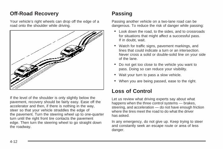
Off-Road RecoveryYour vehicle’s right wheels can drop off the edge of aroad onto the shoulder while driving.
If the level of the shoulder is only slightly below thepavement, recovery should be fairly easy. Ease off theaccelerator and then, if there is nothing in the way,steer so that your vehicle straddles the edge ofthe pavement. Turn the steering wheel up to one-quarterturn until the right front tire contacts the pavementedge. Then turn the steering wheel to go straight downthe roadway.
PassingPassing another vehicle on a two-lane road can bedangerous. To reduce the risk of danger while passing:
• Look down the road, to the sides, and to crossroadsfor situations that might affect a successful pass.If in doubt, wait.
• Watch for traffic signs, pavement markings, andlines that could indicate a turn or an intersection.Never cross a solid or double-solid line on your sideof the lane.
• Do not get too close to the vehicle you want topass. Doing so can reduce your visibility.
• Wait your turn to pass a slow vehicle.
• When you are being passed, ease to the right.
Loss of ControlLet us review what driving experts say about whathappens when the three control systems — brakes,steering, and acceleration — do not have enough frictionwhere the tires meet the road to do what the driverhas asked.
In any emergency, do not give up. Keep trying to steerand constantly seek an escape route or area of lessdanger.
4-12

SkiddingIn a skid, a driver can lose control of the vehicle.Defensive drivers avoid most skids by taking reasonablecare suited to existing conditions, and by not overdrivingthose conditions. But skids are always possible.
The three types of skids correspond to your vehicle’sthree control systems. In the braking skid, the wheels arenot rolling. In the steering or cornering skid, too muchspeed or steering in a curve causes tires to slip and losecornering force. And in the acceleration skid, too muchthrottle causes the driving wheels to spin.
A cornering skid is best handled by easing your foot offof the accelerator pedal.
If your vehicle starts to slide, ease your foot off theaccelerator pedal and quickly steer the way you wantthe vehicle to go. If you start steering quickly enough,your vehicle may straighten out. Always be readyfor a second skid if it occurs.
Of course, traction is reduced when water, snow, ice,gravel, or other material is on the road. For safety, youwant to slow down and adjust your driving to theseconditions. It is important to slow down on slipperysurfaces because stopping distance is longer andvehicle control more limited.
While driving on a surface with reduced traction, tryyour best to avoid sudden steering, acceleration, orbraking, including reducing vehicle speed by shifting to alower gear. Any sudden changes could cause the tires toslide. You might not realize the surface is slippery untilyour vehicle is skidding. Learn to recognize warningclues — such as enough water, ice, or packed snow onthe road to make a mirrored surface — and slow downwhen you have any doubt.
Remember: Any Antilock Brake System (ABS) helpsavoid only the braking skid.
4-13

Driving at NightNight driving is more dangerous than day drivingbecause some drivers are likely to be impaired — byalcohol or drugs, with night vision problems, or byfatigue.
Night driving tips include:
• Drive defensively.
• Do not drink and drive.
• Reduce headlamp glare by adjusting the insiderearview mirror.
• Slow down and keep more space between you andother vehicles because headlamps can only light upso much road ahead.
• Watch for animals.
• When tired, pull off the road.
• Do not wear sunglasses.
• Avoid staring directly into approaching headlamps.
• Keep the windshield and all glass on your vehicleclean — inside and out.
• Keep your eyes moving, especially during turns orcurves.
No one can see as well at night as in the daytime.But, as we get older, these differences increase.A 50-year-old driver might need at least twice as muchlight to see the same thing at night as a 20-year-old.
Driving in Rain and on Wet RoadsRain and wet roads can reduce vehicle tractionand affect your ability to stop and accelerate.Always drive slower in these types of drivingconditions and avoid driving through large puddlesand deep-standing or flowing water.
4-14

{CAUTION:
Wet brakes can cause crashes. They might notwork as well in a quick stop and could causepulling to one side. You could lose control ofthe vehicle.
After driving through a large puddle of wateror a car/vehicle wash, lightly apply the brakepedal until the brakes work normally.
Flowing or rushing water creates strongforces. Driving through flowing water couldcause your vehicle to be carried away. If thishappens, you and other vehicle occupantscould drown. Do not ignore police warningsand be very cautious about trying to drivethrough flowing water.
HydroplaningHydroplaning is dangerous. Water can build up underyour vehicle’s tires so they actually ride on thewater. This can happen if the road is wet enough andyou are going fast enough. When your vehicle ishydroplaning, it has little or no contact with the road.
There is no hard and fast rule about hydroplaning.The best advice is to slow down when the road is wet.
Other Rainy Weather TipsBesides slowing down, other wet weather driving tipsinclude:
• Allow extra following distance.
• Pass with caution.
• Keep windshield wiping equipment in good shape.
• Keep the windshield washer fluid reservoir filled.
• Have good tires with proper tread depth. See Tireson page 5-49.
• Turn off cruise control, if equipped.
4-15

Before Leaving on a Long TripTo prepare your vehicle for a long trip, consider havingit serviced by your dealer/retailer before departing.
Things to check on your own include:
• Windshield Washer Fluid: Reservoir full?Windows clean — inside and outside?
• Wiper Blades: In good shape?
• Fuel, Engine Oil, Other Fluids: All levels checked?
• Lamps: Do they all work and are lenses clean?
• Tires: Are treads good? Are tires inflated torecommended pressure?
• Weather and Maps: Safe to travel?Have up-to-date maps?
Highway HypnosisAlways be alert and pay attention to your surroundingswhile driving. If you become tired or sleepy, find asafe place to park your vehicle and rest.
Other driving tips include:
• Keep the vehicle well ventilated.
• Keep interior temperature cool.
• Keep your eyes moving — scan the road aheadand to the sides.
• Check the rearview mirror and vehicle instrumentsoften.
Hill and Mountain RoadsDriving on steep hills or through mountains is differentthan driving on flat or rolling terrain. Tips for drivingin these conditions include:
• Keep the vehicle serviced and in good shape.
• Check all fluid levels and brakes, tires, coolingsystem, and transmission.
• Going down steep or long hills, shift to alower gear.
4-16

{CAUTION:
If you do not shift down, the brakes could getso hot that they would not work well. Youwould then have poor braking or even nonegoing down a hill. You could crash. Shift downto let the engine assist the brakes on a steepdownhill slope.
{CAUTION:
Coasting downhill in N (Neutral) or with theignition off is dangerous. The brakes will haveto do all the work of slowing down and theycould get so hot that they would not work well.You would then have poor braking or evennone going down a hill. You could crash.Always have the engine running and thevehicle in gear when going downhill.
• Stay in your own lane. Do not swing wide or cutacross the center of the road. Drive at speedsthat let you stay in your own lane.
• Top of hills: Be alert — something could be in yourlane (stalled car, accident).
• Pay attention to special road signs (falling rocksarea, winding roads, long grades, passing orno-passing zones) and take appropriate action.
Winter DrivingHere are some tips for winter driving:
• Have your vehicle in good shape for winter.
• You might want to put winter emergency supplies inyour vehicle.
Include an ice scraper, a small brush or broom, asupply of windshield washer fluid, a rag, some winterouter clothing, a small shovel, a flashlight, a red cloth,and a couple of reflective warning triangles. And, ifyou will be driving under severe conditions, include asmall bag of sand, a piece of old carpet, or a couple ofburlap bags to help provide traction. Be sure youproperly secure these items in your vehicle.
Also see Tires on page 5-49.
4-17

Driving on Snow or IceMost of the time, those places where the tires meet theroad probably have good traction.
However, if there is snow or ice between the tires andthe road, you can have a very slippery situation.You have a lot less traction, or grip, and need to bevery careful.
What is the worst time for this? Wet ice. Very cold snowor ice can be slick and hard to drive on. But wet icecan be even more trouble because it can offer the leasttraction of all. You can get wet ice when it is aboutfreezing, 32°F (0°C), and freezing rain begins to fall.Try to avoid driving on wet ice until salt and sand crewscan get there.
Whatever the condition — smooth ice, packed, blowing,or loose snow — drive with caution.
StabiliTrak® improves your ability to accelerate whendriving on a slippery road. Even with StabiliTrak®, slowdown and adjust your driving to the road conditions.Under certain conditions, you might want to turnthe traction control part of the StabiliTrak® System off,such as when driving through deep snow and loosegravel, to help maintain vehicle motion at lower speeds.See StabiliTrak® System on page 4-6 and If YourVehicle is Stuck in Sand, Mud, Ice, or Snow onpage 4-21.
4-18
The Antilock Brake System (ABS) improves yourvehicle’s stability when you make a hard stop on aslippery road. Even though you have ABS, beginstopping sooner than you would on dry pavement.See Antilock Brake System (ABS) on page 4-5.
• Allow greater following distance on anyslippery road.
• Watch for slippery spots. The road might be fineuntil you hit a spot that is covered with ice. Onan otherwise clear road, ice patches can appear inshaded areas where the sun cannot reach, suchas around clumps of trees, behind buildings,or under bridges. Sometimes the surface of a curveor an overpass can remain icy when thesurrounding roads are clear. If you see a patch ofice ahead of you, brake before you are on it. Try notto brake while you are actually on the ice, andavoid sudden steering maneuvers.
If You Are Caught in a BlizzardIf you are stopped by heavy snow, you could be in aserious situation. You should probably stay withyour vehicle unless you know for sure that you are nearhelp and you can hike through the snow. Here aresome things to do to summon help and keep yourselfand your passengers safe:
• Turn on the hazard warning flashers.
• Tie a red cloth to your vehicle to alert police thatyou have been stopped by the snow.
• Put on extra clothing or wrap a blanket around you.If you do not have blankets or extra clothing, makebody insulators from newspapers, burlap bags,rags, floor mats — anything you can wrap aroundyourself or tuck under your clothing to keep warm.
4-19

You can run the engine to keep warm, but be careful.
{CAUTION:
Snow can trap exhaust gases under yourvehicle. This can cause deadly CO (carbonmonoxide) gas to get inside. CO couldovercome you and kill you. You cannot see itor smell it, so you might not know it is in yourvehicle. Clear away snow from around thebase of your vehicle, especially any that isblocking the exhaust pipe. And check aroundagain from time to time to be sure snow doesnot collect there.
Open a window just a little on the side of thevehicle that is away from the wind. This willhelp keep CO out.
4-20

Run the engine only as long as you must. This savesfuel. When you run the engine, make it go a little fasterthan just idle. That is, push the accelerator slightly. Thisuses less fuel for the heat that you get and it keeps thebattery charged. You will need a well-charged battery torestart the vehicle, and possibly for signaling later on withthe headlamps. Let the heater run for a while.
Then, shut the engine off and close the window almostall the way to preserve the heat. Start the engineagain and repeat this only when you feel reallyuncomfortable from the cold. But do it as little aspossible. Preserve the fuel as long as you can. To helpkeep warm, you can get out of the vehicle and dosome fairly vigorous exercises every half hour or so untilhelp comes.
If Your Vehicle is Stuck in Sand,Mud, Ice, or SnowSlowly and cautiously spin the wheels to free thevehicle when stuck in sand, mud, ice, or snow. SeeRocking Your Vehicle to Get It Out on page 4-22.
If the vehicle has a traction system, it can often help tofree a stuck vehicle. Refer to the vehicle’s tractionsystem in the Index. If stuck too severely for the tractionsystem to free the vehicle, turn the traction system offand use the rocking method.
{CAUTION:
If you let your vehicle’s tires spin at highspeed, they can explode, and you or otherscould be injured. The vehicle can overheat,causing an engine compartment fire or otherdamage. Spin the wheels as little as possibleand avoid going above 35 mph (55 km/h) asshown on the speedometer.
For information about using tire chains on the vehicle,see Tire Chains on page 5-71.
4-21

Rocking Your Vehicle to Get It OutFirst, turn the steering wheel left and right to clearthe area around the front wheels. Turn the tractioncontrol part of the StabiliTrak® System off. SeeStabiliTrak® System on page 4-6. Then shift back andforth between REVERSE (R) and a forward gear,spinning the wheels as little as possible. To preventtransmission wear, wait until the wheels stop spinningbefore shifting gears. Release the accelerator pedalwhile you shift, and press lightly on the accelerator pedalwhen the transmission is in gear. By slowly spinningthe wheels in the forward and reverse directions, you willcause a rocking motion that could free your vehicle.If that does not get your vehicle out after a few tries, itmight need to be towed out. If your vehicle does needto be towed out, see Towing Your Vehicle on page 4-27.
Loading the VehicleIt is very important to know how much weight yourvehicle can carry. This weight is called the vehiclecapacity weight and includes the weight of alloccupants, cargo, and all nonfactory-installedoptions. Two labels on your vehicle show how muchweight it may properly carry, the Tire and LoadingInformation label and the Certification/Tire label.
{CAUTION:
Do not load the vehicle any heavier thanthe Gross Vehicle Weight Rating (GVWR),or either the maximum front or rear GrossAxle Weight Rating (GAWR). If you do,parts on the vehicle can break, and it canchange the way your vehicle handles.These could cause you to lose controland crash. Also, overloading can shortenthe life of the vehicle.
4-22

Tire and Loading Information Label
A vehicle specific Tire and Loading Informationlabel is attached to the center pillar (B-pillar) of yourvehicle. With the driver’s door open, you will find thelabel attached below the door lock post (striker).The tire and loading information label shows thenumber of occupant seating positions (A), and themaximum vehicle capacity weight (B) in kilogramsand pounds.
The Tire and Loading Information label also showsthe size of the original equipment tires (C) andthe recommended cold tire inflation pressures (D).For more information on tires and inflation seeTires on page 5-49 and Inflation - Tire Pressure onpage 5-56.
There is also important loading information on thevehicle Certification/Tire label. It tells you theGross Vehicle Weight Rating (GVWR) andthe Gross Axle Weight Rating (GAWR) for thefront and rear axle. See “Certification/Tire Label”later in this section.
Steps for Determining Correct Load Limit1. Locate the statement “The combined weight
of occupants and cargo should never exceedXXX kg or XXX lbs” on your vehicle’s placard.
2. Determine the combined weight of the driverand passengers that will be riding in yourvehicle.
3. Subtract the combined weight of the driverand passengers from XXX kg or XXX lbs.
Example Label
4-23

4. The resulting figure equals the availableamount of cargo and luggage load capacity.For example, if the “XXX” amount equals1400 lbs and there will be five 150 lbpassengers in your vehicle, the amount ofavailable cargo and luggage load capacity is650 lbs (1400 − 750 (5 x 150) = 650 lbs).
5. Determine the combined weight of luggageand cargo being loaded on the vehicle. Thatweight may not safely exceed the availablecargo and luggage load capacity calculatedin Step 4.
6. If your vehicle will be towing a trailer, the loadfrom your trailer will be transferred to yourvehicle. Consult this manual to determine howthis reduces the available cargo and luggageload capacity for your vehicle.
See Towing a Trailer on page 4-31 for importantinformation on towing a trailer, towing safety rules,and trailering tips.
Item Description Total
AVehicle CapacityWeight forExample 1 =
1,000 lbs(453 kg)
BSubtract OccupantWeight 150 lbs(68 kg) × 2 =
300 lbs (136 kg)
C Available Occupantand Cargo Weight = 700 lbs (317 kg)
Example 1
4-24

Item Description Total
AVehicle CapacityWeight forExample 2 =
1,000 lbs(453 kg)
BSubtract OccupantWeight 150 lbs(68 kg) × 5 =
750 lbs (340 kg)
C Available CargoWeight = 250 lbs (113 kg)
Item Description Total
AVehicle CapacityWeight forExample 3 =
1,000 lbs(453 kg)
BSubtract OccupantWeight 200 lbs(91 kg) × 5 =
1,000 lbs(453 kg)
C Available CargoWeight = 0 lbs (0 kg)
Refer to your vehicle’s tire and loading informationlabel for specific information about your vehicle’scapacity weight and seating positions.
Example 2 Example 3
4-25

The combined weight of the driver, passengers,and cargo should never exceed your vehicle’scapacity weight.
Certification/Tire Label
A vehicle specific Certification/Tire label isattached to the rear edge of the driver’s door.
The label shows the gross weight capacity of yourvehicle. This is called the Gross Vehicle WeightRating (GVWR). The GVWR includes the weight ofthe vehicle, all occupants, fuel, and cargo.
The Certification/Tire label also tells you themaximum weights for the front and rear axles,called the Gross Axle Weight Rating (GAWR). Tofind out the actual loads on your front and rearaxles, you need to go to a weigh station and weighyour vehicle. Your dealer/retailer can help youwith this. Be sure to spread out your load equallyon both sides of the centerline.
Never exceed the GVWR for your vehicle or theGAWR for either the front or rear axle.
{CAUTION:
Do not load the vehicle any heavier thanthe Gross Vehicle Weight Rating (GVWR),or either the maximum front or rear GrossAxle Weight Rating (GAWR). If you do,parts on the vehicle can break, and it canchange the way your vehicle handles.These could cause you to lose controland crash. Also, overloading can shortenthe life of the vehicle.
Notice: Overloading your vehicle may causedamage. Repairs would not be covered by yourwarranty. Do not overload your vehicle.
4-26

If you put things inside your vehicle — likesuitcases, tools, packages, or anything else, theywill go as fast as the vehicle goes. If you haveto stop or turn quickly, or if there is a crash, theywill keep going.
{CAUTION:
Things you put inside your vehicle canstrike and injure people in a sudden stopor turn, or in a crash.
• Put things in the cargo area of yourvehicle. Try to spread the weightevenly.
• Never stack heavier things, likesuitcases, inside the vehicle so thatsome of them are above the tops ofthe seats.
• Do not leave an unsecured childrestraint in your vehicle.
• When you carry something inside thevehicle, secure it whenever you can.
• Do not leave a seat folded downunless you need to.
Towing
Towing Your VehicleTo avoid vehicle damage, a platform or flatbed trailershould be used to transport this vehicle. Consultyour dealer/retailer or a professional towing service ifyou need to have your disabled vehicle towed. SeeRoadside Assistance Program on page 7-7.
If you want to tow your vehicle behind another vehiclefor recreational purposes (such as behind a motorhome),see “Recreational Vehicle Towing” following.
Recreational Vehicle TowingRecreational vehicle towing means towing your vehiclebehind another vehicle – such as behind a motorhome.The two most common types of recreational vehicletowing are known as “dinghy towing” (towing your vehiclewith all four wheels on the ground) and “dolly towing”(towing your vehicle with two wheels on the ground andtwo wheels up on a device known as a “dolly”).
4-27

With the proper preparation and equipment, manyvehicles can be towed in these ways. See “DinghyTowing” and “Dolly Towing” following in this section.
Here are some important things to consider before youdo recreational vehicle towing:
• What’s the towing capacity of the towing vehicle?Be sure you read the tow vehicle manufacturer’srecommendations.
• How far will you tow? Some vehicles haverestrictions on how far and how long they can tow.
• Do you have the proper towing equipment?See your dealer/retailer or trailering professional foradditional advice and equipment recommendations.
• Is your vehicle ready to be towed? Just as youwould prepare your vehicle for a long trip, you’llwant to make sure your vehicle is prepared to betowed. See Before Leaving on a Long Trip onpage 4-16.
Dinghy Towing
If you have a front-wheel-drive vehicle, it can be dinghytowed from the front. These vehicles may also betowed by putting the front wheels on a dolly. See “DollyTowing” later in this section.
If you have an all-wheel-drive vehicle, it can be dinghytowed from the front. You can also tow these vehiclesby placing them on a platform trailer with all four wheelsoff of the ground. These vehicles cannot be towedusing a dolly.
4-28

For vehicles being dinghy towed, the vehicle should berun at the beginning of each day and at each RVfuel stop for about five minutes. This will ensure properlubrication of transmission components. Re-installthe fuse to start the vehicle.
To tow your vehicle from the front with all four wheelson the ground:
1. Position the vehicle to tow and then secure it to thetowing vehicle.
2. Shift the transmission to P (Park) and turn theignition to LOCK/OFF.
3. Set the parking brake.
4. Turn the ignition to ACC/ACCESSORY.
5. Shift the transmission to N (Neutral).
6. To prevent your battery from draining while thevehicle is being towed, remove the 50 ampBATT1 fuse from the underhood fuse block andstore in a safe location. See Underhood Fuse Blockon page 5-115.
7. Release the parking brake.
Notice: If you tow your vehicle without performingeach of the steps listed under “Dinghy Towing,”you could damage the automatic transmission.Be sure to follow all steps of the dinghy towingprocedure prior to and after towing your vehicle.
Notice: If you exceed 65 mph (105 km/h) whiletowing your vehicle, it could be damaged. Neverexceed 65 mph (105 km/h) while towing your vehicle.
Once you have reached your destination:
1. Set the parking brake.
2. Reinstall the 50 amp BATT1 fuse to the underhoodfuse block.
3. Shift the transmission to P (Park), turn the ignitionto LOCK/OFF and remove the key from the ignition.
4. Release the parking brake.
Notice: Don’t tow a vehicle with the front drivewheels on the ground if one of the front tires is acompact spare tire. Towing with two differenttire sizes on the front of the vehicle can causesevere damage to the transmission.
4-29

Dolly Towing (All-Wheel-Drive Vehicles)
All-wheel-drive vehicles must not be towed withtwo wheels on the ground. To properly tow thesevehicles, they should be placed on a platform trailerwith all four wheels off of the ground or dinghy towedfrom the front.
Dolly Towing (Front-Wheel-DriveVehicles Only)
To tow your front-wheel-drive vehicle from the front withtwo wheels on the ground:
1. Put the front wheels on a dolly.
2. Move the shift lever to P (Park).
3. Set the parking brake.
4-30

4. Clamp the steering wheel in a straight-aheadposition with a clamping device designed for towing.
5. Remove the key from the ignition.
6. Secure the vehicle to the dolly.
7. Release the parking brake.
Towing Your Vehicle From the Rear
Notice: Towing your vehicle from the rear coulddamage it. Also, repairs would not be covered bythe warranty. Never have your vehicle towedfrom the rear.
Do not tow your vehicle from the rear.
Towing a Trailer
{CAUTION:
If you do not use the correct equipment anddrive properly, you can lose control when youpull a trailer. For example, if the trailer is tooheavy, the brakes may not work well — or evenat all. You and your passengers could beseriously injured. You may also damage yourvehicle; the resulting repairs would not becovered by your warranty. Pull a trailer only ifyou have followed all the steps in this section.Ask your dealer/retailer for advice andinformation about towing a trailer with yourvehicle.
To identify the trailering capacity of your vehicle, youshould read the information in “Weight of the Trailer” thatappears later in this section. But trailering is differentthan just driving your vehicle by itself. Trailering meanschanges in handling, acceleration, braking, durabilityand fuel economy. Successful, safe trailering takescorrect equipment, and it has to be used properly.
4-31

That is the reason for this part. In it are manytime-tested, important trailering tips and safety rules.Many of these are important for your safety and that ofyour passengers. So please read this section carefullybefore you pull a trailer.
Load-pulling components such as the engine,transmission, rear axle, wheel assemblies and tires areforced to work harder against the drag of the addedweight. The engine is required to operate at relativelyhigher speeds and under greater loads, generating extraheat. What’s more, the trailer adds considerably towind resistance, increasing the pulling requirements.
If You Do Decide to Pull a TrailerIf you do, here are some important points:
• There are many different laws, including speed limitrestrictions, having to do with trailering. Make sureyour rig will be legal, not only where you livebut also where you will be driving. A good sourcefor this information can be state or provincial police.
• Consider using a sway control. You can ask a hitchdealer/retailer about sway controls.
• Do not tow a trailer at all during the first 500 miles(805 km) your new vehicle is driven. Your engine,axle or other parts could be damaged.
• Then, during the first 500 miles (805 km) that youtow a trailer, do not drive over 50 mph (80 km/h)and do not make starts at full throttle. Thishelps your engine and other parts of your vehiclewear in at the heavier loads.
• Obey speed limit restrictions when towing a trailer.Do not drive faster than the maximum posted speedfor trailers, or no more than 55 mph (90 km/h), tosave wear on your vehicle’s parts.
• You can tow in DRIVE (D). You may want to shift thetransmission to LOW (L) or, if necessary, a lowergear selection if the transmission shifts too often(e.g., under heavy loads and/or hilly conditions).See “Tow/Haul Mode” later in this section.
Three important considerations have to do with weight:
• The weight of the trailer.
• The weight of the trailer tongue.
• And the total weight on your vehicle’s tires.
4-32

Tow/Haul ModeTow/Haul is a feature that assists when pulling a heavytrailer or a large or heavy load. The purpose of theTow/Haul mode is to:
• Reduce the frequency and improve the predictabilityof transmission shifts when pulling a heavy trailer ora large or heavy load.
• Provide the same solid shift feel when pulling aheavy trailer or a large or heavy load as whenthe vehicle is unloaded.
• Improve control of vehicle speed while requiringless throttle pedal activity when pulling a heavytrailer or a large or heavy load.
• Increase the charging system voltage to assist inrecharging a battery installed in a trailer.
Press this button locatedon the console toenable/disable theTow/Haul mode.
The Tow/Haul light on the instrument panel will come onto indicate that Tow/Haul mode has been selected.
Tow/Haul may be turned off by pressing the buttonagain, at which time the indicator light on the instrumentpanel will turn off. The vehicle will automatically turnoff Tow/Haul every time it is started.
Tow/Haul is designed to be most effective when thevehicle and trailer combined weight is at least 75 percentof the vehicle’s Gross Combined Weight Rating (GCWR).See Weight of the Trailer later in this section. Tow/Haul ismost useful under the following driving conditions:
• When pulling a heavy trailer or a large or heavy loadthrough rolling terrain.
• When pulling a heavy trailer or a large or heavy loadin stop and go traffic.
• When pulling a heavy trailer or a large or heavy loadin busy parking lots where improved low speedcontrol of the vehicle is desired.
Operating the vehicle in Tow/Haul when lightly loadedor with no trailer at all will not cause damage. However,there is no benefit to the selection of Tow/Haul whenthe vehicle is unloaded. Such a selection when unloadedmay result in unpleasant engine and transmissiondriving characteristics and reduced fuel economy.Tow/Haul is recommended only when pulling a heavytrailer or a large or heavy load.
4-33

Weight of the TrailerHow heavy can a trailer safely be?
It depends on how you plan to use your rig. Forexample, speed, altitude, road grades, outsidetemperature and how much your vehicle is used to pulla trailer are all important. It can also depend on anyspecial equipment that you have on your vehicle,and the amount of tongue weight the vehicle can carry.See “Weight of the Trailer Tongue” later in thissection for more information.
Maximum trailer weight is calculated assuming only thedriver is in the tow vehicle and it has all the requiredtrailering equipment. The weight of additional optionalequipment, passengers and cargo in the tow vehiclemust be subtracted from the maximum trailer weight.
Look in the following chart to find the maximum trailerweight for your vehicle.
Vehicle MaximumTrailer Weight *GCWR
Front-WheelDrive
2,000 lbs(907 kg)
7,500 lbs(3 402 kg)
**Front-WheelDrive
4,500 lbs(2 041 kg)
9,500 lbs(4 309 kg)
All-Wheel Drive 2,000 lbs(907 kg)
7,700 lbs(3 493 kg)
**All-Wheel Drive 4,500 lbs(2 041 kg)
9,700 lbs(4 400 kg)
*The Gross Combination Weight Rating (GCWR) isthe total allowable weight of the completely loadedvehicle and trailer including any passengers, cargo,equipment and conversions. The GCWR for yourvehicle should not be exceeded.**Includes optional trailer towing package (V92)
Ask your dealer/retailer for our trailering information oradvice, or write us at our Customer AssistanceOffices. See Customer Assistance Offices on page 7-6for more information.
4-34

Weight of the Trailer TongueThe tongue load (A) of any trailer is an important weightto measure because it affects the total or gross weightof your vehicle. The Gross Vehicle Weight (GVW)includes the curb weight of the vehicle, any cargo youmay carry in it, and the people who will be riding inthe vehicle. If you have a lot of options, equipment,passengers or cargo in the vehicle, it will reducethe tongue weight your vehicle can carry, which will alsoreduce the trailer weight your vehicle can tow. And ifyou tow a trailer, you must add the tongue load tothe GVW because your vehicle will be carrying thatweight, too. See Loading the Vehicle on page 4-22 formore information about your vehicle’s maximumload capacity.
If you are using a weight-carrying hitch or aweight-distributing hitch, the trailer tongue (A) shouldweigh 10-15 percent of the total loaded trailer weight (B).
After you have loaded your trailer, weigh the trailer andthen the tongue, separately, to see if the weights areproper. If they are not, you may be able to get them rightsimply by moving some items around in the trailer.
Trailering may also be limited by the vehicle’s ability tocarry tongue weight. Tongue weight cannot cause thevehicle to exceed the GVWR (Gross Vehicle WeightRating) or the RGAWR (Rear Gross Axle Weight Rating).The effect of additional weight may reduce your traileringcapacity more than the total of the additional weight.
4-35

Consider the following example:
A vehicle model base weight is 5,500 lbs (2 495 kg);2,800 lbs (1 270 kg) at the front axle and 2,700 lbs(1 225 kg) at the rear axle. It has a GVWR of 7,200 lbs(3 266 kg), a RGAWR of 4,000 lbs (1 814 kg) and aGCWR (Gross Combination Weight Rating) of14,000 lbs (6 350 kg). The trailer rating should be:
You can expect tongue weight to be at least 10 percentof trailer weight (850 lbs (386 kg)) and because theweight is applied well behind the rear axle, the effect onthe rear axle will be greater than just the weightitself, as much as 1.5 times as much. The weight at therear axle could be 850 lbs (386 kg) X 1.5 = 1,275 lbs(578 kg). Since the rear axle already weighs 2,700 lbs(1 225 kg), adding 1,275 lbs (578 kg) brings thetotal to 3,975 lbs (1 803 kg). This is very close to, butwithin the limit for RGAWR as well. The vehicle is set totrailer up to 8,500 lbs (3 856 kg).
But let us say your specific vehicle is equipped withsome of the latest options and you have a frontseat passenger and two rear seat passengers withsome luggage and gear in the vehicle as well. You mayadd 300 lbs (136 kg) to the front axle weight and400 lbs (181 kg) to the rear axle weight. Your vehiclenow weighs:
Weight is still below 7,200 lbs (3 266 kg) and you maythink that you should subtract 700 additional pounds(318 kg) from your trailering capacity to stay withinGCWR limits. Your maximum trailer would only be7,800 lbs (3 538 kg). You may go further and think youmust limit tongue weight to less than 1,000 lbs (454 kg) toavoid exceeding GVWR. But, you must still consider theeffect on the rear axle. Because your rear axle nowweighs 3,100 lbs (1 406 kg), you can only put 900 lbs(408 kg) on the rear axle without exceeding RGAWR.
4-36

The effect of tongue weight is about 1.5 times the actualweight. Dividing the 900 lbs (408 kg) by 1.5 leaves youwith being able to handle only 600 lbs (272 kg) of tongueweight. Since tongue weight is usually at least 10 percentof total loaded trailer weight, you can expect that thelargest trailer your vehicle can properly handle is6,000 lbs (2 721 kg).
It is important that you make sure your vehicle does notexceed any of its ratings — GCWR, GVWR, RGAWR,Maximum Trailer Rating or Tongue Weight. The onlyway to be sure you are not exceeding any of theseratings is to weigh your vehicle and trailer.
Total Weight on Your Vehicle’s TiresBe sure your vehicle’s tires are inflated to the upper limitfor cold tires. You will find these numbers on theCertification/Tire label. See Loading the Vehicle onpage 4-22. Then be sure you do not go over the GVWlimit for your vehicle, including the weight of thetrailer tongue.
HitchesIt is important to have the correct hitch equipment.Crosswinds, large trucks going by and rough roads area few reasons why you will need the right hitch. Hereare some rules to follow:
• The rear bumper on your vehicle is not intendedfor hitches. Do not attach rental hitches orother bumper-type hitches to it. Use only aframe-mounted hitch that does not attach to thebumper.
• Will you have to make any holes in the body ofyour vehicle when you install a trailer hitch? Ifyou do, then be sure to seal the holes later whenyou remove the hitch. If you do not seal them,deadly carbon monoxide (CO) from your exhaustcan get into your vehicle. See Engine Exhauston page 2-37. Dirt and water can, too.
4-37

Safety ChainsYou should always attach chains between your vehicleand your trailer. Cross the safety chains under thetongue of the trailer so that the tongue will not drop tothe road if it becomes separated from the hitch.Instructions about safety chains may be provided by thehitch manufacturer or by the trailer manufacturer.Follow the manufacturer’s recommendation for attachingsafety chains and do not attach them to the bumper.Always leave just enough slack so you can turnwith your rig. And, never allow safety chains to drag onthe ground.
Trailer BrakesIf you tow more than 1,000 lbs (450 kg), use trailerbrakes. Because your vehicle has antilock brakes,do not try to tap into your vehicle’s hydraulic brakesystem. If you do, both brake systems will not workwell, or at all.
Be sure to read and follow the instructions for the trailerbrakes so you will be able to install, adjust andmaintain them properly.
Driving with a TrailerTowing a trailer requires a certain amount of experience.Before setting out for the open road, you will want toget to know your rig. Acquaint yourself with the feel ofhandling and braking with the added weight of the trailer.And always keep in mind that the vehicle you aredriving is now a good deal longer and not nearly asresponsive as your vehicle is by itself.
Before you start, check all trailer hitch parts andattachments, safety chains, electrical connector, lamps,tires and mirror adjustment. If the trailer has electricbrakes, start your vehicle and trailer moving and thenapply the trailer brake controller by hand to be surethe brakes are working. This lets you check yourelectrical connection at the same time.
During your trip, check occasionally to be sure that theload is secure, and that the lamps and any trailerbrakes are still working.
Following DistanceStay at least twice as far behind the vehicle ahead asyou would when driving your vehicle without a trailer.This can help you avoid situations that requireheavy braking and sudden turns.
4-38

PassingYou will need more passing distance up ahead whenyou are towing a trailer. And, because you are a gooddeal longer, you will need to go much farther beyond thepassed vehicle before you can return to your lane.
Backing UpHold the bottom of the steering wheel with one hand.Then, to move the trailer to the left, just move that handto the left. To move the trailer to the right, move yourhand to the right. Always back up slowly and, if possible,have someone guide you.
Making Turns
Notice: Making very sharp turns while traileringcould cause the trailer to come in contact with thevehicle. Your vehicle could be damaged. Avoidmaking very sharp turns while trailering.
When you are turning with a trailer, make wider turnsthan normal. Do this so your trailer will not strikesoft shoulders, curbs, road signs, trees or other objects.Avoid jerky or sudden maneuvers. Signal well inadvance.
Turn Signals When Towing a TrailerWhen you tow a trailer, your vehicle may need adifferent turn signal flasher and/or extra wiring. Checkwith your dealer/retailer. The arrows on your instrumentpanel will flash whenever you signal a turn or lanechange. Properly hooked up, the trailer lamps will alsoflash, telling other drivers you’re about to turn,change lanes or stop.
When towing a trailer, the arrows on your instrumentpanel will flash for turns even if the bulbs on the trailerare burned out. Thus, you may think drivers behindyou are seeing your signal when they are not. Itis important to check occasionally to be sure the trailerbulbs are still working.
Driving on GradesYour vehicle is designed primarily as a passenger andload carrying vehicle. If you tow a trailer, your vehiclewill require more frequent maintenance due to theadditional load. Because of the added load of the trailer,your vehicle’s engine may overheat on hot days,when going up a long or steep grade with a trailer. If theengine coolant temperature gage indicates overheating,turn off the air conditioning to reduce engine load,pull off the road and stop in a safe spot.
4-39

Reduce speed and shift to a lower gear before you startdown a long or steep downgrade. If you do not shiftdown, you might have to use your brakes so much thatthey would get hot and no longer work well.
On a long uphill grade, shift down and reduce yourspeed to around 55 mph (88 km/h) to reduce thepossibility of the engine and the transmissionoverheating.
Parking on Hills
{CAUTION:
You really should not park your vehicle, with atrailer attached, on a hill. If something goeswrong, your rig could start to move. Peoplecan be injured, and both your vehicle and thetrailer can be damaged.
But if you ever have to park your rig on a hill, here ishow to do it:
1. Apply your regular brakes, but do not shift intoPARK (P).When parking uphill, turn your wheels away fromthe curb. When parking downhill, turn your wheelsinto the curb.
2. Have someone place chocks behind the trailerwheels.
3. When the chocks are in place, release the regularbrakes until the chocks absorb the load.
4. Reapply the regular brakes. Then apply yourparking brake and shift into PARK (P).
5. Release the regular brakes.
4-40

When You Are Ready to Leave AfterParking on a Hill1. Apply your regular brakes and hold the pedal down
while you:
• start your engine,
• shift into a gear, and
• release the parking brake.
2. Let up on the brake pedal.
3. Drive slowly until the trailer is clear of the chocks.
4. Stop and have someone pick up and store thechocks.
Maintenance When Trailer TowingYour vehicle will need service more often when you arepulling a trailer. See Scheduled Maintenance onpage 6-4 for more information. Things that are especiallyimportant in trailer operation are automatic transmissionfluid (do not overfill), engine oil, axle lubricant, drivebelt, cooling system and brake system. Each of these iscovered in this manual, and the Index will help youfind them quickly. If you are trailering, it is a good ideato review this information before you start your trip.
Check periodically to see that all hitch nuts and boltsare tight.
Trailer Wiring HarnessYour vehicle is equipped with the following wiringharness for towing a trailer.
4-41

Basic Trailer WiringThe trailer wiring harness, with a seven-pin connector,is located at the rear of the vehicle and is tied tothe vehicle’s frame. The harness connector can beplugged into a seven-pin universal heavy-duty trailerconnector available through your dealer/retailer.
The seven-wire harness contains the following trailercircuits:
• Yellow: Left Stop/Turn Signal
• Dark Green: Right Stop/Turn Signal
• Brown: Taillamps
• Black: Ground
• Light Green: Back-up Lamps
• Red/Black: Battery Feed
• Dark Blue: Trailer Brake*
*The fuse for this circuit is installed in the underhoodelectrical center, but the wires are not connected.They should be connected by your dealer/retailer or aqualified service center.
If the back-up lamp circuit is not functional, contact yourdealer/retailer.
If you are charging a remote (non-vehicle) battery, pressthe Tow/Haul mode switch located on the centerconsole near the climate controls. This will boost thevehicle system voltage and properly charge the battery.If the trailer is too light for Tow/Haul mode, you canturn on the headlamps (Non-HID only) as a second wayto boost the vehicle system and charge the battery.
Engine Cooling When Trailer TowingYour cooling system may temporarily overheat duringsevere operating conditions. See Engine Overheating onpage 5-23.
4-42

Service ............................................................5-3Accessories and Modifications ..........................5-3California Proposition 65 Warning .....................5-4California Perchlorate Materials Requirements .....5-4Doing Your Own Service Work .........................5-4Adding Equipment to the Outside of the
Vehicle ......................................................5-5Fuel ................................................................5-5
Gasoline Octane ............................................5-5Gasoline Specifications ....................................5-6California Fuel ...............................................5-6Additives .......................................................5-6Fuels in Foreign Countries ...............................5-7Filling the Tank ..............................................5-8Filling a Portable Fuel Container .....................5-10
Checking Things Under the Hood ....................5-11Hood Release ..............................................5-11Engine Compartment Overview .......................5-12Engine Oil ...................................................5-13Engine Oil Life System ..................................5-16Engine Air Cleaner/Filter ................................5-18Automatic Transmission Fluid .........................5-20Engine Coolant .............................................5-20Radiator Pressure Cap ..................................5-23Engine Overheating .......................................5-23
Overheated Engine ProtectionOperating Mode ........................................5-25
Cooling System ............................................5-26Power Steering Fluid .....................................5-32Windshield Washer Fluid ................................5-33Brakes ........................................................5-34Battery ........................................................5-37Jump Starting ...............................................5-38
All-Wheel Drive ..............................................5-43Headlamp Aiming ...........................................5-44Bulb Replacement ..........................................5-45
High Intensity Discharge (HID) Lighting ............5-45Halogen Bulbs ..............................................5-45Taillamps, Turn Signal, Stoplamps and
Sidemarker Lamps .....................................5-46License Plate Lamp ......................................5-47Replacement Bulbs .......................................5-47
Windshield Wiper Blade Replacement ..............5-48Tires ..............................................................5-49
Tire Sidewall Labeling ...................................5-50Tire Terminology and Definitions .....................5-53Inflation - Tire Pressure .................................5-56Tire Pressure Monitor System .........................5-58Tire Pressure Monitor Operation .....................5-59
Section 5 Service and Appearance Care
5-1

Tire Inspection and Rotation ...........................5-63When It Is Time for New Tires .......................5-64Buying New Tires .........................................5-65Different Size Tires and Wheels ......................5-67Uniform Tire Quality Grading ..........................5-68Wheel Alignment and Tire Balance ..................5-70Wheel Replacement ......................................5-70Tire Chains ..................................................5-71If a Tire Goes Flat ........................................5-72Tire Sealant and Compressor Kit ....................5-73Changing a Flat Tire .....................................5-84Removing the Spare Tire and Tools ................5-85Removing the Flat Tire and Installing the
Spare Tire ................................................5-88Secondary Latch System ...............................5-93Storing a Flat or Spare Tire and Tools ............5-96Compact Spare Tire ....................................5-100
Appearance Care ..........................................5-100Interior Cleaning .........................................5-100Fabric/Carpet ..............................................5-102Leather ......................................................5-102Instrument Panel, Vinyl, and Other Plastic
Surfaces .................................................5-103Care of Safety Belts ....................................5-103Weatherstrips .............................................5-103
Washing Your Vehicle ..................................5-104Cleaning Exterior Lamps/Lenses ....................5-104Finish Care ................................................5-104Windshield, Backglass, and Wiper Blades .......5-105Aluminum or Chrome-Plated Wheels
and Trim ................................................5-106Tires .........................................................5-106Sheet Metal Damage ...................................5-107Finish Damage ...........................................5-107Underbody Maintenance ...............................5-107Chemical Paint Spotting ...............................5-107Vehicle Care/Appearance Materials ................5-108
Vehicle Identification .....................................5-109Vehicle Identification Number (VIN) ................5-109Service Parts Identification Label ...................5-109
Electrical System ..........................................5-110High Voltage Devices and Wiring ..................5-110Add-On Electrical Equipment .........................5-110Windshield Wiper Fuses ...............................5-110Power Windows and Other Power Options ......5-111Fuses and Circuit Breakers ..........................5-111Instrument Panel Fuse Block ........................5-111Underhood Fuse Block ................................5-115
Capacities and Specifications ........................5-120
Section 5 Service and Appearance Care
5-2
ServiceFor service and parts needs, visit your dealer/retailer.You will receive genuine Saturn parts and Saturn-trainedand supported service people.
Genuine Saturn parts have one of these marks.
Accessories and ModificationsWhen non-dealer/non-retailer accessories are added toyour vehicle they can affect your vehicle’s performanceand safety, including such things as, airbags, braking,stability, ride and handling, emissions systems,aerodynamics, durability, and electronic systems likeantilock brakes, traction control and stability control.Some of these accessories could even cause malfunctionor damage not covered by warranty.
GM Accessories are designed to complement andfunction with other systems on your vehicle. Your GMdealer/retailer can accessorize your vehicle usinggenuine GM Accessories. When you go to your GMdealer/retailer and ask for GM Accessories, you will knowthat GM-trained and supported service technicians willperform the work using genuine GM Accessories.
Also, see Adding Equipment to Your Airbag-EquippedVehicle on page 1-78.
5-3

California Proposition 65 WarningMost motor vehicles, including this one, contain and/oremit chemicals known to the State of California to causecancer and birth defects or other reproductive harm.Engine exhaust, many parts and systems (includingsome inside the vehicle), many fluids, and somecomponent wear by-products contain and/or emitthese chemicals.
California Perchlorate MaterialsRequirementsCertain types of automotive applications, such asairbag initiators, seat belt pretensioners, and lithiumbatteries contained in remote keyless entry transmitters,may contain perchlorate materials. Special handlingmay be necessary. For additional information, seewww.dtsc.ca.gov/hazardouswaste/perchlorate.
Doing Your Own Service Work
{CAUTION:
You can be injured and your vehicle could bedamaged if you try to do service work on avehicle without knowing enough about it.
• Be sure you have sufficient knowledge,experience, the proper replacement parts,and tools before you attempt any vehiclemaintenance task.
• Be sure to use the proper nuts, bolts,and other fasteners. English and metricfasteners can be easily confused. If youuse the wrong fasteners, parts can laterbreak or fall off. You could be hurt.
If you want to do some of your own service work,you should use the proper service manual. It tells youmuch more about how to service your vehicle thanthis manual can. To order the proper service manual,see Service Publications Ordering Information onpage 7-16.
5-4
Your vehicle has an airbag system. Before attemptingto do your own service work, see Servicing YourAirbag-Equipped Vehicle on page 1-78.
You should keep a record with all parts receipts andlist the mileage and the date of any service workyou perform. See Maintenance Record on page 6-15.
Adding Equipment to the Outsideof the VehicleThings you might add to the outside of your vehiclecan affect the airflow around it. This can causewind noise and can affect fuel economy and windshieldwasher performance. Check with your dealer/retailerbefore adding equipment to the outside of your vehicle.
FuelUse of the recommended fuel is an important partof the proper maintenance of your vehicle. To helpkeep the engine clean and maintain optimum vehicleperformance, we recommend the use of gasolineadvertised as TOP TIER Detergent Gasoline.
Gasoline OctaneUse regular unleaded gasoline with a posted octanerating of 87 or higher. For best performance or trailertowing, you could choose to use middle grade 89 octaneunleaded gasoline. If the octane rating is less than 87,you might notice an audible knocking noise when youdrive, commonly referred to as spark knock. If this occurs,use a gasoline rated at 87 octane or higher as soon aspossible. If you are using gasoline rated at 87 octane orhigher and you hear heavy knocking, the engine needsservice.
5-5

Gasoline SpecificationsAt a minimum, gasoline should meet ASTMspecification D 4814 in the United States orCAN/CGSB-3.5 or 3.511 in Canada. Some gasolinescontain an octane-enhancing additive calledmethylcyclopentadienyl manganese tricarbonyl (MMT).We recommend against the use of gasolinescontaining MMT. See Additives on page 5-6for additional information.
California FuelIf your vehicle is certified to meet California EmissionsStandards, it is designed to operate on fuels that meetCalifornia specifications. See the underhood emissioncontrol label. If this fuel is not available in states adoptingCalifornia emissions standards, your vehicle will operatesatisfactorily on fuels meeting federal specifications, butemission control system performance might be affected.The malfunction indicator lamp could turn on and yourvehicle might fail a smog-check test. See MalfunctionIndicator Lamp on page 3-48. If this occurs, return to yourauthorized dealer/retailer for diagnosis. If it is determinedthat the condition is caused by the type of fuel used,repairs might not be covered by the vehicle warranty.
AdditivesTo provide cleaner air, all gasolines in the United Statesare now required to contain additives that help preventengine and fuel system deposits from forming, allowingthe emission control system to work properly. In mostcases, you should not have to add anything to the fuel.However, some gasolines contain only the minimumamount of additive required to meet U.S. EnvironmentalProtection Agency regulations. To help keep fuel injectorsand intake valves clean, or if your vehicle experiencesproblems due to dirty injectors or valves, look for gasolinethat is advertised as TOP TIER Detergent Gasoline. Also,your dealer/retailer has additives that will help correct andprevent most deposit-related problems.
5-6

Gasolines containing oxygenates, such as ethers andethanol, and reformulated gasolines might be available inyour area. We recommend that you use these gasolines,if they comply with the specifications described earlier.However, E85 (85% ethanol) and other fuels containingmore than 10% ethanol must not be used in vehicles thatwere not designed for those fuels.
Notice: Your vehicle was not designed for fuelthat contains methanol. Do not use fuel containingmethanol. It can corrode metal parts in the fuelsystem and also damage plastic and rubber parts.That damage would not be covered under yourwarranty.
Some gasolines that are not reformulated for lowemissions can contain an octane-enhancing additivecalled methylcyclopentadienyl manganese tricarbonyl(MMT); ask the attendant where you buy gasolinewhether the fuel contains MMT. We recommend against
the use of such gasolines. Fuels containing MMT canreduce the life of spark plugs and the performanceof the emission control system could be affected.The malfunction indicator lamp might turn on. If thisoccurs, return to your dealer/retailer for service.
Fuels in Foreign CountriesIf you plan on driving in another country outside theUnited States or Canada, the proper fuel might be hardto find. Never use leaded gasoline or any other fuelnot recommended in the previous text on fuel. Costlyrepairs caused by use of improper fuel would notbe covered by your warranty.
To check the fuel availability, ask an auto club, orcontact a major oil company that does business in thecountry where you will be driving.
5-7

Filling the Tank
{CAUTION:
Fuel vapor burns violently and a fuel fire cancause bad injuries. To help avoid injuries toyou and others, read and follow all theinstructions on the pump island. Turn off yourengine when you are refueling. Do not smokeif you are near fuel or refueling your vehicle.Do not use cellular phones. Keep sparks,flames, and smoking materials away from fuel.Do not leave the fuel pump unattended whenrefueling your vehicle. This is against the lawin some places. Do not re-enter the vehiclewhile pumping fuel. Keep children away fromthe fuel pump; never let children pump fuel.
The tethered fuel cap is located behind a hinged fueldoor on the driver’s side of the vehicle.
To open the fuel door, push the rearward center edge inand release. The door will pop open.
5-8

To remove the fuel cap, turn it slowly counterclockwise.The fuel cap has a spring in it; if the cap is releasedtoo soon, it will spring back to the right.
While refueling, hang the tethered fuel cap from thehook on the fuel door.
{CAUTION:
Fuel can spray out on you if you open thefuel cap too quickly. If you spill fuel and thensomething ignites it, you could be badly burned.This spray can happen if your tank is nearly full,and is more likely in hot weather. Open the fuelcap slowly and wait for any hiss noise to stop.Then unscrew the cap all the way.
Be careful not to spill fuel. Do not top off or overfill thetank and wait a few seconds after you have finishedpumping before removing the nozzle. Clean fuelfrom painted surfaces as soon as possible.See Washing Your Vehicle on page 5-104.
5-9

When replacing the fuel cap, turn it clockwise until itclicks. Make sure the cap is fully installed. The diagnosticsystem can determine if the fuel cap has been left off orimproperly installed. This would allow fuel to evaporateinto the atmosphere. See Malfunction Indicator Lampon page 3-48.
If your vehicle has a Driver Information Center (DIC),the TIGHTEN GAS CAP message will be displayed if thefuel cap is not properly installed.
{CAUTION:
If a fire starts while you are refueling, do notremove the nozzle. Shut off the flow of fuel byshutting off the pump or by notifying thestation attendant. Leave the area immediately.
Notice: If you need a new fuel cap, be sure to getthe right type. Your dealer/retailer can get onefor you. If you get the wrong type, it may not fitproperly. This may cause your malfunction indicatorlamp to light and may damage yourfuel tank and emissions system. See MalfunctionIndicator Lamp on page 3-48.
Filling a Portable Fuel Container
{CAUTION:
Never fill a portable fuel container while it is inyour vehicle. Static electricity discharge fromthe container can ignite the fuel vapor. You canbe badly burned and your vehicle damaged ifthis occurs. To help avoid injury to you andothers:
• Dispense fuel only into approvedcontainers.
• Do not fill a container while it is inside avehicle, in a vehicle’s trunk, pickup bed,or on any surface other than the ground.
• Bring the fill nozzle in contact with theinside of the fill opening before operatingthe nozzle. Contact should be maintaineduntil the filling is complete.
• Do not smoke while pumping fuel.• Do not use a cellular phone while
pumping fuel.
5-10

Checking Things Underthe Hood
{CAUTION:
An electric fan under the hood can start upand injure you even when the engine is notrunning. Keep hands, clothing, and tools awayfrom any underhood electric fan.
{CAUTION:
Things that burn can get on hot engine partsand start a fire. These include liquids like fuel,oil, coolant, brake fluid, windshield washer andother fluids, and plastic or rubber. You orothers could be burned. Be careful not to dropor spill things that will burn onto a hot engine.
Hood ReleaseTo open the hood, do the following:
1. Pull the hood releasehandle with this symbolon it. It is locatedunder the instrumentpanel on the driver’sside of the vehicle.
2. At the front of the vehicle, pull up on the center ofthe hood, and push the secondary hood release tothe right.
3. After you have partially lifted the hood, gas strutswill automatically take over to lift and hold thehood in the fully open position.
Before closing the hood, be sure all filler caps are onproperly.Pull the hood down to close. Lower the hood until thelifting pressure of the strut is reduced. Then allow thehood to fall and latch into place under its own weight.Check to make sure the hood is closed. If the hood doesnot fully latch, gently push the hood down at the front andcenter of the hood until it is completely latched.
5-11

Engine Compartment OverviewWhen you lift the hood, here is what you will see:
5-12

A. Radiator Pressure Cap (Out of View). See RadiatorPressure Cap on page 5-23.
B. Engine Coolant Recovery Cap. See Cooling Systemon page 5-26.
C. Remote Negative (−) Terminal. See Jump Startingon page 5-38.
D. Underhood Fuse Block. See Underhood Fuse Blockon page 5-115.
E. Remote Positive (+) Terminal. See Jump Starting onpage 5-38.
F. Power Steering Fluid Reservoir (Out of View).See Power Steering Fluid on page 5-32.
G. Engine Oil Fill Cap. See “When to Add Engine Oil”under Engine Oil on page 5-13.
H. Engine Oil Dipstick. See “Checking Engine Oil”under Engine Oil on page 5-13.
I. Automatic Transmission Fluid Dipstick. See“Checking the Fluid Level” under AutomaticTransmission Fluid on page 5-20.
J. Brake Master Cylinder Reservoir. See “Brake Fluid”under Brakes on page 5-34.
K. Engine Air Cleaner/Filter. See Engine AirCleaner/Filter on page 5-18.
L. Windshield Washer Fluid Reservoir. See “AddingWasher Fluid” under Windshield Washer Fluidon page 5-33.
Engine Oil
Checking Engine OilIt is a good idea to check the engine oil every time youget fuel. In order to get an accurate reading, the oilmust be warm and the vehicle must be on level ground.
The engine oil dipstick handle is a yellow loop.See Engine Compartment Overview on page 5-12for the location of the engine oil dipstick.
1. Turn off the engine and give the oil several minutesto drain back into the oil pan. If you do not do this,the oil dipstick might not show the actual level.
2. Pull out the dipstick and clean it with a paper towelor cloth, then push it back in all the way. Remove itagain, keeping the tip down, and check the level.
5-13

When to Add Engine Oil
If the oil is below the cross-hatched area at the tip of thedipstick, add at least one quart/liter of the recommendedoil. This section explains what kind of oil to use. Forengine oil crankcase capacity, see Capacities andSpecifications on page 5-120.
Notice: Do not add too much oil. If the enginehas so much oil that the oil level gets above thecross-hatched area that shows the proper operatingrange, the engine could be damaged.
See Engine CompartmentOverview on page 5-12for the location of theengine oil fill cap.
Be sure to add enough oil to put the level somewhere inthe proper operating range in the cross-hatched area.Push the dipstick all the way back in when you arethrough.
5-14

What Kind of Engine Oil to Use
Look for three things:
• GM6094M
Your vehicle’s engine requires oil meeting GMStandard GM6094M. Look for and use only an oilthat meets GM Standard GM6094M.
• SAE 5W-30
As shown in the viscosity chart, SAE 5W-30 is bestfor your vehicle.
These numbers on an oil container show itsviscosity, or thickness. Do not use other viscosityoils such as SAE 20W-50.
• Oils meeting theserequirements shouldhave the starburstsymbol on the container.This symbol indicatesthat the oil has beencertified by theAmerican PetroleumInstitute (API).
Look for this information on the oil container, anduse only those oils that are identified as meeting GMStandard GM6094M and have the starburst symbol onthe front of the oil container.
Notice: Use only engine oil identified as meetingGM Standard GM6094M and showing the AmericanPetroleum Institute Certified For Gasoline Enginesstarburst symbol. Failure to use the recommendedoil can result in engine damage not covered byyour warranty.
5-15

If you are in an area of extreme cold, where thetemperature falls below −20°F (−29°C), it isrecommended that you use either an SAE 5W-30synthetic oil or an SAE 0W-30 oil. Both provide easiercold starting and better protection for the engine atextremely low temperatures.
Engine Oil AdditivesDo not add anything to the oil. The recommended oilswith the starburst symbol that meet GM StandardGM6094M are all you need for good performanceand engine protection.
Engine Oil Life System
When to Change Engine OilYour vehicle has a computer system that lets you knowwhen to change the engine oil and filter. This is based onengine revolutions and engine temperature, and not onmileage. Based on driving conditions, the mileage atwhich an oil change will be indicated can varyconsiderably. For the oil life system to work properly,you must reset the system every time the oil is changed.
When the system has calculated that oil life has beendiminished, it will indicate that an oil change is necessary.A CHANGE ENGINE OIL SOON message will come on.Change the oil as soon as possible within the next600 miles (1 000 km). It is possible that, if you are drivingunder the best conditions, the oil life system might notindicate that an oil change is necessary for over a year.However, the engine oil and filter must be changed atleast once a year and at this time the system must bereset. Your dealer/retailer has trained service people whowill perform this work using genuine parts and reset thesystem. It is also important to check the oil regularly andkeep it at the proper level.
If the system is ever reset accidentally, you mustchange the oil at 3,000 miles (5 000 km) since yourlast oil change. Remember to reset the oil life systemwhenever the oil is changed.
5-16
How to Reset the Engine Oil LifeSystemThe Engine Oil Life System calculates when to changethe engine oil and filter based on vehicle use. Wheneverthe oil is changed, reset the system so it can calculatewhen the next oil change is required. If a situation occurswhere you change the oil prior to a CHANGE ENGINEOIL SOON message being turned on, reset the system.
If your vehicle does not have Driver InformationCenter (DIC) buttons:
1. Turn the ignition to ON/RUN, with the engine off.The vehicle must be in PARK (P) to access thisdisplay. Press the trip odometer reset stem untilOIL LIFE REMAINING displays.
2. Press and hold the trip odometer reset stem untilOIL LIFE REMAINING shows 100%. You will hearthree chimes and the CHANGE ENGINE OIL SOONmessage will go off.
3. Turn the key to LOCK/OFF.If the CHANGE ENGINE OIL SOON messagecomes back on when you start your vehicle, theengine oil life system has not reset. Repeatthe procedure.
If your vehicle has Driver Information Center (DIC)buttons:
1. Turn the ignition to ON/RUN, with the engine off.
2. Press the vehicle information button until OIL LIFEREMAINING displays.
3. Press and hold the set/reset button until 100% isdisplayed. You will hear three chimes and theCHANGE ENGINE OIL SOON message will go off.
4. Turn the key to LOCK/OFF.
If the CHANGE ENGINE OIL SOON message comesback on when you start your vehicle, the engine oillife system has not reset. Repeat the procedure.
5-17
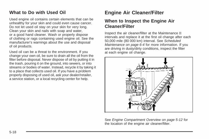
What to Do with Used OilUsed engine oil contains certain elements that can beunhealthy for your skin and could even cause cancer.Do not let used oil stay on your skin for very long.Clean your skin and nails with soap and water,or a good hand cleaner. Wash or properly disposeof clothing or rags containing used engine oil. See themanufacturer’s warnings about the use and disposalof oil products.
Used oil can be a threat to the environment. If youchange your own oil, be sure to drain all the oil from thefilter before disposal. Never dispose of oil by putting it inthe trash, pouring it on the ground, into sewers, or intostreams or bodies of water. Instead, recycle it by taking itto a place that collects used oil. If you have a problemproperly disposing of used oil, ask your dealer/retailer,a service station, or a local recycling center for help.
Engine Air Cleaner/Filter
When to Inspect the Engine AirCleaner/FilterInspect the air cleaner/filter at the Maintenance IIintervals and replace it at the first oil change after each50,000 mile (80 000 km) interval. See ScheduledMaintenance on page 6-4 for more information. If youare driving in dusty/dirty conditions, inspect the filterat each engine oil change.
See Engine Compartment Overview on page 5-12 forthe location of the engine air cleaner/filter.
5-18

How to Inspect the Engine AirCleaner/FilterTo inspect the air cleaner/filter, remove the filter fromthe vehicle and lightly shake the filter (away fromvehicle) to release loose dust and dirt. If the filterremains caked with dirt, a new filter is required.
To inspect or replace the engine air cleaner/filter, do thefollowing:
1. Loosen the screws that hold the cover on.
2. Disconnect the electrical connector.
3. Lift off the cover.
4. Remove the engine air cleaner/filter element andany loose debris that may be found in the aircleaner base.
5. Inspect or replace the air filter element.
6. Reverse Steps 1 through 3 to reinstall the coverand reconnect the electrical connector.
{CAUTION:
Operating the engine with the air cleaner/filteroff can cause you or others to be burned.The air cleaner not only cleans the air; it helpsto stop flames if the engine backfires. If it isnot there and the engine backfires, you couldbe burned. Do not drive with it off, and becareful working on the engine with the aircleaner/filter off.
Notice: If the air cleaner/filter is off, a backfire cancause a damaging engine fire. And, dirt can easily getinto your engine, which will damage it. Always havethe air cleaner/filter in place when you are driving.
5-19

Automatic Transmission FluidIt is not necessary to check the transmission fluid level.A transmission fluid leak is the only reason for fluid loss.If a leak occurs, take your vehicle to the dealer/retailerand have it repaired as soon as possible.
Change the fluid at the intervals listed in AdditionalRequired Services on page 6-6, and be sure to use thetransmission fluid listed in Recommended Fluids andLubricants on page 6-11.
Notice: Use of the incorrect automatic transmissionfluid may damage your vehicle, and the damagesmay not be covered by your warranty. Alwaysuse the automatic transmission fluid listed inRecommended Fluids and Lubricants on page 6-11.
The transmission fluid will not reach the end ofthe dipstick unless the transmission is at operatingtemperature. If you need to check the transmission fluidlevel, please take your vehicle to your dealer/retailer.
Engine CoolantThe cooling system in your vehicle is filled withDEX-COOL® engine coolant. This coolant is designedto remain in your vehicle for five years or 150,000 miles(240 000 km), whichever occurs first, if you add onlyDEX-COOL® extended life coolant.
The following explains your cooling system and howto add coolant when it is low. If you have a problem withengine overheating or if you need to add coolant tothe radiator, see Engine Overheating on page 5-23.
A 50/50 mixture of clean, drinkable water andDEX-COOL® coolant will:
• Give freezing protection down to −34°F (−37°C).
• Give boiling protection up to 265°F (129°C).
• Protect against rust and corrosion.
• Help keep the proper engine temperature.
• Let the warning lights and gages work as theyshould.
Notice: Using coolant other than DEX-COOL® cancause premature engine, heater core, or radiatorcorrosion. In addition, the engine coolant mayrequire changing sooner, at the first maintenanceservice after each 30,000 miles (50 000 km) or24 months, whichever occurs first. Any repairs wouldnot be covered by the vehicle warranty. Always useDEX-COOL® (silicate-free) coolant in the vehicle.
5-20
What to UseUse a mixture of one-half clean, drinkable water andone-half DEX-COOL® coolant which will not damagealuminum parts. If you use this coolant mixture, you donot need to add anything else.
{CAUTION:
Adding only plain water to the cooling systemcan be dangerous. Plain water, or some otherliquid such as alcohol, can boil before theproper coolant mixture will. The vehicle’scoolant warning system is set for the propercoolant mixture. With plain water or the wrongmixture, the engine could get too hot but wouldnot get the overheat warning. The engine couldcatch fire and you or others could be burned.Use a 50/50 mixture of clean, drinkable waterand DEX-COOL® coolant.
Notice: If an improper coolant mixture is used,the engine could overheat and be badly damaged.The repair cost would not be covered by the vehiclewarranty. Too much water in the mixture can freezeand crack the engine, radiator, heater core, andother parts.
If coolant needs to be added more than four times ayear, have your dealer/retailer check the cooling system.
Notice: If extra inhibitors and/or additives areused in the vehicle’s cooling system, the vehiclecould be damaged. Use only the proper mixture ofthe engine coolant listed in this manual for thecooling system. See Recommended Fluids andLubricants on page 6-11 for more information.
5-21

Checking Coolant
The coolant recovery tankcap has this symbol on it.
See Engine Compartment Overview on page 5-12for more information on the location of the coolantrecovery tank.
The vehicle must be on a level surface when checkingthe coolant level.
When the engine is cold, the coolant level should be atthe FULL COLD line or a little higher. When the engine iswarm, the level could be above the FULL COLD level.The FULL COLD line is marked on the coolantrecovery tank.
Adding CoolantIf more coolant is needed, add the proper DEX-COOL®
coolant mixture at the coolant recovery tank, but becareful not to spill it.
If the coolant recovery tank is completely empty, addcoolant to the radiator. See Engine Overheatingon page 5-23.
{CAUTION:
Turning the radiator pressure cap when theengine and radiator are hot can allow steamand scalding liquids to blow out and burnyou badly. With the coolant recovery tank,you will almost never have to add coolant atthe radiator. Never turn the radiator pressurecap — even a little — when the engine andradiator are hot.
5-22
{CAUTION:
You can be burned if you spill coolant on hotengine parts. Coolant contains ethylene glycol,and it will burn if the engine parts are hotenough. Do not spill coolant on a hot engine.
Occasionally check the coolant level in the radiator.For information on how to add coolant to the radiator,see Cooling System on page 5-26.
Radiator Pressure CapNotice: If the pressure cap is not tightly installed,coolant loss and possible engine damage may occur.Be sure the cap is properly and tightly secured.
See Engine Compartment Overview on page 5-12 formore information on location.
Engine OverheatingThere is an engine coolant temperature gage on yourvehicle’s instrument panel. See Engine CoolantTemperature Gage on page 3-47.
Your vehicle may also have an ENGINE OVERHEATEDIDLE ENGINE and ENGINE OVERHEATED STOPENGINE message displayed in the Driver InformationCenter (DIC). See DIC Warnings and Messageson page 3-64.
5-23

If Steam Is Coming From Your Engine
{CAUTION:
Steam from an overheated engine can burnyou badly, even if you just open the hood.Stay away from the engine if you see or hearsteam coming from it. Turn it off and geteveryone away from the vehicle until it coolsdown. Wait until there is no sign of steam orcoolant before you open the hood.
If you keep driving when the vehicles engineis overheated, the liquids in it can catch fire.You or others could be badly burned. Stopyour engine if it overheats, and get out of thevehicle until the engine is cool.
See Overheated Engine Protection OperatingMode on page 5-25 for information on drivingto a safe place in an emergency.
Notice: If the engine catches fire while drivingwith no coolant, the vehicle can be badly damaged.The costly repairs would not be covered by thevehicle warranty. See Overheated Engine ProtectionOperating Mode on page 5-25 for information ondriving to a safe place in an emergency.
If No Steam Is Coming From YourEngineIf you get an engine overheat warning but see orhear no steam, the problem may not be too serious.Sometimes the engine can get a little too hot when you:
• Climb a long hill on a hot day.
• Stop after high-speed driving.
• Idle for long periods in traffic.
• Tow a trailer.
If you get the overheat warning with no sign of steam,try this for a minute or so:
1. If your air conditioner is on, turn it off.
2. Turn on your heater to full hot at the highest fanspeed and open the windows as necessary.
3. If you are in a traffic jam, shift to N (Neutral);otherwise, shift to the highest gear whiledriving — D (Drive) or L (Low).
5-24

If you no longer have the overheat warning, you candrive. Just to be safe, drive slower for about 10 minutes.If the warning does not come back on, you can drivenormally.
If the warning continues, pull over, stop, and park yourvehicle right away.
If there is still no sign of steam, idle the engine forthree minutes while you are parked. If you still have thewarning, turn off the engine and get everyone out ofthe vehicle until it cools down. Also, see “OverheatedEngine Protection Operating Mode” later in this section.
You may decide not to lift the hood but to get servicehelp right away.
Overheated Engine ProtectionOperating ModeThis emergency operating mode lets the vehiclebe driven to a safe place in an emergency situation.If an overheated engine condition exists, an overheatprotection mode which alternates firing groups ofcylinders helps prevent engine damage. In this mode,there is a significant loss in power and engineperformance. The temperature gage indicates anoverheat condition exists. Driving extended distancesand/or towing a trailer in the overheat protection modeshould be avoided.
Notice: After driving in the overheated engineprotection operating mode, to avoid engine damage,allow the engine to cool before attempting anyrepair. The engine oil will be severely degraded.Repair the cause of coolant loss, change the oiland reset the oil life system. See Engine Oilon page 5-13.
5-25

Cooling SystemWhen you decide it is safe to lift the hood, here is whatyou will see:
A. Engine Coolant ReservoirB. Radiator Pressure Cap (covered)C. Engine Cooling Fans
{CAUTION:
An electric engine cooling fan under the hoodcan start up even when the engine is notrunning and can cause injury. Keep hands,clothing, and tools away from any underhoodelectric fan.
If the coolant inside the coolant recovery tank is boiling,do not do anything else until it cools down. The vehicleshould be parked on a level surface.
When the engine is cold, the coolant level should beat least up to the FULL COLD mark. If it is not, you mayhave a leak at the pressure cap or in the radiator hoses,heater hoses, radiator, water pump or somewhere else inthe cooling system.
5-26

{CAUTION:
Heater and radiator hoses, and other engineparts, can be very hot. Do not touch them.If you do, you can be burned.
Do not run the engine if there is a leak. If yourun the engine, it could lose all coolant. Thatcould cause an engine fire, and you could beburned. Get any leak fixed before you drive thevehicle.
If there seems to be no leak, with the engine on, checkto see if the electric engine cooling fans are running.If the engine is overheating, both fans should berunning. If they are not, your vehicle needs service.
Notice: Engine damage from running the enginewithout coolant is not covered by the warranty.
Notice: Using coolant other than DEX-COOL® cancause premature engine, heater core, or radiatorcorrosion. In addition, the engine coolant couldrequire changing sooner, at 30,000 miles (50 000 km)or 24 months, whichever occurs first. Any repairswould not be covered by the vehicle warranty.Always use DEX-COOL® (silicate-free) coolantin the vehicle.
5-27

How to Add Coolant to the CoolantRecovery Tank
Notice: This vehicle has a specific coolant fillprocedure. Failure to follow this procedure couldcause the engine to overheat and be severelydamaged.
If you have not found a problem yet, check to see ifcoolant is visible in the coolant recovery tank. If coolantis visible but the coolant level is not at or above theFULL COLD mark, add a 50/50 mixture of clean,drinkable water and DEX-COOL® coolant at the coolantrecovery tank, but be sure the cooling system, includingthe coolant recovery tank pressure cap, is cool beforeyou do it. See Engine Coolant on page 5-20 for moreinformation.
{CAUTION:
Steam and scalding liquids from a hot coolingsystem can blow out and burn you badly. Theyare under pressure, and if you turn the radiatorpressure cap — even a little — they can comeout at high speed. Never turn the cap when thecooling system, including the radiator pressurecap, is hot. Wait for the cooling system andradiator pressure cap to cool if you ever haveto turn the pressure cap.
5-28

{CAUTION:
Adding only plain water to the cooling systemcan be dangerous. Plain water, or some otherliquid such as alcohol, can boil before theproper coolant mixture will. The vehicle’scoolant warning system is set for the propercoolant mixture. With plain water or the wrongmixture, the engine could get too hot but youwould not get the overheat warning. The enginecould catch fire and you or others could beburned. Use a 50/50 mixture of clean, drinkablewater and DEX-COOL® coolant.
Notice: In cold weather, water can freeze and crackthe engine, radiator, heater core and other parts.Use the recommended coolant and the propercoolant mixture.
{CAUTION:
You can be burned if you spill coolant on hotengine parts. Coolant contains ethylene glycoland it will burn if the engine parts are hotenough. Do not spill coolant on a hot engine.
When the coolant in the coolant recovery tank is at theFULL COLD mark, start your vehicle. If the overheatwarning continues, there is one more thing you can try.You can add the proper mixture directly to the radiator,but be sure the cooling system is cool before you do it.
5-29

1. To remove the panel that covers the radiator cap,detach fasteners and lift off panel.
2. Remove the radiator pressure cap when thecooling system, including the upper radiator hose,is no longer hot. Turn the pressure cap slowlycounterclockwise about one full turn. If you hear ahiss, wait for that to stop. A hiss means there is stillsome pressure left.
3. Keep turning thepressure cap slowly,and remove it.
4. Fill the radiator with the proper DEX-COOL®
coolant mixture, up to the base of the fillerneck. See Engine Coolant on page 5-20 formore information about the proper coolant mixture.
5-30

5. Fill the coolant recovery tank to the FULLCOLD mark.
6. Reinstall the cap on the coolant recovery tank,but leave the radiator pressure cap off.
7. Start the engine and let it run until you can feel theupper radiator hose getting hot. Watch out for theengine cooling fan.
8. By this time, the coolant level inside the radiatorfiller neck may be lower. If the level is lower, addmore of the proper DEX-COOL® coolant mixturethrough the filler neck until the level reaches thebase of the filler neck. Replace the pressure cap.
At any time during this procedure if coolant begins toflow out of the filler neck, reinstall the pressure cap.Be sure to secure it tightly.
5-31

Power Steering Fluid
The power steering fluidreservoir is located towardthe front of the enginecompartment on thepassenger’s side of thevehicle. See EngineCompartment Overviewon page 5-12 for reservoirlocation.
When to Check Power Steering FluidIt is not necessary to regularly check power steering fluidunless you suspect there is a leak in the system oryou hear an unusual noise. A fluid loss in this systemcould indicate a problem. Have the system inspectedand repaired.
How to Check Power Steering FluidTo check the power steering fluid, do the following:
1. Turn the key off and let the engine compartmentcool down.
2. Remove engine oil fill cap
3. Slide engine cover rearward and lift to remove
4. Wipe the cap and the top of the reservoir clean.
5. Unscrew the cap and wipe the dipstick with aclean rag.
6. Replace the cap and completely tighten it.
7. Remove the cap again and look at the fluid level onthe dipstick.
The fluid level should be somewhere between MAXand MIN line on the dipstick in room temperature.If the fluid is on or below MIN line, you should addfluid close to MAX Line.
What to UseTo determine what kind of fluid to use, seeRecommended Fluids and Lubricants on page 6-11.Always use the proper fluid.
Notice: Use of the incorrect fluid may damage yourvehicle and the damages may not be covered byyour warranty. Always use the correct fluid listed inRecommended Fluids and Lubricants on page 6-11.
5-32
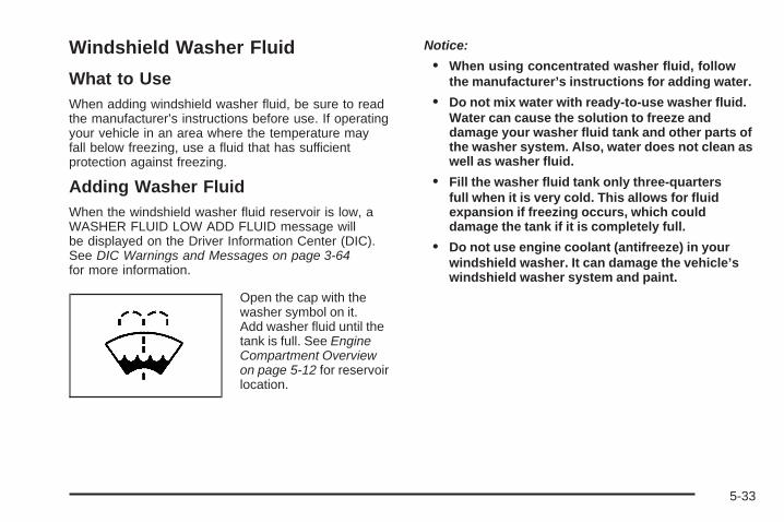
Windshield Washer Fluid
What to UseWhen adding windshield washer fluid, be sure to readthe manufacturer’s instructions before use. If operatingyour vehicle in an area where the temperature mayfall below freezing, use a fluid that has sufficientprotection against freezing.
Adding Washer FluidWhen the windshield washer fluid reservoir is low, aWASHER FLUID LOW ADD FLUID message willbe displayed on the Driver Information Center (DIC).See DIC Warnings and Messages on page 3-64for more information.
Open the cap with thewasher symbol on it.Add washer fluid until thetank is full. See EngineCompartment Overviewon page 5-12 for reservoirlocation.
Notice:
• When using concentrated washer fluid, followthe manufacturer’s instructions for adding water.
• Do not mix water with ready-to-use washer fluid.Water can cause the solution to freeze anddamage your washer fluid tank and other parts ofthe washer system. Also, water does not clean aswell as washer fluid.
• Fill the washer fluid tank only three-quartersfull when it is very cold. This allows for fluidexpansion if freezing occurs, which coulddamage the tank if it is completely full.
• Do not use engine coolant (antifreeze) in yourwindshield washer. It can damage the vehicle’swindshield washer system and paint.
5-33
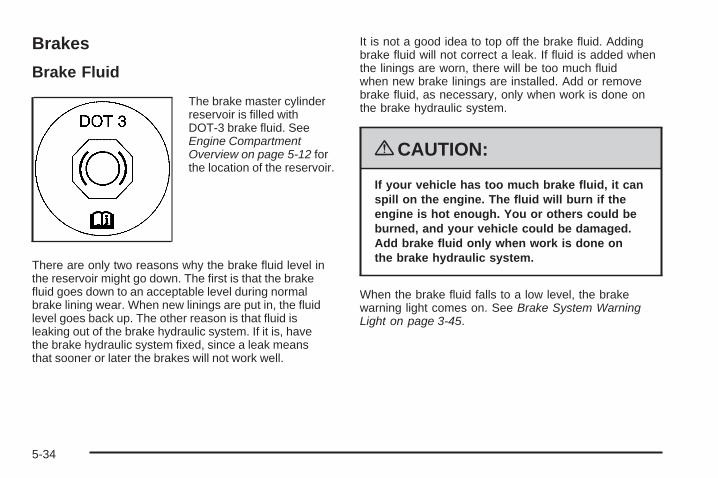
Brakes
Brake Fluid
The brake master cylinderreservoir is filled withDOT-3 brake fluid. SeeEngine CompartmentOverview on page 5-12 forthe location of the reservoir.
There are only two reasons why the brake fluid level inthe reservoir might go down. The first is that the brakefluid goes down to an acceptable level during normalbrake lining wear. When new linings are put in, the fluidlevel goes back up. The other reason is that fluid isleaking out of the brake hydraulic system. If it is, havethe brake hydraulic system fixed, since a leak meansthat sooner or later the brakes will not work well.
It is not a good idea to top off the brake fluid. Addingbrake fluid will not correct a leak. If fluid is added whenthe linings are worn, there will be too much fluidwhen new brake linings are installed. Add or removebrake fluid, as necessary, only when work is done onthe brake hydraulic system.
{CAUTION:
If your vehicle has too much brake fluid, it canspill on the engine. The fluid will burn if theengine is hot enough. You or others could beburned, and your vehicle could be damaged.Add brake fluid only when work is done onthe brake hydraulic system.
When the brake fluid falls to a low level, the brakewarning light comes on. See Brake System WarningLight on page 3-45.
5-34

What to AddWhen you need brake fluid, use only DOT-3 brake fluid.Use new brake fluid from a sealed container only.See Recommended Fluids and Lubricants on page 6-11.
Always clean the brake fluid reservoir cap and thearea around the cap before removing it. This helpskeep dirt from entering the reservoir.
{CAUTION:
With the wrong kind of fluid in the brakehydraulic system, the brakes might not workwell. This could cause a crash. Always use theproper brake fluid.
Notice:
• Using the wrong fluid can badly damage brakehydraulic system parts. For example, just afew drops of mineral-based oil, such as engineoil, in the brake hydraulic system can damagebrake hydraulic system parts so badly that theywill have to be replaced. Do not let someoneput in the wrong kind of fluid.
• If you spill brake fluid on your vehicle’s paintedsurfaces, the paint finish can be damaged.Be careful not to spill brake fluid on yourvehicle. If you do, wash it off immediately.See Washing Your Vehicle on page 5-104.
5-35

Brake WearYour vehicle has disc brakes. Disc brake pads havebuilt-in wear indicators that make a high-pitched warningsound when the brake pads are worn and new padsare needed. The sound can come and go or be heardall the time your vehicle is moving, except when youare pushing on the brake pedal firmly.
{CAUTION:
The brake wear warning sound means thatsoon the brakes will not work well. That couldlead to an accident. When you hear the brakewear warning sound, have your vehicleserviced.
Notice: Continuing to drive with worn-out brakepads could result in costly brake repair.
Some driving conditions or climates can cause a brakesqueal when the brakes are first applied or lightly applied.This does not mean something is wrong with the brakes.
Properly torqued wheel nuts are necessary to helpprevent brake pulsation. When tires are rotated, inspectbrake pads for wear and evenly tighten wheel nuts inthe proper sequence to torque specifications inCapacities and Specifications on page 5-120.
Brake linings should always be replaced as completeaxle sets.
Brake Pedal TravelSee your dealer/retailer if the brake pedal does notreturn to normal height, or if there is a rapid increasein pedal travel. This could be a sign that brake servicemight be required.
Brake AdjustmentEvery time you apply the brakes, with or without thevehicle moving, the brakes adjust for wear.
5-36

Replacing Brake System PartsThe braking system on a vehicle is complex. Its manyparts have to be of top quality and work well together ifthe vehicle is to have really good braking. Your vehiclewas designed and tested with top-quality brake parts.When you replace parts of the braking system — forexample, when the brake linings wear down and youneed new ones put in — be sure you get new approvedreplacement parts. If you do not, the brakes might notwork properly. For example, if someone puts in brakelinings that are wrong for your vehicle, the balancebetween the front and rear brakes can change — forthe worse. The braking performance you have come toexpect can change in many other ways if someone putsin the wrong replacement brake parts.
BatteryYour vehicle has a maintenance free battery. Whenit is time for a new battery, see your dealer/retailerfor one that has the replacement number shown onthe original battery’s label.
For battery replacement, see your dealer/retailer or theservice manual. To purchase a service manual, seeService Publications Ordering Information on page 7-16.Warning: Battery posts, terminals, and relatedaccessories contain lead and lead compounds,chemicals known to the State of California to causecancer and reproductive harm. Wash hands afterhandling.
5-37

Vehicle Storage
{CAUTION:
Batteries have acid that can burn you andgas that can explode. You can be badly hurtif you are not careful. See Jump Starting onpage 5-38 for tips on working around a batterywithout getting hurt.
Infrequent Usage: If you drive your vehicle infrequently,remove the black, negative (−) cable from the battery.This will help keep the battery from running down.
Extended Storage: For extended storage of your vehicle,remove the black, negative (−) cable from the batteryor use a battery trickle charger. This will help maintainthe charge of the battery over an extended periodof time.
Jump StartingIf your vehicle’s battery has run down, you may want touse another vehicle and some jumper cables to start yourvehicle. Be sure to use the following steps to do it safely.
{CAUTION:
Batteries can hurt you. They can be dangerousbecause:
• They contain acid that can burn you.• They contain gas that can explode or
ignite.• They contain enough electricity to
burn you.
If you do not follow these steps exactly, someor all of these things can hurt you.
5-38

Notice: Ignoring these steps could result in costlydamage to your vehicle that would not be coveredby your warranty.
Trying to start your vehicle by pushing or pulling itwill not work, and it could damage your vehicle.
1. Check the other vehicle. It must have a 12-voltbattery with a negative ground system.
Notice: If the other vehicle’s system is not a 12-voltsystem with a negative ground, both vehicles canbe damaged. Only use vehicles with 12-volt systemswith negative grounds to jump start your vehicle.
2. Get the vehicles close enough so the jumper cablescan reach, but be sure the vehicles are not touchingeach other. If they are, it could cause a groundconnection you do not want. You would not beable to start your vehicle, and the bad groundingcould damage the electrical systems.To avoid the possibility of the vehicles rolling, setthe parking brake firmly on both vehicles involvedin the jump start procedure. Put an automatictransmission in P (Park) or a manual transmissionin NEUTRAL before setting the parking brake. If youhave a four-wheel-drive vehicle, be sure the transfercase is not in NEUTRAL.
Notice: If you leave your radio or other accessorieson during the jump starting procedure, they couldbe damaged. The repairs would not be coveredby your warranty. Always turn off your radio andother accessories when jump starting your vehicle.
3. Turn off the ignition on both vehicles. Unplugunnecessary accessories plugged into the cigarettelighter or the accessory power outlets. Turn off theradio and all lamps that are not needed. This willavoid sparks and help save both batteries. And itcould save the radio!
4. Open the hoods and locate the positive (+) andnegative (−) terminal locations on the other vehicle.Your vehicle has a remote positive (+) and a remotenegative (−) jump starting terminal. See EngineCompartment Overview on page 5-12 for moreinformation on the terminal locations.
5-39

{CAUTION:
Using a match near a battery can cause batterygas to explode. People have been hurt doingthis, and some have been blinded. Use aflashlight if you need more light.
Be sure the batteries have enough water.You do not need to add water to the ACDelco®
battery (or batteries) installed in your newvehicle. But if a battery has filler caps, be surethe right amount of fluid is there. If it is low,add water to take care of that first. If you donot, explosive gas could be present.
Battery fluid contains acid that can burn you.Do not get it on you. If you accidentally get itin your eyes or on your skin, flush the placewith water and get medical help immediately.
{CAUTION:
Fans or other moving engine parts can injureyou badly. Keep your hands away from movingparts once the engine is running.
5. Check that the jumper cables do not have looseor missing insulation. If they do, you could get ashock. The vehicles could be damaged too.Before you connect the cables, here are somebasic things you should know. Positive (+) will goto positive (+) or to a remote positive (+) terminalif the vehicle has one. Negative (−) will go to aheavy, unpainted metal engine part or to a remotenegative (−) terminal if the vehicle has one.Do not connect positive (+) to negative (−) or youwill get a short that would damage the batteryand maybe other parts too. And do not connect thenegative (−) cable to the negative (−) terminal onthe dead battery because this can cause sparks.
5-40

6. Connect the redpositive (+) cable to thepositive (+) terminalof the dead battery.
Use a remote positive (+) terminal if the vehiclehas one.
7. Do not let the other end touch metal. Connect it tothe positive (+) terminal of the good battery. Use aremote positive (+) terminal if the vehicle has one.
8. Now connect the black negative (−) cable to thenegative (−) terminal of the good battery. Use aremote negative (−) terminal if the vehicle has one.Do not let the other end touch anything until thenext step. The other end of the negative (−) cabledoes not go to the dead battery. It goes to a heavy,unpainted metal engine part, or to a remotenegative (−) terminal on the vehicle with thedead battery.
9. Connect the otherend of the negative (−)cable at least 18 inches(45 cm) away from thedead battery, but notnear engine partsthat move.
The electrical connection is just as good there, andthe chance of sparks getting back to the batteryis much less.Your vehicle has a remote negative (−) terminal forthis purpose.
10. Now start the vehicle with the good battery and runthe engine for a while.
11. Try to start the vehicle that had the dead battery.If it will not start after a few tries, it probably needsservice.
5-41

Notice: If the jumper cables are connected orremoved in the wrong order, electrical shorting mayoccur and damage the vehicle. The repairs wouldnot be covered by your warranty. Always connectand remove the jumper cables in the correctorder, making sure that the cables do not toucheach other or other metal.
A. Heavy, Unpainted Metal Engine Part or RemoteNegative (−) Terminal
B. Good Battery or Remote Positive (+) and RemoteNegative (−) Terminals
C. Dead Battery or Remote Positive (+) Terminal
To disconnect the jumper cables from both vehicles, dothe following:
1. Disconnect the black negative (−) cable from thevehicle that had the dead battery.
2. Disconnect the black negative (−) cable from thevehicle with the good battery.
3. Disconnect the red positive (+) cable from thevehicle with the good battery.
4. Disconnect the red positive (+) cable from the othervehicle.
Jumper Cable Removal
5-42

All-Wheel DriveBe sure to perform the lubricant checks described inthis section. There are two additional systems that needlubrication.
Transfer CaseWhen to Check LubricantRefer to the Maintenance Schedule to determinehow often to check the lubricant. See ScheduledMaintenance on page 6-4.
How to Check Lubricant
To get an accurate reading, the vehicle should be on alevel surface.If the level is below the bottom of the filler plug hole,you will need to add some lubricant. Add enoughlubricant to raise the level to the bottom of the fillerplug hole. Use care not to overtighten the plug.
What to UseRefer to the Maintenance Schedule to determine whatkind of lubricant to use. See Recommended Fluidsand Lubricants on page 6-11.
(A) Drain Plug (B) Filler Plug
5-43

Rear Drive ModuleWhen to Check LubricantRefer to the Maintenance Schedule to determinehow often to check the lubricant. See ScheduledMaintenance on page 6-4.
How to Check Lubricant
To get an accurate reading, the vehicle should be on alevel surface.
If the level is below the bottom of the filler plug hole,you will need to add some lubricant. Add enoughlubricant to raise the level to the bottom of the fillerplug hole. Use care not to overtighten the plug.
What to UseRefer to the Maintenance Schedule to determine whatkind of lubricant to use. See Recommended Fluidsand Lubricants on page 6-11.
Headlamp AimingHeadlamp aim has been preset at the factory andshould need no further adjustment.
However, if your vehicle is damaged in a crash, theheadlamp aim may be affected. Aim adjustment to thelow-beam headlamps may be necessary if oncomingdrivers flash their high-beam headlamps at you(for vertical aim).
If the headlamps need to be re-aimed, it isrecommended that you take the vehicle to yourdealer/retailer for service.
(A) Filler Plug (B) Drain Plug
5-44

Bulb ReplacementFor the proper type of replacement bulbs, seeReplacement Bulbs on page 5-47.
For any bulb changing procedure not listed in thissection, contact your dealer/retailer.
High Intensity Discharge (HID)Lighting
{CAUTION:
The low beam high intensity discharge lightingsystem operates at a very high voltage. If youtry to service any of the system components,you could be seriously injured. Have yourdealer/retailer or a qualified technicianservice them.
Your vehicle has HID headlamps. After your vehicle’sHID headlamp bulb has been replaced, you may noticethat the beam is a slightly different shade than it wasoriginally. This is normal.
Halogen Bulbs
{CAUTION:
Halogen bulbs have pressurized gas insideand can burst if you drop or scratch the bulb.You or others could be injured. Be sure toread and follow the instructions on the bulbpackage.
5-45

Taillamps, Turn Signal, Stoplampsand Sidemarker Lamps
A. Sidemarker LampB. Taillamp
To replace one of these bulbs:
1. Open the liftgate. See Liftgate on page 2-13 orPower Liftgate on page 2-14.
2. Remove the convenience net, if the vehiclehas one.
3. Remove the two taillamp hex nut covers.
4. Remove the two hex nuts holding the taillampassembly in place.
5. Pull out the taillamp assembly.
6. Turn the bulb socket counterclockwise and pull itstraight out to remove it.
7. Replace the old bulb with a new one.
8. Reverse Steps 3 through 6 to reinstall the taillampassembly.When reinstalling the taillamp assembly, make surethe plastic pin on the taillamp assembly lines upand is inserted correctly into the opening ofthe vehicle.
5-46

License Plate LampTo replace one of these bulbs:
1. Remove the two screws holding each of the licenseplate lamps to the liftgate trim.
2. Turn and pull the license plate lamp forwardthrough the lift gate trim opening.
3. Turn the bulb socket counterclockwise and pull thebulb straight out of the socket.
4. Install the new bulb.
5. Reverse steps 1 – 3 to reinstall the licenseplate lamp.
Replacement Bulbs
Exterior Lamp Bulb Number
License Plate Lamp 194
Rear Turn Signal and Taillamps 3157
For replacement bulbs not listed here, contact yourdealer.
5-47

Windshield Wiper BladeReplacementWindshield wiper blades should be inspected for wearor cracking. See Scheduled Maintenance on page 6-4for more information.
Replacement blades come in different types and areremoved in different ways. To replace the wiperblade assembly, do the following:
1. Pull the windshield wiper arm away from thewindshield.
2. Press the button in the middle of the wiper armconnector, and pull the wiper blade away fromthe arm connector.
3. Install the new wiper blade, and make sure thewiper blade locks into place.
For the proper size and type see MaintenanceReplacement Parts on page 6-13.
Backglass Wiper Blade1. Pull the wiper blade assembly away from the
backglass. The backglass wiper blade will notlock in a vertical position, so care should beused when pulling it away from the vehicle.
2. Rotate the wiper blade assembly, hold the wiperarm in position and push the blade away from thewiper arm.
3. Replace the wiper blade.
4. Return the wiper arm and blade assembly to therest position on the glass.
5-48
TiresYour new vehicle comes with high-quality tiresmade by a leading tire manufacturer. If you everhave questions about your tire warranty and whereto obtain service, see your vehicle Warrantybooklet for details.
{CAUTION:
Poorly maintained and improperly usedtires are dangerous.
• Overloading your vehicle’s tires cancause overheating as a result of toomuch flexing. You could have anair-out and a serious accident. SeeLoading the Vehicle on page 4-22.
CAUTION: (Continued)
CAUTION: (Continued)
• Underinflated tires pose the samedanger as overloaded tires. Theresulting accident could cause seriousinjury. Check all tires frequently tomaintain the recommended pressure.Tire pressure should be checked whenyour vehicle’s tires are cold. SeeInflation - Tire Pressure on page 5-56.
• Overinflated tires are more likelyto be cut, punctured, or broken bya sudden impact — such as whenyou hit a pothole. Keep tires at therecommended pressure.
• Worn, old tires can cause accidents.If the tire’s tread is badly worn, orif your vehicle’s tires have beendamaged, replace them.
5-49

Tire Sidewall LabelingUseful information about a tire is molded into itssidewall. The examples below show a typicalpassenger vehicle tire and a compact spare tiresidewall.
(A) Tire Size: The tire size is a combination ofletters and numbers used to define a particulartire’s width, height, aspect ratio, construction type,and service description. See the “Tire Size”illustration later in this section for more detail.
(B) TPC Spec (Tire Performance CriteriaSpecification): Original equipment tires designedto GM’s specific tire performance criteria have aTPC specification code molded onto the sidewall.GM’s TPC specifications meet or exceed all federalsafety guidelines.
(C) DOT (Department of Transportation):The Department of Transportation (DOT) codeindicates that the tire is in compliance with theU.S. Department of Transportation Motor VehicleSafety Standards.
(D) Tire Identification Number (TIN): The lettersand numbers following DOT (Department ofTransportation) code is the Tire IdentificationNumber (TIN). The TIN shows the manufacturerand plant code, tire size, and date the tire wasmanufactured. The TIN is molded onto both sidesof the tire, although only one side may have thedate of manufacture.
Passenger (P-Metric) Tire Example
5-50
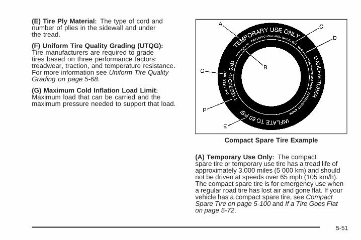
(E) Tire Ply Material: The type of cord andnumber of plies in the sidewall and underthe tread.
(F) Uniform Tire Quality Grading (UTQG):Tire manufacturers are required to gradetires based on three performance factors:treadwear, traction, and temperature resistance.For more information see Uniform Tire QualityGrading on page 5-68.
(G) Maximum Cold Inflation Load Limit:Maximum load that can be carried and themaximum pressure needed to support that load.
(A) Temporary Use Only: The compactspare tire or temporary use tire has a tread life ofapproximately 3,000 miles (5 000 km) and shouldnot be driven at speeds over 65 mph (105 km/h).The compact spare tire is for emergency use whena regular road tire has lost air and gone flat. If yourvehicle has a compact spare tire, see CompactSpare Tire on page 5-100 and If a Tire Goes Flaton page 5-72.
Compact Spare Tire Example
5-51

(B) Tire Ply Material: The type of cord andnumber of plies in the sidewall and underthe tread.
(C) Tire Identification Number (TIN): The lettersand numbers following the DOT (Department ofTransportation) code is the Tire IdentificationNumber (TIN). The TIN shows the manufacturerand plant code, tire size, and date the tire wasmanufactured. The TIN is molded onto both sidesof the tire, although only one side may have thedate of manufacture.
(D) Maximum Cold Inflation Load Limit:Maximum load that can be carried and themaximum pressure needed to support that load.
(E) Tire Inflation: The temporary use tire orcompact spare tire should be inflated to 60 psi(420 kPa). For more information on tire pressureand inflation see Inflation - Tire Pressure onpage 5-56.
(F) Tire Size : A combination of letters andnumbers define a tire’s width, height, aspectratio, construction type, and service description.The letter T as the first character in the tiresize means the tire is for temporary use only.
(G) TPC Spec (Tire Performance CriteriaSpecification): Original equipment tires designedto GM’s specific tire performance criteria have aTPC specification code molded onto the sidewall.GM’s TPC specifications meet or exceed all federalsafety guidelines.
Tire SizeThe following illustration shows an example of atypical passenger vehicle tire size.
(A) Passenger (P-Metric) Tire: The United Statesversion of a metric tire sizing system. The letter Pas the first character in the tire size means apassenger vehicle tire engineered to standardsset by the U.S. Tire and Rim Association.
(B) Tire Width: The three-digit number indicatesthe tire section width in millimeters from sidewallto sidewall.
5-52

(C) Aspect Ratio: A two-digit number thatindicates the tire height-to-width measurements.For example, if the tire size aspect ratio is 60, asshown in item C of the illustration, it would meanthat the tire’s sidewall is 60 percent as high asit is wide.
(D) Construction Code: A letter code is used toindicate the type of ply construction in the tire. Theletter R means radial ply construction; the letter Dmeans diagonal or bias ply construction; and theletter B means belted-bias ply construction.
(E) Rim Diameter: Diameter of the wheel ininches.
(F) Service Description: These charactersrepresent the load range and speed rating of thetire. The load index represents the load carrycapacity a tire is certified to carry. The load indexcan range from 1 to 279. The speed rating isthe maximum speed a tire is certified to carrya load. Speed ratings range from A to Z.
Tire Terminology and Definitions
Air Pressure: The amount of air inside thetire pressing outward on each square inch of thetire. Air pressure is expressed in pounds persquare inch (psi) or kilopascal (kPa).
Accessory Weight: This means the combinedweight of optional accessories. Some examples ofoptional accessories are, automatic transmission,power steering, power brakes, power windows,power seats, and air conditioning.
Aspect Ratio: The relationship of a tire’s heightto its width.
Belt: A rubber coated layer of cords that islocated between the plies and the tread. Cordsmay be made from steel or other reinforcingmaterials.
Bead: The tire bead contains steel wires wrappedby steel cords that hold the tire onto the rim.
5-53

Bias Ply Tire: A pneumatic tire in which the pliesare laid at alternate angles less than 90 degreesto the centerline of the tread.
Cold Tire Pressure: The amount of air pressurein a tire, measured in pounds per square inch (psi)or kilopascals (kPa) before a tire has built up heatfrom driving. See Inflation - Tire Pressure onpage 5-56.
Curb Weight: The weight of a motor vehicle withstandard and optional equipment including themaximum capacity of fuel, oil, and coolant,but without passengers and cargo.
DOT Markings: A code molded into the sidewallof a tire signifying that the tire is in compliancewith the U.S. Department of Transportation (DOT)motor vehicle safety standards. The DOT codeincludes the Tire Identification Number (TIN), analphanumeric designator which can also identifythe tire manufacturer, production plant, brand,and date of production.
GVWR: Gross Vehicle Weight Rating.See Loading the Vehicle on page 4-22.
GAWR FRT: Gross Axle Weight Rating for thefront axle. See Loading the Vehicle on page 4-22.
GAWR RR: Gross Axle Weight Rating for therear axle. See Loading the Vehicle on page 4-22.
Intended Outboard Sidewall: The side of anasymmetrical tire, that must always face outwardwhen mounted on a vehicle.
Kilopascal (kPa): The metric unit for air pressure.
Light Truck (LT-Metric) Tire: A tire used onlight duty trucks and some multipurpose passengervehicles.
Load Index: An assigned number ranging from1 to 279 that corresponds to the load carryingcapacity of a tire.
Maximum Inflation Pressure: The maximumair pressure to which a cold tire can be inflated.The maximum air pressure is molded onto thesidewall.
Maximum Load Rating: The load rating for a tireat the maximum permissible inflation pressurefor that tire.
5-54

Maximum Loaded Vehicle Weight: The sum ofcurb weight, accessory weight, vehicle capacityweight, and production options weight.
Normal Occupant Weight: The number ofoccupants a vehicle is designed to seat multipliedby 150 lbs (68 kg). See Loading the Vehicle onpage 4-22.
Occupant Distribution: Designated seatingpositions.
Outward Facing Sidewall: The side of anasymmetrical tire that has a particular side thatfaces outward when mounted on a vehicle.The side of the tire that contains a whitewall,bears white lettering, or bears manufacturer,brand, and/or model name molding that is higheror deeper than the same moldings on the othersidewall of the tire.
Passenger (P-Metric) Tire: A tire used onpassenger cars and some light duty trucks andmultipurpose vehicles.
Recommended Inflation Pressure: Vehiclemanufacturer’s recommended tire inflationpressure as shown on the tire placard.See Inflation - Tire Pressure on page 5-56and Loading the Vehicle on page 4-22.
Radial Ply Tire: A pneumatic tire in whichthe ply cords that extend to the beads are laidat 90 degrees to the centerline of the tread.
Rim: A metal support for a tire and upon whichthe tire beads are seated.
Sidewall: The portion of a tire between the treadand the bead.
Speed Rating: An alphanumeric code assigned toa tire indicating the maximum speed at which atire can operate.
Traction: The friction between the tire and theroad surface. The amount of grip provided.
Tread: The portion of a tire that comes intocontact with the road.
Treadwear Indicators: Narrow bands, sometimescalled wear bars, that show across the tread ofa tire when only 1/16 inch (1.6 mm) of treadremains. See When It Is Time for New Tireson page 5-64.
5-55

UTQGS (Uniform Tire Quality GradingStandards): A tire information system thatprovides consumers with ratings for a tire’straction, temperature, and treadwear. Ratingsare determined by tire manufacturers usinggovernment testing procedures. The ratings aremolded into the sidewall of the tire. See UniformTire Quality Grading on page 5-68.
Vehicle Capacity Weight: The number ofdesignated seating positions multiplied by 150 lbs(68 kg) plus the rated cargo load. See Loadingthe Vehicle on page 4-22.
Vehicle Maximum Load on the Tire: Load onan individual tire due to curb weight, accessoryweight, occupant weight, and cargo weight.
Vehicle Placard: A label permanently attachedto a vehicle showing the vehicle’s capacityweight and the original equipment tire sizeand recommended inflation pressure.See “Tire and Loading Information Label”under Loading the Vehicle on page 4-22.
Inflation - Tire PressureTires need the correct amount of air pressure tooperate effectively.
Notice: Do not let anyone tell you thatunder-inflation or over-inflation is all right.It is not. If your tires do not have enough air(under-inflation), you can get the following:• Too much flexing• Too much heat• Tire overloading• Premature or irregular wear• Poor handling• Reduced fuel economy
If your tires have too much air (over-inflation),you can get the following:• Unusual wear• Poor handling• Rough ride• Needless damage from road hazards
5-56

A vehicle specific Tire and Loading Informationlabel is attached to your vehicle. This label showsyour vehicle’s original equipment tires and thecorrect inflation pressures for your tires when theyare cold. The recommended cold tire inflationpressure, shown on the label, is the minimumamount of air pressure needed to support yourvehicle’s maximum load carrying capacity.
For additional information regarding how muchweight your vehicle can carry, and an example ofthe Tire and Loading Information label, see Loadingthe Vehicle on page 4-22. How you load yourvehicle affects vehicle handling and ride comfort.Never load your vehicle with more weight than itwas designed to carry.
When to CheckCheck your tires once a month or more. Do notforget to check the compact spare tire, it shouldbe at 60 psi (420 kPa). For additional informationregarding the compact spare tire, see CompactSpare Tire on page 5-100.
How to CheckUse a good quality pocket-type gage to check tirepressure. You cannot tell if your tires are properlyinflated simply by looking at them. Radial tiresmay look properly inflated even when they areunder-inflated. Check the tire’s inflation pressurewhen the tires are cold. Cold means your vehiclehas been sitting for at least three hours or drivenno more than 1 mile (1.6 km).
Remove the valve cap from the tire valve stem.Press the tire gage firmly onto the valve toget a pressure measurement. If the cold tireinflation pressure matches the recommendedpressure on the Tire and Loading Informationlabel, no further adjustment is necessary. If theinflation pressure is low, add air until you reachthe recommended amount.
If you overfill the tire, release air by pushing onthe metal stem in the center of the tire valve.Re-check the tire pressure with the tire gage.
Be sure to put the valve caps back on the valvestems. They help prevent leaks by keeping out dirtand moisture.
5-57

Tire Pressure Monitor SystemThe Tire Pressure Monitor System (TPMS) uses radioand sensor technology to check tire pressure levels.The TPMS sensors monitor the air pressure inyour vehicle’s tires and transmit tire pressure readingsto a receiver located in the vehicle.
Each tire, including the spare (if provided), should bechecked monthly when cold and inflated to the inflationpressure recommended by the vehicle manufactureron the vehicle placard or tire inflation pressure label.(If your vehicle has tires of a different size than thesize indicated on the vehicle placard or tire inflationpressure label, you should determine the propertire inflation pressure for those tires.)
As an added safety feature, your vehicle has beenequipped with a tire pressure monitoring system (TPMS)that illuminates a low tire pressure telltale when oneor more of your tires is significantly under-inflated.
Accordingly, when the low tire pressure telltaleilluminates, you should stop and check your tires assoon as possible, and inflate them to the proper pressure.Driving on a significantly under-inflated tire causes thetire to overheat and can lead to tire failure. Under-inflationalso reduces fuel efficiency and tire tread life, and mayaffect the vehicle’s handling and stopping ability.
Please note that the TPMS is not a substitute for propertire maintenance, and it is the driver’s responsibility tomaintain correct tire pressure, even if under-inflationhas not reached the level to trigger illumination ofthe TPMS low tire pressure telltale.
Your vehicle has also been equipped with a TPMSmalfunction indicator to indicate when the system is notoperating properly. The TPMS malfunction indicator iscombined with the low tire pressure telltale. When thesystem detects a malfunction, the telltale will flash forapproximately one minute and then remain continuouslyilluminated. This sequence will continue uponsubsequent vehicle start-ups as long as the malfunctionexists.
When the malfunction indicator is illuminated, thesystem may not be able to detect or signal low tirepressure as intended. TPMS malfunctions may occurfor a variety of reasons, including the installation ofreplacement or alternate tires or wheels on the vehiclethat prevent the TPMS from functioning properly. Alwayscheck the TPMS malfunction telltale after replacing oneor more tires or wheels on your vehicle to ensure thatthe replacement or alternate tires and wheels allowthe TPMS to continue to function properly.
See Tire Pressure Monitor Operation on page 5-59 foradditional information.
5-58
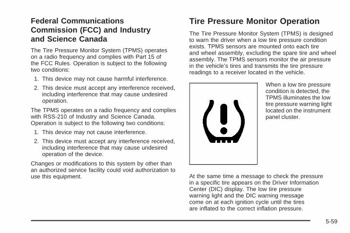
Federal CommunicationsCommission (FCC) and Industryand Science CanadaThe Tire Pressure Monitor System (TPMS) operateson a radio frequency and complies with Part 15 ofthe FCC Rules. Operation is subject to the followingtwo conditions:
1. This device may not cause harmful interference.
2. This device must accept any interference received,including interference that may cause undesiredoperation.
The TPMS operates on a radio frequency and complieswith RSS-210 of Industry and Science Canada.Operation is subject to the following two conditions:
1. This device may not cause interference.
2. This device must accept any interference received,including interference that may cause undesiredoperation of the device.
Changes or modifications to this system by other thanan authorized service facility could void authorization touse this equipment.
Tire Pressure Monitor OperationThe Tire Pressure Monitor System (TPMS) is designedto warn the driver when a low tire pressure conditionexists. TPMS sensors are mounted onto each tireand wheel assembly, excluding the spare tire and wheelassembly. The TPMS sensors monitor the air pressurein the vehicle’s tires and transmits the tire pressurereadings to a receiver located in the vehicle.
When a low tire pressurecondition is detected, theTPMS illuminates the lowtire pressure warning lightlocated on the instrumentpanel cluster.
At the same time a message to check the pressurein a specific tire appears on the Driver InformationCenter (DIC) display. The low tire pressurewarning light and the DIC warning messagecome on at each ignition cycle until the tiresare inflated to the correct inflation pressure.
5-59

Using the DIC, tire pressure levels can be viewed bythe driver. For additional information and detailsabout the DIC operation and displays see DIC Operationand Displays (With DIC Buttons) on page 3-54 or DICOperation and Displays (Without DIC Buttons) onpage 3-60 and DIC Warnings and Messages onpage 3-64.
The low tire pressure warning light may come on in coolweather when the vehicle is first started, and thenturn off as you start to drive. This could be an earlyindicator that the air pressure in the tire(s) are gettinglow and need to be inflated to the proper pressure.
A Tire and Loading Information label, attached toyour vehicle, shows the size of your vehicle’s originalequipment tires and the correct inflation pressure foryour vehicle’s tires when they are cold. See Loading theVehicle on page 4-22, for an example of the Tire andLoading Information label and its location on your vehicle.Also see Inflation - Tire Pressure on page 5-56.
Your vehicle’s TPMS can warn you about a low tirepressure condition but it does not replace normaltire maintenance. See Tire Inspection and Rotationon page 5-63 and Tires on page 5-49.
Notice: Using non-approved tire sealants coulddamage the Tire Pressure Monitor System (TPMS)sensors. TPMS sensor damage caused by usingan incorrect tire sealant is not covered by thevehicle warranty. Always use the GM approvedtire sealant available through your dealer/retailer.
Your vehicle, when new, may have included afactory-installed Tire Sealant and Compressor Kit.This kit uses a GM approved liquid tire sealant.See Tire Sealant and Compressor Kit on page 5-73.
5-60

TPMS Malfunction Light and MessageThe TPMS will not function properly if one or more ofthe TPMS sensors are missing or inoperable. When thesystem detects a malfunction, the low tire warning lightflashes for about one minute and then stays on for theremainder of the ignition cycle. A DIC warning messageis also displayed. The low tire warning light and DICwarning message come on at each ignition cycle untilthe problem is corrected. Some of the conditions thatcan cause the malfunction light and DIC message tocome on are:
• One of the road tires has been replaced with thespare tire, if your vehicle has one. The sparetire does not have a TPMS sensor. The TPMSmalfunction light and DIC message should go offonce you re-install the road tire containing theTPMS sensor.
• The TPMS sensor matching process was started butnot completed or not completed successfully afterrotating the vehicle’s tires. The DIC message andTPMS malfunction light should go off once the TPMSsensor matching process is performed successfully.See “TPMS Sensor Matching Process” later in thissection.
• One or more TPMS sensors are missing ordamaged. The DIC message and the TPMSmalfunction light should go off when the TPMSsensors are installed and the sensor matchingprocess is performed successfully. See yourdealer/retailer for service.
• Replacement tires or wheels do not match yourvehicle’s original equipment tires or wheels. Tiresand wheels other than those recommended for yourvehicle could prevent the TPMS from functioningproperly. See Buying New Tires on page 5-65.
• Operating electronic devices or being near facilitiesusing radio wave frequencies similar to the TPMScould cause the TPMS sensors to malfunction.
If the TPMS is not functioning it cannot detect orsignal a low tire condition. See your dealer/retailer forservice if the TPMS malfunction light and DIC messagecomes on and stays on.
5-61
TPMS Sensor Matching ProcessEach TPMS sensor has a unique identification code.Any time you rotate your vehicle’s tires or replace oneor more of the TPMS sensors, the identification codeswill need to be matched to the new tire/wheel position.The sensors are matched to the tire/wheel positions inthe following order: driver side front tire, passenger sidefront tire, passenger side rear tire, and driver side rear tireusing a TPMS diagnostic tool. See your dealer/retailer forservice.
The TPMS sensors can also be matched to eachtire/wheel position by increasing or decreasing thetire’s air pressure. If increasing the tire’s air pressure,do not exceed the maximum inflation pressure indicatedon the tire’s sidewall.
To decrease air-pressure out of a tire you can use thepointed end of the valve cap, a pencil-style air pressuregage, or a key.
You have two minutes to match the first tire/wheelposition, and five minutes overall to match all fourtire/wheel positions. If it takes longer than two minutes,to match the first tire and wheel, or more thanfive minutes to match all four tire and wheel positionsthe matching process stops and you need to start over.
The TPMS sensor matching process is outlined below:
1. Set the parking brake.
2. Turn the ignition switch to ON/RUN with theengine off.
3. Press the Remote Keyless Entry (RKE) transmitter’sLOCK and UNLOCK buttons at the same time forapproximately five seconds. The horn sounds twiceto signal the receiver is in relearn mode and TIRELEARNING ACTIVE message displays on the DICscreen.
4. Start with the driver side front tire.
5. Remove the valve cap from the valve cap stem.Activate the TPMS sensor by increasing ordecreasing the tire’s air pressure for five seconds,or until a horn chirp sounds. The horn chirp, whichmay take up to 30 seconds to sound, confirms thatthe sensor identification code has been matched tothis tire and wheel position.
6. Proceed to the passenger side front tire, and repeatthe procedure in Step 5.
7. Proceed to the passenger side rear tire, and repeatthe procedure in Step 5.
5-62

8. Proceed to the driver side rear tire, and repeat theprocedure in Step 5. The horn sounds two times toindicate the sensor identification code has beenmatched to the driver side rear tire, and the TPMSsensor matching process is no longer active.The TIRE LEARNING ACTIVE message onthe DIC display screen goes off.
9. Turn the ignition switch to LOCK/OFF.
10. Set all four tires to the recommended air pressurelevel as indicated on the Tire and LoadingInformation label.
11. Put the valve caps back on the valve stems.
Tire Inspection and RotationWe recommend that you regularly inspect yourvehicle’s tires, including the spare tire, for signsof wear or damage. See When It Is Time forNew Tires on page 5-64 for more information.
Tires should be rotated every 5,000 to 8,000 miles(8 000 to 13 000 km). See Scheduled Maintenanceon page 6-4.
The purpose of a regular tire rotation is toachieve a uniform wear for all tires on the vehicle.This will ensure that your vehicle continues toperform most like it did when the tires were new.
Any time you notice unusual wear, rotate your tiresas soon as possible and check wheel alignment.Also check for damaged tires or wheels. See WhenIt Is Time for New Tires on page 5-64 and WheelReplacement on page 5-70.
When rotating your vehicle’s tires, always use thecorrect rotation pattern shown here.
Do not include the compact spare tire in the tirerotation.
After the tires have been rotated, adjust the frontand rear inflation pressures as shown on the Tireand Loading Information label. See Inflation - TirePressure on page 5-56 and Loading the Vehicle onpage 4-22.
5-63

Reset the Tire Pressure Monitor System. See TirePressure Monitor Operation on page 5-59.
Make certain that all wheel nuts are properlytightened. See “Wheel Nut Torque” underCapacities and Specifications on page 5-120.
{CAUTION:
Rust or dirt on a wheel, or on the parts towhich it is fastened, can make wheel nutsbecome loose after time. The wheel couldcome off and cause an accident. Whenyou change a wheel, remove any rust ordirt from places where the wheel attachesto the vehicle. In an emergency, you canuse a cloth or a paper towel to do this;but be sure to use a scraper or wire brushlater, if needed, to get all the rust or dirtoff. See Changing a Flat Tire on page 5-84.
Make sure the spare tire is stored securely.Push, pull, and then try to rotate or turn the tire.If it moves, tighten the cable. See Storing aFlat or Spare Tire and Tools on page 5-96.
When It Is Time for New TiresVarious factors, such as maintenance, temperatures,driving speeds, vehicle loading, and road conditionsinfluence when you need new tires.
One way to tell when itis time for new tires is tocheck the treadwearindicators, which willappear when your tireshave only 1/16 inch(1.6 mm) or less oftread remaining.
5-64

You need new tires if any of the following statementsare true:
• You can see the indicators at three or more placesaround the tire.
• You can see cord or fabric showing through thetire’s rubber.
• The tread or sidewall is cracked, cut, or snaggeddeep enough to show cord or fabric.
• The tire has a bump, bulge, or split.
• The tire has a puncture, cut, or other damage thatcannot be repaired well because of the size orlocation of the damage.
The rubber in tires degrades over time, even if they arenot being used. This is also true for the spare tire, if yourvehicle has one. Multiple conditions affect how fast thisaging takes place, including temperatures, loadingconditions, and inflation pressure maintenance. Withproper care and maintenance tires will typically wear outbefore they degrade due to age. If you are unsure aboutthe need to replace your tires as they get older, consultthe tire manufacturer for more information.
Buying New TiresGM has developed and matched specific tires foryour vehicle. The original equipment tires installedon your vehicle, when it was new, were designedto meet General Motors Tire Performance CriteriaSpecification (TPC Spec) system rating. If you needreplacement tires, GM strongly recommends thatyou get tires with the same TPC Spec rating. Thisway, your vehicle will continue to have tires that aredesigned to give the same performance and vehiclesafety, during normal use, as the original tires.
GM’s exclusive TPC Spec system considers overa dozen critical specifications that impact theoverall performance of your vehicle, includingbrake system performance, ride and handling,traction control, and tire pressure monitoringperformance. GM’s TPC Spec number is moldedonto the tire’s sidewall near the tire size. If thetires have an all-season tread design, theTPC Spec number will be followed by an MSfor mud and snow. See Tire Sidewall Labelingon page 5-50 for additional information.
5-65

GM recommends replacing tires in sets of four.This is because uniform tread depth on all tireswill help keep your vehicle performing most likeit did when the tires were new. Replacing lessthan a full set of tires can affect the brakingand handling performance of your vehicle.See Tire Inspection and Rotation on page 5-63for information on proper tire rotation.
{CAUTION:
Mixing tires could cause you to losecontrol while driving. If you mix tires ofdifferent sizes, brands, or types (radialand bias-belted tires), the vehicle maynot handle properly, and you could havea crash. Using tires of different sizes,brands, or types may also cause damageto your vehicle. Be sure to use the correctsize, brand, and type of tires on all wheels.It is all right to drive with your compactspare temporarily, as it was developed foruse on your vehicle. See Compact SpareTire on page 5-100.
{CAUTION:
If you use bias-ply tires on the vehicle, thewheel rim flanges could develop cracksafter many miles of driving. A tire and/orwheel could fail suddenly, causing acrash. Use only radial-ply tires with thewheels on the vehicle.
If you must replace your vehicle’s tires with thosethat do not have a TPC Spec number, make surethey are the same size, load range, speed rating,and construction type (radial and bias-belted tires)as your vehicle’s original tires.
Vehicles that have a tire pressure monitoringsystem could give an inaccurate low-pressurewarning if non-TPC Spec rated tires are installedon your vehicle. Non-TPC Spec rated tires maygive a low-pressure warning that is higher or lowerthan the proper warning level you would get withTPC Spec rated tires. See Tire Pressure MonitorSystem on page 5-58.
5-66

Your vehicle’s original equipment tires are listedon the Tire and Loading Information Label.See Loading the Vehicle on page 4-22, for moreinformation about the Tire and Loading InformationLabel and its location on your vehicle.
Different Size Tires and WheelsIf you add wheels or tires that are a different size thanyour original equipment wheels and tires, this may affectthe way your vehicle performs, including its braking, rideand handling characteristics, stability, and resistance torollover. Additionally, if your vehicle has electronicsystems such as, anti-lock brakes, rollover airbags,traction control, and stability control, the performanceof these systems can be affected.
{CAUTION:
If you add different sized wheels, yourvehicle may not provide an acceptablelevel of performance and safety if tires notrecommended for those wheels are selected.You may increase the chance that you willcrash and suffer serious injury. Only useSaturn specific wheel and tire systemsdeveloped for your vehicle, and have themproperly installed by a Saturn certifiedtechnician.
See Buying New Tires on page 5-65 and Accessoriesand Modifications on page 5-3 for additional information.
5-67

Uniform Tire Quality GradingQuality grades can be found where applicableon the tire sidewall between tread shoulderand maximum section width. For example:
Treadwear 200 Traction AATemperature AThe following information relates to the systemdeveloped by the United States National HighwayTraffic Safety Administration (NHTSA), whichgrades tires by treadwear, traction, andtemperature performance. This applies only tovehicles sold in the United States. The grades aremolded on the sidewalls of most passenger cartires. The Uniform Tire Quality Grading (UTQG)system does not apply to deep tread, winter-typesnow tires, space-saver, or temporary usespare tires, tires with nominal rim diametersof 10 to 12 inches (25 to 30 cm), or to somelimited-production tires.
While the tires available on General Motorspassenger cars and light trucks may vary withrespect to these grades, they must also conformto federal safety requirements and additionalGeneral Motors Tire Performance Criteria (TPC)standards.
TreadwearThe treadwear grade is a comparative ratingbased on the wear rate of the tire when testedunder controlled conditions on a specifiedgovernment test course. For example, a tiregraded 150 would wear one and a half (1.5) timesas well on the government course as a tiregraded 100. The relative performance of tiresdepends upon the actual conditions of their use,however, and may depart significantly from thenorm due to variations in driving habits, servicepractices, and differences in road characteristicsand climate.
5-68

Traction – AA, A, B, CThe traction grades, from highest to lowest, areAA, A, B, and C. Those grades represent the tire’sability to stop on wet pavement as measured undercontrolled conditions on specified government testsurfaces of asphalt and concrete. A tire marked Cmay have poor traction performance.
{WARNING:
The traction grade assigned to this tire isbased on straight-ahead braking tractiontests, and does not include acceleration,cornering, hydroplaning, or peak tractioncharacteristics.
Temperature – A, B, CThe temperature grades are A (the highest), B,and C, representing the tire’s resistance to thegeneration of heat and its ability to dissipate heatwhen tested under controlled conditions on aspecified indoor laboratory test wheel. Sustainedhigh temperature can cause the material of the tireto degenerate and reduce tire life, and excessivetemperature can lead to sudden tire failure.The grade C corresponds to a level of performancewhich all passenger car tires must meet under theFederal Motor Vehicle Safety Standard No. 109.Grades B and A represent higher levels ofperformance on the laboratory test wheelthan the minimum required by law.
{WARNING:
The temperature grade for this tire isestablished for a tire that is properlyinflated and not overloaded. Excessivespeed, underinflation, or excessiveloading, either separately or incombination, can cause heat buildupand possible tire failure.
5-69

Wheel Alignment and Tire BalanceThe tires and wheels on your vehicle were aligned andbalanced carefully at the factory to give you the longesttire life and best overall performance. Adjustments towheel alignment and tire balancing will not be necessaryon a regular basis. However, if you notice unusual tirewear or your vehicle pulling to one side or the other, thealignment might need to be checked. If you notice yourvehicle vibrating when driving on a smooth road, the tiresand wheels might need to be rebalanced. See yourdealer/retailer for proper diagnosis.
Wheel ReplacementReplace any wheel that is bent, cracked or badly rustedor corroded. If wheel nuts keep coming loose, the wheel,wheel bolts and wheel nuts should be replaced. If thewheel leaks air, replace it (except some aluminumwheels, which can sometimes be repaired). Seeyour dealer/retailer if any of these conditions exist.
Your dealer/retailer will know the kind of wheelyou need.
Each new wheel should have the same load-carryingcapacity, diameter, width, offset and be mountedthe same way as the one it replaces.
If you need to replace any of your wheels, wheel boltsor wheel nuts, replace them only with new Saturnoriginal equipment parts. This way, you will be sureto have the right wheel, wheel bolts and wheel nutsfor your vehicle.
{CAUTION:
Using the wrong replacement wheels, wheelbolts, or wheel nuts on your vehicle can bedangerous. It could affect the braking andhandling of your vehicle, make your tires loseair and make you lose control. You could havea collision in which you or others could beinjured. Always use the correct wheel, wheelbolts, and wheel nuts for replacement.
Notice: The wrong wheel can also cause problemswith bearing life, brake cooling, speedometer orodometer calibration, headlamp aim, bumper height,vehicle ground clearance, and tire or tire chainclearance to the body and chassis.
See Changing a Flat Tire on page 5-84 for moreinformation.
5-70
Used Replacement Wheels
{CAUTION:
Putting a used wheel on your vehicle isdangerous. You cannot know how it has beenused or how far it has been driven. It could failsuddenly and cause a crash. If you have toreplace a wheel, use a new Saturn originalequipment wheel.
Tire Chains
{CAUTION:
Do not use tire chains. There is not enoughclearance. Tire chains used on a vehiclewithout the proper amount of clearance can
CAUTION: (Continued)
CAUTION: (Continued)
cause damage to the brakes, suspension orother vehicle parts. The area damaged by thetire chains could cause you to lose control ofthe vehicle and you or others may be injuredin a crash.
Use another type of traction device only if itsmanufacturer recommends it for use on thevehicle and tire size combination and roadconditions. Follow that manufacturer’sinstructions. To help avoid damage to thevehicle, drive slowly, readjust or remove thedevice if it is contacting the vehicle, and donot spin the vehicle’s wheels. If you do findtraction devices that will fit, install them onthe front tires.
5-71

If a Tire Goes FlatIt is unusual for a tire to blowout while you aredriving, especially if you maintain your tires properly.See Tires on page 5-49. If air goes out of a tire, Itis much more likely to leak out slowly. But if you shouldever have a blowout, here are a few tips about whatto expect and what to do:
If a front tire fails, the flat tire will create a drag thatpulls the vehicle toward that side. Take your foot off theaccelerator pedal and grip the steering wheel firmly.Steer to maintain lane position, and then gently braketo a stop well out of the traffic lane.
A rear blowout, particularly on a curve, acts much like askid and may require the same correction you would usein a skid. In any rear blowout, remove your foot from theaccelerator pedal. Get the vehicle under control bysteering the way you want the vehicle to go. It may bevery bumpy and noisy, but you can still steer. Gentlybrake to a stop, well off the road if possible.
If a tire goes flat, and your vehicle has a compactspare tire, see Changing a Flat Tire on page 5-84.This information shows you how to use your vehicle’stire changing equipment and how to change a flattire safely.
{CAUTION:
Lifting a vehicle and getting under it to domaintenance or repairs is dangerous withoutthe appropriate safety equipment and training.The jack provided with your vehicle is designedonly for changing a flat tire. If it is used foranything else, you or others could be badlyinjured or killed if the vehicle slips off the jack.Use the jack provided with your vehicle onlyfor changing a flat tire.
5-72

Tire Sealant and Compressor KitIf your vehicle has a factory installed tire sealant andcompressor kit, there is no spare tire, no tire changingequipment and no place to store a tire.
If a tire goes flat, avoid further tire and wheel damageby driving slowly to a level place and stopping.
1. Turn on the hazard warning flashers. See HazardWarning Flashers on page 3-6.
2. Park your vehicle. Set the parking brake firmly andput the shift lever in PARK (P). See Shifting IntoPark on page 2-35.
3. Turn off the engine.
4. Inspect the flat tire.
If the tire has been separated from the wheel, hasdamaged sidewalls, or has a puncture larger than a1⁄4 inch (6 mm), the tire is too severely damaged forthe tire sealant and compressor kit to be effective.See Roadside Assistance Program on page 7-7.
If the tire has a puncture less than a 1⁄4 inch (6 mm)in the tread area of the tire, see Tire Sealant andCompressor Kit on page 5-73.
Tire Sealant and Compressor KitYour vehicle is equipped with a tire sealant andcompressor kit that is capable of temporarily sealinga puncture up to a 1⁄4 inch (6 mm) in the tread areaof the tire. The kit inflates with liquid sealant and air.The tire sealant and compressor kit can also be usedto inflate an underinflated tire. After the tire is inflatedto the recommended pressure, see Inflation - TirePressure on page 5-56, the vehicle must be drivenfor five miles (8 km) to distribute the sealant in thetire and seal the puncture. See “Using the TireSealant and Compressor Kit to Temporarily Sealand Inflate a Punctured Tire” later in this section.
5-73

Be sure to read and follow all of the tire sealant andcompressor kit instructions. The kit includes:
A. Selector SwitchB. On/Off ButtonC. Air Pressure GageD. Tire Sealant
Canister
E. Air CompressorAccessory Plug
F. Sealant/AirHose (Clear)
G. Air Only Hose
After temporarily sealing the tire, it is recommended totake your vehicle to an authorized dealer/retailer as soonas possible. If the sealant is removed within 100 miles(161 km) of driving, it is easier to clean from the tire andyou are less likely to require a replacement tire.
Accessing the Tire Sealant andCompressor KitTo access the tire sealant and compressor kit:
1. Open the liftgate. See Liftgate on page 2-13 formore information
2. Open the storage compartment door of theconvenience center that is nearest the liftgate.
5-74

3. The tire sealant and compressor kit is located onthe passenger side of the storage compartment.
4. Remove the tire sealant and compressor kit fromthe storage compartment by grabbing the handleof the bag and pull up.
Tire SealantRead and follow the safe handling instructions on theinstructional label adhered to the sealant canister.
The sealant can temporarily seal a puncture up to1⁄4 inch (6 mm) in the tread area of the tire. The sealantcannot seal sidewall damage, large punctures, or atire that has become unseated from the wheel.See Roadside Assistance Program on page 7-7.
The sealant can only be used to seal one tire.After usage, the tire sealant canister and sealant/airhose assembly must be replaced at a dealer/retailer.See “Removal and Installation of Sealant Canister” laterin this section.
Check the tire sealant expiration date on the sealantcanister. The sealant canister should be replaced beforeits expiration date. Replacement canisters are availableat your local dealer/retailer. See “Removal andInstallation of Sealant Canister” later in this section.
5-75

Using the Tire Sealant and CompressorKit to Temporarily Seal and Inflate aPunctured TireFollow the directions closely for correct sealant usage.
A. Selector SwitchB. On/Off ButtonC. Air Pressure GageD. Tire Sealant
Canister
E. Air CompressorAccessory Plug
F. Sealant/AirHose (Clear)
G. Air Only Hose
1. Do a safety check. See If a Tire Goes Flat onpage 5-72.
2. Inspect the punctured tire.The sealant can temporarily seal a punctureup to 1⁄4 inch (6 mm) in the tread area of the tire.The sealant cannot seal sidewall damage, largepunctures, or a tire that has become unseated fromthe wheel. See Roadside Assistance Program onpage 7-7.Do not remove any objects that have penetratedthe tire.
3. Place the tire sealant and compressor kit on theground and unwrap the sealant/air hose (F) fromthe side of the compressor.
5-76
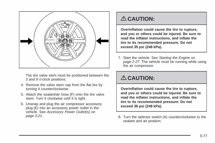
The tire valve stem must be positioned between the3 and 9 o’clock positions.
4. Remove the valve stem cap from the flat tire byturning it counterclockwise.
5. Attach the sealant/air hose (F) onto the tire valvestem. Turn it clockwise until it is tight.
6. Unwrap and plug the air compressor accessoryplug (E) into an accessory power outlet in thevehicle. See Accessory Power Outlet(s) onpage 3-21.
{CAUTION:
Overinflation could cause the tire to rupture,and you or others could be injured. Be sure toread the inflator instructions, and inflate thetire to its recommended pressure. Do notexceed 35 psi (248 kPa).
7. Start the vehicle. See Starting the Engine onpage 2-27. The vehicle must be running while usingthe air compressor.
{CAUTION:
Overinflation could cause the tire to rupture,and you or others could be injured. Be sure toread the inflator instructions, and inflate thetire to its recommended pressure. Do notexceed 36 psi (248 kPa).
8. Turn the selector switch (A) counterclockwise to thesealant and air position.
5-77

9. Push the On/Off button (B).The tire sealant and compressor kit will injectsealant and air into the tire. Sealant may leak fromthe puncture until the vehicle is driven and thehole has sealed.The pressure gage (C) will initially show a highpressure while the compressor pushes the sealantinto the tire. Once the sealant is completelydispersed into the tire, the pressure will quickly dropand start to rise again as the tire inflates with air only.
10. Inflate the tire to the recommended inflationpressure using the air pressure gage (E) on the topof the unit. The recommended inflation pressurecan be found on the Tire and Loading Informationlabel. See Inflation - Tire Pressure on page 5-56.The pressure gage reading is slightly high while thecompressor is on. Turn the compressor off to getan accurate reading. The compressor may be turnedon and off until the correct pressure is reached.
Notice: If the recommended pressure cannot bereached after 20 minutes, the vehicle should notbe driven farther. Damage to the tire is severe andthe sealant will not be effective. Remove the aircompressor plug from the accessory power outletand unscrew the inflating hose from the tire valve.See Roadside Assistance Program on page 7-7 formore information.
11. Turn the compressor off by pushing the On/Offswitch (B).Steps 12 through 20 must be done immediatelyafter Step 11.The tire is not sealed and will continue to leakair until the vehicle is driven and the sealantis distributed in the tire.Be careful while handling the tire sealant andcompressor kit as they could be hot after usage.
12. Unplug the air compressor accessory plug (E) fromthe accessory power outlet in the vehicle.
13. Disconnect the sealant/air hose (F) from the tirevalve stem by turning it counterclockwise andreplace the tire valve stem cap.
14. Wrap the sealant/air hose (F) around the aircompressor channel to stow it in its original location.
15. Stow the air compressor accessory plug (E)back into place.
5-78

16. If the flat tire wasable to inflate to therecommended inflationpressure, remove themaximum speed labelfrom the sealantcanister (B).
17. Place it in a highly visible location such as theinside of the upper left corner of the windshieldor to the face of the radio/clock.The maximum speed label reminds you to drivecautiously and not to exceed 55 mph (90 km/h) untilyou have the damaged tire inspected and repaired.
{CAUTION:
Storing the tire sealant and compressorkit or other equipment in the passengercompartment of the vehicle could cause injury.In a sudden stop or collision, loose equipmentcould strike someone. Store the tire sealantand compressor kit in its original location.
18. Return the equipment to its original storage locationin your vehicle.
19. Immediately drive the vehicle 5 miles (8 km) todistribute the sealant evenly in the tire.
5-79
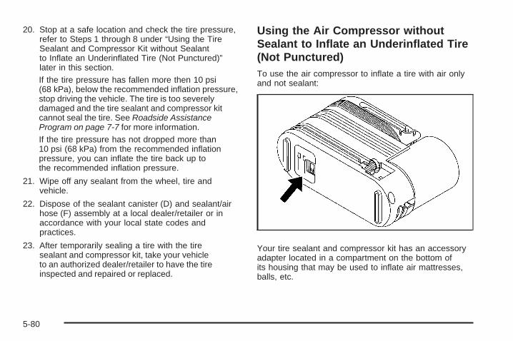
20. Stop at a safe location and check the tire pressure,refer to Steps 1 through 8 under “Using the TireSealant and Compressor Kit without Sealantto Inflate an Underinflated Tire (Not Punctured)”later in this section.If the tire pressure has fallen more then 10 psi(68 kPa), below the recommended inflation pressure,stop driving the vehicle. The tire is too severelydamaged and the tire sealant and compressor kitcannot seal the tire. See Roadside AssistanceProgram on page 7-7 for more information.If the tire pressure has not dropped more than10 psi (68 kPa) from the recommended inflationpressure, you can inflate the tire back up tothe recommended inflation pressure.
21. Wipe off any sealant from the wheel, tire andvehicle.
22. Dispose of the sealant canister (D) and sealant/airhose (F) assembly at a local dealer/retailer or inaccordance with your local state codes andpractices.
23. After temporarily sealing a tire with the tiresealant and compressor kit, take your vehicleto an authorized dealer/retailer to have the tireinspected and repaired or replaced.
Using the Air Compressor withoutSealant to Inflate an Underinflated Tire(Not Punctured)To use the air compressor to inflate a tire with air onlyand not sealant:
Your tire sealant and compressor kit has an accessoryadapter located in a compartment on the bottom ofits housing that may be used to inflate air mattresses,balls, etc.
5-80
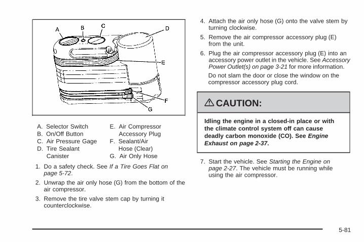
A. Selector SwitchB. On/Off ButtonC. Air Pressure GageD. Tire Sealant
Canister
E. Air CompressorAccessory Plug
F. Sealant/AirHose (Clear)
G. Air Only Hose
1. Do a safety check. See If a Tire Goes Flat onpage 5-72.
2. Unwrap the air only hose (G) from the bottom of theair compressor.
3. Remove the tire valve stem cap by turning itcounterclockwise.
4. Attach the air only hose (G) onto the valve stem byturning clockwise.
5. Remove the air compressor accessory plug (E)from the unit.
6. Plug the air compressor accessory plug (E) into anaccessory power outlet in the vehicle. See AccessoryPower Outlet(s) on page 3-21 for more information.Do not slam the door or close the window on thecompressor accessory plug cord.
{CAUTION:
Idling the engine in a closed-in place or withthe climate control system off can causedeadly carbon monoxide (CO). See EngineExhaust on page 2-37.
7. Start the vehicle. See Starting the Engine onpage 2-27. The vehicle must be running whileusing the air compressor.
5-81

{CAUTION:
Overinflation could cause the tire to rupture,and you or others could be injured. Be sure toread the inflator instructions, and inflate thetire to its recommended pressure. Do notexceed 35 psi (248 kPa).
8. Turn the selector switch (A) clockwise to the aironly position.The tire sealant and compressor kit will inflate thetire with air only.
9. Push the On/Off button (B).
10. Inflate the tire to the recommended inflationpressure using the air pressure gage (E) on thetop of the unit. See Inflation - Tire Pressure onpage 5-56.The pressure gage reading is slightly high while thecompressor is on. Turn the compressor off to getan accurate pressure reading. The compressor maybe turned on and off until the correct pressure isreached.
11. Turn off the air compressor by pushing the On/Offbutton (B).Be careful while handling the tire sealant andcompressor kit as they could be hot after usage.
12. Unplug the air compressor accessory plug andwrap it back into place.
5-82

{CAUTION:
Storing the tire sealant and compressor kit orother equipment in the passenger compartmentof the vehicle could cause injury. In a suddenstop or collision, loose equipment could strikesomeone. Store the tire sealant and compressorkit in its original location.
13. Disconnect the air only hose (G) from the tire valvestem by turning it counterclockwise.
14. Wrap the air only hose (G) around the side of theair compressor channel to stow it back in itsoriginal location.
15. Return the equipment to its original storage locationof your vehicle.
Removal and Installation of the SealantCanisterTo remove the sealant canister, do the following:
1. Unwrap the sealant/air hose from the compressor.
2. Push the canister release button.
3. Pull up and remove the canister.
4. Replace with a new canister. See yourdealer/retailer for the new canister.
5. Push the new canister into place.
5-83

Changing a Flat TireIf a tire goes flat, avoid further tire and wheel damageby driving slowly to a level place. Turn on your vehicle’shazard warning flashers. See Hazard Warning Flasherson page 3-6 for more information.
{CAUTION:
Changing a tire can be dangerous. The vehiclecan slip off the jack and roll over or fall on youor other people. You and they could be badlyinjured or even killed. Find a level place tochange your tire. To help prevent the vehiclefrom moving:
1. Set the parking brake firmly.
2. Put the shift lever in P (Park).
3. Turn off the engine and do not restartwhile the vehicle is raised.
4. Do not allow passengers to remain in thevehicle.
CAUTION: (Continued)
CAUTION: (Continued)
To be even more certain the vehicle will notmove, you should put blocks at the front andrear of the tire farthest away from the onebeing changed. That would be the tire, on theother side, at the opposite end of the vehicle.
When your vehicle has a flat tire, use the followingexample as a guide to assist you in the placement ofwheel blocks.
The following information tells you how to use the jackand change a tire.
5-84
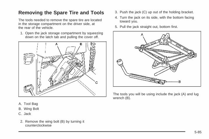
Removing the Spare Tire and ToolsThe tools needed to remove the spare tire are locatedin the storage compartment on the driver side, atthe rear of the vehicle.
1. Open the jack storage compartment by squeezingdown on the latch tab and pulling the cover off.
A. Tool BagB. Wing BoltC. Jack
2. Remove the wing bolt (B) by turning itcounterclockwise
3. Push the jack (C) up out of the holding bracket.
4. Turn the jack on its side, with the bottom facingtoward you.
5. Pull the jack straight out, bottom first.
The tools you will be using include the jack (A) and lugwrench (B).
5-85
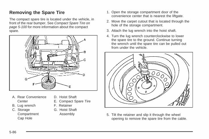
Removing the Spare TireThe compact spare tire is located under the vehicle, infront of the rear bumper. See Compact Spare Tire onpage 5-100 for more information about the compactspare.
A. Rear ConvenienceCenter
B. Lug wrenchC. Storage
CompartmentCap Hole
D. Hoist ShaftE. Compact Spare TireF. RetainerG. Hoist Shaft
Assembly
1. Open the storage compartment door of theconvenience center that is nearest the liftgate.
2. Move the carpet cutout that is located through thehole of the storage compartment.
3. Attach the lug wrench into the hoist shaft.
4. Turn the lug wrench counterclockwise to lowerthe spare tire to the ground. Continue turningthe wrench until the spare tire can be pulled outfrom under the vehicle.
5. Tilt the retainer and slip it through the wheelopening to remove the spare tire from the cable.
5-86

6. Turn the wrench clockwise to raise the cable backup after removing the spare tire.Do not store a full-size or a flat road tire under thevehicle. See Storing a Flat or Spare Tire andTools on page 5-96.
To continue changing the flat tire, see Removing theFlat Tire and Installing the Spare Tire on page 5-88.
If the spare tire will not lower, the secondary latch couldbe engaged.
Do the following to check the cable:
1. Check under the vehicle to see if the cable isvisible.
2. If it is not visible, see Secondary Latch System onpage 5-93.If it is visible, first try to tighten the cable by turningthe lug wrench clockwise until you hear two clicks orfeel it skip twice. You cannot over-tighten the cable.
3. Loosen the cable by turning the wrenchcounterclockwise three or four turns.
4. If the spare tire did lower to the ground, continuewith Step 5 under “Removing the Spare Tire” listedpreviously.
5. If you still cannot lower the spare tire to the ground,see Secondary Latch System on page 5-93.
5-87

Removing the Flat Tire andInstalling the Spare Tire1. Do a safety check before proceeding. See Changing
a Flat Tire on page 5-84 for more information.
2. If the vehicle has a wheel cover, loosen the plasticnut caps with the lug wrench. They will not comeoff. Then, using the flat end of the lug wrench,pry along the edge of the cover until it comes off.Be careful; the edges may be sharp. Do nottry to remove the cover with your bare hands.Store the wheel cover securely in the rear of thevehicle until you have the flat tire repaired orreplaced.If your vehicle has aluminum wheels, remove thewheel nut caps using the lug wrench.
3. Loosen the wheel nuts — but do not removethem — using the lug wrench. For wheels witha wheel lock key, use the wheel lock key betweenthe lock nut and lug wrench.
Notice: If your vehicle has wheel locks and animpact wrench is used to remove the wheel nuts,the lock nut or wheel lock key could be damaged.Do not use an impact wrench to remove thewheel nuts if your vehicle has wheel locks.
5-88

4. To identify the appropriate jacking location, find theV–shaped locating notches in the molding.
Notice: If a jack is used to raise the vehiclewithout positioning it correctly, your vehicle couldbe damaged. When raising your vehicle on a jack,avoid contact with the rear axle control arms.
5. Do not raise the vehicle yet. Put the compact sparetire near you.
{CAUTION:
Getting under a vehicle when it is jacked up isdangerous. If the vehicle slips off the jack, youcould be badly injured or killed. Never get undera vehicle when it is supported only by a jack.
{CAUTION:
Raising your vehicle with the jack improperlypositioned can damage the vehicle and evenmake the vehicle fall. To help avoid personalinjury and vehicle damage, be sure to fit thejack lift head into the proper location beforeraising the vehicle.
6. Attach the lug wrench to the jack, and turnthe wrench clockwise to raise the jack head3 inches (7.6 cm).
5-89

7. Place the jack under the vehicle as identified inStep 3. Raise the vehicle by turning the lug wrenchclockwise in the jack. Raise the vehicle far enoughoff the ground so that there is enough room for thespare tire to fit under the wheel well.
8. Remove all the wheel nuts and the flat tire.
9. Remove the spare tire heat shield by pulling therubber latch. Store the spare tire heat shield. SeeStoring a Flat or Spare Tire and Tools on page 5-96for more information.
5-90

{CAUTION:
Rust or dirt on a wheel, or on the parts towhich it is fastened, can make wheel nutsbecome loose after time. The wheel couldcome off and cause an accident. When youchange a wheel, remove any rust or dirt fromplaces where the wheel attaches to the vehicle.In an emergency, you can use a cloth or apaper towel to do this; but be sure to use ascraper or wire brush later, if needed, to getall the rust or dirt off. See Changing a FlatTire on page 5-84.
{CAUTION:
Never use oil or grease on bolts or nuts.Because the nuts might come loose. Thevehicle’s wheel could fall off, causing a crash.
10. Remove any rust or dirtfrom the wheel bolts,mounting surfaces,and spare wheel.
11. Place the spare tire on the wheel mounting surface.
12. Put the nuts on by hand by turning the clockwiseuntil the wheel is held against the mounting surface.Make sure the rounded end is toward the wheel.
13. Lower the vehicle by attaching the lug wrench tothe jack and turning the wrench counterclockwise.Lower the jack completely.
5-91

{CAUTION:
Incorrect or improperly tightened wheel nutscan cause the wheel to come loose and evencome off. This could lead to a crash. If you haveto replace them, be sure to get new originalequipment wheel nuts. Stop somewhere assoon as you can and have the nuts tightenedwith a torque wrench to the proper torquespecification. See Capacities and Specificationson page 5-120 for wheel nut torquespecification.
Notice: Improperly tightened wheel nuts can leadto brake pulsation and rotor damage. To avoidexpensive brake repairs, evenly tighten the wheelnuts in the proper sequence and to the propertorque specification. See Capacities andSpecifications on page 5-120 for the wheelnut torque specification.
14. Tighten the wheel nutsfirmly in a crisscrosssequence, as shown.
Notice: Wheel covers will not fit on your vehicle’scompact spare. If you try to put a wheel coveron the compact spare, the cover or the sparecould be damaged.
5-92

Secondary Latch SystemYour vehicle has an underbody mounted tire hoistassembly that has a secondary latch system. It isdesigned to stop the compact spare tire from suddenlyfalling off your vehicle if the cable holding the spare tireis damaged. For the secondary latch to work, the tiremust be stowed with the valve stem pointing down. SeeStoring a Flat or Spare Tire and Tools on page 5-96 forinstructions on storing the spare tire correctly.
{CAUTION:
Before beginning this procedure read all theinstructions. Failure to read and follow theinstructions could damage the hoist assemblyand you and others could get hurt. Read andfollow the instructions listed next.
To release the spare tire from the secondary latch:
{CAUTION:
Someone standing too close during theprocedure could be injured by the jack.If the spare tire does not slide off the jackcompletely, make sure no one is behind youor on either side of you as you pull the jackout from the under spare.
1. If the cable is not visible, start this procedure atStep 3.
5-93

2. Turn the lug wrench counterclockwise untilapproximately 6 inches (15 cm) of cable is exposed.
3. Attach the lug wrench to the jack and raise the jackat least 10 turns.
4. Place the jack under the vehicle, ahead of the rearbumper. Position the center lift point of the jackunder the center of the spare tire.
5. Turn the lug wrench clockwise to raise the jack untilit lifts the secondary latch spring.
6. Keep raising the jack until the spare tire stopsmoving upward and is held firmly in place. This letsyou know that the secondary latch has released andthe spare tire is balancing on the jack.
7. Lower the jack by turning the lug wrenchcounterclockwise. Keep lowering the jack untilthe spare tire slides off the jack.
All-Wheel-Drive Vehicle shown
5-94

8. Disconnect the lug wrench from the jack andcarefully remove the jack. Use one hand to pushagainst the spare tire while firmly pulling the jack outfrom under the spare tire with the other hand.
9. Tilt the retainer and slip it through the wheelopening when the spare tire has been completelylowered.
10. Turn the lug wrench clockwise to raise the cableback up if the cable is hanging.
Have the hoist shaft assembly inspected as soon asyou can. You will not be able to store a spare tireusing the hoist assembly until it has been repairedor replaced.
5-95

Storing a Flat or Spare Tire andTools
Storing the Spare Tire
{CAUTION:
The underbody-mounted spare tire needs to bestored with the valve stem pointing down. If thespare tire is stored with the valve stem pointingupwards, its secondary latch will not workproperly and the spare tire could loosen andsuddenly fall from your vehicle. If this happenedwhen your vehicle was being driven, the tiremight contact a person or another vehicle,causing injury and, of course, damage to itselfas well. Be sure the underbody-mounted sparetire is stored with its valve stem pointing down.
{CAUTION:
Storing a jack, a tire, or other equipment in thepassenger compartment of the vehicle couldcause injury. In a sudden stop or collision,loose equipment could strike someone.Store all these in the proper place.
To store the spare tire:
1. Lay the compact spare tire near the rear of thevehicle with the valve stem down.
2. Reinstall the plastic spare tire heat shield on thecompact spare tire.
3. Slide the cable retainer through the center of thewheel and start to raise the compact spare tire.Make sure the retainer is fully seated acrossthe underside of the wheel.
4. When the compact spare tire is almost in the storedposition, turn the tire so the valve is toward the rearof the vehicle.This position helps when checking the air pressurein the compact spare tire.
5-96

5. Raise the tire fully against the underside of thevehicle. Continue turning the lug wrench until youfeel more than two clicks. This indicates that thecompact spare tire is secure and the cable is tight.The spare tire hoist cannot be overtightened.
6. Make sure the tire is stored securely. Push, pull (A),and then try to turn (B) the tire. If the tire moves,use the lug wrench to tighten the cable.
Storing the Flat Tire
Notice: Storing the full-size flat tire in theunderbody hoist system can expose it to heatfrom the exhaust system. This can damage thetire and underbody hoist system. Do not store thefull-size flat tire in the underbody hoist system.
1. Remove the cable package from the jackstorage area.
2. Remove the small center cap by tapping the backof the cap with the extension of the shaft, if thevehicle has aluminum wheels.
3. Put the flat tire in the rear storage area with thevalve stem pointing toward the rear of the vehicle.
5-97

4. Hook one end of the cable onto the outside portionof the liftgate hinge opposite (B).
5. Pull the cable (A) through the center of thewheel (D), then the door striker (E), and the sparetire heat shield (C).
6. Hook the other end ofthe cable onto theouter portion ofthe liftgate hinge (B).
7. Pull on the cable to make sure it is secure.
8. The metal tube should be centered at the striker.
9. Push the tube towardthe front of the vehicle.
10. Close the liftgate and latch it properly.
5-98

Storing the Tools
A. Tool BagB. Wing BoltC. Jack
Put back all tools as they were stored in the jackstorage compartment and put the compartment coverback on.
1. Attach the tool bag to the jack.
2. Make sure that the bottom of the jack is facingtoward you.
3. Turn the jack (C) on its side and place it down onthe holding bracket.
4. Reinstall the wing bolt (B) by turning it clockwise.
5. To replace the cover, line up the tabs on the bottomof the cover with the slots in the cover opening.Push the cover in place, insuring that the upper frontand rear tabs are in the opening and push thecover closed. The center latch should be fullyengaged. This secures the cover in place.
Store the center cap or the plastic bolt-on wheel coversuntil a full size tire is put back on the vehicle. When youreplace the compact spare with a full-size tire, reinstallthe bolt-on wheel covers or the center cap. Hand-tightenthem over the wheel nuts, using the lug wrench.
5-99

Compact Spare TireAlthough the compact spare tire was fully inflatedwhen the vehicle was new, it can lose air after a time.Check the inflation pressure regularly. It should be60 psi (420 kPa).
After installing the compact spare on the vehicle, stop assoon as possible and make sure the spare tire is correctlyinflated. The compact spare is made to perform well atspeeds up to 65 mph (105 km/h) for distances up to3,000 miles (5 000 km), so you can finish your trip andhave the full-size tire repaired or replaced at yourconvenience. Of course, it is best to replace the sparewith a full-size tire as soon as possible. The spare tirewill last longer and be in good shape in case it is neededagain.
Notice: When the compact spare is installed,do not take your vehicle through an automaticcar wash with guide rails. The compact spare canget caught on the rails. That can damage the tireand wheel, and maybe other parts of your vehicle.
Do not use the compact spare on other vehicles.
And do not mix the compact spare tire or wheel withother wheels or tires. They will not fit. Keep thespare tire and its wheel together.
The All-Wheel Drive (AWD) system will be automaticallydisabled when you use the compact spare. To restorethe AWD and prevent excessive wear on the clutchin your AWD, replace the compact spare tire witha full-size tire as soon as possible.
Notice: Tire chains will not fit your compact spare.Using them can damage your vehicle and candamage the chains too. Do not use tire chainson your compact spare.
Appearance Care
Interior CleaningYour vehicle’s interior will continue to look its best if it iscleaned often. Although not always visible, dust and dirtcan accumulate on your upholstery. Dirt can damagecarpet, fabric, leather, and plastic surfaces. Regularvacuuming is recommended to remove particles fromyour upholstery. It is important to keep your upholsteryfrom becoming and remaining heavily soiled. Soils shouldbe removed as quickly as possible. Your vehicle’s interiormay experience extremes of heat that could cause stainsto set rapidly.
5-100
Lighter colored interiors may require more frequentcleaning. Use care because newspapers and garmentsthat transfer color to your home furnishings may alsotransfer color to your vehicle’s interior.
When cleaning your vehicle’s interior, only use cleanersspecifically designed for the surfaces being cleaned.Permanent damage may result from using cleaners onsurfaces for which they were not intended. Use glasscleaner only on glass. Remove any accidental over-sprayfrom other surfaces immediately. To prevent over-spray,apply cleaner directly to the cleaning cloth.
Notice: If you use abrasive cleaners when cleaningglass surfaces on your vehicle, you could scratchthe glass and/or cause damage to the rear windowdefogger. When cleaning the glass on yourvehicle, use only a soft cloth and glass cleaner.
Many cleaners contain solvents that may becomeconcentrated in your vehicle’s breathing space.Before using cleaners, read and adhere to all safetyinstructions on the label. While cleaning your vehicle’sinterior, maintain adequate ventilation by openingyour vehicle’s doors and windows.
Dust may be removed from small buttons and knobsusing a small brush with soft bristles.
Your dealer/retailer has a product for cleaning yourvehicle’s glass. Should it become necessary, you canalso obtain a product from your dealer/retailer to removeodors from your vehicle’s upholstery.
Do not clean your vehicle using:
• A knife or any other sharp object to remove a soilfrom any interior surface.
• A stiff brush. It can cause damage to your vehicle’sinterior surfaces.
• Heavy pressure or aggressive rubbing with acleaning cloth. Use of heavy pressure can damageyour interior and does not improve the effectivenessof soil removal.
• Laundry detergents or dishwashing soaps withdegreasers can leave residue that streaks andattracts dirt. For liquid cleaners, about 20 dropsper gallon (3.78 L) of water is a good guide.Use only mild, neutral-pH soaps.
• Too much cleaner that saturates the upholstery.
• Organic solvents such as naptha, alcohol, etc. thatcan damage your vehicle’s interior.
5-101

Fabric/CarpetUse a vacuum cleaner with a soft brush attachmentfrequently to remove dust and loose dirt. A canistervacuum with a beater bar in the nozzle may only be usedon floor carpet and carpeted floor mats. For any soil,always try to remove it first with plain water or club soda.Before cleaning, gently remove as much of the soil aspossible using one of the following techniques:
• For liquids: gently blot the remaining soil with a papertowel. Allow the soil to absorb into the paper toweluntil no more can be removed.
• For solid dry soils: remove as much as possible andthen vacuum.
To clean:
1. Saturate a lint-free, clean white cloth with water orclub soda.
2. Wring the cloth to remove excess moisture.
3. Start on the outside edge of the soil and gently rubtoward the center. Continue cleaning, using a cleanarea of the cloth each time it becomes soiled.
4. Continue to gently rub the soiled area until thecleaning cloth remains clean.
5. If the soil is not completely removed, use a mildsoap solution and repeat the cleaning processthat was used with plain water.
If any of the soil remains, a commercial fabric cleaneror spot lifter may be necessary. When a commercialupholstery cleaner or spot lifter is to be used, testa small hidden area for colorfastness first. If thelocally cleaned area gives any impression that aring formation may result, clean the entire surface.
After the cleaning process has been completed, a papertowel can be used to blot excess moisture from thefabric or carpet.
LeatherA soft cloth dampened with water can be used toremove dust. If a more thorough cleaning is necessary,a soft cloth dampened with a mild soap solution can beused. Allow the leather to dry naturally. Do not use heatto dry. Never use steam to clean leather. Never use spotlifters or spot removers on leather. Many commercialleather cleaners and coatings that are sold to preserveand protect leather may permanently change theappearance and feel of your leather and are notrecommended. Do not use silicone or wax-basedproducts, or those containing organic solvents toclean your vehicle’s interior because they can alter theappearance by increasing the gloss in a non-uniformmanner. Never use shoe polish on leather.
5-102
Instrument Panel, Vinyl, and OtherPlastic SurfacesA soft cloth dampened with water may be used toremove dust. If a more thorough cleaning is necessary,a clean soft cloth dampened with a mild soap solution canbe used to gently remove dust and dirt. Never use spotlifters or removers on plastic surfaces. Many commercialcleaners and coatings that are sold to preserve andprotect soft plastic surfaces may permanently changethe appearance and feel of your interior and are notrecommended. Do not use silicone or wax-basedproducts, or those containing organic solvents to cleanyour vehicle’s interior because they can alter theappearance by increasing the gloss in a non-uniformmanner.
Some commercial products may increase gloss onyour instrument panel. The increase in gloss may causeannoying reflections in the windshield and even makeit difficult to see through the windshield under certainconditions.
Care of Safety BeltsKeep belts clean and dry.
{CAUTION:
Do not bleach or dye safety belts. If you do,it may severely weaken them. In a crash,they might not be able to provide adequateprotection. Clean safety belts only with mildsoap and lukewarm water.
WeatherstripsSilicone grease on weatherstrips will make them lastlonger, seal better, and not stick or squeak. Applysilicone grease with a clean cloth. During very cold,damp weather frequent application may be required.See Recommended Fluids and Lubricants on page 6-11.
5-103

Washing Your VehicleThe best way to preserve your vehicle’s finish is to keepit clean by washing it often.
Notice: Certain cleaners contain chemicals thatcan damage the emblems or nameplates onyour vehicle. Check the cleaning product label. If itstates that it should not be used on plastic parts,do not use it on your vehicle or damage may occurand it would not be covered by the warranty.
Do not wash the vehicle in direct sunlight. Use a carwashing soap. Do not use cleaning agents that arepetroleum based or that contain acid or abrasives, asthey can damage the paint, metal or plastic on yourvehicle. Approved cleaning products can be obtainedfrom your dealer/retailer. Follow all manufacturers’directions regarding correct product usage, necessarysafety precautions and appropriate disposal of anyvehicle care product.
Rinse the vehicle well, before washing and after toremove all cleaning agents completely. If they areallowed to dry on the surface, they could stain.
Dry the finish with a soft, clean chamois or an all-cottontowel to avoid surface scratches and water spotting.
High pressure car washes may cause water to enterthe vehicle. Avoid using high pressure washes closerthan 12 inches (30 cm) to the surface of the vehicle.Use of power washers exceeding 1,200 psi (8 274 kPa)can result in damage or removal of paint and decals.
Cleaning Exterior Lamps/LensesUse only lukewarm or cold water, a soft cloth and acar washing soap to clean exterior lamps and lenses.Follow instructions under Washing Your Vehicle onpage 5-104.
Finish CareOccasional waxing or mild polishing of your vehicle byhand may be necessary to remove residue from thepaint finish. You can get approved cleaning productsfrom your dealer/retailer.
If your vehicle has a basecoat/clearcoat paint finish,the clearcoat gives more depth and gloss to the coloredbasecoat. Always use waxes and polishes that arenon-abrasive and made for a basecoat/clearcoatpaint finish.
5-104

Notice: Machine compounding or aggressivepolishing on a basecoat/clearcoat paint finishmay damage it. Use only non-abrasive waxes andpolishes that are made for a basecoat/clearcoatpaint finish on your vehicle.
Foreign materials such as calcium chloride and othersalts, ice melting agents, road oil and tar, tree sap, birddroppings, chemicals from industrial chimneys, etc., candamage your vehicle’s finish if they remain on paintedsurfaces. Wash the vehicle as soon as possible. Ifnecessary, use non-abrasive cleaners that are markedsafe for painted surfaces to remove foreign matter.
Exterior painted surfaces are subject to aging, weatherand chemical fallout that can take their toll over aperiod of years. You can help to keep the paint finishlooking new by keeping your vehicle garaged or coveredwhenever possible.
Protecting Exterior Bright Metal PartsBright metal parts should be cleaned regularly to keeptheir luster. Washing with water is all that is usuallyneeded. However, you may use chrome polish onchrome or stainless steel trim, if necessary.
Use special care with aluminum trim. To avoiddamaging protective trim, never use auto or chromepolish, steam or caustic soap to clean aluminum.A coating of wax, rubbed to high polish, is recommendedfor all bright metal parts.
Windshield, Backglass, and WiperBladesClean the outside of the windshield and backglass withglass cleaner.
Clean the rubber blades using a lint free cloth or papertowel soaked with windshield washer fluid or a milddetergent. Wash the windshield thoroughly when youclean the blades. Bugs, road grime, sap and a buildup ofvehicle wash/wax treatments may cause wiper streaking.Replace the wiper blades if they are worn or damaged.
Wipers can be damaged by:
• Extreme dusty conditions
• Sand and salt
• Heat and sun
• Snow and ice, without proper removal
5-105
Aluminum or Chrome-Plated Wheelsand TrimYour vehicle may have either aluminum orchrome-plated wheels.
Keep the wheels clean using a soft clean cloth with mildsoap and water. Rinse with clean water. After rinsingthoroughly, dry with a soft clean towel. A wax may thenbe applied.
Notice: Chrome wheels and other chrome trim maybe damaged if you do not wash your vehicle afterdriving on roads that have been sprayed withmagnesium, calcium or sodium chloride. Thesechlorides are used on roads for conditions suchas ice and dust. Always wash your vehicle’s chromewith soap and water after exposure.
Notice: If you use strong soaps, chemicals,abrasive polishes, cleaners, brushes, or cleaners thatcontain acid on aluminum or chrome-plated wheels,you could damage the surface of the wheel(s). Therepairs would not be covered by your warranty.Use only approved cleaners on aluminum orchrome-plated wheels.
The surface of these wheels is similar to the paintedsurface of your vehicle. Do not use strong soaps,chemicals, abrasive polishes, abrasive cleaners,
cleaners with acid, or abrasive cleaning brusheson them because you could damage the surface.Do not use chrome polish on aluminum wheels.
Notice: Using chrome polish on aluminum wheelscould damage the wheels. The repairs would notbe covered by your warranty. Use chrome polishon chrome wheels only.
Use chrome polish only on chrome-plated wheels, butavoid any painted surface of the wheel, and buff offimmediately after application.
Notice: If you drive your vehicle through anautomatic car wash that has silicone carbide tirecleaning brushes, you could damage the aluminumor chrome-plated wheels. The repairs would notbe covered by your warranty. Never drive a vehicleequipped with aluminum or chrome-plated wheelsthrough an automatic car wash that uses siliconecarbide tire cleaning brushes.
TiresTo clean the tires, use a stiff brush with tire cleaner.
Notice: Using petroleum-based tire dressingproducts on your vehicle may damage the paintfinish and/or tires. When applying a tire dressing,always wipe off any overspray from all paintedsurfaces on your vehicle.
5-106

Sheet Metal DamageIf the vehicle is damaged and requires sheet metalrepair or replacement, make sure the body repair shopapplies anti-corrosion material to parts repaired orreplaced to restore corrosion protection.
Original manufacturer replacement parts will providethe corrosion protection while maintaining the vehiclewarranty.
Finish DamageAny stone chips, fractures or deep scratches in thefinish should be repaired right away. Bare metalwill corrode quickly and may develop into majorrepair expense.
Minor chips and scratches can be repaired with touch-upmaterials available from your dealer/retailer. Largerareas of finish damage can be corrected in yourdealer’s/retailer’s body and paint shop.
Underbody MaintenanceChemicals used for ice and snow removal and dustcontrol can collect on the underbody. If these are notremoved, corrosion and rust can develop on theunderbody parts such as fuel lines, frame, floor pan,and exhaust system even though they have corrosionprotection.
At least every spring, flush these materials from theunderbody with plain water. Clean any areas wheremud and debris can collect. Dirt packed in close areasof the frame should be loosened before being flushed.Your dealer/retailer or an underbody car washing systemcan do this for you.
Chemical Paint SpottingSome weather and atmospheric conditions can create achemical fallout. Airborne pollutants can fall upon andattack painted surfaces on the vehicle. This damage cantake two forms: blotchy, ring-shaped discolorations, andsmall, irregular dark spots etched into the paint surface.
Although no defect in the paint job causes this, we willrepair, at no charge to the owner, the surfaces ofnew vehicles damaged by this fallout condition within12 months or 12,000 miles (20 000 km) of purchase,whichever occurs first.
5-107

Vehicle Care/Appearance Materials
Description UsagePolishing ClothWax-Treated
Interior and exteriorpolishing cloth.
Tar and Road OilRemover
Removes tar, road oil,and asphalt.
Chrome Cleaner andPolish
Use on chrome orstainless steel.
White Sidewall TireCleaner
Removes soil and blackmarks from whitewalls.
Vinyl Cleaner Cleans vinyl.
Glass Cleaner Removes dirt, grime,smoke, and fingerprints.
Chrome and Wire WheelCleaner
Removes dirt and grimefrom chrome wheels andwire wheel covers.
Finish Enhancer
Removes dust,fingerprints, and surfacecontaminants. Spray onwipe off.
Description Usage
Swirl Remover PolishRemoves swirl marks, finescratches, and other lightsurface contamination.
Cleaner Wax Removes light scratchesand protects finish.
Foaming Tire Shine LowGloss
Cleans, shines, andprotects tires. No wipingnecessary.
Wash Wax Concentrate
Medium foamingshampoo. Cleansand lightly waxes.Biodegradable andphosphate free.
Spot LifterRemoves spots and stainsfrom carpets, vinyl, andcloth upholstery.
Odor EliminatorOdorless spray odoreliminator used on fabrics,vinyl, leather, and carpet.
5-108
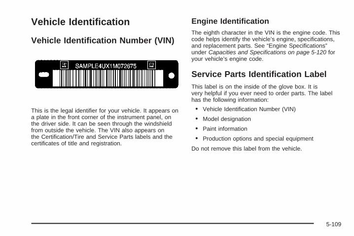
Vehicle Identification
Vehicle Identification Number (VIN)
This is the legal identifier for your vehicle. It appears ona plate in the front corner of the instrument panel, onthe driver side. It can be seen through the windshieldfrom outside the vehicle. The VIN also appears onthe Certification/Tire and Service Parts labels and thecertificates of title and registration.
Engine IdentificationThe eighth character in the VIN is the engine code. Thiscode helps identify the vehicle’s engine, specifications,and replacement parts. See “Engine Specifications”under Capacities and Specifications on page 5-120 foryour vehicle’s engine code.
Service Parts Identification LabelThis label is on the inside of the glove box. It isvery helpful if you ever need to order parts. The labelhas the following information:
• Vehicle Identification Number (VIN)
• Model designation
• Paint information
• Production options and special equipment
Do not remove this label from the vehicle.
5-109

Electrical System
High Voltage Devices and Wiring
{CAUTION:
Exposure to high voltage can cause shock,burns, and even death. The high voltagesystems in your vehicle can only be servicedby technicians with special training.
High voltage devices are identified by labels.Do not remove, open, take apart, or modifythese devices. High voltage cable or wiring hasorange covering. Do not probe, tamper with,cut, or modify high voltage cable or wiring.
Add-On Electrical EquipmentNotice: Do not add anything electrical to yourvehicle unless you check with your dealer/retailerfirst. Some electrical equipment can damageyour vehicle and the damage would not be coveredby your warranty. Some add-on electrical equipmentcan keep other components from working as theyshould.
Add-on equipment can drain your vehicle’s battery, evenif your vehicle is not operating.
Your vehicle has an airbag system. Before attempting toadd anything electrical to your vehicle, see ServicingYour Airbag-Equipped Vehicle on page 1-78.
Windshield Wiper FusesThe windshield wiper motor is protected by a circuitbreaker and a fuse. If the motor overheats due to heavysnow, etc., the wiper will stop until the motor cools.If the overload is caused by some electrical problem,have it fixed.
5-110

Power Windows and Other PowerOptionsCircuit breakers in the fuse block protect the powerwindows and other power accessories. When the currentload is too heavy, the circuit breaker opens and closes,protecting the circuit until the problem is fixed orgoes away.
Fuses and Circuit BreakersThe wiring circuits in your vehicle are protected fromshort circuits by a combination of fuses, circuit breakersand fusible thermal links. This greatly reduces thechance of fires caused by electrical problems.
Look at the silver-colored band inside the fuse. If theband is broken or melted, replace the fuse. Be sure youreplace a bad fuse with a new one of the identicalsize and rating.
Fuses of the same amperage can be temporarilyborrowed from another fuse location, if a fuse goes out.Replace the fuse as soon as you can.
Instrument Panel Fuse BlockThe instrument panel fuse block is located under theinstrument panel on the passenger side of the vehicle.Pull down on the cover to access the fuse block.
5-111

Fuses Usage
FRT/WSW Front Windshield Wiper
SPARE Spare
HTD/SEAT Front Heated Seats
STR/WHL/ILLUM Steering Wheel Illumination
MSM Memory Seat Module
PWR/MIRRORS Power Mirrors
DR/LCK Door Locks
AIRBAG Airbag System
LT/TRN/SIG Driver Side Turn Signal
REAR WIPER Rear Window Wiper
Fuse Side
5-112

Fuses Usage
PWR MOD PassKey Module, Body ControlModule
BCK/UP/STOP Back-up Lamps, Stoplamps
HVAC Climate Control System
DISPLAY Display
RT/TRN/SIG Passenger Side Turn Signal
DRL* Daytime Running Lamps
RADIO Radio
PDM Power Mirrors, Liftgate Release
Fuses Usage
DRL 2** Not Used
INFOTAINMENT Infotainment System
BCM Body Control Module
SPARE Spare
CTSY Dome Lamps
INADV/PWR/LED Interior Lamps
ONSTR/VENT Emissions
AMP Audio Amplifier
5-113

Relays Usage
LT/PWR/SEAT Driver Side Power Seat Relay
RT/PWR/SEAT Passenger Side Power Seat Relay
PWR/WNDW Power Windows Relay
PWR/COLUMN Power Steering Column Relay
L/GATE Liftgate Relay
LCK Power Lock Relay
REAR/WSW Rear Window Washer Relay
Relay Side
5-114

UNLCK Power Unlock Relay
DRL2 Daytime Running Lamps 2 Relay
LT/UNLCK Driver Side Unlock Relay
DRL Daytime Running Lamps Relay
SPARE Spare
FRT/WSW Front Windshield Washer Relay
Underhood Fuse BlockThe underhood fuse block is located in the enginecompartment, on the passenger side of the vehicle.
Lift the cover for access to the fuse/relay block.
Notice: Spilling liquid on any electrical componentson your vehicle may damage it. Always keep thecovers on any electrical component.
5-115

To remove fuses, hold the end of the fuse between your thumb and index finger and pull straight out.
5-116

Fuses Usage
A/C CLUTCH Air Conditioning Clutch
ABS MTR Antilock Braking System (ABS)Motor
AFS Adaptive Forward Lighting System
AIRBAG Airbag System
AUX POWER Auxiliary Power
AWD All-Wheel-Drive System
ECM Engine Control Module
ECM 1 Engine Control Module 1
EMISSION 1 Antilock Brakes System 2
EMISSION 2 Emission 2
EVEN COILS Even Injector Coils
FOG LAMP Fog Lamps
FUEL PUMP Fuel Pump
HORN Horn
HTD MIR Heated Outside Rearview Mirror
LT HI BEAM Left High-Beam Headlamp
LT LO BEAM Left Low-Beam Headlamp
Fuses Usage
LT PRK Left Parking Lamp
LT TRLRSTOP/TRN
Trailer Left Stoplamp and TurnSignal
ODD COILS Odd Injector Coils
PCM IGN Powertrain Control Module Ignition
PWR OUTLET Power Outlet
REARCAMERA Rear Camera
RR APO Rear Accessory Power Outlet
RR HVAC Rear Climate Control System
RT HI BEAM Right High-Beam Headlamp
RT LO BEAM Right Low-Beam Headlamp
RT PRK Right Parking Lamp
RT TRLRSTOP/TRN
Trailer Right Stoplamp and TurnSignal
RVC SNSR Regulated Voltage Control Sensor
SPARE Spare
SPARE Spare
SPARE Spare
5-117

Fuses Usage
SPARE Spare
SPARE Spare
SPARE Spare
TCM Transmission Control Module
TRANS Transmission
TRLR BCK/UP Trailer Back-up Lamps
TRLR BRK Trailer Brake
TRLR PRKLAMP Trailer Parking Lamps
TRLR PWR Trailer Power
WPR/WSW Windshield Wiper/Washer
J-Case Fuses Usage
ABS MTR ABS Motor
BATT 1 Battery 1
BATT 2 Battery 2
BATT 3 Battery 3
FAN 1 Cooling Fan 1
FAN 2 Cooling Fan 2
HTD WASH Heated Windshield Washer System
HVAC BLWR Climate Control System Blower
PWR L/GATE Power Liftgate
RR DEFOG Rear Defogger
S/ROOF/SUNSHADE Sunroof, Sunshade
STRTR Starter
5-118
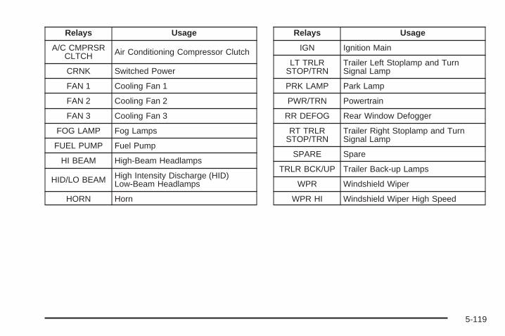
Relays Usage
A/C CMPRSRCLTCH Air Conditioning Compressor Clutch
CRNK Switched Power
FAN 1 Cooling Fan 1
FAN 2 Cooling Fan 2
FAN 3 Cooling Fan 3
FOG LAMP Fog Lamps
FUEL PUMP Fuel Pump
HI BEAM High-Beam Headlamps
HID/LO BEAM High Intensity Discharge (HID)Low-Beam Headlamps
HORN Horn
Relays Usage
IGN Ignition Main
LT TRLRSTOP/TRN
Trailer Left Stoplamp and TurnSignal Lamp
PRK LAMP Park Lamp
PWR/TRN Powertrain
RR DEFOG Rear Window Defogger
RT TRLRSTOP/TRN
Trailer Right Stoplamp and TurnSignal Lamp
SPARE Spare
TRLR BCK/UP Trailer Back-up Lamps
WPR Windshield Wiper
WPR HI Windshield Wiper High Speed
5-119

Capacities and SpecificationsThe following approximate capacities are given in English and metric conversions. See Recommended Fluids andLubricants on page 6-11 for more information.
ApplicationCapacities
English Metric
Air Conditioning Refrigerant R134a
For the air conditioning system refrigerant chargeamount, see the refrigerant caution label locatedunder the hood. See your dealer/retailer for more
information.Cooling System 12.2 qt 11.6 LEngine Oil with Filter 5.5 qt 5.2 LFuel Tank 22.0 gal 83.3 LTransmission Fluid 9.5 qt 9.0 LWheel Nut Torque 140 lb ft 190 Y
All capacities are approximate. When adding, be sure to fill to the approximate level, as recommended in thismanual. Recheck fluid level after filling.
Engine SpecificationsEngine VIN Code Transmission Spark Plug Gap
3.6L V6 7 Automatic 0.043 in (1.10 mm)
5-120

Maintenance Schedule ......................................6-2Introduction ...................................................6-2Maintenance Requirements ..............................6-2Your Vehicle and the Environment ....................6-2Using the Maintenance Schedule ......................6-2Scheduled Maintenance ...................................6-4Additional Required Services ............................6-6Maintenance Footnotes ...................................6-7
Owner Checks and Services ............................6-8At Each Fuel Fill ............................................6-8At Least Once a Month ...................................6-9At Least Once a Year .....................................6-9Recommended Fluids and Lubricants ...............6-11Maintenance Replacement Parts .....................6-13Engine Drive Belt Routing ..............................6-14Maintenance Record .....................................6-15
Section 6 Maintenance Schedule
6-1

Maintenance Schedule
IntroductionImportant: Keep engine oil at the proper level andchange as recommended.
Maintenance RequirementsNotice: Maintenance intervals, checks, inspections,replacement parts, and recommended fluids andlubricants as prescribed in this manual are necessaryto keep your vehicle in good working condition.Any damage caused by failure to follow scheduledmaintenance might not be covered by warranty.
Your Vehicle and the EnvironmentProper vehicle maintenance not only helps to keepyour vehicle in good working condition, but also helpsthe environment. All recommended maintenance isimportant. Improper vehicle maintenance can even affectthe quality of the air we breathe. Improper fluid levels orthe wrong tire inflation can increase the level of emissionsfrom your vehicle. To help protect our environment,and to keep your vehicle in good condition, be sureto maintain your vehicle properly.
Using the Maintenance ScheduleWe want to help you keep your vehicle in good workingcondition. But we do not know exactly how you willdrive it. You might drive very short distances only afew times a week. Or you might drive long distancesall the time in very hot, dusty weather. You mightuse your vehicle in making deliveries. Or you mightdrive it to work, to do errands, or in many other ways.
Because of all the different ways people use theirvehicles, maintenance needs vary. You might needmore frequent checks and replacements. So please readthe following and note how you drive. If you have anyquestions on how to keep your vehicle in good condition,see your dealer/retailer.
This schedule is for vehicles that:
• carry passengers and cargo within recommendedlimits. You will find these limits on the Tire andLoading Information label. See Loading the Vehicleon page 4-22.
• are driven on reasonable road surfaces within legaldriving limits.
• use the recommended fuel. See Gasoline Octaneon page 5-5.
6-2

The services in Scheduled Maintenance on page 6-4should be performed when indicated. See AdditionalRequired Services on page 6-6 and MaintenanceFootnotes on page 6-7 for further information.
{CAUTION:
Performing maintenance work on a vehiclecan be dangerous. In trying to do some jobs,you can be seriously injured. Do your ownmaintenance work only if you have therequired know-how and the proper tools andequipment for the job. If you have any doubt,see your dealer/retailer to have a qualifiedtechnician do the work. See Doing YourOwn Service Work on page 5-4.
Some maintenance services can be complex.So, unless you are technically qualified and havethe necessary equipment, you should have yourdealer/retailer do these jobs.
When you go to your dealer/retailer for your serviceneeds, you will know that trained and supported servicetechnicians will perform the work using genuine parts.
If you want to purchase service information, see ServicePublications Ordering Information on page 7-16.
Owner Checks and Services on page 6-8 tells you whatshould be checked, when to check it, and what you caneasily do to help keep your vehicle in good condition.
The proper replacement parts, fluids, and lubricants touse are listed in Recommended Fluids and Lubricantson page 6-11 and Maintenance Replacement Parts onpage 6-13. When your vehicle is serviced, make surethese are used. All parts should be replaced and allnecessary repairs done before you or anyone elsedrives the vehicle. We recommend the use of genuineparts from your dealer/retailer.
6-3

Scheduled MaintenanceWhen the CHANGE ENGINE OIL SOON messagecomes on, it means that service is required for yourvehicle. Have your vehicle serviced as soon as possiblewithin the next 600 miles (1 000 km). It is possiblethat, if you are driving under the best conditions, theengine oil life system might not indicate that vehicleservice is necessary for over a year. However,the engine oil and filter must be changed at leastonce a year and at this time the system must be reset.Your dealer/retailer has trained service technicianswho will perform this work using genuine parts andreset the system.
If the engine oil life system is ever reset accidentally,you must service your vehicle within 3,000 miles(5 000 km) since your last service. Remember toreset the oil life system whenever the oil is changed.See Engine Oil Life System on page 5-16 for informationon the Engine Oil Life System and resetting the system.
When the CHANGE ENGINE OIL SOON messageappears, certain services, checks, and inspectionsare required. Required services are described in thefollowing for “Maintenance I” and “Maintenance II.”Generally, it is recommended that your first service beMaintenance I, your second service be Maintenance II,and that you alternate Maintenance I and Maintenance IIthereafter. However, in some cases, Maintenance IImay be required more often.
Maintenance I — Use Maintenance I if theCHANGE ENGINE OIL SOON message comes onwithin 10 months since the vehicle was purchasedor Maintenance II was performed.
Maintenance II — Use Maintenance II if the previousservice performed was Maintenance I. Always useMaintenance II whenever the message comes on10 months or more since the last service or if themessage has not come on at all for one year.
6-4

Scheduled MaintenanceService Maintenance I Maintenance II
Change engine oil and filter. See Engine Oil on page 5-13. Reset oil lifesystem. See Engine Oil Life System on page 5-16. An Emission ControlService.
• •
Visually check for any leaks or damage. See footnote (g). • •Inspect engine air cleaner filter. If necessary, replace filter. See Engine AirCleaner/Filter on page 5-18. See footnote (l). •
Rotate tires and check inflation pressures and wear. See Tire Inspection andRotation on page 5-63 and “Tire Wear Inspection” in At Least Once a Monthon page 6-9.
• •
Inspect brake system. See footnote (a). • •Check engine coolant and windshield washer fluid levels and add fluid asneeded. • •
Perform any needed additional services. See “Additional Required Services” inthis section. • •
Inspect suspension and steering components. See footnote (b). •Inspect engine cooling system. See footnote (c). •Inspect wiper blades. See footnote (d). •Inspect restraint system components. See footnote (e). •Lubricate body components. See footnote (f). •Check transmission fluid level and add fluid as needed. •Inspect throttle system. See footnote (j). •
6-5

Additional Required ServicesThe following services should be performed at the first maintenance service (I or II) after the indicated miles(kilometers) shown for each item.
Additional Required Services
Service and Miles (Kilometers) 25,000(40 000)
50,000(80 000)
75,000(120 000)
100,000(160 000)
125,000(200 000)
150,000(240 000)
Inspect fuel system for damage or leaks. • • • • • •Inspect exhaust system for loose ordamaged components. • • • • • •
Replace engine air cleaner filter. SeeEngine Air Cleaner/Filter on page 5-18. • • •
Change automatic transmission fluid(severe service). See footnote (h). • • •
Change automatic transmission fluid(normal service). •
Replace spark plugs and inspect sparkplug wires. An Emission Control Service. •
Engine cooling system service (or everyfive years, whichever occurs first).An Emission Control Service.See footnote (i).
•
Inspect engine accessory drive belt.An Emission Control Service.See footnote (k).
•
6-6

Maintenance Footnotes(a) Visually inspect brake lines and hoses for properhook-up, binding, leaks, cracks, chafing, etc. Inspectdisc brake pads for wear and rotors for surfacecondition. Inspect other brake parts, including calipers,parking brake, etc. Check parking brake adjustment.
(b) Visually inspect front and rear suspension andsteering system for damaged, loose, or missing parts orsigns of wear. Inspect power steering lines and hosesfor proper hook-up, binding, leaks, cracks, chafing, etc.
(c) Visually inspect hoses and have them replaced ifthey are cracked, swollen, or deteriorated. Inspect allpipes, fittings and clamps; replace with genuine parts asneeded. To help ensure proper operation, a pressure testof the cooling system and pressure cap and cleaning theoutside of the radiator and air conditioning condenser isrecommended at least once a year.
(d) Inspect wiper blades for wear, cracking, orcontamination. Clean the windshield and wiper blades,if contaminated. Replace wiper blades that are wornor damaged. See Windshield Wiper Blade Replacementon page 5-48 and Windshield, Backglass, and WiperBlades on page 5-105 for more information.
(e) Make sure the safety belt reminder light and safetybelt assemblies are working properly. Look for any otherloose or damaged safety belt system parts. If you seeanything that might keep a safety belt system from doingits job, have it repaired. Have any torn or frayed safetybelts replaced. Also see Checking the Restraint Systemson page 1-80.
(f) Lubricate all key lock cylinders, hood latchassemblies, secondary latches, pivots, spring anchor andrelease pawl, hood and door hinges, rear folding seats,and liftgate hinges. More frequent lubrication may berequired when exposed to a corrosive environment.Applying silicone grease on weatherstrips with a cleancloth will make them last longer, seal better, and notstick or squeak.
(g) A fluid loss in any vehicle system could indicate aproblem. Have the system inspected and repairedand the fluid level checked. Add fluid if needed.
(h) Change automatic transmission fluid if the vehicle ismainly driven under one or more of these conditions:
− In heavy city traffic where the outside temperatureregularly reaches 90°F (32°C) or higher.
− In hilly or mountainous terrain.− When doing frequent trailer towing.− Uses such as found in taxi, police, or delivery
service.
6-7

(i) Drain, flush, and refill cooling system. This servicecan be complex; you should have your dealer/retailerperform this service. See Engine Coolant on page 5-20for what to use. Inspect hoses. Clean radiator,condenser, pressure cap, and filler neck. Pressuretest the cooling system and pressure cap.
(j) Check system for interference or binding and fordamaged or missing parts. Replace parts as needed.Replace any components that have high effort orexcessive wear. Do not lubricate accelerator orcruise control cables.
(k) Visually inspect belt for fraying, excessive cracks, orobvious damage. Replace belt if necessary.
(l) If you drive regularly under dusty conditions, inspectthe filter at each engine oil change.
Owner Checks and ServicesThese owner checks and services should be performedat the intervals specified to help ensure vehicle safety,dependability, and emission control performance. Yourdealer/retailer can assist with these checks and services.
Be sure any necessary repairs are completed at once.Whenever any fluids or lubricants are added to thevehicle, make sure they are the proper ones, as shownin Recommended Fluids and Lubricants on page 6-11.
At Each Fuel FillIt is important to perform these underhood checks ateach fuel fill.
Engine Oil Level Check
Notice: It is important to check the engine oilregularly and keep it at the proper level. Failure tokeep the engine oil at the proper level can causedamage to the engine not covered by the vehiclewarranty.
Check the engine oil level and add the proper oil ifnecessary. See Engine Oil on page 5-13.
Engine Coolant Level CheckCheck the engine coolant level and add DEX-COOL®
coolant mixture if necessary. See Engine Coolanton page 5-20.
Windshield Washer Fluid Level CheckCheck the windshield washer fluid level in the windshieldwasher fluid reservoir and add the proper fluid ifnecessary.
6-8

At Least Once a Month
Tire Inflation CheckInspect the vehicle’s tires and make sure they areinflated to the correct pressures. Do not forget tocheck the spare tire. See Inflation - Tire Pressure onpage 5-56. Check to make sure the spare tire is storedsecurely. See Changing a Flat Tire on page 5-84.
Tire Wear InspectionTire rotation may be required for high mileage highwaydrivers prior to the Engine Oil Life System servicenotification. Check the tires for wear and, if necessary,rotate the tires. See Tire Inspection and Rotation onpage 5-63.
At Least Once a Year
Starter Switch Check
{CAUTION:
When you are doing this inspection, thevehicle could move suddenly. If the vehiclemoves, you or others could be injured.
1. Before you start, be sure you have enough roomaround the vehicle.
2. Firmly apply both the parking brake and the regularbrake. See Parking Brake on page 2-34.Do not use the accelerator pedal, and be ready toturn off the engine immediately if it starts.
3. Try to start the engine in each gear. The vehicleshould start only in PARK (P) or NEUTRAL (N).If the vehicle starts in any other position, contactyour dealer/retailer for service.
6-9
Automatic Transmission Shift LockControl System Check
{CAUTION:
When you are doing this inspection, thevehicle could move suddenly. If the vehiclemoves, you or others could be injured.
1. Before you start, be sure you have enough roomaround the vehicle. It should be parked on a levelsurface.
2. Firmly apply the parking brake. See Parking Brakeon page 2-34.Be ready to apply the regular brake immediately ifthe vehicle begins to move.
3. With the engine off, turn the ignition to ON/RUN,but do not start the engine. Without applying theregular brake, try to move the shift lever outof PARK (P) with normal effort. If the shift levermoves out of PARK (P), contact your dealer/retailerfor service.
Ignition Transmission Lock CheckWhile parked, and with the parking brake set, try to turnthe ignition to LOCK/OFF in each shift lever position.
• The ignition should turn to LOCK/OFF onlywhen the shift lever is in PARK (P).
• The ignition key should come out only inLOCK/OFF.
Contact your dealer/retailer if service is required.
Parking Brake and AutomaticTransmission Park (P) MechanismCheck
{CAUTION:
When you are doing this check, your vehiclecould begin to move. You or others could beinjured and property could be damaged. Makesure there is room in front of your vehicle incase it begins to roll. Be ready to apply theregular brake at once should the vehicle beginto move.
6-10
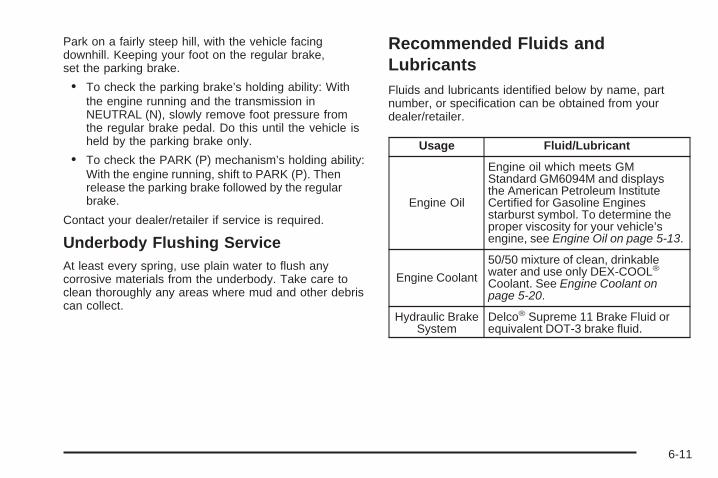
Park on a fairly steep hill, with the vehicle facingdownhill. Keeping your foot on the regular brake,set the parking brake.
• To check the parking brake’s holding ability: Withthe engine running and the transmission inNEUTRAL (N), slowly remove foot pressure fromthe regular brake pedal. Do this until the vehicle isheld by the parking brake only.
• To check the PARK (P) mechanism’s holding ability:With the engine running, shift to PARK (P). Thenrelease the parking brake followed by the regularbrake.
Contact your dealer/retailer if service is required.
Underbody Flushing ServiceAt least every spring, use plain water to flush anycorrosive materials from the underbody. Take care toclean thoroughly any areas where mud and other debriscan collect.
Recommended Fluids andLubricantsFluids and lubricants identified below by name, partnumber, or specification can be obtained from yourdealer/retailer.
Usage Fluid/Lubricant
Engine Oil
Engine oil which meets GMStandard GM6094M and displaysthe American Petroleum InstituteCertified for Gasoline Enginesstarburst symbol. To determine theproper viscosity for your vehicle’sengine, see Engine Oil on page 5-13.
Engine Coolant
50/50 mixture of clean, drinkablewater and use only DEX-COOL®
Coolant. See Engine Coolant onpage 5-20.
Hydraulic BrakeSystem
Delco® Supreme 11 Brake Fluid orequivalent DOT-3 brake fluid.
6-11

Usage Fluid/Lubricant
WindshieldWasher Optikleen Washer Solvent.
Power SteeringSystem
GM Power Steering Fluid(GM Part No. U.S. 89021184,in Canada 89021186).
AutomaticTransmission
DEXRON®-VI AutomaticTransmission Fluid.
Key LockCylinders
Multi-Purpose Lubricant, Superlube(GM Part No. U.S. 12346241,in Canada 10953474).
CarrierAssembly —Differential(Rear DriveModule) and
TransferCase (PowerTransfer Unit)
SAE 75W-90Synthetic Axle Lubricant(GM Part No. U.S. 89021677,in Canada 89021678) meetingGM Specification 9986115.
Usage Fluid/Lubricant
Hood LatchAssembly,Secondary
Latch, Pivots,Spring Anchor,and Release
Pawl
Lubriplate Lubricant Aerosol(GM Part No. U.S. 12346293,in Canada 992723) or lubricantmeeting requirements of NLGI #2,Category LB or GC-LB.
Hood andDoor Hinges
and RearFolding Seat
Multi-Purpose Lubricant, Superlube(GM Part No. U.S. 12346241,in Canada 10953474).
WeatherstripConditioning
Weatherstrip Lubricant(GM Part No. U.S. 3634770,in Canada 10953518) orDielectric Silicone Grease(GM Part No. U.S. 12345579,in Canada 992887).
6-12

Maintenance Replacement PartsReplacement parts identified below by name, part number, or specification can be obtained from your dealer/retailer.
Part GM Part Number ACDelco Part Number
Engine Air Cleaner/Filter 15278634 —
Engine Oil Filter 89017524 PF48
Spark Plugs 12611882 41-107
Wiper Blades
Driver – 24.6 inches (62.5 cm) 15254805 —
Passenger – 20.8 inches (53.0 cm) 15254804 —
Rear – 11.6 inches (30.0 cm) 15276259 —
6-13

Engine Drive Belt Routing
3.6L V6 Engine
6-14

Maintenance RecordAfter the scheduled services are performed, record the date, odometer reading, who performed the service, and thetype of services performed in the boxes provided. See Maintenance Requirements on page 6-2. Any additionalinformation from Owner Checks and Services on page 6-8 can be added on the following record pages. You shouldretain all maintenance receipts.
Maintenance Record
Date OdometerReading Serviced By Maintenance I or
Maintenance II Services Performed
6-15

Maintenance Record (cont’d)
Date OdometerReading Serviced By Maintenance I or
Maintenance II Services Performed
6-16

Maintenance Record (cont’d)
Date OdometerReading Serviced By Maintenance I or
Maintenance II Services Performed
6-17

Maintenance Record (cont’d)
Date OdometerReading Serviced By Maintenance I or
Maintenance II Services Performed
6-18

Customer Assistance and Information ...............7-2Customer Satisfaction Procedure ......................7-2Online Owner Center ......................................7-5Customer Assistance for Text
Telephone (TTY) Users ................................7-6Customer Assistance Offices ............................7-6GM Mobility Reimbursement Program ................7-7Roadside Assistance Program ..........................7-7Scheduling Service Appointments ....................7-10Courtesy Transportation .................................7-10Collision Damage Repair ................................7-12
Reporting Safety Defects ................................7-15Reporting Safety Defects to the
United States Government ..........................7-15Reporting Safety Defects to the
Canadian Government ................................7-15Reporting Safety Defects to Saturn ..................7-16Service Publications Ordering Information .........7-16
Vehicle Data Recording and Privacy ................7-18Event Data Recorders ...................................7-18OnStar® ......................................................7-19Navigation System ........................................7-19Radio Frequency Identification (RFID) ..............7-19
Section 7 Customer Assistance Information
7-1

Customer Assistance andInformation
Customer Satisfaction ProcedureYour satisfaction and goodwill are important toyour retailer and to Saturn. Together we are committedto providing our customers with unparalleled service,before, during, and after the purchase of a Saturnvehicle, for total customer satisfaction. We call this theSaturn Difference. Normally, any concerns with thesales transaction or the operation of the vehicleare resolved by the retailer’s sales or servicedepartments. If, for any reason, your ownershipexperience falls below your expectations, we suggestyou take the following action:
STEP ONE: Contact the Retail Customer AssistanceLiaison. Any member of the retail management team hasthe authority and the desire to resolve your concerns.Normally, concerns can be quickly resolved at this level.
STEP TWO: Should you need additional assistance, inthe U.S., contact the Saturn Customer Assistance Centerby calling 1-800-553-6000. In Canada, call the SaturnCustomer Communication Centre at 1-800-263-1999.A Saturn Customer Assistance Center team member willhandle your call and assist in providing product andwarranty information, the nearest retailer location,roadside assistance, brochures, literature and discussany concerns you may have.
We encourage you to call the toll-free number in order togive your inquiry prompt attention. Please have thefollowing information available to give the CustomerAssistance Representative:
• Vehicle Identification Number (VIN). This 17-digitnumber can be found on the vehicle registration ortitle, on the upper driver side corner of the instrumentpanel, or on your roadside assistance key card.
• The name of your selling and servicing retail facility.
• Vehicle delivery date and present mileage.
• Your daytime and evening phone numbers.
When contacting Saturn, please remember that yourconcern will likely be resolved at a retailer’s facility.That is why we suggest you follow Step One first.
7-2

STEP THREE (U.S. Owners): Both Saturn and itsretailers are committed to making sure you arecompletely satisfied with your Saturn vehicle. However,if you continue to remain unsatisfied after followingthe procedure outlined in Steps One and Two, Saturnand its retailers offer the additional assistance of aneutral party through our voluntary participationin a mediation/arbitration program called Better BusinessBureau (BBB) Auto Line.
The BBB Auto Line Program is an out-of-court programadministered by the Council of Better BusinessBureaus to settle automotive disputes regarding vehiclerepairs or the interpretation of the New VehicleLimited Warranty. This program is available at no costto you, our customer.
Although you may be required to resort to this informaldispute resolution program prior to filing a courtaction, use of the program is free of charge and yourcase is generally heard within 40 days. If you donot agree with the decision given in your case, you canreject it and proceed with any other venue for reliefavailable to you.
Contact the BBB Auto Line Program by using thetoll-free telephone number or by writing them at thefollowing address:
BBB Auto Line ProgramCouncil of Better Business Bureaus, Inc.4200 Wilson BoulevardSuite 800Arlington, VA 22203-1838
Telephone: 1-800-955-5100www.dr.bbb.org/goauto
This program is available in all 50 states and theDistrict of Columbia. Eligibility is limited by vehicleage, mileage and other factors. Saturn Corporationreserves the right to change eligibility limitationsand/or discontinue its participation in this program.
7-3

STEP THREE (Canadian Owners):
General Motors Participation in theMediation/Arbitration ProgramIn the event that you do not feel your concerns havebeen addressed after following the procedure outlined inSteps 1 and 2, General Motors of Canada Limitedhas committed to binding arbitration of owner disputesinvolving factory-related vehicle service claims. Theprogram provides for the review of the facts involved byan impartial third party arbiter, and may include aninformal hearing before the arbiter. The programis designed so that the entire dispute settlementprocess, from the time you file your complaint to thefinal decision, should be completed in approximately70 days. We believe our impartial program offersadvantages over courts in most jurisdictions because itis informal, quick, and free of charge.
For further information concerning eligibility in theCanadian Motor Vehicle Arbitration Plan (CAMVAP),call toll-free 1-800-207-0685. Alternatively, you may callthe Saturn Customer Communication Centre,1-800-263-1999, or you may write to:
Mediation/Arbitration Programc/o Customer Communication CentreGeneral Motors of Canada LimitedMail Code: CA1-163-0051908 Colonel Sam DriveOshawa, Ontario L1H 8P7
Telephone: 1-800-955-5100
Your inquiry should be accompanied by the VehicleIdentification Number (VIN).
7-4
Online Owner Center
(United States only)This is a resource for your Saturn ownership needs.Specific vehicle information can be found in one place.
The Online Owner Center allows you to:
• Get e-mail service reminders.
• Access information about your specific vehicle,including tips and videos and an electronicversion of this owner manual.
• Keep track of your vehicle’s service history andmaintenance schedule.
• Find Saturn retailers for service nationwide.
• Receive special promotions and privileges onlyavailable to members.
Refer to www.saturn.com on the web for updatedinformation and to register your vehicle.
My GM Canada (Canada only)My GM Canada is a password-protected section ofgmcanada.com where you can save information onGM vehicles, get personalized offers, and use handytools and forms with greater ease.
Here are a few of the valuable tools and services youwill have access to:
− My Showroom: Find and save information onvehicles and current offers in your area.
− My Dealers/Retailers: Save details such asaddress and phone number for each of yourpreferred GM Dealers or Retailers.
− My Driveway: Receive service reminders andhelpful advice on owning and maintainingyour vehicle.
− My Preferences: Manage your profile, subscribe toE-News and use tools and forms with greater ease.
To sign up, visit the My GM Canada section withinwww.gmcanada.com.
7-5

Customer Assistance for TextTelephone (TTY) UsersTo assist owners who have hearing difficulties, Saturnhas installed special TDD (Telecommunication Devicesfor the Deaf) equipment in its Saturn CustomerAssistance Center.
Any hearing or speech-impaired customer who hasaccess to a TDD or to a conventional Text Telephone(TTY) can communicate with Saturn by dialing1-800-TDD-6000. TTY users in Canada may dial1-800-263-3830.
Customer Assistance OfficesSaturn encourages customers to call the toll-freenumber for assistance. If a customer wishes to write toSaturn, the letter should be addressed to:
Saturn Customer Assistance Center100 Saturn ParkwayMail Code 371-999-S24Spring Hill, TN 37174-1500
1-800-553-60001-800-833-6000 (For Text Telephone devices (TTYs))Roadside Assistance: 1-800-553-6000
In Canada, write to:
Saturn Customer Communication CentreGeneral Motors of Canada Ltd.CA1-163-0051908 Colonel Sam DriveOshawa, Ontario L1H 8P7
www.gmcanada.com1-800-263-19991-800-263-3830 (For Text Telephone devices (TTYs))Roadside Assistance: 1-800-268-6800
7-6

GM Mobility ReimbursementProgram
This program, available to qualified applicants, canreimburse you up to $1,000 toward eligible aftermarketdriver or passenger adaptive equipment you mayrequire for your vehicle such as hand controls,wheelchair/scooter lifts, etc.
The offer is available for a limited period of time fromthe date of vehicle purchase/lease.
For more details, or to determine your vehicle’seligibility, visit your Saturn retailer or call the SaturnCustomer Assistance Center at 1-800-553-6000.Text telephone (TTY) users, call 1-800-833-6000.
In Canada, customers may call the Saturn CustomerCommunication Centre at 1-800-263-1999. TTY users inCanada may call 1-800-263-3830.
Roadside Assistance ProgramFor vehicles purchased in the U.S., call 1-800-553-6000;(Text Telephone (TTY): 1-800-889-2438).
For vehicles purchased in Canada, call 1-800-268-6800.
Service is available 24 hours a day, 365 days a year.
As the owner of a new Saturn vehicle, you areautomatically enrolled in the Saturn RoadsideAssistance Program.
7-7

Who is Covered?Roadside Assistance coverage is for the vehicleoperator, regardless of ownership. In Canada, a persondriving this vehicle without the consent of the owneris not eligible for coverage.
Services ProvidedThe following services are provided in the U.S. andCanada up to 5 years/100,000 miles (160 000 km),whichever comes first, and, in Canada only, upto a maximum of $100.
• Fuel Delivery: Delivery of enough fuel for thevehicle to get to the nearest service station(approximately $5 Canada). In Canada, service toprovide diesel may be restricted. For safety reasons,propane and other alternative fuels are notprovided through this service.
• Lock-Out Service: Lock-out service is covered atno charge if you are unable to gain entry into yourvehicle. A remote unlock may be available ifyou have an active OnStar® subscription. To ensuresecurity, the driver must present personalidentification before lock-out service is provided. InCanada, the vehicle registration is also required.
• Emergency Tow From a Public Roadway orHighway: Tow to the nearest Saturn retailer forwarranty service or in the event of a vehicle-disablingcrash. Winch-out assistance is provided when thevehicle is mired in sand, mud, or snow.
• Flat Tire Change: Installation of a spare tire in goodcondition, when equipped and properly inflated, iscovered at no charge. The customer is responsiblefor the repair or replacement of the tire if not coveredby a warrantable failure.
• Jump Start: A battery jump start is covered at nocharge if the vehicle does not start.
• Trip Routing Service (Canada Only): Uponrequest, Roadside Assistance will send you detailed,computer personalized maps, highlighting yourchoice of either the most direct route or the mostscenic route to your destination, anywhere in NorthAmerica, along with helpful travel informationpertaining to your trip.
Please allow three weeks before your planneddeparture date. Trip routing requests are limited tosix per calendar year.
7-8

• Trip Interruption Benefits and Assistance(Canada Only): In the event of a warranty relatedvehicle disablement, while en route and over250 kilometres from the original point of departure,you might qualify for trip interruption expenseassistance. This assistance covers reasonablereimbursement of up to a maximum of $500(Canadian) for (A) meals (maximum of $50/day),(B) lodging (maximum of $100/night), and(C) alternate ground transportation (maximum of$40/day). This benefit is to assist you with some ofthe unplanned expense you may incur while waitingfor your vehicle to be repaired.
Pre-authorization, original detailed receipts, and acopy of the repair order are required.Once authorization has been given, your advisor willhelp you make any necessary arrangements andexplain how to claim for trip interruption expenseassistance.
• Alternative Service (Canada Only): There could betimes when Roadside Assistance cannot providetimely assistance. Your advisor may authorize you tosecure local emergency road service, and you will bereimbursed up to $100 upon submission of theoriginal receipt to Roadside Assistance.
In many instances, mechanical failures may be covered.However, any cost for parts and labor for non-warrantyrepairs are the responsibility of the driver.
Saturn and General Motors of Canada Limited reservethe right to limit services or reimbursement to anowner or driver when, in their sole discretion, the claimsbecome excessive in frequency or type of occurrence.
Calling for AssistanceFor prompt and efficient assistance when calling, pleaseprovide the following to the Roadside AssistanceRepresentatives:
• Your name, home address, and home telephonenumber
• Telephone number of your location
• Location of the vehicle
• Model, year, color, and license plate number of thevehicle
• Odometer reading, Vehicle Identification Number(VIN) and delivery date of the vehicle
• Description of the problem
7-9

Towing and Road Service ExclusionsSpecifically excluded from Roadside Assistancecoverage are towing or services for vehicles operated ona non-public roadway or highway, fines, impound towingcaused by a violation of local, Municipal, State, Provincialor Federal law, and mounting, dismounting or changing ofsnow tires, chains, or other traction devices.
Roadside Assistance is not part of or included in thecoverage provided by the New Vehicle Limited Warranty.Saturn and General Motors of Canada Limited reservethe right to make any changes or discontinue theRoadside Assistance program at any time withoutnotification.
Scheduling Service AppointmentsWhen your vehicle requires warranty service, contactyour dealer/retailer and request an appointment.By scheduling a service appointment and advising yourservice consultant of your transportation needs, yourdealer/retailer can help minimize your inconvenience.
If your vehicle cannot be scheduled into the servicedepartment immediately, keep driving it until it can bescheduled for service, unless, of course, the problem issafety-related. If it is, please call your dealership/retailer,let them know this, and ask for instructions.
If the dealer/retailer requests you to bring the vehicle forservice, you are urged to do so as early in the workday as possible to allow for the same day repair.
Courtesy TransportationTo enhance your ownership experience, we and ourparticipating retailers are proud to offer CourtesyTransportation, a customer support program for vehicleswith the Bumper to Bumper (Base Warranty Coverageperiod in Canada) and extended powertrain warrantyin both the U.S. and Canada.
Several courtesy transportation options are available toassist in reducing your inconvenience when warrantyrepairs are required.
Courtesy Transportation is not a part of the New VehicleLimited Warranty. A separate booklet entitled “Warrantyand Owner Assistance Information” furnished witheach new vehicle provides detailed warranty coverageinformation.
7-10

Transportation OptionsWarranty service can generally be completed while youwait. However, if you are unable to wait, Saturn helpsto minimize your inconvenience by providing severaltransportation options. Depending on the circumstances,your retailer can offer you one of the following:
Shuttle ServiceShuttle service is the preferred means of offeringCourtesy Transportation. Retailers may provide you withshuttle service to get you to your destination withminimal interruption of your daily schedule. This includesone-way or round trip shuttle service within reasonabletime and distance parameters of the retailer’s area.
Public Transportation or FuelReimbursementIf your vehicle requires overnight warranty repairs, andpublic transportation is used instead of the retailer’sshuttle service, the expense must be supported byoriginal receipts and can only be up to the maximumamount allowed by Saturn for shuttle service. In addition,for U.S. customers, should you arrange transportationthrough a friend or relative, limited reimbursement forreasonable fuel expenses may be available. Claimamounts should reflect actual costs and be supported byoriginal receipts. See your retailer for informationregarding the allowance amounts for reimbursement offuel or other transportation costs.
Courtesy Rental VehicleYour retailer may arrange to provide you with a courtesyrental vehicle or reimburse you for a rental vehiclethat you obtain if your vehicle is kept for an overnightwarranty repair. Rental reimbursement will be limitedand must be supported by original receipts. Thisrequires that you sign and complete a rental agreementand meet state/provincial, local, and rental vehicleprovider requirements. Requirements vary and mayinclude minimum age requirements, insurance coverage,credit card, etc. You are responsible for fuel usagecharges and may also be responsible for taxes, levies,usage fees, excessive mileage, or rental usagebeyond the completion of the repair.
It may not be possible to provide a like-vehicle as acourtesy rental.
Additional Program InformationAll program options, such as shuttle service, may not beavailable at every retailer. Please contact your retailerfor specific information about availability. All CourtesyTransportation arrangements will be administeredby appropriate retailer personnel.
Saturn reserves the right to unilaterally modify, changeor discontinue Courtesy Transportation at any timeand to resolve all questions of claim eligibility pursuantto the terms and conditions described herein at itssole discretion.
7-11

Collision Damage RepairIf your vehicle is involved in a collision and it isdamaged, have the damage repaired by a qualifiedtechnician using the proper equipment and qualityreplacement parts. Poorly performed collision repairsdiminish your vehicle’s resale value, and safetyperformance can be compromised in subsequentcollisions.
Collision PartsGenuine GM Collision parts are new parts made with thesame materials and construction methods as the partswith which your vehicle was originally built. Genuine GMCollision parts are your best choice to ensure that yourvehicle’s designed appearance, durability, and safety arepreserved. The use of Genuine GM parts can helpmaintain your GM New Vehicle Warranty.
Recycled original equipment parts may also be used forrepair. These parts are typically removed from vehiclesthat were total losses in prior crashes. In most cases, theparts being recycled are from undamaged sections of thevehicle. A recycled original equipment GM part, may be
an acceptable choice to maintain your vehicle’s originallydesigned appearance and safety performance, however,the history of these parts is not known. Such parts are notcovered by your GM New Vehicle Limited Warranty, andany related failures are not covered by that warranty.
Aftermarket collision parts are also available. These aremade by companies other than GM and may nothave been tested for your vehicle. As a result, theseparts may fit poorly, exhibit prematuredurability/corrosion problems, and may not performproperly in subsequent collisions. Aftermarket parts arenot covered by your GM New Vehicle LimitedWarranty, and any vehicle failure related to such partsare not covered by that warranty.
Repair FacilityWe recommend that you choose a collision repairfacility that meets your needs before you ever needcollision repairs. Your dealer/retailer may have acollision repair center with GM-trained technicians andstate of the art equipment, or be able to recommenda collision repair center that has GM-trained techniciansand comparable equipment.
7-12
Insuring Your VehicleProtect your investment in your GM vehicle withcomprehensive and collision insurance coverage. Thereare significant differences in the quality of coverageafforded by various insurance policy terms. Manyinsurance policies provide reduced protection to yourGM vehicle by limiting compensation for damage repairsby using aftermarket collision parts. Some insurancecompanies will not specify aftermarket collisionparts. When purchasing insurance, we recommend thatyou assure your vehicle will be repaired with GMoriginal equipment collision parts. If such insurancecoverage is not available from your current insurancecarrier, consider switching to another insurance carrier.
If your vehicle is leased, the leasing company mayrequire you to have insurance that assures repairs withGenuine GM Original Equipment Manufacturer (OEM)parts or Genuine Manufacturer replacement parts. Readyour lease carefully, as you may be charged at theend of your lease for poor quality repairs.
If a Crash OccursHere is what to do if you are involved in a crash.
• Check to make sure that you are all right. If you areuninjured, make sure that no one else in yourvehicle, or the other vehicle, is injured.
• If there has been an injury, call emergency servicesfor help. Do not leave the scene of a crash until allmatters have been taken care of. Move yourvehicle only if its position puts you in danger or youare instructed to move it by a police officer.
• Give only the necessary and requested informationto police and other parties involved in the crash.Do not discuss your personal condition, mentalframe of mind, or anything unrelated to the crash.This will help guard against post-crash legal action.
• If you need roadside assistance, call GM RoadsideAssistance. See Roadside Assistance Program onpage 7-7 for more information.
• If your vehicle cannot be driven, know where thetowing service will be taking it. Get a card fromthe tow truck operator or write down the driver’sname, the service’s name, and the phone number.
• Remove any valuables from your vehicle before it istowed away. Make sure this includes your insuranceinformation and registration if you keep theseitems in your vehicle.
7-13

• Gather the important information you will need fromthe other driver. Things like name, address, phonenumber, driver’s license number, vehicle licenseplate, vehicle make, model and model year, VehicleIdentification Number (VIN), insurance companyand policy number, and a general description of thedamage to the other vehicle.
• If possible, call your insurance company from thescene of the crash. They will walk you throughthe information they will need. If they ask fora police report, phone or go to the policedepartment headquarters the next day and you canget a copy of the report for a nominal fee. Insome states/provinces with “no fault” insurancelaws, a report may not be necessary. This isespecially true if there are no injuries and bothvehicles are drivable.
• Choose a reputable collision repair facility for yourvehicle. Whether you select a dealer/retailer or aprivate collision repair facility to fix the damage,make sure you are comfortable with them.Remember, you will have to feel comfortable withtheir work for a long time.
• Once you have an estimate, read it carefully andmake sure you understand what work will beperformed on your vehicle. If you have a question,ask for an explanation. Reputable shops welcomethis opportunity.
Managing the Vehicle Damage RepairProcessIn the event that your vehicle requires damage repairs,GM recommends that you take an active role in itsrepair. If you have a pre-determined repair facility ofchoice, take your vehicle there, or have it towed there.Specify to the facility that any required replacementcollision parts be original equipment parts, either newGenuine GM parts or recycled original GM parts.Remember, recycled parts will not be covered by yourGM vehicle warranty.
Insurance pays the bill for the repair, but you must livewith the repair. Depending on your policy limits, yourinsurance company may initially value the repair usingaftermarket parts. Discuss this with your repairprofessional, and insist on Genuine GM parts. Rememberif your vehicle is leased you may be obligated to have thevehicle repaired with Genuine GM parts, even if yourinsurance coverage does not pay the full cost.
If another party’s insurance company is paying for therepairs, you are not obligated to accept a repairvaluation based on that insurance company’s collisionpolicy repair limits, as you have no contractual limits withthat company. In such cases, you can have control ofthe repair and parts choices as long as cost stays withinreasonable limits.
7-14

Reporting Safety Defects
Reporting Safety Defects to theUnited States GovernmentIf you believe that your vehicle has a defect whichcould cause a crash or could cause injury ordeath, you should immediately inform the NationalHighway Traffic Safety Administration (NHTSA),in addition to notifying Saturn Corporation.
If NHTSA receives similar complaints, it couldopen an investigation, and if it finds that a safetydefect exists in a group of vehicles, it could order arecall and remedy campaign. However, NHTSAcannot become involved in individual problemsbetween you, your retailer or Saturn Corporation.
To contact NHTSA, call the Vehicle Safety Hotlinetoll-free at 1-888-327-4236 (TTY: 1-800-424-9153);go to http://www.safercar.gov; or write to:
Administrator, NHTSA1200 New Jersey Avenue, S.E.Washington D.C., 20590
You can also obtain other information about motorvehicle safety from http://www.safercar.gov.
Reporting Safety Defects tothe Canadian GovernmentIf you live in Canada, and you believe that yourvehicle has a safety defect, notify Transport Canadaimmediately, in addition to notifying General Motors ofCanada Limited. Call them at 1-800-333-0510 or write to:
Transport CanadaRoad Safety Branch2780 Sheffield RoadOttawa, Ontario K1B 3V9
7-15

Reporting Safety Defects to SaturnIn addition to notifying NHTSA (or Transport Canada) ina situation like this, please notify Saturn.
Call 1-800-553-6000, or write:
Saturn Corporation100 Saturn ParkwayMail Drop 371-999-S24Spring Hill, TN 37174-1500
In Canada, call 1-800-263-1999, or write:
Saturn Customer Communication CentreGeneral Motors of Canada LimitedCA1-163-0051908 Colonel Sam DriveOshawa, Ontario L1H 8P7
Service Publications OrderingInformation
Service ManualsA variety of publications are available to you. Saturnservice manuals are written for trained technicians, andin some cases, specialized tools and equipment arenecessary to complete certain repairs. However,the manuals are available to owners who either havethe training, or wish to gain a greater understanding ofthe technical aspect of their Saturn.
For additional publications information or to orderpublications in the United States, call toll free1-800-2-SATURN or visit www.saturn-publications.comto order on-line.
In Canada, Saturn service manuals are available bycalling toll free 1-800-551-4123.
7-16

Owner PublicationsInformation on how to obtain product bulletins and asdescribed below is applicable only in the fifty U.S. statesand the District of Columbia, and only for cars andlight trucks with a Gross Vehicle Weight Rating (GVWR)less than 10,000 pounds (4 536 kg). Copies ofindividual bulletins are also at your participating Saturnretailer. You can ask to see them.
In Canada, information relating to product servicebulletins can be obtained by contacting your Saturnretailer.
Service BulletinsSaturn regularly sends its retailers useful servicebulletins about Saturn products. Saturn monitors productperformance in the field. We then prepare bulletins forservicing our products better. You can get thesebulletins, too.
Bulletins cover various subjects. Some pertain to theproper use and care of your vehicle. Some describecostly repairs. Others describe inexpensive repairswhich, if done on time with the latest parts, may avoidfuture costly repairs.
Some bulletins tell a technician how to repair a new orunexpected condition. Others describe a quickerway to fix your vehicle. They can help a technicianservice your vehicle better.
Most bulletins apply to conditions affecting a smallnumber of vehicles. Your Saturn retailer or a qualifiedtechnician may have to determine if a specificbulletin applies to your vehicle. To order Saturn bulletins,call Saturn Publications at 1-800-2-SATURN or visitsaturn-publications.com to order online.
7-17

Vehicle Data Recording andPrivacyYour Saturn vehicle has a number of sophisticatedcomputers that record information about the vehicle’sperformance and how it is driven. For example,your vehicle uses computer modules to monitor andcontrol engine and transmission performance, to monitorthe conditions for airbag deployment and deployairbags in a crash and, if so equipped, to provideantilock braking to help the driver control the vehicle.These modules may store data to help yourdealer/retailer technician service your vehicle. Somemodules may also store data about how you operate thevehicle, such as rate of fuel consumption or averagespeed. These modules may also retain the owner’spersonal preferences, such as radio pre-sets, seatpositions, and temperature settings.
Event Data RecordersThis vehicle has an Event Data Recorder (EDR). Themain purpose of an EDR is to record, in certain crash ornear crash-like situations, such as an airbag deploymentor hitting a road obstacle, data that will assist inunderstanding how a vehicle’s systems performed.The EDR is designed to record data related to vehicledynamics and safety systems for a short period of time,typically 30 seconds or less. The EDR in this vehicleis designed to record such data as:
• How various systems in your vehicle were operating
• Whether or not the driver and passenger safetybelts were buckled/fastened
• How far, if at all, the driver was pressing theaccelerator and/or brake pedal
• How fast the vehicle was traveling
This data can help provide a better understanding of thecircumstances in which crashes and injuries occur.
7-18

Important: EDR data is recorded by your vehicle onlyif a non-trivial crash situation occurs; no data isrecorded by the EDR under normal driving conditionsand no personal data (e.g., name, gender, age,and crash location) is recorded. However, other parties,such as law enforcement, could combine the EDRdata with the type of personally identifying data routinelyacquired during a crash investigation.
To read data recorded by an EDR, special equipment isrequired, and access to the vehicle or the EDR isneeded. In addition to the vehicle manufacturer, otherparties, such as law enforcement, that have the specialequipment, can read the information if they haveaccess to the vehicle or the EDR.
Saturn will not access this data or share it with othersexcept: with the consent of the vehicle owner or, ifthe vehicle is leased, with the consent of the lessee; inresponse to an official request of police or similargovernment office; as part of Saturn’s defense oflitigation through the discovery process; or, as requiredby law. Data that Saturn collects or receives mayalso be used for Saturn research needs or may be madeavailable to others for research purposes, where aneed is shown and the data is not tied to a specificvehicle or vehicle owner.
OnStar®
If your vehicle has OnStar and you subscribe to theOnStar services, please refer to the OnStar Terms andConditions for information on data collection anduse. See also OnStar® System on page 2-47 in thismanual for more information.
Navigation SystemIf your vehicle has a navigation system, use of thesystem may result in the storage of destinations,addresses, telephone numbers, and other tripinformation. Refer to the navigation system operatingmanual for information on stored data and for deletioninstructions.
Radio FrequencyIdentification (RFID)RFID technology is used in some vehicles for functionssuch as tire pressure monitoring and ignition systemsecurity, as well as in connection with conveniencessuch as key fobs for remote door locking/unlocking andstarting, and in-vehicle transmitters for garage dooropeners. RFID technology in Saturn vehicles does notuse or record personal information or link with any otherSaturn system containing personal information.
7-19

✍ NOTES
7-20
AAccessories and Modifications ............................ 5-3Accessory Power Outlets ................................. 3-21Adding Equipment to Your Airbag-Equipped
Vehicle ....................................................... 1-78Additives, Fuel ................................................. 5-6Add-On Electrical Equipment ........................... 5-110Air Cleaner/Filter, Engine ................................. 5-18Air Conditioning ...................................... 3-23, 3-26Airbag
Passenger Status Indicator ........................... 3-41Readiness Light .......................................... 3-40
Airbag System ................................................ 1-64Adding Equipment to Your Airbag-Equipped
Vehicle ................................................... 1-78How Does an Airbag Restrain? ...................... 1-71Passenger Sensing System ........................... 1-73Servicing Your Airbag-Equipped Vehicle .......... 1-78What Makes an Airbag Inflate? ...................... 1-71What Will You See After an Airbag Inflates? ........ 1-72When Should an Airbag Inflate? .................... 1-69Where Are the Airbags? ............................... 1-66
All-Wheel Drive ............................................... 5-43All-Wheel-Drive (AWD) System ........................... 4-9Antilock Brake System (ABS) ............................. 4-5Anti-lock Brake, System Warning Light ............... 3-46
Appearance CareAluminum or Chrome-Plated Wheels ............. 5-106Care of Safety Belts ................................... 5-103Chemical Paint Spotting .............................. 5-107Cleaning Exterior Lamps/Lenses .................. 5-104Fabric/Carpet ............................................ 5-102Finish Care ............................................... 5-104Finish Damage .......................................... 5-107Instrument Panel, Vinyl, and Other Plastic
Surfaces ............................................... 5-103Interior Cleaning ........................................ 5-100Leather .................................................... 5-102Sheet Metal Damage .................................. 5-107Tires ........................................................ 5-106Underbody Maintenance ............................. 5-107Vehicle Care/Appearance Materials ............... 5-108Washing Your Vehicle ................................. 5-104Weatherstrips ............................................ 5-103Windshield, Backglass, and Wiper Blades ...... 5-105
Appointments, Scheduling Service ..................... 7-10Assist Handles ............................................... 2-57Audio System ................................................. 3-82
Audio Steering Wheel Controls .................... 3-126Navigation/Radio System,
see Navigation Manual ............................ 3-115Radio Reception ........................................ 3-127
1

Audio System (cont.)Rear Seat Audio (RSA) ............................... 3-124Setting the Clock ......................................... 3-84Theft-Deterrent Feature ............................... 3-126
Audio System(s) ............................................. 3-86Automatic Transmission
Fluid .......................................................... 5-20Operation ................................................... 2-30
BBattery .......................................................... 5-37
Electric Power Management .......................... 3-20Run-Down Protection ................................... 3-21
BrakeEmergencies ................................................ 4-6
Brakes .......................................................... 5-34System Warning Light .................................. 3-45
Braking ........................................................... 4-4Braking in Emergencies ..................................... 4-6Break-In, New Vehicle ..................................... 2-25Bulb Replacement ........................................... 5-45
Halogen Bulbs ............................................ 5-45Headlamp Aiming ........................................ 5-44High Intensity Discharge (HID) Lighting ........... 5-45License Plate Lamps .................................... 5-47
Bulb Replacement (cont.)Replacement Bulbs ...................................... 5-47Taillamps, Turn Signal, Stoplamps and
Sidemarker Lamps ................................... 5-46Buying New Tires ........................................... 5-65
CCalibration ..................................................... 2-39California Fuel .................................................. 5-6California Perchlorate Materials Requirements ....... 5-4California Proposition 65 Warning ....................... 5-4Canadian Owners ................................................ iiCapacities and Specifications .......................... 5-120Carbon Monoxide ........................... 2-14, 2-37, 4-17Care of
Safety Belts .............................................. 5-103Cargo Cover .................................................. 2-59Cargo Management System ............................. 2-59Cargo Tie Downs ............................................ 2-59CD, MP3 ............................................ 3-104, 3-108Center Console Storage Area ........................... 2-56Chains, Tire ................................................... 5-71Charging System Light .................................... 3-43Check
Engine Light ............................................... 3-48
2
Checking Things Under the Hood ...................... 5-11Chemical Paint Spotting ................................. 5-107Child Restraints
Child Restraint Systems ............................... 1-45Infants and Young Children ........................... 1-42Lower Anchors and Tethers for Children .......... 1-49Older Children ............................................. 1-39Securing a Child Restraint in a
Rear Seat Position ................................... 1-57Securing a Child Restraint in the
Right Front Seat Position .......................... 1-60Where to Put the Restraint ........................... 1-48
CleaningAluminum or Chrome-Plated Wheels ............. 5-106Exterior Lamps/Lenses ................................ 5-104Fabric/Carpet ............................................ 5-102Finish Care ............................................... 5-104Instrument Panel, Vinyl, and Other Plastic
Surfaces ............................................... 5-103Interior ..................................................... 5-100Leather .................................................... 5-102Tires ........................................................ 5-106Underbody Maintenance ............................. 5-107Washing Your Vehicle ................................. 5-104Weatherstrips ............................................ 5-103Windshield, Backglass, and Wiper Blades ...... 5-105
Climate Control System ................................... 3-23Dual Automatic ............................................ 3-26Outlet Adjustment ........................................ 3-34Rear Air Conditioning and Heating System ...... 3-34Rear Air Conditioning and Heating System,
Electronic ................................................ 3-36Clock, Setting ................................................. 3-84Collision Damage Repair .................................. 7-12Compact Spare Tire ...................................... 5-100Compass ....................................................... 2-39Compressor Kit, Tire Sealant ............................ 5-73Content Theft-Deterrent .................................... 2-22Control of a Vehicle .......................................... 4-3Convenience Net ............................................ 2-58Coolant
Engine ....................................................... 5-20Engine Temperature Gage ............................ 3-47Engine Temperature Warning Light ................. 3-47
Cooling System .............................................. 5-26Courtesy Lamps ............................................. 3-17Cruise Control ................................................ 3-12Cruise Control Light ........................................ 3-52Cupholders .................................................... 2-55Customer Assistance Information
Courtesy Transportation ................................ 7-10Customer Assistance for Text
Telephone (TTY) Users ............................... 7-6
3

Customer Assistance Information (cont.)Customer Assistance Offices ........................... 7-6Customer Satisfaction Procedure ..................... 7-2GM Mobility Reimbursement Program ............... 7-7Reporting Safety Defects to Saturn ................ 7-16Reporting Safety Defects to the
Canadian Government .............................. 7-15Reporting Safety Defects to the
United States Government ......................... 7-15Roadside Assistance Program ......................... 7-7Service Publications Ordering Information ........ 7-16
DDaytime Running Lamps/Automatic Headlamp
System ...................................................... 3-16Defensive Driving ............................................. 4-2Delayed Entry Lighting ..................................... 3-19Delayed Exit Lighting ....................................... 3-19Delayed Headlamps ........................................ 3-16Delayed Locking ............................................. 2-11Diesel
Running Out of Fuel .................................... 2-38Disc, MP3 .......................................... 3-104, 3-108Doing Your Own Service Work ........................... 5-4Dome Lamp Override ...................................... 3-18
Dome Lamps ................................................. 3-18Door
Delayed Locking .......................................... 2-11Locks ........................................................ 2-10Power Door Locks ....................................... 2-11Programmable Automatic Door Locks ............. 2-11Rear Door Security Locks ............................. 2-12
DriverSeat Height Adjuster ...................................... 1-3
Driver Information Center (DIC) ......................... 3-54DIC Operation and Displays .................. 3-54, 3-60DIC Vehicle Customization ............................ 3-74DIC Warnings and Messages ........................ 3-64
DrivingAt Night ..................................................... 4-14Before a Long Trip ...................................... 4-16Defensive ..................................................... 4-2Drunken ....................................................... 4-2Highway Hypnosis ....................................... 4-16Hill and Mountain Roads .............................. 4-16In Rain and on Wet Roads ........................... 4-14Rocking Your Vehicle to Get it Out ................. 4-22Winter ........................................................ 4-17
Dual Automatic Climate Control System ............. 3-26DVD
Rear Seat Entertainment System .................. 3-115
4

EEDR ............................................................. 7-18Electrical System
Add-On Equipment ..................................... 5-110Fuses and Circuit Breakers ......................... 5-111Instrument Panel Fuse Block ....................... 5-111Power Windows and Other Power Options ....... 5-111Underhood Fuse Block ............................... 5-115Windshield Wiper Fuses ............................. 5-110
Electronic ImmobilizerPASS-Key® III+ ........................................... 2-23
Electronic Immobilizer OperationPASS-Key® III+ ........................................... 2-24
EngineAir Cleaner/Filter ......................................... 5-18Check and Service Engine Soon Light ............ 3-48Coolant ...................................................... 5-20Coolant Heater ............................................ 2-29Coolant Temperature Gage ........................... 3-47Coolant Temperature Warning Light ................ 3-47Drive Belt Routing ....................................... 6-14Engine Compartment Overview ...................... 5-12Exhaust ..................................................... 2-37Oil ............................................................. 5-13Oil Life System ........................................... 5-16
Engine (cont.)Overheated Protection Operating Mode ........... 5-25Overheating ................................................ 5-23Starting ...................................................... 2-27
Entry Lighting ................................................. 3-18Event Data Recorders ..................................... 7-18Extender, Safety Belt ....................................... 1-38Exterior Lamps ............................................... 3-15
FFilter
Engine Air Cleaner ...................................... 5-18Finish Damage ............................................. 5-107Flashers, Hazard Warning .................................. 3-6Flash-to-Pass ................................................. 3-10Flat Tire ........................................................ 5-72Flat Tire, Changing ......................................... 5-84Flat Tire, Storing ............................................. 5-96Floor Mats ..................................................... 2-57Fluid
Automatic Transmission ................................ 5-20Power Steering ........................................... 5-32Windshield Washer ...................................... 5-33
Fog LampFog ........................................................... 3-17
5
Fog Lamp Light .............................................. 3-52Fuel ............................................................... 5-5
Additives ...................................................... 5-6California Fuel .............................................. 5-6Filling a Portable Fuel Container .................... 5-10Filling the Tank ............................................. 5-8Fuels in Foreign Countries .............................. 5-7Gage ......................................................... 3-53Gasoline Octane ........................................... 5-5Gasoline Specifications .................................. 5-6Running Out of ........................................... 2-38
FusesFuses and Circuit Breakers ......................... 5-111Instrument Panel Fuse Block ....................... 5-111Underhood Fuse Block ............................... 5-115Windshield Wiper ....................................... 5-110
GGage
Engine Coolant Temperature ......................... 3-47Fuel .......................................................... 3-53Speedometer .............................................. 3-39Tachometer ................................................. 3-39Voltmeter Gage ........................................... 3-44
Garage Door Opener ....................................... 2-50
GasolineOctane ........................................................ 5-5Specifications ............................................... 5-6
Glove Box ..................................................... 2-55GM Mobility Reimbursement Program .................. 7-7
HHazard Warning Flashers ................................... 3-6Head Restraints .............................................. 1-11Headlamp
Aiming ....................................................... 5-44Headlamps
Bulb Replacement ....................................... 5-45Daytime Running Lamps/Automatic Headlamp
System ................................................... 3-16Delayed ..................................................... 3-16Exterior Lamps ............................................ 3-15Flash-to-Pass .............................................. 3-10Halogen Bulbs ............................................ 5-45High Intensity Discharge (HID) Lighting ........... 5-45High/Low Beam Changer ................................ 3-9
Heated Seats ................................................... 1-5Heater ........................................................... 3-23
Engine Coolant ........................................... 2-29Heater ........................................................... 3-26
6

Height Adjuster, Driver Seat ............................... 1-3High Voltage Devices and Wiring ..................... 5-110Highbeam On Light ......................................... 3-52Highway Hypnosis ........................................... 4-16Hill and Mountain Roads .................................. 4-16Hood
Checking Things Under ................................ 5-11Release ..................................................... 5-11
Horn ............................................................... 3-7How to Wear Safety Belts Properly ................... 1-23
IIgnition Positions ............................................. 2-26Infants and Young Children, Restraints ............... 1-42Inflation - Tire Pressure ................................... 5-56Inflator Kit, Tire ............................................... 5-73Instrument Panel
Brightness .................................................. 3-17Cluster ....................................................... 3-38Overview ..................................................... 3-4Storage Area .............................................. 2-55
JJump Starting ................................................. 5-38
KKeyless Entry System ....................................... 2-4Keys ............................................................... 2-3
LLabeling, Tire Sidewall ..................................... 5-50Lamps
Courtesy .................................................... 3-17Dome ........................................................ 3-18Dome Lamp Override ................................... 3-18Reading ..................................................... 3-20
Lap-Shoulder Belt ........................................... 1-32LATCH System
Child Restraints ........................................... 1-49License Plate Lamps ....................................... 5-47Liftgate
Carbon Monoxide ........................................ 2-13Liftgate, Power ............................................... 2-14Light
Airbag Readiness ........................................ 3-40Anti-lock Brake System (ABS) Warning ........... 3-46Brake System Warning ................................. 3-45Charging System ......................................... 3-43Cruise Control ............................................. 3-52Engine Coolant Temperature Warning ............. 3-47
7

Light (cont.)Fog Lamp .................................................. 3-52Highbeam On ............................................. 3-52Malfunction Indicator .................................... 3-48Oil Pressure ............................................... 3-51Passenger Airbag Status Indicator .................. 3-41Safety Belt Reminders .................................. 3-39Security ..................................................... 3-51StabiliTrak® Indicator .................................... 3-46Tire Pressure .............................................. 3-48Tow/Haul Mode ........................................... 3-52
LightingDelayed Entry ............................................. 3-19Delayed Exit ............................................... 3-19Entry ......................................................... 3-18Parade Dimming .......................................... 3-19
LightsExterior Lamps ............................................ 3-15Flash-to-Pass .............................................. 3-10High/Low Beam Changer ................................ 3-9
Loading Your Vehicle ....................................... 4-22Lockout Protection .......................................... 2-12Locks
Delayed Locking .......................................... 2-11Door .......................................................... 2-10Lockout Protection ....................................... 2-12Power Door ................................................ 2-11Programmable Automatic Door Locks ............. 2-11Rear Door Security Locks ............................. 2-12
Loss of Control ............................................... 4-12Luggage Carrier .............................................. 2-58Lumbar
Manual Controls ............................................ 1-4Power Controls ............................................. 1-5
MMaintenance Schedule
Additional Required Services ........................... 6-6At Each Fuel Fill ........................................... 6-8At Least Once a Month .................................. 6-9At Least Once a Year .................................... 6-9Introduction .................................................. 6-2Maintenance Footnotes .................................. 6-7Maintenance Record .................................... 6-15Maintenance Replacement Parts .................... 6-13Maintenance Requirements ............................. 6-2Owner Checks and Services ........................... 6-8Recommended Fluids and Lubricants ............. 6-11Scheduled Maintenance ................................. 6-4Using .......................................................... 6-2Your Vehicle and the Environment ................... 6-2
Malfunction Indicator Light ................................ 3-48Manual Lumbar Controls .................................... 1-4Manual Seats ................................................... 1-2Manual, Using .................................................... iiiMemory Seat and Mirrors .................................. 1-6
8

MessageDIC Warnings and Messages ........................ 3-64
MirrorsAutomatic Dimming Rearview with OnStar®
and Compass .......................................... 2-39Manual Rearview Mirror with OnStar® ............. 2-39Outside Convex Mirror ................................. 2-43Outside Heated Mirrors ................................ 2-43Outside Power Foldaway Mirrors .................... 2-42Outside Power Mirrors .................................. 2-41
MP3 .................................................. 3-104, 3-108MyGMLink.com ................................................ 7-5
NNavigation System, Privacy .............................. 7-19Navigation/Radio System,
see Navigation Manual ............................... 3-115New Vehicle Break-In ...................................... 2-25
OOdometer ...................................................... 3-39Off-Road Recovery .......................................... 4-12Oil
Engine ....................................................... 5-13Pressure Light ............................................. 3-51
Oil, Engine Oil Life System .............................. 5-16Older Children, Restraints ................................ 1-39Online Owner Center ........................................ 7-5OnStar, Privacy .............................................. 7-19OnStar® System, see OnStar® Manual ............... 2-47Operation, Universal Home Remote System ........ 2-51Orange Covered Wiring .................................. 5-110Other Warning Devices ...................................... 3-7Outlet Adjustment ............................................ 3-34Outlets
Accessory Power ......................................... 3-21Outside
Convex Mirror ............................................. 2-43Heated Mirrors ............................................ 2-43Power Foldaway Mirrors ............................... 2-42Power Mirrors ............................................. 2-41
Overheated Engine Protection Operating Mode ..... 5-25Owner Checks and Services .............................. 6-8Owners, Canadian ............................................... ii
PPaint, Damage .............................................. 5-107Parade Dimming ............................................. 3-19Park
Shifting Into ................................................ 2-35Shifting Out of ............................................ 2-36
Park Aid ................................................ 2-44, 2-46
9

Park Brake .................................................... 2-34Parking
Assist ........................................................ 2-44Over Things That Burn ................................. 2-37
Passenger Airbag Status Indicator ..................... 3-41Passenger Sensing System .............................. 1-73Passing ......................................................... 4-12PASS-KEY® III+ Electronic Immobilizer ............... 2-23PASS-Key® III+ Electronic Immobilizer
Operation ................................................... 2-24Perchlorate Materials Requirements, California ...... 5-4Power
Door Locks ................................................. 2-11Electrical System ....................................... 5-111Liftgate ...................................................... 2-14Lumbar Controls ........................................... 1-5Outlet 115 Volt Alternating Current ................. 3-22Retained Accessory (RAP) ............................ 2-27Seat ............................................................ 1-3Steering Fluid ............................................. 5-32Tilt Wheel and Telescopic Steering Column ....... 3-8Windows .................................................... 2-19
Privacy .......................................................... 7-18Event Data Recorders .................................. 7-18Navigation System ....................................... 7-19OnStar ....................................................... 7-19Radio Frequency Identification ....................... 7-19
Programmable Automatic Door Locks ................. 2-11
RRadiator Pressure Cap .................................... 5-23Radio Frequency Identification (RFID), Privacy ...... 7-19Radio(s) ........................................................ 3-86Radios
Navigation/Radio System,see Navigation Manual ............................ 3-115
Rear Seat Audio ........................................ 3-124Reception ................................................. 3-127Setting the Clock ......................................... 3-84Theft-Deterrent .......................................... 3-126
Reading Lamps .............................................. 3-20Rear Air Conditioning and Heating System ......... 3-34Rear Air Conditioning and Heating System and
Electronic Climate Controls ........................... 3-36Rear Door Security Locks ................................ 2-12Rear Seat Armrest .......................................... 2-58Rear Seat Audio (RSA) .................................. 3-124Rear Seat Entertainment System ..................... 3-115Rear Seat Operation ....................................... 1-12Rear Vision Camera ........................................ 2-46Rear Windshield Washer/Wiper ......................... 3-11Rearview Mirror, Automatic Dimming with
OnStar® and Compass ................................. 2-39Rearview Mirror with OnStar® ........................... 2-39Reclining Seatbacks .......................................... 1-8
10

Recommended Fluids and Lubricants ................. 6-11Recreational Vehicle Towing ............................. 4-27Remote Keyless Entry (RKE) System .................. 2-4Remote Keyless Entry (RKE) System,
Operation ..................................................... 2-5Remote Vehicle Start ........................................ 2-7Removing the Flat Tire and Installing the
Spare Tire .................................................. 5-88Removing the Spare Tire and Tools ................... 5-85Replacement Bulbs ......................................... 5-47Replacement Parts, Maintenance ...................... 6-13Reporting Safety Defects
Canadian Government .................................. 7-15Saturn ....................................................... 7-16United States Government ............................ 7-15
Restraint System CheckChecking the Restraint Systems .................... 1-80Replacing Restraint System Parts
After a Crash .......................................... 1-81Retained Accessory Power (RAP) ...................... 2-27Roadside
Assistance Program ....................................... 7-7Rocking Your Vehicle to Get it Out .................... 4-22Routing, Engine Drive Belt ............................... 6-14Running Out of Fuel ........................................ 2-38
SSafety Belt
Reminder Light ............................................ 3-39Safety Belts
Care of .................................................... 5-103How to Wear Safety Belts Properly ................ 1-23Lap-Shoulder Belt ........................................ 1-32Safety Belt Extender .................................... 1-38Safety Belt Use During Pregnancy ................. 1-38Safety Belts Are for Everyone ....................... 1-18
Safety Warnings and Symbols .............................. iiiScheduled Maintenance ..................................... 6-4Seats
Driver Seat Height Adjuster ............................. 1-3Head Restraints .......................................... 1-11Heated Seats ............................................... 1-5Manual Lumbar ............................................. 1-4Memory, Mirrors ............................................ 1-6Power Lumbar .............................................. 1-5Power Seats ................................................. 1-3Rear Seat Operation .................................... 1-12Reclining Seatbacks ...................................... 1-8Third Row Seat ........................................... 1-14
Second Row Center Console ............................ 2-56Secondary Latch System ................................. 5-93
11

Securing a Child RestraintRear Seat Position ...................................... 1-57Right Front Seat Position .............................. 1-60
Security Light ................................................. 3-51Service ........................................................... 5-3
Accessories and Modifications ......................... 5-3Adding Equipment to the Outside of the
Vehicle ..................................................... 5-5California Perchlorate Materials Requirements ..... 5-4California Proposition 65 Warning .................... 5-4Doing Your Own Work ................................... 5-4Engine Soon Light ....................................... 3-48Publications Ordering Information ................... 7-16
Service, Scheduling Appointments ..................... 7-10Servicing Your Airbag-Equipped Vehicle .............. 1-78Setting the Clock ............................................ 3-84Sheet Metal Damage ..................................... 5-107Shifting Into Park ............................................ 2-35Shifting Out of Park ........................................ 2-36Signals, Turn and Lane-Change .......................... 3-9Spare Tire
Compact ................................................... 5-100Installing .................................................... 5-88Removing ................................................... 5-85Storing ....................................................... 5-96
Specifications, Capacities ............................... 5-120Speedometer .................................................. 3-39StabiliTrak® Indicator Light ............................... 3-46Stabilitrak® System ........................................... 4-6
Start Vehicle, Remote ....................................... 2-7Starting the Engine ......................................... 2-27Steering .......................................................... 4-9Steering Wheel Controls, Audio ....................... 3-126Steering Wheel, Power Tilt Wheel and
Telescopic Steering Column ............................ 3-8Steering Wheel, Tilt and Telescopic ..................... 3-7Storage Areas
Cargo Management System .......................... 2-59Center Console Storage Area ........................ 2-56Convenience Net ......................................... 2-58Cupholders ................................................. 2-55Glove Box .................................................. 2-55Instrument Panel Storage Area ...................... 2-55Luggage Carrier .......................................... 2-58Rear Seat Armrest ....................................... 2-58Second Row Center Console ........................ 2-56
Stuck in Sand, Mud, Ice, or Snow ..................... 4-21Sun Visors ..................................................... 2-21Sunroof ......................................................... 2-60
TTachometer .................................................... 3-39Taillamps
Turn Signal, Stoplamps andSidemarker Lamps ................................... 5-46
Telescopic Steering Column, Power Tilt Wheel ...... 3-8Telescopic Wheel .............................................. 3-7
12

Theft-Deterrent, Radio .................................... 3-126Theft-Deterrent Systems ................................... 2-21
Content Theft-Deterrent ................................ 2-22PASS-Key® III+ Electronic Immobilizer ............ 2-23PASS-Key® III+ Electronic Immobilizer
Operation ................................................ 2-24Tilt Wheel ........................................................ 3-7Time, Setting .................................................. 3-84Tire
Pressure Light ............................................. 3-48Tires ............................................................. 5-49
Aluminum or Chrome-Plated Wheels,Cleaning ............................................... 5-106
Buying New Tires ........................................ 5-65Chains ....................................................... 5-71Changing a Flat Tire .................................... 5-84Cleaning ................................................... 5-106Compact Spare Tire ................................... 5-100Different Size .............................................. 5-67If a Tire Goes Flat ....................................... 5-72Inflation - Tire Pressure ................................ 5-56Inspection and Rotation ................................ 5-63Installing the Spare Tire ................................ 5-88Pressure Monitor Operation ........................... 5-59Pressure Monitor System .............................. 5-58Removing the Flat Tire ................................. 5-88Removing the Spare Tire and Tools ............... 5-85Secondary Latch System .............................. 5-93Storing a Flat or Spare Tire and Tools ............ 5-96
Tires (cont.)Tire Sealant and Compressor Kit ................... 5-73Tire Sidewall Labeling .................................. 5-50Tire Terminology and Definitions .................... 5-53Uniform Tire Quality Grading ......................... 5-68Wheel Alignment and Tire Balance ................. 5-70Wheel Replacement ..................................... 5-70When It Is Time for New Tires ...................... 5-64
Tow/Haul Mode ............................................... 2-33Tow/Haul Mode Light ....................................... 3-52Towing
Recreational Vehicle ..................................... 4-27Towing a Trailer .......................................... 4-31Your Vehicle ............................................... 4-27
TractionStabilitrak® System ........................................ 4-6
TransmissionFluid, Automatic ........................................... 5-20
Transmission Operation, Automatic .................... 2-30Turn and Lane-Change Signals .......................... 3-9Turn Signal/Multifunction Lever ........................... 3-8
UUltrasonic Rear Parking Assist (URPA) ............... 2-44Uniform Tire Quality Grading ............................ 5-68Universal Home Remote System ....................... 2-50
Operation ................................................... 2-51Using this Manual ............................................... iii
13

VVehicle
Control ........................................................ 4-3Damage Warnings ........................................... ivLoading ...................................................... 4-22Symbols ......................................................... iv
Vehicle Customization, DIC .............................. 3-74Vehicle Data Recording and Privacy .................. 7-18Vehicle Identification
Number (VIN) ............................................ 5-109Service Parts Identification Label .................. 5-109
Vehicle, Remote Start ....................................... 2-7Ventilation Adjustment ...................................... 3-34Visors ........................................................... 2-21Voltage Devices, High and Wiring .................... 5-110Voltmeter Gage .............................................. 3-44
WWarning Lights, Gages, and Indicators ............... 3-37Warnings
DIC Warnings and Messages ........................ 3-64Hazard Warning Flashers ............................... 3-6Other Warning Devices .................................. 3-7Safety and Symbols ......................................... iiiVehicle Damage .............................................. iv
WheelsAlignment and Tire Balance .......................... 5-70Different Size .............................................. 5-67Replacement ............................................... 5-70
Where to Put the Restraint ............................... 1-48Windows ....................................................... 2-18
Power ........................................................ 2-19Windshield
Backglass, and Wiper Blades, Cleaning ........ 5-105Washer ...................................................... 3-10Washer Fluid .............................................. 5-33Wiper Blade Replacement ............................. 5-48Wiper Fuses ............................................. 5-110Wipers ....................................................... 3-10
Windshield, Rear Washer/Wiper ........................ 3-11Winter Driving ................................................ 4-17Wiring, High Voltage Devices .......................... 5-110
XXM Radio Messages ..................................... 3-114
YYour Vehicle and the Environment ....................... 6-2
14