2008 Chrysler Aspen Owner's Manual
479
Aspen OWNER’S MANUAL 2008 2008 Aspen
-
Upload
erjenkins1 -
Category
Documents
-
view
105 -
download
2
Transcript of 2008 Chrysler Aspen Owner's Manual

AspenO W N E R ’ S M A N U A L
2 0 0 8
20
08
Asp
en
81-026-0850 First Edition Printed in U.S.A.
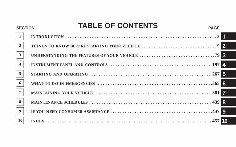
TABLE OF CONTENTSSECTION PAGE
1 INTRODUCTION . . . . . . . . . . . . . . . . . . . . . . . . . . . . . . . . . . . . . . . . . . . . . . . . . . . . . . . . . . . . . 3
2 THINGS TO KNOW BEFORE STARTING YOUR VEHICLE . . . . . . . . . . . . . . . . . . . . . . . . . . . . . . . 9
3 UNDERSTANDING THE FEATURES OF YOUR VEHICLE . . . . . . . . . . . . . . . . . . . . . . . . . . . . . . .79
4 INSTRUMENT PANEL AND CONTROLS . . . . . . . . . . . . . . . . . . . . . . . . . . . . . . . . . . . . . . . . . 197
5 STARTING AND OPERATING . . . . . . . . . . . . . . . . . . . . . . . . . . . . . . . . . . . . . . . . . . . . . . . . . 267
6 WHAT TO DO IN EMERGENCIES . . . . . . . . . . . . . . . . . . . . . . . . . . . . . . . . . . . . . . . . . . . . . . .365
7 MAINTAINING YOUR VEHICLE . . . . . . . . . . . . . . . . . . . . . . . . . . . . . . . . . . . . . . . . . . . . . . . 381
8 MAINTENANCE SCHEDULES . . . . . . . . . . . . . . . . . . . . . . . . . . . . . . . . . . . . . . . . . . . . . . . . . . 439
9 IF YOU NEED CONSUMER ASSISTANCE . . . . . . . . . . . . . . . . . . . . . . . . . . . . . . . . . . . . . . . . . .447
10 INDEX . . . . . . . . . . . . . . . . . . . . . . . . . . . . . . . . . . . . . . . . . . . . . . . . . . . . . . . . . . . . . . . . . . . . 457
1
2
3
4
5
6
7
8
9
10

INTRODUCTION
CONTENTS
m Introduction . . . . . . . . . . . . . . . . . . . . . . . . . . . 4
m Rollover Warning . . . . . . . . . . . . . . . . . . . . . . . . 4
m How To Use This Manual . . . . . . . . . . . . . . . . . . 5
m Warnings And Cautions . . . . . . . . . . . . . . . . . . . 7
m Vehicle Identification Number . . . . . . . . . . . . . . . 7
m Vehicle Modifications/Alterations . . . . . . . . . . . . 8
1

INTRODUCTIONThis Owner’s Manual has been prepared with the assis-tance of service and engineering specialists to acquaintyou with the operation and maintenance of your vehicle.It is supplemented by a Warranty Information Bookletand various customer-oriented documents. You areurged to read these publications carefully. Following theinstructions and recommendations in this manual willhelp assure safe and enjoyable operation of your vehicle.
NOTE: After you read the manual, it should be storedin the vehicle for convenient reference and remain withthe vehicle when sold so that the new owner will beaware of all safety warnings.
When it comes to service, remember that your authorizeddealer knows your vehicle best, has the factory-trainedtechnicians and genuine Mopart parts, and is interestedin your satisfaction.
ROLLOVER WARNINGUtility vehicles have a significantly higher rollover ratethan other types of vehicles. This vehicle has a higherground clearance and a higher center of gravity thanmany passenger cars. It is capable of performing better ina wide variety of off-road applications. Driven in anunsafe manner, all vehicles can go out of control. Becauseof the higher center of gravity, if this vehicle is out ofcontrol it may roll over when some other vehicles maynot.
Do not attempt sharp turns, abrupt maneuvers, or otherunsafe driving actions that can cause loss of vehiclecontrol. Failure to operate this vehicle safely may resultin an accident, rollover of the vehicle, and severe or fatalinjury. Drive carefully.
4 INTRODUCTION
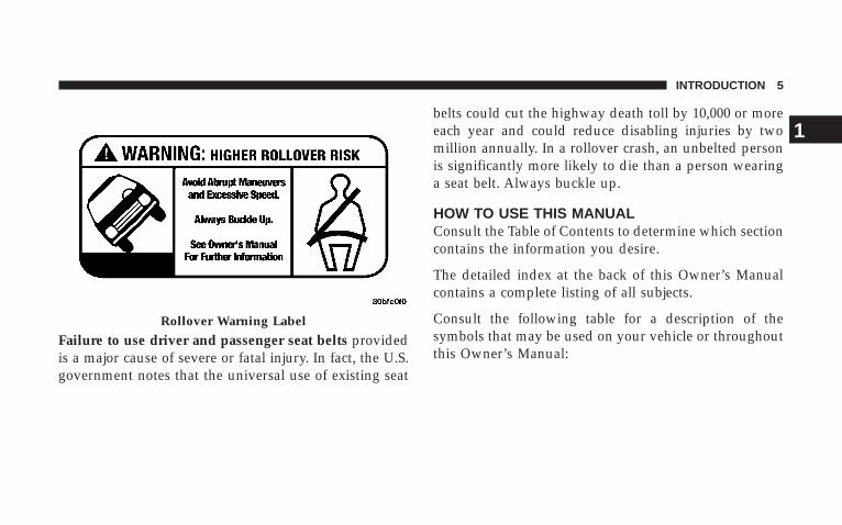
Failure to use driver and passenger seat belts providedis a major cause of severe or fatal injury. In fact, the U.S.government notes that the universal use of existing seat
belts could cut the highway death toll by 10,000 or moreeach year and could reduce disabling injuries by twomillion annually. In a rollover crash, an unbelted personis significantly more likely to die than a person wearinga seat belt. Always buckle up.
HOW TO USE THIS MANUALConsult the Table of Contents to determine which sectioncontains the information you desire.
The detailed index at the back of this Owner’s Manualcontains a complete listing of all subjects.
Consult the following table for a description of thesymbols that may be used on your vehicle or throughoutthis Owner’s Manual:
Rollover Warning Label
INTRODUCTION 5
1

6 INTRODUCTION

WARNINGS AND CAUTIONSThis manual contains WARNINGS against operatingprocedures which could result in an accident or bodilyinjury. It also contains CAUTIONS against procedureswhich could result in damage to your vehicle. If you donot read this entire manual, you may miss importantinformation. Observe all WARNINGS and CAUTIONS.
VEHICLE IDENTIFICATION NUMBERThe Vehicle Identification Number (VIN) is found on theleft front corner of the instrument panel, visible throughthe windshield. This number also appears on the Auto-mobile Information Disclosure Label affixed to a windowon your vehicle, the vehicle registration and title. NOTE: It is illegal to remove the VIN.
VIN Location
INTRODUCTION 7
1
VEHICLE MODIFICATIONS/ALTERATIONS
WARNING!
Any modifications or alterations to this vehicle couldseriously affect its roadworthiness and safety andmay lead to an accident resulting in serious injury ordeath.
8 INTRODUCTION
THINGS TO KNOW BEFORE STARTING YOUR VEHICLE
CONTENTS
m A Word About Your Keys . . . . . . . . . . . . . . . . . .12
▫ Ignition Key Removal . . . . . . . . . . . . . . . . . . .12
▫ Locking Doors With The Key . . . . . . . . . . . . . .13
m Sentry Keyt . . . . . . . . . . . . . . . . . . . . . . . . . . .13
▫ Replacement Keys . . . . . . . . . . . . . . . . . . . . . .15
▫ Customer Key Programming . . . . . . . . . . . . . .15
▫ General Information . . . . . . . . . . . . . . . . . . . .17
m Ignition And Steering Lock . . . . . . . . . . . . . . . . .17
▫ Ignition Accessory Delay Feature . . . . . . . . . . .18
m Security Alarm System — If Equipped . . . . . . . . .18
▫ To Set The Alarm . . . . . . . . . . . . . . . . . . . . . .19
▫ To Disarm The System . . . . . . . . . . . . . . . . . . .19
m Illuminated Entry . . . . . . . . . . . . . . . . . . . . . . . .20
▫ Vehicles Equipped With Power Door Locks . . . .20
m Remote Keyless Entry . . . . . . . . . . . . . . . . . . . . .21
▫ To Unlock The Doors And Liftgate . . . . . . . . . .21
▫ To Lock The Doors And Liftgate . . . . . . . . . . . .22
▫ Using The Panic Alarm . . . . . . . . . . . . . . . . . .24
2

▫ General Information . . . . . . . . . . . . . . . . . . . .25
▫ Programming Additional Transmitters . . . . . . . .25
▫ Battery Replacement . . . . . . . . . . . . . . . . . . . .27
m Remote Starting System — If Equipped . . . . . . . .28
m Door Locks . . . . . . . . . . . . . . . . . . . . . . . . . . . .29
▫ Manual Door Locks . . . . . . . . . . . . . . . . . . . . .29
▫ Power Door Locks . . . . . . . . . . . . . . . . . . . . .30
▫ Child Protection Door Lock . . . . . . . . . . . . . . .33
m Windows . . . . . . . . . . . . . . . . . . . . . . . . . . . . .34
▫ Power Windows . . . . . . . . . . . . . . . . . . . . . . .34
▫ Auto Down . . . . . . . . . . . . . . . . . . . . . . . . . .35
▫ Auto Up Feature With Anti-Pinch Protection(Driver’s And Front Passenger Door Only) . . . .35
▫ Window Lockout Switch . . . . . . . . . . . . . . . . .36
m Liftgate . . . . . . . . . . . . . . . . . . . . . . . . . . . . . . .37
▫ Power Liftgate — If Equipped . . . . . . . . . . . . .38
m Occupant Restraints . . . . . . . . . . . . . . . . . . . . . .41
▫ Lap/Shoulder Belts . . . . . . . . . . . . . . . . . . . . .42
▫ Adjustable Upper Shoulder Belt Anchorage . . . .46
▫ Second Row Center Seat Belt . . . . . . . . . . . . . .47
▫ Automatic Locking Retractors (ALR) Mode – IfEquipped . . . . . . . . . . . . . . . . . . . . . . . . . . . .47
▫ Rear 60/40 Seat Third Row Center Three PointBelt — If Equipped . . . . . . . . . . . . . . . . . . . . .48
▫ Seat Belt Pretensioners . . . . . . . . . . . . . . . . . . .50
▫ Enhanced Driver Seat Belt Reminder System(BeltAlertt) . . . . . . . . . . . . . . . . . . . . . . . . . .51
10 THINGS TO KNOW BEFORE STARTING YOUR VEHICLE
▫ Seat Belts And Pregnant Women . . . . . . . . . . . .52
▫ Seat Belt Extender . . . . . . . . . . . . . . . . . . . . . .53
▫ Driver And Right Front Passenger SupplementalRestraint System (SRS)—Airbags . . . . . . . . . . .53
▫ Event Data Recorder (EDR) . . . . . . . . . . . . . . .62
▫ Child Restraint . . . . . . . . . . . . . . . . . . . . . . . .64
m Engine Break-In Recommendations . . . . . . . . . . .74
m Safety Tips . . . . . . . . . . . . . . . . . . . . . . . . . . . .75
▫ Exhaust System . . . . . . . . . . . . . . . . . . . . . . .75
▫ Safety Checks You Should Make Inside TheVehicle . . . . . . . . . . . . . . . . . . . . . . . . . . . . . .76
▫ Safety Checks You Should Make Outside TheVehicle . . . . . . . . . . . . . . . . . . . . . . . . . . . . . .77
THINGS TO KNOW BEFORE STARTING YOUR VEHICLE 11
2

A WORD ABOUT YOUR KEYSThe authorized dealer that sold you your vehicle has thekey code numbers for your vehicle locks. These numberscan be used to order duplicate keys from your authorizeddealer. Ask your authorized dealer for these numbersand keep them in a safe place.
Ignition Key Removal
Automatic TransmissionPlace the shift lever in PARK. Turn the ignition switch tothe LOCK position and remove the key.
Ignition Key
Ignition Switch Positions
12 THINGS TO KNOW BEFORE STARTING YOUR VEHICLE
NOTE: If you try to remove the key before you place theshift lever in PARK, the key may become trapped tem-porarily in the ignition cylinder. If this occurs, rotate thekey to the right slightly, then remove the key as de-scribed. If a malfunction occurs, the system will trap thekey in the ignition cylinder to warn you that this safetyfeature is inoperable. The engine can be started andstopped but the key cannot be removed until you obtainservice.
WARNING!
Never leave children alone in a vehicle. Leavingunattended children in a vehicle is dangerous for anumber of reasons. A child or others could be seri-ously or fatally injured. Don’t leave the keys in theignition. A child could operate power windows,other controls, or move the vehicle.
CAUTION!
An unlocked vehicle is an invitation to thieves.Always remove key from the ignition and lock alldoors when leaving the vehicle unattended.
Locking Doors With The KeyYou can insert the key with either side up. To lock thedoor, turn the key rearward, to unlock the door, turn thekey forward. For external door lock lubrication, refer to“Body Lubrication” in Section 7.
SENTRY KEYTThe Sentry Keyt Immobilizer system prevents unautho-rized vehicle operation by disabling the engine. Thesystem does not need to be armed or activated. Operationis automatic, regardless of whether the vehicle is lockedor unlocked.
THINGS TO KNOW BEFORE STARTING YOUR VEHICLE 13
2
The system uses ignition keys which have an embeddedelectronic chip (transponder) to prevent unauthorizedvehicle operation. Therefore, only keys that are pro-grammed to the vehicle can be used to start and operatethe vehicle. The system will shut the engine off in twoseconds if someone uses an invalid key to try to start theengine.
NOTE: A key which has not been programmed is alsoconsidered an invalid key, even if it is cut to fit theignition switch lock cylinder for that vehicle.
During normal operation, after turning on the ignitionswitch, the Vehicle Security Alarm Indicator Light willturn on for three seconds for a bulb check. If the lightremains on after the bulb check, it indicates that there isa problem with the electronics. In addition, if the lightbegins to flash after the bulb check, it indicates that
someone used an invalid key to try to start the engine.Either of these conditions will result in the engine beingshut off after two seconds.
If the Vehicle Security Alarm Indicator Light turns onduring normal vehicle operation (vehicle running forlonger than 10 seconds), it indicates that there is a fault inthe electronics. Should this occur, have the vehicle ser-viced as soon as possible.
NOTE:• The Sentry Keyt Immobilizer System is not compat-
ible with some aftermarket remote starting systems.Use of these systems may result in vehicle startingproblems and loss of security protection.
• Exxon/Mobil Speedpass™, additional Sentry Keyst,or any other transponder-equipped components onthe same key chain will not cause a key related(transponder) fault unless the additional part is physi-cally held against the ignition key being used when
14 THINGS TO KNOW BEFORE STARTING YOUR VEHICLE
starting the vehicle. Cell phones, pagers, or other RFelectronics will not cause interference with this system.
All of the keys provided with your new vehicle havebeen programmed to the vehicle electronics.
Replacement Keys
NOTE: Only keys that are programmed to the vehicleelectronics can be used to start and operate the vehicle.Once a Sentry Keyt is programmed to a vehicle, it cannotbe programmed to any other vehicle.
CAUTION!
Always remove the Sentry Keyst from the vehicleand lock all doors when leaving the vehicleunattended.
At the time of purchase, the original owner is providedwith a four-digit Personal Identification Number (PIN).Keep the PIN in a secure location. This number isrequired for authorized dealer replacement of keys. Du-plication of keys may be performed at an authorizeddealer or by following the customer key programmingprocedure. This procedure consists of programming ablank key to the vehicle electronics. A blank key is onewhich has never been programmed.
NOTE: When having the Sentry Keyt ImmobilizerSystem serviced, bring all vehicle keys with you to anauthorized dealer.
Customer Key ProgrammingIf you have two valid Sentry Keyst, you can programnew Sentry Keyst to the system by performing thefollowing procedure:
1. Cut the additional Sentry Keyt Transponder blank(s)to match the ignition switch lock cylinder key code.
THINGS TO KNOW BEFORE STARTING YOUR VEHICLE 15
2
2. Insert the first valid key into the ignition switch. Turnthe ignition switch to the ON position for at least threeseconds, but no longer than 15 seconds. Then, turn theignition switch to the LOCK position and remove the firstkey.
3. Insert the second valid key into the ignition switch.Turn the ignition switch to the ON position within 15seconds. After 10 seconds, a chime will sound. In addi-tion, the Vehicle Security Alarm Indicator Light willbegin to flash. Turn the ignition switch to the LOCKposition and remove the second key.
4. Insert a blank Sentry Keyt into the ignition switch.Turn the ignition switch to the ON position within 60seconds. After 10 seconds, a single chime will sound. Inaddition, the Vehicle Security Alarm Indicator Light willstop flashing. To indicate that programming is complete,the Vehicle Security Alarm Indicator Light will turn onagain for three seconds and then turn off.
The new Sentry Keyt is programmed. The RemoteKeyless Entry transmitter will also be programmedduring this procedure.
Repeat this procedure to program up to eight keys. If youdo not have a programmed Sentry Keyt, contact yourauthorized dealer for details.
NOTE: If a programmed key is lost, see your authorizeddealer to have all remaining keys erased from the sys-tem’s memory. This will prevent the lost key fromstarting your vehicle. The remaining keys must then bereprogrammed. All vehicle keys must be taken to anauthorized dealer at the time of service to be repro-grammed.
16 THINGS TO KNOW BEFORE STARTING YOUR VEHICLE
General InformationThe Sentry Keyt system complies with FCC rules Part 15and with RSS-210 of Industry Canada. Operation issubject to the following conditions:
• This device may not cause harmful interference.
• This device must accept any interference that may bereceived, including interference that may cause undes-ired operation.
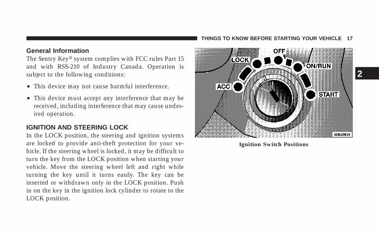
IGNITION AND STEERING LOCKIn the LOCK position, the steering and ignition systemsare locked to provide anti-theft protection for your ve-hicle. If the steering wheel is locked, it may be difficult toturn the key from the LOCK position when starting yourvehicle. Move the steering wheel left and right whileturning the key until it turns easily. The key can beinserted or withdrawn only in the LOCK position. Pushin on the key in the ignition lock cylinder to rotate to theLOCK position.
Ignition Switch Positions
THINGS TO KNOW BEFORE STARTING YOUR VEHICLE 17
2
WARNING!
The key cannot be turned to LOCK until the shiftlever is in the PARK position. Do not attempt to pullthe shift lever out of PARK after the key is in theLOCK position.
NOTE: The steering wheel will lock when the key isremoved, and when the steering wheel is turned around115 degrees clockwise or 65 degrees counterclockwisefrom the center position.
Ignition Accessory Delay FeatureThe power window switches, radio, hands–free system(if equipped), and power outlets will remain active for 10minutes after the ignition switch is turned off. Openingeither front door will cancel this feature.
For vehicles equipped with the Electronic Vehicle Infor-mation Center (EVIC), the time for this feature is pro-grammable. For details, refer to “Personal Settings(Customer-Programmable Features)”/“KEY OFFPOWER DELAY > OFF” under “Electronic Vehicle Infor-mation Center (EVIC)” in Section 3 of this manual.
SECURITY ALARM SYSTEM — IF EQUIPPEDThis system monitors the vehicle doors, liftgate, andignition for unauthorized operation. When the SecurityAlarm System is activated, the system provides bothaudible and visual signals. The horn will sound repeat-edly for three minutes and the headlights and Securitylight in the instrument cluster will flash for an additional15 minutes. The engine will not run until the system isdisarmed.
18 THINGS TO KNOW BEFORE STARTING YOUR VEHICLE

To Set the Alarm:The Security Alarm System will set when you use thepower door locks or use the Remote Keyless EntryTransmitter to lock the doors. After all the doors areclosed and locked, the security light in the instrumentcluster will flash rapidly to signal that the system isarming. The Security light in the instrument panel clusterwill flash rapidly for about 15 seconds to indicate that thealarm is being set. After the alarm is set, the Security lightwill flash at a slower rate to indicate that the system isarmed.
NOTE: If the Security light stays on continuously dur-ing vehicle operation, have the system checked by yourauthorized dealer.
To Disarm the System:Use the Remote Keyless Entry Transmitter to unlock thedoors. If something has triggered the system in yourabsence, the horn will sound three times when youunlock the doors. Check the vehicle for tampering.
The Security Alarm System will also disarm if the vehicleis started with a programmed Sentry Keyt. If an unpro-grammed Sentry Keyt is used to start a vehicle, theengine will start and run for two seconds and then shutdown. After six unsuccessul attempts at starting theengine, the system will shut down until the correct key isused. To exit alarming mode, press the RKE UNLOCKbutton or start the vehicle with a programmed SentryKeyt.
The Security Alarm System is designed to protect yourvehicle; however, you can create conditions where thesystem will arm unexpectedly. If you remain in the
THINGS TO KNOW BEFORE STARTING YOUR VEHICLE 19
2
vehicle and lock the doors with the transmitter, the alarmwill sound when you pull the door handle to exit.
NOTE: You may accidentally activate the SecurityAlarm System (horn sounds and lights flash) by enteringthe vehicle without using the key fob to unlock thedoor(s). The Security Alarm System can be disarmedwith the key fob’s UNLOCK button or by inserting aprogrammed Sentry Keyt into the ignition and turningthe key to the ON position.
ILLUMINATED ENTRY
Vehicles Equipped With Power Door LocksAll interior lights will illuminate in the vehicle when thedoors are unlocked using the key fob.
The interior lights will remain on for 30 seconds after thelast door is closed, or until all doors are closed and eitherthe ignition is turned to the ON position or a key fobLOCK button is pressed.
There is also a battery saver feature that will turn theinterior lights off after eight minutes if the ignition is OFFand a door is left open or the dimmer control is in theinterior lights ON position.
20 THINGS TO KNOW BEFORE STARTING YOUR VEHICLE
REMOTE KEYLESS ENTRY
NOTE: For the remote starting feature (if equipped),refer to “Remote Starting System” in section 2.
NOTE: For the power liftgate feature (if equipped), referto the “Power Liftgate” in section 2.
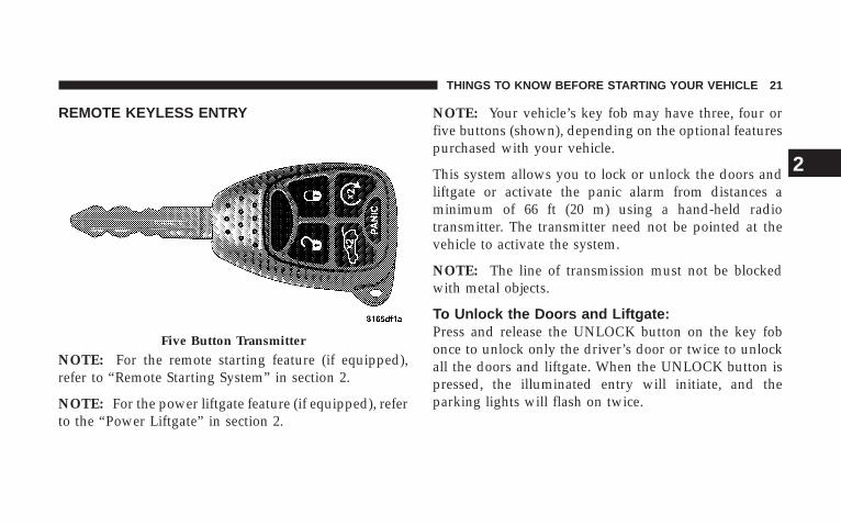
NOTE: Your vehicle’s key fob may have three, four orfive buttons (shown), depending on the optional featurespurchased with your vehicle.
This system allows you to lock or unlock the doors andliftgate or activate the panic alarm from distances aminimum of 66 ft (20 m) using a hand-held radiotransmitter. The transmitter need not be pointed at thevehicle to activate the system.
NOTE: The line of transmission must not be blockedwith metal objects.
To Unlock the Doors and Liftgate:Press and release the UNLOCK button on the key fobonce to unlock only the driver’s door or twice to unlockall the doors and liftgate. When the UNLOCK button ispressed, the illuminated entry will initiate, and theparking lights will flash on twice.
Five Button Transmitter
THINGS TO KNOW BEFORE STARTING YOUR VEHICLE 21
2

The system can be programmed to unlock all the doorsupon the first UNLOCK button press by following theseprocedures:
• For vehicles equipped with the Electronic VehicleInformation Center (EVIC), refer to “Personal Settings(Customer Programmable Features)” under “Over-head Console with Electronic Vehicle InformationCenter (EVIC) – If Equipped” in Section 3.
• For vehicles not equipped with the EVIC:
1. Press and hold the LOCK button on a programmedkey fob.
2. Continue to hold the LOCK button at least fourseconds, but not longer than 10 seconds, then press andhold the UNLOCK button.
3. Release both buttons at the same time.
4. Test the feature while outside of the vehicle, bypressing the LOCK/UNLOCK button on the key fob.
NOTE: Pressing the LOCK button on the key fob whileyou are inside the vehicle will activate the SecurityAlarm. Opening a door with the Security Alarm activatedwill cause the alarm to sound. Press the UNLOCK buttonto deactivate the Security Alarm.
5. If the desired programming was not achieved or toreactivate this feature, repeat the above steps.
To Lock the Doors and Liftgate:Press and release the LOCK button on the key fob to lockall doors and liftgate. If the ignition is OFF when thedoors are locked, the parking lights will flash on onceand the horn will chirp once.
22 THINGS TO KNOW BEFORE STARTING YOUR VEHICLE

Horn Chirp ProgrammingThe horn chirp feature will be activated when shippedfrom the assembly plants. If desired, this feature can bedisabled by following these procedures:
• For vehicles equipped with the Electronic VehicleInformation Center (EVIC), refer to “Personal Settings(Customer Programmable Features)” under “Over-head Console with Electronic Vehicle InformationCenter (EVIC) – If Equipped” in Section 3.
• For vehicles not equipped with the EVIC:
1. Press and hold the LOCK button on the key fob.
2. After holding the LOCK button for four seconds, alsopress the PANIC button within six seconds.
3. Release both buttons at the same time.
4. To reactivate this feature, repeat the above steps.
5. Test the horn chirp feature while outside of the vehicleby pressing the LOCK button on the key fob with theignition in the OFF position and the key removed.
NOTE: Pressing the LOCK button on the key fob whileyou are inside the vehicle will activate the SecurityAlarm. Opening a door with the Security Alarm activatedwill cause the alarm to sound. Press the UNLOCK buttonto deactivate the Security Alarm.
6. If the desired programming was not achieved or toreactivate this feature, repeat the above steps.
Flash Lights with Lock Programming
• For vehicles equipped with the Electronic VehicleInformation Center (EVIC), refer to “Personal Settings(Customer Programmable Features)” under “Over-head Console with Electronic Vehicle InformationCenter (EVIC) – If Equipped” in Section 3.
THINGS TO KNOW BEFORE STARTING YOUR VEHICLE 23
2

• For vehicles not equipped with the EVIC, perform thefollowing procedure:
1. Press and hold the UNLOCK button on the key fob.
2. After holding the UNLOCK button for four seconds,also press the LOCK button within six seconds.
3. Release both buttons at the same time.
4. Test the flash lights with LOCK feature while outsideof the vehicle, by pressing the LOCK button on the keyfob with the ignition in the OFF position and the keyremoved.
NOTE: Pressing the LOCK button on the key fob whileyou are inside the vehicle will activate the SecurityAlarm. Opening a door with the Security Alarm activatedwill cause the alarm to sound. Press the UNLOCK buttonto deactivate the Security Alarm.
5. If the desired programming was not achieved or toreactivate this feature, repeat the above steps.
Using the Panic AlarmTo activate the PANIC mode, while the ignition is OFF,press and release the PANIC button on the transmitteronce. When the PANIC mode is activated, the interiorlights will illuminate, the head lights and parking lightswill flash and the horn will sound.
To cancel the PANIC mode, press and release the PANICbutton on the transmitter a second time. PANIC modewill automatically cancel after three minutes or if thevehicle is started or exceeds 15 mph (24 km/h). Duringthe PANIC mode, the door locks and Remote KeylessEntry systems will function normally. PANIC mode willnot disarm the Security Alarm System on vehicles soequipped.
24 THINGS TO KNOW BEFORE STARTING YOUR VEHICLE

General InformationThis device complies with part 15 of FCC rules and withRS-210 of Industry Canada. Operation is subject to thefollowing conditions:
1. This device may not cause harmful interference.
2. This device must accept any interference that may bereceived including interference that may cause undesiredoperation.
NOTE: Changes or modifications not expressly ap-proved by the party responsible for compliance couldvoid the user’s authority to operate the equipment.
If your Remote Lock Control fails to operate from anormal distance, check for these two conditions.
1. Weak batteries in transmitter. The expected life of thebatteries is five years.
2. Closeness to a radio transmitter, such as a radio stationtower, airport transmitter, military base, and some mobileor CB radios.
Programming Additional TransmittersVehicles will be shipped from the assembly plants withtwo key fob transmitters programmed only for thatvehicle. A total of eight key fobs can be programmed foryour vehicle. Additional key fobs can be programmed toyour vehicle through the use of a currently programmedfob.
NOTE: When entering program mode using that keyfob, all other programmed key fobs will be erased andyou will have to reprogram them for your vehicle.
Use the following procedure to program additional keyfobs if the vehicle is not equipped with Sentry Keyt:
1. Enter your vehicle and close all doors.
THINGS TO KNOW BEFORE STARTING YOUR VEHICLE 25
2

2. Fasten your seat belt. Fastening the seat belt willcancel any chiming that may confuse you during thisprogramming procedure.
3. Place the key into the ignition.
4. Turn the ignition to the ON position. Do not start theengine.
5. Press and hold the UNLOCK button on the key fob.
6. After holding the UNLOCK button for four seconds,also press the PANIC button within six seconds.
7. When a single chime is heard, release both buttons.The chime is an indication that you have successfullyentered program mode. All key fobs that are to beprogrammed must be done so within 60 seconds of whenthe chime was heard.
8. Using the key fob to be programmed, press andrelease both the LOCK and UNLOCK buttons simulta-neously.
9. A single chime will be heard.
10. Within four seconds of hearing the chime, press andrelease the UNLOCK button on the key fob.
11. A single chime will be heard.
12. Repeat steps 8 through 10 to program up to sixadditional key fobs.
13. Turn the ignition to the OFF position.
14. Your vehicle will remain in program mode up to 60seconds from when the original chime was heard. After60 seconds, all programmed key fobs function normally.
NOTE: If you do not have a programmed transmitter,contact your authorized dealer for details.
26 THINGS TO KNOW BEFORE STARTING YOUR VEHICLE

Battery ReplacementThe recommended replacement battery is CR2032.
NOTE: Perchlorate Material – special handling mayapply. See www.dtsc.ca.gov/hazardouswaste/perchlorate.
1. If the key fob is equipped with a screw, remove thescrew. With the transmitter buttons facing down, use aflat blade to pry the two halves of the transmitter apart.Make sure not to damage the elastomer seal duringremoval.
2. Remove and replace the battery. When replacing thebattery, match the + sign on the battery to the + sign onthe inside of the battery clip, located on the back cover.Avoid touching the new battery with your fingers. Skinoils may cause battery deterioration. If you touch abattery, clean it with rubbing alcohol.
Separating Transmitter Halves
THINGS TO KNOW BEFORE STARTING YOUR VEHICLE 27
2
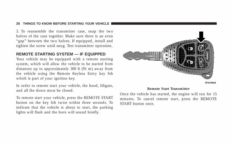
3. To reassemble the transmitter case, snap the twohalves of the case together. Make sure there is an even“gap” between the two halves. If equipped, install andtighten the screw until snug. Test transmitter operation.
REMOTE STARTING SYSTEM — IF EQUIPPEDYour vehicle may be equipped with a remote startingsystem, which will allow the vehicle to be started fromdistances up to approximately 300 ft (91 m) away fromthe vehicle using the Remote Keyless Entry key fobwhich is part of your ignition key.
In order to remote start your vehicle, the hood, liftgate,and all the doors must be closed.
To remote start your vehicle, press the REMOTE STARTbutton on the key fob twice within three seconds. Toindicate that the vehicle is about to start, the parkinglights will flash and the horn will sound briefly.
Once the vehicle has started, the engine will run for 15minutes. To cancel remote start, press the REMOTESTART button once.
Remote Start Transmitter
28 THINGS TO KNOW BEFORE STARTING YOUR VEHICLE

To enter the vehicle while the engine is running during aremote start, you must first unlock the vehicle using theUNLOCK button on the key fob. After the vehicle isunlocked, you have 60 seconds to enter the vehicle, insertthe key in the ignition and move it to the RUN position;otherwise, the engine will cancel remote start and auto-matically turn off.
Remote start will also cancel if any of the following occur:
• If the engine stalls or RPM exceeds 2500
• Any engine warning lamps come on
• The hood is opened
• The hazard switch is pressed
• The transmission is moved out of PARK
• The brake pedal is pressed.
The vehicle can be started remotely up to a maximum oftwo times. The vehicle is also allowed a maximum of onefailed start, where the remote start sequence was initiatedbut the engine stopped cranking without starting. Aftereither of these conditions, or if the Security Alarm Systemis alarming or if the PANIC button was pressed, thevehicle must be reset by inserting a valid key into theignition and moving it to the RUN position, then back toLOCK.
DOOR LOCKS
Manual Door LocksAll the doors can be “manually” locked from the insideby pushing down the door lock plunger, located at therear of the door. Both front doors may be opened from theinside with the door lock plunger in the down or lockedposition.
THINGS TO KNOW BEFORE STARTING YOUR VEHICLE 29
2

WARNING!
• For personal security and safety in the event of anaccident, lock the vehicle doors when you drive aswell as when you park and leave the vehicle.
• Never leave unattended children alone in a ve-hicle. Leaving children in a vehicle is dangerousfor a number of reasons. A child or others could beseriously or fatally injured. Don’t leave the keys inthe ignition. A child could operate power win-dows, other controls, or move the vehicle.
Power Door LocksA power door lock switch is on each front door trimpanel. Use this switch to lock or unlock the doors.
If you press the power door lock switch while the key isin the ignition and any front door is open, the powerlocks will not operate. This prevents you from acciden-tally locking your keys in the vehicle. Removing the keyor closing the door will allow the locks to operate. Achime will sound if the key is in the ignition switch anda door is open, as a reminder to remove the key.
Power Door Lock Switch
30 THINGS TO KNOW BEFORE STARTING YOUR VEHICLE

Automatic Door LocksIf this feature is enabled, your door locks will lockautomatically when the vehicle’s speed exceeds 15 mph(24 km/h).
Automatic Door Lock ProgrammingThis feature is enabled when your vehicle is shippedfrom the assembly plant and can be disabled by follow-ing these procedures:
• For vehicles equipped with the Electronic VehicleInformation Center (EVIC), refer to “Personal Settings(Customer Programmable Features)” under “Over-head Console with Electronic Vehicle InformationCenter (EVIC) – If Equipped” in Section 3.
• For vehicles not equipped with the EVIC:
1. Enter your vehicle and close all doors.
2. Fasten your seat belt. Fastening the seat belt willcancel any chiming that may confuse you during thisprogramming procedure.
3. Place the key into the ignition.
4. Within 10 seconds, cycle the key from the LOCKposition to the ON position a minimum of four times,ending in the LOCK position (do not start the engine).
5. Within 30 seconds, press the driver’s door lock switchin the LOCK direction.
6. A single chime will be heard to indicate the feature hasbeen disabled.
7. To reactivate this feature, repeat the above steps.
8. If a chime is not heard, the program mode wascanceled before the feature could be disabled. If neces-sary, repeat the above procedure.
THINGS TO KNOW BEFORE STARTING YOUR VEHICLE 31
2

Auto Unlock On Exit — If EquippedThis feature unlocks all of the doors of the vehicle whenany door is opened (excluding the liftgate). This willoccur only after the vehicle has been shifted into thePARK position after the vehicle has been driven (shiftedout of PARK and all doors closed).
This feature will not operate if there is any manualoperation of the power door locks (LOCK or UNLOCK).
Auto Unlock On Exit Programming — If EquippedCustomer programming sequence to enable or disablethe Auto Unlock feature:
• For vehicles equipped with the Electronic VehicleInformation Center (EVIC), refer to “Personal Settings(Customer Programmable Features)” under “Over-head Console with Electronic Vehicle InformationCenter (EVIC) – If Equipped” in Section 3.
• For vehicles not equipped with the EVIC, performingthe following procedure:
1. Enter your vehicle and close all doors.
2. Fasten your seat belt. Fastening the seat belt willcancel any chimes that may be confusing during thisprogramming procedure.
3. Insert the key into the ignition.
4. Within 15 seconds, cycle the key from the LOCKposition to the ON position a minimum of four times,ending in the LOCK position (do not start the engine).
5. Within 30 seconds, press the driver’s door lock switchin the UNLOCK direction.
6. A single chime will sound to indicate the feature hasbeen changed.
7. Repeat the above steps to alternate the availability ofthis feature.
32 THINGS TO KNOW BEFORE STARTING YOUR VEHICLE

8. If a chime is not heard, the program mode wascanceled before the feature could be changed. If neces-sary, repeat the above procedure.
Child Protection Door LockTo provide a safer environment for children riding in therear seat, the rear doors of your vehicle have the childprotection door lock system.
To use the system, open each rear door and slide thecontrol UP to engage the locks and DOWN to disengagethe child protection locks. When the system on a door isengaged, that door can only be opened by using theoutside door handle even if the inside door lock is in theunlocked position.
Child Lock
THINGS TO KNOW BEFORE STARTING YOUR VEHICLE 33
2
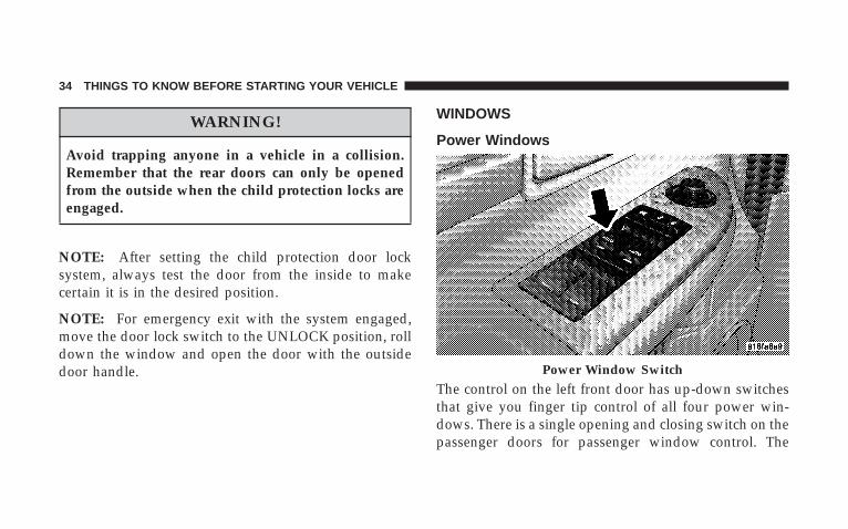
WARNING!
Avoid trapping anyone in a vehicle in a collision.Remember that the rear doors can only be openedfrom the outside when the child protection locks areengaged.
NOTE: After setting the child protection door locksystem, always test the door from the inside to makecertain it is in the desired position.
NOTE: For emergency exit with the system engaged,move the door lock switch to the UNLOCK position, rolldown the window and open the door with the outsidedoor handle.
WINDOWS
Power Windows
The control on the left front door has up-down switchesthat give you finger tip control of all four power win-dows. There is a single opening and closing switch on thepassenger doors for passenger window control. The
Power Window Switch
34 THINGS TO KNOW BEFORE STARTING YOUR VEHICLE

windows will operate only when the ignition switch isturned to the ON position and for 10 minutes after theignition is turned OFF or the driver’s door is opened.This feature can be turned off by your authorized dealer.
NOTE: The Power Accessory Delay feature will allowthe power windows to operate for 10 minutes after theignition it turned OFF.
WARNING!
Never leave children alone in a vehicle. Leavingunattended children in a vehicle is dangerous for anumber of reasons. A child or others could be seri-ously or fatally injured. Don’t leave the keys in theignition. A child could operate power windows,other controls, or move the vehicle.
Auto DownThe driver’s and front passenger window switch has anAuto Down feature. Push the window switch past thefirst detent, release, and the window will go downautomatically. To cancel the Auto Down movement,operate the switch in either the up or down direction andrelease the switch.
Auto Up Feature with Anti-Pinch Protection(Driver’s and Front Passenger Door Only)Lift the window switch to the second detent, release, andthe window will go up automatically.
To stop the window from going all the way up during theAuto Up operation, push down on the switch briefly.
To close the window part way, lift the window switch tothe first detent and release when you want the window tostop.
THINGS TO KNOW BEFORE STARTING YOUR VEHICLE 35
2
NOTE: If the window runs into any obstacle during theauto-closure, it will reverse direction and then stop.Remove the obstacle and use the window switch again toclose the window. Any impact due to rough road condi-tions may trigger the auto reverse function unexpectedlyduring auto-closure. If this happens, pull the switchlightly to the first detent and hold to close the windowmanually.
WARNING!
There is no anti-pinch protection when the windowis almost closed. Be sure to clear all objects from thewindow before closing.
Resetting the Auto Up FeatureShould the Auto Up feature stop working, the windowprobably needs to be reset. To reset Auto Up:
Pull the window switch up and close the window com-pletely, then pull and hold the switch for one second.
Window Lockout SwitchThe window lockout switch on the driver’s door allowsyou to disable the window control on the other doors. Todisable the window controls on the other doors, press thewindow lockout switch. To enable the window controls,press the window lockout switch again.
36 THINGS TO KNOW BEFORE STARTING YOUR VEHICLE
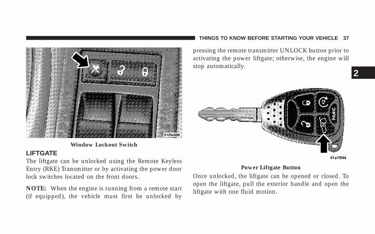
LIFTGATEThe liftgate can be unlocked using the Remote KeylessEntry (RKE) Transmitter or by activating the power doorlock switches located on the front doors.
NOTE: When the engine is running from a remote start(if equipped), the vehicle must first be unlocked by
pressing the remote transmitter UNLOCK button prior toactivating the power liftgate; otherwise, the engine willstop automatically.
Once unlocked, the liftgate can be opened or closed. Toopen the liftgate, pull the exterior handle and open theliftgate with one fluid motion.
Window Lockout Switch
Power Liftgate Button
THINGS TO KNOW BEFORE STARTING YOUR VEHICLE 37
2

The liftgate will not manually open if the vehicle is ingear or the vehicle speed is above 0 mph (0 km/h).
NOTE: If the liftgate is locked and is not equipped witha powered liftgate, pressing the button on the RKETransmitter will result in the liftgate becoming unlockedfor 30 seconds allowing you to manually access theliftgate area. The liftgate will re-lock automatically within10 seconds once the liftgate is closed.
Power Liftgate — If EquippedThe power liftgate may be opened manually or by usingthe button on the RKE Transmitter. Press the powerliftgate button on the RKE Transmitter twice within fiveseconds, to open the power liftgate. Once the liftgate isfully open, pressing the power liftgate button twicewithin five seconds a second time will close the liftgate.
When the RKE Transmitter power liftgate button ispressed two times and the “Lamp Flash” feature isenabled, the turn signals will flash twice to signal that theliftgate is opening or closing.
The power liftgate may also be opened by pressing theswitch located on the overhead console.
Power Liftgate Switch
38 THINGS TO KNOW BEFORE STARTING YOUR VEHICLE

WARNING!
During power operation, personal injury or cargodamage may occur. Ensure the liftgate travel path isclear. Make sure the liftgate is closed and latchedbefore driving away.
A beeping signal will sound two seconds before theliftgate starts to open or close.
NOTE:• If anything obstructs the power liftgate while it is
closing or opening, the liftgate will automaticallyreverse to the closed or open position, provided itmeets sufficient resistance.
• There are also pinch sensors attached to the side of theliftgate. Light pressure anywhere along these stripswill cause the liftgate to return to the open position.
• The power liftgate must be in the full open position inorder to power close. If the liftgate is not fully open,press the RKE Transmitter or overhead console buttonto fully open the liftgate and then press again to close.
• If the liftgate handle is pulled while the power liftgateis closing, the liftgate will reverse to the full openposition.
• If the liftgate handle is pulled while the power liftgateis opening, the liftgate motor will disengage to allowmanual operation.
• The power liftgate buttons will not operate if thevehicle is in gear or the vehicle speed is above 0 mph(0 km/h).
THINGS TO KNOW BEFORE STARTING YOUR VEHICLE 39
2

• The power liftgate will not operate in temperaturesbelow 222°F (230°C) or temperatures above 150°F(65°C). Be sure to remove any buildup of snow or icefrom the liftgate before pressing any of the powerliftgate buttons.
• If the power liftgate encounters multiple obstructionswithin the same cycle, the system will automaticallystop and must be opened or closed manually.
• If your liftgate is power closing and you put thevehicle in gear, the liftgate will continue to powerclose. However, vehicle movement may result in adetection of an obstruction.
WARNING!
• Driving with the liftgate open can allow poison-ous exhaust gases into your vehicle. You and yourpassengers could be injured by these fumes. Keepthe liftgate closed when you are operating thevehicle.
• If you are required to drive with the liftgate open,make sure that all windows are closed and theclimate control blower switch is set at high speed.DO NOT use the recirculation mode.
Gas props support the liftgate in the open position.However, because the gas pressure drops with tempera-ture, it may be necessary to assist the props whenopening the liftgate in cold weather.
40 THINGS TO KNOW BEFORE STARTING YOUR VEHICLE

OCCUPANT RESTRAINTSSome of the most important safety features in yourvehicle are the restraint systems. These include the frontand rear seat belts for the driver and all passengers, kneebolsters, front airbags for both the driver and frontpassenger, and left and right side curtain airbags for thedriver and passengers seated next to a window. If youwill be carrying children too small for adult-size seatbelts, your seat belts or the LATCH feature (refer to theChild Restraint section in this manual), can be used tohold infant and child restraint systems.
Please pay close attention to the information in thissection. It tells you how to use your restraint systemproperly to keep you and your passengers as safe aspossible.
WARNING!
In a collision, you and your passengers can suffermuch greater injuries if you are not properly buckledup. You can strike the interior of your vehicle or otherpassengers, or you can be thrown out of the vehicle.Always be sure you and others in your vehicle arebuckled up properly.
Buckle up even though you are an excellent driver, evenon short trips. Someone on the road may be a poor driverand cause a collision that includes you. This can happenfar away from home or on your own street.
THINGS TO KNOW BEFORE STARTING YOUR VEHICLE 41
2
Research has shown that seat belts save lives, and thatthey can reduce the seriousness of injuries in a collision.Some of the worst injuries happen when people arethrown from the vehicle. Seat belts reduce the possibilityof ejection and the risk of injury caused by striking theinside of the vehicle. Everyone in a motor vehicle shouldbe belted at all times.
Lap/Shoulder BeltsAll seating positions in your vehicle have combinationlap/shoulder belts. The belt webbing retractor is de-signed to lock during very sudden stops or collisions.This feature allows the shoulder part of the belt to movefreely with you under normal conditions. But in a colli-sion, the belt will lock and reduce the risk of your strikingthe inside of the vehicle or being thrown out.
WARNING!
It is extremely dangerous to ride in a cargo area,inside or outside of a vehicle. In a collision, peopleriding in these areas are more likely to be seriouslyinjured or killed.
Do not allow people to ride in any area of yourvehicle that is not equipped with seats and seat belts.
Be sure everyone in your vehicle is in a seat andusing a seat belt properly.
42 THINGS TO KNOW BEFORE STARTING YOUR VEHICLE

WARNING!
• Wearing a seat belt incorrectly is dangerous. Seatbelts are designed to go around the large bones ofyour body. These are the strongest parts of yourbody and can take the forces of a collision the best.Wearing your belt in the wrong place could makeyour injuries in a collision much worse. You mightsuffer internal injuries, or you could even slide outof part of the belt. Follow these instructions towear your seat belt safely and to keep your pas-sengers safe, too.
• Two people should never be belted into a singleseat belt. People belted together can crash into oneanother in an accident, hurting one another badly.Never use a lap/shoulder belt or a lap belt for morethan one person, no matter what their size.
Lap/Shoulder Belt Operating Instructions
1. Enter the vehicle and close the door. Sit back andadjust the seat.
2. The seat belt latch plate is above the back of the frontseat, next to your arm in the rear seat. Grasp the latch
Pulling Out Belt And Latch Plate
THINGS TO KNOW BEFORE STARTING YOUR VEHICLE 43
2

plate and pull out the belt. Slide the latch plate up thewebbing as far as necessary to allow the belt to go aroundyour lap.
3. When the belt is long enough to fit, insert the latchplate into the buckle until you hear a “click.”
WARNING!
• A belt buckled into the wrong buckle will not protectyou properly. The lap portion could ride too high onyour body, possibly causing internal injuries. Alwaysbuckle your belt into the buckle nearest you.
• A belt that is too loose will not protect you as well. Ina sudden stop you could move too far forward, increas-ing the possibility of injury. Wear your seat belt snugly.
• A belt that is worn under your arm is very dangerous.Your body could strike the inside surfaces of the vehiclein a collision, increasing head and neck injury. And abelt worn under the arm can cause internal injuries.Ribs aren’t as strong as shoulder bones. Wear the beltover your shoulder so that your strongest bones willtake the force in a collision.
• A shoulder belt placed behind will not protect youfrom injury during a collision. You are more likely to hityour head in a collision if you do not wear yourshoulder belt. The lap and shoulder belt are meant to beused together.
Latch Plate To Buckle
44 THINGS TO KNOW BEFORE STARTING YOUR VEHICLE
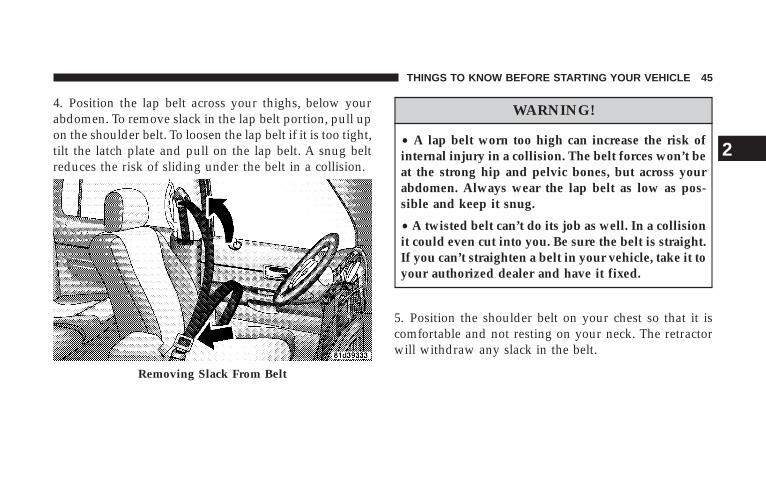
4. Position the lap belt across your thighs, below yourabdomen. To remove slack in the lap belt portion, pull upon the shoulder belt. To loosen the lap belt if it is too tight,tilt the latch plate and pull on the lap belt. A snug beltreduces the risk of sliding under the belt in a collision.
WARNING!
• A lap belt worn too high can increase the risk ofinternal injury in a collision. The belt forces won’t beat the strong hip and pelvic bones, but across yourabdomen. Always wear the lap belt as low as pos-sible and keep it snug.
• A twisted belt can’t do its job as well. In a collisionit could even cut into you. Be sure the belt is straight.If you can’t straighten a belt in your vehicle, take it toyour authorized dealer and have it fixed.
5. Position the shoulder belt on your chest so that it iscomfortable and not resting on your neck. The retractorwill withdraw any slack in the belt.
Removing Slack From Belt
THINGS TO KNOW BEFORE STARTING YOUR VEHICLE 45
2
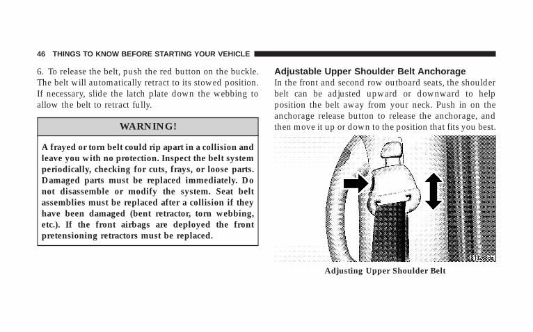
6. To release the belt, push the red button on the buckle.The belt will automatically retract to its stowed position.If necessary, slide the latch plate down the webbing toallow the belt to retract fully.
WARNING!
A frayed or torn belt could rip apart in a collision andleave you with no protection. Inspect the belt systemperiodically, checking for cuts, frays, or loose parts.Damaged parts must be replaced immediately. Donot disassemble or modify the system. Seat beltassemblies must be replaced after a collision if theyhave been damaged (bent retractor, torn webbing,etc.). If the front airbags are deployed the frontpretensioning retractors must be replaced.
Adjustable Upper Shoulder Belt AnchorageIn the front and second row outboard seats, the shoulderbelt can be adjusted upward or downward to helpposition the belt away from your neck. Push in on theanchorage release button to release the anchorage, andthen move it up or down to the position that fits you best.
Adjusting Upper Shoulder Belt
46 THINGS TO KNOW BEFORE STARTING YOUR VEHICLE
As a guide, if you are shorter than average you willprefer a lower position, and if you are taller than averageyou’ll prefer a higher position. When you release theanchorage, try to move it up or down to make sure thatit is locked in the desired position. Pull the seatbackforward to ensure that it is locked in the upright position.
WARNING!
A 20% seatback that is not fully latched in theupright position will not protect you properly.
Second Row Center Seat BeltThe center seating position in the second row has a seatbelt assembly that can be converted from the normalemergency locking mode to the automatic locking mode.The seat belt should only be used in the automaticlocking mode when a child seat is installed at this seatinglocation.
When sitting in this seating location, ensure the seatbackis fully engaged with the seatback latch by pushingrearward on the center seatback until you hear a clickthat signals latch engagement.
Automatic Locking Retractors (ALR) Mode – IfEquippedIn this mode, the shoulder belt is automatically pre-locked. The belt will still retract to remove any slack inthe shoulder belt. The automatic locking mode is avail-able on all passenger seating positions with a combina-tion lap/shoulder belt.
When To Use The Automatic Locking ModeUse the automatic locking mode any time a child safetyseat is installed in a passenger seating position. Children12 years old and under should be properly restrained inthe rear seat whenever possible.
THINGS TO KNOW BEFORE STARTING YOUR VEHICLE 47
2
How To Use The Automatic Locking Mode
1. Buckle the combination lap/shoulder belt.
2. Grasp the shoulder portion and pull downward untilthe entire belt is extracted.
3. Allow the belt to retract. As the belt retracts, you willhear a clicking sound. This indicates the safety belt isnow in the automatic locking mode.
How To Disengage The Automatic Locking ModeDisconnect the combination lap/shoulder belt and allowit to retract completely to disengage the automatic lock-ing mode and activate the vehicle sensitive (emergency)locking mode.
Rear 60/40 Seat Third Row Center Three PointBelt — If EquippedThe center three point seat belt for the third row rear seatmay be disconnected to allow the 60% seatback to easilyfold down. The keyed buckle latch plate (small latch plateat the end of the belt) can be detached from the keyedseat belt buckle (buckle without a red release button)located on the left inboard side of the third row benchseat. Insert the ignition key into the center white slot onthe keyed buckle. The small latchplate can be removedwhen the key is pressed into the buckle. Allow theretractor to take up the surplus webbing, and insert thelatch plates into the slots in the headliner for storagewhile the 60% seatback is folded down.
48 THINGS TO KNOW BEFORE STARTING YOUR VEHICLE

WARNING!
• If the small (keyed buckle) latch plate and keyedbuckle are not properly connected when the seatbelt is used by an occupant, the seat belt will notbe able to provide the proper restraint and willincrease the risk of injury in a collision.
• When reattaching the small (keyed buckle) latchplate and keyed buckle, ensure the seat belt web-bing is not twisted. If the webbing is twisted,follow the preceeding procedure to detach thesmall latch plate from the keyed buckle, untwistthe webbing, and reattach the small latch plate andkeyed buckle.
Third Row Center Seat Belt
THINGS TO KNOW BEFORE STARTING YOUR VEHICLE 49
2

To reattach the seat belt to the third row center seat, pullthe small (keyed buckle) latch plate forward from theheadliner slots and insert it into the keyed buckle untilthere is an audible click. Refer to the previous section forthe proper seat belt usage.
Seat Belt PretensionersThe seat belts for both front seating positions areequipped with pretensioning devices that are designed toremove any slack from the seat belt system in the event ofa collision. These devices improve the performance of theseat belt by assuring that the belt is tight about the
Third Row Center Seat Belt
Headliner Stowage Slots
50 THINGS TO KNOW BEFORE STARTING YOUR VEHICLE

occupant early in a collision. Pretensioners work for allsize occupants, including those in child restraints.
NOTE: These devices are not a substitute for proper seatbelt placement by the occupant. The seat belt still must beworn snugly and positioned properly.
The pretensioners are triggered by the Occupant Re-straint Controller (ORC). Like the airbags, the pretension-ers are single use items. After a collision that is severeenough to deploy the airbags and pretensioners, bothmust be replaced.
Enhanced Driver Seat Belt Reminder System(BeltAlert T)If the driver seat belt has not been buckled within 60seconds of starting the vehicle and if the vehicle speed isgreater than 5 mph (8 km/h), the Enhanced WarningSystem (BeltAlertt) will alert the driver to buckle theirseat belt. The driver should also instruct all other occu-pants to buckle their seat belts. Once the warning is
triggered, the Enhanced Warning System (BeltAlertt)will continue to chime and flash the Seat Belt WarningLight for 96 seconds or until the driver’s seat belt isbuckled. The Enhanced Warning System (BeltAlertt) willbe reactivated if the driver’s seat belt is unbuckled formore than 10 seconds and the vehicle speed is greaterthan 5 mph (8 km/h).
Once the warning is triggered, it can be paused if thevehicle speed drops below 5 mph (8 km/h). The warningwill be restarted if the vehicle speed becomes greaterthan 5 mph (8 km/h).
The Enhanced Warning System (BeltAlertt) can be en-abled or disabled by your authorized dealer or byfollowing these steps:
NOTE: The following steps must occur within the first60 seconds of the ignition switch being turned to the ON
THINGS TO KNOW BEFORE STARTING YOUR VEHICLE 51
2
or START position. DaimlerChrysler does not recom-mend deactivating the Enhanced Warning System(BeltAlertt).
1. Turn the ignition switch to the OFF position andbuckle the driver’s seat belt. DO NOT start the engine orpress the TRIP RESET button.
2. Turn the ignition switch to the ON position and waitfor the seat belt Warning Light to turn off. If during thistime, the seat belt becomes unbuckled or the engine iscranked or started, programming will be cancelled.
3. Unbuckle and then re-buckle the driver’s seat beltthree times within 10 seconds, ending with the seat beltbuckled. A chime will sound immediately (once thefeature has toggled). If during this time the ignitionswitch is turned out of the ON position or the timerexpires, programming mode will be cancelled.
4. Programming mode will be cancelled after the featurehas toggled with the seat belt still buckled or if theignition switch is turned to the LOCK position or 10seconds after the feature has toggled.
The Enhanced Warning System (BeltAlertt) can be reac-tivated by repeating this procedure.
NOTE: Although the Enhanced Warning System(BeltAlertt) has been deactivated, the Seat Belt WarningLight will continue to illuminate while the driver’s seatbelt remains unbuckled.
Seat Belts and Pregnant WomenWe recommend that pregnant women use seat beltsthroughout their pregnancies. Keeping the mother safe isthe best way to keep the baby safe.
Pregnant women should wear the lap part of the beltacross the thighs and as snug against the hips as possible.
52 THINGS TO KNOW BEFORE STARTING YOUR VEHICLE

Keep the belt low so that it does not come across theabdomen. That way the strong bones of the hips will takethe force if there is a collision.
Seat Belt ExtenderIf a seat belt is too short even when fully extended, yourauthorized dealer can provide you with a seat beltextender. This extender should be used only if theexisting belt is not long enough. When it is not required,remove the extender and store it.
WARNING!
Using a seat belt extender when not needed canincrease the risk of injury in a collision. Only use theseat belt extender when the lap belt is not longenough when it is worn low and snug, and in therecommended seating positions. Remove and storethe extender when not needed.
Driver And Right Front Passenger SupplementalRestraint System (SRS)—Airbags
This vehicle has airbags for both the driver and rightfront passenger as a supplement to the seat belt restraintsystems. The driver’s front airbag is mounted in thesteering wheel. The passenger’s front airbag is mounted
THINGS TO KNOW BEFORE STARTING YOUR VEHICLE 53
2

in the instrument panel, above the glove compartment.The words SRS/AIRBAG are embossed on the airbagcovers.
NOTE: The front airbags are certified to the Federalregulations that allow less forceful deployment.
The front airbags have a multistage inflator design. Thismay allow the airbag to have different rates of inflationthat are based on collision severity and occupant size.
This vehicle is also equipped with window bags toprotect the driver, front, and rear passengers sitting nextto a window. The window bags are located above the sidewindows. Their covers are also labeled SRS AIRBAG.
NOTE: Airbag covers may not be obvious in the interiortrim, but they will open to allow airbag deployments.
WARNING!
• Do not put anything on or around the front airbagcovers or attempt to manually open them. You maydamage the airbags and you could be injuredbecause the airbags are no longer functional.These protective covers for the airbag cushions aredesigned to open only when the airbags are inflat-ing.
• Your vehicle is equipped with window bags. Donot stack luggage or other cargo up high enough toblock the location of the window bag. The areawhere the window bag is located should remainfree from any obstructions.
• Do not have any accessory items installed whichwill alter the roof, including adding a sunroof toyour vehicle. Do not add roof racks that requirepermanent attachments (bolts or screws) for instal-lation on the vehicle roof. Do not drill into the roofof the vehicle for any reason.
54 THINGS TO KNOW BEFORE STARTING YOUR VEHICLE
NOTE: Do not use a clothing bar mounted to the coathooks in this vehicle. A clothing bar will impede theproper performance of the window bags.
Along with the seat belts, front airbags work with theinstrument panel knee bolsters to provide improvedprotection for the driver and front passenger. Windowbags also work with seat belts to improve occupantprotection.
The seat belts are designed to protect you in many typesof collisions. The front airbags deploy in moderate tosevere frontal collisions.
The window bag on the crash side of the vehicle istriggered in moderate to severe side collisions. Windowbags will also deploy on rollover events. But even incollisions where the airbags work, you need the seat beltsto keep you in the correct position for the airbags toprotect you properly.
Here are some simple steps you can follow to minimizethe risk of harm from a deploying airbag.
1. Children 12 years and under should always ridebuckled up in a rear seat in an appropriate child restraint.
Infants in rear-facing child restraints should NEVER ridein the front seat of a vehicle with a passenger front airbag.An airbag deployment can cause severe injury or death toinfants in that position.
You should read the instructions provided with yourchild restraint to make sure that you are using it properly.
2. All occupants should use their lap and shoulder beltsproperly.
3. The driver and front passenger seats should be movedback as far as practical to allow the airbag room to inflate.
THINGS TO KNOW BEFORE STARTING YOUR VEHICLE 55
2
4. If your vehicle has window bags, do not lean againstthe door or window. Airbags will inflate forcefully intothe space between you and the door.
5. If the airbag system in this vehicle needs to bemodified to accommodate a disabled person, contact theCustomer Center. Refer to 9If You Need Customer Assis-tance9 in Section 9.
WARNING!
• Relying on the airbags alone could lead to moresevere injuries in a collision. The airbags workwith your seat belt to restrain you properly. Insome collisions the airbags won’t deploy at all.Always wear your seat belts even though you haveairbags.
• Being too close to the steering wheel or instrumentpanel during airbag deployment could cause seri-ous injury. Airbags need room to inflate. Sit back,comfortably extending your arms to reach thesteering wheel or instrument panel.
• If the vehicle has window bags, they also needroom to inflate. Do not lean against the door orwindow. Sit upright in the center of the seat.
56 THINGS TO KNOW BEFORE STARTING YOUR VEHICLE

Airbag System ComponentsThe airbag system consists of the following:
• Occupant Restraint Controller
• Side Remote Acceleration Sensors
• Airbag Warning Light
• Driver Airbag
• Passenger Airbag
• Window Bags above Side Windows
• Steering Wheel and Column
• Instrument Panel
• Interconnecting Wiring
• Knee Impact Bolsters
• Front Acceleration Sensors
• Driver and Front Passenger Seat Belt Pretensioners
How the Airbag System Works
• The Occupant Restraint Controller (ORC) determinesif a frontal collision is severe enough to require theairbags to inflate. The front airbag inflators are de-signed to provide different rates of airbag inflationfrom direction provided by the ORC. The ORC willdetect a roll over when equipped with side airbags.
The ORC also monitors the readiness of the electronicparts of the system whenever the ignition switch is inthe START or RUN positions. These include all of theitems listed above except the steering wheel andcolumn, and knee bolsters. If the key is in the OFFposition, in the ACC position, or not in the ignition,the airbags are not “on” and will not inflate.
During a moderate-to-severe rear impact the ORC maydeploy the seat belt pretensioners alone.
THINGS TO KNOW BEFORE STARTING YOUR VEHICLE 57
2

Also, the ORC turns on the AIRBAG warninglight in the instrument cluster for six to eightseconds for a self-check when the ignition isfirst turned on. After the self-check, the AIR-
BAG warning light will turn off. If the ORC detects amalfunction in any part of the system, it turns on theAIRBAG warning light either momentarily or continu-ously. A single chime will sound if the light comes onagain after initial start up.
WARNING!
Ignoring the AIRBAG warning light in your instru-ment panel could mean you won’t have the airbags toprotect you in a collision. If the light does not comeon, stays on after you start the vehicle, or if it comeson as you drive, have the airbag system checked rightaway.
• The Driver and Passenger Airbag/Inflator Units arelocated in the center of the steering wheel and the rightside of the instrument panel. When the ORC detects acollision requiring the airbags, it signals the inflatorunits. A large quantity of nontoxic gas is generated toinflate the front airbags. Different airbag inflation ratesmay be possible based on collision severity. The steer-ing wheel hub trim cover and the upper right side ofthe instrument panel separate and fold out of the wayas the airbags inflate to their full size. The airbags fullyinflate in about 50 - 70 milliseconds. This is about halfof the time it takes to blink your eyes. The airbags thenquickly deflate while helping to restrain the driver andfront passenger. The driver’s front airbag gas is ventedthrough vent holes in the sides of the airbag. Thepassenger’s front airbag gas is vented through ventholes in the sides of the airbag. In this way the airbagsdo not interfere with your control of the vehicle.
58 THINGS TO KNOW BEFORE STARTING YOUR VEHICLE

• The Side Impact SRS Window Bags are designed toactivate only in certain side collisions or in a roll overevent. When the ORC (with side impact option) de-tects a collision or roll over requiring the window bagsto inflate, it signals the inflators on the crash side of thevehicle. Both window bags will inflate in a roll overevent. A quantity of nontoxic gas is generated to inflatethe window bag. The inflating window bag pushes theoutside edge of the headliner out of the way andcovers the window. The airbag inflates in about 30milliseconds (about one quarter of the time it takes toblink your eyes) with enough force to injure you if youare not belted and seated properly, or if items arepositioned in the area where the window bag inflates.This especially applies to children. The window bag isonly about 3-1/2 in (9 cm) thick when it is inflated.
NOTE: At no time should any Supplemental RestraintSystem (SRS) component or SRS-related component orfastener be modified or replaced with any part exceptthose which are approved by DaimlerChrysler/Mopart.
• The Knee Impact Bolsters help protect the knees ofthe driver and the front passenger, and position every-one for the best interaction with the front airbag.
If A Deployment OccursThe airbag system is designed to deploy the airbagswhen the impact sensors detect a moderate-to-severefrontal collision, to help restrain the driver and frontpassenger, and then immediately deflate.
NOTE: A frontal collision that is not severe enough toneed airbag protection will not activate the system. Thisdoes not mean something is wrong with the airbagsystem.
THINGS TO KNOW BEFORE STARTING YOUR VEHICLE 59
2
If you do have a collision which deploys the airbags, anyor all of the following may occur:
• The nylon airbag material may sometimes cause abra-sions and/or skin reddening to the driver and frontpassenger as the airbags deploy and unfold. Theabrasions are similar to friction rope burns or thoseyou might get sliding along a carpet or gymnasiumfloor. They are not caused by contact with chemicals.They are not permanent and normally heal quickly.However, if you haven’t healed significantly within afew days or if you have any blistering, see your doctorimmediately. As the airbags deflate you may see somesmoke-like particles. The particles are a normal by-product of the process that generates the nontoxic gasused for airbag inflation. These airborne particles mayirritate the skin, eyes, nose, or throat. If you have skinor eye irritation, rinse the area with cool water. Fornose or throat irritation, move to fresh air. If the
irritation continues, see your doctor. If these particlessettle on your clothing, follow the garment manufac-turer’s instructions for cleaning.
• It is not advisable to drive your vehicle after theairbags have deployed. If you are involved in anothercollision, the airbags will not be in place to protect you.
WARNING!
Deployed airbags and seat belt pretensioners cannotprotect you in another collision. Have the airbags,seat belt pretensioners, and the front passenger seatbelt retractor assembly, replaced by an authorizeddealer as soon as possible.
60 THINGS TO KNOW BEFORE STARTING YOUR VEHICLE
Maintaining Your Airbag System
WARNING!
• Modifications to any part of the airbag systemcould cause it to fail when you need it. You couldbe injured if the airbag system is not there toprotect you. Do not modify the components orwiring, including adding any kind of badges orstickers to the steering wheel hub trim cover or theupper right side of the instrument panel. Do notmodify the front bumper, vehicle body structure,or add aftermarket side steps or running boards.
• You need proper knee impact protection in acollision. Do not mount or locate any aftermarketequipment on or behind the knee bolsters.
• It is dangerous to try to repair any part of theairbag system yourself. Be sure to tell anyone whoworks on your vehicle that it has an airbag system.
NOTE: Perchlorate Material – special handling may ap-ply. See www.dtsc.ca.gov/hazardouswaste/perchlorate.
Enhanced Accident Response SystemIf the airbags deploy after an impact and the electricalsystem remains functional, vehicles equipped withpower door locks will unlock automatically, the enginewill shut off and the hazard lights will turn on. Inaddition, approximately five seconds after the vehicle hasstopped moving, the interior lights will light until theignition switch is turned off.
Airbag LightYou will want to have the airbags ready toinflate for your protection in an impact. Whilethe airbag system is designed to be mainte-nance free, if any of the following occurs, havean authorized dealer service the systempromptly:
THINGS TO KNOW BEFORE STARTING YOUR VEHICLE 61
2

• The airbag light does not come on or flickers duringthe six to eight seconds when the ignition switch isfirst turned on.
• The light remains on or flickers after the six to eightsecond interval.
• The light flickers or comes on and remains on whiledriving.
NOTE: If the speedometer, tachometer or any enginerelated gauges are not working, the airbag control mod-ule may also be disabled. The airbags may not be readyto inflate for your protection. Promptly check the fuseblock for blown fuses. Refer to “Fuse Block” in Section 7..See your authorized dealer if the fuse is good.
Event Data Recorder (EDR)In the event of an accident, your vehicle is designed torecord up to five seconds of specific vehicle data param-eters (see the following list) in an event data recorderprior to the moment of airbag deployment and up to aquarter-second of high-speed deceleration data duringand/or after airbag deployment. EDR data are ONLYrecorded if an airbag deploys and are otherwise unavail-able.
NOTE:1. Under certain circumstances, EDR data may not berecorded (e.g., loss of battery power).
In conjunction with other data gathered during a com-plete accident investigation, the electronic data may beused by DaimlerChrysler Corporation and others to learnmore about the possible causes of crashes and associatedinjuries in order to assess and improve vehicle perfor-mance. In addition to crash investigations initiated by
62 THINGS TO KNOW BEFORE STARTING YOUR VEHICLE
DaimlerChrysler Corporation, such investigations maybe requested by customers, insurance carriers, govern-ment officials, and professional crash researchers, such asthose associated with universities, and with hospital andinsurance organizations.
In the event that an investigation is undertaken byDaimlerChrysler Corporation (regardless of initiative),the company or its designated representative will firstobtain permission of the appropriate custodial entity forthe vehicle (usually the vehicle owner or lessee) beforeaccessing the electronic data stored, unless ordered todownload data by a court with legal jurisdiction (i.e.,pursuant to a warrant). A copy of the data will beprovided to the custodial entity upon request. Generaldata that does not identify particular vehicles or crashesmay be released for incorporation in aggregate crashdatabases, such as those maintained by the U.S..govern-ment and various states. Data of a potentially sensitive
nature, such as would identify a particular driver, ve-hicle, or crash, will be treated confidentially. Confidentialdata will not be disclosed by DaimlerChryslerCorporation to any third party except when:
1. Used for research purposes, such as to match datawith a particular crash record in an aggregate database,provided confidentiality of personal data is thereafterpreserved
2. Used in defense of litigation involving aDaimlerChrysler Corporation product
3. Requested by police under a legal warrant
4. Otherwise required by law
Data parameters that may be recorded:
• Diagnostic trouble code(s) and warning lamp statusfor electronically-controlled safety systems, includingthe airbag system
THINGS TO KNOW BEFORE STARTING YOUR VEHICLE 63
2
• Airbag disable lamp status (if equipped)
• 9Time9 of airbag deployment (in terms of ignitioncycles and vehicle mileage)
• Airbag deployment level (if applicable)
• Impact acceleration and angle
• Seat belt status
• Brake status (service and parking brakes)
• Accelerator status (including vehicle speed)
• Engine control status (including engine speed)
• Transmission gear selection
• Cruise control status
• Traction/stability control status
• Tire pressure monitoring system (TPMS) status (ifequipped)
Child RestraintEveryone in your vehicle needs to be buckled up all thetime - babies and children, too. Every state in the UnitedStates and all Canadian provinces require that smallchildren ride in proper restraint systems. This is the law,and you can be prosecuted for ignoring it. Children 12years and under should ride properly buckled up in arear seat, if available. According to crash statistics, chil-dren are safer when properly restrained in the rear seatsrather than in the front.
There are different sizes and types of restraints forchildren from newborn size to the child almost largeenough for an adult seat belt. Always check the child seatOwner’s Manual to ensure you have the right seat foryour child. Use the restraint that is correct for your child.
Infants and Small Children
• This vehicle is not capable of accommodating theinstallation of a car bed used for carrying newborn
64 THINGS TO KNOW BEFORE STARTING YOUR VEHICLE

babies at the right front passenger seat position. If a carbed must be used to transport a newborn baby, the carbed must be installed in the second seating row only.
• Safety experts recommend that children riderearward-facing in the vehicle until they are at leastone year old and weigh at least 20 lbs (9 kg). Two typesof child restraints can be used rearward facing: infantcarriers and 9convertible9 child seats.
• The infant carrier is only used rearward-facing in thevehicle. It is recommended for children who weigh upto about 20 lbs (9 kg). 9Convertible9 child seats can beused either rearward-facing or forward-facing in thevehicle. Convertible child seats often have a higherweight limit in the rearward-facing direction thaninfant carriers do, so they can be used rearward-facingby children who weigh more than 20 lbs (9 kg) but areless than one year old. Both types of child restraints areheld in the vehicle by the lap/shoulder belt or the
LATCH child restraint anchorage system. (Refer to“LATCH - Child Seat Anchorage System” in thissection.)
• Rearward-facing child seats must NEVER be used inthe front seat of a vehicle with a front passengerairbag. An airbag deployment could cause severeinjury or death to infants in this position.
Older Children and Child RestraintsChildren who weigh more than 20 lbs (9 kg) and who areolder than one year can ride forward-facing in thevehicle. Forward-facing child seats and convertible childseats used in the forward-facing direction are for childrenwho weigh 20 to 40 lbs (9 to 18 kg) and who are olderthan one year. These child seats are also held in thevehicle by the lap/shoulder belt or the LATCH childrestraint anchorage system. (Refer to “LATCH - ChildSeat Anchorage System” in this section.)
THINGS TO KNOW BEFORE STARTING YOUR VEHICLE 65
2
The belt-positioning booster seat is for children weighingmore than 40 lbs (18 kg), but who are still too small to fitthe vehicle’s seat belts properly. If the child cannot sitwith knees bent over the vehicle’s seat cushion while thechild’s back is against the seatback, they should use abelt-positioning booster seat. The child and belt-positioning booster seat are held in the vehicle by thelap/shoulder belt.
Children Too Large for Booster SeatsChildren who are large enough to wear the shoulder beltcomfortably, and whose legs are long enough to bendover the front of the seat when their back is against theseatback should use the lap/shoulder belt in a rear seat.
• Make sure that the child is upright in the seat.
• The lap portion should be low on the hips and as snugas possible.
• Check belt fit periodically. A child’s squirming orslouching can move the belt out of position.
• If the shoulder belt contacts the face or neck, move thechild closer to the center of the vehicle. Never allow achild to put the shoulder belt under an arm.
WARNING!
• Improper installation can lead to failure of aninfant or child restraint. It could come loose in acollision. The child could be badly injured orkilled. Follow the manufacturer’s directions ex-actly when installing an infant or child restraint.
• A rearward-facing infant restraint should only beused in a rear seat. A rearward-facing infant re-straint in the front seat may be struck by a deploy-ing passenger airbag which may cause severe orfatal to the infant.
66 THINGS TO KNOW BEFORE STARTING YOUR VEHICLE

Here are some tips for getting the most out of your childrestraint:
• Before buying any restraint system, make sure that ithas a label certifying that it meets all applicable SafetyStandards. The manufacturer recommends that youtry a child restraint in the vehicle seats where you willuse it before you buy it.
• The restraint must be appropriate for your child’sweight and height. Check the label on the restraint forweight and height limits.
• Carefully follow the instructions that come with therestraint. If you install the restraint improperly, it maynot work when you need it.
• The second row outside seating positions and all thirdrow seats have cinching latch plates. The second rowcenter position has an Automatic Locking Retractor.These are designed to keep the lap portion tight
around the child restraint so that it is not necessary touse a locking clip. If the seat belt has a cinching latchplate, pulling up on the shoulder portion of thelap/shoulder belt will tighten the belt. The cinchinglatch plate will keep the belt tight; however, any seatbelt system will loosen with time, so check the beltoccasionally and pull it tight if necessary. If the seatbelt has an Automatic Locking Retractor, it will have adistinctive label. Pull the belt from the retractor untilthere is enough to allow you to pass through the childrestraint and slide the latch plate into the buckle. Then,pull the belt until it is completely extended from theretractor. Allow the belt to return to the retractor,pulling on the excess webbing to tighten the lapportion about the child restraint. Refer to 9AutomaticLocking Mode9 in this section.
• Buckle the child into the restraint exactly as themanufacturer’s instructions tell you.
THINGS TO KNOW BEFORE STARTING YOUR VEHICLE 67
2

• When your child restraint is not in use, secure it in thevehicle with the seat belt or remove it from the vehicle.Do not leave it loose in the vehicle. In a sudden stop orcollision, it could strike the occupants or seatbacks andcause serious personal injury.
LATCH - Child Seat Anchorage System (LowerAnchors and Tether for CHildren)Your vehicle’s second row seat is equipped with the childrestraint anchorage system called LATCH. The LATCHsystem provides for the installation of the child restraintwithout using the vehicle’s seat belts, instead securingthe child restraint using lower anchorages and uppertether straps from the child restraint to the vehiclestructure. LATCH-compatible child restraint systems arenow available. However, because the lower anchoragesare to be introduced over a period of years, child restraintsystems having attachments for those anchorages willcontinue to also have features for installation using thevehicle’s seat belts. Child restraints having tether straps
and hooks for connection to the top tether anchorageshave been available for some time. For some older childrestraints, many child restraint manufacturers offeradd-on tether strap kits or retro-fit kits. You are urged totake advantage of all the available attachments providedwith your child restraint in any vehicle.
All three second row seating positions have lower an-chorages that are capable of accommodating LATCH-compatible child seats having flexible, webbing-mountedlower attachments. Child seats with fixed lower attach-ments must be installed in the outboard positions only.Regardless of the specific type of lower attachment,NEVER install LATCH-compatible child seats such thattwo seats share a common lower anchorage. If you areinstalling LATCH-compatible child restraints in adjacentrear seating positions, you can use the LATCH anchors orthe vehicle’s seat belt for the outboard position, but youmust use the vehicle’s seat belt at the center position. Ifyour child restraints are not LATCH-compatible, you can
68 THINGS TO KNOW BEFORE STARTING YOUR VEHICLE
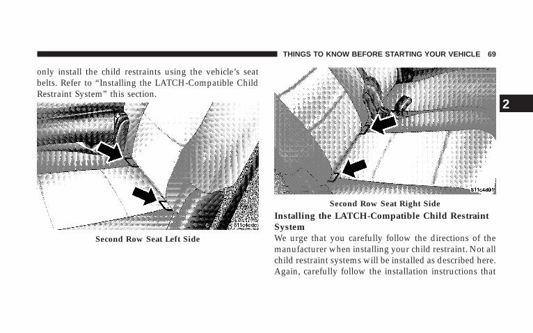
only install the child restraints using the vehicle’s seatbelts. Refer to “Installing the LATCH-Compatible ChildRestraint System” this section.
Installing the LATCH-Compatible Child RestraintSystemWe urge that you carefully follow the directions of themanufacturer when installing your child restraint. Not allchild restraint systems will be installed as described here.Again, carefully follow the installation instructions that
Second Row Seat Left Side
Second Row Seat Right Side
THINGS TO KNOW BEFORE STARTING YOUR VEHICLE 69
2
were provided with the child restraint system. The rearseat lower anchorages are round bars, located at the rearof the seat cushion where it meets the seatback, and arejust visible when you lean into the rear seat to install thechild restraint. You will easily feel them if you run yourfinger along the intersection of the seatback and seatcushion surfaces. In addition, there are tether strapanchorages behind each second row seating positionlocated on the back of the seat. Many, but not all restraintsystems will be equipped with separate straps on eachside, with each having a hook or connector for attach-ment to the lower anchorage and a means of adjustingthe tension in the strap. Forward-facing toddler restraintsand some rear-facing infant restraints will also beequipped with a tether strap, a hook for attachment to thetether strap anchorage and a means of adjusting thetension of the strap. You will first loosen the adjusters onthe lower straps and on the tether strap so that you canmore easily attach the hooks or connectors to the vehicle
anchorages. Next, attach the lower hooks or connectorsover the top of the anchorage bars, pushing aside the seatcover material. Then attach the tether strap to the anchor-age located on the back of the seat, being careful to routethe tether strap to provide the most direct path betweenthe anchor and the child restraint. If your vehicle isequipped with adjustable rear head restraints, raise thehead restraint and, route the tether strap under the headrestraint and between the two posts. Finally, tighten allthree straps as you push the child restraint rearward anddownward into the seat, removing slack in the strapsaccording to the child restraint manufacturer’s instruc-tions.
NOTE: When using the LATCH attaching system toinstall a child restraint, please ensure that all seat beltsnot being used for occupant restraints are stowed and outof reach of children. It is recommended that beforeinstalling the child restraint, buckle the seat belt so theseat belt is tucked behind the child restraint and out of
70 THINGS TO KNOW BEFORE STARTING YOUR VEHICLE

reach. If the buckled seat belt interferes with the childrestraint installation, instead of tucking the seat beltbehind the child restraint, route the seat belt through thechild restraint belt path and then buckle it. This shouldstow the seat belt out of the reach of an inquisitive child.Remind all children in the vehicle that the seat belts arenot toys and should not be played with, and never leavean unattended child in the vehicle.
WARNING!
Improper installation of a child restraint to theLATCH anchorages can lead to failure of an infant orchild restraint. The child could be badly injured orkilled. Follow the manufacturer’s directions exactlywhen installing an infant or child restraint.
Installing Child Restraints Using the Vehicle SeatBeltThe second and third row seats have either cinching latchplates or Automatic Locking Retractors which are de-signed to keep the lap portion tight around the childrestraint so that it is not necessary to use a locking clip. Ifthe seat belt has a cinching latch plate, pulling up on theshoulder portion of the lap/shoulder belt will tighten thebelt. The cinching latch plate will keep the belt tight,however, any seat belt system will loosen with time, socheck the belt occasionally and pull it tight if necessary. Ifthe seat belt has an Automatic Locking Retractor, it willhave a distinctive label. Pull the belt from the retractoruntil there is enough to allow you to pass through thechild restraint and slide the latch plate into the buckle.Then, pull the belt until it is completely extended fromthe retractor. Allow the belt to return to the retractor,
THINGS TO KNOW BEFORE STARTING YOUR VEHICLE 71
2
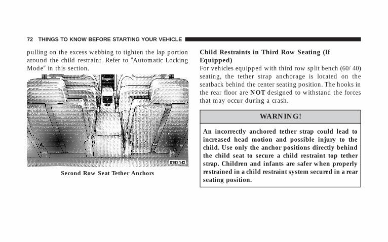
pulling on the excess webbing to tighten the lap portionaround the child restraint. Refer to 9Automatic LockingMode9 in this section.
Child Restraints in Third Row Seating (IfEquipped)For vehicles equipped with third row split bench (60/40)seating, the tether strap anchorage is located on theseatback behind the center seating position. The hooks inthe rear floor are NOT designed to withstand the forcesthat may occur during a crash.
WARNING!
An incorrectly anchored tether strap could lead toincreased head motion and possible injury to thechild. Use only the anchor positions directly behindthe child seat to secure a child restraint top tetherstrap. Children and infants are safer when properlyrestrained in a child restraint system secured in a rearseating position.
Second Row Seat Tether Anchors
72 THINGS TO KNOW BEFORE STARTING YOUR VEHICLE
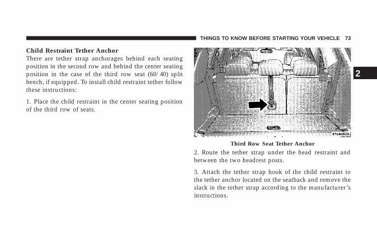
Child Restraint Tether AnchorThere are tether strap anchorages behind each seatingposition in the second row and behind the center seatingposition in the case of the third row seat (60/40) splitbench, if equipped. To install child restraint tether followthese instructions:
1. Place the child restraint in the center seating positionof the third row of seats.
2. Route the tether strap under the head restraint andbetween the two headrest posts.
3. Attach the tether strap hook of the child restraint tothe tether anchor located on the seatback and remove theslack in the tether strap according to the manufacturer’sinstructions.
Third Row Seat Tether Anchor
THINGS TO KNOW BEFORE STARTING YOUR VEHICLE 73
2

WARNING!
An incorrectly anchored tether strap could lead toseat failure and injury to the child. In a collision, theseat could come loose and allow the child to crashinto the inside of the vehicle or other passengers, oreven be thrown from the vehicle. Use only the anchorpositions directly behind the child seat to secure achild restraint top tether strap. Follow the instruc-tions for Child Restraint Tether Anchor in this sec-tion. See your authorized dealer for help if necessary.
Transporting PetsAirbags deploying in the front seat could harm your pet.An unrestrained pet will be thrown about and possiblyinjured, or injure a passenger during panic braking or ina collision. Pets should be restrained in the rear seat inpet harnesses or pet carriers that are secured by seat belts.
ENGINE BREAK-IN RECOMMENDATIONSA long break-in period is not required for the engine inyour new vehicle. Drive moderately during the first 300mi (500 km). After the initial 60 mi (100 km), speeds up to50 or 55 mph (80 or 90 km/h) are desirable. Whilecruising, brief full-throttle acceleration within the limitsof local traffic laws contributes to a good break-in.
Avoid wide-open throttle acceleration in low gear.
The engine oil installed in the engine at the factory is ahigh-quality, energy-conserving type lubricant. Oilchanges should be consistent with anticipated climateconditions under which vehicle operations will occur. Forrecommended viscosity and quality grades, refer to “En-gine Oil” under “Maintenance Procedures” in Section 7.
NON-DETERGENT OR STRAIGHT MINERAL OILSMUST NEVER BE USED.
74 THINGS TO KNOW BEFORE STARTING YOUR VEHICLE

A new engine may consume some oil during its first fewthousand miles (kilometers) of operation. This is a nor-mal part of the break-in and is not an indication ofdifficulty.
SAFETY TIPS
Exhaust System
WARNING!
Exhaust gases contain carbon monoxide, an extremelytoxic gas that by itself is colorless and odorless. Toavoid inhaling these gases, the following precautionsshould be observed:
• Do not run the engine in a closed garage or inconfined areas any longer than needed to move yourvehicle in or out of the area.
• It may be necessary to sit in a parked vehicle with theengine running for more than a short period. If so,adjust your climate control system to force outsideair into the vehicle. Set the blower at high speed andthe controls in any position except OFF or RECIRC.
• The best protection against carbon monoxide entryinto the vehicle body is a properly maintained en-gine exhaust system.
THINGS TO KNOW BEFORE STARTING YOUR VEHICLE 75
2

Be aware of changes in the sound of the exhaust system,exhaust fumes detected inside the vehicle, or damage tothe underside or rear of the vehicle. Have a competentmechanic inspect the complete exhaust system and adja-cent body areas for broken, damaged, deteriorated ormispositioned parts. Open seams or loose connectionscould permit exhaust fumes to seep into the passengercompartment. In addition, inspect the exhaust systemeach time the vehicle is raised for lubrication or oilchange. Replace or adjust as required.
Safety Checks You Should Make Inside TheVehicle
Heater Defroster DuctsInspect the heater defroster ducts for proper operation.Check for proper airflow through all defroster ducts. Ifthere are any question regarding the operation of yourheater defroster ducts, have the system checked by anauthorized dealer.
Seat BeltsInspect the belt system periodically, checking for cuts,frays and loose parts. Damaged parts must be replacedimmediately. Do not disassemble or modify the system.
Seat belt assemblies must be replaced after an accident ifthey have been damaged (bent retractor, torn webbing,etc.) or if the front airbags have deployed. If there is anyquestion regarding belt or retractor condition, replace thebelt.
Airbag LightThe Airbag light should come on and remain on for six toeight seconds as a bulb check when the ignition switch isfirst turned ON. If the light is not lit during starting, seeyour authorized dealer. If the light stays on, flickers orcomes on while driving, have the system checked by anauthorized dealer. If there is a problem with the airbaglight, the seat belt light will flash.
76 THINGS TO KNOW BEFORE STARTING YOUR VEHICLE
Safety Checks You Should Make Outside TheVehicle
TiresExamine tires for tread wear or uneven wear patterns.Check for stones, nails, glass or other objects lodged inthe tread.
Inspect for tread cuts or sidewall cracks. Check wheelnuts for tightness and tires for proper pressure.
LightsCheck the operation of all exterior lights. Check turnsignal and high beam indicator lights on the instrumentpanel.
Door LatchesCheck for positive closing, latching and locking.
Fluid LeaksCheck area under vehicle after overnight parking for fuel,water, oil, or other fluid leaks. Also, if fuel fumes aredetected, the cause should be located and corrected.
THINGS TO KNOW BEFORE STARTING YOUR VEHICLE 77
2

UNDERSTANDING THE FEATURES OF YOUR VEHICLE
CONTENTS
m Mirrors . . . . . . . . . . . . . . . . . . . . . . . . . . . . . . .84
▫ Inside Day/Night Mirror . . . . . . . . . . . . . . . . .84
▫ Automatic Dimming Mirror — If Equipped . . . .84
▫ Outside Mirrors . . . . . . . . . . . . . . . . . . . . . . .85
▫ Exterior Mirrors Folding Feature —If Equipped . . . . . . . . . . . . . . . . . . . . . . . . . .85
▫ Electric Remote-Control Mirrors . . . . . . . . . . . .86
▫ Illuminated Vanity Mirrors — If Equipped . . . .87
▫ Heated Mirrors — If Equipped . . . . . . . . . . . . .87
▫ Automatic Dimming Driver’s Exterior Mirror —If Equipped . . . . . . . . . . . . . . . . . . . . . . . . . .88
m Hands-Free Communication (UConnectt) — IfEquipped . . . . . . . . . . . . . . . . . . . . . . . . . . . . .88
▫ Operation . . . . . . . . . . . . . . . . . . . . . . . . . . . .90
▫ Phone Call Features . . . . . . . . . . . . . . . . . . . .97
▫ UConnectt System Features . . . . . . . . . . . . . . 100
▫ Advanced Phone Connectivity . . . . . . . . . . . . 104
▫ Things You Should Know About YourUConnectt System . . . . . . . . . . . . . . . . . . . . 106
3
▫ General Information . . . . . . . . . . . . . . . . . . . 115
m Voice Recognition System (VR) — If Equipped . . 115
▫ Voice Recognition System (VR) Operation . . . . 115
▫ Commands . . . . . . . . . . . . . . . . . . . . . . . . . . 116
▫ Voice Training . . . . . . . . . . . . . . . . . . . . . . . . 119
m Seats . . . . . . . . . . . . . . . . . . . . . . . . . . . . . . . . 120
▫ Front Seat Manual Seat Adjustment . . . . . . . . 120
▫ Front Seat Manual Seat Recliners . . . . . . . . . . 121
▫ Manual Lumbar Support Adjustment — IfEquipped . . . . . . . . . . . . . . . . . . . . . . . . . . . 122
▫ Adjustable Head Restraints — All SeatingPositions . . . . . . . . . . . . . . . . . . . . . . . . . . . 122
▫ 8-Way Driver’s Power Seat — If Equipped . . . 123
▫ 4-Way Passenger’s Power Seat —If Equipped . . . . . . . . . . . . . . . . . . . . . . . . . 124
▫ Heated Seats — If Equipped . . . . . . . . . . . . . 124
▫ Second Row Bucket Seats — Fold AndTumble . . . . . . . . . . . . . . . . . . . . . . . . . . . . 127
▫ Second Row 40/20/40 Seat — Fold AndTumble . . . . . . . . . . . . . . . . . . . . . . . . . . . . 129
▫ Third Row Seat Bench — If Equipped . . . . . . . 133
▫ Third Row 60/40 Folding — If Equipped . . . . 135
m Driver Memory System — If Equipped . . . . . . . 137
▫ Setting Memory Positions And Linking RemoteKeyless Entry Transmitter To Memory . . . . . . . 138
▫ Memory Position Recall . . . . . . . . . . . . . . . . . 139
▫ To Disable A Transmitter Linked To Memory . . 140
80 UNDERSTANDING THE FEATURES OF YOUR VEHICLE
▫ Self-Limiting Control . . . . . . . . . . . . . . . . . . . 141
▫ Driver Easy Exit And Easy Entry Control . . . . 141
m To Open And Close The Hood . . . . . . . . . . . . . 142
m Lights . . . . . . . . . . . . . . . . . . . . . . . . . . . . . . . 144
▫ Interior Lights . . . . . . . . . . . . . . . . . . . . . . . 145
▫ Battery Saver . . . . . . . . . . . . . . . . . . . . . . . . 145
▫ Headlight Delay . . . . . . . . . . . . . . . . . . . . . . 146
▫ Automatic Headlights — If Equipped . . . . . . . 147
▫ Headlights, Parking Lights, Panel Lights . . . . . 147
▫ Illuminated Entry . . . . . . . . . . . . . . . . . . . . . 147
▫ Daytime Running Lights (Canada Only) . . . . . 148
▫ Lights-On Reminder . . . . . . . . . . . . . . . . . . . 148
▫ Fog Lights — If Equipped . . . . . . . . . . . . . . . 148
▫ Multifunction Control Lever . . . . . . . . . . . . . . 149
m Windshield Wipers And Washers . . . . . . . . . . . . 151
▫ Windshield Wipers . . . . . . . . . . . . . . . . . . . . 151
▫ Windshield Washers . . . . . . . . . . . . . . . . . . . 153
m Tilt Steering Column . . . . . . . . . . . . . . . . . . . . 154
m Driver Adjustable Pedals — If Equipped . . . . . . 155
▫ Adjustment . . . . . . . . . . . . . . . . . . . . . . . . . 155
m Electronic Speed Control — If Equipped . . . . . . 156
▫ To Activate . . . . . . . . . . . . . . . . . . . . . . . . . . 156
▫ To Set At A Desired Speed . . . . . . . . . . . . . . . 157
▫ To Deactivate . . . . . . . . . . . . . . . . . . . . . . . . 157
▫ To Resume Speed . . . . . . . . . . . . . . . . . . . . . 157
▫ To Vary The Speed Setting . . . . . . . . . . . . . . . 158
UNDERSTANDING THE FEATURES OF YOUR VEHICLE 81
3
▫ To Accelerate For Passing . . . . . . . . . . . . . . . 159
m Rear Park Assist System — If Equipped . . . . . . . 160
m Rear Camera — If Equipped . . . . . . . . . . . . . . . 163
m Overhead Console . . . . . . . . . . . . . . . . . . . . . . 165
▫ Courtesy/Reading Lights . . . . . . . . . . . . . . . . 166
m Overhead Console With Electronic VehicleInformation Center (EVIC) — If Equipped . . . . . 166
▫ Dome/Reading Lights . . . . . . . . . . . . . . . . . . 166
▫ Electronic Vehicle Information Center (EVIC) —If Equipped . . . . . . . . . . . . . . . . . . . . . . . . . 167
▫ Compass/Temperature Button . . . . . . . . . . . . 173
m Garage Door Opener — If Equipped . . . . . . . . . 176
▫ Programming HomeLinkt . . . . . . . . . . . . . . . 177
▫ Gate Operator/Canadian Programming . . . . . 180
▫ Using HomeLinkt . . . . . . . . . . . . . . . . . . . . . 181
▫ Reprogramming A Single HomeLinktButton . . . . . . . . . . . . . . . . . . . . . . . . . . . . . 181
▫ Security . . . . . . . . . . . . . . . . . . . . . . . . . . . . 181
▫ Troubleshooting Tips . . . . . . . . . . . . . . . . . . . 181
▫ General Information . . . . . . . . . . . . . . . . . . . 182
m Power Sunroof — If Equipped . . . . . . . . . . . . . 182
▫ Express Open Feature . . . . . . . . . . . . . . . . . . 183
▫ Wind Buffeting . . . . . . . . . . . . . . . . . . . . . . . 184
▫ Sunroof Maintenance . . . . . . . . . . . . . . . . . . . 184
m Electrical Power Outlets . . . . . . . . . . . . . . . . . . 185
▫ 115V Inverter Outlet – If Equipped . . . . . . . . . 185
▫ Electrical Outlet Use With Engine Off (BatteryFed Configuration) . . . . . . . . . . . . . . . . . . . . 187
82 UNDERSTANDING THE FEATURES OF YOUR VEHICLE

m Floor Console . . . . . . . . . . . . . . . . . . . . . . . . . 189
▫ Front Floor Console Features . . . . . . . . . . . . . 189
▫ Rear Floor Console Features – If Equipped . . . 191
m Factory Installed Roof Luggage Rack . . . . . . . . . 192
m Cargo Management System—If Equipped . . . . . . 194
UNDERSTANDING THE FEATURES OF YOUR VEHICLE 83
3
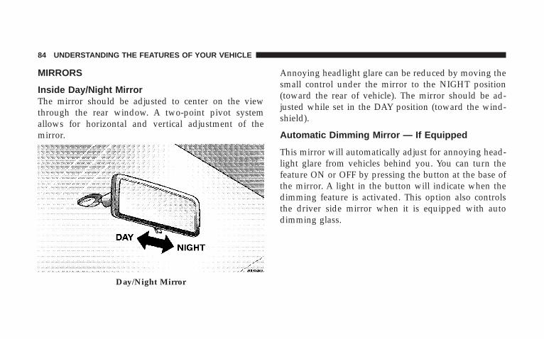
MIRRORS
Inside Day/Night MirrorThe mirror should be adjusted to center on the viewthrough the rear window. A two-point pivot systemallows for horizontal and vertical adjustment of themirror.
Annoying headlight glare can be reduced by moving thesmall control under the mirror to the NIGHT position(toward the rear of vehicle). The mirror should be ad-justed while set in the DAY position (toward the wind-shield).
Automatic Dimming Mirror — If Equipped
This mirror will automatically adjust for annoying head-light glare from vehicles behind you. You can turn thefeature ON or OFF by pressing the button at the base ofthe mirror. A light in the button will indicate when thedimming feature is activated. This option also controlsthe driver side mirror when it is equipped with autodimming glass.
Day/Night Mirror
84 UNDERSTANDING THE FEATURES OF YOUR VEHICLE
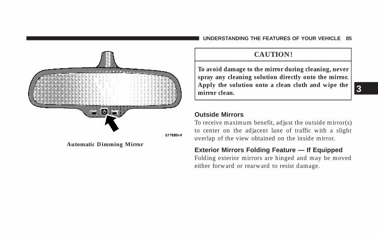
CAUTION!
To avoid damage to the mirror during cleaning, neverspray any cleaning solution directly onto the mirror.Apply the solution onto a clean cloth and wipe themirror clean.
Outside MirrorsTo receive maximum benefit, adjust the outside mirror(s)to center on the adjacent lane of traffic with a slightoverlap of the view obtained on the inside mirror.
Exterior Mirrors Folding Feature — If EquippedFolding exterior mirrors are hinged and may be movedeither forward or rearward to resist damage.
Automatic Dimming Mirror
UNDERSTANDING THE FEATURES OF YOUR VEHICLE 85
3
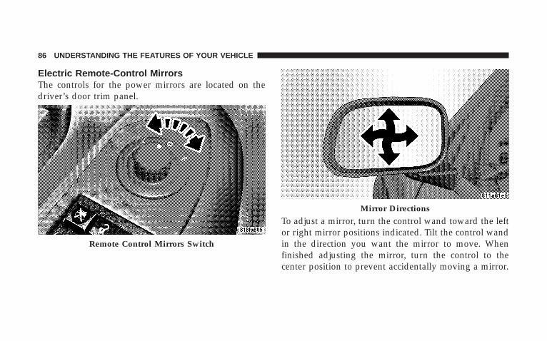
Electric Remote-Control MirrorsThe controls for the power mirrors are located on thedriver’s door trim panel.
To adjust a mirror, turn the control wand toward the leftor right mirror positions indicated. Tilt the control wandin the direction you want the mirror to move. Whenfinished adjusting the mirror, turn the control to thecenter position to prevent accidentally moving a mirror.
Remote Control Mirrors Switch
Mirror Directions
86 UNDERSTANDING THE FEATURES OF YOUR VEHICLE
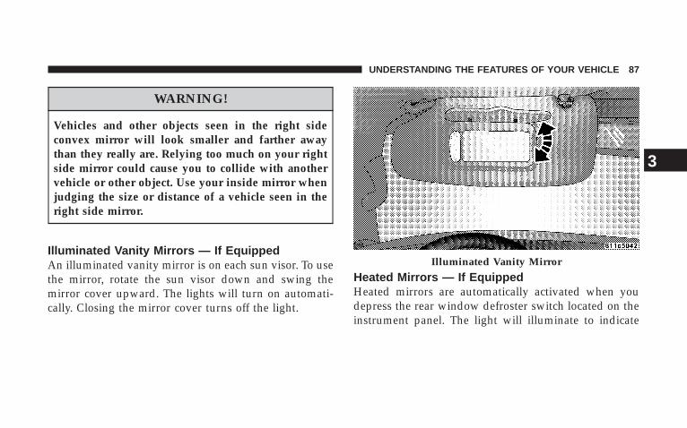
WARNING!
Vehicles and other objects seen in the right sideconvex mirror will look smaller and farther awaythan they really are. Relying too much on your rightside mirror could cause you to collide with anothervehicle or other object. Use your inside mirror whenjudging the size or distance of a vehicle seen in theright side mirror.
Illuminated Vanity Mirrors — If EquippedAn illuminated vanity mirror is on each sun visor. To usethe mirror, rotate the sun visor down and swing themirror cover upward. The lights will turn on automati-cally. Closing the mirror cover turns off the light.
Heated Mirrors — If EquippedHeated mirrors are automatically activated when youdepress the rear window defroster switch located on theinstrument panel. The light will illuminate to indicate
Illuminated Vanity Mirror
UNDERSTANDING THE FEATURES OF YOUR VEHICLE 87
3

that the heating elements are ON. Turning OFF the rearwindow defroster or the ignition will deactivate theheated mirrors.
Automatic Dimming Driver’s Exterior Mirror — IfEquippedThis mirror will automatically adjust for annoying lightglare from vehicles behind you. This feature is controlledby the inside mirror and can be turned off by pressing thebutton at the base of the inside mirror.
HANDS-FREE COMMUNICATION (UConnect T) —IF EQUIPPED
NOTE: The sales code RER radio contains an inte-grated Hands-Free Communication (UConnectt) sys-tem. Refer to your “Navigation User’s Manual” forUConnectt system operating instructions for this radio.
UConnectt is a voice-activated, hands-free, in-vehiclecommunications system. UConnectt allows you to dial a
phone number with your cellular phone using simplevoice commands (e.g., 9Call” { “Mike” {”Work9 or 9Dial”{ “248-555-12129). Your cellular phone’s audio is trans-mitted through your vehicle’s audio system; the systemwill automatically mute your radio when using theUConnectt system.
NOTE: The UConnectt system requires a cellular phoneequipped with the Bluetootht 9Hands-Free Profile,9 Ver-sion 0.96 or higher. See the UConnectt website forsupported phones.
NOTE: For UConnectt customer support, visit thefollowing websites:
• www.chrysler.com/uconnect
• www.dodge.com/uconnect
• www.jeep.com/uconnect
• or call 1–877–855–8400
88 UNDERSTANDING THE FEATURES OF YOUR VEHICLE

UConnectt allows you to transfer calls between thesystem and your cellular phone as you enter or exit yourvehicle and enables you to mute the system’s microphonefor private conversation.
The UConnectt phonebook enables you to store up to 32names, with four numbers per name. Each language hasa separate 32-name phonebook accessible only in thatlanguage. This system is driven through your Bluetootht“Hands-Free profile” cellular phone. UConnectt featuresBluetootht technology - the global standard that enablesdifferent electronic devices to connect to each otherwithout wires or a docking station, so UConnectt worksno matter where you stow your cellular phone (be it yourpurse, pocket, or briefcase), as long as your phone isturned on and has been paired to the vehicle’sUConnectt system. The UConnectt system allows up toseven cellular phones to be linked to the system. Onlyone linked (or paired) cellular phone can be used with the
system at a time. The system is available in English,Spanish, or French languages (as equipped).
PHONE ButtonThe rearview mirror contains the microphonefor the system (depending on the type ofmirror and radio equipped), and either theradio or the mirror has the two control buttons
(PHONE Button and VOICE RECOGNITION button)that will enable you to access the system.
Voice Recognition ButtonActual button location may vary with radio.The individual buttons are described in the“Operation” section.
The UConnectt system can be used with any Hands-FreeProfile certified Bluetootht cellular phone. See theUConnectt website for supported phones. If your cellu-lar phone supports a different profile (e.g., Headset
UNDERSTANDING THE FEATURES OF YOUR VEHICLE 89
3

Profile) you may not be able to use any UConnecttfeatures. Refer to your cellular service provider or thephone manufacturer for details.
The UConnectt system is fully integrated with the vehi-cle’s audio system. The volume of the UConnectt systemcan be adjusted either from the radio volume controlknob or from the steering wheel radio control (rightswitch), if so equipped.
The radio display will be used for visual prompts fromthe UConnectt system such as 9CELL9 or caller ID oncertain radios.
OperationVoice commands can be used to operate the UConnecttsystem and to navigate through the UConnectt menustructure. Voice commands are required after mostUConnectt system prompts. You will be prompted for aspecific command and then guided through the availableoptions.
• Prior to giving a voice command, one must wait forthe beep, which follows the 9Ready9 prompt or anotherprompt.
• For certain operations, compound commands can beused. For example, instead of saying 9Setup9 and then9Phone Pairing,9 the following compound commandcan be said: 9Setup Phone Pairing.9
• For each feature explanation in this section, only thecombined form of the voice command is given. Youcan also break the commands into parts and say eachpart of the command when you are asked for it. Forexample, you can use the combined form voice com-mand 9Phonebook New Entry,9 or you can break thecombined form command into two voice commands:9Phonebook9 and 9New Entry.9 Please remember, theUConnectt system works best when you talk in anormal conversational tone, as if speaking to someonesitting a few feet/meters away from you.
90 UNDERSTANDING THE FEATURES OF YOUR VEHICLE

Voice Command TreeRefer to “Voice Tree” in this section.
Help CommandIf you need assistance at any prompt, or if you want toknow your options at any prompt, say 9Help9 followingthe beep. The UConnectt system will play all the optionsat any prompt if you ask for help.
To activate the UConnectt system from idle, simply pressthe PHONE button and follow the audible prompts fordirections. All UConnectt system sessions begin with apress of the PHONE button on the radio control head.
Cancel CommandAt any prompt, after the beep, you can say 9Cancel9 andyou will be returned to the main menu. However, in afew instances the system will take you back to theprevious menu.
Pair (Link) UConnectt System to a Cellular PhoneTo begin using your UConnectt system, you must pairyour compatible Bluetootht enabled cellular phone.
To complete the pairing process, you will need to refer-ence your cellular phone owner’s manual. TheUConnectt website may also provide detailed instruc-tions for pairing.
The following are general phone to UConnectt systempairing instructions:
• Press the PHONE button to begin.
• After the 9Ready9 prompt and the following beep, say9Setup Phone Pairing.9
• When prompted, after the beep, say 9Pair a Phone9 andfollow the audible prompts.
• You will be asked to say a four-digit Personal Identi-fication Number (PIN), which you will later need to
UNDERSTANDING THE FEATURES OF YOUR VEHICLE 91
3
enter into your cellular phone. You can enter anyfour-digit PIN number. You will not need to rememberthis PIN number after the initial pairing process.
• For identification purposes, you will be prompted togive the UConnectt system a name for your cellularphone. Each cellular phone that is paired should begiven a unique phone name.
• You will then be asked to give your cellular phone apriority level between 1 and 7, with 1 being the highestpriority. You can pair up to seven cellular phones toyour UConnectt system. However, at any given time,only one cellular phone can be in use, connected toyour UConnectt system. The priority allows theUConnectt system to know which cellular phone touse if multiple cellular phones are in the vehicle at thesame time. For example, if priority 3 and priority 5phones are present in the vehicle, the UConnecttsystem will use the priority 3 cellular phone when you
make a call. You can select to use a lower prioritycellular phone at any time (refer to 9Advanced PhoneConnectivity9 in this section).
Dial by Saying a Number
• Press the PHONE button to begin.
• After the 9Ready9 prompt and the following beep, say9Dial.9
• The system will prompt you to say the number youwant to call.
• For example, you can say 9234-567-8901.9 The phonenumber that you enter must be of valid length andcombination. Based on the country in which the ve-hicle was purchased, the UConnectt system limits theuser from dialing an invalid combination of numbers.For example, in the U.S., 234-567-890 is nine digitslong, which is not a valid U.S. phone number - theclosest valid phone number has 10 digits.
92 UNDERSTANDING THE FEATURES OF YOUR VEHICLE
• The UConnectt system will confirm the phone num-ber and then dial. The number will appear in thedisplay of certain radios.
Call by Saying a Name
• Press the PHONE button to begin.
• After the 9Ready9 prompt and the following beep, say“Call.9
• The system will prompt you to say the name of theperson you want to call.
• After the 9Ready9 prompt and the following beep, saythe name of the person you want to call. For example,you can say 9John Doe,9 where John Doe is a previ-ously stored name entry in the UConnectt phonebook.To learn how to store a name in the phonebook, referto 9Add Names to Your UConnectt Phonebook,9 inthis section.
• The UConnectt system will confirm the name andthen dial the corresponding phone number, whichmay appear in the display of certain radios.
Add Names to Your UConnectt Phonebook
NOTE: Adding names to the phonebook is recom-mended when the vehicle is not in motion.
• Press the PHONE button to begin.
• After the 9Ready9 prompt and the following beep, say9Phonebook New Entry.9
• When prompted, say the name of the new entry. Use oflong names helps the voice recognition and it isrecommended. For example, say 9Robert Smith9 or9Robert9 instead of 9Bob.9
UNDERSTANDING THE FEATURES OF YOUR VEHICLE 93
3
• When prompted, enter the number designation (e.g.,9Home,9 9Work,9 9Mobile,9 or 9Pager9). This will allowyou to store multiple numbers for each phonebookentry, if desired.
• When prompted, recite the phone number for thephonebook entry that you are adding.
After you are finished adding an entry into the phone-book, you will be given the opportunity to add morephone numbers to the current entry or to return to themain menu.
The UConnectt system will allow you to enter up to 32names in the phonebook with each name having up tofour associated phone numbers and designations. Eachlanguage has a separate 32-name phonebook accessibleonly in that language.
Phonebook DownloadUConnectt allows the user to download entries fromtheir phone via Bluetootht. To use this feature, press thePHONE button and say “Phonebook Download.” Thesystem prompts, “Ready to accept “V” card entry viaBluetootht…” The system is now ready to accept phone-book entries from your phone using the BluetoothtObject Exchange Profile (OBEX). Please see your phoneOwner’s Manual for specific instructions on how to sendthese entries from your phone.
NOTE:• The phone handset must support Bluetootht OBEX
transfers of phonebook entries to use this feature.
• Some phones cannot send phonebook entries if theyare already connected to any system via Bluetootht,and you may see a message on the phone display thatthe Bluetootht link is busy. In this case, the user mustfirst disconnect or drop the Bluetootht connection to
94 UNDERSTANDING THE FEATURES OF YOUR VEHICLE

the UConnectt system, and then send the addressbook entry via Bluetootht. Please see your phoneowner’s manual for specific instructions on how todrop the Bluetootht connection.
• If the phonebook entry is longer than 24 characters, itwill only use the first 24 characters.
Edit Entries in the UConnectt Phonebook
NOTE: Editing names in the phonebook is recom-mended when the vehicle is not in motion.
• Press the PHONE button to begin.
• After the 9Ready9 prompt and the following beep, say9Phonebook Edit.9
• You will then be asked for the name of the phonebookentry that you wish to edit.
• Next, choose the number designation (home, work,mobile, or pager) that you wish to edit.
• When prompted, recite the new phone number for thephonebook entry that you are editing.
After you are finished editing an entry in the phonebook,you will be given the opportunity to edit another entry inthe phonebook, call the number you just edited, or returnto the main menu.
9Phonebook Edit9 can be used to add another phonenumber to a name entry that already exists in thephonebook. For example, the entry John Doe may have amobile and a home number, but you can add ”JohnDoe’s” work number later using the 9Phonebook Edit9feature.
Delete Entries in the UConnectt Phonebook
NOTE: Editing phonebook entries is recommendedwhen the vehicle is not in motion.
• Press the PHONE button to begin.
UNDERSTANDING THE FEATURES OF YOUR VEHICLE 95
3
• After the 9Ready9 prompt and the following beep, say9Phonebook Delete.9
• After you enter the Phonebook Delete menu, you willthen be asked for the name of the entry that you wishto delete. You can either say the name of a phonebookentry that you wish to delete or you can say 9ListNames9 to hear a list of the entries in the phonebookfrom which you choose. To select one of the entriesfrom the list, press the “Voice Recognition” buttonwhile the UConnectt system is playing the desiredentry and say 9Delete.9
• After you enter the name, the UConnectt system willask you which designation you wish to delete: home,work, mobile, pager, or all. Say the designation youwish to delete.
• Note that only the phonebook entry in the currentlanguage is deleted.
Delete All Entries in the UConnectt Phonebook
• Press the PHONE button to begin.
• After the 9Ready9 prompt and the following beep, say9Phonebook Erase All.9
• The UConnectt system will ask you to verify that youwish to delete all the entries from the phonebook.
• After confirmation, the phonebook entries will bedeleted.
• Note that only the phonebook in the current languageis deleted.
List All Names in the UConnectt Phonebook
• Press the PHONE button to begin.
• After the 9Ready9 prompt and the following beep, say9Phonebook List Names.9
96 UNDERSTANDING THE FEATURES OF YOUR VEHICLE

• The UConnectt system will play the names of all thephonebook entries.
• To call one of the names in the list, press the “VoiceRecognition” button during the playing of the desiredname, and say 9Call.9
NOTE: The user can also exercise 9Edit9 or 9Delete9operations at this point.
• The UConnectt system will then prompt you as to thenumber designation you wish to call.
• The selected number will be dialed.
Phone Call FeaturesThe following features can be accessed through theUConnectt system if the feature(s) are available on yourcellular service plan. For example, if your cellular serviceplan provides three-way calling, this feature can be
accessed through the UConnectt system. Check withyour cellular service provider for the features that youhave.
Answer or Reject an Incoming Call - No CallCurrently in ProgressWhen you receive a call on your cellular phone, theUConnectt system will interrupt the vehicle audio sys-tem, if on, and will ask if you would like to answer thecall. Press the PHONE button to accept the call. To rejectthe call, press and hold the PHONE button until you heara single beep, indicating that the incoming call wasrejected.
Answer or Reject an Incoming Call - CallCurrently in ProgressIf a call is currently in progress and you have anotherincoming call, you will hear the same network tones for
UNDERSTANDING THE FEATURES OF YOUR VEHICLE 97
3

call waiting that you normally hear when using your cellphone. Press the PHONE button to place the current callon hold and answer the incoming call.
NOTE: The UConnectt system compatible phones inthe market today do not support rejecting an incomingcall when another call is in progress. Therefore, the usercan only answer an incoming call or ignore it.
Making a Second Call While Current Call inProgressTo make a second call while you are currently on a call,press the “Voice Recognition” button and say 9Dial9 or9Call9 followed by the phone number or phonebook entryyou wish to call. The first call will be on hold while thesecond call is in progress. To go back to the first call, referto 9Toggling Between Calls9 in this section. To combinetwo calls, refer to 9Conference Call9 in this section.
Place/Retrieve a Call From HoldTo put a call on hold, press the PHONE button until youhear a single beep. This indicates that the call is on hold.To bring the call back from hold, press and hold thePHONE button until you hear a single beep.
Toggling Between CallsIf two calls are in progress (one active and one on hold),press the PHONE button until you hear a single beep,indicating that the active and hold status of the two callshave switched. Only one call can be placed on hold at onetime.
Conference CallWhen two calls are in progress (one active and one onhold), press and hold the PHONE button until you heara double beep indicating that the two calls have beenjoined into one conference call.
98 UNDERSTANDING THE FEATURES OF YOUR VEHICLE
Three-Way CallingTo initiate three-way calling, press the “Voice Recogni-tion” button while a call is in progress, and make asecond phone call, as described under 9Making a SecondCall While Current Call in Progress.9 After the second callhas established, press and hold the PHONE button untilyou hear a double beep, indicating that the two calls havebeen joined into one conference call.
Call TerminationTo end a call in progress, momentarily press the PHONEbutton. Only the active call(s) will be terminated and ifthere is a call on hold, it will become the new active call.If the active call is terminated by the far end, a call onhold may not become active automatically. This is cellphone-dependent. To bring the call back from hold, pressand hold the PHONE button until you hear a single beep.
Redial
• Press the PHONE button to begin.
• After the 9Ready9 prompt and the following beep, say9Redial.9
• The UConnectt system will call the last number thatwas dialed from your cellular phone.
NOTE: This may not be the last number dialed from theUConnectt system.
Call ContinuationCall continuation is the progression of a phone call on theUConnectt system after the vehicle ignition key has beenswitched to OFF. Call continuation functionality avail-able on the vehicle can be any one of three types:
• After the ignition key is switched to OFF, a call cancontinue on the UConnectt system either until the callends, or until the vehicle battery condition dictatescessation of the call on the UConnectt system andtransfer of the call to the mobile phone.
UNDERSTANDING THE FEATURES OF YOUR VEHICLE 99
3
• After the ignition key is switched to OFF, a call cancontinue on the UConnectt system for a certain dura-tion, after which the call is automatically transferredfrom the UConnectt system to the mobile phone.
• An active call is automatically transferred to themobile phone after the ignition key is switched to OFF.
UConnect T System Features
Language SelectionTo change the language that the UConnectt system isusing:
• Press the PHONE button to begin.
• After the 9Ready9 prompt and the following beep, saythe name of the language you wish to switch to(English, Espanol, or Francais, if so equipped).
• Continue to follow the system prompts to completelanguage selection.
After selecting one of the languages, all prompts andvoice commands will be in that language.
NOTE: After every UConnectt language change opera-tion, only the language-specific 32-name phonebook isusable. The paired phone name is not language-specificand usable across all languages.
Emergency AssistanceIf you are in an emergency and the mobile phone isreachable:
• Pick up the phone and manually dial the emergencynumber for your area.
If the phone is not reachable and the UConnectt systemis operational, you may reach the emergency number asfollows:
• Press the PHONE button to begin.
100 UNDERSTANDING THE FEATURES OF YOUR VEHICLE
• After the 9Ready9 prompt and the following beep, say9Emergency9 and the UConnectt system will instructthe paired cellular phone to call the emergency num-ber. This feature is only supported in the U.S.
NOTE: The emergency number dialed is based on thecountry where the vehicle is purchased (911 for the U.S.and Canada and 060 for Mexico). The number dialed maynot be applicable with the available cellular service andarea.
The UConnectt system does slightly lower your chancesof successfully making a phone call as to that for the cellphone directly.
Your phone must be turned on and paired to theUConnectt system to allow use of this vehicle feature inemergency situations, when the cell phone has networkcoverage and stays paired to the UConnectt system.
Towing AssistanceIf you need towing assistance:
• Press the PHONE button to begin.
• After the 9Ready9 prompt and the following beep, say9Towing Assistance.9
NOTE: The Towing Assistance number dialed is basedon the country where the vehicle is purchased (1-800-528-2069 for the U.S., 1-877-213-4525 for Canada, 55-14-3454for Mexico City and 1-800-712-3040 for outside MexicoCity in Mexico).
Please refer to the 24-Hour “Towing Assistance” cover-age details in the Warranty Information Booklet and onthe 24–Hour Towing Assistance Card.
PagingTo learn how to page, refer to 9Working with AutomatedSystems.9 Paging works properly except for pagers of
UNDERSTANDING THE FEATURES OF YOUR VEHICLE 101
3
certain companies, which time out a little too soon towork properly with the UConnectt system.
Voice Mail CallingTo learn how to access your voice mail, refer to 9Workingwith Automated Systems.9
Working with Automated SystemsThis method is used in instances where one generally hasto press numbers on the cellular phone keypad whilenavigating through an automated telephone system.
You can use your UConnectt system to access a voicemail system or an automated service, such as a pagingservice or automated customer service line. Some ser-vices require immediate response selection. In someinstances, that may be too quick for use of the UConnecttsystem.
When calling a number with your UConnectt systemthat normally requires you to enter in a touch-tone
sequence on your cellular phone keypad, you can pressthe “Voice Recognition” button and say the sequence youwish to enter, followed by the word 9Send.9 For example,if required to enter your PIN number followed with apound, (3 7 4 6 #), you can press the “Voice Recognition”button and say, 93 7 4 6 # Send.9 Saying a number, orsequence of numbers, followed by 9Send,9 is also to beused for navigating through an automated customerservice center menu structure, and to leave a number ona pager.
You can also send stored UConnectt phonebook entriesas tones for fast and easy access to voice mail and pagerentries. To use this feature, dial the number you wish tocall and then press the “Voice Recognition” button andsay, “Send.” The system will prompt you to enter thename or number and say the name of the phonebookentry you wish to send. The UConnectt system will thensend the corresponding phone number associated withthe phonebook entry, as tones over the phone.
102 UNDERSTANDING THE FEATURES OF YOUR VEHICLE

NOTE:• You may not hear all of the tones due to cellular phone
network configurations; this is normal.
• Some paging and voice mail systems have system timeout settings that are too short and may not allow theuse of this feature.
Barge In - Overriding PromptsThe “Voice Recognition” button can be used when youwish to skip part of a prompt and issue your voicerecognition command immediately. For example, if aprompt is asking 9Would you like to pair a phone, cleara{,9 you could press the “Voice Recognition” button andsay, 9Pair a Phone9 to select that option without having tolisten to the rest of the voice prompt.
Turning Confirmation Prompts On/OffTurning confirmation prompts off will stop the systemfrom confirming your choices (e.g., the UConnectt sys-tem will not repeat a phone number before you dial it).
• Press the PHONE button to begin.
• After the 9Ready9 prompt and the following beep, say9Setup Confirmations.9 The UConnectt system willplay the current confirmation prompt status and youwill be given the choice to change it.
Phone and Network Status IndicatorsIf available on the radio and/or on a premium displaysuch as the instrument panel cluster, and supported byyour cell phone, the UConnectt system will providenotification to inform you of your phone and networkstatus when you are attempting to make a phone callusing UConnectt. The status is given for roaming, net-work signal strength, phone battery strength, etc.
Dialing Using the Cellular Phone KeypadYou can dial a phone number with your cellular phonekeypad and still use the UConnectt system (while dial-ing via the cell phone keypad, the user must exercisecaution and take precautionary safety measures). By
UNDERSTANDING THE FEATURES OF YOUR VEHICLE 103
3
dialing a number with your paired Bluetootht cellularphone, the audio will be played through your vehicle’saudio system. The UConnectt system will work the sameas if you dial the number using voice recognition.
NOTE: Certain brands of mobile phones do not send thedial ring to the UConnectt system to play it on thevehicle audio system, so you will not hear it. Under thissituation, after successfully dialing a number the usermay feel that the call did not go through even though thecall is in progress. Once your call is answered, you willhear the audio.
Mute/Un-Mute (Mute Off)When you mute the UConnectt system, you will still beable to hear the conversation coming from the otherparty, but the other party will not be able to hear you. Inorder to mute the UConnectt system:
• Press the “Voice Recognition” button.
• Following the beep, say 9Mute.9
In order to un-mute the UConnectt system:
• Press the “Voice Recognition” button.
• Following the beep, say 9Mute off.9
Advanced Phone Connectivity
Transfer Call to and from Cellular PhoneThe UConnectt system allows ongoing calls to be trans-ferred from your cellular phone to the UConnectt systemwithout terminating the call. To transfer an ongoing callfrom your UConnectt paired cellular phone to theUConnectt system or vice versa, press the “Voice Recog-nition” button and say 9Transfer Call.9
Connect or Disconnect Link Between theUConnectt System and Cellular PhoneYour cellular phone can be paired with many differentelectronic devices, but can only be actively 9connected9with one electronic device at a time.
104 UNDERSTANDING THE FEATURES OF YOUR VEHICLE
If you would like to connect or disconnect the Bluetoothtconnection between a UConnectt paired cellular phoneand the UConnectt system, follow the instructions de-scribed in your cellular phone User’s Manual.
List Paired Cellular Phone Names
• Press the PHONE button to begin.
• After the “Ready” prompt and the following beep, say“Setup Phone Pairing.”
• When prompted, say 9List Phones.9
• The UConnectt system will play the phone names ofall paired cellular phones in order from the highest tothe lowest priority. To “select” or “delete” a pairedphone being announced, press the “Voice Recogni-tion” button and say “Select” or “Delete.” Also, see thenext two sections for an alternate way to “select” or“delete” a paired phone.
Select Another Cellular PhoneThis feature allows you to select and start using anotherphone paired with the UConnectt system.
• Press the PHONE button to begin.
• After the 9Ready9 prompt and the following beep, say9Setup Select Phone9 and follow the prompts.
• You can also press the “Voice Recognition” button atany time while the list is being played, and thenchoose the phone that you wish to select.
• The selected phone will be used for the next phonecall. If the selected phone is not available, theUConnectt system will return to using the highestpriority phone present in or near (approximatelywithin 30 ft (9 m) the vehicle.
UNDERSTANDING THE FEATURES OF YOUR VEHICLE 105
3

Delete UConnectt Paired Cellular Phones
• Press the PHONE button to begin.
• After the 9Ready9 prompt and the following beep, say9Setup Phone Pairing.9
• At the next prompt, say 9Delete9 and follow theprompts.
• You can also press the “Voice Recognition” button atany time while the list is being played, and thenchoose the phone you wish to delete.
Things You Should Know About Your UConnect TSystem
UConnectt TutorialTo hear a brief tutorial of the system features, press thePHONE button and say “UConnectt Tutorial.”
Voice TrainingFor users experiencing difficulty with the system recog-nizing their voice commands or numbers, the UConnecttsystem Voice Training feature may be used. To enter thistraining mode, follow one of the two following proce-dures:
From outside the UConnectt mode (e.g., from radiomode):
• Press and hold the “Voice Recognition” button for fiveseconds until the session begins, or,
• Press the “Voice Recognition” button and say the9Setup, Voice Training9 command.
Repeat the words and phrases when prompted by theUConnectt system. For best results, the Voice Trainingsession should be completed when the vehicle is parkedwith the engine running, all windows closed, and theblower fan switched OFF.
106 UNDERSTANDING THE FEATURES OF YOUR VEHICLE

This procedure may be repeated with a new user. Thesystem will adapt to the last trained voice only.
To restore the voice recognition system to factory defaultsettings, enter the Voice Training session via the aboveprocedure and follow the prompts.
Voice Recognition (VR)
• For best performance, adjust the rear view mirror toprovide at least 1⁄2 in (1 cm) gap between the overheadconsole (if equipped) and the mirror.
• Always wait for the beep before speaking.
• Speak normally, without pausing, just as you wouldspeak to a person sitting a few feet/meters away fromyou.
• Make sure that no one other than you is speakingduring a voice recognition period.
• Performance is maximized under:
• low-to-medium blower setting,
• low-to-medium vehicle speed,
• low road noise,
• smooth road surface,
• fully closed windows,
• dry weather condition.
• Even though the system is designed for users speakingin North American English, French, and Spanish ac-cents, the system may not always work for some.
• When navigating through an automated system suchas voice mail, or when sending a page, at the end ofspeaking the digit string, make sure to say 9Send.9
• Storing names in the phonebook when the vehicle isnot in motion is recommended.
UNDERSTANDING THE FEATURES OF YOUR VEHICLE 107
3

• It is not recommended to store similar soundingnames in the UConnectt phonebook.
• The UConnectt phonebook nametag recognition rateis optimized for the person who stored the name in thephonebook.
• You can say 9O9 (letter 9O9) for 909 (zero). 98009 must bespoken 9eight-zero-zero.9
• Even though international dialing for most numbercombinations is supported, some shortcut dialingnumber combinations may not be supported.
• In a convertible vehicle, system performance may becompromised with the convertible top down.
Far End Audio Performance
• Audio quality is maximized under:
• low-to-medium blower setting,
• low-to-medium vehicle speed,
• low road noise,
• smooth road surface,
• fully closed windows,
• dry weather conditions, and
• operation from the drivers seat.
• Performance, such as audio clarity, echo, and loudnessto a large degree rely on the phone and network, andnot the UConnectt system.
• Echo at the far end can sometimes be reduced bylowering the in-vehicle audio volume.
• In a convertible vehicle, system performance may becompromised with the convertible top down.
108 UNDERSTANDING THE FEATURES OF YOUR VEHICLE

Bluetootht Communication LinkCellular phones have been found to lose connection tothe UConnectt system. When this happens, the connec-tion can generally be re-established by switching thephone off/on. Your cell phone is recommended to remainin Bluetootht ON mode.
Power-UpAfter switching the ignition key from OFF to either ONor ACC position, or after a language change, you mustwait at least five seconds prior to using the system.
UNDERSTANDING THE FEATURES OF YOUR VEHICLE 109
3

110 UNDERSTANDING THE FEATURES OF YOUR VEHICLE

UNDERSTANDING THE FEATURES OF YOUR VEHICLE 111
3
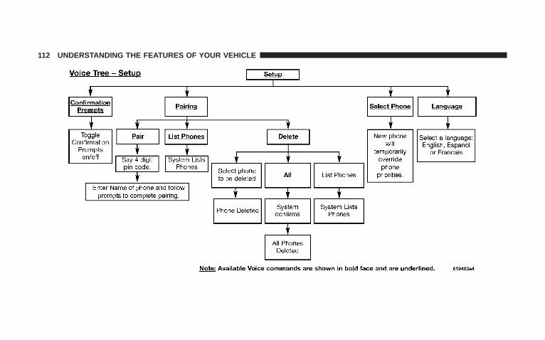
112 UNDERSTANDING THE FEATURES OF YOUR VEHICLE
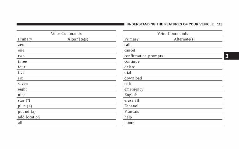
Voice CommandsPrimary Alternate(s)zeroonetwothreefourfivesixseveneightninestar (*)plus (+)pound (#)add locationall
Voice CommandsPrimary Alternate(s)callcancelconfirmation promptscontinuedeletedialdownloadeditemergencyEnglisherase allEspanolFrancaishelphome
UNDERSTANDING THE FEATURES OF YOUR VEHICLE 113
3

Voice CommandsPrimary Alternate(s)languagelist nameslist phonesmobilemutemute offnew entrynopagerpair a phonephone pairing pairingphonebook phone bookpreviousrecord againredial
Voice CommandsPrimary Alternate(s)return to main menu return or main menuselect phone selectsendset up phone settings or phone
set uptowing assistancetransfer callUConnectt Tutorialtry againvoice trainingworkyes
114 UNDERSTANDING THE FEATURES OF YOUR VEHICLE

General InformationThis device complies with part 15 of the FCC rules andRSS 210 of Industry Canada. Operation is subject to thefollowing conditions:
• This device may not cause harmful interference.
• This device must accept any interference received,including interference that may cause undesired op-eration.
VOICE RECOGNITION SYSTEM (VR) — IFEQUIPPED
Voice Recognition System (VR) OperationThis Voice Recognition System allows you tocontrol your AM, FM radio, satellite radio, discplayer, and a memo recorder.
NOTE: In a stressful situation, take care to speak intothe Voice Interface System as calmly and normally aspossible. The ability of the Voice Interface System torecognize user voice commands may be negatively af-fected by rapid speaking or a raised voice level.
WARNING!
Any voice commanded system should be used onlyin safe driving conditions and all attention should bekept on the roadway ahead. Failure to do so mayresult in an accident causing serious injury or death.
When you press the VR hard-key, you will hear a beep.The beep is your signal to give a command.
NOTE: If you do not say a command within a fewseconds, the system will present you with a list ofoptions.
UNDERSTANDING THE FEATURES OF YOUR VEHICLE 115
3
If you ever wish to interrupt the system while it listsoptions, press the VR hard-key, listen for the beep, andsay your command.
Pressing the VR hard-key while the system is speaking isknown as “barging in.” The system will be interruptedand you can add or change commands. This will becomehelpful once you start to learn the options.
NOTE: At any time, you can say the words CANCEL,HELP, or MAIN MENU.
These commands are universal and can be used from anymenu. All other commands can be used depending uponthe active application.
For example, if you are in the disc menu and you arelistening to FM radio, you can speak commands from thedisc menu or from the FM radio menu.
When using this system, you should speak clearly and ata normal speaking volume.
The system will best recognize your speech if the win-dows are closed, and the heater/air-conditioning fan isset to low.
At any point, if the system does not recognize one of yourcommands, you will be prompted to repeat it.
To hear the first available Menu, press the VR hard-keyand say HELP or MAIN MENU.
CommandsThe Voice Recognition System understands two types ofcommands. Global commands are available at all times.Local commands are available if the supported radiomode is active.
Changing the Volume
1. Start a dialogue by pressing the VR hard-key.
2. Say a command (e.g., HELP).
116 UNDERSTANDING THE FEATURES OF YOUR VEHICLE

3. Use the ON/OFF VOLUME rotary knob to adjust thevolume to a comfortable level while the voice recognitionsystem is speaking. Please note the volume setting for VRis different then the audio system.
Main MenuStart a dialogue by pressing the VR hard-key. You maysay MAIN MENU to switch to the main menu.
In this mode, you can say the following commands:
• RADIO (to switch to the radio mode)
• DISC (to switch to the disc mode)
• MEMO (to switch to the memo recorder)
Radio AM (or Radio Long Wave or Radio MediumWave - if equipped)To switch to the AM band say AM or RADIO AM. In thismode, you may say the following commands:
• FREQUENCY (to change the frequency)
• NEXT STATION (to select the next station)
• PREVIOUS STATION (to select the previous station)
• RADIO MENU (to switch to the radio menu)
• MAIN MENU (to switch to the main menu)
Radio FMTo switch to the FM band say FM or RADIO FM. In thismode, you may say the following commands:
• FREQUENCY (to change the frequency)
• NEXT STATION (to select the next station)
• PREVIOUS STATION (to select the previous station)
• RADIO MENU (to switch to the radio menu)
• MAIN MENU (to switch to the main menu)
UNDERSTANDING THE FEATURES OF YOUR VEHICLE 117
3
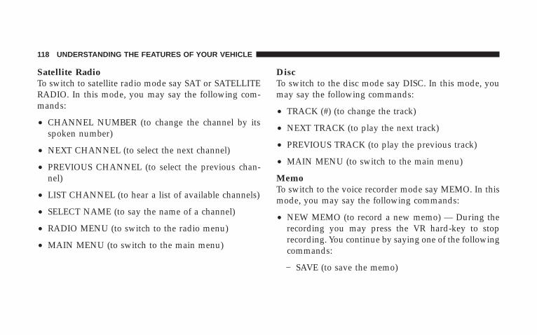
Satellite RadioTo switch to satellite radio mode say SAT or SATELLITERADIO. In this mode, you may say the following com-mands:
• CHANNEL NUMBER (to change the channel by itsspoken number)
• NEXT CHANNEL (to select the next channel)
• PREVIOUS CHANNEL (to select the previous chan-nel)
• LIST CHANNEL (to hear a list of available channels)
• SELECT NAME (to say the name of a channel)
• RADIO MENU (to switch to the radio menu)
• MAIN MENU (to switch to the main menu)
DiscTo switch to the disc mode say DISC. In this mode, youmay say the following commands:
• TRACK (#) (to change the track)
• NEXT TRACK (to play the next track)
• PREVIOUS TRACK (to play the previous track)
• MAIN MENU (to switch to the main menu)
MemoTo switch to the voice recorder mode say MEMO. In thismode, you may say the following commands:
• NEW MEMO (to record a new memo) — During therecording you may press the VR hard-key to stoprecording. You continue by saying one of the followingcommands:
− SAVE (to save the memo)
118 UNDERSTANDING THE FEATURES OF YOUR VEHICLE

− CONTINUE (to continue recording)
− DELETE (to delete the recording)
• PLAY MEMOS (to play previously recorded memos)— During the playback you may press the VR hard-key to stop playing memos. You continue by sayingone of the following commands:
− REPEAT (to repeat a memo)
− NEXT (to play the next memo)
− PREVIOUS (to play the previous memo)
− DELETE (to delete a memo)
• DELETE ALL (to delete all memos)
NOTE: Keep in mind that you have to press the VRhard-key first and wait for the beep, before speaking the“barge in” commands.
Voice TrainingFor users experiencing difficulty with the system recog-nizing their voice commands or numbers, the UConnecttsystem Voice Training feature may be used.
1. Press the VR hard-key, speak “System Setup” and onceyou are in that menu then speak “Voice Training.” Thiswill train your own voice to the system and will improverecognition.
2. Repeat the words and phrases when prompted by theUConnectt System. For best results, the Voice Trainingsession should be completed when the vehicle is parked,engine running, all windows closed, and the blower fanswitched OFF. This procedure may be repeated with anew user. The system will adapt to the last trained voiceonly.
UNDERSTANDING THE FEATURES OF YOUR VEHICLE 119
3
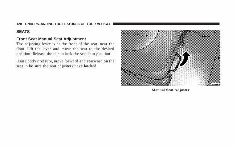
SEATS
Front Seat Manual Seat AdjustmentThe adjusting lever is at the front of the seat, near thefloor. Lift the lever and move the seat to the desiredposition. Release the bar to lock the seat into position.
Using body pressure, move forward and rearward on theseat to be sure the seat adjusters have latched.
Manual Seat Adjuster
120 UNDERSTANDING THE FEATURES OF YOUR VEHICLE
WARNING!
Adjusting a seat while the vehicle is moving isdangerous. The sudden movement of the seat couldcause you to lose control. The seat belt might not beproperly adjusted and you could be injured. Adjustany seat only while the vehicle is parked.
Front Seat Manual Seat ReclinersThe bucket seats are equipped with recliners. The reclin-ing mechanism is operated by a lever located on the rightside of the passenger’s seat and the left side of thedriver’s seat. To recline, lean forward slightly before
lifting the lever, then push back to the desired positionand release the lever. Lean forward and lift the lever toreturn the seatback to its normal position. Using bodypressure, lean forward and rearward on the seat to besure the seatback is locked.
WARNING!
Do not ride with the seatback reclined so that theshoulder belt is no longer resting against your chest.In a collision you could slide under the seat belt andbe seriously or even fatally injured. Use the reclineronly when the vehicle is parked.
UNDERSTANDING THE FEATURES OF YOUR VEHICLE 121
3

Manual Lumbar Support Adjustment — IfEquippedThe manual lumbar support adjustment lever is locatedon the right side of the driver’s seat and on the left sideof the passenger’s seat. Moving the lumbar control leverfore and aft increases or decreases the lumbar support.
Adjustable Head Restraints — All SeatingPositionsHead restraints can reduce the risk of whiplash injury inthe event of impact from the rear. Pull up or push downon the restraints so that the upper edge is as high aspractical, at least to the level of the ears.
To lower the head restraint, depress the release buttonlocated at the base of the head restraint and push downon the head restraint.
Lumbar Support Adjustment Lever
122 UNDERSTANDING THE FEATURES OF YOUR VEHICLE

8-Way Driver’s Power Seat — If EquippedThe driver’s power seat switches are located on the leftside of the driver’s seat lower side trim. The bottomswitch controls up/down, forward/rearward, and tiltadjustment. The top switch controls the seatback reclineadjustment.
Head Restraint Adjustment
Power Seat Switch Location
UNDERSTANDING THE FEATURES OF YOUR VEHICLE 123
3

4-Way Passenger’s Power Seat — If EquippedThe front passenger’s power seat switches are located onthe right side of the passenger seat lower side trim. Thebottom switch controls forward/rearward adjustment.The top switch controls the seatback recline adjustment.
NOTE: The 4-way seat does not have an up/downadjustment.
Heated Seats — If EquippedThis feature heats the driver, front passenger and secondrow seats. The controls for the front heated seats arelocated on the instrument panel below the climate con-trols.
The front heated seat system allows the driver and frontpassenger to select from two different levels of supple-mental electrical seat heating, or no seat heating, to suittheir individual comfort requirements.
Front Heated Seat Switches
124 UNDERSTANDING THE FEATURES OF YOUR VEHICLE

With the ignition switch in the RUN position, depressingthe heated seat switch rocker to its momentary high orlow position provides power to the heated seat elementand maintains the requested temperature setting. If theheated seat switch is depressed to a different position(low or high) than the currently selected state, the re-quested temperature setting will change to a new selec-tion. If the heated seat switch is depressed a second timeto the same position as the currently selected state, theseat heater will turn off.
The controls for the second row heated seats are locatedon the center console between the second row seats.
Each heated seat switch has two settings (HI and LO).Press the switch once to obtain high heat level, then pressthe switch again to obtain low heat level. Pressing theswitch a third time will turn the heated seats off. If youdo not purposefully turn the switch off, the seat heatinglevel will automatically change to the next lower level, or
Second Row Heated Seats Switches
UNDERSTANDING THE FEATURES OF YOUR VEHICLE 125
3
off. Both of the indicators on identifies High heat level.The lower indicator on only identifies Low heat level.
NOTE: The HI heat setting will operate for approxi-mately 30 minutes. After 30 minutes, the system willautomatically transition to the low heat setting. The LOheat setting will operate for 30 minutes, then the systemwill turn off.
If the low heat setting is initially selected, the system willoperate for 30 minutes and then turn off.
If the indicator light on the heated seat switch does notlight, an indicator blinks when the switch is depressed orif the heated seats do not operate, the system should beserviced by a qualified technician.
WARNING!
Persons who are unable to feel pain to the skinbecause of advanced age, chronic illness, diabetes,spinal cord injury, medication, alcohol use, exhaus-tion or other physical condition must exercise carewhen using the seat heater. It may cause burns evenat low temperatures, especially if used for longperiods of time.
Do not place anything on the seat that insulatesagainst heat, such as a blanket or cushion. This maycause the seat heater to overheat.
126 UNDERSTANDING THE FEATURES OF YOUR VEHICLE
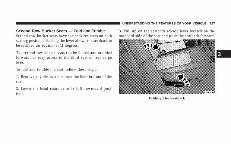
Second Row Bucket Seats — Fold and TumbleSecond row bucket seats have seatback recliners on bothseating positions. Raising the lever allows the seatback tobe reclined an additional 11 degrees.
The second row bucket seats can be folded and tumbledforward for easy access to the third seat or rear cargoarea.
To fold and tumble the seat, follow these steps:
1. Remove any obstructions from the floor in front of theseat.
2. Lower the head restraint to its full downward posi-tion.
3. Pull up on the seatback release lever located on theoutboard side of the seat and push the seatback forward.
Folding The Seatback
UNDERSTANDING THE FEATURES OF YOUR VEHICLE 127
3
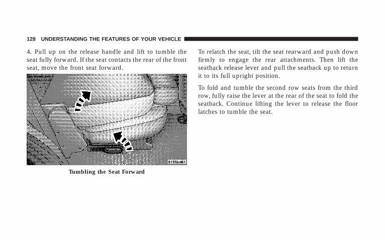
4. Pull up on the release handle and lift to tumble theseat fully forward. If the seat contacts the rear of the frontseat, move the front seat forward.
To relatch the seat, tilt the seat rearward and push downfirmly to engage the rear attachments. Then lift theseatback release lever and pull the seatback up to returnit to its full upright position.
To fold and tumble the second row seats from the thirdrow, fully raise the lever at the rear of the seat to fold theseatback. Continue lifting the lever to release the floorlatches to tumble the seat.
Tumbling the Seat Forward
128 UNDERSTANDING THE FEATURES OF YOUR VEHICLE
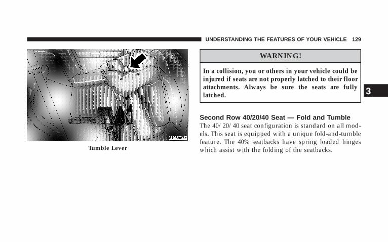
WARNING!
In a collision, you or others in your vehicle could beinjured if seats are not properly latched to their floorattachments. Always be sure the seats are fullylatched.
Second Row 40/20/40 Seat — Fold and TumbleThe 40/20/40 seat configuration is standard on all mod-els. This seat is equipped with a unique fold-and-tumblefeature. The 40% seatbacks have spring loaded hingeswhich assist with the folding of the seatbacks.Tumble Lever
UNDERSTANDING THE FEATURES OF YOUR VEHICLE 129
3

Second row leather seats have seatback recliners at the40% seating positions. Raising the lever allows the seat-back to be reclined an additional 11 degrees.
To fold the 40% seatbacks, fully raise the lever on the sideof the seat to release the seatback. The seatback can nowbe folded into the down position for use as a cargo floor,or the seat can now be tumbled forward to allow accessto the rear of the vehicle.
Fold, Tumble And Recline Lever
Rear 20% Seat Pull Strap
130 UNDERSTANDING THE FEATURES OF YOUR VEHICLE

To fold the 20% seatback, pull the strap forward to releasethe seatback. Fold the seatback down for use as anarmrest or to carry cargo. When returning the seatback tothe upright position, push the seatback rearward to latchthe seatback. Pull the seatback forward to ensure that it islocked in the upright position.
WARNING!
The 20% seatback contains the center shoulder belt.A 20% seatback that is not fully latched in theupright position will not protect you properly.
To tumble the 40% seat, fully raise the lever on the side ofthe seat to release the floor latches and tumble the seat.
Fold, Tumble And Recline Lever
UNDERSTANDING THE FEATURES OF YOUR VEHICLE 131
3
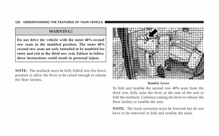
WARNING!
Do not drive the vehicle with the outer 40% secondrow seats in the tumbled position. The outer 40%second row seats are only intended to be tumbled forentry and exit to the third row seat. Failure to followthese instructions could result in personal injury.
NOTE: The seatback must be fully folded into the downposition to allow the lever to be raised enough to releasethe floor latches.
To fold and tumble the second row 40% seats from thethird row, fully raise the lever at the rear of the seat tofold the seatback. Continue raising the lever to release thefloor latches to tumble the seat.
NOTE: The head restraints must be lowered but do nothave to be removed to fold and tumble the seats.
Tumble Lever
132 UNDERSTANDING THE FEATURES OF YOUR VEHICLE
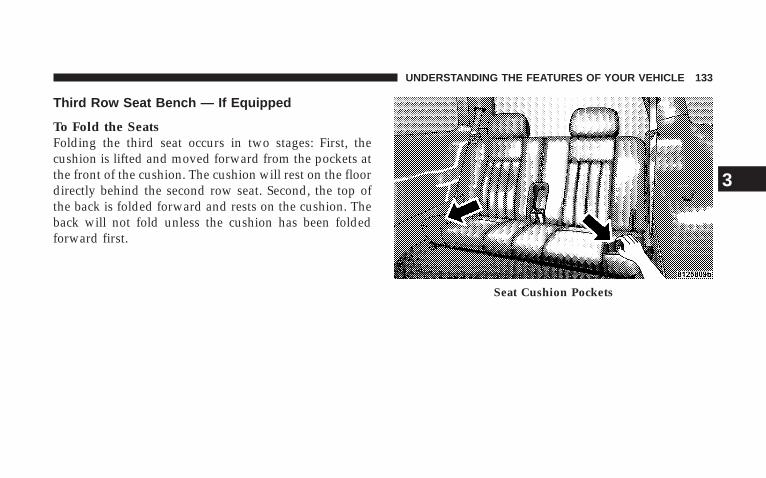
Third Row Seat Bench — If Equipped
To Fold the SeatsFolding the third seat occurs in two stages: First, thecushion is lifted and moved forward from the pockets atthe front of the cushion. The cushion will rest on the floordirectly behind the second row seat. Second, the top ofthe back is folded forward and rests on the cushion. Theback will not fold unless the cushion has been foldedforward first.
Seat Cushion Pockets
UNDERSTANDING THE FEATURES OF YOUR VEHICLE 133
3
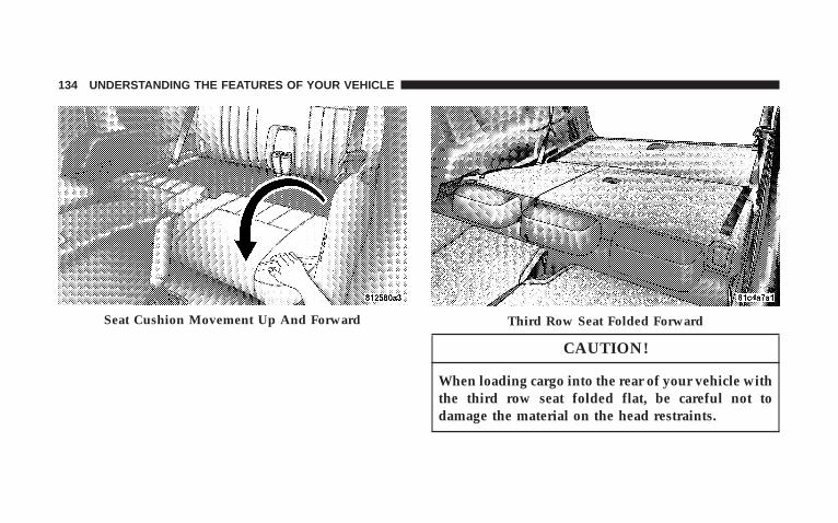
CAUTION!
When loading cargo into the rear of your vehicle withthe third row seat folded flat, be careful not todamage the material on the head restraints.
Seat Cushion Movement Up And Forward Third Row Seat Folded Forward
134 UNDERSTANDING THE FEATURES OF YOUR VEHICLE
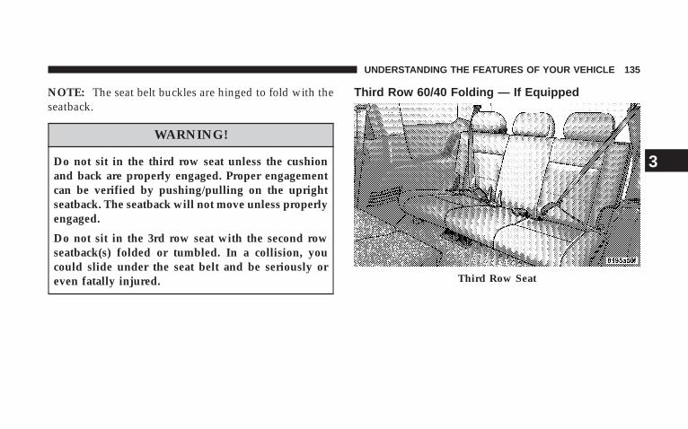
NOTE: The seat belt buckles are hinged to fold with theseatback.
WARNING!
Do not sit in the third row seat unless the cushionand back are properly engaged. Proper engagementcan be verified by pushing/pulling on the uprightseatback. The seatback will not move unless properlyengaged.
Do not sit in the 3rd row seat with the second rowseatback(s) folded or tumbled. In a collision, youcould slide under the seat belt and be seriously oreven fatally injured.
Third Row 60/40 Folding — If Equipped
Third Row Seat
UNDERSTANDING THE FEATURES OF YOUR VEHICLE 135
3

Third Row Seat 40% Seatback Fold Third Row Seat Features
136 UNDERSTANDING THE FEATURES OF YOUR VEHICLE

DRIVER MEMORY SYSTEM — IF EQUIPPEDOnce programmed, the memory buttons 1 and 2 on thedriver’s door panel can be used to recall the driver’s seatposition, driver’s outside mirror position, adjustablebrake and accelerator pedals position, Automatic Tem-perature Control (ATC) temperature and radio station
Third Row Seat Folded Forward Third Row Seat Return Pull Strap
UNDERSTANDING THE FEATURES OF YOUR VEHICLE 137
3
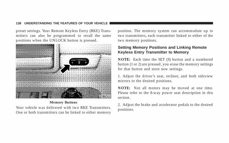
preset settings. Your Remote Keyless Entry (RKE) Trans-mitters can also be programmed to recall the samepositions when the UNLOCK button is pressed.
Your vehicle was delivered with two RKE Transmitters.One or both transmitters can be linked to either memory
position. The memory system can accommodate up totwo transmitters, each transmitter linked to either of thetwo memory positions.
Setting Memory Positions and Linking RemoteKeyless Entry Transmitter to Memory
NOTE: Each time the SET (S) button and a numberedbutton (1 or 2) are pressed, you erase the memory settingsfor that button and store new settings.
1. Adjust the driver’s seat, recliner, and both sideviewmirrors to the desired positions.
NOTE: Not all motors may be moved at one time.Please refer to the 8-way power seat description in thissection.
2. Adjust the brake and accelerator pedals to the desiredpositions.
Memory Buttons
138 UNDERSTANDING THE FEATURES OF YOUR VEHICLE

3. Turn on the radio and set the radio station presets (upto 10 AM and 10 FM stations can be set).
4. Adjust the Automatic Temperature Control (ATC)while the ATC is in Auto mode.
5. Press and release the SET (S) button located on thedriver’s door.
6. Within five seconds, press and release memory button1 or 2 on the driver’s door. The next step must beperformed within 10 seconds if you desire to also use aRKE Transmitter to recall memory positions.
7. Press and release the LOCK button on one of thetransmitters.
8. Insert the ignition key and turn the ignition switch tothe ON position.
9. Repeat the above steps to set the next memory posi-tion using the other numbered memory button or to linkanother RKE Transmitter to memory.
NOTE: A chime sound may be heard if Setting Memorywas inhibited for any reason.
Memory Position Recall
NOTE:• The driver’s seat belt must be unbuckled to recall
memory positions.
• The vehicle must be in PARK to recall memory posi-tions.
• Not all motors may be moved at one time. Please referto the 8-way power seat description in this section.
UNDERSTANDING THE FEATURES OF YOUR VEHICLE 139
3
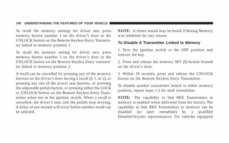
To recall the memory settings for driver one, pressmemory button number 1 on the driver’s door or theUNLOCK button on the Remote Keyless Entry Transmit-ter linked to memory position 1.
To recall the memory setting for driver two, pressmemory button number 2 on the driver’s door or theUNLOCK button on the Remote Keyless Entry transmit-ter linked to memory position 2.
A recall can be cancelled by pressing any of the memorybuttons on the driver’s door during a recall (S, 1, or 2), orpressing any one of the power seat buttons, or pressingthe adjustable pedals button, or pressing either the LOCKor UNLOCK button on the Remote Keyless Entry Trans-mitter when not in the ignition switch. When a recall iscancelled, the driver’s seat, and the pedals stop moving.A delay of one second will occur before another recall canbe selected.
NOTE: A chime sound may be heard if Setting Memorywas inhibited for any reason.
To Disable A Transmitter Linked to Memory
1. Turn the ignition switch to the OFF position andremove the key.
2. Press and release the memory SET (S) button locatedon the driver’s door.
3. Within 10 seconds, press and release the UNLOCKbutton on the Remote Keyless Entry Transmitter.
To disable another transmitter linked to either memoryposition, repeat steps 1-3 for each transmitter.
NOTE: The capability to link RKE Transmitters tomemory is enabled when delivered from the factory. Thecapability to link RKE Transmitters to memory can bedisabled (or later reenabled) by a qualifiedDaimlerChrysler representative. For vehicles equipped
140 UNDERSTANDING THE FEATURES OF YOUR VEHICLE

with the Electronic vehicle Information Center (EVIC),refer to “Personal Settings (Customer ProgrammableFeatures)” under “Overhead Console with ElectronicVehicle Information Center (EVIC) – If Equipped” inSection 3.
Self-Limiting ControlTo improve vehicle reliability, the memory system in-cludes a self-limiting control for full travel positioning ofpower seat and adjustable pedal movement (all direc-tions). This self-limiting control may, however, developan unintended movement limitation if an obstruction isencountered sometime during usage. One example ofsuch an occurrence may include a box or package ob-structing the full rearward movement of the driver’s seat.Once the obstruction is removed, the self-limiting controlmay be restored to maximum position. The self-limitingcontrol may be restored by first reaching the recentlylimited or obstructed position, then release and reactivate
the same button or buttons. Continued seat travel beyondthe obstructed position will indicate the recently encoun-tered self-limitation has been cleared.
Driver Easy Exit and Easy Entry ControlThis additional feature provides automatic driver’s seatpositioning which will enhance driver mobility out ofand into the vehicle. The seat cushion will move rear-ward approximately 2.5 inches (60 mm) when the key isremoved from the ignition switch. The seat will moveforward approximately 2.5 inches (60 mm) when the keyis placed into the ignition and turned out of the LOCKposition. Each stored memory setting will have an asso-ciated Easy Exit and Easy Entry position. The Easy Exitand Easy Entry feature may be automatically disabled ifthe seat is positioned rearward enough and there is nobenefit in moving the seat any farther rearward.
NOTE: The Easy Entry/Easy Exit feature can be en-abled or disabled through the programmable features in
UNDERSTANDING THE FEATURES OF YOUR VEHICLE 141
3
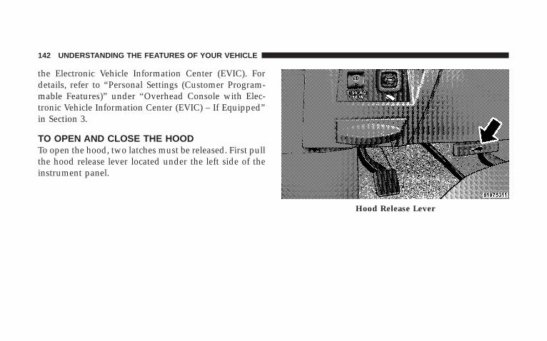
the Electronic Vehicle Information Center (EVIC). Fordetails, refer to “Personal Settings (Customer Program-mable Features)” under “Overhead Console with Elec-tronic Vehicle Information Center (EVIC) – If Equipped”in Section 3.
TO OPEN AND CLOSE THE HOODTo open the hood, two latches must be released. First pullthe hood release lever located under the left side of theinstrument panel.
Hood Release Lever
142 UNDERSTANDING THE FEATURES OF YOUR VEHICLE

Then push the safety latch lever to the left. It is locatedbetween the grille and hood opening right of the center.
To prevent possible damage, do not slam the hood toclose it. Use a firm downward push at the center frontedge of the hood to ensure that both latches engage.Never drive your vehicle unless the hood is fully closed,with both latches engaged.
NOTE: Ensure hood prop rod is fully seated into clipbefore closing hood to prevent damage to grille.
WARNING!
If the hood is not fully latched, it could fly up whenthe vehicle is moving and block your forward vision.Be sure all hood latches are fully latched beforedriving.
Hood Safety Catch
UNDERSTANDING THE FEATURES OF YOUR VEHICLE 143
3

LIGHTS
Headlight Switch LocationHeadlight Switch
144 UNDERSTANDING THE FEATURES OF YOUR VEHICLE

Interior Lights
Courtesy and dome lights are turned on when the frontdoors are opened, when the dimmer control (rotatingwheel on the right side of the switch) is rotated to thesecond upward detent position, or when the UNLOCKbutton is pressed on the key fob. When a door is open
and the interior lights are on, rotating the dimmer controlall of the way down to the OFF detent will cause all theinterior lights to go out. This allows the doors to stayopen for extended periods of time without dischargingthe vehicle’s battery.
The brightness of the instrument panel lighting can beregulated by rotating the dimmer control up (brighter) ordown (dimmer). When the headlights are ON you cansupplement the brightness of the odometer, trip odom-eter, radio and overhead console by rotating the controlup until you hear a click. This feature is termed the9Parade9 mode and is useful when headlights are re-quired during the day.
Battery SaverTo protect the life of your vehicle’s battery, load sheddingis provided for both the interior and exterior lights.
Dimmer Control
UNDERSTANDING THE FEATURES OF YOUR VEHICLE 145
3
If the ignition is off and any door is left ajar for eightminutes or the dimmer control is rotated upwards for 15minutes, the interior lights will automatically turn off.
If the headlights remain on while the ignition is cycledoff, the exterior lights will automatically turn off aftereight minutes. If the headlights are turned on and left onfor eight minutes while the ignition is off, the exteriorlights will automatically turn off.
NOTE: Battery Saver mode is cancelled if the ignition isON.
NOTE: While the engine is running, the system willdeactivate the Fog Lights and Heated seats if a lowbattery system voltage is detected.
Headlight DelayTo aid in your exit, your vehicle is equipped with aheadlight delay that will leave the headlights on for 90seconds. This delay is initiated when the ignition iscycled off while the headlight switch is on, and then theheadlight switch is cycled off. The headlights will remainon for 90 seconds. Headlight delay can be cancelled byeither turning the headlight switch ON then OFF or byturning the ignition ON.
The headlight delay time is programmable on vehiclesequipped with the Electronic Vehicle Information Center(EVIC). For details, refer to “Personal Settings (CustomerProgrammable Features)” under “Overhead Consolewith Electronic Vehicle Information Center (EVIC) – IfEquipped” in Section 3.
146 UNDERSTANDING THE FEATURES OF YOUR VEHICLE

Automatic Headlights — If EquippedAutomatic headlights can be activated by rotating therotary headlight switch to the symbol “A.” The head-lights will turn on when the engine is running and theambient light sensor indicates that the headlights shouldbe activated. The headlights will turn off if the headlightswitch is rotated to the OFF position or 90 seconds afterthe ignition is turned to OFF.
Headlights, Parking Lights, Panel Lights
When the headlight switch is rotated to the first positionto the right, the parking lights, taillights, side markerlights, license plate light and instrument panel lights areall turned on. The headlights will turn ON when theswitch is rotated to the second position.
Your vehicle is equipped with plastic headlight lensesthat are lighter and less susceptible to stone breakagethan glass headlights.
Plastic is not as scratch resistant as glass and thereforedifferent lens cleaning procedures must be followed.
To minimize the possibility of scratching the lenses andreducing light output, avoid wiping with a dry cloth. Toremove road dirt, wash with a mild soap solution fol-lowed by rinsing.
Do not use abrasive cleaning components, solvents, steelwool or other abrasive materials to clean the lenses.
Illuminated EntryHeadlights turn on for 90 seconds, when the RemoteKeyless Entry UNLOCK button is pressed.
The illuminated entry time is programmable on vehiclesequipped with the Electronic Vehicle Information Center(EVIC). For details, refer to “Personal Settings (CustomerProgrammable Features)” under “Overhead Consolewith Electronic Vehicle Information Center (EVIC) – IfEquipped” in Section 3.
UNDERSTANDING THE FEATURES OF YOUR VEHICLE 147
3
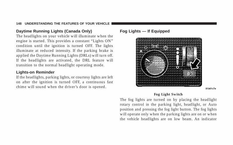
Daytime Running Lights (Canada Only)The headlights on your vehicle will illuminate when theengine is started. This provides a constant “Lights ON”condition until the ignition is turned OFF. The lightsilluminate at reduced intensity. If the parking brake isapplied the Daytime Running Lights (DRLs) will turn off.If the headlights are activated, the DRL feature willtransition to the normal headlight operating mode.
Lights-on ReminderIf the headlights, parking lights, or courtesy lights are lefton after the ignition is turned OFF, a continuous fastchime will sound when the driver’s door is opened.
Fog Lights — If Equipped
The fog lights are turned on by placing the headlightrotary control in the parking light, headlight, or Autoposition and pressing the fog light button. The fog lightswill operate only when the parking lights are on or whenthe vehicle headlights are on low beam. An indicator
Fog Light Switch
148 UNDERSTANDING THE FEATURES OF YOUR VEHICLE

light located in the instrument cluster will illuminatewhen the fog lights are on. The fog lights will turn offwhen the switch is pressed in, when the headlight switchis rotated to the OFF position, or the high beam isselected.
Multifunction Control LeverThe multifunction control lever is located on the left sideof the steering column.
Turn SignalsMove the lever up or down to signal a right-hand orleft-hand turn.
The arrow on either side of the instrument cluster flashesto indicate the direction of the turn, and proper operationof the front and rear turn signal lights. If an indicator failsto light when the lever is moved, it would suggest thatthe switch or indicator lamp is defective.
If a defective bulb or wiring circuit is detected for theturn signal system, the arrow indicators will flash at afaster rate.
You can signal a lane change by moving the leverpartially up or down.
UNDERSTANDING THE FEATURES OF YOUR VEHICLE 149
3
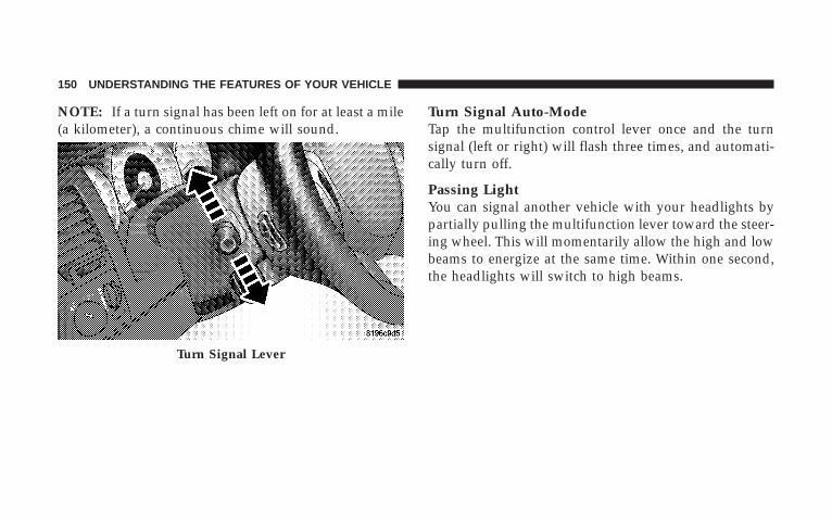
NOTE: If a turn signal has been left on for at least a mile(a kilometer), a continuous chime will sound.
Turn Signal Auto-ModeTap the multifunction control lever once and the turnsignal (left or right) will flash three times, and automati-cally turn off.
Passing LightYou can signal another vehicle with your headlights bypartially pulling the multifunction lever toward the steer-ing wheel. This will momentarily allow the high and lowbeams to energize at the same time. Within one second,the headlights will switch to high beams.
Turn Signal Lever
150 UNDERSTANDING THE FEATURES OF YOUR VEHICLE

High Beam/Low Beam Select SwitchPull the multifunction control lever fully toward thesteering wheel to switch the headlights from high or lowbeam.
WINDSHIELD WIPERS AND WASHERS
Windshield Wipers
The wipers and washers are operated by a switch in themultifunction control lever. Turn the end of the handle toselect the desired wiper speed.
Dimmer Lever
Windshield Wiper Switch
UNDERSTANDING THE FEATURES OF YOUR VEHICLE 151
3

Intermittent Wiper SystemThe intermittent feature of this system was designed foruse when weather conditions make a single wiping cycle,with a variable pause between cycles, desirable. Formaximum delay between cycles, rotate the control knobinto the upper end of the delay range.
The delay interval decreases as you rotate the knob untilit enters the low continual speed position. The delay canbe regulated from a maximum of about 15 secondsbetween cycles, to a cycle every 2 seconds. The delayintervals will double in duration when the vehicle speedis 10 mph (16 km/h) or less.
WARNING!
Sudden loss of visibility through the windshieldcould lead to an accident. You might not see othervehicles or other obstacles. To avoid sudden icing ofthe windshield during freezing weather, warm thewindshield with the defroster before and duringwindshield washer use.
NOTE: Avoid using the wiper blades to remove frost orice from the windshield.
NOTE: If the front wiper is operating when the ignitionis turned OFF, the wiper will automatically return to the9Park9 position. When the vehicle is restarted, the wiperswill resume operation.
152 UNDERSTANDING THE FEATURES OF YOUR VEHICLE

Windshield WashersTo use the washer, push in on the washer knob on the endof the multifunction control lever and hold while spray isdesired. If the washer knob is depressed while in thedelay range, the wiper will operate for several secondsafter the washer knob is released. It will then resume theintermittent interval previously selected. If the washerknob is pushed for a period greater than one secondwhile in the OFF position, the wiper will wipe approxi-mately three wipes after the wash knob is released.
To prevent freeze-up of your windshield washer systemin cold weather, select a solution or mixture that meets orexceeds the temperature range of your climate. Thisrating information can be found on most washer fluidcontainers.
Washer Fluid Switch
UNDERSTANDING THE FEATURES OF YOUR VEHICLE 153
3
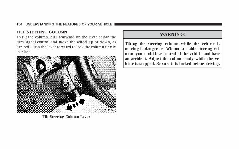
TILT STEERING COLUMNTo tilt the column, pull rearward on the lever below theturn signal control and move the wheel up or down, asdesired. Push the lever forward to lock the column firmlyin place.
WARNING!
Tilting the steering column while the vehicle ismoving is dangerous. Without a stable steering col-umn, you could lose control of the vehicle and havean accident. Adjust the column only while the ve-hicle is stopped. Be sure it is locked before driving.
Tilt Steering Column Lever
154 UNDERSTANDING THE FEATURES OF YOUR VEHICLE
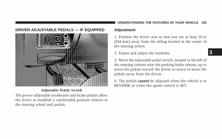
DRIVER ADJUSTABLE PEDALS — IF EQUIPPED
The power adjustable accelerator and brake pedals allowthe driver to establish a comfortable position relative tothe steering wheel and pedals.
Adjustment
1. Position the driver seat so that you are at least 10 in(254 mm) away from the airbag located in the center ofthe steering wheel.
2. Fasten and adjust the seatbelts.
3. Move the adjustable pedal switch, located to the left ofthe steering column near the parking brake release, up tomove the pedals toward the driver or down to move thepedals away from the driver.
4. The pedals cannot be adjusted when the vehicle is inREVERSE or when the speed control is SET.
Adjustable Pedals Switch
UNDERSTANDING THE FEATURES OF YOUR VEHICLE 155
3
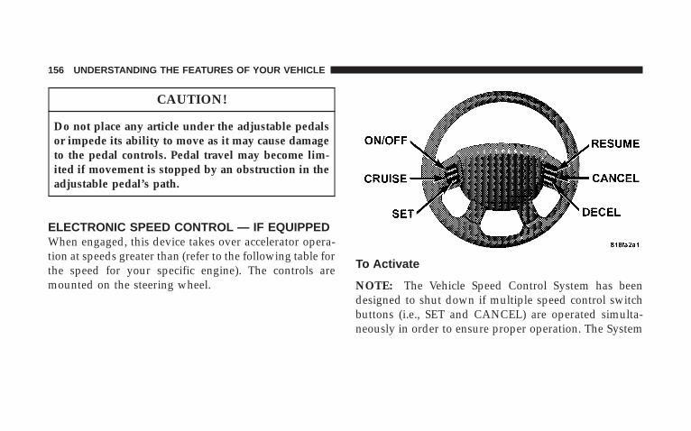
CAUTION!
Do not place any article under the adjustable pedalsor impede its ability to move as it may cause damageto the pedal controls. Pedal travel may become lim-ited if movement is stopped by an obstruction in theadjustable pedal’s path.
ELECTRONIC SPEED CONTROL — IF EQUIPPEDWhen engaged, this device takes over accelerator opera-tion at speeds greater than (refer to the following table forthe speed for your specific engine). The controls aremounted on the steering wheel.
To Activate
NOTE: The Vehicle Speed Control System has beendesigned to shut down if multiple speed control switchbuttons (i.e., SET and CANCEL) are operated simulta-neously in order to ensure proper operation. The System
156 UNDERSTANDING THE FEATURES OF YOUR VEHICLE
can be reactivated by pushing the speed control switchON/OFF button and re-establishing the desired vehicleSET speed.
Push the ON/OFF button to the ON position. In theinstrument cluster, the word “CRUISE” illuminates whenthe system is on.
To Set At A Desired SpeedWhen the vehicle has reached the desired speed, pressand release the SET button. Release the accelerator andthe vehicle will operate at the selected speed.
To DeactivateA soft tap on the brake pedal, normal braking, or pressingthe CANCEL button will deactivate the speed controlwithout erasing the memory. Pushing the ON/OFF but-ton to the OFF position or turning off the ignition erasesthe memory.
WARNING!
Leaving the Speed Control on when not in use isdangerous. You could accidentally set the system tocause it to go faster than you want. You could losecontrol and have an accident. Always leave the sys-tem off when you aren’t using it.
To Resume SpeedTo resume a previously set speed, push and release theRESUME button. Resume can be used at any speed above(refer to the following table for the speed for your specificengine).
UNDERSTANDING THE FEATURES OF YOUR VEHICLE 157
3
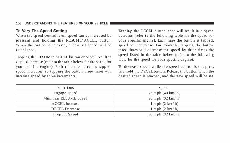
To Vary The Speed SettingWhen the speed control is on, speed can be increased bypressing and holding the RESUME/ACCEL button.When the button is released, a new set speed will beestablished.
Tapping the RESUME/ACCEL button once will result ina speed increase (refer to the table below for the speed foryour specific engine). Each time the button is tapped,speed increases, so tapping the button three times willincrease speed by three increments.
Tapping the DECEL button once will result in a speeddecrease (refer to the following table for the speed foryour specific engine). Each time the button is tapped,speed will decrease. For example, tapping the buttonthree times will decrease the speed by three times thespeed listed in the table below (refer to the followingtable for the speed for your specific engine).
To decrease speed while the speed control is on, pressand hold the DECEL button. Release the button when thedesired speed is reached, and the new speed will be set.
Functions SpeedsEngage Speed 25 mph (40 km/h)
Minimun RESUME Speed 20 mph (32 km/h)ACCEL Increase 1 mph (2 km/h)DECEL Decrease 1 mph (2 km/h)Dropout Speed 20 mph (32 km/h)
158 UNDERSTANDING THE FEATURES OF YOUR VEHICLE
To Accelerate For PassingDepress the accelerator as you would normally. When thepedal is released, the vehicle will return to the set speed.
NOTE: When driving uphill, at elevations above 2,000 ft(610 m), or when the vehicle is heavily loaded (especiallywhen towing) the vehicle may slow below the SET speed.If the vehicle speed drops below (refer to the previoustable for the speed for your specific engine), the speedcontrol will automatically disengage. If this happens, youcan push down on the accelerator pedal to maintain thedesired speed.
Vehicles equipped with an automatic transmission mayexhibit several downshifts under the above conditions.To reduce the frequency of the downshifts and to im-prove vehicle performance, it is advisable to lock outOVERDRIVE by pressing the “TOW/HAUL” buttonlocated at the end of the gear shifter.
WARNING!
Speed Control can be dangerous where the systemcan’t maintain a constant speed. Your vehicle couldgo too fast for the conditions, and you could losecontrol. An accident could be the result. Don’t useSpeed Control in heavy traffic or on roads that arewinding, icy, snow-covered, or slippery.
UNDERSTANDING THE FEATURES OF YOUR VEHICLE 159
3

REAR PARK ASSIST SYSTEM — IF EQUIPPED
NOTE: The manufacturer suggests disabling the RearPark Assist System when towing a trailer. Refer to“Personal Settings (Customer Programmable Features)”under “Overhead Console with Electronic Vehicle Infor-mation Center (EVIC) – If Equipped” in Section 3.
This system is used to help drivers determine if anobstacle is in the way of the vehicle while it is backing upin addition to the use of inside rearview and outsidemirrors.
When the driver selects REVERSE, the system scans forobjects behind the vehicle using four sensors located inthe rear bumper. Objects can be detected from up to 78.7in (200 cm). A warning display above the rear windowprovides both visible and audible warnings indicatingthe range of the object.
The warning display contains two sets of yellow and redLEDs, one set to warn of obstacles behind the left rear ofthe vehicle and the other set to warn of obstacles behindthe right rear of the vehicle. The driver can view the LEDseither through the rearview mirror or by looking at thedisplay above the rear window.
Rear Park Assist LEDs
160 UNDERSTANDING THE FEATURES OF YOUR VEHICLE
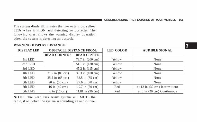
The system dimly illuminates the two outermost yellowLEDs when it is ON and detecting no obstacles. Thefollowing chart shows the warning display operationwhen the system is detecting an obstacle:
WARNING DISPLAY DISTANCES
DISPLAY LED OBSTACLE DISTANCE FROM: LED COLOR AUDIBLE SIGNALREAR CORNERS REAR CENTER
1st LED 78.7 in (200 cm) Yellow None2nd LED 51.1 in (130 cm) Yellow None3rd LED 45.2 in (115 cm) Yellow None4th LED 31.5 in (80 cm) 39.3 in (100 cm) Yellow None5th LED 25.5 in (65 cm) 33.5 in (85 cm) Yellow None6th LED 20 in (50 cm) 27.6 in (70 cm) Yellow None7th LED 16 in (40 cm) 19.7 in (50 cm) Red at 12 in (30 cm) Intermittent8th LED 6 in (15 cm) 11.81 in (30 cm) Red at 8 in (20 cm) Continuous
NOTE: The Rear Park Assist system will MUTE theradio, if on, when the system is sounding an audio tone.
UNDERSTANDING THE FEATURES OF YOUR VEHICLE 161
3
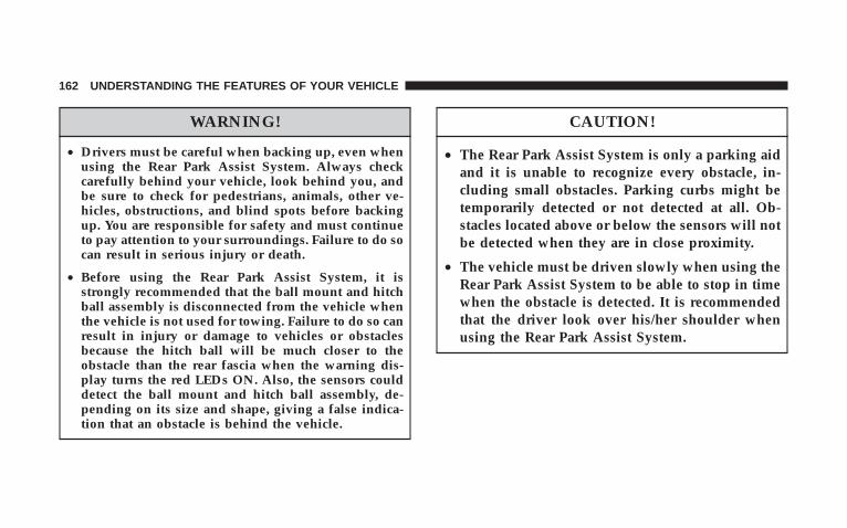
WARNING!
• Drivers must be careful when backing up, even whenusing the Rear Park Assist System. Always checkcarefully behind your vehicle, look behind you, andbe sure to check for pedestrians, animals, other ve-hicles, obstructions, and blind spots before backingup. You are responsible for safety and must continueto pay attention to your surroundings. Failure to do socan result in serious injury or death.
• Before using the Rear Park Assist System, it isstrongly recommended that the ball mount and hitchball assembly is disconnected from the vehicle whenthe vehicle is not used for towing. Failure to do so canresult in injury or damage to vehicles or obstaclesbecause the hitch ball will be much closer to theobstacle than the rear fascia when the warning dis-play turns the red LEDs ON. Also, the sensors coulddetect the ball mount and hitch ball assembly, de-pending on its size and shape, giving a false indica-tion that an obstacle is behind the vehicle.
CAUTION!
• The Rear Park Assist System is only a parking aidand it is unable to recognize every obstacle, in-cluding small obstacles. Parking curbs might betemporarily detected or not detected at all. Ob-stacles located above or below the sensors will notbe detected when they are in close proximity.
• The vehicle must be driven slowly when using theRear Park Assist System to be able to stop in timewhen the obstacle is detected. It is recommendedthat the driver look over his/her shoulder whenusing the Rear Park Assist System.
162 UNDERSTANDING THE FEATURES OF YOUR VEHICLE
NOTE:• Ensure that the rear bumper is free of dirt and debris
to keep the system operating properly.
• Jackhammers, large trucks, and other vibrations couldaffect the performance of the system.
If “Service Park Assist System” appears in the ElectronicVehicle Information Center (EVIC) after making sure therear bumper is clean, please see your authorized dealer.
To turn on/off the rear park assist system, refer to“Personal Settings (Customer Programmable Features)”under “Overhead Console with Electronic Vehicle Infor-mation Center (EVIC) – If Equipped” in Section 3.
REAR CAMERA — IF EQUIPPEDYour vehicle may be equipped with a Rear Camerasystem that allows you to see an on-screen image (locatedin the screen of your Radio) of the rear of your vehiclewhenever it is put into REVERSE. The camera is locatedin the light bar over the rear license plate.
NOTE: Refer to “Setting Display Properties” under“System Settings” in the Navigation User’s Manual forinstructions regarding navigation screen brightness ad-justments.
Use the following steps to access the Rear Backup Cam-era feature:
1. Start the engine.
2. Depress the brake pedal and place the shift lever inREVERSE.
3. Wait one to two seconds, and the camera view willdisplay on the Radio screen.
UNDERSTANDING THE FEATURES OF YOUR VEHICLE 163
3

NOTE: The camera view will display only while thevehicle is in REVERSE.
4. Perform a visual check of the rear area.
NOTE: CHECK ENTIRE SURROUNDINGS beforebacking up.
5. Slowly backup as necessary.
6. Place the shift lever in PARK or DRIVE to exit the RearBackup Camera system.
WARNING!
Drivers must be careful when backing up even whenusing the Rear Camera System. Always check care-fully behind your vehicle, and be sure to check forpedestrians, animals, other vehicles, obstructions, orblind spots before backing up. You are responsiblefor the safety of your surroundings and must con-tinue to pay attention while backing up. Failure to doso can result in serious injury or death.
164 UNDERSTANDING THE FEATURES OF YOUR VEHICLE

CAUTION!
• To avoid vehicle damage, the Rear Camera Systemshould only be used as a parking aid and is unableto view every obstacle or object in your drive path.
• To avoid vehicle damage, the vehicle must bedriven slowly when using the Rear Camera Sys-tem to be able to stop in time when an obstacle isseen. It is recommended that the driver look fre-quently over his/her shoulder when using the RearCamera System.
NOTE: If snow, ice, mud, or anything else builds up onthe camera lens, clean the lens, rinse with water, and drywith a soft cloth. Do not cover the lens.
OVERHEAD CONSOLEThe overhead console has the following features:
• Courtesy Lights
• Garage Door Opener — If Equipped
Overhead Console
UNDERSTANDING THE FEATURES OF YOUR VEHICLE 165
3

• Electronic Vehicle Information Center (EVIC) — IfEquipped
Courtesy/Reading LightsNear the front of the console is one courtesy and tworeading lights.
All lights illuminate as courtesy lights when a door isopened, when the dimmer control is rotated to thecourtesy light position (fully upward position), or whenthe UNLOCK button is pressed on the Remote KeylessEntry (RKE) Transmitter, if so equipped. The two roundlamps are also operated individually as reading lights bypressing the center of each lens.
NOTE: The courtesy/reading lights will remain on untilthe switch is pressed a second time, so be sure they havebeen turned off before leaving the vehicle. If the interiorlights are left on after the vehicle is turned OFF, they willturn off after 15 minutes.
OVERHEAD CONSOLE WITH ELECTRONICVEHICLE INFORMATION CENTER (EVIC) — IFEQUIPPEDThe overhead console contains dome/reading lights, andan Electronic Vehicle Information Center (EVIC).
Dome/Reading Lights
Located in the overhead console are two dome/readinglights.
The dome/reading lights illuminate when a door isopened or when the interior lights are turned on byrotating the dimmer control located on the headlightswitch.
The reading lights are activated by pressing the center ofeach lens.
NOTE: The dome/reading lights will remain on untilthe switch is pressed a second time, so be sure they havebeen turned off before leaving the vehicle.
166 UNDERSTANDING THE FEATURES OF YOUR VEHICLE
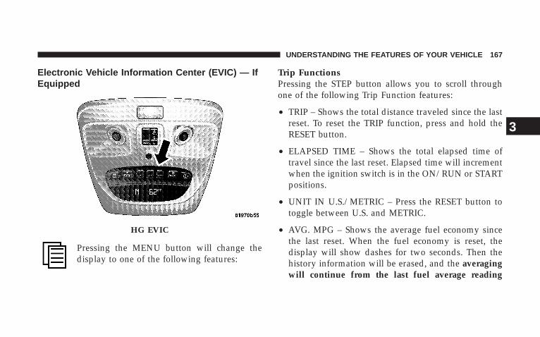
Electronic Vehicle Information Center (EVIC) — IfEquipped
Pressing the MENU button will change thedisplay to one of the following features:
Trip FunctionsPressing the STEP button allows you to scroll throughone of the following Trip Function features:
• TRIP – Shows the total distance traveled since the lastreset. To reset the TRIP function, press and hold theRESET button.
• ELAPSED TIME – Shows the total elapsed time oftravel since the last reset. Elapsed time will incrementwhen the ignition switch is in the ON/RUN or STARTpositions.
• UNIT IN U.S./METRIC – Press the RESET button totoggle between U.S. and METRIC.
• AVG. MPG – Shows the average fuel economy sincethe last reset. When the fuel economy is reset, thedisplay will show dashes for two seconds. Then thehistory information will be erased, and the averagingwill continue from the last fuel average reading
HG EVIC
UNDERSTANDING THE FEATURES OF YOUR VEHICLE 167
3
before the reset. (Example: If your EVIC displays 18AVG. MPG and the RESET button is pressed, theprevious averaging history will be erased and thedisplay will return to the 18 AVG. MPG, not to 0 AVG.MPG). The display may take several miles/kilometersfor the value to change, depending upon drivinghabits. If equipped with a 5.7L engine and MultiDisplacement System (MDS), FUEL SAVER may bedisplayed along with the actual AVG. MPG. Ifequipped with MDS option, the EVIC will displayFUEL SAVER when in fuel economy mode.
• MI TO EMPTY (Distance To Empty) – Shows theestimated distance that can be traveled with the fuelremaining in the tank. This estimated distance isdetermined by a weighted average of fuel economy,according to the current fuel tank level. MI TO EMPTYcannot be reset through the RESET button.
NOTE: Significant changes in driving style or vehicleloading will greatly affect the actual drivable distance ofthe vehicle, regardless of the DTE displayed value.
• When the DTE value is less than 30 miles (48 km)estimated driving distance, the DTE display willchange to a text display of 9LOW FUEL.9 This displaywill continue until the vehicle runs out of fuel. Addinga significant amount of fuel to the vehicle will turn offthe 9LOW FUEL9 text and a new DTE value willdisplay.
• Global Reset – If the RESET button is pressed twicewithin two seconds while in any of the three resettabledisplays (AVG. MPG, ET (ELAPSED TIME) and TRIP),all three displays will be reset.
System Status (EVIC Displays)When the appropriate conditions exist, the EVIC displaysthe following messages:
168 UNDERSTANDING THE FEATURES OF YOUR VEHICLE
• TURN SIGNALS ON (with a continuous warningchime)
• PERSONAL SETTINGS NOT AVAILABLE – Vehiclenot in PARK
• LEFT/RIGHT FRONT DOOR AJAR (one or more,with a single chime if speed is above 1 mph/1 km/h)
• LEFT/RIGHT REAR DOOR AJAR (one or more, witha single chime if speed is above 1 mph/1 km/h)
• DOOR(S) AJAR (with a single chime if vehicle is inmotion)
• LOW WASHER FLUID (with a single chime)
• OIL CHANGE REQUIRED (with a single chime)
• SERVICE PARK ASSIST SYSTEM (with a single chime)
• SERVICE PARK ASSIST SYSTEM
• COOLANT LOW
• LIFTGATE OPEN
• CHECK TPM SYSTEM (with single chime) (PremiumTPM System Only)
OIL CHANGE REQUIRED — If EquippedYour vehicle is equipped with an engine oil changeindicator system. The “Oil Change Required” messagewill flash in the EVIC display for approximately 10seconds after a single chime has sounded to indicate thenext scheduled oil change interval. The engine oil changeindicator system is duty cycle based, which means theengine oil change interval may fluctuate dependent uponyour personal driving style.
Unless reset, this message will continue to display eachtime you turn the ignition switch to the ON/RUNposition. To turn off the message temporarily, press andrelease the MENU button. To reset the oil change indica-tor system (after performing the scheduled maintenance),refer to the following procedure.
UNDERSTANDING THE FEATURES OF YOUR VEHICLE 169
3
1. Turn the ignition switch to the ON position (Do notstart the engine).
2. Fully depress the accelerator pedal slowly three timeswithin 10 seconds.
3. Turn the ignition switch to the OFF/LOCK position.
NOTE: If the indicator message illuminates when youstart the vehicle, the oil change indicator system did notreset. If necessary, repeat this procedure.
Personal Settings (Customer-ProgrammableFeatures)Personal Settings allows the driver to set and recallfeatures when the transmission is in PARK. If the trans-mission is not in PARK the EVIC will display NOTAVAILABLE and VEHICLE NOT IN PARK.
Press and release the MENU button until thePersonal Settings displays on the EVIC.
Use the STEP button to display one of the following:
• “LANGUAGE” – When in this display, you may selectone of several different languages for all displaynomenclature, including the trip functions. Press theRESET button while in this display to select yourpreferred language. Then, as you continue, the infor-mation will display in the selected language.
• “AUTO DOOR LOCK > ON” – When ON is selected,all doors will lock automatically when the vehiclereaches a speed of 15 mph (24 km/h). To make yourselection, press and release the RESET button until“ON” or “OFF” appears.
• “AUTO UNLOCK ON EXIT > ON” – When ON isselected, all doors will unlock when the vehicle is
170 UNDERSTANDING THE FEATURES OF YOUR VEHICLE
stopped and the transmission is in the PARK orNEUTRAL position and the driver’s door is opened.To make your selection, press and release the RESETbutton until “ON” or “OFF” appears.
• “RKE UNLOCK DRV DR 1st” – When DRV DR 1st isselected, only the driver’s door will unlock on the firstpress of the RKE UNLOCK button. When Driver Door1st Press is selected, you must press the RemoteKeyless Entry UNLOCK button twice to unlock thepassenger’s doors. To make your selection, press andrelease the RESET button until “DRV DR 1st ” appears.
• “RKE UNLOCK ALL DR 1ST” – When All ALL DR1ST is selected, all of the doors will unlock on the firstpress of the RKE UNLOCK button. To make yourselection, press and release the RESET button until“All DR 1st” appears.
• MEM. RECALL WITH RKE > ON – When ON isselected, pressing the UNLOCK button on the RKE
will recall the memory settings for the seat, mirror andradio. To make your selection, press and release theRESET button until “ON9 or “OFF” appears.
• “SOUND HORN W/LOCK > ON” – When ON isselected, a short horn sound will occur when theRemote Keyless Entry LOCK button is pressed. Thisfeature may be selected with or without the flash lightson lock/unlock feature. To make your selection, pressand release the RESET button until “ON” or “OFF”appears.
• “FLASH LAMPS W/LOCK >ON” – When ON isselected, the front and rear turn signals will flash whenthe doors are locked or unlocked with the RKE Trans-mitter. This feature may be selected with or withoutthe sound horn on lock feature selected. To make yourselection, press and release the RESET button until“ON” or “OFF” appears.
UNDERSTANDING THE FEATURES OF YOUR VEHICLE 171
3

• “HEADLAMP OFF DELAY > 0 SEC” – When thisfeature is selected, the driver can choose to have theheadlamps remain on for 0, 30, 60, or 90 seconds whenexiting the vehicle. To make your selection, press andrelease the RESET button until “0,” “30,” “60,” or “90”appears.
NOTE: The headlamp switch must be in the “A” automode before this feature will work.
• HEADLAMPS W/WIPERS > ON – When ON isselected, the headlamps will automatically turn onwhen the wiper switch is activated.
• EASY EXIT SEAT > ON – When ON is selected, andthe key is removed from the ignition, the driver’s seatwill automatically move rearward to allow easy exit.
• TILT MIRRORS IN “R” > ON – When ON is selected,and the transmission is put in REVERSE, the outsidemirrors will tilt downward.
• “KEY OFF POWER DELAY> OFF” – When this featureis selected, the power window switches, radio, hands–free system (if equipped), and power outlets willremain active for up to 10 minutes after the ignitionswitch is turned off. Opening a vehicle door willcancel this feature. To make your selection, press andrelease the RESET button until “Off,” “45 sec.,” “5min.,” “10 min.” appears.
• “ILLUMINATED APRCH > OFF” – When this featureis selected, the headlights will activate and remain onfor up to 90 seconds when the doors are unlocked withthe RKE Transmitter. To make your selection, pressand release the RESET button until “OFF,” “30 sec.,”“60 sec.,” or “90 sec.” appears.
• PARK ASST. SYSTEM > ON – When YES is selected,the Rear Park Assist System is activated. When NO isselected, the System is deactivated.
172 UNDERSTANDING THE FEATURES OF YOUR VEHICLE

• “UNIT IN > U.S./METRIC” – The EVIC odometer canbe changed between English and Metric units ofmeasure. To make your selection, press and release theRESET button until “US” or “METRIC” appears.
• “COMPASS VARIANCE > 8” – Press the RESETbutton to change the compass variance setting. Set thisto your current location. If you change location,change your variance according to your variance onthe variance map. Refer to Compass Variance Map inthis section.
• “COMPASS CALIBRATE > YES” – Press the RESETbutton to manually calibrate the compass. Refer toManual Compass Calibration in this section.
Compass/Temperature ButtonPressing the Compass/Temperature buttonwill return the display to the normal compass/temperature display.
NOTE: Temperature accuracy can be affected from heatsoak. For best accuracy, the vehicle should be driven at aspeed greater than 20 mph (32 km/h) for several min-utes.
Automatic Compass CalibrationThis compass is self-calibrating, which reduces the needto calibrate the compass manually. When the vehicle isnew, the compass may appear erratic and the EVIC willdisplay “CAL” until the compass is calibrated. You mayalso calibrate the compass by completing one or more360° turns at speeds less than 5 mph (8 km/h) (in an areafree from large metal or metallic objects) until the “CAL”message displayed in the EVIC turns off. The compasswill now function normally.
UNDERSTANDING THE FEATURES OF YOUR VEHICLE 173
3

Manual Compass CalibrationIf the compass appears erratic and the “CAL” messagedoes not appear in the EVIC display, you must put thecompass into the Calibration Mode manually as follows:
1. Turn the ignition switch to the ON/RUN position.
2. Press the MENU button until “PersonalSettings” is displayed.
3. Press the STEP button until “Calibrate Compass YES”is displayed.
4. Press and release the RESET button to start thecalibration. The message “CAL” will display on thecompass temperature screen in the EVIC.
5. Slowly drive the vehicle at a speed of 5 mph (8 km/h)in a complete 360°circle, (in an area free from largemetal or metallic objects) until the “CAL” messageturns off. The compass will now function normally.
Compass VarianceCompass variance is the difference between magneticNorth and geographic North. In some areas of thecountry, the difference between magnetic and geographicNorth is great enough to cause the compass to give falsereadings. If this occurs, the compass variance must be setusing the following procedure:
NOTE: Magnetic materials should be kept away fromthe overhead console. This is where the compass sensor islocated.
174 UNDERSTANDING THE FEATURES OF YOUR VEHICLE
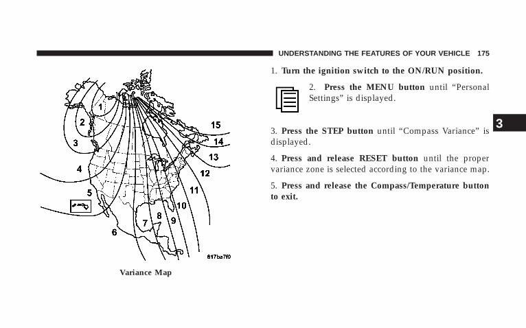
1. Turn the ignition switch to the ON/RUN position.
2. Press the MENU button until “PersonalSettings” is displayed.
3. Press the STEP button until “Compass Variance” isdisplayed.
4. Press and release RESET button until the propervariance zone is selected according to the variance map.
5. Press and release the Compass/Temperature buttonto exit.
Variance Map
UNDERSTANDING THE FEATURES OF YOUR VEHICLE 175
3
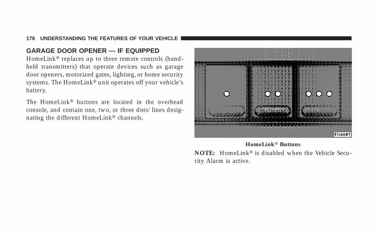
GARAGE DOOR OPENER — IF EQUIPPEDHomeLinkt replaces up to three remote controls (hand-held transmitters) that operate devices such as garagedoor openers, motorized gates, lighting, or home securitysystems. The HomeLinkt unit operates off your vehicle’sbattery.
The HomeLinkt buttons are located in the overheadconsole, and contain one, two, or three dots/lines desig-nating the different HomeLinkt channels.
NOTE: HomeLinkt is disabled when the Vehicle Secu-rity Alarm is active.
HomeLinkt Buttons
176 UNDERSTANDING THE FEATURES OF YOUR VEHICLE

WARNING!
Your motorized door or gate will open and closewhile you are training the Universal Transceiver. Donot train the transceiver if people or pets are in thepath of the door or gate. Only use this transceiverwith a garage door opener that has a “stop andreverse” feature as required by federal safety stan-dards. This includes most garage door opener modelsmanufactured after 1982. Do not use a garage dooropener without these safety features. Call toll-free1–800–355–3515 or, on the Internet atwww.HomeLink.com for safety information orassistance.
WARNING!
Vehicle exhaust contains carbon monoxide, a danger-ous gas. Do not run your vehicle in the garage whiletraining the transceiver. Exhaust gas can cause seri-ous injury or death.
Programming HomeLink T
Before You BeginIf you have not trained any of the HomeLinkt buttons,erase all channels before you begin training.
To do this, press and hold the two outside buttons for 20seconds. The EVIC will display “CLEARING CHAN-NELS.” Release the buttons when the EVIC messagestates “CHANNELS CLEARED.”
UNDERSTANDING THE FEATURES OF YOUR VEHICLE 177
3

It is recommended that a new battery be placed in thehand-held transmitter of the device being programmedto HomeLinkt for more efficient training and accuratetransmission of the radio-frequency signal.
Your vehicle should be parked outside of the garagewhile training.
1. Turn the ignition switch to the ON/RUN position.
2. Place the hand-held transmitter 1 to 3 in (3 to 8 cm)from the HomeLinkt buttons while keeping the EVICdisplay in view.
For optimal training, point the battery end of the hand-held transmitter away from the HomeLinkt.
3. Simultaneously, press and hold both the chosenHomeLinkt button and the hand-held transmitter buttonuntil the EVIC display changes from “CHANNEL #TRAINING” to “CHANNEL # TRAINED.”
Then release both the HomeLinkt and hand-held trans-mitter buttons.
If the EVIC display states “DID NOT TRAIN” repeat Step3. If the signal is too weak, replace the battery in theoriginal hand-held transmitter.
It may take up to 30 seconds, or longer, in rare cases. Thegarage door may open and close while you train.
NOTE: Some gate operators and garage door openersmay require you to replace Step 3 with procedures notedin the “Gate Operator/Canadian Programming” section.
4. Press and hold the just-trained HomeLinkt button. Ifthe channel has been trained, the EVIC display will nowstate “CHANNEL # TRANSMIT.”
If the EVIC display still states “CHANNEL # TRAIN-ING” repeat Step 3.
178 UNDERSTANDING THE FEATURES OF YOUR VEHICLE

NOTE: After training a HomeLinkt channel, if thegarage door does not operate with HomeLinkt and thegarage door opener was manufactured after 1995, thegarage door opener may have rolling code. If so, proceedto the heading “Programming A Rolling Code System.”
5. PROGRAMMING A ROLLING CODE SYSTEMAt the garage door opener motor (in the garage), locatethe “learn” or “training” button.
This can usually be found where the hanging antennawire is attached to the garage door opener motor (it isNOT the button normally used to open and close thedoor).
6. Firmly press and release the “learn” or “training”button. The name and color of the button may vary bymanufacturer.
NOTE: There are 30 seconds in which to initiate the nextstep after the “Learn” button has been pressed.
1 — Garage Door Opener2 — Training Button
UNDERSTANDING THE FEATURES OF YOUR VEHICLE 179
3

7. Return to the vehicle and press the programmedHomeLinkt button twice (holding the button for twoseconds each time). If the device is plugged in andactivates, programming is complete.
If the device does not activate, press the button a thirdtime (for two seconds) to complete the training.
If you have any problems, or require assistance, pleasecall toll-free 1–800–355–3515 or, on the Internet atwww.HomeLink.com for information or assistance.
To program the remaining two HomeLinkt buttons,repeat each step for each remaining button. DO NOTerase the channels.
Gate Operator/Canadian ProgrammingCanadian radio-frequency laws require transmitter sig-nals to “time-out” (or quit) after several seconds oftransmission – which may not be long enough forHomeLinkt to pick up the signal during programming.
Similar to this Canadian law, some U.S. gate operators aredesigned to “time-out” in the same manner.
It may be helpful to unplug the device during the cyclingprocess to prevent possible overheating of the garagedoor or gate motor.
If you are having difficulties programming a garage dooropener or a gate operator, replace “ProgrammingHomeLink” Step 3 with the following:
3. Continue to press and hold the HomeLinkt buttonwhile you press and release - every two seconds(“cycle”) your hand-held transmitter until HomeLinkthas successfully accepted the frequency signal. TheEVIC display will change from “CHANNEL # TRAIN-ING” to “CHANNEL # TRAINED.”
If you unplugged the device for training, plug it back inat this time.
Then proceed with Step 4 under “ProgrammingHomeLinkt” earlier in this section.
180 UNDERSTANDING THE FEATURES OF YOUR VEHICLE
Using HomeLink TTo operate, simply press and release the programmedHomeLinkt button. Activation will now occur for thetrained device (i.e., garage door opener, gate operator,security system, entry door lock, home/office lighting,etc.) The hand-held transmitter of the device may also beused at any time.
Reprogramming A Single HomeLink T ButtonTo reprogram a channel that has been previously trained,follow these steps:
1. Turn the ignition switch to the ON/RUN position.
2. Press and hold the desired HomeLinkt button for 20seconds until the EVIC display states “CHANNEL #TRAINING.” Do not release the button.
3. Without releasing the button, proceed with Program-ming HomeLinkt Step 2 and follow all remaining steps.
SecurityIt is advised to erase all channels before you sell or turnin your vehicle.
To do this, press and hold the two outside buttons for 20seconds until the EVIC message states “CHANNELSCLEARED.” Note that all channels will be erased. Indi-vidual channels cannot be erased.
The HomeLinkt Universal Transceiver is disabled whenthe Vehicle Security Alarm is active.
Troubleshooting TipsIf you are having trouble programming HomeLinkt, hereare some of the most common solutions:
• Replace the battery in the original transmitter.
• Press the learn button on the garage door opener tocomplete the training for rolling code.
UNDERSTANDING THE FEATURES OF YOUR VEHICLE 181
3
• Did you unplug the device for training, and rememberto plug it back in?
If you are having any problems or require assistance,please call toll-free 1–800–355–3515 or, on the Internet atwww.HomeLink.com for information or assistance.
General InformationThis device complies with FCC rules Part 15 and IndustryCanada RSS-210. Operation is subject to the followingtwo conditions:
1. This device may not cause harmful interference
2. This device must accept any interference that may bereceived including interference that may cause undesiredoperation
NOTE: The transmitter has been tested and it complieswith FCC and IC rules. Changes or modifications not
expressly approved by the party responsible for compli-ance could void the user’s authority to operate thedevice.
The term “IC:” before the certification/registration num-ber only signifies that Industry Canada technical specifi-cations were met.
POWER SUNROOF — IF EQUIPPEDThe power sunroof control is located between the sunvisors on the overhead console.
Pressing the 9open9 end of the rocker switch once movesthe panel to the open position.
To close the panel, the 9close9 end of the switch must bepressed and held.
Pressing the “vent” button from a fully closed positionraises the trailing edge of the panel for ventilation. When
182 UNDERSTANDING THE FEATURES OF YOUR VEHICLE
the panel is venting, pressing the “close” end of therocker switch returns it to the closed position. Bothopening and closing operations in the vent mode occuronly while the switch is held.
NOTE: The sunroof will continue to operate for 10minutes after the ignition is turned OFF or until thedriver’s door is opened. This feature may be disabled byyour authorized dealer.
Express Open FeatureDuring the Express Open operation, any movement ofthe switch will stop the sunroof and it will remain in apartial open position. Again, momentarily pressing theswitch rearward will activate the Express Open Feature.
To close the sunroof, hold the switch in the forwardposition. Again, any release of the switch will stop themovement and the sunroof will remain in a partial open
condition until the switch is pushed forward again. Toclose fully, hold the switch in the forward position untilthe glass movement has stopped.
The sunshade can be opened manually. It will also openas the sunroof opens. The sunshade cannot be closed ifthe sunroof is open.
WARNING!
Never leave children alone in a vehicle. Leavingunattended children in a vehicle is dangerous for anumber of reasons. A child or others could be seri-ously or fatally injured. Don’t leave the keys in theignition. A child could operate power windows,other controls, or move the vehicle.
UNDERSTANDING THE FEATURES OF YOUR VEHICLE 183
3
WARNING!
In an accident, there is a greater risk of being thrownfrom a vehicle with an open sunroof. You could alsobe seriously injured or killed. Always fasten yourseat belt properly and make sure all passengers areproperly secured too.
Do not allow small children to operate the sunroof.Never allow fingers or other body parts, or any objectto project through the sunroof opening. Injury mayresult.
Wind BuffetingWind buffeting can be described as the perception ofpressure on the ears or a helicopter type sound in theears. Your vehicle may exhibit wind buffeting with thewindows down, or the sunroof (if equipped) in certainopen or partially open positions. This is a normal occur-rence and can be minimized. If the buffeting occurs withthe rear windows open, open the front and rear windowstogether to minimize the buffeting. If the buffeting occurswith the sunroof open, adjust the sunroof opening tominimize the buffeting, or open any window.
Sunroof MaintenanceUse only a nonabrasive cleaner and a soft cloth to cleanthe glass panel.
184 UNDERSTANDING THE FEATURES OF YOUR VEHICLE
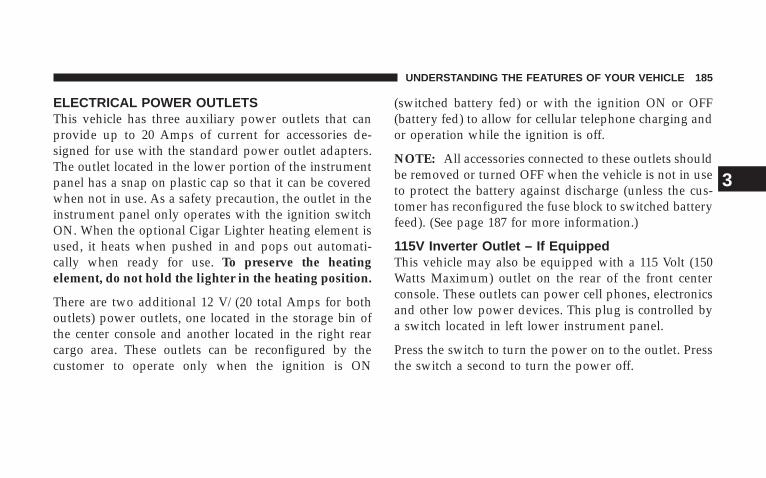
ELECTRICAL POWER OUTLETSThis vehicle has three auxiliary power outlets that canprovide up to 20 Amps of current for accessories de-signed for use with the standard power outlet adapters.The outlet located in the lower portion of the instrumentpanel has a snap on plastic cap so that it can be coveredwhen not in use. As a safety precaution, the outlet in theinstrument panel only operates with the ignition switchON. When the optional Cigar Lighter heating element isused, it heats when pushed in and pops out automati-cally when ready for use. To preserve the heatingelement, do not hold the lighter in the heating position.
There are two additional 12 V/(20 total Amps for bothoutlets) power outlets, one located in the storage bin ofthe center console and another located in the right rearcargo area. These outlets can be reconfigured by thecustomer to operate only when the ignition is ON
(switched battery fed) or with the ignition ON or OFF(battery fed) to allow for cellular telephone charging andor operation while the ignition is off.
NOTE: All accessories connected to these outlets shouldbe removed or turned OFF when the vehicle is not in useto protect the battery against discharge (unless the cus-tomer has reconfigured the fuse block to switched batteryfeed). (See page 187 for more information.)
115V Inverter Outlet – If EquippedThis vehicle may also be equipped with a 115 Volt (150Watts Maximum) outlet on the rear of the front centerconsole. These outlets can power cell phones, electronicsand other low power devices. This plug is controlled bya switch located in left lower instrument panel.
Press the switch to turn the power on to the outlet. Pressthe switch a second to turn the power off.
UNDERSTANDING THE FEATURES OF YOUR VEHICLE 185
3

NOTE: When the inverter switch is pressed, there willbe a delay of approximately one second before theinverter status indicator turns ON. The status Indicator ofthe AC power inverter indicates whether the inverter isproducing AC power.
NOTE: Due to build-in overload protection the inverterwill shut down if the power rating is exceeded.
WARNING!
To avoid serious injury or death:
• Do not use a 3-prong adapter.
• Do not insert any objects into the receptacles.
• Do not touch with wet hands.
• Close the lid when not in use.
• If this outlet is mishandled it may cause an electricshock and failure.
115V Inverter Switch
186 UNDERSTANDING THE FEATURES OF YOUR VEHICLE

Electrical Outlet Use With Engine OFF (BatteryFed Configuration)
CAUTION!
• Many accessories that can be plugged in drawpower from the vehicle’s battery, even when notin use (i.e., cellular phones, etc.). Eventually, ifplugged in long enough, the vehicle’s battery willdischarge sufficiently to degrade battery lifeand/or prevent engine starting.
• Accessories that draw higher power (i.e., coolers,vacuum cleaners, lights, etc.), will discharge thebattery even more quickly. Only use these inter-mittently and with greater caution.
• After the use of high power draw accessories, orlong periods of the vehicle not being started (withaccessories still plugged in), the vehicle must bedriven a sufficient length of time to allow thegenerator to recharge the vehicle’s battery.
115V Inverter Plug
UNDERSTANDING THE FEATURES OF YOUR VEHICLE 187
3
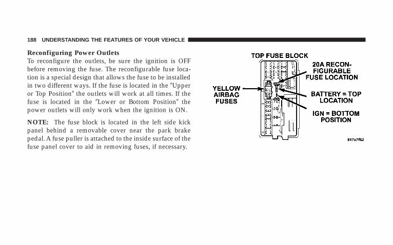
Reconfiguring Power OutletsTo reconfigure the outlets, be sure the ignition is OFFbefore removing the fuse. The reconfigurable fuse loca-tion is a special design that allows the fuse to be installedin two different ways. If the fuse is located in the 9Upperor Top Position9 the outlets will work at all times. If thefuse is located in the 9Lower or Bottom Position9 thepower outlets will only work when the ignition is ON.
NOTE: The fuse block is located in the left side kickpanel behind a removable cover near the park brakepedal. A fuse puller is attached to the inside surface of thefuse panel cover to aid in removing fuses, if necessary.
188 UNDERSTANDING THE FEATURES OF YOUR VEHICLE

FLOOR CONSOLE
Front Floor Console FeaturesThe floor console between the driver’s and front passen-ger’s seat, has the following features:
• Miscellaneous storage compartments
• Portable phone storage bin
• Portable phone cord routing on the sides of the consolelid and the base.
• 12 Volt reconfigurable power outlet inside storagecompartment
• Side open armrest lid
• Tissue holder and pen holder
• Coin slots
• Removable CD bin
• 115 V Inverter Plug
• RCA Jacks
The coin slots are located under the instrument panelcenter stack.
CupholdersYour vehicle has eight cupholders. Four are located in thecenter console, two are located in the second row armrestor rear floor console (if equipped), and two are located inthe left-hand quarter panel for third row occupants. Thecupholders and storage bin located in the front of thecenter console can be accessed by pressing on the accessdoors.
UNDERSTANDING THE FEATURES OF YOUR VEHICLE 189
3

NOTE: In colder temperatures you may experience aslight delay on console doors opening; the console doorspeed will come back to normal after 1–2 cycles.
The front storage bin in the center console is equippedwith a removable bin mat. This mat can be removed bypulling on the tab located on the front edge of the binmat. Removing this mat will allow you to retrieve anylost items that are between the bin doors.
Cupholder Doors
Front Center Console
190 UNDERSTANDING THE FEATURES OF YOUR VEHICLE

Power Outlet and Portable Phone StorageThe console is equipped with a power outlet, portablephone storage bin, and phone cord routing. The phonestorage bin can be used when easy access to the phone isneeded. Also, the power outlet inside the console com-partment can be used to power up the phone while it is
being stored in the bin. To use, plug in the portable powerrecharge cord and place the cord along the openingunder the forward portion of the storage bin. Close theconsole armrest lid and plug the power cord into thephone while resting the phone in the bin. The poweroutlet may be used for any portable item with a standard12 Volt power outlet adapter, requiring up to 20 Amps ofcurrent.
Rear Floor Console Features – If EquippedThe rear floor console located between the second rowbucket seat, has the following features:
• Miscellaneous storage compartments
• Cup holders
• Portable phone cord routing on either side, betweenlid and base
• 12 Volt power outlet inside storage compartment
Bin Mat Tab
UNDERSTANDING THE FEATURES OF YOUR VEHICLE 191
3

• Tissue holder and pen holder
• Second row heated seat switches
• Four slots for DVDs
To access the storage bin, lift up on the console door latch.
FACTORY INSTALLED ROOF LUGGAGE RACK
The load carried on the roof when equipped with aluggage rack must not exceed 150 lbs (68 kg), and shouldbe uniformly distributed over the cargo area.Rear Floor Console
Roof Luggage Rack
192 UNDERSTANDING THE FEATURES OF YOUR VEHICLE

The side rails between the stantions should be used to tiedown cargo. Check the straps frequently to be sure thatthe load remains securely attached.
NOTE: Crossbars are offered by Mopart accessories.
External racks do not increase the total load carryingcapacity of the vehicle. Be sure that the total occupantand luggage load inside the vehicle, plus the load on theluggage rack, do not exceed the maximum vehicle loadcapacity.
CAUTION!
To avoid damage to the roof rack and vehicle, do notexceed the maximum roof rack load capacity. Alwaysdistribute heavy loads as evenly as possible andsecure the load appropriately.
Long loads which extend over the windshield, suchas wood panels or surfboards, should be secured toboth the front and rear of the vehicle.
Place a blanket or other protection between thesurface of the roof and the load.
Travel at reduced speeds and turn corners carefullywhen carrying large or heavy loads on the roof rack.Wind forces, due to natural causes or nearby trucktraffic, can add sudden upward loads. This is espe-cially true on large flat loads and may result indamage to the cargo or your vehicle.
UNDERSTANDING THE FEATURES OF YOUR VEHICLE 193
3
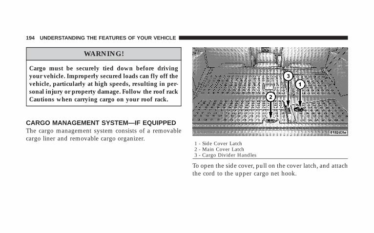
WARNING!
Cargo must be securely tied down before drivingyour vehicle. Improperly secured loads can fly off thevehicle, particularly at high speeds, resulting in per-sonal injury or property damage. Follow the roof rackCautions when carrying cargo on your roof rack.
CARGO MANAGEMENT SYSTEM—IF EQUIPPEDThe cargo management system consists of a removablecargo liner and removable cargo organizer.
To open the side cover, pull on the cover latch, and attachthe cord to the upper cargo net hook.
1 - Side Cover Latch2 - Main Cover Latch3 - Cargo Divider Handles
194 UNDERSTANDING THE FEATURES OF YOUR VEHICLE

To open the main cover, pull up on the latch, and attachthe cord to the rear seat head restraint post.
To open the cargo divider, lift up on the cargo dividerhandles, raising the doors to the full open position. Raisethe side panels until they engage into the doors.
To remove the cargo management system from the ve-hicle, pull the right-hand side of the organizer towardyou so that the right pin slides out of the slot in thevehicle. Push the organizer to the right and lift out of thevehicle.
Side Cover 1 - Cargo Divider Door2 - Cargo Divider Side Panel
UNDERSTANDING THE FEATURES OF YOUR VEHICLE 195
3

INSTRUMENT PANEL AND CONTROLS
CONTENTS
m Instruments And Controls . . . . . . . . . . . . . . . . . 201
m Instrument Cluster . . . . . . . . . . . . . . . . . . . . . . 202
m Instrument Cluster Description . . . . . . . . . . . . . 203
m Electronic Digital Clock . . . . . . . . . . . . . . . . . . 214
▫ Clock Setting Procedure . . . . . . . . . . . . . . . . . 215
m Setting The Analog Clock . . . . . . . . . . . . . . . . . 215
m Radio General Information . . . . . . . . . . . . . . . . 216
▫ Radio Broadcast Signals . . . . . . . . . . . . . . . . . 216
▫ Two Types Of Signals . . . . . . . . . . . . . . . . . . 216
▫ Electrical Disturbances . . . . . . . . . . . . . . . . . . 216
▫ AM Reception . . . . . . . . . . . . . . . . . . . . . . . 216
▫ FM Reception . . . . . . . . . . . . . . . . . . . . . . . . 216
m Sales Code REN — Multimedia System — IfEquipped . . . . . . . . . . . . . . . . . . . . . . . . . . . . 217
▫ Operating Instructions — Satellite Radio (IfEquipped) . . . . . . . . . . . . . . . . . . . . . . . . . . 218
▫ Operating Instructions — Voice RecognitionSystem (VR) (If Equipped) . . . . . . . . . . . . . . . 218
4
▫ Operating Instructions — Hands-FreeCommunication (UConnectt) (If Equipped) . . . 218
▫ Clock Setting Procedure . . . . . . . . . . . . . . . . . 218
m Sales Code RER — Multimedia System — IfEquipped . . . . . . . . . . . . . . . . . . . . . . . . . . . . 220
▫ Operating Instructions — Satellite Radio . . . . . 221
▫ Operating Instructions — Hands-FreeCommunication (UConnectt) (If Equipped) . . . 221
▫ Clock Setting Procedure . . . . . . . . . . . . . . . . . 221
m Sales Code RES — AM/FM Stereo Radio WithCD Player (MP3 AUX Jack) . . . . . . . . . . . . . . . . 224
▫ Operating Instructions - Radio Mode . . . . . . . 224
▫ Operation Instructions - CD Mode For CD AndMP3 Audio Play . . . . . . . . . . . . . . . . . . . . . . 230
▫ Notes On Playing MP3 Files . . . . . . . . . . . . . 232
▫ List Button (CD Mode For MP3 Play) . . . . . . . 235
▫ Info Button (CD Mode For MP3 Play) . . . . . . . 235
m Satellite Radio (RSC) — If Equipped(RER/REQ/REN Radios Only) . . . . . . . . . . . . . 236
▫ System Activation . . . . . . . . . . . . . . . . . . . . . 236
▫ Electronic Serial Number/Sirius IdentificationNumber (ENS/SID) . . . . . . . . . . . . . . . . . . . . 237
▫ Selecting Satellite Mode . . . . . . . . . . . . . . . . . 237
▫ Satellite Antenna . . . . . . . . . . . . . . . . . . . . . . 238
▫ Reception Quality . . . . . . . . . . . . . . . . . . . . . 238
▫ Operating Instructions - Satellite Mode . . . . . . 238
▫ Operating Instructions - Hands-Free Phone (IfEquipped) . . . . . . . . . . . . . . . . . . . . . . . . . . 241
198 INSTRUMENT PANEL AND CONTROLS
▫ Operating Instructions - Video EntertainmentSystem (VES™) (If Equipped) . . . . . . . . . . . . . 241
m Universal Consumer Interface (UCI) —If Equipped . . . . . . . . . . . . . . . . . . . . . . . . . . . 241
▫ Connecting The iPodt Device . . . . . . . . . . . . 242
▫ Controlling The iPodt Using Radio Buttons . . . 242
▫ Play Mode . . . . . . . . . . . . . . . . . . . . . . . . . . 242
▫ List Or Browse Mode . . . . . . . . . . . . . . . . . . 244
m Video Entertainment System (Sales Code XRV) —If Equipped . . . . . . . . . . . . . . . . . . . . . . . . . . . 246
m Remote Sound System Controls — If Equipped . . 246
▫ Right-Hand Switch Functions . . . . . . . . . . . . . 246
▫ Left-Hand Switch Functions For RadioOperation . . . . . . . . . . . . . . . . . . . . . . . . . . . 247
▫ Left-Hand Switch Functions For Media(i.e., CD) Operation . . . . . . . . . . . . . . . . . . . . 247
m Compact Disc Maintenance . . . . . . . . . . . . . . . . 247
m Radio Operation And Cellular Phones . . . . . . . . 248
m Climate Controls . . . . . . . . . . . . . . . . . . . . . . . 249
▫ Manual Control . . . . . . . . . . . . . . . . . . . . . . 249
▫ Air Conditioning Operation . . . . . . . . . . . . . . 249
▫ Front Blower Control . . . . . . . . . . . . . . . . . . . 250
▫ Front Mode Control . . . . . . . . . . . . . . . . . . . 250
▫ Rear Temperature Control — If Equipped . . . . 253
▫ Rear Window Defrosting And Rear WindowWasher/Wiper . . . . . . . . . . . . . . . . . . . . . . . 253
▫ Automatic Temperature Control (ATC) — IfEquipped . . . . . . . . . . . . . . . . . . . . . . . . . . . 254
INSTRUMENT PANEL AND CONTROLS 199
4

▫ Automatic Control . . . . . . . . . . . . . . . . . . . . 254
▫ Level Of Automatic Control . . . . . . . . . . . . . . 255
▫ Manual Control (ATC) . . . . . . . . . . . . . . . . . . 256
▫ Rear Zone Climate Control — If Equipped . . . 259
▫ Rear Rotary Temperature Control . . . . . . . . . . 260
▫ Front Unit To Rear Unit Chart . . . . . . . . . . . . 261
▫ Operating Tips . . . . . . . . . . . . . . . . . . . . . . . 261
▫ Operating Tips Chart . . . . . . . . . . . . . . . . . . . 263
m Rear Window Features . . . . . . . . . . . . . . . . . . . 264
▫ Rear Window Wiper/Washer . . . . . . . . . . . . . 264
▫ Rear Window Defrosting . . . . . . . . . . . . . . . . 265
200 INSTRUMENT PANEL AND CONTROLS
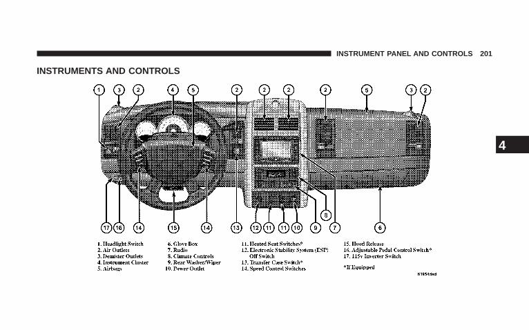
INSTRUMENTS AND CONTROLS
INSTRUMENT PANEL AND CONTROLS 201
4

Instrument Cluster
202 INSTRUMENT PANEL AND CONTROLS

INSTRUMENT CLUSTER DESCRIPTION
1. Fuel GageThe fuel gage shows level of fuel in the tank whenignition switch is in the ON position.
2. Temperature GageThe temperature gage indicates engine coolanttemperature. Any reading within the normalrange indicates that the cooling system is operat-
ing satisfactorily. The gage needle in V6 and V8 engineswill likely indicate a high temperature when driving inhot weather, up mountain grades, in heavy traffic, orwhen towing a trailer. If the needle rises to the “H” mark,stop the vehicle, shift into NEUTRAL and increase enginespeed for two to three minutes. If the temperaturereading does not return to normal, see your authorizeddealer for service immediately..
CAUTION!
Do not leave your vehicle unattended with the en-gine running as you would not be able to react to thetemperature indicator if the engine overheats.
The gage pointer will remain near its last reading whenthe engine is turned off. It will return to a true readingwhen the engine is restarted.
3. Turn Signal IndicatorsWhen a turn signal is activated, a right-pointing orleft-pointing arrow lights up and flashes to indicate thedirection of the turn. These indicators also indicateproper operation of the front and rear turn signal lights.If either indicator flashes at a faster rate than normal,check for a defective bulb. If either indicator fails to lightup when the lever is moved, check for a defective fuse orturn signal LED. A single chime is activated when the
INSTRUMENT PANEL AND CONTROLS 203
4
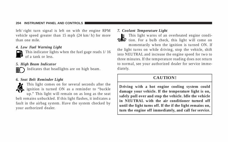
left/right turn signal is left on with the engine RPMvehicle speed greater than 15 mph (24 km/h) for morethan one mile.
4. Low Fuel Warning LightThis indicator lights when the fuel gage reads 1/16of a tank or less.
5. High Beam IndicatorIndicates that headlights are on high beam.
6. Seat Belt Reminder LightThis light comes on for several seconds after theignition is turned ON as a reminder to “buckleup.” This light will remain on as long as the seat
belt remains unbuckled. If this light flashes, it indicates afault in the airbag system. Have the system checked byyour authorized dealer.
7. Coolant Temperature LightThis light warns of an overheated engine condi-tion. For a bulb check, this light will come onmomentarily when the ignition is turned ON. If
the light turns on while driving, stop the vehicle, shiftinto NEUTRAL and increase the engine speed for two tothree minutes. If the temperature reading does not returnto normal, see your authorized dealer for service imme-diately.
CAUTION!
Driving with a hot engine cooling system coulddamage your vehicle. If the temperature light is on,safely pull over and stop the vehicle. Idle the vehiclein NEUTRAL with the air conditioner turned offuntil the light turns off. If the if the light remains on,turn the engine off immediately, and call for service.
204 INSTRUMENT PANEL AND CONTROLS

WARNING!
A hot engine cooling system is dangerous. You orothers could be badly burned by steam or boilingcoolant. You may want to call a service center if yourvehicle overheats. If you decide to look under thehood yourself, refer to “Cooling System PressureCap” under “Cooling System” in Section 7. Followthe warnings under the paragraph.
8. SpeedometerThe speedometer shows the speed of the vehicle.
9. Voltage LightThis light monitors the electrical system voltage.The light should turn on momentarily as the
engine is started. If the light stays on or turns on whiledriving, it indicates a problem with the charging system.See your authorized dealer for service immediately.
10. Security LightThis light will flash rapidly for approximately 15 secondswhen the Vehicle Security Alarm is arming. The light willflash at a slower speed continuously after the alarm is set.The Security light will also come on for about threeseconds when the ignition is first turned on.
11. ABS Warning LightThis light monitors the Anti-Lock Brake System(ABS) which is described elsewhere in thismanual. This light will come on when theignition key is turned to the ON position and
may stay on for approximately three seconds. If this lightremains on or comes on during driving, it indicates thatthe Anti-Lock portion of the brake system is not func-tioning and that service is required. See your authorizeddealer immediately. With the ABS malfunctioning, theBrake Assist System (BAS) and Electronic Stability Pro-gram (ESP) are also switched off. Both malfunctionindicator lights illuminate with the engine running. If the
INSTRUMENT PANEL AND CONTROLS 205
4
charging voltage falls below 10 volts, the malfunctionindicator light illuminates and the ABS is switched off.When the voltage is above this value again, the malfunc-tion indicator light should go out and the ABS is opera-tional. If the malfunction indicator light stays illumi-nated, have the system checked at your authorized dealeras soon as possible.
12. Engine Oil Pressure Indicator LightThis light indicates that the engine oil pressure hasbecome too low. For a bulb check, this light will
come on momentarily when the ignition is turned ON. Ifthe light turns on while driving, stop the vehicle and shutoff the engine as soon as possible. See your authorizeddealer for service immediately.
13. TachometerThis gage measures engine Revolutions-Per-Minute(RPM x 1000).
14. Gear SelectorThe electronic gear selector display is self-containedwithin the instrument cluster. It displays the position ofthe automatic transmission shift lever, and the relation ofeach position to all other positions. For a good signal thedisplay will place a box around the selected transmissionrange (PRND21). If the PRNDL displays only the char-acters PRND21 (no boxes), have the system checked byan authorized dealer.
15. Odometer/Trip OdometerThe odometer shows the total distance the vehicle hasbeen driven. U.S. federal regulations require that upontransfer of vehicle ownership, the seller certify to thepurchaser the correct mileage that the vehicle has beendriven. Therefore, if the odometer reading is changedduring repair or replacement, be sure to keep a record ofthe reading before and after the service so that the correctmileage can be determined.
206 INSTRUMENT PANEL AND CONTROLS

The two trip odometers show individual trip mileage. Toswitch from odometer to trip odometers, press andrelease the Trip Odometer button.
To reset a trip odometer, display the desired trip odom-eter to be reset then push and hold the button until thedisplay resets (approximately two seconds).
Vehicle Warning Messages
For non-Electronic Vehicle Information Center (EVIC)equipped vehicles, when the appropriate conditions ex-ist, messages such as “door ajar” (indicates that a door(s)may be ajar), “gASCAP” (which indicates that your gascap is possibly loose or damaged), 9CHANgE OIL”(indicates that the engine oil should be changed), “Lo-WASH” (low washer fluid), and “noFUSE” (indicatesthat the IOD fuse is removed from the Integrated PowerModule), will display in the odometer.
NOTE: If the vehicle is equipped with an EVIC, mostwarnings will display in the EVIC. For additional infor-mation, refer to “Electronic Vehicle Information Center(EVIC) — If Equipped” in Section 3.
The outside temperature will display in the odometer fornon-EVIC equipped vehicles. Pressing the trip odometerRESET button toggles the feature back to the odometer.
Change Oil Message
Your vehicle is equipped with an engine oil changeindicator system. The “Change Oil” message will flash inthe instrument cluster odometer for approximately 12seconds after a single chime has sounded to indicate thenext scheduled oil change interval. The engine oil changeindicator system is duty cycle based, which means theengine oil change interval may fluctuate dependent uponyour personal driving style.
INSTRUMENT PANEL AND CONTROLS 207
4
Unless reset, this message will continue to display eachtime you turn the ignition switch to the ON/RUNposition. To turn off the message temporarily, press andrelease the Trip Odometer button on the instrumentcluster. To reset the oil change indicator system (afterperforming the scheduled maintenance) refer to the fol-lowing procedure.
1. Turn the ignition switch to the ON position (Do notstart the engine).
2. Fully depress the accelerator pedal slowly threetimes within 10 seconds.
3. Turn the ignition switch to the OFF/LOCK position.
NOTE: If the indicator message illuminates when youstart the vehicle, the oil change indicator system did notreset. If necessary repeat this procedure.
16. OdometerThe odometer shows the total distance the vehicle hasbeen driven.
U.S. federal regulations require that upon transfer ofvehicle ownership, the seller certify to the purchaser thecorrect mileage that the vehicle has been driven. There-fore, if the odometer reading is changed during repair orreplacement, be sure to keep a record of the readingbefore and after the service so that the correct mileage canbe determined.
17. Fog Light IndicatorThis light shows when the fog lights are ON.
18. Electronic Stability Program (ESP) Indicator LightThe yellow ESP indicator light in the speedom-eter area illuminates with the key in the igni-tion switch turned to the ON/RUN position. Itshould go out with the engine running. The
208 INSTRUMENT PANEL AND CONTROLS
ESP/TCS indicator light starts to flash as soon as the tireslose traction and the ESP system becomes active. TheESP/TCS indicator light also flashes when TCS is active.If the ESP/TCS indicator light begins to flash duringacceleration, ease up on the accelerator and apply as littlethrottle as possible. Be sure to adapt your speed anddriving to the prevailing road conditions. The ESP/TCSindicator light becomes illuminated when the ESP-OFFbutton has been pressed or ESP is only partially available,caused by lack of engine management or brake thermalmodel.
19. Transmission Temperature IndicatorThis light indicates that there is excessive trans-mission fluid temperature that might occurwith severe usage, such as trailer towing. If thislight comes on, stop the vehicle and run the
engine at idle or faster, with the transmission in NEU-TRAL until the light goes off.
20. Electronic Throttle Control (ETC)This light informs you of a problem with theElectronic Throttle Control system. If a prob-lem is detected, the light will come on while theengine is running. If the light remains lit with
the engine running your vehicle will usually be drivable,however, see your authorized dealer for service as soonas possible. If the light is flashing when the engine isrunning, immediate service is required and you mayexperience reduced performance, an elevated/rough idleor engine stall and your vehicle may require towing. Thelight will come on when the ignition is first turned onand remain on for 15 seconds as a bulb check. If the lightdoes not come on during starting, have the systemchecked by your authorized dealer.
21. BRAKE System Warning LightThe red “BRAKE” warning light will come on when theignition key is first turned on, and stay on briefly as abulb check. If the bulb does not come on during starting,
INSTRUMENT PANEL AND CONTROLS 209
4
have the bulb repaired promptly. If the light stays on, itmay be an indication that the parking brake has not beenreleased, or there is a low brake fluid level. If the lightremains on when the parking brake has been disengaged,and the fluid level is at the full mark on the mastercylinder reservoir, it indicates a possible brake hydraulicsystem malfunction or a problem with the Brake Booster.In this case, the light will remain on until the conditionhas been corrected. If the problem is related to the brakebooster, the ABS pump will run when applying the brake.
If the parking brake is applied, the light will flash whenthe gear position is out of PARK for automatic transmis-sions.
If brake failure is indicated, immediate repair is neces-sary. Operating the vehicle in this condition is danger-ous!
22. ESP/BAS Warning LampThe malfunction lamp for the ESP is combinedwith BAS. The yellow ESP/BAS warning lampand the yellow ESP/TCS indicator light in theinstrument cluster both come on when the
ignition switch is turned to the ON position. They shouldgo out with the engine running. If the ESP/BAS warninglamp comes on continuously with the engine running, amalfunction has been detected in either the ESP or theBAS system. If this light remains on after several ignitioncycles, and the vehicle has been driven several miles atspeeds greater than 30 mph (48 km/h), see your autho-rized dealer as soon as possible.
NOTE: The ESP/TCS indicator light and the ESP/BASwarning lamp come on momentarily each time the igni-tion switch is turned ON.
The ESP control system will make buzzing or clickingsounds when it is actively operating.
210 INSTRUMENT PANEL AND CONTROLS
23. Malfunction Indicator Light (MIL)This light is part of an onboard diagnostic systemwhich monitors the emissions and engine controlsystem. If the vehicle is ready for emissions
testing, the light will come on when the ignition is firstturned on and remain on, as a bulb check, until theengine is started. If the vehicle is not ready for emissionstesting, the light will come on when the ignition is firstturned on and remain on for 15 seconds, then blink for 10seconds, and remain on until the vehicle is started. If thebulb does not come on during starting, see your autho-rized dealer as soon as possible.
If this light comes on and remains on while driving, itsuggests a potential engine control problem and the needfor system service. See your authorized dealer as soon aspossible.
Although your vehicle will usually be drivable and notneed towing, see your authorized dealer for service assoon as possible.
CAUTION!
Prolonged driving with the MIL on could causedamage to the engine control system. It also couldaffect fuel economy and driveability.
If the MIL is flashing, severe catalytic converterdamage and power loss will soon occur. Immediateservice is required. See your authorized dealer forservice immediately.
24. Tire Pressure Monitoring Telltale LightEach tire, including the spare (if provided),should be checked monthly when cold andinflated to the inflation pressure recommended
INSTRUMENT PANEL AND CONTROLS 211
4

by the vehicle manufacturer on the vehicle placard or tireinflation pressure label. (If your vehicle has tires of adifferent size than the size indicated on the vehicleplacard or tire inflation pressure label, you should deter-mine the proper tire inflation pressure for those tires.)
As an added safety feature, your vehicle has beenequipped with a Tire Pressure Monitoring System(TPMS) that illuminates a low tire pressure telltale whenone or more of your tires is significantly under-inflated.Accordingly, when the low tire pressure telltale illumi-nates, you should stop and check your tires as soon aspossible, and inflate them to the proper pressure. Drivingon a significantly under-inflated tire causes the tire tooverheat and can lead to tire failure. Under-inflation alsoreduces fuel efficiency and tire tread life, and may affectthe vehicle’s handling and stopping ability.
Please note that the TPMS is not a substitute for propertire maintenance, and it is the driver’s responsibility to
maintain correct tire pressure, even if under-inflation hasnot reached the level to trigger illumination of the TPMSlow tire pressure telltale.
Your vehicle has also been equipped with a TPMSmalfunction indicator to indicate when the system is notoperating properly. The TPMS malfunction indicator iscombined with the low tire pressure telltale. When thesystem detects a malfunction, the telltale will flash forapproximately one minute and then remain continuouslyilluminated. This sequence will continue upon subse-quent vehicle start-ups as long as the malfunction exists.When the malfunction indicator is illuminated, the sys-tem may not be able to detect or signal low tire pressureas intended. TPMS malfunctions may occur for a varietyof reasons, including the installation of replacement oralternate tires or wheels on the vehicle that prevent theTPMS from functioning properly. Always check theTPMS malfunction telltale after replacing one or more
212 INSTRUMENT PANEL AND CONTROLS

tires or wheels on your vehicle to ensure that the replace-ment or alternate tires and wheels allow the TPMS tocontinue to function properly.
CAUTION!
The TPMS has been optimized for the originalequipment tires and wheels. TPMS pressures andwarning have been established for the tire sizeequipped on your vehicle. Undesirable system opera-tion or sensor damage may result when using re-placement equipment that is not of the same size,type, and/or style. Aftermarket wheels can causesensor damage. Do not use tire sealant from a can, orbalance beads if your vehicle is equipped with aTPMS, as damage to the sensors may result.
25. Airbag IndicatorThe indicator lights and remains lit for six toeight seconds when the ignition is first turnedON. If the light does not come on when theignition is first turned on, or the light stays on
or comes on while driving, have the airbag systemchecked by an authorized dealer.
26. 4WD IndicatorIndicates when the transfer case is in 4WD position.
27. SVC (Service) 4WD IndicatorThe SVC 4WD lights will come on when the ignition keyis turned to the ON position and will stay on for twoseconds. If the light stays on or comes on during driving,it means that the 4WD system is not functioning properlyand that service is required. See your authorized dealerfor service.
INSTRUMENT PANEL AND CONTROLS 213
4
28. Cruise Light (Speed Control)This indicator lights when the electronic speed controlsystem is turned on.
29. TOW/HAULThe TOW/HAUL button is located at the end of the gearshift lever. This light will illuminate when the TOW/HAUL button has been selected.
30. 4LOW IndicatorIndicates transfer case is in 4LOW position.
31. Odometer/Trip Odometer ButtonPress this button to toggle between the odometer and thetrip odometer display. Holding the button in resets thetrip odometer reading.
ELECTRONIC DIGITAL CLOCKThe clock and radio each use the display panel built intothe radio. A digital readout shows the frequency and/ortime in hours and minutes (depending on your radiomodel), whenever the ignition switch is in the ON orACC position.
When the ignition switch is in the OFF position, or whenthe radio frequency is being displayed, timekeeping isaccurately maintained.
On the AM/FM/CD (six-disc) radio, the time buttonalternates the location of the time and frequency on thedisplay. On the AM/FM/CD (single-disc) radio, only oneof the two, time or frequency, is displayed.
214 INSTRUMENT PANEL AND CONTROLS
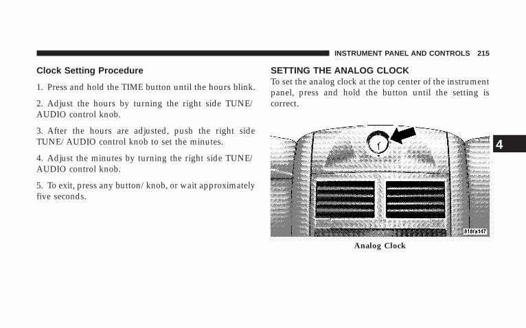
Clock Setting Procedure
1. Press and hold the TIME button until the hours blink.
2. Adjust the hours by turning the right side TUNE/AUDIO control knob.
3. After the hours are adjusted, push the right sideTUNE/AUDIO control knob to set the minutes.
4. Adjust the minutes by turning the right side TUNE/AUDIO control knob.
5. To exit, press any button/knob, or wait approximatelyfive seconds.
SETTING THE ANALOG CLOCKTo set the analog clock at the top center of the instrumentpanel, press and hold the button until the setting iscorrect.
Analog Clock
INSTRUMENT PANEL AND CONTROLS 215
4
RADIO GENERAL INFORMATION
Radio Broadcast SignalsThe radio will provide excellent reception under mostoperating conditions. Like any system, however, vehicleradios have performance limitations, due to mobile op-eration and natural phenomena, which might lead you tobelieve your sound system is malfunctioning. To helpyou understand and save you concern about these “ap-parent” malfunctions, you must understand a point ortwo about the transmission and reception of radio sig-nals.
Two Types of SignalsThere are two basic types of radio signals: AM orAmplitude Modulation, in which the transmitted soundcauses the amplitude, or height, of the radio waves tovary; and FM or Frequency Modulation, in which thefrequency of the wave is varied to carry the sound.
Electrical DisturbancesRadio waves may pick up electrical disturbances duringtransmission. They mainly affect the wave amplitude,and thus remain a part of the AM reception. Theyinterfere very little with the frequency variations thatcarry the FM signal.
AM ReceptionAM sound is based on wave amplitude, so AM receptioncan be disrupted by such things as lightning, power linesand neon signs.
FM ReceptionBecause FM transmission is based on frequency varia-tions, interference that consists of amplitude variationscan be filtered out, leaving the reception relatively clear,which is the major feature of FM radio.
216 INSTRUMENT PANEL AND CONTROLS

NOTE: The radio, steering wheel radio controls (ifequipped), and 6–Disc CD/DVD changer (if equipped)will remain active for up to 10 minutes after the ignitionswitch has been turned OFF. Opening a vehicle frontdoor will cancel this feature.
SALES CODE REN — MULTIMEDIA SYSTEM — IFEQUIPPED
NOTE: The sales code is located on the lower right sideof the unit’s faceplate.
The REN Multimedia system contains a radio, CD/DVDplayer, USB port, a 20-gigabyte hard drive (HDD), and a“JukeBox” (virtual CD changer). Sirius Satellite Radio isoptional. The 6.5-in (16.5 cm) touch screen allows for easymenu selection.
A 20-gigabyte HDD allows uploads of music and photosfrom CDs or through the USB port. The Gracenotedatabase finds the artist, track, and title for the music.
An auxiliary input jack permits passengers to listen to aportable MP3 player through the vehicle’s speakers. Forvehicles equipped with the Vehicle Entertainment System(VES)t, separate audio outputs allow passengers to listento the vehicle speakers while different audio tracks playthrough the system’s wireless headphones. This meansrear-seat passengers can watch a DVD on the optionalrear seat entertainment system, while the driver andfront-seat passenger listen to the radio.
Other special features include direct tune, music typeselections, easy store presets, backup camera display forvehicles equipped with a backup camera, and on somemodels, a dual display screen operation. Refer to yourRadio-specific user’s manual for detailed operating in-structions.
INSTRUMENT PANEL AND CONTROLS 217
4

Operating Instructions — Satellite Radio (IfEquipped)Refer to your Radio-specific user’s manual for detailedoperating instructions.
Operating Instructions — Voice RecognitionSystem (VR) (If Equipped)For the radio, refer to “Voice Recognition System (VR)” inSection 3.
For Hands Free Phone Communication (UConnectt)“Voice Recognition System (VR),” refer to “Hands-FreeCommunication (UConnectt)” in Section 3.
Operating Instructions — Hands-FreeCommunication (UConnect T) (If Equipped)Refer to “Hands-Free Communication (UConnectt)” inSection 3.
Clock Setting Procedure
Setting the Clock
1. Turn on the multimedia system.
2. Touch the screen where the time is displayed. Theclock setting menu will appear on the screen.
3. To move the hour forward, touch the screen where theword “Hour” with the arrow pointing upward is dis-played. To move the hour backward, touch the screenwhere the word “Hour” with the arrow pointing down-ward is displayed.
4. To move the minute forward, touch the screen wherethe word “Min” with the arrow pointing upward isdisplayed. To move the minute backward, touch thescreen where the word “Min” with the arrow pointingdownward is displayed.
218 INSTRUMENT PANEL AND CONTROLS

5. To save the new time setting, touch the screen wherethe word “Save” is displayed.
Changing Daylight Savings TimeWhen selected, this feature will display the time of day indaylight savings time. Proceed as follows to change thecurrent setting:
1. Turn on the multimedia system.
2. Touch the screen where the time is displayed. Theclock setting menu will appear on the screen.
3. When this feature is on, a check mark will appear inthe box next to the words “Daylight Savings.” Touch thescreen where the words “Daylight Savings” are dis-played to change the current setting.
Show Time if Radio is OffWhen selected, this feature will display the time of dayon the touch screen when the multimedia system isturned off. Proceed as follows to change the currentsetting:
1. Turn on the multimedia system.
2. Touch the screen where the time is displayed. Theclock setting menu will appear on the screen.
3. When this feature is on, a check mark will appear inthe box next to the words “Show Time if Radio is Off.”Touch the screen where the words “Show Time if Radio isOff” are displayed to change the current setting.
Changing the Time Zone
1. Turn on the multimedia system.
2. Touch the screen where the time is displayed. Theclock setting menu will appear on the screen.
INSTRUMENT PANEL AND CONTROLS 219
4

3. Touch the screen where the words “Set Time Zone” aredisplayed. The time zone selection menu will appear onthe screen.
4. Select a time zone by touching the screen where yourselection appears. If you do not see a time zone that youwant to select, touch the screen where the word “Page” isdisplayed to view additional time zones in the menu.
5. Touch the screen where the word “Save” is displayed.
SALES CODE RER — MULTIMEDIA SYSTEM — IFEQUIPPED
NOTE: The sales code is located on the lower right sideof the unit’s faceplate.
The RER Multimedia system contains a radio, SiriusSatellite Radio player, navigation system, CD/DVDplayer, USB port, 20-gigabyte hard drive (HDD), and theUConnectt Hands-Free Bluetootht cellular system.
NOTE: If your vehicle is not equipped with UConnectt,the unit will respond with a “Feature Not Available”message when selecting controls related to this feature.
A 6.5-in (16.5 cm) touch screen allows easy menu selec-tion, while the Advanced Voice Dialog System recognizesmore than 1,000 words for audio, navigation, entertain-ment, and hands-free mobile phone use.
The satellite navigation capability combines a Global-Positioning System (GPS)-based navigation system withan integrated color screen to provide maps, turn identi-fication, selection menus, and instructions for selecting avariety of destinations and routes.
A shared HDD for the navigation system, the database,and other radio features allows uploads of music andphotos from CDs or through the USB port. The Gracenotedatabase finds the artist, track, and title for the music.
220 INSTRUMENT PANEL AND CONTROLS
An auxiliary input jack permits passengers to listen to aportable MP3 player through the vehicle’s speakers. Forvehicles equipped with the Vehicle Entertainment System(VES)t, separate audio outputs allow passengers to listento the vehicle speakers while different audio tracks playthrough the system’s wireless headphones. This meansrear-seat passengers can watch a DVD on the optionalrear-seat entertainment system while the driver andfront-seat passenger listen to the radio.
Other special features include direct tune, music typeselections, traffic messaging (optional), easy store presets,parental lockout for VES™ (if equipped), backup cameradisplay for vehicles equipped with a backup camera, andon some models, a dual display screen operation. Refer toyour “Navigation User’s Manual” for detailed operatinginstructions.
Operating Instructions — Satellite RadioRefer to your “Navigation User’s Manual” for detailedoperating instructions.
Operating Instructions — Hands-FreeCommunication (UConnect T) (If Equipped)Refer to your “Navigation User’s Manual” for detailedoperating instructions.
Clock Setting ProcedureThe GPS receiver in this system is synchronized to thetime data being transmitted by the GPS satellites. Thesatellites’ clock is Greenwich Mean Time (GMT). This isthe worldwide standard for time. This makes the sys-tem’s clock very accurate once the appropriate time zoneand daylight savings information is set.
Changing the Time Zone
1. Turn on the multimedia system.
INSTRUMENT PANEL AND CONTROLS 221
4

2. Touch the screen where the time is displayed. Theclock setting menu will appear on the screen. If the words“Time: GPS Time” are displayed at the top of the screen,proceed to Step 4. Otherwise, proceed to Step 3.
3. If the words “Time: User Clock” are displayed at thetop of the screen, touch the bottom of the screen wherethe words “User Clock” are displayed. The GPS timesetting menu will appear on the screen.
4. Touch the screen where the words “Set Time Zone” aredisplayed. The time zone selection menu will appear onthe screen.
5. Select a time zone by touching the screen where yourselection appears. If you do not see a time zone that youwant to select, touch the screen where the word “Page” isdisplayed to view additional time zones in the menu.
Changing Daylight Savings TimeWhen selected, this feature will display the time of day indaylight savings time. Proceed as follows to change thecurrent setting:
1. Turn on the multimedia system.
2. Touch the screen where the time is displayed. Theclock setting menu will appear on the screen.
3. When this feature is on, a check mark will appear inthe box next to the words “Daylight Savings.” Touch thescreen where the words “Daylight Savings” are dis-played to change the current setting.
Setting the User ClockIf you wish to set the clock to a time different from thesystem clock, you can manually adjust the time byperforming the following:
1. Turn on the multimedia system.
222 INSTRUMENT PANEL AND CONTROLS

2. Touch the screen where the time is displayed. Theclock setting menu will appear on the screen. If the words“Time: User Clock” are displayed at the top of the screen,proceed to Step 4. Otherwise, proceed to Step 3.
3. If the words “Time: GPS Time” are displayed at the topof the screen, touch the bottom of the screen where thewords “GPS Time” are displayed. The user clock timesetting menu will appear on the screen.
4. To move the hour forward, touch the screen where theword “Hour” with the arrow pointing upward is dis-played. To move the hour backward, touch the screenwhere the word “Hour” with the arrow pointing down-ward is displayed.
5. To move the minute forward, touch the screen wherethe word “Min” with the arrow pointing upward isdisplayed. To move the minute backward, touch thescreen where the word “Min” with the arrow pointingdownward is displayed.
6. To save the new time setting, touch the screen wherethe word “Save” is displayed.
Show Time if Radio is OffWhen selected, this feature will display the time of dayon the touch screen when the system is turned off.Proceed as follows to change the current setting:
1. Turn on the multimedia system.
2. Touch the screen where the time is displayed. Theclock setting menu will appear on the screen.
3. When this feature is on, a check mark will appear inthe box next to the words “Show Time if Radio is Off.”Touch the screen where the words “Show Time if Radio isOff” are displayed to change the current setting.
INSTRUMENT PANEL AND CONTROLS 223
4

SALES CODE RES — AM/FM STEREO RADIOWITH CD PLAYER (MP3 AUX JACK)
NOTE: The radio sales code is located on the lower rightside of your radio faceplate.
Operating Instructions - Radio Mode
NOTE: The ignition switch must be in the ON or ACCposition to operate the radio.
Power Switch/Volume Control (Rotary)Push the ON/VOLUME control knob to turn on theradio. Push the ON/VOLUME control knob a secondtime to turn off the radio.
Electronic Volume ControlThe electronic volume control turns continuously (360degrees) in either direction without stopping. Turning theON/VOLUME control knob to the right increases thevolume and to the left decreases it.
When the audio system is turned on, the sound will beset at the same volume level as last played.
SEEK ButtonsPress and release the SEEK buttons to search for the nextlistenable station in AM/FM mode. Press the right switch
RES Radio (Non-Satellite Model Shown - With SatelliteSimilar)
224 INSTRUMENT PANEL AND CONTROLS
to seek up and the left switch to seek down. The radiowill remain tuned to the new station until you makeanother selection. Holding either button will bypassstations without stopping until you release it.
SCAN ButtonPressing the SCAN button causes the tuner to search forthe next listenable station in AM or FM frequencies,pausing for five seconds at each listenable station beforecontinuing to the next. To stop the search, press theSCAN button a second time.
Voice Recognition System (Radio) — If EquippedRefer to “Voice Recognition System (VR)” in Section 3.
Voice Recognition Button (UConnectt Hands-FreePhone) — If EquippedPress this button to operate the Hands-Free Phone(UConnectt) feature (if equipped). Refer to “Hands-FreeCommunication (UConnectt)” in Section 3.
If your vehicle is not equipped with this or this feature isnot available on your vehicle, a “Not Equipped WithUConnect” message will display on the radio screen.
PHONE Button (UConnectt Hands-Free Phone) —If EquippedPress this button to operate the Hands-Free Phone(UConnectt) feature (if equipped). Refer to “Hands-FreeCommunication (UConnectt)” in Section 3.
If your vehicle is not equipped with this or this feature isnot available on your vehicle, a “Not Equipped WithUConnectt” message will display on the radio screen.
TIME ButtonPress the TIME button and the time of day will display. InAM or FM mode, pressing the TIME button will switchbetween the time and frequency displays.
INSTRUMENT PANEL AND CONTROLS 225
4
Clock Setting Procedure
1. Press and hold the TIME button, until the hours blink.
2. Adjust the hours by turning the right side TUNE/SCROLL control knob.
3. After adjusting the hours, press the right side TUNE/SCROLL control knob to set the minutes. The minuteswill begin to blink.
4. Adjust the minutes using the right side TUNE/SCROLL control knob. Press the TUNE/SCROLL controlknob to save time change.
5. To exit, press any button/knob or wait five seconds.
The clock can also be set by pressing the SETUP button.For vehicles equipped with satellite radio, press theSETUP button, use the TUNE/SCROLL control to selectSET CLOCK, and then follow the above procedure,
starting at Step 2. For vehicles not equipped with satelliteradio, press the SETUP button and then follow the aboveprocedure, starting at Step 2.
INFO ButtonPress the INFO button for an RDS station (one with callletters displayed). The radio will return a Radio Textmessage broadcast from an FM station (FM mode only).
RW/FFPressing the RW (Rewind) or FF (Fast Forward) buttonscauses the tuner to search for the next frequency in thedirection of the arrows. This feature operates in eitherAM or FM frequencies.
TUNE ControlTurn the rotary TUNE/SCROLL control knob clockwiseto increase or counterclockwise to decrease the frequency.
226 INSTRUMENT PANEL AND CONTROLS
Setting the Tone, Balance, and FadePush the rotary TUNE/SCROLL control knob and BASSwill display. Turn the TUNE/SCROLL control knob tothe right or left to increase or decrease the bass tones.
Push the rotary TUNE/SCROLL control knob a secondtime and MID will display. Turn the TUNE/SCROLLcontrol knob to the right or left to increase or decrease themid range tones.
Push the rotary TUNE/SCROLL control knob a thirdtime and TREBLE will display. Turn the TUNE/SCROLLcontrol knob to the right or left to increase or decrease thetreble tones.
Push the rotary TUNE/SCROLL control knob a fourthtime and BALANCE will display. Turn the TUNE/SCROLL control knob to the right or left to adjust thesound level from the right or left side speakers.
Push the rotary TUNE/SCROLL control knob a fifth timeand FADE will display. Turn the TUNE/SCROLL controlknob to the left or right to adjust the sound level betweenthe front and rear speakers.
Push the rotary TUNE/SCROLL control knob again toexit setting tone, balance, and fade.
MUSIC TYPE ButtonPressing this button once will turn on the Music Typemode for five seconds. Pressing the MUSIC TYPE buttonor turning the TUNE/SCROLL control knob within fiveseconds will allow the program format type to be se-lected. Many radio stations do not currently broadcastMusic Type information.
INSTRUMENT PANEL AND CONTROLS 227
4
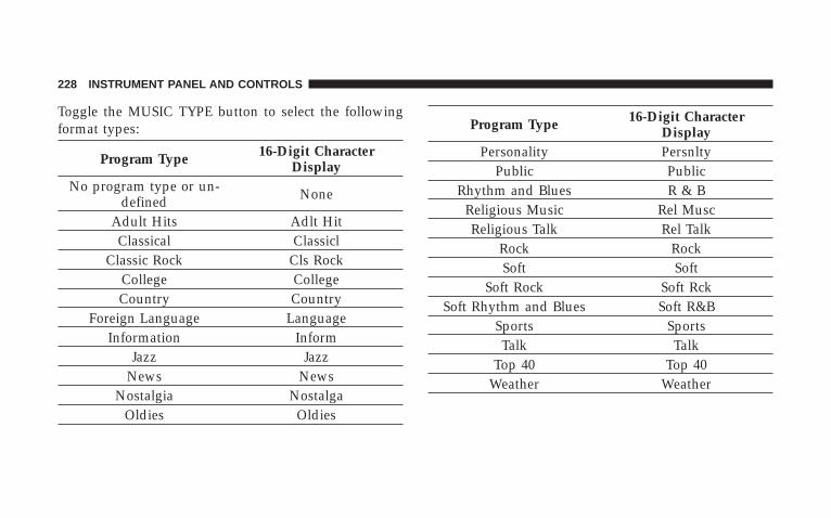
Toggle the MUSIC TYPE button to select the followingformat types:
Program Type 16-Digit CharacterDisplay
No program type or un-defined None
Adult Hits Adlt HitClassical Classicl
Classic Rock Cls RockCollege CollegeCountry Country
Foreign Language LanguageInformation Inform
Jazz JazzNews News
Nostalgia NostalgaOldies Oldies
Program Type 16-Digit CharacterDisplay
Personality PersnltyPublic Public
Rhythm and Blues R & BReligious Music Rel MuscReligious Talk Rel Talk
Rock RockSoft Soft
Soft Rock Soft RckSoft Rhythm and Blues Soft R&B
Sports SportsTalk Talk
Top 40 Top 40Weather Weather
228 INSTRUMENT PANEL AND CONTROLS
By pressing the SEEK button when the Music Type iconis displayed, the radio will be tuned to the next frequencystation with the same selected Music Type name. TheMusic Type function only operates when in the FMmode.
If a preset button is activated while in the Music Type(Program Type) mode, the Music Type mode will beexited and the radio will tune to the preset station.
SETUP ButtonPressing the SETUP button allows you to select betweenthe following items:
• Set Clock — Pressing the SELECT button will allowyou to set the clock. Turn the TUNE/SCROLL controlknob to adjust the hours and then press and turn theTUNE/SCROLL control knob to adjust the minutes.Press the TUNE/SCROLL control knob again to savechanges.
AM and FM ButtonsPress the buttons to select AM or FM modes.
SET Button — To Set the Pushbutton MemoryWhen you are receiving a station that you wish tocommit to pushbutton memory, press the SET button.The symbol SET 1 will now show in the display window.Select the button (1 to 6) you wish to lock onto this stationand press and release that button. If a button is notselected within five seconds after pressing the SET but-ton, the station will continue to play but will not bestored into pushbutton memory.
You may add a second station to each pushbutton byrepeating the above procedure with this exception: Pressthe SET button twice and SET 2 will show in the displaywindow. Each button can be set for SET 1 and SET 2 inboth AM and FM. This allows a total of 12 AM and 12 FMstations to be stored into pushbutton memory. The sta-tions stored in SET 2 memory can be selected by pressingthe pushbutton twice.
INSTRUMENT PANEL AND CONTROLS 229
4
Every time a preset button is used, a correspondingbutton number will display.
Buttons 1 - 6These buttons tune the radio to the stations that youcommit to pushbutton memory (12 AM and 12 FMstations).
DISC ButtonPressing the DISC button will allow you to switch fromAM/FM modes to Disc modes.
Operation Instructions - CD MODE for CD andMP3 Audio Play
NOTE: The ignition switch must be in the ON or ACCposition to operate the radio.
NOTE: This radio is capable of playing compact discs(CD), recordable compact discs (CD-R), rewritable com-pact discs (CD-RW), compact discs with MP3 tracks andmultisession compact discs with CD and MP3 tracks.
Inserting Compact Disc(s)Gently insert one CD into the CD player with the CDlabel facing up. The CD will automatically be pulled intothe CD player and the CD icon will illuminate on theradio display. If a CD does not go into the slot more thanan inch (2.5 cm), a disc may already be loaded and mustbe ejected before a new disc can be loaded.
If you insert a disc with the ignition ON and the radioON, the unit will switch from radio to CD mode andbegin to play when you insert the disc. The display willshow the disc number, the track number, and index timein minutes and seconds. Play will begin at the start oftrack 1.
230 INSTRUMENT PANEL AND CONTROLS

CAUTION!
• This CD player will accept 4–3/4 in (12 cm) discsonly. The use of other sized discs may damage theCD player mechanism.
• Do not use adhesive labels. These labels can peelaway and jam the player mechanism.
• RES is a single CD player. Do not attempt to inserta second CD if one is already loaded.
• Dual-media disc types (one side is a DVD, theother side is a CD) should not be used, and theycan cause damage to the player.
EJECT Button - Ejecting a CDPress the EJECT button to eject the CD.
If you have ejected a disc and have not removed it within10 seconds, it will be reloaded. If the CD is not removed,the radio will reinsert the CD but will not play it.
A disc can be ejected with the radio and ignition OFF.
NOTE: Ejecting with ignition OFF is not allowed onconvertible or soft-top models (if equipped).
SEEK ButtonPress the right SEEK button for the next selection on theCD. Press the left SEEK button to return to the beginningof the current selection, or return to the beginning of theprevious selection if the CD is within the first second ofthe current selection. Pressing and holding the SEEKbutton will allow faster scrolling through the tracks inCD, MP3 modes.
SCAN ButtonPress the SCAN button to scan through each track on theCD currently playing.
INSTRUMENT PANEL AND CONTROLS 231
4
TIME ButtonPress this button to change the display from a large CDplaying time display to a small CD playing time display.
RW/FFPress the RW button to stop the CD at the beginning ofthe current CD track/title.
Press and hold FF (Fast Forward) and the CD player willbegin to fast forward until FF is released or RW oranother CD button is pressed. The RW (Reverse) buttonworks in a similar manner.
AM or FM ButtonSwitches the AM or FM radio to the opposite radio mode.
RND Button (Random Play Button)Press this button while the CD is playing to activateRandom Play. This feature plays the selections on thecompact disc in random order to provide an interestingchange of pace.
Press the right SEEK button to move to the next ran-domly selected track.
Press the RND button a second time to stop RandomPlay.
Notes On Playing MP3 FilesThe radio can play MP3 files; however, acceptable MP3file recording media and formats are limited. Whenwriting MP3 files, pay attention to the following restric-tions.
Supported Media (Disc Types)The MP3 file recording media supported by the radio areCDDA, CD-R, CD-RW, MP3, and CDDA+MP3.
Supported Medium Formats (File Systems)The medium formats supported by the radio are ISO 9660Level 1 and Level 2 and includes the Joliet extension.When reading discs recorded using formats other thanISO 9660 Level 1 and Level 2, the radio may fail to read
232 INSTRUMENT PANEL AND CONTROLS
files properly and may be unable to play the file nor-mally. UDF and Apple HFS formats are not supported.
The radio uses the following limits for file systems:
• Maximum number of folder levels: 8
• Maximum number of files: 255
• Maximum number of folders. (The radio display of filenames and folder names is limited. For large numbersof files and/or folders, the radio may be unable todisplay the file name and folder name and will assigna number instead. With a maximum number of files,exceeding 20 folders will result in this display. With200 files, exceeding 50 folders will result in thisdisplay.)
• Maximum number of characters in file/folder names:
• Level 1: 12 (including a separator 9.9 and a three-character extension)
• Level 2: 31 (including a separator 9.9 and a three-character extension)
Multisession disc formats are supported by the radio.Multisession discs may contain combinations of normalCD audio tracks and computer files (including MP3 files).Discs created with an option such as 9keep disc open afterwriting9 are most likely multisession discs. The use ofmultisession for CD audio or MP3 playback may result inlonger disc loading times.
Supported MP3 File FormatsThe radio will recognize only files with the *.MP3 exten-sion as MP3 files. Non-MP3 files named with the *.MP3extension may cause playback problems. The radio isdesigned to recognize the file as an invalid MP3 and willnot play the file.
When using the MP3 encoder to compress audio data toan MP3 file, the bit rate and sampling frequencies in thefollowing table are supported. In addition, variable bit
INSTRUMENT PANEL AND CONTROLS 233
4
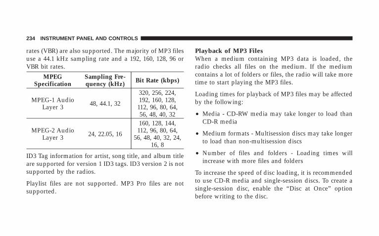
rates (VBR) are also supported. The majority of MP3 filesuse a 44.1 kHz sampling rate and a 192, 160, 128, 96 orVBR bit rates.
MPEGSpecification
Sampling Fre-quency (kHz) Bit Rate (kbps)
MPEG-1 AudioLayer 3 48, 44.1, 32
320, 256, 224,192, 160, 128,
112, 96, 80, 64,56, 48, 40, 32
MPEG-2 AudioLayer 3 24, 22.05, 16
160, 128, 144,112, 96, 80, 64,
56, 48, 40, 32, 24,16, 8
ID3 Tag information for artist, song title, and album titleare supported for version 1 ID3 tags. ID3 version 2 is notsupported by the radios.
Playlist files are not supported. MP3 Pro files are notsupported.
Playback of MP3 FilesWhen a medium containing MP3 data is loaded, theradio checks all files on the medium. If the mediumcontains a lot of folders or files, the radio will take moretime to start playing the MP3 files.
Loading times for playback of MP3 files may be affectedby the following:
• Media - CD-RW media may take longer to load thanCD-R media
• Medium formats - Multisession discs may take longerto load than non-multisession discs
• Number of files and folders - Loading times willincrease with more files and folders
To increase the speed of disc loading, it is recommendedto use CD-R media and single-session discs. To create asingle-session disc, enable the “Disc at Once” optionbefore writing to the disc.
234 INSTRUMENT PANEL AND CONTROLS

LIST Button (CD Mode for MP3 Play)Pressing the LIST button will bring up a list of all folderson the disc. Scrolling up or down the list is done byturning the TUNE/SCROLL control knob. Selecting afolder by pressing the TUNE/SCROLL control knob willbegin playing the files contained in that folder (or thenext folder in sequence if the selection does not containplayable files).
The folder list will time out after five seconds.
INFO Button (CD Mode for MP3 Play)Pressing the INFO button repeatedly will scroll throughthe following TAG information: Song Title, Artist, FileName, and Folder Name (if available).
Press the INFO button once more to return to 9elapsedtime9 priority mode.
Press and hold the INFO button for three seconds ormore and the radio will display song titles for each file.
Press and hold the INFO button again for three secondsto return to 9elapsed time9 display.
Operation Instructions - Auxiliary ModeThe auxiliary (AUX) jack is an audio input jack, whichallows the user to plug in a portable device such as anMP3 player, or cassette player, and utilize the vehicle’saudio system to amplify the source and play through thevehicle speakers.
Pressing the AUX button will change the mode to auxil-iary device if the AUX jack is connected.
NOTE: The AUX device must be turned on and thedevice’s volume set to proper level. If the AUX audio isnot loud enough, turn the device’s volume up. If the AUXaudio sounds distorted, turn the device’s volume down.
INSTRUMENT PANEL AND CONTROLS 235
4
TIME Button (Auxiliary Mode)Press this button to change the display to time of day. Thetime of day will display for five seconds (when ignition isOFF).
Operating Instructions - Hands-Free Phone(UConnectt) (If Equipped)Refer to “Hands-Free Communication (UConnectt)” inSection 3.
Operating Instructions - Satellite Radio Mode (IfEquipped)Refer to “Satellite Radio” in this section.
Operating Instructions - Video EntertainmentSystem™ (VES™) (If Equipped)Refer to separate “Video Entertainment System™(VES™) Guide.”
SATELLITE RADIO (RSC) — IF EQUIPPED(RER/REQ/REN RADIOS ONLY)Satellite radio uses direct satellite-to-receiver broadcast-ing technology to provide clear digital sound, coast tocoast. The subscription service provider is Sirius SatelliteRadio. This service offers over 130 channels of music,sports, news, entertainment, and programming for chil-dren, directly from its satellites and broadcasting studios.
NOTE: Sirius service is not available in Hawaii and haslimited coverage in Alaska.
System ActivationSirius Satellite Radio service is pre-activated, and youmay begin listening immediately to the one year of audioservice that is included with the factory-installed satelliteradio system in your vehicle. Sirius will contact you tosupply a welcome kit and to confirm subscription infor-mation, including the setup of your on-line listeningaccount at no additional charge. For further information,
236 INSTRUMENT PANEL AND CONTROLS

call the toll-free number 888-539-7474, or visit the Siriusweb site at www.sirius.com, or at www.siriuscanada.cafor Canadian residents. Please have the following infor-mation available when calling:
1. The Electronic Serial Number/Sirius IdentificationNumber (ESN/SID).
2. Your Vehicle Identification Number.
Electronic Serial Number/Sirius IdentificationNumber (ENS/SID)The Electronic Serial Number/Sirius Identification Num-ber is needed to activate your Sirius Satellite Radiosystem. To access the ESN/SID, refer to the followingsteps:
ESN/SID Access With REQ RadiosWith the ignition switch in the ON/RUN or ACC posi-tion and the radio ON, press the SETUP button and scrollusing the TUNE/SCROLL control knob until Sirius ID is
selected. Press the TUNE/SCROLL control knob and theSirius ID number will display. The Sirius ID numberdisplay will time out in two minutes. Press any button onthe radio to exit this screen.
ESN/SID Access With RER/REN RadiosWhile in SAT mode, press the MENU button on the radiofaceplate.
Next touch the SUBSCRIPTION tab on the touch screen.All the ESNs that apply to your vehicle will be displayed.
Selecting Satellite ModePress the SAT button until 9SAT9 appears in the display. ACD may remain in the radio while in the Satellite radiomode.
INSTRUMENT PANEL AND CONTROLS 237
4

Satellite AntennaTo ensure optimum reception, do not place items on theroof around the rooftop antenna location or strap items tothe trunk lid around the trunk lid antenna (if equipped).Metal objects placed within the line of sight of theantenna will cause decreased performance. Larger lug-gage items such as bikes should be placed as far rearwardas possible, within the loading design of the rack. Do notplace items directly on or above the antenna.
Reception QualitySatellite reception may be interrupted due to one of thefollowing reasons:
• The vehicle is parked in an underground parkingstructure or under a physical obstacle.
• Dense tree coverage may interrupt reception in theform of short audio mutes.
• Driving under wide bridges or along tall buildings cancause intermittent reception.
• Placing objects over or too close to the antenna cancause signal blockage.
Operating Instructions - Satellite Mode
NOTE: The ignition switch must be in the ON or ACCposition to operate the radio.
SEEK ButtonsPress and release the SEEK buttons to search for the nextchannel in Satellite mode. Press the right switch to seekup and the left switch to seek down. The radio willremain tuned to the new channel until you make anotherselection. Holding either button will bypass channelswithout stopping until you release it.
238 INSTRUMENT PANEL AND CONTROLS

SCAN ButtonPressing the SCAN button causes the tuner to search forthe next channel, pausing for eight seconds before con-tinuing to the next. To stop the search, press the SCANbutton a second time.
INFO ButtonPressing the INFO button will cycle between Artist, SongTitle, and Composer (if available) information. Also,pressing and holding the INFO button for an additionalthree seconds will make the radio display the Song Titleall of the time (press and hold again to return to normaldisplay).
RW/FFPressing the RW (Rewind) or FF (Fast Forward) buttonscauses the tuner to search for the next channel in thedirection of the arrows.
TUNE Control (Rotary)Turn the rotary TUNE/SCROLL control knob clockwiseto increase or counterclockwise to decrease the channel.
MUSIC TYPE ButtonPressing this button once will turn on the Music Typemode for five seconds. Pressing the MUSIC TYPE buttonor turning the TUNE/SCROLL control knob within fiveseconds will allow the program format type to be se-lected.
Toggle the MUSIC TYPE button again to select the musictype.
By pressing the SEEK button when the Music Typefunction is active, the radio will be tuned to the nextchannel with the same selected Music Type name.
If a preset button is activated while in the Music Type(Program Type) mode, the Music Type mode will beexited and the radio will tune to the preset channel.
INSTRUMENT PANEL AND CONTROLS 239
4

SETUP ButtonPressing the SETUP button allows you to select thefollowing items:
• Display Sirius ID number — Press the AUDIO/SELECT button to display the Sirius ID number. Thisnumber is used to activate, deactivate, or change theSirius subscription.
SET Button – To Set the Pushbutton MemoryWhen you are receiving a channel that you wish tocommit to pushbutton memory, press the SET button.The symbol SET 1 will now show in the display window.Select the button (1-6) you wish to lock onto this channeland press and release that button. If a button is notselected within five seconds after pressing the SET but-ton, the channel will continue to play but will not bestored into pushbutton memory.
You may add a second channel to each pushbutton byrepeating the above procedure with this exception: Pressthe SET button twice and SET 2 will show in the displaywindow. Each button can be set for SET 1 and SET 2. Thisallows a total of 12 Satellite channels to be stored intopushbutton memory. The channels stored in SET 2memory can be selected by pressing the pushbuttontwice.
Every time a preset button is used, a correspondingbutton number will display.
Buttons 1 - 6These buttons tune the radio to the channels that youcommit to pushbutton memory (12 Satellite stations).
240 INSTRUMENT PANEL AND CONTROLS

Operating Instructions - Hands-Free Phone (IfEquipped)Refer to “Hands-Free Communication (UConnectt)” inSection 3.
Operating Instructions - Video EntertainmentSystem (VES™) (If Equipped)Refer to separate “Video Entertainment System (VES™)Guide.”
UNIVERSAL CONSUMER INTERFACE (UCI) — IFEQUIPPED
NOTE: This section is for sales code RES and REQradios only with UConnectt. For sales code REN touchscreen radio, refer to the separate User’s Manual.
This feature allows you to plug an iPodt mobile digitaldevice into the vehicle’s sound system through a connec-tor (UCI connector) using an optional connection cable(available through MOPARt). See your authorized dealerfor details.
Using this feature,
• the iPodt audio can be played on the vehicle’s soundsystem, providing metadata (Track Title, Artist, Al-bum, etc.) information display on radio.
• the iPodt can be controlled using the radio buttons toPlay, Browse and List the iPodt contents.
• the iPodt battery charges when plugged into the UCIconnector.
INSTRUMENT PANEL AND CONTROLS 241
4
Connecting The iPod T DeviceUse the optional connection cable to connect an iPodt tothe vehicle’s UCI connector (which is located in the glovebox on some vehicles. This location may vary withvehicle). Once the iPodt is connected and synchronizedto the vehicle system (this may take a few seconds toconnect), the vehicle brand logo appears on the iPodtdisplay, and it starts charging and is ready for use bypressing radio switches as described below.
Controlling The iPod T Using Radio ButtonsTo get into the UCI (iPodt) mode and access a connectediPodt, press the AUX button on the radio faceplate. Oncein the UCI (iPodt) mode, the iPodt audio track (ifavailable from iPodt) will start playing over the vehicleaudio system.
Play ModeWhen switched to UCI mode the iPodt will be in Playmode. In Play mode, you may use the following buttonson the radio faceplate to control the iPodt and displaydata:
TUNE/SCROLL KnobUse the TUNE/SCROLL knob to go to the next orprevious track.
The TUNE/SCROLL knob functions similar to the scrollwheel on the iPodt mobile digital device.
Turning it clockwise (forward) by one click while playinga track skips to the next track.
Turning it counterclockwise (backward) by one clickduring the first two seconds of the track will jump to theprevious track in the list and turning this button at anyother time in the track will jump to the beginning of thecurrent track.
242 INSTRUMENT PANEL AND CONTROLS
RW (Rewind) ButtonPress and hold the RW button to move backward in thecurrent track. Holding the RW button long enough willtake you back to the beginning of the current track.
Pressing and releasing the RW button will go back fiveseconds of the current track.
FF (Fast Forward) ButtonPress and hold the FF button to move forward in thecurrent track.
Pressing and releasing the FF button will go forward fiveseconds of the current track.
SEEK ButtonsUse the SEEK buttons to move to the previous or the nexttrack.
If the left (down) button is pressed during the first twoseconds of the current track, it will go back to theprevious track in the list; if you press this button at anyother time in the current track it will go back to thebeginning of the track.
If the right (up) button is pressed during Play mode, itwill go to the next track in the list.
INFO ButtonPress the INFO button while a track is playing to see theinformation (Track Title, Artist, Album, etc.) for thattrack. Each press of the INFO button will take you to thenext screen of data for that track. Once you have seen allof the screens, the last press of the INFO button will takeyou back to the Play mode screen on the radio.
REPEAT ButtonPress the REPEAT button to repeat the current playingtrack.
INSTRUMENT PANEL AND CONTROLS 243
4
SCAN ButtonPressing the SCAN button will play the first five secondsof each track in the current list and then forward to thenext song. To stop the SCAN mode and start playing thedesired track, press the SCAN button again.
During the SCAN mode, you can also press the SEEKbutton to the left or right to go to the previous or nexttracks.
RND (Random) Button (RES Radios Only)Pressing the RND button will switch between the shuffleon and shuffle off modes of the iPodt. If the RND icon isshowing on the radio display then the shuffle mode is on.
List or Browse ModeDuring Play mode, pressing any of the following buttonswill take you to List mode. List mode enables you toscroll through the list of menus and tracks on the iPodtdevice.
TUNE/SCROLL KnobIn the List mode, the TUNE/SCROLL knob functions ina similar manner as the scroll wheel on the iPodt.
Turning the TUNE/SCROLL knob clockwise (forward)and counterclockwise (backward) scrolls through lists,displaying the track detail on the radio display. Once youhave the track to be played highlighted on the radiodisplay, press the TUNE/SCROLL knob to select andstart playing the track. By turning the TUNE/SCROLLknob fast, you can jump through the list faster. Duringfast scroll, you may notice a slight delay in updating theinformation on the radio display.
During all List modes, the iPodt will display all lists in“wrap-around” mode. So if the track you wish to select isat the bottom of the list, you just turn the TUNE/SCROLL knob backward (counterclockwise) to get to thetrack faster.
244 INSTRUMENT PANEL AND CONTROLS
Radio Preset ButtonsIn the List mode, the radio preset buttons are used asshortcuts to the following lists on the iPodt device.
• 1 – Playlists
• 2 – Artists
• 3 – Albums
• 4 – Genres
• 5 - Audiobooks
• 6 – Podcasts
After pressing a preset button, you will see the list youare in on the top line and the first item in that list on thesecond line.
To exit the List mode without selecting a track, press thesame preset button again to go back to Play mode.
LIST ButtonPressing the LIST button will take to the top level menuof the iPodt. This takes you to the same top level menuas on your iPodt. Turn the TUNE/SCROLL knob to listthe top menu item you wish to select and then press theTUNE/SCROLL knob. This will take you to the next submenu list item of the iPodt and you can follow the samesteps to go to the desired track in that list. Not all iPodtsub menu levels are available on this system.
MUSIC TYPE ButtonThe MUSIC TYPE button is another shortcut button tothe genre listing on your iPodt.
INSTRUMENT PANEL AND CONTROLS 245
4
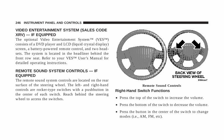
VIDEO ENTERTAINMENT SYSTEM (SALES CODEXRV) — IF EQUIPPEDThe optional Video Entertainment System™ (VES™)consists of a DVD player and LCD (liquid crystal display)screen, a battery-powered remote control, and two head-sets. The system is located in the headliner behind thefront row seat. Refer to your VES™ User’s Manual fordetailed operating instructions.
REMOTE SOUND SYSTEM CONTROLS — IFEQUIPPEDThe remote sound system controls are located on the rearsurface of the steering wheel. The left- and right-handcontrols are rocker-type switches with a pushbutton inthe center of each switch. Reach behind the steeringwheel to access the switches.
Right-Hand Switch Functions
• Press the top of the switch to increase the volume.
• Press the bottom of the switch to decrease the volume.
• Press the button in the center of the switch to changemodes (i.e., AM, FM, etc).
Remote Sound Controls
246 INSTRUMENT PANEL AND CONTROLS

Left-Hand Switch Functions for Radio Operation
• Press the top of the switch to SEEK the next listenablestation up from the current setting.
• Press the bottom of the switch to SEEK the nextlistenable station down from the current setting.
• Press the button in the center of the switch to tune tothe next preset that you have programmed.
Left-Hand Switch Functions for Media (i.e., CD)Operation
• Press the top of the switch once to listen to the nexttrack.
• Press the bottom of the switch once either to listen tothe beginning of the current track or to listen to thebeginning of the previous track if it is within onesecond after the current track begins to play.
• Press the switch up or down twice to listen to thesecond track, three times to listen to the third track,and so forth.
• Press the button located in the center of the switch tochange to the next preset that you have programmed.
COMPACT DISC MAINTENANCETo keep the compact discs in good condition, take thefollowing precautions:
1. Handle the disc by its edge; avoid touching thesurface.
2. If the disc is stained, clean the surface with a soft cloth,wiping from center to edge.
3. Do not apply paper or tape to the disc; avoid scratch-ing the disc.
4. Do not use solvents such as benzine, thinner, cleaners,or antistatic sprays.
INSTRUMENT PANEL AND CONTROLS 247
4

5. Store the disc in its case after playing.
6. Do not expose the disc to direct sunlight.
7. Do not store the disc where temperatures may becometoo high.
NOTE: If you experience difficulty in playing a particu-lar disc, it may be damaged (i.e. scratched, reflectivecoating removed, a hair, moisture or dew on the disc)oversized, or have theft protection encoding. Try aknown good disc before considering disc player service.
RADIO OPERATION AND CELLULAR PHONESUnder certain conditions, the cellular phone being ON inyour vehicle can cause erratic or noisy performance fromyour radio. This condition may be lessened or eliminatedby relocating the cellular phone antenna. This conditionis not harmful to the radio. If your radio performancedoes not satisfactorily “clear” by the repositioning of theantenna, it is recommended that the radio volume beturned down or off during cellular phone operation.
248 INSTRUMENT PANEL AND CONTROLS

CLIMATE CONTROLS
Manual Control
The air conditioning and heating system is designed tomake you comfortable in all types of weather. Thefollowing describes its operation:
Air Conditioning OperationTo turn the air conditioning ON or OFF, performthe following steps:
• Position the mode control button to the desired airflowsetting.
• Set the front blower control to any desired speed.
• Press the Snowflake (A/C) button which is located tothe right of the temperature control slide. An indicatorlight on the Snowflake (A/C) button shows that the airconditioning is ON.
• Press the Snowflake (A/C) button a second time toturn the air conditioning OFF.
NOTE: The compressor will not engage until the enginehas been running for several seconds. Slight changes in
Manual Control
INSTRUMENT PANEL AND CONTROLS 249
4
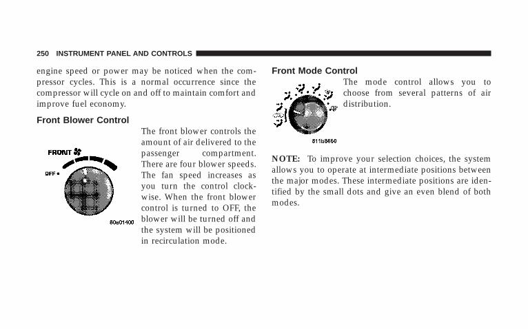
engine speed or power may be noticed when the com-pressor cycles. This is a normal occurrence since thecompressor will cycle on and off to maintain comfort andimprove fuel economy.
Front Blower ControlThe front blower controls theamount of air delivered to thepassenger compartment.There are four blower speeds.The fan speed increases asyou turn the control clock-wise. When the front blowercontrol is turned to OFF, theblower will be turned off andthe system will be positionedin recirculation mode.
Front Mode ControlThe mode control allows you tochoose from several patterns of airdistribution.
NOTE: To improve your selection choices, the systemallows you to operate at intermediate positions betweenthe major modes. These intermediate positions are iden-tified by the small dots and give an even blend of bothmodes.
250 INSTRUMENT PANEL AND CONTROLS

Recirculation Mode (Panel or Bi-Level)Select either the Panel or Bi-Levelmode positions when the outside aircontains smoke, odors, high humidity,or if rapid cooling of the interior isdesired. This feature allows for recir-culation of interior air only, when ei-ther of these positions are selected. Air
flows through the panel outlets or panel and floor outletsin these modes.
PanelOutside air flows through the outlets located in theinstrument panel. These outlets can be adjusted todirect the airflow.
Bi-LevelAir flows through the outlets located in the instru-ment panel and those located on the floor.
NOTE: There is a difference in temperature between theupper and lower outlets for added comfort. The warmerair goes to the floor outlets. This feature gives improvedcomfort during sunny but cool conditions.
Heat (Floor)Outside air flows primarily through the floor out-lets located under the instrument panel. A small
amount of air is directed through the defrost and sidewindow demister outlets.
MixOutside air flows in equal proportions through thefloor and defroster outlet.
DefrostOutside air is primarily directed to the windshieldthrough the defroster outlet located at the base ofthe windshield and side window demist outlets.
INSTRUMENT PANEL AND CONTROLS 251
4

NOTE: The air conditioning compressor operates inboth Mix and Defrost or a blend of these modes, even ifthe A/C button has not been pressed. This dehumidifiesthe air to help dry the windshield.
Temperature ControlThe temperature of the air is controlled by a slide locatedon the top center of the control panel. Move the slide leftor right to change the temperature. The blue area of thescale indicates cooler temperatures while the red areaindicates warmer temperatures.
Manual Temperature Control
252 INSTRUMENT PANEL AND CONTROLS
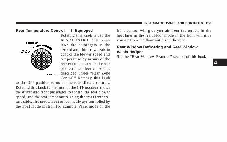
Rear Temperature Control — If EquippedRotating this knob left to theREAR CONTROL position al-lows the passengers in thesecond and third row seats tocontrol the blower speed andtemperature by means of therear control located in the rearof the center floor console asdescribed under “Rear ZoneControl.” Rotating this knob
to the OFF position turns off the rear climate controls.Rotating this knob to the right of the OFF position allowsthe driver and front passenger to control the rear blowerspeed, and the rear temperature using the front tempera-ture slide. The mode, front or rear, is always controlled bythe front mode control. For example: Panel mode on the
front control will give you air from the outlets in theheadliner in the rear. Floor mode in the front will giveyou air from the floor outlets in the rear.
Rear Window Defrosting and Rear WindowWasher/WiperSee the “Rear Window Features” section of this book.
INSTRUMENT PANEL AND CONTROLS 253
4

Automatic Temperature Control (ATC) — IfEquippedThe control can be turned on by pressing the Power knob.When the control is turned on, it will be in the last modeprior to being turned off. Pressing the Power knob againwill turn off the control. The control can also be turned onby pressing any button and it will display the corre-sponding operation mode for that button.
Automatic ControlThe ATC system can maintain a steady comfort level invarious weather conditions with a simple operation:
• Select your desired temperature setting by pressingthe + or - side of the Temp rocker switches. A digitaltemperature setting for driver and passenger will be
Automatic Temperature Control
254 INSTRUMENT PANEL AND CONTROLS

displayed. The ATC system uses an infrared sensorlocated in the overhead console to measure the tem-perature of the driver and passengers. Based on thesensor input, the system will automatically controlcomfort by varying the temperature, fan speed, andmode. This maintains a comfortable temperature, evenunder changing conditions. It is important that objectsare not blocking the infrared sensor. It is also impor-tant that objects are not used that may scratch ordamage it in any way.
Level Of Automatic Control72°F (22°C) is the recommended setting for maximumcomfort for the average person, however, this may vary.
NOTE: The temperature setting can be adjusted at anytime without affecting automatic control operation. It isnot necessary to move the temperature setting for cold or
hot vehicles. The system automatically adjusts the tem-perature, mode and fan speed to provide comfort asquickly as possible.
NOTE: In cold weather, the fan will not turn on in Automode until the engine coolant has warmed up suffi-ciently. This is indicated by the “WARM UP DELAY”message on the display.
NOTE: The temperature can be displayed in U.S. orMetric by selecting the U.S./METRIC Customer-Programmable feature. Refer to 9Overhead ConsoleCustomer-Programmable Features9 in Section 3. Themode will also be shown in the display and will changeas required during automatic operation.
NOTE: The system can be put into recirculate modewithout affecting ATC operation. This will prevent out-side air from entering the vehicle. Use this mode totemporarily block out any outside odors, smoke, or dust.
INSTRUMENT PANEL AND CONTROLS 255
4

Manual Control (ATC)You may also choose to customize your comfort byselecting the fan speed and mode manually. Turning thefan speed knob or any mode button places the systeminto manual operation.
While in manual operation there are six fan speedsavailable and the choice of any mode. The airflowtemperature is adjusted automatically to maintain thedesired comfort level. You can adjust the temperature bypressing the + or - Temp rocker switches.
FAN ControlUse this knob to regulate the amount of air deliveredthrough the system in any mode you select. Rotation
of the knob to increase (clockwise) or decrease (counter-clockwise) fan speed.
Air Conditioning OperationPress this button to enable the air conditioningsystem. Compressor operation is automatic when
you press the AUTO button and no snowflake is shown.A snowflake indicates that the A/C system is enabled.The snowflake will not be displayed in AUTO mode eventhough the A/C system is enabled.
The compressor may operate at any temperature above32°F (0°C).
NOTE: The compressor will not engage until the enginehas been running for several seconds. Slight changes inengine speed or power may be noticed when the com-pressor cycles. This is a normal occurrence since thecompressor will cycle on and off to maintain comfort andimprove fuel economy.
Recirculate ButtonPress this button to recirculate the air inside thevehicle. Outside air is prevented from enteringthe vehicle. Use this mode to temporarily blockout any outside odors, smoke, dust or whenrapid cooling of the interior is required.
256 INSTRUMENT PANEL AND CONTROLS

Manual control of recirculation is possible only in Panel,Floor, and Bi-Level modes. It will not operate in Mix, orDefrost modes. The recirculation symbol will flash threetimes indicating recirculation is not available in thesemodes.
NOTE: If the interior of the windows begin to fog, pressthe Recirculate button to return to outside air. Someconditions will cause captured interior air to fog win-dows when in recirculate mode.
PanelAir flows through the outlets located in the instru-ment panel. These outlets can be adjusted to directthe airflow.
Floor (Heat)Air flows primarily through the floor outlets lo-cated under the instrument panel. A small amount
of air is directed through the defrost and side windowdemister outlets.
MixOutside air flows in equal proportions through thefloor and defroster outlets.
Bi-LevelAir flows through the outlets located in the instru-ment panel and those located on the floor.
NOTE: There is a difference in temperature between theupper and lower outlets for added comfort. The warmerair goes to the floor outlets. This feature gives improvedcomfort during sunny but cool conditions.
DefrostOutside air is directed to the windshield throughthe defroster outlet located at the base of thewindshield and side window demist outlets.
NOTE: The air conditioning compressor operates inboth Mix and Defrost or a blend of these modes, even ifthe A/C snowflake button has not been pressed. Thisdehumidifies the air to help dry the windshield.
INSTRUMENT PANEL AND CONTROLS 257
4

Rear Temperature Control (ATC)The REAR button cycles through the following modes:
Rear Control From FrontThis allows the driver or passenger to control the rearblower speeds rotating the Power/Fan knob and the reartemperature using the PASS/REAR Temp +/- rockerswitch. While in this mode, pressing the POWER/FANknob will turn the rear system off. Pressing the Power/Fan knob will turn the rear system back on.
NOTE: The display will show a 9REAR9 fan speed graphand a 9REAR9 digital temp setting.
CONTROL IN REARThis allows the passengers in the second row seats tocontrol the blower speed and temperature by means ofthe rear control located in the rear of the center floorconsole as described under the 9Rear Zone ClimateControl.9
NOTE: The front display will show “CONTROL INREAR.”
REAR OFFThis turns the rear system off. The control will return tothe front system display after approximately five secondsif no buttons are pushed while in one of the rear systemdisplays. You may also return to the front system displaysooner by pushing any button except the Power/Fanknob, the REAR button, or the driver/passenger Temprocker buttons.
NOTE: The display will show “REAR OFF.”
REAR AUTOThis mode places the rear system in automatic tempera-ture control. Rear temperature can be set as desired (72°F[22°C] recommended for average person) and will bedisplayed digitally on the front control when in rearmode.
258 INSTRUMENT PANEL AND CONTROLS

Rear Window Defrosting and Rear WindowWasher/WiperRefer to “Rear Window Features” in Section 4.
Rear Zone Climate Control — If Equipped
Headliner air comes from the outlets in the headliner.Each of these outlets can be individually adjusted todirect the flow of air. Moving the air vane knobs on theoutlets to one side will shut off the airflow.
Rear Outlets
INSTRUMENT PANEL AND CONTROLS 259
4
The rear compartment control uses two rotary knobs: onefor the temperature control and the other for the fanspeed control. The mode for the rear air conditioning andheating system is always controlled by the front controlunit. Fan and temperature can be controlled from thefront control unit or the rear control unit.
Rear Rotary Blower ControlThe second row seat occupants have control of the rearblower speed only when the front control unit is in the“REAR CONTROL” position or “CONTROL IN REARfor ATC.9
The rear blower switch has an OFF position and a rangeof blower speeds. Rotating the rear blower control clock-wise will increase the blower speed.
Rear Rotary Temperature ControlThe second row seat occupants have control of the reartemperature only when the front control unit is in the9REAR CONTROL9 position.
To change the temperature in the rear of the vehicle,rotate the temperature control knob to the right or left.The blue area indicates cooler temperatures while the redarea indicates warmer temperatures.
NOTE: For best operation, make sure that ventilationgrilles located in the rear storage area are not obstructedby stowed articles.
260 INSTRUMENT PANEL AND CONTROLS

Front Unit to Rear Unit Chart
If the Front Control isselected
Rear Airflow will comefrom
Panel HeadlinerBi-Level HeadlinerFloor FloorMix FloorDefrost Floor
Operating Tips
Fast CooldownFor a fast cooldown, set the blower fan to the highestsetting, set the mode control to the panel fresh position,press the Snowflake button to turn on the air condition-ing, and drive with the windows open for the first fewminutes. Once the hot air has been expelled, close thewindows and set the mode selector to the Recirculationpanel or Recirculation Bi-level position. When a comfort-able condition has been reached, choose a mode position
Rear Storage Ventilation Grilles
INSTRUMENT PANEL AND CONTROLS 261
4

and adjust the temperature control and blower speed asnecessary to maintain comfort. For high humidity condi-tions, it may be necessary to remain in the Recirculationmode to maintain comfort.
Window FoggingWindows will fog on the inside when the humidity insidethe vehicle is high. This often occurs in mild or cooltemperatures when it’s rainy or humid. In most cases,turning on the air conditioning (pressing the snowflakebutton) will clear the fog. Adjust the temperature control,air direction and blower speed to maintain comfort.
As the temperature gets colder it may be necessary todirect air onto the windshield by using Mix Modeposition on the control. Adjust the temperature controland blower speed to maintain comfort. Interior foggingon the windshield can be quickly removed by selectingthe defrost mode.
Regular cleaning of the inside of the windows with anon-filming cleaning solution (vinegar and water worksvery well) will help prevent contaminants (cigarettesmoke, perfumes, etc.) from sticking to the windows.Contaminants increase the rate of window fogging.
Summer OperationAir conditioned vehicles must be protected with a highquality antifreeze coolant during summer to provideproper corrosion protection and to raise the boiling pointof the coolant for protection against overheating. A 50 %concentration is recommended.
Winter OperationWhen operating the system during the winter months,make sure the air intake, located directly in front of thewindshield, is free of ice, slush, snow, or other obstruc-tions. This will also prevent snow ingestion into theducts.
262 INSTRUMENT PANEL AND CONTROLS
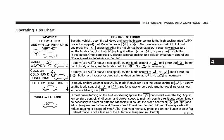
Operating Tips Chart
INSTRUMENT PANEL AND CONTROLS 263
4
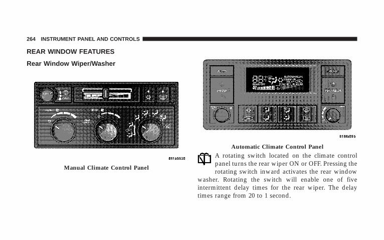
REAR WINDOW FEATURES
Rear Window Wiper/Washer
A rotating switch located on the climate controlpanel turns the rear wiper ON or OFF. Pressing therotating switch inward activates the rear window
washer. Rotating the switch will enable one of fiveintermittent delay times for the rear wiper. The delaytimes range from 20 to 1 second.
Manual Climate Control Panel
Automatic Climate Control Panel
264 INSTRUMENT PANEL AND CONTROLS

If the rear wiper is operating when the ignition is turnedOFF, the wiper will automatically return to the Parkposition. When the vehicle is restarted, the wiper willresume operation.
Rear Window DefrostingA pushbutton type switch is located in the climatecontrol panel. Press the switch and the rear win-
dow defroster and electric remote control heated mirrors(if equipped) will turn on. An amber indicator on thepushbutton will light when the defroster is turned on. Asymbol will be displayed when the defroster is turned onwith an ATC control. Push again to turn off prior totime-out. The defroster will automatically turn off after15 minutes. For 10 more minutes of operation, push thebutton again. To prevent excessive battery drain, use thedefroster only when the engine is operating.
CAUTION!
Use care when washing the inside of the rear windowto prevent damage to heating elements. Use a softcloth and a mild washing solution, wiping parallel tothe heating elements. Also, keep all objects a safedistance from the window to prevent damaging theheating elements.
INSTRUMENT PANEL AND CONTROLS 265
4


STARTING AND OPERATING
CONTENTS
m Starting Procedures . . . . . . . . . . . . . . . . . . . . . 271
▫ Automatic Transmission . . . . . . . . . . . . . . . . 271
▫ Normal Starting . . . . . . . . . . . . . . . . . . . . . . 271
m Engine Block Heater – If Equipped . . . . . . . . . . 274
m Automatic Transmission . . . . . . . . . . . . . . . . . . 274
▫ Brake/Transmission Interlock System . . . . . . . 274
▫ Gear Ranges . . . . . . . . . . . . . . . . . . . . . . . . . 275
▫ Overdrive Operation . . . . . . . . . . . . . . . . . . . 277
▫ When To Use Tow/Haul Mode . . . . . . . . . . . 278
▫ Torque Converter Clutch . . . . . . . . . . . . . . . . 279
m Four-Wheel Drive Operation . . . . . . . . . . . . . . . 280
▫ NV 140 Transfer Case OperatingInformation/Precautions – If Equipped . . . . . . 280
▫ NV 244 Generation II Transfer Case OperatingInformation / Precautions . . . . . . . . . . . . . . . 280
▫ Shifting Procedure - NV 244 Generation IITransfer Case . . . . . . . . . . . . . . . . . . . . . . . . 284
m Driving On Slippery Surfaces . . . . . . . . . . . . . . 286
m Driving Through Water . . . . . . . . . . . . . . . . . . 286
5

▫ Flowing/Rising Water . . . . . . . . . . . . . . . . . . 287
▫ Shallow Standing Water . . . . . . . . . . . . . . . . . 287
m Parking Brake . . . . . . . . . . . . . . . . . . . . . . . . . 289
m Brake System . . . . . . . . . . . . . . . . . . . . . . . . . . 290
▫ Four-Wheel Anti-Lock Brake System (ABS) . . . 290
m Power Steering . . . . . . . . . . . . . . . . . . . . . . . . 293
m Electronic Brake Control System . . . . . . . . . . . . 294
▫ Anti-Lock Brake System (ABS) . . . . . . . . . . . . 294
▫ BAS (Brake Assist System) . . . . . . . . . . . . . . . 295
▫ Traction Control System (TCS) . . . . . . . . . . . . 297
▫ Electronic Roll Mitigation (ERM) . . . . . . . . . . 297
▫ Electronic Stability Program (ESP) . . . . . . . . . 298
m Multi-Displacement System (MDS) — 5.7L EngineOnly . . . . . . . . . . . . . . . . . . . . . . . . . . . . . . . . 303
m Tire Safety Information . . . . . . . . . . . . . . . . . . . 303
▫ Tire Markings . . . . . . . . . . . . . . . . . . . . . . . . 303
▫ Tire Identification Number (TIN) . . . . . . . . . . 307
▫ Tire Loading And Tire Pressure . . . . . . . . . . . 308
m Tires — General Information . . . . . . . . . . . . . . . 312
▫ Tire Pressure . . . . . . . . . . . . . . . . . . . . . . . . . 312
▫ Tire Inflation Pressures . . . . . . . . . . . . . . . . . 313
▫ Radial Ply Tires . . . . . . . . . . . . . . . . . . . . . . 315
▫ Compact Spare Tire — If Equipped . . . . . . . . . 316
▫ Limited-Use Spare — If Equipped . . . . . . . . . 316
▫ Tire Spinning . . . . . . . . . . . . . . . . . . . . . . . . 317
268 STARTING AND OPERATING

▫ Tread Wear Indicators . . . . . . . . . . . . . . . . . . 318
▫ Life Of Tire . . . . . . . . . . . . . . . . . . . . . . . . . 318
▫ Replacement Tires . . . . . . . . . . . . . . . . . . . . . 319
▫ Alignment And Balance . . . . . . . . . . . . . . . . . 320
m Supplemental Tire Pressure Information — IfEquipped . . . . . . . . . . . . . . . . . . . . . . . . . . . . 321
m Tire Chains . . . . . . . . . . . . . . . . . . . . . . . . . . . 321
m Snow Tires . . . . . . . . . . . . . . . . . . . . . . . . . . . 322
m Tire Rotation Recommendations . . . . . . . . . . . . 323
m Tire Pressure Monitor System (TPMS) —If Equipped . . . . . . . . . . . . . . . . . . . . . . . . . . . 324
▫ Base System – If Equipped . . . . . . . . . . . . . . . 326
▫ Premium System – If Equipped . . . . . . . . . . . 328
▫ General Information . . . . . . . . . . . . . . . . . . . 331
m Fuel Requirements . . . . . . . . . . . . . . . . . . . . . . 331
▫ Reformulated Gasoline . . . . . . . . . . . . . . . . . 332
▫ Gasoline/Oxygenate Blends . . . . . . . . . . . . . . 333
▫ MMT In Gasoline . . . . . . . . . . . . . . . . . . . . . 333
▫ Materials Added To Fuel . . . . . . . . . . . . . . . . 334
▫ Fuel System Cautions . . . . . . . . . . . . . . . . . . 334
▫ Carbon Monoxide Warnings . . . . . . . . . . . . . . 335
m Adding Fuel . . . . . . . . . . . . . . . . . . . . . . . . . . 336
▫ Fuel Filler Cap (Gas Cap) . . . . . . . . . . . . . . . 336
▫ Loose Fuel Filler Cap (Gas Cap) Message . . . . 337
m Flexible Fuel — If Equipped . . . . . . . . . . . . . . . 338
▫ E-85 General Information . . . . . . . . . . . . . . . . 338
▫ Ethanol Fuel (E-85) . . . . . . . . . . . . . . . . . . . . 339
STARTING AND OPERATING 269
5
▫ Fuel Requirements . . . . . . . . . . . . . . . . . . . . 340
▫ Selection Of Engine Oil For Flexible FuelVehicles (E-85) And Gasoline Vehicles . . . . . . . 340
▫ Starting . . . . . . . . . . . . . . . . . . . . . . . . . . . . 341
▫ Cruising Range . . . . . . . . . . . . . . . . . . . . . . . 341
▫ Replacement Parts . . . . . . . . . . . . . . . . . . . . . 341
m Vehicle Loading . . . . . . . . . . . . . . . . . . . . . . . . 342
▫ Certification Label . . . . . . . . . . . . . . . . . . . . . 342
▫ Curb Weight . . . . . . . . . . . . . . . . . . . . . . . . . 343
▫ Loading . . . . . . . . . . . . . . . . . . . . . . . . . . . . 343
m Trailer Towing . . . . . . . . . . . . . . . . . . . . . . . . . 345
▫ Common Towing Definitions . . . . . . . . . . . . . 345
▫ Trailer Hitch Classification . . . . . . . . . . . . . . . 350
▫ Trailer Towing Weights (Maximum TrailerWeight Ratings) . . . . . . . . . . . . . . . . . . . . . . 351
▫ Trailer And Tongue Weight . . . . . . . . . . . . . . 351
▫ Towing Requirements . . . . . . . . . . . . . . . . . . 352
▫ Towing Tips . . . . . . . . . . . . . . . . . . . . . . . . . 357
m Snowplow . . . . . . . . . . . . . . . . . . . . . . . . . . . . 359
m Recreational Towing (Behind Motorhome, Etc.) . . 360
▫ Recreational Towing 2WD Models . . . . . . . . . 360
▫ Recreational Towing 4WD Models . . . . . . . . . 360
m Equipment Identification Plate . . . . . . . . . . . . . 364
270 STARTING AND OPERATING

STARTING PROCEDURESBefore starting your vehicle, adjust your seat, adjust bothinside and outside mirrors, and fasten your seat belts.
WARNING!
Be sure to turn off the engine and remove the keyfrom the ignition switch if you want to rest or sleepin your car. Accidents can be caused by inadvertentlymoving the shift lever or by pressing the acceleratorpedal. This may cause excessive heat in the exhaustsystem, resulting in overheating and vehicle firewhich may cause serious or fatal injuries.
WARNING!
Do not leave children or animals inside parkedvehicles in hot weather. Interior heat build up maycause serious injury or death.
Automatic TransmissionStart the engine with the selector lever in NEUTRAL orPARK position. Apply the brake before shifting to anydriving range.
Normal StartingNormal starting of either a warm or cold engine isobtained without pumping or depressing the acceleratorpedal.
STARTING AND OPERATING 271
5

Tip Start FeatureYour vehicle has a “Tip Start” starting system. With “TipStart” the driver does not need to hold the key in theSTART position until the vehicle starts, but can releasethe key (still in the ignition) and the vehicle will continuethrough the start cycle.
• Turn the ignition key to the START position until thestart motor engages.
• Release the key (still in the ignition) and the starterwill continue through the start cycle until the vehiclestarts or for five seconds (whichever comes first).
If Engine Fails To StartIf the engine fails to start after you have followed thenormal starting procedure, it may be flooded. Push theaccelerator pedal all the way to the floor and hold it therewhile cranking the engine. This should clear any excessfuel in case the engine is flooded.
CAUTION!
To prevent damage to the starter, do not crank theengine for more than 15 seconds at a time. Wait 10 to15 seconds before trying again.
WARNING!
Never pour fuel or other flammable liquid into thethrottle body air inlet opening in an attempt to startthe vehicle. This could result in flash fire causingserious personal injury.
272 STARTING AND OPERATING

WARNING!
Do not attempt to push or tow your vehicle to get itstarted. Vehicles equipped with an automatic trans-mission cannot be started this way. Unburned fuelcould enter the catalytic converter and once theengine has started, ignite and damage the converterand vehicle. If the vehicle has a discharged battery,booster cables may be used to obtain a start from abooster battery or the battery in another vehicle. Thistype of start can be dangerous if done improperly.Refer to “Jump Starting” in Section 6 for the properjump-starting procedures and follow them carefully.
If the engine has been flooded it may start to run, but nothave enough power to continue running when the key isreleased. If this occurs, continue cranking with the accel-erator pedal pushed all the way to the floor. Release theaccelerator pedal and the key once the engine is runningsmoothly.
If the engine shows no sign of starting after two 15second periods of cranking with the accelerator pedalheld to the floor, the normal starting procedure should berepeated.
After StartingThe idle speed is automatically controlled on fuel injectedengines and will decrease as the engine warms up.
STARTING AND OPERATING 273
5
ENGINE BLOCK HEATER – IF EQUIPPEDThe engine block heater warms the engine coolant andpermits quicker starts in cold weather. Connect the cordto a standard 110-115 volt AC electrical outlet with agrounded, three wire extension cord.
The 3.7L/4.7L engine block heater cord is located at thefront of the engine compartment near the radiator cap.The 5.7L engine block heater cord is located on the leftside of the engine compartment and rearward of thepower distribution center.
WARNING!
Remember to disconnect the cord before driving.Damage to the 110-115 volt electrical cord could causeelectrocution.
AUTOMATIC TRANSMISSIONThe electronic PRNDL on the instrument cluster indicatesthe transmission gear selected. The shift lever is mountedon the right side of the steering column. To drive, movethe shift lever from PARK or NEUTRAL to the desireddrive position. Pull the shift lever toward you whenshifting into REVERSE, 2nd, 1st or PARK, or whenshifting out of PARK.
Brake/Transmission Interlock SystemThis system prevents you from moving the gear shift outof PARK and into any gear unless the brake pedal ispressed. This system is active only while the ignitionswitch is in the ON position. Always depress the brakepedal first, before moving the gear selector out of PARK.
274 STARTING AND OPERATING
Gear RangesDO NOT race the engine when shifting from PARK orNEUTRAL position into another gear range.
“P” PARKSupplements parking brake by locking the transmission.Engine can be started in this range. Never use PARKwhile vehicle is in motion. Apply the parking brake whenleaving the vehicle in this range. Always apply theparking brake first, then place the shift lever in PARKposition.
WARNING!
Your vehicle could move and injure you and others ifit is not completely in PARK. Check by trying tomove the gearshift lever back and forth without firstpulling the lever toward you, after you have set it inPARK. Make sure it is in PARK before leaving thevehicle.
WARNING!
Never use the PARK position on an automatic trans-mission as a substitute for the parking brake. Alwaysapply the parking brake fully when parked to guardagainst vehicle movement and possible injury ordamage.
STARTING AND OPERATING 275
5
WARNING!
It is dangerous to shift the gear shift lever out ofPARK or NEUTRAL if the engine speed is higherthan idle speed. If your foot is not firmly on thebrake pedal, the vehicle could accelerate quicklyforward or in reverse. You could lose control of thevehicle and hit someone or something. Only shiftinto gear when the engine is idling normally andwhen your right foot is firmly on the brake pedal.
“R” REVERSEUse this range only after the vehicle has come to acomplete stop.
“N” NEUTRALShift to NEUTRAL when the vehicle is standing forprolonged periods with the engine running. The enginemay be started in this range. Set the parking brake if youmust leave the vehicle.
NOTE: Towing the vehicle (except as specified underTowing A Disabled Vehicle), coasting, or otherwise driv-ing the vehicle while in NEUTRAL can cause severetransmission damage
“D” DRIVEFor most city and highway driving.
“2” 2ndFor driving slowly in heavy city traffic or on mountainroads where more precise speed control is desirable. Useit also when climbing long grades, and for engine brak-ing when descending moderately steep grades. To pre-vent excessive engine speed, do not exceed 45 mph (72km/h) in this range.
276 STARTING AND OPERATING
“1” 1stFor driving up very steep hills and for engine braking atlow speeds (25 mph {40 km/h} or less) when goingdownhill. To prevent excessive engine speed do notexceed 25 mph (40 km/h) in this range.
OVERDRIVE OperationThe OVERDRIVE automatic transmission contains anelectronically controlled fourth and fifth (if equipped)speed (OVERDRIVE). The transmission will automati-cally shift from DRIVE to OVERDRIVE if the followingconditions are present:
• the transmission selector is in DRIVE;
• the engine coolant has reached normal operating tem-perature;
• vehicle speed is above approximately 30 mph (48km/h);
• the TOW/HAUL switch has not been activated;
• transmission has reached normal operating tempera-ture.
NOTE: If the vehicle is started in extremely cold tem-peratures, the transmission may not shift into OVER-DRIVE and will automatically select the most desirablegear for operation at this temperature. Normal operationwill resume when the transmission fluid temperature hasrisen to a suitable level. Refer also to the Note undertorque converter clutch, later in this section.
If the transmission temperature gets extremely hot, thetransmission will automatically select the most desirablegear for operation at this temperature. If the transmissiontemperature becomes hot enough, the “TRANS TEMP”light may illuminate and the transmission may down-shift out of OVERDRIVE until the transmission coolsdown. After cooldown, the transmission will resumenormal operation.
STARTING AND OPERATING 277
5
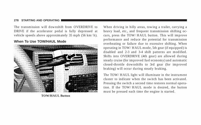
The transmission will downshift from OVERDRIVE toDRIVE if the accelerator pedal is fully depressed atvehicle speeds above approximately 35 mph (56 km/h).
When To Use TOW/HAUL Mode
When driving in hilly areas, towing a trailer, carrying aheavy load, etc., and frequent transmission shifting oc-curs, press the TOW/HAUL button. This will improveperformance and reduce the potential for transmissionoverheating or failure due to excessive shifting. Whenoperating in TOW/HAUL mode, 5th gear (if equipped) isdisabled and 2-3 and 3-4 shift patterns are modified.Shifts into OVERDRIVE (4th gear) are allowed duringsteady cruise (for improved fuel economy) and automaticclosed-throttle downshifts to 3rd gear (for improvedbraking) will occur during steady braking.
The TOW/HAUL light will illuminate in the instrumentcluster to indicate when the switch has been activated.Pressing the switch a second time restores normal opera-tion. If the TOW/HAUL mode is desired, the buttonmust be pressed each time the engine is started.
TOW/HAUL Button
278 STARTING AND OPERATING

Torque Converter ClutchA feature designed to improve fuel economy is includedin all automatic transmissions. A clutch within the torqueconverter engages automatically at a calibrated speed atlight throttle. It engages at higher speeds under heavieracceleration. This may result in a slightly different feelingor response during normal operation in high gear. Whenthe vehicle speed drops below a calibrated speed, orduring acceleration, the clutch automatically andsmoothly disengages. The feature is operational inOVERDRIVE and in DRIVE.
NOTE: The torque converter clutch will not engageuntil the transmission fluid and engine coolant are warm(usually after 1-3 mi [1.6 - 4.8 km] of driving). Because theengine speed is higher when the torque converter clutchis not engaged, it may seem as if the transmission is notshifting into Overdrive when cold. This is normal. Press-ing the TOW/HAUL button, when the transmission issufficiently warm, will demonstrate that the transmission
is able to shift into, and out of, Overdrive. For vehicleswith 4.7L or 5.7L engines (which have two Overdrivegears), the transmission may not shift into 5th gear untilthe transmission fluid and engine coolant are warm.
NOTE: If the vehicle has not been driven in severaldays, the first few seconds of operation after shifting thetransmission into gear may seem sluggish. This is due tothe fluid partially draining from the torque converter intothe transmission. This condition is normal and will notcause damage to the transmission. The torque converterwill refill within five seconds of shifting from PARK intoany other gear position.
STARTING AND OPERATING 279
5
FOUR-WHEEL DRIVE OPERATION
NV 140 Transfer Case OperatingInformation/Precautions – If EquippedThe NV 140 is a single speed (4 HI range only) transfercase which provides convenient full-time 4-wheel drive.No driver interaction is required. This transfer casedivides engine torque almost evenly with 48 percent ofengine torque to the front axle and 52 percent of enginetorque to the rear axle.
Proper operation of 4-wheel drive vehicles depends ontires of equal size, type and circumference on each wheel.Any difference in tire size can cause damage to thetransfer case.
Because 4-wheel drive provides improved traction, thereis a tendency to exceed safe turning and stopping speeds.Do not go faster than road conditions permit.
4WDNormal 4-Wheel Drive High Range - Employs inter-axledifferential. Allows front and rear wheels to rotate atdifferent speeds. All road surfaces.
NV 244 Generation II Transfer Case OperatingInformation / PrecautionsThe NV 244 Generation II is an electric-shift transfer caseand is operated by the 4WD Control Switch, which islocated on the instrument panel.
The NV 244 Generation II transfer case provides fourmode positions - Normal 4-wheel drive (4WD) highrange, 4-wheel-drive lock (4WD LOCK), 4-wheel drivelow (4WD LOW) range, and NEUTRAL.
This transfer case is equipped with an inter-axle differ-ential that allows driving the vehicle in the normalall-wheel drive position (4WD) at all times on any givenroad surface, including dry, hard-surfaced roads. The4WD mode allows the front and rear wheels to rotate at
280 STARTING AND OPERATING

different speeds. This eliminates driveline binding andcomponent wear normally associated with driving thevehicle in the 4WD LOCK position on dry, hard-surfacedroads. This feature provides the safety, security, andconvenience of operating in all-wheel drive at all timesregardless of road conditions.
When additional traction is required, the 4WD LOCKand 4WD LOW positions can be used to lock the frontand rear driveshafts together, through the transfer caseinter-axle differential, and force the front and rear wheelsto rotate at the same speed. This is accomplished byrotating the 4WD Control Switch to these positions. The4WD LOCK and 4WD LOW positions are intended forloose, slippery road surfaces only. Driving in the 4WDLOCK and 4WD LOW positions on dry, hard-surfacedroads may cause increased tire wear and damage to thedriveline components.
The transfer case NEUTRAL position is selected bydepressing the recessed button located on the lower lefthand corner of the 4WD Control Switch.
NOTE: The transfer case NEUTRAL position is to beused for recreational towing only. Refer to “RecreationalTowing” under Section 5 for specific procedures onshifting into and out of NEUTRAL.
Transfer Case Position Indicator LightsTransfer case position indicator lights are located on theinstrument cluster. If there are no indicator lights on orflashing, the transfer case position is 4-wheel drive(4WD) and indicates the current and desired transfer caseselection (4WD ⇔ 4WD LOCK).
The “SVC 4WD” warning light monitors the electric shift4WD system. If this light remains on after engine start upor illuminates during driving, it means that the 4WDsystem is not functioning properly and that service isrequired. See your authorized dealer for service.
STARTING AND OPERATING 281
5

WARNING!
Always engage the parking brake when poweringdown the vehicle if the (SVC 4WD( light is illumi-nated. Not engaging the parking brake may allow thevehicle to roll, which may cause personal injury.
NOTE: Do not attempt to make a shift while only thefront or rear wheels are spinning. The NV 244 GenerationII transfer case is not equipped with a synchronizer andtherefore the front and rear driveshaft speeds must beequal for the shift to take place. Shifting while only thefront or rear wheels are spinning can cause damage to thetransfer case.
When operating your vehicle in 4WD LOW, the enginespeed is approximately three times that of the 4WD or4WD LOCK positions at a given road speed. Take carenot to overspeed the engine and do not exceed 25 mph(40 km/h).
Proper operation of 4-wheel drive vehicles depends ontires of equal size, type and circumference on each wheel.Any difference in tire size can cause damage to thetransfer case.
Because 4-wheel drive provides improved traction, thereis a tendency to exceed safe turning and stopping speeds.Do not go faster than road conditions permit.
282 STARTING AND OPERATING

WARNING!
You or others could be injured if you leave thevehicle unattended with the transfer case in theNEUTRAL position without first fully engaging theparking brake. The transfer case NEUTRAL positiondisengages both the front and rear driveshafts fromthe powertrain and will allow the vehicle to move,regardless of the transmission position. The parkingbrake should always be applied when the driver isnot in the vehicle.
For additional information on the appropriate use of eachtransfer case mode position, refer to the following infor-mation:
4WDNormal 4-Wheel Drive High range employs the inter-axledifferential. This range allows front and rear wheels torotate at different speeds on all road surfaces.
4WD LOCKThe 4-Wheel Drive Lock (4WD LOCK) range, locks thetransfer case inter-axle differential, forcing the front andrear wheels to rotate at the same speed. Additionaltraction for loose, slippery road surfaces only.
STARTING AND OPERATING 283
5

4WD LOWThe 4-Wheel Drive Low (4WD LOW) Range provideslow speed 4-wheel drive. It locks the front and reardriveshafts together, forcing the front and rear wheels torotate at the same speed. This range provides additionaltraction and maximum pulling power for loose or slip-pery road surfaces only. Do not exceed 25 mph (40km/h).
NThe NEUTRAL ranged disengages both the front andrear driveshafts from the powertrain. NEUTRAL is usedfor flat towing behind another vehicle. Refer to “Recre-ational Towing” in Section 5.
Shifting Procedure - NV 244 Generation IITransfer Case
NOTE: The 4x4 system will not allow shifts between4WD/4WD LOCK if the rear wheels are spinning (notraction). In this situation, a position indicator light willflash and the original position indicator light will remainon. At this time, reduce speed and stop spinning the
284 STARTING AND OPERATING

wheels to complete the shift. There may be a delay up to13 seconds for the shift to complete after the wheels havestopped spinning.
NOTE: Delayed shifting out of the 4WD LOCK positionmay be experienced due to uneven tire wear, low tirepressure, or excessive loading.
NOTE: When shifting into, or out of 4WD LOW, somegear noise may be heard. This noise is normal and is notdetrimental to the vehicle or occupants.
Shifting can be performed with the vehicle rolling 2 to 3mph (3 to 5 km/h) or completely stopped. USE EITHEROF THE FOLLOWING PROCEDURES:
Preferred Procedure
1. With the engine running, slow the vehicle to 2 to 3mph (3 to 5 km/h).
2. Shift the transmission into NEUTRAL.
3. While still rolling, rotate the transfer case controlswitch to the desired position.
4. After the position indicator light has stopped flashing,shift the transmission back into gear.
Alternate Procedure
1. Bring the vehicle to a complete stop.
2. With the key ON and the engine either OFF orrunning, shift the transmission into NEUTRAL.
3. Rotate the transfer case control switch to the desiredposition.
4. After the position indicator light has stopped flashing,shift the transmission back into gear.
NOTE: The ignition key must be ON for a shift to takeplace and for the position indicator lights to be operable.If the key is not ON then the shift will not take place andno position indicator lights will be on or flashing.
STARTING AND OPERATING 285
5

NOTE: If any of the requirements to select a newtransfer case position have not been met, the transfer casewill not shift. The indicator light will flash and thecurrent transfer case position will be maintained. To retrythe selection, turn the control knob back to the currentposition, wait five seconds, and retry the shift.
DRIVING ON SLIPPERY SURFACESWhen driving on wet or slushy roads, it is possible for awedge of water to build up between the tire and roadsurface. This is known as hydroplaning and may causepartial or complete loss of vehicle control and stoppingability. To reduce this possibility, the following precau-tions should be observed:
1. Slow down during rainstorms or when roads areslushy.
2. Slow down if road has standing water or puddles.
3. Replace tires when tread wear indicators first becomevisible.
4. Keep tires properly inflated.
5. Maintain sufficient distance between your vehicle andthe car in front to avoid a collision in a sudden stop.
DRIVING THROUGH WATERDriving through water more than a few inches/millimeters deep will require extra caution to ensuresafety and prevent damage to your vehicle.
286 STARTING AND OPERATING

Flowing/Rising Water
WARNING!
Do not drive on, or cross, a road or a path wherewater is flowing and/or rising (as in storm run-off).Flowing water can wear away the road or path’ssurface and cause your vehicle to sink into deeperwater. Furthermore, flowing and/or rising water cancarry your vehicle away swiftly. Failure to follow thiswarning may result in injuries that are serious orfatal to you, your passengers, and others around you.
Shallow Standing WaterAlthough your vehicle is capable of driving throughshallow standing water, consider the following Cautionand Warning before doing so.
CAUTION!
• Always check the depth of the standing waterbefore driving through it. Never drive throughstanding water that is deeper than the bottom ofthe tire rims mounted on the vehicle.
• Determine the condition of the road or the paththat is under water, and if there are any obstaclesin the way, before driving through the standingwater.
• Do not exceed 5 mph (8 km/h) when drivingthrough standing water. This will minimize waveeffects.
STARTING AND OPERATING 287
5

CAUTION!
• Driving through standing water may cause dam-age to your vehicle’s drivetrain components. Al-ways inspect your vehicle’s fluids (i.e., engine oil,transmission, axle, etc.) for signs of contamination(i.e., fluid that is milky or foamy in appearance)after driving through standing water. Do not con-tinue to operate the vehicle if any fluid appearscontaminated, as this may result in further dam-age. Such damage is not covered by the NewVehicle Limited Warranty.
• Getting water inside your vehicle’s engine cancause it to lock up and stall out, and cause seriousinternal damage to the engine. Such damage is notcovered by the New Vehicle Limited Warranty.
WARNING!
• Driving through standing water limits your vehi-cle’s traction capabilities. Do not exceed 5 mph (8km/h) when driving through standing water.
• Driving through standing water limits your vehi-cle’s braking capabilities, which increases stop-ping distances. Therefore, after driving throughstanding water, drive slowly and lightly press onthe brake pedal several times to dry the brakes.
• Getting water inside your vehicle’s engine cancause it to lock up and stall out, and leave youstranded.
• Failure to follow these warnings may result ininjuries that are serious or fatal to you, yourpassengers, and others around you.
288 STARTING AND OPERATING
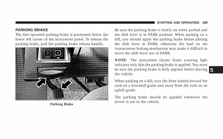
PARKING BRAKEThe foot operated parking brake is positioned below thelower left corner of the instrument panel. To release theparking brake, pull the parking brake release handle.
Be sure the parking brake is firmly set when parked andthe shift lever is in PARK position. When parking on ahill, you should apply the parking brake before placingthe shift lever in PARK; otherwise the load on thetransmission locking mechanism may make it difficult tomove the shift lever out of PARK.
NOTE: The instrument cluster brake warning lightindicates only that the parking brake is applied. You mustbe sure the parking brake is fully applied before leavingthe vehicle.
When parking on a hill, turn the front wheels toward thecurb on a downhill grade and away from the curb on anuphill grade.
The parking brake should be applied whenever thedriver is not in the vehicle.
Parking Brake
STARTING AND OPERATING 289
5

WARNING!
• Always fully apply the parking brake when leav-ing your vehicle, or the vehicle may roll and causedamage or injury. Also be certain to leave anautomatic transmission in Park. Failure to do somay cause the vehicle to roll and cause damage orinjury.
• Be sure the parking brake is fully disengagedbefore driving, failure to do so can lead to brakefailure and an accident.
• Never leave children alone in a vehicle. Leavingunattended children in a vehicle is dangerous for anumber of reasons. A child or others could beseriously or fatally injured. Don’t leave the keys inthe ignition. A child could operate power win-dows, other controls, or move the vehicle.
BRAKE SYSTEMIn the event power assist is lost for any reason, (forexample, repeated brake applications with the engineoff), the brakes will still function. The effort required tobrake the vehicle will be significantly increased over thatrequired with the power system operating.
If either the front or rear hydraulic systems lose normalcapability, the remaining system will still function withsome loss of braking effectiveness. This will be evident byincreased pedal travel during application, greater pedalforce required to slow or stop, and activation of the BrakeWarning Light and the ABS Light during brake use.
Four-Wheel Anti-Lock Brake System (ABS)The Anti-Lock Brake System (ABS) is designed to aid thedriver in maintaining vehicle control under adversebraking conditions. The system operates with a separatecomputer to modulate hydraulic pressure to preventwheel lock-up and help avoid skidding on slippery
290 STARTING AND OPERATING
surfaces. All vehicle wheels and tires must be the samesize and type and tires must be properly inflated toproduce accurate signals for the computer.
WARNING!
Significant over-or-under-inflation of tires, or mixingsizes of tires or wheels on the vehicle can lead to lossof braking effectiveness.
The ABS conducts a low-speed self-test at about 12 mph(20 km/h). If you have your foot lightly on the brakewhile this test is occurring you may feel slight pedalmovement. The movement can be more apparent on iceand snow. This is normal. The ABS pump motor runsduring the self-test at 12 mph (20 km/h) and during anABS stop. The pump motor makes a low humming noiseduring operation, which is normal.
At the instant one of the wheels is about to lock up, aslight pulsation can be felt in the brake pedal, indicatingthat the ABS is in the regulating mode. Keep firm andsteady pressure on the brake pedal while experiencingthe pulsation. Continuous, steady brake pedal pressureresults in optimal braking power while maintaining theability to steer the vehicle. In the case of an emergencybrake maneuver, keep continuous full pressure on thebrake pedal. In this manner only can the ABS be mosteffective. On slippery road surfaces, the ABS will respondeven with light brake pedal pressure because of theincreased likelihood of locking wheels. The pulsatingbrake pedal can be an indication of hazardous roadconditions and functions as a reminder to take extra carewhile driving.
STARTING AND OPERATING 291
5

WARNING!
ABS contains sophisticated electronic equipment. Itmay be susceptible to interference caused by improp-erly installed or high output radio transmittingequipment. This interference can cause possible lossof anti-lock braking capability. Installation of suchequipment should be done by qualifiedprofessionals.
WARNING!
Pumping of the Anti-lock brakes will diminish theireffectiveness and may lead to an accident. Pumpingmakes the stopping distance longer. Just press firmlyon your brake pedal when you need to slow down orstop.
WARNING!
• ABS cannot prevent the natural laws of physicsfrom acting on the vehicle, nor can it increasebraking or steering efficiency beyond that af-forded by the condition of the vehicle brakes andtires or the traction afforded.
• The ABS cannot prevent accidents, includingthose resulting from excessive speed in turns,following another vehicle too closely, or hydro-planing. Only a safe, attentive, and skillful drivercan prevent accidents.
• The capabilities of an ABS equipped vehicle mustnever be exploited in a reckless or dangerousmanner which could jeopardize the user’s safetyor the safety of others.
292 STARTING AND OPERATING

When you are in a severe braking condition involvinguse of the ABS, you will experience some pedal drop asthe vehicle comes to a stop. This is the result of thesystem reverting to the base brake system.
Engagement of the ABS may be accompanied by apulsing sensation. You may also hear a clicking noise.These occurrences are normal, and indicate that thesystem is functioning properly.
POWER STEERINGThe standard power steering system will give you goodvehicle response and increased ease of maneuverabilityin tight spaces. The system will provide mechanicalsteering capability if power assist is lost.
If for some reason the power assist is interrupted, it willstill be possible to steer your vehicle. Under these condi-tions you will observe a substantial increase in steeringeffort, especially at very low vehicle speeds and duringparking maneuvers.
NOTE: Increased noise levels at the end of the steeringwheel travel are considered normal and does not indicatethat there is a problem with the power steering system.
Upon initial start-up in cold weather, the power steeringpump may make noise for a short period of time. This isdue to the cold, thick fluid in the steering system. Thisnoise should be considered normal, and does not in anyway damage the steering system.
WARNING!
Continued operation with reduced power steeringassist could pose a safety risk to yourself and others.Service should be obtained as soon as possible.
STARTING AND OPERATING 293
5

CAUTION!
Prolonged operation of the steering system at the endof the steering wheel travel will increase the steeringfluid temperature and should be avoided when pos-sible. Damage to the power steering pump may occur.
ELECTRONIC BRAKE CONTROL SYSTEMYour vehicle is equipped with an advanced electronicbrake control system that includes Anti-Lock Brake Sys-tem (ABS), Brake Assist System (BAS), Traction ControlSystem (TCS), Electronic Roll Mitigation (ERM), Elec-tronic Stability Program (ESP) and Trailer Sway Control(TSC). All six systems work together to enhance vehiclestability and control in various driving conditions, andare commonly referred to as ESP.
Anti-Lock Brake System (ABS)
This system aids the driver in maintaining vehicle controlunder adverse braking conditions. The system controlshydraulic brake pressure to prevent wheel lockup andhelp avoid skidding on slippery surfaces during braking.Refer to “Anti-Lock Brake System” in Section 5 of thismanual for more information about ABS.
NOTE: ABS improves steering control of the vehicleduring hard braking maneuvers.
294 STARTING AND OPERATING
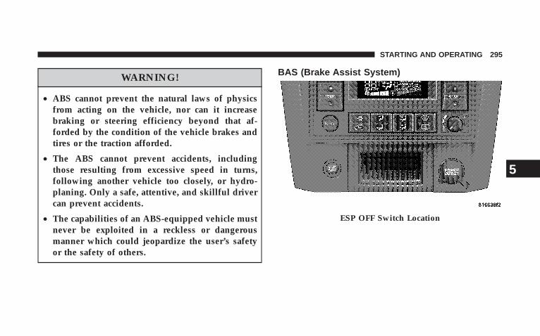
WARNING!
• ABS cannot prevent the natural laws of physicsfrom acting on the vehicle, nor can it increasebraking or steering efficiency beyond that af-forded by the condition of the vehicle brakes andtires or the traction afforded.
• The ABS cannot prevent accidents, includingthose resulting from excessive speed in turns,following another vehicle too closely, or hydro-planing. Only a safe, attentive, and skillful drivercan prevent accidents.
• The capabilities of an ABS-equipped vehicle mustnever be exploited in a reckless or dangerousmanner which could jeopardize the user’s safetyor the safety of others.
BAS (Brake Assist System)
ESP OFF Switch Location
STARTING AND OPERATING 295
5
The BAS is designed to optimize the vehicle’s brakingcapability during emergency braking maneuvers. Thesystem detects an emergency braking situation by sens-ing the rate and amount of brake application and thenapplies optimum pressure to the brakes. The systemapplies optimum pressure to the brakes in emergencybraking conditions. This can help reduce braking dis-tances. The BAS complements the ABS. Applying thebrakes very quickly results in the best BAS assistance. Toreceive the benefit of the system, you must apply con-tinuous braking pressure during the stopping sequence.Do not reduce brake pedal pressure unless braking is nolonger desired.
Once the brake pedal is released, the BAS is deactivated.
WARNING!
• BAS cannot prevent the natural laws of physicsfrom acting on the vehicle, nor can it increasebraking efficiency beyond that afforded by thecondition of the vehicle brakes and tires or thetraction afforded.
• The BAS cannot prevent accidents, includingthose resulting from excessive speed in turns,following another vehicle too closely, or hydro-planing. Only a safe, attentive, and skillful drivercan prevent accidents.
• The capabilities of a BAS-equipped vehicle mustnever be exploited in a reckless or dangerousmanner which could jeopardize the user’s safetyor the safety of others.
296 STARTING AND OPERATING
Traction Control System (TCS)
This system monitors the amount of wheel spin of each ofthe driven wheels. If wheel spin is detected, brakepressure is applied to the slipping wheel(s) and enginepower is reduced to provide enhanced acceleration andstability. A feature of the TCS system functions similar toa limited slip differential and controls the wheel spinacross a driven axle. If one wheel on a driven axle isspinning faster than the other, the system will apply thebrake of the spinning wheel. This will allow more enginetorque to be applied to the wheel that is not spinning.This feature remains active even if TCS and ESP are in the“Partial Off” mode. Refer to “ESP (Electronic StabilityProgram)” in this Section. This brake pressure modula-tion transfers drive torque from slipping to non-slippingwheels to provide optimal forward traction.
Electronic Roll Mitigation (ERM)This system anticipates the potential for wheel lift bymonitoring the driver’s steering wheel input and thespeed of the vehicle. When ERM determines that the rateof change of the steering wheel angle and vehicles speedare sufficient to potentially cause wheel lift, it applies theappropriate brake and may reduce engine power tolessen the chance that wheel lift will occur. ERM will onlyintervene during very severe or evasive driving maneu-vers.
ERM can only reduce the chance of wheel lift occurringduring severe or evasive driving maneuvers. It cannotprevent wheel lift due to other factors such as roadconditions, leaving the roadway or striking objects orother vehicles.
STARTING AND OPERATING 297
5

WARNING!
Many factors, such as vehicle loading, road condi-tions and driving conditions, influence the chancethat wheel lift or rollover may occur.
• ERM cannot prevent all wheel lift or rollovers,especially those that involve leaving the roadwayor striking objects or other vehicles. Only a safe,attentive, and skillful driver can prevent accidents.
• The capabilities of an ERM-equipped vehiclemust never be exploited in a reckless or dangerousmanner which could jeopardize the user’s safetyor the safety of others.
Electronic Stability Program (ESP)
This system enhances directional control and stability ofthe vehicle under various driving conditions. ESP cor-rects for over/under steering of the vehicle by applyingthe brake of the appropriate wheel to assist in counter-acting the over/under steer condition. Engine powermay also be reduced to help the vehicle maintain thedesired path.
ESP uses sensors in the vehicle to determine the vehiclepath intended by the driver and compares it to the actualpath of the vehicle. When the actual path does not matchthe intended path, ESP applies the brake of the appropri-ate wheel to assist in counteracting the oversteer orundersteer condition.
• Oversteer - when the vehicle is turning more thanappropriate for the steering wheel position.
298 STARTING AND OPERATING

• Understeer - when the vehicle is turning less thanappropriate for the steering wheel position.
ESP/TCS Indicator LightThe ESP/TCS Indicator Light starts to flash assoon as the tires lose traction and the TCS orESP system becomes active. It will also flashonce a swaying trailer is detected and the
Trailer Sway Control (TSC) system activates. If the ESP/TCS Indicator Light begins to flash during acceleration,ease up on the accelerator and apply as little throttle aspossible. Be sure to adapt your speed and driving to theprevailing road conditions.
WARNING!
• ESP cannot prevent the natural laws of physicsfrom acting on the vehicle, nor can it increase thetraction afforded.
• ESP cannot prevent accidents, including thoseresulting from excessive speed in turns, or hydro-planing. Only a safe, attentive, and skillful drivercan prevent accidents.
• The capabilities of an ESP-equipped vehicle mustnever be exploited in a reckless or dangerousmanner which could jeopardize the user’s safetyor the safety of others.
The ESP system has two available operating modes.
STARTING AND OPERATING 299
5

4WD/4WD LOCK or 2WD Models
ONThis is the normal operating mode for ESP in 4WD LOCKand in 2WD vehicles. Whenever the vehicle is started orthe transfer case (if equipped) is shifted from 4WD LOWor NEUTRAL back to 4WD LOCK, the ESP system will bein this mode. This mode should be used for almost alldriving situations. ESP should only be turned to “PartialOff” for specific reasons as noted below.
This mode is entered by momentarilydepressing the ESP OFF ControlSwitch. When in “Partial Off” mode,the engine management portion ofESP has been desensitized, the thresh-olds for ESP activation are raised, andthe “ESP/TCS Indicator Light” will beilluminated. This mode is intended tobe used if the vehicle is in deep snow,
sand or gravel conditions and more wheel spin than ESPwould normally allow is required to gain traction. TrailerSway Control (TSC) is not available when the system is inthe 9Partial Off9 mode. To turn ESP on again, momen-tarily depress the ESP OFF Control Switch. This willrestore the normal ON mode of operation. ESP alwaysoperates under braking, even with the switch in the OFFposition.
WARNING!
In the “Partial Off” mode, the engine torque reduc-tion and stability features are desensitized. There-fore, the enhanced vehicle stability offered by ESP isunavailable.
Partial Off
300 STARTING AND OPERATING
NOTE: To improve the vehicle’s traction when drivingwith snow chains, or starting off in deep snow, sand orgravel, it may be desirable to switch to the “Partial Off”mode by pressing the ESP Control Switch. Once thesituation requiring ESP to be switched to the “Partial Off”mode is overcome, turn ESP on by momentarily depress-ing the ESP Control Switch. This may be done with thevehicle in motion.
4WD LOW Range
Partial OffThis is the normal operating mode for ESP in 4WD LOW.Whenever the vehicle is started in 4WD LOW or thetransfer case (if equipped) is shifted from 4WD LOCK orNEUTRAL to 4WD LOW, the ESP system will be in thismode. In 4WD LOW, ESP function is desensitized untilthe vehicle reaches a speed of 30 mph (48 km/h). At 30mph (48 km/h) the normal ESP stability function returnsand the ESP/TCS Indicator Light turns off. When the
vehicle speed drops below 25 mph (40 km/h) the ESPsystem goes back to Partial Off. ESP is desensitized at lowvehicle speeds in 4WD LOW so that it will not interferewith off road driving but ESP function returns to providethe stability feature at speeds above 30 mph (48 km/h).The ABS is in a special Off Road mode that allows wheelsto lock at lower speeds if gravel is detected to shortenstopping distances.
NOTE: When the vehicle is in 4WD LOW, a feature ofthe ESP system remains active whether the ESP is on oroff. This feature functions similar to a limited slip differ-ential and controls the wheel spin across an axle. If onewheel on an axle is spinning faster than the other, thesystem will apply the brake of the spinning wheel andallow more engine torque to be applied to the wheel thatis not spinning.
STARTING AND OPERATING 301
5
WARNING!
In the Partial Off mode, the engine torque reductionand stability features are desensitized. Therefore, theenhanced vehicle stability offered by ESP isunavailable.
ESP/BAS Warning Lamp and ESP/TCS IndicatorLightThe malfunction indicator for the ESP is combined withthe BAS indicator. The yellow ESP/BAS Warning Lightand the yellow ESP/TCS Indicator Light in the instru-ment cluster both come on when the ignition switch isturned to the ON position. They should both go out withthe engine running. If the ESP/BAS Warning Light comeson continuously with the engine running, a malfunctionhas been detected in either the ESP or BAS system, orboth. If this light remains on after several ignition cycles,
and the vehicle has been driven several miles at speedsgreater than 30 mph (48 km/h), see your authorizeddealer as soon as possible to have the problem diagnosedand corrected.
NOTE:• The ESP Indicator Light and the ESP/BAS Warning
Light come on momentarily each time the ignitionswitch is turned ON.
• Each time the ignition is turned ON, the ESP Systemwill be ON even if it was turned off previously.
• The ESP Control System will make buzzing or clickingsounds when it is active. This is normal; the soundswill stop when ESP becomes inactive following themaneuver that caused the ESP activation.
Trailer Sway Control (TSC)TSC uses sensors in the vehicle to recognize a swayingtrailer and will take the appropriate actions to attempt to
302 STARTING AND OPERATING
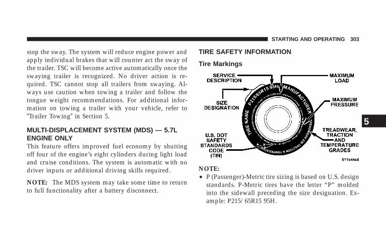
stop the sway. The system will reduce engine power andapply individual brakes that will counter act the sway ofthe trailer. TSC will become active automatically once theswaying trailer is recognized. No driver action is re-quired. TSC cannot stop all trailers from swaying. Al-ways use caution when towing a trailer and follow thetongue weight recommendations. For additional infor-mation on towing a trailer with your vehicle, refer to9Trailer Towing9 in Section 5.
MULTI-DISPLACEMENT SYSTEM (MDS) — 5.7LENGINE ONLYThis feature offers improved fuel economy by shuttingoff four of the engine’s eight cylinders during light loadand cruise conditions. The system is automatic with nodriver inputs or additional driving skills required.
NOTE: The MDS system may take some time to returnto full functionality after a battery disconnect.
TIRE SAFETY INFORMATION
Tire Markings
NOTE:• P (Passenger)-Metric tire sizing is based on U.S. design
standards. P-Metric tires have the letter “P” moldedinto the sidewall preceding the size designation. Ex-ample: P215/65R15 95H.
STARTING AND OPERATING 303
5

• European Metric tire sizing is based on Europeandesign standards. Tires designed to this standard havethe tire size molded into the sidewall beginning withthe section width. The letter 9P9 is absent from this tiresize designation. Example: 215/65R15 96H
• LT (Light Truck)-Metric tire sizing is based on U.S.design standards. The size designation for LT-Metrictires is the same as for P-Metric tires except for theletters “LT” that are molded into the sidewall preced-ing the size designation. Example: LT235/85R16.
• Temporary spare tires are high-pressure compactspares designed for temporary emergency use only.Tires designed to this standard have the letter “T”molded into the sidewall preceding the size designa-tion. Example: T145/80D18 103M.
• High flotation tire sizing is based on U.S. designstandards, and it begins with the tire diameter moldedinto the sidewall. Example: 31x10.5 R15 LT.
304 STARTING AND OPERATING
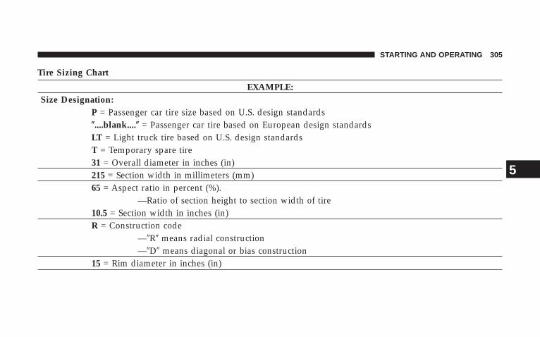
Tire Sizing Chart
EXAMPLE:Size Designation:
P = Passenger car tire size based on U.S. design standards(....blank....( = Passenger car tire based on European design standardsLT = Light truck tire based on U.S. design standardsT = Temporary spare tire31 = Overall diameter in inches (in)215 = Section width in millimeters (mm)65 = Aspect ratio in percent (%).
—Ratio of section height to section width of tire10.5 = Section width in inches (in)R = Construction code
—9R9 means radial construction—9D9 means diagonal or bias construction
15 = Rim diameter in inches (in)
STARTING AND OPERATING 305
5

EXAMPLE:Service Description:
95 = Load Index—A numerical code associated with the maximum load a tire can carry
H = Speed Symbol—A symbol indicating the range of speeds at which a tire can carry a load correspondingto its load index under certain operating conditions—The maximum speed corresponding to the speed symbol should only be achieved un-der specified operating conditions (i.e., tire pressure, vehicle loading, road conditions,and posted speed limits)
Load Identification:(....blank....( = Absence of any text on the sidewall of the tire indicates a Standard Load (SL) TireExtra Load (XL) = Extra load (or reinforced) tireLight Load = Light load tireC,D,E = Load range associated with the maximum load a tire can carry at a specified pressure
Maximum Load — Maximum load indicates the maximum load this tire is designed to carryMaximum Pressure — Maximum pressure indicates the maximum permissible cold tire inflation pressure for this tire
306 STARTING AND OPERATING
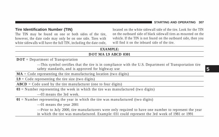
Tire Identification Number (TIN)The TIN may be found on one or both sides of the tire,however, the date code may only be on one side. Tires withwhite sidewalls will have the full TIN, including the date code,
located on the white sidewall side of the tire. Look for the TINon the outboard side of black sidewall tires as mounted on thevehicle. If the TIN is not found on the outboard side, then youwill find it on the inboard side of the tire.
EXAMPLE:DOT MA L9 ABCD 0301
DOT = Department of Transportation—This symbol certifies that the tire is in compliance with the U.S. Department of Transportation tiresafety standards, and is approved for highway use
MA = Code representing the tire manufacturing location (two digits)L9 = Code representing the tire size (two digits)ABCD = Code used by the tire manufacturer (one to four digits)03 = Number representing the week in which the tire was manufactured (two digits)
—03 means the 3rd week.01 = Number representing the year in which the tire was manufactured (two digits)
—01 means the year 2001—Prior to July 2000, tire manufacturers were only required to have one number to represent the yearin which the tire was manufactured. Example: 031 could represent the 3rd week of 1981 or 1991
STARTING AND OPERATING 307
5
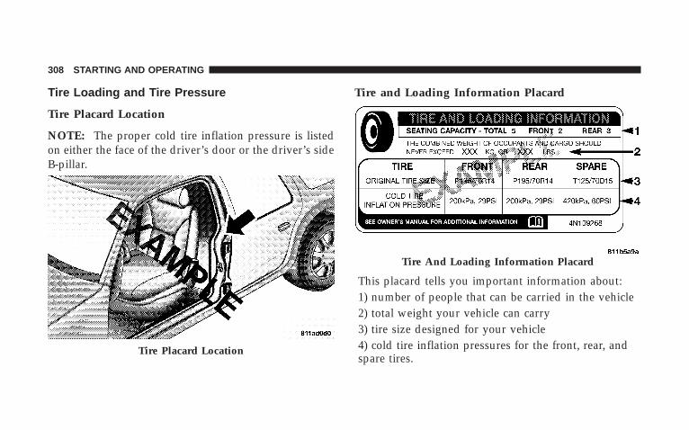
Tire Loading and Tire Pressure
Tire Placard Location
NOTE: The proper cold tire inflation pressure is listedon either the face of the driver’s door or the driver’s sideB-pillar.
Tire and Loading Information Placard
This placard tells you important information about:1) number of people that can be carried in the vehicle2) total weight your vehicle can carry3) tire size designed for your vehicle4) cold tire inflation pressures for the front, rear, andspare tires.
Tire Placard Location
Tire And Loading Information Placard
308 STARTING AND OPERATING
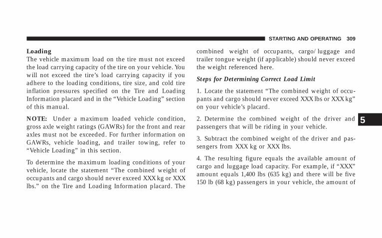
LoadingThe vehicle maximum load on the tire must not exceedthe load carrying capacity of the tire on your vehicle. Youwill not exceed the tire’s load carrying capacity if youadhere to the loading conditions, tire size, and cold tireinflation pressures specified on the Tire and LoadingInformation placard and in the “Vehicle Loading” sectionof this manual.
NOTE: Under a maximum loaded vehicle condition,gross axle weight ratings (GAWRs) for the front and rearaxles must not be exceeded. For further information onGAWRs, vehicle loading, and trailer towing, refer to“Vehicle Loading” in this section.
To determine the maximum loading conditions of yourvehicle, locate the statement “The combined weight ofoccupants and cargo should never exceed XXX kg or XXXlbs.” on the Tire and Loading Information placard. The
combined weight of occupants, cargo/luggage andtrailer tongue weight (if applicable) should never exceedthe weight referenced here.
Steps for Determining Correct Load Limit
1. Locate the statement “The combined weight of occu-pants and cargo should never exceed XXX lbs or XXX kg”on your vehicle’s placard.
2. Determine the combined weight of the driver andpassengers that will be riding in your vehicle.
3. Subtract the combined weight of the driver and pas-sengers from XXX kg or XXX lbs.
4. The resulting figure equals the available amount ofcargo and luggage load capacity. For example, if “XXX”amount equals 1,400 lbs (635 kg) and there will be five150 lb (68 kg) passengers in your vehicle, the amount of
STARTING AND OPERATING 309
5

available cargo and luggage load capacity is 650 lbs (295kg) {(since 5 x 150 = 750, and 1400 – 750 = 650 lbs (295kg)}.
5. Determine the combined weight of luggage and cargobeing loaded on the vehicle. That weight may not safelyexceed the available cargo and luggage load capacitycalculated in Step 4.
6. If your vehicle will be towing a trailer, load from yourtrailer will be transferred to your vehicle. Consult thismanual to determine how this reduces the availablecargo and luggage load capacity of your vehicle.
NOTE: The following table shows examples on how tocalculate total load, cargo/luggage, and towing capaci-ties of your vehicle with varying seating configurationsand number and size of occupants. This table is forillustration purposes only and may not be accurate forthe seating and load carry capacity of your vehicle.
NOTE: For the following example, the combined weightof occupants and cargo should never exceed 865 lbs (392kg).
310 STARTING AND OPERATING
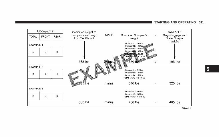
STARTING AND OPERATING 311
5

WARNING!
Overloading of your tires is dangerous. Overloadingcan cause tire failure, affect vehicle handling, andincrease your stopping distance. Use tires of therecommended load capacity for your vehicle. Neveroverload them.
TIRES — GENERAL INFORMATION
Tire PressureProper tire inflation pressure is essential to the safe andsatisfactory operation of your vehicle. Three primaryareas are affected by improper tire pressure:
1. Safety—
WARNING!
• Improperly inflated tires are dangerous and cancause accidents.• Under-inflation increases tire flexing and can resultin tire failure.• Over-inflation reduces a tire’s ability to cushionshock. Objects on the road and chuckholes can causedamage that result in tire failure.• Unequal tire pressures can cause steering problems.You could lose control of your vehicle.• Over-inflated or under-inflated tires can affect ve-hicle handling and can fail suddenly, resulting in lossof vehicle control.• Unequal tire pressures from one side of the vehicleto the other can cause the vehicle to drift to the right orleft.• Always drive with each tire inflated to the recom-mended cold tire inflation pressure.
312 STARTING AND OPERATING
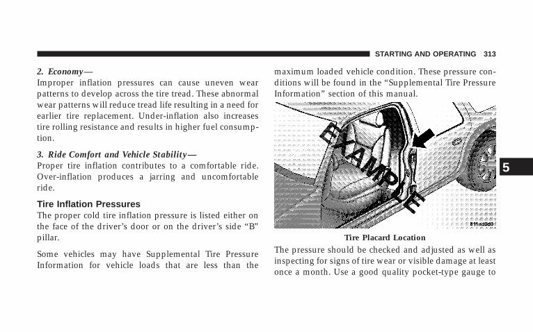
2. Economy—Improper inflation pressures can cause uneven wearpatterns to develop across the tire tread. These abnormalwear patterns will reduce tread life resulting in a need forearlier tire replacement. Under-inflation also increasestire rolling resistance and results in higher fuel consump-tion.
3. Ride Comfort and Vehicle Stability—Proper tire inflation contributes to a comfortable ride.Over-inflation produces a jarring and uncomfortableride.
Tire Inflation PressuresThe proper cold tire inflation pressure is listed either onthe face of the driver’s door or on the driver’s side “B”pillar.
Some vehicles may have Supplemental Tire PressureInformation for vehicle loads that are less than the
maximum loaded vehicle condition. These pressure con-ditions will be found in the “Supplemental Tire PressureInformation” section of this manual.
The pressure should be checked and adjusted as well asinspecting for signs of tire wear or visible damage at leastonce a month. Use a good quality pocket-type gauge to
Tire Placard Location
STARTING AND OPERATING 313
5
check tire pressure. Do not make a visual judgementwhen determining proper inflation. Radial tires may lookproperly inflated even when they are under-inflated.
CAUTION!
After inspecting or adjusting the tire pressure, al-ways reinstall the valve stem cap (if equipped). Thiswill prevent moisture and dirt from entering thevalve stem, which could damage the valve stem.
Inflation pressures specified on the placard are always“cold tire inflation pressure.” Cold tire inflation pressureis defined as the tire pressure after the vehicle has notbeen driven for at least three hours, or driven less than 1mi (1.6 km) after a three hour period. The cold tireinflation pressure must not exceed the maximum infla-tion pressure molded into the tire sidewall.
Check tire pressures more often if subject to a wide rangeof outdoor temperatures, as tire pressures vary withtemperature changes.
Tire pressures change by approximately 1 psi (7 kPa) per12°F (7°C) of air temperature change. Keep this in mindwhen checking tire pressure inside a garage, especially inthe winter.
Example: If garage temperature = 68°F (20°C) and theoutside temperature = 32°F (0°C) then the cold tireinflation pressure should be increased by 3 psi (21 kPa),which equals 1 psi (7 kPa) for every 12 °F (7°C) for thisoutside temperature condition.
Tire pressure may increase from 2 to 6 psi (13 to 40 kPa)during operation. DO NOT reduce this normal pressurebuild up or your tire pressure will be too low.
314 STARTING AND OPERATING
Tire Pressures for High Speed OperationThe manufacturer advocates driving at safe speedswithin posted speed limits. Where speed limits or condi-tions are such that the vehicle can be driven at highspeeds, maintaining correct tire inflation pressure is veryimportant. Increased tire pressure and reduced vehicleloading may be required for high-speed vehicle opera-tion. Refer to original equipment or an authorized tiredealer for recommended safe operating speeds, loadingand cold tire inflation pressures.
WARNING!
High speed driving with your vehicle under maxi-mum load is dangerous. The added strain on yourtires could cause them to fail. You could have aserious accident. Don’t drive a vehicle loaded to themaximum capacity at continuous speeds above 75mph (120 km/h).
Radial Ply Tires
WARNING!
Combining radial ply tires with other types of tireson your vehicle will cause your vehicle to handlepoorly. The instability could cause an accident. Al-ways use radial ply tires in sets of four (or six, in caseof trucks with dual rear wheels). Never combinethem with other types of tires.
Cuts and punctures in radial tires are repairable only inthe tread area because of sidewall flexing. Consult yourauthorized tire dealer for radial tire repairs.
STARTING AND OPERATING 315
5
Compact Spare Tire — If EquippedThe compact spare is for temporary emergency use withradial tires. It is engineered to be used on your stylevehicle only. Since this tire has limited tread life, theoriginal tire should be repaired (or replaced) and rein-stalled at the first opportunity.
WARNING!
Temporary use spare tires are for emergency use only.With these tires, do not drive more than 50 mph (80km/h). Temporary use spare tires have limited treadlife. When the tread is worn to the tread wearindicators, the temporary use spare tire needs to bereplaced. Be sure to follow the warnings which applyto your spare. Failure to do so could result in sparetire failure and loss of vehicle control.
Do not install a wheel cover or attempt to mount aconventional tire on the compact spare wheel, since thewheel is designed specifically for the compact spare.
Do not install more than one compact spare tire/wheelon the vehicle at any given time.
CAUTION!
Because of the reduced ground clearance, do not takeyour vehicle through an automatic car wash with thecompact spare installed. Damage to the vehicle mayresult.
Limited-Use Spare — If EquippedThe limited-use spare tire is for temporary emergencyuse on your vehicle. This tire is identified by a limited-use spare tire warning label located on the limited-usespare tire and wheel assembly. This tire may look like the
316 STARTING AND OPERATING
original equipped tire on the front or rear axle of yourvehicle, but it is not. Installation of this limited-use sparetire affects vehicle handling. Since it is not the same tire,replace (or repair) the original tire and reinstall on thevehicle at the first opportunity.
WARNING!
The limited-use spare tires are for emergency useonly. Installation of this limited-use spare tire affectsvehicle handling. With this tire, do not drive morethan 50 mph (80 km/h). Keep inflated to the cold tireinflation pressure listed on either your tire placard orlimited-use spare tire and wheel assembly. Replace(or repair) the original tire at the first opportunityand reinstall it on your vehicle. Failure to do so couldresult in loss of vehicle control.
Tire SpinningWhen stuck in mud, sand, snow, or ice conditions, do notspin your vehicle’s wheels faster than 30 mph (48 km/h)or for longer than 30 seconds continuously withoutstopping when you are stuck.
For additional information, refer to “Freeing A StuckVehicle” in Section 6.
WARNING!
Fast spinning tires can be dangerous. Forces gener-ated by excessive wheel speeds may cause tire dam-age or failure. A tire could explode and injure some-one. Do not spin your vehicle’s wheels faster than 30mph (48 km/h) or for more than 30 seconds continu-ously when you are stuck, and don’t let anyone neara spinning wheel, no matter what the speed.
STARTING AND OPERATING 317
5
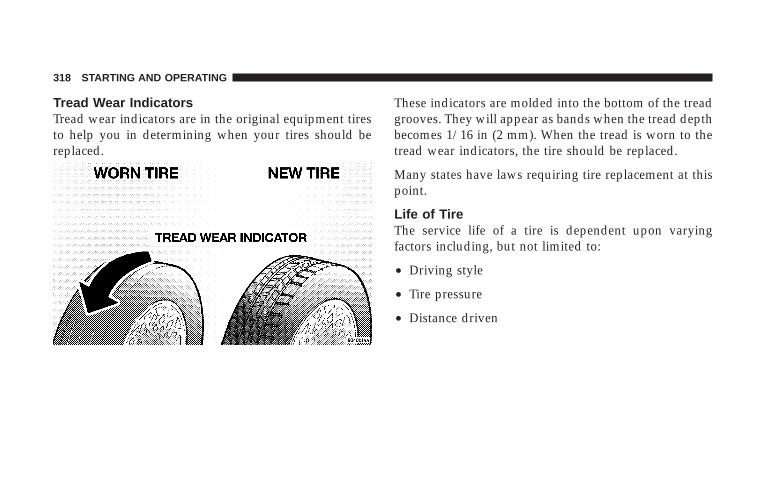
Tread Wear IndicatorsTread wear indicators are in the original equipment tiresto help you in determining when your tires should bereplaced.
These indicators are molded into the bottom of the treadgrooves. They will appear as bands when the tread depthbecomes 1/16 in (2 mm). When the tread is worn to thetread wear indicators, the tire should be replaced.
Many states have laws requiring tire replacement at thispoint.
Life of TireThe service life of a tire is dependent upon varyingfactors including, but not limited to:
• Driving style
• Tire pressure
• Distance driven
318 STARTING AND OPERATING
WARNING!
Tires and spare tire should be replaced after six years,regardless of the remaining tread. Failure to followthis warning can result in sudden tire failure. Youcould lose control and have an accident resulting inserious injury or death.
Keep dismounted tires in a cool, dry place with as littleexposure to light as possible. Protect tires from contactwith oil, grease, and gasoline.
Replacement TiresThe tires on your new vehicle provide a balance of manycharacteristics. They should be inspected regularly forwear and correct cold tire inflation pressure. The manu-facturer strongly recommends that you use tires equiva-lent to the originals in size, quality and performancewhen replacement is needed (refer to the paragraph on“Tread Wear Indicators”). Refer to the “Tire and LoadingInformation” placard for the size designation of your tire.The service description and load identification will befound on the original equipment tire. Failure to useequivalent replacement tires may adversely affect thesafety, handling, and ride of your vehicle. We recommendthat you contact your original equipment or an autho-rized tire dealer with any questions you may have on tirespecifications or capability.
STARTING AND OPERATING 319
5
WARNING!
• Do not use a tire, wheel size or rating other thanthat specified for your vehicle. Some combinationsof unapproved tires and wheels may change sus-pension dimensions and performance characteris-tics, resulting in changes to steering, handling, andbraking of your vehicle. This can cause unpredict-able handling and stress to steering and suspen-sion components. You could lose control and havean accident resulting in serious injury or death.Use only the tire and wheel sizes with load ratingsapproved for your vehicle.
• Never use a tire with a smaller load index orcapacity, other than what was originally equippedon your vehicle. Using a tire with a smaller loadindex could result in tire overloading and failure.You could lose control and have an accident.
• Failure to equip your vehicle with tires havingadequate speed capability can result in sudden tirefailure and loss of vehicle control.
CAUTION!
Replacing original tires with tires of a different sizemay result in false speedometer and odometerreadings.
Alignment and BalancePoor suspension alignment may result in:
• Fast tire wear.
• Uneven tire wear, such as feathering and one-sidedwear.
• Vehicle pull to right or left.
Tires may also cause the vehicle to pull to the left or right.Alignment will not correct this condition. See yourauthorized dealer for proper diagnosis.
320 STARTING AND OPERATING

Improper alignment will not cause vehicle vibration.Vibration may be a result of tire and wheel out-of-balance. Proper balancing will reduce vibration andavoid tire cupping and spotty wear.
SUPPLEMENTAL TIRE PRESSURE INFORMATION— IF EQUIPPEDA light load vehicle condition is defined as two passen-gers [150 lbs (68 kg) each] plus 200 lbs (91 kg) of cargo.Cold tire inflation pressures for a lightly loaded vehiclewill be found on the face of the driver’s door.
TIRE CHAINSUse “Class S” chains on your vehicle, or other tractionaids that meet SAE Type “S” specifications.
NOTE: Chains must be the proper size for the vehicle,as recommended by the chain manufacturer.
CAUTION!
To avoid damage to your vehicle, tires or chains, observe thefollowing precautions:• Because of limited chain clearance between tires and other
suspension components, it is important that only chains ingood condition are used. Broken chains can cause seriousvehicle damage. Stop the vehicle immediately if noiseoccurs that could suggest chain breakage. Remove thedamaged parts of the chain before further use.
• Install chains as tightly as possible and then retightenafter driving about 1/2 mile (0.8 km).
• Do not exceed 45 mph (72 km/h).• Drive cautiously and avoid severe turns and large bumps,
especially with a loaded vehicle.• Do not install tire chains on front wheels of 4x2 vehicles.• Do not drive for a prolonged period on dry pavement.• Observe the tire chain manufacturer’s instructions on
method of installation, operating speed, and conditionsfor usage. Always use the lower suggested operatingspeed of the chain manufacturer if different than thespeed recommended by the manufacturer.
STARTING AND OPERATING 321
5

These cautions apply to all chain traction devices, includ-ing link and cable (radial) chains.
Tire chain use is permitted only on the rear tires of yourtruck.
NOTE: The use of class “S” chains is permitted on yourvehicle with P245/70R17 tires.
CAUTION!
Do not use tire chains on 4x4 trucks equipped withtires other than P245/70R17 tires. There may not beadequate clearance for the chains and you are riskingstructural or body damage to your vehicle. Do not usetire chains on the 4X2 front wheels of your vehicle.There may not be adequate clearance for the chainsand you are risking structural or body damage toyour vehicle.
SNOW TIRESSnow tires should be of the same size and type construc-tion as the front tires. Consult the manufacturer of thesnow tire to determine any maximum vehicle speedrequirement associated with the tire. These tires shouldalways be operated at the vehicle maximum capacityinflation pressures under any load condition.
While studded tires improve performance on ice, skidand traction capability on wet or dry surfaces may bepoorer than that of non-studded tires. Some states pro-hibit studded tires; therefore, local laws should bechecked before using these tire types.
322 STARTING AND OPERATING

TIRE ROTATION RECOMMENDATIONSTires on the front and rear axles of vehicles operate atdifferent loads and perform different steering, driving,and braking functions. For these reasons, they wear atunequal rates and tend to develop irregular wear pat-terns. These effects can be reduced by timely rotation oftires. The benefits of rotation are especially worthwhilewith aggressive tread designs such as those on all seasontype tires. Rotation will increase tread life, help to main-tain mud, snow and wet traction levels, and contribute toa smooth, quiet ride.
Follow the recommended tire rotation frequency for yourtype of driving found in the “Maintenance Schedules”Section of this manual. More frequent rotation is permis-sible if desired. The reasons for any rapid or unusualwear should be corrected prior to rotation being per-formed.
STARTING AND OPERATING 323
5
TIRE PRESSURE MONITOR SYSTEM (TPMS) — IFEQUIPPEDThe Tire Pressure Monitoring System (TPMS) will warnthe driver of a low tire pressure based on the vehiclerecommended cold placard pressure (the placard is lo-cated on the driver’s side B-pillar).
The tire pressure will vary with temperature by about 1psi (6.9 kPa) for every 12°F (6.5°C). This means that whenthe outside temperature decreases, the tire pressure willdecrease. Tire pressure should always be set based oncold inflation tire pressure. This is defined as the tirepressure after a vehicle has not been driven for more thanthree hours - and in outside ambient temperature. Referto the “Tires – General Information” in this section forinformation on how to properly inflate the vehicle’stires. The tire pressure will also increase as the vehicle isdriven - this is normal and there should be no adjustmentfor this increased pressure.
TPMS will warn the driver of a low tire pressure if the tirepressure falls below the low pressure warning thresholdfor any reason, including low temperature effects, ornatural pressure loss through the tire.
The TPMS will continue to warn the driver of low tirepressure as long as the condition exists, and will not turnoff until the tire pressure is at or above recommendedcold placard pressure. Once the low tire pressure warn-ing has been illuminated, the tire pressure must beincreased to the recommended cold placard pressure inorder for the TPMS warning light to be turned off. Thesystem will automatically update and the TPMS warninglight p will extinguish once the updated tire pressureshave been received. The vehicle may need to be drivenfor up to 10 minutes above 15 mph (25 km/h) to receivethis information.
324 STARTING AND OPERATING

For example, your vehicle has a recommended cold(parked for more than three hours) placard pressure of 33psi (227 kPa). If the ambient temperature is 68°F (20°C)and the measured tire pressure is 28 psi (193 kPa), atemperature drop to 20°F (-7°C) will decrease the tirepressure to approximately 24 psi (165 kPa). This tirepressure is sufficiently low enough to turn on the TPMSlight. Driving the vehicle may cause the tire pressure torise to approximately 28 psi (193 kPa), but the TPMS lightwill still be ON. In this situation, the TPMS light will turnoff only after the tires have been inflated to the vehicle’srecommended cold placard pressure value.
CAUTION!
The TPMS has been optimized for the originalequipment tires and wheels. TPMS pressures havebeen established for the tire size equipped on yourvehicle. Undesirable system operation or sensordamage may result when using replacement equip-ment that is not of the same size, type, and/or style.Aftermarket wheels can cause sensor damage. Do notuse aftermarket tire sealants or balance beads if yourvehicle is equipped with a TPMS, as damage to thesensors may result.
STARTING AND OPERATING 325
5
CAUTION!
After inspecting or adjusting the tire pressure alwaysreinstall the valve stem cap. This will prevent mois-ture and dirt from entering the valve stem, whichcould damage the tire pressure monitoring sensor.
NOTE:• The TPMS is not intended to replace normal tire care
and maintenance, or to provide warning of a tirefailure or condition.
• The TPMS should not be used as a tire pressure gaugewhile adjusting your tire pressure.
• Driving on a significantly under-inflated tire causesthe tire to overheat and can lead to tire failure.
Under-inflation also reduces fuel efficiency and tiretread life, and may affect the vehicle’s handling andstopping ability.
• The TPMS is not a substitute for proper tire mainte-nance, and it is the driver’s responsibility to maintaincorrect tire pressure using an accurate tire gauge, evenif under-inflation has not reached the level to triggerillumination of the Tire Pressure Monitoring TelltaleLamp.
• Seasonal temperature changes will affect tire pressure,and the TPMS will monitor the actual tire pressure inthe tire.
Base System – If EquippedThe Tire Pressure Monitor System (TPMS) uses wirelesstechnology with wheel rim mounted electronic sensors tomonitor tire pressure levels. Sensors, mounted to eachwheel as part of the valve stem, transmit tire pressurereadings to the receiver module.
326 STARTING AND OPERATING

NOTE: It is particularly important for you to check thetire pressure in all of your tires regularly and to maintainthe proper pressure.
The TPMS consists of the following components:
• Receiver module
• Four tire pressure monitoring sensors
• Tire Pressure Monitoring Telltale Lamp
The Tire Pressure Monitoring Telltale Lamp willilluminate in the instrument cluster, and an au-dible chime will be activated when one or more of
the four active road tire pressures are low. Should thisoccur, you should stop as soon as possible, check theinflation pressure of each tire on your vehicle, and inflateeach tire to the vehicle’s recommended cold placardpressure value. The system will automatically updateand the Tire Pressure Monitoring Telltale Lamp willextinguish once the updated tire pressures have been
received. The vehicle may need to be driven for up to 10minutes above 15 mph (25 km/h) to receive this infor-mation.
The Tire Pressure Monitoring Telltale Lamp will flash onand off for 75 seconds, and remain on solid when asystem fault is detected. The system fault will also sounda chime. If the ignition key is cycled, this sequence willrepeat, providing the system fault still exists. The TirePressure Monitoring Telltale Lamp will turn off when thefault condition no longer exists. A system fault can occurby any of the following scenarios: 1) Jamming due toelectronic devices or driving next to facilities emitting thesame radio frequencies as the TPM sensors; 2) Installingsome form of aftermarket window tinting that affectsradio wave signals; 3) Lots of snow or ice around thewheels or wheel housings; 4) Using tire chains on thevehicle; 5) Using wheels/tires not equipped with TPMsensors.
STARTING AND OPERATING 327
5

NOTE: Your vehicle is equipped with a non-matchingfull size spare wheel and tire assembly.
1. This spare tire does not have a tire pressure monitor-ing sensor. Therefore, the TPMS will not monitor the tirepressure in the spare tire.
2. If you install the full size spare tire in place of a roadtire that has a pressure below the low-pressure warninglimit, upon the next ignition key cycle a chime will soundand the TPM Telltale Lamp will still turn ON due to thelow tire.
3. However, after driving the vehicle for up to 10 min-utes above 15 mph (25 km/h), the TPM Telltale Lampwill flash on and off for 75 seconds and then remain onsolid.
4. For each subsequent ignition key cycle, a chime willsound and the TPM Telltale Light will flash on and off for75 seconds and then remain on solid.
5. Once you repair or replace the original road tire, andreinstall it on the vehicle in place of the full size spare tire,the TPMS will update automatically and the TPM TelltaleLamp will turn OFF, as long as no tire pressure is belowthe low-pressure warning limit in any of the four activeroad tires. The vehicle may need to be driven for up to 10minutes above 15 mph (25 km/h) in order for the TPMSto receive this information.
Premium System – If EquippedThe Tire Pressure Monitor System (TPMS) uses wirelesstechnology with wheel rim mounted electronic sensors tomonitor tire pressure levels. Sensors, mounted to eachwheel as part of the valve stem, transmit tire pressurereadings to the receiver module.
NOTE: It is particularly important for you to check thetire pressure in all of your tires regularly and to maintainthe proper pressure.
328 STARTING AND OPERATING

The TPMS consists of the following components:
• Receiver module
• Four tire pressure monitoring sensors
• Three trigger modules (mounted in three of the fourwheel wells).
• Various TPMS messages, which display in the Elec-tronic Vehicle Information Center (EVIC), and agraphic displaying tire pressures.
• Yellow Tire Pressure Monitoring Telltale Light.
Tire Pressure Monitoring Low Pressure WarningsThe Tire Pressure Monitoring Telltale Light will illumi-nate in the instrument cluster, and an audible chime willbe activated when one or more of the four active road tirepressures are low. In addition, the EVIC will display agraphic of the pressure value(s) with the low tire(s)flashing.
Should a low tire condition occur on any of the fouractive road tire(s), you should stop as soon as possible,and inflate the low tire(s) that is flashing on the graphicdisplay to the vehicle’s recommended cold placard pres-sure value. The system will automatically update, thegraphic display of the pressure value(s) will stop flash-ing, and the Tire Pressure Monitoring Telltale Light willextinguish once the updated tire pressure(s) have beenreceived. The vehicle may need to be driven for up to 10minutes above 15 mph (25 km/h) to receive this infor-mation.
Check TPMS MessageThe Tire Pressure Monitoring Telltale Light will flash onand off for 75 seconds, and remain on solid when asystem fault is detected. The system fault will also sounda chime. The EVIC will display a “CHECK TPM SYS-TEM” message for three seconds. This text message isthen followed by a graphic display, with “- - -“ in place of
STARTING AND OPERATING 329
5

the pressure value(s) indicating which tire pressuremonitoring sensor(s) is not being received.
If the ignition key is cycled, this sequence will repeat,providing the system fault still exists. If the system faultno longer exists, the Tire Pressure Monitoring TelltaleLight will no longer flash, the 9CHECK TPM SYSTEM9text message will not be present, and a pressure valuewill be displayed instead of dashes. A system fault canoccur by any of the following scenarios: 1) Jamming dueto electronic devices or driving next to facilities emittingthe same radio frequencies as the TPM sensors;. 2)Installing some form of aftermarket window tinting thataffects radio wave signals; 3) Lots of snow or ice aroundthe wheels or wheel housings; 4) Using tire chains on thevehicle; 5) Using wheels/tires not equipped with TPMsensors.
NOTE: Your vehicle is equipped with a non-matchingfull size spare wheel and tire assembly.
1. This spare tire does not have a tire pressure monitor-ing sensor. Therefore, the TPMS will not monitor the tirepressure in the spare tire.
2. If you install the full size spare tire in place of a roadtire that has a pressure below the low-pressure warninglimit, upon the next ignition key cycle, a chime willsound and the TPM Telltale Light will still turn ON. Inaddition, the graphic in the EVIC will still display aflashing pressure value.
3. However, after driving the vehicle for up to 10 min-utes above 15 mph (25 km/h), the TPM Telltale Light willflash on and off for 75 seconds and then remain on solid.The EVIC will display a “CHECK TPM SYSTEM” mes-sage for three seconds and then display dashes (- - -) inplace of the pressure value.
4. For each subsequent ignition key cycle, a chime willsound and the TPM Telltale Light will flash on and off for75 seconds and then remain on solid. The EVIC will
330 STARTING AND OPERATING
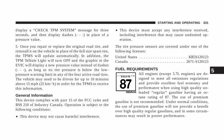
display a “CHECK TPM SYSTEM” message for threeseconds, and then display dashes (- - -) in place of apressure value.
5. Once you repair or replace the original road tire, andreinstall it on the vehicle in place of the full size spare tire,the TPMS will update automatically. In addition, theTPM Telltale Light will turn OFF and the graphic in theEVIC will display a new pressure value instead of dashes(- - -), as long as no tire pressure is below the low-pressure warning limit in any of the four active road tires.The vehicle may need to be driven for up to 10 minutesabove 15 mph (25 km/h) in order for the TPMS to receivethis information.
General InformationThis device complies with part 15 of the FCC rules andRSS 210 of Industry Canada. Operation is subject to thefollowing conditions:
• This device may not cause harmful interference.
• This device must accept any interference received,including interference that may cause undesired op-eration.
The tire pressure sensors are covered under one of thefollowing licenses:United States . . . . . . . . . . . . . . . . . . . . . KR5S120123Canada . . . . . . . . . . . . . . . . . . . . . . . . 2671-S120123
FUEL REQUIREMENTSAll engines (except 5.7L engines) are de-signed to meet all emissions regulationsand provide excellent fuel economy andperformance when using high quality un-leaded “regular” gasoline having an oc-tane rating of 87. The use of premium
gasoline is not recommended. Under normal conditions,the use of premium gasoline will not provide a benefitover high quality regular gasolines, and in some circum-stances may result in poorer performance.
STARTING AND OPERATING 331
5

The 5.7L engine is designed to meet allemissions regulations and provide satisfac-tory fuel economy and performance whenusing high quality unleaded gasoline hav-ing an octane range of 87 to 89. The manu-facturer recommends the use of 89 octane
for optimum performance. The use of premium gasolineis not recommended. Under normal conditions, the use ofpremium gasoline will not provide a benefit over highquality regular and mid-grade gasolines, and in somecircumstances may result in poorer performance.
Light spark knock at low engine speeds is not harmful toyour engine. However, continued heavy spark knock athigh speeds can cause damage and immediate service isrequired. Poor quality gasoline can cause problems suchas hard starting, stalling, and hesitations. If you experi-ence these symptoms, try another brand of gasolinebefore considering service for the vehicle.
Over 40 auto manufacturers worldwide have issued andendorsed consistent gasoline specifications (the World-wide Fuel Charter, WWFC) which define fuel propertiesnecessary to deliver enhanced emissions, performance,and durability for your vehicle. The manufacturer recom-mends the use of gasoline that meets the WWFC speci-fications if they are available.
Reformulated GasolineMany areas of the country require the use of cleanerburning gasoline referred to as “Reformulated Gasoline.”Reformulated gasolines contain oxygenates, and are spe-cifically blended to reduce vehicle emissions and im-prove air quality.
We strongly support the use of reformulated gasolines.Properly blended reformulated gasolines will provideexcellent performance and durability for the engine andfuel system components.
332 STARTING AND OPERATING
Gasoline/Oxygenate BlendsSome fuel suppliers blend unleaded gasoline with oxy-genates such as 10% ethanol, MTBE and ETBE. Oxygen-ates are required in some areas of the country during thewinter months to reduce carbon monoxide emissions.Fuels blended with these oxygenates may be used inyour vehicle.
CAUTION!
DO NOT use gasoline containing Methanol or E85Ethanol. Use of these blends may result in startingand driveability problems and may damage criticalfuel system components.
NOTE: 4.7L Engine — If Equipped , is now rated forE85 Ethanol use. Only vehicles with the E-85 fuel fillerdoor label can operate on E-85. For more information,refer to “Flexible Fuel” in this section.
Problems that result from using methanol/gasoline orE85 Ethanol blends are not the responsibility of themanufacturer. While MTBE is an oxygenate made fromMethanol, it does not have the negative effects of Metha-nol.
MMT In GasolineMMT is a manganese containing metallic additive that isblended into some gasoline to increase octane. Gasolineblended with MMT provides no performance advantagebeyond gasoline of the same octane number withoutMMT. Gasoline blended with MMT reduces spark pluglife and reduces emission system performance in somevehicles. The manufacturer recommends that gasolinewithout MMT be used in your vehicle. The MMT content
STARTING AND OPERATING 333
5

of gasoline may not be indicated on the gasoline pump,therefore, you should ask your gasoline retailer whetheror not his/her gasoline contains MMT. It is even moreimportant to look for gasolines without MMT in Canada,because MMT can be used at levels higher than thoseallowed in the United States. MMT is prohibited inFederal and California reformulated gasoline.
Materials Added To FuelAll gasolines sold in the United States are required tocontain effective detergent additives. Use of additionaldetergents or other additives is not needed under normalconditions and would result in unnecessary cost. There-fore, you should not have to add anything to the fuel.
Fuel System Cautions
CAUTION!
Follow these guidelines to maintain your vehicle’s performance:
• The use of leaded gas is prohibited by Federal law. Usingleaded gasoline can impair engine performance, damage theemission control system.
• An out-of-tune engine, or certain fuel or ignition malfunc-tions, can cause the catalytic converter to overheat. If younotice a pungent burning odor or some light smoke, yourengine may be out of tune or malfunctioning and may requireimmediate service. Contact your authorized dealer for serviceassistance.
• When pulling a heavy load or driving a fully loaded vehiclewhen the humidity is low and the temperature is high, use apremium unleaded fuel to help prevent spark knock. If sparkknock persists, lighten the load, or engine piston damage mayresult.
• The use of fuel additives which are now being sold as octaneenhancers is not recommended. Many of these products con-tain high concentrations of methanol. Fuel system damage orvehicle performance problems resulting from the use of suchfuels or additives is not the responsibility of the manufacturer.
334 STARTING AND OPERATING
NOTE: Intentional tampering with emissions controlsystems can result in civil penalties being assessedagainst you.
Carbon Monoxide Warnings
WARNING!
Carbon monoxide (CO) in exhaust gases is deadly. Follow theprecautions below to prevent carbon monoxide poisoning:• Do not inhale exhaust gases. They contain carbon monox-
ide, a colorless and odorless gas which can kill. Never runthe engine in a closed area, such as a garage, and never sitin a parked vehicle with the engine running for anextended period. If the vehicle is stopped in an open areawith the engine running for more than a short period,adjust the ventilation system to force fresh, outside airinto the vehicle.
• Guard against carbon monoxide with proper maintenance.Have the exhaust system inspected every time the vehicleis raised. Have any abnormal conditions repairedpromptly. Until repaired, drive with all side windowsfully open.
• Keep the liftgate closed when driving your vehicle toprevent carbon monoxide and other poisonous exhaustgases from entering the vehicle.
STARTING AND OPERATING 335
5

ADDING FUEL
Fuel Filler Cap (Gas Cap)
The gas cap is behind the fuel filler door. If the gas cap islost or damaged, be sure the replacement cap is for usewith this vehicle.
NOTE: To avoid contact between fuel cap and paint,hang tether strap over hook provided on inner fuel door.
CAUTION!
Damage to the fuel system or emission control sys-tem could result from using an improper fuel tankfiller tube cap (gas cap). A poorly fitting cap could letimpurities into the fuel system.
CAUTION!
A poorly fitting gas cap may cause the MalfunctionIndicator Light to turn on.
CAUTION!
To avoid fuel spillage and overfilling, do not “topoff” the fuel tank after filling.
NOTE: When the fuel nozzle “clicks” or shuts off, thefuel tank is full.
336 STARTING AND OPERATING

WARNING!
• Never have any smoking materials lit in or nearthe vehicle when the gas cap is removed or thetank filled.
• Never add fuel when the engine is running. This isin violation of most state and federal fire regula-tions and may cause the Malfunction IndicatorLight to turn on.
NOTE: Tighten the gas cap about 1/4 turn until youhear one click. This is an indication that cap is properlytightened.
If the gas cap is not tightened properly, the MalfunctionIndicator Light will come on. Be sure the gas cap istightened every time the vehicle is refueled.
WARNING!
A fire may result if gasoline is pumped into aportable container that is inside of a vehicle. Youcould be burned. Always place gas containers on theground while filling.
Loose Fuel Filler Cap (Gas Cap) MessageAfter fuel is added, the vehicle diagnostic system candetermine if the fuel filler cap is loose, improperlyinstalled, or damaged. A loose fuel filler cap message willbe displayed in the instrument cluster. Tighten the gascap until a 9clicking9 sound is heard. This is an indicationthat the gas cap is properly tightened. Press the odometerRESET button to turn the message off. If the problempersists, the message will appear the next time thevehicle is started. This might indicate a damaged cap. If
STARTING AND OPERATING 337
5
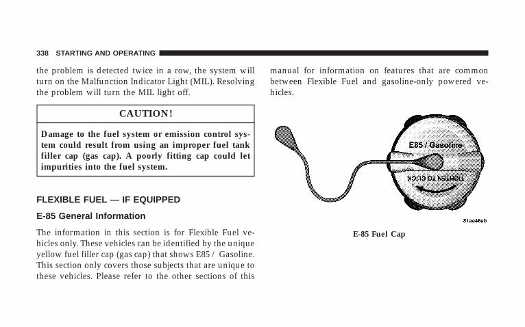
the problem is detected twice in a row, the system willturn on the Malfunction Indicator Light (MIL). Resolvingthe problem will turn the MIL light off.
CAUTION!
Damage to the fuel system or emission control sys-tem could result from using an improper fuel tankfiller cap (gas cap). A poorly fitting cap could letimpurities into the fuel system.
FLEXIBLE FUEL — IF EQUIPPED
E-85 General Information
The information in this section is for Flexible Fuel ve-hicles only. These vehicles can be identified by the uniqueyellow fuel filler cap (gas cap) that shows E85 / Gasoline.This section only covers those subjects that are unique tothese vehicles. Please refer to the other sections of this
manual for information on features that are commonbetween Flexible Fuel and gasoline-only powered ve-hicles.
E-85 Fuel Cap
338 STARTING AND OPERATING
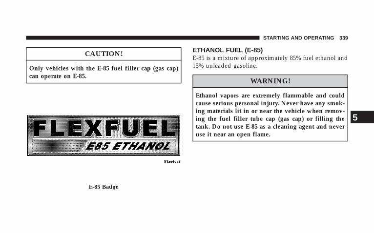
CAUTION!
Only vehicles with the E-85 fuel filler cap (gas cap)can operate on E-85.
ETHANOL FUEL (E-85)E-85 is a mixture of approximately 85% fuel ethanol and15% unleaded gasoline.
WARNING!
Ethanol vapors are extremely flammable and couldcause serious personal injury. Never have any smok-ing materials lit in or near the vehicle when remov-ing the fuel filler tube cap (gas cap) or filling thetank. Do not use E-85 as a cleaning agent and neveruse it near an open flame.
E-85 Badge
STARTING AND OPERATING 339
5
Fuel RequirementsYour vehicle will operate on both unleaded gasoline withan octane rating of 87, or E-85 fuel, or any mixture ofthese two.
For best results, a refueling pattern that alternates be-tween E-85 and unleaded gasoline should be avoided.When you do switch fuels, it is recommended that you:
• do not switch when the fuel gauge indicates less than1/4 full
• do not add less than five gallons (19 Liters) whenrefueling
• operate the vehicle immediately after refueling for aperiod of at least five minutes
Observing these precautions will avoid possible hardstarting and/or significant deterioration in drivabilityduring warm up.
NOTE: When the ambient temperature is above 90°F(32°C), you may experience hard starting and rough idlefollowing startup, even if the above recommendationsare followed.
Selection Of Engine Oil For Flexible Fuel Vehicles(E-85) and Gasoline VehiclesFFV vehicles operated on E-85 require specially formu-lated engine oils. These special requirements are includedin Mopart engine oils, and in equivalent oils meetingDaimlerChrysler Specification MS-6395. The manufac-turer only recommends engine oils that are API Certifiedand meet the requirements of Material Standard MS-6395. MS-6395 contains additional requirements, devel-oped during extensive fleet testing, to provide additionalprotection to DaimlerChrysler Corporation engines. UseMopart or an equivalent oil meeting the specificationMS-6395.
340 STARTING AND OPERATING
StartingThe characteristics of E-85 fuel make it unsuitable for usewhen ambient temperatures fall below 0°F (-18°C). In therange of 0°F (-18°C) to 32°F (0°C), you may experience anincrease in the time it takes for your engine to start, anda deterioration in drivability (sags and/or hesitations)until the engine is fully warmed up.
CAUTION!
Do not use ethanol mixture greater than 85% in yourvehicle. It will cause difficulty in cold starting andmay affect drivability.
Cruising RangeBecause E-85 fuel contains less energy per gallon/Literthan gasoline, you will experience an increase in fuelconsumption. You can expect your miles per gallon(mpg)/miles per liter and your driving range to decreaseby about 30%, compared to gasoline operation.
Replacement PartsMany components in your Flexible Fuel Vehicle (FFV) aredesigned to be compatible with ethanol. Always be surethat your vehicle is serviced with correct ethanol, com-patible parts.
CAUTION!
Replacing fuel system components with non-ethanolcompatible components can damage your vehicle.
STARTING AND OPERATING 341
5

VEHICLE LOADING
Certification LabelAs required by National Highway Traffic Safety Admin-istration Regulations, your vehicle has a certificationlabel affixed to the driver’s side door.
This label contains the month and year of manufacture,Gross Vehicle Weight Rating (GVWR), Gross Axle WeightRating (GAWR) front and rear, and Vehicle IdentificationNumber (VIN). A Month-Day-Hour (MDH) number isincluded on this label and shows the month, day, andhour of manufacture. The bar code that appears on thebottom of the label is your Vehicle Identification Number(VIN).
Gross Vehicle Weight Rating (GVWR)The GVWR is the total permissible weight of your vehicleincluding driver, passengers, vehicle, options, and cargo.The label also specifies maximum capacities of front andrear axle systems. Total load must be limited so thatGVWR is not exceeded.
PayloadThe payload of a vehicle is defined as the allowable loadweight a vehicle can carry including the weight of thedriver, all passengers, options, and cargo.
Certification Label
342 STARTING AND OPERATING

Gross Axle Weight Rating (GAWR)The GAWR is the maximum permissible load on the frontand rear axles. The load must be distributed in the cargoarea so that the GAWR of each axle is not exceeded.
Each axle GAWR is determined by the component in thesystem with the lowest load carrying capacity (axle,springs, tires, or wheels).
Heavier axles or suspension components sometimesspecified by purchasers for increased durability do notnecessarily increase the vehicle’s GVWR.
Tire SizeThis is the minimum allowable tire size for your vehicle.Replacement tires must be equal to the load capacity ofthis tire size.
Rim SizeThis is the rim size that is appropriate for the tire sizelisted.
Inflation Pressure (Cold)This is the cold tire inflation pressure for your vehicle forall loading conditions up to full GAWR.
Curb WeightThe curb weight of a vehicle is defined as the total weightof the vehicle with all fluids, including vehicle fuel, at fullcapacity conditions, and with no occupants or cargoloaded into the vehicle. The front and rear curb weightvalues are determined by weighing your vehicle on acommercial scale before any occupants or cargo areadded.
LoadingThe actual total weight and the weight of the front andrear of your vehicle at the ground can best be determinedby weighing it when it is loaded and ready for operation.
The entire vehicle should first be weighed on a commer-cial scale to ensure that the GVWR has not been ex-ceeded. The weight on the front and rear of the vehicle
STARTING AND OPERATING 343
5
should then be determined separately to be sure that theload is properly distributed over front and rear axle.Weighing the vehicle may show that the GAWR of eitherthe front or rear axles has been exceeded but the totalload is within the specified GVWR. If so, weight must beshifted from front to rear or rear to front as appropriateuntil the specified weight limitations are met.
Store heavier items down low and be sure that the weightis distributed equally. Stow all loose items securely beforedriving.
Improper weight distribution can have an adverse effecton the way your vehicle steers and handles and the waythe brakes operate.
WARNING!
Do not load your vehicle any heavier than the GVWRor the maximum front and rear GAWR. If you do,parts on your vehicle can break, or it can change theway your vehicle handles. This could cause you tolose control. Also, overloading can shorten the life ofyour vehicle.
A loaded vehicle is shown in the following example. Notethat neither GVWR nor GAWR capabilities are exceeded.Overloading can cause potential safety hazards andshorten service life.
NOTE: The weights shown in this chart are not theweights for your vehicle. Also, the amount of loadadded to both the front and rear axles can be computed
344 STARTING AND OPERATING
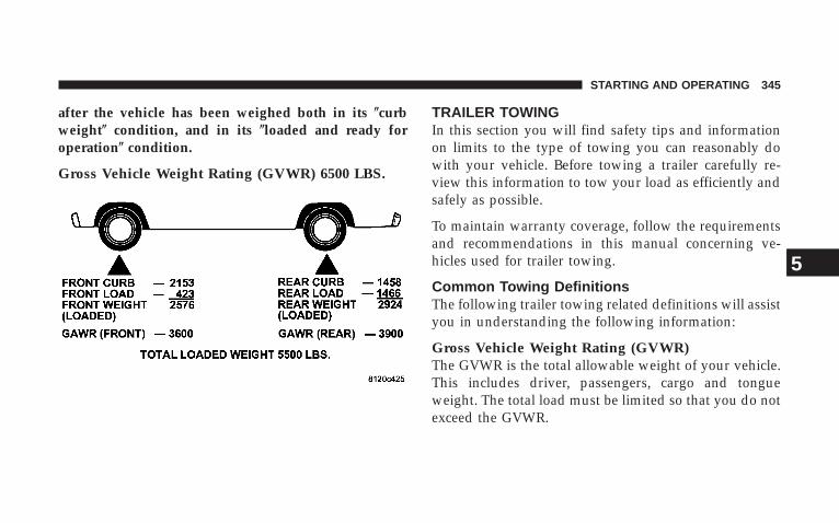
after the vehicle has been weighed both in its (curbweight( condition, and in its (loaded and ready foroperation( condition.
Gross Vehicle Weight Rating (GVWR) 6500 LBS.
TRAILER TOWINGIn this section you will find safety tips and informationon limits to the type of towing you can reasonably dowith your vehicle. Before towing a trailer carefully re-view this information to tow your load as efficiently andsafely as possible.
To maintain warranty coverage, follow the requirementsand recommendations in this manual concerning ve-hicles used for trailer towing.
Common Towing DefinitionsThe following trailer towing related definitions will assistyou in understanding the following information:
Gross Vehicle Weight Rating (GVWR)The GVWR is the total allowable weight of your vehicle.This includes driver, passengers, cargo and tongueweight. The total load must be limited so that you do notexceed the GVWR.
STARTING AND OPERATING 345
5
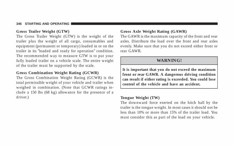
Gross Trailer Weight (GTW)The Gross Trailer Weight (GTW) is the weight of thetrailer plus the weight of all cargo, consumables andequipment (permanent or temporary) loaded in or on thetrailer in its 9loaded and ready for operation9 condition.The recommended way to measure GTW is to put yourfully loaded trailer on a vehicle scale. The entire weightof the trailer must be supported by the scale.
Gross Combination Weight Rating (GCWR)The Gross Combination Weight Rating (GCWR) is thetotal permissible weight of your vehicle and trailer whenweighed in combination. (Note that GCWR ratings in-clude a 150 lbs (68 kg) allowance for the presence of adriver.)
Gross Axle Weight Rating (GAWR)The GAWR is the maximum capacity of the front and rearaxles. Distribute the load over the front and rear axlesevenly. Make sure that you do not exceed either front orrear GAWR.
WARNING!
It is important that you do not exceed the maximumfront or rear GAWR. A dangerous driving conditioncan result if either rating is exceeded. You could losecontrol of the vehicle and have an accident.
Tongue Weight (TW)The downward force exerted on the hitch ball by thetrailer is the tongue weight. In most cases it should not beless than 10% or more than 15% of the trailer load. Youmust consider this as part of the load on your vehicle.
346 STARTING AND OPERATING

Frontal AreaThe maximum height and maximum width of the front ofa trailer.
TSC (Trailer Sway Control) – If Equipped
• Trailer Sway Control – ElectronicTSC uses sensors in the vehicle to recognize a swayingtrailer and will take the appropriate actions to attempt tostop the sway. The system will reduce engine power andapply individual brakes that will counteract the sway ofthe trailer. TSC will become active automatically once theswaying trailer is recognized. No driver action is re-quired. TSC cannot stop all trailers from swaying. Al-ways use caution when towing a trailer and follow thetongue weight recommendations. Even if your vehicle isequipped with electronic TSC, mechanical sway controlis recommended when appropriate for the size of yourtrailer.
• Trailer Sway Control – MechanicalThe trailer sway control is a telescoping link that can beinstalled between the hitch receiver and the trailer tonguethat typically provides adjustable friction associated withthe telescoping motion to dampen any unwanted trailerswaying motions while traveling.
Weight-Carrying HitchA weight-carrying hitch supports the trailer tongueweight, just as if it were luggage located at a hitch ball orsome other connecting point of the vehicle. These kind ofhitches are the most popular on the market today andthey’re commonly used to tow small- and medium-sizedtrailers.
Weight-Distributing HitchA weight-distributing system works by applying lever-age through spring (load) bars. They are typically usedfor heavier loads, to distribute trailer tongue weight tothe tow vehicle’s front axle and the trailer axle(s). When
STARTING AND OPERATING 347
5

used in accordance with the manufacturers’ directions, itprovides for a more level ride, offering more consistentsteering and brake control thereby enhancing towingsafety. The addition of a friction/hydraulic sway controlalso dampens sway caused by traffic and crosswinds andcontributes positively to tow vehicle and trailer stability.Trailer sway control and a weight distributing (loadequalizing) hitch are recommended for heavier tongueweights and may be required depending on vehicle andtrailer configuration/loading to comply with Gross AxleWeight Rating (GAWR) requirements.
WARNING!
An improperly adjusted Weight-Distributing Hitchsystem may reduce handling, stability, and brakingperformance, and could result in an accident.
Weight-Distributing Systems may not be compatiblewith surge brake couplers. Consult with your hitchand trailer manufacturer or a reputable recreationalvehicle dealer for additional information.
348 STARTING AND OPERATING
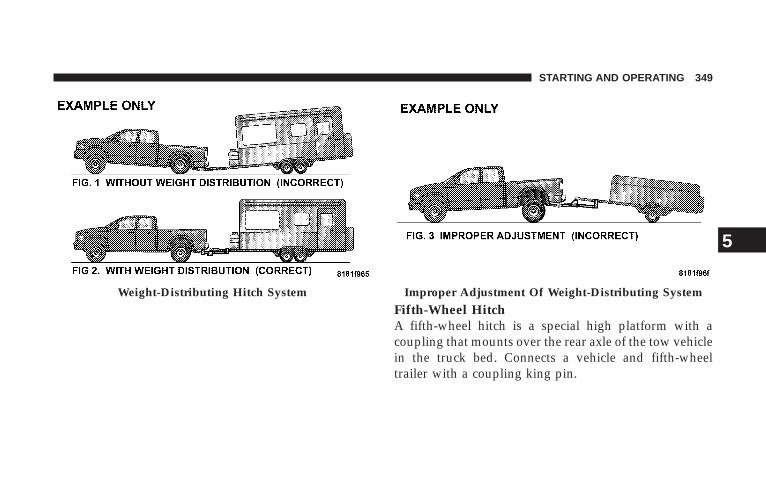
Fifth-Wheel HitchA fifth-wheel hitch is a special high platform with acoupling that mounts over the rear axle of the tow vehiclein the truck bed. Connects a vehicle and fifth-wheeltrailer with a coupling king pin.
Weight-Distributing Hitch System Improper Adjustment Of Weight-Distributing System
STARTING AND OPERATING 349
5

Gooseneck HitchThe gooseneck hitch employs a pivoted coupling armwhich attaches to a ball mounted in the bed of a pickuptruck. The coupling arm connects to the hitch mountedover the rear axle in the truck bed.
Trailer Hitch ClassificationThe rear bumper is intended to tow trailers up to 2,000lbs (907 kg) without added equipment or alterations tothe standard equipment. Your vehicle may be factoryequipped for safe towing of trailers weighing over 2,000lbs (907 kg) with the optional Trailer Tow Prep Package.See your authorized dealer for package content.
The following chart provides the industry standard forthe maximum trailer weight a given trailer hitch class cantow and should be used to assist you in selecting thecorrect trailer hitch for your intended towing condition.Refer to “Trailer Towing Weights (Maximum Trailer
Weight Ratings)” for the website address that containsthe necessary information for your specific drivetrain.
Trailer Hitch ClassificationClass Max. GTW
(Gross Trailer Wt.)Class I - Light Duty 2,000 lbs (907 kg)Class II - MediumDuty
3,500 lbs (1587 kg)
Class III - Heavy Duty 5,000 lbs (2268 kg)Class IV - ExtraHeavy Duty
10,000 lbs (4540 kg)
Fifth Wheel/Gooseneck
Greater than 10,000 lbs(4540 kg)
All trailer hitches should be professionally installed onyour vehicle.
350 STARTING AND OPERATING
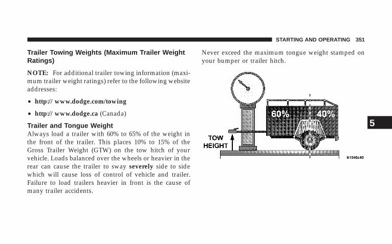
Trailer Towing Weights (Maximum Trailer WeightRatings)
NOTE: For additional trailer towing information (maxi-mum trailer weight ratings) refer to the following websiteaddresses:
• http:// www.dodge.com/towing
• http:// www.dodge.ca (Canada)
Trailer and Tongue WeightAlways load a trailer with 60% to 65% of the weight inthe front of the trailer. This places 10% to 15% of theGross Trailer Weight (GTW) on the tow hitch of yourvehicle. Loads balanced over the wheels or heavier in therear can cause the trailer to sway severely side to sidewhich will cause loss of control of vehicle and trailer.Failure to load trailers heavier in front is the cause ofmany trailer accidents.
Never exceed the maximum tongue weight stamped onyour bumper or trailer hitch.
STARTING AND OPERATING 351
5

Consider the following items when computing theweight on the rear axle of the vehicle:
• The tongue weight of the trailer.
• The weight of any other type of cargo or equipmentput in or on your vehicle.
• The weight of the driver and all passengers.
NOTE: Remember that everything put into or on thetrailer adds to the load on your vehicle. Also, additionalfactory-installed options, or dealer-installed options,must be considered as part of the total load on yourvehicle. Refer to “Tire and Loading Information placard”under “Tire Safety Information” in Section 5.
Towing RequirementsTo promote proper break-in of your new vehicle driv-etrain components the following guidelines are recom-mended:
CAUTION!
• Avoid towing a trailer for the first 500 mi (805 km)of vehicle operation. Doing so may damage yourvehicle.
• During the first 500 mi (805 km) of trailer towing,limit your speed to 50 mph (80 km/h).
Perform the maintenance listed in Section 8 of thismanual. When towing a trailer, never exceed the GAWRor GCWR ratings.
352 STARTING AND OPERATING

WARNING!
Improper towing can lead to an injury accident.Follow these guidelines to make your trailer towingas safe as possible:
Make certain that the load is secured in the trailerand will not shift during travel. When traileringcargo that is not fully secured, dynamic load shiftscan occur that may be difficult for the driver tocontrol. You could lose control of your vehicle andhave an accident.
• When hauling cargo or towing a trailer, do not over-load your vehicle or trailer. Overloading can cause aloss of control, poor performance or damage to brakes,axle, engine, transmission, steering, suspension, chas-sis structure or tires.
• Safety chains must always be used between yourvehicle and trailer. Always connect the chains to theframe or hook retainers of the vehicle hitch. Cross thechains under the trailer tongue and allow enoughslack for turning corners.
• Vehicles with trailers should not be parked on a grade.When parking, apply the parking brake on the towvehicle. Put the tow vehicle automatic transmission inPARK. With a manual transmission, shift the transmis-sion into REVERSE. And with 4-wheel drive vehicles,make sure the transfer case is not in NEUTRAL.Always, block or 9chock9 the trailer wheels.
• GCWR must not be exceeded.
• Total weight must be distributed between the towvehicle and the trailer so that the following fourratings are not exceeded:
1. GVWR
STARTING AND OPERATING 353
5

2. GTW
3. GAWR
4. Tongue weight rating for the trailer hitch utilized(This requirement may limit the ability to alwaysachieve the 10% to 15% range of tongue weight as apercentage of total trailer weight.)
Towing Requirements — Tires
− Do not attempt to tow a trailer while using a compactspare tire.
− Proper tire inflation pressures are essential to the safeand satisfactory operation of your vehicle. For propertire inflation procedures, refer to “Tire Pressures”under ”Tires–General Information” in Section 5.
− Also, check the trailer tires for proper tire inflationpressures before trailer usage.
− Check for signs of tire wear or visible tire damagebefore towing a trailer. For the proper inspectionprocedure, refer to “Tread Wear Indicators” under”Tires–General Information” in Section 5.
− When replacing tires, refer to “Replacement Tires”under “Tires–General Information” in Section 5. Re-placing tires with a higher load carrying capacity willnot increase the vehicle’s GVWR and GAWR limits.
Towing Requirements — Trailer Brakes
− Do not interconnect the hydraulic brake system orvacuum system of your vehicle with that of the trailer.This could cause inadequate braking and possiblepersonal injury.
354 STARTING AND OPERATING
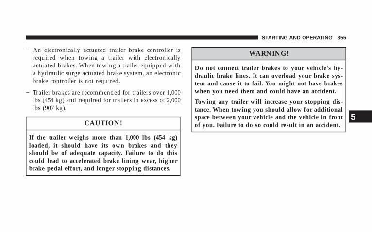
− An electronically actuated trailer brake controller isrequired when towing a trailer with electronicallyactuated brakes. When towing a trailer equipped witha hydraulic surge actuated brake system, an electronicbrake controller is not required.
− Trailer brakes are recommended for trailers over 1,000lbs (454 kg) and required for trailers in excess of 2,000lbs (907 kg).
CAUTION!
If the trailer weighs more than 1,000 lbs (454 kg)loaded, it should have its own brakes and theyshould be of adequate capacity. Failure to do thiscould lead to accelerated brake lining wear, higherbrake pedal effort, and longer stopping distances.
WARNING!
Do not connect trailer brakes to your vehicle’s hy-draulic brake lines. It can overload your brake sys-tem and cause it to fail. You might not have brakeswhen you need them and could have an accident.
Towing any trailer will increase your stopping dis-tance. When towing you should allow for additionalspace between your vehicle and the vehicle in frontof you. Failure to do so could result in an accident.
STARTING AND OPERATING 355
5
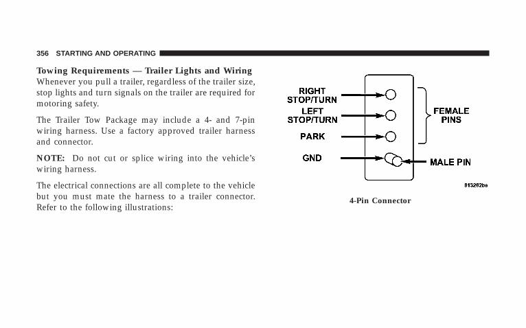
Towing Requirements — Trailer Lights and WiringWhenever you pull a trailer, regardless of the trailer size,stop lights and turn signals on the trailer are required formotoring safety.
The Trailer Tow Package may include a 4- and 7-pinwiring harness. Use a factory approved trailer harnessand connector.
NOTE: Do not cut or splice wiring into the vehicle’swiring harness.
The electrical connections are all complete to the vehiclebut you must mate the harness to a trailer connector.Refer to the following illustrations:
4-Pin Connector
356 STARTING AND OPERATING
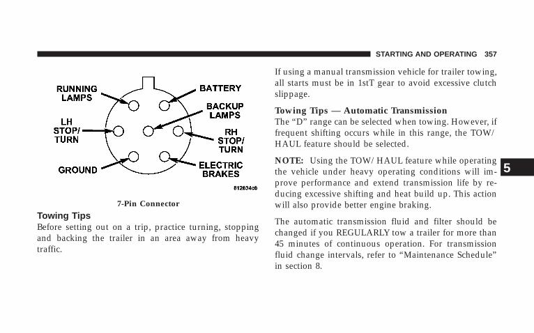
Towing TipsBefore setting out on a trip, practice turning, stoppingand backing the trailer in an area away from heavytraffic.
If using a manual transmission vehicle for trailer towing,all starts must be in 1stT gear to avoid excessive clutchslippage.
Towing Tips — Automatic TransmissionThe “D” range can be selected when towing. However, iffrequent shifting occurs while in this range, the TOW/HAUL feature should be selected.
NOTE: Using the TOW/HAUL feature while operatingthe vehicle under heavy operating conditions will im-prove performance and extend transmission life by re-ducing excessive shifting and heat build up. This actionwill also provide better engine braking.
The automatic transmission fluid and filter should bechanged if you REGULARLY tow a trailer for more than45 minutes of continuous operation. For transmissionfluid change intervals, refer to “Maintenance Schedule”in section 8.
7-Pin Connector
STARTING AND OPERATING 357
5

NOTE: Check the automatic transmission fluid levelbefore towing.
Towing Tips — Tow/Haul (If Equipped)To reduce potential for automatic transmission overheat-ing, turn the TOW/HAUL feature ON when driving inhilly areas or shift the transmission to Drive position 2 onmore severe grades.
Towing Tips — Electronic Speed Control (IfEquipped)
− Don’t use in hilly terrain or with heavy loads.
− When using the speed control, if you experience speeddrops greater than 10 mph (16 km/h), disengage untilyou can resume cruising speed.
− Use speed control in flat terrain and with light loads tomaximize fuel efficiency.
Towing Tips — Cooling SystemTo reduce potential for engine and transmission over-heating, take the following actions:
− City DrivingWhen stopped for short periods of time, put transmissionin NEUTRAL and increase engine idle speed.
− Highway DrivingReduce speed.
− Air ConditioningTurn off temporarily.
− refer to “Cooling System Operating” under “Mainte-nance Procedures” in section 8.
358 STARTING AND OPERATING

SNOWPLOW
NOTE: Do not use this vehicle for snowplow applica-tions.
WARNING!
Snowplows, winches, and other aftermarket equip-ment should not be added to the front end of yourvehicle. The airbag crash sensors may be affected bythe change in the front end structure. The airbagscould deploy unexpectedly or could fail to deployduring a collision, resulting in serious injury ordeath.
CAUTION!
Using this vehicle for snowplow applications cancause damage to the vehicle.
WARNING!
Attaching a snowplow to this vehicle could adverselyaffect performance of the airbag system in an acci-dent. Do not expect that the airbag will perform asdescribed earlier in this manual.
STARTING AND OPERATING 359
5

RECREATIONAL TOWING (BEHINDMOTORHOME, ETC.)
Recreational Towing 2WD ModelsRecreational towing of 2WD models is not allowable.Towing the vehicle with the transmission in NEUTRALcan cause severe transmission damage. Removal of thedriveshaft for towing is not recommended since thisallows transmission fluid to leak out.
Recreational Towing 4WD Models
CAUTION!
Vehicles equipped with an NV 140 Transfer Case(which has no NEUTRAL position) may NOT beused for recreational towing.
WARNING!
You or others could be injured if you leave thevehicle unattended with the transfer case in theNEUTRAL position without first fully engaging theparking brake. The transfer case NEUTRAL positiondisengages both the front and rear driveshafts fromthe powertrain and will allow the vehicle to movedespite the transmission position. The parking brakeshould always be applied when the driver is not inthe vehicle.
CAUTION!
Internal damage to the transfer case will occur if afront or rear wheel lift is used when recreationaltowing.
360 STARTING AND OPERATING

NOTE: The NV 244 Generation II transfer case must beshifted into NEUTRAL for recreational towing. The NEU-TRAL selection button is located on the lower left-handcorner of the 4WD Control Switch. Shifts into and out oftransfer case NEUTRAL can take place with the selectorswitch in any mode position.
Shifting into NEUTRALUse the following procedure to prepare your vehicle forrecreational towing.
CAUTION!
It is necessary to follow these steps to be certain thatthe transfer case is fully in NEUTRAL before recre-ational towing to prevent damage to internal parts.
1. Bring vehicle to a complete stop.
2. Shut engine OFF.
3. Turn the ignition key to the ON position withoutstarting the engine.
4. Depress brake pedal.
5. Shift automatic transmission to NEUTRAL.
6. Using the point of a ballpoint pen or similar object,depress the recessed transfer case NEUTRAL button forfour seconds.
7. After shift is completed and the NEUTRAL lightcomes on, release the NEUTRAL button.
8. Start the engine.
9. Shift the automatic transmission into REVERSE.
10. Release brake pedal for five seconds and ensure thatthere is no vehicle movement.
11. Repeat steps 9 and 10 with the transmission inDRIVE.
STARTING AND OPERATING 361
5

12. Turn ignition key to the unlocked OFF position.
13. Shift the automatic transmission into PARK.
14. Attach vehicle to tow vehicle with tow bar.
NOTE: Items 1 through 5 are requirements that must bemet prior to depressing the NEUTRAL selection button,and must continue to be met until the four secondselapses and the shift has been completed.
If any of these requirements (with the exception of Step 3- Key ON) are not met prior to depressing the NEUTRALbutton or are no longer met during the four second timer,then the NEUTRAL indicator light will flash continu-ously until all requirements are met or until the NEU-TRAL button is released.
NOTE: The ignition key must be ON for a shift to takeplace and for the position indicator lights to be operable.If the key is not ON, the shift will not take place and noposition indicator lights will be on or flashing.
CAUTION!
Damage to the transmission may occur if the trans-mission is shifted into PARK with the transfer case inNEUTRAL and the engine RUNNING. With thetransfer case in NEUTRAL, ensure that the engine isOFF prior to shifting the transmission into PARK.
Shifting Out of NEUTRALUse the following procedure to prepare your vehicle fornormal usage.
1. Bring vehicle to a complete stop.
2. Shut engine OFF.
3. Turn the ignition key to the ON position withoutstarting the engine.
4. Depress brake pedal.
362 STARTING AND OPERATING
5. Shift the automatic transmission to NEUTRAL.
6. Using the point of a ballpoint pen or similar object,depress the recessed transfer case NEUTRAL button forone second.
7. After the NEUTRAL indicator light turns off, releasethe NEUTRAL button.
8. After the NEUTRAL button has been released, thetransfer case will shift to the position identified by theselector switch.
9. Shift the automatic transmission into PARK.
10. Start the engine.
11. Shift the automatic transmission into DRIVE.
NOTE: Steps 1 through 5 are requirements that must bemet prior to depressing the NEUTRAL selection button,and must continue to be met until one second elapses andthe shift has been completed.
If any of these requirements are not met prior to depress-ing the NEUTRAL button or are no longer met during theone second time, then all of the position indicator lightswill flash continuously until all requirements are met oruntil the NEUTRAL button is released.
NOTE: The ignition key must be ON for a shift to takeplace and for the position indicator lights to be operable.If the key is not ON, the shift will not take place and noposition indicator lights will be on or flashing.
NOTE: A flashing NEUTRAL position indicator lightindicates that shift requirements have not been met.
STARTING AND OPERATING 363
5

CAUTION!
• Do not use a bumper-mounted clamp-on tow baron your vehicle. The bumper face bar will bedamaged.
• Do not disconnect the rear driveshaft becausefluid will leak from the transfer case and damageinternal parts.
EQUIPMENT IDENTIFICATION PLATEThe equipment Identification Plate is located on the hoodinner surface.
The following information about your vehicle is dis-played on this plate: Model, Wheelbase, Vehicle Identifi-cation Number, Truck Order Number, and code numberswith descriptions of all production and special equip-ment on the truck as shipped from the factory.
NOTE: Always refer to the equipment identificationplate when ordering parts.
364 STARTING AND OPERATING
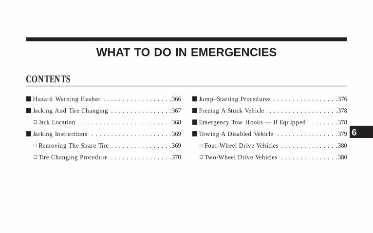
WHAT TO DO IN EMERGENCIES
CONTENTS
m Hazard Warning Flasher . . . . . . . . . . . . . . . . . . 366
m Jacking And Tire Changing . . . . . . . . . . . . . . . . 367
▫ Jack Location . . . . . . . . . . . . . . . . . . . . . . . . 368
m Jacking Instructions . . . . . . . . . . . . . . . . . . . . . 369
▫ Removing The Spare Tire . . . . . . . . . . . . . . . . 369
▫ Tire Changing Procedure . . . . . . . . . . . . . . . . 370
m Jump–Starting Procedures . . . . . . . . . . . . . . . . . 376
m Freeing A Stuck Vehicle . . . . . . . . . . . . . . . . . . 378
m Emergency Tow Hooks — If Equipped . . . . . . . . 378
m Towing A Disabled Vehicle . . . . . . . . . . . . . . . . 379
▫ Four-Wheel Drive Vehicles . . . . . . . . . . . . . . . 380
▫ Two-Wheel Drive Vehicles . . . . . . . . . . . . . . . 380
6

HAZARD WARNING FLASHERThe flasher switch is on the top of the steering column,just behind the steering wheel. Press the flasher switchand all front and rear directional signals will flashintermittently.
Press the switch a second time to turn off the emergencyflashers.
This is an emergency warning system and should not beused when the vehicle is in motion. Use it when yourvehicle is disabled and is creating a safety hazard forother motorists.
Flasher Switch
366 WHAT TO DO IN EMERGENCIES

If it is necessary to leave the vehicle to go for service, theflasher system will continue to operate with the ignitionkey removed and the vehicle locked.
JACKING AND TIRE CHANGING
WARNING!
• Being under a jacked-up vehicle is dangerous. Thevehicle could slip off the jack and fall on you. Youcould be crushed. Never put any part of your bodyunder a vehicle that is on a jack. Never start or runthe engine while the vehicle is on a jack. If youneed to get under a raised vehicle, take it to aservice center where it can be raised on a lift.
• The jack is designed to use as a tool for changingtires only. The jack should not be used to lift thevehicle for service purposes. The vehicle shouldbe jacked on a firm level surface only. Avoid ice orslippery areas.
WHAT TO DO IN EMERGENCIES 367
6

Jack LocationThe scissor jack and tire changing tools are stowed underthe second row seat.
The jack is secured in place with a winged stud and afixed stud. It is very important to secure the jack tightlyin place by engaging the slot in the base to the fixed studunder the middle seat. The winged stud inserts throughthe eyelet in the end of the jack’s worm screw.
Jack Location
368 WHAT TO DO IN EMERGENCIES

JACKING INSTRUCTIONS
Removing The Spare TireThe spare tire on your vehicle is located underneath thevehicle in the rear.
Remove the spare tire before attempting to jack thevehicle.
1. Remove the rubber plug from the floor in the cargoarea.
2. Engage the jack wrench extension to the spare tirewinch through the hole in the floor.Spare Tire Location
Spare Tire Winch
WHAT TO DO IN EMERGENCIES 369
6
3. Turn the wrench counterclockwise to lower the sparetire. Continue to turn the wrench until the spare tire canbe pulled out from under the vehicle.
It is recommended that you stow the flat tire or spare toavoid tangling the loose cable.
CAUTION!
The winch mechanism is designed for use with thejack extension tube only. Use of an air wrench orother power tools is not recommended and can dam-age the winch.
Tire Changing Procedure
WARNING!
Getting under a jacked-up vehicle is dangerous. Thevehicle could slip off the jack and fall on you. Youcould be crushed. Never get any part of your bodyunder a vehicle that is on a jack. Never start or runthe engine while the vehicle is on a jack. If you needto get under a raised vehicle, take it to a service centerwhere it can be raised on a lift.
Do not raise this vehicle using a bumper jack. The scissorjack is designed as a tool for changing tires on this vehicleonly. It is not recommended that the jack be used forservice purposes or to lift more than one wheel at a time.
370 WHAT TO DO IN EMERGENCIES

PreparationsPark the vehicle on a firm level surface, avoiding ice orslippery areas. Set the parking brake and place the shiftlever in PARK (automatic transmission). On 4-wheeldrive vehicles, shift the transfer case to the “4L” position.
WARNING!
Do not attempt to change a tire on the side of thevehicle close to moving traffic. Pull far enough offthe road to avoid the danger of being hit whenoperating the jack or changing the wheel.
• Turn on the hazard warning flasher.
• Block both the front and rearof the wheel diagonally oppo-site the jacking position. Forexample, if the right frontwheel is being changed, blockthe left rear wheel.
• Passengers should not remain in the vehicle when thevehicle is being jacked.
Instructions
Jack Warning Label
WHAT TO DO IN EMERGENCIES 371
6
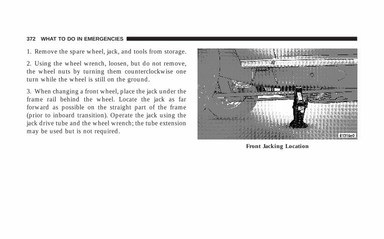
1. Remove the spare wheel, jack, and tools from storage.
2. Using the wheel wrench, loosen, but do not remove,the wheel nuts by turning them counterclockwise oneturn while the wheel is still on the ground.
3. When changing a front wheel, place the jack under theframe rail behind the wheel. Locate the jack as farforward as possible on the straight part of the frame(prior to inboard transition). Operate the jack using thejack drive tube and the wheel wrench; the tube extensionmay be used but is not required.
Front Jacking Location
372 WHAT TO DO IN EMERGENCIES

When changing a rear wheel, assemble the jack drivetube to the jack and connect the drive tube to theextension tube. Place the jack under the axle as close tothe tire as posssible with the drive tubes extending to therear. Connect the jack tube extension and wheel wrench.
Before raising the wheel off the ground, make sure thatthe jack will not damage surrounding truck parts andadjust the jack position as required.
4. By rotating the wheel wrench clockwise, raise thevehicle until the wheel just clears the surface.Rear Left Jacking Location
Rear Right Jacking Location
WHAT TO DO IN EMERGENCIES 373
6

WARNING!
Raising the vehicle higher than necessary can makethe vehicle unstable and cause an accident. It couldslip off the jack and hurt someone near it. Raise thevehicle only enough to remove the tire.
5. Remove the wheel nuts and pull the wheel off. Installthe spare wheel and wheel nuts with the cone shaped endof the nuts toward the wheel. Lightly tighten the nuts. Toavoid risk of forcing the vehicle off the jack, do not fullytighten the nuts until the vehicle has been lowered.
NOTE: Do not oil wheel studs. For chrome wheels, donot substitute with chrome plated wheel nuts.
6. Using the wheel wrench, finish tightening the nuts ina crisscross pattern. Correct nut tightness is 135 ± 10 ft lbs(183 ± 14 N·m) dynamic torque. If in doubt about the
correct tightness, have them checked with a torquewrench by your authorized dealer or at a service station.
WARNING!
A loose tire or jack thrown forward in a collision orhard stop could injure someone in the vehicle. Al-ways stow the jack, tools and the extra tire and wheelin the places provided.
7. Remove wheel blocks. Do not install chrome or alu-minum wheel center caps on the spare wheel. This mayresult in cap damage.
8. Lower the jack to its fully closed position. Stow thereplaced tire, jack, and tools as previously described.
9. Adjust the tire pressure when possible.
NOTE: Do not oil wheel studs. For chrome wheels, donot substitute with chrome plated wheel nuts.
374 WHAT TO DO IN EMERGENCIES
WARNING!
Carefully follow these tire changing warnings to helpprevent personal injury or damage to your vehicle:• Always park on a firm, level surface as far from the
edge of the roadway as possible before raising thevehicle.
• Block the wheel diagonally opposite the wheel tobe raised.
• Apply the parking brake firmly before jacking.• Never start the engine with the vehicle on a jack.• Do not let anyone sit in the vehicle when it is on a
jack.• Do not get under the vehicle when it is on a jack.• Only use the jack in the positions indicated.• If working on or near a roadway, be extremely
careful of motor traffic.• To assure that spare tires, flat or inflated, are
securely stowed, spares must be stowed with thevalve stem facing the ground.
To Stow The Flat Or SpareTurn the wheel so that the valve stem is down. Slide thewheel retainer through the center of the wheel andposition it properly across the wheel opening.
For convenience in checking the spare tire inflation, stowwith the valve stem toward the rear of the vehicle.
Rotate the winch mechanism until the wheel is drawninto place against the underside of the vehicle. Continueto rotate until you feel the winch mechanism slip or clicktwo times. It cannot be overtightened. Push against thetire several times to be sure it is firmly in place.
WHAT TO DO IN EMERGENCIES 375
6

JUMP–STARTING PROCEDURES
WARNING!
• Battery fluid is a corrosive acid solution; do notallow battery fluid to contact eyes, skin or cloth-ing. Don’t lean over battery when attachingclamps or allow the clamps to touch each other. Ifacid splashes in eyes or on skin, flush the contami-nated area immediately with large quantities ofwater.
• A battery generates hydrogen gas which is flam-mable and explosive. Keep flame or spark awayfrom the vent holes. Do not use a booster batteryor any other booster source with an output thatexceeds 12 volts.
Check the Battery Test Indicator (if equipped). If a light orbright colored dot is visible in the indicator (if equipped),DO NOT jump-start the battery.
If the indicator (if equipped) is dark or shows a green dot,proceed as follows:
1. Wear eye protection and remove all metal jewelry suchas watch bands or bracelets which might make anunintended electrical contact.
2. Park the booster vehicle within cable reach but with-out letting the vehicles touch. Set the parking brake, placethe automatic transmission in PARK and turn the ignitionOFF on both vehicles.
3. Turn OFF heater, radio and all unnecessary electricalloads.
376 WHAT TO DO IN EMERGENCIES
4. Connect one end of a jumper cable to the positiveterminal of the booster battery. Connect the other end ofthe same cable to the positive terminal of the dischargedbattery.
WARNING!
Do not permit vehicles to touch each other as thiscould establish a ground connection and personalinjury could result.
5. Connect the other cable, first to the negative terminalof the booster battery and then to the engine of thevehicle with the discharged battery. Make sure you havea good contact on the engine.
WARNING!
Do not connect the cable to the negative post of thedischarge battery. The resulting electrical spark couldcause the battery to explode.
During cold weather when temperatures are belowfreezing point, electrolyte in a discharged batterymay freeze. Do not attempt jump-starting becausethe battery could rupture or explode. The batterytemperature must be brought up above freezingpoint before attempting a jump-start.
6. Start the engine in the vehicle which has the boosterbattery, let the engine idle a few minutes, then start theengine in the vehicle with the discharged battery.
7. When removing the jumper cables, reverse the abovesequence exactly. Be careful of the moving belts and fan.
WHAT TO DO IN EMERGENCIES 377
6

WARNING!
Any procedure other than above could result in:
1. Personal injury caused by electrolyte squirting outthe battery vent;
2. Personal injury or property damage due to batteryexplosion;
3. Damage to charging system of booster vehicle orof immobilized vehicle.
FREEING A STUCK VEHICLEIf vehicle becomes stuck in snow, sand, or mud, it canoften be moved by a rocking motion. Move the gearselector rhythmically between FIRST and REVERSE,while applying slight pressure to the accelerator.
The least amount of accelerator pedal pressure to main-tain the rocking motion without spinning the wheels orracing the engine is most effective. Allow the engine toidle with the shift lever in NEUTRAL for at least oneminute after every five rocking-motion cycles. This willminimize overheating and reduce the risk of transmis-sion failure during prolonged efforts to free a stuckvehicle.
EMERGENCY TOW HOOKS — IF EQUIPPEDYour vehicle may be equipped with emergency towhooks.
NOTE: For off-road recovery, it is recommended to useboth of the front tow hooks to minimize the risk ofdamage to the vehicle.
378 WHAT TO DO IN EMERGENCIES
WARNING!
Chains are not recommended for freeing a stuckvehicle. Chains may break, causing serious injury ordeath.
WARNING!
Stand clear of vehicles when pulling with tow hooks.Tow straps and chains may break, causing seriousinjury.
CAUTION!
Tow hooks are for emergency use only, to rescue avehicle stranded off-road. Do not use tow hooks fortow truck hookup or highway towing. You coulddamage your vehicle.
TOWING A DISABLED VEHICLEProper towing or lifting equipment is required to preventdamage to your vehicle. Use of safety chains is recom-mended. Attach towing device to main structural mem-bers of the vehicle — not to bumpers or associatedbrackets. State and local laws, applying to vehiclesunder tow, must be observed.
WHAT TO DO IN EMERGENCIES 379
6
Four-Wheel Drive VehiclesThe manufacturer recommends towing with all wheelsOFF the ground. Acceptable methods are to tow thevehicle on a flatbed or with one end of the vehicle raisedand the opposite end on a towing dolly.
Two-Wheel Drive Vehicles
Provided that the transmission is operable, tow with thetransmission in NEUTRAL and the ignition key in theOFF position, along with the front wheels raised and therear wheels on the ground. The speed must not exceed 30mph (50 km/h), and the distance must not exceed 15 mi(25 km).
If the vehicle is to be towed more than 15 mi (25 km) orfaster than 30 mph (50 km/h), it must be towed on aflatbed, or with the rear wheels raised and the frontwheels on the ground, or with the front end raised andthe rear wheels on a towing dolly.
NOTE: Towing the vehicle with the rear wheels on theground at more than 30 mph (50 km/h) or for more than15 mi (25 km), can cause severe transmission damage.
380 WHAT TO DO IN EMERGENCIES
MAINTAINING YOUR VEHICLE
CONTENTS
m Engine Compartment 4.7L V-8 . . . . . . . . . . . . . . 384
m Engine Compartment 5.7L HEMI V-8 . . . . . . . . . 385
m Onboard Diagnostic System — OBD II . . . . . . . . 386
▫ Loose Fuel Filler Cap Message . . . . . . . . . . . . 386
m Emissions Inspection And MaintenancePrograms . . . . . . . . . . . . . . . . . . . . . . . . . . . . 387
m Replacement Parts . . . . . . . . . . . . . . . . . . . . . . 388
m Dealer Service . . . . . . . . . . . . . . . . . . . . . . . . . 389
m Maintenance Procedures . . . . . . . . . . . . . . . . . . 389
▫ Engine Oil . . . . . . . . . . . . . . . . . . . . . . . . . . 390
▫ Engine Oil Filter . . . . . . . . . . . . . . . . . . . . . . 393
▫ Drive Belts — Check Condition And Tension . . 393
▫ Spark Plugs . . . . . . . . . . . . . . . . . . . . . . . . . 394
▫ Engine Air Cleaner Filter . . . . . . . . . . . . . . . . 394
▫ Engine Fuel Filter . . . . . . . . . . . . . . . . . . . . . 395
▫ Catalytic Converter . . . . . . . . . . . . . . . . . . . . 395
▫ Maintenance Free Battery . . . . . . . . . . . . . . . . 396
▫ Power Steering — Fluid Check . . . . . . . . . . . . 398
7

▫ Air Conditioner Maintenance . . . . . . . . . . . . . 398
▫ Front Suspension Ball Joints . . . . . . . . . . . . . . 399
▫ Drive Shaft Constant Velocity Joints . . . . . . . . 400
▫ Body Lubrication . . . . . . . . . . . . . . . . . . . . . 400
▫ Windshield Wiper Blades . . . . . . . . . . . . . . . . 400
▫ Windshield And Rear Window Washers . . . . . 401
▫ Exhaust System . . . . . . . . . . . . . . . . . . . . . . 401
▫ Cooling System . . . . . . . . . . . . . . . . . . . . . . . 402
▫ Emission Related Components . . . . . . . . . . . . 407
▫ Brake System . . . . . . . . . . . . . . . . . . . . . . . . 408
▫ Automatic Transmission . . . . . . . . . . . . . . . . 410
▫ Transfer Case . . . . . . . . . . . . . . . . . . . . . . . . 413
▫ Axles . . . . . . . . . . . . . . . . . . . . . . . . . . . . . . 413
▫ Appearance Care And Protection FromCorrosion . . . . . . . . . . . . . . . . . . . . . . . . . . . 414
m Fuse Block . . . . . . . . . . . . . . . . . . . . . . . . . . . . 419
▫ Fuses (Interior) . . . . . . . . . . . . . . . . . . . . . . . 420
▫ Fuses (Power Distribution Center) . . . . . . . . . 423
▫ Fuses (Integrated Power Module) . . . . . . . . . . 426
m Vehicle Storage . . . . . . . . . . . . . . . . . . . . . . . . 428
m Replacement Light Bulbs . . . . . . . . . . . . . . . . . 429
m Bulb Replacement . . . . . . . . . . . . . . . . . . . . . . 429
▫ Headlights/Parking/Turn Signal . . . . . . . . . . 429
▫ Tail Lights, Turn Signals And Backup Lights —Replacement . . . . . . . . . . . . . . . . . . . . . . . . . 431
▫ License Lights . . . . . . . . . . . . . . . . . . . . . . . . 433
▫ Center High-Mounted Stoplight . . . . . . . . . . . 434
382 MAINTAINING YOUR VEHICLE

▫ Fog Lights . . . . . . . . . . . . . . . . . . . . . . . . . . 435
m Fluids And Capacities . . . . . . . . . . . . . . . . . . . 436
m Fluids, Lubricants And Genuine Parts . . . . . . . . 437
▫ Engine . . . . . . . . . . . . . . . . . . . . . . . . . . . . . 437
▫ Chassis . . . . . . . . . . . . . . . . . . . . . . . . . . . . 438
MAINTAINING YOUR VEHICLE 383
7

ENGINE COMPARTMENT 4.7L V-8
384 MAINTAINING YOUR VEHICLE
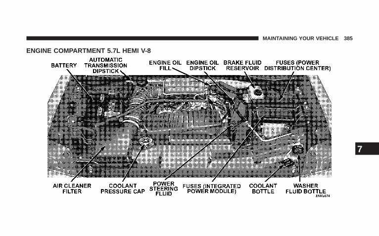
ENGINE COMPARTMENT 5.7L HEMI V-8
MAINTAINING YOUR VEHICLE 385
7

ONBOARD DIAGNOSTIC SYSTEM — OBD IIYour vehicle is equipped with a sophisticated onboarddiagnostic system called OBD II. This system monitorsthe performance of the emissions, engine, and automatictransmission control systems. When these systems areoperating properly, your vehicle will provide excellentperformance and fuel economy, as well as engine emis-sions well within current government regulations.
If any of these systems require service, the OBD II systemwill turn on the Malfunction Indicator Light (MIL). It willalso store diagnostic codes and other information toassist your service technician in making repairs. Al-though your vehicle will usually be drivable and notneed towing, see your authorized dealer for service assoon as possible.
CAUTION!
• Prolonged driving with the MIL on could causefurther damage to the emission control system. Itcould also affect fuel economy and driveability.The vehicle must be serviced before any emissionstests can be performed.
• If the MIL is flashing while the engine is running,severe catalytic converter damage and power losswill soon occur. Immediate service is required.
Loose Fuel Filler Cap MessageAfter fuel is added, the vehicle diagnostic system candetermine if the fuel filler cap is possibly loose, improp-erly installed, or damaged. A loose fuel filler cap messagewill be displayed in the instrument cluster. Tighten thegas cap until a 9clicking9 sound is heard. This is anindication that the gas cap is properly tightened. Press
386 MAINTAINING YOUR VEHICLE

the odometer RESET button to turn the message off. If theproblem persists, the message will appear the next timethe vehicle is started. This might indicate a damaged cap.If the problem is detected twice in a row, the system willturn on the MIL. Resolving the problem will turn the MILoff.
EMISSIONS INSPECTION AND MAINTENANCEPROGRAMSIn some localities, it may be a legal requirement to passan inspection of your vehicle’s emissions control system.Failure to pass could prevent vehicle registration.
For states which have an I/M (Inspection andMaintenance) requirement, this check verifies thefollowing: the Malfunction Indicator Lamp (MIL)
is functioning and is not on when the engine is running,and that the On Board Diagnostic (OBD) system is readyfor testing.
Normally, the OBD system will be ready. The OBDsystem may not be ready if your vehicle was recentlyserviced, if you recently had a dead battery, or a batteryreplacement. If the OBD system is determined not readyfor the I/M test, your vehicle may fail the test.
Your vehicle has a simple ignition key actuated testwhich you can use prior to going to the test station. Tocheck if your vehicle’s OBD system is ready, you must dothe following:
1. Insert your ignition key into the ignition switch.
2. Turn the ignition to the ON position, but do not crankor start the engine. If you crank or start the engine, youwill have to start this test over.
3. As soon as you turn your key to the ON position, youwill see your MIL symbol come on as part of a normalbulb check.
MAINTAINING YOUR VEHICLE 387
7

4. Approximately 15 seconds later, one of two things willhappen:
a. The MIL will blink for approximately five secondsand then remain on until the first engine crank or thekey is turned off. This means that your vehicle’s OBDsystem is not ready and you should not proceed to theI/M station.
b. The MIL will remain fully illuminated until the firstengine crank or the key is turned off. This means thatyour vehicle’s OBD system is ready and you canproceed to the I/M station.
If your OBD system is not ready, you should see yourauthorized dealer or repair facility. If your vehicle wasrecently serviced or had a battery failure or replacement,you may need to do nothing more than drive yourvehicle as you normally would in order for your OBDsystem to update. A recheck with the above test routinemay then indicate that the system is now ready.
Regardless of whether your vehicle’s OBD system isready or not ready, if the MIL symbol is illuminatedduring normal vehicle operation, you should have yourvehicle serviced before going to the I/M station. The I/Mstation can fail your vehicle because the MIL symbol is onwith the engine running.
REPLACEMENT PARTSUse of genuine Mopart parts for normal/scheduledmaintenance and repairs is highly recommended to en-sure the designed performance. Damage or failurescaused by the use of non-Mopart parts for maintenanceand repairs will not be covered by the manufacturer’swarranty.
388 MAINTAINING YOUR VEHICLE
DEALER SERVICEYour authorized dealer has the qualified service person-nel, special tools and equipment to perform all serviceoperations in an expert manner. Service Manuals areavailable which include detailed service information foryour vehicle. Refer to these manuals before attemptingany procedure yourself.
NOTE: Intentional tampering with emissions controlsystems can result in civil penalties being assessedagainst you.
WARNING!
You can be badly injured working on or around amotor vehicle. Do only that service work for whichyou have the knowledge and the proper equipment.If you have any doubt about your ability to performa service job, take your vehicle to a competentmechanic.
MAINTENANCE PROCEDURESThe pages that follow contain the required maintenanceservices determined by the engineers who designed yourvehicle.
Besides the maintenance items for which there are fixedmaintenance intervals, there are other items that shouldoperate satisfactorily without periodic maintenance.However, if a malfunction of these items does occur, itcould adversely affect the engine or vehicle performance.
MAINTAINING YOUR VEHICLE 389
7

These items should be inspected if a malfunction isobserved or suspected.
Engine Oil
Checking Oil LevelTo assure proper lubrication of your vehicle’s engine, theengine oil must be maintained at the correct level. Thebest time to check the engine oil level is about fiveminutes after a fully warmed up engine is shut off orbefore starting the engine after it has sat overnight.
Checking the oil while the vehicle is on level ground willimprove the accuracy of the oil level readings. Alwaysmaintain the oil level within the SAFE zone on thedipstick. Adding 1 quart/liter of oil when the reading isat the bottom of the SAFE zone will result in a reading atthe top of the SAFE zone on these engines.
CAUTION!
Overfilling or underfilling the crankcase will causeoil aeration or loss of oil pressure. This could damageyour engine.
390 MAINTAINING YOUR VEHICLE
Change Engine OilFollow the Maintenance Schedule for recommended en-gine oil and filter change intervals.
NOTE: Under no circumstances should oil change in-tervals exceed 6,000 miles (10 000 km) or 6 months,whichever comes first.
4x4 Models, If Used Primarily For Off-Road OperationEvery 50 hours of use.
Dusty ConditionsDriving through dust-laden air increases the problems ofkeeping abrasive materials out of the engine. Under theseconditions, special attention should be given to theengine air cleaner and the crankcase inlet air cleaner. Thecrankcase ventilation system should also be checkedperiodically. Make sure that these units are always clean.This will tend to reduce to a minimum the amount ofabrasive material that may enter the engine.
Engine Oil SelectionFor best performance and maximum protection under alltypes of operating conditions, the manufacturer onlyrecommends engine oils that are API certified and meetthe requirements of DaimlerChrysler Material StandardMS-6395.
American Petroleum Institute (API) Engine OilIdentification Symbol
This symbol means that the oil hasbeen certified by the AmericanPetroleum Institute (API). Themanufacturer only recommendsAPI Certified engine oils.
MAINTAINING YOUR VEHICLE 391
7
Engine Oil Viscosity (SAE Grade)SAE 5W-20 engine oil is recommended for all operatingtemperatures. This engine oil improves low tempera-ture starting and vehicle fuel economy. The engine oilfiller cap also shows the recommended engine oilviscosity for your vehicle.
For information on engine oil filler cap location, see theEngine Compartment illustration in this section.
NOTE: Vehicles equipped with a 5.7L engine must useSAE 5W-20 oil. Failure to do so may result in improperoperation of the Multiple Displacement System (MDS).Refer to “Multi Displacement System” under “Startingand Operating” in Section 5.
Lubricants which do not have both the engine oil certi-fication mark and the correct SAE viscosity grade num-ber should not be used.
Synthetic Engine OilsYou may use synthetic engine oils provided the recom-mended oil quality requirements are met, and the recom-mended maintenance intervals for oil and filter changesare followed.
Materials Added to Engine OilsThe manufacturer strongly recommends against the ad-dition of any additives (other than leak detection dyes) tothe engine oil. Engine oil is an engineered product and itsperformance may be impaired by supplemental addi-tives.
Disposing of Used Engine Oil and Oil FiltersCare should be taken in disposing of used engine oil andoil filters from your vehicle. Used oil and oil filters,indiscriminately discarded, can present a problem to theenvironment. Contact your authorized dealer, service
392 MAINTAINING YOUR VEHICLE
station, or governmental agency for advice on how andwhere used oil and oil filters can be safely discarded inyour area.
Engine Oil FilterThe engine oil filter should be replaced at every engineoil change.
Engine Oil Filter SelectionThe manufacturer’s engines have a full-flow type oilfilter. Use a filter of this type for replacement. The qualityof replacement filters varies considerably. Only highquality filters should be used to assure most efficientservice. Mopart Engine Oil Filters are a high quality oilfilter and are recommended.
Drive Belts — Check Condition and TensionBelt tension is controlled by means of an automatictensioner. No belt tension adjustments are required.However, belt and belt tensioner condition should beinspected at the specified intervals, and replaced if re-quired. See your authorized dealer for service. At themileage indicated in the maintenance schedule, all beltsand tensioner should be checked for condition. Improperbelt tension can cause belt slippage and failure. Beltsshould be inspected for evidence of cuts, cracks, glazing,or frayed cords and replaced if there is indication ofdamage which could result in belt failure. Low generatorbelt tension can cause battery failure. Also check beltrouting to make sure there is no interference between thebelts and other engine components.
MAINTAINING YOUR VEHICLE 393
7
Spark PlugsSpark plugs must fire properly to assure proper engineperformance and emission control. The plugs installed inyour vehicle should operate satisfactorily in normalservice for the mileage indicated in the MaintenanceChart. New plugs should be installed at this mileage. Theentire set should be replaced if there is any malfunctiondue to a faulty spark plug. For the proper type of sparkplug for your vehicle, refer to ”Spark Plugs” underFluids, Lubricants and Genuine Parts” in this section.
CAUTION!
When replacing plugs, do not overtighten. You coulddamage them and cause them to leak.
Engine Air Cleaner Filter
Follow the Maintenance Schedule for recommended en-gine air cleaner filter change intervals.
WARNING!
The air cleaner can provide a measure of protectionin the case of engine backfire. Do not remove the aircleaner unless such removal is necessary for repair ormaintenance. Make sure that no one is near theengine compartment before starting the vehicle withthe air cleaner removed. Failure to do so can result inserious personal injury.
394 MAINTAINING YOUR VEHICLE

Engine Fuel FilterA plugged fuel filter can cause stalling, limit the speed atwhich a vehicle can be driven or cause hard starting.Should an excessive amount of dirt accumulate in thefuel tank, frequent filter replacement may be necessary.See your authorized dealer for service.
Catalytic ConverterThe catalytic converter requires the use of unleaded fuelonly. Leaded gasoline will destroy the effectiveness of thecatalyst as an emission control device.
Under normal operating conditions, the catalytic con-verter will not require maintenance. However, it is im-portant to keep the engine properly tuned to assureproper catalyst operation and prevent possible catalystdamage.
CAUTION!
Damage to the catalytic converter can result if yourvehicle is not kept in proper operating condition. Inthe event of engine malfunction, particularly involv-ing engine misfire or other apparent loss of perfor-mance, have your vehicle serviced promptly. Contin-ued operation of your vehicle with a severemalfunction could cause the converter to overheat,resulting in possible damage to the converter and thevehicle.
NOTE: Intentional tampering with emissions controlsystems can result in civil penalties being assessedagainst you.
MAINTAINING YOUR VEHICLE 395
7
WARNING!
A hot exhaust system can start a fire if you park overmaterials that can burn. Such materials might begrass or leaves coming into contact with your exhaustsystem. Do not park or operate your vehicle in areaswhere your exhaust system can contact anything thatcan burn.
In unusual situations involving grossly malfunctioningengine operation, a scorching odor may indicate severeand abnormal catalyst overheating. If this occurs, thevehicle should be stopped, the engine shut off and thevehicle allowed to cool. Thereafter, service, including atune-up to manufacturer’s specifications, should be ob-tained immediately.
To minimize the possibility of catalyst damage:
• Do not shut off the engine or interrupt the ignitionwhen the transmission is in gear and the vehicle is inmotion.
• Do not try to start engine by pushing or towing thevehicle.
• Do not idle the engine with any spark plug wiresdisconnected or removed, such as when diagnostictesting, or for prolonged periods during very roughidling or malfunctioning operating conditions.
Maintenance Free BatteryThe top of the maintenance free battery is permanentlysealed. You will never have to add water, nor is periodicmaintenance required.
396 MAINTAINING YOUR VEHICLE

WARNING!
• Battery fluid is a corrosive acid solution and canburn or even blind you. Don’t allow battery fluidto contact your eyes, skin or clothing. Don’t leanover a battery when attaching clamps. If acidsplashes in eyes or on skin, flush the area imme-diately with large amounts of water.
• Battery gas is flammable and explosive. Keepflame or sparks away from the battery. Don’t use abooster battery or any other booster source with anoutput greater than 12 volts. Don’t allow cableclamps to touch each other.
• Battery posts, terminals and related accessoriescontain lead and lead compounds. Wash handsafter handling.
CAUTION!
• It is essential when replacing the cables on thebattery that the positive cable is attached to thepositive post and the negative cable is attached tothe negative post. Battery posts are marked (+)positive and negative (-) and identified on thebattery case.
• If a “fast charger” is used while battery is invehicle, disconnect both vehicle battery cablesbefore connecting the charger to battery. Do notuse a “fast charger” to provide starting voltage.
MAINTAINING YOUR VEHICLE 397
7

Power Steering — Fluid CheckChecking the power steering fluid level at a definedservice interval is not required. The fluid should only bechecked if a leak is suspected, abnormal noises areapparent, and/or the system is not functioning as antici-pated. Coordinate inspection efforts through an autho-rized DaimlerChrysler dealership.
WARNING!
Fluid level should be checked on a level surface andwith the engine off to prevent injury from movingparts and to ensure accurate fluid level reading. Donot overfill. Use only manufacturers recommendedpower steering fluid.
If necessary, add fluid to restore to the proper indicatedlevel. With a clean cloth, wipe any spilled fluid from allsurfaces. For correct fluid type, refer to ”Power SteeringReservoir” under “Fluids, Lubricants, and GenuineParts” in this section.
Air Conditioner MaintenanceFor best possible performance, your air conditionershould be checked and serviced by an authorized dealerat the start of each warm season. This service shouldinclude cleaning of the condenser fins and a performancetest. Drive belt tension should also be checked at thistime.
398 MAINTAINING YOUR VEHICLE

WARNING!
• Use only refrigerants and compressor lubricantsapproved by the manufacturer for your air condi-tioning system. Some unapproved refrigerants areflammable and can explode, injuring you. Otherunapproved refrigerants or lubricants can causethe system to fail, requiring costly repairs. Refer toSection 3 of the Warranty Information book forfurther warranty information.
• The air conditioning system contains refrigerantunder high pressure. To avoid risk of personalinjury or damage to the system, adding refrigerantor any repair requiring lines to be disconnectedshould be done by an experienced technician.
NOTE: Use only manufacturer approved A/C SystemSealers, Stop Leak Products, Seal Conditioners, Compres-sor Oils and Refrigerants.
Refrigerant Recovery and RecyclingR-134a air conditioning refrigerant is a hydrofluorocar-bon (HFC) that is endorsed by the Environmental Pro-tection Agency and is an ozone-saving product. How-ever, the manufacturer recommends that air conditioningservice be performed by authorized dealers or otherservice facilities using recovery and recycling equipment.
Front Suspension Ball JointsThe ball joints and seals should be inspected wheneverthe vehicle is serviced for other reasons. Damaged sealsshould be replaced to prevent leakage or contaminationof the grease.
MAINTAINING YOUR VEHICLE 399
7
Drive Shaft Constant Velocity JointsAll 4-wheel drive models are equipped with four con-stant velocity joints. Periodic lubrication of these joints isnot required. However, the joint boot should be inspectedfor external leakage or damage periodically. If externalleakage or damage is evident, the joint boot and greaseshould be replaced immediately. Continued operationcould result in failure of the joint due to water and dirtcontamination of the grease. This would require com-plete replacement of the joint assembly. Refer to theService Manual for the detailed replacement procedure.
Body LubricationLocks and all body pivot points, including such items asseat tracks, doors, liftgate, and hood hinges should belubricated periodically to assure quiet, easy operationand to protect against rust and wear. Prior to the appli-cation of any lubricant, the parts concerned should bewiped clean to remove dust and grit; after lubricatingexcess oil and grease should be removed. Particular
attention should also be given to hood latching compo-nents to ensure proper function. When performing otherunderhood services, the hood latch release mechanismand safety catch should be cleaned and lubricated.
The external lock cylinders should be lubricated twice ayear, preferably in the fall and spring. Apply a smallamount of a high quality lubricant such as Mopart LockCylinder Lubricant directly into the lock cylinder.
Windshield Wiper BladesThe rubber edges of the wiper blades and the windshieldshould be cleaned periodically with a sponge or soft clothand a mild nonabrasive cleaner. This will remove accu-mulations of salt or road film.
Operation of the wipers on dry glass for long periodsmay cause deterioration of the wiper blades. Always usewasher fluid when using the wipers to remove salt or dirtfrom a dry windshield.
400 MAINTAINING YOUR VEHICLE

Avoid using the wiper blades to remove frost or ice fromthe windshield. Keep the blade rubber out of contact withpetroleum products such as engine oil, gasoline, etc.
Windshield and Rear Window WashersThe fluid reservoir for the windshield washers and therear window washer is shared. The fluid reservoir islocated in the engine compartment: be sure to check thefluid level at regular intervals. Fill the reservoir withwindshield washer solvent only (not radiator antifreeze).When refilling the washer fluid reservoir, take somewasher fluid and apply it to a cloth or towel and wipeclean the wiper blades; this will help blade performance.To prevent freeze-up of your windshield washer systemin cold weather, select a solution or mixture that meets orexceeds the temperature range of your climate. Thisrating information can be found on most washer fluidcontainers.
The washer fluid reservoir will hold a full gallon/liter offluid when the Low Washer Fluid Light illuminates.
WARNING!
Commercially available windshield washer solventsare flammable. They could ignite and burn you. Caremust be exercised when filling or working aroundthe washer solution.
Exhaust SystemThe best protection against carbon monoxide entry intothe vehicle body is a properly maintained engine exhaustsystem.
Whenever a change is noticed in the sound of the exhaustsystem, when exhaust fumes can be detected inside thevehicle, or when the underside or rear of the vehicle is
MAINTAINING YOUR VEHICLE 401
7
damaged, have a competent mechanic inspect the com-plete exhaust system and adjacent body areas for broken,damaged, deteriorated, or mispositioned parts. Openseams or loose connections could permit exhaust fumesto seep into the passenger compartment. In addition,inspect the exhaust system each time the vehicle is raisedfor lubrication or oil change. Replace as required.
WARNING!
Exhaust gases can injure or kill. They contain carbonmonoxide (CO) which is colorless and odorless.Breathing it can make you unconscious and caneventually poison you. To avoid breathing CO, fol-low the preceding safety tips.
Cooling System
WARNING!
You or others can be badly burned by hot coolant orsteam from your radiator. If you see or hear steamcoming from under the hood, don’t open the hooduntil the radiator has had time to cool. Never try toopen a cooling system pressure cap when the radiatoris hot.
Engine Coolant ChecksCheck the engine coolant (antifreeze) protection every 12months (before the onset of freezing weather, whereapplicable). If coolant is dirty or rusty in appearance, thesystem should be drained, flushed and refilled with freshcoolant. Check the front of the A/C condenser andradiator for any accumulation of bugs, leaves, etc. If dirty,
402 MAINTAINING YOUR VEHICLE
clean by gently spraying water from a garden hosevertically down the face of the condenser and radiator.
Check the coolant recovery bottle tubing for brittle rub-ber, cracking, tears, cuts and tightness of the connectionat the bottle and radiator. Inspect the entire system forleaks.
With the engine at normal operating temperature (butnot running), check the cooling system pressure cap forproper vacuum sealing by draining a small amount ofcoolant from the radiator drain cock. If the cap is sealingproperly, the engine coolant (antifreeze) will begin todrain from the coolant recovery bottle. DO NOT RE-MOVE THE COOLANT PRESSURE CAP WHEN THECOOLING SYSTEM IS HOT.
Cooling System — Drain, Flush and RefillAt the intervals shown on the Maintenance Schedules,the system should be drained, flushed and refilled.
If the solution is dirty or contains a considerable amountof sediment, clean and flush with a reliable coolingsystem cleaner. Follow with a thorough rinsing to removeall deposits and chemicals. Properly dispose of oldantifreeze solution.
Selection Of CoolantUse only the manufacturer’s recommended coolant; forcorrect coolant type, refer to “Engine Coolant” under“Fluids, Lubricants and Genuine Parts” in this section.
MAINTAINING YOUR VEHICLE 403
7
CAUTION!
• Mixing of coolants other than specified HOATengine coolants may result in engine damage andmay decrease corrosion protection. If a non-HOATcoolant is introduced into the cooling system in anemergency, it should be replaced with the speci-fied coolant as soon as possible.
• Do not use plain water alone or alcohol-basedengine coolant (antifreeze) products. Do not useadditional rust inhibitors or antirust products, asthey may not be compatible with the radiatorengine coolant and may plug the radiator.
• This vehicle has not been designed for use withPropylene Glycol based coolants. Use of Propy-lene Glycol based coolants is not recommended.
Adding CoolantYour vehicle has been built with an improved enginecoolant that allows extended maintenance intervals. Thiscoolant can be used up to 5 Years or 100,000 miles (160000 km) before replacement. To prevent reducing thisextended maintenance period, it is important that youuse the same coolant throughout the life of your vehicle.Please review these recommendations for using HybridOrganic Additive Technology (HOAT) coolant. Whenadding coolant:
• The manufacturer recommends using MopartAntifreeze/Coolant 5 Year/100,000 Mile FormulaHOAT (Hybrid Organic Additive Technology)
• Mix a minimum solution of 50% HOAT engine coolantand distilled water. Use higher concentrations (not toexceed 70%) if temperatures below -34°F (-37°C) areanticipated.
404 MAINTAINING YOUR VEHICLE
• Use only high purity water such as distilled or deion-ized water when mixing the water/engine coolantsolution. The use of lower quality water will reducethe amount of corrosion protection in the enginecooling system.
Please note that it is the owner’s responsibility to main-tain the proper level of protection against freezing ac-cording to the temperatures occurring in the area wherethe vehicle is operated.
NOTE: Mixing coolant types will decrease the life of theengine coolant and will require more frequent coolantchanges.
Cooling System Pressure CapThe cap must be fully tightened to prevent loss ofcoolant, and to ensure that coolant will return to theradiator from the coolant recovery bottle.
The cap should be inspected and cleaned if there is anyaccumulation of foreign material on the sealing surfaces.
WARNING!
• The warning words “DO NOT OPEN HOT” onthe cooling system pressure cap are a safety pre-caution. Never add coolant when the engine isoverheated. Do not loosen or remove the cap tocool an overheated engine. Heat causes pressure tobuild up in the cooling system. To prevent scald-ing or injury, do not remove the pressure cap whilethe system is hot or under pressure.
• Do not use a pressure cap other than the onespecified for your vehicle. Personal injury or en-gine damage may result.
MAINTAINING YOUR VEHICLE 405
7

Disposal of Used Engine CoolantUsed ethylene glycol based engine coolant is a regulatedsubstance requiring proper disposal. Check with yourlocal authorities to determine the disposal rules for yourcommunity. To prevent ingestion by animals or childrendo not store ethylene glycol based engine coolant in opencontainers or allow it to remain in puddles on theground. If ingested by a child, contact a physicianimmediately. Clean up any ground spills immediately.
Coolant LevelThe coolant bottle provides a quick visual method fordetermining that the coolant level is adequate. With theengine cold, the level of the coolant in the coolantrecovery bottle should be between the ranges indicatedon the bottle dipstick.
The radiator normally remains completely full, so there isno need to remove the radiator cap unless checking forcoolant freeze point or replacing coolant. Advise your
service attendant of this. As long as the engine operatingtemperature is satisfactory, the coolant bottle need onlybe checked once a month.
When additional coolant is needed to maintain theproper level, it should be added to the coolant bottle. Donot overfill.
Points to Remember
NOTE: When the vehicle is stopped after a few miles (afew kilometers) of operation, you may observe vaporcoming from the front of the engine compartment. This isnormally a result of moisture from rain, snow, or highhumidity accumulating on the radiator and being vapor-ized when the thermostat opens, allowing hot coolant toenter the radiator.
If an examination of your engine compartment shows noevidence of radiator or hose leaks, the vehicle may besafely driven. The vapor will soon dissipate.
406 MAINTAINING YOUR VEHICLE
• Do not overfill the coolant recovery bottle.
• Check coolant freeze point in the radiator and in thecoolant recovery bottle. If antifreeze needs to beadded, contents of coolant recovery bottle must also beprotected against freezing.
• If frequent coolant additions are required, or if thelevel in the coolant recovery bottle does not drop whenthe engine cools, the cooling system should be pres-sure tested for leaks.
• Maintain coolant concentration at 50% HOAT enginecoolant (minimum) and distilled/deionized water forproper corrosion protection of your engine whichcontains aluminum components.
• Make sure that the radiator and coolant recoverybottle overflow hoses are not kinked or obstructed.
• Keep the front of the radiator clean. If your vehicle isequipped with air conditioning, keep the front of thecondenser clean, also.
• Do not change the thermostat for summer or winteroperation. If replacement is ever necessary, installONLY the correct type thermostat. Other designs mayresult in unsatisfactory coolant performance, poor gasmileage, and increased emissions.
Emission Related Components
Fuel System Hoses and Vapor/Vacuum HarnessesWhen the vehicle is serviced for scheduled maintenance,inspect surface of hoses and nylon tubing for evidence ofheat and mechanical damage. Hard and brittle rubber,cracking, checking, tears, cuts, abrasions, and excessiveswelling suggest deterioration of the rubber. Particularattention should be given to examining hose surfacesnearest to high heat sources, such as the exhaust mani-fold.
MAINTAINING YOUR VEHICLE 407
7
Ensure nylon tubing in these areas has not melted orcollapsed.
Inspect all hose clamps and couplings to make sure theyare secure and no leaks are present.
NOTE: Fluids such as oil, power steering fluid, andbrake fluid are used during assembly plant operations toease the assembly of hoses to couplings. Therefore, oilwetness at the hose-coupling area is not necessarily anindication of leakage. Actual dripping of hot fluid whensystems are under pressure (during vehicle operation),should be noted before hose is replaced based on leakage.
You are urged to use only the manufacturer’s specifiedhoses and clamps, or their equivalent in material andspecification, in any fuel system servicing. It is manda-tory to replace all clamps that have been loosened orremoved during service. Care should be taken in install-ing new clamps to ensure they are properly torqued.
Positive Crankcase Ventilation (PCV) ValveProper operation of the crankcase ventilation systemrequires that the PCV valve be free of sticking or plug-ging because of deposits. Deposits can accumulate in thePCV valve and passage with increasing mileage. Havethe PCV valve, hoses, and passages checked for properoperation at the intervals specified. If the valve isplugged or sticking, replace with a new valve – Do notattempt to clean the PCV valve! Check ventilating hosefor indication of damage or plugging with deposits.Replace if necessary.
Brake System
Power Disc Brakes (Front and Rear)Disc brakes do not require adjustment; however, severalhard stops during the break-in period are recommendedto seat the linings and wear off any foreign material.
408 MAINTAINING YOUR VEHICLE
Brake Master CylindersThe fluid level in the master cylinders should be checkedwhenever the vehicle is serviced, or immediately if thebrake system warning light is on. If necessary, add fluidto bring level to the full mark on the side of the reservoirof the brake master cylinder. Be sure to clean the top ofthe master cylinder area before removing the cap. Withdisc brakes, fluid level can be expected to fall as the brakepads wear. Brake fluid level should be checked whenpads are replaced. If the brake fluid level is abnormallylow, check system for leaks.
For correct fluid type, refer to ”Brake Master Cylinder”under “Fluids, Lubricants and Genuine Parts” in thissection.
WARNING!
Use of brake fluid that may have a lower initialboiling point, or is unidentified as to specificationsmay result in sudden brake failure during hardprolonged braking. You could have an accident.
WARNING!
Overfilling the brake fluid reservoir can result inspilling brake fluid on hot engine parts and thebrake fluid catching on fire.
Use only brake fluid that has been in a tightly closedcontainer to avoid contamination from foreign matter ormoisture.
MAINTAINING YOUR VEHICLE 409
7
CAUTION!
Do not allow a petroleum-base fluid to contaminatethe brake fluid. Seal damage may result.
Brake HosesInspection should be performed whenever the brakesystem is serviced or at intervals specified. Inspect hy-draulic brake hoses for surface cracking, scuffing or wornspots. If there is any evidence of cracking, scuffing, orworn spots, the hose should be replaced immediately!Eventual deterioration of the hose can take place withpossible burst failure.
WARNING!
Worn brake hoses can burst and cause brake failure.You could have an accident. If you see any sign ofcracking, scuffing, or worn spots, have the brakehoses replaced immediately.
Automatic Transmission
Fluid Level Check
NOTE: If equipped with a dipstick, use the followingprocedure. If your vehicle has a capped dipstick, it issealed and should not be tampered with. Your authorizeddealer has the proper tools to ensure that the fluid levelis set properly.
Check the fluid level while the transmission is at normaloperating temperature 180°F (82°C). This occurs after at
410 MAINTAINING YOUR VEHICLE
least 15 miles (24 km) of driving. At normal operatingtemperature the fluid cannot be held comfortably be-tween the fingertips.
To check the automatic transmission fluid level properly,the following procedure must be used:
1. Operate the engine at idle speed and normal operatingtemperature.
2. The vehicle must be on level ground.
3. Fully apply the parking brake and press the brakepedal.
4. Place the shift lever momentarily in each gear positionending with the lever in PARK.
5. Remove the dipstick, wipe it clean and reinsert it untilseated.
6. Remove the dipstick again and note the fluid level onboth sides. The fluid level should be between the “HOT”(upper) reference holes on the dipstick at normal operat-ing temperature. Verify that solid coating of oil is seen onboth sides of the dipstick. If the fluid is low, add asrequired into the dipstick tube. Do not overfill. Afteradding any quantity of oil through the oil fill tube, waita minimum of two minutes for the oil to fully drain intothe transmission before rechecking the fluid level.
NOTE: If it is necessary to check the transmission belowthe operating temperature, the fluid level should bebetween the two “COLD” (lower) holes on the dipstickwith the fluid at approximately 70°F (21°C) (room tem-perature). If the fluid level is correctly established atroom temperature, it should be between the “HOT”(upper) reference holes when the transmission reaches180°F ( 82°C). Remember it is best to check the level at thenormal operating temperature.
MAINTAINING YOUR VEHICLE 411
7
CAUTION!
Be aware that if the fluid temperature is below 50°F(10°C) it may not register on the dipstick. Do not addfluid until the temperature is elevated enough toproduce an accurate reading.
7. Check for leaks. Release parking brake.
To prevent dirt and water from entering the transmissionafter checking or replenishing fluid, make certain that thedipstick cap is properly reseated. It is normal for thedipstick cap to spring back slightly from its fully seatedposition, as long as its seal remains engaged in thedipstick tube.
Automatic Transmission Fluid And Filter ChangeFollow the Maintenance Schedule for recommendedtransmission fluid and filter change intervals.
Selection of LubricantIt is important that the proper lubricant is used in thetransmission to assure optimum transmission perfor-mance. Use only manufacturer’s recommended transmis-sion fluid; for correct fluid type, refer to “AutomaticTransmission” under “Fluids, Lubricants and GenuineParts” in this section. It is important that the transmissionfluid be maintained at the prescribed level using therecommended fluid.
Special AdditivesAutomatic Transmission Fluid (ATF) is an engineeredproduct and its performance may be impaired by supple-mental additives. Therefore, do not add any fluid addi-tives to the transmission. The only exception to thispolicy is the use of special dyes to aid in detecting fluidleaks. In addition, avoid using transmission sealers asthey may adversely affect seals.
412 MAINTAINING YOUR VEHICLE

CAUTION!
Using a transmission fluid other than the manufac-turer’s recommended fluid may cause deteriorationin transmission shift quality and/or torque convertershudder. Using a transmission fluid other than themanufacturer’s recommended fluid will result inmore frequent fluid and filter changes. For correctfluid type, refer to “Automatic Transmission” under“Fluids, Lubricants and Genuine Parts” in thissection.
Transfer CaseInspect the transfer case for fluid leaks. If a fluid leak isevident the transfer case fluid level may be low. Have thetransfer case serviced immediately.
CAUTION!
Damage may result from operation of the vehiclewith low transfer case fluid.
Drain And RefillFollow the Maintenance Schedule for recommendedtransfer case fluid change intervals.
Lubricant SelectionFor correct fluid type, refer to ”Transfer Case” under“Fluids, Lubricants and Genuine Parts” in this section.
AxlesFor correct fluid type, refer to ”Front or Rear Axle” under“Fluids, Lubricants and Genuine Parts” in this section.
Drain And RefillFollow the Maintenance Schedule for recommended axlefluid change intervals.
MAINTAINING YOUR VEHICLE 413
7
NOTE: The presence of water in the gear lubricant willresult in corrosion and possible failure of differentialcomponents. Operation of the vehicle in water, as may beencountered in some off-highway types of service, willrequire draining and refilling the axle to avoid damage.
Rear AxleRear Axle fluid levels should be 7/8 in (22 mm) +/- 1/4in (6 mm) below the fill hole for 8 1/4 in (21 cm) and 91/4 (23 cm) in axles should be 1 5/8 in (31 mm) +/- 1/4in (6 mm)
Front AxleFront axle fluid level should be 3/4 in (20 mm) +/- 1/4 in(6 mm) below the level of the fill hole.
Appearance Care and Protection From Corrosion
Protection of Body and Paint from CorrosionVehicle body care requirements vary according to geo-graphic locations and usage. Chemicals that make roadspassable in snow and ice, and those that are sprayed ontrees and road surfaces during other seasons, are highlycorrosive to the metal in your vehicle. Outside parking,which exposes your vehicle to airborne contaminants,road surfaces on which the vehicle is operated, extremehot or cold weather and other extreme conditions willhave an adverse effect on paint, metal trim, and under-body protection.
The following maintenance recommendations will enableyou to obtain maximum benefit from the corrosionresistance built into your vehicle.
What Causes Corrosion?Corrosion is the result of deterioration or removal ofpaint and protective coatings from your vehicle.
414 MAINTAINING YOUR VEHICLE
The most common causes are:
• Road salt, dirt and moisture accumulation.
• Stone and gravel impact.
• Insects, tree sap and tar.
• Salt in the air near seacoast localities.
• Atmospheric fallout/industrial pollutants.
Washing
• Wash your vehicle regularly. Always wash your ve-hicle in the shade using a mild car wash soap, andrinse the panels completely with clear water.
• If insects, tar or other similar deposits have accumu-lated on your vehicle, wash it as soon as possible.
• Use Mopart Auto Polish to remove road film andstains and to polish your vehicle. Take care never toscratch the paint.
• Avoid using abrasive compounds and power buffingthat may diminish the gloss or thin out the paintfinish.
CAUTION!
Do not use abrasive or strong cleaning materials suchas steel wool or scouring powder, which will scratchmetal and painted surfaces.
Special Care
• If you drive on salted or dusty roads or if you drivenear the ocean, hose off the undercarriage at least oncea month.
• It is important that the drain holes in the lower edgesof the doors, rocker panels and liftgate be kept clearand open.
MAINTAINING YOUR VEHICLE 415
7

• If you detect any stone chips or scratches in the paint,touch them up immediately. The cost of such repairs isconsidered the responsibility of the owner.
• If your vehicle is damaged due to an accident orsimilar cause which destroys the paint and protectivecoating have your vehicle repaired as soon as possible.The cost of such repairs is considered the responsibil-ity of the owner.
• If you carry special cargo such as chemicals, fertilizers,de-icer salt, etc., be sure that such materials are wellpackaged and sealed.
• If a lot of driving is done on gravel roads, considermud or stone shields behind each wheel.
• Use Mopart touch up paint on scratches as soon aspossible. Your authorized dealer has touch up paint tomatch the color of your vehicle.
Wheel and Wheel Trim CareAll wheels and wheel trim, especially aluminum andchrome plated wheels, should be cleaned regularly witha mild soap and water to prevent corrosion. To removeheavy soil, use Mopart Wheel Cleaner or select a non-abrasive, non-acidic cleaner. Do not use scouring pads,steel wool, a bristle brush or metal polishes. OnlyMopart cleaners are recommended. Do not use ovencleaner. Avoid automatic car washes that use acidicsolutions or harsh brushes that may damage the wheels’protective finish.
YES Essentialst Fabric Cleaning Procedure – IfEquippedYES Essentialst seats may be cleaned in the followingmanner:
• Remove as much of the stain as possible by blottingwith a clean, dry towel.
• Blot any remaining stain with a clean, damp towel.
416 MAINTAINING YOUR VEHICLE

• For tough stains, apply Mopart Total Clean or a mildsoap solution to a clean, damp cloth and remove stain.Use a fresh, damp towel to remove soap residue.
• For grease stains, apply Mopart Multi-PurposeCleaner to a clean, damp cloth and remove stain. Usea fresh, damp towel to remove soap residue.
• Do not use any solvents or protectants onYES Essentialst products.
Interior CareUse Mopart Fabric Cleaner to clean fabric upholsteryand carpeting.
Use Mopart Vinyl Cleaner to clean vinyl upholstery andtrim.
Mopart Total Clean is specifically recommended forleather upholstery.
Your leather upholstery can be best preserved by regularcleaning with a damp soft cloth. Small particles of dirtcan act as an abrasive and damage the leather upholsteryand should be removed promptly with a damp cloth.Stubborn soils can be removed easily with a soft clothand Mopart Total Clean. Care should be taken to avoidsoaking your leather upholstery with any liquid. Pleasedo not use polishes, oils, cleaning fluids, solvents, deter-gents, or ammonia based cleaners to clean your leatherupholstery. Application of a leather conditioner is notrequired to maintain the original condition.
WARNING!
Do not use volatile solvents for cleaning purposes.Many are potentially flammable, and if used inclosed areas they may cause respiratory harm.
MAINTAINING YOUR VEHICLE 417
7
Cleaning HeadlightsYour vehicle has plastic headlights that are lighter andless susceptible to stone breakage than glass headlights.
Plastic is not as scratch resistant as glass and thereforedifferent lens cleaning procedures must be followed.
To minimize the possibility of scratching the lenses andreducing light output, avoid wiping with a dry cloth. Toremove road dirt, wash with a mild soap solution fol-lowed by rinsing.
Do not use abrasive cleaning components, solvents, steelwool or other aggressive material to clean the lenses.
Glass SurfacesAll glass surfaces should be cleaned on a regular basiswith any commercial household-type glass cleaner.Never use an abrasive type cleaner. Use caution whencleaning inside rear windows equipped with electric
defrosters or windshields equipped with a windshieldwiper de-icer. Do not use scrapers or other sharp instru-ments which may scratch the elements.
When cleaning the rear view mirror, spray cleaner on thetowel or rag that you are using. Do not spray cleanerdirectly on the mirror.
Cleaning Plastic Instrument Cluster LensesThe lenses in front of the instruments in this vehicle aremolded in clear plastic. When cleaning the lenses, caremust be taken to avoid scratching the plastic.
1. Clean with a wet soft rag. A mild soap solution may beused, but do not use high alcohol content or abrasivecleaners. If soap is used, wipe clean with a clean damprag.
2. Dry with a soft tissue.
418 MAINTAINING YOUR VEHICLE
Seat Belt MaintenanceDo not bleach, dye or clean the belts with chemicalsolvents or abrasive cleaners. This will weaken the fabric.Sun damage will also weaken the fabric.
If the belts need cleaning, use a mild soap solution orlukewarm water. Do not remove the belts from thevehicle to wash them.
Replace the belts if they appear frayed or worn or if thebuckles do not work properly.
FUSE BLOCK
CAUTION!
When replacing a blown fuse, it is important to useonly a fuse having the correct amperage rating. Theuse of a fuse with a rating other than indicated mayresult in a dangerous electrical system overload. If aproperly rated fuse continues to blow, it suggests aproblem in the circuit that must be corrected.
NOTE: If you are leaving your vehicle dormant forlonger than 21 days you may want to take steps to protectyour battery. You may do this by disconnecting thebattery or by disconnecting the two ignition-off draw(I.O.D.) fuses located in the auxiliary Power DistributionCenter (PDC) in the engine compartment. The I.O.D.cavities include a snap-in retainer that allows the fuse tobe disconnected without removing it from the fuse block.Pressing the I.O.D. fuse back into the cavity reconnects it.
MAINTAINING YOUR VEHICLE 419
7
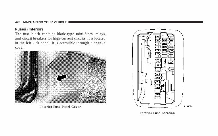
Fuses (Interior)The fuse block contains blade-type mini-fuses, relays,and circuit breakers for high-current circuits. It is locatedin the left kick panel. It is accessible through a snap-incover.
Interior Fuse Panel Cover
Interior Fuse Location
420 MAINTAINING YOUR VEHICLE

Cavity Mini Fuse/Color Description
F1 15 Amp Blue Instrument ClusterBattery Feed
F 2 10 Amp Red Spare
F3 10 Amp Red
Ignition Run/Startfor Next GenerationController (NGC),Integrated Power
Module (IPM), A/CRelay and Fuel
Pump Relay
F4 10 Amp Red
Door Node andNon-MemoryPower Mirror
Switch Battery Feed
F5 (2) 10 AmpRed
Airbags (two Fusesin Yellow Holder)
F6 2 Amp Clear Ignition Run/StartUnlock
F7 25 Amp Natu-ral Radio Battery Feed
F8 10 Amp Red
Ignition Run/Startfor Cluster/TransferCase/Seat Sw. Back
Lighting
F9 10 Amp Red
Satellite Digital Au-dio Receiver
(SDAR)/DigitalVideo Disc (DVD)
Battery FeedF10 10 Amp Red SpareF11 10 Amp Red Heated Mirrors
F12 20 Amp Yellow Cluster BatteryFeed
MAINTAINING YOUR VEHICLE 421
7

F13 10 Amp Red
Ignition Run HVACModule/HeatedRear Glass (EBL)
Relay
F14 10 Amp Red ABS Module Igni-tion Run
F15 15 Amp Blue
Battery FeedBluetootht,
Compass/TripComputer (CMTC),Sentry Keyt Diag-
nostics
F16 20 Amp Yellow ReconfigurablePower Outlets
F17 20 Amp Yellow
Ignition Run / RearPark Assist / Sec-ond Row Heated
Seats
F18 20 Amp Yellow Cigar Lighter Igni-tion
F19 10 Amp Red Spare Fuse
F20 15 Amp BlueHeating & Air Con-
ditioning w/ATCOnly Battery Feed
F21 25 Amp Natu-ral
Amplifier BatteryFeed
422 MAINTAINING YOUR VEHICLE

Fuses (Power Distribution Center)
Your vehicle is equipped with an electrical power distri-bution center located in the left side of the enginecompartment.
This center contains cartridge fuses, mini fuses andrelays. A description of each fuse and component may be
stamped on the inside cover, otherwise the cavity num-ber of each fuse is stamped on the inside cover thatcorresponds to the following chart. These fuses andrelays can be obtained from your authorized dealer.
CavityCartridge
Fuse /Relay
MiniFuse Description
1 30 AmpPink
Starter
2 30 AmpPink
Front Wiper
3 40 AmpGreen
Brake Batt
4 30 AmpPink
JB Feed Acc # 2
5 40 AmpGreen
Power Seats
6 30 AmpPink
Run Remote RelayFeed
Power Distribution Center
MAINTAINING YOUR VEHICLE 423
7

CavityCartridge
Fuse /Relay
MiniFuse Description
7 40 AmpGreen
Blower Motor RelayFeed
8 40 AmpGreen
JB Feed Acc Delay
9 Spare10 30 Amp
PinkASD
11 40 AmpGreen
Power Liftgate ( IfEquipped)
12 40 AmpGreen
JB Feed / HeatedRear Glass (EBL)/T-Case Brake
13 30 AmpPink
JB Feed RR
14 40 AmpGreen
ESP Pump
CavityCartridge
Fuse /Relay
MiniFuse Description
15 50 AmpRed
JB Feed
16 10 AmpRed
Spare
17 Spare18 20 Amp
YellowFuel Pump
19 20 AmpYellow
Next Generation Con-troller (NGC)
20 25 AmpClear
115V Power Inverter
21 20 AmpYellow
ABS Batt
22 20 AmpYellow
Next Generation Con-troller (NGC) Batt
424 MAINTAINING YOUR VEHICLE

CavityCartridge
Fuse /Relay
MiniFuse Description
23 20 AmpYellow
Trailer Tow
24 15 AmpBlue
A/C Clutch
25 15 AmpBlue
Stop Lamp Switch
26 Spare27 20 Amp
YellowRun/Start Relay Feed
28 Spare29 Relay Run Start30 Relay Run Remote31 Spare32 Relay Starter
CavityCartridge
Fuse /Relay
MiniFuse Description
33 Relay Electronic AutomaticTransaxle (EATX)
34 Relay AC Clutch35 Relay Fuel Pump Rly36 Spare37 Relay Stop Lamp Switch38 Spare39 Relay Blower Motor40 Relay Auto Shut Down
(ASD) Rly
MAINTAINING YOUR VEHICLE 425
7

Fuses (Integrated Power Module)
An integrated power module is located in the left side ofthe engine compartment. This center contains cartridgefuses, mini fuses and relays. A description of each fuseand component may be stamped on the inside cover,
otherwise the cavity number of each fuse is stamped onthe inside cover that corresponds to the following chart.
CavityCartridge
Fuse /Relay
MiniFuse Description
1 Relay Wiper On/Off Rly2 Relay Wiper Hi/Lo Rly3 Relay Horn Rly4 Relay Rear Wiper Rly5 Relay Lt Trailer-Tow Stop/
Turn Rly6 Relay Rt Trailer-Tow Stop/
Turn Rly7 Relay Park Lamps Rly8 10 Amp
RedLt Park Lamps
9 10 AmpRed
Trailer-Tow ParkLamps
Integrated Power Module
426 MAINTAINING YOUR VEHICLE

CavityCartridge
Fuse /Relay
MiniFuse Description
10 10 AmpRed
Rt Park Lamps
11 Relay Radiator Fan Hi Rly12 20 Amp
YellowFront Control Module(FCM) Batt #4
13 20 AmpYellow
Front Control Module(FCM) Batt #2
14 20 AmpYellow
Adjustable Pedal
15 20 AmpYellow
Ft Fog Lamps
16 20 AmpYellow
Horn
17 20 AmpYellow
Rear Wiper
CavityCartridge
Fuse /Relay
MiniFuse Description
18 20 AmpYellow
Front Control Module(FCM) Batt #1
19 20 AmpYellow
Lt Trailer-Tow Stop/Turn
20 20 AmpYellow
Front Control Module(FCM) Batt #3
21 20 AmpYellow
Rt Trailer-Tow Stop/Turn
22 30 AmpPink
Front Control Module(FCM) BATT # 5
23 40 AmpGreen
Radiator Fan
24 Relay Radiator Fan Lo Rly25 Relay Ft Fog Lamps Rly26 Relay Adjustable Pedal Rly
MAINTAINING YOUR VEHICLE 427
7
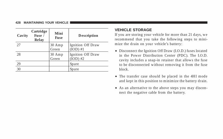
CavityCartridge
Fuse /Relay
MiniFuse Description
27 30 AmpGreen
Ignition Off Draw(IOD) #1
28 30 AmpGreen
Ignition Off Draw(IOD) #2
29 Spare30 Spare
VEHICLE STORAGEIf you are storing your vehicle for more than 21 days, werecommend that you take the following steps to mini-mize the drain on your vehicle’s battery:
• Disconnect the Ignition Off Draw (I.O.D.) fuses locatedin the Power Distribution Center (PDC). The I.O.D.cavity includes a snap-in retainer that allows the fuseto be disconnected without removing it from the fuseblock.
• The transfer case should be placed in the 4HI modeand kept in this position to minimize the battery drain.
• As an alternative to the above steps you may discon-nect the negative cable from the battery.
428 MAINTAINING YOUR VEHICLE

REPLACEMENT LIGHT BULBS
LIGHT BULBS — Interior Bulb No.Dome Light . . . . . . . . . . . . . . . . . . . . Not ServiceableLiftgate Lamp . . . . . . . . . . . . . . . . . . . . . . . . . . . 567Overhead Console Lights. . . . . . . . . . . Not ServiceableReading Light. . . . . . . . . . . . . . . . . . . Not ServiceableVisor Vanity Lights . . . . . . . . . . . . . . . Not Serviceable
LIGHT BULBS — Exterior Bulb No.Headlight . . . . . . . . . . . . . . . . . . . . . . . . . . . . . H13Front Park/Turn . . . . . . . . . . . . . . . . . . . . . . 3457AKBackup . . . . . . . . . . . . . . . . . . . . . . . . . . . . . . . 3057Center High-Mounted Stop Light . . . . . . . . . . . . . 921Front Side Marker . . . . . . . . . . . . . . . . . . . . . . . . 168Fog Lamp . . . . . . . . . . . . . . . . . . . . . . . . . . . . . 9145License Plate Light . . . . . . . . . . . . . . . . . . . . . . . 168Rear Tail, Stop, Turn Signal and Side Marker . . . . 3057
BULB REPLACEMENT
Headlights/Parking/Turn Signal
1. Remove the two bolts attaching the headlight to theupper fender reinforcement (hood must be opened toaccess bolts).
MAINTAINING YOUR VEHICLE 429
7
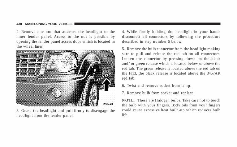
2. Remove one nut that attaches the headlight to theinner fender panel. Access to the nut is possible byopening the fender panel access door which is located inthe wheel liner.
3. Grasp the headlight and pull firmly to disengage theheadlight from the fender panel.
4. While firmly holding the headlight in your handsdisconnect all connectors by following the proceduredescribed in step number 5 below.
5. Remove the bulb connector from the headlight makingsure to pull and release the red tab on all connectors.Loosen the connector by pressing down on the blackand/or green release which is located below or above thered tab. The green release is located above the red tab onthe H13, the black release is located above the 3457AKred tab.
6. Twist and remove socket from lamp.
7. Remove bulb from socket and replace.
NOTE: These are Halogen bulbs. Take care not to touchthe bulb with your fingers. Body oils from your fingerscould cause excessive heat build-up which reduces bulblife.
430 MAINTAINING YOUR VEHICLE

Tail Lights, Turn Signals And Backup Lights —Replacement
1. Remove the two push-pins from the tail light housing.
2. Rotate the light to the outboard side of the vehicle andremove.
MAINTAINING YOUR VEHICLE 431
7

3. Unlock and remove electrical connector. 4. Twist bulb sockets counterclockwise to remove fromhousing.
5. Remove the bulbs from the bulb sockets by pulling thebulb straight out.
432 MAINTAINING YOUR VEHICLE
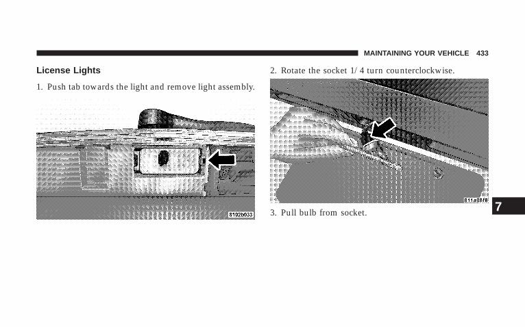
License Lights
1. Push tab towards the light and remove light assembly.
2. Rotate the socket 1/4 turn counterclockwise.
3. Pull bulb from socket.
MAINTAINING YOUR VEHICLE 433
7
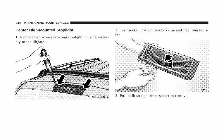
Center High-Mounted Stoplight
1. Remove two screws securing stoplight housing assem-bly to the liftgate.
2. Turn socket 1/4 counterclockwise and free from hous-ing.
3. Pull bulb straight from socket to remove.
434 MAINTAINING YOUR VEHICLE

Fog Lights
To replace the left foglamp bulb:
1. Remove the three wheel liner screws
2. Remove the far left air dam screw at the bottom of thefascia.
3. Peel back the liner and access the fog light.
4. Rotate the socket and connector 1/4 turn counter-clockwise and pull straight reward to disengage from thelight.
5. Remove the bulb from the socket and replace.
The right fog light can be accessed from below thevehicle. Follow the previous Steps 4 and 5 of the left foglight to replace the bulb.
NOTE: These are halogen bulbs. Take care not to touchthe bulb with your fingers. Body oils from your fingerscould cause excessive heat build-up, which reduces bulblife.
1 - Wheel Liner Screws2 - Far Left Air Dam Screw
MAINTAINING YOUR VEHICLE 435
7
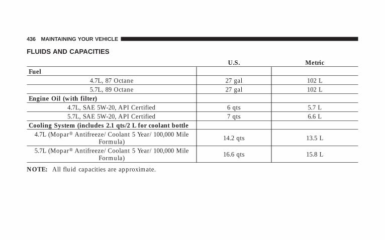
FLUIDS AND CAPACITIES
U.S. MetricFuel
4.7L, 87 Octane 27 gal 102 L5.7L, 89 Octane 27 gal 102 L
Engine Oil (with filter)4.7L, SAE 5W-20, API Certified 6 qts 5.7 L5.7L, SAE 5W-20, API Certified 7 qts 6.6 L
Cooling System (includes 2.1 qts/2 L for coolant bottle4.7L (Mopart Antifreeze/Coolant 5 Year/100,000 Mile
Formula) 14.2 qts 13.5 L
5.7L (Mopart Antifreeze/Coolant 5 Year/100,000 MileFormula) 16.6 qts 15.8 L
NOTE: All fluid capacities are approximate.
436 MAINTAINING YOUR VEHICLE

FLUIDS, LUBRICANTS AND GENUINE PARTS
Engine
Component Fluids, Lubricants and Genuine PartsEngine Coolant Mopart Antifreeze/Coolant 5 Year/100,000 Mile Formula HOAT (Hybrid Or-
ganic Additive Technology).4.7L/5.7L Engine Oil Use API Certified SAE 5W-20 Engine Oil, meeting the requirements of
DaimlerChrysler Material Standard MS-6395. Refer to your engine oil fillercap for correct SAE grade.
Engine Oil Filter Mopart Engine Oil Filter, P/N 5281090 or equivalent.Spark Plugs (4.7L Engine) Upper Bank — FR8TE2 (Gap 0.039 in [.99 mm]) Lower Bank — FR8T1332
(Gap 0.051 in [1.30 mm])Spark Plugs (5.7L Engine) REC14MCC4 (Gap 0.043 in [1.09 mm])Fuel Selection (4.7L Engine) 87 OctaneFuel Selection (5.7L Engine) 87 Octane Acceptable - 89 Octane Recommended
MAINTAINING YOUR VEHICLE 437
7

Chassis
Component Fluids, Lubricants and Genuine Parts.Automatic Transmission Mopart ATF+4, Automatic Transmission Fluid.Transfer Case Mopart ATF+4, Automatic Transmission Fluid.Front Axle SAE 75W-90 Multipurpose Type, GL-5 Gear Lubricant or equivalent.Rear Axle SAE 75W-140 Synthetic Gear Lubricant or equivalent.Brake Master Cylinder Mopart DOT 3 and SAE J1703 should be used or equivalent. If DOT 3
brake fluid is not available, then DOT 4 is acceptable. Use only recom-mended brake fluids.
Power Steering Reservoir Mopart ATF+4, Automatic Transmission Fluid.
438 MAINTAINING YOUR VEHICLE

MAINTENANCE SCHEDULES
CONTENTS
m Emission Control System Maintenance . . . . . . . . 440
m Maintenance Schedule . . . . . . . . . . . . . . . . . . . 440
▫ Required Maintenance Intervals . . . . . . . . . . . 442
8
MAINTENANCE
SCHEDULES
EMISSION CONTROL SYSTEM MAINTENANCEThe “Scheduled” maintenance services, listed in boldtype on the following pages, must be done at the times ormileages specified to assure the continued proper func-tioning of the emission control system. These, and allother maintenance services included in this manual,should be done to provide best vehicle performance andreliability. More frequent maintenance may be needed forvehicles in severe operating conditions such as dustyareas and very short trip driving.
Inspection and service also should be done anytime amalfunction is suspected.
NOTE: Maintenance, replacement, or repair of the emis-sion control devices and systems on your vehicle may beperformed by any automotive repair establishment orindividual, using any automotive part that has beencertified pursuant to U.S. EPA or, in the State of Califor-nia, California Air Resources Board regulations.
MAINTENANCE SCHEDULEThe oil change indicator system will remind you that it istime to take your vehicle in for scheduled maintenance.
On Electronic Vehicle Information Center (EVIC)equipped vehicles “Oil Change Required” will be dis-played in the EVIC and a single chime will sound,indicating that an oil change is necessary.
On non-EVIC equipped vehicles “Change Oil” will flashin the instrument cluster odometer and a single chimewill sound, indicating that an oil change is necessary.
Based on engine operation conditions the oil changeindicator message will illuminate, this means that serviceis required for your vehicle. Have your vehicle servicedas soon as possible, within the next 500 mi (805 km).
NOTE:• The oil change indicator message will not monitor the
time since the last oil change. Change your vehicle’s
440 MAINTENANCE SCHEDULES
8
MAINTENANCE
SCHEDULES

oil if it has been 6 months since your last oil changeeven if the oil change indicator message is NOTilluminated.
• Change your engine oil more often if you drive yourvehicle off-road for an extended period of time.
• Under no circumstances should oil change intervalsexceed 6,000 mi (10 000 km) or 6 months, whichevercomes first.
Your authorized dealer will reset the oil change indicatormessage after completing the scheduled oil change. If thisscheduled oil change is performed by someone otherthan your authorized dealer the message can be reset byreferring to the steps described under “OIL CHANGEREQUIRED – If Equipped” under “System Status (EVICDisplays)” in Section 3, or under “Odometer/Trip Odom-eter” under “Instrument Cluster Description” in Section4.
At Each Stop for Fuel
• Check the engine oil level about five minutes after afully warmed engine is shut off. Checking the oil levelwhile the vehicle is on level ground will improve theaccuracy of the oil level reading. Add oil only whenthe level is at or below the ADD or MIN mark.
• Check the windshield washer solvent and add ifrequired.
Once a Month
• Check tire pressure and look for unusual wear ordamage.
• Inspect the battery and clean and tighten the terminalsas required.
• Check the fluid levels of coolant reservoir, brakemaster cylinder, power steering and transmission andadd as needed.
MAINTENANCE SCHEDULES 441
8
MAINTENANCE
SCHEDULES
• Check all lights and other electrical items for correctoperation.
At Each Oil Change
• Change the engine oil filter.
• Inspect the brake hoses and lines.
CAUTION!
Failure to perform the required maintenance itemsmay result in damage to the vehicle.
Required Maintenance Intervals
NOTE: ** Vehicles built with the 4.7L engine areequipped with 16 spark plugs; one set is located on thetop of the engine under the coils and the second set islocated on the side of the engine.
The spark plugs located under the coils are a standardplug and must be changed every 30,000 mi (50 000 km).
The spark plugs located on the side of the engine are apremium plug and must be changed every 102,000 mi(170 000 km).
442 MAINTENANCE SCHEDULES
8
MAINTENANCE
SCHEDULES

Perform Maintenance Every (Where time and mileageare listed, follow the interval that occurs first.)
Maintenance Items Miles Kilometers or MonthsChange the engine oil and engine oil filter. 6,000 10 000 6Rotate tires. 6,000 10 000 6If using your vehicle for any of the following: Dusty oroff-road conditions. Inspect the engine air cleaner filter;replace if necessary.
12,000 20 000 12
Inspect the brake linings; replace if necessary. 12,000 20 000 12Inspect the front and rear axle fluid; change if using yourvehicle for police, taxi, fleet, off-road or frequent trailertowing.
18,000 30 000 18
Inspect the CV joints. Perform the first inspection at12,000 mi (20 000 km) or 12 months. 24,000 40 000 24
Inspect exhaust system. Perform the first inspection at12,000 mi (20 000 km) or 12 months. 24,000 40 000 24
Inspect the front suspension, tie rod ends and boot seals;replace if necessary. 24,000 40 000 24
MAINTENANCE SCHEDULES 443
8
MAINTENANCE
SCHEDULES

Perform Maintenance Every (Where time and mileageare listed, follow the interval that occurs first.)
Maintenance Items Miles Kilometers or MonthsReplace the engine air cleaner filter. 30,000 50 000 30Inspect the transfer case fluid. 30,000 50 000 30Replace the top row of spark plugs on 4.7L engines. ** 30,000 50 000 30Replace the spark plugs on 3.7L and 5.7L engines. 30,000 50 000 30Change the automatic transmission fluid & filter if usingyour vehicle for any of the following: police, taxi, fleet orfrequent trailer towing.
60,000 100 000 60
Change the transfer case fluid if using your vehicle forany of the following: police, taxi, fleet, off-road or fre-quent trailer towing.
60,000 100 000 60
Inspect and replace PCV valve if necessary. 90,000 150 000 90Flush and replace the engine coolant. 102,000 170 000 60Replace the ignition cables on 4.7L engines. 102,000 170 000 102Replace the side row of spark plugs on 4.7L engines. ** 102,000 170 000 102
444 MAINTENANCE SCHEDULES
8
MAINTENANCE
SCHEDULES
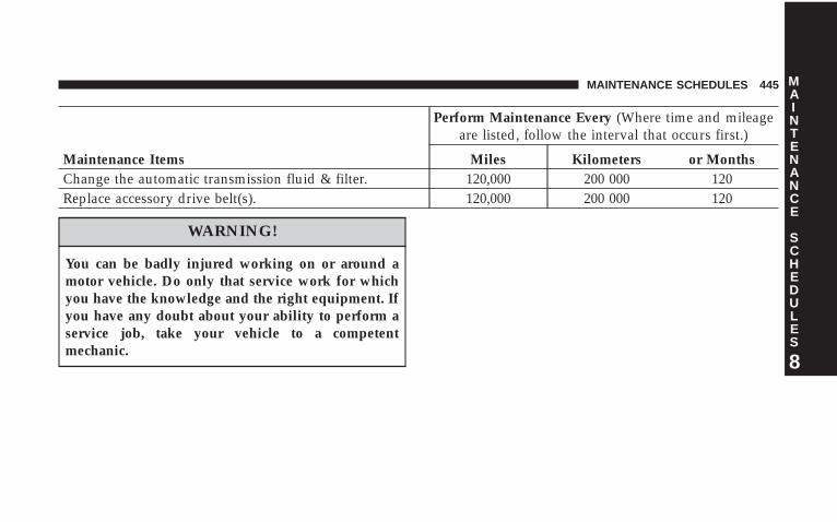
Perform Maintenance Every (Where time and mileageare listed, follow the interval that occurs first.)
Maintenance Items Miles Kilometers or MonthsChange the automatic transmission fluid & filter. 120,000 200 000 120Replace accessory drive belt(s). 120,000 200 000 120
WARNING!
You can be badly injured working on or around amotor vehicle. Do only that service work for whichyou have the knowledge and the right equipment. Ifyou have any doubt about your ability to perform aservice job, take your vehicle to a competentmechanic.
MAINTENANCE SCHEDULES 445
8
MAINTENANCE
SCHEDULES

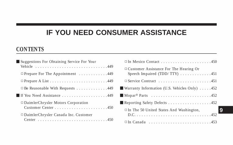
IF YOU NEED CONSUMER ASSISTANCE
CONTENTS
m Suggestions For Obtaining Service For YourVehicle . . . . . . . . . . . . . . . . . . . . . . . . . . . . . . 449
▫ Prepare For The Appointment . . . . . . . . . . . . 449
▫ Prepare A List . . . . . . . . . . . . . . . . . . . . . . . . 449
▫ Be Reasonable With Requests . . . . . . . . . . . . . 449
m If You Need Assistance . . . . . . . . . . . . . . . . . . . 449
▫ DaimlerChrysler Motors CorporationCustomer Center . . . . . . . . . . . . . . . . . . . . . . 450
▫ DaimlerChrysler Canada Inc. CustomerCenter . . . . . . . . . . . . . . . . . . . . . . . . . . . . . 450
▫ In Mexico Contact . . . . . . . . . . . . . . . . . . . . . 450
▫ Customer Assistance For The Hearing OrSpeech Impaired (TDD/TTY) . . . . . . . . . . . . . 451
▫ Service Contract . . . . . . . . . . . . . . . . . . . . . . 451
m Warranty Information (U.S. Vehicles Only) . . . . . 452
m Mopart Parts . . . . . . . . . . . . . . . . . . . . . . . . . 452
m Reporting Safety Defects . . . . . . . . . . . . . . . . . . 452
▫ In The 50 United States And Washington,D.C. . . . . . . . . . . . . . . . . . . . . . . . . . . . . . . . 452
▫ In Canada . . . . . . . . . . . . . . . . . . . . . . . . . . 453
9

m Publication Order Forms . . . . . . . . . . . . . . . . . . 453
m Department Of Transportation Uniform TireQuality Grades . . . . . . . . . . . . . . . . . . . . . . . . 455
▫ Treadwear . . . . . . . . . . . . . . . . . . . . . . . . . . 455
▫ Traction Grades . . . . . . . . . . . . . . . . . . . . . . 455
▫ Temperature Grades . . . . . . . . . . . . . . . . . . . 456
448 IF YOU NEED CONSUMER ASSISTANCE
SUGGESTIONS FOR OBTAINING SERVICE FORYOUR VEHICLE
Prepare For The AppointmentIf you’re having warranty work done, be sure to have theright papers with you. Take your warranty folder. Allwork to be performed may not be covered by thewarranty. Discuss additional charges with the servicemanager. Keep a maintenance log of your vehicle’sservice history. This can often provide a clue to thecurrent problem.
Prepare A ListMake a written list of your vehicle’s problems or thespecific work you want done. If you’ve had an accidentor work done that is not on your maintenance log, let theservice advisor know.
Be Reasonable With RequestsIf you list a number of items and you must have yourvehicle by the end of the day, discuss the situation withthe service advisor and list the items in order of priority.At many authorized dealers, you may obtain a rentalvehicle at a minimal daily charge. If you need a rental, itis advisable to make these arrangements when you callfor an appointment.
IF YOU NEED ASSISTANCEThe manufacturer and its authorized dealers are vitallyinterested in your satisfaction. We want you to be happywith our products and services.
Warranty service must be done by an authorized dealer.We strongly recommend that you take your vehicle toyour authorized selling dealer. They know you and yourvehicle best, and are most concerned that you get promptand high quality service. The manufacturer’s authorizeddealers have the facilities, factory-trained technicians,
IF YOU NEED CONSUMER ASSISTANCE 449
9
special tools, and the latest information to ensure yourvehicle is fixed correctly and in a timely manner.
This is why you should always talk to your authorizeddealer’s service manager first. Most matters can be re-solved with this process.
• If for some reason you are still not satisfied, talk to thegeneral manager or owner of the authorized dealer-ship. They want to know if you need assistance.
• If your authorized dealership is unable to resolve theconcern, you may contact the Manufacturer’s Cus-tomer Center.
Any communication to the Manufacturer’s CustomerCenter should include the following information:
• Owner’s name and address
• Owner’s telephone number (home and office)
• Authorized dealership name
• Vehicle Identification Number (VIN)
• Vehicle delivery date and mileage
DaimlerChrysler Motors Corporation CustomerCenterP.O. Box 21–8004Auburn Hills, MI 48321–8004Phone: (800) 992-1997
DaimlerChrysler Canada Inc. Customer CenterP.O. Box 1621Windsor, Ontario N9A 4H6Phone: (800) 465–2001
In Mexico contact:Av. Prolongacion Paseo de la Reforma, 1240Sante Fe C.P. 05109Mexico, D. F.In Mexico: (915) 729–1248 or 729–1240Outside Mexico: (525) 729–1248 or 729–1240
450 IF YOU NEED CONSUMER ASSISTANCE
Customer Assistance for the Hearing or SpeechImpaired (TDD/TTY)To assist customers who have hearing difficulties, themanufacturer has installed special TDD (Telecommuni-cation Devices for the Deaf) equipment at its CustomerCenter. Any hearing or speech impaired customer, whohas access to a TDD or a conventional teletypewriter(TTY) in the United States, can communicate with themanufacturer by dialing 1–800–380–CHRY.
Service ContractYou may have purchased a service contract for yourvehicle to help protect you from the high cost of unex-pected repairs after your manufacturer’s New VehicleLimited Warranty expires. The manufacturer stands be-hind only the manufacturer’s Service Contracts. If youpurchased a manufacturer’s Service Contract, you willreceive Plan Provisions and an Owner Identification Cardin the mail within three weeks of your vehicle deliverydate. If you have any questions about your service
contract, call the manufacturer’s Service Contract Na-tional Customer Hotline at 1-800-521-9922.
The manufacturer will not stand behind any servicecontract that is not the manufacturer’s Service Contract. Itis not responsible for any service contract other than themanufacturer’s Service Contract. If you purchased aservice contract that is not a manufacturer’s ServiceContract, and you require service after your manufactur-er’s New Vehicle Limited Warranty expires, please referto your contract documents, and contact the person listedin those documents.
We appreciate that you have made a major investmentwhen you purchased your vehicle. Your authorizeddealer has also made a major investment in facilities,tools, and training to assure that you are absolutelydelighted with your ownership experience. You’ll bepleased with their sincere efforts to resolve any warrantyissues or related concerns.
IF YOU NEED CONSUMER ASSISTANCE 451
9
WARNING!
Engine exhaust, some of its constituents, and certainvehicle components contain, or emit, chemicalsknown to the State of California to cause cancer andbirth defects or other reproductive harm. In addition,certain fluids contained in vehicles and certain prod-ucts of component wear contain, or emit, chemicalsknown to the State of California to cause cancer andbirth defects or other reproductive harm.
WARRANTY INFORMATION (U.S. Vehicles Only)See the Warranty Information Booklet for the terms andprovisions of DaimlerChrysler’s warranties applicable tothis vehicle.
MOPART PARTSMOPARt fluids, lubricants, parts, and accessories areavailable from your authorized dealer. They will helpyou keep your vehicle operating at its best.
REPORTING SAFETY DEFECTS
In the 50 United States and Washington, D.C.If you believe that your vehicle has a defect which couldcause a crash or cause injury or death, you shouldimmediately inform the National Highway Traffic SafetyAdministration (NHTSA) in addition to notifying themanufacturer.
If NHTSA receives similar complaints, it may open aninvestigation, and if it finds that a safety defect exists ina group of vehicles, it may order a recall and remedycampaign. However, NHTSA cannot become involved inindividual problems between you, your authorizeddealer, and the manufacturer.
452 IF YOU NEED CONSUMER ASSISTANCE

To contact NHTSA, you may either call the Auto SafetyHotline toll free at 1–888–327–4236 (TTY: 1–800–424– 9153),or go to http://www.safercar.gov; or write to: Administra-tor, NHTSA, 400 Seventh Street, SW., Washington, D.C.20590. You can also obtain other information about motorvehicle safety from http://www.safercar.gov.
In CanadaIf you believe that your vehicle has a safety defect, youshould contact the Customer Service Department imme-diately. Canadian customers who wish to report a safetydefect to the Canadian government should write to:Transport Canada, Motor Vehicle Defect Investigationsand Recalls, 2780 Sheffield Road, Ottawa, Ontario K1B3V9.
PUBLICATION ORDER FORMSTo order the following manuals, you may use either thewebsite or the phone numbers listed below. Visa, Mas-tercard, American Express, and Discover orders are ac-cepted. If you prefer mailing your payment, please callfor an order form.
NOTE: A street address is required when orderingmanuals (no P.O. Boxes).
• Service Manuals
These comprehensive Service Manuals provide theinformation that students and professional techniciansneed in diagnosing/troubleshooting, problem solving,maintaining, servicing, and repairing DaimlerChryslerCorporation vehicles. A complete working knowledgeof the vehicle, system, and/or components is writtenin straightforward language with illustrations, dia-grams, and charts.
IF YOU NEED CONSUMER ASSISTANCE 453
9
• Diagnostic Procedure Manuals
Diagnostic Procedure Manuals are filled with dia-grams, charts and detailed illustrations. These practi-cal manuals make it easy for students and techniciansto find and fix problems on computer-controlled ve-hicle systems and features. They show exactly how tofind and correct problems the first time, using step-by-step troubleshooting and drivability procedures,proven diagnostic tests and a complete list of all toolsand equipment.
• Owner’s Manuals
These Owner’s Manuals have been prepared with theassistance of service and engineering specialists toacquaint you with specific DaimlerChryslerCorporation vehicles. Included are starting, operating,emergency and maintenance procedures as well asspecifications, capabilities and safety tips.
Call toll free at:
• 1–800–890–4038 (U.S.)
• 1–800–387–1143 (Canada)
Or
Visit us on the Worldwide Web at:
• www.techauthority.daimlerchrysler.com
• www.daimlerchrysler.ca/manuals
454 IF YOU NEED CONSUMER ASSISTANCE

DEPARTMENT OF TRANSPORTATION UNIFORMTIRE QUALITY GRADESThe following tire grading categories were established bythe National Highway Traffic Safety Administration. Thespecific grade rating assigned by the tire’s manufacturerin each category is shown on the sidewall of the tires onyour vehicle.
All passenger car tires must conform to Federal safetyrequirements in addition to these grades.
TreadwearThe treadwear grade is a comparative rating, based onthe wear rate of the tire when tested under controlledconditions on a specified government test course. Forexample, a tire graded 150 would wear 1-1/2 times aswell on the government course as a tire graded 100. Therelative performance of tires depends upon the actual
conditions of their use, however, and may depart signifi-cantly from the norm due to variations in driving habits,service practices, and differences in road characteristicsand climate.
Traction GradesThe traction grades, from highest to lowest, are AA, A, B,and C. These grades represent the tire’s ability to stop onwet pavement, as measured under controlled conditionson specified government test surfaces of asphalt andconcrete. A tire marked C may have poor traction perfor-mance.
WARNING!
The traction grade assigned to this tire is based onstraight-ahead braking traction tests, and does notinclude acceleration, cornering, hydroplaning, orpeak traction characteristics.
IF YOU NEED CONSUMER ASSISTANCE 455
9
Temperature GradesThe temperature grades are A (the highest), B, and C,representing the tire’s resistance to the generation of heatand its ability to dissipate heat, when tested undercontrolled conditions on a specified indoor laboratorytest wheel. Sustained high temperature can cause thematerial of the tire to degenerate and reduce tire life, andexcessive temperature can lead to sudden tire failure. Thegrade C corresponds to a level of performance, which allpassenger car tires must meet under the Federal MotorVehicle Safety Standard No. 109. Grades B and A repre-sent higher levels of performance on the laboratory testwheel, than the minimum required by law.
WARNING!
The temperature grade for this tire is established fora tire that is properly inflated and not overloaded.Excessive speed, under-inflation, or excessive load-ing, either separately or in combination, can causeheat buildup and possible tire failure.
456 IF YOU NEED CONSUMER ASSISTANCE

INDEX
10

ABS (Anti-Lock Brake System) . . . . . . . . . . . . 205,290Adding Fuel . . . . . . . . . . . . . . . . . . . . . . . . . . . 336Adjustable Pedals . . . . . . . . . . . . . . . . . . . . . . . 155Air Cleaner, Engine (Engine Air Cleaner Filter) . . . 394Air Conditioner Maintenance . . . . . . . . . . . . 249,398Air Conditioning . . . . . . . . . . . . . . . . . . . . . . . . 249Air Conditioning, Operating Tips . . . . . . . . . . . . 261Air Conditioning, Rear Zone . . . . . . . . . . . . . . . . 253Air Conditioning Refrigerant . . . . . . . . . . . . . 398,399Air Conditioning System . . . . . . . . . . . . . . . . 249,398Air Filter . . . . . . . . . . . . . . . . . . . . . . . . 384,385,394Air Pressure, Tires . . . . . . . . . . . . . . . . . . . . 313,321Airbag . . . . . . . . . . . . . . . . . . . . . . . . . . . . . 53,213Airbag Light . . . . . . . . . . . . . . . . . . . . . . . . . . 61,76Alarm, Panic . . . . . . . . . . . . . . . . . . . . . . . . . . . . 24Alarm (Security Alarm) . . . . . . . . . . . . . . . . . 18,205Alignment and Balance . . . . . . . . . . . . . . . . . . . 320Alterations/Modifications, Vehicle . . . . . . . . . . . . . 8Antenna, Satellite Radio . . . . . . . . . . . . . . . . . . . 238
Antifreeze (Engine Coolant) . . . . . . . . . . . 403,404,436Disposal . . . . . . . . . . . . . . . . . . . . . . . . . . . . 406
Anti-Lock Brake System (ABS) . . . . . . . . . . . . 290,294Anti-Lock Warning Light . . . . . . . . . . . . . . . . . . 205Anti-Theft System . . . . . . . . . . . . . . . . . . . . . 18,205Appearance Care . . . . . . . . . . . . . . . . . . . . . . . . 414Arming Theft System (Security Alarm) . . . . . . . . . 19Assistance Towing . . . . . . . . . . . . . . . . . . . . . . . 101Audio Systems (Radio) . . . . . . . . . . . . . . . . . 217,220Auto Unlock, Doors . . . . . . . . . . . . . . . . . . . . . . 170Automatic Dimming Mirror . . . . . . . . . . . . . . . 84,88Automatic Door Locks . . . . . . . . . . . . . . . . . . 31,170Automatic Headlights . . . . . . . . . . . . . . . . . . . . 147Automatic Transaxle . . . . . . . . . . . . . . . . . . . . 12,274Automatic Transmission . . . . . . . . . . . . . 271,274,410
Adding Fluid . . . . . . . . . . . . . . . . . . . . . . . . . 411Fluid and Filter Changes . . . . . . . . . . . . . . . . . 412Fluid Level Check . . . . . . . . . . . . . . . . . . . . . . 410Fluid Type . . . . . . . . . . . . . . . . . . . . . . . . . . . 438
458 INDEX
Gear Ranges . . . . . . . . . . . . . . . . . . . . . . . . . . 275Special Additives . . . . . . . . . . . . . . . . . . . . . . 412Torque Converter . . . . . . . . . . . . . . . . . . . . . . 279
Axle Fluid . . . . . . . . . . . . . . . . . . . . . . . . . . . . . 438Axle Lubrication (Axle Fluid) . . . . . . . . . . . . . . . 413
Ball Joints . . . . . . . . . . . . . . . . . . . . . . . . . . . . . 399Battery . . . . . . . . . . . . . . . . . . . . . . . . . . 384,385,396
Charging . . . . . . . . . . . . . . . . . . . . . . . . . . . . 376Emergency Starting . . . . . . . . . . . . . . . . . . . . . 376Gas Caution . . . . . . . . . . . . . . . . . . . . . . . . . . 376Keyless Transmitter Replacement (RKE) . . . . . . . 27Saving Feature (Protection) . . . . . . . . . . . . . . . 145
Belts, Drive . . . . . . . . . . . . . . . . . . . . . . . . . . . . 393Belts, Seat . . . . . . . . . . . . . . . . . . . . . . . . . . . . . . 42Body Mechanism Lubrication . . . . . . . . . . . . . . . 400B-Pillar Location . . . . . . . . . . . . . . . . . . . . . . . . 308Brake Assist System . . . . . . . . . . . . . . . . . . . . . . 295Brake Control System, Electronic . . . . . . . . . . . . . 294
Brake Fluid . . . . . . . . . . . . . . . . . . . . . . . . . . . . 438Brake System . . . . . . . . . . . . . . . . . . . . . . . . 290,408
Anti-Lock (ABS) . . . . . . . . . . . . . . . . . . . . 290,294Disc Brakes . . . . . . . . . . . . . . . . . . . . . . . . . . 408Fluid Check . . . . . . . . . . . . . . . . . . . . . . . . . . 409Hoses . . . . . . . . . . . . . . . . . . . . . . . . . . . . . . 410Master Cylinder . . . . . . . . . . . . . . . . . . . . . . . 409Parking . . . . . . . . . . . . . . . . . . . . . . . . . . . . . 289Warning Light . . . . . . . . . . . . . . . . . . . . . 205,209
Brakes . . . . . . . . . . . . . . . . . . . . . . . . . . . . . . . 290Brake/Transmission Interlock . . . . . . . . . . . . . . . 274Break-In Recommendations, New Vehicle . . . . . . . . 74Bulb Replacement . . . . . . . . . . . . . . . . . . . . . . . 429Bulbs, Light . . . . . . . . . . . . . . . . . . . . . . . . . . . . 429
Calibration, Compass . . . . . . . . . . . . . . . . . . . . . 174Camera, Rear . . . . . . . . . . . . . . . . . . . . . . . . . . . 163Capacities, Fluid . . . . . . . . . . . . . . . . . . . . . . . . 436
INDEX 459
10
Caps, FillerFuel . . . . . . . . . . . . . . . . . . . . . . . . . . . . . . . . 336Oil (Engine) . . . . . . . . . . . . . . . . . . . . . . . . . . 392Power Steering . . . . . . . . . . . . . . . . . . . . . . . . 398Radiator (Coolant Pressure) . . . . . . . . . . . . . . . 405
Car Washes . . . . . . . . . . . . . . . . . . . . . . . . . . . . 415Carbon Monoxide Warning . . . . . . . . . . . . . . . 75,335Cargo Management System . . . . . . . . . . . . . . . . . 194
Cargo Organizer . . . . . . . . . . . . . . . . . . . . . . . 194Cargo Organizer . . . . . . . . . . . . . . . . . . . . . . . . 194Cargo (Vehicle Loading) . . . . . . . . . . . . . . . . . . . 342Catalytic Converter . . . . . . . . . . . . . . . . . . . . . . 395CD (Compact Disc) Player . . . . . . . . . . . . . . . 217,220Cellular Phone . . . . . . . . . . . . . . . . . . 88,220,221,248Center High Mounted Stop Light . . . . . . . . . . . . 434Certification Label . . . . . . . . . . . . . . . . . . . . . . . 342Charging . . . . . . . . . . . . . . . . . . . . . . . . . . . . . . 376Chart, Tire Sizing . . . . . . . . . . . . . . . . . . . . . . . . 305Child Restraint . . . . . . . . . . . . . . . . . . . . . . 64,65,66
Child Restraint Tether Anchors . . . . . . . . . . . . . 68,73Child Seat . . . . . . . . . . . . . . . . . . . . . . . . . . . . . . 69Circuit Breakers . . . . . . . . . . . . . . . . . . . . . . . . . 419Cleaning
Wheels . . . . . . . . . . . . . . . . . . . . . . . . . . . . . 416Climate Control . . . . . . . . . . . . . . . . . . . . . . . . . 249Climate Control, Rear Zone . . . . . . . . . . . . . . 253,259Clock . . . . . . . . . . . . . . . . . . . . . 214,215,218,221,226Compact Disc (CD) Maintenance . . . . . . . . . . . . . 247Compact Spare Tire . . . . . . . . . . . . . . . . . . . . . . 316Compass Calibration . . . . . . . . . . . . . . . . . . . . . 174Compass Variance . . . . . . . . . . . . . . . . . . . . . . . 174Connector
UCI . . . . . . . . . . . . . . . . . . . . . . . . . . . . . . . . 241Universal Consumer Interface (UCI) . . . . . . . . . 241
Console, Floor . . . . . . . . . . . . . . . . . . . . . . . 189,191Console, Overhead . . . . . . . . . . . . . . . . . . . . 165,166Contract, Service . . . . . . . . . . . . . . . . . . . . . . . . 451Coolant Pressure Cap (Radiator Cap) . . . . 384,385,405
460 INDEX
Cooling System . . . . . . . . . . . . . . . . . . . . . . . . . 402Adding Coolant (Antifreeze) . . . . . . . . . . . . . . 404Coolant Capacity . . . . . . . . . . . . . . . . . . . . . . 436Coolant Level . . . . . . . . . . . . . . . . . . . . . . 402,406Disposal of Used Coolant . . . . . . . . . . . . . . . . 406Drain, Flush, and Refill . . . . . . . . . . . . . . . . . . 403Inspection . . . . . . . . . . . . . . . . . . . . . . . . . . . 406Points to Remember . . . . . . . . . . . . . . . . . . . . 406Pressure Cap . . . . . . . . . . . . . . . . . . . . . . . . . 405Radiator Cap . . . . . . . . . . . . . . . . . . . . . . . . . 405Selection of Coolant (Antifreeze) . . . . . . 403,436,437Temperature Gauge . . . . . . . . . . . . . . . . . . . . . 203
Cruise Control (Speed Control) . . . . . . . . . . . . . . 156Cup Holder . . . . . . . . . . . . . . . . . . . . . . . . . . . . 189Customer Assistance . . . . . . . . . . . . . . . . . . . . . 449
Data Recorder, Event . . . . . . . . . . . . . . . . . . . . . . 62Daytime Running Lights . . . . . . . . . . . . . . . . . . . 148Dealer Service . . . . . . . . . . . . . . . . . . . . . . . . . . 389
Defroster, Rear Window . . . . . . . . . . . . . . . . . . . 265Defroster, Windshield . . . . . . . . . . . . . . . . 76,251,257Delay (Intermittent) Wipers . . . . . . . . . . . . . . . . . 152Diagnostic System, Onboard . . . . . . . . . . . . . . . . 386Digital Video Disc (DVD) Player . . . . . . . . . . 217,220Dimmer Switch, Headlight . . . . . . . . . . . . . . . . . 204Dipsticks
Automatic Transmission . . . . . . . . . . . . . . . . . 410Oil (Engine) . . . . . . . . . . . . . . . . . . . . . . . . . . 390Power Steering . . . . . . . . . . . . . . . . . . . . . . . . 398
Disarming, Theft System . . . . . . . . . . . . . . . . . . . 19Disc Brakes . . . . . . . . . . . . . . . . . . . . . . . . . . . . 408Disposal
Antifreeze (Engine Coolant) . . . . . . . . . . . . . . . 406Door Locks . . . . . . . . . . . . . . . . . . . . . . . . . . . . . 29Door Locks, Automatic . . . . . . . . . . . . . . . . . . . . 170Door Opener, Garage . . . . . . . . . . . . . . . . . . . . . 176Drive Belts . . . . . . . . . . . . . . . . . . . . . . . . . . . . 393Drive Shaft Universal Joints . . . . . . . . . . . . . . . . 400
INDEX 461
10
DrivingThrough Flowing, Rising, or Shallow StandingWater . . . . . . . . . . . . . . . . . . . . . . . . . . . . . . 286
DVD Player (Video Entertainment System) . . . . . . 246
E-85 Fuel . . . . . . . . . . . . . . . . . . . . . . . . . . . . . 338Electric Remote Mirrors . . . . . . . . . . . . . . . . . . . . 86Electrical Power Outlets . . . . . . . . . . . . . . . . . . . 185Electronic Brake Control System . . . . . . . . . . . . . 294
Anti-Lock Brake System . . . . . . . . . . . . . . . . . 294Brake Assist System . . . . . . . . . . . . . . . . . . . . 295Electronic Roll Mitigation . . . . . . . . . . . . . . . . 297Electronic Stability Program . . . . . . . . . . . . . . . 298Traction Control System . . . . . . . . . . . . . . . . . 297
Electronic Roll Mitigation (ERM) . . . . . . . . . . . . . 297Electronic Speed Control (Cruise Control) . . . . . . 156Electronic Stability Program (ESP) . . . . . . . . . 210,298Electronic Vehicle Information Center(EVIC) . . . . . . . . . . . . . . . . . . . . . . . . . . . . . 163,167
Emergency, In Case ofFreeing Vehicle When Stuck . . . . . . . . . . . . . . . 378Jacking . . . . . . . . . . . . . . . . . . . . . . . . . . . . . 370Tow Hooks . . . . . . . . . . . . . . . . . . . . . . . . . . 378Towing . . . . . . . . . . . . . . . . . . . . . . . . . . . . . 379
Emission Control System Maintenance . . . . . . . . . 440Emission Related Components . . . . . . . . . . . . . . 407Engine
Air Cleaner . . . . . . . . . . . . . . . . . . . . . . . . . . 394Block Heater . . . . . . . . . . . . . . . . . . . . . . . . . 274Break-In Recommendations . . . . . . . . . . . . . . . . 74Compartment . . . . . . . . . . . . . . . . . . . . . . 384,385Coolant (Antifreeze) . . . . . . . . . . . . . . . . . . . . 437Exhaust Gas Caution . . . . . . . . . . . . . . . . 40,75,335Fails to Start . . . . . . . . . . . . . . . . . . . . . . . . . . 272Flooded, Starting . . . . . . . . . . . . . . . . . . . . . . 272Fuel Requirements . . . . . . . . . . . . . . . . . . . . . 436Jump Starting . . . . . . . . . . . . . . . . . . . . . . . . . 376Multi-Displacement . . . . . . . . . . . . . . . . . . . . . 303
462 INDEX

Oil . . . . . . . . . . . . . . . . . . . . . . . . . . . 390,436,437Oil Filler Cap . . . . . . . . . . . . . . . . . . . 384,385,392Oil Selection . . . . . . . . . . . . . . . . . . . . . . . 391,436Oil Synthetic . . . . . . . . . . . . . . . . . . . . . . . . . 392Starting . . . . . . . . . . . . . . . . . . . . . . . . . . . . . 271Temperature Gauge . . . . . . . . . . . . . . . . . . . . . 203
Entry System, Illuminated . . . . . . . . . . . . . . . . . . 20Equipment Identification Plate . . . . . . . . . . . . . . 364Event Data Recorder . . . . . . . . . . . . . . . . . . . . . . 62Exhaust Gas Caution . . . . . . . . . . . . . . 40,75,335,402Exhaust System . . . . . . . . . . . . . . . . . . . . . . . 75,401Extender, Seat Belt . . . . . . . . . . . . . . . . . . . . . . . . 53Exterior Lighting . . . . . . . . . . . . . . . . . . . . . . . . 147
Fabric Care . . . . . . . . . . . . . . . . . . . . . . . . . . . . 416Filters
Air Cleaner . . . . . . . . . . . . . . . . . . . . . . . . . . 394Engine Fuel . . . . . . . . . . . . . . . . . . . . . . . . . . 395Engine Oil . . . . . . . . . . . . . . . . . . . . . . . . 393,437
Engine Oil Disposal . . . . . . . . . . . . . . . . . . . . 392Flashers
Hazard Warning . . . . . . . . . . . . . . . . . . . . . . . 366Turn Signal . . . . . . . . . . . . . . . . . . . . . 149,203,431
Flat Tire Stowage . . . . . . . . . . . . . . . . . . . . . 369,375Flexible Fuel Vehicles
Cruising Range . . . . . . . . . . . . . . . . . . . . . . . . 341Engine Oil . . . . . . . . . . . . . . . . . . . . . . . . . . . 340Fuel Requirements . . . . . . . . . . . . . . . . . . 338,340Replacement Parts . . . . . . . . . . . . . . . . . . . . . 341Starting . . . . . . . . . . . . . . . . . . . . . . . . . . . . . 341
Flooded Engine Starting . . . . . . . . . . . . . . . . . . . 272Floor Console . . . . . . . . . . . . . . . . . . . . . . . 189,191Fluid, Brake . . . . . . . . . . . . . . . . . . . . . . . . . 409,438Fluid Capacities . . . . . . . . . . . . . . . . . . . . . . . . . 436Fluid Level Checks
Automatic Transmission . . . . . . . . . . . . . . . . . 410Brake . . . . . . . . . . . . . . . . . . . . . . . . . . . . . . . 409Engine Oil . . . . . . . . . . . . . . . . . . . . . . . . . . . 390
INDEX 463
10
Power Steering . . . . . . . . . . . . . . . . . . . . . . . . 398Transfer Case . . . . . . . . . . . . . . . . . . . . . . . . . 413
Fluids, Lubricants and Genuine Parts . . . . . . . . . . 437Fog Lights . . . . . . . . . . . . . . . . . . . . . . . . . . 148,435Folding Rear Seat . . . . . . . . . . . . . . . . . . . . . 129,133Four Wheel Drive . . . . . . . . . . . . . . . . . . . . . . . 280
Operation . . . . . . . . . . . . . . . . . . . . . . . . . . . 280Four-Way Hazard Flasher . . . . . . . . . . . . . . . . . . 366Freeing A Stuck Vehicle . . . . . . . . . . . . . . . . . . . 378Front Axle (Differential) . . . . . . . . . . . . . . . . . . . 414Fuel . . . . . . . . . . . . . . . . . . . . . . . . . . . . . . . . . 331
Filler Cap (Gas Cap) . . . . . . . . . . . . . . . . . 336,337Filter . . . . . . . . . . . . . . . . . . . . . . . . . . . . . . . 395Gauge . . . . . . . . . . . . . . . . . . . . . . . . . . . . . . 203Octane Rating . . . . . . . . . . . . . . . . . . . . . . 331,437Requirements . . . . . . . . . . . . . . . . . . . . . . 331,436Tank Capacity . . . . . . . . . . . . . . . . . . . . . . . . 436
Fuel, Flexible . . . . . . . . . . . . . See Flexible Fuel VehiclesFuel System Caution . . . . . . . . . . . . . . . . . . . . . 338Fuses . . . . . . . . . . . . . . . . . . . . . 188,419,420,423,426
Garage Door Opener (HomeLinkt) . . . . . . . . . . . 176Gas Cap (Fuel Filler Cap) . . . . . . . . . . . . 336,337,386Gas Gauge (Fuel Gauge) . . . . . . . . . . . . . . . . . . . 203Gasoline (Fuel) . . . . . . . . . . . . . . . . . . . . . . . . . 331Gasoline, Reformulated . . . . . . . . . . . . . . . . . . . 332Gauges
Coolant Temperature . . . . . . . . . . . . . . . . . . . . 203Fuel . . . . . . . . . . . . . . . . . . . . . . . . . . . . . . . . 203Odometer . . . . . . . . . . . . . . . . . . . . . . . . . 206,208Speedometer . . . . . . . . . . . . . . . . . . . . . . . . . 205Tachometer . . . . . . . . . . . . . . . . . . . . . . . . . . 206
Gear Ranges . . . . . . . . . . . . . . . . . . . . . . . . . . . 275General Information . . . . . . . . . . . . . . . . . 17,115,331
464 INDEX
Glass Cleaning . . . . . . . . . . . . . . . . . . . . . . . . . . 418Gross Axle Weight Rating . . . . . . . . . . . . . . . 343,346Gross Cargo Weight . . . . . . . . . . . . . . . . . . . . . . 342Gross Vehicle Weight Rating . . . . . . . . . . . . . . . . 345GVWR . . . . . . . . . . . . . . . . . . . . . . . . . . . . 342,345
Hands-Free Phone (UConnect™) . . . . . . . . 88,220,221Hard Drive (HDD) . . . . . . . . . . . . . . . . . . . . 217,220Hazard
Driving Through Flowing, Rising, or ShallowStanding Water . . . . . . . . . . . . . . . . . . . . . . . . 286
Hazard Warning Flasher . . . . . . . . . . . . . . . . . . . 366Headlights . . . . . . . . . . . . . . . . . . . . . . . . . . . . 429
Cleaning . . . . . . . . . . . . . . . . . . . . . . . . . . . . 418Delay . . . . . . . . . . . . . . . . . . . . . . . . . . . . . . 146High Beam . . . . . . . . . . . . . . . . . . . . . . . . . . . 151High Beam/Low Beam Select Switch . . . . . . . . 151Lights On Reminder . . . . . . . . . . . . . . . . . . . . 148Passing . . . . . . . . . . . . . . . . . . . . . . . . . . . . . 150
Replacing . . . . . . . . . . . . . . . . . . . . . . . . . . . . 429Heated Mirrors . . . . . . . . . . . . . . . . . . . . . . . . . . 87Heated Seats . . . . . . . . . . . . . . . . . . . . . . . . . . . 124Heater . . . . . . . . . . . . . . . . . . . . . . . . . . . . . . . 249Heater, Engine Block . . . . . . . . . . . . . . . . . . . . . 274High Beam Indicator . . . . . . . . . . . . . . . . . . . . . 204High Beam/Low Beam Select (Dimmer) Switch . . 151Hitches
Trailer Towing . . . . . . . . . . . . . . . . . . . . . . . . 350HomeLinkt (Garage Door Opener) Transmitter . . . 176Hood Release . . . . . . . . . . . . . . . . . . . . . . . . . . 142Hoses . . . . . . . . . . . . . . . . . . . . . . . . . . . . . . . . 407
Ignition . . . . . . . . . . . . . . . . . . . . . . . . . . . . . 12,17Key . . . . . . . . . . . . . . . . . . . . . . . . . . . . . . . . . 12Lock . . . . . . . . . . . . . . . . . . . . . . . . . . . . . . . . 17
Ignition Key Removal . . . . . . . . . . . . . . . . . . . . . 12Illuminated Entry . . . . . . . . . . . . . . . . . . . . . . . . 20Immobilizer (Sentry Key) . . . . . . . . . . . . . . . . . . . 13
INDEX 465
10

Infant Restraint . . . . . . . . . . . . . . . . . . . . . . . . 64,65Inflation Pressure Tires . . . . . . . . . . . . . . . . . . . . 321Information Center . . . . . . . . . . . . . . . . . . . . . . 167Information Center, Vehicle . . . . . . . . . . . . . . . . . 167Inside Rearview Mirror . . . . . . . . . . . . . . . . . . . . 84Instrument Cluster . . . . . . . . . . . . . . . . . . . . . . . 203Instrument Panel and Controls . . . . . . . . . . . . . . 201Instrument Panel Lens Cleaning . . . . . . . . . . . . . 418Integrated Power Module (Fuses) . . . . . . . . . . . . 426Interior Appearance Care . . . . . . . . . . . . . . . . . . 417Interior Fuses . . . . . . . . . . . . . . . . . . . . . . . . . . 420Interior Lighting . . . . . . . . . . . . . . . . . . . . . . . . 145Interior Lights . . . . . . . . . . . . . . . . . . . . . . . . . . 145Intermittent Wipers (Delay Wipers) . . . . . . . . . . . 152Introduction . . . . . . . . . . . . . . . . . . . . . . . . . . . . . 4Inverter Outlet (115V) . . . . . . . . . . . . . . . . . . . . . 185
Jack Location . . . . . . . . . . . . . . . . . . . . . . . . . . . 367Jack Operation . . . . . . . . . . . . . . . . . . . . . . . 368,370
Jacking Instructions . . . . . . . . . . . . . . . . . . . . . . 371
Key, Programming . . . . . . . . . . . . . . . . . . . . . . . . 15Key, Replacement . . . . . . . . . . . . . . . . . . . . . . . . 15Key, Sentry (Immobilizer) . . . . . . . . . . . . . . . . . . . 13Keyless Entry System . . . . . . . . . . . . . . . . . . . . . . 21Keys . . . . . . . . . . . . . . . . . . . . . . . . . . . . . . . . . 12Knee Bolster . . . . . . . . . . . . . . . . . . . . . . . . . . . . 53
Lane Change and Turn Signals . . . . . . . . . 149,203,431Lap/Shoulder Belts . . . . . . . . . . . . . . . . . . . . . 42,47LATCH (Lower Anchors and Tether forCHildren) . . . . . . . . . . . . . . . . . . . . . . . . . . . . . . 68Life of Tires . . . . . . . . . . . . . . . . . . . . . . . . . . . . 318Liftgate . . . . . . . . . . . . . . . . . . . . . . . . . . . . . . . . 37Lights . . . . . . . . . . . . . . . . . . . . . . . . . . . . . . 77,144
Airbag . . . . . . . . . . . . . . . . . . . . . . . . . . . . 61,213Anti-Lock Warning . . . . . . . . . . . . . . . . . . . . . 205Automatic Headlights . . . . . . . . . . . . . . . . . . . 147
466 INDEX
Back-Up . . . . . . . . . . . . . . . . . . . . . . . . . . . . . 431Brake Warning . . . . . . . . . . . . . . . . . . . . . . . . 209Bulb Replacement . . . . . . . . . . . . . . . . . . . . . . 429Center Mounted Stop . . . . . . . . . . . . . . . . . . . 434Courtesy/Reading . . . . . . . . . . . . . . . . . . . . . 166Cruise . . . . . . . . . . . . . . . . . . . . . . . . . . . . . . 214Daytime Running . . . . . . . . . . . . . . . . . . . . . . 148Dome . . . . . . . . . . . . . . . . . . . . . . . . . . . . . . 166Electronic Stability Program (ESP)Indicator . . . . . . . . . . . . . . . . . . . . . . . . . 210,299Fog . . . . . . . . . . . . . . . . . . . . . . . . . . 148,208,435Hazard Warning Flasher . . . . . . . . . . . . . . . . . 366Headlights . . . . . . . . . . . . . . . . . . . . . . . . . . . 147High Beam . . . . . . . . . . . . . . . . . . . . . . . . . . . 151High Beam/Low Beam Select . . . . . . . . . . . . . 151Instrument Cluster . . . . . . . . . . . . . . . . . . 147,203Interior . . . . . . . . . . . . . . . . . . . . . . . . . . 145,166License . . . . . . . . . . . . . . . . . . . . . . . . . . . . . 433Lights On Reminder . . . . . . . . . . . . . . . . . . . . 148
Low Fuel . . . . . . . . . . . . . . . . . . . . . . . . . 203,204Malfunction Indicator (Check Engine) . . . . . . . . 211Park . . . . . . . . . . . . . . . . . . . . . . . . . . . . . . . 147Passing . . . . . . . . . . . . . . . . . . . . . . . . . . . . . 150Reading . . . . . . . . . . . . . . . . . . . . . . . . . . . . . 166Seat Belt Reminder . . . . . . . . . . . . . . . . . . . . . 204Service . . . . . . . . . . . . . . . . . . . . . . . . . . . . . . 429Tire Pressure Monitoring (TPMS) . . . . . . . . . . . 211Traction Control . . . . . . . . . . . . . . . . . . . . . . . 299Turn Signal . . . . . . . . . . . . . . . . . . . . . . . . 149,431Warning (Instrument Cluster Description) . . . . . 203
Loading Vehicle . . . . . . . . . . . . . . . . . . . . . . . . . 342Tires . . . . . . . . . . . . . . . . . . . . . . . . . . . . . . . 308
Locks . . . . . . . . . . . . . . . . . . . . . . . . . . . . . . . . . 29Automatic Door . . . . . . . . . . . . . . . . . . . . . . . . 31Child Protection . . . . . . . . . . . . . . . . . . . . . . . . 33Door . . . . . . . . . . . . . . . . . . . . . . . . . . . . . . . . 29Ignition . . . . . . . . . . . . . . . . . . . . . . . . . . . . . . 17Keys . . . . . . . . . . . . . . . . . . . . . . . . . . . . . . . . 12
INDEX 467
10
Power Door . . . . . . . . . . . . . . . . . . . . . . . . . . . 30Steering Wheel . . . . . . . . . . . . . . . . . . . . . . . . . 17
Lower Anchors and Tether for CHildren(LATCH) . . . . . . . . . . . . . . . . . . . . . . . . . . . . . . 68Lubrication, Body . . . . . . . . . . . . . . . . . . . . . . . 400Lug Nuts . . . . . . . . . . . . . . . . . . . . . . . . . . . . . 374Luggage Carrier . . . . . . . . . . . . . . . . . . . . . . . . . 192Lumbar Support . . . . . . . . . . . . . . . . . . . . . . . . 122
Maintenance Free Battery . . . . . . . . . . . . . . . . . . 396Maintenance Procedures . . . . . . . . . . . . . . . . . . . 389Maintenance Schedule . . . . . . . . . . . . . . . . . . . . 440Malfunction Indicator Light (Check Engine) . . 211,387Manual, Service . . . . . . . . . . . . . . . . . . . . . . . . . 453Manual Transmission
Lubricant Selection . . . . . . . . . . . . . . . . . . . . . 438Map/Reading Lights . . . . . . . . . . . . . . . . . . . . . 166Memory Seat . . . . . . . . . . . . . . . . . . . . . . . . . . . 137Mirrors . . . . . . . . . . . . . . . . . . . . . . . . . . . . . . . . 84
Automatic Dimming . . . . . . . . . . . . . . . . . . . 84,88Electric Powered . . . . . . . . . . . . . . . . . . . . . . . 86Heated . . . . . . . . . . . . . . . . . . . . . . . . . . . . . . 87Memory . . . . . . . . . . . . . . . . . . . . . . . . . . . . . 137Outside . . . . . . . . . . . . . . . . . . . . . . . . . . . . . . 85Rearview . . . . . . . . . . . . . . . . . . . . . . . . . . . . . 84Vanity . . . . . . . . . . . . . . . . . . . . . . . . . . . . . . . 87
Modifications/Alterations, Vehicle . . . . . . . . . . . . . 8Monitor, Tire Pressure System . . . . . . . . . . . . . . . 324Mopar Parts . . . . . . . . . . . . . . . . . . . . . . . . . 388,452MP3 Player . . . . . . . . . . . . . . . . . . . . . . . . . 217,220Multi-Displacement Engine System . . . . . . . . . . . 303Multi-Function Control Lever . . . . . . . . . . . . . . . 149
Navigation Radio . . . . . . . . . . . . . . . . . . . . . . . . 220Navigation System . . . . . . . . . . . . . . . . . . . . 163,220New Vehicle Break-In Period . . . . . . . . . . . . . . . . 74
Occupant Restraints . . . . . . . . . . . . . . . . . . . . . . . 41
468 INDEX
Octane Rating, Gasoline (Fuel) . . . . . . . . . . . . . . 331Oil Change Indicator . . . . . . . . . . . . . . . . . . 169,207Oil Change Indicator, Reset . . . . . . . . . . . . . . . . . 207Oil, Engine . . . . . . . . . . . . . . . . . . . . . . . . . 390,437
Capacity . . . . . . . . . . . . . . . . . . . . . . . . . . . . 436Change Interval . . . . . . . . . . . . . . . . . . . . . . . 391Dipstick . . . . . . . . . . . . . . . . . . . . . . . . . . . . . 390Disposal . . . . . . . . . . . . . . . . . . . . . . . . . . . . 392Filter . . . . . . . . . . . . . . . . . . . . . . . . . . . . 393,437Filter Disposal . . . . . . . . . . . . . . . . . . . . . . . . 392Identification Logo . . . . . . . . . . . . . . . . . . . . . 391Materials Added to . . . . . . . . . . . . . . . . . . . . . 392Recommendation . . . . . . . . . . . . . . . . . . . 391,436Synthetic . . . . . . . . . . . . . . . . . . . . . . . . . . . . 392Viscosity . . . . . . . . . . . . . . . . . . . . . . . . . . 392,436
Onboard Diagnostic System . . . . . . . . . . . . . . 386,387Opener, Garage Door (HomeLinkt) . . . . . . . . . . . 176Outside Rearview Mirrors . . . . . . . . . . . . . . . . . . 85Overdrive . . . . . . . . . . . . . . . . . . . . . . . . . . 206,277
Overdrive OFF Switch . . . . . . . . . . . . . . . . . . . . 277Overhead Console . . . . . . . . . . . . . . . . . . . . 165,166Overheating, Engine . . . . . . . . . . . . . . . . . . . . . . 204Owner’s Manual (Operator Manual) . . . . . . . . . . 453
Panic Alarm . . . . . . . . . . . . . . . . . . . . . . . . . . . . 24Park Sense System, Rear . . . . . . . . . . . . . . . . . . . 160Parking Brake . . . . . . . . . . . . . . . . . . . . . . . . . . 289Parking On Hill . . . . . . . . . . . . . . . . . . . . . . . . . 289Passing Light . . . . . . . . . . . . . . . . . . . . . . . . . . . 150Pedals, Adjustable . . . . . . . . . . . . . . . . . . . . . . . 155Personal Settings . . . . . . . . . . . . . . . . . . . . . . . . 170Pets . . . . . . . . . . . . . . . . . . . . . . . . . . . . . . . . . . 74Pets, Transporting . . . . . . . . . . . . . . . . . . . . . . . . 74Phone, Cellular . . . . . . . . . . . . . . . . . . . . 88,220,221Phone, Hands-Free (UConnect™) . . . . . . . . 88,220,221Placard, Tire and Loading Information . . . . . . . . . 308Port
Universal Serial Bus (USB) . . . . . . . . . . . . . 217,220
INDEX 469
10
USB . . . . . . . . . . . . . . . . . . . . . . . . . . . . . 217,220Positive Crankcase Valve . . . . . . . . . . . . . . . . . . 408Power
Brakes . . . . . . . . . . . . . . . . . . . . . . . . . . . . . . 408Distribution Center (Fuses) . . . . . . . . . . 384,385,423Door Locks . . . . . . . . . . . . . . . . . . . . . . . . . 20,30Lift Gate . . . . . . . . . . . . . . . . . . . . . . . . . . . . . 38Mirrors . . . . . . . . . . . . . . . . . . . . . . . . . . . . . . 86Outlet (Auxiliary Electrical Outlet) . . . . . . . . . . 185Steering . . . . . . . . . . . . . . . . . . . . . . . . . . 293,398Steering Filler Cap . . . . . . . . . . . . . . . . . . 384,385Sunroof . . . . . . . . . . . . . . . . . . . . . . . . . . . . . 182Windows . . . . . . . . . . . . . . . . . . . . . . . . . . . . . 34
Power Steering Fluid . . . . . . . . . . . . . . . . . . . . . 438Pregnant Women and Seat Belts . . . . . . . . . . . . . . 52Preparation for Jacking . . . . . . . . . . . . . . . . . . . . 371Pretensioners
Seat Belts . . . . . . . . . . . . . . . . . . . . . . . . . . . . . 50Programmable Electronic Features . . . . . . . . . . . . 170
Programming Transmitters (Remote KeylessEntry) . . . . . . . . . . . . . . . . . . . . . . . . . . . . . . . . . 25
Radial Ply Tires . . . . . . . . . . . . . . . . . . . . . . . . . 315Radiator Cap (Coolant Pressure Cap) . . . . . . . 403,405Radio Broadcast Signals . . . . . . . . . . . . . . . . . . . 216Radio, Navigation . . . . . . . . . . . . . . . . . . . . . . . 220Radio Operation . . . . . . . . . . . . . . . . . . . 217,221,248Radio Remote Controls . . . . . . . . . . . . . . . . . . . . 246Radio, Satellite . . . . . . . . . . . . . . 217,218,220,221,236Radio (Sound Systems) . . . . . . . . . . . . . . . . . 217,220Rear Axle (Differential) . . . . . . . . . . . . . . . . . . . . 414Rear Camera . . . . . . . . . . . . . . . . . . . . . . . . . . . 163Rear Cup Holder . . . . . . . . . . . . . . . . . . . . . . . . 191Rear Liftgate . . . . . . . . . . . . . . . . . . . . . . . . . . . . 37Rear Park Sense System . . . . . . . . . . . . . . . . . . . 160Rear Window Defroster . . . . . . . . . . . . . . . . . . . 265Rear Window Features . . . . . . . . . . . . . . . . . . . . 264Rear Wiper/Washer . . . . . . . . . . . . . . . . . . . . . . 264
470 INDEX
Rearview Mirrors . . . . . . . . . . . . . . . . . . . . . . . . 84Reclining Front Seats . . . . . . . . . . . . . . . . . . . . . 121Recorder, Event Data . . . . . . . . . . . . . . . . . . . . . . 62Recreational Towing . . . . . . . . . . . . . . . . . . . . . . 360
Shifting into Transfer Case Neutral (N) . . . . . . . 361Shifting out of Transfer Case Neutral (N) . . . . . 362
Reformulated Gasoline . . . . . . . . . . . . . . . . . . . . 332Refrigerant . . . . . . . . . . . . . . . . . . . . . . . . . . . . 399Release, Hood . . . . . . . . . . . . . . . . . . . . . . . . . . 142Reminder, Seat Belt . . . . . . . . . . . . . . . . . . . . . . . 51Remote Keyless Entry (RKE) . . . . . . . . . . . . . . . . . 21Remote Sound System (Radio) Controls . . . . . . . . 246Remote Starting System . . . . . . . . . . . . . . . . . . . . 28Replacement Keys . . . . . . . . . . . . . . . . . . . . . . . . 15Replacement Parts . . . . . . . . . . . . . . . . . . . . . . . 388Replacement Tires . . . . . . . . . . . . . . . . . . . . . . . 319Reporting Safety Defects . . . . . . . . . . . . . . . . . . . 452Resetting Oil Change Indicator . . . . . . . . . . . 169,207Restraints, Child . . . . . . . . . . . . . . . . . . . . . . . 64,69
Restraints, Occupant . . . . . . . . . . . . . . . . . . . . . . 41Rocking Vehicle When Stuck . . . . . . . . . . . . . . . . 378Roll Over Warning . . . . . . . . . . . . . . . . . . . . . . . . 4Roof Type Carrier . . . . . . . . . . . . . . . . . . . . . . . 192Rotation, Tires . . . . . . . . . . . . . . . . . . . . . . . . . . 323
Safety Checks Inside Vehicle . . . . . . . . . . . . . . . . . 76Safety Checks Outside Vehicle . . . . . . . . . . . . . . . 77Safety Defects, Reporting . . . . . . . . . . . . . . . . . . 452Safety, Exhaust Gas . . . . . . . . . . . . . . . . . . . . . . . 40Safety Information, Tire . . . . . . . . . . . . . . . . . . . 303Safety Tips . . . . . . . . . . . . . . . . . . . . . . . . . . . . . 75Satellite Radio . . . . . . . . . . . . . . . 217,218,220,221,236Satellite Radio Antenna . . . . . . . . . . . . . . . . . . . 238Schedule, Maintenance . . . . . . . . . . . . . . . . . . . . 440Seat Belt Maintenance . . . . . . . . . . . . . . . . . . . . 419Seat Belt Reminder . . . . . . . . . . . . . . . . . . . . . . . 51Seat Belts . . . . . . . . . . . . . . . . . . . . . . . . . . 41,42,76
And Pregnant Women . . . . . . . . . . . . . . . . . . . 52
INDEX 471
10
Child Restraint . . . . . . . . . . . . . . . . . . . . . . . 64,66Extender . . . . . . . . . . . . . . . . . . . . . . . . . . . . . 53Front Seat . . . . . . . . . . . . . . . . . . . . . . . . . . . . 42Pretensioners . . . . . . . . . . . . . . . . . . . . . . . . . . 50Reminder . . . . . . . . . . . . . . . . . . . . . . . . . . . . 204
Seats . . . . . . . . . . . . . . . . . . . . . . . . . . . . . . . . . 120Adjustment . . . . . . . . . . . . . . . . . . . . . . . . . . 120Cleaning . . . . . . . . . . . . . . . . . . . . . . . . . . . . 416Fold and Tumble Rear . . . . . . . . . . . . . . . . 127,129Heated . . . . . . . . . . . . . . . . . . . . . . . . . . . . . 124Lumbar Support . . . . . . . . . . . . . . . . . . . . . . . 122Memory . . . . . . . . . . . . . . . . . . . . . . . . . . . . . 137Rear Folding . . . . . . . . . . . . . . . . . . . . . . . 127,129Reclining . . . . . . . . . . . . . . . . . . . . . . . . . . . . 121
Security Alarm (Theft Alarm) . . . . . . . . . . . . . 18,205Selection of Coolant (Antifreeze) . . . . . . . . . . 403,437Selection of Oil . . . . . . . . . . . . . . . . . . . . . . . . . 391Sentry Key (Immobilizer) . . . . . . . . . . . . . . . . . . . 13Sentry Key Programming . . . . . . . . . . . . . . . . . . . 15
Sentry Key Replacement . . . . . . . . . . . . . . . . . . . 15Service and Maintenance . . . . . . . . . . . . . . . . 389,440Service Assistance . . . . . . . . . . . . . . . . . . . . . . . 449Service Contract . . . . . . . . . . . . . . . . . . . . . . . . . 451Service Manuals . . . . . . . . . . . . . . . . . . . . . . . . 453Setting the Clock . . . . . . . . . . . . . . . . 215,218,221,226Settings, Personal . . . . . . . . . . . . . . . . . . . . . . . . 170Shifting
Automatic Transmission . . . . . . . . . . . . . . . . . 274Transfer Case . . . . . . . . . . . . . . . . . . . . . . . . . 280Transfer Case, Shifting into Transfer CaseNeutral (N) . . . . . . . . . . . . . . . . . . . . . . . . . . 361Transfer Case, Shifting out of Transfer CaseNeutral (N) . . . . . . . . . . . . . . . . . . . . . . . . . . 362
Shoulder Belt Upper Anchorage . . . . . . . . . . . . . . 46Shoulder Belts . . . . . . . . . . . . . . . . . . . . . . . . . . . 42Signals, Turn . . . . . . . . . . . . . . . . . . . . . 149,203,431Snow Chains (Tire Chains) . . . . . . . . . . . . . . . . . 321Snow Plow . . . . . . . . . . . . . . . . . . . . . . . . . . . . 359
472 INDEX
Snow Tires . . . . . . . . . . . . . . . . . . . . . . . . . . . . 322Sound Systems (Radio) . . . . . . . . . . . . . . . . . 217,220Spare Tire . . . . . . . . . . . . . . . . . . . . . . . . . . . . . 316Spark Plugs . . . . . . . . . . . . . . . . . . . . . . . . . . . . 394Speed Control (Cruise Control) . . . . . . . . . . . . . . 156Speedometer . . . . . . . . . . . . . . . . . . . . . . . . . . . 205Starting . . . . . . . . . . . . . . . . . . . . . . . . . . . . . . . 271
Automatic Transmission . . . . . . . . . . . . . . . . . 271Emergency (Jump Starting) . . . . . . . . . . . . . . . 376Engine Block Heater . . . . . . . . . . . . . . . . . . . . 274Engine Fails to Start . . . . . . . . . . . . . . . . . . . . 272Remote . . . . . . . . . . . . . . . . . . . . . . . . . . . . . . 28
Starting Procedures . . . . . . . . . . . . . . . . . . . . . . 271Steering
Column Controls . . . . . . . . . . . . . . . . . . . . . . 149Column Lock . . . . . . . . . . . . . . . . . . . . . . . . . . 17Power . . . . . . . . . . . . . . . . . . . . . . . . . . . 293,398Wheel, Tilt . . . . . . . . . . . . . . . . . . . . . . . . . . . 154
Steering Wheel Mounted Sound System
Controls . . . . . . . . . . . . . . . . . . . . . . . . . . . . . . 246Storage, Vehicle . . . . . . . . . . . . . . . . . . . . . . . . . 428Stuck, Freeing . . . . . . . . . . . . . . . . . . . . . . . . . . 378Sun Roof . . . . . . . . . . . . . . . . . . . . . . . . . . . . . . 182Supplemental Tire Pressure Information . . . . . . . . 321Synthetic Engine Oil . . . . . . . . . . . . . . . . . . . . . . 392System, Navigation . . . . . . . . . . . . . . . . . . . . . . 220System, Remote Starting . . . . . . . . . . . . . . . . . . . . 28
Tachometer . . . . . . . . . . . . . . . . . . . . . . . . . . . . 206Taillights . . . . . . . . . . . . . . . . . . . . . . . . . . . . . . 431Temperature Control, Automatic (ATC) . . . . . . . . 254Temperature Gauge, Engine Coolant . . . . . . . . . . 203Tether Anchor, Child Restraint . . . . . . . . . . . . . . . 68Theft System Arming . . . . . . . . . . . . . . . . . . . . . . 19Theft System Disarming . . . . . . . . . . . . . . . . . . . . 19Tilt Steering Column . . . . . . . . . . . . . . . . . . . . . 154Tire and Loading Information Placard . . . . . . 308,321Tire Identification Number (TIN) . . . . . . . . . . . . . 307
INDEX 473
10

Tire Markings . . . . . . . . . . . . . . . . . . . . . . . . . . 303Tire Safety Information . . . . . . . . . . . . . . . . . . . . 303Tires . . . . . . . . . . . . . . . . . . . . . . . . . . . . 77,312,455
Aging (Life of Tires) . . . . . . . . . . . . . . . . . . . . 318Air Pressure . . . . . . . . . . . . . . . . . . . . . . . . . . 312Alignment . . . . . . . . . . . . . . . . . . . . . . . . . . . 320Chains . . . . . . . . . . . . . . . . . . . . . . . . . . . . . . 321Changing . . . . . . . . . . . . . . . . . . . . . . . . . . . . 369Compact Spare . . . . . . . . . . . . . . . . . . . . . . . . 316General Information . . . . . . . . . . . . . . . . . . . . 312High Speed . . . . . . . . . . . . . . . . . . . . . . . . . . 315Inflation Pressures . . . . . . . . . . . . . . . . . . . . . 313Jacking . . . . . . . . . . . . . . . . . . . . . . . . . . . . . 370Life of Tires . . . . . . . . . . . . . . . . . . . . . . . . . . 318Load Capacity . . . . . . . . . . . . . . . . . . . . . 308,309Pressure Monitor System (TPMS) . . . . . . . . . . . 324Pressure Warning Light . . . . . . . . . . . . . . . . . . 211Quality Grading . . . . . . . . . . . . . . . . . . . . . . . 455Radial . . . . . . . . . . . . . . . . . . . . . . . . . . . . . . 315
Replacement . . . . . . . . . . . . . . . . . . . . . . . . . 319Rotation . . . . . . . . . . . . . . . . . . . . . . . . . . . . . 323Safety . . . . . . . . . . . . . . . . . . . . . . . . . . . 303,312Sizes . . . . . . . . . . . . . . . . . . . . . . . . . . . . . . . 305Snow Tires . . . . . . . . . . . . . . . . . . . . . . . . . . . 322Spare Tire . . . . . . . . . . . . . . . . . . . . . . . . . . . 369Spinning . . . . . . . . . . . . . . . . . . . . . . . . . . . . 317Tread Wear Indicators . . . . . . . . . . . . . . . . . . . 318Wheel Mounting . . . . . . . . . . . . . . . . . . . . . . . 370Wheel Nut Torque . . . . . . . . . . . . . . . . . . . . . 374
Tongue Weight/Trailer Weight . . . . . . . . . . . . . . 351Torque Converter Clutch . . . . . . . . . . . . . . . . . . 279Tow Hooks, Emergency . . . . . . . . . . . . . . . . . . . 378Towing . . . . . . . . . . . . . . . . . . . . . . . . . . . . . . . 345
24-Hour Towing Assistance . . . . . . . . . . . . . . . 101Disabled Vehicle . . . . . . . . . . . . . . . . . . . . . . . 379Guide . . . . . . . . . . . . . . . . . . . . . . . . . . . . . . 351Recreational . . . . . . . . . . . . . . . . . . . . . . . . . . 360Weight . . . . . . . . . . . . . . . . . . . . . . . . . . . . . . 351
474 INDEX

Towing Assistance . . . . . . . . . . . . . . . . . . . . . . . 101Traction . . . . . . . . . . . . . . . . . . . . . . . . . . . . . . 286Traction Control . . . . . . . . . . . . . . . . . . . . . . 208,297Trailer Towing . . . . . . . . . . . . . . . . . . . . . . . . . . 345
Cooling System Tips . . . . . . . . . . . . . . . . . . . . 358Hitches . . . . . . . . . . . . . . . . . . . . . . . . . . . . . 350Minimum Requirements . . . . . . . . . . . . . . . . . 352Trailer and Tongue Weight . . . . . . . . . . . . . . . . 351Wiring . . . . . . . . . . . . . . . . . . . . . . . . . . . . . . 356
Trailer Towing Guide . . . . . . . . . . . . . . . . . . . . . 351Trailer Weight . . . . . . . . . . . . . . . . . . . . . . . . . . 351Transaxle . . . . . . . . . . . . . . . . . . . . . . . . . . . . . 274
Automatic . . . . . . . . . . . . . . . . . . . . . . . . . 12,274Operation . . . . . . . . . . . . . . . . . . . . . . . . . . . 274
Transfer Case . . . . . . . . . . . . . . . . . . . . . . . . . . . 413Fluid . . . . . . . . . . . . . . . . . . . . . . . . . . . . . . . 438
Transmission . . . . . . . . . . . . . . . . . . . . . . . . 274,410Automatic . . . . . . . . . . . . . . . . . . . . . . . . 274,410Filter . . . . . . . . . . . . . . . . . . . . . . . . . . . . . . . 412Fluid . . . . . . . . . . . . . . . . . . . . . . . . . . . . . . . 438Maintenance . . . . . . . . . . . . . . . . . . . . . . . . . . 410
Transmitter Battery Service (Remote KeylessEntry) . . . . . . . . . . . . . . . . . . . . . . . . . . . . . . . . . 27Transmitter, Garage Door Opener (HomeLinkt) . . 176
INDEX 475
10
Transmitter Programming (Remote KeylessEntry) . . . . . . . . . . . . . . . . . . . . . . . . . . . . . . . . . 25Tread Wear Indicators . . . . . . . . . . . . . . . . . . . . 318Trip Odometer . . . . . . . . . . . . . . . . . . . . . . . . . . 208Trip Odometer Reset Button . . . . . . . . . . . . . . . . 214Turn Signals . . . . . . . . . . . . . . . . . . . . . . 149,203,431
UCI Connector . . . . . . . . . . . . . . . . . . . . . . . . . 241UConnect™ (Hands-Free Phone) . . . . . . . . . . . 88,220Underhood Fuses . . . . . . . . . . . . . . . . . . . . . . . . 423Uniform Tire Quality Grades . . . . . . . . . . . . . . . . 455Universal Consumer Interface (UCI) Connector . . . 241Universal Serial Bus (USB) Port . . . . . . . . . . . 217,220Universal Transmitter . . . . . . . . . . . . . . . . . . . . . 176USB Port . . . . . . . . . . . . . . . . . . . . . . . . . . . 217,220
Vacuum/Vapor Harnesses . . . . . . . . . . . . . . . . . 407Vanity Mirrors . . . . . . . . . . . . . . . . . . . . . . . . . . . 87Variance, Compass . . . . . . . . . . . . . . . . . . . . . . . 174
Vehicle Identification Number (VIN) . . . . . . . . . . . . 7Vehicle Information Center . . . . . . . . . . . . . . . . . 167Vehicle Loading . . . . . . . . . . . . . . . . . . . . . . 309,342Vehicle Modifications/Alterations . . . . . . . . . . . . . . 8Vehicle Storage . . . . . . . . . . . . . . . . . . . . . . . . . 428Video Entertainment System (Rear Seat VideoSystem) . . . . . . . . . . . . . . . . . . . . . . . . . . . . . . . 246Voice Recognition System (VR) . . . . . . . . . . . . . . 115
Warning Lights (Instrument ClusterDescription) . . . . . . . . . . . . . . . . . . . . . . . . . . . 203Warning, Roll Over . . . . . . . . . . . . . . . . . . . . . . . . 4Warnings and Cautions . . . . . . . . . . . . . . . . . . . . . 7Warranty Information . . . . . . . . . . . . . . . . . . . . . 452Washer, Adding Fluid . . . . . . . . . . . . . . . . . . 384,385Washers, Windshield . . . . . . . . . . . . . . . . . . . . . 153Washing Vehicle . . . . . . . . . . . . . . . . . . . . . . . . . 415Water
Driving Through . . . . . . . . . . . . . . . . . . . . . . 286
476 INDEX
Weight Load Carrying . . . . . . . . . . . . . . . . . . . . 342Wheel Alignment and Balance . . . . . . . . . . . . . . . 320Wheel and Wheel Trim . . . . . . . . . . . . . . . . . . . . 416Wheel and Wheel Trim Care . . . . . . . . . . . . . . . . 416Wheel Changing . . . . . . . . . . . . . . . . . . . . . . . . 369Wheel Mounting . . . . . . . . . . . . . . . . . . . . . . . . 370Wheel Nut Torque . . . . . . . . . . . . . . . . . . . . . . . 374Wind Buffeting . . . . . . . . . . . . . . . . . . . . . . . . . 184Window Fogging . . . . . . . . . . . . . . . . . . . . . . . . 262Windows . . . . . . . . . . . . . . . . . . . . . . . . . . . . . . 34
Power . . . . . . . . . . . . . . . . . . . . . . . . . . . . . . . 34
Windshield Defroster . . . . . . . . . . . . . . . . . . 251,257Windshield Washers . . . . . . . . . . . . . . . . 151,153,401
Fluid . . . . . . . . . . . . . . . . . . . . . . . 151,384,385,401Windshield Wiper Blades . . . . . . . . . . . . . . . . . . 400Windshield Wipers . . . . . . . . . . . . . . . . . . . . . . . 151Wiper Blade Replacement . . . . . . . . . . . . . . . . . . 400Wiper, Rear . . . . . . . . . . . . . . . . . . . . . . . . . . . . 264Wipers, Intermittent . . . . . . . . . . . . . . . . . . . . . . 152Wrecker Towing . . . . . . . . . . . . . . . . . . . . . . . . . 379
YES Essentialst Fabric Cleaning Procedure . . . . . . 416
INDEX 477
10

AspenO W N E R ’ S M A N U A L
2 0 0 8
20
08
Asp
en
81-026-0850 First Edition Printed in U.S.A.