2008 Cadillac DTS Owner Manual M - General MotorsUsing this Manual Many people read the owner manual...
450
Seats and Restraint Systems ........................... 1-1 Front Seats ............................................... 1-2 Rear Seats ............................................... 1-9 Safety Belts ............................................. 1-10 Child Restraints ....................................... 1-31 Airbag System ......................................... 1-54 Restraint System Check ............................ 1-69 Features and Controls ..................................... 2-1 Keys ........................................................ 2-3 Doors and Locks ...................................... 2-10 Windows ................................................. 2-14 Theft-Deterrent Systems ............................ 2-18 Starting and Operating Your Vehicle ........... 2-22 Mirrors .................................................... 2-36 Object Detection Systems .......................... 2-44 OnStar ® System ...................................... 2-53 Universal Home Remote System ................ 2-56 Storage Areas ......................................... 2-63 Sunroof .................................................. 2-65 Instrument Panel ............................................. 3-1 Instrument Panel Overview .......................... 3-4 Climate Controls ...................................... 3-40 Warning Lights, Gages, and Indicators ........ 3-51 Driver Information Center (DIC) .................. 3-68 Audio System(s) ....................................... 3-95 Driving Your Vehicle ....................................... 4-1 Your Driving, the Road, and Your Vehicle ..... 4-2 Towing ................................................... 4-26 Service and Appearance Care .......................... 5-1 Service ..................................................... 5-3 Fuel ......................................................... 5-5 Checking Things Under the Hood ............... 5-10 Headlamp Aiming ..................................... 5-44 Bulb Replacement .................................... 5-47 Windshield Wiper Blade Replacement ......... 5-48 Tires ...................................................... 5-50 Appearance Care ..................................... 5-87 Vehicle Identification ................................. 5-95 Electrical System ...................................... 5-96 Capacities and Specifications ................... 5-105 Maintenance Schedule ..................................... 6-1 Maintenance Schedule ................................ 6-2 Customer Assistance Information .................... 7-1 Customer Assistance and Information ........... 7-2 Reporting Safety Defects ........................... 7-14 Vehicle Data Recording and Privacy ........... 7-16 Index ................................................................ 1 2008 Cadillac DTS Owner Manual M
Transcript of 2008 Cadillac DTS Owner Manual M - General MotorsUsing this Manual Many people read the owner manual...
Seats and Restraint Systems ........................... 1-1Front Seats ............................................... 1-2Rear Seats ............................................... 1-9Safety Belts ............................................. 1-10Child Restraints ....................................... 1-31Airbag System ......................................... 1-54Restraint System Check ............................ 1-69
Features and Controls ..................................... 2-1Keys ........................................................ 2-3Doors and Locks ...................................... 2-10Windows ................................................. 2-14Theft-Deterrent Systems ............................ 2-18Starting and Operating Your Vehicle ........... 2-22Mirrors .................................................... 2-36Object Detection Systems .......................... 2-44OnStar® System ...................................... 2-53Universal Home Remote System ................ 2-56Storage Areas ......................................... 2-63Sunroof .................................................. 2-65
Instrument Panel ............................................. 3-1Instrument Panel Overview .......................... 3-4Climate Controls ...................................... 3-40Warning Lights, Gages, and Indicators ........ 3-51Driver Information Center (DIC) .................. 3-68Audio System(s) ....................................... 3-95
Driving Your Vehicle ....................................... 4-1Your Driving, the Road, and Your Vehicle ..... 4-2Towing ................................................... 4-26
Service and Appearance Care .......................... 5-1Service ..................................................... 5-3Fuel ......................................................... 5-5Checking Things Under the Hood ............... 5-10Headlamp Aiming ..................................... 5-44Bulb Replacement .................................... 5-47Windshield Wiper Blade Replacement ......... 5-48Tires ...................................................... 5-50Appearance Care ..................................... 5-87Vehicle Identification ................................. 5-95Electrical System ...................................... 5-96Capacities and Specifications ................... 5-105
Maintenance Schedule ..................................... 6-1Maintenance Schedule ................................ 6-2
Customer Assistance Information .................... 7-1Customer Assistance and Information ........... 7-2Reporting Safety Defects ........................... 7-14Vehicle Data Recording and Privacy ........... 7-16
Index ................................................................ 1
2008 Cadillac DTS Owner Manual M

GENERAL MOTORS, GM, the GM Emblem, CADILLAC,the CADILLAC Crest & Wreath, and the name DTS areregistered trademarks of General Motors Corporation.
This manual includes the latest information at the timeit was printed. We reserve the right to make changesafter that time without notice. For vehicles first soldin Canada, substitute the name “General Motorsof Canada Limited” for Cadillac Motor Car Divisionwhenever it appears in this manual.
This manual describes features that may be available inthis model, but your vehicle may not have all of them.For example, more than one entertainment system maybe offered or your vehicle may have been orderedwithout a front passenger or rear seats.
Keep this manual in the vehicle for quick reference.
Canadian OwnersA French language copy of this manual can be obtainedfrom your dealer/retailer or from:
Helm, IncorporatedP.O. Box 07130Detroit, MI 48207
1-800-551-4123www.helminc.com
Propriétaires CanadiensOn peut obtenir un exemplaire de ce guide en françaisauprès de concessionnaire ou à l’adresse suivante:
Helm IncorporatedP.O. Box 07130Detroit, MI 48207
1-800-551-4123www.helminc.com
Litho in U.S.A.Part No. 15870508 A First Printing ©2007 General Motors Corporation. All Rights Reserved.
ii

Using this ManualMany people read the owner manual from beginningto end when they first receive their new vehicle tolearn about the vehicle’s features and controls.Pictures and words work together to explain things.
IndexA good place to quickly locate information aboutthe vehicle is the Index in the back of the manual.It is an alphabetical list of what is in the manual andthe page number where it can be found.
Safety Warnings and SymbolsThere are a number of safety cautions in this book.A box with the word CAUTION is used to tell aboutthings that could hurt you or others if you were toignore the warning.
{CAUTION:
These mean there is something that couldhurt you or other people.
We tell you what the hazard is and what to do to helpavoid or reduce the hazard. Please read these cautions.If you do not, you or others could be hurt.
A circle with a slashthrough it is a safetysymbol which means“Do Not,” “Do Not dothis” or “Do Not letthis happen.”
iii

Vehicle Damage WarningsYou will also find notices in this manual.
Notice: These mean there is something thatcould damage your vehicle.
A notice tells about something that can damage thevehicle. Many times, this damage would not be coveredby your vehicle’s warranty, and it could be costly.The notice tells what to do to help avoid the damage.
When you read other manuals, you might seeCAUTION and NOTICE warnings in different colorsor in different words.
There are also warning labels on the vehicle whichuse the same words, CAUTION or NOTICE.
Vehicle SymbolsThe vehicle has components and labels that usesymbols instead of text. Symbols are shown alongwith the text describing the operation or informationrelating to a specific component, control, message,gage, or indicator.
iv

Front Seats ......................................................1-2Power Seats ..................................................1-2Power Lumbar ...............................................1-2Massaging Lumbar .........................................1-3Heated and Cooled Seats ................................1-3Memory Seat, Mirrors and Steering Wheel .........1-4Power Reclining Seatbacks ..............................1-6Head Restraints .............................................1-7Center Seat ...................................................1-8
Rear Seats .......................................................1-9Heated Seats .................................................1-9Rear Seat Pass-Through Door .........................1-9Power Lumbar ..............................................1-10
Safety Belts ...................................................1-10Safety Belts: They Are for Everyone ................1-10How to Wear Safety Belts Properly .................1-16Lap-Shoulder Belt .........................................1-24Safety Belt Use During Pregnancy ..................1-29Lap Belt ......................................................1-29Safety Belt Extender .....................................1-30
Child Restraints .............................................1-31Older Children ..............................................1-31Infants and Young Children ............................1-34
Child Restraint Systems .................................1-37Where to Put the Restraint .............................1-40Lower Anchors and Tethers for
Children (LATCH) ......................................1-41Securing a Child Restraint in a
Rear Seat Position ....................................1-48Securing a Child Restraint in the
Center Front Seat Position ..........................1-50Securing a Child Restraint in the
Right Front Seat Position ............................1-50Airbag System ...............................................1-54
Where Are the Airbags? ................................1-56When Should an Airbag Inflate? .....................1-59What Makes an Airbag Inflate? .......................1-60How Does an Airbag Restrain? .......................1-60What Will You See After an Airbag Inflates? .....1-61Passenger Sensing System ............................1-62Servicing Your Airbag-Equipped Vehicle ...........1-67Adding Equipment to Your
Airbag-Equipped Vehicle .............................1-68Restraint System Check ..................................1-69
Checking the Restraint Systems ......................1-69Replacing Restraint System Parts
After a Crash ............................................1-70
Section 1 Seats and Restraint Systems
1-1

Front Seats
Power Seats
The power seatcontrols are locatedon the outboard sideof the seats.
• Move the seat forward or rearward by sliding thecontrol forward or rearward.
• Raise or lower the front part of the seat cushionby moving the front of the control up or down.
• Raise or lower the rear part of the seat cushionby moving the rear of the control up or down.
The front seats also have power reclining seatbacks.See Power Reclining Seatbacks on page 1-6.
If your vehicle has the memory feature, you can programand recall memory settings for seat positions. SeeMemory Seat, Mirrors and Steering Wheel on page 1-4.
Power Lumbar
The power lumbarcontrols are locatedon the outboard sideof the front seats.
Press the lumbar control forward to increase supportand rearward to decrease support. Press the topor bottom of the control to raise or lower the supportmechanism.
The ignition does not need to be on for the powerlumbar feature to work.
Keep in mind that as your seating position changes,as it may during long trips, so should the position ofyour lumbar support. Adjust the seat as needed.
1-2

Massaging Lumbar
If your vehicle has thisfeature, the switch islocated on the outboardside of the front seatsbehind the lumbar switch.Press the switch toturn the massaginglumbar feature on.The ignition must be on.
The massage cycle will run for up to 10 minutes.To stop massage, press the massaging lumbarswitch again, or press the power lumbar switch.
Heated and Cooled SeatsYour vehicle may have heated and cooled front seats.
To operate the heated or cooled seats, the ignitionmust be on.
The buttons are locatedon the front doors.
I (Heated Seatback): Press this button to turn onthe heated seatback.
H (Cooled Seat): Press this button to turn on thecooled seat.
J (Heated Seat and Seatback): Press this buttonto turn on the heated seat and seatback.
Driver’s Side ButtonsShown, Passenger’sSide Buttons Similar
1-3

Press a button to turn on the desired feature. A light onthat button will display to show which feature is on.
There are three temperature settings for each feature.A column of three lights next to the buttons willdisplay which setting the feature is in: high, mediumor low. Three lights indicate the highest setting,two lights for medium and one light for the lowestsetting.
When you press a button, the feature will turn on atthe highest setting. Each time you press the button,the feature will go down one temperature setting.
To turn the feature off, keep pressing the button untilthe display lights turn off.
If your vehicle has remote vehicle start and is startedusing the remote keyless entry transmitter, the frontheated seats will be turned on to the high setting if itis cold outside. See “Remote Vehicle Start” underRemote Keyless Entry (RKE) System Operation onpage 2-5. When the key is inserted into the ignitionand the ignition is turned on, this feature will turn off.To turn it back on, press the desired button.
Memory Seat, Mirrors andSteering WheelYour vehicle may have the memory package.
The controls for this feature are located on the driver’sdoor panel, and are used to program and recallmemory settings for the driver’s seat, outside mirror,and the steering wheel position if the vehicle hasthe power tilt wheel and telescopic steering feature.
To save your positions in memory, do the following:
1. Adjust the driver’s seat, including the seatbackrecliner and lumbar, both outside mirrors, andthe steering wheel to a comfortable position.
2. Press and hold button 1 until two beeps soundthrough the driver’s side front speaker to let youknow that the position has been stored.
1-4

A second seating, mirror, and steering wheel positioncan be programmed by repeating the above stepsand pressing button 2 for a second driver.
To recall your memory positions, the vehicle must bein PARK (P). Press and release either button 1 orbutton 2 corresponding to the desired driving position.The seat, outside mirrors, and steering wheel willmove to the position previously stored for the identifieddriver. You will hear a single beep.
If you use the remote keyless entry transmitter to enteryour vehicle and the remote recall memory featureis on, automatic seat and mirror movement will occur.See “MEMORY SEAT RECALL” under DIC VehicleCustomization on page 3-86 for more information.
To stop recall movement of the memory feature atany time, press one of the power seat controls,memory buttons, power tilt wheel control, or powermirror buttons.
If something has blocked the driver’s seat and/or thesteering column while recalling a memory position,the driver’s seat and/or the steering column recall maystop. If this happens remove the obstruction, thenpress the appropriate control for the area that is notrecalling for two seconds. Try recalling the memoryposition again by pressing the appropriate memorybutton. If the memory position is still not recalling,see your dealer for service.
Easy Exit RecallThe control for this feature is located on the driver’sdoor panel between buttons 1 and 2.
With the vehicle in PARK (P), the exit position canbe recalled by pressing the exit button. You will heara single beep. The driver’s seat will move back,and if the vehicle has the power tilt wheel and telescopicsteering feature, the power telescopic steering columnwill move up and forward.
If the easy exit seat feature is on in the DIC, automaticseat and power telescopic steering column movementwill occur when the key is removed from the ignition.See “EASY EXIT RECALL” under DIC VehicleCustomization on page 3-86 for more information.
Further programming for automatic seat andsteering wheel movement can be done using theDriver Information Center (DIC). You can select ornot select the following:
• The easy exit recall feature
• The memory seat recall feature
For programming information, see DIC VehicleCustomization on page 3-86.
1-5
Power Reclining Seatbacks
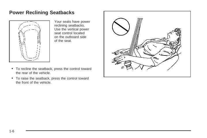
Your seats have powerreclining seatbacks.Use the vertical powerseat control locatedon the outboard sideof the seat.
• To recline the seatback, press the control towardthe rear of the vehicle.
• To raise the seatback, press the control towardthe front of the vehicle.
1-6

{CAUTION:
Sitting in a reclined position when your vehicleis in motion can be dangerous. Even if youbuckle up, your safety belts cannot do theirjob when you are reclined like this.
The shoulder belt cannot do its job because itwill not be against your body. Instead, it will bein front of you. In a crash, you could go into it,receiving neck or other injuries.
The lap belt cannot do its job either. In a crash,the belt could go up over your abdomen. Thebelt forces would be there, not at your pelvicbones. This could cause serious internalinjuries.
For proper protection when the vehicle is inmotion, have the seatback upright. Then sitwell back in the seat and wear your safety beltproperly.
Do not have a seatback reclined if your vehicle is moving.
Head Restraints
Adjust the head restraint so that the top of the restraintis at the same height as the top of the occupant’shead. This position reduces the chance of a neck injuryin a crash.
The height of all the head restraints can be adjusted.
1-7
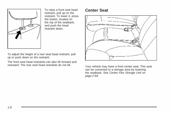
To raise a front seat headrestraint, pull up on therestraint. To lower it, pressthe button, located onthe top of the seatback,and push the headrestraint down.
To adjust the height of a rear seat head restraint, pullup or push down on the restraint.
The front seat head restraints can also tilt forward andrearward. The rear seat head restraints do not tilt.
Center Seat
Your vehicle may have a front center seat. This seatcan be converted to a storage area by loweringthe seatback. See Center Flex Storage Unit onpage 2-64.
1-8
Rear Seats
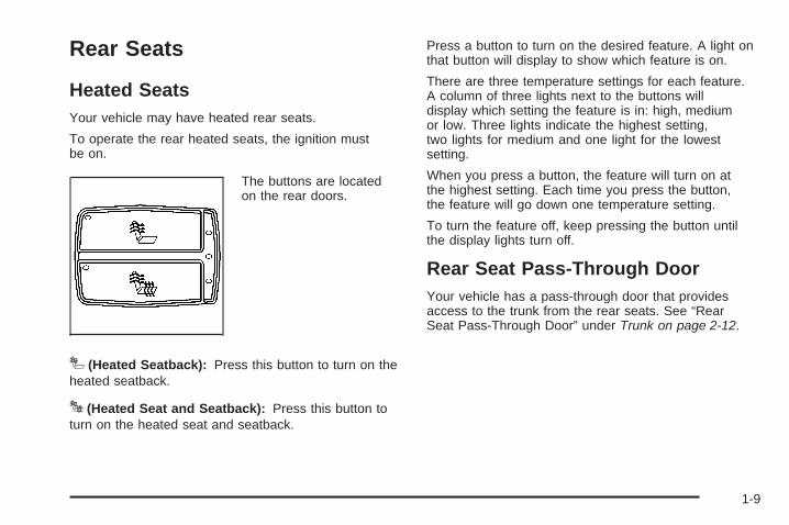
Heated SeatsYour vehicle may have heated rear seats.
To operate the rear heated seats, the ignition mustbe on.
The buttons are locatedon the rear doors.
I (Heated Seatback): Press this button to turn on theheated seatback.
J (Heated Seat and Seatback): Press this button toturn on the heated seat and seatback.
Press a button to turn on the desired feature. A light onthat button will display to show which feature is on.
There are three temperature settings for each feature.A column of three lights next to the buttons willdisplay which setting the feature is in: high, mediumor low. Three lights indicate the highest setting,two lights for medium and one light for the lowestsetting.
When you press a button, the feature will turn on atthe highest setting. Each time you press the button,the feature will go down one temperature setting.
To turn the feature off, keep pressing the button untilthe display lights turn off.
Rear Seat Pass-Through DoorYour vehicle has a pass-through door that providesaccess to the trunk from the rear seats. See “RearSeat Pass-Through Door” under Trunk on page 2-12.
1-9
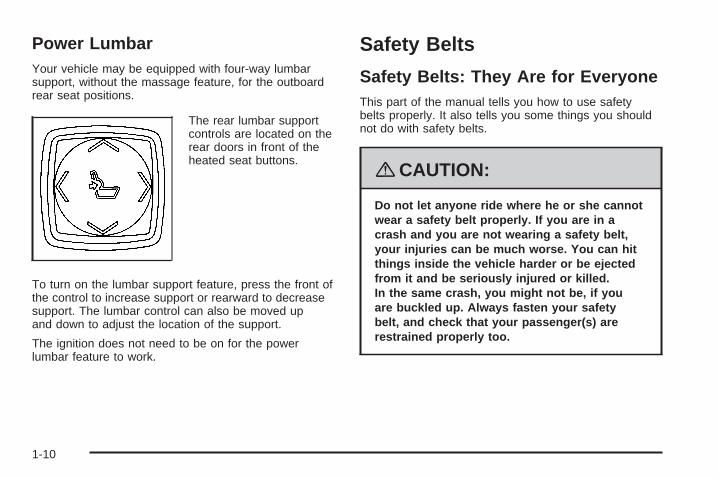
Power LumbarYour vehicle may be equipped with four-way lumbarsupport, without the massage feature, for the outboardrear seat positions.
The rear lumbar supportcontrols are located on therear doors in front of theheated seat buttons.
To turn on the lumbar support feature, press the front ofthe control to increase support or rearward to decreasesupport. The lumbar control can also be moved upand down to adjust the location of the support.
The ignition does not need to be on for the powerlumbar feature to work.
Safety Belts
Safety Belts: They Are for EveryoneThis part of the manual tells you how to use safetybelts properly. It also tells you some things you shouldnot do with safety belts.
{CAUTION:
Do not let anyone ride where he or she cannotwear a safety belt properly. If you are in acrash and you are not wearing a safety belt,your injuries can be much worse. You can hitthings inside the vehicle harder or be ejectedfrom it and be seriously injured or killed.In the same crash, you might not be, if youare buckled up. Always fasten your safetybelt, and check that your passenger(s) arerestrained properly too.
1-10
{CAUTION:
It is extremely dangerous to ride in a cargoarea, inside or outside of a vehicle. In acollision, people riding in these areas aremore likely to be seriously injured or killed.Do not allow people to ride in any area of yourvehicle that is not equipped with seats andsafety belts. Be sure everyone in your vehicleis in a seat and using a safety belt properly.
Your vehicle has indicators as a reminder to buckle yoursafety belts. See Safety Belt Reminders on page 3-54.
In most states and in all Canadian provinces, the lawrequires wearing safety belts. Here is why:
You never know if you will be in a crash. If you do havea crash, you do not know if it will be a serious one.
A few crashes are mild, and some crashes can be soserious that even buckled up, a person would notsurvive. But most crashes are in between. In manyof them, people who buckle up can survive andsometimes walk away. Without belts they could havebeen badly hurt or killed.
After more than 40 years of safety belts in vehicles,the facts are clear. In most crashes buckling up doesmatter... a lot!
1-11

Why Safety Belts WorkWhen you ride in or on anything, you go as fast as it goes.
Take the simplest vehicle. Suppose it is just a seaton wheels.
Put someone on it.
1-12

Get it up to speed. Then stop the vehicle.The rider does not stop.
The person keeps going until stopped by something.In a real vehicle, it could be the windshield...
1-13
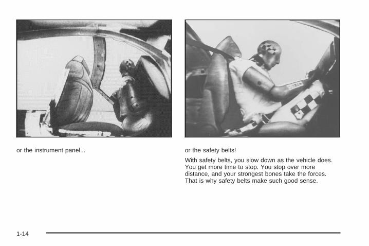
or the instrument panel... or the safety belts!
With safety belts, you slow down as the vehicle does.You get more time to stop. You stop over moredistance, and your strongest bones take the forces.That is why safety belts make such good sense.
1-14

Questions and Answers AboutSafety Belts
Q: Will I be trapped in the vehicle after a crash ifI am wearing a safety belt?
A: You could be — whether you are wearing a safetybelt or not. But your chance of being consciousduring and after an accident, so you can unbuckleand get out, is much greater if you are belted.And you can unbuckle a safety belt, even if youare upside down.
Q: If my vehicle has airbags, why should I haveto wear safety belts?
A: Airbags are supplemental systems only; so theywork with safety belts — not instead of them.Whether or not an airbag is provided, all occupantsstill have to buckle up to get the most protection.That is true not only in frontal collisions, butespecially in side and other collisions.
Q: If I am a good driver, and I never drive far fromhome, why should I wear safety belts?
A: You may be an excellent driver, but if you are ina crash — even one that is not your fault — youand your passenger(s) can be hurt. Being agood driver does not protect you from thingsbeyond your control, such as bad drivers.
Most accidents occur within 25 miles (40 km)of home. And the greatest number of seriousinjuries and deaths occur at speeds of less than40 mph (65 km/h).
Safety belts are for everyone.
1-15
How to Wear Safety Belts ProperlyThis section is only for people of adult size.
Be aware that there are special things to know aboutsafety belts and children. And there are differentrules for smaller children and babies. If a child will beriding in your vehicle, see Older Children on page 1-31or Infants and Young Children on page 1-34. Followthose rules for everyone’s protection.
It is very important for all occupants to buckle up.Statistics show that unbelted people are hurt more oftenin crashes than those who are wearing safety belts.
Occupants who are not buckled up can be thrown outof the vehicle in a crash. And they can strike othersin the vehicle who are wearing safety belts.
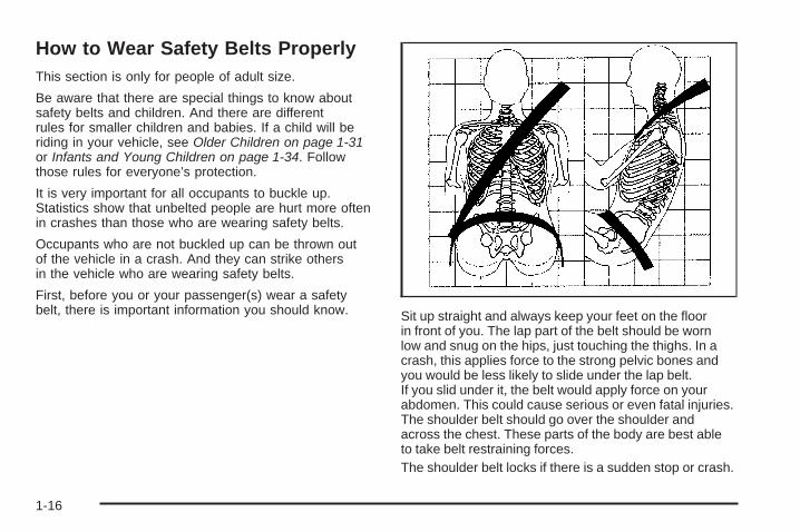
First, before you or your passenger(s) wear a safetybelt, there is important information you should know. Sit up straight and always keep your feet on the floor
in front of you. The lap part of the belt should be wornlow and snug on the hips, just touching the thighs. In acrash, this applies force to the strong pelvic bones andyou would be less likely to slide under the lap belt.If you slid under it, the belt would apply force on yourabdomen. This could cause serious or even fatal injuries.The shoulder belt should go over the shoulder andacross the chest. These parts of the body are best ableto take belt restraining forces.The shoulder belt locks if there is a sudden stop or crash.
1-16

Q: What is wrong with this?
A: The shoulder belt is too loose. It will not give nearlyas much protection this way.
{CAUTION:
You can be seriously hurt if your shoulderbelt is too loose. In a crash, you would moveforward too much, which could increase injury.The shoulder belt should fit snugly againstyour body.
1-17

Q: What is wrong with this?
A: The lap belt is too loose. It will not give as muchprotection this way.
{CAUTION:
You can be seriously hurt if your lap belt istoo loose. In a crash, you could slide underthe lap belt and apply force on your abdomen.This could cause serious or even fatal injuries.The lap belt should be worn low and snugon the hips, just touching the thighs.
1-18

Q: What is wrong with this?
A: The belt is buckled in the wrong place.
{CAUTION:
You can be seriously injured if your belt isbuckled in the wrong place like this. In a crash,the belt would go up over your abdomen.The belt forces would be there, not on thepelvic bones. This could cause serious internalinjuries. Always buckle your belt into thebuckle nearest you.
1-19

Q: What is wrong with this?
A: The belt is over an armrest.
{CAUTION:
You can be seriously injured if your belt goesover an armrest like this. The belt would bemuch too high. In a crash, you can slide underthe belt. The belt force would then be appliedon the abdomen, not on the pelvic bones,and that could cause serious or fatal injuries.Be sure the belt goes under the armrests.
1-20

Q: What is wrong with this?
A: The shoulder belt is worn under the arm.It should be worn over the shoulder at all times.
{CAUTION:
You can be seriously injured if you wear theshoulder belt under your arm. In a crash,your body would move too far forward, whichwould increase the chance of head and neckinjury. Also, the belt would apply too muchforce to the ribs, which are not as strong asshoulder bones. You could also severelyinjure internal organs like your liver or spleen.The shoulder belt should go over the shoulderand across the chest.
1-21

Q: What is wrong with this?
A: The belt is behind the body.
{CAUTION:
You can be seriously injured by not wearingthe lap-shoulder belt properly. In a crash,you would not be restrained by the shoulderbelt. Your body could move too far forwardincreasing the chance of head and neck injury.You might also slide under the lap belt. Thebelt force would then be applied right on theabdomen. That could cause serious or fatalinjuries. The shoulder belt should go overthe shoulder and across the chest.
1-22

Q: What is wrong with this?
A: The belt is twisted across the body.
{CAUTION:
You can be seriously injured by a twisted belt.In a crash, you would not have the full widthof the belt to spread impact forces. If a beltis twisted, make it straight so it can workproperly, or ask your dealer/retailer to fix it.
1-23
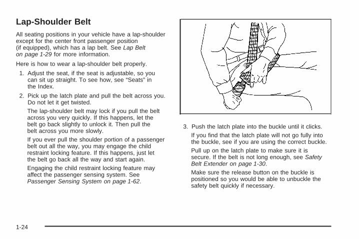
Lap-Shoulder BeltAll seating positions in your vehicle have a lap-shoulderexcept for the center front passenger position(if equipped), which has a lap belt. See Lap Belton page 1-29 for more information.
Here is how to wear a lap-shoulder belt properly.
1. Adjust the seat, if the seat is adjustable, so youcan sit up straight. To see how, see “Seats” inthe Index.
2. Pick up the latch plate and pull the belt across you.Do not let it get twisted.The lap-shoulder belt may lock if you pull the beltacross you very quickly. If this happens, let thebelt go back slightly to unlock it. Then pull thebelt across you more slowly.If you ever pull the shoulder portion of a passengerbelt out all the way, you may engage the childrestraint locking feature. If this happens, just letthe belt go back all the way and start again.Engaging the child restraint locking feature mayaffect the passenger sensing system. SeePassenger Sensing System on page 1-62.
3. Push the latch plate into the buckle until it clicks.If you find that the latch plate will not go fully intothe buckle, see if you are using the correct buckle.Pull up on the latch plate to make sure it issecure. If the belt is not long enough, see SafetyBelt Extender on page 1-30.Make sure the release button on the buckle ispositioned so you would be able to unbuckle thesafety belt quickly if necessary.
1-24

4. If equipped with a shoulder belt height adjuster,move it to the height that is right for you. Impropershoulder belt height adjustment could reducethe effectiveness of the safety belt in a crash.See “Shoulder Belt Height Adjustment” later inthis section.
5. To make the lap part tight, pull up on theshoulder belt.It may be necessary to pull stitching on thesafety belt through the latch plate to fully tightenthe lap belt on smaller occupants.
To unlatch the belt, push the button on the buckle.The belt should go back out of the way. When the safetybelt is not in use, slide the latch plate up so that it isstored on the safety belt stitching, near the guide loop.
Before you close a door, be sure the belt is out ofthe way. If you slam the door on it, you can damageboth the belt and your vehicle.
1-25

Shoulder Belt Height AdjusterYour vehicle has shoulder belt height adjusters forthe driver and right front passenger position.
Adjust the height so that the shoulder portion of thebelt is centered on your shoulder. The belt shouldbe away from your face and neck, but not falling offyour shoulder. Incorrect positioning of the shoulder beltcan reduce the effectiveness of the safety belt.
To move it down, pressthe release button (A)and move the heightadjuster to the desiredposition. You can movethe height adjuster upjust by pushing up onthe shoulder belt guide.
After you move the height adjuster to where you want it,try to move it down without pressing the releasebutton to make sure it has locked into position.
Safety Belt PretensionersYour vehicle has safety belt pretensioners for frontoutboard occupants. Although you cannot see them,they are part of the safety belt assembly. They can helptighten the safety belts during the early stages of amoderate to severe frontal and near frontal crash ifthe threshold conditions for pretensioner activation aremet. And, if your vehicle has side impact airbags,safety belt pretensioners can help tighten the safetybelts in a side crash.
Pretensioners work only once. If they activate in acrash, you will need to get new ones, and probably othernew parts for your safety belt system. See ReplacingRestraint System Parts After a Crash on page 1-70.
Rear Safety Belt Comfort GuidesRear shoulder belt comfort guides may provide addedsafety belt comfort for older children who have outgrownbooster seats and for small adults. When installed ona shoulder belt, the comfort guide better positionsthe belt away from the neck and head.
1-26

There is one guide for each outside passenger positionin the rear seat. Here is how to install a comfortguide to the safety belt:
1. Remove the guide from its storage pocket on theside of the seatback.
2. Slide the guide under and past the belt. The elasticcord must be under the belt. Then, place the guideover the belt, and insert the two edges of thebelt into the slots of the guide.
3. Be sure that the belt is not twisted and it lies flat.The elastic cord must be under the belt and theguide on top.
1-27
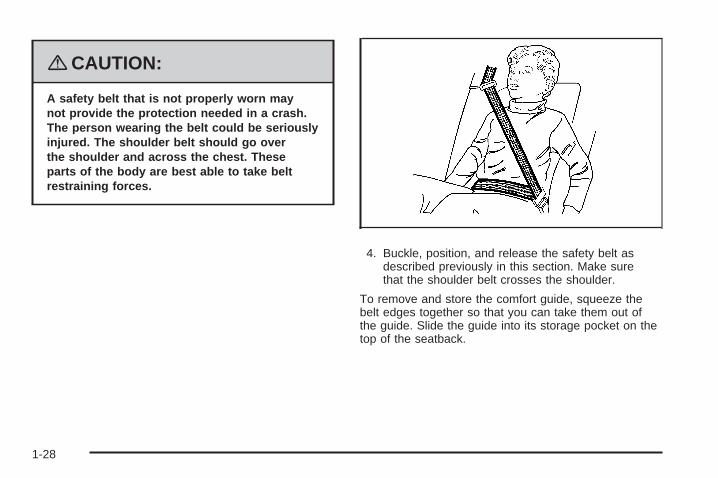
{CAUTION:
A safety belt that is not properly worn maynot provide the protection needed in a crash.The person wearing the belt could be seriouslyinjured. The shoulder belt should go overthe shoulder and across the chest. Theseparts of the body are best able to take beltrestraining forces.
4. Buckle, position, and release the safety belt asdescribed previously in this section. Make surethat the shoulder belt crosses the shoulder.
To remove and store the comfort guide, squeeze thebelt edges together so that you can take them out ofthe guide. Slide the guide into its storage pocket on thetop of the seatback.
1-28

Safety Belt Use During PregnancySafety belts work for everyone, including pregnantwomen. Like all occupants, they are more likely to beseriously injured if they do not wear safety belts.
A pregnant woman should wear a lap-shoulder belt,and the lap portion should be worn as low as possible,below the rounding, throughout the pregnancy.
The best way to protect the fetus is to protect themother. When a safety belt is worn properly, it ismore likely that the fetus will not be hurt in a crash.For pregnant women, as for anyone, the key to makingsafety belts effective is wearing them properly.
Lap BeltThis part is only for the lap belt. To learn how to wear alap-shoulder belt, see Lap-Shoulder Belt on page 1-24.
You vehicle may have a center seating position.When you sit in the center front seating position,you have a lap safety belt, which has no retractor.
To make the belt longer, tilt the latch plate and pull italong the belt.
Buckle, position and release it the same way as thelap part of a lap-shoulder belt.
1-29

To make the belt shorter, pull its free end as shownuntil the belt is snug.
If the belt is not long enough, see Safety Belt Extenderon page 1-30.
Make sure the release button on the buckle is positionedso you would be able to unbuckle the safety beltquickly if necessary.
If you find that the latch plate will not go fully intothe buckle, see if you are using the correct buckle.Be sure that the latch plate clicks when insertedinto the buckle.
Safety Belt ExtenderIf the vehicle’s safety belt will fasten around you,you should use it.
But if a safety belt is not long enough, yourdealer/retailer will order you an extender. When yougo in to order it, take the heaviest coat you will wear,so the extender will be long enough for you. To help avoidpersonal injury, do not let someone else use it, and use itonly for the seat it is made to fit. The extender has beendesigned for adults. Never use it for securing child seats.To wear it, attach it to the regular safety belt. For moreinformation, see the instruction sheet that comes withthe extender.
1-30

Child Restraints
Older Children
Older children who have outgrown booster seats shouldwear the vehicle’s safety belts.
The manufacturer’s instructions that come with thebooster seat, state the weight and height limitations forthat booster. Use a booster seat with a lap-shoulderbelt until the child passes the below fit test:
• Sit all the way back on the seat. Do the kneesbend at the seat edge? If yes, continue. If no,return to the booster seat.
• Buckle the lap-shoulder belt. Does the shoulderbelt rest on the shoulder? If yes, continue. If no,try using the rear safety belt comfort guide.See “Rear Safety Belt Comfort Guides” underLap-Shoulder Belt on page 1-24 for moreinformation. If the shoulder belt still does not reston the shoulder, then return to the booster seat.
• Does the lap belt fit low and snug on the hips,touching the thighs? If yes, continue. If no,return to the booster seat.
• Can proper safety belt fit be maintained forlength of trip? If yes, continue. If no, return tothe booster seat.
If you have the choice, a child should sit in a positionwith a lap-shoulder belt and get the additional restrainta shoulder belt can provide.
1-31

Q: What is the proper way to wear safety belts?
A: An older child should wear a lap-shoulder belt andget the additional restraint a shoulder belt canprovide. The shoulder belt should not cross the faceor neck. The lap belt should fit snugly below thehips, just touching the top of the thighs. This appliesbelt force to the child’s pelvic bones in a crash.It should never be worn over the abdomen, whichcould cause severe or even fatal internal injuriesin a crash.
Also see “Rear Safety Belt Comfort Guides” underLap-Shoulder Belt on page 1-24.
According to accident statistics, children and infantsare safer when properly restrained in the rear seatingpositions than in the front seating positions.
In a crash, children who are not buckled up can strikeother people who are buckled up, or can be thrownout of the vehicle. Older children need to use safetybelts properly.
{CAUTION:
Never do this.
Here two children are wearing the same belt.The belt cannot properly spread the impactforces. In a crash, the two children can becrushed together and seriously injured. A beltmust be used by only one person at a time.
1-32

{CAUTION:
Never do this.
Here a child is sitting in a seat that has alap-shoulder belt, but the shoulder part isbehind the child. In a crash, the child wouldnot be restrained by the shoulder belt. Thechild might slide under the lap belt. The beltforce would then be applied right on theabdomen. That could cause serious or fatalinjuries. The child could also move too farforward increasing the chance of head andneck injury. The shoulder belt should goover the shoulder and across the chest.
1-33

Infants and Young ChildrenEveryone in a vehicle needs protection! This includesinfants and all other children. Neither the distancetraveled nor the age and size of the traveler changesthe need, for everyone, to use safety restraints.In fact, the law in every state in the United Statesand in every Canadian province says children up tosome age must be restrained while in a vehicle.
{CAUTION:
Children can be seriously injured or strangled ifa shoulder belt is wrapped around their neckand the safety belt continues to tighten. Neverleave children unattended in a vehicle and neverallow children to play with the safety belts.
Every time infants and young children ride in vehicles,they should have the protection provided by appropriaterestraints. Children who are not restrained properly canstrike other people, or can be thrown out of the vehicle.In addition, young children should not use the vehicle’sadult safety belts alone; they need to use a child restraint.
{CAUTION:
People should never hold an infant in theirarms while riding in a vehicle. An infant doesnot weigh much — until a crash. During acrash an infant will become so heavy it is notpossible to hold it. For example, in a crash atonly 25 mph (40 km/h), a 12 lb (5.5 kg) infant willsuddenly become a 240 lb (110 kg) force on aperson’s arms. An infant should be secured inan appropriate restraint.
1-34
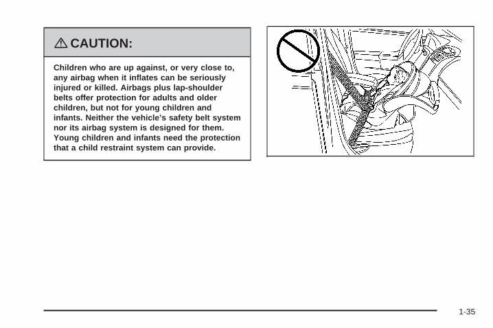
{CAUTION:
Children who are up against, or very close to,any airbag when it inflates can be seriouslyinjured or killed. Airbags plus lap-shoulderbelts offer protection for adults and olderchildren, but not for young children andinfants. Neither the vehicle’s safety belt systemnor its airbag system is designed for them.Young children and infants need the protectionthat a child restraint system can provide.
1-35

Q: What are the different types of add-on childrestraints?
A: Add-on child restraints, which are purchased by thevehicle’s owner, are available in four basic types.Selection of a particular restraint should takeinto consideration not only the child’s weight, height,and age but also whether or not the restraint willbe compatible with the motor vehicle in which itwill be used.
For most basic types of child restraints, there aremany different models available. When purchasinga child restraint, be sure it is designed to beused in a motor vehicle. If it is, the restraint willhave a label saying that it meets federal motorvehicle safety standards.
The restraint manufacturer’s instructions thatcome with the restraint state the weight andheight limitations for a particular child restraint.In addition, there are many kinds of restraintsavailable for children with special needs.
{CAUTION:
Newborn infants need complete support,including support for the head and neck.This is necessary because a newborn infant’sneck is weak and its head weighs so muchcompared with the rest of its body. In a crash,an infant in a rear-facing seat settles intothe restraint, so the crash forces can bedistributed across the strongest part of aninfant’s body, the back and shoulders. Infantsshould always be secured in appropriateinfant restraints.
1-36

{CAUTION:
The body structure of a young child is quiteunlike that of an adult or older child, for whomthe safety belts are designed. A young child’ship bones are still so small that the vehicle’sregular safety belt may not remain low on thehip bones, as it should. Instead, it may settleup around the child’s abdomen. In a crash,the belt would apply force on a body areathat is unprotected by any bony structure.This alone could cause serious or fatalinjuries. Young children should always besecured in appropriate child restraints.
Child Restraint Systems
A rear-facing infantseat (A) providesrestraint with theseating surfaceagainst the backof the infant.
The harness system holds the infant in place and, in acrash, acts to keep the infant positioned in the restraint.
A forward-facingchild seat (B) providesrestraint for thechild’s body withthe harness.
1-37

A booster seat (C-D) is a child restraint designed toimprove the fit of the vehicle’s safety belt system.A booster seat can also help a child to see outthe window.
Securing an Add-On Child Restraintin the Vehicle
{CAUTION:
A child can be seriously injured or killed ina crash if the child restraint is not properlysecured in the vehicle. Make sure the childrestraint is properly installed in the vehicleusing the vehicle’s safety belt or LATCHsystem, following the instructions that camewith that restraint, and also the instructionsin this manual.
1-38

To help reduce the chance of injury, the child restraintmust be secured in the vehicle. Child restraint systemsmust be secured in vehicle seats by lap belts or thelap belt portion of a lap-shoulder belt, or by the LATCHsystem. See Lower Anchors and Tethers for Children(LATCH) on page 1-41 for more information. A childcan be endangered in a crash if the child restraint isnot properly secured in the vehicle.
When securing an add-on child restraint, refer to theinstructions that come with the restraint which may be onthe restraint itself or in a booklet, or both, and to thismanual. The child restraint instructions are important,so if they are not available, obtain a replacementcopy from the manufacturer.
Keep in mind that an unsecured child restraint canmove around in a collision or sudden stop and injurepeople in the vehicle. Be sure to properly secureany child restraint in your vehicle — even whenno child is in it.
Securing the Child Within theChild Restraint
{CAUTION:
A child can be seriously injured or killed ina crash if the child is not properly securedin the child restraint. Because there aredifferent systems, it is important to refer tothe instructions that come with the restraint.Make sure the child is properly secured,following the instructions that came withthat restraint.
1-39

Where to Put the RestraintAccident statistics show that children are safer if theyare restrained in the rear rather than the front seat.
We recommend that children and child restraintsbe secured in a rear seat, including: an infant or a childriding in a rear-facing child restraint; a child riding ina forward-facing child seat; an older child riding ina booster seat; and children, who are large enough,using safety belts.
A label on your sun visor says, “Never put a rear-facingchild seat in the front.” This is because the risk to therear-facing child is so great, if the airbag deploys.
{CAUTION:
A child in a rear-facing child restraint can beseriously injured or killed if the right frontpassenger’s airbag inflates. This is becausethe back of the rear-facing child restraintwould be very close to the inflating airbag.
Even though the passenger sensing system isdesigned to turn off the right front passenger’sfrontal airbag if the system detects a rear-facingchild restraint, no system is fail-safe, and noone can guarantee that an airbag will not deployunder some unusual circumstance, eventhough it is turned off. We recommend thatrear-facing child restraints be secured in arear seat, even if the airbag is off.
If you secure a forward-facing child restraintin the right front seat, always move the frontpassenger seat as far back as it will go. It isbetter to secure the child restraint in a rear seat.
See Passenger Sensing System on page 1-62for additional information.
1-40

{CAUTION:
A child in a child restraint in the center frontseat can be badly injured or killed by thefrontal airbags if they inflate. Never securea child restraint in the center front seat.It is always better to secure a child restraintin a rear seat.
Do not use child restraints in the center front seatposition.
When securing a child restraint in a rear seatingposition, study the instructions that came with your childrestraint to make sure it is compatible with this vehicle.
Wherever you install a child restraint, be sure tosecure the child restraint properly.
Keep in mind that an unsecured child restraint canmove around in a collision or sudden stop and injurepeople in the vehicle. Be sure to properly secureany child restraint in your vehicle — even whenno child is in it.
Lower Anchors and Tethers forChildren (LATCH)The LATCH system holds a child restraint duringdriving or in a crash. This system is designed to makeinstallation of a child restraint easier. The LATCHsystem uses anchors in the vehicle and attachmentson the child restraint that are made for use withthe LATCH system.
Make sure that a LATCH-compatible child restraintis properly installed using the anchors, or use thevehicle’s safety belts to secure the restraint, followingthe instructions that came with that restraint, andalso the instructions in this manual. When installinga child restraint with a top tether, you must alsouse either the lower anchors or the safety belts toproperly secure the child restraint. A child restraintmust never be installed using only the top tetherand anchor.
In order to use the LATCH system in your vehicle,you need a child restraint that has LATCH attachments.The child restraint manufacturer will provide you withinstructions on how to use the child restraint andits attachments. The following explains how to attach achild restraint with these attachments in your vehicle.
Not all vehicle seating positions or child restraintshave lower anchors and attachments or top tetheranchors and attachments.
1-41
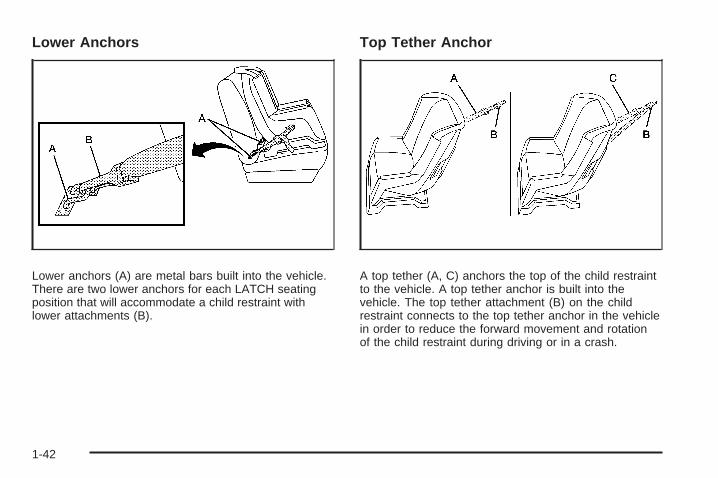
Lower Anchors
Lower anchors (A) are metal bars built into the vehicle.There are two lower anchors for each LATCH seatingposition that will accommodate a child restraint withlower attachments (B).
Top Tether Anchor
A top tether (A, C) anchors the top of the child restraintto the vehicle. A top tether anchor is built into thevehicle. The top tether attachment (B) on the childrestraint connects to the top tether anchor in the vehiclein order to reduce the forward movement and rotationof the child restraint during driving or in a crash.
1-42
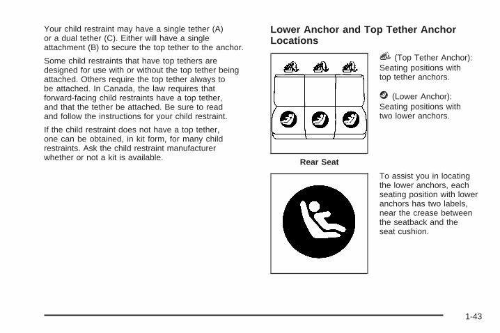
Your child restraint may have a single tether (A)or a dual tether (C). Either will have a singleattachment (B) to secure the top tether to the anchor.
Some child restraints that have top tethers aredesigned for use with or without the top tether beingattached. Others require the top tether always tobe attached. In Canada, the law requires thatforward-facing child restraints have a top tether,and that the tether be attached. Be sure to readand follow the instructions for your child restraint.
If the child restraint does not have a top tether,one can be obtained, in kit form, for many childrestraints. Ask the child restraint manufacturerwhether or not a kit is available.
Lower Anchor and Top Tether AnchorLocations
i (Top Tether Anchor):Seating positions withtop tether anchors.
j (Lower Anchor):Seating positions withtwo lower anchors.
To assist you in locatingthe lower anchors, eachseating position with loweranchors has two labels,near the crease betweenthe seatback and theseat cushion.
Rear Seat
1-43

To assist you in locatingthe top tether anchors, thetop tether anchor symbolis located on the cover.
The top tether anchors are located under the covers onthe rear seatback filler panel. Pull open the cover toaccess the anchors. Be sure to use an anchor locatedon the same side of the vehicle as the seating positionwhere the child restraint will be placed. Do not secure a child restraint in a position without a
top tether anchor if a national or local law requires thatthe top tether be attached, or if the instructions thatcome with the child restraint say that the top tethermust be attached.
Accident statistics show that children are safer if theyare restrained in the rear rather than the front seat.See Where to Put the Restraint on page 1-40 foradditional information.
1-44

Securing a Child Restraint Designed forthe LATCH System
{CAUTION:
If a LATCH-type child restraint is not attachedto anchors, the restraint will not be able toprotect the child correctly. In a crash, the childcould be seriously injured or killed. Make surethat a LATCH-type child restraint is properlyinstalled using the anchors, or use the vehicle’ssafety belts to secure the restraint, followingthe instructions that came with that restraint,and also the instructions in this manual.
{CAUTION:
Each top tether anchor and lower anchor inthe vehicle is designed to hold only one childrestraint. Attaching more than one childrestraint to a single anchor could cause theanchor or attachment to come loose or evenbreak during a crash. A child or others couldbe injured if this happens. To help preventinjury to people and damage to your vehicle,attach only one child restraint per anchor.
1-45

{CAUTION:
Children can be seriously injured or strangledif a shoulder belt is wrapped around theirneck and the safety belt continues to tighten.Secure any unused safety belts behind thechild restraint so children cannot reach them.Pull the shoulder belt all the way out of theretractor to set the lock, if your vehicle hasone, after the child restraint has been installed.Be sure to follow the instructions of the childrestraint manufacturer.
Notice: Contact between the child restraint LATCHattachment parts and the vehicle’s safety beltassembly may cause damage to these parts. Makesure when securing unused safety belts behindthe child restraint that there is no contact betweenthe child restraint LATCH attachment parts andthe vehicle’s safety belt assembly.
Folding an empty rear seat with the safety beltssecured may cause damage to the safety belt or theseat. When removing the child restraint, alwaysremember to return the safety belts to their normal,stowed position before folding the rear seat.
1. Attach and tighten the lower attachments to thelower anchors. If the child restraint does not havelower attachments or the desired seating positiondoes not have lower anchors, secure the childrestraint with the top tether and the safety belts.Refer to your child restraint manufacturerinstructions and the instructions in this manual.
1.1. Find the lower anchors for the desiredseating position.
1.2. Put the child restraint on the seat.1.3. Attach and tighten the lower attachments
on the child restraint to the lower anchors.
1-46

2. If the child restraint manufacturer recommendsthat the top tether be attached, attach and tightenthe top tether to the top tether anchor, if equipped.Refer to the child restraint instructions and thefollowing steps:
2.1. Find the top tether anchor.2.2. Pull open the top tether anchor cover to
expose the anchor.2.3. If you have an adjustable headrest or head
restraint, raise the headrest or head restraint.2.4. Route, attach and tighten the top tether
according to your child restraint instructionsand the following instructions:
If the position you areusing has a fixed headrestor head restraint andyou are using a singletether, route the tetherover the headrest orhead restraint.
If the position you areusing has a fixed oradjustable headrest orhead restraint and youare using a dual tether,route the tether aroundthe headrest or headrestraint.
If the position you areusing has an adjustableheadrest or head restraintand you are using asingle tether, route thetether under the headrestor head restraint andin between the headrestor head restraint posts.
3. Push and pull the child restraint in differentdirections to be sure it is secure.
1-47

Securing a Child Restraint in aRear Seat PositionWhen securing a child restraint in a rear seatingposition, study the instructions that came with your childrestraint to make sure it is compatible with this vehicle.
If your child restraint has the LATCH system, see LowerAnchors and Tethers for Children (LATCH) on page 1-41for how to install your child restraint using LATCH. If yousecure a child restraint using a safety belt and it uses atop tether, see Lower Anchors and Tethers for Children(LATCH) on page 1-41 for top tether anchor locations.
Do not secure a child seat in a position without a toptether anchor if a national or local law requires that thetop tether be anchored, or if the instructions that comewith the child restraint say that the top strap must beanchored.
In Canada, the law requires that forward-facing childrestraints have a top tether, and that the tether beattached.
If your child restraint does not have the LATCH system,you will be using the safety belt to secure the childrestraint in this position. Be sure to follow the instructionsthat came with the child restraint. Secure the child in thechild restraint when and as the instructions say.
If you need to install more than one child restraint in therear seat, be sure to read Where to Put the Restrainton page 1-40.
1. Put the child restraint on the seat.
2. Pick up the latch plate, and run the lap and shoulderportions of the vehicle’s safety belt through oraround the restraint. The child restraint instructionswill show you how.
3. Push the latch plate into the buckle until it clicks.Make sure the release button is positioned so youwould be able to unbuckle the safety belt quicklyif necessary.
1-48
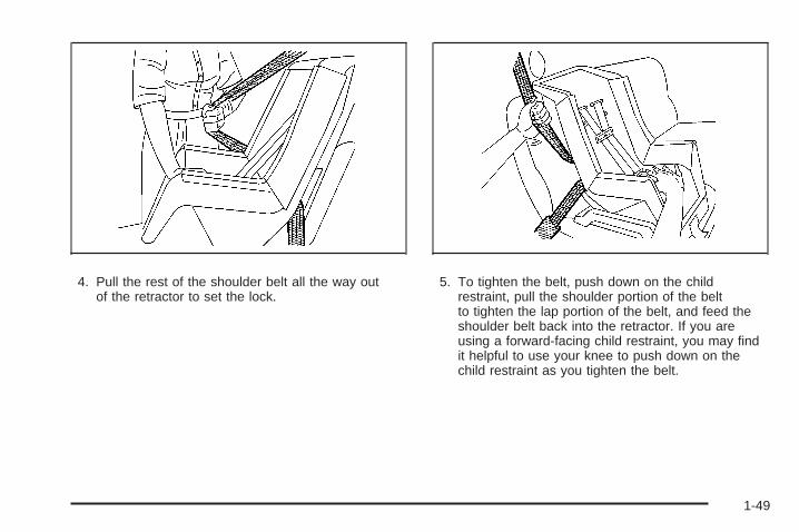
4. Pull the rest of the shoulder belt all the way outof the retractor to set the lock.
5. To tighten the belt, push down on the childrestraint, pull the shoulder portion of the beltto tighten the lap portion of the belt, and feed theshoulder belt back into the retractor. If you areusing a forward-facing child restraint, you may findit helpful to use your knee to push down on thechild restraint as you tighten the belt.
1-49

6. If your child restraint has a top tether, follow thechild restraint manufacturer’s instructions regardingthe use of the top tether. See Lower Anchorsand Tethers for Children (LATCH) on page 1-41for more information.
7. Push and pull the child restraint in differentdirections to be sure it is secure.
To remove the child restraint, unbuckle the vehicle’ssafety belt and let it go back all the way. If the toptether is attached to a top tether anchor, disconnect it.
Securing a Child Restraint in theCenter Front Seat Position
{CAUTION:
A child in a child restraint in the center frontseat can be badly injured or killed by the frontalairbags if they inflate. Never secure a childrestraint in the center front seat. It is alwaysbetter to secure a child restraint in a rear seat.
Do not use child restraints in the center front seat position.
Securing a Child Restraint in theRight Front Seat PositionYour vehicle has airbags. A rear seat is a safer place tosecure a forward-facing child restraint. See Where toPut the Restraint on page 1-40.
In addition, your vehicle has a passenger sensingsystem which is designed to turn off the right frontpassenger’s frontal airbag and seat-mounted side impactairbag under certain conditions. See PassengerSensing System on page 1-62 and Passenger AirbagStatus Indicator on page 3-56 for more informationon this, including important safety information.
A label on your sun visor says, “Never put a rear-facingchild seat in the front.” This is because the risk to therear-facing child is so great, if the airbag deploys.
1-50
{CAUTION:
A child in a rear-facing child restraint can beseriously injured or killed if the right frontpassenger’s airbag inflates. This is becausethe back of the rear-facing child restraintwould be very close to the inflating airbag.
Even though the passenger sensing system isdesigned to turn off the right front passenger’sfrontal airbag if the system detects a rear-facingchild restraint, no system is fail-safe, and noone can guarantee that an airbag will not deployunder some unusual circumstance, eventhough it is turned off. We recommend thatrear-facing child restraints be secured in a rearseat, even if the airbag is off.
If you secure a forward-facing child restraint inthe right front seat, always move the frontpassenger seat as far back as it will go. It isbetter to secure the child restraint in a rear seat.
See Passenger Sensing System on page 1-62for additional information.
If your child restraint has the LATCH system, seeLower Anchors and Tethers for Children (LATCH)on page 1-41 for how to install your child restraint usingLATCH. If you secure a child restraint using a safetybelt and it uses a top tether, see Lower Anchorsand Tethers for Children (LATCH) on page 1-41 fortop tether anchor locations.Do not secure a child seat in a position without a toptether anchor if a national or local law requires thatthe top tether be anchored, or if the instructionsthat come with the child restraint say that the topstrap must be anchored.In Canada, the law requires that forward-facing childrestraints have a top tether, and that the tether beattached.You will be using the lap-shoulder belt to secure thechild restraint in this position. Follow the instructionsthat came with the child restraint.
1. Move the seat as far back as it will go beforesecuring the forward-facing child restraint.When the passenger sensing system has turnedoff the right front passenger’s frontal airbag andseat-mounted side impact airbag, the off indicatoron the passenger airbag status indicator shouldlight and stay lit when you start the vehicle. SeePassenger Airbag Status Indicator on page 3-56.
2. Put the child restraint on the seat.
1-51

3. Pick up the latch plate, and run the lap and shoulderportions of the vehicle’s safety belt through oraround the restraint. The child restraint instructionswill show you how.
4. Push the latch plate into the buckle until it clicks.Make sure the release button is positioned so youwould be able to unbuckle the safety belt quicklyif necessary.
5. Pull the rest of the shoulder belt all the way outof the retractor to set the lock.
1-52

6. To tighten the belt, push down on the childrestraint, pull the shoulder portion of the beltto tighten the lap portion of the belt and feed theshoulder belt back into the retractor. If you areusing a forward-facing child restraint, you may findit helpful to use your knee to push down on thechild restraint as you tighten the belt.
7. Push and pull the child restraint in differentdirections to be sure it is secure.
If the airbags are off, the off indicator in the passengerairbag status indicator will come on and stay onwhen the vehicle is started.
If a child restraint has been installed and the onindicator is lit, turn the vehicle off. Remove the childrestraint from the vehicle and reinstall the child restraint.
If, after reinstalling the child restraint and restartingthe vehicle, the on indicator is still lit, check to makesure that the vehicle’s seatback is not pressing thechild restraint into the seat cushion. If this happens,slightly recline the vehicle’s seatback and adjust theseat cushion if possible. Also make sure the childrestraint is not trapped under the vehicle head restraint.If this happens, adjust the head restraint.
Remove any additional material from the seat suchas blankets, cushions, seat covers, seat heaters orseat massagers before reinstalling or securing thechild restraint.
If the on indicator is still lit, secure the child in thechild restraint in a rear seat position in the vehicleand check with your dealer/retailer.
To remove the child restraint, unbuckle the vehicle’ssafety belt and let it go back all the way.
1-53
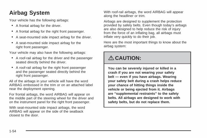
Airbag SystemYour vehicle has the following airbags:
• A frontal airbag for the driver.
• A frontal airbag for the right front passenger.
• A seat-mounted side impact airbag for the driver.
• A seat-mounted side impact airbag for theright front passenger.
Your vehicle may also have the following airbags:
• A roof-rail airbag for the driver and the passengerseated directly behind the driver.
• A roof-rail airbag for the right front passengerand the passenger seated directly behind theright front passenger.
All of the airbags in your vehicle will have the wordAIRBAG embossed in the trim or on an attached labelnear the deployment opening.
For frontal airbags, the word AIRBAG will appear onthe middle part of the steering wheel for the driver andon the instrument panel for the right front passenger.
With seat-mounted side impact airbags, the wordAIRBAG will appear on the side of the seatbackclosest to the door.
With roof-rail airbags, the word AIRBAG will appearalong the headliner or trim.
Airbags are designed to supplement the protectionprovided by safety belts. Even though today’s airbagsare also designed to help reduce the risk of injuryfrom the force of an inflating bag, all airbags mustinflate very quickly to do their job.
Here are the most important things to know about theairbag system:
{CAUTION:
You can be severely injured or killed in acrash if you are not wearing your safetybelt — even if you have airbags. Wearingyour safety belt during a crash helps reduceyour chance of hitting things inside thevehicle or being ejected from it. Airbagsare “supplemental restraints” to the safetybelts. All airbags are designed to work withsafety belts, but do not replace them.
1-54

{CAUTION:
Frontal airbags are designed to deploy inmoderate to severe frontal and near frontalcrashes. They are not designed to inflate inrollover, rear crashes, or in many side crashes.
Seat-mounted side impact airbags and roof-railairbags are designed to inflate in moderateto severe crashes where something hits theside of your vehicle. They are not designed toinflate in frontal, in rollover, or in rear crashes.
Everyone in your vehicle should wear a safetybelt properly — whether or not there is anairbag for that person.
{CAUTION:
Airbags inflate with great force, faster thanthe blink of an eye. Anyone who is up against,or very close to, any airbag when it inflatescan be seriously injured or killed. Do not situnnecessarily close to the airbag, as youwould be if you were sitting on the edge ofyour seat or leaning forward. Safety beltshelp keep you in position before and duringa crash. Always wear your safety belt, evenwith airbags. The driver should sit as far backas possible while still maintaining controlof the vehicle.
Occupants should not lean on or sleep againstthe door or side windows in seating positionswith seat-mounted side impact airbags and/orroof-rail airbags.
1-55

{CAUTION:
Airbags plus lap-shoulder belts offer thebest protection for adults, but not for youngchildren and infants. Neither the vehicle’ssafety belt system nor its airbag system isdesigned for them. Young children and infantsneed the protection that a child restraintsystem can provide. Always secure childrenproperly in your vehicle. To read how, seeOlder Children on page 1-31 or Infants andYoung Children on page 1-34.
There is an airbagreadiness light onthe instrument panel,which shows theairbag symbol.
The system checks the airbag electrical system formalfunctions. The light tells you if there is an electricalproblem. See Airbag Readiness Light on page 3-55for more information.
Where Are the Airbags?
The driver’s frontal airbag is in the middle of thesteering wheel.
1-56

The right front passenger’s frontal airbag is in theinstrument panel on the passenger’s side. The seat-mounted side impact airbags for the driver and
right front passenger are in the side of the seatbacksclosest to the door.
Driver Side shown, Passenger Side similar
1-57

If your vehicle has roof-rail airbags for the driver, rightfront passenger, and second row outboard passengers,they are in the ceiling above the side windows.
{CAUTION:
If something is between an occupant and anairbag, the airbag might not inflate properlyor it might force the object into that personcausing severe injury or even death. The pathof an inflating airbag must be kept clear.Do not put anything between an occupantand an airbag, and do not attach or putanything on the steering wheel hub or onor near any other airbag covering.
Do not use seat accessories that block theinflation path of a seat-mounted side impactairbag.
If your vehicle has roof-rail airbags, neversecure anything to the roof of your vehicleby routing the rope or tie down through anydoor or window opening. If you do, the path ofan inflating roof-rail airbag will be blocked.
Driver Side shown, Passenger Side similar
1-58
When Should an Airbag Inflate?Frontal airbags are designed to inflate in moderate tosevere frontal or near-frontal crashes to help reduce thepotential for severe injuries mainly to the driver’s orright front passenger’s head and chest. However, theyare only designed to inflate if the impact exceeds apredetermined deployment threshold. Deploymentthresholds are used to predict how severe a crash islikely to be in time for the airbags to inflate andhelp restrain the occupants.Whether your frontal airbags will or should deploy is notbased on how fast your vehicle is traveling. It dependslargely on what you hit, the direction of the impact,and how quickly your vehicle slows down.Frontal airbags may inflate at different crash speeds.For example:• If the vehicle hits a stationary object, the airbags
could inflate at a different crash speed than if thevehicle hits a moving object.
• If the vehicle hits an object that deforms, theairbags could inflate at a different crash speed thanif the vehicle hits an object that does not deform.
• If the vehicle hits a narrow object (like a pole), theairbags could inflate at a different crash speedthan if the vehicle hits a wide object (like a wall).
• If the vehicle goes into an object at an angle, theairbags could inflate at a different crash speedthan if the vehicle goes straight into the object.
Thresholds can also vary with specific vehicle design.Frontal airbags are not intended to inflate during vehiclerollovers, rear impacts, or in many side impacts.Your vehicle has a seat position sensor which enablesthe sensing system to monitor the position of the rightfront passenger’s seat. The passenger seat positionsensor and passenger safety belt buckle switch provideinformation that is used to determine if the airbags shoulddeploy at a reduced level or at full deployment.In addition, your vehicle has a dual-stage driver airbag.Dual-stage airbags adjust the restraint according tocrash severity. Your vehicle has electronic frontalsensors, which help the sensing system distinguishbetween a moderate frontal impact and a more severefrontal impact. For moderate frontal impacts, dual-stageairbags inflate at a level less than full deployment.For more severe frontal impacts, full deployment occurs.Your vehicle also has a dual-depth passenger airbag thatadjusts the restraint according to crash severity, seatlocation, and safety belt status using electronic frontalsensor(s) and other special sensors which enable thesensing system to monitor the position of the frontpassenger seat. The passenger airbag inflates to areduced depth when the passenger seat is in a forwardposition. For more rearward front seating positions,the passenger airbag may inflate to an increased depth(a full deployment), based on safety belt status and thecrash severity measured early in the event. (Always wearyour safety belt, even with frontal airbags.)
1-59

Your vehicle has seat-mounted side impact airbags.Your vehicle may have roof-rail airbags. See AirbagSystem on page 1-54. Seat-mounted side impact androof-rail airbags are intended to inflate in moderateto severe side crashes. Seat-mounted side impact androof-rail airbags will inflate if the crash severity isabove the system’s designed threshold level. Thethreshold level can vary with specific vehicle design.
Seat-mounted side impact and roof-rail airbags arenot intended to inflate in frontal impacts, near-frontalimpacts, rollovers, or rear impacts. A seat-mountedside impact airbag is intended to deploy on the sideof the vehicle that is struck. Both roof-rail airbagswill deploy when either side of the vehicle is struck.
In any particular crash, no one can say whether an airbagshould have inflated simply because of the damageto a vehicle or because of what the repair costs were.For frontal airbags, inflation is determined by what thevehicle hits, the angle of the impact, and how quicklythe vehicle slows down. For seat-mounted side impactand roof-rail airbags, deployment is determined by thelocation and severity of the side impact.
What Makes an Airbag Inflate?In a deployment event, the sensing system sends anelectrical signal triggering a release of gas from theinflator. Gas from the inflator fills the airbag causing thebag to break out of the cover and deploy. The inflator,the airbag, and related hardware are all part of the airbagmodule.Frontal airbag modules are located inside the steeringwheel and instrument panel. For vehicles withseat-mounted side impact airbags, there are airbagmodules in the side of the front seatbacks closest tothe door. For vehicles with roof-rail airbags, there areairbag modules in the ceiling of the vehicle, near theside windows that have occupant seating positions.
How Does an Airbag Restrain?In moderate to severe frontal or near frontal collisions,even belted occupants can contact the steering wheelor the instrument panel. In moderate to severe sidecollisions, even belted occupants can contact theinside of the vehicle.Airbags supplement the protection provided by safetybelts. Frontal airbags distribute the force of the impactmore evenly over the occupant’s upper body, stoppingthe occupant more gradually. Seat-mounted side impactand roof-rail airbags distribute the force of the impactmore evenly over the occupant’s upper body.
1-60
But airbags would not help in many types of collisions,primarily because the occupant’s motion is not towardthose airbags. See When Should an Airbag Inflate?on page 1-59 for more information.
Airbags should never be regarded as anything morethan a supplement to safety belts.
What Will You See After anAirbag Inflates?After the frontal airbags and seat-mounted side impactairbags inflate, they quickly deflate, so quickly that somepeople may not even realize an airbag inflated. Roof-railairbags may still be at least partially inflated for sometime after they deploy. Some components of the airbagmodule may be hot for several minutes. For location ofthe airbag modules, see What Makes an Airbag Inflate?on page 1-60.
The parts of the airbag that come into contact with youmay be warm, but not too hot to touch. There may besome smoke and dust coming from the vents in thedeflated airbags. Airbag inflation does not prevent thedriver from seeing out of the windshield or being ableto steer the vehicle, nor does it prevent people fromleaving the vehicle.
{CAUTION:
When an airbag inflates, there may be dustin the air. This dust could cause breathingproblems for people with a history of asthmaor other breathing trouble. To avoid this,everyone in the vehicle should get out assoon as it is safe to do so. If you havebreathing problems but cannot get out ofthe vehicle after an airbag inflates, then getfresh air by opening a window or a door.If you experience breathing problemsfollowing an airbag deployment, you shouldseek medical attention.
Your vehicle has a feature that may automaticallyunlock the doors, turn the interior lamps on, and turnthe hazard warning flashers on when the airbags inflate.You can lock the doors, turn the interior lamps off,and turn the hazard warning flashers off by usingthe controls for those features.
1-61

In many crashes severe enough to inflate the airbag,windshields are broken by vehicle deformation.Additional windshield breakage may also occur fromthe right front passenger airbag.
• Airbags are designed to inflate only once. After anairbag inflates, you will need some new parts forthe airbag system. If you do not get them, the airbagsystem will not be there to help protect you inanother crash. A new system will include airbagmodules and possibly other parts. The servicemanual for your vehicle covers the need toreplace other parts.
• Your vehicle has a crash sensing and diagnosticmodule which records information after a crash.See Vehicle Data Recording and Privacy onpage 7-16 and Event Data Recorders on page 7-16.
• Let only qualified technicians work on the airbagsystems. Improper service can mean that anairbag system will not work properly. See yourdealer/retailer for service.
Passenger Sensing SystemYour vehicle has a passenger sensing system forthe right front passenger’s position. The passengerairbag status indicator will be visible on the overheadconsole when you start your vehicle.
The words ON and OFF, or the symbol for on and off,will be visible during the system check. If you areusing remote start to start your vehicle from a distance,if equipped, you may not see the system check.When the system check is complete, either the wordON or the word OFF, or the symbol for on or the symbolfor off, will be visible. See Passenger Airbag StatusIndicator on page 3-56.
United States Canada
1-62

The passenger sensing system will turn off the rightfront passenger’s frontal airbag and seat-mounted sideimpact airbag under certain conditions. The driver’sairbags are not part of the passenger sensing system.
The passenger sensing system works with sensorsthat are part of the right front passenger’s seatand safety belt. The sensors are designed to detect thepresence of a properly-seated occupant and determineif the right front passenger’s frontal airbag andseat-mounted side impact airbag should be enabled(may inflate) or not.
Accident statistics show that children are safer if theyare restrained in the rear rather than the front seat.
We recommend that children be secured in a rear seat,including: an infant or a child riding in a rear-facingchild restraint; a child riding in a forward-facing childseat; an older child riding in a booster seat; and children,who are large enough, using safety belts.
A label on your sun visor says, “Never put a rear-facingchild seat in the front.” This is because the risk to therear-facing child is so great, if the airbag deploys.
{CAUTION:
A child in a rear-facing child restraint can beseriously injured or killed if the right frontpassenger’s airbag inflates. This is becausethe back of the rear-facing child restraintwould be very close to the inflating airbag.
Even though the passenger sensing system isdesigned to turn off the right front passenger’sfrontal and seat-mounted side impact airbag ifthe system detects a rear-facing child restraint,no system is fail-safe, and no one can guaranteethat an airbag will not deploy under someunusual circumstance, even though it is turnedoff. We recommend that rear-facing childrestraints be secured in a rear seat, even ifthe airbags are off.
If you secure a forward-facing child restraintin the right front seat, always move the frontpassenger seat as far back as it will go. It isbetter to secure the child restraint in a rear seat.
1-63
The passenger sensing system is designed to turn offthe right front passenger’s frontal airbag andseat-mounted side impact airbag if:• The right front passenger seat is unoccupied.• The system determines that an infant is present in
a rear-facing infant seat.• The system determines that a small child is present
in a child restraint.• The system determines that a small child is present
in a booster seat.• A right front passenger takes his/her weight off of
the seat for a period of time.• The right front passenger seat is occupied by a
smaller person, such as a child who has outgrownchild restraints.
• Or, if there is a critical problem with the airbagsystem or the passenger sensing system.
When the passenger sensing system has turned off theright front passenger’s frontal airbag and seat-mountedside impact airbag, the off indicator will light andstay lit to remind you that the airbags are off. SeePassenger Airbag Status Indicator on page 3-56.
If a child restraint has been installed and the onindicator is lit, turn the vehicle off. Remove the childrestraint from the vehicle and reinstall the child restraintfollowing the child restraint manufacturer’s directionsand refer to Securing a Child Restraint in the Right FrontSeat Position on page 1-50.
If, after reinstalling the child restraint and restarting thevehicle, the on indicator is still lit, check to make sure thatthe vehicle’s seatback is not pressing the child restraintinto the seat cushion. If this happens, slightly reclinethe vehicle’s seatback and adjust the seat cushion ifpossible. Also make sure the child restraint is not trappedunder the vehicle head restraint. If this happens, adjustthe head restraint. See Head Restraints on page 1-7.
Remove any additional material from the seat such asblankets, cushions, seat covers, seat heaters, or seatmassagers before reinstalling or securing the childrestraint.
If the on indicator is still lit, secure the child in the childrestraint in a rear seat position in the vehicle, and checkwith your dealer/retailer.
1-64

The passenger sensing system is designed toenable (may inflate) the right front passenger’s frontalairbag and seat-mounted side impact airbag anytimethe system senses that a person of adult size issitting properly in the right front passenger’s seat.When the passenger sensing system has allowed theairbags to be enabled, the on indicator will light andstay lit to remind you that the airbags are active.
For some children who have outgrown child restraintsand for very small adults, the passenger sensing systemmay or may not turn off the right front passenger’sfrontal airbag and seat-mounted side impact airbag,depending upon the person’s seating posture andbody build. Everyone in your vehicle who hasoutgrown child restraints should wear a safety beltproperly — whether or not there is an airbag forthat person.
If a person of adult-size is sitting in the right frontpassenger’s seat, but the off indicator is lit, it couldbe because that person is not sitting properly in theseat. If this happens, turn the vehicle off, remove anyadditional material from the seat, such as blankets,cushions, seat covers, seat heaters or seat massagersand ask the person to place the seatback in the fullyupright position, then sit upright in the seat, centeredon the seat cushion, with the person’s legs comfortablyextended. Restart the vehicle and have the personremain in this position for two to three minutes.This will allow the system to detect that person andthen enable the right front passenger’s frontal airbagand seat-mounted side impact airbag.
1-65

Safety belts help keep the passenger in position onthe seat during vehicle maneuvers and braking, whichhelps the passenger sensing system maintain thepassenger airbag status. See “Safety Belts” and“Child Restraints” in the Index for additional informationabout the importance of proper restraint use.
If you ever pull the shoulder portion of the belt out all theway, you will engage the child restraint locking feature.This may unintentionally cause the passenger sensingsystem to turn the airbag(s) off for some adult sizeoccupants. If this happens, just let the belt go back allthe way and start again.
{CAUTION:
If the airbag readiness light in the instrumentpanel cluster ever comes on and stays on,it means that something may be wrong withthe airbag system. If this ever happens, havethe vehicle serviced promptly, because anadult-size person sitting in the right frontpassenger’s seat may not have the protectionof the airbag(s). See Airbag Readiness Lighton page 3-55 for more on this, includingimportant safety information.
1-66
A thick layer of additional material, such as a blanket orcushion, or aftermarket equipment such as seat covers,seat heaters, and seat massagers can affect how wellthe passenger sensing system operates. We recommendthat you not use seat covers or other aftermarketequipment other than any that GM has approved foryour specific vehicle. See Adding Equipment to YourAirbag-Equipped Vehicle on page 1-68 for moreinformation about modifications that can affect howthe system operates.
{CAUTION:
Stowing of articles under the passenger’sseat or between the passenger’s seat cushionand seatback may interfere with the properoperation of the passenger sensing system.
Servicing Your Airbag-EquippedVehicleAirbags affect how your vehicle should be serviced.There are parts of the airbag system in several placesaround your vehicle. Your dealer/retailer and the servicemanual have information about servicing your vehicle andthe airbag system. To purchase a service manual, seeService Publications Ordering Information on page 7-15.
{CAUTION:
For up to 10 seconds after the ignition is turnedoff and the battery is disconnected, an airbagcan still inflate during improper service. Youcan be injured if you are close to an airbag whenit inflates. Avoid yellow connectors. They areprobably part of the airbag system. Be sure tofollow proper service procedures, and makesure the person performing work for you isqualified to do so.
1-67

Adding Equipment to YourAirbag-Equipped Vehicle
Q: Is there anything I might add to or changeabout the vehicle that could keep the airbagsfrom working properly?
A: Yes. If you add things that change your vehicle’sframe, bumper system, height, front end or sidesheet metal, they may keep the airbag system fromworking properly. Changing or moving any parts ofthe front seats, safety belts, the airbag sensing anddiagnostic module, steering wheel, instrument panel,roof-rail airbag modules, ceiling headliner or pillargarnish trim, overhead console, front sensors, sideimpact sensors, or airbag wiring can affect theoperation of the airbag system.
In addition, your vehicle has a passenger sensingsystem for the right front passenger’s position, whichincludes sensors that are part of the passenger’sseat. The passenger sensing system may notoperate properly if the original seat trim is replacedwith non-GM covers, upholstery or trim, or withGM covers, upholstery or trim designed for adifferent vehicle. Any object, such as an aftermarketseat heater or a comfort enhancing pad or device,
installed under or on top of the seat fabric, could alsointerfere with the operation of the passenger sensingsystem. This could either prevent proper deploymentof the passenger airbag(s) or prevent the passengersensing system from properly turning off thepassenger airbag(s). See Passenger SensingSystem on page 1-62.
If you have any questions about this, you shouldcontact Customer Assistance before you modifyyour vehicle. The phone numbers and addressesfor Customer Assistance are in Step Two of theCustomer Satisfaction Procedure in this manual.See Customer Satisfaction Procedure on page 7-2.
Q: Because I have a disability, I have to get myvehicle modified. How can I find out whetherthis will affect my airbag system?
A: If you have questions, call Customer Assistance.The phone numbers and addresses for CustomerAssistance are in Step Two of the CustomerSatisfaction Procedure in this manual. SeeCustomer Satisfaction Procedure on page 7-2.
In addition, your dealer/retailer and the service manualhave information about the location of the airbag sensors,sensing and diagnostic module and airbag wiring.
1-68

Restraint System Check
Checking the Restraint Systems
Safety BeltsNow and then, make sure the safety belt reminder lightand all your belts, buckles, latch plates, retractorsand anchorages are working properly.
Look for any other loose or damaged safety beltsystem parts. If you see anything that might keep asafety belt system from doing its job, have it repaired.Torn or frayed safety belts may not protect you in acrash. They can rip apart under impact forces. If a beltis torn or frayed, get a new one right away.
Make sure the safety belt reminder light is working.See Safety Belt Reminders on page 3-54 for moreinformation.
Keep safety belts clean and dry. See Care of SafetyBelts on page 5-90.
AirbagsThe airbag system does not need regularly scheduledmaintenance or replacement. Make sure the airbagreadiness light is working. See Airbag Readiness Lighton page 3-55 for more information.
Notice: If an airbag covering is damaged, opened,or broken, the airbag may not work properly. Do notopen or break the airbag coverings. If there are anyopened or broken airbag covers, have the airbagcovering and/or airbag module replaced. For thelocation of the airbag modules, see What Makes anAirbag Inflate? on page 1-60. See your dealer/retailerfor service.
1-69

Replacing Restraint System PartsAfter a Crash
{CAUTION:
A crash can damage the restraint systemsin your vehicle. A damaged restraint systemmay not properly protect the person using it,resulting in serious injury or even death ina crash. To help make sure your restraintsystems are working properly after a crash,have them inspected and any necessaryreplacements made as soon as possible.
If you have had a crash, do you need new belts orLATCH system (if equipped) parts?
After a very minor crash, nothing may be necessary.But the belt assemblies that were used during anycrash may have been stressed or damaged. See yourdealer/retailer to have your safety belt assembliesinspected or replaced.
If your vehicle has the LATCH system and it wasbeing used during a crash, you may need new LATCHsystem parts.
New parts and repairs may be necessary even if thebelt or LATCH system (if equipped), was not being usedat the time of the crash.
If an airbag inflates, you will need to replace airbagsystem parts. See the part on the airbag system earlierin this section.
Have your safety belt pretensioners checked if yourvehicle has been in a crash, if your airbag readinesslight stays on after you start your vehicle, or while youare driving. See Airbag Readiness Light on page 3-55.
1-70
Keys ...............................................................2-3Remote Keyless Entry (RKE) System ................2-4Remote Keyless Entry (RKE) System
Operation ...................................................2-5Remote Vehicle Start ......................................2-8
Doors and Locks ............................................2-10Door Locks ..................................................2-10Central Door Unlocking System ......................2-10Power Door Locks ........................................2-10Programmable Automatic Door Locks ..............2-11Rear Door Security Locks ..............................2-11Lockout Protection ........................................2-12Trunk ..........................................................2-12
Windows ........................................................2-14Power Windows ............................................2-15Sun Visors ...................................................2-17
Theft-Deterrent Systems ..................................2-18Valet Lockout Switch .....................................2-18Content Theft-Deterrent .................................2-19PASS-Key® III+ ............................................2-20PASS-Key® III+ Operation ..............................2-21
Starting and Operating Your Vehicle ................2-22New Vehicle Break-In ....................................2-22Ignition Positions ..........................................2-23Retained Accessory Power (RAP) ...................2-24Starting the Engine .......................................2-24Engine Coolant Heater ..................................2-26Automatic Transmission Operation ...................2-27Performance Shifting .....................................2-29Parking Brake ..............................................2-30Shifting Into PARK (P) ...................................2-31Shifting Out of PARK (P) ...............................2-33Parking Over Things That Burn .......................2-34Engine Exhaust ............................................2-34Running the Engine While Parked ...................2-35
Mirrors ...........................................................2-36Automatic Dimming Rearview Mirror with
Intellibeam™, OnStar®, and Compass ..........2-36Automatic Dimming Rearview Mirror
with OnStar® and Compass ........................2-38Automatic Dimming Rearview Mirror
with Compass ...........................................2-40Outside Power Foldaway Mirrors .....................2-41Outside Automatic Dimming Mirror ..................2-42
Section 2 Features and Controls
2-1
Park Tilt Mirrors ............................................2-42Outside Convex Mirror ...................................2-43Outside Heated Mirrors ..................................2-43
Object Detection Systems ...............................2-44Ultrasonic Front and Rear Parking
Assist (UFRPA) .........................................2-44Side Blind Zone Alert ....................................2-47Lane Departure Warning ................................2-50
OnStar® System .............................................2-53Universal Home Remote System ......................2-56
Universal Home Remote System Operation(With Three Round LED) ............................2-56
Storage Areas ................................................2-63Glove Box ...................................................2-63Cupholder(s) ................................................2-63Coinholder(s) ................................................2-63Front Storage Area .......................................2-63Center Console Storage .................................2-63Center Flex Storage Unit ...............................2-64Floor Mats ...................................................2-64Rear Seat Armrest ........................................2-64Convenience Net ..........................................2-64
Sunroof .........................................................2-65
Section 2 Features and Controls
2-2

Keys
{CAUTION:
Leaving children in a vehicle with the ignitionkey is dangerous for many reasons, childrenor others could be badly injured or even killed.They could operate the power windows orother controls or even make the vehicle move.The windows will function with the keys in theignition and they could be seriously injuredor killed if caught in the path of a closingwindow. Do not leave the keys in a vehiclewith children.
The master key can be used for the driver’s door,ignition, and glove box.
The valet key can only be used for the driver’s door andignition.
Notice: If you ever lock your keys in your vehicle,you may have to damage the vehicle to get in.Be sure you have spare keys.
In an emergency, contact Roadside Assistance.See Roadside Service on page 7-7.
2-3
Remote Keyless Entry (RKE)SystemYour Remote Keyless Entry (RKE) system operates ona radio frequency subject to Federal CommunicationsCommission (FCC) Rules and with Industry Canada.
This device complies with Part 15 of the FCC Rules.Operation is subject to the following two conditions:
1. This device may not cause interference.
2. This device must accept any interference received,including interference that may cause undesiredoperation of the device.
This device complies with RSS-210 of Industry Canada.Operation is subject to the following two conditions:
1. This device may not cause interference.
2. This device must accept any interference received,including interference that may cause undesiredoperation of the device.
Changes or modifications to this system by other thanan authorized service facility could void authorization touse this equipment.
At times you may notice a decrease in operating range.This is normal for any RKE system. If the transmitterdoes not work or if you have to stand closer toyour vehicle for the transmitter to work, try this:
• Check the distance. You may be too far from yourvehicle. You may need to stand closer duringrainy or snowy weather.
• Check the location. Other vehicles or objects maybe blocking the signal. Take a few steps to theleft or right, hold the transmitter higher, andtry again.
• Check to determine if battery replacement isnecessary. See “Battery Replacement” later inthis section.
• If you are still having trouble, see your dealer/retaileror a qualified technician for service.
2-4
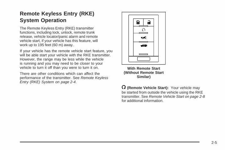
Remote Keyless Entry (RKE)System OperationThe Remote Keyless Entry (RKE) transmitterfunctions, including lock, unlock, remote trunkrelease, vehicle locator/panic alarm and remotevehicle start, if your vehicle has this feature, willwork up to 195 feet (60 m) away.
If your vehicle has the remote vehicle start feature, youwill be able start your vehicle with the RKE transmitter.However, the range may be less while the vehicleis running and you may need to be closer to yourvehicle to turn it off than you were to turn it on.
There are other conditions which can affect theperformance of the transmitter. See Remote KeylessEntry (RKE) System on page 2-4.
/ (Remote Vehicle Start): Your vehicle maybe started from outside the vehicle using the RKEtransmitter. See Remote Vehicle Start on page 2-8for additional information.
With Remote Start(Without Remote Start
Similar)
2-5
Q (Lock): Press the lock button to lock all the doors.If enabled through the Driver Information Center (DIC),the parking lamps may flash once to indicate locking hasoccurred, or the horn may chirp when the lock button ispressed again within five seconds from the previouspress of the lock button. See DIC Vehicle Customizationon page 3-86 for additional information. If the vehicle hasthe content theft-deterrent system, pressing the lockbutton may also arm it. See Content Theft-Deterrenton page 2-19.
" (Unlock): Press the unlock button to unlock thedriver’s door. If the button is pressed again withinfive seconds, all remaining doors will unlock. The interiorlamps will come on and stay on for 20 seconds or untilthe ignition is turned on. If enabled through the DIC, theparking lamps can be programmed to come on for a setamount of time when the vehicle is unlocked using theRKE transmitter. See DIC Vehicle Customization onpage 3-86. Pressing the unlock button on the RKEtransmitter may disarm the content theft-deterrentsystem. See Content Theft-Deterrent on page 2-19.
V (Remote Trunk Release): Press and hold thisbutton for about one second to release the trunk lid.The transmission must be in PARK (P) for this featureto operate.
L (Vehicle Locator/Panic Alarm): Press and releasethis button to locate your vehicle. The turn signal lampswill flash and the horn will sound three times. Press andhold this button for more than two seconds to activate thepanic alarm. The turn signal lamps will flash and the hornwill sound repeatedly for 30 seconds. The alarm will turnoff when the ignition is moved to ON/RUN or the alarmbutton is pressed again. The ignition must be in LOCK/OFF for the panic alarm to work.
Matching Transmitter(s) to YourVehicleEach RKE transmitter is coded to prevent anothertransmitter from unlocking your vehicle. If a transmitteris lost or stolen, a replacement can be purchasedthrough your dealer/retailer. Remember to bring anyadditional transmitters so they can also be re-codedto match the new transmitter. Once your dealer/retailerhas coded the new transmitter, the lost transmitterwill not unlock your vehicle. The vehicle can havea maximum of eight transmitters matched to it.See RELEARN REMOTE KEY under DICOperation and Displays on page 3-69.
2-6

Battery ReplacementUnder normal use, the battery in your RKE transmittershould last about four years.
The battery is weak if the transmitter will not work at thenormal range in any location. If you have to get closeto your vehicle before the transmitter works, it isprobably time to change the battery.
The REPLACE BATTERY IN REMOTE KEY messagein the vehicle’s DIC will display if the RKE transmitterbattery is low. See “REPLACE BATTERY IN REMOTEKEY” under DIC Warnings and Messages onpage 3-73 for additional information.
Notice: When replacing the battery, use care not totouch any of the circuitry. Static from your bodytransferred to these surfaces may damage thetransmitter.
To replace the battery:1. Use a flat object with a thin edge into the notch,
located above the metal base, and separate thebottom half from the top half of the transmitter.
2. Remove the old battery, but do not use a metalobject to do this.
3. Slide the new battery into the transmitter withthe positive side of the battery facing up.Use a type CR2032 battery, or equivalent type.
4. Snap the front and the back of the transmittertogether tightly so moisture does not get in.
5. Test the operation of the transmitter with thevehicle.
2-7

Remote Vehicle StartThe remote vehicle starting feature allows you to start theengine from outside of the vehicle. It also starts up thevehicle’s automatic climate control system. When theremote start system is active, the climate control systemwill heat and cool the inside of the vehicle according tothe previous settings of the system before turning thevehicle off. The rear window defogger will be turned on bythe climate control system when it is cold outside. If thevehicle has heated seats, they will also turn on when it iscold outside. See Heated and Cooled Seats on page 1-3for additional information. Cooled seats are not activatedduring a remote start. Normal operation of the climatecontrol system will return after the key is turned toON/RUN. See Dual Climate Control System onpage 3-40.
Laws in some communities may restrict the use ofremote starters. For example, some laws may requirea person using remote start to have the vehicle inview when doing so. Check local regulations forany requirements on remote starting of vehicles.
Do not use the remote start feature if your vehicle is lowon fuel. Your vehicle may run out of fuel.
Your RKE transmitter, with the remote start button,provides an increased range of operation. However,the range may be less while the vehicle is running.As a result, you may need to be closer to your vehicleto turn it off than you were to turn it on.
There are other conditions which can affect theperformance of the transmitter, see Remote KeylessEntry (RKE) System Operation on page 2-5 foradditional information.
/ (Remote Start): This button will be on the RKEtransmitter if you have remote start.
To start the vehicle using the remote start feature:
1. Aim the transmitter at the vehicle.
2. Press and release the transmitter’s lock button, thenimmediately press and hold the transmitter’s remotestart button until the turn signal lights flash or if thevehicle’s lights are not visible, press and hold theremote start button for at least four seconds. Thevehicle’s doors will lock. Pressing the remote startbutton again after the vehicle has started will turn offthe ignition.When the vehicle starts, the parking lamps will turnon and remain on while the vehicle is running.
3. If it is the first remote start since the vehicle hasbeen driven, repeat these steps, while the engineis still running, to extend the engine running timeby 10 minutes. Remote start can be extendedone time.
After entering the vehicle during a remote start, insertand turn the key to ON/RUN to drive the vehicle.
2-8
If the vehicle is left running it will automatically shut offafter 10 minutes unless a time extension has been done.
To manually shut off a remote start:
• Aim the RKE transmitter at the vehicle and pressthe remote start button until the parking lampsturn off.
• Turn on the hazard warning flashers.
• Turn the ignition switch on and then off.
The remote vehicle start feature provides two separatestarts, each with 10 minutes of engine running, or itprovides one start with 10 minutes of engine runningthat may be extended 10 more minutes. If you press andrelease the transmitter lock button and then press andhold the remote start button on the RKE transmitter againbefore the first 10 minutes of engine running time hasexpired, 10 minutes are added to the remaining minutes.For example, if the lock button and then the remote startbuttons are pressed again after five minutes of the enginerun time, 10 minutes are added and you now have15 minutes of engine running. The added ten minutesare considered a second remote vehicle start.
Once two remote starts or a single start with a timeextension have been used, the vehicle must be startedwith the ignition key before you can use the remotestart feature again.
The remote vehicle start feature will not operate if thekey is in the ignition, the hood is not closed, or if there isan emission control system malfunction.
The engine will turn off during a remote vehicle start ifthe coolant temperature gets too high, or the oil pressureis too low.
Your vehicle was shipped from the factory with theremote vehicle start system enabled. The system maybe disabled through the Driver Information Center (DIC).See “REMOTE START” under DIC VehicleCustomization on page 3-86 for additional information.
See Engine Exhaust on page 2-34 for important safetyinformation when using remote start in a closed garage.
Remote Start ReadyIf your vehicle does not have the remote vehicle startfeature, it may have the remote start ready feature.This feature allows your dealer/retailer to add themanufacturer’s remote vehicle start feature. See yourdealer/retailer if you would like to add the manufacturer’sremote vehicle start feature to your vehicle.
2-9

Doors and Locks
Door Locks
{CAUTION:
Unlocked doors can be dangerous.• Passengers, especially children, can
easily open the doors and fall out of amoving vehicle. When a door is locked,the handle will not open it. You increasethe chance of being thrown out of thevehicle in a crash if the doors are notlocked. So, wear safety belts properlyand lock the doors whenever you drive.
• Young children who get into unlockedvehicles may be unable to get out. A childcan be overcome by extreme heat and cansuffer permanent injuries or even deathfrom heat stroke. Always lock your vehiclewhenever you leave it.
• Outsiders can easily enter through anunlocked door when you slow down orstop your vehicle. Locking your doorscan help prevent this from happening.
There are several ways to lock and unlock your vehicle.
Because your vehicle has the theft-deterrent system,you must unlock the doors with the key or remotekeyless entry transmitter to avoid setting off the alarm.
From the outside, use either the key or the remotekeyless entry transmitter.
From the inside, use the power door lock switches ormanual lock knobs. The manual lock knobs are locatedat the top of the door panel near the window.
Push the manual lock knob down to lock the door.To unlock the door, pull up on the knob.
Central Door Unlocking SystemYour vehicle has a central door unlocking mode. Whenunlocking the driver’s door, you can unlock the otherdoors at the same time by turning the key clockwisein the door lock cylinder twice.
Power Door LocksThe power door lock switches are located on thefront doors.
K (Unlock): Press to unlock the doors.
Q (Lock): Press to lock the doors.
2-10

Programmable AutomaticDoor LocksYour vehicle is programmed so that, when the doors areclosed, the ignition is on, and the shift lever is movedout of PARK (P), all the doors will lock. The doorswill unlock every time you stop the vehicle and movethe shift lever into PARK (P).
If someone needs to get out while your vehicle is notin PARK (P), have the person use the manual lock knobor power door lock switch. When the door is closedagain, it will not lock automatically. Use the manuallock knob or power door lock switch to lock the door.
With the vehicle in PARK (P) and the ignition on,the door locks can be programmed through promptsdisplayed on the Driver Information Center (DIC).These prompts allow the driver to choose various lockand unlock settings. For programming information,see DIC Vehicle Customization on page 3-86.
Rear Door Security LocksYour vehicle has security locks that prevent passengersfrom opening the rear doors from the inside.
The rear door security locks are located on the insideedge of each rear door. You must open the rear doors toaccess them.
To assist you in finding the lock, your vehicle will haveone of the following:
To use these locks, do the following:
1. Turn the knob to the vertical position to engagethe lock.
2. Close the door.
3. Do the same for the other rear door.
2-11

The rear doors on your vehicle cannot be opened fromthe inside when this feature is in use.
When you want to open a rear door when the securitylock is on, do the following:
1. Unlock the door using the remote keyless entrytransmitter, the front door power lock switch,or by lifting the rear door manual lock knob.
2. Open the door from the outside.
To cancel the rear door security lock, do the following:
1. Unlock the door and open it from the outside.
2. Turn the knob to the horizontal position todisengage the lock.
3. Do the same for the other rear door.
Lockout ProtectionIf the key is in the ignition and the power door lockswitch is used to lock the doors, all doors will lockand then the driver’s door will unlock. It is alwaysrecommended that you remove the ignition keywhen locking your vehicle.
The lockout protection feature can be overridden byholding the power door lock switch for three seconds orlonger.
Trunk
{CAUTION:
It can be dangerous to drive with the trunk lidopen because carbon monoxide (CO) gas cancome into your vehicle. You cannot see orsmell CO. It can cause unconsciousness andeven death. If you must drive with the trunklid open or if electrical wiring or other cableconnections must pass through the sealbetween the body and the trunk lid:
• Make sure all other windows are shut.• Turn the fan on your heating or cooling
system to its highest speed and select thecontrol setting that will force outside airinto your vehicle. See Climate ControlSystem.
• If you have air outlets on or under theinstrument panel, open them all the way.
See Engine Exhaust on page 2-34.
2-12
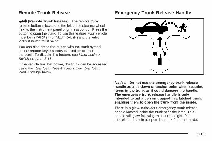
Remote Trunk Release
G (Remote Trunk Release): The remote trunkrelease button is located to the left of the steering wheelnext to the instrument panel brightness control. Press thebutton to open the trunk. To use this feature, your vehiclemust be in PARK (P) or NEUTRAL (N) and the valetlockout switch must be off.
You can also press the button with the trunk symbolon the remote keyless entry transmitter to openthe trunk. To disable this feature, see Valet LockoutSwitch on page 2-18.
If the vehicle has lost power, the trunk can be accessedusing the Rear Seat Pass-Through. See Rear SeatPass-Through below.
Emergency Trunk Release Handle
Notice: Do not use the emergency trunk releasehandle as a tie-down or anchor point when securingitems in the trunk as it could damage the handle.The emergency trunk release handle is onlyintended to aid a person trapped in a latched trunk,enabling them to open the trunk from the inside.
There is a glow-in-the-dark emergency trunk releasehandle located inside the trunk near the latch. Thishandle will glow following exposure to light. Pullthe release handle to open the trunk from the inside.
2-13

Rear Seat Pass-ThroughYour vehicle has a small door in the rear seat.This door allows you to access the trunk frominside the vehicle.
The rear seat armrest must be down for thepass-through door to open. To release the pass-throughdoor, move the release up with your fingers. To close thedoor, raise it and push it until it latches.
Windows
{CAUTION:
Leaving children, helpless adults, or pets in avehicle with the windows closed is dangerous.They can be overcome by the extreme heatand suffer permanent injuries or even deathfrom heat stroke. Never leave a child, ahelpless adult, or a pet alone in a vehicle,especially with the windows closed in warmor hot weather.
2-14

Power Windows
{CAUTION:
Leaving children, helpless adults, or pets in avehicle with the windows closed is dangerous.They can be overcome from extreme heat inwarm or hot weather and suffer permanentinjuries or even death from heat stroke.
Leaving children in a vehicle with the ignitionkey is dangerous for many reasons, childrenor others could be badly injured or even killed.They could operate the power windows orother controls or even make the vehicle move.The windows will function with the keys in theignition and they could be seriously injuredor killed if caught in the path of a closingwindow. Do not leave keys in a vehicle withchildren.
When there are children in the rear seatuse the window lockout button to preventunintentional operation of the windows.
The power windowswitches are located onthe driver’s door armrest.
In addition, each door has a switch for its own window.The front power window switch operates with twopositions for both up and down movement and the rearpower window switch operates with one position for upand two positions for down movement. Press the switchto the first position to lower the window to the desiredlevel. Pull the switch up to raise the window. Your vehiclehas Retained Accessory Power (RAP) that allows you touse the power windows once the ignition has been turnedoff. For more information, see Retained Accessory Power(RAP) on page 2-24.
2-15

Express-Down WindowThis feature is on all windows. Press the switch to thesecond position and release the switch to activate theexpress-down feature. To stop the window as it islowering, press down or pull up briefly on the switchagain.
Express-Up WindowThis feature is on the front windows. Pull the switchup to the second position and release the switchto activate the express-up feature. To stop the windowas it is raising, pull up or press down briefly on theswitch again.
Programming the Power WindowsIf the battery on your vehicle has been recharged,disconnected, or is not working, you will need toreprogram each front power window for the express-upfeature to work. Before reprogramming, you will needto replace or recharge your vehicle’s battery.
To program each front window, follow these steps:
1. With the ignition in ACC/ACCESSORY, ON/RUN, orwhen Retained Accessory Power (RAP) is active,close all doors.
2. Press and hold the power window switch until thewindow is fully open.
3. Pull the power window switch up until the window isfully closed.
4. Continue holding the switch up for approximatelytwo seconds after the window is completely closed.
The window is now reprogrammed. Repeat the processfor the other windows.
Express Window Anti-Pinch FeatureIf any object is in the path of the window when theexpress-up is active, the window will stop at theobstruction and auto-reverse to a preset factory position.Weather conditions such as severe icing may also causethe window to auto-reverse. The window will return tonormal operation once the obstruction or condition isremoved.
2-16

Express Window Anti-Pinch Override
{CAUTION:
If express override is activated, the windowwill not reverse automatically. You or otherscould be injured and the window could bedamaged. Before you use express override,make sure that all people and obstructions areclear of the window path.
In an emergency, the anti-pinch feature can beoverridden in a supervised mode. Hold the windowswitch all the way up to the second position. The windowwill rise for as long as the switch is held. Once theswitch is released, the express mode is re-activated.
In this mode, the window can still close on an object inits path. Use care when using the override mode.
Window Lockout
o (Window Lockout): The rear window lockout buttonis located on the driver’s door armrest near the windowswitches.
Press the right side of the button to disable the rearwindow controls. The light on the button will illuminate,indicating the feature is in use. The rear windows still canbe raised or lowered using the driver’s window switcheswhen the lockout feature is active.
To restore power to the rear windows, press the buttonagain. The light on the button will go out.
Sun VisorsSwing down the primary visor to block out glare. It canalso be detached from the center mount and moved tothe side while the auxiliary sunshade remains to blockthe glare from the front. The visors also have side-to-sideslide capability.
Lighted Visor Vanity MirrorPull the visor down and lift the cover to view the mirror.The light will come on when the cover is opened.It will go out when you close the cover. If your vehiclehas the adjustable lighting feature, slide the switch upor down to brighten or dim the light.
2-17

Rear Power SunshadeIf your vehicle has a rear power sunshade, it helps toreduce the amount of heat and light entering therear window.
The switch is located onthe overhead console.
The rear power sunshade is located in the rear shelf.It only works while the ignition is on or while theRetained Accessory Power (RAP) is active. SeeRetained Accessory Power (RAP) on page 2-24.
To raise the power sunshade, press and release theswitch. To close the power sunshade, press and releasethe switch again.
Never store objects on the rear shelf because they mayget caught in the sunshade or be tossed about inyour vehicle.
Theft-Deterrent SystemsVehicle theft is big business, especially in some cities.Although your vehicle has a number of theft-deterrentfeatures, we know that nothing we put on it can make itimpossible to steal.
Valet Lockout Switch
The valet lockout switchis located inside theglove box.
9 (Off): Press this side of the button to turn thelockout feature off. When the lockout feature is off,you can open the trunk using either the keyless entrytransmitter or the trunk release button located nearthe headlamp switch on the instrument panel.
2-18

— (On): Press this side of the button to turn the lockoutfeature on. When the lockout feature is turned on,the trunk cannot be unlocked with the keyless entrytransmitter or the trunk release button located nearthe headlamp switch on the instrument panel.
If the valet lockout feature is on it will also disable theUniversal Home Remote transmitter, if equipped.
Locking the glove box with your key will also help tosecure your vehicle.
See Remote Keyless Entry (RKE) System Operationon page 2-5 and Trunk on page 2-12 for additionalinformation.
Content Theft-Deterrent
The security light islocated on the instrumentpanel cluster.
If the ignition is off and any door is open, the securitylight will flash, reminding you to arm the system.
To arm the system:
1. Open the door.
2. Lock the door using the power door lock switch withthe door open or the Remote Keyless Entry (RKE)transmitter. The security light should come onand stay on.
3. Close all the doors. The security light should go offwithin approximately 30 seconds.
If a door or the trunk is opened without a key or a RKEtransmitter, the horn will sound and the lamps willflash for about 30 seconds.
The theft-deterrent system will not arm if you lockthe doors with a key or use the manual door lock.It activates only if you use a power door lock withthe door open or the RKE transmitter.
To avoid activating the alarm by accident:
• Lock the vehicle with the door key or the manualdoor lock after the doors are closed.
• Always unlock a door with a key or use the RKEtransmitter system. Pressing the unlock button on theRKE transmitter disables the theft-deterrent system.Unlocking a door any other way will activate thealarm when a door or the trunk is opened.
2-19
If you activate the alarm by accident, unlock the driver’sdoor with your key. You can also turn off the alarmby using the unlock button on the RKE transmittersystem, or by starting the car with a valid key.Changes or modifications made to this system byother than an authorized service facility could voidauthorization to use the theft system.
Testing the Alarm1. From inside the vehicle, roll down the window, then
get out of the vehicle, keeping the door open.2. From outside of the vehicle, with the door open,
lock the vehicle using the power door lock or theRKE system and close the door. Wait 30 secondsuntil the security lamp goes off.
3. Reach in and unlock the door using the manuallock and open the door. The horn will sound andthe hazard lights will flash.
You can turn off the alarm by unlocking the driver’sdoor with your key, using the unlock button on the RKEtransmitter or by starting the car with a valid key.If the alarm does not sound when it should, check tosee if the horn works. The horn fuse may be blown.To replace the fuse, see Fuses and Circuit Breakers onpage 5-97. If the fuse does not need to be replaced,you may need to have your vehicle serviced.To reduce the possibility of theft, always arm thetheft-deterrent system when leaving your vehicle.
PASS-Key® III+The PASS-Key® III+ system operates on a radiofrequency subject to Federal CommunicationsCommission (FCC) Rules and with Industry Canada.
This device complies with Part 15 of the FCC Rules.Operation is subject to the following two conditions:
1. This device may not cause harmful interference.
2. This device must accept any interference received,including interference that may cause undesiredoperation.
This device complies with RSS-210 of Industry Canada.Operation is subject to the following two conditions:
1. This device may not cause interference.
2. This device must accept any interference received,including interference that may cause undesiredoperation of the device.
Changes or modifications to this system by other thanan authorized service facility could void authorization touse this equipment.
PASS-Key® III+ uses a radio frequency transponder inthe key that matches a decoder in your vehicle.
2-20

PASS-Key® III+ OperationYour vehicle has PASS-Key® III+ (PersonalizedAutomotive Security System) theft-deterrent system.PASS-Key® III+ is a passive theft-deterrent system.
The system is automatically armed when the keyis removed from the ignition.
The system is automatically disarmed when the keyis turned to ON/RUN, ACC/ACCESSORY or STARTfrom the LOCK/OFF position.
You do not have to manually arm or disarm the system.
The security light will come on if there is a problemwith arming or disarming the theft-deterrent system.
When the PASS-Key® III+ system senses that someoneis using the wrong key, it prevents the vehicle fromstarting. Anyone using a trial-and-error method to startthe vehicle will be discouraged because of the highnumber of electrical key codes.
If the engine does not start and the security lightcomes on when trying to start the vehicle, theremay be a problem with your theft-deterrent system.Turn the ignition off and try again.
If the engine still does not start, and the key appearsto be undamaged, try another ignition key. At this time,you may also want to check the fuse, see Fusesand Circuit Breakers on page 5-97. If the engine stilldoes not start with the other key, your vehicle needsservice. If your vehicle does start, the first key maybe faulty. See your dealer/retailer who can servicethe PASS-Key® III+ to have a new key made.In an emergency, contact Roadside Assistance.
It is possible for the PASS-Key® III+ decoder to “learn”the transponder value of a new or replacement key. Up tonine additional keys may be programmed for the vehicle.The following procedure is for programming additionalkeys only. If all the currently programmed keys are lostor do not operate, you must see your dealer/retailer or alocksmith who can service PASS-Key® III+ to have keysmade and programmed to the system.
See your dealer/retailer or a locksmith who can servicePASS-Key® III+ to get a new key blank that is cutexactly as the ignition key that operates the system.
2-21

To program the new key:
1. Verify that the new key has a 1 stamped on it.
2. Insert the original, already programmed, key in theignition and start the engine. If the engine will notstart, see your dealer/retailer for service.
3. After the engine has started, turn the key toLOCK/OFF, and remove the key.
4. Insert the new key to be programmed and turnit to the ON/RUN position within five seconds ofremoving the original key.The security light will turn off once the key hasbeen programmed.
5. Repeat Steps 1 through 4 if additional keys are tobe programmed.
If you lose or damage your PASS-Key® III+ key, seeyour dealer/retailer or a locksmith who can servicePASS-Key® III+ to have a new key made.
Do not leave the key or device that disarms ordeactivates the theft deterrent system in the vehicle.
Starting and OperatingYour Vehicle
New Vehicle Break-InNotice: Your vehicle does not need an elaboratebreak-in. But it will perform better in the long run ifyou follow these guidelines:
• Do not drive at any one constant speed, fast orslow, for the first 500 miles (805 km). Do notmake full-throttle starts. Avoid downshiftingto brake or slow the vehicle.
• Avoid making hard stops for the first200 miles (322 km) or so. During this timethe new brake linings are not yet broken in.Hard stops with new linings can meanpremature wear and earlier replacement.Follow this breaking-in guideline everytime you get new brake linings.
• Do not tow a trailer during break-in.See Towing a Trailer on page 4-27 forthe trailer towing capabilities of yourvehicle and more information.
Following break-in, engine speed and load can begradually increased.
2-22

Ignition PositionsWith the ignition key in theignition, the key can beturned to four differentpositions:
In order to shift out of PARK (P), ignition must be in theON/RUN or ACC/ACCESSORY and the regular brakepedal must be applied.
Notice: Using a tool to force the key from theignition switch could cause damage or break thekey. Use the correct key and turn the key only withyour hand. Make sure the key is in all the way. Ifnone of this works, then your vehicle needs service.
A (LOCK/OFF): This is the only position in which theignition key can be inserted or removed. This positionlocks the ignition and transmission and steering column.It is a theft-deterrent feature.
If the steering wheel is locked, move it from right toleft and turn the key to ACC/ACCESSORY. If noneof this works, then your vehicle needs service.
B (ACC/ACCESSORY): This position lets the radioand windshield wipers operate while the engine is off.To use ACC/ACCESSORY, turn the key clockwise.
C (ON/RUN): This position is where the key returnsto after the vehicle is started. This position displayssome of the warning and indicator lights.
The battery could be drained if you leave the key inthe ACC/ACCESSORY or ON/RUN position with theengine off. You may not be able to start your vehicle if thebattery is allowed to drain for an extended period of time.
D (START): This position starts the engine.
A warning chime will sound and the Driver InformationCenter (DIC) will display DRIVER DOOR OPENwhen the driver’s door is opened if the ignition is inLOCK/OFF, ACC/ACCESSORY and the key is in theignition. See DIC Warnings and Messages on page 3-73for more information.
2-23
Key In the IgnitionNever leave your vehicle with the keys inside, as it is aneasy target for joy riders or thieves. If you leave the keyin the ignition and park your vehicle, a chime will sound,when you open the driver’s door. Always remember toremove your key from the ignition and take it with you.This will lock your ignition and transmission. Also, alwaysremember to lock the doors.
The battery could be drained if you leave the key in theignition while your vehicle is parked. You may not beable to start your vehicle after it has been parked foran extended period of time.
Retained Accessory Power (RAP)These vehicle accessories can be used for up to10 minutes after the ignition key is turned off:
• Audio System
• Audio Steering Wheel Controls
• Power Windows
• Sunroof
Power to these accessories will work up to 10 minutesor until the driver’s door is opened. For an additional10 minutes of power, close all the doors and turn the keyto ON/RUN and then back to LOCK/OFF.
Starting the EngineMove your shift lever to PARK (P) or NEUTRAL (N).Your engine will not start in any other position – thisis a safety feature. To restart when you are alreadymoving, use NEUTRAL (N) only.
Notice: Do not try to shift to PARK (P) if yourvehicle is moving. If you do, you could damage thetransmission. Shift to PARK (P) only when yourvehicle is stopped.
2-24

Starting Procedure1. With your foot off the accelerator pedal, turn the
ignition key to START. When the engine starts,let go of the key. The idle speed will go down asyour engine gets warm. Do not race the engineimmediately after starting it. Operate the engineand transmission gently to allow the oil to warmup and lubricate all moving parts.Your vehicle has a Computer-Controlled CrankingSystem. This feature assists in starting the engineand protects components. If the ignition key is turnedto the START position, and then released when theengine begins cranking, the engine will continuecranking for a few seconds or until the vehicle starts.If the engine does not start and the key is held inSTART for many seconds, cranking will be stoppedafter 15 seconds to prevent cranking motor damage.To prevent gear damage, this system also preventscranking if the engine is already running. Enginecranking can be stopped by turning the ignitionswitch to the ACC/ACCESSORY or LOCK/OFFposition.
Notice: Cranking the engine for long periods oftime, by returning the key to the START positionimmediately after cranking has ended, can overheatand damage the cranking motor, and drain thebattery. Wait at least 15 seconds between eachtry, to let the cranking motor cool down.
2. If the engine does not start after 5-10 seconds,especially in very cold weather (below 0°F or −18°C),it could be flooded with too much gasoline. Trypushing the accelerator pedal all the way to the floorand holding it there as you hold the key in STARTfor up to a maximum of 15 seconds. Wait at least15 seconds between each try, to allow the crankingmotor to cool down. When the engine starts, let go ofthe key and accelerator. If the vehicle starts brieflybut then stops again, do the same thing. This clearsthe extra gasoline from the engine. Do not race theengine immediately after starting it. Operate theengine and transmission gently until the oil warmsup and lubricates all moving parts.
Notice: The engine is designed to work with theelectronics in your vehicle. If you add electricalparts or accessories, you could change the way theengine operates. Before adding electrical equipment,check with your dealer/retailer. If you do not, yourengine might not perform properly. Any resultingdamage would not be covered by your vehicle’swarranty.
2-25

Engine Coolant HeaterThe engine coolant heater, if available, can help in coldweather conditions at or below 0°F (−18°C) for easierstarting and better fuel economy during engine warm-up.Plug in the coolant heater at least four hours beforestarting your vehicle.
To Use the Engine Coolant Heater1. Turn off the engine.
2. Open the hood and unwrap the electrical cord.The electrical cord is located on the driver’s sideof the engine, behind the transmission dipstick/fluidfill location and next to the engine.
3. Plug it into a normal, grounded 110-volt AC outlet.
{CAUTION:
Plugging the cord into an ungrounded outletcould cause an electrical shock. Also, thewrong kind of extension cord could overheatand cause a fire. You could be seriouslyinjured. Plug the cord into a properly groundedthree-prong 110-volt AC outlet. If the cord willnot reach, use a heavy-duty three-prongextension cord rated for at least 15 amps.
4. Before starting the engine, be sure to unplug andstore the cord as it was before to keep it awayfrom moving engine parts. If you do not, it couldbe damaged.
How long should you keep the coolant heater pluggedin? The answer depends on the outside temperature,the kind of oil you have, and some other things. Insteadof trying to list everything here, we ask that youcontact your dealer in the area where you will beparking your vehicle. The dealer/retailer can giveyou the best advice for that particular area.
2-26
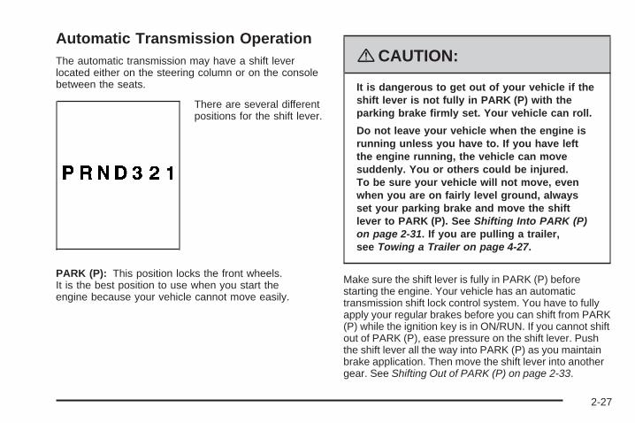
Automatic Transmission OperationThe automatic transmission may have a shift leverlocated either on the steering column or on the consolebetween the seats.
There are several differentpositions for the shift lever.
PARK (P): This position locks the front wheels.It is the best position to use when you start theengine because your vehicle cannot move easily.
{CAUTION:
It is dangerous to get out of your vehicle if theshift lever is not fully in PARK (P) with theparking brake firmly set. Your vehicle can roll.
Do not leave your vehicle when the engine isrunning unless you have to. If you have leftthe engine running, the vehicle can movesuddenly. You or others could be injured.To be sure your vehicle will not move, evenwhen you are on fairly level ground, alwaysset your parking brake and move the shiftlever to PARK (P). See Shifting Into PARK (P)on page 2-31. If you are pulling a trailer,see Towing a Trailer on page 4-27.
Make sure the shift lever is fully in PARK (P) beforestarting the engine. Your vehicle has an automatictransmission shift lock control system. You have to fullyapply your regular brakes before you can shift from PARK(P) while the ignition key is in ON/RUN. If you cannot shiftout of PARK (P), ease pressure on the shift lever. Pushthe shift lever all the way into PARK (P) as you maintainbrake application. Then move the shift lever into anothergear. See Shifting Out of PARK (P) on page 2-33.
2-27

REVERSE (R): Use this gear to back up.
Notice: Shifting to REVERSE (R) while your vehicleis moving forward could damage the transmission.The repairs would not be covered by your warranty.Shift to REVERSE (R) only after your vehicle isstopped.
Also use this gear to rock your vehicle back and forth toget out of snow, ice or sand without damaging yourtransmission. See If Your Vehicle is Stuck in Sand, Mud,Ice, or Snow on page 4-19 for additional information.
NEUTRAL (N): In this position, the engine does notconnect with the wheels. To restart when you arealready moving, use NEUTRAL (N) only. Also, useNEUTRAL (N) when your vehicle is being towed.
{CAUTION:
Shifting into a drive gear while the engine isrunning at high speed is dangerous. Unlessyour foot is firmly on the brake pedal, yourvehicle could move very rapidly. You couldlose control and hit people or objects. Do notshift into a drive gear while your engine isrunning at high speed.
Notice: Shifting out of PARK (P) or NEUTRAL (N)with the engine running at high speed may damagethe transmission. The repairs would not becovered by your warranty. Be sure the engine is notrunning at high speed when shifting your vehicle.
DRIVE (D): This position is for normal driving.It provides the best fuel economy for your vehicle.If you need more power for passing, and you are:
• Going less than 35 mph (55 km/h), push theaccelerator pedal about halfway down.
• Going about 35 mph (55 km/h) or more, push theaccelerator all the way down.The transmission will shift down to the next gearand have more power.
Downshifting the transmission in slippery road conditionscould result in skidding, see Skidding under Loss ofControl on page 4-10.
Notice: Driving your vehicle if you notice that it ismoving slowly or not shifting gears as you increasespeed may damage the transmission. Have yourvehicle serviced right away. You can drive inSECOND (2) when you are driving less than 35 mph(55 km/h) and DRIVE (D) for higher speeds until then.
2-28

DRIVE (D) can be used for towing. You may want toshift the transmission to THIRD (3) or, if necessary,to a lower gear if the transmission shifts too oftenunder heavy loads and/or hilly conditions.
See Towing a Trailer on page 4-27 for more information.
THIRD (3): This position is also used for normaldriving. However, it reduces vehicle speed more thanDRIVE (D) without using your brakes. You might chooseTHIRD (3) instead of DRIVE (D) when driving on hilly,winding roads, when towing a trailer, so there isless shifting between gears and when going downa steep hill.
SECOND (2): This position reduces vehicle speed morethan THIRD (3) without using your brakes. You canuse SECOND (2) on hills. It can help control your speedas you go down steep mountain roads, but then youwould also want to use your brakes off and on.
Notice: Do not shift into SECOND (2) unless youare going slower than 65 mph (105 km/h), or youcan damage your engine and/or transmission.
FIRST (1): This position reduces vehicle speed evenmore than SECOND (2) without using your brakes.You can use it on very steep hills, or in deep snow ormud. If the shift lever is put in FIRST (1) while thevehicle is moving forward, the transmission will not shiftinto first gear until the vehicle is going slowly enough.
Notice: Spinning the tires or holding the vehiclein one place on a hill using only the acceleratorpedal may damage the transmission. The repair willnot be covered by your warranty. If you are stuck,do not spin the tires. When stopping on a hill,use the brakes to hold the vehicle in place.
Performance ShiftingIf your vehicle has this feature, it can detect a changein driving patterns. If you make an aggressive drivingmaneuver, the vehicle’s transmission automaticallyshifts to the lowest possible gear to maximize vehicleperformance. The vehicle will automatically return tonormal operation when you return to normal drivingpatterns.
2-29
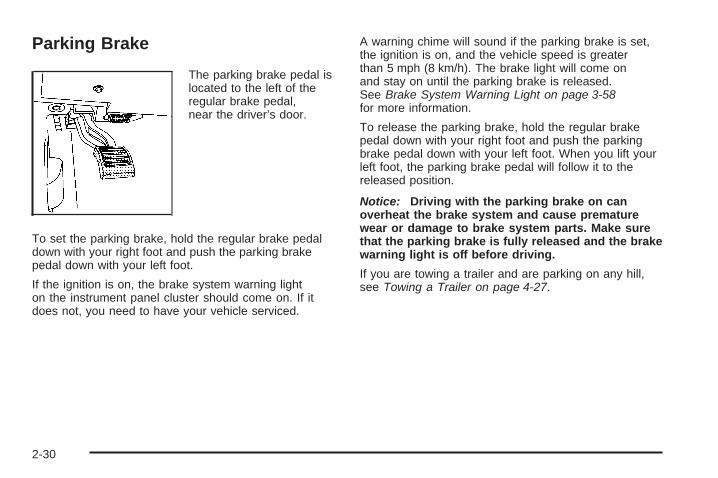
Parking Brake
The parking brake pedal islocated to the left of theregular brake pedal,near the driver’s door.
To set the parking brake, hold the regular brake pedaldown with your right foot and push the parking brakepedal down with your left foot.
If the ignition is on, the brake system warning lighton the instrument panel cluster should come on. If itdoes not, you need to have your vehicle serviced.
A warning chime will sound if the parking brake is set,the ignition is on, and the vehicle speed is greaterthan 5 mph (8 km/h). The brake light will come onand stay on until the parking brake is released.See Brake System Warning Light on page 3-58for more information.
To release the parking brake, hold the regular brakepedal down with your right foot and push the parkingbrake pedal down with your left foot. When you lift yourleft foot, the parking brake pedal will follow it to thereleased position.
Notice: Driving with the parking brake on canoverheat the brake system and cause prematurewear or damage to brake system parts. Make surethat the parking brake is fully released and the brakewarning light is off before driving.
If you are towing a trailer and are parking on any hill,see Towing a Trailer on page 4-27.
2-30

Shifting Into PARK (P)
{CAUTION:
It can be dangerous to get out of your vehicleif the shift lever is not fully in PARK (P) withthe parking brake firmly set. Your vehicle canroll. If you have left the engine running, thevehicle can move suddenly. You or otherscould be injured. To be sure your vehicle willnot move, even when you are on fairly levelground, use the steps that follow. If you arepulling a trailer, see Towing a Trailer onpage 4-27.
Steering Column Shift LeverIf your vehicle has a steering column shift lever, use thisprocedure to shift the vehicle into PARK (P):
1. Hold the brake pedal down with your right foot.
2. Move the shift lever into PARK (P) by pulling theshift lever toward you and moving it up as far as itwill go.
3. With your right foot still holding the brake pedaldown, set the parking brake. See Parking Brakeon page 2-30 for more information.
4. Turn the ignition key to LOCK/OFF.
5. Remove the key and take it with you. If you canleave your vehicle with the ignition key in yourhand, your vehicle is in PARK (P).
Console Shift LeverIf your vehicle is equipped with a console shift lever,use this procedure to shift the vehicle into PARK (P):
1. Hold the brake pedal down with your right foot.
2. Move the shift lever into PARK (P) by pushing thelever all the way toward the front of your vehicleand then to the left.
3. With your right foot still holding the brake pedaldown, set the parking brake. See Parking Brakeon page 2-30 for more information.
4. Turn the ignition key to LOCK/OFF.
5. Remove the key and take it with you. If you canleave your vehicle with the ignition key in yourhand, your vehicle is in PARK (P).
2-31
Leaving Your Vehicle With theEngine Running
{CAUTION:
It can be dangerous to leave your vehicle withthe engine running. Your vehicle could movesuddenly if the shift lever is not fully inPARK (P) with the parking brake firmly set.And, if you leave the vehicle with the enginerunning, it could overheat and even catch fire.You or others could be injured. Do not leaveyour vehicle with the engine running.
If you have to leave your vehicle with the enginerunning, be sure your vehicle is in PARK (P) andyour parking brake is firmly set before you leave it.See Parking Brake on page 2-30 for more information.
Torque LockIf you are parking on a hill and you do not shift yourtransmission into PARK (P) properly, the weight of thevehicle may put too much force on the parking pawlin the transmission. You may find it difficult to pull theshift lever out of PARK (P). This is called torque lock.To prevent torque lock, set the parking brake andthen shift into PARK (P) properly before you leave thedriver’s seat. To find out how, see Shifting Into PARK (P)on page 2-31.
If torque lock does occur, you may need to haveanother vehicle push yours a little uphill to take some ofthe pressure from the parking pawl in the transmission,so you can pull the shift lever out of PARK (P).
2-32

Shifting Out of PARK (P)
Automatic Transmission Shift LockThis vehicle has an electronic shift lock release system.The shift lock release is designed to:
• Prevent ignition key removal unless the shift lever isin PARK (P)
• Prevent movement of the shift lever out ofPARK (P), unless the ignition is in ON/RUN orACC/ACCESSORY and the regular brake pedalis applied.
The shift lock is always functional except in the case of aan uncharged or low voltage (less than 9 volt) battery.
If your vehicle has an uncharged battery or a batterywith low voltage, try charging or jump starting thebattery. See Jump Starting on page 5-40.
Console ShiftIf your console shift cannot be moved out of PARK (P)
1. Apply and maintain the regular brakes.
2. Turn the ignition to ON/RUN or ACC/ACCESSORYposition. See Ignition Positions on page 2-23 formore information.
3. Let up on the shift lever and make sure the shiftlever is pushed all the way into PARK (P).
4. Then, move the shift into the desired gear.
If you still cannot move the shift lever from PARK (P),consult your dealer/retailer or a professional towingservice.
Column ShiftIf your park lock cable cannot be moved out of PARK (P)
1. Apply and maintain the regular brakes.
2. Turn the ignition key to the ON/RUN or ACC/ACCESSORY position. See Ignition Positionson page 2-23 for more information.
3. Shift out of the PARK (P) position to theNEUTRAL (N) position.
4. Move the vehicle to a safe location.
If you still cannot move the shift lever from PARK (P),consult your dealer/retailer or a professional towingservice.
2-33
Parking Over Things That Burn
{CAUTION:
Things that can burn could touch hot exhaustparts under your vehicle and ignite. Do notpark over papers, leaves, dry grass, or otherthings that can burn.
Engine Exhaust
{CAUTION:
Engine exhaust can kill. It contains the gascarbon monoxide (CO), which you cannot see orsmell. It can cause unconsciousness and death.
You might have exhaust coming in if:• The exhaust system sounds strange or
different.• Your vehicle gets rusty underneath.• Your vehicle was damaged in a collision.• Your vehicle was damaged when driving
over high points on the road or over roaddebris.
• Repairs were not done correctly.• Your vehicle or the exhaust system has
been modified improperly.
If you ever suspect exhaust is coming into yourvehicle:
• Drive it only with all the windows down toblow out any CO; and
• Have your vehicle fixed immediately.
2-34
Running the Engine While ParkedIt is better not to park with the engine running. But if youever have to, here are some things to know.
{CAUTION:
Idling the engine with the climate controlsystem off could allow dangerous exhaust intoyour vehicle. See the earlier caution underEngine Exhaust on page 2-34.
Also, idling in a closed-in place can let deadlycarbon monoxide (CO) into your vehicle even ifthe climate control fan is at the highest setting.One place this can happen is a garage.Exhaust — with CO — can come in easily.NEVER park in a garage with the enginerunning.
Another closed-in place can be a blizzard.See Winter Driving on page 4-15.
{CAUTION:
It can be dangerous to get out of your vehicleif the shift lever is not fully in PARK (P) withthe parking brake firmly set. Your vehicle canroll. Do not leave your vehicle when the engineis running unless you have to. If you haveleft the engine running, the vehicle can movesuddenly. You or others could be injured.To be sure your vehicle will not move, evenwhen you are on fairly level ground, alwaysset the parking brake after you move the shiftlever to PARK (P).
Follow the proper steps to be sure your vehicle will notmove. See Shifting Into PARK (P) on page 2-31.
If you are parking on a hill and if you are pulling a trailer,also see Towing a Trailer on page 4-27.
2-35

Mirrors
Automatic Dimming Rearview Mirrorwith Intellibeam™, OnStar®, andCompassYour vehicle may have an automatic dimming rearviewmirror with OnStar® and a compass display. For moreinformation, see OnStar® System on page 2-53. For moreinformation on Intellibeam™, see “Intellibeam IntelligentHigh-Beam Headlamp Control System” under ExteriorLamps on page 3-30.
The mirror includes an eight-point compass display inthe upper right corner of the mirror face. When on,the compass automatically calibrates as the vehicleis driven.
Automatic DimmingYour vehicle is equipped with an automatic dimmingrearview mirror. The automatic dimming feature isactivated whenever the vehicle is turned on and dimsonly during nighttime driving.
Compass Operation
AUTO 3: Press and hold the “auto highbeam” buttonfor approximately three seconds to turn the compasson or off.
When the ignition and the compass feature are on,the compass will show two character boxes for abouttwo seconds. After two seconds, the mirror will displaythe compass heading.
Compass CalibrationIf after two seconds the display does not show thecorrect direction, (N for North for example), there maybe a strong magnetic field interfering with the compass.Such interference may be caused by a magneticantenna mount, magnetic note pad holder, or asimilar magnetic item.
The compass can be placed in calibration modemanually by pressing and holding the “auto highbeam”button for approximately nine seconds until a C isshown in the compass display.
The mirror can then be calibrated by driving the vehiclein circles at 5 mph (8 km/h) or less until the displayreads a direction.
2-36
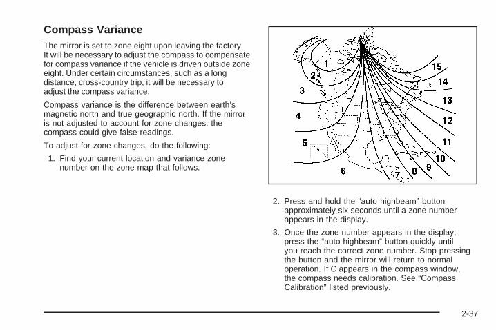
Compass VarianceThe mirror is set to zone eight upon leaving the factory.It will be necessary to adjust the compass to compensatefor compass variance if the vehicle is driven outside zoneeight. Under certain circumstances, such as a longdistance, cross-country trip, it will be necessary toadjust the compass variance.
Compass variance is the difference between earth’smagnetic north and true geographic north. If the mirroris not adjusted to account for zone changes, thecompass could give false readings.
To adjust for zone changes, do the following:
1. Find your current location and variance zonenumber on the zone map that follows.
2. Press and hold the “auto highbeam” buttonapproximately six seconds until a zone numberappears in the display.
3. Once the zone number appears in the display,press the “auto highbeam” button quickly untilyou reach the correct zone number. Stop pressingthe button and the mirror will return to normaloperation. If C appears in the compass window,the compass needs calibration. See “CompassCalibration” listed previously.
2-37

Cleaning the MirrorWhen cleaning the mirror, use a paper towel or similarmaterial dampened with glass cleaner. Do not sprayglass cleaner directly on the mirror as that may causethe liquid cleaner to enter the mirror housing.
Automatic Dimming Rearview Mirrorwith OnStar® and CompassYour vehicle may have an automatic dimming rearviewmirror with a compass display. The mirror also containsOnStar® controls. For more information see OnStar®
System on page 2-53.
The mirror includes an eight-point compass displayin the upper right corner of the mirror face. When on,the compass automatically calibrates as the vehicleis driven.
Mirror Operation
O (On/Off): Press and hold the button, located on thelower left side of the mirror face, for about three secondsto turn the automatic dimming feature on or off. Theindicator light will illuminate when this feature is active.The automatic dimming feature is active each time thevehicle is started.
Compass OperationPress the on/off button once to turn the compasson or off.
When the ignition and the compass feature are on,the compass will show two character boxes for abouttwo seconds. After two seconds, the mirror will displaythe compass heading.
Compass CalibrationIf after two seconds, the display does not show acompass heading (for example, N for North), there maybe a strong magnetic field interfering with the compass.Such interference may be caused by a magnetic antennamount, magnetic note pad holder or a similar magneticitem. If the letter C should ever appear in the compasswindow, the compass may need calibration.
The mirror can be calibrated by driving the vehicle incircles at 5 mph (8 km/h) or less until the display readsa direction.
The compass can be placed in calibration modemanually by pressing and holding the on/off buttonuntil a C is shown in the compass display.
2-38
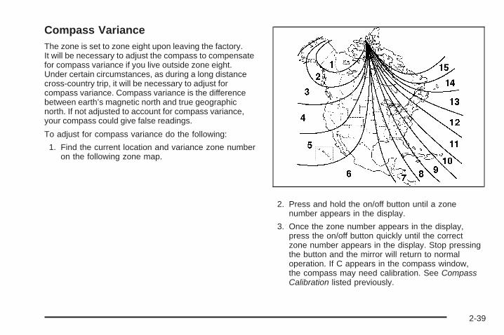
Compass VarianceThe zone is set to zone eight upon leaving the factory.It will be necessary to adjust the compass to compensatefor compass variance if you live outside zone eight.Under certain circumstances, as during a long distancecross-country trip, it will be necessary to adjust forcompass variance. Compass variance is the differencebetween earth’s magnetic north and true geographicnorth. If not adjusted to account for compass variance,your compass could give false readings.
To adjust for compass variance do the following:
1. Find the current location and variance zone numberon the following zone map.
2. Press and hold the on/off button until a zonenumber appears in the display.
3. Once the zone number appears in the display,press the on/off button quickly until the correctzone number appears in the display. Stop pressingthe button and the mirror will return to normaloperation. If C appears in the compass window,the compass may need calibration. See CompassCalibration listed previously.
2-39

Cleaning the MirrorWhen cleaning the mirror, use a paper towel or similarmaterial dampened with glass cleaner. Do not sprayglass cleaner directly on the mirror as that may causethe liquid cleaner to enter the mirror housing.
Automatic Dimming Rearview Mirrorwith CompassYour vehicle may have an automatic dimming rearviewmirror with a compass display.
The mirror includes an eight-point compass display inthe upper right corner of the mirror face. When on, thecompass automatically calibrates as the vehicle is driven.
Mirror Operation
O (On/Off): Press and hold the button, located on thelower left side of the mirror face, for about three secondsto turn the automatic dimming feature on or off. Theindicator light will illuminate when this feature is active.The automatic dimming feature is active each time thevehicle is started.
Compass OperationPress the on/off button once to turn the compasson or off.
When the ignition and the compass feature are on,the compass will show two character boxes for abouttwo seconds. After two seconds, the mirror will displaythe compass heading.
Compass CalibrationSee “Compass Calibration” under Automatic DimmingRearview Mirror with OnStar® and Compass onpage 2-38 for more information.
Compass VarianceSee “Compass Variance” under Automatic DimmingRearview Mirror with OnStar® and Compass onpage 2-38 for more information.
Cleaning the MirrorWhen cleaning the mirror, use a paper towel or similarmaterial dampened with glass cleaner. Do not sprayglass cleaner directly on the mirror as that may causethe liquid cleaner to enter the mirror housing.
2-40

Outside Power Foldaway Mirrors
Your vehicle’s mirrorcontrols are located onthe driver’s door armrest.
• Press (A) to select the driver’s side mirror. Thenpress the arrows located on the four-way controlpad to adjust the mirror.
• Press (B) to select the passenger’s side mirror.Then press the arrows located on the four-waycontrol pad to adjust the mirror.
If your vehicle has manual fold mirrors, the mirrors can bemanually folded inward to prevent damage when goingthrough an automatic car wash. To fold, push the mirrortoward the vehicle. To return the mirror to its originalposition, push outward. Be sure to return both mirrorsto their original unfolded position before driving.
If your vehicle has the power foldaway mirrors feature,do the following:
• Press (C) to unfold the mirrors.
• Press (D) to fold the mirrors.
If the mirrors are accidentally folded/unfolded manually,they may shake or flutter at normal driving speedsand may not stay in the unfolded position. If thishappens, you will need to reset the mirrors. See“Resetting the Power Foldaway Mirrors” next.
2-41

Resetting the Power Foldaway MirrorsYou will need to reset the power foldaway mirrors if thefollowing occurs:
• They are accidentally manually folded/unfolded.
• The mirrors will not stay in the unfolded position.
• The mirrors shake and flutter at normal drivingspeeds.
To reset the power foldaway mirrors, fold and unfoldthem three times using the mirror controls. This will resetthem to their normal position.
Outside Automatic Dimming MirrorIf your vehicle has this feature, the driver’s sidemirror will adjust for the glare of headlamps behind you.This feature is controlled by the on and off settingson the automatic dimming rearview mirror.
Park Tilt MirrorsIf your vehicle is equipped with memory mirrors, it willalso be capable of performing the park tilt mirror feature.This feature will allow the driver’s and passenger’sside mirror to tilt to a factory programmed position whenthe vehicle is in REVERSE (R). This feature may beuseful in allowing you to view the curb when youare parallel parking.
When the vehicle is shifted out of REVERSE (R) andeither a five-second delay has occurred, or the ignitionis turned to LOCK/OFF, the driver’s and passenger’sside mirror will return to its original position.
This feature can be enabled/disabled through theDriver Information Center (DIC). See DIC VehicleCustomization on page 3-86.
2-42
Outside Convex Mirror
{CAUTION:
A convex mirror can make things (like othervehicles) look farther away than they really are.If you cut too sharply into the right lane, youcould hit a vehicle on your right. Check yourinside mirror or glance over your shoulderbefore changing lanes.
The passenger side mirror is convex. A convex mirror’ssurface is curved so more can be seen from the driver’sseat. This mirror does not have a dimming feature.
Outside Heated MirrorsWhen the rear window defogger is turned on, it alsowarms both outside rearview mirrors to help clear themof fog or ice. See “Rear Window Defogger” underDual Climate Control System on page 3-40 for moreinformation.
Side Blind Zone Alert (SBZA)If your vehicle has the Side Blind Zone Alert (SBZA)system, see Side Blind Zone Alert on page 2-47.
2-43

Object Detection Systems
Ultrasonic Front and Rear ParkingAssist (UFRPA)If your vehicle has the Ultrasonic Front and Rear ParkingAssist (UFRPA) system, it helps you park easier andhelps you avoid colliding with objects such as parkedvehicles. It operates at speeds less than 5 mph (8 km/h).It can determine how close objects are to the frontbumper, up to 4 feet (1.2 m) in front of your vehicle andthe rear bumper, up to 8 feet (2.5 m) behind your vehicle.The distance sensors are located on the front and rearbumper.
{CAUTION:
The Ultrasonic Front and Rear ParkAssist (UFRPA) system does not replacedriver vision. It cannot detect:
• objects that are below the bumper,underneath the vehicle, or if they aretoo close or far from the vehicle
• children, pedestrians, bicyclists, or pets.
If you do not use proper care before movingforward and while backing; vehicle damage,injury, or death could occur. Even with UFRPA,always check in front of your vehicle beforemoving forward and behind your vehiclebefore backing up. While moving forward andbacking, be sure to look for objects and checkyour vehicle’s mirrors.
2-44

The front display is located on top of the instrumentpanel to the right of the driver. The front display will haveeither three or six lights to provide distance and systeminformation. With Adaptive Cruise control (ACC), it willhave three lights along with the ACC lights. Without ACC,it will have six lights. High-toned beeps from the frontspeakers are for objects detected near the front bumper.
The rear display is located near the rear windowand can be seen by looking over your right shoulder.The rear display uses three color-coded lights to providedistance and system information. Low-toned beepsfrom the rear speakers are for the rear bumper.
How the System WorksUFRPA comes on automatically when the shift lever ismoved out of PARK (P). The system does not work at aforward or reverse speed greater than 5 mph (8 km/h).
To be detected, objects must be at least 10 inches(25.4 cm) off the ground and below hood or trunk level.Objects must also be within 4 feet (1.2 m) in front of yourvehicle and 8 feet (2.5 m) from your rear bumper. Thisdistance may be less during warmer or humid weather.
When backing, if objects are detected at the same timenear both the front and rear bumpers, both color-codedlight displays will notify you of objects close to eachbumper. If there are objects detected near both bumpers,the beeps will only be sounded to notify that objects areclose to the rear bumper. However, if while you arebacking and an object comes within 1 ft (0.3 m) of thefront bumper, and at the same time there is anotherobject further than 1 ft (0.3 m) from the rear bumper,then the beeps will only be sounded to notify you ofthe closer object that is near the front bumper.
The system can be disabled using the Driver InformationCenter (DIC). See “Parking Assist” under DIC Operationand Displays on page 3-69 for more information.
Front Parking AssistDisplay
Rear Parking AssistDisplay
2-45

Moving ForwardWhen the vehicle is started, the front display will brieflyilluminate to let you know the system is working.
The following describes what will occur with the frontdisplay as you get closer to a object detected in the frontof your vehicle:
Description English Metricamber/amber lights
ACC — one amber light 4 ft 1.2 m
four amber lightsACC — two amber lights 40 in 1.0 m
four amber/ two red lightsACC — two amberlights/one red light
23 in 0.6 m
four amber/ two red lightsand beep for
three secondsACC — two amber
lights/one red light andbeep for three seconds
1 ft 0.3 m
BackingURPA comes on automatically when the shift leveris moved into REVERSE (R). The rear display willthen briefly illuminate to let you know the systemis working.
The following describes what will occur with the reardisplay as you get closer to an object detected inthe rear of your vehicle:
Description English Metricamber light 8 ft 2.5 m
amber/amber lights 40 in 1.0 mamber/amber/red lights 23 in 0.6 mamber/amber/red lightsflashing and beep for
three seconds1 ft 0.3 m
The system can be disabled through the DriverInformation Center (DIC). See “Parking Assist” underDIC Operation and Displays on page 3-69 for moreinformation.
2-46

When the System Does Not Seem toWork Properly• The driver disables the system.
• The parking brake pedal is depressed.
• The ultrasonic sensors are not kept clean. So besure to keep your vehicle’s front and rear bumpersfree of mud, dirt, snow, ice and slush. For cleaninginstructions, see Washing Your Vehicle onpage 5-90.
• A trailer was attached to your vehicle, or a bicycle oran object was hanging out of your trunk during yourlast drive cycle, the red light may illuminate in therear display. Once the attached object is removed,UFRPA will return to normal operation.
• A tow bar is attached to your vehicle.
• The vehicle’s bumper is damaged. Take the vehicleto your dealer/retailer to repair the system.
• Other conditions may affect system performance,such as vibrations from a jackhammer or thecompression of air brakes on a very large truck.
If the system is still disabled after driving forward atleast 15 mph (25 km/h), take your vehicle to yourdealer/retailer.
Side Blind Zone AlertYour vehicle may have a Side Blind Zone Alert (SBZA)system. Read this entire section before using the system.
{CAUTION:
The Side Blind Zone Alert (SBZA) systemdoes not detect vehicles outside the side blindzones, which may be rapidly approaching.SBZA is not designed to detect pedestrians,bicyclists, or animals. SBZA is only a lanechange aid. If you do not use proper carebefore changing lanes, vehicle damage, injury,or death could occur. Even with SBZA, alwayscheck your vehicle’s mirrors, glance over yourshoulder, and start your turn signal beforechanging lanes.
The SBZA system is an aid that may help youavoid lane change crashes with vehicles in yourside blind spots (zones). When the system detectsa vehicle in the side blind zone, amber SBZAdisplays will light up in your side mirrors.
2-47

This indicates that it may be unsafe for you to changelanes. Before making a lane change, always check theSBZA display, check the outside and rearview mirrors,look over your shoulder for vehicles and hazards, andstart the turn signal.
SBZA Detection ZonesThe SBZA sensor covers a zone of approximatelyone lane over from both sides of the vehicle,11 ft. or 3.5 m. This zone starts at each side mirrorand goes back approximately 16 ft. (5.0 m). The heightof the zone is approximately between 1.5 ft. (0.5 m)and 6 ft. (2.0 m) off the ground.
The SBZA detection zones do not change if yourvehicle is towing a trailer. So be extra careful whenchanging lanes while towing a trailer.
2-48
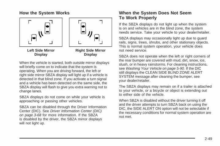
How the System Works
When the vehicle is started, both outside mirror displayswill briefly come on to indicate that the system isoperating. When you are driving forward, the left orright side mirror SBZA display will light up if a vehicle isdetected in that blind zone. If you activate a turn signaland a vehicle has been detected on the same side, theSBZA display will flash to give you extra warning not tochange lanes.
SBZA displays do not come on while your vehicle isapproaching or passing other vehicles.
SBZA can be disabled through the Driver InformationCenter (DIC). See Driver Information Center (DIC)on page 3-68 for more information. If the SBZAis disabled by the driver, the SBZA mirror displayswill not light up.
When the System Does Not SeemTo Work ProperlyIf the SBZA displays do not light up when the systemis on and vehicles are in the blind zone, the systemneeds service. Take your vehicle to your dealer/retailer.
SBZA displays may occasionally light up due to guardrails, signs, trees, shrubs, and other stationary objects.This is normal system operation, your vehicle doesnot need service.
SBZA does not operate when the left or right corners ofthe rear bumper are covered with mud, dirt, snow, ice,slush, or in heavy rainstorms. For cleaning instructions,see Washing Your Vehicle on page 5-90. If the DICstill displays the CLEAN SIDE BLIND ZONE ALERTSYSTEM message after cleaning the bumper, seeyour dealer/retailer.
The SBZA displays may remain on if a trailer is attachedto your vehicle, or a bicycle or object is extending outto either side of the vehicle.
When SBZA is disabled without the driver turning it offand the driver attempts to turn SBZA back on using theDIC, the SIDE ALERT ON option will not be selectable ifthe necessary conditions for normal system operation arenot met.
Left Side MirrorDisplay
Right Side MirrorDisplay
2-49

SBZA Error MessagesThe following messages may appear in the DIC:
SIDE BLIND ZONE ALERT SYSTEM OFF: Thismessage indicates that the driver has turned thesystem off.
CLEAN SIDE BLIND ZONE ALERT SYSTEM: Thismessage indicates that the SBZA system is disabledbecause the sensor is blocked and cannot detectvehicles in your blind zone. The sensor may be blockedby mud, dirt, snow, ice, slush, or even heavy rainstorms.This message may also activate during heavy rain ordue to road spray. Your vehicle does not need service.For cleaning, see Washing Your Vehicle on page 5-90.
SERVICE SIDE BLIND ZONE ALERT SYSTEM: If thismessage appears, both SBZA displays will remain onindicating there is a problem with the SBZA system.If these displays remain on after continued driving,the system needs service. Take your vehicle to yourdealer/retailer.
Lane Departure WarningYour vehicle may have a Lane Departure Warning (LDW)system. Read this entire section before using the system.
{CAUTION:
The Lane Departure Warning (LDW) systemdoes not steer the vehicle and is only an aid tohelp you stay in your driving lane. The LDWsystem may not:
• Provide you with enough time to avoid alane change collision.
• Be loud enough for you to hear thewarning beeps.
• Work properly under bad weatherconditions or if the windshield is notkept clean.
• Detect lane markings and will not detectroad edges.
• Warn you that your vehicle is crossing alane marking if the system does not detectthe lane marking.
CAUTION: (Continued)
2-50

CAUTION: (Continued)
LDW will indicate the system is workingwhenever it detects either the left or right lanemarking. So if you depart on the side of thelane that LDW is not detecting, LDW will notwarn you.
If you do not carefully maintain your vehicleposition within the lane, vehicle damage, injury,or death could occur. Even with LDW, alwayskeep your attention on the road and maintainproper vehicle position within the lane. Alwayskeep the windshield clean and do not use LDWin bad weather conditions.
When you cross a detected lane marking, the LDWsymbol will flash and you will hear three beeps.LDW will not warn you if your turn signal is on or if youmake a sharp maneuver. Before making a lane change,check your vehicle’s mirrors, glance over your shoulderfor vehicles and hazards, and start your turn signal beforechanging lanes.
How the System WorksLDW uses a camera located between the inside rearviewmirror and the windshield to detect the lane markings.
@ (Lane Departure Warning): To turn LDW on and off,press the LDW control, located by the exteriorheadlamp control. An indicator on the control will light toindicate that LDW is on.
When the vehicle isstarted, the LDW symbol,located in the instrumentpanel cluster, willbriefly come on to indicatethat the light is operational.
LDW only operates at speeds of 35 mph (56 km) orgreater. If LDW is turned on when traveling at thesespeeds, the LDW symbol will appear green if the systemdetects a left or right lane marking. This symbol willchange to amber and flash and three beeps will soundif you cross a detected lane marking without using yourturn signal.
2-51

If the LDW symbol does not appear, LDW is notcurrently operating and will not warn you.
If you would like to change the volume of the warningchime, see Chime Volume under DIC VehicleCustomization on page 3-86 for more information.
When the System Does Not SeemTo Work ProperlyThe LDW symbol will not appear when the system ishaving difficulty seeing the lines on the road or if the viewof the camera on the windshield is blocked with mud, dirt,snow, ice, or slush, if the windshield is damaged, or whenweather limits visibility, such as while driving in fog, rain,or snow conditions. This is normal operation, your vehicledoes not need service. For cleaning instructions,see Washing Your Vehicle on page 5-90.
LDW warnings may occasionally occur due to tarmarks, shadows, cracks in the road, or other roadimperfections. This is normal system operation, yourvehicle does not need service.
LDW Error Message
SERVICE LANE DEPARTURE SYSTEM: Thismessage may appear in the DIC to indicate that LDW isnot working properly. If this message remains on aftercontinued driving, the system needs service. Take yourvehicle to your dealer/retailer. See DIC Warnings andMessages on page 3-73 for more information.
LANE DEPARTURE SYSTEM UNAVAILABLE:This message may appear in the DIC if LDWdoes not activate due to a temporary condition.See DIC Warnings and Messages on page 3-73 formore information.
2-52

OnStar® System
OnStar uses several innovative technologies and liveadvisors to provide you with a wide range of safety,security, information, and convenience services. If yourairbags deploy, the system is designed to make anautomatic call to OnStar Emergency advisors who canrequest emergency services be sent to your location.If you lock your keys in the vehicle, call OnStar at1-888-4-ONSTAR and they can send a signal to unlockyour doors. If you need roadside assistance, pressthe OnStar button and they can contact RoadsideService for you.
OnStar service is provided to you subject to theOnStar Terms and Conditions. You may cancel yourOnStar service at any time by contacting OnStar.A complete OnStar Owner’s Guide and the OnStarTerms and Conditions are included in the vehicle’sOnStar Subscriber glove box literature. For moreinformation, visit onstar.com or onstar.ca, contactOnStar at 1-888-4-ONSTAR (1-888-466-7827) orTTY 1-877-248-2080, or press the OnStar buttonto speak with an OnStar advisor 24 hours a day,7 days a week.
Not all OnStar features are available on all vehicles.To check if your vehicle is equipped to provide theservices described below, or for a full description ofOnStar services and system limitations, see the OnStarOwner’s Guide in your glove box or visit onstar.com.
OnStar ServicesFor new vehicles with OnStar, the Safe & Sound Plan,or the Directions & Connections Plan is included forone year from the date of purchase. You can extendthis plan beyond the first year, or upgrade to theDirections & Connections Plan. For more information,press the OnStar button to speak with an advisor. SomeOnStar services (such as Remote Door Unlock or StolenVehicle Location Assistance) may not be available untilyou register with OnStar.
2-53
Available Services with Safe & Sound Plan• Automatic Notification of Airbag Deployment
• Advanced Automatic Crash Notification (AACN)(If equipped)
• Link to Emergency Services
• Roadside Assistance
• Stolen Vehicle Location Assistance
• AccidentAssist
• Remote Door Unlock/Vehicle Alert
• OnStar Vehicle Diagnostics
• GM Goodwrench® On Demand Diagnostics
• OnStar Hands-Free Calling with30 complimentary minutes
• OnStar Virtual Advisor (U.S. Only)
Available Services included withDirections & Connections Plan• All Safe and Sound Plan Services
• Driving Directions - Advisor delivered or OnStarTurn-by-Turn Navigation (If equipped)
• RideAssist
• Information and Convenience Services
OnStar Hands-Free CallingOnStar Hands-Free Calling allows eligible OnStarsubscribers to make and receive calls using voicecommands. Hands-Free Calling is fully integrated intothe vehicle, and can be used with OnStar Pre-PaidMinute Packages. Hands-Free Calling may also be linkedto a Verizon Wireless service plan in the U.S. or a BellMobility service plan in Canada, depending on eligibility.To find out more, refer to the OnStar Owner’s Guidein the vehicle’s glove box, visit www.onstar.com orwww.onstar.ca, or speak with an OnStar advisor bypressing the OnStar button or calling 1-888-4-ONSTAR(1-888-466-7827).
OnStar Virtual AdvisorOnStar Virtual Advisor is a feature of OnStar Hands-FreeCalling that uses your minutes to access location-basedweather, local traffic reports, and stock quotes. Bypressing the phone button and giving a few simple voicecommands, you can browse through the various topics.See the OnStar Owner’s Guide for more information(Only available in the continental U.S.).
2-54

OnStar Steering Wheel ControlsYour vehicle may have a Talk/Mute button that canbe used to interact with OnStar Hands-Free Calling.See Audio Steering Wheel Controls on page 3-117 formore information.
On some vehicles, you may have to hold the button fora few seconds and give the command “ONSTAR” toactivate the OnStar Hands-Free Calling.
On some vehicles, the mute button can be used todial numbers into voicemail systems, or to dial phoneextensions. See the OnStar Owner’s Guide formore information.
How OnStar Service WorksYour vehicle’s OnStar system has the capabilityof recording and transmitting vehicle information.This information is automatically sent to an OnStar CallCenter at the time of an OnStar button press, Emergencybutton press or if your airbags or AACN system deploys.The vehicle information usually includes your GPSlocation and, in the event of a crash, additionalinformation regarding the accident that your vehiclehas been involved in (e.g. the direction from which yourvehicle was hit). When you use the Virtual Advisor featureof OnStar Hands-Free Calling, your vehicle also sendsOnStar your GPS location so that we can provide youwith location-based services.
OnStar service cannot work unless your vehicle is in aplace where OnStar has an agreement with a wirelessservice provider for service in that area. OnStar servicealso cannot work unless you are in a place where thewireless service provider OnStar has hired for that areahas coverage, network capacity and reception when theservice is needed, and technology that is compatiblewith the OnStar service. Not all services are availableeverywhere, particularly in remote or enclosed areas,or at all times.Location information about your vehicle is only available ifthe GPS satellite signals are unobstructed and available.Your vehicle must have a working electrical system(including adequate battery power) for the OnStarequipment to operate. There are other problems OnStarcannot control that may prevent OnStar from providingOnStar service to you at any particular time or place.Some examples are damage to important parts of yourvehicle in an accident, hills, tall buildings, tunnels,weather or wireless phone network congestion.
Your ResponsibilityIncrease the radio volume if you cannot hear the OnStaradvisor. If the light next to the OnStar buttons is red,this means that your system is not functioning properlyand should be checked by your dealer/retailer. If thelight appears clear (no light is appearing), your OnStarsubscription has expired. You can always press theOnStar button to confirm that your OnStar equipmentis active.
2-55

Universal Home RemoteSystemThe Universal Home Remote System provides a way toreplace up to three hand-held Radio-Frequency (RF)transmitters used to activate devices such as garagedoor openers, security systems, and home lighting.
This device complies with Part 15 of the FCC Rules.Operation is subject to the following two conditions:
1. This device may not cause harmful interference.
2. This device must accept any interference received,including interference that may cause undesiredoperation.
This device complies with RSS-210 of Industry Canada.Operation is subject to the following two conditions:
1. This device may not cause interference.
2. This device must accept any interference received,including interference that may cause undesiredoperation of the device.
Changes or modifications to this system by other thanan authorized service facility could void authorization touse this equipment.
Universal Home Remote SystemOperation (With Three Round LED)
Your vehicle may have the Universal Home RemoteSystem. If there are three round Light EmittingDiode (LED) indicator lights above the UniversalHome Remote buttons, follow the instructions below.
This system provides a way to replace up to threeremote control transmitters used to activate devicessuch as garage door openers, security systems,and home automation devices.
Do not use this system with any garage door openerthat does not have the stop and reverse feature.This includes any garage door opener modelmanufactured before April 1, 1982.
Read the instructions completely before attempting toprogram the transmitter. Because of the steps involved,it may be helpful to have another person available toassist you in programming the transmitter.
2-56

Be sure to keep the original remote control transmitter foruse in other vehicles, as well as, for future programming.You only need the original remote control transmitter forFixed Code programming. It is also recommended thatupon the sale or lease termination of the vehicle, theprogrammed buttons should be erased for securitypurposes. See “Erasing Universal Home RemoteButtons” later in this section.
When programming a garage door, it is advised topark outside of the garage. Be sure that peopleand objects are clear of the garage door or securitydevice you are programming.
Programming Universal HomeRemote — Rolling CodeIf you have questions or need help programming theUniversal Home Remote System, call 1-866-572-2728or go to www.learcar2u.com.
Most garage door openers sold after 1996 are RollingCode units.
Programming a garage door opener involvestime-sensitive actions, so read the entire procedurebefore you begin. If you do not follow these actions,the device will time out and you will have to repeat theprocedure.
To program up to three devices:
1. From inside the vehicle, press the two outsidebuttons at the same time for one to two seconds,and immediately release them.
2-57
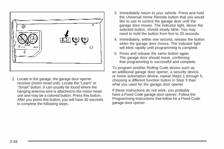
2. Locate in the garage, the garage door openerreceiver (motor-head unit). Locate the “Learn” or“Smart” button. It can usually be found where thehanging antenna wire is attached to the motor-headunit and may be a colored button. Press this button.After you press this button, you will have 30 secondsto complete the following steps.
3. Immediately return to your vehicle. Press and holdthe Universal Home Remote button that you wouldlike to use to control the garage door until thegarage door moves. The indicator light, above theselected button, should slowly blink. You mayneed to hold the button from five to 20 seconds.
4. Immediately, within one second, release the buttonwhen the garage door moves. The indicator lightwill blink rapidly until programming is complete.
5. Press and release the same button again.The garage door should move, confirmingthat programming is successful and complete.
To program another Rolling Code device such asan additional garage door opener, a security device,or home automation device, repeat Steps 1 through 5,choosing a different function button in Step 3 thanwhat you used for the garage door opener.
If these instructions do not work, you probablyhave a Fixed Code garage door opener. Follow theProgramming instructions that follow for a Fixed Codegarage door opener.
2-58

Programming Universal HomeRemote — Fixed CodeIf you have questions or need help programming theUniversal Home Remote System, call 1-866-572-2728or go to www.learcar2u.com.
Most garage door openers sold before 1996 areFixed Code units.
Programming a garage door opener involvestime-sensitive actions, so read the entire procedurebefore you begin. If you do not follow these actions,the device will time out and you will have to repeatthe procedure.
To program up to three devices:
1. To verify if you have a Fixed Code garage dooropener, remove the battery cover on your handheld transmitter supplied by the manufacturerof your garage door opener motor. If you see arow of dip switches similar to the graphic above,you have a Fixed Code garage door opener.If you do not see a row of dip switches, return tothe previous section for Programming UniversalHome Remote – Rolling Code.Your hand held transmitter may have betweeneight to 12 dip switches depending on the brandof transmitter.
2-59
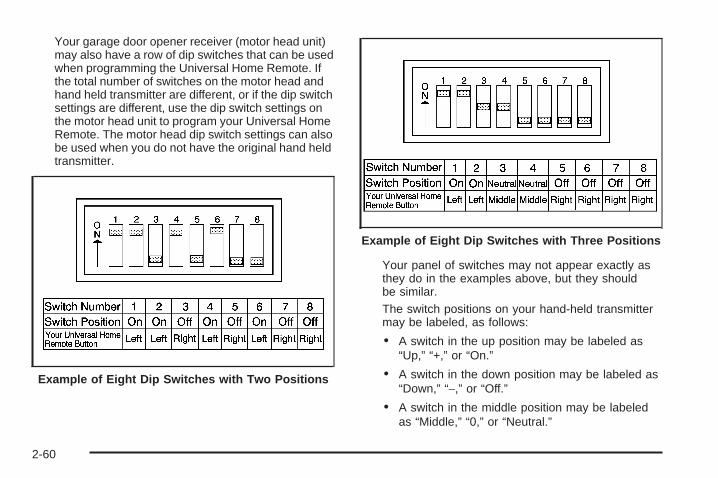
Your garage door opener receiver (motor head unit)may also have a row of dip switches that can be usedwhen programming the Universal Home Remote. Ifthe total number of switches on the motor head andhand held transmitter are different, or if the dip switchsettings are different, use the dip switch settings onthe motor head unit to program your Universal HomeRemote. The motor head dip switch settings can alsobe used when you do not have the original hand heldtransmitter.
Your panel of switches may not appear exactly asthey do in the examples above, but they shouldbe similar.The switch positions on your hand-held transmittermay be labeled, as follows:
• A switch in the up position may be labeled as“Up,” “+,” or “On.”
• A switch in the down position may be labeled as“Down,” “−,” or “Off.”
• A switch in the middle position may be labeledas “Middle,” “0,” or “Neutral.”
Example of Eight Dip Switches with Two Positions
Example of Eight Dip Switches with Three Positions
2-60

2. Write down the eight to 12 switch settings from leftto right as follows:
• When a switch is in the up position, write “Left.”
• When a switch is in the down position,write “Right.”
• If a switch is set between the up and downposition, write “Middle.”The switch settings that you wrote down inStep 2 will now become the button strokes youenter into the Universal Home Remote in Step 4.Be sure to enter the switch settings that you wrotedown in Step 2, in order from left to right, intothe Universal Home Remote, when completingStep 4.
3. From inside your vehicle, first firmly press all threebuttons at the same time for about three seconds.Release the buttons to put the Universal HomeRemote into programming mode.
4. The indicator lights will blink slowly. Enter eachswitch setting from Step 2 into your vehicle’sUniversal Home Remote. You will have two andone-half minutes to complete Step 4. Now pressone button on the Universal Home Remote foreach switch setting as follows:
• If you wrote “Left,” press the left button in thevehicle.
• If you wrote “Right,” press the right button in thevehicle.
• If you wrote “Middle,” press the middle button inthe vehicle.
2-61
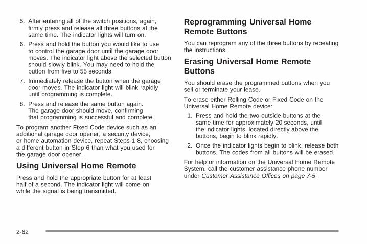
5. After entering all of the switch positions, again,firmly press and release all three buttons at thesame time. The indicator lights will turn on.
6. Press and hold the button you would like to useto control the garage door until the garage doormoves. The indicator light above the selected buttonshould slowly blink. You may need to hold thebutton from five to 55 seconds.
7. Immediately release the button when the garagedoor moves. The indicator light will blink rapidlyuntil programming is complete.
8. Press and release the same button again.The garage door should move, confirmingthat programming is successful and complete.
To program another Fixed Code device such as anadditional garage door opener, a security device,or home automation device, repeat Steps 1-8, choosinga different button in Step 6 than what you used forthe garage door opener.
Using Universal Home RemotePress and hold the appropriate button for at leasthalf of a second. The indicator light will come onwhile the signal is being transmitted.
Reprogramming Universal HomeRemote ButtonsYou can reprogram any of the three buttons by repeatingthe instructions.
Erasing Universal Home RemoteButtonsYou should erase the programmed buttons when yousell or terminate your lease.
To erase either Rolling Code or Fixed Code on theUniversal Home Remote device:
1. Press and hold the two outside buttons at thesame time for approximately 20 seconds, untilthe indicator lights, located directly above thebuttons, begin to blink rapidly.
2. Once the indicator lights begin to blink, release bothbuttons. The codes from all buttons will be erased.
For help or information on the Universal Home RemoteSystem, call the customer assistance phone numberunder Customer Assistance Offices on page 7-5.
2-62

Storage Areas
Glove BoxTo open, lift the handle up. Use the key to lock andunlock.
Cupholder(s)There are cupholders located in the full floor console, orin the front of the center seat console. Cupholders arealso located in the rear armrest. To access the full floorconsole cupholder slide the cover back. To access thecenter seat console cupholder, fold open the front of theconsole.
Coinholder(s)Your vehicle may be equipped with a coinholder.
Front Storage AreaYour vehicle has a removable front storage bin. To open,push down then release to reveal the front bin andaccessory outlet. To remove, push up and forward toloosen, then pull the bin out. If your vehicle has a centerflex storage unit, pull the handle rearward to open thefront bin and accessory power outlet. To remove, pullthe bin out.
Center Console Storage
If your vehicle has a full floor console it has two storageareas. To access the upper tray storage, lift the leftlever located in the front of the armrest lid. To accessthe lower storage area, lift the right lever. If your vehiclehas a center seat console it will have two storage areas.To access the upper storage area, press the buttonlocated on the front of the armrest and lift the armrest lid.To access the lower storage area, pull the strap locatedbehind the cup holder.
2-63

Center Flex Storage UnitYour vehicle may have a center flex storage unit thatincludes a front center seat with a lap belt and anunderseat storage compartment. The center seatbackcan also be used as a fold down armrest. Cupholdersare also located at the front edge of the storage unit andcan be accessed by folding the compartment forward.
When not being used, the center seat lap belt canbe stored in the underseat storage compartment.
Floor MatsThe floor mat is designed to remain in position underyour feet and out of reach of the accelerator pedal.The driver side floor mat is held in place by two locatorhooks.
Make sure that the driver side floor mat is properlyplaced on the floor so that it does not block themovement of the accelerator pedal.
To remove the floor mat, pull up on the rear of the matto disconnect it from the locator hooks.
To reinstall the floor mat, line up the openings in thefloor mat over the locator hooks and push it downinto place.
Rear Seat ArmrestYour vehicle may be equipped with a rear seat centerconsole and armrest. To open the console, pushthe button and lift the lid. Inside the console aretwo cupholders that can be pulled out when in use.
Convenience NetYour vehicle may have a convenience net in the rear ofthe vehicle. Put small loads behind the net. The netis not for heavier loads. Store them as far forwardas you can.
2-64

SunroofThe vehicle may have a power sunroof.
The switches that operatethe sunroof are located onthe overhead console.
To open or close the sunroof, the ignition must be turnedto ON/RUN or Retained Accessory Power (RAP) mustbe active. See Retained Accessory Power (RAP) onpage 2-24.
Express Open: The express open feature will operatefrom the closed or partially open position. To expressopen the power sunroof, fully press the driver’s sideswitch rearward once. To stop the sunroof glass in adesired position other than to the express-open position,press the switch again, in either direction, to stop themovement. If the sunshade is in the closed position, itwill open with the sunroof, or it can be opened manually.
Vent Open: From the closed position, press and holdthe passenger’s side switch forward to vent the sunroof.The rear of the sunroof panel will tilt upward to thefull vent position. The sunshade must be openedmanually.
Close: To close the sunroof, operate the controlsaccording to one of the following:
• From the open position, press and hold the driver’sside sunroof switch forward. The sunshade must beclosed manually.
• From the vent position, press and hold thepassenger’s side sunroof switch rearward.
2-65

✍ NOTES
2-66

Instrument Panel Overview ...............................3-4Hazard Warning Flashers ................................3-6Other Warning Devices ...................................3-6Horn .............................................................3-6Tilt Wheel .....................................................3-6Power Tilt Wheel and Telescopic
Steering Column .........................................3-7Heated Steering Wheel ...................................3-7Turn Signal/Multifunction Lever .........................3-8Turn and Lane-Change Signals ........................3-8Headlamp High/Low-Beam Changer ..................3-9Forward Collision Alert (FCA) System ................3-9Flash-to-Pass ...............................................3-13Windshield Wipers ........................................3-13Rainsense™ II Wipers ...................................3-14Windshield Washer .......................................3-15Cruise Control ..............................................3-16Adaptive Cruise Control .................................3-19Exterior Lamps .............................................3-30Wiper Activated Headlamps ............................3-33Headlamps on Reminder ................................3-33Daytime Running Lamps (DRL) .......................3-33
Fog Lamps ..................................................3-34Cornering Lamps ..........................................3-35Exterior Lighting Battery Saver ........................3-35Instrument Panel Brightness ...........................3-35Courtesy Lamps ...........................................3-35Entry Lighting ...............................................3-36Parade Dimming ...........................................3-36Reading Lamps ............................................3-36Footwell Lamps ............................................3-36Battery Load Management .............................3-37Electric Power Management ...........................3-37Inadvertent Power Battery Saver .....................3-38Battery Run-Down Protection ..........................3-38Accessory Power Outlet(s) .............................3-38Ashtray(s) ....................................................3-39Analog Clock ...............................................3-40
Climate Controls ............................................3-40Dual Climate Control System ..........................3-40Outlet Adjustment .........................................3-46Rear Climate Control System .........................3-47Passenger Compartment Air Filter ...................3-48
Section 3 Instrument Panel
3-1

Warning Lights, Gages, and Indicators ............3-51Instrument Panel Cluster ................................3-52Speedometer and Odometer ...........................3-53Tachometer .................................................3-53Safety Belt Reminders ...................................3-54Airbag Readiness Light ..................................3-55Passenger Airbag Status Indicator ...................3-56Charging System Light ..................................3-58Brake System Warning Light ..........................3-58Antilock Brake System Warning Light ...............3-59Traction Control System (TCS) Warning Light ......3-60StabiliTrak® Indicator Light ..............................3-60Lane Departure Warning Light ........................3-61Engine Coolant Temperature Warning Light ........3-61Engine Coolant Temperature Gage ...................3-62Tire Pressure Light .......................................3-62Malfunction Indicator Lamp .............................3-63Oil Pressure Light .........................................3-66Security Light ...............................................3-66Fog Lamp Light ............................................3-66
Lights On Reminder ......................................3-67Cruise Control Light ......................................3-67Highbeam On Light .......................................3-67Fuel Gage ...................................................3-68
Driver Information Center (DIC) .......................3-68DIC Operation and Displays ...........................3-69DIC Warnings and Messages .........................3-73DIC Vehicle Customization .............................3-86
Audio System(s) .............................................3-95Setting the Time ...........................................3-96Radio(s) (MP3) ...........................................3-100Using an MP3 ............................................3-110XM Radio Messages ...................................3-115Navigation/Radio System ..............................3-116Theft-Deterrent Feature ................................3-116Audio Steering Wheel Controls ......................3-117Radio Reception .........................................3-118Backglass Antenna ......................................3-119XM™ Satellite Radio Antenna System ............3-119
Section 3 Instrument Panel
3-2

✍ NOTES
3-3

Instrument Panel Overview
Console-Shift Model shown, Column-Shift Model similar
3-4

The main components of the instrument panel are the following:
A. Air Outlets. See Outlet Adjustment on page 3-46.B. Driver Information Center (DIC) Buttons.
See Driver Information Center (DIC) on page 3-68.C. Exterior Lamp Controls. See Exterior Lamps
on page 3-30.D. Instrument Panel Cluster. See Instrument Panel
Cluster on page 3-52.E. Horn. See Horn on page 3-6.F. Audio Steering Wheel Controls. See Audio Steering
Wheel Controls on page 3-117.G. Ultrasonic Front and Rear Parking Assist and
Adaptive Cruise Control Display (If Equipped).See Ultrasonic Front and Rear Parking Assist(UFRPA) on page 2-44 and Adaptive Cruise Controlon page 3-19.
H. Analog Clock. See Analog Clock on page 3-40.I. Hazard Warning Flashers Button. See Hazard
Warning Flashers on page 3-6.J. Radio. See Audio System(s) on page 3-95.K. Trunk Release Button. See Trunk on page 2-12.L. Instrument Panel Brightness Control. See Instrument
Panel Brightness on page 3-35.M. Lane Departure Warning. See Lane Departure
Warning on page 2-50.
N. Turn Signal/Multifunction Lever. See TurnSignal/Multifunction Lever on page 3-8.
O. Hood Release. See Hood Release on page 5-11.P. Parking Brake. See Parking Brake on page 2-30.Q. Heated Steering Wheel Button (If Equipped).
See Heated Steering Wheel on page 3-7.R. Cruise Control or Adaptive Cruise Control.
See Cruise Control on page 3-16 or AdaptiveCruise Control on page 3-19.
S. Tilt Wheel. See Tilt Wheel on page 3-6. PowerTilt and Telescopic Steering Wheel (If Equipped).See Power Tilt Wheel and Telescopic SteeringColumn on page 3-7.
T. Climate Controls. See Dual Climate ControlSystem on page 3-40.
U. Traction Control System Button (Console-ShiftVehicles). See Traction Control System (TCS)on page 4-5.
V. Shift Lever. See Automatic Transmission Operationon page 2-27.
W. Accessory Power Outlet. See Accessory PowerOutlet(s) on page 3-38.
X. Glove Box. See Glove Box on page 2-63.Valet Lockout Switch. See Valet Lockout Switchon page 2-18.
3-5

Hazard Warning FlashersThe hazard warning flashers let you warn the policeand others that you have a problem. The front andrear turn signal lamps will flash on and off.
The hazard warningflasher button is locatedtowards the center ofthe instrument panel.
Press the button to make the front and rear turn signallamps flash on and off. Press the button again toturn the flashers off.
While the hazard warning flashers are on, the turnsignals do not work.
The hazard warning flashers work no matter whatposition the key is in, and even if the key is not inthe ignition switch.
Other Warning DevicesIf you carry reflective triangles, you can set them upat the side of the road about 300 feet (100 m) behindyour vehicle.
HornPress near or on the horn symbols on the steeringwheel pad to sound the horn.
Tilt WheelA tilt wheel lets you adjust the steering wheel beforeyou drive. You can raise the steering wheel to thehighest level to give your legs more room when youenter and exit the vehicle.
The lever that lets you tilt the steering wheel is locatedon the left side of the steering column.
To tilt the wheel, hold thewheel and pull the lever.Then move the wheelto a comfortable positionand release the leverto lock the wheel in place.
3-6

Power Tilt Wheel and TelescopicSteering Column
If your vehicle has thisfeature, the power tiltand telescope wheelcontrol is located onthe outboard side ofthe steering column.
To operate the power tilt feature, push the controlup and the steering wheel tilts up. Push the control downand the steering wheel goes down.
Push the control forward and the steering wheel movestoward the front of the vehicle. Push the controlrearward and the steering wheel moves toward the rearof the vehicle. To set the memory position, see DICVehicle Customization on page 3-86 and Memory Seat,Mirrors and Steering Wheel on page 1-4.
Heated Steering WheelYour vehicle may have a heated steering wheel.
The button for thisfeature is located onthe steering wheel.
Press the button to turn the heated steering wheel onor off. A light on the button will display while the featureis turned on.
The steering wheel will take about three minutes tostart heating.
3-7

Turn Signal/Multifunction Lever
The lever on the left side of the steering columnincludes the following:• GTurn and Lane-Change Signals. See Turn and
Lane-Change Signals on page 3-8.
• 23Headlamp High/Low-Beam Changer. SeeHeadlamp High/Low-Beam Changer on page 3-9.
• Flash-To-Pass Feature. See Flash-to-Passon page 3-13.
• NWindshield Wipers. See Windshield Wipers onpage 3-13.
• LWindshield Washer. See Windshield Washer onpage 3-15.
• _ Heated Washer Fluid. See Windshield Washeron page 3-15.
Turn and Lane-Change SignalsTo signal a turn, move the lever all the way up or down.The lever returns automatically when the turn iscomplete. If you momentarily press and release thelever, the turn signal will flash 3 times.
An arrow on the instrumentpanel cluster and in theoutside rearview mirror willflash in the direction ofthe turn or lane change.
Raise or lower the lever until the arrow starts to flashto signal a lane change. Hold it there until the lanechange is complete. The lever returns when it isreleased.
If the turn signal is left on, a warning chime will soundand the Driver Information Center (DIC) will displayTURN SIGNAL ON after driving about a mile to remindyou to turn it off. See DIC Warnings and Messageson page 3-73.
3-8

Arrows that flash rapidly when signaling for a turn orlane change may be caused by a burned out signalbulb. Other drivers will not see the turn signal.
Replace burned-out bulbs to help avoid possibleaccidents. Check the fuse and for burned-out bulbsif the arrow fails to work when signaling a turn.See Rear Underseat Fuse Block on page 5-100.
Headlamp High/Low-Beam ChangerPush forward to change the headlamps from lowbeam to high. Pull the lever back and then releaseit to change from high beam to low.
This light on theinstrument panel clusterwill be on, indicatinghigh-beam usage.
Forward Collision Alert (FCA)SystemIf your vehicle has this feature, be sure to read thisentire section before using it.
The system operates on a radio frequency subject toFederal Communications Commission (FCC) Rulesand with Industry Canada.
This device complies with Part 15 of the FCC Rules.Operation is subject to the following two conditions:
1. This device may not cause interference.
2. This device must accept any interference received,including interference that may cause undesiredoperation of the device.
This device complies with RSS-210 of Industry Canada.Operation is subject to the following two conditions:
1. This device may not cause interference.
2. This device must accept any interference received,including interference that may cause undesiredoperation of the device.
Changes or modifications to this system by other thanan authorized service facility could void authorizationto use this equipment.
3-9

The Forward Collision Alert (FCA) system providesan audible and visual alert if you approach a vehicle tooquickly that is directly ahead. FCA also provides avisual alert with no audible alert if you are followinganother vehicle much too closely. The FCA alert symbolis located on top of the instrument panel to the rightof the driver. FCA uses the Adaptive Cruise Controlradar to detect a vehicle directly ahead, in your path,within a distance of 328 ft (100 m) and operates atspeeds above 20 mph (32 km/h).
{CAUTION:
FCA is only a warning system and does notapply the brakes. When you are approaching avehicle or object too rapidly or when you arefollowing a vehicle too closely that is ahead ofyou, FCA may not provide you with enoughtime to avoid a collision. FCA is not designedto warn the driver of pedestrians or animals.Your complete attention is always requiredwhile driving and you should be ready totake action and apply the brakes. For moreinformation, see Defensive Driving on page 4-2.
The FCA control is locatedon the steering wheel.
To enable or disable FCA, press the Adaptive CruiseControl button. See Adaptive Cruise Control onpage 3-19.
FCA is enabled when the green light on the button is lit.FCA is disabled when the indicator light is amber.
3-10

{CAUTION:
• On winding roads, FCA may not detecta vehicle ahead. You could crash into avehicle ahead of you. Do not rely on FCAon winding roads.
• When weather limits visibility, such as infog, rain, or snow, FCA performance islimited. There may not be enough warningdistance to the vehicle in front of you. Donot rely on FCA in low visibility conditions.
{CAUTION:
When FCA is enabled, the Adaptive CruiseControl switch is on. If you press anotherAdaptive Cruise Control button, you mightgo into cruise when you do not want to.You could be startled and even lose control.Be careful not to press adaptive cruise buttonsunless you want to use cruise control.
Alerting the Driver
The FCA alert symbol willflash and a warning beepwill sound when driveraction may be required.
The alert symbol will flash when:
• Your vehicle is approaching another vehicletoo quickly.
• Your vehicle is following a vehicle ahead ofyou much too closely.
See Defensive Driving on page 4-2 for more information.
3-11
Detecting the Vehicle AheadThe vehicle ahead symbol, located next to the FCAsymbol, will only appear when a vehicle ahead of you isdetected in your path. If this symbol does not appear,or disappears briefly, FCA will not respond to vehiclesyou may see ahead. The symbol may disappear oncurves, highway exit ramps, or hills. Also, when anothervehicle enters the same lane as you, the FCA systemwill not detect the vehicle until it is completely inyour driving lane.
{CAUTION:
When the Adaptive Cruise Control radar isblocked by snow, ice, or dirt, it may not detecta vehicle ahead. FCA may not help you avoid acollision under these conditions. Do not useFCA when the radar is blocked by snow, ice,or dirt. Keep your radar clean. See “Cleaningthe System” under Adaptive Cruise Controlon page 3-19.
{CAUTION:
FCA may not detect and warn soon enough tostationary or slow-moving vehicles or otherobjects ahead of you. You could crash into anobject ahead of you. Do not rely on FCA whenapproaching stationary or slow-movingvehicles or other objects.
Unnecessary AlertsFCA may occasionally provide alerts that you considerunnecessary. It could respond to a turning vehicleahead of you, guard rails, signs, and other stationaryobjects. This is normal operation, your vehicle doesnot need service.
Other MessagesThere are three messages that may appear on theDriver Information Center (DIC). They are CLEANRADAR, RADAR CRUISE NOT READY and SERVICERADAR CRUISE. See DIC Warnings and Messageson page 3-73.
3-12
Cleaning the SystemThe radar can become blocked by snow, ice, or dirt.If so, you may need to turn off the engine and cleanthe lens. See “Cleaning the System” under AdaptiveCruise Control on page 3-19.
Flash-to-PassThis feature lets you use the high-beam headlamps tosignal the driver in front of you that you want to pass.
The flash-to-pass feature will only work with theheadlamps on. It does not work with Daytime RunningLamps (DRL).
Pull and hold the turn signal lever toward you to use.
If the headlamps are on low beam, pulling the turnsignal towards you will flash the high beams.
Windshield WipersYou control the windshield wipers by turning the bandwith the wiper symbol on it.
8 (Mist): Turn the band to mist for a single wipingcycle. Hold it there until the wipers start. Then letgo. The wipers stop after one wipe. For more wipecycles, hold the band longer on mist.
6 (Delay): Turn the band to choose the delay timebetween wipe cycles. The wiper speed can be set for along or short delay between wipes. The closer the bandis set to the top of the lever, the shorter the delay.
6 (Low Speed): Turn the band away from you tothe first solid band past the delay settings for steadywiping at low speed.
1 (High Speed): For high-speed wiping, turn theband further, to the second solid band past thedelay settings.
9 (Off): To stop the wipers, move the band to off.
Clear ice and snow from the wiper blades before usingthem. If they are frozen to the windshield, carefullyloosen or thaw them. If the blades become wornor damaged, replace with new blades or blade inserts.
Heavy snow or ice can overload the wiper motor.A circuit breaker will stop the motor until it cools.Clear away snow or ice to prevent an overload.
Your vehicle has wiper-activated headlamps. After thewindshield wipers have completed eight wipe cycleswithin four minutes, the headlamps automaticallyturn on. See Wiper Activated Headlamps on page 3-33for more information.
3-13

Rainsense™ II WipersIf your vehicle has this feature, the moisture sensor ismounted on the interior side of the windshield behind therearview mirror. It is used to automatically operate thewipers by monitoring the amount of moisture build-upon the windshield. Wipes occur as needed to clearthe windshield depending on driving conditions and thesensitivity setting. In light rain or snow, fewer wipeswill occur. In heavy rain or snow, wipes will occur morefrequently. The Rainsense™ II wipers operate in adelay mode as well as a continuous low or high speedas needed. If the system is left on for long periodsof time, occasional wipes may occur without anymoisture on the windshield. This is normal and indicatesthat the Rainsense™ II system is activated.
The Rainsense™ II system can be activated by turningthe wiper band to one of the five sensitivity levelsindicated on the wiper stalk. The position closest to offis the lowest sensitivity setting, level one. This allowsmore rain or snow to collect on the windshield betweenwipes. Turning the wiper band away from you tohigher sensitivity levels increases the sensitivity of
the system and frequency of wipes. The highestsensitivity setting, level five is closest to low. A singlewipe will occur each time you turn the wiper stalkto a higher sensitivity level to indicate that thesensitivity level has been increased.
Notice: Going through an automatic car wash withthe wipers on can damage them. Turn the wipersoff when going through an automatic car wash.
The mist and wash cycles operate as normal andare not affected by the Rainsense™ II function. TheRainsense™ II system can be overridden at any timeby manually turning the wiper band to low or high speed.
When Rainsense™ II is active, the headlamps willturn on automatically. The headlamps will turn off againonce the wipers turn off if it is light enough outside.If it is dark, they will remain on. See Wiper ActivatedHeadlamps on page 3-33 for more information.
Notice: Do not place stickers or other items onthe exterior glass surface directly in front ofthe moisture sensor. Doing this could cause themoisture sensor to malfunction.
3-14

Windshield Washer
{CAUTION:
In freezing weather, do not use your washeruntil the windshield is warmed. Otherwise thewasher fluid can form ice on the windshield,blocking your vision.
J (Washer Fluid): Press and release this paddle,located at the top of the turn signal/multifunction lever,to spray washer fluid on the windshield. The wiperswill clear the windshield and either stop or return toyour preset speed. For more washer cycles, pressand hold the paddle.
_ (Heated Washer Fluid): The heated windshieldwasher fluid system, if your vehicle has this feature,may be used to help clear ice, snow, tree sap, or bugs
from your windshield. Sliding the switch on the turnsignal/multifunction lever to this position and thenreleasing it will activate the heated windshield washerfluid system. This activation will initiate four heatedwash/wipe cycles. The first heated wash/wipe cycle maytake up to 40 seconds to occur, depending on outsidetemperature. After the first wash/wipe cycle, it maytake up to 20 seconds for each of the remaining cycles.The heated windshield washer fluid system may beturned off at any time by sliding the switch on the turnsignal/multifunction lever to this position again.
When the heated windshield washer fluid system isactivated under certain outside temperature conditions,steam may flow out of the washer nozzles for a shortperiod of time before washer fluid is sprayed. This isa normal condition.
WASHER FLUID LOW ADD FLUID will be displayedon the Driver Information Center (DIC) when thewasher fluid is low. See DIC Warnings and Messageson page 3-73.
3-15

Cruise ControlWith cruise control, you can maintain a speed ofapproximately 25 mph (40 km/h) or more withoutkeeping your foot on the accelerator. This is helpfulon long trips. Cruise control does not work at speedsbelow about 25 mph (40 km/h). When cruise controlis on, you will see a cruise light on the instrumentpanel cluster.
When you apply your brakes, the cruise control shuts off.
{CAUTION:
Cruise control can be dangerous whereyou cannot drive safely at a steady speed.So, do not use your cruise control on windingroads or in heavy traffic.
Cruise control can be dangerous on slipperyroads. On such roads, fast changes in tiretraction can cause excessive wheel slip,and you could lose control. Do not usecruise control on slippery roads.
If your vehicle is in cruise control when the TractionControl System (TCS) begins to limit wheel spin,the cruise control automatically turns off. See TractionControl System (TCS) on page 4-5. When roadconditions let you safely use it again, you can turnthe cruise control back on.
Setting Cruise Control
{CAUTION:
If you leave your cruise control on when youare not using cruise, you might hit a buttonand go into cruise when you do not want to.You could be startled and even lose control.Keep the cruise control switch off until youwant to use cruise control.
3-16

The cruise controlbuttons are locatedon left side of thesteering wheel.
I (On): This position turns on the system.
+ RES (Resume/Accelerate): Press this buttonto make the vehicle accelerate or resume to apreviously set speed.
SET– (Set): Press this button to set the speed.
[ (Cancel): Press this button to cancel cruise control.
Cruise control will not work if the parking brake isset, or if the master cylinder brake fluid level is low.
If the brakes are applied, the cruise control shuts off.
The cruise light on the instrument panel cluster comes onafter the cruise control has been set to the desired speed.
1. Press the cruise control button.
2. Get up to the desired speed.
3. Press the SET– button located on the steeringwheel and release it.
4. Take your foot off the accelerator.
Resuming a Set SpeedSuppose you set the cruise control at a desired speedand then you apply the brake. This shuts off thecruise control. But you do not need to reset it.
Once the vehicle is traveling approximately 25 mph(40 km/h) or more, you can press the +RES (resume/accelerate) button to return to your desired preset speed.The cruise light displays again.
The vehicle returns to and stays at your preset speed.If you press and hold the +RES button, the vehiclespeed increases until you release the button or applythe brake. Do not hold in the +RES button, if you donot want the vehicle speed to increase.
3-17

Increasing Speed While UsingCruise ControlThere are two ways to go to a higher speed:
• Use the accelerator pedal to get to the higherspeed. Press the SET– button, then releasethe button and the accelerator pedal. The vehiclenow cruises at the higher speed.
• Press the +RES button. Hold it there until you getup to the desired speed, and then release thebutton. To increase your speed in very smallamounts, briefly press the +RES button and thenrelease it. Each time you do this, the vehicleaccelerates approximately 1 mph (1.6 km/h).
The accelerate feature only works after you have setthe cruise control speed by pressing the SET– button.
Reducing Speed While UsingCruise ControlThere are two ways to reduce your speed while usingcruise control:
• Press the SET– button until you reach the lowerdesired speed, then release it.
• To slow down in very small amounts, push theSET– button briefly. Each time you do this, thevehicle slows down approximately 1 mph (1.6 km/h).
Passing Another Vehicle While UsingCruise ControlUse the accelerator pedal to increase your speed.When you take your foot off the pedal, the vehicleslows down to your previous cruise control speed.
3-18

Using Cruise Control on HillsHow well your cruise control works on hills dependsupon the vehicle speed, load, and the steepness ofthe hills. When going up steep hills, you might have tostep on the accelerator pedal to maintain the vehicle’sspeed. When going downhill, you might have to brakeor shift to a lower gear to keep the vehicle’s speeddown. Applying the brake or shifting into a lower gearends cruise control. If you need to apply the brakeor shift to a lower gear due to the grade of the downhillslope, you might not want to attempt to use thecruise control feature.
Ending Cruise ControlTo turn off the cruise control, step lightly on the brakepedal, or press the cancel button on the steering wheel.
Erasing Speed MemoryWhen you turn off the cruise control or the ignition,your cruise control set speed memory is erased.
Adaptive Cruise ControlIf your vehicle has this feature, be sure to read thisentire section before using it.
The system operates on a radio frequency subject toFederal Communications Commission (FCC) Rulesand with Industry Canada.
This device complies with Part 15 of the FCC Rules.Operation is subject to the following two conditions:
1. This device may not cause interference.
2. This device must accept any interference received,including interference that may cause undesiredoperation of the device.
This device complies with RSS-210 of Industry Canada.Operation is subject to the following two conditions:
1. This device may not cause interference.
2. This device must accept any interference received,including interference that may cause undesiredoperation of the device.
Changes or modifications to this system by other thanan authorized service facility could void authorizationto use this equipment.
3-19

Adaptive Cruise Control is an enhancement totraditional cruise control. It allows you to keepcruise control engaged in moderate traffic conditionswithout having to constantly reset your cruise control.Adaptive Cruise Control uses radar to detect avehicle directly ahead in your path, within a distanceof 330 ft (100 m), and operates at speeds above25 mph (40 km/h). When it is engaged by the driver,the system can apply limited braking or accelerationof the vehicle automatically to maintain a selectedfollow distance to the vehicle ahead. Braking is limitedto 0.25 g’s (2.45 m/sec2) of deceleration, which iscomparable to moderate application of the vehicle’sbrakes. To disengage Adaptive Cruise Control, applythe brake. If no vehicle is in your path, the vehiclewill react like traditional cruise control.
{CAUTION:
Adaptive Cruise Control will not apply hardbraking or bring the vehicle to a completestop. It will not respond to stopped vehicles,pedestrians or animals. When you areapproaching a vehicle or object, AdaptiveCruise Control may not have time to slowyour vehicle enough to avoid a collision.Your complete attention is always requiredwhile driving and you should be ready totake action and apply the brakes. For moreinformation, see Defensive Driving on page 4-2.
{CAUTION:
• On winding roads, Adaptive CruiseControl may not detect a vehicle ahead.You could crash into a vehicle aheadof you. Do not use Adaptive Cruise Controlon winding roads.
CAUTION: (Continued)
3-20
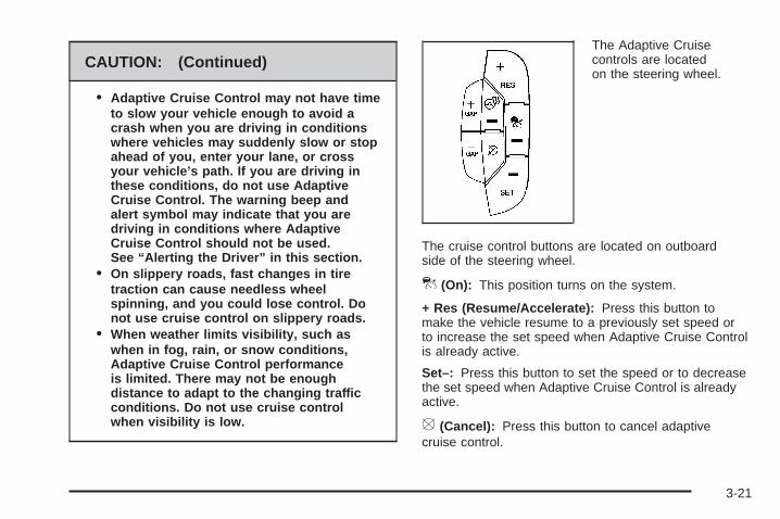
CAUTION: (Continued)
• Adaptive Cruise Control may not have timeto slow your vehicle enough to avoid acrash when you are driving in conditionswhere vehicles may suddenly slow or stopahead of you, enter your lane, or crossyour vehicle’s path. If you are driving inthese conditions, do not use AdaptiveCruise Control. The warning beep andalert symbol may indicate that you aredriving in conditions where AdaptiveCruise Control should not be used.See “Alerting the Driver” in this section.
• On slippery roads, fast changes in tiretraction can cause needless wheelspinning, and you could lose control. Donot use cruise control on slippery roads.
• When weather limits visibility, such aswhen in fog, rain, or snow conditions,Adaptive Cruise Control performanceis limited. There may not be enoughdistance to adapt to the changing trafficconditions. Do not use cruise controlwhen visibility is low.
The Adaptive Cruisecontrols are locatedon the steering wheel.
The cruise control buttons are located on outboardside of the steering wheel.
] (On): This position turns on the system.
+ Res (Resume/Accelerate): Press this button tomake the vehicle resume to a previously set speed orto increase the set speed when Adaptive Cruise Controlis already active.
Set–: Press this button to set the speed or to decreasethe set speed when Adaptive Cruise Control is alreadyactive.
[ (Cancel): Press this button to cancel adaptivecruise control.
3-21

+GAP (Increase Following Distance): Press thisbutton to increase the distance between your vehicleand other vehicles.
−GAP (Decrease Following Distance): Press thisbutton to decrease the distance between your vehicleand other vehicles.
Adaptive cruise control will not work if the mastercylinder brake fluid level is low.
Engaging Adaptive Cruise ControlWith the Set Button
{CAUTION:
If you leave your Adaptive Cruise Controlswitch on when you are not using cruise, youmight hit a button and go into cruise when youdo not want to. You could be startled and evenlose control. Keep the Adaptive Cruise Controlswitch off until you want to use cruise control.
The set speed is selected by the driver. This is the speedyou will travel if there is no vehicle detected in your path.
To set Adaptive Cruise Control, do the following:
1. Press the ] (On) button.2. Get up to the speed desired.3. Press in the SET– button and release it.4. Take your foot off the accelerator pedal.
Once Adaptive Cruise Control is set, it may immediatelyapply the brakes if it detects a vehicle ahead is tooclose or moving slower than your vehicle.
The on symbol is located on the display at the top ofthe instrument panel to the right of the driver. Whenthe on symbol is lit on the display, it indicates thatAdaptive Cruise Control is active.
A message on the DIC will also display whenAdaptive Cruise Control is set. See DIC Warningsand Messages on page 3-73.
Keep in mind speed limits, surrounding traffic speeds,and weather conditions when adjusting your set speed.
If your vehicle is in Adaptive Cruise Control whenthe traction control system begins to limit wheel spin,the Adaptive Cruise Control will automatically disengage.See Traction Control System (TCS) on page 4-5 andStabiliTrak® System on page 4-7. When road conditionsallow you to safely use it again, you may turn theAdaptive Cruise Control back on.
3-22

Increasing Set Speed While UsingAdaptive Cruise ControlThere are two ways to increase the set speed:• Use the accelerator to get to the higher speed.
Press the SET– button and then release thebutton and the accelerator pedal. The vehiclewill now cruise at the higher speed.
• Press the +RES button. Hold it there until the desiredset speed is displayed on the Driver InformationCenter (DIC), then release the switch. To increaseyour set speed in very small amounts, move theswitch briefly to +RES. Each time this is done, yourset speed increases by 1 mph (1 km/h).
Your vehicle will not reach the set speed until the systemdetermines there is not a vehicle in front of you. At thatpoint, your vehicle speed will increase to the set speed.
Decreasing Set Speed While UsingAdaptive Cruise ControlPress the SET– button until you reach the lower speeddesired, then release it.
To slow down in very small amounts, briefly press theSET– button. Each time this is done, your set speeddecreases by 1 mph (1 km/h) slower.
Resuming a Set SpeedSuppose the Adaptive Cruise Control is set at a desiredspeed and then the brakes are applied. This will turnoff the Adaptive Cruise Control. But it does not needto be reset.
Once you are going about 25 mph (40 km/h) or more,press the +RES button. Adaptive Cruise Controlwill be engaged with the previously chosen set speed.
Selecting the Follow Distance (GAP)When the system detects a slower moving vehicle,it will adjust your vehicle’s speed and maintain thefollow distance (gap) you select.
Use the plus and minus buttons on the steering wheelto adjust the follow distance.
Press the plus button to increase the distance or theminus button to decrease the distance. The first buttonpress shows the current follow distance setting onthe DIC. The current follow distance setting willbe maintained until you change it.
3-23

There are six follow distances to choose from.The follow distance selection ranges from near to far(one second to two seconds follow time). The distancemaintained for a selected follow distance will varybased on vehicle speed. The faster the vehicle speedthe further back your vehicle will follow. Considertraffic and weather conditions when selecting thefollow distance. The range of selectable distancesmay not be appropriate for all drivers and drivingconditions. If you prefer to travel at a follow distancefarther than Adaptive Cruise Control allows, disengagethe system and drive manually.
Alerting the Driver
The Adaptive CruiseControl alert symbolis located on thedisplay at the top ofthe instrument panelto the right of the driver.
The alert symbol will flash and a warning beep will soundwhen driver action may be required. If Adaptive CruiseControl is engaged, the alert symbol will flash when:
• Adaptive Cruise Control cannot apply sufficientbraking because you are approaching a vehicletoo rapidly.
• The vehicle speed drops below about20 mph (32 km/h).
• A temporary condition prohibits Adaptive CruiseControl from operating. See DIC Warnings andMessages on page 3-73 for more information.
• A malfunction is detected in the system. See DICWarnings and Messages on page 3-73 for moreinformation.
See Defensive Driving on page 4-2.
{CAUTION:
Adaptive Cruise Control has only limited brakingability to slow your vehicle. In some cases,Adaptive Cruise Control may not have timeto slow your vehicle enough to avoid a collision.Be ready to take action and apply the brakesyourself. See Defensive Driving on page 4-2.
3-24
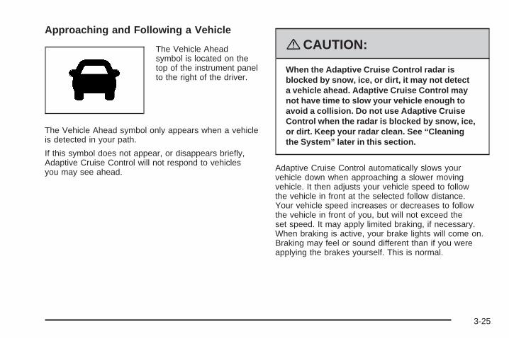
Approaching and Following a Vehicle
The Vehicle Aheadsymbol is located on thetop of the instrument panelto the right of the driver.
The Vehicle Ahead symbol only appears when a vehicleis detected in your path.
If this symbol does not appear, or disappears briefly,Adaptive Cruise Control will not respond to vehiclesyou may see ahead.
{CAUTION:
When the Adaptive Cruise Control radar isblocked by snow, ice, or dirt, it may not detecta vehicle ahead. Adaptive Cruise Control maynot have time to slow your vehicle enough toavoid a collision. Do not use Adaptive CruiseControl when the radar is blocked by snow, ice,or dirt. Keep your radar clean. See “Cleaningthe System” later in this section.
Adaptive Cruise Control automatically slows yourvehicle down when approaching a slower movingvehicle. It then adjusts your vehicle speed to followthe vehicle in front at the selected follow distance.Your vehicle speed increases or decreases to followthe vehicle in front of you, but will not exceed theset speed. It may apply limited braking, if necessary.When braking is active, your brake lights will come on.Braking may feel or sound different than if you wereapplying the brakes yourself. This is normal.
3-25

Stationary or Very Slow-Moving Objects
{CAUTION:
Adaptive Cruise Control may not detect andreact to stationary or slow-moving vehicles orother objects ahead of you. You could crashinto an object ahead of you. Do not useAdaptive Cruise Control when approachingstationary or slow-moving vehicles or otherobjects.
{CAUTION:
Adaptive Cruise Control may not detect andreact to stationary or slow-moving vehicles orother objects ahead of you. Your vehicle mayaccelerate toward objects, such as a stoppedvehicle that suddenly appears after the leadvehicle changes lanes. Your complete attentionis always required while driving and you shouldbe ready to take action and apply the brakes.
Low-Speed DeactivationIf your speed falls below 20 mph (32 km/h) whilefollowing a vehicle ahead, Adaptive Cruise Controlwill begin to disengage. The Driver Alert symbolwill flash and the warning beep will sound. The drivermust take action since Adaptive Cruise Control willnot slow the vehicle to a stop.
Passing a Vehicle/Adaptive CruiseControl OverrideIf you need to increase speed to pass a vehicle,use the accelerator pedal. While you are doing this,the system will not automatically apply the brakes.A message will appear on the DIC. See DIC Warningsand Messages on page 3-73. Once you removeyour foot from the accelerator pedal, Adaptive CruiseControl will return to normal operation and be ableto apply the brakes, if needed.
3-26

{CAUTION:
If you rest your foot on the accelerator pedal,the system will not automatically apply thebrakes. You could crash into a vehicle aheadof you. Do not rest your foot on the acceleratorpedal when using Adaptive Cruise Control.
Curves in the Road
{CAUTION:
Due to Adaptive Cruise Control limitations incurves, it may respond to a vehicle in anotherlane, or may not have time to react to a vehiclein your lane. You could crash into a vehicleahead of you, or lose control of your vehicle.Give extra attention in curves and be readyto use the brakes if necessary. Select anappropriate speed while driving in curves.
Adaptive Cruise Control may operate differently in asharp curve. It may reduce your speed if the curveis too sharp.
When following a vehicle and entering a curve,Adaptive Cruise Control could lose track of the vehiclein your lane and accelerate your vehicle. When thishappens the Vehicle Ahead symbol will not appear.
3-27
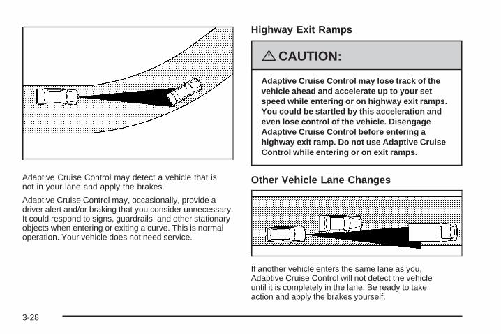
Adaptive Cruise Control may detect a vehicle that isnot in your lane and apply the brakes.
Adaptive Cruise Control may, occasionally, provide adriver alert and/or braking that you consider unnecessary.It could respond to signs, guardrails, and other stationaryobjects when entering or exiting a curve. This is normaloperation. Your vehicle does not need service.
Highway Exit Ramps
{CAUTION:
Adaptive Cruise Control may lose track of thevehicle ahead and accelerate up to your setspeed while entering or on highway exit ramps.You could be startled by this acceleration andeven lose control of the vehicle. DisengageAdaptive Cruise Control before entering ahighway exit ramp. Do not use Adaptive CruiseControl while entering or on exit ramps.
Other Vehicle Lane Changes
If another vehicle enters the same lane as you,Adaptive Cruise Control will not detect the vehicleuntil it is completely in the lane. Be ready to takeaction and apply the brakes yourself.
3-28

Using Adaptive Cruise Control on Hillsand When Towing a Trailer
How well Adaptive Cruise Control will work on hillsand when towing a trailer depends on your vehicle’sspeed, vehicle load, traffic conditions and the steepnessof the hills. It may not detect a vehicle in your lane whiledriving on hills. When going up steep hills, you may wantto use the accelerator pedal to maintain your vehicle’sspeed. When going downhill, especially when towing atrailer, you may want to brake to keep your speed down.Applying the brake disengages the system. You maychoose not to use Adaptive Cruise Control on steep hills,especially when towing a trailer.
Disengaging Adaptive Cruise ControlTo turn off the system, apply the brake pedal,press the cancel button, or press the AdaptiveCruise Control button.
Erasing Set Speed MemoryPress the Adaptive Cruise Control button or turnthe ignition off.
Other MessagesThere are three additional messages that may appearon the DIC. They are SERVICE RADAR CRUISE,RADAR CRUISE NOT READY and CLEAN RADAR.These messages will appear to indicate a problem withthe Adaptive Cruise Control. See DIC Warnings andMessages on page 3-73 for more information.
Cleaning the SystemThe radar can become blocked by snow, ice, or dirt.If so, you may need to turn off the engine and clean thelens. Remember, do not use Adaptive Cruise Controlin icy conditions, or when visibility is low, such as in fog,rain or snow.
The emblem/lens is located in the center of the grille.
To clean the emblem/lens, wipe the surface with asoft cloth. After cleaning the emblem/lens, try toengage the Adaptive Cruise Control. If you areunable to do so, see your dealer/retailer.
3-29

Exterior Lamps
The exterior lampscontrol is located onthe instrument panelto the left of thesteering wheel.
It controls the following systems:
• Headlamps
• Taillamps
• Parking Lamps
• License Plate Lamps
• Instrument Panel Lights
• Fog Lamps
The exterior lamps control has four positions:
O(Off): This position turns off the exterior lampsexcept for Daytime Running Lamps (DRL).
AUTO (Automatic): This position automatically turnson the headlamps at normal brightness, togetherwith the following:
• Parking Lamps• Instrument Panel Lights• IntelliBeam™
; (Parking Lamps): This position turns on theparking lamps together with the following:
• Instrument Panel Lights• License Plate Lamps• Taillamps• Side Marker Lamps
The parking brake indicator light comes on and stays onwhile the parking lamps are on with the engine offand the ignition in ACC/ACCESSORY or ON/RUN.
2 (Headlamps): This position turns on the headlampstogether with the previously listed lamps. A warningchime sounds if the driver’s door is opened whilethe ignition switch is off and the headlamps are on.
- (Fog Lamps): Press the exterior lamps control toturn on the fog lamps. See Fog Lamps on page 3-34.
3-30

IntelliBeam™ Intelligent High-BeamHeadlamp Control SystemIf your vehicle has this feature, be sure to read thisentire section before using it.
IntelliBeam™ is an enhancement to the vehicle’sheadlamp system. Using a digital light sensor on therearview mirror, this system turns the vehicle’s high-beamheadlamps on and off according to surrounding trafficconditions.
The IntelliBeam™ system turns the high-beamheadlamps on when it is dark enough, there is no othertraffic present, and the IntelliBeam system is enabled.
Turning On and Enabling IntelliBeam™Press and release the IntelliBeam™ button on the insiderear view mirror. The IntelliBeam™ indicator on the mirrorturns on to indicate the system is on. Once the systemhas been turned on, it remains on each time the vehicleis started, but the IntelliBeam system must be enabled.
To enable the IntelliBeam™ system, turn the exteriorlamp control to AUTO, with the turn signal/multifunctionlever in its neutral position. The High-Beam OnLight appears on the instrument panel cluster whenthe high-beams are on. See Highbeam On Lighton page 3-67.
Driving with IntelliBeam™IntelliBeam™ only activates the high-beams whendriving over 20 mph (32 km/h).The high-beam headlamps remain on, under theautomatic control of IntelliBeam™, until any of thefollowing situations occur:
• The system detects an approaching vehicle’sheadlamps.
• The system detects a preceding vehicle’s taillamps.
• The outside light is bright enough that high-beamheadlamps are not required.
• The vehicle’s speed drops below 15 mph (24 km/h).
• The headlamp stalk is moved forward to thehigh-beam position or the flash-to-pass feature isused. See Headlamp High/Low-Beam Changeron page 3-9 and Flash-to-Pass on page 3-13.When either of these conditions occur, theIntelliBeam™ feature is disabled and theIntelliBeam™ light in the mirror turns off until thehigh-beam stalk is returned to the neutral position.
• If IntelliBeam™ was using low-beams prior to thisaction, the IntelliBeam™ feature is temporarilydisabled until the stalk is returned to the neutralposition.
3-31

• The exterior lamp control is turned to any settingexcept AUTO.When this occurs, IntelliBeam™ is disabled until thecontrol is turned back to the AUTO position.
• The IntelliBeam™ system is turned off at the insiderearview mirror.
IntelliBeam™ might not turn off the high-beams if thesystem cannot detect other vehicle’s lamps because ofany of the following:• The other vehicle’s lamp(s) are missing, damaged,
obstructed from view, or otherwise undetected.• The other vehicle’s lamp(s) are covered with dirt,
snow, and/or road spray.• The other vehicle’s lamp(s) cannot be detected due
to dense exhaust, smoke, fog, snow, road spray,mist, or other airborne obstructions.
• Your vehicle’s windshield is dirty, cracked, orobstructed by something that blocks the view of theIntelliBeam™ light sensor.
• Your vehicle’s windshield is covered with ice, dirt,haze, or other obstructions.
• Your vehicle is loaded such that the front end of thevehicle points upward, causing the IntelliBeam™sensor to aim high and not detect headlampsand taillamps.
• You are driving on winding or hilly roads.
You might need to manually disable or cancel thehigh-beam headlamps by turning the low-beamheadlamps on, if any of the above conditions exist.
Disabling and Resetting IntelliBeam™at the Rearview MirrorIntelliBeam™ can be disabled by using the controlson the inside rearview mirror.
AUTO 3(On/Off): Press this button on the insiderearview mirror to disable the system. The IntelliBeam™indicator turns off and does not come back on untilthe IntelliBeam™ button is pressed again.
When IntelliBeam™ has turned on the high-beams,pull or push the high-beam stalk. This will disableIntelliBeam™. The IntelliBeam™ indicator on the mirrorturns off. To turn IntelliBeam™ back on, press theIntelliBeam™ button on the mirror.
A different sensitivity setting is available fordealer/retailer diagnostics. This is done by pushing andholding this button for 20 seconds until the IntelliBeam™indicator light flashes three times. If you accidentallyactivate this, the vehicle’s setting automatically is resetwhen the ignition is turned off and then on again.
3-32

Cleaning the IntelliBeam™ Light Sensor
The light sensor islocated on the inside ofthe vehicle in front ofthe inside rearview mirror.
Clean the light sensor window, periodically, usingglass cleaner on a soft cloth. Gently wipe the sensorwindow. Do not spray glass cleaner directly on thesurface of the sensor window.
Wiper Activated HeadlampsThis feature activates the headlamps and parkinglamps after the windshield wipers are turned on andhave completed eight wipe cycles within four minutes.
When the ignition is turned to LOCK/OFF, thewiper-activated headlamps immediately turn off.The wiper-activated headlamps also turn off if thewindshield wipers are turned off.
Headlamps on ReminderA warning chime will sound if the exterior lamp controlis left on in either the headlamp or parking lamp positionand the driver’s door is opened with the ignition off.
Daytime Running Lamps (DRL)Daytime Running Lamps (DRL) can make it easierfor others to see the front of your vehicle during the day.DRL can be helpful in many different driving conditions,but they can be especially helpful in the short periodsafter dawn and before sunset. Fully functional daytimerunning lamps are required on all vehicles first soldin Canada.
The DRL system makes the turn signal lamps comeon when the following conditions are met:
• It is still daylight and the ignition is on.
• The exterior lamp control is in the off position.
• The transmission is not in PARK (P)(United States only).
• The light sensor is covered or not detecting light.See “Sensors” under Dual Climate Control Systemon page 3-40.
3-33

When DRL are on, no other exterior lamps such asthe parking lamps, taillamps, etc. will be on when theDRL are being used. The instrument panel will not belit up either.
When automatic lighting is on and it is dark enoughoutside, the turn signal lamps turn off and normallow-beam headlamp operation occurs.
When automatic lighting is on and it is bright enoughoutside, the regular lamps go off, and the DRL takes over.If the vehicle is started in a dark garage, the automaticheadlamp system comes on immediately. Once youleave the garage, it will take approximately one minute forthe automatic headlamp system to change to DRL if thereis light outside. During that delay, the instrument panelcluster may not be as bright as usual. Make sure theinstrument panel brightness knob is in the full brightposition. See Instrument Panel Brightness on page 3-35.
Turning on automatic lighting or the headlamps willdeactivate the DRL. If the parking lamps or the fog lampswere turned on instead, the DRL will still deactivate.
To idle the vehicle with the DRL off at night, turn offautomatic lighting and shift the transmission intoPARK (P). Placing the vehicle in PARK (P) disablesthe DRL. The DRL will stay off until the vehicle is shiftedout of PARK (P).
To drive the vehicle with the DRL off, turn off automaticlighting and manually turn on the parking lamps or foglamps, if the vehicle has them.
As with any vehicle, the regular headlamp systemshould be turned on when needed.
Fog LampsUse the fog lamps for better vision in foggy or mistyconditions.
-(Fog Lamps): The fog lamps button is located onthe exterior lamps control. The exterior lamps controlis located on the instrument panel to the left of thesteering column.
The ignition must be on for the fog lamps to work.
Press the exterior lamps button to turn the fog lampson or off. A light will come on in the instrumentpanel cluster when the fog lamps are in use.
When the headlamps are changed to high-beam,the fog lamps will turn off. The fog lamps come back onagain when the high-beam headlamps are turned off.
Some localities have laws that require the headlampsto be on along with the fog lamps.
3-34

Cornering LampsThe cornering lamps come on when the headlampsor parking lamps are on and you signal a turn withthe multifunction lever. They provide more lightfor cornering.
Exterior Lighting Battery SaverIf the exterior lamp button has been left on, theexterior lamps will turn off about 10 minutes afterthe ignition is turned to LOCK/OFF and a door hasbeen opened. This protects against draining thebattery if the headlamps or parking lamps areaccidentally left on. If you need to leave the lampson for more than 10 minutes, use the exterior lampcontrol to turn the lamps back on after the ignitionis turned to LOCK/OFF and any door is opened.
Instrument Panel Brightness
D (Instrument Panel Brightness): This featurecontrols the brightness of the instrument panel andfootwell lights, if equipped.
The button for this control is located below the exteriorlamps control.
Push the button in and release to extend the button.Turn the button clockwise or counterclockwise tobrighten or dim the lights.
Courtesy LampsThe courtesy lamps are located on the headlinerabove the rear seat. These lamps come on by turningthe instrument panel brightness knob fully clockwiseor when any door is opened and it is dark outside.Puddle lamps are located on the bottom of the frontand rear door trim.
Professional vehicles have an additional dome lampand also opera lamps.
3-35

Entry LightingThis feature turns on the courtesy lamps and thebacklighting for the door switches and the exteriorlamp control when a door is opened or if the remotekeyless entry transmitter unlock button is pressed.If activated due to the transmitter, the lighting remainsactive for about 40 seconds. Since the entry lightingsystem uses the light sensor, it must be dark outside inorder for the courtesy lamps to turn on. The courtesylamps turn off approximately 25 seconds after thelast door is closed. They will dim to off if the ignitionkey is turned to ON/RUN, or immediately deactivateif the power locks are activated.
Parade DimmingThis feature prohibits dimming of the digital displaysand backlighting during daylight hours when the key isin the ignition and the headlamps are on. This featureis fully automatic. When the light sensor reads darknessoutside and the parking lamps are active, the digitaldisplays can be adjusted by turning the instrument panelbrightness knob counterclockwise to dim and clockwiseto brighten lighting.
Reading LampsThe reading lamps are located on the overhead consoleon the headliner and in the rear door opening. Theselamps come on automatically when any door is openedand it is dark outside.
For manual operation, press the button to turn them on.Press it again to turn them off.
If the reading lamps are left on, they automatically shutoff 10 minutes after the ignition has been turned off.
Footwell LampsIf your vehicle has footwell lamps, they are locatedunder the instrument panel and at the rear of thefront seats. These lamps provide soft light to the frontand rear floor areas. They dim with the instrumentpanel cluster lights, before going out completely.
Footwell lighting brightness can be adjusted with theinstrument panel brightness control located belowthe exterior lamps control. See Instrument PanelBrightness on page 3-35. The footwell lights will turnoff before the instrument panel lights are at theirlowest level of brightness.
3-36

Battery Load ManagementThe battery load management feature is designed tomonitor the vehicle’s electrical load and determinewhen the battery is in a heavy discharge condition.During times of high electrical loading, the enginemay idle at a higher revolutions per minute (rpm)setting than normal to make sure the battery charges.High electrical loads may occur when several ofthe following are on: headlamps, high beams, fog lamps,rear window defogger, the climate control fan at highspeeds, heated seats and engine cooling fans.
If the battery continues to discharge, even with theengine idling at a higher rpm setting, some electricalloads will automatically be reduced. When this occurs,the rear window defogger may take slightly longerto clear the glass, the heated seats may not get aswarm as they usually do and the climate control fanmay cut back to a lower speed. For more battery savinginformation, see “Battery Saver Active Message”under DIC Warnings and Messages on page 3-73.
Electric Power ManagementThe vehicle has Electric Power Management (EPM)that estimates the battery’s temperature and stateof charge. It then adjusts the voltage for bestperformance and extended life of the battery.
When the battery’s state of charge is low, the voltageis raised slightly to quickly put the charge back in.When the state of charge is high, the voltage is loweredslightly to prevent overcharging. If the vehicle has avoltmeter gage or a voltage display on the DriverInformation Center (DIC), you may see the voltagemove up or down. This is normal. If there is a problem,an alert will be displayed.
The battery can be discharged at idle if the electricalloads are very high. This is true for all vehicles.This is because the generator (alternator) may notbe spinning fast enough at idle to produce all thepower that is needed for very high electrical loads.
A high electrical load occurs when several of thefollowing loads are on: headlamps, high beams, foglamps, rear window defogger, climate control fan athigh speed, heated seats, engine cooling fans, trailerloads, and loads plugged into accessory power outlets.
3-37

EPM works to prevent excessive discharge of thebattery. It does this by balancing the generator’s outputand the vehicle’s electrical needs. It can increaseengine idle speed to generate more power, wheneverneeded. It can temporarily reduce the power demandsof some accessories.
Normally, these actions occur in steps or levels, withoutbeing noticeable. In rare cases at the highest levelsof corrective action, this action may be noticeableto the driver. If so, a Driver Information Center (DIC)message might be displayed, such as Battery SaverActive or Service Battery Charging System. If thismessage is displayed, it is recommended that thedriver reduce the electrical loads as much as possible.See DIC Warnings and Messages on page 3-73.
Inadvertent Power Battery SaverThis feature is designed to protect your vehicle’s batteryagainst drainage from the interior lamps, trunk lamp,glove box lamp, or the garage door opener. Whenthe ignition is turned off, the power to these featureswill automatically turn off after 10 minutes. Power willbe restored for an additional 10 minutes if any dooror trunk is opened, or the courtesy lamp switch isturned on.
Battery Run-Down ProtectionThis vehicle has a feature to help prevent the batteryfrom being drained, if the interior courtesy lamps,reading/map lamps, visor vanity lamps or trunk lampare accidentally left on. If any of these lamps areleft on, they will automatically turn off after 10 minutes,if the ignition is off. The lamps will not come backon again until one of the following occurs:
• The ignition is turned on.• The exterior lamps control is turned off,
then on again.The headlamps will timeout after 10 minutes, if theyare manually turned on before the ignition is off.
Accessory Power Outlet(s)The accessory power outlets can be used to plug inelectrical equipment such as a cellular telephone,CB radio, etc.
If your vehicle has a center console, the power outlet islocated inside the lower storage area. There are outletsalso on the right front lower part of the driver’s seatand under the climate control system next to the ashtray.See Center Console Storage on page 2-63.
3-38

There are two accessory power outlets in the rearseat area located on the door armrests next to theashtrays.
There may be a small cap that must be removed toaccess the accessory power outlet. When not usingthe outlet be sure to cover it with the protective cap.
The accessory power outlet can be used at any time.
Notice: Leaving electrical equipment plugged infor an extended period of time while the vehicle isoff will drain the battery. Power is always suppliedto the outlets. Always unplug electrical equipmentwhen not in use and do not plug in equipmentthat exceeds the maximum 20 ampere rating.
Certain accessory power plugs may not be compatibleto the accessory power outlet and could result in blownvehicle or adapter fuses. If you experience a problemsee your dealer/retailer for additional information on theaccessory power outlets.
Notice: Adding any electrical equipment to yourvehicle may damage it or keep other componentsfrom working as they should. The repairs would notbe covered by your warranty. Do not use equipmentexceeding maximum amperage rating of 20 amperes.Check with your dealer/retailer before addingelectrical equipment.
Follow the proper installation instructions that areincluded with any electrical equipment you install.
Notice: Improper use of the power outlet can causedamage not covered by your warranty. Do not hangany type of accessory or accessory bracket fromthe plug because the power outlets are designed foraccessory power plugs only.
Ashtray(s)Notice: If you put papers, pins, or other flammableitems in the ashtray, hot cigarettes or othersmoking materials could ignite them and possiblydamage your vehicle. Never put flammable itemsin the ashtray.
Front AshtrayWith the full floor console, the ashtray is locatedbelow the climate control system. To open, push downand then release the cover. To clean the ashtray,push the lip of the ashtray to remove it. Push theopposite side of the ashtray’s lip to install.
For vehicles without the floor console, pull the traylocated below the climate controls to reveal the ashtray.The ashtray can be removed by pulling on the ledgelocated at the top of the ashtray.
3-39

Rear AshtrayThe ashtrays are located on the door armrests.To use an ashtray, lift the lid.
Analog ClockThe analog clock is located on the instrumentpanel above the radio. The clock is not connectedwith any other vehicle system and runs by itself.To adjust the clock:
1. Locate the adjustment button directly below theclock face.
2. Push and hold the adjustment button to advancethe clock hands. Holding the button down willcause the clock to advance faster. Release thebutton before reaching the desired time.
3. Push and release the button to increase the timeby one minute increments until the desired timeis reached.
Climate Controls
Dual Climate Control SystemThe heating, cooling, and ventilation for the vehiclecan be controlled with this system. To avoid windowfogging on rainy and humid days at temperaturesabove freezing, run the air conditioning. Also, it is bestto avoid the use of recirculation mode except whenmaximum air conditioning performance is needed fora short amount of time to avoid exterior odors andfogging.
Dual Climate Control System
3-40

Automatic Operation
AUTO 9(Automatic Fan): When this position isselected on the fan control, the system adjusts the fanspeed. If the OnStar® system is activated when thisposition is selected, the climate control fan speedwill lower.
AUTO (Automatic Mode):
1. Turn the fan control to the AUTO position.
2. Turn the mode control to the AUTO position.
3. Adjust the temperature to a comfortable settingbetween 68°F (21°C) and 78°F (26°C).Choosing the coldest or warmest temperature settingwill not cause the system to heat or cool any faster.In cold weather, the system will start at reducedfan speeds to avoid blowing cold air into the vehicleuntil warmer air is available. The system starts outblowing air at the floor but may change modesautomatically as the vehicle warms up to maintainthe chosen temperature setting. The length of timeneeded to warm the interior depends on the outsidetemperature and temperature of the vehicle.
4. Wait 20 to 30 minutes for the system to stabilizein order for the system to regulate automatically.Then adjust the temperature as necessary tofind your comfort setting.
Do not cover the solar sensor located in the center ofthe instrument panel near the windshield. For moreinformation on the solar sensor, see “Sensors” laterin this section.
After the vehicle is started, the display will showthe interior temperature settings and the outsidetemperature.
Dual Climate Control System for Vehicleswith Rear Climate Control
3-41
If the AUTO position is selected on the fan or modecontrol, the system automatically controls the airconditioning compressor. The A/C compressor willrun automatically even at cool outside temperaturesin order to dehumidify the air. The A/C indicator lightis lit when the system is operating automatically,even at near freezing outside temperatures. Pressthe A/C button on the fan control to turn off the A/C.For improved window clearing performance in defog ordefrost modes, the A/C compressor runs automatically.
h(AUTO RECIRCULATION): If the AUTOposition is selected on either the fan or mode control,the system automatically controls the air inlet tosupply fresh outside air or recirculate the interiorair to cool the car faster. The indicator light on therecirculation button will light whenever the systemswitches to recirculation. You may force outside airby pressing the recirculation button when the light is lit.For vehicles without rear climate controls, press theoutside air button to force outside air. The nexttime AUTO fan or mode is selected, the air inlet willreset back to AUTO operation.
Manual Operation
9(Fan): Turn the left control knob clockwise orcounterclockwise to adjust the fan speed. Turningthis control completely counterclockwise will turn onthe automatic fan operation. Turning this control to the“O” position will turn the climate control system off.If the airflow seems low when the fan speed is at thehighest setting, the passenger compartment air filter mayneed to be replaced. See Passenger CompartmentAir Filter on page 3-48.
9(Off): Turn the left control knob to this position toturn the entire climate control system off. Outside airstill enters the vehicle and is directed to the floor.The airflow direction and temperature can be adjusted,as indicated below.
If the temperature is adjusted while the system is off,the display will light to show the current settings.
Mode Control: Turn the right knob clockwise orcounterclockwise to change the current airflow mode.
AUTO: Turn the control to this position to turn onthe automatic delivery mode operation.
3-42
F (Vent): Turn the control to this mode to direct air tothe instrument panel outlets.
* (Bi-Level): Turn the control to this mode to directapproximately half of the air to the instrument paneloutlets and most of the remaining air to the floor outlets.In automatic operation, cooler air is directed to theupper outlets and warmer air to the floor outlets.
7 (Floor): Turn the control to this mode to directmost of the air to the floor outlets with some airdirected to the side window outlets and the windshield.
If recirculation is selected, it only stays on forthree minutes to reduce windshield fogging.
The mode control can also be used to select the floor/defog mode. In this mode, the system automaticallyuses outside air. Information on defogging and defrostingcan be found later in this section.
:(Outside Air): Press this button to allow outsideair to come into the vehicle. Press this button to turn theoutside air mode on or off. When the button is pressed,the indicator light comes on. Pressing the recirculationbutton will cancel this mode.
? (Recirculation): Press this button to recirculatecabin air through the vehicle. An indicator light below thebutton comes on to show that this mode is activated.This mode can be used to prevent outside air andodors from entering the vehicle or to help cool the airinside the vehicle more quickly. This mode cannotbe selected while in the defog or defrost modes.If you try to select the recirculation mode, the indicatorlight flashes three times and turns off.
Operation in this mode during periods of high humidityand cool outside temperatures may result in increasedwindow fogging. If window fogging is experienced,select the defrost mode.
wx (Driver’s Temperature Controls): Press thesebuttons next to the fan control to manually increaseor decrease the temperature inside the vehicle.
wx (Passenger’s Temperature Controls): Pressthese buttons next to the mode control to manuallyincrease or decrease the temperature for the frontpassenger. If the passenger’s climate control systemis off, pressing one of these buttons turns it on.
3-43

PASS (Passenger’s Climate Control): Press thisbutton to turn the passenger’s climate control systemson or off. When the passenger’s climate control systemis on, the passenger’s temperature setting is displayed.The temperature selected by the front passenger alsocontrols the rear system air temperature unless the rearseat passengers select their own comfort setting.
If the PASS button is pressed to turn the passengertemperature setting off, the driver’s temperature knobwill control the temperature for the entire vehicle.
AUX: If your vehicle has a rear climate control system,press this button to turn the rear climate control fanon for automatic operation. After the AUX buttonis pressed, the indicator light comes on. Press the buttonagain to turn the auxiliary fan off. See Rear ClimateControl System on page 3-47.
#(Air Conditioning): Press the center of the leftcontrol knob to override the automatic system and turnthe air conditioning system on or off. When in AUTO,the air conditioning compressor comes on automatically,as necessary.
The air conditioning system removes moisture from theair, so a small amount of water may drip underneaththe vehicle while idling or after turning off the engine.This is normal.
Sensors
The solar sensor, located in the defrost grille, middleof the instrument panel, monitors the solar radiation.Do not cover the solar sensor or the system will notwork properly.
3-44

There is also an interiortemperature sensorlocated next to the steeringwheel that measures thetemperature of the airinside your vehicle.
There is also an exterior temperature sensor locatedbehind the front grille. This sensor reads the outside airtemperature and helps maintain the temperature insidethe vehicle. Any cover on the front of the vehicle couldcause a false reading in the displayed temperature.
In order to prevent false temperature readings at startup,the displayed temperature will not change until thefollowing occurs:
• Vehicle speed is above 10 mph (16 km/h)for 5 minutes.
• Vehicle speed is above 32 mph (51 km/h)for 2 and a half minutes.
The climate control system uses the informationfrom these sensors to maintain your comfort settingby adjusting the outlet temperature, fan speed, andthe air delivery mode. The system may also supplycooler air to the side of the vehicle facing the sun.The recirculation mode will also be used as neededto maintain cool outlet temperatures.
Defogging and DefrostingFog on the inside of windows is a result of highhumidity (moisture) condensing on the cool windowglass. This can be minimized if the climate controlsystem is used properly. There are two modes to clearfog from your windshield. Use the floor/defog modeto clear the windows of fog or moisture and warm thepassengers. Use the defrost mode to remove fog orfrost from the windshield more quickly.
W (Floor/Defog): Turn the control to this mode todirect approximately half of the air to the floor outletsand the remaining air is directed to the side windowoutlets and to the windshield. When you selectthis mode, the system turns off recirculation and runsthe air conditioning compressor unless the outsidetemperature is at or below freezing. The recirculationmode cannot be selected while in the floor/defog mode.
3-45
0 (Defrost): Turn the control to this mode to directmost of the air to the windshield and the side windowoutlets. In this mode, the system automatically turns offrecirculation and runs the air conditioning compressor,unless the outside temperature is at or below freezing.Recirculation cannot be selected while in the defrostmode. Do not drive the vehicle until all the windowsare clear.
For professional vehicles, air will be allowed to flowthrough the rear outlets. For quicker defrost, press theAUX button on the front climate control system sothat the light is not lit.
Rear Window DefoggerThe rear window defogger uses a warming grid toremove fog or frost from the rear window.
< (Rear Defogger): Press the center of the rightcontrol to turn the rear window defogger on or off.Be sure to clear as much snow from the rear windowas possible. The rear window defogger will turn offapproximately 20 minutes after the button is pressedif your vehicle is moving at slower vehicle speeds.At higher vehicle speeds, the rear defogger may stayon continuously. Each additional press will run thedefogger for approximately 10 minutes.
The heated outside rearview mirrors will heat to helpclear fog or frost from the surface of the mirror whenthe rear window defogger is on.
Notice: Do not use a razor blade or sharp objectto clear the inside rear window. Do not adhereanything to the defogger grid lines in the rear glass.These actions may damage the rear defogger.Repairs would not be covered by your warranty.
Outlet AdjustmentFor the front outlets, use the thumbwheel locatedbelow each outlet to change the direction of the airflow.Use the thumbwheel located next to the outlets to shutthe airflow or to open the outlets and re-direct the air.For the rear outlets, slide the lever left or right and upor down to change the direction of the airflow.
Operation Tips• Clear away any ice, snow or leaves from the
air inlets at the base of the windshield thatmay block the flow of air into your vehicle.
• Use of non-GM approved hood deflectors mayadversely affect the performance of the system.
• Keep the path under the front seats clear ofobjects to help circulate the air inside of yourvehicle more effectively.
3-46

Rear Climate Control System
If your vehicle has a rear climate control system,the rear seat passengers can adjust the direction ofthe airflow, fan speed and temperature for the rearseating area. This system also works with the mainclimate control system in the vehicle.
The control panel for this system is located on theback of the center console.
Press the AUX button located on the front climatecontrol panel to turn the rear climate control system onor off. When turned on the rear system operates inautomatic mode and the temperature settings selectedfor the front climate control panel will also be selectedfor the rear passengers.
To adjust the rear climate control system, the rearpassenger can select a different temperature, modeor fan speed.
Whenever the rear passengers have adjusted settingson the rear climate control system, the AUX light is liton the front climate control system.
When the front climate control system is turned off or indefrost mode, the rear climate control system is turnedoff. The rear system will turn back on once another frontmode is selected.
For more information on how to use the climate controlsystem, see Dual Climate Control System on page 3-40.For more information on the air outlets, see OutletAdjustment on page 3-46.
3-47

Automatic Operation
«Aª(Fan): Press this button until AUTO appearson the display to place the system in automaticmode. When automatic operation is active, the systemautomatically controls the fan speed. If in auto fanmode, pressing the up arrow button will cancelautomatic operation and places the system in manualmode. If in auto mode, pressing the down arrow willturn the rear climate control system off.
«Nª(Mode): Press the this button until AUTOappears on the display to place the system in automaticmode. When automatic operation is active, the systemautomatically controls the air delivery mode.
Manual Operation
«Aª(Fan): Press these up or down arrow buttonsto increase or decrease the fan speed.
«bª(Temperature): Press these up or downarrow buttons to increase or decrease the temperaturefor the rear seat passengers. Once the rear settingtemperature is altered from following the front settingtemperature, it will no longer follow changes to thefront setting temperature until the front climate controlAUX button resets it.
«Nª(Mode): Press these buttons to change theair delivery mode. If in AUTO air delivery mode, pressingthe up arrow button will cancel automatic operationand place the system in manual mode.
Y (Vent): This mode directs air to the upper outlets.
%(Bi-Level): This mode splits the air betweenthe upper outlets and the floor outlets.
[ (Floor): This mode directs the air to the floor outlets.
For more information on how to use the front climatecontrol system, see Dual Climate Control Systemon page 3-40.
For more information on the air outlets, see OutletAdjustment on page 3-46. Be sure to keep the areaunder the front seats clear of any objects so that theair inside of the vehicle can circulate effectively.
Passenger Compartment Air FilterThe passenger compartment air filter traps most ofthe pollen from the air entering your vehicle. Like yourvehicle’s engine air cleaner/filter, it may need to bechanged periodically. For how often to change thepassenger compartment air filter, see ScheduledMaintenance on page 6-4.
3-48

The access panel for the passenger compartment airfilter is located under the hood near the windshield,on the passenger’s side of the vehicle.
To access the passenger compartment air filter, do thefollowing:
1. Use a tool to gently pry the cover up. If your vehiclehas tabs that allow you to unlatch the cover withyour fingers, you will not need a tool for this step.
3-49

2. Then, insert a tool behind the push pin locatedon the inboard side of the air filter compartmentto carefully pry the pin out.
3. To remove the air filter, insert a tool between theair filter and the compartment wall on the outboardside of the vehicle. Then, push in to flatten thepin holding the air filter in place. Gently remove theair filter and any loose debris that may be insidethe air filter compartment.
4. Insert the new air filter by pushing until you heara click. Then, reinstall the push pin and snap thecover into place.
3-50

Warning Lights, Gages,and IndicatorsThis part describes the warning lights and gages thatmay be on your vehicle. The pictures will help youlocate them.
Warning lights and gages can signal that somethingis wrong before it becomes serious enough to causean expensive repair or replacement. Paying attentionto your warning lights and gages could also save youor others from injury.
Warning lights come on when there may be or is aproblem with one of your vehicle’s functions. As youwill see in the details on the next few pages, somewarning lights come on briefly when you start theengine just to let you know they are working. If youare familiar with this section, you should not bealarmed when this happens.
Gages can indicate when there may be or is aproblem with one of your vehicle’s functions. Oftengages and warning lights work together to let youknow when there is a problem with your vehicle.
When one of the warning lights comes on and stayson when you are driving, or when one of the gagesshows there may be a problem, check the sectionthat tells you what to do about it. Follow this manual’sadvice. Waiting to do repairs can be costly – andeven dangerous. So please get to know your warninglights and gages. They are a big help.
Your vehicle also has a Driver Information Center (DIC)that works along with the warning lights and gages.See Driver Information Center (DIC) on page 3-68for more information.
3-51

Instrument Panel ClusterThe instrument panel cluster is designed to let you know at a glance how your vehicle is running. You will know howfast you are going, how much fuel you are using and many of the other things you will need to know to drive safelyand economically.
United States version shown, Canada similar
3-52

Speedometer and OdometerThe speedometer lets you see your speed in bothmiles per hour (mph) and kilometers per hour (km/h).See “MPH (km)” under DIC Operation and Displayson page 3-69 for more information.
The odometer mileage can be checked without thevehicle running. Your vehicle’s odometer works togetherwith the driver information center. You can set aTrip A and a Trip B odometer. See “Trip Fuel” underDIC Operation and Displays on page 3-69 for moreinformation.
If your vehicle ever needs a new odometer installed,the new one will be set to the correct mileage totalof the old odometer.
Tachometer
This gage indicatesthe engine speed inrevolutions perminute (rpm).
3-53

Safety Belt Reminders
Safety Belt Reminder LightWhen the engine is started, a chime will come on forseveral seconds to remind people to fasten their safetybelts, unless the driver’s safety belt is already buckled.
The safety belt light willalso come on and stayon for several seconds,then it will flash forseveral more.
This chime and light is repeated if the driver remainsunbuckled and the vehicle is in motion. If the driver’sbelt is already buckled, neither the chime nor thelight will come on.
Passenger Safety Belt Reminder LightSeveral seconds after the engine is started, a chimewill sound for several seconds to remind the frontpassenger to buckle their safety belt. This wouldonly occur if the passenger airbag is enabled. SeePassenger Sensing System on page 1-62 for moreinformation. The passenger safety belt light, locatedon the instrument panel, will come on and stay on forseveral seconds and then flash for several more.
This chime and light arerepeated if the passengerremains unbuckled andthe vehicle is in motion.
If the passenger’s safety belt is buckled, neither thechime nor the light will come on.
3-54

Airbag Readiness LightThere is an airbag readiness light on the instrumentpanel cluster, which shows the airbag symbol. Thesystem checks the airbag’s electrical system formalfunctions. The light tells you if there is an electricalproblem. The system check includes the airbagsensor, the pretensioners, the airbag modules, thewiring and the crash sensing and diagnostic module.For more information on the airbag system, seeAirbag System on page 1-54.
This light will come onwhen you start yourvehicle, and it will flashfor a few seconds.The light should go outand the system is ready.
If the airbag readiness light stays on after you startthe vehicle or comes on when you are driving,your airbag system may not work properly.Have your vehicle serviced right away.
{CAUTION:
If the airbag readiness light stays on after youstart your vehicle, it means the airbag systemmay not be working properly. The airbags inyour vehicle may not inflate in a crash, or theycould even inflate without a crash. To help avoidinjury to yourself or others, have your vehicleserviced right away if the airbag readiness lightstays on after you start your vehicle.
The airbag readiness light should flash for a few secondswhen you start the engine. If the light does not comeon then, have it fixed immediately. If there is a problemwith the airbag system, an airbag Driver InformationCenter (DIC) message may also come on. See DICWarnings and Messages on page 3-73 for moreinformation.
3-55
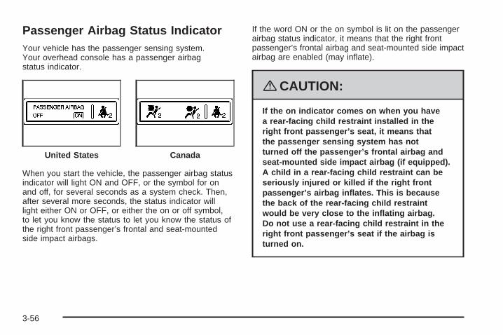
Passenger Airbag Status IndicatorYour vehicle has the passenger sensing system.Your overhead console has a passenger airbagstatus indicator.
When you start the vehicle, the passenger airbag statusindicator will light ON and OFF, or the symbol for onand off, for several seconds as a system check. Then,after several more seconds, the status indicator willlight either ON or OFF, or either the on or off symbol,to let you know the status to let you know the status ofthe right front passenger’s frontal and seat-mountedside impact airbags.
If the word ON or the on symbol is lit on the passengerairbag status indicator, it means that the right frontpassenger’s frontal airbag and seat-mounted side impactairbag are enabled (may inflate).
{CAUTION:
If the on indicator comes on when you havea rear-facing child restraint installed in theright front passenger’s seat, it means thatthe passenger sensing system has notturned off the passenger’s frontal airbag andseat-mounted side impact airbag (if equipped).A child in a rear-facing child restraint can beseriously injured or killed if the right frontpassenger’s airbag inflates. This is becausethe back of the rear-facing child restraintwould be very close to the inflating airbag.Do not use a rear-facing child restraint in theright front passenger’s seat if the airbag isturned on.
United States Canada
3-56

{CAUTION:
Even though the passenger sensing system isdesigned to turn off the right front passenger’sfrontal airbag and seat-mounted side impactairbag (if equipped) if the system detects arear-facing child restraint, no system isfail-safe, and no one can guarantee that anairbag will not deploy under some unusualcircumstance, even though it is turned off.We recommend that rear-facing child restraintsbe secured in a rear seat, even if the airbagis or airbags are off.
If the word OFF or the off symbol is lit on the passengerairbag status indicator, it means that the passengersensing system has turned off the right front passenger’sfrontal airbag and seat-mounted side impact airbag.See Passenger Sensing System on page 1-62 formore on this, including important safety information.
If, after several seconds, both status indicator lightsremain on, or if there are no lights at all, there maybe a problem with the lights or the passenger sensingsystem. See your dealer/retailer for service.
{CAUTION:
If the airbag readiness light in the instrumentpanel cluster ever comes on and stays on,it means that something may be wrong withthe airbag system. If this ever happens, havethe vehicle serviced promptly, because anadult-size person sitting in the right frontpassenger’s seat may not have the protectionof the airbag(s). See Airbag Readiness Lighton page 3-55 for more on this, includingimportant safety information.
3-57
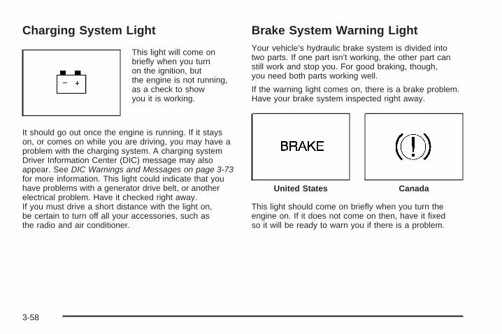
Charging System Light
This light will come onbriefly when you turnon the ignition, butthe engine is not running,as a check to showyou it is working.
It should go out once the engine is running. If it stayson, or comes on while you are driving, you may have aproblem with the charging system. A charging systemDriver Information Center (DIC) message may alsoappear. See DIC Warnings and Messages on page 3-73for more information. This light could indicate that youhave problems with a generator drive belt, or anotherelectrical problem. Have it checked right away.If you must drive a short distance with the light on,be certain to turn off all your accessories, such asthe radio and air conditioner.
Brake System Warning LightYour vehicle’s hydraulic brake system is divided intotwo parts. If one part isn’t working, the other part canstill work and stop you. For good braking, though,you need both parts working well.
If the warning light comes on, there is a brake problem.Have your brake system inspected right away.
This light should come on briefly when you turn theengine on. If it does not come on then, have it fixedso it will be ready to warn you if there is a problem.
United States Canada
3-58
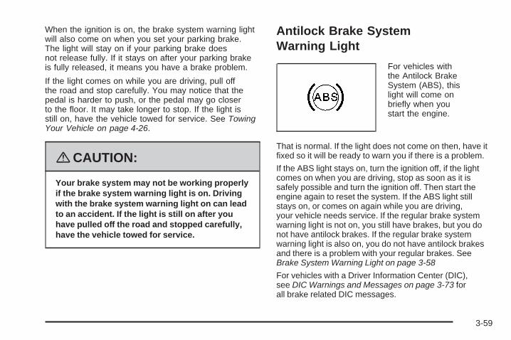
When the ignition is on, the brake system warning lightwill also come on when you set your parking brake.The light will stay on if your parking brake doesnot release fully. If it stays on after your parking brakeis fully released, it means you have a brake problem.
If the light comes on while you are driving, pull offthe road and stop carefully. You may notice that thepedal is harder to push, or the pedal may go closerto the floor. It may take longer to stop. If the light isstill on, have the vehicle towed for service. See TowingYour Vehicle on page 4-26.
{CAUTION:
Your brake system may not be working properlyif the brake system warning light is on. Drivingwith the brake system warning light on can leadto an accident. If the light is still on after youhave pulled off the road and stopped carefully,have the vehicle towed for service.
Antilock Brake SystemWarning Light
For vehicles withthe Antilock BrakeSystem (ABS), thislight will come onbriefly when youstart the engine.
That is normal. If the light does not come on then, have itfixed so it will be ready to warn you if there is a problem.
If the ABS light stays on, turn the ignition off, if the lightcomes on when you are driving, stop as soon as it issafely possible and turn the ignition off. Then start theengine again to reset the system. If the ABS light stillstays on, or comes on again while you are driving,your vehicle needs service. If the regular brake systemwarning light is not on, you still have brakes, but you donot have antilock brakes. If the regular brake systemwarning light is also on, you do not have antilock brakesand there is a problem with your regular brakes. SeeBrake System Warning Light on page 3-58
For vehicles with a Driver Information Center (DIC),see DIC Warnings and Messages on page 3-73 forall brake related DIC messages.
3-59

Traction Control System (TCS)Warning Light
The traction controlsystem warning lightshould come on brieflywhen the engineis started.
If the warning light does not come on then, have it fixedso it will be ready to warn you if there is a problem.If it stays on, or comes on when you are driving, theremay be a problem with your traction control systemand your vehicle may need service. When this warninglight is on, the system will not limit wheel spin. Adjustyour driving accordingly.
If the traction control system warning light comes onand stays on for an extended period of time whenthe system is turned on, your vehicle needs service.See Traction Control System (TCS) on page 4-5for more information.
StabiliTrak® Indicator Light
For vehicles thathave the StabiliTrak®
system, this warninglight should come onbriefly when the engineis started.
If the warning light does not come on then, have it fixedso it will be ready to warn you if there is a problem.If it stays on, or comes on when you are driving,there may be a problem with your StabiliTrak® systemand your vehicle may need service. When this warninglight is on, the system will not limit wheel spin. Adjustyour driving accordingly.
If the StabiliTrak® system warning light comes onand stays on for an extended period of time whenthe system is turned on, your vehicle needs service.See StabiliTrak® System on page 4-7 for moreinformation.
3-60

Lane Departure Warning Light
Your vehicle may havethe lane departurewarning system.
This light will come on green, briefly, when the vehicleis started to show that it is working. This light willalso come on green if the system detects a left orright lane marking. This light will change to amberand flash and three beeps will sound if you crossa detected lane marking without using your turnsignal. For more information, see the Index in theNavigation Manual.
Engine Coolant TemperatureWarning Light
The engine coolanttemperature warninglight will come on whenthe engine is very hot.
This light will also come on briefly when the vehicleis started.
If the light does not go out or comes on and stayson while driving, there may be a problem with thecooling system. Driving with engine coolant temperaturelight on could cause your vehicle to overheat, seeOverheated Engine Protection Operating Mode onpage 5-27. See Engine Overheating on page 5-25and DIC Warnings and Messages on page 3-73 formore information.
3-61

Engine Coolant Temperature Gage
This gage showsthe engine coolanttemperature.
It indicates when the engine has warmed up and ifthe cooling system is operating properly. If the gagepointer moves into the shaded area, the enginecoolant is too hot and the engine coolant temperaturewarning light will come on. See Engine Overheatingon page 5-25 for more information.
Tire Pressure LightThis light comes on brieflywhen the engine is started.
This light will also come on when one or more of yourtires are significantly underinflated.A tire pressure message in the Driver Information Center(DIC), may accompany the light. See DIC Warningsand Messages on page 3-73 for more information.Stop and check your tires as soon as it is safe todo so. If underinflated, inflate to the proper pressure.See Tires on page 5-50 for more information.
If a problem is detected with the Tire Pressure MonitorSystem, this light will flash for approximately 60 secondsand then stay on solid for the remainder of the ignitioncycle. See Tire Pressure Monitor System on page 5-61for more information.
3-62

Malfunction Indicator Lamp
Check Engine LightA computer system called OBD II (On-BoardDiagnostics-Second Generation) monitors operation ofthe fuel, ignition, and emission control systems. It makessure that emissions are at acceptable levels for the lifeof the vehicle, helping to produce a cleaner environment.
The check engine lightcomes on to indicatethat there is an OBD IIproblem and serviceis required.
Malfunctions often are indicated by the system beforeany problem is apparent. This can prevent more seriousdamage to your vehicle. This system is also designedto assist your service technician in correctly diagnosingany malfunction.
Notice: If you keep driving your vehicle with thislight on, after a while, the emission controlsmight not work as well, your vehicle’s fuel economymight not be as good, and the engine might notrun as smoothly. This could lead to costly repairsthat might not be covered by your warranty.
Notice: Modifications made to the engine,transmission, exhaust, intake, or fuel system ofyour vehicle or the replacement of the original tireswith other than those of the same Tire PerformanceCriteria (TPC) can affect your vehicle’s emissioncontrols and can cause this light to come on.Modifications to these systems could lead to costlyrepairs not covered by your warranty. This couldalso result in a failure to pass a required EmissionInspection/Maintenance test. See Accessoriesand Modifications on page 5-3.
This light comes on, as a check to show it is working,when the ignition is turned ON/RUN but the engineis not running. If the light does not come on, haveit repaired. This light also comes on during amalfunction in one of two ways:
• Light Flashing — A misfire condition has beendetected. A misfire increases vehicle emissionsand could damage the emission control systemon your vehicle. Diagnosis and service mightbe required.
• Light On Steady — An emission control systemmalfunction has been detected on your vehicle.Diagnosis and service might be required.
3-63

If the Light is FlashingThe following can prevent more serious damage toyour vehicle:
• Reduce vehicle speed.
• Avoid hard accelerations.
• Avoid steep uphill grades.
• If you are towing a trailer, reduce the amount ofcargo being hauled as soon as it is possible.
If the light stops flashing and remains on steady,see “If the Light Is On Steady” following.
If the light continues to flash, when it is safe to do so,stop the vehicle. Find a safe place to park the vehicle.Turn the ignition off, wait at least 10 seconds, and restartthe engine. If the light remains on steady, see “If theLight Is On Steady” following. If the light is still flashing,follow the previous steps and see your dealer/retailerfor service as soon as possible.
If the Light Is On SteadyYou might be able to correct the emission systemmalfunction by considering the following:
Did you recently put fuel into your vehicle?
If so, reinstall the fuel cap, making sure to fully install thecap. See Filling the Tank on page 5-8. The diagnosticsystem can determine if the fuel cap has been left off orimproperly installed. A loose or missing fuel cap allowsfuel to evaporate into the atmosphere. A few driving tripswith the cap properly installed should turn the light off.
Did you just drive through a deep puddle of water?
If so, your vehicle’s electrical system might be wet. Thecondition is usually corrected when the electrical systemdries out. A few driving trips should turn the light off.
3-64

Have you recently changed brands of fuel?
If so, be sure to fuel your vehicle with quality fuel. SeeGasoline Octane on page 5-5. Poor fuel quality causesthe engine not to run as efficiently as designed. Youmight notice this as stalling after start-up, stalling whenyou put the vehicle into gear, misfiring, hesitation onacceleration, or stumbling on acceleration — theseconditions might go away once the engine is warmedup. This will be detected by the system and cause thelight to turn on.
If you experience one or more of these conditions,change the fuel brand you use. It will require at leastone full tank of the proper fuel to turn the light off.
If none of the above steps have made the light turnoff, your dealer/retailer can check the vehicle. Yourdealer/retailer has the proper test equipment anddiagnostic tools to fix any mechanical or electricalproblems that might have developed.
Emissions Inspection andMaintenance ProgramsSome state/provincial and local governments have ormight begin programs to inspect the emission controlequipment on your vehicle. Failure to pass thisinspection could prevent you from getting a vehicleregistration.
Here are some things you need to know to help yourvehicle pass an inspection:
Your vehicle will not pass this inspection if the checkengine light is on or not working properly.
Your vehicle will not pass this inspection if theOBD (on-board diagnostic) system determines thatcritical emission control systems have not beencompletely diagnosed by the system. The vehiclewould be considered not ready for inspection. Thiscan happen if you have recently replaced the batteryor if the battery has run down. The diagnostic systemis designed to evaluate critical emission control systemsduring normal driving. This can take several days ofroutine driving. If you have done this and your vehiclestill does not pass the inspection for lack of OBDsystem readiness, your dealer/retailer can preparethe vehicle for inspection.
3-65
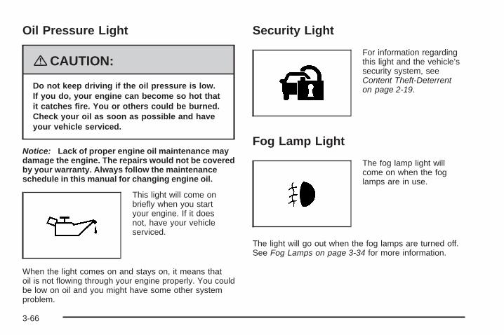
Oil Pressure Light
{CAUTION:
Do not keep driving if the oil pressure is low.If you do, your engine can become so hot thatit catches fire. You or others could be burned.Check your oil as soon as possible and haveyour vehicle serviced.
Notice: Lack of proper engine oil maintenance maydamage the engine. The repairs would not be coveredby your warranty. Always follow the maintenanceschedule in this manual for changing engine oil.
This light will come onbriefly when you startyour engine. If it doesnot, have your vehicleserviced.
When the light comes on and stays on, it means thatoil is not flowing through your engine properly. You couldbe low on oil and you might have some other systemproblem.
Security Light
For information regardingthis light and the vehicle’ssecurity system, seeContent Theft-Deterrenton page 2-19.
Fog Lamp Light
The fog lamp light willcome on when the foglamps are in use.
The light will go out when the fog lamps are turned off.See Fog Lamps on page 3-34 for more information.
3-66
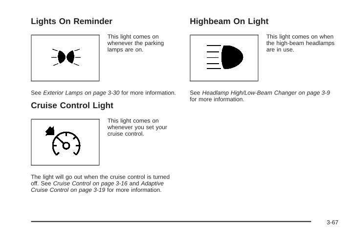
Lights On Reminder
This light comes onwhenever the parkinglamps are on.
See Exterior Lamps on page 3-30 for more information.
Cruise Control Light
This light comes onwhenever you set yourcruise control.
The light will go out when the cruise control is turnedoff. See Cruise Control on page 3-16 and AdaptiveCruise Control on page 3-19 for more information.
Highbeam On Light
This light comes on whenthe high-beam headlampsare in use.
See Headlamp High/Low-Beam Changer on page 3-9for more information.
3-67
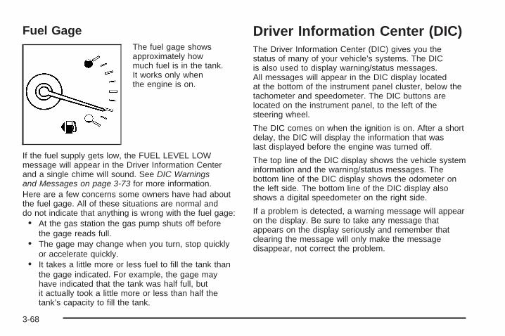
Fuel GageThe fuel gage showsapproximately howmuch fuel is in the tank.It works only whenthe engine is on.
If the fuel supply gets low, the FUEL LEVEL LOWmessage will appear in the Driver Information Centerand a single chime will sound. See DIC Warningsand Messages on page 3-73 for more information.Here are a few concerns some owners have had aboutthe fuel gage. All of these situations are normal anddo not indicate that anything is wrong with the fuel gage:• At the gas station the gas pump shuts off before
the gage reads full.• The gage may change when you turn, stop quickly
or accelerate quickly.• It takes a little more or less fuel to fill the tank than
the gage indicated. For example, the gage mayhave indicated that the tank was half full, butit actually took a little more or less than half thetank’s capacity to fill the tank.
Driver Information Center (DIC)The Driver Information Center (DIC) gives you thestatus of many of your vehicle’s systems. The DICis also used to display warning/status messages.All messages will appear in the DIC display locatedat the bottom of the instrument panel cluster, below thetachometer and speedometer. The DIC buttons arelocated on the instrument panel, to the left of thesteering wheel.
The DIC comes on when the ignition is on. After a shortdelay, the DIC will display the information that waslast displayed before the engine was turned off.
The top line of the DIC display shows the vehicle systeminformation and the warning/status messages. Thebottom line of the DIC display shows the odometer onthe left side. The bottom line of the DIC display alsoshows a digital speedometer on the right side.
If a problem is detected, a warning message will appearon the display. Be sure to take any message thatappears on the display seriously and remember thatclearing the message will only make the messagedisappear, not correct the problem.
3-68

DIC Operation and Displays
The Driver InformationCenter (DIC) has differentdisplays which can beaccessed by pressing theDIC buttons located onthe instrument panel, to theleft of the steering wheel.
3 Trip/Fuel: Press this button to scroll through thetrip and fuel displays. See “Trip/Fuel Display MenuItems” following for more information on these displays.
T Vehicle Information: Press this button to scrollthrough the vehicle information displays. See “VehicleInformation Display Menu Items” following for moreinformation on these displays.
U Customization: Press this button to scroll througheach of the customization features. See DIC VehicleCustomization on page 3-86 for more information onthe customization features.
V Set/Reset: Press this button to reset certain DICfeatures and to acknowledge DIC warning messagesand clear them from the DIC display.
yz Menu Up/Down: Press this button to scroll upand down the menu items.
Trip/Fuel Display Menu Items
3 (Trip/Fuel): The following display menu itemscan be displayed by pressing the trip/fuel button:
TRIP A or TRIP BThese displays show the current distance traveled sincethe last reset for each trip odometer in either miles (mi)or kilometers (km). Both odometers can be used atthe same time. Each trip odometer can be reset tozero separately by pressing and holding the set/resetbutton for a few seconds while the desired trip odometeris displayed.
3-69

FUEL RANGEThis display shows the approximate number ofremaining miles (mi) or kilometers (km) you can drivewithout refilling the fuel tank. This estimate is basedon the current driving conditions and will change if thedriving conditions change. For example, if you aredriving in traffic and making frequent stops, the displaymay read one number, but if you enter the freeway,the number may change even though you still have thesame amount of fuel in the fuel tank. This is becausedifferent driving conditions produce different fueleconomies. Generally, freeway driving producesbetter fuel economy than city driving.
Once the range drops below an estimated40 miles (64 km) remaining, the display will showFUEL RANGE LOW.
If your vehicle is low on fuel, the FUEL LEVEL LOWmessage will be displayed. See “FUEL LEVEL LOW”under DIC Warnings and Messages on page 3-73 formore information.
AVERAGE ECONOMY (AFE)This display shows the approximate average miles pergallon (mpg) or liters per 100 kilometers (L/100 km).This number is calculated based on the numberof mpg (L/100 km) recorded since the last time thisdisplay was reset. To reset this display, press theset/reset button. The display will return to zero.
INST (Instantaneous) ECONOMY (IFE)This display shows the current fuel economy ineither miles per gallon (mpg) or liters per 100 kilometers(L/100 km). This number reflects only the fuel economythat the vehicle has right now and will change frequentlyas driving conditions change. Unlike average economy,this display cannot be reset.
FUEL USEDThis display shows the number of gallons (gal) orliters (L) of fuel used since the last reset of this display.To reset this display, press the set/reset button.The display will return to zero.
TIMER ON/OFFThis display can be used like a stopwatch. You canrecord the time it takes to travel from one point toanother. To access the timer, press the trip/fuel buttonuntil 00:00:00 TIMER OFF displays.
To turn on the timer, press the set/reset button untilTIMER ON displays. The timer will then start.
To turn off the timer, press the set/reset button againuntil TIMER OFF displays. The timer will stop anddisplay the end timing value.
To reset the timer, press and hold the set/reset buttonafter the timer has been stopped. The display willreturn to zero.
3-70

AVERAGE SPEEDThis display shows the average speed of the vehicle ineither miles per hour (mph) or kilometers per hour (km/h).This average is calculated based on the various vehiclespeeds recorded since the last reset of this display.To reset this display, press the set/reset button. Thedisplay will return to zero.
BATTERY VOLTAGEThis display shows the current battery voltage.If the voltage is in the normal range, the value willdisplay. For example, the display may read BATTERYVOLTAGE 13.2 VOLTS. If the voltage is low, the displaywill show LOW. If the voltage is high, the display willshow HIGH. Your vehicle’s charging system regulatesvoltage based on the state of the battery. The batteryvoltage may fluctuate when viewing this information onthe DIC. This is normal. See Charging System Lighton page 3-58 for more information.
If there is a problem with the battery charging system,the DIC will display a message. See DIC Warningsand Messages on page 3-73 and Electric PowerManagement on page 3-37 for more information.
Blank DisplayThis display shows no information.
Vehicle Information Display Menu Items
T (Vehicle Information): The following displaymenu items can be displayed by pressing the vehicleinformation button:
OIL LIFE REMAININGIf the vehicle has this display, it shows the estimated oillife remaining. If you see 99% OIL LIFE REMAININGon the display, that means that 99% of the current oillife remains.
When the oil life is depleted, the CHANGE ENGINEOIL SOON message will appear on the display.You should change the oil as soon as possible.In addition to the engine oil life system monitoringthe oil life, additional maintenance is recommendedin the Maintenance Schedule in this manual.See Scheduled Maintenance on page 6-4 andEngine Oil on page 5-13.
Remember, you must reset the OIL LIFE yourselfafter each oil change. It will not reset itself. Also, becareful not to reset the OIL LIFE accidentally at anytime other than when the oil has just been changed.It cannot be reset accurately until the next oil change.To reset the engine oil life system, See Engine OilLife System on page 5-16. The display will show100% when the system is reset.
3-71

UNITSThis display allows you to select between English orMetric units of measurement. Once in this display,press the set/reset button to select between ENGLISHor METRIC units.
PARKING ASSISTIf your vehicle has the Ultrasonic Front and Rear ParkingAssist (UFRPA) system, this display allows the systemto be turned on or off. Once in this display, press theset/reset button to select between ON or OFF. If youchoose ON, the system will be turned on. If you chooseOFF, the system will be turned off. The UFRPA systemautomatically turns back on after each vehicle start.When the UFRPA system is turned off and the vehicleis shifted out of PARK (P), the DIC will display thePARKING ASSIST OFF message as a reminder thatthe system has been turned off. See DIC Warningsand Messages on page 3-73 and Ultrasonic Front andRear Parking Assist (UFRPA) on page 2-44 for moreinformation.
SIDE BLIND ZONE ALERTIf your vehicle has the Side Blind Zone Alert (SBZA)system, this display allows the system to be turned onor off. Once in this display, press the set/reset button toselect between ON or OFF. If you choose ON, the systemwill be turned on. If you choose OFF, the system will beturned off. When the SBZA system is turned off, the DICwill display the SIDE BLIND ZONE ALERT SYSTEM OFFmessage as a reminder that the system has been turnedoff. See DIC Warnings and Messages on page 3-73 andSide Blind Zone Alert on page 2-47 for more information.
FRONT TIRES or REAR TIRESThe pressure for each tire can be viewed in the DIC.The tire pressure will be shown in either pounds persquare inch (psi) or kilopascals (kPa). Press thevehicle information button until the DIC displaysFRONT TIRES PSI (kPa) LEFT ## RIGHT ##. Pressthe vehicle information button again until the DICdisplays REAR TIRES PSI (kPa) LEFT ## RIGHT ##.
If a low or high tire pressure condition is detected bythe system while driving, a message advising you tocheck the pressure in a specific tire will appear in thedisplay. See Inflation - Tire Pressure on page 5-58and DIC Warnings and Messages on page 3-73 formore information.
3-72

If the tire pressure display shows dashes instead of avalue, there may be a problem with your vehicle. If thisconsistently occurs, see your dealer/retailer for service.
RELEARN REMOTE KEYThis display allows you to match Remote KeylessEntry (RKE) transmitters to your vehicle. To matchan RKE transmitter to your vehicle:1. Press the vehicle information button until
PRESS V TO RELEARN REMOTE KEY displays.
2. Press the set/reset button until REMOTE KEYLEARNING ACTIVE is displayed.
3. Press and hold the lock and unlock buttonson the first transmitter at the same time forabout 15 seconds.On vehicles with memory recall seats, the firsttransmitter learned will match driver 1 andthe second will match driver 2.A chime will sound indicating that the transmitteris matched.
4. To match additional transmitters at this time,repeat Step 3.Each vehicle can have a maximum of eighttransmitters matched to it.
5. To exit the programming mode, you must cyclethe key to LOCK/OFF.
Blank DisplayThis display shows no information.
DIC Warnings and MessagesThese messages appear if there is a problem detectedin one of your vehicle’s systems.
You must acknowledge a message to clear it fromthe screen for further use. To clear a message, pressthe set/reset button.
Be sure to take any message that appears on thescreen seriously and remember that clearing themessage will only make the message disappear,not the problem.
AUTOMATIC LIGHT CONTROL OFFThis message displays when the automatic headlampsare turned off. See Exterior Lamps on page 3-30 formore information.
AUTOMATIC LIGHT CONTROL ONThis message displays when the automatic headlampsare turned on. See Exterior Lamps on page 3-30 formore information.
3-73

BATTERY SAVER ACTIVEThis message displays when the system detects thatthe battery voltage is dropping beyond a reasonablelevel. The battery saver system starts reducing certainfeatures of the vehicle that you may be able to notice.At the point that the features are disabled, this messageis displayed. It means that the vehicle is trying tosave the charge in the battery.
Turn off all unnecessary accessories to allow the batteryto recharge.
The normal battery voltage range is 11.5 to 15.5 volts.You can monitor battery voltage on the Driver InformationCenter (DIC) by pressing the trip/fuel button untilBATTERY VOLTAGE is displayed.
CHANGE ENGINE OIL SOONThis message displays when service is required foryour vehicle. See your dealer/retailer. See Engine Oilon page 5-13 and Scheduled Maintenance on page 6-4for more information.
When you reset the CHANGE ENGINE OIL SOONmessage by clearing it from the display, you still mustreset the engine oil life system separately. For moreinformation on resetting the engine oil life system,see Engine Oil Life System on page 5-16.
CHECK TIRE PRESSUREThis message displays when the pressure in one ormore of the vehicle’s tires needs to be checked.This message also displays LEFT FRONT, RIGHTFRONT, LEFT REAR, or RIGHT REAR to indicatewhich tire needs to be checked. You can receive morethan one tire pressure message at a time. To readthe other messages that may have been sent atthe same time, press the set/reset button. If a tirepressure message appears on the DIC, stop as soonas you can. Have the tire pressures checked and setto those shown on the Tire Loading Informationlabel. See Tires on page 5-50, Loading Your Vehicle onpage 4-20, and Inflation - Tire Pressure on page 5-58.The DIC also shows the tire pressure values. SeeDIC Operation and Displays on page 3-69. If the tirepressure is low, the low tire pressure warning lightcomes on. See Tire Pressure Light on page 3-62.
CLEAN RADARThis message displays when the Adaptive CruiseControl (ACC) system and the Forward Collision Alert(FCA) system are disabled because the radar is blockedand cannot detect vehicles in your path. It may alsoactivate during heavy rain or due to road spray. To cleanthe system, see “Cleaning the System” under AdaptiveCruise Control on page 3-19.
3-74

CLEAN SIDE BLIND ZONEALERT SYSTEMIf your vehicle has the Side Blind Zone Alert (SBZA)system, this message displays when the SBZA systemis disabled because the sensor is blocked and cannotdetect vehicles in your blind zone. The sensor maybe blocked by mud, dirt, snow, ice, or slush. Thismessage may also display during heavy rain or dueto road spray. Your vehicle does not need service.For cleaning instructions, see Washing Your Vehicleon page 5-90. See Side Blind Zone Alert on page 2-47for more information.
CRUISE SET TO XXX MPH (km/h)This message displays whenever the cruise control isset. See Cruise Control on page 3-16 and AdaptiveCruise Control on page 3-19 for more information.
If your vehicle has Adaptive Cruise Control (ACC),after a few seconds, this message clears and themessage “SET SPD XX” displays at the bottom of theDIC. See “SET SPD (Speed)” later in this section.
DRIVER DOOR OPEN
This symbol appearswith this message.
This message displays when the driver door is notclosed completely. Make sure that the door is closedcompletely.
ENGINE HOT – A/C (AirConditioning) OFFThis message displays when the engine coolantbecomes hotter than the normal operating temperature.See Engine Coolant Temperature Gage on page 3-62.To avoid added strain on a hot engine, the airconditioning compressor automatically turns off. Whenthe coolant temperature returns to normal, the airconditioning compressor turns back on. You cancontinue to drive your vehicle.If this message continues to appear, have the systemrepaired by your dealer/retailer as soon as possibleto avoid damage to the engine.
3-75

ENGINE OVERHEATED IDLE ENGINE
Notice: If you drive your vehicle while the engineis overheating, severe engine damage may occur.If an overheat warning appears on the instrumentpanel cluster and/or DIC, stop the vehicle as soonas possible. Do not increase the engine speed abovenormal idling speed. See Engine Overheating onpage 5-25 for more information.
This message displays when the engine coolanttemperature is too hot. Stop and allow the vehicleto idle until it cools down. See Engine CoolantTemperature Warning Light on page 3-61.
See Overheated Engine Protection Operating Modeon page 5-27 for information on driving to a safeplace in an emergency.
ENGINE OVERHEATED STOP ENGINE
Notice: If you drive your vehicle while the engineis overheating, severe engine damage may occur.If an overheat warning appears on the instrumentpanel cluster and/or DIC, stop the vehicle as soonas possible. See Engine Overheating on page 5-25for more information.
This message displays when the engine has overheated.Immediately look for a safe place to pull your vehicleover and turn the engine off right away to avoid severeengine damage. See Engine Overheating on page 5-25and Overheated Engine Protection Operating Modeon page 5-27. A chime also sounds when this messageis displayed.
ENGINE POWER REDUCEDThis message displays when the engine power is beingreduced to protect the engine from damage. There couldbe several malfunctions that might cause this message.Reduced engine power can affect the vehicle’s abilityto accelerate. If this message is on, but there is noreduction in performance, proceed to your destination.The performance may be reduced the next time thevehicle is driven. The vehicle may be driven at a reducedspeed while this message is on, but acceleration andspeed may be reduced. Anytime this message stays on,the vehicle should be taken to your dealer/retailer forservice as soon as possible.
3-76

FOLLOWING GAP
This symbol appears with this message.
If your vehicle has Adaptive Cruise Control (ACC),this message displays to show the follow distance thathas been set. There are six follow distances to choosefrom. Each follow distance is shown on the DIC bydisplaying from one to six bars between two car symbols.See Adaptive Cruise Control on page 3-19 for moreinformation.
FUEL LEVEL LOW
This symbol appearswith this message.
This message displays when your vehicle is low on fuel.Refill the fuel tank as soon as possible. A single chimesounds when this message is displayed. See Filling theTank on page 5-8.
HEATED WASHER FLUID SYSTEM OFFThis message displays when you manually turn offthe heated washer fluid system or when the systemautomatically turns off. See “Heated Washer Fluid”under Windshield Washer on page 3-15 for moreinformation.
3-77
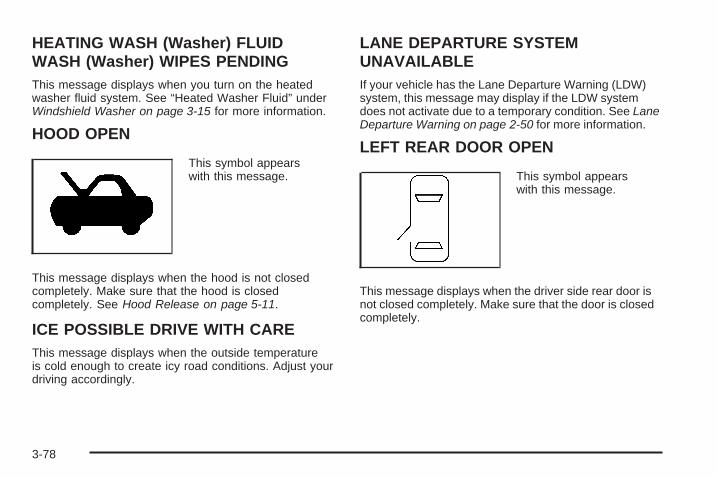
HEATING WASH (Washer) FLUIDWASH (Washer) WIPES PENDINGThis message displays when you turn on the heatedwasher fluid system. See “Heated Washer Fluid” underWindshield Washer on page 3-15 for more information.
HOOD OPEN
This symbol appearswith this message.
This message displays when the hood is not closedcompletely. Make sure that the hood is closedcompletely. See Hood Release on page 5-11.
ICE POSSIBLE DRIVE WITH CAREThis message displays when the outside temperatureis cold enough to create icy road conditions. Adjust yourdriving accordingly.
LANE DEPARTURE SYSTEMUNAVAILABLEIf your vehicle has the Lane Departure Warning (LDW)system, this message may display if the LDW systemdoes not activate due to a temporary condition. See LaneDeparture Warning on page 2-50 for more information.
LEFT REAR DOOR OPEN
This symbol appearswith this message.
This message displays when the driver side rear door isnot closed completely. Make sure that the door is closedcompletely.
3-78

NO CRUISE BRAKING GASPEDAL APPLIEDThis message displays when the Adaptive CruiseControl (ACC) is engaged and you are pressing theaccelerator pedal enough to disable ACC automaticbraking. See Adaptive Cruise Control on page 3-19 formore information.
OIL PRESSURE LOW STOP ENGINENotice: If you drive your vehicle while the engineoil pressure is low, severe engine damage mayoccur. If a low oil pressure warning appears onthe instrument panel cluster and/or DIC, stop thevehicle as soon as possible. Do not drive the vehicleuntil the cause of the low oil pressure is corrected.See Engine Oil on page 5-13 for more information.
This message displays when the vehicle’s engineoil pressure is low. The oil pressure light also appearson the instrument panel cluster. See Oil PressureLight on page 3-66.
A multiple chime sounds when this message isdisplayed. See Engine Oil on page 5-13 for moreinformation.
Stop the vehicle immediately, as engine damage canresult from driving a vehicle with low oil pressure.Have the vehicle serviced by your dealer/retailer assoon as possible when this message is displayed.
PARKING ASSIST OFFIf your vehicle has the Ultrasonic Front and RearParking Assist (UFRPA) system, after the vehicle isshifted out of PARK (P), this message displays to remindthe driver that the UFRPA system has been turnedoff. Press the set/reset button to acknowledge thismessage and clear it from the DIC display. To turnthe UFRPA system back on, see “PARKING ASSIST”under DIC Operation and Displays on page 3-69.See Ultrasonic Front and Rear Parking Assist (UFRPA)on page 2-44 for more information.
PASSENGER DOOR OPEN
This symbol appearswith this message.
This message displays when the passenger side frontdoor is not closed completely. Make sure that the dooris closed completely.
3-79

RADAR CRUISE NOT READYThis message displays when the Adaptive CruiseControl (ACC) system will not activate due to atemporary condition. Your vehicle does not requireservice. If this message appears when you attemptto activate the system, continue driving for severalminutes and then try activating the system again.See Adaptive Cruise Control on page 3-19 for moreinformation.
RAINSENSE WIPERS ACTIVEIf your vehicle has Rainsense™ II wipers, this messagedisplays while this feature is active. See Rainsense™II Wipers on page 3-14 for more information.
REMOTE KEY LEARNING ACTIVEThis message displays while you are matching aRemote Keyless Entry (RKE) transmitter to your vehicle.See “Matching Transmitter(s) to Your Vehicle” underRemote Keyless Entry (RKE) System Operationon page 2-5 and DIC Operation and Displays onpage 3-69 for more information.
REPLACE BATTERY IN REMOTE KEYThis message displays when the battery in the RemoteKeyless Entry (RKE) transmitter needs to be replaced.To replace the battery, see “Battery Replacement”under Remote Keyless Entry (RKE) System Operationon page 2-5.
RIGHT REAR DOOR OPEN
This symbol appearswith this message.
This message displays when the passenger side reardoor is not closed completely. Make sure that the dooris closed completely.
3-80

SERVICE AIR BAGThis message displays when there is a problem withthe airbag system. Have your vehicle serviced by yourdealer/retailer immediately. See Airbag ReadinessLight on page 3-55 for more information.
SERVICE A/C SYSTEMThis message displays when the air delivery modedoor or the electronic sensors that control the airconditioning and heating systems are no longer working.Have the climate control system serviced by yourdealer/retailer if you notice a drop in heating andair conditioning efficiency.
SERVICE BATTERY CHARGINGSYSTEMThis message displays when a problem with thecharging system has been detected. The chargingsystem light also displays on the instrument panelcluster. See Charging System Light on page 3-58 formore information. Have your vehicle serviced byyour dealer/retailer.
SERVICE BRAKE ASSISTThis message displays if there is a problem with thebrake system. The brake system warning light andthe antilock brake system warning light may also bedisplayed on the instrument panel cluster. See BrakeSystem Warning Light on page 3-58 and Antilock BrakeSystem Warning Light on page 3-59 for more information.If this happens, stop as soon as possible and turn off thevehicle. Restart the vehicle and check for the messageon the DIC display. If the message is displayed orappears again when you begin driving, the brake systemneeds service. See your dealer/retailer as soon aspossible. See Brakes on page 5-35 for more information.
SERVICE BRAKE SYSTEMThis message displays if the ignition is on to informthe driver that the brake fluid level is low. Havethe brake system serviced by your dealer/retailer assoon as possible.
SERVICE LANE DEPARTURE SYSTEMIf your vehicle has the Lane Departure Warning (LDW)system, this message may display to indicate that theLDW system is not working properly. If this messageremains on after continued driving, the system needsservice. See your dealer/retailer. See Lane DepartureWarning on page 2-50 for more information.
3-81

SERVICE PARKING ASSISTIf your vehicle has the Ultrasonic Front and RearParking Assist (UFRPA) system, this message displaysif there is a problem with the UFRPA system. Do notuse this system to help you park. See Ultrasonic Frontand Rear Parking Assist (UFRPA) on page 2-44 formore information. See your dealer/retailer for service.
SERVICE POWER STEERINGYour vehicle may have a speed variable assiststeering system. See Steering on page 4-8.
This message displays if a problem is detected withthe speed variable assist steering system. Whenthis message is displayed, you may notice that theeffort required to steer the vehicle decreases or feelslighter, but you will still be able to steer the vehicle.
SERVICE RADAR CRUISEThis message displays when the Adaptive CruiseControl (ACC) system and the Forward CollisionAlert (FCA) system are disabled and need service.See your dealer/retailer.
SERVICE SIDE BLIND ZONE ALERTSYSTEMIf your vehicle has the Side Blind Zone Alert (SBZA)system and this message displays, both SBZA displayswill remain on indicating there is a problem with theSBZA system. If these displays remain on aftercontinued driving, the system needs service. See yourdealer/retailer. See Side Blind Zone Alert on page 2-47for more information.
SERVICE STABILITRAKYour vehicle may have a vehicle stability enhancementsystem called StabiliTrak®. See StabiliTrak® Systemon page 4-7.
This message displays if there has been a problemdetected with the StabiliTrak® system.
If this message comes on while you are driving, pull offthe road as soon as possible and stop carefully. Tryresetting the system by turning the ignition off then backon. If this message still stays on or comes back onagain while you are driving, your vehicle needs service.Have the StabiliTrak® system inspected by yourdealer/retailer as soon as possible.
3-82

SERVICE SUSPENSION SYS (System)This message displays when the magnetic ridecontrol or automatic leveling control system is notoperating properly. Have your vehicle serviced byyour dealer/retailer.
SERVICE THEFT DETERRENT SYSTEMThis message displays when there is a problem withthe theft-deterrent system programmed in the key.A fault has been detected in the system which meansthat the system is disabled and it is not protectingthe vehicle. The vehicle usually restarts; however, youmay want to take the vehicle to your dealer/retailerbefore turning off the engine. See PASS-Key® III+Operation on page 2-21 for more information.
SERVICE TIRE MONITOR SYSTEMThis message displays if a part on the Tire PressureMonitor System (TPMS) is not working properly. The tirepressure light also flashes and then remains on duringthe same ignition cycle. See Tire Pressure Light onpage 3-62. Several conditions may cause this messageto appear. See Tire Pressure Monitor Operation onpage 5-62 for more information. If the warning comes onand stays on, there may be a problem with the TPMS.See your dealer/retailer.
SERVICE TRACTION CONTROLThis message displays when there is a problem with theTraction Control System (TCS). When this message isdisplayed, the system will not limit wheel spin. Adjust yourdriving accordingly. See your dealer/retailer for service.See Traction Control System (TCS) on page 4-5 formore information.
SERVICE TRANSMISSIONThis message displays when there is a problem withthe vehicle’s transmission. Have your vehicle servicedby your dealer/retailer.
SERVICE VEHICLE SOONThis message displays when a non-emissions relatedmalfunction occurs. Have your vehicle serviced byyour dealer/retailer as soon as possible.
SET SPD (Speed)If your vehicle has Adaptive Cruise Control (ACC), thismessage displays whenever the cruise control is set.First, the “CRUISE SET TO XXX MPH (km/h)” messageappears. After a few seconds, the “CRUISE SET TOXXX MPH (km/h)” message clears and the message“SET SPD XX” displays at the bottom of the DIC.See “CRUISE SET TO XXX MPH (km/h)” earlier inthis section and Adaptive Cruise Control on page 3-19for more information.
3-83

SIDE BLIND ZONE ALERTSYSTEM OFFIf your vehicle has the Side Blind Zone Alert (SBZA)system, this message displays when the SBZAsystem has been turned off. See Side Blind Zone Alerton page 2-47 and DIC Operation and Displays onpage 3-69 for more information.
SPEED LIMITED TO XXX MPH (km/h)This message displays when your vehicle speedis limited to 80 mph (128 km/h) because the vehicledetects a problem in the speed variable assiststeering, magnetic ride control, or automatic levelingcontrol systems. Have your vehicle serviced byyour dealer/retailer.
STABILITRAK NOT READYIf your vehicle has StabiliTrak®, this message maydisplay and the Traction Control System andStabiliTrak® Warning Light on the instrument panelcluster may be on after first driving the vehicleand exceeding 19 mph (30 km/h) for 30 seconds.The StabiliTrak® system is not functional until thelight has turned off. See StabiliTrak® Systemon page 4-7 for more information.
STARTING DISABLED SERVICETHROTTLEThis message displays when your vehicle’s throttlesystem is not functioning properly. Have your vehicleserviced by your dealer/retailer.
THEFT ATTEMPTED
This symbol appearswith this message.
This message displays if the content theft-deterrentsystem has detected a break-in attempt while you wereaway from your vehicle. See Content Theft-Deterrenton page 2-19 for more information.
TIGHTEN GAS CAPThis message displays when the fuel cap has not beenfully tightened. Recheck the fuel cap to ensure that itis on and tightened properly.
3-84
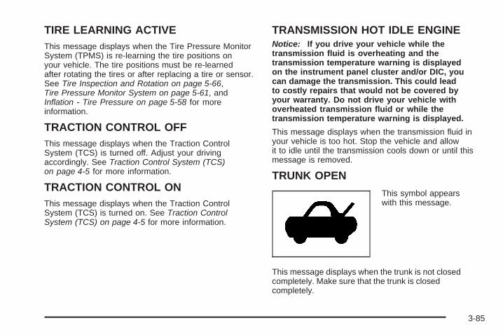
TIRE LEARNING ACTIVEThis message displays when the Tire Pressure MonitorSystem (TPMS) is re-learning the tire positions onyour vehicle. The tire positions must be re-learnedafter rotating the tires or after replacing a tire or sensor.See Tire Inspection and Rotation on page 5-66,Tire Pressure Monitor System on page 5-61, andInflation - Tire Pressure on page 5-58 for moreinformation.
TRACTION CONTROL OFFThis message displays when the Traction ControlSystem (TCS) is turned off. Adjust your drivingaccordingly. See Traction Control System (TCS)on page 4-5 for more information.
TRACTION CONTROL ONThis message displays when the Traction ControlSystem (TCS) is turned on. See Traction ControlSystem (TCS) on page 4-5 for more information.
TRANSMISSION HOT IDLE ENGINENotice: If you drive your vehicle while thetransmission fluid is overheating and thetransmission temperature warning is displayedon the instrument panel cluster and/or DIC, youcan damage the transmission. This could leadto costly repairs that would not be covered byyour warranty. Do not drive your vehicle withoverheated transmission fluid or while thetransmission temperature warning is displayed.
This message displays when the transmission fluid inyour vehicle is too hot. Stop the vehicle and allowit to idle until the transmission cools down or until thismessage is removed.
TRUNK OPEN
This symbol appearswith this message.
This message displays when the trunk is not closedcompletely. Make sure that the trunk is closedcompletely.
3-85

TURN SIGNAL ONThis message displays as a reminder to turn off theturn signal if you drive your vehicle for more than about1 mile (1.6 km) with a turn signal on. A multiple chimesounds when this message is displayed.
WASHER FLUID LOW ADD FLUID
This symbol appears withthis message.
This message displays when your vehicle is low onwindshield washer fluid. Refill the windshield washerfluid reservoir as soon as possible. See WindshieldWasher Fluid on page 5-34 for more information.
DIC Vehicle CustomizationYour vehicle has customization capabilities that allowyou to program certain features to one preferred setting.Customization features can only be programmed toone setting on the vehicle and cannot be programmedto a preferred setting for two different drivers.
All of the customization options may not be availableon your vehicle. Only the options available will bedisplayed on the DIC.
The default settings for the customization featureswere set when your vehicle left the factory, butmay have been changed from their default statesince then.
The customization preferences are automaticallyrecalled.
To change customization preferences, use thefollowing procedure.
3-86

Entering the Feature Settings Menu1. Turn the ignition on and place the vehicle in
PARK (P).To avoid excessive drain on the battery, it isrecommended that the headlamps are turned off.
2. Press the customization button to enter thefeature settings menu.If the menu is not available, FEATURE SETTINGSAVAILABLE IN PARK will display. Before enteringthe menu, make sure the vehicle is in PARK (P).
Feature Settings Menu ItemsThe following are customization features that allowyou to program settings to the vehicle:
DISPLAY IN ENGLISHThis feature will only display if a language other thanEnglish has been set. This feature allows you to changethe language in which the DIC messages appearto English.
Press the customization button until the PRESS V TODISPLAY IN ENGLISH screen appears on the DICdisplay. Press the set/reset button once to display allDIC messages in English.
DISPLAY LANGUAGEThis feature allows you to select the language in whichthe DIC messages will appear.
Press the customization button until the DISPLAYLANGUAGE screen appears on the DIC display.Press the set/reset button once to access the settingsfor this feature. Then press the menu up/down buttonto scroll through the following settings:
ENGLISH (default): All messages will appear inEnglish.
DEUTSCH: All messages will appear in German.
FRANCAIS: All messages will appear in French.
ESPANOL: All messages will appear in Spanish.
JAPANESE: All messages will appear in Japanese.
ARABIC: All messages will appear in Arabic.
NO CHANGE: No change will be made to this feature.The current setting will remain.
To select a setting, press the set/reset button while thedesired setting is displayed on the DIC.
3-87

AUTO DOOR LOCKThis feature allows you to select when the vehicle’sdoors will automatically lock. See ProgrammableAutomatic Door Locks on page 2-11 for moreinformation.
Press the customization button until AUTO DOORLOCK appears on the DIC display. Press the set/resetbutton once to access the settings for this feature.Then press the menu up/down button to scroll throughthe following settings:
SHIFT OUT OF PARK (default): The doorsautomatically lock when the doors are closed and thevehicle is shifted out of PARK (P).
AT VEHICLE SPEED: The doors automatically lockwhen the vehicle speed is above 5 mph (8 km/h)for three seconds.
NO CHANGE: No change will be made to this feature.The current setting will remain.
To select a setting, press the set/reset button while thedesired setting is displayed on the DIC.
AUTO DOOR UNLOCKThis feature allows you to select whether or not toturn off the automatic door unlocking feature. It alsoallows you to select which doors and when the doors willautomatically unlock. See Programmable AutomaticDoor Locks on page 2-11 for more information.
Press the customization button until AUTO DOORUNLOCK appears on the DIC display. Press theset/reset button once to access the settings for thisfeature. Then press the menu up/down button to scrollthrough the following settings:
OFF: None of the doors will automatically unlock.
DRIVER AT KEY OUT: Only the driver’s door willunlock when the key is taken out of the ignition.
DRIVER IN PARK: Only the driver’s door will unlockwhen the vehicle is shifted into PARK (P).
ALL AT KEY OUT: All of the doors will unlock whenthe key is taken out of the ignition.
ALL IN PARK (default): All of the doors will unlockwhen the vehicle is shifted into PARK (P).
NO CHANGE: No change will be made to this feature.The current setting will remain.
To select a setting, press the set/reset button while thedesired setting is displayed on the DIC.
3-88

REMOTE DOOR LOCKThis feature allows you to select the type of feedbackyou will receive when locking the vehicle with theRemote Keyless Entry (RKE) transmitter. You will notreceive feedback when locking the vehicle with the RKEtransmitter if the doors are open. See Remote KeylessEntry (RKE) System Operation on page 2-5 for moreinformation.
Press the customization button until REMOTE DOORLOCK appears on the DIC display. Press the set/resetbutton once to access the settings for this feature.Then press the menu up/down button to scroll throughthe following settings:
OFF: There will be no feedback when you press thelock button on the RKE transmitter.
LIGHTS ONLY: The exterior lamps will flash when youpress the lock button on the RKE transmitter.
HORN ONLY: The horn will sound on the second pressof the lock button on the RKE transmitter.
HORN & LIGHTS (default): The exterior lamps willflash when you press the lock button on the RKEtransmitter, and the horn will sound when the lock buttonis pressed again within five seconds of the previouscommand.
NO CHANGE: No change will be made to this feature.The current setting will remain.To select a setting, press the set/reset button while thedesired setting is displayed on the DIC.
REMOTE DOOR UNLOCKThis feature allows you to select the type of feedbackyou will receive when unlocking the vehicle withthe Remote Keyless Entry (RKE) transmitter. You willnot receive feedback when unlocking the vehiclewith the RKE transmitter if the doors are open. SeeRemote Keyless Entry (RKE) System Operationon page 2-5 for more information.Press the customization button until REMOTE DOORUNLOCK appears on the DIC display. Press theset/reset button once to access the settings for thisfeature. Then press the menu up/down button to scrollthrough the following settings:
LIGHTS OFF: The exterior lamps will not flash whenyou press the unlock button on the RKE transmitter.
LIGHTS ON (default): The exterior lamps willflash when you press the unlock button on the RKEtransmitter.
NO CHANGE: No change will be made to this feature.The current setting will remain.To select a setting, press the set/reset button while thedesired setting is displayed on the DIC.
3-89

DELAY DOOR LOCKThis feature allows you to select whether or not thelocking of the vehicle’s doors will be delayed. Whenlocking the doors with the power door lock switch and adoor is open, this feature will delay locking the doorsuntil five seconds after the last door is closed. You willhear three chimes to signal that the delayed lockingfeature is in use. The key must be out of the ignition forthis feature to work. You can temporarily overridedelayed locking by pressing the power door lock switchtwice or the lock button on the RKE transmitter twice.
Press the customization button until DELAY DOORLOCK appears on the DIC display. Press the set/resetbutton once to access the settings for this feature.Then press the menu up/down button to scroll throughthe following settings:
OFF: There will be no delayed locking of thevehicle’s doors.
ON (default): The doors will not lock until five secondsafter the last door is closed.
NO CHANGE: No change will be made to this feature.The current setting will remain.
To select a setting, press the set/reset button while thedesired setting is displayed on the DIC.
EXIT LIGHTINGThis feature allows you to select the amount of time youwant the exterior lamps to remain on when it is darkenough outside. This happens after the key is turnedfrom ON/RUN to LOCK/OFF.
Press the customization button until EXIT LIGHTINGappears on the DIC display. Press the set/reset buttononce to access the settings for this feature. Thenpress the menu up/down button to scroll through thefollowing settings:
OFF: The exterior lamps will not turn on.
30 SECONDS (default): The exterior lamps will stayon for 30 seconds.
1 MINUTE: The exterior lamps will stay on forone minute.
2 MINUTES: The exterior lamps will stay on fortwo minutes.
NO CHANGE: No change will be made to this feature.The current setting will remain.
To select a setting, press the set/reset button while thedesired setting is displayed on the DIC.
3-90
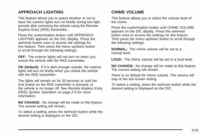
APPROACH LIGHTINGThis feature allows you to select whether or not tohave the exterior lights turn on briefly during low lightperiods after unlocking the vehicle using the RemoteKeyless Entry (RKE) transmitter.
Press the customization button until APPROACHLIGHTING appears on the DIC display. Press theset/reset button once to access the settings forthis feature. Then press the menu up/down buttonto scroll through the following settings:
OFF: The exterior lights will not turn on when youunlock the vehicle with the RKE transmitter.
ON (default): If it is dark enough outside, the exteriorlights will turn on briefly when you unlock the vehiclewith the RKE transmitter.
The lights will remain on for 20 seconds or until thelock button on the RKE transmitter is pressed, orthe vehicle is no longer off. See Remote Keyless Entry(RKE) System Operation on page 2-5 for moreinformation.
NO CHANGE: No change will be made to this feature.The current setting will remain.
To select a setting, press the set/reset button while thedesired setting is displayed on the DIC.
CHIME VOLUMEThis feature allows you to select the volume level ofthe chime.
Press the customization button until CHIME VOLUMEappears on the DIC display. Press the set/resetbutton once to access the settings for this feature.Then press the menu up/down button to scroll throughthe following settings:
NORMAL: The chime volume will be set to anormal level.
LOUD: The chime volume will be set to a loud level.
NO CHANGE: No change will be made to this feature.The current setting will remain.
There is no default for chime volume. The volume willstay at the last known setting.
To select a setting, press the set/reset button while thedesired setting is displayed on the DIC.
3-91

PARK TILT MIRRORSIf your vehicle has this feature, it allows you to selectwhether or not the outside mirror(s) will automatically tiltdown when the vehicle is shifted into REVERSE (R).See Park Tilt Mirrors on page 2-42 for more information.
Press the customization button until PARK TILTMIRRORS appears on the DIC display. Press theset/reset button once to access the settings forthis feature. Then press the menu up/down button toscroll through the following settings:
OFF (default): Neither outside mirror will be tilted downwhen the vehicle is shifted into REVERSE (R).
DRIVER MIRROR: The driver’s outside mirror will betilted down when the vehicle is shifted intoREVERSE (R).
PASSENGER MIRROR: The passenger’s outsidemirror will be tilted down when the vehicle is shifted intoREVERSE (R).
BOTH MIRRORS: The driver’s and passenger’s outsidemirrors will be tilted down when the vehicle is shiftedinto REVERSE (R).
NO CHANGE: No change will be made to this feature.The current setting will remain.To select a setting, press the set/reset button while thedesired setting is displayed on the DIC.
EASY EXIT RECALLIf your vehicle has this feature, it allows you to selectyour preference for the automatic easy exit seat feature.See Memory Seat, Mirrors and Steering Wheel onpage 1-4 for more information.Press the customization button until EASY EXITRECALL appears on the DIC display. Press the set/resetbutton once to access the settings for this feature.Then press the menu up/down button to scroll throughthe following settings:
DOOR BUTTON ONLY: No automatic seat exit recallwill occur. The recall will only occur after pressingthe easy exit seat button.
BUTTON AND KEY OUT (default): If the features areenabled through the EASY EXIT SETUP menu, thedriver’s seat will move back, and if the vehicle has thepower tilt wheel and telescopic steering feature, thepower steering column will move up and forward whenthe key is removed from the ignition or after pressingthe easy exit seat button.
The automatic easy exit seat movement will only occurone time after the key is removed from the ignition.If the automatic movement has already occurred, andyou put the key back in the ignition and remove it again,the seat and steering column will stay in the originalexit position, unless a memory recall took place prior toremoving the key again.
3-92

NO CHANGE: No change will be made to this feature.The current setting will remain.
To select a setting, press the set/reset button while thedesired setting is displayed on the DIC.
EASY EXIT SETUPIf your vehicle has this feature, it allows you to selectwhich areas will recall with the automatic easy exit seatfeature. It also allows you to turn off the automaticeasy exit feature. See Memory Seat, Mirrors andSteering Wheel on page 1-4 and “EASY EXIT RECALL”earlier for more information.
Press the customization button until EASY EXIT SETUPappears on the DIC display. Press the set/reset buttononce to access the settings for this feature. Thenpress the menu up/down button to scroll through thefollowing settings:
OFF: No automatic seat exit will recall.
SEAT ONLY: The driver’s seat will recall.
TILT ONLY: The steering wheel tilt feature will recall.
TELESCOPE ONLY: The steering column telescopefeature will recall.
SEAT/TILT: The driver’s seat and the steering wheel tiltfeature will recall.
SEAT/TELESCOPE: The driver’s seat and the steeringcolumn telescope feature will recall.
TILT/TELESCOPE: The steering wheel tilt and steeringcolumn telescope features will recall.
ALL (default): The driver’s seat and the steering wheeltilt and steering column telescope features will recall,if your vehicle has this option.
NO CHANGE: No change will be made to this feature.The current setting will remain.
To select a setting, press the set/reset button while thedesired setting is displayed on the DIC.
3-93
MEMORY SEAT RECALLIf your vehicle has this feature, it allows you to selectyour preference for the remote memory seat recallfeature. See Memory Seat, Mirrors and Steering Wheelon page 1-4 for more information.
Press the customization button until MEMORY SEATRECALL appears on the DIC display. Press the set/resetbutton once to access the settings for this feature.Then press the menu up/down button to scroll throughthe following settings:
OFF (default): No remote memory seat recall will occur.ON: The driver’s seat and outside mirrors willautomatically move to the stored driving positionwhen the unlock button on the Remote Keyless Entry(RKE) transmitter is pressed. The steering columnwill also move on vehicles with the power tilt andtelescopic steering feature. See Power Tilt Wheel andTelescopic Steering Column on page 3-7 for moreinformation. See “RELEARN REMOTE KEY” underDIC Operation and Displays on page 3-69 for moreinformation on matching transmitters to driverID numbers.
NO CHANGE: No change will be made to this feature.The current setting will remain.To select a setting, press the set/reset button while thedesired setting is displayed on the DIC.
REMOTE STARTIf your vehicle has this feature, it allows you to turn theremote start off or on. The remote start feature allowsyou to start the engine from outside of the vehicle usingthe Remote Keyless Entry (RKE) transmitter. SeeRemote Vehicle Start on page 2-8 for more information.
Press the customization button until REMOTE STARTappears on the DIC display. Press the set/resetbutton once to access the settings for this feature.Then press the menu up/down button to scroll throughthe following settings:
OFF: The remote start feature will be disabled.
ON (default): The remote start feature will be enabled.
NO CHANGE: No change will be made to thisfeature. The current setting will remain.
To select a setting, press the set/reset button while thedesired setting is displayed on the DIC.
FACTORY SETTINGSThis feature allows you to set all of the customizationfeatures back to their factory default settings.
3-94

Press the customization button until FACTORYSETTINGS appears on the DIC display. Press theset/reset button once to access the settings forthis feature. Then press the menu up/down button toscroll through the following settings:
RESTORE ALL (default): The customization featureswill be set to their factory default settings.
DO NOT RESTORE: The customization features willnot be set to their factory default settings.
To select a setting, press the set/reset button while thedesired setting is displayed on the DIC.
Exiting the Feature Settings MenuThe feature settings menu will be exited when any ofthe following occurs:
• The vehicle is shifted out of PARK (P).
• The vehicle is no longer in ON/RUN.
• The trip/fuel or vehicle information DIC buttonsare pressed.
• The end of the feature settings menu is reachedand exited.
• A 40 second time period has elapsed with noselection made.
Audio System(s)Determine which radio your vehicle has and then read thepages following to familiarize yourself with its features.
{CAUTION:
This system provides you with far greateraccess to audio stations and song listings.Giving extended attention to entertainmenttasks while driving can cause a crash and youor others can be injured or killed. Always keepyour eyes on the road and your mind on thedrive — avoid engaging in extended searchingwhile driving.
Keeping your mind on the drive is important for safedriving. See Defensive Driving on page 4-2. Hereare some ways in which you can help avoid distractionwhile driving.
While your vehicle is parked:
• Familiarize yourself with all of its controls.
• Familiarize yourself with its operation.
3-95
• Set up your audio system by presetting yourfavorite radio stations, setting the tone, andadjusting the speakers. Then, when drivingconditions permit, you can tune to your favoriteradio stations using the presets and steering wheelcontrols if the vehicle has them.
Notice: Before adding any sound equipment toyour vehicle, such as an audio system, CD player,CB radio, mobile telephone, or two-way radio,make sure that it can be added by checking withyour dealer/retailer. Also, check federal rulescovering mobile radio and telephone units. If soundequipment can be added, it is very important todo it properly. Added sound equipment mayinterfere with the operation of your vehicle’s engine,radio, or other systems, and even damage them.Your vehicle’s systems may interfere with theoperation of sound equipment that has been added.
Your vehicle has a feature called Retained AccessoryPower (RAP). With RAP, the audio system canbe played even after the ignition is turned off.See Retained Accessory Power (RAP) on page 2-24for more information.
Setting the Time
Radio with a Single CD or a Six-DiscCD PlayerYour vehicle has an analog clock as well as thedigital radio clock. At the time of new vehicle delivery,the digital radio clock display should be disabled.If you decide to use the digital radio clock as well asthe analog clock, you can change the setting to enablethe radio clock display.
Enabling/Disabling the DigitalRadio ClockFor the Single CD PlayerTurn the radio clock display on or off by followingthese steps:
1. Turn the radio on.
2. Press the H (clock) button until the clock and datesetting menus appear.
3-96

3. Press the pushbutton located under the forwardarrow label until the menu for default clock anddate settings appear.
4. Press the pushbutton located under the currentlydisplayed status of either ON or OFF. The ONdisplay indicates the radio clock display is disabledand the OFF display indicates the radio clockdisplay is enabled. Press this pushbutton to togglethe radio clock display on or off.If the radio clock display is turned on, the screendisplays Radio Clock ON for 10 seconds, thenreturns to the original clock display menu.If the radio clock display is turned off, the screendisplays Radio Clock OFF for 10 seconds. Themenus for clock and date settings are removed,and ON displays as a current status indicating thatthe clock display can be turned on, if desired.
The radio clock and analog clock are not synchronized.Occasionally you might need to set the digital radioclock using the procedure below to synchronizeboth clocks.
For a Six-Disc CD PlayerTurn the radio clock display on or off by followingthese steps:
1. Turn the radio on.
2. Press the MENU button until the H (clock) labeloption is displayed
3. Press the pushbutton located under the H labeluntil the clock and date settings appear.
4. Press the pushbutton located under the forwardarrow label until the menu for default clock anddate settings appear.
5. Press the pushbutton located under the currentlydisplayed status of either ON or OFF. The ONdisplay indicates the radio clock display is disabledand the OFF display indicates the radio clockdisplay is enabled. Press this pushbutton totoggle the radio clock display on or off.If the radio clock display is turned on, the screendisplays Radio Clock ON for 10 seconds, thenreturns to the original clock display menu.If the radio clock display is turned off, the screendisplays Radio Clock OFF for 10 seconds. Themenus for clock and date settings are removed,and ON displays as a current status indicatingthat the clock display can be turned on, if desired.
3-97

Setting the Time and DateFor the Single CD Player
This type of radio has a H (clock) button for settingthe time and date. To set the time and date,do the following:
1. Turn the radio on.
2. Press the H button and HR, MIN, MM, DD, YYYY(hour, minute, month, day, and year) displays.
3. Press the pushbutton located under any one of thelabels that you want to change. Every time thepushbutton is pressed again, the time or the dateif selected, increases by one.
• Another way to increase the time or date,is to press the right SEEK arrow or the\FWD (forward) button.
• To decrease the time or date, press the leftSEEK arrow or the sREV (reverse) button.You can also turn the a (tune) knob, locatedon the upper right side of the radio faceplate,to adjust the selected setting.
For a Six-Disc CD PlayerThis type of radio has a MENU button for setting thetime and date. To set the time and date, do thefollowing:
1. Turn the radio on.
2. Press the MENU button until the H label optionis displayed.
3. Press the pushbutton located under the H labeland the HR, MIN, MM, DD, YYYY (hour, minute,month, day, and year) displays.
4. Press the pushbutton located under any one of thelabels that you want to change. Every time thepushbutton is pressed again, the time or the dateif selected, increases by one.
• Another way to increase the time or date,is to press the right SEEK arrow or the\FWD button.
• To decrease the time or date, press the leftSEEK arrow or the sREV button. Youcan also turn the a (tune) knob, located onthe upper right side of the radio faceplate,to adjust the selected setting.
3-98

Changing the Time and DateDefault SettingFor the Single CD PlayerTo change the time and date default setting, do thefollowing:
1. Change the time default setting from 12 hour to24 hour or the date default setting from month/day/year to day/month/year, by pressing the H (clock)button.
2. Once the clock and date settings display along withthe forward arrow, press the pushbutton locatedunder the forward arrow until the time 12H and 24H,and the date MM/DD/YYYY (month, day, and year)and DD/MM/YYYY (day, month, and year) displays.
3. Press the pushbutton located under the desiredoption, then press the H button again to applythe selected default, or let the screen time out.
For the Six-Disc CD PlayerTo change the time and date default setting, do thefollowing:
1. Change the time default setting from 12 hour to24 hour or the date default setting from month/day/year to day/month/year, by pressing the MENUbutton.
2. Once the H (clock) label displays, press thepushbutton located under that label until thetime and date settings display along with aforward arrow.
3. Press the pushbutton located under the forwardarrow until the time 12H and 24H, and thedate MM/DD/YYYY (month, day, and year) andDD/MM/YYYY (day, month, and year) displays.
4. Press the pushbutton located under the desiredoption, then press the MENU button again toapply the selected default, or let the screentime out.
3-99
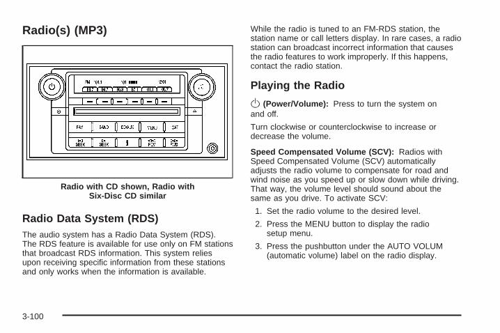
Radio(s) (MP3)
Radio Data System (RDS)The audio system has a Radio Data System (RDS).The RDS feature is available for use only on FM stationsthat broadcast RDS information. This system reliesupon receiving specific information from these stationsand only works when the information is available.
While the radio is tuned to an FM-RDS station, thestation name or call letters display. In rare cases, a radiostation can broadcast incorrect information that causesthe radio features to work improperly. If this happens,contact the radio station.
Playing the Radio
O(Power/Volume): Press to turn the system onand off.
Turn clockwise or counterclockwise to increase ordecrease the volume.
Speed Compensated Volume (SCV): Radios withSpeed Compensated Volume (SCV) automaticallyadjusts the radio volume to compensate for road andwind noise as you speed up or slow down while driving.That way, the volume level should sound about thesame as you drive. To activate SCV:
1. Set the radio volume to the desired level.
2. Press the MENU button to display the radiosetup menu.
3. Press the pushbutton under the AUTO VOLUM(automatic volume) label on the radio display.
Radio with CD shown, Radio withSix-Disc CD similar
3-100

4. Press the pushbutton under the desired SpeedCompensated Volume setting (OFF, Low, Med,or High) to select the level of radio volumecompensation. The display times out afterapproximately 10 seconds. Each higher settingallows for more radio volume compensation atfaster vehicle speeds.
AudioPilot®: If your vehicle has the Bose® audiosystem, it has AudioPilot® noise compensationtechnology.To use AudioPilot®, do the following steps:1. Set the radio volume to the desired level.2. Press the MENU button to display the radio
setup menu.3. Press the pushbutton located under the
AUTO VOLUM label on the radio display.4. Press the ON or OFF button to turn this feature
on or off.When turned ON, AudioPilot® continuously adjusts theaudio system equalization, to compensate forbackground noise, so that your music always soundsthe same at the set volume level.The feature is most effective at lower radio volumesettings where background noise can affect how wellyou hear the music being played through your vehicle’saudio system. At high volume settings there might be littleor no adjustments by AudioPilot®. For more informationon AudioPilot®, visit www.bose.com/audiopilot.
Finding a Station
BAND: Press to switch between AM, FM, or XM™(if equipped). The selection displays.
a (Tune): Turn to select radio stations.
©SEEK ¨: Press the arrows to go to the next orto the previous station and stay there.
To scan stations, press and hold either arrow forthree seconds until a beep sounds. The radio goesto a station, plays for a few seconds, then goes to thenext station. Press either arrow again to stop scanning.
The radio only seeks and scans stations with astrong signal that are in the selected band.
4 (Information) (XM™ Satellite Radio Service,MP3/WMA, and RDS Features): Press this buttonto display additional text information related to thecurrent FM-RDS or XM™ (if equipped) station, orMP3/WMA song. A choice of additional information suchas: Channel, Song, Artist, CAT (category) can display.Continue pressing the information button to highlightthe desired label, or press the pushbutton positionedunder any one of the labels and the informationabout that label displays.
When information is not available, No Info displays.
3-101

Storing a Radio Station as a FavoriteDrivers are encouraged to set up their radio stationfavorites while the vehicle is in PARK (P). Tune to yourfavorite stations using the presets, favorites button,and steering wheel controls, if the vehicle has thisfeature. See Defensive Driving on page 4-2.
FAV (Favorites): A maximum of 36 stations can beprogrammed as favorites using the six pushbuttonspositioned below the radio station frequency labels andby using the radio favorites page button (FAV button).Press the FAV button to go through up to six pagesof favorites, each having six favorite stations availableper page. Each page of favorites can contain anycombination of AM, FM, or XM™ (if equipped) stations.To store a station as a favorite, perform the followingsteps:
1. Tune to the desired radio station.
2. Press the FAV button to display the page whereyou want the station stored.
3. Press and hold one of the six pushbuttons until abeep sounds. When that pushbutton is pressedand released, the station that was set, returns.
4. Repeat the steps for each pushbutton radio stationyou want stored as a favorite.
The number of favorites pages can be setup usingthe MENU button. To setup the number of favoritespages, perform the following steps:
1. Press the MENU button to display the radiosetup menu.
2. Press the pushbutton located below theFAV 1-6 label.
3. Select the desired number of favorites pagesby pressing the pushbutton located below thedisplayed page numbers.
4. Press the FAV button, or let the menu time out,to return to the original main radio screen showingthe radio station frequency labels and to beginthe process of programming your favorites for thechosen amount of numbered pages.
Setting the Tone(Bass/Midrange/Treble)
BASS/MID/TREB (Bass, Midrange, or Treble): Toadjust bass, midrange, or treble, press the a (tune)knob until the tone control labels display. Continuepressing to highlight the desired label, or pressthe pushbutton positioned under the desired label.
3-102

Turn the a knob clockwise or counterclockwise toadjust the highlighted setting. The highlighted setting canalso be adjusted by pressing either SEEK arrow,\FWD (forward), or sREV (reverse) button untilthe desired levels are obtained. If a station’s frequencyis weak or has static, decrease the treble.
To quickly adjust bass, midrange, or treble to the middleposition, press the pushbutton positioned under theBASS, MID, or TREB label for more than two seconds.A beep sounds and the level adjusts to the middleposition.
To quickly adjust all tone and speaker controls to themiddle position, press the a knob for more thantwo seconds until a beep sounds.
EQ (Equalization): For the non-Bose® amplified radio,perform the following steps to setup the equalizationsettings:
1. Press the a knob until the equalization labeldisplays.
2. Press the pushbutton located under the equalizationlabel to get choices of POP, ROCK, CTRY (country),TALK, JAZZ, and CLAS (classical), to display.
3. Press the pushbutton located under the desiredsetting.
For the Bose® amplified radio, perform the followingsteps to setup the equalization settings:
1. Press the a knob until the DSP (Digital SignalProcessing) label displays.
2. Press the pushbutton located under the DSP labelto get choices of Norm, Driv, Rear, and Surround,to display.
3. Press the pushbutton located under the desiredsetting.To select Surround, press either the fourth or fifthpushbutton located under the displayed Surrounduntil Centerpoint displays.
To return to the manual mode, press the tune knob.Select either BASS, MID, or TREB and start to manuallyadjust the settings by turning the a knob.
Adjusting the Speakers (Balance/Fade)BAL/FADE (Balance/Fade): To adjust balance or fade,press the a (tune) knob until the speaker control labelsdisplay. Continue pressing to highlight the desired label,or press the pushbutton positioned under the desiredlabel. Turn the a knob clockwise or counterclockwise toadjust the highlighted setting. The highlighted setting canbe adjusted by pressing either SEEK arrow, \FWD,or sREV buttons until the desired levels are obtained.
3-103

To quickly adjust balance or fade to the middle position,press the pushbutton positioned under the BAL or FADElabel for more than two seconds. A beep sounds and thelevel adjusts to the middle position.
To quickly adjust all speaker and tone controls to themiddle position, press the a knob for more thantwo seconds until a beep sounds.
Digital Signal Processing (DSP)This feature is used to provide a choice of four differentlistening experiences. DSP can be used while listeningto the audio system or a CD. To change the DSP mode,press the a (tune) knob until the DSP control labeldisplays. Press the pushbutton located under theDSP label until the control labels display. Continue bypressing the desired button below the control labelson the display.
For more information on the control label displays,see the following:
• Norm (Normal): Select this screen button toadjust the audio for normal mode. This providesthe best sound quality for all seating positions.
• Driv (Driver): Select this screen button to adjustthe audio for the driver to receive the bestpossible sound quality.
• Rear: Select this screen button to adjust the audiofor the rear seat passengers to receive the bestpossible sound quality.
• Surround (Centerpoint®): Select this screen buttonto enable Bose Centerpoint® signal processingcircuitry. Centerpoint® produces a full vehiclesurround sound listening experience from a CD,MP3/WMA, or XM stereo digital audio source anddelivers five independent audio channels fromconventional two channel stereo recordings.(Not available for AM, FM, or auxiliary sources.)
Digital Signal Processing (DSP) is only available onvehicles that have the Bose® Premium audio system.
Finding a Category (CAT) StationCAT (Category): The CAT button is used to findXM™ (if equipped) stations while the radio is in theXM™ mode. To find XM™ (if equipped) channelswithin a desired category, perform the following:
1. Press the BAND button until the XM™ (if equipped)frequency displays. Press the CAT button to displaythe category labels. Continue pressing the CATbutton until the desired category name displays.Another way to select a category is to pressthe sREV or \FWD button until the desiredcategory is selected.
3-104

2. Press either of the two pushbuttons below thedesired category label to immediately tune tothe first XM™ (if equipped) station associated withthat category.
3. Turn the a knob, press the pushbuttons below thedisplayed right or left arrows, or press either SEEKarrow to go to the previous or the next XM™(if equipped) station within the selected category.
4. To exit the category search mode, press the FAVbutton or BAND button to display your favoritesagain.
Undesired XM™ (if equipped) categories can beremoved through the setup menu. To remove anundesired category, perform the following:
1. Press the MENU button to display the radiosetup menu.
2. Press the pushbutton located below theXM CAT label.
3. Turn the a knob to display the category youwant removed.
4. Press the pushbutton located under the Removelabel until the category name along with the wordRemoved displays.
5. Repeat the steps to remove more categories.
Removed categories can be restored by pressing thepushbutton under the Add label when a removedcategory is displayed or by pressing the pushbuttonunder the Restore All label.
The radio does not let you remove or add categorieswhile the vehicle is moving faster than 5 mph (8 km/h).
The CAT button also toggles between compressedand uncompressed audio when a mixed disc is present.See “Compressed Audio” later in this section.
Radio Message
Locked: This message displays when the THEFTLOCKsystem has locked up the radio. Take the vehicle toyour dealer/retailer for service.
If any error occurs repeatedly or if an error cannot becorrected, contact your dealer/retailer.
3-105

XM™ Satellite Radio ServiceXM™ is a satellite radio service that is based in the48 contiguous United States and 10 Canadian provinces.XM™ Satellite Radio has a wide variety of programmingand commercial-free music, coast-to-coast, and indigital-quality sound. During your trial or when yousubscribe, you will get unlimited access to XM™ RadioOnline for when you are not in your vehicle. A servicefee is required to receive the XM™ service. For moreinformation, contact XM™ at www.xmradio.com or call1-800-929-2100 in the U.S. and www.xmradio.ca orcall 1-877-438-9677 in Canada.
Radio Messages for XM™ OnlySee XM Radio Messages on page 3-115 later in thissection for further detail.
Playing a CD (Single CD Player)Insert a CD partway into the slot, label side up. Theplayer pulls it in and the CD should begin playing.
If the ignition or radio is turned off with a CD in theplayer, it stays in the player. When the ignition or radiois turned on, the CD starts playing where it stopped,if it was the last selected audio source.
When a CD is inserted, the CD symbol displays. Aseach new track starts to play the track number displays.
Care of Your CDsIf playing a CD-R, the sound quality can be reduceddue to CD-R quality, the method of recording, the qualityof the music that has been recorded, and the way theCD-R has been handled. Handle them carefully.Store CD-R(s) in their original cases or other protectivecases and away from direct sunlight and dust. TheCD player scans the bottom surface of the disc. If thesurface of a CD is damaged, such as cracked, broken,or scratched, the CD does not play properly or notat all. Do not touch the bottom side of a CD whilehandling it; this could damage the surface. Pick up CDsby grasping the outer edges or the edge of the holeand the outer edge.
If the surface of a CD is soiled, take a soft, lint free clothor dampen a clean, soft cloth in a mild, neutral detergentsolution mixed with water, and clean it. Make sure thewiping process starts from the center to the edge.
Care of Your CD PlayerDo not add any label to a CD, it could get caught in theCD player. If a CD is recorded on a personal computerand a description label is needed, try labeling the top ofthe recorded CD with a marking pen.
3-106

The use of CD lens cleaners for CDs is not advised,due to the risk of contaminating the lens of the CD opticswith lubricants internal to the CD player mechanism.
Notice: If a label is added to a CD, or more than oneCD is inserted into the slot at a time, or an attemptis made to play scratched or damaged CDs, theCD player could be damaged. While using the CDplayer, use only CDs in good condition withoutany label, load one CD at a time, and keep the CDplayer and the loading slot free of foreign materials,liquids, and debris.
If an error displays, see “CD Messages” later in thissection.
Playing a CD(s) (Six-Disc CD Player)
LOAD ^: Press to load CDs into the CD player.This CD player holds up to six CDs.
To insert one CD, do the following:
1. Press and release the load button.
2. Wait for the message to insert the disc.
3. Load a CD. Insert the CD partway into the slot,label side up. The player pulls the CD in.
To insert multiple CDs, do the following:
1. Press and hold the LOAD button for five seconds.A beep sounds and Load All Discs displays.
2. Follow the displayed instruction on when to insertthe discs. The CD player takes up to six CDs.
3. Press the Load button again to cancel loadingmore CDs.
Z (Eject): Press to eject the CD. If the CD is notremoved, after several seconds, the CD automaticallypulls back into the player.
For the Radio with Six-Disc CD player, press and holdfor two seconds to eject all discs, if one or morediscs are loaded.
a (Tune): Turn to select tracks on the CD currentlyplaying.
©SEEK ¨: Press the left arrow to go to the start ofthe current track, if more than ten seconds have played.Press the right arrow to go to the next track. If eitherarrow is held or pressed multiple times, the playercontinues moving backward or forward through the CD.
3-107
s REV (Fast Reverse): Press and hold to reverseplayback quickly within a track. You will hear sound at areduced volume. Release to resume playing thetrack. The elapsed time of the track displays.
\ FWD (Fast Forward): Press and hold to advanceplayback quickly within a track. You will hear soundat a reduced volume. Release to resume playingthe track. The elapsed time of the track displays.
RDM (Random): With the random setting, CD trackscan be played in random, rather than sequentialorder. This feature is not available in playlist mode.To use random, do the following:1. To play tracks in random order from the CD that is
currently playing, press the pushbutton positionedunder the RDM label. The random icon displays.
2. Press the same pushbutton again to turn off randomplay. The random icon is no longer highlighted.
RDM (Random) (Radio with Six-Disc CD Player):With the random setting, CD tracks can be playedin random, rather than sequential order, on one CD orall CDs in a six-disc CD player. To use random, do oneof the following:• To play the tracks in random order from the CD that
is currently playing, press the pushbutton positionedunder the RDM label until Randomize Current Discdisplays. Press again to turn off random play.
• To play tracks from all CDs loaded in a six-disc CDplayer in random order, press the pushbuttonpositioned under the RDM label until Randomize AllDiscs displays. Press again to turn off random play.
4 (Information): Press to switch the display betweenthe track number, elapsed time of the track, and thetime. When the ignition is off, press to display the time(if the clock display is enabled). See “Enabling/Disablingthe Digital Radio Clock” under, Setting the Time onpage 3-96 for more information.
BAND: Press to listen to the radio when a CD is playing.The CD remains inside the radio for future listening.
CD/AUX (CD/Auxiliary): Press to play a CD whenlistening to the radio. The CD icon and track numberdisplays when a CD is in the player. Press again and thesystem automatically searches for an auxiliary inputdevice, such as a portable audio player. If a portableaudio player is not connected, “No Aux Input DeviceFound” displays.
Playing an MP3/WMA CD-R orCD-RW DiscRadios with the MP3 feature are capable of playing anMP3/WMA CD-R or CD-RW disc. For more informationon how to play an MP3/WMA CD-R or CD-RW disc,see Using an MP3 on page 3-110 later in this section.
3-108

CD Messages
DISC ERROR: If this message displays and/or the CDejects, it could be for one of the following reasons:
• The radio system does not support the playlistformat, the compressed audio format, or the datafile format.
• It is very hot. When the temperature returns tonormal, the CD should play.
• You are driving on a very rough road. When theroad becomes smoother, the CD should play.
• The CD is dirty, scratched, wet, or upside down.
• The air is very humid. If so, wait about an hourand try again.
• There could have been a problem while burningthe CD.
• The label could be caught in the CD player.
If the CD is not playing correctly, for any other reason,try a known good CD.
If any error occurs repeatedly or if an error cannot becorrected, contact your dealer/retailer. If the radiodisplays an error message, write it down and provideit to your dealer/retailer when reporting the problem.
Using the Auxiliary Input JackYour radio system has an auxiliary input jack locatedon the lower right side of the faceplate. This is notan audio output; do not plug the headphone set into thefront auxiliary input jack. You can however, connectan external audio device such as an iPod, laptopcomputer, MP3 player, CD changer, or cassette tapeplayer, etc. to the auxiliary input jack for use as anothersource for audio listening.
Drivers are encouraged to set up any auxiliary devicewhile the vehicle is in PARK (P). See Defensive Drivingon page 4-2 for more information on driver distraction.
To use a portable audio player, connect a 3.5 mm(1/8 inch) cable to the radio’s front auxiliary inputjack. When connecting an auxiliary device, the radioautomatically detects the device and “Aux Input Device”displays. The device begins playing audio over thevehicle speakers. If an auxiliary device has alreadybeen connected, the device does not begin playingaudio until the radio’s CD/AUX button is pressed.
O(Power/Volume): Turn clockwise orcounterclockwise to increase or decrease the volumeof the portable player. You might need to do additionalvolume adjustments from the portable device.
3-109
BAND: Press to listen to the radio when a portableaudio device is playing. The portable audio devicecontinues playing, so you might want to stop itor power it off.
CD/AUX (CD/Auxiliary): Press to play a CD when aportable audio device is playing. Press again andthe system begins playing audio from the connectedportable audio player. If a portable audio player isnot connected, “No Aux Input Device Found” displays.
Using an MP3
MP3/WMA CD-R or CD-RW DiscThe radio plays MP3 and WMA files that were recordedon a CD-R or CD-RW disc. The files can be recordedwith the following fixed bit rates: 32 kbps, 40 kbps,56 kbps, 64 kbps, 80 kbps, 96 kbps, 112 kbps,128 kbps, 160 kbps, 192 kbps, 224 kbps, 256 kbps,and 320 kbps or a variable bit rate. Song title, artistname, and album can display when files are recordedusing ID3 tags version 1 and 2.
Compressed AudioThe radio also plays discs that contain bothuncompressed CD audio (.CDA files) and MP3/WMAfiles. By default the radio reads only the uncompressedaudio and ignores the MP3/WMA files. Pressing theCAT (category) button toggles between compressed anduncompressed audio format.
MP3/WMA FormatIf you burn your own MP3/WMA disc on a personalcomputer:
• Make sure the MP3/WMA files are recorded on aCD-R or CD-RW disc.
• Do not mix standard audio and MP3/WMA files onone disc.
• The CD player is able to read and play a maximumof 50 folders, 50 playlists, and 255 files.
• Create a folder structure that makes it easy to findsongs while driving. Organize songs by albumsusing one folder for each album. Each folderor album should contain 18 songs or less.
• Avoid subfolders. The system can support up to8 subfolders deep, however, keep the totalnumber of folders to a minimum in order to reducethe complexity and confusion in trying to locatea particular folder during playback.
3-110

• Make sure playlists have a .mp3 or .wpl extension(other file extensions might not work).
• Minimize the length of the file, folder or playlistnames. Long file, folder, or playlist names, or acombination of a large number of files and folders,or playlists can cause the player to be unable toplay up to the maximum number of files, folders,playlists, or sessions. If you wish to play alarge number of files, folders, playlists, or sessions,minimize the length of the file, folder, or playlistname. Long names also take up more space onthe display, potentially getting cut off.
• Finalize the audio disc before you burn it. Trying toadd music to an existing disc can cause the discnot to function in the player.
Playlists can be changed by using the Sc (previous)and cT (next) folder buttons, the a knob, or theSEEK arrows. An MP3/WMA CD-R or CD-RW that wasrecorded using no file folders can also be played. If aCD-R or CD-RW contains more than the maximum of50 folders, 50 playlists, and 255 files, the player lets youaccess and navigate up to the maximum, but all itemsover the maximum cannot be accessed.
Root DirectoryThe root directory of the CD-R or CD-RW is treated as afolder. If the root directory has compressed audio files,the directory displays as F1 ROOT. All files containeddirectly under the root directory are accessed prior to anyroot directory folders. However, playlists (Px) are alwaysaccessed before root folders or files.
Empty Directory or FolderIf a root directory or a folder exists somewhere in thefile structure that contains only folders/subfolders andno compressed files directly beneath them, the playeradvances to the next folder in the file structure thatcontains compressed audio files. The empty folderdoes not display.
No FolderWhen the CD contains only compressed files, the filesare located under the root folder. The next and previousfolder functions do not display on a CD that wasrecorded without folders or playlists. When displayingthe name of the folder the radio displays ROOT.
When the CD contains only playlists and compressedaudio files, but no folders, all files are located under theroot folder. The folder down and the folder up buttonssearch playlists (Px) first and then goes to the rootfolder. When the radio displays the name of the folderthe radio displays ROOT.
3-111

Order of PlayTracks recorded to the CD-R or CD-RW play in thefollowing order:
• Play begins from the first track in the first playlistand continues sequentially through all tracks ineach playlist. When the last track of the last playlisthas played, play continues from the first track ofthe first playlist.
− Playlists can be changed by pressingthe Sc and cT folder buttons,the a knob, or the SEEK arrows.
• Play begins from the first track in the first folderand continues sequentially through all tracks ineach folder. When the last track of the last folderhas played, play continues from the first trackof the first folder.
When play enters a new folder, the display does notautomatically show the new folder name unlessthe folder mode has been chosen as the defaultdisplay. The new track name displays.
File System and NamingThe song name that displays is the song name that iscontained in the ID3 tag. If the song name is not presentin the ID3 tag, then the radio displays the file namewithout the extension (such as .mp3) as the track name.
Track names longer than 32 characters or four pagesare shortened. Parts of words on the last page oftext and the extension of the filename does not display.
Preprogrammed PlaylistsPreprogrammed playlists that were created usingWinAmp™, MusicMatch™, or Real Jukebox™ softwarecan be accessed, however, they cannot be editedusing the radio. These playlists are treated as specialfolders containing compressed audio song files. Playlistsmust have a file extension of PLS, M3U, or WPL.
Playlists can be changed by using the Sc andcT folder buttons, the a knob, or the SEEKarrows. Tracks cannot be changed. Songs are playedsequentially; press the sREV or \FWD to reverseor advance through the currently playing song.
3-112
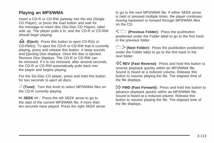
Playing an MP3/WMAInsert a CD-R or CD-RW partway into the slot (SingleCD Player), or press the load button and wait forthe message to insert disc (Six-Disc CD Player), labelside up. The player pulls it in, and the CD-R or CD-RWshould begin playing.
Z (Eject): Press this button to eject CD-R(s) orCD-RW(s). To eject the CD-R or CD-RW that is currentlyplaying, press and release this button. A beep soundsand Ejecting Disc displays. Once the disc is ejected,Remove Disc displays. The CD-R or CD-RW canbe removed. If it is not removed, after several seconds,the CD-R or CD-RW automatically pulls back intothe player and begins playing.
For the Six-Disc CD player, press and hold this buttonfor two seconds to eject all discs.
a (Tune): Turn this knob to select MP3/WMA files onthe CD-R currently playing.
©SEEK ¨: Press the left SEEK arrow to go tothe start of the current MP3/WMA file, if more thanten seconds have played. Press the right SEEK arrow
to go to the next MP3/WMA file. If either SEEK arrowis held or pressed multiple times, the player continuesmoving backward or forward through MP3/WMA fileson the CD.
Sc (Previous Folder): Press the pushbuttonpositioned under the Folder label to go to the first trackin the previous folder.
cT(Next Folder): Press the pushbutton positionedunder the Folder label to go to the first track in thenext folder.
sREV (Fast Reverse): Press and hold this button toreverse playback quickly within an MP3/WMA file.Sound is heard at a reduced volume. Release thisbutton to resume playing the file. The elapsed time ofthe file displays.
\FWD (Fast Forward): Press and hold this button toadvance playback quickly within an MP3/WMA file.Sound is heard at a reduced volume. Release thisbutton to resume playing the file. The elapsed time ofthe file displays.
3-113
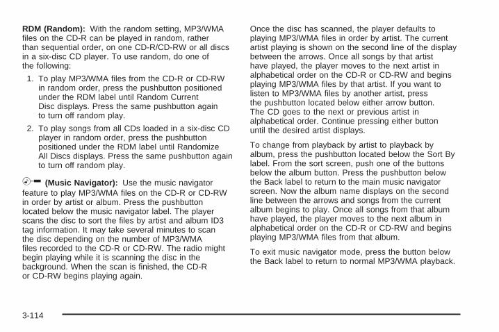
RDM (Random): With the random setting, MP3/WMAfiles on the CD-R can be played in random, ratherthan sequential order, on one CD-R/CD-RW or all discsin a six-disc CD player. To use random, do one ofthe following:
1. To play MP3/WMA files from the CD-R or CD-RWin random order, press the pushbutton positionedunder the RDM label until Random CurrentDisc displays. Press the same pushbutton againto turn off random play.
2. To play songs from all CDs loaded in a six-disc CDplayer in random order, press the pushbuttonpositioned under the RDM label until RandomizeAll Discs displays. Press the same pushbutton againto turn off random play.
h (Music Navigator): Use the music navigatorfeature to play MP3/WMA files on the CD-R or CD-RWin order by artist or album. Press the pushbuttonlocated below the music navigator label. The playerscans the disc to sort the files by artist and album ID3tag information. It may take several minutes to scanthe disc depending on the number of MP3/WMAfiles recorded to the CD-R or CD-RW. The radio mightbegin playing while it is scanning the disc in thebackground. When the scan is finished, the CD-Ror CD-RW begins playing again.
Once the disc has scanned, the player defaults toplaying MP3/WMA files in order by artist. The currentartist playing is shown on the second line of the displaybetween the arrows. Once all songs by that artisthave played, the player moves to the next artist inalphabetical order on the CD-R or CD-RW and beginsplaying MP3/WMA files by that artist. If you want tolisten to MP3/WMA files by another artist, pressthe pushbutton located below either arrow button.The CD goes to the next or previous artist inalphabetical order. Continue pressing either buttonuntil the desired artist displays.
To change from playback by artist to playback byalbum, press the pushbutton located below the Sort Bylabel. From the sort screen, push one of the buttonsbelow the album button. Press the pushbutton belowthe Back label to return to the main music navigatorscreen. Now the album name displays on the secondline between the arrows and songs from the currentalbum begins to play. Once all songs from that albumhave played, the player moves to the next album inalphabetical order on the CD-R or CD-RW and beginsplaying MP3/WMA files from that album.
To exit music navigator mode, press the button belowthe Back label to return to normal MP3/WMA playback.
3-114

BAND: Press this button to listen to the radio whena CD is playing. The inactive CD remains insidethe radio for future listening.
CD/AUX (CD/Auxiliary): Press this button to playa CD when listening to the radio. The CD icon and amessage showing disc and/or track number displayswhen a CD is in the player. Press this button againand the system automatically searches for an auxiliaryinput device such as a portable audio player. If aportable audio player is not connected, “No Aux InputDevice Found” displays.
XM Radio Messages
XL (Explicit Language Channels): These channels,or any others, can be blocked at a customer’s request,by calling 1-800-852-XMXM (9696).
XM Updating: The encryption code in the receiver isbeing updated, and no action is required. This processshould take no longer than 30 seconds.
No XM Signal: The system is functioning correctly,but the vehicle is in a location that is blocking the XM™signal. When the vehicle is moved into an open area,the signal should return.
Loading XM: The audio system is acquiring andprocessing audio and text data. No action is needed.This message should disappear shortly.
Channel Off Air: This channel is not currently inservice. Tune to another channel.
Channel Unavail: This previously assigned channel isno longer assigned. Tune to another station. If thisstation was one of the presets, choose another stationfor that preset button.
No Artist Info: No artist information is available at thistime on this channel. The system is working properly.
No Title Info: No song title information is availableat this time on this channel. The system is workingproperly.
No CAT Info: No category information is availableat this time on this channel. The system is workingproperly.
No Information: No text or informational messages areavailable at this time on this channel. The system isworking properly.
CAT Not Found: There are no channels available forthe selected category. The system is working properly.
3-115
XM TheftLocked: The XM™ receiver in the vehiclemay have previously been in another vehicle. Forsecurity purposes, XM™ receivers cannot be swappedbetween vehicles. If this message appears afterhaving your vehicle serviced, check with yourdealer/retailer.
XM Radio ID: If tuned to channel 0, this messagealternates with the XM™ Radio eight digit radio IDlabel. This label is needed to activate the service.
Unknown: If this message is received when tuned tochannel 0, there could be a receiver fault. Consultwith your dealer/retailer.
Check XM Receivr: If this message does not clearwithin a short period of time, the receiver could havea fault. Consult with your dealer/retailer.
XM Not Available: If this message does not clearwithin a short period of time, the receiver could havea fault. Consult with your dealer/retailer.
Navigation/Radio SystemYour vehicle may have a navigation radio system.
The navigation system has built-in features intendedto minimize driver distraction. Technology alone,no matter how advanced, can never replace yourown judgment. See the Navigation System manual forsome tips to help you reduce distractions while driving.
Theft-Deterrent FeatureTHEFTLOCK® is designed to discourage theft ofyour vehicle’s radio. The feature works automaticallyby learning a portion of the Vehicle IdentificationNumber (VIN). If the radio is moved to a differentvehicle, it does not operate and LOC, LOCK, orLOCKED could display.
With THEFTLOCK® activated, the radio does notoperate if stolen.
3-116

Audio Steering Wheel Controls
The audio steeringwheel controls may bedifferent depending onyour vehicle’s options.Some audio controlscan be adjusted at thesteering wheel. Theyinclude the following:
xw (Next/Previous): Press the down or up arrowto go to the next or to the previous radio station storedas a favorite.
The radio has up to six favorites pages and five presetsto each favorites page. If favorites page one is activated,press the up arrow to go to the next preset radio station.Press the up arrow multiple times to go through all fivepresets. Once all five presets have played, press the uparrow again to go to favorites page two.
When a CD is playing, press the down or up arrow to goto the next or to the previous track.
g (Mute/Voice Recognition): Press this button tosilence the system. Press this button again or turn thevolume knob to turn the sound on.
Press and hold this button to interact with the OnStar®
system. If your vehicle is also equipped with thenavigation system, push this button to initiate voicerecognition and say, “OnStar” to enter OnStar® mode,see the OnStar® System on page 2-53 in this manualfor more information.
If your vehicle has the navigation system, press thisbutton to initiate voice recognition. See “VoiceRecognition” in the index of your vehicle’s navigationsystem manual for more information.
SRCE (Source): Press this button to switch betweenAM, FM, or XM (if equipped), radio, or CD.
+ e − e (Volume): Press the plus or minus buttonto increase or to decrease the volume.
3-117

¨ (Seek): Press the seek arrow to go to the nextradio station and stay there. The system only seeksradio stations with strong frequencies.
When the seek arrow is pressed and held fortwo seconds, the system scans the radio stationsthat are in the selected band. If listening to a CD,the system advances to the next CD when multiplediscs are inserted.
If you have the navigation system, some of the audiosteering wheel controls work when a DVD is playingin the navigation radio. See the Navigation Systemmanual for more information.
Radio ReceptionFrequency interference and static can occur duringnormal radio reception if items such as cell phonechargers, vehicle convenience accessories, andexternal electronic devices are plugged into theaccessory power outlet. If there is interference orstatic, unplug the item from the accessorypower outlet.
AMThe range for most AM stations is greater than for FM,especially at night. The longer range can cause stationfrequencies to interfere with each other. For better radioreception, most AM radio stations boost the power levelsduring the day, and then reduce these levels during thenight. Static can also occur when things like storms andpower lines interfere with radio reception. When thishappens, try reducing the treble on your radio.
FM StereoFM stereo gives the best sound, but FM signals onlyreach about 10 to 40 miles (16 to 65 km). Tall buildingsor hills can interfere with FM signals, causing the soundto fade in and out.
XM™ Satellite Radio ServiceXM™ Satellite Radio Service gives digital radio receptionfrom coast-to-coast in the 48 contiguous United States,and in Canada. Just as with FM, tall buildings or hills caninterfere with satellite radio signals, causing the sound tofade in and out. In addition, traveling or standing underheavy foliage, bridges, garages, or through tunnels couldcause loss of the XM signal for a period of time. The radiomay display NO XM SIGNAL to indicate interference.
3-118
Backglass AntennaThe AM-FM antenna is integrated with the rear windowdefogger, located in the rear window. Make sure thatthe inside surface of the rear window is not scratchedand that the grid lines on the glass are not damaged.If the inside surface is damaged, it could interferewith radio reception.
Notice: Using a razor blade or sharp object toclear the inside rear window may damage the rearwindow antenna and/or the rear window defogger.Repairs would not be covered by your warranty.Do not clear the inside rear window with sharpobjects.
Notice: Do not apply aftermarket glass tintingwith metallic film. The metallic film in some tintingmaterials will interfere with or distort the incomingradio reception. Any damage caused to yourbackglass antenna due to metallic tinting materialswill not be covered by your warranty.
If static is heard on the radio, when the rear windowdefogger is turned on, it could mean that a defogger gridline has been damaged. If this is true, the grid linemust be repaired.
If adding a cellular telephone to your vehicle, and theantenna needs to be attached to the glass, makesure that the grid lines for the AM-FM antenna are notdamaged. There is enough space between the grid linesto attach a cellular telephone antenna without interferingwith radio reception.
XM™ Satellite Radio AntennaSystemThe XM™ Satellite Radio antenna is located on the roofof your vehicle. Keep this antenna clear of snow andice build up for clear radio reception.
If your vehicle has a sunroof, the performance of theXM™ system may be affected if the sunroof is open.
Loading items onto the roof of your vehicle can interferewith the performance of the XM™ system. Make surethe XM™ Satellite Radio antenna is not obstructed.
3-119

✍ NOTES
3-120
Your Driving, the Road, and Your Vehicle ..........4-2Defensive Driving ...........................................4-2Drunk Driving .................................................4-2Control of a Vehicle ........................................4-3Braking .........................................................4-3Antilock Brake System (ABS) ...........................4-4Braking in Emergencies ...................................4-5Traction Control System (TCS) .........................4-5Magnetic Ride Control .....................................4-6StabiliTrak® System ........................................4-7Panic Brake Assist .........................................4-7Steering ........................................................4-8Off-Road Recovery .......................................4-10Passing .......................................................4-10Loss of Control .............................................4-10
Driving at Night ............................................4-12Driving in Rain and on Wet Roads ..................4-12Before Leaving on a Long Trip .......................4-13Highway Hypnosis ........................................4-14Hill and Mountain Roads ................................4-14Winter Driving ..............................................4-15If Your Vehicle is Stuck in Sand, Mud,
Ice, or Snow .............................................4-19Rocking Your Vehicle to Get It Out .................4-20Loading Your Vehicle ....................................4-20
Towing ..........................................................4-26Towing Your Vehicle .....................................4-26Recreational Vehicle Towing ...........................4-26Towing a Trailer ...........................................4-27
Section 4 Driving Your Vehicle
4-1

Your Driving, the Road,and Your Vehicle
Defensive DrivingDefensive driving means “always expect theunexpected.” The first step in driving defensively isto wear your safety belt — See Safety Belts: They Arefor Everyone on page 1-10.
{CAUTION:
Assume that other road users (pedestrians,bicyclists, and other drivers) are going to becareless and make mistakes. Anticipate whatthey might do and be ready. In addition:
• Allow enough following distance betweenyou and the driver in front of you.
• Focus on the task of driving.
Driver distraction can cause collisionsresulting in injury or possible death. Thesesimple defensive driving techniques couldsave your life.
Drunk Driving
{CAUTION:
Drinking and then driving is very dangerous.Your reflexes, perceptions, attentiveness,and judgment can be affected by even a smallamount of alcohol. You can have a serious — oreven fatal — collision if you drive after drinking.Do not drink and drive or ride with a driver whohas been drinking. Ride home in a cab; or ifyou are with a group, designate a driver whowill not drink.
Death and injury associated with drinking and driving isa global tragedy.
Alcohol affects four things that anyone needs to drive avehicle: judgment, muscular coordination, vision, andattentiveness.
Police records show that almost 40 percent of all motorvehicle-related deaths involve alcohol. In most cases,these deaths are the result of someone who was drinkingand driving. In recent years, more than 17,000 annualmotor vehicle-related deaths have been associated withthe use of alcohol, with about 250,000 people injured.
4-2
For persons under 21, it is against the law in everyU.S. state to drink alcohol. There are good medical,psychological, and developmental reasons forthese laws.
The obvious way to eliminate the leading highwaysafety problem is for people never to drink alcoholand then drive.
Medical research shows that alcohol in a person’ssystem can make crash injuries worse, especiallyinjuries to the brain, spinal cord, or heart. This meansthat when anyone who has been drinking — driveror passenger — is in a crash, that person’s chanceof being killed or permanently disabled is higher thanif the person had not been drinking.
Control of a VehicleThe following three systems help to control your vehiclewhile driving — brakes, steering, and accelerator. Attimes, as when driving on snow or ice, it is easy to askmore of those control systems than the tires and road canprovide. Meaning, you can lose control of your vehicle.See Traction Control System (TCS) on page 4-5.
Adding non-dealer/non-retailer accessories can affectyour vehicle’s performance. See Accessories andModifications on page 5-3.
BrakingSee Brake System Warning Light on page 3-58.
Braking action involves perception time and reactiontime. First, you have to decide to push on the brakepedal. That is perception time. Then you have to bringup your foot and do it. That is reaction time.
Average reaction time is about three-fourths of asecond. But that is only an average. It might be lesswith one driver and as long as two or three seconds ormore with another. Age, physical condition, alertness,coordination, and eyesight all play a part. So do alcohol,drugs, and frustration. But even in three-fourths of asecond, a vehicle moving at 60 mph (100 km/h) travels66 feet (20 m). That could be a lot of distance in anemergency, so keeping enough space betweenyour vehicle and others is important.
And, of course, actual stopping distances vary greatlywith the surface of the road, whether it is pavement orgravel; the condition of the road, whether it is wet, dry, oricy; tire tread; the condition of the brakes; the weight ofthe vehicle; and the amount of brake force applied.
4-3

Avoid needless heavy braking. Some people drivein spurts — heavy acceleration followed by heavybraking — rather than keeping pace with traffic.This is a mistake. The brakes might not have timeto cool between hard stops. The brakes will wearout much faster if you do a lot of heavy braking. If youkeep pace with the traffic and allow realistic followingdistances, you will eliminate a lot of unnecessarybraking. That means better brakingand longer brake life.
If your vehicle’s engine ever stops while you are driving,brake normally but do not pump the brakes. If you do, thepedal could get harder to push down. If the engine stops,you will still have some power brake assist. But you willuse it when you brake. Once the power assist is used up,it can take longer to stop and the brake pedal will beharder to push.
Adding non-dealer/non-retailer accessories can affectyour vehicle’s performance. See Accessories andModifications on page 5-3.
Antilock Brake System (ABS)Your vehicle has the Antilock Brake System (ABS),an advanced electronic braking system that willhelp prevent a braking skid.
When you start the engine and begin to drive away,ABS will check itself. You might hear a momentarymotor or clicking noise while this test is going on,and you might even notice that the brake pedalmoves a little. This is normal.
If there is a problem withABS, this warning light willstay on. See AntilockBrake System WarningLight on page 3-59.
Let us say the road is wet and you are driving safely.Suddenly, an animal jumps out in front of you. Youslam on the brakes and continue braking. Here is whathappens with ABS:
A computer senses that wheels are slowing down.If one of the wheels is about to stop rolling, the computerwill separately work the brakes at each front wheeland at both rear wheels.
4-4

ABS can change the brake pressure faster than anydriver could. The computer is programmed to makethe most of available tire and road conditions. Thiscan help you steer around the obstacle whilebraking hard.
As you brake, the computer keeps receiving updates onwheel speed and controls braking pressure accordingly.
Remember: ABS does not change the time you need toget your foot up to the brake pedal or always decreasestopping distance. If you get too close to the vehicle infront of you, you will not have time to apply the brakesif that vehicle suddenly slows or stops. Always leaveenough room up ahead to stop, even though youhave ABS.
Using ABSDo not pump the brakes. Just hold the brake pedaldown firmly and let antilock work for you. You mighthear the antilock pump or motor operate, and feelthe brake pedal pulsate, but this is normal.
Braking in EmergenciesWith ABS, you can steer and brake at the same time.In many emergencies, steering can help you more thaneven the very best braking.
Traction Control System (TCS)Your vehicle has a traction control system that limitswheel spin. This is especially useful in slippery roadconditions. The system operates only if it senses that thefront wheels are spinning too much or beginning to losetraction. When this happens, the system works the frontbrakes and reduces engine power (by closing the throttleand managing engine spark) to limit wheel spin.
The traction control system and StabiliTrak® warninglight will flash when the traction control system is limitingwheel spin. See Traction Control System (TCS)Warning Light on page 3-60 for more information. Youmay feel or hear the system working, but this is normal.
If your vehicle is in cruise control when the tractioncontrol system begins to limit wheel spin, the cruisecontrol will automatically disengage. When roadconditions allow you to safely use it again, you mayre-engage the cruise control. See Cruise Controlon page 3-16 for more information.
The SERVICE TRACTION CONTROL message, thetraction control system warning light and the StabiliTrak®
warning light will come on to let you know if thereis a problem with the traction control system.See DIC Warnings and Messages on page 3-73.
When this light and the SERVICE TRACTIONCONTROL message are on, the system will notlimit wheel spin. Adjust your driving accordingly.
4-5

The traction control system automatically comeson whenever you start your vehicle. To limit wheel spin,especially in slippery road conditions, you shouldalways leave the system on. But you can turn thetraction control system off if you ever need to.
You can turn the system on or off at any time by pressingthe traction control system button located on the consoleor on the end of the column shifter. The DIC will displayTRACTION CONTROL OFF when you press the button,and part of the traction control system is disabled. Yourvehicle will still have brake-traction control, but will notbe able to use the engine speed management system.You may still hear system noises as a result of thebrake-traction control coming on. If the controller detectsexcessive wheel spin in this mode, the traction controlsystem and StabiliTrak® indicator light may blink.
It is recommended to leave the system on for normaldriving conditions, but it may be necessary to turnthe system off if your vehicle is stuck in sand, mud,ice or snow, and you may want to “rock” your vehiclein an attempt to free it. See If Your Vehicle is Stuckin Sand, Mud, Ice, or Snow on page 4-19 for moreinformation.
Adding non-dealer/non-retailer accessories can affectyour vehicle’s performance. See Accessories andModifications on page 5-3 for more information.
Magnetic Ride ControlYour vehicle may have a feature called Magnetic RideControl that automatically adjusts the ride of your vehicle.Automatic ride control is achieved through a computerused to control and monitor the suspension system.The controller receives input from various sensors todetermine the proper system response. If the controllerdetects a problem within the system, the DIC will displaya SERVICE SUSPENSION SYS message. See DICWarnings and Messages on page 3-73 for moreinformation. If this message appears, have yourvehicle serviced at your dealer/retailer.
Electronically Controlled Air RideSuspensionIf you have a Professional Vehicle, you may have afeature called Electronically Controlled Air Suspension.Air ride control is achieved through a computer used tocontrol and monitor the system. The controller receivesinput from two height sensors to determine the propersystem response. If the controller detects a problemwith the system, the Driver Information Center (DIC)will display a SERVICE SUSPENSION SYS message.If this message appears, have your vehicle serviced atyour dealer/retailer.
4-6
StabiliTrak® SystemYour vehicle may have this feature. The StabiliTrak®
system is an advanced computer controlled system thathelps the driver maintain directional control of the vehiclein difficult driving conditions. This is accomplished byselectively applying any one of the vehicle’s brakesand reducing engine power.
The StabiliTrak® system comes on automaticallywhenever you start your vehicle. The system cannotbe turned off.
The STABILITRAK NOT READY message may bedisplayed in the DIC and the traction control system andStabiliTrak® warning light on the instrument panel clusterwill be on after first driving the vehicle and exceeding19 mph (30 km/h) for 30 seconds. The StabiliTrak®
system is off until the light has turned off. This couldtake up to 15 minutes.
The traction control system and StabiliTrak® warning lighton the instrument panel cluster will flash when the systemis operating. See Traction Control System (TCS) WarningLight on page 3-60 and StabiliTrak® Indicator Light onpage 3-60 for more information. You may also feel orhear the system working. This is normal.
The SERVICE STABILITRAK message will be displayedand the traction control system and StabiliTrak® warninglight on the instrument panel cluster will come on if thereis a problem with the system. When this light and theSERVICE STABILITRAK message are on, the systemis not operational. Adjust your driving accordingly.
Panic Brake AssistYour vehicle may have a panic brake assist systemthat monitors the intention of the driver while braking.If the system senses that the driver has applied hard/fastpressure to the brake pedal, the system will generateadditional pressure, making it easier for the driver tomaintain brake application. When this happens the brakepedal will feel easier to push. Just hold the brake pedaldown firmly and let the system work for you. You may feelthe brakes vibrate, or you may notice some noise but thisis normal. The brakes will return to normal operation afterthe brake pedal has been released.
4-7
SteeringPower SteeringIf you lose power steering assist because the enginestops or the system is not functioning, you can steer butit will take much more effort.
Magnetic Speed Variable AssistSteering SystemThis system continuously adjusts the effort you feelwhen steering at all vehicle speeds. It provides easewhen parking, yet a firm, solid feel at highway speeds.
Steering TipsIt is important to take curves at a reasonable speed.A lot of the “driver lost control” accidents mentioned onthe news happen on curves. Here is why:Experienced driver or beginner, each of us is subjectto the same laws of physics when driving on curves.The traction of the tires against the road surface makes itpossible for the vehicle to change its path when you turnthe front wheels. If there is no traction, inertia will keepthe vehicle going in the same direction. If you haveever tried to steer a vehicle on wet ice, you willunderstand this.The traction you can get in a curve depends on thecondition of the tires and the road surface, the angleat which the curve is banked, and your speed. While youare in a curve, speed is the one factor you can control.
Suppose you are steering through a sharp curve.Then you suddenly accelerate. Both controlsystems — steering and acceleration — have todo their work where the tires meet the road. Adding thesudden acceleration can demand too much of thoseplaces. You can lose control. See Traction ControlSystem (TCS) on page 4-5.What should you do if this ever happens? Ease up onthe accelerator pedal, steer the vehicle the way youwant it to go, and slow down.If you have StabiliTrak®, the system may be active.See StabiliTrak® System on page 4-7.Speed limit signs near curves warn that you shouldadjust your speed. Of course, the posted speedsare based on good weather and road conditions. Underless favorable conditions you will want to go slower.If you need to reduce your speed as you approacha curve, do it before you enter the curve, while thefront wheels are straight ahead.Try to adjust your speed so you can drive throughthe curve. Maintain a reasonable, steady speed.Wait to accelerate until you are out of the curve,and then accelerate gently into the straightaway.Adding non-dealer/non-retailer accessories can affectyour vehicle’s performance. See Accessories andModifications on page 5-3.
4-8

Steering in EmergenciesThere are times when steering can be more effective thanbraking. For example, you come over a hill and find atruck stopped in your lane, or a car suddenly pulls outfrom nowhere, or a child darts out from between parkedcars and stops right in front of you. You can avoid theseproblems by braking — if you can stop in time. Butsometimes you cannot; there is not room. That is thetime for evasive action — steering around the problem.
Your vehicle can perform very well in emergencies likethese. First apply the brakes. See Braking on page 4-3.It is better to remove as much speed as you canfrom a possible collision. Then steer around theproblem, to the left or right depending on the spaceavailable.
An emergency like this requires close attention and aquick decision. If you are holding the steering wheel atthe recommended 9 and 3 o’clock positions, you can turnit a full 180 degrees very quickly without removing eitherhand. But you have to act fast, steer quickly, and just asquickly straighten the wheel once you have avoided theobject.
The fact that such emergency situations are alwayspossible is a good reason to practice defensive drivingat all times and wear safety belts properly.
4-9

Off-Road RecoveryYou may find that your vehicle’s right wheels havedropped off the edge of a road onto the shoulder whileyou are driving.
If the level of the shoulder is only slightly below thepavement, recovery should be fairly easy. Ease off theaccelerator and then, if there is nothing in the way,steer so that your vehicle straddles the edge ofthe pavement. You can turn the steering wheel upto one-quarter turn until the right front tire contactsthe pavement edge. Then turn the steering wheel togo straight down the roadway.
PassingPassing another vehicle on a two-lane road can bedangerous. To reduce the risk of danger while passing,we suggest the following tips:
• Look down the road, to the sides, and to crossroadsfor situations that might affect a successful pass.If in doubt, wait.
• Watch for traffic signs, pavement markings, andlines that could indicate a turn or an intersection.Never cross a solid or double-solid line on yourside of the lane.
• Do not get too close to the vehicle you want topass. Doing so can reduce your visibility.
• Wait your turn to pass a slow vehicle.
• When you are being passed, ease to the right.
Loss of ControlLet us review what driving experts say about whathappens when the three control systems — brakes,steering, and acceleration — do not have enough frictionwhere the tires meet the road to do what the driver hasasked.
In any emergency, do not give up. Keep trying to steerand constantly seek an escape route or area of lessdanger.
4-10
SkiddingIn a skid, a driver can lose control of the vehicle.Defensive drivers avoid most skids by taking reasonablecare suited to existing conditions, and by not overdrivingthose conditions. But skids are always possible.
The three types of skids correspond to your vehicle’sthree control systems. In the braking skid, the wheels arenot rolling. In the steering or cornering skid, too muchspeed or steering in a curve causes tires to slip and losecornering force. And in the acceleration skid, too muchthrottle causes the driving wheels to spin.
A cornering skid is best handled by easing your foot offthe accelerator pedal.
Remember: Any traction control system helps avoid onlythe acceleration skid. If your traction control system isoff, then an acceleration skid is also best handledby easing your foot off the accelerator pedal.
If your vehicle starts to slide, ease your foot off theaccelerator pedal and quickly steer the way you wantthe vehicle to go. If you start steering quickly enough,your vehicle may straighten out. Always be readyfor a second skid if it occurs.
If you have StabiliTrak®, the system may be active.See StabiliTrak® System on page 4-7.
Of course, traction is reduced when water, snow, ice,gravel, or other material is on the road. For safety,you will want to slow down and adjust your driving tothese conditions. It is important to slow down on slipperysurfaces because stopping distance will be longer andvehicle control more limited.
While driving on a surface with reduced traction, try yourbest to avoid sudden steering, acceleration, or braking,including reducing vehicle speed by shifting to a lowergear. Any sudden changes could cause the tires to slide.You may not realize the surface is slippery until yourvehicle is skidding. Learn to recognize warningclues — such as enough water, ice, or packed snowon the road to make a mirrored surface — and slowdown when you have any doubt.
Remember: Any Antilock Brake System (ABS) helpsavoid only the braking skid.
4-11

Driving at NightNight driving is more dangerous than day driving becausesome drivers are likely to be impaired — by alcohol ordrugs, with night vision problems, or by fatigue.
Night driving tips include:
• Drive defensively.
• Do not drink and drive.
• Reduce headlamp glare by adjusting the insiderearview mirror.
• Slow down and keep more space between you andother vehicles because your headlamps can onlylight up so much road ahead.
• Watch for animals.
• When tired, pull off the road.
• Do not wear sunglasses.
• Avoid staring directly into approaching headlamps.
• Keep the windshield and all glass on your vehicleclean — inside and out.
• Keep your eyes moving, especially during turns orcurves.
No one can see as well at night as in the daytime.But, as we get older, these differences increase.A 50-year-old driver might need at least twice as muchlight to see the same thing at night as a 20-year-old.
Driving in Rain and on Wet RoadsRain and wet roads can reduce vehicle tractionand affect your ability to stop and accelerate. Alwaysdrive slower in these types of driving conditionsand avoid driving through large puddles anddeep-standing or flowing water.
{CAUTION:
Wet brakes can cause crashes. They might notwork as well in a quick stop and could causepulling to one side. You could lose control ofthe vehicle.
After driving through a large puddle of wateror a car/vehicle wash, lightly apply the brakepedal until the brakes work normally.
Flowing or rushing water creates strongforces. Driving through flowing water couldcause your vehicle to be carried away. If thishappens, you and other vehicle occupantscould drown. Do not ignore police warningsand be very cautious about trying to drivethrough flowing water.
4-12

HydroplaningHydroplaning is dangerous. Water can build up underyour vehicle’s tires so they actually ride on the water. Thiscan happen if the road is wet enough and you are goingfast enough. When your vehicle is hydroplaning, it haslittle or no contact with the road.
There is no hard and fast rule about hydroplaning.The best advice is to slow down when the road is wet.
Other Rainy Weather TipsBesides slowing down, other wet weather drivingtips include:
• Allow extra following distance.
• Pass with caution.
• Keep windshield wiping equipment in good shape.
• Keep the windshield washer fluid reservoir filled.
• Have good tires with proper tread depth.See Tires on page 5-50.
Before Leaving on a Long TripTo prepare your vehicle for a long trip, consider havingit serviced by your dealer/retailer before departing.
Things to check on your own include:
• Windshield Washer Fluid: Reservoir full?Windows clean — inside and outside?
• Wiper Blades: In good shape?
• Fuel, Engine Oil, Other Fluids: All levels checked?
• Lamps: Do they all work and are lenses clean?
• Tires: Are treads good? Are tires inflated torecommended pressure?
• Weather and Maps: Safe to travel?Have up-to-date maps?
4-13

Highway HypnosisAlways be alert and pay attention to your surroundingswhile driving. If you become tired or sleepy, find asafe place to park your vehicle and rest.
Other driving tips include:
• Keep the vehicle well ventilated.
• Keep interior temperature cool.
• Keep your eyes moving — scan the road aheadand to the sides.
• Check the rearview mirror and vehicleinstruments often.
Hill and Mountain RoadsDriving on steep hills or through mountains is differentthan driving on flat or rolling terrain. Tips for drivingin these conditions include:
• Keep your vehicle serviced and in good shape.
• Check all fluid levels and brakes, tires, coolingsystem, and transmission.
• Going down steep or long hills, shift to alower gear.
{CAUTION:
If you do not shift down, the brakes couldget so hot that they would not work well.You would then have poor braking or evennone going down a hill. You could crash.Shift down to let the engine assist the brakeson a steep downhill slope.
4-14

{CAUTION:
Coasting downhill in NEUTRAL (N) or with theignition off is dangerous. The brakes will haveto do all the work of slowing down and theycould get so hot that they would not work well.You would then have poor braking or evennone going down a hill. You could crash.Always have the engine running and yourvehicle in gear when you go downhill.
• Stay in your own lane. Do not swing wide or cutacross the center of the road. Drive at speedsthat let you stay in your own lane.
• Top of hills: Be alert — something could be in yourlane (stalled car, accident).
• Pay attention to special road signs (falling rocksarea, winding roads, long grades, passing orno-passing zones) and take appropriate action.
Winter DrivingHere are some tips for winter driving:
• Have your vehicle in good shape for winter.
• You might want to put winter emergency supplies inyour trunk.
Include an ice scraper, a small brush or broom, a supplyof windshield washer fluid, a rag, some winter outerclothing, a small shovel, a flashlight, a red cloth, and acouple of reflective warning triangles. And, if you will bedriving under severe conditions, include a small bag ofsand, a piece of old carpet, or a couple of burlap bags tohelp provide traction. Be sure you properly secure theseitems in your vehicle.
Also see Tires on page 5-50.
4-15

Driving on Snow or IceMost of the time, those places where the tires meet theroad probably have good traction.
However, if there is snow or ice between the tiresand the road, you can have a very slippery situation.You have a lot less traction, or grip, and need to bevery careful.
What is the worst time for this? Wet ice. Very cold snowor ice can be slick and hard to drive on. But wet icecan be even more trouble because it can offer the leasttraction of all. You can get wet ice when it is aboutfreezing, 32°F (0°C), and freezing rain begins to fall.Try to avoid driving on wet ice until salt and sand crewscan get there.
Whatever the condition — smooth ice, packed, blowing,or loose snow — drive with caution.
The Traction Control System (TCS) improves yourability to accelerate when driving on a slippery road.Even though you have TCS, slow down and adjust yourdriving to the road conditions. Under certain conditions,you might want to turn the TCS off, such as whendriving through deep snow and loose gravel, to helpmaintain vehicle motion at lower speeds. See TractionControl System (TCS) on page 4-5.
4-16

The Antilock Brake System (ABS) improves yourvehicle’s stability when you make a hard stop on aslippery road. Even though you have ABS, beginstopping sooner than you would on dry pavement.See Antilock Brake System (ABS) on page 4-4.
• Allow greater following distance on anyslippery road.
• Watch for slippery spots. The road might be fineuntil you hit a spot that is covered with ice. On anotherwise clear road, ice patches can appear inshaded areas where the sun cannot reach, such asaround clumps of trees, behind buildings, or underbridges. Sometimes the surface of a curve or anoverpass can remain icy when the surrounding roadsare clear. If you see a patch of ice ahead of you,brake before you are on it. Try not to brake while youare actually on the ice, and avoid sudden steeringmaneuvers.
If You Are Caught in a BlizzardIf you are stopped by heavy snow, you could be ina serious situation. You should probably stay withyour vehicle unless you know for sure that you arenear help and you can hike through the snow. Hereare some things to do to summon help and keepyourself and your passengers safe:
• Turn on the hazard warning flashers.
• Tie a red cloth to your vehicle to alert police thatyou have been stopped by the snow.
• Put on extra clothing or wrap a blanket around you.If you do not have blankets or extra clothing, makebody insulators from newspapers, burlap bags,rags, floor mats — anything you can wrap aroundyourself or tuck under your clothing to keep warm.
4-17

You can run the engine to keep warm, but be careful.
{CAUTION:
Snow can trap exhaust gases under yourvehicle. This can cause deadly CO (carbonmonoxide) gas to get inside. CO couldovercome you and kill you. You cannot see itor smell it, so you might not know it is in yourvehicle. Clear away snow from around thebase of your vehicle, especially any that isblocking the exhaust pipe. And check aroundagain from time to time to be sure snow doesnot collect there.
Open a window just a little on the side of thevehicle that is away from the wind. This willhelp keep CO out.
Run your engine only as long as you must. This savesfuel. When you run the engine, make it go a little fasterthan just idle. That is, push the accelerator slightly. Thisuses less fuel for the heat that you get and it keeps thebattery charged. You will need a well-charged battery torestart the vehicle, and possibly for signaling later on withthe headlamps. Let the heater run for a while.
4-18

Then, shut the engine off and close the window almost allthe way to preserve the heat. Start the engine again andrepeat this only when you feel really uncomfortable fromthe cold. But do it as little as possible. Preserve the fuelas long as you can. To help keep warm, you can get outof the vehicle and do some fairly vigorous exercisesevery half hour or so until help comes.
If Your Vehicle is Stuck in Sand,Mud, Ice, or SnowSlowly and cautiously spin the wheels to free yourvehicle when stuck in sand, mud, ice, or snow. SeeRocking Your Vehicle to Get It Out on page 4-20.
If your vehicle has a traction system, it can often helpto free a stuck vehicle. Refer to your vehicle’s tractionsystem in the Index. If the stuck condition is toosevere for the traction system to free the vehicle, turnthe traction system off and use the rocking method.
{CAUTION:
If you let your vehicle’s tires spin at highspeed, they can explode, and you or otherscould be injured. The vehicle can overheat,causing an engine compartment fire or otherdamage. Spin the wheels as little as possibleand avoid going above 35 mph (55 km/h) asshown on the speedometer.
For information about using tire chains on your vehicle,see Tire Chains on page 5-75.
4-19
Rocking Your Vehicle to Get It OutFirst, turn the steering wheel left and right to clear thearea around the front wheels. Turn off any traction orstability system. See Traction Control System (TCS)on page 4-5 and StabiliTrak® System on page 4-7.Then shift back and forth between REVERSE (R) and aforward gear, spinning the wheels as little as possible.To prevent transmission wear, wait until the wheels stopspinning before shifting gears. Release the acceleratorpedal while you shift, and press lightly on the acceleratorpedal when the transmission is in gear. By slowlyspinning the wheels in the forward and reverse directions,you will cause a rocking motion that could free yourvehicle. If that does not get your vehicle out after afew tries, it might need to be towed out. If your vehicledoes need to be towed out, see Towing Your Vehicleon page 4-26.
Loading Your VehicleIt is very important to know how much weight yourvehicle can carry. This weight is called the vehiclecapacity weight and includes the weight of alloccupants, cargo, and all nonfactory-installedoptions. Two labels on your vehicle show how muchweight it may properly carry, the Tire and LoadingInformation label and the Certification label.
{CAUTION:
Do not load your vehicle any heavier thanthe Gross Vehicle Weight Rating (GVWR),or either the maximum front or rear GrossAxle Weight Rating (GAWR). If you do,parts on your vehicle can break, and itcan change the way your vehicle handles.These could cause you to lose controland crash. Also, overloading can shortenthe life of your vehicle.
4-20
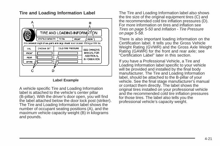
Tire and Loading Information Label
A vehicle specific Tire and Loading Informationlabel is attached to the vehicle’s center pillar(B-pillar). With the driver’s door open, you will findthe label attached below the door lock post (striker).The Tire and Loading Information label shows thenumber of occupant seating positions (A), and themaximum vehicle capacity weight (B) in kilogramsand pounds.
The Tire and Loading Information label also showsthe tire size of the original equipment tires (C) andthe recommended cold tire inflation pressures (D).For more information on tires and inflation seeTires on page 5-50 and Inflation - Tire Pressureon page 5-58.
There is also important loading information on theCertification label. It tells you the Gross VehicleWeight Rating (GVWR) and the Gross Axle WeightRating (GAWR) for the front and rear axle; see“Certification Label” later in this section.
If you have a Professional Vehicle, a Tire andLoading Information label specific to your vehiclewill be provided and installed by the final bodymanufacturer. The Tire and Loading Informationlabel, should be attached to the B-pillar of yourvehicle. See the final stage manufacturer’s manualor contact them directly. The label shows theoriginal tires installed on your professional vehicleand the recommended cold tire inflation pressuresfor those tires. The label also tells you theprofessional vehicle’s capacity weight.
Label Example
4-21

Steps for Determining Correct Load Limit1. Locate the statement “The combined weight
of occupants and cargo should never exceedXXX kg or XXX lbs” on your vehicle’s placard.
2. Determine the combined weight of the driverand passengers that will be riding in yourvehicle.
3. Subtract the combined weight of the driverand passengers from XXX kg or XXX lbs.
4. The resulting figure equals the availableamount of cargo and luggage load capacity.For example, if the “XXX” amount equals1400 lbs and there will be five 150 lbpassengers in your vehicle, the amount ofavailable cargo and luggage load capacityis 650 lbs (1400 − 750 (5 x 150) = 650 lbs).
5. Determine the combined weight of luggage andcargo being loaded on the vehicle. That weightmay not safely exceed the available cargo andluggage load capacity calculated in Step 4.
6. If your vehicle will be towing a trailer, the loadfrom your trailer will be transferred to yourvehicle. Consult this manual to determine howthis reduces the available cargo and luggageload capacity of your vehicle.If your vehicle can tow a trailer, see “Towing aTrailer” for important information on towinga trailer, towing safety rules, and trailering tips.
Item Description Total
AVehicle CapacityWeight forExample 1 =
1,000 lbs (453 kg)
BSubtractOccupant Weight150 lbs (68 kg) × 2 =
300 lbs (136 kg)
C Available Occupantand Cargo Weight = 700 lbs (317 kg)
Example 1
4-22

Item Description Total
AVehicle CapacityWeight forExample 2 =
1,000 lbs (453 kg)
BSubtractOccupant Weight150 lbs (68 kg) × 5 =
750 lbs (340 kg)
C Available CargoWeight = 250 lbs (113 kg)
Item Description Total
AVehicle CapacityWeight forExample 3 =
1,000 lbs (453 kg)
BSubtractOccupant Weight200 lbs (91 kg) × 5 =
1,000 lbs (453 kg)
C Available CargoWeight = 0 lbs (0 kg)
Refer to your vehicle’s Tire and LoadingInformation label for specific information aboutyour vehicle’s capacity weight and seatingpositions. The combined weight of the driver,passengers, and cargo should never exceedyour vehicle’s capacity weight.
Example 2 Example 3
4-23

Certification Label
A vehicle specific Certification label is attached tothe rear edge of the driver’s door. This label showsthe gross weight capacity of your vehicle, called theGross Vehicle Weight Rating (GVWR). The GVWRincludes the weight of the vehicle, all occupants,fuel, and cargo. Never exceed the GVWR for yourvehicle, or the Gross Axle Weight Rating (GAWR)for either the front or rear axle.
If your vehicle is a Professional Vehicle, the vehiclespecific Certification label is provided by the finalstage manufacturer. The coach-builder should beconsulted if the final stage manufacturer’s label isnot present. The Gross Vehicle Weight RatingGVWR label should be on the driver’s door edge.
If you do have a heavy load, you should spreadit out. See “Steps for Determining CorrectLoad Limit” earlier in this section.
{CAUTION:
Do not load your vehicle any heavier thanthe Gross Vehicle Weight Rating (GVWR),or either the maximum front or rear GrossAxle Weight Rating (GAWR). If you do,parts on your vehicle can break, and itcan change the way your vehicle handles.These could cause you to lose controland crash. Also, overloading can shortenthe life of your vehicle.
Notice: Overloading your vehicle may causedamage. Repairs would not be covered by yourwarranty. Do not overload your vehicle.
4-24

If you put things inside your vehicle, like suitcases,tools, packages, or anything else, they will go asfast as the vehicle goes. If you have to stop or turnquickly, or if there is a crash, they will keep going.
{CAUTION:
Things you put inside your vehicle canstrike and injure people in a sudden stopor turn, or in a crash.
• Put things in the trunk of your vehicle.In a trunk, put them as far forward asyou can. Try to spread the weightevenly.
• Never stack heavier things, likesuitcases, inside the vehicle so thatsome of them are above the tops ofthe seats.
• Do not leave an unsecured childrestraint in your vehicle.
• When you carry something inside thevehicle, secure it whenever you can.
Automatic Level ControlThis feature keeps the rear of your vehicle levelas the load changes. It is automatic, you donot need to adjust anything.
This type of level control is fully automatic and willprovide a better leveled riding position as well asbetter handling under a variety of passenger andloading conditions. An air compressor connectedto the rear shocks will raise or lower the rear ofthe vehicle to maintain proper vehicle height.The system is activated when the ignition key isturned to ON/RUN and will automatically adjustvehicle height thereafter. The system may exhaust(lower vehicle height) for up to ten minutes afterthe ignition key has been turned to LOCK/OFF.You may hear the air compressor operating whenthe height is being adjusted.
4-25

Towing
Towing Your VehicleConsult your dealer/retailer or a professional towingservice if you need to have your disabled vehicle towed.See Roadside Service on page 7-7.
If you want to tow your vehicle behind another vehiclefor recreational purposes (such as behind a motorhome),see Recreational Vehicle Towing following.
Recreational Vehicle TowingRecreational vehicle towing means towing your vehiclebehind another vehicle – such as behind a motorhome.The two most common types of recreational vehicletowing are known as “dinghy towing” (towing your vehiclewith all four wheels on the ground) and “dolly towing”(towing your vehicle with two wheels on the groundand two wheels up on a device known as a “dolly”).
With the proper preparation and equipment, manyvehicles can be towed in these ways. See “DinghyTowing” and “Dolly Towing,” following.
Here are some important things to consider before youdo recreational vehicle towing:
• What is the towing capacity of the towing vehicle?Be sure you read the tow vehicle manufacturer’srecommendations.
• How far will you tow? Some vehicles haverestrictions on how far and how long they can tow.
• Do you have the proper towing equipment?See your dealer/retailer or trailering professional foradditional advice and equipment recommendations.
• Is your vehicle ready to be towed? Just as youwould prepare your vehicle for a long trip, youwill want to make sure your vehicle is prepared tobe towed. See Before Leaving on a Long Tripon page 4-13.
Dinghy Towing
Notice: If you tow your vehicle with all four wheelson the ground, the drivetrain components couldbe damaged. The repairs would not be covered byyour warranty. Do not tow your vehicle with allfour wheels on the ground.
Your vehicle was not designed to be towed with all fourwheels on the ground. If your vehicle must be towed,you should use a dolly. See “Dolly Towing” later in thissection for more information.
4-26
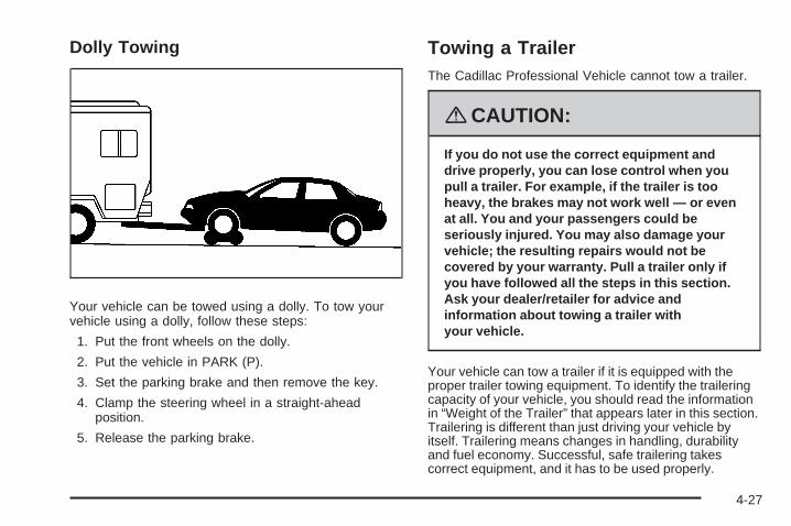
Dolly Towing
Your vehicle can be towed using a dolly. To tow yourvehicle using a dolly, follow these steps:
1. Put the front wheels on the dolly.
2. Put the vehicle in PARK (P).
3. Set the parking brake and then remove the key.
4. Clamp the steering wheel in a straight-aheadposition.
5. Release the parking brake.
Towing a TrailerThe Cadillac Professional Vehicle cannot tow a trailer.
{CAUTION:
If you do not use the correct equipment anddrive properly, you can lose control when youpull a trailer. For example, if the trailer is tooheavy, the brakes may not work well — or evenat all. You and your passengers could beseriously injured. You may also damage yourvehicle; the resulting repairs would not becovered by your warranty. Pull a trailer only ifyou have followed all the steps in this section.Ask your dealer/retailer for advice andinformation about towing a trailer withyour vehicle.
Your vehicle can tow a trailer if it is equipped with theproper trailer towing equipment. To identify the traileringcapacity of your vehicle, you should read the informationin “Weight of the Trailer” that appears later in this section.Trailering is different than just driving your vehicle byitself. Trailering means changes in handling, durabilityand fuel economy. Successful, safe trailering takescorrect equipment, and it has to be used properly.
4-27

That is the reason for this part. In it are manytime-tested, important trailering tips and safety rules.Many of these are important for your safety and that ofyour passengers. So please read this section carefullybefore you pull a trailer.
Load-pulling components such as the engine,transmission, wheel assemblies and tires are forcedto work harder against the drag of the added weight.The engine is required to operate at relatively higherspeeds and under greater loads, generating extra heat.What is more, the trailer adds considerably to windresistance, increasing the pulling requirements.
If You Do Decide To Pull a TrailerIf you do, here are some important points:
• There are many different laws, including speed limitrestrictions, having to do with trailering. Make sureyour rig will be legal, not only where you livebut also where you will be driving. A good sourcefor this information can be state or provincial police.
• Consider using a sway control. You can ask a hitchdealer/retailer about sway controls.
• Do not tow a trailer at all during the first 1,000 miles(1 600 km) your new vehicle is driven. Your engine,axle or other parts could be damaged.
• Then, during the first 500 miles (800 km) that you towa trailer, do not drive over 50 mph (80 km/h) and donot make starts at full throttle. This helps your engineand other parts of your vehicle wear in at theheavier loads.
• Obey speed limit restrictions when towing a trailer.Do not drive faster than the maximum posted speedfor trailers, or no more than 55 mph (90 km/h), tosave wear on your vehicle’s parts.
Three important considerations have to do with weight:
• The weight of the trailer
• The weight of the trailer tongue
• The total weight on your vehicle’s tires
4-28

Weight of the TrailerHow heavy can a trailer safely be?
It should never weigh more than 1,000 lbs (454 kg).These are total maximum weights including the load.But even that can be too heavy.
It depends on how you plan to use your rig. For example,speed, altitude, road grades, outside temperature andhow much your vehicle is used to pull a trailer are allimportant. It can also depend on any special equipmentthat you have on your vehicle, and the amount of tongueweight the vehicle can carry. See “Weight of the TrailerTongue” later in this section for more information.
Maximum trailer weight is calculated assuming only thedriver is in the tow vehicle and it has all the requiredtrailering equipment. The weight of additional optionalequipment, passengers and cargo in the tow vehiclemust be subtracted from the maximum trailer weight.
You can ask your dealer/retailer for our traileringinformation or advice, or you can write us at ourCustomer Assistance Offices. See CustomerAssistance Offices on page 7-5 for more information.
Weight of the Trailer TongueThe tongue load (A) of any trailer is an important weightto measure because it affects the total or gross weight ofyour vehicle. The Gross Vehicle Weight (GVW) includesthe curb weight of the vehicle, any cargo you may carry init, and the people who will be riding in the vehicle. And ifyou tow a trailer, you must add the tongue load to theGVW because your vehicle will be carrying that weight,too. See Loading Your Vehicle on page 4-20 for moreinformation about your vehicle’s maximum load capacity.
If you are using a weight-carrying hitch or aweight-distributing hitch, the trailer tongue (A)should weigh 10 to 15 percent of the total loadedtrailer weight (B).
4-29

After you have loaded your trailer, weigh the trailer andthen the tongue, separately, to see if the weights areproper. If they are not, you may be able to get them rightsimply by moving some items around in the trailer.
Total Weight on Your Vehicle’s TiresBe sure your vehicle’s tires are inflated to the upper limitfor cold tires. You will find these numbers on the Tire andLoading Information Label. See Loading Your Vehicle onpage 4-20. Then be sure you do not go over the GVWlimit for your vehicle, including the weight of the trailertongue.
HitchesIt is important to have the correct hitch equipment.Crosswinds, large trucks going by and rough roads area few reasons why you will need the right hitch. Hereare some rules to follow:• The rear bumper on your vehicle is not intended
for hitches. Do not attach rental hitches or otherbumper-type hitches to it. Use only a frame-mountedhitch that does not attach to the bumper.
• Will you have to make any holes in the body of yourvehicle when you install a trailer hitch? If you do, thenbe sure to seal the holes later when you remove thehitch. If you do not seal them, deadly carbonmonoxide (CO) from your exhaust can get into yourvehicle. See Engine Exhaust on page 2-34. Dirt andwater can, too.
Safety ChainsYou should always attach chains between your vehicleand your trailer. Cross the safety chains under the tongueof the trailer so that the tongue will not drop to the road ifit becomes separated from the hitch. Instructions aboutsafety chains may be provided by the hitch manufactureror by the trailer manufacturer. Follow the manufacturer’srecommendation for attaching safety chains and do notattach them to the bumper. Always leave just enoughslack so you can turn with your rig. And, never allowsafety chains to drag on the ground.
Trailer BrakesBecause your vehicle has anti-lock brakes, do not try totap into your vehicle’s hydraulic brake system. If youdo, both brake systems will not work well, or at all.
Be sure to read and follow the instructions for the trailerbrakes so you will be able to maintain them properly.
4-30

Driving with a TrailerTowing a trailer requires a certain amount of experience.Before setting out for the open road, you will want toget to know your rig. Acquaint yourself with the feel ofhandling and braking with the added weight of the trailer.And always keep in mind that the vehicle you aredriving is now a good deal longer and not nearlyas responsive as your vehicle is by itself.
Before you start, check the trailer hitch and platform,parts and attachments, safety chains, electricalconnector, lamps, tires and mirror adjustment. If thetrailer has electric brakes, start your vehicle and trailermoving and then apply the trailer brake controllerby hand to be sure the brakes are working. This letsyou check your electrical connection at the same time.
During your trip, check occasionally to be sure thatthe load is secure, and that the lamps and any trailerbrakes are still working.
Following DistanceStay at least twice as far behind the vehicle ahead asyou would when driving your vehicle without a trailer.This can help you avoid situations that requireheavy braking and sudden turns.
PassingYou will need more passing distance up ahead whenyou are towing a trailer. And, because the vehicleis a good deal longer, you will need to go much fartherbeyond the passed vehicle before you can return toyour lane.
Backing UpHold the bottom of the steering wheel with one hand.Then, to move the trailer to the left, just move that handto the left. To move the trailer to the right, move yourhand to the right. Always back up slowly and, if possible,have someone guide you.
Making Turns
Notice: Making very sharp turns while traileringcould cause the trailer to come in contact with thevehicle. Your vehicle could be damaged. Avoidmaking very sharp turns while trailering.
When you are turning with a trailer, make wider turnsthan normal. Do this so your trailer will not strike softshoulders, curbs, road signs, trees or other objects.Avoid jerky or sudden maneuvers. Signal well in advance.
4-31

Turn Signals When Towing a TrailerWhen you tow a trailer, your vehicle may need adifferent turn signal flasher and/or extra wiring. Checkwith your /retailer. The arrows on your instrument panelwill flash whenever you signal a turn or lane change.Properly hooked up, the trailer lamps will also flash,telling other drivers you are about to turn, changelanes or stop.
When towing a trailer, the arrows on your instrumentpanel will flash for turns even if the bulbs on the trailer areburned out. Thus, you may think drivers behind you areseeing your signal when they are not. It is important tocheck occasionally to be sure the trailer bulbs are stillworking.
Driving on GradesReduce speed and shift to a lower gear before you startdown a long or steep downgrade. If you do not shiftdown, you might have to use your brakes so muchthat they would get hot and no longer work well.
On a long uphill grade, shift down and reduce yourspeed to around 45 mph (70 km/h) to reduce thepossibility of the engine and the transmissionoverheating.
Parking on Hills
{CAUTION:
You really should not park your vehicle, with atrailer attached, on a hill. If something goeswrong, your rig could start to move. Peoplecan be injured, and both your vehicle and thetrailer can be damaged.
But if you ever have to park your rig on a hill, here ishow to do it:
1. Apply your regular brakes, but do not shift intoPARK (P).
2. Have someone place chocks behind the trailerwheels.
3. When the wheel chocks are in place, release theregular brakes until the chocks absorb the load.
4. Reapply the regular brakes. Then shift intoPARK (P) firmly and apply your parking brake.
5. Release the regular brakes.
4-32
When You Are Ready to Leave AfterParking on a Hill1. Apply your regular brakes and hold the pedal down
while you:
• Start your engine,
• Shift into a gear, and
• Make sure the parking brake has released.
2. Let up on the brake pedal.
3. Drive slowly until the trailer is clear of the chocks.
4. Stop and have someone pick up and store thechocks.
Maintenance When Trailer TowingYour vehicle will need service more often when you arepulling a trailer. See the Maintenance Schedule for moreon this. Things that are especially important in traileroperation are automatic transmission fluid (do notoverfill), engine oil, drive belt, cooling system and brakesystem. Each of these is covered in this manual, and theIndex will help you find them quickly. If you are trailering,it is a good idea to review this information before youstart your trip.
Check periodically to see that all hitch nuts and boltsare tight.
Engine Cooling When Trailer TowingYour cooling system may temporarily overheat duringsevere operating conditions. See Engine Overheatingon page 5-25.
4-33

✍ NOTES
4-34

Service ............................................................5-3Accessories and Modifications ..........................5-3California Proposition 65 Warning .....................5-4California Perchlorate Materials Requirements .....5-4Doing Your Own Service Work .........................5-4Adding Equipment to the Outside
of Your Vehicle ...........................................5-5Fuel ................................................................5-5
Gasoline Octane ............................................5-5Gasoline Specifications ....................................5-6California Fuel ...............................................5-6Additives .......................................................5-6Fuels in Foreign Countries ...............................5-7Filling the Tank ..............................................5-8Filling a Portable Fuel Container .....................5-10
Checking Things Under the Hood ....................5-10Hood Release ..............................................5-11Engine Compartment Overview .......................5-12Engine Oil ...................................................5-13Engine Oil Life System ..................................5-16Engine Air Cleaner/Filter ................................5-18Automatic Transmission Fluid .........................5-19Engine Coolant .............................................5-22Coolant Surge Tank Pressure Cap ..................5-25Engine Overheating .......................................5-25
Overheated Engine ProtectionOperating Mode ........................................5-27
Cooling System ............................................5-28Power Steering Fluid .....................................5-33Windshield Washer Fluid ................................5-34Brakes ........................................................5-35Battery ........................................................5-38Jump Starting ...............................................5-40
Headlamp Aiming ...........................................5-44Bulb Replacement ..........................................5-47
High Intensity Discharge (HID) Lighting ............5-47Windshield Wiper Blade Replacement ..............5-48Tires ..............................................................5-50
Tire Sidewall Labeling ...................................5-51Tire Terminology and Definitions .....................5-55Inflation - Tire Pressure .................................5-58High-Speed Operation ...................................5-60Tire Pressure Monitor System .........................5-61Tire Pressure Monitor Operation .....................5-62Tire Inspection and Rotation ...........................5-66When It Is Time for New Tires .......................5-68Buying New Tires .........................................5-69Different Size Tires and Wheels ......................5-71Uniform Tire Quality Grading ..........................5-72
Section 5 Service and Appearance Care
5-1

Wheel Alignment and Tire Balance ..................5-73Wheel Replacement ......................................5-74Tire Chains ..................................................5-75If a Tire Goes Flat ........................................5-76Changing a Flat Tire .....................................5-77Removing the Spare Tire and Tools ................5-78Removing the Flat Tire and Installing
the Spare Tire ..........................................5-79Storing a Flat or Spare Tire and Tools ............5-85Spare Tire ...................................................5-86
Appearance Care ............................................5-87Interior Cleaning ...........................................5-87Fabric/Carpet ...............................................5-88Leather .......................................................5-89Instrument Panel, Vinyl, and
Other Plastic Surfaces ................................5-89Wood Panels ...............................................5-89Speaker Covers ............................................5-90Care of Safety Belts ......................................5-90Weatherstrips ...............................................5-90Washing Your Vehicle ...................................5-90Cleaning Exterior Lamps/Lenses .....................5-91Finish Care ..................................................5-91
Windshield and Wiper Blades .........................5-92Aluminum or Chrome-Plated
Wheels and Trim .......................................5-92Tires ...........................................................5-93Sheet Metal Damage .....................................5-93Finish Damage .............................................5-93Underbody Maintenance ................................5-94Chemical Paint Spotting .................................5-94Vehicle Care/Appearance Materials ..................5-94
Vehicle Identification ......................................5-95Vehicle Identification Number (VIN) .................5-95Service Parts Identification Label .....................5-96
Electrical System ............................................5-96Add-On Electrical Equipment ..........................5-96Headlamp Wiring ..........................................5-96Windshield Wiper Fuses ................................5-96Power Windows and Other
Power Options ..........................................5-97Fuses and Circuit Breakers ............................5-97Underhood Fuse Block ..................................5-97Rear Underseat Fuse Block ..........................5-100
Capacities and Specifications ........................5-105
Section 5 Service and Appearance Care
5-2

ServiceFor service and parts needs, visit your dealer/retailer.You will receive genuine GM parts and GM-trainedand supported service people.
Genuine GM parts have one of these marks:
Accessories and ModificationsWhen non-dealer/non-retailer accessories are added toyour vehicle they can affect your vehicle’s performanceand safety, including such things as, airbags, braking,stability, ride and handling, emissions systems,aerodynamics, durability, and electronic systems likeantilock brakes, traction control and stability control.Some of these accessories could even causemalfunction or damage not covered by warranty.
GM Accessories are designed to complement andfunction with other systems on your vehicle. YourGM dealer/retailer can accessorize your vehicleusing genuine GM Accessories. When you go toyour GM dealer/retailer and ask for GM Accessories,you will know that GM-trained and supported servicetechnicians will perform the work using genuineGM Accessories.
Also, see Adding Equipment to Your Airbag-EquippedVehicle on page 1-68.
5-3

California Proposition 65 WarningMost motor vehicles, including this one, contain and/oremit chemicals known to the State of California tocause cancer and birth defects or other reproductiveharm. Engine exhaust, many parts and systems(including some inside the vehicle), many fluids,and some component wear by-products containand/or emit these chemicals.
California Perchlorate MaterialsRequirementsCertain types of automotive applications, such asairbag initiators, seat belt pretensioners, and lithiumbatteries contained in remote keyless entry transmitters,may contain perchlorate materials. Special handlingmay be necessary. For additional information, seewww.dtsc.ca.gov/hazardouswaste/perchlorate.
Doing Your Own Service Work
{CAUTION:
You can be injured and your vehicle could bedamaged if you try to do service work on avehicle without knowing enough about it.
• Be sure you have sufficient knowledge,experience, the proper replacementparts, and tools before you attempt anyvehicle maintenance task.
• Be sure to use the proper nuts, bolts,and other fasteners. English and metricfasteners can be easily confused. If youuse the wrong fasteners, parts can laterbreak or fall off. You could be hurt.
5-4

If you want to do some of your own service work,you should use the proper service manual. It tellsyou much more about how to service your vehiclethan this manual can. To order the proper servicemanual, see Service Publications Ordering Informationon page 7-15.
Your vehicle has an airbag system. Before attemptingto do your own service work, see Servicing YourAirbag-Equipped Vehicle on page 1-67.
You should keep a record with all parts receipts andlist the mileage and the date of any service workyou perform. See Maintenance Record on page 6-16.
Adding Equipment to the Outsideof Your VehicleThings you might add to the outside of your vehiclecan affect the airflow around it. This can causewind noise and can affect fuel economy and windshieldwasher performance. Check with your dealer/retailerbefore adding equipment to the outside of your vehicle.
FuelUse of the recommended fuel is an important part ofthe proper maintenance of your vehicle. To helpkeep the engine clean and maintain optimum vehicleperformance, we recommend the use of gasolineadvertised as TOP TIER Detergent Gasoline.
Gasoline OctaneUse premium unleaded gasoline with a posted octanerating of 91 or higher. You can also use regularunleaded gasoline rated at 87 octane or higher, butyour vehicle’s acceleration could be slightly reduced,and you might notice a slight audible knockingnoise, commonly referred to as spark knock. If theoctane is less than 87, you might notice a heavyknocking noise when you drive. If this occurs, use agasoline rated at 87 octane or higher as soon aspossible. Otherwise, you could damage the engine.If you are using gasoline rated at 87 octane or higherand you hear heavy knocking, the engine needs service.
5-5
Gasoline SpecificationsAt a minimum, gasoline should meet ASTMspecification D 4814 in the United States orCAN/CGSB-3.5 or 3.511 in Canada. Some gasolinescontain an octane-enhancing additive calledmethylcyclopentadienyl manganese tricarbonyl (MMT).We recommend against the use of gasolinescontaining MMT. See Additives on page 5-6 foradditional information.
California FuelIf your vehicle is certified to meet California EmissionsStandards, it is designed to operate on fuels thatmeet California specifications. See the underhoodemission control label. If this fuel is not availablein states adopting California emissions standards, yourvehicle will operate satisfactorily on fuels meetingfederal specifications, but emission control systemperformance might be affected. The malfunctionindicator lamp could turn on and your vehicle might faila smog-check test. See Malfunction Indicator Lampon page 3-63. If this occurs, return to your authorizeddealer/retailer for diagnosis. If it is determined thatthe condition is caused by the type of fuel used,repairs might not be covered by your warranty.
AdditivesTo provide cleaner air, all gasolines in the United Statesare now required to contain additives that help preventengine and fuel system deposits from forming, allowingthe emission control system to work properly. In mostcases, you should not have to add anything to the fuel.However, some gasolines contain only the minimumamount of additive required to meet U.S. EnvironmentalProtection Agency regulations. To help keep fuel injectorsand intake valves clean, or if your vehicle experiencesproblems due to dirty injectors or valves, look for gasolinethat is advertised as TOP TIER Detergent Gasoline.Also, your dealer/retailer has additives that will helpcorrect and prevent most deposit-related problems.
Gasolines containing oxygenates, such as ethers andethanol, and reformulated gasolines might be available inyour area. We recommend that you use these gasolines,if they comply with the specifications described earlier.However, E85 (85% ethanol) and other fuels containingmore than 10% ethanol must not be used in vehicles thatwere not designed for those fuels.
5-6

Notice: Your vehicle was not designed for fuelthat contains methanol. Do not use fuel containingmethanol. It can corrode metal parts in the fuelsystem and also damage plastic and rubber parts.That damage would not be covered under yourwarranty.
Some gasolines that are not reformulated for lowemissions can contain an octane-enhancing additivecalled methylcyclopentadienyl manganese tricarbonyl(MMT); ask the attendant where you buy gasolinewhether the fuel contains MMT. We recommend againstthe use of such gasolines. Fuels containing MMT canreduce the life of spark plugs and the performanceof the emission control system could be affected.The malfunction indicator lamp might turn on. If thisoccurs, return to your dealer/retailer for service.
Fuels in Foreign CountriesIf you plan on driving in another country outside theUnited States or Canada, the proper fuel might behard to find. Never use leaded gasoline or any otherfuel not recommended in the previous text on fuel.Costly repairs caused by use of improper fuel wouldnot be covered by your warranty.
To check the fuel availability, ask an auto club,or contact a major oil company that does businessin the country where you will be driving.
5-7

Filling the Tank
{CAUTION:
Fuel vapor burns violently and a fuel fire cancause bad injuries. To help avoid injuriesto you and others, read and follow all theinstructions on the pump island. Turn off yourengine when you are refueling. Do not smokeif you are near fuel or refueling your vehicle.Do not use cellular phones. Keep sparks,flames, and smoking materials away from fuel.Do not leave the fuel pump unattended whenrefueling your vehicle. This is against the lawin some places. Do not re-enter the vehiclewhile pumping fuel. Keep children away fromthe fuel pump; never let children pump fuel.
The tethered fuel cap is located behind a hinged fueldoor on the driver’s side of the vehicle.
To open the fuel door, apply pressure in the center ofthe rear edge of the fuel door and it will pop open.
5-8

To remove the fuel cap, turn it slowly counterclockwise.The fuel cap has a spring in it; if the cap is releasedtoo soon, it will spring back to the right.
While refueling, hang the tethered fuel cap from thehook on the fuel door.
{CAUTION:
Fuel can spray out on you if you open thefuel cap too quickly. If you spill fuel and thensomething ignites it, you could be badly burned.This spray can happen if your tank is nearly full,and is more likely in hot weather. Open the fuelcap slowly and wait for any hiss noise to stop.Then unscrew the cap all the way.
Be careful not to spill fuel. Do not top off or overfillthe tank and wait a few seconds after you have finishedpumping before removing the nozzle. Clean fuel frompainted surfaces as soon as possible. See WashingYour Vehicle on page 5-90.
When replacing the fuel cap, turn it clockwise until itclicks. Make sure the cap is fully installed. The diagnosticsystem can determine if the fuel cap has been left off orimproperly installed. This would allow fuel to evaporateinto the atmosphere. See Malfunction Indicator Lampon page 3-63.
The TIGHTEN GAS CAP message will be displayed onthe Driver Information Center (DIC) if the fuel cap is notproperly installed. See DIC Warnings and Messageson page 3-73 for more information.
{CAUTION:
If a fire starts while you are refueling, do notremove the nozzle. Shut off the flow of fuel byshutting off the pump or by notifying thestation attendant. Leave the area immediately.
Notice: If you need a new fuel cap, be sure to getthe right type. Your dealer/retailer can get onefor you. If you get the wrong type, it may not fitproperly. This may cause your malfunction indicatorlamp to light and may damage your fuel tank andemissions system. See Malfunction Indicator Lampon page 3-63.
5-9

Filling a Portable Fuel Container
{CAUTION:
Never fill a portable fuel container while itis in your vehicle. Static electricity dischargefrom the container can ignite the fuel vapor.You can be badly burned and your vehicledamaged if this occurs. To help avoid injuryto you and others:
• Dispense fuel only into approvedcontainers.
• Do not fill a container while it is inside avehicle, in a vehicle’s trunk, pickup bed,or on any surface other than the ground.
• Bring the fill nozzle in contact with theinside of the fill opening before operatingthe nozzle. Contact should be maintaineduntil the filling is complete.
• Do not smoke while pumping fuel.• Do not use a cellular phone while
pumping fuel.
Checking Things Underthe Hood
{CAUTION:
An electric fan under the hood can start upand injure you even when the engine is notrunning. Keep hands, clothing, and toolsaway from any underhood electric fan.
{CAUTION:
Things that burn can get on hot engine partsand start a fire. These include liquids like fuel,oil, coolant, brake fluid, windshield washerand other fluids, and plastic or rubber. You orothers could be burned. Be careful not to dropor spill things that will burn onto a hot engine.
5-10

Hood ReleaseTo lift the hood, use the following steps:
1. Pull the hood releaselever with this symbolon it. It is locatedon the lower left side ofthe instrument panel.
2. Then go to the front of the vehicle and find thesecondary hood release lever, located near thecenter of the hood. Move the release lever upand to the right to raise the hood.
Before closing the hood, be sure all filler caps are onproperly. Then pull the hood down and close it firmly.
5-11
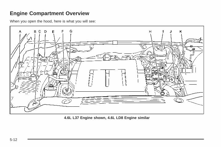
Engine Compartment OverviewWhen you open the hood, here is what you will see:
4.6L L37 Engine shown, 4.6L LD8 Engine similar
5-12

A. Underhood Fuse Block. See Underhood Fuse Blockon page 5-97.
B. Remote Positive (+) Terminal. See Jump Startingon page 5-40.
C. Windshield Washer Fluid Reservoir. See “AddingWasher Fluid” under Windshield Washer Fluidon page 5-34.
D. Engine Coolant Surge Tank and Pressure Cap.See Coolant Surge Tank Pressure Cap on page 5-25and Cooling System on page 5-28.
E. Remote Negative (−) Terminal. See Jump Startingon page 5-40 Jump Starting.
F. Power Steering Fluid. See Power Steering Fluidon page 5-33.
G. Engine Oil Fill Cap. See “When to Add Engine Oil”under Engine Oil on page 5-13.
H. Engine Oil Dipstick. See “Checking Engine Oil”under Engine Oil on page 5-13.
I. Brake Master Cylinder Reservoir. See “Brake Fluid”under Brakes on page 5-35.
J. Automatic Transmission Fluid Cap and Dipstick(Out of View). See Automatic Transmission Fluidon page 5-19.
K. Engine Air Cleaner/Filter. See Engine AirCleaner/Filter on page 5-18.
Engine Oil
Checking Engine OilIt is a good idea to check the engine oil every timeyou get fuel. In order to get an accurate reading,the oil must be warm and the vehicle must be onlevel ground.
The engine oil dipstick handle is a yellow loop.See Engine Compartment Overview on page 5-12for the location of the engine oil dipstick.
1. Turn off the engine and give the oil several minutesto drain back into the oil pan. If you do not do this,the oil dipstick might not show the actual level.
2. Pull out the dipstick and clean it with a papertowel or cloth, then push it back in all the way.Remove it again, keeping the tip down, andcheck the level.
5-13
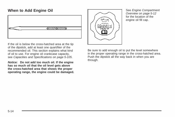
When to Add Engine Oil
If the oil is below the cross-hatched area at the tipof the dipstick, add at least one quart/liter of therecommended oil. This section explains what kindof oil to use. For engine oil crankcase capacity,see Capacities and Specifications on page 5-105.
Notice: Do not add too much oil. If the enginehas so much oil that the oil level gets abovethe cross-hatched area that shows the properoperating range, the engine could be damaged.
See Engine CompartmentOverview on page 5-12for the location of theengine oil fill cap.
Be sure to add enough oil to put the level somewherein the proper operating range in the cross-hatched area.Push the dipstick all the way back in when you arethrough.
5-14

What Kind of Engine Oil to Use
Look for three things:
• GM4718M
Your vehicle’s engine requires a special oilmeeting GM Standard GM4718M. Oils meetingthis standard may be identified as synthetic.However, not all synthetic oils will meet thisGM standard. Look for and use only an oil thatmeets GM Standard GM4718M.
Notice: If you use oils that do not have theGM4718M Standard designation, you can causeengine damage not covered by your warranty.
• SAE 5W-30
As shown in the viscosity chart, SAE 5W-30is best for your vehicle.These numbers on an oil container show itsviscosity, or thickness. Do not use other viscosityoils such as SAE 20W-50.
• Oils meeting theserequirements shouldhave the starburstsymbol on the container.This symbol indicatesthat the oil hasbeen certified by theAmerican PetroleumInstitute (API).
Look for this on the oil container, and use only those oilsthat are identified as meeting GM Standard GM4718Mand have the starburst symbol on the front of the oilcontainer.
Your vehicle’s engine is filled at the factory with aMobil 1® synthetic oil, which meets all requirementsfor your vehicle.
5-15

Substitute Engine Oil: When adding oil to maintainengine oil level, oil meeting GM Standard GM4718Mmay not be available. You can add substitute oildesignated SAE 5W-30 with the starburst symbol at alltemperatures. Substitute oil not meeting GM StandardGM4718M should not be used for an oil change.
Engine Oil AdditivesDo not add anything to the oil. The recommended oilswith the starburst symbol that meet GM standards are allyou need for good performance and engine protection.
Engine Oil Life System
When to Change Engine OilYour vehicle has a computer system that lets youknow when to change the engine oil and filter. This isbased on engine revolutions and engine temperature,and not on mileage. Based on driving conditions,the mileage at which an oil change will be indicatedcan vary considerably. For the oil life system towork properly, you must reset the system every timethe oil is changed.
When the system has calculated that oil life hasbeen diminished, it will indicate that an oil change isnecessary. A CHANGE ENGINE OIL SOON messagein the Driver Information Center (DIC) will come on.Change the oil as soon as possible within the next600 miles (1 000 km). It is possible that, if you aredriving under the best conditions, the oil life systemmight not indicate that an oil change is necessary forover a year. However, the engine oil and filter mustbe changed at least once a year and at this timethe system must be reset. Your dealer/retailer hastrained people who will perform this work using genuineparts and reset the system. It is also important tocheck the oil regularly and keep it at the proper level.
If the system is ever reset accidentally, you mustchange the oil at 3,000 miles (5 000 km) since thelast oil change. Remember to reset the oil life systemwhenever the oil is changed.
5-16
How to Reset the Engine OilLife SystemThe Engine Oil Life System calculates when to changethe engine oil and filter based on vehicle use. Wheneverthe oil is changed, reset the system so it can calculatewhen the next oil change is required. If a situation occurswhere you change the oil prior to a CHANGE ENGINEOIL SOON message in the Driver InformationCenter (DIC) being turned on, reset the system.
After the oil has been changed, the CHANGE ENGINEOIL SOON message must be reset:
1. Turn the key to the ON/RUN position withoutstarting the engine.
2. Press the INFO button on the Driver InformationCenter (DIC) until OIL LIFE REMAINING isdisplayed. See DIC Operation and Displayson page 3-69.
3. Press and hold the INFO RESET button until100% is displayed. This resets the oil life indicator.
4. Turn the key to LOCK/OFF.
If the CHANGE ENGINE OIL SOON message comesback on when you start your vehicle, the engine oillife system has not reset. Repeat the procedure.
What to Do with Used OilUsed engine oil contains certain elements that can beunhealthy for your skin and could even cause cancer.Do not let used oil stay on your skin for very long.Clean your skin and nails with soap and water,or a good hand cleaner. Wash or properly disposeof clothing or rags containing used engine oil. See themanufacturer’s warnings about the use and disposalof oil products.
Used oil can be a threat to the environment. If youchange your own oil, be sure to drain all the oil fromthe filter before disposal. Never dispose of oil by puttingit in the trash, pouring it on the ground, into sewers,or into streams or bodies of water. Instead, recycle itby taking it to a place that collects used oil. If you havea problem properly disposing of used oil, ask yourdealer/retailer, a service station, or a local recyclingcenter for help.
5-17

Engine Air Cleaner/FilterSee Engine Compartment Overview on page 5-12 forthe location of the engine air cleaner/filter.
When to Inspect the EngineAir Cleaner/FilterInspect the air cleaner/filter at the Maintenance IIintervals and replace it at the first oil change aftereach 50,000 mile (80 000 km) interval. See ScheduledMaintenance on page 6-4 for more information.If you are driving in dusty/dirty conditions, inspectthe filter at each engine oil change.
How to Inspect the EngineAir Cleaner/FilterTo inspect the air cleaner/filter, remove the filterfrom the vehicle and lightly shake the filter to releaseloose dust and dirt. If the filter remains caked with dirt,a new filter is required.
To inspect or replace the filter, do the following:
1. Loosen and remove the two screws on the top ofthe engine air cleaner/filter cover.
2. Lift up the outboard side of the cover at an anglewhile pulling toward you. This is necessary dueto the two hinges located on the inboard sideof the cover.
3. Remove the engine air cleaner/filter element andany loose debris that may be found in the aircleaner base.
4. Inspect or replace the air filter element.
5-18
Follow these steps to reinstall the cover to the engineair cleaner/filter housing:1. Align the two hinges located on the inboard side
of the cover.
2. Push the cover slightly down and towards theengine to engage the tabs in the hinges andalign the two screws.
3. Tighten the two screws on the top of the engineair cleaner/filter housing cover.
{CAUTION:
Operating the engine with the air cleaner/filteroff can cause you or others to be burned.The air cleaner not only cleans the air; it helpsto stop flames if the engine backfires. If it isnot there and the engine backfires, you couldbe burned. Do not drive with it off, and becareful working on the engine with the aircleaner/filter off.
Notice: If the air cleaner/filter is off, a backfire cancause a damaging engine fire. And, dirt can easily getinto your engine, which will damage it. Always havethe air cleaner/filter in place when you are driving.
Automatic Transmission Fluid
When to Check and Change AutomaticTransmission FluidA good time to check your automatic transmissionfluid level is when the engine oil is changed.
Change the fluid and filter at the intervals listed inAdditional Required Services on page 6-6, and be sureto use the transmission fluid listed in RecommendedFluids and Lubricants on page 6-13.
5-19

How to Check AutomaticTransmission FluidBecause this operation can be a little difficult, you maychoose to have this done at the dealer/retailer servicedepartment.If you do it yourself, be sure to follow all the instructionshere, or you could get a false reading on the dipstick.Notice: Too much or too little fluid can damageyour transmission. Too much can mean that someof the fluid could come out and fall on hot engineparts or exhaust system parts, starting a fire.Too little fluid could cause the transmission tooverheat. Be sure to get an accurate reading if youcheck your transmission fluid.Wait at least 30 minutes before checking thetransmission fluid level if you have been driving:• When outside temperatures are above 90°F (32°C).• At high speed for quite a while.• In heavy traffic — especially in hot weather.• While pulling a trailer.
To get the right reading, the fluid should be atnormal operating temperature, which is 180°F to 200°F(82°C to 93°C).Get the vehicle warmed up by driving about15 miles (24 km) when outside temperatures areabove 50°F (10°C). If it is colder than 50°F (10°C),you may have to drive longer.
Checking the Fluid LevelPrepare you vehicle as follows:
1. Park your vehicle on a level place. Keep theengine running.
2. With the parking brake applied, place the shiftlever in PARK (P).
3. With your foot on the brake pedal, move the shiftlever through each gear range, pausing for aboutthree seconds in each range. Then, positionthe shift lever in PARK (P).
4. Let the engine run at idle for three to five minutes.
Then, without shutting off the engine, follow these steps:
The transmission fluid cap is located next to the radiatorhose and below the engine air cleaner/filter assemblyon the driver’s side of the vehicle, and is markedTRANS FLUID. See Engine Compartment Overviewon page 5-12 for more information on location.
1. After removing the engine air cleaner/filter assemblyto reach the transmission fluid cap, turn the capcounterclockwise to remove. Pull out the dipstickand wipe it with a clean rag or paper towel.
2. Push it back in all the way, wait three seconds,and then pull it back out again.
5-20

3. Check both sides of the dipstick, and readthe lower level. The fluid level must be in thecross-hatched area.
4. If the fluid level is in the acceptable range,push the dipstick back in all the way and turnthe handle clockwise. Reinstall the engineair cleaner/filter assembly.
How to Add AutomaticTransmission FluidRefer to the Maintenance Schedule to determine whatkind of transmission fluid to use. See RecommendedFluids and Lubricants on page 6-13.
If the fluid level is low, add only enough of the properfluid to bring the level into the cross-hatched area onthe dipstick.
1. Pull out the dipstick.
2. Using a long-neck funnel, add enough fluid atthe dipstick hole to bring it to the proper level.It does not take much fluid, generally less thanone pint (0.5 L). Do not overfill.
Notice: Use of the incorrect automatic transmissionfluid may damage your vehicle, and the damagesmay not be covered by your warranty. Alwaysuse the automatic transmission fluid listed inRecommended Fluids and Lubricants on page 6-13.
3. After adding fluid, recheck the fluid level asdescribed under “How to Check AutomaticTransmission Fluid,” earlier in this section.
4. When the correct fluid level is obtained, push thedipstick back in all the way and turn the handleclockwise.
5-21

Engine CoolantThe cooling system in your vehicle is filled withDEX-COOL® engine coolant. This coolant isdesigned to remain in your vehicle for five years or150,000 miles (240 000 km), whichever occurs first,if you add only DEX-COOL® extended life coolant.
The following explains your cooling system and howto add coolant when it is low. If you have a problemwith engine overheating, see Engine Overheatingon page 5-25.
A 50/50 mixture of clean, drinkable water andDEX-COOL® coolant will:
• Giving freezing protection down to −34°F (−37°C).
• Give boiling protection up to 265°F (129°C).
• Protect against rust and corrosion.
• Help keep the proper engine temperature.
• Let the warning lights and gages work asthey should.
Notice: Using coolant other than DEX-COOL® maycause premature engine, heater core, or radiatorcorrosion. In addition, the engine coolant mayrequire changing sooner, at the first maintenanceservice after each 30,000 miles (50 000 km) or24 months, whichever occurs first. Any repairswould not be covered by your warranty. Always useDEX-COOL® (silicate-free) coolant in your vehicle.
5-22

What to UseUse a mixture of one-half clean, drinkable water andone-half DEX-COOL® coolant which will not damagealuminum parts. If you use this coolant mixture, you donot need to add anything else.
{CAUTION:
Adding only plain water to your coolingsystem can be dangerous. Plain water, orsome other liquid such as alcohol, can boilbefore the proper coolant mixture will. Yourvehicle’s coolant warning system is set for theproper coolant mixture. With plain water or thewrong mixture, your engine could get too hotbut you would not get the overheat warning.Your engine could catch fire and you or otherscould be burned. Use a 50/50 mixture of clean,drinkable water and DEX-COOL® coolant.
Notice: If you use an improper coolant mixture,your engine could overheat and be badly damaged.The repair cost would not be covered by yourwarranty. Too much water in the mixture can freezeand crack the engine, radiator, heater core, andother parts.
If you have to add coolant more than two times a year,have your dealer/retailer check your cooling system.
Notice: If you use extra inhibitors and/or additivesin your vehicle’s cooling system, you coulddamage your vehicle. Use only the proper mixtureof the engine coolant listed in this manual forthe cooling system. See Recommended Fluids andLubricants on page 6-13 for more information.
5-23

Checking Coolant
The engine coolantsurge tank is locatedtoward the rear ofthe engine compartmenton the passenger’sside of the vehicle.
For more information on location, see EngineCompartment Overview on page 5-12.
{CAUTION:
Turning the surge tank pressure cap when theengine and radiator are hot can allow steam andscalding liquids to blow out and burn you badly.Never turn the surge tank pressure cap — evena little — when the engine and radiator are hot.
The vehicle must be on a level surface. When yourengine is cold, the coolant level should be at theFULL COLD mark, located on the side of the surgetank that faces the engine.
5-24

Adding CoolantIf you need more coolant, add the proper DEX-COOL®
coolant mixture at the coolant surge tank, but onlywhen the engine is cool.
{CAUTION:
You can be burned if you spill coolant on hotengine parts. Coolant contains ethylene glycol,and it will burn if the engine parts are hotenough. Do not spill coolant on a hot engine.
When replacing the pressure cap, make sure to turnthe cap until it clicks.
Coolant Surge Tank Pressure CapNotice: If the pressure cap is not tightly installed,coolant loss and possible engine damage may occur.Be sure the cap is properly and tightly secured.
The coolant surge tank pressure cap must be fullyinstalled on the coolant surge tank. See EngineCompartment Overview on page 5-12 for moreinformation on location.
Engine OverheatingYou will find an ENGINE OVERHEATED IDLE ENGINEmessage or an ENGINE OVERHEATED STOP ENGINEmessage displayed in the Driver Information Center(DIC). See DIC Warnings and Messages on page 3-73for more information. You will also hear a chime.
There is also an engine temperature warning lightand/or gage on the instrument panel cluster. See EngineCoolant Temperature Warning Light on page 3-61 andEngine Coolant Temperature Gage on page 3-62.
5-25

If Steam Is Coming From Your Engine
{CAUTION:
Steam from an overheated engine can burnyou badly, even if you just open the hood.Stay away from the engine if you see or hearsteam coming from it. Turn it off and geteveryone away from the vehicle until it coolsdown. Wait until there is no sign of steamor coolant before you open the hood.
If you keep driving when the vehicles engineis overheated, the liquids in it can catchfire. You or others could be badly burned.Stop your engine if it overheats, and get outof the vehicle until the engine is cool.
See Overheated Engine Protection OperatingMode on page 5-27 for information on drivingto a safe place in an emergency.
Notice: If your engine catches fire because you keepdriving with no coolant, your vehicle can be badlydamaged. The costly repairs would not be covered byyour warranty. See Overheated Engine ProtectionOperating Mode on page 5-27 for information ondriving to a safe place in an emergency.
If No Steam Is Coming FromYour EngineAn overheat warning, along with a low coolant message,can indicate a serious problem.
If you get an engine overheat warning with no lowcoolant message, but see or hear no steam, the problemmay not be too serious. Sometimes the engine canget a little too hot when you:
• Climb a long hill on a hot day.
• Stop after high-speed driving.
• Idle for long periods in traffic.
• Tow a trailer.
5-26

If you get the overheat warning with no sign of steam,try this for a minute or so:
1. In heavy traffic, let the engine idle in NEUTRAL (N)while stopped. If it safe to do so, pull off the road,shift to PARK (P) or NEUTRAL (N) and let theengine idle.
2. Set the climate controls to the highest heat settingand fan speed and open the windows as necessary.
If you no longer have the overheat warning, youcan drive. Just to be safe, drive slower for about10 minutes. If the warning does not come back on,you can drive normally.
If the warning continues, pull over, stop, and parkyour vehicle right away.
If there is still no sign of steam, idle the engine forthree minutes while you are parked. If you still havethe warning, turn off the engine and get everyoneout of the vehicle until it cools down. Also, see“Overheated Engine Protection Operating Mode” laterin this section.
You may decide not to lift the hood but to get servicehelp right away.
Overheated Engine ProtectionOperating ModeIf an overheated engine condition exists and themessage ENGINE OVERHEATED STOP ENGINE isdisplayed, an overheat protection mode which alternatesfiring groups of cylinders helps prevent engine damage.In this mode, you will notice a loss in power andengine performance. This operating mode allows yourvehicle to be driven to a safe place in an emergency.Driving extended miles (km) and/or towing a trailer inthe overheat protection mode should be avoided.
Notice: After driving in the overheated engineprotection operating mode, to avoid engine damage,allow the engine to cool before attempting anyrepair. The engine oil will be severely degraded.Repair the cause of coolant loss, change the oiland reset the oil life system. See Engine Oilon page 5-13.
5-27

Cooling SystemWhen you decide it is safe to lift the hood, here is what you will see:
A. Coolant Surge Tank with Pressure Cap B. Electric Engine Cooling Fans
4.6L L37 Engine shown, 4.6L LD8 Engine similar
5-28

{CAUTION:
An electric engine cooling fan under the hoodcan start up even when the engine is notrunning and can injure you. Keep hands,clothing, and tools away from any underhoodelectric fan.
If the coolant inside the coolant surge tank is boiling,do not do anything else until it cools down. The vehicleshould be parked on a level surface.
{CAUTION:
Heater and radiator hoses, and other engineparts, can be very hot. Do not touch them.If you do, you can be burned.
Do not run the engine if there is a leak.If you run the engine, it could lose all coolant.That could cause an engine fire, and youcould be burned. Get any leak fixed beforeyou drive the vehicle.
If there seems to be no leak, with the engine on, checkto see if the electric engine cooling fans are running.If the engine is overheating, both fans should berunning. If they are not, your vehicle needs service.
Notice: Engine damage from running your enginewithout coolant is not covered by your warranty.See Overheated Engine Protection Operating Modeon page 5-27 for information on driving to a safeplace in an emergency.
Notice: Using coolant other than DEX-COOL® maycause premature engine, heater core, or radiatorcorrosion. In addition, the engine coolant couldrequire changing sooner, at 30,000 miles (50 000 km)or 24 months, whichever occurs first. Any repairswould not be covered by the warranty. Alwaysuse DEX-COOL® (silicate-free) coolant in the vehicle.
5-29
How to Add Coolant to the CoolantSurge TankIf you have not found a problem yet, check to seeif coolant is visible in the surge tank. If coolant isvisible but the level is not at the FULL COLD marklocated on the side of the surge tank, add enoughof a 50/50 mixture of clean, drinkable water andDEX-COOL® coolant at the coolant surge tank tobring the level to the FULL COLD mark, but besure the cooling system, including the coolantsurge tank pressure cap, is cool before you do it.See Engine Coolant on page 5-22 for moreinformation.
If no coolant is visible in the surge tank, add coolantas follows:
{CAUTION:
Steam and scalding liquids from a hot coolingsystem can blow out and burn you badly.They are under pressure, and if you turn thecoolant surge tank pressure cap — even alittle — they can come out at high speed.Never turn the cap when the cooling system,including the coolant surge tank pressurecap, is hot. Wait for the cooling system andcoolant surge tank pressure cap to cool if youever have to turn the pressure cap.
5-30

{CAUTION:
Adding only plain water to the cooling systemcan be dangerous. Plain water, or some otherliquid such as alcohol, can boil before theproper coolant mixture will. The vehicle’scoolant warning system is set for the propercoolant mixture. With plain water or the wrongmixture, the engine could get too hot but youwould not get the overheat warning. Theengine could catch fire and you or otherscould be burned. Use a 50/50 mixture of clean,drinkable water and DEX-COOL® coolant.
Notice: In cold weather, water can freeze and crackthe engine, radiator, heater core and other parts.Use the recommended coolant and the propercoolant mixture.
{CAUTION:
You can be burned if you spill coolant on hotengine parts. Coolant contains ethylene glycoland it will burn if the engine parts are hotenough. Do not spill coolant on a hot engine.
1. You can remove thecoolant surge tankpressure cap whenthe cooling system,including the coolantsurge tank pressurecap and upper radiatorhose, is no longer hot.
Turn the pressure cap slowly counterclockwise.If you hear a hiss, wait for that to stop. A hissmeans there is still some pressure left.
5-31

2. Then keep turning the cap and remove it.
3. Fill the coolantsurge tank with theproper mixture tothe FULL COLD markon the side of thecoolant surge tank.
4. With the coolant surge tank cap off, start theengine and let it run until you can feel the upperradiator hose getting hot. Watch out for the enginecooling fans.By this time, the coolant level inside the coolantsurge tank may be lower. If the level is lower,add more of the proper mixture to the coolant surgetank until the level reaches the FULL COLD markon the side of the coolant surge tank.
5. Then replace the cap. Be sure the cap is hand-tightand fully seated.
4.6L L37 Engine shown, 4.6L LD8 Engine similar
5-32

Power Steering Fluid
The power steering fluidreservoir is located nextto the underhood fuseblock on the passenger’sside of the vehicle.See Engine CompartmentOverview on page 5-12for more informationon location.
When to Check Power Steering FluidIt is not necessary to regularly check power steering fluidunless you suspect there is a leak in the system oryou hear an unusual noise. A fluid loss in this systemcould indicate a problem. Have the system inspectedand repaired.
How to Check Power Steering FluidTo check the power steering fluid, do the following:
1. Turn the key off and let the engine compartmentcool down.
2. Wipe the cap and the top of the reservoir clean.
3. Unscrew the cap and wipe the dipstick with aclean rag.
4. Replace the cap and completely tighten it.
5. Remove the cap again and look at the fluid levelon the dipstick.
The level should be at the FULL COLD mark.If necessary, add only enough fluid to bring thelevel up to the mark.
What to UseTo determine what kind of fluid to use, seeRecommended Fluids and Lubricants on page 6-13.Always use the proper fluid.
Notice: Use of the incorrect fluid may damage yourvehicle and the damages may not be covered byyour warranty. Always use the correct fluid listed inRecommended Fluids and Lubricants on page 6-13.
5-33

Windshield Washer Fluid
What to UseWhen you need windshield washer fluid, be sure toread the manufacturer’s instructions before use. If youwill be operating your vehicle in an area where thetemperature may fall below freezing, use a fluid thathas sufficient protection against freezing.
Adding Washer FluidThe WASHER FLUID LOW ADD FLUID message willbe displayed on the Driver Information Center (DIC)when the fluid is low. See DIC Warnings and Messageson page 3-73 for more information.
Open the cap with thewasher symbol on it.Add washer fluid until thetank is full. See EngineCompartment Overviewon page 5-12 for reservoirlocation.
Notice:
• When using concentrated washer fluid, followthe manufacturer’s instructions for addingwater.
• Do not mix water with ready-to-use washer fluid.Water can cause the solution to freeze anddamage your washer fluid tank and other partsof the washer system. Also, water does notclean as well as washer fluid.
• Fill the washer fluid tank only three-quartersfull when it is very cold. This allows for fluidexpansion if freezing occurs, which coulddamage the tank if it is completely full.
• Do not use engine coolant (antifreeze) in yourwindshield washer. It can damage the vehicle’swindshield washer system and paint.
5-34

Brakes
Brake Fluid
The brake master cylinderreservoir is filled withDOT-3 brake fluid. SeeEngine CompartmentOverview on page 5-12for reservoir locationand access.
There are only two reasons why the brake fluid levelin the reservoir might go down. The first is that the brakefluid goes down to an acceptable level during normalbrake lining wear. When new linings are put in, the fluidlevel goes back up. The other reason is that fluid isleaking out of the brake hydraulic system. If it is, youshould have the brake hydraulic system fixed, sincea leak means that sooner or later the brakes willnot work well.
It is not a good idea to top off the brake fluid. Addingbrake fluid will not correct a leak. If fluid is addedwhen the linings are worn, there will be too much fluidwhen new brake linings are installed. Add or removebrake fluid, as necessary, only when work is doneon the brake hydraulic system.
{CAUTION:
If your vehicle has too much brake fluid, it canspill on the engine. The fluid will burn if theengine is hot enough. You or others could beburned, and your vehicle could be damaged.Add brake fluid only when work is done on thebrake hydraulic system.
If the ignition is on and the brake fluid is low,the SERVICE BRAKE SYSTEM message will bedisplayed in the Driver Information Center (DIC).See DIC Warnings and Messages on page 3-73.
5-35

What to AddWhen you do need brake fluid, use only DOT-3 brakefluid. Use new brake fluid from a sealed containeronly. See Recommended Fluids and Lubricantson page 6-13.
Always clean the brake fluid reservoir cap and the areaaround the cap before removing it. This helps keepdirt from entering the reservoir.
{CAUTION:
With the wrong kind of fluid in the brakehydraulic system, the brakes might not workwell. This could cause a crash. Always usethe proper brake fluid.
Notice:
• Using the wrong fluid can badly damage brakehydraulic system parts. For example, just afew drops of mineral-based oil, such as engineoil, in the brake hydraulic system can damagebrake hydraulic system parts so badly that theywill have to be replaced. Do not let someoneput in the wrong kind of fluid.
• If you spill brake fluid on your vehicle’s paintedsurfaces, the paint finish can be damaged. Becareful not to spill brake fluid on your vehicle.If you do, wash it off immediately. See WashingYour Vehicle on page 5-90.
Brake WearYour vehicle has disc brakes. Disc brake pads havebuilt-in wear indicators that make a high-pitched warningsound when the brake pads are worn and new padsare needed. The sound can come and go or be heard allthe time your vehicle is moving, except when you arepushing on the brake pedal firmly.
5-36

{CAUTION:
The brake wear warning sound means thatsoon the brakes will not work well. That couldlead to an accident. When you hear the brakewear warning sound, have your vehicleserviced.
Notice: Continuing to drive with worn-out brakepads could result in costly brake repair.
Some driving conditions or climates can cause a brakesqueal when the brakes are first applied or lightlyapplied. This does not mean something is wrong withthe brakes.
Properly torqued wheel nuts are necessary to helpprevent brake pulsation. When tires are rotated, inspectbrake pads for wear and evenly tighten wheel nuts inthe proper sequence to torque specifications inCapacities and Specifications on page 5-105.
Brake linings should always be replaced as completeaxle sets.
Brake Pedal TravelSee your dealer/retailer if the brake pedal does notreturn to normal height, or if there is a rapid increasein pedal travel. This could be a sign that brake servicemight be required.
Brake AdjustmentEvery time you apply the brakes, with or without thevehicle moving, the brakes adjust for wear.
Replacing Brake System PartsThe braking system on a vehicle is complex. Its manyparts have to be of top quality and work well together ifthe vehicle is to have really good braking. Your vehiclewas designed and tested with top-quality brake parts.When you replace parts of the braking system — forexample, when the brake linings wear down and youneed new ones put in — be sure you get new approvedreplacement parts. If you do not, the brakes might notwork properly. For example, if someone puts in brakelinings that are wrong for your vehicle, the balancebetween the front and rear brakes can change — forthe worse. The braking performance you have come toexpect can change in many other ways if someone putsin the wrong replacement brake parts.
5-37
BatteryYour vehicle has a maintenance free battery. Whenit is time for a new battery, see your dealer/retailerfor one that has the replacement number shown onthe original battery’s label.
Warning: Battery posts, terminals, and relatedaccessories contain lead and lead compounds,chemicals known to the State of California to causecancer and reproductive harm. Wash hands afterhandling.
The battery is located under the rear seat cushion.To access the battery, see Rear Underseat FuseBlock on page 5-100. You do not need to access thebattery to jump start your vehicle. See Jump Startingon page 5-40.
{CAUTION:
A battery that is not properly vented can letsulfuric acid fumes into the area under therear seat cushion. These fumes can damageyour rear seat safety belt systems. You maynot be able to see this damage, and the safetybelts might not provide the protection neededin a crash. If a replacement battery is everneeded, it must be vented in the same manneras the original battery. Always make sure thatthe vent hose is properly reattached beforereinstalling the seat cushion.
5-38

To be sure the vent hose (A) is properly attached,the vent hose connectors (B) must be securelyreattached to the vent outlets (C) on each side ofthe battery, and the vent assembly grommet (D)must be secured to the floor pan (E).
Vehicle Storage
{CAUTION:
Batteries have acid that can burn you andgas that can explode. You can be badly hurtif you are not careful. See Jump Starting onpage 5-40 for tips on working around a batterywithout getting hurt.
Infrequent Usage: If you drive your vehicle infrequently,remove the black, negative (−) cable from the battery.This will help keep the battery from running down.
Extended Storage: For extended storage of your vehicle,remove the black, negative (−) cable from the batteryor use a battery trickle charger. This will help maintainthe charge of the battery over an extended periodof time.
5-39

Jump StartingIf your vehicle’s battery has run down, you may wantto use another vehicle and some jumper cables tostart your vehicle. Be sure to use the following stepsto do it safely.
{CAUTION:
Batteries can hurt you. They can be dangerousbecause:
• They contain acid that can burn you.• They contain gas that can explode
or ignite.• They contain enough electricity to
burn you.
If you do not follow these steps exactly,some or all of these things can hurt you.
Notice: Ignoring these steps could result in costlydamage to your vehicle that would not be coveredby your warranty.
Trying to start your vehicle by pushing or pulling itwill not work, and it could damage your vehicle.
1. Check the other vehicle. It must have a 12-voltbattery with a negative ground system.
Notice: If the other vehicle’s system is not a 12-voltsystem with a negative ground, both vehicles canbe damaged. Only use vehicles with 12-volt systemswith negative grounds to jump start your vehicle.
2. Get the vehicles close enough so the jumper cablescan reach, but be sure the vehicles are not touchingeach other. If they are, it could cause a groundconnection you do not want. You would not be ableto start your vehicle and the bad grounding coulddamage the electrical systems.To avoid the possibility of the vehicles rolling, setthe parking brake firmly on both vehicles involvedin the jump start procedure. Put an automatictransmission in PARK (P) or a manual transmissionin NEUTRAL before setting the parking brake.
5-40
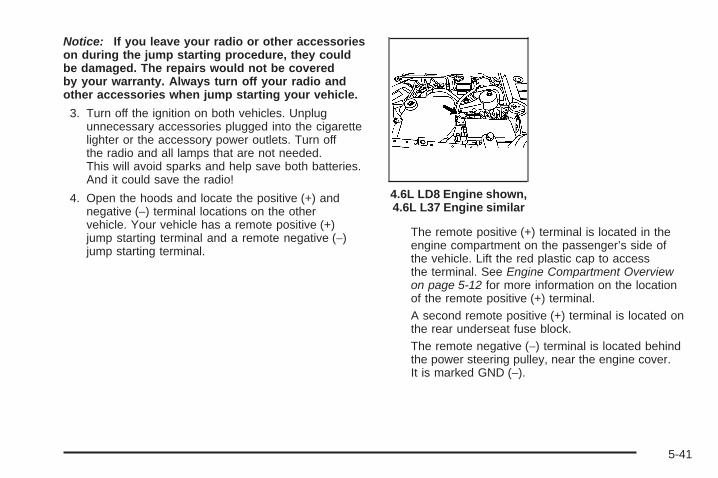
Notice: If you leave your radio or other accessorieson during the jump starting procedure, they couldbe damaged. The repairs would not be coveredby your warranty. Always turn off your radio andother accessories when jump starting your vehicle.
3. Turn off the ignition on both vehicles. Unplugunnecessary accessories plugged into the cigarettelighter or the accessory power outlets. Turn offthe radio and all lamps that are not needed.This will avoid sparks and help save both batteries.And it could save the radio!
4. Open the hoods and locate the positive (+) andnegative (−) terminal locations on the othervehicle. Your vehicle has a remote positive (+)jump starting terminal and a remote negative (−)jump starting terminal.
The remote positive (+) terminal is located in theengine compartment on the passenger’s side ofthe vehicle. Lift the red plastic cap to accessthe terminal. See Engine Compartment Overviewon page 5-12 for more information on the locationof the remote positive (+) terminal.A second remote positive (+) terminal is located onthe rear underseat fuse block.The remote negative (−) terminal is located behindthe power steering pulley, near the engine cover.It is marked GND (−).
4.6L LD8 Engine shown,4.6L L37 Engine similar
5-41

You will not see the battery of your vehicle underthe hood. It is located under the rear passenger’sseat. You will not need to access the batteryfor jump starting. The remote terminals are forthat purpose.
{CAUTION:
An electric fan can start up even when theengine is not running and can injure you.Keep hands, clothing and tools away fromany underhood electric fan.
{CAUTION:
Using a match near a battery can cause batterygas to explode. People have been hurt doingthis, and some have been blinded. Use aflashlight if you need more light.
CAUTION: (Continued)
CAUTION: (Continued)
Be sure the battery has enough water. You donot need to add water to the battery installedin your new vehicle. But if a battery has fillercaps, be sure the right amount of fluid is there.If it is low, add water to take care of that first.If you do not, explosive gas could be present.
Battery fluid contains acid that can burn you.Do not get it on you. If you accidentally get itin your eyes or on your skin, flush the placewith water and get medical help immediately.
{CAUTION:
Fans or other moving engine parts can injureyou badly. Keep your hands away from movingparts once the engine is running.
5-42

5. Check that the jumper cables do not have loose ormissing insulation. If they do, you could get ashock. The vehicles could be damaged too.Before you connect the cables, here are somebasic things you should know. Positive (+) will go topositive (+) or to a remote positive (+) terminal ifthe vehicle has one. Negative (−) will go to a heavy,unpainted metal engine part or to a remotenegative (−) terminal if the vehicle has one.Do not connect positive (+) to negative (−) or youwill get a short that would damage the batteryand maybe other parts too. And do not connect thenegative (−) cable to the negative (−) terminal onthe dead battery because this can cause sparks.
6. Connect the red positive (+) cable to the remotepositive (+) terminal location on the vehicle withthe dead battery. Use a remote positive (+) terminalif the vehicle has one.
7. Do not let the other end touch metal. Connect itto the positive (+) terminal location of the vehiclewith the good battery. Use a remote positive (+)terminal if the vehicle has one.
8. Now connect the black negative (−) cable to thenegative (−) terminal location of the vehicle withthe good battery. Use a remote negative (−)terminal if the vehicle has one.Do not let the other end of the cable touch anythinguntil the next step. The other end of the negative (−)cable does not go to the dead battery. It goes toa heavy, unpainted metal engine part or to a remotenegative (−) terminal on the vehicle with the deadbattery.
9. Connect the other end of the negative (−) cable tothe negative (−) terminal location on the vehiclewith the dead battery. Your vehicle has a remotenegative (−) terminal marked GND (−).
10. Now start the vehicle with the good battery andrun the engine for a while.
11. Try to start the vehicle that had the dead battery.If it will not start after a few tries, it probably needsservice.
5-43

Notice: If the jumper cables are connected orremoved in the wrong order, electrical shorting mayoccur and damage the vehicle. The repairs wouldnot be covered by your warranty. Always connectand remove the jumper cables in the correctorder, making sure that the cables do not toucheach other or other metal.
A. Heavy, Unpainted Metal Engine Part or RemoteNegative (−) Terminal (GND)
B. Good Battery or Remote Positive (+) and RemoteNegative (−) Terminals
C. Dead Battery or Remote Positive (+) Terminal
To disconnect the jumper cables from both vehicles,do the following:
1. Disconnect the black negative (−) cable from thevehicle that had the dead battery.
2. Disconnect the black negative (−) cable from thevehicle with the good battery.
3. Disconnect the red positive (+) cable from thevehicle with the good battery.
4. Disconnect the red positive (+) cable from theother vehicle.
5. Return the remote positive (+) terminal cover toits original position.
Headlamp AimingThe vehicle has a visual optical headlamp aimingsystem. The aim has been preset at the factory andshould need no further adjustment.
However, if the vehicle is damaged in a crash, theheadlamp aim may be affected and adjustment maybe necessary.
If oncoming vehicles flash their high beams at you,this may also mean the vertical aim needs to beadjusted.
Jumper Cable Removal
5-44

It is recommended that the vehicle is taken to yourdealer/retailer for service if the headlamps needto be re-aimed. It is possible however, to re-aim theheadlamps as described.
Notice: To make sure your headlamps are aimedproperly, read all the instructions before beginning.Failure to follow these instructions could causedamage to headlamp parts.
The vehicle should:
• Be placed so the headlamps are 25 ft. (7.6 m) froma light colored wall.
• Have all four tires on a level surface which is levelall the way to the wall.
• Be placed so it is perpendicular to the wall.
• Not have any snow, ice, or mud on it.
• Be fully assembled and all other work stopped whileheadlamp aiming is being performed.
• Be normally loaded with a full tank of fuel and oneperson or 160 lbs (75 kg) sitting on the driver seat.
• Have all tires properly inflated.
• Have the spare tire is in its original location inthe vehicle.
Headlamp aiming is done with the vehicle’s low-beamheadlamps. The high-beam headlamps will be correctlyaimed if the low-beam headlamps are aimed properly.
To adjust the vertical aim:
1. Open the hood. See Hood Release on page 5-11for more information.
2. Find the center line running through the lens ofthe headlamp.
3. Record the distance from the ground to the centerline running through the lens of the headlamp.
5-45

4. At a wall, measure from the ground upward (A) tothe recorded distance from Step 3 and mark it.
5. Draw or tape a horizontal line (B) the width of thevehicle at the wall where it was marked in Step 4.
Notice: Do not cover a headlamp to improve beamcut-off when aiming. Covering a headlamp maycause excessive heat build-up which may causedamage to the headlamp.
6. Turn on the low-beam headlamps and place apiece of cardboard or equivalent in front of theheadlamp not being aimed. This should allowonly the beam of light from the headlamp beingaimed to be seen on the flat surface.
7. Locate the vertical headlamp aiming screws. Theyare located under the hood near each headlampassembly. First lift the flap to access either of them.Each one is the top outboard screw by the “ V” onthe cover panel next to the aiming flap.The adjustment screw can be turned with a6 mm hex wrench.
8. Turn the vertical aiming screw until the headlampbeam is aimed to the horizontal tape line. Turn itclockwise or counterclockwise to raise or lowerthe angle of the beam.The top edge of the cut-off should be positioned atthe bottom edge of the horizontal tape line.
5-46
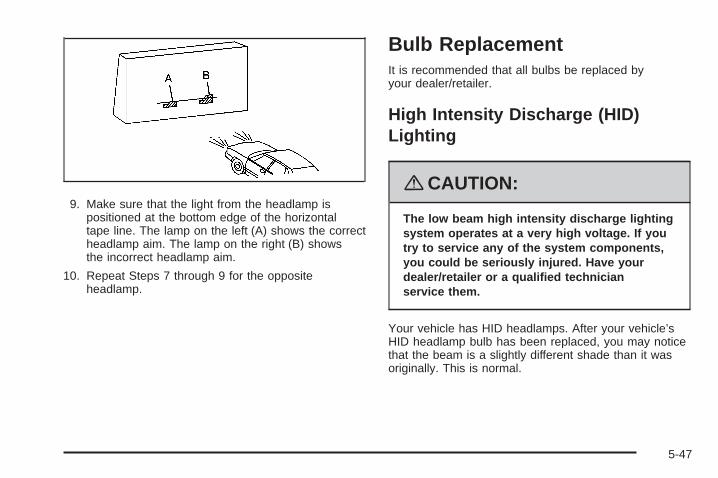
9. Make sure that the light from the headlamp ispositioned at the bottom edge of the horizontaltape line. The lamp on the left (A) shows the correctheadlamp aim. The lamp on the right (B) showsthe incorrect headlamp aim.
10. Repeat Steps 7 through 9 for the oppositeheadlamp.
Bulb ReplacementIt is recommended that all bulbs be replaced byyour dealer/retailer.
High Intensity Discharge (HID)Lighting
{CAUTION:
The low beam high intensity discharge lightingsystem operates at a very high voltage. If youtry to service any of the system components,you could be seriously injured. Have yourdealer/retailer or a qualified technicianservice them.
Your vehicle has HID headlamps. After your vehicle’sHID headlamp bulb has been replaced, you may noticethat the beam is a slightly different shade than it wasoriginally. This is normal.
5-47

Windshield Wiper BladeReplacementWindshield wiper blades should be inspected for wearor cracking. See Scheduled Maintenance on page 6-4for more information on wiper blade inspection.
Replacement blades come in different types and areremoved in different ways. Here’s how to removethe wiper blade:
1. Turn the engine off.
2. Lift the windshield wiper arm and blade awayfrom the windshield.
3. Pull the clip up from the blade connecting point,and pull the blade assembly down toward thewindshield to remove it from the wiper arm.
4. Install the new wiper blade onto the wiper arm andfirmly press down on the clip to snap it into place.
5-48
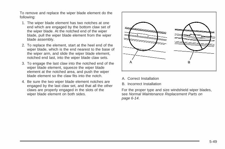
To remove and replace the wiper blade element do thefollowing:
1. The wiper blade element has two notches at oneend which are engaged by the bottom claw set ofthe wiper blade. At the notched end of the wiperblade, pull the wiper blade element from the wiperblade assembly.
2. To replace the element, start at the heel end of thewiper blade, which is the end nearest to the base ofthe wiper arm, and slide the wiper blade element,notched end last, into the wiper blade claw sets.
3. To engage the last claw into the notched end of thewiper blade element, squeeze the wiper bladeelement at the notched area, and push the wiperblade element so the claw fits into the notch.
4. Be sure the two wiper blade element notches areengaged by the last claw set, and that all the otherclaws are properly engaged in the slots of thewiper blade element on both sides.
A. Correct InstallationB. Incorrect Installation
For the proper type and size windshield wiper blades,see Normal Maintenance Replacement Parts onpage 6-14.
5-49
TiresYour new vehicle comes with high-quality tiresmade by a leading tire manufacturer. If youever have questions about your tire warrantyand where to obtain service, see your vehicleWarranty booklet for details.
{CAUTION:
• Poorly maintained and improperlyused tires are dangerous.
• Overloading your tires can causeoverheating as a result of too muchflexing. You could have an air-out anda serious accident. See Loading YourVehicle on page 4-20.
• Underinflated tires pose the samedanger as overloaded tires. Theresulting accident could cause seriousinjury. Check all tires frequently tomaintain the recommended pressure.
CAUTION: (Continued)
CAUTION: (Continued)
Tire pressure should be checked whenyour tires are cold. See Inflation - TirePressure on page 5-58.
• Overinflated tires are more likely tobe cut, punctured, or broken by asudden impact — such as whenyou hit a pothole. Keep tires at therecommended pressure.
• Worn, old tires can cause accidents.If your tread is badly worn, or ifyour tires have been damaged,replace them.
See High-Speed Operation on page 5-60for inflation pressure adjustment forhigh speed driving.
5-50

Tire Sidewall LabelingUseful information about a tire is moldedinto its sidewall.
(A) Tire Size: The tire size is a combination ofletters and numbers used to define a particulartire’s width, height, aspect ratio, construction typeand service description. See the “Tire Size”illustration later in this section for more detail.
(B) TPC Spec (Tire Performance CriteriaSpecification): Original equipment tires designedto GM’s specific tire performance criteria havea TPC specification code molded onto the sidewall.GM’s TPC specifications meet or exceed allfederal safety guidelines.
(C) DOT (Department of Transportation):The Department of Transportation (DOT) codeindicates that the tire is in compliance with theU.S. Department of Transportation Motor VehicleSafety Standards.
(D) Tire Identification Number (TIN): Theletters and numbers following the DOT code arethe Tire Identification Number (TIN). The TINshows the manufacturer and plant code, tire size,and date the tire was manufactured. The TINis molded onto both sides of the tire, althoughonly one side may have the date of manufacture.
(E) Tire Ply Material: The type of cord and numberof plies in the sidewall and under the tread.
(F) Uniform Tire Quality Grading (UTQG):Tire manufacturers are required to gradetires based on three performance factors:treadwear, traction and temperature resistance.For more information see Uniform Tire QualityGrading on page 5-72.
Passenger Car Tire Example
5-51

(G) Maximum Cold Inflation Load Limit:Maximum load that can be carried and themaximum pressure needed to support that load.For information on recommended tire pressuresee Inflation - Tire Pressure on page 5-58and Loading Your Vehicle on page 4-20.
(A) Temporary Use Only: The compact sparetire or temporary use tire has a tread life ofapproximately 3,000 miles (5 000 km) and shouldnot be driven at speeds over 65 mph (105 km/h).
The compact spare tire is for emergency usewhen a regular road tire has lost air and goneflat. See Spare Tire on page 5-86 and If aTire Goes Flat on page 5-76.
(B) Tire Ply Material: The type of cord andnumber of plies in the sidewall and under the tread.
(C) Tire Identification Number (TIN): TheTire Identification Number (TIN). The TIN showsthe manufacturer and plant code, tire size,and date the tire was manufactured. The TINis molded onto both sides of the tire, althoughonly one side may have the date of manufacture.
(D) Maximum Cold Inflation Load Limit:Maximum load that can be carried and themaximum pressure needed to support that load.See Inflation - Tire Pressure on page 5-58and Loading Your Vehicle on page 4-20.
(E) Tire Inflation: The temporary use tire orcompact spare tire should be inflated to 60 psi(420 kPa). For more information on tire pressureand inflation see Inflation - Tire Pressure onpage 5-58 and Spare Tire on page 5-86.
(F) Tire Size : A combination of letters andnumbers define a tire’s width, height, aspect ratio,construction type and service description. Theletter T as the first character in the tire size meansthe tire is for temporary use only.
Compact Spare Tire Example
5-52

(G) TPC Spec (Tire Performance CriteriaSpecification): Original equipment tires designedto GM’s specific tire performance criteria havea TPC specification code molded onto the sidewall.GM’s TPC specifications meet or exceed allfederal safety guidelines.
(A) Tire Size: The tire size code is a combinationof letters and numbers used to define a particulartire’s width, height, aspect ratio, constructiontype and service description. See the “Tire Size”illustration later in this section for more detail.
(B) TPC Spec (Tire Performance CriteriaSpecification): Original equipment tires designedto GM’s specific tire performance criteria havea TPC specification code molded onto the sidewall.GM’s TPC specifications meet or exceed allfederal safety guidelines.
(C) Dual Tire Maximum Load: Maximum loadthat can be carried and the maximum pressureneeded to support that load when used in a dualconfiguration.
(D) DOT (Department of Transportation):The Department of Transportation (DOT) codeindicates that the tire is in compliance with theU.S. Department of Transportation Motor VehicleSafety Standards.
(E) Tire Identification Number (TIN): The lettersand numbers following DOT code are the TireIdentification Number (TIN). The TIN showsthe manufacturer and plant code, tire size, anddate the tire was manufactured. The TIN is moldedonto both sides of the tire, although only oneside may have the date of manufacture.
(F) Tire Ply Material: The type of cord and numberof plies in the sidewall and under the tread.
Light Truck Tire Example
5-53
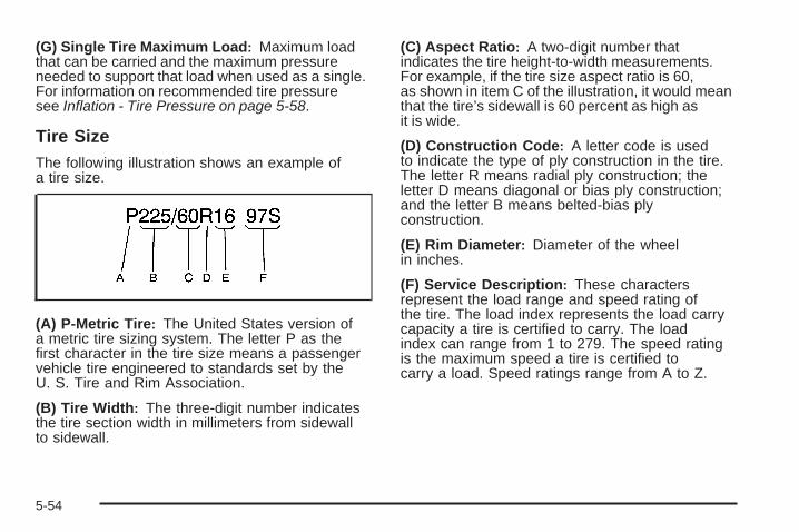
(G) Single Tire Maximum Load: Maximum loadthat can be carried and the maximum pressureneeded to support that load when used as a single.For information on recommended tire pressuresee Inflation - Tire Pressure on page 5-58.
Tire SizeThe following illustration shows an example ofa tire size.
(A) P-Metric Tire: The United States version ofa metric tire sizing system. The letter P as thefirst character in the tire size means a passengervehicle tire engineered to standards set by theU. S. Tire and Rim Association.
(B) Tire Width: The three-digit number indicatesthe tire section width in millimeters from sidewallto sidewall.
(C) Aspect Ratio: A two-digit number thatindicates the tire height-to-width measurements.For example, if the tire size aspect ratio is 60,as shown in item C of the illustration, it would meanthat the tire’s sidewall is 60 percent as high asit is wide.
(D) Construction Code: A letter code is usedto indicate the type of ply construction in the tire.The letter R means radial ply construction; theletter D means diagonal or bias ply construction;and the letter B means belted-bias plyconstruction.
(E) Rim Diameter: Diameter of the wheelin inches.
(F) Service Description: These charactersrepresent the load range and speed rating ofthe tire. The load index represents the load carrycapacity a tire is certified to carry. The loadindex can range from 1 to 279. The speed ratingis the maximum speed a tire is certified tocarry a load. Speed ratings range from A to Z.
5-54

Tire Terminology and Definitions
Air Pressure: The amount of air inside thetire pressing outward on each square inch ofthe tire. Air pressure is expressed in poundsper square inch (psi) or kilopascal (kPa).
Accessory Weight: This means the combinedweight of optional accessories. Some examples ofoptional accessories are, automatic transmission,power steering, power brakes, power windows,power seats, and air conditioning.
Aspect Ratio: The relationship of a tire’s heightto its width.
Belt: A rubber coated layer of cords that islocated between the plies and the tread. Cordsmay be made from steel or other reinforcingmaterials.
Bead: The tire bead contains steel wires wrappedby steel cords that hold the tire onto the rim.
Bias Ply Tire: A pneumatic tire in which the pliesare laid at alternate angles less than 90 degreesto the centerline of the tread.
Cold Tire Pressure: The amount of air pressurein a tire, measured in pounds per square inch(psi) or kilopascals (kPa) before a tire has builtup heat from driving. See Inflation - Tire Pressureon page 5-58.
Curb Weight: The weight of a motor vehiclewith standard and optional equipment includingthe maximum capacity of fuel, oil, and coolant,but without passengers and cargo.
DOT Markings: A code molded into the sidewallof a tire signifying that the tire is in compliancewith the U.S. Department of Transportation (DOT)motor vehicle safety standards. The DOT codeincludes the Tire Identification Number (TIN),an alphanumeric designator which can alsoidentify the tire manufacturer, production plant,brand, and date of production.
GVWR: Gross Vehicle Weight Rating.See Loading Your Vehicle on page 4-20.
GAWR FRT: Gross Axle Weight Rating forthe front axle. See Loading Your Vehicleon page 4-20.
5-55
GAWR RR: Gross Axle Weight Rating for the rearaxle. See Loading Your Vehicle on page 4-20.
Intended Outboard Sidewall: The side ofan asymmetrical tire, that must always faceoutward when mounted on a vehicle.
Kilopascal (kPa): The metric unit for air pressure.
Light Truck (LT-Metric) Tire: A tire used onlight duty trucks and some multipurpose passengervehicles.
Load Index: An assigned number ranging from1 to 279 that corresponds to the load carryingcapacity of a tire.
Maximum Inflation Pressure: The maximumair pressure to which a cold tire can be inflated.The maximum air pressure is molded onto thesidewall.
Maximum Load Rating: The load rating for atire at the maximum permissible inflation pressurefor that tire.
Maximum Loaded Vehicle Weight: The sum ofcurb weight, accessory weight, vehicle capacityweight, and production options weight.
Normal Occupant Weight: The number ofoccupants a vehicle is designed to seat multipliedby 150 lbs (68 kg). See Loading Your Vehicleon page 4-20.
Occupant Distribution: Designated seatingpositions.
Outward Facing Sidewall: The side of anasymmetrical tire that has a particular side thatfaces outward when mounted on a vehicle.The side of the tire that contains a whitewall, bearswhite lettering, or bears manufacturer, brand,and/or model name molding that is higheror deeper than the same moldings on the othersidewall of the tire.
Passenger (P-Metric) Tire: A tire used onpassenger cars and some light duty trucks andmultipurpose vehicles.
Recommended Inflation Pressure: Vehiclemanufacturer’s recommended tire inflation pressureas shown on the tire placard. See Inflation - TirePressure on page 5-58 and Loading Your Vehicleon page 4-20.
5-56

Radial Ply Tire: A pneumatic tire in which theply cords that extend to the beads are laid at90 degrees to the centerline of the tread.
Rim: A metal support for a tire and upon whichthe tire beads are seated.
Sidewall: The portion of a tire between the treadand the bead.
Speed Rating: An alphanumeric code assignedto a tire indicating the maximum speed at whicha tire can operate.
Traction: The friction between the tire and theroad surface. The amount of grip provided.
Tread: The portion of a tire that comes intocontact with the road.
Treadwear Indicators: Narrow bands, sometimescalled wear bars, that show across the tread of atire when only 1/16 inch (1.6 mm) of tread remains.See When It Is Time for New Tires on page 5-68.
UTQGS (Uniform Tire Quality GradingStandards): A tire information system thatprovides consumers with ratings for a tire’straction, temperature, and treadwear. Ratingsare determined by tire manufacturers usinggovernment testing procedures. The ratingsare molded into the sidewall of the tire. SeeUniform Tire Quality Grading on page 5-72.
Vehicle Capacity Weight: The number ofdesignated seating positions multiplied by150 lbs (68 kg) plus the rated cargo load.See Loading Your Vehicle on page 4-20.
Vehicle Maximum Load on the Tire: Load onan individual tire due to curb weight, accessoryweight, occupant weight, and cargo weight.
Vehicle Placard: A label permanently attachedto a vehicle showing the vehicle’s capacityweight and the original equipment tire size andrecommended inflation pressure. See “Tireand Loading Information Label” under LoadingYour Vehicle on page 4-20.
5-57

Inflation - Tire PressureTires need the correct amount of air pressureto operate effectively.
Notice: Do not let anyone tell you thatunder-inflation or over-inflation is all right.It is not. If your tires do not have enough air(under-inflation), you can get the following:• Too much flexing• Too much heat• Tire overloading• Premature or irregular wear• Poor handling• Reduced fuel economy
If your tires have too much air (over-inflation),you can get the following:• Unusual wear• Poor handling• Rough ride• Needless damage from road hazards
A Tire and Loading Information label is attachedto the vehicle’s center pillar. This label lists yourvehicle’s original equipment tires and shows thecorrect inflation pressures for your tires when theyare cold. The recommended cold tire inflationpressure, shown on the label, is the minimumamount of air pressure needed to support yourvehicle’s maximum load carrying capacity.
For additional information regarding how muchweight your vehicle can carry, and an exampleof the Tire and Loading Information label,see Loading Your Vehicle on page 4-20. How youload your vehicle affects the vehicle handlingand ride comfort, never load your vehiclewith more weight than it was designed to carry.
When to CheckCheck your tires once a month or more.Do not forget to check the spare tire. If yourvehicle has a compact spare tire, it should beat 60 psi (420 kPa). For additional informationsee Spare Tire on page 5-86.
5-58
How to CheckUse a good quality pocket-type gage to check tirepressure. You cannot tell if your tires are properlyinflated simply by looking at them. Radial tiresmay look properly inflated even when they areunder-inflated. Check the tire’s inflation pressurewhen the tires are cold. Cold means your vehiclehas been sitting for at least three hours or drivenno more than 1 mile (1.6 km).
Remove the valve cap from the tire valve stem.Press the tire gage firmly onto the valve toget a pressure measurement. If the cold tireinflation pressure matches the recommendedpressure on the Tire and Loading Informationlabel, no further adjustment is necessary. If theinflation pressure is low, add air until you reachthe recommended amount.
If you overfill the tire, release air by pushing onthe metal stem in the center of the tire valve.Re-check the tire pressure with the tire gage.
Be sure to put the valve caps back on the valvestems. They help prevent leaks by keeping outdirt and moisture.
Professional VehicleThe proper inflation of the tires on yourprofessional vehicle depends on the typeof tires on it.• If your vehicle has P235/60R17 size tires,
the cold inflation pressure is 41 psi (284 kPa).• If your vehicle has LT235/60R17E size
tires, the cold inflation pressure depends onthe vehicle mass and should be determinedby the vehicle coach-builder. A Tire andLoading Information label provided by thefinal stage manufacturer should be attachedto the B-pillar on the driver’s side of thevehicle. If the final stage manufacturer’s labelis not present, the coach-builder should beconsulted. Do not use the tire pressuresindicated on the General Motors label. Thesetire pressures are for the incomplete vehicleand are not the correct tire pressures forthe completed professional vehicle.
Operation at inflation pressures below thisrecommendation may cause your tires tobecome overloaded.
5-59

High-Speed Operation
{CAUTION:
Driving at high speeds, 100 mph (160 km/h)or higher, puts an additional strain on tires.Sustained high-speed driving causes excessiveheat build up and can cause sudden tire failure.You could have a crash and you or others couldbe killed. Some high-speed rated tires requireinflation pressure adjustment for high speedoperation. When speed limits and roadconditions are such that a vehicle can be drivenat high speeds, make sure the tires are ratedfor high speed operation, in excellent condition,and set to the correct cold tire inflation pressurefor the vehicle load.
If your vehicle has P235/55R17 or P245/50R18 sizetires, and you will be driving at speeds of 100 mph(160 km/h) or higher, where it is legal, set the coldinflation pressure to the maximum inflation pressureshown on the tire sidewall, or 38 psi (265 kPa),whichever is lower. See the example following.
Example:
You will find the maximum load and inflation pressuremolded on the tire’s sidewall, in small letters, nearthe rim flange. It will read something like this: Maximumload 690 kg (1521 lbs) 300 kPa (44 psi) Max. Press.
For this example, you would set the inflation pressurefor high-speed driving at 38 psi (265 kPa).
When you end this high-speed driving, return the tiresto the cold inflation pressure shown on the Tire andLoading Information label. See Loading Your Vehicleon page 4-20.
5-60
Tire Pressure Monitor SystemThe Tire Pressure Monitor System (TPMS) uses radioand sensor technology to check tire pressure levels.The TPMS sensors monitor the air pressure inyour vehicle’s tires and transmit tire pressure readingsto a receiver located in the vehicle.
Each tire, including the spare (if provided), should bechecked monthly when cold and inflated to the inflationpressure recommended by the vehicle manufactureron the vehicle placard or tire inflation pressure label.(If your vehicle has tires of a different size than thesize indicated on the vehicle placard or tire inflationpressure label, you should determine the propertire inflation pressure for those tires.)
As an added safety feature, your vehicle has beenequipped with a tire pressure monitoring system (TPMS)that illuminates a low tire pressure telltale when oneor more of your tires is significantly under-inflated.
Accordingly, when the low tire pressure telltaleilluminates, you should stop and check your tires assoon as possible, and inflate them to the properpressure. Driving on a significantly under-inflated tirecauses the tire to overheat and can lead to tire failure.Under-inflation also reduces fuel efficiency and tiretread life, and may affect the vehicle’s handlingand stopping ability.
Please note that the TPMS is not a substitute for propertire maintenance, and it is the driver’s responsibility tomaintain correct tire pressure, even if under-inflationhas not reached the level to trigger illumination ofthe TPMS low tire pressure telltale.
Your vehicle has also been equipped with a TPMSmalfunction indicator to indicate when the system isnot operating properly. The TPMS malfunction indicatoris combined with the low tire pressure telltale. Whenthe system detects a malfunction, the telltale willflash for approximately one minute and then remaincontinuously illuminated. This sequence will continueupon subsequent vehicle start-ups as long as themalfunction exists.
When the malfunction indicator is illuminated, thesystem may not be able to detect or signal low tirepressure as intended. TPMS malfunctions may occurfor a variety of reasons, including the installationof replacement or alternate tires or wheels on thevehicle that prevent the TPMS from functioning properly.Always check the TPMS malfunction telltale afterreplacing one or more tires or wheels on your vehicleto ensure that the replacement or alternate tires andwheels allow the TPMS to continue to function properly.
See Tire Pressure Monitor Operation on page 5-62,for additional information.
5-61

Federal CommunicationsCommission (FCC) and Industryand Science CanadaThe Tire Pressure Monitor System (TPMS) operateson a radio frequency and complies with Part 15 ofthe FCC Rules. Operation is subject to the followingtwo conditions:
1. This device may not cause harmful interference.
2. This device must accept any interference received,including interference that may cause undesiredoperation.
The Tire Pressure Monitor System (TPMS) operateson a radio frequency and complies with RSS-210of Industry and Science Canada. Operation is subjectto the following two conditions:
1. This device may not cause interference.
2. This device must accept any interference received,including interference that may cause undesiredoperation of the device.
Changes or modifications to this system by other thanan authorized service facility could void authorizationto use this equipment.
Tire Pressure Monitor OperationThe Tire Pressure Monitor System (TPMS) is designedto warn the driver when a low tire pressure conditionexists. TPMS sensors are mounted onto each tireand wheel assembly, excluding the spare tire and wheelassembly. The TPMS sensors monitor the air pressurein the vehicle’s tires and transmits the tire pressurereadings to a receiver located in the vehicle.
When a low tire pressurecondition is detected,the TPMS illuminatesthe low tire pressurewarning light locatedon the instrumentpanel cluster.
5-62

At the same time a message to check the pressurein a specific tire appears on the Driver Information Center(DIC) display. The low tire pressure warning light and theDIC warning message come on at each ignition cycleuntil the tires are inflated to the correct inflation pressure.Using the DIC, tire pressure levels can be viewed bythe driver. For additional information and details aboutthe DIC operation and displays see DIC Operation andDisplays on page 3-69 and DIC Warnings and Messageson page 3-73.
The low tire pressure warning light may come on incool weather when the vehicle is first started, and thenturn off as you start to drive. This could be an earlyindicator that the air pressure in the tire(s) are gettinglow and need to be inflated to the proper pressure.
A Tire and Loading Information label, attached toyour vehicle, shows the size of your vehicle’soriginal equipment tires and the correct inflationpressure for your vehicle’s tires when they are cold.
See Loading Your Vehicle on page 4-20, for an exampleof the Tire and Loading Information label and itslocation on your vehicle. Also see Inflation - TirePressure on page 5-58.
Your vehicle’s TPMS can warn you about a low tirepressure condition but it does not replace normaltire maintenance. See Tire Inspection and Rotationon page 5-66 and Tires on page 5-50.
Notice: Liquid tire sealants could damage theTire Pressure Monitor System (TPMS) sensors.Sensor damage caused by using a tire sealant isnot covered by your warranty. Do not use liquidtire sealants.
5-63

TPMS Malfunction Light and MessageThe TPMS will not function properly if one or moreof the TPMS sensors are missing or inoperable. Whenthe system detects a malfunction, the low tire warninglight flashes for about one minute and then stays onfor the remainder of the ignition cycle. A DIC warningmessage is also displayed. The low tire warninglight and DIC warning message come on at eachignition cycle until the problem is corrected. Some ofthe conditions that can cause the malfunction lightand DIC message to come on are:
• One of the road tires has been replaced with thespare tire. The spare tire does not have a TPMSsensor. The TPMS malfunction light and DICmessage should go off once you re-install theroad tire containing the TPMS sensor.
• The TPMS sensor matching process was startedbut not completed or not completed successfullyafter rotating the vehicle’s tires. The DIC messageand TPMS malfunction light should go off oncethe TPMS sensor matching process is performedsuccessfully. See “TPMS Sensor Matching Process”later in this section.
• One or more TPMS sensors are missing ordamaged. The DIC message and the TPMSmalfunction light should go off when the TPMSsensors are installed and the sensor matchingprocess is performed successfully. See yourdealer/retailer for service.
• Replacement tires or wheels do not match yourvehicle’s original equipment tires or wheels.Tires and wheels other than those recommendedfor your vehicle could prevent the TPMS fromfunctioning properly. See Buying New Tireson page 5-69.
• Operating electronic devices or being near facilitiesusing radio wave frequencies similar to the TPMScould cause the TPMS sensors to malfunction.
If the TPMS is not functioning it cannot detect orsignal a low tire condition. See your dealer/retailerfor service if the TPMS malfunction light and DICmessage comes on and stays on.
5-64

TPMS Sensor Matching ProcessEach TPMS sensor has a unique identification code.Any time you rotate your vehicle’s tires or replaceone or more of the TPMS sensors, the identificationcodes will need to be matched to the new tire/wheelposition. The sensors are matched to the tire/wheelpositions in the following order: driver side fronttire, passenger side front tire, passenger side reartire, and driver side rear tire using a TPMS diagnostictool. See your dealer/retailer for service.
The TPMS sensors can also be matched to eachtire/wheel position by increasing or decreasing thetire’s air pressure. If increasing the tire’s air pressure,do not exceed the maximum inflation pressureindicated on the tire’s sidewall.
To decrease air-pressure out of a tire you can usethe pointed end of the valve cap, a pencil-styleair pressure gage, or a key.
You have two minutes to match the first tire/wheelposition, and five minutes overall to match all four tire/wheel positions. If it takes longer thantwo minutes, to match the first tire and wheel,
or more than five minutes to match all four tire andwheel positions the matching process stops andyou need to start over.
The TPMS sensor matching process is outlined below:
1. Set the parking brake.
2. Turn the ignition switch to ON/RUN with theengine off.
3. Press the Remote Keyless Entry (RKE) transmitter’sLOCK and UNLOCK buttons at the same timefor approximately five seconds. The horn soundstwice to signal the receiver is in relearn modeand TIRE LEARNING ACTIVE message displayson the DIC screen.
4. Start with the driver side front tire.
5. Remove the valve cap from the valve cap stem.Activate the TPMS sensor by increasing ordecreasing the tire’s air pressure for five seconds,or until a horn chirp sounds. The horn chirp,which may take up to 30 seconds to sound,confirms that the sensor identification code hasbeen matched to this tire and wheel position.
5-65
6. Proceed to the passenger side front tire, and repeatthe procedure in Step 5.
7. Proceed to the passenger side rear tire, and repeatthe procedure in Step 5.
8. Proceed to the driver side rear tire, and repeat theprocedure in Step 5. The horn sounds two timesto indicate the sensor identification code hasbeen matched to the driver side rear tire, and theTPMS sensor matching process is no longer active.The TIRE LEARNING ACTIVE message on theDIC display screen goes off.
9. Turn the ignition switch to LOCK/OFF.
10. Set all four tires to the recommended air pressurelevel as indicated on the Tire and LoadingInformation label.
11. Put the valve caps back on the valve stems.
Tire Inspection and RotationWe recommend that you regularly inspect yourvehicle’s tires, including the spare tire, for signsof wear or damage. See When It Is Time forNew Tires on page 5-68 for more information.
Tires should be rotated every 5,000 to 8,000 miles(8 000 to 13 000 km). See Scheduled Maintenanceon page 6-4.
The purpose of a regular tire rotation is to achievea uniform wear for all tires on the vehicle. Thiswill ensure that your vehicle continues to performmost like it did when the tires were new.
Any time you notice unusual wear, rotate yourtires as soon as possible and check wheelalignment. Also check for damaged tires or wheels.See When It Is Time for New Tires on page 5-68and Wheel Replacement on page 5-74 formore information.
5-66

If your vehicle has a compact spare tire, it shouldnot be included in the tire rotation process.Use the four-tire rotation pattern shown.
A five-tire rotation pattern may be used for yourprofessional vehicle, if it has a full-size spare tireand wheel assembly that matches the originalequipment tires and wheels in size, type and brand.The correct five-tire rotation pattern is shown.
After the tires have been rotated, adjust thefront and rear inflation pressures as shownon the Tire and Loading Information label.See Loading Your Vehicle on page 4-20.
Four-Tire Rotation Pattern Five-Tire Rotation Pattern
5-67

Vehicles that have the Tire Pressure MonitorSystem (TPMS) will need to have the sensorsreset after a tire rotation is performed. SeeTire Pressure Monitor System on page 5-61.
Make certain that all wheel nuts are properlytightened. See “Wheel Nut Torque” underCapacities and Specifications on page 5-105.
{CAUTION:
Rust or dirt on a wheel, or on the partsto which it is fastened, can make wheelnuts become loose after time. The wheelcould come off and cause an accident.When you change a wheel, remove anyrust or dirt from places where the wheelattaches to the vehicle. In an emergency,you can use a cloth or a paper towel todo this; but be sure to use a scraper orwire brush later, if needed, to get all therust or dirt off. See Changing a Flat Tireon page 5-77.
When It Is Time for New TiresVarious factors, such as maintenance, temperatures,driving speeds, vehicle loading, and road conditionsinfluence when you need new tires.
One way to tell when itis time for new tires isto check the treadwearindicators, which willappear when your tireshave only 1/16 inch(1.6 mm) or less oftread remaining.
5-68

You need new tires if any of the following statementsare true:
• You can see the indicators at three or more placesaround the tire.
• You can see cord or fabric showing through thetire’s rubber.
• The tread or sidewall is cracked, cut, or snaggeddeep enough to show cord or fabric.
• The tire has a bump, bulge, or split.
• The tire has a puncture, cut, or other damage thatcannot be repaired well because of the size orlocation of the damage.
The rubber in tires degrades over time, even if theyare not being used. This is also true for the spare tire,if your vehicle has one. Multiple conditions affecthow fast this aging takes place, including temperatures,loading conditions, and inflation pressure maintenance.With proper care and maintenance tires will typicallywear out before they degrade due to age. If youare unsure about the need to replace your tires asthey get older, consult the tire manufacturer for moreinformation.
Buying New TiresGM has developed and matched specific tires foryour vehicle. The original equipment tires installedon your vehicle, when it was new, were designed tomeet General Motors Tire Performance CriteriaSpecification (TPC Spec) system rating. If you needreplacement tires, GM strongly recommends that youget tires with the same TPC Spec rating. This way,your vehicle will continue to have tires that are designedto give the same performance and vehicle safety,during normal use, as the original tires.GM’s exclusive TPC Spec system considers over adozen critical specifications that impact the overallperformance of your vehicle, including brake systemperformance, ride and handling, traction control, andtire pressure monitoring performance. GM’s TPC Specnumber is molded onto the tire’s sidewall near thetire size. If the tires have an all-season tread design,the TPC Spec number will be followed by an MS formud and snow. See Tire Sidewall Labeling on page 5-51for additional information.
5-69
GM recommends replacing tires in sets of four. Thisis because uniform tread depth on all tires will helpkeep your vehicle performing most like it did when thetires were new. Replacing less than a full set of tires canaffect the braking and handling performance of yourvehicle. See Tire Inspection and Rotation on page 5-66for information on proper tire rotation.
{CAUTION:
Mixing tires could cause you to lose control ofyour vehicle while driving. If you mix tires ofdifferent sizes, brands, or types (radial andbias-belted tires), the vehicle may not handleproperly, and you could have a crash. Usingtires of different sizes, brands, or types mayalso cause damage to your vehicle. Be sure touse the correct size, brand, and type of tireson all wheels.
CAUTION: (Continued)
CAUTION: (Continued)
Your vehicle may have a compact spare tireand wheel assembly. If the vehicle has acompact spare tire and wheel, they have thesame overall diameter as your vehicle’s full-sizetires and wheels. Because they were designedand developed for use on your vehicle, it is allright to drive your vehicle with the compactspare installed properly. Compact sparetires are designed for temporary use only.See Spare Tire on page 5-86.
{CAUTION:
If you use bias-ply tires on your vehicle,the wheel rim flanges could developcracks after many miles of driving. A tireand/or wheel could fail suddenly, causinga crash. Use only radial-ply tires with thewheels on your vehicle.
5-70
If you must replace your vehicle’s tires with those thatdo not have a TPC Spec number, make sure theyare the same size, load range, speed rating, andconstruction type (radial and bias-belted tires) asyour vehicle’s original tires.
Vehicles that have a tire pressure monitoring systemcould give an inaccurate low-pressure warning ifnon-TPC Spec rated tires are installed on your vehicle.Non-TPC Spec rated tires may give a low-pressurewarning that is higher or lower than the proper warninglevel you would get with TPC Spec rated tires.See Tire Pressure Monitor System on page 5-61.
Your vehicle’s original equipment tires are listed onthe Tire and Loading Information Label. See LoadingYour Vehicle on page 4-20, for more informationabout the Tire and Loading Information Label andits location on your vehicle.
Different Size Tires and WheelsIf you add wheels or tires that are a different size thanyour original equipment wheels and tires, this mayaffect the way your vehicle performs, including itsbraking, ride and handling characteristics, stability,and resistance to rollover. Additionally, if your vehiclehas electronic systems such as, anti-lock brakes,traction control, and electronic stability control, theperformance of these systems can be affected.
{CAUTION:
If you add different sized wheels, yourvehicle may not provide an acceptablelevel of performance and safety if tires notrecommended for those wheels are selected.You may increase the chance that you willcrash and suffer serious injury. Only useGM specific wheel and tire systems developedfor your vehicle, and have them properlyinstalled by a GM certified technician.
See Buying New Tires on page 5-69 and Accessoriesand Modifications on page 5-3 for additional information.
5-71

Uniform Tire Quality GradingQuality grades can be found where applicableon the tire sidewall between tread shoulderand maximum section width. For example:
Treadwear 200 Traction AA Temperature AThe following information relates to the systemdeveloped by the United States NationalHighway Traffic Safety Administration (NHTSA),which grades tires by treadwear, traction, andtemperature performance. This applies onlyto vehicles sold in the United States. The gradesare molded on the sidewalls of most passengercar tires. The Uniform Tire Quality Grading(UTQG) system does not apply to deep tread,winter-type snow tires, space-saver, or temporaryuse spare tires, tires with nominal rim diametersof 10 to 12 inches (25 to 30 cm), or to somelimited-production tires.
While the tires available on General Motorspassenger cars and light trucks may vary withrespect to these grades, they must also conformto federal safety requirements and additionalGeneral Motors Tire Performance Criteria (TPC)standards.
TreadwearThe treadwear grade is a comparative rating basedon the wear rate of the tire when tested undercontrolled conditions on a specified governmenttest course. For example, a tire graded 150 wouldwear one and a half (1.5) times as well on thegovernment course as a tire graded 100. Therelative performance of tires depends upon theactual conditions of their use, however, and maydepart significantly from the norm due to variationsin driving habits, service practices, and differencesin road characteristics and climate.
Traction – AA, A, B, CThe traction grades, from highest to lowest, are AA,A, B, and C. Those grades represent the tire’sability to stop on wet pavement as measured undercontrolled conditions on specified government testsurfaces of asphalt and concrete. A tire marked Cmay have poor traction performance.
Warning: The traction grade assigned tothis tire is based on straight-ahead brakingtraction tests, and does not includeacceleration, cornering, hydroplaning,or peak traction characteristics.
5-72

Temperature – A, B, CThe temperature grades are A (the highest),B, and C, representing the tire’s resistance tothe generation of heat and its ability to dissipateheat when tested under controlled conditions on aspecified indoor laboratory test wheel. Sustainedhigh temperature can cause the material of the tireto degenerate and reduce tire life, and excessivetemperature can lead to sudden tire failure.The grade C corresponds to a level of performancewhich all passenger car tires must meet underthe Federal Motor Vehicle Safety StandardNo. 109. Grades B and A represent higher levelsof performance on the laboratory test wheelthan the minimum required by law.
Warning: The temperature grade for thistire is established for a tire that is properlyinflated and not overloaded. Excessive speed,underinflation, or excessive loading, eitherseparately or in combination, can cause heatbuildup and possible tire failure.
Wheel Alignment and Tire BalanceThe tires and wheels on your vehicle were alignedand balanced carefully at the factory to give you thelongest tire life and best overall performance.Adjustments to wheel alignment and tire balancing willnot be necessary on a regular basis. However, ifyou notice unusual tire wear or your vehicle pulling toone side or the other, the alignment might need tobe checked. If you notice your vehicle vibrating whendriving on a smooth road, the tires and wheelsmight need to be rebalanced. See your dealer/retailerfor proper diagnosis.
5-73

Wheel ReplacementReplace any wheel that is bent, cracked or badlyrusted or corroded. If wheel nuts keep coming loose,the wheel, wheel bolts and wheel nuts should bereplaced. If the wheel leaks air, replace it. Somealuminum wheels can sometimes be repaired.See your GM dealer/retailer if any of theseconditions exist.
Your GM dealer/retailer will know the kind of wheelyou need.
Each new wheel should have the same load-carryingcapacity, diameter, width, offset and be mountedthe same way as the one it replaces.
If you need to replace any of your wheels, wheel bolts,wheel nuts, or Tire Pressure Monitor System (TPMS)sensors, replace them only with new GM originalequipment parts. This way, you will be sure to havethe right wheel, wheel bolts, wheel nuts, and TPMSsensors for your vehicle.
{CAUTION:
Using the wrong replacement wheels, wheelbolts, or wheel nuts on your vehicle can bedangerous. It could affect the braking andhandling of your vehicle, make your tires loseair and make you lose control. You couldhave a collision in which you or others couldbe injured. Always use the correct wheel,wheel bolts, and wheel nuts for replacement.
Notice: The wrong wheel can also cause problemswith bearing life, brake cooling, speedometer orodometer calibration, headlamp aim, bumper height,vehicle ground clearance, and tire or tire chainclearance to the body and chassis.
If your vehicle is a professional model, the wheels havea unique offset and bolt hole diameter. Each of thewheels on the professional vehicle have eight wheelsnuts. The wheels on the non-professional vehiclehave five wheel nuts. See Changing a Flat Tire onpage 5-77 for more information.
5-74

Used Replacement Wheels
{CAUTION:
Putting a used wheel on your vehicle isdangerous. You cannot know how it has beenused or how far it has been driven. It couldfail suddenly and cause a crash. If you haveto replace a wheel, use a new GM originalequipment wheel.
Tire Chains
{CAUTION:
Do not use tire chains. There is not enoughclearance. Tire chains used on a vehiclewithout the proper amount of clearance cancause damage to the brakes, suspension orother vehicle parts. The area damaged bythe tire chains could cause you to losecontrol of your vehicle and you or othersmay be injured in a crash.
Use another type of traction device onlyif its manufacturer recommends it for useon your vehicle and tire size combination androad conditions. Follow that manufacturer’sinstructions. To help avoid damage to yourvehicle, drive slowly, readjust or removethe device if it is contacting your vehicle,and do not spin your vehicle’s wheels.If you do find traction devices that will fit,install them on the front tires.
5-75

If a Tire Goes FlatIt is unusual for a tire to blowout while you are driving,especially if you maintain your vehicle’s tires properly.If air goes out of a tire, it is much more likely to leakout slowly. But if you should ever have a blowout, hereare a few tips about what to expect and what to do:
If a front tire fails, the flat tire creates a drag that pullsthe vehicle toward that side. Take your foot off theaccelerator pedal and grip the steering wheel firmly.Steer to maintain lane position, and then gentlybrake to a stop well out of the traffic lane.
A rear blowout, particularly on a curve, acts muchlike a skid and may require the same correction youwould use in a skid. In any rear blowout removeyour foot from the accelerator pedal. Get the vehicleunder control by steering the way you want the vehicleto go. It may be very bumpy and noisy, but you canstill steer. Gently brake to a stop, well off the roadif possible.
{CAUTION:
Lifting a vehicle and getting under it todo maintenance or repairs is dangerouswithout the appropriate safety equipment andtraining. The jack provided with your vehicleis designed only for changing a flat tire. If itis used for anything else, you or others couldbe badly injured or killed if the vehicle slipsoff the jack. Use the jack provided with yourvehicle only for changing a flat tire.
If a tire goes flat, the next part shows how to use thejacking equipment to change a flat tire safely.
5-76

Changing a Flat TireIf a tire goes flat, avoid further tire and wheel damageby driving slowly to a level place. Turn on your vehicle’shazard warning flashers. See Hazard Warning Flasherson page 3-6 for more information.
{CAUTION:
Changing a tire can be dangerous. The vehiclecan slip off the jack and roll over or fall on youor other people. You and they could be badlyinjured or even killed. Find a level place tochange your tire. To help prevent the vehiclefrom moving:
1. Set the parking brake firmly.2. Put the shift lever in PARK (P).3. Turn off the engine and do not restart
while the vehicle is raised.4. Do not allow passengers to remain in
the vehicle.To be even more certain the vehicle will notmove, you should put blocks at the front andrear of the tire farthest away from the onebeing changed. That would be the tire, on theother side, at the opposite end of the vehicle.
When your vehicle has a flat tire, use the followingexample as a guide to assist you in the placementof wheel blocks.
The following information tells you how to use thejack and change a tire.
5-77

Removing the Spare Tire and ToolsThe equipment needed is in the trunk.To access the equipment:
1. Open the trunk. See Trunk on page 2-12for more information.
2. Press the area atthe front of thehandle located onthe cover so thatthe back edgeraises.
3. Grab the handle andremove the cover.
4. Turn the wing nut to remove the retainer that holdsthe wrench and jack.
5-78

5. Remove the wheel wrench, jack and spare tire fromthe trunk. See Spare Tire on page 5-86 for moreinformation.
The tools to be used are the jack (A) and the wheelwrench (B).
Removing the Flat Tire andInstalling the Spare Tire1. Do a safety check before proceeding. See Changing
a Flat Tire on page 5-77 for more information.
2. For models having aluminum wheels with a centerwheel cover, use the flat end of the wheel wrenchto gently pry the wheel covers off. Store the wheelcover and lug nut caps in the trunk until you have theflat tire repaired or replaced. Be careful not to scratchthe aluminum wheel edge and do not try to removeit with your hands. Then loosen the wheel nuts withthe wheel wrench. Do not remove them yet.
5-79

3. For models with exposed lug nuts, loosenthem using the wheel wrench. Do not removethem yet.
4. Find the jacking location from the diagram aboveand use the corresponding cutouts located in theplastic molding.The front location is (A) 8.5 inches (21 cm) fromthe rear edge of the front wheel well, and therear location (B) is 3.5 inches (8.5 cm) from thefront edge of the rear wheel well.The notches may also be labeled JACK with anarrow pointing to the jacking location on the vehicle.
5-80

{CAUTION:
Getting under a vehicle when it is jacked up isdangerous. If the vehicle slips off the jack, youcould be badly injured or killed. Never get undera vehicle when it is supported only by a jack.
{CAUTION:
Raising your vehicle with the jack improperlypositioned can damage the vehicle and evenmake the vehicle fall. To help avoid personalinjury and vehicle damage, be sure to fit thejack lift head into the proper location beforeraising the vehicle.
Notice: If you position the jack under the rockermolding and attempt to raise the vehicle, you couldbreak the molding and/or cause other damage toyour vehicle. Always position the jack so thatwhen the jack head is raised, it will fit firmly in thenotch located inboard from the rocker molding.
5. Turn the jack handle counterclockwise to lower thejack lift head until the jack fits under the vehicle.
6. Raise the jack until the metal flange fits firmlyinto the channel of the jack head.
7. Put the spare tire near you.
5-81

8. Raise the vehicle by turning the jack handleclockwise. Raise the vehicle far enough off theground for the spare tire to fit under the vehicle.
9. Remove all wheel nuts and the flat tire.
10. Remove any rust or dirtfrom the wheel bolts,mounting surfaces,and spare wheel.
{CAUTION:
Rust or dirt on a wheel, or on the parts towhich it is fastened, can make wheel nutsbecome loose after time. The wheel couldcome off and cause an accident. When youchange a wheel, remove any rust or dirt fromplaces where the wheel attaches to the vehicle.In an emergency, you can use a cloth or apaper towel to do this; but be sure to use ascraper or wire brush later, if needed, to getall the rust or dirt off. See Changing a Flat Tireon page 5-77.
5-82

11. Place the spare tire on the wheel-mounting surface.
{CAUTION:
Never use oil or grease on studs or nuts.Because the nuts might come loose. Thevehicle’s wheel could fall off, causing a crash.
12. Put the wheel nutsback on with therounded end of thenuts toward the wheel.Tighten each nut byhand until the wheel isheld against the hub.
13. Lower the vehicle by turning the jack handlecounterclockwise. Lower the jack completely.
5-83

{CAUTION:
Incorrect or improperly tightened wheelnuts can cause the wheel to come loose andeven come off. This could lead to a crash.If you have to replace them, be sure to getnew original equipment wheel nuts. Stopsomewhere as soon as you can and have thenuts tightened with a torque wrench to theproper torque specification. See Capacitiesand Specifications on page 5-105 for wheelnut torque specification.
Notice: Improperly tightened wheel nuts canlead to brake pulsation and rotor damage.To avoid expensive brake repairs, evenly tightenthe wheel nuts in the proper sequence and tothe proper torque specification. See Capacitiesand Specifications on page 5-105 for the wheelnut torque specification.
14. Tighten the wheel nuts firmly in a crisscrosssequence as shown.If your vehicle is equipped with wheel nut covers,screw the nut covers on with your fingers, thentighten one-quarter turn with the wheel wrench.
Notice: Wheel covers will not fit on your vehicle’scompact spare. If you try to put a wheel coveron the compact spare, the cover or the spare couldbe damaged.
5-Wheel Nuts 8-Wheel Nuts
5-84
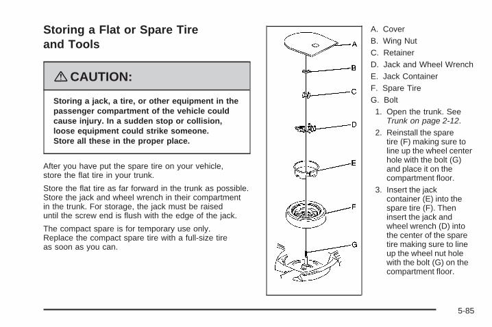
Storing a Flat or Spare Tireand Tools
{CAUTION:
Storing a jack, a tire, or other equipment in thepassenger compartment of the vehicle couldcause injury. In a sudden stop or collision,loose equipment could strike someone.Store all these in the proper place.
After you have put the spare tire on your vehicle,store the flat tire in your trunk.
Store the flat tire as far forward in the trunk as possible.Store the jack and wheel wrench in their compartmentin the trunk. For storage, the jack must be raiseduntil the screw end is flush with the edge of the jack.
The compact spare is for temporary use only.Replace the compact spare tire with a full-size tireas soon as you can.
A. CoverB. Wing NutC. RetainerD. Jack and Wheel WrenchE. Jack ContainerF. Spare TireG. Bolt1. Open the trunk. See
Trunk on page 2-12.2. Reinstall the spare
tire (F) making sure toline up the wheel centerhole with the bolt (G)and place it on thecompartment floor.
3. Insert the jackcontainer (E) into thespare tire (F). Theninsert the jack andwheel wrench (D) intothe center of the sparetire making sure to lineup the wheel nut holewith the bolt (G) on thecompartment floor.
5-85

4. Secure the spare tire and the jack container withthe retainer (C) and then the wing nut (B).
5. Reinstall the spare tire cover (A).
Spare Tire
Compact Spare TireYour vehicle may have a compact spare tire. Althoughthe compact spare tire was fully inflated when the vehiclewas new, it can lose air after a time. Check the inflationpressure regularly. It should be 60 psi (420 kPa).
After installing the compact spare on the vehicle, stopas soon as possible and make sure the spare tire iscorrectly inflated. The compact spare is made to performwell at speeds up to 65 mph (105 km/h) for distancesup to 3,000 miles (5 000 km), so you can finish yourtrip and have the full-size tire repaired or replaced at yourconvenience. Of course, it is best to replace the sparewith a full-size tire as soon as possible. The spare tirewill last longer and be in good shape in case it isneeded again.
Notice: When the compact spare is installed,do not take your vehicle through an automaticcar wash with guide rails. The compact spare canget caught on the rails. That can damage the tireand wheel, and maybe other parts of your vehicle.
Do not use the compact spare on other vehicles.
And do not mix the compact spare tire or wheel with otherwheels or tires. They will not fit. Keep the spare tire andits wheel together.
Notice: Tire chains will not fit your compact spare.Using them can damage your vehicle and candamage the chains too. Do not use tire chainson your compact spare.
Spare TireYour vehicle may have a spare tire, which, when new,was fully inflated. A spare tire may lose air over time, socheck its inflation pressure regularly. See Inflation - TirePressure on page 5-58 and Loading Your Vehicle onpage 4-20 for information regarding proper tire inflationand loading your vehicle. For instructions on how toremove, install or store a spare tire, see Removing theFlat Tire and Installing the Spare Tire on page 5-79.
After installing the spare tire on your vehicle, you shouldstop as soon as possible and make sure the spare iscorrectly inflated. Have the damaged or flat road tirerepaired or replaced as soon as you can and installedback onto your vehicle. This way, a spare tire will beavailable in case you need it again.
5-86

Your vehicle may have a different size spare tire than theroad tire originally installed on your vehicle. This sparetire was developed for use on your vehicle, so it is allright to drive on it.
If your vehicle has a spare tire that does not matchyour vehicle’s original road tires and wheels in sizeand type, do not include the spare in the tire rotation.
Appearance Care
Interior CleaningYour vehicle’s interior will continue to look its bestif it is cleaned often. Although not always visible,dust and dirt can accumulate on your upholstery.Dirt can damage carpet, fabric, leather, and plasticsurfaces. Regular vacuuming is recommended toremove particles from your upholstery. It is importantto keep your upholstery from becoming and remainingheavily soiled. Soils should be removed as quicklyas possible. Your vehicle’s interior may experienceextremes of heat that could cause stains to set rapidly.
Lighter colored interiors may require more frequentcleaning. Use care because newspapers and garmentsthat transfer color to your home furnishings may alsotransfer color to your vehicle’s interior.
When cleaning your vehicle’s interior, only usecleaners specifically designed for the surfaces beingcleaned. Permanent damage may result from usingcleaners on surfaces for which they were not intended.Use glass cleaner only on glass. Remove anyaccidental over-spray from other surfaces immediately.To prevent over-spray, apply cleaner directly to thecleaning cloth.
Notice: If you use abrasive cleaners when cleaningglass surfaces on your vehicle, you could scratchthe glass and/or cause damage to the rear windowdefogger. When cleaning the glass on yourvehicle, use only a soft cloth and glass cleaner.
Many cleaners contain solvents that may becomeconcentrated in your vehicle’s breathing space.Before using cleaners, read and adhere to all safetyinstructions on the label. While cleaning your vehicle’sinterior, maintain adequate ventilation by openingyour vehicle’s doors and windows.
Dust may be removed from small buttons and knobsusing a small brush with soft bristles.
Your dealer/retailer has a product for cleaning yourvehicle’s glass. Should it become necessary, youcan also obtain a product from your dealer/retailerto remove odors from your vehicle’s upholstery.
5-87

Do not clean your vehicle using the following cleanersor techniques:
• Never use a knife or any other sharp object toremove a soil from any interior surface.
• Never use a stiff brush. It can cause damageto your vehicle’s interior surfaces.
• Never apply heavy pressure or rub aggressivelywith a cleaning cloth. Use of heavy pressurecan damage your interior and does not improvethe effectiveness of soil removal.
• Use only mild, neutral-pH soaps. Avoid laundrydetergents or dishwashing soaps with degreasers.Using too much soap will leave a residue thatleaves streaks and attracts dirt. For liquid cleaners,about 20 drops per gallon (3.78 L) of water isa good guide.
• Do not heavily saturate your upholstery whilecleaning.
• Damage to your vehicle’s interior may result fromthe use of many organic solvents such as naptha,alcohol, etc.
Fabric/CarpetUse a vacuum cleaner with a soft brush attachmentfrequently to remove dust and loose dirt. A canistervacuum with a beater bar in the nozzle may only be usedon floor carpet and carpeted floor mats. For soils, alwaystry to remove them first with plain water or club soda.Before cleaning, gently remove as much of the soil aspossible using one of the following techniques:
• For liquids: gently blot the remaining soil with a papertowel. Allow the soil to absorb into the paper toweluntil no more can be removed.
• For solid dry soils: remove as much as possible andthen vacuum.
To clean, use the following instructions:
1. Saturate a lint-free, clean white cloth with water orclub soda.
2. Wring the cloth to remove excess moisture.
3. Start on the outside edge of the soil and gently rubtoward the center. Continue cleaning, using a cleanarea of the cloth each time it becomes soiled.
4. Continue to gently rub the soiled area until thecleaning cloth remains clean.
5. If the soil is not completely removed, use a mildsoap solution and repeat the cleaning processthat was used with plain water.
5-88
If any of the soil remains, a commercial fabric cleaneror spot lifter may be necessary. When a commercialupholstery cleaner or spot lifter is to be used, testa small hidden area for colorfastness first. If thelocally cleaned area gives any impression that aring formation may result, clean the entire surface.
After the cleaning process has been completed,a paper towel can be used to blot excess moisturefrom the fabric or carpet.
LeatherA soft cloth dampened with water can be used toremove dust. If a more thorough cleaning is necessary,a soft cloth dampened with a mild soap solution canbe used. Allow the leather to dry naturally. Do not useheat to dry. Never use steam to clean leather. Neveruse spot lifters or spot removers on leather. Manycommercial leather cleaners and coatings that aresold to preserve and protect leather may permanentlychange the appearance and feel of your leather and arenot recommended. Do not use silicone or wax-basedproducts, or those containing organic solvents to cleanyour vehicle’s interior because they can alter theappearance by increasing the gloss in a non-uniformmanner. Never use shoe polish on leather.
Instrument Panel, Vinyl, andOther Plastic SurfacesA soft cloth dampened with water may be used toremove dust. If a more thorough cleaning is necessary,a clean soft cloth dampened with a mild soap solutioncan be used to gently remove dust and dirt. Neveruse spot lifters or removers on plastic surfaces.Many commercial cleaners and coatings that are soldto preserve and protect soft plastic surfaces maypermanently change the appearance and feel of yourinterior and are not recommended. Do not use siliconeor wax-based products, or those containing organicsolvents to clean your vehicle’s interior becausethey can alter the appearance by increasing the glossin a non-uniform manner.
Some commercial products may increase gloss on yourinstrument panel. The increase in gloss may causeannoying reflections in the windshield and even makeit difficult to see through the windshield under certainconditions.
Wood PanelsUse a clean cloth moistened in warm, soapy water(use mild dish washing soap). Dry the wood immediatelywith a clean cloth.
5-89
Speaker CoversVacuum around a speaker cover gently, so that thespeaker will not be damaged. Clean spots withjust water and mild soap.
Care of Safety BeltsKeep belts clean and dry.
{CAUTION:
Do not bleach or dye safety belts. If you do,it may severely weaken them. In a crash,they might not be able to provide adequateprotection. Clean safety belts only withmild soap and lukewarm water.
WeatherstripsSilicone grease on weatherstrips will make them lastlonger, seal better, and not stick or squeak. Applysilicone grease with a clean cloth. During very cold,damp weather frequent application may be required.See Recommended Fluids and Lubricants on page 6-13.
Washing Your VehicleThe best way to preserve your vehicle’s finish is tokeep it clean by washing it often.
Notice: Certain cleaners contain chemicals thatcan damage the emblems or nameplates onyour vehicle. Check the cleaning product label.If it states that is should not be used on plasticparts, do not use it on your vehicle or damage mayoccur and it would not be covered by the warranty.
Do not wash the vehicle in direct sunlight. Use acar washing soap. Do not use cleaning agents thatare petroleum based or that contain acid or abrasives,as they can damage the paint, metal or plastic onyour vehicle. Approved cleaning products can beobtained from your dealer/retailer. See VehicleCare/Appearance Materials on page 5-94. Follow allmanufacturers’ directions regarding correct productusage, necessary safety precautions and appropriatedisposal of any vehicle care product.
Rinse the vehicle well, before washing and after toremove all cleaning agents completely. If they areallowed to dry on the surface, they could stain.
Dry the finish with a soft, clean chamois or an all-cottontowel to avoid surface scratches and water spotting
5-90

High pressure car washes may cause water to enterthe vehicle. Avoid using high pressure washes closerthan 12 inches (30 cm) to the surface of the vehicle.Use of power washers exceeding 1,200 psi (8 274 kPa)can result in damage or removal of paint and decals.
Cleaning Exterior Lamps/LensesUse only lukewarm or cold water, a soft cloth and a carwashing soap to clean exterior lamps and lenses. Followinstructions under Washing Your Vehicle on page 5-90.
Finish CareOccasional waxing or mild polishing of your vehicle byhand may be necessary to remove residue from thepaint finish. You can get approved cleaning productsfrom your dealer/retailer. See Vehicle Care/AppearanceMaterials on page 5-94.
If your vehicle has a basecoat/clearcoat paint finish,the clearcoat gives more depth and gloss to the coloredbasecoat. Always use waxes and polishes that arenon-abrasive and made for a basecoat/clearcoatpaint finish.
Notice: Machine compounding or aggressivepolishing on a basecoat/clearcoat paint finish maydamage it. Use only non-abrasive waxes andpolishes that are made for a basecoat/clearcoatpaint finish on your vehicle.
Foreign materials such as calcium chloride and othersalts, ice melting agents, road oil and tar, tree sap,bird droppings, chemicals from industrial chimneys,etc., can damage your vehicle’s finish if they remainon painted surfaces. Wash the vehicle as soon aspossible. If necessary, use non-abrasive cleanersthat are marked safe for painted surfaces to removeforeign matter.
Exterior painted surfaces are subject to aging, weatherand chemical fallout that can take their toll over aperiod of years. You can help to keep the paint finishlooking new by keeping your vehicle garaged orcovered whenever possible.
Protecting Exterior Bright Metal PartsBright metal parts should be cleaned regularly tokeep their luster. Washing with water is all that isusually needed. However, you may use chrome polishon chrome or stainless steel trim, if necessary.
5-91
Use special care with aluminum trim. To avoid damagingprotective trim, never use auto or chrome polish,steam or caustic soap to clean aluminum. A coating ofwax, rubbed to high polish, is recommended for allbright metal parts.
Windshield and Wiper BladesClean the outside of the windshield with glass cleaner.
Clean the rubber blades using a lint free cloth or papertowel soaked with windshield washer fluid or a milddetergent. Wash the windshield thoroughly whencleaning the blades. Bugs, road grime, sap, and abuildup of vehicle wash/wax treatments may causewiper streaking. Replace the wiper blades if theyare worn or damaged.
Wipers can be damaged by:
• Extreme dusty conditions
• Sand and salt
• Heat and sun
• Snow and ice, without proper removal
Aluminum or Chrome-PlatedWheels and TrimYour vehicle may have either aluminum orchrome-plated wheels.
Keep the wheels clean using a soft clean cloth with mildsoap and water. Rinse with clean water. After rinsingthoroughly, dry with a soft clean towel. A wax may thenbe applied.
Notice: Chrome wheels and other chrome trimmay be damaged if you do not wash your vehicleafter driving on roads that have been sprayedwith magnesium, calcium or sodium chloride.These chlorides are used on roads for conditionssuch as ice and dust. Always wash your vehicle’schrome with soap and water after exposure.
Notice: If you use strong soaps, chemicals,abrasive polishes, cleaners, brushes, or cleanersthat contain acid on aluminum or chrome-platedwheels, you could damage the surface of thewheel(s). The repairs would not be covered byyour warranty. Use only approved cleaners onaluminum or chrome-plated wheels.
5-92

The surface of these wheels is similar to the paintedsurface of your vehicle. Do not use strong soaps,chemicals, abrasive polishes, abrasive cleaners,cleaners with acid, or abrasive cleaning brusheson them because you could damage the surface.Do not use chrome polish on aluminum wheels.
Notice: Using chrome polish on aluminum wheelscould damage the wheels. The repairs would notbe covered by your warranty. Use chrome polishon chrome wheels only.
Use chrome polish only on chrome-plated wheels,but avoid any painted surface of the wheel, and buffoff immediately after application.
Notice: If you drive your vehicle through anautomatic car wash that has silicone carbide tirecleaning brushes, you could damage the aluminumor chrome-plated wheels. The repairs would notbe covered by your warranty. Never drive a vehicleequipped with aluminum or chrome-plated wheelsthrough an automatic car wash that uses siliconecarbide tire cleaning brushes.
TiresTo clean the tires, use a stiff brush with tire cleaner.
Notice: Using petroleum-based tire dressingproducts on your vehicle may damage the paintfinish and/or tires. When applying a tire dressing,always wipe off any overspray from all paintedsurfaces on your vehicle.
Sheet Metal DamageIf the vehicle is damaged and requires sheet metalrepair or replacement, make sure the body repair shopapplies anti-corrosion material to parts repaired orreplaced to restore corrosion protection.Original manufacturer replacement parts will providethe corrosion protection while maintaining the warranty.
Finish DamageAny stone chips, fractures or deep scratches in thefinish should be repaired right away. Bare metalwill corrode quickly and may develop into majorrepair expense.Minor chips and scratches can be repaired withtouch-up materials available from your dealer/retailer.Larger areas of finish damage can be corrected inyour dealer’s/retailer’s body and paint shop.
5-93

Underbody MaintenanceChemicals used for ice and snow removal and dustcontrol can collect on the underbody. If these arenot removed, corrosion and rust can develop on theunderbody parts such as fuel lines, frame, floor pan,and exhaust system even though they have corrosionprotection.At least every spring, flush these materials from theunderbody with plain water. Clean any areas wheremud and debris can collect. Dirt packed in close areasof the frame should be loosened before being flushed.Your dealer/retailer or an underbody car washingsystem can do this for you.
Chemical Paint SpottingSome weather and atmospheric conditions can createa chemical fallout. Airborne pollutants can fall upon andattack painted surfaces on the vehicle. This damagecan take two forms: blotchy, ring-shaped discolorations,and small, irregular dark spots etched into the paintsurface.Although no defect in the paint job causes this, we willrepair, at no charge to the owner, the surfaces ofnew vehicles damaged by this fallout condition within12 months or 12,000 miles (20 000 km) of purchase,whichever occurs first.
Vehicle Care/Appearance Materials
Description Usage
Polishing Cloth Interior and exteriorpolishing cloth.
Tar and Road OilRemover
Removes tar, road oil,and asphalt.
Chrome Cleanerand Polish
Use on chrome orstainless steel.
White SidewallTire Cleaner
Removes soil and blackmarks from whitewallsand raised white lettering.
Vinyl Cleaner Cleans vinyl.
Glass Cleaner Removes dirt, grime,smoke and fingerprints.
Chrome WheelCleaner
Removes dirt and grimefrom chrome wheels.
Finish Enhancer
Removes dust,fingerprints, and surfacecontaminants. Spray onand wipe off.
5-94
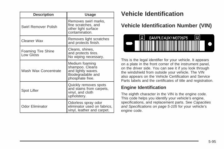
Description Usage
Swirl Remover Polish
Removes swirl marks,fine scratches, andother light surfacecontamination.
Cleaner Wax Removes light scratchesand protects finish.
Foaming Tire ShineLow Gloss
Cleans, shines,and protects tires.No wiping necessary.
Wash Wax Concentrate
Medium foamingshampoo. Cleansand lightly waxes.Biodegradable andphosphate free.
Spot Lifter
Quickly removes spotsand stains from carpets,vinyl, and clothupholstery.
Odor EliminatorOdorless spray odoreliminator used on fabrics,vinyl, leather and carpet.
Vehicle Identification
Vehicle Identification Number (VIN)
This is the legal identifier for your vehicle. It appearson a plate in the front corner of the instrument panel,on the driver side. You can see it if you look throughthe windshield from outside your vehicle. The VINalso appears on the Vehicle Certification and ServiceParts labels and the certificates of title and registration.
Engine IdentificationThe eighth character in the VIN is the engine code.This code helps you identify your vehicle’s engine,specifications, and replacement parts. See Capacitiesand Specifications on page 5-105 for your vehicle’sengine code.
5-95

Service Parts Identification LabelThis label is on the spare tire cover. It is very helpful ifyou ever need to order parts. The label has thefollowing information:• Vehicle Identification Number (VIN)• Model designation• Paint information• Production options and special equipment
Do not remove this label from the vehicle.
Electrical System
Add-On Electrical EquipmentNotice: Do not add anything electrical to yourvehicle unless you check with your dealer/retailerfirst. Some electrical equipment can damage yourvehicle and the damage would not be covered byyour warranty. Some add-on electrical equipment cankeep other components from working as they should.
Add-on equipment can drain your vehicle’s battery, evenif your vehicle is not operating.
Your vehicle has an airbag system. Before attempting toadd anything electrical to your vehicle, see ServicingYour Airbag-Equipped Vehicle on page 1-67.
Headlamp WiringThe headlamp wiring system has four individual fuses.An electrical overload will cause the lamps to go onand off, or in some cases to remain off. If this happens,have the headlamp wiring checked right away.
Windshield Wiper FusesThe windshield wiper motor is protected by an internalcircuit breaker. If the wiper motor overheats due toheavy snow, the wipers will stop until the motor coolsand will then restart.
A fuse powers the wiper motor. If the fuse blows,there is an electrical problem. Be sure to have it fixed.
5-96

Power Windows and OtherPower OptionsCircuit breakers in the fuse block protect the powerwindows and other power accessories. When thecurrent load is too heavy, the circuit breaker opensand closes, protecting the circuit until the problem isfixed or goes away.
Fuses and Circuit BreakersThe wiring circuits in your vehicle are protected fromshort circuits by a combination of fuses and circuitbreakers. This greatly reduces the chance of firescaused by electrical problems.
Look at the silver-colored band inside the fuse. If theband is broken or melted, replace the fuse. Be sureyou replace a bad fuse with a new one of the identicalsize and rating.
If you ever have a problem on the road and don’t havea spare fuse, you can borrow one that has the sameamperage. Just pick some feature of your vehiclethat you can get along without — like the radio orcigarette lighter — and use its fuse, if it is the correctamperage. Replace it as soon as you can.
Underhood Fuse BlockThe underhood fuse block is located on the passengerside of the engine compartment. Remove the fusecover and secondary service cover to access thefuse block.
Notice: Spilling liquid on any electrical componentson your vehicle may damage it. Always keep thecovers on any electrical component.
5-97
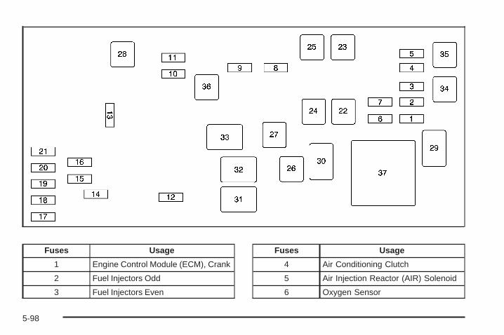
Fuses Usage
1 Engine Control Module (ECM), Crank
2 Fuel Injectors Odd
3 Fuel Injectors Even
Fuses Usage
4 Air Conditioning Clutch
5 Air Injection Reactor (AIR) Solenoid
6 Oxygen Sensor
5-98

Fuses Usage
7 Emission Device
8 Transmission, Ignition 1
9 Engine Control Module (ECM),Powertrain Control Module (PCM)
10 Climate Control System,Instrument Panel Cluster Ignition 1
11 Airbag System
12 Horn
13 Windshield Wiper
14 Fog Lamps
15 Right High-Beam Headlamp
16 Left High-Beam Headlamp
17 Left Low-Beam Headlamp
18 Right Low-Beam Headlamp
19 Windshield Washer Pump Motor
20 Left Front Cornering Lamp
21 Right Front Cornering Lamp
22 Air Pump (J-Case)
Fuses Usage
23 Antilock Brake System (ABS)(J-Case)
24 Starter (J-Case)
25 Antilock Brake System (ABS)Motor (J-Case)
26 Cooling Fan 2 (J-Case)
27 Cooling Fan 1 (J-Case)
28 Windshield Washer Heater (J-Case)
Relays Usage
29 Powertrain
30 Starter
31 Cooling Fan 2
32 Cooling Fan 3
33 Cooling Fan 1
34 Air Conditioning Clutch
35 Air Injection Reactor (AIR) Solenoid
36 Ignition
37 Air Pump
5-99

Rear Underseat Fuse BlockThe rear fuse block is located under the rear seat onthe driver side. The rear seat cushion must be removedto access the rear fuse block.
Removing the Rear Seat Cushion
Notice: If you touch the exposed wires with themetal on the seat cushion, you could cause ashort that could damage the battery and or wires.Avoid contact between the rear seat and thefuse center whenever you remove or reinstallthe rear seat. Do not remove covers from any ofthe covered parts, and do not store anythingunder the seats.
To remove the rear seat cushion, do the following:
1. Pull up on the front of the cushion to releasethe front hooks.
2. Pull the cushion up and out toward the front ofthe vehicle.
To access the fuse block, pull out and lift up on thecover latch, located at the end of the fuse block,near the battery cable.
5-100

To reinstall the rear seat cushion, do the following:
{CAUTION:
A safety belt that is not properly routedthrough the seat cushion or is twisted willnot provide the protection needed in a crash.
CAUTION: (Continued)
CAUTION: (Continued)
If the safety belt has not been routed throughthe seat cushion at all, it will not be there towork for the next passenger. The personsitting in that position could be badly injured.After reinstalling the seat cushion, alwayscheck to be sure that the safety belts areproperly routed and are not twisted.
1. Buckle the center passenger position safety belt,then route the safety belts through the proper slotsin the seat cushion. Do not let the safety beltsget twisted.
2. Slide the rear of the cushion up and under theseatback so the rear-locating guides hook intothe wire loops on the back frame.
3. With the seat cushion lowered, push rearward andthen press down on the seat cushion until thespring locks on both ends engage.
4. Check to make sure the safety belts are properlyrouted and that no portion of any safety belt istrapped under the seat. Also make sure the seatcushion is secured.
5-101

Fuses Usage
1 Fuel Pump
2 Left Park Lamp
3 Run 3 - Rear Blower
Fuses Usage
4 Right Park Lamp
5 Engine Control Module (ECM)/Transmission Control Module (TCM)
5-102
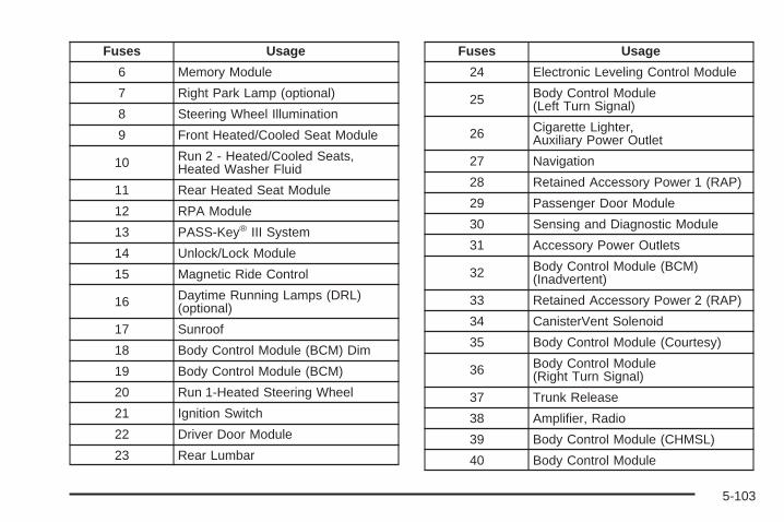
Fuses Usage
6 Memory Module
7 Right Park Lamp (optional)
8 Steering Wheel Illumination
9 Front Heated/Cooled Seat Module
10 Run 2 - Heated/Cooled Seats,Heated Washer Fluid
11 Rear Heated Seat Module
12 RPA Module
13 PASS-Key® III System
14 Unlock/Lock Module
15 Magnetic Ride Control
16 Daytime Running Lamps (DRL)(optional)
17 Sunroof
18 Body Control Module (BCM) Dim
19 Body Control Module (BCM)
20 Run 1-Heated Steering Wheel
21 Ignition Switch
22 Driver Door Module
23 Rear Lumbar
Fuses Usage
24 Electronic Leveling Control Module
25 Body Control Module(Left Turn Signal)
26 Cigarette Lighter,Auxiliary Power Outlet
27 Navigation
28 Retained Accessory Power 1 (RAP)
29 Passenger Door Module
30 Sensing and Diagnostic Module
31 Accessory Power Outlets
32 Body Control Module (BCM)(Inadvertent)
33 Retained Accessory Power 2 (RAP)
34 CanisterVent Solenoid
35 Body Control Module (Courtesy)
36 Body Control Module(Right Turn Signal)
37 Trunk Release
38 Amplifier, Radio
39 Body Control Module (CHMSL)
40 Body Control Module
5-103
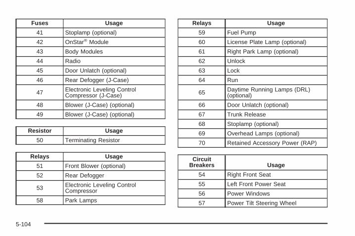
Fuses Usage
41 Stoplamp (optional)
42 OnStar® Module
43 Body Modules
44 Radio
45 Door Unlatch (optional)
46 Rear Defogger (J-Case)
47 Electronic Leveling ControlCompressor (J-Case)
48 Blower (J-Case) (optional)
49 Blower (J-Case) (optional)
Resistor Usage
50 Terminating Resistor
Relays Usage
51 Front Blower (optional)
52 Rear Defogger
53 Electronic Leveling ControlCompressor
58 Park Lamps
Relays Usage
59 Fuel Pump
60 License Plate Lamp (optional)
61 Right Park Lamp (optional)
62 Unlock
63 Lock
64 Run
65 Daytime Running Lamps (DRL)(optional)
66 Door Unlatch (optional)
67 Trunk Release
68 Stoplamp (optional)
69 Overhead Lamps (optional)
70 Retained Accessory Power (RAP)
CircuitBreakers Usage
54 Right Front Seat
55 Left Front Power Seat
56 Power Windows
57 Power Tilt Steering Wheel
5-104

Capacities and SpecificationsThe following approximate capacities are given in English and metric conversions. See Recommended Fluids andLubricants on page 6-13 for more information.
Application
Capacities
English Metric
Air Conditioning Refrigerant
For the air conditioning system refrigerantcharge amount, see the refrigerant caution
label located under the hood. See yourdealer/retailer for more information.
Cooling System 12.6 qt 12.0 L
Engine Oil with Filter 7.5 qt 7.1 L
Fuel Tank 18.5 gal 70.0 L
Transmission 7.0 qt 6.6 L
Wheel Nut Torque 100 lb ft 140 Y
All capacities are approximate. When adding, be sure to fill to the approximate level as recommended in thismanual. Recheck fluid level after filling.
Engine SpecificationsEngine VIN Code Transmission Spark Plug Gap
4.6L DOHC V8 Y Automatic 0.050 inches (1.27 mm)
4.6L DOHC V8 9 Automatic 0.050 inches (1.27 mm)
5-105

✍ NOTES
5-106

Maintenance Schedule ......................................6-2Introduction ...................................................6-2Maintenance Requirements ..............................6-2Your Vehicle and the Environment ....................6-2Using the Maintenance Schedule ......................6-3Scheduled Maintenance ...................................6-4Additional Required Services ............................6-6Maintenance Footnotes ...................................6-8
Owner Checks and Services ............................6-9At Each Fuel Fill ............................................6-9At Least Once a Month .................................6-10At Least Once a Year ...................................6-10Recommended Fluids and Lubricants ...............6-13Normal Maintenance Replacement Parts ..........6-14Engine Drive Belt Routing ..............................6-15Maintenance Record .....................................6-16
Section 6 Maintenance Schedule
6-1

Maintenance Schedule
IntroductionImportant: Keep engine oil at the proper level andchange as recommended.
Have you purchased the GM Protection Plan? The Plansupplements your new vehicle warranties. See yourWarranty and Owner Assistance booklet or yourdealer/retailer for details.
Maintenance RequirementsNotice: Maintenance intervals, checks, inspections,replacement parts, and recommended fluids andlubricants as prescribed in this manual arenecessary to keep your vehicle in good workingcondition. Any damage caused by failure to followscheduled maintenance might not be coveredby warranty.
Your Vehicle and the EnvironmentProper vehicle maintenance not only helps to keep yourvehicle in good working condition, but also helps theenvironment. All recommended maintenance isimportant. Improper vehicle maintenance can evenaffect the quality of the air we breathe. Improper fluidlevels or the wrong tire inflation can increase the levelof emissions from your vehicle. To help protect ourenvironment, and to keep your vehicle in good condition,be sure to maintain your vehicle properly.
6-2

Using the Maintenance ScheduleWe want to help you keep your vehicle in good workingcondition. But we do not know exactly how you willdrive it. You might drive very short distances only a fewtimes a week. Or you might drive long distances allthe time in very hot, dusty weather. You might use yourvehicle in making deliveries. Or you might drive it towork, to do errands, or in many other ways.
Because of all the different ways people use theirvehicles, maintenance needs vary. You might need morefrequent checks and replacements. So please readthe following and note how you drive. If you have anyquestions on how to keep your vehicle in good condition,see your dealer/retailer.
This schedule is for vehicles that:
• carry passengers and cargo within recommendedlimits. You will find these limits on the Tire andLoading Information label. See Loading YourVehicle on page 4-20.
• are driven on reasonable road surfaces within legaldriving limits.
• use the recommended fuel. See Gasoline Octaneon page 5-5.
The services in Scheduled Maintenance on page 6-4should be performed when indicated. See AdditionalRequired Services on page 6-6 and MaintenanceFootnotes on page 6-8 for further information.
{CAUTION:
Performing maintenance work on a vehiclecan be dangerous. In trying to do some jobs,you can be seriously injured. Do your ownmaintenance work only if you have therequired know-how and the proper tools andequipment for the job. If you have any doubt,see your dealer/retailer to have a qualifiedtechnician do the work. See Doing Your OwnService Work on page 5-4.
Some maintenance services can be complex. So,unless you are technically qualified and have thenecessary equipment, you should have yourdealer/retailer do these jobs.
6-3
When you go to your dealer/retailer for your serviceneeds, you will know that trained and supported servicetechnicians will perform the work using genuine parts.
If you want to purchase service information, see ServicePublications Ordering Information on page 7-15.
Owner Checks and Services on page 6-9 tells you whatshould be checked, when to check it, and what youcan easily do to help keep your vehicle in goodcondition.
The proper replacement parts, fluids, and lubricants touse are listed in Recommended Fluids and Lubricantson page 6-13 and Normal Maintenance ReplacementParts on page 6-14. When your vehicle is serviced,make sure these are used. All parts should be replacedand all necessary repairs done before you or anyoneelse drives the vehicle. We recommend the use ofgenuine parts from your dealer/retailer.
Scheduled MaintenanceTo maintain the ride, handling, and performance of yourvehicle, it is important that the first tire rotation servicebe performed when the vehicle has 5,000 to 8,000 miles(8 000 to 13 000 km). Check tires for inflation pressuresand wear. See Tires on page 5-50. Rotate tires.See Tire Inspection and Rotation on page 5-66 and“Tire Wear Inspection” in At Least Once a Monthon page 6-10.
When the CHANGE ENGINE OIL SOON message inthe Driver Information Center (DIC) comes on, it meansthat service is required for your vehicle. Have yourvehicle serviced as soon as possible within the next600 miles (1 000 km). It is possible that, if you aredriving under the best conditions, the engine oil lifesystem may not indicate that vehicle service isnecessary for over a year. However, your engine oil andfilter must be changed at least once a year and atthis time the system must be reset. Your dealer/retailerhas trained service technicians who will perform thiswork using genuine parts and reset the system.
6-4

If the engine oil life system is ever reset accidentally,you must service your vehicle within 3,000 miles(5 000 km) since your last service. Remember to resetthe oil life system whenever the oil is changed.See Engine Oil Life System on page 5-16 for informationon the Engine Oil Life System and resetting the system.
When the CHANGE ENGINE OIL SOON messageappears, the following services, checks, and inspectionsare required:❑ Change engine oil and filter. See Engine Oil on
page 5-13. Reset oil life system. See Engine Oil LifeSystem on page 5-16. An Emission Control Service.
❑ Visually check for any leaks or damage.See footnote (k).
❑ Inspect engine air cleaner filter. If necessary, replacefilter. See Engine Air Cleaner/Filter on page 5-18.See footnote (m).
❑ Rotate tires and check inflation pressures and wear.See Tire Inspection and Rotation on page 5-66 and“Tire Wear Inspection” in At Least Once a Monthon page 6-10.
❑ Inspect brake system. See footnote (a).❑ Check engine coolant and windshield washer
fluid levels and add fluid as needed.❑ Perform any needed additional services.
See “Additional Required Services” in this section.❑ Inspect suspension and steering components.
See footnote (b).❑ Inspect engine cooling system. See footnote (c).❑ Inspect wiper blades. See footnote (d).❑ Inspect restraint system components.
See footnote (e).❑ Lubricate body components. See footnote (f).❑ Check transmission fluid level and add fluid
as needed.
6-5
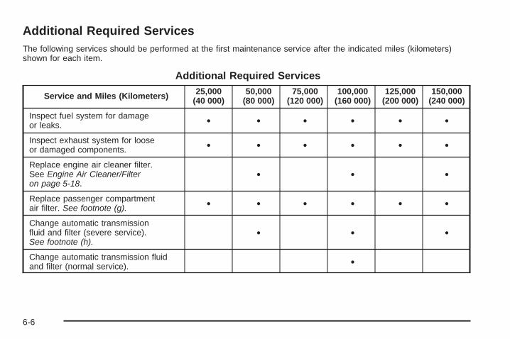
Additional Required ServicesThe following services should be performed at the first maintenance service after the indicated miles (kilometers)shown for each item.
Additional Required Services
Service and Miles (Kilometers) 25,000(40 000)
50,000(80 000)
75,000(120 000)
100,000(160 000)
125,000(200 000)
150,000(240 000)
Inspect fuel system for damageor leaks. • • • • • •
Inspect exhaust system for looseor damaged components. • • • • • •
Replace engine air cleaner filter.See Engine Air Cleaner/Filteron page 5-18.
• • •
Replace passenger compartmentair filter. See footnote (g). • • • • • •
Change automatic transmissionfluid and filter (severe service).See footnote (h).
• • •
Change automatic transmission fluidand filter (normal service). •
6-6
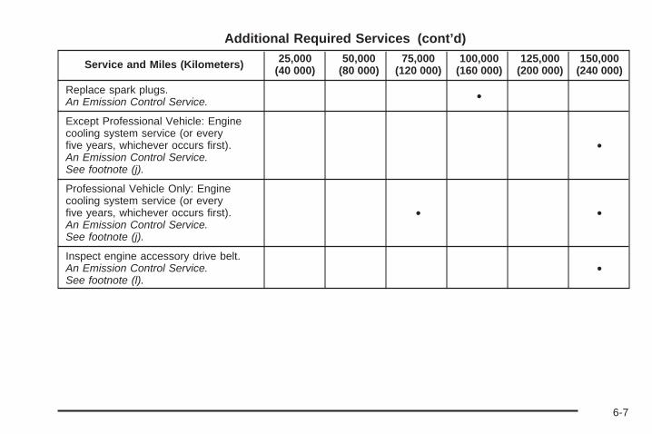
Additional Required Services (cont’d)
Service and Miles (Kilometers) 25,000(40 000)
50,000(80 000)
75,000(120 000)
100,000(160 000)
125,000(200 000)
150,000(240 000)
Replace spark plugs.An Emission Control Service. •
Except Professional Vehicle: Enginecooling system service (or everyfive years, whichever occurs first).An Emission Control Service.See footnote (j).
•
Professional Vehicle Only: Enginecooling system service (or everyfive years, whichever occurs first).An Emission Control Service.See footnote (j).
• •
Inspect engine accessory drive belt.An Emission Control Service.See footnote (l).
•
6-7

Maintenance Footnotes(a) Visually inspect brake lines and hoses for properhook-up, binding, leaks, cracks, chafing, etc. Inspectdisc brake pads for wear and rotors for surfacecondition. Inspect other brake parts, including calipers,parking brake, etc.
(b) Visually inspect front and rear suspension andsteering system for damaged, loose, or missing parts orsigns of wear. Inspect power steering lines and hosesfor proper hook-up, binding, leaks, cracks, chafing, etc.
(c) Visually inspect hoses and have them replaced if theyare cracked, swollen, or deteriorated. Inspect all pipes,fittings and clamps; replace with genuine parts asneeded. To help ensure proper operation, a pressure testof the cooling system and pressure cap and cleaning theoutside of the radiator and air conditioning condenser isrecommended at least once a year.
(d) Inspect wiper blades for wear, cracking, orcontamination. Clean the windshield and wiper blades,if contaminated. Replace wiper blades that are wornor damaged. See Windshield Wiper Blade Replacementon page 5-48 and Windshield and Wiper Blades onpage 5-92 for more information.
(e) Make sure the safety belt reminder light and safetybelt assemblies are working properly. Look for anyother loose or damaged safety belt system parts. If yousee anything that might keep a safety belt systemfrom doing its job, have it repaired. Have any torn orfrayed safety belts replaced. Also see Checkingthe Restraint Systems on page 1-69.
(f) Lubricate all key lock cylinders. Lubricate all hingesand latches, including those for the hood, rearcompartment, glove box door, and console door.More frequent lubrication may be required whenexposed to a corrosive environment. Applying siliconegrease on weatherstrips with a clean cloth will makethem last longer, seal better, and not stick or squeak.
(g) If you drive regularly under dusty conditions, the filtermay require replacement more often.
(h) Change automatic transmission fluid and filter if thevehicle is mainly driven under one or more of theseconditions:
− In heavy city traffic where the outside temperatureregularly reaches 90°F (32°C) or higher.
− In hilly or mountainous terrain.− When doing frequent trailer towing.− Professional vehicle uses, such as limousine
service.− Uses such as high performance operation.
6-8

(j) Drain, flush, and refill cooling system. This servicecan be complex; you should have your dealer/retailerperform this service. See Engine Coolant on page 5-22for what to use. Inspect hoses. Clean radiator,condenser, pressure cap, and filler neck. Pressuretest the cooling system and pressure cap.
(k) A fluid loss in any vehicle system could indicate aproblem. Have the system inspected and repairedand the fluid level checked. Add fluid if needed.
(l) Visually inspect belt for fraying, excessive cracks,or obvious damage. Replace belt if necessary.
(m) If you drive regularly under dusty conditions,inspect the filter at each engine oil change.
Owner Checks and ServicesThese owner checks and services should be performedat the intervals specified to help ensure the safety,dependability, and emission control performance of yourvehicle. Your dealer/retailer can assist you with thesechecks and services.
Be sure any necessary repairs are completed at once.Whenever any fluids or lubricants are added to yourvehicle, make sure they are the proper ones, as shownin Recommended Fluids and Lubricants on page 6-13.
At Each Fuel FillIt is important to perform these underhood checks ateach fuel fill.
Engine Oil Level Check
Notice: It is important to check the engine oilregularly and keep it at the proper level. Failure tokeep the engine oil at the proper level can causedamage to the engine not covered by your warranty.
Check the engine oil level and add the proper oil ifnecessary. See Engine Oil on page 5-13.
Engine Coolant Level CheckCheck the engine coolant level and add DEX-COOL®
coolant mixture if necessary. See Engine Coolanton page 5-22.
Windshield Washer Fluid Level CheckCheck the windshield washer fluid level in the windshieldwasher fluid reservoir and add the proper fluid ifnecessary.
6-9

At Least Once a Month
Tire Inflation CheckInspect your vehicle’s tires and make sure they areinflated to the correct pressures. Do not forget tocheck the spare tire. See Inflation - Tire Pressure onpage 5-58. Check to make sure the spare tire is storedsecurely. See Changing a Flat Tire on page 5-77.
Tire Wear InspectionTire rotation may be required for high mileage highwaydrivers prior to the Engine Oil Life System servicenotification. Check the tires for wear and, if necessary,rotate the tires. See Tire Inspection and Rotationon page 5-66.
At Least Once a Year
Starter Switch Check
{CAUTION:
When you are doing this inspection, thevehicle could move suddenly. If the vehiclemoves, you or others could be injured.
1. Before you start, be sure you have enough roomaround the vehicle.
2. Firmly apply both the parking brake and the regularbrake. See Parking Brake on page 2-30.Do not use the accelerator pedal, and be ready toturn off the engine immediately if it starts.
3. Try to start the engine in each gear. The vehicleshould start only in PARK (P) or NEUTRAL (N).If the vehicle starts in any other position, contactyour dealer/retailer for service.
6-10

Automatic Transmission Shift LockControl System Check
{CAUTION:
When you are doing this inspection, thevehicle could move suddenly. If the vehiclemoves, you or others could be injured.
1. Before you start, be sure you have enough roomaround the vehicle. It should be parked on a levelsurface.
2. Firmly apply the parking brake. See Parking Brakeon page 2-30.Be ready to apply the regular brake immediately ifthe vehicle begins to move.
3. With the engine off, turn the ignition to ON/RUN,but do not start the engine. Without applying theregular brake, try to move the shift lever outof PARK (P) with normal effort. If the shift levermoves out of PARK (P), contact your dealer/retailerfor service.
Ignition Transmission Lock CheckWhile parked, and with the parking brake set, try to turnthe ignition to LOCK/OFF in each shift lever position.
• The ignition should turn to LOCK/OFF onlywhen the shift lever is in PARK (P).
• The ignition key should come out only inLOCK/OFF.
Contact your dealer/retailer if service is required.
6-11

Parking Brake and AutomaticTransmission Park (P) Mechanism Check
{CAUTION:
When you are doing this check, your vehiclecould begin to move. You or others could beinjured and property could be damaged.Make sure there is room in front of yourvehicle in case it begins to roll. Be ready toapply the regular brake at once should thevehicle begin to move.
Park on a fairly steep hill, with the vehicle facingdownhill. Keeping your foot on the regular brake,set the parking brake.
• To check the parking brake’s holding ability:With the engine running and the transmissionin NEUTRAL (N), slowly remove foot pressure fromthe regular brake pedal. Do this until the vehicleis held by the parking brake only.
• To check the PARK (P) mechanism’s holding ability:With the engine running, shift to PARK (P). Thenrelease the parking brake followed by the regularbrake.
Contact your dealer/retailer if service is required.
Underbody Flushing ServiceAt least every spring, use plain water to flush anycorrosive materials from the underbody. Take careto clean thoroughly any areas where mud and otherdebris can collect.
6-12

Recommended Fluids andLubricantsFluids and lubricants identified below by name,part number, or specification can be obtained fromyour dealer/retailer.
Usage Fluid/Lubricant
Engine Oil
The engine requires a special engineoil meeting GM Standard GM4718M.Oils meeting this standard can beidentified as synthetic, and shouldalso be identified with the AmericanPetroleum Institute (API) Certified forGasoline Engines starburst symbol.However, not all synthetic API oilswith the starburst symbol will meetthis GM standard. Look for and useonly oil that meets GM StandardGM4718M. For the proper viscosity,see Engine Oil on page 5-13.
Engine Coolant50/50 mixture of clean, drinkablewater and use only DEX-COOL®
Coolant. See Engine Coolant onpage 5-22.
Hydraulic BrakeSystem
Delco® Supreme 11 Brake Fluid orequivalent DOT-3 brake fluid.
WindshieldWasher Optikleen® Washer Solvent.
Usage Fluid/Lubricant
Parking BrakeCable Guides
Chassis Lubricant(GM Part No. U.S. 12377985,in Canada 88901242) or lubricantmeeting requirements of NLGI #2,Category LB or GC-LB.
Power SteeringSystem
GM Power Steering Fluid(GM Part No. U.S. 89021184,in Canada 89021186).
AutomaticTransmission
DEXRON®-VI AutomaticTransmission Fluid.
Key LockCylinders
Multi-Purpose Lubricant, Superlube(GM Part No. U.S. 12346241,in Canada 10953474).
Hood LatchAssembly,Secondary
Latch, Pivots,Spring
Anchor, andRelease Pawl
Lubriplate Lubricant Aerosol(GM Part No. U.S. 12346293,in Canada 992723) or lubricantmeeting requirements of NLGI #2,Category LB or GC-LB.
Hood andDoor Hinges
Multi-Purpose Lubricant, Superlube(GM Part No. U.S. 12346241,in Canada 10953474).
WeatherstripConditioning
Weatherstrip Lubricant(GM Part No. U.S. 3634770,in Canada 10953518) orDielectric Silicone Grease(GM Part No. U.S. 12345579,in Canada 992887).
6-13

Normal Maintenance Replacement PartsReplacement parts identified below by name, part number, or specification can be obtained from your dealer/retailer.
Part GM Part Number ACDelco® Part Number
Engine Air Cleaner/Filter Element 22676970 A1627C
Engine Oil Filter 89017342 PF61
Passenger Compartment Air Filter Element 25689297 CF118C
Spark Plugs 12571535 41–987
Wiper Blade21.7 in (55.0 cm)
Driver’s Side 10374585 —
Passenger’s Side 10374586 —
6-14

Engine Drive Belt Routing
4.6L V8 Engines
6-15

Maintenance RecordAfter the scheduled services are performed, record the date, odometer reading, who performed the service, and thetype of services performed in the boxes provided. See Maintenance Requirements on page 6-2. Any additionalinformation from Owner Checks and Services on page 6-9 can be added on the following record pages. You shouldretain all maintenance receipts.
Maintenance Record
Date OdometerReading Serviced By Maintenance Stamp Services Performed
6-16

Maintenance Record (cont’d)
Date OdometerReading Serviced By Maintenance Stamp Services Performed
6-17

Maintenance Record (cont’d)
Date OdometerReading Serviced By Maintenance Stamp Services Performed
6-18

Customer Assistance and Information ...............7-2Customer Satisfaction Procedure ......................7-2Online Owner Center ......................................7-4Customer Assistance for Text
Telephone (TTY) Users ................................7-5Customer Assistance Offices ............................7-5GM Mobility Reimbursement Program ................7-6Roadside Service ...........................................7-7Scheduling Service Appointments .....................7-9Courtesy Transportation ...................................7-9Collision Damage Repair ................................7-11
Reporting Safety Defects ................................7-14Reporting Safety Defects to the
United States Government ..........................7-14Reporting Safety Defects to the
Canadian Government ................................7-14Reporting Safety Defects to General Motors .....7-14Service Publications Ordering Information .........7-15
Vehicle Data Recording and Privacy ................7-16Event Data Recorders ...................................7-16OnStar® ......................................................7-17Navigation System ........................................7-17Radio Frequency Identification (RFID) ..............7-17
Section 7 Customer Assistance Information
7-1

Customer Assistance andInformation
Customer Satisfaction ProcedureYour satisfaction and goodwill are important toyour dealer and to Cadillac. Normally, any concernswith the sales transaction or the operation of yourvehicle will be resolved by your dealer’s sales or servicedepartments. Sometimes, however, despite the bestintentions of all concerned, misunderstandings canoccur. If your concern has not been resolved to yoursatisfaction, the following steps should be taken:
STEP ONE: Discuss your concern with a member ofdealership management. Normally, concerns canbe quickly resolved at that level. If the matter hasalready been reviewed with the sales, service or partsmanager, contact the owner of the dealership orthe general manager.
STEP TWO: If after contacting a member of dealershipmanagement, it appears your concern cannot beresolved by the dealership without further help, in theUnited States, contact the Cadillac Customer AssistanceCenter, 24 hours a day, by calling 1-800-458-8006.In Canada, contact the Canadian Cadillac CustomerCommunication Centre by calling 1-888-446-2000.
We encourage you to call the toll-free number in orderto give your inquiry prompt attention. Please havethe following information available to give the CustomerAssistance Representative:
• Vehicle Identification Number (VIN). This isavailable from the vehicle registration or title, or theplate at the top left of the instrument panel andvisible through the windshield.
• Dealership name and location.• Vehicle delivery date and present mileage.
When contacting Cadillac, please remember that yourconcern will likely be resolved at a dealer’s facility.That is why we suggest you follow Step One first if youhave a concern.
STEP THREE (United States Owners): Both GeneralMotors and your dealer are committed to makingsure you are completely satisfied with your new vehicle.However, if you continue to remain unsatisfied afterfollowing the procedure outlined in Steps One and Two,you should file with the Better Business Bureau (BBB)Auto Line Program to enforce your rights.
The BBB Auto Line Program is an out of court programadministered by the Council of Better BusinessBureaus to settle automotive disputes regarding vehiclerepairs or the interpretation of the New VehicleLimited Warranty. Although you may be required toresort to this informal dispute resolution program prior to
7-2
filing a court action, use of the program is free of chargeand your case will generally be heard within 40 days.If you do not agree with the decision given in your case,you may reject it and proceed with any other venuefor relief available to you.
You may contact the BBB Auto Line Program usingthe toll-free telephone number or write them at thefollowing address:
BBB Auto Line ProgramCouncil of Better Business Bureaus, Inc.4200 Wilson BoulevardSuite 800Arlington, VA 22203-1838Telephone: 1-800-955-5100
This program is available in all 50 states and theDistrict of Columbia. Eligibility is limited by vehicle age,mileage and other factors. General Motors reservesthe right to change eligibility limitations and/ordiscontinue its participation in this program.
STEP THREE (Canadian Owners):
General Motors Participation in theMediation/Arbitration Program
In the event that you do not feel your concerns havebeen addressed after the following the procedureoutlined in Steps One and Two. General Motors ofCanada Limited wants you to be aware of itsparticipation in a no-charge mediation/Arbitration
program. General Motors of Canada Limited hascommitted to binding arbitration of owner disputesinvolving factory-related vehicle service claims.The program provides for the review of the factsinvolved by an impartial third party arbiter, and mayinclude an informal hearing before the arbiter.The program is designed so that the entire disputesettlement process, from the time you file yourcomplaint to the final decision, should be completedin approximately 70 days. We believe our impartialprogram offers advantages over courts in mostjurisdictions because it is informal, quick, and freeof charge.
For further information concerning eligibility in theCanadian Motor Vehicle Arbitration Plan (CAMVAP),call toll-free 1-800-207-0685. Alternatively you may callthe General Motors Customer Communication Centre,1-800-263-3777 (English), 1-800-263-7854 (French), oryou may write to the Mediation/Arbitration Program at thefollowing address. Your inquiry should be accompaniedby your Vehicle Identification Number (VIN).
Mediation/Arbitration Programc/o Customer Communication CentreGeneral Motors of Canada LimitedMail Code: CA1–163–0051908 Colonel Sam DriveOshawa, Ontario L1H 8P7
7-3

Online Owner Center
Online Owner Center(United States only)The Owner Center is a resource for your GM ownershipneeds. Specific vehicle information can be found inone place.
The Online Owner Center allows you to:
• Get e-mail service reminders.
• Access information about your specific vehicle,including tips and videos and an electronicversion of this owner manual.
• Keep track of your vehicle’s service history andmaintenance schedule.
• Find GM dealers/retailers for service nationwide.
• Receive special promotions and privileges onlyavailable to members.
Refer to www.MyGMLink.com on the web for updatedinformation and to register your vehicle.
My GM Canada (Canada only)My GM Canada is a password-protected section ofgmcanada.com where you can save information onGM vehicles, get personalized offers, and use handytools and forms with greater ease.
Here are a few of the valuable tools and services youwill have access to:
− My Showroom: Find and save information onvehicles and current offers in your area.
− My Dealers/Retailers: Save details such asaddress and phone number for each of yourpreferred GM Dealers or Retailers.
− My Driveway: Receive service reminders andhelpful advice on owning and maintainingyour vehicle.
− My Preferences: Manage your profile, subscribe toE-News and use tools and forms with greater ease.
To sign up to My GM Canada, visit the My GM Canadasection within www.gmcanada.com.
7-4

Customer Assistance for TextTelephone (TTY) UsersTo assist customers who are deaf, hard of hearing, orspeech-impaired and who use Text Telephones (TTYs),Cadillac has TTY equipment available at its CustomerAssistance Center. Any TTY user can communicatewith Cadillac by dialing: 1-800-833-CMCC (2622).(TTY users in Canada can dial 1-800-263-3830.)
Customer Assistance OfficesCadillac encourages customers to call the toll-freenumber for assistance. However, if a customer wishesto write or e-mail Cadillac, the letter should beaddressed to:
United States — Customer AssistanceCadillac Customer Assistance CenterCadillac Motor Car DivisionP.O. Box 33169Detroit, MI 48232-5169
www.Cadillac.com1-800-458-80061-800-833-2622 (For Text Telephone devices (TTYs))Roadside Assistance: 1-800-882-1112Fax Number: 313-381-0022
From Puerto Rico:1-800-496-9992 (English)1-800-496-9993 (Spanish)Fax Number: 313-381-0022
From U.S. Virgin Islands:1-800-496-9994Fax Number: 313-381-0022
Canada — Customer AssistanceGeneral Motors of Canada LimitedCanadian Cadillac Customer Communication Centre,CA1-163-0051908 Colonel Sam DriveOshawa, Ontario L1H 8P7
www.gmcanada.com1-888-446-20001-800-263-3830 (For Text Telephone devices (TTYs))Roadside Assistance: 1-800-882-1112
7-5
Overseas — Customer AssistancePlease contact the local General Motors Business Unit.
Mexico, Central America andCaribbean Islands/Countries(Except Puerto Rico and U.S. VirginIslands) — Customer Assistance
General Motors de Mexico, S. de R.L. de C.V.Customer Assistance CenterPaseo de la Reforma # 2740Col. Lomas de BezaresC.P. 11910, Mexico, D.F.01-800-508-0000Long Distance: 011-52-53 29 0 800
GM Mobility ReimbursementProgram
This program, available to qualified applicants, canreimburse you up to $1,000 of the cost of eligibleaftermarket adaptive equipment required for your vehicle,such as hand controls or a wheelchair/scooter lift.
The offer is available for a very limited period of timefrom the date of vehicle purchase/lease. For moredetails, or to determine your vehicle’s eligibility, visitgmmobility.com or call the GM Mobility AssistanceCenter at 1-800-323-9935. Text telephone (TTY) users,call 1-800-833-9935.
General Motors of Canada also has a Mobility Program.Call 1-800-GM-DRIVE (463-7483) for details.TTY users call 1-800-263-3830.
7-6
Roadside ServiceIn the United States or Canada, call 1-800-882-1112.
Text Telephone (TTY), U.S. only, call 1-888-889-2438.
Service is available 24 hours a day, 365 days a year.
As the owner of a new Cadillac vehicle, you areautomatically enrolled in the Cadillac RoadsideService® program.
Who Is Covered?Roadside Service coverage is for the vehicle operator,regardless of ownership. In Canada, a person drivingthis vehicle without the consent of the owner is noteligible for coverage.
Cadillac Owner Privileges™The following services are provided in the U.S. andCanada up to 5 years/100,000 miles (160 000 km),whichever occurs first, and, in Canada only, upto a maximum coverage of $100. These services areprovided at a nominal charge if the vehicle is no longerwithin the Powertrain warranty.
Roadside Service provides several Cadillac OwnerPrivileges™ at “no charge,” throughout yourCadillac Powertrain Warranty — 5 years/100,000 miles(160 000 km).
Emergency Road Service is performed on site for thefollowing situations:
• Fuel Delivery: Delivery of enough fuel for thevehicle to get to the nearest service station(approximately $5 in Canada). In Canada, for safetyreasons, propane and other alternative fuels willnot be provided through this service.
• Lock-out Service: Lock-out service will be coveredat no charge if you are unable to gain entry intoyour vehicle. A remote unlock may be available ifyou have an active OnStar® subscription. To ensuresecurity, the driver must present personalidentification before lock-out service is provided.In Canada, the vehicle registration is also required.
• Emergency Tow From a Public Roadway orHighway: Tow to the nearest dealership for warrantyservice or in the event of a vehicle-disabling crash.Winch-out assistance is provided when the vehicle ismired in sand, mud, or snow.
• Flat Tire Change: Installation of a spare tire in goodcondition, when equipped and properly inflated, iscovered at no charge. The customer is responsiblefor the repair or replacement of the tire if not coveredby a warrantable failure.
• Jump Start: A battery jump start is covered at nocharge if the vehicle does not start.
7-7

• Trip Routing Service: Upon request, CadillacRoadside Service will send you detailed, computerpersonalized maps, highlighting your choice of eitherthe most direct route or the most scenic route to yourdestination, anywhere in North America, along withhelpful travel information pertaining to your trip.Please allow three weeks before your planneddeparture date. In Canada, trip routing requests willbe limited to six per calendar year.
• Trip Interruption Benefits and Assistance: If yourtrip is interrupted due to a warranty failure,incidental expenses may be reimbursed during the60 months/100,000 miles (160 000 km) warrantyperiod. Items covered are hotel, meals, andrental car.
• Alternative Service (Canada only): There may betimes when Roadside Service cannot provide timelyassistance. Your advisor may authorize you tosecure local emergency road service, and you will bereimbursed up to $100 upon submission of theoriginal receipt to Cadillac Roadside Service®.
Cadillac and General Motors of Canada Limited reservethe right to limit services or reimbursement to anowner or driver when, in their sole discretion, the claimsbecome excessive in frequency or type of occurrence.
Cadillac Technician Roadside Service(U.S. only)Cadillac’s exceptional Roadside Service is more than anauto club or towing service. It provides every Cadillacowner in the United States with the advantage ofcontacting a Cadillac advisor and, where available, aCadillac trained dealer technician who can provideon-site service.
A dealer technician will travel to your location within a30 mile radius of a participating Cadillac dealership.If beyond this radius, we will arrange to have your cartowed to the nearest Cadillac dealership. Each techniciantravels with a specially equipped service vehicle completewith the necessary Cadillac parts and tools required tohandle most roadside repairs.
Calling for AssistanceFor prompt and efficient assistance when calling,please provide the following to the Roadside ServiceRepresentative:
• Your name, home address, and home telephonenumber
• Telephone number of your location• Location of the vehicle• Model, year, color, and license plate number of
the vehicle
7-8

• Odometer reading, Vehicle Identification Number(VIN), and delivery date of the vehicle
• Description of the problem
Towing and Road Service ExclusionsSpecifically excluded from Roadside Service coverageare towing or services for vehicles operated on anon-public roadway or highway, fines, impoundtowing caused by a violation of local, Municipal, State,Provincial or Federal law, and mounting, dismounting orchanging of snow tires, chains, or other traction devices.
Roadside Service is not part of or included in thecoverage provided by the New Vehicle Limited Warranty.Cadillac and General Motors of Canada Limitedreserve the right to make any changes or discontinuethe Roadside Service program at any time withoutnotification.
Scheduling Service AppointmentsWhen your vehicle requires warranty service, contactyour dealer/retailer and request an appointment.By scheduling a service appointment and advising yourservice consultant of your transportation needs, yourdealer/retailer can help minimize your inconvenience.
If your vehicle cannot be scheduled into the servicedepartment immediately, keep driving it until it can bescheduled for service, unless, of course, the problem issafety-related. If it is, please call your dealership/retailer,let them know this, and ask for instructions.
If the dealer/retailer requests that you simply drop thevehicle off for service, you are urged to do so as early inthe work day as possible to allow for the same day repair.
Courtesy TransportationTo enhance your ownership experience, we and ourparticipating dealers are proud to offer CourtesyTransportation, a customer support program for vehicleswith the Bumper to Bumper (Base Warranty Coverageperiod in Canada) and extended powertrain warrantyin both the U.S. and Canada.
Several courtesy transportation options are available toassist in reducing your inconvenience when warrantyrepairs are required.
Courtesy Transportation is not a part of the New VehicleLimited Warranty. A separate booklet entitled “Warrantyand Owner Assistance Information” furnished witheach new vehicle provides detailed warranty coverageinformation.
7-9
Transportation OptionsWarranty service can generally be completed while youwait. However, if you are unable to wait, GM helpsto minimize your inconvenience by providing severaltransportation options. Depending on the circumstances,your dealer can offer you one of the following:
Shuttle ServiceParticipating dealers can provide shuttle service to getyou to your destination with minimal interruption ofyour daily schedule. This includes one-way or round tripshuttle service to a destination up to 10 miles (16 km)from the dealership.
Public Transportation orFuel ReimbursementIf your vehicle requires warranty repairs, and publictransportation is used instead of the dealer’s shuttleservice, the expense must be supported by originalreceipts and can only be up to the maximum amountallowed by GM for shuttle service. In addition, forU.S. customers, should you arrange transportationthrough a friend or relative, limited reimbursementfor reasonable fuel expenses may be available.
Claim amounts should reflect actual costs and besupported by original receipts. See your dealer forinformation regarding the allowance amounts forreimbursement of fuel or other transportation costs.
Courtesy Rental VehicleYour dealer may arrange to provide you with a courtesyrental vehicle or reimburse you for a rental vehiclethat you obtain if your vehicle is kept for a warrantyrepair. If you obtain a rental vehicle on your own, pleasesee your dealer for the maximum number of daysallowed and the allowance per rental day. Rentalreimbursement must be supported by original receipts.This requires that you sign and complete a rentalagreement and meet state, local, and rental vehicleprovider requirements. Requirements vary andmay include minimum age requirements, insurancecoverage, credit card, etc. You are responsible forfuel usage charges and may also be responsible fortaxes, levies, usage fees, excessive mileage, or rentalusage beyond the completion of the repair.
It may not be possible to provide a like-vehicle as acourtesy rental.
7-10

Additional Program InformationAll program options, such as shuttle service, may not beavailable at every dealer. Please contact your dealerfor specific information about availability. All CourtesyTransportation arrangements will be administeredby appropriate dealer personnel.
General Motors reserves the right to unilaterally modify,change, or discontinue Courtesy Transportation atany time and to resolve all questions of claim eligibilitypursuant to the terms and conditions describedherein at its sole discretion.
Collision Damage RepairIf your vehicle is involved in a collision and it isdamaged, have the damage repaired by a qualifiedtechnician using the proper equipment and qualityreplacement parts. Poorly performed collision repairswill diminish your vehicle’s resale value, and safetyperformance can be compromised in subsequentcollisions.
Collision PartsGenuine GM Collision parts are new parts made withthe same materials and construction methods asthe parts with which your vehicle was originally built.
Genuine GM Collision parts are your best choice toassure that your vehicle’s designed appearance,durability and safety are preserved. The use ofGenuine GM parts can help maintain your GM NewVehicle Warranty.
Recycled original equipment parts may also be used forrepair. These parts are typically removed from vehiclesthat were total losses in prior crashes. In most cases,the parts being recycled are from undamaged sectionsof the vehicle. A recycled original equipment GM part,may be an acceptable choice to maintain your vehicle’soriginally designed appearance and safety performance,however, the history of these parts is not known.Such parts are not covered by your GM New VehicleLimited Warranty, and any related failures are notcovered by that warranty.
Aftermarket collision parts are also available.These are made by companies other than GM andmay not have been tested for your vehicle. As a result,these parts may fit poorly, exhibit prematuredurability/corrosion problems, and may not performproperly in subsequent collisions. Aftermarket partsare not covered by your GM New Vehicle LimitedWarranty, and any vehicle failure related to such partsare not covered by that warranty.
7-11

Repair FacilityGM also recommends that you choose a collision repairfacility that meets your needs before you ever needcollision repairs. Your GM dealer/retailer may have acollision repair center with GM-trained techniciansand state of the art equipment, or be able to recommenda collision repair center that has GM-trained techniciansand comparable equipment.
Insuring Your VehicleProtect your investment in your GM vehicle withcomprehensive and collision insurance coverage. Thereare significant differences in the quality of coverageafforded by various insurance policy terms. Manyinsurance policies provide reduced protection to yourGM vehicle by limiting compensation for damage repairsby using aftermarket collision parts. Some insurancecompanies will not specify aftermarket collisionparts. When purchasing insurance, we recommend thatyou assure your vehicle will be repaired with GMoriginal equipment collision parts. If such insurancecoverage is not available from your current insurancecarrier, consider switching to another insurance carrier.
If your vehicle is leased, the leasing company mayrequire you to have insurance that assures repairs withGenuine GM Original Equipment Manufacturer (OEM)parts or Genuine Manufacturer replacement parts.Read your lease carefully, as you may be charged atthe end of your lease for poor quality repairs.
If a Crash OccursHere is what to do if you are involved in a crash.
• Try to relax and then check to make sure you are allright. If you are uninjured, make sure that no one elsein your vehicle, or the other vehicle, is injured.
• If there has been an injury, call emergency servicesfor help. Do not leave the scene of a crash until allmatters have been taken care of. Move your vehicleonly if its position puts you in danger or you areinstructed to move it by a police officer.
• Give only the necessary and requested informationto police and other parties involved in the crash. Donot discuss your personal condition, mental frame ofmind, or anything unrelated to the crash. This willhelp guard against post-crash legal action.
• If you need roadside assistance, call GM RoadsideAssistance. See Roadside Service on page 7-7 formore information.
• If your vehicle cannot be driven, know where thetowing service will be taking it. Get a card from thetow truck operator or write down the driver’s name,the service’s name, and the phone number.
• Remove any valuables from your vehicle before it istowed away. Make sure this includes your insuranceinformation and registration if you keep these itemsin your vehicle.
7-12
• Gather the important information you will need fromthe other driver. Things like name, address, phonenumber, driver’s license number, vehicle licenseplate, vehicle make, model and model year, VehicleIdentification Number (VIN), insurance company andpolicy number, and a general description of thedamage to the other vehicle.
• If possible, call your insurance company from thescene of the crash. They will walk you through theinformation they will need. If they ask for a policereport, phone or go to the police departmentheadquarters the next day and you can get a copy ofthe report for a nominal fee. In some states/provinceswith “no fault” insurance laws, a report may not benecessary. This is especially true if there are noinjuries and both vehicles are driveable.
• Choose a reputable collision repair facility for yourvehicle. Whether you select a GM dealer/retailer or aprivate collision repair facility to fix the damage,make sure you are comfortable with them.Remember, you will have to feel comfortable withtheir work for a long time.
• Once you have an estimate, read it carefully andmake sure you understand what work will beperformed on your vehicle. If you have a question,ask for an explanation. Reputable shops welcomethis opportunity.
Managing the Vehicle DamageRepair ProcessIn the event that your vehicle requires damage repairs,GM recommends that you take an active role in itsrepair. If you have a pre-determined repair facility ofchoice, take your vehicle there, or have it towed there.Specify to the facility that any required replacementcollision parts be original equipment parts, either newGenuine GM parts or recycled original GM parts.Remember, recycled parts will not be covered by yourGM vehicle warranty.
Insurance pays the bill for the repair, but you must livewith the repair. Depending on your policy limits, yourinsurance company may initially value the repair usingaftermarket parts. Discuss this with your repairprofessional, and insist on Genuine GM parts.Remember if your vehicle is leased you may beobligated to have the vehicle repaired with Genuine GMparts, even if your insurance coverage does not paythe full cost.
If another party’s insurance company is paying for therepairs, you are not obligated to accept a repairvaluation based on that insurance company’s collisionpolicy repair limits, as you have no contractual limits withthat company. In such cases, you can have control ofthe repair and parts choices as long as cost stays withinreasonable limits.
7-13

Reporting Safety Defects
Reporting Safety Defects to theUnited States GovernmentIf you believe that your vehicle has a defect whichcould cause a crash or could cause injury ordeath, you should immediately inform the NationalHighway Traffic Safety Administration (NHTSA)in addition to notifying General Motors.
If NHTSA receives similar complaints, it may openan investigation, and if it finds that a safety defectexists in a group of vehicles, it may order a recalland remedy campaign. However, NHTSA cannotbecome involved in individual problems betweenyou, your dealer/retailer, or General Motors.
To contact NHTSA, you may call the VehicleSafety Hotline toll-free at 1-888-327-4236(TTY: 1-800-424-9153); go tohttp://www.safercar.gov; or write to:
Administrator, NHTSA400 Seventh Street, SW.Washington D.C., 20590
You can also obtain other information about motorvehicle safety from http://www.safercar.gov.
Reporting Safety Defects to theCanadian GovernmentIf you live in Canada, and you believe that yourvehicle has a safety defect, notify Transport Canadaimmediately, in addition to notifying General Motors ofCanada Limited. Call them at 1-800-333-0510 or write to:
Transport CanadaRoad Safety Branch2780 Sheffield RoadOttawa, Ontario K1B 3V9
Reporting Safety Defects toGeneral MotorsIn addition to notifying NHTSA (or Transport Canada) ina situation like this, please notify General Motors.
Call 1-800-458-8006, or write:Cadillac Customer Assistance CenterCadillac Motor Car DivisionP.O. Box 33169Detroit, MI 48232-5169
In Canada, call 1-888-446-2000, or write:Canadian Cadillac Customer Communication Centre,CA1-163-005General Motors of Canada Limited1908 Colonel Sam DriveOshawa, Ontario L1H 8P7
7-14

Service Publications OrderingInformation
Service ManualsService Manuals have the diagnosis and repairinformation on engines, transmission, axle suspension,brakes, electrical, steering, body, etc.
Service BulletinsService Bulletins’ give additional technical serviceinformation needed to knowledgeably service GeneralMotors cars and trucks. Each bulletin containsinstructions to assist in the diagnosis and service ofyour vehicle.
Owner InformationOwner publications are written specifically for ownersand intended to provide basic operational informationabout the vehicle. The owner manual includes theMaintenance Schedule for all models.
In-Portfolio: Includes a Portfolio, Owner Manual, andWarranty Booklet.
RETAIL SELL PRICE: $35.00 (U.S.) plus processing fee
Without Portfolio: Owner Manual only.
RETAIL SELL PRICE: $25.00 (U.S.) plus processing fee
Current and Past Model Order FormsTechnical Service Bulletins and Manuals are availablefor current and past model GM vehicles. To requestan order form, specify year and model name ofthe vehicle.
ORDER TOLL FREE: 1-800-551-4123Monday-Friday 8:00 AM - 6:00 PMEastern TimeFor Credit Card Orders Only(VISA-MasterCard-Discover), visit Helm, Inc. on theWorld Wide Web at: www.helminc.com
Or you can write to:
Helm, IncorporatedP.O. Box 07130Detroit, MI 48207
Prices are subject to change without notice and withoutincurring obligation. Allow ample time for delivery.
Note to Canadian Customers: All listed prices arequoted in U.S. funds. Canadian residents are to makechecks payable in U.S. funds.
7-15

Vehicle Data Recordingand PrivacyYour GM vehicle has a number of sophisticatedcomputers that record information about the vehicle’sperformance and how it is driven. For example,your vehicle uses computer modules to monitor andcontrol engine and transmission performance,to monitor the conditions for airbag deployment anddeploy airbags in a crash and, if so equipped,to provide antilock braking to help the driver controlthe vehicle. These modules may store data to help yourdealer/retailer technician service your vehicle.Some modules may also store data about how youoperate the vehicle, such as rate of fuel consumption oraverage speed. These modules may also retain theowner’s personal preferences, such as radio pre-sets,seat positions, and temperature settings.
Event Data RecordersThis vehicle has an Event Data Recorder (EDR).The main purpose of an EDR is to record, in certaincrash or near crash-like situations, such as an air bagdeployment or hitting a road obstacle, data that willassist in understanding how a vehicle’s systemsperformed. The EDR is designed to record data relatedto vehicle dynamics and safety systems for a shortperiod of time, typically 30 seconds or less. The EDR inthis vehicle is designed to record such data as:
• How various systems in your vehicle were operating• Whether or not the driver and passenger safety
belts were buckled/fastened• How far, if at all, the driver was pressing the
accelerator and/or brake pedal• How fast the vehicle was traveling
This data can help provide a better understanding of thecircumstances in which crashes and injuries occur.
Important: EDR data is recorded by your vehicle onlyif a non-trivial crash situation occurs; no data isrecorded by the EDR under normal driving conditionsand no personal data (e.g., name, gender, age, andcrash location) is recorded. However, other parties,such as law enforcement, could combine the EDR datawith the type of personally identifying data routinelyacquired during a crash investigation.
7-16

To read data recorded by an EDR, special equipment isrequired, and access to the vehicle or the EDR isneeded. In addition to the vehicle manufacturer, otherparties, such as law enforcement, that have the specialequipment, can read the information if they haveaccess to the vehicle or the EDR.
GM will not access this data or share it with othersexcept: with the consent of the vehicle owner or, if thevehicle is leased, with the consent of the lessee; inresponse to an official request of police or similargovernment office; as part of GM’s defense of litigationthrough the discovery process; or, as required bylaw. Data that GM collects or receives may also be usedfor GM research needs or may be made available toothers for research purposes, where a need is shownand the data is not tied to a specific vehicle orvehicle owner.
OnStar®
If your vehicle has OnStar® and you subscribe to theOnStar® services, please refer to the OnStar®
Terms and Conditions for information on data collectionand use. See also OnStar® System on page 2-53 inthis manual for more information.
Navigation SystemIf your vehicle has a navigation system, use of thesystem may result in the storage of destinations,addresses, telephone numbers, and other tripinformation. Refer to the navigation system operatingmanual for information on stored data and for deletioninstructions.
Radio FrequencyIdentification (RFID)RFID technology is used in some vehicles for functionssuch as tire pressure monitoring and ignition systemsecurity, as well as in connection with conveniencessuch as key fobs for remote door locking/unlocking andstarting, and in-vehicle transmitters for garage dooropeners. RFID technology in GM vehicles does not useor record personal information or link with any otherGM system containing personal information.
7-17

✍ NOTES
7-18

AAccessories and Modifications ............................ 5-3Adaptive Cruise Control ................................... 3-19Adding Equipment to Your Airbag-Equipped
Vehicle ....................................................... 1-68Additives, Fuel ................................................. 5-6Add-On Electrical Equipment ............................ 5-96Air Cleaner/Filter, Engine ................................. 5-18Air Conditioning .............................................. 3-40Airbag
Passenger Status Indicator ........................... 3-56Readiness Light .......................................... 3-55
Airbag System ................................................ 1-54What Will You See After an Airbag Inflates? .... 1-61When Should an Airbag Inflate? .................... 1-59Where Are the Airbags? ............................... 1-56
Airbag SystemsAdding Equipment to Your Airbag-Equipped
Vehicle ................................................... 1-68How Does an Airbag Restrain? ...................... 1-60Passenger Sensing System ........................... 1-62Servicing Your Airbag-Equipped Vehicle .......... 1-67What Makes an Airbag Inflate? ...................... 1-60
Analog Clock .................................................. 3-40Antenna, Backglass ....................................... 3-119
Antenna, XM™ Satellite RadioAntenna System ........................................ 3-119
Antilock Brake System (ABS) ............................. 4-4Antilock Brake, System Warning Light ................ 3-59Appearance Care
Aluminum or Chrome-Plated Wheels .............. 5-92Care of Safety Belts .................................... 5-90Chemical Paint Spotting ............................... 5-94Cleaning Exterior Lamps/Lenses .................... 5-91Fabric/Carpet .............................................. 5-88Finish Care ................................................. 5-91Finish Damage ............................................ 5-93Instrument Panel, Vinyl, and Other
Plastic Surfaces ....................................... 5-89Interior Cleaning .......................................... 5-87Leather ...................................................... 5-89Sheet Metal Damage ................................... 5-93Speaker Covers .......................................... 5-90Tires .......................................................... 5-93Underbody Maintenance ............................... 5-94Vehicle Care/Appearance Materials ................ 5-94Washing Your Vehicle ................................... 5-90Weatherstrips .............................................. 5-90Windshield and Wiper Blades ........................ 5-92Wood Panels .............................................. 5-89
Appointments, Scheduling Service ....................... 7-9
1
Ashtray(s) ...................................................... 3-39Audio System ................................................. 3-95
Audio Steering Wheel Controls .................... 3-117Backglass Antenna ..................................... 3-119Navigation/Radio System,
see Navigation Manual ............................ 3-116Radio Reception ........................................ 3-118Setting the Time .......................................... 3-96Theft-Deterrent Feature ............................... 3-116XM™ Satellite Radio Antenna System ........... 3-119
Audio System(s) ............................................ 3-100Automatic Transmission
Fluid .......................................................... 5-19Operation ................................................... 2-27
BBackglass Antenna ........................................ 3-119Battery .......................................................... 5-38
Electric Power Management .......................... 3-37Exterior Lighting Battery Saver ...................... 3-35Inadvertent Power Saver .............................. 3-38Load Management ....................................... 3-37Run-Down Protection ................................... 3-38
BrakeEmergencies ................................................ 4-5
Brakes .......................................................... 5-35Panic Assist ................................................. 4-7System Warning Light .................................. 3-58
Braking ........................................................... 4-3Braking in Emergencies ..................................... 4-5Break-In, New Vehicle ..................................... 2-22Bulb Replacement ........................................... 5-47
Headlamp Aiming ........................................ 5-44High Intensity Discharge (HID) Lighting ........... 5-47
Buying New Tires ........................................... 5-69
CCalibration ............................... 1-9, 2-36, 2-38, 2-40California Fuel .................................................. 5-6California Perchlorate Materials Requirements ....... 5-4California Proposition 65 Warning ....................... 5-4Canadian Owners ................................................ iiCapacities and Specifications .......................... 5-105Carbon Monoxide ................... 2-12, 2-34, 4-15, 4-27Care of
Safety Belts ................................................ 5-90CD, MP3 ..................................................... 3-110Center Console Storage Area ........................... 2-63Center Flex Storage Unit ................................. 2-64Center Seat ..................................................... 1-8
2

Chains, Tire ................................................... 5-75Charging System Light .................................... 3-58Check
Engine Light ............................................... 3-63Checking Things Under the Hood ...................... 5-10Chemical Paint Spotting ................................... 5-94Child Restraints
Child Restraint Systems ............................... 1-37Infants and Young Children ........................... 1-34Lower Anchors and Tethers for Children .......... 1-41Older Children ............................................. 1-31Securing a Child Restraint in a
Rear Seat Position ................................... 1-48Securing a Child Restraint in the
Center Front Seat Position ........................ 1-50Securing a Child Restraint in the
Right Front Seat Position .......................... 1-50Where to Put the Restraint ........................... 1-40
CleaningAluminum or Chrome-Plated Wheels .............. 5-92Exterior Lamps/Lenses ................................. 5-91Fabric/Carpet .............................................. 5-88Finish Care ................................................. 5-91Instrument Panel, Vinyl, and Other
Plastic Surfaces ....................................... 5-89Interior ....................................................... 5-87
Cleaning (cont.)Leather ...................................................... 5-89Speaker Covers .......................................... 5-90Tires .......................................................... 5-93Underbody Maintenance ............................... 5-94Washing Your Vehicle ................................... 5-90Weatherstrips .............................................. 5-90Windshield and Wiper Blades ........................ 5-92Wood Panels .............................................. 5-89
Climate Control SystemAir Filter, Passenger Compartment ................. 3-48Dual .......................................................... 3-40Outlet Adjustment ........................................ 3-46Rear .......................................................... 3-47
Clock .................................................... 3-40, 3-96Coinholder(s) .................................................. 2-63Collision Damage Repair .................................. 7-11Compass ................................ 1-9, 2-36, 2-38, 2-40Content Theft-Deterrent .................................... 2-19Control of a Vehicle .......................................... 4-3Convenience Net ............................................ 2-64Coolant
Engine Temperature Gage ............................ 3-62Engine Temperature Warning Light ................. 3-61Heater, Engine ............................................ 2-26Surge Tank Pressure Cap ............................. 5-25
3
Cooled Seats ................................................... 1-3Cooling System .............................................. 5-28Cornering Lamps ............................................ 3-35Courtesy Lamps ............................................. 3-35Cruise Control ................................................ 3-16Cruise Control, Forward Collision
Alert (FAC) System ....................................... 3-9Cruise Control Light ........................................ 3-67Cupholder(s) .................................................. 2-63Customer Assistance Information
Courtesy Transportation .................................. 7-9Customer Assistance for Text
Telephone (TTY) Users ............................... 7-5Customer Assistance Offices ........................... 7-5Customer Satisfaction Procedure ..................... 7-2GM Mobility Reimbursement Program ............... 7-6Reporting Safety Defects to
General Motors ........................................ 7-14Reporting Safety Defects to the
Canadian Government .............................. 7-14Reporting Safety Defects to the
United States Government ......................... 7-14Roadside Service .......................................... 7-7Service Publications Ordering Information ........ 7-15
DDaytime Running Lamps .................................. 3-33Defensive Driving ............................................. 4-2Disc, MP3 .................................................... 3-110Doing Your Own Service Work ........................... 5-4Door
Central Door Unlocking System ..................... 2-10Locks ........................................................ 2-10Power Door Locks ....................................... 2-10Programmable Automatic Door Locks ............. 2-11Rear Door Security Locks ............................. 2-11
Driver Information Center (DIC) ......................... 3-68DIC Operation and Displays .......................... 3-69DIC Vehicle Customization ............................ 3-86DIC Warnings and Messages ........................ 3-73
DrivingAt Night ..................................................... 4-12Before a Long Trip ...................................... 4-13Defensive ..................................................... 4-2Drunken ....................................................... 4-2Highway Hypnosis ....................................... 4-14Hill and Mountain Roads .............................. 4-14In Rain and on Wet Roads ........................... 4-12Rocking Your Vehicle to Get it Out ................. 4-20Winter ........................................................ 4-15
Dual Climate Control System ............................ 3-40
4

EEDR ............................................................. 7-16Electrical System
Add-On Equipment ...................................... 5-96Fuses and Circuit Breakers ........................... 5-97Headlamp Wiring ......................................... 5-96Power Windows and Other Power Options ...... 5-97Rear Underseat Fuse Block ......................... 5-100Underhood Fuse Block ................................. 5-97Windshield Wiper Fuses ............................... 5-96
EngineAir Cleaner/Filter ......................................... 5-18Check and Service Engine Soon Light ............ 3-63Coolant ...................................................... 5-22Coolant Heater ............................................ 2-26Coolant Temperature Gage ........................... 3-62Coolant Temperature Warning Light ................ 3-61Drive Belt Routing ....................................... 6-15Engine Compartment Overview ...................... 5-12Exhaust ..................................................... 2-34Oil ............................................................. 5-13Oil Life System ........................................... 5-16Overheated Protection Operating Mode ........... 5-27Overheating ................................................ 5-25Running While Parked .................................. 2-35Starting ...................................................... 2-24
Entry Lighting ................................................. 3-36Event Data Recorders ..................................... 7-16Extender, Safety Belt ....................................... 1-30Exterior Lamps ............................................... 3-30Exterior Lighting Battery Saver .......................... 3-35
FFilter
Engine Air Cleaner ...................................... 5-18Finish Damage ............................................... 5-93Flashers, Hazard Warning .................................. 3-6Flash-to-Pass ................................................. 3-13Flat Tire ........................................................ 5-76Flat Tire, Changing ......................................... 5-77Flat Tire, Storing ............................................. 5-85Floor Mats ..................................................... 2-64Fluid ............................................................. 5-19
Power Steering ........................................... 5-33Windshield Washer ...................................... 5-34
Fog LampFog ........................................................... 3-34
Fog Lamp Light .............................................. 3-66Footwell Lamps .............................................. 3-36Forward Collision Alert (FAC) System .................. 3-9Front Storage Area ......................................... 2-63
5
Fuel ............................................................... 5-5Additives ...................................................... 5-6California Fuel .............................................. 5-6Filling a Portable Fuel Container .................... 5-10Filling the Tank ............................................. 5-8Fuels in Foreign Countries .............................. 5-7Gage ......................................................... 3-68Gasoline Octane ........................................... 5-5Gasoline Specifications .................................. 5-6
FusesFuses and Circuit Breakers ........................... 5-97Rear Underseat Fuse Block ......................... 5-100Underhood Fuse Block ................................. 5-97Windshield Wiper ......................................... 5-96
GGage
Engine Coolant Temperature ......................... 3-62Fuel .......................................................... 3-68Speedometer .............................................. 3-53Tachometer ................................................. 3-53
Garage Door Opener ....................................... 2-56Gasoline
Octane ........................................................ 5-5Specifications ............................................... 5-6
Glove Box ..................................................... 2-63GM Mobility Reimbursement Program .................. 7-6
HHazard Warning Flashers ................................... 3-6Head Restraints ............................................... 1-7Headlamp
Aiming ....................................................... 5-44Headlamp Wiring ............................................ 5-96Headlamps
Bulb Replacement ....................................... 5-47Daytime Running Lamps ............................... 3-33Exterior Lamps ............................................ 3-30Flash-to-Pass .............................................. 3-13High Intensity Discharge (HID) Lighting ........... 5-47High/Low Beam Changer ................................ 3-9On Reminder .............................................. 3-33Wiper Activated ........................................... 3-33
Heated Seats ................................................... 1-3Heated Steering Wheel ..................................... 3-7Heater ........................................................... 3-40Highbeam On Light ......................................... 3-67High-Speed Operation, Tires ............................. 5-60Highway Hypnosis ........................................... 4-14Hill and Mountain Roads .................................. 4-14Hood
Checking Things Under ................................ 5-10Release ..................................................... 5-11
Horn ............................................................... 3-6How to Wear Safety Belts Properly ................... 1-16
6

IIgnition Positions ............................................. 2-23Inadvertent Power Battery Saver ....................... 3-38Infants and Young Children, Restraints ............... 1-34Inflation - Tire Pressure ................................... 5-58Instrument Panel
Overview ..................................................... 3-4Instrument Panel (I/P)
Brightness .................................................. 3-35Cluster ....................................................... 3-52
JJump Starting ................................................. 5-40
KKeyless Entry System ....................................... 2-4Keys ............................................................... 2-3
LLabeling, Tire Sidewall ..................................... 5-51Lamps
Cornering ................................................... 3-35Courtesy .................................................... 3-35
Lamps (cont.)Exterior Lighting Battery Saver ...................... 3-35Footwell ..................................................... 3-36Inadvertent Power Battery Saver .................... 3-38Reading ..................................................... 3-36
Lane Departure Warning .................................. 2-50Lane Departure Warning Light .......................... 3-61Lap Belt ........................................................ 1-29Lap-Shoulder Belt ........................................... 1-24LATCH System
Child Restraints ........................................... 1-41Light
Airbag Readiness ........................................ 3-55Antilock Brake System Warning ..................... 3-59Brake System Warning ................................. 3-58Charging System ......................................... 3-58Cruise Control ............................................. 3-67Engine Coolant Temperature Warning ............. 3-61Fog Lamp .................................................. 3-66Highbeam On ............................................. 3-67Lane Departure Warning ............................... 3-61Lights On Reminder ..................................... 3-67Malfunction Indicator .................................... 3-63Oil Pressure ............................................... 3-66Passenger Airbag Status Indicator .................. 3-56Safety Belt Reminders .................................. 3-54Security ..................................................... 3-66StabiliTrak® Indicator .................................... 3-60
7

Light (cont.)TCS Warning Light ...................................... 3-60Tire Pressure .............................................. 3-62Traction Control System (TCS) Warning .......... 3-60
LightingEntry ......................................................... 3-36Parade Dimming .......................................... 3-36
LightsExterior Lamps ............................................ 3-30Flash-to-Pass .............................................. 3-13High/Low Beam Changer ................................ 3-9On Reminder .............................................. 3-33
Loading Your Vehicle ....................................... 4-20Lockout Protection .......................................... 2-12Locks
Central Door Unlocking System ..................... 2-10Door .......................................................... 2-10Lockout Protection ....................................... 2-12Power Door ................................................ 2-10Programmable Automatic Door Locks ............. 2-11Rear Door Security Locks ............................. 2-11
Loss of Control ............................................... 4-10Lumbar
Massaging Controls ....................................... 1-3Power Controls ............................................. 1-2
Lumbar Controls, Rear Power ........................... 1-10
MMagnetic Ride Control ....................................... 4-6Maintenance Schedule
Additional Required Services ........................... 6-6At Each Fuel Fill ........................................... 6-9At Least Once a Month ................................ 6-10At Least Once a Year .................................. 6-10Introduction .................................................. 6-2Maintenance Footnotes .................................. 6-8Maintenance Record .................................... 6-16Maintenance Requirements ............................. 6-2Normal Maintenance Replacement Parts ......... 6-14Owner Checks and Services ........................... 6-9Recommended Fluids and Lubricants ............. 6-13Scheduled Maintenance ................................. 6-4Using .......................................................... 6-3Your Vehicle and the Environment ................... 6-2
Malfunction Indicator Light ................................ 3-63Manual, Using .................................................... iiiMassaging Lumbar Controls ............................... 1-3Memory Seat, Mirrors, Steering Wheel Controls .... 1-4Message
DIC Warnings and Messages ........................ 3-73
8
MirrorsAutomatic Dimming Mirror with Intellibeam™,
OnStar®, and Compass ............................. 2-36Automatic Dimming Rearview with Compass .... 2-40Automatic Dimming Rearview with OnStar®
and Compass .......................................... 2-38Manual Rearview Mirror with Compass
and Temperature ........................................ 1-9Outside Automatic Dimming Mirror ................. 2-42Outside Convex Mirror ................................. 2-43Outside Heated Mirrors ................................ 2-43Outside Power Foldaway Mirrors .................... 2-41Park Tilt ..................................................... 2-42
MP3 ............................................................ 3-110MyGMLink.com ................................................ 7-4
NNavigation System, Privacy .............................. 7-17Navigation/Radio System,
see Navigation Manual ............................... 3-116New Vehicle Break-In ...................................... 2-22Normal Maintenance Replacement Parts ............ 6-14
OOdometer ...................................................... 3-53Off-Road Recovery .......................................... 4-10Oil
Engine ....................................................... 5-13Pressure Light ............................................. 3-66
Oil, Engine Oil Life System .............................. 5-16Older Children, Restraints ................................ 1-31Online Owner Center ........................................ 7-4OnStar, Privacy .............................................. 7-17OnStar® System, see OnStar® Manual ............... 2-53Operation, Universal Home Remote System ........ 2-56Other Warning Devices ...................................... 3-6Outlet Adjustment ............................................ 3-46Outlets
Accessory Power ......................................... 3-38Outside
Automatic Dimming Mirror ............................. 2-42Convex Mirror ............................................. 2-43Heated Mirrors ............................................ 2-43Power Foldaway Mirrors ............................... 2-41
Overheated Engine Protection Operating Mode ... 5-27Owner Checks and Services .............................. 6-9Owners, Canadian ............................................... ii
9
PPaint, Damage ............................................... 5-93Panic Brake Assist ............................................ 4-7Parade Dimming ............................................. 3-36Park Aid ........................................................ 2-44Park Brake .................................................... 2-30Park (P)
Shifting Into ................................................ 2-31Shifting Out of ............................................ 2-33
Park Tilt Mirrors .............................................. 2-42Parking
Assist ........................................................ 2-44Over Things That Burn ................................. 2-34
Passenger Airbag Status Indicator ..................... 3-56Passenger Compartment Air Filter ..................... 3-48Passenger Sensing System .............................. 1-62Passing ......................................................... 4-10PASS-Key® III+ .............................................. 2-20PASS-Key® III+ Operation ................................ 2-21Perchlorate Materials Requirements, California ....... 5-4Performance Shifting ....................................... 2-29Power
Door Locks ................................................. 2-10Electrical System ......................................... 5-97Inadvertent Battery Saver ............................. 3-38Lumbar Controls ........................................... 1-2Rear Lumbar Controls .................................. 1-10Reclining Seatbacks ...................................... 1-6Retained Accessory (RAP) ............................ 2-24
Power (cont.)Seat ............................................................ 1-2Steering Fluid ............................................. 5-33Tilt Wheel and Telescopic Steering Column ....... 3-7Windows .................................................... 2-15
Privacy .......................................................... 7-16Event Data Recorders .................................. 7-16Navigation System ....................................... 7-17OnStar ....................................................... 7-17Radio Frequency Identification ....................... 7-17
Programmable Automatic Door Locks ................. 2-11
RRadio Frequency Identification (RFID), Privacy ...... 7-17Radios .......................................................... 3-95Radio(s) ....................................................... 3-100Radios
Navigation/Radio System,see Navigation Manual ............................ 3-116
Reception ................................................. 3-118Setting the Time .......................................... 3-96Theft-Deterrent .......................................... 3-116
Rainsense™ II Wipers ..................................... 3-14Reading Lamps .............................................. 3-36Rear Climate Control System ............................ 3-47Rear Door Security Locks ................................ 2-11Rear Heated Seats ........................................... 1-9Rear Seat Armrest .......................................... 2-64
10

Rearview Mirror, Automatic Dimmingwith Compass ............................................. 2-40
Rearview Mirror, Automatic Dimmingwith OnStar® and Compass .......................... 2-38
Rearview Mirror with Compass and Temperature ..... 1-9Reclining Seatbacks, Power ............................... 1-6Recommended Fluids and Lubricants ................. 6-13Recreational Vehicle Towing ............................. 4-26Remote Keyless Entry (RKE) System .................. 2-4Remote Keyless Entry (RKE) System,
Operation ..................................................... 2-5Remote Vehicle Start ........................................ 2-8Removing the Flat Tire and Installing
the Spare Tire ............................................. 5-79Removing the Spare Tire and Tools ................... 5-78Reporting Safety Defects
Canadian Government .................................. 7-14General Motors ........................................... 7-14United States Government ............................ 7-14
Restraint System CheckChecking the Restraint Systems .................... 1-69Replacing Restraint System Parts
After a Crash .......................................... 1-70Retained Accessory Power (RAP) ...................... 2-24Roadside
Service ........................................................ 7-7Rocking Your Vehicle to Get it Out .................... 4-20Routing, Engine Drive Belt ............................... 6-15Running the Engine While Parked ..................... 2-35
SSafety Belt
Reminder Light ............................................ 3-54Safety Belts
Care of ...................................................... 5-90How to Wear Safety Belts Properly ................ 1-16Lap Belt ..................................................... 1-29Lap-Shoulder Belt ........................................ 1-24Safety Belt Extender .................................... 1-30Safety Belt Use During Pregnancy ................. 1-29Safety Belts Are for Everyone ....................... 1-10
Safety Warnings and Symbols .............................. iiiScheduled Maintenance ..................................... 6-4Seats
Center Seat .................................................. 1-8Head Restraints ............................................ 1-7Heated and Cooled Seats .............................. 1-3Heated Seats - Rear ..................................... 1-9Massaging Lumbar ........................................ 1-3Memory, Mirrors ............................................ 1-4Power Lumbar .............................................. 1-2Power Lumbar, Rear .................................... 1-10Power Reclining Seatbacks ............................. 1-6Power Seats ................................................. 1-2
Securing a Child RestraintCenter Front Seat Position ............................ 1-50Rear Seat Position ...................................... 1-48Right Front Seat Position .............................. 1-50
11

Security Light ................................................. 3-66Service ........................................................... 5-3
Accessories and Modifications ......................... 5-3Adding Equipment to the Outside
of Your Vehicle .......................................... 5-5California Pershlorate Materials Requirements ..... 5-4California Proposition 65 Warning .................... 5-4Doing Your Own Work ................................... 5-4Engine Soon Light ....................................... 3-63Publications Ordering Information ................... 7-15
Service, Scheduling Appointments ....................... 7-9Servicing Your Airbag-Equipped Vehicle .............. 1-67Sheet Metal Damage ....................................... 5-93Shifting Into Park (P) ....................................... 2-31Shifting Out of Park (P) ................................... 2-33Side Blind Zone Alert ...................................... 2-47Signals, Turn and Lane-Change .......................... 3-8Spare Tire ..................................................... 5-86
Installing .................................................... 5-79Removing ................................................... 5-78Storing ....................................................... 5-85
Specifications, Capacities ............................... 5-105Speedometer .................................................. 3-53StabiliTrak® System .......................................... 4-7StabiliTrak® Indicator Light ................................ 3-60Start Vehicle, Remote ....................................... 2-8Starting the Engine ......................................... 2-24Steering .......................................................... 4-8Steering Wheel Controls, Audio ....................... 3-117
Steering Wheel Controls, Memory ....................... 1-4Steering Wheel, Heated ..................................... 3-7Steering Wheel, Power Tilt Wheel and
Telescopic Steering Column ............................ 3-7Steering Wheel, Tilt Wheel ................................. 3-6Storage Areas
Center Console Storage Area ........................ 2-63Center Flex Storage Unit .............................. 2-64Coinholder(s) .............................................. 2-63Convenience Net ......................................... 2-64Cupholder(s) ............................................... 2-63Front Storage Area ...................................... 2-63Glove Box .................................................. 2-63Rear Seat Armrest ....................................... 2-64
Stuck in Sand, Mud, Ice, or Snow ..................... 4-19Sun Visors ..................................................... 2-17Sunroof ......................................................... 2-65
TTachometer .................................................... 3-53TCS Warning Light .......................................... 3-60Telescopic Steering Column, Power Tilt Wheel ...... 3-7Theft-Deterrent, Radio .................................... 3-116Theft-Deterrent Systems ................................... 2-18
Content Theft-Deterrent ................................ 2-19PASS-Key® III+ ........................................... 2-20PASS-Key® III+ Operation ............................. 2-21
12

Tilt Wheel ........................................................ 3-6Time, Setting .................................................. 3-96Tire
Pressure Light ............................................. 3-62Tires ............................................................. 5-50
Aluminum or Chrome-Plated Wheels,Cleaning ................................................. 5-92
Buying New Tires ........................................ 5-69Chains ....................................................... 5-75Changing a Flat Tire .................................... 5-77Cleaning .................................................... 5-93Different Size .............................................. 5-71High-Speed Operation .................................. 5-60If a Tire Goes Flat ....................................... 5-76Inflation - Tire Pressure ................................ 5-58Inspection and Rotation ................................ 5-66Installing the Spare Tire ................................ 5-79Pressure Monitor Operation ........................... 5-62Pressure Monitor System .............................. 5-61Removing the Flat Tire ................................. 5-79Removing the Spare Tire and Tools ............... 5-78Spare Tire .................................................. 5-86Storing a Flat or Spare Tire and Tools ............ 5-85Tire Sidewall Labeling .................................. 5-51Tire Terminology and Definitions .................... 5-55Uniform Tire Quality Grading ......................... 5-72Wheel Alignment and Tire Balance ................. 5-73Wheel Replacement ..................................... 5-74When It Is Time for New Tires ...................... 5-68
TowingRecreational Vehicle ..................................... 4-26Towing a Trailer .......................................... 4-27Your Vehicle ............................................... 4-26
TractionControl System (TCS) .................................... 4-5Control System Warning Light ....................... 3-60Magnetic Ride Control ................................... 4-6StabiliTrak® System ....................................... 4-7
TransmissionFluid, Automatic ........................................... 5-19
Transmission Operation, Automatic .................... 2-27Trunk ............................................................ 2-12Turn and Lane-Change Signals .......................... 3-8Turn Signal/Multifunction Lever ........................... 3-8
UUltrasonic Front and Rear
Parking Assist (UFRPA) ................................ 2-44Uniform Tire Quality Grading ............................ 5-72Universal Home Remote System ....................... 2-56
Operation ................................................... 2-56Using this Manual ............................................... iii
13
VValet Lockout Switch ....................................... 2-18Vehicle
Control ........................................................ 4-3Damage Warnings ........................................... ivLoading ...................................................... 4-20Symbols ......................................................... iv
Vehicle Customization, DIC .............................. 3-86Vehicle Data Recording and Privacy .................. 7-16Vehicle Identification
Number (VIN) ............................................. 5-95Service Parts Identification Label ................... 5-96
Vehicle, Remote Start ....................................... 2-8Ventilation Adjustment ...................................... 3-46Visors ........................................................... 2-17
WWarning Lights, Gages
and Indicators ............................................. 3-51Warnings
DIC Warnings and Messages ........................ 3-73Hazard Warning Flashers ............................... 3-6Other Warning Devices .................................. 3-6Safety and Symbols ......................................... iiiVehicle Damage .............................................. iv
WheelsAlignment and Tire Balance .......................... 5-73Different Size .............................................. 5-71Replacement ............................................... 5-74
Where to Put the Restraint ............................... 1-40Windows ....................................................... 2-14
Power ........................................................ 2-15Windshield
Rainsense™ II Wipers .................................. 3-14Washer ...................................................... 3-15Washer Fluid .............................................. 5-34Wiper Blade Replacement ............................. 5-48Wiper Blades, Cleaning ................................ 5-92Wiper Fuses ............................................... 5-96Wipers ....................................................... 3-13
Winter Driving ................................................ 4-15Wiper Activated Headlamps .............................. 3-33
XXM Radio Messages ..................................... 3-115XM™ Satellite Radio Antenna System .............. 3-119
YYour Vehicle and the Environment ....................... 6-2
14