2008 01 research overview.ppt · · 2009-09-29gracefully handles GPS outages ... R. Beard...
14
Vehicle Testbed Ai f Airframes ¾ 3-Axis Angular Rate & Acceleration Measurement ¾ 20 Point Sensor Temperature Compensation ¾ Kalman Filter Attitude Estimation ¾ Optional “piggy-back” Modem Autopilot Fixed Wing ¾ Configurable Failsafes ¾ 2-Axis Magnetometer ¾ 2-Axis Gimbal Support ¾ Dead reckoning filter gracefully handles GPS outages ¾ Multiple-UAVs Gimbaled Camera Software Hovercraft Tailsitter ¾ Smart Loiters ¾ Auto-Trim 16.7 grams 2” x 1.37” x .47” Gimbaled Camera Software ¾ BYU Design ¾ Driven by Hitec Servos ¾ Azimuth: HS-77BB Low Profile ¾ Torque: 61.1oz-in ¾ Elevation: HS-50 Feather Kestrel Autopilot Kestrel Autopilot Image Tracking Software Image Tracking Software Aviones MAV Camera ¾ Torque: 8.33 oz-in ¾ PWM Input Signal (900-2100 μs) ¾ Camera: Panasonic KX-141 ¾ Resolution: 480 lines ¾ Sensitivity: 2 lux City Maker DEM Map City Maker DEM Map Research Overview Guidance, Navigation, Vehicle Control R. Beard ¾ FOV lenses available: 19°, 30°, 64°, 120° ¾ Format: NTSC (PAL available) ¾ Total Weight: 7.4 ounces Virtual Cockpit Virtual Cockpit Path Planner Path Planner
Transcript of 2008 01 research overview.ppt · · 2009-09-29gracefully handles GPS outages ... R. Beard...

Vehicle TestbedAi fAirframes
3-Axis Angular Rate & Acceleration Measurement20 Point Sensor Temperature CompensationKalman Filter Attitude EstimationOptional “piggy-back” Modem
Autopilot
Fixed Wing
Configurable Failsafes2-Axis Magnetometer2-Axis Gimbal SupportDead reckoning filter gracefully handles GPS outagesMultiple-UAVs
Gimbaled Camera SoftwareHovercraft Tailsitter
Smart LoitersAuto-Trim
16.7 grams
2” x 1.37”x .47”
Gimbaled Camera SoftwareBYU DesignDriven by Hitec Servos
Azimuth: HS-77BB Low ProfileTorque: 61.1oz-in
Elevation: HS-50 FeatherKestrel AutopilotKestrel Autopilot Image Tracking
SoftwareImage Tracking
SoftwareAviones
MAVCamera
Torque: 8.33 oz-inPWM Input Signal (900-2100 μs)
Camera: Panasonic KX-141Resolution: 480 lines Sensitivity: 2 lux City Maker
DEM Map
City Maker
DEM Map
Research Overview Guidance, Navigation, Vehicle ControlR. Beard
FOV lenses available: 19°, 30°, 64°, 120°Format: NTSC (PAL available)
Total Weight: 7.4 ounces Virtual CockpitVirtual Cockpit Path PlannerPath Planner

TailsitterObjective: Design guidance, navigation, and control strategies for tailsitter UAVs. Challenges include attitude estimation, and transitions between hover and level flight.
P i i l I ti t Ti M L i R d B d
Problem Summary1: VTOL MAV Aerodynamic Modeling: Develop a preliminary design tool for low Reynolds number aircraft via a modified numerical lifting line algorithm.
2 Ad ti A t il t f VTOL MAV D lPrinciple Investigators: Tim McLain, Randy Beard
Sample Publication: Nathan B. Knoebel, Stephen R. Osborne, Deryl O. Snyder, Timothy W. McLain, Randal W. Beard, Andrew M. Eldredge “Preliminary Modeling, Control, and Trajectory Design for Miniature Autonomous Tailsitters,” AIAA Conference on G id N i ti d C t l K t CO 2006
2: Adaptive Autopilot for VTOL MAVs Develop an adaptive autopilot capable of control in both hover and cruise flight modes.
3: Enhanced Attitude Estimation Develop and implement attitude estimation algorithms capable of largeGuidance,Navigation, and Control, Keystone CO, 2006, paper no.
AIAA-2006-6713.
Funding Source: AFRL/MN.
Approach Results
implement attitude estimation algorithms capable of large attitude angles and high-performance maneuvers that are suitable for the sensors and processors used on MAVs.
Approach Results1. Represent attitude with unit
quaternion
2. Derived a novel extended Kalman
Successful flight test in 2005-2007.
Hover to level transition.
filter for attitude estimation.
3. Developed inner feedback loops based on adaptive control around unit quaternion.
Level to hover transition.
Long term hover.
Autonomous take-off and
Research Overview Guidance, Navigation, Vehicle ControlR. Beard
4. Developed adaptive speed controller for power control.
Autonomous take off and landing. (Landing is still rough.)

Path PlanningObjective: Develop path planning techniques for UAVs that can be implemented in real-time on simple computational hardware.
Principle Investigators: Randy Beard, Tim McLain
Problem SummaryGiven the current position of the UAV, a desired goal configuration, and a terrain map, plan a feasible path through the terrain.
Sample Publication: Stephen Griffiths, Jeff Saunders, Andrew Curtis, Blake Barber, Tim McLain, Randy Beard, “Obstacle and Terrain Avoidance for Miniature Aerial Vehicles,” Chapter 7 in Advances in Unmanned Aerial Vehicles: State of the art and the road to autonomy
g
Waypoint path planner
Path manager
Vector field path following
List of waypoints
Tracking error
Status
Destination,obstacles
Hierarchical decomposition of the problem into waypoint path Vehicles: State of the art and the road to autonomy,
edited by Kimon P. Valavanis, Springer Verlag, 2007.
Funding Source: AFOSR, AFRL/MN.
Approach Results
Autopilot
Micro air vehicleOn-board sensors
Position errorfrom camera
Servo commandsState estimatorState estimator
Wind
yp pplanning and dynamic path following.
Approach Results
Developed path planning algorithms that use b th th V i
First successful flight test in 2005.
Successful flight through rural canyon in central Utah.
Successful flight through simulated urban terrainboth the Voronoi algorithm and the Rapidly Exploring Random Tree (RRT) algorithm.
Successful flight through simulated urban terrain
Research Overview Guidance, Navigation, Vehicle ControlR. Beard

Trajectory Following
Objective: Given a desired orbit or waypoint path, precisely follow the path even in heavy winds.
Principle Investigators: Tim McLain, Randy Beard
Vector Field MethodTwo key characteristics:
Path following instead of trajectory trackingp g , y
Sample Publication: Derek R. Nelson, Blake Barber, Timothy W. McLain, Randal W. Beard, “Vector Field Path Following for Miniature Air Vehicles,” IEEE Transactions on Robotics, vol. 23, no. 3, June, 2007, p 519-529.
Be “on the path” vs. “follow the rabbit”
Controlling course instead of heading
Funding Source: AFOSR, AFRL/MN.
Key AccomplishmentsFlight Test Results Key AccomplishmentsFlight Test ResultsFirst successful flight test in 2003.
Robustness to wind disturbances
Avg tracking error less than 3 wingspans
Hitting the waypoint Equalized path length Circular orbit
Avg tracking error less than 3 wingspans when wind is 30 to 50% of commanded air speed
Licensed to Procerus Technologies in 2004 as
Equalized path length Simulated urban terrain
Research Overview Guidance, Navigation, Vehicle ControlR. Beard
gpart of the Kestrel autopilot system.
Hundreds of hours of successful flight tests.

Laser Range Finder
Objective: Use a forward pointing laser range finder to detect and avoid obstacles.
Principle Investigators: Randy Beard, Tim McLain
Laser Range FinderOpti-Logic RS400 Laser Rangefinder
400 tSample Publication: Stephen Griffths, Jeff Saunders, Andrew Curtis, D. Blake Barber, Timothy W. McLain, Randal W. Beard, “Maximizing miniature aerial vehicles,” IEEE Robotics and Automation Magazine, vol. 13, no. 3, 2006 p 34-43
400 meter range
10 Hertz update rate
6 oz2006 p. 34 43.
Funding Source: AFOSR.
Approach Results
6 oz
1.8 Watts
Approach Results1. While following a nominal waypoint path, laser
detects object.2. Upon detection, insert cylindrical object into world
map and plan path around the obsticle.
First successful flight test in 2005.
Detected and avoided a 50 meter hight
3. Continue until the obstacle has been avoided. g
building on the BYU Campus.
Original Waypoint Path
UnexpectedObstacle
Research Overview Guidance, Navigation, Vehicle ControlR. Beard

Optic Flow Sensor
Objective: Using optic flow sensors, detect and track the walls of a rural or urban terrain.
Principle Investigators: Tim McLain, Randy Beard
Optic Flow Sensor• Computationally cheap • Light weight – 0.8 oz (22 grams)
Small form factor 1” 1”Sample Publication: Stephen Griffths, Jeff Saunders, Andrew Curtis, D. Blake Barber, Timothy W. McLain, Randal W. Beard, “Maximizing miniature aerial vehicles,” IEEE Robotics and Automation Magazine, vol. 13, no. 3, 2006 p 34-43
• Small form factor – 1” x 1” x 1.5” • Inexpensive – $80 including optics• Fast – computes optic flow at 2300 fps2006 p. 34 43.
Funding Source: AFOSR.
Approach Results
at 2300 fps• Range: 80 m using 1.2 deg FOV lens. • Custom design at BYU
Approach ResultsFirst successful flight test
in 2005.
Successful terrain following (height above ground) in 2005.
Flew through a rural canyon in 2005
Research Overview Guidance, Navigation, Vehicle ControlR. Beard
canyon in 2005.

Kestrel AutopilotThe Kestrel autopilot began in 2001 as a mobile
robot control board for a robot soccer senior design project. The board was adapted for flight control in 2002 and successfully flew its first small UAV in 2003 In 2004 the technology was licensed to
3-Axis Angular Rate & Acceleration Measurement20 Point Sensor Temperature CompensationKalman Filter Attitude EstimationOptional “piggy-back” ModemConfigurable Failsafes2003. In 2004 the technology was licensed to
Procerus Technologies, a new start-up, which has been successfully commercialized the product and now employs ten engineers.
T k l d h K l il i h
2-Axis Magnetometer2-Axis Gimbal SupportDead reckoning filter gracefully handles GPS outagesMultiple-UAVsSmart LoitersTo our knowledge, the Kestrel autopilot is the
smallest available fully functional autopilot in the world.
Flowchart Technology Transition
Smart LoitersAuto-Trim
16.7 grams
2” x 1.37”x .47”
Flowchart Technology TransitionUniversity AFRL
Autopilot for BATCAM Program (2003)
FundingUAV
On-boardcamera
Sensors:GPS, gyros, etc.
Actuators
Autopilot
• Servo loops• Attitude est.• Waypoint nav
Autopilot
• Servo loops• Attitude est.• Waypoint nav Gimbal
Helios FPGA Board:Color / Feature tracking
Avionics for BATCAM (2004)
Army TACMAV (2005)AF Night Hawk (2006)
Kestrel Autopilot (2004)Flight Control Software (2004)
Video stabilization (2006)Target tracking (2006)Target localization (2006)
Sensor platform (2006)Unique gimbal design (2006)
Funding
By-pass switch
900 MHztransceiver900 MHz
transceiver2.4 GHz
transmitter2.4 GHz
transmitter
RC Controls
Laptop• ground station
- telemetryi t l
Laptop• ground station
- telemetryi t l
900 MHztransceiver900 MHz
transceiver
2.4 GHztransmitter2.4 GHz
transmitterserial
Research Overview Guidance, Navigation, Vehicle ControlR. Beard
Industry 2004 Start-up2004 Start-up2006 Start-up2006 Start-up
Ground
Interface DevicesPDA & Voice
- waypoint planner- human interface
• Path planning• Video display.• Video processing
- waypoint planner- human interface
• Path planning• Video display.• Video processing
frame grabber
802.11b

Target GeolocationObjective: Allow a user watching a video stream to click on a target of interest, and to enable the system to continuously track the target and accurately estimate its GPS coordinates.
Principle Investigators: Tim McLain Randy Beard
Problem SummaryStep 1. User identifies target of interest in the video stream. Step 2. Computer vision algorithm tracks the target in the video stream.Principle Investigators: Tim McLain, Randy Beard,
Clark Taylor
Sample Publication: D. Blake Barber, Joshua D. Redding, Timothy W. McLain, Randal W. Beard, Clark N. Taylor, “Vision-based Target Geo-location using a Fixed-wing Miniature Air V hi l ” J l f I t lli t d R b ti S t l 47 4
the video stream. Step 3. UAV sensors are used to estimate the relative position of the target, and its GPS coordinate is estimated from the UAVs GPS sensor.Step 4. Servo pan-tilt gimbal so that
Vehicle,” Journal of Intelligent and Robotic Systems, vol. 47, no. 4, December, 2006, p. 361-382.
Funding Source: AFOSR.
Approach Results
object is in center of imageStep 5. Modify flight path of UAV to orbit object
Approach Results1. Kalman filter raw data
2. On-board gimbal calibration
3 Optimal flight path selection 20
40
60
80MAV loctarget esttarget est avg
Relative target estimation error less than 2 meters after one orbit
First successful flight test3. Optimal flight path selection
4. Wind estimation andcompensation
5. Telemetry Synchronization -80
-60
-40
-20
0
20 First successful flight test in 2005.
Licensed to Procerus Technologies in 2006.
Research Overview Guidance, Navigation, Vehicle ControlR. Beard
5. Telemetry Synchronization
6. Range Estimation Using Digital Elevation Models
-80 -60 -40 -20 0 20 40 60 80-80
target estimate error = 1.9611m
Commercial product: OnPoint

Target ProsecutionObjective: Use computer vision to autonomously land a small fixed wing UAV on a visually distinct target.
Principle Investigators: Randy Beard, Tim McLain, Jim Archibald
Problem SummaryThere are many applications that require precision landing for micro air vehicles. These include:• Convoy support – landing in the back of a vehicle.
Sample Publication: D. Blake Barber, Stephen Griffiths, Timothy W. McLain, Randal W. Beard, “Autonomous Landing of Miniature Aerial Vehicles,” AIAA Journal of Aerospace Computing, Information, and C i ti l 4 5 M 2007 770 784
y pp g• Micro munitions.
A user is often tasked to assist the vehicle in landing.
Computer vision and missile guidance algorithms can be d t i l diCommunication, vol. 4, no. 5 May, 2007, p. 770-784.
Funding Source: AFOSR.
Approach Results
used to ensure very precise landings.
Approach ResultsFirst successful flight test in 2006.
Landed in the back of a moving truck in 2006
Adapted Proportional Navigation algorithm to bank-to-turn UAVs:
Step 1. User identifies location to land in video stream.Step 2 Computer vision tracks the target in the video truck in 2006.
Licensed to Procerus Technologies in 2007.
Currently a commercial product.
Step 2. Computer vision tracks the target in the video.Step 3. Ego motion is estimated using IMU and removed from relative position vector.Step 4. Desired acceleration is computed in the body frame.Step 5. Acceleration is converted to commanded roll and
Research Overview Guidance, Navigation, Vehicle ControlR. Beard
y pStep 5. Acceleration is converted to commanded roll and pitch angles.

Road Following
Objective: Use computer vision to autonomously track a perimeter on the ground.
Principle Investigators: Randy Beard, Clark Taylor
Computer Vision
• Threshold in Hue-Saturation-Value (HSV) color spacep g y y
Sample Publication: Joseph Egbert, Randal W. Beard, “Road Following Control Constraints for Low Altitude Miniature Air Vehicles,” American Control Conference, New York, New York, July 2007, p. 353-358.
Value (HSV) color space.
• Connect the classified pixels into components
• Find the largest components
Funding Source: NASA.
Approach Results
Find the largest components and return the top center pixel.
Approach ResultsControl a desired heading rate for a skid-to-turn platform equipped with a strapped-down camera: Image Processing
Camera
Captured Image
rs)
100
150
200
250• Successful flight test in 2007.
• Used in conjunction with
Control a desired roll angle and a gimbal elevation angle for a bank-to-turn platform equipped with a gimbaled
Guidance and Control
Road Pixel Location (εx,εy)
PN Control Law
Relative East (meters)
Rel
ativ
e N
orth
(met
er
-300 -200 -100 0 100 200 300-250
-200
-150
-100
-50
0
50cooperative perimeter tracking and image mosiacing.
• Rural road successfully tracked for over two miles.
Research Overview Guidance, Navigation, Vehicle ControlR. Beard
q pp gcamera:
UAS and Autopilot Telemetry
φ, αel

Cooperative Rendezvous
Objective: To maximize the element of surprise, a team of UAVs is autonomously maneuvered to simultaneously arrive at a specific location. no-flydetection
regionno-flySAMsite
Problem Summary
Principle Investigators: Tim McLain, Randy Beard
Sample Publication: Timothy W. McLain, Randal W. Beard, “Coordination Variables, Coordination Functions, and Cooperative Timing Missions,” AIAA Journal of Guidance, Control, & Dynamics, vol. 28, no. 1., January, 2005, p. 150-161. boundary
boundary
boundaryloiterpenalty
Wind25knots
X
threatthreat
Funding Source: AFOSR. 25 miles no-fly
Approach Results
J(x,u)
Cost vs timingJ(x,u)
Cost vs timing
#3
[ ] ] ][[
Path #1 Path #2
Path #3Θ(x) Set of feasible CVs
variable velocity yields range
[ ] ] ][[
Path #1 Path #2
Path #3Θ(x) Set of feasible CVs
variable velocity yields range
Approach Results
• Successful flight test with three UAVs in summer 2005.
[ ] ] ][[
Path #1 Path #2
Path #3
θ
Cost vs. timing
[ ] ] ][[
Path #1 Path #2
Path #3
θ
Cost vs. timing
J(x,u) φ (x, θ )i Pseudo-inverse of fselects lowest cost
J(x,u) φ (x, θ )i Pseudo-inverse of fselects lowest cost#1
#2 • Simultaneous rendezvous in moderate winds.
• Timing error less than 0.1 seconds.
Research Overview Guidance, Navigation, Vehicle ControlR. Beard
[[ ]] ]] ]][[[[
Path #1 Path #2
Path #3
θ
[[[[ ]] ]][[[ ]][[ ]] ] ]][[[ [ ]
selects lowest cost path for a given θ
[[ ]] ]] ]][[[[
Path #1 Path #2
Path #3
θ
[[[[ ]] ]][[[ ]][[ ]] ] ]][[[ [ ]
selects lowest cost path for a given θ
#1 seconds.

Cooperative Perimeter MonitoringObjective: Use a team of cooperatively monitor a fixed or dynamically changing border.
Principle Investigators: Randy Beard, Tim McLain
Problem SummaryA team of MAVs with flight durations of 1-2 hours, are tasked to cooperative monitor a perimeter. The communications range is limited and precludes constant communication. The perimeter may be changing as
Sample Publication: David W. Casbeer, Derek B. Kingston, Randal W. Beard, Timothy W. McLain, Sai-Ming Li, Raman Mehra, “Cooperative Forest Fire Surveillance Using a Team of Small Unmanned Air Vehicles,” International Journal of Systems Science, vol.
communication. The perimeter may be changing as would be the case for a forest fire perimeter.
37, no. 6, May, 2006, p. 351-360.
Funding Source: NASA.
Approach Results
Possible applications include border patrol, fire surveillance, hazardous material monitoring
Approach Results
if rendezvous with neighbor then Theorem
Simple decentralized algorithm. Guaranteed optimal performance.
• Successfully flight tested in 2006-2007 using three MAVs.• Robust with respect to wind.• Seamlessly handles vehicle insertions and deletions.• Works for arbitrarily small communication radius.
if rendezvous with neighbor then- calculate shared border position- travel with neighbor to shared border- set direction to monitor own segment
else if reached perimeter endpoint- reverse direction
else
If the perimeter and number of agents are fixed, then consensus is achieved in 3T, where T is the time required for one MAV to traverse the perimeter.
Research Overview Guidance, Navigation, Vehicle ControlR. Beard
else- continue in current direction
perimeter.Proof:
Based on consensus ideas.Step Change Sinusoidal Change
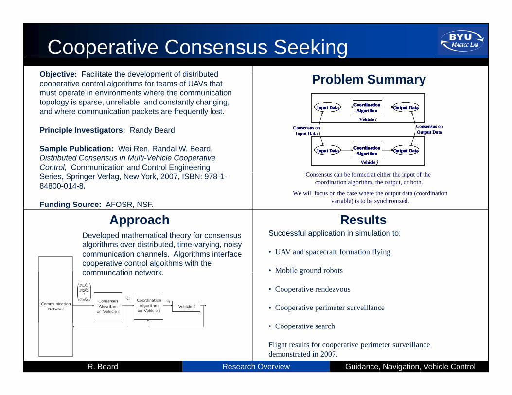
Cooperative Consensus SeekingObjective: Facilitate the development of distributedObjective: Facilitate the development of distributed cooperative control algorithms for teams of UAVs that must operate in environments where the communication topology is sparse, unreliable, and constantly changing, and where communication packets are frequently lost.
Problem Summary
Input Data Output DataCoordinationAlgorithm
Vehicle i
Input Data Output DataCoordinationAlgorithmInput DataInput Data Output DataOutput DataCoordinationAlgorithm
CoordinationAlgorithm
Vehicle i
Principle Investigators: Randy Beard
Sample Publication: Wei Ren, Randal W. Beard, Distributed Consensus in Multi-Vehicle Cooperative Control, Communication and Control Engineering
Input Data Output DataCoordinationAlgorithm
Vehicle j
Consensus onOutput Data
Consensus onInput Data
Input Data Output DataCoordinationAlgorithmInput DataInput Data Output DataOutput DataCoordinationAlgorithm
CoordinationAlgorithm
Vehicle j
Consensus onOutput Data
Consensus onInput Data
C b f d i h h i f hSeries, Springer Verlag, New York, 2007, ISBN: 978-1-84800-014-8.
Funding Source: AFOSR, NSF.
Approach Results
Consensus can be formed at either the input of thecoordination algorithm, the output, or both.
We will focus on the case where the output data (coordinationvariable) is to be synchronized.
Approach ResultsDeveloped mathematical theory for consensus algorithms over distributed, time-varying, noisy communication channels. Algorithms interface cooperative control algoithms with the communcation network
Successful application in simulation to:
• UAV and spacecraft formation flying
• Mobile ground robotscommuncation network. Mobile ground robots
• Cooperative rendezvous
• Cooperative perimeter surveillance
Research Overview Guidance, Navigation, Vehicle ControlR. Beard
• Cooperative search
Flight results for cooperative perimeter surveillance demonstrated in 2007.

Cooperative OrbitingObjective:. Keep target in camera view even with possible occlusions while satisfying UAV dynamics
Principle Investigators: Randy Beard
Problem SummaryA team of UAVs, each equipped with a gimbaled camera, are orbiting a moving ground target. The UAV autonomously distributed themselves around an orbit so that sensor occlusions are minimizedPrinciple Investigators: Randy Beard
Sample Publication: Derek B. Kingston, Randal W. Beard, “UAV Splay State Configuration for Moving Targets in Wind,” in Advances in Cooperative Control and Optimization, edited by Michael J. Hirsch, Lecture
that sensor occlusions are minimized.
Notes in Computer Science, Springer Verlag, (to appear).
Funding Source: NSF, AFOSR.
Approach ResultsApproach ResultsHeading command is proportional to (1) distance from orbit, and (2) relative spacing. Essential idea: UAVs increase or decrease radius to achieve spacing.
• Successful flight test with three UAVs in summer 2007.
Salient Features:• Decentralized – Only neighbor information required• Robust to insertion/deletion• Constant UAV velocity
• Can adapt to moving targets.
• Can adapt to heavy winds.
Research Overview Guidance, Navigation, Vehicle ControlR. Beard
y• Guaranteed to space UAVs equally along the orbit• Minimizes lateral motion of object in image.