
2007: Innovative Core Flooding Technology for … thermally Enhanced Oil Recovery ... fundamentals...
12
SCA2007-23 1/12 INNOVATIVE CORE FLOODING TECHNOLOGY FOR HEAVY OIL RECOVERY STUDIES J.G.C. Coenen, Shell International Exploration and Production BV. This paper was prepared for presentation at the International Symposium of the Society of Core Analysts held in Calgary, Canada, 10-12 September 2007 ABSTRACT Many heavy oil (HVO) fields are produced using heat induction processes such as Steam flooding, Cyclic Steam Stimulation (CSS or Huff & Puff) or Steam Assisted Gravity Drainage process (SAGD). We have developed experimental core flooding technology to identify fundamentals of heat transfer and oil mobilization effects prevailing during steam flooding and CSS. The new core flooding equipment combines a number of innovative components that allow experimenting under realistic HPHT field conditions while using CT scanning. Key parts are a laboratory steam generator for generating super hot steam at extreme pressure, a composite core holder to accommodate whole HVO field cores, miniature sensors for P&T measurement along core and software control of the experimental set-up. X-ray CT scanning is used for imaging in-situ fluid flow events under pressure and temperature. The system can operate in a CSS mode and in a steam flooding mode. Herein we describe the various components of the core flooding set-up and some experimental results obtained on synthetic HVO core material. INTRODUCTION With high oil prices, exploration and production of Heavy Oil (HVO) is becoming economically very attractive. In many cases heavy oil fields are produced using heat induction processes such as Steam flooding, Cyclic Steam Stimulation (CSS or Huff & Puff) or Steam Assisted Gravity Drainage process (SAGD) [Hart Energy Publishing (2006)]. These thermally Enhanced Oil Recovery (EOR) processes increase oil mobility by reducing oil viscosity. The efficiency of the heat transfer process and the mobilization of oil are important parameters that determine the economy of these processes. We have developed innovative laboratory core flooding technology for studying steam injection processes for thermal EOR of HVO fields. The objective is to shed light in the fundamentals of heat transfer and oil mobilization prevailing during steam flooding and cyclic steam stimulation. The primary aim was to develop a steam injection core flooding system for experimenting at realistic field pressure levels up to 100 bar and steam temperatures up to 300 0 C. These demands generate a strong need for innovation on SCAL core flooding technology, in particular to smart sensing. Our new steam core flooding equipment therefore combines a number of innovative technology components that allow experimenting under harsh and realistic field conditions in combination with the use of Computerized Tomography (CT) scanning. Next we present an overview on the technical development of our steam injection core flooding system for EOR research on heavy oil recovery and present some first results.
Transcript of 2007: Innovative Core Flooding Technology for … thermally Enhanced Oil Recovery ... fundamentals...
SCA2007-23 1/12
INNOVATIVE CORE FLOODING TECHNOLOGY FOR HEAVY OIL RECOVERY STUDIES
J.G.C. Coenen, Shell International Exploration and Production BV.
This paper was prepared for presentation at the International Symposium of the
Society of Core Analysts held in Calgary, Canada, 10-12 September 2007
ABSTRACT Many heavy oil (HVO) fields are produced using heat induction processes such as Steam flooding, Cyclic Steam Stimulation (CSS or Huff & Puff) or Steam Assisted Gravity Drainage process (SAGD). We have developed experimental core flooding technology to identify fundamentals of heat transfer and oil mobilization effects prevailing during steam flooding and CSS. The new core flooding equipment combines a number of innovative components that allow experimenting under realistic HPHT field conditions while using CT scanning. Key parts are a laboratory steam generator for generating super hot steam at extreme pressure, a composite core holder to accommodate whole HVO field cores, miniature sensors for P&T measurement along core and software control of the experimental set-up. X-ray CT scanning is used for imaging in-situ fluid flow events under pressure and temperature. The system can operate in a CSS mode and in a steam flooding mode. Herein we describe the various components of the core flooding set-up and some experimental results obtained on synthetic HVO core material.
INTRODUCTION With high oil prices, exploration and production of Heavy Oil (HVO) is becoming economically very attractive. In many cases heavy oil fields are produced using heat induction processes such as Steam flooding, Cyclic Steam Stimulation (CSS or Huff & Puff) or Steam Assisted Gravity Drainage process (SAGD) [Hart Energy Publishing (2006)]. These thermally Enhanced Oil Recovery (EOR) processes increase oil mobility by reducing oil viscosity. The efficiency of the heat transfer process and the mobilization of oil are important parameters that determine the economy of these processes. We have developed innovative laboratory core flooding technology for studying steam injection processes for thermal EOR of HVO fields. The objective is to shed light in the fundamentals of heat transfer and oil mobilization prevailing during steam flooding and cyclic steam stimulation. The primary aim was to develop a steam injection core flooding system for experimenting at realistic field pressure levels up to 100 bar and steam temperatures up to 300 0C. These demands generate a strong need for innovation on SCAL core flooding technology, in particular to smart sensing. Our new steam core flooding equipment therefore combines a number of innovative technology components that allow experimenting under harsh and realistic field conditions in combination with the use of Computerized Tomography (CT) scanning. Next we present an overview on the technical development of our steam injection core flooding system for EOR research on heavy oil recovery and present some first results.

SCA2007-23 2/12
MEASUREMENT CONCEPT Scaled laboratory EOR core flooding experiments provide important data such as hydrocarbon recovery potential, fluid mobility and sweep efficiency at lower costs than field pilot studies. With modern imaging tools [Tomutsa (1991)], such laboratory experiments offer a unique opportunity to learn about in-situ processes that play a role in steam induced thermal EOR and allow benchmarking with computer simulation tools [Glandt (1991)]. These concepts motivated us to develop innovative core flooding technology for Heavy Oil Recovery studies. The steam core flooding rig contains a large HVO “Whole core” of 3.5” OD diameter and 1 foot length with enough hydrocarbon volume for accurate observation of the thermal EOR process and oil recovery. Sophisticated sensors and advanced analytical tools are employed to provide in-situ information on the process. Inside the core, we have temperature and pressure sensors distributed along its length to provide maximal data on in-situ events in combination with material balance control. Since 1987 Computerized Tomography (CT) has become an indispensable imaging tool for E&P research [Wellington (1987)]. Our objective has been to integrate CT into our steam core flooding set-up providing digital images of the in-situ progress of the EOR steam flooding prevailing under harsh experimental conditions. The CT data should complement the findings of the P&T sensors and will help us to understand the yet hidden heat transfer processes. In the past some attempts were done in the same directions [Fransham (1987), Sedgwick (1987)]. With modern technology however chances of success are increasing. CORE FLOODING SYSTEM WITH STEAM INJECTION Core Flooding and Steam Flow Loop Concept Our main objective is to study the CSS process. Figure 1 shows the basic outline of our steam injection core flooding system. It consists of an open, high-pressure high-temperature flow loop in which an excessive amount of steam is generated and conveyed along the front face of the core. The main components in the steam set-up are; the steam injection section, the core holder section and the production section. A precision micro-metering flow pump feeds water to a steam generator. The feed pump has on-board control logic that keeps the supply rate accurate to 10-3 ml/min. Because a main feature of this program is to study Cyclic Steam Stimulation, the steam is injected at the front of the core. Steam penetrates into the core and transfers heat to the core and oil. Due to the cold rock, part of the injected steam condenses primarily at the tip of the steam front. The condensed water is produced together with mobilized oil. These liquids are subsequently conveyed from the core under pressure and temperature to a production unit. The production section of the steam core flooding set-up entails high-pressure tubing with trace heating, a steam condenser, backpressure control unit and oil-water collection unit. The steam condenser is a coil of tubing surrounded by cooling water fed from a chiller. Cooling water absorbs the heat of condensation from the steam in the condenser.

SCA2007-23 3/12
Absorbed heat is transferred to the chiller and subsequently to the ambient air in the room.
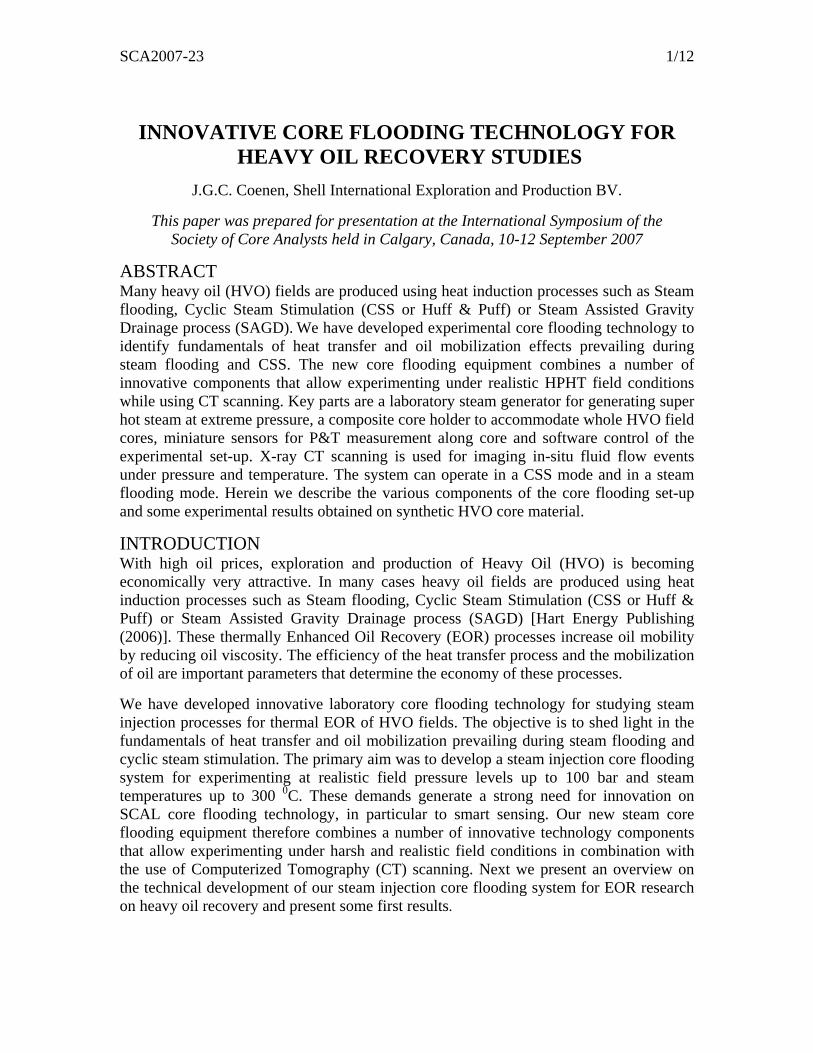
Figure 1: Schematic overview of steam injection core flooding system for Thermal EOR research A micro flow pump controls backpressure. This backpressure controller has on board control logic to automatically maintain the set-point pressure at the exit of the flow loop, irrespective of the flow rate in the system. When injected steam reaches the end of the core, the CSS experiment can continue with steam flooding in a “flow-through state” by opening the valve at the tail of the core holder, permitting the steam to leave the core at its tail. Steam and fluid effluents are fed back to the steam condenser unit. The main benefit of our steam flow loop concept is of having liquid fluid at both ends of the flow loop with a relative cold temperature. This liquid flow can easily be controlled in terms of flow and pressure by the water feed pump and backpressure controller. The hot steam (gas phase) is confined in between the steam generator and steam condenser. Figure 2 shows the base principle of the steam flow loop i.e. the various fluid phases, its aggregation state and P and T over the trajectory of the circuit. Typically the pressure and temperatures change relative to the energy (heat) supply and with draw rates. Steam Generator At the start of this program we have searched for a commercially available steam generator. Commercial products usually have low pressure and temperature ratings and are usually designed for very large flow rates. We developed our own high-pressure, high-temperature (4 kwatt, 100 bar, 300 0C) steam generator for low flow rate. We pay courtesy to Professor P. Colonna of the Faculty of Mechanical Engineering and Marine
HVO core length 1 foot
Tc
Temp. profile core
registration
Pressure profilecore
registration
Overburden pressure
Flow throughsection
3.5” OD Heavy Oil core
Steam injectionsection
Pc
Water
Water supplypump
Steam generator
Back pressurepump
Oil-waterseparator
Steamcondenser
Productionsection
Heat
Heat
CT scan range
P
TSteam
Effluent
Mass registration
HVO core length 1 foot
TcTc
Temp. profile core
registration
Pressure profilecore
registration
Overburden pressure
Flow throughsection
3.5” OD Heavy Oil core
Steam injectionsection
PcPc
Water
Water supplypump
Steam generator
Back pressurepump
Oil-waterseparator
Steamcondenser
Productionsection
Heat
Heat
CT scan range
PP
TTSteam
Effluent
Mass registration
SCA2007-23 4/12
Technology Energy from Delft University of technology for his good advice in this process [Ahnert (2003)].
100 bar20 0C
TC
100 bar300 0C
1 bar50 0C
1 Feed water&
Supply pump
4 Steam condenser
2 Steam generator
3 High pressure steam loop
to core holder
5 Back pressurecontroller &water dump
1 bar20 0C
PC
Controller& Logic
Electric power
Cooling water
100 bar80 0C
TI
Chiller unit
Heat
Pref
Heat
Heat
Balance
100 bar300 0C
Liquid LiquidSteamSteam
Figure 2: Overview on the base principle of the steam flow loop.
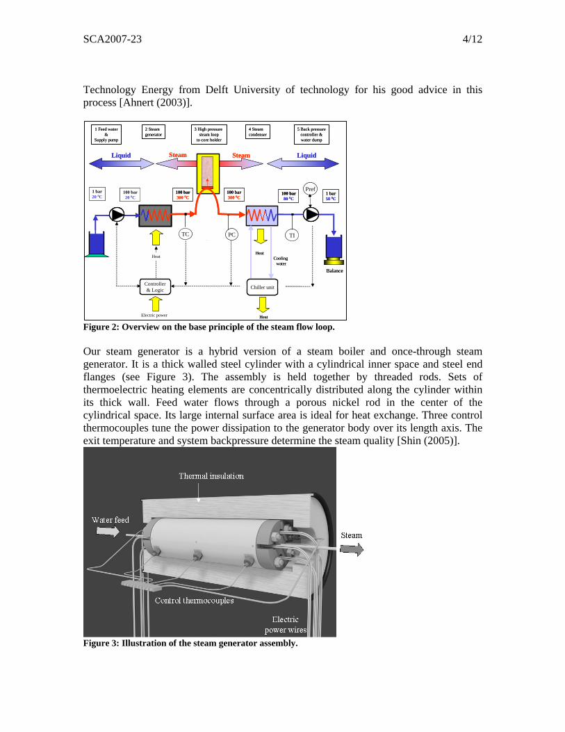
Our steam generator is a hybrid version of a steam boiler and once-through steam generator. It is a thick walled steel cylinder with a cylindrical inner space and steel end flanges (see Figure 3). The assembly is held together by threaded rods. Sets of thermoelectric heating elements are concentrically distributed along the cylinder within its thick wall. Feed water flows through a porous nickel rod in the center of the cylindrical space. Its large internal surface area is ideal for heat exchange. Three control thermocouples tune the power dissipation to the generator body over its length axis. The exit temperature and system backpressure determine the steam quality [Shin (2005)].
Figure 3: Illustration of the steam generator assembly.

SCA2007-23 5/12
Heated Valve Manifold and Steam Quality Preservation For practical reasons we mounted the steam generator at some distance from the core holder. However when the steam is underway from the steam generator to the core, heat losses must be prevented to keep the delivered steam at the desired temperature and quality. Another important demand to this experiment is that we should be able to study the CSS or Huff & Puff steam injection process. However due to the shear mass of the steam generator we would need, after shutting down the steam generator e.g. after a Huff cycle, considerable time to condition the steam generator again to the original desired temperature for the next Huff cycle. Because this is impractical for these CSS experiments, the steam generator is kept on power at all times. During the Puff cycle (i.e. when the core holder is shut-in and pressure is released from the core) we let the steam bypass the core holder. An extra “Heated Valve Manifold” is used for diversion of the steam away from core (Figure 4). The manifold is heated by sets of thermoelectric heating elements. The manifold confines an assembly of bended high-pressure tubing and high-pressure valves and is filled-up with fine Copper grains to homogenize the temperature inside the panel. The valves in the hot manifold are actuated by air driven torsion motors. The valves can remotely be opened or closed.
Figure 4: Exposed view of the heated valve manifold for the supply of steam to the core holder or via the bypass flow loop. The function of the valve manifold is (1) to convey the steam from the generator into the core holder, (2) to bypass the core holder when we need to stabilize the back pressure and (3) to temporary divert the steam flow from the main flow loop to a second steam condenser and back pressure controller. In case (1), the steam has to pass a distance of about 20 cm to reach the steam injector in the core holder entrance. For this situation we have used a flat Copper plate with thermoelectric heater elements and temperature control as a “Heated Injector Block”. Subsequently the hot steam flows into the core holder.
SCA2007-23 6/12
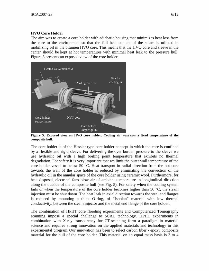
HVO Core Holder The aim was to create a core holder with adiabatic housing that minimizes heat loss from the core to the environment so that the full heat content of the steam is utilized in mobilizing oil in the bitumen HVO core. This means that the HVO core and sleeve in the center should be kept at hot temperatures with minimal heat leak to the pressure hull. Figure 5 presents an exposed view of the core holder.
Figure 5: Exposed view on HVO core holder. Cooling air warrants a fixed temperature of the composite hull. The core holder is of the Hassler type core holder concept in which the core is confined by a flexible and rigid sleeve. For delivering the over burden pressure to the sleeve we use hydraulic oil with a high boiling point temperature that exhibits no thermal degradation. For safety it is very important that we limit the outer wall temperature of the core holder vessel to below 50 0C. Heat transport in radial direction from the hot core towards the wall of the core holder is reduced by eliminating the convection of the hydraulic oil in the annular space of the core holder using ceramic wool. Furthermore, for heat disposal, electrical fans blow air of ambient temperature in longitudinal direction along the outside of the composite hull (see Fig. 5). For safety when the cooling system fails or when the temperature of the core holder becomes higher than 50 0C, the steam injection must be shut down. The heat leak in axial direction towards the steel end flanges is reduced by mounting a thick O-ring, of “Isoplan” material with low thermal conductivity, between the steam injector and the metal end flange of the core holder. The combination of HPHT core flooding experiments and Computerized Tomography scanning impose a special challenge to SCAL technology. HPHT experiments in combination with X-ray transparency for CT-scanning form a paradigm in material science and requires strong innovation on the applied materials and technology in this experimental program. Our innovation has been to select carbon fiber - epoxy composite material for the hull of the core holder. This material on an equal mass basis is 3 to 4

SCA2007-23 7/12
times stronger than steel [Seamark (1990)] and at the same time offers very low heat conduction as well as low absorption for X-rays. The latter is a desired attribute for the transmission of 10-100 keV X-rays in CT-scanning. Therefore carbon fiber- epoxy composite is a very attractive material for thermal EOR studies. We have acquired a tailor-made carbon fiber composite core holder suited to accommodate a core of 3.5” diameter and 1 foot length for 100 bar static pressure and a maximal operating temperature of 50 0C. CT scanning tests with test objects placed inside this core holder have shown very good signal-to-noise ratios. Care has been given to the design of the steam injector at the front of the core holder. This robust metal part provides passage for pressurized hot steam from the high-pressure tubing to the core. In CSS it also allows the produced steam, condense water and oil to flow in backward direction via second steel tubing in the same injector (see Figure 4). The tubing and heated injector block are thermally insulated to reduce the heat loss from the steam prior to entry into the core. We have also reduced the steel mass of the injector by making it in the shape of a concave dome. Sensors for In-situ Observations Another objective was to mount temperature and pressure sensors inside the HVO core to provide data on the thermodynamic conditions during the progress of the steam front in real-time. For temperature sensors we have selected thermocouples with very thin diameter (0.8 mm). Totally we have introduced 11 temperature sensors at different positions in the core. One extra long thermocouple is put close to the steam injector to guard the steam temperature upon injection into the core. We have as well build-in 11 pressure sensors to monitor the pressure in the core. Actually the approach has been to choose for pressure guidance via a, hydraulic oil filled, thin and long steel capillary towards a pressure gauge mounted outside the core holder. As pressure gauge we have used MEMS miniature pressure transducers with a piezo resistive sensor. These sensors offer minimal fluid displacement under pressure and minimize the risk on clogging of the capillary entrance by bitumen. The quality of CT imaging of the whole core and sensor assembly is good. A separate hydraulic oil pump provides the overburden pressure to the sleeve. This pump is put at the back of the CT scanner on a mobile platform and travels together with the core holder (see Figure 6). Back Pressure Control & Heavy Oil Production System During the production cycle of the CSS process steam, condensed water and produced heavy oil is guided in backward direction through the heated injector block, valve panel and the steam condenser to the backpressure system. In the steam condenser, the hot steam and other effluent fluids are cooled to 80 0C and turned into the liquid state. The condenser basically is a spiral-coiled, high-pressure tubing surrounded by cooling water supplied by a chiller unit. This chiller (2.5 kwatt cooling capacity) maintains a control temperature by either cooling or by heating. Extracted heat is disposed in the room. Trace heating is applied along all production tubing to prevent oil that is guided to the backpressure regulator (BPR) from becoming too viscous. The piston cylinders of the

SCA2007-23 8/12
BPR as well as control valves are also placed in an 80 0C cabinet. This versatile pump has on board control logic and is operated in the constant pressure retrieve mode. This means that the backpressure pump automatically maintains the pressure at the exit of the flow loop, regardless of the flow rate in the system. All produced fluids are guided to a small vessel placed on an electronic balance. This facilitates registration of the cumulative produced mass of condensed water and heavy oil. For unattended operation we can guide the fluids to a large dump vessel. Again, all tubing to the balance and dump vessel are trace heated to 80 0C in order to avoid clogging of the flow lines. CT-Scanner A Siemens Somatom ART medical CT scanner is used for our HVO research. The scanner employs an X-ray source with a rotation anode. X-rays are emitted in a flat fan-beam to a 512-unit detector array placed opposite of the source producing digital images of 512 by 512 pixels. The CT scanner is used as a snapshot camera to observe the in-situ distribution of fluids during the steam injection experiments. During the experiments CT scans are made at 130 KV, with maximal dose for good signal-to-noise ratio and 2 mm slice thickness for good lateral resolution. Dopants are not added to the test fluids. The CT scanner and the steam core flooding equipment are all placed in an X-ray shielded room. The CT-scanner as well as the steam core flooding equipment is remotely operated.
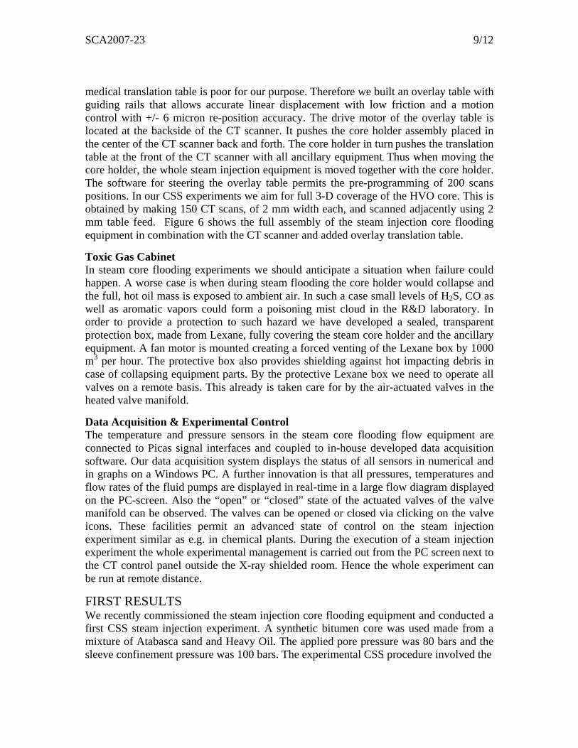
Figure 6: Overview on the steam injection core flooding equipment mounted on the overlay translation table in the CT scanner. The Lexane protection box is omitted. CT Translation Table System During core flooding the core holder must be translated through the CT scanner with high re-position accuracy. This is because the flow phenomena during the various stages in the flooding are interpreted on basis of differential imaging using scan images belonging to identical physical position along the core. We learned that the re-position accuracy of the
SCA2007-23 9/12
medical translation table is poor for our purpose. Therefore we built an overlay table with guiding rails that allows accurate linear displacement with low friction and a motion control with +/- 6 micron re-position accuracy. The drive motor of the overlay table is located at the backside of the CT scanner. It pushes the core holder assembly placed in the center of the CT scanner back and forth. The core holder in turn pushes the translation table at the front of the CT scanner with all ancillary equipment. Thus when moving the core holder, the whole steam injection equipment is moved together with the core holder. The software for steering the overlay table permits the pre-programming of 200 scans positions. In our CSS experiments we aim for full 3-D coverage of the HVO core. This is obtained by making 150 CT scans, of 2 mm width each, and scanned adjacently using 2 mm table feed. Figure 6 shows the full assembly of the steam injection core flooding equipment in combination with the CT scanner and added overlay translation table. Toxic Gas Cabinet In steam core flooding experiments we should anticipate a situation when failure could happen. A worse case is when during steam flooding the core holder would collapse and the full, hot oil mass is exposed to ambient air. In such a case small levels of H2S, CO as well as aromatic vapors could form a poisoning mist cloud in the R&D laboratory. In order to provide a protection to such hazard we have developed a sealed, transparent protection box, made from Lexane, fully covering the steam core holder and the ancillary equipment. A fan motor is mounted creating a forced venting of the Lexane box by 1000 m3 per hour. The protective box also provides shielding against hot impacting debris in case of collapsing equipment parts. By the protective Lexane box we need to operate all valves on a remote basis. This already is taken care for by the air-actuated valves in the heated valve manifold. Data Acquisition & Experimental Control The temperature and pressure sensors in the steam core flooding flow equipment are connected to Picas signal interfaces and coupled to in-house developed data acquisition software. Our data acquisition system displays the status of all sensors in numerical and in graphs on a Windows PC. A further innovation is that all pressures, temperatures and flow rates of the fluid pumps are displayed in real-time in a large flow diagram displayed on the PC-screen. Also the “open” or “closed” state of the actuated valves of the valve manifold can be observed. The valves can be opened or closed via clicking on the valve icons. These facilities permit an advanced state of control on the steam injection experiment similar as e.g. in chemical plants. During the execution of a steam injection experiment the whole experimental management is carried out from the PC screen next to the CT control panel outside the X-ray shielded room. Hence the whole experiment can be run at remote distance.
FIRST RESULTS We recently commissioned the steam injection core flooding equipment and conducted a first CSS steam injection experiment. A synthetic bitumen core was used made from a mixture of Atabasca sand and Heavy Oil. The applied pore pressure was 80 bars and the sleeve confinement pressure was 100 bars. The experimental CSS procedure involved the

SCA2007-23 10/12
injection of steam at the front of the, in the previous cycle, pressure depleted core. As a result the pore pressure steeply increases. Then when reaching a pore pressure of 80 bar, the steam flow is temporary diverted to the bypass line with the second steam condenser and second BPR. Next after shutting in the core for a while, the pore pressure was released to ambient pressure (1 bar). Figure 7 shows the temperature recordings during the subsequent CSS cycles. In the graph the various temperatures positioned inside the bitumen core (Tc7 and Tc12 at the front, Tc1 at the tail) are plotted versus time. In Figure 7 the temperature peak starts at 250 0C and increase at higher cycle numbers. The temperatures down stream increase slowly over time.When the steam reaches the front of the core also the steel tubing and injector parts are heated. We have mounted an extra thermocouple against the outside of the steam injector close to the front face (T-st inj.). Typically we observe that the first thermocouple at the front face inside the core where steam is injected (Tc7) has an almost identical history as the temperature of the steam injector.
Temperature development during steam injection
0
20
40
60
80
100
120
140
160
180
200
220
240
260
280
N N N N N N N N N N
Time
T [C
]
Huff & Puff cycle-1
Huff & Puff cycle-2
Huff & Puff cycle-3
Huff & Puff cycle-4
Huff & Puff cycle-5
Huff & Puff cycle-6
Huff & Puff cycle-7
Tc-11
Tc-12
T st.inj.
Tc-7
Tc-10Tc-9 Tc-8
Tc-6Tc-2
Tc-1
Figure 7. Temperature development during steam injection. Figure 8 shows in detail the temperature and the pressure development in the core during one of the initial Huff & Puff cycles. Due to the relative large permeability of the synthetic core, the pressures in the core were similar to the backpressure imposed to the system by the BPR. From the combination of temperature and pressure, especially at the front face of the core we can deduce that during the pressure build-up stage no steam was injected into the core but only hot water. Likewise, during the pressure depletion stage no steam or only hot water was produced from the core. In Figure 8 we have as well displayed the CT scans taken at the front face of the core during various moments. The CT images show a change in saturation during the peak of pressure build-up stage. However after pressure depletion the CT images show more or less the same value as prior to the Huff part.

SCA2007-23 11/12
Temperature & pressure development during initial Huff/Puff cycle
0
20
40
60
80
100
120
140
160
180
200
220
240
260
280
300
N N N N N N N N N
Time
T [C
] & P
[bar
]
Tc-7T-st.inj.
Tc-12
Tc-11
Tc-10Pt9
Puff cycle
P BPR
P annulus
Huff cycle
.05* Cumm. Prod.Mass [g]
Temperature & pressure development during initial Huff/Puff cycle
0
20
40
60
80
100
120
140
160
180
200
220
240
260
280
300
N N N N N N N N N
Time
T [C
] & P
[bar
]
Tc-7T-st.inj.
Tc-12
Tc-11
Tc-10Pt9
Puff cycle
P BPR
P annulus
Huff cycle
.05* Cumm. Prod.Mass [g]
Figure 8. Temperature and pressure development during initial Huff & Puff cycle.
Figure 9 shows the temperature and the pressure development in the core at a later moment in the experiment. During this stage, after several pressure build-up attempts, the pore pressure was depleted almost instantaneously. By the combination of temperatures and pressure in the core during the pressure depletion stage, steam has developed as result of a kind of flash expansion. This observation is supported by the CT scans along core showing the development of a steam finger in the core. Throughout the steam injection experiment the mass of produced oil and condense water were registrated.
Temp. & pressure development during a later Huff & Puff cycle
0
20
40
60
80
100
120
140
160
180
200
220
240
260
N N N N N N
Time
Tem
p [C
] ; P
[Bar
]
Tc-7
P BPR
Pt9
P
Huff cycle Puff cycle
Tc-11
T st.inj.
Tc-12
Temp. & pressure development during a later Huff & Puff cycle
0
20
40
60
80
100
120
140
160
180
200
220
240
260
N N N N N N
Time
Tem
p [C
] ; P
[Bar
]
Tc-7
P BPR
Pt9
P
Huff cycle Puff cycle
Tc-11
T st.inj.
Tc-12
Figure 9. Temperature and pressure development during a later Huff & Puff cycle.

SCA2007-23 12/12
CONCLUSIONS We have developed innovative experimental core flooding technology for steam injection experiments in support of thermal Heavy Oil Recovery studies. The new core flooding equipment combines a number of innovative technology components that allow experimenting under harsh field conditions while using CT-scanning. Key in this program is the core holder made from carbon fiber composite material, which is designed to accommodate a bitumen core of 3.5” diameter and 1 foot length. With this core holder design and the use of P&T sensors mounted along core, we have succeeded to solve a paradigm in EOR experimenting. This means providing a rigid vessel to allow experimenting at high-pressure and extremely high temperatures while at the same time providing X-ray transparency such to be able to carry out CT scanning. We have as well fully automated our CT scanner for imaging of in-situ fluid flow events at various positions along core under pressure and temperature. The first results from the new steam injection core flooding equipment have shown that during CSS the phase behavior of the injected steam and events in the core during the production phase can be explained on basis of the in-situ P&T sensor signals combined with the CT information.
REFERENCES Ahnert, F., Colonna, P., “Moving Boundary Model Of Once Through Boiler Evaporators“, in Proceedings of the IMEC ’03, International Mechanical Engineering Congress and Exhibitions, (Nov 2003), no IMECE2003-55583, ASME (Washington, D.C.), pp. 1-7.
Fransham, P. and Jelen, J., “Displacement of Heavy Oil Visualized by CAT scan”, NOVA/HUSKY Research Corporation Ltd. Heavy Oil, Journal of Canadian Petroleum Technology, Montreal, (May-June 1987).
Glandt, C., Malcolm, J., “Numerical Simulation of Peace River Recovery Processes”, SPE 22645 presented at the SPE Annual Techn. Conf. and Exhib., Dallas, TX. (6-9 Oct 1991).
Hart Energy Publishing, LP., “Unleashing the Potential of Heavy Oil”,A custom publication to E&P Oil and Gas Investor, Hart Energy Publishing, LP,Houston Texas, July 2006.
Sedgwick, G.E., Miles-Dixon, E.W.A., “Application of X-ray Imaging Techniques To Oil Sands Experiments”, 38-th annual Petroleum Society of CIM, Paper no. 87-38-84, 1987.
Shin, H., Alleyne, I., and Pollikar, M., ”Automated process control system for steam injection proceses”, SPE 96031 presented at the SPE Annual Tech. Conf. and Exhib., Dallas TX. (9-12 Oct. 2005)
Seamark, M., ”Current and Potential Opportunities For Fibre reinforced Composites Offshore”, Marine Management LTD, Meeting of The Institute of Marine Engineers and Royal Institution of Navla Architects, Joint Offshore Group, London, (May-1 1990).
Tomutsa, L., Doughty, D., Mahmood, S, Brinkmeyer, A. and Madden, M., “Imaging Techniques Applied To The study of Fluids in Porous Media”, Report NIPER-485 prepared under U.S. Dept. of Energy contract No,. FC22-83FE60149 (Jan. 1991). NTIS order number DE91002215.
Wellington, S., Vinegar, H.,”X-ray Computerized Tomography”, Journal of Petroleum Technology, (Aug. 1987), 39, 8, pp. 885-898.