2006/4/17Extended SOT17@NAOJ1 Solar-B mission onboard control and data handling (data recorder,...
20
2006/4/17 Extended SOT17@NAOJ 1 Solar-B mission onboard control and data handlin g (data recorder, downlinks, observation ta bles…) Toshifumi Shimizu ISAS/JAXA [email protected]
-
Upload
angela-thornton -
Category
Documents
-
view
216 -
download
0
Transcript of 2006/4/17Extended SOT17@NAOJ1 Solar-B mission onboard control and data handling (data recorder,...

2006/4/17 Extended SOT17@NAOJ 1
Solar-B mission onboard control and data handling
(data recorder, downlinks, observation tables…)
Toshifumi ShimizuISAS/JAXA

2006/4/17 Extended SOT17@NAOJ 2
Presentation Outline
Base knowledge for planning observations. 3 telescopes on Solar-B: field of view Onboard observation control: Observation tables Onboard data flow Solar-B data recorder and downlinks Consider the amount of data for planning observations

2006/4/17 Extended SOT17@NAOJ 3
Solar-BSolar-BFlight model Solar-B under system-level test
Shake test (2005 Oct) TV test (2006 Mar) Beautiful photo (2006 Mar)

2006/4/17 Extended SOT17@NAOJ 4
3 high-performance telescopes
EUV Imaging Spectrometer (EIS)– Diagnostics of the coronal
thermal properties and dynamics
Solar Optical Telescope (SOT)– High resolutional observations of
magnetic and velocity fields at the photosphere
X-Ray Telescope (XRT)– High resolution imaging of the
corona
Coordinated observations among three telescopes

2006/4/17 Extended SOT17@NAOJ 5
Solar-B Field of Views
320arcsec
160arcsec
SOT
XRT
360arcsec
512arcsec
EIS
800arcsec
2000arcsec
Maximum size of FOV is shown here.

2006/4/17 Extended SOT17@NAOJ 6
Sequence control of observations is managed by observing tables in Mission Data Processor (MDP).– One table for filter observation, the other for SP observation
– The table is the list of macro-commands for taking observables with time interval.
– FPP takes observables according to the arrival of macro-commands
Onboard Observation Sequence Control
DHU
MDP CTM
FPPSOTTable
(1)Commands to CTM-E
(2)Commands to FPP-E
(3)MDP commands for table control (4) Macrocommands(issued from table)
(5)Servo ON/OFFAngle set/reset
Onboard observation controls

2006/4/17 Extended SOT17@NAOJ 7
Observation table– Consists of “PROGRAM” (main routine and sub routines) and “SEQUENCE”s.– The sequences are the list of macro-commands for taking observables with time
interval.
Onboard Observation Sequence Control
OBS Program Version No
Main-Routine Loop Count
Call Sub-Routine # Sub-Routine Repeat Count Interval Time
Call Sub-Routine # Sub-Routine Repeat Count Interval Time
Call Sub-Routine # Sub-Routine Repeat Count Interval Time
End of Main-Routine - -
Call FG Sequence Table # FG Sequence Table Repeat Count Interval Time
Call FG Sequence Table # FG Sequence Table Repeat Count Interval Time
Call FG Sequence Table # FG Sequence Table Repeat Count Interval Time
End of Sub-Routine - -
Main Routine
4 Sub-Routines
Sequence Table Version No
Command Parameter Command ID =Macro-Command DMF COMP Code 1 COMP Code 2 PAR No ROI No Reserved
Interval Time
Command Parameter Command ID =Macro-Command DMF COMP Code 1 COMP Code 2 PAR No ROI No Reserved
Interval Time
Command Parameter Command ID =Inst. Command Inst Command Parameter Set Reserved
Interval Time
End of Sequence --- ---
SEQUENCE tables (#100)for the time sequence of macro-commands
Observation PROGRAMs (#20)to form nest structures
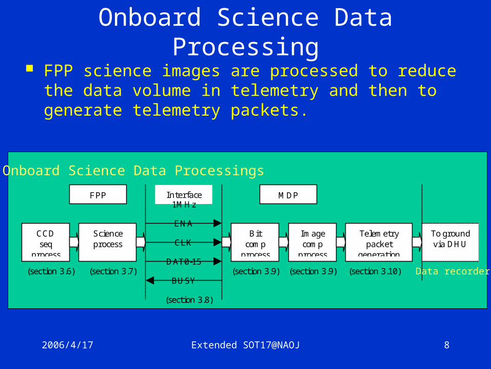
2006/4/17 Extended SOT17@NAOJ 8
FPP science images are processed to reduce the data volume in telemetry and then to generate telemetry packets.
Onboard Science Data Processing
CCD seq
process
Science process
Bit comp
process
Image comp
process
Telemetry packet
generation
FPP MDP
To ground via DHU
Interface
ENA
CLK
DAT0-15
BUSY
1MHz
(section 3.6) (section 3.7)
(section 3.8)
(section 3.9) (section 3.9) (section 3.10)
Onboard Science Data Processings
Data recorder

2006/4/17 Extended SOT17@NAOJ 9
Solar-B Data Recorder and Data Downlinks– Capacity: 7Gbits for science data (total volume is 8Gbits)
– The volume is shared among SOT/XRT/EIS• Nominal allocation
SOT: XRT: EIS = 70% (4.9Gbits) : 15% (1.05Gbits) : 15% (1.05Gbits)
• Allocation ratio can be adjusted according to observational coordination in operation meetings
– 4Mbps high telemetry (X-band) downloads ~1.7 Gbits FPP data in one station (10min duration).
Solar-B data recorder and downlinks

2006/4/17 Extended SOT17@NAOJ 10
Solar-B data recorder and downlinks How much data can be obtained per day?
– Depends on how many downlink stations available– Solar-B orbit: Sun synchronous polar orbit, ~95min period– Downlink stations planned
• Uchinoura Space Center (USC, Japan) two contacts (max) in the morning, two contacts (max) in the evening
• Svalbard stations (Norway, under support of ESA) every revolution, 15 contacts per day
– Estimated downlinked data volume• Svalbard
– 1 contact duration 3~11min (El. 6 ~ 90 deg)– Total contact duration ~138 min in one day
• USC– 1 contact duration 5~11min– Total contact duration 32min in one day
• Downlink rate ~4Mbps• Total downlinked data 40.8Gbits 、 science data 35.7Gbits (4.4Gbytes)

2006/4/17 Extended SOT17@NAOJ 11
Science data per day 35.7Gbits (4.4Gbytes)– Nominal allocation SOT:XRT:EIS= 70%:15%:15%= 25.0Gbits: 5.4Gb:5.4Gb
Allocated telemetry rate for FPP (compressed) data– Rate averaged per day ~300 Kbps, or 25.0Gbits for one day– Burst (high data rate) observations can also be performed with the
allocated capacity of data recorder• Burst observation for a certain period, then minimized observation in the rest• Possible maximum rate for FPP
~1.3 Mbps (in nominal)
~1.8 Mbps (in SOT dominant) ~50 min to occupy 4.9Gbits in data recorder The rest of the time is in idle.
Data volume predictions for planning

2006/4/17 Extended SOT17@NAOJ 12
Predicting volume of data products is key in planning observation sequences
– Due to telemetry bandwidth
– Although high rate observations possible for FPP
Science data can be compressed in MDP– MDP has an ASIC chip for 12bit JPEG/DPCM
• Pixel data is bit-compressed from 16 bit-pixel to 12 bit; 8 look-up tables
• 12bit JPEG (DCT): lossy– ~3 bits/pixel for SOT/FG data– ~1.5 bits/pixel for SOT/SP data, when compression noise is comparable to photon noise level
• 12bit DPCM: lossless, 6-8 bits/pixel• Compression ratio depends on images and required quality
Data volume predictions for planning

2006/4/17 Extended SOT17@NAOJ 13
Data volume predictions for planning
FPP FG Camera simulated image, made from La Palma data

2006/4/17 Extended SOT17@NAOJ 14
SOT Observational Capabilities- Focal Plane Instruments Package (FPP)-
Spectral (SP) Observation
Broadband Filter Imager (BFI)
Narrowband Filter Imager (NFI)
A 4Kx2K CCD camera shared Typical Observables
Spectro-Polarimeter (SP)
Filter (FG) Observation
Filtergram
Dopplergram
Long. Magnetogram
Stokes IQUV
Stokes IQUV
Shutterd exposure
Shutterless exposure

2006/4/17 Extended SOT17@NAOJ 15continuum (G-band)
Multi-wavelength filter observations with SOT
Magnetic fields
Obtained with SVST @ La Palma
CaII H
H alpha

2006/4/17 Extended SOT17@NAOJ 16
Example: 2005/7 Observation at La Palma
Run 5 CCDs simultaneously CaII H G-band Blue continuum H alpha Red continuum
G-bandDOT
Data volume after Speckle processing 1.3K x 1K 90”x70” 5 images every 30sec 220Kpixel/sec In case of Solar-B data 3bit/pixel compression 650Kbps Need to restrict FOV, or reduce time resolution, or have burst observation in a certain period

2006/4/17 Extended SOT17@NAOJ 17
Observation Example To study magnetic/dynamical nature of microflare-associat
ed small emerging fields in AR. Need telemetry ~300 Kbps continuously for a long period SP observation
– Fast mapping, 80” wide scanning, NS size=80”, 0.32” resolution– One map completed every 15 min– Data size: 229Kpixel every 3.6 sec. – Telemetry: 96 Kbps with 1.5bits/pixel compression.
FG observation– G-band, 3 wavelengths in Halpha, Longitudinal magnetogram, Dopplergr
am, repeated every ~45 sec.– 80”x80” FOV, 0.08” resolution for G-band and magnetogram, 0.16” for
Halpha and Dopplergram – Data size: 3.25M pixel every 45sec– Telemetry: 222 Kbps with 3 bits/pixel compression

2006/4/17 Extended SOT17@NAOJ 18
Observation Example (2) To study short-term magnetic evolutions of entire AR. SP observation
– Normal mapping, 180” wide scanning, NS size=180”, 0.16” resolution– One map completed every 90 min– Data size: 191Kpixel/sec. – Telemetry: 290 Kbps with 1.5bits/pixel compression.
FG observation– G-band, 3 wavelengths in Halpha, Longitudinal magnetogram, Dopplergr
am, repeated every ~ 1 min.– 160”x160” FOV, 0.16” resolution (2x2 summing)– Data size: 8.4M pixel every 60 sec– Telemetry: 420 Kbps with 3 bits/pixel compression
Total 710Kbps Twice of 300Kbps Observation in ½ period and no observation in the rest time

2006/4/17 Extended SOT17@NAOJ 19
Observation controlled by observation tables:
Typical Time Cadences typical data rate for XRT(1) ~ 600 k pixel / min
– example 1: Continuous Observation (576 k pixel / min)• 384”×384”, 1”-resolution, 30sec-interval of a filter pair.
– example 2: High-Speed Observation (576 k pixel / min)• 384”×384”, 1”-resolution, 5sec-interval of a filter pair,
10min-continuous observation and 50min intermission.– example 3: Combination of FFI and PFI (586 k pixel / min)
• 384”×384”, 1”-resolution, 40sec-interval of a filter pair.• 2048”×2048”, 4”-resolution, 200sec-interval of a filter pair.
(1) The total rate of 400kbps (about 15 downlink/day) is assumed. SOT, XRT and EIS usually share this data rate in the ratio of 70%, 15% and 15 %. XRT image data is 12bit/pixel and may be compressed to about 6bit/pixel by DPCM.
XRT case

2006/4/17 Extended SOT17@NAOJ 20
2Mbps max1.3 Mbps
EIS Data Flow
CCD Readout Electronics EIS ICU
Large hardware CCD window
S/C MDP
Small spectral window (25 max)
Data compressionDPCM(loss less) or 12bit-JPEG
250 kbps max for short duration, 40 kbps average
Telemetrydata format
Average rate depends on number of downlink station.
1 slit obs. 40 slot obs. 250 slot obs.Spec.width 16 40 250Spatial width 256 512 256No. of lines 8 4 4Compression 20% 20 % 20%Cadence 2 sec 5 sec 15 secRate 38.4 kbps 38.4 kbps 40 kbps
10 min cadence for 44 rastering
Observation tablecontrol