2006 FDOT Design · PDF fileThe pole shall be tapered as required to provide a top outside...
7
ELEVATION AND NOTES ALUMINUM LIGHT POLE NOTES 1 Truss Arm See Details Fixture Arm Length To Roadway | Pole 2^ 1’-9" 1’-5" Pole Height Taper Varies Finished Grade NOTE: DO NOT ERECT POLE WITHOUT LUMINAIRE ATTACHED ELEVATION Luminaire - not furnished with pole assembly Fill Height 25’ Maximum Wind Height at Fixture (For Pole Design) 40’, 45’ or 50’ Design Mounting Height (For Pole Design) 6" \ Pole Top with cast aluminum Cap attached to Pole with 3 - Stainless Steel Set Screws. Varies Aluminum Identification Tag Not to Exceed 2" x 4". Secure to Transformer Base by 0.125" Stainless Steel rivets or screws. Fabricator to provide details for approval. Identification Tag Located on inside of base visible from door opening. Tag to be stamped with the following information : Financial Project ID Pole Design Designation (ie. Pole Pay Item Number) Manufacturer’s Name Certification No. 6" 3’ or 5’-6" See Sheet No. 2 Natural Ground Line adjacent to Poles on Fill 10" \ Pole Base in Base Shoe Casting See Sheet No. 3 of 7 17" high Frangible Transformer Base See Sheet No. 3 of 7 2’-6" \ Concrete Foundation See Details 1 : 4 Max Slope. Fixture Mounting Height (From Lighting Design Requirements) -> ASTM B221 - ALLOY 6063-T6 -> ASTM B221 - ALLOY 6063-T6 -> ASTM B221 - ALLOY 6061-T6 -> ASTM B26 - ALLOY 356-T6 or ASTM B108 - ALLOY 356-T6 -> ASTM B26 (319-F) -> ASTM B26 - ALLOY 356-T6 or ASTM B108 - ALLOY 356-T6 -> ER4043 -> ASTM F1554 Grade 55 -> ASTM A325 Type 1 -> ASTM A563 Grade DH -> ASTM F436 Type 1 -> A.I.S.I. Grade 304 1. Light Pole Materials shall be as follows: Poles Arm Tube Extrusions Pole Connection Extrusions, Bars and Plates Shoe Base Casting Aluminum Caps and Covers Frangible Transformer Base Casting Weld Metal Anchor Bolts Shoe Base Connection Bolts Nuts for Connection Bolts and Anchor Bolts Washers for Connection Bolts and Anchor Bolts Stainless Steel Fasteners and Hardware 2. Aluminum alloy 6063 is to be furnished in T4 condition and heat treated in accordance with ASTM B597 3. Shoe Base Connection Bolts, Anchor Bolts, Nuts and Washers shall be galvanized in accordance with ASTM A153. Lock Washers shall galvanized in accordance with ASTM B695 Class 50 4. Foundation concrete shall be Class ? (Special) with a minimum 28-day Compressive Strength (f’c) of 3,000 psi for all environmental classifications. 5. Reinforcing Steel shall be ASTM A615 Grade 60. 6. A design wind speed of 80 or 100 mph with a 30% gust factor for wind loading on the pole is included in the design. 7. The pole shall be tapered as required to provide a top outside diameter (O.D.) of 6" with a base O.D. of 10". Portions of the shaft near the base shoe and at the arm connections may be held constant at 10" and 6" respectively to simplify fabrication . 8. The pole shall be free of transverse welds except at the base. 9. Poles constructed out of two or more sections with overlapping splices are not permitted. 10. All welding shall conform to American Welding Society Structural Welding Code (Aluminum) ANSI/AWS D1.2 (current edition). 11. See Standard Index No. 17500 for grounding and wiring details. 12. The pole and arms shall be furnished with a 50 grit satin rubbed finish. 13. All designs to be in accordance with the 1994 AASHTO Standard Specifications for Structural Supports for Highway Signs , Luminaires and Traffic Signals. 14. All Light Poles within 5 miles of the coastline shall be equipped with a damping device. Information, details and performance data on the damping device shall be included with the Manufacturer’s Qualified Products List (QPL) application. 15. Manufacturers seeking approval of an aluminum light pole assembly for inclusion on the Qualified Products List must submit a QPL Product Evaluation Application along with design documentation and drawings showing the product meets all specified requirements of this Index. The application shall include test reports certifying that the Arm, Pole and Base Connection components, including the breakaway transformer base, are capable of resisting the forces (axial, shear, torsion, and moment, as applicable) shown in the data tables for the arm and pole. Sheet No. Index No. 2006 FDOT Design Standards Revision 17515 07/01/05 ALUMINUM LIGHT POLE 1 of 7 Last
Transcript of 2006 FDOT Design · PDF fileThe pole shall be tapered as required to provide a top outside...

ELEVATION AND NOTES
ALUMINUM LIGHT POLE NOTES
1
Truss Arm
See Details
Fixture Arm LengthTo Roadway| Pole
2^
1’-
9"
1’-
5"
Pole
Heig
ht
Tap
er V
arie
s
Finished Grade
NOTE:
DO NOT ERECT POLE
WITHOUT LUMINAIRE
ATTACHED
ELEVATION
Luminaire - not furnished
with pole assembly
Fil
l H
eig
ht
25’
Maxim
um
Win
d H
eig
ht
at
Fix
ture (
For P
ole
Desig
n)
40
’,
45
’ o
r 5
0’ D
esig
n M
ou
nti
ng
Heig
ht
(F
or P
ole
Desig
n)
6" \ Pole Top with cast aluminum Cap
attached to Pole with 3 - Stainless
Steel Set Screws.
Varies
Aluminum Identification Tag Not to Exceed 2" x 4". Secure to Transformer Base
by 0.125" Stainless Steel rivets or screws. Fabricator to provide details for approval.
Identification Tag Located on inside of base visible from door opening. Tag to
be stamped with the following information :
Financial Project ID
Pole Design Designation (ie. Pole Pay Item Number)
Manufacturer’s Name
Certification No.
6"
3’ o
r 5
’-6"
See S
heet
No
. 2
Natural Ground Line
adjacent to Poles on Fill
10" \ Pole Base in
Base Shoe Casting
See Sheet No. 3 of 7
17" high Frangible Transformer Base
See Sheet No. 3 of 7
2’-6" \ Concrete
Foundation
See Details
1 : 4 Max Slope.
Fix
ture M
ounti
ng H
eig
ht
(F
rom
Lig
hti
ng D
esig
n R
equir
em
ents
)
-> ASTM B221 - ALLOY 6063-T6
-> ASTM B221 - ALLOY 6063-T6
-> ASTM B221 - ALLOY 6061-T6
-> ASTM B26 - ALLOY 356-T6
or ASTM B108 - ALLOY 356-T6
-> ASTM B26 (319-F)
-> ASTM B26 - ALLOY 356-T6
or ASTM B108 - ALLOY 356-T6
-> ER4043
-> ASTM F1554 Grade 55
-> ASTM A325 Type 1
-> ASTM A563 Grade DH
-> ASTM F436 Type 1
-> A.I.S.I. Grade 304
1. Light Pole Materials shall be as follows:
Poles
Arm Tube Extrusions
Pole Connection Extrusions, Bars and Plates
Shoe Base Casting
Aluminum Caps and Covers
Frangible Transformer Base Casting
Weld Metal
Anchor Bolts
Shoe Base Connection Bolts
Nuts for Connection Bolts and Anchor Bolts
Washers for Connection Bolts and Anchor Bolts
Stainless Steel Fasteners and Hardware
2. Aluminum alloy 6063 is to be furnished in T4 condition and heat
treated in accordance with ASTM B597
3. Shoe Base Connection Bolts, Anchor Bolts, Nuts and Washers shall be galvanized
in accordance with ASTM A153. Lock Washers shall galvanized in accordance with
ASTM B695 Class 50
4. Foundation concrete shall be Class ? (Special) with a minimum 28-day Compressive Strength
(f’c) of 3,000 psi for all environmental classifications.
5. Reinforcing Steel shall be ASTM A615 Grade 60.
6. A design wind speed of 80 or 100 mph with a 30% gust factor for wind loading on
the pole is included in the design.
7. The pole shall be tapered as required to provide a top outside diameter (O.D.) of 6"
with a base O.D. of 10". Portions of the shaft near the base shoe and at the arm
connections may be held constant at 10" and 6" respectively to simplify fabrication .
8. The pole shall be free of transverse welds except at the base.
9. Poles constructed out of two or more sections with overlapping splices are not
permitted.
10. All welding shall conform to American Welding Society Structural Welding Code (Aluminum)
ANSI/AWS D1.2 (current edition).
11. See Standard Index No. 17500 for grounding and wiring details.
12. The pole and arms shall be furnished with a 50 grit satin rubbed finish.
13. All designs to be in accordance with the 1994 AASHTO Standard Specifications for Structural
Supports for Highway Signs , Luminaires and Traffic Signals.
14. All Light Poles within 5 miles of the coastline shall be equipped with a damping device.
Information, details and performance data on the damping device shall be included with the
Manufacturer’s Qualified Products List (QPL) application.
15. Manufacturers seeking approval of an aluminum light pole assembly for inclusion on the Qualified
Products List must submit a QPL Product Evaluation Application along with design
documentation and drawings showing the product meets all specified requirements of this
Index. The application shall include test reports certifying that the Arm, Pole and Base
Connection components, including the breakaway transformer base, are capable of resisting
the forces (axial, shear, torsion, and moment, as applicable) shown in the data tables for the arm
and pole.
Sheet No.
Index No.
2006 FDOT Design StandardsRevision
17515
07/01/05
ALUMINUM LIGHT POLE
1 of 7
Last
���
���
3’-0"
1’-4"6"
| Pole
1
As Required
ARM CONNECTION DETAIL
ARM ELEVATION
4" min. Radius
at bend
Upper Arm
1’-
9"
SECTION A-A
(Connection At Lower Arm Similar)
| arm at
face of pole
ARM DETAILS
6"1
1/2
"1
1/2
"
3/16
1’-0"
See Arm
Connection
Detail
4’-
6" M
axim
um
Radiu
s
6"
2^
A
A
Fillet weld arm tube to
connection extrusion.
See ARM DATA Tables
for Weld Size
Provide 2" \ wiring
hole in connection
extrusion at base of
upper arm only.
8 1/4 " 3/64
2 3/8 " O.D. pipe beyond
this point - See Arm
Tube Extrusion Note
ARM SECTION
Outside
Diameter
See ’O.D.’ in
Arm Data Tables
Vertical Axis
Upper Arm Tube - See
ARM SECTION above.
Lower Arm Tube - See
ARM SECTION above.
2 3/
8 "
(’FA’ - 3’-0")/4
Press on or Welded
Cap At Lower Arm
1/2 " \ x 3" Bar
(Welded Each Side),
Extruded Saddle,
or other acceptable
connection
Strut - 1 1/2 " O.D. x 0.125 (min.)
Varies
| of wiring hole in pole
at | of upper arm for 1" min.
I.D. rubber grommet.
2" Nominal Pipe Size
Slipfitter (2 3/8 " O.D.)
for luminaire attachment.
6"
1/8 " Wall Thickness (nominal)
Up
per A
rm
an
d
Low
er
Arm
Fixture Arm Length = 8’, 10’, 12’ or 15’
3 x (Fixture Arm Length - 3’-0")/4
3’-0" (8’ and 10’ Fixture Arm Lengths)
5’-6" (12’ and 15’ Fixture Arm Lengths)
Provide 1/8 " (min.) drain holes in
underside of arm tubes 1 1/2 "
from the base weld.
Provide 1/2 " \ Stainless Steel Bolts
with Hex Nuts and
2- 1 1/8 " O.D. flat washers
and a split lockwasher each side
of pole where shown.
ARM TUBE EXTRUSIONS NOTES:
At the pole connections, provide arm tube extrusions with dimensions as
shown in the ARM SECTION and as tabulated in the ARM DATA Tables.
Uniformly transition elliptical extrusions to a cylindrical section at the arm
connection.
The fabricator may substitute elliptical cross sections other than those
tabulated, provided the section properties about the vertical axis and the area
of the section equal or exceed that of the required section, and provided the
wall thickness is a minimum of 1/8 " nominal and within the Aluminum Association
Tolerances.
The outside diameter about the minor axis should be held at 2 3/8 " at the
upper and lower arms.
Pole connection extrusion
(typical) - See Note on Sheet No. 1 of 7
Sheet No.
Index No.
2006 FDOT Design StandardsRevision
17515
04
ALUMINUM LIGHT POLE
2 of 7
Last
���
���
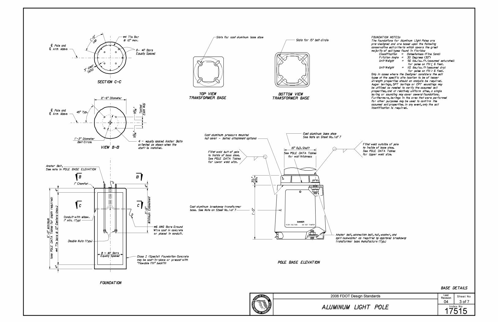
BASE DETAILS
SECTION C-C
VIEW B-B
1’-0"
Lap
#4 Tie Bar
@ 12" max.
3" cle
ar
(min)
2’-6" Diameter
1’-3" Diameter
Bolt Circle
5 5/
16 "
Ty
pic
al
Each
Way
| Pole and
| Arm Above
CC
BB
#6 AWG Bare Ground
Wire cast in concrete
or placed in conduit.
4"
4"
4"
1" Chamfer
5 5/
16 "
1’-
5"
Cast aluminum pressure mounted
nut cover - bolted attachment optional
10" O.D. Shaft
DANGER
HIGH VOLTAGE DO NOT TAMPER
TOP VIEW
TRANSFORMER BASE
BOTTOM VIEW
TRANSFORMER BASE
POLE BASE ELEVATION
Conduit with elbow.
1" min. (Typ)
See POLE DATA Tables
for wall thickness
45^ Typ.
FOUNDATION
3 1/
2 "
Min
.
| Pole and
| Arm Above8- #7 Bars
Equally Spaced
8 ~ #7 Bars
Equally Spaced Class ? (Special) Foundation Concrete
may be cast-in-place or precast with
"flowable fill" backfill
Double Nuts (Typ.)
Anchor Bolt,
See note in POLE BASE ELEVATION
#4 T
ie b
ars @
12" C
ente
rs (
max.)
Slots for cast aluminum base shoe
Slots for 15" bolt circle
Anchor bolt, connection bolt, nut, washer, and
split lockwasher as required by approved breakaway
transformer base manufacture (Typ.)
4 - equally spaced Anchor Bolts
oriented as shown when the
shaft is installed.
_
Cast aluminum breakaway transformer
base. See Note on Sheet No. 1 of 7
Cast aluminum base shoe
See Note on Sheet No. 1 of 7
Fillet weld outside of pole
to inside of base shoe.
See POLE DATA Tables
for Upper weld size.Fillet weld butt of pole
to inside of base shoe.
See POLE DATA Tables
for Lower weld size.
FOUNDATION NOTES:
The foundations for Aluminum Light Poles are
pre-designed and are based upon the following
conservative soil criteria which covers the great
majority of soil types found in Florida:
Classification = Cohesionless (Fine Sand)
Friction Angle = 30 Degrees (30^)
Unit Weight = 50 lbs./cu. ft. (assumed saturated)
for poles on fill < 6 feet.
Unit Weight = 112 lbs./cu. ft (assumed dry)
for poles on fill > 6 feet.
Only in cases where the Designer considers the soil
types at the specific site location to be of lesser
strength properties should an analysis be required.
Auger borings, SPT borings or CPT soundings may
be utilized as needed to verify the assumed soil
properties, and at relatively uniform sites, a single
boring or sounding may cover several foundations.
Furthermore, borings in the area that were performed
for other purposes may be used to confirm the
assumed soil properties. In any event, only the soil
identification is required.
Sheet No.
Index No.
2006 FDOT Design StandardsRevision
17515
04
ALUMINUM LIGHT POLE
3 of 7
Last
���
���

WIND
HEIGHT
(FT.)
CASE
NO.
WIND
SPEED
(MPH)
O.D.
(IN.)
WELD
(IN.)
MOMENT
(FT.KIP)
SHEAR
(KIP)
N *
(KIP)
O.D.
(IN.)
WELD
(IN.)
MOMENT
(FT.KIP)
SHEAR
(KIP)
N *
(KIP)
UPPER ARM LOWER ARMWIND
HEIGHT
(FT.)
CASE
NO.
WIND
SPEED
(MPH)
O.D.
(IN.)
WELD
(IN.)
MOMENT
(FT.KIP)
SHEAR
(KIP)
N *
(KIP)
O.D.
(IN.)
WELD
(IN.)
MOMENT
(FT.KIP)
SHEAR
(KIP)
N *
(KIP)
UPPER ARM LOWER ARM
WIND
HEIGHT
(FT.)
CASE
NO.
WIND
SPEED
(MPH)
O.D.
(IN.)
WELD
(IN.)
MOMENT
(FT.KIP)
SHEAR
(KIP)
N *
(KIP)
O.D.
(IN.)
WELD
(IN.)
MOMENT
(FT.KIP)
SHEAR
(KIP)
N *
(KIP)
UPPER ARM LOWER ARMWIND
HEIGHT
(FT.)
CASE
NO.
WIND
SPEED
(MPH)
O.D.
(IN.)
WELD
(IN.)
MOMENT
(FT.KIP)
SHEAR
(KIP)
N *
(KIP)
O.D.
(IN.)
WELD
(IN.)
MOMENT
(FT.KIP)
SHEAR
(KIP)
N *
(KIP)
UPPER ARM LOWER ARM
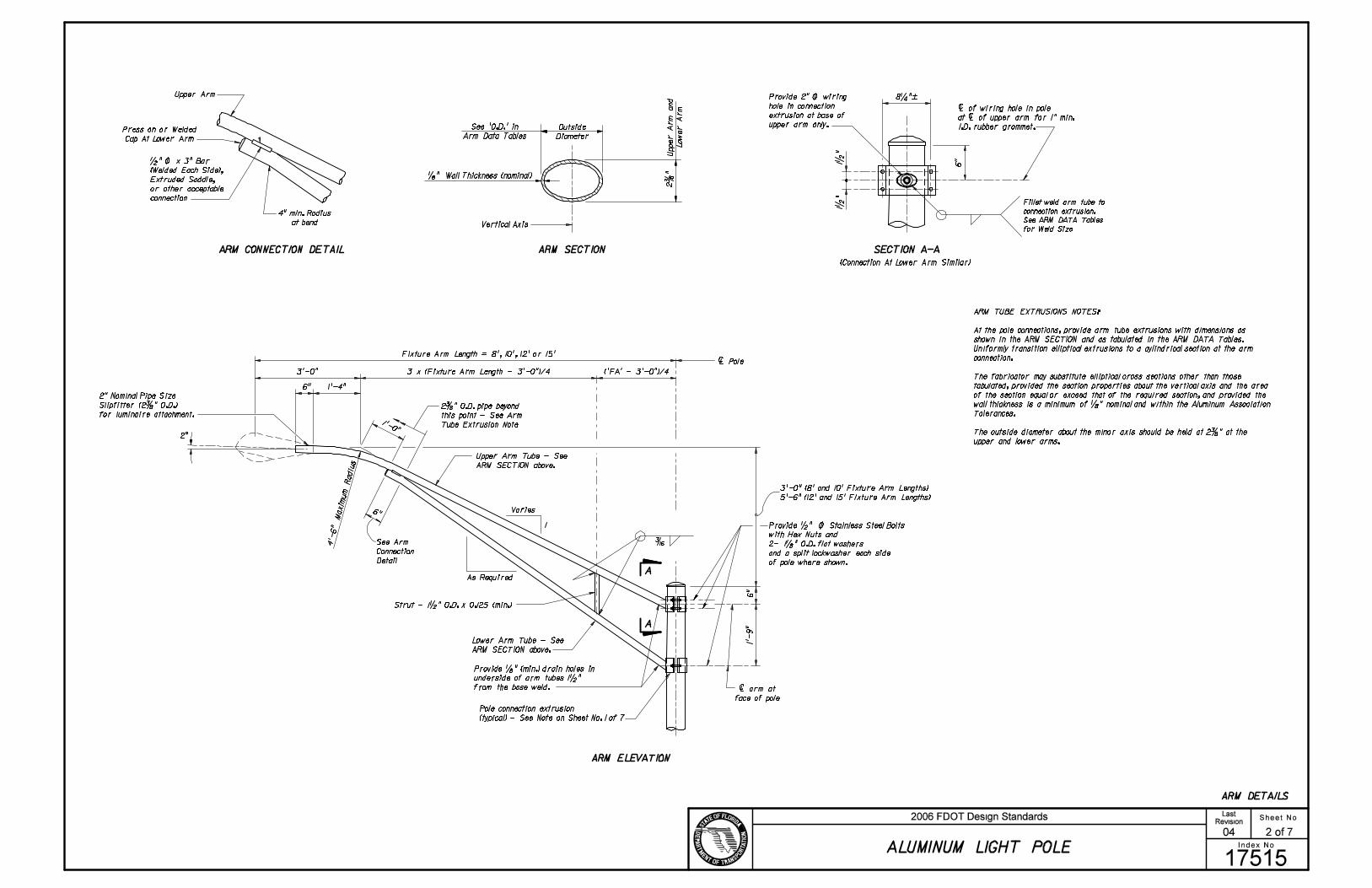
* ’N’ equals force normal to face of
connection due to axial force in the
arm - tension upper arm -
compression lower arm.
ARM DATA
8 FT. ARM DATA 10 FT. ARM DATA
12 FT. ARM DATA 15 FT. ARM DATA
2
1 40 80 2.375 0.250 0.392 0.100 0.162 2.375 0.188 0.218 0.056 0.090
2 40 100 3.625 0.250 0.755 0.178 0.212 2.375 0.188 0.152 0.036 0.043
3 45 80 2.375 0.250 0.392 0.100 0.162 2.375 0.188 0.218 0.056 0.090
4 45 100 3.625 0.250 0.755 0.178 0.212 2.375 0.188 0.152 0.036 0.043
5 50 80 2.375 0.250 0.424 0.104 0.162 2.375 0.250 0.236 0.058 0.090
6 50 100 3.625 0.250 0.819 0.186 0.212 2.375 0.188 0.165 0.037 0.043
7 55 100 3.625 0.250 0.857 0.200 0.212 2.375 0.188 0.173 0.040 0.043
8 60 100 3.625 0.250 0.857 0.200 0.212 2.375 0.188 0.173 0.040 0.043
9 65 100 3.625 0.250 0.857 0.200 0.212 2.375 0.188 0.173 0.040 0.043
10 70 100 3.625 0.250 0.857 0.200 0.212 2.375 0.188 0.173 0.040 0.043
11 75 100 3.625 0.250 0.857 0.200 0.212 2.375 0.188 0.173 0.040 0.043
1 40 80 3.625 0.188 0.669 0.134 0.269 2.375 0.188 0.150 0.030 0.060
2 40 100 3.625 0.188 0.651 0.118 0.182 3.625 0.188 0.556 0.101 0.155
3 45 80 3.625 0.188 0.669 0.134 0.269 2.375 0.188 0.150 0.030 0.060
4 45 100 3.625 0.188 0.651 0.118 0.182 3.625 0.188 0.556 0.101 0.155
5 50 80 3.625 0.250 0.720 0.138 0.269 2.375 0.188 0.161 0.031 0.060
6 50 100 3.625 0.250 0.703 0.123 0.182 3.625 0.250 0.601 0.105 0.155
7 55 100 3.625 0.250 0.739 0.133 0.182 3.625 0.250 0.632 0.114 0.155
8 60 100 3.625 0.250 0.739 0.133 0.182 3.625 0.250 0.632 0.114 0.155
9 65 100 3.625 0.250 0.739 0.133 0.182 3.625 0.250 0.632 0.114 0.155
10 70 100 3.625 0.250 0.739 0.133 0.182 3.625 0.250 0.632 0.114 0.155
11 75 100 3.625 0.250 0.739 0.133 0.182 3.625 0.250 0.632 0.114 0.155
1 40 80 3.625 0.188 0.593 0.099 0.235 3.625 0.188 0.486 0.081 0.192
2 40 100 4.625 0.250 1.150 0.179 0.299 3.625 0.188 0.518 0.081 0.135
3 45 80 3.625 0.188 0.593 0.099 0.235 3.625 0.188 0.486 0.081 0.192
4 45 100 4.625 0.250 1.150 0.179 0.299 3.625 0.188 0.518 0.081 0.135
5 50 80 3.625 0.188 0.634 0.102 0.235 3.625 0.188 0.520 0.084 0.192
6 50 100 4.625 0.250 1.230 0.185 0.299 3.625 0.188 0.554 0.084 0.135
7 55 100 4.625 0.313 1.300 0.201 0.299 3.625 0.250 0.588 0.091 0.135
8 60 100 4.625 0.313 1.300 0.201 0.299 3.625 0.250 0.588 0.091 0.135
9 65 100 4.625 0.313 1.300 0.201 0.299 3.625 0.250 0.588 0.091 0.135
10 70 100 4.625 0.313 1.300 0.201 0.299 3.625 0.250 0.588 0.091 0.135
11 75 100 4.625 0.313 1.300 0.201 0.299 3.625 0.250 0.588 0.091 0.135
1 40 80 4.625 0.250 1.02 0.137 0.388 3.625 0.188 0.484 0.065 0.184
2 40 100 4.625 0.250 1.15 0.145 0.293 4.625 0.250 1.170 0.146 0.296
3 45 80 4.625 0.250 1.02 0.137 0.388 3.625 0.188 0.484 0.065 0.184
4 45 100 4.625 0.250 1.15 0.145 0.293 4.625 0.250 1.170 0.146 0.296
5 50 80 4.625 0.250 1.09 0.140 0.388 3.625 0.188 0.514 0.066 0.184
6 50 100 4.625 0.250 1.23 0.149 0.293 4.625 0.313 1.240 0.151 0.296
7 55 100 4.625 0.313 1.31 0.162 0.293 4.625 0.313 1.330 0.164 0.296
8 60 100 4.625 0.313 1.31 0.162 0.293 4.625 0.313 1.330 0.164 0.296
9 65 100 4.625 0.313 1.31 0.162 0.293 4.625 0.313 1.330 0.164 0.296
10 70 100 4.625 0.313 1.31 0.162 0.293 4.625 0.313 1.330 0.164 0.296
11 75 100 4.625 0.313 1.31 0.162 0.293 4.625 0.313 1.330 0.164 0.296
Note:
All tables were developed assuming the following Luminaire properties:
Effective Projected Area = 1.5 ft (includes wind drag coefficient)
Weight = 51 pounds
Sheet No.
Index No.
2006 FDOT Design StandardsRevision
17515
07/01/05
ALUMINUM LIGHT POLE
4 of 7
Last
���
���

WIND
HEIGHT
(FT.)
CASE
NO.
WIND
SPEED
(MPH)
POLE
WALL
(IN.)
UPPER
WELD
(IN.)
LOWER
WELD
(IN.)
BASE FORCES
MOMENT
(FT.KIP)
SHEAR
(KIP)
TORSION
(FT.KIP)
POLE DATA - 40 FT. MOUNTING HEIGHT
DATA FOR POLE WITH 8 FT. ARM
FOUND.
DEPTH
(FT.)
WIND
HEIGHT
(FT.)
CASE
NO.
WIND
SPEED
(MPH)
POLE
WALL
(IN.)
UPPER
WELD
(IN.)
LOWER
WELD
(IN.)
BASE FORCES
MOMENT
(FT.KIP)
SHEAR
(KIP)
TORSION
(FT.KIP)
FOUND.
DEPTH
(FT.)
WIND
HEIGHT
(FT.)
CASE
NO.
WIND
SPEED
(MPH)
POLE
WALL
(IN.)
UPPER
WELD
(IN.)
LOWER
WELD
(IN.)
BASE FORCES
MOMENT
(FT.KIP)
SHEAR
(KIP)
TORSION
(FT.KIP)
FOUND.
DEPTH
(FT.)
WIND
HEIGHT
(FT.)
CASE
NO.
WIND
SPEED
(MPH)
POLE
WALL
(IN.)
UPPER
WELD
(IN.)
LOWER
WELD
(IN.)
BASE FORCES
MOMENT
(FT.KIP)
SHEAR
(KIP)
TORSION
(FT.KIP)
FOUND.
DEPTH
(FT.)
AXIAL
(KIP)
AXIAL
(KIP)
AXIAL
(KIP)
AXIAL
(KIP)
DATA FOR POLE WITH 10 FT. ARM
DATA FOR POLE WITH 12 FT. ARM DATA FOR POLE WITH 15 FT. ARM
1 40 80 0.156 0.188 0.156 13.5 0.522 0.611 0.227 6
2 40 100 0.156 0.188 0.156 17.6 0.690 0.907 0.229 7
3 45 80 0.156 0.188 0.156 13.8 0.539 0.611 0.227 6
4 45 100 0.156 0.188 0.156 18.0 0.713 0.907 0.229 7
5 50 80 0.156 0.188 0.156 14.3 0.563 0.660 0.227 6
6 50 100 0.156 0.188 0.156 18.6 0.747 0.985 0.229 6
7 55 100 0.156 0.188 0.156 19.7 0.790 1.030 0.229 6
8 60 100 0.188 0.188 0.188 20.1 0.805 1.030 0.261 6
9 65 100 0.188 0.188 0.188 20.4 0.825 1.030 0.261 6
1 40 80 0.156 0.188 0.156 13.7 0.528 0.819 0.233 6
2 40 100 0.156 0.188 0.156 17.8 0.694 1.210 0.236 7
3 45 80 0.156 0.188 0.156 14.0 0.545 0.819 0.233 6
4 45 100 0.156 0.188 0.156 18.2 0.717 1.210 0.236 7
5 50 80 0.156 0.188 0.156 14.5 0.569 0.881 0.233 6
6 50 100 0.156 0.188 0.156 18.8 0.751 1.300 0.236 6
7 55 100 0.188 0.188 0.188 19.9 0.795 1.370 0.268 6
8 60 100 0.188 0.188 0.188 20.3 0.810 1.370 0.268 6
9 65 100 0.188 0.188 0.188 20.6 0.830 1.370 0.268 6
1 40 80 0.156 0.188 0.156 13.9 0.533 1.51 0.242 6
2 40 100 0.156 0.188 0.156 19.1 0.728 2.32 0.246 7
3 45 80 0.156 0.188 0.156 14.2 0.550 1.51 0.242 6
4 45 100 0.188 0.188 0.188 19.4 0.750 2.32 0.276 7
5 50 80 0.156 0.188 0.156 14.6 0.572 1.60 0.242 6
6 50 100 0.188 0.188 0.188 20.1 0.782 2.46 0.276 6
7 55 100 0.188 0.188 0.188 21.3 0.829 2.63 0.276 6
8 60 100 0.188 0.188 0.188 21.7 0.847 2.63 0.276 6
9 65 100 0.188 0.188 0.188 22.0 0.865 2.63 0.276 6
1 40 80 0.156 0.188 0.156 13.1 0.514 1.08 0.232 6
2 40 100 0.156 0.188 0.156 17.9 0.699 1.66 0.235 7
3 45 80 0.156 0.188 0.156 13.4 0.530 1.08 0.232 6
4 45 100 0.156 0.188 0.156 18.2 0.721 1.66 0.235 7
5 50 80 0.156 0.188 0.156 13.8 0.553 1.15 0.232 6
6 50 100 0.156 0.188 0.156 18.9 0.753 1.78 0.235 6
7 55 100 0.188 0.188 0.188 19.9 0.796 1.89 0.265 6
8 60 100 0.188 0.188 0.188 20.4 0.814 1.89 0.265 6
9 65 100 0.188 0.188 0.188 20.7 0.832 1.89 0.265 6
NOTES:
1. Pole wall thicknesses shown in the POLE DATA TABLES
are nominals and shall be within the Aluminum Association Tolerances.
Thicker walls are permitted and tapered walls may be used provided
the minimum Aluminum Association thicknesses are not violated.
2. See sheet 3 of 7 for Foundation Notes.
Sheet No.
Index No.
2006 FDOT Design StandardsRevision
17515
04
ALUMINUM LIGHT POLE
5 of 7
Last
���
���
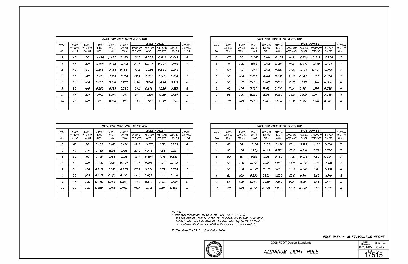
POLE DATA - 45 FT. MOUNTING HEIGHT
WIND
HEIGHT
(FT.)
CASE
NO.
WIND
SPEED
(MPH)
POLE
WALL
(IN.)
UPPER
WELD
(IN.)
LOWER
WELD
(IN.)
BASE FORCES
MOMENT
(FT.KIP)
SHEAR
(KIP)
TORSION
(FT.KIP)
DATA FOR POLE WITH 8 FT. ARM
FOUND.
DEPTH
(FT.)
WIND
HEIGHT
(FT.)
CASE
NO.
WIND
SPEED
(MPH)
POLE
WALL
(IN.)
UPPER
WELD
(IN.)
LOWER
WELD
(IN.)
BASE FORCES
MOMENT
(FT.KIP)
SHEAR
(KIP)
TORSION
(FT.KIP)
FOUND.
DEPTH
(FT.)
WIND
HEIGHT
(FT.)
CASE
NO.
WIND
SPEED
(MPH)
POLE
WALL
(IN.)
UPPER
WELD
(IN.)
LOWER
WELD
(IN.)
BASE FORCES
MOMENT
(FT.KIP)
SHEAR
(KIP)
TORSION
(FT.KIP)
FOUND.
DEPTH
(FT.)
WIND
HEIGHT
(FT.)
CASE
NO.
WIND
SPEED
(MPH)
POLE
WALL
(IN.)
UPPER
WELD
(IN.)
LOWER
WELD
(IN.)
BASE FORCES
MOMENT
(FT.KIP)
SHEAR
(KIP)
TORSION
(FT.KIP)
FOUND.
DEPTH
(FT.)
AXIAL
(KIP)
AXIAL
(KIP)
AXIAL
(KIP)
AXIAL
(KIP)
DATA FOR POLE WITH 10 FT. ARM
DATA FOR POLE WITH 12 FT. ARM DATA FOR POLE WITH 15 FT. ARM
NOTES:
1. Pole wall thicknesses shown in the POLE DATA TABLES
are nominals and shall be within the Aluminum Association Tolerances.
Thicker walls are permitted and tapered walls may be used provided
the minimum Aluminum Association thicknesses are not violated.
2. See sheet 3 of 7 for Foundation Notes.
Sheet No.
Index No.
2006 FDOT Design StandardsRevision
17515
07/01/05
ALUMINUM LIGHT POLE
6 of 7
Last
���
���

POLE DATA - 50 FT. MOUNTING HEIGHT
WIND
HEIGHT
(FT.)
CASE
NO.
WIND
SPEED
(MPH)
POLE
WALL
(IN.)
UPPER
WELD
(IN.)
LOWER
WELD
(IN.)
BASE FORCES
MOMENT
(FT.KIP)
SHEAR
(KIP)
TORSION
(FT.KIP)
DATA FOR POLE WITH 8 FT. ARM
FOUND.
DEPTH
(FT.)
WIND
HEIGHT
(FT.)
CASE
NO.
WIND
SPEED
(MPH)
POLE
WALL
(IN.)
UPPER
WELD
(IN.)
LOWER
WELD
(IN.)
BASE FORCES
MOMENT
(FT.KIP)
SHEAR
(KIP)
TORSION
(FT.KIP)
FOUND.
DEPTH
(FT.)
WIND
HEIGHT
(FT.)
CASE
NO.
WIND
SPEED
(MPH)
POLE
WALL
(IN.)
UPPER
WELD
(IN.)
LOWER
WELD
(IN.)
BASE FORCES
MOMENT
(FT.KIP)
SHEAR
(KIP)
TORSION
(FT.KIP)
FOUND.
DEPTH
(FT.)
WIND
HEIGHT
(FT.)
CASE
NO.
WIND
SPEED
(MPH)
POLE
WALL
(IN.)
UPPER
WELD
(IN.)
LOWER
WELD
(IN.)
BASE FORCES
MOMENT
(FT.KIP)
SHEAR
(KIP)
TORSION
(FT.KIP)
FOUND.
DEPTH
(FT.)
AXIAL
(KIP)
AXIAL
(KIP)
AXIAL
(KIP)
AXIAL
(KIP)
DATA FOR POLE WITH 10 FT. ARM
DATA FOR POLE WITH 12 FT. ARM DATA FOR POLE WITH 15 FT. ARM
NOTES:
1. Pole wall thicknesses shown in the POLE DATA TABLES
are nominals and shall be within the Aluminum Association Tolerances.
Thicker walls are permitted and tapered walls may be used provided
the minimum Aluminum Association thicknesses are not violated.
2. See sheet 3 of 7 for Foundation Notes.
Sheet No.
Index No.
2006 FDOT Design StandardsRevision
17515
07/01/05
ALUMINUM LIGHT POLE
7 of 7
Last
���
���