2005/03/30-Vermont Yankee July 2008 Evidentiary Hearing ...
116
Secondary Piping Rupture Accident at /Mihama Power Station, Unit 3, of the Kansai Electric Power Co., Inc. (Final Report) U.S. NUCLEAR.REGULATORY COMMISSION In the Mawro Ue-~ ~~E~YA t a OFFERED 4 r Intervenor_ ,____ DOCKETED NRC Sf Other USNRC Iotwwd$~wt~wae ,S*c August 12, 2008 (11:00am) A c lt : REJECTED WIr O RAWN OFFICE OF SECRETARY RULEMAKINGS AND QW. I,/hC-- ADJUDICATIONS STAFF March 30, 2005 The Nuclear and Industrial Safety Agency (Translated by JNES, Rev 1 as of May 14, 2005) • •x L ,_ • _ • .2 .•._. .... .. :.. . .. .. ...... .. ..... : .... .... ... . . .. .. . . .... .. .. .. .. .. .... .
Transcript of 2005/03/30-Vermont Yankee July 2008 Evidentiary Hearing ...

Secondary Piping Rupture Accident at/Mihama Power Station, Unit 3, of the Kansai
Electric Power Co., Inc. (Final Report)
U.S. NUCLEAR.REGULATORY COMMISSION
In the Mawro Ue-~ ~~E~YA t aOFFERED 4 r Intervenor_ ,____
DOCKETED NRC Sf OtherUSNRC Iotwwd$~wt~wae ,S*c
August 12, 2008 (11:00am) A c lt : REJECTED WIr O RAWN
OFFICE OF SECRETARYRULEMAKINGS AND QW. I,/hC--
ADJUDICATIONS STAFF
March 30, 2005The Nuclear and Industrial Safety Agency
(Translated by JNES, Rev 1 as of May 14, 2005)
• •x L ,_ • _ • .2 .•._. .. .. .. :.. . .. .. .. .. .. . . ..... : .... .... ... . . .. .. . . .. . . .. .. .. .. .. .... .

Contents
1 . Intro d u ctio n ..................................................................................................... . . 1.
2. Accident situation and reactions ....................................................................... 3
2.1 Situation at the accident ....................................................................................... 32.2 Initial reactions of KEPCO and NISA assessment .............................................. 4
2.2.1 Notification and communications, rescue activities and NISA assessment... 42.2.2 Shutdown operations and NISA assessment ............................................ 6
2.3 Influences on the reactor and related facilities and NISA assessment .................. 72.3.1 Influences on the reactor ........................................................................ 72.3.2 Temporary inoperativeness of auxiliary feed water flow control valve
located in turbine-driven auxiliary feed water line ................................... 72.3.3 Influences of steam and high temperature water on facilities.................... 8
2.4 Influences on surrounding environment .............................................................. 10
3. Technical investigations of pipe rupture ....................................................... 11
3.1 Ruptured condition of pipe ............................... ....... 113.2 Investigation of similar portion ......................................................................... 123.3 Investigation of design specifications ................................................................. 133.4 Investigation of installed condition of piping ..................................................... 133.5 Investigation of quality control history of secondary cooling water.................. 143.6 Investigation of operation history ....................................... ................................ 153.7 Investigation of pipe rupture mechanism ........................................................... 15
3.7.1 Metallurgical investigations ................................. 163.7.2 Pipe flow analysis ................................................................................... 163.7.3 Thinning behavior analysis ..................................................................... 173.7.4 Pipe rupture structual behavior analysis ................................................. 173.7.5 Pipe flow visualization test ................................................................... 173.7.6 Investigation results ................................................................................ 18
4. Investigation of pipe wall thickness control .......................... 19
4.1 Legal positioning of pipe wall thickness control ................................................. 194.2 Verification of control techniques for pipe wall thickness ................................... 19
4.2.1 Control techniques at PWR plants ...................................................... ........ 194.2.2 Control techniques at BWR plants ...................................................... ........ 22
4.3 Implementation state of pipe wall thickness control by licensees ...................... 224.3.1 Management structure ....................... I .......................................... 234.3.2 D ecision criteria .................................................................................... 234.3.3 Improvement state at each licensee ..................................................... 25
4.4 R esponses of N ISA ................. ............................. . -............ , .......................... 254.4.1 Establishing rules about pipe wall thickness control .............................. 25
4 .5 F u tu re ta sk s .............................................................................................................. 2 6
Contents-i

5. Cause determination and recurrence prevention measures ........................... 27
5.1 Actions taken in response to the Interim Summary ............................................. 275.2 Investigation by N ISA ............................. I ......................................................... 285.3 Reports on cause determination and recurrence prevention measures from
KEPCO ................................................. 295.3.1 Addressing for recurrence prevention after the Interim Summary ...... 295.3.2 Summary of the KEPCO Recurrence Prevention Report ........................ 30
5.4 Reports on cause determination and recurrence prevention measures from MHI... 31
5.4.1 Addressing for recurrence prevention after the Interim Summary ........... 315.4.2 Summary of the report .................................... 31
5.5 Results of interview with Nihon Arm ................................................................ . 335.5.1 Addressing for recurrence prevention after the Interim Summary .......... 335.5.2 Summary of interview with Nihon Arm ...................................................... 33.
5.6 Assessment of cause determination and recurrence prevention measures ....... 355.6.1 Assessment of investigation system at KEPCO and MHI ............ 355.6.2 Assessment of the details of registration omissions for the portions to be
inspected ............................................................................................... . . 365.6.3 Assessment of basic attitude toward maintenance management service
and detailed process of registration omissionshaving remainedundiscovered .......................................................................................... . . 37
5.6.4 Assessment of continuation of inappropriate pipe remaining lifem an agem ent ................................................................................................. 39
5.6.5 Assessment of recurrence prevention measures of KEPCO and MHI ........ 41
6. Responses to tasks found in relation to the accident ..................................... 46
6.1 Lessons learned from the accident and its reflection ........................................... 466.1.1 Reforming nuclear safety regulations ...................................................... 466.1.2 Confirming the construction of an effective quality assurance system by
licen sees ............................................................................................... . . 4 76.1.3 Responses to aging in nuclear power plants ........................................... 48
6.2 R esponses to other tasks ..................................................................................... 496.2.1 Efforts for industrial safety...................................................................... 496.2.2 Social and regional impacts following the accident and responses to the
im p act .................................................................................................... . . 52
7 . C o nclusio n ................................................................................................... . . 54
Contents-ii
1. Introduction
An accident occurred at Mihama Power Station, Unit 3, of the Kansai Electric Power Co., Inc.
(abbreviated to KEPCO hereinafter) on August 9, 2004. A secondary piping ruptured and hightemperature secondarycooling water flowed out, so the reactor shut down automatically. An
investigation was carried out on the spot and an opening was confirmed in a pipe of the
condensate system.,
This accident was one of so-called secondary piping rupture accidents of a pressurized water
reactor (PWR). When compared to the results of an analysis of the same kind accident in thesafety review, no particular problem was recognized in the reactor parameter variations
immediately after the accident. However, the accident resulted in a serious consequence that
was unprecedented at a nuclear power plant in Japan. That is, of the workers working in the
turbine building, 5 were killed and 6 were injured.
Immediately after the occurrence of the accident, the Nuclear and Industrial Safety Agency(abbreviated to NISA hereinafter) dispatched a Deputy Director-General to the scene
-1-

reprimand for the accident in writing. At the same time, he issued a technical standard
conformance order concerning Mihama Power Station, Unit 3, based on Article 40 of the
Electric Utilities Industry Law to order a suspension of its use until the conformance to the
technical standards was verified.
After that, the Investigation Committee continued surveys and investigations about the
matters pointed out in the Interim Summary and also examined the reports submitted by
KEPCO and Mitsubishi Heavy Industries, Ltd. (abbreviated to MHI hereinafter) on March 1,2005. NISA summarized these investigation results into a final report about this accident.
For the investigations of the accident, the Investigation Committee sessions were opened to
the public to disclose the deliberation processes transparently. During this period, NISA has
made efforts to fulfill its accountability for the accident by explaining directly to Fukui
Prefecture, Mihama-cho, and other local municipalities concerning the progress of surveys
and investigations.
To help the investigation and discussion at the Nuclear Safety Commission, NISA has
appropriately reported the progress of surveys and investigations at the Investigation
Committee to the Nuclear Safety Commission.
-2-

2. Accident situation and reactions
2.1 Situation at the accident
While Mihama Power Station, Unit 3, was in operation at the rated thermal output, a "Fire
Alarm Operation" alarm, etc. was generated in the central control room at 15:22 on August 9,
2004. The operator grasped that the alarm-generated spot was on the second floor of the
turbine building and checked the spot to find that the building was filled with steam. Thus,
it was judged that there was a high possibility of steam or high temperature water leakage
from the secondary piping. The operator started emergency load reductionat 15:26. While
those operations took place, a "3A SG Feed water < Steam Flow Inconsistency Trip)' alarm
was generated at 15:28 and the reactor and then the turbine shut down automatically.
No particular problem was recognized in the major plant parameter variations at the accident
and the reactor reached to a cold shutdown at 23:45 on August 10, 2004.
The operator made an inspection in the turbine building and confirmed a ruptured opening in
an A-loop condensate pipe at 17:30 on August 9, 2004, which was the feed water line from
the 4th feed water heater 2 to the deaerator 3 running near the ceiling on the deaerator side at
the 2nd floor of the turbine building& After that, the nuclear safety inspector also confirmed
the same situation.
For the unit in question, the 21st periodical inspection was planned to start on August 14,
2004. In the turbine building, a total of 105 workers of KEPCO and affiliated companies
were doing preparatory work for the periodical inspection at the time of occurrence of the
accident. Of them, the affiliated company's workers working near the ruptured A-loop
condensate pipe fell victim to the steam and high temperature water flowed out from the
ruptured opening, and 5 were killed and 6 were injured.
The major systems of PWR and the ruptured spot are shown in Figure 1.
According to KEPCO, they examined the operation parameters before an'd after the
occurrence of the accident, but did not find out any variation indicating a symptom of rupture
before the occurrence of the rupture. They say they did not perform any special operation
that might have induced the accident.
SG Feed water < Steam Flow Inconsistency Trip: An alarm issued when the water level of the steamgenerator is low and the feed water flow to the steam generator is less than the steam flow.
2 Feed water heater: A heat exchanger to heat feed water by the heat of extraction steam from the turbine.3 Deaerator: A device to heat feed water by the heat of extraction steam from the turbine to separate and
remove noncondensing gases (oxygen and others) in the feed water.
-3-

Reactor containment
Figure 1. Major systems of PWR and the ruptured spot
(Reference information) Outline of Mihama Power Station, Unit 3
1.
2.
3.
4.
5.
6.
7.
Name:
Location:
Rated thermal output:
Rated electric output:
Reactor type:
Commissioning:
Operating time:
Mihama Power Station, Unit 3, of KEPCO
Nyu, Mihama-cho, Mikata County, Fukui Prefecture
2.44 million kW
826 thousand kW
Pressurized water reactor (PWR)
December 1, 1976
185,700 hours
2.2 Initial reactions of KEPCO and NISA assessment
2.2.1 Notification and communications, rescue activities and NISA assessment
(1) Notification and communications, rescue activities
KEPCO submitted a report named "On the Secondary Piping Rupture Accident of MihamaPower Station, Unit 3" dated on March 1, 2005 (abbreviated to the KEPCO Accident Report
hereinafter). According to the KEPCO Accident Report, the actions taken after the
occurrence of the accident were as follows. On receipt of a fire alarm, a member of the
General Manager's staff immediately instructed evacuation from the turbine building through
a public address system. At the same time, the member dialed 119 to call for ambulances.
As for the related organs, the Mihama Nuclear Safety Inspector Office of NISA was notified
10 minutes after the occurrence of the accident. As for the local municipalities, Mihama-chowas notified 8 minutes after, and Fukui Prefecture 12 minutes after the occurrence of the
accident.
Rescue activities for the victims could not proceed easily at first, because the turbine building
was filled with high temperature steam. However, the staffs of the Power Station and the
affiliated companies rescued 6 persons and, after arrival of fire brigades, the Power Station
-4-

staffs and members of fire brigades cooperated in searching and succeeded in rescuing 5.
persons. All 11 persons were carried out completely by 16:46, or 1 hour and 24 minutes
after the occurrence of the accident.
The series of situations are shown in Appendix 1.
(2) Assessment by NISA
NISA points out in the Interim Summary that the accident should not be taken as a mere
accident, but the various lessons learned from the accident should be utilized for enhancing
disaster prevention measures by expanding the initial action framework and reinforcing
cooperation with the related organs in case of nuclear power station troubles and accidents.
With regard to the initial reactions of KEPCO at the occurrence of the accident, rescue of
victims and notification to the related organs were performed appropriately in general.
However, inappropriate actions were found in several points. For example, the emergency
notification to the fire headquarters did not take place in accordance with the notification path
stipulated in the fire defense plan. There was no rule available for the licensee to directly
inform the medical agencies of the information whether the radiation contamination
-5-

such as preparation of an initial response manual that describes a prompt response system in
case of an emergency.
2.2.2 Shutdown operations and NISA assessment
(1) Shutdown operations
In the KEPCO Accident Report, the operations performed by the operator at the accident are
examined in the divided stages of (a) Judgment of emergency load reduction, (b) Response
after the reactor trip, (c) Closing of the deaerator water level control valve, and (d) Transition
operations from reactor hot shutdown to cold shutdown. As aresult, it is concluded that (a)
was performed in accordance with the "Operation Room Job Manual," (b) in accordance with
the "Accident Manual" and (d) in accordance with the "Normal Operation Manual" each.
For (c), the report says that the operation took place because there was a concern regarding
system water boiling due to the opening in the secondary piping.
With regard to a large amount of secondary cooling water flowed out from the opening into
the turbine building as described later, KEPCO examinedthe possibility of reducing the
amount of outflow, by operator manipulations. As a result, it assessed that there was a
possibility of reduction of the outflow amount if the operator had closed the deaerator water
level control valve earlier.
(2) Assessment by NISA
NISA assessed the responses of the operators at the accident in view of (a) whether they
responded in accordance with the various manuals, and (b) whether the spread of accident
damage could be prevented if more appropriate operations were taken.
For (a), the responses and operations of the operators were collated with the respective
manuals and, as a result, their conformance to the manuals was confirmed.
For (b), it is important for the licensee to sincerely investigate operation procedures that are
effective in reducing the extent of accident damage to be as small as possible. Therefore, it
can be appreciated, though being an ex-post measure, that KEPCO made various kinds of case
studies concerning how the outflow amount could be reduced.
For this time accident, however, there was a substantial amount of outflow immediately after
the pipe rupture, and it can be estimated that the disaster occurred simultaneously.
Therefore, even on the assumption that the operator performed the best operations for outflow
reduction, it is problematic how much those actions contributed to mitigation of the accident
damage.
-6-

At the time of the accident, the reactor cooling was maintained by the emergency feedwater
system. Therefore, the outflow of cooling water from the secondary system, regardless the
amount, did not affect the reactor safety.
2.3 Influences on the reactor and related facilities and NISA assessment
2.3.1 Influences on the reactor
For the influence of the accident on the reactor, as stated in the Interim Summary, the systems
related to reactor safety operated normally, and the reactor, pressure, primary coolant
temperature and other major parameters did not indicate more severe influence than the
results assumed in the safety assessment analysis performed at the safety review.
2.3.2 Temporary inoperativeness of auxiliary feed water flow control valve located in
turbine-driven auxiliary feed water line
(1) Outline of the event, causes and countermeasures
According to the KEPCO Accident Report, two motor-driven auxiliary feed water pumps
automatically started at 15:28 on the day of the accident, followed by an automatic start of
one turbine-driven auxiliary feed water pump due to the abnormal low water level of the
steam generator. After that, because the necessary flow rate of auxiliary feed water was
secured, so the auxiliary feed water flow control valves A, B and C in the turbine-driven
auxiliary feed water line were closed at 15:32 to stop lowering the primary coolant
temperature excessively.
After that, the water level of the steam generator was recovered and became stable, so the
turbine-driven auxiliary feed water pump was stopped at 17:12. To put this pump in an
automatic standby condition, the operator tried to open the auxiliary flow control values A, B,
and C at 17:13. However, the valves A and C stayed closed and no opening action took
place. The operator tried to open the valves A and C again the next day, and both valves
opened.
As a result of the cause investigation , it was presumed that the backpressure of thevalves in
question exceeded the valve opening force while the pump. was stopped, and this kind of
system condition was not assumed in the design conditions for the valve. That was
estimated to be a cause. As a countermeasure, it was decided to replace the valve opening
spring with one having a larger spring constant to provide the valve with a larger valve
opening force than the maximum back pressure assumed in the design.
-7-

(2) Assessment by NISA
As a result of examination of the contents reported by KEPCO, NISA considers these
estimated causes to be appropriate
From the fact that the turbine-driven auxiliary feed water pump fulfilled its function to secure
the necessary flow rate of auxiliary feed water and that it was possible to open the valves
because the inlet pressure of the valve will increase to exceed the backpressure in case of
the turbine-driven auxiliary feed water pump operation, the trouble can be considered in
consequence as not affecting the reactor safe shutdown. On the other hand, for the important
equipments that are indispensable to secure the reactor safety, it is necessary indeed that they
should be designed to keep their functions in any situation in which they are expected to
operate. The trouble was caused by the fact that the service conditions appeared during the
accident were not sufficiently considered in the design stage. It is appropriate to replace the
valve operating spring with one that has a larger spring constant.
2.3.3 Influences of steam and high temperature water on facilities
(1) Evaluation of the amount of leakage and affected zone
In the Interim Summary, the amount of secondary cooling water outflow from the opening
was calculated by summing up the amount of makeup water from the secondary makeup
water tank, the amount of deaerator water level falling and the amount of water contained in
the piping (from the 4th low-pressure feed water heater to the deaerator). As a result, it was
evaluated to be about 885 tons.
Table 1. Leakage amount from various parts(Unit: ton)
Amount of makeup water from the secondary makeup water About 565tank About_565Amount of deaerator water level falling About 307
Amount of water contained in the piping About 13
Total About 885
According to the KEPCO Accident Report, it was estimated as a result of the situation survey
on the spot that high temperature water flowed out from the opening and then flowed down
from the second floor to the I st floor through the stairs and openings, and finally flowed into
the turbine sump. With regard to steam blown out from the opening, it is estimated that the
steam rapidly permeated almost all the whole area of the turbine building immediately after
the pipe rupture and intruded into some portions of the control building and the intermediate
building adjacent to the turbine building.
-8-

In the region estimated to have touched high temperature water or steam that blew out from
the pipe opening, there were the solenoid valves for main steam isolation valves, the control
panels installed in the central control room, the instrument power facilities, the DC power
facilities and the turbine-driven auxiliary feedwater pump as safety-related facilities.
Of these, high temperature water intruded into the terminal box of one of the three solenoid
valves for the main steam isolation valves, and one-sided grounding formed in the DC circuit;
however, it operated normally at the accident.
A trace of steam intrusion was found at the control panels installed in the central control
room, the instrument power facilities and the DC power facilities; however, they operated
normally at the accident.
For the turbine-driven auxiliary feed water pump, no trace of steam intrusion was found in the
pump room, and the pump operated normally at the accident.
In the regions estimated to have touched high temperature water or steam that blew out from
the pipe opening, no facilities related to the plant safe shutdown were installed other than
these facilities.
(2) Assessment by NISA
According to the KEPCO Accident Report, in the region estimated to have touched high
temperature water or steam, there were the solenoid valves for main steam isolation valves,
the control panels installed in the central control room, the instrument power facilities, the DC
power facilities and the turbine-driven auxiliary feed water pump as safety-related facilities.
According to the report, these equipments operated normally during the accident, and there
was no trouble in the plant shutdown after the accident; however, the report says that high
temperature water or steam intruded into some of the facilities related to the plant safe
shutdown at an accident.
In the accident, steam intrusion was observed in the control panels installed in the central
control room. The central control room is a place where operators stay even at the time of an
accident to perform operations for accident countermeasures, so the room must be designed
for ventilation to prevent unnecessary outside air from intruding. According to KEPCO, the
steam intrusion this. time occurred due to inappropriate sealing work at some of the wall
penetrations for cable trays and conduits. Because such inappropriate portions can
substantially affect the habitability of the central control room, NISA considers this a serious
problem. Therefore, NISA will instruct licensees to check, if necessary, whether construction
work has been executed certainly or not at plants other than Mihama Power Station, Unit 3.
-9-

2.4 Influences on surrounding environment
As stated in the Interim Summary, no influence' of radiation on the surrounding environment
due to the leaked secondary cooling water was observed.
- 10-

3. Technical investigations of pipe rupture
With regard to the pipe rupture mechanism, it was estimated in the Interim Summary based on
the results of the investigations of ruptured condition of pipe that the cause for the pipe
rupture was so-called erosion/corrosion, which gradually reduced the pipe wall thickness with
the lapse of operation time, resulting in insufficient pipe strength and rupture under the load
during operation. After that, NISA proceeded with investigations such as metallurgical
investigations on the ruptured portion, pipe flow analysis, pipe rupture structural behavior
analysis in cooperation with the Japan Nuclear Energy Safety Organization (abbreviated to
JNES hereinafter) and the Japan Atomic Energy Research Institute (abbreviated to JAERI
hereinafter). This chapter covers the content described in the Interim Summary with an
addition of the results of investigations carried out after that and marshals them as a result of
technical investigations of pipe rupture.
3.1 Ruptured condition of pipe
The portion where a rupture was confirmed was in a condensate pipe of the A-loop, one of the
txN¢o loopg of condensate piping going from the 4th low-pressure feed water heater to the
deaerator near the ceiling on the deaerator side on the 2nd floor of the turbine building, and
was near the downstream of the orifice4 for measuring the condensate flow rate of the A-
loop.
A joint team of NISA and JNES conducted an on-the-spot inspection, and as a result
confirmed a fracture opening in the ruptured portion, which extended a maximum of about
515 mm in the axial direction and about 930 mm in the circumferential direction of the pipe.
KEPCO measured the pipe in the presence of the police authority, and the result was 0.4 mm
at the thinnest portion of the pipe, whereas it must be 4.7 mm or over5 according to the
technical standards. As shown in Appendix 2, the thinning was striking in the upper part of
the pipe.
The A-loop pipe was cut out, including the ruptured portion, and examined at JAERI. As a
result, a portion was found out downstream of the vent hole of the orifice6 where pipe wall
thinning reached to the flange for the orifice support.
Orifice: A throttling mechanism to narrow down the cross section of a pipeline. An orifice installed tomeasure the flow rate of the fluid flowing in the pipe is called a flow meter orifice, and an orifice installed toreduce the fluid pressure in the pipe is called a pressure reducing orifice.According to the strength calculation for pressure-resistance of pipes attached to a steam turbine, based onthe "Ordinance of Establishing Technical Standards on Thermal Power Generation Equipment" applied to thesecondary system of PWRs
6 Vent hole of orifice: A hole provided at the top of the orifice to vent air (the diameter is 4 mm for the orificein question).
-11-
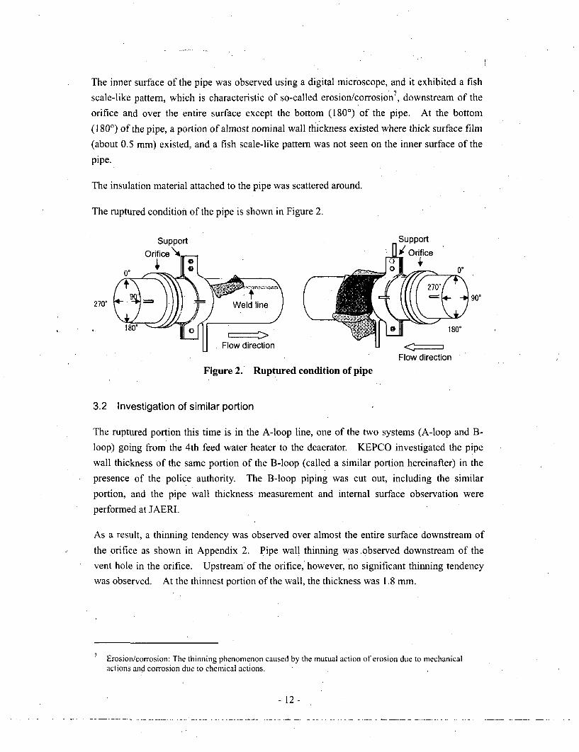
The inner surface of the pipe was observed using a digital microscope, and it exhibited a fish
scale-like pattern, which is characteristic of so-called erosion/corrosion 7, downstream of the
orifice and over the entire surface except the bottom (1800) of the pipe. At the bottom
(180') of the pipe, a portion of almost nominal wall thickness existed where thick surface film(about 0.5 mm) existed, and a fish scale-like pattern was not seen on the inner surface of the
pipe.
The insulation material attached to the pipe was scattered around.
The ruptured condition of the pipe is shown in Figure 2.
0. 10) 0
Flow directionFlow direction
Figure 2. Ruptured condition of pipe
3.2 Investigation of similar portion
The ruptured portion this time is in the A-loop line, one of the two systems (A-loop and B-loop) going from the 4th feed water heater to the deaerator. KEPCO investigated the pipe
wall thickness of the same portion of the B-loop (called a similar portion hereinafter) in thepresence of the police authority. The B-loop piping was cut out, including the similar
portion, and the pipe wall thickness, measurement and internal surface observation were
performed at JAER- •
As a result, a thinning tendency was observed over almost the entire surface downstream of
the orifice as shown in Appendix 2. Pipe wall thinning was observed downstream of the
vent hole in the orifice. Upstream of the orifice, however, no significant thinning tendency
was observed. At the thinnest portion of the wall, the thickness was 1.8 mm.
7 Erosioicorrosion: The thinning phenomenon caused by the mutual action of erosion due to mechanicalactions and corrosion due to chemical actions.
- 12-

The inner surface of the pipe was observed using a digital microscope, and the result was that
it exhibited a fish scale-like pattern over almost the entire surface, which is characteristic of
so-called erosion/corrosion.
3.3 Investigation of design specifications
According to KEPCO, in case of the design of secondary system piping, material selection
and strength calculation of pressure retaining parts were performed in accordance with the
"Technical Standards on Thermal Power Generation."
The maximum service pressure of the pipe in question is 1.27 MPa, and the maximum service
temperature is 195°C. From among materials having sufficient strength margin, carbon steel
(SB42) was chosen, considering its service performance.
Major specifications of the piping in question are shown 'in Table 2 "Major specifications of
the piping in question."
Table 2. Major specifications of the piping in question
Material Carbon steel (SB42)Outer diameter (mm) 558.8Thickness (mm) 10
Maximum service temperature (0C) 195Maximum service pressure (MPa) 1.27
According to KEPCO, the temperature of the ruptured portion in the state of actual service isabout 140 0C, the pressure is about 0.93 MPa, and the flow rate is about 1,700 mn3/h.
The design specifications of this piping were decided considering the service environment.
The mill sheet8 was examined concerning the tensile strength, material ingredients, etc.
However, no problem was identified by NISA.
3.4 Investigation of installed condition of piping
The roundness deviation of the A-loop pipe in question and B-loop pipe at the similar portion
was examined. The result was that, the tolerance of the outer diameter exceeded the
tolerance of JIS (±0.8%) in parts downstream of the ruptured portion of the A-loop pipe;
however, the roundness deviation in other portions was within the tolerance.
Mill sheet: When an order of steel with a specified standard is received, this document is attached to theproduct to certify that the manufactured results of the steel satisfy the requirements, like specified standard,specifications and so on.
- 13 -

The installed condition of the orifice at the ruptured portion was examined, and the result was
that the misalignment of the orifice hole center was 0.61 mm in the vertical direction and 0.71
mm in the horizontal direction with respect to the inner diameter center of the pipe.
3.5 Investigation of quality control history of secondary cooling water
According to the KEPCO Accident Report, Mihama Power Station, Unit 3, injects feed water
treatment chemicals basically from downstream of the condensate treatment equipment from
the standpoint of corrosion inhibition of the whole secondary piping and equipment. All
volatile treatment (AVT) using ammonia (pH adjuster) and hydrazine (deoxidizer) ,as the feed
water treatment chemicals, has been performed since the commissioning. As an anti-
corrosion measure for the steam generator tube, boron injection 9 had been performed from
the 10th to the 15th operation periods. From the 17th operation period, ethanolamine has
been added as a pH adjuster.
KEPCO investigated the water quality control history since the commissioning of Mihama
Power Station, Unit 3; and as a result, it says that both the feed and condensate water quality
data have been maintained within the water quality control values and that there was no
variation in pH, dissolved oxygen, etc. At. Mihama Power Station, Unit 3, condenser tube
leaks occurred twice in the past, and seawater flowed into the secondary cooling water.
However, these events are considered to have no effect because the copper alloy does not
corrode on the side in contact with the condensate water almost free of oxygen.
The effect of boric acid on pipe wall thinning was investigated; however, no significant
difference was recognized in the effect on the thinning rate between with and without boron
injection'.
The control values of secondary system water quality at Mihama Unit 3 are shown in Table 3.
9 Boron injection: A substance injected for neutralization to prevent alkali from concentrating in parts of thesteam generator tube/support plate and thereby prevent intergranular corrosion in the Inconel 600-alloytube.
- 14-

Table 3. Secondary system water quality control values at Mihama, Unit 3
Item Control valueAVT 8.8 to 9.3 (9.2)
PH (at 25eC) AVT + boron injection 8.5 to 9.3(Feedwater)
_ AVT + ETA injection 8.8 to 9.7
Ethanolamine (at injection of ETA in feed water) 3 ppm1 Dissolved oxygen in condensate + 5 ppb
2 to 7 2 ppb
Hydrazine 8 to 15 5 ppb
(Feed water) 16 to 18 200 ppb100 ppb
19 to 21 + Dissolved oxygen in condensate x40
Dissolved oxygen (in feed water) 5 ppb
Dissolved oxygen 1 to 15 50 ppb(in condensate) 16 to 21 10 ppb
Totaliron I6to 15 20 ppb
(in feed water) 16 to 18 10 ppb19 to 21 2 ppb
(Note) Numbers in the "item" column denote operation periods.
3.6 Investigation of operation history
According to the KEPCO Accident Report, plant trips could cause variations in condensate
flow rate, temperature and pressure in the piping in question and affect the portion in
question. Past plant trips and other transient events having such possibility were
investigated. The result was that their influence on feed water flow rate, pressure and
temperature was within the limits of the design conditions. And it was confirmed that theirnumber of occurrences was within the limits of the design number of occurrences.
In addition, an interview was held to confirm the plant operation conditions and occurrence of
abnormal sound or the like immediately before the rupture of the portion in question.
According to the interview result, no transient event or precursor was perceived that might
have induced the rupture event.
3.7 Investigation of pipe rupture mechanism
JNES, JAERI and KEPCO carried out the following investigations to estimate the pipe
rupture mechanism.
-15 -

3.7.1 Metallurgical investigations
As metallurgical investigations on cutouts from the ruptured pipe (A-loop piping) and B-loop
piping, JAERI performed appearance observation, material investigations (material chemical
composition analysis, tensile test, metallographic observation, hardness test, and others), wall
thickness measurement, and fractographic observation.
The appearance of the ruptured opening was observed by the naked eye, and there was no
traces of external loads, detrimental scratches, cracks that might cause the rupture.
As to the chemical compositions, tensile properties and the like of the pipe material, it was
confirmed that the material used for the pipe in question conformed to the mill sheet for both
the A-loop and B-loop piping.
On the internal surface of the thinned wall portion, a fish scale-like pattern with a smooth
surface was observed. This pattern is formed by so-called erosion/corrosion. The wall
thickness near the axial crack in the ruptured opening was 0.3 to 0.4 mm in the thinnest part.
On all representative fracture surfaces in the ruptured opening, dimples' 0 were observed,
which are characteristic of ductile fracture, and fatigue cracks were not observed.
An outline of metallurgical investigations is given in Appendix 3.
3.7.2 Pipe flow analysis
Since flow analysis is apt to exhibit, the features of the method, employed to make the model
and the code used for the analysis, flow analyses were carried out independently using
multiple codes owned by JNES and JAERI to evaluate the wall thinning tendency due to flow.
disturbances.
A prediction analysis to examine the thinning tendency due to turbulent flow was carried out
(at JNES and JAERI), and results were compared with actual measurements. They showed a
relatively good agreement as to the position of maximum thinning (downstream of the orifice,
at a distance of about 1.2 times the pipe diameter).
From a 3-dimensional turbulent flow analysis (at JNES and JAERI), a strong
counterclockwise swirling flow, as seen from upstream, was confirmed in the flow velocity
distribution at the orifice inlet for the A-loop piping, and a Weak clockwise swirling flow, as
seen from upstream, was confirmed for the B-loop piping.
Dimples: Depressions occurring in the fracture surface when a metallic material is ruptured by ductilefracture.
- 16-
According to a 1-dimensional 2-phase flow analysis using the design values (at JNES), the
result obtained was that the possibility of decompressed boiling (cavitation) was low
downstream of the orifice.
An outline of pipe flow analysis is given in Appendix 4.
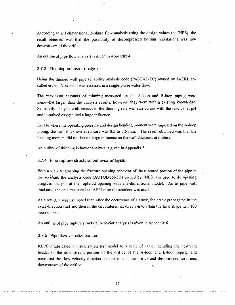
3.7.3 Thinning behavior analysis
Using the thinned wall pipe reliability analysis code (PASCAL-EC) owned by JAERI, so-
called erosion/corrosion was assessed in a single-phase water flow.
The maximum amounts of thinning measured on the A-loop and B-loop piping were
somewhat larger than the analysis results; however, they were within existing knowledge.
Sensitivity analysis with respect to the thinning rate was carried out with the result that pH
and dissolved oxygen had a large influence.
In case where the operating pressure and design bending moment were imposed on the A-loop
piping, the wall thickness at rupture was 0.5 to 0.6 mm. The result obtained was that thebending moment did not have a large influence on the wall thickness at rupture.
An outline of thinning behavior analysis is given in Appendix 5.
3.7.4 Pipe rupture structural behavior analysis
With a view to grasping the fracture opening behavior of the ruptured portion of the pipe atthe accident, the analysis code (AUTODYN-3D) owned by JNES was used to do openingprogress analysis at the ruptured opening with a 3'-dimensional model. As to pipe wall
thickness, the data measured at JAERI after the accident was used.
As a result, it was estimated that, after the occurrence of a crack, the crack propagated in the
axial direction first and then in the circumferential direction to attain the final shape in 1/100
second or so.
An outline of pipe rupture structural behavior analysis is given in Appendix 6.
3.7.5 Pipe flow visualization test
KEPCO fabricated a visualization test model to a scale of 1/2.6, including the upstreamheader to the downstream portion of the orifice of the A-loop and B-loop piping, and
measured the flow velocity distribution upstream of the orifice and the pressure variations
downstream of the orifice.
- 17-

As a result of the visualization test, it was confirmed that a stronger swirling flow occurred in
the A-loop pipe than in B-loop pipe due to the pipe branching configuration at the header and
a relatively large flow disturbance occurred downstream of the orifice.
3.7.6 Investigation results
Findings by the investigations performed so far are summarized as follows:
a. The ruptured pipe is of carbon steel, and the ruptured portion was downstream of the
orifice where channeling is apt to occur.
b. The condensate temperature was about 140'C in the neighborhood of the ruptured
portion. So-called erosion/corrosion is apt to occur at this temperature.
c. The pH, dissolved oxygen and other water quality data of 'the feed water and
condensate systems have been maintained within the control values.
d. The inner surface of the pipe suffered substantial thinning and exhibited a fish scale-
like pattern over almost the entire surface, which is characteristic of so-called
erosion/corrosion. On a representative fracture surface at the ruptured opening,
dimples were observed, which is characteristic of ductile fracture.
e. At the similar portion of the B-loop, the inner surface of the pipe similarly suffered
substantial thinning and exhibited a fish scale-like pattern.
f. From the result of pipe flow analysis, a stronger swirling flow was recognized in the
A-loop pipe than in the B-loop pipe. The abrupt thinning tendency seen at the
ruptured opening could be reproduced by the analysis relatively well.
Therefore, the cause for the pipe rupture is estimated to be so-called erosion/corrosion, which
has gradually reduced the pipe wall thickness with the lapse of operation time. At last, the
pipe strength became insufficient and the pipe ruptured under the load during operation.
The maximum amount of wall thinning of the pipe was within existing knowledge, such as
past operation experience at various plants and experimental data.
in the portion downstream of the vent hole of the orifice, local wall thinning which reached to
* the orifice-supporting flange was found; however, it cannot be thought to have affected the
wall thinning at the ruptured opening. The wall thinning in this portion is local and the
flange acts as a reinforcing member, so it is not thought that this thinning could cause a large
opening in the pipe.
-18-

4. Investigation of pipe wall thickness control
4.1 Legal positioning of pipe wall thickness control
For the secondary piping of PWR plants, KEPCO established the "Guidelines for Secondary
Piping Wall Thickness Control at Nuclear Facilities (PWR)", (abbreviated to PWR
Management Guidelines hereinafter) in May 1990, and based on the Guidelines, all licensees
operating PWRs had conducted a wall thickness measurement as a self-imposed inspection.
With the amendment of the nuclear facility inspection system in October 2003, secondary
piping control is now incorporated in the periodic licensee's inspection, and in this scheme,
the regulatory authority also checks the appropriateness of the state of fulfillment by the
licensee.
The pipe wall thickness control at a thermal power station is given in Appendix 10.
4.2 Verification of control techniques for pipe wall thickness
4.2.1 Control techniques at PWR plants
(1) Background to establishment of PWR Management Guidelines
For PWR, thinning due to erosion/corrosion occurred in some plants in the first half of the
1980s, and investigations were carried out on pipe wall thickness. After that, a secondarypiping rupture accident occurred at the Surry Power Station in the US in December 1986.
With this accident as a turning point, KEPCO statistically evaluated the data obtained from
the results of the secondary pipe wall thinning survey then carried out at KEPCO's PWR
plants by commissioning to MHI and examined the control method for that thinning. Basedon the examination results, KEPCO established the "PWR Management Guidelines" in May
1990.
In response to the establishment of the PWR Management Guidelines, the licensees
operating PWRs reported the establishment of the Guidelines to the then Agency for Natural
Resources and Energy, which held jurisdiction over nuclear safety regulations, and appended
a note to the effect that they would conduct self-imposed inspections according to the
Guidelines.
In response to this report from the licensees, the then Agency for Natural Resources and
Energy deliberated in the Advisory Committee on Nuclear Power Generation to confirm the
validity of the Guidelines, and after the confirmation, decided to entrust the control to self-
imposed safety inspections by the licensees based on the "obligation for conformity with the
technical standards" imposed on the licensees by the Electric Utilities Industry Law.
- 19-

(2) Validity of PWR Management Guidelines
For the PWR Management Guidelines, more than 10 years have passed since the
establishment, and a lot of thinning data has been obtained. Nevertheless, no review has
been done based on the latest data. Therefore, as shown in Appendix 7, NISA examined this
time the validity of the PWR Management Guidelines based on the measured thinning
data"
Measured points and thinning tendency of major piping
The PWR Management Guidelines prescribe the initial thinning rate by wetness fraction,
flow velocity and temperature differently for "two-phase" and "single-phase water flow,"
for the systems to be inspected. This time, actual values of the thinning rate based on
the data obtained by the inspections so far, described later, at nuclear power plants
throughout the country were analyzed, and it was found that these values are less than the
initially set value of thinning rate prescribed in the PWR Management Guidelines except
for only a few of them. Therefore, the initially set value of thinning rate prescribed in
the Guidelines can be assessed to be valid in principle.
Selection of sampling points
For the portions showing no tendency of thinning, the PWR Management Guidelines
stipulate inspection of those portions at a rate of about 25% every 10 years. As a result
of the investigation this time, the thinning tendency of the sampling points belonging to"other systems" is less than the main checked systems as an overall tendency. That is,
the data obtained indicates that control by sampling will cause no problem. However,
care must be taken because a thinning tendency of the same degree as the main checked
systems was observed at some portions.
Measuring areas and measuring points of thinning
The PWR Management Guidelines stipulate the measuring area of thinning to be, for an
orifice for example, from its installed place to 2xD downstream (D is the pipe inside
diameter). According to an investigation result, the place of severe thinning is within
2xD. No measuring points are stipulated in the PWR Management Guidelines. In
actual practice, however, 8 or 4 measuring points are set up per one cross section. If the
wall thickness at a measuring point falls short of a certain criterion of wall thickness,
Thinning data: The values of thinning rate and other data at the minimum thickness points (21 points forPWR, 27 points forBWR and 38 points at Mihama Power Station, Unit 3), obtained from the licenseesaccording to "Collection of Reports on the Inspection Concerning the Pipe Thinning Phenomenon" (August11, 2004) based on Paragraph 1, Article 106, of the Electric Utilities Industry Law.
- 20 -

detailed measurement is performed around the measuring point with a finer measuring
pitch. As a result, the measuring area and measuring points stipulated in the PWR
Management Guidelines are justified as being capable of appropriately keeping track of
thinning in combination with the detailed measurement.
(3) Future tasks regarding the PWR Management Guidelines
The major pipes in the PWR secondary piping were checked for thinning. On some pipes,
the thinning rate exceeded the initially set thinning rate stipulated in the PWR Management
Guidelines. Although it is necessary to conduct a verification by further accumulating data
in the future, the actual value of thinning rate is within the value assumed in these Guidelines
for most of the pipes. The initially set thinning rate is for use in determining the period to
the first wall thickness measurement. Once the thickness measurement is done, a new
thinning rate is set based on that measured value. This determines the remaining life and the
period to the next measurement. Therefore, the first wall thickness measurement must be
performed well in advance, and appropriate thinning rate setting and appropriate remaining
life evaluation must be done for the portions to be measured. It is thought that no safety
problem will occur as long as repair and replacement are carried out'based oA these results.
For the "other systems" of PWR under control by sampling, the thinning rate is fairly lower
than the main checked systems as a whole. As seen in the case of Mihama Power Station,
Unit 3, shown in Appendix 7, and the case of Ohi Power Station, Unit 1, shown in Appendix
8, some portions exhibited the same thinning rate as the main checked systems. For such
portions including the similar portions, therefore, it is thought necessary to examine from the
actual measurements so far to see whether or not there is a safety problem and to do a wall
thickness measurement advancing the inspection date or otherwise if necessary. In addition,
it should be examined after this whether or not there is the necessity for doing control of the
portion in question as a main checked system.
By practicing measurement at representative measuring points and detailed measurement
based on the data from that measurement, it is thought possible to keep track of the shape and
size of various kinds of thinning. However, this technique is not specified in the PWR
Management Guidelines. In the revising work of the Guidelines after this, current (currently
employed) measuring methods should be appropriately reflected in the Guidelines by adding
this detailed measuring technique to the Guidelines or otherwise.
-21 -
4.2.2 Control techniques at BWR plants
(1) Current situation of control techniques
For BWR, thinning due to erosion/corrosion was also recognized at some plants in the initial
stage of their operation. Oxygen injection to the feed water and condensate systems is
performed as an environmental improvement measure of water quality, and replacement with
erosion/corrosion-resistant materials is taking place. For thinning control, the secondary
piping rupture accident at the Surry Nuclear Power Station described above acted as a trigger
for beginning measurement of thinning at various plants, and each licensee has set down a
control technique on its own terms, based on such measurements.
(2) Future tasks regarding BWR control technique
Each licensee operating BWRs has set down control guidelines on its own terms, and there is
a great. deal of common matter in the contents. Compared to the practices of PWR control
based on the PWR Management Guidelines, the inspection frequency (for the portions to be
inspected, the ratio of the number of portions actually inspected to the number of portions
evaluated or otherwise checked at a representative inspection point instead) for BWR is lower
than that for PWR as shown in Appendix 9.
The change of the amount of thinning measured at various BWR plants and the actual values
of the thinning rate based on the measurements were surveyed. As a result, the tendency of
thinning is different between PWR and BWR, or the thinning rate of BWR is less than that of
PWR. This is presumably related to the difference in water quality between PWR and BWR.
After this, the licensees should increase the inspection frequency and obtain sufficient data for
analysis of thinning tendencies. In addition, they should mutually utilize the thinning data at
different licensees to deepen their scientific analysis further and make their various control
guidelines common by joint efforts.
4.3 Implementation state of pipe wall thickness control by licensees
NISA carried out a safety inspection at all nuclear power stations except for the Higashi-Dori
Nuclear Power Station of Tohoku Electric Power Company from late August to early October
of 2004 (second safety inspection of 2004) and from late November to the middle of
December (third safety inspection of the same year) by nuclear safety inspectors and other
staffs in residence throughout the country with "implementation policy and implementation
state of pipe wall thickness control" taken as a priority inspection item. On that occasion,
emphasis was laid on the appropriateness of the licensee's management structure for pipe wall
thickness control (selection of the portions to be inspected, determination of an assessing
- 22 -
method and assessment of measurements) and decision making criteria. For KEPCO,
NISA conducted a special safety inspection after having doubled the inspector numbers and
so on.
As a result of the safety inspection, which is described later, it was recognized that the
management structure was being developed to be suitable for the licensee's independent
control. As to decision-making criteria, there were cases in the past where various
inappropriate interpretations specific to the licensee were applied to the evaluation of
remaining life, and such cases were recognized also for licensees other than KEPCO.
As a result of the second and third safety inspections of 2004, NISA instructed licensees to
improve the items, for example taking concrete shape for inspection plans and evaluation
methods regarding pipe wall thickness control, which are necessary to comply appropriately
with the Operational Safety Program.
4.3.1 Management structure
Before this accident, every licensee had outsourced the pipe wall thickness control service to
affiliated companies. For the selection of portions to be inspected, determination of an
assessment method and evaluation of measurement results, the licensees used to confirm and
approve the results by the affiliated companies except some licensees. After the accident,
the necessary management structure is being built to ensure that the licensee itself exercises
the control in a proactive manner.
4.3.2 Decision criteria
It is stipulated that the licensees operating PWRs should make a replacement plan based on
the PWR Management Guidelines if the remaining life is 2 years or less.
Actually, however, instances were recognized in which even when the remaining life became
2 years or less, re-assessment was conducted based on the actual operating pressure, or the
allowable tensile stress derived from the mill sheet value, or what is more, based on the
proviso to Clause 1, Paragraph 1, of Article 4 (Allowable stress of material) of "On the
Interpretation of Technical Standards on Thermal Power Generation " (called the "proviso" to
the Interpretation of Technical Standards hereinafter) and replacement was postponed.
The instances of inappropriate control recognized at KEPCO will be described in the next
chapter, and the instances of inappropriate control recognized at other licensees operating
PWRs are shown in Table 4.
- 23 -

Table 4. Instances of inappropriate application of PWR Management Guidelines(Licensees other than KEPCO)
I
o Tomari Power Station, Unit 2, of Hokkaido Electric Power CompanyIn 1999 (6th periodic inspection), re-assessment was performed at two portions with aremaining life of less than 1 year, based on the actual operating pressure. They werereplaced at the next periodic inspection.
o Tsuruga Power Station, Unit 2, of the Japan Atomic Power CompanyIn 2001 (11 th periodic inspection), re-assessment was performed at two portions with aremaining life of less than 1 year, based on the allowable tensile, stress derived fromthe mill sheet value. They were replaced at the next and subsequent periodicinspections.
o Sendai Nuclear Power Station, Units 1 and 2 of Kyushu Electric Power Company
Unit 1:In 1996 (10th periodic inspection), re-assessment was performed at one portion with aremaining life of less than 1 year, based on the actual operating pressure. It wasreplaced at the next periodic inspection.
Unit 2:In 2000 (12th periodic inspection) and 2002 (13th periodic inspection), re-assessmentwas performed each time at one portion with a remaining life of less than 1 year,based on the actual operating'pressuie. They were each replaced at the followinginspection..In 2003 (14th periodic inspection), re-assessment was performed at one portion with aremaining life of less than 1 year, based on the "proviso" to the Interpretation ofTechnical Standards. It was replaced at the next periodic inspection.
Among the licensees operating BWRs, no common technique had been established for
evaluating theremaining life, and each licensee used to replace at its individual discretion in
some planned manner before the necessary minimum wall thickness was reached.
Under the above-mentioned practice prevailing, Tokyo Electric Power Co., Inc. (abbreviated
to TEPCO hereinafter) conducted a wall thickness check in the periodic inspection at
Fukushima Daiichi Nuclear Power Station, Unit 5 (in May 2003) and found a portion whose
remaining life would be calculated to be less than 1 year if evaluated by the control
techniques laid down independently by TEPCO. Nevertheless, TEPCO judged that no safety
problem would occur if the use of the piping was continued until the next periodic inspection,
and continued the operation. NISA recognized this case in September 2004. This suggests
a problem in the conventional control methods of the licensees. ' For this case, NISA
suggested laying down a piping control policy as an in-house standard, and TEPCO laid down
the "Pipe Wall Thinning Control Guidelines" in November 2004.
- 24 -

4.3.3 Improvement state at each licensee
NISA sent the "Interim Summary" to licensees other than KEPCO as of September 27, 2004,
to ask for autonomous improvement activities about pipe wall thickness control. Reports
were returned on March 1, 2005, from the licensees about their responses based on the
Interim Summary. In the report content, some portions were found to have room for
improvement. In general, however, the content was the same as the, content confirmed in the
safety inspection and the like by NISA. NISA has a policy to monitor the efforts of the
licensees, including these points, through nuclear safety inspections and the like after this and
to instruct them if necessary.
4.4 Responses of NISA
4.4.1 Establishing rules about pipe wall thickness control
(1) Clarification of objects and inspection methods of a periodical licensee's
inspection of nuclear power stations
In response to the Interim Summary, NISA amended the Rules for the Enforcement of the
Electricity Utilities Industry Law stipulating the facilities to be inspected and the inspection
methods of a periodical licensee's inspection concerning nuclear power stations to clarify the
inspection objects, -ihcluding the piping of steam turbines and the inspection methods
(promulgated and enforced on December 28, 2004).
NISA judged that it was necessary to clarify the requirements in the safety regulations for the
period until the time when more precise standards are established by the Japan Society of
Mechanical Engineers (abbreviated to JSME hereinafter) and issued a notice as of February
18, 2005, stipulating a detailed measuring method of pipe wall thickness, etc. The content is
given in Appendix 11.
(2) Request for establishment of standards by JSME
On a request from NISA, JSME is proceeding with work for establishing pipe wall thickness
control standards through a transparent process. NISA participated in this establishing work
and raised remarks to be considered in the investigation. Based on these requests from
NISA, JMSE is proceeding with the work of establishing standards no later than September
2005, making good use of the trouble case data opened to the public after the accident at
Mihama Power Station.
-25 -

4.5 Future tasks
While proceeding in the investigation on the causes of the accident and examination of
countermeasures, it was found that the licensees used in-house standards laid down on their
own terms for pipe wall thickness control, and inappropriate application of decision criteria
had been practiced partly in the past. The concrete control methods have been entrusted tothe individual licensees thus far, and this is one of the factors that caused such a situation.
Reflecting on the past conduct, NISA considers that the control based on unified guidelines is
necessary after this.
Therefore, NISA requested JSME to start the work of examining in a transparent process and
establishing more precise standards. It is expected that the standards will be established
promptly through cooperation among industry, academy and government. On completion ofthe establishment of pipe wall thickness standards by JSME, NISA intends to performtechnical assessment on those standards over again separately, and position them as decision
criteria in administrative procedures. NISA also has a policy to monitor the licensees by
safety inspections and the like to check whether they are exercising an appropriate pipe wallthickness control in conformance with those criteria.
To prevent inappropriate application of decision criteria at nuclear power stations and to
ensure that the licensees can make efforts to establish and amend related rules for construct an
appropriate pipe thinning control structure, NISA has a policy to continue confirmation
through routine inspections and nuclear safety inspections by the nuclear safety inspectors.
For KEPCO, NISA has a policy to continue the special safety inspections until the verification
of their recurrence prevention measures is completed.
- 26 -

5. Cause determination and recurrence prevention measures
5.1 Actions taken in response to the Interim Summary
In the Interim Summary, NISA judged that the direct cause of the accident was a "mistake in
secondary pipe thinning control involving the three companies of KEPCO, MHI and Nihon
Arm Co., LTD." and due to this, "the portion to be controlled was missing from the initial
control list, and this could not be corrected until the accident." Based on this judgment,
NISA pointed out to the licensees that the licensees should conduct investigations, review and
also consider mistake prevention measures in the management aspects from the standpoint of
the quality assurance, which was introduced in the safety regulations by the amendment of the
Nuclear Facility Inspection System last year. Based on the Interim Summary, the Minister of
Economy, Trade and Industry gave a strict reprimand to the president of KEPCO, pointing
out, as shown in Appendix 12, that the Company's quality assurance system and maintenance
management system had been poorly prepared for securing "nuclear safety" in an organized
way, which is the direct cause of the accident. In addition, the Minister instructed KEPCO
to submit a report on recurrence prevention measures within the current year.
For Mihama Power Station, Unit 3, a technical standard conformance order was issued as of
the same date based on Article 40 of the Electricity Utilities Industry Law to suspend its use
until the Ministry of Economy, Trade and Industry confirms that the facility, including the
ruptured portion, conforms to the technical standards.
In addition, base on Article 55 of the Electric Utilities Industry Law, NISA annulled the rated
results of Mihama Power Station, Unit 1, Ohi Power Station, Unit 2, and Takahama Power
Station, Unit 3, which JNES had evaluated up to the time of the accident through the periodic
safety management review to examine the organizational structure related to a periodic
licensee's inspection (organization in charge of execution, inspection methods, process
control, management of affiliated companies, and inspection-related education and training)
Then NISA sent a notice of the re-rated results to KEPCO on the same day that "rated C. the
organization subjected to this review has grave non-conformities regarding the execution of a
periodic licensee's inspection, and the quality management system is not functioning.',12
2 The rating criterion was amended as of February 23, 2005, as follows:
A. The execution structure for periodic licensee's inspection of the organization subjected to the review canconduct a periodic licensee's inspection autonomously and appropriately.
B. The execution structure for periodic licensee's inspection of the organization subjected to the review canconduct a periodic licensee's inspection autonomously and appropriately, though room for improvementis recognized partly.
- 27-

In response to the "immediate actions" and "matters to be examined" described in the
"Interim Summary," NISA took the necessary measures for pipe wall thickness control and
has conducted an investigation to iden'tify the primary cause of the accident, focusing on the
quality assurance system of KEPCO, MHI and Nihon Arm Co., LTD (abbreviated to Nihon
Arm hereinafter).
5.2 Investigation by NISA
Based on the indications in the Interim Summary and in the form of a complement to the
instructions by the Minister of Economy, Trade and Industry on September 27, 2004, NISA
asked KEPCO to search for the causes of these mistakes, or specifically to identify the
primary cause for the accident from the standpoint of quality assurance introduced by the
amendment of the inspection system for nuclear facilities in 2003 and also to establish
effective recurrence prevention measures based on the results.
Based on the indications in the Interim Summary, NISA conducted inspections on the three
companies, KEPCO, MHI and Nihon Arm, as follows after October in 2004. The inspection
consisted basically of interviews at NISA with the persons concerned, which was held 14
times for KEPCO, 15 times for MHI and 3 times for Nihon Arm by the end of February of
this year. The matters inspected were the following three points indicated in the Interim
Summary:
(a) Maintenance management, procurement management and other related processes at
KEPCO
(b) In-house business process at MHI and Nihon Arm
(c) Business transfer of pipe inspection service from MHI to Nihon Arm and the subsequent
actual state of information transmittal
In execution of the examination about the above-stated matters, the following examinations
were carried out concurrently to analyze the primary causes clearly from the point of view of
grasping the background of the accident.
a. Design concept of PWR secondary piping and appropriate pipe wall thickness
control method based on the concept.
C. The execution structure for periodic licensee's inspection of the organization subjected to the review hasa plenty of room for improvement to conduct a periodic licensee's inspection autonomously andappropriately.Because KEPCO's investigation into recurrence prevention measures for this accident was still underway, NISA rated Ohi Power Station, Units I and 4, and Takahama Power Station, Unit 4, of the Companyto be C as of March 7, 2005.
-28 -

b. Licensee's maintenance management execution policy for nuclear power stations and
the state of development of the policy. Specifically, what transitions has secondary
pipe wall thickness control gone through in its exercise up to now?
c. With what structure has maintenance management service been performed at the
three companies? Specifically, how have so-called nonconforming events been
corrected, including errors occurring by chance in maintenance management service?
And how have the knowledge on nonconforming events been linked with prevention
measures?
5,3 Reports on cause determination and recurrence prevention measures from
KEPCO
5.3.1 Addressing for recurrence prevention after the Interim Summary
KEPCO submitted to NISA a report entitled "Recurrence Prevention Measures of Mihama
Power Station, Unit 3-- Toward business operation for safer nuclear power" (abbreviated to
the KEPCO Recurrence Prevention Report hereinafter) on March 1, 2005, as a reply to the
above-stated Minister's instructions.
According to the KEPCO Recurrence Prevention Report, the company established variouscompany-wide committees successively under the leadership of the president immediately
after the occurrence of the accident to determine the causes for the accident and draw up
recurrence prevention measures.
Concretely, a "Mihama Power Station, Unit 3 Accident Countermeasures Committee" was
established for investigating the causes for the accident and studying recurrence prevention
measures and a "Mihama Power Station, Unit 3 Accident Cause Verification Committee" wasestablished for carrying out investigation and verification of the causes and background from
aspects other than technical or physical aspects. In view of maintenance function
enhancement, a. "Nuclear Maintenance Function Enhancement Examination Committee" was
established to indicate the direction of investigation and give necessary instructions to the two
Committees, and investigate and establish accident recurrence prevention and proactive
measures. It was decided to report at appropriate times to the "Quality and Safety
Committee" established in-house beforehand to obtain objective guidance and advice.
- 29 -

5.3.2 Summary of the KEPCO Recurrence Prevention Report
(1) Details of registration omission for the accident portion (portion downstream of
the flow meter orifice)
a. After the start of pipe wall thickness control based on the PWR Management
Guidelines, which was commissioned to MHI, the numbers of registration omissions
from the inspection target portions in the main inspection systems was 3, including
the portion of the accident, for Mihama Power Station, Unit 3 and total 42 for 11
units of KEPCO. However, KEPCO was not aware of this fact.
b. The cause for the registration omissions is presumed that the check work at MHI was
one person's monotonous work and that the treatment of a flow meter orifice
regarding inspection objects' was changed before and after the establishment of the
PWR Management Guidelines. MHI corrected 10 registration omissions by 1995;
however, they did not report it to KEPCO.
(2), Basic attitude toward maintenance management of secondary piping
a. KEPCO commissioned MHI to exercise secondary pipe thinning control based on the
PWR Management Guidelines from 1990 to 1995 and Nihon Arm in and after 1996.
b. KEPCO assumed that the both companies extracted and controlled the object
portions for in conformity with the PWR Management Guidelines. (K-EPCO did
not aware of the registration omissions, etc.)
(3) Continuation of inappropriate pipe thinning control
a. In the process of investigation of the inspection records regarding secondary piping,
it was found that there were many inspection records indicating that pipes, falling
short of the technical standard requirement or having the possibility, were not
replaced during the said periodic inspection and continuously used, even though
temporarily, in and after 1995. There were 67 such pipes, and of these, 34 fell short
of the technical standard requirement.
b. In the background of continuation of such inappropriate pipe thinning control, there
was earnest consciousness to conserve the periodic inspection process.
(4) Recurrence prevention measures
Take the following recurrence prevention measures and be sure to follow them:
-30 -

a. Permeation and fixation of "safety first" management policy and management plan at
the first line
b. Organizational restructure of nuclear departments
c. Reallocation of resources (process, personnel, education, investment) to make a
nuclear workplace free of pressure
d. Declaration and activity of the safety standard by each person
5.4 Reports on cause determination and recurrence prevention measures from MHI
5.4.1 Addressing for recurrence prevention after the Interim Summary
NISA also made an inspection of MHI to analyze the background of the accident and judged
that a report from MHI was also necessary to prevent a recurrence of a similar accident.
Thus, NISA requested MHI to summarize and submit the Company's recurrence prevention
measures. In response to this, a report on recurrence prevention was also submitted to NISA
on March 1, 2005.
5.4.2 Summary of the report
(1) Details of registration omission for the accident portion (portion downstream of
the flow meter orifice)
a. KEPCO laid down the PWR Management Guidelines in 1990. Before that, the
portion downstream of a flow meter orifice, including the accident portion, was not
included in the portions of secondary piping inspection performed by MHI; however,
KEPCO laid down the PWR Management Guidelines by adding the portion
downstream of a flow meter orifice. After that, MHI was entrusted with the
inspection work based on the PWR Management Guidelines. MHI left the work in
the charge of an experienced employee alone without confirmation about the change
in the treatment of a flow meter orifice before and after the establishment of the
PWR Management Guidelines. That resulted in the registration omission for 42
portions to be inspected.
b. It is true that MHI missed inspection portions (registration omission) that should be
objects of inspection following the PWR Management Guidelines. MHI sincerely
reflects on its past conduct as a plant manufacturer.
-31 -

(2) Basic attitude toward maintenance management of secondary piping
a. Most secondary piping of PWRs uses carbon steel because of its cost advantage and
is designed on the concept of repairing the piping while monitoring its condition.
Therefore, secondary piping always has a possibility of wall thinning, and the
inspection portions given in the PWR Management Guidelines are merely examples
for illustrative purposes based on the knowledge at the time in 1990. On this
premise, the knowledge obtained from the inspections after the establishment of the
Guidelines should be reflected in enlarging or changing the scope of inspection in
due order, and MHI took this kind of reflection as well as periodic inspections for the
basis of maintenance management.
b. Therefore, it was general practice to extract and verify the uninspected portions and
add them in the inspection list at all times. (The concept of "registration omission"
rarely existed.)
(3) Continuation of inappropriate pipe thinning control
At the evaluation of remaining life, MHI applied an inappropriate evaluation method not
based on the technical standards and postponed pipe replacement, naming it "real ability
evaluation." This is a result of taking priority to the relationship with their customers, and
MHI reflects on the fact that the corporate philosophy of legal compliance was not thoroughly
permeated.
(4) Recurrence prevention measures
a. Enhancement of document control for skeleton drawings and the, like as a
countermeasure of "omissions in the list," as well as thoroughly implementation of
lateral spread of nonconformance information.
b. Company-wide development of the following three items for proactive preventions:- Establishment of a nuclear in-house reform committee.
- Improvement of the quality management system.
- Improvement of corporate social responsibility-related (CSR 13) activities.
13 Corporate Social Responsibility: According to the definition by the Ministry of Economy, Trade andIndustry, it means the process in which a corporation succeeds in its business by taking a balanced approachnot merely to legal compliance, but also to economic, environmental .and social issues in the form ofbenefiting the people, local community and society on its own initiative.
- 32 -

5.5 Results of interview with Nihon Arm
5.5.1 Addressing for recurrence prevention after the Interim Summary
Nihon Arm, a subsidiary of KEPCO, received an order of the "Investigation work of
secondary pipe aging deterioration" from KEPCO. This work was performed mainly by
those dispatched or transferred from KEPCO.
KEPCO announced its intention to transfer the main management performance of the
"investigation work of secondary pipe aging deterioratioh" from Nihon Arm to KEPCO itself.
Therefore, for addressing recurrence prevention after theInterim Summary, Nihon Arm could
-33 -
Unit 1 and Tsuruga Unit 2, this kind of information was not correctly transferred from
NUSEC to Nihon Arm.
(2) Details of registration of the accident portion (portion downstream of the flow
meter orifice)
From fiscal 2001 to 2002, Nihon Arm added a function, in commission from KEPCO, to
identi fy and indicate the evaluated remaining life values and the like on skeleton CAD
drawings for enhancement of secondary pipe maintenance management services. After the
commissioned work, Nihon Arm used this added function to import remaining life evaluation
data into the skeleton drawing on its own and found that there were many portions which
were registered in the inspection management sheets of the Nuclear Inspection Data
Processing System (abbreviated to NIPS hereinafter) but not entered in the skeleton drawings.
Nihon Arm executed correction work for this trouble intensively from February to July 2003.
In this intensive work, a registration omission for the ruptured portion in question of Mihama
Power Station, Unit 3, was discovered in the NIPS Inspection Management Sheet and the
skeleton drawing, and an additional registration was performed. In the same procedure as
before, the portion of the additional registration was reflected in the plan of the earliest
inspection as an uninspected portion, and the plan was proposed to KEPCO.
(3) Continuation of inappropriate pipe thinning control
In the pipe remaining life evaluation by Nihon Arm, pipe replacement was recommended for
the portion, with a pipe remaining life of less than one year, based on the Measurement Result
Evaluation Flow Chart attached to the Work Execution Procedure approved by KEPCO, and
the evaluated remaining life value with respect to operating pressure was reported as reference
information.
For pipes with a remaining life of less than one year, the judgment whether their replacement
timing would be postponed to the next periodic inspection or thereafter, was made by KEPCO
itself in the end.
(4) Recurrence prevention measures
As a recurrence prevention measure, Nihon Arm revised their in-house rules stipulating a
concrete procedure of the "investigation work of secondary pipe aging deterioration" to
conform to the PWR Management Guidelines and deleted the provisions for remaining life
evaluation with respect to operating pressure.
- 34-

In response to the Maintenance Service Procedure Guidelines revised by KEPCO after the
accident, or on September 17, 2004, Nihon Arm added provisions about "actions to be taken
when an unregistered portion is found at a major inspection portion" and "change
management of skeleton drawings."
5.6 Assessment of cause determination and recurrence prevention measures
5.6.1 Assessment of investigation system at KEPCO and MHI
'For the in-house investigation system reported by KEPCO and MHI, it can be assessed to
have become an appropriate system for arranging and coordinating an objective investigation;
however, the following problems were found in the process of the investigation by NISA. In
constructing an investigation system promptly for cause determination at an accident or the
like in the future, these problems are thought to serve as material for reflections.
(1) Investigation system at KEPCO
In its report, KEPCO claims that an investigation system was constructed immediately after
the accident under the leadership of the president to conduct investigations; however, it was
early December 2004 when the investigation system described in the KEPCO Recurrence
Prevention Report was presented in response to the additional investigation by NISA, and
even then, the purpose and mutual relationship of the committees were not clear yet.
It is claimed that the in-house investigation at KEPCO Was performed while making efforts to
know the actual conditions by each committee. However, the investigation focused entirely
on the omissions in the inspection list, so it was not necessarily sufficient for accurately
grasping the background of the accident. Therefore, NISA instructed KEPCO to clarify the
functional sharing among the committees and construct an in-house structure that would allow
objective investigation. As a result, in addition to the previous investigations, the Accident
Inspection Committee, which is independent of the nuclear business department, conducted
an anonymous inspection as to the actual state of on-the-spot maintenance management in
February of this year to grasp the causes in a more appropriate way.
(2) Inspection system at MHI
MHI claims that it established the Countermeasure Headquarters immediately after the
accident in its Takasago Machinery Works, which has charge of the secondary facilities, to
perform cause determination and investigations together with the Nuclear Energy Systems
Department and Kobe Shipyard & Machinery Works, which has charge of the primary
facilities, in one united body. However, at the beginning of the additional investigation by
-35 -

NISA, the investigation focused mainly on the omissions in the inspection list in the same
way as KEPCO.
By the investigation of NISA, several points to be improved regarding the secondary piping
management service were found in MHI's quality assurance activities, for example, the
company manual was left unrevised that might cause an inappropriate application of the PWR
Management Guidelines. As a result, MHI established the Nuclear Corporate Reform
Committee in December 2004 with a president as its chairman in the light of the management
policy of fulfilling Corporate Social Responsibility (CSR) and the corporate management
department have discussed and examined improvement measures in cooperation with the
Nuclear Energy Systems Department.
5.6.2 Assessment of the details of registration omissions for the portions to be
inspected
The PWR Management Guidelines were laid down by KEPCO using its plant as a model and
commissioning the work to MHI. The flow meter orifice was not included in the report on
the commissioned investigation submitted by MHI to KEPCO at that time; however, KEP`CO
added the flow meter orifice when it laid down the Management Guidelines. Therefore, it is
thought that there was some confusion at MHI.
However, because the two companies have mutually been engaged in the process of laying
down the management guidelines, they probably assumed that they could share sufficient
knowledge. As a result, in the secondary pipe inspection work performed by KEPCO in
commission to MHI after the establishment of the Maintenance Guidelines, -the inspection
was performed in accordance with the established PWR Management Guidelines; however, it
was not explicitly required to review the inspection list in accordance with the PWR
Management Guidelines.
In the plants of KEPCO, therefore, registration omissions had occurred for several portions
downstream of a- flow meter orifice, including the portion ruptured by this accident, since the
initial stage. So, it is estimated that the recognition of "registration omissions" rarely existed
at both companies.
4t MHI, an experienced worker who was helped by subcontractors was given charge of
planning of secondary piping management service, and the check function for the inspection
plan laid down by the worker existed formally, but it did not work sufficiently in reality. An
inspection was not performed in the viewpoint of whether or not the work process was
executed as stipulated and whether the planned work process itself was appropriate or not.
- 36-
For the inspection portion's registration omissions that existed at the beginning, MHI has
corrected them by expanding the scope of inspection in due order based on the company's
PWR secondary piping management policy, and claims that there is no registration omission
at present at any licensee other than KEPCO. However, these were corrected merely as a
result of expanding the scope of inspection. For the portions discovered that were not
inspected due to registration omissions, the company not only inspected them promptly as
nonconformance management, but also should have investigated the causes why they were
left uninspected and taken appropriate corrective measures for recurrence prevention, such as
investigation and inspection of similar portions (so-called lateral spread of registration
omission). However, it is hard to say that these corrective measures have been taken
appropriately.
As to Nihon Arm, there were defects on the skeleton drawings in addition to the initial
registration omissions charged to MHI, so it claims that it had continuously discovered
uninspected portions with some frequency since the transfer of the work. The discovered
uninspected portions had been reflected in the plan of the earliest periodic inspection, and this
procedure presumably took root in the company. As with MHI, however, the company is
also far from having investigated into the causes why the discovered uninspected portions due
to registration omission had been left uninspected and having taken appropriate corrective
measures for recurrence prevention, such as investigation or inspection of similar portions.
Thus, several points to be improved were found in the quality assurance system of the two
companies commissioned with secondary piping management service from KEPCO.
5.6.3 Assessment of basic attitude toward maintenance management service and
detailed process of registration omissions having remained undiscovered
According to MHI who designed PWR, most secondary piping of PWRs uses carbon steel,
because of its cost advantage, and are designed on the concept of repairing them while
monitoring their state, on the premise that secondary piping always has a possibility of wall
thinning. Therefore, considering that the inspection portions given in the PWR Management
Guidelines were merely based on the knowledge at the time of 1990, the company claims that
it has exercised secondary pipe thinning control on the basic concept of maintenance
management that the knowledge obtained from the inspections after the establishment of the
Guidelines should be reflected in expanding or modifying the scope of inspection in due
order.
On the other hand, as described in 5.6.2 "Assessment of the details of registration omissions
for the portions to be inspected," KEPCO has exercised its secondary pipe thinning control by
closing an inspection contract (investigation work of secondary pipe aging deterioration) with
-37-

MHI and Nihon Arm for each periodic inspection. In this contract, no provisions were
stipulated as to the reporting obligation when registration omissions for the inspection
portions were found. Therefore, when uninspected portions were found, the correspondence
of the two companies was inadequate as described above. Continuation of the work in such
an inadequate state could not be prevented, and this indicates that KEPCO, who ordered the
work, could not make procurement control over the suppliers adequately.
KEPCO describes in, for example, the KEPCO Recurrence Prevention Measures Report, "We
thought that MHI checked the skeleton drawings of the secondary piping based on the PWR
Management Guidelines, and we did not check to prevent omissions of the inspection
portions."' 4 Outsourcing is indispensable indeed for the maintenance management work;
however, outsourcing must be carried out under the appropriate control of KEPCO who
ordered the work. This is a matter of course as the responsibility of a licensee and is also
stipulated in the ministerial ordinance' 5 of the Reactor Regulation Law. The description in
the above-stated report indicates KEPCO's insufficient awareness that the responsibility for
the occurrence of omissions as a result of outsourcing under such insufficient control lays
primarily in the licensee.
The pipe arrangement has possibility of being changed by a repair or remodeling work done
at a periodic inspection. Considering such a situation, the planning of secondary piping
inspection should be performed based on the renewed skeleton drawings showing the latest
pipe arrangement, while accurately keeping track of the portions to be inspected. According
to the investigation by NISA, however, it is hard to admit that, when the piping was changed
by a repair or reform work, KEPCO made efforts to accurately reflect the actual conditions in
the skeleton drawings. It cannot be said that KEPCO, who ordered the maintenance
management service, has performed an appropriate control. As described above, considering
that the inspection portions given in the PWR Management Guidelines were merely based on
the knowledge as of 1990, MHI had a basic concept that it would continue to expand or
modify the scope of inspection in due order to reflect the knowledge obtained after the
establishment of the Guidelines. However, it is presumed that the basic concept was not
recognized clearly by KEPCO because of the self-confidence of having established the PWR
Management Guidelines.
In such a situation, a plan of secondary piping inspection to be performed at a. periodic
inspection was laid down without preparing sufficiently skeleton drawings that reflected the
actual state of the plant accurately. That is, KEPCO made MHI and Nihon Arm do work for
14 See the last paragraph of Phase' I of (2) "Results of survey of facts" in 4. "Investigations and
Countermeasures of Secondary Pipe Wall Thickness Control System"is It is stipulated in Clause 3 of Article 7.3.4 and in Clause 2 of Article 7.3.5 in the Rules for Installation,
Operation, etc., of Commercial Power Reactors amended in October 2003.
-38-

extracting inspection portions and preparing an inspection list and inspection plan using the
skeleton drawings that inadequately. reflected the actual state of the plant. KEPCO itself
mainly checked the inspection list, which is the outcome of the work, but did not check the
skeleton drawings adequately. It is presumed that the portions to be inspected, but omitted
from the first, had remained unchecked consequently.
5.6.4 Assessment of continuation of inappropriate pipe remaining life managementI
NISA investigated the actual conditions of the maintenance management work. In the
investigation, NISA made the above-mentioned investigation regarding how the licensee had
corrected nonconforming events occurring accidentally or necessarily in the maintenance
management.
In the process, continuation of nonconformance to the technical standards was found at
KEPCO. Namely from 1995 to the present, even when KEPCO found a pipe which thicknessfell short of the technical standards' requirements, KEPCO postponed the repair by applying
an arbitrary interpretation of the technical standards because of considerations of the lead time
for material procurement, which resulted in a delay bf resurhption of the plant operation.
KEPCO has declared a policy of "Safety First." However, this policy became a dead letterand did not function, and this state had been left uncorrected for a long time. These facts are
considered to be a serious problem as a concrete indication of the decay of safety culture.
For the inappropriate operation by KEPCO, the plant manufacturer MHI was engaged in aninappropriate pipe remaining life evaluation, naming it "real ability evaluation." This
contradicts the corporate social responsibility (CSR) declared by MHI and is also considered
to be a serious problem, indicating a decay of safety culture.
KEPCO submitted documents about the cases where, in spite of the fact that the remaininglife was less than 1 year, replacement or other appropriate repair was not performed at the
relevant periodic inspection. Based on the data, NISA marshaled and analyzed such cases at
all of KEPCO's plants.
The number of cases in the past where appropriate repair was not performed at the periodic
inspection in spite of the fact that the remaining life fell short of 1 year was counted for all
plants of KEPCO. Results are shown in Table 5 "Number of cases where appropriate repair
was not performed in spite of the fact that the remaining life fell short of I year."
According to the report by KEPCO, there were 67 portions where inappropriate operation of
the PWR Management Guidelines was performed, and 34 of them did not conform to the
technical standards. On the other hand, according to the counting by NISA, there were 78
-39-

cases of inappropriate operation of the PWR Management Guidelines, and 46 of them did not
obviously conform to the technical standards.
The difference of counting value is explained as follows- The breakdown of the counting in
the KEPCO report and by NISA is shown in Table 6 ."Counting of the number of portions
having undergone inappropriate pipe remaining life management." In the way of counting
by KEPCO, a portion having been subjected to inappropriate' treatment as a result, of
remaining life evaluation was counted as one case.
On the other hand, as a result of NISA investigation,' it was discovered that a replacement of
repair of several portions, where KEPCO applied the inappropriate remaining life evaluation,
was postponed over multiple times of periodic inspections. Thus, NISA took the viewpoint
that such an action should be counted as one case, and included the number of times ofinappropriate remaining life evaluation in the number of cases.
KEPCO claims that a portion to be counted as a case of falling short of the calculated
necessary thickness (Tsr) is a portion with a remaining life of less than 0 year and excludes
the case of a remaining life of just 0 year. However, NISA includes such cases, because a
portion with a remaining life of 0 year cannot be used for operation after the periodic
inspection.
Table 5. Number of cases where appropriate repair was not performed in spite of thefact that the remaining life fell short of 1 year
A: Number of cases of[remaining life
- 40 -

Table 6. Counting of the number of portions having undergone inappropriate piperemaining life management
Portion with a calculated remaining life of less than 1 year(Inappropriate operation of the Management Guidelines) 67 portions
Portions evaluated based only on the internal pressure criterion 1 portionsPortions evaluated based on a wrong interpretation of the proviso 6 portions
Din ption " Portions evaluated using operating pressure 45 portionsin KEPCOreport Portions evaluated on actual yield stress basis 6 portions
Portions evaluated otherwise 9 portionsPortions falling short of the calculated necessary thickness (Tsr) (orwith a remaining life of less than 0 year) 34 portions
(Nonconformance to the technical standards)Number of cases where a calculated remaining life is less than 1year 78 cases
(Inappropriate operation of the ManagementGuidelines)= Portions with a remaining life of less than 1 year 67 portions6 Portions with a remaining life of less than 1 year whose repair
C b was postponed over multiple times of a periodic inspection 11 casesCounting by Number of cases where the pipe wall thickness is less than or
NISAequal to the calculated necessary thickness (Tsr) (or where a remaining 46 cases
life is 0 or less)(Nonconformance to the technical standards)Portions with a remaining life of less than 0 year 34 portions
SPortions with aremaining life of 0 year 4 portionsPortions with a remaining life of 0 year or less whose repair was 8 cases-postponed over multiple times of a periodic inspection
5.6.5 Assessment of recurrence prevention measures of KEPCO and MHI
(1) Assessment of recurrence prevention measures of KEPCO
For the maintenance and operation management, it is indispensable in the field of the power
plant to reflect the changes of plant condition caused by repair or remodeling and also the
knowledge obtained by operation experiences. However, it was brought to light by the
investigation of the accident that KEPCO had not performed this in an appropriate manner.
KEPCO declares in the KEPCO Recurrence Prevention Report, (a) permeation and fixation of
the "safety first" management policy and management plan at the first line, and organizational
restructure of nuclear departments, (b) reallocation of resources (process, personnel,
education, investment) to make a nuclear workplace free of pressure, and (c) declaration and
activity of the safety standard by each person, as recurrence prevention measures.
As KEPCO recognizes this as a lesson learned from the accident, a mere instruction of
recurrence prevention measures to the field will not finction by itself as instructed. To makethese recurrence prevention measures effective, it is necessary to ascertain the current
situation as soon as possible, lay down an accurate plan considering its feasibility and
-41 -

implement the plan steadily. It is also indispensable to make an assessment in a timely and
appropriate manner to see whether the recurrence prevention measures are executed in line
with the initial target and establish a scheme to lead to further improvements based on the
assessment results.
Bearing the responsibility of an owner of nuclear plants and a licensee under the Nuclear
Regulation. Law, KEPCO must clarify its maintenance management policy for its own plants,
and then lay down an appropriate maintenance management plan based on the plant life and
implement the plan. In addition, licensees are required to always review their maintenance
and operation management plan based on the knowledge obtained by maintenance
management experiences.
However, it was hard to say that KEPCO presented clearly the maintenance management
policy of KEPCO, matters to be done by KEPCO itself and considerations in case of
commissioning for the NISA investigations. KEPCO also did not present a concrete plan to
continuously conduct the recurrence prevention measures and yield the outcome in line with
the initial target.
Therefore, in view of shaping up recurrence prevention measures, NISA gave KEPCO
instructions about the "requirements for shaping up recurrence prevention measures"
comprising 5 items on March 10, 2005, as shown in Appendix 13. Through the accident
investigation, it was recognized that permeation of safety culture and enhancement of the
quality assurance system and maintenance management system were necessary over thewhole company of KEPCO. Therefore, NISA required that the framework of recurrence
prevention measures should be based on the commitment16 of the top management. On top
of that, NISA instructed KEPCO to deploy each measure accurately based on the
framework.
As a result, KEPCO presented the framework of recurrence prevention measures in the 9th
session of the Accident Investigation Committee on March 14, 2005. Because, for example,the measures concerning maintenance management and procurement management, which
were included in the requirements presented by NISA, were not definitive at some points, the
necessity to secure consistency with the requirements and enrich the content was pointed out.
In response to this, KEPCO submitted its "Action plan for prevention of recurrence, Mihama
Unit 3 accident" (abbreviated to the Action Plan hereinafter) to NISA.
16 Here, the term "'commitment" is used in the sense of "promise." This term is used in ISO 9001 and other
international quality assurance standards. Unlike the word "promise" itself, which can mean a meredeclaration of an intention, the intrinsic meaning of the English word "commitment" is an obligation to befulfilled with responsibility, or a pledge of the obligation or manifestation of a determination. Because theword "promise" can be interpreted in either meaning, the word "commitment" is used here deliberately."Promise" is a mere declaration of intending to do something.
- 42 -

In the Action Plan, the president himself of KEPCO holds' up the phrase "Secure safety. It ismy mission and our company's mission," as a declaration of the first priority of securing
safety. Under the president's declaration, a basic action policy consisting of 5 items is held
up: (a) Give top priority to safety, (b) Aggressively invest resources for safety, (c)
Continuously improve maintenance management for safety and construct a cooperativestructure with manufacturers and affiliated companies, (d) Make efforts to recover the reliance
of the local community, and (e) Assess activities for safety objectively and inform the publicof the result. Each item of the basic action policy is developed into concrete details toimplement it, which in turn are classified into measures already executed, short-term
measures and middle-term measures, specifying the term of the measure. These satisfy therequirements presented by NISA previously, and can be assessed to be in line with the
indication by the Accident Investigation Committee.
For the accident, however, there were registration omissions for the inspection portions at the
beginning and the lateral information spread for their correction was inadequate; nosystematic review has been performed on the inspection portions of the secondary piping for
many years; and the PWR Management Guidelines have been operated inappropriately.These are serious problems. These problems occurring in the field could not be
appropriately kept track of or managed through quality inspections, and it is necessary toreview the administrative functions necessary for fulfilling the primary responsibility for
outsourcing (procurement) management in conducting maintenance management as alicensee. Therefore, it is premature to judge with the report that all above mentioned items
have been solved (corrected) already.
Because KEPCO's Action Plan declares concrete recurrence prevention to the public and
society, its appropriate fulfillment should be confirmed. To secure this, the basic action
policy's Item (e) "Assess activities for safety objectively and inform the public of the result"
should be developed. As such, it is stipulated for sure implementation of the recurrence
-prevention measures to establish a "Nuclear Quality and Safety Committee (provisionalname)" including local intellectuals to assess the state of implementations periodically and
announce the results to the public. Therefore, its implementations and content will beobserved closely by the whole society.
NISA must confirm that the recurrence prevention measures are surely performed in line with
the action plan, so it will continue the special safety inspections and especially strict safety
management reviews on KEPCO. Besides this, it has a policy to follow up KEPCO's
implementations in a strict way by conducting on-site inspections as needed and otherwise
making full use of the current inspection system. ,
- 43 -

KEPCO is the top PWR owner of Japan, that is, it has 11 PWRs of a total of 23 PWRs in
Japan. This company has led the PWR-operating licensees in Japan; for example, it was the
first company to assess and analyze data obtained at its own plants to establish the PWR
Management Guidelines in 1990. Responses appropriate-for the top PWR owner of Japan
are expected from the company, so the company should become aware of this fact anew at this
occasion. On top of it, the company should sincerely tackle with the recurrence prevention
measures stipulated by it and publicize their content so as to serve as a model for other
licensees. This is thought to be the social mission imposed on the company.
(2) Assessment of recurrence prevention measures of MHI
MHI submitted its recurrence prevention measures to NISA on March 1, 2005, as described
above, and in addition submitted the "Additional Report on the Secondary Pipe Rupture
Accident at KEPCO Mihama Power Station, Unit 3" on March 23, presenting concrete
recurrence prevention measures.
MHI's recurrence prevention measures include enhancement of making and review process of
skeleton drawing for secondary piping inspection and computerization of skeleton drawing
management. At the same time, the company establishes a "Mitsubishi Maintenance
Examination Committee" in the company to enhance the maintenance management toward
aging as the Mitsubishi Group. In addition, it holds recurrence prevention measures, such as
newly establishing a "Nuclear Quality and Safety Audit Office," and company reform
activities, such as newly establishing a "Nuclear In-House Reform Committee" and enhancing
its corporate-social responsibility (CSR).
These can be appraised to some degree as conceivable ordinary recurrence prevention
measures. However, MHI was involved in the accident concerning the initial registration
omissions for the inspection portions and the insufficient lateral information' spread for
correcting the registration omissions, and these are problems regarding quality control.
Particularly, the company had not conducted a systematic review on the state of registration of
the inspection portions of the secondary piping for many years, and had been engaged in
inappropriate operation of the PWR Management Guidelines. These are serious problems.
In addition, these problems occurring in the field could not be appropriately kept track of or
managed through quality inspections, and this is a problem also with the quality management
system in the organization. Therefore, it cannot be judged with this report that all above-
mentioned items have been solved (corrected) already.
MHI was engaged in the inappropriate pipe remaining life evaluation by KEPCO, and this act
contradicts the corporate social responsibility (CSR) held up as the management policy of this
- 44 -
company. Thus, MHI says that it will perform company reform activities, such as enhancing
the corporate social responsibility (CSR).
NISA intends to watch the process of steady implementation of these various measures
presented by MHI. NISA will pay particular attention to the statement in the MHI
recurrence prevention measures that it will proceed with company reform activities involving
the whole company as a unit with awareness of responsibility as the only PWR manufacturer
in Japan. The nuclear plant. manufacturers, such as MHI, are not gubject to nuclear safety
regulations (the Reactor Regulation Law) but are, participants in operation of nuclear power
plants as the contracting party of works commissioned by a licensee. In actuality, however,
these manufacturers have comprehensive knowledge and experiences from construction to
maintenance of nuclear power plants, and licensees rely not a little on them. For PWR
plants in particular, MHI is the only domestic manufacturer, and this situation makes it
difficult to introduce competitive principles. MHI should recognize this situation anew
and, on top of it, should not take the position as a mere partner of a commission contract for
maintenance service, but should be aware of being a major leader of the nuclear industry of
Japan. MHI is expected to always try to take an attitude to increase the participation in
securing the nuclear safety with that awareness. For example, the recognition of giving top
priority to safety should be shared with licensees, and the approach to the targets should be
coordinated, with them. If there is some new finding in the events or maintenance work of a
plant, it is desirable for the company to take the lead in lateral information spreading to the
nuclear power plants of other PWR licensees.
- 45 -

6. Responses to tasks found in relation to the accident
6.1 Lessons learned from the accident and its reflection
Japan currently has 53 nuclear power plants in commercial operation, and is a leading countryin the field of nuclear power, both in reputation and in reality. Some of these plants have
been operated not so long period since the commission for commercial operations, and there
is a need to confirm the safety of the new design improvements they employ, meaning that
regulations on hardware matters remain important. In general, however, the transition from
a construction-oriented age to an operation-oriented age has now been made.
The JCO criticality accident, which occurred in 1999, demonstrates not only the importance
of design safety but also the importance of operation safety. It should be understood thatnuclear power generation in Japan has made the transition from an age of construction to an
age of operation, and that measures to handle aging have become important at many nuclear
power plants. Given this, responses focusing on non-hardware factors such as organization
operations and maintenance management systems are gaining importance, and dealing withthese problems in an appropriate manner has become a task for the regulatory agencies.
6.1.1 Reforming nuclear safety regulations
Japanese nuclear safety regulations have been prepared and operated with the main aim of
ensuring the safety of hardware, for example to keep the integrity of equipments and facilitiesby overcoming troubles at first in the early period of the introduction of nuclear power
generation. It is presumed that the traditional regulatory system directed the attention oflicensees towards the management of equipments and facilities, which was directly subject to
regulations, was one of the factors that caused them to neglect independent dealing with the
maintenance management of the whole plant of its own accord.
From the JCO criticality accident which occurred in 1999, the Government learned the lesson
that, if the focus was placed on ensuring the safety of hardware alone, as was conventional, itwould not be possible in practice to make the appropriate safety regulations effective.
Accordingly, the Government changed radically the concept of nuclear safety regulations in
*Japan by introducing software matters such as the appropriate execution of safety activities by
the licensees, in addition to hardware matters as usual, into the targets of safety regulations.
At the same time, the Government introduced nuclear safety inspections in fiscal 2000 newly
to check the safety activities of the licensees and, reflecting on the past, decided that
additional radical reforms of the inspection system were necessary, and began to conductstudies into a new inspection system. for nuclear facilities in fiscal 2001.
- 46 -

As the outcome of the study, the Government decided that it was necessary to check, through
inspections by the regulatory agencies, whether quality assurance activities and maintenance
management activities, which had been carried out as self-imposed activities by the licensees
until then, were being performed appropriately. Accordingly, amendments were made to the
related ordinances, the Electricity Utilities Industry Law and the Law for the Regulations of
Nuclear Source Material, Nuclear Fuel Material and Reactors, and then a new inspection
system was started in October 2003. The inspection system stipulates appropriate
establishments of quality assurance and maintenance management as the legal obligations of
the licensees.
One feature of the new inspection system is that enhancement of licensee's capability
regarding autonomous maintenance management for a whole plant is a main target, in
addition to re-evaluate the role of the regulatory agencies and licensees, to achieve"prevention of nuclear disasters," which is the objective of the Reactor Regulation Law. In
addition to conducting inspections of facilities important for safety, the regulatory agencies
(NISA and JNES) have borne the role of building a structure for promoting autonomous
maintenance management by licensees.
Looking back at the regulations on secondary .piping from the point of view of moving
forward these reforms of the regulatory system, it seems that there are many points, which
need to be reviewed again, in the response of the Japanese Government. On the contrary, the
NRC in the United States has actively dealt with reforms of the regulatory system since the
Surry Power Station accident in 1989. For example, the licensee's management program for
secondary piping was included in the scope of NRC supervisions despite opposition from
licensees. NISA considers that it is necessary to take positive action to improve the
regulations, including reforms of the system in the future.
6.1.2 Confirming the construction of an effective quality assurance system by
licensees
In the process of studies into the new inspection, system, an intentional illicit act was found in
the records of the self-imposed inspections by TEPCO. These cases, and the Mihama Power
Station accident, support the necessity of the new inspection system.
In the period just after the occurrence of the accident, the concern of the investigation focused
on the mechanism of the occurrence of erosion and corrosion and the detailed process of
registration omissions in the inspection list, because the direct cause was a pipe rupture
accident, which was caused by the pipe wall thinning due to the registration omission of a
portion to be inspected in the inspection list. In subsequent investigations, however, it was
discovered that KEPCO's maintenance management system and quality assurance system did
- 47 -

not function sufficiently and that a safety culture had not permeated into the whole company
and the registration omissions from the first had not been corrected for many years.
Safety cannot be achieved by the field of power stations alone. Policies for achieving safety
must be set up in a practical way in the different layers of the organization and continuously
improved. To carry out improvements, it is necessary to assess what is lacking in the
organization and re-allocate "management resources" such as personnel, organizations,
facilities and money, appropriately. It is therefore indispensable that the top management
takes the lead in dealing with these items. This is the reason why the reactor establisher
(the president) has been designated as the person (the top management) responsible for the
quality management system of the relevant licensee in the quality assurance system
introduced by NISA in the amendments to the inspection system in October 2003.
In the scheme for the new inspection system, the secondary piping where the accident
occurred is the objective of the periodic licensee's inspection, with the regulatory agencies
checking whether the inspection has been carried out appropriately. In the accident, it was
discovered that there was no lateral spread of trouble information appropriately. Under the
scheme of the new system, however, the licensee should make lateral spread of trouble
information, not only at its own power stations but also at other licensees' power stations, as
part of legally stipulated quality assurance activities.
Even if a new inspection system is built,, however, good results cannot be expected without
appropriate operation based on the purpose. NISA will therefore make continued efforts to
carry out appropriate inspections. NISA will also follow up appropriately to see whether the
licensees have built precise quality assurance systems and are operating them as stipulated,
and whether the state of their execution is being assessed in an open scheme, in an objective
way, and instruct licensees to open the results to the public.
6.1.3 Responses to aging in nuclear ipower plants
From the result of the investigation to determine the causes of the accident, the serious
problem was found that KEPCO, as a plant owner, had not been carrying out appropriate
maintenance management based on the operation history of the plant. As the effect of the
operation history becomes larger in proportion to the plant operation period, aging plants
occupy the interest of society. For this reason, NISA has established an Investigation
Committee for Measures on Aging in the Nuclear Safety and Security Subcommittee of the
Advisory Committee on Natural Resources and Energy and started deliberations in December
2004 for the purpose of making effective use of the accumulated technical assessments and
the latest technical knowledge and enhancing the activities for measures on aging both at
licensees and regulatory agencies.
-48-
The Investigation Committee for Measures on Aging will compile an interim report "Basic
concepts on improving measures on aging," including a basic policy on controlling
deterioration with aging (wall thinning) for the secondary piping.by early April this year. In
addition, it intends to compile suggestions regarding clarification of the standards and
guidelines necessary for measures on aging and also reasonable inspections by the
Government by July or August this year.
Since the general pipe wall thinning phenomenon is one of the most important aging
deterioration phenomena, licensees are required to position control measures for pipe wall
thinning appropriately in the measures on aging for each nuclear plant, lay down the
necessary management policies and then implement them. NISA, for its part, intends to
make the rational review and inspection system satisfactory to assess the control policy for
pipe wall thinning of each licensee effectively, and watch the state of implementation, in line
with the policy compiled by the Investigation Committee for Measures on Aging.
6.2 Responses to other tasks
6.2.1 Efforts for industrial safety
(1) Industrial safety in the electric industry
To secure the safety for workers working at nuclear power stations, NISA performs numerous
reviews and inspections in the design, installation, operation and decommissioning stages of
nuclear plants and other facilities, based on the Reactor Regulation Law and the Electricity
Utilities Industry Law, to prevent disasters occurring from the use of nuclear plants or similar
facilities, and to ensure public safety.
At the same time, the Ministry of Health, Labour and Welfare is providing the necessary
guidance and support, based on the Industrial Safety and Health Law, to secure the
implementation of prevention measures for industrial accidents stipulated by law, and
promote autonomous efforts as part of activities to prevent industrial accidents performed by
licensees, with a view to securing the health and safety of laborers.
In this time accident, the ruptured pipe is an electric facility subject to the Electricity Utilities
Industry Law. The relevant safety measures were therefore handled by NISA, which has
jurisdiction over safety for the facility. However, as the accident was a serious industrial
disaster, with 11 workers suffering fatal accidents or injuries, the Ministry of Health, Labour
and Welfare handled the safety managenment system which the licensee was obliged to
establish, and appropriate implementations of safety education for the employees from the
- 49 -

viewpoint of industrial safety and sanitation measures, as it has jurisdiction over industrial
safety.
(2) Indications from the Government based on the accident
NISA says in the Interim Summary, "It is important for licensees to clearly position not only
prevention of radiation hazards but also prevention of industrial accidents at nuclear power
plants in their management systems and carry out proper management and administration to
respond to every situation." Specifically, NISA pointed out that, to call workers' attention
to the potential risks in work environments according to the plantoperation conditions, they
should carry out preparatory training, and display information on risk in dangerous places.
The Ministry of Health, Labour and Welfare gave instructions in the instruction document
"For strict execution of industrial accident prevention measures" on October 25, 2004
addressed to the General Manager of Mihama Power Station from the director of the Fukui
Labour Bureau; (a)Thorough measures regarding both "identification and assessment of
dangerous places in the workplace and thorough execution of measures based on this" and''secure appropriate equipment maintenance management" based on the "Guidance for urgent
measures related to the enhancement of safety management in the large-scale manufacturing
industry" (the notice from the Director of the Labour Standards Bureau, the Ministry of
Health, Labour and Welfare on March 16, 2004), (b)Securing mutual cooperation between the
person in charge of facility safety and the person in charge of occupational safety in the
workplace, (c)Carrying out appropriate safety management activities at Mihama Power
Station with the general health and safety supervisor playing a central role and (d)thorough
execution of general emergency evacuation trainings at the power station, including
subcontractors.
(3) Responses of the licensee based on the indications by the Government
In response to the indications and guidance by the Government, KEPCO produced the
following recurrence prevention measures related to industrial safety in the KEPCO Accident
Report; (a) introducing an industrial health and safety management system, (b)positive
execution of safety management activities, (c)improving communication, and (d)
administering education to safety managers.
In response to the guidance by the Ministry of Health, Labour and Welfare, KEPCO submitted
a response paper (on November 30, 2004) to the Fukui Labour Bureau, describing the
introduction of an industrial health and safety management system. The company reported
the subsequent state of execution for the guidance concerning Mihama Power Station to the
- 50-

Fukui Labour Bureau on February 28, 2005 and reported the state of execution of company-
wide response to the Ministry of Health, Labour and Welfare on February 24, 2005.
(4) Assessment of the response of the licensee
In response to the guidance by the Government, KEPCO decided to carry out a full-scale
introduction of an industrial health and safety management system at Mihama Power Station,
the first in any of its nuclear power stations. On January 6, 2005, it laid down 3 station
notices and station rules, including the "Station notice on industrial health and safety
management at Mihama Power Station (Industrial Safety and Health Manual)" and is dealing
positively with preparing systems related to industrial safety.
In terms of specific operations, a manager familiar with the field facilities was appointed as a
safety manager for the purpose of integrated execution of safety management and facility
management activities. At the same time, the positive execution of safety management
activities is now underway with the general safety manager playing the central role, and the
education given to the safety manager on the occasion of appointment becomes satisfactory.
Dangerous places in the field will be identified and assessed, and measures based on this will
be executed thoroughly. KEPCO is required that the above industrial safety activities will be
steady and surely put into practice, taking the accident as a turning point.
To make these industrial safety activities by the licensees steady and sure, and for further
enhancement of industrial safety in the electricity industry, NISA intends to keep in close
contact with the Ministry of Health, Labour and Welfare, which has jurisdiction over
industrial safety, to carry out consistent measures and to make familiarize, the licensees with
the content of these measures.
a. Sharing industrial safety information and nuclear facility safety information and
smooth communication ,among the policy decision makers at the ministries
concerned
b. Sharing the above information and smooth communication among Nuclear Safety
Inspector Offices, Labour Standards Inspection Offices and the like at the field
c. Familiarizing thoroughly the electric licensees as a whole, including other licensees,
with the above information and lateral spread
-51 -

6.2.2 Social and regional impacts following the accident and responses to the
impacts,
The accident caused many casualties and physical damages to the power plant facilities.
Besides these impacts, the accident also caused social and regional impact like distrust about
nuclear safety regulations, an increase of anxiety in the region. The social and regional
impact is thought to show up itself in various forms, reflecting the impressions and
understanding of the public and residents in the region about the accident. Lookirig at the
impact of the accident from this viewpoint, the following four major factors can be
mentioned:
(1) Loss of the sense of security about nuclear power stations among the local
residents
With the accident, the' residents of Mihama-cho, where the power station is sited, and the
surrounding cities, towns and villages and even Fukui Prefecture were anxious about the
safety of nuclear power stations and showed distrust about the activities of the licensee and
regulatory agents. The sense of trust toward nuclear power was substantially impaired.
Concern about health problems and consciousness of the problems regarding means of
evacuation at the time of accidents or trouble increased. Many. local residents 'work in the
nuclear power station and their anxiety and distrust about their own work place increased.
The contribution of the nuclear power station to the region may be expressed in terms of"coexistence" between the region and the nuclear power station; however, as an impact of theaccident, there may be some doubt increasing about the contribution.
(2) Increase in the administrative activities of local municipalities
Local administrative activities concerning the accident increased dramatically to verify and
investigate the accident earnestly, to explain and talk with residents with a lot of time, to re-
examine the relationship between the licensee and the municipalities. For example, the
Nuclear Safety Expert Committee of Fukui Prefecture was held several times. According to
comments from municipality officials in the region of the site, the above mentioned activities
almost hindered the other administrative services, which could not receive the necessary
resources.
(3) Occurrence of damage from bad reputations to economic activities in the region
of the site
After the occurrence of the accident, there were cancellations of reservations at
accommodation facilities and suspensions of sightseeing trips. The number of tourists and
- 52 -

*other visitors to the region decreased. This was because judgments were not made based on
accurate information and knowledge. Sightseeing and local products were avoided simply
because "the region was near the site of the nuclear accident." This would seem to be an
instance of damage from bad reputations.
(4) Loss of national confidence in the use of nuclear power
Distrust about the attitude of the licensee toward securing safety at nuclear power stations andabout the effectiveness of government safety regulations increased, and as a result, national
confidence in the use of nuclear power decreased undeniably.
NISA proceeded investigations to determine the causes of the accident and establish
recurrence prevention measures with listening to the comments of municipality officials and
also bearing in mind the impact of the accident. NISA has promptly put the matters
presented in the Interim Summary into effect. It has also expressed its intention to make
efforts to strengthen the system for enforcing safety regulations in the region.
In addition, NISA has made a lot of efforts of information dispatch, like provision of promptand accurate information about the nature of the accident and recurrence prevention measures
via various methods, holding direct explanation meeting to municipalities and local residents
and presentation of NISA activities at the national level. NISA has supported roadimprovements along the route where emergency transport was hindered and has managed the
task of improving research into nuclear safety.
On the other hand, for the purpose of effective implementation of these activities, it is pointed
out that examinations, analysis and investigations of the countermeasures are necessary from
the standpoint of social and regional factors in addition to the cause examinations and
investigations of recurrence prevention measures from the engineering. points of view.
Based on the facts that there were social and regional impacts occurred in case of the past
accidents and disasters at nuclear power stations, NISA will make efforts to implement
effective countermeasures for future accidents and disasters just in case, by assessing and
analyzing the social and regional impacts accurately and establishing a place for investigating
the measures necessary based on the results of assessment and analysis.
-53 -

7. Conclusion
* It will soon be eight months since the occurrence of the accident. Under the framework of
investigations and deliberations at the Accident Investigation Committee, earnest endeavors
from all quarters regarding determination of the accident causes and establishment of
recurrence prevention measures have been carried out during this period. Putting together
these results, NISA has compiled the final report.
To identify the mechanism of the pipe rupture in the accident, technical research was
conducted in cooperation with JNES, JAERI and other related institutions. The results
showed that the cause was so-called erosion and corrosion and that the physical phenomenon
was within the scope of knowledge obtained from operational experiences at various plants
and experimental data up to now.
It is made clear that the reason why the accident could not be avoided finally, even though the
accident could have be foreseen or prevented with existing scientific knowledge, was
inappropriate management of the nuclear facilities by KEPCO, MHI and Nihon Arm. Namely,
the direct cause of the accident was the mistake that had overlooked the, pipe wall thinning of
the relevant pipe due to the registration omission in the check list. Further, the root cause of
the accident was inappropriate maintenance management and quality assurance activities by
these companies with background of tear of the "safety culture" in each company. The fact
that KEPCO performed inappropriate outsourcing. management, which was against the legal
and external responsibility as a reactor licensee and also took up management system, which
could not grasp and correct the actual conditions of the field was real problem that
substantially impaired confidence of nuclear safety. Besides the inappropriate maintenance
management at MHI corresponded to the behavior, which lacked self-discipline as a
manufacturer playing a main role in the construction and maintenance of nuclear facilities.
The responsibilities of these companies and the assessment of their recurrence prevention
measures are as described above. It should not be forgotten that the establishment of
licensees' maintenance management and quality assurance systems, which is closely related to
the corporate culture and organizational climate concerning nuclear safety, requires persistent
efforts. The fair recurrence prevention measures have been submitted by KEPCO and MHI;
however, whether or not these measures involve substantial reform of consciousness and
efforts for improvement by the top management, leading to reform and fixing of the corporate
culture and organizational climate concerning nuclear safety will be the key to their success or
failure. The two companies should perform these activities in earnest, and explain their
processes and results to the outside of companies. This will be an obligation for them, as they
have hurt the national confidence, especially local residents', in nuclear safety. NISA will
- 54 -

follow up these actions rigorously with special safety inspections for KEPCO, among other
measures.
The accident provides an important lesson for other licensees to promote the maintenance
management and quality assurance activities necessary for nuclear safety. It is important for
each licensee to incorporate the' tasks and measures clarified this time into its maintenance
management and quality assurance activities. NISA will make sure that the licensees give
thorough lateral spread among them regarding this matter.
On the other hand, NISA took the accident seriously, and made efforts to examine nuclearsafety regulations and to extract problems earnestly. As a result, NISA thought over the
fact first of all that the detailed methods of the pipe wall thickness control had been entrusted
to in-house standards of each licensee and this entrustment was one of the factors that causedthe inappropriate application of the decision criteria. Therefore NISA clarified the
requirements as national standards regarding objects and inspection methods at the periodic
licensee's inspection by amending the Enforcement of the Electricity Utilities Industry Law
(December 2004) and issuing the NISA notice (February 2005) for the final purpose of
thorough control based on the forthcoming unified kuidetines. NISA is participating
positively in the JSME workshop to establish the standard regarding pipe wall thickness
control. At the same time, NISA will watch and instruct licensees' activities to ensure that
they are controlling pipe wall thickness in an appropriate manner through nuclear safety
inspections.
The licensee's autonomous maintenance management and quality assurance activities are
fundamental in ensuring the safety of nuclear facilities, and NISA has recognized anew theimportance of the inspection system (enacted in October 2003) to watch and give instructions
for these activities. In that respect, the following matters have come to light as a result of the
accident : (a) To establish appropriate maintenance management and quality assurance
systems, it is essential to reform consciousness of the top management in real terms and to
bring out their efforts for improvement, and (b) The nuclear licensees are required to perform
more substantial outsourcing management to fulfill all its comprehensive responsibilities
related to maintenance work at nuclear facilities, including the work outsourced to
manufacturers and affiliated companies. NISA intends to make use of these pieces of
knowledge in future inspections regarding the licensee's maintenance management and
quality assurance activities and continue to improve the quality of inspections.
The accident had consequences that were unprecedented at nuclear power plants in Japan.
NISA recognizes it as responsibility requested for to keep the accident in mind and to reflect
continuously and humbly on how nuclear safety regulation should be. With considering the
difficulties with which the residents and municipalities in the region of the site faced at the
-55 -

accident, who are pointing to a coexistence with nuclear energy, to listen to their requests
seriously is very important. Based on this recognition, NISA makes a fresh resolve to secure
and maintain confidence in nuclear safety by continuous improvements of safety regulations
like making inspections satisfactory, enhancing the quality of nuclear safety inspectors in
addition to a dialogue with the public and constant examination of safety regulations.
- 56-
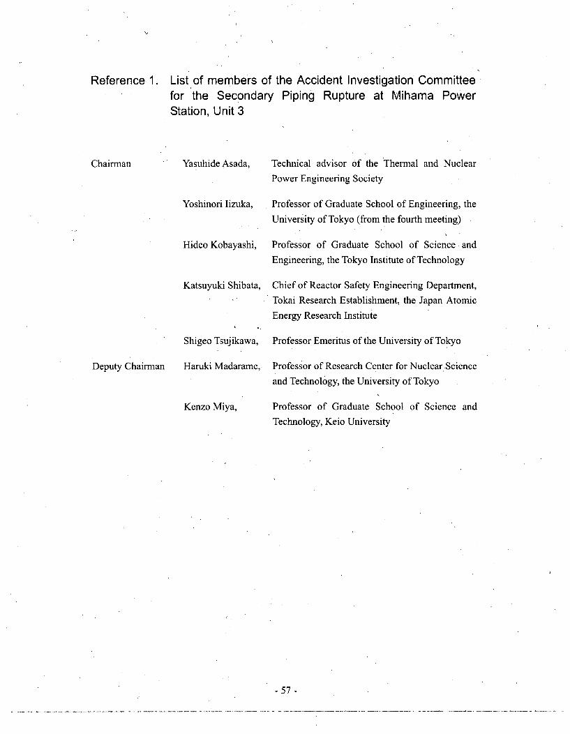
Reference 1. List of members of the Accident Investigation Committeefor the Secondary Piping Rupture at Mihama PowerStation, Unit 3
Chairman Yasuhide Asada,
Yoshinori lizuka,
Hideo Kobayashi,
Katsuyuki Shibata,
Shigeo Tsujikawa,
Haruki Madarame,
Technical advisor of the Thermal and Nuclear
Power Engineering Society
Professor of Graduate School of Engineering, the
University of Tokyo (from the fourth meeting)
Professor of Graduate School of Science and
Engineering, the Tokyo Institute of Technology
Chief of Reactor Safety Engineering Department,
Tokai Research Establishment, the Japan Atomic
Energy Research Institute
Professor Emeritus of the University of Tokyo
Professor of Research Center for Nuclear Science
and Technology, the University of Tokyo
Professor of Graduate School of Science and
Technology, Keio University
Deputy Chairman
Kenzo Miya,
-57-

Reference 2. Progress of deliberation
First session, August 11 (Wednesday), 2004
Outline of the secondary pipe rupture accident at Mihama Power Station, Unit 3
Results of on-the-spot survey.
Concepts and situations of inspection of the ruptured pipe portion
Second session, August 19 (Wednesday), 2004
Report on the secondary pipe rupture accident at Mihama Power Station, Unit 3
Outline of on-the-spot inspection
Concept of investigation procedure to determine causes for the secondary pipe rupture
accident at Mihama Power station, Unit 3
Results of collected reports on the pipe wall thinning events
Third session, August 27 (Friday), 2004
Concept of investigation procedure at the Investigation Committee on the Secondary
Piping Rupture Accident at Mihama Power Station, Unit 3
Clarification of the mechanism of the pipe rupture
Tendencies in pipe wall thinning and control techniques
Appropriateness of maintenance management for pipe wall thickness
Regulations on pipe wall thinning controls in the US
Results of investigation into pipe accident at Shinchi Power Station, Unit 2 of Soma
Kyodo Power Company, Ltd.
Examination of conformance state of water and steam piping at thermal power facilities
with technical standards
Fourth session, September 6 (Monday), 2004 (held at Fukui City)
Clarification of the mechanism of the pipe rupture
Situation of inspection by KEPCO
Controls of pipe wall thinning
Recurrence prevention measures
Skeleton (draft) of the interim summary
Fifth session, September 17 (Friday), 2004
Background, immediate measures and future tasks of KEPCO
Clarification of the mechanism of the pipe rupture
Situation of inspection
Background of registration omission for inspection
The Interim Summary (draft)
- 58 -
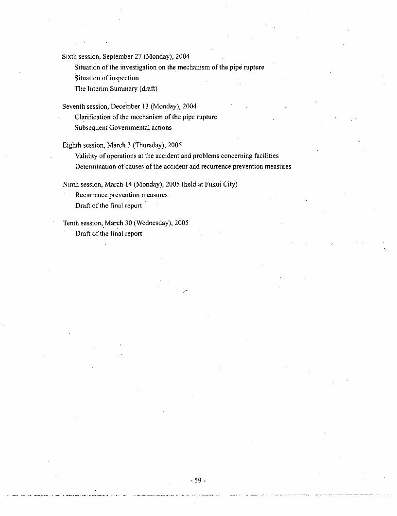
Sixth session, September 27 (Monday), 2004
Situation of the investigation on the mechanism of the pipe rupture
Situation of inspection
The Interim Summary (draft)
Seventh session, December 13 (Monday), 2004
Clarification of the mechanism of the pipe rupture
Subsequent Governmental actions
Eighth session, March 3 (Thursday), 2005
Validity of operations at the accident and problems concerning facilities
Determination of causes of the accident and recurrence prevention measures
Ninth session, March 14 (Monday), 2005 (held at Fukui City)
Recurrence prevention measures
Draft of the final report
Tenth session, March 30 (Wednesday), 2005
Draft of the final report
7-
-59-

Appendices
Appendix I Initial reactions, notification to the related organs and actions for rescue of
victim s (in tim e sequence) .......................................................................... 61
Appendix 2 Ruptured condition of secondary piping at Mihama Power Station, Unit 3 .... 62
Appendix 3 Results of metallurgical investigations by JAERI ..................................... 66
Appendix 4 Results of pipe flow analysis by JNES and JAERI .................. 69
Appendix 5 Results of thinning behavior analysis by JNES .............................................. 71
Appendix 6 Results of pipe rupture structural behavior analysis by JNES ........... 72
Appendix 7 Study of validity of "PWR Management Guidelines" ............................... 73
Appendix 8 General description of thinning phenomenon of main feed water piping of
O hi Pow er Station, U nit I ............................................................................ 86
Appendix 9 Results of verification by NISA for the reports of control situation of piping
thinning from electric power companies ......................... 88
Appendix 10 Pipe wall thickness control at thermal power stations ................ 90
Appendix 11 Requirements for pipe wall thickness control at nuclear power stations
(NISA-163a-05-1 as of February 18, 2005, issued by NISA) .................... 93
Appendix 12 Documentary guidance to KEPCO (September 27, 2004, the Minister of
Econom y, Trade and Industry) ....................................................................... 108
Appendix 13 Requirements necessary for establishment of concrete recurrence
prevention measures (M arch 14, 2005, NISA) ............................................... 111
-60-

Wpe-ndI x 1
Initial reactions, notification to the related organs and actions for rescue
of victims (in time sequence)
0 August 9, 2004
15:22 A "Fire Alarm Operation" alarm, etc., was generated. An operator promptly
announced a "fire breaking out in the turbine building" through a public address
system.
15:27 An operator found a victim at the front of an elevator on the second floor of the
turbine building.
15:30 A member of the General Manager's staff dialed 119 (the first report). Shortly after
that, the member also called for ambulances. Then the local municipality (Mihama-
cho) was notified about the occurrence of the accident.
15:30-15:45
A member of the General Manager's staff ordered an evacuation from the turbine
building through a public address system.
15:32 The Mihama Nuclear Safety Inspector's Office of NISA was notified about the
occurrence of the accident.
15:34 The local municipality (Fukui Prefecture) was notified about the occurrence of the
accident.
15:35 On-site rescue personnel (the Power Station staff (including the staff of an affiliated
company)) started to rescue victims.
15:58 An ambulance crew (fire-fighting vehicles) arrived. Firefighters and the Power
Station staff cooperated in conducting a rescue operation for victims.
16:46 All 11 victims were transported to hospitals.(The hospitals to which the victims were transported: 8 victims at Tsuruga City
Hospital, 3 victims at Fukui National Hospital)
After that, while access to the accident site was restricted, a search-and-rescue
operation was continued.
19:00 The fire station confirmed that no victims were found in the turbine building.
-61 -

.[pendix 2]
Ruptured condition of secondary piping at Mihama Power Station, Unit 3
1. Summary of investigation
Ccntainment vessel
Main data:(1) Piping downstream of the orifice; Material: JIS G SB42, Diameter (hereinafter referred to as D):
approximately 560 mm, Initial thickness: approximately 10 mm(2) Flow condition during operation; Flow rate: approximately 1,700 t/h, Pressure in use:
approximately 0.93 MPa, Temperature: 142 degrees Celsius, Flow velocity: approximately 2.2m/sec
(3) Operation time; approximately 185,700 hours(4) Water quality; pH: 8.6 to 9.3, Dissolved oxygen concentration: less than 5 ppb
- 62-

2. Results of. pipe wall thickness measurements
Area downstream from0= the orifice of the A-loop
SNear 10 (62 crm)
(Weld)
J27(
to-.7'
asit' ~ 15
Area downstream fromthe orifice of the B-loopNear 10 (62 cm)
' %(Weld)
a
Near 1D from the downstream end of the orificeFArea downstream from A rea downstream frorr
the orifice of the A-loop . the orifice of the B-tool• . ...... ....... Near 2D (112crm) I......i.......,.,, Near 2D (112 cm )
(Weld) '- (Weld)/)
I 10
22.L•,,!" I 3W 2
Near 2D from the downstream end of the orifice
Situation of reduced thickness at the Situation of reduced thickness at thedownstream orifice of A-piping downstream orifice of B-piping
El
- 63 -

3. Observation results of the inner surfaces of the piping
A piping orifice downstreamTo tlerg.thabo 2.500 mr Upstream side , •M y ,r
-ootoM . pý- Uotra

4. Situations at downstream of the vent hole
Outer diameter of flangeSFlange
A piping orifice downstream flange
Shape ofdepressed
area
45. ... ,4........ Flange - •!
•'• Orifice
(5t)
G(4t)e
Fillet weld • ,
-om ..... Piow direction Vent holeNominal
thickness Depressed Enlarged view(101) area
LI
Outer diameter of flange
rf"" Flange '
E* :I
Depressed
area
'I Enlarged view
B piping downstream flange
Sources: Extracted for Section 1, 2, and 3, from Material 7-1-1(Attachment 1-1) of the 7th accident investigation committee,and for Section 4, from Material 5-1-2 (Attachment 1) of the5th accident investigation committee (documents submittedfrom JAERI and JNES)
- 65 -

Noendix 31
Results of metallurgical investigations by JAERI
Summary
By using a scanning electron microscope (SEM), the fracture surface of the ruptured opening
was observed with emphasis on the vicinity of the thinnest area. In each SEM photograph,
there were dimples (small depressed areas formed on a fracture surface at the time of the
occurrence of ductile fracture) on the fracture surface. In addition, in comparison with the
hardness in the areas other than the ruptured opening, the hardness in the vicinity of the
ruptured opening had a tendency to increase toward the edge of the ruptured opening.
Therefore, it is considered that plastic deformation occurred at the time of the occurrence of
the fracture. For these reasons, it was proved that the fracture mode was ductile fracture.
- 66 -

of theaxial crack.
i
0.8,0.70.60.50.40.3020.10.0
-2
Wall thickness distribution in theper ip heralI are a o f th e axialI cra ck
00-o75
-150 -125. -100 -75 -50 -25 /0 25Distance from the short, circumferential crack (mm)
/7f75,/ J
/ I inner side of the
1- ,-,,-' - I - " -A.5.Ommj 0,05m
Dimples, which indicated ductile fracture, were found on the fracture surface.
Figure 1 Condition of the fracture surface and wall thickness distribution in the vicinityof the crack at the ruptured opening
- 67 -

3003OO
a .-250 -
-z200 ---- Hardrness in areas-o -er
1505 4 3 2 1 0
Distance from the edge (mm)
Figure 2 Hardness distribution on a cross-section surface in the vicinityof the ruptured opening
Sources: Extracted from Material 7-1-1 (Attachment 1-1) of the 7th accidentinvestigation committee (documents submitted from JAERI)
- 68 -
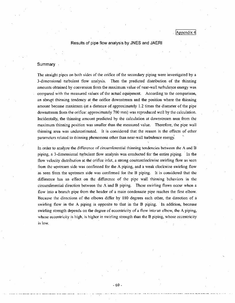
Wpe~ndix-4]
Results of pipe flow analysis by JNES and JAERI
Summary
The straight pipes on both sides of the orifice of the secondary piping were investigated by a
3-dimensional turbulent flow analysis. Then the predicted distribution, of the thinning
amounts obtained by conversion from the maximum value of near-wall turbulence energy was
compared with the measured values of the actual equipment. According to the comparison,
an abrupt thinning tendency at the orifice downstream and the position where the thinning
amount became maximum (at a distance of approximately 1.2 times the diameter of the pipe
downstream from the orifice: approximately 700 mm) was reproduced well by the calculation.
Incidentally, the thinning amount predicted by the calculation at downstream area from the
maximum thinning position was smaller than the measured value. Therefore, the pipe wall
thinning area was underestimated. It is considered that the reason is the effects of other
parameters related to thinning phenomena other than near-wall turbulence energy.
In order to analyze the difference of circumferential thinning tendencies between the A and B
piping, a 3-dimensional turbulent flow analysis was conducted for the entire piping. In the
flow velocity distribution at the orifice inlet, a strong counterclockwise swirling flow as seen
from the upstream side was confirmed for the A piping, and a weak clockwise swirling flow
as seen from the upstream side was confirmed for the B piping. It is considered that the
difference has an effect on the difference of the pipe wall thinning behaviors in the
circumferential direction between the A and B piping. These swirling flows occur when a
flow into a branch pipe from the header of a main condensate pipe reaches the first elbow.
Because the directions of the elbows differ by 180 degrees each other, the direction of a
swirling flow in the A piping is opposite to that in the B piping. In addition, because
swirling strength depends on the degree of eccentricity of a flow into an elbow, the A piping,
whose eccentricity is high, is higher in swirling strength than the B piping, whose eccentricity
is low.
- 69 -

10
E8
2
(0
A-piping
C Measured values
-PLAHSY-8FC (First-rder upw.rd)-- FLUENT (Fast-rder upwimnd). FLUENT (Seond-order upwind)
STAR-CD (Second-order upwind)
10
E 8E
(6
.~4
00 500 1000 1500 2000 2500 3000
Distance from the orifice (mm)
0 500 1000 1500 2000 2500 3000
Distance from the orifice (mm)
Figure 1 Comparison between the thinning amounts predictedby near-wall turbulence energy and the measured values
(at 270 degrees clockwise as seen from the upstream side)
Orific~e
Distribution of near-wallturbulence energyA-piping
Strong counterclockwise swirlingflow as seen from the upstreamside
The number of analysis gridsapproximately 360 million
Weak clockwiseity on swirling flow as seen
ce (mn) from the upstream sideB pipingNear-wall turbulence
energy (m2/s
2)
Strength of flow veloca cross-section surfac
Figure 2 Analysis results based on the simulation of the actual piping
Figure 3 Mechanism of the occurrence of swirling flow in piping
Sources: Extracted from Material 7-1-1 (Attachment 2-1),of the 7th accidentI investigation committee (documents submitted from JAERI and JNES)
- 70-

Apendix 5t
Results of thinning behaviors analysis by JNES
Summary
Regarding the thinning amounts, by using PASCAL-EC, the thinning amounts of carbon steel
tube caused by erosion-corrosion (E/C) in single-phase water flow were calculated on the
basis of the prediction formula given by Kastner et al. The figure below shows the analysis
results related to the wall thinning behaviors by using the actual water environment and
material data. In the figure, the maximum thinning amounts of the A and B loop piping in
Mihama Power Station, Unit 3, are also shown. In addition, the maximum thinning amount
is calculated on the assumption that the initial wall thickness is 10 mm, and error bars are
shown in consideration of 0.7mm tolerance of wall thickness. The measured maximum
thinning amounts of A and B-loop piping were somewhat larger in comparison with the
analysis results as shown in the figure below. In consideration of existing knowledge
regarding the prediction accuracy of thinning amounts, it is concluded that the thinning
amount of A-loop piping is within the range of predictable variations.
10
8
6
4
2
0. . . . . . . . . . . . . . . . . . . . . . .
0 5 10 15 20 25 30
Figure 1 Analysis results of thinning progress based on actual water environment data, etc.Analysis conditions: Flow velocity = 2.2 m/s,
Water temperature = 146
-71 -
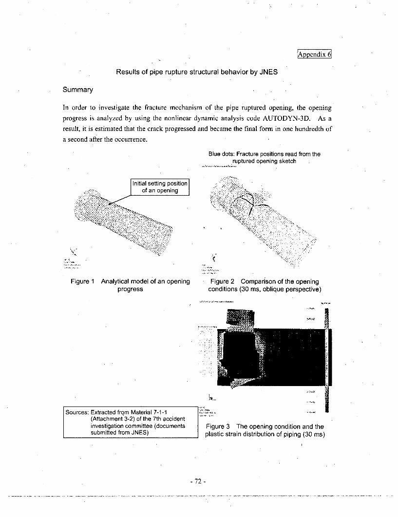
Appendix 6
Results of pipe rupture structural behavior by JNES
Summary
In order to investigate the fracture mechanism of the pipe ruptured opening, the opening
progress is analyzed by using the nonlinear dynamic analysis code AUTODYN-3D. As a
result, it is estimated that the crack progressed and became the final form in one hundredth of
a second after the occurrence.
Initial setting positionof an opening
Figure 1 Analytical model of an openingprogress
Blue dots: Fracture positions read from theruptured opening sketch
Figure 2 Comparison of the openingconditions (30 ms, oblique perspective)
Sources: Extracted from Material 7-1-1(Attachment 3-2) of the 7th accidentinvestigation committee (documentssubmitted from JNES)
Figure 3 The opening condition and theplastic strain distribution of piping (30 ms)
- 72 -

Study of validity of "PWR Management Guidelines"
1. Summary of "PWR Management Guidelines"
(1) Scope
Carbon steel piping of PWR plant secondary side (excluding small diameter piping such
as instrument system)
(2) Inspection method
Check by ultrasonic thickness measuring instrument based on JIS Z 2355 "Methods for
measurement of thickness by ultrasonic pulse echo technique"
(3) Subject of inspection
Areas where channeling occurs and 2 x D downstream areas (D: piping diameter) among
main systems to be inspected shown in Table 1 are specified as main inspection areas
(Table 1).
For other areas, 25% of areas where channeling occurs are also specified as subject of
inspection for ten years.,
Areas where channeling occurs include downstream area of a control valve,
downstream area of a globe check valve, elbow, T pipe, orifice downstream,
downstream area of a swing check valve, reducer, and curved piping.
(4) Inspection frequency
Remaining life to the necessary minimum thickness on calculation should be determined
at each location, and the area concerned should be inspected before the remaining life isless than two years. It is also stipulated that the inspection should be repeated using
evaluation of inspection results until the remaining life reaches to less than two years
(Figure 1).
- 73 -

Table 1 Main systems to be inspected
Classifil Requirements
cation Wetness Flow Tempera- Typical system name Remarks- fraction velocity I ture,
150-200 0 CNo. 6 high pressure heater drain piping,No. 5 high pressure heater drain pipingLess than
30 m/sec200-250 0C
Moisture separator heater drain tankdrain piping
Morethan15%
30-50 150-200 0 Crn/sec 200-2500 C
More than50 m/sec
150-200 0CHigh pressure exhaust piping drainpiping
200-2500 C
Less than 150-200°C30 m/sec 200-250°C Steam converter heating steam piping
No. 5 extract piping, No. 4 extract30-50 150-200°C ppn
5-15% m/sec 200-2500C
No. 5 extract piping, No.4 extractMore than piping50 m/sec No. 6 extract piping, No.5 extract
200-250 0 C pinIpiping
Two-phaseflow
150-2000 C I Deaerator air vent pipingApply forall main
inspectionareas.Less than
30 rn/sec
No. 6 high pressure heater air vent200-250'C piping, No. 5 high pressure heater air
vent piping
More than Moisture separator heater balance250'C piping
Lessthan 5%
150-200 0C30-50 200-250 0 Cm/sec More than Moisture separator heater balance
2500C piping
150-2000 C
More than50 m/sec
200-250 0C
More than2500 C
I. *4 4 .4
100-150 0C Main condensate pipingLess than3 m/secSingle-
phaseflow
150-2000 CFeedwater booster pump suction piping,moisture separator drain piping
Water 4 .4
100-150°C3-6 mn/sec
150-2000 CMain feedwater piping, feedwaterbooster pump discharge piping
- 74 -

Single- 100-1500Cphase Water More thanflow 6 m/sec 150-200 0C
(cont.)
Less than No. 4 low pressure heater drain piping30 m/sec
Two- More 30-50 Apply forphase than m/sec 100-150 0 C only-,flow 15% down-
More than stream of50 m/sec control
Less than 3 valve andSingle- m/sec globeSingle-check
phase Water 3-6 m/sec 200-2500 C Main feedwater piping valve.
flow More than
6 rn/sec-: No piping exists at present plants.
- 75 -

ItE~
LrUP) =tno - Negative allowance - tnr H
Thinning rate (Wr1 °))
Lr(0) Remaining lifetoo Nominal thicknesstnr Required thickness on
calculationWr(g) Initial thinning rate
specified in Table 1H Operation time
Tl-1 Wrio) value used fort Lr10 set
ieesc 200C 00 C 250C 0 C~r
Twoph- 1 30 n], %lb
o0.3015% rno
Ea0 m orlwl
--ph. 30 m,,
thacen 555 50 mlu, nf~~&h~~i/d
(p~ossoin 50 ml,mioluafl oroe 1nh
3 ndi
Waler atngle. 3/.or~~wphase flow 60
Note) 1. UnitofWRt': ,10'.mlHr2. Scope marked wrh shadow
(1) For downstream of contmol Wval, figures in the table should be mulbplied by S.(21 For downsteam of Wove chear elveo fl.ure in the table should be multolied b5 2.
0a)
0
0
a)CL0
:3
Lr = tmin - tnr
Thinning rate (Wr(1 )
Lrt) Remaining life (time)trmin Measured minimum thicknesstnr Required thickness on calculationWrl1) By the method in Table-2
Table-2 Wr ) value used for Lr(1 ) set
Inspect two years before (eo isetexpiring remaining life Second inspection)
Reevaluation of thethickness difference
method
(Two years or less)
< Remaining life (Lr~t ) Replacement plan
(Longer than two years)
Inspect two years beforeexpiring remaining life (Second inspection)
Method classification(area concerned) Calculation of thinning rate
Longitudinal thickness F/it=-(Maximrum thickness in pipe axis
method directiony(operation time)
Thickness Immediatelyafter manufacturing Isuniform longitudinaily . . .
f Teipel , mother pipe sidec. of T pipe, curved pipe)difference n -
4 Circumferential thickness /r('-(Maximum thickness in pipe axismethod directionV/(operation time)Thickness immediately
, after manufacturing Isuniform circumferentially(reducer, straight pipe*.branch pipe side of T
Z pip.) Maximum thickness difference I t_ -Nominal thickness method mr,'. , -n.,uwi n.kn.n
lreducer. straiht pipe* m"rwu mor(,a)E
a)
0)
a)
CL
Eu
n)
zf
IfIE valuate remaining life bythe least-squares method
I-or reducer or straight pipe, apply the thinning rate by the thicknessdifference method or the nominal thickness method, whichever is larger, forevaluation.
I(Two years or less)
Remaining life (Lr Replacement plan
(Longer than two years)
LrF(2) tmin - tnrThinning rate (Wr12 )
L (2) Remaining life (time)trin i Measured minimum
thicknesstnr Required thickness
on calculationWr2) By the method in
Table-3
Table-3 Wr(2) value used for Lr(2) setMethod
classification Calculation of thinning rate(area concerned)
Obtain the slope by the least-squares method to determine Wr(2)
E Least square "C: method
_ (for all areas) .
'- Operation time
Figure 1 Remaining life determination method
- 76 -
2. Piping thinning control method and trend of thinning
(1) Factors of thinning to be controlled
The PWR Management Guidelines used by PWR operators and the management method
used by BWR operators are intended to control thinning due to erosion and corrosion.
In this case, erosion and corrosion mean the "thinning phenomenon caused by combined
actions of mechanical erosion and chemical corrosion," typically showing fish scale-like
pattern on the thinned surface.
(2) Evaluation based on data submitted in report collection
We analyzed the thinning trend using the following two materials: (1) Thinning
measurement data for individual plants reported from every licensee responding to the
report collection for inspection related to piping thinning phenomenon dated August 11,
2004; (2) Thickness measurement data of secondary piping of Mihama Power Station,
Unit 3 submitted by KEPCO responding to the report collection on the secondary
piping rupture at Mihama Power Station, Unit 3 dated August 18, 2004.
(3) Thinning related to PWR piping
Figure 2 shows the trend of thinning measured by every PWR plant and its resultant
actual thinning rate. Comparison between the actual thinning rate and the initially set
value of thinning rate specified in the PWR Management Guidelines reveals that the
actual thinning rate, except for the main feedwater piping in A-loop, is lower thanthe
initially set value of thinning rate.
Figure 3 shows the trend of thinning measured at Mihama Unit 3, and comparison with
the initially set value of thinning rate shown in the PWR Management Guidelines.
According to the figure, the actual trend of thinning is lower than the initially set value of
thinning rate except small part of data.
Figure 4 shows a comparison of thinning between main inspected systems, all of which
are inspected in accordance with the PWR Management Guidelines and other systems
inspected on a sampling basis. As a result, the thinning rate of other systems is smaller
than that of the main inspected systems as a whole. This suggests that the thinning rate
is affected by an environmental difference. Nevertheless some-other systems show
thinning rates comparable with the main inspected systems.
- 77 -

(4) Estimated thinning rate of ruptured piping of Mihama Unit 3
Estimated thinning rate of ruptured piping of Mihama Unit 3 was calculated based on the
remaining life evaluation equation in the PWR Management Guidelines to be 0.47 x 10 4
mm/Hr. This is almost the same as 0.45 x l0• mm/Hr, the initially set value of thinning
rate in the guidelines.
The remaining life evaluation equation to determine the remaining life for uninspectedareas usually uses "nominal thickness - negative allowance" for the original thickness,
but for conservative evaluation of thinning rate the negative allowance will not be
included in calculation. This is an issue to study in the future.
3. Measuring area and measuring points in main inspection areas
(1) Determination of measuring points
PWR operators determine measuring area and measuring points at every periodic
inspection on a contract basis with inspection companies. Concretely, they specifymeasuring sections depending on the structure at measuring areas and determine eight or
four measuring points at a section (hereinafter referred to. as "typical measuring .points")
and apply 3 x D (D: piping diameter) for downstream area of an orifice for measurement.At the typical measuring point, the thickness if less than the threshold thickness for
detailed measurement will be measured in detail at a 20 mm pitch around the typical
measuring point.
(2) Analysis of measured results
NISA used detailed measurement results of Mihama Unit .3 obtained from KEPCO
through the report collection requirement to analyze the relation between the measuring
area and measuring points and, occurring situa'tion of thinning. Figure 5 shows
distribution of measured results. This reveals that measurement by the typicalmeasuring points and resultant detailed measurements are effective to judge the shape
and dimensions of the area concerned.
4. Thinning of BWR piping
(1) Applied management method
BWR operators specify their own management methods individually, but the contents
have many common descriptions. Comparison with the PWR Management Guidelines
shows that the inspection area concerned is wider for BWR than PWR, but the inspection
for PWR is more frequently than BWR because of the following reasons. One reason is
- 78 -

that PWR has main inspection systems for entire inspection required much more than
BWR and the other reason is that BWR has less numbers of inspection areas than PWR
because of frequent sampling inspection.
(2) Thinning of BWR piping
Figure 6 shows the trend of thinning measured at BWR plants and its resultant actual
thinning rate. Comparison of Figure 2 and 6 reveals that PWR and BWR are different inthe trend of thinning and the rate of BWR is lower than that of PWR. This is caused by
the difference in water chemistry control between PWR and BWR.
- 79 -
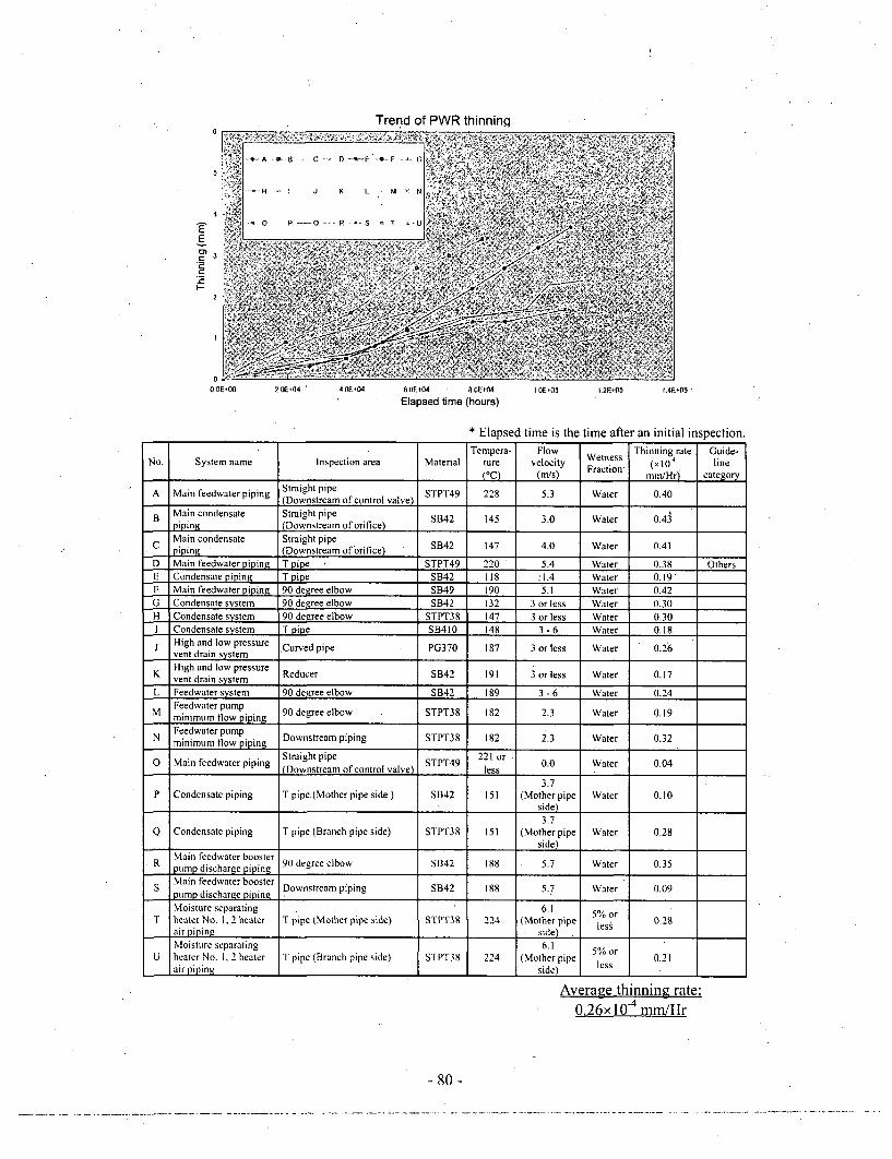
E
I"-F_2
O.OE.00 2.10F04 4,0E.04 6,OE+04 . AOF+4
Elapsed time (hours)I OEý05 I 2E+5 I.4A •05
* Elapsed time is the time after an initial inspection.Tempera- Flow Thinning rate Guide-
No. System name Inspection area Material ture velocity Wetness T rt GuideFraction' (x 10" line(°C) (m/s) Fracion mm/Hr) category
A Main feedwater piping Straight pipe(Downstream of control valve) STPT49 228 5.3 Water 0.40
B Main condensate Straight pipe SB42 145 3.0 Water OApiping (Downstream of orifice)Main condensate Straight pipepiping (Downstream of orifice) . B42 147 4.0 Water 0.41
D Main feedwater piping T pipe STPT49 220 5.4 Water 0.38 OthersE Condensate piping T pipe SB42 118 '1.4 Water 0.19F Main feedwater piping 90 degree elbow SB49 190 5.1 Water 0.42G Condensate system 90 degree elbow SB42 132 3 or less Water 0.30H Condensate system 90 degree elbow STPT38 147 3 or less Water 0.301 Condensate system T pipe SB410 148 3-6 Water 0.18j High and low pressure Curved pipe PG370 187 3 or less Water 0.26
vent drain systemK High and low pressure Reducer SB42 191 3 or less Water 0.17
vent drain systemL Feedwater system 90 degree elbow SB42 189 3 -6 Water 0.24
Feedwater pumpM minimum flow piping 90 degree elbow STPT38 182 2.3 Water 0.19
N Feedwater pumpminimum flow piping Downstream piping STPT38 182 2.3 Water 0.32
0 Main feedwater piping Straight pipe STPT49 221 or 0.0 Water 0.04(Downstream of control valve) less
3.7P Condensate piping T pipe (Mother pipe side) SB42 151 (Mother pipe Water 0.10
side)
3.7Q Condensate piping T pipe (Branch pipe side) STPT38 151 (Mother pipe Water 0.28
I side)
R Main feedwater booster 90 degree elbow SB42 188 5.7 Water 0.35___ pump discharge piping 9 ee o4 8 5t 0.35S Main feedwater booster Downstream piping SB42 188 5.7 Water 0.09
pump discharge pipingMoisture separating 6.1 5% or
T heater No. 1, 2 heater T pipe (Mother pipe side) STPT39 224 (Mother pipe less 0.28air piping side) .Moisture separating 6.1 5Or
U heater No. 1, 2 heater T pipe (Branch pipe side) STPT38 224 (Mother pipe less 0.21air piping side) less
Average thinning rate:0.26x 10⁻⁴ mm/Hr
- 80-

(Note) Initially set value of thinning rate in PWR Management GuidelinesTemperature
I 000c 1001C - I 50o c- 200•C - 250oCor less 150°C 200°0 250'C or more
Two phase 2-'flow , . or less
Wetness -' 30 m/s -
fraction 15% -" 50r/s 0.30ormore 50mn/sor more I30 m/s
Two phase 3 "
flow, 3 or less
Wetness -2 30 n/s -P 50 m/sfraction 5 to
1.5% 1Z 50 m/sor more
Two phase 30 m/s ,flow, or less K~
Wetness " 30 m/s - sfraction 5% , 50 n/s
or less , o .(possibly 50 m/s IF S 1involving or moredrain) .. !+ '?3 + +" • ... .!
. or less , o nly 'or 00 , --
Water single- • 3 ni/s - • only for,,:phaser finlow P 6 Fs/ '-;s
045 du'reamno
phase flow 6, control salve:. 6 mn/s dor or +• t .•+ of otobe chockl
or more
Note) I.UnitofWR'01: 10tmm/Hr
2. Scope marked with shadow
(I) For downstream of control valve, figures in the table should be multiplied by 5.(2) For downstream of globe check valve, figures in the table should be multiplied by 2.
Figure 2 Measurement area and the trend of thinning in PWR piping
-81 -
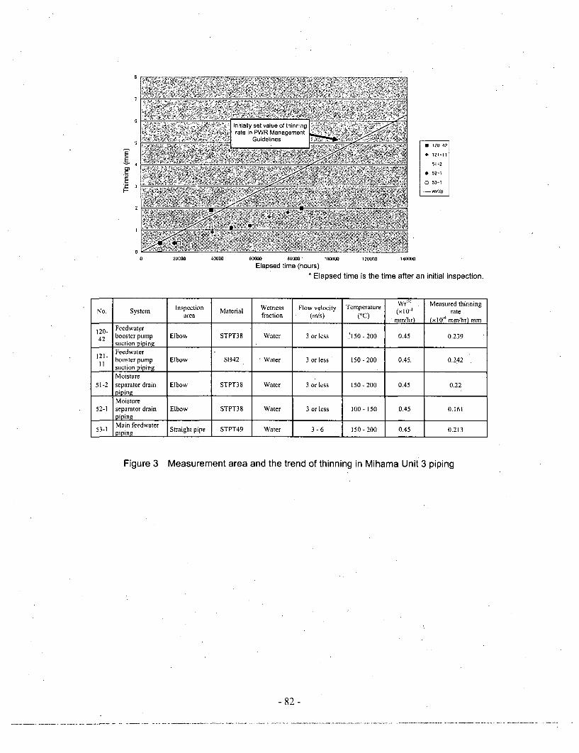
Eý51 2-4
*52-1
0 53-1
0000 120000 140000
ours)* Elapsed time is the time after an initial inspection.
20)000 4000 0000 W 00o0-
Elapsed time (ho
No. System Inspection Material Wetness Flow velocity Temperature Wr(" Measured thinning
area fraction (m/s) (°C) mm/hr) (xlO"4 mm/hr) mm
120- Feedwater42 booster pump Elbow STPT38 Water 3 or less '150 - 200 0.45 0.239
suction pipingFeedwater
121- booster pump Elbow SB42 -Water 3 or less 150-200 0.45, 0.2421I suction piping
Moisture51-2 separator drain Elbow STPT38 Water 3 or less 150-200 0.45 0.22
piping
Moisture52-1 separator drain Elbow STPT38 Water 3 or less 100- 150 0.45 0.161
pipin2zMain feedwater
53-1 Miing Straight pipe STPT49 Water 3-6 150-200 0.45 0.213
Figure 3 Measurement area and the trend of thinning in Mihama Unit 3 piping
- 82 -

E1E
F-'
•..• •'•.•..:L _•(-.•,-•: '-:• Main
inspectioni•!, .•;],•.| system •
SUE Othersystems
100000 120000 140000
• Elapsed time is the time after an initial inspection.
0 20000 40000 60000 00000Elapsed time (hours)
No. System Inspection Material Wetness Flow velocity Temperature Measured thinning ratearea fraction (m/s) (°C) (x 10' mm/hr) mm
1-2 No.3 extracting piping T'pipe STPT38 5% or less 30-50 100- 150 0.26615-1 Turbine bypass piping Reducer STPT39 5% or less 30 or less 250 or more 0.07516-5 Turbine bypass piping Reducer STPT40 5% or less 30 or less 250 or more 0.02417-2 Moisture separator heater steam piping Elbow STPT41 5% or less 30- 50 250 or more 0.0219-1 Moisture separator heater steam piping Elbow STPT42 5% or less 30-50 250 or more 0.13520-7 Moisture separator heater steam piping Reducer STPT43 5% or less 30- 50 250 or more 0.03223-1 Deaerator heater steam piping Elbow STPT44 5% or less 30 or less 250 or more 0.203
25-3 No.2 heater drain piping Elbow STPT45 15% 30 or less 100 or less 0.438(Downstream of control valve) or more25-6 No.2 heater drain piping Elbow STPT46 15% 30 or less 100 or less 0.334
(Downstream of control' valve) or more
25-9 No.2 heater drain piping Elbow STPT47 15% 30 or less 100 or less 0.327(Downstream of control valve) or more
42-6 Low-pressure drain tank balance piping Elbow STPT48 Water 3 or less 100 or less 0.02565-4 Main steam piping T pipe SB42 5% or less 50 or more 250 or more 0.19466-2 Turbine steam dump piping Tpipe STPT38 5% or less 30 or less 250 or more 0.101
Figure 4 Comparison of main inspection systems and other systems in Mihama Unit 3
/
- 83 -

9~~r~itesrn point2 :1aitd " asuin pointr --easunng point tor minimum*.. .. .... . g
i. i A : • • ; : :
*'4 ' ' 3. I I ;
- iii.
ii ~ Nain it,-ON~j..n
Skdcitiin N, i Nii. 253.
hk..,uringi~~niu liei Ot tt
hrii.inhiiiirs hou'in irs
Nlaimit di ,nit) tO NIin
t iniikni u
N~imi MA .1
ciit t~iie iii i1 tmontent ti . ... : ....
j0
olw direction,
t4
1-1-1. ý .1
.A .LB.L_,i A, ., .. 1 [.. I. I.
-anomat easuingort- mountedr...... ::npnitC, ulr, ...... ".r
,•Detailed measung pointiMeaunrn non for minimum thicknesa
... ... .. ....
S....... ......... s
.. .... . .... .. ..i i
U Bos'
Oufic . ..
.... i ....Plnt s n ceiin rned titinnult Unit 3
7imi winiunot itSNaeopar Iron~ piiip diiiharii
Skliiin Nii. - p- N,,. 73
MOuting Nt 65.947e1 ni
M.teiais STP'tI8Mnninumniiriin rsutn 1.57 WMP.
Outerdi etr3 . mN mol il hickness 10.3.m
(Iuint i lhicknr m alculalitm 3, in
Cluitaio innii MumogmcmntCGtid lines ______
4: 1.•
View fro ýupstreamsd L0 I . . .. . i '! .,.. I i
......ttj , .......r., , .
-4 - . .. A ,.!. •. .
Figure 5 Measured results of Mihama Unit 3 (example)
- 84 -

BWR thinninq trend
5-
4'
E
Z
2
00.0E+00 2.0E+04 4.OE'04 6.0E'04 8.OE+04 I.E'-05 1.2E+05 IAE-05
Elapsed time (hours)* Elapsed time is the time after an initial inspection.
No. Inspection part Material Temperature Flow velocity Wetness Thinning rate(°C) (m/s) fraction (N10-
4 mmiHr)
A Reactor feedwater pump inlet elbow SB49 114 3.1 Water 0.10B Moisture separator drain line elbow STPT42 194 0.4 Water 0.26C Downstream of condensate cleanup line orifice STPT38 34 6 Water 0.16D Downstream of M/DRFP outlet line valve STPT49 196 6.3 Water 0.02E Feedwater heater drain line elbow STPT38 113 5.6 Water 0.08F Straight piping at downstream of feedwater recirculation SB49 34 4.3 Water 0.10
line orificeG HPCP suction line elbow SB46 33 2 Water 0.14H M/DRFP suction header line T pipe SB49 190 4 Water 0.08I M/DRFP mini-flow valve after valve downstream elbow STPT49 145 5 Water 0.04J No.3 feedwater heater outlet line straight pipe SB42 144 5 Water 0.01K M/DRFP mini-flow piping orifice upstream safe end A105 190 5.2 Water 0.14L M/DRFP mini-flow valve downstream reducer SF50A 144 5.1 Water 0.08M Condensate pump discharge flow rate regulating valve STPT38 60 1.3 Water 0.04
downstream reducerN T/DRFP discharge piping elbow SB49 145 5.4 Water 0.05O T/DRFP mini-flow line FCV downstream STPT49 145 .5.1 Water 0.30p High pressure drain pump seal water regulating valve STPT370 43 1.8 Water 0.05
downstream elbowQ Main steam stop valve outlet straight pipe STPT42 277 39.3 0.4% 0.05R T/DRFP outlet elbow STPT42 158 4.7 Water 0.05S Feedwater pump recirculation line condenser return area STPT49 160 6.6 Water 0.02
straight pipeT Condensate pump outlet straight pipe SM41A 33 1.2 Water 0.10U Condensate system orifice downstream straight pipe STPT38 65 Water 0.11V Extracting system reducer SB46 207 1 1.5% or more 0.30W Feedwater system flow nozzle downstream straight pipe SB480 231 Water 0.31X Downstream of extracting system T pipe SB42B 193 43 Water 0.05Y Feedwater heater inlet elbow SM50A 98 4.5 Water 0.40Z Drain system cap SM41 A 40 1.5% or more 0.20a Condensate system elbow STPT49 70 Water 0.18
Averaged thinning rate: 0.13x 10⁻⁴ mm/Hr
Figure 6 Measured parts of thinning and its trend of, BWR piping
- 85-
edix ý8
General description of thinning phenomenon of main feed water pipingof Ohi Power Station, Unit 1
On July 5, 2004, measurement of thickness of main feedwater piping (carbon steel) connected
to the steam generator at KEPCO, Ohi Power Station, Unit 1 (PWR, rated electric output of
1,175,000 kW) under periodic inspection revealed that the thickness of piping elbows at three
lines in four lines was partially thinner than the thickness required on calculation (subject of
report based on the law.)
Visual inspection of the inside of cut-off piping shows that no abnormality such as cracks or
corrosion, etc. occurred, but thickness decreased with fish scale-like patterns characteristic of
erosion/corrosion on the entire region. Analysis for flow condition at the. elbow and its
upstream main feedwater isolation valve (globe valve) reveals that the flow disturbance that
occurred inside the piping was further intensified, potentially causing erosion/corrosion.
In 1989 and 1993, the elbow area concerned was inspected in the self-controlled inspection by
KEPCO to detect the trend of thinning, but since then the area had not been inspected until the
periodic inspection this time.
KEPCO decided to take the following countermeasures considering the above findings.
1) To replace the elbow area concerned with piping manufactured at the same dimensions
using the same material.
2) To strengthen, in the future, monitoring of thinning trends at the areas concerned
'including Ohi Power Station, Unit 2 with the same type of main feedwater isolation
valve, and to take the same countermeasures for areas with the potential to generate
significant thinning at the main feedwater system, including at other plants.
3) To review the total maintenance management system mainly for issues clarified this time
regarding the maintenance management and to take measures based on the results.
This thinned area belongs to the water piping operated at 230'C, so it is classified into "other
systems" in the PWR Management Guidelines. "Other systems" require inspection on a
sampling basis. The thinning phenomenon causes a need to review the PWR Management
Guidelines regarding whether the sampling inspection requirement is adequate for "other
systems" and how to manage the D system, because no significant thinning was detected in
the D system, which has the same structure and environment as the area concerned.
- 86 -

System outline diagram
Containment vessel
7• ries~r ý
Thinned areaThree points of A, B,
and C lines
Main steam Isolation valverMain steam pipingSteam
Main feedwater isolation valve W=X Main feedwater pping.ti, Turbine Generator
.. ,L~~~~ Cond........ ' •! kenserao
~Z . To outlet,C•: ooling water (sea water)
op • Circulationmlent Feedwater pump
Moeasurement results
Required MeasuredPiping shape thickness on minimum thicknesscalculation
A main feedwater piping curved section (450) 14.5 mmB main feedwater Piping curved section (900) 15.7 mm 12.1 mmC main feedwater piping curved section (90-) 13.9 mmD main feedwater piping curved section (901) 20.0 mm
Piping sp~cification
Outer diameter: about 410 mmThickness: about 21 mmMaximum internal pressure: about 8 MPaMaximum temperature: about 2301CMaterial: Carbon steel pipeFlow rate: about 1,700 t/h, loop
It was confirmed that the flow disturbancethat occurred at the inside of the mainfeedwater isolation valve (globe valve) wasfurther intensified at the piping curvedsection to potentially causeerosion/corrosion. I
F-Flow pattern analysis (4Enlarged view of "A" area I
f7-1
Main feedwater solati on
Slow
•xanlDl• I•: •xnRrltltetl ¢)I3RRrVRTI•n reSUlt or m•ln t'•dwRr'•r
FishScale,
It was confirmed that flow was disturbed downstream of themain teedwater isolation valve to potentially causeerosion/corrosion. L Fish Scale-like pattern typically appearing in
erosion/corrosion leading to thinning
Figure Investigation results of thinning at secondary system main feedwater piping elbowarea at Ohi Power Station, Unit 1
- 87 -

00
•pendix
Results of verification by NISA for the reports of control situation of piping thinning from electric power companies
Number of Number of areas applying thinninginspection areas control Number of areas
concernedmissing Remarks
After confirmation Already evaluated inspectionsbased on Inspected (*2) at typical inspection
instruction (* 1) area, etc. (*3) _.,____. _____ _ _ __._-_:-Condensate system 12,027 8,985 3,042 0Area where accident occurred at Mihama, Unit
3 and the similar area are excluded.
Feedwater system 7,374 6,761 608 5 Takahama, Unit 3 (5)
Main steam system 14,376 9,834 4,538 4 . Takahama, Unit 3 (2) and Ohi, Unit 3 (2)Extracting system 4,357 3,139 1,212 Mihama, Unit 3, Takahama, Unit 1, 3, and 4,
SExtracting system 4,357 3,139 1,212 4 Oi Ui 3 and 4 (1 each)
(23 units) Drain system 35,661 28,859 6,802 ___-___"__0____-__"____________
Steam dump system, SG blow-down, etc.Others 7,974 4,356 3,618 0, (Some companies counted this system as part of
. , the drain system or main steam system.)
F Subtotal 81,769 61,934 19,82-0 15(*4)
Condensate system 34,343 4,815 29,528 . .0.
Feedwater system 7,308 2,446 4,862 0
BWR Main steam system 7,971 928 7,043 0(29 units) Extracting system 1,966 326 1,640 0
Drain system 14,558 1,213 13,345 0
Subtotal 66,146 9,728 56,418 .""0__ "_.__ ,
Total 147,915 71,662 76,238 " 5(*4)
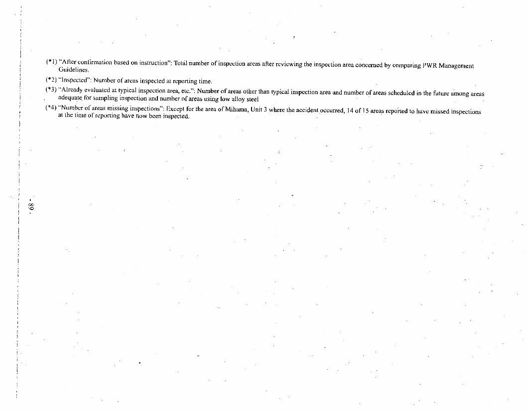
1(*) "After confirmation based on instruction": Total number of inspection areas after reviewing the inspection area concerned by comparing PWR Management
Guidelines.(*2) "Inspected": Number of areas inspected at reporting time.(*3) "Already evaluated at typical inspection area, etc.": Number of areas other than typical inspection area and number of areas scheduled in the future among areas
adequate for sampling inspection and number of areas using low alloy steel(*4) "Number of areas missing inspections": Except for the area of Mihama, Unit 3 where the accident occurred, 14 of 15 areas repoted to have missed inspections
at the time of reporting have now been inspected.
00

•Appendix 10
Pipe wall thickness control at thermal power stations,
1. Legal positioning regarding the pipe wall thickness control
Pipe wall thickness measurements at thermal power stations were not subject'to the periodic
licensee's inspections based on the Electricity Utilities Industry Law. Therefore, until now,
some licensees have verified conformance to the technical standards on the pipe wall
thickness as part of self-imposed safety preservation.
2. Implementation situation of the pipe wall thickness control by licensees
Regarding thermal power stations, on August 11, 2004, based on Paragraph 3 and 4 of Article
106 of the Electricity Utilities Industry Law, electric licensees, etc., that had thermal power
generation facilities (general electric enterprises and joint thermal power structure and captiveelectric structure establishers, etc.) were requested to make a report on the implementation
situation of non-destructive inspections of water and steam pipe wall thickness at the portions
where thinning can occur and inspection implementation plans for the portions not subjected
to inspections yet.
As a result, by October 19, the inspection implementation plans of pipe wall thickness were
submitted by electric licensees, etc. The compiled results are shown in "Table 1.
Implementation situation of the inspections for pipe wall thickness at thermal power stations."
According to the reports, approximately 487,000 portions among approximately 541,000
portions to be inspected had not been inspected until that time, but all licensees had the plans
to conduct inspections and evaluations concerning the pipe wall thickness to verify the safetyof piping, and expressed that inspections, etc., would be conducted in sequence.
Table 1. Implementation situation of the inspections for pipe wall thickness
at.thermal power stations
Number of the Number of the Number of theportions to be portions that were portions that were
inspected inspected not inspected
Eleven general Approximately Approximately, Approximatelyelectricity licensees 166,000 portions 14,000 portions 152,000 portions
Captive electric Approximately Approximately Approximatelystructure establishers 374,000 portions 39,000 portions 335,000 portions
tal Approximately Approximately Approximately,To 541,000 portions 53,000 portions 487,000 portions
- 90 -

3. Responses of NISA
3.1 Addition of the pipe wall thickness control to the periodic licensee's inspections
In consideration of the indications in the interim report, in order to ensure that conformity to
the technical standards regarding the pipe thinning phenomena. would be continuously
verified. NISA decided that the wall thickness inspections on the pipe susceptible to thinning
would be added to the objects of the periodic licensee's inspections.
Specifically, in the amendment of the Rules for the Enforcement of the Electricity UtilitiesIndustry Law described in 4.4.1 (1) of this report, the equipment subject to the periodic
licensee's inspections was clarified regarding steam turbines, etc., of thermal power
generation equipment. In addition, in response to the Rules, the notice that the pipe wall
thickness inspections related to thermal power generation equipment would be newly added to
the objects of the periodic licensee's inspections will be enforced as of April 1, 2005.
Consequently, in April of 2005 or later, licensees will have to conduct the periodic inspectionsaccording to the new notice, and will control the pipe wall thickness based on the 'plans for
pipe wall thickness inspections prepared on their own. Incidentally, the government and
registered agencies for the reviews of safety management will verify the implementationsystem for the periodic licensee's inspections in the safety management reviews.
3.2 Request for establishment of standards to JSME
On a request from NISA, JSME is proceeding with the work of establishing -standards (see
4.4.1 (2) in this report) The objects of the work include not only standards for nuclear power
plants, but also standards for thermal power plants. In the past, regarding thermal power
plants, common technical guidelines for the pipe wall thickness control were not prescribed.
Some licensees defined their own self-imposed management policies. However, mostlicensees inspected only a small portion of the piping based on the past troubles of other
power plants.
In addition, many licensees of thermal power plants make implementation plans for
inspections by using the PWR Management Guidelines as reference. However, unlike
nuclear power plants, thermal power plants have a variety of operating conditions, such as
responses to base load and peak load, and suffer different temperature and pressures.
Therefore, it is necessary to collect data on measurement results obtained under inspection
execution plans of each licensee to a neutral organization, analyze the data, and develop
technical guidelines for appropriate pipe wall thickness control at thermal power plants.
-91 -

JSME established a functional standard concerning the pipe wall thickness control on March
16, 2005, and intends to establish a technical standard as soon as possible in the future.
- 92 -

ApendxI
Ministry of Economy, Trade and Industry
February 16, 2005, Gen-in No. 1
February 18, 2005
Requirements for pipe wall thickness control at nuclear power stations
Nuclear and Industrial Safety Agency
NISA-163a-05-1
In response to the interim report concerning the "secondary piping rupture accident at
Mihama Power Station, Unit 3, of the Kansai Electric Power Co., Inc." that occurred onAugust 9, 2004, the Nuclear and.Industrial Safety Agency (hereinafter called NISA) amendeda portion of the Rules for the Enforcement of the Electricity Utilities Industry Law (the
ministerial ordinance of Ministry of International Trade and Industry, No. 77, .1995) as ofDecember 28, 2004, as measures for preventing a recurrence of the accident, and clarified the
legal positioning of pipe wall thickness measurements at boiling water nuclear power plants
and pressurized water nuclear power plants (hereinafter called "BWR plants" and "PWR
plants," respectively) as inspections that should be conducted as periodic licensee'sinspections based on Article 55 of the Electricity Utilities Industry Law.
In association with the amendment of the Rules for the Enforcement of the Electricity Utilities
Industry Law, NISA laid down the items concerning the selection of locations subject toinspections, the selection of measuring points, the determination of the timing for theimplementation of inspections, the measures that should be conducted depending on the
calculated remaining life, etc., on the occasion of the implementation of the pipe wall
thickness control, which was entrusted to licensees in the past, with which each licensee
should comply on the occasion of the implementation of the inspections. In addition, NISA
decided to request licensees to comply with the items.
Incidentally, this request is positioned as a provisional measure to be applied until the Japan
Society of Mechanical Engineers establishes technical standards concerning the pipe wallthickness control of nuclear power generation equipment and then the technical standards is
positioned as criteria after NISA technical evaluations.
1. Selection of locations subiect to inspections
As fort the locations that fall under 1. (1) among the pipes subject to the control of periodiclicensee's inspections, conduct ihspections properly in accordance with the rules from 2. to 4.
- 93 -

In addition, as for the locations that do not fall under 1.(1), conduct inspections properly in
accordance with the rule of 5, which is also applied to the locations that fall under 1. (1).
(1) Locations
As for locations that are affected by channeling flow, including areas downstream from
an orifice, areas downstream from a control valve or a flow regulating valve, areas
downstream from a globe valve, areas downstream from a globe check valve, areas
downstream from a swing check valve, elbows, T-tubes, reducers, and bent pipes, select
locations where the significant progress of thinning is forecast to occur due to erosion,
corrosion, the interaction between them, etc., as locations subject to inspections, in
consideration of existing engineering knowledge concerning the temperature, the flow
rate, and the condition (a single-phase flow or a two-phase flow) of the fluid that flows
inside a pipe, frequency of use of such locations, the control guidelines that were adopted
so far by each licensee, actual thinning experiences included in the past failures and
troubles, degradation, failure modes, etc.
If locations subject to inspections were selected by a narrowing down method before this
document issuance, verify their adequacy again by using Attachment 1 as reference.
There is possibility that the degrees of thinning vary even among the locations where
environmental conditions (temperature, wetness fraction, flow velocity, dissolved oxygen
concentration, etc.) and structural conditions (inside diameters, wall thicknesses,
materials, etc.) and other conditions seem to be similar. Therefore, when locations
subject to inspections are selected as representatives (representative locations), verify the
adequacy of the selection cautiously by making comprehensive judgments in
consideration of the layout of upstream and downstream pipes of a location where
channeling flow occurs and other factors.
However, when locations subject to inspections are selected by a narrowing down method
and the calculated remaining life of a representative location becomes 5 years or less,
select all locations as the objects of inspections without narrowing down.
In addition, as for locations where the significant progress of thinning is forecast to occur
on the basis of existing engineering knowledge, including past failures record, actual
operating experience of troubles, degradation and failure modes, etc., select all locations
as the objects of inspections without narrowing down.
Incidentally, as for the selection of locations subject to inspections from the pipes subject
to control, in order to verify the adequacy of such selected locations, inspect locations
other than the selected locations subject to inspections as needed.
94 -

(2) Materials
Carbon steel, low alloy steel, stainless steel
(3) Reexamination of locations subject to inspections
As a result of inspections, if it is determined that a reexamination is necessary, reexamine
locations subject to inspections as soon as possible.
2. Determination of measuring points
When measuring points concerning locations subject to inspections are determined, classify
each case into "cases where measurement is conducted to determine whether there is a
thinning tendency (normal measurement)" and "cases where measurement is conducted to
determine the progress of thinning in case the occurrence of thinning is confirmed by a
normal measurement (detailed measurement)," and comply with the following:
(1) Grasping whether there is a thinning tendency (normal measurement)
1) For PWR plants
When measuring points are determined, comply with Attachment 2 "Regarding the
determination of measuring points depending on the structure of a location to be
measured."
A. Circumferential directionI
Determine the number of measuring points depending on the inside diameter of
a pipe as follows, and ensure that the measuring points are at nearly equal
spacing in a circumferential direction.
Nominal diameter of a pipe Number of measuring points
5 inches or less No fewer than 4 points
Over 5 inches No fewer than 8 points
B. Axial direction
For the areas downstream from an orifice, determine suitable measuring points
within the range from the installation location of an orifice to up to 3 times the
nominal pipe diameter.
For other locations that' are considered to be affected by channeling flow (areas
downstream from a control valve or a flow regulating valve, areas downstream
- 95 -

from a globe valve, areas downstream from a globe check valve, elbows, T-
tubes, areas downstream from a swing check valve, reducers, bent pipes, etc.),
determine suitable measuring points within the range from the area where
channeling flow occurs to up to twice the nominal pipe diameter.
2) For BWR plants
When measuring points are determined, comply with Attachment 2 "Regarding the.
determination of measuring points depending on the structure of a location to be
measured."
A. Circumferential direction
Determine the number of measuring points depending on the inside diameter of
a pipe as follows, and ensure that the measuring points are at nearly equal
spacing in a circumferential direction.
Nominal diameter of a pipe Number of measuring points
5 inches or less No fewer than 4 points
Over 5 inches No fewer than 8 points, or a measuring
pitch of not more than 100 mm
B. Axial direction
Where the inside diameter of a pipe is 5 inches or less, within the range from the
area where channeling flow occurs to up to 300 mm, ensure that the measuring
pitch is the shorter of twice the inside diameter of the pipe and 100 mm.
Beyond the range, determine suitable measuring points in accordance with
Attachment 2.
Where the inside diameter of a pipe is over 5 inches, within the range from the
area where channeling flow occurs to up to 500 mm, ensure that the measuring
pitch is the shorter of twice the inside diameter of the pipe and 100 mm.
Beyond the range, determine suitable measuring points in accordance with
Attachment 2.
Incidentally, it is acceptable to measure at narrower pitches than theabove.
(2) Determining the progress of thinning (detailed measurement)
When a measuring point, where thickness is less than the following criterion, is found as
a result of normal measurement, determine measuring points at narrower pitches
- 96 -

(approximately 20 mm as a criterion) in a grid pattern whose center is the measuring
point where thickness is less than the criterion, in order to grasp the range where the
thickness is less than the criterion.
Criterion of thickness = minimum necessary thickness + (minimum thickness of pipe
manufacturing - minimum necessary thickness) x 2/3
When the criterion of thickness is determined, use the "minimum necessary thickness"
prescribed in "Technical Standards on Structure, etc., of Nuclear Power Generation
Facilities," "Ordinance of Establishing Technical Standards on Thermal Power
Generation ," and "Interpretation of Technical Standards on Thermal Power Generation "
as a minimum necessary thickness. In addition, for a "minimum thickness of pipe
manufacturing," use the value that is obtained by subtracting a tolerance from a nominal
thickness.
3. Determination of timing for the implementation of inspections
(1) For PWNR plants
For timing for the implementation of inspections, where the remaining life obtained by
Attachment 3 "Evaluation method of the remaining life of piping" is 5 years or more,
comply with the following.
However, when the calculated remaining life is below 5 years in all the following cases,
comply with "4. Measures that should be conducted depending on the calculated
remaining life." In addition, for locations where it is necessary to strengthen the
monitoring in consideration of existing engineering knowledge, including past inspection
results, actual thinning experiences included in the past failures and troubles,
degradation and failure modes, etc., increase the frequency of inspections regardless of
the following.
1) Timing of the first inspection
For the first inspection, the timing for the implementation of the first inspection shall
be set up as prior to the time that the remaining life calculated by using the initial
thinning rate of "Guidelines for Secondary Piping Wall Thickness Control at Nuclear
* Facilities (PWR)" prescribed on the basis of past records, etc., becomes 5 years,
When it is difficult to determine the initial thinning rate based on the past records,
etc., the first inspection shall be performed as soon as possible. Then, based on the
remaining life obtained by Attachment 3 "Evaluation method of the remaining life of
- 97 -

piping," the timing for the implementation of the next inspection shall be set, up as
prior to the time that the remaining life becomes 5 years.
When the calculated remaining life is supposed to become below 5 years during the
next operating cycle, the timing for the implementation of the inspections shall be set
up as at the next periodic licensee's inspections.
2) Timing of the second or a later inspection
Regarding the timing of the second inspection, the timing of the next inspection shall
be set up as prior to the time that the remaining life, which is calculated by using the
first inspection results and the method described in Attachment 3 "Evaluation method
of the remaining life of piping," becomes 5 years.
Regarding later inspections, the timing of the (n+l)-th inspection shall be set up in a
similar manner as prior to the time that the remaining life, which is calculated using
the n-th inspection results, becomes 5 years.
However, when the calculated remaining life is supposed to become below 5 years
during the next operating cycle, the timing for the implementation of the inspections
shall be set up as at the next periodic licensee's inspections.
(2) For BWR plants
For timing for the implementation of inspections, where the remaining life obtained by
Attachment 3 "Evaluation method of the remaining life of piping" is 5 years or more,
comply with the following.
However, when the calculated remaining life is below 5 years in all the following cases,
comply with "4. Measures that should be conducted depending on the calculated
remaining life." .In addition, for locations where it is necessary to strengthen the
monitoring in consideration of existing engineering knowledge, including past inspection
results, actual thinning experiences included in the past failures and troubles,
degradation and failure modes, etc., increase the frequency of inspections regardless of
the following.
1) Timing of the first inspection
The location subject to inspections (representative locations) (Note 1) shall be
inspected within a certain period (approximately 5,years) since the piping was put
into service.
-98 -

(Note 1) Representative locations include the locations that are selected as locations
subject to inspections because the significant progress of thinning is
forecast to occur, in consideration of existing engineering knowledge,
including past inspection results, actual thinning experiences included in
the past failures and troubles, degradation and failure modes, etc.
2) Timing of the second or a later inspection
Regarding the timing of the second inspection, where the remaining life calculated
with the first inspection results is over 5 years, the timing of the next inspection shall
be set up at either of the time that the remaining life calculated by using the method
described in Attachment 3 "Evaluation method of the remaining life of piping"
becomes 5 years or the time that half of the remaining life passes (Note 2), which is
earlier.
Regarding later inspections, the timing of the (n+ 1)-th inspection shall be set up in a
similar manner as prior to the time that the remaining life, which is calculated using
the n-th inspection results, becomes 5 years.
However, when the calculated remaining life is supposed to become below 5 years
during the next operating cycle, the timing for the implementation of the inspections
shall be set up as at the next periodic licensee's inspections.
(Note 2) The reason why the time that half of the remaining life passes is added as
the timing for the implementation of inspections is that it is necessary to
immediately reexamine the locations subject to inspections on the basis of
inspection results because the locations subject to inspections are selected
by a narrowing down method at first in BWR plants.
4. Measures that should be conducted according to the calculated remaining life
In order to ensure the integrity of piping, it is necessary to take measures like replacement ofpipes deliberately in advance to some extent. Therefore, take measures described in the
following table according to the remaining life calculated on the basis of Attachment 3
"Evaluation method of the remaining life of piping."
However, in case of a narrowing method used for selection of locations subject to inspections,
after the calculated remaining life of a representative location becomes 5 years or less, take
measures described in the following table for all locations subject to inspections and similar
locations without narrowing down.
- 99 -

Table: Measures that should be taken according to the calculated remaining life
Calculated remaining life Measures that should be taken.
Not less than 5 years According to the remaining life, determine the timing for thenext inspection.
Less than 5 years, but not Make the pipes replacement plan, and conduct inspections atless than 2 years each periodic licensee's inspection until the replacement carried
out.
Less than 2 years, but not Replace pipes during the next coming periodic licensee'sless than 13 months inspection.
Less than 13 months Replace pipes during the said periodic licensee's inspection.
5. Preparation of a medium-term plan for inspections
In order to conduct adequately the wall thickness control on pipes subject to the control of
periodic licensee's inspections, prepare a medium-term plan (10 years) and conduct
inspections.
In particular, also for the locations in PWR plants that are categorized as "others" in
"Guidelines for Secondary Piping Wall Thickness Control at Nuclear Facilities (PWR)" and
the locations in BWR plants that are notrepresentative locations, prepare a medium-term plan
and conduct inspections based on the plan.
6. Starting date to apply this document
Apply the piping wall thickness control based on this document for the first periodic
licensee's inspection after this document issuance.
However, "5. A medium-term plan for inspections" shall be prepared within 6 months after
this document issuance.
- 100-

Attachment 1
Practical examples of narrowing down locations subject to inspections
(1) Where one line branches into two or more lines with the same configuration in parallel in
one system, select one or more lines at random from among those lines. (See Figure 1)
For plural lines in parallel where environmental conditions (temperature, wetness
fraction, flow velocity, dissolved oxygen concentration, etc.) and structural
conditions (pipe inside diameter, wall thickness, material,. etc.) are equal and also the
route shape of pipes, configuration, etc., are similar, select one or more lines from
among those lines as a line subject to inspections supposing that the turbulent
conditions of flows in pipes are considered to be the same.
(2) For multiple locations subject to inspections where environmental conditions and
structural conditions are equal, select one or more locations at random from among those
locations. (See Figure 2)
For multiple locations subject to inspections where environmental conditions
(temperature, wetness fraction, flow velocity, dissolved oxygen concentration, etc.)
and structural conditions (pipe inside diameter, wall thickness, material, etc.) can be
equated, for example, multiple locations subject to inspections that are placed on the
same line, select one or more locations from among those locations as a location
subject to inspections supposing that the turbulent conditions of flows in pipes areconsidered to be the same.
(3) Where it can be judged that the environmental conditions and structural conditions of one
location are more severe than those of other locations, select such a location as a location
subject to inspections. (See Figure 3)
Where it can be judged that the thinning conditions of one location are more severe
than those of other locations among multiple locations subject to inspections on
different lines in the same plant in consideration of environmental conditions
(temperature, wetness fraction, flow velocity, dissolved oxygen concentration, etc.)
and structural conditions (pipe inside diameter, wall thickness, material, etc.), select.
the said location as a location subject to inspections.
- 101 -
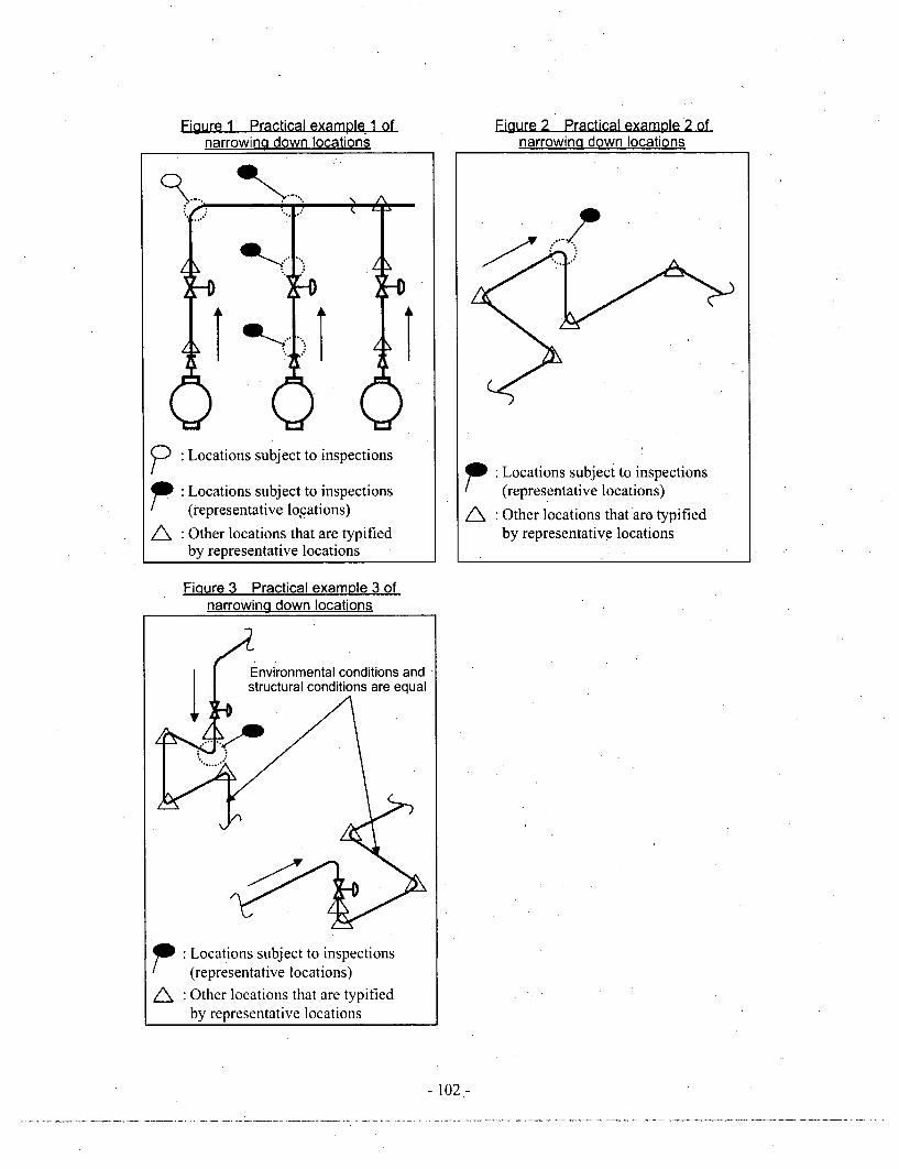
Figure 1 Practical example 1 ofnarrowing down locations
Figure 2 Practical example 2 ofnarrowing down locations
-)" Locations subject to inspections
D. Locations subject to inspections(representative locations)
Other locations that are typifiedby representative locations
A
Locations subject to inspections(representative locations)
Other locations that aro typifiedby representative locations
Fiqure 3 Practical example 3 ofnarrowing down locations
" Locations subject to inspections(representative locations)
A •Other locations that are typifiedby representative locations
- 102 -

Attachment 2
Determination of measuring points according to the structure of.the location-to bemeasured
(I ) 90-degree elbow <over 5 inches> <5 inches or less>1 I
See from the See from the25 mm or less amsde mm or less
25 25m5m m orlesidx ,,'.*
4 6
3- -7 "3-
D EY 2 '8 EY 11 a
(Note) If an abnormality was found on the A side in the vicinity of a weld line or can be' predicted,
measure me upstream pipe A.
(2) 45-degree elbow <over 5 inches> <5 inches or less>See from the Seetfrom the25mmor less ulstream side 2 upstream side
S4 6
x 3 7.7
CEY 'E8 C E Y
(Note) If an abnormality was found on the A side in the vicinity of a weld line or can be predicted,measure the upstream pipe X.
(3) Tee (T-tube) <over 5 inches> <5 inches or less>
H 5S1 4 6
-~S'.. ...... 7 7
. e kt 2 8XAB C DEY 1 XA C EY 1
(Note) If an abnormality was found on the A side in the vicinity of a weld line or can be predicted,measure the upstream pipe X.
(4) Reducer <over 5 inches> <5 inches or less>See from the See from the
upstream side uostrearm side
6 inches or more 5 inches or less
,___ __________ 8 i 2,,'
XA C EY 6 4 X A EY-
(Note) If there is an elbow or a tee in the vicinity, define its position on the back side as starting point 1.Take the same steps as in section (1) for X.
- 103 -

Determination of measuring points according to the structure of the location to bemeasured
(1; 't ;-ah 1,n ýh r ;i < n r €; 1n,h •> <5 inches or less>. . - -.... _... 1 1 - a u j, wk uýk& uk kýSee from the
upstream side
8 2
7-- ... 3 -3. -
6 4XA DY 5 XA DY 5
(Note) Take the same steps as in section (4) Reducer. However, if there is no elbow and no tee, define the positiondescribed above as starting point 1. Take the same steps as in section (1) for X.
(6) Straight pipe downstream from a valve <over 5 inches> <5 inches or less>
See from the See from theiipqtragm siden i pqtr~a %ideA
AsBs C 5 AB C
(Note) If there is a tee on the downstream side of a valve, measure any one point to check the wall thickness.
(7) Pipe downstream from an orifice <over 5 inches> <5 inches or less>
3 Measre anyMeasure any" " one point to See from the one point to See from thed d d check the walt upstream side d d d check the wall upstream side
4 6A 1N
(8r Ben _i <ove 5 Inhs<5ice or less >
W einning 2mmfof atben Wihee2m from the______
unepontto e ream side ognnin pof n a ten See from thed__dcectewal uptra_ sdedd__hekhwl upstream aide
A thcndoaesd. A End of ahicbend .
B C~I 46 4. B C
_ 11
-104-

Attachment 3.
Evaluation method of the remaining life of piping
When the remaining life of a certain measuring location of piping is evaluated, the remaining
life calculated from a combination of the maximum value (maximum thinning rate) among
thinning rates at all measuring points of the location in question and the minimum value
(minimum wall thickness) among wall thicknesses at all measuring points of the location in
question is defined as the remaining life of the location in question.
(1) Calculation method of a thinning rate
Depending on the number of measurements from the commencement of service of the
pipe in question to the measurement in question, calculate a thinning rate in the following
manner:
.a. At the time of the first measurement (nominal wall thickness method)
From the difference between the nominal wall thickness and the wall thickness at thefirst measurement and the operating time, determine a thinning rate [mm/hr] for
every measuring point by using the following formula:
Thinning rate [Mimrhr]
(nominal wall thickness - wall thickness at the first measurement) [mm]
/ (operating time from the installation to the first measurement) [hr]
However, if a wall thickness was measured before the commencement of service,
substitute the value measured before the commencement of service for the nominalwall thickness and calculate it.
b. At the time of the second measurement
From the difference between the wall thickness at the first measurement and the wall
thickness at the second measurement and the operating time, determine a thinning
rate [mm/hr] for every measuring point by using the following formula:
Thinning rate [mm/hr]
(wall thickness atthe first measurement
- wall thickness at the second measurement) [mm]
/ (operating time from the first measurement to the second measurement) [hr]
- 105 -

However, if a wall thickness was measured before the commencement of service, use
the least squares method described in section c., and calculate it by using measured
values, including the value measured before the commencement of service.
c. At the time of the third or a later measurement (least squares method)
Determine a thinning rate [mm/hr] for every measuring point by using the least
squares method (primary expression) and the measured wall thicknesses and each
operating time from the first measurement to the measurement in question.
However, if a wall thickness was measured before the commencement of service,
calculate it by using measured values, including the value measured before the
commencement of service.
(2) Calculation method of a remaining life
Calculate a remaining life for every measuring location by using the following formula:
Remaining time [hr]
(minimum measured wall thickness at the time of the measurement in question
- minimum necessary thickness) [mm] / (maximum thinning rate) [mmihr]
Remaining life [years] = remaining time [hr] / 8,760 [hr]
However, if the thinning rate obtained in (1) is zero, do not calculate the remaining time.
If the remaining time is over one million hours, do not evaluate the remaining life.
(Note 1) As for the remaining life used for the determination of the timing for the
implementation of the. first inspection in PWR plants, calculate it in the
following manner:
Remaining time [hr]
- (minimum thickness of pipe manufacturing
- minimum necessary thickness) [mm] / initial thinning rate [mm/hr]
Remaining life [years] = remaining time [hr] / 8,760 [hr]
For an "initial thinning rate," use the value that was set for each location in consideration
of past records, etc.
However, if a wall thickness was measured before the commencement of service,
substitute the value measured before the commencement of service for the "minimum
thickness of pipe manufacturing," and calculate it.
- 106-

(Note 2) In case the locations of thin-wall parts arising from a manufacturing process,
such as welding grooves, are clear, it is acceptable to use the measured data of
appropriate points other than the measuring points in question of the locations
in question.
- 107-

ý_ppendix 12
September 22, 2004, Gen No.7
September 27, 2004
The Kansai Electric Power Co., Inc.
Mr. Yousaku Fuji, President
- 108-

Regarding the occurrence of the accident caused by the dysfunctional quality assurance
system, etc., our ministry severely reprimands your company responsible for the assurance of
the safety of nuclear power stations.
Since the last year revision- of systems, our ministry has demanded thorough development of
the quality assurance system from all nuclear licensees. As a result of the periodic safety
management review conducted to verify the quality assurance system of your company under
the new system, it was judged that "there are minor non-conformances, but the quality
assurance system is functioning" for Mihama Power Station, Unit 1, Takahama Power Station,
Unit 3, and Ohi Power Station, Unit 2, of your company. However, in consideration of therecently-found problems, our ministry annulled the judgment, and newly judged that "there
are major non-conformances, and the quality assurance system is not functioning." Our
ministry strongly demands that your company should review your company's quality
assurance system and should resolve the above problems related to systems in order to
prevent such accidents.
In addition, our ministry takes the long-term nonobservance of technical standards for
secondary piping in Mihama Power Station, Unit 3, seriously and issues a technical standard
conformance order to your company. Therefore, our ministry orders the suspension of the
use of electric facilities until our ministry confirms conformance to the standards.
Our ministry demands that your company should feel deeply responsible for the accident and
should develop effective recurrence prevention measures in consideration of the above
indications and actions, and then should report the measures to our ministry by the end of this
fiscal year.
In addition, in order to verify the efforts of your company to improve the quality assurance
system, etc., our ministry will temporarily adopt administrative measures (see Attachment),
which are the implementation of a special safety inspection and the strict implementation of a
periodic safety management review.
Incidentally, our ministry is continuing to investigate the accident. Therefore, if new facts
are found, our ministry will again adopt the necessary measures as a matter of course.
- 109-
(Attachment)
1. Implementation of a special safety inspection
All nuclear power plants of your company will be subject to the priority inspections of safety
inspections by the government based on Paragraph 5 of Article 37 of the Law on the
Regulation of Nuclear Source Material, Nuclear Fuel Material and Reactors. Specifically, a
special safety inspection will be conducted with particular emphasis on the maintenancemanagement, including the thinning control of secondary piping, which your company
conducted as a self-imposed inspection in the past, and the actual conditions of subcontract
management (procurement control) for affiliated companies on the occasion of the said
maintenance management.
In addition, various measures clarified in the recurrence prevention measures to be submitted
by your company will be verified in a special safety inspection.
2. Strict implementation of a periodic safety management review
For electric facilities in each nuclear power station of your company, on the occasion of the
implementation of a periodic safety management review to be conducted by Japan Nuclear
Energy Safety Organization (hereinafter called JNES) based on Paragraph 4 of Article 55 of
the Electricity Utilities Industry Law, our ministry will order JNES to conduct the review
temporarily with emphasis on the inspection items that were positioned as a self-imposed
inspection in the past. On that occasion, our ministry will demand that JNES should
increase the number of items subject to sampling in comparison with normal reviews and
should strictly conduct a periodic safety management review regarding the implementation
system of periodic inspections by your company.
In addition, regarding recurrence prevention measures to be submitted by your company, the
state of the implementation of relevant items will be verified properly.
- 110-

[pendix 13
Requirements necessary for establishment of concrete recurrence prevention
measures
March 14, 2005
Nuclear and Industry Safety Agency
The Kansai Electric Power Co., Inc., submitted a report regarding recurrence prevention to
NISA on March 1, 2005. NISA presented the interim evaluation result of the report at the
accident investigation committee on March 3. In the evaluation result, NISA indicated that
an action program that fully took feasibility into account should be presented because a
concrete process toward the realization of the recurrence prevention measures presented by
the Kansai Electric Power Co., Inc., was not presented.
Because recurrence prevention measures must be able to be implemented adequately and
certainly as a company-wide activity, many detailed implementation plans presented by the
Kansai Electric Power Co., Inc., are insufficient. In other words, the framework of an action
program must be based on the commitment of the top management, and each action must be
.implemented adequately under the commitment.
For this reason, NISA presented the requirements necessary for establishment of the concrete
recurrence prevention measures as follows to the Kansai Electric Power Co., Inc., on March
10. In evaluating the recurrence prevention measures submitted by the Kansai Electric
Power Co., Inc., NISA will take the requirements into consideration.
1. Commitment regarding safety
(1) Change the management policy or "assurance of safety takes top priority" into a policy
that is feasible depending on the actual conditions of the organization and is easily
understandable and clear for each employee when making judgments for executing daily
work.
(2) Each item of recurrence prevention measures described in the report may give the
impression that it seems to be a please-everyone policy. Therefore, make the
commitment of the top management as several types of basic action policies (master
plans) in consideration of lessons learned at the accident, regardless of superficial events.
(3) Ensure that basic action policies include the preparation of maintenance plans, items
related to safety in an actual process, items related to safety in procurement work and
procurement control, items related to accountability concerning nuclear safety inside and
outside of the company and outside evaluation, etc. Clarify that each item of recurrence
-111-

prevention measures will be adequately implemented in accordance with the above basic
action policies.
2. Reallocation of resources to make nuclear workplaces free of pressure
(1) Necessary reallocation of major management resources, including "personnel, things,
funds, information, and time,"* must be continually conducted depending on actual
conditions.
(2) On the occasion of an organizational reform, clarify its significance, and set up an
adequate organization.
(3) On the occasion of the implementation of periodic inspections, sweep out the work
climate where workers on site may have a false impression that processes are placed at
the highest priority, for example, 40-day. periodic inspections. Ensure the
implementation of periodic inspections that "place safety at the highest priority" in order
to ensure safety by inspections.
(4) In order to ensure the safety of aging power stations, establish a mechanism that allocates
the management resources necessary for power plants fairly and certainly.
3. Actions and declaration of safety standards by each person
(1) Without excessively depending on the self-imposed activities of each worker, establish a
mechanism that enables systematic implementation.
(2) Because one-way information provision, including campaigns, posters, and lecture
meetings is considered to be a supplementary measure, do not depend on it excessively.
4. Collaboration with plant makers and affiliated companies, and coexistence with
local societies
(1) Cooperate with plant makers and other PWR licensees and establish a mechanism that
utilizes the technical capabilities and information resources possessed by each company.
(2) As a procurer of maintenance activities, establish a mechanism for creating a high sense
of ethics and the improvement of the technical capabilities of affiliated companies,
including subcontractors.
(3) Strengthen the disclosure of information to the surrounding areas of power stations.
- 112-

5. Mechanism for ensuring the implementation of action plans
(1) In order to ensure a steady implementation of basic action policies, set the timing for the
implementation adequately, depending on the urgency and importance, and on the
capability of the current organization. At the end of the 2005 fiscal year, evaluate the
state of the implementation of the plans prepared on this occasion, and improve problems.
In addition, repeat this process also in the next fiscal year and later fiscal years, and.
continuously improve the problems.
(2) Establish a mechanism that enables periodic evaluations with transparency. For
example, it is advised that the state of the implementation of the action plans be evaluated
by a working committee that consists of external knowledgeable persons for each power
plant. In addition, report the results of the above evaluations to citizens and societies.
- 113 -