2005-up Mustang Front TQ CoilOver Strut Installation ...
8
2005-up Mustang Front TQ CoilOver Strut Installation Instructions Table of contents Page 2......... Included components Page 3......... Disassembly and Getting Started Page 4......... Strut Assembly and Upper Mount Assembly Page 5......... Assembly Page 6......... Final Assembly and Spring Adjustemnt and Preload Page 7......... Strut Adjustment Page 8......... Strut Adjustment Installation Instructions Installation Instructions Part # 12153111 -2005 up Mustang Recommended Tools 812-482-2932 www.ridetech.com
Transcript of 2005-up Mustang Front TQ CoilOver Strut Installation ...
2005-up Mustang Front TQ CoilOver Strut
Installation Instructions
Table of contentsPage 2......... Included componentsPage 3......... Disassembly and Getting StartedPage 4......... Strut Assembly and Upper Mount AssemblyPage 5......... AssemblyPage 6......... Final Assembly and Spring Adjustemnt and PreloadPage 7......... Strut AdjustmentPage 8......... Strut Adjustment
Installation Instructions
InstallationInstructions
Part # 12153111 -2005 up MustangRecommended Tools
812-482-2932www.ridetech.com

1
2
3
4
5
6
7
8
9
11
12
13
14
15
16
7
1616
16
14
17
18
1920
21
22
2324
2526
18
Installation Instructions
812-482-2932www.ridetech.com
InstallationInstructions
Included Components .....In the box
2
DRIVERSHOWN
Item #
Part # Description QTY
1 27669999 Strut Cartridge 2
2 90000648 Bearing Retaining Mount 2
3 90000584 Upper Mounting Plate 2
4 70010943 Strut Extrusion 2
5 90002368 Thrust Bearing Adapter 2
6 70010987 Thrust Bearing 2
7 70010988 Thrust Bearing Washer 4
8 90001042 Upper Mount Bearing 2
9 90000805 Upper Bearing Snap Ring 2
11 99562003 9/16”-18 Nylok Nut 2
12 59100325 10” 325lb CoilSpring 2
13 90002365 CoilSpring to Bearing Adpater 2
14 70010828 Delrin Washer 4
15 90002372 Sway Bar Link Mount 2
16 90000803 Eccentric Bolt 2
17 70010992 Strut Retaining Ring 2
18 99371042 3/8”-16 x 1” SHCS 6
19 72000222 Retaining Ring 2
20 99371004 3/8”-16 x 1 1/4” Hex Bolt 8
21 99373003 3/8” Flatwasher 16
22 99372002 3/8’-16 Nylok Nut 8
23 90002222kit CoilSpring Cap Retaining Ring 2
24 90002222kit CoilSpring Cap 2
25 90002222kit CoilSpring Adjuster Nut 2
26 90002222kit Adjuster Nut Locking Screw 2
90000695 Posilink Spacer (Not Shown) 2
90002573 12mm 90 Degree PosiLink 4

InstallationInstructions
812-482-2932www.ridetech.com
1. Remove the front struts by fi rst disconnecting the ABS wire and brake line(retain hardware) from the factory strut. 2. Disconnect the swaybar linkage from the strut and swaybar this will be replaced with new linkage. 3. Support the front hub and control arm assembly and remove the (2) struts bolts(retain hardware) that attach the strut to the spindle.
4. Remove the (4) nuts holding the upper strut mount to the car body. DO NOT REMOVE THE CENTER NUT.
5. Remove strut assembly from the car.
Disassembly
7.
6. The upper strut mount provided in this kit has is designed to aid in tire clearance. The notch on the upper mount is positioned to-wards the wheel of the car.
NOTE: The Struts are Driver and Passen-ger, the sway bar mount points to the rear of the car.
7. Bolt the upper mount into the car posi-tioning it to the inside of the car. The cam-ber adjustment will be done on the bottom of the strut using the supplied camber bolt. The plate gets bolted in from the bottom side of the strut tower using (4) 3/8”-16 x 1 1/4” bolts. Install a 3/8” washer on the top and bottom and secure it with (4) 3/8”16 Nylok Nuts. Tighten all (4) down.
6.
Getting Started
FACTORY SHOCKTOWER
3
WHEEL SIDE
NOTCH
Installation Instructions
InstallationInstructions
812-482-2932.comwww.ridetech.com
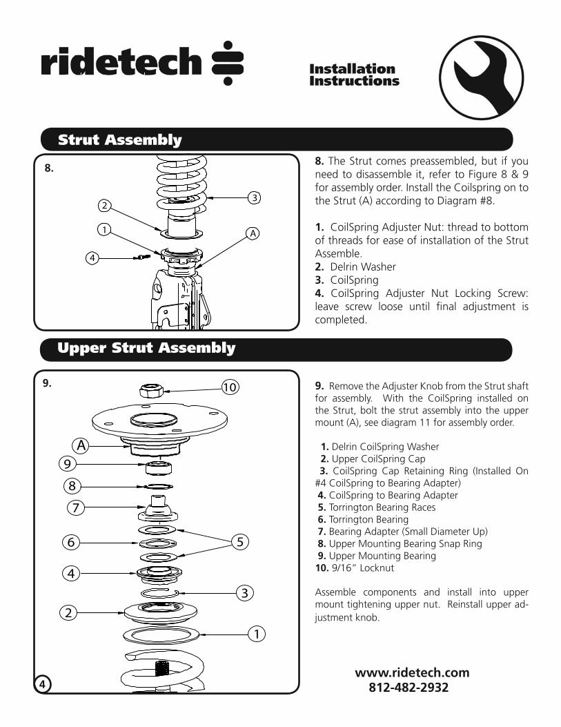
Strut Assembly 8. The Strut comes preassembled, but if you need to disassemble it, refer to Figure 8 & 9 for assembly order. Install the Coilspring on to the Strut (A) according to Diagram #8.
1. CoilSpring Adjuster Nut: thread to bottom of threads for ease of installation of the Strut Assemble.2. Delrin Washer3. CoilSpring4. CoilSpring Adjuster Nut Locking Screw: leave screw loose until fi nal adjustment is completed.
9. Remove the Adjuster Knob from the Strut shaft for assembly. With the CoilSpring installed on the Strut, bolt the strut assembly into the upper mount (A), see diagram 11 for assembly order.
1. Delrin CoilSpring Washer 2. Upper CoilSpring Cap 3. CoilSpring Cap Retaining Ring (Installed On #4 CoilSpring to Bearing Adapter) 4. CoilSpring to Bearing Adapter 5. Torrington Bearing Races 6. Torrington Bearing 7. Bearing Adapter (Small Diameter Up) 8. Upper Mounting Bearing Snap Ring 9. Upper Mounting Bearing10. 9/16” Locknut
Assemble components and install into upper mount tightening upper nut. Reinstall upper ad-justment knob.
9.
4
1
23
4
A
8.
Upper Strut Assembly
1
23
4
56
7
8
9
10
A

10.
5
812-482-2932812-482-2932.com
www.ridetech.com
10. Slide the lower strut mount onto the spin-dle reusing the Factory hardware in the lower mounting hole. Insert the supplied Camber bolt into the top hole.
11. Attach the PosiLinks between the strut and Sway bar using the 12mm Nylok Nut. .
12. The Posilink mounts with the stud on the Strut pointing outward, and the stud on the Sway bar pointing in.
Note: Image is viewing the strut from rear of the vehicle.
11.
Installation Instructions
InstallationInstructions
Assembly
12.

Installation Instructions
InstallationInstructions
Spring Adjustment and Preload
Ride Height We have designed most cars to have a ride height of about 2” lower than factory. To achieve the best ride qual-ity & handling, the shock absorber needs to be at 40-60% overall travel when the car is at ride height. This will ensure that the shock will not bottom out or top out over even the largest bumps. Measuring the shock can be diffi cult, especially on some front suspensions. Measuring overall wheel travel is just as effective and can be much easier. Most cars will have 4-6” of overall wheel travel. One easy way to determine where you are at in wheel travel is to take a measurement from the fender lip (center of the wheel) to the ground. Then lift the car by the frame until the wheel is just touching the ground, re-measure. This will indicate how far you are from full exten-sion of the shock. A minimum of 1.5” of extension travel (at the wheel) is needed to ensure that the shock does not top out. If you are more than 3” from full extension of the shock then you are in danger of bottoming out the shock absorber.
Adjusting Spring Height When assembling the CoilOver, screw the spring retainer tight up to the spring (0 preload). After entire weight of car is on the wheels, jounce the suspension and roll the car forward and backward to alleviate suspension bind.
retainer down would lower the car, this could allow the spring to fall out of its seat when lifting the car by the frame.
achieve ride height. On 2.6” - 4” stroke shocks, up to 1.5” of preload is acceptable. On 5-7” stroke shocks, up to 2.5” of preload is acceptable. If more preload is needed to achieve ride height a stiffer spring rate is required. Too much preload may lead to coil bind, causing ride quality to suffer.
812-482-2932.comwww.ridetech.com
Final Assembly
13. Attach the brake line to the Strut using the Factory hardware.
14. Route the Airline to the Air Spring. When hooking up the Airline be sure that you can turn the steering from lock to lock with out tugging on the Airline. This situation will eventually cause the line to leak.
15. Repeat previous steps on Passenger side.
16. With Both sides installed, slowly lower the car to the ground to check ride height. It may be necessary to tighten the Adjusting nut (Also known as preloading the CoilSpring) to achieve proper ride height. To do this you will need to loosen the Adjuster Nut Locking Screw and tighten the Adjuster Nut to put PreLoad into the Coil-Spring. Once the correct ride height is achieved tighten the Locking Screw in the lower Adjuster nut. It may be helpful to read the section pertaining to spring preload and adjustment on Page 9.
6

Installation Instructions
InstallationInstructions
812-482-2932.comwww.ridetech.com
7
Strut Adjustment 101- Single AdjustableRebound Adjustment:How to adjust your new struts.The rebound adjustment knob is located on the top of the Strut protruding through the upper mount. You must fi rst begin at the ZERO setting, then set the shock to a soft setting of 20.
-Begin with the Strut adjusted to the ZERO rebound position (full stiff). Do this by rotating the rebound adjuster knob clockwise until it stops.
-Now turn the rebound adjuster knob counter clock wise 20 clicks. This sets the shock at 20. (settings 21-24 are typically too soft for street use).
Take the vehicle for a test drive.
-If you are satisfi ed with the ride quality, do not do anything, you are set!
-If the ride quality is too soft increase the damping effect by rotating the rebound knob clock wise 3 clicks.
Take the vehicle for another test drive. -If the vehicle is too soft increase the damping effect by rotating the rebound knob clock wise 3 additional clicks. -If the vehicle is too stiff rotate the rebound adjustment knob counter clock wise 2 clicks and you are set!Take the vehicle for another test drive and repeat the above steps until the ride quality is satisfactory.
Note:One end of the vehicle will likely reach the desired setting before the other end. If this happens stop adjusting the satisfi ed end and keep adjusting the unsatisfi ed end until the overall ride quality is satisfactory.
Strut Adjustment

Installation Instructions
InstallationInstructions
Strut Adjustmentp j g q y y
Triple Adjustable:Step One: High Speed Compression
-High speed compression adjustments are used in both street driving and track tuning.
-Begin with the shocks adjusted to the ZERO high speed compression position (full stiff). Do this by rotating the high speed compression adjuster (large knob) clockwise until it stops.
-Now turn the high speed compression adjuster knob counter clock wise 20 clicks. This sets the shock at 20. (settings 21-24 are typically too soft for street use. For typical street driving the high speed compression adjuster will remain at setting 20.
Step Two: Low Speed Compression Low speed compression adjustment is what is typically felt during street driving. -Begin with the shocks adjusted to the ZERO low speed compression position (full stiff). Do this by rotating the low speed compression adjuster (small knob) clockwise until it stops. -Now turn the low speed compression adjuster knob counter clock wise 20 clicks. This sets the shock at 20. (settings 21-24 are typically too soft for street use). Take the vehicle for a test drive.
-if you are satisfi ed with the ride quality, do not do anything, you are set!
-if the ride quality is too soft increase the damping effect by rotating the low speed compression knob clock wise 3 clicks.
Shock adjustment 101- Triple Adjustable
Take the vehicle for another test drive.
-if the vehicle is too soft increase the damping effect by rotating the low speed compression knob clock wise 3 additional clicks.
-If the vehicle is too stiff rotate the low speed compression adjustment knob counter clock wise 2 clicks and you are set!
Take the vehicle for another test drive and repeat the above steps until the ride quality is satisfactory.
Step 3: Adjust rebound according to Single Adjustable instructions.
Note:One end of the vehicle will likely reach the desired setting before the other end. If this happens stop adjusting the satisfi ed end and keep adjusting the unsatisfi ed end until the overall ride quality is satisfactory.
812-482-2932.comwww.ridetech.com
8