2005 National Building Code of Canada Seismic Design ... · 2005 National Building Code of Canada...
78
2005 National Building Code of Canada Seismic Design Changes Impact on Insurance Industry
Transcript of 2005 National Building Code of Canada Seismic Design ... · 2005 National Building Code of Canada...
2005 National Building Code of Canada
Seismic Design ChangesSeismic Design Changes
Impact on Insurance Industry
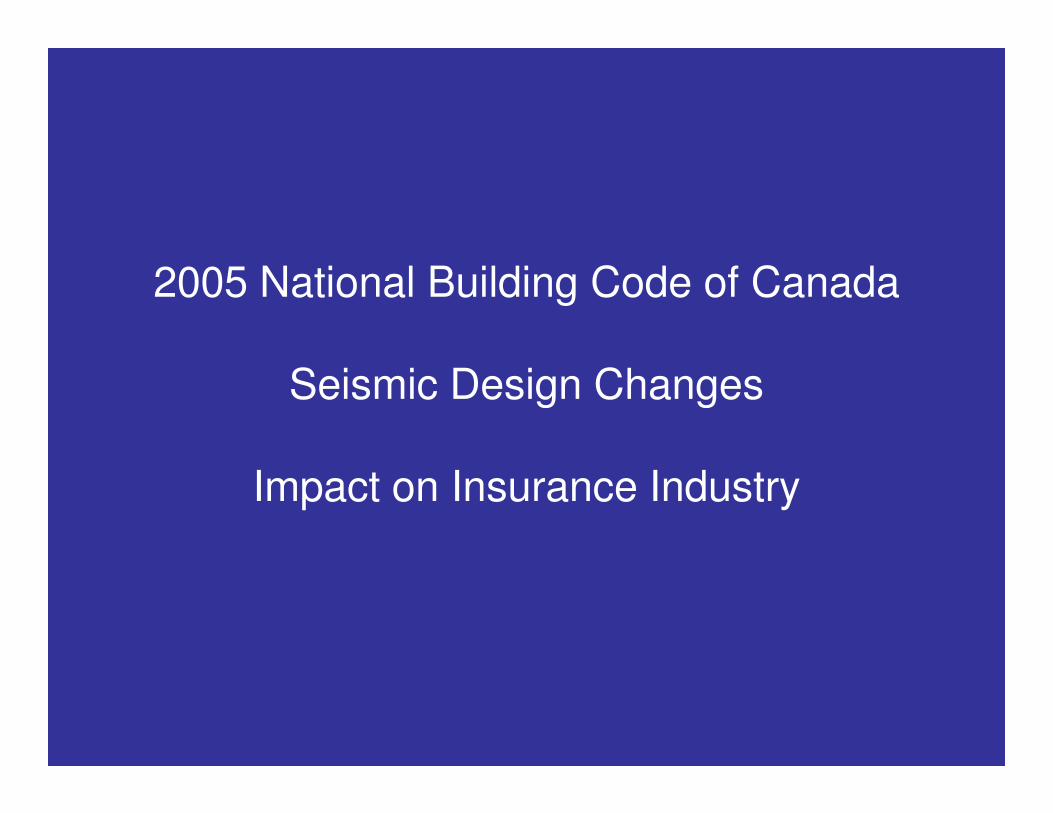
NBCC 2005 Seismic Design Changes
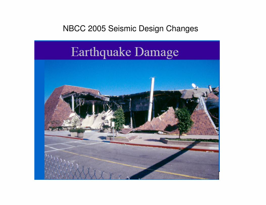
Gravity Element Failures
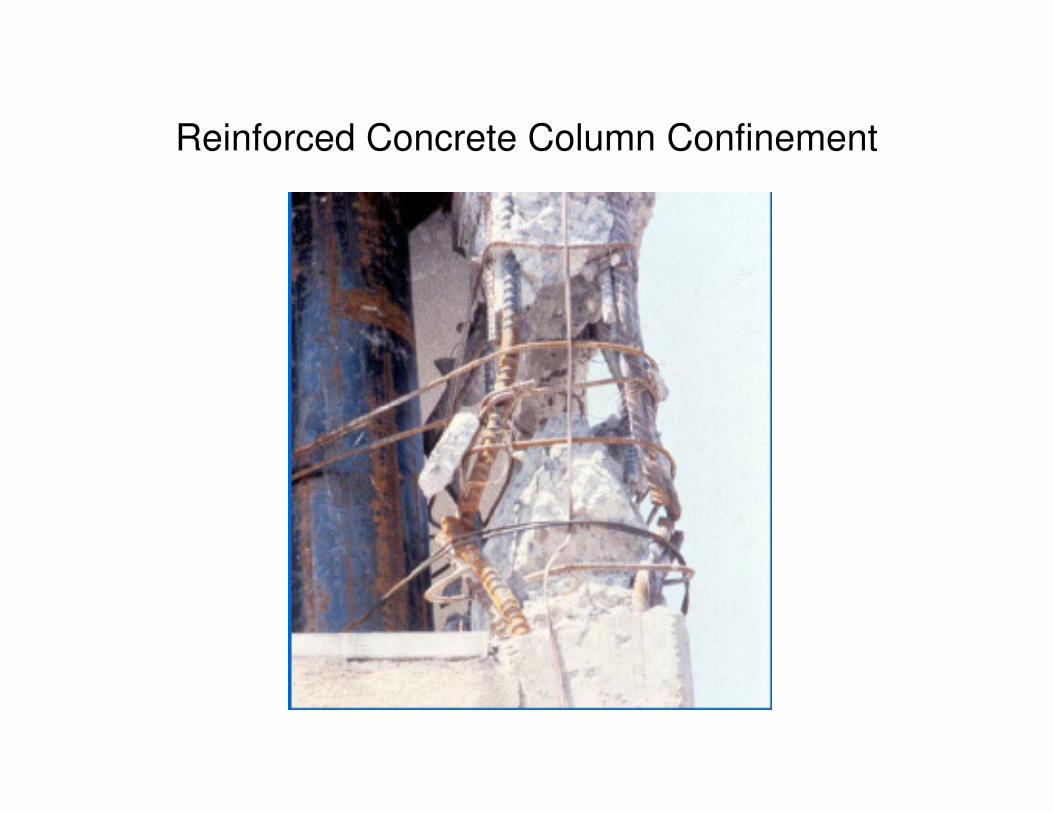
Reinforced Concrete Column Confinement
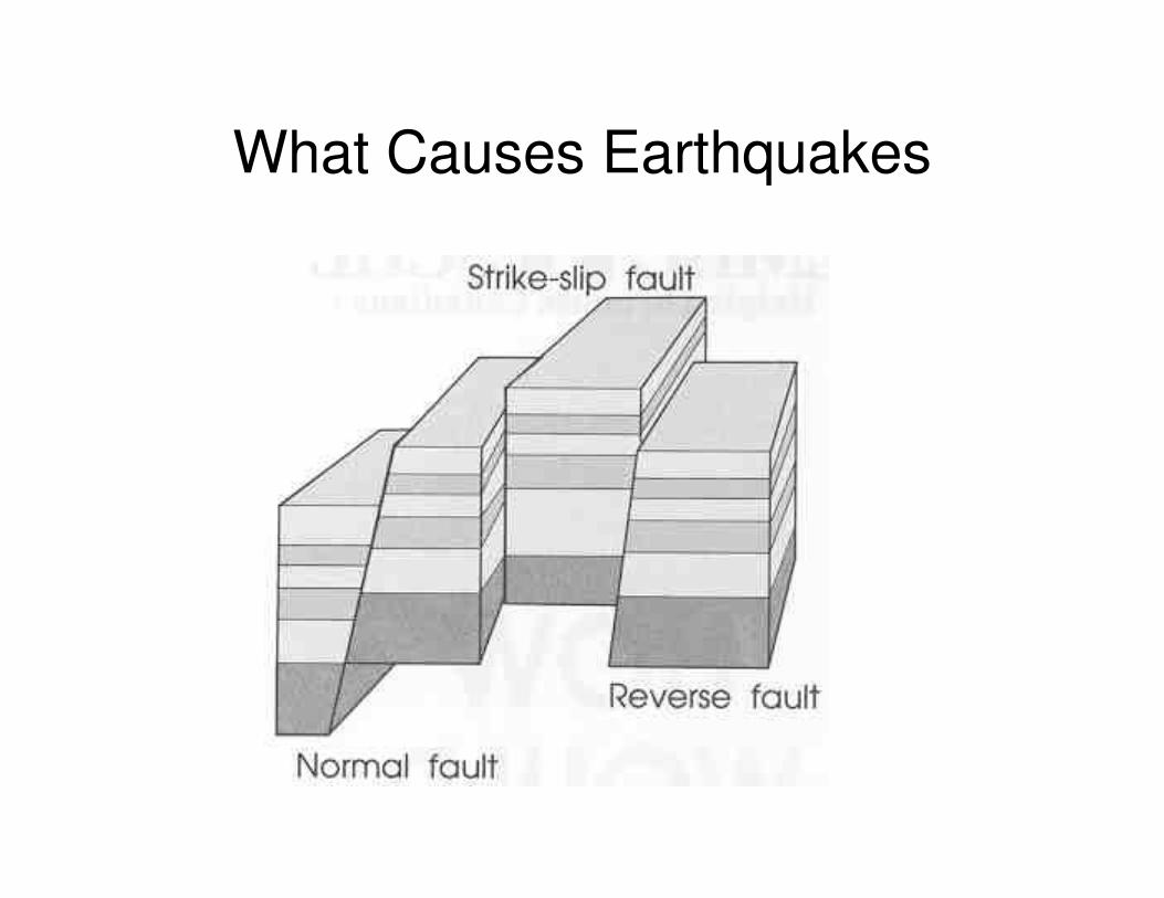
What Causes Earthquakes
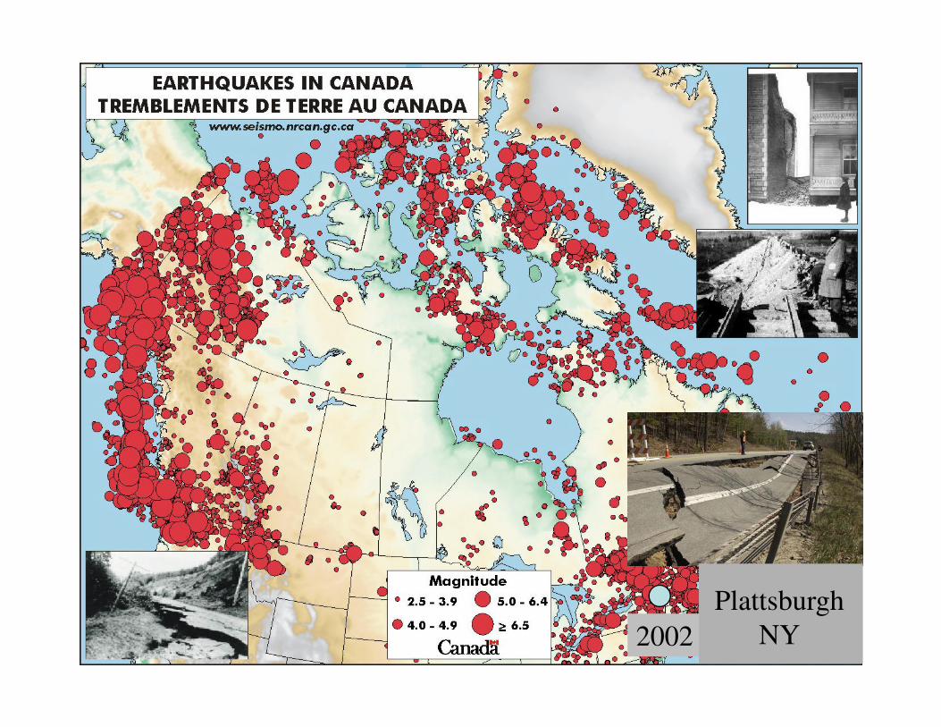
2002
Plattsburgh
NY
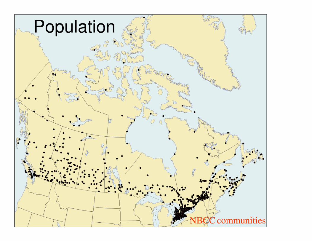
Population
NBCC communities
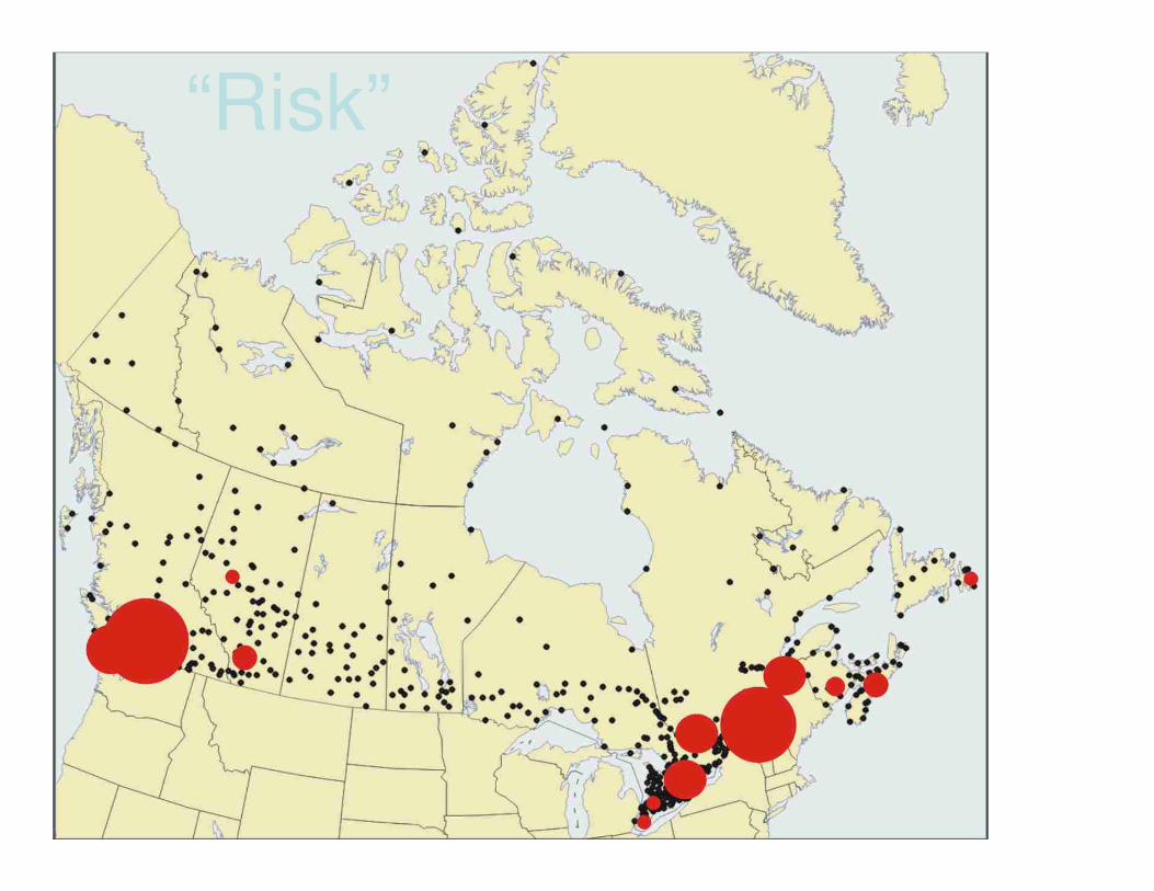
“Risk”
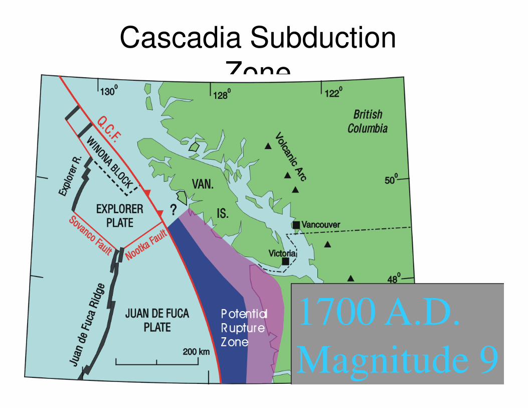
Cascadia Subduction
Zone
1700 A.D.
Magnitude 9
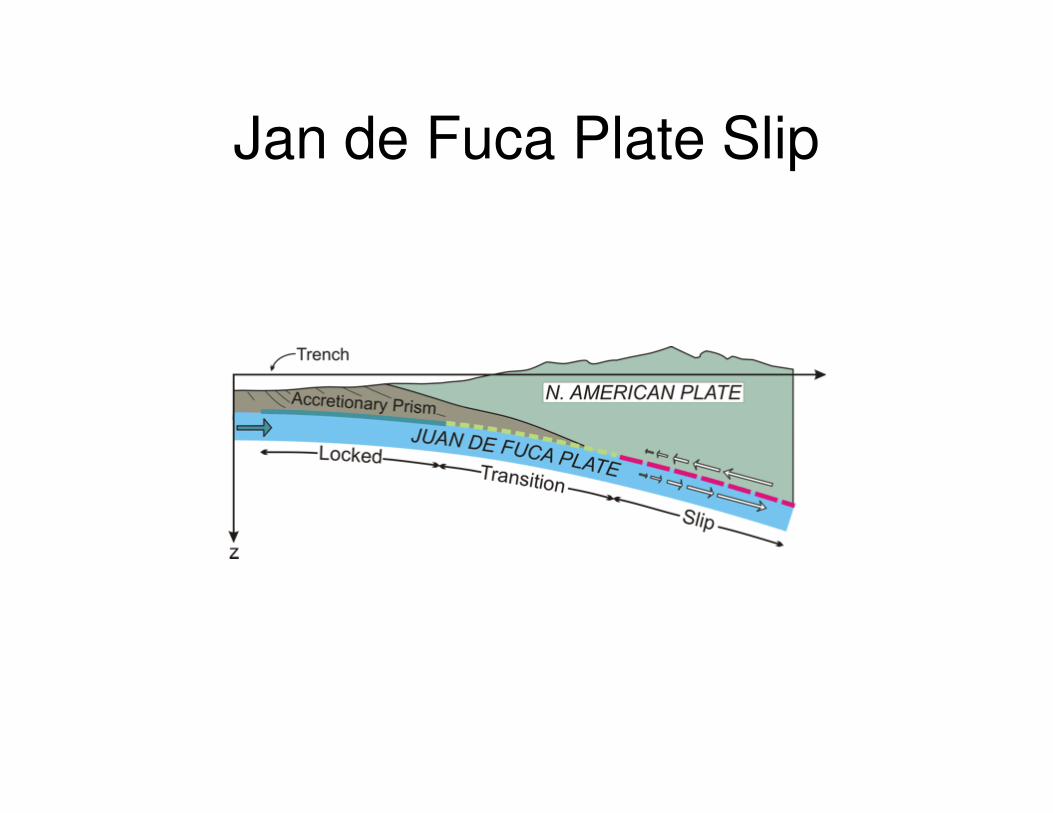
Jan de Fuca Plate Slip
2005 National Building Code of Canada Seismic Design
• Basics of Seismic Design
• Changes Incorporated in 2005 NBCC
• Seismic Loads – New Hazard Map
• Structural Analysis
• Rationale Behind the Changes
• Changes in CSA A23.3 Design Of Concrete Structures Standard.
• Implications for the Insurance Industry
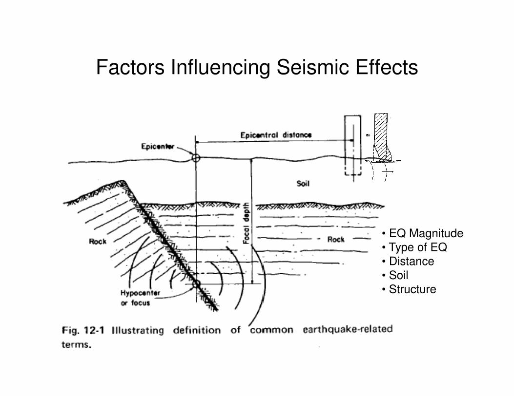
Factors Influencing Seismic Effects
• EQ Magnitude
• Type of EQ
• Distance
• Soil
• Structure
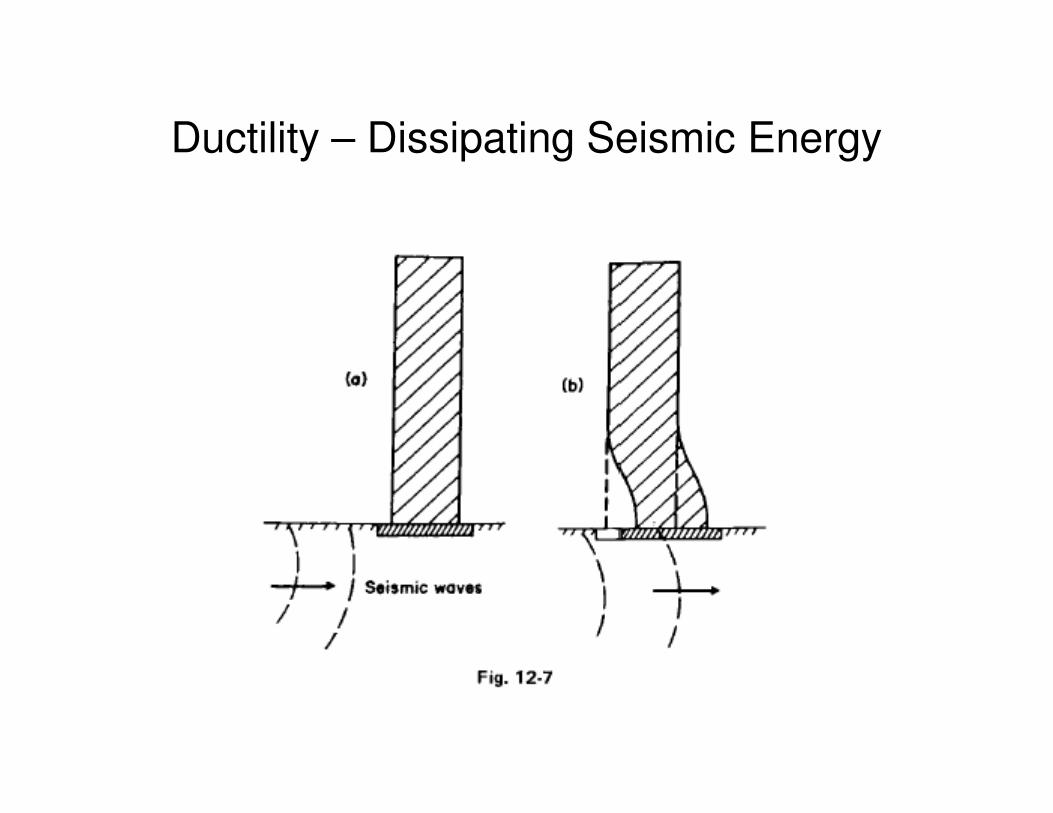
Ductility – Dissipating Seismic Energy
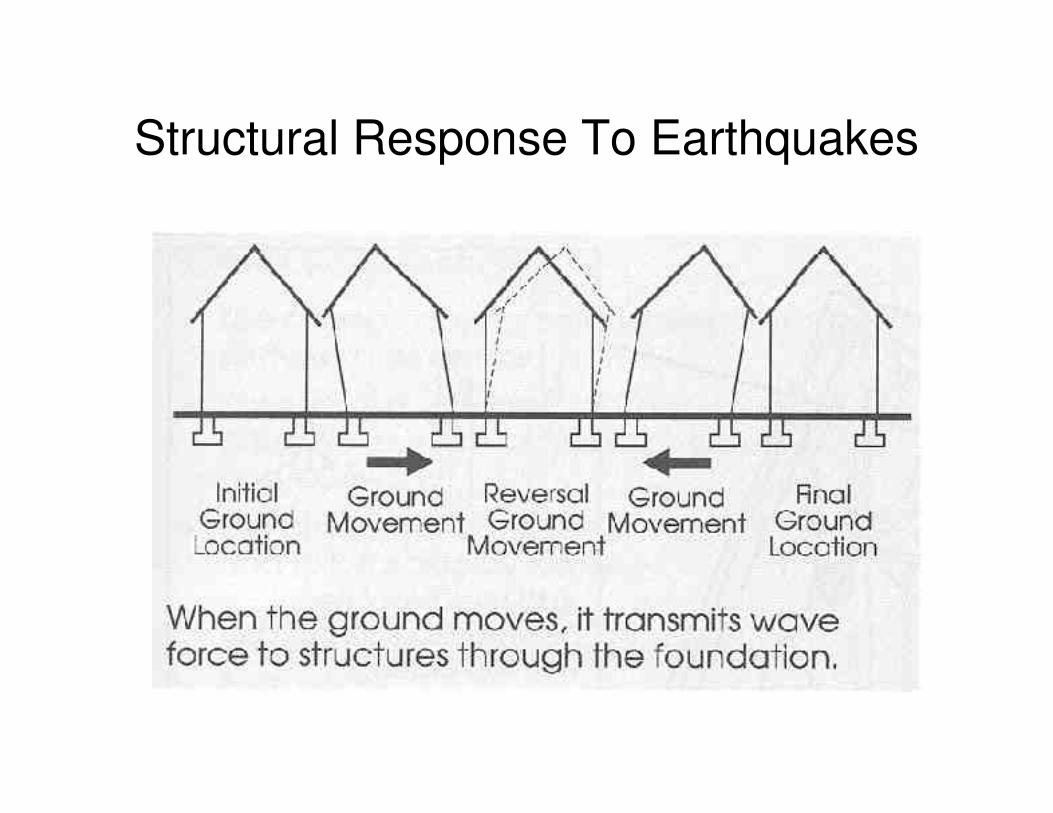
Structural Response To Earthquakes
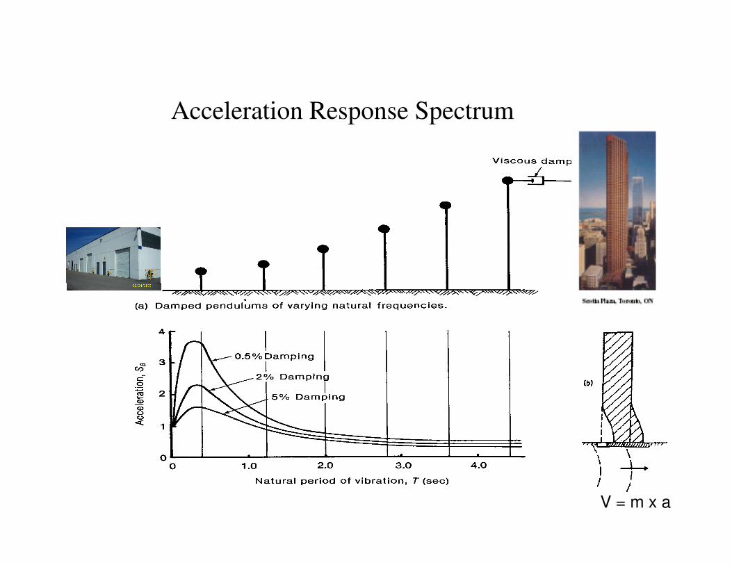
Acceleration Response Spectrum
V = m x a
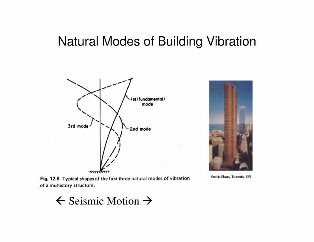
Natural Modes of Building Vibration
� Seismic Motion �
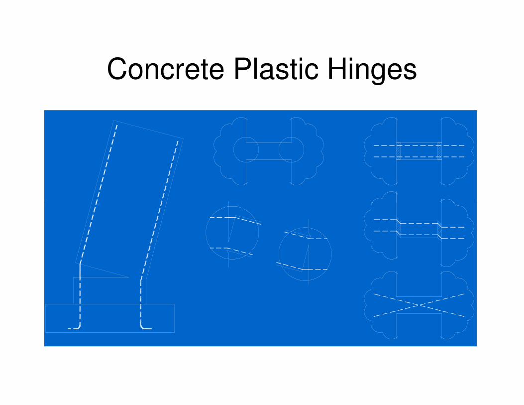
Concrete Plastic Hinges
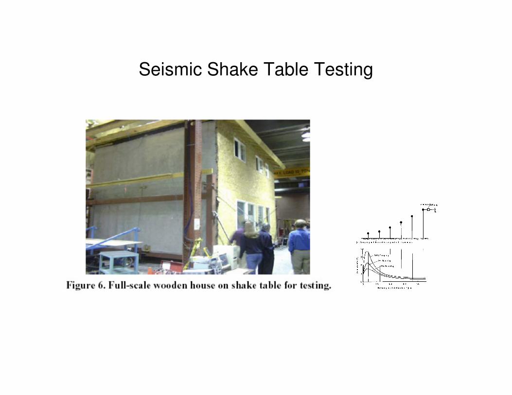
Seismic Shake Table Testing
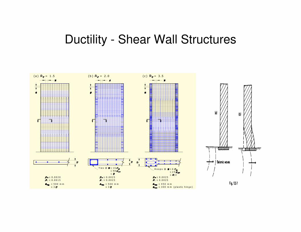
Ductility - Shear Wall Structures
( a ) = 1 .5 ( b ) = 2 .0 ( c ) = 3 .5
≥ 0 .0 0 2 0
0 .0 0 1 5≥
≤ 5 0 0 m m
3≤
0 .0 0 2 5
0 .0 0 2 5
5 0 0 m m
≤ 3
≤
≥
≥
4 5 0 m m
0 .0 0 2 5
0 .0 0 2 5
≤
≥
≥
T ie s @ ≤ 1 6
4 8≤
≤
H o o p s @
2 4≤
≤
6≤
/ 2
≤ 3 0 0 m m ( p la s t ic h in g e )
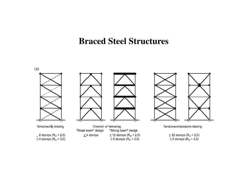
Braced Steel Structures
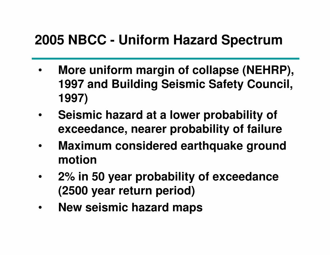
2005 NBCC - Uniform Hazard Spectrum
• More uniform margin of collapse (NEHRP),
1997 and Building Seismic Safety Council,
1997)
• Seismic hazard at a lower probability of
exceedance, nearer probability of failure exceedance, nearer probability of failure
• Maximum considered earthquake ground
motion
• 2% in 50 year probability of exceedance
(2500 year return period)
• New seismic hazard maps
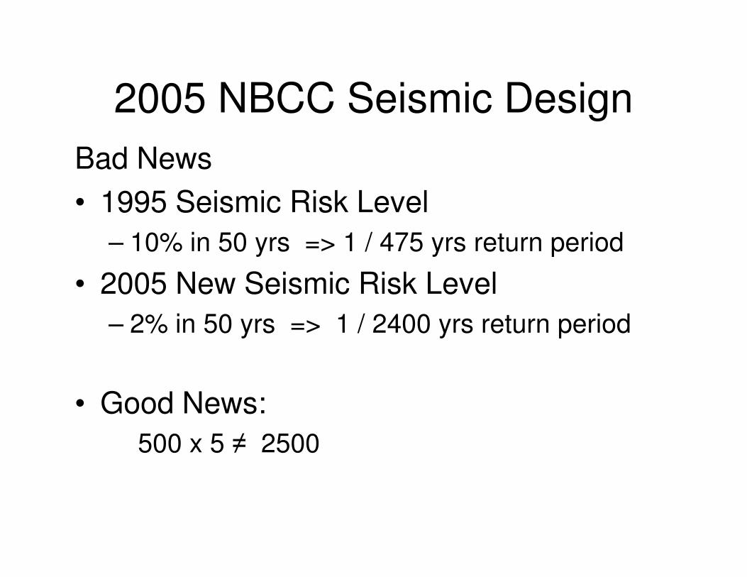
2005 NBCC Seismic Design
Bad News
• 1995 Seismic Risk Level
– 10% in 50 yrs => 1 / 475 yrs return period
• 2005 New Seismic Risk Level• 2005 New Seismic Risk Level
– 2% in 50 yrs => 1 / 2400 yrs return period
• Good News:
500 x 5 ≠ 2500
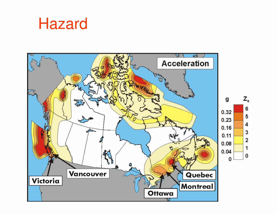
Hazard
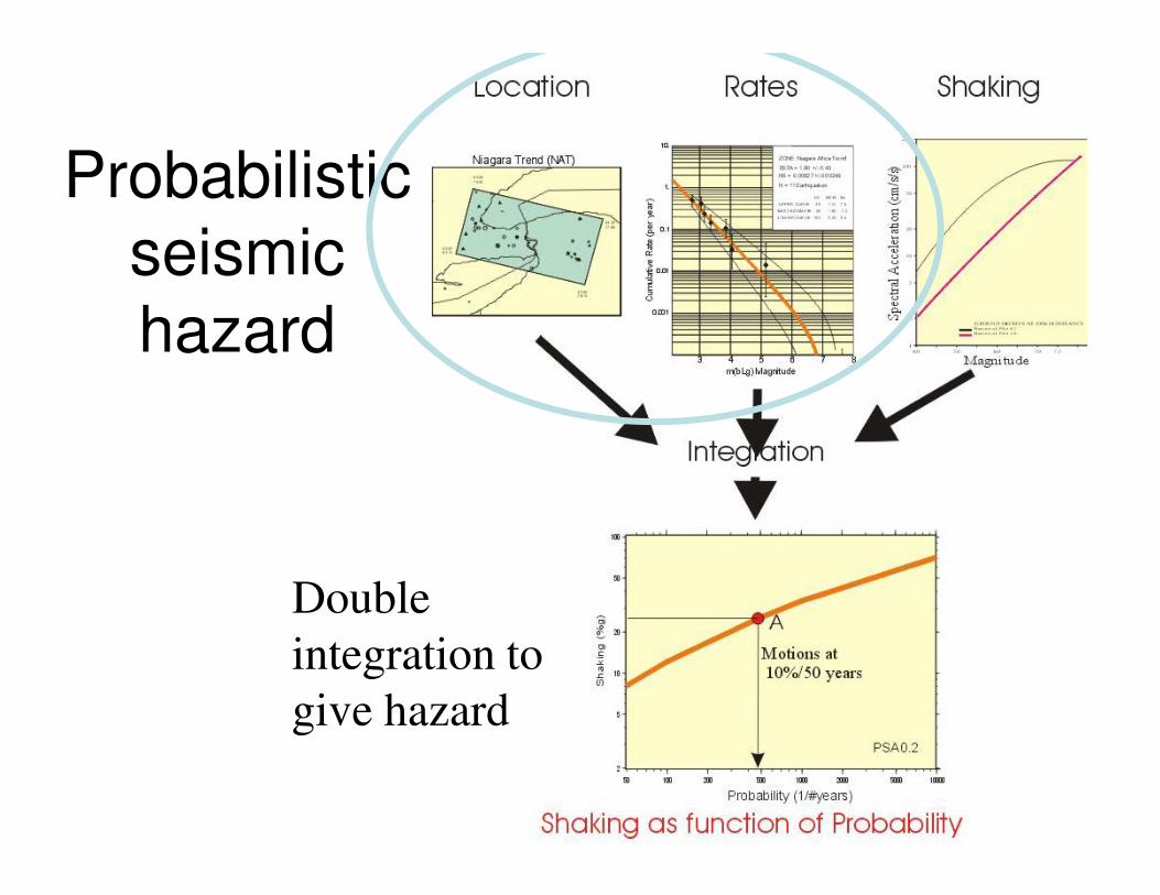
Probabilistic
seismic
hazard
Double
integration to
give hazard
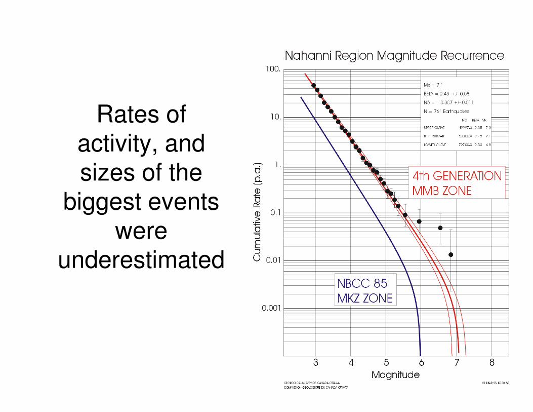
Rates of
activity, and
sizes of the
biggest events biggest events
were
underestimated
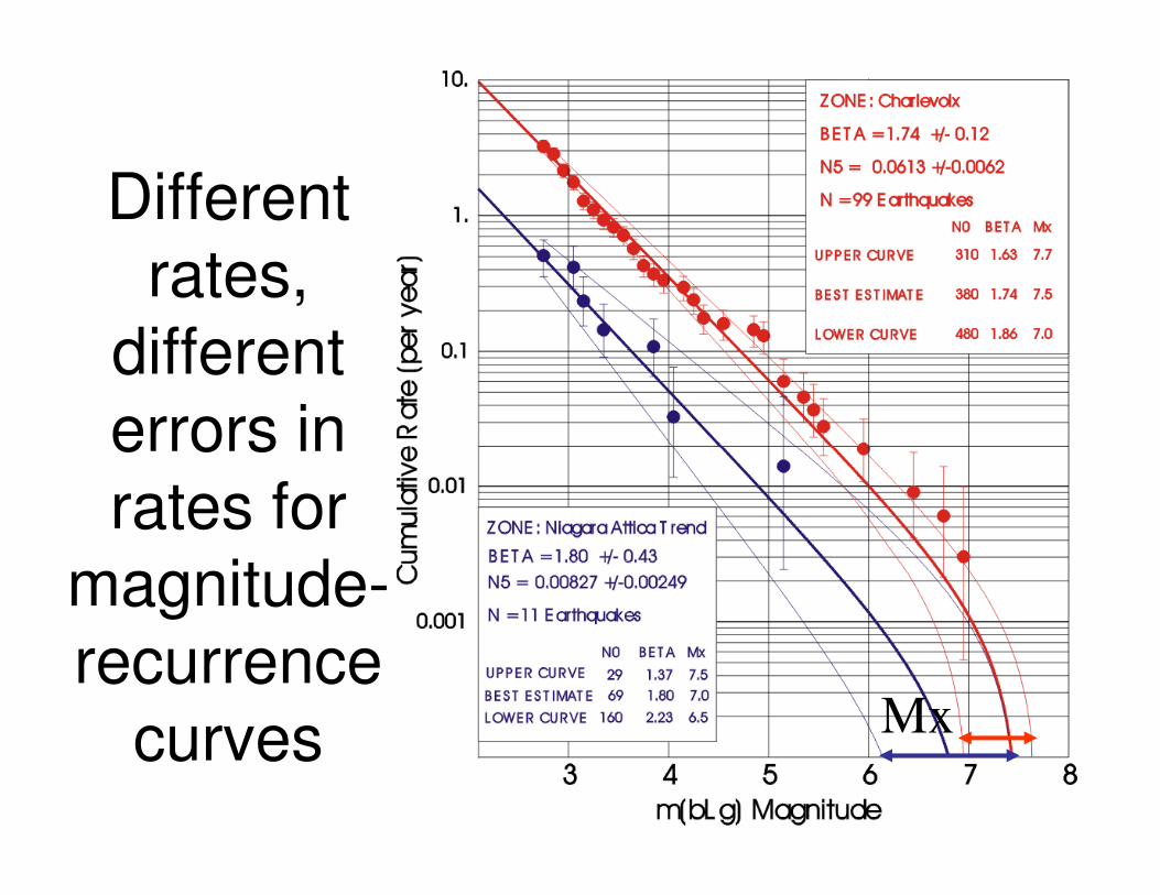
Different
rates,
different
errors in errors in
rates for
magnitude-
recurrence
curves Mx
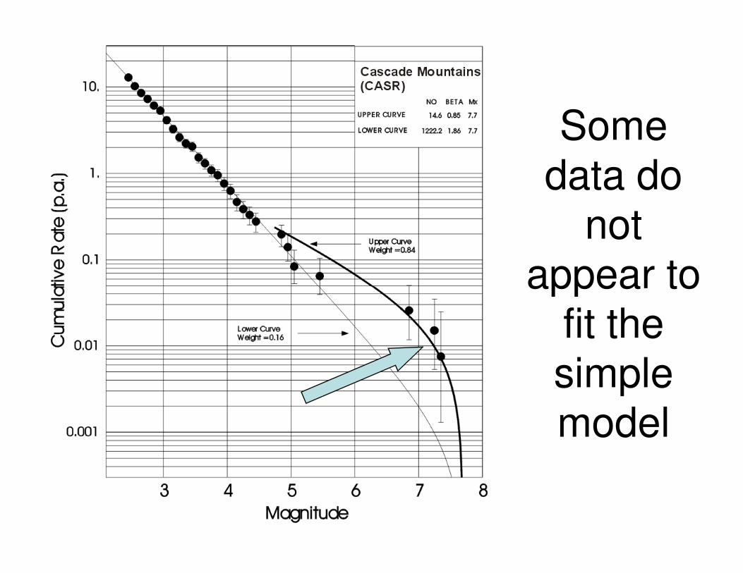
Some
data do
not
appear to appear to
fit the
simple
model
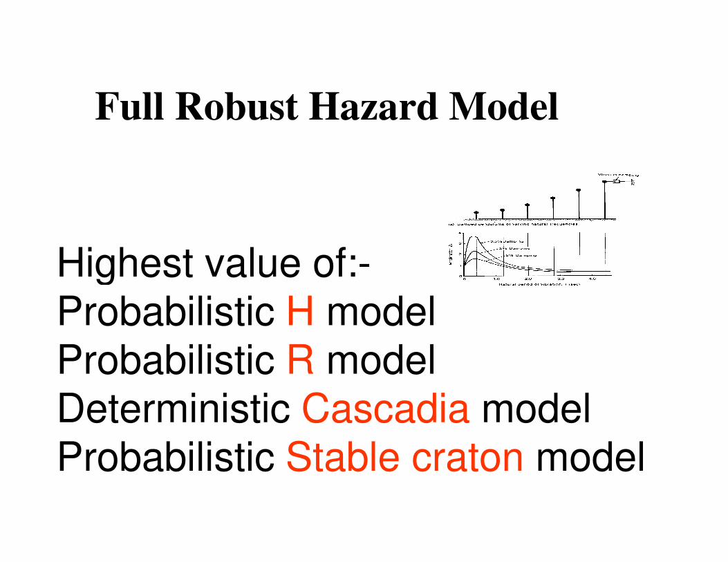
Highest value of:-
Full Robust Hazard Model
Highest value of:-
Probabilistic H model
Probabilistic R model
Deterministic Cascadia model
Probabilistic Stable craton model
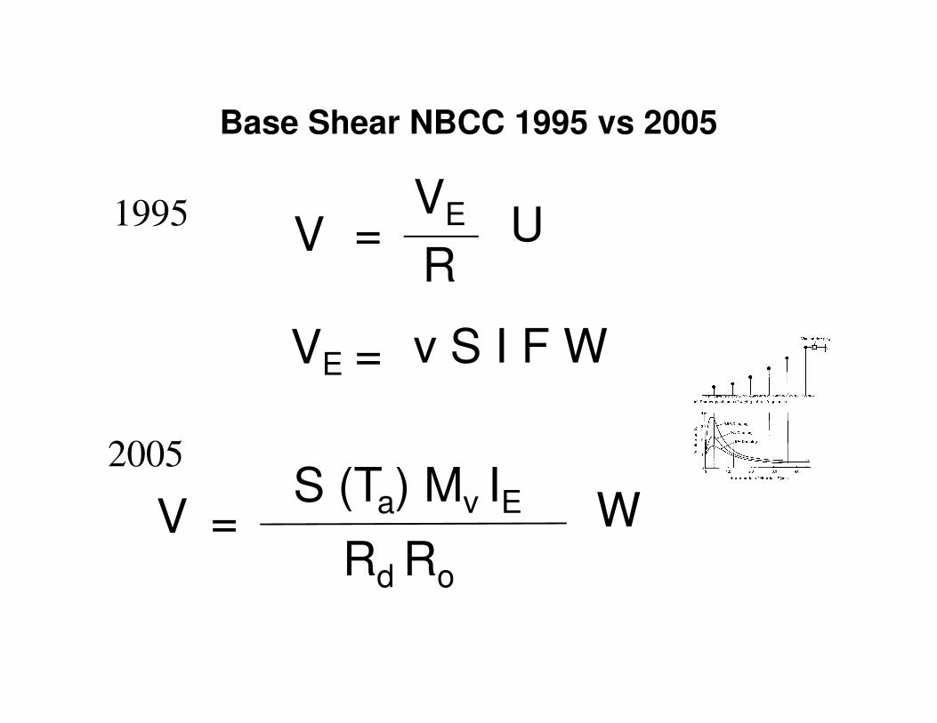
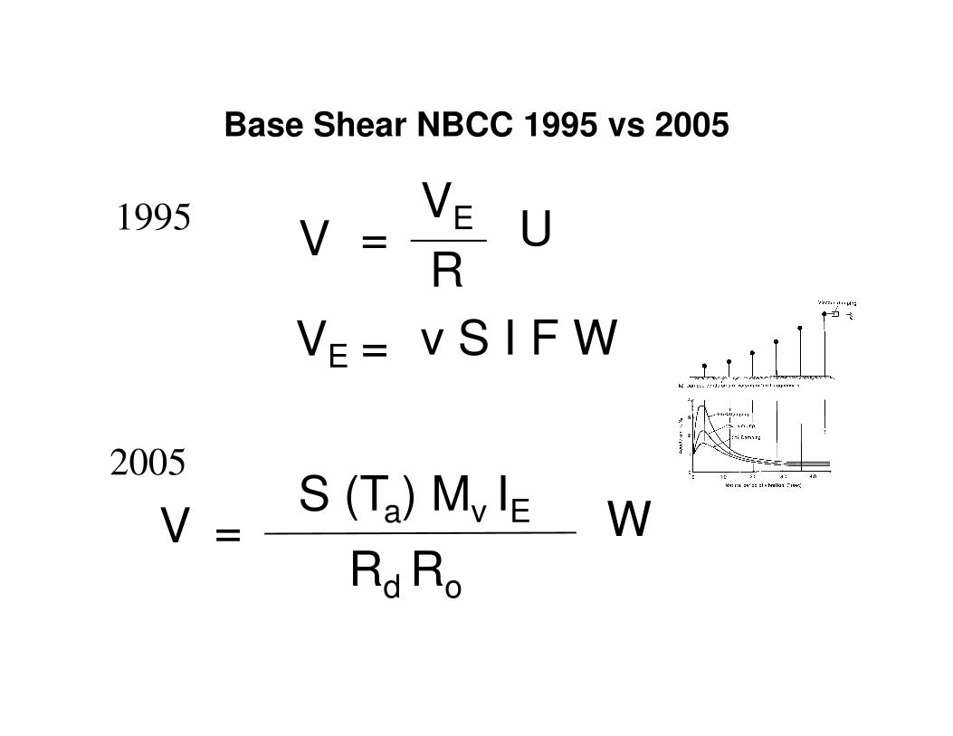
Base Shear NBCC 1995 vs 2005
V =VE
RU
VE = v S I F W
1995
V =S (Ta) Mv IE
Rd Ro
W
VE = v S I F W
2005
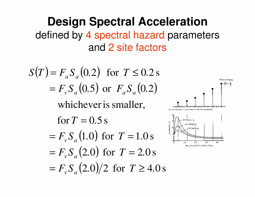
Design Spectral Accelerationdefined by 4 spectral hazard parameters
and 2 site factors
( ) ( )( ) ( )
smaller, is whichever
20or 50
s 20for 20
.SF.SF
.T.SFTS
aaav
aa
=
≤=
( )( )( ) s 04for 202
s 02for 02
s 01for 01
s 50for
smaller, is whichever
.T.SF
.T.SF
.T.SF
.T
av
av
av
≥=
==
==
=
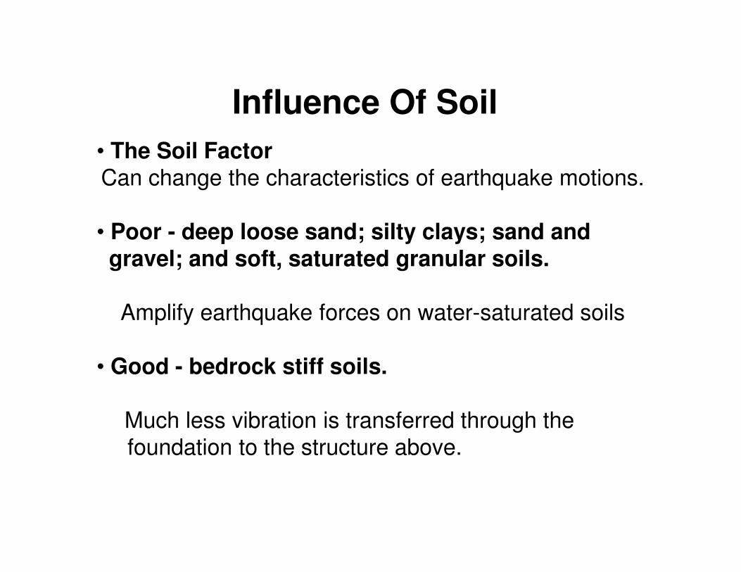
Influence Of Soil
• The Soil Factor
Can change the characteristics of earthquake motions.
• Poor - deep loose sand; silty clays; sand and gravel; and soft, saturated granular soils.
Amplify earthquake forces on water-saturated soils
• Good - bedrock stiff soils.
Much less vibration is transferred through the
foundation to the structure above.
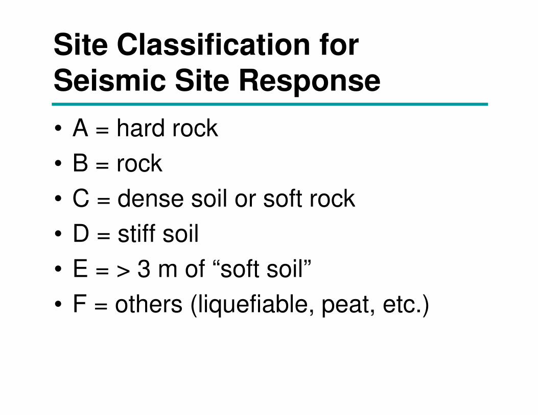
Site Classification for Seismic Site Response
• A = hard rock
• B = rock
• C = dense soil or soft rock• C = dense soil or soft rock
• D = stiff soil
• E = > 3 m of “soft soil”
• F = others (liquefiable, peat, etc.)
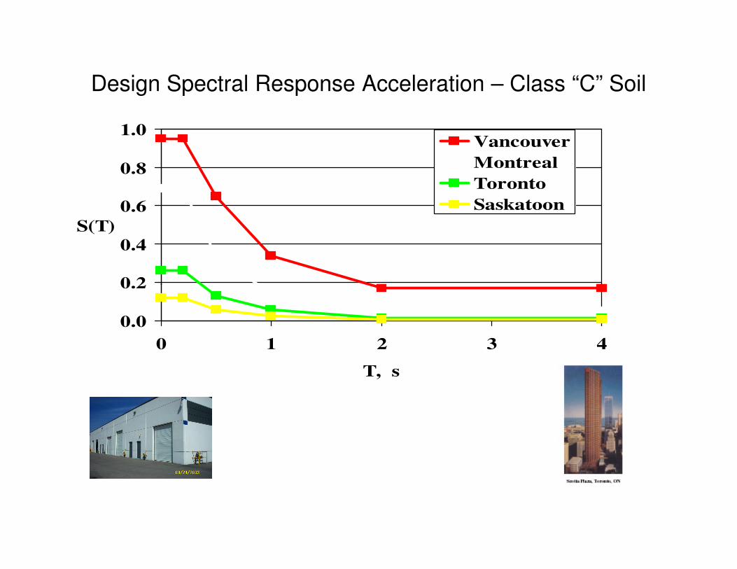
Design Spectral Response Acceleration – Class “C” Soil
0.2
0.4
0.6
0.8
1.0
S(T)
Vancouver
Montreal
Toronto
Saskatoon
0.0
0.2
0 1 2 3 4
T, s
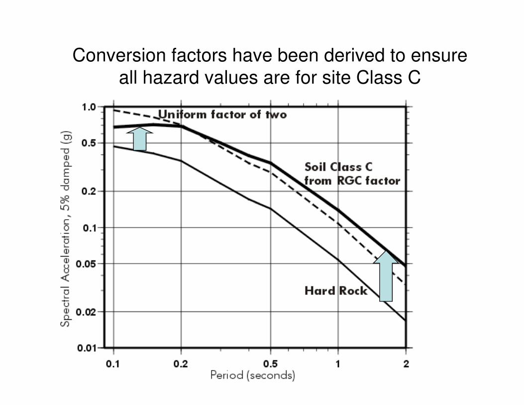
Conversion factors have been derived to ensure
all hazard values are for site Class C
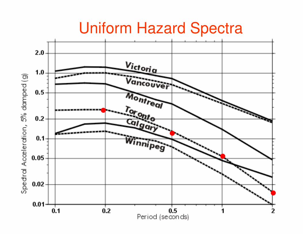
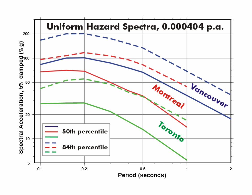
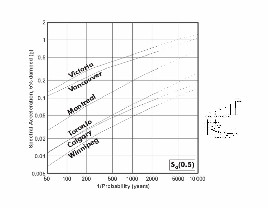
Uniform Hazard Spectra
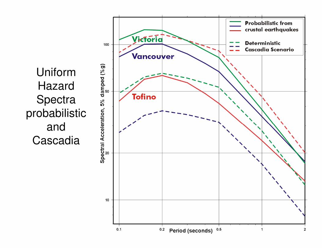
Uniform
Hazard
Spectra
probabilistic
and and
Cascadia
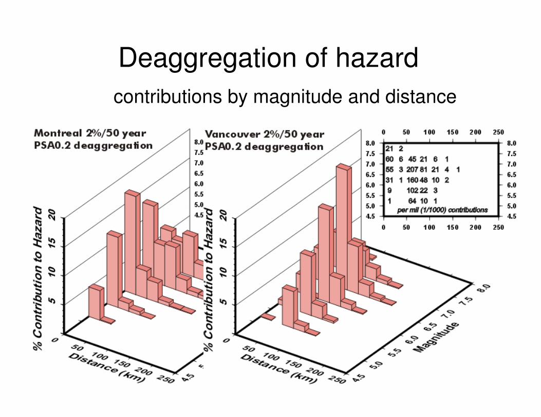
Deaggregation of hazard
contributions by magnitude and distance
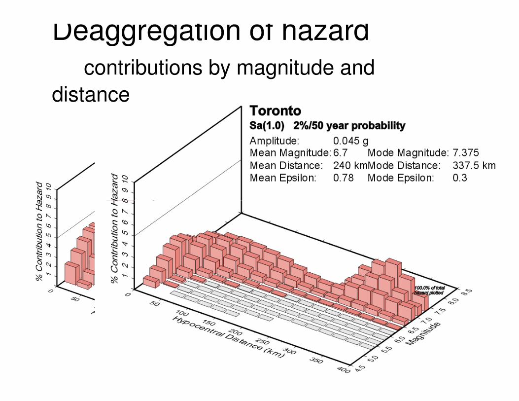
Deaggregation of hazard
contributions by magnitude and
distance
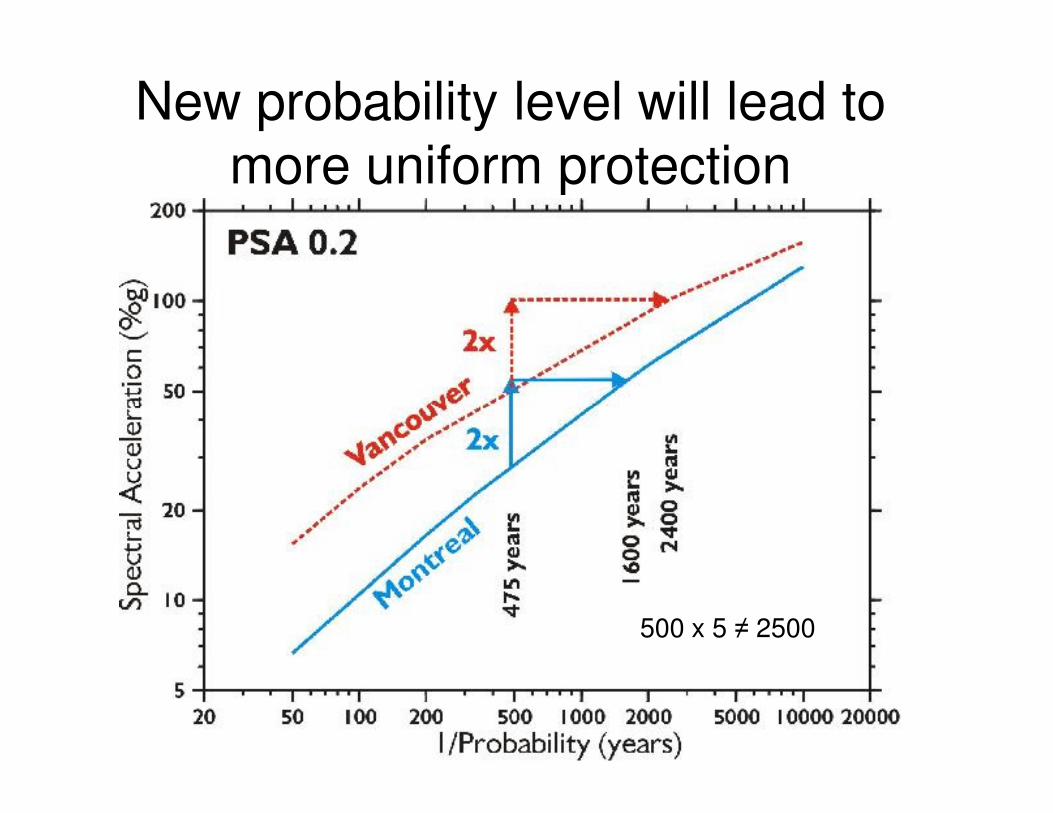
New probability level will lead to
more uniform protection
500 x 5 ≠ 2500
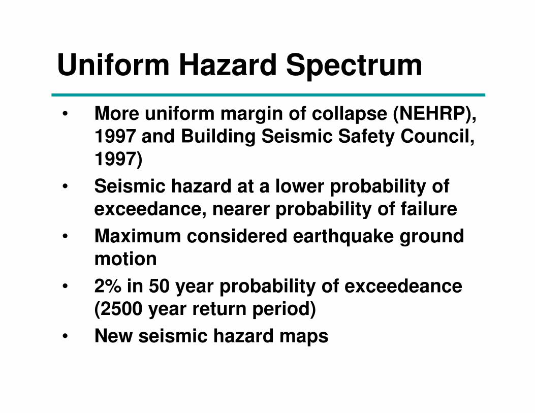
Uniform Hazard Spectrum
• More uniform margin of collapse (NEHRP),
1997 and Building Seismic Safety Council,
1997)
• Seismic hazard at a lower probability of
exceedance, nearer probability of failure exceedance, nearer probability of failure
• Maximum considered earthquake ground
motion
• 2% in 50 year probability of exceedeance
(2500 year return period)
• New seismic hazard maps
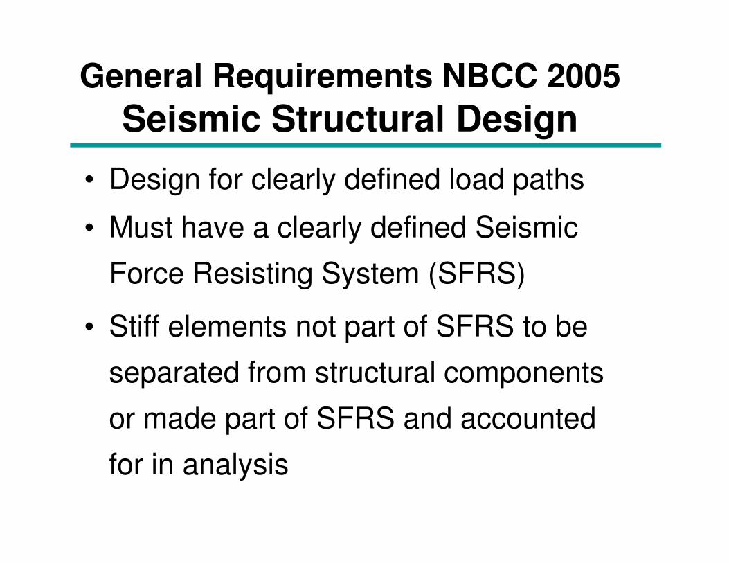
General Requirements NBCC 2005
Seismic Structural Design
• Design for clearly defined load paths
• Must have a clearly defined Seismic
Force Resisting System (SFRS)Force Resisting System (SFRS)
• Stiff elements not part of SFRS to be
separated from structural components
or made part of SFRS and accounted
for in analysis
Base Shear NBCC 1995 vs 2005
V =VE
RU
VE = v S I F W
1995
V =S (Ta) Mv IE
Rd Ro
W
=
2005
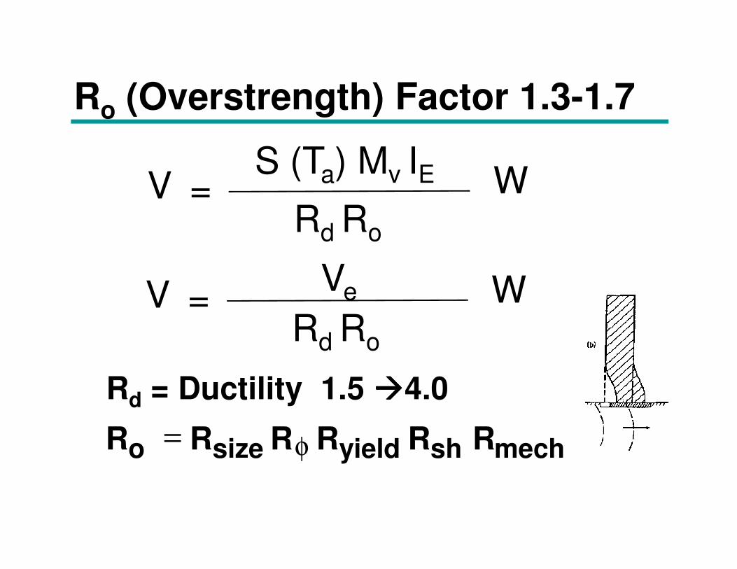
Ro (Overstrength) Factor 1.3-1.7
V =S (Ta) Mv IE
Rd Ro
W
V =Ve W
R R RR R Ro yieldsize sh mech= φ
Rd = Ductility 1.5 ����4.0
V =Ve
Rd Ro
W
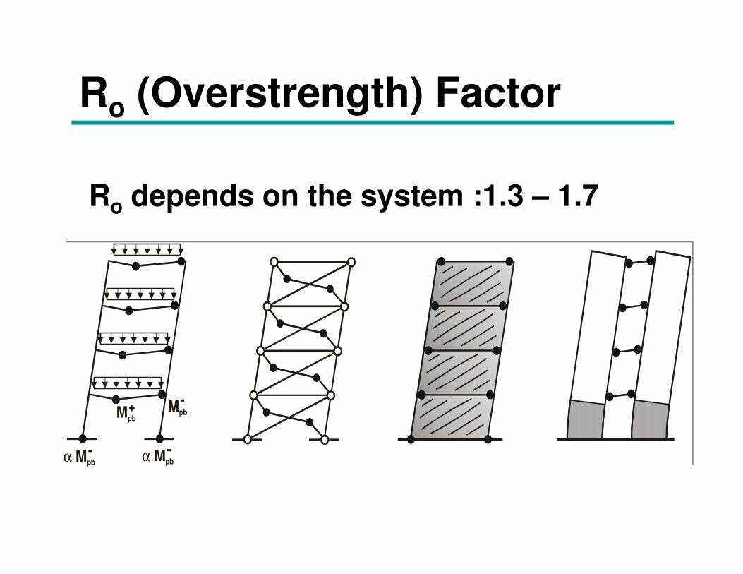
Ro (Overstrength) Factor
Ro depends on the system :1.3 – 1.7
Mpb
α Mpb α Mpb
Mpb
-
- -
+
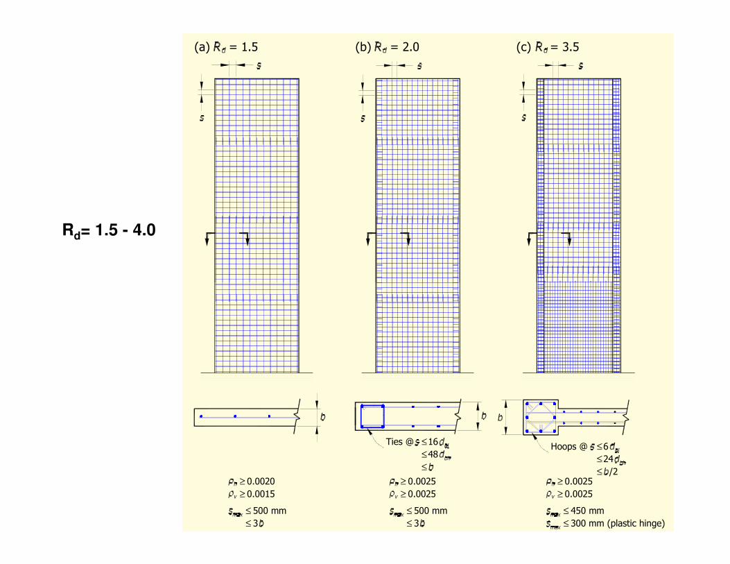
(a) = 1.5 (b) = 2.0 (c) = 3.5
Rd= 1.5 - 4.0
≥ 0.0020
0.0015≥
≤ 500 mm
3≤
0.0025
0.0025
500 mm
≤ 3
≤
≥
≥
450 mm
0.0025
0.0025
≤
≥
≥
Ties @ ≤16
48≤
≤
Hoops @
24≤
≤
6≤
/2
≤ 300 mm (plastic hinge)
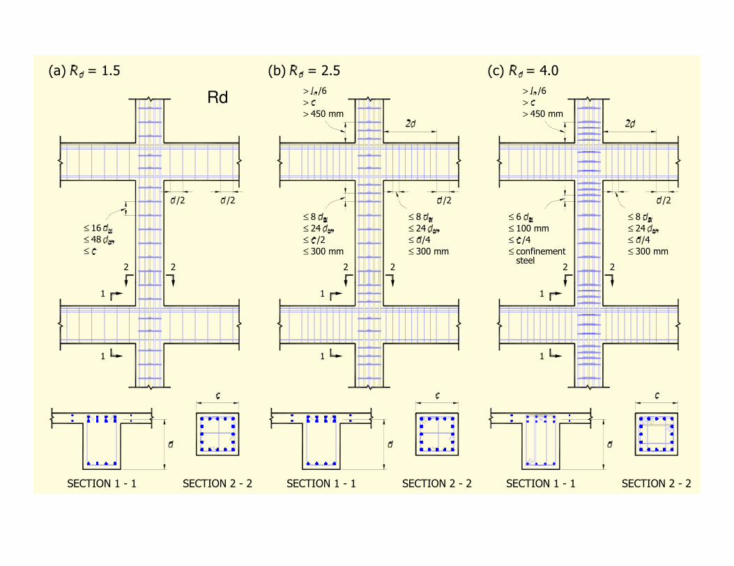
(a) = 1.5 (b) = 2.5 (c) = 4.0
/2 /2 /2 /2
>>>
450 mm
/6
>>>
450 mm
/6
≤≤≤
16
48
≤≤≤
8
24
≤ 300 mm
/2
≤≤≤
8
24
≤ 300 mm
/4
≤≤≤
6
100 mm
≤ confinement
/4
≤≤≤
8
24
≤ 300 mm
/4
steel2 2 2 2 2 2
Rd
1
1
1
1
1
1
SECTION 2 - 2SECTION 1 - 1 SECTION 1 - 1 SECTION 1 - 1SECTION 2 - 2 SECTION 2 - 2
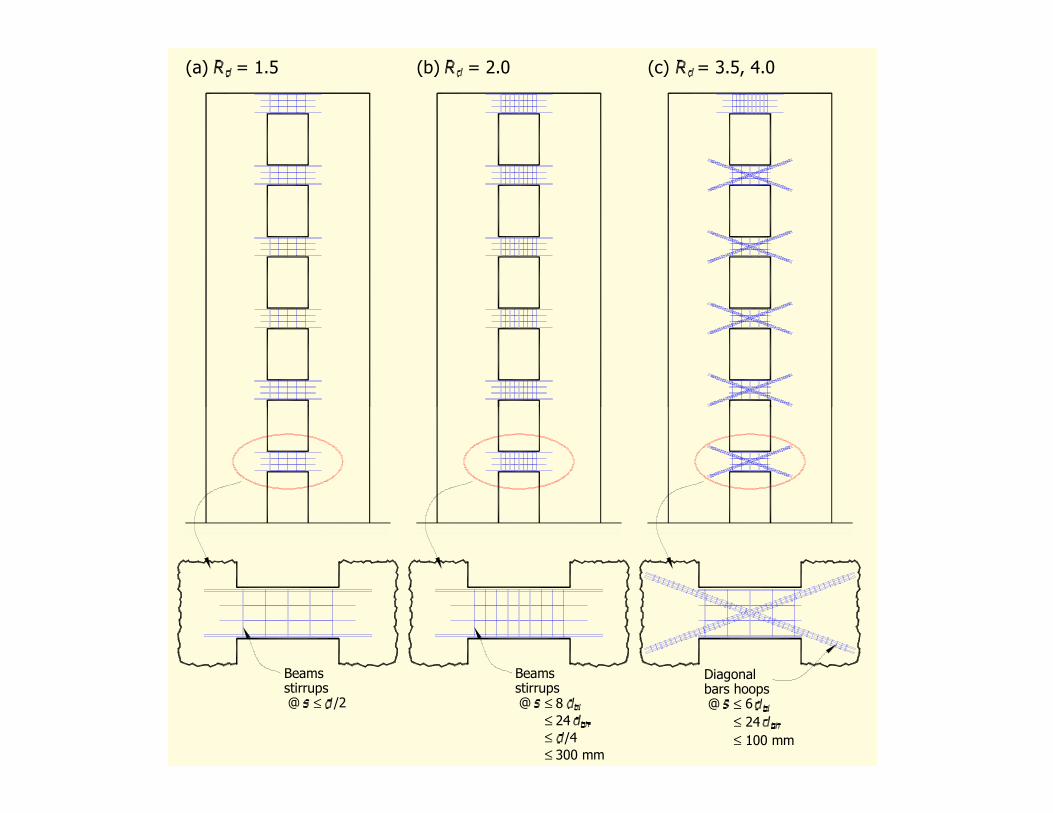
(a) = 1.5 (b) = 2.0 (c) = 3.5, 4.0
stirrups@ /2≤
Beams Diagonalbars hoops
Beamsstirrups@ @ 6≤
≤
≤
24
100 mm
≤≤≤
8
24
≤ 300 mm
/4
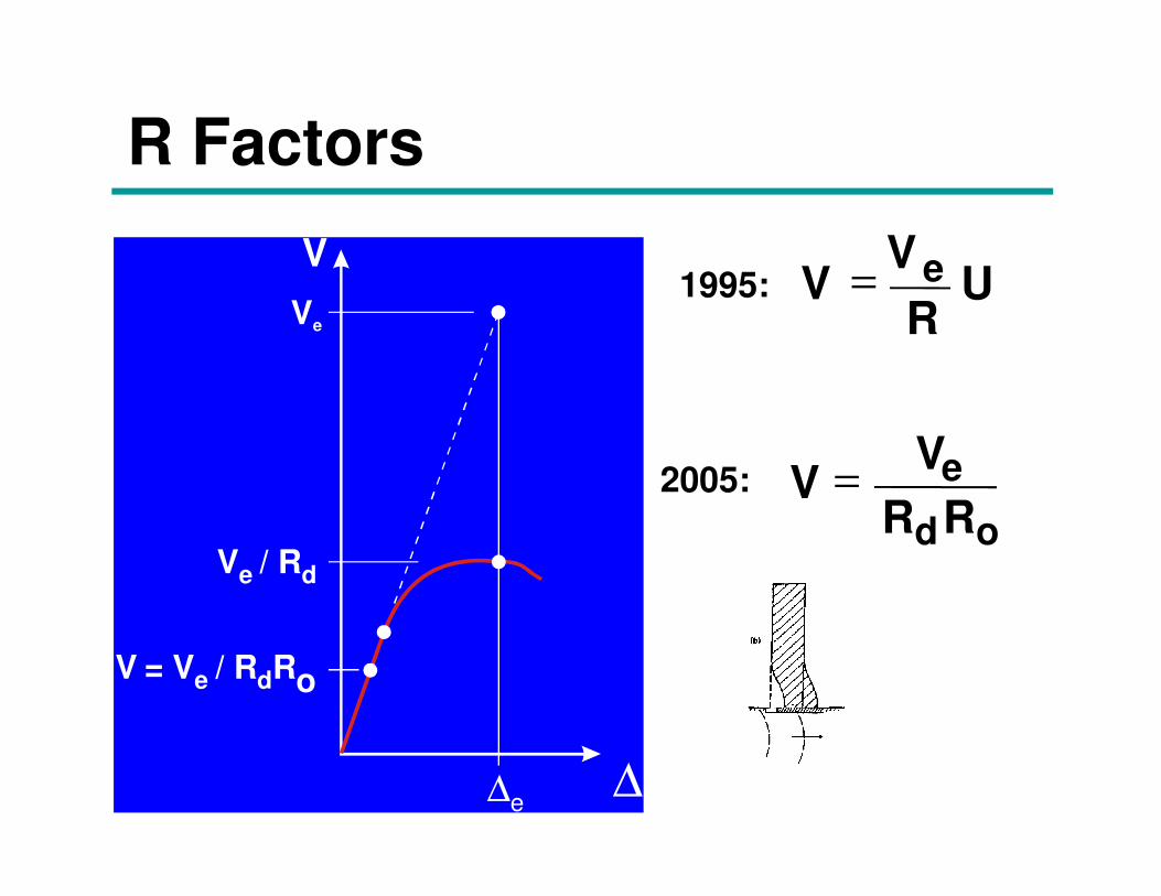
Ve=
R Factors
V
Ve
VV
RUe=1995:
VV
R Re
d o
=
∆e∆
V = / R R d oVe
Ve / Rd
2005:
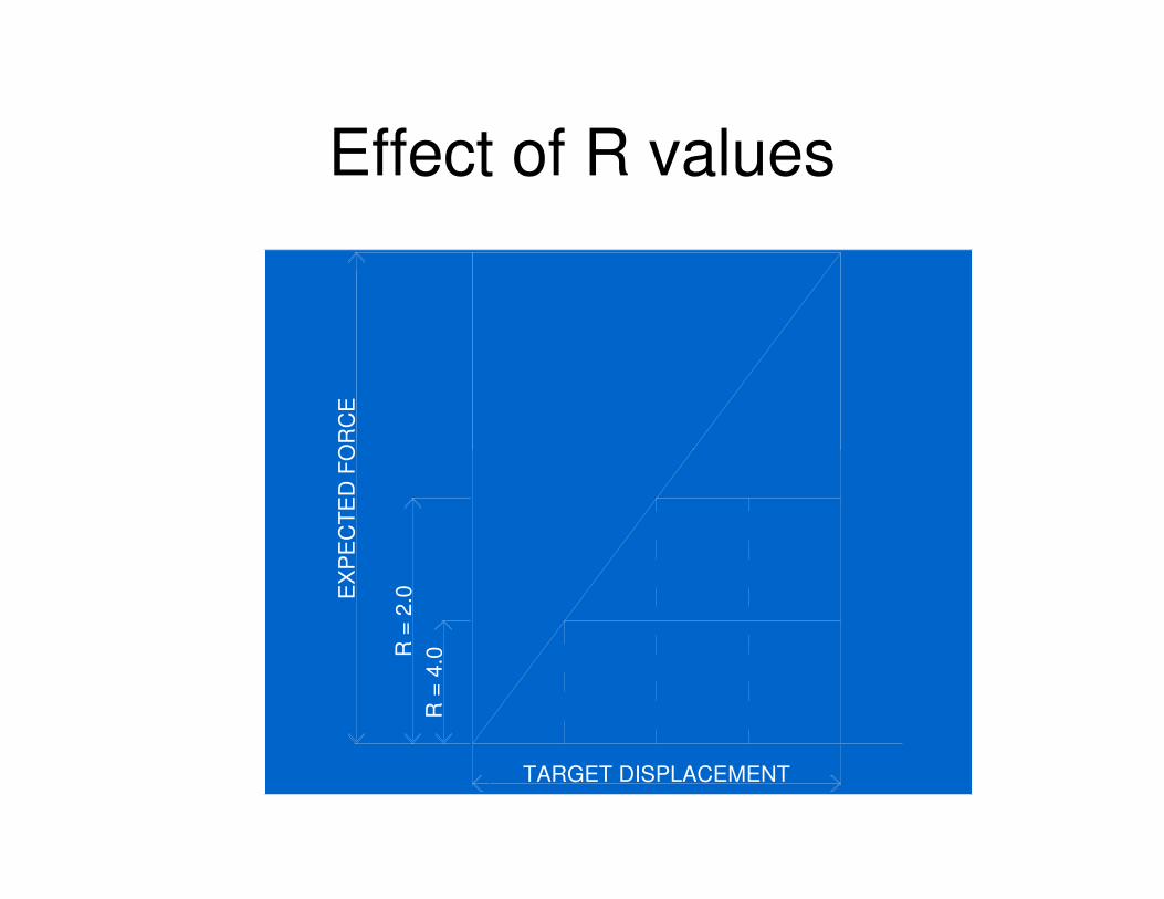
Effect of R values
EX
PE
CT
ED
FO
RC
E
R =
2.0
R =
4.0
TARGET DISPLACEMENT
EX
PE
CT
ED
FO
RC
E
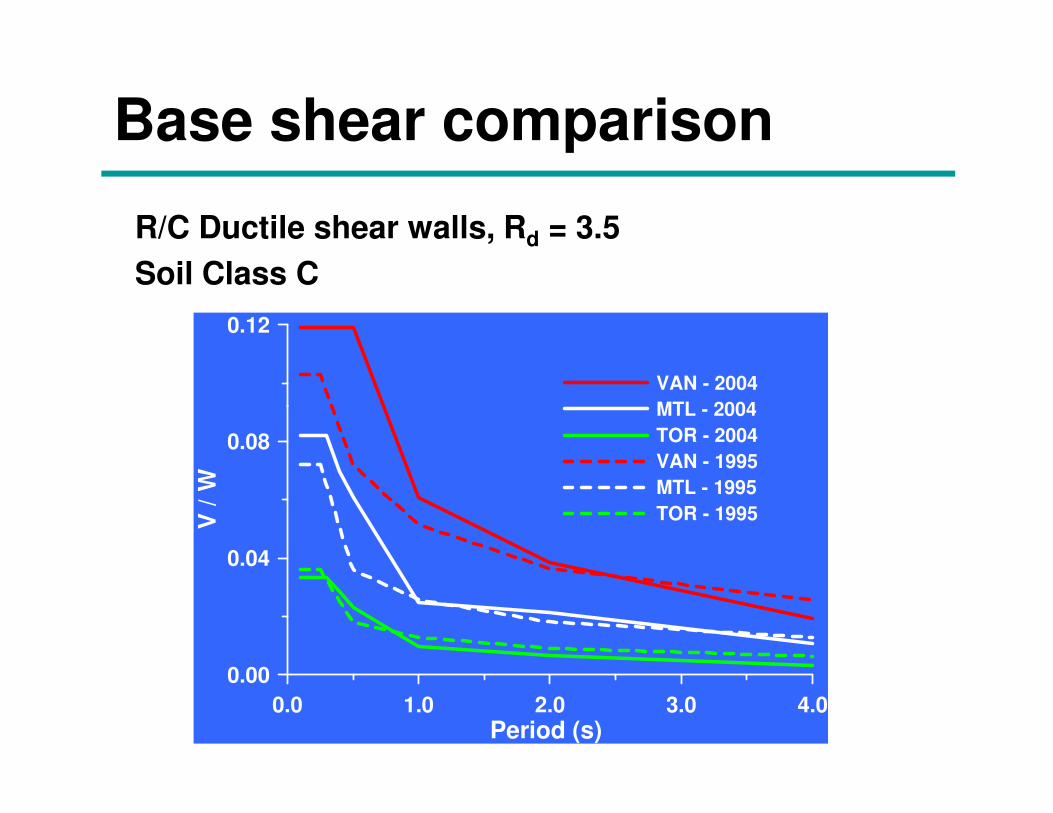
Base shear comparison
R/C Ductile shear walls, Rd = 3.5
Soil Class C
0.12
VAN - 2004
MTL - 2004
0.0 1.0 2.0 3.0 4.0Period (s)
0.00
0.04
0.08
V /
W
MTL - 2004
TOR - 2004
VAN - 1995
MTL - 1995
TOR - 1995
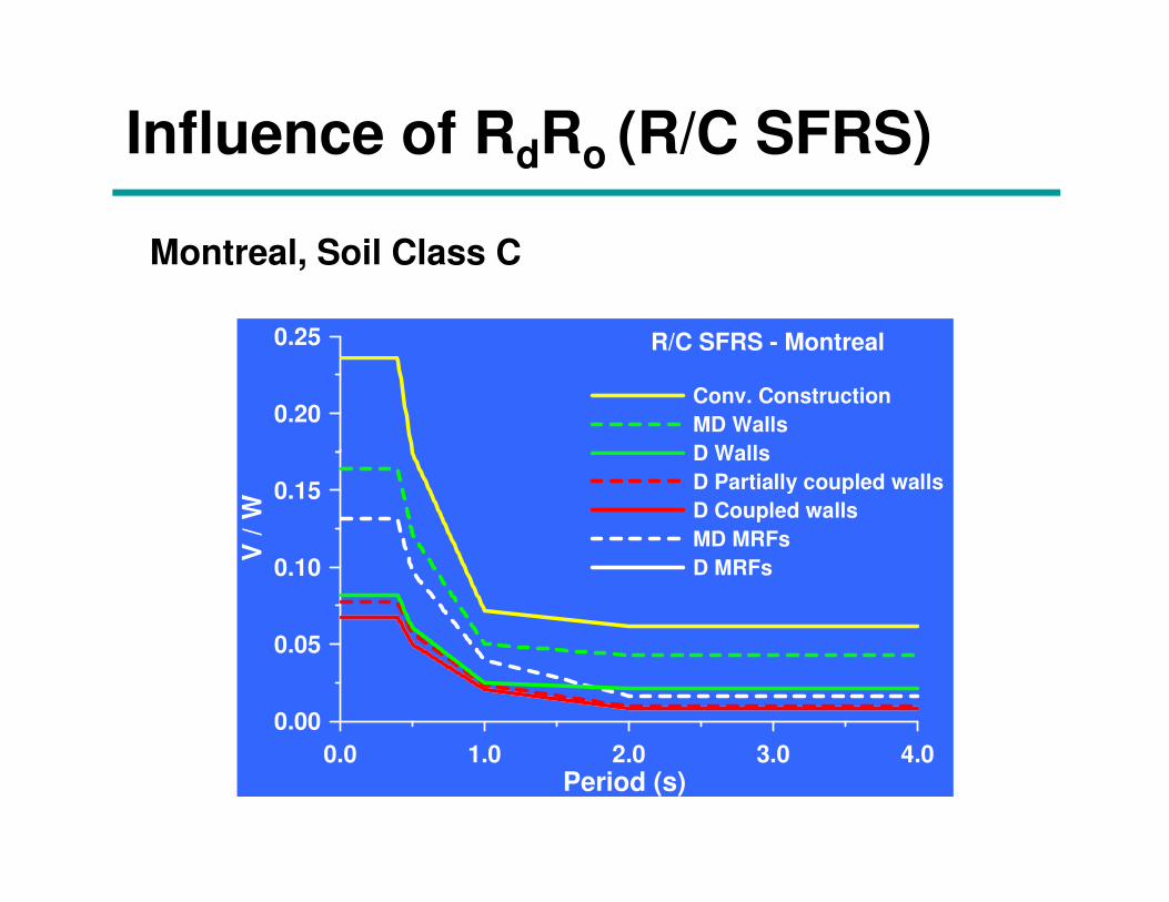
Influence of RdRo (R/C SFRS)
Montreal, Soil Class C
0.20
0.25 R/C SFRS - Montreal
Conv. Construction
MD Walls
D Walls
0.0 1.0 2.0 3.0 4.0Period (s)
0.00
0.05
0.10
0.15
V /
W
D Walls
D Partially coupled walls
D Coupled walls
MD MRFs
D MRFs
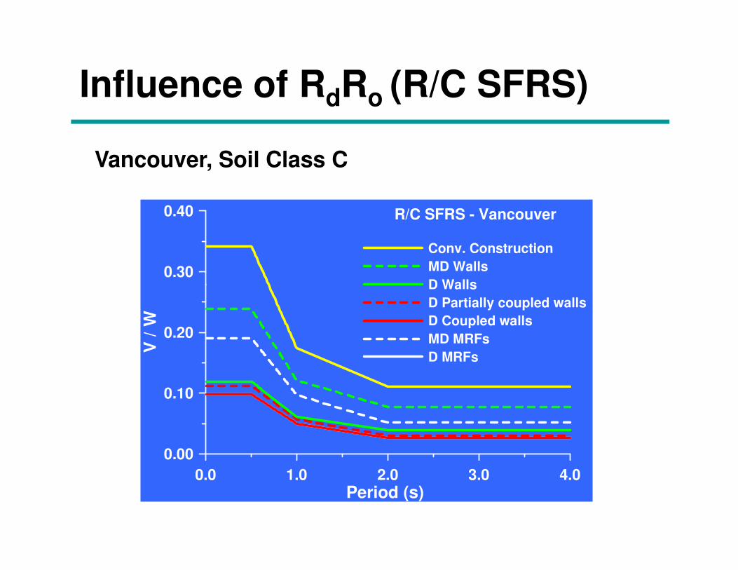
Influence of RdRo (R/C SFRS)
Vancouver, Soil Class C
0.30
0.40 R/C SFRS - Vancouver
Conv. Construction
MD Walls
D Walls
0.0 1.0 2.0 3.0 4.0Period (s)
0.00
0.10
0.20
V /
W
D Walls
D Partially coupled walls
D Coupled walls
MD MRFs
D MRFs
2005 NBCC Seismic Analysis
• Better consideration of irregularities
• Requires more dynamic analysis
• Better consideration of torsional sensitivity
• Lateral storey drift limit increased: 2% -> • Lateral storey drift limit increased: 2% -> 2.5%. Relates to structural damage.
• Post-disaster buildings shall not have any irregularity
Types of structural irregularities
1 Vertical stiffness irregularity
2 Weight (mass) irregularity
3 Vertical geometric irregularity
4 In-plane discontinuity4 In-plane discontinuity
5 Out-of-plane offsets
6 Discontinuity in capacity (weak storey)
7 Torsional sensitivity
8 Non-orthogonal systems
Irregularity trigger
When:
IE·Fa·Sa(0.2) > 0.35
+ any one of the 8 irregularity types,+ any one of the 8 irregularity types,
the building is considered as irregular
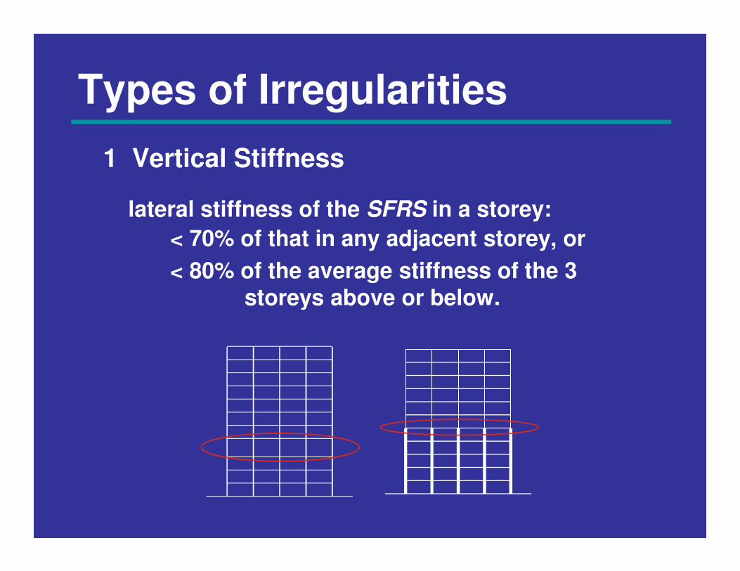
Types of Irregularities
1 Vertical Stiffness
lateral stiffness of the SFRS in a storey:
< 70% of that in any adjacent storey, or
< 80% of the average stiffness of the 3
storeys above or below.storeys above or below.
Types of Irregularities
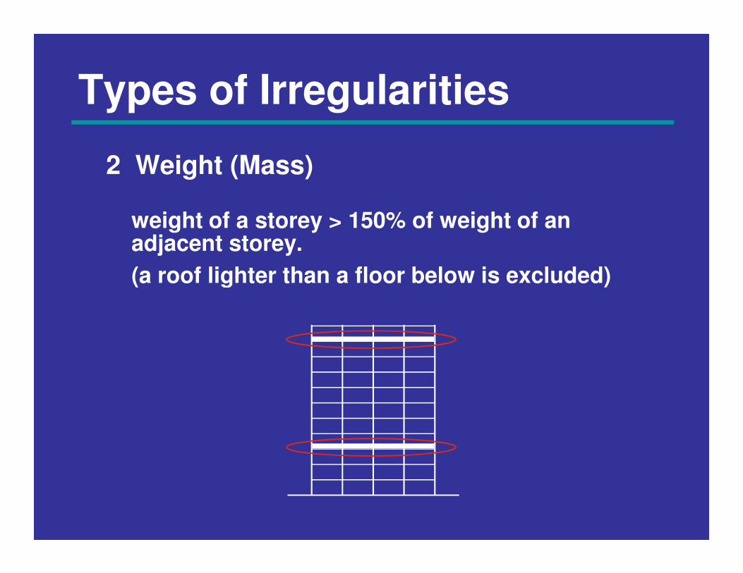
2 Weight (Mass)
weight of a storey > 150% of weight of anadjacent storey.
(a roof lighter than a floor below is excluded) (a roof lighter than a floor below is excluded)
Types of Irregularities
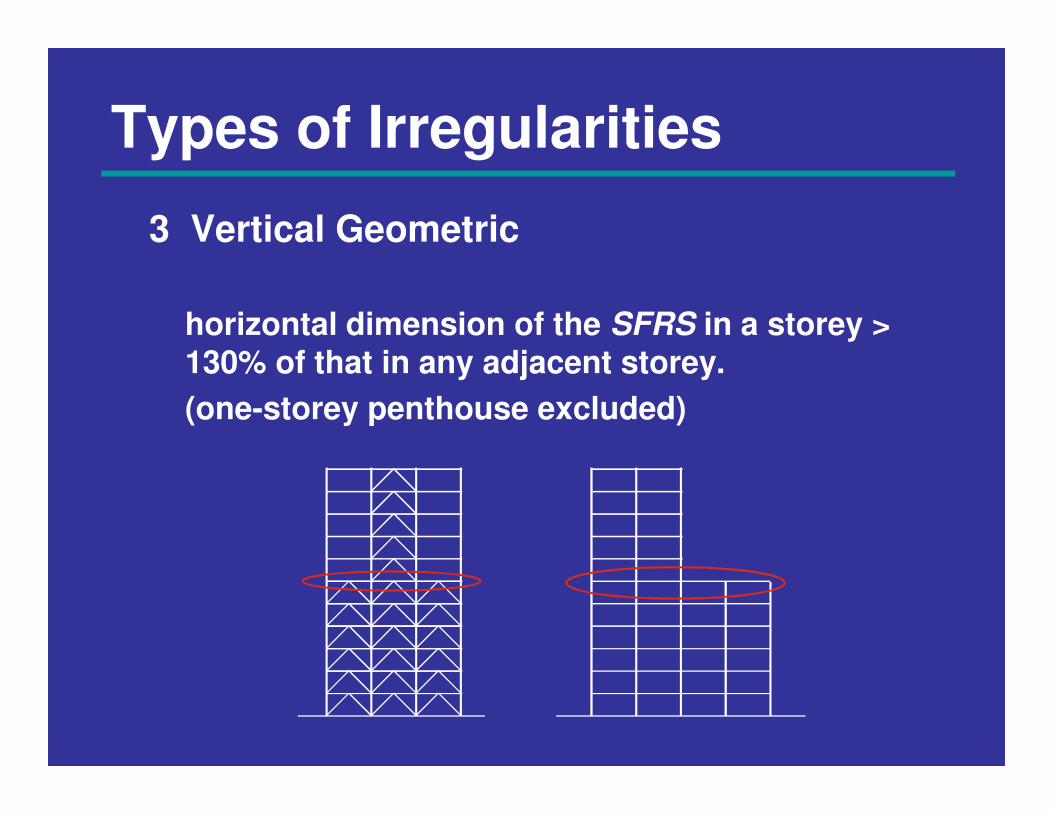
3 Vertical Geometric
horizontal dimension of the SFRS in a storey > 130% of that in any adjacent storey.
(one-storey penthouse excluded)(one-storey penthouse excluded)
Types of Irregularities
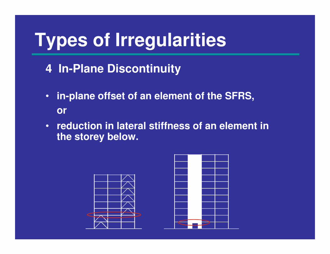
4 In-Plane Discontinuity
• in-plane offset of an element of the SFRS,
or
• reduction in lateral stiffness of an element in • reduction in lateral stiffness of an element in the storey below.
Types of Irregularities
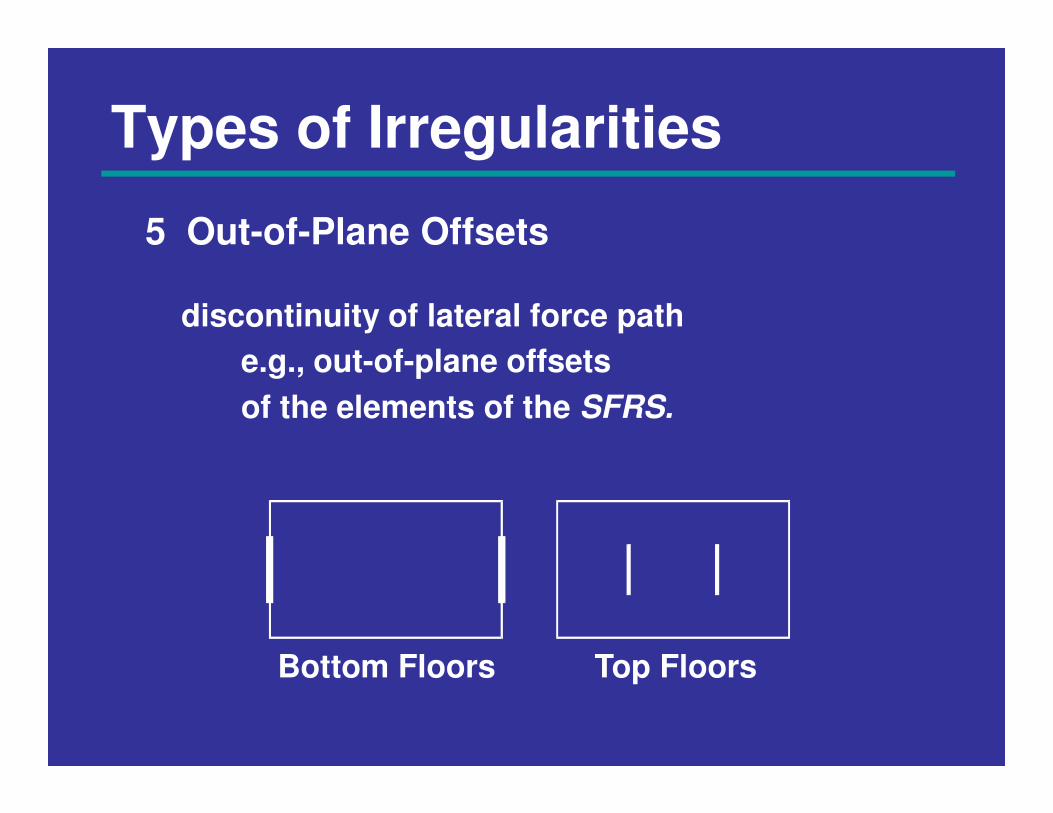
5 Out-of-Plane Offsets
discontinuity of lateral force path
e.g., out-of-plane offsets
of the elements of the SFRS.of the elements of the SFRS.
Top FloorsBottom Floors
Types of Irregularities
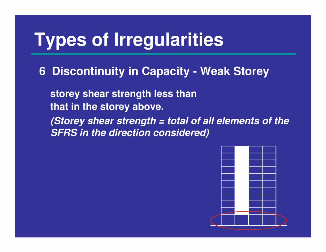
6 Discontinuity in Capacity - Weak Storey
storey shear strength less than
that in the storey above.
(Storey shear strength = total of all elements of the (Storey shear strength = total of all elements of the SFRS in the direction considered)
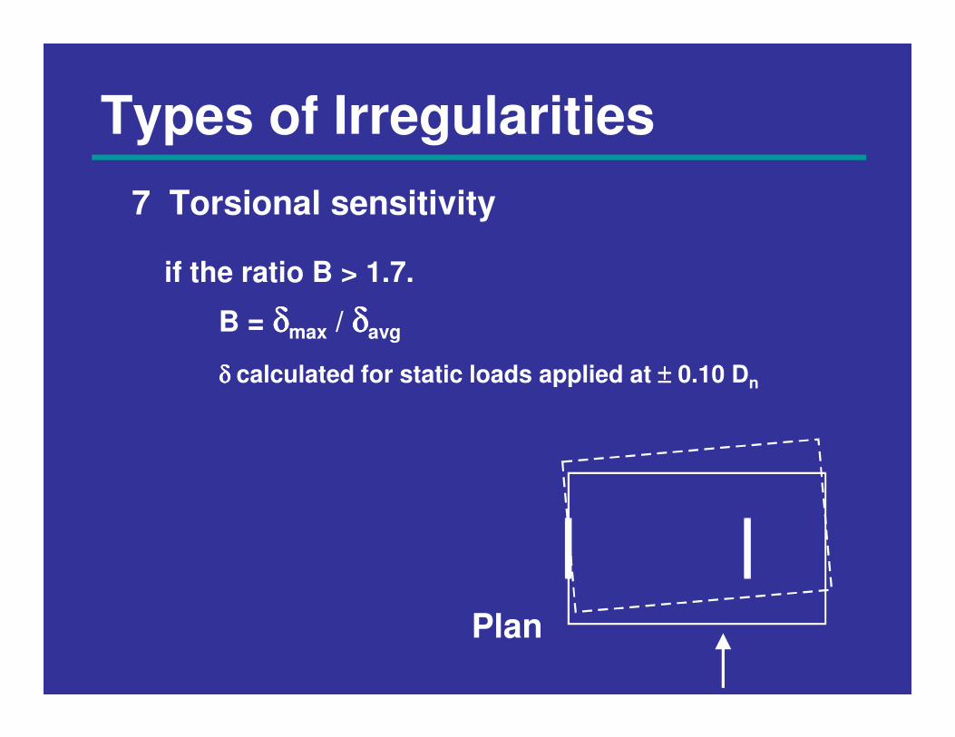
Types of Irregularities
7 Torsional sensitivity
if the ratio B > 1.7.
B = δδδδmax / δδδδavg
δ δ δ δ calculated for static loads applied at ±±±± 0.10 Dδ δ δ δ calculated for static loads applied at ±±±± 0.10 Dn
Plan
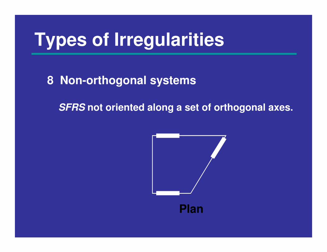
Types of Irregularities
8 Non-orthogonal systems
SFRS not oriented along a set of orthogonal axes.
Plan
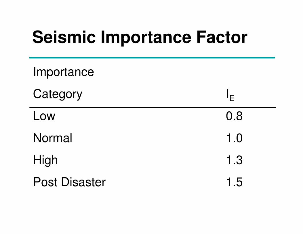
Seismic Importance Factor
Importance
Category IE
Low 0.8Low 0.8
Normal 1.0
High 1.3
Post Disaster 1.5
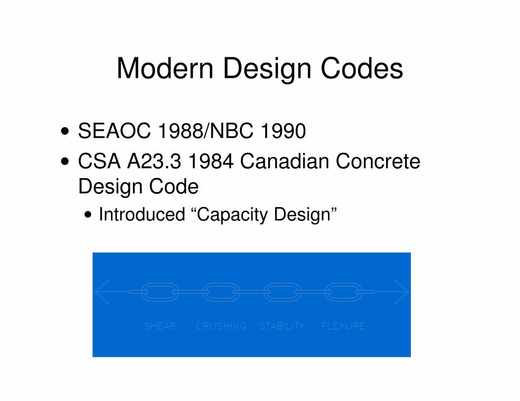
Modern Design Codes
• SEAOC 1988/NBC 1990
• CSA A23.3 1984 Canadian Concrete Design Code
• Introduced “Capacity Design”

Concrete Plastic Hinges
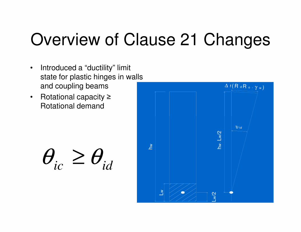
Overview of Clause 21 Changes
• Introduced a “ductility” limit state for plastic hinges in walls and coupling beams
• Rotational capacity ≥ Rotational demand
∆ f ( R d R o - γ w )
idicθθ ≥
υ id
hw
hw
- L
w/2
Lw
Lw/2
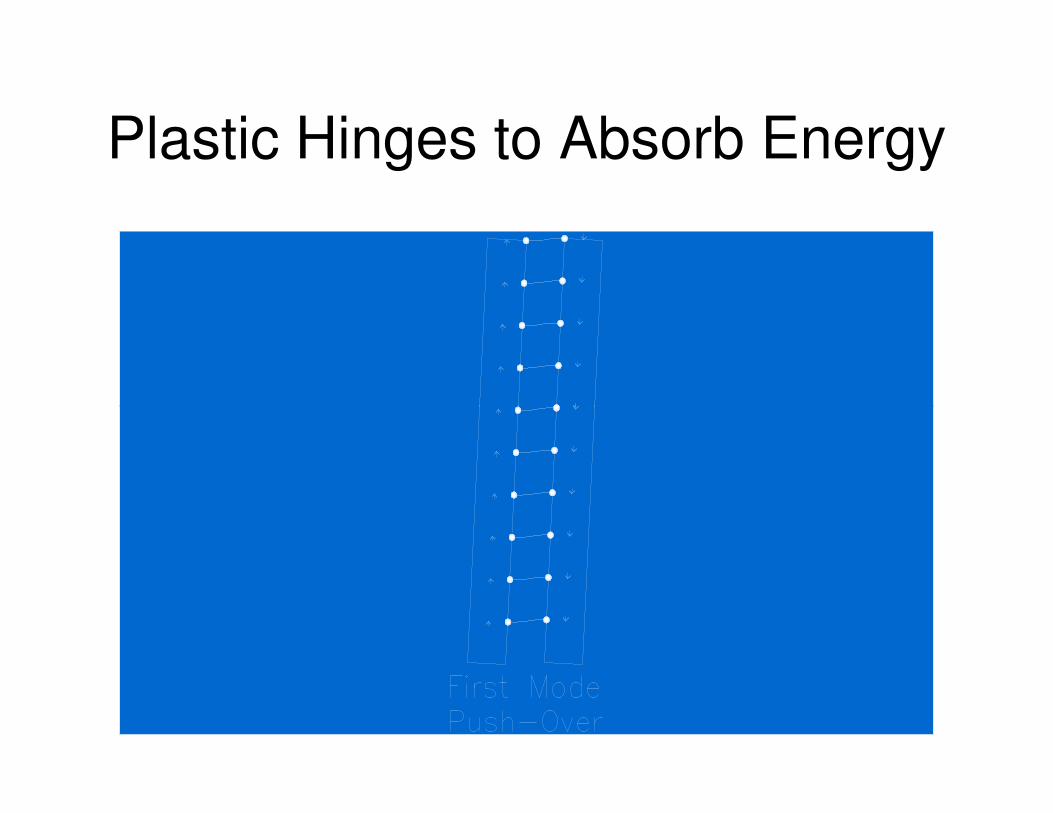
Plastic Hinges to Absorb Energy
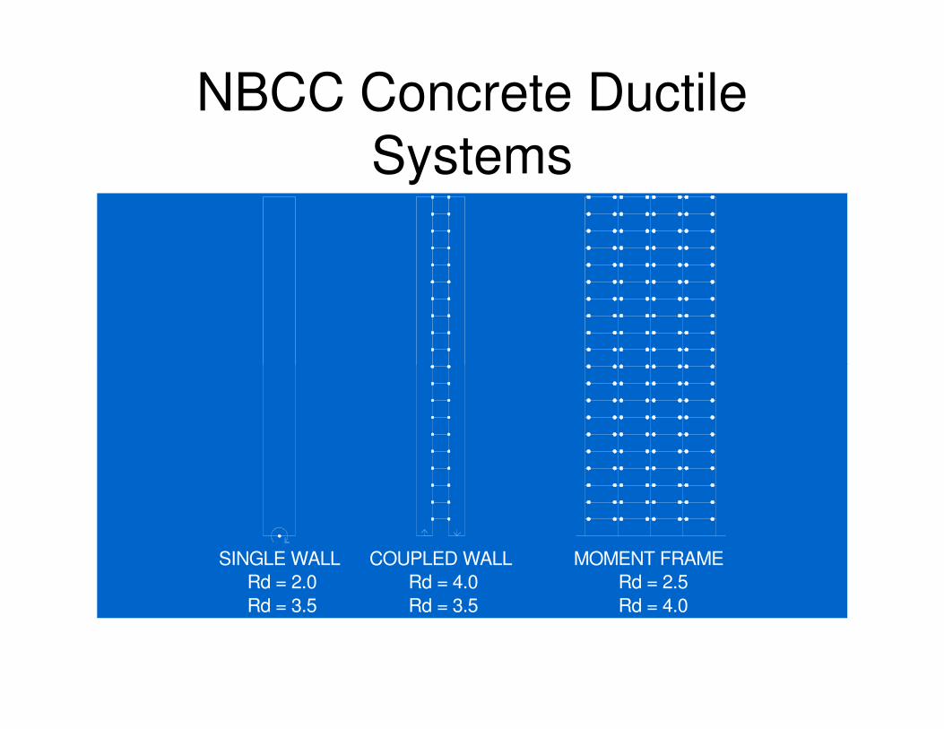
NBCC Concrete Ductile
Systems
SINGLE WALL
Rd = 2.0 Rd = 4.0
COUPLED WALL
Rd = 2.5
MOMENT FRAME
Rd = 3.5 Rd = 4.0Rd = 3.5
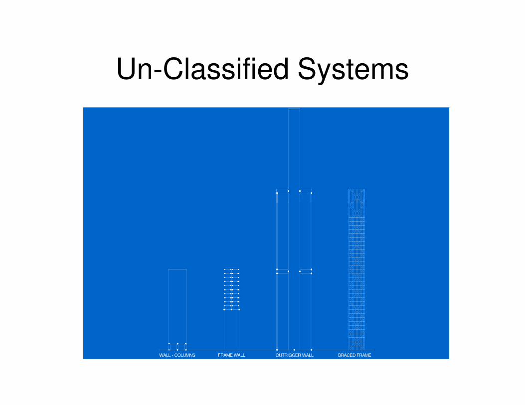
Un-Classified Systems
OUTRIGGER WALLFRAME WALLWALL - COLUMNS BRACED FRAME
Earthquake Design Factor of
Safety
• “Earthquake” Factored Load Design
– Factored Load ≈ 0.15 to 0.5 x Expected
LoadLoad
– Factored Bending Resistance ≈ 0.17 to 0.6
x Expected Load
– “Factor of Safety” ≈ 0.17 to 0.6
Philosophical Underpinning
• Earthquakes are rare events, the design event has a 2% probability of exceedance in 50 years. That is, in an assumed 50 year building life, there is a 98% chance year building life, there is a 98% chance that the building will not experience an earthquake of this magnitude in its design life.
• Therefore design only for life safety, not asset protection, the building may be irreparable but no one dies.
2005 NBCC – Objective Based Format
• Part 1 – Objectives of the Code
• Part 2 – Prescriptive Solutions to Objectives
• 1995• 1995
• Firewalls with a fire rating of 2 hrs or less shall
be constructed of concrete or masonry.
• 2005
• Firewalls with a fire rating of 2 hrs or less not
explicitly required to be masonry or concrete.
Further Information
Commentary J - NBCC 2005Canadian J. of Civil Engineering, April 2003:
- overview and background of changes- seismic hazard maps
- ground amplification factors- ground amplification factors- equivalent static load method- force modification factors- torsion- dynamic analysis- foundation rocking- non-structural components

Thank YouThank You