2005 Cadillac DeVille Owner Manual M System ..... 5-97 Capacities and Specifications ..... 5-106...
416
Seats and Restraint Systems ........................... 1-1 Front Seats ............................................... 1-2 Rear Seats ............................................... 1-5 Safety Belts .............................................. 1-7 Child Restraints ....................................... 1-26 Airbag System ......................................... 1-45 Restraint System Check ............................ 1-54 Features and Controls ..................................... 2-1 Keys ........................................................ 2-3 Doors and Locks ....................................... 2-8 Windows ................................................. 2-15 Theft-Deterrent Systems ............................ 2-19 Starting and Operating Your Vehicle ........... 2-24 Mirrors .................................................... 2-37 OnStar ® System ...................................... 2-42 HomeLink ® Transmitter ............................. 2-44 Storage Areas ......................................... 2-48 Sunroof .................................................. 2-51 Vehicle Personalization ............................. 2-52 Instrument Panel ............................................. 3-1 Instrument Panel Overview .......................... 3-4 Climate Controls ...................................... 3-30 Warning Lights, Gages, and Indicators ........ 3-40 Driver Information Center (DIC) .................. 3-57 Trip Computer ......................................... 3-79 Audio System(s) ....................................... 3-79 Driving Your Vehicle ....................................... 4-1 Your Driving, the Road, and Your Vehicle ..... 4-2 Towing ................................................... 4-35 Service and Appearance Care .......................... 5-1 Service ..................................................... 5-3 Fuel ......................................................... 5-5 Checking Things Under the Hood ............... 5-10 Headlamp Aiming ..................................... 5-48 Bulb Replacement .................................... 5-51 Windshield Wiper Blade Replacement ......... 5-56 Tires ...................................................... 5-57 Appearance Care ..................................... 5-87 Vehicle Identification ................................. 5-96 Electrical System ...................................... 5-97 Capacities and Specifications ................... 5-106 Maintenance Schedule ..................................... 6-1 Maintenance Schedule ................................ 6-2 Customer Assistance and Information .............. 7-1 Customer Assistance and Information ........... 7-2 Reporting Safety Defects ........................... 7-10 Index ................................................................ 1 2005 Cadillac DeVille Owner Manual M
Transcript of 2005 Cadillac DeVille Owner Manual M System ..... 5-97 Capacities and Specifications ..... 5-106...
Seats and Restraint Systems ........................... 1-1Front Seats ............................................... 1-2Rear Seats ............................................... 1-5Safety Belts .............................................. 1-7Child Restraints ....................................... 1-26Airbag System ......................................... 1-45Restraint System Check ............................ 1-54
Features and Controls ..................................... 2-1Keys ........................................................ 2-3Doors and Locks ....................................... 2-8Windows ................................................. 2-15Theft-Deterrent Systems ............................ 2-19Starting and Operating Your Vehicle ........... 2-24Mirrors .................................................... 2-37OnStar® System ...................................... 2-42HomeLink® Transmitter ............................. 2-44Storage Areas ......................................... 2-48Sunroof .................................................. 2-51Vehicle Personalization ............................. 2-52
Instrument Panel ............................................. 3-1Instrument Panel Overview .......................... 3-4Climate Controls ...................................... 3-30Warning Lights, Gages, and Indicators ........ 3-40Driver Information Center (DIC) .................. 3-57
Trip Computer ......................................... 3-79Audio System(s) ....................................... 3-79
Driving Your Vehicle ....................................... 4-1Your Driving, the Road, and Your Vehicle ..... 4-2Towing ................................................... 4-35
Service and Appearance Care .......................... 5-1Service ..................................................... 5-3Fuel ......................................................... 5-5Checking Things Under the Hood ............... 5-10Headlamp Aiming ..................................... 5-48Bulb Replacement .................................... 5-51Windshield Wiper Blade Replacement ......... 5-56Tires ...................................................... 5-57Appearance Care ..................................... 5-87Vehicle Identification ................................. 5-96Electrical System ...................................... 5-97Capacities and Specifications ................... 5-106
Maintenance Schedule ..................................... 6-1Maintenance Schedule ................................ 6-2
Customer Assistance and Information .............. 7-1Customer Assistance and Information ........... 7-2Reporting Safety Defects ........................... 7-10
Index ................................................................ 1
2005 Cadillac DeVille Owner Manual M
GENERAL MOTORS, GM, the GM Emblem, CADILLAC,the CADILLAC Crest & Wreath, and the name DEVILLEare registered trademarks of General Motors Corporation.
This manual includes the latest information at the time itwas printed. We reserve the right to make changesafter that time without notice. For vehicles first sold inCanada, substitute the name “General Motors of CanadaLimited” for Cadillac Motor Car Division whenever itappears in this manual.
Keep this manual in the vehicle, so it will be there if it isneeded while your are on the road. If the vehicle issold, leave this manual in the vehicle.
Canadian OwnersA French language copy of this manual can be obtainedfrom your dealer or from:
Helm, IncorporatedP.O. Box 07130Detroit, MI 48207
How to Use This ManualMany people read the owner manual from beginning toend when they first receive their new vehicle. If thisis done, it can help you learn about the featuresand controls for the vehicle. Pictures and words worktogether in the owner manual to explain things.
IndexA good place to quickly locate information about thevehicle is the Index in the back of the manual. It is analphabetical list of what is in the manual and thepage number where it can be found.
Litho in U.S.A.Part No. 05DEVILLE A First Edition ©2004 General Motors Corporation. All Rights Reserved.
ii
Safety Warnings and SymbolsThere are a number of safety cautions in this book. Weuse a box and the word CAUTION to tell about thingsthat could hurt you if you were to ignore the warning.
{CAUTION:
These mean there is something that could hurtyou or other people.
In the caution area, we tell you what the hazard is.Then we tell you what to do to help avoid or reduce thehazard. Please read these cautions. If you do not,you or others could be hurt.
You will also find a circlewith a slash through it inthis book. This safetysymbol means “Do Not,”“Do Not do this” or “Do Notlet this happen.”
iii
Vehicle Damage WarningsAlso, in this manual you will find these notices:
Notice: These mean there is something that coulddamage your vehicle.
A notice tells about something that can damage thevehicle. Many times, this damage would not be coveredby your vehicle’s warranty, and it could be costly. Butthe notice will tell what to do to help avoid the damage.
When you read other manuals, you might seeCAUTION and NOTICE warnings in different colors or indifferent words.
There are also warning labels on the vehicle. They usethe same words, CAUTION or NOTICE.
Vehicle SymbolsThe vehicle has components and labels that usesymbols instead of text. Symbols are shown along withthe text describing the operation or informationrelating to a specific component, control, message,gage, or indicator.
If you need help figuring out a specific name of acomponent, gage, or indicator, reference the followingtopics:
• Seats and Restraint Systems in Section 1
• Features and Controls in Section 2
• Instrument Panel Overview in Section 3
• Climate Controls in Section 3
• Warning Lights, Gages, and Indicators in Section 3
• Audio System(s) in Section 3
• Engine Compartment Overview in Section 5
iv
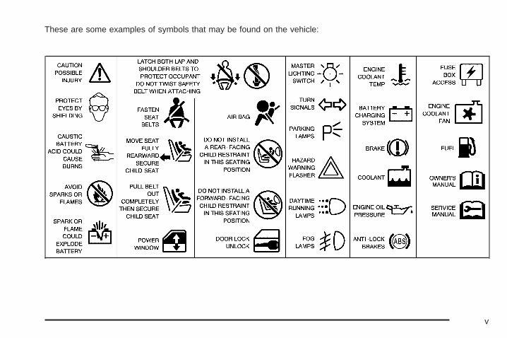
These are some examples of symbols that may be found on the vehicle:
v

✍ NOTES
vi
Front Seats ......................................................1-2Power Seats ..................................................1-2Power Lumbar ...............................................1-2Massaging Lumbar .........................................1-3Heated and Cooled Seats ................................1-3Reclining Seatbacks ........................................1-4
Rear Seats .......................................................1-5Heated Seats .................................................1-5Power Lumbar ...............................................1-6
Safety Belts .....................................................1-7Safety Belts: They Are for Everyone .................1-7Questions and Answers About Safety Belts ......1-11How to Wear Safety Belts Properly .................1-12Driver Position ..............................................1-12Safety Belt Use During Pregnancy ..................1-18Right Front Passenger Position .......................1-19Center Front Passenger Position .....................1-19Rear Seat Passengers ..................................1-20Rear Safety Belt Comfort Guides for Children
and Small Adults .......................................1-23Safety Belt Pretensioners ...............................1-25Safety Belt Extender .....................................1-25
Child Restraints .............................................1-26Older Children ..............................................1-26Infants and Young Children ............................1-28
Child Restraint Systems .................................1-31Where to Put the Restraint .............................1-34Top Strap ....................................................1-35Top Strap Anchor Location .............................1-37Lower Anchorages and Top Tethers for
Children (LATCH System) ...........................1-37Securing a Child Restraint Designed for the
LATCH System .........................................1-39Securing a Child Restraint in a Rear Seat
Position ...................................................1-40Securing a Child Restraint in the Center Front
Seat Position ............................................1-42Securing a Child Restraint in the Right Front
Seat Position ............................................1-42Airbag System ...............................................1-45
Where Are the Airbags? ................................1-48When Should an Airbag Inflate? .....................1-50What Makes an Airbag Inflate? .......................1-52How Does an Airbag Restrain? .......................1-52What Will You See After an Airbag Inflates? .....1-52Servicing Your Airbag-Equipped Vehicle ...........1-54
Restraint System Check ..................................1-54Checking Your Restraint Systems ...................1-54Replacing Restraint System Parts After
a Crash ...................................................1-55
Section 1 Seats and Restraint Systems
1-1

Front Seats
Power Seats
The power seat controlsare located on theoutboard sides of the frontseat cushions.
• Move the front of the seat control up or down toadjust the front portion of the cushion.
• Move the rear of the seat control up or down toadjust the rear portion of the cushion.
• Lift up or push down on the center of the seatcontrol to move the entire seat up or down.
• Slide the seat control forward or rearward to movethe entire seat forward or rearward.
Power Lumbar
If your vehicle has thisfeature, the controls arelocated on the outboardsides of the front seats.
Use the power seat controls first to get the properposition, then continue with the lumbar adjustment.
Press the lumbar control forward to increase supportand rearward to decrease support. Press the control upor down to raise or lower the support mechanism.
Keep in mind that as your seating position changes, asit may during long trips, so should the position ofyour lumbar support. Adjust the seat as needed.
1-2
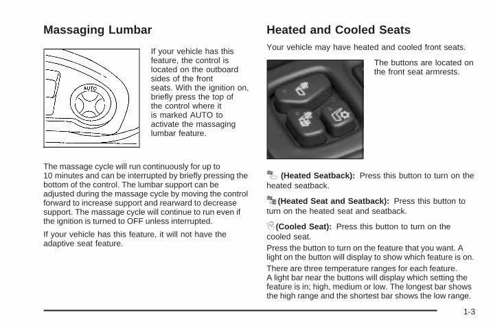
Massaging Lumbar
If your vehicle has thisfeature, the control islocated on the outboardsides of the frontseats. With the ignition on,briefly press the top ofthe control where itis marked AUTO toactivate the massaginglumbar feature.
The massage cycle will run continuously for up to10 minutes and can be interrupted by briefly pressing thebottom of the control. The lumbar support can beadjusted during the massage cycle by moving the controlforward to increase support and rearward to decreasesupport. The massage cycle will continue to run even ifthe ignition is turned to OFF unless interrupted.
If your vehicle has this feature, it will not have theadaptive seat feature.
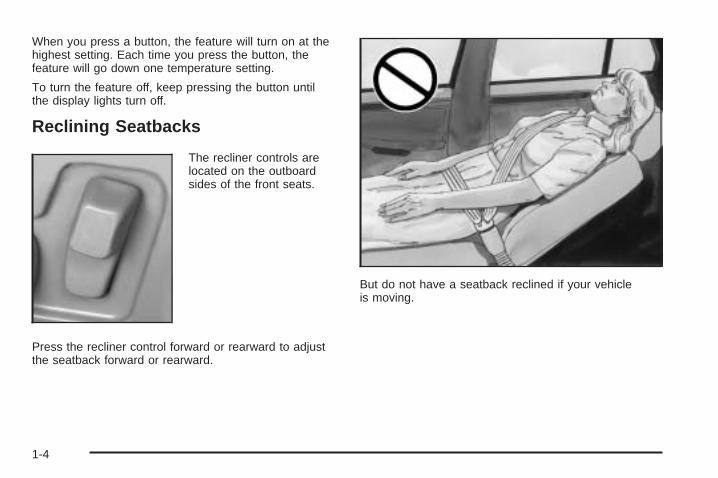
Heated and Cooled SeatsYour vehicle may have heated and cooled front seats.
The buttons are located onthe front seat armrests.
I (Heated Seatback): Press this button to turn on theheated seatback.
J(Heated Seat and Seatback): Press this button toturn on the heated seat and seatback.
H(Cooled Seat): Press this button to turn on thecooled seat.Press the button to turn on the feature that you want. Alight on the button will display to show which feature is on.There are three temperature ranges for each feature.A light bar near the buttons will display which setting thefeature is in; high, medium or low. The longest bar showsthe high range and the shortest bar shows the low range.
1-3
When you press a button, the feature will turn on at thehighest setting. Each time you press the button, thefeature will go down one temperature setting.
To turn the feature off, keep pressing the button untilthe display lights turn off.
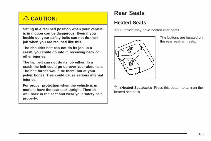
Reclining Seatbacks
The recliner controls arelocated on the outboardsides of the front seats.
Press the recliner control forward or rearward to adjustthe seatback forward or rearward.
But do not have a seatback reclined if your vehicleis moving.
1-4
{CAUTION:
Sitting in a reclined position when your vehicleis in motion can be dangerous. Even if youbuckle up, your safety belts can not do theirjob when you are reclined like this.
The shoulder belt can not do its job. In acrash, you could go into it, receiving neck orother injuries.
The lap belt can not do its job either. In acrash the belt could go up over your abdomen.The belt forces would be there, not at yourpelvic bones. This could cause serious internalinjuries.
For proper protection when the vehicle is inmotion, have the seatback upright. Then sitwell back in the seat and wear your safety beltproperly.
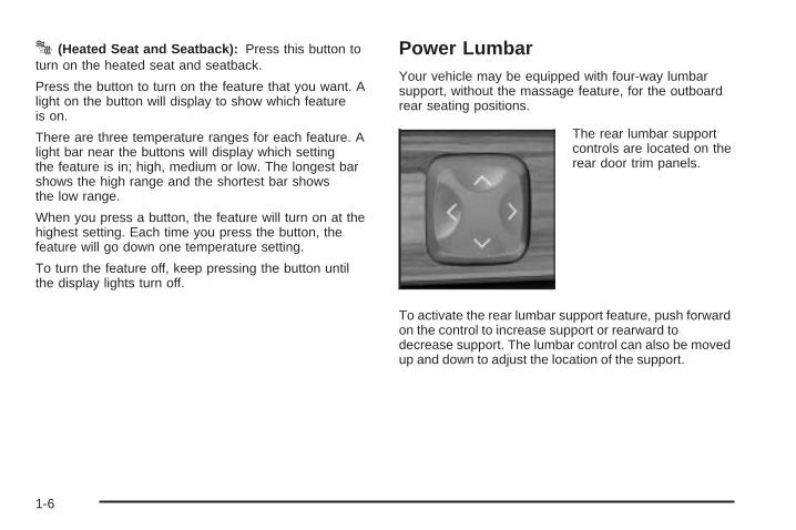
Rear Seats
Heated SeatsYour vehicle may have heated rear seats.
The buttons are located onthe rear seat armrests.
I (Heated Seatback): Press this button to turn on theheated seatback.
1-5
J (Heated Seat and Seatback): Press this button toturn on the heated seat and seatback.
Press the button to turn on the feature that you want. Alight on the button will display to show which featureis on.
There are three temperature ranges for each feature. Alight bar near the buttons will display which settingthe feature is in; high, medium or low. The longest barshows the high range and the shortest bar showsthe low range.
When you press a button, the feature will turn on at thehighest setting. Each time you press the button, thefeature will go down one temperature setting.
To turn the feature off, keep pressing the button untilthe display lights turn off.
Power LumbarYour vehicle may be equipped with four-way lumbarsupport, without the massage feature, for the outboardrear seating positions.
The rear lumbar supportcontrols are located on therear door trim panels.
To activate the rear lumbar support feature, push forwardon the control to increase support or rearward todecrease support. The lumbar control can also be movedup and down to adjust the location of the support.
1-6
Safety Belts
Safety Belts: They Are for EveryoneThis part of the manual tells you how to use safetybelts properly. It also tells you some things you shouldnot do with safety belts.
{CAUTION:
Do not let anyone ride where he or she can notwear a safety belt properly. If you are in acrash and you are not wearing a safety belt,your injuries can be much worse. You can hitthings inside the vehicle or be ejected from it.You can be seriously injured or killed. In thesame crash, you might not be, if you arebuckled up. Always fasten your safety belt,and check that your passengers’ belts arefastened properly too.
{CAUTION:
It is extremely dangerous to ride in a cargoarea, inside or outside of a vehicle. In acollision, people riding in these areas are morelikely to be seriously injured or killed. Do notallow people to ride in any area of your vehiclethat is not equipped with seats and safetybelts. Be sure everyone in your vehicle is in aseat and using a safety belt properly.
Your vehicle has a lightthat comes on as areminder to buckle up. SeeSafety Belt ReminderLight on page 3-45.
In most states and in all Canadian provinces, the lawsays to wear safety belts. Here is why: They work.
1-7
You never know if you will be in a crash. If you do havea crash, you do not know if it will be a bad one.
A few crashes are mild, and some crashes can be soserious that even buckled up, a person would notsurvive. But most crashes are in between. In many ofthem, people who buckle up can survive and sometimeswalk away. Without belts they could have been badlyhurt or killed.
After more than 30 years of safety belts in vehicles, thefacts are clear. In most crashes buckling up doesmatter...a lot!
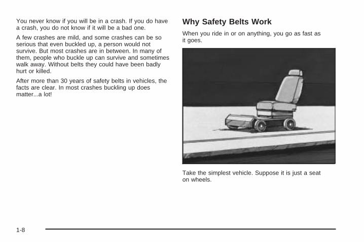
Why Safety Belts WorkWhen you ride in or on anything, you go as fast asit goes.
Take the simplest vehicle. Suppose it is just a seaton wheels.
1-8
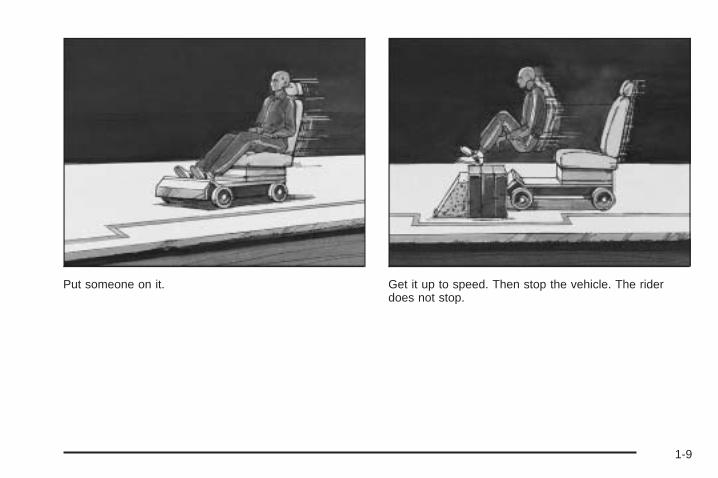
Put someone on it. Get it up to speed. Then stop the vehicle. The riderdoes not stop.
1-9
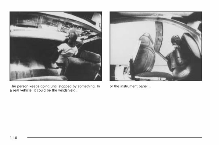
The person keeps going until stopped by something. Ina real vehicle, it could be the windshield...
or the instrument panel...
1-10
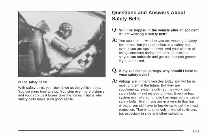
or the safety belts!
With safety belts, you slow down as the vehicle does.You get more time to stop. You stop over more distance,and your strongest bones take the forces. That is whysafety belts make such good sense.
Questions and Answers AboutSafety Belts
Q: Will I be trapped in the vehicle after an accidentif I am wearing a safety belt?
A: You could be — whether you are wearing a safetybelt or not. But you can unbuckle a safety belt,even if you are upside down. And your chance ofbeing conscious during and after an accident,so you can unbuckle and get out, is much greaterif you are belted.
Q: If my vehicle has airbags, why should I have towear safety belts?
A: Airbags are in many vehicles today and will be inmost of them in the future. But they aresupplemental systems only; so they work withsafety belts — not instead of them. Every airbagsystem ever offered for sale has required the use ofsafety belts. Even if you are in a vehicle that hasairbags, you still have to buckle up to get the mostprotection. That is true not only in frontal collisions,but especially in side and other collisions.
1-11
Q: If I am a good driver, and I never drive far fromhome, why should I wear safety belts?
A: You may be an excellent driver, but if you are in anaccident — even one that is not your fault — youand your passengers can be hurt. Being a gooddriver does not protect you from things beyond yourcontrol, such as bad drivers.
Most accidents occur within 25 miles (40 km) ofhome. And the greatest number of serious injuriesand deaths occur at speeds of less than40 mph (65 km/h).
Safety belts are for everyone.
How to Wear Safety Belts ProperlyThis part is only for people of adult size.
Be aware that there are special things to know aboutsafety belts and children. And there are differentrules for smaller children and babies. If a child will beriding in your vehicle, see Older Children on page 1-26or Infants and Young Children on page 1-28. Followthose rules for everyone’s protection.
First, you will want to know which restraint systems yourvehicle has.
We will start with the driver position.
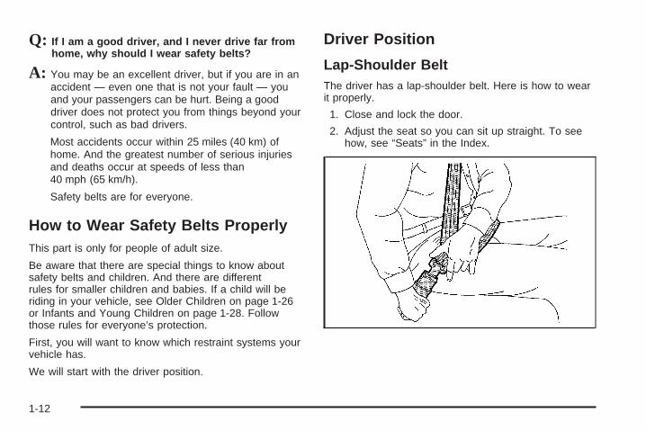
Driver Position
Lap-Shoulder BeltThe driver has a lap-shoulder belt. Here is how to wearit properly.
1. Close and lock the door.
2. Adjust the seat so you can sit up straight. To seehow, see “Seats” in the Index.
1-12
3. Pick up the latch plate and pull the belt across you.Do not let it get twisted.The lap-shoulder belt may lock if you pull the beltacross you very quickly. If this happens, let the beltgo back slightly to unlock it. Then pull the beltacross you more slowly.
4. Push the latch plate into the buckle until it clicks.Be sure to use the correct buckle when bucklingyour lap-shoulder belt. If you find that the latch platewill not go fully into the buckle, see if you areusing the buckle for the center passenger position.Pull up on the latch plate to make sure it issecure. If the belt is not long enough, see SafetyBelt Extender on page 1-25.Make sure the release button on the buckle ispositioned so you would be able to unbuckle thesafety belt quickly if you ever had to.
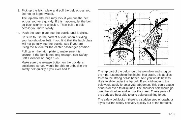
The lap part of the belt should be worn low and snug onthe hips, just touching the thighs. In a crash, this appliesforce to the strong pelvic bones. And you would be lesslikely to slide under the lap belt. If you slid under it, thebelt would apply force at your abdomen. This could causeserious or even fatal injuries. The shoulder belt should goover the shoulder and across the chest. These parts ofthe body are best able to take belt restraining forces.
The safety belt locks if there is a sudden stop or crash, orif you pull the safety belt very quickly out of the retractor.
1-13
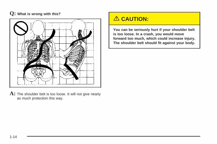
Q: What is wrong with this?
A: The shoulder belt is too loose. It will not give nearlyas much protection this way.
{CAUTION:
You can be seriously hurt if your shoulder beltis too loose. In a crash, you would moveforward too much, which could increase injury.The shoulder belt should fit against your body.
1-14
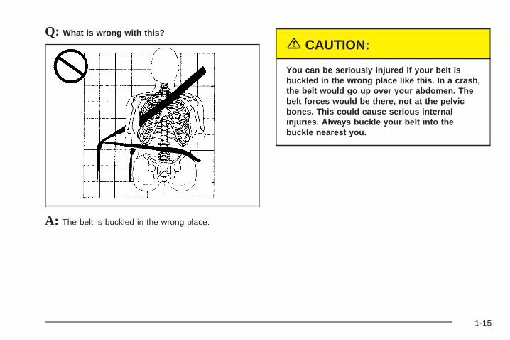
Q: What is wrong with this?
A: The belt is buckled in the wrong place.
{CAUTION:
You can be seriously injured if your belt isbuckled in the wrong place like this. In a crash,the belt would go up over your abdomen. Thebelt forces would be there, not at the pelvicbones. This could cause serious internalinjuries. Always buckle your belt into thebuckle nearest you.
1-15
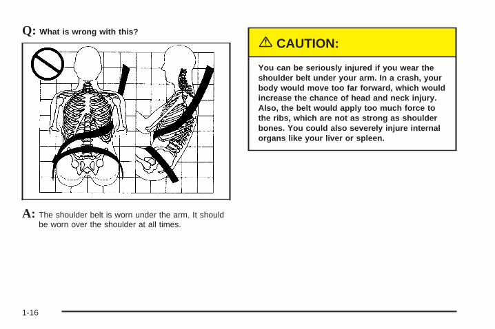
Q: What is wrong with this?
A: The shoulder belt is worn under the arm. It shouldbe worn over the shoulder at all times.
{CAUTION:
You can be seriously injured if you wear theshoulder belt under your arm. In a crash, yourbody would move too far forward, which wouldincrease the chance of head and neck injury.Also, the belt would apply too much force tothe ribs, which are not as strong as shoulderbones. You could also severely injure internalorgans like your liver or spleen.
1-16
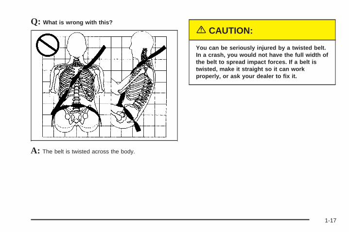
Q: What is wrong with this?
A: The belt is twisted across the body.
{CAUTION:
You can be seriously injured by a twisted belt.In a crash, you would not have the full width ofthe belt to spread impact forces. If a belt istwisted, make it straight so it can workproperly, or ask your dealer to fix it.
1-17
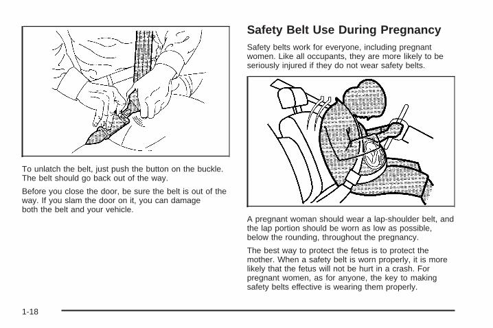
To unlatch the belt, just push the button on the buckle.The belt should go back out of the way.
Before you close the door, be sure the belt is out of theway. If you slam the door on it, you can damageboth the belt and your vehicle.
Safety Belt Use During PregnancySafety belts work for everyone, including pregnantwomen. Like all occupants, they are more likely to beseriously injured if they do not wear safety belts.
A pregnant woman should wear a lap-shoulder belt, andthe lap portion should be worn as low as possible,below the rounding, throughout the pregnancy.
The best way to protect the fetus is to protect themother. When a safety belt is worn properly, it is morelikely that the fetus will not be hurt in a crash. Forpregnant women, as for anyone, the key to makingsafety belts effective is wearing them properly.
1-18
Right Front Passenger PositionTo learn how to wear the right front passenger’s safetybelt properly, see Driver Position on page 1-12.
The right front passenger’s safety belt works the sameway as the driver’s safety belt — except for onething. If you ever pull the lap portion of the belt out allthe way, you will engage the child restraint lockingfeature. If this happens, just let the belt go back all theway and start again.
Center Front Passenger Position
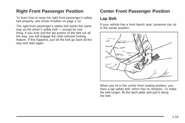
Lap BeltIf your vehicle has a front bench seat, someone can sitin the center position.
When you sit in the center front seating position, youhave a lap safety belt, which has no retractor. To makethe belt longer, tilt the latch plate and pull it alongthe belt.
1-19
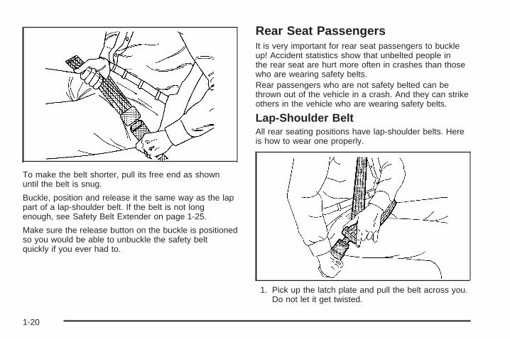
To make the belt shorter, pull its free end as shownuntil the belt is snug.
Buckle, position and release it the same way as the lappart of a lap-shoulder belt. If the belt is not longenough, see Safety Belt Extender on page 1-25.
Make sure the release button on the buckle is positionedso you would be able to unbuckle the safety beltquickly if you ever had to.
Rear Seat PassengersIt is very important for rear seat passengers to buckleup! Accident statistics show that unbelted people inthe rear seat are hurt more often in crashes than thosewho are wearing safety belts.Rear passengers who are not safety belted can bethrown out of the vehicle in a crash. And they can strikeothers in the vehicle who are wearing safety belts.
Lap-Shoulder BeltAll rear seating positions have lap-shoulder belts. Hereis how to wear one properly.
1. Pick up the latch plate and pull the belt across you.Do not let it get twisted.
1-20
The shoulder belt may lock if you pull the beltacross you very quickly. If this happens, let the beltgo back slightly to unlock it. Then pull the beltacross you more slowly.
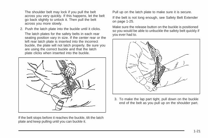
2. Push the latch plate into the buckle until it clicks.The latch plates for the safety belts in each rearseating position vary in size. If the center rear or theleft rear latch plate is inserted into the incorrectbuckle, the plate will not latch properly. Be sure youare using the correct buckle and that the latchplate clicks when inserted into the buckle.
If the belt stops before it reaches the buckle, tilt the latchplate and keep pulling until you can buckle it.
Pull up on the latch plate to make sure it is secure.
If the belt is not long enough, see Safety Belt Extenderon page 1-25.
Make sure the release button on the buckle is positionedso you would be able to unbuckle the safety belt quickly ifyou ever had to.
3. To make the lap part tight, pull down on the buckleend of the belt as you pull up on the shoulder part.
1-21
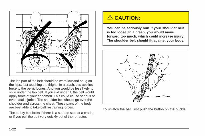
The lap part of the belt should be worn low and snug onthe hips, just touching the thighs. In a crash, this appliesforce to the pelvic bones. And you would be less likely toslide under the lap belt. If you slid under it, the belt wouldapply force at your abdomen. This could cause serious oreven fatal injuries. The shoulder belt should go over theshoulder and across the chest. These parts of the bodyare best able to take belt restraining forces.
The safety belt locks if there is a sudden stop or a crash,or if you pull the belt very quickly out of the retractor.
{CAUTION:
You can be seriously hurt if your shoulder beltis too loose. In a crash, you would moveforward too much, which could increase injury.The shoulder belt should fit against your body.
To unlatch the belt, just push the button on the buckle.
1-22
Rear Safety Belt Comfort Guides forChildren and Small AdultsRear shoulder belt comfort guides will provide addedsafety belt comfort for older children who have outgrownbooster seats and for small adults. When installed ona shoulder belt, the comfort guide better positionsthe belt away from the neck and head.
There is one guide for each outside passenger positionin the rear seat. To provide added safety belt comfortfor children who have outgrown child restraints andbooster seats and for smaller adults, the comfort guidesmay be installed on the shoulder belts.
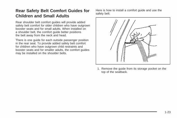
Here is how to install a comfort guide and use thesafety belt:
1. Remove the guide from its storage pocket on thetop of the seatback.
1-23
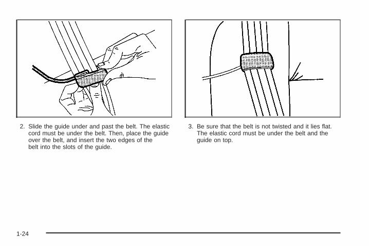
2. Slide the guide under and past the belt. The elasticcord must be under the belt. Then, place the guideover the belt, and insert the two edges of thebelt into the slots of the guide.
3. Be sure that the belt is not twisted and it lies flat.The elastic cord must be under the belt and theguide on top.
1-24
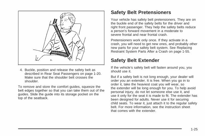
4. Buckle, position and release the safety belt asdescribed in Rear Seat Passengers on page 1-20.Make sure that the shoulder belt crosses theshoulder.
To remove and store the comfort guides, squeeze thebelt edges together so that you can take them out of theguides. Slide the guide into its storage pocket on thetop of the seatback.
Safety Belt PretensionersYour vehicle has safety belt pretensioners. They are onthe buckle end of the safety belts for the driver andright front passenger. They help the safety belts reducea person’s forward movement in a moderate tosevere frontal and near frontal crash.
Pretensioners work only once. If they activate in acrash, you will need to get new ones, and probably othernew parts for your safety belt system. See ReplacingRestraint System Parts After a Crash on page 1-55.
Safety Belt ExtenderIf the vehicle’s safety belt will fasten around you, youshould use it.
But if a safety belt is not long enough, your dealer willorder you an extender. It is free. When you go in toorder it, take the heaviest coat you will wear, sothe extender will be long enough for you. To help avoidpersonal injury, do not let someone else use it, anduse it only for the seat it is made to fit. The extender hasbeen designed for adults. Never use it for securingchild seats. To wear it, just attach it to the regular safetybelt. For more information, see the instruction sheetthat comes with the extender.
1-25
Child Restraints
Older Children
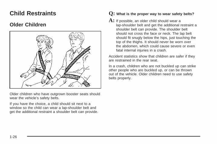
Older children who have outgrown booster seats shouldwear the vehicle’s safety belts.
If you have the choice, a child should sit next to awindow so the child can wear a lap-shoulder belt andget the additional restraint a shoulder belt can provide.
Q: What is the proper way to wear safety belts?
A: If possible, an older child should wear alap-shoulder belt and get the additional restraint ashoulder belt can provide. The shoulder beltshould not cross the face or neck. The lap beltshould fit snugly below the hips, just touching thetop of the thighs. It should never be worn overthe abdomen, which could cause severe or evenfatal internal injuries in a crash.
Accident statistics show that children are safer if theyare restrained in the rear seat.
In a crash, children who are not buckled up can strikeother people who are buckled up, or can be thrownout of the vehicle. Older children need to use safetybelts properly.
1-26
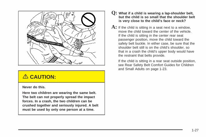
{CAUTION:
Never do this.
Here two children are wearing the same belt.The belt can not properly spread the impactforces. In a crash, the two children can becrushed together and seriously injured. A beltmust be used by only one person at a time.
Q: What if a child is wearing a lap-shoulder belt,but the child is so small that the shoulder beltis very close to the child’s face or neck?
A: If the child is sitting in a seat next to a window,move the child toward the center of the vehicle.If the child is sitting in the center rear seatpassenger position, move the child toward thesafety belt buckle. In either case, be sure that theshoulder belt still is on the child’s shoulder, sothat in a crash the child’s upper body would havethe restraint that belts provide.
If the child is sitting in a rear seat outside position,see Rear Safety Belt Comfort Guides for Childrenand Small Adults on page 1-23.
1-27
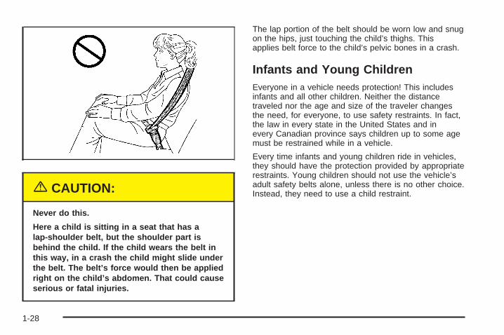
{CAUTION:
Never do this.
Here a child is sitting in a seat that has alap-shoulder belt, but the shoulder part isbehind the child. If the child wears the belt inthis way, in a crash the child might slide underthe belt. The belt’s force would then be appliedright on the child’s abdomen. That could causeserious or fatal injuries.
The lap portion of the belt should be worn low and snugon the hips, just touching the child’s thighs. Thisapplies belt force to the child’s pelvic bones in a crash.
Infants and Young ChildrenEveryone in a vehicle needs protection! This includesinfants and all other children. Neither the distancetraveled nor the age and size of the traveler changesthe need, for everyone, to use safety restraints. In fact,the law in every state in the United States and inevery Canadian province says children up to some agemust be restrained while in a vehicle.
Every time infants and young children ride in vehicles,they should have the protection provided by appropriaterestraints. Young children should not use the vehicle’sadult safety belts alone, unless there is no other choice.Instead, they need to use a child restraint.
1-28
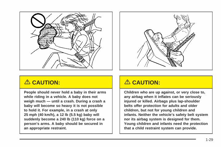
{CAUTION:
People should never hold a baby in their armswhile riding in a vehicle. A baby does notweigh much — until a crash. During a crash ababy will become so heavy it is not possibleto hold it. For example, in a crash at only25 mph (40 km/h), a 12 lb (5.5 kg) baby willsuddenly become a 240 lb (110 kg) force on aperson’s arms. A baby should be secured inan appropriate restraint.
{CAUTION:
Children who are up against, or very close to,any airbag when it inflates can be seriouslyinjured or killed. Airbags plus lap-shoulderbelts offer protection for adults and olderchildren, but not for young children andinfants. Neither the vehicle’s safety belt systemnor its airbag system is designed for them.Young children and infants need the protectionthat a child restraint system can provide.
1-29
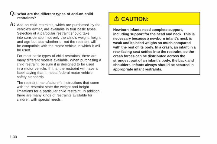
Q: What are the different types of add-on childrestraints?
A: Add-on child restraints, which are purchased by thevehicle’s owner, are available in four basic types.Selection of a particular restraint should takeinto consideration not only the child’s weight, heightand age but also whether or not the restraint willbe compatible with the motor vehicle in which it willbe used.
For most basic types of child restraints, there aremany different models available. When purchasing achild restraint, be sure it is designed to be usedin a motor vehicle. If it is, the restraint will have alabel saying that it meets federal motor vehiclesafety standards.
The restraint manufacturer’s instructions that comewith the restraint state the weight and heightlimitations for a particular child restraint. In addition,there are many kinds of restraints available forchildren with special needs.
{CAUTION:
Newborn infants need complete support,including support for the head and neck. This isnecessary because a newborn infant’s neck isweak and its head weighs so much comparedwith the rest of its body. In a crash, an infant in arear-facing seat settles into the restraint, so thecrash forces can be distributed across thestrongest part of an infant’s body, the back andshoulders. Infants always should be secured inappropriate infant restraints.
1-30
{CAUTION:
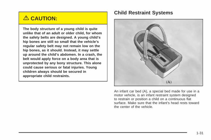
The body structure of a young child is quiteunlike that of an adult or older child, for whomthe safety belts are designed. A young child’ship bones are still so small that the vehicle’sregular safety belt may not remain low on thehip bones, as it should. Instead, it may settleup around the child’s abdomen. In a crash, thebelt would apply force on a body area that isunprotected by any bony structure. This alonecould cause serious or fatal injuries. Youngchildren always should be secured inappropriate child restraints.
Child Restraint Systems
An infant car bed (A), a special bed made for use in amotor vehicle, is an infant restraint system designedto restrain or position a child on a continuous flatsurface. Make sure that the infant’s head rests towardthe center of the vehicle.
1-31
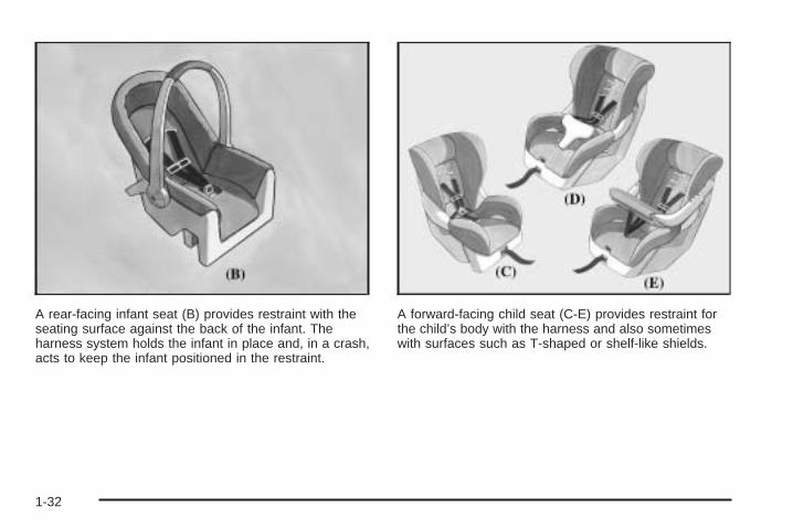
A rear-facing infant seat (B) provides restraint with theseating surface against the back of the infant. Theharness system holds the infant in place and, in a crash,acts to keep the infant positioned in the restraint.
A forward-facing child seat (C-E) provides restraint forthe child’s body with the harness and also sometimeswith surfaces such as T-shaped or shelf-like shields.
1-32
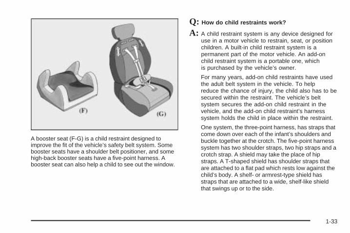
A booster seat (F-G) is a child restraint designed toimprove the fit of the vehicle’s safety belt system. Somebooster seats have a shoulder belt positioner, and somehigh-back booster seats have a five-point harness. Abooster seat can also help a child to see out the window.
Q: How do child restraints work?
A: A child restraint system is any device designed foruse in a motor vehicle to restrain, seat, or positionchildren. A built-in child restraint system is apermanent part of the motor vehicle. An add-onchild restraint system is a portable one, whichis purchased by the vehicle’s owner.
For many years, add-on child restraints have usedthe adult belt system in the vehicle. To helpreduce the chance of injury, the child also has to besecured within the restraint. The vehicle’s beltsystem secures the add-on child restraint in thevehicle, and the add-on child restraint’s harnesssystem holds the child in place within the restraint.
One system, the three-point harness, has straps thatcome down over each of the infant’s shoulders andbuckle together at the crotch. The five-point harnesssystem has two shoulder straps, two hip straps and acrotch strap. A shield may take the place of hipstraps. A T-shaped shield has shoulder straps thatare attached to a flat pad which rests low against thechild’s body. A shelf- or armrest-type shield hasstraps that are attached to a wide, shelf-like shieldthat swings up or to the side.
1-33
When choosing a child restraint, be sure the childrestraint is designed to be used in a vehicle. If it is, itwill have a label saying that it meets federal motorvehicle safety standards.
Then follow the instructions for the restraint. You mayfind these instructions on the restraint itself or in abooklet, or both. These restraints use the belt system orthe LATCH system in your vehicle, but the child alsohas to be secured within the restraint to help reduce thechance of personal injury. When securing an add-onchild restraint, refer to the instructions that come with therestraint which may be on the restraint itself or in abooklet, or both, and to this manual. The child restraintinstructions are important, so if they are not available,obtain a replacement copy from the manufacturer.
Where to Put the RestraintAccident statistics show that children are safer if they arerestrained in the rear rather than the front seat. We,therefore, recommend that child restraints be secured ina rear seat, including an infant riding in a rear-facinginfant seat, a child riding in a forward-facing child seatand an older child riding in a booster seat. Never put arear-facing child restraint in the front passenger seat.
Here is why:
{CAUTION:
A child in a rear-facing child restraint can beseriously injured or killed if the right frontpassenger’s airbag inflates. This is becausethe back of the rear-facing child restraintwould be very close to the inflating airbag.Always secure a rear-facing child restraint in arear seat.
If you need to secure a forward-facing childrestraint in the right front seat, always movethe front passenger seat as far back as it willgo. It is better to secure the child restraint in arear seat.
1-34
{CAUTION:
A child in a child restraint in the center frontseat can be badly injured or killed by the rightfront passenger’s airbag if it inflates. Neversecure a child restraint in the center front seat.It is always better to secure a child restraint inthe rear seat.
If you need to secure a forward-facing childrestraint in the right front passenger seat,always move the front passenger seat as farback as it will go. It is better to secure thechild restraint in a rear seat.
Wherever you install it, be sure to secure the childrestraint properly.
Keep in mind that an unsecured child restraint canmove around in a collision or sudden stop and injurepeople in the vehicle. Be sure to properly secureany child restraint in your vehicle — even when no childis in it.
Top StrapSome child restraints have a top strap, or “top tether.” Itcan help restrain the child restraint during a collision.For it to work, a top strap must be properly anchored tothe vehicle. Some top strap-equipped child restraintsare designed for use with or without the top strap beinganchored. Others require the top strap always to beanchored. Be sure to read and follow the instructions foryour child restraint. If yours requires that the top strapbe anchored, do not use the restraint unless it isanchored properly.
If the child restraint does not have a top strap, one canbe obtained, in kit form, for many child restraints.Ask the child restraint manufacturer whether or not a kitis available.
1-35
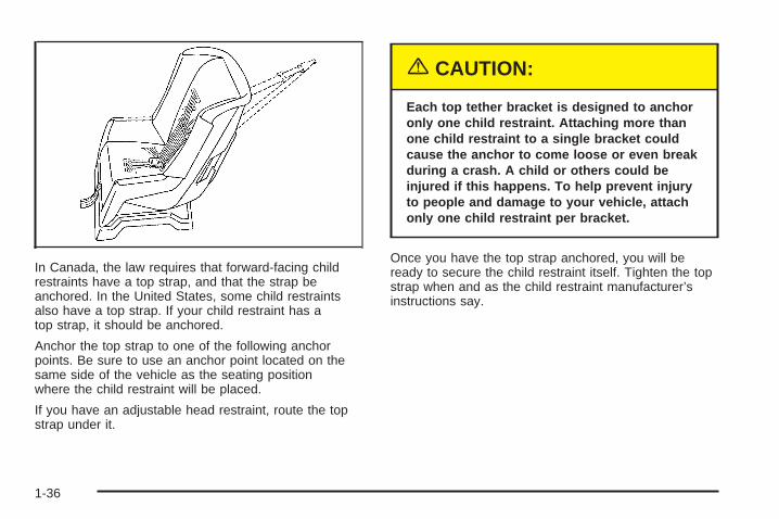
In Canada, the law requires that forward-facing childrestraints have a top strap, and that the strap beanchored. In the United States, some child restraintsalso have a top strap. If your child restraint has atop strap, it should be anchored.
Anchor the top strap to one of the following anchorpoints. Be sure to use an anchor point located on thesame side of the vehicle as the seating positionwhere the child restraint will be placed.
If you have an adjustable head restraint, route the topstrap under it.
{CAUTION:
Each top tether bracket is designed to anchoronly one child restraint. Attaching more thanone child restraint to a single bracket couldcause the anchor to come loose or even breakduring a crash. A child or others could beinjured if this happens. To help prevent injuryto people and damage to your vehicle, attachonly one child restraint per bracket.
Once you have the top strap anchored, you will beready to secure the child restraint itself. Tighten the topstrap when and as the child restraint manufacturer’sinstructions say.
1-36
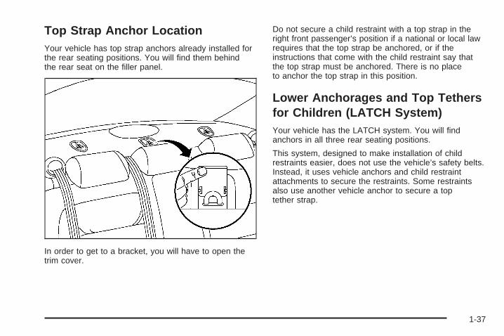
Top Strap Anchor LocationYour vehicle has top strap anchors already installed forthe rear seating positions. You will find them behindthe rear seat on the filler panel.
In order to get to a bracket, you will have to open thetrim cover.
Do not secure a child restraint with a top strap in theright front passenger’s position if a national or local lawrequires that the top strap be anchored, or if theinstructions that come with the child restraint say thatthe top strap must be anchored. There is no placeto anchor the top strap in this position.
Lower Anchorages and Top Tethersfor Children (LATCH System)Your vehicle has the LATCH system. You will findanchors in all three rear seating positions.
This system, designed to make installation of childrestraints easier, does not use the vehicle’s safety belts.Instead, it uses vehicle anchors and child restraintattachments to secure the restraints. Some restraintsalso use another vehicle anchor to secure a toptether strap.
1-37
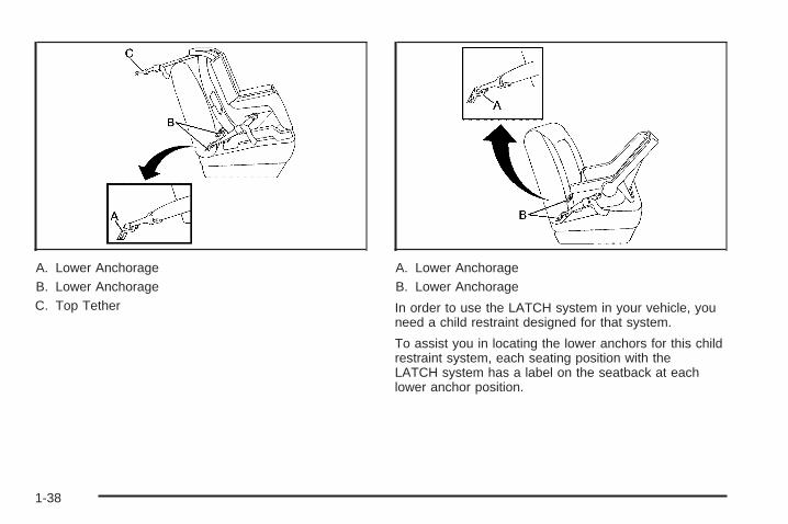
A. Lower AnchorageB. Lower AnchorageC. Top Tether
A. Lower AnchorageB. Lower Anchorage
In order to use the LATCH system in your vehicle, youneed a child restraint designed for that system.
To assist you in locating the lower anchors for this childrestraint system, each seating position with theLATCH system has a label on the seatback at eachlower anchor position.
1-38
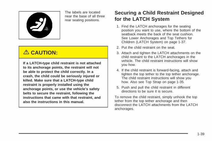
The labels are locatednear the base of all threerear seating positions.
{CAUTION:
If a LATCH-type child restraint is not attachedto its anchorage points, the restraint will notbe able to protect the child correctly. In acrash, the child could be seriously injured orkilled. Make sure that a LATCH-type childrestraint is properly installed using theanchorage points, or use the vehicle’s safetybelts to secure the restraint, following theinstructions that came with that restraint, andalso the instructions in this manual.
Securing a Child Restraint Designedfor the LATCH System
1. Find the LATCH anchorages for the seatingposition you want to use, where the bottom of theseatback meets the back of the seat cushion.See Lower Anchorages and Top Tethers forChildren (LATCH System) on page 1-37.
2. Put the child restraint on the seat.
3. Attach and tighten the LATCH attachments on thechild restraint to the LATCH anchorages in thevehicle. The child restraint instructions will showyou how.
4. If the child restraint is forward-facing, attach andtighten the top tether to the top tether anchorage.The child restraint instructions will show youhow. Also see Top Strap on page 1-35.
5. Push and pull the child restraint in differentdirections to be sure it is secure.
To remove the child restraint, simply unhook the toptether from the top tether anchorage and thendisconnect the LATCH attachments from the LATCHanchorages.
1-39
Securing a Child Restraint in a RearSeat PositionIf your child restraint is equipped with the LATCHsystem, see Lower Anchorages and Top Tethers forChildren (LATCH System) on page 1-37. See Top Strapon page 1-35 if the child restraint has one.
{CAUTION:
A child in a child restraint in the center frontseat can be badly injured or killed by the rightfront passenger’s airbag if it inflates. Neversecure a child restraint in the center front seat.It is always better to secure a child restraint inthe rear seat.
If you need to secure a forward-facing childrestraint in the right front passenger seat,always move the front passenger seat as farback as it will go. It is better to secure thechild restraint in a rear seat.
If your child restraint does not have the LATCH system,you will be using the lap-shoulder belt to secure therestraint in this position. Be sure to follow the instructionsthat came with the child restraint. Secure the child in thechild restraint when and as the instructions say.
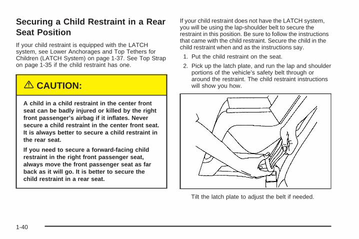
1. Put the child restraint on the seat.
2. Pick up the latch plate, and run the lap and shoulderportions of the vehicle’s safety belt through oraround the restraint. The child restraint instructionswill show you how.
Tilt the latch plate to adjust the belt if needed.
1-40
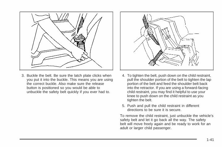
3. Buckle the belt. Be sure the latch plate clicks whenyou put it into the buckle. This means you are usingthe correct buckle. Also make sure the releasebutton is positioned so you would be able tounbuckle the safety belt quickly if you ever had to.
4. To tighten the belt, push down on the child restraint,pull the shoulder portion of the belt to tighten the lapportion of the belt and feed the shoulder belt backinto the retractor. If you are using a forward-facingchild restraint, you may find it helpful to use yourknee to push down on the child restraint as youtighten the belt.
5. Push and pull the child restraint in differentdirections to be sure it is secure.
To remove the child restraint, just unbuckle the vehicle’ssafety belt and let it go back all the way. The safetybelt will move freely again and be ready to work for anadult or larger child passenger.
1-41
Securing a Child Restraint in theCenter Front Seat Position
{CAUTION:
A child in a child restraint in the center frontseat can be badly injured or killed by the rightfront passenger’s airbag if it inflates. Neversecure a child restraint in the center front seat.It is always better to secure a child restraint inthe rear seat.
If you need to secure a forward-facing childrestraint in the right front passenger seat,always move the front passenger seat as farback as it will go. It is better to secure thechild restraint in a rear seat.
Do not secure a child restraint in the center front seatposition.
Securing a Child Restraint in theRight Front Seat PositionIf your child restraint is equipped with the LATCHsystem, see Lower Anchorages and Top Tethers forChildren (LATCH System) on page 1-37.
There is no top strap anchor in the right frontpassenger’s position. Do not secure a child seat in thisposition if a national or local law requires that thetop strap be anchored, or if the instructions that comewith the child restraint say that the top strap mustbe anchored. See Top Strap on page 1-35, if the childrestraint has one.
Your vehicle has a right front passenger airbag. Neverput a rear facing child restraint in this seat.
1-42
Here is why:
{CAUTION:
A child in a rear-facing child restraint can beseriously injured or killed if the right frontpassenger’s airbag inflates. This is becausethe back of the rear-facing child restraintwould be very close to the inflating airbag.Always secure a rear-facing child restraint ina rear seat.
A rear seat is a safer place to secure a forward-facingchild restraint.
If you need to secure a forward-facing child restraint inthe right front seat you will be using the lap-shoulderbelt to secure the child restraint in this position. Be sureto follow the instructions that came with the childrestraint. Secure the child in the child restraint whenand as the instructions say.
1. Because your vehicle has a right front passengerairbag, always move the seat as far back as it willgo before securing a forward-facing child restraint.See Power Seats on page 1-2.
2. Put the child restraint on the seat.
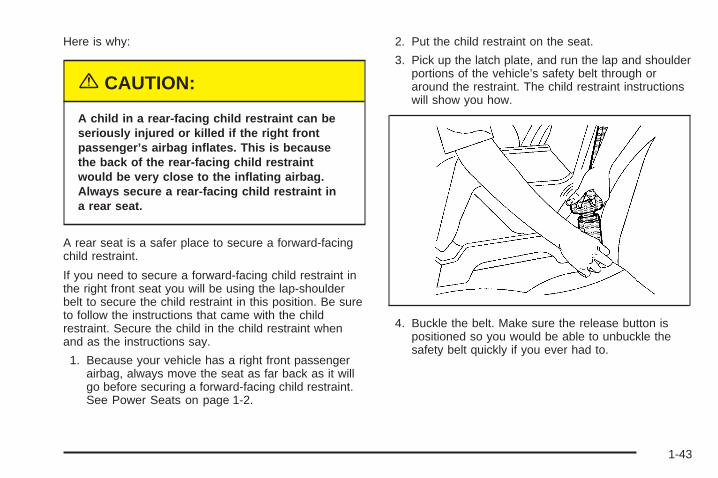
3. Pick up the latch plate, and run the lap and shoulderportions of the vehicle’s safety belt through oraround the restraint. The child restraint instructionswill show you how.
4. Buckle the belt. Make sure the release button ispositioned so you would be able to unbuckle thesafety belt quickly if you ever had to.
1-43
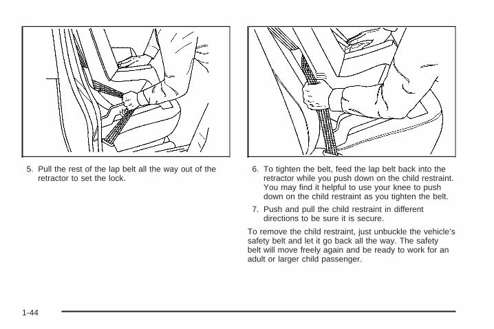
5. Pull the rest of the lap belt all the way out of theretractor to set the lock.
6. To tighten the belt, feed the lap belt back into theretractor while you push down on the child restraint.You may find it helpful to use your knee to pushdown on the child restraint as you tighten the belt.
7. Push and pull the child restraint in differentdirections to be sure it is secure.
To remove the child restraint, just unbuckle the vehicle’ssafety belt and let it go back all the way. The safetybelt will move freely again and be ready to work for anadult or larger child passenger.
1-44
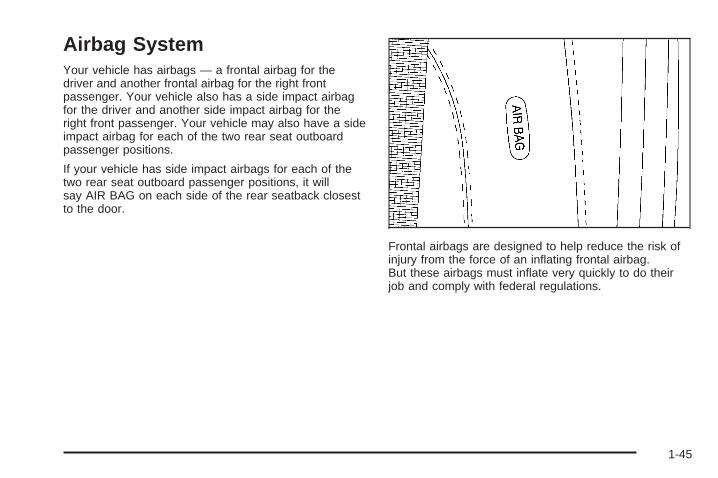
Airbag SystemYour vehicle has airbags — a frontal airbag for thedriver and another frontal airbag for the right frontpassenger. Your vehicle also has a side impact airbagfor the driver and another side impact airbag for theright front passenger. Your vehicle may also have a sideimpact airbag for each of the two rear seat outboardpassenger positions.
If your vehicle has side impact airbags for each of thetwo rear seat outboard passenger positions, it willsay AIR BAG on each side of the rear seatback closestto the door.
Frontal airbags are designed to help reduce the risk ofinjury from the force of an inflating frontal airbag.But these airbags must inflate very quickly to do theirjob and comply with federal regulations.
1-45
{CAUTION:
You can be severely injured or killed in a crashif you are not wearing your safety belt, even ifyou have airbags. Wearing your safety beltduring a crash helps reduce your chance ofhitting things inside the vehicle or beingejected from it. Airbags are designed to workwith safety belts but do not replace them.
Frontal airbags for the driver and right frontpassenger are designed to deploy only inmoderate to severe frontal and near frontalcrashes. They are not designed to inflate inrollover, rear or low-speed frontal crashes, or inmany side crashes. And, for some unrestrainedoccupants, frontal airbags may provide lessprotection in frontal crashes than more forcefulairbags have provided in the past.
Side impact airbags are designed to inflate onlyin moderate to severe crashes where somethinghits the side of your vehicle.
CAUTION: (Continued)
CAUTION: (Continued)
They are not designed to inflate in frontal, inrollover or in rear crashes.
Everyone in your vehicle should wear a safetybelt properly, whether or not there is an airbagfor that person.
{CAUTION:
Both frontal and side impact airbags inflatewith great force, faster than the blink of aneye. If you are too close to an inflating airbag,as you would be if you were leaning forward, itcould seriously injure you. Safety belts helpkeep you in position for airbag inflation beforeand during a crash. Always wear your safetybelt even with frontal airbags. The drivershould sit as far back as possible while stillmaintaining control of the vehicle. Occupantsshould not lean on or sleep against the door.
1-46
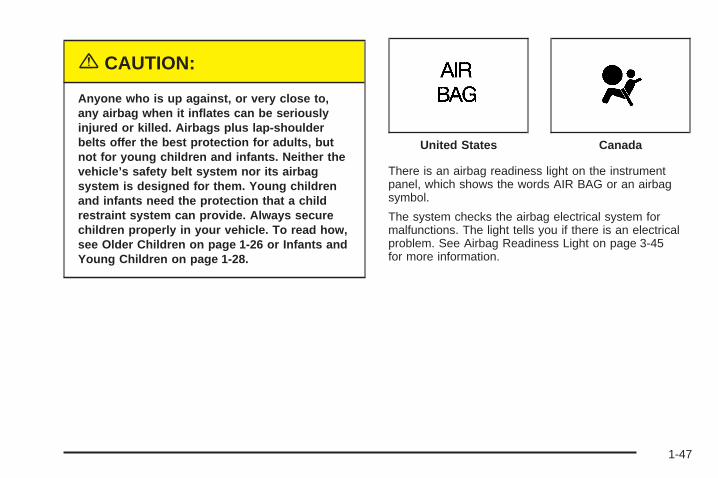
{CAUTION:
Anyone who is up against, or very close to,any airbag when it inflates can be seriouslyinjured or killed. Airbags plus lap-shoulderbelts offer the best protection for adults, butnot for young children and infants. Neither thevehicle’s safety belt system nor its airbagsystem is designed for them. Young childrenand infants need the protection that a childrestraint system can provide. Always securechildren properly in your vehicle. To read how,see Older Children on page 1-26 or Infants andYoung Children on page 1-28.
There is an airbag readiness light on the instrumentpanel, which shows the words AIR BAG or an airbagsymbol.
The system checks the airbag electrical system formalfunctions. The light tells you if there is an electricalproblem. See Airbag Readiness Light on page 3-45for more information.
United States Canada
1-47
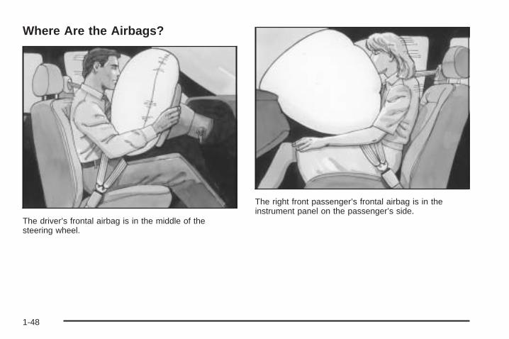
Where Are the Airbags?
The driver’s frontal airbag is in the middle of thesteering wheel.
The right front passenger’s frontal airbag is in theinstrument panel on the passenger’s side.
1-48
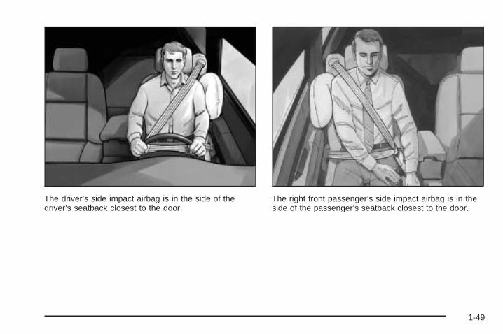
The driver’s side impact airbag is in the side of thedriver’s seatback closest to the door.
The right front passenger’s side impact airbag is in theside of the passenger’s seatback closest to the door.
1-49
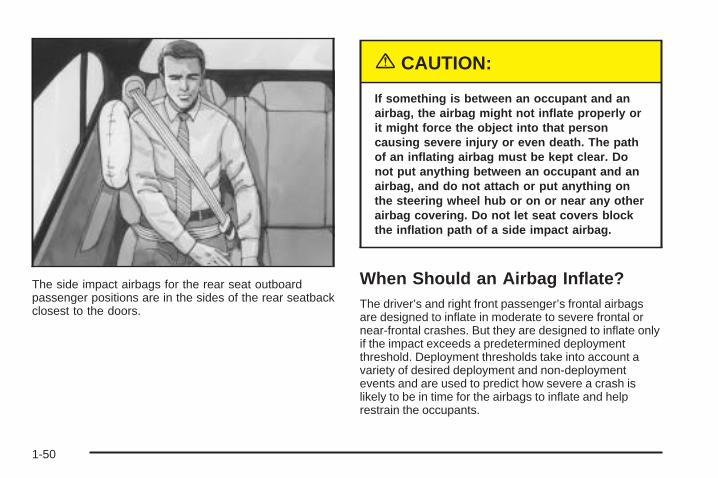
The side impact airbags for the rear seat outboardpassenger positions are in the sides of the rear seatbackclosest to the doors.
{CAUTION:
If something is between an occupant and anairbag, the airbag might not inflate properly orit might force the object into that personcausing severe injury or even death. The pathof an inflating airbag must be kept clear. Donot put anything between an occupant and anairbag, and do not attach or put anything onthe steering wheel hub or on or near any otherairbag covering. Do not let seat covers blockthe inflation path of a side impact airbag.
When Should an Airbag Inflate?The driver’s and right front passenger’s frontal airbagsare designed to inflate in moderate to severe frontal ornear-frontal crashes. But they are designed to inflate onlyif the impact exceeds a predetermined deploymentthreshold. Deployment thresholds take into account avariety of desired deployment and non-deploymentevents and are used to predict how severe a crash islikely to be in time for the airbags to inflate and helprestrain the occupants.
1-50
Whether your frontal airbags will or should deploy is notbased on how fast your vehicle is traveling. It dependslargely on what you hit, the direction of the impact andhow quickly your vehicle slows down.
In addition, your vehicle has “dual stage” frontal airbags,which adjust the restraint according to crash severity.Your vehicle is equipped with an electronic frontal sensor,which helps the sensing system distinguish between amoderate frontal impact and a more severe frontalimpact. For moderate frontal impacts, these airbagsinflate at a level less than full deployment. For moresevere frontal impacts, full deployment occurs. If the frontof your vehicle goes straight into a wall that does notmove or deform, the threshold level for the reduceddeployment is about 10 to 16 mph (18 to 26 km/h), andthe threshold level for a full deployment is about 18 to24 mph (29 to 38.5 km/h). (The threshold level can vary,however, with specific vehicle design, so that it can besomewhat above or below this range.)
Airbags may inflate at different crash speeds. Forexample:
• If the vehicle hits a stationary object, the airbagcould inflate at a different crash speed than ifthe object were moving.
• If the object deforms, the airbag could inflate ata different crash speed than if the object doesnot deform.
• If the vehicle hits a narrow object (like a pole) theairbag could inflate at a different crash speedthan if the vehicle hits a wide object (like a wall).
• If the vehicle goes into an object at an angle theairbag could inflate at a different crash speedthan if the vehicle goes straight into the object.
The frontal airbags (driver and right front passenger) arenot intended to inflate during vehicle rollovers, rearimpacts, or in many side impacts because inflationwould not likely help the occupants.
The side impact airbags are designed to inflate inmoderate to severe side crashes. A side impact airbagwill inflate if the crash severity is above the system’sdesigned “threshold level.” The threshold level can varywith specific vehicle design. Side impact airbags arenot designed to inflate in frontal or near-frontal impacts,rollovers or rear impacts, because inflation would notlikely help the occupant. A side impact airbag willonly deploy on the side of the vehicle that is struck.
In any particular crash, no one can say whetheran airbag should have inflated simply because of thedamage to a vehicle or because of what the repair costswere. For frontal airbags, inflation is determined bythe angle of the impact and how quickly the vehicleslows down in frontal and near-frontal impacts. For sideimpact airbags, inflation is determined by the locationand severity of the impact.
1-51
What Makes an Airbag Inflate?In an impact of sufficient severity, the airbag sensingsystem detects that the vehicle is in a crash. For both thefrontal and side impact airbags, the sensing systemtriggers a release of gas from the inflator, which inflatesthe airbag. The inflator, airbag and related hardware areall part of the airbag modules inside the steering wheel,instrument panel and the side of the front seatbacks andbehind the rear seatbacks closest to the door.
How Does an Airbag Restrain?In moderate to severe frontal or near frontal collisions,even belted occupants can contact the steering wheel orthe instrument panel. In moderate to severe sidecollisions, even belted occupants can contact the insideof the vehicle. The airbag supplements the protectionprovided by safety belts. Airbags distribute the force ofthe impact more evenly over the occupant’s upperbody, stopping the occupant more gradually. But thefrontal airbags would not help you in many typesof collisions, including rollovers, rear impacts, and manyside impacts, primarily because an occupant’s motionis not toward the airbag.
Side impact airbags would not help you in many typesof collisions, including frontal or near frontal collisions,rollovers, and rear impacts, primarily because anoccupant’s motion is not toward those airbags. Airbagsshould never be regarded as anything more than asupplement to safety belts, and then only in moderate tosevere frontal or near-frontal collisions for the driver’sand right front passenger’s frontal airbags, and onlyin moderate to severe side collisions for the sideimpact airbags.
What Will You See After an AirbagInflates?After the airbag inflates, it quickly deflates, so quicklythat some people may not even realize the airbaginflated. Some components of the airbag module — thesteering wheel hub for the driver’s airbag, theinstrument panel for the right front passenger’s bag, theside of the seatback closest to the door for the sideimpact airbags — will be hot for a short time. The partsof the bag that come into contact with you may bewarm, but not too hot to touch. There will be somesmoke and dust coming from the vents in the deflatedairbags. Airbag inflation does not prevent the driver fromseeing or being able to steer the vehicle, nor does itstop people from leaving the vehicle.
1-52
{CAUTION:
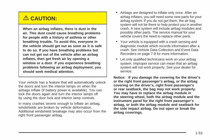
When an airbag inflates, there is dust in theair. This dust could cause breathing problemsfor people with a history of asthma or otherbreathing trouble. To avoid this, everyone inthe vehicle should get out as soon as it is safeto do so. If you have breathing problems butcan not get out of the vehicle after an airbaginflates, then get fresh air by opening awindow or a door. If you experience breathingproblems following an airbag deployment, youshould seek medical attention.
Your vehicle has a feature that will automatically unlockthe doors and turn the interior lamps on when theairbags inflate (if battery power is available). You canlock the doors again and turn the interior lamps offby using the door lock and interior lamp controls.
In many crashes severe enough to inflate an airbag,windshields are broken by vehicle deformation.Additional windshield breakage may also occur from theright front passenger airbag.
• Airbags are designed to inflate only once. After anairbag inflates, you will need some new parts for yourairbag system. If you do not get them, the air bagsystem will not be there to help protect you in anothercrash. A new system will include airbag modules andpossibly other parts. The service manual for yourvehicle covers the need to replace other parts.
• Your vehicle is equipped with a crash sensing anddiagnostic module which records information after acrash. See Vehicle Data Collection and Event DataRecorders on page 7-9 for more information.
• Let only qualified technicians work on your airbagsystem. Improper service can mean that an airbagsystem will not work properly. See your dealer forservice.
Notice: If you damage the covering for the driver’sor the right front passenger’s airbag, or the airbagcovering on the driver’s, right front passenger’sor rear seatback, the bag may not work properly.You may have to replace the airbag module inthe steering wheel, both the airbag module and theinstrument panel for the right front passenger’sairbag, or both the airbag module and seatback forthe side impact airbag. Do not open or break theairbag coverings.
1-53
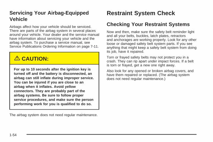
Servicing Your Airbag-EquippedVehicleAirbags affect how your vehicle should be serviced.There are parts of the airbag system in several placesaround your vehicle. Your dealer and the service manualhave information about servicing your vehicle and theairbag system. To purchase a service manual, seeService Publications Ordering Information on page 7-11.
{CAUTION:
For up to 10 seconds after the ignition key isturned off and the battery is disconnected, anairbag can still inflate during improper service.You can be injured if you are close to anairbag when it inflates. Avoid yellowconnectors. They are probably part of theairbag systems. Be sure to follow properservice procedures, and make sure the personperforming work for you is qualified to do so.
The airbag system does not need regular maintenance.
Restraint System Check
Checking Your Restraint SystemsNow and then, make sure the safety belt reminder lightand all your belts, buckles, latch plates, retractorsand anchorages are working properly. Look for any otherloose or damaged safety belt system parts. If you seeanything that might keep a safety belt system from doingits job, have it repaired.
Torn or frayed safety belts may not protect you in acrash. They can rip apart under impact forces. If a beltis torn or frayed, get a new one right away.
Also look for any opened or broken airbag covers, andhave them repaired or replaced. (The airbag systemdoes not need regular maintenance.)
1-54
Replacing Restraint System PartsAfter a Crash
{CAUTION:
A crash can damage the restraint systems inyour vehicle. A damaged restraint system maynot properly protect the person using it,resulting in serious injury or even death in acrash. To help make sure your restraintsystems are working properly after a crash,have them inspected and any necessaryreplacements made as soon as possible.
If you have had a crash, do you need new belts orLATCH system parts?
After a very minor collision, nothing may be necessary.But if the belts were stretched, as they would be ifworn during a more severe crash, then you neednew parts.
If the LATCH system was being used during a moresevere crash, you may need new LATCH system parts.
If belts are cut or damaged, replace them. Collisiondamage also may mean you will need to have LATCHsystem, safety belt or seat parts repaired or replaced.New parts and repairs may be necessary even if the beltor LATCH system was not being used at the time ofthe collision.
If an airbag inflates, you will need to replace airbagsystem parts. See the part on the airbag system earlierin this section.
If the frontal airbags inflate, you will also need toreplace the driver’s and right front passenger’s safetybelt buckle assembly. Be sure to do so. Then thenew buckle assembly will be there to help protect you ina collision.
After a crash you may need to replace the driver andfront passenger’s safety belt buckle assemblies, even ifthe frontal airbags have not deployed. The driverand front passenger’s safety belt buckle assembliescontain the safety belt pretensioners. Have your safetybelt pretensioners checked if your vehicle has beenin a collision, or if your airbag readiness light stays onafter you start your vehicle or while you are driving. SeeAirbag Readiness Light on page 3-45.
1-55

✍ NOTES
1-56
Keys ...............................................................2-3Remote Keyless Entry System .........................2-5Remote Keyless Entry System Operation ...........2-6
Doors and Locks .............................................2-8Door Locks ....................................................2-8Central Door Unlocking System ........................2-9Power Door Locks ..........................................2-9Programmable Automatic Door Locks ..............2-10Rear Door Security Locks ..............................2-10Lockout Protection ........................................2-11Trunk ..........................................................2-12
Windows ........................................................2-15Power Windows ............................................2-16Sun Visors ...................................................2-18
Theft-Deterrent Systems ..................................2-19Valet Lockout Switch .....................................2-21PASS-Key® III ..............................................2-21PASS-Key® III Operation ...............................2-22
Starting and Operating Your Vehicle ................2-24New Vehicle Break-In ....................................2-24Ignition Positions ..........................................2-24Retained Accessory Power (RAP) ...................2-25Starting Your Engine .....................................2-26Engine Coolant Heater ..................................2-27Automatic Transaxle Operation .......................2-28
Performance Shifting (DTS Only) ....................2-31Parking Brake ..............................................2-31Shifting Into Park (P) .....................................2-32Shifting Out of Park (P) .................................2-34Parking Over Things That Burn .......................2-35Engine Exhaust ............................................2-35Running Your Engine While You Are Parked ....2-36
Mirrors ...........................................................2-37Automatic Dimming Rearview Mirror with
OnStar® ...................................................2-37Automatic Dimming Rearview Mirror with
OnStar® and Compass ...............................2-37Outside Power Mirrors ...................................2-40Outside Automatic Dimming Mirror ..................2-41Outside Curb View Assist Mirror .....................2-41Outside Convex Mirror ...................................2-41Outside Heated Mirrors ..................................2-41
OnStar ® System .............................................2-42HomeLink ® Transmitter ...................................2-44
Programming the HomeLink® Transmitter .........2-45Storage Areas ................................................2-48
Glove Box ...................................................2-48Instrument Panel Storage Area .......................2-48Cellular Telephone ........................................2-48Front Storage Area .......................................2-49
Section 2 Features and Controls
2-1
Full Floor Console Storage Area .....................2-49Center Console Storage Area .........................2-49Center Flex Storage Unit ...............................2-50Map Pocket .................................................2-50Assist Handles .............................................2-50Umbrella Holder ...........................................2-51
Rear Storage Area ........................................2-51Rear Storage Door Trim Armrest .....................2-51Convenience Net ..........................................2-51
Sunroof .........................................................2-51Vehicle Personalization ...................................2-52
Memory Seat, Mirrors and Steering Wheel .......2-52
Section 2 Features and Controls
2-2
Keys
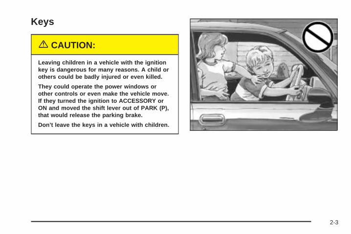
{CAUTION:
Leaving children in a vehicle with the ignitionkey is dangerous for many reasons. A child orothers could be badly injured or even killed.
They could operate the power windows orother controls or even make the vehicle move.If they turned the ignition to ACCESSORY orON and moved the shift lever out of PARK (P),that would release the parking brake.
Don’t leave the keys in a vehicle with children.
2-3
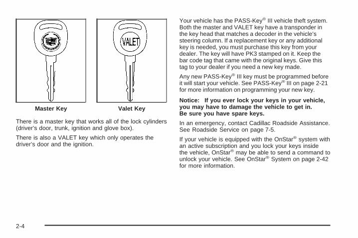
There is a master key that works all of the lock cylinders(driver’s door, trunk, ignition and glove box).
There is also a VALET key which only operates thedriver’s door and the ignition.
Your vehicle has the PASS-Key® III vehicle theft system.Both the master and VALET key have a transponder inthe key head that matches a decoder in the vehicle’ssteering column. If a replacement key or any additionalkey is needed, you must purchase this key from yourdealer. The key will have PK3 stamped on it. Keep thebar code tag that came with the original keys. Give thistag to your dealer if you need a new key made.
Any new PASS-Key® III key must be programmed beforeit will start your vehicle. See PASS-Key® III on page 2-21for more information on programming your new key.
Notice: If you ever lock your keys in your vehicle,you may have to damage the vehicle to get in.Be sure you have spare keys.
In an emergency, contact Cadillac Roadside Assistance.See Roadside Service on page 7-5.
If your vehicle is equipped with the OnStar® system withan active subscription and you lock your keys insidethe vehicle, OnStar® may be able to send a command tounlock your vehicle. See OnStar® System on page 2-42for more information.
Master Key Valet Key
2-4
Remote Keyless Entry SystemYour keyless entry system operates on a radiofrequency subject to Federal CommunicationsCommission (FCC) Rules and with Industry Canada.
This device complies with Part 15 of the FCC Rules.Operation is subject to the following two conditions:
1. This device may not cause interference, and
2. This device must accept any interference received,including interference that may cause undesiredoperation of the device.
This device complies with RSS-210 of Industry Canada.Operation is subject to the following two conditions:
1. This device may not cause interference, and
2. This device must accept any interference received,including interference that may cause undesiredoperation of the device.
Changes or modifications to this system by other thanan authorized service facility could void authorization touse this equipment.
At times you may notice a decrease in range. This isnormal for any remote keyless entry system. If thetransmitter does not work or if you have to stand closerto your vehicle for the transmitter to work, try this:
• Check the distance. You may be too far from yourvehicle. You may need to stand closer duringrainy or snowy weather.
• Check the location. Other vehicles or objects maybe blocking the signal. Take a few steps to theleft or right, hold the transmitter higher, andtry again.
• Check to determine if battery replacement isnecessary. See “Battery Replacement” underRemote Keyless Entry System Operation onpage 2-6.
• If you are still having trouble, see your dealer or aqualified technician for service.
2-5
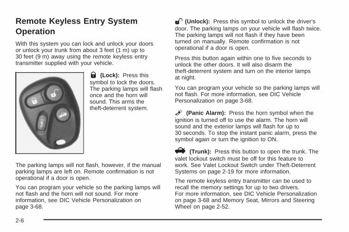
Remote Keyless Entry SystemOperationWith this system you can lock and unlock your doorsor unlock your trunk from about 3 feet (1 m) up to30 feet (9 m) away using the remote keyless entrytransmitter supplied with your vehicle.
Q (Lock): Press thissymbol to lock the doors.The parking lamps will flashonce and the horn willsound. This arms thetheft-deterrent system.
The parking lamps will not flash, however, if the manualparking lamps are left on. Remote confirmation is notoperational if a door is open.
You can program your vehicle so the parking lamps willnot flash and the horn will not sound. For moreinformation, see DIC Vehicle Personalization onpage 3-68.
W(Unlock): Press this symbol to unlock the driver’sdoor. The parking lamps on your vehicle will flash twice.The parking lamps will not flash if they have beenturned on manually. Remote confirmation is notoperational if a door is open.
Press this button again within one to five seconds tounlock the other doors. It will also disarm thetheft-deterrent system and turn on the interior lampsat night.
You can program your vehicle so the parking lamps willnot flash. For more information, see DIC VehiclePersonalization on page 3-68.
L (Panic Alarm): Press the horn symbol when theignition is turned off to use the alarm. The horn willsound and the exterior lamps will flash for up to30 seconds. To stop the instant panic alarm, press thesymbol again or turn the ignition to ON.
V (Trunk): Press this button to open the trunk. Thevalet lockout switch must be off for this feature towork. See Valet Lockout Switch under Theft-DeterrentSystems on page 2-19 for more information.
The remote keyless entry transmitter can be used torecall the memory settings for up to two drivers.For more information, see DIC Vehicle Personalizationon page 3-68 and Memory Seat, Mirrors and SteeringWheel on page 2-52.
2-6
Matching Transmitter(s) to YourVehicleEach remote keyless entry transmitter is coded toprevent another transmitter from unlocking your vehicle.If a transmitter is lost or stolen, a replacement canbe purchased through your dealer. Remember to bringany remaining transmitters with you when you go toyour dealer. When the dealer matches the replacementtransmitter to your vehicle, any remaining transmittersmust also be matched. Once your dealer has coded thenew transmitter, the lost transmitter will not unlockyour vehicle. Each vehicle can have a maximum offour transmitters matched to it.
Vehicles are delivered with two transmitters. See yourdealer for information on how to obtain additionaltransmitters.
Battery ReplacementUnder normal use, the battery in your remote keylessentry transmitter should last about four years.
You can tell the battery is weak if the transmitter will notwork at the normal range in any location. If you haveto get close to your vehicle before the transmitter works,it is probably time to change the battery.
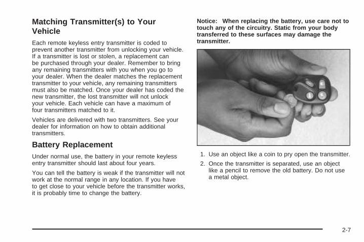
Notice: When replacing the battery, use care not totouch any of the circuitry. Static from your bodytransferred to these surfaces may damage thetransmitter.
1. Use an object like a coin to pry open the transmitter.
2. Once the transmitter is separated, use an objectlike a pencil to remove the old battery. Do not usea metal object.
2-7
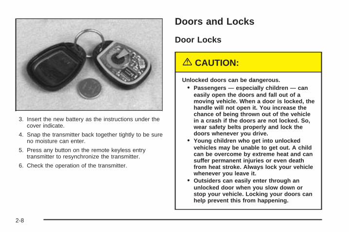
3. Insert the new battery as the instructions under thecover indicate.
4. Snap the transmitter back together tightly to be sureno moisture can enter.
5. Press any button on the remote keyless entrytransmitter to resynchronize the transmitter.
6. Check the operation of the transmitter.
Doors and Locks
Door Locks
{CAUTION:
Unlocked doors can be dangerous.• Passengers — especially children — can
easily open the doors and fall out of amoving vehicle. When a door is locked, thehandle will not open it. You increase thechance of being thrown out of the vehiclein a crash if the doors are not locked. So,wear safety belts properly and lock thedoors whenever you drive.
• Young children who get into unlockedvehicles may be unable to get out. A childcan be overcome by extreme heat and cansuffer permanent injuries or even deathfrom heat stroke. Always lock your vehiclewhenever you leave it.
• Outsiders can easily enter through anunlocked door when you slow down orstop your vehicle. Locking your doors canhelp prevent this from happening.
2-8
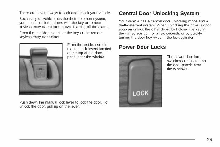
There are several ways to lock and unlock your vehicle.
Because your vehicle has the theft-deterrent system,you must unlock the doors with the key or remotekeyless entry transmitter to avoid setting off the alarm.
From the outside, use either the key or the remotekeyless entry transmitter.
From the inside, use themanual lock levers locatedat the top of the doorpanel near the window.
Push down the manual lock lever to lock the door. Tounlock the door, pull up on the lever.
Central Door Unlocking SystemYour vehicle has a central door unlocking mode and atheft-deterrent system. When unlocking the driver’s door,you can unlock the other doors by holding the key inthe turned position for a few seconds or by quicklyturning the door key twice in the lock cylinder.
Power Door Locks
The power door lockswitches are located onthe door panels nearthe windows.
2-9
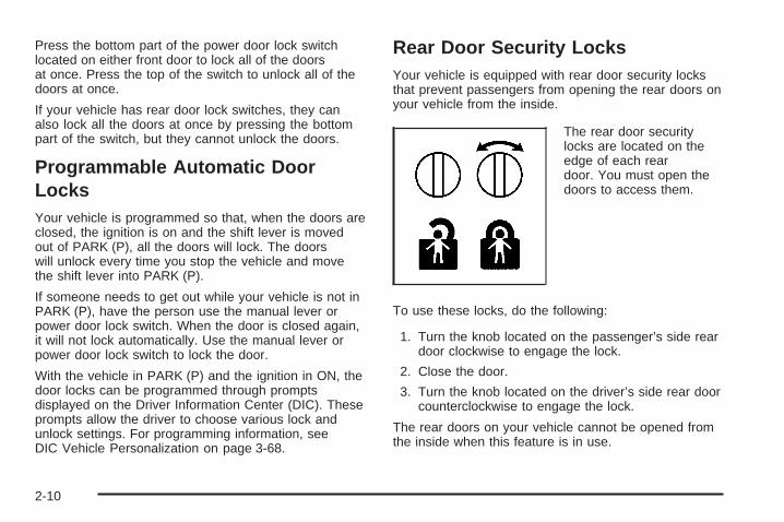
Press the bottom part of the power door lock switchlocated on either front door to lock all of the doorsat once. Press the top of the switch to unlock all of thedoors at once.
If your vehicle has rear door lock switches, they canalso lock all the doors at once by pressing the bottompart of the switch, but they cannot unlock the doors.
Programmable Automatic DoorLocksYour vehicle is programmed so that, when the doors areclosed, the ignition is on and the shift lever is movedout of PARK (P), all the doors will lock. The doorswill unlock every time you stop the vehicle and movethe shift lever into PARK (P).
If someone needs to get out while your vehicle is not inPARK (P), have the person use the manual lever orpower door lock switch. When the door is closed again,it will not lock automatically. Use the manual lever orpower door lock switch to lock the door.
With the vehicle in PARK (P) and the ignition in ON, thedoor locks can be programmed through promptsdisplayed on the Driver Information Center (DIC). Theseprompts allow the driver to choose various lock andunlock settings. For programming information, seeDIC Vehicle Personalization on page 3-68.
Rear Door Security LocksYour vehicle is equipped with rear door security locksthat prevent passengers from opening the rear doors onyour vehicle from the inside.
The rear door securitylocks are located on theedge of each reardoor. You must open thedoors to access them.
To use these locks, do the following:
1. Turn the knob located on the passenger’s side reardoor clockwise to engage the lock.
2. Close the door.
3. Turn the knob located on the driver’s side rear doorcounterclockwise to engage the lock.
The rear doors on your vehicle cannot be opened fromthe inside when this feature is in use.
2-10
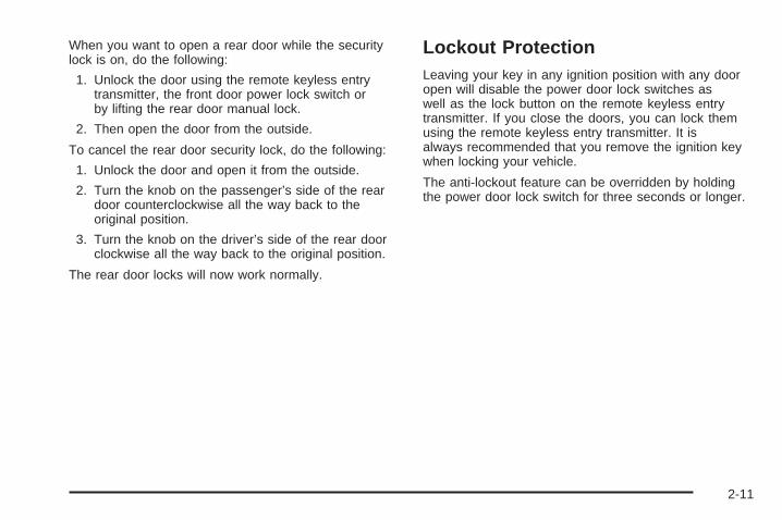
When you want to open a rear door while the securitylock is on, do the following:
1. Unlock the door using the remote keyless entrytransmitter, the front door power lock switch orby lifting the rear door manual lock.
2. Then open the door from the outside.
To cancel the rear door security lock, do the following:
1. Unlock the door and open it from the outside.
2. Turn the knob on the passenger’s side of the reardoor counterclockwise all the way back to theoriginal position.
3. Turn the knob on the driver’s side of the rear doorclockwise all the way back to the original position.
The rear door locks will now work normally.
Lockout ProtectionLeaving your key in any ignition position with any dooropen will disable the power door lock switches aswell as the lock button on the remote keyless entrytransmitter. If you close the doors, you can lock themusing the remote keyless entry transmitter. It isalways recommended that you remove the ignition keywhen locking your vehicle.
The anti-lockout feature can be overridden by holdingthe power door lock switch for three seconds or longer.
2-11
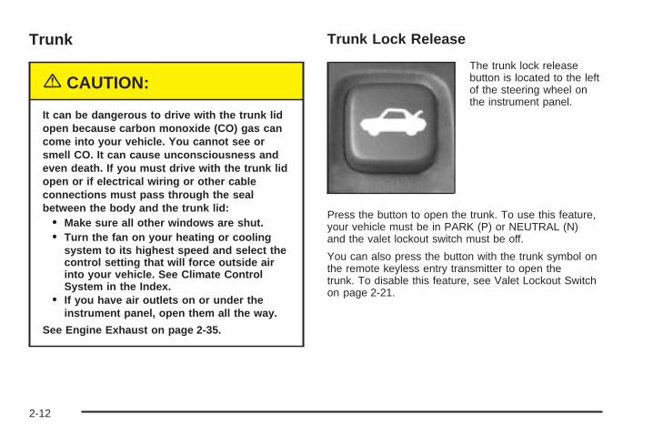
Trunk
{CAUTION:
It can be dangerous to drive with the trunk lidopen because carbon monoxide (CO) gas cancome into your vehicle. You cannot see orsmell CO. It can cause unconsciousness andeven death. If you must drive with the trunk lidopen or if electrical wiring or other cableconnections must pass through the sealbetween the body and the trunk lid:
• Make sure all other windows are shut.• Turn the fan on your heating or cooling
system to its highest speed and select thecontrol setting that will force outside airinto your vehicle. See Climate ControlSystem in the Index.
• If you have air outlets on or under theinstrument panel, open them all the way.
See Engine Exhaust on page 2-35.
Trunk Lock Release
The trunk lock releasebutton is located to the leftof the steering wheel onthe instrument panel.
Press the button to open the trunk. To use this feature,your vehicle must be in PARK (P) or NEUTRAL (N)and the valet lockout switch must be off.
You can also press the button with the trunk symbol onthe remote keyless entry transmitter to open thetrunk. To disable this feature, see Valet Lockout Switchon page 2-21.
2-12
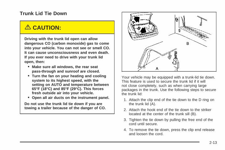
Trunk Lid Tie Down
{CAUTION:
Driving with the trunk lid open can allowdangerous CO (carbon monoxide) gas to comeinto your vehicle. You can not see or smell CO.It can cause unconsciousness and even death.If you ever need to drive with your trunk lidopen, then:
• Make sure all windows, the rear seatpass-through and sunroof are closed.
• Turn the fan on your heating and coolingsystem to its highest speed, with thesetting on AUTO and temperature between65°F (18°C) and 85°F (29°C). This forcesfresh outside air into your vehicle.
• Open all air ducts on the instrument panel.
Do not use the trunk lid tie down if you aretowing a trailer because of the danger of CO.
Your vehicle may be equipped with a trunk-lid tie down.This feature is used to secure the trunk lid if it willnot close completely, such as when carrying largepackages in the trunk. Use the following steps to securethe trunk lid:
1. Attach the clip end of the tie down to the D ring onthe trunk lid (A).
2. Attach the hook end of the tie down to the strikerlocated at the center of the trunk sill (B).
3. Tighten the tie down by pulling the free end of thecord until secure.
4. To remove the tie down, press the clip end releaseand loosen the cord.
2-13
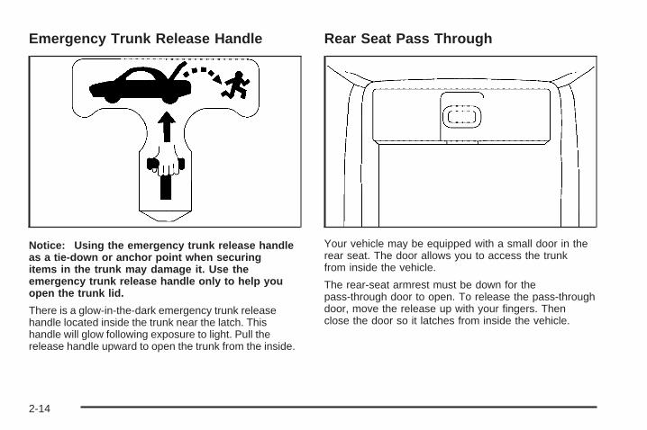
Emergency Trunk Release Handle
Notice: Using the emergency trunk release handleas a tie-down or anchor point when securingitems in the trunk may damage it. Use theemergency trunk release handle only to help youopen the trunk lid.
There is a glow-in-the-dark emergency trunk releasehandle located inside the trunk near the latch. Thishandle will glow following exposure to light. Pull therelease handle upward to open the trunk from the inside.
Rear Seat Pass Through
Your vehicle may be equipped with a small door in therear seat. The door allows you to access the trunkfrom inside the vehicle.
The rear-seat armrest must be down for thepass-through door to open. To release the pass-throughdoor, move the release up with your fingers. Thenclose the door so it latches from inside the vehicle.
2-14

Windows
{CAUTION:
Leaving children, helpless adults, or pets in avehicle with the windows closed is dangerous.They can be overcome by the extreme heatand suffer permanent injuries or even deathfrom heat stroke. Never leave a child, ahelpless adult, or a pet alone in a vehicle,especially with the windows closed in warm orhot weather.
2-15
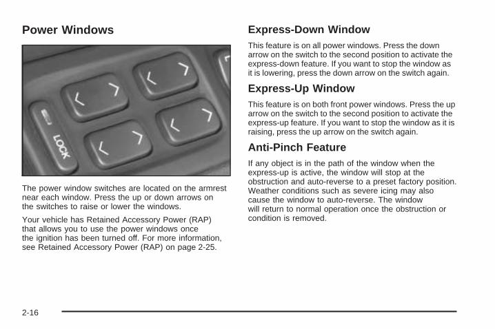
Power Windows
The power window switches are located on the armrestnear each window. Press the up or down arrows onthe switches to raise or lower the windows.
Your vehicle has Retained Accessory Power (RAP)that allows you to use the power windows oncethe ignition has been turned off. For more information,see Retained Accessory Power (RAP) on page 2-25.
Express-Down WindowThis feature is on all power windows. Press the downarrow on the switch to the second position to activate theexpress-down feature. If you want to stop the window asit is lowering, press the down arrow on the switch again.
Express-Up WindowThis feature is on both front power windows. Press the uparrow on the switch to the second position to activate theexpress-up feature. If you want to stop the window as it israising, press the up arrow on the switch again.
Anti-Pinch FeatureIf any object is in the path of the window when theexpress-up is active, the window will stop at theobstruction and auto-reverse to a preset factory position.Weather conditions such as severe icing may alsocause the window to auto-reverse. The windowwill return to normal operation once the obstruction orcondition is removed.
2-16
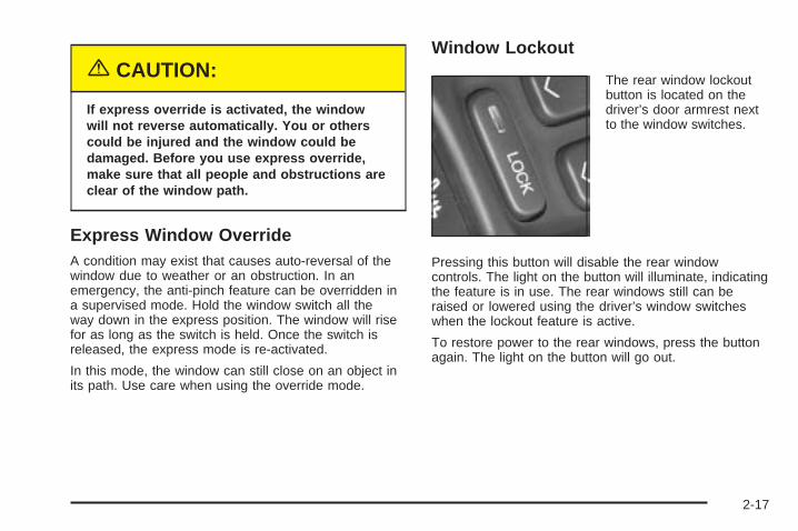
{CAUTION:
If express override is activated, the windowwill not reverse automatically. You or otherscould be injured and the window could bedamaged. Before you use express override,make sure that all people and obstructions areclear of the window path.
Express Window OverrideA condition may exist that causes auto-reversal of thewindow due to weather or an obstruction. In anemergency, the anti-pinch feature can be overridden ina supervised mode. Hold the window switch all theway down in the express position. The window will risefor as long as the switch is held. Once the switch isreleased, the express mode is re-activated.
In this mode, the window can still close on an object inits path. Use care when using the override mode.
Window Lockout
The rear window lockoutbutton is located on thedriver’s door armrest nextto the window switches.
Pressing this button will disable the rear windowcontrols. The light on the button will illuminate, indicatingthe feature is in use. The rear windows still can beraised or lowered using the driver’s window switcheswhen the lockout feature is active.
To restore power to the rear windows, press the buttonagain. The light on the button will go out.
2-17
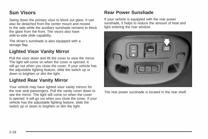
Sun VisorsSwing down the primary visor to block out glare. It canalso be detached from the center mount and movedto the side while the auxiliary sunshade remains to blockthe glare from the front. The visors also haveside-to-side slide capability.
The driver’s sunshade is also equipped with astorage flap.
Lighted Visor Vanity MirrorPull the visor down and lift the cover to view the mirror.The light will come on when the cover is opened. Itwill go out when you close the cover. If your vehicle hasthe adjustable lighting feature, slide the switch up ordown to brighten or dim the light.
Lighted Rear Vanity MirrorYour vehicle may have lighted visor vanity mirrors forthe rear seat passengers. Pull the vanity cover down tosee the mirror. The light will come on when the coveris opened. It will go out when you close the cover. If yourvehicle has the adjustable lighting feature, slide theswitch up or down to brighten or dim the light.
Rear Power SunshadeIf your vehicle is equipped with the rear powersunshade, it helps to reduce the amount of heat andlight entering the rear window.
The rear power sunshade is located in the rear shelf.
2-18
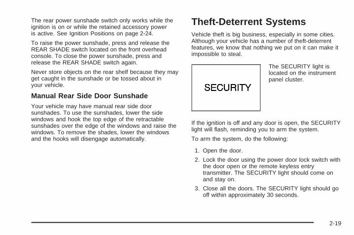
The rear power sunshade switch only works while theignition is on or while the retained accessory poweris active. See Ignition Positions on page 2-24.
To raise the power sunshade, press and release theREAR SHADE switch located on the front overheadconsole. To close the power sunshade, press andrelease the REAR SHADE switch again.
Never store objects on the rear shelf because they mayget caught in the sunshade or be tossed about inyour vehicle.
Manual Rear Side Door SunshadeYour vehicle may have manual rear side doorsunshades. To use the sunshades, lower the sidewindows and hook the top edge of the retractablesunshades over the edge of the windows and raise thewindows. To remove the shades, lower the windowsand the hooks will disengage automatically.
Theft-Deterrent SystemsVehicle theft is big business, especially in some cities.Although your vehicle has a number of theft-deterrentfeatures, we know that nothing we put on it can make itimpossible to steal.
The SECURITY light islocated on the instrumentpanel cluster.
If the ignition is off and any door is open, the SECURITYlight will flash, reminding you to arm the system.
To arm the system, do the following:
1. Open the door.
2. Lock the door using the power door lock switch withthe door open or the remote keyless entrytransmitter. The SECURITY light should come onand stay on.
3. Close all the doors. The SECURITY light should gooff within approximately 30 seconds.
2-19
If a door or the trunk is opened without a key or aremote keyless entry transmitter, the horn will soundand the lamps will flash for about 30 seconds.
Remember, the theft-deterrent system will not arm if youlock the doors with a key or use the manual doorlock. It activates only if you use a power door lock withthe door open or the remote keyless entry transmitter.
To avoid activating the alarm by accident do thefollowing:
• The vehicle should be locked with the door key orthe manual door lock after the doors are closed ifyou do not want to arm the theft-deterrent system.
• Always unlock a door with a key or use the remotekeyless entry transmitter system. Pressing theunlock button on the remote keyless entrytransmitter disables the theft-deterrent system.Unlocking a door any other way will activatethe alarm when a door or the trunk is opened.
If you activate the alarm by accident, unlock the driver’sdoor with your key. You can also turn off the alarm byusing the unlock button on the remote keyless entrytransmitter system, or by starting the car with a valid key.
Changes or modifications made to this system by otherthan an authorized service facility could voidauthorization to use the theft system.
Testing the Alarm1. From inside the vehicle, roll down the window, then
get out of the vehicle, keeping the door open.
2. From outside of the vehicle, with the door open, lockthe vehicle using the power door lock or the remotekeyless entry system and close the door. Wait30 seconds until the SECURITY lamp goes off.
3. Reach in and unlock the door using the manuallock and open the door. The horn will sound andthe hazard lights will flash.
You can turn off the alarm by unlocking the driver’s doorwith your key, using the unlock button on the remotekeyless entry transmitter or by starting the car witha valid key.
If the alarm does not sound when it should, check tosee if the horn works. The horn fuse may be blown. Toreplace the fuse, see Fuses and Circuit Breakers onpage 5-98. If the fuse does not need to be replaced, youmay need to have your vehicle serviced.
To reduce the possibility of theft, always arm thetheft-deterrent system when leaving your vehicle.
2-20
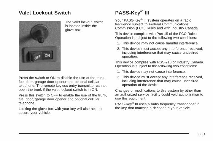
Valet Lockout Switch
The valet lockout switchis located inside theglove box.
Press the switch to ON to disable the use of the trunk,fuel door, garage door opener and optional cellulartelephone. The remote keyless entry transmitter cannotopen the trunk if the valet lockout switch is in ON.
Press this switch to OFF to enable the use of the trunk,fuel door, garage door opener and optional cellulartelephone.
Locking the glove box with your key will also help tosecure your vehicle.
PASS-Key ® IIIYour PASS-Key® III system operates on a radiofrequency subject to Federal CommunicationsCommission (FCC) Rules and with Industry Canada.
This device complies with Part 15 of the FCC Rules.Operation is subject to the following two conditions:
1. This device may not cause harmful interference.
2. This device must accept any interference received,including interference that may cause undesiredoperation.
This device complies with RSS-210 of Industry Canada.Operation is subject to the following two conditions:
1. This device may not cause interference.
2. This device must accept any interference received,including interference that may cause undesiredoperation of the device.
Changes or modifications to this system by other thanan authorized service facility could void authorization touse this equipment.
PASS-Key® III uses a radio frequency transponder inthe key that matches a decoder in your vehicle.
2-21
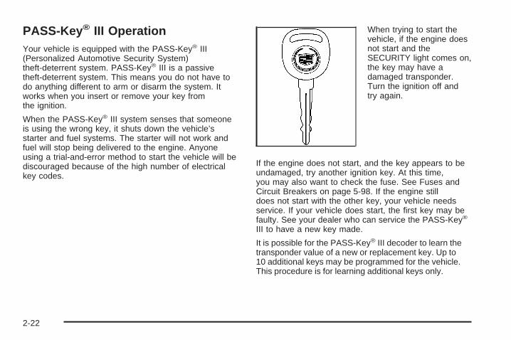
PASS-Key ® III OperationYour vehicle is equipped with the PASS-Key® III(Personalized Automotive Security System)theft-deterrent system. PASS-Key® III is a passivetheft-deterrent system. This means you do not have todo anything different to arm or disarm the system. Itworks when you insert or remove your key fromthe ignition.
When the PASS-Key® III system senses that someoneis using the wrong key, it shuts down the vehicle’sstarter and fuel systems. The starter will not work andfuel will stop being delivered to the engine. Anyoneusing a trial-and-error method to start the vehicle will bediscouraged because of the high number of electricalkey codes.
When trying to start thevehicle, if the engine doesnot start and theSECURITY light comes on,the key may have adamaged transponder.Turn the ignition off andtry again.
If the engine does not start, and the key appears to beundamaged, try another ignition key. At this time,you may also want to check the fuse. See Fuses andCircuit Breakers on page 5-98. If the engine stilldoes not start with the other key, your vehicle needsservice. If your vehicle does start, the first key may befaulty. See your dealer who can service the PASS-Key®
III to have a new key made.
It is possible for the PASS-Key® III decoder to learn thetransponder value of a new or replacement key. Up to10 additional keys may be programmed for the vehicle.This procedure is for learning additional keys only.
2-22
Canadian Owners: If you lose or damage your keys,only a GM dealer can service PASS-Key® III tohave new keys made. To program additional keys youwill require two current driver’s keys (black in color). Youmust add a step to the following procedure. AfterStep 2, repeat Steps 1 and 2 with the second currentdriver’s key. Then continue with Step 3.
To program the new key do the following:
1. Verify that the new key has PK3 stamped on it.
2. Insert the current driver’s key in the ignitionand start the engine. If the engine will not start seeyour dealer for service.
3. After the engine has started, turn the key to OFF,and remove the key.
4. Insert the key to be programmed and turn it to ONwithin 10 seconds of removing the previous key.
5. The SECURITY light will turn off once the key hasbeen programmed. It may not be apparent that theSECURITY light went on due to how quickly thekey is programmed.
6. Repeat the Steps 1 through 4 if additional keys areto be programmed.
If you are ever driving and the SECURITY light comeson and stays on, you will be able to restart yourengine if you turn it off. Your PASS- Key® III system,however, is not working properly and must be servicedby your dealer. Your vehicle is not protected by thePASS-Key® III system at this time.
If you lose or damage a PASS-Key® III key, contactyour dealer to have a new key made.
In an emergency, contact Cadillac Roadside Assistance.See Roadside Service on page 7-5.
2-23
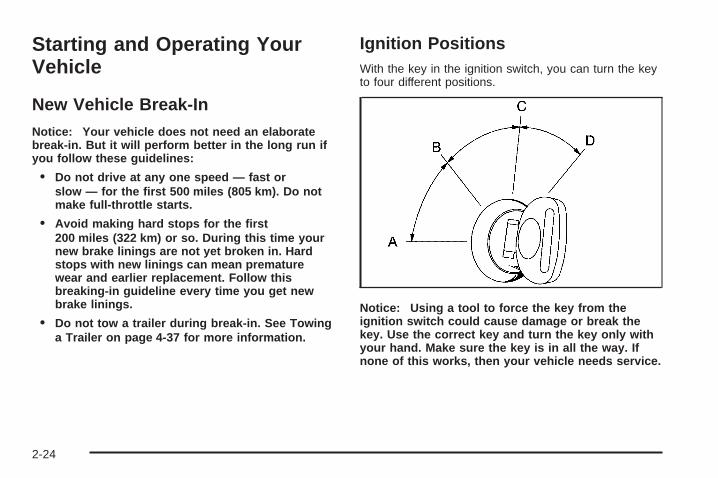
Starting and Operating YourVehicle
New Vehicle Break-InNotice: Your vehicle does not need an elaboratebreak-in. But it will perform better in the long run ifyou follow these guidelines:
• Do not drive at any one speed — fast orslow — for the first 500 miles (805 km). Do notmake full-throttle starts.
• Avoid making hard stops for the first200 miles (322 km) or so. During this time yournew brake linings are not yet broken in. Hardstops with new linings can mean prematurewear and earlier replacement. Follow thisbreaking-in guideline every time you get newbrake linings.
• Do not tow a trailer during break-in. See Towinga Trailer on page 4-37 for more information.
Ignition PositionsWith the key in the ignition switch, you can turn the keyto four different positions.
Notice: Using a tool to force the key from theignition switch could cause damage or break thekey. Use the correct key and turn the key only withyour hand. Make sure the key is in all the way. Ifnone of this works, then your vehicle needs service.
2-24

A (OFF): This is the only position in which you caninsert or remove the key. This position locks the ignitionand transaxle. It is a theft-deterrent feature.
B (ACCESSORY): This position allows you to use thingslike the radio and the windshield wipers when the engineis off. This position will allow you to turn off the engine. Ifyour vehicle has a column shifter, you will still be able tomove the shift lever. Use ACCESSORY if you must haveyour vehicle in motion while the engine is off, for example,if your vehicle is being pushed or towed.
C (ON): This position is for driving. If your vehicle has aconsole shifter and you turn off the engine, thetransaxle will lock. If you need to shift the transaxle outof PARK (P), the ignition key has to be in ON.
D (START): This position starts the engine.
Retained Accessory Power (RAP)The following accessories on your vehicle may be usedfor up to 10 minutes after the ignition key is turnedfrom ON to OFF:
• Cellular Telephone
• Radio
• Power Windows
• Audio Steering Wheel Controls
• Sunroof
Power to these accessories stops after 10 minutes or ifa door is opened. If you want power for another10 minutes, close all the doors and turn the ignition keyto ON and then back to OFF. If the cellular phone isbeing used while retained accessory power is active, thetimer is suspended to avoid interruption of the call.The timer resets to 10 minutes at the end of the call.
2-25
Starting Your EngineMove your shift lever to PARK (P) or NEUTRAL (N).The engine will not start in any other position — that isa safety feature. To restart when you are alreadymoving, use NEUTRAL (N) only.
Notice: Shifting into PARK (P) with the vehiclemoving could damage the transaxle. Shift intoPARK (P) only when your vehicle is stopped.
1. With your foot off the accelerator pedal, turn theignition key to START. When the engine starts,let go of the key. The idle speed will go down as theengine gets warm.
Notice: Holding your key in START for longer than15 seconds at a time will cause your battery tobe drained much sooner. And the excessive heatcan damage your starter motor. Wait about15 seconds between each try to help avoid drainingyour battery or damaging your starter.
2. If the engine does not start within 10 seconds, holdyour key in START for about 10 seconds at a timeuntil the engine starts. Wait about 15 secondsbetween each try.When your engine has run for about 10 seconds towarm up, your vehicle is ready to be driven. Donot race your engine when it is cold.If the weather is below freezing (32°F or 0°C), letthe engine run for a few minutes to warm up.
3. If your engine still will not start, or starts but thenstops, it could be flooded with too much gasoline.Try pushing your accelerator pedal all the way to thefloor and holding it there as you hold the key inSTART for about three seconds. If the vehicle startsbriefly but then stops again, do the same thing.This time keep the pedal down for five or sixseconds to clear the extra gasoline from the engine.After waiting about 15 seconds, repeat the normalstarting procedure.
Notice: Your engine is designed to work with theelectronics in your vehicle. If you add electricalparts or accessories, you could change the way theengine operates. Before adding electrical equipment,check with your dealer. If you do not, your enginemight not perform properly.
2-26
Engine Coolant HeaterYour vehicle may be equipped with an engine coolantheater.
In very cold weather, 0°F (−18°C) or colder, the enginecoolant heater can help. You will get easier startingand better fuel economy during engine warm-up.Usually, the coolant heater should be plugged in aminimum of four hours prior to starting your vehicle. Attemperatures above 32°F (0°C), use of the coolantheater is not required.
To Use the Engine Coolant Heater1. Turn off the engine.
2. Open the hood and unwrap the electrical cord.The electrical cord is located on the driver’s sideof the engine, behind the transaxle dipstick/fluid filllocation and next to the engine.
3. Plug it into a normal, grounded 110-volt AC outlet.
{CAUTION:
Plugging the cord into an ungrounded outletcould cause an electrical shock. Also, thewrong kind of extension cord could overheatand cause a fire. You could be seriouslyinjured. Plug the cord into a properly groundedthree-prong 110-volt AC outlet. If the cord willnot reach, use a heavy-duty three-prongextension cord rated for at least 15 amps.
4. Before starting the engine, be sure to unplug andstore the cord as it was before to keep it awayfrom moving engine parts. If you do not, it could bedamaged.
How long should you keep the coolant heater pluggedin? The answer depends on the outside temperature, thekind of oil you have, and some other things. Insteadof trying to list everything here, we ask that you contactyour dealer in the area where you will be parkingyour vehicle. The dealer can give you the best advicefor that particular area.
2-27
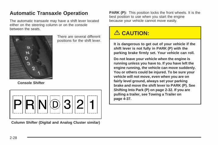
Automatic Transaxle OperationThe automatic transaxle may have a shift lever locatedeither on the steering column or on the consolebetween the seats.
There are several differentpositions for the shift lever.
PARK (P): This position locks the front wheels. It is thebest position to use when you start the enginebecause your vehicle cannot move easily.
{CAUTION:
It is dangerous to get out of your vehicle if theshift lever is not fully in PARK (P) with theparking brake firmly set. Your vehicle can roll.
Do not leave your vehicle when the engine isrunning unless you have to. If you have left theengine running, the vehicle can move suddenly.You or others could be injured. To be sure yourvehicle will not move, even when you are onfairly level ground, always set your parkingbrake and move the shift lever to PARK (P). SeeShifting Into Park (P) on page 2-32. If you arepulling a trailer, see Towing a Trailer onpage 4-37.
Console Shifter
Column Shifter (Digital and Analog Cluster similar)
2-28
Ensure the shift lever is fully in PARK (P) before startingthe engine. Your vehicle has an automatic transaxle shiftlock control system. You have to fully apply your regularbrakes before you can shift from PARK (P) while theignition key is in ON. If you cannot shift out of PARK (P),ease pressure on the shift lever. Push the shift lever allthe way into PARK (P) as you maintain brake application.Then move the shift lever into the gear you wish. SeeShifting Out of Park (P) on page 2-34.
REVERSE (R): Use this gear to back up.
Notice: Shifting to REVERSE (R) while your vehicleis moving forward could damage the transaxle. Therepairs would not be covered by your warranty. Shiftto REVERSE (R) only after your vehicle is stopped.
Also use this gear to rock your vehicle back and forth toget out of snow, ice or sand without damaging yourtransaxle. See If You Are Stuck: In Sand, Mud, Ice orSnow on page 4-29 for additional information.
NEUTRAL (N): In this position, the engine does notconnect with the wheels. To restart when you arealready moving, use NEUTRAL (N) only. Also, useNEUTRAL (N) when your vehicle is being towed.
{CAUTION:
Shifting into a drive gear while your engine isrunning at high speed is dangerous. Unlessyour foot is firmly on the brake pedal, yourvehicle could move very rapidly. You couldlose control and hit people or objects. Do notshift into a drive gear while your engine isrunning at high speed.
Notice: Shifting out of PARK (P) or NEUTRAL (N)with the engine racing may damage the transaxle.The repairs would not be covered by your warranty.Be sure the engine is not racing when shiftingyour vehicle.
2-29
AUTOMATIC OVERDRIVE (X): This position is fornormal driving. If you need more power for passing, andyou are:
• Going less than 35 mph (55 km/h), push theaccelerator pedal about halfway down.
• Going about 35 mph (55 km/h) or more, push theaccelerator all the way down.
The transaxle will shift down to the next gear and havemore power.
Notice: Driving your vehicle if you notice that it ismoving slowly or not shifting gears as you increasespeed may damage the transaxle. Have your vehicleserviced right away. You can drive in SECOND (2)when you are driving less than 35 mph (55 km/h)and AUTOMATIC OVERDRIVE X for higher speedsuntil then.
THIRD (3): This position is also used for normal driving,however, it offers more power and lower fuel economythan AUTOMATIC OVERDRIVE (X).
Here are examples for using THIRD (3) instead ofAUTOMATIC OVERDRIVE (X):
• When driving on hilly, winding roads.
• When towing a trailer, so there is less shiftingbetween gears.
• When going down a steep hill.
SECOND (2): This position gives you more power thanTHIRD (3). You can use SECOND (2) on hills. It canhelp control your speed as you go down steep mountainroads, but then you would also want to use yourbrakes off and on.
Notice: Do not shift into SECOND (2) unless youare going slower than 65 mph (105 km/h), or you candamage your engine.
FIRST (1): This position gives you even more powerthan SECOND (2). You can use it on very steep hills, or indeep snow or mud. If the shift lever is put in FIRST (1),the transaxle will not shift into first gear until the vehicle isgoing slowly enough.
Notice: Spinning the tires or holding the vehicle inone place on a hill using only the acceleratorpedal may damage the transaxle. If you are stuck,do not spin the tires. When stopping on a hill,use the brakes to hold the vehicle in place.
2-30
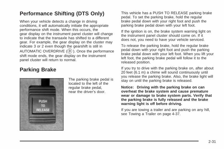
Performance Shifting (DTS Only)When your vehicle detects a change in drivingconditions, it will automatically initiate the appropriateperformance shift mode. When this occurs, thegear display on the instrument panel cluster will changeto indicate that the transaxle has shifted to a differentgear. For example, the gear display on the cluster mayindicate 3 or 2 even though the gearshift is still inAUTOMATIC OVERDRIVE (X). Once the performanceshift mode ends, the gear display on the instrumentpanel cluster will return to normal.
Parking Brake
The parking brake pedal islocated to the left of theregular brake pedal,near the driver’s door.
This vehicle has a PUSH TO RELEASE parking brakepedal. To set the parking brake, hold the regularbrake pedal down with your right foot and push theparking brake pedal down with your left foot.
If the ignition is on, the brake system warning light onthe instrument panel cluster should come on. If itdoes not, you need to have your vehicle serviced.
To release the parking brake, hold the regular brakepedal down with your right foot and push the parkingbrake pedal down with your left foot. When you lift yourleft foot, the parking brake pedal will follow it to thereleased position.
If you try to drive with the parking brake on, after about20 feet (6.1 m) a chime will sound continuously untilyou release the parking brake. Also, the brake light willstay on until the parking brake is released.
Notice: Driving with the parking brake on canoverheat the brake system and cause prematurewear or damage to brake system parts. Verify thatthe parking brake is fully released and the brakewarning light is off before driving.
If you are towing a trailer and are parking on any hill,see Towing a Trailer on page 4-37.
2-31
Shifting Into Park (P)
{CAUTION:
It can be dangerous to get out of your vehicle ifthe shift lever is not fully in PARK (P) with theparking brake firmly set. Your vehicle can roll. Ifyou have left the engine running, the vehiclecan move suddenly. You or others could beinjured. To be sure your vehicle will not move,even when you are on fairly level ground, usethe steps that follow. If you are pulling a trailer,see Towing a Trailer on page 4-37.
Steering Column Shift LeverIf your vehicle is equipped with a steering column shiftlever, use the following procedure to shift the vehicleinto PARK (P):
1. Hold the brake pedal down with your right foot.
2. Move the shift lever into PARK (P) by pulling theshift lever toward you and moving it up as far as itwill go.
3. With your right foot still holding the brake pedaldown, set the parking brake.
4. Turn the ignition key to OFF.
5. Remove the key and take it with you. If you canleave your vehicle with the ignition key in yourhand, your vehicle is in PARK (P).
Console Shift LeverIf your vehicle is equipped with a console shift lever,use the following procedure to shift the vehicle intoPARK (P):
1. Hold the brake pedal down with your right foot.
2. Move the shift lever into PARK (P) by pushing thelever all the way toward the front of your vehicleand then to the left.
3. With your right foot still holding the brake pedaldown, set the parking brake.
4. Turn the ignition key to OFF.
5. Remove the key and take it with you. If you canleave your vehicle with the ignition key in yourhand, your vehicle is in PARK (P).
2-32
Leaving Your Vehicle With the EngineRunning
{CAUTION:
It can be dangerous to leave your vehicle withthe engine running. Your vehicle could movesuddenly if the shift lever is not fully inPARK (P) with the parking brake firmly set.And, if you leave the vehicle with the enginerunning, it could overheat and even catch fire.You or others could be injured. Do not leaveyour vehicle with the engine running.
If you have to leave your vehicle with the enginerunning, be sure your vehicle is in PARK (P) and yourparking brake is firmly set before you leave it.
Torque LockIf you are parking on a hill and you do not shift yourtransaxle into PARK (P) properly, the weight ofthe vehicle may put too much force on the parking pawlin the transaxle. You may find it difficult to pull theshift lever out of PARK (P). This is called “torque lock.”To prevent torque lock, set the parking brake andthen shift into PARK (P) properly before you leave thedriver’s seat. To find out how, see Shifting Into Park (P)on page 2-32.
If torque lock does occur, you may need to haveanother vehicle push yours a little uphill to take some ofthe pressure from the parking pawl in the transaxle,so you can pull the shift lever out of PARK (P).
2-33
Shifting Out of Park (P)Your vehicle has an automatic transaxle shift lockcontrol system. You have to fully apply your regularbrakes before you can shift from PARK (P) whenthe ignition is ON. See Automatic Transaxle Operationon page 2-28.
The shift lock control system is designed to do thefollowing:
• Prevent the ignition key from being removed unlessthe shift lever is in PARK (P), and
• prevent movement of the console shift lever (DTSonly) out of PARK (P) unless the ignition is in aposition other than OFF.
The shift lock control system is always functional exceptin the case of a dead battery or low voltage (lessthan 9 V) battery.
If you cannot shift out of PARK (P), ease the pressureon the shift lever. Push the shift lever all the wayinto PARK (P) as you maintain brake application. Thenmove the shift lever into the gear you want.
If you ever hold the pedal down but still cannot shift outof PARK (P), try the following:
1. Turn the ignition key to ACCESSORY. Open andclose the driver’s door to turn off the RAP feature.
2. Apply and hold the brake until the end of Step 4.
3. Shift to NEUTRAL (N).
4. Start the vehicle and then shift to the drive gearyou want.
5. Have the vehicle fixed as soon as you can.
2-34
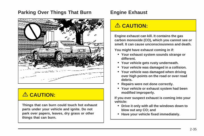
Parking Over Things That Burn
{CAUTION:
Things that can burn could touch hot exhaustparts under your vehicle and ignite. Do notpark over papers, leaves, dry grass or otherthings that can burn.
Engine Exhaust
{CAUTION:
Engine exhaust can kill. It contains the gascarbon monoxide (CO), which you cannot see orsmell. It can cause unconsciousness and death.
You might have exhaust coming in if:• Your exhaust system sounds strange or
different.• Your vehicle gets rusty underneath.• Your vehicle was damaged in a collision.• Your vehicle was damaged when driving
over high points on the road or over roaddebris.
• Repairs were not done correctly.• Your vehicle or exhaust system had been
modified improperly.
If you ever suspect exhaust is coming into yourvehicle:
• Drive it only with all the windows down toblow out any CO; and
• Have your vehicle fixed immediately.
2-35
Running Your Engine While YouAre ParkedIt is better not to park with the engine running. But ifyou ever have to, here are some things to know.
{CAUTION:
Idling the engine with the climate controlsystem off could allow dangerous exhaust intoyour vehicle. See the earlier caution underEngine Exhaust on page 2-35.
Also, idling in a closed-in place can let deadlycarbon monoxide (CO) into your vehicle even ifthe climate control fan is at the highest setting.One place this can happen is a garage.Exhaust — with CO — can come in easily.NEVER park in a garage with the enginerunning.
Another closed-in place can be a blizzard. SeeWinter Driving on page 4-25.
{CAUTION:
It can be dangerous to get out of your vehicleif the shift lever is not fully in PARK (P) withthe parking brake firmly set. Your vehicle canroll. Do not leave your vehicle when the engineis running unless you have to. If you have leftthe engine running, the vehicle can movesuddenly. You or others could be injured. Tobe sure your vehicle will not move, even whenyou are on fairly level ground, always set yourparking brake after you move the shift leverto PARK (P).
Follow the proper steps to be sure your vehicle will notmove. See Shifting Into Park (P) on page 2-32.
If you are parking on a hill and if you are pulling atrailer, also see Towing a Trailer on page 4-37.
2-36
Mirrors
Automatic Dimming Rearview Mirrorwith OnStar ®
Your vehicle may have an automatic dimming rearviewmirror with OnStar® system controls. For moreinformation about OnStar®, see OnStar® Systemon page 2-42.
When the automatic dimming feature is turned on, themirror automatically changes to reduce glare fromheadlamps behind you. A photocell on the mirror senseswhen it is becoming dark outside. Another photocellbuilt into the mirror face senses when headlampsare behind you.
At night, when the glare is too bright, the mirror willgradually darken to reduce glare. This change may takea few seconds. The mirror will return to its clear,daytime state when the glare is reduced.
Mirror Operation
O (On/Off): Press the on/off button, located on thelower left side of the mirror face, to turn the automaticdimming feature on or off. The indicator light will beilluminated when the automatic dimming feature is on.
Cleaning the MirrorWhen cleaning the mirror, use a paper towel or similarmaterial dampened with glass cleaner. Do not sprayglass cleaner directly on the mirror as that may causethe liquid cleaner to enter the mirror housing.
Automatic Dimming Rearview Mirrorwith OnStar ® and CompassYour vehicle may have an automatic dimming rearviewmirror with a compass display. The mirror alsocontains OnStar® controls. For more information seeOnStar® System on page 2-42.
The automatic dimming feature functions the same asthat of the automatic dimming rearview mirror without acompass. See Automatic Dimming Rearview Mirrorwith OnStar® on page 2-37.
The mirror also includes an eight-point compass displayin the upper right corner of the mirror face. When on,the compass automatically calibrates as the vehicleis driven.
2-37
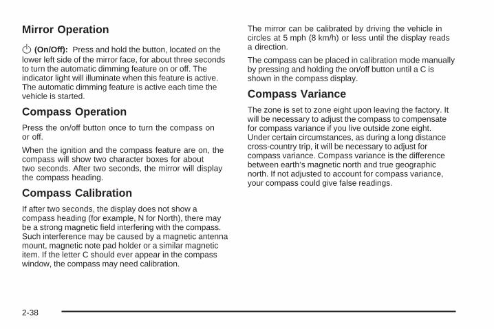
Mirror Operation
O(On/Off): Press and hold the button, located on thelower left side of the mirror face, for about three secondsto turn the automatic dimming feature on or off. Theindicator light will illuminate when this feature is active.The automatic dimming feature is active each time thevehicle is started.
Compass OperationPress the on/off button once to turn the compass onor off.
When the ignition and the compass feature are on, thecompass will show two character boxes for abouttwo seconds. After two seconds, the mirror will displaythe compass heading.
Compass CalibrationIf after two seconds, the display does not show acompass heading (for example, N for North), there maybe a strong magnetic field interfering with the compass.Such interference may be caused by a magnetic antennamount, magnetic note pad holder or a similar magneticitem. If the letter C should ever appear in the compasswindow, the compass may need calibration.
The mirror can be calibrated by driving the vehicle incircles at 5 mph (8 km/h) or less until the display readsa direction.
The compass can be placed in calibration mode manuallyby pressing and holding the on/off button until a C isshown in the compass display.
Compass VarianceThe zone is set to zone eight upon leaving the factory. Itwill be necessary to adjust the compass to compensatefor compass variance if you live outside zone eight.Under certain circumstances, as during a long distancecross-country trip, it will be necessary to adjust forcompass variance. Compass variance is the differencebetween earth’s magnetic north and true geographicnorth. If not adjusted to account for compass variance,your compass could give false readings.
2-38
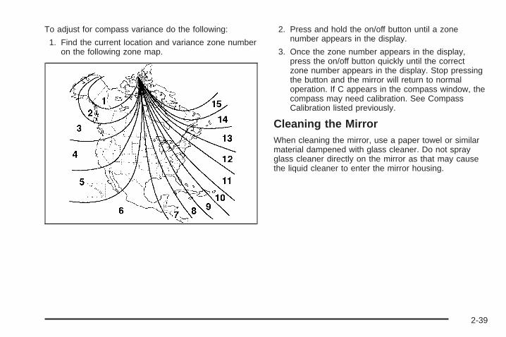
To adjust for compass variance do the following:
1. Find the current location and variance zone numberon the following zone map.
2. Press and hold the on/off button until a zonenumber appears in the display.
3. Once the zone number appears in the display,press the on/off button quickly until the correctzone number appears in the display. Stop pressingthe button and the mirror will return to normaloperation. If C appears in the compass window, thecompass may need calibration. See CompassCalibration listed previously.
Cleaning the MirrorWhen cleaning the mirror, use a paper towel or similarmaterial dampened with glass cleaner. Do not sprayglass cleaner directly on the mirror as that may causethe liquid cleaner to enter the mirror housing.
2-39
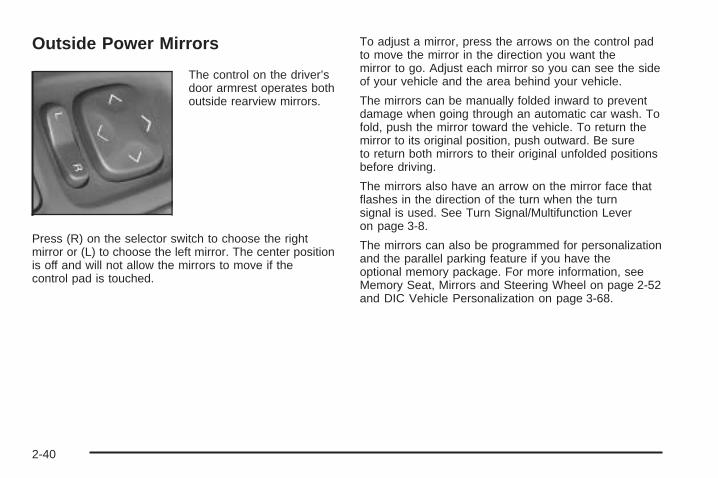
Outside Power Mirrors
The control on the driver’sdoor armrest operates bothoutside rearview mirrors.
Press (R) on the selector switch to choose the rightmirror or (L) to choose the left mirror. The center positionis off and will not allow the mirrors to move if thecontrol pad is touched.
To adjust a mirror, press the arrows on the control padto move the mirror in the direction you want themirror to go. Adjust each mirror so you can see the sideof your vehicle and the area behind your vehicle.
The mirrors can be manually folded inward to preventdamage when going through an automatic car wash. Tofold, push the mirror toward the vehicle. To return themirror to its original position, push outward. Be sureto return both mirrors to their original unfolded positionsbefore driving.
The mirrors also have an arrow on the mirror face thatflashes in the direction of the turn when the turnsignal is used. See Turn Signal/Multifunction Leveron page 3-8.
The mirrors can also be programmed for personalizationand the parallel parking feature if you have theoptional memory package. For more information, seeMemory Seat, Mirrors and Steering Wheel on page 2-52and DIC Vehicle Personalization on page 3-68.
2-40
Outside Automatic Dimming MirrorIf the vehicle is equipped with this feature, thedriver’s side mirror will adjust for the glare of headlampsbehind you. This feature is controlled by the on andoff settings on the automatic dimming rearview mirror.See Automatic Dimming Rearview Mirror with OnStar®
on page 2-37.
Outside Curb View Assist MirrorIf your vehicle is equipped with memory mirrors, it willalso be capable of performing the curb view assist mirrorfeature. This feature will allow the passenger’s sidemirror to tilt to a factory programmed position when thevehicle is in REVERSE (R). This feature may beuseful in allowing you to view the curb when you areparallel parking.
When the vehicle is shifted out of REVERSE (R) and afive-second delay has occurred, the passenger’sside mirror will return to its original position.
If further adjustment is needed after the mirror is tilted,the mirror switch may be used.
This feature can be enabled/disabled through the DriverInformation Center (DIC). See DIC VehiclePersonalization on page 3-68 for more information.
Outside Convex Mirror
{CAUTION:
A convex mirror can make things (like othervehicles) look farther away than they really are.If you cut too sharply into the right lane, youcould hit a vehicle on your right. Check yourinside mirror or glance over your shoulderbefore changing lanes.
The passenger’s side mirror is convex. A convex mirror’ssurface is curved so more can be seen from the driver’sseat. This mirror does not have a dimming feature.
Outside Heated MirrorsWhen you operate the rear window defogger, it alsowarms both outside mirrors to help clear them of fog orice. See Dual Climate Control System on page 3-30for more information.
2-41
OnStar ® SystemOnStar® uses global positioning system (GPS) satellitetechnology, wireless communications, and call centersto provide you with a wide range of safety, security,information, and convenience services.
A complete OnStar® user’s guide and the terms andconditions of the OnStar® Subscription ServiceAgreement are included in the vehicle’s glove boxliterature. For more information, visit www.onstar.comor www.onstarcanada.com. Contact OnStar® at1-888-4-ONSTAR (1-888-466-7827), or press theOnStar® button to speak to an OnStar® advisor24 hours a day, 7 days a week.
Terms and conditions of the Subscription ServiceAgreement can be found at www.onstar.com orwww.onstarcanada.com.
OnStar ® ServicesThe Directions and Connections Plan is included onnew vehicles for one year from the date of purchase.This OnStar® subscription plan can be extended beyondthe first year to fit your needs.
Directions and Connections Plan• Automatic Notification of Airbag Deployment
• Emergency Services
• Roadside Assistance
• Stolen Vehicle Tracking
• AccidentAssist
• Remote Door Unlock/Vehicle Alert
• Remote Diagnostics
• Online Concierge
• Driving Directions
• RideAssist
• Information and Convenience Services
2-42
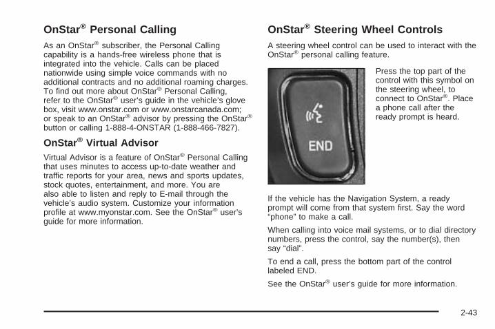
OnStar ® Personal CallingAs an OnStar® subscriber, the Personal Callingcapability is a hands-free wireless phone that isintegrated into the vehicle. Calls can be placednationwide using simple voice commands with noadditional contracts and no additional roaming charges.To find out more about OnStar® Personal Calling,refer to the OnStar® user’s guide in the vehicle’s glovebox, visit www.onstar.com or www.onstarcanada.com;or speak to an OnStar® advisor by pressing the OnStar®
button or calling 1-888-4-ONSTAR (1-888-466-7827).
OnStar ® Virtual AdvisorVirtual Advisor is a feature of OnStar® Personal Callingthat uses minutes to access up-to-date weather andtraffic reports for your area, news and sports updates,stock quotes, entertainment, and more. You arealso able to listen and reply to E-mail through thevehicle’s audio system. Customize your informationprofile at www.myonstar.com. See the OnStar® user’sguide for more information.
OnStar ® Steering Wheel ControlsA steering wheel control can be used to interact with theOnStar® personal calling feature.
Press the top part of thecontrol with this symbol onthe steering wheel, toconnect to OnStar®. Placea phone call after theready prompt is heard.
If the vehicle has the Navigation System, a readyprompt will come from that system first. Say the word“phone” to make a call.
When calling into voice mail systems, or to dial directorynumbers, press the control, say the number(s), thensay “dial”.
To end a call, press the bottom part of the controllabeled END.
See the OnStar® user’s guide for more information.
2-43
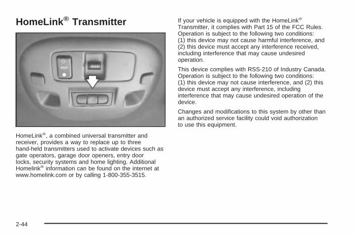
HomeLink ® Transmitter
HomeLink®, a combined universal transmitter andreceiver, provides a way to replace up to threehand-held transmitters used to activate devices such asgate operators, garage door openers, entry doorlocks, security systems and home lighting. AdditionalHomelink® information can be found on the internet atwww.homelink.com or by calling 1-800-355-3515.
If your vehicle is equipped with the HomeLink®
Transmitter, it complies with Part 15 of the FCC Rules.Operation is subject to the following two conditions:(1) this device may not cause harmful interference, and(2) this device must accept any interference received,including interference that may cause undesiredoperation.
This device complies with RSS-210 of Industry Canada.Operation is subject to the following two conditions:(1) this device may not cause interference, and (2) thisdevice must accept any interference, includinginterference that may cause undesired operation of thedevice.
Changes and modifications to this system by other thanan authorized service facility could void authorizationto use this equipment.
2-44
Programming the HomeLink ®
TransmitterDo not use the HomeLink® Transmitter with any garagedoor opener that does not have the “stop and reverse”feature. This includes any garage door opener modelmanufactured before April 1, 1982. If you have a newergarage door opener with rolling codes, please besure to follow Steps 6 through 8 to complete theprogramming of your HomeLink® Transmitter.
Read the instructions completely before attempting toprogram the HomeLink® Transmitter. Because of thesteps involved, it may be helpful to have another personavailable to assist you in programming the transmitter.
Keep the original transmitter for use in other vehicles aswell as for future HomeLink® programming. It is alsorecommended that upon the sale of the vehicle, theprogrammed HomeLink® buttons should be erased forsecurity purposes. Refer to “Erasing HomeLink® Buttons”or, for assistance, contact HomeLink® on the internet at:www.homelink.com or by calling 1-800-355-3515.
Be sure that people and objects are clear of the garagedoor or gate operator you are programming. Whenprogramming a garage door, it is advised to park outsideof the garage.
It is recommended that a new battery be installed inyour hand-held transmitter for quicker and moreaccurate transmission of the radio frequency.
Programming HomeLink ®
Your vehicle’s engine should be turned off whileprogramming the transmitter. Follow these steps toprogram up to three channels:
1. Press and hold down the two outside buttons,releasing only when the indicator light begins toflash, after 20 seconds. Do not hold down thebuttons for longer than 30 seconds and do notrepeat this step to program a second and/or thirdtransmitter to the remaining two HomeLink® buttons.
2. Position the end of your hand-held transmitter about1 to 3 inches (3 to 8 cm) away from the HomeLink®
buttons while keeping the indicator light in view.
2-45
3. Simultaneously press and hold both the desiredbutton on HomeLink® and the hand-held transmitterbutton. Do not release the buttons until Step 4has been completed.Some entry gates and garage door openers mayrequire you to substitute Step 3 with the procedurenoted in “Gate Operator and CanadianProgramming” later in this section.
4. The indicator light will flash slowly at first and thenrapidly after HomeLink® successfully receives thefrequency signal from the hand-held transmitter.Release both buttons.
5. Press and hold the newly-trained HomeLink® buttonand observe the indicator light.If the indicator light stays on constantly, programmingis complete and your device should activate when theHomeLink® button is pressed and released.To program the remaining two HomeLink® buttons,begin with Step 2 under “Programming HomeLink®.”Do not repeat Step 1 as this will erase all of theprogrammed channels.If the indicator light blinks rapidly for two secondsand then turns to a constant light, continue withSteps 6 through 8 following to complete theprogramming of a rolling-code equipped device(most commonly, a garage door opener).
6. Locate in the garage, the garage door openerreceiver (motor-head unit). Locate the “Learn”or “Smart” button. This can usually be found wherethe hanging antenna wire is attached to themotor-head unit.
7. Firmly press and release the “Learn” or “Smart”button. The name and color of the button mayvary by manufacturer.You will have 30 seconds to start Step 8.
8. Return to the vehicle. Firmly press and hold theprogrammed HomeLink® button for two seconds,then release. Repeat the press/hold/releasesequence a second time, and depending on thebrand of the garage door opener (or other rollingcode device), repeat this sequence a third timeto complete the programming.HomeLink® should now activate your rolling-codeequipped device.
To program the remaining two HomeLink® buttons, beginwith Step 2 of “Programming HomeLink®.” You do notwant to repeat Step 1, as this will erase all previousprogramming.
2-46
Gate Operator and CanadianProgrammingCanadian radio-frequency laws require transmittersignals to “time out” or quit after several seconds oftransmission. This may not be long enough forHomeLink® to pick up the signal during programming.Similarly, some U.S. gate operators are manufacturedto “time out” in the same manner.
If you live in Canada, or you are having difficultyprogramming a gate operator by using the“Programming HomeLink®” procedures (regardless ofwhere you live), replace Step 3 under “ProgrammingHomeLink®” with the following:
Continue to press and hold the HomeLink® button whileyou press and release every two seconds (cycle)your hand-held transmitter until the frequency signal hasbeen successfully accepted by HomeLink®. Theindicator light will flash slowly at first and then rapidly.Proceed with Step 4 under “Programming HomeLink®”to complete.
Using HomeLink ®
Press and hold the appropriate HomeLink® button for atleast half of a second. The indicator light will comeon while the signal is being transmitted.
Erasing HomeLink ® ButtonsTo erase programming from the three buttons do thefollowing:
1. Press and hold down the two outside buttons untilthe indicator light begins to flash, after 20 seconds.Do not hold the two outside buttons for longerthan 30 seconds.
2. Release both buttons.
HomeLink® is now in the train (learning) mode and canbe programmed at any time beginning with Step 2under “Programming HomeLink®” shown earlier inthis section.
Individual buttons cannot be erased, but they canbe reprogrammed. See “Reprogramming a SingleHomeLink® Button” following this section.
2-47
Reprogramming a Single HomeLink ®
ButtonTo program a device to HomeLink® using a HomeLink®
button previously trained, follow these steps:
1. Press and hold the desired HomeLink® button. Donot release the button.
2. The indicator light will begin to flash after20 seconds. While still holding the HomeLink®
button, proceed with Step 2 under “ProgrammingHomeLink®” shown earlier in this section.
Resetting DefaultsTo reset HomeLink® to default settings do the following:
1. Hold down the two outside buttons for about20 seconds until the indicator light begins to flash.
2. Continue to hold both buttons until the HomeLink®
indicator light turns off.
3. Release both buttons.
For questions or comments, contact HomeLink® at1-800-355-3515, or on the internet atwww.homelink.com.
Storage Areas
Glove BoxTo open the glove box, lift up on the lever. The glovebox has a light inside.
Instrument Panel Storage AreaThis storage compartment is located in the center ofthe instrument panel below the radio. Pull the door outto reveal the accessory power outlet and storagecompartment. To clean the storage compartment, liftout while pulling on the sides.
Cellular TelephoneYour vehicle may have been prewired for dealerinstallation of a portable cellular telephone system. Thesystem has steering wheel telephone controls andinformation output through the Driver InformationCenter (DIC). Voice activation with remote record andhands-free operation are standard features. Formore information, contact your dealer. A user’s guideis provided with the telephone.
2-48
Front Storage AreaIf your vehicle is equipped with the front storage area, itcomes with a coinholder, a storage compartment, anoptional cellular telephone and a dual cupholder.
Full Floor Console Storage AreaIf your vehicle is equipped with the full floor console, ithas an upper and lower storage area. The upperstorage area is available for the optional cellulartelephone. The lower storage area has two removablebins that can hold tapes and/or CDs.
To open the console, pull up on either lever to open theupper or lower storage area.
There is also a removable coinholder that attaches tothe side of one of the bins. A dual cupholder is located infront of the console. Open and close by pressing onthe cupholder.
Center Console Storage AreaIf your vehicle is equipped with the center console, itcomes with a storage tray, a storage compartmentfor CDs or tapes, a dual cupholder that unfolds,a coinholder, an optional phone and an armrest. Thecupholder can be opened by pressing on the surfacepanel located in front of the armrest and unfoldingit. Close the lid to secure it.
2-49
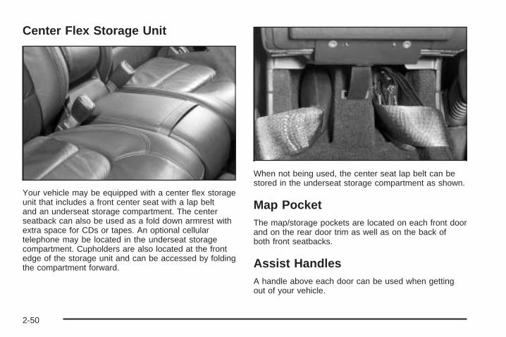
Center Flex Storage Unit
Your vehicle may be equipped with a center flex storageunit that includes a front center seat with a lap beltand an underseat storage compartment. The centerseatback can also be used as a fold down armrest withextra space for CDs or tapes. An optional cellulartelephone may be located in the underseat storagecompartment. Cupholders are also located at the frontedge of the storage unit and can be accessed by foldingthe compartment forward.
When not being used, the center seat lap belt can bestored in the underseat storage compartment as shown.
Map PocketThe map/storage pockets are located on each front doorand on the rear door trim as well as on the back ofboth front seatbacks.
Assist HandlesA handle above each door can be used when gettingout of your vehicle.
2-50
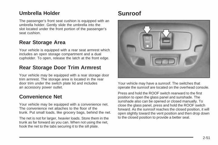
Umbrella HolderThe passenger’s front seat cushion is equipped with anumbrella holder. Gently slide the umbrella into theslot located under the front portion of the passenger’sseat cushion.
Rear Storage AreaYour vehicle is equipped with a rear seat armrest whichincludes an open storage compartment and a dualcupholder. To open, release the latch at the front edge.
Rear Storage Door Trim ArmrestYour vehicle may be equipped with a rear storage doortrim armrest. The storage area is located in the reardoor trim under the switch plate lid and includesan accessory power outlet.
Convenience NetYour vehicle may be equipped with a convenience net.The convenience net attaches to the floor of thetrunk. Put small loads, like grocery bags, behind the net.
The net is not for larger, heavier loads. Store them in thetrunk as far forward as you can. When not using the net,hook the net to the tabs securing it to the sill plate.
Sunroof
Your vehicle may have a sunroof. The switches thatoperate the sunroof are located on the overhead console.
Press and hold the ROOF switch rearward to the firstposition to open the glass panel and sunshade. Thesunshade also can be opened or closed manually. Toclose the glass panel, press and hold the ROOF switchforward. As the sunroof reaches the closed position, it willopen slightly toward the vent position and then drop downto the closed position to provide a better seal.
2-51
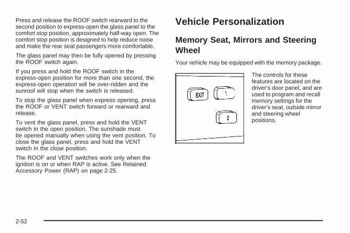
Press and release the ROOF switch rearward to thesecond position to express-open the glass panel to thecomfort stop position, approximately half-way open. Thecomfort stop position is designed to help reduce noiseand make the rear seat passengers more comfortable.
The glass panel may then be fully opened by pressingthe ROOF switch again.
If you press and hold the ROOF switch in theexpress-open position for more than one second, theexpress-open operation will be over-ridden and thesunroof will stop when the switch is released.
To stop the glass panel when express opening, pressthe ROOF or VENT switch forward or rearward andrelease.
To vent the glass panel, press and hold the VENTswitch in the open position. The sunshade mustbe opened manually when using the vent position. Toclose the glass panel, press and hold the VENTswitch in the close position.
The ROOF and VENT switches work only when theignition is on or when RAP is active. See RetainedAccessory Power (RAP) on page 2-25.
Vehicle Personalization
Memory Seat, Mirrors and SteeringWheelYour vehicle may be equipped with the memory package.
The controls for thesefeatures are located on thedriver’s door panel, and areused to program and recallmemory settings for thedriver’s seat, outside mirrorand steering wheelpositions.
2-52
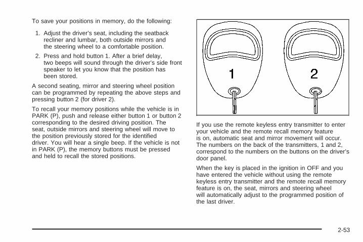
To save your positions in memory, do the following:
1. Adjust the driver’s seat, including the seatbackrecliner and lumbar, both outside mirrors andthe steering wheel to a comfortable position.
2. Press and hold button 1. After a brief delay,two beeps will sound through the driver’s side frontspeaker to let you know that the position hasbeen stored.
A second seating, mirror and steering wheel positioncan be programmed by repeating the above steps andpressing button 2 (for driver 2).
To recall your memory positions while the vehicle is inPARK (P), push and release either button 1 or button 2corresponding to the desired driving position. Theseat, outside mirrors and steering wheel will move tothe position previously stored for the identifieddriver. You will hear a single beep. If the vehicle is notin PARK (P), the memory buttons must be pressedand held to recall the stored positions.
If you use the remote keyless entry transmitter to enteryour vehicle and the remote recall memory featureis on, automatic seat and mirror movement will occur.The numbers on the back of the transmitters, 1 and 2,correspond to the numbers on the buttons on the driver’sdoor panel.
When the key is placed in the ignition in OFF and youhave entered the vehicle without using the remotekeyless entry transmitter and the remote recall memoryfeature is on, the seat, mirrors and steering wheelwill automatically adjust to the programmed position ofthe last driver.
2-53
To stop recall movement of the memory feature at anytime, press one of the power seat controls or memorybuttons.
To store the exit position for an easy exit, do thefollowing:
1. Recall the driver position by pressing button 1, orby pressing the unlock button on the remotekeyless entry transmitter 1.
2. Adjust the driver’s seat and steering wheel to thedesired exit positions.
3. Press and hold the EXIT button. After a brief delay,two beeps will sound through the driver’s side frontspeaker to let you know that the position hasbeen stored.
An exit position for driver position 2 can be programmedby repeating the above steps, pressing button 2 (fordriver 2) and using remote keyless entry transmitternumber 2.
With the vehicle in PARK (P), the exit position for thepreviously set driver can be recalled by pressing the EXITbutton. You will hear a single beep. The mirrors andpower lumbar positions will not be stored or recalled.
Further programming for automatic seat and steeringwheel movement can be done using the DriverInformation Center (DIC). You can select or not selectthe following:
• Automatic seat and steering wheel movement whenthe vehicle is unlocked with the remote keylessentry transmitter.
• Automatic seat and steering wheel movement whena key is placed in the ignition.
For programming information, see DIC VehiclePersonalization on page 3-68.
2-54
Instrument Panel Overview ...............................3-4Hazard Warning Flashers ................................3-6Other Warning Devices ...................................3-6Horn .............................................................3-6Tilt Wheel .....................................................3-6Power Tilt Wheel and Telescopic Steering
Column ......................................................3-7Heated Steering Wheel ...................................3-7Turn Signal/Multifunction Lever .........................3-8Turn and Lane-Change Signals ........................3-8Headlamp High/Low-Beam Changer ..................3-9Flash-to-Pass .................................................3-9Windshield Wipers ..........................................3-9Rainsense™ II Wipers ...................................3-10Windshield Washer .......................................3-11Cruise Control ..............................................3-12Exterior Lamps .............................................3-15Wiper Activated Headlamps ............................3-16Headlamps on Reminder ................................3-16Daytime Running Lamps (DRL) .......................3-16Fog Lamps ..................................................3-18Cornering Lamps ..........................................3-18Twilight Sentinel® ..........................................3-18Exterior Lighting Battery Saver ........................3-20Instrument Panel Brightness ...........................3-20Courtesy Lamps ...........................................3-21Entry Lighting ...............................................3-21
Parade Dimming ...........................................3-21Reading Lamps ............................................3-22Battery Load Management .............................3-22Inadvertent Power Battery Saver .....................3-23Night Vision System ......................................3-23Ultrasonic Rear Parking Assist (URPA) ............3-26Accessory Power Outlets ...............................3-28Ashtrays and Cigarette Lighter ........................3-29
Climate Controls ............................................3-30Dual Climate Control System ..........................3-30Outlet Adjustment .........................................3-34Rear Climate Control System .........................3-35Passenger Compartment Air Filter ...................3-36Steering Wheel Climate Controls .....................3-38Climate Controls Personalization .....................3-39
Warning Lights, Gages, and Indicators ............3-40Instrument Panel Cluster ................................3-41Speedometer and Odometer ...........................3-43Trip Odometer ..............................................3-43Tachometer (Analog Cluster Only) ...................3-44Engine Speed Limiter ....................................3-44Safety Belt Reminder Light .............................3-45Airbag Readiness Light ..................................3-45Charging System Light ..................................3-46Brake System Warning and Parking Brake
Indicator Light ...........................................3-47
Section 3 Instrument Panel
3-1
Anti-Lock Brake System Warning Light .............3-48Traction Control System (TCS) Warning Light ......3-48Engine Coolant Temperature Warning Light ......3-49Engine Coolant Temperature Gage ..................3-49Malfunction Indicator Lamp .............................3-50Oil Pressure Light .........................................3-53Security Light ...............................................3-53Fog Lamp Light ............................................3-54Lights On Reminder ......................................3-54Cruise Control Light ......................................3-54Highbeam On Light .......................................3-54Fuel Gage ...................................................3-55Fuel Data Display (Digital Cluster Only) ...........3-56
Driver Information Center (DIC) .......................3-57DIC Controls and Displays .............................3-57DIC Warnings and Messages .........................3-60Climate Controls and Radio System
Personalization ..........................................3-68DIC Vehicle Personalization ............................3-68
Trip Computer ................................................3-79Oil Life Indicator ...........................................3-79
Audio System(s) .............................................3-79Setting the Time for Radios without Radio
Data Systems (RDS) ..................................3-80Setting the Time for Radios with Radio Data
Systems (RDS) .........................................3-80Radio with CD ..............................................3-80Radio with Cassette and CD ..........................3-87Navigation/Radio System ...............................3-99Glovebox-Mounted CD Changer ......................3-99Radio Personalization with Home and Away
Feature ..................................................3-102Theft-Deterrent Feature ................................3-103Audio Steering Wheel Controls ......................3-103Radio Reception .........................................3-104Care of Your Cassette Tape Player ...............3-104Care of Your CDs .......................................3-106Care of Your CD Player ...............................3-106Diversity Antenna System .............................3-106XM™ Satellite Radio Antenna System ............3-107
Section 3 Instrument Panel
3-2

✍ NOTES
3-3
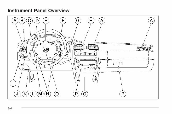
Instrument Panel Overview
3-4
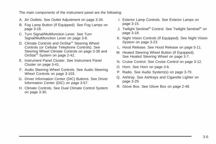
The main components of the instrument panel are the following:
A. Air Outlets. See Outlet Adjustment on page 3-34.B. Fog Lamp Button (If Equipped). See Fog Lamps on
page 3-18.C. Turn Signal/Multifunction Lever. See Turn
Signal/Multifunction Lever on page 3-8.D. Climate Controls and OnStar® Steering Wheel
Controls (or Cellular Telephone Controls). SeeSteering Wheel Climate Controls on page 3-38 andOnStar® System on page 2-42.
E. Instrument Panel Cluster. See Instrument PanelCluster on page 3-41.
F. Audio Steering Wheel Controls. See Audio SteeringWheel Controls on page 3-103.
G. Driver Information Center (DIC) Buttons. See DriverInformation Center (DIC) on page 3-57.
H. Climate Controls. See Dual Climate Control Systemon page 3-30.
I. Exterior Lamp Controls. See Exterior Lamps onpage 3-15.
J. Twilight Sentinel® Control. See Twilight Sentinel® onpage 3-18.
K. Night Vision Controls (If Equipped). See Night VisionSystem on page 3-23.
L. Hood Release. See Hood Release on page 5-11.M. Heated Steering Wheel Button (If Equipped).
See Heated Steering Wheel on page 3-7.N. Cruise Control. See Cruise Control on page 3-12.O. Horn. See Horn on page 3-6.P. Radio. See Audio System(s) on page 3-79.Q. Ashtray. See Ashtrays and Cigarette Lighter on
page 3-29.R. Glove Box. See Glove Box on page 2-48.
3-5
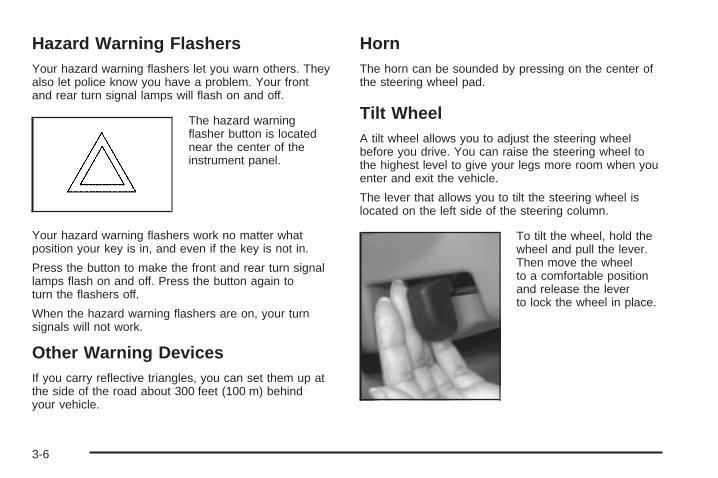
Hazard Warning FlashersYour hazard warning flashers let you warn others. Theyalso let police know you have a problem. Your frontand rear turn signal lamps will flash on and off.
The hazard warningflasher button is locatednear the center of theinstrument panel.
Your hazard warning flashers work no matter whatposition your key is in, and even if the key is not in.
Press the button to make the front and rear turn signallamps flash on and off. Press the button again toturn the flashers off.
When the hazard warning flashers are on, your turnsignals will not work.
Other Warning DevicesIf you carry reflective triangles, you can set them up atthe side of the road about 300 feet (100 m) behindyour vehicle.
HornThe horn can be sounded by pressing on the center ofthe steering wheel pad.
Tilt WheelA tilt wheel allows you to adjust the steering wheelbefore you drive. You can raise the steering wheel tothe highest level to give your legs more room when youenter and exit the vehicle.
The lever that allows you to tilt the steering wheel islocated on the left side of the steering column.
To tilt the wheel, hold thewheel and pull the lever.Then move the wheelto a comfortable positionand release the leverto lock the wheel in place.
3-6
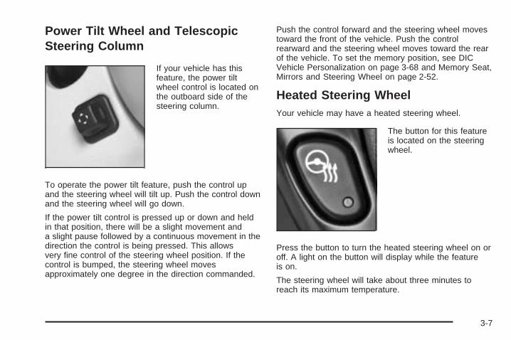
Power Tilt Wheel and TelescopicSteering Column
If your vehicle has thisfeature, the power tiltwheel control is located onthe outboard side of thesteering column.
To operate the power tilt feature, push the control upand the steering wheel will tilt up. Push the control downand the steering wheel will go down.
If the power tilt control is pressed up or down and heldin that position, there will be a slight movement anda slight pause followed by a continuous movement in thedirection the control is being pressed. This allowsvery fine control of the steering wheel position. If thecontrol is bumped, the steering wheel movesapproximately one degree in the direction commanded.
Push the control forward and the steering wheel movestoward the front of the vehicle. Push the controlrearward and the steering wheel moves toward the rearof the vehicle. To set the memory position, see DICVehicle Personalization on page 3-68 and Memory Seat,Mirrors and Steering Wheel on page 2-52.
Heated Steering WheelYour vehicle may have a heated steering wheel.
The button for this featureis located on the steeringwheel.
Press the button to turn the heated steering wheel on oroff. A light on the button will display while the featureis on.
The steering wheel will take about three minutes toreach its maximum temperature.
3-7
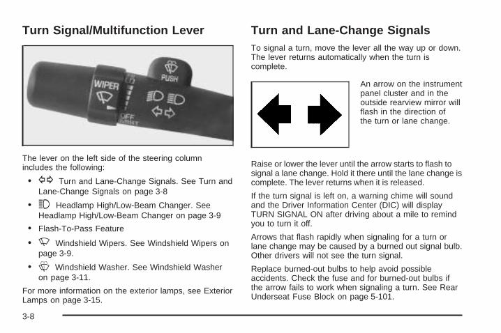
Turn Signal/Multifunction Lever
The lever on the left side of the steering columnincludes the following:
• G Turn and Lane-Change Signals. See Turn andLane-Change Signals on page 3-8
• 3 Headlamp High/Low-Beam Changer. SeeHeadlamp High/Low-Beam Changer on page 3-9
• Flash-To-Pass Feature
• N Windshield Wipers. See Windshield Wipers onpage 3-9.
• L Windshield Washer. See Windshield Washeron page 3-11.
For more information on the exterior lamps, see ExteriorLamps on page 3-15.
Turn and Lane-Change SignalsTo signal a turn, move the lever all the way up or down.The lever returns automatically when the turn iscomplete.
An arrow on the instrumentpanel cluster and in theoutside rearview mirror willflash in the direction ofthe turn or lane change.
Raise or lower the lever until the arrow starts to flash tosignal a lane change. Hold it there until the lane change iscomplete. The lever returns when it is released.
If the turn signal is left on, a warning chime will soundand the Driver Information Center (DIC) will displayTURN SIGNAL ON after driving about a mile to remindyou to turn it off.
Arrows that flash rapidly when signaling for a turn orlane change may be caused by a burned out signal bulb.Other drivers will not see the turn signal.
Replace burned-out bulbs to help avoid possibleaccidents. Check the fuse and for burned-out bulbs ifthe arrow fails to work when signaling a turn. See RearUnderseat Fuse Block on page 5-101.
3-8
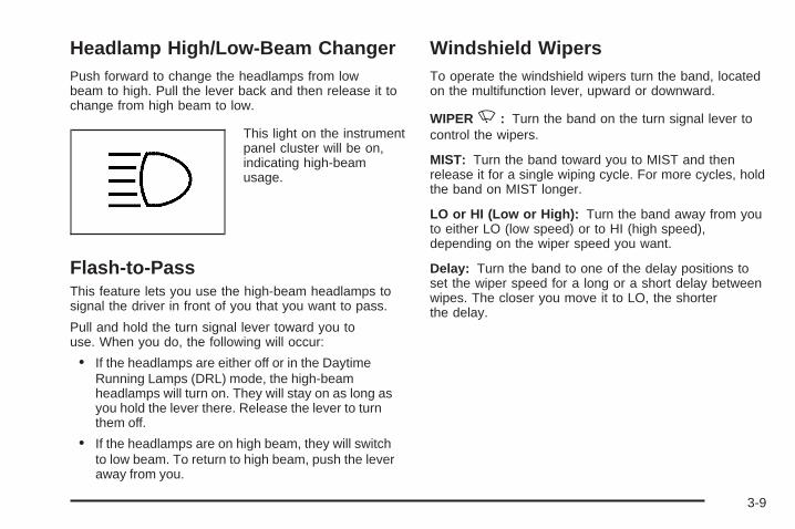
Headlamp High/Low-Beam ChangerPush forward to change the headlamps from lowbeam to high. Pull the lever back and then release it tochange from high beam to low.
This light on the instrumentpanel cluster will be on,indicating high-beamusage.
Flash-to-PassThis feature lets you use the high-beam headlamps tosignal the driver in front of you that you want to pass.
Pull and hold the turn signal lever toward you touse. When you do, the following will occur:
• If the headlamps are either off or in the DaytimeRunning Lamps (DRL) mode, the high-beamheadlamps will turn on. They will stay on as long asyou hold the lever there. Release the lever to turnthem off.
• If the headlamps are on high beam, they will switchto low beam. To return to high beam, push the leveraway from you.
Windshield WipersTo operate the windshield wipers turn the band, locatedon the multifunction lever, upward or downward.
WIPERN: Turn the band on the turn signal lever tocontrol the wipers.
MIST: Turn the band toward you to MIST and thenrelease it for a single wiping cycle. For more cycles, holdthe band on MIST longer.
LO or HI (Low or High): Turn the band away from youto either LO (low speed) or to HI (high speed),depending on the wiper speed you want.
Delay: Turn the band to one of the delay positions toset the wiper speed for a long or a short delay betweenwipes. The closer you move it to LO, the shorterthe delay.
3-9
OFF: Turn the band to OFF to turn off the wipers.
Be sure to clear ice and snow from the wiper bladesbefore using them. If they are frozen to the windshield,carefully loosen or thaw them. If the blades dobecome damaged, get new blades or blade inserts.
Heavy snow or ice can overload the wiper motor.A circuit breaker will stop the motor until it cools. Clearaway snow or ice to prevent an overload.
Your vehicle is equipped with wiper-activatedheadlamps. After the windshield wipers have been onfor approximately six seconds, the headlamps willautomatically turn on. See Wiper Activated Headlampson page 3-16 for more information.
Rainsense™ II WipersIf your vehicle has this feature, the moisture sensor ismounted on the interior side of the windshield behind therearview mirror. It is used to automatically operate thewipers by monitoring the amount of moisture build-up onthe windshield. Wipes occur as needed to clear thewindshield depending on driving conditions andthe sensitivity setting. In light rain or snow, fewer wipeswill occur. In heavy rain or snow, wipes will occurmore frequently. The Rainsense™ II wipers operate in adelay mode as well as a continuous low or high speedas needed. If the system is left on for long periodsof time, occasional wipes may occur without anymoisture on the windshield. This is normal and indicatesthat the Rainsense™ II system is activated.
The Rainsense™ II system can be activated by turningthe wiper band to one of the five sensitivity levelsindicated on the wiper stalk. The position closest to OFFis the lowest sensitivity setting, level one. This allowsmore rain or snow to collect on the windshield betweenwipes. Turning the wiper band away from you tohigher sensitivity levels increases the sensitivity of thesystem and frequency of wipes. The highest sensitivitysetting, level five is closest to LO. A single wipe willoccur each time you turn the wiper stalk to a highersensitivity level to indicate that the sensitivity level hasbeen increased.
3-10
Notice: Going through an automatic car wash withthe wipers on can damage them. Turn the wipersoff when going through an automatic car wash.
The MIST and wash cycles operate as normal and arenot affected by the Rainsense™ II function. TheRainsense™ II system can be overridden at any time bymanually turning the wiper band to LO or HI speed.
When Rainsense™ II is active, the headlamps will turnon automatically. The headlamps will turn off againonce the wipers turn off if it is light enough outside. If itis dark, they will remain on. See Wiper ActivatedHeadlamps on page 3-16 for more information.
Notice: Do not place stickers or other items on theexterior glass surface directly in front of themoisture sensor. Doing this could cause themoisture sensor to malfunction.
Windshield Washer
{CAUTION:
In freezing weather, do not use your washeruntil the windshield is warmed. Otherwise thewasher fluid can form ice on the windshield,blocking your vision.
LPUSH Press and release this paddle, located at thetop of the turn signal/multifunction lever, to spraywasher fluid on the windshield. The wipers will clear thewindshield and either stop or return to your presetspeed. For more washer cycles, press and holdthe paddle.
CHECK WASHER FLUID will be displayed on the DriverInformation Center (DIC) when the washer fluid is low.
3-11
Cruise ControlWith cruise control, you can maintain a speed ofapproximately 25 mph (40 km/h) or more without keepingyour foot on the accelerator. This is helpful on long trips.Cruise control does not work at speeds below about25 mph (40 km/h). When cruise control is on, you will seea CRUISE light on the instrument panel cluster.
When you apply your brakes, the cruise control shuts off.
{CAUTION:
Cruise control can be dangerous where youcannot drive safely at a steady speed. So, donot use your cruise control on winding roadsor in heavy traffic.
Cruise control can be dangerous on slipperyroads. On such roads, fast changes in tiretraction can cause needless wheel spinning,and you could lose control. Do not use cruisecontrol on slippery roads.
If your vehicle is in cruise control when the tractioncontrol system begins to limit wheel spin, the cruisecontrol will automatically disengage. See TractionControl System (TCS) on page 4-8. When roadconditions allow you to safely use it again, you mayturn the cruise control back on.
Setting Cruise Control
{CAUTION:
If you leave your cruise control on when youare not using cruise, you might hit a buttonand go into cruise when you do not want to.You could be startled and even lose control.Keep the cruise control switch off until youwant to use cruise control.
3-12
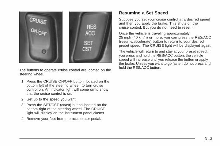
The buttons to operate cruise control are located on thesteering wheel.
1. Press the CRUISE ON/OFF button, located on thebottom left of the steering wheel, to turn cruisecontrol on. An indicator light will come on to showthat the cruise control is on.
2. Get up to the speed you want.
3. Press the SET/CST (coast) button located on thebottom right of the steering wheel. The CRUISElight will display on the instrument panel cluster.
4. Remove your foot from the accelerator pedal.
Resuming a Set SpeedSuppose you set your cruise control at a desired speedand then you apply the brake. This shuts off thecruise control. But you do not need to reset it.
Once the vehicle is traveling approximately25 mph (40 km/h) or more, you can press the RES/ACC(resume/accelerate) button to return to your desiredpreset speed. The CRUISE light will be displayed again.
The vehicle will return to and stay at your preset speed. Ifyou press and hold the RES/ACC button, the vehiclespeed will increase until you release the button or applythe brake. Unless you want to go faster, do not press andhold the RES/ACC button.
3-13
Increasing Speed While Using CruiseControlThere are two ways to go to a higher speed:
• Use the accelerator pedal to get to the higherspeed. Press the SET/CST button, then release thebutton and the accelerator pedal. You will nowcruise at the higher speed.
• Press the RES/ACC button. Hold it there until you getup to the speed that you want, and then release thebutton. To increase your speed in very smallamounts, briefly press the RES/ACC button and thenrelease it. Each time you do this, your vehicle willspeed up approximately 1 mph (1.6 km/h).
The accelerate feature will only work after you have setthe cruise control speed by pressing the SET/CST button.
Reducing Speed While Using CruiseControlThere are two ways to reduce your speed while usingcruise control:
• Press the SET/CST button until you reach the lowerspeed you want, then release it.
• To slow down in very small amounts, push theSET/CST button briefly. Each time you do this,the vehicle will slow down approximately1 mph (1.6 km/h).
Passing Another Vehicle While UsingCruise ControlUse the accelerator pedal to increase your speed.When you take your foot off the pedal, your vehicle willslow down to the cruise control speed you set earlier.
Using Cruise Control on HillsHow well your cruise control will work on hills dependsupon your speed, load and the steepness of the hills.When going up steep hills, you may have to step on theaccelerator pedal to maintain your speed. When goingdownhill, you may have to brake or shift to a lower gear tokeep your speed down. Applying the brake or shifting intoa lower gear will take you out of cruise control. If youneed to apply the brake or shift to a lower gear due to thegrade of the downhill slope, you may not want to attemptto use your cruise control feature.
Ending Cruise ControlTo turn off the cruise control, step lightly on the brakepedal, or press the CRUISE ON/OFF button on thesteering wheel.
Erasing Speed MemoryWhen you turn off the cruise control or the ignition, yourcruise control set speed memory is erased.
3-14
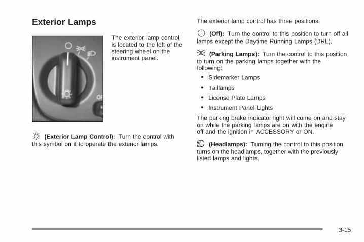
Exterior Lamps
The exterior lamp controlis located to the left of thesteering wheel on theinstrument panel.
O (Exterior Lamp Control): Turn the control withthis symbol on it to operate the exterior lamps.
The exterior lamp control has three positions:
9 (Off): Turn the control to this position to turn off alllamps except the Daytime Running Lamps (DRL).
; (Parking Lamps): Turn the control to this positionto turn on the parking lamps together with thefollowing:
• Sidemarker Lamps
• Taillamps
• License Plate Lamps
• Instrument Panel Lights
The parking brake indicator light will come on and stayon while the parking lamps are on with the engineoff and the ignition in ACCESSORY or ON.
5 (Headlamps): Turning the control to this positionturns on the headlamps, together with the previouslylisted lamps and lights.
3-15
Wiper Activated HeadlampsThis feature activates the headlamps and parking lampsafter the windshield wipers have been in use forapproximately six seconds. To operate, the TwilightSentinel® feature must be turned on.
When the exterior lamp control is in the off position orparking lamp position and the wiper control is on delay,LO or HI, the HEADLAMPS SUGGESTED messagewill appear on the Driver Information Center (DIC).
When the ignition is turned to OFF, the wiper-activatedheadlamps will immediately turn off. The wiper-activatedheadlamps will also turn off if the Twilight Sentinel® orthe windshield wipers are turned off.
Headlamps on ReminderA warning chime will sound if the exterior lamp controlis left on in either the headlamp or parking lamp positionand the driver’s door is opened with the ignition off.
Daytime Running Lamps (DRL)Daytime Running Lamps (DRL) can make it easier forothers to see the front of your vehicle during theday. DRL can be helpful in many different drivingconditions, but they can be especially helpful in the shortperiods after dawn and before sunset. Fully functionaldaytime running lamps are required on all vehiclesfirst sold in Canada.
The DRL system will make the low-beam headlampscome on at reduced intensity when the followingconditions are met:
• It is still daylight and the ignition is on.
• The exterior lamp control is in the off position.
• The transaxle is not in PARK (P).
When DRL are on, only your low-beam headlamps atreduced brightness will be on. No other exteriorlamps such as the parking lamps, taillamps, etc. will beon when the DRL are being used. Your instrumentpanel will not be lit up either.
3-16
When the Twilight Sentinel® lever is on and it is darkenough outside, the low-beam headlamps at reducedintensity will turn off and normal low-beam headlampoperation will occur.
When the Twilight Sentinel® lever is on and it is brightenough outside, the regular lamps will go off, andthe low-beam headlamps at reduced brightness will takeover. If you start your vehicle in a dark garage, theautomatic headlamp system will come on immediately.Once you leave the garage, it will take approximatelyone minute for the automatic headlamp system tochange to DRL if it is light outside. During that delay,your instrument panel cluster may not be as brightas usual. Make sure your instrument panel brightnessknob is in the full bright position. See InstrumentPanel Brightness on page 3-20.
If it is dark enough outside and the TwilightSentinel® lever is off, a HEADLAMPS SUGGESTEDmessage will display on the Driver’s InformationCenter (DIC). This message informs the driver thatturning on the exterior lamps is recommended eventhough the DRL are still illuminated.
Turning on the Twilight Sentinel® or the headlamps willdeactivate the DRL and remove the HEADLAMPSSUGGESTED message. If the parking lamps or the foglamps were turned on instead, the DRL will stilldeactivate and the HEADLAMPS SUGGESTEDmessage will continue to be displayed.
To idle your vehicle with the DRL off at night, turn off theTwilight Sentinel® and shift the transaxle into PARK (P).Placing your vehicle in PARK (P) disables the DRL. TheDRL will stay off until you shift out of PARK (P).
To drive your vehicle with the DRL off, turn off theTwilight Sentinel® and manually turn on the parkinglamps or fog lamps (if equipped).
As with any vehicle, you should turn on the regularheadlamp system when you need it.
3-17
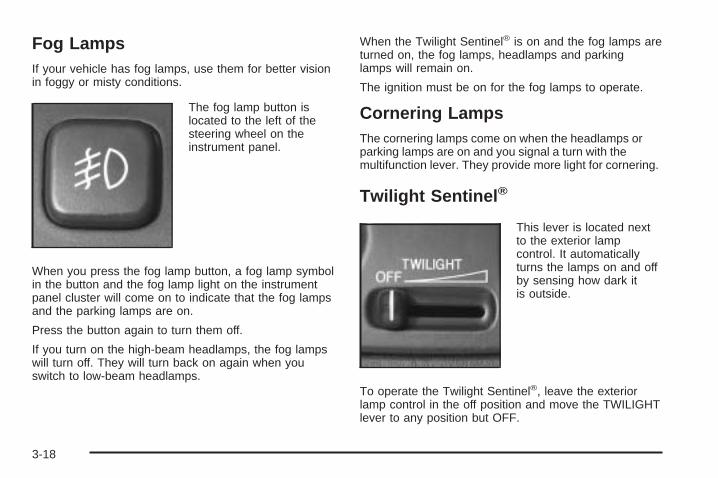
Fog LampsIf your vehicle has fog lamps, use them for better visionin foggy or misty conditions.
The fog lamp button islocated to the left of thesteering wheel on theinstrument panel.
When you press the fog lamp button, a fog lamp symbolin the button and the fog lamp light on the instrumentpanel cluster will come on to indicate that the fog lampsand the parking lamps are on.
Press the button again to turn them off.
If you turn on the high-beam headlamps, the fog lampswill turn off. They will turn back on again when youswitch to low-beam headlamps.
When the Twilight Sentinel® is on and the fog lamps areturned on, the fog lamps, headlamps and parkinglamps will remain on.
The ignition must be on for the fog lamps to operate.
Cornering LampsThe cornering lamps come on when the headlamps orparking lamps are on and you signal a turn with themultifunction lever. They provide more light for cornering.
Twilight Sentinel ®
This lever is located nextto the exterior lampcontrol. It automaticallyturns the lamps on and offby sensing how dark itis outside.
To operate the Twilight Sentinel®, leave the exteriorlamp control in the off position and move the TWILIGHTlever to any position but OFF.
3-18
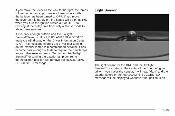
If you move the lever all the way to the right, the lampswill remain on for approximately three minutes afterthe ignition has been turned to OFF. If you movethe lever so it is barely on, the lamps will go off quicklywhen you turn the ignition switch out of OFF. Youcan adjust the delay time from only a few seconds toabout three minutes.
If it is dark enough outside and the TwilightSentinel® lever is off, a HEADLAMPS SUGGESTEDmessage will display on the Driver Information Center(DIC). This message informs the driver that turningon the exterior lamps is recommended because it hasbecome dark enough outside to require the headlampsand/or other exterior lamps. Turning on the TwilightSentinel® or turning the exterior lamp control tothe headlamp position will remove the HEADLAMPSSUGGESTED message.
Light Sensor
The light sensor for the DRL and the TwilightSentinel® is located in the center of the front defoggergrille. If you cover the sensor, it will read “dark” and theexterior lamps or the HEADLAMPS SUGGESTEDmessage will be displayed whenever the ignition is on.
3-19
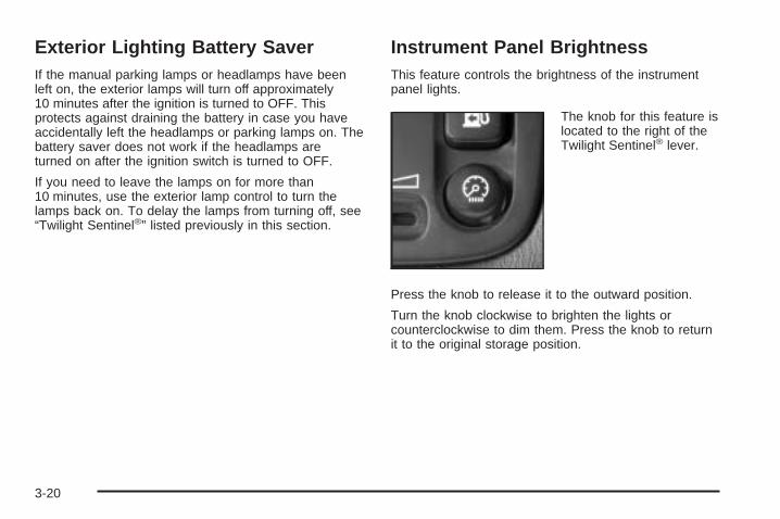
Exterior Lighting Battery SaverIf the manual parking lamps or headlamps have beenleft on, the exterior lamps will turn off approximately10 minutes after the ignition is turned to OFF. Thisprotects against draining the battery in case you haveaccidentally left the headlamps or parking lamps on. Thebattery saver does not work if the headlamps areturned on after the ignition switch is turned to OFF.
If you need to leave the lamps on for more than10 minutes, use the exterior lamp control to turn thelamps back on. To delay the lamps from turning off, see“Twilight Sentinel®” listed previously in this section.
Instrument Panel BrightnessThis feature controls the brightness of the instrumentpanel lights.
The knob for this feature islocated to the right of theTwilight Sentinel® lever.
Press the knob to release it to the outward position.
Turn the knob clockwise to brighten the lights orcounterclockwise to dim them. Press the knob to returnit to the original storage position.
3-20
Courtesy LampsThe courtesy lamps are located on the headliner abovethe rear seat. These lamps come on by turning theinstrument panel brightness knob fully clockwise or whenany door is opened and it is dark outside. Puddle lampsare located on the bottom of the front and rear door trim.
Entry LightingThis feature turns on the courtesy lamps and thebacklighting to the door switches and to the exteriorlamp control when a door is opened or if you press theremote keyless entry transmitter unlock button. Ifactivated due to the transmitter, the lighting will remainactive for about 40 seconds. Since the entry lightingsystem uses the light sensor, it must be dark outside inorder for the courtesy lamps to turn on. The courtesylamps turn off approximately 25 seconds after thelast door is closed. They will dim to off if the ignition keyis placed in ON, or immediately deactivate if thepower locks are activated.
Parade DimmingThis feature prohibits dimming of the digital displays andbacklighting during daylight hours when the key is inthe ignition and the headlamps are on. This featureoperates with the light sensor for the TwilightSentinel® and is fully automatic. When the light sensorreads darkness outside and the parking lamps areactive, the digital displays can be adjusted by turningthe instrument panel brightness knob counterclockwiseto dim and clockwise to brighten lighting.
3-21
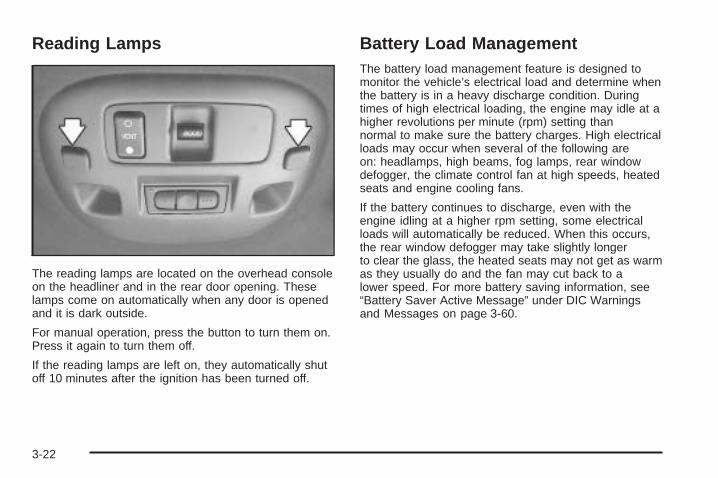
Reading Lamps
The reading lamps are located on the overhead consoleon the headliner and in the rear door opening. Theselamps come on automatically when any door is openedand it is dark outside.
For manual operation, press the button to turn them on.Press it again to turn them off.
If the reading lamps are left on, they automatically shutoff 10 minutes after the ignition has been turned off.
Battery Load ManagementThe battery load management feature is designed tomonitor the vehicle’s electrical load and determine whenthe battery is in a heavy discharge condition. Duringtimes of high electrical loading, the engine may idle at ahigher revolutions per minute (rpm) setting thannormal to make sure the battery charges. High electricalloads may occur when several of the following areon: headlamps, high beams, fog lamps, rear windowdefogger, the climate control fan at high speeds, heatedseats and engine cooling fans.
If the battery continues to discharge, even with theengine idling at a higher rpm setting, some electricalloads will automatically be reduced. When this occurs,the rear window defogger may take slightly longerto clear the glass, the heated seats may not get as warmas they usually do and the fan may cut back to alower speed. For more battery saving information, see“Battery Saver Active Message” under DIC Warningsand Messages on page 3-60.
3-22
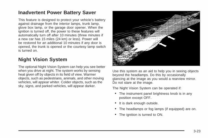
Inadvertent Power Battery SaverThis feature is designed to protect your vehicle’s batteryagainst drainage from the interior lamps, trunk lamp,glove box lamp, or the garage door opener. When theignition is turned off, the power to these features willautomatically turn off after 10 minutes (three minutes ifa new car has 15 miles (24 km) or less). Power willbe restored for an additional 10 minutes if any door isopened, the trunk is opened or the courtesy lamp switchis turned on.
Night Vision SystemThe optional Night Vision System can help you see betterwhen you drive at night. The system works by sensingheat given off by objects in its field of view. Warmerobjects, such as pedestrians, animals, and other movingvehicles, will appear whiter. Colder objects, such as thesky, signs, and parked vehicles, will appear darker.
Use this system as an aid to help you in seeing objectsbeyond the headlamps. Do this by occasionallyglancing at the image as you would a rearview mirror.Do not stare at the image.
The Night Vision System can be operated if:
• The instrument panel brightness knob is in anyposition except OFF.
• It is dark enough outside.
• The headlamps or fog lamps (if equipped) are on.
• The ignition is turned to ON.
3-23
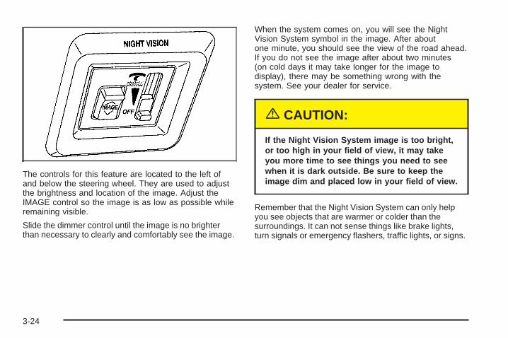
The controls for this feature are located to the left ofand below the steering wheel. They are used to adjustthe brightness and location of the image. Adjust theIMAGE control so the image is as low as possible whileremaining visible.
Slide the dimmer control until the image is no brighterthan necessary to clearly and comfortably see the image.
When the system comes on, you will see the NightVision System symbol in the image. After aboutone minute, you should see the view of the road ahead.If you do not see the image after about two minutes(on cold days it may take longer for the image todisplay), there may be something wrong with thesystem. See your dealer for service.
{CAUTION:
If the Night Vision System image is too bright,or too high in your field of view, it may takeyou more time to see things you need to seewhen it is dark outside. Be sure to keep theimage dim and placed low in your field of view.
Remember that the Night Vision System can only helpyou see objects that are warmer or colder than thesurroundings. It can not sense things like brake lights,turn signals or emergency flashers, traffic lights, or signs.
3-24
In dry, clear weather, the system can see pedestrians,animals, and the direction of the road ahead. In lightrain, light snow, or light fog the image may not beas clear and you may not be able to see the direction ofthe road ahead. In more severe weather conditions,the image may be unclear and not usable.
{CAUTION:
Do not use the Night Vision System to replaceyour normal view of the road ahead. It can nottell you how far away things are. It senses onlywarmer or colder objects, not all objects.Driving by staring at the image might causeyou not to see important objects in the roadahead. If you do not see something in time,you could have a crash in which you andothers could be injured. Use the Night VisionSystem only as a driving aid.
It is also important to keep your windshield, the HUD(Head-Up Display for the Night Vision System) lens, andthe camera lens clean. If you do not keep everythingclean, system performance may be affected.
The HUD system is located on the driver’s side of theinstrument panel, next to the windshield and the camerais located behind the center of the front grille.
Use only household glass cleaner and a soft cloth toclean the HUD or camera lens. Wipe gently anddry thoroughly.
Notice: When cleaning, be careful not to scratchthe HUD or camera lenses. Do not spray glasscleaner directly on the HUD lens because thecleaner could leak inside the unit and causedamage.
The camera must also be aligned to work correctly. Ifthe camera needs adjustment, see your dealer. Donot attempt to adjust the camera yourself.
3-25
Ultrasonic Rear Parking Assist(URPA)Your vehicle may be equipped with Ultrasonic RearParking Assist (URPA). URPA is designed to help youpark while in REVERSE (R) and operates only at speedsless than 3 mph (5 km/h). URPA can help you avoidcolliding with objects such as parked vehicles. Thesystem can detect objects 5 feet (1.5 m) behind yourvehicle and tell you how close those objects are to yourrear bumper.
{CAUTION:
Even with the Ultrasonic Rear Park Assistsystem, the driver must check carefully beforebacking up. The system does not operate abovetypical backing speeds of 3 mph (5 km/h) whileparking. And, the system does not detectobjects that are more than 5 feet (1.5 meters)behind the vehicle.
So, unless you check carefully behind youbefore and when you back up, you could strikechildren, pedestrians, bicyclists or pets behindyou, and they could be injured or killed.
Whether or not you are using rear park assist,always check carefully behind your vehiclebefore you back up and then watch closely asyou do.
3-26
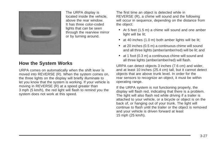
The URPA display islocated inside the vehicle,above the rear window.It has three color-codedlights that can be seenthrough the rearview mirroror by turning around.
How the System WorksURPA comes on automatically when the shift lever ismoved into REVERSE (R). When the system comes on,the three lights on the display will briefly illuminate tolet you know that the system is working. If your vehicle ismoving in REVERSE (R) at a speed greater than3 mph (5 km/h), the red light will flash to remind you thesystem does not work at this speed.
The first time an object is detected while inREVERSE (R), a chime will sound and the followingwill occur in sequence, depending on the distance fromthe object:
• At 5 feet (1.5 m) a chime will sound and one amberlight will be lit;
• at 40 inches (1.0 m) both amber lights will be lit;
• at 20 inches (0.5 m) a continuous chime will soundand all three lights (amber/amber/red) will be lit; and
• at 1 foot (0.3 m) a continuous chime will sound andall three lights (amber/amber/red) will flash.
URPA can detect objects 3 inches (7.6 cm) and wider,and at least 10 inches (25.4 cm) tall, but it cannot detectobjects that are above trunk level. In order for therear sensors to recognize an object, it must be withinoperating range.
If the URPA system is not functioning properly, thedisplay will flash red, indicating that there is a problem.The light will also flash red while driving if a trailer isattached to your vehicle, or a bicycle or object is on theback of, or hanging out of your trunk. The light willcontinue to flash until the trailer or the object is removedand your vehicle is driven forward at least15 mph (25 km/h).
3-27
It may also flash red if the ultrasonic sensors are notkept clean. So be sure to keep your rear bumper free ofmud, dirt, snow, ice and slush or materials such aspaint or the system may not work properly. If aftercleaning the rear bumper and driving forward at least15 mph (25 km/h), the display continues to flash red, seeyour dealer. For cleaning instructions, see WashingYour Vehicle on page 5-91.
It may also flash red if your vehicle is moving inREVERSE (R) at a speed greater than 3 mph (5 km/h).Other conditions that may affect system performanceinclude things like the vibrations from a jackhammer orthe compression of air brakes on a very large truck.
As always, drivers should use care when backing up avehicle. Always look behind you, being sure to checkfor other vehicles, obstructions and blind spots.
Accessory Power OutletsYour vehicle is equipped with accessory power outlets.The outlets can be used to plug in electrical equipmentsuch as a cellular telephone, CB radio, etc.
If you have a vehicle with a center storage compartmentlocated on the instrument panel, you may have anaccessory power outlet in the storage drawer. There isalso an outlet on the front passenger’s seat nearthe umbrella tray.
There are two accessory power outlets in the rear seatarea located on the door armrests next to the ashtrays.
Your vehicle may have a small cap that must beremoved to access the accessory power outlet. If itdoes, when not using the outlet be sure to cover it withthe protective cap.
The accessory power outlet will only operate when theignition is in ACCESSORY or ON and for 10 minutesafter turning the ignition OFF. If you would like theaccessory power outlet to operate regardless of ignitionposition, and for extended periods of time, see yourdealer for more information.
Notice: Leaving electrical equipment on forextended periods will drain the battery. Always turnoff electrical equipment when not in use and donot plug in equipment that exceeds the maximumamperage rating.
Certain accessory power plugs may not be compatibleto the accessory power outlet and could result inblown vehicle or adapter fuses. If you experience aproblem see your dealer for additional information on theaccessory power outlets.
Notice: Adding any electrical equipment to yourvehicle may damage it or keep other componentsfrom working as they should. The repairs would notbe covered by your warranty. Check with yourdealer before adding electrical equipment.
3-28
Follow the proper installation instructions that areincluded with any electrical equipment you install.
Notice: Improper use of the power outlet can causedamage not covered by your warranty. Do nothang any type of accessory or accessory bracketfrom the plug because the power outlets aredesigned for accessory power plugs only.
Ashtrays and Cigarette LighterNotice: If you put papers or other flammable itemsin the ashtray, hot cigarettes or other smokingmaterials could ignite them and possibly damageyour vehicle. Never put flammable items in theashtray.
Front AshtrayWith the full floor console, the ashtray is located belowthe climate control system. To open, push down onthe cover. To clean the ashtray, lift it out by grippingthe sides.
For vehicles without the floor console, pull the traylocated below the radio to reveal the ashtray. Theashtray can be removed for cleaning.
Rear AshtrayThe ashtrays are located on the door armrests. To usean ashtray, lift the lid.
Cigarette Lighter
Notice: Holding a cigarette lighter in while it isheating will not allow the lighter to back away fromthe heating element when it is hot. Damage fromoverheating may occur to the lighter or heatingelement, or a fuse could be blown. Do not hold acigarette lighter in while it is heating. Do notuse anything other than the cigarette lighter in theheating element.
The cigarette lighter is located near the front ashtray.
Press the lighter all the way in and release it. It will popback out by itself once the element has heated for use.
Cigarette lighters can be used to provide electricalpower to accessories. See Accessory Power Outlets onpage 3-28 for more information.
3-29
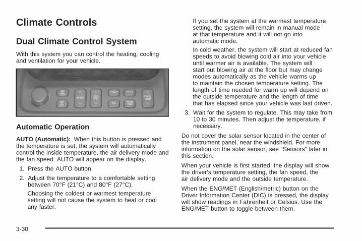
Climate Controls
Dual Climate Control SystemWith this system you can control the heating, coolingand ventilation for your vehicle.
Automatic Operation
AUTO (Automatic): When this button is pressed andthe temperature is set, the system will automaticallycontrol the inside temperature, the air delivery mode andthe fan speed. AUTO will appear on the display.
1. Press the AUTO button.
2. Adjust the temperature to a comfortable settingbetween 70°F (21°C) and 80°F (27°C).Choosing the coldest or warmest temperaturesetting will not cause the system to heat or coolany faster.
If you set the system at the warmest temperaturesetting, the system will remain in manual modeat that temperature and it will not go intoautomatic mode.In cold weather, the system will start at reduced fanspeeds to avoid blowing cold air into your vehicleuntil warmer air is available. The system willstart out blowing air at the floor but may changemodes automatically as the vehicle warms upto maintain the chosen temperature setting. Thelength of time needed for warm up will depend onthe outside temperature and the length of timethat has elapsed since your vehicle was last driven.
3. Wait for the system to regulate. This may take from10 to 30 minutes. Then adjust the temperature, ifnecessary.
Do not cover the solar sensor located in the center ofthe instrument panel, near the windshield. For moreinformation on the solar sensor, see “Sensors” later inthis section.
When your vehicle is first started, the display will showthe driver’s temperature setting, the fan speed, theair delivery mode and the outside temperature.
When the ENG/MET (English/metric) button on theDriver Information Center (DIC) is pressed, the displaywill show readings in Fahrenheit or Celsius. Use theENG/MET button to toggle between them.
3-30
Manual Operation
yMODEz: Pressing the MODE switch and changingthe mode cancels automatic operation and places thesystem in manual mode. Press AUTO to return toautomatic operation.
To change the current mode, select one of the following:
F (Vent): This mode directs air to the instrumentpanel outlets.
* (Bi-Level): This mode directs approximately half ofthe air to the instrument panel outlets, and then directsmost of the remaining air to the floor outlets. Some airmay be directed toward the windshield. In automaticoperation, cooler air is directed to the upper outlets andwarmer air to the floor outlets.
7 (Floor): This mode directs most of the air to thefloor outlets with some air directed to the outboardoutlets, for the side windows, and a little air directed tothe windshield.
The MODE switch can also be used to select thefloor/defog mode. Information on defogging anddefrosting can be found later in this section.
y9z (Fan): Press this switch to increase ordecrease the fan speed. Pressing this switch cancelsautomatic operation and places the system in manualmode. Press AUTO to return to automatic operation.
If the airflow seems low when the fan speed is atthe highest setting, the passenger compartment air filtermay need to be replaced. For more information, seePassenger Compartment Air Filter on page 3-36and Scheduled Maintenance on page 6-4.
? (Recirculation): This mode keeps outside airfrom coming in the vehicle. It can be used to preventoutside air and odors from entering your vehicle orto help heat or cool the air inside your vehicle morequickly. Press this button to turn the recirculation modeon or off. When the button is pressed, an indicatorlight will come on. The air-conditioning compressor alsocomes on.
Driver’s Temperature Knob: Press this knob to turnthe entire climate control system on or off. Turn this knobclockwise or counterclockwise to manually increase ordecrease the temperature inside your vehicle.
3-31
yPASS TEMPz (Passenger’s Temperature):Press this switch to turn the passengers’ climate controlsystems on. Press this switch to manually increaseor decrease the temperature for the front passenger.
PASS OFF (Passenger’s Climate Control): Press thisbutton to turn all passenger climate control systems off.
If the passenger’s temperature switch is turned off, thedriver’s temperature knob will control the temperature forthe entire vehicle.
A/C (Air Conditioning): Press this button to overridethe automatic system and turn the air-conditioningsystem on or off. When in AUTO the air-conditioningcompressor will come on automatically, as necessary.
On hot days, open the windows to let hot inside airescape; then close them. This helps to reduce the timeit takes for your vehicle to cool down. It also helpsthe system to operate more efficiently.
For quick cool down on hot days:
1. Select the vent mode.
2. Select the recirculation mode.
3. Select A/C.
4. Select the coolest temperature.
5. Select the highest fan speed.
6. Open all outlets.
Using these settings together for long periods of timemay cause the air inside your vehicle to become too dry.To prevent this from happening, after the air in yourvehicle has cooled, turn the recirculation mode off.
The air-conditioning system removes moisture from theair, so you may sometimes notice a small amount ofwater dripping underneath your vehicle while idlingor after turning off the engine. This is normal.
If your vehicle has the memory option, it can be used torecall your climate control settings. For more information,see Climate Controls Personalization on page 3-39.
3-32
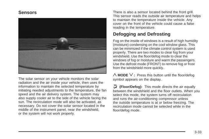
Sensors
The solar sensor on your vehicle monitors the solarradiation and the air inside your vehicle, then uses theinformation to maintain the selected temperature byinitiating needed adjustments to the temperature, the fanspeed and the air delivery system. The system mayalso supply cooler air to the side of the vehicle facing thesun. The recirculation mode will also be activated, asnecessary. Do not cover the solar sensor located in themiddle of the instrument panel, near the windshield,or the system will not work properly.
There is also a sensor located behind the front grill.This sensor reads the outside air temperature and helpsto maintain the temperature inside the vehicle. Anycover on the front of the vehicle could cause a falsereading in the temperature.
Defogging and DefrostingFog on the inside of windows is a result of high humidity(moisture) condensing on the cool window glass. Thiscan be minimized if the climate control system is usedproperly. There are two modes to clear fog from yourwindshield. Use the floor/defog mode to clear thewindows of fog or moisture and warm the passengers.Use the defrost mode (FRONT) to remove fog or frostfrom the windshield more quickly.
yMODEz: Press this button until the floor/defogsymbol appears on the display.
. (Floor/Defog): This mode directs the air equallybetween the windshield and the floor outlets. When youselect this mode, the system turns off recirculationand runs the air-conditioning compressor unlessthe outside temperature is at or below freezing. Therecirculation mode cannot be selected while in thefloor/defog mode.
3-33
1 FRONT (Defrost): Pressing FRONT directs most ofthe air to the windshield and the side window outlets, withsome air directed to the floor outlets. In this mode, thesystem will automatically turn off recirculation and run theair-conditioning compressor, unless the outsidetemperature is at or below freezing. Recirculation cannotbe selected while in the defrost mode. Do not drive thevehicle until all the windows are clear.
Rear Window DefoggerThe rear window defogger uses a warming grid toremove fog or frost from the rear window.
The rear window defogger will only work when theignition is in ON.
= REAR: Press this button to turn the rear windowdefogger on or off. Be sure to clear as much snow fromthe rear window as possible.
The rear window defogger will turn off approximately10 minutes after the button is pressed. If turned onagain, the defogger will only run for approximatelyfive minutes before turning off. The defogger can alsobe turned off by pressing the button again or by turningoff the engine.
The heated outside rearview mirrors will heat to helpclear fog or frost from the surface of the mirror when theREAR button is pressed.
Notice: Using a razor blade or sharp object toclear the inside rear window may damage the rearwindow defogger. Repairs would not be coveredby your warranty. Do not clear the inside of the rearwindow with sharp objects.
Outlet AdjustmentUse the lever located in the center of each outlet tochange the direction of the airflow. Use the thumbwheellocated next to the outlets to turn them on and off.
Operation Tips• Clear away any ice, snow or leaves from the air
inlets at the base of the windshield that mayblock the flow of air into your vehicle.
• Use of non-GM approved hood deflectors mayadversely affect the performance of the system.
• Keep the path under the front seats clear of objectsto help circulate the air inside of your vehicle moreeffectively.
3-34
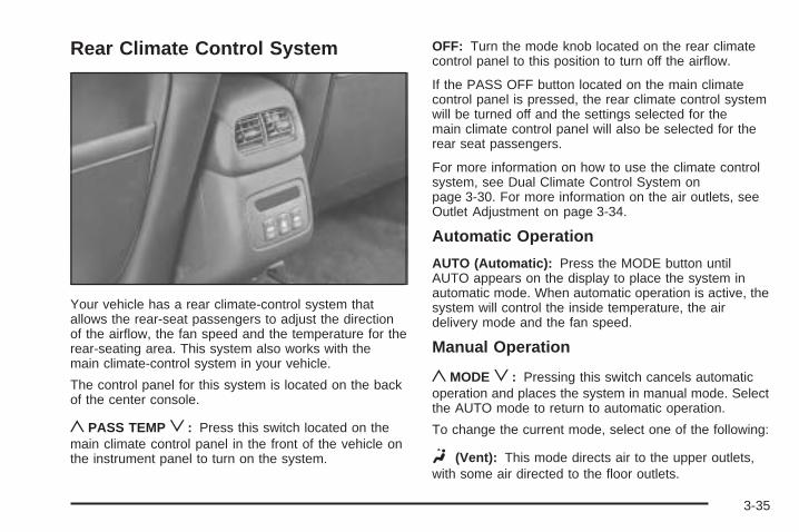
Rear Climate Control System
Your vehicle has a rear climate-control system thatallows the rear-seat passengers to adjust the directionof the airflow, the fan speed and the temperature for therear-seating area. This system also works with themain climate-control system in your vehicle.
The control panel for this system is located on the backof the center console.
yPASS TEMPz: Press this switch located on themain climate control panel in the front of the vehicle onthe instrument panel to turn on the system.
OFF: Turn the mode knob located on the rear climatecontrol panel to this position to turn off the airflow.
If the PASS OFF button located on the main climatecontrol panel is pressed, the rear climate control systemwill be turned off and the settings selected for themain climate control panel will also be selected for therear seat passengers.
For more information on how to use the climate controlsystem, see Dual Climate Control System onpage 3-30. For more information on the air outlets, seeOutlet Adjustment on page 3-34.
Automatic Operation
AUTO (Automatic): Press the MODE button untilAUTO appears on the display to place the system inautomatic mode. When automatic operation is active, thesystem will control the inside temperature, the airdelivery mode and the fan speed.
Manual Operation
yMODEz: Pressing this switch cancels automaticoperation and places the system in manual mode. Selectthe AUTO mode to return to automatic operation.
To change the current mode, select one of the following:
F (Vent): This mode directs air to the upper outlets,with some air directed to the floor outlets.
3-35
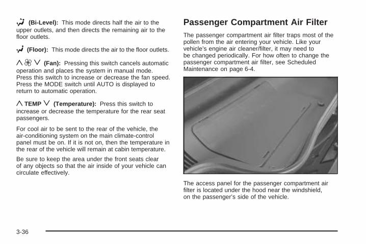
* (Bi-Level): This mode directs half the air to theupper outlets, and then directs the remaining air to thefloor outlets.
7 (Floor): This mode directs the air to the floor outlets.
y9z (Fan): Pressing this switch cancels automaticoperation and places the system in manual mode.Press this switch to increase or decrease the fan speed.Press the MODE switch until AUTO is displayed toreturn to automatic operation.
yTEMPz (Temperature): Press this switch toincrease or decrease the temperature for the rear seatpassengers.
For cool air to be sent to the rear of the vehicle, theair-conditioning system on the main climate-controlpanel must be on. If it is not on, then the temperature inthe rear of the vehicle will remain at cabin temperature.
Be sure to keep the area under the front seats clearof any objects so that the air inside of your vehicle cancirculate effectively.
Passenger Compartment Air FilterThe passenger compartment air filter traps most of thepollen from the air entering your vehicle. Like yourvehicle’s engine air cleaner/filter, it may need tobe changed periodically. For how often to change thepassenger compartment air filter, see ScheduledMaintenance on page 6-4.
The access panel for the passenger compartment airfilter is located under the hood near the windshield,on the passenger’s side of the vehicle.
3-36
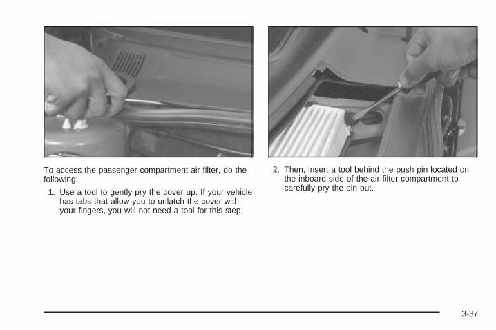
To access the passenger compartment air filter, do thefollowing:
1. Use a tool to gently pry the cover up. If your vehiclehas tabs that allow you to unlatch the cover withyour fingers, you will not need a tool for this step.
2. Then, insert a tool behind the push pin located onthe inboard side of the air filter compartment tocarefully pry the pin out.
3-37
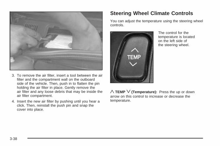
3. To remove the air filter, insert a tool between the airfilter and the compartment wall on the outboardside of the vehicle. Then, push in to flatten the pinholding the air filter in place. Gently remove theair filter and any loose debris that may be inside theair filter compartment.
4. Insert the new air filter by pushing until you hear aclick. Then, reinstall the push pin and snap thecover into place.
Steering Wheel Climate ControlsYou can adjust the temperature using the steering wheelcontrols.
The control for thetemperature is locatedon the left side ofthe steering wheel.
yTEMPz(Temperature): Press the up or downarrow on this control to increase or decrease thetemperature.
3-38
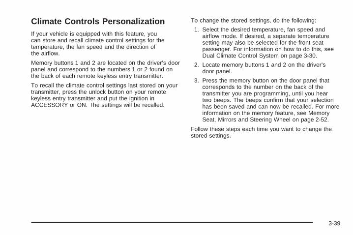
Climate Controls PersonalizationIf your vehicle is equipped with this feature, youcan store and recall climate control settings for thetemperature, the fan speed and the direction ofthe airflow.
Memory buttons 1 and 2 are located on the driver’s doorpanel and correspond to the numbers 1 or 2 found onthe back of each remote keyless entry transmitter.
To recall the climate control settings last stored on yourtransmitter, press the unlock button on your remotekeyless entry transmitter and put the ignition inACCESSORY or ON. The settings will be recalled.
To change the stored settings, do the following:
1. Select the desired temperature, fan speed andairflow mode. If desired, a separate temperaturesetting may also be selected for the front seatpassenger. For information on how to do this, seeDual Climate Control System on page 3-30.
2. Locate memory buttons 1 and 2 on the driver’sdoor panel.
3. Press the memory button on the door panel thatcorresponds to the number on the back of thetransmitter you are programming, until you heartwo beeps. The beeps confirm that your selectionhas been saved and can now be recalled. For moreinformation on the memory feature, see MemorySeat, Mirrors and Steering Wheel on page 2-52.
Follow these steps each time you want to change thestored settings.
3-39
Warning Lights, Gages, andIndicatorsThis part describes the warning lights and gages thatmay be on your vehicle. The pictures will help youlocate them.
Warning lights and gages can signal that something iswrong before it becomes serious enough to causean expensive repair or replacement. Paying attention toyour warning lights and gages could also save youor others from injury.
Warning lights come on when there may be or is aproblem with one of your vehicle’s functions. As you willsee in the details on the next few pages, somewarning lights come on briefly when you start theengine just to let you know they are working. If you arefamiliar with this section, you should not be alarmedwhen this happens.
Gages can indicate when there may be or is a problemwith one of your vehicle’s functions. Often gagesand warning lights work together to let you know whenthere is a problem with your vehicle.
When one of the warning lights comes on and stays onwhen you are driving, or when one of the gagesshows there may be a problem, check the section thattells you what to do about it. Follow this manual’sadvice. Waiting to do repairs can be costly – and evendangerous. So please get to know your warninglights and gages. They are a big help.
Your vehicle also has a Driver Information Center (DIC)that works along with the warning lights and gages.See Driver Information Center (DIC) on page 3-57 formore information.
3-40
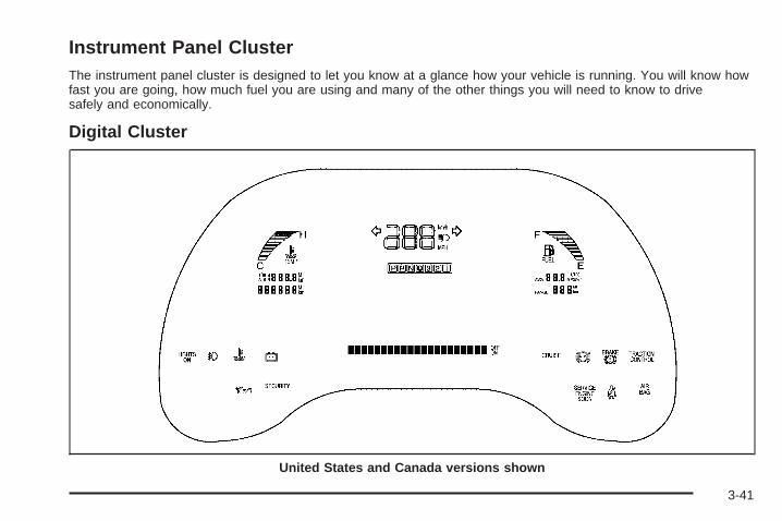
Instrument Panel ClusterThe instrument panel cluster is designed to let you know at a glance how your vehicle is running. You will know howfast you are going, how much fuel you are using and many of the other things you will need to know to drivesafely and economically.
Digital Cluster
United States and Canada versions shown
3-41
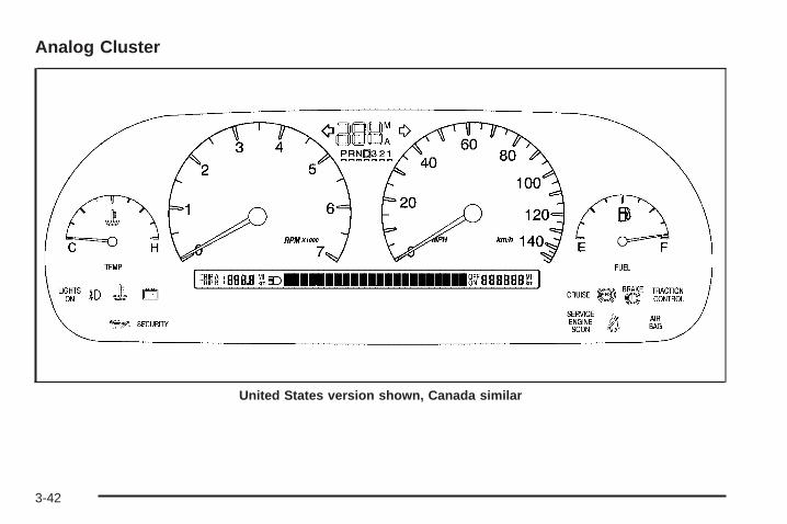
Analog Cluster
United States version shown, Canada similar
3-42
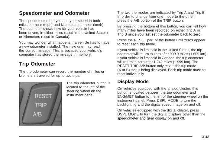
Speedometer and OdometerThe speedometer lets you see your speed in bothmiles per hour (mph) and kilometers per hour (km/h).The odometer shows how far your vehicle hasbeen driven, in either miles (used in the United States)or kilometers (used in Canada).
You may wonder what happens if a vehicle has to havea new odometer installed. The new one may readthe correct mileage. This is because your vehicle’scomputer has stored the mileage in memory.
Trip OdometerThe trip odometer can record the number of miles orkilometers traveled for up to two trips.
The trip odometer button islocated to the left of thesteering wheel on theinstrument panel.
The two trip modes are indicated by Trip A and Trip B.In order to change from one mode to the other,press the A/B portion of the TRIP button.
By pressing the bottom of this button, you can tell howmany miles have been recorded on either Trip A orTrip B since you last set the odometer back to zero.
Press the RESET part of the button until zeros appearto reset each trip mode.
If your vehicle is first sold in the United States, the tripodometer will return to zero after 999.9 miles (1 609 km).If your vehicle is first sold in Canada, the trip odometerwill return to zero after 1,242 miles (1 999 km). TheRESET TRIP A/B button only resets the trip mode(A or B) that is being displayed. Each trip mode must bereset individually.
Display ModeOn vehicles equipped with the analog cluster, thisbutton is located between the trip odometer andENG/MET button to the left of the steering wheel on theinstrument panel. Press DSPL MODE to turn thebacklighting and the digital speed image on and off.
On vehicles equipped with the digital cluster, pressDSPL MODE to turn the digital displays other than thespeedometer and gear display on and off.
3-43
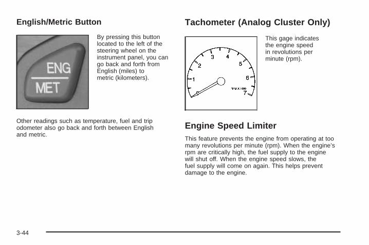
English/Metric Button
By pressing this buttonlocated to the left of thesteering wheel on theinstrument panel, you cango back and forth fromEnglish (miles) tometric (kilometers).
Other readings such as temperature, fuel and tripodometer also go back and forth between Englishand metric.
Tachometer (Analog Cluster Only)
This gage indicatesthe engine speedin revolutions perminute (rpm).
Engine Speed LimiterThis feature prevents the engine from operating at toomany revolutions per minute (rpm). When the engine’srpm are critically high, the fuel supply to the enginewill shut off. When the engine speed slows, thefuel supply will come on again. This helps preventdamage to the engine.
3-44
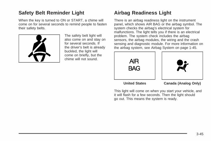
Safety Belt Reminder LightWhen the key is turned to ON or START, a chime willcome on for several seconds to remind people to fastentheir safety belts.
The safety belt light willalso come on and stay onfor several seconds. Ifthe driver’s belt is alreadybuckled, the light willcome on briefly, but thechime will not sound.
Airbag Readiness LightThere is an airbag readiness light on the instrumentpanel, which shows AIR BAG or the airbag symbol. Thesystem checks the airbag’s electrical system formalfunctions. The light tells you if there is an electricalproblem. The system check includes the airbagsensors, the airbag modules, the wiring and the crashsensing and diagnostic module. For more information onthe airbag system, see Airbag System on page 1-45.
This light will come on when you start your vehicle, andit will flash for a few seconds. Then the light shouldgo out. This means the system is ready.
United States Canada (Analog Only)
3-45
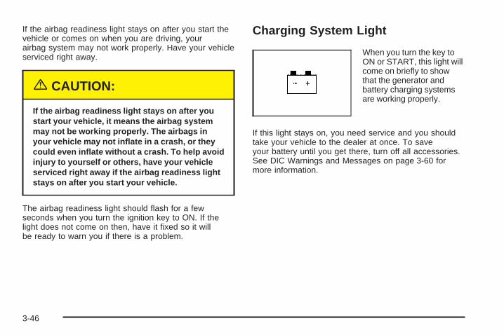
If the airbag readiness light stays on after you start thevehicle or comes on when you are driving, yourairbag system may not work properly. Have your vehicleserviced right away.
{CAUTION:
If the airbag readiness light stays on after youstart your vehicle, it means the airbag systemmay not be working properly. The airbags inyour vehicle may not inflate in a crash, or theycould even inflate without a crash. To help avoidinjury to yourself or others, have your vehicleserviced right away if the airbag readiness lightstays on after you start your vehicle.
The airbag readiness light should flash for a fewseconds when you turn the ignition key to ON. If thelight does not come on then, have it fixed so it willbe ready to warn you if there is a problem.
Charging System Light
When you turn the key toON or START, this light willcome on briefly to showthat the generator andbattery charging systemsare working properly.
If this light stays on, you need service and you shouldtake your vehicle to the dealer at once. To saveyour battery until you get there, turn off all accessories.See DIC Warnings and Messages on page 3-60 formore information.
3-46
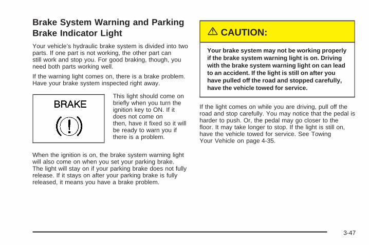
Brake System Warning and ParkingBrake Indicator LightYour vehicle’s hydraulic brake system is divided into twoparts. If one part is not working, the other part canstill work and stop you. For good braking, though, youneed both parts working well.
If the warning light comes on, there is a brake problem.Have your brake system inspected right away.
This light should come onbriefly when you turn theignition key to ON. If itdoes not come onthen, have it fixed so it willbe ready to warn you ifthere is a problem.
When the ignition is on, the brake system warning lightwill also come on when you set your parking brake.The light will stay on if your parking brake does not fullyrelease. If it stays on after your parking brake is fullyreleased, it means you have a brake problem.
{CAUTION:
Your brake system may not be working properlyif the brake system warning light is on. Drivingwith the brake system warning light on can leadto an accident. If the light is still on after youhave pulled off the road and stopped carefully,have the vehicle towed for service.
If the light comes on while you are driving, pull off theroad and stop carefully. You may notice that the pedal isharder to push. Or, the pedal may go closer to thefloor. It may take longer to stop. If the light is still on,have the vehicle towed for service. See TowingYour Vehicle on page 4-35.
3-47
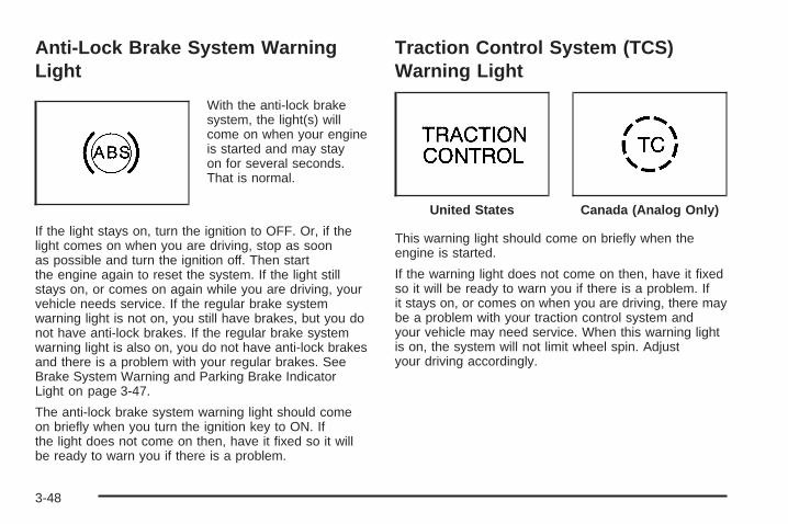
Anti-Lock Brake System WarningLight
With the anti-lock brakesystem, the light(s) willcome on when your engineis started and may stayon for several seconds.That is normal.
If the light stays on, turn the ignition to OFF. Or, if thelight comes on when you are driving, stop as soonas possible and turn the ignition off. Then startthe engine again to reset the system. If the light stillstays on, or comes on again while you are driving, yourvehicle needs service. If the regular brake systemwarning light is not on, you still have brakes, but you donot have anti-lock brakes. If the regular brake systemwarning light is also on, you do not have anti-lock brakesand there is a problem with your regular brakes. SeeBrake System Warning and Parking Brake IndicatorLight on page 3-47.
The anti-lock brake system warning light should comeon briefly when you turn the ignition key to ON. Ifthe light does not come on then, have it fixed so it willbe ready to warn you if there is a problem.
Traction Control System (TCS)Warning Light
This warning light should come on briefly when theengine is started.
If the warning light does not come on then, have it fixedso it will be ready to warn you if there is a problem. Ifit stays on, or comes on when you are driving, there maybe a problem with your traction control system andyour vehicle may need service. When this warning lightis on, the system will not limit wheel spin. Adjustyour driving accordingly.
United States Canada (Analog Only)
3-48
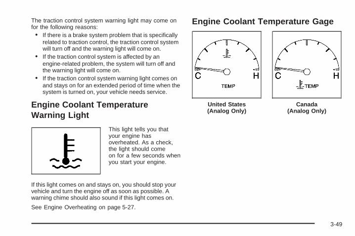
The traction control system warning light may come onfor the following reasons:• If there is a brake system problem that is specifically
related to traction control, the traction control systemwill turn off and the warning light will come on.
• If the traction control system is affected by anengine-related problem, the system will turn off andthe warning light will come on.
• If the traction control system warning light comes onand stays on for an extended period of time when thesystem is turned on, your vehicle needs service.
Engine Coolant TemperatureWarning Light
This light tells you thatyour engine hasoverheated. As a check,the light should comeon for a few seconds whenyou start your engine.
If this light comes on and stays on, you should stop yourvehicle and turn the engine off as soon as possible. Awarning chime should also sound if this light comes on.
See Engine Overheating on page 5-27.
Engine Coolant Temperature Gage
United States(Analog Only)
Canada(Analog Only)
3-49
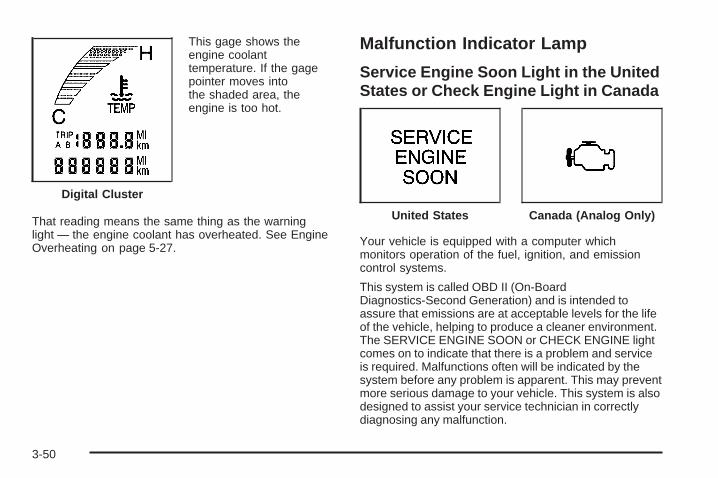
This gage shows theengine coolanttemperature. If the gagepointer moves intothe shaded area, theengine is too hot.
That reading means the same thing as the warninglight — the engine coolant has overheated. See EngineOverheating on page 5-27.
Malfunction Indicator Lamp
Service Engine Soon Light in the UnitedStates or Check Engine Light in Canada
Your vehicle is equipped with a computer whichmonitors operation of the fuel, ignition, and emissioncontrol systems.
This system is called OBD II (On-BoardDiagnostics-Second Generation) and is intended toassure that emissions are at acceptable levels for the lifeof the vehicle, helping to produce a cleaner environment.The SERVICE ENGINE SOON or CHECK ENGINE lightcomes on to indicate that there is a problem and serviceis required. Malfunctions often will be indicated by thesystem before any problem is apparent. This may preventmore serious damage to your vehicle. This system is alsodesigned to assist your service technician in correctlydiagnosing any malfunction.
Digital Cluster
United States Canada (Analog Only)
3-50
Notice: If you keep driving your vehicle with thislight on, after awhile, your emission controlsmay not work as well, your fuel economy may notbe as good, and your engine may not run assmoothly. This could lead to costly repairs that maynot be covered by your warranty.
Notice: Modifications made to the engine,transaxle, exhaust, intake, or fuel system of yourvehicle or the replacement of the original tires withother than those of the same Tire PerformanceCriteria (TPC) can affect your vehicle’s emissioncontrols and may cause this light to come on.Modifications to these systems could lead to costlyrepairs not covered by your warranty. This mayalso result in a failure to pass a required EmissionInspection/Maintenance test.
This light should come on, as a check to show you it isworking, when the ignition is on and the engine isnot running. If the light does not come on, have itrepaired. This light will also come on during amalfunction in one of two ways:
• Light Flashing — A misfire condition has beendetected. A misfire increases vehicle emissions andmay damage the emission control system on yourvehicle. Diagnosis and service may be required.
• Light On Steady — An emission control systemmalfunction has been detected on your vehicle.Diagnosis and service may be required.
If the Light Is FlashingThe following may prevent more serious damage toyour vehicle:
• Reducing vehicle speed
• Avoiding hard accelerations
• Avoiding steep uphill grades
• If you are towing a trailer, reduce the amount ofcargo being hauled as soon as it is possible
If the light stops flashing and remains on steady, see “Ifthe Light Is On Steady” following.
If the light continues to flash, when it is safe to do so,stop the vehicle. Find a safe place to park your vehicle.Turn the key off, wait at least 10 seconds and restartthe engine. If the light remains on steady, see “Ifthe Light Is On Steady” following. If the light is stillflashing, follow the previous steps, and see your dealerfor service as soon as possible.
3-51
If the Light Is On SteadyYou may be able to correct the emission systemmalfunction by considering the following:
Did you recently put fuel into your vehicle?
If so, reinstall the fuel cap, making sure to fully installthe cap. See Filling Your Tank on page 5-7. Thediagnostic system can determine if the fuel cap hasbeen left off or improperly installed. A loose or missingfuel cap will allow fuel to evaporate into the atmosphere.A few driving trips with the cap properly installedshould turn the light off.
Did you just drive through a deep puddle of water?
If so, your electrical system may be wet. The conditionwill usually be corrected when the electrical systemdries out. A few driving trips should turn the light off.
Have you recently changed brands of fuel?
If so, be sure to fuel your vehicle with quality fuel. SeeGasoline Octane on page 5-5. Poor fuel quality willcause your engine not to run as efficiently as designed.You may notice this as stalling after start-up, stallingwhen you put the vehicle into gear, misfiring, hesitationon acceleration, or stumbling on acceleration. (Theseconditions may go away once the engine is warmed up.)This will be detected by the system and cause thelight to turn on.
If you experience one or more of these conditions,change the fuel brand you use. It will require at leastone full tank of the proper fuel to turn the light off.
If none of the above steps have made the light turn off,your dealer can check the vehicle. Your dealer hasthe proper test equipment and diagnostic tools to fix anymechanical or electrical problems that may havedeveloped.
Emissions Inspection and MaintenanceProgramsSome state/provincial and local governments have ormay begin programs to inspect the emission controlequipment on your vehicle. Failure to pass this inspectioncould prevent you from getting a vehicle registration.
Here are some things you need to know in order to helpyour vehicle pass an inspection:
Your vehicle will not pass this inspection if the SERVICEENGINE SOON or CHECK ENGINE light is on or notworking properly.
Your vehicle will not pass this inspection if the OBD(on-board diagnostic) system determines that criticalemission control systems have not been completelydiagnosed by the system. The vehicle would beconsidered not ready for inspection.
3-52
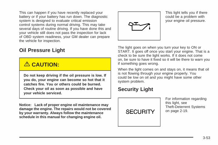
This can happen if you have recently replaced yourbattery or if your battery has run down. The diagnosticsystem is designed to evaluate critical emissioncontrol systems during normal driving. This may takeseveral days of routine driving. If you have done this andyour vehicle still does not pass the inspection for lackof OBD system readiness, your GM dealer can preparethe vehicle for inspection.
Oil Pressure Light
{CAUTION:
Do not keep driving if the oil pressure is low. Ifyou do, your engine can become so hot that itcatches fire. You or others could be burned.Check your oil as soon as possible and haveyour vehicle serviced.
Notice: Lack of proper engine oil maintenance maydamage the engine. The repairs would not be coveredby your warranty. Always follow the maintenanceschedule in this manual for changing engine oil.
This light tells you if therecould be a problem withyour engine oil pressure.
The light goes on when you turn your key to ON orSTART. It goes off once you start your engine. That is acheck to be sure the light works. If it does not comeon, be sure to have it fixed so it will be there to warn youif something goes wrong.
When the light comes on and stays on, it means that oilis not flowing through your engine properly. Youcould be low on oil and you might have some othersystem problem.
Security Light
For information regardingthis light, seeTheft-Deterrent Systemson page 2-19.
3-53
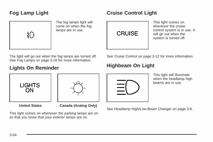
Fog Lamp Light
The fog lamps light willcome on when the foglamps are in use.
The light will go out when the fog lamps are turned off.See Fog Lamps on page 3-18 for more information.
Lights On Reminder
This light comes on whenever the parking lamps are onso that you know that your exterior lamps are on.
Cruise Control Light
This light comes onwhenever the cruisecontrol system is in use. Itwill go out when thesystem is turned off.
See Cruise Control on page 3-12 for more information.
Highbeam On Light
This light will illuminatewhen the headlamp highbeams are in use.
See Headlamp High/Low-Beam Changer on page 3-9.United States Canada (Analog Only)
3-54
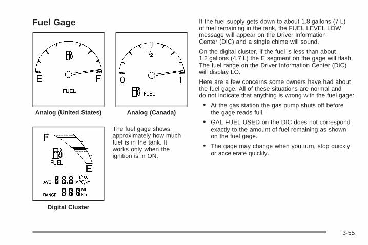
Fuel Gage
The fuel gage showsapproximately how muchfuel is in the tank. Itworks only when theignition is in ON.
If the fuel supply gets down to about 1.8 gallons (7 L)of fuel remaining in the tank, the FUEL LEVEL LOWmessage will appear on the Driver InformationCenter (DIC) and a single chime will sound.
On the digital cluster, if the fuel is less than about1.2 gallons (4.7 L) the E segment on the gage will flash.The fuel range on the Driver Information Center (DIC)will display LO.
Here are a few concerns some owners have had aboutthe fuel gage. All of these situations are normal anddo not indicate that anything is wrong with the fuel gage:
• At the gas station the gas pump shuts off beforethe gage reads full.
• GAL FUEL USED on the DIC does not correspondexactly to the amount of fuel remaining as shownon the fuel gage.
• The gage may change when you turn, stop quicklyor accelerate quickly.
Analog (United States) Analog (Canada)
Digital Cluster
3-55
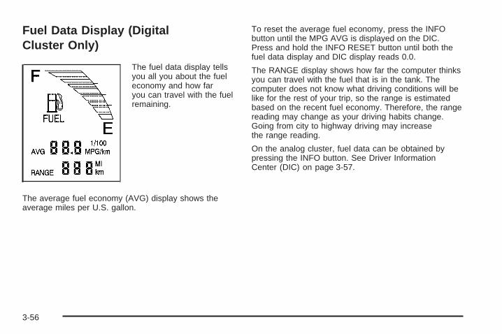
Fuel Data Display (DigitalCluster Only)
The fuel data display tellsyou all you about the fueleconomy and how faryou can travel with the fuelremaining.
The average fuel economy (AVG) display shows theaverage miles per U.S. gallon.
To reset the average fuel economy, press the INFObutton until the MPG AVG is displayed on the DIC.Press and hold the INFO RESET button until both thefuel data display and DIC display reads 0.0.
The RANGE display shows how far the computer thinksyou can travel with the fuel that is in the tank. Thecomputer does not know what driving conditions will belike for the rest of your trip, so the range is estimatedbased on the recent fuel economy. Therefore, the rangereading may change as your driving habits change.Going from city to highway driving may increasethe range reading.
On the analog cluster, fuel data can be obtained bypressing the INFO button. See Driver InformationCenter (DIC) on page 3-57.
3-56
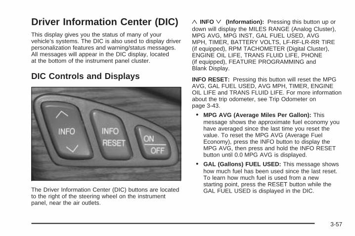
Driver Information Center (DIC)This display gives you the status of many of yourvehicle’s systems. The DIC is also used to display driverpersonalization features and warning/status messages.All messages will appear in the DIC display, locatedat the bottom of the instrument panel cluster.
DIC Controls and Displays
The Driver Information Center (DIC) buttons are locatedto the right of the steering wheel on the instrumentpanel, near the air outlets.
«INFOª (Information): Pressing this button up ordown will display the MILES RANGE (Analog Cluster),MPG AVG, MPG INST, GAL FUEL USED, AVGMPH, TIMER, BATTERY VOLTS, LF-RF-LR-RR TIRE(if equipped), RPM TACHOMETER (Digital Cluster),ENGINE OIL LIFE, TRANS FLUID LIFE, PHONE(if equipped), FEATURE PROGRAMMING andBlank Display.
INFO RESET: Pressing this button will reset the MPGAVG, GAL FUEL USED, AVG MPH, TIMER, ENGINEOIL LIFE and TRANS FLUID LIFE. For more informationabout the trip odometer, see Trip Odometer onpage 3-43.
• MPG AVG (Average Miles Per Gallon): Thismessage shows the approximate fuel economy youhave averaged since the last time you reset thevalue. To reset the MPG AVG (Average FuelEconomy), press the INFO button to display theMPG AVG, then press and hold the INFO RESETbutton until 0.0 MPG AVG is displayed.
• GAL (Gallons) FUEL USED: This message showshow much fuel has been used since the last reset.To learn how much fuel is used from a newstarting point, press the RESET button while theGAL FUEL USED is displayed in the DIC.
3-57
• AVG MPH (Average Miles per Hour): Thismessage shows the average speed you havetraveled at since the last time you reset the value.To reset the value, press the INFO button todisplay AVG MPH, then press and hold the INFORESET button until 0.0 AVG MPH is displayed.
• TIMER: This feature is like a stopwatch, in that youcan clock the time it takes to get from one point toanother.To operate, press the INFO button to displayTIMER. Each of the fields for the hours, minutesand seconds are two numeric digits.Once TIMER 00:00:00 is displayed, press theON/OFF button to start the timing feature. Press theON/OFF button again to stop it. If you will be startingand stopping your vehicle, during a trip for instance,the TIMER feature will automatically start timingwhere it left off when you last stopped. To reset it,press and hold the INFO RESET button until thedisplay reads TIMER 00:00:00. Press the INFObutton to exit from the TIMER display.
• ENGINE OIL LIFE: This message shows thepercentage of remaining oil life for your vehicle.When the oil life is depleted, the CHANGE ENGINEOIL message will appear on the display. See EngineOil on page 5-14 and Oil Life Indicator on page 3-79.In addition to the engine oil life system monitoring theoil life, additional maintenance is recommended inthe Maintenance Schedule in this manual. SeeScheduled Maintenance on page 6-4. To reset theengine oil life system, see Engine Oil Life System onpage 5-17. This only needs to be reset after youhave had the oil changed.
• TRANSMISSION FLUID LIFE: This message showsthe percentage of remaining transmission fluid life foryour vehicle. Under normal conditions, the rate ofdeterioration of the transmission fluid is slow. SeeScheduled Maintenance on page 6-4 for proper fluidand change intervals. To reset the transmission fluidlife, press the INFO button to display TRANS FLUIDLIFE, then press and hold the INFO RESET buttonuntil 100% TRANS FLUID LIFE is displayed. Thisonly needs to be reset after you have had thefluid changed.
3-58
ON/OFF: Pressing this button turns the Programmingand Personalization Features on and off. FEATUREPROGRAMMING must be displayed on the DIC to beginactual programming. This button also starts and stopsthe timer.
MILES RANGE: (Analog Cluster only) This messageshows about how many miles you can drive withoutrefilling your fuel tank. Once the range drops below40 miles (64 km) remaining, the display will show LOW.
MPG INST (Instantaneous Miles per Gallon): Thismessage shows the instantaneous fuel economy whichvaries with your driving conditions, such as acceleration,braking and the grade of the road being traveled.The INFO RESET button does not function in this mode.
BATTERY VOLTS: This message shows the currentbattery voltage. If the voltage is normal, the display willshow BATTERY VOLTS OK. If the voltage dropsbelow 10.5 volts, the display will show BATTERYVOLTS LOW. If the voltage is above 16 volts, thedisplay will show BATTERY VOLTS HIGH. If the displayshows the high or low message, you will need tohave your battery checked. See DIC Warnings andMessages on page 3-60 for more information.
LF-RF-LR-RR TIRE: On vehicles equipped with thetire pressure monitor, this message shows the tirepressure for each tire (left front, right front, left rearand right rear). Pressing the INFO button will scrollthrough the tire pressure for each of the four tires,such as:
• 34 PSI LF TIRE OK or
• 234 kPa LF TIRE OK
If a tire pressure is below 25 psi (172 kPa) or above38 psi (265 kPa), the message will appear as shownabove except it will show TIRE LOW or TIRE HIGH asappropriate. If desired, the tire pressure informationcan be programmed not to appear when using the INFObutton to scroll through the DIC displays. See DICVehicle Personalization on page 3-68.
If a low or high tire pressure is detected by the systemwhile driving, a CHECK TIRE PRESSURE messagewill appear in the display. If this occurs, press the INFObutton to scroll to the tire(s) with a low or highpressure condition. See DIC Warnings and Messageson page 3-60 for more information.
ENG/MET (English/Metric): Press this button, locatedto the left of the steering wheel on the instrument panel,to display information in the English or metric system.
3-59
DIC Warnings and MessagesThese messages will appear if there is a problemsensed in one of your vehicle’s systems. Vehicles thatare first sold in Canada will have a number aftereach message. This number helps to identify theproblem. You must then press INFO or INFO RESET toclear the display screen for further use. However, besure to take any message that appears on the displayscreen seriously and remember that pressing theINFO or INFO RESET button will only make themessage disappear, not the problem.
DIC messages can also be displayed in French,German, Spanish and Japanese. Contact yourGM dealer to have the language display adjusted foryour vehicle.
BATTERY NOT CHARGING – 7: This message willappear if the battery is not being charged. Havethe electrical system checked by your GM dealer at yourearliest convenience.
BATTERY SAVER ACTIVE – 27: This message isdisplayed when the vehicle has detected that the batteryvoltage is dropping beyond a reasonable point. Thebattery saver system will start reducing certain featuresof the vehicle that you may not be able to notice. Atthe point that features are disabled, this messageis displayed. It means that the vehicle is trying to savethe charge in the battery. Turn off unnecessaryaccessories to allow the battery to recharge.
BATTERY VOLTAGE HIGH – 8: This message showsthat the electrical charging system is overcharging (morethan 16 volts). To avoid being stranded, have theelectrical system checked by your GM dealer. You canreduce the charging overload by using the accessories.Turn on the lamps and radio, set the climate control onAUTO and the fan speed on HI, and turn the rear windowdefogger on. You can monitor battery voltage on the DICby pressing the INFO button. The normal range is11.5 to 15.5 volts when the engine is running.
3-60
BATTERY VOLTAGE LOW – 6: This message willappear when the electrical system is charging less than10 volts or if the battery has been drained. If thismessage appears immediately after starting, it ispossible that the generator can still recharge the battery.The battery should recharge while driving but maytake a few hours to do so. Consider using an auxiliarycharger (be sure to follow the manufacturer’sinstructions) to boost the battery after returning home orto a final destination. If this message appears whiledriving or after starting your vehicle and stays on, haveit checked immediately by your GM dealer to determinethe cause of this problem. To help the generatorrecharge the battery quickly, you can reduce the loadon the electrical system by turning off the accessories.You can monitor battery voltage on the DIC bypressing the INFO button. The normal range is11.5 to 15.5 volts.
CHANGE ENGINE OIL – 82: This means that the lifeof the engine oil has expired. See ScheduledMaintenance on page 6-4. After an oil change, the oillife indicator must be reset. See Engine Oil Life Systemon page 5-17. See Engine Oil on page 5-14 and OilLife Indicator on page 3-79 for more information.
CHANGE TRANS FLUID – 47: This message willappear when it is time to change the transaxle fluid. SeeScheduled Maintenance on page 6-4 for the properfluid and change intervals.
After the transaxle fluid has been changed, the transaxlefluid change indicator must be reset. See “How toReset the Transaxle Fluid Indicator” under AutomaticTransaxle Fluid on page 5-21.
CHECK BRAKE FLUID – 37: This message willdisplay if the ignition is in ON to inform the driver thatthe brake fluid level is low. Have the brake systemserviced by your GM dealer as soon as possible. SeeBrake System Warning and Parking Brake IndicatorLight on page 3-47.
CHECK COOLANT LEVEL – 2: This message willappear when there is a low level of engine coolant. Havethe cooling system serviced by your GM dealer assoon as possible. See Engine Coolant on page 5-24.
CHECK FUEL GAGE – 50: (Analog Cluster) Thismessage will appear when the fuel supply is less than5 gallons (18.9 L) and the display is turned off. Asingle chime will also sound when this message isdisplayed.
3-61
CHECK GAS CAP – 61: This message will appear ifthe gas cap has not been fully tightened. You shouldrecheck your gas cap to ensure that it is on properly.
CHECK OIL LEVEL – 36: For correct operation of thelow oil sensing system, your vehicle should be on alevel surface. A false CHECK OIL LEVEL message mayappear if the vehicle is parked on a grade. The oillevel sensing system does not check for actual oil levelif the engine has been off for a short period of time,and the oil level is never checked while the engine isrunning. If the CHECK OIL LEVEL message appears,and your vehicle has been parked on level groundwith the engine off for at least 30 minutes, the oil levelshould be checked by observing the oil dipstick. Prior tochecking the oil level, be sure the engine has beenoff for a few minutes and your vehicle is on a levelsurface. Then check the dipstick and add oil ifnecessary. See Engine Oil on page 5-14.
CHECK TIRE PRESSURE – 144: This message isdisplayed when the Tire Pressure Monitor (TPM) systemdetects a low or high tire pressure condition in one ormore of the road tires.
By pressing the INFO button up or down, the DICdisplay will show which tire or tires do not have thecorrect inflation pressure. The system will display the airpressure, the tire location (LF, RF, RR or LR), andLOW TIRE if the air pressure is low or HIGH TIRE if theair pressure is high. The tire pressure information isavailable in English or metric measurements. Forexample, a driver’s side front tire that is low may beshown as: 22 PSI LF TIRE LOW.
The correct tire inflation pressure should be set to thoseshown on the Tire and Loading Information label. SeeLoading Your Vehicle on page 4-30 for the locationof this label. For more information regarding proper tireinflation, see Inflation - Tire Pressure on page 5-65.If a tire is low, you should stop as soon as possible andinspect your tire(s) for damage. If a tire is flat, see Ifa Tire Goes Flat on page 5-76.
Once the TPM system detects the low or high tirepressure condition, the message CHECK TIREPRESSURE will be displayed whenever you start theengine. To remove or clear the CHECK TIREPRESSURE message, you will need to set the tire(s) tothe proper tire pressure. See Inflation - Tire Pressureon page 5-65. See Tire Pressure Monitor Operation onpage 5-68 for more information.
3-62
{CAUTION:
When the CHECK TIRE PRESSURE message isdisplayed on the Driver Information Center andthe tire pressure is low, your vehicle’shandling capabilities will be reduced duringsevere maneuvers. If you drive too fast, youcould lose control of your vehicle. You orothers could be injured. Don’t drive over55 mph (90 km/h) when the tire pressure islow. Drive cautiously and correct the tirepressure as soon as you can.
CHECK WASHER FLUID – 25: This message meansthat your vehicle is low on windshield washer fluid.See Windshield Washer Fluid on page 5-36.
DRIVER DOOR AJAR – 140: This message willdisplay anytime the key is in ON, the transaxle is not inPARK (P) and the driver’s door is open or ajar. Achime will sound when the vehicle’s speed is greaterthan 3 mph (4.8 km/h).
DRIVE NO. X (1 or 2): This message will be displayedwith the key in ON and while entering FEATUREPROGRAMMING, but only if the vehicle is equippedwith memory seats. The message will show which driveris activating the personalization feature. It will onlystay on for five seconds. This message can becustomized for you by your GM dealer.
ENGINE COOLANT HOT, IDLE ENGINE – 44:This message will appear when the engine coolanttemperature is over 262°F (128°C). Stop and allow yourvehicle to idle in PARK (P) until it cools down and themessage is removed. Do not increase engine speedabove a normal idle. If it does not cool down, turn off theengine and have it serviced by your GM dealer beforedriving it again. Severe engine damage can resultfrom an overheated engine. See Engine Overheatingon page 5-27.
Notice: If you drive your vehicle while the engine isoverheating, severe engine damage may occur. Ifan overheat warning appears on the instrumentpanel cluster and/or DIC, stop the vehicle as soonas possible. Do not increase the engine speed abovenormal idling speed. See Engine Overheating onpage 5-27 for more information.
3-63
ENGINE HOT–AC OFF – 16: This message displayswhen the engine coolant becomes hotter than thenormal operating temperature. To avoid added strain ona hot engine, the air conditioning compressor isautomatically turned off. When the coolant temperaturereturns to normal, the A/C operation will automaticallyresume. You can continue to drive your vehicle. Ifthis message continues to appear, have the systemrepaired by your GM dealer as soon as possible to avoidcompressor damage.
ENGINE OVERHEATED, STOP ENGINE – 42: Thismessage will appear when the engine has overheated.Stop and turn the engine off immediately to avoidsevere engine damage. See Engine Overheating onpage 5-27. A multiple chime will also sound when thismessage is displayed.
ENGINE POWER REDUCED – 41: This messageinforms you that the vehicle is reducing engine powerbecause the transaxle is being placed in gear underconditions that may cause damage to the vehicle’sengine, transaxle or ability to accelerate.
FUEL LEVEL LOW – 11: This message serves as awarning that the fuel level in the tank is criticallylow. Stop for fuel soon. A single chime will sound whenthis message is displayed.
HEADLAMPS SUGGESTED – 23: If it is dark enoughoutside and the headlamps and Twilight Sentinel®
controls are off, this message will display on the DIC. Thismessage informs the driver that turning on the exteriorlamps is recommended even though the DRL are stillilluminated. It has become dark enough outside to requirethe headlamps and/or other exterior lamps. Thismessage will also appear if the optional Rainsense™wiping feature is on and the Twilight Sentinel® is off.
ICE POSSIBLE – 13: This message appears when theoutside air temperature is cold enough to create icyroad conditions.
LEFT REAR DOOR AJAR – 142: The left rear door isopen or ajar when this message appears. The ignitionmust be in ON and the transaxle not in PARK (P) for thismessage to display. A chime will sound if the vehicle’sspeed is greater than 3 mph (5 km/h).
OIL PRESSURE LOW STOP ENGINE – 35: If thismessage appears while the engine is running, stop theengine and do not operate it until the cause of lowoil pressure is corrected. Severe damage to the enginecan result. A multiple chime will sound when thismessage is displayed.
3-64
PASSENGER DOOR AJAR – 141: The right frontpassenger’s door is open or ajar when this messageappears. The ignition must be in ON and the transaxlenot in PARK (P) for this message to display. A chimewill sound if the vehicle’s speed is greater than3 mph (5 km/h).
RIGHT REAR DOOR AJAR – 143: The right rear dooris open or ajar when this message appears. Theignition must be in ON and the transaxle not in PARK (P)for this message to display. A chime will sound if thevehicle’s speed is greater than 3 mph (5 km/h).
SERVICE AC SYSTEM – 14: This message appearswhen the electronic sensors that control the airconditioning and heating systems are no longer working.Have the climate control system serviced by yourGM dealer if you notice a drop in heating and airconditioning efficiency.
SERVICE AIR BAG – 83: There is a problem with theairbag system when this message appears. Let onlya qualified technician work on your vehicle. Have yourvehicle serviced by your GM dealer immediately.
SERVICE CHARGING SYS – 102: This message willdisplay when a problem with the charging systemhas been detected. Have your vehicle serviced by yourGM dealer.
SERVICE ELECTRICAL SYS – 106: This message willdisplay if an electrical problem has occurred withinthe Powertrain Control Module (PCM) or the ignitionswitch. Have your vehicle serviced by your GM dealer.
SERVICE FUEL SYSTEM – 101: The PowertrainControl Module (PCM) has detected a problem withinthe fuel system when this message appears. Have yourvehicle serviced by your GM dealer.
SERVICE IDLE CONTROL – 107: A problem with theidle control has occurred when this message displays.Have your vehicle serviced by your GM dealer.
SERVICE STABILITY SYS – 54: If you ever see theSERVICE STABILITY SYS message, it meansthere may be a problem with your stability enhancementsystem. If you see this message, try to reset thesystem (stop, turn off the engine, then start the engineagain). If the SERVICE STABILITY SYS messagestill comes on, it means there is a problem. You shouldsee your GM dealer for service. Reduce your speedand drive accordingly. A single chime will also soundwhen this message is displayed.
SERVICE STEERING – 127: This message is displayedwhen a problem has been detected in the magneticspeed variable assist steering system. If this messagecomes on, service is required. See your GM dealer.
3-65
SERVICE SUSPENSION SYS – 84: This message isdisplayed to indicate that the suspension system isnot operating properly. To correct this problem, haveyour vehicle serviced by your GM dealer.
SERVICE THEFT SYSTEM – 34: This message meansthere is a problem with the PASS-Key® III system. Afault has been detected in the system which means thatthe system is disabled and is not protecting thevehicle. The vehicle usually restarts, however, you maywant to take your vehicle to your GM dealer beforeturning off the engine.
SERVICE TPM SYSTEM – 51: When this message isdisplayed, the Tire Pressure Monitor (TPM) systemis not working properly. See your GM dealer for service.
SERVICE TRANSMISSION – 100: See your GM dealerfor repair.
SERVICE VEHICLE SOON – 3: This message isdisplayed when a non-emissions related powertrainmalfunction occurs. Have your vehicle serviced by yourGM dealer as soon as possible.
SPEED LIMIT TO 90 – 113: A failure in the suspensioncontrol system has occurred when this messageappears. The Powertrain Control Module (PCM)determines the speed to which your vehicle is limited.Have your vehicle serviced by your GM dealer ifthis message appears.
STABILITY SYS ENGAGED – 55: You may see theSTABILITY SYS ENGAGED message on the DriverInformation Center. It means that an advanced,computer-controlled system has come on to help yourvehicle continue to go in the direction in which youare steering. This stability enhancement systemactivates when the computer senses that your vehicle isjust starting to spin, as it might if you hit a patch ofice or other slippery spot on the road. When the systemis on, you may hear a noise or feel a vibration in thebrake pedal. This is normal.
When the STABILITY SYS ENGAGED message is on,you should continue to steer in the direction you want togo. The system is designed to help you in bad weather orother difficult driving situations by making the most ofwhatever road conditions will permit. If the STABILITYSYS ENGAGED message comes on, you will know thatsomething has caused your vehicle to start to spin, soyou should consider slowing down. A single chime willalso sound when this message is displayed.
STARTING DISABLED REMOVE KEY – 33: Thismessage will appear when the PASS-Key® III systemdetects that an improper ignition key is being used to tryto start the vehicle. Check the ignition key for damage.If it is damaged, it may need to be replaced. If it isnot damaged, remove the key and try to start the vehicleagain. If it still does not start, try another ignition keyor see your GM dealer for service.
3-66
THEFT ATTEMPTED – 40: This message is displayedif the theft system has detected a break-in attemptwhile you were away from your vehicle.
TOP SPEED FUEL CUT-OFF – 111: This message willappear when the Powertrain Control Module (PCM)detects that the maximum speed for your vehicle hasbeen reached. The speed of your vehicle will surge as thefuel supply is cut off. Your vehicle’s top speed is based onthe top speed rating of the tires. This ensures that yourvehicle stays in a safe operating range for the tires.
TRACTION ENGAGED – 91: When your tractioncontrol system is limiting wheel spin, the TRACTIONENGAGED message will be displayed. Slippery roadconditions may exist if this message is displayed, soadjust your driving accordingly. This message will stay onfor a few seconds after the traction control system stopslimited wheel spin.
TRACTION OFF – 89: This message will be displayedafter the traction control system has been turned offusing the TRAC ON/OFF button on the center console.
TRACTION READY – 90: This message informs thedriver that the traction control system is available.Pressing the TRAC ON/OFF button on the center consoleonce turns the traction control system off. Pressing thebutton again turns the system back on. This messagewill automatically disappear from the display afterfive seconds.
TRACTION SUSPENDED – 56: This message displayswhen the traction control system has been temporarilyshut off because your vehicle’s brakes have overheated.This message does not indicate a problem with yourvehicle’s traction control system. After a few minutes,the traction control system will be available againand the TRACTION READY message will appear.
TRANS HOT IDLE ENGINE – 112: This messageindicates that the transaxle fluid in your vehicle is toohot. Stop and allow your vehicle to idle until it coolsdown or until this message is removed.
TRUNK OPEN – 24: This message indicates that thetrunk is open when the ignition is on.
TURN SIGNAL ON – 20: If you drive your vehicle formore than a mile with a turn signal on, this message willappear as a reminder to turn off the turn signal. A multiplechime will sound when this message is displayed.
VEHICLE OVERSPEED – 52: This message isdisplayed when the vehicle speed exceeds a certainlimit as required by some export countries. A continuouschime will sound when this message is displayed.
3-67
Climate Controls and Radio SystemPersonalizationThese features allow both drivers to personalize theirown climate control settings as well as their radiosettings. For more information, see Climate ControlsPersonalization on page 3-39 and Radio Personalizationwith Home and Away Feature on page 3-102.
DIC Vehicle PersonalizationYour vehicle is equipped with personalization capabilitiesthat allows you to program certain features to a preferredsetting for up to two people. The number ofprogrammable features varies depending upon whichmodel of the vehicle is purchased. On all vehicles,features such as climate control settings, radio presetsettings, exterior lighting at unlock, remote lock andunlock confirmation, and automatic door locks havealready been programmed for your convenience. Somevehicles are equipped with additional features that can beprogrammed including the seat position, steering columnposition (if equipped) and outside mirror position. Thenavigation screen preferences (if equipped) will remain atthe last set position.
If your vehicle is equipped with the ability to programadditional personalization features, the driver’spreferences are recalled by pressing the unlock buttonon the remote keyless entry transmitter or by pressingthe appropriate memory button, 1 or 2, located onthe driver’s door. Certain features can be programmednot to recall until the key is placed in the ignition.To change feature preferences you must use one of thefollowing procedures.
Entering Feature ProgrammingTo enter feature programming mode, do the following:
1. Turn the ignition to ON, making sure the vehicle is inPARK (P).
2. If your vehicle has memory settings, press theappropriate memory button, 1 or 2, located onthe driver’s door panel. The DIC display will showeither 1 or 2 depending on which button wasselected. Make sure the number on the DIC displaymatches the number on the back of your key fob.
3. Press the INFO button until FEATUREPROGRAMMING appears on the DIC display.
4. Press the ON/OFF button to enter FEATUREPROGRAMMING.
3-68
Remote Recall MemoryIf your vehicle has the optional memory package, youwill have this feature. This feature recalls any previouslyprogrammed seat and mirror controls when the unlockbutton on the remote keyless entry transmitter ispressed. The telescoping steering column (if equipped)will return to its programmed position when the keyis inserted in the ignition switch and turned to ON.
Programmable Modes
Mode 1: ON
Mode 2: OFF
Before your vehicle was shipped from the factory, it wasprogrammed to Mode 1. The mode to which thevehicle was programmed may have been changed sinceit left the factory. To determine the mode to which thevehicle is programmed or to program the vehicle toa different mode, do the following:
1. Enter FEATURE PROGRAMMING following theinstructions listed previously.
2. Press the down arrow on the INFO button untilREMOTE RECALL MEMORY appears on theDIC display.
3. To turn on the feature, press the ON/OFF buttonuntil ON appears on the DIC display. To turn it off,press the ON/OFF button until OFF appears onthe display.
The mode you selected is now set. You can either exitthe programming mode by following the instructionslater in this section or program the next feature availableon your vehicle.
Key in Recall MemoryIf your vehicle has the optional memory package, youwill have this feature. This feature recalls any previouslyprogrammed seat and mirror controls when the key isinserted into the ignition. The telescoping steeringcolumn (if equipped) will return to its programmedposition when the key is inserted in the ignition switchand turned to ON.
3-69
Programmable Modes
Mode 1: ON
Mode 2: OFF
Before your vehicle was shipped from the factory, it wasprogrammed to Mode 2. The mode to which thevehicle was programmed may have been changed sinceit left the factory. To determine the mode to which thevehicle is programmed or to program the vehicle toa different mode, do the following:
1. Enter FEATURE PROGRAMMING following theinstructions listed previously.
2. Press the down arrow on the INFO button until KEYIN RECALL MEMORY appears on the DIC display.
3. To turn on the feature, press the ON/OFF buttonuntil ON appears on the DIC display. To turn it off,press the ON/OFF button until OFF appears onthe display.
The mode you selected is now set. You can either exitthe programming mode by following the instructionslater in this section or program the next feature availableon your vehicle.
Auto Exit SeatIf your vehicle has the optional memory package, youwill have this feature. This feature will move the driver’sseat to the previously programmed exit position whenthe ignition is turned off and the driver’s door is opened.
Programmable Modes
Mode 1: ON
Mode 2: OFF
Before your vehicle was shipped from the factory, it wasprogrammed to Mode 2. The mode to which thevehicle was programmed may have been changed sinceit left the factory. To determine the mode to which thevehicle is programmed or to program the vehicle toa different mode, do the following:
1. Enter FEATURE PROGRAMMING following theinstructions listed previously.
2. Press the down arrow on the INFO button untilAUTO EXIT SEAT appears on the DIC display.
3. To turn on the feature, press the ON/OFF buttonuntil ON appears on the DIC display. To turn it off,press the ON/OFF button until OFF appears onthe display.
3-70
The mode you selected is now set. You can either exitthe programming mode by following the instructionslater in this section or program the next feature availableon your vehicle.
Auto Exit Steering WheelIf your vehicle has the optional memory package, youmay have this feature also. This feature will movethe steering column to the driver’s previouslyprogrammed exit position when the ignition is turned offand the driver’s door is opened.
Programmable Modes
Mode 1: ON
Mode 2: OFF
Before your vehicle was shipped from the factory, it wasprogrammed to Mode 1. The mode to which thevehicle was programmed may have been changed sinceit left the factory. To determine the mode to which thevehicle is programmed or to program the vehicle toa different mode, do the following:
1. Enter FEATURE PROGRAMMING following theinstructions listed previously.
2. Press the down arrow on the INFO button untilAUTO EXIT STRG WHEEL appears on the DICdisplay.
3. To turn on the feature, press the ON/OFF buttonuntil ON appears on the DIC display. To turn it off,press the ON/OFF button until OFF appears onthe display.
The mode you selected is now set. You can either exitthe programming mode by following the instructionslater in this section or program the next feature availableon your vehicle.
Lights Flash at UnlockThis feature allows the parking lamps to flash twicewhen the remote keyless entry transmitter is usedto unlock the vehicle. All doors must be closed, and thelamps will not flash if the manual parking lamps orheadlamps are active.
3-71
Programmable Modes
Mode 1: ON
Mode 2: OFF
Before your vehicle was shipped from the factory, it wasprogrammed to Mode 1. The mode to which thevehicle was programmed may have been changed sinceit left the factory. To determine the mode to which thevehicle is programmed or to program the vehicle toa different mode, do the following:
1. Enter FEATURE PROGRAMMING following theinstructions listed previously.
2. Press the down arrow on the INFO button untilLIGHTS FLASH AT UNLOCK appears on theDIC display.
3. To turn on the feature, press the ON/OFF buttonuntil ON appears on the DIC display. To turn it off,press the ON/OFF button until OFF appears onthe display.
The mode you selected is now set. You can either exitthe programming mode by following the instructionslater in this section or program the next feature availableon your vehicle.
Lights Flash at LockThis feature allows the parking lamps to flash oncewhen the remote keyless entry transmitter is used tolock the vehicle. All doors must be closed for this featureto work, and the lamps will not flash if the manualparking lamps or headlamps are active.
Programmable Modes
Mode 1: ON
Mode 2: OFF
Before your vehicle was shipped from the factory, it wasprogrammed to Mode 1. The mode to which thevehicle was programmed may have been changed sinceit left the factory. To determine the mode to which thevehicle is programmed or to program the vehicle toa different mode, do the following:
1. Enter FEATURE PROGRAMMING following theinstructions listed previously.
2. Press the down arrow on the INFO button untilLIGHTS FLASH AT LOCK appears on the DICdisplay.
3. To turn on the feature, press the ON/OFF buttonuntil ON appears on the DIC display. To turn it off,press the ON/OFF button until OFF appears onthe display.
3-72
The mode you selected is now set. You can either exitthe programming mode by following the instructionslater in this section or program the next feature availableon your vehicle.
Horn Sounds at LockThis feature sounds the horn once when the remotekeyless entry transmitter is used to lock the vehicle. Alldoors must be closed for this feature to work.
Programmable Modes
Mode 1: ON
Mode 2: OFF
Before your vehicle was shipped from the factory, it wasprogrammed to Mode 2. The mode to which thevehicle was programmed may have been changed sinceit left the factory. To determine the mode to which thevehicle is programmed or to program the vehicle toa different mode, do the following:
1. Enter FEATURE PROGRAMMING following theinstructions listed previously.
2. Press the down arrow on the INFO button untilHORN SOUNDS AT LOCK appears on the DICdisplay.
3. To turn on the feature, press the ON/OFF buttonuntil ON appears on the DIC display. To turn it off,press the ON/OFF button until OFF appears onthe display.
The mode you selected is now set. You can either exitthe programming mode by following the instructionslater in this section or program the next feature availableon your vehicle.
Exterior Lights at UnlockThis feature turns on the exterior lamps when theremote keyless entry transmitter is used to unlock thevehicle. The lamps will remain on for about 20 secondsunless a door is opened, the ignition is turned toACCESSORY, ON or START or the remote keylessentry transmitter is used to lock the vehicle.
3-73
Programmable Modes
Mode 1: ON
Mode 2: OFF
Before your vehicle was shipped from the factory, it wasprogrammed to Mode 1. The mode to which thevehicle was programmed may have been changed sinceit left the factory. To determine the mode to which thevehicle is programmed or to program the vehicle toa different mode, do the following:
1. Enter FEATURE PROGRAMMING following theinstructions listed previously.
2. Press the down arrow on the INFO button until EXTLIGHTS AT UNLOCK appears on the DIC display.
3. To turn on the feature, press the ON/OFF buttonuntil ON appears on the DIC display. To turn it off,press the ON/OFF button until OFF appears onthe display.
The mode you selected is now set. You can either exitthe programming mode by following the instructionslater in this section or program the next feature availableon your vehicle.
Doors Lock in GearWith the ignition in ON and all the doors closed, thisfeature allows the vehicle’s doors to automatically lockwhen the driver shifts the transaxle out of PARK (P).
Programmable ModesMode 1: ON
Mode 2: OFFBefore your vehicle was shipped from the factory, it wasprogrammed to Mode 1. The mode to which thevehicle was programmed may have been changed sinceit left the factory. To determine the mode to which thevehicle is programmed or to program the vehicle toa different mode, do the following:
1. Enter FEATURE PROGRAMMING following theinstructions listed previously.
2. Press the down arrow on the INFO button untilDOORS LOCK IN GEAR appears on the DICdisplay.
3. To turn on the feature, press the ON/OFF buttonuntil ON appears on the DIC display. To turn it off,press the ON/OFF button until OFF appears onthe display.
The mode you selected is now set. You can either exitthe programming mode by following the instructionslater in this section or program the next feature availableon your vehicle.
3-74
Driver Unlock in PARK (P)This feature allows the driver’s door to automaticallyunlock when the vehicle is shifted into PARK (P).All other doors will remain locked until the unlock buttonon either front door armrest or on the remote keylessentry transmitter is pressed.
Programmable Modes
Mode 1: ON
Mode 2: OFF
Before your vehicle was shipped from the factory, it wasprogrammed to Mode 2. The mode to which thevehicle was programmed may have been changed sinceit left the factory. To determine the mode to which thevehicle is programmed or to program the vehicle toa different mode, do the following:
1. Enter FEATURE PROGRAMMING following theinstructions listed previously.
2. Press the down arrow on the INFO button untilDRIVER UNLOCK IN PARK appears on the DICdisplay.
3. To turn on the feature, press the ON/OFF buttonuntil ON appears on the DIC display. To turn it off,press the ON/OFF button until OFF appears onthe display.
The mode you selected is now set. You can either exitthe programming mode by following the instructionslater in this section or program the next feature availableon your vehicle.
Driver Unlock Key OffThis feature allows the driver’s door to automaticallyunlock when the ignition key is turned to OFF. All otherdoors will remain locked until the unlock button oneither front door armrest or on the remote keyless entrytransmitter is pressed.
Programmable Modes
Mode 1: ON
Mode 2: OFF
Before your vehicle was shipped from the factory, it wasprogrammed to Mode 2. The mode to which the vehiclewas programmed may have been changed since it leftthe factory. To determine the mode to which the vehicle isprogrammed or to program the vehicle to a differentmode, do the following:
1. Enter FEATURE PROGRAMMING following theinstructions listed previously.
2. Press the down arrow on the INFO button untilDRIVER UNLOCK KEY OFF appears on theDIC display.
3-75
3. To turn on the feature, press the ON/OFF buttonuntil ON appears on the DIC display. To turn it off,press the ON/OFF button until OFF appears onthe display.
The mode you selected is now set. You can either exitthe programming mode by following the instructionslater in this section or program the next feature availableon your vehicle.
Doors Unlock in PARK (P)This feature will automatically unlock all doors when thevehicle is shifted in to PARK (P).
Programmable Modes
Mode 1: ON
Mode 2: OFF
Before your vehicle was shipped from the factory, it wasprogrammed to Mode 1. The mode to which thevehicle was programmed may have been changed sinceit left the factory. To determine the mode to which thevehicle is programmed or to program the vehicle toa different mode, do the following:
1. Enter FEATURE PROGRAMMING following theinstructions listed previously.
2. Press the down arrow on the INFO button untilDOORS UNLOCK IN PARK appears on the DICdisplay.
3. To turn on the feature, press the ON/OFF buttonuntil ON appears on the DIC display. To turn it off,press the ON/OFF button until OFF appears onthe display.
The mode you selected is now set. You can either exitthe programming mode by following the instructionslater in this section or program the next feature availableon your vehicle.
Doors Unlock Key OffThis feature will automatically unlock all doors when theignition key is turned to OFF.
Programmable Modes
Mode 1: ON
Mode 2: OFF
Before your vehicle was shipped from the factory, it wasprogrammed to Mode 2. The mode to which thevehicle was programmed may have been changed sinceit left the factory. To determine the mode to which thevehicle is programmed or to program the vehicle toa different mode, do the following:
1. Enter FEATURE PROGRAMMING following theinstructions listed previously.
2. Press the down arrow on the INFO button untilDRIVER UNLOCK KEY OFF appears on theDIC display.
3-76
3. To turn on the feature, press the ON/OFF buttonuntil ON appears on the DIC display. To turn it off,press the ON/OFF button until OFF appears onthe display.
The mode you selected is now set. You can either exitthe programming mode by following the instructionslater in this section or program the next feature availableon your vehicle.
Mirror to Curb In ReverseIf your vehicle has the optional memory package, youwill have this feature. This feature will move thepassenger’s outside rearview mirror to a curb viewposition when the shift lever is placed in REVERSE (R),and it will return the mirror to the last known drivingposition when the shift lever is moved out ofREVERSE (R). See Outside Curb View Assist Mirror onpage 2-41 for more information.
Programmable Modes
Mode 1: ON
Mode 2: OFF
Before your vehicle was shipped from the factory, it wasprogrammed to Mode 2. The mode to which thevehicle was programmed may have been changed since
it left the factory. To determine the mode to which thevehicle is programmed or to program the vehicle toa different mode, do the following:
1. Enter FEATURE PROGRAMMING following theinstructions listed previously.
2. Press the down arrow on the INFO button untilMIRROR TO CURB IN REV appears on the DICdisplay.
3. To turn on the feature, press the ON/OFF buttonuntil ON appears on the DIC display. To turn it off,press the ON/OFF button until OFF appears onthe display.
The mode you selected is now set. You can either exitthe programming mode by following the instructionslater in this section or program the next feature availableon your vehicle.
Tire Pressure DisplayThis feature will allow the individual tire pressurereadings to be displayed when using the INFO button toscroll through the DIC displays. Even with this featureprogrammed to be turned off, a low or high tire pressurecondition will still cause the CHECK TIRE PRESSUREmessage to be displayed on the DIC. See DIC Warningsand Messages on page 3-60 for more information.
3-77
Programmable Modes
Mode 1: ON
Mode 2: OFF
Before your vehicle was shipped from the factory, it wasprogrammed to Mode 1. The mode to which thevehicle was programmed may have been changed sinceit left the factory. To determine the mode to which thevehicle is programmed or to program the vehicle toa different mode, do the following:
1. Enter FEATURE PROGRAMMING following theinstructions listed previously.
2. Press the down arrow on the INFO button untilTIRE PRESSURE DISPLAY appears on the DICdisplay.
3. To turn on the feature, press the ON/OFF buttonuntil ON appears on the DIC display. To turn it off,press the ON/OFF button until OFF appears onthe display.
The mode you selected is now set. You can either exitthe programming mode by following the instructionslater in this section or program the next feature availableon your vehicle.
Driver’s Name Set/RecallIf your vehicle has the optional memory package, youwill have this feature. This feature allows individualdriver’s names to be displayed in the DIC whenthe ignition is turned to ON. This feature only workswhen the remote keyless entry transmitter is usedto unlock the vehicle or when buttons 1 or 2 on thedriver’s door are pressed. See your dealer for assistancein programming this feature.
Exiting Feature ProgrammingTo exit FEATURE PROGRAMMING, press the INFORESET or INFO button.
3-78
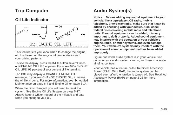
Trip Computer
Oil Life Indicator
This feature lets you know when to change the engineoil. It is based on the engine oil temperatures andyour driving patterns.
To see the display, press the INFO button several timesuntil ENGINE OIL LIFE appears. If you see 99% ENGINEOIL LIFE, 99 percent of your current oil life remains.
The DIC may display a CHANGE ENGINE OILmessage. If you see CHANGE ENGINE OIL, it meansthe oil life is gone. For more information, see ScheduledMaintenance on page 6-4 and Engine Oil on page 5-14.
When the oil is changed, you will need to reset thesystem. See Engine Oil Life System on page 5-17.Always keep a written record of the mileage and datewhen you changed your oil.
Audio System(s)Notice: Before adding any sound equipment to yourvehicle, like a tape player, CB radio, mobiletelephone, or two-way radio, make sure that it can beadded by checking with your dealer. Also, checkfederal rules covering mobile radio and telephoneunits. If sound equipment can be added, it is veryimportant to do it properly. Added sound equipmentmay interfere with the operation of your vehicle’sengine, radio, or other systems, and even damagethem. Your vehicle’s systems may interfere with theoperation of sound equipment that has been addedimproperly.
Figure out which audio system is in your vehicle, findout what your audio system can do, and how to operateall of its controls.
Your vehicle has a feature called Retained AccessoryPower (RAP). With RAP, the audio system can beplayed even after the ignition is turned off. See RetainedAccessory Power (RAP) on page 2-25 for moreinformation.
3-79
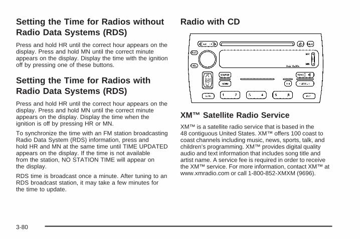
Setting the Time for Radios withoutRadio Data Systems (RDS)Press and hold HR until the correct hour appears on thedisplay. Press and hold MN until the correct minuteappears on the display. Display the time with the ignitionoff by pressing one of these buttons.
Setting the Time for Radios withRadio Data Systems (RDS)Press and hold HR until the correct hour appears on thedisplay. Press and hold MN until the correct minuteappears on the display. Display the time when theignition is off by pressing HR or MN.
To synchronize the time with an FM station broadcastingRadio Data System (RDS) information, press andhold HR and MN at the same time until TIME UPDATEDappears on the display. If the time is not availablefrom the station, NO STATION TIME will appear onthe display.
RDS time is broadcast once a minute. After tuning to anRDS broadcast station, it may take a few minutes forthe time to update.
Radio with CD
XM™ Satellite Radio ServiceXM™ is a satellite radio service that is based in the48 contiguous United States. XM™ offers 100 coast tocoast channels including music, news, sports, talk, andchildren’s programming. XM™ provides digital qualityaudio and text information that includes song title andartist name. A service fee is required in order to receivethe XM™ service. For more information, contact XM™ atwww.xmradio.com or call 1-800-852-XMXM (9696).
3-80
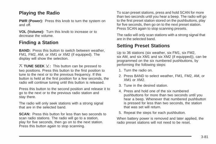
Playing the Radio
PWR (Power): Press this knob to turn the system onand off.
VOL (Volume): Turn this knob to increase or todecrease the volume.
Finding a Station
BAND: Press this button to switch between weather,FM1, FM2, AM, or XM1 or XM2 (if equipped). Thedisplay will show the selection.
¦TUNE SEEK ¥: This button can be pressed totwo positions. Press this button to the first position totune to the next or to the previous frequency. If thisbutton is held at the first position for a few seconds, theradio will continue tuning until this button is released.
Press this button to the second position and release it togo to the next or to the previous radio station andstay there.
The radio will only seek stations with a strong signalthat are in the selected band.
SCAN: Press this button for less than two seconds toscan radio stations. The radio will go to a station,play for five seconds, then go on to the next station.Press this button again to stop scanning.
To scan preset stations, press and hold SCAN for morethan two seconds until you hear a beep. The radio will goto the first preset station stored on the pushbuttons, playfor five seconds, then go on to the next preset station.Press SCAN again to stop scanning presets.
The radio will only scan stations with a strong signal thatare in the selected band.
Setting Preset StationsUp to 36 stations (six weather, six FM1, six FM2,six AM, and six XM1 and six XM2 (if equipped)), can beprogrammed on the six numbered pushbuttons, byperforming the following steps:
1. Turn the radio on.
2. Press BAND to select weather, FM1, FM2, AM, orXM1 or XM2.
3. Tune in the desired station.
4. Press and hold one of the six numberedpushbuttons for more than two seconds until youhear a beep. Whenever that numbered pushbuttonis pressed for less than two seconds, the stationthat was set will return.
5. Repeat the steps for each pushbutton.
When battery power is removed and later applied, theradio preset stations will not need to be reset.
3-81
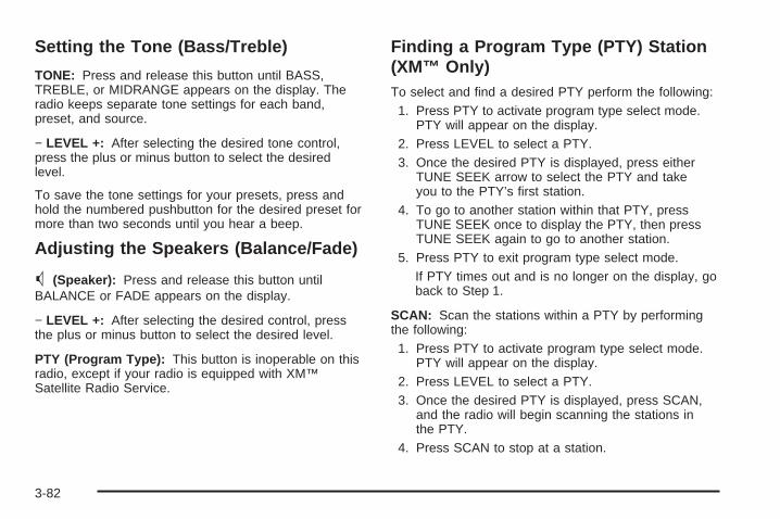
Setting the Tone (Bass/Treble)
TONE: Press and release this button until BASS,TREBLE, or MIDRANGE appears on the display. Theradio keeps separate tone settings for each band,preset, and source.
− LEVEL +: After selecting the desired tone control,press the plus or minus button to select the desiredlevel.
To save the tone settings for your presets, press andhold the numbered pushbutton for the desired preset formore than two seconds until you hear a beep.
Adjusting the Speakers (Balance/Fade)
M (Speaker): Press and release this button untilBALANCE or FADE appears on the display.
− LEVEL +: After selecting the desired control, pressthe plus or minus button to select the desired level.
PTY (Program Type): This button is inoperable on thisradio, except if your radio is equipped with XM™Satellite Radio Service.
Finding a Program Type (PTY) Station(XM™ Only)To select and find a desired PTY perform the following:
1. Press PTY to activate program type select mode.PTY will appear on the display.
2. Press LEVEL to select a PTY.3. Once the desired PTY is displayed, press either
TUNE SEEK arrow to select the PTY and takeyou to the PTY’s first station.
4. To go to another station within that PTY, pressTUNE SEEK once to display the PTY, then pressTUNE SEEK again to go to another station.
5. Press PTY to exit program type select mode.If PTY times out and is no longer on the display, goback to Step 1.
SCAN: Scan the stations within a PTY by performingthe following:
1. Press PTY to activate program type select mode.PTY will appear on the display.
2. Press LEVEL to select a PTY.3. Once the desired PTY is displayed, press SCAN,
and the radio will begin scanning the stations inthe PTY.
4. Press SCAN to stop at a station.
3-82
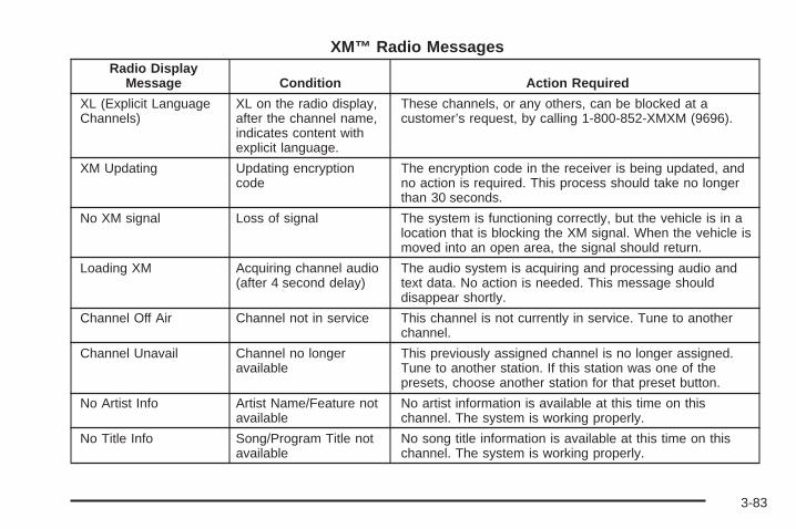
XM™ Radio MessagesRadio Display
Message Condition Action Required
XL (Explicit LanguageChannels)
XL on the radio display,after the channel name,indicates content withexplicit language.
These channels, or any others, can be blocked at acustomer’s request, by calling 1-800-852-XMXM (9696).
XM Updating Updating encryptioncode
The encryption code in the receiver is being updated, andno action is required. This process should take no longerthan 30 seconds.
No XM signal Loss of signal The system is functioning correctly, but the vehicle is in alocation that is blocking the XM signal. When the vehicle ismoved into an open area, the signal should return.
Loading XM Acquiring channel audio(after 4 second delay)
The audio system is acquiring and processing audio andtext data. No action is needed. This message shoulddisappear shortly.
Channel Off Air Channel not in service This channel is not currently in service. Tune to anotherchannel.
Channel Unavail Channel no longeravailable
This previously assigned channel is no longer assigned.Tune to another station. If this station was one of thepresets, choose another station for that preset button.
No Artist Info Artist Name/Feature notavailable
No artist information is available at this time on thischannel. The system is working properly.
No Title Info Song/Program Title notavailable
No song title information is available at this time on thischannel. The system is working properly.
3-83
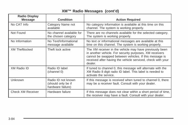
XM™ Radio Messages (cont’d)Radio Display
Message Condition Action Required
No CAT Info Category Name notavailable
No category information is available at this time on thischannel. The system is working properly.
Not Found No channel available forthe chosen category
There are no channels available for the selected category.The system is working properly.
No Information No Text/Informationalmessage available
No text or informational messages are available at thistime on this channel. The system is working properly.
XM Theftlocked Theft lock active The XM receiver in the vehicle may have previously beenin another vehicle. For security purposes, XM receiverscannot be swapped between vehicles. If this message isreceived after having the vehicle serviced, check with yourdealer.
XM Radio ID Radio ID label(channel 0)
If tuned to channel 0, this message will alternate with theXM Radio 8 digit radio ID label. This label is needed toactivate the service.
Unknown Radio ID not known(should only be ifhardware failure)
If this message is received when tuned to channel 0, theremay be a receiver fault. Consult with your dealer.
Check XM Receiver Hardware failure If this message does not clear within a short period of time,the receiver may have a fault. Consult with your dealer.
3-84
Playing a CDInsert a CD partway into the slot, label side up. Theplayer will pull it in. If the ignition and the radio are onand the underlined CD symbol appears on thedisplay, the CD will begin playing. A CD may be loadedwith the radio off but it will not start playing until theradio is on. If you want to insert a CD when the ignitionis off, first press the eject button.
If the ignition or radio is turned off with a CD in theplayer it will stay in the player. When the ignition or radiois turned on, the CD will start to play where it stopped,if it was the last selected audio source.
As each new track starts to play, the track number willappear on the display.
The CD player can play the smaller 3 inch (8 cm) singleCDs with an adapter ring. Full-size CDs and thesmaller CDs are loaded in the same manner.
If playing a CD-R the sound quality may be reduceddue to CD-R quality, the method of recording, the qualityof the music that has been recorded, and the way theCD-R has been handled. There may be an increasein skipping, difficulty in finding tracks, and/or difficulty inloading and ejecting. If these problems occur try aknown good CD.
Do not add paper labels to CDs, they could get caughtin the CD player.
If an error appears on the display, see “CD Messages”later in this section.
{ RW (Rewind): Press and hold the left arrow toreverse the CD. Release it to return to playing speed.
FF| (Fast Forward): Press and hold the right arrowto fast forward to another part of the CD. Release itto return to playing speed.
¦TUNE SEEK ¥: Press the up or the down arrow togo to the next or to the previous track.
1–6: Press this button to go to the next CD loaded inthe Glovebox-Mounted CD Changer. SeeGlovebox-Mounted CD Changer on page 3-99 for moreinformation.
RDM (Random): Press this pushbutton to listen to thetracks in random, rather than sequential, order. RDMwill appear on the display. Press RDM to turn off randomplay. RDM will disappear from the display.
3-85
SCAN: Press this button to listen to tracks for a fewseconds. The CD will go to a track, play for a fewseconds, then go on to the next track. Press this buttonagain to stop scanning.
SOURCE: Press this button to select a CD whenlistening to the radio. A CD must be loaded to play. If aCD is not loaded, NO SOURCE LOADED will appearon the display.
BAND: Press this button to listen to the radio whenlistening to the CD. The inactive CD will remain safelyinside the radio for future listening.
Z (Eject): Press this button to stop a CD when it isplaying or to eject a CD when it is not playing. Ejectmay be activated with the radio and the ignition off.
CD MessagesIf the CD comes out, it could be for one of the followingreasons:
• It is very hot. When the temperature returns tonormal, the CD should play.
• You are driving on a very rough road. When theroad becomes smoother, the CD should play.
• It is very hot. When the temperature returns tonormal, the CD should play.
• The CD is dirty, scratched, wet, or upside down.
• The air is very humid. If so, wait about an hour andtry again.
• There may have been a problem while burningthe CD.
• The label may be caught in the CD player.
If the CD is not playing correctly, for any other reason,try a known good CD.
If any error occurs repeatedly or if an error cannot becorrected, contact your dealer. If the radio displayan error message, write it down and provide it to yourdealer when reporting the problem.
3-86
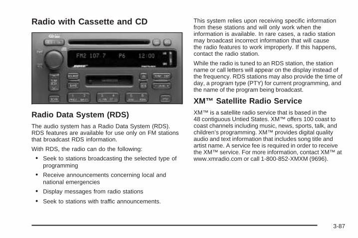
Radio with Cassette and CD
Radio Data System (RDS)The audio system has a Radio Data System (RDS).RDS features are available for use only on FM stationsthat broadcast RDS information.
With RDS, the radio can do the following:
• Seek to stations broadcasting the selected type ofprogramming
• Receive announcements concerning local andnational emergencies
• Display messages from radio stations
• Seek to stations with traffic announcements.
This system relies upon receiving specific informationfrom these stations and will only work when theinformation is available. In rare cases, a radio stationmay broadcast incorrect information that will causethe radio features to work improperly. If this happens,contact the radio station.
While the radio is tuned to an RDS station, the stationname or call letters will appear on the display instead ofthe frequency. RDS stations may also provide the time ofday, a program type (PTY) for current programming, andthe name of the program being broadcast.
XM™ Satellite Radio ServiceXM™ is a satellite radio service that is based in the48 contiguous Untied States. XM™ offers 100 coast tocoast channels including music, news, sports, talk, andchildren’s programming. XM™ provides digital qualityaudio and text information that includes song title andartist name. A service fee is required in order to receivethe XM™ service. For more information, contact XM™ atwww.xmradio.com or call 1-800-852-XMXM (9696).
3-87
Playing the Radio
PWR (Power): Press this knob to turn the system onand off.
VOL (Volume): Turn this knob to increase or todecrease the volume.
AVC (Automatic Volume Control): With AVC, theaudio system adjusts automatically to make up for roador wind noise as you drive.
To use AVC, press and hold the TONE button untilAUTO VOLUME CONTROL OFF appears on thedisplay. Then press the LEVEL plus symbol. AUTOVOLUME CONTROL ON will appear on the display.AVC VOLUME will appear on the display any time youadjust the volume while AVC is on. To turn AVC off,press and hold the TONE button until AUTO VOLUMECONTROL ON appears on the display. Then pressthe LEVEL minus symbol. AUTO VOLUME CONTROLOFF will appear on the display.
Finding a Station
BAND: Press this button to select weather, FM1, FM2,AM, or XM1 or XM2 (if equipped). The display willshow the selection.
¦TUNE SEEK¥: This button can be pressed to twopositions. Press this button to the first position to tune tothe next or to the previous frequency. If this button is heldat the first position for a few seconds, the radio willcontinue tuning until this button is released.
Press this button to the second position and release it togo to the next or to the previous radio station and staythere.
The radio will only seek stations with a strong signal thatare in the selected band.
SCAN: Press this button for less than two seconds toscan radio stations. The radio will go to a station,play for five seconds, then go on to the next station.Press this button again to stop scanning.
To scan preset stations, press and hold SCAN for morethan two seconds until you hear a beep. The radiowill go to the first preset station, play for five seconds,then go on to the next preset station. Press SCAN againto stop scanning presets.
The radio will only scan stations with a strong signalthat are in the selected band.
3-88
Setting Preset StationsThe RDS PTY mode must be off to set preset stations.Up to 36 stations (six weather, six FM1, six FM2,and six AM, six XM1 and six XM2 (if equipped), can beprogrammed on the six numbered pushbuttons, byperforming the following steps:
1. Turn the radio on.
2. Press BAND to select weather, FM1, FM2, AM, orXM1 or XM2.
3. Tune in the desired station.
4. Press and hold one of the six numberedpushbuttons for more than two seconds until youhear a beep. Whenever that numbered pushbuttonis pressed for less than two seconds, the stationthat was set will return.
5. Repeat the steps for each pushbutton.
When battery power is removed and later applied, youwill not have to reset the radio presets.
Setting the Tone (Bass/Treble)
TONE: Press and release this button until BASS,TREBLE, or MIDRANGE appears on the display. Theradio keeps separate tone settings for each band, preset(except weather band presets), and source.
− LEVEL +: After selecting the desired tone control,press the plus or minus button to select the desired level.
To save the tone settings for the presets, press and holdthe numbered pushbutton for the desired preset for morethan two seconds until you hear a beep.
Adjusting the Speakers (Balance/Fade)
TONE: Press and release this button until BALANCEor FADE appears on the display.
− LEVEL +: After selecting the desired control, pressthe plus or minus button to select the desired level.
To save the tone settings for the presets, press and holdthe numbered pushbutton for the desired preset formore than two seconds until you hear a beep.
3-89
Using Digital Signal Processing (DSP)
DSP: This feature is used to provide a choice offour different listening experiences: talk, front seat,ambience, and spacious. DSP can be used whilelistening to the radio, cassette, CD, or XM™.
Press this button to turn DSP on. Press and release thisbutton until the desired selection appears on the display.
To turn DSP off, press and hold this button until DSP OFFappears on the display. When DSP OFF appears on thedisplay, the system will provide the best overall audioperformance. The radio keeps separate DSP settings foreach band (except weather, which is always set to talk),preset, and source.
TALK: This setting should be used when listening tonon-musical material such as news, talk shows,sports broadcasts, and books on tape. Talk makesspoken words sound very clear.
FRONT SEAT: This setting adjusts the audio to give thedriver the best possible sound qualities. Front seat can beused at any time for any material. Rear seat passengersin the vehicle may not get the same effect.
AMBIENCE: This setting is used to enhance thestereo effect.
SPACIOUS: This setting is used to make the listeningspace seem larger.
Finding a Program Type (PTY) Station(XM™ Only)To select and find a desired PTY perform the following:
1. Press PTY to activate program type select mode.PTY will appear on the display.
2. Press LEVEL to select a PTY.
3. Once the desired PTY is displayed, press eitherTUNE SEEK arrow to select the PTY and to takeyou to the PTY’s first station.
4. To go to another station within that PTY, pressTUNE SEEK once to display the PTY, then pressTUNE SEEK again to go to another station.
5. Press PTY to exit program type select mode.If PTY times out and is no longer on the display, goback to Step 1.
If both PTY and TA are on, the radio will search forstations with the selected PTY and trafficannouncements.
3-90
SCAN: Scan the stations within a PTY by performingthe following:
1. Press PTY to activate program type select mode.PTY will appear on the display.
2. Press LEVEL to select a PTY.
3. Once the desired PTY is displayed, press SCAN,and the radio will begin scanning the stations inthe PTY.
4. Press SCAN to stop at a station.
RDS Messages
ALERT!: Alert warns of local or continental U.S.-basedemergencies. When an alert announcement comes onthe current radio station or a related network station,ALERT will appear on the display. You will hear theannouncement, even if the volume is low or a cassettetape or a CD is playing, or if RDS mode is turned off.
To increase or to decrease the volume, turn the PWR/VOL knob. TA VOLUME will appear on the display whilethe volume is being adjusted.
If the radio tunes to a related network station for an alertannouncement, it will return to the original station whenthe announcement is finished. If a cassette tape or CD isplaying, play will stop during the announcement. Alertannouncements cannot be turned off.
ALERT! will not be affected by tests of the emergencybroadcast system. This feature is not supported by allRDS stations.
MSG (Message): If the current station has a message,MSG will appear on the display. Press this button, tosee the message. The message may display the artist,song title, call in phone numbers, etc.
If the entire message does not appear on the display,parts of the message will appear every three seconds.To scroll through the message, press and releasethe MSG button. A new group of words will appear onthe display after every press of the MSG button.Once the complete message has been displayed, MSGwill disappear from the display until another newMSG is received.
3-91
For XM™ (if equipped), press the MSG button while inXM mode to retrieve four different categories ofinformation related to the current song or channel: ArtistName/Feature, Song/Program Title, Channel Category.
Each of the four information types may have multiplepages of text. To reach a category, press and releasethe MSG button repeatedly until the desired type isdisplayed. If there are multiple pages of text forthe information selected type, the radio will automaticallydisplay all the pages for that type at a rate of aboutone page every three seconds before timing outand returning to the default display. You may overridethis feature by pressing the MSG button to review all ofthe pages at your own pace.
TA (Traffic): If TA appears on the display, the tunedstation broadcasts traffic announcements and whena traffic announcement comes on the tuned radio stationyou will hear it.
If the station does not broadcast traffic announcements,press the TA button and the radio will seek to astation that does. When a station that broadcasts trafficannouncements is found, the radio will stop seekingand TA will appear on the display.
When a traffic announcement comes on the tuned radiostation you will hear it. If no station is found thatbroadcasts traffic announcements, NO TRAFFICSTATION FOUND will appear on the display.
If TA is on the display, press the TA button to turn offthe traffic announcements.
The radio will play the traffic announcement even if thevolume is low. The radio will interrupt the play of acassette tape or CD if the last tuned station broadcaststraffic announcements.
This function does not apply to XM™ Satellite RadioService.
3-92

XM™ Radio MessagesRadio Display
Message Condition Action Required
XL (Explicit LanguageChannels)
XL on the radio display,after the channel name,indicates content withexplicit language.
These channels, or any others, can be blocked at acustomer’s request, by calling 1-800-852-XMXM (9696).
XM Updating Updating encryptioncode
The encryption code in the receiver is being updated, andno action is required. This process should take no longerthan 30 seconds.
No XM signal Loss of signal The system is functioning correctly, but the vehicle is in alocation that is blocking the XM signal. When you moveinto an open area, the signal should return.
Loading XM Acquiring channel audio(after 4 second delay)
The audio system is acquiring and processing audio andtext data. No action is needed. This message shoulddisappear shortly.
Channel Off Air Channel not in service This channel is not currently in service. Tune to anotherchannel.
Channel Unavail Channel no longeravailable
This previously assigned channel is no longer assigned.Tune to another station. If this station was one of thepresets, choose another station for that preset button.
No Artist Info Artist Name/Feature notavailable
No artist information is available at this time on thischannel. The system is working properly.
No Title Info Song/Program Title notavailable
No song title information is available at this time on thischannel. The system is working properly.
3-93
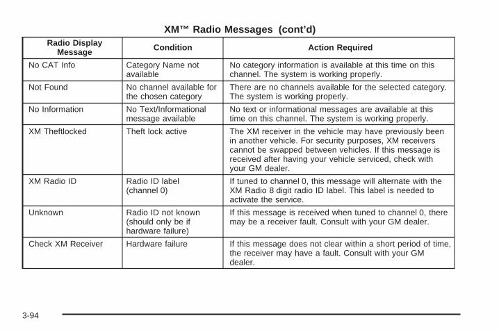
XM™ Radio Messages (cont’d)Radio Display
Message Condition Action Required
No CAT Info Category Name notavailable
No category information is available at this time on thischannel. The system is working properly.
Not Found No channel available forthe chosen category
There are no channels available for the selected category.The system is working properly.
No Information No Text/Informationalmessage available
No text or informational messages are available at thistime on this channel. The system is working properly.
XM Theftlocked Theft lock active The XM receiver in the vehicle may have previously beenin another vehicle. For security purposes, XM receiverscannot be swapped between vehicles. If this message isreceived after having your vehicle serviced, check withyour GM dealer.
XM Radio ID Radio ID label(channel 0)
If tuned to channel 0, this message will alternate with theXM Radio 8 digit radio ID label. This label is needed toactivate the service.
Unknown Radio ID not known(should only be ifhardware failure)
If this message is received when tuned to channel 0, theremay be a receiver fault. Consult with your GM dealer.
Check XM Receiver Hardware failure If this message does not clear within a short period of time,the receiver may have a fault. Consult with your GMdealer.
3-94
Playing a Cassette TapeThe tape player is built to work best with tapes that areup to 30 to 45 minutes long on each side. Tapeslonger than that are so thin they may not work well inthis player. The longer side with the tape visible shouldface to the right. If you hear nothing or hear a garbledsound, the tape may not be in squarely. Press the ejectbutton to remove the tape and start over.
If the ignition and radio are off, press the eject button orthe RCL knob to insert and to begin play of a tape. Ifthe ignition is on and the radio is off, the tape canbe inserted and will begin playing.
While the tape is playing, use the VOL, TONE, LEVEL,and DSP controls just as you do for the radio. Othercontrols may have different functions when a tapeis inserted. The display will show an underlined tapesymbol. TAPE PLAY will appear on the display when atape is playing, with an arrow to indicate which sideof the tape is playing.
Your cassette tape player automatically reducesbackground noise. Dolby® Noise Reduction ismanufactured under a license from Dolby® LaboratoriesLicensing Corporation. Dolby® and the double-Dsymbol are trademarks of Dolby® Laboratories LicensingCorporation.
Cassette tape adapter kits for portable CD players willwork in the cassette tape player. See “CD Adapter Kits”later for more information.
The tape bias is set automatically when a metal orchrome tape is inserted.
If an error appears on the display, see “Cassette TapeMessages” later in this section.
1 PREV (Previous): The tape must have at leastthree seconds of silence between each selection forprevious to work. Press this pushbutton to go tothe previous selection on the tape.
2 NEXT: The tape must have at least three seconds ofsilence between each selection for next to work. Pressthis pushbutton to go to the next selection on the tape.
3{ RW (Rewind): Press this pushbutton to quicklyrewind the tape. The radio will play while the taperewinds. Press this pushbutton again to return toplaying speed.
4 FF| (Fast Forward): Press this pushbutton toquickly fast forward the tape. The radio will play whilethe tape advances. Press this pushbutton again to returnto playing speed.
3-95
¦SEEK¥: The tape must have at least three secondsof silence between each selection for SEEK to work.Press the up or the down arrow to seek to the next or tothe previous selection on the tape.
SCAN: Press this button to listen to each selection fora few seconds. The tape will go to the next selection,play for a few seconds, then go on to the next selection.Press this button again to stop scanning.
SOURCE: Press this button to play a cassette tape orCD when listening to the radio. Available loadedsources are shown on the display. If a source is beingused, it will be underlined on the display. If none ofthe audio sources are loaded, NO SOURCE LOADEDwill appear on the display.
BAND: Press this button to listen to the radio whenplaying a cassette tape or CD. The inactive tape or CDwill remain safely inside the radio for future listening.
SIDE: Press this button to play the other side ofthe tape.
Z (Eject): Press this button, located to the right ofthe cassette tape slot, to stop a tape when it is playingor to eject a tape when it is not playing. Eject maybe activated with the radio and the ignition off. Cassettetapes may be loaded with the radio and ignition off ifthis button is pressed first.
Cassette Tape MessagesIf an error occurs while trying to play a cassette tape, itcould be for one of the following reasons:
• The cassette tape is tight and the cassette playercannot turn the tape hubs. Remove the tape.Hold the tape with the open end down and try toturn the right hub counterclockwise with apencil. Turn the tape over and repeat. If the hubsdo not turn easily, the tape may be damagedand should not be used in the player. Try a newtape to make sure the player is working properly.
• The tape is broken. Try a new tape.
• The tape is wrapped around the tape head. Attemptto get the cassette out. Try a new tape.
CLEAN TAPE: If this message appears on the display,the cassette tape player needs to be cleaned. It willstill play tapes, but it should be cleaned as soonas possible to prevent damage to the tapes and player.See Care of Your Cassette Tape Player on page 3-104.
If the cassette tape is not playing correctly, for anyother reason, try a known good cassette.
If any error occurs repeatedly or if an error cannot becorrected, contact your GM dealer. If the radio displaysan error message, write it down and provide it toyour GM dealer when reporting the problem.
3-96
Playing a CDInsert a CD partway into the slot, label side up. Theplayer will pull it in and the CD should begin playing. Ifyou want to insert a CD when the ignition is off, firstpress the eject button or push the RCL knob.
If the ignition or radio is turned off with the CD in theplayer, it will stay in the player. When the ignitionor radio is turned on, the CD will start playing where itstopped, if it was the last selected audio source.
When a CD is inserted, the CD symbol will appear onthe display. As each new track starts to play, thetrack number will appear on the display.
The CD player can play the smaller 3 inch (8 cm) singleCDs with an adapter ring. Full-size CDs and thesmaller CDs are loaded in the same manner.
If playing a CD-R the sound quality may be reduceddue to CD-R quality, the method of recording, the qualityof the music that has been recorded, and the way theCD-R has been handled. There may be an increasein skipping, difficulty in finding tracks, and/or difficulty inloading and ejecting. If these problems occur try aknown good CD.
Do not add paper labels to CDs, they could get caughtin the CD player.
If an error appears on the display, see “CD Messages”later in this section.
1 PREV (Previous): Press this pushbutton to go to theprevious track on the CD.
2 NEXT: Press this pushbutton to go to the next trackon the CD.
3{ RW (Rewind): Press this pushbutton to reversequickly within a track. Release it to return to playingspeed.
4 FF| (Fast Forward): Press this pushbutton to fastforward quickly within a track. Release it to return toplaying speed.
6 RDM (Random): Press this pushbutton to listen tothe tracks in random, rather than sequential, order. RDMwill appear on the display. Press RDM to turn offrandom play. RDM will disappear from the display.
¦SEEK ¥: Press the up or the down arrow to go tothe next or to the previous track.
SIDE: Press this button to play a CD when listening tothe radio.
3-97
SCAN: Press this button to listen to each track for afew seconds. The CD will go to a track, play for afew seconds, then go on to the next track. Press thisbutton again to stop scanning.
SOURCE: Press this button to play a cassette tape orCD when listening to the radio. Available loadedsources are shown on the display. If a source is beingused, it will be underlined on the display. If none ofthe audio sources are loaded, NO SOURCE LOADEDwill appear on the display.
BAND: Press this button to listen to the radio whenplaying a cassette tape or CD. The inactive tape or CDwill remain safely inside the radio for future listening.
Z (Eject): Press this button, located to the right of theCD slot, to stop a CD when it is playing or to eject aCD when it is not playing. Eject may be activated withthe ignition and radio off.
CD MessagesIf the CD comes out, it could be for one of the followingreasons:
• It is very hot. When the temperature returns tonormal, the CD should play.
• You are driving on a very rough road. When theroad becomes smoother, the CD should play.
• It is very hot. When the temperature returns tonormal, the CD should play.
• The CD is dirty, scratched, wet, or upside down.
• The air is very humid. If so, wait about an hour andtry again.
• There may have been a problem while burningthe CD.
• The label may be caught in the CD player.
If the CD is not playing correctly, for any other reason,try a known good CD.
If any error occurs repeatedly or if an error cannot becorrected, contact your GM dealer. If the radio displaysan error message, write it down and provide it toyour GM dealer when reporting the problem.
3-98
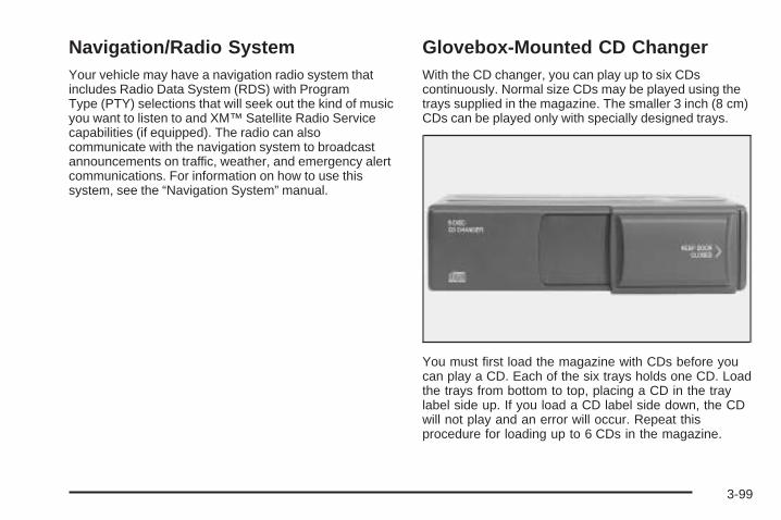
Navigation/Radio SystemYour vehicle may have a navigation radio system thatincludes Radio Data System (RDS) with ProgramType (PTY) selections that will seek out the kind of musicyou want to listen to and XM™ Satellite Radio Servicecapabilities (if equipped). The radio can alsocommunicate with the navigation system to broadcastannouncements on traffic, weather, and emergency alertcommunications. For information on how to use thissystem, see the “Navigation System” manual.
Glovebox-Mounted CD ChangerWith the CD changer, you can play up to six CDscontinuously. Normal size CDs may be played using thetrays supplied in the magazine. The smaller 3 inch (8 cm)CDs can be played only with specially designed trays.
You must first load the magazine with CDs before youcan play a CD. Each of the six trays holds one CD. Loadthe trays from bottom to top, placing a CD in the traylabel side up. If you load a CD label side down, the CDwill not play and an error will occur. Repeat thisprocedure for loading up to 6 CDs in the magazine.
3-99
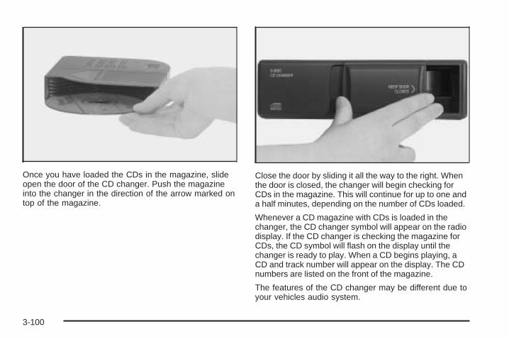
Once you have loaded the CDs in the magazine, slideopen the door of the CD changer. Push the magazineinto the changer in the direction of the arrow marked ontop of the magazine.
Close the door by sliding it all the way to the right. Whenthe door is closed, the changer will begin checking forCDs in the magazine. This will continue for up to one anda half minutes, depending on the number of CDs loaded.
Whenever a CD magazine with CDs is loaded in thechanger, the CD changer symbol will appear on the radiodisplay. If the CD changer is checking the magazine forCDs, the CD symbol will flash on the display until thechanger is ready to play. When a CD begins playing, aCD and track number will appear on the display. The CDnumbers are listed on the front of the magazine.
The features of the CD changer may be different due toyour vehicles audio system.
3-100
1 PREV (Previous) / ¦TUNE SEEK ¥: Press thispushbutton or the up arrow to go to the previoustrack on the CD. If playing the first track of the CD,press this pushbutton or the up arrow to go to the lasttrack of the CD.
2 NEXT /¦TUNE SEEK ¥: Press this pushbutton orthe down arrow to go to the next track on the CD. Ifplaying last track of the CD, press this pushbutton or thedown arrow to go to the first track of the CD.
3{ RW /{ RW (Rewind): Press and hold thispushbutton to reverse quickly within a track.
4 FF| / FF| (Fast Forward): Press and hold thispushbutton to advance quickly within a track.
5 CD / 5: Press this pushbutton to select the next CD inthe changer. Each time you press this button, LOADINGwill appear on the display and the CD number on theradio display will go to that of the next available CD.
6 RDM / RDM (Random): Press this pushbutton to hearthe tracks in random, rather than sequential, order. RDMwill appear on the display. Press the PREV or NEXTpushbuttons while RDM is on the display to randomlyseek through CDs. Press RDM again to turn off randomplay. This feature may not be available on your radio.
SCAN: Press this button to hear the first few secondsof the first track on each CD. SCAN will appear onthe display and the CD will mute while scanning. Pressthis button again to stop scanning.
SOURCE: Press this button to play a cassette tape orCD when listening to the radio. The inactive CD willremain safely inside the radio for future listening.
BAND: Press this button to listen to the radio whenplaying a CD. The inactive CD(s) will remain safelyinside the radio for future listening.
EJECT: Slide the CD changer door all the way open.Press the EJECT button and the magazine will eject.
3-101
CD MessagesCD CHANGER ERROR: This message may appear onthe display for one of the following reasons:
• It is very hot. When the temperature returns tonormal, the CD should play.
• You are driving on a very rough road. When theroad becomes smoother, the CD should play.
• The CD is dirty, scratched, wet, or upside down.
• The air is very humid. If so, wait about an hour andtry again.
• There may have been a problem while burningthe CD.
• The label may be caught in the CD player.
If the CD is not playing correctly, for any other reason,try a known good CD.
If any error occurs repeatedly or if an error cannot becorrected, contact your dealer. If the radio displaysan error message, write it down and provide it to yourdealer when reporting the problem.
Radio Personalization with Homeand Away FeatureIf your vehicle has this feature, DRIVER 1 (HOME orAWAY) PRESETS or DRIVER 2 (HOME or AWAY)PRESETS will appear on the display when the radio isfirst turned on.
This feature allows the driver to return to the last usedaudio source: radio, cassette, or CD, using theremote keyless entry transmitter. This feature can alsostore and recall AM and FM presets, volume, tone,and the last selected radio station. The number on theback of each transmitter, 1 or 2, corresponds todriver 1 or 2. If transmitter 1 is used to enter the vehicle,the last used audio source and/or settings set bydriver 1 will be recalled. If transmitter 2 is used to enterthe vehicle, the last used audio source and/or settingsset by driver 2 will be recalled. The settings can also berecalled by pressing the memory seat buttons 1 or 2located on the driver’s door.
Your radio can store home and away presets. Home andaway presets allow you to use one set of preset radiosettings in the area where you live, and another set whenyou go out of town. You will not need to reprogram thepresets every time you travel.
3-102
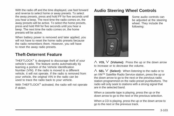
With the radio off and the time displayed, use fast forwardand reverse to select home or away presets. To selectthe away presets, press and hold FF for five seconds untilyou hear a beep. The next time the radio comes on, theaway presets will be active. To select the home presets,press and hold RW for five seconds until you hear abeep. The next time the radio comes on, the homepresets will be active.
When battery power is removed and later applied, youwill not have to reset the home radio presets becausethe radio remembers them. However, you will haveto reset the away radio presets.
Theft-Deterrent FeatureTHEFTLOCK® is designed to discourage theft of yourvehicle’s radio. The feature works automatically bylearning a portion of the Vehicle IdentificationNumber (VIN). If the radio is moved to a differentvehicle, it will not operate. If the radio is removed fromyour vehicle, the original VIN in the radio can beused to trace the radio back to your vehicle.
With THEFTLOCK® activated, the radio will not operateif stolen.
Audio Steering Wheel ControlsSome audio controls canbe adjusted at the steeringwheel. They include thefollowing:
y VOLz (Volume): Press the up or the down arrowto increase or to decrease the volume.
y SELz (Select): When listening to the radio or toan XM™ Satellite Radio Service station, press the up orthe down arrow to go to the next or the previous radiostation programmed on the radio preset pushbuttons. Theradio will only seek to stations with a strong signal thatare in the selected band.
When a cassette tape is playing, press the up or thedown arrow to go to the next or the previous selection.
When a CD is playing, press the up or the down arrow togo to the next or the previous track.
3-103
Radio Reception
AMThe range for most AM stations is greater than for FM,especially at night. The longer range can causestation frequencies to interfere with each other. Staticcan occur on AM stations caused by things likestorms and power lines. Try reducing the treble toreduce this noise.
FM StereoFM stereo will give the best sound, but FM signals willreach only about 10 to 40 miles (16 to 65 km). Tallbuildings or hills can interfere with FM signals, causingthe sound to fade in and out.
XM™ Satellite Radio ServiceXM™ Satellite Radio Service gives digital radio receptionfrom coast to coast. Just as with FM, tall buildings or hillscan interfere with satellite radio signals, causing thesound to fade in and out. The radio may display NO XMSIGNAL to indicate interference.
Cellular Phone UsageCellular phone usage may cause interference with yourvehicle’s radio. This interference may occur whenmaking or receiving phone calls, charging the phone’sbattery, or simply having the phone on. This interferenceis an increased level of static while listening to theradio. If static is received while listening to the radio,unplug the cellular phone and turn it off.
Weather BandWeather band is restricted to speech and the audioquality is not as good as with the AM or FM bands.Depending on location, the radio should receive one ortwo channels.
Care of Your Cassette Tape PlayerA tape player that is not cleaned regularly can causereduced sound quality, ruined cassettes, or a damagedmechanism. Cassette tapes should be stored in theircases away from contaminants, direct sunlight, andextreme heat. If they are not, they may not operateproperly or may cause failure of the tape player.
3-104
The tape player should be cleaned regularly after every50 hours of use. The radio may display CLEAN TAPE toindicate that the tape player has been used for 50 hourswithout resetting the tape clean timer. If this messageappears on the display, the cassette tape player needs tobe cleaned. It will still play tapes, but it should be cleanedas soon as possible to prevent damage to the tapes andplayer. If there is a reduction in sound quality, try a knowngood cassette to see if the tape or the tape player is atfault. If this other cassette has no improvement in soundquality, clean the tape player.
For best results, use a scrubbing action, non-abrasivecleaning cassette with pads which scrub the tape head asthe hubs of the cleaner cassette turn. The recommendedcleaning cassette is available through your dealer.
The broken tape detection feature of the cassette tapeplayer may identify the cleaning cassette as a damagedtape, in error. To prevent the cleaning cassette frombeing ejected, use the following steps:
1. Turn the ignition on.
2. Turn the radio off.
3. Press and hold the SOURCE button for two seconds.The tape symbol on the display will flash three times.
4. Turn the radio on and insert the scrubbing actioncleaning cassette.
5. Eject the cleaning cassette after the manufacturer’srecommended cleaning time.After the cleaning cassette is ejected, the brokentape detection feature will be active again.
A non-scrubbing action, wet-type cleaner which uses acassette with a fabric belt to clean the tape head can beused. This type of cleaning cassette will not eject on itsown. A non-scrubbing action cleaner may not clean asthoroughly as the scrubbing type cleaner. The use of anon-scrubbing action, dry-type cleaning cassette is notrecommended.
After the player is cleaned, press and hold the ejectbutton for five seconds to reset the CLEAN TAPEindicator. The radio will display CLEAN TAPE MSGCLEARED to show the indicator was reset.
Cassettes are subject to wear and the sound quality maydegrade over time. Always make sure the cassette tapeis in good condition before the tape player is serviced.
3-105
Care of Your CDsHandle CDs carefully. Store them in their original casesor other protective cases and away from directsunlight and dust. If the surface of a CD is soiled,dampen a clean, soft cloth in a mild, neutral detergentsolution and clean it, wiping from the center to the edge.
Be sure never to touch the side without writing whenhandling CDs. Pick up CDs by grasping the outer edgesor the edge of the hole and the outer edge.
Care of Your CD PlayerThe use of CD lens cleaners for CD players is notadvised, due to the risk of contaminating the lens of theCD optics with lubricants internal to the CD mechanism.
Diversity Antenna SystemThe AM-FM antennas are located in the windshield andrear window. Make sure that the inside surfaces of thewindshield and rear window are not scratched and thatthe grid lines on the glass are not damaged. If the insidesurfaces are damaged, they could interfere with radioreception. Also, for proper radio reception, the antennaconnector located on the passenger’s side top corner ofthe windshield and the antenna connector located on thedriver’s side top corner of the rear window need to beproperly attached to the buttons on the glass.
Notice: Do not apply aftermarket glass tinting withmetallic film. The metallic film in some tintingmaterials will interfere with or distort the incomingradio reception. Any damage caused to yourbackglass antenna due to metallic tinting materialswill not be covered by your warranty.
3-106
Notice: Do not try to clear frost or other materialfrom the inside of the front windshield and rearwindow with a razor blade or anything else that issharp. This may damage the rear window defoggergrid and affect your radio’s ability to pick upstations clearly. The repairs wouldn’t be covered byyour warranty.
If static is heard on the radio, when the rear windowdefogger is turned on, it could mean that a defogger gridline has been damaged. If this is true, the grid linemust be repaired.
If adding an aftermarket cellular telephone to yourvehicle, and the antenna needs to be attached to theglass, make sure that the grid lines for the AM-FMantennas are not damaged. Make sure the cellulartelephone antenna does not touch a grid line.
XM™ Satellite Radio AntennaSystemThe XM™ Satellite Radio antenna is located on the roofof your vehicle. Keep this antenna clear of snow andice build up for clear radio reception.
3-107

✍ NOTES
3-108
Your Driving, the Road, and Your Vehicle ..........4-2Defensive Driving ...........................................4-2Drunken Driving .............................................4-2Control of a Vehicle ........................................4-5Braking .........................................................4-5Anti-Lock Brake System (ABS) .........................4-6Braking in Emergencies ...................................4-8Traction Control System (TCS) .........................4-8Continuous Variable Road Sensing
Suspension (CVRSS) .................................4-10Steering ......................................................4-10Off-Road Recovery .......................................4-12Passing .......................................................4-13Loss of Control .............................................4-14Driving at Night ............................................4-16
Driving in Rain and on Wet Roads ..................4-17City Driving ..................................................4-20Freeway Driving ...........................................4-21Before Leaving on a Long Trip .......................4-22Highway Hypnosis ........................................4-23Hill and Mountain Roads ................................4-23Winter Driving ..............................................4-25If You Are Stuck: In Sand, Mud, Ice or Snow ........4-29Rocking Your Vehicle to Get It Out .................4-30Loading Your Vehicle ....................................4-30
Towing ..........................................................4-35Towing Your Vehicle .....................................4-35Recreational Vehicle Towing ...........................4-35Towing a Trailer ...........................................4-37
Section 4 Driving Your Vehicle
4-1
Your Driving, the Road, andYour Vehicle
Defensive DrivingThe best advice anyone can give about driving is: Drivedefensively.
Please start with a very important safety device in yourvehicle: Buckle up. See Safety Belts: They Are forEveryone on page 1-7.
Defensive driving really means “be ready for anything.”On city streets, rural roads, or freeways, it means“always expect the unexpected.”
Assume that pedestrians or other drivers are going tobe careless and make mistakes. Anticipate whatthey might do. Be ready for their mistakes.
Rear-end collisions are about the most preventable ofaccidents. Yet they are common. Allow enough followingdistance. It is the best defensive driving maneuver, inboth city and rural driving. You never know when thevehicle in front of you is going to brake or turn suddenly.
Defensive driving requires that a driver concentrate onthe driving task. Anything that distracts from the drivingtask — such as concentrating on a cellular telephone call,reading, or reaching for something on the floor — makesproper defensive driving more difficult and can evencause a collision, with resulting injury. Ask a passenger tohelp do things like this, or pull off the road in a safe placeto do them yourself. These simple defensive drivingtechniques could save your life.
Drunken DrivingDeath and injury associated with drinking and driving isa national tragedy. It is the number one contributorto the highway death toll, claiming thousands of victimsevery year.
Alcohol affects four things that anyone needs to drive avehicle:
• Judgment
• Muscular Coordination
• Vision
• Attentiveness
4-2
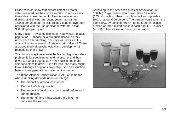
Police records show that almost half of all motorvehicle-related deaths involve alcohol. In most cases,these deaths are the result of someone who wasdrinking and driving. In recent years, more than16,000 annual motor vehicle-related deaths have beenassociated with the use of alcohol, with more than300,000 people injured.
Many adults — by some estimates, nearly half the adultpopulation — choose never to drink alcohol, so theynever drive after drinking. For persons under 21, it isagainst the law in every U.S. state to drink alcohol. Thereare good medical, psychological and developmentalreasons for these laws.
The obvious way to eliminate the leading highway safetyproblem is for people never to drink alcohol and thendrive. But what if people do? How much is “too much” ifsomeone plans to drive? It is a lot less than many mightthink. Although it depends on each person and situation,here is some general information on the problem.
The Blood Alcohol Concentration (BAC) of someonewho is drinking depends upon four things:• The amount of alcohol consumed• The drinker’s body weight• The amount of food that is consumed before and
during drinking• The length of time it has taken the drinker to
consume the alcohol
According to the American Medical Association, a180 lb (82 kg) person who drinks three 12 ounce(355 ml) bottles of beer in an hour will end up with aBAC of about 0.06 percent. The person would reach thesame BAC by drinking three 4 ounce (120 ml) glassesof wine or three mixed drinks if each had 1-1/2 ounces(45 ml) of liquors like whiskey, gin, or vodka.
4-3
It is the amount of alcohol that counts. For example, ifthe same person drank three double martinis (3 ouncesor 90 ml of liquor each) within an hour, the person’sBAC would be close to 0.12 percent. A personwho consumes food just before or during drinking willhave a somewhat lower BAC level.
There is a gender difference, too. Women generallyhave a lower relative percentage of body waterthan men. Since alcohol is carried in body water, thismeans that a woman generally will reach a higher BAClevel than a man of her same body weight will wheneach has the same number of drinks.
The law in most U.S. states, and throughout Canada,sets the legal limit at 0.08 percent. In some othercountries, the limit is even lower. For example, it is0.05 percent in both France and Germany. TheBAC limit for all commercial drivers in the United Statesis 0.04 percent.
The BAC will be over 0.10 percent after three tosix drinks (in one hour). Of course, as we have seen, itdepends on how much alcohol is in the drinks, andhow quickly the person drinks them.
But the ability to drive is affected well below a BAC of0.10 percent. Research shows that the driving skillsof many people are impaired at a BAC approaching0.05 percent, and that the effects are worse at night. Alldrivers are impaired at BAC levels above 0.05 percent.Statistics show that the chance of being in a collisionincreases sharply for drivers who have a BAC of0.05 percent or above. A driver with a BAC level of0.06 percent has doubled his or her chance of having acollision. At a BAC level of 0.10 percent, the chanceof this driver having a collision is 12 times greater; at alevel of 0.15 percent, the chance is 25 times greater!
The body takes about an hour to rid itself of the alcohol inone drink. No amount of coffee or number of coldshowers will speed that up. “I will be careful” is not theright answer. What if there is an emergency, a need totake sudden action, as when a child darts into the street?A person with even a moderate BAC might not be able toreact quickly enough to avoid the collision.
There is something else about drinking and driving thatmany people do not know. Medical research shows thatalcohol in a person’s system can make crash injuriesworse, especially injuries to the brain, spinal cord, orheart. This means that when anyone who has beendrinking — driver or passenger — is in a crash, thatperson’s chance of being killed or permanently disabledis higher than if the person had not been drinking.
4-4
{CAUTION:
Drinking and then driving is very dangerous.Your reflexes, perceptions, attentiveness, andjudgment can be affected by even a smallamount of alcohol. You can have a serious — oreven fatal — collision if you drive after drinking.Please do not drink and drive or ride with adriver who has been drinking. Ride home in acab; or if you are with a group, designate adriver who will not drink.
Control of a VehicleYou have three systems that make your vehicle go whereyou want it to go. They are the brakes, the steering, andthe accelerator. All three systems have to do their work atthe places where the tires meet the road.
Sometimes, as when you are driving on snow or ice, it iseasy to ask more of those control systems than the tiresand road can provide. That means you can lose control ofyour vehicle. See Traction Control System (TCS) onpage 4-8.
BrakingBraking action involves perception time andreaction time.
First, you have to decide to push on the brake pedal.That is perception time. Then you have to bring up yourfoot and do it. That is reaction time.
Average reaction time is about three-fourths of asecond. But that is only an average. It might be lesswith one driver and as long as two or three seconds ormore with another. Age, physical condition, alertness,coordination and eyesight all play a part. So do alcohol,drugs and frustration. But even in three-fourths of asecond, a vehicle moving at 60 mph (100 km/h) travels66 feet (20 m). That could be a lot of distance in anemergency, so keeping enough space betweenyour vehicle and others is important.
And, of course, actual stopping distances vary greatlywith the surface of the road (whether it is pavementor gravel); the condition of the road (wet, dry, icy); tiretread; the condition of your brakes; the weight ofthe vehicle and the amount of brake force applied.
4-5
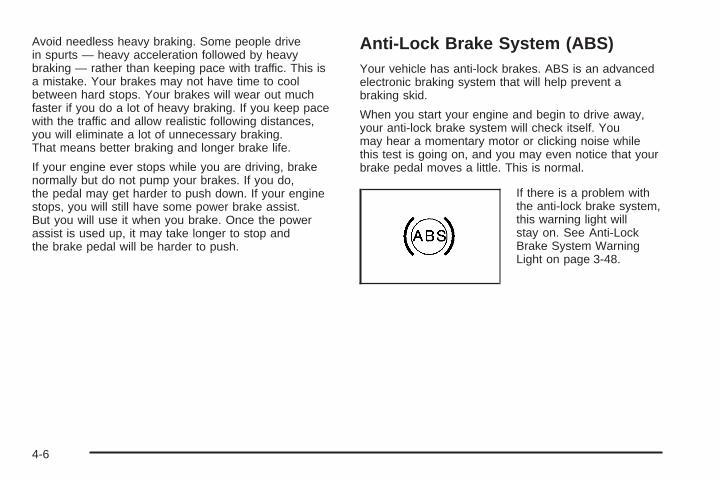
Avoid needless heavy braking. Some people drivein spurts — heavy acceleration followed by heavybraking — rather than keeping pace with traffic. This isa mistake. Your brakes may not have time to coolbetween hard stops. Your brakes will wear out muchfaster if you do a lot of heavy braking. If you keep pacewith the traffic and allow realistic following distances,you will eliminate a lot of unnecessary braking.That means better braking and longer brake life.
If your engine ever stops while you are driving, brakenormally but do not pump your brakes. If you do,the pedal may get harder to push down. If your enginestops, you will still have some power brake assist.But you will use it when you brake. Once the powerassist is used up, it may take longer to stop andthe brake pedal will be harder to push.
Anti-Lock Brake System (ABS)Your vehicle has anti-lock brakes. ABS is an advancedelectronic braking system that will help prevent abraking skid.
When you start your engine and begin to drive away,your anti-lock brake system will check itself. Youmay hear a momentary motor or clicking noise whilethis test is going on, and you may even notice that yourbrake pedal moves a little. This is normal.
If there is a problem withthe anti-lock brake system,this warning light willstay on. See Anti-LockBrake System WarningLight on page 3-48.
4-6
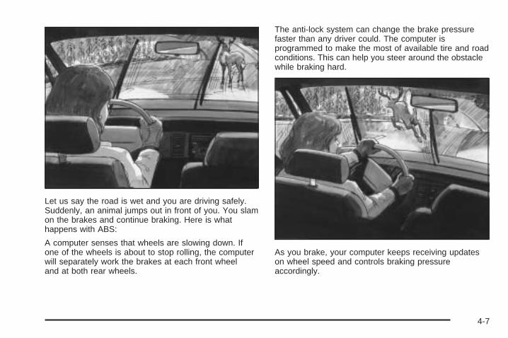
Let us say the road is wet and you are driving safely.Suddenly, an animal jumps out in front of you. You slamon the brakes and continue braking. Here is whathappens with ABS:
A computer senses that wheels are slowing down. Ifone of the wheels is about to stop rolling, the computerwill separately work the brakes at each front wheeland at both rear wheels.
The anti-lock system can change the brake pressurefaster than any driver could. The computer isprogrammed to make the most of available tire and roadconditions. This can help you steer around the obstaclewhile braking hard.
As you brake, your computer keeps receiving updateson wheel speed and controls braking pressureaccordingly.
4-7
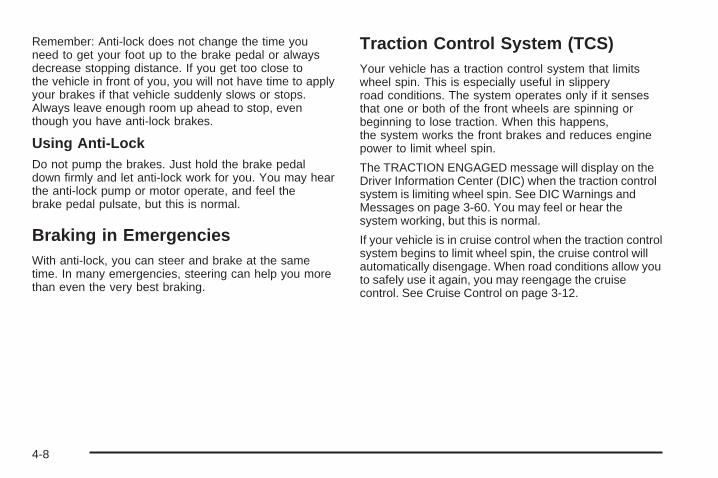
Remember: Anti-lock does not change the time youneed to get your foot up to the brake pedal or alwaysdecrease stopping distance. If you get too close tothe vehicle in front of you, you will not have time to applyyour brakes if that vehicle suddenly slows or stops.Always leave enough room up ahead to stop, eventhough you have anti-lock brakes.
Using Anti-LockDo not pump the brakes. Just hold the brake pedaldown firmly and let anti-lock work for you. You may hearthe anti-lock pump or motor operate, and feel thebrake pedal pulsate, but this is normal.
Braking in EmergenciesWith anti-lock, you can steer and brake at the sametime. In many emergencies, steering can help you morethan even the very best braking.
Traction Control System (TCS)Your vehicle has a traction control system that limitswheel spin. This is especially useful in slipperyroad conditions. The system operates only if it sensesthat one or both of the front wheels are spinning orbeginning to lose traction. When this happens,the system works the front brakes and reduces enginepower to limit wheel spin.
The TRACTION ENGAGED message will display on theDriver Information Center (DIC) when the traction controlsystem is limiting wheel spin. See DIC Warnings andMessages on page 3-60. You may feel or hear thesystem working, but this is normal.
If your vehicle is in cruise control when the traction controlsystem begins to limit wheel spin, the cruise control willautomatically disengage. When road conditions allow youto safely use it again, you may reengage the cruisecontrol. See Cruise Control on page 3-12.
4-8
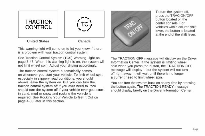
This warning light will come on to let you know if thereis a problem with your traction control system.
See Traction Control System (TCS) Warning Light onpage 3-48. When this warning light is on, the system willnot limit wheel spin. Adjust your driving accordingly.
The traction control system automatically comeson whenever you start your vehicle. To limit wheel spin,especially in slippery road conditions, you shouldalways leave the system on. But you can turn thetraction control system off if you ever need to. Youshould turn the system off if your vehicle ever gets stuckin sand, mud or snow and rocking the vehicle isrequired. See Rocking Your Vehicle to Get It Out onpage 4-30 later in this section.
To turn the system off,press the TRAC ON/OFFbutton located on thecenter console. Forvehicles with a column shiftlever, the button is locatedat the end of the shift lever.
The TRACTION OFF message will display on the DriverInformation Center. If the system is limiting wheelspin when you press the button, the TRACTION OFFmessage will display – but the system will not turnoff right away. It will wait until there is no longera current need to limit wheel spin.
You can turn the system back on at any time by pressingthe button again. The TRACTION READY messageshould display briefly on the Driver Information Center.
United States Canada
4-9
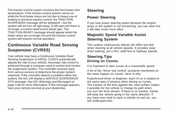
The traction control system monitors the front brake rotortemperature. If the traction control system comes onwhile the front brake rotors are hot due to heavy use ofbraking or previous traction control, the TRACTIONSUSPENDED message will be displayed – but thesystem will not turn off right away. It will wait until there isno longer a current need to limit wheel spin. TheTRACTION READY message should appear when thebrake rotors are no longer hot and the traction controlsystem will resume normal operation.
Continuous Variable Road SensingSuspension (CVRSS)Your vehicle may have a Continuous Variable RoadSensing Suspension (CVRSS). CVRSS automaticallyadjusts the ride of your vehicle. Automatic ride control isachieved through a computer used to control and monitorthe suspension system. The controller receives inputfrom various sensors to determine the proper systemresponse. If the controller detects a problem within thesystem, the DIC will display a SERVICE SUSPENSIONSYS message. See DIC Warnings and Messages onpage 3-60 for more information. If this message appears,have your vehicle serviced at your dealership.
Steering
Power SteeringIf you lose power steering assist because the enginestops or the system is not functioning, you can steer butit will take much more effort.
Magnetic Speed Variable AssistSteering SystemThis system continuously adjusts the effort you feelwhen steering at all vehicle speeds. It provides easewhen parking, yet a firm, solid feel at highway speeds.
Steering TipsDriving on CurvesIt is important to take curves at a reasonable speed.
A lot of the “driver lost control” accidents mentioned onthe news happen on curves. Here is why:
Experienced driver or beginner, each of us is subject tothe same laws of physics when driving on curves.The traction of the tires against the road surface makesit possible for the vehicle to change its path whenyou turn the front wheels. If there is no traction, inertiawill keep the vehicle going in the same direction. Ifyou have ever tried to steer a vehicle on wet ice, youwill understand this.
4-10
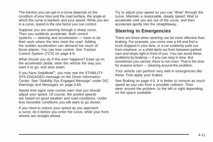
The traction you can get in a curve depends on thecondition of your tires and the road surface, the angle atwhich the curve is banked, and your speed. While you arein a curve, speed is the one factor you can control.
Suppose you are steering through a sharp curve.Then you suddenly accelerate. Both controlsystems — steering and acceleration — have to dotheir work where the tires meet the road. Addingthe sudden acceleration can demand too much ofthose places. You can lose control. See TractionControl System (TCS) on page 4-8.
What should you do if this ever happens? Ease up onthe accelerator pedal, steer the vehicle the way youwant it to go, and slow down.
If you have Stabilitrak®, you may see the STABILITYSYS ENGAGED message on the Driver InformationCenter. See “Stability Sys Engaged Message” under DICWarnings and Messages on page 3-60.
Speed limit signs near curves warn that you shouldadjust your speed. Of course, the posted speedsare based on good weather and road conditions. Underless favorable conditions you will want to go slower.
If you need to reduce your speed as you approacha curve, do it before you enter the curve, while your frontwheels are straight ahead.
Try to adjust your speed so you can “drive” through thecurve. Maintain a reasonable, steady speed. Wait toaccelerate until you are out of the curve, and thenaccelerate gently into the straightaway.
Steering in EmergenciesThere are times when steering can be more effective thanbraking. For example, you come over a hill and find atruck stopped in your lane, or a car suddenly pulls outfrom nowhere, or a child darts out from between parkedcars and stops right in front of you. You can avoid theseproblems by braking — if you can stop in time. Butsometimes you cannot; there is not room. That is the timefor evasive action — steering around the problem.
Your vehicle can perform very well in emergencies likethese. First apply your brakes.
See Braking on page 4-5. It is better to remove as muchspeed as you can from a possible collision. Thensteer around the problem, to the left or right dependingon the space available.
4-11
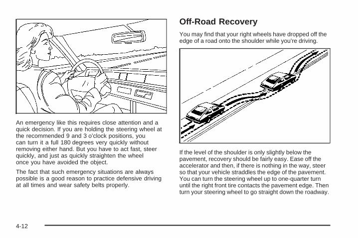
An emergency like this requires close attention and aquick decision. If you are holding the steering wheel atthe recommended 9 and 3 o’clock positions, youcan turn it a full 180 degrees very quickly withoutremoving either hand. But you have to act fast, steerquickly, and just as quickly straighten the wheelonce you have avoided the object.
The fact that such emergency situations are alwayspossible is a good reason to practice defensive drivingat all times and wear safety belts properly.
Off-Road RecoveryYou may find that your right wheels have dropped off theedge of a road onto the shoulder while you’re driving.
If the level of the shoulder is only slightly below thepavement, recovery should be fairly easy. Ease off theaccelerator and then, if there is nothing in the way, steerso that your vehicle straddles the edge of the pavement.You can turn the steering wheel up to one-quarter turnuntil the right front tire contacts the pavement edge. Thenturn your steering wheel to go straight down the roadway.
4-12
PassingThe driver of a vehicle about to pass another on atwo-lane highway waits for just the right moment,accelerates, moves around the vehicle ahead, thengoes back into the right lane again. A simple maneuver?
Not necessarily! Passing another vehicle on a two-lanehighway is a potentially dangerous move, since thepassing vehicle occupies the same lane as oncomingtraffic for several seconds. A miscalculation, an error injudgment, or a brief surrender to frustration or angercan suddenly put the passing driver face to face with theworst of all traffic accidents — the head-on collision.
So here are some tips for passing:
• Drive ahead. Look down the road, to the sides andto crossroads for situations that might affect yourpassing patterns. If you have any doubt whatsoeverabout making a successful pass, wait for abetter time.
• Watch for traffic signs, pavement markings andlines. If you can see a sign up ahead that mightindicate a turn or an intersection, delay your pass.A broken center line usually indicates it is allright to pass, providing the road ahead is clear.Never cross a solid line on your side of the lane ora double solid line, even if the road seems emptyof approaching traffic.
• Do not get too close to the vehicle you want topass while you are awaiting an opportunity. For onething, following too closely reduces your area ofvision, especially if you are following a largervehicle. Also, you will not have adequate space ifthe vehicle ahead suddenly slows or stops.Keep back a reasonable distance.
• When it looks like a chance to pass is coming up,start to accelerate but stay in the right lane and donot get too close. Time your move so you will beincreasing speed as the time comes to move into theother lane. If the way is clear to pass, you will have arunning start that more than makes up for thedistance you would lose by dropping back. And ifsomething happens to cause you to cancel yourpass, you need only slow down and drop back againand wait for another opportunity.
• If other vehicles are lined up to pass a slow vehicle,wait your turn. But take care that someone is nottrying to pass you as you pull out to pass the slowvehicle. Remember to glance over your shoulder andcheck the blind spot.
4-13
• Check your mirrors, glance over your shoulder, andstart your left lane change signal before moving outof the right lane to pass. When you are far enoughahead of the passed vehicle to see its front in yourinside mirror, activate your right lane change signaland move back into the right lane. Remember thatyour right outside mirror is convex. The vehicle youjust passed may seem to be farther away from youthan it really is.
• Try not to pass more than one vehicle at a time ontwo-lane roads. Reconsider before passing the nextvehicle.
• Do not overtake a slowly moving vehicle too rapidly.Even though the brake lamps are not flashing, it maybe slowing down or starting to turn.
• If you are being passed, make it easy for thefollowing driver to get ahead of you. Perhaps youcan ease a little to the right.
Loss of ControlLet us review what driving experts say about whathappens when the three control systems — brakes,steering, and acceleration — do not have enough frictionwhere the tires meet the road to do what the driverhas asked.
In any emergency, do not give up. Keep trying to steerand constantly seek an escape route or area of lessdanger.
SkiddingIn a skid, a driver can lose control of the vehicle.Defensive drivers avoid most skids by taking reasonablecare suited to existing conditions, and by not overdrivingthose conditions. But skids are always possible.
The three types of skids correspond to your vehicle’sthree control systems. In the braking skid, your wheelsare not rolling. In the steering or cornering skid, too muchspeed or steering in a curve causes tires to slip and losecornering force. And in the acceleration skid, too muchthrottle causes the driving wheels to spin.
4-14
A cornering skid is best handled by easing your foot offthe accelerator pedal.
Remember: Any traction control system helps avoid onlythe acceleration skid. If your traction control system isoff, then an acceleration skid is also best handledby easing your foot off the accelerator pedal.
If your vehicle starts to slide, ease your foot off theaccelerator pedal and quickly steer the way you wantthe vehicle to go. If you start steering quickly enough,your vehicle may straighten out. Always be readyfor a second skid if it occurs.
If you have Stabilitrak®, you may see the STABILITYSYS ENGAGED message on the Driver InformationCenter (DIC). See “Stability Sys Engaged Message”under DIC Warnings and Messages on page 3-60.
Of course, traction is reduced when water, snow, ice,gravel, or other material is on the road. For safety, youwill want to slow down and adjust your driving tothese conditions. It is important to slow down on slipperysurfaces because stopping distance will be longer andvehicle control more limited.
While driving on a surface with reduced traction, tryyour best to avoid sudden steering, acceleration,or braking, including engine braking by shifting to alower gear. Any sudden changes could cause the tiresto slide. You may not realize the surface is slipperyuntil your vehicle is skidding. Learn to recognize warningclues — such as enough water, ice, or packed snowon the road to make a mirrored surface — andslow down when you have any doubt.
Remember: Any anti-lock brake system (ABS) helpsavoid only the braking skid.
4-15
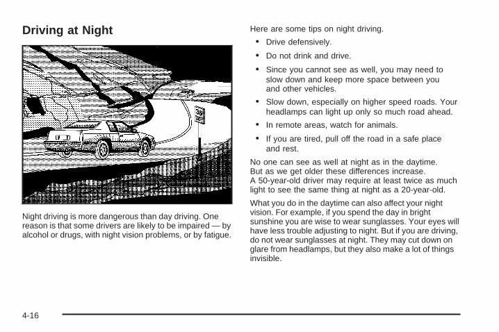
Driving at Night
Night driving is more dangerous than day driving. Onereason is that some drivers are likely to be impaired — byalcohol or drugs, with night vision problems, or by fatigue.
Here are some tips on night driving.
• Drive defensively.
• Do not drink and drive.
• Since you cannot see as well, you may need toslow down and keep more space between youand other vehicles.
• Slow down, especially on higher speed roads. Yourheadlamps can light up only so much road ahead.
• In remote areas, watch for animals.
• If you are tired, pull off the road in a safe placeand rest.
No one can see as well at night as in the daytime.But as we get older these differences increase.A 50-year-old driver may require at least twice as muchlight to see the same thing at night as a 20-year-old.
What you do in the daytime can also affect your nightvision. For example, if you spend the day in brightsunshine you are wise to wear sunglasses. Your eyes willhave less trouble adjusting to night. But if you are driving,do not wear sunglasses at night. They may cut down onglare from headlamps, but they also make a lot of thingsinvisible.
4-16
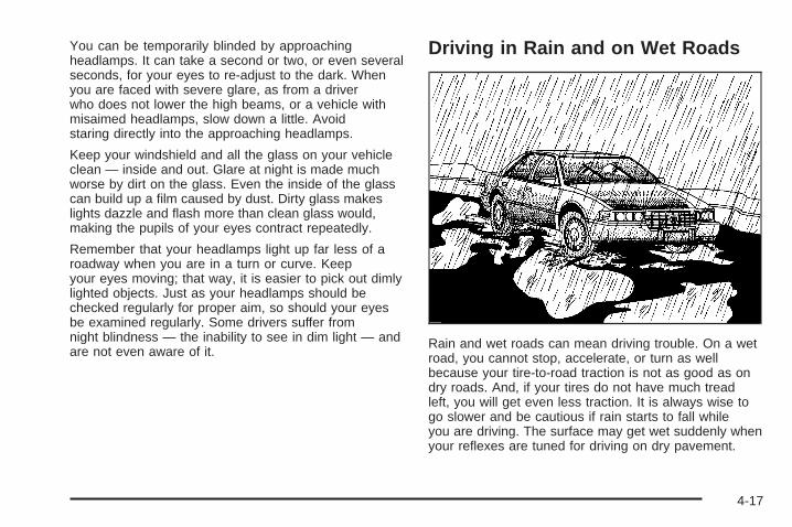
You can be temporarily blinded by approachingheadlamps. It can take a second or two, or even severalseconds, for your eyes to re-adjust to the dark. Whenyou are faced with severe glare, as from a driverwho does not lower the high beams, or a vehicle withmisaimed headlamps, slow down a little. Avoidstaring directly into the approaching headlamps.
Keep your windshield and all the glass on your vehicleclean — inside and out. Glare at night is made muchworse by dirt on the glass. Even the inside of the glasscan build up a film caused by dust. Dirty glass makeslights dazzle and flash more than clean glass would,making the pupils of your eyes contract repeatedly.
Remember that your headlamps light up far less of aroadway when you are in a turn or curve. Keepyour eyes moving; that way, it is easier to pick out dimlylighted objects. Just as your headlamps should bechecked regularly for proper aim, so should your eyesbe examined regularly. Some drivers suffer fromnight blindness — the inability to see in dim light — andare not even aware of it.
Driving in Rain and on Wet Roads
Rain and wet roads can mean driving trouble. On a wetroad, you cannot stop, accelerate, or turn as wellbecause your tire-to-road traction is not as good as ondry roads. And, if your tires do not have much treadleft, you will get even less traction. It is always wise togo slower and be cautious if rain starts to fall whileyou are driving. The surface may get wet suddenly whenyour reflexes are tuned for driving on dry pavement.
4-17
The heavier the rain, the harder it is to see. Even if yourwindshield wiper blades are in good shape, a heavyrain can make it harder to see road signs andtraffic signals, pavement markings, the edge of the road,and even people walking.
It is wise to keep your windshield wiping equipment ingood shape and keep your windshield washer tank filledwith washer fluid. Replace your windshield wiper insertswhen they show signs of streaking or missing areas onthe windshield, or when strips of rubber start to separatefrom the inserts.
Driving too fast through large water puddles or evengoing through some car washes can cause problems,too. The water may affect your brakes. Try to avoidpuddles. But if you cannot, try to slow down before youhit them.
{CAUTION:
Wet brakes can cause accidents. They will notwork as well in a quick stop and may causepulling to one side. You could lose control ofthe vehicle.
After driving through a large puddle of wateror a car wash, apply your brake pedal lightlyuntil your brakes work normally.
4-18
HydroplaningHydroplaning is dangerous. So much water can build upunder your tires that they can actually ride on thewater. This can happen if the road is wet enough andyou are going fast enough. When your vehicle ishydroplaning, it has little or no contact with the road.
Hydroplaning does not happen often. But it can if yourtires do not have much tread or if the pressure in one ormore is low. It can happen if a lot of water is standing onthe road. If you can see reflections from trees, telephonepoles, or other vehicles, and raindrops dimple the water’ssurface, there could be hydroplaning.
Hydroplaning usually happens at higher speeds. Therejust is not a hard and fast rule about hydroplaning.The best advice is to slow down when it is raining.
Driving Through Deep Standing Water
Notice: If you drive too quickly through deeppuddles or standing water, water can come inthrough your engine’s air intake and badly damageyour engine. Never drive through water that isslightly lower than the underbody of your vehicle. Ifyou cannot avoid deep puddles or standing water,drive through them very slowly.
Driving Through Flowing Water
{CAUTION:
Flowing or rushing water creates strong forces.If you try to drive through flowing water, as youmight at a low water crossing, your vehicle canbe carried away. As little as six inches offlowing water can carry away a smaller vehicle.If this happens, you and other vehicleoccupants could drown. Do not ignore policewarning signs, and otherwise be very cautiousabout trying to drive through flowing water.
Some Other Rainy Weather Tips• Besides slowing down, allow some extra following
distance. And be especially careful when youpass another vehicle. Allow yourself more clearroom ahead, and be prepared to have yourview restricted by road spray.
• Have good tires with proper tread depth. See Tireson page 5-57.
4-19
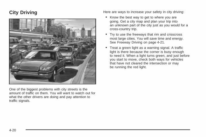
City Driving
One of the biggest problems with city streets is theamount of traffic on them. You will want to watch out forwhat the other drivers are doing and pay attention totraffic signals.
Here are ways to increase your safety in city driving:
• Know the best way to get to where you aregoing. Get a city map and plan your trip intoan unknown part of the city just as you would for across-country trip.
• Try to use the freeways that rim and crisscrossmost large cities. You will save time and energy.See Freeway Driving on page 4-21.
• Treat a green light as a warning signal. A trafficlight is there because the corner is busy enoughto need it. When a light turns green, and just beforeyou start to move, check both ways for vehiclesthat have not cleared the intersection or maybe running the red light.
4-20
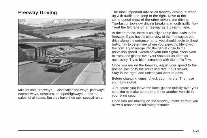
Freeway Driving
Mile for mile, freeways — also called thruways, parkways,expressways, turnpikes, or superhighways — are thesafest of all roads. But they have their own special rules.
The most important advice on freeway driving is: Keepup with traffic and keep to the right. Drive at thesame speed most of the other drivers are driving.Too-fast or too-slow driving breaks a smooth traffic flow.Treat the left lane on a freeway as a passing lane.
At the entrance, there is usually a ramp that leads to thefreeway. If you have a clear view of the freeway as youdrive along the entrance ramp, you should begin to checktraffic. Try to determine where you expect to blend withthe flow. Try to merge into the gap at close to theprevailing speed. Switch on your turn signal, check yourmirrors, and glance over your shoulder as often asnecessary. Try to blend smoothly with the traffic flow.
Once you are on the freeway, adjust your speed to theposted limit or to the prevailing rate if it is slower.Stay in the right lane unless you want to pass.
Before changing lanes, check your mirrors. Then useyour turn signal.
Just before you leave the lane, glance quickly over yourshoulder to make sure there is not another vehicle inyour blind spot.
Once you are moving on the freeway, make certain youallow a reasonable following distance.
4-21
Expect to move slightly slower at night.
When you want to leave the freeway, move to theproper lane well in advance. If you miss your exit, donot, under any circumstances, stop and back up. Driveon to the next exit.
The exit ramp can be curved, sometimes quite sharply.The exit speed is usually posted. Reduce your speedaccording to your speedometer, not to your senseof motion. After driving for any distance at higherspeeds, you may tend to think you are going slowerthan you actually are.
Before Leaving on a Long TripMake sure you are ready. Try to be well rested. If youmust start when you are not fresh — such as aftera day’s work — do not plan to make too many miles thatfirst part of the journey. Wear comfortable clothingand shoes you can easily drive in.
Is your vehicle ready for a long trip? If you keep itserviced and maintained, it is ready to go. If it needsservice, have it done before starting out. Of course, youwill find experienced and able service experts in GMdealerships all across North America. They will be readyand willing to help if you need it.
Here are some things you can check before a trip:
• Windshield Washer Fluid: Is the reservoir full? Areall windows clean inside and outside?
• Wiper Blades: Are they in good shape?
• Fuel, Engine Oil, Other Fluids: Have you checkedall levels?
• Lamps: Are they all working? Are the lenses clean?
• Tires: They are vitally important to a safe,trouble-free trip. Is the tread good enough forlong-distance driving? Are the tires all inflated to therecommended pressure?
• Weather Forecasts: What is the weather outlookalong your route? Should you delay your trip ashort time to avoid a major storm system?
• Maps: Do you have up-to-date maps?
4-22
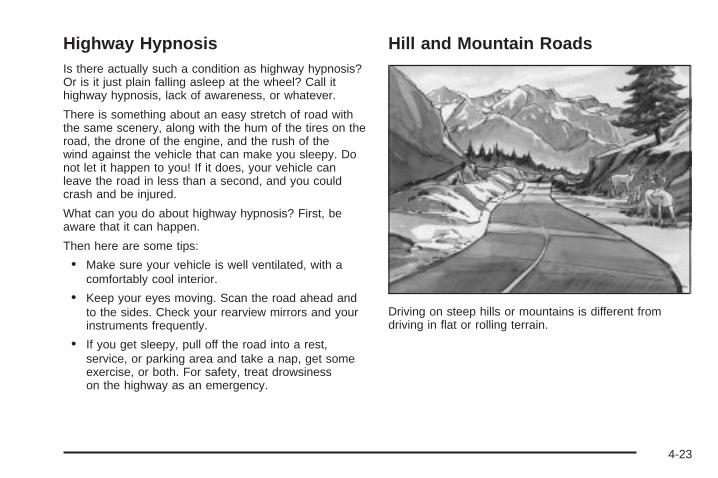
Highway HypnosisIs there actually such a condition as highway hypnosis?Or is it just plain falling asleep at the wheel? Call ithighway hypnosis, lack of awareness, or whatever.
There is something about an easy stretch of road withthe same scenery, along with the hum of the tires on theroad, the drone of the engine, and the rush of thewind against the vehicle that can make you sleepy. Donot let it happen to you! If it does, your vehicle canleave the road in less than a second, and you couldcrash and be injured.
What can you do about highway hypnosis? First, beaware that it can happen.
Then here are some tips:
• Make sure your vehicle is well ventilated, with acomfortably cool interior.
• Keep your eyes moving. Scan the road ahead andto the sides. Check your rearview mirrors and yourinstruments frequently.
• If you get sleepy, pull off the road into a rest,service, or parking area and take a nap, get someexercise, or both. For safety, treat drowsinesson the highway as an emergency.
Hill and Mountain Roads
Driving on steep hills or mountains is different fromdriving in flat or rolling terrain.
4-23
If you drive regularly in steep country, or if you areplanning to visit there, here are some tips that can makeyour trips safer and more enjoyable.
• Keep your vehicle in good shape. Check all fluidlevels and also the brakes, tires, cooling system,and transaxle. These parts can work hard onmountain roads.
• Know how to go down hills. The most importantthing to know is this: let your engine do some ofthe slowing down. Shift to a lower gear when you godown a steep or long hill.
{CAUTION:
If you do not shift down, your brakes could getso hot that they would not work well. Youwould then have poor braking or even nonegoing down a hill. You could crash. Shift downto let your engine assist your brakes on asteep downhill slope.
{CAUTION:
Coasting downhill in NEUTRAL (N) or with theignition off is dangerous. Your brakes will haveto do all the work of slowing down. They couldget so hot that they would not work well. Youwould then have poor braking or even nonegoing down a hill. You could crash. Alwayshave your engine running and your vehicle ingear when you go downhill.
• Know how to go uphill. You may want to shift down toa lower gear. The lower gears help cool your engineand transaxle, and you can climb the hill better.
• Stay in your own lane when driving on two-laneroads in hills or mountains. Do not swing wide or cutacross the center of the road. Drive at speeds that letyou stay in your own lane.
• As you go over the top of a hill, be alert. There couldbe something in your lane, like a stalled car or anaccident.
• You may see highway signs on mountains that warnof special problems. Examples are long grades,passing or no-passing zones, a falling rocks area, orwinding roads. Be alert to these and take appropriateaction.
4-24
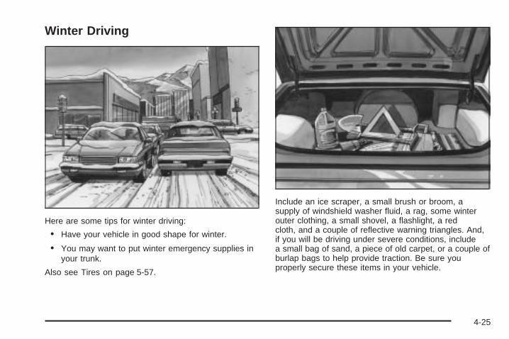
Winter Driving
Here are some tips for winter driving:
• Have your vehicle in good shape for winter.
• You may want to put winter emergency supplies inyour trunk.
Also see Tires on page 5-57.
Include an ice scraper, a small brush or broom, asupply of windshield washer fluid, a rag, some winterouter clothing, a small shovel, a flashlight, a redcloth, and a couple of reflective warning triangles. And,if you will be driving under severe conditions, includea small bag of sand, a piece of old carpet, or a couple ofburlap bags to help provide traction. Be sure youproperly secure these items in your vehicle.
4-25
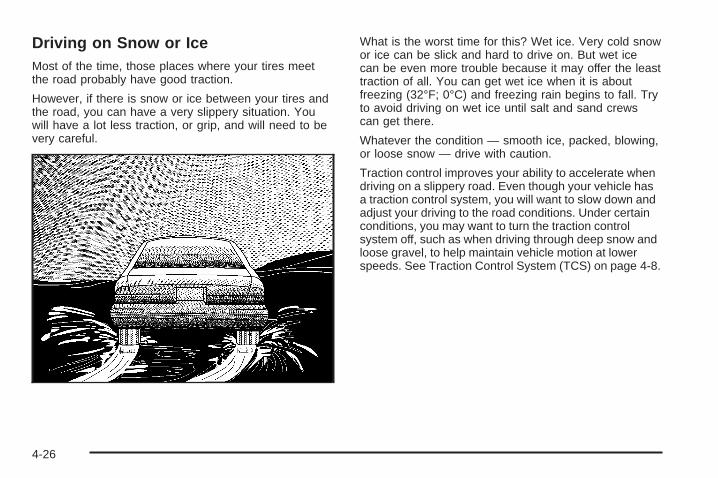
Driving on Snow or IceMost of the time, those places where your tires meetthe road probably have good traction.
However, if there is snow or ice between your tires andthe road, you can have a very slippery situation. Youwill have a lot less traction, or grip, and will need to bevery careful.
What is the worst time for this? Wet ice. Very cold snowor ice can be slick and hard to drive on. But wet icecan be even more trouble because it may offer the leasttraction of all. You can get wet ice when it is aboutfreezing (32°F; 0°C) and freezing rain begins to fall. Tryto avoid driving on wet ice until salt and sand crewscan get there.
Whatever the condition — smooth ice, packed, blowing,or loose snow — drive with caution.
Traction control improves your ability to accelerate whendriving on a slippery road. Even though your vehicle hasa traction control system, you will want to slow down andadjust your driving to the road conditions. Under certainconditions, you may want to turn the traction controlsystem off, such as when driving through deep snow andloose gravel, to help maintain vehicle motion at lowerspeeds. See Traction Control System (TCS) on page 4-8.
4-26
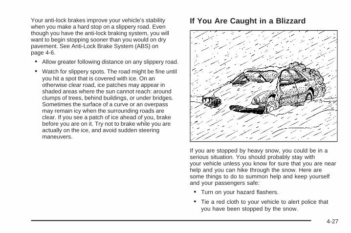
Your anti-lock brakes improve your vehicle’s stabilitywhen you make a hard stop on a slippery road. Eventhough you have the anti-lock braking system, you willwant to begin stopping sooner than you would on drypavement. See Anti-Lock Brake System (ABS) onpage 4-6.
• Allow greater following distance on any slippery road.
• Watch for slippery spots. The road might be fine untilyou hit a spot that is covered with ice. On anotherwise clear road, ice patches may appear inshaded areas where the sun cannot reach: aroundclumps of trees, behind buildings, or under bridges.Sometimes the surface of a curve or an overpassmay remain icy when the surrounding roads areclear. If you see a patch of ice ahead of you, brakebefore you are on it. Try not to brake while you areactually on the ice, and avoid sudden steeringmaneuvers.
If You Are Caught in a Blizzard
If you are stopped by heavy snow, you could be in aserious situation. You should probably stay withyour vehicle unless you know for sure that you are nearhelp and you can hike through the snow. Here aresome things to do to summon help and keep yourselfand your passengers safe:
• Turn on your hazard flashers.
• Tie a red cloth to your vehicle to alert police thatyou have been stopped by the snow.
4-27
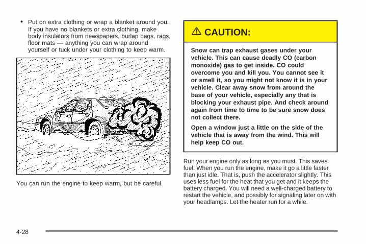
• Put on extra clothing or wrap a blanket around you.If you have no blankets or extra clothing, makebody insulators from newspapers, burlap bags, rags,floor mats — anything you can wrap aroundyourself or tuck under your clothing to keep warm.
You can run the engine to keep warm, but be careful.
{CAUTION:
Snow can trap exhaust gases under yourvehicle. This can cause deadly CO (carbonmonoxide) gas to get inside. CO couldovercome you and kill you. You cannot see itor smell it, so you might not know it is in yourvehicle. Clear away snow from around thebase of your vehicle, especially any that isblocking your exhaust pipe. And check aroundagain from time to time to be sure snow doesnot collect there.
Open a window just a little on the side of thevehicle that is away from the wind. This willhelp keep CO out.
Run your engine only as long as you must. This savesfuel. When you run the engine, make it go a little fasterthan just idle. That is, push the accelerator slightly. Thisuses less fuel for the heat that you get and it keeps thebattery charged. You will need a well-charged battery torestart the vehicle, and possibly for signaling later on withyour headlamps. Let the heater run for a while.
4-28
Then, shut the engine off and close the window almostall the way to preserve the heat. Start the engineagain and repeat this only when you feel reallyuncomfortable from the cold. But do it as little aspossible. Preserve the fuel as long as you can. To helpkeep warm, you can get out of the vehicle and dosome fairly vigorous exercises every half hour or so untilhelp comes.
If You Are Stuck: In Sand, Mud, Iceor SnowIn order to free your vehicle when it is stuck, you willneed to spin the wheels, but you do not want tospin your wheels too fast. The method known as rockingcan help you get out when you are stuck, but youmust use caution.
{CAUTION:
If you let your tires spin at high speed, they canexplode, and you or others could be injured.And, the transaxle or other parts of the vehiclecan overheat. That could cause an enginecompartment fire or other damage. When youare stuck, spin the wheels as little as possible.Do not spin the wheels above 35 mph (55 km/h)as shown on the speedometer.
Notice: Spinning your wheels can destroy parts ofyour vehicle as well as the tires. If you spin thewheels too fast while shifting your transaxle backand forth, you can destroy your transaxle. SeeRocking Your Vehicle to Get It Out on page 4-30.
For information about using tire chains on your vehicle,see Tire Chains on page 5-75.
4-29
Rocking Your Vehicle to Get It OutFirst, turn your steering wheel left and right. Thatwill clear the area around your front wheels. You shouldturn your traction control system off. See TractionControl System (TCS) on page 4-8. Then shift back andforth between REVERSE (R) and a forward gear,spinning the wheels as little as possible. Release theaccelerator pedal while you shift, and press lightly on theaccelerator pedal when the transaxle is in gear. Byslowly spinning your wheels in the forward and reversedirections, you will cause a rocking motion that mayfree your vehicle. If that does not get you out after a fewtries, you may need to be towed out. If you do needto be towed out, see Towing Your Vehicle on page 4-35.
Loading Your VehicleIt is very important to know how much weight yourvehicle can carry. This weight is called the vehiclecapacity weight and includes the weight of all occupants,cargo and all nonfactory-installed options. Two labelson your vehicle show how much weight it may properlycarry, the Tire and Loading Information label and theCertification label.
{CAUTION:
Do not load your vehicle any heavier than theGross Vehicle Weight Rating (GVWR), or eitherthe maximum front or rear Gross Axle WeightRating (GAWR). If you do, parts on yourvehicle can break, and it can change the wayyour vehicle handles. These could cause youto lose control and crash. Also, overloadingcan shorten the life of your vehicle.
4-30
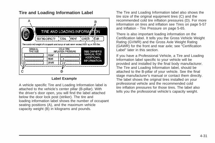
Tire and Loading Information Label
A vehicle specific Tire and Loading Information label isattached to the vehicle’s center pillar (B-pillar). Withthe driver’s door open, you will find the label attachedbelow the door lock post (striker). The tire andloading information label shows the number of occupantseating positions (A), and the maximum vehiclecapacity weight (B) in kilograms and pounds.
The Tire and Loading Information label also shows thetire size of the original equipment tires (C) and therecommended cold tire inflation pressures (D). For moreinformation on tires and inflation see Tires on page 5-57and Inflation - Tire Pressure on page 5-65.
There is also important loading information on theCertification label. It tells you the Gross Vehicle WeightRating (GVWR) and the Gross Axle Weight Rating(GAWR) for the front and rear axle; see “CertificationLabel” later in this section.
If you have a Professional Vehicle, a Tire and LoadingInformation label specific to your vehicle will beprovided and installed by the final body manufacturer.The Tire and Loading Information label, should beattached to the B-pillar of your vehicle. See the finalstage manufacturer’s manual or contact them directly.The label shows the original tires installed on yourprofessional vehicle and the recommended coldtire inflation pressures for those tires. The label alsotells you the professional vehicle’s capacity weight.
Label Example
4-31
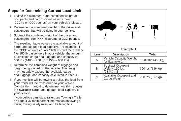
Steps for Determining Correct Load Limit1. Locate the statement “The combined weight of
occupants and cargo should never exceedXXX kg or XXX pounds” on your vehicle’s placard.
2. Determine the combined weight of the driver andpassengers that will be riding in your vehicle.
3. Subtract the combined weight of the driver andpassengers from XXX kilograms or XXX pounds.
4. The resulting figure equals the available amount ofcargo and luggage load capacity. For example, ifthe “XXX” amount equals 1400 lbs and there will befive 150 lb passengers in your vehicle, the amountof available cargo and luggage load capacity is650 lbs (1400 − 750 (5 x 150) = 650 lbs).
5. Determine the combined weight of luggage andcargo being loaded on the vehicle. That weightmay not safely exceed the available cargoand luggage load capacity calculated in Step 4.
6. If your vehicle will be towing a trailer, the load fromyour trailer will be transferred to your vehicle.Consult this manual to determine how this reducesthe available cargo and luggage load capacity ofyour vehicle.If your vehicle can tow a trailer, see Towing a Traileron page 4-37 for important information on towing atrailer, towing safety rules, and trailering tips.
Item Description Total
A Vehicle Capacity Weightfor Example 1 = 1,000 lbs (453 kg)
BSubtract OccupantWeight 150 lbs(68 kg) × 2 =
300 lbs (136 kg)
C Available Occupant andCargo Weight = 700 lbs (317 kg)
Example 1
4-32
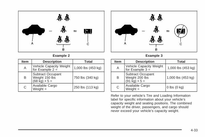
Item Description Total
A Vehicle Capacity Weightfor Example 2 = 1,000 lbs (453 kg)
BSubtract OccupantWeight 150 lbs(68 kg) × 5 =
750 lbs (340 kg)
C Available CargoWeight = 250 lbs (113 kg)
Item Description Total
A Vehicle Capacity Weightfor Example 3 = 1,000 lbs (453 kg)
BSubtract OccupantWeight 200 lbs(91 kg) × 5 =
1,000 lbs (453 kg)
C Available CargoWeight = 0 lbs (0 kg)
Refer to your vehicle’s Tire and Loading Informationlabel for specific information about your vehicle’scapacity weight and seating positions. The combinedweight of the driver, passengers, and cargo shouldnever exceed your vehicle’s capacity weight.
Example 2 Example 3
4-33
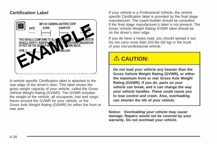
Certification Label
A vehicle specific Certification label is attached to therear edge of the driver’s door. This label shows thegross weight capacity of your vehicle, called the GrossVehicle Weight Rating (GVWR). The GVWR includesthe weight of the vehicle, all occupants, fuel and cargo.Never exceed the GVWR for your vehicle, or theGross Axle Weight Rating (GAWR) for either the front orrear axle.
If your vehicle is a Professional Vehicle, the vehiclespecific Certification label is provided by the final stagemanufacturer. The coach-builder should be consultedif the final stage manufacturer’s label is not present. TheGross Vehicle Weight Rating GVWR label should beon the driver’s door edge.
If you do have a heavy load, you should spread it out.Do not carry more than 203 lbs (92 kg) in the trunkof your non-professional vehicle.
{CAUTION:
Do not load your vehicle any heavier than theGross Vehicle Weight Rating (GVWR), or eitherthe maximum front or rear Gross Axle WeightRating (GAWR). If you do, parts on yourvehicle can break, and it can change the wayyour vehicle handles. These could cause youto lose control and crash. Also, overloadingcan shorten the life of your vehicle.
Notice: Overloading your vehicle may causedamage. Repairs would not be covered by yourwarranty. Do not overload your vehicle.
4-34
If you put things inside your vehicle, like suitcases,tools, packages, or anything else, they will go as fast asthe vehicle goes. If you have to stop or turn quickly,or if there is a crash, they will keep going.
{CAUTION:
Things you put inside your vehicle can strikeand injure people in a sudden stop or turn, orin a crash.
• Put things in the trunk of your vehicle. In atrunk, put them as far forward as you can.Try to spread the weight evenly.
• Never stack heavier things, like suitcases,inside the vehicle so that some of themare above the tops of the seats.
• Do not leave an unsecured child restraintin your vehicle.
• When you carry something inside thevehicle, secure it whenever you can.
Automatic Level ControlThis feature keeps the rear of your vehicle level as theload changes. It is automatic, you do not need toadjust anything.
Towing
Towing Your VehicleConsult your dealer or a professional towing service ifyou need to have your disabled vehicle towed. SeeRoadside Service on page 7-5.
If you want to tow your vehicle behind another vehiclefor recreational purposes (such as behind a motorhome),see Recreational Vehicle Towing following.
Recreational Vehicle TowingRecreational vehicle towing means towing your vehiclebehind another vehicle – such as behind a motorhome.The two most common types of recreational vehicletowing are known as “dinghy towing” (towing your vehiclewith all four wheels on the ground) and “dolly towing”(towing your vehicle with two wheels on the ground andtwo wheels up on a device known as a “dolly”).
With the proper preparation and equipment, manyvehicles can be towed in these ways. See “DinghyTowing” and “Dolly Towing,” following.
4-35
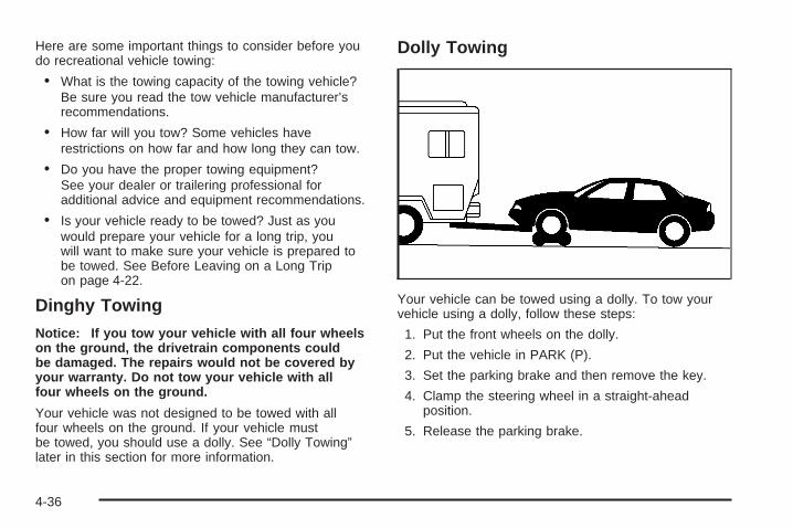
Here are some important things to consider before youdo recreational vehicle towing:
• What is the towing capacity of the towing vehicle?Be sure you read the tow vehicle manufacturer’srecommendations.
• How far will you tow? Some vehicles haverestrictions on how far and how long they can tow.
• Do you have the proper towing equipment?See your dealer or trailering professional foradditional advice and equipment recommendations.
• Is your vehicle ready to be towed? Just as youwould prepare your vehicle for a long trip, youwill want to make sure your vehicle is prepared tobe towed. See Before Leaving on a Long Tripon page 4-22.
Dinghy Towing
Notice: If you tow your vehicle with all four wheelson the ground, the drivetrain components couldbe damaged. The repairs would not be covered byyour warranty. Do not tow your vehicle with allfour wheels on the ground.
Your vehicle was not designed to be towed with allfour wheels on the ground. If your vehicle mustbe towed, you should use a dolly. See “Dolly Towing”later in this section for more information.
Dolly Towing
Your vehicle can be towed using a dolly. To tow yourvehicle using a dolly, follow these steps:
1. Put the front wheels on the dolly.
2. Put the vehicle in PARK (P).
3. Set the parking brake and then remove the key.
4. Clamp the steering wheel in a straight-aheadposition.
5. Release the parking brake.
4-36

Towing a TrailerThe Cadillac Professional Vehicle cannot tow a trailer.
{CAUTION:
If you do not use the correct equipment anddrive properly, you can lose control when youpull a trailer. For example, if the trailer is tooheavy, the brakes may not work well — or evenat all. You and your passengers could beseriously injured. You may also damage yourvehicle; the resulting repairs would not becovered by your warranty. Pull a trailer only ifyou have followed all the steps in this section.Ask your dealer for advice and informationabout towing a trailer with your vehicle.
Your vehicle can tow a trailer if it is equipped with theproper trailer towing equipment. To identify whatthe vehicle trailering capacity is for your vehicle, youshould read the information in “Weight of the Trailer” thatappears later in this section. But trailering is differentthan just driving your vehicle by itself. Trailering meanschanges in handling, durability and fuel economy.Successful, safe trailering takes correct equipment, andit has to be used properly.
That is the reason for this part. In it are manytime-tested, important trailering tips and safety rules.Many of these are important for your safety and that ofyour passengers. So please read this section carefullybefore you pull a trailer.
Load-pulling components such as the engine, transaxle,wheel assemblies and tires are forced to work harderagainst the drag of the added weight. The engineis required to operate at relatively higher speeds andunder greater loads, generating extra heat. Whatis more, the trailer adds considerably to wind resistance,increasing the pulling requirements.
4-37
If You Do Decide To Pull a TrailerIf you do, here are some important points:• There are many different laws, including speed limit
restrictions, having to do with trailering. Make sureyour rig will be legal, not only where you livebut also where you will be driving. A good sourcefor this information can be state or provincial police.
• Consider using a sway control. You can ask a hitchdealer about sway controls.
• Do not tow a trailer at all during the first 1,000 miles(1 600 km) your new vehicle is driven. Your engine,axle or other parts could be damaged.
• Then, during the first 500 miles (800 km) that youtow a trailer, do not drive over 50 mph (80 km/h)and do not make starts at full throttle. Thishelps your engine and other parts of your vehiclewear in at the heavier loads.
• Obey speed limit restrictions when towing a trailer.Do not drive faster than the maximum posted speedfor trailers, or no more than 55 mph (90 km/h), tosave wear on your vehicle’s parts.
Three important considerations have to do with weight:• The weight of the trailer• The weight of the trailer tongue• The total weight on your vehicle’s tires
Weight of the TrailerHow heavy can a trailer safely be?
It depends on how you plan to use your rig. For example,speed, altitude, road grades, outside temperature andhow much your vehicle is used to pull a trailer are allimportant. And, it can also depend on any specialequipment that you have on your vehicle.
It should never weigh more than 2,000 lbs (900 kg).These are total maximum weights including the load. Buteven that can be too heavy.
The maximum trailer weight for your vehicle can bedetermined from the Gross Combined Vehicle Weight(GCVW). The GCVW = curb weight + passenger’sweight + cargo weight + trailer weight. The GCVWshould never be more than 7,200 lbs (3 273 kg).
You can ask your dealer for our trailering information oradvice, or you can write us at:
Cadillac Customer Assistance CenterCadillac Motor Car DivisionP.O. Box 33169Detroit, MI 48232-5169
In Canada, write to:
General Motors of Canada LimitedCustomer Communication Centre, 163-0051908 Colonel Sam DriveOshawa, Ontario L1H 8P7
4-38
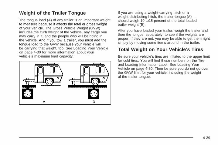
Weight of the Trailer TongueThe tongue load (A) of any trailer is an important weightto measure because it affects the total or gross weightof your vehicle. The Gross Vehicle Weight (GVW)includes the curb weight of the vehicle, any cargo youmay carry in it, and the people who will be riding inthe vehicle. And if you tow a trailer, you must add thetongue load to the GVW because your vehicle willbe carrying that weight, too. See Loading Your Vehicleon page 4-30 for more information about yourvehicle’s maximum load capacity.
If you are using a weight-carrying hitch or aweight-distributing hitch, the trailer tongue (A)should weigh 10 to15 percent of the total loadedtrailer weight (B).
After you have loaded your trailer, weigh the trailer andthen the tongue, separately, to see if the weights areproper. If they are not, you may be able to get them rightsimply by moving some items around in the trailer.
Total Weight on Your Vehicle’s TiresBe sure your vehicle’s tires are inflated to the upper limitfor cold tires. You will find these numbers on the Tireand Loading Information Label. See Loading YourVehicle on page 4-30. Then be sure you do not go overthe GVW limit for your vehicle, including the weightof the trailer tongue.
4-39
HitchesIt is important to have the correct hitch equipment.Crosswinds, large trucks going by and rough roads area few reasons why you will need the right hitch. Hereare some rules to follow:
• The rear bumper on your vehicle is not intended forhitches. Do not attach rental hitches or otherbumper-type hitches to it. Use only a frame-mountedhitch that does not attach to the bumper.
• Will you have to make any holes in the body of yourvehicle when you install a trailer hitch? If you do, thenbe sure to seal the holes later when you remove thehitch. If you do not seal them, deadly carbonmonoxide (CO) from your exhaust can get into yourvehicle. See Engine Exhaust on page 2-35. Dirt andwater can, too.
Safety ChainsYou should always attach chains between your vehicleand your trailer. Cross the safety chains under the tongueof the trailer so that the tongue will not drop to the road ifit becomes separated from the hitch. Instructions aboutsafety chains may be provided by the hitch manufactureror by the trailer manufacturer. Follow the manufacturer’srecommendation for attaching safety chains and do notattach them to the bumper. Always leave just enoughslack so you can turn with your rig. And, never allowsafety chains to drag on the ground.
Trailer BrakesBecause you have anti-lock brakes, do not try to tapinto your vehicle’s hydraulic brake system. If youdo, both brake systems will not work well, or at all. Ifyou tow more than 1,000 lbs (450 kg), use trailer brakes.Be sure to follow the instructions that come with thetrailer or from the brake manufacturer.
Be sure to read and follow the instructions for the trailerbrakes so you will be able to maintain them properly.
4-40
Driving with a TrailerTowing a trailer requires a certain amount of experience.Before setting out for the open road, you will want toget to know your rig. Acquaint yourself with the feel ofhandling and braking with the added weight of the trailer.And always keep in mind that the vehicle you aredriving is now a good deal longer and not nearly asresponsive as your vehicle is by itself.
Before you start, check the trailer hitch and platform,parts and attachments, safety chains, electricalconnector, lamps, tires and mirror adjustment. If thetrailer has electric brakes, start your vehicle and trailermoving and then apply the trailer brake controllerby hand to be sure the brakes are working. This letsyou check your electrical connection at the same time.
During your trip, check occasionally to be sure thatthe load is secure, and that the lamps and any trailerbrakes are still working.
Following DistanceStay at least twice as far behind the vehicle ahead asyou would when driving your vehicle without a trailer.This can help you avoid situations that requireheavy braking and sudden turns.
PassingYou will need more passing distance up ahead whenyou are towing a trailer. And, because the vehicleis a good deal longer, you will need to go much fartherbeyond the passed vehicle before you can return toyour lane.
Backing UpHold the bottom of the steering wheel with one hand.Then, to move the trailer to the left, just move that handto the left. To move the trailer to the right, move yourhand to the right. Always back up slowly and, if possible,have someone guide you.
Making Turns
Notice: Making very sharp turns while traileringcould cause the trailer to come in contact with thevehicle. Your vehicle could be damaged. Avoidmaking very sharp turns while trailering.
When you are turning with a trailer, make wider turns thannormal. Do this so your trailer will not strike softshoulders, curbs, road signs, trees or other objects. Avoidjerky or sudden maneuvers. Signal well in advance.
4-41
Turn Signals When Towing a TrailerWhen you tow a trailer, your vehicle may need adifferent turn signal flasher and/or extra wiring. Checkwith your dealer. The arrows on your instrumentpanel will flash whenever you signal a turn or lanechange. Properly hooked up, the trailer lamps will alsoflash, telling other drivers you are about to turn,change lanes or stop.
When towing a trailer, the arrows on your instrumentpanel will flash for turns even if the bulbs on the trailerare burned out. Thus, you may think drivers behindyou are seeing your signal when they are not. Itis important to check occasionally to be sure the trailerbulbs are still working.
Driving on GradesReduce speed and shift to a lower gear before you startdown a long or steep downgrade. If you do not shiftdown, you might have to use your brakes so much thatthey would get hot and no longer work well.
On long uphill grades, reduce speed to 45 to 50 mph(70 to 90 km/h) and avoid prolonged use of SECOND (2)gear and engine speeds above 3800 rpm.
Climbing grades steeper than four percent attemperatures above 90°F (32°C) with a loaded vehicleand trailer is not recommended. The cooling systemmay temporarily overheat. See Engine Overheating onpage 5-27.
Parking on Hills
{CAUTION:
You really should not park your vehicle, with atrailer attached, on a hill. If something goeswrong, your rig could start to move. Peoplecan be injured, and both your vehicle and thetrailer can be damaged.
4-42
But if you ever have to park your rig on a hill, here ishow to do it:
1. Apply your regular brakes, but do not shift intoPARK (P).
2. Have someone place chocks behind the trailerwheels.
3. When the wheel chocks are in place, release theregular brakes until the chocks absorb the load.
4. Reapply the regular brakes. Then shift intoPARK (P) firmly and apply your parking brake.
5. Release the regular brakes.
When You Are Ready to Leave AfterParking on a Hill
1. Apply your regular brakes and hold the pedal downwhile you:
• Start your engine,
• Shift into a gear, and
• Make sure the parking brake has released.
2. Let up on the brake pedal.
3. Drive slowly until the trailer is clear of the chocks.
4. Stop and have someone pick up and store thechocks.
Maintenance When Trailer TowingYour vehicle will need service more often when you arepulling a trailer. See the Maintenance Schedule formore on this. Things that are especially important intrailer operation are automatic transaxle fluid (donot overfill), engine oil, drive belt, cooling system andbrake system. Each of these is covered in this manual,and the Index will help you find them quickly. If youare trailering, it is a good idea to review this informationbefore you start your trip.
Check periodically to see that all hitch nuts and boltsare tight.
Engine Cooling When Trailer TowingYour cooling system may temporarily overheat duringsevere operating conditions. See Engine Overheating onpage 5-27.
4-43

✍ NOTES
4-44
Service ............................................................5-3Doing Your Own Service Work .........................5-4Adding Equipment to the Outside of Your
Vehicle ......................................................5-5Fuel ................................................................5-5
Gasoline Octane ............................................5-5Gasoline Specifications ....................................5-5California Fuel ...............................................5-5Additives .......................................................5-6Fuels in Foreign Countries ...............................5-6Filling Your Tank ............................................5-7Filling a Portable Fuel Container .....................5-10
Checking Things Under the Hood ....................5-10Hood Release ..............................................5-11Engine Compartment Overview .......................5-12Engine Oil ...................................................5-14Engine Oil Life System ..................................5-17Engine Air Cleaner/Filter ................................5-19Automatic Transaxle Fluid ..............................5-21Engine Coolant .............................................5-24Coolant Surge Tank Pressure Cap ..................5-27Engine Overheating .......................................5-27Overheated Engine Protection
Operating Mode ........................................5-29Cooling System ............................................5-30Power Steering Fluid .....................................5-35
Windshield Washer Fluid ................................5-36Brakes ........................................................5-37Battery ........................................................5-40Jump Starting ...............................................5-42
Headlamp Aiming ...........................................5-48Headlamp Horizontal Aiming ...........................5-49Headlamp Vertical Aiming ..............................5-50
Bulb Replacement ..........................................5-51Halogen Bulbs ..............................................5-51Headlamps ..................................................5-51Front Turn Signal, Sidemarker, Parking and
Cornering Lamps .......................................5-55Replacement Bulbs .......................................5-56
Windshield Wiper Blade Replacement ..............5-56Tires ..............................................................5-57
Tire Sidewall Labelling ...................................5-58Tire Terminology and Definitions .....................5-62Inflation - Tire Pressure .................................5-65Tire Pressure Monitor Operation .....................5-68Tire Inspection and Rotation ...........................5-69When It Is Time for New Tires .......................5-70Buying New Tires .........................................5-71Uniform Tire Quality Grading ..........................5-72Wheel Alignment and Tire Balance ..................5-73Wheel Replacement ......................................5-73Tire Chains ..................................................5-75
Section 5 Service and Appearance Care
5-1
If a Tire Goes Flat ........................................5-76Changing a Flat Tire .....................................5-77Removing the Spare Tire and Tools ................5-78Removing the Flat Tire and Installing the
Spare Tire ................................................5-80Storing a Flat or Spare Tire and Tools ............5-85Compact Spare Tire ......................................5-86
Appearance Care ............................................5-87Fabric/Carpet ...............................................5-87Vinyl ...........................................................5-89Leather .......................................................5-89Instrument Panel ..........................................5-89Interior Plastic Components ............................5-89Wood Panels ...............................................5-89Speaker Covers ............................................5-90Glass Surfaces .............................................5-90Care of Safety Belts ......................................5-90Weatherstrips ...............................................5-90Washing Your Vehicle ...................................5-91Cleaning Exterior Lamps/Lenses .....................5-91Finish Care ..................................................5-92
Windshield and Wiper Blades .........................5-92Aluminum or Chrome-Plated Wheels ................5-93Tires ...........................................................5-94Sheet Metal Damage .....................................5-94Finish Damage .............................................5-94Underbody Maintenance ................................5-94Chemical Paint Spotting .................................5-94Vehicle Care/Appearance Materials ..................5-95
Vehicle Identification ......................................5-96Vehicle Identification Number (VIN) .................5-96Service Parts Identification Label .....................5-96
Electrical System ............................................5-97Add-On Electrical Equipment ..........................5-97Headlamp Wiring ..........................................5-97Windshield Wiper Fuses ................................5-97Power Windows and Other Power Options .......5-97Fuses and Circuit Breakers ............................5-98Underhood Fuse Block ..................................5-98Rear Underseat Fuse Block ..........................5-101
Capacities and Specifications ........................5-106
Section 5 Service and Appearance Care
5-2
ServiceYour dealer knows your vehicle best and wants you tobe happy with it. We hope you will go to your dealerfor all your service needs. You will get genuine GM partsand GM-trained and supported service people.
We hope you will want to keep your GM vehicle all GM.Genuine GM parts have one of these marks:
California Proposition 65 WarningMost motor vehicles, including this one, contain and/oremit chemicals known to the State of California tocause cancer and birth defects or other reproductiveharm. Engine exhaust, many parts and systems(including some inside the vehicle), many fluids, andsome component wear by-products contain and/or emitthese chemicals.
5-3
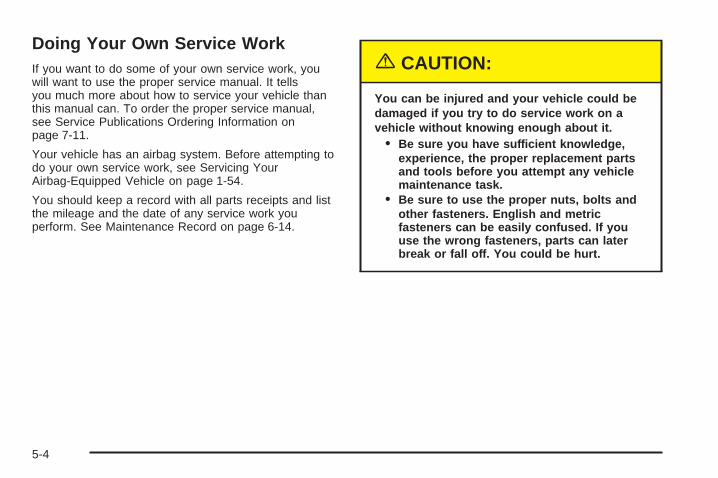
Doing Your Own Service WorkIf you want to do some of your own service work, youwill want to use the proper service manual. It tellsyou much more about how to service your vehicle thanthis manual can. To order the proper service manual,see Service Publications Ordering Information onpage 7-11.
Your vehicle has an airbag system. Before attempting todo your own service work, see Servicing YourAirbag-Equipped Vehicle on page 1-54.
You should keep a record with all parts receipts and listthe mileage and the date of any service work youperform. See Maintenance Record on page 6-14.
{CAUTION:
You can be injured and your vehicle could bedamaged if you try to do service work on avehicle without knowing enough about it.
• Be sure you have sufficient knowledge,experience, the proper replacement partsand tools before you attempt any vehiclemaintenance task.
• Be sure to use the proper nuts, bolts andother fasteners. English and metricfasteners can be easily confused. If youuse the wrong fasteners, parts can laterbreak or fall off. You could be hurt.
5-4
Adding Equipment to the Outside ofYour VehicleThings you might add to the outside of your vehicle canaffect the airflow around it. This may cause windnoise and affect windshield washer performance. Checkwith your dealer before adding equipment to theoutside of your vehicle.
FuelUse of the recommended fuel is an important part of theproper maintenance of your vehicle.
Gasoline OctaneUse regular unleaded gasoline with a posted octane of87 or higher. However, for best performance and fortrailer towing, you may wish to use middle gradeor premium unleaded gasoline. If the octane is less than87, you may get a heavy knocking noise when youdrive. If this occurs, use a gasoline rated at 87 octaneor higher as soon as possible. Otherwise, you mightdamage your engine.
Gasoline SpecificationsIt is recommended that gasoline meet specificationswhich were developed by automobile manufacturersaround the world and contained in the World-Wide FuelCharter which is available from the Alliance ofAutomobile Manufacturers atwww.autoalliance.org/fuel_charter.htm. Gasolinemeeting these specifications could provide improveddriveability and emission control system performancecompared to other gasoline.
California FuelIf your vehicle is certified to meet California EmissionStandards (see the underhood emission control label), itis designed to operate on fuels that meet Californiaspecifications. If this fuel is not available in statesadopting California emissions standards, your vehicle willoperate satisfactorily on fuels meeting federalspecifications, but emission control system performancemay be affected. The malfunction indicator lamp may turnon and your vehicle may fail a smog-check test. SeeMalfunction Indicator Lamp on page 3-50. If this occurs,return to your authorized GM dealer for diagnosis. If it isdetermined that the condition is caused by the type of fuelused, repairs may not be covered by your warranty.
5-5
AdditivesTo provide cleaner air, all gasolines in the United Statesare now required to contain additives that will helpprevent engine and fuel system deposits from forming,allowing your emission control system to work properly. Inmost cases, you should not have to add anything to yourfuel. However, some gasolines contain only the minimumamount of additive required to meet U.S. EnvironmentalProtection Agency regulations. General Motorsrecommends that you buy gasolines that are advertisedto help keep fuel injectors and intake valves clean. If yourvehicle experiences problems due to dirty injectors orvalves, try a different brand of gasoline. Also, your GMdealer has additives that will help correct and preventmost deposit-related problems.
Gasolines containing oxygenates, such as ethers andethanol, and reformulated gasolines may be available inyour area to contribute to clean air. General Motorsrecommends that you use these gasolines, particularly ifthey comply with the specifications described earlier.
Notice: Your vehicle was not designed for fuel thatcontains methanol. Do not use fuel containingmethanol. It can corrode metal parts in your fuelsystem and also damage the plastic and rubberparts. That damage would not be covered underyour warranty.
Some gasolines that are not reformulated for lowemissions may contain an octane-enhancing additivecalled methylcyclopentadienyl manganesetricarbonyl (MMT); ask the attendant where you buygasoline whether the fuel contains MMT. General Motorsdoes not recommend the use of such gasolines.Fuels containing MMT can reduce the life of spark plugsand the performance of the emission control systemmay be affected. The malfunction indicator lampmay turn on. If this occurs, return to your authorizedGM dealer for service.
Fuels in Foreign CountriesIf you plan on driving in another country outside theUnited States or Canada, the proper fuel may be hardto find. Never use leaded gasoline or any other fuelnot recommended in the previous text on fuel. Costlyrepairs caused by use of improper fuel would notbe covered by your warranty.
To check the fuel availability, ask an auto club, orcontact a major oil company that does business in thecountry where you will be driving.
5-6
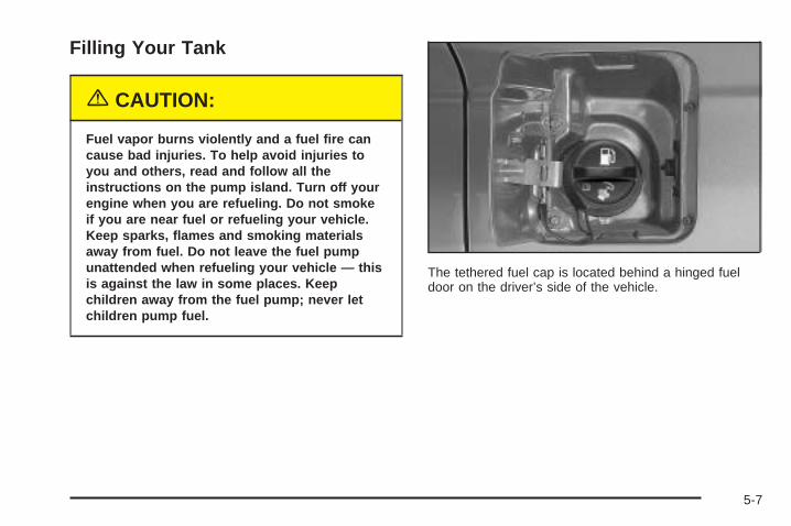
Filling Your Tank
{CAUTION:
Fuel vapor burns violently and a fuel fire cancause bad injuries. To help avoid injuries toyou and others, read and follow all theinstructions on the pump island. Turn off yourengine when you are refueling. Do not smokeif you are near fuel or refueling your vehicle.Keep sparks, flames and smoking materialsaway from fuel. Do not leave the fuel pumpunattended when refueling your vehicle — thisis against the law in some places. Keepchildren away from the fuel pump; never letchildren pump fuel.
The tethered fuel cap is located behind a hinged fueldoor on the driver’s side of the vehicle.
5-7
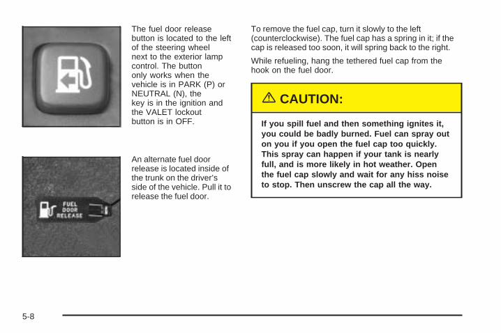
The fuel door releasebutton is located to the leftof the steering wheelnext to the exterior lampcontrol. The buttononly works when thevehicle is in PARK (P) orNEUTRAL (N), thekey is in the ignition andthe VALET lockoutbutton is in OFF.
An alternate fuel doorrelease is located inside ofthe trunk on the driver’sside of the vehicle. Pull it torelease the fuel door.
To remove the fuel cap, turn it slowly to the left(counterclockwise). The fuel cap has a spring in it; if thecap is released too soon, it will spring back to the right.
While refueling, hang the tethered fuel cap from thehook on the fuel door.
{CAUTION:
If you spill fuel and then something ignites it,you could be badly burned. Fuel can spray outon you if you open the fuel cap too quickly.This spray can happen if your tank is nearlyfull, and is more likely in hot weather. Openthe fuel cap slowly and wait for any hiss noiseto stop. Then unscrew the cap all the way.
5-8
Be careful not to spill fuel. Do not top off or overfill thetank and wait a few seconds after you have finishedpumping before removing the nozzle. Clean fuelfrom painted surfaces as soon as possible. SeeWashing Your Vehicle on page 5-91.
When replacing the fuel cap, turn it to the right(clockwise) until it clicks. Make sure the cap is fullyinstalled. The diagnostic system can determine if the fuelcap has been left off or improperly installed. Thiswould allow fuel to evaporate into the atmosphere. SeeMalfunction Indicator Lamp on page 3-50.
The CHECK GAS CAP message in the DriverInformation Center (DIC) will be displayed if the fuel capis not properly installed.
{CAUTION:
If a fire starts while you are refueling, do notremove the nozzle. Shut off the flow of fuel byshutting off the pump or by notifying thestation attendant. Leave the area immediately.
Notice: If you need a new fuel cap, be sure to get theright type. Your dealer can get one for you. If you getthe wrong type, it may not fit properly. This maycause your malfunction indicator lamp to light andmay damage your fuel tank and emissions system.See Malfunction Indicator Lamp on page 3-50.
5-9
Filling a Portable Fuel Container
{CAUTION:
Never fill a portable fuel container while it is inyour vehicle. Static electricity discharge fromthe container can ignite the gasoline vapor.You can be badly burned and your vehicledamaged if this occurs. To help avoid injury toyou and others:
• Dispense gasoline only into approvedcontainers.
• Do not fill a container while it is inside avehicle, in a vehicle’s trunk, pickup bed oron any surface other than the ground.
• Bring the fill nozzle in contact with theinside of the fill opening before operatingthe nozzle. Contact should be maintaineduntil the filling is complete.
• Do not smoke while pumping gasoline.
Checking Things Underthe Hood
{CAUTION:
An electric fan under the hood can start upand injure you even when the engine is notrunning. Keep hands, clothing and tools awayfrom any underhood electric fan.
{CAUTION:
Things that burn can get on hot engine partsand start a fire. These include liquids like fuel,oil, coolant, brake fluid, windshield washer andother fluids, and plastic or rubber. You orothers could be burned. Be careful not to dropor spill things that will burn onto a hot engine.
5-10
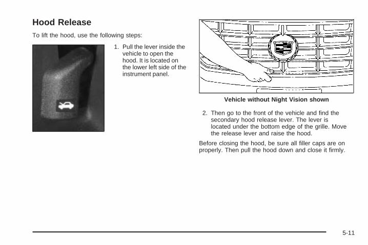
Hood ReleaseTo lift the hood, use the following steps:
1. Pull the lever inside thevehicle to open thehood. It is located onthe lower left side of theinstrument panel.
2. Then go to the front of the vehicle and find thesecondary hood release lever. The lever islocated under the bottom edge of the grille. Movethe release lever and raise the hood.
Before closing the hood, be sure all filler caps are onproperly. Then pull the hood down and close it firmly.
Vehicle without Night Vision shown
5-11
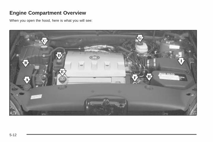
Engine Compartment OverviewWhen you open the hood, here is what you will see:
5-12

A. Windshield Washer Fluid Reservoir. See “AddingWasher Fluid” under Windshield Washer Fluidon page 5-36.
B. Underhood Fuse Block. See Underhood Fuse Blockon page 5-98.
C. Engine Coolant Surge Tank and Pressure Cap. SeeCoolant Surge Tank Pressure Cap on page 5-27and Cooling System on page 5-30.
D. Power Steering Fluid. See Power Steering Fluid onpage 5-35.
E. Engine Oil Fill Cap. See “When to Add Engine Oil”under Engine Oil on page 5-14.
F. Engine Oil Dipstick. See “Checking Engine Oil”under Engine Oil on page 5-14.
G. Brake Master Cylinder. See “Brake Fluid” underBrakes on page 5-37.
H. Automatic Transaxle Fluid Cap and Dipstick. SeeAutomatic Transaxle Fluid on page 5-21.
I. Engine Air Cleaner/Filter. See Engine AirCleaner/Filter on page 5-19.
5-13
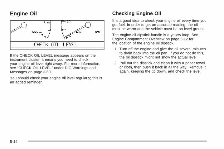
Engine Oil
If the CHECK OIL LEVEL message appears on theinstrument cluster, it means you need to checkyour engine oil level right away. For more information,see “CHECK OIL LEVEL” under DIC Warnings andMessages on page 3-60.
You should check your engine oil level regularly; this isan added reminder.
Checking Engine OilIt is a good idea to check your engine oil every time youget fuel. In order to get an accurate reading, the oilmust be warm and the vehicle must be on level ground.
The engine oil dipstick handle is a yellow loop. SeeEngine Compartment Overview on page 5-12 forthe location of the engine oil dipstick.
1. Turn off the engine and give the oil several minutesto drain back into the oil pan. If you do not do this,the oil dipstick might not show the actual level.
2. Pull out the dipstick and clean it with a paper towelor cloth, then push it back in all the way. Remove itagain, keeping the tip down, and check the level.
5-14
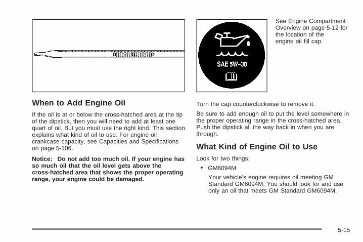
When to Add Engine OilIf the oil is at or below the cross-hatched area at the tipof the dipstick, then you will need to add at least onequart of oil. But you must use the right kind. This sectionexplains what kind of oil to use. For engine oilcrankcase capacity, see Capacities and Specificationson page 5-106.
Notice: Do not add too much oil. If your engine hasso much oil that the oil level gets above thecross-hatched area that shows the proper operatingrange, your engine could be damaged.
See Engine CompartmentOverview on page 5-12 forthe location of theengine oil fill cap.
Turn the cap counterclockwise to remove it.
Be sure to add enough oil to put the level somewhere inthe proper operating range in the cross-hatched area.Push the dipstick all the way back in when you arethrough.
What Kind of Engine Oil to UseLook for two things:
• GM6094M
Your vehicle’s engine requires oil meeting GMStandard GM6094M. You should look for and useonly an oil that meets GM Standard GM6094M.
5-15
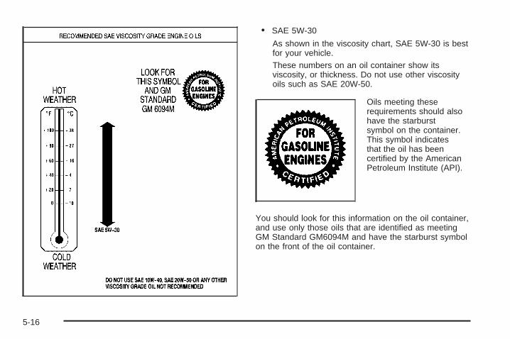
• SAE 5W-30
As shown in the viscosity chart, SAE 5W-30 is bestfor your vehicle.These numbers on an oil container show itsviscosity, or thickness. Do not use other viscosityoils such as SAE 20W-50.
Oils meeting theserequirements should alsohave the starburstsymbol on the container.This symbol indicatesthat the oil has beencertified by the AmericanPetroleum Institute (API).
You should look for this information on the oil container,and use only those oils that are identified as meetingGM Standard GM6094M and have the starburst symbolon the front of the oil container.
5-16
Notice: Use only engine oil identified as meetingGM Standard GM6094M and showing the AmericanPetroleum Institute Certified For Gasoline Enginesstarburst symbol. Failure to use the recommendedoil can result in engine damage not covered byyour warranty.
GM Goodwrench® oil meets all the requirements foryour vehicle.
If you are in an area of extreme cold, where thetemperature falls below −20°F (−29°C), it isrecommended that you use either an SAE 5W-30synthetic oil or an SAE 0W-30 oil. Both will provideeasier cold starting and better protection for your engineat extremely low temperatures.
Engine Oil AdditivesDo not add anything to your oil. The recommended oilswith the starburst symbol that meet GM StandardGM6094M are all you will need for good performanceand engine protection.
Engine Oil Life System
When to Change Engine OilYour vehicle has a computer system that lets you knowwhen to change the engine oil and filter. This is based onengine revolutions and engine temperature, and not onmileage. Based on driving conditions, the mileage atwhich an oil change will be indicated can varyconsiderably. For the oil life system to work properly, youmust reset the system every time the oil is changed.
When the system has calculated that oil life has beendiminished, it will indicate that an oil change is necessary.A CHANGE ENGINE OIL message in the DriverInformation Center (DIC) will come on. Change your oilas soon as possible within the next 600 miles (1 000 km).It is possible that, if you are driving under the bestconditions, the oil life system may not indicate that an oilchange is necessary for over a year. However, yourengine oil and filter must be changed at least once a yearand at this time the system must be reset. Your dealerhas GM-trained people who will perform this work usinggenuine GM parts and reset the system. It is alsoimportant to check your oil regularly and keep it at theproper level.
If the system is ever reset accidentally, you mustchange your oil at 3,000 miles (5 000 km) since yourlast oil change. Remember to reset the oil life systemwhenever the oil is changed.
5-17
How to Reset the Engine Oil LifeSystemThe Engine Oil Life System calculates when to changeyour engine oil and filter based on vehicle use. Anytimeyour oil is changed, reset the system so it can calculatewhen the next oil change is required. If a situation occurswhere you change your oil prior to a CHANGE ENGINEOIL message in the Driver Information Center (DIC) beingturned on, reset the system.
After the oil has been changed, the CHANGE ENGINEOIL message must be reset. To reset the message,do the following:
1. Turn the key to the ON position without starting theengine.
2. Press the INFO button on the Driver InformationCenter (DIC) until ENGINE OIL LIFE is displayed.
3. Press and hold the INFO RESET button until 100%ENGINE OIL LIFE is displayed. This resets the oillife indicator.
4. Turn the key to OFF.
If the CHANGE ENGINE OIL message comes back onwhen you start your vehicle, the engine oil life systemhas not reset. Repeat the procedure.
The percentage of oil life remaining may be checked atany time by pressing the INFO button until ENGINE OILLIFE is displayed on the DIC. For more information on theoil life indicator, see Oil Life Indicator on page 3-79.
What to Do with Used OilUsed engine oil contains certain elements that may beunhealthy for your skin and could even cause cancer.Do not let used oil stay on your skin for very long. Cleanyour skin and nails with soap and water, or a goodhand cleaner. Wash or properly dispose of clothing orrags containing used engine oil. See the manufacturer’swarnings about the use and disposal of oil products.
Used oil can be a threat to the environment. If youchange your own oil, be sure to drain all the oil from thefilter before disposal. Never dispose of oil by putting it inthe trash, pouring it on the ground, into sewers, or intostreams or bodies of water. Instead, recycle it by taking itto a place that collects used oil. If you have a problemproperly disposing of your used oil, ask your dealer, aservice station or a local recycling center for help.
5-18
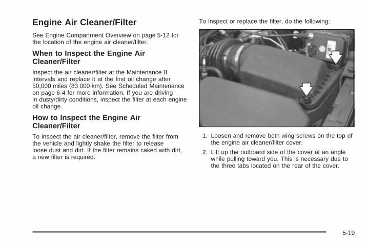
Engine Air Cleaner/FilterSee Engine Compartment Overview on page 5-12 forthe location of the engine air cleaner/filter.
When to Inspect the Engine AirCleaner/FilterInspect the air cleaner/filter at the Maintenance IIintervals and replace it at the first oil change after50,000 miles (83 000 km). See Scheduled Maintenanceon page 6-4 for more information. If you are drivingin dusty/dirty conditions, inspect the filter at each engineoil change.
How to Inspect the Engine AirCleaner/FilterTo inspect the air cleaner/filter, remove the filter fromthe vehicle and lightly shake the filter to releaseloose dust and dirt. If the filter remains caked with dirt,a new filter is required.
To inspect or replace the filter, do the following:
1. Loosen and remove both wing screws on the top ofthe engine air cleaner/filter cover.
2. Lift up the outboard side of the cover at an anglewhile pulling toward you. This is necessary due tothe three tabs located on the rear of the cover.
5-19
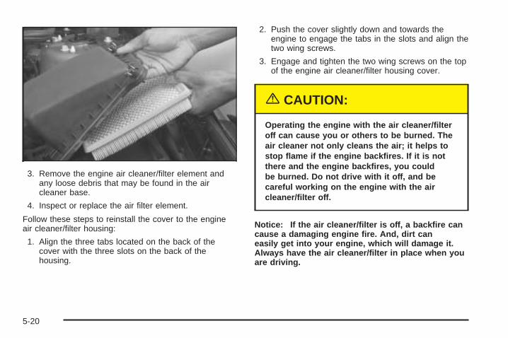
3. Remove the engine air cleaner/filter element andany loose debris that may be found in the aircleaner base.
4. Inspect or replace the air filter element.
Follow these steps to reinstall the cover to the engineair cleaner/filter housing:
1. Align the three tabs located on the back of thecover with the three slots on the back of thehousing.
2. Push the cover slightly down and towards theengine to engage the tabs in the slots and align thetwo wing screws.
3. Engage and tighten the two wing screws on the topof the engine air cleaner/filter housing cover.
{CAUTION:
Operating the engine with the air cleaner/filteroff can cause you or others to be burned. Theair cleaner not only cleans the air; it helps tostop flame if the engine backfires. If it is notthere and the engine backfires, you couldbe burned. Do not drive with it off, and becareful working on the engine with the aircleaner/filter off.
Notice: If the air cleaner/filter is off, a backfire cancause a damaging engine fire. And, dirt caneasily get into your engine, which will damage it.Always have the air cleaner/filter in place when youare driving.
5-20
Automatic Transaxle Fluid
When to Check and ChangeA good time to check your automatic transaxle fluidlevel is when the engine oil is changed.
Change both the fluid and filter every 50,000 miles(83 000 km) if the vehicle is mainly driven under one ormore of these conditions:
• In heavy city traffic where the outside temperatureregularly reaches 90°F (32°C) or higher.
• In hilly or mountainous terrain.
• When doing frequent trailer towing.
• Uses such as found in taxi, police or deliveryservice.
• Use such as limousine service.
If you do not use your vehicle under any of theseconditions, the fluid and filter do not require change untilthe message CHANGE TRANS FLUID appears onthe Driver Information Center (DIC).
See Scheduled Maintenance on page 6-4.
How to CheckBecause this operation can be a little difficult, you maychoose to have this done at the dealership servicedepartment.
If you do it yourself, be sure to follow all the instructionshere, or you could get a false reading on the dipstick.
Notice: Too much or too little fluid can damage thetransaxle. Too much can mean that some of the fluidcould come out and fall on hot engine or exhaustsystem parts, starting a fire. Too little fluid couldcause the transaxle to overheat. Be sure to get anaccurate reading if you check the transaxle fluid.
Wait at least 30 minutes before checking the transaxlefluid level if you have been driving:
• When outside temperatures are above 90°F (32°C)
• At high speed for quite a while.
• In heavy traffic — especially in hot weather.
• While pulling a trailer.
To get the right reading, the fluid should be atnormal operating temperature, which is180°F to 200°F (82°C to 93°C).
Get the vehicle warmed up by driving about15 miles (24 km) when outside temperatures are above50°F (10°C). If it is colder than 50°F (10°C), youmay have to drive longer.
5-21
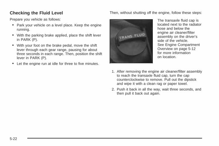
Checking the Fluid LevelPrepare you vehicle as follows:
• Park your vehicle on a level place. Keep the enginerunning.
• With the parking brake applied, place the shift leverin PARK (P).
• With your foot on the brake pedal, move the shiftlever through each gear range, pausing for aboutthree seconds in each range. Then, position the shiftlever in PARK (P).
• Let the engine run at idle for three to five minutes.
Then, without shutting off the engine, follow these steps:
The transaxle fluid cap islocated next to the radiatorhose and below theengine air cleaner/filterassembly on the driver’sside of the vehicle.See Engine CompartmentOverview on page 5-12for more informationon location.
1. After removing the engine air cleaner/filter assemblyto reach the transaxle fluid cap, turn the capcounterclockwise to remove. Pull out the dipstickand wipe it with a clean rag or paper towel.
2. Push it back in all the way, wait three seconds, andthen pull it back out again.
5-22
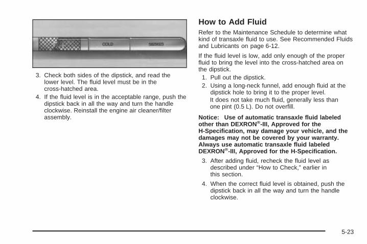
3. Check both sides of the dipstick, and read thelower level. The fluid level must be in thecross-hatched area.
4. If the fluid level is in the acceptable range, push thedipstick back in all the way and turn the handleclockwise. Reinstall the engine air cleaner/filterassembly.
How to Add FluidRefer to the Maintenance Schedule to determine whatkind of transaxle fluid to use. See Recommended Fluidsand Lubricants on page 6-12.
If the fluid level is low, add only enough of the properfluid to bring the level into the cross-hatched area onthe dipstick.
1. Pull out the dipstick.2. Using a long-neck funnel, add enough fluid at the
dipstick hole to bring it to the proper level.It does not take much fluid, generally less thanone pint (0.5 L). Do not overfill.
Notice: Use of automatic transaxle fluid labeledother than DEXRON ®-III, Approved for theH-Specification, may damage your vehicle, and thedamages may not be covered by your warranty.Always use automatic transaxle fluid labeledDEXRON®-III, Approved for the H-Specification.
3. After adding fluid, recheck the fluid level asdescribed under “How to Check,” earlier inthis section.
4. When the correct fluid level is obtained, push thedipstick back in all the way and turn the handleclockwise.
5-23
How to Reset the Transaxle FluidIndicatorAfter the transaxle fluid has been changed, the transaxlefluid change indicator must be reset. To reset theindicator, do the following:
1. Press the INFO button on the Driver InformationCenter (DIC) until TRANS FLUID LIFE is displayed.
2. Press and hold the RESET button until 100%is displayed. This resets the transaxle fluid changeindicator.
The percentage of transaxle fluid life remaining may bechecked at any time by pressing INFO on the DICuntil the TRANS FLUID LIFE message appears.
Engine CoolantThe cooling system in your vehicle is filled withDEX-COOL® engine coolant. This coolant is designedto remain in your vehicle for 5 years or 150,000 miles(240 000 km), whichever occurs first, if you addonly DEX-COOL® extended life coolant.
The following explains your cooling system and how toadd coolant when it is low. If you have a problem withengine overheating, see Engine Overheating onpage 5-27.
A 50/50 mixture of clean, drinkable water andDEX-COOL® coolant will:
• Giving freezing protection down to −34°F (−37°C).
• Give boiling protection up to 265°F (129°C).
• Protect against rust and corrosion.
• Help keep the proper engine temperature.
• Let the warning lights and gages work asthey should.
Notice: Using coolant other than DEX-COOL ® maycause premature engine, heater core or radiatorcorrosion. In addition, the engine coolant mayrequire changing sooner, at 30,000 miles (50 000 km)or 24 months, whichever occurs first. Any repairswould not be covered by your warranty. Always useDEX-COOL® (silicate-free) coolant in your vehicle.
5-24
What to UseUse a mixture of one-half clean, drinkable water andone-half DEX-COOL® coolant which will not damagealuminum parts. If you use this coolant mixture, you donot need to add anything else.
{CAUTION:
Adding only plain water to your coolingsystem can be dangerous. Plain water, orsome other liquid such as alcohol, can boilbefore the proper coolant mixture will. Yourvehicle’s coolant warning system is set for theproper coolant mixture. With plain water or thewrong mixture, your engine could get too hotbut you would not get the overheat warning.Your engine could catch fire and you or otherscould be burned. Use a 50/50 mixture of clean,drinkable water and DEX-COOL ® coolant.
Notice: If you use an improper coolant mixture,your engine could overheat and be badly damaged.The repair cost would not be covered by yourwarranty. Too much water in the mixture can freezeand crack the engine, radiator, heater core andother parts.
If you have to add coolant more than two times a year,have your dealer check your cooling system.
Notice: If you use the proper coolant, you do nothave to add extra inhibitors or additives which claimto improve the system. These can be harmful.
5-25
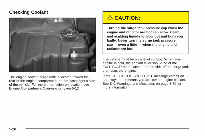
Checking Coolant
The engine coolant surge tank is located toward therear of the engine compartment on the passenger’s sideof the vehicle. For more information on location, seeEngine Compartment Overview on page 5-12.
{CAUTION:
Turning the surge tank pressure cap when theengine and radiator are hot can allow steamand scalding liquids to blow out and burn youbadly. Never turn the surge tank pressurecap — even a little — when the engine andradiator are hot.
The vehicle must be on a level surface. When yourengine is cold, the coolant level should be at theFULL COLD mark, located on the side of the surge tankthat faces the engine.
If the CHECK COOLANT LEVEL message comes onand stays on, it means you are low on engine coolant.See DIC Warnings and Messages on page 3-60 formore information.
5-26
Adding CoolantIf you need more coolant, add the proper DEX-COOL®
coolant mixture at the surge tank, but only when theengine is cool.
{CAUTION:
You can be burned if you spill coolant on hotengine parts. Coolant contains ethylene glycol,and it will burn if the engine parts are hotenough. Do not spill coolant on a hot engine.
When replacing the pressure cap, make sure the arrowlines up with the tube.
Coolant Surge Tank Pressure CapNotice: If the pressure cap is not tightly installed,coolant loss and possible engine damage may occur.Be sure the cap is properly and tightly secured.
See Engine Compartment Overview on page 5-12 formore information on location.
Engine OverheatingYou will find an ENGINE COOLANT HOT, IDLEENGINE message or an ENGINE OVERHEATED,STOP ENGINE message displayed in the DriverInformation Center (DIC). See DIC Warnings andMessages on page 3-60 for more information. You willalso hear a chime.
There is also an engine temperature warning lightand/or gage on the instrument panel cluster. See EngineCoolant Temperature Warning Light on page 3-49 andEngine Coolant Temperature Gage on page 3-49.
5-27
If Steam Is Coming From Your Engine
{CAUTION:
Steam from an overheated engine can burnyou badly, even if you just open the hood. Stayaway from the engine if you see or hear steamcoming from it. Just turn it off and geteveryone away from the vehicle until it coolsdown. Wait until there is no sign of steam orcoolant before you open the hood.
If you keep driving when your engine isoverheated, the liquids in it can catch fire. Youor others could be badly burned. Stop yourengine if it overheats, and get out of thevehicle until the engine is cool.
See Overheated Engine Protection OperatingMode on page 5-29 for information on drivingto a safe place in an emergency.
Notice: If your engine catches fire because you keepdriving with no coolant, your vehicle can be badlydamaged. The costly repairs would not be covered byyour warranty. See Overheated Engine ProtectionOperating Mode on page 5-29 for information ondriving to a safe place in an emergency.
If No Steam Is Coming From YourEngineAn overheat warning, along with a low coolant message,can indicate a serious problem.
If you get an engine overheat warning with no lowcoolant message, but see or hear no steam, the problemmay not be too serious. Sometimes the engine canget a little too hot when you:
• Climb a long hill on a hot day.
• Stop after high-speed driving.
• Idle for long periods in traffic.
• Tow a trailer.
5-28
If you get the overheat warning with no sign of steam,try this for a minute or so:
1. In heavy traffic, let the engine idle in NEUTRAL (N)while stopped. If it safe to do so, pull off the road,shift to PARK (P) or NEUTRAL (N) and let theengine idle.
2. Set the climate controls to the highest heat settingand fan speed and open the windows as necessary.
If you no longer have the overheat warning, youcan drive. Just to be safe, drive slower for about10 minutes. If the warning does not come back on, youcan drive normally.
If the warning continues, pull over, stop, and park yourvehicle right away.
If there is still no sign of steam, idle the engine forthree minutes while you are parked. If you still have thewarning, turn off the engine and get everyone out ofthe vehicle until it cools down. Also, see “OverheatedEngine Protection Operating Mode” later in this section.
You may decide not to lift the hood but to get servicehelp right away.
Overheated Engine ProtectionOperating ModeIf an overheated engine condition exists and themessage ENGINE OVERHEATED, STOP ENGINE isdisplayed, an overheat protection mode which alternatesfiring groups of cylinders helps prevent engine damage.In this mode, you will notice a loss in power andengine performance. This operating mode allows yourvehicle to be driven to a safe place in an emergency.Driving extended miles (km) and/or towing a trailer in theoverheat protection mode should be avoided.
Notice: After driving in the overheated engineprotection operating mode, to avoid engine damage,allow the engine to cool before attempting any repair.The engine oil will be severely degraded. Repair thecause of coolant loss, change the oil and reset the oillife system. See Engine Oil on page 5-14.
5-29
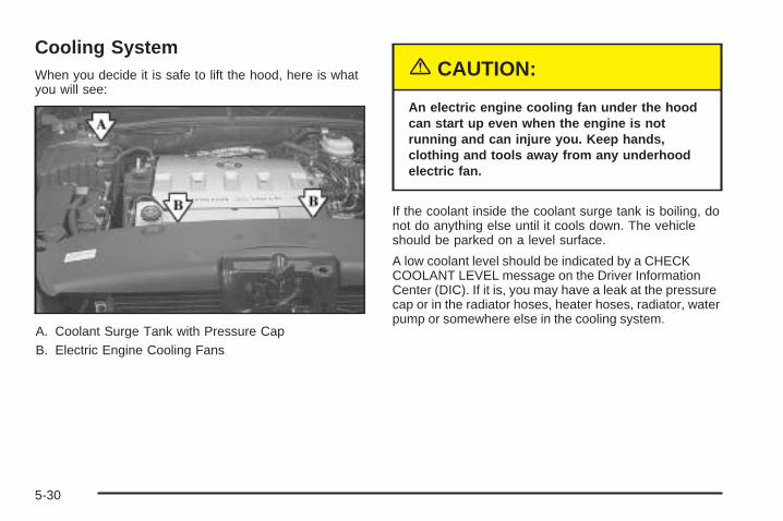
Cooling SystemWhen you decide it is safe to lift the hood, here is whatyou will see:
A. Coolant Surge Tank with Pressure CapB. Electric Engine Cooling Fans
{CAUTION:
An electric engine cooling fan under the hoodcan start up even when the engine is notrunning and can injure you. Keep hands,clothing and tools away from any underhoodelectric fan.
If the coolant inside the coolant surge tank is boiling, donot do anything else until it cools down. The vehicleshould be parked on a level surface.
A low coolant level should be indicated by a CHECKCOOLANT LEVEL message on the Driver InformationCenter (DIC). If it is, you may have a leak at the pressurecap or in the radiator hoses, heater hoses, radiator, waterpump or somewhere else in the cooling system.
5-30
{CAUTION:
Heater and radiator hoses, and other engineparts, can be very hot. Do not touch them. Ifyou do, you can be burned.
Do not run the engine if there is a leak. If yourun the engine, it could lose all coolant. Thatcould cause an engine fire, and you could beburned. Get any leak fixed before you drive thevehicle.
If there seems to be no leak, with the engine on, checkto see if the electric engine cooling fans are running.If the engine is overheating, both fans should berunning. If they are not, your vehicle needs service.
Notice: Engine damage from running your enginewithout coolant is not covered by your warranty. SeeOverheated Engine Protection Operating Mode onpage 5-29 for information on driving to a safe placein an emergency.
Notice: Using coolant other than DEX-COOL ® maycause premature engine, heater core or radiatorcorrosion. In addition, the engine coolant mayrequire changing sooner, at 30,000 miles (50 000 km)or 24 months, whichever occurs first. Any repairswould not be covered by your warranty. Always useDEX-COOL® (silicate-free) coolant in your vehicle.
5-31
How to Add Coolant to the CoolantSurge TankIf you have not found a problem yet, check to see ifcoolant is visible in the surge tank. If coolant is visible butthe level is not 4.5 inches (11.4 cm) below the top of thefiller neck, add a 50/50 mixture of clean, drinkable waterand DEX-COOL® coolant at the coolant surge tank, butbe sure the cooling system, including the coolant surgetank pressure cap, is cool before you do it. See EngineCoolant on page 5-24 for more information.
If no coolant is visible in the surge tank, add coolant asfollows:
{CAUTION:
Steam and scalding liquids from a hot coolingsystem can blow out and burn you badly. Theyare under pressure, and if you turn the coolantsurge tank pressure cap — even a little — theycan come out at high speed. Never turn thecap when the cooling system, including thecoolant surge tank pressure cap, is hot. Waitfor the cooling system and coolant surge tankpressure cap to cool if you ever have to turnthe pressure cap.
5-32
{CAUTION:
Adding only plain water to your coolingsystem can be dangerous. Plain water, orsome other liquid such as alcohol, can boilbefore the proper coolant mixture will. Yourvehicle’s coolant warning system is set for theproper coolant mixture. With plain water or thewrong mixture, your engine could get too hotbut you would not get the overheat warning.Your engine could catch fire and you or otherscould be burned. Use a 50/50 mixture of clean,drinkable water and DEX-COOL ® coolant.
Notice: In cold weather, water can freeze and crackthe engine, radiator, heater core and other parts.Use the recommended coolant and the propercoolant mixture.
{CAUTION:
You can be burned if you spill coolant on hotengine parts. Coolant contains ethylene glycoland it will burn if the engine parts are hotenough. Do not spill coolant on a hot engine.
5-33
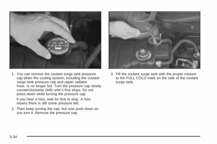
1. You can remove the coolant surge tank pressurecap when the cooling system, including the coolantsurge tank pressure cap and upper radiatorhose, is no longer hot. Turn the pressure cap slowlycounterclockwise (left) until it first stops. Do notpress down while turning the pressure cap.If you hear a hiss, wait for that to stop. A hissmeans there is still some pressure left.
2. Then keep turning the cap, but now push down asyou turn it. Remove the pressure cap.
3. Fill the coolant surge tank with the proper mixtureto the FULL COLD mark on the side of the coolantsurge tank.
5-34
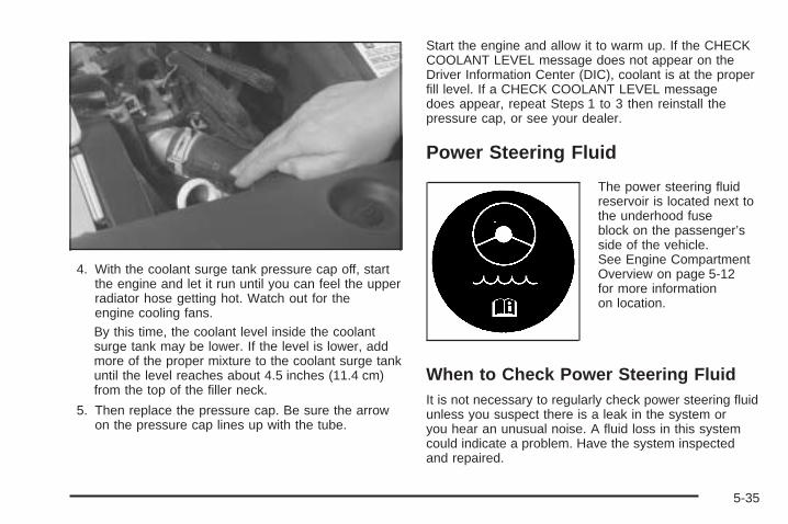
4. With the coolant surge tank pressure cap off, startthe engine and let it run until you can feel the upperradiator hose getting hot. Watch out for theengine cooling fans.By this time, the coolant level inside the coolantsurge tank may be lower. If the level is lower, addmore of the proper mixture to the coolant surge tankuntil the level reaches about 4.5 inches (11.4 cm)from the top of the filler neck.
5. Then replace the pressure cap. Be sure the arrowon the pressure cap lines up with the tube.
Start the engine and allow it to warm up. If the CHECKCOOLANT LEVEL message does not appear on theDriver Information Center (DIC), coolant is at the properfill level. If a CHECK COOLANT LEVEL messagedoes appear, repeat Steps 1 to 3 then reinstall thepressure cap, or see your dealer.
Power Steering Fluid
The power steering fluidreservoir is located next tothe underhood fuseblock on the passenger’sside of the vehicle.See Engine CompartmentOverview on page 5-12for more informationon location.
When to Check Power Steering FluidIt is not necessary to regularly check power steering fluidunless you suspect there is a leak in the system oryou hear an unusual noise. A fluid loss in this systemcould indicate a problem. Have the system inspectedand repaired.
5-35
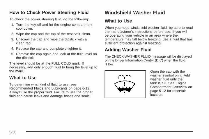
How to Check Power Steering FluidTo check the power steering fluid, do the following:
1. Turn the key off and let the engine compartmentcool down.
2. Wipe the cap and the top of the reservoir clean.
3. Unscrew the cap and wipe the dipstick with aclean rag.
4. Replace the cap and completely tighten it.
5. Remove the cap again and look at the fluid level onthe dipstick.
The level should be at the FULL COLD mark. Ifnecessary, add only enough fluid to bring the level up tothe mark.
What to UseTo determine what kind of fluid to use, seeRecommended Fluids and Lubricants on page 6-12.Always use the proper fluid. Failure to use the properfluid can cause leaks and damage hoses and seals.
Windshield Washer Fluid
What to UseWhen you need windshield washer fluid, be sure to readthe manufacturer’s instructions before use. If you willbe operating your vehicle in an area where thetemperature may fall below freezing, use a fluid that hassufficient protection against freezing.
Adding Washer FluidThe CHECK WASHER FLUID message will be displayedon the Driver Information Center (DIC) when the fluidis low.
Open the cap with thewasher symbol on it. Addwasher fluid until thetank is full. See EngineCompartment Overview onpage 5-12 for reservoirlocation.
5-36
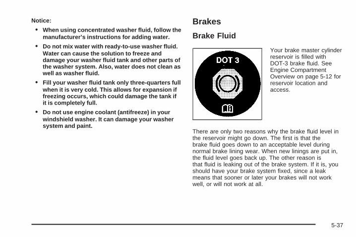
Notice:
• When using concentrated washer fluid, follow themanufacturer’s instructions for adding water.
• Do not mix water with ready-to-use washer fluid.Water can cause the solution to freeze anddamage your washer fluid tank and other parts ofthe washer system. Also, water does not clean aswell as washer fluid.
• Fill your washer fluid tank only three-quarters fullwhen it is very cold. This allows for expansion iffreezing occurs, which could damage the tank ifit is completely full.
• Do not use engine coolant (antifreeze) in yourwindshield washer. It can damage your washersystem and paint.
Brakes
Brake Fluid
Your brake master cylinderreservoir is filled withDOT-3 brake fluid. SeeEngine CompartmentOverview on page 5-12 forreservoir location andaccess.
There are only two reasons why the brake fluid level inthe reservoir might go down. The first is that thebrake fluid goes down to an acceptable level duringnormal brake lining wear. When new linings are put in,the fluid level goes back up. The other reason isthat fluid is leaking out of the brake system. If it is, youshould have your brake system fixed, since a leakmeans that sooner or later your brakes will not workwell, or will not work at all.
5-37
So, it is not a good idea to top off your brake fluid.Adding brake fluid will not correct a leak. If you add fluidwhen your linings are worn, then you will have toomuch fluid when you get new brake linings. You shouldadd or remove brake fluid, as necessary, only whenwork is done on the brake hydraulic system.
{CAUTION:
If you have too much brake fluid, it can spill onthe engine. The fluid will burn if the engine ishot enough. You or others could be burned,and your vehicle could be damaged. Add brakefluid only when work is done on the brakehydraulic system.
If the ignition is in ON and the brake fluid is low, theCHECK BRAKE FLUID message will be displayed in theDriver Information Center (DIC). See DIC Warningsand Messages on page 3-60.
What to AddWhen you do need brake fluid, use only DOT-3 brakefluid. Use new brake fluid from a sealed containeronly. See Recommended Fluids and Lubricants onpage 6-12.
Always clean the brake fluid reservoir cap and the areaaround the cap before removing it. This will helpkeep dirt from entering the reservoir.
{CAUTION:
With the wrong kind of fluid in your brakesystem, your brakes may not work well, or theymay not even work at all. This could cause acrash. Always use the proper brake fluid.
5-38
Notice:
• Using the wrong fluid can badly damage brakesystem parts. For example, just a few drops ofmineral-based oil, such as engine oil, in yourbrake system can damage brake system parts sobadly that they will have to be replaced. Do notlet someone put in the wrong kind of fluid.
• If you spill brake fluid on your vehicle’s paintedsurfaces, the paint finish can be damaged. Becareful not to spill brake fluid on your vehicle. Ifyou do, wash it off immediately. See AppearanceCare on page 5-87.
Brake WearYour vehicle has four-wheel disc brakes.
Disc brake pads have built-in wear indicators that makea high-pitched warning sound when the brake padsare worn and new pads are needed. The soundmay come and go or be heard all the time your vehicleis moving, except when you are pushing on thebrake pedal firmly.
{CAUTION:
The brake wear warning sound means that soonyour brakes will not work well. That could leadto an accident. When you hear the brake wearwarning sound, have your vehicle serviced.
Notice: Continuing to drive with worn-out brakepads could result in costly brake repair.
Some driving conditions or climates may cause a brakesqueal when the brakes are first applied or lightlyapplied. This does not mean something is wrong withyour brakes.
Properly torqued wheel nuts are necessary to helpprevent brake pulsation. When tires are rotated, inspectbrake pads for wear and evenly tighten wheel nuts inthe proper sequence to GM torque specifications.
Brake linings should always be replaced as completeaxle sets.
5-39
Brake Pedal TravelSee your dealer if the brake pedal does not return tonormal height, or if there is a rapid increase inpedal travel. This could be a sign of brake trouble.
Brake AdjustmentEvery time you apply the brakes, with or without thevehicle moving, your brakes adjust for wear.
Replacing Brake System PartsThe braking system on a vehicle is complex. Its manyparts have to be of top quality and work well together ifthe vehicle is to have really good braking. Yourvehicle was designed and tested with top-quality GMbrake parts. When you replace parts of your brakingsystem — for example, when your brake liningswear down and you need new ones put in — be sureyou get new approved replacement parts. If you do not,your brakes may no longer work properly. Forexample, if someone puts in brake linings that arewrong for your vehicle, the balance between your frontand rear brakes can change — for the worse. Thebraking performance you have come to expectcan change in many other ways if someone puts in thewrong replacement brake parts.
BatteryYour vehicle has a maintenance free battery. When it istime for a new battery, get one that has the replacementnumber shown on the original battery’s label. Werecommend an ACDelco® replacement battery.Warning: Battery posts, terminals and relatedaccessories contain lead and lead compounds,chemicals known to the State of California to causecancer and reproductive harm. Wash hands afterhandling.
The battery is located under the rear seat cushion. Toaccess the battery, see Rear Underseat Fuse Block onpage 5-101. You do not need to access the battery tojump start your vehicle. See Jump Starting on page 5-42.
5-40
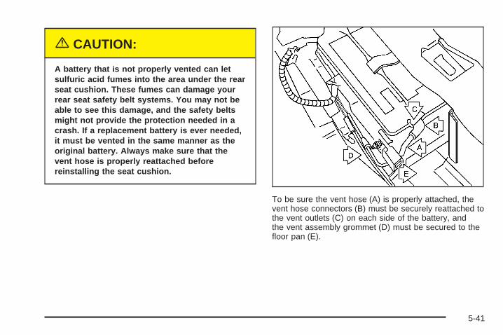
{CAUTION:
A battery that is not properly vented can letsulfuric acid fumes into the area under the rearseat cushion. These fumes can damage yourrear seat safety belt systems. You may not beable to see this damage, and the safety beltsmight not provide the protection needed in acrash. If a replacement battery is ever needed,it must be vented in the same manner as theoriginal battery. Always make sure that thevent hose is properly reattached beforereinstalling the seat cushion.
To be sure the vent hose (A) is properly attached, thevent hose connectors (B) must be securely reattached tothe vent outlets (C) on each side of the battery, andthe vent assembly grommet (D) must be secured to thefloor pan (E).
5-41
Vehicle StorageIf you are not going to drive your vehicle for 25 daysor more, remove the black, negative (−) cable fromthe battery. This will help keep your battery fromrunning down.
{CAUTION:
Batteries have acid that can burn you and gasthat can explode. You can be badly hurt if youare not careful. See Jump Starting onpage 5-42 for tips on working around a batterywithout getting hurt.
Also, for your audio system, see Theft-DeterrentFeature on page 3-103.
Jump StartingIf you cannot start your vehicle and you are unable toremove your key from the ignition, see “Shift LockRelease” under Automatic Transaxle Operation onpage 2-28.
If your battery has run down, you may want to useanother vehicle and some jumper cables to start yourvehicle. Be sure to use the following steps to do it safely.
{CAUTION:
Batteries can hurt you. They can be dangerousbecause:
• They contain acid that can burn you.• They contain gas that can explode or ignite.• They contain enough electricity to
burn you.
If you do not follow these steps exactly, some orall of these things can hurt you.
5-42
Notice: Ignoring these steps could result in costlydamage to your vehicle that would not be coveredby your warranty.
Trying to start your vehicle by pushing or pulling itwill not work, and it could damage your vehicle.
1. Check the other vehicle. It must have a 12-voltbattery with a negative ground system.
Notice: If the other vehicle’s system is not a 12-voltsystem with a negative ground, both vehicles canbe damaged. Only use vehicles with 12-volt systemswith negative grounds to jump start your vehicle.
2. Get the vehicles close enough so the jumper cablescan reach, but be sure the vehicles are not touchingeach other. If they are, it could cause a groundconnection you do not want. You would not be ableto start your vehicle and the bad grounding coulddamage the electrical systems.To avoid the possibility of the vehicles rolling, setthe parking brake firmly on both vehicles involved inthe jump start procedure. Put an automatictransaxle in PARK (P) or a manual transaxle inNEUTRAL before setting the parking brake.
Notice: If you leave your radio or other accessorieson during the jump starting procedure, they couldbe damaged. The repairs would not be coveredby your warranty. Always turn off your radio andother accessories when jump starting your vehicle.
3. Turn off the ignition on both vehicles. Unplugunnecessary accessories plugged into the cigarettelighter or the accessory power outlets. Turn offthe radio and all lamps that are not needed. Thiswill avoid sparks and help save both batteries. Andit could save the radio!
5-43
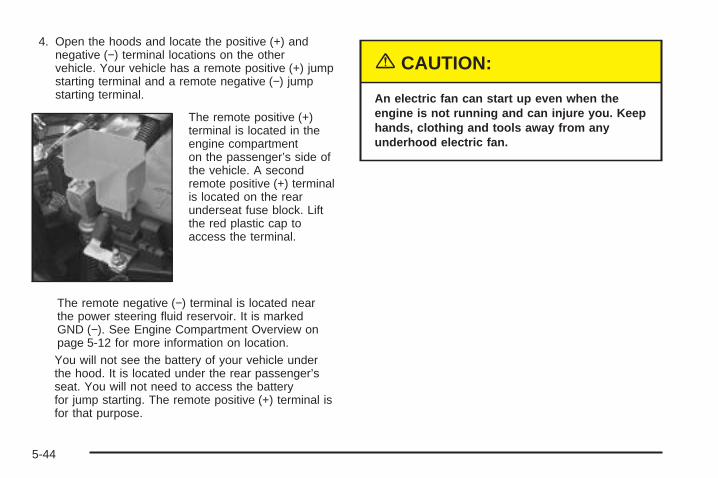
4. Open the hoods and locate the positive (+) andnegative (−) terminal locations on the othervehicle. Your vehicle has a remote positive (+) jumpstarting terminal and a remote negative (−) jumpstarting terminal.
The remote positive (+)terminal is located in theengine compartmenton the passenger’s side ofthe vehicle. A secondremote positive (+) terminalis located on the rearunderseat fuse block. Liftthe red plastic cap toaccess the terminal.
The remote negative (−) terminal is located nearthe power steering fluid reservoir. It is markedGND (−). See Engine Compartment Overview onpage 5-12 for more information on location.You will not see the battery of your vehicle underthe hood. It is located under the rear passenger’sseat. You will not need to access the batteryfor jump starting. The remote positive (+) terminal isfor that purpose.
{CAUTION:
An electric fan can start up even when theengine is not running and can injure you. Keephands, clothing and tools away from anyunderhood electric fan.
5-44
{CAUTION:
Using a match near a battery can cause batterygas to explode. People have been hurt doingthis, and some have been blinded. Use aflashlight if you need more light.
Be sure the battery has enough water. You donot need to add water to the battery installedin your new vehicle. But if a battery has fillercaps, be sure the right amount of fluid is there.If it is low, add water to take care of that first.If you do not, explosive gas could be present.
Battery fluid contains acid that can burn you.Do not get it on you. If you accidentally get itin your eyes or on your skin, flush the placewith water and get medical help immediately.
{CAUTION:
Fans or other moving engine parts can injureyou badly. Keep your hands away from movingparts once the engine is running.
5. Check that the jumper cables do not have loose ormissing insulation. If they do, you could get ashock. The vehicles could be damaged too.Before you connect the cables, here are somebasic things you should know. Positive (+) will go topositive (+) or to a remote positive (+) terminal ifthe vehicle has one. Negative (−) will go to a heavy,unpainted metal engine part or to a remotenegative (−) terminal if the vehicle has one.Do not connect positive (+) to negative (−) or youwill get a short that would damage the batteryand maybe other parts too. And do not connect thenegative (−) cable to the negative (−) terminal onthe dead battery because this can cause sparks.
5-45
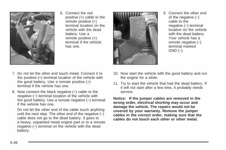
6. Connect the redpositive (+) cable to theremote positive (+)terminal location on thevehicle with the deadbattery. Use aremote positive (+)terminal if the vehiclehas one.
7. Do not let the other end touch metal. Connect it tothe positive (+) terminal location of the vehicle withthe good battery. Use a remote positive (+)terminal if the vehicle has one.
8. Now connect the black negative (−) cable to thenegative (−) terminal location of the vehicle withthe good battery. Use a remote negative (−) terminalif the vehicle has one.Do not let the other end of the cable touch anythinguntil the next step. The other end of the negative (−)cable does not go to the dead battery. It goes toa heavy, unpainted metal engine part or to a remotenegative (−) terminal on the vehicle with the deadbattery.
9. Connect the other endof the negative (−)cable to thenegative (−) terminallocation on the vehiclewith the dead battery.Your vehicle has aremote negative (−)terminal markedGND (−).
10. Now start the vehicle with the good battery and runthe engine for a while.
11. Try to start the vehicle that had the dead battery. Ifit will not start after a few tries, it probably needsservice.
Notice: If the jumper cables are removed in thewrong order, electrical shorting may occur anddamage the vehicle. The repairs would not becovered by your warranty. Remove the jumpercables in the correct order, making sure that thecables do not touch each other or other metal.
5-46
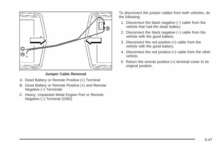
A. Dead Battery or Remote Positive (+) TerminalB. Good Battery or Remote Positive (+) and Remote
Negative (−) TerminalsC. Heavy, Unpainted Metal Engine Part or Remote
Negative (−) Terminal (GND)
To disconnect the jumper cables from both vehicles, dothe following:
1. Disconnect the black negative (−) cable from thevehicle that had the dead battery.
2. Disconnect the black negative (−) cable from thevehicle with the good battery.
3. Disconnect the red positive (+) cable from thevehicle with the good battery.
4. Disconnect the red positive (+) cable from the othervehicle.
5. Return the remote positive (+) terminal cover to itsoriginal position.
Jumper Cable Removal
5-47
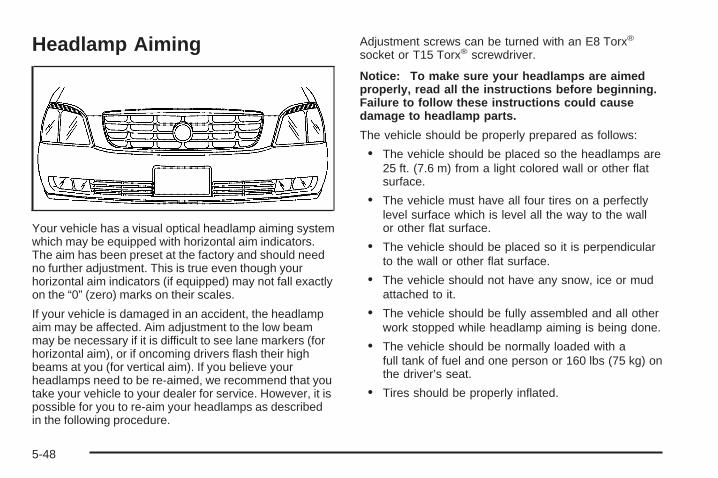
Headlamp Aiming
Your vehicle has a visual optical headlamp aiming systemwhich may be equipped with horizontal aim indicators.The aim has been preset at the factory and should needno further adjustment. This is true even though yourhorizontal aim indicators (if equipped) may not fall exactlyon the “0” (zero) marks on their scales.
If your vehicle is damaged in an accident, the headlampaim may be affected. Aim adjustment to the low beammay be necessary if it is difficult to see lane markers (forhorizontal aim), or if oncoming drivers flash their highbeams at you (for vertical aim). If you believe yourheadlamps need to be re-aimed, we recommend that youtake your vehicle to your dealer for service. However, it ispossible for you to re-aim your headlamps as describedin the following procedure.
Adjustment screws can be turned with an E8 Torx®
socket or T15 Torx® screwdriver.
Notice: To make sure your headlamps are aimedproperly, read all the instructions before beginning.Failure to follow these instructions could causedamage to headlamp parts.
The vehicle should be properly prepared as follows:
• The vehicle should be placed so the headlamps are25 ft. (7.6 m) from a light colored wall or other flatsurface.
• The vehicle must have all four tires on a perfectlylevel surface which is level all the way to the wallor other flat surface.
• The vehicle should be placed so it is perpendicularto the wall or other flat surface.
• The vehicle should not have any snow, ice or mudattached to it.
• The vehicle should be fully assembled and all otherwork stopped while headlamp aiming is being done.
• The vehicle should be normally loaded with afull tank of fuel and one person or 160 lbs (75 kg) onthe driver’s seat.
• Tires should be properly inflated.
5-48
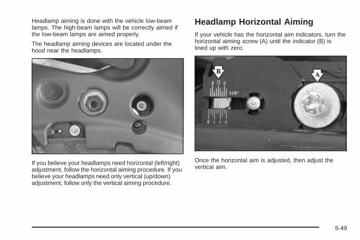
Headlamp aiming is done with the vehicle low-beamlamps. The high-beam lamps will be correctly aimed ifthe low-beam lamps are aimed properly.
The headlamp aiming devices are located under thehood near the headlamps.
If you believe your headlamps need horizontal (left/right)adjustment, follow the horizontal aiming procedure. If youbelieve your headlamps need only vertical (up/down)adjustment, follow only the vertical aiming procedure.
Headlamp Horizontal AimingIf your vehicle has the horizontal aim indicators, turn thehorizontal aiming screw (A) until the indicator (B) islined up with zero.
Once the horizontal aim is adjusted, then adjust thevertical aim.
5-49
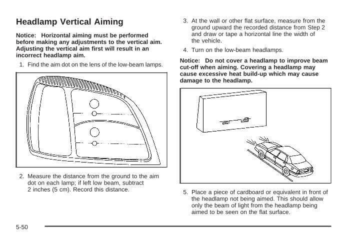
Headlamp Vertical AimingNotice: Horizontal aiming must be performedbefore making any adjustments to the vertical aim.Adjusting the vertical aim first will result in anincorrect headlamp aim.
1. Find the aim dot on the lens of the low-beam lamps.
2. Measure the distance from the ground to the aimdot on each lamp; if left low beam, subtract2 inches (5 cm). Record this distance.
3. At the wall or other flat surface, measure from theground upward the recorded distance from Step 2and draw or tape a horizontal line the width ofthe vehicle.
4. Turn on the low-beam headlamps.
Notice: Do not cover a headlamp to improve beamcut-off when aiming. Covering a headlamp maycause excessive heat build-up which may causedamage to the headlamp.
5. Place a piece of cardboard or equivalent in front ofthe headlamp not being aimed. This should allowonly the beam of light from the headlamp beingaimed to be seen on the flat surface.
5-50
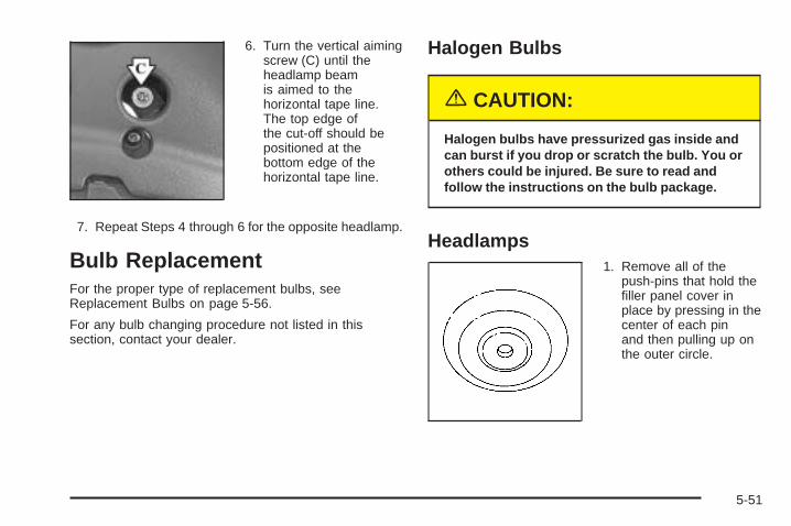
6. Turn the vertical aimingscrew (C) until theheadlamp beamis aimed to thehorizontal tape line.The top edge ofthe cut-off should bepositioned at thebottom edge of thehorizontal tape line.
7. Repeat Steps 4 through 6 for the opposite headlamp.
Bulb ReplacementFor the proper type of replacement bulbs, seeReplacement Bulbs on page 5-56.
For any bulb changing procedure not listed in thissection, contact your dealer.
Halogen Bulbs
{CAUTION:
Halogen bulbs have pressurized gas inside andcan burst if you drop or scratch the bulb. You orothers could be injured. Be sure to read andfollow the instructions on the bulb package.
Headlamps1. Remove all of the
push-pins that hold thefiller panel cover inplace by pressing in thecenter of each pinand then pulling up onthe outer circle.
5-51
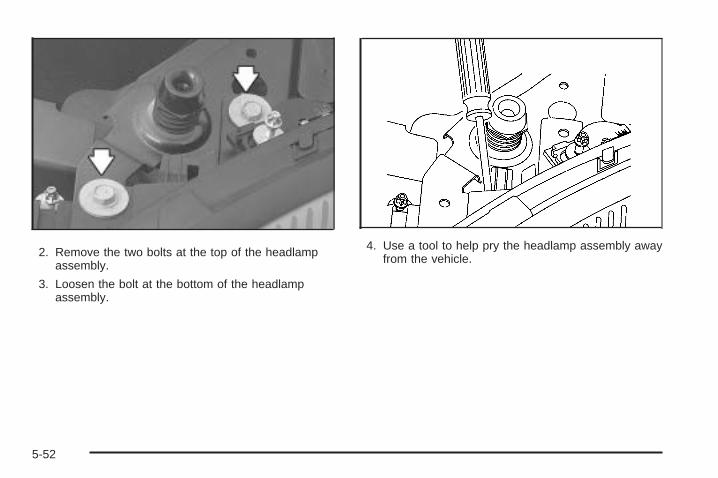
2. Remove the two bolts at the top of the headlampassembly.
3. Loosen the bolt at the bottom of the headlampassembly.
4. Use a tool to help pry the headlamp assembly awayfrom the vehicle.
5-52
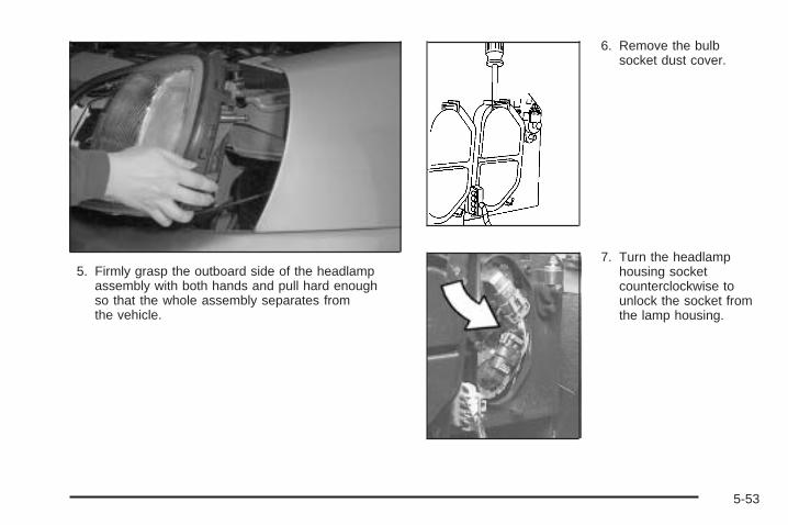
5. Firmly grasp the outboard side of the headlampassembly with both hands and pull hard enoughso that the whole assembly separates fromthe vehicle.
6. Remove the bulbsocket dust cover.
7. Turn the headlamphousing socketcounterclockwise tounlock the socket fromthe lamp housing.
5-53
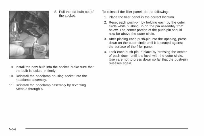
8. Pull the old bulb out ofthe socket.
9. Install the new bulb into the socket. Make sure thatthe bulb is locked in firmly.
10. Reinstall the headlamp housing socket into theheadlamp assembly.
11. Reinstall the headlamp assembly by reversingSteps 2 through 6.
To reinstall the filler panel, do the following:
1. Place the filler panel in the correct location.
2. Reset each push-pin by holding each by the outercircle while pushing up on the pin assembly frombelow. The center portion of the push-pin shouldnow be above the outer circle.
3. After placing each push-pin into the opening, pressdown on the outer circle until it is seated againstthe surface of the filler panel.
4. Lock each push-pin in place by pressing the centerof each down until it is level with the outer circle.Use care not to press down so far that the push-pinreleases again.
5-54
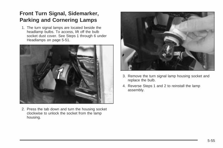
Front Turn Signal, Sidemarker,Parking and Cornering Lamps
1. The turn signal lamps are located beside theheadlamp bulbs. To access, lift off the bulbsocket dust cover. See Steps 1 through 6 underHeadlamps on page 5-51.
2. Press the tab down and turn the housing socketclockwise to unlock the socket from the lamphousing.
3. Remove the turn signal lamp housing socket andreplace the bulb.
4. Reverse Steps 1 and 2 to reinstall the lampassembly.
5-55
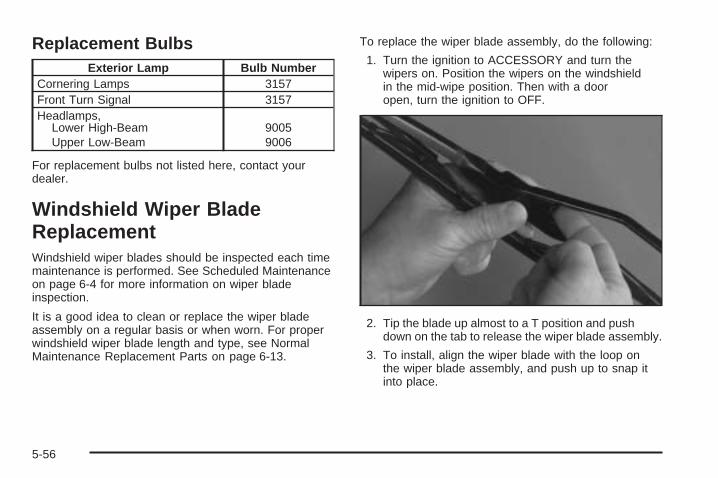
Replacement BulbsExterior Lamp Bulb Number
Cornering Lamps 3157Front Turn Signal 3157Headlamps,
Lower High-BeamUpper Low-Beam
90059006
For replacement bulbs not listed here, contact yourdealer.
Windshield Wiper BladeReplacementWindshield wiper blades should be inspected each timemaintenance is performed. See Scheduled Maintenanceon page 6-4 for more information on wiper bladeinspection.
It is a good idea to clean or replace the wiper bladeassembly on a regular basis or when worn. For properwindshield wiper blade length and type, see NormalMaintenance Replacement Parts on page 6-13.
To replace the wiper blade assembly, do the following:
1. Turn the ignition to ACCESSORY and turn thewipers on. Position the wipers on the windshieldin the mid-wipe position. Then with a dooropen, turn the ignition to OFF.
2. Tip the blade up almost to a T position and pushdown on the tab to release the wiper blade assembly.
3. To install, align the wiper blade with the loop onthe wiper blade assembly, and push up to snap itinto place.
5-56
TiresYour new vehicle comes with high-quality tires made bya leading tire manufacturer. If you ever have questionsabout your tire warranty and where to obtain service,see your GM Warranty booklet for details. For additionalinformation refer to the tire manufacturer’s bookletincluded with your vehicle’s owner’s manual.
{CAUTION:
• Poorly maintained and improperly usedtires are dangerous.
• Overloading your tires can causeoverheating as a result of too muchfriction. You could have an air-out and aserious accident. See Loading YourVehicle on page 4-30.
CAUTION: (Continued)
CAUTION: (Continued)
• Underinflated tires pose the same dangeras overloaded tires. The resulting accidentcould cause serious injury. Check all tiresfrequently to maintain the recommendedpressure. Tire pressure should be checkedwhen your tires are cold.
• Overinflated tires are more likely to becut, punctured or broken by a suddenimpact— such as when you hit a pothole.Keep tires at the recommended pressure.
• Worn, old tires can cause accidents. Ifyour tread is badly worn, or if your tireshave been damaged, replace them.
See Inflation - Tire Pressure on page 5-65, forinflation pressure adjustment for high speeddriving.
5-57
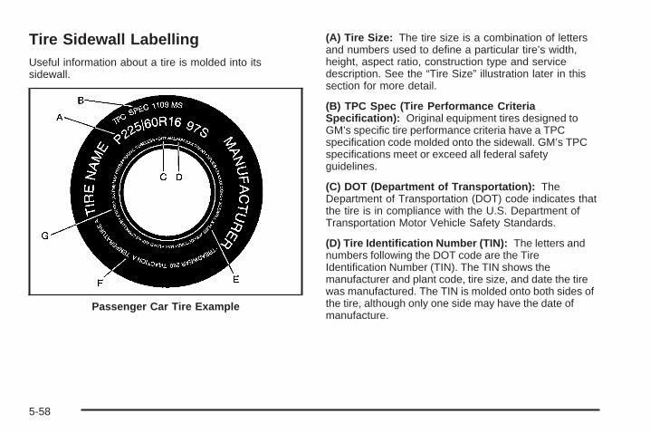
Tire Sidewall LabellingUseful information about a tire is molded into itssidewall.
(A) Tire Size: The tire size is a combination of lettersand numbers used to define a particular tire’s width,height, aspect ratio, construction type and servicedescription. See the “Tire Size” illustration later in thissection for more detail.
(B) TPC Spec (Tire Performance CriteriaSpecification): Original equipment tires designed toGM’s specific tire performance criteria have a TPCspecification code molded onto the sidewall. GM’s TPCspecifications meet or exceed all federal safetyguidelines.
(C) DOT (Department of Transportation): TheDepartment of Transportation (DOT) code indicates thatthe tire is in compliance with the U.S. Department ofTransportation Motor Vehicle Safety Standards.
(D) Tire Identification Number (TIN): The letters andnumbers following the DOT code are the TireIdentification Number (TIN). The TIN shows themanufacturer and plant code, tire size, and date the tirewas manufactured. The TIN is molded onto both sides ofthe tire, although only one side may have the date ofmanufacture.
Passenger Car Tire Example
5-58
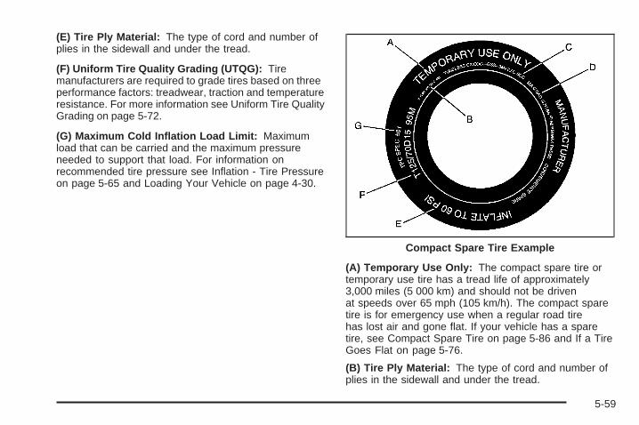
(E) Tire Ply Material: The type of cord and number ofplies in the sidewall and under the tread.
(F) Uniform Tire Quality Grading (UTQG): Tiremanufacturers are required to grade tires based on threeperformance factors: treadwear, traction and temperatureresistance. For more information see Uniform Tire QualityGrading on page 5-72.
(G) Maximum Cold Inflation Load Limit: Maximumload that can be carried and the maximum pressureneeded to support that load. For information onrecommended tire pressure see Inflation - Tire Pressureon page 5-65 and Loading Your Vehicle on page 4-30.
(A) Temporary Use Only: The compact spare tire ortemporary use tire has a tread life of approximately3,000 miles (5 000 km) and should not be drivenat speeds over 65 mph (105 km/h). The compact sparetire is for emergency use when a regular road tirehas lost air and gone flat. If your vehicle has a sparetire, see Compact Spare Tire on page 5-86 and If a TireGoes Flat on page 5-76.
(B) Tire Ply Material: The type of cord and number ofplies in the sidewall and under the tread.
Compact Spare Tire Example
5-59
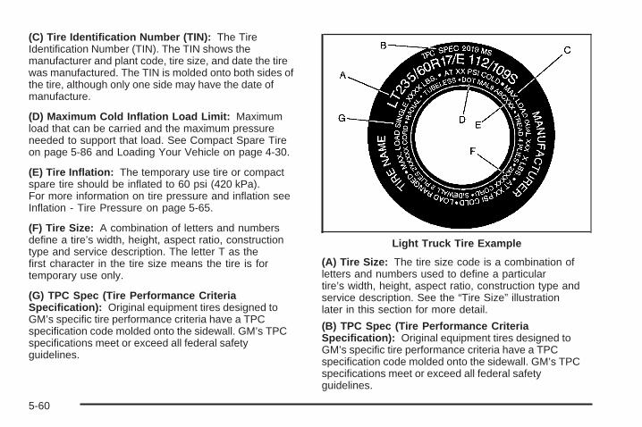
(C) Tire Identification Number (TIN): The TireIdentification Number (TIN). The TIN shows themanufacturer and plant code, tire size, and date the tirewas manufactured. The TIN is molded onto both sides ofthe tire, although only one side may have the date ofmanufacture.
(D) Maximum Cold Inflation Load Limit: Maximumload that can be carried and the maximum pressureneeded to support that load. See Compact Spare Tireon page 5-86 and Loading Your Vehicle on page 4-30.
(E) Tire Inflation: The temporary use tire or compactspare tire should be inflated to 60 psi (420 kPa).For more information on tire pressure and inflation seeInflation - Tire Pressure on page 5-65.
(F) Tire Size: A combination of letters and numbersdefine a tire’s width, height, aspect ratio, constructiontype and service description. The letter T as thefirst character in the tire size means the tire is fortemporary use only.
(G) TPC Spec (Tire Performance CriteriaSpecification): Original equipment tires designed toGM’s specific tire performance criteria have a TPCspecification code molded onto the sidewall. GM’s TPCspecifications meet or exceed all federal safetyguidelines.
(A) Tire Size: The tire size code is a combination ofletters and numbers used to define a particulartire’s width, height, aspect ratio, construction type andservice description. See the “Tire Size” illustrationlater in this section for more detail.
(B) TPC Spec (Tire Performance CriteriaSpecification): Original equipment tires designed toGM’s specific tire performance criteria have a TPCspecification code molded onto the sidewall. GM’s TPCspecifications meet or exceed all federal safetyguidelines.
Light Truck Tire Example
5-60
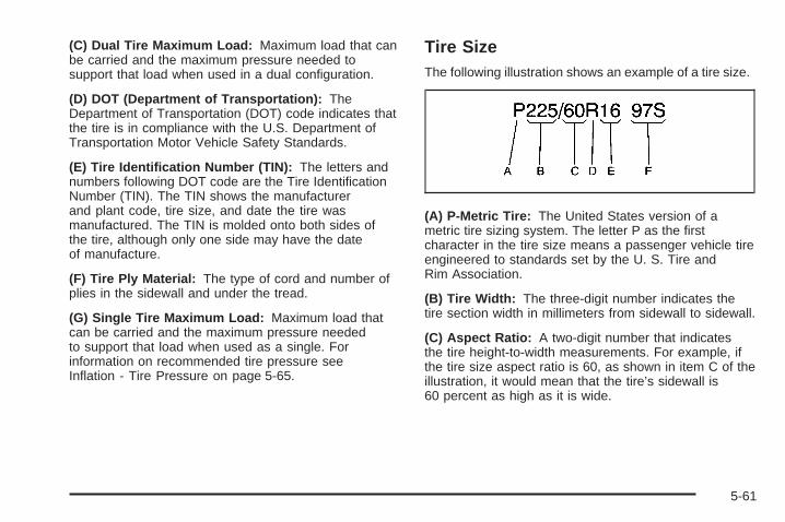
(C) Dual Tire Maximum Load: Maximum load that canbe carried and the maximum pressure needed tosupport that load when used in a dual configuration.
(D) DOT (Department of Transportation): TheDepartment of Transportation (DOT) code indicates thatthe tire is in compliance with the U.S. Department ofTransportation Motor Vehicle Safety Standards.
(E) Tire Identification Number (TIN): The letters andnumbers following DOT code are the Tire IdentificationNumber (TIN). The TIN shows the manufacturerand plant code, tire size, and date the tire wasmanufactured. The TIN is molded onto both sides ofthe tire, although only one side may have the dateof manufacture.
(F) Tire Ply Material: The type of cord and number ofplies in the sidewall and under the tread.
(G) Single Tire Maximum Load: Maximum load thatcan be carried and the maximum pressure neededto support that load when used as a single. Forinformation on recommended tire pressure seeInflation - Tire Pressure on page 5-65.
Tire SizeThe following illustration shows an example of a tire size.
(A) P-Metric Tire: The United States version of ametric tire sizing system. The letter P as the firstcharacter in the tire size means a passenger vehicle tireengineered to standards set by the U. S. Tire andRim Association.
(B) Tire Width: The three-digit number indicates thetire section width in millimeters from sidewall to sidewall.
(C) Aspect Ratio: A two-digit number that indicatesthe tire height-to-width measurements. For example, ifthe tire size aspect ratio is 60, as shown in item C of theillustration, it would mean that the tire’s sidewall is60 percent as high as it is wide.
5-61
(D) Construction Code: A letter code is used toindicate the type of ply construction in the tire. The letterR means radial ply construction; the letter D meansdiagonal or bias ply construction; and the letter B meansbelted-bias ply construction.
(E) Rim Diameter: Diameter of the wheel in inches.
(F) Service Description: These characters representthe load range and speed rating of the tire. The loadindex represents the load carry capacity a tire is certifiedto carry. The load index can range from 1 to 279. Thespeed rating is the maximum speed a tire is certifiedto carry a load. Speed ratings range from A to Z.
Tire Terminology and Definitions
Air Pressure: The amount of air inside the tire pressingoutward on each square inch of the tire. Air pressureis expressed in pounds per square inch (psi) orkiloPascal (kPa).
Accessory Weight: This means the combined weightof optional accessories. Some examples of optionalaccessories are, automatic transmission, power steering,power brakes, power windows, power seats, and airconditioning.
Aspect Ratio: The relationship of a tire’s height toits width.
Belt: A rubber coated layer of cords that is locatedbetween the plies and the tread. Cords may be madefrom steel or other reinforcing materials.
Bead: The tire bead contains steel wires wrapped bysteel cords that hold the tire onto the rim.
Bias Ply Tire: A pneumatic tire in which the plies arelaid at alternate angles less than 90 degrees to thecenterline of the tread.
Cold Inflation Pressure: The amount of air pressure ina tire, measured in pounds per square inch (psi) orkilopascals (kPa) before a tire has built up heatfrom driving. See Inflation - Tire Pressure on page 5-65.
Curb Weight: This means the weight of a motorvehicle with standard and optional equipment includingthe maximum capacity of fuel, oil and coolant, butwithout passengers and cargo.
DOT Markings: A code molded into the sidewall of atire signifying that the tire is in compliance with theU.S. Department of Transportation (DOT) motor vehiclesafety standards. The DOT code includes the TireIdentification Number (TIN), an alphanumeric designatorwhich can also identify the tire manufacturer, productionplant, brand and date of production.
5-62
GVWR: Gross Vehicle Weight Rating, see LoadingYour Vehicle on page 4-30.
GAWR FRT: Gross Axle Weight Rating for the frontaxle, see Loading Your Vehicle on page 4-30.
GAWR RR: Gross Axle Weight Rating for the rear axle,see Loading Your Vehicle on page 4-30.
Intended Outboard Sidewall: The side of anasymmetrical tire, that must always face outward whenmounted on a vehicle.
KiloPascal (kPa): The metric unit for air pressure.
Light Truck (LT-Metric) Tire: A tire used on light dutytrucks and some multipurpose passenger vehicles.
Load Index: An assigned number ranging from 1 to 279that corresponds to the load carrying capacity of a tire.
Maximum Inflation Pressure: The maximum airpressure to which a cold tire may be inflated. Themaximum air pressure is molded onto the sidewall.
Maximum Load Rating: The load rating for a tire at themaximum permissible inflation pressure for that tire.
Maximum Loaded Vehicle Weight: The sum of curbweight; accessory weight; vehicle capacity weight;and production options weight.
Normal Occupant Weight: The number of occupants avehicle is designed to seat multiplied by 150 lbs (68 kg).See Loading Your Vehicle on page 4-30.
Occupant Distribution: Designated seating positions.
Outward Facing Sidewall: The side of an asymmetricaltire that has a particular side that faces outward whenmounted on a vehicle. The side of the tire that contains awhitewall, bears white lettering or bears manufacturer,brand, and/or model name molding that is higher ordeeper than the same moldings on the other sidewallof the tire.
Passenger (P-Metric) Tire: A tire used on passengercars and some light duty trucks and multipurposevehicles.
Recommended Inflation Pressure: Vehiclemanufacturer’s recommended tire inflation pressure andshown on the tire placard. See Inflation - Tire Pressureon page 5-65 and Loading Your Vehicle on page 4-30.
5-63
Radial Ply Tire: A pneumatic tire in which the ply cordsthat extend to the beads are laid at 90 degrees to thecenterline of the tread.
Rim: A metal support for a tire and upon which the tirebeads are seated.
Sidewall: The portion of a tire between the tread andthe bead.
Speed Rating: An alphanumeric code assigned to atire indicating the maximum speed at which a tirecan operate.
Traction: The friction between the tire and the roadsurface. The amount of grip provided.
Tread: The portion of a tire that comes into contactwith the road.
Treadwear Indicators: Narrow bands, sometimescalled “wear bars,” that show across the tread of a tirewhen only 1/16 inch (1.6 mm) of tread remains. SeeWhen It Is Time for New Tires on page 5-70.
UTQGS (Uniform Tire Quality Grading Standards):A tire information system that provides consumerswith ratings for a tire’s traction, temperature, andtreadwear. Ratings are determined by tire manufacturersusing government testing procedures. The ratings aremolded into the sidewall of the tire. See UniformTire Quality Grading on page 5-72.
Vehicle Capacity Weight: The number of designatedseating positions multiplied by 150 lbs (68 kg) plusthe rated cargo load. See Loading Your Vehicleon page 4-30.
Vehicle Maximum Load on the Tire: Load on anindividual tire due to curb weight, accessory weight,occupant weight, and cargo weight.
Vehicle Placard: A label permanently attached to avehicle showing the vehicle’s capacity weight andthe original equipment tire size and recommendedinflation pressure. See “Tire and Loading InformationLabel” under Loading Your Vehicle on page 4-30.
5-64
Inflation - Tire PressureTires need the correct amount of air pressure to operateeffectively.
Notice: Do not let anyone tell you thatunder-inflation or over-inflation is all right. It is not.If your tires do not have enough air (under-inflation),you can get the following:
• Too much flexing
• Too much heat
• Tire overloading
• Premature or irregular wear
• Poor handling
• Reduced fuel economy
If your tires have too much air (over-inflation), youcan get the following:
• Unusual wear
• Poor handling
• Rough ride
• Needless damage from road hazards
A Tire and Loading Information label is attached to thevehicle’s center pillar, below the driver’s door latch.This label lists your vehicle’s original equipmenttires and shows the correct inflation pressures for yourtires when they are cold. The recommended coldtire inflation pressure, shown on the label, is theminimum amount of air pressure needed to support yourvehicle’s maximum load carrying capacity.
For additional information regarding how much weightyour vehicle can carry, and an example of the tireand loading information label, see Loading Your Vehicleon page 4-30. How you load your vehicle affects thevehicle handling and ride comfort, never load yourvehicle with more weight than it was designed to carry.
When to CheckCheck your tires once a month or more. Do not forget tocheck the spare tire. If your vehicle has a compactspare tire, it should be at 60 psi (420 kPa). For additionalinformation regarding the compact spare tire, seeCompact Spare Tire on page 5-86
5-65
How to CheckUse a good quality pocket-type gage to check tirepressure. You cannot tell if your tires are properly inflatedsimply by looking at them. Radial tires may look properlyinflated even when they are under-inflated. Check thetire’s inflation pressure when the tires are cold. Coldmeans your vehicle has been sitting for at leastthree hours or driven no more than 1 mile (1.6 km).
Remove the valve cap from the tire valve stem. Pressthe tire gage firmly onto the valve to get a pressuremeasurement. If the cold tire inflation pressure matchesthe recommended pressure on the Tire and LoadingInformation label, no further adjustment is necessary. Ifthe inflation pressure is low, add air until you reachthe recommended amount.
If you overfill the tire, release air by pushing on themetal stem in the center of the tire valve. Re-check thetire pressure with the tire gage.
Be sure to put the valve caps back on the valve stems.They help prevent leaks by keeping out dirt and moisture.
Your vehicle has a Tire Pressure Monitor (TPM) thatsends tire pressure information to the Driver InformationCenter (DIC). Using the DIC control buttons, thedriver is able to check tire pressure levels in all fourroad tires. See Tire Pressure Monitor Operationon page 5-68 and DIC Controls and Displays onpage 3-57 for additional information.
High Speed Operation
{CAUTION:
Driving at high speeds, 100 mph (160 km/h) orhigher, puts an additional strain on tires.Sustained high-speed driving, causesexcessive heat build up and can cause suddentire failure. You could have a crash and you orothers could be killed. Some high-speed ratedtires require inflation pressure adjustment forhigh speed operation. When speed limits androad conditions are such, that a vehicle can bedriven at high speeds, make sure the tires arerated for high speed operation, in excellentcondition and set to the correct cold tireinflation pressure for the vehicle load.
5-66
If your vehicle has P225/60R16 97S or P235/55R17 98Hsize tires and you will be driving at speeds of100 mph (160 km/h) or higher, where it is legal, setthe cold inflation pressure to the maximum inflationpressure shown on the tire sidewall, or 38 psi (265 kPa),whichever is lower. See the example following. Whenyou end this high-speed driving, return the tires tothe cold inflation pressure shown on the Tire andLoading Information label. See Loading Your Vehicleon page 4-30.
Example:
You’ll find maximum load and inflation pressure moldedon the tire’s sidewall, in small letters, near the rimflange. It will read something like this: Maximum load690 kg (1521 lbs) 300 kPa (44 psi) Max. Press.
For this example, you would set the inflation pressurefor high-speed driving at 38 psi (265 kPa).
Professional VehicleThe proper inflation of the tires on your professionalvehicle depends on the type of tires on it.
• If your vehicle has P235/60R17EL 103S size tires,the cold inflation pressure is 41 psi (284 kPa).
• If your vehicle has LT235/60R17E 112S size tires,the cold inflation pressure depends on the vehiclemass and should be determined by the vehiclecoach-builder. A tire and loading information labelprovided by the final stage manufacturer should beattached to the B-pillar on the driver’s side of thevehicle. If the final stage manufacturer’s label is notpresent, the coach-builder should be consulted. Donot use the tire pressures indicated on the GeneralMotors label. These tire pressures are for theincomplete vehicle and are not the correct tirepressures for the completed professional vehicle.
Operation at inflation pressures below thisrecommendation may cause your tires to becomeoverloaded.
5-67
Tire Pressure Monitor OperationIf your vehicle has the Tire Pressure Monitor (TPM)system, it uses radio and sensor technology to check tirepressure levels. Sensors, mounted on each road wheel,transmit tire pressure readings to a receiver located in thetrunk. Tire pressure status and tire pressure warnings areshown on the Driver Information Center (DIC) display.See Driver Information Center (DIC) on page 3-57, fordetails regarding DIC controls and displays.
The system operates on a radio frequency subject toFederal Communications Commission (FCC) Rules andwith Industry and Science Canada.
This device complies with Part 15 of the FCC Rules.Operation is subject to the following two conditions:(1) this device may not cause harmful interference, and(2) this device must accept any interference received,including interference that may cause undesiredoperation.
This device complies with RSS-210 of Industry andScience Canada. Operation is subject to the followingtwo conditions: (1) this device may not causeinterference, and (2) this device must accept anyinterference received, including interference that maycause undesired operation of the device.
Changes or modifications to this system by anyoneother than an authorized service facility could voidauthorization to use this equipment.
If the TPM system detects low tire pressure, below25 psi (172 kPa), or high tire pressure, above38 psi (262 kPa), a message, CHECK TIREPRESSURE, will appear on the Driver InformationCenter (DIC) display. By pressing the INFO button, theDIC screen will show which tire(s) has the low orhigh pressure condition. See Inflation - Tire Pressure onpage 5-65 for information regarding correct tireinflation. If a tire is low, you should stop as soon aspossible and check all your tires for damage. If a tire isflat, see If a Tire Goes Flat on page 5-76.
Notice: Do not use a tire sealant if your vehicle isequipped with Tire Pressure Monitors. The liquidsealant can damage the tire pressure monitorsensors.
Once a low or high tire pressure condition is detected,the TPM system will display the CHECK TIREMESSAGE each time the engine is started, until thetire(s) are set to the correct inflation pressure.
The Tire-Loading Information Label, which is located onthe rear edge of the driver’s door, shows the correctinflation pressure for the tires on your vehicle.
5-68
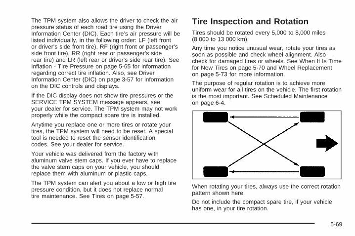
The TPM system also allows the driver to check the airpressure status of each road tire using the DriverInformation Center (DIC). Each tire’s air pressure will belisted individually, in the following order: LF (left frontor driver’s side front tire), RF (right front or passenger’sside front tire), RR (right rear or passenger’s siderear tire) and LR (left rear or driver’s side rear tire). SeeInflation - Tire Pressure on page 5-65 for informationregarding correct tire inflation. Also, see DriverInformation Center (DIC) on page 3-57 for informationon the DIC controls and displays.
If the DIC display does not show tire pressures or theSERVICE TPM SYSTEM message appears, seeyour dealer for service. The TPM system may not workproperly while the compact spare tire is installed.
Anytime you replace one or more tires or rotate yourtires, the TPM system will need to be reset. A specialtool is needed to reset the sensor identificationcodes. See your dealer for service.
Your vehicle was delivered from the factory withaluminum valve stem caps. If you ever have to replacethe valve stem caps on your vehicle, you shouldreplace them with aluminum or plastic caps.
The TPM system can alert you about a low or high tirepressure condition, but it does not replace normaltire maintenance. See Tires on page 5-57.
Tire Inspection and RotationTires should be rotated every 5,000 to 8,000 miles(8 000 to 13 000 km).
Any time you notice unusual wear, rotate your tires assoon as possible and check wheel alignment. Alsocheck for damaged tires or wheels. See When It Is Timefor New Tires on page 5-70 and Wheel Replacementon page 5-73 for more information.
The purpose of regular rotation is to achieve moreuniform wear for all tires on the vehicle. The first rotationis the most important. See Scheduled Maintenanceon page 6-4.
When rotating your tires, always use the correct rotationpattern shown here.
Do not include the compact spare tire, if your vehiclehas one, in your tire rotation.
5-69
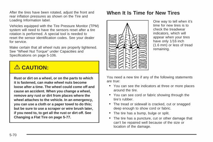
After the tires have been rotated, adjust the front andrear inflation pressures as shown on the Tire andLoading Information label.
Vehicles equipped with the Tire Pressure Monitor (TPM)system will need to have the sensors reset after a tirerotation is performed. A special tool is needed toreset the sensor identification codes. See your dealerfor service.
Make certain that all wheel nuts are properly tightened.See “Wheel Nut Torque” under Capacities andSpecifications on page 5-106.
{CAUTION:
Rust or dirt on a wheel, or on the parts to whichit is fastened, can make wheel nuts becomeloose after a time. The wheel could come off andcause an accident. When you change a wheel,remove any rust or dirt from places where thewheel attaches to the vehicle. In an emergency,you can use a cloth or a paper towel to do this;but be sure to use a scraper or wire brush later,if you need to, to get all the rust or dirt off. SeeChanging a Flat Tire on page 5-77.
When It Is Time for New Tires
One way to tell when it’stime for new tires is tocheck the treadwearindicators, which willappear when your tireshave only 1/16 inch(1.6 mm) or less of treadremaining.
You need a new tire if any of the following statementsare true:• You can see the indicators at three or more places
around the tire.• You can see cord or fabric showing through the
tire’s rubber.• The tread or sidewall is cracked, cut or snagged
deep enough to show cord or fabric.• The tire has a bump, bulge or split.• The tire has a puncture, cut or other damage that
can’t be repaired well because of the size orlocation of the damage.
5-70
Buying New TiresTo find out what kind and size of tires your vehicleneeds, look at the tire and loading information label. Formore information about this label and its location onyour vehicle, see Loading Your Vehicle on page 4-30.
The tires installed on your vehicle when it was new had aTire Performance Criteria Specification (TPC Spec)number on each tire’s sidewall. When you get new tires,GM recommends that you get tires with that same TPCSpec number. That way your vehicle will continue to havetires that are designed to give proper endurance,handling, speed rating, load range, traction, ride andother things during normal service on your vehicle. If yourtires have an all-season tread design, the TPC numberwill be followed by an “MS” (for mud and snow).
If you ever replace your tires with those not having aTPC Spec number, make sure they are the same size,load range, speed rating and construction type (bias,bias-belted or radial) as your original tires.
{CAUTION:
Mixing tires could cause you to lose controlwhile driving. If you mix tires of different sizesor types (radial and bias-belted tires), thevehicle may not handle properly, and youcould have a crash. Using tires of differentsizes may also cause damage to your vehicle.Be sure to use the same size and type tires onall wheels. It’s all right to drive with yourcompact spare temporarily, it was developedfor use on your vehicle. See Compact SpareTire on page 5-86.
{CAUTION:
If you use bias-ply tires on your vehicle, thewheel rim flanges could develop cracks aftermany miles of driving. A tire and/or wheelcould fail suddenly, causing a crash. Use onlyradial-ply tires with the wheels on your vehicle.
5-71
Uniform Tire Quality GradingQuality grades can be found where applicable on thetire sidewall between tread shoulder and maximumsection width. For example:
Treadwear 200 Traction AA Temperature AThe following information relates to the system developedby the United States National Highway Traffic SafetyAdministration, which grades tires by treadwear, tractionand temperature performance. (This applies only tovehicles sold in the United States.) The grades aremolded on the sidewalls of most passenger car tires. TheUniform Tire Quality Grading system does not apply todeep tread, winter-type snow tires, space-saver ortemporary use spare tires, tires with nominal rimdiameters of 10 to 12 inches (25 to 30 cm), or to somelimited-production tires.
While the tires available on General Motors passengercars and light trucks may vary with respect to thesegrades, they must also conform to federal safetyrequirements and additional General Motors TirePerformance Criteria (TPC) standards.
TreadwearThe treadwear grade is a comparative rating based onthe wear rate of the tire when tested under controlledconditions on a specified government test course.For example, a tire graded 150 would wear one anda half (1.5) times as well on the government course asa tire graded 100. The relative performance of tiresdepends upon the actual conditions of their use,however, and may depart significantly from the normdue to variations in driving habits, service practices anddifferences in road characteristics and climate.
Traction – AA, A, B, CThe traction grades, from highest to lowest, are AA, A,B, and C. Those grades represent the tire’s abilityto stop on wet pavement as measured under controlledconditions on specified government test surfaces ofasphalt and concrete. A tire marked C may have poortraction performance. Warning: The traction gradeassigned to this tire is based on straight-ahead brakingtraction tests, and does not include acceleration,cornering, hydroplaning, or peak traction characteristics.
5-72
Temperature – A, B, CThe temperature grades are A (the highest), B, and C,representing the tire’s resistance to the generationof heat and its ability to dissipate heat when testedunder controlled conditions on a specified indoorlaboratory test wheel. Sustained high temperature cancause the material of the tire to degenerate andreduce tire life, and excessive temperature can lead tosudden tire failure. The grade C corresponds to alevel of performance which all passenger car tires mustmeet under the Federal Motor Vehicle Safety StandardNo. 109. Grades B and A represent higher levels ofperformance on the laboratory test wheel than theminimum required by law.
Warning: The temperature grade for this tire isestablished for a tire that is properly inflated and notoverloaded. Excessive speed, underinflation, orexcessive loading, either separately or in combination,can cause heat buildup and possible tire failure.
Wheel Alignment and Tire BalanceThe wheels on your vehicle were aligned and balancedcarefully at the factory to give you the longest tire lifeand best overall performance.
If you notice unusual tire wear or your vehicle pullingone way or the other, the alignment may need tobe reset. If you notice your vehicle vibrating when drivingon a smooth road, your wheels may need to berebalanced.
Wheel ReplacementReplace any wheel that is bent, cracked or badly rustedor corroded. If wheel nuts keep coming loose, thewheel, wheel bolts and wheel nuts should be replaced.If the wheel leaks air, replace it. Some aluminumwheels can sometimes be repaired. See your GM dealerif any of these conditions exist.
Your GM dealer will know the kind of wheel you need.
5-73
Each new wheel should have the same load-carryingcapacity, diameter, width, offset and be mountedthe same way as the one it replaces.
If you need to replace any of your wheels, wheel boltsor wheel nuts, replace them only with new GMoriginal equipment parts. This way, you will be sure tohave the right wheel, wheel bolts and wheel nutsfor your vehicle.
{CAUTION:
Using the wrong replacement wheels, wheelbolts or wheel nuts on your vehicle can bedangerous. It could affect the braking andhandling of your vehicle, make your tires loseair and make you lose control. You could havea collision in which you or others could beinjured. Always use the correct wheel, wheelbolts and wheel nuts for replacement.
Notice: The wrong wheel can also cause problemswith bearing life, brake cooling, speedometer orodometer calibration, headlamp aim, bumper height,vehicle ground clearance and tire or tire chainclearance to the body and chassis.
If your vehicle is a professional model, the wheels havea unique offset and bolt hole diameter. Each of thewheels on the professional vehicle have eight wheelsnuts. The wheels on the non-professional vehiclehave five wheel nuts. See Changing a Flat Tire onpage 5-77 for more information.
Used Replacement Wheels
{CAUTION:
Putting a used wheel on your vehicle isdangerous. You can’t know how it’s been usedor how far it’s been driven. It could failsuddenly and cause a crash. If you have toreplace a wheel, use a new GM originalequipment wheel.
5-74
Tire Chains
{CAUTION:
If your vehicle has P235/55R17, LT235/60R17Eor P235/60R17/EL size tires, do not use tirechains, there is not enough clearance.
Tire chains used on a vehicle without theproper amount of clearance can cause damageto the brakes, suspension or other vehicleparts. The area damaged by the tire chainscould cause you to lose control of your vehicleand you or others may be injured in a crash.
Use another type of traction device only if itsmanufacturer recommends it for use on yourvehicle and tire size combination and roadconditions. Follow that manufacturer’sinstructions. To help avoid damage to yourvehicle, drive slowly, readjust or remove thedevice if it is contacting your vehicle, and donot spin your wheels.
If you do find traction devices that will fit,install them on the front tires.
Notice: If your vehicle has a tire size other thanP235/55R17, LT235/60R17E or P235/60R17/ELsize tires, use tire chains only where legal and onlywhen you must. Use only SAE Class “S” typechains that are the proper size for your tires. Installthem on the front tires and tighten them as tightlyas possible with the ends securely fastened.Drive slowly and follow the chain manufacturer’sinstructions. If you can hear the chains contactingyour vehicle, stop and retighten them. If the contactcontinues, slow down until it stops. Driving toofast or spinning the wheels with chains on willdamage your vehicle.
5-75
If a Tire Goes FlatIt’s unusual for a tire to “blowout” while you’re driving,especially if you maintain your tires properly. If air goesout of a tire, it’s much more likely to leak out slowly.But if you should ever have a “blowout,” here are a fewtips about what to expect and what to do:
If a front tire fails, the flat tire will create a drag thatpulls the vehicle toward that side. Take your foot off theaccelerator pedal and grip the steering wheel firmly.Steer to maintain lane position, and then gently brake toa stop well out of the traffic lane.
A rear blowout, particularly on a curve, acts much like askid and may require the same correction you’d usein a skid. In any rear blowout, remove your foot from theaccelerator pedal. Get the vehicle under control bysteering the way you want the vehicle to go. It may bevery bumpy and noisy, but you can still steer. Gentlybrake to a stop, well off the road if possible.
{CAUTION:
Lifting a vehicle and getting under it to domaintenance or repairs is dangerous withoutthe appropriate safety equipment and training.The jack provided with your vehicle isdesigned only for changing a flat tire. If it isused for anything else, you or others could bebadly injured or killed if the vehicle slips offthe jack. Use the jack provided with yourvehicle only for changing a flat tire.
If a tire goes flat, the next part shows how to use yourjacking equipment to change a flat tire safely.
5-76
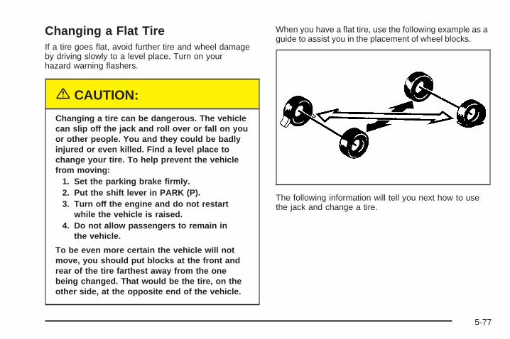
Changing a Flat TireIf a tire goes flat, avoid further tire and wheel damageby driving slowly to a level place. Turn on yourhazard warning flashers.
{CAUTION:
Changing a tire can be dangerous. The vehiclecan slip off the jack and roll over or fall on youor other people. You and they could be badlyinjured or even killed. Find a level place tochange your tire. To help prevent the vehiclefrom moving:
1. Set the parking brake firmly.2. Put the shift lever in PARK (P).3. Turn off the engine and do not restart
while the vehicle is raised.4. Do not allow passengers to remain in
the vehicle.
To be even more certain the vehicle will notmove, you should put blocks at the front andrear of the tire farthest away from the onebeing changed. That would be the tire, on theother side, at the opposite end of the vehicle.
When you have a flat tire, use the following example as aguide to assist you in the placement of wheel blocks.
The following information will tell you next how to usethe jack and change a tire.
5-77
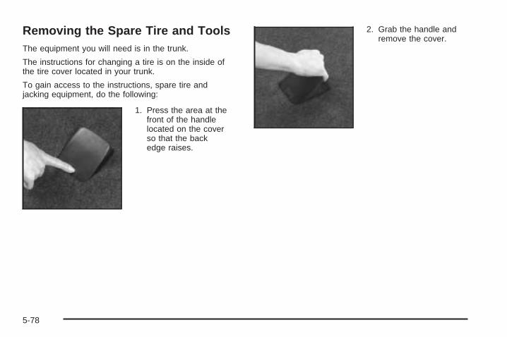
Removing the Spare Tire and ToolsThe equipment you will need is in the trunk.
The instructions for changing a tire is on the inside ofthe tire cover located in your trunk.
To gain access to the instructions, spare tire andjacking equipment, do the following:
1. Press the area at thefront of the handlelocated on the coverso that the backedge raises.
2. Grab the handle andremove the cover.
5-78

3. Turn the wing nuts to remove the container thatholds the wrench and jack.
4. Remove the wheel wrench, jack and compact sparetire from the trunk. See Compact Spare Tire onpage 5-86 for more information.
The tools you will be using include the jack (A) and thewheel wrench (B).
5-79
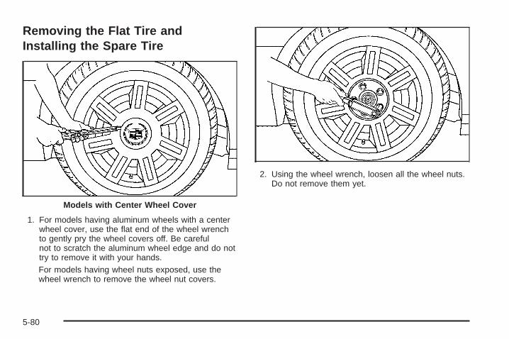
Removing the Flat Tire andInstalling the Spare Tire
1. For models having aluminum wheels with a centerwheel cover, use the flat end of the wheel wrenchto gently pry the wheel covers off. Be carefulnot to scratch the aluminum wheel edge and do nottry to remove it with your hands.For models having wheel nuts exposed, use thewheel wrench to remove the wheel nut covers.
2. Using the wheel wrench, loosen all the wheel nuts.Do not remove them yet.
Models with Center Wheel Cover
5-80
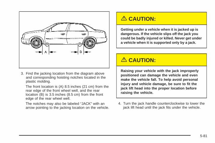
3. Find the jacking location from the diagram aboveand corresponding hoisting notches located in theplastic molding.The front location is (A) 8.5 inches (21 cm) from therear edge of the front wheel well, and the rearlocation (B) is 3.5 inches (8.5 cm) from the frontedge of the rear wheel well.The notches may also be labeled “JACK” with anarrow pointing to the jacking location on the vehicle.
{CAUTION:
Getting under a vehicle when it is jacked up isdangerous. If the vehicle slips off the jack youcould be badly injured or killed. Never get undera vehicle when it is supported only by a jack.
{CAUTION:
Raising your vehicle with the jack improperlypositioned can damage the vehicle and evenmake the vehicle fall. To help avoid personalinjury and vehicle damage, be sure to fit thejack lift head into the proper location beforeraising the vehicle.
4. Turn the jack handle counterclockwise to lower thejack lift head until the jack fits under the vehicle.
5-81
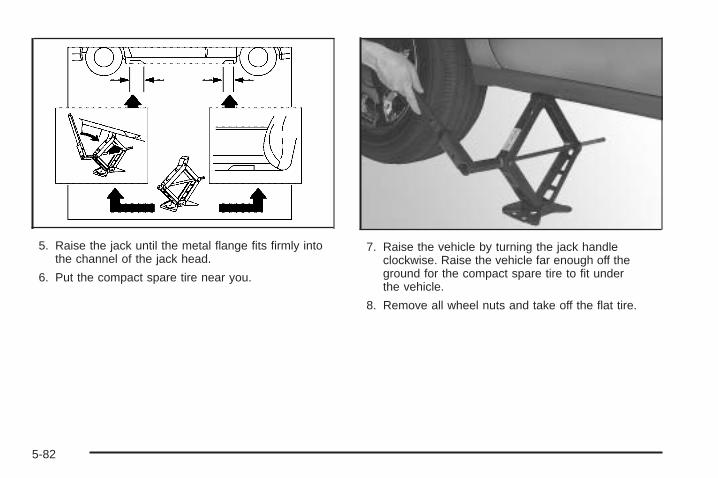
5. Raise the jack until the metal flange fits firmly intothe channel of the jack head.
6. Put the compact spare tire near you.
7. Raise the vehicle by turning the jack handleclockwise. Raise the vehicle far enough off theground for the compact spare tire to fit underthe vehicle.
8. Remove all wheel nuts and take off the flat tire.
5-82
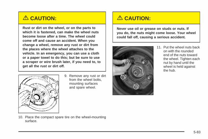
{CAUTION:
Rust or dirt on the wheel, or on the parts towhich it is fastened, can make the wheel nutsbecome loose after a time. The wheel couldcome off and cause an accident. When youchange a wheel, remove any rust or dirt fromthe places where the wheel attaches to thevehicle. In an emergency, you can use a clothor a paper towel to do this; but be sure to usea scraper or wire brush later, if you need to, toget all the rust or dirt off.
9. Remove any rust or dirtfrom the wheel bolts,mounting surfacesand spare wheel.
10. Place the compact spare tire on the wheel-mountingsurface.
{CAUTION:
Never use oil or grease on studs or nuts. Ifyou do, the nuts might come loose. Your wheelcould fall off, causing a serious accident.
11. Put the wheel nuts backon with the roundedend of the nuts towardthe wheel. Tighten eachnut by hand until thewheel is held againstthe hub.
5-83
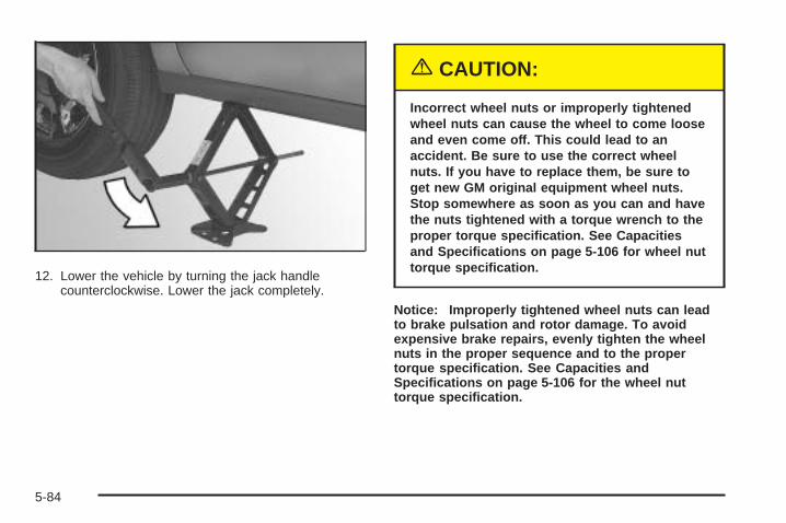
12. Lower the vehicle by turning the jack handlecounterclockwise. Lower the jack completely.
{CAUTION:
Incorrect wheel nuts or improperly tightenedwheel nuts can cause the wheel to come looseand even come off. This could lead to anaccident. Be sure to use the correct wheelnuts. If you have to replace them, be sure toget new GM original equipment wheel nuts.Stop somewhere as soon as you can and havethe nuts tightened with a torque wrench to theproper torque specification. See Capacitiesand Specifications on page 5-106 for wheel nuttorque specification.
Notice: Improperly tightened wheel nuts can leadto brake pulsation and rotor damage. To avoidexpensive brake repairs, evenly tighten the wheelnuts in the proper sequence and to the propertorque specification. See Capacities andSpecifications on page 5-106 for the wheel nuttorque specification.
5-84
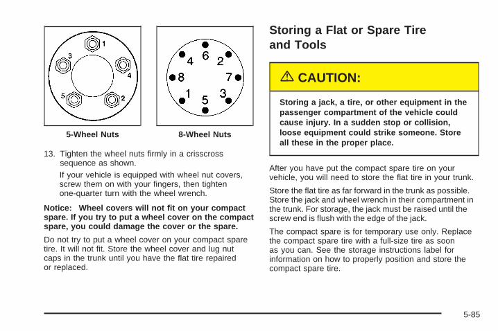
13. Tighten the wheel nuts firmly in a crisscrosssequence as shown.If your vehicle is equipped with wheel nut covers,screw them on with your fingers, then tightenone-quarter turn with the wheel wrench.
Notice: Wheel covers will not fit on your compactspare. If you try to put a wheel cover on the compactspare, you could damage the cover or the spare.
Do not try to put a wheel cover on your compact sparetire. It will not fit. Store the wheel cover and lug nutcaps in the trunk until you have the flat tire repairedor replaced.
Storing a Flat or Spare Tireand Tools
{CAUTION:
Storing a jack, a tire, or other equipment in thepassenger compartment of the vehicle couldcause injury. In a sudden stop or collision,loose equipment could strike someone. Storeall these in the proper place.
After you have put the compact spare tire on yourvehicle, you will need to store the flat tire in your trunk.
Store the flat tire as far forward in the trunk as possible.Store the jack and wheel wrench in their compartment inthe trunk. For storage, the jack must be raised until thescrew end is flush with the edge of the jack.
The compact spare is for temporary use only. Replacethe compact spare tire with a full-size tire as soonas you can. See the storage instructions label forinformation on how to properly position and store thecompact spare tire.
5-Wheel Nuts 8-Wheel Nuts
5-85
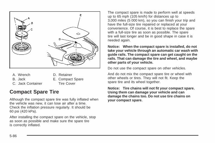
A. WrenchB. JackC. Jack Container
D. RetainerE. Compact Spare
Tire Cover
Compact Spare TireAlthough the compact spare tire was fully inflated whenthe vehicle was new, it can lose air after a time.Check the inflation pressure regularly. It should be60 psi (420 kPa).
After installing the compact spare on the vehicle, stopas soon as possible and make sure the spare tireis correctly inflated.
The compact spare is made to perform well at speedsup to 65 mph (105 km/h) for distances up to3,000 miles (5 000 km), so you can finish your trip andhave the full-size tire repaired or replaced at yourconvenience. Of course, it is best to replace the sparewith a full-size tire as soon as possible. The sparetire will last longer and be in good shape in case it isneeded again.
Notice: When the compact spare is installed, do nottake your vehicle through an automatic car wash withguide rails. The compact spare can get caught on therails. That can damage the tire and wheel, and maybeother parts of your vehicle.
Do not use the compact spare on other vehicles.
And do not mix the compact spare tire or wheel withother wheels or tires. They will not fit. Keep thespare tire and its wheel together.
Notice: Tire chains will not fit your compact spare.Using them can damage your vehicle and candamage the chains too. Do not use tire chains onyour compact spare.
5-86
Appearance CareCleaning products can be hazardous. Some are toxic.Other cleaning products can burst into flames if a matchis struck near them or if they get on a hot part of thevehicle. Some are dangerous if their fumes are inhaled ina closed space. When anything from a container is usedto clean the vehicle, be sure to follow the manufacturer’swarnings and instructions. Always open the doors orwindows of the vehicle when cleaning the inside.
Never use these to clean the vehicle:
• Gasoline
• Benzene
• Naphtha
• Carbon Tetrachloride
• Acetone
• Paint Thinner
• Turpentine
• Lacquer Thinner
• Nail Polish Remover
They can all be hazardous — some more thanothers — and they can all damage the vehicle, too.
Do not use any of these products unless this manualsays you can. In many uses, these will damagethe vehicle:
• Alcohol
• Laundry Soap
• Bleach
• Reducing Agents
Fabric/CarpetUse a vacuum cleaner often to get rid of dust and loosedirt. Wipe vinyl, leather, plastic, and painted surfaceswith a clean, damp cloth.
GM-approved cleaning products can be obtained fromyour dealer.
Here are some cleaning tips:
• Always read the instructions on the cleaner label.
• Clean up stains as soon as you can before they set.
• Carefully scrape off any excess stain.
• Use a clean cloth or sponge, and change to a cleanarea often. A soft brush may be used if stains arestubborn.
• To avoid forming a ring on fabric after spot cleaning,clean the entire area immediately or it will set.
5-87
Most stains can be removed with club soda water. Toclean, use the following instructions:
1. For liquids: blot with a clean, soft, white cloth. Forsolids: remove as much as possible and thenvacuum or brush.
2. Apply club soda water to a clean, soft, white cloth. Donot over-saturate; the cloth should not drip water.
3. Clean the entire area. Avoid getting the fabrictoo wet.
4. Start cleaning from the seams into the stain toavoid a ring effect.
5. Continue cleaning, using a clean area of the clotheach time it becomes soiled.
6. When the stain is removed, blot the cleaned areawith another dry, clean, soft, white cloth.
Using Cleaner on Fabric1. First, try the cleaner on an area of the fabric that is
not easily seen to make sure the cleaner does notaffect the color of the fabric.
2. For liquids: blot with a clean, soft, white cloth. Forsolids: remove as much as possible and thenvacuum or brush.
3. Spray a small amount of the cleaner onto a cleansoft, white, cloth. Do not apply spray directly tothe fabric.
4. Start cleaning from the seams into the stain toavoid a ring effect.
5. Continue cleaning, using a clean area of the clotheach time it becomes soiled.
6. When the stain is removed, blot the cleaned areawith another dry, clean, soft, white cloth.
7. If the cleaner leaves a ring effect, follow up withthe club soda water instructions given earlier inthis section.
Special Fabric Cleaning ProblemsStains caused by such things as catsup, black coffee,egg, fruit, fruit juice, milk, soft drinks, vomit, urine, andblood can be removed using the club soda waterinstructions given earlier in this section. If an odor lingersafter cleaning vomit or urine, treat the area with a waterand baking soda solution: 1 teaspoon (5 ml) of bakingsoda to 1 cup (250 ml) of lukewarm water. Let dry.
Stains caused by oil and grease can be cleaned with anapproved GM cleaner and a clean, white cloth.
1. Carefully scrape off excess stain.
2. Clean with cool water and allow to dry completely.
3. If a stain remains, follow the “Using Cleaner onFabric” instructions described earlier.
5-88
VinylUse warm water and a clean cloth.
• Rub with a clean, damp cloth to remove dirt. Thismay have to be done more than once.
• Things like tar, asphalt, and shoe polish will stain ifthey are not removed quickly. Use a clean clothand vinyl cleaner. See your dealer for this product.
LeatherUse a soft cloth with lukewarm water and a mild soap orsaddle soap and wipe dry with a soft cloth. Then, letthe leather dry naturally. Do not use heat to dry.
• For stubborn stains, use a leather cleaner.
• Never use oils, varnishes, solvent-based or abrasivecleaners, furniture polish, or shoe polish on leather.
• Soiled or stained leather should be cleanedimmediately. If dirt is allowed to work into the finish,it can harm the leather.
Instrument PanelUse only mild soap and water to clean the top surfaces ofthe instrument panel. Sprays containing silicones orwaxes may cause annoying reflections in the windshieldand even make it difficult to see through the windshieldunder certain conditions.
Interior Plastic ComponentsUse only a mild soap and water solution on a soft clothor sponge. Commercial cleaners may affect thesurface finish.
Wood PanelsUse a clean cloth moistened in warm, soapy water (usemild dish washing soap). Dry the wood immediatelywith a clean cloth.
5-89
Speaker CoversVacuum around a speaker cover gently, so that thespeaker will not be damaged. Clean spots withjust water and mild soap.
Glass SurfacesGlass should be cleaned often. GM Glass Cleaner or aliquid household glass cleaner will remove normaltobacco smoke and dust films on interior glass. SeeVehicle Care/Appearance Materials on page 5-95.
Notice: If you use abrasive cleaners when cleaningglass surfaces on your vehicle, you could scratchthe glass and/or cause damage to the rear windowdefogger and the integrated radio antenna. Whencleaning the glass on your vehicle, use only a softcloth and glass cleaner.
Care of Safety BeltsKeep belts clean and dry.
{CAUTION:
Do not bleach or dye safety belts. If you do, itmay severely weaken them. In a crash, theymight not be able to provide adequateprotection. Clean safety belts only with mildsoap and lukewarm water.
WeatherstripsSilicone grease on weatherstrips will make them lastlonger, seal better, and not stick or squeak. Applysilicone grease with a clean cloth. During very cold,damp weather frequent application may be required. SeeRecommended Fluids and Lubricants on page 6-12.
5-90
Washing Your VehicleThe paint finish on the vehicle provides beauty, depth ofcolor, gloss retention, and durability.
The best way to preserve the vehicle’s finish is to keep itclean by washing it often with lukewarm or cold water.
Do not wash the vehicle in the direct rays of the sun.Use a car washing soap. Do not use strong soapsor chemical detergents. Be sure to rinse the vehicle well,removing all soap residue completely. GM-approvedcleaning products can be obtained from your dealer. SeeVehicle Care/Appearance Materials on page 5-95. Donot use cleaning agents that are petroleum based,or that contain acid or abrasives. All cleaning agentsshould be flushed promptly and not allowed to dry on thesurface, or they could stain. Dry the finish with a soft,clean chamois or an all-cotton towel to avoid surfacescratches and water spotting.
Notice: If you drive your vehicle through anautomatic car wash that does not have enoughclearance for the wide rear tires and wheels, youcould damage your vehicle. Verify with the managerof the car wash that your vehicle will fit beforeentering the car wash or use a touchless car wash.
High pressure car washes may cause water to enterthe vehicle.
Cleaning Exterior Lamps/LensesUse only lukewarm or cold water, a soft cloth and a carwashing soap to clean exterior lamps and lenses. Followinstructions under Washing Your Vehicle on page 5-91.
5-91
Finish CareOccasional waxing or mild polishing of the vehicle byhand may be necessary to remove residue fromthe paint finish. GM-approved cleaning products can beobtained from your dealer. See VehicleCare/Appearance Materials on page 5-95.
The vehicle has a “basecoat/clearcoat” paint finish. Theclearcoat gives more depth and gloss to the coloredbasecoat. Always use waxes and polishes that arenon-abrasive and made for a basecoat/clearcoatpaint finish.
Notice: Machine compounding or aggressivepolishing on a basecoat/clearcoat paint finish maydamage it. Use only non-abrasive waxes andpolishes that are made for a basecoat/clearcoatpaint finish on your vehicle.
Foreign materials such as calcium chloride and othersalts, ice melting agents, road oil and tar, tree sap, birddroppings, chemicals from industrial chimneys, etc.,can damage the vehicle’s finish if they remain on paintedsurfaces. Wash the vehicle as soon as possible. Ifnecessary, use non-abrasive cleaners that are markedsafe for painted surfaces to remove foreign matter.
Exterior painted surfaces are subject to aging, weather,and chemical fallout that can take their toll over a periodof years. To help keep the paint finish looking new, keepthe vehicle in a garage or covered whenever possible.
Windshield and Wiper BladesIf the windshield is not clear after using the windshieldwasher, or if the wiper blade chatters when running,wax, sap, or other material may be on the bladeor windshield.
Clean the outside of the windshield with a glasscleaning liquid or powder and water solution. Thewindshield is clean if beads do not form when it is rinsedwith water.
Grime from the windshield will stick to the wiper bladesand affect their performance. Clean the blade bywiping vigorously with a cloth soaked in full-strengthwindshield washer solvent. Then rinse the bladewith water.
Check the wiper blades and clean them as necessary;replace blades that look worn.
5-92
Aluminum or Chrome-Plated WheelsThe vehicle may be equipped with either aluminum orchrome-plated wheels.
Keep the wheels clean using a soft clean cloth with mildsoap and water. Rinse with clean water. After rinsingthoroughly, dry with a soft clean towel. A wax may thenbe applied.
Notice: If you use strong soaps, chemicals,abrasive polishes, cleaners, brushes, or cleanersthat contain acid on aluminum or chrome-platedwheels, you could damage the surface of thewheel(s). The repairs would not be covered by yourwarranty. Use only GM-approved cleaners onaluminum or chrome-plated wheels.
The surface of these wheels is similar to the paintedsurface of your vehicle. Do not use strong soaps,chemicals, abrasive polishes, abrasive cleaners,cleaners with acid, or abrasive cleaning brushes onthem because you could damage the surface. Do notuse chrome polish on aluminum wheels.
Notice: Using chrome polish on aluminum wheelscould damage the wheels. The repairs would notbe covered by your warranty. Use chrome polish onchrome wheels only.
Use chrome polish only on chrome-plated wheels, butavoid any painted surface of the wheel, and buff offimmediately after application.
Notice: If you drive your vehicle through anautomatic car wash that has silicone carbide tirecleaning brushes, you could damage the aluminumor chrome-plated wheels. The repairs would notbe covered by your warranty. Never drive a vehicleequipped with aluminum or chrome-plated wheelsthrough an automatic car wash that uses siliconecarbide tire cleaning brushes.
Do not take your vehicle through an automatic car washthat has silicone carbide tire cleaning brushes. Thesebrushes can also damage the surface of these wheels.
5-93
TiresTo clean the tires, use a stiff brush with tire cleaner.
Notice: Using petroleum-based tire dressingproducts on your vehicle may damage the paintfinish and/or tires. When applying a tire dressing,always wipe off any overspray from all paintedsurfaces on your vehicle.
Sheet Metal DamageIf the vehicle is damaged and requires sheet metalrepair or replacement, make sure the body repair shopapplies anti-corrosion material to parts repaired orreplaced to restore corrosion protection.
Original manufacturer replacement parts will provide thecorrosion protection while maintaining the warranty.
Finish DamageAny stone chips, fractures or deep scratches in the finishshould be repaired right away. Bare metal will corrodequickly and may develop into major repair expense.
Minor chips and scratches can be repaired with touch-upmaterials available from your GM dealer. Larger areasof finish damage can be corrected in your GMdealer’s body and paint shop.
Underbody MaintenanceChemicals used for ice and snow removal and dustcontrol can collect on the underbody. If these are notremoved, corrosion and rust can develop on theunderbody parts such as fuel lines, frame, floor pan,and exhaust system even though they have corrosionprotection.
At least every spring, flush these materials from theunderbody with plain water. Clean any areas where mudand debris can collect. Dirt packed in close areas ofthe frame should be loosened before being flushed.Your GM dealer or an underbody car washing systemcan do this for you.
Chemical Paint SpottingSome weather and atmospheric conditions can create achemical fallout. Airborne pollutants can fall upon andattack painted surfaces on the vehicle. This damage cantake two forms: blotchy, ring-shaped discolorations, andsmall, irregular dark spots etched into the paint surface.
Although no defect in the paint job causes this, GM willrepair, at no charge to the owner, the surfaces ofnew vehicles damaged by this fallout condition within12 months or 12,000 miles (20 000 km) of purchase,whichever occurs first.
5-94
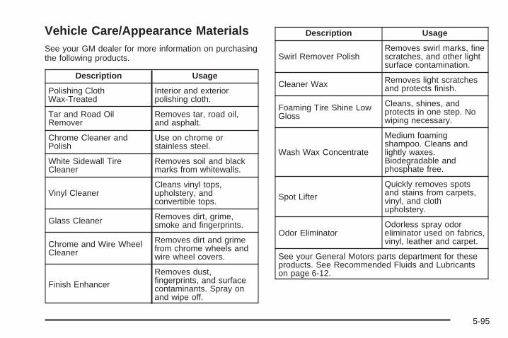
Vehicle Care/Appearance MaterialsSee your GM dealer for more information on purchasingthe following products.
Description Usage
Polishing ClothWax-Treated
Interior and exteriorpolishing cloth.
Tar and Road OilRemover
Removes tar, road oil,and asphalt.
Chrome Cleaner andPolish
Use on chrome orstainless steel.
White Sidewall TireCleaner
Removes soil and blackmarks from whitewalls.
Vinyl CleanerCleans vinyl tops,upholstery, andconvertible tops.
Glass Cleaner Removes dirt, grime,smoke and fingerprints.
Chrome and Wire WheelCleaner
Removes dirt and grimefrom chrome wheels andwire wheel covers.
Finish Enhancer
Removes dust,fingerprints, and surfacecontaminants. Spray onand wipe off.
Description Usage
Swirl Remover PolishRemoves swirl marks, finescratches, and other lightsurface contamination.
Cleaner Wax Removes light scratchesand protects finish.
Foaming Tire Shine LowGloss
Cleans, shines, andprotects in one step. Nowiping necessary.
Wash Wax Concentrate
Medium foamingshampoo. Cleans andlightly waxes.Biodegradable andphosphate free.
Spot Lifter
Quickly removes spotsand stains from carpets,vinyl, and clothupholstery.
Odor EliminatorOdorless spray odoreliminator used on fabrics,vinyl, leather and carpet.
See your General Motors parts department for theseproducts. See Recommended Fluids and Lubricantson page 6-12.
5-95
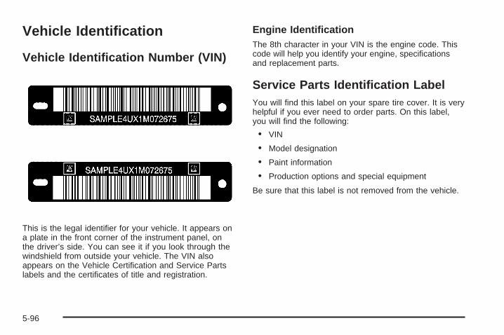
Vehicle Identification
Vehicle Identification Number (VIN)
This is the legal identifier for your vehicle. It appears ona plate in the front corner of the instrument panel, onthe driver’s side. You can see it if you look through thewindshield from outside your vehicle. The VIN alsoappears on the Vehicle Certification and Service Partslabels and the certificates of title and registration.
Engine IdentificationThe 8th character in your VIN is the engine code. Thiscode will help you identify your engine, specificationsand replacement parts.
Service Parts Identification LabelYou will find this label on your spare tire cover. It is veryhelpful if you ever need to order parts. On this label,you will find the following:
• VIN
• Model designation
• Paint information
• Production options and special equipment
Be sure that this label is not removed from the vehicle.
5-96
Electrical System
Add-On Electrical EquipmentNotice: Don’t add anything electrical to your vehicleunless you check with your dealer first. Someelectrical equipment can damage your vehicle andthe damage wouldn’t be covered by your warranty.Some add-on electrical equipment can keep othercomponents from working as they should.
Your vehicle has an airbag system. Before attempting toadd anything electrical to your vehicle, see ServicingYour Airbag-Equipped Vehicle on page 1-54.
Headlamp WiringThe headlamp wiring system has four individual fuses.An electrical overload will cause the lamps to go onand off, or in some cases to remain off. If this happens,have the headlamp wiring checked right away.
Windshield Wiper FusesThe windshield wiper motor is protected by an internalcircuit breaker. If the wiper motor overheats due toheavy snow, the wipers will stop until the motor coolsand will then restart.
A fuse powers the wiper motor. If the fuse blows, thereis an electrical problem. Be sure to have it fixed.
Power Windows and Other PowerOptionsCircuit breakers protect the power windows and powerseats. When the current load is too heavy, the circuitbreaker opens and closes, protecting the circuit until theproblem is fixed or goes away.
5-97
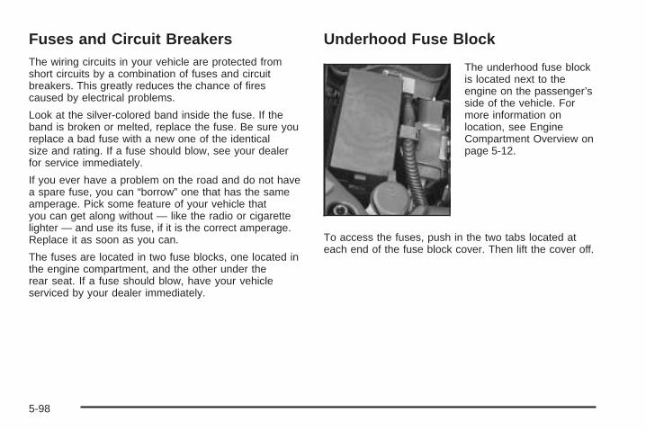
Fuses and Circuit BreakersThe wiring circuits in your vehicle are protected fromshort circuits by a combination of fuses and circuitbreakers. This greatly reduces the chance of firescaused by electrical problems.
Look at the silver-colored band inside the fuse. If theband is broken or melted, replace the fuse. Be sure youreplace a bad fuse with a new one of the identicalsize and rating. If a fuse should blow, see your dealerfor service immediately.
If you ever have a problem on the road and do not havea spare fuse, you can “borrow” one that has the sameamperage. Pick some feature of your vehicle thatyou can get along without — like the radio or cigarettelighter — and use its fuse, if it is the correct amperage.Replace it as soon as you can.
The fuses are located in two fuse blocks, one located inthe engine compartment, and the other under therear seat. If a fuse should blow, have your vehicleserviced by your dealer immediately.
Underhood Fuse Block
The underhood fuse blockis located next to theengine on the passenger’sside of the vehicle. Formore information onlocation, see EngineCompartment Overview onpage 5-12.
To access the fuses, push in the two tabs located ateach end of the fuse block cover. Then lift the cover off.
5-98
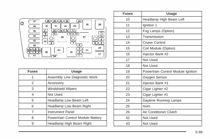
Fuses Usage
1 Assembly Line Diagnostic Work
2 Accessory
3 Windshield Wipers
4 Not Used
5 Headlamp Low Beam Left
6 Headlamp Low Beam Right
7 Instrument Panel
8 Powertrain Control Module Battery
9 Headlamp High Beam Right
Fuses Usage
10 Headlamp High Beam Left
11 Ignition 1
12 Fog Lamps (Option)
13 Transmission
14 Cruise Control
15 Coil Module (Option)
16 Injector Bank #2
17 Not Used
18 Not Used
19 Powertrain Control Module Ignition
20 Oxygen Sensor
21 Injector Bank #1
22 Cigar Lighter #2
23 Cigar Lighter #1
24 Daytime Running Lamps
25 Horn
26 Air Conditioner Clutch
42 Not Used
43 Not Used
5-99
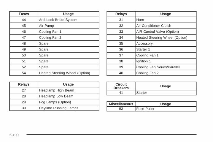
Fuses Usage
44 Anti-Lock Brake System
45 Air Pump
46 Cooling Fan 1
47 Cooling Fan 2
48 Spare
49 Spare
50 Spare
51 Spare
52 Spare
54 Heated Steering Wheel (Option)
Relays Usage
27 Headlamp High Beam
28 Headlamp Low Beam
29 Fog Lamps (Option)
30 Daytime Running Lamps
Relays Usage
31 Horn
32 Air Conditioner Clutch
33 AIR Control Valve (Option)
34 Heated Steering Wheel (Option)
35 Accessory
36 Starter 1
37 Cooling Fan 1
38 Ignition 1
39 Cooling Fan Series/Parallel
40 Cooling Fan 2
CircuitBreakers Usage
41 Starter
Miscellaneous Usage53 Fuse Puller
5-100
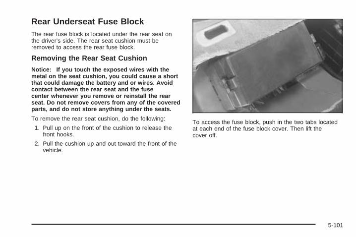
Rear Underseat Fuse BlockThe rear fuse block is located under the rear seat onthe driver’s side. The rear seat cushion must beremoved to access the rear fuse block.
Removing the Rear Seat Cushion
Notice: If you touch the exposed wires with themetal on the seat cushion, you could cause a shortthat could damage the battery and or wires. Avoidcontact between the rear seat and the fusecenter whenever you remove or reinstall the rearseat. Do not remove covers from any of the coveredparts, and do not store anything under the seats.
To remove the rear seat cushion, do the following:
1. Pull up on the front of the cushion to release thefront hooks.
2. Pull the cushion up and out toward the front of thevehicle.
To access the fuse block, push in the two tabs locatedat each end of the fuse block cover. Then lift thecover off.
5-101
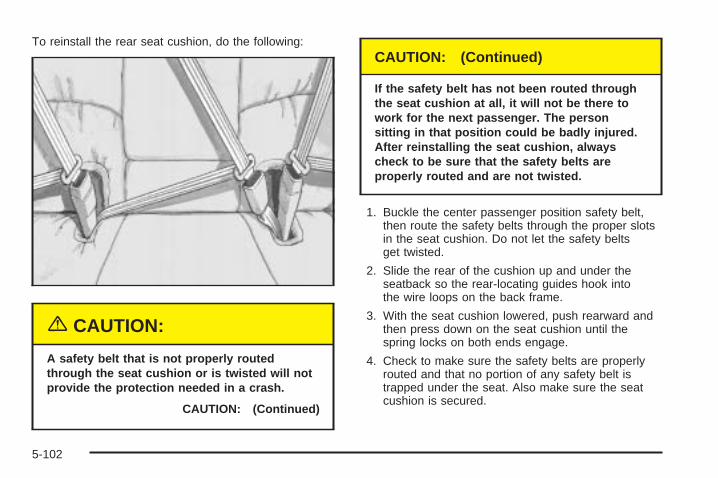
To reinstall the rear seat cushion, do the following:
{CAUTION:
A safety belt that is not properly routedthrough the seat cushion or is twisted will notprovide the protection needed in a crash.
CAUTION: (Continued)
CAUTION: (Continued)
If the safety belt has not been routed throughthe seat cushion at all, it will not be there towork for the next passenger. The personsitting in that position could be badly injured.After reinstalling the seat cushion, alwayscheck to be sure that the safety belts areproperly routed and are not twisted.
1. Buckle the center passenger position safety belt,then route the safety belts through the proper slotsin the seat cushion. Do not let the safety beltsget twisted.
2. Slide the rear of the cushion up and under theseatback so the rear-locating guides hook intothe wire loops on the back frame.
3. With the seat cushion lowered, push rearward andthen press down on the seat cushion until thespring locks on both ends engage.
4. Check to make sure the safety belts are properlyrouted and that no portion of any safety belt istrapped under the seat. Also make sure the seatcushion is secured.
5-102
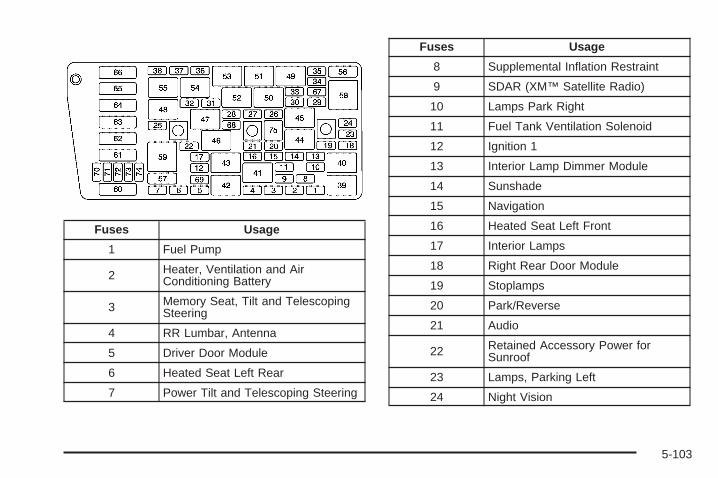
Fuses Usage
1 Fuel Pump
2 Heater, Ventilation and AirConditioning Battery
3 Memory Seat, Tilt and TelescopingSteering
4 RR Lumbar, Antenna
5 Driver Door Module
6 Heated Seat Left Rear
7 Power Tilt and Telescoping Steering
Fuses Usage
8 Supplemental Inflation Restraint
9 SDAR (XM™ Satellite Radio)
10 Lamps Park Right
11 Fuel Tank Ventilation Solenoid
12 Ignition 1
13 Interior Lamp Dimmer Module
14 Sunshade
15 Navigation
16 Heated Seat Left Front
17 Interior Lamps
18 Right Rear Door Module
19 Stoplamps
20 Park/Reverse
21 Audio
22 Retained Accessory Power forSunroof
23 Lamps, Parking Left
24 Night Vision
5-103
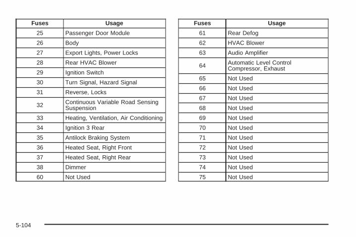
Fuses Usage
25 Passenger Door Module
26 Body
27 Export Lights, Power Locks
28 Rear HVAC Blower
29 Ignition Switch
30 Turn Signal, Hazard Signal
31 Reverse, Locks
32 Continuous Variable Road SensingSuspension
33 Heating, Ventilation, Air Conditioning
34 Ignition 3 Rear
35 Antilock Braking System
36 Heated Seat, Right Front
37 Heated Seat, Right Rear
38 Dimmer
60 Not Used
Fuses Usage
61 Rear Defog
62 HVAC Blower
63 Audio Amplifier
64 Automatic Level ControlCompressor, Exhaust
65 Not Used
66 Not Used
67 Not Used
68 Not Used
69 Not Used
70 Not Used
71 Not Used
72 Not Used
73 Not Used
74 Not Used
75 Not Used
5-104
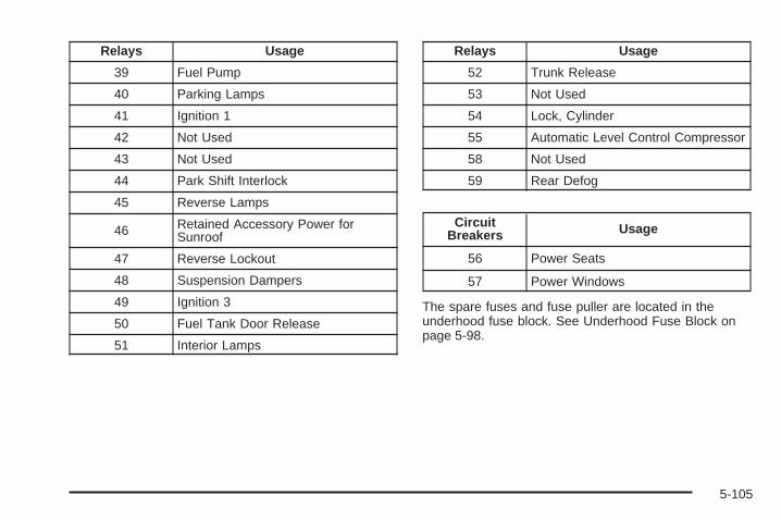
Relays Usage
39 Fuel Pump
40 Parking Lamps
41 Ignition 1
42 Not Used
43 Not Used
44 Park Shift Interlock
45 Reverse Lamps
46 Retained Accessory Power forSunroof
47 Reverse Lockout
48 Suspension Dampers
49 Ignition 3
50 Fuel Tank Door Release
51 Interior Lamps
Relays Usage
52 Trunk Release
53 Not Used
54 Lock, Cylinder
55 Automatic Level Control Compressor
58 Not Used
59 Rear Defog
CircuitBreakers Usage
56 Power Seats
57 Power Windows
The spare fuses and fuse puller are located in theunderhood fuse block. See Underhood Fuse Block onpage 5-98.
5-105
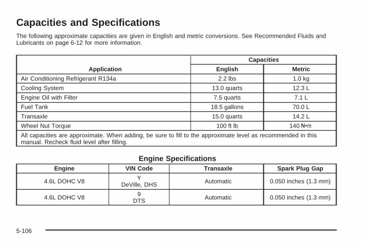
Capacities and SpecificationsThe following approximate capacities are given in English and metric conversions. See Recommended Fluids andLubricants on page 6-12 for more information.
Application
Capacities
English Metric
Air Conditioning Refrigerant R134a 2.2 lbs 1.0 kg
Cooling System 13.0 quarts 12.3 L
Engine Oil with Filter 7.5 quarts 7.1 L
Fuel Tank 18.5 gallons 70.0 L
Transaxle 15.0 quarts 14.2 L
Wheel Nut Torque 100 ft lb 140Y
All capacities are approximate. When adding, be sure to fill to the approximate level as recommended in thismanual. Recheck fluid level after filling.
Engine SpecificationsEngine VIN Code Transaxle Spark Plug Gap
4.6L DOHC V8 YDeVille, DHS Automatic 0.050 inches (1.3 mm)
4.6L DOHC V8 9DTS Automatic 0.050 inches (1.3 mm)
5-106
Maintenance Schedule ......................................6-2Introduction ...................................................6-2Maintenance Requirements ..............................6-2Your Vehicle and the Environment ....................6-2Using Your Maintenance Schedule ....................6-2Scheduled Maintenance ...................................6-4Additional Required Services ............................6-6Maintenance Footnotes ...................................6-7
Owner Checks and Services ............................6-9At Each Fuel Fill ............................................6-9At Least Once a Month ...................................6-9At Least Once a Year ...................................6-10Recommended Fluids and Lubricants ...............6-12Normal Maintenance Replacement Parts ..........6-13Maintenance Record .....................................6-14
Section 6 Maintenance Schedule
6-1
Maintenance Schedule
IntroductionImportant: Keep engine oil at the proper level andchange as recommended.
Have you purchased the GM Protection Plan? The Plansupplements your new vehicle warranties. See yourWarranty and Owner Assistance booklet or your dealerfor details.
Maintenance RequirementsNotice: Maintenance intervals, checks, inspections,replacement parts and recommended fluids andlubricants as prescribed in this manual are necessaryto keep your vehicle in good working condition. Anydamage caused by failure to follow scheduledmaintenance may not be covered by warranty.
Your Vehicle and the EnvironmentProper vehicle maintenance not only helps to keep yourvehicle in good working condition, but also helps theenvironment. All recommended maintenance isimportant. Improper vehicle maintenance can even affectthe quality of the air we breathe. Improper fluid levels orthe wrong tire inflation can increase the level of emissionsfrom your vehicle. To help protect our environment, andto keep your vehicle in good condition, be sure tomaintain your vehicle properly.
Using Your Maintenance ScheduleWe at General Motors want to help you keep your vehiclein good working condition. But we do not know exactlyhow you will drive it. You may drive very short distancesonly a few times a week. Or you may drive long distancesall the time in very hot, dusty weather. You may use yourvehicle in making deliveries. Or you may drive it to work,to do errands or in many other ways.
Because of all the different ways people use theirvehicles, maintenance needs vary. You may need morefrequent checks and replacements. So please readthe following and note how you drive. If you have anyquestions on how to keep your vehicle in good condition,see your GM Goodwrench dealer.
6-2
This schedule is for vehicles that:
• carry passengers and cargo within recommendedlimits. You will find these limits on the tire andloading information label. See Loading Your Vehicleon page 4-30.
• are driven on reasonable road surfaces within legaldriving limits.
• use the recommended fuel. See Gasoline Octaneon page 5-5.
The services in Scheduled Maintenance on page 6-4should be performed when indicated. See AdditionalRequired Services on page 6-6 and MaintenanceFootnotes on page 6-7 for further information.
{CAUTION:
Performing maintenance work on a vehicle canbe dangerous. In trying to do some jobs, youcan be seriously injured. Do your ownmaintenance work only if you have therequired know-how and the proper tools andequipment for the job. If you have any doubt,see your GM Goodwrench dealer to have aqualified technician do the work.
Some maintenance services can be complex. So,unless you are technically qualified and have thenecessary equipment, you should have your GMGoodwrench dealer do these jobs.
When you go to your GM Goodwrench dealer for yourservice needs, you will know that GM-trained andsupported service technicians will perform the workusing genuine GM parts.
If you want to purchase service information, see ServicePublications Ordering Information on page 7-11.
Owner Checks and Services on page 6-9 tells you whatshould be checked, when to check it and what you caneasily do to help keep your vehicle in good condition.
The proper replacement parts, fluids and lubricants touse are listed in Recommended Fluids and Lubricantson page 6-12 and Normal Maintenance ReplacementParts on page 6-13. When your vehicle is serviced,make sure these are used. All parts should be replacedand all necessary repairs done before you or anyoneelse drives the vehicle. We recommend the use ofgenuine GM parts.
6-3
Scheduled MaintenanceWhen the CHANGE ENGINE OIL message in the DriverInformation Center (DIC) comes on, it means thatservice is required for your vehicle. Have your vehicleserviced as soon as possible within the next600 miles (1 000 km). It is possible that, if you aredriving under the best conditions, the engine oillife system may not indicate that vehicle service isnecessary for over a year. However, your engine oil andfilter must be changed at least once a year and atthis time the system must be reset. Your GMGoodwrench dealer has GM-trained service technicianswho will perform this work using genuine GM partsand reset the system.
If the engine oil life system is ever reset accidentally,you must service your vehicle within 3,000 miles(5 000 km) since your last service. Remember to resetthe oil life system whenever the oil is changed. SeeEngine Oil Life System on page 5-17 for information onthe Engine Oil Life System and resetting the system.
When the change engine oil message appears, certainservices, checks and inspections are required.Required services are described in the following for“Maintenance I” and “Maintenance II.” Generally,it is recommended that your first service beMaintenance I, your second service be Maintenance IIand that you alternate Maintenance I and Maintenance IIthereafter. However, in some cases, Maintenance IImay be required more often.
Maintenance I — Use Maintenance I if the changeengine oil message comes on within 10 months since thevehicle was purchased or Maintenance II was performed.
Maintenance II — Use Maintenance II if the previousservice performed was Maintenance I. Always useMaintenance II whenever the message comes on10 months or more since the last service or if themessage has not come on at all for one year.
6-4
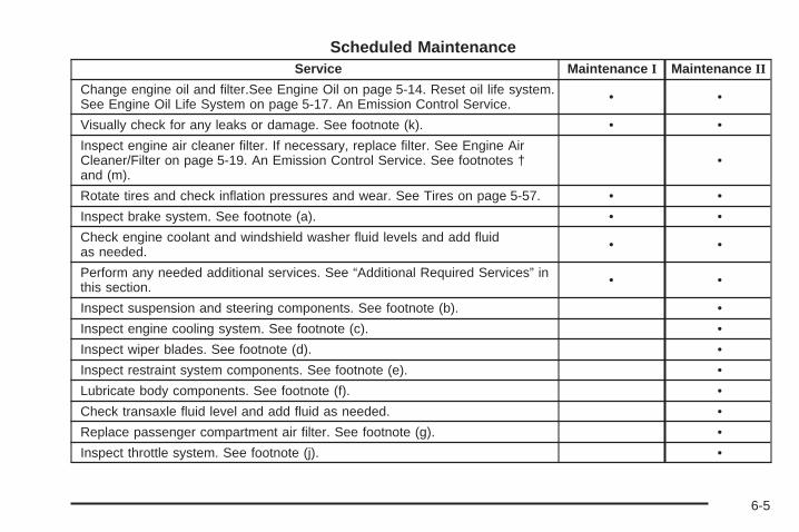
Scheduled MaintenanceService Maintenance I Maintenance II
Change engine oil and filter.See Engine Oil on page 5-14. Reset oil life system.See Engine Oil Life System on page 5-17. An Emission Control Service. • •
Visually check for any leaks or damage. See footnote (k). • •Inspect engine air cleaner filter. If necessary, replace filter. See Engine AirCleaner/Filter on page 5-19. An Emission Control Service. See footnotes †and (m).
•
Rotate tires and check inflation pressures and wear. See Tires on page 5-57. • •Inspect brake system. See footnote (a). • •Check engine coolant and windshield washer fluid levels and add fluidas needed. • •
Perform any needed additional services. See “Additional Required Services” inthis section. • •
Inspect suspension and steering components. See footnote (b). •Inspect engine cooling system. See footnote (c). •Inspect wiper blades. See footnote (d). •Inspect restraint system components. See footnote (e). •Lubricate body components. See footnote (f). •Check transaxle fluid level and add fluid as needed. •Replace passenger compartment air filter. See footnote (g). •Inspect throttle system. See footnote (j). •
6-5
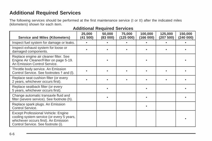
Additional Required ServicesThe following services should be performed at the first maintenance service (I or II) after the indicated miles(kilometers) shown for each item.
Additional Required Services
Service and Miles (Kilometers)25,000
(41 500)50,000
(83 000)75,000
(125 000)100,000
(166 000)125,000
(207 500)150,000
(240 000)Inspect fuel system for damage or leaks. • • • • • •Inspect exhaust system for loose ordamaged components. • • • • • •
Replace engine air cleaner filter. SeeEngine Air Cleaner/Filter on page 5-19.An Emission Control Service.
• • •
Throttle body service. An EmissionControl Service. See footnotes † and (l). • • • • • •
Replace seat cushion filter (or every2 years, whichever occurs first). • • • • • •
Replace seatback filter (or every5 years, whichever occurs first). • • •
Change automatic transaxle fluid andfilter (severe service). See footnote (h). • • •
Replace spark plugs. An EmissionControl Service. •
Except Professional Vehicle: Enginecooling system service (or every 5 years,whichever occurs first). An EmissionControl Service. See footnote (i).
•
6-6
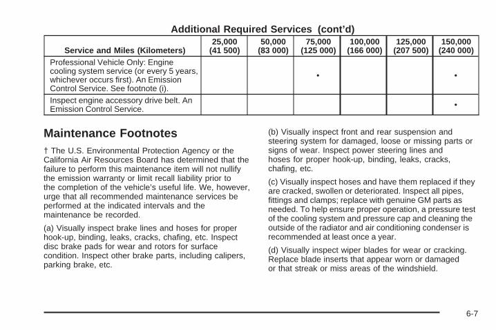
Additional Required Services (cont’d)
Service and Miles (Kilometers)25,000
(41 500)50,000
(83 000)75,000
(125 000)100,000
(166 000)125,000
(207 500)150,000
(240 000)Professional Vehicle Only: Enginecooling system service (or every 5 years,whichever occurs first). An EmissionControl Service. See footnote (i).
• •
Inspect engine accessory drive belt. AnEmission Control Service. •
Maintenance Footnotes† The U.S. Environmental Protection Agency or theCalifornia Air Resources Board has determined that thefailure to perform this maintenance item will not nullifythe emission warranty or limit recall liability prior tothe completion of the vehicle’s useful life. We, however,urge that all recommended maintenance services beperformed at the indicated intervals and themaintenance be recorded.
(a) Visually inspect brake lines and hoses for properhook-up, binding, leaks, cracks, chafing, etc. Inspectdisc brake pads for wear and rotors for surfacecondition. Inspect other brake parts, including calipers,parking brake, etc.
(b) Visually inspect front and rear suspension andsteering system for damaged, loose or missing parts orsigns of wear. Inspect power steering lines andhoses for proper hook-up, binding, leaks, cracks,chafing, etc.
(c) Visually inspect hoses and have them replaced if theyare cracked, swollen or deteriorated. Inspect all pipes,fittings and clamps; replace with genuine GM parts asneeded. To help ensure proper operation, a pressure testof the cooling system and pressure cap and cleaning theoutside of the radiator and air conditioning condenser isrecommended at least once a year.
(d) Visually inspect wiper blades for wear or cracking.Replace blade inserts that appear worn or damagedor that streak or miss areas of the windshield.
6-7
(e) Make sure the safety belt reminder light and all yourbelts, buckles, latch plates, retractors and anchoragesare working properly. Look for any other loose ordamaged safety belt system parts. If you see anythingthat might keep a safety belt system from doing itsjob, have it repaired. Have any torn or frayed safety beltsreplaced. Also look for any opened or broken airbagcoverings, and have them repaired or replaced.(The airbag system does not need regular maintenance.)
(f) Lubricate all key lock cylinders. Lubricate all hingesand latches, including those for the hood, rearcompartment, glove box door and console door. Morefrequent lubrication may be required when exposed to acorrosive environment. Applying silicone grease onweatherstrips with a clean cloth will make themlast longer, seal better and not stick or squeak.
(g) If you drive regularly under dusty conditions, thefilter may require replacement more often.
(h) If you do not use your vehicle under the followingconditions, the fluid and filter do not require change untilthe CHANGE TRANS FLUID message appears onthe Driver Information Center.
Change automatic transaxle fluid and filter if the vehicleis mainly driven under one or more of these conditions:
− In heavy city traffic where the outside temperatureregularly reaches 90°F (32°C) or higher.
− In hilly or mountainous terrain.− When doing frequent trailer towing.− Professional vehicle uses, such as limousine
service.− Uses such as high performance operation.
(i) Drain, flush and refill cooling system. See EngineCoolant on page 5-24 for what to use. Inspect hoses.Clean radiator, condenser, pressure cap and filler neck.Pressure test the cooling system and pressure cap.
(j) Check throttle system for interference or binding andfor damaged or missing parts. Replace parts as needed.Replace any components that have high effort orexcessive wear. Do not lubricate accelerator or cruisecontrol cables.
(k) A fluid loss in any vehicle system could indicate aproblem. Have the system inspected and repairedand the fluid level checked. Add fluid if needed.
(l) Inspect throttle body bore and valve plates fordeposits. Open the throttle valve and inspect allsurfaces. Clean as required.
(m) If you drive regularly under dusty conditions, inspectthe filter at each engine oil change.
6-8
Owner Checks and ServicesThese owner checks and services should be performedat the intervals specified to help ensure the safety,dependability and emission control performance of yourvehicle. Your GM Goodwrench dealer can assist youwith these checks and services.
Be sure any necessary repairs are completed at once.Whenever any fluids or lubricants are added to yourvehicle, make sure they are the proper ones, as shownin Recommended Fluids and Lubricants on page 6-12.
At Each Fuel FillIt is important to perform these underhood checks ateach fuel fill.
Engine Oil Level CheckCheck the engine oil level and add the proper oil ifnecessary. See Engine Oil on page 5-14 for furtherdetails.
Notice: It is important to check your oil regularlyand keep it at the proper level. Failure to keep yourengine oil at the proper level can cause damageto your engine not covered by your warranty.
Engine Coolant Level CheckCheck the engine coolant level and addDEX-COOL® coolant mixture if necessary. See EngineCoolant on page 5-24 for further details.
Windshield Washer Fluid Level CheckCheck the windshield washer fluid level in the windshieldwasher tank and add the proper fluid if necessary.
At Least Once a Month
Tire Inflation CheckVisually inspect your tires and make sure tires are inflatedto the correct pressures. Do not forget to check yourspare tire. See Tires on page 5-57 for further details.Check to make sure the spare tire is stored securely.Push, pull and then try to turn the spare tire. If it moves,tighten it. See Changing a Flat Tire on page 5-77.
6-9
At Least Once a Year
Starter Switch Check
{CAUTION:
When you are doing this inspection, thevehicle could move suddenly. If the vehiclemoves, you or others could be injured.
1. Before you start, be sure you have enough roomaround the vehicle.
2. Firmly apply both the parking brake and the regularbrake. See Parking Brake on page 2-31 ifnecessary.Do not use the accelerator pedal, and be ready toturn off the engine immediately if it starts.
3. Try to start the engine in each gear. The startershould work only in PARK (P) or NEUTRAL (N).If the starter works in any other position, contactyour GM Goodwrench dealer for service.
Automatic Transaxle Shift Lock ControlSystem Check
{CAUTION:
When you are doing this inspection, thevehicle could move suddenly. If the vehiclemoves, you or others could be injured.
1. Before you start, be sure you have enough roomaround the vehicle. It should be parked on a levelsurface.
2. Firmly apply the parking brake. See Parking Brakeon page 2-31 if necessary.Be ready to apply the regular brake immediately ifthe vehicle begins to move.
3. With the engine off, turn the ignition to ON, but donot start the engine. Without applying the regularbrake, try to move the shift lever out of PARK (P)with normal effort. If the shift lever moves outof PARK (P), contact your GM Goodwrench dealerfor service.
6-10
Ignition Transaxle Lock CheckWhile parked, and with the parking brake set, try to turnthe ignition to OFF in each shift lever position.
• The ignition should turn to OFF only when the shiftlever is in PARK (P).
• The key should come out only in OFF.
Contact your GM Goodwrench dealer if service isrequired.
Parking Brake and Automatic TransaxlePark (P) Mechanism Check
{CAUTION:
When you are doing this check, your vehiclecould begin to move. You or others could beinjured and property could be damaged. Makesure there is room in front of your vehicle incase it begins to roll. Be ready to apply theregular brake at once should the vehicle beginto move.
Park on a fairly steep hill, with the vehicle facingdownhill. Keeping your foot on the regular brake, set theparking brake.
• To check the parking brake’s holding ability: Withthe engine running and transaxle in NEUTRAL (N),slowly remove foot pressure from the regularbrake pedal. Do this until the vehicle is held by theparking brake only.
• To check the PARK (P) mechanism’s holding ability:With the engine running, shift to PARK (P). Thenrelease the parking brake followed by the regularbrake.
Contact your GM Goodwrench dealer if service isrequired.
Underbody Flushing ServiceAt least every spring, use plain water to flush anycorrosive materials from the underbody. Take care toclean thoroughly any areas where mud and other debriscan collect.
6-11
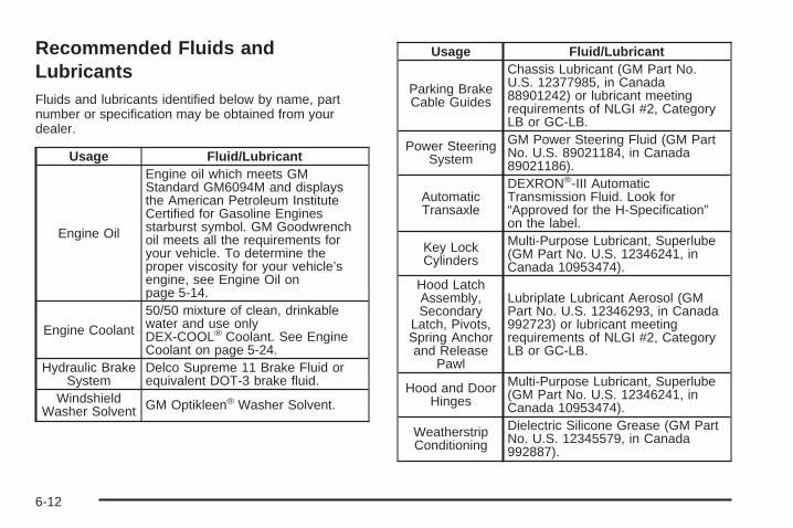
Recommended Fluids andLubricantsFluids and lubricants identified below by name, partnumber or specification may be obtained from yourdealer.
Usage Fluid/Lubricant
Engine Oil
Engine oil which meets GMStandard GM6094M and displaysthe American Petroleum InstituteCertified for Gasoline Enginesstarburst symbol. GM Goodwrenchoil meets all the requirements foryour vehicle. To determine theproper viscosity for your vehicle’sengine, see Engine Oil onpage 5-14.
Engine Coolant
50/50 mixture of clean, drinkablewater and use onlyDEX-COOL® Coolant. See EngineCoolant on page 5-24.
Hydraulic BrakeSystem
Delco Supreme 11 Brake Fluid orequivalent DOT-3 brake fluid.
WindshieldWasher Solvent GM Optikleen® Washer Solvent.
Usage Fluid/Lubricant
Parking BrakeCable Guides
Chassis Lubricant (GM Part No.U.S. 12377985, in Canada88901242) or lubricant meetingrequirements of NLGI #2, CategoryLB or GC-LB.
Power SteeringSystem
GM Power Steering Fluid (GM PartNo. U.S. 89021184, in Canada89021186).
AutomaticTransaxle
DEXRON®-III AutomaticTransmission Fluid. Look for“Approved for the H-Specification”on the label.
Key LockCylinders
Multi-Purpose Lubricant, Superlube(GM Part No. U.S. 12346241, inCanada 10953474).
Hood LatchAssembly,Secondary
Latch, Pivots,Spring Anchorand Release
Pawl
Lubriplate Lubricant Aerosol (GMPart No. U.S. 12346293, in Canada992723) or lubricant meetingrequirements of NLGI #2, CategoryLB or GC-LB.
Hood and DoorHinges
Multi-Purpose Lubricant, Superlube(GM Part No. U.S. 12346241, inCanada 10953474).
WeatherstripConditioning
Dielectric Silicone Grease (GM PartNo. U.S. 12345579, in Canada992887).
6-12
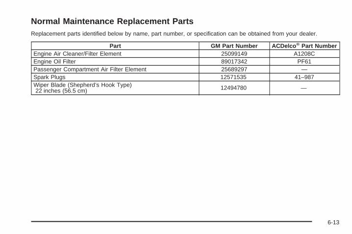
Normal Maintenance Replacement PartsReplacement parts identified below by name, part number, or specification can be obtained from your dealer.
Part GM Part Number ACDelco ® Part NumberEngine Air Cleaner/Filter Element 25099149 A1208CEngine Oil Filter 89017342 PF61Passenger Compartment Air Filter Element 25689297 —Spark Plugs 12571535 41–987Wiper Blade (Shepherd’s Hook Type)22 inches (56.5 cm) 12494780 —
6-13
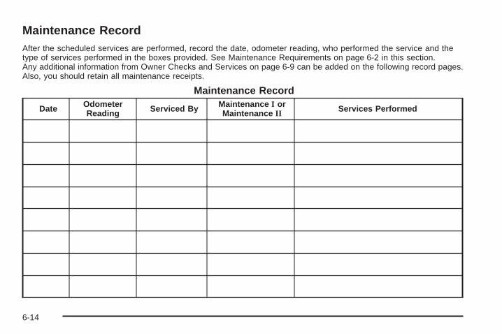
Maintenance RecordAfter the scheduled services are performed, record the date, odometer reading, who performed the service and thetype of services performed in the boxes provided. See Maintenance Requirements on page 6-2 in this section.Any additional information from Owner Checks and Services on page 6-9 can be added on the following record pages.Also, you should retain all maintenance receipts.
Maintenance Record
Date OdometerReading Serviced By Maintenance I or
Maintenance II Services Performed
6-14
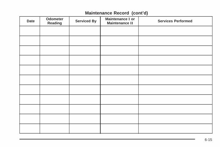
Maintenance Record (cont’d)
Date OdometerReading Serviced By Maintenance I or
Maintenance II Services Performed
6-15
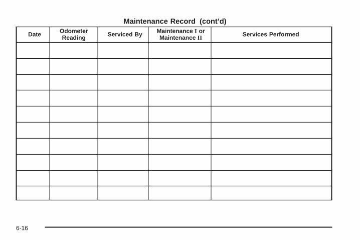
Maintenance Record (cont’d)
Date OdometerReading Serviced By Maintenance I or
Maintenance II Services Performed
6-16
Customer Assistance and Information ...............7-2Customer Satisfaction Procedure ......................7-2Online Owner Center ......................................7-3Customer Assistance for Text Telephone
(TTY) Users ...............................................7-4Customer Assistance Offices ............................7-4GM Mobility Reimbursement Program ................7-5Roadside Service ...........................................7-5Courtesy Transportation ...................................7-7Vehicle Data Collection and Event Data
Recorders ..................................................7-9
Reporting Safety Defects ................................7-10Reporting Safety Defects to the United States
Government ..............................................7-10Reporting Safety Defects to the Canadian
Government ..............................................7-11Reporting Safety Defects to
General Motors .........................................7-11Service Publications Ordering Information .........7-11
Section 7 Customer Assistance and Information
7-1
Customer Assistance andInformation
Customer Satisfaction ProcedureYour satisfaction and goodwill are important to yourdealer and to Cadillac. Normally, any concerns with thesales transaction or the operation of your vehicle will beresolved by your dealer’s sales or service departments.Sometimes, however, despite the best intentions of allconcerned, misunderstandings can occur. If your concernhas not been resolved to your satisfaction, the followingsteps should be taken:
STEP ONE: Discuss your concern with a member ofdealership management. Normally, concerns canbe quickly resolved at that level. If the matter hasalready been reviewed with the sales, service or partsmanager, contact the owner of the dealership orthe general manager.
STEP TWO: If after contacting a member of dealershipmanagement, it appears your concern cannot beresolved by the dealership without further help, contactthe Cadillac Customer Assistance Center, 24 hoursa day, by calling 1-800-458-8006. In Canada, contactGM of Canada, Canadian Cadillac CustomerCommunication Centre by calling 1-888-446–2000.
We encourage you to call the toll-free number in orderto give your inquiry prompt attention. Please havethe following information available to give the CustomerAssistance Representative:
• Vehicle Identification Number (VIN). This isavailable from the vehicle registration or title, or theplate at the top left of the instrument panel andvisible through the windshield.
• Dealership name and location.
• Vehicle delivery date and present mileage.
When contacting Cadillac, please remember that yourconcern will likely be resolved at a dealer’s facility. Thatis why we suggest you follow Step One first if youhave a concern.
STEP THREE: Both General Motors and your dealerare committed to making sure you are completelysatisfied with your new vehicle. However, if you continueto remain unsatisfied after following the procedureoutlined in Steps One and Two, you should file with theBBB Auto Line Program to enforce any additionalrights you may have. Canadian owners refer to yourWarranty and Owner Assistance Information booklet forinformation on the Canadian Motor Vehicle ArbitrationPlan (CAMVAP).
7-2
The BBB Auto Line Program is an out of court programadministered by the Council of Better Business Bureausto settle automotive disputes regarding vehicle repairs orthe interpretation of the New Vehicle Limited Warranty.Although you may be required to resort to this informaldispute resolution program prior to filing a court action,use of the program is free of charge and your case willgenerally be heard within 40 days. If you do not agreewith the decision given in your case, you may reject it andproceed with any other venue for relief available to you.
You may contact the BBB Auto Line Program using thetoll-free telephone number or write them at the followingaddress:
BBB Auto Line ProgramCouncil of Better Business Bureaus, Inc.4200 Wilson BoulevardSuite 800Arlington, VA 22203-1838
Telephone: 1-800-955-5100
This program is available in all 50 states and the Districtof Columbia. Eligibility is limited by vehicle age, mileageand other factors. General Motors reserves the right tochange eligibility limitations and/or discontinue itsparticipation in this program.
Online Owner CenterThe Owner Center is a resource for your GM ownershipneeds. Specific vehicle information can be found inone place.
The Online Owner Center allows you to:
• Get e-mail service reminders.
• Access information about your specific vehicle,including tips and videos and an electronicversion of this owner’s manual (United States only).
• Keep track of your vehicle’s service history andmaintenance schedule.
• Find GM dealers for service nationwide.
• Receive special promotions and privileges onlyavailable to members (United States only).
Refer to the web for updated information.
To register your vehicle, visit www.MyGMLink.com(United States) or My GM Canada withinwww.gmcanada.com (Canada).
7-3
Customer Assistance for TextTelephone (TTY) UsersTo assist customers who are deaf, hard of hearing, orspeech-impaired and who use Text Telephones (TTYs),Cadillac has TTY equipment available at its CustomerAssistance Center. Any TTY user can communicate withCadillac by dialing: 1-800-833-CMCC (2622). (TTYusers in Canada can dial 1-800-263-3830.)
Customer Assistance OfficesCadillac encourages customers to call the toll-freenumber for assistance. If a U.S. customer wishes towrite to Cadillac, the letter should be addressedto Cadillac’s Customer Assistance Center.
United States— Customer AssistanceCadillac Customer Assistance CenterCadillac Motor Car DivisionP.O. Box 33169Detroit, MI 48232-5169
1-800-458-80061-800-833-2622 (For Text Telephone devices (TTYs))Roadside Assistance: 1-800-882-1112Fax Number: 313-381-0022
From Puerto Rico:1-800-496-9992 (English)1-800-496-9993 (Spanish)Fax Number: 313-381-0022
From U.S. Virgin Islands:1-800-496-9994Fax Number: 313-381-0022
Canada — Customer AssistanceGeneral Motors of Canada LimitedCanadian Cadillac Customer Communication Centre,163-0051908 Colonel Sam DriveOshawa, Ontario L1H 8P7
1-888-446-20001-800-263-3830 (For Text Telephone devices (TTYs))Roadside Assistance: 1-800-882-1112
7-4
Overseas — Customer AssistancePlease contact the local General Motors Business Unit.
Mexico, Central America andCaribbean Islands/Countries(Except Puerto Rico and U.S. VirginIslands) — Customer Assistance
General Motors de Mexico, S. de R.L. de C.V.Customer Assistance CenterPaseo de la Reforma # 2740Col. Lomas de BezaresC.P. 11910, Mexico, D.F.01-800-508-0000Long Distance: 011-52-53 29 0 800
GM Mobility ReimbursementProgramThis program, available to qualified applicants, canreimburse you up to $1,000 toward eligible aftermarketdriver’s or passenger’s adaptive equipment you mayrequire for your vehicle, such as hand controls andwheelchair/scooter lifts.
The offer is available for a limited period of time from thedate of vehicle purchase/lease. For more details, or todetermine your vehicle’s eligibility, visit gmmobility.comor call the GM Mobility Assistance Center at1-800-323-9935. Text telephone (TTY) users, call1-800-833-9935.
GM of Canada also has a Mobility Program. Call1-800-GM-DRIVE (463-7483) for details. TTY users call1-800-263-3830.
Roadside ServiceCadillac’s exceptional Roadside Service is more than anauto club or towing service. It provides every Cadillacowner with the advantage of contacting a Cadillacadvisor and, where available, a Cadillac trained dealertechnician who can provide on-site service.
Each technician travels with a specially equippedservice vehicle complete with the necessary Cadillacparts and tools required to handle most roadside repairs.
Cadillac Roadside Service® can be reached by dialing1-800-882-1112, 24 hours a day, 365 days a year. Thisservice is provided at no charge for any warranty-coveredsituation and for a nominal charge if the Cadillac is nolonger under warranty. Roadside Service is available onlyin the United States and Canada.
7-5
Cadillac Owner Privileges™Roadside Service provides several Cadillac OwnerPrivileges™ at “no charge,” throughout your CadillacWarranty Period — 48 months/50,000 miles (80 000 km).
Emergency Road Service is performed on site for thefollowing situations:
• Towing Service
• Battery Jump Starting
• Lock Out Assistance
• Fuel Delivery
• Flat Tire Change (Covers change only)
• Trip Interruption — If your trip is interrupted due toa warranty failure, incidental expenses may bereimbursed during the 48 months/50,000 miles(80 000 km) warranty period. Items coveredare hotel, meals, and rental car.
Roadside Service AvailabilityWherever you drive in the United States or Canada, anadvisor is available to assist you over the phone. A dealertechnician, if available, can travel to your location within a30 mile (50 km) radius of a participating Cadillacdealership. If beyond this radius, we will arrange to haveyour car towed to the nearest Cadillac dealership.
Reaching Roadside ServiceDial the toll-free Roadside Service number:1-800-882-1112. A Roadside Service Advisor will assistyou and request the following information:
• A description of the problem
• Name, home address, home telephone number
• Location of your Cadillac and number you arecalling from
• The model year, Vehicle Identification Number (VIN),mileage, and date of delivery
Roadside Service for the Hearing orSpeech ImpairedRoadside Service is prepared to assist owners who havehearing difficulties or are speech impaired. Cadillac hasinstalled special telecommunication devices called TextTelephone (TTY) in the Roadside Service Center.
Any customer who has access to a (TTY) or aconventional teletypewriter can communicate withCadillac by dialing from the United States or Canada1-888-889-2438 — daily, 24 hours.
7-6
Courtesy TransportationCadillac has always exemplified quality and value in itsoffering of motor vehicles. To enhance your ownershipexperience, we and our participating dealers areproud to offer Courtesy Transportation, a customersupport program for new vehicles.
The Courtesy Transportation program is offered to retailpurchase/lease customers in conjunction with theBumper-to-Bumper coverage provided by the NewVehicle Limited Warranty. Several transportation optionsare available when warranty repairs are required. This willreduce your inconvenience during warranty repairs.
Scheduling Service AppointmentsWhen your vehicle requires warranty service, you shouldcontact your dealer and request an appointment. Byscheduling a service appointment and advisingyour service consultant of your transportation needs,your dealer can help minimize your inconvenience.
If your vehicle cannot be scheduled into the servicedepartment immediately, keep driving it until it can bescheduled for service, unless, of course, the problem issafety-related. If it is, please call your dealership, letthem know this, and ask for instructions.
If the dealer requests that you simply drop the vehicleoff for service, you are urged to do so as early inthe work day as possible to allow for same day repair.
Transportation OptionsWarranty service can generally be completed while youwait. However, if you are unable to wait Cadillac helpsminimize your inconvenience by providing severaltransportation options. Depending on the circumstances,your dealer can offer you one of the following:
Shuttle ServiceParticipating dealers can provide you with shuttleservice to get you to your destination with minimalinterruption of your daily schedule. This includes a oneway or round trip shuttle service to a destination upto 10 miles from the dealership.
Public Transportation or FuelReimbursementIf your vehicle requires overnight warranty repairs,reimbursement of up to a five day maximum may beavailable for the use of public transportation such as ataxi or bus. In addition, should you arrange transportationthrough a friend or relative, reimbursement forreasonable fuel expenses of up to a five day maximummay be available. Claim amounts should reflect actualcosts and be supported by original receipts.
7-7
Courtesy Rental VehicleYour dealer may arrange to provide you with a courtesyrental vehicle or reimburse you for a rental vehicle thatyou obtain if your vehicle is kept for a warranty repair.Reimbursement will be limited to a maximum of $40 a dayand must be supported by receipts. This requires that yousign and complete a rental agreement and meet state,local and rental vehicle provider requirements.Requirements vary and may include minimum agerequirements, insurance coverage, credit card, etc. Youare responsible for fuel usage charges and may also beresponsible for taxes, levies, usage fees, excessivemileage, or rental usage beyond the completion ofthe repair.
Generally it is not possible to provide a like-vehicle as acourtesy rental.
Additional Program InformationCourtesy Transportation is available during theBumper-to-Bumper warranty coverage period, but it isnot part of the New Vehicle Limited Warranty. Aseparate booklet entitled Warranty and OwnerAssistance Information furnished with each new vehicleprovides detailed warranty coverage information.
Courtesy Transportation is available only at participatingdealers and all program options, such as shuttleservice, may not be available at every dealer. Pleasecontact your dealer for specific information aboutavailability. All Courtesy Transportation arrangementswill be administered by appropriate dealer personnel.
Canadian Vehicles: For warranty repairs duringthe Complete Vehicle Coverage period of the GeneralMotors of Canada New Vehicle Limited Warranty,alternative transportation may be available under theCourtesy Transportation Program. Please consultyour dealer for details.
General Motors reserves the right to unilaterally modify,change or discontinue Courtesy Transportation atany time and to resolve all questions of claim eligibilitypursuant to the terms and conditions describedherein at its sole discretion.
7-8
Vehicle Data Collection and EventData RecordersYour vehicle, like other modern motor vehicles, has anumber of sophisticated computer systems that monitorand control several aspects of the vehicle’s performance.Your vehicle uses on-board vehicle computers to monitoremission control components to optimize fuel economy,to monitor conditions for airbag deployment and, if soequipped, to provide anti-lock braking and to help thedriver control the vehicle in difficult driving situations.Some information may be stored during regularoperations to facilitate repair of detected malfunctions;other information is stored only in a crash event bycomputer systems, such as those commonly called eventdata recorders (EDR).
In a crash event, computer systems, such as the AirbagSensing and Diagnostic Module (SDM) in your vehiclemay record information about the condition of the vehicleand how it was operated, such as data related to enginespeed, brake application, throttle position, vehicle speed,safety belt usage, airbag readiness, airbag performance,and the severity of a collision. This information has beenused to improve vehicle crash performance and may beused to improve crash performance of future vehicles anddriving safety. Unlike the data recorders on manyairplanes, these on-board systems do not record sounds,such as conversation of vehicle occupants.
To read this information, special equipment is neededand access to the vehicle or the device that storesthe data is required. GM will not access informationabout a crash event or share it with others other than:
• with the consent of the vehicle owner or, if thevehicle is leased, with the consent of the lessee,
• in response to an official request of police or similargovernment office,
• as part of GM’s defense of litigation through thediscovery process, or
• as required by law.
7-9
In addition, once GM collects or receives data, GM may:
• use the data for GM research needs,
• make it available for research where appropriateconfidentiality is to be maintained and need isshown, or
• share summary data which is not tied to a specificvehicle with non-GM organizations for researchpurposes.
Others, such as law enforcement, may have access tothe special equipment that can read the informationif they have access to the vehicle or the devicethat stores the data.
If your vehicle is equipped with OnStar®, please checkthe OnStar® subscription service agreement or manualfor information on its operations and data collection.
Reporting Safety Defects
Reporting Safety Defects to theUnited States GovernmentIf you believe that your vehicle has a defect which couldcause a crash or could cause injury or death, youshould immediately inform the National Highway TrafficSafety Administration (NHTSA), in addition to notifyingGeneral Motors.
If NHTSA receives similar complaints, it may open aninvestigation, and if it finds that a safety defect exists ina group of vehicles, it may order a recall and remedycampaign. However, NHTSA cannot become involved inindividual problems between you, your dealer, orGeneral Motors.
To contact NHTSA, you may either call the Auto SafetyHotline toll-free at 1-800-424-9393 (or 366-0123 inthe Washington, D.C. area) or write to:
NHTSA, U.S. Department of TransportationWashington, D.C. 20590
You can also obtain other information about motorvehicle safety from the hotline.
7-10
Reporting Safety Defects to theCanadian GovernmentIf you live in Canada, and you believe that your vehiclehas a safety defect, you should immediately notifyTransport Canada, in addition to notifying GeneralMotors of Canada Limited. You may write to:
Transport Canada330 Sparks StreetTower COttawa, Ontario K1A 0N5
Reporting Safety Defects toGeneral MotorsIn addition to notifying NHTSA (or Transport Canada) ina situation like this, we certainly hope you will notifyus. Please call us at 1-800-458-8006, or write:
Cadillac Customer Assistance CenterCadillac Motor Car DivisionP.O. Box 33169Detroit, MI 48232-5169
In Canada, please call us at 1– 888– 446–2000. Or, write:
Canadian Cadillac Customer Communication Centre,163-005General Motors of Canada Limited1908 Colonel Sam DriveOshawa, Ontario L1H 8P7
Service Publications OrderingInformation
Service ManualsService Manuals have the diagnosis and repairinformation on engines, transmission, axle suspension,brakes, electrical, steering, body, etc.
Transmission, Transaxle, TransferCase Unit Repair ManualThis manual provides information on unit repair serviceprocedures, adjustments, and specifications for GMtransmissions, transaxles, and transfer cases.
Service BulletinsService Bulletins give technical service informationneeded to knowledgeably service General Motors carsand trucks. Each bulletin contains instructions toassist in the diagnosis and service of your vehicle.
In Canada, information pertaining to Product ServiceBulletins can be obtained by contacting your GeneralMotors dealer or by calling 1-800-GM-DRIVE(1-800-463-7483).
7-11
Owner’s InformationOwner publications are written specifically for ownersand intended to provide basic operational informationabout the vehicle. The owner’s manual will includethe Maintenance Schedule for all models.
In-Portfolio: Includes a Portfolio, Owner’s Manual, andWarranty Booklet.
RETAIL SELL PRICE: $35.00
Without Portfolio: Owner’s Manual only.
RETAIL SELL PRICE: $25.00
Current and Past Model Order FormsService Publications are available for current andpast model GM vehicles. To request an order form,please specify year and model name of the vehicle.
ORDER TOLL FREE: 1-800-551-4123Monday-Friday 8:00 AM - 6:00 PMEastern TimeFor Credit Card Orders Only(VISA-MasterCard-Discover), visit Helm, Inc. on theWorld Wide Web at: www.helminc.com
Or you can write to:
Helm, IncorporatedP. O. Box 07130Detroit, MI 48207
Prices are subject to change without notice and withoutincurring obligation. Allow ample time for delivery.
Note to Canadian Customers: All listed prices arequoted in U.S. funds. Canadian residents are to makechecks payable in U.S. funds.
7-12
AAccessory Power Outlets ................................. 3-28Additives, Fuel ................................................. 5-6Add-On Electrical Equipment ............................ 5-97Air Cleaner/Filter, Engine ................................. 5-19Air Conditioning .............................................. 3-30Airbag
Readiness Light .......................................... 3-45Airbag Sensing and Diagnostic Module (SDM) ...... 7-9Airbag System ................................................ 1-45
How Does an Airbag Restrain? ...................... 1-52Servicing Your Airbag-Equipped Vehicle .......... 1-54What Makes an Airbag Inflate? ...................... 1-52What Will You See After an Airbag Inflates? ........ 1-52When Should an Airbag Inflate? .................... 1-50Where Are the Airbags? ............................... 1-48
Antenna, Diversity Antenna System .................. 3-106Antenna, XM™ Satellite Radio Antenna
System ..................................................... 3-107Anti-Lock Brake System (ABS) ........................... 4-6Anti-Lock Brake, System Warning Light .............. 3-48Appearance Care ............................................ 5-87
Aluminum or Chrome-Plated Wheels .............. 5-93Care of Safety Belts .................................... 5-90Chemical Paint Spotting ............................... 5-94Cleaning Exterior Lamps/Lenses .................... 5-91Fabric/Carpet .............................................. 5-87Finish Care ................................................. 5-92Finish Damage ............................................ 5-94
Appearance Care (cont.)Glass Surfaces ............................................ 5-90Instrument Panel ......................................... 5-89Interior Plastic Components ........................... 5-89Leather ...................................................... 5-89Sheet Metal Damage ................................... 5-94Speaker Covers .......................................... 5-90Tires .......................................................... 5-94Underbody Maintenance ............................... 5-94Vehicle Care/Appearance Materials ................ 5-95Vinyl .......................................................... 5-89Washing Your Vehicle ................................... 5-91Weatherstrips .............................................. 5-90Windshield and Wiper Blades ........................ 5-92Wood Panels .............................................. 5-89
Ashtrays ........................................................ 3-29Assist Handles ............................................... 2-50Audio System(s) ............................................. 3-79
Audio Steering Wheel Controls .................... 3-103Care of Your Cassette Tape Player ............... 3-104Care of Your CD Player .............................. 3-106Care of Your CDs ...................................... 3-106Diversity Antenna System ............................ 3-106Glovebox-Mounted CD Changer ..................... 3-99Navigation/Radio System .............................. 3-99Radio Personalization with Home and Away
Feature ................................................. 3-102Radio with Cassette and CD ......................... 3-87Radio with CD ............................................ 3-80
1
Audio System(s) (cont.)Setting the Time for Radios with Radio Data
Systems (RDS) ........................................ 3-80Setting the Time for Radios without Radio
Data Systems (RDS) ................................ 3-80Theft-Deterrent Feature ............................... 3-103Understanding Radio Reception ................... 3-104XM™ Satellite Radio Antenna System ........... 3-107
Automatic TransaxleFluid .......................................................... 5-21Operation ................................................... 2-28
BBattery .......................................................... 5-40
Exterior Lighting Battery Saver ...................... 3-20Inadvertent Power Saver .............................. 3-23Load Management ....................................... 3-22
Before Leaving on a Long Trip ......................... 4-22Brake
Anti-Lock Brake System (ABS) ........................ 4-6Emergencies ................................................ 4-8Parking ...................................................... 2-31System Warning and Parking Brake Indicator
Light ...................................................... 3-47Brakes .......................................................... 5-37Braking ........................................................... 4-5Braking in Emergencies ..................................... 4-8
Break-In, New Vehicle ..................................... 2-24Bulb Replacement ........................................... 5-51
Front Turn Signal, Sidemarker, Parking andCornering Lamps ...................................... 5-55
Halogen Bulbs ............................................ 5-51Headlamp Aiming ........................................ 5-48Headlamps ................................................. 5-51Replacement Bulbs ...................................... 5-56
Buying New Tires ........................................... 5-71
CCalifornia Fuel .................................................. 5-5Canadian Owners ................................................ iiCapacities and Specifications .......................... 5-106Carbon Monoxide ................... 2-12, 2-35, 4-25, 4-37Care of
Safety Belts ................................................ 5-90Your Cassette Tape Player .......................... 3-104Your CD Player ......................................... 3-106Your CDs ................................................. 3-106
CD Changer, Glovebox-Mounted ....................... 3-99Cellular Telephone, Storage Area ...................... 2-48Center Console Storage Area ........................... 2-49Center Flex Storage Unit ................................. 2-50Center Front Passenger Position, Safety Belts ....... 1-19Chains, Tire ................................................... 5-75Charging System Light .................................... 3-46
2
CheckEngine Light ............................................... 3-50
Checking Things Under the Hood ...................... 5-10Chemical Paint Spotting ................................... 5-94Child Restraints
Child Restraint Systems ............................... 1-31Infants and Young Children ........................... 1-28Lower Anchorages and Top Tethers for
Children (LATCH System) .......................... 1-37Older Children ............................................. 1-26Securing a Child Restraint Designed for the
LATCH System ........................................ 1-39Securing a Child Restraint in a Rear Seat
Position .................................................. 1-40Securing a Child Restraint in the Center Front
Seat Position ........................................... 1-42Securing a Child Restraint in the Right Front
Seat Position ........................................... 1-42Top Strap ................................................... 1-35Top Strap Anchor Location ............................ 1-37Where to Put the Restraint ........................... 1-34
Cigarette Lighter ............................................. 3-29Cleaning
Aluminum or Chrome-Plated Wheels .............. 5-93Exterior Lamps/Lenses ................................. 5-91Fabric/Carpet .............................................. 5-87Finish Care ................................................. 5-92Glass Surfaces ............................................ 5-90Instrument Panel ......................................... 5-89Interior Plastic Components ........................... 5-89
Cleaning (cont.)Leather ...................................................... 5-89Speaker Covers .......................................... 5-90Tires .......................................................... 5-94Underbody Maintenance ............................... 5-94Vinyl .......................................................... 5-89Washing Your Vehicle ................................... 5-91Weatherstrips .............................................. 5-90Windshield and Wiper Blades ........................ 5-92Wood Panels .............................................. 5-89
Climate Control SystemAir Filter, Passenger Compartment ................. 3-36Climate Controls Personalization .................... 3-39Dual .......................................................... 3-30Outlet Adjustment ........................................ 3-34Rear .......................................................... 3-35Steering Wheel Controls ............................... 3-38
Comfort Controls, DIC Personalization ................ 3-68Comfort Guides, Rear Safety Belt ..................... 1-23Compact Spare Tire ........................................ 5-86Continuous Variable Road Sensing
Suspension (CVRSS) ................................... 4-10Control of a Vehicle .......................................... 4-5Convenience Net ............................................ 2-51Coolant
Engine Temperature Gage ............................ 3-49Engine Temperature Warning Light ................. 3-49Heater, Engine ............................................ 2-27Surge Tank Pressure Cap ............................. 5-27
Cooled Seats ................................................... 1-3
3
Cooling System .............................................. 5-30Cornering Lamps ............................................ 3-18Courtesy Lamps ............................................. 3-21Cruise Control Lever ....................................... 3-12Cruise Control Light ........................................ 3-54Customer Assistance Information
Courtesy Transportation .................................. 7-7Customer Assistance for Text Telephone (TTY)
Users ....................................................... 7-4Customer Assistance Offices ........................... 7-4Customer Satisfaction Procedure ..................... 7-2GM Mobility Reimbursement Program ............... 7-5Reporting Safety Defects to General Motors ....... 7-11Reporting Safety Defects to the Canadian
Government ............................................ 7-11Reporting Safety Defects to the United States
Government ............................................ 7-10Roadside Service .......................................... 7-5Service Publications Ordering Information ........ 7-11
DDaytime Running Lamps .................................. 3-16Defensive Driving ............................................. 4-2Diversity Antenna System ............................... 3-106Doing Your Own Service Work ........................... 5-4
DoorCentral Door Unlocking System ....................... 2-9Locks .......................................................... 2-8Power Door Locks ......................................... 2-9Programmable Automatic Door Locks ............. 2-10Rear Door Security Locks ............................. 2-10
DriverPosition, Safety Belt ..................................... 1-12
Driver Information Center (DIC) ......................... 3-57Climate Controls and Radio System
Personalization ........................................ 3-68DIC Controls and Displays ............................ 3-57DIC Vehicle Personalization .......................... 3-68DIC Warnings and Messages ........................ 3-60
DrivingAt Night ..................................................... 4-16City ........................................................... 4-20Defensive ..................................................... 4-2Drunken ....................................................... 4-2Freeway ..................................................... 4-21Hill and Mountain Roads .............................. 4-23In Rain and on Wet Roads ........................... 4-17Rocking Your Vehicle to Get it Out ................. 4-30Winter ........................................................ 4-25
Dual Climate Control System ............................ 3-30
4
EElectrical System
Add-On Equipment ...................................... 5-97Fuses and Circuit Breakers ........................... 5-98Headlamp Wiring ......................................... 5-97Power Windows and Other Power Options ...... 5-97Rear Underseat Fuse Block ......................... 5-101Underhood Fuse Block ................................. 5-98Windshield Wiper Fuses ............................... 5-97
EngineAir Cleaner/Filter ......................................... 5-19Battery ....................................................... 5-40Check and Service Engine Soon Light ............ 3-50Coolant ...................................................... 5-24Coolant Heater ............................................ 2-27Coolant Temperature Gage ........................... 3-49Coolant Temperature Warning Light ................ 3-49Engine Compartment Overview ...................... 5-12Exhaust ..................................................... 2-35Oil ............................................................. 5-14Overheated Protection Operating Mode ........... 5-29Overheating ................................................ 5-27Speed Limiter ............................................. 3-44Starting ...................................................... 2-26
Entry Lighting ................................................. 3-21Event Data Recorders (EDR) ............................. 7-9Extender, Safety Belt ....................................... 1-25Exterior Lamps ............................................... 3-15Exterior Lighting Battery Saver .......................... 3-20
FFilter
Engine Air Cleaner ...................................... 5-19Finish Damage ............................................... 5-94Flash-to-Pass ................................................... 3-9Flat Tire ........................................................ 5-76Flat Tire, Changing ......................................... 5-77Flat Tire, Storing ............................................. 5-85Fluid
Automatic Transaxle ..................................... 5-21Power Steering ........................................... 5-35Windshield Washer ...................................... 5-36
Fog Lamp Light .............................................. 3-54Fog Lamps .................................................... 3-18Front Storage Area ......................................... 2-49Fuel ............................................................... 5-5
Additives ...................................................... 5-6California Fuel .............................................. 5-5Data Display ............................................... 3-56Filling a Portable Fuel Container .................... 5-10Filling Your Tank ........................................... 5-7Fuels in Foreign Countries .............................. 5-6Gage ......................................................... 3-55Gasoline Octane ........................................... 5-5Gasoline Specifications .................................. 5-5
Full Floor Console Storage Area ....................... 2-49
5
FusesFuses and Circuit Breakers ........................... 5-98Rear Underseat Fuse Block ......................... 5-101Underhood Fuse Block ................................. 5-98Windshield Wiper ......................................... 5-97
GGage
Engine Coolant Temperature ......................... 3-49Fuel .......................................................... 3-55Speedometer .............................................. 3-43Tachometer ................................................. 3-44
Garage Door Opener ....................................... 2-44Gasoline
Octane ........................................................ 5-5Specifications ............................................... 5-5
Glove Box ..................................................... 2-48Glovebox-Mounted CD Changer ........................ 3-99GM Mobility Reimbursement Program .................. 7-5
HHazard Warning Flashers ................................... 3-6Headlamp
Aiming ....................................................... 5-48Horizontal Aiming ......................................... 5-49Vertical Aiming ............................................ 5-50
Headlamp Wiring ............................................ 5-97Headlamps .................................................... 5-51
Bulb Replacement ....................................... 5-51Daytime Running Lamps ............................... 3-16Flash-to-Pass ............................................... 3-9Front Turn Signal, Sidemarker, Parking and
Cornering Lamps ...................................... 5-55Halogen Bulbs ............................................ 5-51High/Low Beam Changer ................................ 3-9On Reminder .............................................. 3-16Wiper Activated ........................................... 3-16
Heated Seats ................................................... 1-3Heated Steering Wheel ..................................... 3-7Heater ........................................................... 3-30Highbeam On Light ......................................... 3-54Highway Hypnosis ........................................... 4-23Hill and Mountain Roads .................................. 4-23HomeLink® Transmitter .................................... 2-44HomeLink® Transmitter, Programming ................ 2-45Hood
Checking Things Under ................................ 5-10Release ..................................................... 5-11
Horn ............................................................... 3-6How to Use This Manual ...................................... iiHow to Wear Safety Belts Properly ................... 1-12
6
IIgnition Positions ............................................. 2-24Inadvertent Power Battery Saver ....................... 3-23Infants and Young Children, Restraints ............... 1-28Inflation -- Tire Pressure .................................. 5-65Instrument Panel
Brightness .................................................. 3-20Cluster ....................................................... 3-41Overview ..................................................... 3-4Storage Area .............................................. 2-48
JJump Starting ................................................. 5-42
KKeyless Entry System ....................................... 2-5Keys ............................................................... 2-3
LLabelling, Tire Sidewall .................................... 5-58Lamps
Battery Load Management ............................ 3-22Cornering ................................................... 3-18Courtesy .................................................... 3-21
Lamps (cont.)Exterior ...................................................... 3-15Exterior Lighting Battery Saver ...................... 3-20Fog ........................................................... 3-18Inadvertent Power Battery Saver .................... 3-23Reading ..................................................... 3-22Twilight Sentinel® ........................................ 3-18
LATCH SystemChild Restraints ........................................... 1-37Securing a Child Restraint Designed for the
LATCH System ........................................ 1-39Light
Airbag Readiness ........................................ 3-45Anti-Lock Brake System Warning ................... 3-48Brake System Warning and Parking Brake
Indicator ................................................. 3-47Charging System ......................................... 3-46Cruise Control ............................................. 3-54Engine Coolant Temperature Warning ............. 3-49Fog Lamp .................................................. 3-54Highbeam On ............................................. 3-54Lights On Reminder ..................................... 3-54Malfunction Indicator .................................... 3-50Oil Pressure ............................................... 3-53Safety Belt Reminder ................................... 3-45Security ..................................................... 3-53TCS Warning Light ...................................... 3-48Traction Control System (TCS) Warning .......... 3-48
7
LightingEntry ......................................................... 3-21Parade Dimming .......................................... 3-21
Lockout Protection .......................................... 2-11Locks
Central Door Unlocking System ....................... 2-9Door ........................................................... 2-8Lockout Protection ....................................... 2-11Power Door .................................................. 2-9Programmable Automatic Door Locks ............. 2-10Rear Door Security Locks ............................. 2-10
Loss of Control ............................................... 4-14Lumbar
Massaging Controls ....................................... 1-3Power Controls ............................................. 1-2
Lumbar Controls, Rear Power ............................ 1-6
MMaintenance Schedule
Additional Required Services ........................... 6-6At Each Fuel Fill ........................................... 6-9At Least Once a Month .................................. 6-9At Least Once a Year .................................. 6-10Introduction .................................................. 6-2Maintenance Footnotes .................................. 6-7Maintenance Record .................................... 6-14
Maintenance Schedule (cont.)Maintenance Requirements ............................. 6-2Normal Maintenance Replacement Parts ......... 6-13Owner Checks and Services ........................... 6-9Recommended Fluids and Lubricants ............. 6-12Scheduled Maintenance ................................. 6-4Using Your ................................................... 6-2Your Vehicle and the Environment ................... 6-2
Malfunction Indicator Light ................................ 3-50Map Pocket ................................................... 2-50Massaging Lumbar Controls ............................... 1-3Memory Mirrors .............................................. 2-52Memory Seat ................................................. 2-52Memory Steering Wheel Controls ...................... 2-52Message
DIC Warnings and Messages ........................ 3-60Mirrors
Automatic Dimming Rearview with OnStar® ....... 2-37Automatic Dimming Rearview with OnStar®
and Compass .......................................... 2-37Memory ..................................................... 2-52Outside Automatic Dimming Mirror ................. 2-41Outside Convex Mirror ................................. 2-41Outside Curb View Assist Mirror .................... 2-41Outside Heated Mirrors ................................ 2-41Outside Power Mirrors .................................. 2-40
MyGMLink.com ................................................ 7-3
8
NNavigation/Radio System .................................. 3-99New Vehicle Break-In ...................................... 2-24Night Vision System ........................................ 3-23Normal Maintenance Replacement Parts ............ 6-13
OOdometer ...................................................... 3-43Odometer, Trip ............................................... 3-43Off-Road Recovery .......................................... 4-12Oil
Engine ....................................................... 5-14Life Indicator ............................................... 3-79Pressure Light ............................................. 3-53
Older Children, Restraints ................................ 1-26Online Owner Center ........................................ 7-3OnStar® System ............................................. 2-42Other Warning Devices ...................................... 3-6Outlet Adjustment ............................................ 3-34Outside
Automatic Dimming Mirror ............................. 2-41Convex Mirror ............................................. 2-41Curb View Assist Mirror ................................ 2-41Heated Mirrors ............................................ 2-41Power Mirrors ............................................. 2-40
Overheated Engine Protection Operating Mode ..... 5-29Owner Checks and Services .............................. 6-9Owners, Canadian ............................................... ii
PParade Dimming ............................................. 3-21Park Aid ........................................................ 3-26Park (P)
Shifting Into ................................................ 2-32Shifting Out of ............................................ 2-34
ParkingAssist ........................................................ 3-26Brake ........................................................ 2-31Brake Indicator Light .................................... 3-47Over Things That Burn ................................. 2-35
Passenger Compartment Air Filter ..................... 3-36Passing ......................................................... 4-13PASS-Key® III ................................................ 2-21PASS-Key® III Operation .................................. 2-22Performance Shifting ....................................... 2-31Personalization, Climate Controls ...................... 3-39Power
Accessory Outlets ........................................ 3-28Door Locks .................................................. 2-9Electrical System ......................................... 5-97Inadvertent Battery Saver ............................. 3-23
9
Power (cont.)Lumbar Controls ........................................... 1-2Rear Lumbar Controls .................................... 1-6Retained Accessory (RAP) ............................ 2-25Seat ............................................................ 1-2Steering Fluid ............................................. 5-35Tilt Wheel and Telescopic Steering Column ....... 3-7Windows .................................................... 2-16
Pretensioners, Safety Belt ................................ 1-25Programmable Automatic Door Locks ................. 2-10Programming the HomeLink® Transmitter ........... 2-45
QQuestions and Answers About Safety Belts ......... 1-11
RRadios .......................................................... 3-79
Care of Your Cassette Tape Player ............... 3-104Care of Your CD Player .............................. 3-106Care of Your CDs ...................................... 3-106DIC Personalization ..................................... 3-68Glovebox-Mounted CD Changer ..................... 3-99Navigation/Radio System .............................. 3-99Radio Personalization with Home and Away
Feature ................................................. 3-102Radio with Cassette and CD ......................... 3-87Radio with CD ............................................ 3-80
Radios (cont.)Setting the Time for Radios with Radio Data
Systems (RDS) ........................................ 3-80Setting the Time for Radios without Radio
Data Systems (RDS) ................................ 3-80Theft-Deterrent .......................................... 3-103Understanding Reception ............................ 3-104
Rainsense™ II Wipers ..................................... 3-10Reading Lamps .............................................. 3-22Rear Climate Control System ............................ 3-35Rear Door Security Locks ................................ 2-10Rear Heated Seats ........................................... 1-5Rear Safety Belt Comfort Guides ...................... 1-23Rear Seat Passengers, Safety Belts .................. 1-20Rear Storage Area .......................................... 2-51Rear Storage Door Trim Armrest ....................... 2-51Rearview Mirror, Automatic Dimming with
OnStar® ..................................................... 2-37Rearview Mirror, Automatic Dimming with
OnStar® and Compass ................................. 2-37Reclining Seatbacks .......................................... 1-4Recommended Fluids and Lubricants ................. 6-12Recreational Vehicle Towing ............................. 4-35Remote Keyless Entry System ............................ 2-5Remote Keyless Entry System, Operation ............ 2-6Removing the Flat Tire and Installing the
Spare Tire .................................................. 5-80Removing the Spare Tire and Tools ................... 5-78Replacement Bulbs ......................................... 5-56
10
Reporting Safety DefectsCanadian Government .................................. 7-11General Motors ........................................... 7-11United States Government ............................ 7-10
Restraint System CheckChecking Your Restraint Systems ................... 1-54Replacing Restraint System Parts After
a Crash .................................................. 1-55Restraint Systems
Checking .................................................... 1-54Replacing Parts ........................................... 1-55
Retained Accessory Power (RAP) ...................... 2-25Right Front Passenger Position, Safety Belts ...... 1-19Roadside
Service ........................................................ 7-5Rocking Your Vehicle to Get it Out .................... 4-30Running Your Engine While You Are Parked ....... 2-36
SSafety Belt
Pretensioners .............................................. 1-25Reminder Light ............................................ 3-45
Safety BeltsCare of ...................................................... 5-90Center Front Passenger Position .................... 1-19Driver Position ............................................ 1-12How to Wear Safety Belts Properly ................ 1-12Questions and Answers About Safety Belts ..... 1-11
Safety Belts (cont.)Rear Safety Belt Comfort Guides for Children
and Small Adults ...................................... 1-23Rear Seat Passengers ................................. 1-20Right Front Passenger Position ...................... 1-19Safety Belt Extender .................................... 1-25Safety Belt Use During Pregnancy ................. 1-18Safety Belts Are for Everyone ......................... 1-7
Safety Warnings and Symbols .............................. iiiScheduled Maintenance ..................................... 6-4Seats
Heated and Cooled Seats .............................. 1-3Heated Seats, Rear ....................................... 1-5Massaging Lumbar ........................................ 1-3Memory ..................................................... 2-52Power Lumbar .............................................. 1-2Power Lumbar, Rear ...................................... 1-6Power Seats ................................................. 1-2Reclining Seatbacks ...................................... 1-4
Securing a Child RestraintCenter Front Seat Position ............................ 1-42Designed for the LATCH System ................... 1-39Rear Seat Position ...................................... 1-40Right Front Seat Position .............................. 1-42
Security Light ................................................. 3-53Service ........................................................... 5-3
Adding Equipment to the Outside of YourVehicle ..................................................... 5-5
Doing Your Own Work ................................... 5-4
11
Service (cont.)Engine Soon Light ....................................... 3-50Publications Ordering Information ................... 7-11
Servicing Your Airbag-Equipped Vehicle .............. 1-54Setting the Time
Radios with Radio Data Systems (RDS) ......... 3-80Radios without Radio Data Systems (RDS) ..... 3-80
Sheet Metal Damage ....................................... 5-94Shifting Into Park (P) ....................................... 2-32Shifting Out of Park (P) ................................... 2-34Signals, Turn and Lane-Change .......................... 3-8Spare Tire
Installing .................................................... 5-80Removing ................................................... 5-78Storing ....................................................... 5-85
Specifications, Capacities ............................... 5-106Speedometer .................................................. 3-43Starting Your Engine ....................................... 2-26Steering ........................................................ 4-10Steering Wheel Comfort Controls ...................... 3-38Steering Wheel Controls, Audio ....................... 3-103Steering Wheel Controls, Memory ..................... 2-52Steering Wheel, Heated ..................................... 3-7Steering Wheel, Power Tilt Wheel and Telescopic
Steering Column ........................................... 3-7Steering Wheel, Tilt Wheel ................................. 3-6Storage Areas
Cellular Telephone ....................................... 2-48Center Console Storage Area ........................ 2-49Center Flex Storage Unit .............................. 2-50
Storage Areas (cont.)Convenience Net ......................................... 2-51Front Storage Area ...................................... 2-49Full Floor Console Storage Area .................... 2-49Glove Box .................................................. 2-48Instrument Panel Storage Area ...................... 2-48Map Pocket ................................................ 2-50Rear Storage Area ....................................... 2-51Rear Storage Door Trim Armrest .................... 2-51Umbrella Holder .......................................... 2-51
Stuck in Sand, Mud, Ice or Snow ...................... 4-29Sun Visors ..................................................... 2-18Sunroof ......................................................... 2-51
TTachometer .................................................... 3-44TCS Warning Light .......................................... 3-48Telescopic Steering Column, Power Tilt Wheel ...... 3-7Theft-Deterrent, Radio .................................... 3-103Theft-Deterrent Systems ................................... 2-19
PASS-Key® III ............................................. 2-21PASS-Key® III Operation .............................. 2-22
Tilt Wheel ........................................................ 3-6Tires ............................................................. 5-57
Aluminum or Chrome-Plated Wheels,Cleaning ................................................. 5-93
Buying New Tires ........................................ 5-71Chains ....................................................... 5-75
12
Tires (cont.)Changing a Flat Tire .................................... 5-77Cleaning .................................................... 5-94Compact Spare Tire ..................................... 5-86If a Tire Goes Flat ....................................... 5-76Inflation -- Tire Pressure ............................... 5-65Inspection and Rotation ................................ 5-69Installing the Spare Tire ................................ 5-80Pressure Monitor Operation ........................... 5-68Removing the Flat Tire ................................. 5-80Removing the Spare Tire and Tools ............... 5-78Storing a Flat or Spare Tire and Tools ............ 5-85Tire Sidewall Labelling .................................. 5-58Tire Terminology and Definitions .................... 5-62Uniform Tire Quality Grading ......................... 5-72Wheel Alignment and Tire Balance ................. 5-73Wheel Replacement ..................................... 5-73When It Is Time for New Tires ...................... 5-70
Top Strap ...................................................... 1-35Top Strap Anchor Location ............................... 1-37Towing
Recreational Vehicle ..................................... 4-35Towing a Trailer .......................................... 4-37Your Vehicle ............................................... 4-35
TractionContinuous Variable Road Sensing Suspension
(CVRSS) ................................................. 4-10Control System (TCS) .................................... 4-8Control System Warning Light ....................... 3-48
TransaxleFluid, Automatic ........................................... 5-21
Transaxle Operation, Automatic ......................... 2-28Trip Computer
Oil Life Indicator .......................................... 3-79Trip Odometer ................................................ 3-43Trunk ............................................................ 2-12Turn and Lane-Change Signals .......................... 3-8Turn Signal/Multifunction Lever ........................... 3-8Twilight Sentinel® ............................................ 3-18
UUltrasonic Rear Parking Assist (URPA) ............... 3-26Umbrella Holder .............................................. 2-51Understanding Radio Reception ....................... 3-104Uniform Tire Quality Grading ............................ 5-72
VValet Lockout Switch ....................................... 2-21Vehicle
Control ........................................................ 4-5Damage Warnings ........................................... ivSymbols ......................................................... iv
Vehicle Data Collection and Event DataRecorders .................................................... 7-9
13
Vehicle IdentificationNumber (VIN) ............................................. 5-96Service Parts Identification Label ................... 5-96
Vehicle PersonalizationDIC ........................................................... 3-68Memory Seat, Mirrors and Steering Wheel ...... 2-52
Ventilation Adjustment ...................................... 3-34Visors ........................................................... 2-18
WWarning Lights, Gages and Indicators ................ 3-40Warnings
DIC Warnings and Messages ........................ 3-60Hazard Warning Flashers ............................... 3-6Other Warning Devices .................................. 3-6Safety and Symbols ......................................... iiiVehicle Damage .............................................. iv
WheelsAlignment and Tire Balance .......................... 5-73Replacement ............................................... 5-73
Where to Put the Restraint ............................... 1-34
Windows ....................................................... 2-15Power ........................................................ 2-16
WindshieldWiper Blades, Cleaning ................................ 5-92
Windshield Washer ......................................... 3-11Fluid .......................................................... 5-36
Windshield WiperBlade Replacement ...................................... 5-56Fuses ........................................................ 5-97Rainsense™ II Wipers .................................. 3-10Windshield Wipers ......................................... 3-9
Winter Driving ................................................ 4-25Wiper Activated Headlamps .............................. 3-16
XXM™ Satellite Radio Antenna System .............. 3-107
YYour Vehicle and the Environment ....................... 6-2
14