©2004 Brooks/Cole FIGURES FOR CHAPTER 18 CIRCUITS FOR ARITHMETIC OPERATIONS Click the mouse to move...
21
©2004 Brooks/Cole FIGURES FOR CHAPTER 18 CIRCUITS FOR ARITHMETIC OPERATIONS Click the mouse to move to the next page. Use the ESC key to exit this chapter. This chapter in the book includes: Objectives Study Guide 18.1 Serial Adder with Accumulator 18.2 Design of a Parallel Multiplier 18.3 Design of a Binary Divider Programmed Exercises Problems
-
Upload
elvin-chase -
Category
Documents
-
view
214 -
download
0
Transcript of ©2004 Brooks/Cole FIGURES FOR CHAPTER 18 CIRCUITS FOR ARITHMETIC OPERATIONS Click the mouse to move...

©2004 Brooks/Cole
FIGURES FOR
CHAPTER 18
CIRCUITS FOR ARITHMETIC OPERATIONS
Click the mouse to move to the next page.Use the ESC key to exit this chapter.
This chapter in the book includes:ObjectivesStudy Guide
18.1 Serial Adder with Accumulator18.2 Design of a Parallel Multiplier18.3 Design of a Binary Divider
Programmed ExercisesProblems

©2004 Brooks/Cole
Figure 18-1: Block Diagram for Serial Adder with Accumulator

©2004 Brooks/Cole
Figure 18-2ab:
Operation of Serial Adder

©2004 Brooks/Cole
Figure 18-2cd:
Operation of Serial Adder

©2004 Brooks/Cole
Figure 18-2c:
Operation of Serial Adder

©2004 Brooks/Cole
Table 18-1 Operation of Serial Adder
©2004 Brooks/Cole
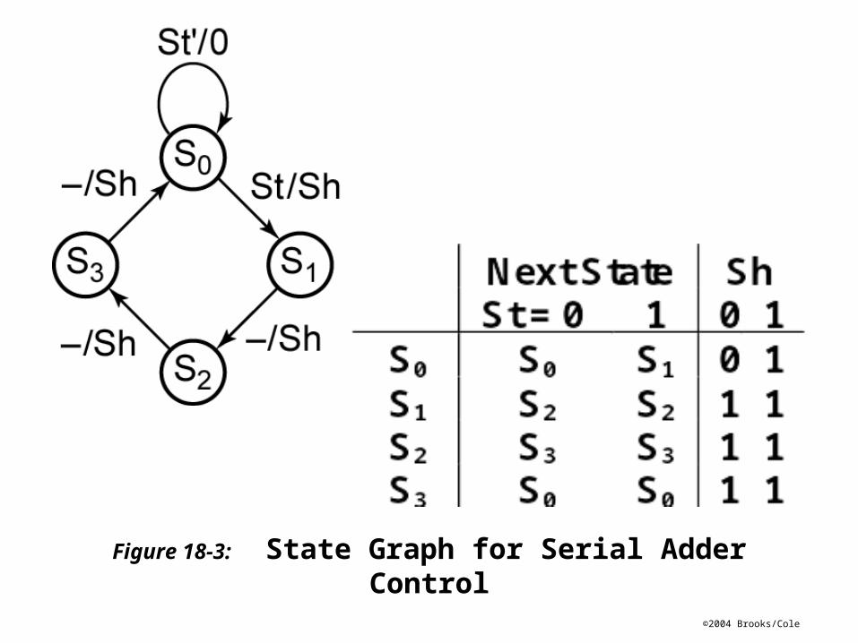
Figure 18-3: State Graph for Serial Adder Control

©2004 Brooks/Cole
Figure 18-4a: Derivation ofControl Circuit Equations

©2004 Brooks/Cole
Figure 18-4b: Derivation of Control Circuit Equations

©2004 Brooks/Cole
Figure 18-5: Typical Serial Processing Unit

©2004 Brooks/Cole
Figure 18-6: State Graphs for Serial Processing Unit

©2004 Brooks/Cole
Figure 18-7: Block Diagram for ParallelBinary Multiplier

©2004 Brooks/Cole
Parallel Binary Multiplication

©2004 Brooks/Cole
Figure 18-8: State Graph for Multiplier Control

©2004 Brooks/Cole
Figure 18-9

©2004 Brooks/Cole
Table 18.2 Operation of a Multiplier Using a Counter

©2004 Brooks/Cole
Figure 18-10: Block Diagram for Parallel Binary Divider

©2004 Brooks/Cole
Figure 18-11: State Graph for DividerControl Circuit

©2004 Brooks/Cole
Figure 18-12: Logic Diagram for5-Bit Subtracter

©2004 Brooks/Cole
Section 18.3, p. 550

©2004 Brooks/Cole
Figure 18-13:
Block Diagram for Divider Using Bus
Notation