2004-12-wj
116
PUBLISHED BY THE AMERICAN WELDING SOCIETY TO ADVANCE THE SCIENCE, TECHNOLOGY AND APPLICATION OF WELDING AND ALLIED PROCESSES, INCLUDING JOINING, BRAZING, SOLDERING, CUTTING AND THERMAL SPRAYING December 2004 •Spotlight on Shielding Gases •Developing an Effectibe Web site •Weldability of Powder Metal Parts •Spotlight on Shielding Gases •Developing an Effective Web Site •Weldability of Powder Metal Parts
-
Upload
joel-cristobal -
Category
Documents
-
view
108 -
download
5
Transcript of 2004-12-wj

PUBLISHED BY THE AMERICAN WELDING SOCIETY TO ADVANCE THE SCIENCE, TECHNOLOGY AND APPLICATION OF WELDINGAND ALLIED PROCESSES, INCLUDING JOINING, BRAZING, SOLDERING, CUTTING AND THERMAL SPRAYING
WE
LD
ING
JOU
RN
AL
• VO
LU
ME
83 NU
MB
ER
12 • DE
CE
MB
ER
2004
December 2004
•Spotlight on Shielding Gases•Developing an Effectibe Web site•Weldability of Powder Metal Parts
•Spotlight on Shielding Gases•Developing an Effective Web Site•Weldability of Powder Metal Parts

600 Enterprise DriveP.O. Box 259
Fort Loramie, OH 45845-0259Phone: (937) 295-5215
Fax: (937) 295-5217www.select-arc.com
Rising solid wireprices have madespecifying Select-Arc’s higherproductivity metal-coredelectrodes an evensmarter choice.
Select-Arc metal-coredelectrodes have earnedtheir outstandingreputation by deliveringan exceptional combina-tion—the efficiencies ofsolid wire and the high
productivityof flux cored.Additionalsignificant
benefits include:
• Virtually no spatteremission meansreduced cleanup costs
• Very smooth spraytransfer
• Low fumegeneration
• Superb beadgeometry
• Fastertravelspeedforgreaterproductivity
Discover for yourselfthe many reasons toswitch from solid wireto Select-Arc’s premium
line of metal-cored electrodes.Call us today at1-800-341-5215.
The Time Is Rightto Switch...
to Select-Arc Metal-Cored Electrodes
Circle No. 38 on Reader Info-Card
select arc 11/5/04 1:45 PM Page C2

GEInspection Technologies
GE Inspection Technologies50 Industrial Park, Lewistown, PA 17044(866) 243-2638GEInspectionTechnologies.com
The beam gets through most anything. The operator gets through it 50 percent faster.
The ERESCO MF3 line of portable X-ray equipment from GE Inspection Technologies offers exposure times up to 50 percent faster than other portable equipment. It is the fastest line of portable equipment available, and can help you drastically improve productivity. Available from 5–300 kV for a variety of materials, ERESCO equipment is compact, lightweight, and weatherproof. Warm it up only once per day, you won’t believe how it gets your inspections humming along. Find out more about the MF3 line and our other X-ray, ultrasonic, and eddy current equipment, or get exposed to our global application centers and services by visiting www.GEInspectionTechnologies.com today.
Digital | Eddy Current | Film | Testing Machines | Ultrasonics | X-ray
Circle No. 30 on Reader Info-Card
ge insp 11/11/04 7:17 AM Page 1

And the AWS Welding Show 2005 is the biggest of them all!
© American Welding Society 2004 CON-1070
April 26-28, Dallas, TexasDALLAS CONVENTION CENTER
• Advance multi-media ad and direct mail campaign promoting the Show.
• Local newspaper and media coverage.
• Listing in the official Show Program and Buyers’ Guide distributed at the Show.
• Use of the AWS Press Room.
• Discounts on freight, car rentals, and room rates, as well as free shuttle buses from AWS-sponsored hotels to the Show.
• On-site staff to assist you during the Show and to help provide a hassle-free exit at the end.
• AWS website, which is used as a year-round tool by manufacturers, distributors and end-users looking for products and services.
• A targeted demographic attendee list will be available from Show management.
• Our marketing staff will be available for consultation on lead follow-up and tracking.
Exhibiting at the AWS Welding Show 2005 is the most cost-effective way to gain broadexposure in a short time. As an AWS exhibitor, you will have the opportunity to meet thosebuyers who need your products. The AWS Welding Show has more to offer than any othershow in the metal-fabricating and construction industries.
Big benefits for exhibitors before, during, and after the Show.
Seven exciting Special Pavilions giveattendees new reasonsto come to the Show:★ Gas Products★ Oilfield and Pipeline
Equipment★ Cutting and Grinding
Products★ Brazing and Soldering★ Resistance Welding★ Laser Welding and Cutting★ Nondestructive Testing
and Inspection
To participate in any of the pavilions or for more information, please contactour Welding Show Exhibit Sales office at: 1-800-443-9353, ext. 295 or 242.
Everything is biggerin Texas
Circle No. 13 on Reader Info-Card
Page 2 11/9/04 4:57 PM Page 2

CONTENTS26 Bay Bridge Puts New Gas Mixtures to the Test
Challenging bridge project relied on advancedthree-part gas mixturesB. O’Neil and M. E. Rodgers III
30 How to Optimize Mild Steel GMAWThe right shielding gas can lead to reduced productioncosts and higher quality productsR. Green
34 Exploring the Weldability of Powder Metal PartsThe weldability of powder metal parts under a varietyof manufacturing conditions was investigatedA. Kurt et al.
38 Boot Camp for Battlefield WeldersArmy, Air Force, and Marine welders prepare for battlefield welding at Aberdeen Proving GroundR. Hancock
41 Upgrade Your Web Site’s UsabilityTips for making your Web site more useful
Welding Journal (ISSN 0043-2296) is publishedmonthly by the American Welding Society for$90.00 per year in the United States and posses-sions, $130 per year in foreign countries: $6.00 persingle issue for AWS members and $8.00 per sin-gle issue for nonmembers. American Welding So-ciety is located at 550 NW LeJeune Rd., Miami, FL33126-5671; telephone (305) 443-9353. Periodi-cals postage paid in Miami, Fla., and additional mail-ing offices. POSTMASTER: Send address changesto Welding Journal, 550 NW LeJeune Rd., Miami,FL 33126-5671.
Readers of Welding Journal may make copies of ar-ticles for personal, archival, educational or researchpurposes, and which are not for sale or resale. Per-mission is granted to quote from articles, providedcustomary acknowledgment of authors andsources is made. Starred (*) items excluded fromcopyright.
DepartmentsWashington Watchword..........4
Press Time News..................6
Editorial ............................8
News of the Industry ............10
Aluminum Q & A ................16
CyberNotes ......................18
New Products ....................20
Coming Events ..................44
Navy Joining Center ............52
Welding Workbook ..............54
Society News ....................55
Tech Topics ......................61
Standards Errata
Guide to AWS Services ........70
New Literature ..................72
Personnel ........................74
Welding Journal Index..........76
Classifieds........................90
Advertiser Index ................92
Welding ConsultantsDirectory ......................92
319-S Physical and Welding Metallurgy of Gd-enriched Austenitic Alloys for Spent NuclearFuel Applications — Part II: Nickel-basedAlloysNickel-based, gadolinium-enriched alloys showedimproved hot ductility and cracking resistancecompared to Gd-enriched stainless steelsJ. N. DuPont et al.
330-S Numerical Simulation of Transient 3-D SurfaceDeformation of a Completely Penetrated GTA WeldA transient numerical model was developed to investigate the dynamic behavior of a completely penetrated GTAW jointC. S. Wu et al.
336-S Signature Analysis for Quality Monitoring in Short-Circuit GMAWA time-frequency analysis method was developed to identify process stability and welding quality of short-circuit GMAWY. X. Chu et al.
Features
Welding Research Supplement30
26
38
3WELDING JOURNAL
December 2004 • Volume 83 • Number 12 AWS Web site http://www.aws.org
Cover photo courtesy of Craig Bratt, Fraunhofer USA. The hybridlaser beam welding process combines the traditional GMAWprocess with laser beam processing.
TOC 12/04 Layout 11/9/04 2:59 PM Page 3

OHSA Issues Final Rule on Shipyard FireProtection
The U.S. Occupational Safety and Health Administration(OSHA) has issued a final rule on Fire Protection in ShipyardEmployment. The purpose of the standard, which becomes ef-fective December 14, is to increase the protection of shipyardworkers from fire hazards.
According to OSHA, shipyard workers are subject to a risk ofinjury and death from fires and explosions during ship repair,shipbuilding, and shipbreaking. As well, many of the core tasksinvolved in shipyard employment, such as welding, can providean ignition source for fires.
The Bureau of Labor Statistics data show that there is an an-nual average of 1 fatality, 110 lost-workday “heat/burn” injuries,and more than 300 total injuries due to shipyard fires.
Congress Enacts Manufacturing Deduction
As part of the American Jobs Creation Act of 2004, a new taxdeduction will now be available for “U.S. production activities.”Ultimately, the deduction will be 9% of a manufacturer’s taxableincome, though it will be phased in with 3% for 2005 and 2006,and 6% for 2007 through 2009. The deduction will be limited to50% of W-2 wages plus certain elective income deferrals, and itwill be allowed against the Alternative Minimum Tax.
Stricter Standard Proposed for HexavalentChromium
The U.S. Occupational Safety and Health Administration(OSHA) has issued a Notice of Proposed Rulemaking for occu-pational exposure to hexavalent chromium. OSHA is proposingto lower its permissible exposure limit for hexavalent chromiumfrom 52 to one µg/m3 of air as an eight-hour time-weighted aver-age. The proposed rule also includes provisions for employeeprotection such as preferred methods for controlling exposure,respiratory protection, protective work clothing and equipment,hygiene areas and practices, medical surveillance, hazard com-munication, and record keeping. This proposal will affect allmetal fabricators who join stainless steel or use electrodes con-taining chromium.
Public comments will be accepted until January 3, 2005. In addition, OSHA plans to hold an informal public hearing inWashington, D.C., beginning February 1, 2005. A federal courtorder requires OSHA to publish a final rule by January 18,2006. The OSHA Web site for submitting comments is http://ecomments.osha.gov. The entire proposed rule can be accessedat http://www.osha.gov/FedReg_osha_pdf/FED20041004.pdf.
H-1B Visas Reach Limit for Fiscal Year 2005
On October 1, 2004, the first day of fiscal year 2005, the De-partment of Homeland Security’s office of U.S. Citizenship andImmigration Services announced that it had already receivedenough petitions to account for all 65,000 H-1B visas allocatedfor the year. The H-1B program is designed to facilitate the hir-
ing of foreign highly skilled workers.This is the seventh time since 1997 that the H-1B cap was
reached before the end of the fiscal year, but the first time thatit was reached on the first day of the new year. Business groupshave asked Congress to intervene by extending the 65,000 visalimit.
R&D Tax Credit Extended
Congress has extended the Research and Development(R&D) tax credit for corporations through December 31, 2005.The extension is retroactive to June 2004, when the credit lastexpired. The R&D credit has expired 11 times since its creation,which has made long-term R&D planning difficult.
The business community has tried to convince Congress tomake the tax credit permanent.
OSHA Pursues More CooperativeApproach
In recent years, the U.S. Occupational Safety and Health Ad-ministration (OSHA) has tried to accomplish its goals throughmore cooperative initiatives with industry, as a complement toits usual regulatory and enforcement activities. For example, theagency has formed 231 long-term alliances with trade associa-tions and companies since 2002 that emphasize outreach, educa-tion, and sharing “best practices.”
OSHA has also forged 214 active strategic partnerships thatset safety goals involving 4762 employers, and there are 1153 vol-untary protection program sites where companies with exem-plary safety records forego routine inspections.
States Ranked for Their Small BusinessClimates
The nonprofit Small Business & Entrepreneurship Councilhas issued a ranking of states based on their public policy cli-mates for small businesses. The index is based on an analysis of23 major government-imposed or government-related costs af-fecting small businesses and entrepreneurs, including an assort-ment of taxes and measures that reflect various regulatory costssuch as worker’s compensation. The following are the top tenstates:
1. South Dakota2. Nevada3. Wyoming4. Washington5. Florida6. Michigan7. Mississippi8. Alabama9. Colorado10. Indiana
WASHINGTONWATCHWORD
DECEMBER 20044
BY HUGH K. WEBSTERAWS WASHINGTON GOVERNMENT AFFAIRS OFFICE
Contact the AWS Washington Government Affairs Office at 1747 Pennsylvania Ave. NW, Washington, DC 20006; e-mail [email protected]; FAX (202) 835-0243.
Washington Watchword 12/04corr 11/9/04 3:01 PM Page 4

www.lincolnelectric.com/askhow
Ask Lincoln How!www.lincolnelectric.com/askhow
Ask Lincoln How!Automation Tech Support Consumables Equipment
Want to make your welding operationcompetitive with any in the world?
LINCOLN HAS THE ANSWER.
Lincoln offers:
• Robotic welding solutions thatdrive down production costs
• Waveform Control power sources that deliver higher welding productivity
• Real-time data delivery thatimproves product quality
Ask the Experts at Lincoln how arobotic welding system can boostyour productivity and keep youahead of the competition.
AR04-32
Circle No. 35 on Reader Info-Card
WJ-NEXTWELD AD AR05-00 11/8/04 2:23 PM Page 5
PRESS TIMENEWS
Mittal Steel Set to Become World’s Largest Steel Company
Ispat International N.V. announced it has agreed to acquire LNM Holdings N.V. Fol-lowing completion of this transaction, the company will be renamed Mittal Steel Co.N.V. Also, the board of directors from Ispat and International Steel Group, Inc., haveunanimously approved a definitive agreement to merge these two companies.
The combined Mittal Steel will be the largest and most global steel company in theworld, with operations in 14 countries on four continents, and 165,000 employees. It willserve the major steel-consuming sectors, including automotive, appliance, machinery,and construction.
For 2004, it expects pro forma revenues of more than $31.5 billion, and pro formatotal steel shipments of approximately 57 million tons.
Oshkosh Developing Second-Generation Robotic Truck
Oshkosh Truck Corp., Oshkosh, Wis., is developing a second-generation version ofits self-navigating robotic TerraMax™truck to compete in the Pentagon-sponsored $2million 2005 DARPA Grand Challenge.
During this competition in the Mojave Desert, the sensor-data based TerraMax mustmake its own decisions on route planning, obstacle avoidance, and speed, without the aidof any human intervention once en route. The platform for the truck is the company’sMedium Tactical Vehicle Replacement, which is equipped with the Oshkosh TAK-4® in-dependent suspension, Command Zone™ advanced electronics, and “on-the-go” centraltire inflation.
By 2015, the Pentagon hopes that the application of autonomous military vehicleswill be able to help save the lives of military personnel who today are at risk when driv-ing slow-moving supply convoys.
Report Reveals Business Conditions of Metalforming Companies
According to the Precision Metalforming Association (PMA) Business ConditionsReport from October, metalforming companies are feeling less optimistic about currentand near-term business conditions than they were in September.
When asked what they anticipated the general economic activity would be like overthe next three months, 27% expected business conditions to improve (down from 36%in September), 53% said activity would remain the same, and 20% thought it would de-crease (compared to 15% in September). Also, expectations for incoming orders for thenext three months were down, with 38% anticipating orders would rise (down from 42%in September), 37% predicting no change (the same number reported in September),and 25% indicating orders would decrease (up from 21%).
The PMA, Cleveland, Ohio, conducts this monthly report as an economic indicatorfor manufacturing by sampling 172 metalforming companies in the United States andCanada.
Praxair Creates Web Site for Professional Welders
Praxair Distribution, Inc., Danbury, Conn., has launched an all-in-one Web site, weld-zone.praxair.com, to provide the latest information on products and services for the metalfabrication industry.
Users can browse e-catalogs that contain more than 40,000 items. Other services in-clude product-specific, safety, and technical information, welding gases and products, awelding equipment clearance center, on-line purchasing capabilities, and tips to improvewelding and cutting operations.
Users can also learn about upcoming welding demonstrations and events.
World’s Largest Solar-Powered Irrigation System Completed
WorldWater & Power Corp., Pennington, N.J., recently announced the installation ofa 200-hp, solar-powered irrigation system at a commercial citrus ranch in California.The company’s AquaMax™ solar motors are powering the $2 million water pumping in-stallation.
This is the largest solar-power system in California’s San Diego County, and it is thelargest solar-driven irrigation system in the world.
DECEMBER 20046
MEMBER
Publisher Andrew Cullison
Publisher Emeritus Jeff Weber
EditorialEditor/Editorial Director Andrew Cullison
Senior Editor Mary Ruth JohnsenAssociate Editor Howard M. Woodward
Assistant Editor Kristin CampbellPeer Review Coordinator Doreen Kubish
Graphics and Production Production Editor Zaida Chavez
Production Assistant Brenda Flores
AdvertisingNational Sales Director Rob Saltzstein
Advertising Sales Representative Lea GarriganAdvertising Production Frank Wilson
SubscriptionsLeidy [email protected]
American Welding Society550 NW LeJeune Rd., Miami, FL 33126
(305) 443-9353 or (800) 443-9353
Publications, Expositions, Marketing CommitteeG. O. Wilcox, Chair
Thermadyne IndustriesD. L. Doench, Vice Chair
Hobart Brothers Co.J. D. Weber, Secretary
American Welding SocietyR. L. Arn, WELDtech InternationalT. A. Barry, Miller Electric Mfg. Co.
M. Balmforth, Sandia National LabsR. Durda, The Nordam Group
J. R. Franklin, Sellstrom Mfg. Co.R. G. Pali, J. P. Nissen Co.L. Pierce, Cee Kay Supply
J. F. Saenger, Jr., Edison Welding InstituteR. D. Smith, The Lincoln Electric Co.
S. Smith, Weld Aid Products.B. Damkroger, Ex Off., Sandia National Laboratories
J. E. Greer, Ex Off., Moraine Valley CollegeD. C. Klingman, Ex Off., The Lincoln Electric Co.
D. J. Landon, Ex Off., Vermeer Mfg. Co.E. D. Levert, Ex Off., Lockheed MartinE. C. Lipphardt, Ex Off., ConsultantJ. G. Postle, Ex Off., Postle Industries
R. W. Shook, Ex Off., American Welding Society
Copyright © 2004 by American Welding Society in both printed and elec-tronic formats. The Society is not responsible for any statement made oropinion expressed herein. Data and information developed by the authorsof specific articles are for informational purposes only and are not in-tended for use without independent, substantiating investigation on thepart of potential users.
Press Time News 12/04corr 11/4/04 11:43 AM Page 6

VeronaFiere, 17-19 March 2005VeronaFiere, 17-19 March 2005
The Italian exhibition dedicated to welding and cutting technologies to stay in touch with
the market and its key playersAfter the success of the first edition, SALDAT is back.Sponsored by ANASTA, the Italian Association forWelding, Cutting, and Related TechnologyCompanies, this biannual event has been designedfor the trade operators and for all interested in thewelding and cutting market.At SALDAT, end users, integrators, professionals,and dealers will learn about the new markettrends, attend demonstrations and presentationsand guided tours, get new contacts, find concreteofferings to improve their business.Thanks to ANASTA’s collaboration with organizations,associations, and universities, SALDAT will be richwith opportunities of discussing all of the latestissues, attending conferences on specific topics, andparticipating in training sessions for schools andprofessional institutes.
The exhibitors at SALDAT are exclusively Italianmanufacturing firms, subsidiaries of multinationalcompanies, distributors for the Italian market oftrade brands and firms working in relatedindustries. During the event, the most innovativesolutions to the welding and cutting needs of thevarious industry segments will be presented,including:•manual oxy-gas welding, cutting and heating;•manual and semiautomatic arc and resistance
welding and cutting;•consumables products;•automation of welding and cutting;•support machinery and accessories of welding
and cutting.
Entrance is free
For information:Exhibition Organization Tel. + 39 02 7002534
www.saldat.it
Italian Association for Welding, Cutting,and Related Technology Companies
www.anasta.it • www.weld.itCircle No. 37 on Reader Info-Card
saldat 11/5/04 1:45 PM Page 7

EDITORIAL
Thoughout most of my business career, I have been employed in sales. I’ve soldall types of products, from cars to office supplies, from advertising to retail. I’ve beenin distribution, and I’ve been a factory representative. I always believed that any prod-uct just needed to be “sold,” and that I could sell anything. Like the old saying goes,“I could sell ice cubes to Eskimos.”
So 32 years ago I applied for a job in the welding and cutting industry withChemetron Corporation (formerly NCG). Again, I thought, “Selling is selling…pe-riod. Just give me a company car and a commission, and I’ll do the rest.”
I soon found that selling welding and cutting products and gases was differentfrom what I was used to. For most products, all a salesperson needed was a quicktraining class. Selling welding products, however, required a lot more knowledge thanwhat a simple training seminar could supply. I also soon learned that a sale repre-sented something a lot more important than just a sale, because the products werebeing used to build something to last, something that would affect neighborhoods,cities, or even countries.
I went back to college for more education on welding and metallurgy. I discov-ered the more I learned, the more I needed to learn. Never before had I been chal-lenged by products, but now I was. That’s because in welding there are usually sev-eral ways to accomplish a job based on need or speed or specification. There’s not al-ways one absolute “right” way. Alloy selection, process used, the design of the work-piece, and the way it is cut or shaped all influence the quality of the final product.That’s why, as I work with my customers, I always try to look at each project withfresh eyes and to consider several options.
Within months of starting this new job, a wise colleague told me that if I was seri-ous about the welding industry, I needed to attend the local AWS meetings. I went tomy first Section meeting the very next Thursday night. Section meetings gave me anopportunity to meet customers, competitors, and people who gave back to their in-dustry. The meetings helped me to grasp the enormous breadth of the industry andhow it provides opportunities for many types of careers.
Our industry has a history of shedding off good people who want to work, but whodon’t succeed because they never quite saw the total picture. Becoming involved withAWS helped me view the big picture. I soon realized that if you make an effort tolearn, and you make it past the first few years, then you will have a career for life.While this may not always be the highest paying industry, to me it’s always challeng-ing. During my welding sales career, I have been to so many interesting projects, fromthe Alaska pipeline to the Mercury nuclear test site in Nevada to standing on a 1000-ft ship as it was being built. What other industry is so vast and constantly growing?
Nowadays, when I have the opportunity to talk to students at colleges or vo-techschools, I encourage them to try to achieve the highest level skills they can and tolearn the AWS standards. Then when it’s time to put their education and skills on themarket, they’ll have many options. My point is there’s room in welding and in the
American Welding Society for many types of peo-ple. This is a career industry that needs architects,engineers, teachers, welders, and, yes, sales peoplesuch as myself.
DECEMBER 20048
Founded in 1919 to Advance the Science,Technology and Application of Welding
A Place for Everyone
Gene E. LawsonAWS Vice President
OfficersPresident James E. Greer
Moraine Valley Community College
Vice President Damian J. KoteckiThe Lincoln Electric Co.
Vice President Gerald D. UttrachiWA Technology, LLC
Vice President Gene E. LawsonESAB Welding & Cutting Products
Treasurer Earl C. LipphardtConsultant
Executive Director Ray W. ShookAmerican Welding Society
DirectorsT. R. Alberts (Dist. 4), New River Community College
B. P. Albrecht (At Large), Miller Electric Mfg. Co.
A. J. Badeaux, Sr. (Dist. 3), Charles Cty. Career & Tech. Center
K. S. Baucher (Dist. 22), Technicon Engineering Services, Inc.
M. D. Bell (At Large), Preventive Metallurgy
J. C. Bruskotter (Dist. 9), Bruskotter Consulting Services
C. F. Burg (Dist. 16), Ames Laboratory IPRT
N. M. Carlson (Dist. 20), INEEL
H. R. Castner (At Large), Edison Welding Institute
N. A. Chapman (Dist. 6), Entergy Nuclear Northeast
S. C. Chapple (At Large), Consultant
N. C. Cole (At Large), NCC Engineering
J. D. Compton (Dist. 21), College of the Canyons
L. P. Connor (Dist. 5), Consultant
J. R. Franklin (At Large), Sellstrom Mfg. Co.
J. D. Heikkinen (Dist. 15), Spartan Sauna Heaters, Inc.
W. E. Honey (Dist. 8), Anchor Research Corp.
D. C. Howard (Dist. 7), Concurrent Technologies Corp.
J. L. Hunter (Dist. 13), Mitsubishi Motor Mfg. of America, Inc.
M. D. Kersey (Dist. 12), The Lincoln Electric Co.
E. D. Levert (Past President), Lockheed Martin Missiles & Fire Control
V. Y. Matthews (Dist. 10), The Lincoln Electric Co.
J. L. Mendoza (Dist. 18), City Public Service
T. M. Mustaleski (Past President), BWXT Y-12, LLC
R. L. Norris (Dist. 1), Merriam Graves Corp.
T. C. Parker (Dist. 14), Miller Electric Mfg. Co.
O. P. Reich (Dist. 17), Texas State Technical College at Waco
E. Siradakis (Dist. 11), Airgas Great Lakes
K. R. Stockton (Dist. 2), PSE&G, Maplewood Testing Serv.
P. F. Zammit (Dist. 19), Brooklyn Iron Works, Inc.
Editorial for 12/04corr 11/4/04 9:13 AM Page 8

Circle No. 4 on Reader Info-Card
arc one 11/5/04 1:44 PM Page 9

NEWS OF THEINDUSTRY
Airgas Helps Fuel SpaceShipOne’sAnsari X Prize
Scaled Composites, LLC, Mojave, Calif., founded by BurtRutan, led the SpaceShipOne team in winning the $10 millionAnsari X Prize for commercial manned space flight on October4. The team, privately financed by Paul G. Allen, became the first
to build and launch a spaceship able to carry three people to aheight of 62.5 miles and return safely. The spaceship launchedfrom its mother aircraft, White Knight, over the Mojave Desertin California and reached space three times; the team had tomake two space flights with the same ship within two weeks tobe the winner.
SpaceShipOne has a hybrid motor that uses nitrous oxide asan oxidizer and hydroxy-terminated polybutadiene for fuel. Air-gas, Inc., Radnor, Pa., provided the liquid nitrous oxide used topower it. Airgas West supplied air, nitrogen, carbon dioxide, andUHP nitrogen, along with gas regulators and fittings for manag-ing the gas supply.
“With this record-breaking achievement, the SpaceShipOneteam has opened the door to exciting and challenging possibili-ties in the fields of aviation and aerospace,” said Martin Tupman,vice president and general manager of Airgas Nitrous Oxide.
Attendees of Shipbuilding Meeting SeeWelding Demonstrations
The Laser Processing Division of ARL Penn State recentlyhosted a meeting of the National Shipbuilding Research Pro-gram’s SP-7 Welding Technology Panel. It attracted more than35 attendees from across the country, with representatives fromthe Navy and commercial shipyards, government and regulatoryagencies, and a host of welding equipment suppliers.
A tour of ARL Penn State’s Laser Processing Laboratory was
DECEMBER 200410
SpaceShipOne, pictured here sitting on the ramp on its landinggear, brought its team a place in history and a $10 million prize.
Circle No. 24 on Reader Info-Card
Layout 11/5/04 9:27 AM Page 10
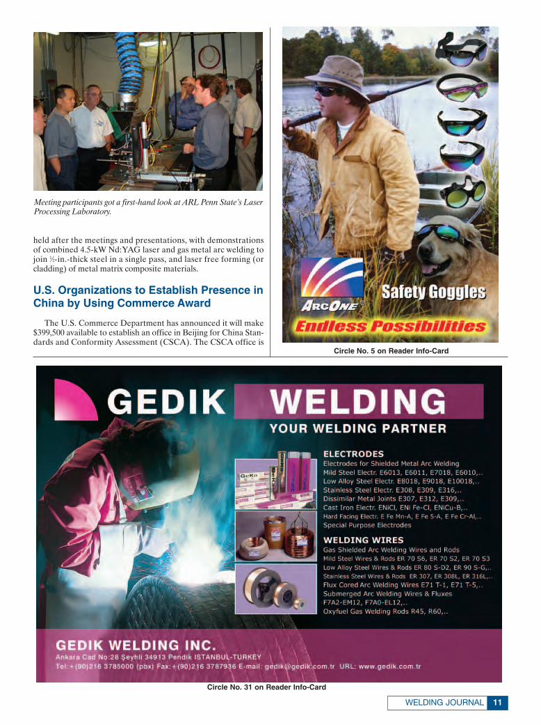
held after the meetings and presentations, with demonstrationsof combined 4.5-kW Nd:YAG laser and gas metal arc welding tojoin 1⁄2-in.-thick steel in a single pass, and laser free forming (orcladding) of metal matrix composite materials.
U.S. Organizations to Establish Presence inChina by Using Commerce Award
The U.S. Commerce Department has announced it will make$399,500 available to establish an office in Beijing for China Stan-dards and Conformity Assessment (CSCA). The CSCA office is
11WELDING JOURNAL
Meeting participants got a first-hand look at ARL Penn State’s LaserProcessing Laboratory.
Circle No. 5 on Reader Info-Card
Circle No. 31 on Reader Info-Card
Layout 11/10/04 8:43 AM Page 11

an initiative by a four-member consortium: The American Soci-ety of Mechanical Engineers, The American Petroleum Institute,ASTM International, and CSA America.
Through this Beijing office, the consortium will form relation-ships with peer agencies in China, monitor standards develop-ment, and promote acceptance of members’ standards and con-formity assessment systems. Once established and staffed, theywill prepare Chinese marketing materials and a Web site, obtainmarket and standards information of strategic importance, net-work with government agencies and standards officials, and con-duct training.
The funds awarded to the consortium are made availablethrough the Commerce Department’s Market Development Co-operator Program, and the consortium will match every federaldollar with two dollars of its own.
Study on Steel Phase Transformations Results in New ASTM Standard
A collaborative study on quantitative measurement of steelphase transformation by the American Iron and Steel Institute(AISI), West Conshohocken, Pa., in cooperation with more thana dozen companies, resulted in a recently approved new ASTMstandard, A 1033, Practice for Quantitative Measurement and Re-porting of Hypoeutectoid Carbon and Low-Alloys Steel Phase Trans-formations. It was sponsored by the U.S. Department of Energyunder AISI’s Technology Roadmap Project.
In practice, dilatometer equipment is used to detect and meas-ure the changes in dimension that occur as functions of both timeand temperature during defined thermal cycles. The resultingdata are converted to discrete values of strain for specific valuesof time and temperature during the thermal cycle that can be
used to determine the beginning and completion of one or morephase transformations.
As well, the practice can provide data for computer modelsused in the control of steel manufacturing, forging, casting, heat-treating, and welding processes.
Steel Sculpture Commemorates WrightBrothers’ Flight
Van Noorden Co., Franklin, Mass., recently built and erecteda 40-ton sculpture for the Raleigh-Durham Airport that serves
This sculpture at the Raleigh-Durham Airport, commemorating theWright brothers’ first powered flight, features an eliptical ring and apair of intersecting wings atop a 50-ft tower.
AWS CORPORATE MEMBERSHIP...helping Companies (large and small) and Educational Institutions
stay at the cutting edge of the materials joining industry!
AWS CORPORATE MEMBERSHIP...helping Companies (large and small) and Educational Institutions
stay at the cutting edge of the materials joining industry!
Join an elite group of over 400 AWS Sustaining CompanyMembers and enjoy:• Your choice of one of these money-
saving benefits:1. AWS Standards Library ($6,500 value)2. Discount Promotional Package – save
on Welding Journal advertisingand booth space at the AWS WELDING SHOW (save thousands)
3. 10 additional AWS Individual Memberships ($870 value)
Plus...• 10 AWS Individual Memberships
($870 value); each Individual Membership includes a FREE subscription to the WeldingJournal, up to an 87% discount on an AWS publication, Members’-only discounts and much more
• Free company publicity – give your company a global presence in the Welding Journal, on the AWS Website, and at the AWS WELDING SHOW
• Exclusive usage of the AWS Sustaining Company logo on your company's letterhead and on promotional materials for a competitive edge
• An attractive AWS Sustaining Company wall plaque
• Free hyperlink from AWS's 40,000-visitors-a-month website to your company's website
• Complimentary VIP passes to the AWS WELDING SHOW
• An additional 5% discount off the already-reduced member price of any AWS conference or seminar registration• Up to 62% off Yellow Freight shipping
charges, outbound or inbound, short or long haul
AND MUCH MORE...Also available AWS SupportingCompany Membership,AWS Welding DistributorMembership and AWS Educational Institution Membership
AWS SUSTAINING COMPANY MEMBERSHIP
550 N.W. LeJeune Rd.Miami, Florida 33126Visit our website at www.aws.org
For more informationon AWS CorporateMembership, call
(800) 443-9353, ext. 253or 260. E-mail:
[email protected] an application.
Your organizationneeds solutions.
AWS means answers.Circle No. 17 on Reader Info-Card
Layout 11/5/04 9:27 AM Page 12

as an icon commemorating the 100th anniversary of the Wrightbrothers’ first powered flight. It evokes the Wright brothers’ spiritof invention and the circuitous nature of air travel involving time,movement, and return.
The 122-ft-long sculpture is fabricated from 3⁄8-in. steel plate,and features an eliptical ring and a pair of intersecting wings atopa 50-ft tower.
Architect Wellington Reiter of Urban Instruments, Newton,Mass., designed the sculpture.
GAWDA Raises Money for HIV/AIDSService Organization
Golden Rainbow, Las Vegas, Nev., an HIV/AIDS service or-ganization, has received $53,000 from the Philadelphia-basedGases and Welding Distributors Association (GAWDA) as thisyear’s recipient of the GAWDA Gives Back program. Each yearfor the past five years as part of its annual convention, GAWDAhas chosen a charity in the convention’s host city to receive vol-untary donations from the organization’s membership.
“Our housing program is being threatened by freeway expan-sion in Las Vegas, and GAWDA’s incredible contribution will goa long way toward helping us seek out or build new housing tocontinue our mission,” said Carol Hunter, Golden Rainbow president.
Deere & Co. to Build Tractor Factory in Brazil
Deere & Co., Moline, Ill., recently announced it will build anew tractor factory in Brazil to increase its manufacturing capac-ity for farm tractors, combines, and seeding equipment in theSouth American agricultural equipment market.
The new facility will manufacture farm tractors while the com-pany’s existing factory there will focus on combines and plantingequipment. In addition, the equipment manufactured in bothplaces will be exported to other markets.
Deere will invest $80 million to construct the new facility inMontenegro, Rio Grande do Sul, and expects it to be in full pro-duction by the second half of 2006.
Chairman Elected at Lincoln Electric Holdings, Inc.
Lincoln Electric Holdings, Inc., Cleveland, Ohio, recently an-nounced that its board of directors has elected John M. Stropkias chairman of the board. He succeeds Anthony A. Massaro, whohas retired afrer 11 years with the company.
Stropki began his career at Lincoln 35 years ago, working inthe company’s Cleveland factory while he was an engineering stu-dent at Purdue University. After graduation, he became a salestrainee and rose through the sales organization. In 1996, Stropkiwas the company’s executive vice president and president, NorthAmerica, from May 2003 to June 2004 served as chief operatingofficer, and in June 2004 was named president and chief execu-tive officer.
He is a member of the American Welding Society, the Manu-facturers Alliance/MAPI Presidents Council, and the Gases andWelding Distributors Association.
GE and Honda Establish Joint Venture toMarket Jet Engine
General Electric Co. and Honda Motor Co., Ltd., have estab-lished a new joint venture company, GE Honda Aero Engines,
13WELDING JOURNAL
Circle No. 6 on Reader Info-Card
Circle No. 28 on Reader Info-Card
Layout 11/10/04 8:43 AM Page 13

LLC, to pursue launching of Honda’s HF118 turbofan engine inthe jet engine market.
The HF118 will enter service in the 1600-lb thrust class. Also,the engine has run more than 2400 h in ground tests and morethan 450 h in flight tests to demonstrate reliability, long mainte-nance interval, and fuel economy.
The 50/50 joint company will begin operating near the end of2004 in Cincinnati, Ohio. It envisions a future market of approx-imately 200 or more of these business jets annually.
Northrop Grumman Awarded Contract forNuclear-Powered Submarine
Northrop Grumman Corp., Newport News, Va., has beenawarded a contract valued at $36.5 million for the planning and
execution of dry-docking work on the nuclear-powered subma-rine USS Hyman G. Rickover.
Maintenance work on the Rickover will be performed at thecompany’s Newport News sector. This includes blasting and paint-ing the submarine’s internal and external tanks, removal andoverhaul of various system valves, steering and diving gear in-spection and repair, repairs to torpedo systems, and inspectionand repairs to the sail, pressure, and nonpressure hulls.
It will take approximately five months to complete and shouldbe finished in March 2005.
Industry Notes• The Titan Corp., San Diego, Calif., has been awarded an in-
definite delivery/indefinite quantity multiple award contractfor engineering and technical services to the U.S. Navy’sNAVSEA Shipbuilding Office (NAVSHIPSO). As a multipleaward five-year contract, with one base year and four one-yearoptions, it has a potential ceiling value in excess of $1.05 bil-lion. Titan will compete against seven other companies for taskorders to provide NAVSHIPSO habitability, propulsion, elec-trical, auxiliary and electronics systems engineering, and tech-nical services for ships and shore stations.
• South Korean steelmaker Posco is in discussions with Brazil-ian iron-ore giant Companhia Vale do Rio Doce to participatein a joint venture to develop an $11.4 billion steel-manufac-turing plant on Brazil’s north coast. This new slab-making op-eration would make Brazil one of the top steel producers inthe world, according to a recent Wall Street Journal article.
• Praxair, Inc., Danbury, Conn., announced that Praxair Distrib-ution, a division of Praxair Canada, Inc., has signed an agree-ment to provide welding gases and hard goods to TSC Stores,
Maintenance work on the USS Hyman G. Rickover is expected tobe completed in March 2005.
AWS AFFILIATE COMPANY MEMBERSHIPMEMBER BENEFITS:
• Priceless exposure of your shop with free publicity on AWS’s 40,000-visitors-a-month website.
• $50 OFF a job posting on AWS JobFind www.aws.org/jobfind, your connection to hundreds of welders, inspectors and other job seekers!
• An AWS Individual Membership ($75 value), which includes need-to-know technical information through a FREE monthly subscription to the Welding Journal. WJ covers the latest trends, events, news and products guaranteed to make your job easier.
• Quick access to welding information through a personal library of AWS Pocket Handbooks:
1. Everyday Pocket Handbook for Arc Welding Steel
2. Everyday Pocket Handbook for Visual Inspection and Weld Discontinuities – Causes and Remedies
3. Everyday Pocket Handbook for Gas Metal Arc and Flux-Cored Arc Welding
• A 62% discount on freight shipments with Yellow Transportation, Inc.
• Practical information through The American Welder, a special section of the Welding Journalgeared toward front-line welders.
• Exclusive usage of the AWS Affiliate Company Member logo on your business card and promotional material for a competitive edge.
• Wall certificate to show your company’s affiliationwith the world’s premier welding association.
• Window decal to display on your shop’s storefront.
• Free passes to the AWS Welding Show for you and your shop’s best employees.
• Unmatched networking opportunities at local Section Meetings, the annual AWS Welding Show, as well as at AWS-sponsored educational events.
• Professional development via discounts on world-renowned and industry-wide AWS Certification programs, conferences and workshops.
• Technical information through a 25% Members’-only discount on 300+ industry-specific AWS Publications and technical standards.
THE ANSWER FOR INDEPENDENT WELDING SHOPS!THE ANSWER FOR INDEPENDENT WELDING SHOPS!
To join, or for more information call: (800) 443-9353, ext. 480 or (305) 443-9353, ext. 480 Visit us on-line at www.aws.orgReal-world business solutions for welding and fabricating shops
Circle No. 16 on Reader Info-Card
Layout 11/5/04 9:28 AM Page 14

Ltd., a London, Ont., Canada, based retailer that specializes inhardware and farm supplies. By the end of the year, Praxair’sindustrial cylinders exchange program, which lets customerspurchase new cylinders or exchange empties for full ones ofPraxair’s Star™ gases and blends for welding and cutting, andthe store-within-a-store program will be available at all of TSCStores’ 25 retail outlets in southwestern and eastern Ontario.
• Lime Rock Partners and SGAM/4D have announced the pur-chase of Serimer DASA, headquartered in Paris with a secondfacility in Villers-Cotterets, France, and Serimer DASA NorthAmerica, with offices in Houston, Tex., from Stolt Offshore.This is the first time Serimer DASA has not been a part of anoffshore contractor group. David Williams will assume the po-sition of chairman of the board.
• United Rentals, Inc., Greenwich, Conn., recently purchasedAtlantic Rentals, Ltd., of Woodstock, NB, Canada. AtlanticRentals is the largest equipment rental company in Canada’sMaritime Provinces, with revenues of approximately $35 million.
• IPG Laser GmbH, Burbach, Germany, has appointed HM Laseras a new distributor in China. HM Laser will provide training,support, and service to Chinese OEMs and systems manufac-turers for IPG’s industrial fiber lasers.
15WELDING JOURNAL
1-DAY Seminars Offered
Laser Welding and Processing This seminar provides a solid background on
issues that influence laser processing with emphasis on laser welding.
February 15, 2005
Robotic Arc Welding This seminar is designed for those considering automating welding operations with robotics.
April 12, 2005
For more information or to register Call Today! 1-800-332-9448
or visit us at www.welding.org for more information. Some restrictions apply; please contact us for details. © 2004 Hobart Institute of Welding Technology, Troy, OH, St. of Ohio Reg. No. 70-12-0064HT
Correction
In the August Welding Journal on pg. 10, there was anannouncement that Lincoln Electric Holdings, Inc., hadacquired the controlling interest in a tungsten electrode facto-ry in northern China. That item should have stated that thecontrolling interest was in a covered electrode factory.
Circle No. 7 on Reader Info-Card
Circle No. 27 on Reader Info-CardCircle No. 33 on Reader Info-Card
Layout 11/10/04 8:43 AM Page 15
Q: I have heard, on occasion, referencemade to some aluminum alloys as un-weldable. What does this mean? Are theresuch aluminum alloys, and if so, whatmakes them unweldable?
A: I shall start by saying that the major-ity of aluminum-based alloys can be suc-cessfully arc welded when using the cor-rect welding procedures. However, yes,there are some aluminum-based alloysthat are sometimes referred to as unweld-able. These groups of alloys are wellknown as being unsuitable for arc weld-ing and, for this reason, are joined me-chanically by riveting or bolting.
Before we start examining the variousreasons for the poor weldability of thesealloys, we should start by considering theterm “unweldable.” This is a nonstandardterm that is sometimes used to describealuminum alloys that can be difficult toarc weld without encountering problemsduring and/or after welding. These prob-lems are usually associated with cracking,most often hot cracking, and on occasion,stress-corrosion cracking (SCC).
When we consider the aluminum al-loys that fall into this difficult-to-weld cat-egory, we can divide them into differentgroups.
We will first consider the small selec-tion of aluminum alloys that were de-signed for machineability, not weldabil-ity, such as 2011 and 6262 that contain0.20–0.6 Bi, 0.20–0.6 Pb and 0.40–0.7 Bi,0.40–0.07 Pb, respectively. The additionof these elements (bismuth and lead) tothese materials greatly assists in chip for-mation in these free-machining alloys.However, because of the low solidifica-tion temperatures of these elements, theycan seriously reduce the ability to suc-cessfully produce sound welds in thesematerials.
There are a number of aluminum al-loys that are quite susceptible to hotcracking if arc welded. These alloys areusually heat-treatable alloys and are mostcommonly found in the 2xxx-series, aluminum-copper (Al-Cu), and 7xxx-series, aluminum-zinc (Al-Zn) groups ofmaterials.
In order to understand why some ofthese alloys are unsuitable for arc weld-ing (unweldable), we need to consider thereasons why some aluminum alloys can bemore susceptible to hot cracking.
Hot cracking, or solidification crack-ing, occurs in aluminum welds when highlevels of thermal stress and solidificationshrinkage are present while the weld is un-
dergoing various degrees of solidification.The hot-cracking sensitivity of any alu-minum alloy is influenced by a combina-tion of mechanical, thermal, and metal-lurgical factors.
A number of high-performance, heat-treatable aluminum alloys have been de-veloped by combining various alloying el-ements in order to improve the materials’mechanical properties. In some cases, thecombination of the required alloying ele-ments has produced materials with highhot-cracking sensitivity.
Coherence Range
Perhaps the most important factor af-fecting the hot-crack sensitivity of alu-minum welds is the temperature range ofdendrite coherence and the type andamount of liquid available during thefreezing process. Coherence is when thedendrites begin to interlock with one an-other to the point that the melted mate-rial begins to form a mushy stage. The co-herence range is the temperature betweenthe formation of coherent-interlockingdendrites and the solidus temperature;this could be referred to as the mushyrange during solidification. The wider thecoherence range, the more likely hotcracking will occur because of the accu-mulating strain of solidification betweenthe interlocking dendrites.
The 2xxx-Series Alloys (Al-Cu)
Hot-cracking sensitivity in the Al-Cualloys increases as we add Cu up to ap-proximately 3% Cu, and then decreasesto a relatively low level at 4.5% Cu andabove. Alloy 2219 with 6.3% Cu showsgood resistance to hot cracking becauseof its relatively narrow coherence range.Alloy 2024 contains approximately 4.5%Cu, which may initially encourage us tosuppose that it would have relatively lowcrack sensitivity. However, Alloy 2024 alsocontains a small amount of magnesium(Mg). The small amount of Mg in this alloydepresses the solidus temperature, but itdoes not affect the coherence tempera-ture; therefore, the coherence range is ex-tended and the hot-cracking tendency isincreased.
The problem to be considered whenwelding 2024 is that the heat of the weld-ing operation will allow segregation of thealloying constituents at the grain bound-aries, and the presence of Mg, as statedabove, will depress the solidus tempera-
ture. Because these alloying constituentshave lower melting phases, the stress ofsolidification may cause cracking at thegrain boundaries and/or establish the con-dition within the material conducive tostress-corrosion cracking later. High heatinput during welding, repeated weldpasses, and larger weld sizes can all in-crease the grain-boundary segregationproblem (segregation is a time-tempera-ture relationship) and subsequent crack-ing tendency.
The 7xxx-Series Alloys (Al-Zn)
The 7xxx-series of alloys can also beseparated into two groups as far as weld-ability is concerned. These are the Al-Zn-Mg and the Al-Zn-Mg-Cu types.
The Al-Zn-Mg alloys, such as 7005, re-sist hot cracking better and exhibit betterjoint performance than the Al-Zn-Mg-Cualloys, such as 7075. The Mg content inthis group (Al-Zn-Mg) of alloys wouldgenerally increase the cracking sensitiv-ity. However, zirconium is added to re-fine grain size, and this effectively reducesthe cracking tendency. This alloy groupis easily welded with the high-magnesiumfiller metals, such as 5356, which ensuresthe weld contains sufficient magnesiumto prevent cracking. Silicon-based fillermetals, such as 4043, are not generallyrecommended for these alloys becausethe excess Si introduced by the filler metalcan result in the formation of excessiveamounts of brittle Mg2Si particles in theweld.
ALUMINUMQ&A BY TONY ANDERSON
DECEMBER 200416
TONY ANDERSON is Director of Technical
Training for ESAB North America. He is a Senior
Member of the TWI and a Registered Chartered
Engineer. He is Chairman of the Aluminum
Association Technical Advisory Committee for
Welding and Joining and holds numerous
positions including Chairman, Vice Chairman
and Member of various AWS technical commit-
tees. Questions may be sent to Mr. Anderson
c/o Welding Journal, 550 NW LeJeune Rd.,
Miami, FL 33126 or via e-mail at
Aluminum Q&A 12/04 11/5/04 3:21 PM Page 16

The Al-Zn-Mg-Cu alloys, such as 7075, have small amountsof Cu added. The small amounts of Cu, along with the Mg, ex-tend the coherence range and, therefore, increase the crack sen-sitivity. A similar situation can occur with these materials as withthe 2024-type alloys. The stress of solidification may cause crack-ing at the grain boundaries and/or establish the condition withinthe material conducive to stress-corrosion cracking later.
Be Aware
It should be stressed that the problem of higher susceptibilityto hot cracking from increasing the coherence range is not onlyconfined to the welding of these more susceptible base alloys,such as 2024 and 7075. Crack sensitivity can be substantially in-creased when welding incompatible dissimilar base metals (whichare normally easily welded to themselves) and/or through the se-lection of an incompatible filler metal. For example, by joining aperfectly weldable 2xxx series base metal to a perfectly weldable5xxx series base metal, or by using a 5xxx series filler metal toweld a 2xxx series base metal, or a 2xxx series filler metal on a5xxx series base metal, we can create the same scenario. If wemix high Cu and high Mg, we can extend the coherence rangeand, therefore, increase the crack sensitivity.◆
17WELDING JOURNAL
Circle No. 22 on Reader Info-Card
Circle No. 8 on Reader Info-Card
HOTTEST WELDINGBOOKS ON THE WEBwww.aws.org/catalogs
Aluminum Q&A 12/04 11/5/04 3:21 PM Page 17

CYBERNOTES
Wolf Robotics LaunchesWeb Site
Wolf Robotics. This new Web site offersinformation on the company, its products,services, and staff. Based in Fort Collins,Colo., the company is the former WeldingSystems Division of ABB and still serves asits strategic partner for robotic arc weldingand cutting systems in the United States.The site provides information on the com-pany’s standard and custom products andoptional accessories. It features a companyhistory, contact information for specificbusiness operations, a breakdown of salesterritories, and directions to the manufac-turing plant. In addition, it includesdescriptions of a variety of training classes.
www.wolfrobotics.com
Nilfisk-Advance AmericaAdds E-Commerce Section
Nilfisk-Advance America. The compa-ny recently launched an e-commerce sec-tion on its Web site. Manufacturers cannow purchase a select group of industrialvacuum cleaners, vacuum filters, and vac-uum attachments directly from the site.The company’s most popular Nilfisk andCFM vacuum models, including portable,compressed air, and wet/dry vacuums, aswell as several specialty vacuums areavailable. Visitors can also shop for avariety of filters, hoses, nozzles, brushes,wands, and other accessories.
www.n-aa.com/info31
Site Highlights Testing Services
TÜV America, Inc. The company is aninternational, third-party testing and cer-tification organization providing globalconformity testing and certification serv-ices. Its Web site includes sections on theindustries it serves, including aerospace/defense, automotive, electrical andmechanical safety, management systems,medical, pressure equipment, semicon-ductor, and telecom. The site includes a“Breaking News and Events” section, anonline store, a media center, a listing ofcompany locations worldwide, and refer-ence tools to provide visitors with infor-mation about TÜV’s accreditations, certi-fication marks, and clients. That sectionalso includes a list of industry-relatedlinks. Visitors can access the company’sTÜV Service News online newsletter.
www.tuvamerica.com
Site Offers ComprehensiveMaterials Information
ASM International. Although much ofthis site’s offerings are restricted to mem-bers only, a wide variety of materialsinformation can be viewed by nonmem-bers. The site includes industry news, anonline bookstore, standards information,descriptions of affiliate societies and linksto their Web sites, an online newsletter,and a calendar of events. The “Ask ASM”section offers discussion groups in the fol-lowing technical interest areas: general
discussion, chapter forum, heat treating,and failure analysis and testing. Visitorscan also register for both on-site andonline training, request brochures of var-ious types, and download a free micro-graph screen saver.
The site’s “Materials Information”section consists of three main contentareas: “ASM Handbooks Online,” whichfeatures the complete contents of 20 ASMHandbook volumes plus two ASM DeskEditions: “Alloy Center Online,” whichfeatures property data, performancecharts, and processing guidelines for spe-cific metals and alloys; and “MicrographCenter Online,” which includes morethan 2500 micrographs for industriallyimportant alloys. The “ASM Archive”lists thousands of articles published in theorganization’s magazines, journals, andconference proceedings, including hun-dreds of articles related to materials test-ing and characterization, many of whichare available in PDF format. ASM mem-bers can download two free PDF docu-ments per year; they are available for pur-chase by nonmembers.
www.asminternational.org
National Lab Site DetailsEngineering Solutions
Idaho National Engineering andEnvironmental Laboratory (INEEL). Inoperation since 1949, this national labora-tory located in Idaho Falls, Idaho, “is a sci-ence-based, applied engineering nationallaboratory dedicated to supporting theU.S. Department of Energy's missions inenvironment, energy, science, and nationaldefense.” The lab’s Web site offers scien-tific and technical information that hasbeen issued for unlimited distribution,including technical reports, conferencepapers, and bibliographic informationabout journal articles. Visitors can searchby document number, author name, key-words, and several other parameters.
The site includes a news desk, featurearticles about the work of INEEL andother government laboratories, an eventscalendar, and links to a variety ofresources. A staff directory is also included.
Transferring technology to the com-mercial sector is among the responsibili-ties of each DOE lab. Therefore, the sitealso includes a large amount of informa-tion regarding technology transfer andcommercialization, including contactinformation.
www.inel.gov
A COLLECTION OF INDUSTRY NEWS FROM THE INTERNET
DECEMBER 200418
CyberNotes for 12/04 11/4/04 11:46 AM Page 18

We’re proud to announce the AWS RadiographicInterpreter certification program. Designed for NDEprofessionals and current AWS Certified WeldingInspectors, this training and certification programassures employers and practitioners alike that theprinciples of radiographic interpretation are reliablyapplied to the examination of welds.
If your job responsibilities include reading andinterpretation of weld radiographs, this program isfor you. You’ll learn proper film exposure, correctselection of penetrameters, characterization ofindications and use of acceptance criteria asexpressed in the AWS, API and ASME codes.
For more information on the course,qualification requirements, certification examsand test locations, please visit our website at www.aws.org/certification/RI or call 1-800-443-9353 ext 273.
© A
mer
ican
Wel
ding
Soc
iety
200
4
CER
1157
12/
04
Get some career exposure.
Get certified as an AWS Radiographic Interpreter.
Founded in 1919 to Advance the Science,Technology and Application of Welding.
AWS RADIOGRAPHIC INTERPRETER Training Seminar & Certification ExamMilwaukee, WI – May 2-7, 2005 Pittsburgh, PA – May 23-28, 2005 Baton Rouge, LA – July 18-23, 2005
AWS RADIOGRAPHIC INTERPRETER Training Seminar & Certification ExamMilwaukee, WI – May 2-7, 2005 Pittsburgh, PA – May 23-28, 2005 Baton Rouge, LA – July 18-23, 2005
Circle No. 10 on Reader Info-Card
Page 19 11/9/04 5:31 PM Page 19

DECEMBER 200420
NEWPRODUCTS
Transducer Measures Gas Flows in Real Time
The F-series flow transducer can meas-ure gas flows as low as 2 ft3/h with a real-time output of 0–10 V or 4–20 mA. Thepressure changes that occur when a gas ispassed through a special venturi orifice ismeasured and used to determine the flow
of the gas in real-time. The output is lin-ear over the flow range, and the device iscontained in a rugged NEMA 4 housing.
Proportion-Air, Inc. 100P.O. Box 218, McCordsville, IN 46055
Manifold Monitors and Displays Pressure
The SG960 fully automatic switchovermanifold for high-purity gases features anintegrated circuit board that monitors anddisplays cylinder bank pressure and deliv-ery pressure electronically. The need tomanually reset levers or valves is elimi-nated because changeovers occur auto-matically. The system comes standardwith an audio/visual alarm and optionalon-site telemetry, and is designed to ac-commodate future cylinder expansion byadding header extensions.
Harris Calorific, Inc. 1012345 Murphy Blvd., Gainesville, GA 30504-6000
System Monitors Bulk Storage Tank Product Status
The Freedom Telemetry and Manage-ment System for bulk storage tanks en-sures that tanks will never run out. Thissystem uses state-of-the-art microproces-
FOR MORE INFORMATION, CIRCLE NUMBER ON READER INFORMATION CARD.
Circle No. 36 on Reader Info-Card Circle No. 2 on Reader Info-Card
New Products 12/04corr 11/8/04 3:24 PM Page 20

sor control technology. It features com-patibility with most electronicgauges/pressure switches on bulk storageunits and micro-bulk tanks; monitors forup to two gas units, two bulk storage tanks,or one bulk tank and one gas manifold;alerts at two levels (high and low) of prod-uct with input in percentages, gallons,liters, kilograms, pounds, or cubic feet;signals using 4–20 mA input; rugged stain-less steel enclosure for severe weatherconditions; Windows®-based software toallow information processing in an easy-to-understand format; and software to e-mail information.
Rexarc International, Inc. 10235 E Third St., West Alexandria, OH 45381
Chop Saw Blade Cuts Thick Metal Stock
An angle iron/heavy bar, double-rein-forced chop saw blade made with zirco-nia aluminum can be used for cutting allferrous metals, especially thicker stock.The blade can be used on general angleiron, iron/steel bar, metal decking andcable, pipe line, wall studs, high tensilesteel, stainless steel sheets, and stainlesssteel bars. The size of the blade is 14 ¥ 3⁄32
¥ 1 in., and it can run at speeds of up to4400 rpm.
CGW-Camel Grinding Wheels, USA 1037525 N Oak Park Ave., Niles, IL 60714
Welding Carriage Operateson Battery Power
The Mini-Vert is a compact weldingcarriage with a four-wheel drive, battery-operated fillet welding machine. It has aquick torch mount that allows the weld-ing gun to be rapidly moved from one sideof the machine to the other, enabling theoperator to weld the entire workpiecefrom end to end. The tool features a 14.4-
V power supply, with a 3-A-h battery;clearance of 3⁄32 in.; manual torch adjust-ment horizontally and vertically of 3⁄4 in.;carrying capacity for walls vertically andhorizontally of 15 lb, with flat position of50 lb; speed of 3.9–39 in./min; dimensionsof 13.5 ¥ 8.4 ¥ 10.6 in.; and a weight of 16lb without the battery.
Bug-O Systems 1043001 W Carson St., Pittsburgh, PA 15204-1899
Portable Purge Monitor Detects Oxygen Levels
The portable Argweld titanium purgemonitor accurately measures oxygen con-
You’ll find it with us.SM
Get the gas that sets the
GOLD STANDARDin welding performance.
Airgas Gold Gas mixtures improve efficiency by:Increasing weld speed—compared to “C25” and “C10”Reducing costs incurred from rejects and downtimeDelivering uniformity, precision and high weld quality(low spatter, less overweld)Helping you comply with OSHA emission standards
A contaminated welding environment slows production and increases rejects and downtime,ultimately costing you money. Airgas Gold Gas® premium shielding gases enhance
weld atmosphere, performance and efficiency. Our welding process experts will helpyou determine which of our seven industry-leading mixes best fits your needs.
Call TOLL-FREE 1-866-924-7427 for the Airgas location nearest you, or visit our eCatalog at: www.airgas.com.
21WELDING JOURNAL
Circle No. 3 on Reader Info-Card
New Products 12/04corr 11/8/04 3:24 PM Page 21

DECEMBER 200422
tent down to 10 ppm and displays the re-sults on an alphanumeric LED displaythat can also be switched to show oxygencontent as a percentage. The unit can beinterlocked to isolate welding equipmentor a power supply to ensure that weldingtakes place only under the right condi-tions. Instructions are on the menu-drivendisplay, and users can control the unitusing a four-button layout. An internalalarm can be set to operate when mini-mum or maximum oxygen levels arereached, and only users with access to asecurity code number can change the set-tings. Oxygen levels are monitored con-tinuously from the exhaust of the purgearea via a tube and passed across the faceof a sensor. The monitor measures 140 ¥8060 mm, operates from a 110- or 220-V,50- or 60-Hz single-phase electricity sup-ply, and has a serial port for connectionto a PC; optional software can be used toprovide traceability documents to confirmoxygen levels during welding operations.
Huntingdon Fusion Techniques, Ltd.105Stukeley Meadow, Burry Port, CarmarthenshireWales, U.K. SA16 0BU
Air Cleaner Offers MultipleAttachments
The TM 1000 TaskMaster offers shop
and plant air cleaning versatility. The userrolls the cleaner to where it is needed,plugs it into any 120-V single-phase out-let, and chooses the attachment needed.Attachments include articulated sourcecapture arms in various sizes, dual articu-lated arms, downdraft table, backdrafthood, and long-reach flexible hose withhood; these make the unit capable ofsource capturing pollutants when grind-ing, welding, cutting, gluing, and painting.It is powered by a high-capacity motor-blower assembly that provides 1000ft3/min, all within a 251⁄2 ¥ 35-in. footprint.Also, the unit has dual cartridge filterscleaned by the company’s Roto-Pulse™cartridge cleaning system. Optional plug-
ins to 208/230-V and 460-V three-phaseoutlets are available.
Micro Air 106P.O. Box 1138, Wichita, KS 67201
Electronic Calipers ResistCoolant, Metal Chips
The 797 Electronic Caliper Series offerIP65 level protection in harsh manufac-turing environments. They are resistantto coolant, water, dust, dirt, and metalchips. The calipers also feature a large,easy-to-read LCD with 0.310-in.-highcharacters, zero at any position, instantin./mm conversion, manual on/off withauto-off after four hours of nonuse,CR2032 battery with more than 3500 con-tinuous hours of life, RS232 output portfor collecting and outputting data to de-vices, and a fitted plastic case. Made of
BETTER CANDIDATES, BETTER RESULTSAWS JobFind works better than other job sites because it special-izes in the materials joining industry. Hire those hard-to-findCertified Welding Inspectors (CWIs), Welders, Engineers, WeldingManagers, Consultants and more at www.awsjobfind.com You’llfind more than 2,000 résumés of top job seekers in the industry!
THE TOOLS TO DO MOREAWS JobFind provides companies with the tools to post, edit andmanage their job listings easily and effectively, any day or time,have immediate access to an entire résumé database of qualifiedcandidates, look for candidates who match their employmentneeds: full-time, part-time or contract employees, receive andrespond to résumés, cover letters, etc. via e-mail.www.awsjobfind.com
ENHANCEAWS JOBFIND
@ www.awsjobfind.comHIRE JOB SEEKERS WHO STAND OUT
YOUR CANDIDATE SEARCH
Circle No. 18 on Reader Info-Card
New Products 12/04corr 11/8/04 3:25 PM Page 22
hardened stainless steel, they are availablein sizes from 0 to 6 in. with outside jawdepth of 11⁄2 in. and inside jaw depth of 5⁄8in., 0–8 in. with outside jaw depth of 17⁄8 in.and inside jaw depth of 3⁄4 in., and 0–12 in.with outside jaw depth of 21⁄2 in. and insidejaw depth of 3⁄4 in.
The L. S. Starrett Co. 107121 Crescent St., Athol, MA 01331-1915
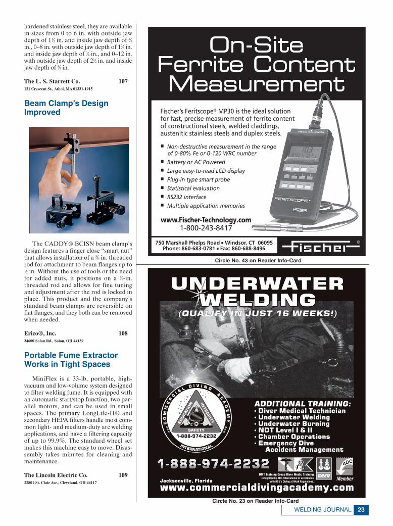
Beam Clamp’s DesignImproved
The CADDY® BCISN beam clamp’sdesign features a finger close “smart nut”that allows installation of a 3⁄8-in. threadedrod for attachment to beam flanges up to1⁄2 in. Without the use of tools or the needfor added nuts, it positions on a 3⁄8-in.threaded rod and allows for fine tuningand adjustment after the rod is locked inplace. This product and the company’sstandard beam clamps are reversible onflat flanges, and they both can be removedwhen needed.
Erico®, Inc. 10834600 Solon Rd., Solon, OH 44139
Portable Fume ExtractorWorks in Tight Spaces
MiniFlex is a 33-lb, portable, high-vacuum and low-volume system designedto filter welding fume. It is equipped withan automatic start/stop function, two par-allel motors, and can be used in smallspaces. The primary LongLife-H® andsecondary HEPA filters handle most com-mon light- and medium-duty arc weldingapplications, and have a filtering capacityof up to 99.9%. The standard wheel setmakes this machine easy to move. Disas-sembly takes minutes for cleaning andmaintenance.
The Lincoln Electric Co. 10922801 St. Clair Ave., Cleveland, OH 44117
23WELDING JOURNAL
Circle No. 23 on Reader Info-Card
Circle No. 43 on Reader Info-Card
New Products 12/04corr 11/8/04 3:25 PM Page 23
AWS FOUNDATION
Highlights of 2004The Foundation, along with Section support,surpassed $340,000 in scholarship and fellowshipfunding, serving nearly 350 students.
The Foundation has established four additionalscholarships this year. The Donald and ShirleyHastings which awards $2,500 to a student pursuing a four-year degree in welding engineeringor welding engineering technology; the ITWWelding Companies Scholarship, whichawards two $3,000 scholarships to students pursuing a four-year degree in welding engineeringtechnology or welding engineering, with a prefer-ence for WET at Ferris State University; and theRobert L. Peaslee – Detroit Brazing &Soldering Division Scholarship which awards$2,500 to an individual pursuing a minimum four-year degree in welding engineering or welding engineering technology with an emphasison Brazing and Soldering applications.
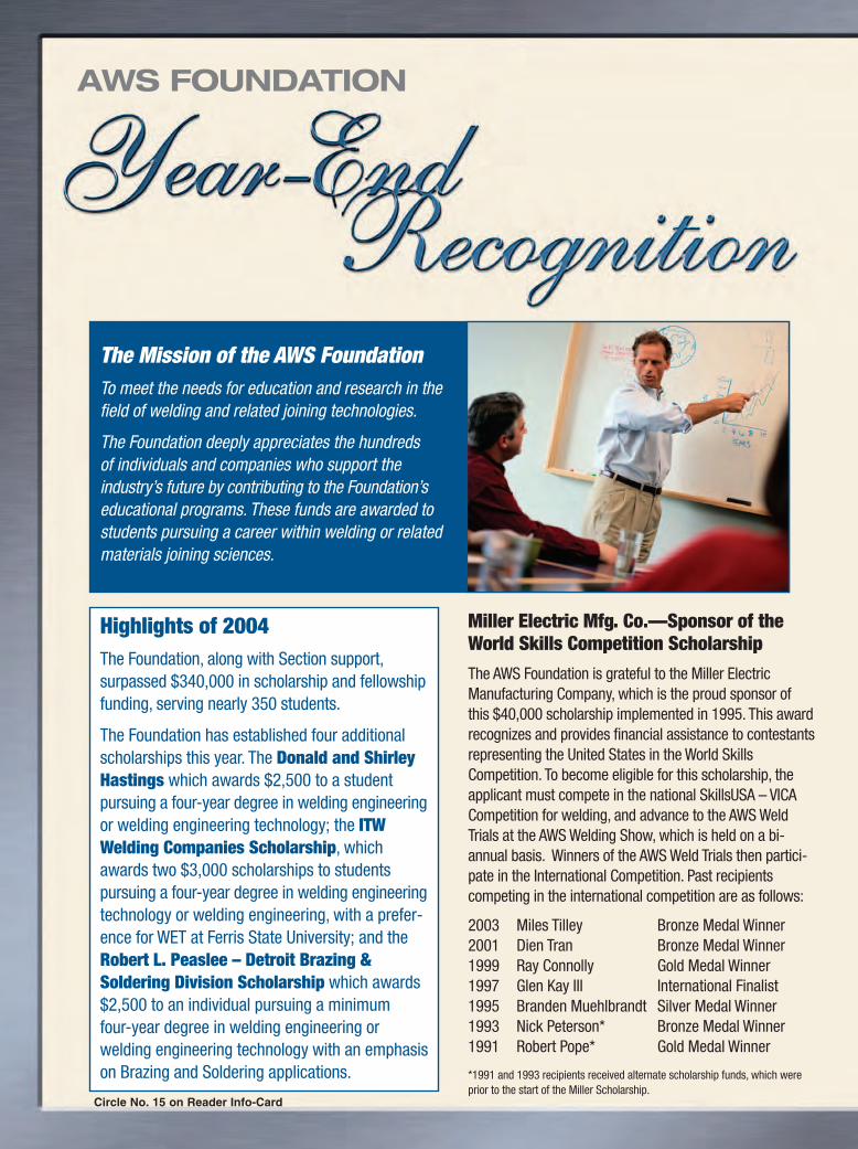
The Mission of the AWS FoundationTo meet the needs for education and research in thefield of welding and related joining technologies.
The Foundation deeply appreciates the hundreds of individuals and companies who support the industry’s future by contributing to the Foundation’seducational programs. These funds are awarded tostudents pursuing a career within welding or relatedmaterials joining sciences.
Miller Electric Mfg. Co.—Sponsor of theWorld Skills Competition ScholarshipThe AWS Foundation is grateful to the Miller ElectricManufacturing Company, which is the proud sponsor ofthis $40,000 scholarship implemented in 1995. This awardrecognizes and provides financial assistance to contestantsrepresenting the United States in the World SkillsCompetition. To become eligible for this scholarship, theapplicant must compete in the national SkillsUSA – VICACompetition for welding, and advance to the AWS WeldTrials at the AWS Welding Show, which is held on a bi-annual basis. Winners of the AWS Weld Trials then partici-pate in the International Competition. Past recipientscompeting in the international competition are as follows:
2003 Miles Tilley Bronze Medal Winner2001 Dien Tran Bronze Medal Winner1999 Ray Connolly Gold Medal Winner1997 Glen Kay III International Finalist1995 Branden Muehlbrandt Silver Medal Winner1993 Nick Peterson* Bronze Medal Winner1991 Robert Pope* Gold Medal Winner
*1991 and 1993 recipients received alternate scholarship funds, which wereprior to the start of the Miller Scholarship.
Circle No. 15 on Reader Info-Card
Page 24&25 11/10/04 11:42 AM Page 24

© American Welding Society 2004 FDN1150
INDIVIDUALS Wilma J. AdkinsOsama Al-ErhayemRichard AmirikianRichard L. ArnRoman F. ArnoldyHil J. BaxD. Fred BovieWilliam A. and Ann M. BrothersJoseph M. and Debbie A. CilliDonald E. and Jean ClevelandJack and Jo DammannMr. and Mrs. J. F. DammannLouis DeFreitasFrank G. DeLaurierWilliam T. DeLongRichard D. FrenchGlenn J. GibsonJoyce E. HarrisonDonald F. and Shirley HastingsRobb F. HowellJeffrey R. HufseyJoseph R. JohnsonDeborah H. KurdJ. J. McLaughlinL. William and Judy MyersRobert and Annette O’BrienRobert L. PeasleeRonald C. PierceJerome L. RobinsonRobert and Mitzie RoedigerRay W. ShookMyron and Ginny StepathCharley A. StoodyR. D. Thomas, Jr.James A. Turner, Jr.Gerald and Christine UttrachiNelson WallAmos O. and Marilyn WinsandNannette Zapata
CORPORATIONSAirgasAir Liquide America CorporationAir Products and Chemicals, Inc.American Welding SocietyCaterpillar, Inc.Chemalloy Company, Inc.C-K WorldwideCor-Met, Inc.ESAB Welding & Cutting ProductsEdison Welding InstituteEutetic CastolinThe Fibre-Metal Products CompanyGases and Welding DistributorsAssociation
Gibson Tube, Inc.Malcolm T. Gilliland, Inc.Gullco International, Inc.Harris Calorific, Inc.High Purity GasHobart Brothers Company
- Corex- McKay Welding Products- Tri-Mark
Hypertherm, Inc.Illinois Tool Works CompaniesIndependent Can CompanyInweld CorporationThe Irene & George A. DavisFoundationJ. W. Harris Company, Inc.Kirk FoundationKobelco Welding of America, Inc.The Lincoln Electric CompanyThe Lincoln Electric FoundationMK Products, Inc.Matsuo Bridge Co. Ltd.Miller Electric Mfg. Co.Mountain Enterprises, Inc.National Electric Mfg. AssociationNational Welders Supply CompanyNavy Joining CenterNORCO, Inc.ORS NASCO, Inc.OXO Welding Equipment CompanyPferd, Inc.Praxair Distribution, Inc.Roberts Oxygen Company, Inc.Saf-T-CartSelect-Arc, Inc.SESCOShell Chemical LP - WTCThermadyne Holdings CorporationTrinity Industries, Inc.Uvex Safety, Inc.Webster, Chamberlain & BeanWelding Engineering Supply Co., Inc.Weldstar CompanyWolverine Bronze Company
We would like to thank the following Major Donors who have supported theFoundation's activities:
Services and Programs Offered by the AWS Foundation
NATIONAL SCHOLARSHIP PROGRAMHoward E. Adkins Memorial ScholarshipAirgas – Jerry Baker ScholarshipAirgas – Terry Jarvis Memorial ScholarshipArsham Amirikian Engineering ScholarshipEdward J. Brady Memorial ScholarshipWilliam A. and Ann M. Brothers ScholarshipDonald F. Hastings ScholarshipDonald and Shirley Hastings ScholarshipWilliam B. Howell Memorial ScholarshipHypertherm – International HyTech Leadership ScholarshipITW Welding Companies ScholarshipsJohn C. Lincoln Memorial ScholarshipMatsuo Bridge Company, Ltd. of Japan ScholarshipMiller Electric World Skills Competition ScholarshipPraxair International ScholarshipRobert L. Peaslee Brazing & Soldering ScholarshipJerry Robinson – Inweld Corporation ScholarshipJames A. Turner, Jr. Memorial Scholarship
SECTION NAMED SCHOLARSHIPAmos and Marilyn Winsand – Detroit Section Named Scholarship
SCHOLARSHIP PROGRAMS IN DEVELOPMENTJack R. Barckhoff ScholarshipDonald and Jean Cleveland-Willamette Valley ScholarshipGold Collar ScholarshipRobert L. O’Brien Memorial ScholarshipRonald C. Pierce ScholarshipTed B. Jefferson ScholarshipThermadyne Industries Scholarship
AWS INTERNATIONAL SCHOLARSHIPGRADUATE RESEARCH FELLOWSHIPSGlenn J. Gibson FellowshipMiller Electric FellowshipNavy Joining Fellowship (2)
HISTORY OF WELDING CDThis CD provides a story of welding history, stressing the importance of welding and the critical shortage ofskilled manpower.
EDUCATIONAL TOOLSEngineering Your FutureWelding So Hot It’s Cool Video/CDHot Careers in Welding Video
Page 24&25 11/10/04 11:42 AM Page 25

Bay Bridge PutsNew Gas Mixtures
to the Test
DECEMBER 200426
Since the creation of gas metal arcwelding (GMAW) in the early 1920s andits implementation in 1948, shielding gasmixtures have played a critical role in theapplication and development of thisimportant welding process. As related arcwelding processes have progressed, fluxcored and metal cored arc welding haveevolved with literally hundreds of fillermetal and gas mixture choices. One pointhas proved crucial with improvements inwire welding. The cylinder gas mixturequality and consistency have become ascritical a component to these weldingprocesses as the electricity provided fromthe power source. Without reliability ineither one, the other doesn’t work verywell.
Manufacturers in the welding industryhave experienced the evolution of thesemixtures and the value they add to their
processes over the last few decades.Certainly there are endless applicationsand special considerations that each indi-vidual involved in making a gas choicemust consider. The major gas companiesand their distributors have developedthrough research, experience, and fieldtrials a wide selection of products to meetthese needs.
Making Sense of theOptions
So what can a fabricator do to makesense of all the choices available in shield-ing gas mixtures? Traditional componentsof the GMAW and flux cored arc welding(FCAW) processes have been argon andcarbon dioxide for carbon steel. Today,advanced three-part mixtures includeadditions of oxygen, carbon dioxide, orhelium with the balance gas being argon.These are increasingly used in the placeof traditional single- or two-part mix-tures. These changes have resulted inimproved appearance, mechanical prop-erties, and deposition rates as well as
increased travel speeds. Even newerdevelopments are beginning to enter themarket with small additions of nitrogen inspecific mixtures.
To maximize overall productivity,manufacturers are faced with numerousoptions with traditional GMAW orFCAW. This is where the right gas mix-tures designed to optimize speed, appear-ance, and deposition rate in all positionshave evolved for a given filler metal anddiameter and weld size. While there isnever a “one-size-fits-all” solution, com-binations of optimized gas componentshave been developed to address themajority of concerns a fabricator mayhave in most welding situations.
An example of a critical job wherethese criteria were taken into considera-tion was for the San Francisco Bay BridgeProject in California.
History of the BridgeProject
You may remember the Loma Prietaearthquake that occurred in October
BRYAN O’NEIL is U.S. Cylinder BusinessDevelopment Manager, Air Liquide Amer-ica, L.P., (713) 624-8000. MARVIN E.RODGERS III is General Manager, Al-liance Gas Products, Oakland, Calif., (510)663-9353.
The new Bay Bridge is seen in this artist rendering. It is scheduledfor completion in 2009. (Photo courtesy of CALTRANS.)
Many factors should be
considered when selecting
shielding gases
BY BRYAN O’NEIL AND MARVIN E. RODGERS III
O'Neill Feature for 12/04 11/4/04 8:58 AM Page 26

1989 during the World Series, or the hor-rific pictures and videos that were takenin the San Francisco and Oakland area ofthe collapsed Cypress Freeway. Althoughthe Cypress Freeway has since been relo-cated and reconstructed, many peopledon’t realize that some 15 years later, theresidents of the Bay area are still crossingthe same bridge.
After an extensive study of the spanwhere a section collapsed in 1989, theCalifornia Department of Transportation(CALTRANS) determined that it was notfeasible to simply retrofit the easternspan of the Bay Bridge to protect it fromearthquake damage; instead, a new east-ern span would need to be constructed.
In a section of the country famous formajestic bridges and city skylines, thereplacement span could not simply beanother traditional trestle bridge. Thesuccessful design turned out to be a com-bination skyway and suspension bridge.The bridge will be the world’s first single-tower, self-anchored suspension bridge.In addition, the new span, which featuressome of the largest and heaviest compo-nents ever seen in bridge building, needsto exceed the safety requirements setforth to become an earthquake-resistantbridge build.
Project Hits theMarketplace
It’s not often that a supplier gets toparticipate in one of the most expensivepublic works projects ever undertaken inthe United States, so when the SanFrancisco Bay Bridge general contractingjoint venture of Kiewitt, Flatiron, andManson (KFM, LLC) presented arequest for a gas supply to the industrialgas and welding supply distributors in theSan Francisco Bay Area, everyone tooknotice. To win this award, it would be nec-essary to address all of the unique chal-lenges that KFM and the regulatory agen-cies were going to impose upon the suc-cessful gas supplier. This hurdle could notbe met with traditional gas packages, mix-tures, and tolerances.
Alliance Gas Products of Oakland,Calif., had been supplying one of the BayBridge’s joint venture partners at anotherbridge project in Benicia, Calif., about 40miles away. So when it received its bidpackage, Alliance Gas Products initiallyassumed it could use the one bridge proj-ect as a template for the other. However,the challenges and requirements for thetwo bridges were very different. It was ini-tially assumed that the volumes of gasrequired for the welding operations wouldrequire a traditional method of gas supply(dewars) in conjunction with an on-sitegas mixer. But, as the company tried towork through the requirements of the
project, it became increasingly apparentthat a new approach would be needed.
The ChallengesThe 1993 Northridge earthquake in
southern California raised many concernsregarding welding procedures for publicworks structures. The filler metal andconstruction industries have respondedby creating new products and proceduresto ensure mechanical integrity will exceedthe design requirements. In addition,shielding gases have not been overlooked.CALTRANS has considered shieldinggases just as important a contributor asany other material to the mechanicalproperties of the final weldment.
To ensure repeatability and certifica-tion of weld procedures, CALTRANS setstandards it would be willing to accept forgas purity and mixture tolerance. In addi-tion, it wanted the welding gas “at thearc” to be traceable, and to also be certi-fied for purity and mixture accuracy.
There were logistics challenges aswell. KFM needed to complete all of thework from barge platforms. All the gaseshad to be transported to the barge fromthe shore or supply barge via crane.Crane time was scarce, and gas move-ment could not be scheduled on a dailybasis. Operationally, the company couldnot run out of product once welding start-ed, so it needed a package that wouldhold product without venting for anindefinite period of time. More impor-tantly, workers needed accuracy andtraceability of contents to ensure KFMwas receiving the product specified withinthe welding procedures.
A Special Consideration:Confined Space Welding
What is most evident in the welding ofpiles and footings used to support thebridge is their mammoth diameter andthe depth at which these components areset. A typical weld joint is 6 ft long andconsists of a double-V partial-penetrationjoint detail.
Approximately 35 weld passes takeplace on each joint, with more than 5000joints to complete — Fig. 1. That meansproduction of more than 30,000 ft of weldon thicker than 2-in. plate, welding uphillusing semiautomatic FCAW equipment.Job completion relies on the expertise ofa team of welders and welding engineers,like Dave Polette and Doug Silverwoodfrom Flat Iron Constructors and GeneralConstruction. Both Polette andSilverwood oversee the day-to-day issuesthat arise as a result of confined spacewelding protocol — Figs. 2, 3. Eachmorning at the beginning of a shift andthroughout the day, air monitors and air-
27
Fig. 1 — A welding operator monitors theuphill FCA welding with Blueshield withinthe internal section of bridge piling. This isone of more than 5000 weld jointsrequiring 35 or more passes each to becompleted on the Bay Bridge project. Thebase material thickness is in excess of 2 in.in some joints. Preheating is done byelectrical means. Gas quality is ensured atthe welding gun for this complexapplication.
Fig. 2 — Working in confined spaces at theBay Bridge site brought new challenges forwelding teams, requiring calesthenics aspart of their workday. Here, the Pier 16Enight welding crew warms up beforedropping into the cofferdam in May 2003.(Photo courtesy of KWT.)
Fig. 3 — A welder is hard at work inside apiling at the new Bay Bridge site. (Photocourtesy of KWT.)
WELDING JOURNAL
O'Neill Feature for 12/04 11/4/04 8:58 AM Page 27

DECEMBER 200428
exchanging equipment are used to meas-ure the oxygen content and replace theatmosphere with fresh air. Since there islittle room for additional equipment, theconstruction group needed to choose aninnovative package and mixture to assistin achieving the desired results.
Alliance contacted its partner, AirLiquide, to address the needs of the spe-cific customer requirements. Workingtogether, both companies reviewed thestringent requirements of the contractorsand governing agency. Looking at pastsuccess in similar applications, a uniquepatented assembly and high-quality cylin-der brand name, Blueshield™, was cho-sen. This provided the features of innova-tive package design, safety in handling,reliability in service, and, most important-ly, traceability of each package back tothe original gas analysis at the fill plant.The value of a premium mixture used incombination with proper weld parame-ters provided the company with easy slagremoval and higher travel speed out ofposition. Welding on the bridge com-menced in April 2003 and is scheduled toend May 2005. With almost five miles ofwelding scheduled, innovative gas use willresult in a much shorter welding time andmore time spent depositing weld metal,with less time spent worrying about gasmixture quality and handling.
ConclusionIt is important for fabricators to
undertake a thorough analysis of shield-ing gas mixtures that includes the follow-ing:
• Test the product being considered overa trial period in production and not justin a demonstration.
• Measure and track results. Also, makesure the packaging and quality processis in place, particularly when consider-ing AWS and ASME codes and bridgeand marine specifications.
• Look for safety enhancements or han-dling advantages offered to improvethe welder’s environment.
• Lastly, ensure that you are meeting orexceeding the mechanical require-ments of the gas and filler metal com-bination and a program is in place fortraceability of the productpurchased.◆
2005 Welding Journal Editorial CalendarEditorial Deadline
January • Resistance Welding Today Nov. 22• Trends in Welding Automation: Robots,
Sensors, Equipment
February • Welding Thin Metals Dec. 17• Building Bridges with Better Processes
and Techniques
March • Educating the Next Generation of Welders Jan. 17• Technology Transfer: From the Lab to the
Shop Floor• Products for Metal Cutting
April • Preview of the 2005 AWS Show Feb. 18
May • Choosing the Right Filler Metal for the Job March 18• Developments in Thermal Spraying• Bonus: The American Welder Supplement
June • Technologies to Carry Joining into the Future April 15• Pipe and Tube Welding
July • Understanding the Heat-Affected Zone for May 16Improved Quality
• Developments in Power Supplies
August • What’s New in Laser Welding and Cutting? June 17• What Makes a Winning Weld: Tips from the Pros• Essen Welding Fair Preview
September • Welding Customized Motorcycles July 15• Preventing and Detecting Weld Cracking• Apparel for Safety and Productivity
October • Special Emphasis: Brazing and Soldering Aug. 19• Bonus: The American Welder Supplement
November • Building Our Energy Infrastructure Sept. 16• Underwater Welding• AWS Welding Show/FABTECH preview
December • Marine Construction Oct. 17• Architectural and Ornamental Welding
O'Neill Feature for 12/04 11/4/04 8:58 AM Page 28

To: Professors Engaged in Joining Research
Subject: Request for Proposals for AWS Fellowships for the 2005-06 Academic Year
The American Welding Society (AWS) seeks to foster university research in joining and to recognize outstanding facultyand student talent. We are again requesting your proposals for consideration by AWS.
It is expected that the winning researchers will take advantage of the opportunity to work with industry committeesinterested in the research topics and report work in progress.
Please note, there are important changes in the schedule which you must follow in order to enable the awards to bemade in a timely fashion. Proposals must be received at American Welding Society by January 10, 2005. New AWSFellowships will be announced at the AWS Annual Meeting, April 26-28, 2005.
THE AWARDS
The Fellowships or Grants are to be in amounts of up to $25,000 per year, renewable for up to three years of research.However, progress reports and requests for renewal must be submitted for the second and third years. Renewal by AWS will becontingent on demonstration of reasonable progress in the research or in graduate studies.
The AWS Fellowship is awarded to the student for graduate research toward a Masters or Ph.D Degree under asponsoring professor at a North American University. The qualifications of the Graduate Student are key elements to beconsidered in the award. The academic credentials, plans and research history (if any) of the student should be provided.The student must prepare the proposal for the AWS Fellowship. However, the proposal must be under the auspices ofa professor and accompanied by one or more letters of recommendation from the sponsoring professor or others acquaintedwith the student’s technical capabilities. Topics for the AWS Fellowship may span the full range of the joining industry. Shouldthe student selected by AWS be unable to accept the Fellowship or continue with the research at any time during the periodof the award, the award will be forfeited and no (further) funding provided by AWS. The bulk of AWS funding should be forstudent support. AWS reserves the right not to make awards in the event that its Committee finds all candidates unsatisfactory.
DETAILS
The Proposal should include:
1. Executive Summary2. Annualized Breakdown of Funding Required and Purpose of Funds (Student Salary, Tuition, etc.)3. Matching Funding or Other Support for Intended Research4. Duration of Project5. Statement of Problem and Objectives6. Current Status of Relevant Research7. Technical Plan of Action8. Qualifications of Researchers9. Pertinent Literature References and Related Publications10. Special Equipment Required and Availability11. Statement of Critical Issues Which Will Influence Success or Failure of Research
In addition, the proposal must include:
1. Student’s Academic History, Resume and Transcript2. Recommendation(s) Indicating Qualifications for Research3. Brief Section or Commentary on Importance of Research to the Welding Community and to AWS,
Including Technical Merit, National Need, Long Term Benefits, etc.4. Statement Regarding Probability of Success
The technical portion of the Proposal should be about ten typewritten pages. Proposal should be sent electronically byJanuary 10, 2005, to:
Gricelda Manalich ([email protected])Executive Assistant, Board Services/IIWAmerican Welding Society550 N.W. LeJeune Rd., Miami, FL 33126
Yours sincerely,
Ray W. ShookExecutive DirectorAmerican Welding Society
AWS Fellowships
Page 29 11/9/04 2:54 PM Page 29
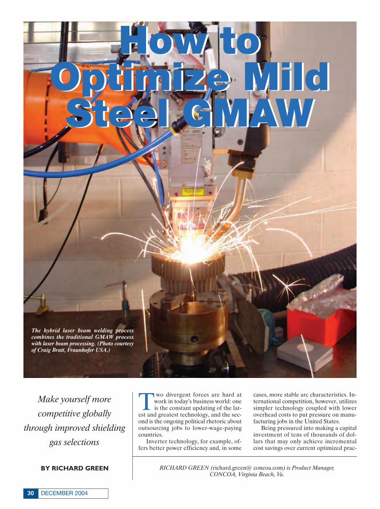
DECEMBER 200430
Two divergent forces are hard atwork in today’s business world: oneis the constant updating of the lat-
est and greatest technology, and the sec-ond is the ongoing political rhetoric aboutoutsourcing jobs to lower-wage-payingcountries.
Inverter technology, for example, of-fers better power efficiency and, in some
cases, more stable arc characteristics. In-ternational competition, however, utilizessimpler technology coupled with loweroverhead costs to put pressure on manu-facturing jobs in the United States.
Being pressured into making a capitalinvestment of tens of thousands of dol-lars that may only achieve incrementalcost savings over current optimized prac-
RICHARD GREEN (richard.green@ concoa.com) is Product Manager, CONCOA, Virginia Beach, Va.
How toOptimize MildSteel GMAW
How toOptimize MildSteel GMAW
Make yourself more
competitive globally
through improved shielding
gas selections
BY RICHARD GREEN
The hybrid laser beam welding process combines the traditional GMAW processwith laser beam processing. (Photo courtesyof Craig Bratt, Fraunhofer USA.)
Concoa article 12/04 11/5/04 12:30 PM Page 30

31WELDING JOURNAL
tices is obviously a pitfall to avoid. In-stead, American business and its employees can offer the world the inge-nuity it takes to produce quality weld-ments cost-competitively.
What follows is a strategy for optimiz-ing the cost to produce a mild steel gasmetal arc weldment. This includes evalu-ating the mode of transfer as well as laborand overhead rates, deposition efficiency,electrode cost, and power consumption.It also shows the gas system required toobtain a competitive rate using existingassets.
To begin, the three basic modes ofmetal transfer for a gas metal arc welding(GMAW) procedure as classified by cur-rent range need to be understood. Figure1 illustrates the approximate currentranges for the three modes of transfer forboth 0.035- and 0.045-in.-diameter solidwire. Short-circuiting arc occurs between60 and 175 A for 0.035 wire, and 90 to 220A for 0.045 wire. Short-circuiting arc weld-ing offers low thermal input, which facili-tates welding in all positions and reducespart distortion. Metallurgical propertiesare not adversely affected by the low en-ergy input and subsequent dilution of thebase material.
Figure 2 illustrates the voltage and cur-rent relationship as the metal is trans-ferred from the wire to the workpiece. Asthe wire is fed into the weld pool, the tipof the wire connected to the positive ter-minal of the power supply comes in con-tact with the workpiece that is connectedto the negative terminal, and a short is cre-ated in the circuit. The welding machineoutput current rises to a minimum currentlevel of 320 A for 0.035 wire, and 370 Afor 0.045 wire, to separate it from the weldpool. The short-circuit process will occur50 to 230 times per second depending onprocess design.
Welding machine manufacturers havedeveloped both fixed and variable slopewelding power supplies to control the out-put voltage with increasing amperage.This limits the maximum energy availableto separate the wire from the pool. If thereis too much energy, the result is excessivespatter, which lowers the deposition effi-ciency; with too little energy, the wire pilesup, resulting in incomplete fusion andpoor weld quality.
Secondly, welding equipment manu-facturers have developed both fixed andvariable inductance to control the rate ofthe current rise as illustrated by the cur-rent curve sequence A-B in Fig. 2. As in-ductance is increased, the amount of arc-ing time also increases as illustrated bythe voltage curve sequence E-H in Fig. 2.The additional arc-on time produces amore fluid weld pool, which yields a flat-ter weld bead with better wetting at theedges. In turn, this affects the cosmeticsand load-bearing capacity of the joint.
The proper selection of shielding gaswill drastically affect the energy transferand deposition efficiency of the GMAWshort-circuit transfer mode. Carbon diox-ide was the first shielding gas used becauseof its availability and cost. The arc plasmahas a narrow inner core and a low outertemperature envelope resulting from itslow thermal conductivity that producesnarrow and deep penetration. This pres-ents problems for thin materials.
More expensive GMAW wire contain-ing higher amounts of deoxidizing ele-ments is typically needed to balance theoxidizing nature of carbon dioxide. Also,because of centerline crowning and exces-sive spatter that result in 85 to 95% dep-osition efficiencies, manufacturers devel-oped binary mixtures of argon and carbondioxide.
Additions of up to 80% argon (with the
balance being carbon dioxide) will pro-duce less crowning, better edge tie-in, and94 to 98% deposition efficiencies. Argonadditions offer better arc ignition and sta-bility based on argon’s low ionization po-tential. Argon has a low thermal conduc-tivity that yields similar arc constrictionbut a shallower penetration profile thancarbon dioxide. Plus, argon-carbon diox-ide mixtures yield higher deposition rateswith less spatter, which is ideal for all-position welding and thin materials.
As additional welding current is ap-plied, the end of the welding wire becomesoverheated and balls up 1.5 to 3 times thewire diameter. This establishes a longerarc length as illustrated in sequence F-Hof Fig. 2. Gravity facilitates the metaltransfer, which creates instability and ex-cessive spatter. Deposition efficiencytends to fall between 80 and 90% depend-ing on gas selection and processing pa-rameters. For this reason and welding po-sition limitations, it is wise to stay outsidethe globular transition range of 160 to 185 A for 0.035 wire, and 200 to 220 A for0.045 wire.
Depending on the gas selection, theminimum transition current for spraytransfer occurs between 155 and 195 A for0.035 wire, and 220 and 250 A for 0.045wire. Above this transfer range, the endof the wire electrode develops a taper thatemits fine droplets of metal across the arcwith virtually no spatter, yielding 97 to99% deposition efficiencies. The spraytransfer yields higher travel speeds anddeposition rates because of the superiorarc stability and high droplet rate. How-ever, the high heat input limits the weld-ment to the flat position.
Choosing the optimal shielding gas forspray transfer takes some forethought tounderstand the application and effectseach gas component will contribute to the
Fig. 1 — The approximate current ranges include the threemodes of transfer for both 0.035- and 0.045-in.-diametersolid wire.
Fig. 2 — This graph illustrates voltage and current relationship through a short-circuiting arc sequence transfer. (Reprinted from AWS C5.6-89R, Recom-mended Practices for Gas Metal Arc Welding, p. 6.)
.045” spray
.045” globular.045” short-
circuiting arc.035” spray
.035” globular.035” short-
circuiting arc
Transfer Mode Current Range
Concoa article 12/04 11/5/04 12:30 PM Page 31

deposition efficiency and cost, environ-mental, and mechanical properties.
Pure argon produces higher arc volt-age and subsequent longer arc lengths,which create arc instability and excessiveundercut at the edge of the welds. For thisreason, 5 to 20% carbon dioxide is addedto create an argon mixture that stabilizesthe spray transfer. It is well documentedthat the lower the amount of carbon diox-ide concentration, the lower the minimumspray transfer current and subsequentfume generation rates.
It should also be noted that 8 to 15%carbon dioxide mixtures are flexibleenough to facilitate both spray and short-circuit transfer modes. In some cases, 1 to5% oxygen may be added to argon toachieve superior arc stability and bettertie-in (wetting) at the weld edge. Oxygentends to provide a wider but shallowerpenetration profile, as compared to car-bon dioxide mixtures, because of its lowerionization and higher thermal conductiv-ity properties. Oxygen additions tend toyield better toughness and strengths be-cause of the absence of carbon retentionassociated with carbon dioxide mixtures.Shielding gas development has led manu-facturers to design three-component gasblends that offer the benefits of both car-bon dioxide and oxygen additions toargon-based mild steel gas metal arc applications.
As mentioned previously, each com-pany must evaluate the incremental ben-efits of three-component mixtures as com-pared to two. In most cases, attention toquality and continually training person-nel to meet the basic processing parame-
ters will yield the greatest return with min-imal investment.
For example, assume that the weld-ment is a 1⁄4-in. mild steel, 12-in. fillet weldrequiring 0.106 lb/ft of welding wire. Cur-rent practice calls for a 0.045-in.-diame-ter wire using 75% argon balance carbondioxide. It is assumed that the wire costs$0.80 per pound on a 33-lb spool, and thetypical labor and overhead rate is $40/h.There is a total of ten weld stations eachusing a single “T-size” (330 ft3) high-pres-sure bottle. The company uses eight bot-tles per week at a cost of $18 each. Themanual welding is performed utilizingconventional short-circuit parameters setat 20 V/200 A, yielding a deposition rateof 5.5 lb/h at 96% efficiency.
In today’s market, it is also safe to as-sume that the company is receiving pric-ing pressure from international competi-tors. Utilizing existing equipment and pro-viding the required training, the proce-dure is changed to a spray transfer withthe following parameters listed below.
The shielding gas is changed to 92%argon, balance carbon dioxide. The weld-ing machine parameters are 29 V/300 A,which provide a deposition rate of 9.7 lb/hwith a 98% efficiency. The economic re-sults displayed in Table 1 show that a 38%cost reduction per foot of weld is achiev-able because of the higher deposition rateand efficiency of a spray transfer. As well,Table 1 illustrates that an additional 6%in cost savings can be realized by mixingthe argon-carbon dioxide shielding gason-site.
Simple blending systems as illustratedin Fig. 3 enable the company to realize ad-
ditional duty cycle or productivity savingsby eliminating daily cylinder handling.
Finally, the on-site blending system en-ables the company to adjust the ratio ofcarbon dioxide in the shielding gas, whichwill have a positive effect on the weld-ment’s mechanical properties and workenvironment.
With American business facing somuch competitive pressure today, it is nec-essary to look for the “lowest hangingfruit” to reduce production costs and en-hance the quality of products. Gettingback to the basics will further enhance theincremental cost savings of future invest-ment in technology. To achieve such re-sults, solutions as simple as evaluating themode of transfer for a gas metal arc weldand the gas delivery system are importantin the highly competitive global market-place.◆
DECEMBER 200432
Table 1 — Economic Comparison
Short-Circuiting Arc Spray Transfer On-Site MixingGas System
Labor and Overhead ($/h) 40 40 40Deposition Rate (lb/h) 5.5 9.7 9.7Duty Cycle (%) 0.4 0.4 0.45Electrode Cost ($/lb) 0.8 0.8 0.8Deposition Efficiency (%) 0.96 0.98 0.98Gas Flow Rate (ft3/h) 35 40 40Gas Cost (dollars per hundred cubic feet) 5.45 6.06 5.28Electrical Cost (kWh) 0.06 0.06 0.06Machine Volts 20 29 29Machine Amps 200 300 300Travel Speed (in./min) 9 15 15
Cost per Foot of Weld
Labor and Overhead 2.22 1.33 1.19Wire Cost 0.09 0.09 0.09Shielding Gas Cost 0.04 0.03 0.03Power Cost 0.01 0.01 0.01Total Cost per Foot of Weld 2.36 1.46 1.31
Percent Cost Reduction 38.13% 44.59%
Fig. 3 — Simple blending systems allow foradditional duty cycle or productivity savingsby eliminating daily cylinder handling.
Change of Address?Moving?
Make sure delivery of your Welding Journal is not interrupted.Contact the Membership Depart-ment with your new address infor-mation — (800) 443-9353, ext. 480;[email protected].
ARE YOU UP TO STANDARD?www.aws.org/catalogs
Concoa article 12/04 11/5/04 12:30 PM Page 32

REGISTER FREE ONLINE AT WWW.AWS.ORG/EXPO OR CALL TOLL-FREE 877-868-5290
AWS Welding Show 2005April 26-28, Dallas, Texas
Dallas Convention CenterSponsored by the American Welding Society
© American Welding Society 2004 CON 1071
For the BIGGEST NEWS in welding,come to the BIGGEST welding show in the U.S.
★ ★ ★ ★ ★ ★ ★ ★ ★ ★ ★ ★ ★ ★ ★ ★ ★
BIG SHOW HIGHLIGHTS:★ More than 400 exhibits
★ Free sessions
★ Thousands of experts and highly-trained technical representatives
★ Hundreds of live demos
★ 2.6 million tons of equipment
★ Seven special pavilions
— Gas Products— Oilfield and Pipeline Equipment— Cutting and Grinding Products— Brazing and Soldering— Resistance Welding— Laser Welding and Cutting— Nondestructive Testing and Inspection
★ U.S. Open Weld Trials
★ Show-only deep discounts
★ And much more...
Circle No. 12 on Reader Info-Card
Page 33 11/9/04 5:09 PM Page 33
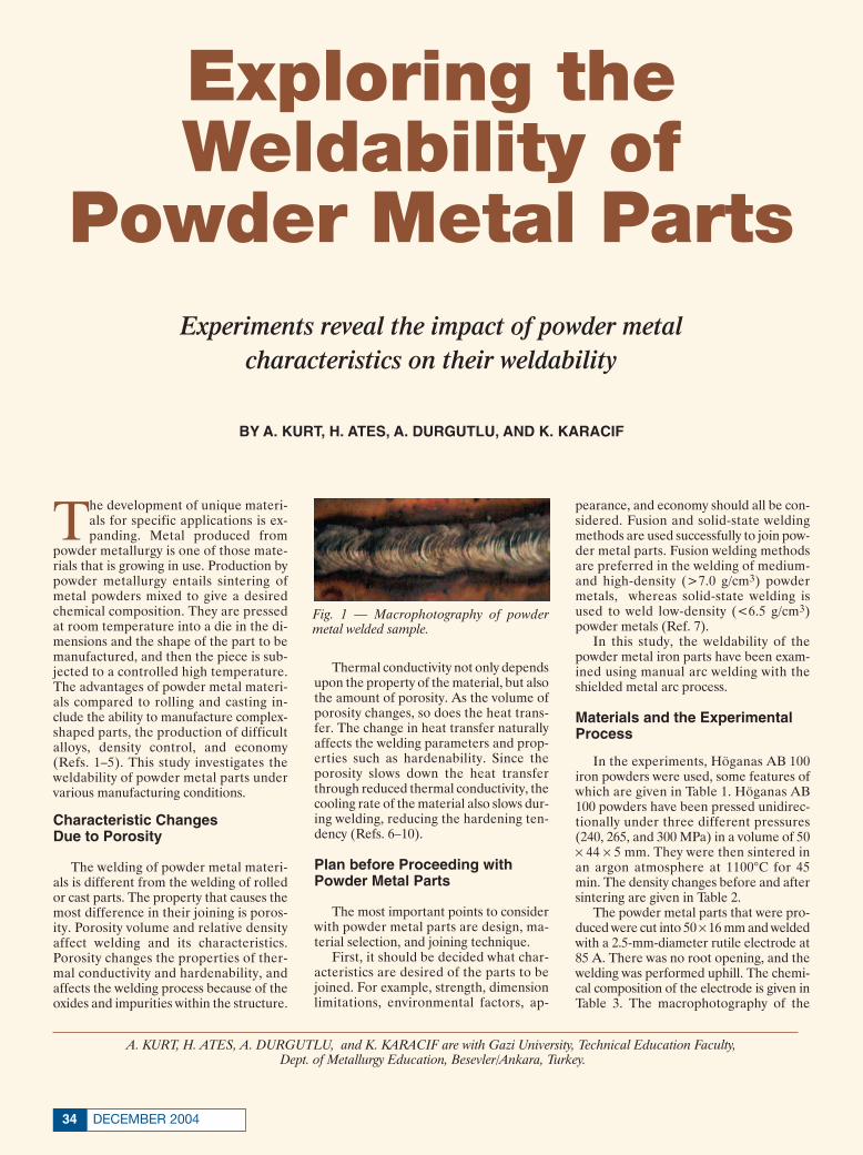
DECEMBER 200434
The development of unique materi-als for specific applications is ex-panding. Metal produced from
powder metallurgy is one of those mate-rials that is growing in use. Production bypowder metallurgy entails sintering ofmetal powders mixed to give a desiredchemical composition. They are pressedat room temperature into a die in the di-mensions and the shape of the part to bemanufactured, and then the piece is sub-jected to a controlled high temperature.The advantages of powder metal materi-als compared to rolling and casting in-clude the ability to manufacture complex-shaped parts, the production of difficultalloys, density control, and economy(Refs. 1–5). This study investigates theweldability of powder metal parts undervarious manufacturing conditions.
Characteristic Changes Due to Porosity
The welding of powder metal materi-als is different from the welding of rolledor cast parts. The property that causes themost difference in their joining is poros-ity. Porosity volume and relative densityaffect welding and its characteristics.Porosity changes the properties of ther-mal conductivity and hardenability, andaffects the welding process because of theoxides and impurities within the structure.
Thermal conductivity not only dependsupon the property of the material, but alsothe amount of porosity. As the volume ofporosity changes, so does the heat trans-fer. The change in heat transfer naturallyaffects the welding parameters and prop-erties such as hardenability. Since theporosity slows down the heat transferthrough reduced thermal conductivity, thecooling rate of the material also slows dur-ing welding, reducing the hardening ten-dency (Refs. 6–10).
Plan before Proceeding withPowder Metal Parts
The most important points to considerwith powder metal parts are design, ma-terial selection, and joining technique.
First, it should be decided what char-acteristics are desired of the parts to bejoined. For example, strength, dimensionlimitations, environmental factors, ap-
pearance, and economy should all be con-sidered. Fusion and solid-state weldingmethods are used successfully to join pow-der metal parts. Fusion welding methodsare preferred in the welding of medium-and high-density (>7.0 g/cm3) powdermetals, whereas solid-state welding isused to weld low-density (<6.5 g/cm3)powder metals (Ref. 7).
In this study, the weldability of thepowder metal iron parts have been exam-ined using manual arc welding with theshielded metal arc process.
Materials and the ExperimentalProcess
In the experiments, Höganas AB 100iron powders were used, some features ofwhich are given in Table 1. Höganas AB100 powders have been pressed unidirec-tionally under three different pressures(240, 265, and 300 MPa) in a volume of 50¥ 44 ¥ 5 mm. They were then sintered inan argon atmosphere at 1100°C for 45min. The density changes before and aftersintering are given in Table 2.
The powder metal parts that were pro-duced were cut into 50 ¥ 16 mm and weldedwith a 2.5-mm-diameter rutile electrode at85 A. There was no root opening, and thewelding was performed uphill. The chemi-cal composition of the electrode is given inTable 3. The macrophotography of the
Experiments reveal the impact of powder metal characteristics on their weldability
BY A. KURT, H. ATES, A. DURGUTLU, AND K. KARACIF
A. KURT, H. ATES, A. DURGUTLU, and K. KARACIF are with Gazi University, Technical Education Faculty,Dept. of Metallurgy Education, Besevler/Ankara, Turkey.
Exploring theWeldability of
Powder Metal Parts
Fig. 1 — Macrophotography of powdermetal welded sample.
Layout 11/4/04 8:48 AM Page 34

35WELDING JOURNAL
welded samples is presented in Fig. 1. Microstructure and hardness samples
were prepared from vertically cut couponsright after the joint was welded. The sam-ples were prepared for metallographic ex-amination by grinding (200–1200), polish-ing (with Al2O3), and etching with 2%nital. Photographs of the microstructurewere taken with an optical microscopeshowing the base metal, heat-affectedzone, and weld metal. Vickers hardnessvalues were taken using a 5-kg load fromthe regions shown in Fig. 2.
Results of the Investigation
Microstructure and Powder Metal Base Material
Density increases in powder metalparts as the pressure increases, althoughit is minimal after 90% of density isreached. At the lowest compaction pres-sure of 240 MPa, the density was meas-ured as 68.35%, at 265 MPa the densitywas 73.01%, and at 300 MPa it was72.86%. The slight decrease in density ob-served at 300 MPa is probably the resultthe powder particles hardening with theincreased compaction pressure. The hard-ened particles have a negative influenceon density.
No big decrease in density was ob-served after sintering, but a few factors doaffect an increase in density from sinter-ing. One of these is the outgassing of airfrom the cavities of porosity through thesintering process. Also, the weight of thesample diminished from the vaporizationof low-melting-point elements. It was ob-served that factors like these do not havemuch effect since a lubricant such as Znsterat was not added to the powders. If lu-bricants had been added, a density of morethan 80% would have been realized. Lu-bricant was not added for the purpose ofdetermining the weldability of powdermetals with porosity.
In the metallographic study, it was ob-served that porosity decreased as com-paction pressure increased in the powdermetal parts — Fig. 3.
A great amount of porosity was observedin the microstructure of the sample com-pacted at 240 MPa — Fig. 3A. The mate-rial is denser at 265 MPa of pressure — Fig.3B. It is observed in Fig. 3C that the den-
Fig. 2 — The regions where hardness values were taken.
Fig. 3 — Microstructures (100¥) of the pow-der metal iron parts compacted with vari-ous pressures. A — 240 MPa; B — 265 MPa;and C — 300 MPa.
Fig. 4 — Microstructures (50¥) of weld in-terface regions of powder metal iron partscompacted at various pressures. A — 240MPa; B — 265 MPa; and C — 300 MPa.
Table 1 — Features of Höganas AB 100 Iron Powders
Particle size Apparent Flow H2 loss C Green Strength Compressibilityrange (µm) density (g/cm3) (s/50 g) (%) (%) (N/mm2) (g/cm3)
at 600 MPa at 4.2 t/cm2 at 600 MPa≈20–180 3.04 24 0.10 < 0.10 33 6.72 7.17
A A
B B
C C
Layout 11/4/04 8:48 AM Page 35
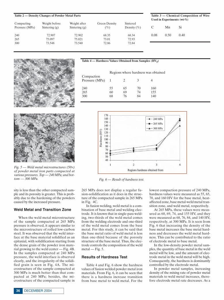
sity is less than the other compacted sam-ple and its porosity is greater. This is prob-ably due to the hardening of the powderscaused by the increased pressure.
Weld Metal and Transition Zone
When the weld metal microstructureof the sample compacted at 265 MPapressure is observed, it appears similar tothe microstructure of rolled low-carbonsteel. It was observed that the weld inter-face at the base material solidified as anepitaxial, with solidification starting fromthe dense grain of the powder iron mate-rial growing to the weld center — Fig. 4B.In the samples compacted at 240 MPapressure, the weld interface is observedclearly, and the irregularity of the solidi-fied grain is seen in Fig. 4A. The mi-crostructure of the sample compacted at300 MPa is much better than that com-pacted at 240 MPa; besides, the mi-crostructure of the compacted sample in
265 MPa does not display a regular fu-sion-solidification as it does in the struc-ture of the compacted sample in 265 MPain Fig. 4C.
In fusion welding, weld metal is a com-bination of base metal and welding elec-trode. It is known that in single-pass weld-ing, two-thirds of the weld metal comesfrom the welding electrode and one-thirdof the weld metal comes from the basemetal. For this study, it can be said thatthe base metal ratio of weld metal is lessthan one-third because of the porositystructure of the base metal. Thus, the elec-trode controls the composition of the weldmetal — Fig. 5.
Results of Hardness Test
Table 4 and Fig. 6 show the hardnessvalues of fusion welded powder metal ironmaterials. From Fig. 6, it can be seen thatthere is a hardness increase transitionfrom base metal to weld metal. For the
lowest compaction pressure of 240 MPa,hardness values were measured as 55, 65,70, and 160 HV for the base metal, heat-affected zone, base metal-weld metal tran-sition zone, and weld metal, respectively.
At 265 MPa, these values were meas-ured as 60, 69, 74, and 155 HV, and theywere measured as 68, 76, 84, and 140 HV,respectively, at 300 MPa. It is seen fromFig. 6 that increasing the density of thebase metal increases the base metal hard-ness and decreases the weld metal hard-ness. This can be contributed to the ratioof electrode metal to base metal.
In the low-density powder metal sam-ples, the quantity of base metal in the weldmetal will be low, and the amount of elec-trode metal in the weld metal will be high.Consequently, the hardness is dominantlycontrolled by the electrode metal.
In powder metal samples, increasingdensity of the mixing rate of powder metalmaterials to weld metal increases, there-fore electrode metal rate decreases. As a
DECEMBER 200436
Table 2 — Density Changes of Powder Metal Parts
Compacting Weight before Weight after Green Density Sintered Pressure (MPa) Sintering (g) Sintering (g) (%) Density (%)
240 72.907 72.902 68.35 68.34265 75.097 75.021 73.01 72.93300 73.548 73.540 72.86 72.84
Table 3 — Chemical Composition of WireUsed in Experiments (wt-%)
C Mn Si
0.08 0.50 0.40
Table 4 — Hardness Values Obtained from Samples (HV5)
Regions where hardness was obtainedCompactionPressure (MPa) 1 2 3 4
240 55 65 70 160265 60 69 74 155300 68 76 84 140
Fig. 5 — Weld metal microstructures (50¥)of powder metal iron parts compacted atvarious pressures. Top — 240 MPa; and bot-tom — 300 MPa. Fig. 6 — Result of hardness test.
Layout 11/4/04 8:48 AM Page 36

result of this, base metal hardness increaseswith increasing density, while weld metalhardness decreases with increasing density.
Conclusions
In this experimental study, the join-ablity of powder metal iron parts using amanual arc welding method have been in-vestigated with the following results.
1. The porosity of powder metal mate-rials decreased with increased compact-ing pressure.
2. Iron-based materials produced bypowder metallurgy were successfullyjoined using a manual welding method.
3. Aluminum powder metal materialsshowed more porosity and surface oxidesthan other metallic materials.
4. The rate of density did not changemore than the critical density (73%).®
References
1. Saritas, S. 1995. Powder steel forg-ing. METU Journal of Applied Research, 3(11): 1–26 ( in Turkish).
2. Demir, A., Saritas, S. 1993. Mechan-ical properties of powder metal steels. AUIsparta Journal of Mechanical Engineering,Vol. 7, pp. 1–13 ( in Turkish).
3. German, R. M., and Dangelo, K. A.1984. Enhanced sintering treatments forferrous powders. Int. Metals Rev., Vol. 29,pp. 249–272.
4. Metals Handbook, 9th Ed., Vol. 7.1984. Powder Metallurgy, pp. 23–99. Ma-terials Park, Ohio: ASM International.
5. German, R. M. 1984. Powder metal-lurgy science, pp. 9–55. Princeton, N.J.:Metal Powder Industries Federation.
6. Hamill, J. A. 1991. PM joiningprocesses materials and techniques. TheInt. J. of Powder Metallurgy, 27 (4):363–371.
7. Kurt, A., Gülenç, B., and Durgutlu,A. 1999. Investigation of HAZ in Rolle-PM Cu materials joined by fusion weld-ing methods. Second National Powder Met-allurgy Conference Proceedings, pp.565–570 (in Turkish).
8. Kurt, A., Gülenç, B., and Türker, M.1996. Investigation of weldability of PMparts compacted pure iron powder to low-carbon steel by MIG-MAG welding. FirstNational Powder Metallurgy ConferenceProceedings, pp. 595–602 ( in Turkish).
9. Hamil, J. A. Jr. 1993. What are thejoining processes, materials and tech-niques for powder metal parts? WeldingJournal 72(2): 37–45.
10. Dudas, J. H., and Dean, W. A. 1969.The production of precision aluminumP/M parts, Progress in Powder Metallurgy,Conference Proceedings, MPIF, Vol. 25, pp.101–129.
37WELDING JOURNALCircle No. 9 on Reader Info-Card
Circle No. 39 on Reader Info-Card
Layout 11/8/04 3:35 PM Page 37
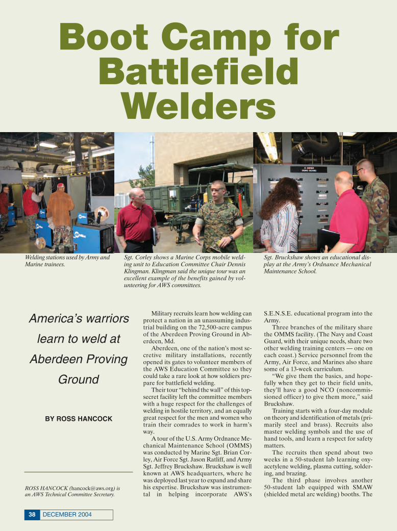
DECEMBER 200438
Military recruits learn how welding canprotect a nation in an unassuming indus-trial building on the 72,500-acre campusof the Aberdeen Proving Ground in Ab-erdeen, Md.
Aberdeen, one of the nation’s most se-cretive military installations, recentlyopened its gates to volunteer members ofthe AWS Education Committee so theycould take a rare look at how soldiers pre-pare for battlefield welding.
Their tour “behind the wall” of this top-secret facility left the committee memberswith a huge respect for the challenges ofwelding in hostile territory, and an equallygreat respect for the men and women whotrain their comrades to work in harm’sway.
A tour of the U.S. Army Ordnance Me-chanical Maintenance School (OMMS)was conducted by Marine Sgt. Brian Cor-ley, Air Force Sgt. Jason Ratliff, and ArmySgt. Jeffrey Bruckshaw. Bruckshaw is wellknown at AWS headquarters, where hewas deployed last year to expand and sharehis expertise. Bruckshaw was instrumen-tal in helping incorporate AWS’s
S.E.N.S.E. educational program into theArmy.
Three branches of the military sharethe OMMS facility. (The Navy and CoastGuard, with their unique needs, share twoother welding training centers — one oneach coast.) Service personnel from theArmy, Air Force, and Marines also sharesome of a 13-week curriculum.
“We give them the basics, and hope-fully when they get to their field units,they’ll have a good NCO (noncommis-sioned officer) to give them more,” saidBruckshaw.
Training starts with a four-day moduleon theory and identification of metals (pri-marily steel and brass). Recruits also master welding symbols and the use ofhand tools, and learn a respect for safety matters.
The recruits then spend about twoweeks in a 50-student lab learning oxy-acetylene welding, plasma cutting, solder-ing, and brazing.
The third phase involves another 50-student lab equipped with SMAW(shielded metal arc welding) booths. The
Boot Camp forBattlefieldWelders
ROSS HANCOCK ([email protected]) is an AWS Technical Committee Secretary.
Sgt. Bruckshaw shows an educational dis-play at the Army’s Ordnance MechanicalMaintenance School.
Welding stations used by Army andMarine trainees.
Sgt. Corley shows a Marine Corps mobile weld-ing unit to Education Committee Chair DennisKlingman. Klingman said the unique tour was anexcellent example of the benefits gained by vol-unteering for AWS committees.
America’s warriors
learn to weld at
Aberdeen Proving
Ground
BY ROSS HANCOCK
aberdeen qwk corr 11/5/04 8:45 AM Page 38

39WELDING JOURNAL
Army and Marines train together withMiller 350 LX machines, while the AirForce trains separately with LincolnPower MIG 300 machines and place moreemphasis on fleet vehicles and aircraft, asopposed to mechanized armor.
The Air Force detachment utilizes verysophisticated welding booths that incor-porate high-resolution, close-up camerasthat record the welder’s actions and dis-play multiple angles on wide-screen LCDdisplays for replay and review.
The Marines and Army personnel pro-ceed to a module on GMAW (gas metalarc welding) of aluminum and stainlesssteel, including butt-joint and complete-joint-penetration welding. Soldiers learnhow to troubleshoot wire feeders in thefield.
The Marines take an additional monthof training that includes welding titaniumand often leads to AWS certification,while the Army personnel practice usingfield equipment to repair breeched armor,and learn such tasks as dye penetrant test-ing and plasma arc gouging.
“We have a different theory from theArmy on armor repair,” said Corley. Heshowed the visitors the Marine’s mobiletrailer for field repair of mechanizedarmor and artillery.
The Army recruits learn other skillsthat could be useful in the field, such asauto body and glass repair, fuel tank andradiator maintenance, and rivetingpatches over bullet holes on Humveefenders.
Welders in the line of fire can providea strategic advantage for a military forceif they can keep damaged tanks and otherequipment operational. They may beworking in difficult terrain, in bad weather(such as 115°F heat in Iraq), and under in-tense pressure. Maybe bullets are flying.
In addition to hostile forces, militarywelders contend with vehicles that are ar-mored with very hard, exotic metals, ce-ramics, and composite materials. The ve-hicles usually contain explosive weaponrythat could kill a welder, and sophisticatedelectronics that can be damaged if thewelder makes a mistake. Among environ-mental hazards are depleted uranium,which is used to strengthen armaments,and the CART (chemical agent retardanttechnology) paint used on tanks, whichcan have dangerous health effects to awelder.
“We’re fighting to see that our weldersin the field are taken care of,” said ArmySFC Jim Abels. “There’s enough peopletrying to kill them. We don’t want to killthem ourselves.”
Field welders are trained to weargrounding wrist straps to reduce damageto electronics from static electricity.
“Anytime you weld, you have to down-load the ammo,” Abels pointed out.
Abels has helped develop strategies toreduce the risk to battlefield welders fromhostile actions and environmental risks.He showed the AWS visitors some ar-mored vehicle “first-aid kits” that includehigh-tech Belzona® polymeric adhesivesfor patching armor. These materials con-sist of packets or tubes of base and solidi-fier chemicals that can be mixed on a ra-tion kit or a piece of cardboard to attach
a armor patch. This provides a strongtemporary repair until the armored vehi-cle can be safely welded.
Abels said Aberdeen is under a Con-gressional mandate to test all armoredequipment under live fire.
“It’s mandatory that you take it overthe fence and shoot at it,” he said. “Then86% of the time we’re able to ‘MacGyver’the stuff and return it to work.” ◆
An Air Force welding booth is equipped with plasma display panels that show close-up images of welding.
Aberdeen Proving Ground features many fields displaying historic armaments from variousnations. Aberdeen is also home to the U.S. Army Ordnance Museum, which is open to thepublic.
aberdeen qwk corr 11/5/04 8:46 AM Page 39

SIGN UP FOR THE AWS CWI OR CWE SEMINARS,AND PREP WITH THE EXPERTS.We offer five and a half days of intensive seminars that help prepare you to pass the AWScertification tests. Our experienced teachers help you learn the material you need toknow fast, and show you how to use and understand the latest standards. AWS seminarsare an excellent value, saving you time and literally hundreds of dollars, by supplying youwith many of the books you need FREE . Seminar topics include D1.1 Code,API 1104 Code,Welding Inspection and Technology, and Visual Inspection, followed by the certificationexam at the end of the week. By grouping the preparation with the test, you can attendAWS seminars with less time off from the job and less travel expense.
When it comes to preparing for an exam that proves you’re one of the best, then take itfrom the people who know it best—AWS.
FIND THE AWS SEMINAR NEAREST YOU.
For more information, call 1-800-443-9353, Ext. 449
Since 1919, we’ve established the standardsthat guide welding.
Doesn’t it make sense to let us guide you to getting certified?
Founded in 1919 to Advance the Science,Technology and Application of Welding.
To become an AWS member, call 800-443-9353, ext. 480, or visit our website at http://www.aws.org
LOCATION SEMINAR EXAM DATES DATES
MIAMI, FL (EXAM ONLY) 1/20/2005BATON ROUGE, LA 1/23-28 1/29/2005BOSTON, MA 1/23-28 1/29/2005DENVER, CO 1/30–2/4 2/5/2005SEATTLE, WA 1/30–2/4 2/5/2005ONTARIO, CA 1/30–2/4 2/5/2005BIRMINGHAM, AL 2/6-11 2/12/2005MIAMI, FL (EXAM ONLY) 2/17/2005CORPUS CHRISTI, TX (EXAM ONLY) 2/19/2005NORFOLK, VA 2/20-25 2/26/2005HARTFORD, CT 2/27-3/4 3/5/2005LAS VEGAS, NV 3/6-11 3/12/2005NASHVILLE, TN 3/6-11 3/12/2005PERRYSBURG, OH (EXAM ONLY) 3/12/2005ROCHESTER, NY (EXAM ONLY) 3/12/2005MIAMI, FL (EXAM ONLY) 3/17/2005
LOCATION SEMINAR EXAM DATES DATES
HOUSTON, TX 3/13-18 3/19/2005NEW ORLEANS, LA 3/13-18 3/19/2005MOBILE, AL (EXAM ONLY) 3/19/2005YORK, PA (EXAM ONLY) 3/26/2005SAN FRANCISCO, CA 3/20-25 3/26/2005ANCHORAGE, AK 3/20-25 3/26/2005CORPUS CHRISTI, TX (EXAM ONLY) 4/16/2005MIAMI, FL (EXAM ONLY) 4/21/2005PORTLAND, ME 4/17-22 4/23/2005ROANOKE, VA 4/17-22 4/23/2005BAKERSFIELD, CA 4/24-29 4/30/2005COLUMBUS, OH (AT NBBPVI)* 4/25-29 4/30/2005WACO, TX (EXAM ONLY) 5/7/2005MILWAUKEE, WI 5/1-6 5/7/2005NEWARK, NJ 5/1-6 5/7/2005SPOKANE, WA 5/1-6 5/7/2005
© A
mer
ican
Wel
ding
Soc
iety
200
4
CNF
1129
12/
04
Circle No. 11 on Reader Info-Card
Page 40 11/9/04 5:26 PM Page 40

Over the last ten years, the Internet hasbecome an essential part of the way Amer-ica does business. These days, it’s as im-portant to have a Web site as it is to havea phone book listing.
Unfortunately, many Web sites are rid-dled with perplexing navigation and un-clear priorities that leave many users con-fused and frustrated. So, what’s the solu-tion? It’s time to review your site to see ifit fits today’s standards of usability.
“In short, usability is the ease withwhich someone can use your Web site todo a particular task and get the expectedresults based on what they currentlyknow,” said Mary Elges, a creative de-signer with Tallán, a custom IT solutioncompany headquartered in Glastonbury,
Conn. “In other words, the site has to beintuitive.”
According to Elges, usability is proba-bly one of the most important aspects ofyour Web site. It not only will save youtime and money, it will also drastically in-crease the effectiveness of your Web site,whether it exists as a brochure, e-commerce, or somewhere in between.
Below are five simple steps to help yourbusiness ensure its Web site offers goodusability.
Identify the Users
“You need to know who your users willbe. Pinpoint their ages, sex, education,computer experience, and what technolo-gies they will most likely be using. Onceyou have identified your users, you canthen create user scenarios to ensure thatthe priority tasks they will perform onyour Web site will be intuitive,” Elgesstated.
“Let’s say your business is selling weld-ing supplies. In one of your user scenar-ios, you profile a 32-year-old male userpurchasing supplies for his shop. After de-veloping a profile on this user, create ascenario of how he would most likely ap-proach the task of buying the supplies.
This might also be a good time to showthis user monthly specials. By identifying,profiling, and creating user scenarios, youwill gain foresight on how to develop tasks,web flow, and the most likely ways this userintuitively navigates and views page com-ponents to complete the given task effec-tively,” she explained.
Identify the Purposeand Goals
What is the overall goal of the Website? Is it simply to provide informationabout your fabricating company, or areyou selling welding supplies via an onlinecatalog? The site may even be a mixed
brochure and catalog. By defining the purpose and goals, you
can ensure the correct selection of sitenavigation, prioritize tasks appropriately,and get the correct message out aboutwhat your company does that is of valueto your user. In addition, your purpose andgoals aid in the choice of the appropriatenavigation style, page layout, graphics uti-lization, and what technologies should beused.
Identify the Tasks
“Write down all of the tasks on the siteand then rank them by priority, frequency,and what type of flow would be best suitedfor the task at hand,” Elges said. This isalso an excellent time to start usability test-ing to see if users are comprehending theinformation. “Usability testing at thisstage identifies many pitfalls before devel-opment even starts. This saves both timeand money and, oftentimes, a futurerewrite.”
Identify the EnvironmentalChallenges
If you know that some users will faceenvironmental challenges, you need to
41WELDING JOURNAL
Upgrade Your Web Site’s Usability
Based on information from Tallán, Glaston-bury, Conn. For more information, contactMary Elges at [email protected].
Follow these navigation and content tips to makeyour Web site a more effective marketing tool
Tallan Website Feature 12/04 11/4/04 11:34 AM Page 41

make sure that your site is accessible withthe equipment your target audience willhave at hand. Will some visitors be hand-icapped or need to use screen readers?This will affect the overall design of yoursite.
Identify the Technology
“When deciding what to put on yourWeb site, consider what technologies yourtarget audience will be using. Most busi-nesses are using DSL or a cable modem.But if you expect to have visitors from thegeneral population, most are still access-ing the Internet via dial up,” Elges stated.“This means animation and streamingvideo will be excruciatingly slow to viewand can cause these potential customersto visit a competitor. You can build a sitethat lets the user select the preferredbandwidth to view pages, but if this isn’tcost effective, design your Web site for thelowest common bandwidth and sacrificeflash for usability.”
Once you’ve completed these tasks,you will be ready to consider other waysto improve your Web site’s usability. Elgesoffers the following tips to improve us-ability when you start the redesign or cre-ation of your site.
Navigation Tips
System navigation should not be trickyor confusing. Elges suggests the following:• Determine the Appropriate Navigation
Structure. This can be done by consid-ering navigation complexity, the tasksat hand, and the depth of the site tominimize the path of action traveled.
• Determine How Your Users Like to Nav-igate. Do they prefer images instead ofbuttons or text?
• Ensure Your Links Look Clickable.• Utilize Page Identifiers. Let the visitor
know where they are currently locatedin the site.
• Show Navigation State. Utilize stylesheets and variations of graphics toshow visited links and currently activepage links.
Content Tips
As for content, Elges said the rule ofthumb is to make the site easily understandable.• Use the User’s Language.• Use Labels that Users Already Recog-
nize. For example, use a “Contact Us”page, not “Give Us a Yell.”
• Write Clearly. Create content that is
readable at a glance. Use bullets, intro-duction summaries, and clear labelingand titles.
• Ensure Text Is Legible. Ensure all ofyour fonts are from the same font fam-ily and are at least ten points. Ensurethere is good contrast between the pagebackground and the font color, and re-member white background with blacktext is still the most legible for yourusers. In addition, align your text to theleft, and avoid using all capital lettersand italics in large bodies of text.
• Use Color to Your Advantage. Color canbe used for grouping, dividing, show-ing relationships, or to draw attention.But if you overuse color, it becomesmore of a distraction than a marketingtool. My rule of thumb is to use no morethan three colors throughout a site.
“If users visit your site and can’t figureout how to find information or how toorder a product, they’re going to go some-where else and not come back,” Elges ex-plained. “This is why companies can’t putoff making sure that their sites are up topar for usability. If your site has neverbeen reviewed for usability, do it now.Every day that your company goes by withan ineffective Web site means another dayof lost business.”◆
DECEMBER 200442
Circle No. 26 on Reader Info-Card Circle No. 40 on Reader Info-Card
Tallan Website Feature 12/04 11/4/04 11:34 AM Page 42

© American Welding Society 2004 WEM1156
NEW 2005 TRADE MISSIONS—
Mission #1—Saudi Arabia, Dubai, Libya, Kuwait
Mission #2—Russia, Poland, Czech Republic, Slovakia
Mission #3—Argentina, Chile, Brazil, Venezuela
INTERNATIONAL TRADE SHOWS—Exhibit in the AWS/WEMCO-SPONSOREDAMERICAN PAVILION at these shows.
EXPO MANUFACTURAFebruary 22-24, 2005Monterrey, Mexico
“SCHWEISSEN & SCHNEIDEN”—The International Essen Welding FairSeptember 12-17, 2005Essen, Germany
BENEFITS INCLUDE:• Exhibit space discounts• Shipping, logistics and customs assistance• Exclusive exhibitors’ lounge• Booth packages• Interpreters• Contacts at the best hotels• Exhibitor receptions
FIND OUT MORE. Join us at the WEMCO Annual Meeting at the Loews Ventana Canyon Resort in Tucson,Arizona, January 20-22, 2005.
Learn more about Trade Missions andExhibitions—and participate in some of thefinest networking in the industry.
Join AWS/WEMCO and prospect for new sales in the growing international arena. Makenew contacts, put your products in front of new purchasers, and position your company totake advantage of the turning economic tide.
INTERNATIONAL OPPORTUNITIES IN WELDING & CUTTING SALES AWAIT YOU!Be a part of new trade missions. Exhibit at major trade shows.
For more information, contact Mary Ellen Mills (800) 443-9353,ext. 444 or [email protected].
Circle No. 21 on Reader Info-Card
Page 43 11/9/04 5:14 PM Page 43

DECEMBER 200444
COMINGEVENTS
®Welding & Joining 2005, Frontiers of Materials Joining. Jan.25–28, David Inter-Continental Hotel, Tel Aviv, Israel. Sponsoredby AWS Israeli International Section, Israeli National WeldingCommittee, and Association of Engineers and Architects in Is-rael. Cosponsored by AWS, IIW, and DVS. Contact:www.bgu.ac.il/me/convention/welding/welding2005.html.
Weldmex 2005 Welding Show and Symposium. Jan. 25–27, WorldTrade Center, Mexico City, Mexico. Symposium to include resist-ance, arc, laser beam, and spot welding, and welding stainlesssteels. Contact: www.weldmex.com; [email protected].
Advanced Materials Conference — Ship and Ground Vehicle Ap-plications. Feb. 1–2, Rosen Centre Hotel, Orlando, Fla. Concur-rent Technologies Corp., facilitated by National Center for Excel-lence in Metalworking Technology. Contact: www.ncemt.ctc.com.
® 5th Weld Cracking Conference. Feb. 15–16, Monteleone Hotel,New Orleans, La. Sixteen experts will discuss the elements of hotand cold cracking, weld repair, lamellar tearing, stress corrosioncracking, toughness testing, and heat treating. Contact AmericanWelding Society, www.aws.org/conferences; (800/305) 443-9353,ext. 449.
HOUSTEX® APEX (Advanced Productivity Exposition). March1–3, George R. Brown Convention Center, Houston, Tex. ContactSociety of Manufacturing Engineers, (313) 425-3155;www.sme.org/events.
International Laser Safety Conference. March 7–10, MarriottHotel, Marina Del Rey, Calif. Sponsored by the Laser Institute ofAmerica. Contact: (407) 380-1553; www.laserinstitute.org;[email protected].
JOM-12, Twelfth International Conference on the Joining ofMaterials, and Fourth International Conference on Education inWelding. March 20–23, Helsingör, Denmark. Contact Institutefor the Joining of Metals, [email protected].
Metalform 2005 Symposium. March 20–23, Donald E. StephensConvention Center, Rosemont, Ill. Sponsored by the PrecisionMetalforming Assn. Contact Precision Metalforming Assn., 6363Oak Tree Blvd., Independence, OH 44131; (216) 901-8800;www.metalforming.com.
WESTEC® APEX (Advanced Productivity Exposition). April4–7, Los Angeles Convention Center, Los Angeles, Calif. Con-tact Society of Manufacturing Engineers, (313) 425-3155;www.sme.org/events.
®AWS Welding Show. April 26–28, Dallas Convention Center,Dallas, Tex. Featuring gas products, oilfield and pipeline equip-ment, cutting and grinding products, brazing and soldering, re-sistance welding, laser beam welding and cutting, nondestructivetesting and inspection, the SkillsUSA national student weldingcompetition, and 35th International Brazing and Soldering Sym-posium. To exhibit, contact Susan Hopkins at (800) 443-9353, ext.295. For more information, visit www.aws.org/expo.
NOTE: A DIAMOND (®) DENOTES AN AWS-SPONSORED EVENT.
WELDING AUTOMATIONPOSITIONERSTURNING ROLLS
w w w . g e n s t a r t e c h . c o m
Circle No. 42 on Reader Info-CardCircle No. 32 on Reader Info-Card
CE Dec. 2004corr 11/8/04 4:12 PM Page 44

Twin Cities APEX (Advanced Productivity Exposition). May 3–5,Minneapolis Convention Center, Minneapolis, Minn. Contact So-ciety of Manufacturing Engineers, (313) 425-3155;www.sme.org/events.
Rapid Prototyping & Manufacturing. May 10–12, Hyatt RegencyDearborn, Dearborn, Mich. Contact Society of ManufacturingEngineers, (313) 425-3155; www.sme.org/events.
XXXVI Steelmaking Seminar International. May 16–18, Vitõria,E.S., Brazil. Contact: [email protected];www.abmbrasil.com.br/seminarios/fusao/index.shtml.
EASTEC® APEX (Advanced Productivity Exposition). May24–25, Eastern States Exposition Grounds, West Springfield,Mass. Contact Society of Manufacturing Engineers, (313) 425-3155; www.sme.org/events.
Cleveland APEX (Advanced Productivity Exposition). June 7–9,I-X Center, Cleveland, Ohio. Contact Society of ManufacturingEngineers, (313) 425-3155; www.sme.org/events.
EMO Hannover: The World of Machine Tools & Metalworking.Sept. 14–21, Fairgrounds, Hannover, Germany. Contacts:www.emo-hannover.de; Hannover Fairs USA, Angela Dessables,at [email protected].
FABTECH International 2005. Nov. 13–16, McCormick PlaceSouth, Chicago, Ill. Contact Society of Manufacturing Engineers,(313) 425-3155; www.sme.org/events.
FabForm 2005. Dec. 6–8, Exhibition Center, Nuremberg, Ger-many. Encompasses key sectors of sheet metal forming and fab-ricating technologies. Contact, www.fabform.de.
Educational OpportunitiesMotorsports Welding School. Basic Course: Jan. 17–21, Feb.21–25, March 14–18, April 25–29, May 23–27, June 13–17, Aug.1–5, Sept. 12–16, Sept. 26–30, Oct. 10–14, Nov. 14–18, Dec. 5–9.Advanced Course: March 21–25, May 2–6, Sept. 19–23, Oct.17–21. The Lincoln Electric Co., Cleveland, Ohio. Contact: (216)383-2461; www.lincolnelectric.com.
Laser Welding and Processing Seminar. Feb. 15. A seven-hourseminar discusses Nd:YAG, CO2, disk, and fiber lasers, includingbasics, metallurgy, joint design, and safety. Registration is $1050.Contact: Hobart Institute of Welding Technology, www.weld-ing.org; e-mail: [email protected]; (800) 332-9448, ext. 5300.
Engineering Effective Team Management & Practice Seminar.Feb. 16–18, Aug. 15–17. Troy, Mich. Designed for managers at alllevels, including those preparing to take on management respon-sibilities for the first time. Fees, including lunch and refresh-ments, are $1235, $1135 for members of the Society ofAutomotive Engineers (SAE). Contact: SAE International, (877)606-7323; [email protected].
Robotic Arc Welding Seminar. April 12. This one-day seminarcovers robotic equipment, systems, applications, and economicjustifications for implementation. Presented by instructors fromEdison Welding Institute. Registration is $1050. Contact: HobartInstitute of Welding Technology, www.welding.org; e-mail:[email protected]; (800) 332-9448, ext. 5300.
CWI/CWE Course and Exam. This 10-day program designed toprepare students for taking the AWS-certified CWI/CWE examis presented in Troy, Ohio. The exam is presented on the last day.For schedule and entry requirements, contact Hobart Institute ofWelding Technology, (800) 332-9448; www.welding.org;[email protected].
T.E.S.T. NDT, Inc., Courses. CWI preparation, ultrasonic, eddycurrent, radiography, dye penetrant, magnetic particle, and visu-al at Levels 1, 2, and 3. Meet SNT-TC-1A and NAS-410 require-ments. On-site training available. T.E.S.T. NDT, Inc., 193 VikingAve., Brea, CA 92821; (714) 255-1500; FAX (714) 255-1580; e-mail: [email protected]; www.testndt.com.
Boiler and Pressure Vessel Inspectors Training Courses andSeminars. Courses and seminars cover such topics as ASMECode Sections I, IV, V, VIII (Division 1), IX, and B31.1; WritingWelding Procedures; Repairing Pressure Relief Valves;Understanding How Boilers and Pressure Vessels AreConstructed and Inspected; and others. To obtain the 2004schedule of training courses and seminars offered by theNational Board of Boiler and Pressure Vessel Inspectors at itsTraining and Conference Center in Columbus, Ohio, contact:Richard McGuire, Manager of Training, (614) 888-8320, e-mail:[email protected]; www.nationalboard.org.
Welding Introduction for Robot Operators and Programmers.This one-week course is offered at the Troy, Ohio, facility; orpresented at a corporate location tailored to specific needs.Contact Hobart Institute of Welding Technology, (800) 332-9448, ext. 5603; Web site: www.welding.org.
Unitek Miyachi Corp. Training Services. Unitek Miyachi’sApplications Lab offers personalized training services onresistance and laser beam welding and laser marking. Forinformation, contact (626) 303-5676 or e-mail [email protected]; www.unitekmiyachi.com.
CWI Preparatory and Visual Weld Inspection Courses. Classespresented in Pascagoula, Miss., Houston, Tex., Houma, La., andSulphur, La. Course lengths range from 40 to 80 hours. ContactReal Educational Services, Inc., (800) 489-2890; or e-mail [email protected].
EPRI NDE Training Seminars. EPRI offers NDE technical skillstraining in visual examination, ultrasonic examination, ASMESection XI, and UT operator training. For information, contactSherryl Stogner, (704) 547-6174, e-mail: [email protected].
Free Home Study Internet-based GTAW Training Course forWelding Engineers and Beginners. This three-month-long cer-tificate course requires 2–3 h study/week. Presented byHuntingdon Fusion Techniques. For complete details, send an e-mail to [email protected].
Victor 2004 Training Seminars. Victor Equipment Co. offerstraining programs for gas apparatus and service repair techni-cians, end users, and sales personnel. For the 2004 schedule, con-tact Aaron Flippen, (940) 381-1217; www.victorequip.com.
The Fabricators & Manufacturers Association, International(FMA), and the Tube and Pipe Association, International (TPA),Courses. For the course schedule, call (815) 399-8775; e-mail:[email protected]; www.fmametalfab.org.
45WELDING JOURNAL
CE Dec. 2004corr 11/5/04 9:03 AM Page 45

DECEMBER 200446
City Exam Prep CWI/CWECourse Exam
Anchorage, Alaska March 20–25 March 26(API 1104 Clinic also offered)
Atlanta, Ga. May 15–20 May 21(API 1104 Clinic also offered)
Bakersfield, Calif. April 24–29 April 30(API 1104 Clinic also offered)
Baton Rouge, La. Jan. 23–28 Jan. 29(API 1104 Clinic also offered)
Beaumont, Tex. June 5–10 June 11(API 1104 Clinic also offered)
Birmingham, Ala. Feb. 6–11 Feb. 12(API 1104 Clinic also offered)
Birmingham, Ala. EXAM ONLY May 28Boston, Mass. Jan. 23–28 Jan. 29
(API 1104 Clinic also offered)Boston, Mass. EXAM ONLY May 14Columbus, Ohio April 25–29 April 30
(NBBPVI)Corpus Christi, Tex. EXAM ONLY Feb. 16Corpus Christi, Tex. EXAM ONLY April 16Corpus Christi, Tex. EXAM ONLY May 21Dallas, Tex. Jan. 9–14 Jan. 15
(API 1104 Clinic also offered)Dallas, Tex. March 21–26 No Test
9-Year Recertification CourseDenver, Colo. Jan. 30–Feb. 4 Feb. 5
(API 1104 Clinic also offered)Denver, Colo. Feb. 21–26 No Test
9-Year Recertification CourseFargo, N.Dak. June 5–10 June 11
(API 1104 Clinic also offered)Fresno, Calif. Jan. 9–14 Jan. 15
(API 1104 Clinic also offered)Hartford, Conn. Feb. 27–Mar. 4 March 5
(API 1104 Clinic also offered)Houston, Tex. March 13–18 March 19
(API 1104 Clinic also offered)Knoxville, Tenn. EXAM ONLY Jan. 15Las Vegas, Nev. March 6–11 March 12
(API 1104 Clinic also offered)Long Beach, Calif. May 22–27 May 28
(API 1104 Clinic also offered)Miami, Fla. EXAM ONLY Jan. 20Miami, Fla. EXAM ONLY Feb. 17Miami, Fla. EXAM ONLY March 17Miami, Fla. EXAM ONLY April 21Miami, Fla. May 15–20 May 21
(API 1104 Clinic also offered)Miami, Fla. EXAM ONLY June 16Mobile, Ala. EXAM ONLY March 19Milwaukee, Wis. May 1–6 May 7
(API 1104 Clinic also offered)Nashville, Tenn. March 6–11 March 12
(API 1104 Clinic also offered)Newark, N.J. May 1–6 May 7
(API 1104 Clinic also offered)
City Exam Prep CWI/CWECourse Exam
New Orleans, La. Jan. 24–29 No Test9-Year Recertification Course
New Orleans, La. March 13–18 March 19(API 1104 Clinic also offered)
Norfolk, Va. Feb. 20–25 Feb. 26(API 1104 Clinic also offered)
Ontario, Calif. Jan. 30–Feb. 4 Feb. 5(API 1104 Clinic also offered)
Perrysburg, Ohio EXAM ONLY March 12Pittsburgh, Pa. May 22–27 May 28
(API 1104 Clinic also offered)Pittsburgh, Pa. June 27–July 2 No Test
9-Year Recertification CoursePortland, Maine April 17–22 Apr. 23
(API 1104 Clinic also offered)Roanoke, Va. April 17–22 Apr. 23
(API 1104 Clinic also offered)Rochester, N.Y. EXAM ONLY March 12Sacramento, Calif. April 4–9 No Test
9-Year Recertification CourseSacramento, Calif. June 5–10 June 11
(API 1104 Clinic also offered)St. Louis, Mo. May 15–20 May 21
(API 1104 Clinic also offered)San Juan, P.R. May 22–27 May 28
(API 1104 Clinic also offered)San Francisco, Calif. March 20–25 March 26
(API 1104 Clinic also offered)Seattle, Wash. Jan. 30–Feb. 4 Feb. 5
(API 1104 Clinic also offered)Spokane, Wash. May 1–6 May 7
(API 1104 Clinic also offered)Waco, Tex. EXAM ONLY May 7York, Pa. EXAM ONLY March 26
Educational Opportunities
AWS 2005 ScheduleCWI/CWE Prep Courses and Exams
Exam applications must be submitted six weeks before the exam date. For exam information, contact Certification Dept., (800) 443-9353,ext. 273. For information on prep courses, contact Education Dept., (800) 443-9353, ext. 229.
The Mexico training and testing location is DALUS, S.A. deC.V., Monterrey, N.L. Contact: Lorena Garza [email protected]. DALUS is an AWS-accredited training andtesting facility. It employs the S.E.N.S.E. (Schools ExcellingThrough Skill Standards Education) programs.
Monterrey, Mex. April 11–15 April 16Monterrey, Mex. July 11–15 July 16
INTERNATIONAL COURSES
CE Dec. 2004corr 11/5/04 9:03 AM Page 46

Will ISO welding standards include U.S. practices?
You decide.
ISO welding standards are important. In the long run, they will be used worldwide.Within the next few years, the U.S. will begin using ISO filler metal standards. Thanks to U.S. volunteerefforts, those standards will contain U.S. standard practices and methods.
Without continuing U.S. volunteer participation — without being “at the table” when future ISO committee work is being done — additional ISO standards will be based on practices and methods other than those currently used in the U.S. Without U.S. volunteer participation, the industry will have to learn a whole new and expensive set of welding standards, rewrite thousands of WPSs, and requalify tens of thousands of welders.
ISO Welding committee meetings take place all over the world. U.S. volunteers donate considerable time to attend. AWS assists by providing up to $1,000 a year to defray travel expenses — but our supportfund is low.
Your contribution is important and will make a difference.To make contributing easy — and to provide you with advertising and recognition in return — we’re selling ads in a special International Section of the Welding Journal. These ads will reach 50,000readers, all potential buyers of your products. All proceeds will go directly to the ISO Participation fund,administered by the AWS International Standards Activities Committee.
Show your support for US participation in ISO.A small, two-column inch ad in one Welding Journal issue is just $500. Discounts are available if you buy more than two months of advertising at a time.
Send your check, payable to AWS ISO Participation Fund, with 25 words of copy to:AWS ISO Participation FundAmerican Welding Society550 NW LeJeune RoadMiami, FL 33126
These ads will appear in future issues of Welding Journal, beginning in the spring of 2005.
For more information on contributing,call Bob Bishopric, Director of Marketing,at 800-443-9353, ext. 213 or email [email protected] volunteer for work on ISO or other AWS standards,call Andrew Davis at ext. 466 or email [email protected].
© A
mer
ican
Wel
ding
Soc
iety
200
4
TEC
1124
.4a
Founded in 1919 to Advance the Science,Technology and Application of Welding
Circle No. 19 on Reader Info-Card
Page 47 11/9/04 5:02 PM Page 47

Counselor letter 11/9/04 2:42 PM Page 84

© American Welding Society 2004 EDU 1146
Learn About Welding in Your Pajamas
Whatever you wear and wherever you are,WeldAcademy puts welding knowledge at your fingertips. Just log your computer onto this convenient Internet-based introductory professional-development course.
For in-service training and expanding your personal knowledge, WeldAcademy is preciselywhat you need. Engineers and others interestedin welding technology and the welding industrywill find it ideal for individual or corporate use.
WeldAcademy offers a great entry point if you’renew to welding, or an engaging refresher courseto confirm previous knowledge. Its ten modulescover the basics, including safety, weldingprocesses, welding inspection, and metallurgy.Over 30 pre- and post-assessment questions foreach module reinforce key learning objectives.
Teach yourself at your own pace, and earn up to 40 Professional Development Hours ofAmerican Welding Society continuing-educationcredits. In a corporate setting, WeldAcademy’stracking-management system lets instructorsrate module-users’ progress.
For a demonstration, skill test,and licensing information,visit www.weldacademy.comYou can enroll online or call 888-344-0609 toll-free.
Nonmembers: $80/module or $800/setAWS Members: $60/module or $600/set
Circle No. 14 on Reader Info-Card
Page 51 11/9/04 4:46 PM Page 51

NAVY JOININGCENTER
The Navy Joining Center (NJC) isleading a project to develop noveldesign-for-manufacturing methods
(DFM) and welding automation to sup-port product-centered structural fabrica-tion at General Dynamics Electric Boat(GDEB).
The project team is combining thewelding process and automation expert-ise of Edison Welding Institute (EWI) andthe manufacturing systems design talentsof the Institute for Manufacturing andSustainment Technology (iMAST) to as-sist GDEB in planning a new state-of-the-art fabrication facility that will featureproduct-centered manufacturing.
At the onset of this project, the teamidentified a family of tank components inthe Virginia Class submarine as candidatesfor DFM principles. The tanks identifiedwere for feed water, bilge water, and lubeoil. These tanks are complex structures re-quiring more than 15,000 worker-hours tofabricate. To facilitate making these tanks,state-of-the-art welding automation tech-nologies have been evaluated for GDEBproduction welding operations. The mostappropriate welding process and portableautomation solutions have been deter-mined, and the functional requirementshave been established for a comprehensiveflexible fixture design.
The primary purposes of any weldingfixture are to ensure accurate positioningof components for production welding,and to provide minimal interference tothe welder (or automation device) duringthe welding process. Even with an opti-mum welding fixture, the ability to pro-duce a final component meeting all of thedimensional requirements will be limitedunless consideration is given to the se-quence in which individual pieces, or sub-assemblies, are introduced and includedinto the final welded structure being fab-ricated. Toward that end, the project teamis currently selecting automation methodsand developing new fixturing technology.
Fixtures are also being designed to ac-commodate the access and positioning re-quirements dictated by optimized weld-ing procedures and automation weldingsystems.
A Welding Procedure Estimator™ isalso under development to accurately pre-dict welding fabrication time. This toolwill assist in making production work as-signments and enable GDEB to easilycompare the economic benefits of multi-ple welding processes, or to compare theadvantages of semiautomatic vs. auto-mated deployment of a single weldingprocess.
The key to exploiting product-centered
manufacturing is to improve productivityacross all production operations.
Electric Boat has already achieved sig-nificant advancements in cutting, form-ing, marking, and surface-preparationprocesses. Without first developing therequisite infrastructure to support prod-uct-centered manufacturing, the poten-tial of these enhanced capabilities cannotbe fully realized. Thus far, the project hasbeen successful and work will continueduring the next year to apply flexible-fixture approaches employing DFM prin-ciples to applications for fabrication offoundation tanks in the Virginia Class submarine.
For more information, contact NancyPorter, Navy Joining Center, at 614-688-5194 or e-mail to [email protected].
A MANTECH CENTER OF EXCELLENCE OPERATED BY EWI
Operated by
The Navy Joining Center1250 Arthur E. Adams Dr.Columbus, OH 43221Phone: (614) 688-5010FAX: (614) 688-5001e-mail: [email protected]: http://www.ewi.orgContact: Larry Brown
NJC Explores Product-Centered Manufacturing for Submarine Construction
The Virginia Class submarine is one candidate for design-for-manufacturing methods being developed by the Navy Joining Center.
DECEMBER 200452
NJC Dec.corr 11/4/04 9:59 AM Page 52

If you don’t have this, you don’t have the latest welding requirements for quality fabrication.
The industry reference since 1928, the 2004 edition covers:• Design of Welded Connections• Pre-qualification of Welding Procedure Specifications• Qualification for Procedures and Personnel• Fabrication• Inspection• Stud Welding• Strengthening and Repair of Existing Structures
NEW for 2004• Clarifies when an engineer’s approval is needed• Details newest allowable stress range formulae • Latest restrictions on pre-qualified FCAW and GMAW
power sources• Most current tolerances for PJP and CJP groove welds• Adjusts welder qualification essential variables• Adjusts pre-qualification figure details• Latest revision of the pre-qualified base metal list
Order today. Call us at 800.854.7179 or visit global.ihs.com to get your copy.
ANSI approved, Department of Defense adopted, NASA NON- AWSpreferred, U.S. customary and metric units of measurement. MEMBER MEMBER
D1.1/D1.1M:2004 (Web Order Code: D1.1/D1.M) $344 $258
D1.1/D1.1M:2004 CD (Web Order Code: D1.1/D1.1M CD) $375 $281Full D1.1-2004 text, as well as graphics and tables now on a CD-ROM. Find specific provisions fast with five convenient search methods.
D1.1/D1.1M COMBO (Web Order Code: D1.1/D1.1M Combo) $616 $462Buy the hardcopy D1.1 and companion CD ROM and SAVE.
Sales, fulfillment and customer service managed by Global Enginering Documents
Founded in 1919 to Advance the Science,Technology and Application of Welding.
© American Welding Society 2004 TEC1053B
To become an AWS member, call 800.854.7179or visit our website at http://www.aws.org
Circle No. 20 on Reader Info-Card
Page 53 11/9/04 4:51 PM Page 53

WELDINGWORKBOOK
Surfacing is the process of depositing a material onto a basemetal to obtain desired properties or dimensions. Probably thesingle greatest difference between welding a joint and depositingsurfacing material is the concern about dilution. Figure 1 showsdilution as a function of the amounts of base metal melted (B)and surfacing metal added (A).
The properties of the surfacing material are strongly influ-enced by dilution. For example, when surfacing a low-alloy orcarbon steel with stainless steel using an E308 electrode (19%chromium-9% nickel) at 30% dilution, a first-layer deposit wouldconsist of only 70% surfacing alloy, and therefore, contain about13% chromium and 6% nickel. On the other hand, if an E309electrode (25% chromium-12% nickel) was used under the sameconditions, a deposit containing about 17% chromium and 8%nickel would be obtained, providing better corrosion resistance.
It is important to know the effect each electrode and weldingvariable has on dilution. The variables below need to be closelycontrolled when surfacing because they affect dilution.
Amperage. Increasing amperage increases dilution. The arcbecomes hotter and stiffer, penetrating deeper and melting morebase metal.
Polarity. Direct current electrode negative (DCEN) gives lesspenetration and, hence, lower dilution than direct current elec-trode positive (DCEP). Alternating current (AC) gives penetra-tion intermediate between the two.
Electrode Size. Smaller electrodes, as a rule, mean lower am-perages, and therefore lower dilution. In gas metal arc welding,for a given amperage, larger electrodes mean lower dilution ifthey result in globular transfer.
Electrode Extension. A long electrode extension decreasesdilution. Conversely, a short electrode extension increases dilu-tion, within limits.
Bead Spacing or Pitching. Tight bead spacing (more over-lap) reduces dilution because more of the previously depositedbead is remelted and added to the weld pool, and less base metal
is melted and incorporated into the pool. Wider bead spacing in-creases dilution.
Electrode Oscillation. Greater width of electrode oscillationreduces dilution. The stringer bead gives maximum dilution. Asa rule, the higher the frequency of oscillation the lower the dilu-tion. The three basic oscillation patterns are shown in Fig. 2.
Pendulum oscillation, characterized by a slight hesitation atboth sides of the bead, produces slightly greater penetration andsomewhat higher dilution. The arc length is continually changingwith this type of oscillation.
Straight-line oscillation is similar to pendulum, except thatthe arc length is maintained constant.
Straight-line constant velocity oscillation produces the lowestlevel of dilution and provides for movement on a horizontal pathso that arc length remains constant. Ideally it should be pro-grammed to have no hesitation at the sides of the bead, elimi-nating deep penetration at the sides.
Travel Speed. A decrease in travel speed increases the amountof surfacing metal added, per unit time or distance, thus decreas-ing dilution.This reduction is the result of changes in bead shapeand thickness, and the arc force is expended on the weld poolrather than the base metal.
Welding Position. Depending on the welding position or workinclination, gravity will cause the pool to run ahead of, remainunder, or run behind the arc. The more the pool stays ahead orunder the arc, the less penetration into the base metal and thelower the dilution.
Arc Shielding. The shielding medium influences the extentto which the weld metal will wet the base metal and blend in alongthe edges of the bead. It also affects the welding current that isrequired. In general, the order of decreasing dilution for variousshielding media are as follows: helium (highest), granular fluxwithout alloy additions, carbon dioxide, argon, granular flux withalloy additions (lowest).
DECEMBER 200454
Datasheet 262a
Excerpted from the Welding Handbook, Vol. 4, eighth edition.
Controlling Dilution in Weld Surfacing
Fig. 1 — Calculating weld metal dilution.
Fig. 2 — Surfacing oscillation techniques and bead configurations.
WWB--12/04 11/9/04 10:50 AM Page 54

Candidates Named for Election to Key AWS Posts
The 2003–2004 Nominating Committeehas announced its slate of candidateswho will stand for election to AWS na-
tional offices for the 2005–2006 term, whichbegins June 1, 2005.
Nominated are the following:Damian J. Kotecki for president
Gerald D. Uttrachi for vice presidentGene E. Lawson for vice presidentVictor Y. Matthews for vice president(Three vice presidents to be elected.)
Osama Al-Erhayem for director-at-largeWilliam A. Rice, Jr., for director-at-large(Two directors-at-large to be elected.)
The National Nominating Committee waschaired by Past President Ernest D. Levert.Serving on the committee with Levert wereNancy C. Cole, Wayne J. Engeron, Alfred F.Fleury, Jesse A. Grantham, Wallace E. Honey,Robert J. Teuscher, Dave L. McQuaid, DaveJ. Nangle, Tully C. Parker, Geoffrey H. Put-nam, Oren P. Reich, and Eftihios Siradakis.Jack McLaughlin served as secretary.
The Nominating Committees for Districts3, 6, 9, 12, 15, 18, and 21 have selected the fol-lowing candidates for election or reelectionas District directors for the three-year termsJune 1, 2005, through May 31, 2008. The nom-inees are Alan J. Badeaux, Sr., District 3 di-rector; Neal A. Chapman, District 6 director;John Bruskotter, District 9 director; Sean
Moran, District 12 director; Mace Harris,District 15 director; John Mendoza, District18 director; and Jack Compton, District 21director. Don Howard, District 7 director, isfulfilling the June 1, 2004, through May 31,2006, term vacated by the previous director.
Nominated for PresidentDamian J. Kotecki
Damian J. Kotecki is currently complet-ing his third year as an AWS vice president.He joined The Lincoln Electric Co. in 1989where he serves as technical director forstainless and high-alloy product develop-ment. Kotecki has been active in the devel-opment of stainless steel welding filler met-als since 1974. Kotecki holds a Ph.D. in me-chanical engineering from the University ofWisconsin-Madison.
Kotecki is past chair of the AWS Tech-nical Activities Committee, the A5 Commit-tee on Filler Metals and Allied Materials, theWRC Subcommittee on Welding StainlessSteels, and the WRC Subcommittee on Hard-facing and Wear. In addition, he is past chairof the International Institute of Welding(IIW), Commission II, as well as U.S. dele-gate to that commission. This year, he waselected vice president of the IIW. He is amember of the AWS Technical Papers Com-mittee, the IIW Select Committee on Stan-dardization, IIW Technical Committee, andISO TC44 and its Subcommittee 3.
Damian J. Koteckipresident
Gerald D. Uttrachivice president
Gene E. Lawsonvice president
Victor Y. Matthewsvice president
Osama Al-Erhayemdirector-at-large
William A. Rice, Jr.director-at-large
55WELDING JOURNAL
— Kotecki continued on page 58
SOCIETYNEWSSOCIETYNEWSBY HOWARD M. WOODWARD
Society News 12/2004 11/8/04 3:15 PM Page 55

All Aboard! Flying Yankee Is an AWS Historical Welded Structure
DECEMBER 200456
Heaping praise upon the 69-year-old “shot-welded” stainlesssteel Flying Yankee diesel-elec-
tric three-passenger-car train was easyfor the celebrants who met October 8at the New Hampshire Dept. of Trans-portation headquarters in Concord.Commissioner Carol A. Murray ac-cepted the AWS Historical WeldedStructure Award on behalf of the train’sowner, the state of New Hampshire. Afollow-up public presentation of theaward and tours of the train took placeOctober 9 at the Claremont ConcordRailroad in Claremont, N.H., where theFlying Yankee has been undergoing acomplete restoration since November1997.
Participating in the two-day cere-monies were AWS President 1960–1961R. David Thomas, Jr., District 1 Direc-tor Russ Norris, and Joseph Tokarskiof the Green & White Mountains Sec-tion. Other dignitaries included LisaJamen representing Governor Benson’soffice, R. Stoning Morrell, president,and George Howard, treasurer, of thenonprofit Flying Yankee RestorationGroup, Inc., members of the Robert S.Morrell family who founded the FlyingYankee Restoration Group, Inc., andnoted train historian Dick Gassett whonarrated a slide presentation document-ing the history of the Flying Yankee.
R. David Thomas, Jr., explainedduring his pres-entation speech,October 9, “TheAWS Past Presi-dents Committeemeets once ayear to reviewthe nominationsfor the AWS His-torical WeldedStructure Awardand vote on itsselections.
“I, for one, was tremendously im-pressed with this welded structure,representing the only historical struc-ture we had yet recognized that madeuse of the electric resistance weldingprocess. In this process, the surge ofpower to make the weld nugget in ad-jacent sheet steel components is meas-ured in milliseconds to minimize theheat that would otherwise damage thestrength and corrosion-resistant prop-erties of the stainless steel.
Shown during the formal presentation of the AWS Historical Welded Structure AwardOctober 8, are (from left) Joseph Tokarski; Lisa Jamen representing Governor Benson'soffice; George Howard, treasurer, Flying Yankee Restoration Group; Carol A. Murray,commissioner, N.H. DOT; and AWS District 1 Director Russ Norris. Taken at the NewHampshire Department of Transportation (NHDOT) headquarters in Concord.(NHDOT photo)
Shown leaving the Edward G. Budd Mfg. Co. in 1935, the Flying Yankee starts out onwhat will become a 22-year-long history-making journey.
“A patent was issued in 1931 for thewelding process which, because of its ex-tremely short time interval, has sincebeen termed ‘shot welding.’
“On behalf of the officers of the
American Welding Society, I am privi-leged to make this award to be displayedwith the train to railroad buffs, tourists,and other visitors to this exhibit.”
The inscription on the plaque reads:
Dave Thomas
Society News 12/2004 11/8/04 3:16 PM Page 56

The AWS Historical Welded Struc-ture Award honors structures that areat least 35 years old and have had a sig-nificant impact on history. Previous re-cipients include the St. Louis Arch,Hoover Dam, USS Intrepid aircraft car-rier, and USS Nautilus submarine.
George Howard said, “The FlyingYankee not only pushed the limits oftechnology when it was built in 1935 atthe end of the Great Depression, it alsogave the American people the confi-dence they could dream again.”
Engineered with eye-popping ArtDeco good looks and innovative fea-tures guaranteed to dazzle, it coveredintermediate distances quickly with itsWinton 201 diesel-electric locomotive— the first longer-distance train not
57WELDING JOURNAL
A Snow Goose? Yes, the sleek aerody-namic front end of the Flying Yankeeunfortunately scooped snow up over thewindows — obscuring the engineer’s viewof the tracks. It took some more Yankeeingenuity to invent and retrofit this SnowGoose, whose wide-spread stainless steel“wings” deflected the white stuff off to thesides of the train.
Romanticized in this 1935 E. G. BuddMfg. Co. advertisement, the FlyingYankee no doubt raised hopes for abrighter future for millions of Americansemerging from the depths of the GreatDepression.
The Flying Yankee drew crowds in Nashua, N.H., March 1935, during the innovativestreamliner’s inaugural run. (Photo from the collection of Ted Polinski.)
Also, you might want to fetch yourNovember 1934 issue of Welding Jour-nal to read M. B. Butler, Jr.’s, article de-tailing how E. G. Budd Mfg. Co. usedthe shot-weld process to produce light-weight stainless steel truck bodies.
The Flying Yankee’s restoration tooperating condition, now about two-thirds completed, will cost about $4 mil-lion and require another two years ofwork. But stimulated by her designationas an AWS Historical Welded Structure,the future looks brighter for this shot-welded stainless steel grand old lady toonce again hear the “All aboard!” thenfire-up her engine, head down thetracks, and start flying once more.®
powered by steam. It was the first trainwith fixed windows because it was alsothe first train with air conditioning.True, it had no dining car, but food wasprepared in a galley and served to pas-sengers on trays affixed to the seat infront — the forerunner of the trays usedtoday on all airlines. It was the first ofthe streamliners constructed of weldedlightweight stainless steel throughout.
Edward G. Budd Mfg. Co., Philadel-phia, Pa., delivered the Flying Yankee onFebruary 10, 1935, to the B&M Rail-road, Mechanicville, N.Y. For the nextseveral weeks, the train went on tourover the entire B&M-MEC Railroadsystem. In Nashua, N.H., 10,000 peoplecame to see it, while 20,000 reportedlyshowed up to marvel over it in Boston.
On April 1, 1935, the Flying Yankeewas christened (with a bottle of waterfrom Lake Sebago, Maine) and beganservice on its rigorous daily route: Port-land to Boston to Portland to Bangor toPortland to Boston and back to Port-land — 750 miles/day, 6 days a week.(Maintenance was performed everySunday.)
The train was successful beyond ex-pectations. It reliably served for 22 yearsuntil May 7, 1957, when service was dis-continued. The train set was donated byB&M to the Edaville Rail Road inCarver, Mass., where it languished al-most 40 years until a visionary, RobertS. Morrell, purchased the train andmoved it to New Hampshire to begin itsrestoration to operating condition — asan example of American ingenuity inthe face of adversity. He stored the trainin Glen, N.H., until 1997 when it wasmoved to the Claremont Concord Rail-road facility at Claremont Junction,N.H. There the Flying Yankee is beingrestored to operate again some day asMr. Morrell envisioned. To view manymore photographs and interesting in-formation visit, www.flying yankee.com.
The American Welding SocietyHistorical Welded Structure Award
Is honorably bestowed upon theFlying Yankee. In recognition of theadvanced technology and innovativewelding technique known as ‘shotwelding’ that was developed by theEdward G. Budd ManufacturingCompany to join stainless steelthroughout this train. This processcreated a lighter and faster train,thereby revolutionizing American railtravel. The Flying Yankee remainsone of the technological marvels ofthe modern world, and a testamentto the quality of work undertaken bythe welders and engineers who con-structed it.
October 8, 2004.
Society News 12/2004 11/8/04 3:16 PM Page 57

An AWS Fellow and a registeredProfessional Engineer, Kotecki holdsseveral patents for arc welding fillermetals. He has authored numeroustechnical papers and writes the WeldingJournal’s “Stainless Q&A” column.
AWS presented Kotecki with theJames F. Lincoln Gold Medal in 1979and again in 1987; the William IrrgangAward in 1987; the R. D. ThomasMemorial Award in 1983; the R. D.Thomas, Jr. International LectureAward in 1994; the Prof. Dr. ReneWasserman Memorial Award in 1995and 1997; the George E. Willis Awardin 1995; and the A. F. Davis SilverMedal in 1996. He was awarded the IIWThomas Medal in 1999. He was selectedby AWS to present the 1996 ComfortA. Adams Memorial Lecture titled“Ferrite Determination in StainlessSteel Welds — Advances since 1974.”
Nominated for Vice PresidentGerald D. Uttrachi
Gerald D. Uttrachi, an AWS LifeMember, is currently completing hissecond year as an AWS vice president.
Uttrachi is president of his com-pany, WA Technology, LLC. The firmsells his invention, a recently patenteddevice that effects major cost savingsduring welding by minimizing shield-ing gas losses.
Previously, he served as a devel-opment engineer, project engineer,welding materials laboratory manager,and director of welding market devel-opment with Linde Division of UnionCarbide Corp. He was vice presidentof marketing for L-TEC Welding &Cutting Systems, then vice president ofequipment marketing for ESAB Weld-ing & Cutting Products.
Throughout his 39-year career inthe welding industry, Uttrachi has beeninvolved with the development of au-tomatic welding processes and weldingmaterials. He has published numeroustechnical papers on welding processesand filler metals.
Uttrachi holds master’s degrees inmechanical engineering and in businessmanagement from New Jersey Instituteof Technology.
Uttrachi has served on various fillermetals committees, the Welding Hand-book Committee, Technical PapersCommittee, and has chaired the Mar-keting and PEMCO Committees. Hehas also acted as representative to IIWCommittees on Filler Metals Specifica-tions. Uttrachi is currently chairman ofthe AWS Metric Practices Committee,a member of the Conference Commit-tee, and is an AWS Foundation trustee.
Nominated for Vice PresidentGene E. Lawson
Gene E. Lawson is currently com-pleting his first year as an AWS vicepresident. An AWS member since 1974,he received a degree in commercialart/advertising from Colorado Instituteof Art. He continued his education atDenver Community College specializ-ing in welding and metallurgy.
At Chemetron Corp., he special-ized in sales of welding consumables andequipment. In 1975, he moved to south-ern California as Chemetron’s regionalsales manager. Although Chemetronlater became Alloy Rods Corp., and isnow ESAB Welding & Cutting Products,Lawson remains its representative asterritory sales manager for southernCalifornia, Arizona, and Hawaii.
Lawson has served several terms aschairman of the Los Angeles Section,served three years as a director-at-large,and two terms as District 21 director.
He has taken the CWI preparationcourse and proctored CWI examina-tions. In 1990, he served on the Steer-ing Committee for the AWS NationalConvention held in Anaheim, Calif. Healso served on the Liaison Committeein 1996 for the Los Angeles show.
Lawson has been a member of theProduct Development, Prayer Break-fast, Membership, and Executive com-mittees, and served on the GovernmentAffairs Liaison, National Nominating,and Convention Site Committees. Hehas sat on the Board of Directors andDistricts, Communications, and Mar-keting Councils. Lawson also serves onthe advisory board at Orange CoastCollege.
Nominated for Vice PresidentVictor Y. Matthews
Victor Y. Matthews, a member ofthe Cleveland Section for 37 years,began his career at The Lincoln Elec-tric Co. in 1963 as a bend brake opera-tor. He attended Lincoln’s weldingschool and earned all of the diplomas ithad to offer. He progressed to work inthe Electrode Research and Develop-ment group for 13 years where his workand name are recorded on patents ineight countries. Matthews moved to themanufacturing facility as Plant WeldingEngineer where he worked for 12 years.He automated many workstations andput into production the company’s first-ever welding robot for piecework. In1990, he joined the Service Departmentwith responsibility for engine-drivenwelding machines. In 1992, he was as-signed responsibility for Cleveland-manufactured consumable productsworldwide. Currently, he is responsible
for consumables, GTA and SMA weld-ing machines, plasma arc cutting ma-chines, inverters under 300 A, and is li-aison to the Italian subsidiaries. Lincolnrecognized him with its Man of the YearAward in 1995. He is the past presidentof the Lincoln Electric Employee’s As-sociation and Sick Benefit Fund.
Matthews also is a past chairmanof the Cleveland Section. He served asnational chairman of the Liaison Com-mittee for the 1995 Welding Show heldat the Cleveland IX-Center. Currently,he is District 10 Director and serves onthe Prayer Breakfast Committee, Stan-dards Council, Districts Council, andthe Membership Committee. He servedeight years on PEMCO, the ExecutiveCommittee, the Professional Develop-ment Council, TFPS, and GovernmentAffairs Liaison Committee.
Nominated for Director-at-LargeOsama Al-Erhayem
Osama Al-Erhayem founded theInstitute for Joining of Materials (JOM)in Denmark in 1979 to enhance train-ing and research and development inwelding technology. The Institute cur-rently publishes a journal for its mem-bers residing in 40 countries. Al-Er-hayem left his native Iraq following highschool to study mechanical engineeringin Germany. He earned his Ph.D. at theTechnical University at Hannover in1966. The topic of his dissertation wassubmerged arc welding of high-strengthsteels in shipbuilding. He moved toDenmark in 1966 and received Danishcitizenship in 1973. He chartered andhas chaired the AWS InternationalScandinavia Section in Denmark serv-ing AWS members in Sweden, Norway,Finland, and Denmark. From 1969 until1996, Al-Erhayem was a lecturer inwelding and materials technology atPolytechnic, Elsinore, Denmark, andfrom 1996 until 2001 he was an associ-ate professor at Denmark TechnicalUniversity. From 1986 until the presenthe has served as an executive for theJOM Institute. Al-Erhayem has pub-lished widely and has been invited topresent his papers in Egypt, Europe,Korea, and Scandinavia. He has re-ceived numerous awards, including theAWS International Meritorious Award,the AWS Leaders of Excellence Award,and the Distinguished Member Award.
Nominated for Director-at-LargeWilliam A. Rice, Jr.
William A. Rice, Jr., holds the AWSSilver Award for 25 years of member-ship in the Society. Now semiretired, heserves as a part-time CEO for OKIBering Supply, and is a member of the
— Kotecki continued from page 55
DECEMBER 200458
Society News 12/2004 11/8/04 3:16 PM Page 58

boards of trustees for several health andfinancial organizations in West Virginia.
Rice worked for Airgas, Inc., from1993 to 2001, where he served as its pres-ident and COO. From 1971 to 1992, hewas president of Virginia Welding Sup-ply Co., and president of several otherwelding-related companies, which helater sold to Airgas. He served as chair-man of the state VICA welding contests1979–1983.
Rice earned his degree in businessmarketing from West Virginia Univer-sity with postgraduate studies in jour-nalism, public relations, psychology, andlabor relations. He has completed nu-merous welding-related courses pre-sented by AWS, Hobart Brothers,Union Carbide, Stellite HardfacingSchool, Stoody, The Lincoln ElectricCo., and Thermal Dynamics.
Nominated for Director District 3Alan J. Badeaux, Sr.
Alan Badeaux, an AWS memberfor 24 years, has been nominated for re-election as District 3 director. Badeauxhas 24 years of experience as a weldinginstructor in the public school systemtraining students to become certifiedwelders and fabricators using federal,state, and industry guidelines and pro-cedures to comply with OSHA andMOSHA regulations. Currently withCharles County Career TechnologyCenter, where he has taught since 2001,he previously taught for 22 years atCrossland High School in Maryland. Hechaired the Washington, D.C., Section2001–2002, and served as advisor formany years for the Crossland HighSchool and the Washington, D.C., Stu-dent Chapters. A graduate of the Uni-versity of Maryland, he holds an ad-vanced professional certification fromthe state of Maryland, is a certified high-pressure-vessel pipe welder, and is cer-tified as a structural steel welder.
Nominated for Director District 6Neal A. Chapman
Neal Chapman is a welding engi-neer for Entergy Nuclear Northeast,where he is responsible for the develop-ment and administration of the sitewelding program. He previously did en-gineering work at New York Power Au-thority in Scriba, N.Y., and as a corpo-rate welding/quality engineer for J. P.Bell and Sons in Rochester, N.Y. Chap-man has served as treasurer and tech-nical representative for the SyracuseSection, and sits on the national levelCertification Committee and the EthicsSubcommittee. He has chaired the Sub-committee on Certified Welding Engi-neers. He holds a degree in weldingtechnology from Community College ofBeaver County in Monaca, Pa., withcontinuing studies at the State Univer-sity of New York at Oswego.
Nominated for Director District 7Donald C. Howard
Don Howard is currently fulfillingthe term vacated by the previous direc-tor: June 1, 2004, through May 31, 2006.
He is a technical staff member atConcurrent Technologies Corp., a non-profit applied research and develop-ment company in Johnstown, Pa., wherehe has worked in the Advanced Materi-als department since 1990. His area ofinterest is the welding of high-strengthlow-alloy (HSLA) steels for use in ship-building. His published reports concernthe characteristics of HSLA steels. Priorto joining the company, he worked as awelder in a truck body manufacturingplant, and welding and fabrication aspart of a building construction crew.Howard received his welding engineer-ing technologies degree from West-moreland County Community College,where he serves as an adjunct facultymember, teaching courses in its weldingprogram.
Nominated for Director District 9John C. Bruskotter
John Bruskotter has been nomi-nated for reelection as District 9 direc-tor. He currently operates BruskotterConsulting Services working for an in-dependent oil and gas operator. Previ-ously, he worked for several years as aproject manager with Dynamic Indus-tries, Inc. From 1986–2000, Bruskotterwas employed with Houma Industries,Inc., where his positions included fabri-cation and quality control manager, vicepresident of operations onshore, off-shore fabrication and coatings andwarehousing and maintenance.
Bruskotter joined the AWS NewOrleans Section in 1993 where he servedas its treasurer and vice chair. From1999 to 2000, he served as both the Sec-tion chairman and District 9 deputy Di-rector.
Nominated for Director District 12Sean P. Moran
Sean Moran is currently a productmanager for Miller Electric Mfg. Co. Hejoined the company in 1999 as a weld-ing engineer in the Arc Research group.His prior experience includes ten yearsas a welding instructor for secondaryand postsecondary levels at public andprivate institutions. His teaching cre-dentials were earned at the Universityof North Texas. He earned his engineer-ing degree at The Ohio State Universityand his master’s in engineering manage-ment from Milwaukee School of Engi-neering. He is a Certified Welding In-spector (CWI) and a Certified WeldingEducator (CWE).
He served on the AWS WeldingHandbook Volume 2 Committee aschair of the Chapter Committee on ArcWelding Power Sources. He currentlyserves as a member of the WeldingHandbook Volume 3 Committee onWelding Processes, with oversight for
Alan J. Badeaux, Sr. Neal A. Chapman Donald C. Howard John C. Bruskotter
59WELDING JOURNAL
Society News 12/2004 11/8/04 3:16 PM Page 59

Chapters 1, 3, and 5. He has served onthe Education Scholarship Committeeand is currently a member of the Edu-cators Committee.
Moran received the AWS DistrictEducator Award, and also the DonaldHastings and the Hypertherm Hytechawards for leadership and scholarship.
Nominated for Director District 15Mace Harris
Mace Harris joined ReynoldsWelding Supply in 1988, where he cur-rently serves as a route salesman. Ear-lier, he worked as a mechanic and awelder for ten years. A member of AWSsince 1990 with the Northwest Section,he worked his way though the chairs andserved as chairman 1999–2000. He hasserved on various Section committees.Currently, he is the cochair of the schol-arship committee, a position he has heldfor six years. He also plays a leadershiprole in the SkillsUSA/VICA weldingcontests in Minnesota.
Nominated for Director District 18John L. Mendoza
John Mendoza is currently com-pleting his first three-year term as Dis-trict 18 director and has been nominatedfor reelection. Mendoza has served theCity Public Service in San Antonio’s gasand electric utility for 30 years. He isqualified to ASME Section IX in SMAand GTA welding, and has performedpower plant maintenance for more than20 years. He joined AWS in 1991 andhas held several offices in the San An-tonio Section, including chairman1997–1999. As an AWS Certified Weld-ing Inspector and a Certified WeldingEducator, he has served as a supervisorfor the CWI and CWE exams. Mendozahas received the District Dalton E.Hamilton Memorial CWI of the YearAward.
Nominated for Director District 21Jack D. Compton
Jack Compton learned the basicsof welding from his father, who did a lotof welding, soldering and brazing, andsheet metal work. After he graduatedhigh school, he worked as a welder at anaerospace company in Burbank, Calif.He performed welding in the U.S. Armywhere he served as a combat engineerin Vietnam. Following discharge, hewelded at night and studied civil engi-neering and industrial arts in the day-time. He earned his associate’s degreefrom Pierce College, and later his bach-elor’s from California State Universityat Los Angeles, doing welding jobs topay his tuition. In 1976, he started teach-ing full time at College of the Canyonsand Wm. S. Hart High School. He is theauthor and publisher of Guide to Certi-fied Welder Examinations, which has sold14,000+ copies. Today he does what heenjoys most — teaches welding at Col-lege of the Canyons.®
Sean P. Moran Mace Harris John L. Mendoza Jack D. Compton
The Corpus Christi Section (Dis-trict 18), has been awarded theHenry C. Neizel National Mem-
bership Award for the greatest net nu-merical increase in membership for the2003–2004 year.
The Fresno Section (District 22),earned the award for the greatest netpercentage increase in membership.Listed below is the Section in each Dis-trict achieving the greatest percentageincrease in membership during the year.
Green & White Mountains (1)Central Pennsylvania (3)Charlotte (4)North Central Florida (5)Mid-Ohio Valley (7)
Greater Huntsville (8)Morgan City (9)Drake Well (10)Detroit (11)Upper Peninsula (12)Illinois Valley (13)Louisville (14)Siouxland (16)Ozark (17)Sabine (18)Puget Sound (19)Albuquerque (20)Hawaii (21)Fresno (22).
Districts 2, 6, and 15 have no Sec-tions qualifying for this award.®
Neizel Membership Awards Announced District Director Award Presented
District Director Awards pro-vide a means for District direc-tors to recognize individuals
who have contributed their time andeffort to the affairs of their local Sec-tion and/or District.
Victor Matthews, District 10 Direc-tor, has nominated the following mem-ber for this award for 2003–2004.
Guy EulianoNorthwestern Pennsylvania Section.
DECEMBER 200460
Society News 12/2004 11/8/04 3:16 PM Page 60

technicalcommitteemeetings
AWS technical committee meet-ings are open to the public. Toattend a meeting, contact the
staff secretary of the committee as listedin the Guide to AWS Services, on page70 of this issue of Welding Journal. Notechnical committee meetings are listedat this time.
standards notices
one standard for PINSDevelopment work has begun on the
following revised standard. Materiallyaffected individuals are invited to con-tribute to its development. Contact thestaff secretary Harold Ellison, ext. 299,for more information.
Participation on AWS TechnicalCommittees and Subcommittees is opento all persons.
AWS C4.2:200X, RecommendedPractices for Safe Oxyfuel Gas CuttingTorch Operation. The new revised man-ual for oxyfuel gas cutting includes thelatest procedures to be used in conjunc-tion with oxyfuel gas cutting equipment.The manual also includes the latestsafety requirements. Complete lists of
equipment are available from individ-ual manufacturers.
Stakeholders: This document will beused by oxyfuel gas cutters (operators)involved with steel plate cutting, tool-ing fabrication, manufacturers of equip-ment, and building construction. Re-vised standard: Harold Ellison ext. 299.
Standard for public reviewAWS was approved as an accredited
standards-preparing organization by theAmerican National Standards Institute(ANSI) in 1979. AWS rules, as ap-proved by ANSI, require that all stan-dards be open to public review for com-ment during the approval process. Thiscolumn also advises of ANSI approvalof documents. The following standardis submitted for public review. A draftcopy may be obtained from RosalindaO’Neill, AWS, Technical Services Busi-ness Unit, 550 NW LeJeune Rd., Miami,FL 33126; telephone (800/305) 443-9353, ext. 451, e-mail: [email protected].
D14.3/D14.3M:200X, Specificationfor Welding Earthmoving, Construction,and Agricultural Equipment. Revisedstandard — $8.00. ANSI Public reviewexpires 12/7/2004.
Standards extensionsapproved by ANSI
A5.15-90R, Specification for WeldingElectrodes and Rods for Cast Iron. Ex-tension granted to 9/25/06.A5.17/A5.17M-97, Specification for Car-bon Steel Electrodes and Fluxes for Sub-
Tech Topics
ERRATAin a published standard
An incorrect UNS number isrecorded in the following AWS spec-ification:
ANSI/AWS A5.7-84R, Specificationfor Copper and Copper Alloy BareWelding Rods and Electrodes.
Page 3, Table 1, titled Chemicalcomposition requirements, percent
In second column, change UNSNumber for ERCuNi to C71581.
merged Arc Welding. Extension grantedto 9/25/06.
A5.20-95, Specification for Carbon SteelElectrodes for Flux Cored Arc Welding.Extension granted to 8/18/05.
A5.23/A5.23M:1997, Specification forLow Alloy Steel Electrodes and Fluxes forSubmerged Arc Welding. Extensiongranted to 9/25/06.
A5.24-90R, Specification for Zirconiumand Zirconium Alloy Welding Electrodesand Rods. Extension granted to 8/11/06.
A5.30-97, Specification for ConsumableInserts. Extension granted to 8/11/06.®
MembershipCounts New AWS Supporters
Member As ofGrades 11/1/04
Sustaining companies ......................414Supporting companies* ....................199Educational institutions ....................322Affiliate companies............................257Welding distributor companies ........ 51
Total corporate members .................. 1,243*Supporting Company members identi-fied as welding distributors have beenupgraded to the Welding distributor com-panies category.
Individual members......................42,947Student + transitional members ........4,439
Total members.............................. 47,386
Affiliate CompaniesBill Lykens & Son Welding Co., Inc.1500 4th Ave. SBirmingham, AL 35233
Cryomech113 Falso Dr.Syracuse, NY 13211
Dan’s Welding & Machine1320 E Glendale Ave.Sparks, NV 89431
David Garza Jr. Welding Service1808 N MainMcAllen, TX 78501
Delta Welding Corp.80 Oak St.Brooklyn, NY 11222
Detronic Industries, Inc.35800 Beattie Dr.Sterling Heights, MI 48312
Fred’s Welding Service, Inc.2401 N MainCleburne, TX 76033
Hagerman Welding, Inc.428 Elnora Dr.Fort Wayne, IN 46825
IMM, Inc.P.O. Box 747Grayling, MI 49738
— Supporters continued on next page
61WELDING JOURNAL
Society News 12/2004 11/8/04 3:16 PM Page 61

Affiliate Companies (continued)K. K. Welding, Inc.107 Providence St., Hyde Park Boston, MA 02136
King Fabrication, LLC19300 W Hardy Rd.Houston, TX 77073
M. K. Enterprises, Inc.DBA Van Grouw Welding430 W Main St., Wyckoff, NJ 07481
Metal Sartigan, Inc.1000 40th St., St. Georges QCG5Y 6V2 Canada
Mingo Aerospace, LLC8141 N 116th East Ave.Owasso, OK 74055
NI Welding Supply, LLCP.O. Box 11335New Iberia, LA 70562
Nick’s Welding, Inc.1625 Main St.Lewiston, ID 83501
Suncoast Industries of Florida11385 Ranchette Rd.Fort Myers, FL 33912
Sygometal Kokkinis D & Co.15 Athinon Ave. 10447Athens, Hellas 108657 Greece
Wayne’s, Inc.P.O. Box 187Morgan, MN 56266
Supporting CompaniesF. A. Wilhelm Construction, Inc.3914 Prospect St.Indianapolis, IN 46206-0516
STADCO1931 N BroadwayLos Angeles, CA 90031
Distributor MemberBest Welder’s Supply, Inc.1824 SW Blvd.Tulsa, OK 74107
Educational InstitutionsCollege of the North AtlanticBox 370, Burin Bay ArmNewfoundland, Canada A0E 1G0
GEICO Auto Damage School1690 Old Meadow Rd.McLean, VA 22102
Ivy Tech State College Region 14200 Daniels WayBloomington, IN 47404
Lurleen B. Wallace Community CollegeMacArthur Campus1708 N Main St.Opp, AL 36467 ®
Listed are the members participat-ing in the 2004–2005 campaign.For rules and a prize list, see page
67 of this Welding Journal. For questions regarding your mem-
ber proposer points, call the Member-ship Dept. at (800) 443-9353, ext. 480.
Winner’s Circle(Members who have sponsored 20 ormore new Individual Members, per year,since June 1, 1999.)J. Compton, San Fernando Valley (4)E. H. Ezell, Mobile (2)J. Merzthal, Peru (2)B. A. Mikeska, Houston (1)R. L. Peaslee, Detroit (1)W. L. Shreve, Fox Valley (1)G. Taylor, Pascagoula (2)S. McGill, Northeast Tennessee (1)T. Weaver, Johnstown/Altoona (1)G. Woomer, Johnstown/Altoona (1)R. Wray, Nebraska (1)( ) Denotes the number of times themember has achieved Winner’s Circlestatus. Status will be reviewed at the closeof each membership campaign year.
President’s Guild(Members sponsoring 20 or more newIndividual Members between June 1,2004, and May 31, 2005.)
M. Karagoulis, Detroit — 43
President’s Club(Members sponsoring 6–10 newIndividual Members between June 1,2004, and May 31, 2005.)W. M. Shreve, Fox Valley — 8J. Compton, San Fernando Valley — 7
President’s Honor Roll(Members sponsoring 1–5 newIndividual Members between June 1,2004, and May 31, 2005. Only thosesponsoring 2 or more are listed.)M. Tryon, Utah — 5D. Guthrie, Tulsa — 4B. Franklin, Mobile — 3G. Taylor, Pascagoula — 3A. Baughman, Stark Central — 2J. Campbell, Racine-Kenosha — 2J. Cantlin, Southern Colorado — 2J. Carney, Western Michigan — 2J. Emmerson, Connecticut — 2K. Erickson, Florida West Coast — 2E. Ezell, Mobile — 2G. Fudala, Philadelphia — 2G. Garner, St. Louis — 2P. Harper, Baton Rouge — 2J. Jaeger, Kansas — 2D. Kensrue, Long Beach/Orange Cty. — 2J. Krall, Dayton — 2P. Layola, International — 2R. Robles, Corpus Christi — 2S. Salamon, New Jersey — 2G. Schroeter, Puget Sound — 2T. Shirk, Tidewater — 2O. Templet, Baton Rouge — 2
Student Sponsors(Members sponsoring 3 or more newStudent Members between June 1, 2004,and May 31, 2005.)H. Hughes, Mahoning Valley — 27A. Baughman, Stark Central — 22D. Scott, Peoria — 21G. Euliano, Northwestern Pa. — 20C. Daily, Puget Sound — 19J. Fox, Northwest Ohio — 17D. Newman, Ozark — 16N. Carlson, E. Idaho/Montana — 11R. Collins, New York — 11J. Davis, Maryland — 11D. Combs, Santa Clara Valley — 10S. Robeson, Cumberland Valley — 10A. Badeaux, Washington, D.C. — 9G. Seese, Pittsburgh — 8J. Crosby, Atlanta — 7L. Davis, New Orleans — 7D. Hatfield, Tulsa — 6M. Hill, Lexington — 6M. Tait, L.A./Inland Empire — 6T. Alberts, Southwest Virginia — 5J. Boyer, Lancaster — 5J. Carney, Western Michigan — 5J. Pelster, Southeast Nebraska — 5D. Zabel, Southeast Nebraska — 5T. Buchanan, Mid-Ohio Valley — 4T. Shirk, Tidewater — 4B. Taves, Puget Sound — 4R. Theiss, Houston — 4R. Palovcsik, St. Louis — 3D. Vranich, North Florida — 3 ®
Member-Get-a-Member Campaign
DECEMBER 200462
— Supporters from previous page
Society News 12/2004 11/8/04 3:16 PM Page 62

BOSTONOCTOBER 4Speaker: John Scholl, welding instruc-torAffiliation: Engineers Local No. 4Topic: Specification used for the repairof earthmoving equipmentActivity: The Section members touredthe Operating Engineers Training Cen-ter at the Hoisting and Portable Engi-neers Local No. 4, led by welding in-structors Ralph Fatieger and JohnScholl.
CONNECTICUTJUNE 15Activity: The Section toured the FourHorsemen Motor Company in Preston,Conn., to study the designing, engineer-ing, and fabrication of custom-mademotorcycles. Steve Raymond, partner,conducted the tour.
AUGUST 10Activity: The Connecticut Section mem-bers joined members of the ASM Inter-national Hartford Chapter for a jointlysponsored golf tournament held atBlackridge Country Club. The event at-tracted 140 participants.
NEW JERSEYSEPTEMBER 21Speaker: Dennis Sullivan, regionalmanagerAffiliation: ESAB Welding & CuttingTopic: Flux cored wire and weldingActivity: The Section honored BillMiller, a past chairman, on his retire-ment as a welding instructor at Somer-set County Vo-Tech. Ed Jones, Somer-set County Vo-Tech principal, attendedthe program.
October 19Speaker: Tim Gittens, marketingmanagerAffiliation: PraxairTopic: Shielding gases and mixing tech-niquesActivity: The program was held at theL’Affaire Restaurant in Mountainside,N.J., the New Jersey Section’s regularmeeting place.
LANCASTERSEPTEMBER 28Activity: The executive board met toplan the Section’s 2004–2005 calendar.
YORK CENTRAL PA.OCTOBER 7Speakers: Robert Blauser, Mike FinkTopic: Welding motorcycle structures
Activity: Brian T. Yarrison, advisor, andmembers of the York County School ofTechnology Student Chapter wereguests at the program.
SECTIONNEWS
63WELDING JOURNAL
DISTRICT 1Director: Russ NorrisPhone: (603) 433-0855
DISTRICT 2Director: Kenneth R. StocktonPhone: (732) 787-0805
Shown at the Boston Section program areJohn Scholl (left) and Ralph Fatieger.
Retiree Bill Miller (right) is shown withEd Jones, principal, Somerset County Vo-Tech, at the September New Jersey Sec-tion program.
Shown at the October meeting of the NewJersey Section are Vince Murray (left) andspeaker Tim Gittens.
DISTRICT 3Director: Alan J. Badeaux, Sr.Phone: (301) 934-9061
Shown at the Lancaster Section board meeting are (from left) Michael Sebergandio,Claudia Bottenfield, Russ Ross, John Boyer, Chairman John Ament, Trina Siegrist, JoeTaylor, and Tim Siegrist.
DISTRICT 4Director: Ted AlbertsPhone: (540) 674-3600, ext. 4314
SECTIONNEWS
Society News 12/2004 11/8/04 3:16 PM Page 63
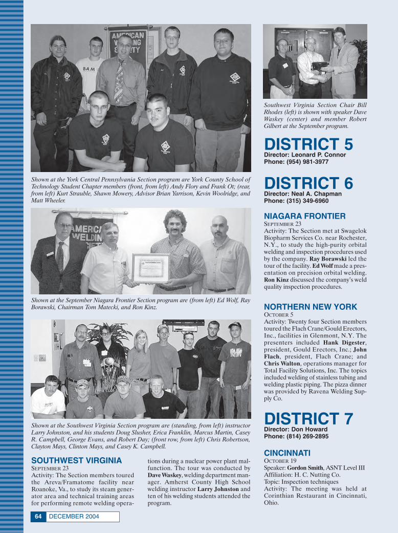
DECEMBER 200464
Shown at the York Central Pennsylvania Section program are York County School ofTechnology Student Chapter members (front, from left) Andy Flory and Frank Ot; (rear,from left) Kurt Strauble, Shawn Mowery, Advisor Brian Yarrison, Kevin Woolridge, andMatt Wheeler.
Shown at the Southwest Virginia Section program are (standing, from left) instructorLarry Johnston, and his students Doug Slusher, Erica Franklin, Marcus Martin, CaseyR. Campbell, George Evans, and Robert Day; (front row, from left) Chris Robertson,Clayton Mays, Clinton Mays, and Casey K. Campbell.
Southwest Virginia Section Chair BillRhodes (left) is shown with speaker DaveWaskey (center) and member RobertGilbert at the September program.
tions during a nuclear power plant mal-function. The tour was conducted byDave Waskey, welding department man-ager. Amherst County High Schoolwelding instructor Larry Johnston andten of his welding students attended theprogram.
Shown at the September Niagara Frontier Section program are (from left) Ed Wolf, RayBorawski, Chairman Tom Matecki, and Ron Kinz.
DISTRICT 5Director: Leonard P. ConnorPhone: (954) 981-3977
DISTRICT 6Director: Neal A. ChapmanPhone: (315) 349-6960
DISTRICT 7Director: Don HowardPhone: (814) 269-2895
SOUTHWEST VIRGINIASEPTEMBER 23Activity: The Section members touredthe Areva/Framatome facility nearRoanoke, Va., to study its steam gener-ator area and technical training areasfor performing remote welding opera-
NIAGARA FRONTIERSEPTEMBER 23Activity: The Section met at SwagelokBiopharm Services Co. near Rochester,N.Y., to study the high-purity orbitalwelding and inspection procedures usedby the company. Ray Borawski led thetour of the facility. Ed Wolf made a pres-entation on precision orbital welding.Ron Kinz discussed the company’s weldquality inspection procedures.
NORTHERN NEW YORK OCTOBER 5Activity: Twenty four Section memberstoured the Flach Crane/Gould Erectors,Inc., facilities in Glenmont, N.Y. Thepresenters included Hank Digester,president, Gould Erectors, Inc.; JohnFlach, president, Flach Crane; andChris Walton, operations manager forTotal Facility Solutions, Inc. The topicsincluded welding of stainless tubing andwelding plastic piping. The pizza dinnerwas provided by Ravena Welding Sup-ply Co.
CINCINNATIOCTOBER 19Speaker: Gordon Smith, ASNT Level IIIAffiliation: H. C. Nutting Co.Topic: Inspection techniquesActivity: The meeting was held atCorinthian Restaurant in Cincinnati,Ohio.
Society News 12/2004 11/8/04 3:16 PM Page 64

65WELDING JOURNAL
Gordon Smith (left) accepts a speakerplaque from Uwe Aschemeier, CincinnatiSection secretary, at the October meeting.
CHATTANOOGASEPTEMBER 21Activity: Following dinner at DurtyNelly’s Pub, the Section toured the Ten-nessee Rand Co.’s new 100,000-sq-ft fa-cility in downtown Chattanooga, Tenn.Highlights included the company’s en-gineering and CNC machine shops.
GREATER HUNTSVILLEAUGUST 19Activity: The Section members touredthe Taylor-Wharton Coyne facility inHuntsville, Ala., to study its methodsfor producing cylinders of oxygen,acetylene, and mixed gases.
SEPTEMBER 23Activity: Greater Huntsville SectionChair Larry Smith, a welding instruc-tor at Blount County AVC, led the Sec-tion members on a tour of the school’sshops to observe students engaged inironworking and welding projects.
HOLSTON VALLEYOCTOBER 5Activity: The Section held its socialevening at Holiday Lanes Bowling inJohnson City, Tenn.
NASHVILLESEPTEMBER 11Activity: The Section hosted its 10th an-nual golf tournament at Farm LakesGolf Course.
OCTOBER 12Activity: The Nashville Section mem-bers toured the Bobby Hamilton Rac-ing facility in Mt. Juliet, Tenn.
DISTRICT 8Director: Wallace E. HoneyPhone: (256) 332-3366
DISTRICT 9Director: John BruskotterPhone: (504) 394-0812
MOBILESEPTEMBER 9Speaker: Barbara Estes, presidentAffiliation: Associated Builders andContractorsTopic: Area construction projectsActivity: Christine Farmer, a welderand mechanic at Christ Steam Plant inPensacola, Fla., described how weldingimproved her life. She learned the skillsshe needed to obtain satisfying work atGeorge Stone Vocational School. Sheattends evening college classes andmakes presentations to students on thevalue of careers in welding. The pro-
gram was held at Cock of the WalkRestaurant in Mobile, Ala.
NEW ORLEANSSEPTEMBERActivity: Gabe Signorelli conducted theSection on a tour of the New OrleansSewage and Water Board. Jim Greer,AWS president, and John Bruskotter,District 9 director, participated, alongwith 60 members and guests.
PASCAGOULASEPTEMBER 30Speaker: Mickey Holmes, technical rep-resentativeAffiliation: Lincoln Motor SportsTopic: Job opportunities for welders atNASCARActivity: This student night programwas held at Mississippi Gulf CoastCommunity College (MGCCC). Stu-dents received door prizes includingfree tickets to the Talladega WinstonCup Race, donated by Lincoln Electric.Chairman William Harris fromMGCCC presided over this meeting.
Shown at the New Orleans Section’s tour are (from left) Ron Fryou, Bob Bartlett, JohnSchexnayder, Jim Greer, John Gerrets, and John Bruskotter.
Speaker Barbara Estes poses with LavonMills, Mobile Section chair, at the Sep-tember program.
Christine Farmer is shown with LavonMills, Mobile Section chair, at the Sep-tember meeting.
Mickey Holmes (left) is shown withWilliam Harris, Pascagoula Section chair,at the September meeting.
Society News 12/2004 11/8/04 3:16 PM Page 65

DECEMBER 200466
Speaker Pat Pollock (right) accepts aspeaker gift from Detroit Vice Chair RayRoberts at the October meeting.
Shown at the September Lakeshore Sec-tion program are (from left) speaker Mag-nus Carlsson, Ben Mueller, and Jim Hoff-mann.
At the Chicago Section program, speakerDennis Klingman (above, left) is shownwith Chairman Jeff Stanczak. Below,Craig Ticheler (left) accepts his achieve-ment award from Jesse Hunter, District13 director.
DISTRICT 10Director: Victor Y. MatthewsPhone: (216) 383-2638
DISTRICT 11Director: Eftihios SiradakisPhone: (989) 894-4101
DETROITOCTOBER 14Speaker: Pat Pollock, vice presidentAffiliation: Genesis Systems GroupTopic: Managing variations in roboticwelding applications
NORTHERN MICHIGANSEPTEMBER 30Activity: The Section members touredthe Great Lakes Maritime Academy inTraverse City, Mich. Highlights in-cluded a tour of the ship State of Michi-gan, new academy building, and partsof the Northwestern Michigan CollegeAcademy of Maritime and CulinaryArts campus. Jerry Williams conductedthe tour.
WESTERN MICHIGANSEPTEMBER 20Speaker: Mike Soter, vice presidentAffiliation: Rollan Engineering ServicesTopic: The art and science of resistanceweld verificationActivity: The Section made plans for itsupcoming golf outing. The meeting washeld at O’Mally’s Grill and Pub inGrand Rapids, Mich.
DISTRICT 12Director: Michael D. KerseyPhone: (262) 650-9364
LAKESHORESEPTEMBER 23Speaker: Magnus Carlsson, managerAffiliation: SSAB, Oxelösund, SwedenTopic: Working high-strength steelsActivity: Carlsson detailed the methodsused at SSAB to weld, cut, form, andmachine the company’s Hardox brandof quenched and tempered wear-resist-ant steel. The program was held at theCoach Light Inn in Manitowoc, Wisc.
DISTRICT 13Director: Jesse L. HunterPhone: (309) 359-8358
CHICAGOOCTOBER 13Speaker: Dennis Klingman, manager,technical trainingAffiliation: The Lincoln Electric Co.Topic: Motorsports weldingActivity: Craig Ticheler and Walt Steinreceived awards for their outstandingservice from Jesse Hunter, District 13director. Jim Greer, AWS president,spoke on items of general interest aboutthe Society. The program was held atBaby Joe’s Barbecue.
DISTRICT 14Director: Tully C. ParkerPhone: (618) 667-7744
INDIANASEPTEMBER 8, 9Activity: Gary Dugger and Mike Ander-son manned the Section’s booth at theSolutions Expo 2004 presented by Prax-air Distribution, Inc., in Indianapolis,Ind.
SEPTEMBER 20Activity: The Indiana Section membersparticipated in demonstrations of sol-dering, brazing, and oxyacetylene pro-cedures emphasizing safety. The pro-gram, held at Starweld in Rushville,Ind., was led by Bob Richwine from IvyTech State College, Muncie, Ind.
ST. LOUISSEPTEMBER 23Activity: Following an introductory pro-gram by Mark Kohler, vice president,manufacturing, the group toured theGundlach division of JMJ Industries,Inc. The facility does everything in-house from oxygen cutting to roboticapplication of hardfacing materials.
DISTRICT 15Director: J. D. HeikkinenPhone: (800) 249-2774
DISTRICT 16Director: Charles F. BurgPhone: (515) 233-1333
KANSAS CITYOCTOBER 14Speaker: David CraigAffiliation: Computer Engineering, Inc.Topic: Welding computer programsActivity: The program was held at Hay-ward’s Barbecue.
Society News 12/2004 11/8/04 3:16 PM Page 66

69WELDING JOURNAL
Shown working the Indiana Section’s booth at Solutions Expo 2004 are (from left) GaryDugger and Mike Anderson.
Dick Alley (left), AWS past president(1989–90), and presenter Bob Richwine(right) are shown at the Indiana SectionSeptember 20 program.
DISTRICT 17Director: Oren P. ReichPhone: (254) 867-2203
DISTRICT 19Director: Phil ZammitPhone: (509) 468-2310 ext. 120
DISTRICT 18Director: John L. MendozaPhone: (210) 353-3679
SABINESEPTEMBER 21Speakers: Ashley Madray, Jason Will-ingham, and Carl ChanceAffiliation: Gas Innovations/WWS, Inc.Topic: Flux cored wire advantages andgas cylinder inspectionsActivity: The program was held at LaHacienda Restaurant in Port Arthur,Tex., for 56 attendees.
DISTRICT 20Director: Nancy M. CarlsonPhone: (208) 526-6302
DISTRICT 21Director: Jack D. ComptonPhone: (661) 362-3218
DISTRICT 22Director: Kent S. BaucherPhone: (559) 276-9311
INTERNATIONALSECTION
RIO DE LA PLATASEPTEMBER 10Activity: The International Sectionsponsored a national technical programnamed 8th FECOL Expo, attended bymore than 200 visitors. Chairman Car-los Nozralah was a featured speaker.
The Section also planned the 2ndIAS Conference on Uses of Steel,scheduled for November 3–5 at HotelColonial San Nicolas in San Nicolas,Buenos Aires, Argentina.
Bob Palovcsik (front, left), St. Louis Section Chair, presents a gift to Mark Kohler fol-lowing the Section’s tour of the Gundlach facilities.
David Craig discussed welding softwareat the Kansas City Section meeting Octo-ber 14.
Shown at the Sabine Section program are(from left) Ashley Madray, Section ChairTom Holt, Jason Willingham, and CarlChance.
Shown at the Rio de la Plata Section Expoare (from left) Roberto Pieklo, Expo or-ganizer; Heriberto Weiberlen, vice chair;Daniel Bottero, secretary; and SectionChairman Carlos Nozralah.
Society News 12/2004 11/8/04 3:17 PM Page 69

AWS PRESIDENTJames E. Greer [email protected] Valley Community College248 Circlegate Rd., New Lenox, IL 60451
ADMINISTRATIONExecutive DirectorRay W. Shook.. [email protected] ............(210)
CFO/Deputy Executive DirectorFrank R. Tarafa.. [email protected] ..........(252)
Deputy Executive DirectorJeffrey R. Hufsey .. [email protected] ....(264)
Associate Executive DirectorCassie R. Burrell.. [email protected] ....(253)
Corporate DirectorBusiness Management Systems Linda K. Henderson.. [email protected] (298)
Executive Assistant for Board ServicesGricelda Manalich.. [email protected] ..(294)
COMPENSATION + BENEFITSDirectorLuisa Hernandez.. [email protected] ..........(266)
DATABASE ADMINISTRATIONCorporate DirectorJim Lankford.. [email protected] ..................(214)
INT’L INSTITUTE OF WELDINGSenior Coordinator Sissibeth [email protected] ............(319)
Provides liaison activities involving other pro-fessional societies and standards organizations,nationally and internationally.
GOVERNMENT LIAISON SERVICESHugh K. Webster. [email protected], Chamberlain & BeanWashington, D.C.(202) 466-2976; FAX (202) 835-0243
Identifies funding sources for welding educa-tion, research, and development. Monitors leg-islative and regulatory issues of importance tothe industry.
BRAZING AND SOLDERING MANUFACTURERS’ COMMITTEEJeff Weber.. [email protected] ..................(246)
WEMCO-WELDING EQUIPMENTMANUFACTURERS’ COMMITTEEMary Ellen Mills.. [email protected] ......(444)
WIN-WELDING INDUSTRY NETWORKMary Ellen Mills.. [email protected] ......(444)
CONVENTION & EXPOSITIONSExhibiting Information .................. (242, 295)
Associate Executive Director/Sales DirectorJeff Weber.. [email protected] ..................(246)
Director of Convention & ExpositionsJohn Ospina.. [email protected]..............(462)
Organizes the annual AWS Welding Show andConvention. Regulates space assignments, reg-istration materials, and other Expo activities.
PUBLICATION SERVICESDepartment Information ........................(275)
Managing DirectorAndrew Cullison.. [email protected]......(249)
Welding JournalPublisher/EditorAndrew Cullison.. [email protected]......(249)
National Sales DirectorRob Saltzstein.. [email protected] ..............(243)
Welding HandbookWelding Handbook EditorAnnette O’Brien.. [email protected] ......(303)
Publishes the Society’s monthly magazine,Welding Journal, which provides information onthe state of the welding industry, its technol-ogy, and Society activities. Publishes InspectionTrends, the Welding Handbook, and books ongeneral welding subjects.
MARKETINGCorporate DirectorBob Bishopric.. [email protected]..............(213)
Plans and coordinates marketing of AWS prod-ucts and services.
Marketing CommunicationsSenior ManagerGeorge Leposky.. [email protected] ....(416)
ManagerAmy Nathan.. [email protected]. .............(308)
MEMBER SERVICESDepartment Information ........................(480)
Associate Executive DirectorCassie R. Burrell.. [email protected] ....(253)
DirectorRhenda A. Mayo.. [email protected] ......(260)
Serves as a liaison between Section members andAWS headquarters. Informs members aboutAWS benefits and activities.
PROFESSIONAL INSTRUCTION SERVICESManaging DirectorDebrah C. Weir.. [email protected] ............(482)
Proposes new products and services. Re-searches effectiveness of existing programs.
Educational Product Development Director Christopher Pollock.. [email protected](219)
Responsible for tracking the effectiveness ofexisting programs and for the orchestration ofnew product and service development. Coordi-nates in-plant seminars and workshops. Admin-isters the S.E.N.S.E. program. Assists Govern-ment Liaison Committee with advocacy efforts.Works with Education Committees to dissemi-nate information on careers, national educa-tion and training trends, and schools that offerwelding training, certificates or degrees.
Conferences and SeminarsDirectorGiselle I. Hufsey.. [email protected] ........(278)
Responsible for conferences, exhibitions, andseminars on topics ranging from the basicsto the leading edge of technology. OrganizesCWI, SCWI, and 9-Year Renewal certification-driven seminars.
CERTIFICATION OPERATIONSDirectorTerry Perez.. [email protected] ..................(470)
Information and application materials on certi-fying welders, inspectors, and educators..(273)
INTERNATIONAL BUSINESSDEVELOPMENTDirector Walter Herrera.. [email protected] ............(475)
AWS AWARDS, FELLOWS, andCOUNSELORSManaging DirectorWendy S. Reeve.. [email protected] ........(293)
Coordinates AWS awards and AWS Fellowand Counselor nominees.
TECHNICAL SERVICESDepartment Information ........................(340)
Managing DirectorAndrew R. Davis.. [email protected] ......(466)International Standards Activities, AmericanCouncil of the International Institute of Weld-ing (IIW)
Director, National Standards ActivitiesPeter Howe.. [email protected]................(309)Machinery and Equipment Welding, Roboticand Automatic Welding, Computerization ofWelding Information.
Manager, Safety and HealthStephen P. Hedrick.. [email protected] (305)Metric Practice, Personnel and Facilities Qual-ification, Safety and Health, Joining of Plasticsand Composites.
Technical Committee SecretariesHarold P. Ellison.. [email protected] .....(299)Welding in Sanitary Applications, AutomotiveWelding, Resistance Welding, High-EnergyBeam Welding, Aircraft and Aerospace, Oxy-fuel Gas Welding and Cutting.John L. Gayler.. [email protected] ..........(472)Structural Welding, Welding Iron Castings.Rakesh Gupta.. [email protected] ..........(301)Filler Metals and Allied Materials, Interna-tional Filler Metals, Instrumentation for Weld-ing.
Ross Hancock.. [email protected] ....(226)Welding Qualification, Friction Welding, Rail-road Welding, Joining of Metals and Alloys.
Cynthia Jenney .. [email protected] ....(304) Definitions and Symbols, Brazing and Soldering,Brazing Filler Metals and Fluxes, Technical Edit-ing.
Brian McGrath . [email protected] ......(311)Methods of Inspection, Mechanical Testing ofWelds, Thermal Spray, Arc Welding and Cut-ting, Welding in Marine Construction, Pipingand Tubing, Titanium and Zirconium FillerMetals, Filler Metals for Naval Vessels.
Note: Official interpretations of AWS standardsmay be obtained only by sending a request in writ-ing to the Managing Director, Technical Services.Oral opinions on AWS standards may be ren-dered. However, such opinions represent only thepersonal opinions of the particular individualsgiving them. These individuals do not speak onbehalf of AWS, nor do these oral opinions con-stitute official or unofficial opinions or interpre-tations of AWS. In addition, oral opinions are in-formal and should not be used as a substitute foran official interpretation.
Technical PublicationsSenior Manager, Rosalinda O’Neill.. [email protected] ....(451)
AWS publishes more than 200 technical standardsand publications widely used in the welding in-dustry.
WEB SITE ADMINISTRATIONDirectorKeith Thompson.. [email protected]........(414)
Guide to AWS Services550 NW LeJeune Rd., Miami, FL 33126
Phone (800) 443-9353; (888) WELDING; FAX (305) 443-7559Internet: www.aws.org
Phone extensions appear in parentheses.
DECEMBER 200470
Society News 12/2004 11/8/04 3:17 PM Page 70
Nominees for National Office
AWS Mission Statement
The mission of the American WeldingSociety is to advance the science,
technology, and application of weldingand allied processes, including
joining, brazing, soldering, cutting, and thermal spray.
It is the intent of the American Weld-ing Society to build AWS to the highestquality standards possible. The Society wel-comes your suggestions. Please contact anyof the staff listed on the previous page orAWS President James E. Greer, MoraineValley Community College, 248 CirclegateRd., New Lenox, IL 60451.
AWS Foundation, Inc.
550 NW LeJeune Rd., Miami, FL 33126(305) 445-6628; (800) 443-9353 ext. 293
e-mail: [email protected] information
(800) 443-9353, ext. 689
Chairman, Board of TrusteesRonald C. Pierce
Executive DirectorRay W. Shook
Managing DirectorWendy S. Reeve
The AWS Foundation is a not-for-profit corpo-ration established to provide support for edu-cational and scientific endeavors of the Ameri-can Welding Society. Information on gift-giv-ing programs is available upon request.
Only Sustaining Members, Members,Honorary Members, Life Members, orRetired Members who have been mem-bers for a period of at least three yearsshall be eligible for election as a Direc-tor or National Officer.
It is the duty of the National Nominat-ing Committee to nominate candidates fornational office. The committee shall holdan open meeting, preferably at the AnnualMeeting, at which members may appear topresent and discuss the eligibility of allcandidates.
To be considered a candidate for posi-tions of President, Vice President, Trea-surer, or Director-at-Large, the followingqualifications and conditions apply:
President: To be eligible to hold theoffice of President, an individual musthave served as a Vice President for atleast one year.
Vice President: To be eligible to holdthe office of Vice President, an individ-ual must have served at least one yearas a Director, other than Executive Di-rector and Secretary.
Treasurer: To be eligible to hold theoffice of Treasurer, an individual mustbe a member of the Society, other than
a Student Member, must be frequentlyavailable to the National Office, andshould be of executive status in businessor industry with experience in financialaffairs.
Director-at-Large: To be eligible forelection as a Director-at-Large, an indi-vidual shall previously have held officeas Chairman of a Section; as Chairmanor Vice Chairman of a standing, techni-cal or special committee of the Society;or as District Director.
Interested parties are to send a let-ter stating which particular office theyare seeking, including a statement ofqualifications, their willingness and abil-ity to serve if nominated and elected,and 20 copies of their biographicalsketch.
This material should be sent toThomas M. Mustaleski, Chairman, Na-tional Nominating Committee, Ameri-can Welding Society, 550 NW LeJeuneRd., Miami, FL 33126.
The next meeting of the NationalNominating Committee is currentlyscheduled for April 2005. The term ofoffice for candidates nominated at thismeeting will commence June 1, 2006.®
Honorary-Meritorious AwardsThe Honorary-Meritorious Awards Committee makes recommendations for the nomi-
nees presented for Honorary Membership, National Meritorious Certificate, William IrrgangMemorial, and the George E. Willis Awards. These awards are presented during the AWSExposition and Convention held each spring. The deadline for submissions is July 1 prior to theyear of awards presentations. Send candidate materials to Wendy Sue Reeve, Secretary,Honorary-Meritorious Awards Committee, 550 NW LeJeune Rd., Miami, FL 33126. A descrip-tion of the awards follow.
National Meritorious CertificateAward: This award is given in recognitionof the candidate’s counsel, loyalty, and de-votion to the affairs of the Society, assis-tance in promoting cordial relations withindustry and other organizations, and forthe contribution of time and effort on be-half of the Society.
William Irrgang Memorial Award: Thisaward is administered by the AmericanWelding Society and sponsored by The Lin-coln Electric Co. to honor the late WilliamIrrgang. It is awarded each year to the indi-vidual who has done the most to enhancethe American Welding Society’s goal of ad-vancing the science and technology of weld-ing over the past five-year period.
George E. Willis Award: This award isadministered by the American WeldingSociety and sponsored by The LincolnElectric Co. to honor George E. Willis. Itis awarded each year to an individual forpromoting the advancement of welding in-ternationally by fostering cooperative par-ticipation in areas such as technologytransfer, standards rationalization, andpromotion of industrial goodwill.
International Meritorious CertificateAward: This award is given in recognitionof the candidate’s significant contributionsto the worldwide welding industry. Thisaward should reflect “Service to the Inter-national Welding Community” in thebroadest terms. The awardee is not re-quired to be a member of the AmericanWelding Society. Multiple awards can begiven per year as the situation dictates. Theaward consists of a certificate to be pre-sented at the awards luncheon or at an-other time as appropriate in conjunctionwith the AWS President’s travel itinerary,and, if appropriate, a one-year member-ship in the American Welding Society.
Honorary Membership Award: AnHonorary Member shall be a person of ac-knowledged eminence in the welding pro-fession, or who is accredited with excep-tional accomplishments in the develop-ment of the welding art, upon whom theAmerican Welding Society sees fit to con-fer an honorary distinction. An HonoraryMember shall have full rights of member-ship.®
TeleWeldFAX: (305) 443-5951
Publications Sales/OrdersGlobal Engineering Documents (800) 854-7179 or (303) 397-7956, or online at www.global.ihs.com.
ReprintsOrder quality custom reprints from Claudia Stachowiak, FosteReprints, telephone (866) 879-9144 ext. 121, ore-mail at [email protected].
71WELDING JOURNAL
Society News 12/2004 11/8/04 3:17 PM Page 71

NEWLITERATURE
English Translations of DINStandards Released
The 2004 Catalog of DIN Translations,issued as volume 3 of the DIN Catalog ofTechnical Rules, lists English translationsof nearly 14,500 DIN, DIN EN, and DINISO standards. The 468-page, soft covervolume covers such diverse fields asgauges, fasteners, steel and nonferrousmetal products, compression couplings,building construction contract proce-dures, insulating materials, materials test-ing, etc. The 17,700 documents, classifiedaccording to subject group, are presentedwith date of issue and a keyword index.For more information, e-mail [email protected], or visit www.beuth.de.
Gas Delivery Systems Pictured
A 48-page catalog displays gas-delivery systems and gas control equip-
ment for a wide array of applications inthe industrial laser materials processingindustry. The applications range from cut-ting sheet metal to laser beam welding.Systems and equipment are designed tomeet the specific requirements of majorlaser manufacturers including Bystronic,Tanaka, Mitsubishi, and Trumpf. Informa-tion is grouped according to specific sys-tems that supply mixtures of gases to CO2and solid-state lasers with demanding re-quirements for purity, pressure, and flow.
CONCOA 1101501 Harpers Rd., Virginia Beach, VA 23454
Cutting Tools Detailed inGeneral Catalog
A catalog features the company’s com-plete line of products for turning, boring,milling, drilling, grooving, threading, andcut-off applications. New products includeinsert grades of CVD-coated carbides forductile iron, and supermicro-grain cer-mets, and CBN inserts with chip break-ers, PCD grades, and others. Detailed is the indexable Magic Drill, the multi-function Ultra Drill Mill, and antivibra-tion Strong Bar in sizes up to 1 in. in diameter.
Kyocera Industrial Ceramics Corp. 111100 Industrial Pk. Rd., Mountain Home, NC 28758
New Flexible Hoses andDucting Illustrated
A 16-page catalog pictures and de-scribes flexible hoses and ducting. Fea-tured are ten new products includingcrushproof, vapor-recovery, extreme-temperature, and variations on stockhoses in new sizes up to 24 in. ID.
Detailed are a crushproof thermoplasticpolyurethane hose reinforced with a ure-thane helix, drag-resistant types, light-weight PVC, heavy 60-mil urethane hose,vacuum hoses, and blower hoses.
Hi-Tech Hose, Inc. 112400 E. Main St., Georgetown, MA 01833
Metallurgy Text on Alloys
The text, The Growth of the Alloy Tree,is intended as a reference for metallur-gists and materials engineers. Using a nar-rative style, it shows the interrelationshipsbetween the main alloy groups. Ten chap-ters describe how stainless steels, nickelalloys, and some low-alloy steels haveevolved from plain carbon steel. Eachchapter explains the background, devel-opment, key properties, and applicationsof the alloy types. Abbreviations, specifi-cations, product forms, alloying costs, andtypes of corrosion are covered in exten-sive appendixes. Price is $125 plus ship-ping. Published by Woodhead PublishingLtd., Abington Hall, Abington, Cam-bridge, CB1 6AH, U.K. For details, visitwww.woodhead-publishing.com.
Portable Electric Tools Depicted in Catalog
An 18-page, full-color catalog fea-tures the company’s lines of professional-grade portable electric power tools andabrasives for industrial construction andwelding applications. Among the new andenhanced tools displayed are a rotaryhammer, reciprocating saw, masonry bits,jig saw, variable-speed polisher, and anumber of new accessories including acordless battery pack, paint-remover
FOR MORE INFORMATION, CIRCLE NUMBER ON READER INFORMATION CARD.
DECEMBER 200472
Circle No. 25 on Reader Info-Card
Layout 11/8/04 11:41 AM Page 72

accessory, and new 5- and 6-in. randomorbit sanding discs.
Metabo 1131231 Wilson Dr., West Chester, PA 19380
Eye and Face SafetyStandard Updated
The recently updated American na-tional standard, ANSI Z87.1-2003, Occu-pational and Educational Personal Eye andFace Protection Devices, states the mini-mum performance requirements for weld-ing helmets and hand shields, spectacles,goggles, face shields, and respirators. Italso includes guidelines for the selection,use, and maintenance of these devices.The 67-page standard features numerousillustrations and includes a pull-out selec-tion chart that can be posted in the work-place to provide guidance for various haz-ard exposures that require eye and faceprotection. A reproducible Eye Injury Re-port Form is included. The single copyprice is $53, with discounts available onbulk orders. Contact International SafetyEquipment Association (ISEA), 1901 NMoore St., Ste. 808, Arlington, VA 22209;[email protected]; or visitwww.safetyequipment.org.
Literature Pictures UpdatedPlasma Torches
A well-illustrated brochure describesthe company’s FineCut™ consumablesand new line of plasma torches for cutting10- to 24-gauge mild and stainless steels.Shown are examples of the cuts display-ing decreased heat-affected zone, nar-rower kerf width, and improved cut angu-larity, with minimal dross. Also detailedare several FineCut starter kits for usewith the company’s MAX™ and Power-max™ series of manual cutting systems.Detailed are the part numbers and de-scriptions of the consumables with ex-ploded views of the assemblies. An oper-ating data chart displays typical parame-ters for cutting mild and stainless steels,including thicknesses, torch standoff dis-tances, arc current and voltage settings,and travel speeds.
Hypertherm, Inc. 11421 Great Hollow Rd., Hanover, NH 03755
Welding and MetallurgyCourses Offered on DVDs
A metallurgy course and twoS.E.N.S.E.-based welding courses are of-fered in the DVD “courseware” format toassist instructors teaching basic weldabil-ity of carbon steel, aluminum, and stain-less steel, and the basics of the shielded
73WELDING JOURNAL
Explore alternatives - Find practical solutions
Specify least – cost Welding Procedures
IWE-Consulting, Inc.
Phone: 954-432 -2655
E-mail: [email protected]
Check new features !
www.iweconsulting.com
• Compliance with AWS D1.1:2004 / AWS D1.5:2002
• Prequalified Joint Details - Base Metals - Filler Metals
• Preheat Tables / PWHT Information
• Deposition Rate Equations
• Weld Metal – Welding Time - Welding Cost Estimating
• Standard Joints for Pipe Welding
• Automatically Create WPS’s / PQR’s with minimum typing
• English / Spanish WPS Reports
• High Level and Accuracy of Code - Checking
• U.S Customary – International System of Units
WPS – Designer 3.0
Buildings - Bridges
Circle No. 34 on Reader Info-Card
Circle No. 41 on Reader Info-Card
— continued on page 74
Layout 11/8/04 11:42 AM Page 73

PERSONNEL
Lincoln Names Asia Pacific Head
Lincoln ElectricHoldings, Inc., hasannounced the pro-motion of ThomasA. Flohn to presi-dent of LincolnElectric Asia Pa-cific, effective Janu-ary 1. He will suc-ceed Michael J. F.Gillespie. Until heretires at the end ofthe 2005 first quar-
ter, Gillespie will become vice presidentand special assistant to the president ofAsia Pacific. Flohn, with the company for21 years, is presently vice president, salesand marketing.
Two Named to RoboticsBoard
Innova Holdings, Inc., Fort Myers,Fla., announced that Ron Fukui and TomHelzerman have joined the board of di-rectors of Robotic Workspace Technolo-gies, Inc. (RWT), a wholly owned sub-sidiary of Innova. Fukui, currently presi-dent and co-owner of Amiteq Interna-tional LLC, will serve as chief technologyofficer. Helzerman, with 36 years of expe-rience in vehicle operations engineeringat Ford Motor Co., joined RWT in 2002as president and COO.
ASTM Presents Its Awardof Merit
The American Society for Testing andMaterials (ASTM International), Con-shohocken, Pa., has conferred its 2004Award of Merit and title of fellow to An-drew David McCrindle, a retired metal-lurgist with GenFast Manufacturing,Bantford, Ont., Canada. The society’shighest honor was presented to McCrindlein recognition of his achievements in de-veloping technical standards and his lead-ership serving as chair of Committee F16on Fasteners for six years.
Harsco GasServ SelectsSales Manager
Harsco GasServ, Mechanicsburg, Pa.,
has named Allen J.(Jeff) Clay III assouthern regionsales manager, re-sponsible for shield-ing gas systems andacetylene cylindersin Alabama,Florida, Georgia,Louisiana, Missis-sippi, South Car-olina, and Texas.Clay previously was
national marketing manager for AirgasNitrous Oxide.
Hypertherm DesignatesCalifornia Sales Manager
Hypertherm, Inc.,Hanover, N.H., hasappointed KrisScherm as its districtsales manager forsouthern California.Scherm previouslyserved the companyin various key salespositions for the pastten years.
ObituaryRobert (Bob) J. Keller
Robert J. Keller, 92, died December18, 2003. Mr. Keller, a lifelong supporterof the American Welding Society, wasborn in southern Indiana. He graduatedfrom Hanover College in 1933 with ma-jors in chemistry and physics. Mr. Kellermoved to Milwaukee, Wis., with his wife,Nellie, to work in the A. O. Smith Corp.welding research laboratory. There, hemoved up into management positions inthe welding research division, which wassubsequently sold to Harnishfager, andthen to Chemetron. After retiring fromChemetron, Hanover, Pa., he returned tosouthern Indiana where he took a job sell-ing welding supply contracts for WeldingTherapy in Columbus, Ind. Mr. Kellerlater started his own consulting companyserving clients in Australia, Germany, andthe U.S.
DECEMBER 200474
Thomas A. Flohn
Allen J. Clay III
Kris Scherm
metal arc welding (SMAW) and gas metalarc welding (GMAW) processes. Thevideo action is organized in a modularmenu-driven format that corresponds withthe skills-based student workbooks andcomprehensive Instructor Guides. Dis-played are dynamic welding videos andclose-up views of the weld pool, with allof the amenities of the digital video disctechnology including, slow motion, freezeframe, and both English and Spanishsound tracks. For more information andprice schedules, contact Training Materi-als Dept., Hobart Institute of WeldingTechnology, 400 Trade Square East, Troy,OH 45373; (800) 332-9448, ext. 5433; e-mail [email protected].
Air Plasma Cutting SystemIllustrated in Brochure
A 4-page, full-color brochure providesdetails on the Cutmaster™ 101 air plasmacutting system for non-high-frequency startautomation applications. Described is theadvanced torch connector (ATC™) forquick disconnects. This system is rated for3⁄8-in. production cut capacity and 11⁄4-in.edge start capacity for use on aluminum,stainless steel, and mild steel including thin-gauge production fabrications.
Thermal Dynamics Corp. 115Ste. 300, 16052 Swingley Ridge Rd., Chesterfield, MO 63017
NEW LITERATURE— continued from page 73
Layout 11/8/04 11:42 AM Page 74

Circle No. 44 on Reader Info-Card
Page 75 11/9/04 4:32 PM Page 75

WELDING JOURNALINDEX
Abrasive Wheels, Save Time and Money with the RightAbrasive Wheels — C. Karpac, K. Honaker, and T. Fogarty,38 (May)
Airline Millions, Weld Repair Saves — M. R. Johnsen, 28(Aug)
Aluminum Breaks Out of the Vacuum, EBW of — K. Schulzeand D. E. Powers, 32 (Feb)
Aluminum Cuts Energy Costs by 99%, Friction Welding of —R. Hancock, 40 (Feb)
Aluminum Shipbuilding, New Developments in — T.Anderson, 28 (Feb)
Aluminum Space Frames Speeds Introduction of Sports Car,Robotic Welding of — C. Occhialini, 24 (Feb)
Atmospheres for Bright Brazing, Controlled — P. F. Strattonand A. McCracken, 25 (Oct)
Atomization, Manufacture of Brazed and Solder AlloyPowders by — D. Fortuna, 40 (Oct)
Automating Materials Handling — 33 (Aug)Auto Parts Maker Goes Ductless — 36 (Sept)Battlefield Welders, Boot Camp for — R. Hancock, 38 (Dec)Brazed and Solder Alloy Powders by Atomization,
Manufacture of — D. Fortuna, 40 (Oct)Brazing, Controlled Atmospheres for Bright — P. F. Stratton
and A. McCracken, 25 (Oct)Brazing of Stainless Steel, Modern — S. L. Feldbauer, 30 (Oct)Bridge Puts New Gas Mixtures to the Test, Bay — B. O’Neil
and M. E. Rodgers III, 26 (Dec)Chicago, Spend Four Profitable Days in — M. R. Johnsen, 38
(Jan)Coke Drums, Vertical Plate Technology Extends the Life of
Coke Drums — C. Stewart, 34 (Apr)Costs by 99%, Friction Welding of Aluminum Cuts Energy —
R. Hancock, 40 (Feb)Cleveland, Fabtech Comes to — 51 (Oct)Cutting Tips, Tips for Selecting Qxyfuel — J. Jones, 71 (Sept)Daughters Bond through Welding, Dads and — R. Hancock, 91
(Apr)Distortion, Understanding — D. McGowan, 76 (Sept)Electrodes Improve GMAW Heat Input Control, Double — Y.
M. Zhang, M. Jiang, and W. Lu, 39 (Nov)Ferritic Welds, Understanding Hydrogen Failures of — J. R.
Still, 26 (Jan)Filler Metal Review, Nickel Alloy — H.W. Ebert, 60 (July)Fires?, How Do We Prevent Hot Work — M. Blank, 26 (Sept)Force-Guided Relays Add Extra Measure of Safety — R.
Harris, 38 (Sept)Frames Speeds Introduction of Sports Car, Robotic Welding of
Aluminum Space — C. Occhialini, 24 (Feb)Gas Mixtures to the Test, Bay Bridge Puts New — B. O’Neil
and M. E. Rodgers III, 26 (Dec)Gas Platforms, Now Made in USA: Spar Hulls for Oil and —
R. Hancock, 38 (Apr)Girls, Welding Sparks Self-Esteem for — R. Hancock, 73
(Sept)
Guns and Torches, Developments in — R. Hancock and M. R.Johnsen, 29 (May)
GMAW Heat Input Control, Double Electrodes Improve —Y. M. Zhang, M. Jiang, and W. Lu, 39 (Nov)
GMAW, How to Optimize Mild Steel— Richard Green, 30(Dec)
Heat Treatment Is Critical to Refurbishing a WellheadHousing, Postweld — J. R. Still and V. Blackwood, 34 (Oct)
Heat Input Control, Double Electrodes Improve GMAW —Y. M. Zhang, M. Jiang, and W. Lu, 39 (Nov)
Hermetic Sealing, Optimizing Projection Welding for — T. E.Salzer, 42 (March)
High-Purity Water Systems Rely on Orbital Welding — 39(Aug)
Hollywood Bowl, A New Tune for the — R. Aday, 54 (July)How Do We Prevent Hot Work Fires? — M. Blank, 26 (Sept)Hydrogen Failures of Ferritic Welds, Understanding —
J. R. Still, 26 (Jan)Hybrid Welding?, What’s Next for — R. W. Messler, Jr., 30
(March)Hybrid Welding of Ships, Laser- — S. Herbert, 39 (June)Insert Metal, Friction Welding Using — H. Ochi, K. Ogawa, Y.
Yamamoto, and Y. Suga, 36 (March)Ironworkers New Skills, Dinosaur Project Teaches — N.
Borchert, 42 (Nov)Job Shops, Tips for — M. R. Johnsen, 45 (June)Life of Coke Drums, Vertical Plate Technology Extends the —
C. Stewart, 34 (Apr)Materials Handling, Automating — 33 (Aug)Mild Steel GMAW, How to Optimize — Richard Green, 30
(Dec)Mixtures to the Test, Bay Bridge Puts New Gas —
B. O’Neil and M. E. Rodgers III, 26 (Dec)Money with the Right Abrasive Wheels, Save Time and — C.
Karpac, K. Honaker, and T. Fogarty, 38 (May)Nickel Steel, Electrodes for Welding 9% — J. Hilkes, F.
Neesen, and S. Caballero, 30 (Jan)Nuclear Power Plant Benefits from Innovative Repair
Technology — N. Chapman, 36 (Aug)Oil and Gas Platforms, Now Made in USA: Spar Hulls — R.
Hancock, 38 (Apr)Orbital Welding, High-Purity Water Systems Rely on — 39
(Aug)Qxyfuel Cutting Tips, Tips for Selecting — J. Jones, 71 (Sept)Parts Maker Goes Ductless, Auto — 36 (Sept)P91, Welding Root Beads — C. Patrick, T. Ferguson, and J.
Maitlen, 38 (July)Pipeline, Maintenance Welding on the Trans-Alaska — W. A.
Bruce and A. S. Beckett, 48 (July)Pipelines, Weld Metal Properties of Reeled — J. R. Still, 42
(July)Plate Technology Extends the Life of Coke Drums, Vertical —
C. Stewart, 34 (Apr)Powder Metal Parts, Exploring the Weldability of — A. Kurt,
Part 1 — WELDING JOURNALSUBJECT INDEX
DECEMBER 200476
WJ Index 2004corr 11/9/04 1:26 PM Page 76

H. Ates, A. Durgutlu, and K. Karacif, 34 (Dec)Power Plant Benefits From Innovative Repair Technology,
Nuclear — N. Chapman, 36 (Aug)Pressure Vessel Challenge, Vertical Welding Solves a — J.
Ferrell and P. Formento, 48 (Nov)Profitable Days in Chicago, Spend Four — M. R. Johnsen, 38
(Jan)Projection Welding for Hermetic Sealing, Optimizing — T. E.
Salzer, 42 (March)Properties of Reeled Pipelines, Weld Metal — J. R. Still, 42
(July)Protect Your Most Valuable Asset — Yourself — M. Schifsky,
30 (Sept)Protection, Volunteer Welders Give Troops a Ton of — R.
Hancock, 83 (Apr)Repair Technology, Nuclear Power Plant Benefits from
Innovative — N. Chapman, 36 (Aug)Repair Saves Airline Millions, Weld — M. R. Johnsen, 28
(Aug)Root Beads in P91, Welding — C. Patrick, T. Ferguson, and J.
Maitlen, 38 (July)Safety, Force-Guided Relays Add Extra Measure of — R.
Harris, 38 (Sept)Shipbuilding, New Developments in Aluminum — T.
Anderson, 28 (Feb)Ships, Laser-Hybrid Welding of — S. Herbert, 39 (June)Show, A Look at the AWS Welding — A. Cullison, R.
Hancock, and M. R. Johnsen, 33 (June)Skills, Dinosaur Project Teaches Ironworkers New — N.
Borchert, 42 (Nov)Society Turns 85, The American Welding — A. Cullison, 50
(June)Solder Alloy Powders by Atomization, Manufacture of Brazed
and — D. Fortuna, 40 (Oct)Spar Hulls for Oil and Gas Platforms, Now Made in USA: —
R. Hancock, 38 (Apr)Sports Car, Robotic Welding of Aluminum Space Frames
Speeds Introduction of — C. Occhialini, 24 (Feb)Stainless Steel, Modern Brazing of — S. L. Feldbauer, 30 (Oct)Strongest Linepipe in Arctic Conditions, Welding the World’s
— R. Hancock, 58 (July)Success, Dressed for — R. Hancock, 29 (Apr)Thermoplastics, Welding of — D. Ziegler, 45 (Oct)Tips for Selecting Qxyfuel Cutting Tips — J. Jones, 71 (Sept)
Titanium Specification Revised, Update: — J. A. McMasterand R. C. Sutherlin, 43 (May)
Toolbox?, What’s in Your — A. Cullison, R. Hancock, and M.R. Johnsen, 34 (May)
Torches, Developments in Guns and — R. Hancock and M. R.Johnsen, 29 (May)
Trans-Alaska Pipeline, Maintenance Welding on the — W. A.Bruce and A. S. Beckett, 48 (July)
Troops a Ton of Protection, Volunteer Welders Give — R.Hancock, 83 (April)
Understanding Distortion — D. McGowan, 76 (Sept)Usability, Upgrade Your Web Site’s — 41 (Dec)Vacuum, EBW of Aluminum Breaks Out of the — K. Schulze
and D. E. Powers, 32 (Feb)Web Site’s Usability, Upgrade Your — 41 (Dec)Weldability of Powder Metal Parts, Exploring the — A. Kurt,
H. Ates, A. Durgutlu, and K. Karacif, 34 (Dec)Welders Give Troops a Ton of Protection, Volunteer — R.
Hancock, 83 (Apr)Welding, Dads and Daughters Bond through — R. Hanock, 91
(Apr)Welding 9% Nickel Steel, Electrodes for — J. Hilkes, F.
Neesen, and S. Caballero, 30 (Jan)Weld Repair Saves Airline Millions — M. R. Johnsen, 28 (Aug)Welding Show, A Look at the AWS — A. Cullison, R.
Hancock, and M. R. Johnsen, 33 (June)Welding Society Turns 85, The American — A. Cullison, 50
(June)Welding Solves a Pressure Vessel Challenge, Vertical — J.
Ferrell and P. Formento, 48 (Nov)Welding Sparks Self-Esteem for Girls — R. Hancock, 73 (Sept)Welding Using Insert Metal, Friction — H. Ochi, K. Ogawa, Y.
Yamamoto, and Y. Suga, 36 (March)Welding?, What’s Next for Hybrid — R. W. Messler, Jr., 30
(March)Wellhead Housing, Postweld Heat Treatment Is Critical to
Refurbishing a — J. R. Still and V. Blackwood, 34 (Oct) Wheels, Save Time and Money with the Right Abrasive — C.
Karpac, K. Honaker, and T. Fogarty, 38 (May)Workplace Safety: The Human Factor — M. Pankratz and D.
Dorn, 32 (Sept)World Now, They’re in the Real — M. R. Johnsen, 87 (Apr)World Trade Center Site, Construction Begins at the — B.
Sommer, 36 (Nov)
77WELDING JOURNAL
WJ Index 2004corr 11/9/04 1:26 PM Page 77

Aday, R. — A New Tune for the Hollywood Bowl, 54 (July)Anderson, T. — New Developments in Aluminum
Shipbuilding, 28 (Feb)Ates, H., Durgutlu, A., Karacif, K., and Kurt, A. — Exploring
the Weldability of Powder Metal Parts, 34 (Dec)Beckett, A. S., and Bruce, W. A. — Maintenance Welding on
the Trans-Alaska Pipeline, 48 (July)Blackwood, V., and Still, J. R. — Postweld Heat Treatment Is
Critical to Refurbishing a Wellhead Housing, 34 (Oct)Blank, M. — How Do We Prevent Hot Work Fires?, 26, (Sept)Borchert, N. — Dinosaur Project Teaches Ironworkers New
Skills, 42 (Nov)Bruce, W. A., and Beckett, A. S. — Maintenance Welding on
the Trans-Alaska Pipeline, 48 (July)Chapman, N. — Nuclear Power Plant Benefits from Innovative
Repair Technology, 36 (Aug)Cullison, A. — The American Welding Society Turns 85, 50
(June)Cullison, A., Hancock, R., and Johnsen, M. R. — What’s in
Your Toolbox?, 34 (May)Cullison, A., Hancock, R., and Johnsen, M. R. — A Look at the
AWS Welding Show, 33 (June)Caballero, S., Hilkes, J., and Neesen, F. — Electrodes for
Welding 9% Nickel Steel, 30 (Jan)Dorn, D., and Pankratz, M. — Workplace Safety: The Human
Factor, 32 (Sept)Durgutlu, A., Karacif, K., Kurt, A., and Ates, H. — Exploring
the Weldability of Powder Metal Parts, 34 (Dec)Ebert, H. W. — Nickel Alloy Filler Metal Review, 60 (July)Ferguson, T., Maitlen, J., and Patrick, C. — Welding Root
Beads in P91, 38 (July)Feldbauer, S. L. — Modern Brazing of Stainless Steel, 30 (Oct)Ferrell, J., and Formento, P. — Vertical Welding Solves a
Pressure Vessel Challenge, 48 (Nov)Fogarty, T., Karpac, C., and Honaker, K. — Save Time and
Money with the Right Abrasive Wheels, 38 (May)Formento, P., and Ferrell, J. — Vertical Welding Solves a
Pressure Vessel Challenge, 48 (Nov)Fortuna, D. — Manufacture of Brazed and Solder Alloy
Powders by Atomization, 40 (Oct)Green, R. — How to Optimize Mild Steel GMAW, 30 (Dec)Hancock, R., Johnsen, M. R., and Cullison, A. — A Look at the
AWS Welding Show, 33 (June)Hancock, R. — Dads and Daughters Bond through Welding, 91
(Apr)Hancock, R., and Johnsen, M. R. — Developments in Guns
and Torches, 29 (May)Hancock, R. — Dressed for Success, 29 (Apr)Hancock, R. — Friction Welding of Aluminum Cuts Energy
Costs by 99%, 40 (Feb)Hancock, R. — Now Made in USA: Spar Hulls for Oil and Gas
Platforms, 38 (Apr)Hancock, R. — Volunteer Welders Give Troops a Ton of
Protection, 83 (Apr)Hancock, R. — Welding Sparks Self-Esteem for Girls, 73
(Sept)Hancock, R., Johnsen, M. R. and Cullison, A. — What’s in
Your Toolbox?, 34 (May)Hancock, R. — Boot Camp for Battlefield Welders, 38 (Dec)Harris, R. — Force-Guided Relays Add Extra Measure of
Safety, 38 (Sept)Herbert, S. — Laser-Hybrid Welding of Ships, 39 (June)Hilkes, J., Neesen, F., and Caballero, S. — Electrodes for
Welding 9% Nickel Steel, 30 (Jan)Honaker, K., Fogarty, T., and Karpac, C. — Save Time and
Money with the Right Abrasive Wheels, 38 (May)Jiang, M., Zhang, Y. M., and Lu, W. — Double Electrodes
Improve GMAW Heat Input Control, 39 (Nov)Johnsen, M. R., Cullison, A., and Hancock, R. — A Look at the
AWS Welding Show, 33 (June)Johnsen, M. R., and Hancock, R. — Developments in Guns and
Torches, 29 (May)Johnsen, M. R., Hancock, R., and Cullison, A. — What’s in
Your Toolbox?, 34 (May)Johnsen, M. R. — Spend Four Profitable Days in Chicago, 38
(Jan)Johnsen, M. R. — They’re in the Real World Now, 87 (Apr)Johnsen, M. R. –– Weld Repair Saves Airline Millions, 28
(Aug)Johnsen, M. R. — Tips for Job Shops, 45 (June)Jones, J. — Tips for Selecting Qxyfuel Cutting Tips, 71 (Sept)Karacif, K., Kurt, A., Ates, H., and Durgutlu, A. — Exploring
the Weldability of Powder Metal Parts, 34 (Dec)Karpac, C., Honaker, K., and Fogarty, T. — Save Time and
Money with the Right Abrasive Wheels, 38 (May)Kurt, A., Ates, H., Durgutlu, A., and Karacif, K. — Exploring
the Weldability of Powder Metal Parts, 34 (Dec)Kvaale, P. E., Van Der Eijk, C., Akselsen, O.M., and Rorvik, G.
— Microstructure-Property Relationships in HAZ of New13% Cr Martensitic Stainless Steels, 160-S (May)
Lu, W., Zhang, Y. M., and Jiang, M. — Double ElectrodesImprove GMAW Heat Input Control, 39 (Nov)
Maitlen, J., Patrick, C., and Ferguson, T. — Welding RootBeads in P91, 38 (July)
McCracken, A., and Stratton, P. F. — Controlled Atmospheresfor Bright Brazing, 25 (Oct)
McGowan, D. — Understanding Distortion, 76 (Sept) McMaster, J. A., and Sutherlin, R.C. — Update: Titamium
Specification Revised, 43 (May)Messler, Jr., R. W. — What’s Next for Hybrid Welding?, 30
(March)Neesen, F., Caballero, S., and Hilkes, J. — Electrodes for
Welding 9% Nickel Steel, 30 (Jan)Occhialini, C. — Robotic Welding of Aluminum Space Frames
Speeds Introduction of Sports Car, 24 (Feb)Ochi, H., Ogawa, K., Yamamoto, Y., and Suga, Y. — Friction
Welding Using Insert Metal, 36 (March)Ogawa, K., Yamamoto, Y., Suga, Y., and Ochi, H. — Friction
Welding Using Insert Metal, 36 (March)O’Neil, B., and Rodgers III, M. E. — Bay Bridge Puts New Gas
Mixtures to the Test, 26 (Dec)Powers, D. E., and Schulze, K. — EBW of Aluminum Breaks
Out of the Vacuum, 32 (Feb)Pankratz, M., and Dorn, D. — Workplace Safety: The Human
Factor, 32 (Sept)Patrick, C., Ferguson, T., and Maitlen, J. — Welding Root
Beads in P91, 38 (July)Rodgers III, M. E., and O’Neil, B. — Bay Bridge Puts New Gas
Mixtures to the Test, 26 (Dec)Salzer, T. E. — Optimizing Projection Welding for Hermetic
AUTHORS FOR FEATURE ARTICLES
DECEMBER 200478
WJ Index 2004corr 11/9/04 1:26 PM Page 78
Sealing, 42 (March)Schifsky, M. — Protect Your Most Valuable Asset — Yourself,
30 (Sept)Schulze, K. and Powers, D. E. — EBW of Aluminum Breaks
Out of the Vacuum, 32 (Feb)Sommer, B. — Construction Begins at the World Trade Center
Site, 36 (Nov)Stewart, C. — Vertical Plate Technology Extends the Life of
Coke Drums, 34 (Apr)Still, J. R. — Understanding Hydrogen Failures of Ferritic
Welds, 26 (Jan)Still, J. R. — Weld Metal Properties of Reeled Pipelines, 42
(July)
Still, J. R., and Blackwood, V. — Postweld Heat Treatment IsCritical to Refurbishing a Wellhead Housing, 34 (Oct)
Stratton, P. F., and McCracken, A. — Controlled Atmospheresfor Bright Brazing, 25 (Oct)
Suga, Y., Ochi, H., Ogawa, K., and Yamamoto, Y. — FrictionWelding Using Insert Metal, 36 (March)
Sutherlin, R. C., and McMaster, J. A. — Update: TitaniumSpecification Revised, 43 (May)
Yamamoto, Y., Suga, Y., Ochi, H., and Ogawa, K. — FrictionWelding Using Insert Metal, 36 (March)
Ziegler, D. — Welding of Thermoplastics, 45 (Oct)Zhang,Y. M., Jiang, M., and Lu, W. — Double Electrodes
Improve GMAW Heat Input Control, 39 (Nov)
Al-Cu Welds, Liquation Cracking in Full-Penetration — C.Huang and S. Kou, 50-S (Feb)
Aluminum Alloys, ‘Kissing Bond’ Phenomena in Solid-StateWelds of — A. Oosterkamp, L. Djapic Oosterkamp, and A.Nordeide, 225-S (Aug)
Aluminum Alloy to Steel with Transition Material — FromProcess to Performance — Part I: Experimental Study,Resistance Spot Welding of — X. Sun, E.V. Stephens, M. A.Khaleel, H. Sao, and M. Kimchi, 188-S (June)
Aluminum Alloy to Steel with Transition Material — Part II:Finite Element Analyses of Nugget Growth, Resistance SpotWelding of — X. Sun and M. A. Khaleel, 197-S (July)
Aluminum Alloy 5052 and Low-Carbon Steel by Laser RollWelding, Joining of — M. J. Rathod and M. Kutsuna, 16-S(Jan)
Aluminum Alloy Subjected to an External Electrostatic Field,Metallurgical Characterization of a Friction Welded — L.Fu and S. G. Du, 232-S (Aug)
Aluminum Alloy to Steel, Friction Stir Welding of — K.Kimapong and T. Watanabe, 277-S (Oct)
Aluminum Brazed Joints, Prediction of the Fillet Mass andTopology of — D. P. Sekulic, F. Gao, H. Zhao, B. Zellmer,and Y. Y. Qian, 102-S (March)
Aluminum Resistance Spot Welds, Effects of Fusion Zone Sizeon Failure Modes and Static Strength of — X. Sun, E. V.Stephens, R. W. Davies, M. A. Khaleel, and D. J. Spinella,308-S (Nov)
Austenitic Alloys for Spent Nuclear Fuel Applicatons — Part I:Stainless Steel Alloys, Physical and Welding Metallurgy ofGd-Enriched — J. N. DuPont, C. V. Robino, J. R. Michael,R. E. Mizia, and D. B. Williams, 289-S (Nov)
Austenitic Alloys for Spent Nuclear Fuel Applications — PartII: Nickel-based Alloys, Physical and Welding Metallurgy ofGd-enriched — J. N. DuPont, C. V. Robino, J. R. Michael,R. E. Mizia, and D. B. Williams, 319-S (Dec)
Bead Geometry, The Influence of Various Hybrid WeldingParameters on — M. El Rayes, C. Walz, and G. Sepold, 147-S(May)
Beam Measurement for Spot Welding Lasers, Developmentand Evaluation of an In-Situ Beam Measurement for SpotWelding Lasers — P. W. Fuerschbach, J. T. Norris, R. C.Dykhuizen, and A. R. Mahoney, 154-S (May)
Brazed Joints, Prediction of the Fillet Mass and Topology ofAluminum — D. P. Sekulic, F. Gao, H. Zhao, B. Zellmer,and Y. Y. Qian, 102-S (March)
Brazing Technology for Manufacture of Titanium HoneycombStructures — A Statstical Study, Activated Diffusion — X.Huang and N. L. Richards, 73-S (March)
Boundary Character in Alloy 690 and Ductility-Dip CrackingSusceptibility, Grain — V. R. Dave, M. J. Cola, M. Kumar,A. J. Schwartz, and G. N. A. Hussen, 1-S (Jan)
Brazed Joints — Part 1, Flaw Tolerance in Lap Shear — Y.Flom amd L. Wang, 32-S (Jan)
Charpy Toughness, Optimization of Shielded Metal Arc WeldMetal Composition for — M. Murugananth, S. S. Babu, andS. A. David, 267-S (Oct)
Clad Steel Plate, Single-Pass Laser Beam Welding of — S.Missori, F. Murdolo, and A. Sili, 65-S (Feb)
Cored Arc Weld Metal Deposits, The Effect of WeldingProcedure on ANSI/AWS A5.29-98 E81T1-Ni1 Flux — H.G. Svoboda, N. M. Ramini De Rissone, L. A. De Veida, andE. S. Surian, 301-S (Nov)
Crack Propagation Behavior of Stainless Steel Welds, TheInfluence of Microstructure on Fatigue — C. S. Kusko, J. N.DuPont, and A. R. Marder, 6-S (Jan)
Crack Propagation Behavior of Stainless Steel Welds, Influenceof Stress Ratio on Fatigue — C. S. Kusko, J. N. DuPont, andA. R. Marder, 59-S (Feb)
Cracking in Full-Penetration Al-Cu Welds, Liquation — C.Huang and S. Kou, 50-S (Feb)
Cracking in Full-Penetration Al-Mg-Si Welds, Liquation — C.Huang and S. Kou, 111-S (Apr)
Cracking in Nickel-Based Weld Meals — Part III, AnInvestigation of Ductility-Dip — M. G. Collins, A. J.Ramirez, and J. C. Lippold, 39-S (Feb)
Cracking Susceptibility, Grain Boundary Character in Alloy
Part 2 — RESEARCHSUPPLEMENT SUBJECT INDEX
79WELDING JOURNAL
WJ Index 2004corr 11/9/04 1:26 PM Page 79

690 and Ductility-Dip — V. R. Dave, M. J. Cola, M. Kumar,A. J. Schwartz, and G. N. A. Hussen, 1-S (Jan)
Deformation and Fracture of Weld-Bonded Joints, Cohesive-Zone Modeling of the — M. N. Cavalli, M. D. Thouless, andQ. D. Yang, 133-S (Apr)
Deformation of a Completely Penetrated GTA Weld,Numerical Simulation of Transient 3-D Surface — C. S. Wu,P. C. Zhao, and Y. M. Zhang, 330-S (Dec)
Direct Observations of Ausentite, Bainite, and MartensiteFormation during Arc Welding of 1045 Steel Using Time-Resolved X-ray Diffraction — J. W. Elmer, T. A. Palmer, S.S. Babu, W. Zhang, and T. DebRoy, 244-S (Sept)
Distortion Analysis for Fillet Welded Thin-Plate T-joints,Plasticity-Based — G. H. Jung and C. L. Tsai, 177-S (June)
Distortion Control Plans on Angular Distortion in FilletWelded T-Joints — G. H. Jung and C. L. Tsai, 213-S (July)
Ductility-Dip Cracking in Nickel-Based Weld Metals — PartIII, An Investigation of — M. G. Collins, A. J. Ramirez, andJ. C. Lippold, 39-S (Feb)
Ellipsodial Heat Source in Finite Thick Plate, AnalyticalApproximate Solution for Double — N. T. Nguyen, Y. -W.Mai, S. Simpson, and A. Ohta, 82-S (March)
Failure Modes and Static Strength of Aluminum ResistanceSpot Welds, Effects of Fusion Zone Size on — X. Sun, E. V.Stephens, R. W. Davies, M. A. Khaleel, and D. J. Spinella,308-S (Nov)
Filler Metals, The Kinetics of Nitrogen Absorption by Arc-Melted Fe-C-Mn-Type Filler Metals — A. Gruszczyk, 94-S(March)
Fillet Mass and Topology of Aluminum Brazed Joints,Prediction of the — D. P. Sekulic, F. Gao, H. Zhao, B.Zellmer, and Y. Y. Qian, 102-S (March)
Fillet Welded Thin-Plate T-joints, Plasticity-Based DistortionAnalysis for — G. H. Jung and C. L. Tsai, 177-S (June)
Fillet Welded T-Joints, Fundamental Studies on the Effect ofDistortion Control Plans on Angular Distortion in — G. H.Jung and C. L. Tsai, 213-S (July)
Finite Element Analyses of Nugget Growth, Resistance SpotWelding of Aluminum Alloy to Steel with TransitionMaterial — X. Sun and M. A. Khaleel, 197-S (July)
Flux Cored Arc Weld Metal Deposits, The Effect of WeldingProcedure on ANSI/AWS A5.29-98 E81T1-Ni1 — H. G.Svoboda, N. M. Ramini De Rissone, L. A. De Veida, and E.S. Surian, 301-S (Nov)
Fracture of Weld-Bonded Joints, Cohesive-Zone Modeling ofthe Deformation and — M. N. Cavalli, M. D. Thouless, andQ. D. Yang, 133-S (April)
Friction Welded Aluminum Alloy Subjected to an ExternalElectrostatic Field, Metallurgical Characterization of a —L. Fu and S. G. Du, 232-S (Aug)
Full-Penetration Al-Mg-Si-Welds, Liquation Cracking in — C.Huang and S. Kou, 111-S (April)
Fusion Zone Size on Failure Modes and Static Strength ofAluminum Resistance Spot Welds, Effects of — X. Sun, E.V. Stephens, R. W. Davies, M. A. Khaleel, and D. J.Spinella, 308-S (Nov)
Gases in GTA Welding of a Wrought AZ80 Magnesium Alloy,An Investigation on the Effects of — M. Marya, G. R.Edwards, and S. Liu, 203-S (July)
GMA Weld Pool with Free Surface, Three DimensionalSimulation of Transient — Z. Cao, Z. Yang, and X. L. Chen,169-S (June)
GTA Welding of a Wrought AZ80 Magnesium Alloy, An
Investigation on the Effects of Gases in — M. Marya, G. R.Edwards, and S. Liu, 203-S (July)
GTA Weld, Numerical Simulation of Transient 3-D SurfaceDeformation of a Completely Penetrated — C. S. Wu, P. C.Zhao, and Y. M. Zhang, 330-S (Dec)
HAZ of New 13% Cr Martensitic Stainless Steels,Microstructure-Property Relationships in — O. M.Askelsen, G. Rorvik, P. E. Kvaale, and C. Van Der Eijk, 160-S (May)
Heat Source in Finite Thick Plate, Analytical ApproximateSolution for Double Ellipsodial — N. T. Nguyen, Y. -W.Mai, S. Simpson, and A. Ohta, 82-S (March)
High-Frequency Electric Resistance Welding, PenetratorFormation Mechanisms during — J. -H. Choi, Y. S. Chang,C. -M. Kim, J.-S. Oh, and Y. -S. Kim, 27-S (Jan)
Honeycomb Structures — A Statistical, Activated DiffusionBrazing Technology for Manufacture of Titanium — X.Huang and N. L. Richards, 73-S (March)
HSLA Steel Welds, Yttrium Hydrogen Trapping to ManageHydrogen in — C. A. Lensing, Y. D. Park, I. S. Maroeff, andD. L. Olson, 254-S (Sept)
Hybrid Welding Parameters on Bead Geometry, The Influenceof Various — M. El Rayes, C. Walz, and G. Sepold, 147-S(May)
Hydrogen in HSLA Steel Welds, Yttrium Hydrogen Trappingto Manage — C. A. Lensing, Y. D. Park, I. S. Maroeff, andD. L. Olson, 254-S (Sept)
Kinetics of Nitrogen Absorption by Arc-Melted Fe-C-Mn-TypeFiller Metals, The — A. Gruszczyk, 94-S (March)
‘Kissing Bond’ Phenomena in Solid-State Welds of AluminumAlloys — A. Oosterkamp, L. Djapic Oosterkamp, and A.Nordeide, 225-S (Aug)
Lance, Flame-Focusing Modification of a Wire-Core Thermal— H. Wang, P. Pranda, and V. Hlavacek, 283-S (Oct)
Laser Beam Welding of Clad Steel Plate, Single-Pass — S.Missori, F. Murdolo, and A. Sili, 65-S (Feb)
Lasers, Development and Evaluation of an In-Situ BeamMeasurement for Spot Welding — P. W. Fuerschbach, J. T.Norris, R.C. Dykhuizen, and A. R. Mahoney, 154-S (May)
Laser Roll Welding, Joining of Aluminum Alloy 5052 andLow-Carbon Steel by — M. J. Rathod and M. Kutsuna, 16-S (Jan)
Low-Carbon Steel by Laser Roll Welding, Joining ofAluminum Alloy 5052 and — M. J. Rathod and M. Kutsuna,16-S (Jan)
Magnesium Alloy, An Investigation on the Effects of Gases inGTA Welding of Wrought AZ80 — M. Marya, G. R.Edwards, and S. Liu, 203-S (July)
Martensitic Stainless Steels, Microstructure-PropertyRelationships in HAZ of New 13% Cr — O. M. Askelsen,G. Rorvik, P. E. Kvaale, and C. Van Der Eijk, 160-S (May)
Mechanisms during High-Frequency Electric ResistanceWelding, Penetrator Formation — J. -H. Choi, Y. S. Chang,C. -M. Kim, J. -S. Oh, and Y. -S. Kim, 27-S (Jan)
Metallurgical Characterization of a Friction WeldedAluminum Alloy Subjected to an External ElectrostaticField — L. Fu and S. G. Du, 232-S (Aug)
Metallurgy of Gd-Enriched Austenitic Alloys for SpentNuclear Fuel Applicatons — Part I: Stainless Steel Alloys,Physical and Welding — J. N. DuPont, C. V. Robino, J. R.Michael, R. E. Mizia, and D. B. Williams, 289-S (Nov)
Metallurgy of Gd-enriched Austenitic Alloys for Spent
DECEMBER 200480
WJ Index 2004corr 11/9/04 1:26 PM Page 80

Nuclear Fuel Applications — Part II: Nickel-based Alloys,Physical and Welding — J. N. DuPont, C. V. Robino, J. R.Michael, R. E. Mizia, and D. B. Williams, 319-S (Dec)
Microstructure and Property Calculations, Reliability of Weld— H. K. D. H. Bhadeshia, 237-S (Sept)
Modeling of the Deformation and Fracture of Weld-BondedJoints, Cohesive-Zone — M. N. Cavalli, M. D. Thouless, andQ.D. Yang, 133-S (Apr)
Modeling of Ultrasonic Welding, Mechanical — C.Doumanidis and Y. Gao, 140-S (Apr)
Monitoring in Short-Circuit GMAW, Signature Analysis forQuality — Y. X. Chu, S. J. Hu, W. K. Hou, P. C. Wang, andS. P. Marin, 336-S (Dec)
Microstructure on Fatigue Crack Propagation Behavior ofStainless Steel Welds, The Influence of — C. S. Kusko, J. N.DuPont, and A. R. Marder, 6-S (Jan)
Nickel-Based Weld Metals — Part III, An Investigation ofDuctility-Dip Cracking in — M. G. Collins, A. J. Ramirez,and J. C Lippold, 39-S (Feb)
Nickel-based Alloys, Physical and Welding Metallurgy of Gd-enriched Austenitic Alloys for Spent Nuclear FuelApplications — Part II: — J. N. DuPont, C. V. Robino, J. R.Michael, R. E. Mizia, and D. B. Williams, XX (Dec)
Nitrogen Absorption by Arc-Melted Fe-C-Mn-Type FillerMetals, The Kinetics of — A. Gruszczyk, 94-S (Mar)
Nuclear Fuel Applicatons — Part I: Stainless Steel Alloys,Physical and Welding Metallurgy of Gd-enriched AusteniticAlloys for Spent — J. N. DuPont, C. V. Robino, J. R.Michael, R. E. Mizia, and D. B. Williams, 289-S (Nov)
Nuclear Fuel Applications — Part II: Nickel-based Alloys,Physical and Welding Metallurgy of Gd-enriched AusteniticAlloys for Spent — J. N. DuPont, C. V. Robino, J. R.Michael, R. E. Mizia, and D. B. Williams, XX (Dec)
Nugget Growth, Resistance Spot Welding of Aluminum Alloyto Steel with Transition Material — Part II: Finite ElementAnalyses of Nugget Growth — X. Sun and M. A. Khaleel,197-S (July)
Penetrated GTA Weld, Numerical Simulation of Transient 3-DSurface Deformation of a Completely — C. S. Wu, P. C.Zhao, and Y. M. Zhang, 330-S (Dec)
Penetration Al-Mg-Si Welds, Liquation Cracking in Full — C.Huang and S. Kou, 111-S (Apr)
Penetration Al-Cu Welds, Liquation Cracking in Full — C.Huang and S. Kou, 50-S (Feb)
Plate, Analytical Approximate Solution for Double EllipsodialHeat Source in Finite Thick— N. T. Nguyen, Y. -W. Mai, S.Simpson, and A. Ohta, 82-S (March)
Plate, Single-Pass Laser Beam Welding of Clad Steel — S.Missori, F. Murdolo, and A. Sili, 65-S (Feb)
Pool with Free Surface, Three- Dimensional Simulation ofTransient GMA Weld — Z. Cao, Z. Yang, and X. L. Chen,169-S (June)
Prediction in Resistance Spot Welding, Expulsion — J.Senkara, H. Zhang, and S. J. Hu, 123-S (Apr)
Procedure on ANSI/AWS A5.29-98 E81T1-Ni1 Flux Cored ArcWeld Metal Deposits, The Effect of Welding — H. G.Svoboda, N. M. Ramini De Rissone, L. A. De Veida, and E.S. Surian, 301-S (Nov)
Reliability of Weld Microstructure and Property Calculations— H. K. D. H. Bhadeshia, 237-S (Sept)
Resistance Welding, Penetrator Formation Mechanisms duringHigh-Frequency Electric — J. -H. Choi, Y. S. Chang, C. -M.Kim, J. -S. Oh, and Y. -S. Kim, 27-S (Jan)
Shear Brazed Joints — Part 1, Flaw Tolerance in Lap — Y.Flom and L. Wang, 32-S (Jan)
Shielded Metal Arc Weld Metal Composition for CharpyToughness, Optimization of — M. Murugananth, S. S. Babu,and S. A. David, 267-S (Oct)
Short-Circuit GMAW, Signature Analysis for QualityMonitoring in — Y. X. Chu, S. J. Hu, W. K. Hou, P. C. Wang,and S. P. Marin, XX (Dec)
Simulation of Tranient GMA Weld Pool with Free Surface,Three Dimensional — Z. Cao. Z. Yang, and X.L. Chen, 169-S (Jun)
Simulation of Transient 3-D Surface Deformation of aCompletely Penetrated GTA Weld, Numerical — C. S. Wu,P. C. Zhao, and Y. M. Zhang, 330-S (Dec)
Solid-State Weld of Aluminum Alloys, ‘Kissing Bond’Phenomena in — A. Oosterkamp, L. Djapic Oosterkamp,and A. Nordeide, 225-S (Aug)
Spot Welds, Effects of Fusion Zone Size on Failure Modes andStatic Strenght of Aluminum Resistance — X. Sun, E. V.Stephens, R. W. Davies, M. A. Khaleel, and D. J. Spinella,308-S (Nov)
Spot Welding of Aluminum Alloy to Steel with TransitionMaterial — From Process to Performance — Part I:Experimental Study — X. Sun, E.V. Stephens, M.A. Khaleel,H. Sao, and M. Kimchi, 188-S (June)
Spot Welding, Expulsion Prediction in Resistance — J.Senakara, H. Zhang, and S. J. Hu, 123-S (Apr)
Spot Welding Lasers, Development and Evaluation of an In-Situ Beam Measurement for — P. W. Fuerschbach, J. T.Norris, R.C. Dykhuizen, and A. R. Mahoney, 154-S (May)
Spot Welding of Aluminum Alloy to Steel with TransitionMaterial — Part II: Finite Element Analyses of NuggetGrowth, Resistance — X. Sun and M. A. Khaleel, 197-S(July)
Stainless Steel Alloys, Physical and Welding Metallurgy of Gd-Enriched Austenitic Alloys for Spent Nuclear FuelApplicatons — Part I — J. N. DuPont, C. V. Robino, J. R.Michael, R. E. Mizia, and D. B. Williams, 289-S (Nov)
Stainless Steels, Microstructure-Property Relationships in HAZof Ne 13% Cr Martensitic — O. M. Akelesen, G. Rorvik, P .E.Kvaale, and C. Van Der Eijk, 160-S (May)
Stainless Steel Welds, The Influence of Microstructure onFatigue Crack Propagation Behavior of — C. S. Kusko, J. N.Dupont, and A. R. Marder, 6-S (Jan)
Stainless Steel Welds, Influence of Stress Ratio on FatigueCrack Propagation Behavior of — C. S. Kusko, J. N.Dupont, and A. R. Marder, 59-S (Feb)
Statistical Study, Activated Diffusion Brazing Technology forManufacture of Titanium Honeycomb Structures — A — X.Huang and N. L Richards, 73-S (March)
Steel Using Time-Resolved X-ray Diffraction, DirectObservations of Ausentite, Bainite, and MartensiteFormation During Arc Welding of 1045 — J. W. Elmer, T. A.Palmer, S. S. Babu, W. Zhang, and T. DebRoy, 244-S (Sept)
Stir Welding of Aluminum Alloy to Steel, Friction — K.Kimapong and T. Wantanabe, 277-S (Oct)
Stress Ratio on Fatigue Crack Propagation Behavior ofStainless Steel Welds, Influence of — C. S. Kusko, J. N.DuPont, and A. R. Marder, 59-S (Feb)
Susceptibility, Grain Boundary Character in Alloy 690 andDuctility-Dip Cracking — V. R. Dave, M. J. Cola, M.Kumar, A. J. Schwartz, and G. N. A. Hussen, 1-S (Jan)
Titanium Honeycomb Structures — A Statistical Study,
81WELDING JOURNAL
WJ Index 2004corr 11/9/04 1:26 PM Page 81
Akelesen, O. M., Rorvik, G., Kvaale, P .E., and Van Der Eijk,C. — Microstructure-Property Relationships in HAZ ofNew 13% Cr Martensitic Stainless Steels, 160-S (May)
Babu, S. S., Zhang, W., DebRoy, T. J., Elmer, W., and Palmer,T. A. — Direct Observations of Ausentite, Bainite, andMartensite Formation During Arc Welding of 1045 SteelUsing Time-Resolved X-ray Diffraction, 244-S (Sept)
Babu, S. S., David, S. A. and Murugananth, M. — Optimizationof Shielded Metal Arc Weld Metal Composition for CharpyToughness, 267-S (Oct)
Bhadeshia, H. K. D. H. — Reliability of Weld Microstructureand Property Calculations, 237-S (Sept)
Blank, M. — How Do We Prevent Hot Work Fires?, 26 (Sept)Cao, Z., Yang, Z., and Chen, X. L. — Three- Dimensional
Simulation of Transient GMA Weld Pool with Free Surface,169-S (June)
Cavalli, M. N., Thouless, M. D., and Yang, Q. D. — Cohesive-Zone Modeling of the Deformation and Fracture of Weld-Bonded Joints, 133-S (Apr)
Chen, X. L., Cao, Z., and Yang, Z. — Three-DimensionalSimulation of Transient GMA Weld Pool with Free Surface,169-S (June)
Cola, M. J., Kumar, M., Schwartz, A. J., Hussen, G. N. A., andDave, V. R. — Grain Boundary Character in Alloy 690 andDuctility-Dip Cracking Susceptibility, 1-S (Jan)
Collins, M. G., Ramirez, A. J., and Lippold, J. C. — AnInvestigation of Ductility-Dip Cracking in Nickel-BasedWeld Metals — Part III, 39-S (Feb)
Chang, Y. S., Kim, C. -M., Oh, J. -S., Kim,Y. -S., and Choi, J. -H. — Penetrator Formation Mechanisms during High-Frequency Electric Resistance Welding, 27-S (Jan)
Choi, J. -H., Chang, Y. S., Kim, C. -M., Oh, J. -S., and Kim, Y.-S. — Penetrator Formation Mechanisms during High-Frequency Electric Resistance Welding, 27-S (Jan)
Chu, Y. X., Hu, S. J., Hou, W. K., Wang, P. C., and Marin, S. P.
— Monitoring in Short-Circuit GMAW, Signature Analysisfor Quality, XX (Dec)
Davé, V. R., Cola, M. J., Kumar, M., Schwartz, A. J., andHussen, G. N. A. — Grain Boundary Character in Alloy 690and Ductility-Dip Cracking Susceptibility, 1-S (Jan)
David, S. A., Murugananth, M., and Babu, S. S. —Optimization of Shielded Metal Arc Weld MetalComposition for Charpy Toughness, 267-S (Oct)
Davies, R. W., Khaleel, M. A., Spinella, D. J., Sun, X. andStephens, E. V. — Effects of Fusion Zone Size on FailureModes and Static Strength of Aluminum Resistance SpotWelds, 308-S (Nov)
De Veida, L. A., Surian, E. S., Svoboda, H. G., and Ramini DeRissone, N. M. — The Effect of Welding Procedure onANSI/AWS A5.29-98 E81T1-Ni1 Flux Cored Arc WeldMetal Deposits, 301-S (Nov)
DebRoy, T., Elmer, J. W., Palmer, T. A., Babu, S. S., and Zhang,W. — Direct Observations of Ausentite, Bainite, andMartensite Formation During Arc Welding of 1045 SteelUsing Time-Resolved X-ray Diffraction, 244-S (Sept)
Doumanidis, C. and Gao, Y. — Mechanical Modeling ofUltrasonic Welding, 140-S (Apr)
Du, S. G. and Fu, L. — Metallurgical Characterization of aFriction Welded Aluminum Alloy Subjected to an ExternalElectrostatic Field, 232-S (Aug)
DuPont, J. N., Marder, A. R., and Kusko, C. S. — TheInfluence of Microstructure on Fatigue Crack PropagationBehavior of Stainless Steel Welds, 6-S (Jan)
DuPont, J. N., Marder, A. R., and Kusko, C. S. — Influence ofStress Ratio on Fatigue Crack Propagation Behavior ofStainless Steel Welds, 59-S (Feb)
DuPont, J. N., Robino, C. V., Michael, J. R., Mizia, R. E., andWilliams, D. B. — Physical and Welding Metallurgy of Gd-Enriched Austenitic Alloys for Spent Nuclear Fuel
AUTHORS FOR RESEARCH SUPPLEMENTS
Activated Diffusion Brazing Technology for Manufacture of— X. Huang and N. L. Richards, 73-S (March)
T-joints, Plasticity-Based Distortion Analysis for Fillet WeldedThin-Plate T-joints — G.H. Jung and C. L. Tsai, 177-S(June)
T-Joints, Fundamental Studies on the Effect of DistortionControl Plans on Angular Distortion in Fillet Welded — G.H. Jung and C. L. Tsai, 213-S (July)
Tolerance in Lap Shear Brazed Joints — Part 1, Flaw — Y.Flom and L. Wang, 32-S (Jan)
Topology of Aluminum Brazed Joints, Prediction of the FilletMass and — D. P. Sekulic, F. Gao, H. Zhao, B. Zellmer, andY. Y. Qian, 102-S (March)
Transition Material — From Process to Performance — Part I:Experimental Study, Resistance Spot Welding of AluminumAlloy to Steel with — X. Sun, E. V. Stephens, M. A. Khaleel,H. Sao, and M. Kimchi, 188-S (June)
Ultrasonic Welding, Mechanical Modeling of — C.Doumanidis and Y. Gao, 140-S (Apr)
Weld-Bonded Joints, Cohesive-Zone Modeling of theDeformation and Fracture of — M. N. Cavalli, M. D.Thouless, and Q.D. Yang, 133-S (Apr)
Weld Metal Composition for Charpy Toughness, Optimizationof Shielded Metal Arc — M. Murugananth, S. S. Babu, andS. A. David, 267-S (Oct)
Wire-Core Thermal Lance, Flame-Focusing Modification of a— H. Wang, P. Pranda, and V. Hlavacek, 283-S (Oct)
X-ray Diffraction, Direct Observations of Ausentite, Bainite,and Martensite Formation During Arc Welding of 1045Steel Using Time-Resolved — J. W. Elmer, T. A. Palmer, S.S. Babu, W. Zhang, and T. DEBroy, 244-S (Sept)
Yttrium Hydrogen Trapping to Manage Hydrogen in HSLASteel Welds — C. A. Lensing, Y. D. Park, I. S. Maroeff, andD. L. Olson, 254-S (Sept)
DECEMBER 200482
WJ Index 2004corr 11/9/04 1:26 PM Page 82

83WELDING JOURNAL
Applicatons — Part I: Stainless Steel Alloys, 289-S (Nov)DuPont, J. N., Robino, C. V., Michael, J. R., Mizia, R. E., and
Williams, D. B. — Physical and Welding Metallurgy of Gd-enriched Austenitic Alloys for Spent Nuclear FuelApplications — Part II: — Nickel-based Alloys, 319-S(Dec)
Dykhuizen, R. C., Mahoney, A. R., Fuerschbach, P. W., andNorris, J. T — Development and Evaluation of an In-SituBeam Measurement for Spot Welding Lasers, 154-S (May)
Edwards, G. R., Liu, S. and Marya, M.— An Investigation onthe Effects of Gases in GTA Welding of a Wrought AZ80Magnesium Alloy, 203-S (July)
Elmer, J. W., Palmer, T. A., Babu, S. S., Zhang, W., and Debroy,T. — Direct Observations of Ausentite, Bainite, andMartensite Formation During Arc Welding of 1045 SteelUsing Time-Resolved X-ray Diffraction, 244-S (Sept)
Flom, Y. and Wang, L. — Flaw toletance in Lap Shear BrazedJoints — Part 1, 32-S (Jan)
Fuerschbach, P. W., Norris, J. T., Dykhuizen, R. C., andMahoney, A. R. — Development and Evaluation of an In-Situ Beam Measurement for Spot Welding Lasers, 154-S(May)
Fu, L. and Du, S. G. — Metallurgical Characterization of aFriction Welded Aluminum Alloy Subjected to an ExternalElectrostatic Field, 232-S (Aug)
Gao, Y. and Doumanidis, C. — Mechanical Modeling ofUltrasonic Welding, 140-S (Apr)
Gao, F., Zhao, H., Zellmer, B., Qian, Y. Y., and Sekulic, D. P.— Predicton of the Filler Mass and Topology of AluminumBrazed Joints, 102-S (March)
Gruszczyk, A. — The Kinetics of Nitrogen Absorption by Arc-Melted Fe-C-Mn-Type Filler Metals, 94-S (March)
Hlavacek V., Wang, H. and Pranda, P. — Flame-FocusingModification of a Wire-Core Thermal Lance, 283-S (Oct)
Hou, W. K., Wang, P. C., Marin, S. P., Chu, Y. X., and Hu, S. J.— Signature Analysis for Quality Monitoring in Short-Circuit GMAW, 336-S (Dec)
Huang, C. and Kou, S. — Liquation Cracking in Full-Penetration Al-Cu Welds, 50-S (Feb)
Huang, C. and Kou, S. — Liquation Cracking in Full-Penetration Al-Mg-Si Welds, 111-S (Apr)
Huang, X. and Richards, N. L. — Activated Diffusion BrazingTechnology for Manufacture of Titanium HoneycombStructures — A Statistical Study, 73-S (Mar)
Hussen, N. A., Dave, V. R., Cola, M. J., Kumar, M., andSchwartz, A. J. — Grain Boundary Character in Alloy 690and Ductility-Dip Cracking Susceptibility, 1-S (Jan)
Hu, S. J., Senkara, J., and Zhang, H. — Expulsion Prediction inResistance Spot Welding, 123-S (Apr)
Hu, S. J., Hou, W. K., Wang, P. C., Marin, S. P., and Chu, Y. X.— Monitoring in Short-Circuit GMAW, Signature Analysisfor Quality, XX (Dec)
Jung, G. H. and Tsai, C. L. — Plasticity-Based DistortionAnalysis for Fillet Welded Thin-Plate T-joints, 177-S (June)
Jung, G. H. and Tsai, C. L. — Fundamental Studies on theEffect of Distortion Control Plans on Angular Distortion inFillet Welded T-Joints, 213-S (July)
Khaleel, M.A., Shao, H., Kimchi, M., Sun, X., and Stephens, V.E. — Resistance Spot Welding of Aluminum Alloy to Steelwith Transition Material - From Process to Performance -Part 1: Experimental Study, 188-S (June)
Khaleel, M. A. and Sun, X. — Resistance Spot Welding ofAluminum Alloy to Steel with Transition Material — Part II:Finite Element Analyses of Nugget Growth, 197-S (July)
Khaleel, M. A., Spinella, D. J., Sun, X., Stephens, E. V., and
Davies, R. W.— Effects of Fusion Zone Size on FailureModes and Static Strenght of Aluminum Resistance SpotWelds, 308-S (Nov)
Kim, C. -M., Oh, J. -S., Kim, Y. -S., Choi, J. -H, and Chang, Y.S. — Penetrator Formation Mechanisms during HighFrequency Electric Resistance Welding, 27-S (Jan)
Kim, Y. -S., Choi, J. -H., Chang, Y. S., Kim, C. -M., and Oh, J.-S. — Penetrator Formation Mechanisms during HighFrequency Electric Resistance Welding, 27-S (Jan)
Kimapong, K. and Watanabe, T. — Friction Stir Welding ofAluminum Alloy to Steel, 277-S (Oct)
Kimchi, M., Sun, X., Stephens, E. V., Khaleel, M. A., Shao, H.,and Kimchi, M. — Resistance Spot Welding of AluminumAlloy to Steel with Transition Material - From Process toPerformance - Part 1: Experimental Study, 188-S (June)
Kou, S. and Huang, C. — Liquation Cracking in Full-Penetration Al-Cu Welds, 50-S (Feb)
Kou, S. and Huang, C. — Liquation Cracking in Full-Penetration Al-Mg-Si Welds, 111-S (Apr)
Kumar, M., Schwartz, A. J., Hussen, G. N. A., Dave, V. R., andCola, M. J. — Grain Boundary Character in Alloy 690 andDuctility-Dip Cracking Susceptibility, 1-S (Jan)
Kusko, C. S., DuPont, J. N., and Marder, A. R. — TheInfluence of Microstructure on Fatigue Crack PropagationBehavior of Stainless Steel Welds, 6-S (Jan)
Kusko, C. S., DuPont, J. N., and Marder, A. R. — Influence ofStress Ratio on Fatigue Crack Propagation Behavior ofStainless Steel Welds, 59-S (Feb)
Kutsuna, M., and Rathod, M. J. — Joining of Aluminum Alloy5052 and Low-Carbon Steel by Laser Roll Welding, 16-S(Jan)
Lippold, J. C., Collins, M. G., and Ramirez, A. J. — AnInvestigation of Ductility-Dip Cracking in Nickel-BasedWeld Metals — Part III, 39-S (Feb)
Liu, S., Marya, M., and Edwards, G. R. — An Investigation onthe Effects of Gases in GTA Welding of a Wrought AZ80Magnesium Alloy, 203-S (July)
Mai, Y. -W., Simpson, S., Ohta, A., and Nyugen, N. T. —Analytical Approxiamte Solution for Double EllipsodialHeat Source in Finite Thick Plate, 82-S (March)
Mahoney, A. R., Fuerschbach, P. W., Norris, J. T. andDykhuizen, R. C. — Development and Evaluation of an In-Situ Beam Measurement for Spot Welding Lasers, 154-S(May)
Marder, A. R., Kusko, C. S., and DuPont, J. N. — TheInfluence of Microstructure on Fatigue Crack PropagationBehavior of Stainless Steel Welds, 6-S (Jan)
Marder, A. R., Kusko, C. S., and DuPont, J. N. — Influence ofStress Ratio on Fatigue Crack Propagation Behavior ofStainless Steel Welds, 59-S (Feb)
Marin, S. P., Chu, Y. X., Hu, S. J., Hou, W. K., and Wang, P. C.— Monitoring in Short-Circuit GMAW, Signature Analysisfor Quality, XX (Dec)
Marya, M., Edwards, G. R. and Liu, S. — An Investigation onthe Effects of Gases in GTA Welding of a Wrought AZ80Magnesium Alloy, 203-S (July)
Michael, J. R., Mizia, R. E., Williams, D. B., DuPont, J. N., andRobino, C. V. — Physical and Welding Metallurgy of Gd-Enriched Austenitic Alloys for Spent Nuclear FuelApplicatons — Part I: Stainless Steel Alloys, 289-S (Nov)
Michael, J. R., Williams, D. B., DuPont, J. N., Robino, C. V.,and Mizia, R. E.— Physical and Welding Metallurgy of Gd-enriched Austenitic Alloys for Spent Nuclear FuelApplications — Part II: — Nickel-based Alloys, 319-S (Dec)
WJ Index 2004corr 11/9/04 1:26 PM Page 83
Fellow letter 11/9/04 2:49 PM Page 48

Missori, S., Murdolo, F., and Sili, A. — Single Pass Laser BeamWelding of Clad Steel Plate, 65-S (Feb)
Mizia, R. E., Williams, D. B., DuPont, J. N., Robino, C. V., andMichael, J. R. — Physical and Welding Metallurgy of Gd-Enriched Austenitic Alloys for Spent Nuclear FuelApplicatons — Part I: Stainless Steel Alloys, 289-S (Nov)
Mizia, R. E., Michael, J. R., Williams, D. B., DuPont, J. N., andRobino, C. V. — Physical and Welding Metallurgy of Gd-enriched Austenitic Alloys for Spent Nuclear FuelApplications — Part II: — Nickel-based Alloys, XX (Dec)
Murdolo, F., Sili, A., and Missori, S. — Single-Pass Laser BeamWelding of Clad Steel Plate, 65-S (Feb)
Murugananth, M., Babu, S. S., and David, S. A. —Optimization of Shielded Metal Arc Weld MetalComposition for Charpy Toughness, 267-S (Oct)
Nordeide, A., Oosterkamp, A., and Oosterkamp, L. Djapic —‘Kissing Bond’ Phenomena in Solid-State Weld ofAluminum Alloys, 225-S (Aug)
Norris, J. T., Dykhuizen, R. C., Mahoney, A. R., andFuerschbach, P. W. — Development and Evaluation of an In-Situ Beam Measurement for Spot Welding Lasers, 154-S(May)
Nyugen, N. T., Mai, Y. -W., Simpson, S., and Ohta, A. —Analytical Approxiamte Solution for Double EllipsodialHeat Source in Finite Thick Plate, 82-S (March)
Oh, J. -S., Kim, Y. -S., Choi, J. -H., Chang, Y. S., and Kim, C. -M. — Penetrator Formation Mechanisms during High-Frequency Electric Resistance Welding, 27-S (Jan)
Ohta, A., Nyugen, N. T., Mai, Y. -W., and Simpson, S. —Analytical Approxiamte Solution for Double EllipsodialHeat Source in Finite Thick Plate, 82-S (March)
Oosterkamp, A., Oosterkamp, L. Djapic, and Nordeide, A. —‘Kissing Bond’ Phenomena in Solid-State Weld ofAluminum Alloys, 225-S (Aug)
Oosterkamp, L. Djapic, Oosterkamp, A., and Nordeide, A. —‘Kissing Bond’ Phenomena in Solid-State Weld ofAluminum Alloys,225-S (Aug)
Pranda, P., Hlavacek, V., and Wang, H. — Flame-FocusingModification of a Wire-Core Thermal Lance, 283-S (Oct)
Palmer, T. A., Babu, S. S., Zhang, W., DebRoy, T., and Elmer,J. W. — Direct Observations of Ausentite, Bainite, andMartensite Formation During Arc Welding of 1045 SteelUsing Time-Resolved X-ray Diffraction, 244-S (Sept)
Qian, Y. Y., Sekulic, D. P., Gao, F., Zhao, H., and Zellmer, B.— Prediction of the Fillet Mass and Topology of AluminumBrazed Joints, 102-S (March)
Ramini De Rissone, N. M., De Veida, L. A., Surian, E. S., andSvoboda, H. G. — The Effect of Welding Procedure onANSI/AWS A5.29-98 E81T1-Ni1 Flux Cored Arc WeldMetal Deposits, 301-S (Nov)
Ramirez, A. J., Lippold, J. C., and Collins, M. G. — AnInvestigation of Ductility-Dip Cracking in Nickel-BasedWeld Metals — Part III, 39-S (Feb)
Rathod, M. J. and Kutsuna, M. — Joining of Aluminum Alloy5052 and Low-Carbon Steel by Laser Roll Welding, 16-S(Jan)
Rayes, M. El, Walz, C., and Sepold, G. — The Influence ofVarious Hybrid Welding Parameters on Bead Geomety, 147-S(May)
Richards, N. L. and Huang, X. — Activated Diffusion BrazingTechnology for Manufacture of Titanium HoneycombStructures — A Statistical Study, 73-S (March)
Robino, C. V., Michael, J. R., Mizia, R. E., Williams, D. B., andDuPont, J. N. — Physical and Welding Metallurgy of Gd-
Enriched Austenitic Alloys for Spent Nuclear FuelApplicatons — Part I Stainless Steel Alloys, 289-S (Nov)
Robino, C. V., Mizia, R. E., Michael, J. R., Williams, D. B., andDuPont, J. N. — Physical and Welding Metallurgy of Gd-enriched Austenitic Alloys for Spent Nuclear FuelApplications — Part II: — Nickel-based Alloys, 319-S (Dec)
Rorvik, G., Kvaale, P. E., Van Der Eijk, C., and Akelesen, O.M.— Microstructure-Property Relationships in HAZ of New13% Cr Martensitic Stainless Steels, 160-S (May)
Shao, H. E., Kimchi, M., Sun, X., Stephens, V., and Khaleel, M.A. — Resistance Spot Welding of Aluminum Alloy to Steelwith Transition Material — From Process to Performance —Part I: Experimental Study, 188-S (June)
Schwartz, A. J., Hussen, G. N. A., Davé, V. R., Cola, M. J., andKumar, M. — Grain Boundary Character in Alloy 690 andDuctility-Dip Cracking Susceptibility, 1-S (Jan)
Sekulic, D. P., Gao, F., Zhao, H., Zellmer, B., and Qian, Y. Y.— Prediction of the Fillet Mass and Topology of AluminumBrazed Joints, 102-S (March)
Senkara, J., Zhang, H., and Hu, S. J. — Expulsion Prediction inResistance Spot Welding, 123-S (Apr)
Sepold, G., El Rayes, M., and Walz, C. — The Influence ofVarious Hybrid Welding Parameters on Bead Geometry,147-S (May)
Sili, A., Missori, S., and Murdolo, F. — Single-Pass Laser BeamWelding of Clad Steel Plate, 65-S (Feb)
Simpson, S., Ohta, A., Nyugen, N. T., and Mai, Y. -W. —Analytical Approxiamte Solution for Double EllipsodialHeat Source in Finite Thick Plate, 82-S (March)
Spinella, D. J., Sun, X., Stephens, E. V., Davies, R.W., andKhaleel, M. A. — Effects of Fusion Zone Size on FailureModes and Static Strenght of Aluminum Resistance SpotWelds, 308-S (Nov)
Stephens, E. V., Khaleel, M.A., Shao, H., Kimchi, M., and Sun,X. — Resistance Spot Welding of Aluminum Alloy to Steelwith Transition Material - From Process to Performance -Part 1: Experimental Study, 188-S (June)
Stephens, E. V., Davies, R. W., Khaleel, M. A., Spinella, D. J.,and Sun, X. — Effects of Fusion Zone Size on FailureModes and Static Strength of Aluminum Resistance SpotWelds, 308-S (Nov)
Sun, X., Stephens, E. V., Khaleel, M. A., Shao, H., and Kimchi,M. — Resistance Spot Welding of Aluminum Alloy to Steelwith Transition Material - From Process to Performance-Part I: Experimental Study, 188-S (June)
Sun, X. and Khaleel, M. A. — Resistance Spot Welding ofAluminum Alloy to Steel with Transition Material — Part II:Finite Element Analyses of Nugget Growth, 197-S, (July)
Sun, X., Stephens, E. V., Davies, R. W., Khaleel, M. A., andSpinella, D. J. — Effects of Fusion Zone Size on FailureModes and Static Strength of Aluminum Resistance SpotWelds, 308-S (Nov)
Surian, E. S., Svoboda, H. G., Ramini De Rissone, N. M., andDe Veida, L. A. — The Effect of Welding Procedure onANSI/AWS A5.29-98 E81T1-Ni1 Flux Cored Arc WeldMetal Deposits, 301-S (Nov)
Svoboda, H. G., Ramini De Rissone, N. M., De Veida, L. A.,and Surian, E. S. — The Effect of Welding Procedure onANSI/AWS A5.29-98 E81T1-Ni1 Flux Cored Arc WeldMetal Deposits, 301-S (Nov)
Thouless, M. D., Yang, Q., and Cavalli, M. N. — Cohesive-Zone Modeling of the Deformation and Fracture of Weld-Bonded Joints, 133-S (Apr)
Tsai, C. L. and Jung, G. H. — Plasticity-Based Distortion
87WELDING JOURNAL
WJ Index 2004corr 11/9/04 1:26 PM Page 87
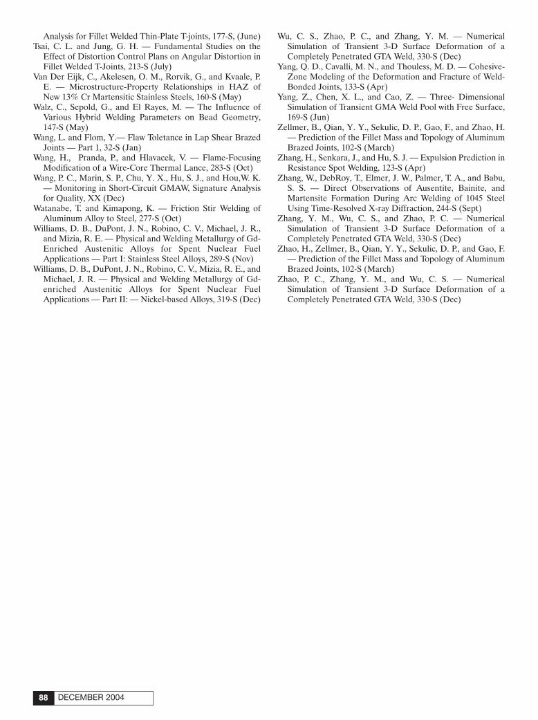
Analysis for Fillet Welded Thin-Plate T-joints, 177-S, (June)Tsai, C. L. and Jung, G. H. — Fundamental Studies on the
Effect of Distortion Control Plans on Angular Distortion inFillet Welded T-Joints, 213-S (July)
Van Der Eijk, C., Akelesen, O. M., Rorvik, G., and Kvaale, P.E. — Microstructure-Property Relationships in HAZ ofNew 13% Cr Martensitic Stainless Steels, 160-S (May)
Walz, C., Sepold, G., and El Rayes, M. — The Influence ofVarious Hybrid Welding Parameters on Bead Geometry,147-S (May)
Wang, L. and Flom, Y.— Flaw Toletance in Lap Shear BrazedJoints — Part 1, 32-S (Jan)
Wang, H., Pranda, P., and Hlavacek, V. — Flame-FocusingModification of a Wire-Core Thermal Lance, 283-S (Oct)
Wang, P. C., Marin, S. P., Chu, Y. X., Hu, S. J., and Hou,W. K.— Monitoring in Short-Circuit GMAW, Signature Analysisfor Quality, XX (Dec)
Watanabe, T. and Kimapong, K. — Friction Stir Welding ofAluminum Alloy to Steel, 277-S (Oct)
Williams, D. B., DuPont, J. N., Robino, C. V., Michael, J. R.,and Mizia, R. E. — Physical and Welding Metallurgy of Gd-Enriched Austenitic Alloys for Spent Nuclear FuelApplications — Part I: Stainless Steel Alloys, 289-S (Nov)
Williams, D. B., DuPont, J. N., Robino, C. V., Mizia, R. E., andMichael, J. R. — Physical and Welding Metallurgy of Gd-enriched Austenitic Alloys for Spent Nuclear FuelApplications — Part II: — Nickel-based Alloys, 319-S (Dec)
Wu, C. S., Zhao, P. C., and Zhang, Y. M. — NumericalSimulation of Transient 3-D Surface Deformation of aCompletely Penetrated GTA Weld, 330-S (Dec)
Yang, Q. D., Cavalli, M. N., and Thouless, M. D. — Cohesive-Zone Modeling of the Deformation and Fracture of Weld-Bonded Joints, 133-S (Apr)
Yang, Z., Chen, X. L., and Cao, Z. — Three- DimensionalSimulation of Transient GMA Weld Pool with Free Surface,169-S (Jun)
Zellmer, B., Qian, Y. Y., Sekulic, D. P., Gao, F., and Zhao, H.— Prediction of the Fillet Mass and Topology of AluminumBrazed Joints, 102-S (March)
Zhang, H., Senkara, J., and Hu, S. J. — Expulsion Prediction inResistance Spot Welding, 123-S (Apr)
Zhang, W., DebRoy, T., Elmer, J. W., Palmer, T. A., and Babu,S. S. — Direct Observations of Ausentite, Bainite, andMartensite Formation During Arc Welding of 1045 SteelUsing Time-Resolved X-ray Diffraction, 244-S (Sept)
Zhang, Y. M., Wu, C. S., and Zhao, P. C. — NumericalSimulation of Transient 3-D Surface Deformation of aCompletely Penetrated GTA Weld, 330-S (Dec)
Zhao, H., Zellmer, B., Qian, Y. Y., Sekulic, D. P., and Gao, F.— Prediction of the Fillet Mass and Topology of AluminumBrazed Joints, 102-S (March)
Zhao, P. C., Zhang, Y. M., and Wu, C. S. — NumericalSimulation of Transient 3-D Surface Deformation of aCompletely Penetrated GTA Weld, 330-S (Dec)
DECEMBER 200488
WJ Index 2004corr 11/9/04 1:26 PM Page 88

Guidelines for submitting electronic files
1. Platform:Macintosh or PC accepted
2. Files accepted:QuarkXpress, Adobe Photoshop, Adobe Illustrator, TIFF, EPS and PDF files only.
3. Color:Send all files in as CMYK (for color) or Grayscale (for b/w).
4. Images:Minimum resolution required for magazine printing is 300 dpi for full color artwork orgrayscale at least 1000 dpi for bitmap (B&W/line art). Images and logos from Web sitesare NOT usable for printing. They are low resolution images (72 dpi). Images taken witha digital camera are not acceptable unless they meet the minimum 300 dpi requirement.
5. Proof:A proof of the images should always be provided.
6. Electronic File Transfer:Files larger than 68k are not acceptable as an email attachment; please CD or Zip, may also send files to the printer FTP site ( a user name and password will be providedwhen requested)
Check list for submitting electronic files:
Colors: ❐ 4/C ❐ Grayscale ❐ B&W/line art
File Type: ❐ TIFF ❐ EPS
File sent via: ❐ Floppy disk ❐ Zip disk ❐ Jaz disk ❐ CD ❐ Email (68k limit)
❐ Proof supplied/faxed
❐ CMYK images at 300 dpi or higher, B&W/line art at 1000 dpi or higher.
❐ All color in all images set to CMYK process (not RGB)
When submitting ads please send them to the attention of
Frank WilsonAdvertising ProductionAmerican Welding Society550 NW LeJeune Rd.Miami, Fla. 33126
WJ Index 2004corr 11/9/04 1:26 PM Page 89

CLASSIFIEDS
DECEMBER 200490
WANTEDIndependent Sales Reps
to demonstrate welding alloys toend users.-Consumables Market-Repeat Customers-Complements Industrial Rep’spresent line(s) of products.Very unique opportunity.Contact Christopher BiggarVulcan Systems, Inc.(800) 642-9885
Flame Cutting Trainingat Your Location
All aspects of Mechanized Flame Cutting leading to maximumcut quality and productivity.
Contact John DawsonThermal Cutting Consulting Inc.E-mail: [email protected]: 843-665-6776
The AWS CertificationCommittee
Is seeking the donation of sets of Shop and Erection drawings of high-rise buildings greater than ten storieswith Moment Connections includingOrdinary Moment Resistant Frame(OMRF) and Special MomentResistant Frame (SMRF) for use inAWS training and certification activi-ties. Drawings should be in CAD for-mat for reproduction purposes.Written permission for unrestrictedreproduction, alteration, and reuse astraining and testing material isrequested from the owner and othersholding intellectual rights.
For further information, contact:
Joseph P. Kane 631-265-3422 (office) 516-658-7571 (cell)
2005 TRAININGCWI PREPARATORY
Guarantee - Pass or Repeat FREE!
2 WEEK COURSE (10 DAYS)MORE HANDS–ON/PRACTICAL APPLICATIONS
Pascagoula, MS Jan. 17–28 Mar 14–25Houston, TX Feb. 14–25
Houma, LA Apr. 4–15
SAT–FRI COURSE (7 DAYS)EXTRA INSTRUCTION TO GET A HEAD STARTPascagoula, MS Jan. 22–28 Mar 19–25
Houston, TX Feb. 19–25Houma, LA Apr. 9–15
MON–FRI COURSE (5 DAYS)GET READY - FAST–PACED COURSE!
Pascagoula, MS Jan. 24–28 Mar 21–25Houston, TX Feb. 21–25Houma, LA Apr. 11–15
(Test follows on Saturday at same facility)
Continue Your Education With:
API 510 & API 570Let us prepare you for the API exams
APPLICATIONS OF VISUALWELDING INSPECTION
Hands-on training for real work situations
RT FILM INTERPRETATION Challenging practicals using real welds
WELDING PROCEDURESLearn code requirements to write/audit
ADVANCED VISUAL INSPECTIONFor experienced inspectors & engineers
MT/PT/UT/RT LEVEL l & ll Classroom training per ASNT SNT-TC-1A
For our entire class schedule, contact1-800-489-2890 or
AWS JobFind
www.aws.org/jobfindJob categories for welders, engineers, inspectors, and more than 17
other materials joining industry classifications!
@Post Jobs.
Find Jobs.
SERVICES
CERTIFICATION & TRAINING
CAREER OPPORTUNITIES
WELDING ENGR/QC MGRKomline-Sanderson an Int’l leader in de-sign, fabrication and installation of dryers,filters, wastewater treatment filtration equip-ment, seeks a hands on, degreed engineerto develop weld procedures/techniques.Sound knowledge of metallurgy and weld-ing methods to minimize fatigue failure inrotating shafts a must. Responsible for im-plementing and maintaining quality systemto ASME Code including weld proce-dures/qualifications; Supervise in-house &vendor Inspection; qualify vendors to pro-vide manufacturing support for Code andnon-Code contracts. Minimum 15 years ex-perience a MUST. Domestic/Int’l travel re-quired. NDT Level III a plus/PE helpful.
Classifieds 12/04 11/9/04 2:20 PM Page 90

ATTENTION!Welding Equipment Sales Personnel.We pay you for finding us good used
welding systems, seamers, positioners, manipulators, turning rolls, etc.
We will buy your customers’ trade-ins.
WELD PLUS, INC.1-800-288-9414
SAVE TAXES!! ---- DELIVERY IN 2004!!
“BRAND NEW 2004” IN OUR STOCK!! JETLINE SEAMERS!! PANDJIRISPOSITIONERS!! WEBB TURNING ROLLS!! FACTORY WARRANTY!!
JUST IN!! JETLINE CW5-264, 22 ft. Welding Lathes, Excellent Condition!!“1996” Webb M-5 Offset “Joggle” Forming Machine 1/2” Capacity.
Well Over 150 Positioners Total, Up to 60 Tons!! Head/Tailstocks, Turntables up to 60tons. Manipulators up to 14’ x 14’, Travel Cars, Longitudinal Seamers from 6 in. to 26ft., Turning rolls up to 400 Tons, Circular Weld Systems, Welding Lathes, ArcMachines & other Orbital Welders.
WELDING RELATED MACHINERY IS OUR ONLY BUSINESSIf You are a Weld Fabricator—YOU NEED TO VISIT US!!!
TALK TO US!!—“WE KNOW WELDING”
w w w. w e l d p l u s . c o mE-mail: [email protected] Jack, Pete, Paul or DennisFax: 513-467-3585
Used-Robots .com
We buy and sell 1- 877- 487- 3376
1989 2-Ton GMCCylinder Transport Truck
16 ft. bed with Waltco rail gate,366 gasoline engine, 54,000 miles, immaculate condi-tion. $23,000.
Photos available upon request.
Contact 800-767-0276 from8 a.m. to 5 p.m., EST M—F
FOR SALE - FOR RENTWelding PositionersHeadstock TailstockTank Turning Rolls
Manipulators, SubarcWelding Machines
800-218-9620713-943-8032
BUSINESS FOR SALE
EQUIPMENT SALES/RENTAL
EQUIPMENT TO BUY OR SELL
BUSINESS FOR SALE
Established 1983. Make small storedenergy welding equipment. Pulse arc,spot resistance and fusion percussionmini stud welder. International marketsthrough distributors, reps and directsales. Miniature tech joining of similarand dissimilar metals for medical, den-tal, optical, jewelry, crafts, appliance,auto, aircraft, and electronics indus-tries. Very strong gross profit @84%,before tax earnings @26% and after taxprofits of 15%. Strictly confidential,please write:
Business 4 SalePO Box 893
E. Greenwich, RI 02818
91WELDING JOURNAL
Classifieds 12/04 11/9/04 2:20 PM Page 91

DECEMBER 200492
ADVERTISERINDEX
Abicor Binzel ................................................www.binzel-abicor.com ......................IBC
Aelectronic Bonding, Inc.............................www.abiusa.net ......................................20
Airgas............................................................www.airgas.com......................................21
ArcOne..........................................................www.arc1weldsafe.com ....9, 11, 13, 15, 17
Atlas Welding Accessories, Inc. ..................www.atlasweld.com ................................37
AWS Certification Department ..................www.aws.org............................................19
AWS Conference Dept. ................................www.aws.org............................................40
AWS Conventions & Expositions ..............www.aws.org............................................33
AWS Convention Sales................................www.aws.org..............................................2
AWS Education Dept...................................www.aws.org............................................51
AWS Foundation..........................................www.aws.org......................................24, 25
AWS Member Services ................................www.aws.org................................12, 14, 22
AWS Technical Services ..............................www.aws.org......................................47, 53
Centerline Ltd. ............................................www.cntrline.com ..................................RI
College of Oceaneering ..............................www.coo.edu............................................17
Commercial Diving Academy ....................www.commercialdivingacademy.com ..23
Cor-Met ........................................................www.cor-met.com ............................10, 72
C-Spec ..........................................................www.weldoffice.com ..............................42
Diamond Ground Products, Inc.................www.diamondground.com ....................15
Divers Academy International ..................www.diversacademy.com........................13
ESAB Welding & Cutting Prod. ................www.esabna.com................................OBC
Fischer Technology, Inc. ..............................www.Fischer-Technology.com................23
GE Inspection Technology ..........................www.GEInspectionTechnologies.com ....1
Gedik Welding Inc. ......................................www.gedik.com.tr ..................................11
Genstar Technologies Co., Inc. ..................www.genstartech.com ............................44
Hobart Inst. of Welding Tech. ....................www.welding.org ....................................15
Industrial Tradesman Magazine................www.industrialtradesman.com ............75
IWE Consulting, Inc. ..................................www.iweconsulting.com ........................73
Lincoln Electric Co. ....................................www.lincolnelectric.com ..........................5
MK Products................................................www.mkprod.com ..................................20
Saldat Anasta Weldiing & Cutting Expo ..www.saldat.it ............................................7
Select Arc, Inc. ............................................www.select-arc.com ............................IFC
Silver Mine Distribution, Inc. ....................www.silverminedistribution.com ..........37
Triangle Engineering, Inc. ..........................www.trieng.com ......................................42
Weld Hugger, L.L.C ....................................www.weldhugger.com ............................73
Weld Logic, Inc.............................................www.weldlogic.com ................................44
WEMCO ......................................................www.aws.org............................................43
IFC = Inside Front Cover
IBC = Inside Back Cover
OBC = Outside Back Cover
RI = Reader Information Card
BUSINESSOPPORTUNITIES
DISTRIBUTORS WANTED
Extruded Aluminum Manifolds
&
Headers
No Stocking Required
Pamark Inc.Phone: 616-456-6043
Fax: 616-456-8849
WELDINGCONSULTANTS
Want to be a Welding Journal
Advertiser?For information, contact
Rob Saltzstein at (800) 443-9353, ext. 243,
or via e-mail [email protected].
REPRINTS REPRINTS
To order custom reprints of articles in
Welding Journal,call FosteReprints at
(219) 879-8366 or(800) 382-0808 or.
Request for quotes can befaxed to (219) 874-2849.
You can e-mailFosteReprints at
Classifieds 12/04 11/10/04 11:54 AM Page 92

WELDING RESEARCH
-S319WELDING JOURNAL
ABSTRACT. The physical and weldingmetallurgy of gadolinium- (Gd-) enrichedNi-based alloys has been examined using acombination of differential thermal analy-sis, hot ductility testing, Varestraint testing,and various microstructural characteriza-tion techniques. Three different matrixcompositions were chosen that were similarto commercial Ni-Cr-Mo base alloys (UNSN06455, N06022, and N06059). A ternaryNi-Cr-Gd alloy was also examined. The Gdlevel of each alloy was ~2 wt-%. All the al-loys initiated solidification by formation ofprimary austenite and terminated solidifi-cation by a Liquid → g + Ni5Gd eutectic-type reaction at ~1270°C. The solidificationtemperature ranges of the alloys variedfrom ~100° to 130°C (depending on alloycomposition). This is a substantial reduc-tion compared to the solidification temper-ature range of Gd-enriched stainless steels(360° to 400°C) that terminate solidificationby a peritectic reaction at ~1060°C. Thehigher-temperature eutectic reaction thatoccurs in the Ni-based alloys is accompa-nied by significant improvements in hotductility and solidification cracking resis-tance. The results of this research demon-strate that Gd-enriched Ni-based alloys areexcellent candidate materials for nuclearcriticality control in spent nuclear fuel stor-age applications that require production
and fabrication of large amounts of mater-ial through conventional ingot metallurgyand fusion welding techniques.
Introduction
Part 1 of this research article (Ref. 1)summarized results on development ofGd-enriched stainless steel alloys for nu-clear criticality control in spent nuclearfuel storage applications. In that work, itwas shown that Gd additions to a 316L-type matrix leads to the formation of an in-termetallic (Fe,Ni,Cr)3Gd phase that pro-duces a very large solidificationtemperature range (360° to 400°C, de-pending on Gd concentration) and se-verely limits the hot ductility and weld-ability of these alloys to a point wherecommercial production is not practical.
As shown by the binary Fe-Gd phasediagram in Fig. 1A (Ref. 2), Fe-Gd alloyswith low Gd concentrations exhibit a pri-mary delta solidification mode that is fol-lowed by a brief region of austenite solid-ification. Under nonequilibriumsolidification conditions in which solutediffusion in the solid is negligible, austen-ite formation is followed by a series of cas-cading peritectic reactions before solidifi-cation terminates at 845°C by a terminal
eutectic reaction involving the Fe2Gd in-termetallic. Thus, the solidification tem-perature range of simple Fe-Gd alloys isalso very large under nonequilibrium so-lidification conditions. In multicompo-nent Gd-enriched stainless steels, solidifi-cation starts with primary delta andterminates by a peritectic reaction involv-ing the (Fe,Ni,Cr)3Gd phase at ~1060°C,which also produces a very large solidifi-cation temperature range. Thus, althoughthere are significant differences betweensimple Fe-Gd alloys and multicomponentFe-Ni-Cr-Mo-Gd stainless steels, the al-loys are similar in that a low-temperatureperitectic reaction is responsible for pro-ducing a very large solidification tempera-ture range in each system. As mentionedpreviously, this severely limits the hot duc-tility and weldability of these alloys.
Comparison of the Ni-Gd (Fig. 1B)and Fe-Gd systems reveals some signifi-cant differences in the solidification be-havior of alloys with low Gd concentra-tions. In particular, Ni-Gd alloys with lessthan about 13 wt-% Gd exhibit a simpletwo step solidification sequence consistingof primary austenite (Ni) formation fol-lowed by a terminal eutectic reaction at1275°C involving the Ni17Gd2 intermetal-lic. The presence of the high-temperatureeutectic reaction in the Ni-Gd system sig-nificantly decreases the solidification tem-perature range compared to Fe-Gd alloys.Thus, in general, it appears that the solid-ification behavior of the multicomponentGd-enriched stainless steels mimics theFe-Gd system more closely than the Ni-Gd system. From a technical standpoint, itis highly desirable to identify alloyingstrategies that could be utilized to modifythe solidification behavior of the commer-cial-type Gd-enriched alloys so that solid-ification more closely follows that of the
SUPPLEMENT TO THE WELDING JOURNAL, DECEMBER 2004Sponsored by the American Welding Society and the Welding Research Council
KEYWORDS
Gadolinium-EnrichedNickel-Based Alloys
Austenitic AlloysDifferential Thermal AnalysisHot Ductility TestingVarestraint TestingSolidification CrackingEutectic Reaction
Physical and Welding Metallurgy ofGd-enriched Austenitic Alloys for Spent
Nuclear Fuel Applications —Part II: Nickel-based Alloys
Tests proved Gd-enriched Ni-based alloys are excellent candidates for use instoring spent nuclear fuels
J. N. DUPONT, C. V. ROBINO, J. R. MICHAEL, R. E. MIZIA, AND D. B. WILLIAMS
J. N. DUPONT is Associate Professor and D. B.WILLIAMS is Vice Provost for Research and aProfessor, Department of Materials Science & En-gineering, Lehigh University, Bethlehem, Pa. C. V.ROBINO is with the Technical Staff, Joining andCoating Department, and J. R. MICHAEL is withthe Technical Staff, Materials CharacterizationDept.,Sandia National Laboratories, Albu-querque, N.Mex. R. E. MIZIA is Engineering Fel-low, Energy and Engineering Technology, IdahoNational Engineering and Environmental Labo-ratory, Idaho Falls, Idaho.
DuPont Supplement for 12/04corr 11/5/04 4:42 PM Page 319

WELDING RESEARCH
DECEMBER 2004-S320
Ni-Gd system. In particular, it is of inter-est to develop alloying strategies thatwould lead to replacement of the low-temperature peritectic reaction with ahigher temperature terminal eutectic re-action. This could potentially produce asignificant reduction in the solidificationtemperature range and concomitant im-provements in weldability and hot ductil-
ity. The most obvious approach to accom-plish this modification would be to in-crease the Ni content of the matrix. Thus,the objective of this research is to investi-gate the use of Ni-based alloys for im-proving the hot ductility and weldability ofGd-enriched austenitic alloys for spentnuclear fuel applications.
Experimental Procedure
Preliminary Alloy Experiments
The solidification responses of twosmall-scale (2.3 kg) alloys were first evalu-ated in the as-cast condition before largerscale heats were prepared. The composi-
Table 1 — Chemical Compositions of Small-Scale Alloys Used for Preliminary Experiments (All values in wt-%)
Alloy Gd Fe Ni Cr Mo Mn SiE-1 6.0 Bal 19.8 13.9 2.3 1.4 0.13E-2 2.0 2.8 Bal 20.9 12.5 <0.5 <0.08
Table 2 — Compositions (wt-%) for the Trial Ni-based Alloys(a)
Element N06455-Gd N06022-Gd N06059-Gd Ni-Cr-Gd
Gd 1.58 1.98 1.82 1.93Mo 14.16 12.01 15.02 0.57Cr 16.21 21.27 22.64 22.33Fe 0.147 2.02 0.163 0.087W 0.014 2.98 0.125 0.005Co <0.10 0.085 0.008 <0.10C 0.011 0.006 0.010 0.009Si 0.033 0.036 0.040 0.053Mn 0.104 0.101 0.103 0.098V 0.007 0.012 0.009 0.009P <0.010 <0.010 <0.010 <0.010S 0.0018 0.0012 0.0019 0.0019Ti 0.004 0.004 0.005 0.003Al 0.042 0.056 0.303 0.055Cu 0.004 0.003 0.030 0.055N 0.0046 0.0068 0.0074 0.0067O 0.0129 0.0140 0.0209 0.0191Ni bal bal bal bal
(a) Values shown are averages of three determinations at each of three laboratories.
Fig. 1 — Binary phase diagrams. A — Fe-Gd; B — Ni-Gd.
Fig. 2 — SEM photomicrograph and EBSP analysisof high-Ni stainless steel Alloy E-1 with Gd addition.
BA Fe-Gd Ni-Gd
DuPont Supplement for 12/04corr 11/5/04 4:42 PM Page 320

WELDING RESEARCH
-S321WELDING JOURNAL
tions of the two experimental alloys areshown in Table 1. Alloy E-1 was based ona stainless steel type composition withhigh Ni, while Alloy E-2 is a Ni-based alloywith a matrix composition similar to thecommercial alloy UNS #N06022. Alloy E-1 was examined to determine if an in-creased Ni content could be used to sig-nificantly modify the solidificationbehavior in a favorable way, while stillmaintaining a stainless-steel-type matrixcomposition. The N06022 alloy heat wasexamined to determine if higher Ni con-tents were needed in the matrix in order toproduce the desired result. The N06022matrix composition was chosen becausethis commercial alloy is already being con-sidered for spent nuclear fuel applica-tions. Each alloy was characterized by dif-ferential thermal analysis (DTA) andmicrostructural characterization tech-niques as described in Part 1 (Ref. 1).
Large-Scale Alloy Experiments
Results from the preliminary alloy op-timization experiments showed that desir-able results were obtained by adding Gd to
a N06022-type matrix. Thus, four largerscale heats of Ni-based alloys were pre-pared for more detailed investigationsusing the same techniques described inPart 1. The compositions of the four alloysare summarized in Table 2. Three of the al-loys were chosen to provide matrix com-positions similar to highly corrosion-resistant Ni-Cr-Mo alloys (UNS#N06455, UNS #N06022, and UNS#N06059), which will provide the properlong-term corrosion resistance under stor-age conditions. As with the stainless steelalloys, in order to achieve the desired ma-trix composition, modifications to thenominal alloy composition were requiredto account for Ni depletion and Cr en-richment of the matrix due to formation ofGd-rich intermetallics (Ref. 3), and thesewere based on the measured compositionof the intermetallic in the small-scaleN06022-Gd trial heat. The fourth alloy isa simplified ternary Ni-Cr-Gd alloy thatwas included as a basis for comparison. Al-though previous work (Ref. 1) consideredGd additions up to 6 wt-%, recent experi-ments performed at the Los Alamos Na-tional Laboratory Criticality Experiments
Facility (Ref. 4) indicate that, for the mosthighly enriched spent nuclear fuel and thecurrent repository container design, a Gdlevel of 2 wt-% should be adequate tomeet criticality control needs. Thus, targetGd levels were set at 2 wt-%. The valuesshown in Table 2 are averages of three de-terminations each at three independentlaboratories (nine total measurements).For the four alloys, the standard deviationin the Gd determinations, expressed as afraction of the average value, ranged from4.4 to 10.7% of the average for the ninemeasurements. In general, values for theother major elements were in reasonableagreement, with a single standard devia-tion of approximately 5% of the averagevalue for that element.
The same experimental techniques uti-lized in Part 1 (DTA, hot ductility, Vare-straint weldability, microstructural char-acterization) were conducted on the largescale Ni-based alloys with the followingexceptions. The Ni-based alloys weremelted by vacuum induction heating, castinto 10-cm-diameter, 11.3-kg ingots, ho-mogenized at 1160°C for 16 h, and hotrolled at 1160°C with moderate reductions
Fig. 3 — DTA traces for as-cast high-Ni stainless steel Alloy E-1 with Gd addition. A — Heating trace; B — cooling trace.
A B
Fig. 4 — Light optical photomicrographs of high-Ni stainless steel Alloy E-1 with Gd addition after DTA analysis.
A B
DuPont Supplement for 12/04corr 11/5/04 4:42 PM Page 321

WELDING RESEARCH
DECEMBER 2004-S322
(3–6 mm) per pass to 14-mm-thick by15.2-cm-wide plate. Frequent reheatingwas used to maintain the rolling tempera-ture near 1150°C. Following rolling, thealloys were annealed in an argon atmos-phere at 1150°C for 4 h and quenched withchilled flowing argon.
Varestraint weldability tests were con-ducted on the N06455-Gd and Ni-Cr-Gdplate. The Varestraint tests were con-ducted on 165 ¥ 25.4 ¥ 3-mm subsize sam-ples with a current, voltage, and travelspeed of 100 A, 9 V, and 3 mm/s, respec-tively. Augmented strain levels of 1.0%and 3.5% were used. Simple autogeneouswelds were also made on the N06455-Gdalloy plate using electron beam welding(EBW) and gas tungsten arc welding(GTAW). The electron beam welds weremade at sharp focus, an accelerating volt-age of 100 kV, various beam currents be-tween 6 and 40 mA, and travel speedsranging from 6 to 25 mm/s. Sharp focuswas defined as the focus setting that
yielded the maximum visible heating of atungsten block at the appropriate beamcurrent, voltage, and final lens-to-workdistance. This produced welds ranging inpenetration from 1.5 to 3.2 mm. The au-togeneous GTA weld was made at a volt-age of 14 V, a current of 120 A, and a travelspeed of 3.4 mm/s.
Results
Preliminary Alloy OptimizationExperiments
An SEM photomicrograph of the high-Ni stainless steel heat (Alloy E-1) in theas-cast condition is shown in Fig. 2 alongwith EBSP patterns of the phases ob-served in the microstructure. The lack ofretained ferrite in the dendrite cores is ap-parent, as is the absence of the thin(Fe,Ni,Cr)3Gd rim and terminal ferriteconstituents around the interdendritic(Ni,Fe)3Gd phase that were observed in
316L-type stainless steels enriched in Gd(Ref. 1). With the increased Ni content,solidification appears to initiate by theformation of austenite dendrites and ter-minate by a peritectic-like reaction, sinceFe3Gd and Ni3Gd both form by peritecticreactions in the Fe-Gd and Ni-Gd sys-tems, and the (Fe,Ni,Cr)3Gd phase formsperitectically in Gd-enriched 316L stain-less steel.
Differential thermal analysis of the Nimodified heat is shown in Fig. 3. Duringheating, liquation of the (Ni,Fe)3Gdphase initiates at 1127°C — Fig. 3A. Thus,the liquation temperature of the(Ni,Fe)3Gd phase in this alloy is raised byabout 65°C compared to that in the 316L-type alloys, which liquates at ~1060°C(Ref. 1). The cooling portion of the DTAtrace indicates that, for the cooling rateused for the DTA analysis (5°C/min), so-lidification terminates with the formationof two constituents. The microstructure ofthe DTA samples is shown in Fig. 4 and in-
Fig. 5 — Light optical photomicrograph of Ni-based Alloy E-2 with Gdaddition.
Fig. 6 — DTA result for the Ni-based Alloy E-2 with Gd addition.
A
Fig. 7 — EPMA results acquired from Ni-based Alloy E-2 with Gd addition. A — SEM photomicrograph showing location of EPMA trace; B — EPMA results.
B
DuPont Supplement for 12/04corr 11/5/04 4:42 PM Page 322

WELDING RESEARCH
-S323WELDING JOURNAL
dicates that at least two constituents areassociated with the interdendritic regions.Although these constituents have not yetbeen identified, consideration of the Fe-
Gd and Ni-Gd phase diagrams, and the es-tablished tendency of these alloys to formGd-rich intermetallics (Ref. 2), impliesthat the intermetallic phases are probably
based on the Ni3Gd and Ni7Gd2 struc-tures. The presence of two distinct Gd in-termetallic phases was not apparent in ei-ther the microstructural analysis orheating DTA response of the alloy in theas-cast condition, so it is clear that thecooling rate through the solidificationtemperature range is an important factorthat affects microstructural developmentin this alloy. In any case, although the so-lidification temperature range of the Ni-modified alloy has been reduced by~65°C, the solidification temperaturerange is still almost 300°C and would notbe expected to significantly improve theweldability and hot ductility.
The as-cast microstructure of Alloy E-2
Table 3 — Compositions (All Values in wt-%) of Ni5Gd-Type Phase Observed in As-Cast Ingots
Alloy Ni Cr Mo Mn Fe W Al Si Gd
N06455-Gd 63.13 2.00 0.69 0.00 0.04 0.00 0.00 0.08 35.26N06022-Gd 60.50 2.35 0.53 0.00 0.52 0.00 0.02 0.10 34.93N06059-Gd 61.72 2.82 0.84 0.00 0.00 0.00 0.50 0.11 35.50Ni-Cr-Gd 61.41 2.52 0.04 0.00 0.04 0.00 0.00 0.04 34.23
Table 4 — Summary of On-Heating DTA Results
Sample Eutectic Type L Æg + Ni5Gd Liquidus Average MeltingTemperature, °C Temperature, °C Temperature Range, °C
N06455-Gd 1290, 1290 1400, 1402 110N06022-Gd 1272, 1276 1379, 1381 106N06059-Gd 1265, 1269 1370, 1369 103Ni-Cr-Gd 1291, 1294 1423, 1423 131
Fig. 8 — Backscattered electron SEM photomicrographs of four Ni-based alloys with Gd additions. A — N06455-Gd; B — N06022-Gd; C — N06059-Gd; D — Ni-Cr-Gd.
A B
C D
DuPont Supplement for 12/04corr 11/5/04 4:43 PM Page 323

WELDING RESEARCH
DECEMBER 2004-S324
is shown in Fig. 5. The eutectic constituentin the microstructure is clearly visible, andit is evident that the primary austenite iscontinuous with the austenite in the eutec-tic constituent. The results of the differen-tial thermal analysis are shown in Fig. 6. Onheating, a single liquation event initiates atapproximately 1285°C and melting is com-plete near 1391°C. On cooling, some un-dercooling is apparent, with solidificationinitiating at 1374°C and terminating withthe formation of a single constituent at1255°C. The single terminal solidificationpeak is consistent with the LOM photomi-crograph shown in Fig. 5 in which a singleeutectic-like constituent was observed. Fig-ure 7 shows the results of an electron probemicroanalysis (EPMA) scan conductedacross the cellular substructure of this alloy.The line shown in Fig. 7A denotes the loca-tion of the EPMA scan. As with the stain-less-steel-type alloys, the intermetallic ishigh in Gd, and there is essentially no Gd
dissolved in the austenite matrix. Based on the results presented above,
the Ni-based alloy provides the desirablesolidification characteristics in which so-lidification terminates by a high-tempera-ture eutectic-type reaction instead of alow-temperature peritectic reaction.Comparison of the DTA traces with thosefor the initial 316L-type heats and the Ni-modified alloy indicates that the meltingtemperature range for this Ni-based alloyis significantly smaller, i.e., ~100°C forthe Ni-based alloy vs. 300–400°C for thestainless steel alloys. Thus, based on theseinitial results, a full series of experimentswas conducted on several commercial-type Ni-based alloys with Gd additions(compositions shown in Table 2).
Full-Scale Experiments on Ni-basedAlloys
Figure 8 shows typical backscattered
electron images of the large-scale alloys inthe as-cast condition. All of the alloys ex-hibited a cellular substructure with an in-tercellular secondary constituent. Figure9 shows a representative backscattereddiffraction result, which shows that thematrix is austenite and the secondaryphase within the eutectic constituent is aNi5Gd-type intermetallic. Gadolinium ox-ides were also observed. These resultswere consistent among all the alloys. Thecompositions of the Ni5Gd-type phasesobserved in each alloy are summarized inTable 3. The composition of the phase isconsistent with the Ni5Gd stoichiometry,with small amounts of dissolved Cr, Mo,Fe, and Al.
Figure 10A shows a DTA heating scanand Fig. 10B shows a cooling scan fromAlloy N06455-Gd that was typical for allthe alloys. On heating, the alloy exhibitsan endothermic peak at 1290°C associatedwith liquation of the g/Ni5Gd eutectic-
A B
Fig. 10 — DTA scans from Alloy N06455-Gd that were typical for all the alloys: A — Heating; B —cooling.
Fig. 9 — Backscattered diffraction results for AlloyN06022-Gd that were typical for all the alloys.
Fig. 11 — DTA microstructure of Alloy N06455-Gd showing primaryaustenite cells and an intercellular g/Ni5Gd eutectic-type constituent.
Fig. 12 — Hot ductility results of Ni-based alloys with Gd additions.
DuPont Supplement for 12/04corr 11/5/04 4:43 PM Page 324
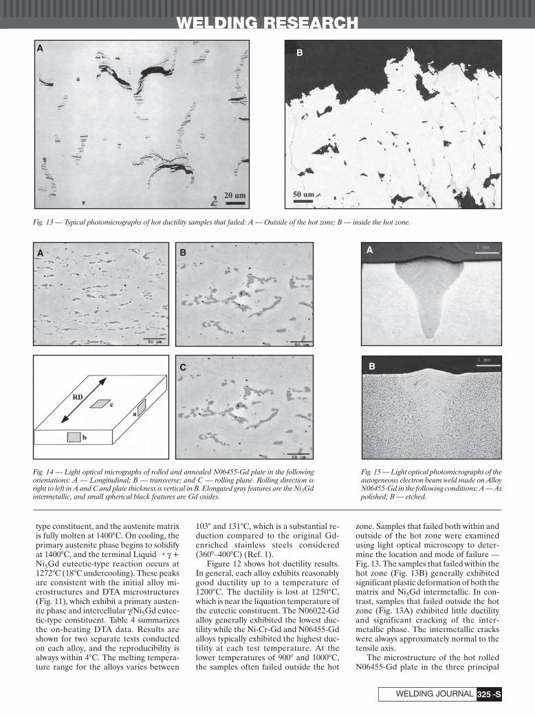
WELDING RESEARCH
-S325WELDING JOURNAL
type constituent, and the austenite matrixis fully molten at 1400°C. On cooling, theprimary austenite phase begins to solidifyat 1400°C, and the terminal Liquid → g +Ni5Gd eutectic-type reaction occurs at1272°C (18°C undercooling). These peaksare consistent with the initial alloy mi-crostructures and DTA microstructures(Fig. 11), which exhibit a primary austen-ite phase and intercellular g/Ni5Gd eutec-tic-type constituent. Table 4 summarizesthe on-heating DTA data. Results areshown for two separate tests conductedon each alloy, and the reproducibility isalways within 4°C. The melting tempera-ture range for the alloys varies between
103° and 131°C, which is a substantial re-duction compared to the original Gd-enriched stainless steels considered(360°–400°C) (Ref. 1).
Figure 12 shows hot ductility results.In general, each alloy exhibits reasonablygood ductility up to a temperature of1200°C. The ductility is lost at 1250°C,which is near the liquation temperature ofthe eutectic constituent. The N06022-Gdalloy generally exhibited the lowest duc-tility while the Ni-Cr-Gd and N06455-Gdalloys typically exhibited the highest duc-tility at each test temperature. At thelower temperatures of 900° and 1000°C,the samples often failed outside the hot
zone. Samples that failed both within andoutside of the hot zone were examinedusing light optical microscopy to deter-mine the location and mode of failure —Fig. 13. The samples that failed within thehot zone (Fig. 13B) generally exhibitedsignificant plastic deformation of both thematrix and Ni5Gd intermetallic. In con-trast, samples that failed outside the hotzone (Fig. 13A) exhibited little ductilityand significant cracking of the inter-metallic phase. The intermetallic crackswere always approximately normal to thetensile axis.
The microstructure of the hot rolledN06455-Gd plate in the three principal
A
Fig. 13 — Typical photomicrographs of hot ductility samples that failed: A — Outside of the hot zone; B — inside the hot zone.
Fig. 14 — Light optical micrographs of rolled and annealed N06455-Gd plate in the followingorientations: A — Longitudinal; B — transverse; and C — rolling plane. Rolling direction isright to left in A and C and plate thickness is vertical in B. Elongated gray features are the Ni5Gdintermetallic, and small spherical black features are Gd oxides.
A AB
C B
Fig. 15 — Light optical photomicrographs of theautogeneous electron beam weld made on AlloyN06455-Gd in the following conditions: A — Aspolished; B — etched.
B
DuPont Supplement for 12/04corr 11/5/04 4:43 PM Page 325

WELDING RESEARCH
DECEMBER 2004-S326
plate orientations is shown in Fig. 14, andis representative of that observed in allthe alloys. As shown, the gadolinide dis-tribution is substantially changed duringrolling. At the hot rolling temperatureused (1150°C), the gadolinides appear tobe relatively soft and ductile, and this results in a gadolinide morphology that iselongated in the rolling direction and flat-tened out in the rolling plane. In a man-ner similar to the as-cast microstructureof Fig. 9, the rolled plate also containssmall spherical Gd oxides that are appar-ently distributed throughout the austen-ite matrix as well as within the Ni5Gdintermetallic.
Figure 15 shows light optical photomi-crographs of an autogeneous electronbeam weld made on the N06455-Gd alloyin the as-polished and etched conditions.The weld exhibits columnar grains thatgrow epitaxially from the base metal, andthis grain morphology is typically ob-served in fusion welds. No solidification
cracks or other defectswere observed in this orthe other electronbeam welds producedin this study. Figure 16shows the structure ofan autogeneous GTAweld. The weld exhibitsa microstructure simi-lar to that of the ingots(primary austenite cellswith intercellularg/Ni5Gd eutectic-typeconstituent). The cellspacing and secondaryphase is much finerthan the ingots due tothe higher cooling ratesin the weld. A partiallymelted zone (PMZ) isclearly distinguishableoutside of the fusionzone (FZ). This PMZbounds temperaturesbetween the liquidus at
the PMZ/FZ interface and the Liquid Æg+ Ni5Gd eutectic-type temperature at thePMZ/HAZ interface. Within this region,the g/Ni5Gd constituent will liquate, asshown in Fig. 16C. The PMZ is often a re-gion where liquation cracking will occur inalloys with wide solidification tempera-ture ranges. However, the solidificationtemperature range in this alloy is rela-tively narrow (110°C) and comparable toother nickel-based alloys that are readilyweldable. Thus, liquation cracking is gen-erally not expected except, as describedbelow, under conditions of high restraintor where macrosegregation is persistent.
Figure 17 shows light optical photomi-crographs of an isolated region of a GTAweld that contained a crack. Inspection ofthe cracked region at slightly higher mag-nification (Fig. 17B) shows that a rela-tively large amount of the g/Ni5Gd con-stituent exists at the edge of the crack. Thelarge amount of g/Ni5Gd in this area can
be attributed to macrosegregation fromthe original ingot, and this form of crack-ing should be easily avoided whenmacrosegregation in the original ingot isprevented by a secondary refining stepsuch as vacuum arc remelting.
Figure 18 shows the Varestraint hotcracking results for the N06455-Gd andNi-Cr-Gd alloys. Results are shown forthe total and maximum crack length. As abasis for comparison, Fig. 19 shows Vare-straint hot cracking results for the stain-less steel alloys (Ref. 1). The results forthe stainless steel alloys were acquired asa function of Gd concentration at a fixedstrain level of 3.5%. The stainless steelsamples were 0.25 in. thick while the Ni-based samples were 0.125 in. thick. TheVarestraint welding parameters wereidentical for each alloy system. The weldsize produced on the stainless steel sam-ples was similar to the welds produced onthe Ni-based samples. Although directcomparisons cannot be made between theresults for the stainless steels and Ni-based alloys due to differences in samplesize, the very large difference in maximumand total crack length values clearly showsthe significant level of improvement inweldability for the Ni-based alloys. Interms of maximum crack length (MCL),the stainless steel alloys with comparableGd levels (1.9 wt-%) exhibited MCL val-ues near 5 mm, which is significantlyhigher than that of the Ni-based alloys of1 to 1.2 mm. Similar results were obtainedwhen total crack length (TCL) was used asthe cracking susceptibility indicator. TheTCL value for the stainless steel alloy with1.9 wt-% Gd was 50 mm, which is signifi-cantly higher than the TCL value of 5.7 to7.5 mm for the Ni-based alloys.
Discussion
The results of this research show thatthe solidification behavior and resultanthot ductility and weldability of Gd-
Fig. 16 — Light optical photomicrographs of an autogeneous GTA weldmade on the Alloy N06455-Gd. The weld exhibits a microstructure simi-lar to that of the ingots (primary austenite cells with intercellular g/Ni5Gdeutectic-type constituent).
A B
C
DuPont Supplement for 12/04corr 11/5/04 4:43 PM Page 326

WELDING RESEARCH
-S327WELDING JOURNAL
enriched austenitic alloys dependsstrongly on the matrix composition. Inparticular, stainless-steel-type matrixcompositions form a low-temperature(Fe,Ni,Cr)3Gd-type intermetallic by aperitectic reaction. This undesirable reac-tion sequence and concomitantly largemelting temperature range can be avoidedby the use of austenitic alloys with a Ni-based matrix. The DTA results from theNi-based alloys indicated that, in the ab-sence of undercooling, solidification initi-ates at the liquidus temperature (in therange of ~1370°–1420°C depending onalloy composition) by the formation of pri-mary g-austenite. Essentially no Gd is dis-solved in the austenite matrix. Thus, as so-lidification proceeds, the liquid becomesincreasingly enriched in Gd until the Liq-uid Æ g + Ni5Gd eutectic-type reaction isreached, at which point solidification isterminated by the eutectic reaction. This
reaction sequence and temperature rangeis generally similar to that expected in thebinary Ni-Gd system. Simple binary Ni-Gd alloys with less than about 13 wt-% Gdexhibit a similar two-step solidification se-quence consisting of primary austeniteformation followed by a terminal eutecticinvolving the Ni17Gd2 intermetallic at1275°C (Ref. 2). By comparison, the multi-component Ni-Cr-Mo-Gd alloys termi-nate solidification in the range of1260°–1290°C by a terminal eutectic-typereaction involving the Ni5Gd intermetal-lic. Thus, although the secondary phasewithin the terminal eutectic constituent isdifferent in each case, the terminal reac-tion temperatures are very similar.
The Gleeble hot ductility test resultsconfirm that the reduced melting temper-ature range provides improved hot work-ability (relative to the Gd-stainless alloys)at temperatures above ~1000°C. As
shown in Fig. 12, the hot ductility of the al-loys over the temperature range of 900°–1200°C can be roughly grouped into high-est ductility (N06455-Gd and Ni-Cr-Gd),intermediate ductility (N06059-Gd), andlowest ductility (N06022-Gd). Qualita-tively, this response can be rationalized interms of the concentrations of major al-loying elements (Cr, Mo, Fe, W) andgadolinide volume fraction (Gd level)(Table 2). The Ni-Cr-Gd alloy has the low-est substitutional alloying element level,while the N06455-Gd alloy has an appre-ciably lower Gd concentration (and inter-metallic volume fraction) than the otheralloys. Conversely, the N06022-Gd alloyhas both the highest alloying element leveland highest intermetallic volume fraction,while the N06059-Gd alloy is intermediateby these measures. At temperatures below900°C, the fracture process initiates by lo-calized cracking in the brittle Ni5Gd
Fig. 17 — Light optical photomicrographs of an isolated region of the GTA weld in Alloy N06455-Gd that contained a crack.
Fig. 18 — Varestraint hot cracking results for the Ni-Cr-Gd and N06455-Gd alloys. Results are shown for the following: A — Maximum crack length; B — totalcrack length.
A B
DuPont Supplement for 12/04corr 11/5/04 4:44 PM Page 327

WELDING RESEARCH
DECEMBER 2004-S328
phase, while ductility at the higher tem-perature (~1250°C) appears to be limitedby liquation of the Ni5Gd phase. In anycase, all the alloys were successfully re-duced to plate by hot rolling at tempera-tures near 1150°C. For these working con-ditions, the Ni5Gd intermetallicconstituent appears to be relatively softand ductile, and an elongated pancake-like morphology is developed. This mor-phology is likely not optimal from a me-chanical properties perspective, but noattempt was made in the current investi-gation to optimize either the hot workingprocedures or the resultant microstruc-ture. Such efforts are, however, ongoing.
The significant improvement in solidi-fication cracking resistance of the Ni-based alloys compared to the Gd-modi-fied stainless steel alloys can also beattributed to the large reduction in solidi-fication temperature range. The N06455-Gd and Ni-Cr-Gd alloys exhibit a solidifi-cation temperature range of 110°C and131°C, respectively. In comparison, theGd-stainless steel alloys exhibited a solid-ification temperature range of360°–400°C. For a given set of welding pa-rameters (i.e., temperature gradient), thesize of the crack-susceptible two-phasesolid + liquid region behind the fullymolten weld pool increases as the solidifi-cation temperature range increases. Thus,the distance a solidification crack canpropagate in the two-phase region also in-creases, resulting in higher MCL and TCLvalues (i.e., higher cracking susceptibility).Note that the cracking susceptibility is alsodependent on the volume fraction of theterminal liquid, but the comparisons be-tween the Gd-stainless alloys and the Gd-Ni alloys were made at similar Gd levels
(and thus similar volume fractions of ter-minal constituents). Comparisons can alsobe made to commercial Ni-based alloys inwhich a history of weldability has been es-tablished through practical applications.For example, Alloys IN718 and IN625tested with equivalent size samples andwelding parameters at strain level of 2.5%exhibit MCL values of ~1.6 and 1.2 mm,respectively (Ref. 5). These MCL valuesare comparable to those observed here,and these commercial alloys are known tobe readily weldable in typical applicationswhere the level of restraint is not large.Thus, based on the solidification temper-ature range and Varestraint data acquiredhere, the Ni-based alloys are expected tobe readily weldable under most applica-tions where the level of restraint is not veryhigh. Preliminary conformation of this wasprovided in the electron beam and GTAwelds that were generally crack free. Theisolated region of cracking observed inone GTA weld was confined to a regionwhere a local increase in the amount of theg/Ni5Gd constituent (relative to the nomi-nal g/Ni5Gd content) existed due tomacrosegregation. The g/Ni5Gd con-stituent was present as liquid just prior tothe end of solidification. In places wherethe liquid exists in large quantities, it canpromote solidification cracking by inter-fering with the formation of solid/solidboundaries across cells and grains. Thiscontinuous grain boundary/intercellularliquid film cannot support solidificationshrinkage strains at the terminal stages ofsolidification, and hot tears form as a re-sult. It is considered that solidificationcracking in this alloy should not be a majorproblem when macrosegregation has beenreduced by an intermediate processing
step such as vacuum arc remelting. Itshould be noted that ongoing work, whichincludes more extensive welding trials andweld schedule development, has not en-countered any difficulties with HAZcracking in narrow gap cold wire feedGTA butt joint welds. Work is in progressto evaluate this issue in more detail andwill be presented in a future article.
Conclusions
The influence of Gd additions on thesolidification behavior, hot ductility, andweldability of Ni-based alloys has been in-vestigated. The following conclusions canbe drawn from this research.
1. The addition of 6 wt-% Gd to a nom-inal 20Ni-14Cr-2Mo stainless-steel-typealloy results in a primary austenite solidi-fication mode and formation of a Gd-richinterdendritic constituent at ~1130°C.The resulting solidification temperaturerange of this high-Ni stainless steel is stillrather large (300°C) and not significantlydifferent than that previously observed inType 316L stainless steel alloys with Gdadditions (360° to 400°C).
2. The Ni-based alloys with ~2 wt-%Gd initiated solidification by primaryaustenite and terminated solidification bya Liquid Æ g + Ni5Gd eutectic-type reac-tion at ~1270°C. The solidification tem-perature range of these alloys (100° to130°C) is significantly smaller comparedto that of Gd-enriched 316L-type stainlesssteels that terminate solidification by aperitectic reaction at ~1060°C.
3. The higher temperature eutectic re-action that occurs in the Ni-based alloys isaccompanied by significant improvementsin hot ductility and solidification cracking
Fig. 19 — Varestraint hot cracking results for the stainless steel alloys. Results are shown as a function of Gd concentration at a fixed strain level of 3.5%. A — Maximum crack lengths; B — total crack lengths.
A B
DuPont Supplement for 12/04corr 11/5/04 4:44 PM Page 328
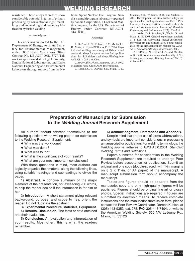
WELDING RESEARCH
-S329WELDING JOURNAL
resistance. These alloys therefore showconsiderable potential in terms of primaryprocessing by conventional ingot metal-lurgy and hot working, and secondary fab-rication by fusion welding.
Acknowledgments
This work was supported by the U.S.Department of Energy, Assistant Secre-tary for Environmental Management,under DOE Idaho Operations OfficeContract No. DE-AC07-99ID13727. Thiswork was performed at Lehigh University,Sandia National Laboratories, and IdahoNational Engineering and EnvironmentalLaboratory through support from the Na-
tional Spent Nuclear Fuel Program. San-dia is a multiprogram laboratory operatedby Sandia Corporation, a Lockheed Mar-tin company, for the U.S. Department ofEnergy under Contract DE-AC04-94AL8500.
References
1. DuPont, J. N., Robino, C. V., Michael, J.R., Mizia, R. E., and Williams, D. B. 2004. Phys-ical and welding metallurgy of Gd-enrichedaustenitic alloys for spent nuclear fuel applica-tions, Part I: Stainless steel alloys. Welding Jour-nal 83(11): 289-s to 300-s.
2. Binary Alloy Phase Diagrams, Vol. 3. 1992.Materials Park, Ohio: ASM International.
3. Robino, C. V., DuPont, J. N., Mizia, R. E.,
Michael, J. R., Williams, D. B., and Shaber, E.2003. Development of Gd-enriched alloys forspent nuclear fuel applications — Part I: Pre-liminary characterization of small scale Gd-enriched stainless steels. Journal of MaterialsEngineering and Performance 12(2): 206–214.
4. Loaiza, D. J., Sanchez, R., Wachs, G., andMizia, R. E. 2003. Critical experiment analysisof a neutron absorbing nickel-chromium-molybdenum-gadolinium alloy being consid-ered for the disposal of spent nuclear fuel. Jour-nal of Nuclear Materials Management 32(1).
5. DuPont, J. N., Robino, C. V., and Marder,A. R. 1998. Solidification and weldability of Nb-bearing superalloys, Welding Journal 77(10):417-s to 431-s.
All authors should address themselves to thefollowing questions when writing papers for submissionto the Welding Research Supplement:
◆ Why was the work done?◆ What was done?◆ What was found?◆ What is the significance of your results?◆ What are your most important conclusions?With those questions in mind, most authors can
logically organize their material along the following lines,using suitable headings and subheadings to divide thepaper.
1) Abstract. A concise summary of the majorelements of the presentation, not exceeding 200 words,to help the reader decide if the information is for him orher.
2) Introduction. A short statement giving relevantbackground, purpose, and scope to help orient thereader. Do not duplicate the abstract.
3) Experimental Procedure, Materials, Equipment.4) Results, Discussion. The facts or data obtained
and their evaluation.5) Conclusion. An evaluation and interpretation of
your results. Most often, this is what the readersremember.
6) Acknowledgment, References and Appendix.Keep in mind that proper use of terms, abbreviations,
and symbols are important considerations in processinga manuscript for publication. For welding terminology, theWelding Journal adheres to AWS A3.0:2001, StandardWelding Terms and Definitions.
Papers submitted for consideration in the WeldingResearch Supplement are required to undergo PeerReview before acceptance for publication. Submit anoriginal and one copy (double-spaced, with 1-in. marginson 8 1⁄2 x 11-in. or A4 paper) of the manuscript. Amanuscript submission form should accompany themanuscript.
Tables and figures should be separate from themanuscript copy and only high-quality figures will bepublished. Figures should be original line art or glossyphotos. Special instructions are required if figures aresubmitted by electronic means. To receive completeinstructions and the manuscript submission form, pleasecontact the Peer Review Coordinator, Doreen Kubish, at(305) 443-9353, ext. 275; FAX 305-443-7404; or write tothe American Welding Society, 550 NW LeJeune Rd.,Miami, FL 33126.
Preparation of Manuscripts for Submissionto the Welding Journal Research Supplement
DuPont Supplement for 12/04corr 11/5/04 4:48 PM Page 329

WELDING RESEARCH
DECEMBER 2004-S330
ABSTRACT. By establishing the correla-tion between transient behavior of a weldpool surface deformation and workpiecepenetration, and quantitatively analyzingthe surface deformation at the top andbottom surfaces at the moment the poolpenetrates and their dynamic responses towelding process parameters will providebasic data for the development of topsidevision-based penetration control in gastungsten arc welding (GTAW). A transientnumerical model was developed to inves-tigate the dynamic behavior of a com-pletely penetrated GTAW joint. A com-plete and comprehensive scheme was usedin which many factors, such as moving arc,3-D fluid and heat flow fields, transientstate, completely penetrated weld, andsurface deformation at both the top andbottom surfaces were considered. Thetransient development of 3-D surface de-formation and shape of a weld pool duringthe period from partial penetration tocomplete penetration is predicted. Thesimulated results showed that the ratiocurves of the maximum depression to thelength and width at the top surface of theweld pool at different times clearly indi-cated basic information on penetration.Therefore, the relation of the ratios vs.time can be used as an indicator to judgewhether the joint is penetrated.
Introduction
Gas tungsten arc welding (GTAW) isthe most used arc welding process for crit-ical and accurate joining. For this process,100% complete joint penetration must beensured without melt-through or over-penetration (Ref. 1). To this end, auto-
mated sensing and control of the GTAWprocess must be realized (Ref. 2). In prac-tice, the backside weld bead width is usu-ally employed to determine the extent ofpenetration. Although the backside beadwidth can be sensed by a backside sensor,there are limitations of access and coordi-nating the motion between the torch andsensor, and it is often necessary that thesensor be attached to and moved with thetorch to form a weld-face or topside sen-sor. However, the invisibility of the back-side and the strong arc light radiation to-gether cause tremendous difficulties forsuch sensors. To find a feasible sensor forautomated control, various methods havebeen studied, including pool oscillation(Ref. 3), ultrasound (Ref. 4), and an in-frared sensor (Ref. 5). Although signifi-cant progress has been made, practical ap-plications are still restricted.
Weld pool behavior contains enoughinformation on penetration. The pool sur-face is deformed because of the plasmaimpingement. Previous researchers havefound that the resultant depression of theweld pool surface correlates to the pene-tration depth of the weld pool (Refs. 6–8),but there is a lack of quantitative analysisof such a correlation. Establishing the cor-relation between dynamic behavior ofweld pool surface deformation and thepenetration information, while quantita-tively analyzing the surface deformation atthe top and bottom surfaces when the joint
is penetrated and their dynamic responseto welding process parameters will pro-vide much basic data for the realization ofa topside vision-based penetration controlfor the GTAW process. Thus, numericalsimulation of the surface deformation andits dynamic behavior to the GTAW processis of great significance for designing theprocess control algorithm.
Although there have been significantadvances in the numerical simulation ofthe GTAW process (Refs. 9–24), little at-tention has been paid to the transient dy-namics of the 3-D weld pool surface de-formation at both the topside andbackside of a fully penetrated weld pooland its correlation to the extent of pene-tration. Previous studies have shown thatthe pool depression has a direct effect onthe penetration (Refs. 6–8). In fact, theweld pool surfaces at both the front andback are depressed when there is com-plete penetration, and the amplitude ofsuch depression could be a reflection ofthe extent of penetration (Refs. 25, 26).For dynamic control, quantitative analysisis required to reveal how the process vari-ables (weld pool geometry and surface de-pression) change with the welding para-meters (welding current and velocity). Inthis paper, a numerical model is devel-oped to describe the transient behavior ofa 3-D GTA weld pool with complete pen-etration and surface deformation, and thequantitative relationship between thepool surface depression at the front sideand the extent of penetration.
Formulation
In order to describe the developmentof weld pool shape, surface deformation,thermal field, and fluid flow field, aGTAW arc is considered to be impingingon the workpiece along the z direction andit moves in the x direction at a constantspeed u0. A moving (x, y, z) coordinate sys-
KEY WORDS
Weld PoolSurface DeformationPenetrationCorrelationNumerical Simulation
Numerical Simulation of Transient 3-DSurface Deformation of a Completely
Penetrated GTA Weld
An analytical model that explores the dynamic behavior of a weld pool willhelp in the development of a sensor that detects complete joint penetration
in gas tungsten arc welding
BY C. S. WU, P. C. ZHAO, AND Y. M. ZHANG
C. S. WU and P. C. ZHAO are with Institute ofMaterials Joining, Shandong University, Jinan,China, [email protected]. Y. M. ZHANG is withCenter for Manufacturing and Department ofElectrical and Computer Engineering, Universityof Kentucky, Lexington, Ky.
Wu---12/04 11/5/04 2:28 PM Page 330

WELDING RESEARCH
-S331WELDING JOURNAL
tem is so chosen that its origin is located atthe intersection between the arc center-line and the workpiece surface. For such athree-dimensional transient problem, thegoverning equations include the energy,momentum, and continuity equations. Be-cause of the surface deformations at bothtopside and backside of the weld pool,some new boundaries appeared at bothtop and bottom surfaces, and their posi-tions changed with time. Therefore, thecalculation domain is no longer a regularrectangular one, which causes someboundary conditions to be difficult to dealwith. To represent the irregular bound-aries, a coordinate transformation isadopted. The independent variable intransformed space (z*) is related to thevertical coordinate in physical space (z)according to
(1)
where F(x,y,t) and B(x,y,t) are functionsthat define the upper and lower surfacesof the weld pool, respectively. The trans-formation maps the irregularly shaped re-gions into rectangular computational do-mains in which the two curvilinearsurfaces are stationary during any giventime interval, and are defined by z* = 0and z* = 1. Then, the governing equationsdescribing the fluid flow and heat transferphenomena in a weld pool are expressedas:
(2)
(3)
(4)
where V is the fluid velocity vector withthe components (u, v, w) in x, y, and z di-rections, Vl is the fluid velocity vector withthe components (u, v, wl) in x, y, and z di-rections, Vt is the fluid velocity vector withthe components (u, v, wt) in x, y, and z di-rections, r is the density, cp is the specificheat, p is the pressure, m is the viscosity, kis the thermal conductivity, and other sym-bols are defined as follows:
(5)
(6)
(7)
(8)
(9)
(10)
(11)
(12)For the body force term,
(13)
where b is the volume expansion coeffi-cient, g is the acceleration of gravity, T∞ isthe ambient temperature, and the electro-magnetic force J ¥ Bm is calculated basedon Wu’s analytical solutions (Refs. 12 and15) expressed as follows:
(14)
(15)
(16)
where mm is the magnetic permeability, I isthe welding current, sj is the effective ra-dius of the current distribution in Gauss-ian form, H is the thickness of the work-piece, and r =√x2 + y2.
When the workpiece is not completelypenetrated, the weld pool has only onefree surface F(x,y,t), which is deformedunder the combined action of arc pres-sure, hydrostatic force, and surface ten-sion. If the workpiece is completely pene-trated, the weld pool has two free surfaces,i.e., the upper surface F(x,y,t) and thelower surface B(x,y,t).
Under the condition of partial pene-tration, the shape of weld pool surfaceF(x,y,t) can be described by the followingequation:
(17)
where pa is the plasma arc pressure, C1 theLangrangian constant, g the surface ten-sion, and Fs = z – F(x,y,t) = 0.
The arc pressure pa can be described by(Ref. 27)
(18)
where J is the current density at the work-piece surface, which can be assumed to bein Gaussian distribution (Ref. 28)
(19)
J rI r
j j( ) = -
Ê
ËÁÁ
ˆ
¯˜˜2 22
2
2ps sexp
PIJ
arcm= m
p4
p gF CF
Fa
s
- + = — —
—
Ê
Ë
ÁÁÁ
ˆ
¯
˜˜̃r g1
5
r rJ B
I
Hr
r z
H
mz
m
j
¥( ) =
- -Ê
ËÁÁ
ˆ
¯˜˜
È
Î
ÍÍÍ
˘
˚
˙˙˙
-Ê
ËÁ
ˆ
¯˜
m
p
s
2
2 2
2
2
24
1 exp2
1
r rJ B
I
r
r
r z
H
y
r
my
m
j j
j
¥( ) =
- -Ê
ËÁÁ
ˆ
¯˜˜
- -Ê
ËÁÁ
ˆ
¯˜˜
È
Î
ÍÍÍ
˘
˚
˙˙˙
-Ê
ËÁ
ˆ
¯˜
m
p s s
s
2 2
2
22
1 exp 1
4 2
2
2 2
2
exp
r rJ B
I
r
r
r z
H
x
r
mx
m
j j
j
¥( ) =
- -Ê
ËÁÁ
ˆ
¯˜˜
- -Ê
ËÁÁ
ˆ
¯˜˜
È
Î
ÍÍÍ
˘
˚
˙˙˙
-Ê
ËÁ
ˆ
¯˜
m
p s s
s
2
2 2
2
2
2
2
2
exp
exp 1
4 2
12
r r r rF J B g T Tb m= ¥ - -( )•rb
— = ∂∂
+ ∂∂
xyx
iy
jr r
CT
zzT xy xy= — ∂
∂
Ê
ËÁ
ˆ
¯˜
È
ÎÍÍ
˘
˚˙˙
◊ —*
*2m
rr
CV
zzv xy xy= — ∂
∂
Ê
ËÁ
ˆ
¯˜
È
ÎÍÍ
˘
˚˙˙
◊ —*
*2m
w V zk
czt
p
= ◊ — - —* *r
r2
w V z zl = ◊ — - —* *r m
r2
— = ∂∂
+ ∂∂
+ ∂
∂ *sx
iy
j Sz
kr r r
— = ∂∂
+ ∂∂
+ ∂
∂* *x
iy
jz
kr r r
— = ∂∂
+ ∂∂
+ ∂∂x
iy
jz
kr r r
r cT
tV T k T kCp t s s T
∂∂
+ ◊ —Ê
ËÁ
ˆ
¯˜ = — —( ) +*
r
r r
m
∂∂
+ ◊ —( ) = -
— + ∂
∂◊ —
Ê
ËÁ
ˆ
¯˜ + — +
*
**
rr r r
r r
V
tV V F
pp
zz V C
l b
s v2
— + ∂
∂◊ — =
**
rr
VV
zz 0
zz F x y t
B x y t F x y t
* =- ( )
( ) - ( ), ,
, , , ,
Table 1 — Other Thermophysical Properties and Parameters Used in the Calculation
Property or Parameter Symbol Value
Melting point Tm 1763 KAmbient temperature T∞ 293 KDensity r 7200 kg m–3
Latent heat of vaporization Lb 73.43 ¥ 105 J kg–1
Gravitational acceleration g 9.8 m s–2
Surface radiation emissivity e 0.4Magnetic permeability mm 1.66 ¥ 10–6 H m–1
Surface tension g 1.0 N m–1
Temperature coefficient of surface tension ∂g/∂T –1.12 ¥ 10–4 N m–1K–1
Thermal expansion coefficient b 10–4
Current density distribution parameter sj 1.5 mmHeat flux distribution parameter sq 2.25 mmArc power efficiency h 0.65Plate thickness H 3 mm
Wu---12/04 11/5/04 2:28 PM Page 331

WELDING RESEARCH
DECEMBER 2004-S332
Equation 17 should satisfy with the con-straint condition
(20)where St is the area of fusion zone at theworkpiece’s upper surface (z = 0), i.e., thedomain of F(x,y,t) at the plane z = 0. TheLangrangian constant C1 can be deter-mined by using Equation 20.
If the workpiece is completely pene-trated, the upper surface F(x,y,t) and thelower surface B(x,y,t) of the weld pool canbe expressed as
(21)
(22)
where Bs = z – B(x,y,t) = 0, and C2 is theLangranian constant, to make Equations21 and 22 satisfactory with the constraintcondition
(23)
where SB is the area of the fusion zone atthe workpiece’s lower surface (z = H), i.e.,the domain of B(x,y,t) at the plane z = H.
In transient state, the weld pool geom-etry changes with time t, so the domains STand SB also vary with time. In this way, thevariations of F(x,y,t) and B(x,y,t) with timet are described.
The boundary conditions for solvingthe governing Equations 2–4 are as follows:
For the free surface of weld pool,
(24)
(25)
w = 0 (26)
(27)when,
(28)
when,
(29)
(30)
(31)
where a(b1 + b2) = 12s2q, a = 1.87sq, b1
= 2.51sq, b2 = 3.91sq, h the arc power ef-ficiency, E the arc voltage, and sq the dis-tribution parameter of arc heat flux. Inthis research, hcr is the combined heattransfer coefficient for the convection andradiation boundary, T∞ is the ambienttemperature, Lb is the latent heat of evap-oration, and mer is the evaporation massrate. For a metal such as steel, hcr and mevcan be written as (Refs. 29, 30)
hcr = 24.1 ¥ 10–4 eT1.61 (32)
log(mev) = A – B/T – 0.5logT (33)
where e is the emissivity of the workpiecesurface, and A and B are constants (A =8.641, B = 18836).
For the symmetric plane (y = 0),
(34)In the solid,
(35)
The boundary conditions for Equa-tions 19, 21, and 22 are written as:
For the domain outside the meltingzone,
F = 0, B = 0 (36)
For the points at the melting zoneboundary on the oxz-plane,
(37)For the initial conditions:
t = 0, T(x,y,z,0) = T∞ ,F(x,y,0) = 0, B(x,y,0) = 0 (38)
Methods of Solution
The governing equations and bound-ary conditions are solved by means of thefinite difference technique. The scheme ofdifferences has a high degree of nonlin-earity, as the characteristic values for thematerial are taken as temperature-dependent. Coupling occurs between andwithin the relevant aspects of the problem.Thus, a special iterative procedure is necessitated.
The program first calculates the tem-perature field in the solid workpiece.Once the melt zone emerges, the wholedomain is divided into two regions, i.e., thefluid flow zone in the weld pool and thesolid zone outside the pool. The calcula-tions of fluid flow and heat transfer insidethe pool and the conductive heat transferoutside the pool are conducted simultane-ously. Then, the shape of the weld poolsurface is calculated according to the pres-sure and energy equilibrium conditions.The liquid-solid boundary is determinedby the enthalpy at the melting point. Based
∂∂
= ∂∂
=F
x
B
x0 , 0
rV = 0
∂∂
= ∂∂
=rV
y
T
y0 , 0
q m Levp er b=
q h T Tcr cr= - •( )
x u t q x yEI
a b b
x u t
b
y
a
arc-( ) < ( ) =+( )
--( )È
Î
ÍÍÍÍ
˘
˚
˙˙˙˙
-Ê
ËÁÁ
ˆ
¯˜̃
01 2
02
22
2
2
06
exp3
exp3
, ,h
p
x u t q x yEI
a b b
x u t
b
y
a
arc-( ) ≥ ( ) =+( )
--( )È
Î
ÍÍÍÍ
˘
˚
˙˙˙˙
-Ê
ËÁÁ
ˆ
¯˜̃
0
0
6
3
0
exp3
exp
1 2
2
12
2
2
, ,h
p
- ∂
∂
∂∂
= - -*
*k
T
z
z
zq q qarc cr evp
m g∂
∂
∂∂
= - ∂∂
∂∂*
*v
z
z
z T
T
y
m g∂
∂
∂∂
= - ∂∂
∂∂*
*u
z
z
z T
T
x
Fdxdy BdxdySS BT
- =ÚÚÚÚ 0
r gg B F CB
B
s
s
-( ) + = — —
—
Ê
Ë
ÁÁÁ
ˆ
¯
˜˜̃2
p gF CF
Fa
s
s
- + = — —
—
Ê
Ë
ÁÁÁ
ˆ
¯
˜˜̃r g2
F dxdyST
=ÚÚ 0
Table 2 — Comparison of the MaximumDepression at Top Surface
Predicted MeasuredWeld Depression Weld Depressionwidth (mm) width (mm)(mm) (mm)
Top 5.4 0.14 6.5 0.12sideBottom 1.9 0.27 1.7 0.30side
(SS304 workpiece, thickness 3 mm, 110 A, 12 V, 125 mm/min)
Fig. 1 — The surface deformation vs. time (workpiece, SS304; thickness, 3 mm; 100A; 14 V; 125 mm/min).
Wu---12/04 11/9/04 6:00 PM Page 332

WELDING RESEARCH
-S333WELDING JOURNAL
on the deformed pool surface, the fluidflow and temperature fields are recalcu-lated. Then, the configuration of the weldpool surface and geometry is adjusted, anda repeated calculation procedure com-mences. Once the workpiece is completelypenetrated, the appropriate equilibriumconditions of pressure are applied to de-termine the shape of the weld pool and itssurface deformation at both topside andbottom side. The fluid flow and heat trans-fer within the pool are recalculated, andthe pool geometry is modified. Iterationsare performed until the selected conver-gence criterion is satisfied. The overall al-gorithm consists of individual procedureswhich are performed iteratively. The iter-ative calculations for the transient prob-lems are carried out. At each time step, allphysical subprocesses are solved numeri-cally until the convergence criterion ismet, and then time is incremented and thecalculation procedure is repeated.
The additional source term method isutilized to transform both energy and mo-mentum boundary conditions into discreteforms, and the discrete governing equationsin body-fitted coordinates are established.Nonuniform grids are used with finer spac-ing inside the weld pool and coarser awayfrom it to improve the simulation accuracyand speed up the convergence. Various sub-process problems are calculated separatelyand improved by turns during the whole it-erative procedure. In this way, the stronglycoupling problems are solved effectivelyand successfully.
Results
Numerical simulations are performedfor GTAW on stainless steel 304. A halfworkpiece with a welding domain of 200 ¥50 ¥ 3 mm are divided into the mesh of 352¥ 60 ¥ 10 grid points. For the 304 material,the specific heat cp, dynamic viscosity µ,and thermal conductivity k are tempera-ture dependent, which can be expressed asfollows (Ref. 31):
(39)
(40)
(41)
Other thermophysical properties andparameters used in the calculation aresummarized in Table 1.
The development of the weld pool in-cludes the following stages: weld poolforming after the arc ignition, the pool ex-panding, and the pool reaching quasi-
steady state. The welding conditions wereas follows:
1) Test piece was 304 stainless steelwith 250 mm length, 60 mm width, and 3mm thickness.
2) The welding current was 100 A. 3) The arc voltage was 14 V.4) The welding speed was 125 mm/min.The figures and tables denote condi-
tions as workpiece, SS304; thickness, 3mm; 100 A; 14 V; and 125 mm/s. For thewelding conditions used, the weld poolemerges at t = 0.82 s, then expands con-tinuously, gets fully penetrated at t = 3.54s, and reaches the quasi-steady state at t =4.24 s. Figure 1 shows the transient devel-opment of the pool surface deformation,i.e., the maximum values of the depressionat both sides and the hump at the topsidevs. time. After the weld pool is formed at t= 0.82 s, the pool surface deformation isproduced. As the pool volume expandswith increasing time, the extent of the poolsurface deformation gets bigger, and bothmaximum depression and hump at topsideincrease with time. The test plate is com-pletely penetrated t = 3.54 s. In the meantime, the bottom surface of the weld poolstarts to deform, so the whole weld pool isdepressed. Then, the hump at topside de-creases, while the depressions at bothsides rise at a higher rate. When the ther-mal process reaches the quasi-steady stateat t = 4.24 s, the weld pool geometry keepsconstant, the hump at the topside be-comes zero, and the depressions of theweld pool at both sides attain their maxi-
C
T T K
T K T K
T K T K
T K T
p =
+ £+ ( ) £ £
- £ £+ £
Ï
Ì
ÔÔ
Ó
ÔÔ
438 95 0 198
137 93 0 59 873
871 25 0 25 973
555 2 0 0775 973
. .
. .
. .
. .
773
J kg 773
873
-1
m =
- £ £- ( ) £ £
- £ £- £ £
Ï
Ì
ÔÔ
Ó
ÔÔ
- - -
37 203 0 0176
20 354 0 008 10 1763
34 849 0 0162 1763 1853
13 129 0 0045 1873
3 1
. .
. .
. .
. .
T K T K
T K T K
T K T K
T K T K
1713 1743
kg m s 1743
1853
1
k
T T K
T K K
T K T K
T T
=
+ £+ ( ) £ £
£ £+ £
Ï
Ì
ÔÔ
Ó
ÔÔ
- -
10 717 0 014955 780
12 076 0 013213
8 278 0 0115
1
. .
. .
. .
W m K 780 T 1672
217.12 - 0.1094 1672 1727 1727
1
Fig. 2 — The transient development of weld pool surface deformation (workpiece, SS304; thickness, 3 mm; 100 A; 14 V; 125 mm/min). A — Deformation attop surface (side view, enlarged in z direction); B — deformation at bottom surface (side view, enlarged in z direction); C — deformation at top surface (frontview, enlarged in z direction); D — deformation at bottom surface (front view, enlarged in z direction).
A B
C D
Wu---12/04 11/5/04 2:28 PM Page 333

WELDING RESEARCH
DECEMBER 2004-S334
mum and do not vary anymore with time.It can be seen that the increasing rate ofthe pool surface depressions is quite dif-ferent before and after the pool is com-pletely penetrated.
Figure 2 illustrates the transient devel-opment of weld pool surface deformation atboth the top and bottom sides of the weldpool. In this figure, A and B are the longi-tudinal sections (side view), while C and Dare the transverse cross sections (frontview). Compared to the top surface of theweld pool, the bottom surface gets de-pressed more seriously and quickly. Themaximum depression at the bottom surfaceincreases from 0 mm at t = 3.54 s (the mo-ment when the pool is just completely pen-etrated) to 0.26 mm at t = 4.24 s (the instantwhen the quasi-steady state is reached). Theincreasing rate is 0.371 mm/s. As shown inFig. 2D, there is a minor oscillation of thepool surface deformation at the bottom sideafter the weld pool geometry reaches quasi-steady state. But the amplitude of such os-cillation is so low that the bottom surfacecontours at t = 4.2 s and t = 4.4 s are nearlyidentical with each other. For the top sur-face depression, the increasing rates of max-imum depression are 0.031 mm/s beforecomplete penetration (from 0 mm at t =0.82 s to 0.098 mm at t = 4.0 s) and 0.117mm/s after complete penetration (from0.098 mm at t = 4.0 s to 0.126 mm at t = 4.24s), respectively.
Since the variation rate of the top sur-face depression of the weld pool has amarked increase after the pool is com-pletely penetrated, it can be taken as an in-dicator to judge whether the plate is pen-etrated or not. On the other hand, the poollength and width at the topside are alsochanged after complete penetration isachieved. To quantitatively describe thecorrelation of the topside surface depres-sion with the extent of penetration, twocharacteristic variables are used to reflectthe variation of the whole weld pool geom-etry, i.e., the ratio of the maximum de-
pression Ddmax to the pool width W(Ddmax/W), and the ratio of Ddmax to thepool length L (Ddmax/L). Figure 3 showsthe ratios of Ddmax/W and Ddmax/L vs.time. The three-segment curves of such ra-tios reflect the information on the pene-tration. During the expanding of the non-penetrated weld pool, the values ofDdmax/W and Ddmax/L rise slowly withtime. At the moment the weld pool is fullypenetrated (t = 3.54 s), the rising rates ofDdmax/W and Ddmax/L are suddenly in-creased, i.e., the slopes of two curves in-crease in a marked way. The first kinkpoint on the curves corresponds to themoment when the weld pool gets fullypenetrated. When the quasi-steady state isobtained at t = 4.24 s, the weld pool geom-etry is in a relatively stable condition,Ddmax/W and Ddmax/L are nearly constant,so the curves are just straight lines after4.24 s. The second kink point on the curvescorresponds to the moment when the weldpool reaches the quasi-steady state. Be-cause the depression of the weld pool sur-face at the topside has the characteristicsmentioned above, it can be employed asan indicator of weld penetration extent. Inpractice, the topside sensor can be devel-oped to measure the weld pool surface de-pression for weld penetration control.
Experimental measurements are madeto verify the model. After welding, amacrograph of a weld cross section ismade to measure the weld dimension.Table 2 is the comparison between the pre-dicted and experimental weld depressionson a weld cross section. They are in agree-ment with each other.
Conclusions
1) A 3-D transient numerical model isdeveloped for investigating the dynamicbehavior of the weld pool geometry, sur-face deformation, heat transfer, and fluidflow in a full-joint penetrated GTA weldpool. Based on the model, the weld pool
emerges at t = 0.82 s, then it expands con-tinuously, gets fully penetrated at t = 3.54s, and reaches the quasi-steady state at t =4.24 s, for the welding conditions used(workpiece, SS304; thickness, 3 mm; 100A; 14 V; 125 mm/s).
2) For the top surface depression, theincreasing rates of maximum depressionare 0.031 mm/s before complete penetra-tion (from 0 mm at t = 0.82 s to 0.098 mmat t = 4.0 s) and 0.117 mm/s after completepenetration (from 0.098 mm at t = 4.0 s to0.126 mm at t = 4.24 s), respectively. Com-pared to the top surface of the weld pool,the bottom surface gets depressed moreseriously and quickly, with the maximumdepression of 0.26 mm and the increasingrate of 0.371 mm/s.
3) The variation rate of the ratios of themaximum pool surface depression at thetopside to the pool width, and to the poollength, can be described if the plate is com-pletely penetrated. The simulation resultslay a foundation for topside sensor-basedprocess control of the GTAW process.
Acknowledgments
The authors are grateful for the finan-cial support for this project from UnitedStates National Science Foundation underGrant No. DMI-0114982, and The Na-tional Natural Science Foundation ofChina under Grant No. 50475131. Theywould like to thank T. T. Feng, M. X.Zhang, and J. K. Hu for their help in ex-periments, and H. G. Wang for his help ingraph drawing.
References
1. Swaim, W. 1998. Gas tungsten arc weldingmade easy. Welding Journal 77(9): 51–52.
2. Zhang, Y. M., Kovacevic, R., and Lin., L.1996. Adaptive control of full penetration GTAwelding. IEEE Trans. on Control Systems Tech-nology 4(4): 394–403.
Fig. 3 — The ratios of Ddmax/W and Ddmax/L vs. time (workpiece, SS304; thickness, 3 mm; 100 A; 14 V; 125 mm/min). A — The ratio of the maximum de-pression to the pool width; B — the ratio of the maximum depression to the pool length.
A B
Wu---12/04 11/5/04 2:28 PM Page 334
WELDING RESEARCH
-S335WELDING JOURNAL
3. Xiao, Y. X., and Ouden, G. den 1993. Weldpool oscillation during GTA welding of mild steel.Welding Journal 72(8): 428-s to 434-s.
4. Carlson, N. M., and Johnson, J. A. 1988.Ultrasonic sensing of weld pool penetration.Welding Journal 67(11): 239-s to 246-s.
5. Wikle, H. C., Kottilingam, S., Zee, R. H.,and Chen, B. A. 2001. Infrared sensing tech-niques for penetration depth control of the sub-merged arc welding process. Journal of Materi-als Processing Technology, 113: 228–233.
6. Friedman, E. 1978. Analysis of weld pud-dle distortion and its effect on penetration.Welding Journal 57(6): 161-s to 166-s.
7. Lin, M. L., and Eagar, T. W. 1985. Influ-ence of arc pressure on weld pool geometry.Welding Journal 64(6): 163-s to 169-s.
8. Rokhlin, S. I., and Guu, A. C. 1993. Astudy of arc force, pool depression, and weldpenetration during gas tungsten arc welding.Welding Journal 72(8): 381-s to 390-s.
9. Oreper, G. M., and Szekely, J. 1984. Heat-and fluid-flow phenomena in weld pools. Jour-nal of Fluid Mechanics, 147(10): 53–79.
10. Oreper, G. M., Szekely, J., and Eagar,T. W. 1986. The role of transient convection inthe melting and solidification in arc weldpools.Metall. Trans. B, 17: 735–744.
11. Kou, S., and Wang, Y. H. 1986. Com-puter simulation of convection in moving arcweld pools. Metall. Trans. A, 17 (12): 2271–2277.
12. Tsao, K. C., and Wu, C. S. 1988. Fluidflow and heat transfer in GMA weld pools.Welding Journal 67(3): 70-s to 75-s.
13. Zacharia, T., David, S. A., Vitek, J. M.,and Debroy, T. 1989. Weld pool developmentduring GTA and laser beam welding of type 304stainless steel, part I — theoretical analysis.Welding Journal 68: 499-s to 509-s.
14. Zacharia, T., Eraslan, A. H., Aidun, D.K., and David, S. A. 1989. Three-dimensionaltransient model for arc welding process. Metall.Trans. B, 20(10): 645–659.
15. Wu, C. S., and Tsao, K. C. 1990. Model-ling the three-dimensional fluid flow and heattransfer in a moving weld pool. EngineeringComputations 7(3): 241–248.
16. Zacharia, T., David, S. A., Vitek, J. M.,and Debroy, T. 1990. Modeling of interfacialphenomena in welding. Metall. Trans. B, 21(6):600–603.
17. Choo, R. T. C., Szekely, J., and Westhoff,R. C. 1991. Modeling of high-current arcs withemphasis on free surface phenomena in the weldpool. Welding Journal 69(9): 346-s to 361-s.
18. Choo, R. T. C., Szekely, J., and David, S.A. 1992. On the calculation of the free surfacetemperature of gas-tungsten-arc weld poolsfrom first principles: part II modeling the weldpool and comparison with experiments. Metall.Trans. B, 23(6): 371–384.
19. Wu, C. S., and Dorn, L. 1994. Computersimulation of fluid dynamics and heat transferin full-penertrated TIG weld pools with surfacedepression. Computational Materials Science, 2:341–349.
20. Domey, J., Aidun, D. K., Ahmadi, G.,Regel, L., and Wilcox, W. R. 1995. Numericalsimulation of the effect of gravity on weld poolshape. Welding Journal 74(8): 263-s to 268-s.
21. Wu, C. S., and Zheng, W. 1997. Analysisof fluid flow and heat transfer in a movingpulsed TIG weld pool. International Journal forthe Joining of Materials, 9: 166–170.
22. Wu, C. S., Sun, J. S. 1998. Determiningthe distribution of the heat content of fillermetal droplet transferred into GMA weldpools. Proc Instn Mech Engrs, Part B: Journal of
Engineering Manufacture, Vol. 212B, 525–531.23. Ko, S. H., Choi, S. K., and Yoo, C. D.
2001. Effects of surface depression on pool con-vection and geometry in stationary GTAW.Welding Journal 80: 39-s to 45-s.
24. Wu, C. S., and Yan, F. 2004. Numericalsimulation of transient development anddiminution of weld pool in gas tungsten arcwelding. Modeling and Simulation in MaterialsScience and Engineering, 12: 13–20.
25. Kovacevic, R., and Zhang, Y. M. 1997.Real-time image processing for monitoring offree weld pool surface. ASME Journal of Man-ufacturing Science and Engineering, 119:161–169.
26. Saeed, G., and Zhang, Y. M. 2003.Mathematical formulation and simulation ofspecular reflection based measurement systemfor gas tungsten arc weld pool surface. Mea-surement Science and Technology, 14:1671–1682.
27. Lin, M. L., and Eagar, T. W. 1986. Pres-sure produced by gas tungsten arcs. Metall.Trans. B, 17(9): 601–607.
28. Tsai, N. S., and Eagar, T. W. 1985. Dis-tribution of the heat and current fluxes in gastungsten arcs. Metall. Trans. B, 16(4): 841–846.
29. Goldak, J., Bibby, M., Moore, J., andPatel, B. 1986. Computer modeling of heat flowin welds. Metall. Trans., 17B: 587–600.
30. Choi, M., and Greif, R. 1987. A study ofheat transfer during welding with applicationsto pure metals or alloys and low or high boilingtemperature materials. Numerical Heat Trans-fer, 11: 477–489.
31. Wu, C. S. Computer simulation of three-dimensional convection in traveling MIG weldpools. 1992. Engineering Computations, 9(5):529–537.
CAN WE TALK?The Welding Journal staff encourages an exchange of ideas with you, our readers. If you’d like to ask a question, share an idea or
voice an opinion, you can call, write, e-mail or fax. Staff e-mail addresses are listed below, along with a guide to help you interact withthe right person.
Publisher/Editor Andrew Cullison [email protected], Extension 249Article Submissions
Senior EditorMary Ruth [email protected], Extension 238Feature Articles
Associate Editor Howard [email protected], Extension 244Society NewsPersonnel
Assistant Editor Kristin [email protected], Extension 257New ProductsNew Literature
Production Editor Zaida [email protected], Extension 265Design and Production
Advertising Sales Director Rob Saltzstein [email protected], Extension 243Advertising Sales
Advertising Production Coordinator Frank [email protected], Extension 465Advertising Production
Advertising Sales & Promotion Coordinator
Lea [email protected], Extension 220Production and Promotion
Peer Review Coordinator Doreen [email protected], Extension 275Peer Review of Research Papers
Welding Journal Dept. 550 N.W. LeJeune Rd. Miami, FL 33126 (800) 443-9353FAX (305) 443-7404
Wu---12/04 11/5/04 2:28 PM Page 335
WELDING RESEARCH
DECEMBER 2004-S336
ABSTRACT. An efficient approach is pre-sented to identify the stability and qualityof short-circuit gas metal arc welding(GMAW) by using power spectral analysisand time-frequency spectral analysismethods. A systematic analysis based onexperimental data shows that the short-circuiting frequency is a determining fac-tor on weld process stability. The relation-ship between the short-circuitingfrequency and the process stability is es-tablished. Moreover, using the time-frequency analysis method, some distur-bances and unpredictable variation ofwelding conditions, which contributes toan instable process, can be easily identi-fied and weld defects can be located. A setof experiments with designed distur-bances was conducted to verify themethod. The results show that it is possi-ble to evaluate the process stability anddetect weld defects automatically duringthe welding process. The time-frequencyanalysis method is also useful in tuning orrefining a welding procedure to obtain thegreatest level of stability.
Introduction
Gas metal arc welding (GMAW) iswidely applied in various industries be-cause of its high productivity, flexibility,and low cost. It can be operated in semi-automatic and automatic modes and canbe utilized particularly well in a high-volume production environment. InGMAW, there are three major modes ofmetal transfer from the electrode wire tothe weld pool: globular transfer, spraytransfer, and short-circuiting transfer.Short-circuit GMAW employs the lowestrange of welding current, low voltage, andsmall wire diameters, thus producing lowheat input and a small, fast-freezing weldpool. The low heat input minimizes dis-tortion of the welded structure. There-fore, short-circuit GMAW is highly suited
for welding thin sheet metals. Recenttrends toward fabricating hydroformedparts for vehicle structures have led to theimplementation of short-circuit GMAWfor thin sheets in the automotive industry.
Short-circuit GMAW is characterizedby periodic contacts between the elec-trode wire and the weld pool. This causesperiodic changes in its welding currentand voltage. Therefore, there must be arelationship between the electrical signals,welding process stability, and weld quality(since the weld joint with good quality canonly be produced by a stable weldingprocess). Signal processing and analysistechniques, which are widely used inprocess monitoring and control, may beemployed to analyze the complex short-circuit processes of GMAW. Using thesemethods, weld joint quality and weldingstability corresponding to different short- circuit welding processes can be investigated.
The stability of the arc in the short-circuit process affects the quality — suchas surface finish, penetration, and amountof spatter — of the weld. This means thatstable arcs can result in stable weldingprocesses and good weld quality. But evengiven a set of good welding parameters,the process may be disturbed by some un-predictable variation of welding condi-tions, causing unstable welding processesand leading to a greater probability ofspatter, nonuniform weld bead, and otherfusion defects. Thus, the goal of industrialwelding to consistently produce high qual-ity is quite difficult. However, traditionalmethods of monitoring welding processesand weld quality are heavily dependent onthe knowledge, skill, and experience ofwelders. This is typically labor intensive,may be unreliable, and may also increase
manufacturing cost. Therefore, a methodof on-line monitoring of weld stability andweld quality by analyzing the signatures ofthe GMAW process would be highly desirable.
In the last few years, much effort hasbeen put into the study of weld stabilityand weld quality. The related research(Refs. 1–8) uses the welding voltage andcurrent to analyze the stability or regular-ity of metal transfer in welding processes.Standard deviation is computed with arcand short-circuiting time, short-circuitingpeak current, mean current, and voltage toassess the process stability. However, littleresearch attention has been paid to thefrequency domain or the time-frequencyanalysis of the welding processes to con-sider time-varying frequencies corre-sponding to unstable welding processes.Most existing studies have been focusedon the time domain. There is no system-atic study on the relationship betweenshort-circuiting frequencies, weldingprocess stability, welding parameters, andweld quality. It was reported (Refs. 1, 2)that in the short-circuiting welding mode,optimal stability occurs when the short-circuit frequency equals the oscillationfrequency of the weld pool and reaches itsmaximum. But measuring the weld pooloscillations is not practically possible inGMAW, in particular because of the im-pact of droplets entering the weld pool.Some monitoring systems are based on thevisual analysis of weld quality after weld-ing and normally employ visual informa-tion from the weld joint geometry, weldpool, and/or from the weld bead geometry(Ref. 9). However, visual systems are notalways reliable where used in a productionenvironment because the intensive distur-bance from the electric arc interferes withthe visual sensor system.
The objective of this paper is to analyzethe signatures of a welding process forwelding stability and weld quality usingpower spectral density and time-frequency analysis methods. By analyzingthe welding voltage and current in the fre-quency domain, the relationship betweenshort-circuiting frequency and processstability and other welding parameters,
Signature Analysis for Quality Monitoring inShort-Circuit GMAW
An effective method has been developed to identify the processstability and weld quality of short-circuit GMAW
BY Y. X. CHU, S. J. HU, W. K. HOU, P. C. WANG AND S. P. MARIN
KEYWORDS
GMAWProcess StabilityShort-Circuiting FrequencyQuality MonitoringDefect Detection
Y. X. CHU, S. J. HU, and W. K. HOU are with theDepartment of Mechanical Engineering, Univer-sity of Michigan at Ann Arbor. P. C. WANG andS. P. MARIN are with Manufacturing Systems Re-search Lab, General Motors Corp.
Chu Supplement 12/04corr 11/3/04 8:45 AM Page 336

WELDING RESEARCH
-S337WELDING JOURNAL
such as travel speed, wire feed rate, andwelding voltage, is discussed and estab-lished. Signatures of welding processes forweld quality are analyzed and identified.The time-frequency analysis is used toidentify the stability of a process at a spe-cific time (or point). A systematic studybased on experimental data shows that thepower spectral analysis and time-frequency analysis methods are efficientapproaches for stability and quality analy-sis of the GMAW process. This paper isorganized as follows: the next section de-scribes the short-circuit GMAW process,while the subsequent section presents sig-nature analysis methodology, results anddiscussion, and a final summary.
Short-Circuit GMAW Process
Short-circuit GMAW is characterizedby periodic contacts between the elec-trode wire and the weld pool. As shown inFig. 1, the electrode wire melts and themolten droplet is formed at the electrodetip during the arcing period Ta. When themolten droplet touches the surface of theweld pool, short-circuiting transfer occurs,which extinguishes the arc. During theshort-circuiting period Ts, the weldingvoltage decreases to its minimum value,and the current increases to its maximumvalue. Once the contact bridge breaks, thearc is reignited, and another short-circuit-ing cycle starts. Therefore, the short-circuiting frequency of the welding voltageand current corresponds to the character-istics of the molten metal transfer of ashort-circuiting process.
The GMAW process employs a con-sumable wire electrode passing through acopper contact tube, as shown in Fig. 2.The welding voltage is measured betweenthe electrode wire applied to the contacttube and the conducting worktable that
serves as a reference. A Hall sensor is usedto measure the welding current. After sig-nal conditioning, the current and voltageare sampled by a data acquisition systemwith the sample frequency 4.0 kHz. Thedata are transferred to and stored in thecomputer. While the computer starts col-lecting current and voltage signals, a trig-ger signal is sent to a high-speed videocamera to take images of the short-circuiting transfer process in a synchro-nous way. Thus, the real image descriptionof a short-circuiting transfer process, asshown in Fig. 1, can be observed to corre-spond with the periodic changes with cur-rent and voltage signals.
Signature Analysis of WeldingProcesses
In this research, the welding voltageand current are used as main characteris-tic signals for signature analysis of thewelding process. Since one cycle of weld-ing current or voltage waveform corre-sponds to the transfer of one moltendroplet in the short-circuiting process, thevariation of the short-circuiting frequencyof the current and voltage represents ir-regularity of metal transfer (i.e., the sta-bility of the process). The following sub-sections will discuss the relationshipbetween the short-circuiting frequencies,process stability, and weld quality by thepower spectral density analysis and time-frequency analysis methods. First, thepower spectral density and time-frequency functions are described. Next,the experimental results and computa-tional analyses are presented.
Power Spectral Density Function
Power spectral density is a frequency-domain function. It is most directly inter-
preted as a measure of the frequency dis-tribution of the mean square value of thedata. For the sequence of a sampled signalwith a finite interval N, x(n), n=0,1,…,N–1, the power spectral density is the dis-crete Fourier transformation of the auto-correlation function as follows (Ref. 10):
where f is the frequency, rxx(k) is the auto-correlation function of a signal x(n) givenby
It can also be viewed in terms of directFourier transformation of the originaldata by
The function Pxx(f) defined in Equation 1is equivalent to the corresponding func-tion defined in Equation 3. Thus, spectraldensity functions can be estimated eitherthrough finite Fourier transformations ofthe correlation’s functions, or through fi-nite Fourier transformations of the origi-nal time history signals.
Time-Frequency SpectrumFunction
The time-frequency analysis describes
P fN
x k exxk
Nj kf( ) = ( )È
Î
ÍÍ
˘
˚
˙˙
=
--Â1
(3)0
12
2
p
r kN
x n x n k
k N
xxn
N k( ) = ( ) +( )= -
=
- -
Â1
0,1, 1. (2)
1
0
,
,L
P f r k exx xxk N
Nj fk( ) = ( )
= +
--Â
– 1
12 (1)p
Fig. 1 — The captured images of a metal transfer in short-circuit GMAW andthe corresponding welding current and voltage.
Fig. 2 — Schematic diagram of GMAW principle with data acquisition.
Chu Supplement 12/04corr 11/3/04 8:45 AM Page 337
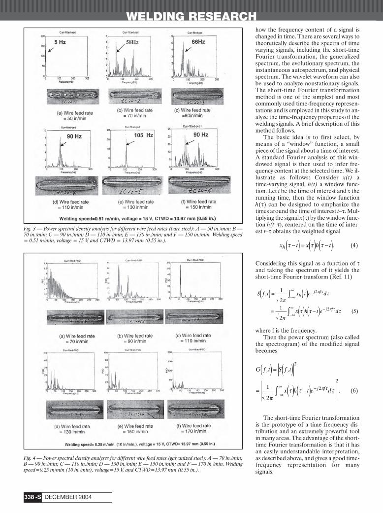
WELDING RESEARCH
DECEMBER 2004-S338
how the frequency content of a signal ischanged in time. There are several ways totheoretically describe the spectra of timevarying signals, including the short-timeFourier transformation, the generalizedspectrum, the evolutionary spectrum, theinstantaneous autospectrum, and physicalspectrum. The wavelet waveform can alsobe used to analyze nonstationary signals.The short-time Fourier transformationmethod is one of the simplest and mostcommonly used time-frequency represen-tations and is employed in this study to an-alyze the time-frequency properties of thewelding signals. A brief description of thismethod follows.
The basic idea is to first select, bymeans of a “window” function, a smallpiece of the signal about a time of interest.A standard Fourier analysis of this win-dowed signal is then used to infer fre-quency content at the selected time. We il-lustrate as follows: Consider x(t) atime-varying signal, h(t) a window func-tion. Let t be the time of interest and t therunning time, then the window functionh(t) can be designed to emphasize thetimes around the time of interest t–t. Mul-tiplying the signal x(t) by the window func-tion h(t–t), centered on the time of inter-est t–t obtains the weighted signal
Considering this signal as a function of tand taking the spectrum of it yields theshort-time Fourier transform (Ref. 11)
where f is the frequency.Then the power spectrum (also called
the spectrogram) of the modified signalbecomes
The short-time Fourier transformationis the prototype of a time-frequency dis-tribution and an extremely powerful toolin many areas. The advantage of the short-time Fourier transformation is that it hasan easily understandable interpretation,as described above, and gives a good time-frequency representation for manysignals.
G f t S f t
x h t e dj f
, ,
.
( ) = ( )= ( ) -( )-•
• -Ú
2
2
21
2(6)
pt t tp t
S f t x e d
x h t e d
hj f
j f
,( ) = ( )= ( ) -( )
-•
• -
-•
• -
Ú
Ú
1
21
2(5)
2
2
pt t
pt t t
p t
p t
x t x h th t t t-( ) = ( ) -( ). (4)
Fig. 3 — Power spectral density analysis for different wire feed rates (bare steel): A — 50 in./min; B —70 in./min; C — 90 in./min; D — 110 in./min; E — 130 in./min; and F — 150 in./min. Welding speed= 0.51 m/min, voltage = 15 V, and CTWD = 13.97 mm (0.55 in.).
Fig. 4 — Power spectral density analyses for different wire feed rates (galvanized steel): A — 70 in./min;B — 90 in./min; C — 110 in./min; D — 130 in./min; E — 150 in./min; and F — 170 in./min. Weldingspeed=0.25 m/min (10 in./min), voltage=15 V, and CTWD=13.97 mm (0.55 in.).
Chu Supplement 12/04corr 11/3/04 8:45 AM Page 338

WELDING RESEARCH
-S339WELDING JOURNAL
The commonly used windows includerectangular, triangular, Hanning, Ham-ming, and Blackman windows. In thisstudy, a Hanning window was chosen andit worked well for the welding signalanalysis. The mathematical formuladefining the Hanning window (Ref. 11) isas follows:
For the sequence of a sampled signal,the discrete form of the short-time Fouriertransformation is used. The signal pro-cessing and algorithm implementationwere done with the signal processing tool-box of Matlab.
Results and Discussion
Several sets of experiments with dif-ferent welding parameters were con-ducted. Welding signals were collectedand analyzed as described previously. APowerwave 455 welding machine made byLincoln Electric Co. was used as the weld-ing power source, and an automatic trav-
eling cart was employed to move the weld-ing torch according to a preset weldingspeed. ER70S-6 was chosen as the weld-ing filler metal. The contact tip-to-work-piece distance (CTWD) was 13.97 mm(0.55 in). Bare and galvanized steels withgauges of 0.063 in. (1.6 mm) were used inthe welding trials. Bead-on-plate weldswere made with GMAW using variouswelding parameters. Table 1 lists thewelding parameters and welding consum-ables used in this study.
The welding voltage and current sig-nals were collected by the data acquisitionsystem during the experiments. Pho-tographs of the weld surfaces were takenand weld specimens were cut to measure
the weld bead geometry, and to check in-ternal weld quality, porosity, and weldpenetration. The weld surface quality wasevaluated based on three criteria: unifor-mity of the weld bead width, smoothnessof the weld surface, and amount of thespatter. Based on the evaluation result ofthe weld surface and the examination out-come of the weld cross section, a weldquality judgment was given to each weld.With the welding voltages and current sig-nals, a low-pass filter is designed and ap-plied to filter measurement noise and in-duced noise.
In the discussion that follows, we de-scribe the analysis of various welding sig-nals using the methods described above.
h tt t
otherwise( ) = - ( )Ê
ˈ¯ £ £Ï
ÌÔ
ÓÔ
1 2 0 1
0(7)
cos / 2, ,
,
p
Fig. 5 — Relationship between the short-circuiting frequency and wire feed rates: A — bare steel; and B — galvanized steel.
Fig. 6 — Relationship between short-circuiting frequency and welding voltage.
Fig. 7 — Relationship between short-circuiting frequency and CTWD.
Table 1 — Welding Parameters and Consumables Used in the Study
Wire Wire Feed Voltage Welding Electrode Gun Shielding FlowType Diameter Rate (volt) Speed CTWD Angle Gas Rate
in. (mm) in./min in./min in. (mm) (ft3/h)(m/min) (m/min)
ER70S-6 0.035 50–190 15 5~30 0.55 90 deg 75%Ar 30(0.9) (1.27–4.83) (0.127~0.765) (13.97) +25%CO2
Chu Supplement 12/04corr 11/3/04 8:46 AM Page 339
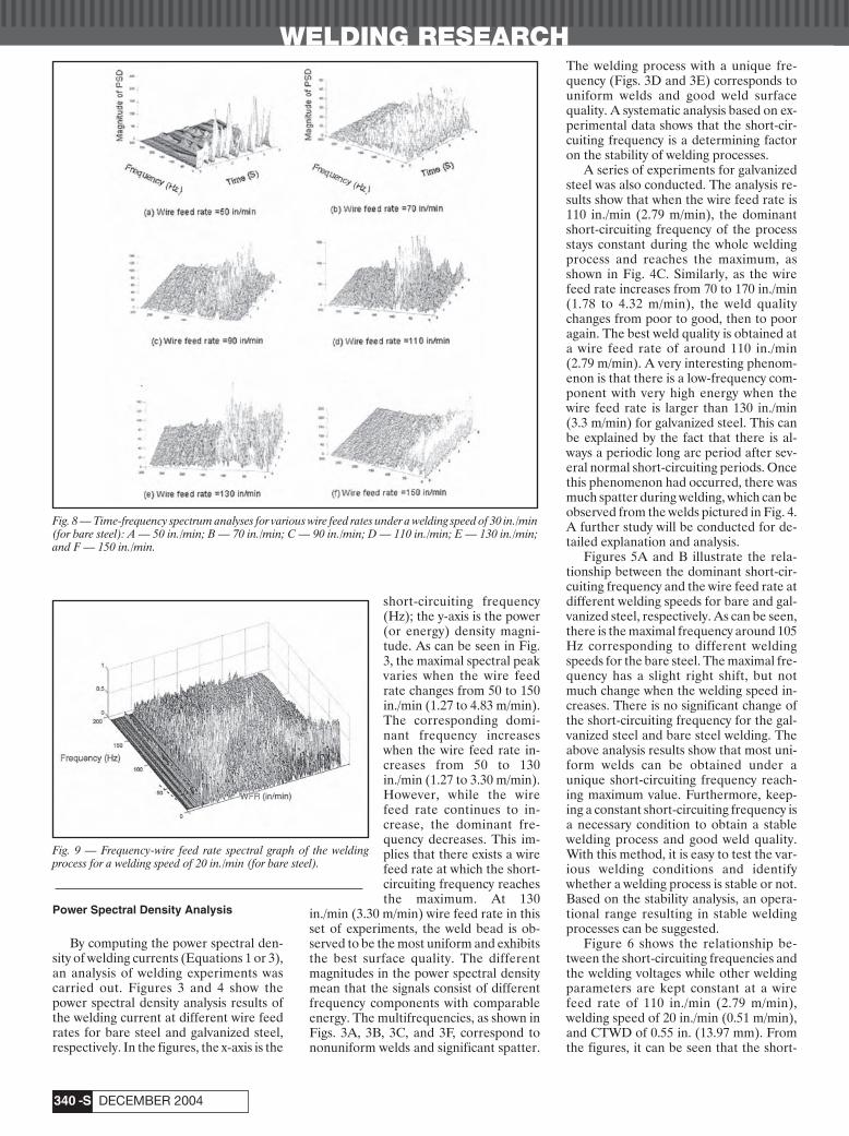
WELDING RESEARCH
DECEMBER 2004-S340
Power Spectral Density Analysis
By computing the power spectral den-sity of welding currents (Equations 1 or 3),an analysis of welding experiments wascarried out. Figures 3 and 4 show thepower spectral density analysis results ofthe welding current at different wire feedrates for bare steel and galvanized steel,respectively. In the figures, the x-axis is the
short-circuiting frequency(Hz); the y-axis is the power(or energy) density magni-tude. As can be seen in Fig.3, the maximal spectral peakvaries when the wire feedrate changes from 50 to 150in./min (1.27 to 4.83 m/min).The corresponding domi-nant frequency increaseswhen the wire feed rate in-creases from 50 to 130in./min (1.27 to 3.30 m/min).However, while the wirefeed rate continues to in-crease, the dominant fre-quency decreases. This im-plies that there exists a wirefeed rate at which the short-circuiting frequency reachesthe maximum. At 130
in./min (3.30 m/min) wire feed rate in thisset of experiments, the weld bead is ob-served to be the most uniform and exhibitsthe best surface quality. The differentmagnitudes in the power spectral densitymean that the signals consist of differentfrequency components with comparableenergy. The multifrequencies, as shown inFigs. 3A, 3B, 3C, and 3F, correspond tononuniform welds and significant spatter.
The welding process with a unique fre-quency (Figs. 3D and 3E) corresponds touniform welds and good weld surfacequality. A systematic analysis based on ex-perimental data shows that the short-cir-cuiting frequency is a determining factoron the stability of welding processes.
A series of experiments for galvanizedsteel was also conducted. The analysis re-sults show that when the wire feed rate is110 in./min (2.79 m/min), the dominantshort-circuiting frequency of the processstays constant during the whole weldingprocess and reaches the maximum, asshown in Fig. 4C. Similarly, as the wirefeed rate increases from 70 to 170 in./min(1.78 to 4.32 m/min), the weld qualitychanges from poor to good, then to pooragain. The best weld quality is obtained ata wire feed rate of around 110 in./min(2.79 m/min). A very interesting phenom-enon is that there is a low-frequency com-ponent with very high energy when thewire feed rate is larger than 130 in./min(3.3 m/min) for galvanized steel. This canbe explained by the fact that there is al-ways a periodic long arc period after sev-eral normal short-circuiting periods. Oncethis phenomenon had occurred, there wasmuch spatter during welding, which can beobserved from the welds pictured in Fig. 4.A further study will be conducted for de-tailed explanation and analysis.
Figures 5A and B illustrate the rela-tionship between the dominant short-cir-cuiting frequency and the wire feed rate atdifferent welding speeds for bare and gal-vanized steel, respectively. As can be seen,there is the maximal frequency around 105Hz corresponding to different weldingspeeds for the bare steel. The maximal fre-quency has a slight right shift, but notmuch change when the welding speed in-creases. There is no significant change ofthe short-circuiting frequency for the gal-vanized steel and bare steel welding. Theabove analysis results show that most uni-form welds can be obtained under aunique short-circuiting frequency reach-ing maximum value. Furthermore, keep-ing a constant short-circuiting frequency isa necessary condition to obtain a stablewelding process and good weld quality.With this method, it is easy to test the var-ious welding conditions and identifywhether a welding process is stable or not.Based on the stability analysis, an opera-tional range resulting in stable weldingprocesses can be suggested.
Figure 6 shows the relationship be-tween the short-circuiting frequencies andthe welding voltages while other weldingparameters are kept constant at a wirefeed rate of 110 in./min (2.79 m/min),welding speed of 20 in./min (0.51 m/min),and CTWD of 0.55 in. (13.97 mm). Fromthe figures, it can be seen that the short-
Fig. 8 — Time-frequency spectrum analyses for various wire feed rates under a welding speed of 30 in./min(for bare steel): A — 50 in./min; B — 70 in./min; C — 90 in./min; D — 110 in./min; E — 130 in./min;and F — 150 in./min.
Fig. 9 — Frequency-wire feed rate spectral graph of the weldingprocess for a welding speed of 20 in./min (for bare steel).
Chu Supplement 12/04corr 11/3/04 8:46 AM Page 340
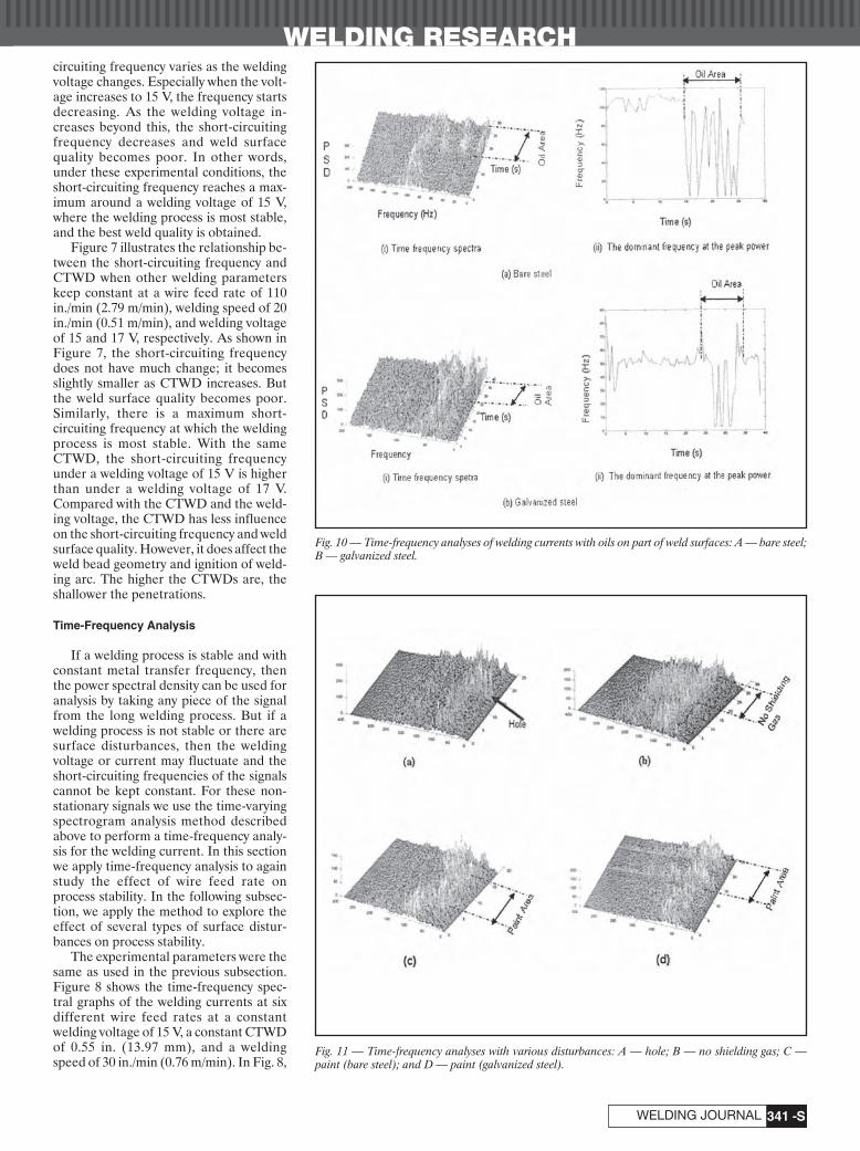
WELDING RESEARCH
-S341WELDING JOURNAL
circuiting frequency varies as the weldingvoltage changes. Especially when the volt-age increases to 15 V, the frequency startsdecreasing. As the welding voltage in-creases beyond this, the short-circuitingfrequency decreases and weld surfacequality becomes poor. In other words,under these experimental conditions, theshort-circuiting frequency reaches a max-imum around a welding voltage of 15 V,where the welding process is most stable,and the best weld quality is obtained.
Figure 7 illustrates the relationship be-tween the short-circuiting frequency andCTWD when other welding parameterskeep constant at a wire feed rate of 110in./min (2.79 m/min), welding speed of 20in./min (0.51 m/min), and welding voltageof 15 and 17 V, respectively. As shown inFigure 7, the short-circuiting frequencydoes not have much change; it becomesslightly smaller as CTWD increases. Butthe weld surface quality becomes poor.Similarly, there is a maximum short-circuiting frequency at which the weldingprocess is most stable. With the sameCTWD, the short-circuiting frequencyunder a welding voltage of 15 V is higherthan under a welding voltage of 17 V.Compared with the CTWD and the weld-ing voltage, the CTWD has less influenceon the short-circuiting frequency and weldsurface quality. However, it does affect theweld bead geometry and ignition of weld-ing arc. The higher the CTWDs are, theshallower the penetrations.
Time-Frequency Analysis
If a welding process is stable and withconstant metal transfer frequency, thenthe power spectral density can be used foranalysis by taking any piece of the signalfrom the long welding process. But if awelding process is not stable or there aresurface disturbances, then the weldingvoltage or current may fluctuate and theshort-circuiting frequencies of the signalscannot be kept constant. For these non-stationary signals we use the time-varyingspectrogram analysis method describedabove to perform a time-frequency analy-sis for the welding current. In this sectionwe apply time-frequency analysis to againstudy the effect of wire feed rate onprocess stability. In the following subsec-tion, we apply the method to explore theeffect of several types of surface distur-bances on process stability.
The experimental parameters were thesame as used in the previous subsection.Figure 8 shows the time-frequency spec-tral graphs of the welding currents at sixdifferent wire feed rates at a constantwelding voltage of 15 V, a constant CTWDof 0.55 in. (13.97 mm), and a weldingspeed of 30 in./min (0.76 m/min). In Fig. 8,
Fig. 11 — Time-frequency analyses with various disturbances: A — hole; B — no shielding gas; C —paint (bare steel); and D — paint (galvanized steel).
Fig. 10 — Time-frequency analyses of welding currents with oils on part of weld surfaces: A — bare steel;B — galvanized steel.
Chu Supplement 12/04corr 11/3/04 8:46 AM Page 341
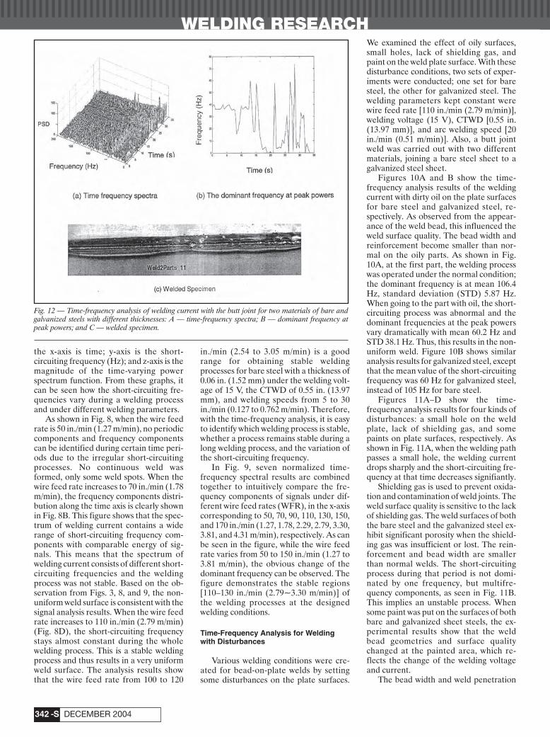
WELDING RESEARCH
DECEMBER 2004-S342
the x-axis is time; y-axis is the short-circuiting frequency (Hz); and z-axis is themagnitude of the time-varying powerspectrum function. From these graphs, itcan be seen how the short-circuiting fre-quencies vary during a welding processand under different welding parameters.
As shown in Fig. 8, when the wire feedrate is 50 in./min (1.27 m/min), no periodiccomponents and frequency componentscan be identified during certain time peri-ods due to the irregular short-circuitingprocesses. No continuous weld wasformed, only some weld spots. When thewire feed rate increases to 70 in./min (1.78m/min), the frequency components distri-bution along the time axis is clearly shownin Fig. 8B. This figure shows that the spec-trum of welding current contains a widerange of short-circuiting frequency com-ponents with comparable energy of sig-nals. This means that the spectrum ofwelding current consists of different short-circuiting frequencies and the weldingprocess was not stable. Based on the ob-servation from Figs. 3, 8, and 9, the non-uniform weld surface is consistent with thesignal analysis results. When the wire feedrate increases to 110 in./min (2.79 m/min)(Fig. 8D), the short-circuiting frequencystays almost constant during the wholewelding process. This is a stable weldingprocess and thus results in a very uniformweld surface. The analysis results showthat the wire feed rate from 100 to 120
in./min (2.54 to 3.05 m/min) is a goodrange for obtaining stable weldingprocesses for bare steel with a thickness of0.06 in. (1.52 mm) under the welding volt-age of 15 V, the CTWD of 0.55 in. (13.97mm), and welding speeds from 5 to 30in./min (0.127 to 0.762 m/min). Therefore,with the time-frequency analysis, it is easyto identify which welding process is stable,whether a process remains stable during along welding process, and the variation ofthe short-circuiting frequency.
In Fig. 9, seven normalized time-frequency spectral results are combinedtogether to intuitively compare the fre-quency components of signals under dif-ferent wire feed rates (WFR), in the x-axiscorresponding to 50, 70, 90, 110, 130, 150,and 170 in./min (1.27, 1.78, 2.29, 2.79, 3.30,3.81, and 4.31 m/min), respectively. As canbe seen in the figure, while the wire feedrate varies from 50 to 150 in./min (1.27 to3.81 m/min), the obvious change of thedominant frequency can be observed. Thefigure demonstrates the stable regions[110–130 in./min (2.79~3.30 m/min)] ofthe welding processes at the designedwelding conditions.
Time-Frequency Analysis for Weldingwith Disturbances
Various welding conditions were cre-ated for bead-on-plate welds by settingsome disturbances on the plate surfaces.
We examined the effect of oily surfaces,small holes, lack of shielding gas, andpaint on the weld plate surface. With thesedisturbance conditions, two sets of exper-iments were conducted; one set for baresteel, the other for galvanized steel. Thewelding parameters kept constant werewire feed rate [110 in./min (2.79 m/min)],welding voltage (15 V), CTWD [0.55 in.(13.97 mm)], and arc welding speed [20in./min (0.51 m/min)]. Also, a butt jointweld was carried out with two differentmaterials, joining a bare steel sheet to agalvanized steel sheet.
Figures 10A and B show the time-frequency analysis results of the weldingcurrent with dirty oil on the plate surfacesfor bare steel and galvanized steel, re-spectively. As observed from the appear-ance of the weld bead, this influenced theweld surface quality. The bead width andreinforcement become smaller than nor-mal on the oily parts. As shown in Fig.10A, at the first part, the welding processwas operated under the normal condition;the dominant frequency is at mean 106.4Hz, standard deviation (STD) 5.87 Hz.When going to the part with oil, the short-circuiting process was abnormal and thedominant frequencies at the peak powersvary dramatically with mean 60.2 Hz andSTD 38.1 Hz. Thus, this results in the non-uniform weld. Figure 10B shows similaranalysis results for galvanized steel, exceptthat the mean value of the short-circuitingfrequency was 60 Hz for galvanized steel,instead of 105 Hz for bare steel.
Figures 11A–D show the time-frequency analysis results for four kinds ofdisturbances: a small hole on the weldplate, lack of shielding gas, and somepaints on plate surfaces, respectively. Asshown in Fig. 11A, when the welding pathpasses a small hole, the welding currentdrops sharply and the short-circuiting fre-quency at that time decreases signifiantly.
Shielding gas is used to prevent oxida-tion and contamination of weld joints. Theweld surface quality is sensitive to the lackof shielding gas. The weld surfaces of boththe bare steel and the galvanized steel ex-hibit significant porosity when the shield-ing gas was insufficient or lost. The rein-forcement and bead width are smallerthan normal welds. The short-circuitingprocess during that period is not domi-nated by one frequency, but multifre-quency components, as seen in Fig. 11B.This implies an unstable process. Whensome paint was put on the surfaces of bothbare and galvanized sheet steels, the ex-perimental results show that the weldbead geometries and surface qualitychanged at the painted area, which re-flects the change of the welding voltageand current.
The bead width and weld penetration
Fig. 12 — Time-frequency analysis of welding current with the butt joint for two materials of bare andgalvanized steels with different thicknesses: A — time-frequency spectra; B — dominant frequency atpeak powers; and C — welded specimen.
Chu Supplement 12/04corr 11/3/04 8:46 AM Page 342

WELDING RESEARCH
-S343WELDING JOURNAL
at the painted area are narrower and shal-lower than those made at nominal condi-tions. As shown in the time-frequencyanalysis result of Fig. 11C, the mean of theshort-circuiting frequency has changed,decreasing to 57.8 Hz on the painted sur-face from 97.5 Hz under the normal con-dition. For the galvanized steel, the weld-ing current suddenly jumps from itsnormal value at the first boundary be-tween the painted area and the unpaintedarea, and then returns to normal on thepainted surface. But at the secondaryboundary end edge between the paintedarea and the unpainted area, the weldingcurrent has a second jump. At these twoboundaries, the weld beads have seriousdefects, very nonuniform, almost no rein-forcement. The time-frequency analysisalso shows the frequency change at thetwo boundaries in Figs. 11C and D.
Finally, we examined the joining of twosheets with different coatings. Bare steeland galvanized steel were welded togetherusing a butt joint method. Figure 12Cshows the picture of the weld. The firstpart of the weld is uniform and of goodquality, but the second part of the weldshows defects due to the deviation of theroot opening between the two partscaused by heat deformation after weldingof the first part. The short-circuiting fre-quency at the first part is about 40 Hz, butat the second part, the short-circuiting fre-quency dropped and varied dramatically.The change of the frequency representsthe weld surface quality change.
Summary
This paper focuses on the signatureanalysis of the short-circuiting frequencyof GMAW processes for weld surfacequality by using power spectral density
and time-frequency analysis methods. Therelationship between the short-circuitingfrequency, welding stability, weld quality,and other welding parameters, such as thetravel speed, the wire feed rate, and thewelding voltage, was investigated based onexperimental data analysis. A systematicanalysis shows that the short-circuitingfrequency is a determining factor on thestability of welding processes. A series ofexperiments was carried out for validationof the analysis results. The characteristicdifference between welding processes forbare steel and galvanized steel were stud-ied and compared. Based on the fre-quency signature analysis, a stable weldingprocess and uniform weld beads can beobtained when the short-circuiting fre-quency remains stable and reaches itsmaximum. The analyses show that thetime-frequency analysis method for weld-ing signals is an effective approach foridentifying the stability of processes andweld surface quality. This method is alsovery useful in tuning or refining a weldingprocedure to obtain the greatest level ofstability. The study on the short-circuitingfrequency of the metal transfer process isimportant in understanding the effect ofwelding parameters on short-circuitingprocesses and weld stability in GMAW.
Acknowledgments
This research was sponsored by theGeneral Motors Collaborative ResearchLaboratory at the University of Michigan.The Lincoln Electric Co. is also acknowl-edged for providing welding machines.
References
1. Hermans M. J. M., and Den Ouden, G.1999. Process behavior and stability in short cir-
cuit gas metal arc welding. Welding Journal78(4): 137-s to 141-s.
2. Adolfsson, S., Bahrami, G., Bolmsio, G.,and Claesson, I. 1999. On-line quality monitor-ing in short-circuit gas metal arc welding, Weld-ing Journal 78(2): 59-s to 73-s.
3. Quinn T. P. M., Smith, C., McCowan, C.N., Blachowiak, E., and Madjgan, R. B. 1999.Arc sensing for defects in constant-voltage gasmetal arc welding. Welding Journal 78(9): 322-sto 328-s.
4. Subramaniam, S., White, D. R., Jones, J.E., and Lyons, D. W. 1999. Experimental ap-proach to selection of pulsing parameters inpulsed GMAW. Welding Journal 78(5): 166-s to172-s.
5. Blumschein-E. 1997. Fast detection of es-sential changes in GMAW processes. SeventhInternational Conference on Computer Tech-nology in Welding (NIST SP 923). Washington,D.C.: NIST, pp. 474–485.
6. Norrish, J. 1994. Process stability assess-ment and metal transfer control for robotic gasmetal arc welding, 10th ISPE/IFAC Interna-tional Conference on CAD/CAM, Roboticsand Factories of the Future CARs & FOF’94.Information Technology for Modern Manufac-turing. Conference Proceedings, pp. 336–41.
7. Cook, G. E., Maxwell, J. E., Barnett, R.J., and Thompson F. M. 1994. Statistical weldprocess monitoring and interpretation. Proc. of1994 IEEE Industry Applications Society AnnualMeeting, Vol. 3, Denver, Colo., pp. 1828–35.
8. Sanders, L., West, M., and Norrish, J.1998. Real-time irregularity detection in gasmetal arc welding. Proceedings of the 8th Inter-national Conference on Computer Technology inWelding, pp. 62–76.
9. Wezenbeek, H. C. 1992. A system formeasurement and control of weld pool geome-try in automatic arc welding. Ph.D. dissertation,Technische University, Eindhoven, Nether-lands.
10. Hayes, M. H. 1996. Statistical Digital Sig-nal Processing and Modeling. New York, N.Y.:John Wiley & Sons.
11. Carmona, R., Hwang, W.-L., and Torre-sani, B. 1998. Practical Time-Frequency Analysis.Academic Press.
An ImportantEvent on Its
Way?Send information on upcomingevents to the Welding JournalDept., 550 NW LeJeune Rd.,Miami, FL 33126. Items canalso be sent via FAX to (305)443-7404 or by e-mail to [email protected].
Want to be a Welding Journal
Advertiser?For information, contact
Rob Saltzstein at (800) 443-9353, ext. 243,
or via e-mail [email protected].
Dear Readers:
The Welding Journal encouragesan exchange of ideas through letters to the editor. Please sendyour letters to the Welding JournalDept., 550 NW LeJeune Rd.,Miami, FL 33126. You can alsoreach us by FAX at (305) 443-7404or by sending an e-mail to KristinCampbell at [email protected].
Chu Supplement 12/04corr 11/3/04 8:46 AM Page 343
Text• approximately 1500–3500 words in length •submit hard copy• submissions via disk or electronic transmission — pre-
ferred format is Mac but common PC files are alsoacceptable
• acceptable disks include floppy, zip, and CD.
Format• include a title• include a subtitle or “blurb” highlighting major point or
idea• include all author names, titles, affiliations, geographic
locations• separate paper into sections with headings
Photos/Illustrations/Figures• glossy prints, slides, or transparencies are acceptable• black and white and color photos must be scanned at
a minimum of 300 dpi• line art should be scanned at 1000 dpi• photos must include a description of action/object/per-
son and relevance for use as a caption• prints must be a minimum size of 4 in. x 6 in., making
certain the photo is sharp• do not embed the figures or photos in the text• acceptable electronic format for photos and figures are
EPS, JPEG, and TIFF. TIFF format is preferred.
Other• illustrations should accompany article• drawings, tables, and graphs should be legible for
reproduction and labeled with captions• references/bibliography should be included at the end
of the article
Editorial Deadline• January issue deadline is November 11 • February issue deadline is December 10• March issue deadline is January 13• April issue deadline is February 10• May issue deadline is March 10• June issue deadline is April 9• July issue deadline is May 12• August issue deadline is June 13• September issue deadline is July 11• October issue deadline is August 11• November issue deadline is September 12• December issue deadline is October 10
Suggested topics for articles• case studies, specific projects• new procedures, “how to”• applied technology
Mail to:Andrew CullisonEditor, Welding Journal550 NW LeJeune RoadMiami, FL 33126(305) 443-9353, x 249; FAX (305) [email protected]
WELDING JOURNALInstructions and Suggestions for
Preparation of Articles
Call
R e p r i n t s • E p r i n t s • R e p r i n t s • E p r i n t s • R e p r i n t s • E p r i n t s
Today!
Were You FeaturedIn This Issue?
Reprints are a polished way to showcasethird party endorsements adding credibilityto your product, company or service. Theydemonstrate to your clients, partners andemployees that you have been recognizedin a well-respected magazine.
We can professionally customize yourreprints with your company logo and business information.
• Trade Shows • Sales Aids • Media Kits • Employee Training • Sales Presentations • Conference Material • Educational Programs • PDF for your Company’s
Web Site
Claudia [email protected](866) 879.9144 x121www.fostereprints.com
Page 344 11/11/04 10:37 AM Page 344
hh
Typewriter
WWW.WELD.4T.COM

Chrome Nozzle Seat and DualCooling . . . the most updated approach
to water-cooling found only in the newABIMIG guns from ABICOR Binzel Corp. These
rugged yet lightweight MIG guns now feature a chromenozzle seat that reduces wear on the swanneck, extending
service life. The dual cooling design channels water along thebolted copper inner barrel, cooling the tip, while concurrently water
travels along the bolted brass outer barrel, cooling the nozzle. Dual cool-ing draws heat away from the source, ensuring not only longer tip life butnozzle life as well. The improved strain relief of the 500, 550 and 650ampere Water-Cooled ABIMIG welding torches protects cable components andwithstands the toughest handling.
W A T E R - C O O L E D T O R C H E S
W e l d i n g a n d c u t t i n g b r o u g h t t o t h e p o i n t .
8 0 0 . 5 4 2 . 4 8 6 7
www.abicorusa.comCircle No. 1 on Reader Info-Card
abicor 11/5/04 1:44 PM Page C3

Your Partner in Welding & Cutting
For reliable stainless steel welding, call us at 1-800-ESAB-123, or find us on the internet at www.esabna.com
ESABThink of UsFirst forStainless SteelFabrication
ESABThink of UsFirst forStainless SteelFabricationWhen you need to join stainless steels and meet critical design requirementsfor corrosion resistance andimpact toughness, think ofESAB first for superior weldingelectrodes and equipment.
ESAB stainless steel productsare specially formulated toproduce low hydrogen weldsand specific ferrite levels. Our 350mpi power supply provides reliability and ease of use in a powerful, versatilepackage ideal for your stainlessapplications.
When you need to join stainless steels and meet critical design requirementsfor corrosion resistance andimpact toughness, think ofESAB first for superior weldingelectrodes and equipment.
ESAB stainless steel productsare specially formulated toproduce low hydrogen weldsand specific ferrite levels. Our 350mpi power supply provides reliability and ease of use in a powerful, versatilepackage ideal for your stainlessapplications.
Circle No. 29 on Reader Info-Card
esab 11/5/04 1:44 PM Page C4
hh
Typewriter
WWW.WELD.4T.COM