2003.09.30 Feedstream Analysis Plan
22
INTERNATIONAL Norlite Corporation Cohoes, New York Feedstream Analysis Plan (FAP) Pursuant to the HWC MACT Regulations Revision: 0 ENSR Corporation September 30, 2003 Project Number 09514-061-100 'r OCT I 5 ..... 1 L
Transcript of 2003.09.30 Feedstream Analysis Plan

INTERNATIONAL
Norlite Corporation
Cohoes, New York
Feedstream Analysis Plan (F AP) Pursuant to the HWC MACT Regulations
Revision: 0
ENSR Corporation September 30, 2003 Project Number 09514-061-100
'r OCT I 5
..... 1 L

Norlite Corporation - Cohoes, NY - Feedstream Analysis Plan (FAP)
TABLE OF CONTENTS
Revision: 0 Date: September 30, 2003
Section: Contents
Page: ii of iii
1.0 INTRODUCTION .... ................................................................. ............. .................................................. 1
1.1 Program Summary [40 CFR 63.1209(c)] ...................................... .. ............................................ 1
1.2 Overlap and Differences Between the MACT FAP and the RCRA WAP ................ .................. 2
1.3 Cross-Reference of FAP Requirements .......... .... ..... .... .............................................................. 2
2.0 KILN FEEDSTREAM DESCRIPTIONS ........................................... ................. .................................... 1
2.1 General Overview .... .............................................. ........................................................ ............... 1
2.2 Liquid Waste Feeds ................................ .... ... ... ... .. .. ........... ................................... ................. ... .. 1
2.2.1 Liquid Low Grade Fuel (LLGF) ........ ...... .. ........... ... ... ................ ....................................... 1
2.2.2 Used Oil ... ..... ...... .................. ...... .................................................... .... .............................. 2
2.3 Solid Feed Materials (i.e., shale) .. ........... .. ....... ........................................................ .. .... ............. 3
2.4 Process Vent Streams ........................... ...................................................... ................................ 3
2.5 Supplemental Fuels ......... ................. ............................................................... .............. ..... .... ..... 4
2.6 Parameters and Rationale ...... ..... ... ..................................... .. ..... ................................................. 4
3.0 FEEDSTREAM CHARACTERIZATION STRATEGY ......................................................................... 1
4.0 TEST METHODS ........................................................ ........................................................................... 1
5.0 SAMPLING METHODS ......................................................................................................................... 1
6.0 FREQUENCY OF ANALYSIS .................................................................... ................................... ........ 1
7.0 RECORD KEEPING OF FEEDRATES ...................................................................... .......................... 1
APPENDIX: NORLITE'S WASTE ANALYSIS PLAN (SECTION C OF THE PART 373 PERMIT)
C:\WINDOWS\Desktop\MACT\MACT Plans\Final Plans\Norlite NY FAP Rev 0.doc

Norlite Corporation - Cohoes, NY - Feedstream Analysis Plan (FAP)
LIST OF TABLES
Revision: 0 Date: September 30, 2003
Section: Contents Page: iii of iii
Table 1-1 Cross Reference of FAP Requirements ..................................................................................... 3
Table 2-1 HAPs Potentially Present in LLGF ..................................... ... .... ...... .................... ....................... 5
Table 2-2 Typical LLGF Feed Properties ..................... ... ...... ........ ...................... ....................................... 6
Table 2-3 Typical LLGF Analyses for Compound Classes ......... ... .......... ................................................. 7
Table 2-4 Representative Data for LLGF Hazardous Constituents .......................................................... 8
Table 2-5 Typical Used Oil Specifications ................ ..................... ...... ........ ............................................... 9
Table 2-6 Typical Shale Properties .... .... ..... .... .................. ........... .............................................................. 9
Table 2-7 Typical Fuel Oil Properties ..... ...... ....... ......... .. .......................................................................... 1 O
Table 2-8 Summary of Target MACT Feed rate Limits* ......... .................................................................. 1 O
C:\WINDOWS\Desktop\MACT\MACT Plans\Final Plans\Norlite NY FAP Rev 0.doc

Norlite Corporation - Cohoes, NY - Feedstream Analysis Plan (FAP)
1.0 INTRODUCTION
1.1 Program Summary [40 CFR 63.1209(c))
Revision: 0
Date: September 30, 2003
Section: 1.0 Page: 1 of 3
This document represents the Feedstream Analysis Plan (FAP) for the two lightweight aggregate kilns (LWAKs) operated by Norlite Corporation at its Cohoes, New York facility. This Plan has been prepared in accordance with requirements promulgated in NESHAPS: Final Standards for Hazardous Waste Air Pollutants for Hazardous Waste Combustors, (generally referred to as the Hazardous Waste Combustor [or "HWC"] MACT Rule) published by US EPA on September 30, 1999 in 40 CFR 63 Subpart EEE. Since the Norlite LWAKs treat certain waste that are classified as hazardous under state and/or federal regulations, these units are subject to the requirements of the HWC MACT Rule. The specific FAP requirements within Subpart EEE are set forth in 40 CFR 63.1209( c )(2) with six key plan elements.as follows:
1. A list of parameters that will be analyzed for each feedstream to ensure compliance with facility operating limits;
2. A description of how feedstream constituent information will be obtained. For example, will the information be obtained by collecting and analyzing samples or by other methods such as using analytical information obtained from others or via published or documented sources;
3. A description of how the analysis results will be used to document compliance with feedrate limits for blended wastes if the analysis data is obtained prior to blending and not from the blended, asfired waste;
4. Which test methods which will be used to obtain the analytical data;
5. Which sampling methods will be used to obtain a representative sample of each feedstream to be analyzed using sampling methods described in 40 CFR 266, Appendix IX, or equivalent; and
6. The frequency of review or repeat of the initial analysis of each feedstream to ensure that the analysis is accurate and up-to-date.
In addition, Section 7.0 of this plan outlines the record keeping requirements specified in 40 CFR 63.1209(c)(4).
C:IWINDOWSIDesk1op\MACl\MACT P1ans\Final Plans\Norlite NY FAP Rev O.doc

Norlite Corporation• Cohoes, NY• Feedstream Analysis Plan (FAP)
Revision: 0 Date: September 30, 2003 Section: 1.0
Page: 2 of 3
1.2 Overlap and Differences Between the MACT FAP and the RCRA WAP
The MACT regulations require that a FAP be prepared and made part of the facility's operating record. The Norlite facility's Part 373 hazardous waste permit requires that a RCRA waste analysis plan
(WAP) be prepared and submitted for NYSDEC approval. These MACT Rule and RCRA regulations have many of the same requirements, although there are several important differences between these two overlapping regulations. One fundamental difference is that the MACT Rule requires that the FAP address Hazardous Air Pollutants (HAPs), while RCRA regulates compounds listed in 40 CFR 261 ,
Appendix VIII. For consistency between these two analysis plan requirements, Norlite has ameneded the LLGF Specification Sheet (Exhibit C-1 to the WAP) to request off-site generators and blenders to identify any HAPs in their wastes. In addition, this plan also addresses vent streams from the fossil fuel tank farm.
The MACT Rule specifies that any HAP analyses performed need only be done on the hazardous waste feedstreams. Additionally, sources are not required to monitor for metals and chlorine in natural gas, process air and vapor recovery feedstreams.
Many of the MACT Rule requirements are cross-referenced to Norlite's NYSDEC-approved WAP. Other MACT Rule requirements that are not addressed in the WAP are addressed within this FAP.
1.3 Cross-Reference of FAP Requirements
In order to minimize duplication of the overlapping requirements and for ease of regulatory completeness review, Table 1-1 provides a regulatory cross-reference to the Norlite WAP and/or the relevant section within this FAP.
C:IWINDOWS\Desktop\MACT\MACT Plans\Final Plans\Norl~e NY FAP Rev 0.doc

Norlite Corporation - Cohoes, NY - Feedstream Analysis Plan (FAP)
Revision: 0
Date: September 30, 2003
Section: 1.0 Page: 3 of 3
Table 1-1 Cross Reference of FAP Requirements
Section No. Section No. in this
Regulatory Citation Requirement intheWAP Document
40 CFR 1209(c)(2)(i) Parameters for analysis C-2 2.0
40 CFR 1209(c)(2)(ii) Obtain analysis by performing direct sampling C-5(a) 3.0 and analysis or by other methods
40 CFR 1209(c)(2)(iii) Use of analysis to document compliance with C-5(a)/(b)/(d)/ 3.0 feedrate limits (e.g., for blended wastes) (g)
40 CFR 1209(c)(2)(iv) Test methods to obtain these analyses C-4 4.0
40 CFR 1209(c)(2)(v) Sampling methods to obtain a representative C-3 5.0 sample of each feedstream
40 CFR 1209(c)(2)(vi) Frequency of review or repeat of initial C-6 6.0 feedstream analysis
C:IWINDOWS\Desktop\MACT\MACT Plans\Final Plans\Norl ite NY FAP Rev O.doc
Norlite Corporation - Cohoes, NY - Feedstream Analysis Plan (FAP)
2.0 KILN FEEDSTREAM DESCRIPTIONS
2.1 General Overview
Revision: 0 Date: September 30, 2003
Section: 2.0 Page: 1 of 10
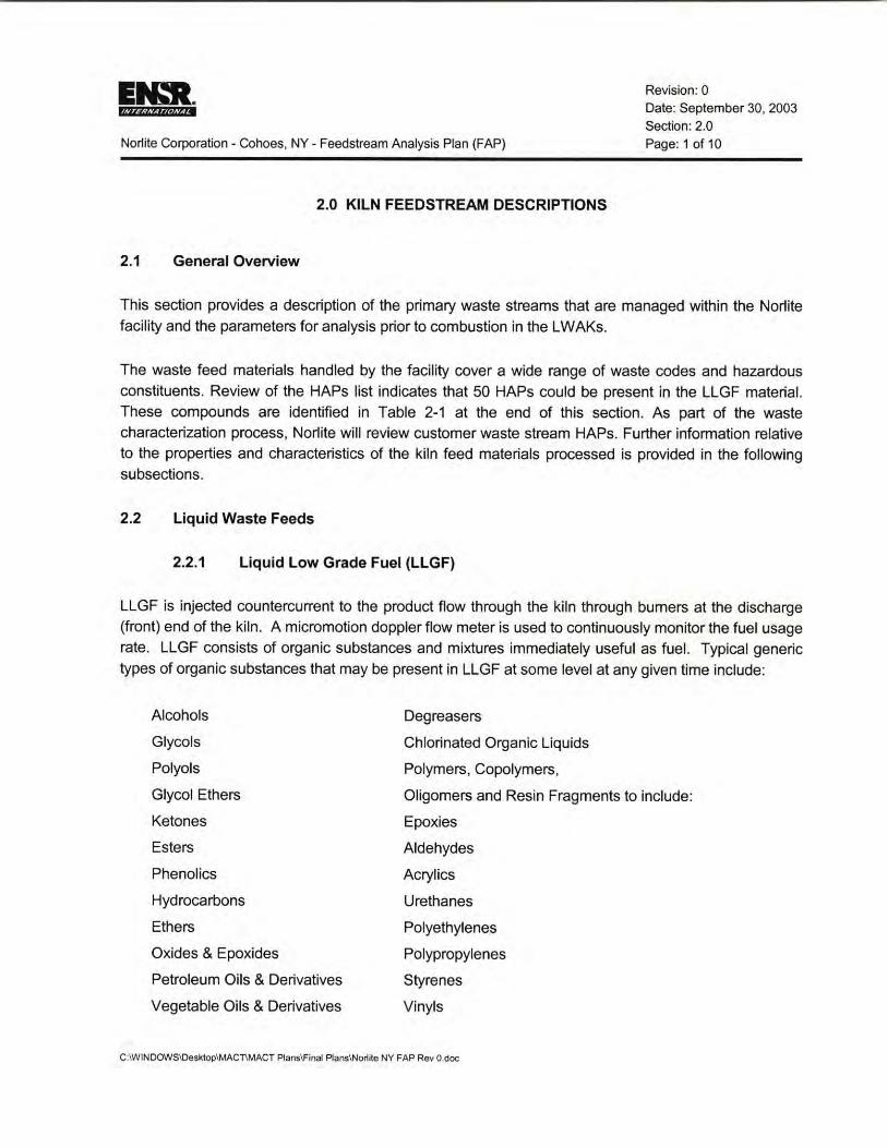
This section provides a description of the primary waste streams that are managed within the Norlite facility and the parameters for analysis prior to combustion in the LWAKs.
The waste feed materials handled by the facility cover a wide range of waste codes and hazardous constituents. Review of the HAPs list indicates that 50 HAPs could be present in the LLGF material. These compounds are identified in Table 2-1 at the end of this section. As part of the waste characterization process, Norlite will review customer waste stream HAPs. Further information relative to the properties and characteristics of the kiln feed materials processed is provided in the following subsections.
2.2 Liquid Waste Feeds
2.2.1 Liquid Low Grade Fuel (LLGF)
LLGF is injected countercurrent to the product flow through the kiln through burners at the discharge (front) end of the kiln. A micromotion doppler flow meter is used to continuously monitor the fuel usage rate. LLGF consists of organic substances and mixtures immediately useful as fuel. Typical generic
types of organic substances that may be present in LLGF at some level at any given time include:
Alcohols
Glycols
Polyols
Glycol Ethers
Ketones
Esters
Phenolics
Hydrocarbons
Ethers
Oxides & Epoxides
Petroleum Oils & Derivatives
Vegetable Oils & Derivatives
Degreasers
Chlorinated Organic Liquids
Polymers, Copolymers,
Oligomers and Resin Fragments to include:
Epoxies
Aldehydes
Acrylics
Urethanes
Polyethylenes
Polypropylenes
Styrenes
Vinyls
C:\WINOOWS\Oesktop\MACnMACT Plans\Final Plans\No~ite NY FAP Rev 0.doc

Ital. f4?ii·&ftii.ZZ.t◄
Norlite Corporation - Cohoes, NY - Feedstream Analysis Plan (FAP)
Revision: 0 Date: September 30, 2003
Section: 2.0 Page: 2 of 10
The above list is descriptive and not considered limiting. The substances contained in LLGF are typically those used each day in industry, commerce and around the home. They are found in products such as paints, varnishes, lacquers, thinners, cleaners, detergent formulations, spot removers, nail polish remover, lighter fluid and gasoline. Expected ranges for MACT-regulated parameters in the LLGF are shown in Table 2-2. Metal concentrations can exceed the values shown in Table 2-2, provided the feed is from agitated tanks and provided that the LLGF feed rate is reduced proportionately to compensate for the higher metals concentration and thereby reduce the net metal feed rate to comply with the mass feed limits in the Part 373 hazardous waste permit. Norlite does not use as LLGF any substances or mixtures of PCBs subject to NYCRR regulations pursuant to Part 371 or Federal PCB regulations pursuant to 40 CFR Part 761 . The contents of streams vary greatly on a daily basis. Typical ranges of analyses for separate LLGF streams are shown in Table 2-3. Additional data for hazardous constituents in LLGF are provided in Table 2-4.
2.2.2 Used Oil
Norlite uses non-hazardous waste fuels that can be defined as used oil under 40 CFR 279 and 6 NYCRR 374-2, or Waste Fuel A as defined in 6 NYCRR 225-2. This fuel is used to supplement the hazardous waste LLGF in operating the lightweight aggregate kilns. Used oil is classified as either specification used oil fuel or off-specification used oil fuel. Specification used oil fuel is defined as used oil meeting the following criteria:
Parameter Limitation
Arsenic <5ppm
Cadmium <2 ppm
Chromium < 10 ppm
Lead < 100 ppm
Flash Point > 100°F
Total Halogens < 4,000 ppm*
PCBs <2 ppm
* any used oil containing greater than 1,000 ppm total halogens is considered a hazardous waste because it is presumed to be mixed with listed hazardous waste. This presumption may be rebutted by demonstrating that the used oil does not contain listed hazardous waste constituents pursuant to 40 CFR 279.10(b)(ii) and 6 NYCRR 374-2.2(a)(i).
Used oil that does not meet this specification is considered off-specification used oil fuel. Norlite uses specification used oil fuel for start up and shutdown of the kilns and any time the units are not operating under the Part 373 permit parameters (e.g. after an AWFCO). This fuel is considered equivalent to virgin fuel oils and may be used in place of virgin fuels as they are described in the permit. Waste Fuel A is defined under § 225-2 as any waste oil, fuel oil or mixture of these to be C:IWINDOWS\Desktop\MAC"T\MACT Plans\Final Plans\Norlite NY FAP Rev O.doc
Et.,t. t4U#Wt-td-fti@
Norlite Corporation - Cohoes, NY - Feedstream Analysis Plan (FAP)
Revision: 0
Date: September 30, 2003 Section: 2.0
Page: 3 of 10
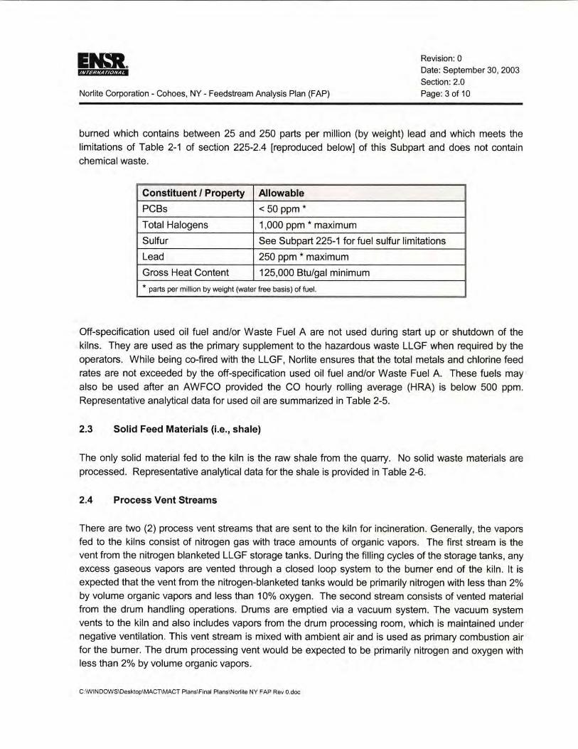
burned which contains between 25 and 250 parts per million (by weight) lead and which meets the limitations of Table 2-1 of section 225-2.4 [reproduced below] of this Subpart and does not contain chemical waste.
Constituent I Property Allowable
PCBs < 50 ppm*
Total Halogens 1,000 ppm * maximum
Sulfur See Subpart 225-1 for fuel sulfur limitations
Lead 250 ppm * maximum
Gross Heat Content 125,000 Btu/gal minimum
" parts per million by weight (water free basis) of fuel.
Off-specification used oil fuel and/or Waste Fuel A are not used during start up or shutdown of the
kilns. They are used as the primary supplement to the hazardous waste LLGF when required by the
operators. While being co-fired with the LLGF, Norlite ensures that the total metals and chlorine feed rates are not exceeded by the off-specification used oil fuel and/or Waste Fuel A. These fuels may also be used after an AWFCO provided the CO hourly rolling average (HRA) is below 500 ppm. Representative analytical data for used oil are summarized in Table 2-5.
2.3 Solid Feed Materials (i.e., shale)
The only solid material fed to the kiln is the raw shale from the quarry. No solid waste materials are processed. Representative analytical data for the shale is provided in Table 2-6.
2.4 Process Vent Streams
There are two (2) process vent streams that are sent to the kiln for incineration. Generally, the vapors fed to the kilns consist of nitrogen gas with trace amounts of organic vapors. The first stream is the vent from the nitrogen blanketed LLGF storage tanks. During the filling cycles of the storage tanks, any excess gaseous vapors are vented through a closed loop system to the burner end of the kiln. It is expected that the vent from the nitrogen-blanketed tanks would be primarily nitrogen with less than 2% by volume organic vapors and less than 10% oxygen. The second stream consists of vented material from the drum handling operations. Drums are emptied via a vacuum system. The vacuum system vents to the kiln and also includes vapors from the drum processing room, which is maintained under negative ventilation. This vent stream is mixed with ambient air and is used as primary combustion air for the burner. The drum processing vent would be expected to be primarily nitrogen and oxygen with less than 2% by volume organic vapors.
C:\WINDOWSIOesktoplMAC"T\MACT Plans\Final Plans\No~ite NY FAP Rev 0.doc

Norlite Corporation - Cohoes, NY - Feedstream Analysis Plan (FAP)
2.5 Supplemental Fuels
Revision: 0 Date: September 30, 2003
Section: 2.0 Page: 4 of 10
Fossil fuels or used oil is used to preheat the kiln during start-up. In cases where fuel oils or used oil is fired with LLGF, the metals content of the fuel oil is taken into account to comply with existing permit limits. Representative data for the fuel oil is summarized in Table 2-7. None of the regulated constituents would be expected to be present in natural gas.
2.6 Parameters and Rationale
The FAP regulation requires that, prior to feeding hazardous waste into the combustors, the facility must obtain an analysis of each feedstream that is sufficient to document compliance with the applicable feedrate limits (see Table 2-8). The MACT Rule allows regulatory officials to waive the comprehensive analysis of organic compounds if a source documents that the POHCs used to demonstrate compliance with the DRE standard continue to be representative of the organic HAPs in the hazardous waste feedstreams. In performing the Comprehensive Performance Test, Norlite has selected monchlorobenzene (MCB) is the POHC because it is a Class I POHC on the Thermal Stability ranking and is ranked 20th on that list. All HAPs processed at the facility have a Thermal Stability below MCB and therefore, MCB is more difficult to bum on that basis.
Target MACT feedrate limits are summarizd in Table 2-8. As discussed in Section C-2 of the Waste Analysis Plan approved under the Part 373 hazardous waste permit, additional limits pertaining to all feedstreams fired at the facility are presented in Table WAP-1 .
C:\WINDOWSIDesktop\MACnMACT Plans\Flnal Plans\Nor1~e NY FAP Rev O.doc

Norlite Corporation - Cohoes, NY - Feedstream Analysis Plan (FAP)
Revision: 0
Date: September 30, 2003
Section: 2.0
Page: 5 of 10
Table 2-1 HAPs Potentially Present in LLGF
CAS# Compound CAS# Compound 75058 Acetonitrile 1634044 Methyl tert butyl ether
107131 Acrylonitrile 75092 Methylene chloride (Dichloromethane)
71432 Benzene (including benzene from 91203 Naphthalene gasoline)
117817 Bis(2-ethylhexyl)phthalate (DEHP) 108952 Phenol
56235 Carbon tetrachloride 100425 Styrene
108907 Chlorobenzene 127184 Tetrachloroethylene (Perchloroethylene)
67663 Chloroform 108883 Toluene
1319773 Cresols/Cresylic acid (isomers and 79005 1, 1,2-Trichloroethane mixture)
95487 o-Cresol 79016 T richloroethylene
108394 m-Cresol 108054 Vinyl acetate
106445 p-Cresol 75014 Vinyl chloride
106467 1,4-Dichlorobenzene(p) 1330207 Xylenes (isomers and mixture) 140885 Ethyl acrylate 95476 o-Xylenes 100414 Ethyl benzene 108383 m-Xylenes
107062 Ethylene dichloride (1,2-Dichloroethane) 106423 p-Xylenes 107211 Ethylene glycol N/A Antimony Compounds 50000 Formaldehyde NIA Arsenic Compounds (inorganic
including arsine)
110543 Hexane N/A Beryllium Compounds
302012 Hydrazine N/A Cadmium Compounds 67561 Methanol N/A Chromium Compounds 74873 Methyl chloride (Chloromethane) N/A Glycol ethers
71556 Methyl chloroform (1, 1, 1-Trichloroethane) N/A Lead Compounds 78933 Methyl ethyl ketone (2-Butanone) N/A Nickel Compounds 108101 Methyl isobutyl ketone (Hexone) N/A Polycyclic Organic Matter 80626 Methyl methacrylate N/A Selenium Compounds
C:\WINDOWS\Desktop\MACT\MACT Plans\Final P!ans\No~ite NY FAP Rev O.doc

Norlite Corporation - Cohoes, NY - Feedstream Analysis Plan (FAP)
Revision: 0 Date: September 30, 2003
Section: 2.0
Page: 6 of 10
Table 2-2 Typical LLGF Feed Properties
Parameter Units Expected Range
Arsenic mg/kg 0.5-0.7
Beryllium mg/kg < 0.2
Chromium mg/kg 7.1-52.0
Cadmium mg/kg 0.5-1 .6
Lead mg/kg 30.8-82.4
Mercury mg/kg < 0.04
Heat Content Btu/lb 3,200-11 ,000
Density glee 0.88-0.94
Total Chlorine %wt. 0.04-2.6
Ash Content %wt. 0.5-2.1
C:IWINOOWS\DesktoplMACnMACT Plans\Final Plans\Norlite NY FAP Rev 0.doc

EN:R. fiiii·?t@•j.f@
Norlite Corporation - Cohoes, NY - Feedstream Analysis Plan (FAP)
Revision: 0
Date: September 30, 2003
Section: 2.0 Page: 7 of 10
Table 2-3 Typical LLGF Analyses for Compound Classes
Compound Concentration Range, %wt.
Chlorinated solvents (Trichloroethane, Trichloroethene, 0 - 4% Tetrachloroethylene, Methylene Chloride, Monochlorobenzene and T etrachloromethane)
Alcohols (Methanol , Ethanol , Propanol, Butanol and lsopropyl alcohol) 0 - 20%
Ketones (Methyl Ethyl Ketone, Methyl lsobutyl Ketone, Acetone and 0-15% Cyclopentanone)
Aldehydes (Formaldehyde, Butyl Aldehyde and Acetaldehyde) 0-0.5%
Petroleum Oils (Fuel oils, Hydraulic oils and Cutting oils) 0 - 25%
Acetates (Ethyl acetate, methyl acetate, Butyl acetate and Vinyl acetate) 0-25%
Phenol 0 - 5%
Aromatic Compounds (Benzene, Toluene, Xylenes and Naphthalene) 0-25%
Aliphatic Compounds (Hexane, Heptane and Pentane) 0 - 25%
Coal Tars 0 -25%
Fatty Acids 0-5%
Waste Oils 0 - 15%
PCBs < 25 ppm
Organic Halogens < 5%
C:IWINDOWS\Desktop\MACT\MACT Plans\Flnal Plans\No~rte NY FAP Rev 0.doc

Norlite Corporation - Cohoes, NY - Feedstream Analysis Plan (FAP)
Revision: 0
Date: September 30, 2003 Section: 2.0
Page: 8 of 10
Table 2-4 Representative Data for LLGF Hazardous Constituents
Compound Formula Molecular Heat of Boiling Fraction (Common Name) Weight Combustion Point (°C) ofLLGF
(kcal/g) (% wt.)
Carbon Tetrachloride CCl4 153.8 0.24 76.7 <3%
Tetrachloroethylene C2Cl4 165.8 1.19 121.1 <3%
Trichloroethene C2HCl3 131.4 1.74 86.7 <3%
1, 1, 1-Trichloroethane CH3CCl3 133.4 1.99 74.0 <3%
Monochlorobenzene CsHsCI 112.56 6.60 132.2 <3%
Formaldehyde HCHO 30 4.47 -19 <0.5%
Phenol CsHsOH 94.11 7.78 181 .7 <5%
Methyl Ethyl Ketone CH3COCH2CH3 72.11 8.07 79.4 <15%
Naphthalene CIOH8 128.17 9.62 217.8 <25%
Benzene CsHs 78.11 10.03 80.0 <25%
Toluene CsHsCH3 92.14 10.14 110.6 <25%
C:IWIN0OWS\Oesktop\MACT\MACT Plans\Final Plans\Norlite NY FAP Rev 0.doc

EN:R. @fili:&tlillht-tw
Norlite Corporation - Cohoes, NY - Feedstream Analysis Plan (FAP)
Revision: 0 Date: September 30, 2003
Section: 2.0 Page: 9 of 10
Table 2-5 Typical Used Oil Specifications
Parameter Units Expected Range
Arsenic mg/kg < 5.0
Beryllium mg/kg < 0.1
Chromium mg/kg 2.0-8.0
Cadmium mg/kg < 2.0
Lead mg/kg 10-50
Mercury mg/kg < 0.1
Heat Content Btu/lb ~ 17,000
Total Chlorine mg/kg < 1,000
Ash Content %wt. < 0.65
Table 2-6 Typical Shale Properties
Parameter Units Expected Range
Arsenic mg/kg 3.6-13.7
Beryllium mg/kg 0.6-0.9
Chromium mg/kg 22.9-47.4
Cadmium mg/kg 4.3-6.2
Lead mg/kg 23.4-32.9
Mercury mg/kg 0.24-0.50
Total Chlorine %wt. 0.002-0.05
C:IWINDOWS\Desktop\MACT\MACT Ptans\Final Ptans\Norlite NY FAP Rev O.doc

EN:R. ff?2¥W?J@4iN
Norlite Corporation - Cohoes, NY - Feedstream Analysis Plan (FAP)
Revision: 0
Date: September 30, 2003 Section: 2.0
Page: 10 of 10
Table 2-7 Typical Fuel Oil Properties
Parameter Units Expected Range
Arsenic mg/kg < 0.1
Beryllium mg/kg < 0.01
Chromium mg/kg < 0.1
Cadmium mg/kg < 0.1
Lead mg/kg < 1.0
Mercury mg/kg < 0.01
Heat Content Btu/lb > 16,000
Total Chlorine mg/kg < 100
Ash Content % wt. < 0.1
Table 2-8 Summary of Target MACT Feedrate Limits*
Parameter
Chlorine/Chloride
Mercury
Semi-volatile Metals (Cadmium and Lead)
Low-volatile Metals (Arsenic, Beryllium and Chromium)
*Tobe established during the MACT CPT.
** These are 12-hour rolling average limits.
C:\WINDOWS\Oesktop\MACn MACT Planslfinal P1ans\No~ite NY FAP Rev a.doc
Feedrate Limit (lbs/hr)""'
115.0
0.0104
6.72
9.57

Norlite Corporation - Cohoes, NY - Feedstream Analysis Plan (FAP)
Revision: 0
Date: September 30, 2003
Section: 3.0 Page: 1 of 1
3.0 FEEDSTREAM CHARACTERIZATION STRATEGY
Feedstream characterization will be performed by one of the following methods in accordance with
Section C-5 of the WAP:
• Direct sampling and analysis at the on-site analytical laboratory;
• Sampling at the generator or blender facilities and analysis at off-site analytical laboratories; or
• Use of generator process knowledge.
C:IWINDOWSIDesktoplMACl\MACT P1ans\Final Plans\Norltte NY FAP Rev O.doc

Norlite Corporation - Cohoes, NY - Feedstream Analysis Plan (FAP)
4.0 TEST METHODS
Revision: 0
Date: September 30, 2003
Section: 4.0 Page: 1 of 1
Section C-4 of the Norlite WAP describes the test methods used during analyses of feedstreams. Tests are either performed by the on-site analytical laboratory or by off-site laboratories that are certified under New York State Environmental Laboratory Approval Program (ELAP). The Norlite laboratory is certified under NYS and National ELAP programs.
C:\WINDOWS\Desktop\MAC1\MACT Plans\Final Plans\NoMite NY FAP Rev O.doc

EtGR. HWiif#❖Zti
Norlite Corporation - Cohoes, NY - Feedstream Analysis Plan (FAP)
5.0 SAMPLING METHODS
Revision: 0
Date: September 30, 2003
Section: 5.0
Page: 1 of 1
Section G-3 of the Norlite WAP describes the sampling methods used to obtain a representative sample of each feedstream.
C:IWIN0OWSIDesktop\MACl\MACT Plans\Final Plans\No~ije NY FAP Rev O.doc

Norlite Corporation• Cohoes, NY• Feedstream Analysis Plan (FAP)
6.0 FREQUENCY OF ANALYSIS
Revision: 0 Date: September 30, 2003
Section: 6.0
Page: 1 of 1
In accordance with Section C-6 and Table WAP-1 of the Nortite WAP, analysis will be performed on the following feedstreams at the frequencies specified:
• On each load of incoming LLGF and Used Oil. In addition, Norlite requires generators and blenders to complete and submit a LLGF Specification Sheet (Exhibit C-1 to the WAP) for each
new waste stream and at least annually.
• Blended tanks are sampled and analyzed weekly.
• Shale is sampled and analyzed after each blast in the quarry.
C:\WINOOWS\Oesktop\MACT\MACT Plans\Final P1ans\No~~e NY FAP Rev O.doc

Norlite Corporation - Cohoes, NY - Feedstream Analysis Plan (FAP)
7.0 RECORD KEEPING OF FEEDRATES
Revision: 0
Date: September 30, 2003
Section: 7 .0 Page: 1 of 1
Although not required in the written FAP, in order to comply with the applicable feedrate limits of the
MACT Rule, the Norlite facility will monitor and record feedrates in accordance with 40 CFR
63 .1209( c )( 4 ), as follows:
(i) Determine and record the value of the parameter for each feedstream by sampling and analysis or
other method;
(ii) Determine and record the mass or volume flowrate of each feedstream by a CMS. If determining
the flowrate of a feedstream by volume, the facility will determine and record the density of the
feedstream by sampling and analysis (unless reporting the constituent concentration in units of
weight per unit volume (e.g., mg/I)); and
(iii) Calculate and record the mass feedrate of the parameter per unit time.
C:\WINOOWS\Desktop\MACT\MACT Plans\Final Plans\No~ite NY FAP Rev O.doc

E~. H?AWt-@❖t,N
Norlite Corporation - Cohoes, NY - Feedstream Analysis Plan {FAP)
APPENDIX
Revision: 0 Date: September 30, 2003 Section: Appendix
Page: 1 of 74
NORLITE'S WASTE ANALYSIS PLAN (SECTION C OF THE PART 373 PERMIT)
C:IWINDOWS\OesktoplMACnMACT Plans\Final Plans\Nor1 ite NY FAP Rev 0.doc