2003 SRC Rock Mass Classification (1)
13
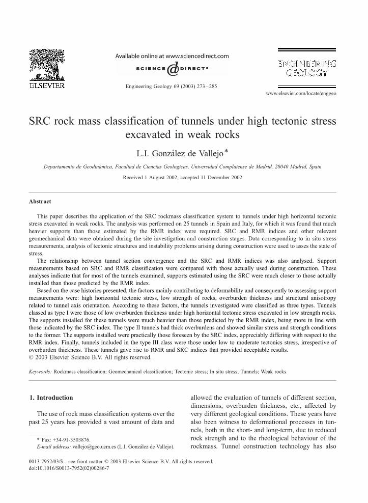
SRC rock mass classification of tunnels under high tectonic stress excavated in weak rocks L.I. Gonza ´lez de Vallejo * Departamento de Geodina ´mica, Facultad de Ciencias Geologicas, Universidad Complutense de Madrid, 28040 Madrid, Spain Received 1 August 2002; accepted 11 December 2002 Abstract This paper describes the application of the SRC rockmass classification system to tunnels under high horizontal tectonic stress excavated in weak rocks. The analysis was performed on 25 tunnels in Spain and Italy, for which it was found that much heavier supports than those estimated by the RMR index were required. SRC and RMR indices and other relevant geomechanical data were obtained during the site investigation and construction stages. Data corresponding to in situ stress measurements, analysis of tectonic structures and instability problems arising during construction were used to asses the state of stress. The relationship between tunnel section convergence and the SRC and RMR indices was also analysed. Support measurements based on SRC and RMR classification were compared with those actually used during construction. These analyses indicate that for most of the tunnels examined, supports estimated using the SRC were much closer to those actually installed than those predicted by the RMR index. Based on the case histories presented, the factors mainly contributing to deformability and consequently to assessing support measurements were: high horizontal tectonic stress, low strength of rocks, overburden thickness and structural anisotropy related to tunnel axis orientation. According to these factors, the tunnels investigated were classified as three types. Tunnels classed as type I were those of low overburden thickness under high horizontal tectonic stress excavated in low strength rocks. The supports installed for these tunnels were much heavier than those predicted by the RMR index, being more in line with those indicated by the SRC index. The type II tunnels had thick overburdens and showed similar stress and strength conditions to the former. The supports installed were practically those foreseen by the SRC index, appreciably differing with respect to the RMR index. Finally, tunnels included in the type III class were those under low to moderate tectonics stress, irrespective of overburden thickness. These tunnels gave rise to RMR and SRC indices that provided acceptable results. D 2003 Elsevier Science B.V. All rights reserved. Keywords: Rockmass classification; Geomechanical classification; Tectonic stress; In situ stress; Tunnels; Weak rocks 1. Introduction The use of rock mass classification systems over the past 25 years has provided a vast amount of data and allowed the evaluation of tunnels of different section, dimensions, overburden thickness, etc., affected by very different geological conditions. These years have also been witness to deformational processes in tun- nels, both in the short- and long-term, due to reduced rock strength and to the rheological behaviour of the rockmass. Tunnel construction technology has also 0013-7952/03/$ - see front matter D 2003 Elsevier Science B.V. All rights reserved. doi:10.1016/S0013-7952(02)00286-7 * Fax: +34-91-3503876. E-mail address: [email protected] (L.I. Gonza ´lez de Vallejo). www.elsevier.com/locate/enggeo Engineering Geology 69 (2003) 273 – 285
-
Upload
yiset-ramirez-avalos -
Category
Documents
-
view
81 -
download
4
Transcript of 2003 SRC Rock Mass Classification (1)
SRC rock mass classification of tunnels under high tectonic stress
excavated in weak rocks
L.I. Gonzalez de Vallejo*
Departamento de Geodinamica, Facultad de Ciencias Geologicas, Universidad Complutense de Madrid, 28040 Madrid, Spain
Received 1 August 2002; accepted 11 December 2002
Abstract
This paper describes the application of the SRC rockmass classification system to tunnels under high horizontal tectonic
stress excavated in weak rocks. The analysis was performed on 25 tunnels in Spain and Italy, for which it was found that much
heavier supports than those estimated by the RMR index were required. SRC and RMR indices and other relevant
geomechanical data were obtained during the site investigation and construction stages. Data corresponding to in situ stress
measurements, analysis of tectonic structures and instability problems arising during construction were used to asses the state of
stress.
The relationship between tunnel section convergence and the SRC and RMR indices was also analysed. Support
measurements based on SRC and RMR classification were compared with those actually used during construction. These
analyses indicate that for most of the tunnels examined, supports estimated using the SRC were much closer to those actually
installed than those predicted by the RMR index.
Based on the case histories presented, the factors mainly contributing to deformability and consequently to assessing support
measurements were: high horizontal tectonic stress, low strength of rocks, overburden thickness and structural anisotropy
related to tunnel axis orientation. According to these factors, the tunnels investigated were classified as three types. Tunnels
classed as type I were those of low overburden thickness under high horizontal tectonic stress excavated in low strength rocks.
The supports installed for these tunnels were much heavier than those predicted by the RMR index, being more in line with
those indicated by the SRC index. The type II tunnels had thick overburdens and showed similar stress and strength conditions
to the former. The supports installed were practically those foreseen by the SRC index, appreciably differing with respect to the
RMR index. Finally, tunnels included in the type III class were those under low to moderate tectonics stress, irrespective of
overburden thickness. These tunnels gave rise to RMR and SRC indices that provided acceptable results.
D 2003 Elsevier Science B.V. All rights reserved.
Keywords: Rockmass classification; Geomechanical classification; Tectonic stress; In situ stress; Tunnels; Weak rocks
1. Introduction
The use of rock mass classification systems over the
past 25 years has provided a vast amount of data and
allowed the evaluation of tunnels of different section,
dimensions, overburden thickness, etc., affected by
very different geological conditions. These years have
also been witness to deformational processes in tun-
nels, both in the short- and long-term, due to reduced
rock strength and to the rheological behaviour of the
rockmass. Tunnel construction technology has also
0013-7952/03/$ - see front matter D 2003 Elsevier Science B.V. All rights reserved.
doi:10.1016/S0013-7952(02)00286-7
* Fax: +34-91-3503876.
E-mail address: [email protected] (L.I. Gonzalez de Vallejo).
www.elsevier.com/locate/enggeo
Engineering Geology 69 (2003) 273–285
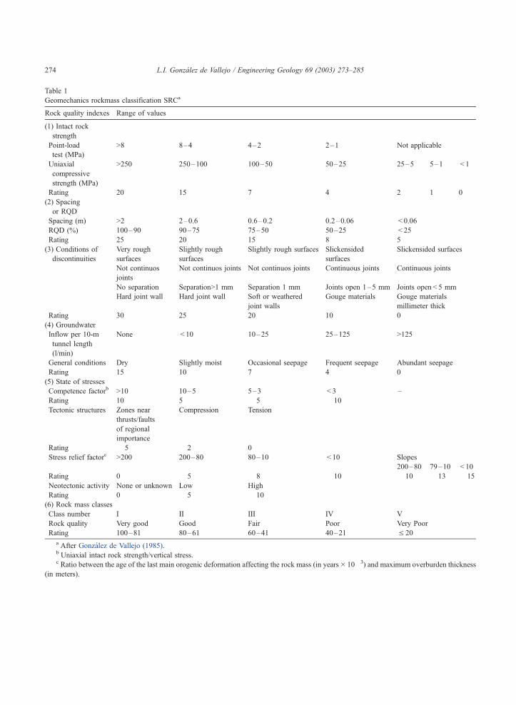
Table 1
Geomechanics rockmass classification SRCa
Rock quality indexes Range of values
(1) Intact rock
strength
Point-load
test (MPa)
>8 8–4 4–2 2–1 Not applicable
Uniaxial
compressive
strength (MPa)
>250 250–100 100–50 50–25 25–5 5–1 < 1
Rating 20 15 7 4 2 1 0
(2) Spacing
or RQD
Spacing (m) >2 2–0.6 0.6–0.2 0.2–0.06 < 0.06
RQD (%) 100–90 90–75 75–50 50–25 < 25
Rating 25 20 15 8 5
(3) Conditions of
discontinuities
Very rough
surfaces
Slightly rough
surfaces
Slightly rough surfaces Slickensided
surfaces
Slickensided surfaces
Not continuos
joints
Not continuos joints Not continuos joints Continuous joints Continuous joints
No separation Separation>1 mm Separation 1 mm Joints open 1–5 mm Joints open < 5 mm
Hard joint wall Hard joint wall Soft or weathered
joint walls
Gouge materials Gouge materials
millimeter thick
Rating 30 25 20 10 0
(4) Groundwater
Inflow per 10-m
tunnel length
(l/min)
None < 10 10–25 25–125 >125
General conditions Dry Slightly moist Occasional seepage Frequent seepage Abundant seepage
Rating 15 10 7 4 0
(5) State of stresses
Competence factorb >10 10–5 5–3 < 3 –
Rating 10 5 � 5 � 10
Tectonic structures Zones near
thrusts/faults
of regional
importance
Compression Tension
Rating � 5 � 2 0
Stress relief factorc >200 200–80 80–10 < 10 Slopes
200–80 79–10 < 10
Rating 0 � 5 � 8 � 10 � 10 � 13 � 15
Neotectonic activity None or unknown Low High
Rating 0 � 5 � 10
(6) Rock mass classes
Class number I II III IV V
Rock quality Very good Good Fair Poor Very Poor
Rating 100–81 80–61 60–41 40–21 V 20
a After Gonzalez de Vallejo (1985).b Uniaxial intact rock strength/vertical stress.c Ratio between the age of the last main orogenic deformation affecting the rock mass (in years� 10� 3) and maximum overburden thickness
(in meters).
L.I. Gonzalez de Vallejo / Engineering Geology 69 (2003) 273–285274
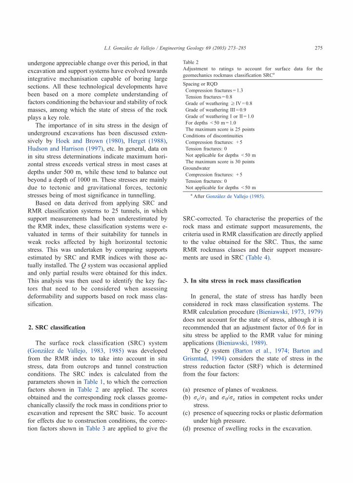
undergone appreciable change over this period, in that
excavation and support systems have evolved towards
integrative mechanisation capable of boring large
sections. All these technological developments have
been based on a more complete understanding of
factors conditioning the behaviour and stability of rock
masses, among which the state of stress of the rock
plays a key role.
The importance of in situ stress in the design of
underground excavations has been discussed exten-
sively by Hoek and Brown (1980), Herget (1988),
Hudson and Harrison (1997), etc. In general, data on
in situ stress determinations indicate maximum hori-
zontal stress exceeds vertical stress in most cases at
depths under 500 m, while these tend to balance out
beyond a depth of 1000 m. These stresses are mainly
due to tectonic and gravitational forces, tectonic
stresses being of most significance in tunnelling.
Based on data derived from applying SRC and
RMR classification systems to 25 tunnels, in which
support measurements had been underestimated by
the RMR index, these classification systems were e-
valuated in terms of their suitability for tunnels in
weak rocks affected by high horizontal tectonic
stress. This was undertaken by comparing supports
estimated by SRC and RMR indices with those ac-
tually installed. The Q system was occasional applied
and only partial results were obtained for this index.
This analysis was then used to identify the key fac-
tors that need to be considered when assessing
deformability and supports based on rock mass clas-
sification.
2. SRC classification
The surface rock classification (SRC) system
(Gonzalez de Vallejo, 1983, 1985) was developed
from the RMR index to take into account in situ
stress, data from outcrops and tunnel construction
conditions. The SRC index is calculated from the
parameters shown in Table 1, to which the correction
factors shown in Table 2 are applied. The scores
obtained and the corresponding rock classes geome-
chanically classify the rock mass in conditions prior to
excavation and represent the SRC basic. To account
for effects due to construction conditions, the correc-
tion factors shown in Table 3 are applied to give the
SRC-corrected. To characterise the properties of the
rock mass and estimate support measurements, the
criteria used in RMR classification are directly applied
to the value obtained for the SRC. Thus, the same
RMR rockmass classes and their support measure-
ments are used in SRC (Table 4).
3. In situ stress in rock mass classification
In general, the state of stress has hardly been
considered in rock mass classification systems. The
RMR calculation procedure (Bieniawski, 1973, 1979)
does not account for the state of stress, although it is
recommended that an adjustment factor of 0.6 for in
situ stress be applied to the RMR value for mining
applications (Bieniawski, 1989).
The Q system (Barton et al., 1974; Barton and
Grismtad, 1994) considers the state of stress in the
stress reduction factor (SRF) which is determined
from the four factors:
(a) presence of planes of weakness.
(b) rc/r1 and rh/rc ratios in competent rocks under
stress.
(c) presence of squeezing rocks or plastic deformation
under high pressure.
(d) presence of swelling rocks in the excavation.
Table 2
Adjustment to ratings to account for surface data for the
geomechanics rockmass classification SRCa
Spacing or RQD
Compression fractures = 1.3
Tension fractures = 0.8
Grade of weathering z IV= 0.8
Grade of weathering III = 0.9
Grade of weathering I or II = 1.0
For depths < 50 m= 1.0
The maximum score is 25 points
Conditions of discontinuities
Compression fractures: + 5
Tension fractures: 0
Not applicable for depths < 50 m
The maximum score is 30 points
Groundwater
Compression fractures: + 5
Tension fractures: 0
Not applicable for depths < 50 m
a After Gonzalez de Vallejo (1985).
L.I. Gonzalez de Vallejo / Engineering Geology 69 (2003) 273–285 275

Factor (a) is an indicator of accumulated tectonic
stresses, but these planes also occur in decompressed
rock masses and in areas of tectonic extension, whose
residual stresses have already been released and, thus,
the influence of tectonic stress is uncertain. Factors (b)
and (c) are related to the lithostatic load and the
Table 3
Adjustment to ratings to account for construction factors for the geomechanics rockmass classification SRCa
The total rating from Table 1 must be adjusted for the following factors:
Excavation methods
Tunneling boring machines, continuos miner, cutter machines, roadheaders, etc. + 5
Controlled blasting, presplitting, soft blasting, etc. 0
Poor-quality blastingb � 10
Support methodsc
Class I 0
Class II
< 10 d 0
>10– < 20 d � 5
>20 d � 10
Class III
< 2 d 0
>2– < 5 d � 5
>5– < 10 d � 10
>10 d � 20
Classes IV and V
< 8 h 0
>8– < 24 h � 10
>24 h � 20
Distance to adjacent excavationd
AEF< 2.5 � 10
Portals, accesses and areas with small overburden thicknesse
PF < 3 � 10
Rock resistance to weatheringf
Rock of high durability (low clay content) 0
Rock of low durability (high clay content) � 5
Rock of very low durability (very high clay content) � 10
Discontinuity orientationsg
Strike perpendicular to tunnel axis Strike parallel to tunnel axis Dip 0–20j at
any direction
Drive with dip Drive against dip
Dip 45–90j(very favourable)
Dip 20–45j(favourable)
Dip 45–90j(fair)
Dip 20–45j(unfavourable)
Dip 45–90j(very unfavourable)
Dip 20–45j(fair)
Unfavourable
0 � 2 � 5 � 10 � 12 � 5 � 10
a After Gonzalez de Vallejo (1985).b Conventional blasting: 0.c Based on Bieniawski’s (1979) graphic representation of the stand-up time and the unsupported span, the ratings are applied in relation to
the maximum stand-up time. d: days, h: hours.d AEF is the adjacent excavation factor, defined as the ratio between the distance to an adjacent excavation (in meters) from the excavation
under design and the span of the adjacent excavation (in meters).e PF is the portal factor, defined as the ratio between the thickness of overburden and the span of the excavation, both in meters.f Durability can be assessed by the slake durability test, or indirectly by the clay content.g After Bieniawski (1979).
L.I. Gonzalez de Vallejo / Engineering Geology 69 (2003) 273–285276

strength of the rocks, whereas factor (d) depends on
the chemical composition of the rocks and the pres-
ence of water.
In SRC classification, the following parameters are
used to asses the state of stress:
(a) competence factor: rc/r1.
(b) tectonic accidents of regional magnitude present or
near the site and their tectonic regime.
(c) stress relief factor, expressed as the ratio between
the age of the last main orogenic deformation af-
fecting the rock mass (in years� 10� 3) and
maximum overburden thickness (in metres). Main
orogenic deformations are considered as Herci-
nian and Alpine in Spain and Italy. The age of
these folds is of the order of 300 million years
for the Hercinian and 10–12 million for the
Alpine. Maximum overburden thickness refers to
the existing overburden plus that supported by
the rock mass throughout its geological history,
which could be absent because of erosion proc-
esses.
(d) seismic activity in the zone.
No specific analyses are required to calculate these
parameters, but rather an approximation based on
geological data, in some cases taken from the liter-
ature. An example of how state of stress parameters
are estimated is presented below.
Tunnel excavated in Palaeozoic shales and sand-
stones for which the following data were obtained:
– mean density: 2.1 t/m3
– mean uniaxial compressive strength: 1,500 t/m2
(15 MPa)
– present overburden thickness: 300 m
– age of folding: Hercinian, approximately 300
million years
– maximum overburden thickness: 500 m (actual
overburden thickness 300 m plus 200 m of eroded
materials according to regional geological data).
– competence factor: 1500/300� 2.1 = 2.3 (� 10
points).
(a) tectonic accidents: faults of regional significance
in the tunnel area (� 5 points).
(b) stress relief factor: {300,000,000 years� 10� 3/
500 m} = 600 (0 points)
Table 4
Guidelines for excavation and support of 10-m-span rock tunnels according to the RMR Systema
Rock mass class Excavation Rock bolts
(20-mm diameter, fully grouted)
Shotcrete Steel sets
(I) Very good rock,
RMR: 81–100
Full face, 3 m advance Generally no support
required except spot bolting.
(II) Good rock,
RMR: 61–80
Full face, 1–1.5 m advance;
complete support 20 m
from face
Locally, bolts 4 m long,
spaced 1.5–2 m in crown
50 mm in crown
where required
None
(III) Fair rock,
RMR: 41–60
Top heading and bench
1.5–3 m advance in
top heading; commence
support after each blast;
complete support
10 m from face
Systematic bolts 4 m long,
spaced 1.5–2 m in crown
and walls with wire
mesh in crown
50–100 mm in crown
and 30 mm in sides
None
(IV) Poor rock,
RMR: 21–40
Top heading and bench
1.0–1.5 m advance in
top heading; install
support concurrently with
excavation, 10 m from face
Systematic bolts 4–5 m long,
spaced 1–1.5 m in crown
and wall with wire mesh
100–150 mm in crown
and 100 mm in sides
Light to medium
ribs spaced 1.5 m
where required
(V) Very poor rock,
RMR: < 20
Multiple drifts 0.5–1.5 m
advance in top heading;
install support concurrently
with excavation; shotcrete
as soon as possible after
blasting
Systematic bolts 5–6 m long,
spaced 1–1.5 m in crown
and wall with wire mesh;
bolt invert
150–200 mm in crown,
150 mm in sides and
50 mm on face
Medium to heavy ribs
spaced 0.75 m with steel
lagging and forepoling
if required; close invert
a After Bieniawski (1989).
L.I. Gonzalez de Vallejo / Engineering Geology 69 (2003) 273–285 277

(c) seismic activity: none (0 points).
(d) total state of stress score:� 10� 5 + 0 + 0 =� 15
points.
Fig. 1 shows the relative influence of the different
factors contributing to SRC, RMR and Q indices.
Whereas the state of stress does not contribute to the
RMR index, the strength of the intact rock is not
included in Q.
4. Tunnels under high tectonic stress
The expansion of rapid transport systems, mainly
railways and roads, has meant that many tunnels have
been constructed in Spain and Italy in the last decade.
Twenty-five tunnels from these countries were ana-
lysed, since it was observed that the support measure-
ments estimated according to RMR classification were
much lower than those required to stabilise deforma-
tions occurring during construction. These tunnels
have been described in detail by Encinas (1992),
Alfani (1993), Alfani et al. (1994) Bellini (1998)
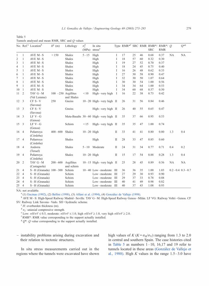
and Gonzalez de Vallejo (1998). Table 5 includes
some relevant data on these tunnels. Despite showing
highly variable conditions both in geological and
construction terms, these tunnels share the following
features:
– located in Spain and Northern Italy, mostly for
high-speed railways,
– sections up to120 m2,
– predominance of low strength rocks (shales,
schists, argillites, etc.),
– significant folding and deformation structures
(folds, faults, thrusts, etc.),
– overburden thicknesses up to 700 m.
In 22 of the 25 cases, the main type of rock was of
low strength, with typical strength values of 10–15
MPa. These weak rocks were composed of shales,
schists and argillites which show highly anisotropic
behaviour.
The state of stress was evaluated by considering
the following data:
– tectonic history of the region, presence of
deformation structures and current tectonic re-
gime,
– in situ stress measurements,
Fig. 1. Relative influence of the geomechanical parameters in RMR, Q and SRC rockmass classification.
L.I. Gonzalez de Vallejo / Engineering Geology 69 (2003) 273–285278
– instability problems arising during excavation and
their relation to tectonic structures.
In situ stress measurements carried out in the
regions where the tunnels were excavated have shown
high values of K (K = rH/rV) ranging from 1.3 to 2.0
in central and southern Spain. The case histories cited
in Table 5 as numbers 1–10, 16,17 and 19 refer to
tunnels located in these areas (Gonzalez de Vallejo et
al., 1988). High K values in the range 1.5–3.0 have
Table 5
Tunnels analysed and mean RMR, SRC and Q values
No. Ref.a Locationb Hc (m) Lithology rcd
(MPa)
In situ
stresseType RMR*f SRC RMR RMR*/
SRC
RMR*/
RMR
Q Q*g
1 1 AVE M–S < 150 Shales 5–15 High I 17 25 46 0.68 0.37 NA NA
2 1 AVE M–S Shales High I 18 57 60 0.32 0.30
3 1 AVE M–S Shales High I 19 27 52 0.70 0.37
4 1 AVE M–S Shales High I 18 24 45 0.75 0.40
5 1 AVE M–S Shales High I 16 26 48 0.62 0.33
6 1 AVE M–S Shales High I 27 30 58 0.90 0.47
7 1 AVE M–S Shales High I 32 30 50 1.07 0.64
8 1 AVE M–S Shales High I 30 30 54 1.00 0.56
9 1 AVE M–S Shales High I 34 34 64 1.00 0.53
10 1 AVE M–S Shales High I 34 60 68 0.57 0.50
11 2 TAV G–M
(Val Lemme)
100 –250 Argillites
and Shales
< 10 High–very high I 16 22 38 0.73 0.42
12 3 CF S–V
(Savona)
250 Gneiss 10–20 High–very high II 26 31 56 0.84 0.46
13 3 CF S–V
(Savona)
Gneiss High–very high II 26 40 55 0.65 0.47
14 3 LF V–G
(Genoa)
Meta-Basalts 30–60 High–very high II 35 37 66 0.95 0.53
15 3 LF V–G
(Genoa)
Schists < 15 High–very high II 35 35 47 1.00 0.74
16 4 Penarroya
(Cordoba)
400–600 Shales 10–20 High II 33 41 41 0.80 0.80 1.3 0.4
17 4 Penarroya
(Cordoba)
Shales High II 28 33 47 0.85 0.60
18 4 Andorra
(Teruel)
Shales 5–10 Moderate II 24 31 34 0.77 0.71 0.4 0.2
19 4 Penarroya
(Cordoba)
Shales 10–20 High II 15 17 54 0.88 0.28 1.3 0.4
20 2 TAV G–M
(Castagnola)
200–600 Argillites
and schists
10–15 High–very high II 25 28 45 0.89 0.56 NA NA
21 4 S–H (Granada) 100–300 Schists 10–40 Low–moderate III 36 36 35 1.00 1.03 0.2–0.4 0.3–0.7
22 4 S–H (Granada) Schists Low–moderate III 27 29 30 0.93 0.90
23 4 S–H (Granada) Schists Low–moderate III 29 37 33 0.78 0.88
24 4 S–H (Granada) Schists Low–moderate III 40 41 49 0.98 0.82
25 4 S–H (Granada) Schists Low–moderate III 40 37 43 1.08 0.93
NA: not available.a (1) Encinas (1992), (2) Bellini (1998), (3) Alfani et al. (1994), (4) Gonzalez de Vallejo (1998).b AVE M–S: High-Speed Railway Madrid–Seville. TAV G–M: High-Speed Railway Genoa–Milan. LF VG: Railway Voltri –Genoa. CF
SV: Railway Link Savona–Vado. SH= hydraulic scheme.c H: overburden thickness (m).d rc: uniaxial compressive strength.e Low: rH/rVV 0.5, moderate: rH/rVV 1.0, high rH/rVz 1.0, very high rH/rVz 2.0.f RMR*: RMR value corresponding to the support actually installed.g Q*: Q value corresponding to the support actually installed.
L.I. Gonzalez de Vallejo / Engineering Geology 69 (2003) 273–285 279

also been reported for northern Italy (Martinetti and
Ribacci, 1980; Crivelli et al., 1994) and correspond to
the areas of case histories numbers 11–15 and 20.
Based on the above-mentioned data, the state of
stress was assessed as follows:
– High tectonic stress was considered for tunnels
under compressive tectonic regimes, mainly situ-
ated in zones of Alpine folding expected to show
high horizontal stresses.
– Moderate tectonic stress was assumed for tunnels
mostly located in Palaeozoic massifs folded in
the Hercinian that were frequently affected by
later tectonics of the extension type and also for
those located in zones undergoing erosion proc-
esses.
Fig. 2. Variation intervals of RMR and SRC indices with respect to RMR* in the study cases.
L.I. Gonzalez de Vallejo / Engineering Geology 69 (2003) 273–285280

The following information was also analysed for
each tunnel:
– Project stage: geological and geomechanical data,
RMR and SRC indices, and recommended supports
according to these classifications.
– Construction stage: geological and geomechanical
data from the excavation fronts, RMR and SRC
indices, section convergence, problems related to
instability and supports installed.
Measurements of the supports installed in the
tunnels were assigned to one of the five classes
described in Table 4. Though a simplification, this
classification was nevertheless useful for establishing
comparative criteria for the different types of support
installed in the tunnels.
The RMR and SRC indices measured at the exca-
vation fronts were compared with those estimated in
the project. When the supports installed were signifi-
cantly different from those predicted by the classifi-
cation score, the RMR corresponding to the support
installed was calculated, yielding an empirical RMR
value denoted RMR*. The RMR* was determined
either from direct measurements at the excavation
front or by back analysing the support installed. Mean
RMR* values are shown in Table 5, and the differ-
ences between RMR* and RMR or SRC are repre-
sented in Figs. 2 and 3. In some cases, Q and Q*
values were also obtained (Table 5).
5. Results
The tunnels examined were classified into three
types:
– Type I: tunnels located in zones subjected to high
horizontal tectonic stresses with low overburden
thicknesses (generally less than 150 m).
– Type II: tunnels located in zones subjected to high
horizontal tectonic stresses with high overburden
thicknesses (higher than 150 m, but generally more
than 250 m).
– Type III: tunnels located in zones of low to
moderate tectonic stresses, irrespective of over-
burden thickness.
To evaluate differences between the rock mass
classifications results and rock mass behaviour after
excavation, the ratios RMR*/SRC and RMR*/RMR
and the differences in rock class between RMR* and
RMR, and between RMR* and SRC were calculated
for each type of tunnel. The results shown in Table 6
Fig. 3. Score differences between RMR and SRC indices with respect to RMR* for the study cases.
L.I. Gonzalez de Vallejo / Engineering Geology 69 (2003) 273–285 281

indicate that most differences between the RMR*
and RMR or SRC were shown by type I tunnels
under high tectonic stress with low overburden
thicknesses. Mean RMR*/SRC and RMR*/RMR
ratios were 0.75 and 0.44, respectively. Type II
tunnels showed the same tendency but yielded some-
what higher values for these ratios; 0.84 for RMR*/
SRC and 0.56 for RMR*/RMR. The ratio with
respect to RMR* was close to 1.0 in both cases for
type III tunnels; 0.95 for RMR*/SRC and 0.91 for
RMR*/RMR.
Table 6 also shows the differences in rock classes
between RMR* and RMR, and between RMR* and
SRC. RMR* was always lower or equal to the RMR
or SRC indices, which meant that supports heavier
than predicted were installed. 100% of cases showed
differences in classes between RMR* and RMR,
compared to 64% between RMR* and SRC. Greatest
differences were recorded for type I tunnels, which
showed a difference of two classes between RMR*
and RMR in 64% of the cases analysed, versus 9%
between RMR* and SRC. In type II tunnels, where
Fig. 4. RMR and SRC indices and convergence values for the Val Lemme Tunnel, a tunnel with a thin overburden and schistosity parallel to the
tunnel axis (Bellini, 1998).
Table 6
Mean relations between RMR* and SRC and RMR for each type of tunnel
Type RMR*/SRC (mean) RMR*/RMR (mean) Difference in rock class with respect to RMR* (%)
Same class One class Two classes
SRC RMR SRC RMR SRC RMR
I 0.75 0.44 36 0 55 36 9 64
II 0.84 0.56 78 11 22 67 0 22
III 0.95 0.91 100 100 0 0 0 0
L.I. Gonzalez de Vallejo / Engineering Geology 69 (2003) 273–285282

89% of all cases showed class differences between
RMR* and RMR, and 22% between RMR* and SRC,
the greatest percentage corresponded to a difference of
one class of rock in 67% of cases between RMR* and
RMR; no significant class differences between RMR*
and SRC being noted in 78% of cases. For the type III
tunnels, both RMR and SRC presented the same class
of rock as RMR*. For types I and II, the means of
these ratios were: RMR*/RMRc 0.5 and RMR*/
SRCc 0.8.
The Q index was only determined in some cases,
thus, the same comparative criteria as for RMR and
SRC could not be established. The results for type II
tunnels, corresponding to cases 16, 17 and 19 (Table
5), indicate a difference in one class of support from
Class D (Poor) to Class E (Very Poor); Class D
corresponds to the estimated support, and Class E to
the support actually installed. For case 18, the pre-
dicted type of support was the same as those actually
installed. For type III tunnels, cases 21–25, installed
supports were as predicted. NoQ values were available
for type I tunnels. These results suggest that the Q
index provides a better estimate of support require-
ments than the RMR for type II tunnels. However,
more data would be needed for comparisons with the
SRC index and for type I tunnels.
Highly variable relationships were observed bet-
ween the deformations or convergences determined in
tunnel sections and RMR and SRC indices. In general,
neither index could adequately predict convergence
nor establish acceptable correlation between rock
classification and deformation. This lack of correla-
tion could be explained by the influence of the
following key geomechanical parameters, besides
construction factors not accounted for in these classi-
fication systems such as the shape and size of the
Fig. 5. RMR and SRC indices and convergence values for the Castagnola Tunnel, a tunnel with a thick overburden and schistosity perpendicular
to the tunnel axis (Bellini, 1998).
L.I. Gonzalez de Vallejo / Engineering Geology 69 (2003) 273–285 283

tunnel section, the excavation system and the type of
support:
– high horizontal stress
– low rock strength
– thin overburden
– unfavourable structural anisotropy with respect to
tunnel axis orientation
In the tunnels examined, structural anisotropy due
to bedding planes and schistosity, and confinement
degree played a major role in deformation. In tunnels
with thin overburdens, the effect of structural aniso-
tropy was marked, while this effect was much reduced
in tunnels with thick overburdens. These features are
shown in Figs. 4 and 5. In Fig. 4, correlation between
deformations and RMR and SRC indices is low for a
tunnel of thin overburden with schistosity parallel to
the tunnel axis, while Fig. 5, in which correlation is
much improved, corresponds to a tunnel of thick
overburden with schistosity perpendicular to the tunnel
axis (Bellini, 1998).
6. Conclusions
The results presented in this investigation, allowed
us to compare supports determined according to SRC
and RMR indices with those actually installed. In the
majority of the tunnels investigated, heavier supports
were used than those predicted by RMR. Systematic
analysis during excavation of geomechanical data,
SRC and RMR indices, in situ stress and tunnel
section deformability served to identify the main
geomechanical factors contributing to underestimation
of supports as:
– high horizontal tectonics stress
– low rock strength
– thin overburden
– highly anisotropic rock behaviour.
The results of applying SRC and RMR indices to
the 25 tunnels analysed can be summarised by the
following types of behaviour:
– Type I. Shallow tunnels under high horizontal
tectonic stress excavated in weak rocks. In these
tunnels, highly anisotropic rockmass behaviour
depends on structural anisotropy and its orientation
with respect to the tunnel axis. The supports installed
in all cases were much heavier than those estimated
by the RMR index: 64% of cases showed a
difference of two classes and 36% showed a
difference of one class, thus, accounting for all the
tunnels of this type. However, corresponding results
for the SRC index were 9% showing a two-class
difference, 55% a difference of one class and 36%
showing the same class. Correlations between SRC
or RMR indices and convergence measurements in
tunnel sections were low for these tunnels.
– Type II. Tunnels with high overburden thickness,
high horizontal tectonic stress and low strength
rocks. Rock mass behaviour is less anisotropic
than for type I tunnels, and RMR or SRC in-
dices correlated well with tunnel convergence.
Supports installed in 78% of cases were the same
as those estimated by the SRC index, while the
RMR underestimated supports in 89% of these
tunnels.
– Type III. Tunnels under low to moderate horizontal
tectonic stress regardless of overburden thickness
excavated in weak rocks. The supports installed
were consistent with those predicted by both the
RMR and SRC indices.
In general, these findings indicate that the SRC
index provides a reasonable estimate of tunnel sup-
port in tunnels under high horizontal tectonic stress
excavated in weak rocks. In contrast, under the
conditions of the present analysis, the RMR can
underestimate support requirements by one or two
classes of rock.
Acknowledgements
The author thanks Dr. Marino Trimboli and Dr.
Sergio Pedemonte for their valuable contributions to
this study. The authors of theses on rock mass
classification undertaken at the Universidad Complu-
tense de Madrid (Valeria Bellini, Ignacio Encinas and
Luis Munoz) and at the Universita di Genova (Marco
Alfani) are also gratefully acknowledged. Thanks are
also due to Dr. M. Ferrer and Sr. J.M. Insua for their
help during preparation of the paper.
L.I. Gonzalez de Vallejo / Engineering Geology 69 (2003) 273–285284

References
Alfani, M., 1993. Le classificazioni geomeccaniche di Gonzalez de
Vallejo (1983) e Romana (1990) applicate al alcuni litotigi lig-
uri: correlazioni con la progettazioni di opere in sotterrares.
Tesis, Universita di Genova.
Alfani, M., Nosengo, S., Pedemonte, S., 1994. La classificazioni
geomeccaniche SRC di Gonzalez de Vallejo (1983) e SMR di
Romana (1990): considerazioni e proposta. Professione Geologo
3, 12–20 (Genova).
Barton, N., Grismtad, E., 1994. The Q-System following twenty
years of application in NATM support selection. Geomechanics
Felsbau 12, 6.
Barton, N., Lien, R., Lunde, J., 1974. Engineering classification of
rock masses for the design of tunnel support. Rock Mechanics 6
(4), 189–236.
Bellini, V., 1998. Caracterizacion geomecanica de rocas blandas:
metodologıas de clasificacion y medidas de convergencia en las
galerıas de exploracion para el proyecto del tren de alta veloc-
idad Genova–Milan. Tesis del Master de Ing. Geologica, Uni-
versidad Complutense de Madrid.
Bieniawski, Z.T., 1973. Engineering classification of jointed rock
masses. The Civil Engineer in South Africa 15 (12), 335–344.
Bieniawski, Z.T., 1979. The geomechanics classification in rock
engineering applications. 4th Int. Congress Rock Mechanics,
Montreaux, vol. 2. Balkema, Rotterdam, pp. 41–48.
Bieniawski, Z.T., 1989. Engineering Rock Mass Classifications.
Wiley, Chichester.
Crivelli, R., Devin, P., Guido, S., Rossi, P.P., 1994. Indagini in sito e
in laboratorio per il Progetto e l’essecuzione di Gallerie Pro-
fonde. In: Barla, G. (Ed.), Conf. on Mechanics and Engineering
of Rocks, MIR’94, Torino, vol. 2, pp. 1–17.
Encinas, I., 1992. Aplicaciones de las clasificaciones geomecanicas
en rocas blandas a partir de datos del frente de excavacion. Tesis
del Master de Ing. Geologica, Universidad Complutense de Ma-
drid.
Gonzalez de Vallejo, L.I., 1983. A new classification system for
underground assessment using surface data. IAEG Symp. on
Eng. Geol. and Underground Construction, Lisboa 2. Balkema,
Rotterdam, pp. 85–94.
Gonzalez de Vallejo, L.I., 1985. Tunnelling evaluation using the
Surface Rock Mass Classification System SRC. ISMR Symp.
The Role of Rock Mechanics in Excavations for Mining and
Civil Works, Zacatecas, Mexico, vol. 1. Soc. Mexicana de Mec.
de Rocas, Mexico, D.F., pp. 458–466.
Gonzalez de Vallejo, L.I., 1998. Las clasificaciones geomecanicas
para tuneles. In: Lopez, J. (Ed.), Ingeotuneles, vol. 1. Entorno
Grafico, Madrid, pp. 25–68. Cap 1.
Gonzalez de Vallejo, L.I., Serrano, A.A., Capote, R., De Vicente,
G., 1988. The state of stress in Spain and its assesment by
empirical methods. Rock Mech. and Power Plants. ISRM
Symp., vol. 1. Balkema, Rotterdam, pp. 165–172.
Herget, G., 1988. Stresses in Rock. Balkema, Rotterdam.
Hoek, E., Brown, E.T., 1980. Underground Excavation in Rock.
Inst. Min. and Met., London.
Hudson, J.A., Harrison, J.P., 1997. Engineering Rock Mechanics.
An Introduction to the Principles. Pergamon, Oxford.
Martinetti, S., Ribacci, R., 1980. In situ stress measurements in
Italy. Rock Mechanics (Suppl. 9), 31–47.
L.I. Gonzalez de Vallejo / Engineering Geology 69 (2003) 273–285 285