2002-2008 H-D TOURING MODELS INSTALLATION INSTRUCTIONS · 2002-2008 flh renegade- rev. 8 2002-2008...
41
2002-2008 FLH Renegade- Rev. 8 2002-2008 H-D TOURING MODELS INSTALLATION INSTRUCTIONS *FLHX AND FLTR MODELS REQUIRE ADDITIONAL HARDWARE December 2013
Transcript of 2002-2008 H-D TOURING MODELS INSTALLATION INSTRUCTIONS · 2002-2008 flh renegade- rev. 8 2002-2008...

2002-2008 FLH Renegade- Rev. 8
2002-2008 H-D TOURING MODELS
INSTALLATION INSTRUCTIONS
*FLHX AND FLTR MODELS REQUIRE ADDITIONAL HARDWARE
December 2013

2002-2008 FLH Renegade- Rev. 8
Table of Contents SECTION Introduction Unpacking Kit Preparing Motorcycle Installing Lehman Swingarm Top Motor Mount Link Installing Differential Belt Tensioning and Tracking Brake Systems Installing Lehman Frame and Suspension Installing Exhaust Lights and Wiring Body Neck Race Preload Motor Mounts General Information Replacement Parts Renegade Torque Specifications Final Trike Inspection *Notes before starting conversion *For 2002-03 models, the standard Lehman Renegade conversion will not accommodate the original 1-1/2” final drive belt. The following belt replacement is required to properly complete the Renegade installation. *For FLHX (Street Glide) and FLTR (Road Glide) installations, the following parts will need to be or-dered from H-D for antenna and turn signal installation: HD P/N Description Qty. 76252-86 Base, antenna 1 76253-86 Reinforcement plate 1 76255-86 Gasket, base 1 11486 Grommet 1 68713-94A Lamp, rear signal 2 **Dakota Digital offers a hidden antenna kit as an alternative. Part # ANT-2000 **ABS Models– Disabling the ABS light will also disable the cruise control light.
2
02-06 MODELS INCLUDE:
02-08 BASE KIT
CARRIER/PULLEY ASSEMBLY– 70 TOOTH
07-08 MODELS INCLUDE:
02-08 BASE KIT
CARRIER/PULLEY ASSEMBLY– 66 TOOTH
ABS DISABLE KIT (S001068)
Model Belt Required H-D part number
FLH 2002-03 1-1/8" width, 139 tooth 40024-04

2002-2008 FLH Renegade- Rev. 8
UNDERSTANDING SAFETY LABELS & INSTRUCTIONS
READ AND BECOME FAMILIAR WITH ALL WARNING, CAUTION SYMBOLS AND STATEMENTS
LISTED BELOW AND IN THE TEXT OF THIS MANUAL BEFORE YOU BEGIN WORK.
DANGER, WARNINGS & CAUTION SYMBOLS
Throughout these instructions “Front” or “Forward” refers to the front of the bike. The front of any com-ponent is the end which faces toward the front of the bike. The “Left” and “Right” hand sides refer to the position of the parts as viewed by a rider sitting on the seat, facing forward. NOTE: The symbol HD refers to Harley Davidson. The symbol LH refers to left-hand side while seated on the bike. The symbol RH refers to the right-hand side while seated on the bike. These instructions do not include information, specifications, or procedures relating to the motorcycle itself. For this information, refer to the factory service manual. The information in these instructions is provided to Lehman Trike dealers. It is proprietary to Lehman Trikes, Inc. and provided solely for use by dealers. Any unauthorized duplication or distribution is a vio-lation of international copyright law.
3
This is the safety alert symbol. When you see this symbol on your machine or in this manual, be alert to the potential for personal injury. Your safety is involved!
SAFETY ALERT WARNING indicates a potential hazard that may result in severe injury or death to the operator, by-stander or person (s) inspecting or servicing the vehicle.
Indicates a potential hazard that may result in minor per-sonal injury or damage to the vehicle.
CAUTION indicates special precautions that must be taken to avoid vehicle damage or property damage.
NOTE provides key information by clarifying instructions.
IMPORTANT provides key reminders during disassembly, assembly and inspection of components.
WARNING
CAUTION
CAUTION
NOTE:
IMPORTANT:

2002-2008 FLH Renegade- Rev. 8
General Safety Information This kit is designed to be installed by a competent technician. Improper installation can affect the safe operation of your trike, which could also result in serious injury or death. Make sure you have a complete understanding of the work to be preformed. Unqualified installers are urged to have the unit installed by a trained technician.
• Always protect yourself when the vehicle is in the air. Make sure the vehicle is properly supported anytime you use a hoist or jack.
• Always use the proper tools.
• Protect your eyes by using proper safety glasses or goggles.
• Read through the installation instructions before you begin. Make sure you have all the proper tools, parts and skill set to perform the installation safely and completely.
NOTE: Compliance with national (DOT-USA, MOT-Canada), State, Provincial, and local vehicle is standards is the responsibility of the installer. Installation of the parking brake and grab handles is necessary to achieve compliance with DOT/MOT.
ARB Label Confirmation– California Kits 1. See Fig. 1. California Air Resource Board (ARB) certification
label must be affixed on all swingarms for kits sold into Califor-nia.
2. Label should be placed on left side of swingarm 1/2” from rear weld.
3. Make sure label correlates with correct model year.
4
Fig. 1

2002-2008 FLH Renegade- Rev. 8
Unpacking the Kit
The crate contains the following:
• Body • Differential with brakes • Tires mounted on rims • Boxed swingarm • Lehman frame • Hardware box containing smaller parts and bolt bags • Warranty Book • Owner’s Manual • Packing/parts list
5
Fig. 1
LB1295 2002-06 SWINGARM BUSHING

2002-2008 FLH Renegade- Rev. 8
6
LS2013-2002+ SWINGARM
LF2084-FRAME
MODULAR DIFFERENTIAL
LB1301/LB1302 2007-08 SWINGARM BUSHINGS
GM0142 MOTOR MOUNT LINK

2002-2008 FLH Renegade- Rev. 8
Preparing Motorcycle The following instructions are a guide to preparing the motorcycle to accept the Lehman Trike Conver-sion Kit. This will assist you in removing the necessary parts to install the kit. 1. Note motorcycle year, model and serial number, as well as Lehman serial number, located
inside body, on left-side of swingarm and on warranty registration form in owner’s manual. 2. Make sure motorcycle is standing straight up and handlebars are centered. Support motorcycle with
center stand under rear of transmission so it is straight up and down and handlebars are straight. The front forks or handlebars should be anchored to hold bike.
Note: Use a small level on rear wheel or disc brake to stand bike straight up. Any movement of handlebars will move bike off level. Locate reference point on bike frame that is level to use dur-ing conversion. 3. Remove seat and save mounting screw. 4. Disconnect battery. Caution: Always disconnect negative battery cable first. If positive cable should contact a grounded object while negative cable is installed, resulting sparks may cause an explosion. 5. Remove tour pack. For 2006-08 models- save mounting bar, spacers and hardware for rear hole. 6. Raise motorcycle lift to working height. 7. Remove side stand mounting bolt and separate side stand from bracket. 8. Remove passenger footboards. Save boards and hardware for re-installation. 9. Remove side covers. 10. Remove rear side cover grommets from motorcycle for use with Lehman side cover mounts. 11. Remove saddlebags (if equipped). 12. Remove mufflers and saddlebag mounts. Keep all muffler mounting hardware including rubber iso-
lators located in saddlebag mounts. These parts will be re-used. 13. Remove rear heat shields from exhaust pipes and loosen head pipe bolts. Save all exhaust hard-
ware. 14. Remove carriage bolt from lower RH exhaust bracket and save. 15. Disconnect airlines from shocks and remove shocks. Stand shocks upright to prevent oil leaks.
Save air valve plate and discard original shock mounting bolts. 16. Remove rear fender. Save two front mounting bolts. Save turn signal lights and fender mounting
hardware, including stud plate for grab rail. These parts will be re-used. 17. Remove brake line from caliper and remove caliper. 19. Remove clip from rear axle and remove axle nut with 36mm socket. Axle can now be removed. 20. Remove rear wheel assembly. 21. Support bottom side of transmission housing with floor jack and padded block. 22. Remove pivot shaft nut from LH side of bike. Remove LH/RH swingarm brackets. Tap shaft out of
swingarm and remove from RH side. Swingarm may now be removed. 23. For 2002-07 models, fuel tank must be removed. Refer to HD service manual for proper procedure.
7

2002-2008 FLH Renegade- Rev. 8
Installing Lehman Swingarm Note: If all original components from H-D swingarm are in good working order, they may be re-used. 1. Press bearing assemblies out of H-D swingarm using appropriate press collar or socket. Refer to H-
D service manual. Note: Make sure there is no dirt or powder coat material in bearing bore where bearing is to be started. 2. Press bearings into Lehman swingarm following HD service manual procedure. Bearings should
bottom out on stop in Lehman swingarm collar. Note: Refer to H-D service manual for swingarm installation procedures and torque specifica-tions for specific model of motorcycle. 3. Install Lehman swingarm with word
“TOP” (stamped into swingarm collar) facing upward. Use Loctite 242 on threads. Torque rear swingarm (fork) pivot shaft to 45 ft.-lbs.
4. Install steel bushings into swingarm with shoul-der toward inside of swingarm.
2002-2006 Models 5. See Fig. 1. Install orange urethane bushings
and steel bushings into swingarm rubber mounts on both sides of trike.
• (2) Orange Urethane Bushings– LB1295 • (2) Steel Bushings– LB1296
2007-2008 Models 6. See Fig. 2. Urethane bushings are black for
2007-08 models. Each bushing is marked “L” or “R” and has a unique ridge to fit properly into fork brackets on 2007-08 kits. Install with steel bushings.
• (1) LH Urethane Bushing– LB1301 • (1) RH Urethane Bushing– LB1302 • (2) Steel Bushings– LB1296
7. Re-install rear swingarm (fork) brackets. Apply Loctite 242 and torque bolts to 42 ft.-lbs.
8. Be sure swingarm moves freely up and down with no side to side movement. Light resistance is normal.
8
Fig. 1
Fig. 2

2002-2008 FLH Renegade- Rev. 8
9
Top Motor Mount Link-2002-2007 Models Only *2008 Models– See pg. 12 1. Before loosening lock nuts for original top motor mount
link, measure length from center to center of bolt holes. 2. Remove OEM top motor mount link. 3. Adjust Lehman stabilizer link (Fig. 1) to achieve same
length as OEM motor mount link. 4. Position top motor mount bracket (LB1277) against frame
and outline around it. Note: For 2006-2007 models, a small notch must be cut from plastic HD frame cover to accommodate Lehman mo-tor mount bracket (LB1277). Move any wiring before cutting. 5. Sand or grind frame to bare metal finish inside outline where bracket will fit. A slightly rough surface
is desirable. Note: Use a generous amount of glue (Loctite 330) to fill between bracket and frame. Apply glue to plate and spray activator onto glue rather than frame. 6. See Fig. 2. Install 3/8” x 1 1/2” bolt, lock washer and flat washer through bracket and into frame.
Use 2-3 “C” clamps to hold bracket to frame. 7. Allow adhesive to cure for 24 hours. 8. Installation may proceed while glue cures. 9. Attach link assembly to upper mounting bracket.
Fig. 1
Fig. 2
GM0142

2002-2008 FLH Renegade- Rev. 8
10
10. Link should run horizontal to motorcycle. Be sure to shim both sides of link end with supplied shims
and use OEM spacer (Fig.’s 2 & 3). 11. Tighten all bolts to factory torque specs (frame-22 ft.-lbs., engine-33 ft.-lbs.) 12. Check for any interference of motorcycle parts (wire harnesses, air hoses, etc.). 13. Reroute any wire harnesses around or behind bracket. The coil wire on a fuel-injected model will
run over top edge of bracket. Note: Make sure harnesses are not pinched when fuel tank is reinstalled.
Fig. 3

2002-2008 FLH Renegade- Rev. 8
11
Head Bolts and Front Motor Mount Reminder: Applies only to 2002-2007 Models FLH Head Bolts 1. Remove existing 3/8” bolt, lock washer and flat washer that holds engine stabilizer bracket to en-
gine. 2. Apply blue Loctite 242 to threads of 3/8” x 1 1/4” hex flange-locking bolt. 3. Assemble bolt, spacer (LS1189) and external tooth lock washer in appropriate order. 4. Torque bolt to 42 ft.-lbs. 5. Reinstall gas tank according to H-D service manual once top motor mount glue is fully cured. FLH Lower Engine Mount Bolt 1. Remove 3/8” bolt; lock washer and flat washer that holds engine stabilizer to engine. 2. Apply blue Loctite 242 to threads of 3/8” x 1 1/2” hex flange-locking bolt. 3. Install 3/8” x 1 1/2” flanged bolt and original washer. Torque bolt to 42 ft.-lbs. 4. On same bolt, install 3/8” supplied locknut and torque to 38 ft.-lbs. 5. Remove bolt, lock washer and flat washers that hold stabilizer to frame. 6. Apply Loctite to supplied 3/8” x 1 1/2” flanged head bolt. Install supplied bolt with original flat wash-
ers to frame. Torque bolt to 42 ft.-lbs. 7. Remove front engine mount; apply Loctite to threads and re-install nut. Torque bolt to 45-54 ft.-lbs.

2002-2008 FLH Renegade- Rev. 8
12
Reminder: For 2008 models, do not disturb OEM head bolts or lower engine mount bolt. Top Motor Mount Link Removal- 2008 Models 1. OEM top motor mount link will be replaced with Leh-
man Motor Mount Link (Fig. 1). 2. Before loosening lock nuts from OEM motor mount
link, measure length from center to center of holes. 3. Remove OEM motor mount link, save washer on RH
side (Fig. 2). Lehman Motor Mount Link Installation 4. Adjust Lehman motor mount link to same distance
from center of hole to center of hole as OEM motor mount link.
• (1) Upper Engine Stabilizer Link– GM0142 Note: Locate position of eyelet holes and alignment of OEM link. Lehman link must be adjusted same as OEM link. 5. Install Lehman link (Fig. 3) using existing OEM bolts,
washer on RH side, blue Loctite 242 and supplied motor mount link shims.
Note: Be sure to shim both sides of link ends. 6. Torque OEM bolts to 22 ft. lbs.
Fig. 1
Fig. 2
Fig. 3
OEM Top motor mount link
Lehman motor mount link
OEM link installed
Lehman link installed

2002-2008 FLH Renegade- Rev. 8
13
Differential Installation 1. See Fig. 1. Attach LH adapter plate (LP1038) to
swingarm as shown. Leave hardware loose. 2. See Fig. 2. Attach RH adapter plate to swin-
garm as shown with park brake bracket mounted to lower holes. Leave hardware loose.
3. See Fig. 1 and 2. Install 3/8” nut to adjuster bolt and thread into adapter plate from backside. Run bolt completely into adapter plate.
Fig. 1
Fig. 2

2002-2008 FLH Renegade- Rev. 8
14
4. See Fig. 3 and 4. Loosely install hardware to pinch blocks before installing differential to swingarm.
Fig. 3
Fig. 4

2002-2008 FLH Renegade- Rev. 8
15
5. Support swingarm with jack stands. 6. See Fig. 5. With differential assembly on lift,
slide belt over LH axle tube and against center housing.
7. See Fig. 5. Set differential assembly on swin-garm adapter plates. Slide differential as far forward as possible. Set jack stands under axle tubes.
8. Tighten pinch block hardware just enough to allow differential to slide on swingarm adapter plates.
9. See Fig. 5. Remove upper, lower and rear housing plates.
10. See Fig. 6. Carefully slide belt over pulley. 11. Reinstall housing plates with original hardware
using Loctite 242. Install all hardware before tightening. Torque hardware to 17 ft. lbs.
Fig. 5
Install belt
Fig. 6
Remove plates

2002-2008 FLH Renegade- Rev. 8
Belt Tensioning and Tracking 1. Center differential to motorcycle frame– this is
critical for proper belt tensioning. Make sure distance is within 1/16” from side to side.
2. See Fig. 1. Level swingarm to motorcycle frame. This will help achieve proper ride height. With standard shocks, measure 12” from inner boss against center section to center of upper motor-cycle frame.
3. See Fig. 2. Using adjusters, push differential assembly back until belt has about 3/8” slack with 10 lbs. pressure at midpoint of bottom run. Measure between adapter plates and pinch blocks to ensure that distances are equal.
4. Rotate pulleys forward for at least 3 revolutions of rear pulley by pulling backwards on bottom run of belt. Pull belt straight back to get an accu-rate reading. Check that belt is running about 0.030” from flange on rear pulley. Tap differen-tial left or right to achieve this reading. Belt may ride next to flange as long as it’s not trying to climb.
5. Tighten socket head screws (8) that hold adapter plates to swingarm and torque to 35 ft. lbs. 6. Once tracking is obtained, re-check belt tension. Raise and lower differential assembly slowly with a
jack while checking belt tension. When tightest position is located, apply 10 lbs. force at midpoint of lower strand of belt. Correct deflection is 5/16” - 3/8”.
7. Increase or reduce belt deflection by turning adjuster screw on each side in or out an equal number of turns.
8. Look along top of belt to check belt alignment on front pulley. There should be about 0.030” clear-ance between pulley flange and belt. If adjustment is required, loosen cap screws that hold adapter plate to swingarm and tap differential housing with rubber mallet in desired direction. Check rear alignment and belt tension again if adjustment is required.
Note: If necessary, apply chalk to edge of belt to aid in getting proper clearance between belt and pulley flanges. If visible clearance cannot be obtained, be sure belt is not climbing up the side of pulleys or squeaking as belt is rotated. 9. After all adjustments are made, tighten adjuster lock nuts and tighten pinch block bolts. Tighten
pinch blocks in a crosswise pattern. Go over both sides at least 2 times to seat blocks over pins. Torque bolts to 25 ft. lbs.
16
Fig. 1
12”
Drive belt deflection
Fig. 2

2002-2008 FLH Renegade- Rev. 8
12. See Fig. 10. Remove RH front plate hardware
and install tapered washers (S001784) into holes on RH side before installing brace.
13. Bolt rear half of differential brace to housing us-ing bolts (CB1939).
14. See Fig. 11. Bolt front half of differential brace to top of swingarm gusset with a 3/8” x 1” bolt, flat washers and lock nut.
Note: Do not bolt down brace until belt tension-ing is completed. 15. Tighten bolts in following order:
a. Front half of brace to swingarm gusset. Torque bolts to 35 ft. lbs.
b. Rear half of brace to differential housing. Torque bolt to 17 ft. lbs.
c. Torque LH front plate bolts to 17 ft. lbs.
17
Fig. 10
Fig. 11
Tapered washers

2002-2008 FLH Renegade- Rev. 8
Disc Brakes CAUTION: Brakes are a critical safety compo-nent of the trike. Verify all brake components have been properly installed before test riding. Improper brake operation could result in death or serious injury. Do not allow dirt or debris to enter master cylinder reservoir. Brake pads will need to be seated in during initial test ride. Note: FOR ABS DISABLE, SEE PAGE 21 Brake System 1. See Fig. 1. Attach brass tee to differential
brace using the following hardware. • (1) Brass Tee– CF5105 • (1) Spacer– S001530 • (2) 1/4” x 1-3/4” Hex Bolt– CB1100 • (2) 1/4” Flat Washers– CW2005 • (2) 1/4” Lock Nut– CN3042
2. See Fig. 1. Install original brake line from master cyclinder and rear braided lines to brass tee using the following hardware. Torque banjo bolt to 16 ft. lbs.
• (1) Banjo Bolt– S002022 • (2) Banjo Washers- GC6002 • (2) 45” M10 Braided Line– S001976
3. See Fig. 2. Install (2) braided brake lines to rear calipers as shown. Torque bolts to 16 ft. lbs.
• (2) M10 Banjo Bolt– CB6001 • (4) M10 Banjo Washers- GC6002
4. Secure brake lines to swingarm with cable ties.
18
Fig. 1
Fig. 2
OEM line
Spacer
Install brake lines to LH/RH calipers

2002-2008 FLH Renegade- Rev. 8
Note: Be sure you have correct model year res-ervoir extension pack before proceeding (Reminder: packs are labeled 1997-2007 and 2008+). 5. See Fig. 3. Remove original master cylinder
reservoir cap screws and discard. Install ex-tension to master cylinder with new extension screws. Do not over tighten extension screws.
Note: Verify all brake lines and hardware are tight before bleeding system. 6. Add brake fluid (refer to OEM reservoir cap for
brake fluid requirements) to brake system and work brakes to fill lines.
7. Remove rubber caps on bleeder valves. Install clear brake bleeder hose over bleeder valve on caliper.
8. Pump brake pedal to build pressure. 9. While holding the brake pedal, open bleeder
valve to release pressure and remove air from system. Repeat bleeding on both calipers until fluid is solid without bubbles in bleeder hose.
10. Tighten bleeder valves and check for leaks. 11. Install master cylinder reservoir cap with new
screws. Do not over tighten cap screws. Park Brake Assembly 1. See Fig. 4. Install park brake cable to caliper
brackets. Secure cable to bracket with cir-clip provided on cables.
19
Fig. 4
Attach cable
Secure to bracket
Fig. 3
Supplied cover screws
Extension screws (2008+ pack)

2002-2008 FLH Renegade- Rev. 8
2. See Fig. 5. Remove snap ring from one side of
large clevis pin on brake lever. Hold park brake lever on its side and push release button at end of park brake lever to allow clevis pin to slide out.
3. See Fig. 5.Place park brake lever within park brake bracket, ensuring ratchet is secure on cross brace. Attach with large clevis pin.
4. See Fig. 5. Attach park brake cable pulling bracket to brake lever using small clevis pin and cotter pin.
• (1) Cable Pulling Bracket– LB1294 • (1) Clevis Pin– CC3106 • (1) Cotter Pin- CC4017
5. See Fig. 6. Route left park brake cable above differential and under motorcycle frame, at-taching cable ties to cable and frame, and in-stall in left hole in handle mount.
6. See Fig. 7. Route right park brake cable up around axle and forward to right hole in handle mount.
7. See Fig. 7. Secure both cables to upper rear pinch block with clamp (GC0108).
8. See Fig. 8. Secure cable retaining nuts to handle mount with 7/8” wrench.
9. Check for tire clearance. 10. See Fig. 8. Thread one 5/16” NF nut onto
each brake cable. Place threaded end of brake cables through holes in cable bracket. Thread second nut onto each brake cable.
11. Adjust park brake cables at handle to engage at 3–4 clicks.
Note: Take up slack in cables before tighten-ing ends to ensure good adjustment range with threaded end of brake cables.
20
Fig. 6
Left park brake cable
Fig. 7
Fig. 8
Cable routing
Cable retaining nuts
Adjuster nuts
Attach clamp
Fig. 5

2002-2008 FLH Renegade- Rev. 8
ABS Systems 1. See Fig. 1. Disconnect OEM rear brake line
(black) from ABS unit “MR”. Route brake line along lower frame tube and above swingarm. This line will be used for the rear brake system.
2. See Fig. 2. Re-install banjo bolt with spacer (S001067) in ABS unit “MR” and tighten.
3. See Fig. 1. Disconnect OEM rear brake line (silver) from ABS unit “R” and discard (brake line was disconnected from rear caliper during motor-cycle disassembly).
4. See Fig. 2. Re-install banjo bolt with spacer (S001067) in ABS unit “R” and tighten.
5. See Fig 3. Locate ABS front wheel sensor plug under left side of fairing and disconnect. Secure longer sensor plug to fairing wire bundle with cable tie (CT1026).
6. See Fig. 4. Locate ABS rear wheel sensor plug (left side of ABS unit). Disconnect plug, remove sensor from right-side axle and discard.
Fig. 1
Fig. 2
Fig. 3
Fig. 4
From ABS to caliper (silver) From Master
Cylinder. to ABS (black)
R
MR
Banjo bolt spacer (S001067)
R
MR
ABS front wheel sensor plug
ABS rear wheel sensor plug
21

2002-2008 FLH Renegade- Rev. 8
ABS Systems Continued
22
Note: Items 7-11 can be performed during Neck Race Preload check on page 38. 7. Remove outer fairing (refer to HD service man-
ual). Caution: Disabling ABS light will also disable cruise control light. 8. See Fig. 5. Disable ABS warning light by cut-
ting orange wire with white stripe. 9. See Fig. 6. Install 2” heat-shrink to each end of
cut wire. 10. Re-install fairing. 11. See Fig. 7. Place ABS warning label above
warning light indicators on fairing.
Fig. 5
Fig. 6
Fig. 7
Place “ABS Disabled” sticker here
Apply heat shrink to ends of wires

2002-2008 FLH Renegade- Rev. 8
23
Installing Lehman Frame and 1. See Figs. 1-3. Install frame plates to H-D frame with (2)
5/16” X 1 1/2” bolts, flat washers (if necessary, between frame plate and motorcycle frame) and lock nuts for front hole only. Rear bolt will be used with imitation fender. Do not tighten bolts.
Note: See Fig. 1. Front bolt on each side will install from inside with head of bolt toward middle of trike. This provides clearance between fender and bolt. 2. Set frame in place and install (2) 1/2” X 1 1/2” bolts, flat
washers and lock washers, through front holes of trike frame and into original shock mount on H-D frame.
3. See Fig. 2 and 3. Attach frame plates (LB1220) to Leh-man frame plate using 5/16” X 1” bolts, flat washers and a lock nuts.
4. See Fig. 2. Level Lehman frame to H-D frame. Frames should be parallel with each other. Tighten all bolts when level. Torque front 1/2” bolts to 78 ft.-lbs. Torque all frame plate bolts to 19 ft. lbs.
5. See Fig. 3. Lower differential and install 1/2” X 2 1/4” bottom shock bolt through lower shock eye and thread it into shock plate. Use (1) washer under head of bolt. Torque bolt to 40 ft.-lbs. and secure bolt with lock nut.
Note: Do not install flat washer under lock nut. 6. See Fig. 3. Raise differential and install top of shock using 1/2” X 2 1/4” bolt, lock washers and (1)
washer under head of bolt. Shock should run parallel to frame tube when viewed from rear. Torque shock bolts to 40 ft.-lbs.
Fig. 2
Fig. 1
Front bolt on each side
Rear bolt on each side
Fig. 3
Level frame Frame plate

2002-2008 FLH Renegade- Rev. 8
24
7. See Fig. 4. Lower portion of frame braces will at-
tach to welded tabs on motorcycle frame above swingarm. Braces are bolted to outside of motor-cycle frame.
8. Top end of frame braces are not factory-drilled. Braces should line up with hole in frame ahead of top square tube.
9. Clamp top of frame braces to outside of Lehman frame and drill through braces using a 3/8” drill bit. Bolt together with 3/8” x 1 1/4” bolts, flat washers and lock nut.
10. Use new air line to connect shocks to valve. 11. See Fig. 5. Air valve plate for front and rear
shocks must be relocated. Recommended loca-tion is on right side of trike behind top bolt on electronic control module. Re-route air lines to fit.
12. Charge system with air @ 20 psi and check for leaks with soapy water.
13. A plastic imitation fender is used to mount seat and grab handle (LH1026). Imitation fender will use original motorcycle fender mounting hard-ware. Front of imitation fender mounts in same location as original fender. Rear of imitation fender mounts to rear holes on motorcycle frame using 5/16” x 1 1/2” bolts.
Note: To meet DOT and MOT requirements one of the following must be installed- stock grab handles, stock grab strap or Lehman-supplied grab handles. For 2002-05 models, the OEM grab handle can be reused. 14. Attach grab handle to imitation fender using 1/4” X 1” bolts, 1/4” fender washers and original
flanged nuts. • (1) Grab Handle– LH1026 • (2) 1/4” x 1” Bolts– CB1085 • (2) 1/4” Fender Washers– CW2108 • (2) OEM Flange Nuts
Fig. 4
Fig. 5

2002-2008 FLH Renegade- Rev. 8
25
Installing Exhaust (2002-2008 models) 1. See Fig. 4. Install mufflers to Lehman frame using original mounting hardware. Make sure mufflers
are level before making final cuts to exhaust pipes. Note: Some adjustment may be required to get pipes even and level. DO NOT CUT TOO MUCH MATERIAL FROM EXHAUST PIPES INITIALLY. 2. See Fig. 3. For RH exhaust, cut 2 1/2” from end of
head pipe. 3. See Fig. 1. For LH exhaust, cut 6 1/8” up on outside
radius of head pipe. This pipe may need to be tilted downward to achieve proper angle with muffler.
4. See Fig. 2. Cut 1 3/4” off back of Lehman-supplied LH drop pipe (LP1350).
5. See Fig. 2. Cut 5 1/2” off back of Lehman-supplied RH drop pipe (LP1351).
6. Trim heat shields as needed for proper fitment. 7. Fasten exhaust clamps to joint using 5/16” X 1 1/4”
NF Gr. 8 bolt and 5/16” NF Gr. 8 nut. Position clamp so they do not squeeze a slit open on sides and clamp opening does not line up with slits in pipe.
Note: Pipe length may need to be adjusted accord-ing to the following: • With or without light bar • Rare occurrences of body alignment
Fig. 1
LH Drop pipe
LP1350/1351
Fig. 2
Fig. 3
RH Drop pipe

2002-2008 FLH Renegade- Rev. 8
26
Fig. 4
Item Part # Qty. Desc. 0 Oem Part
1 1 Right Exhaust Pipe
2 1 Left Exhaust Pipe
3 GC1001 2 Exhaust Clamp
4 CB1164 2 5/16” x 1 1/4” NF Gr. 8 Bolt
5 CN3009 2 5/16” NF Gr. 8 Bolt

2002-2008 FLH Renegade- Rev. 8
Lights and Wiring Caution: Use care with painted surfaces 1. See Fig. 1. Drill 15/16” hole for turn signal on flat
below taillight. Center turn signal with inside edge of taillights. Mount H-D turn signals using original bolts with supplied washers (CW2001).
NOTE: Do not over tighten taillight mounting hard-ware. Damage to housing may occur. 2. See Fig 2. Mount taillight assemblies to body with
gaskets. Attach ground wire to stud with flange nut after taillight mounting hardware is installed.
• (2) Taillight Assembly-S002204
• (2) Gaskets– BG0200
• (4) 1/4” Flat Washer– CW2006
• (4) Lock washer– Provided with light
• (4) Nut– Provided with light
• (2) 1/4” Flange Nut– CN3007 3. See Fig’s 3 & 4. If required- Install female terminals
and male connectors to taillight wiring Use appropriate tool for crimping terminals to wires. (Mac Tools– TCT1028).
4. See Fig’s 3 & 4. Inspect crimps before installing into connector. Distortion should be minimal.
27
Fig. 1
Fig. 2
Mount signal to body
Fig. 4
Fig. 3
Wire core crimp
Insulation crimp Female Terminal
1
2
3
Attach ground wire to stud

2002-2008 FLH Renegade- Rev. 8
5. See Fig. 5. Install license plate bracket to door with 1/4” x 1” bolts, washers, lock nuts and rubber wash-ers. Use rubber washers between bracket and door. Install U-nuts to bracket
• (2) 1/4” x 1” Button head bolt (CB1086)
• (2) 1/4” Rubber washer (FG1002)
• (2) 1/4” Flat washer (CW2005)
• (2) 1/4” Lock nut (CN3040)
• (2) 1/4” U-nut (CN3301) 6. See Fig. 6. Install license plate light and support
plate to bracket using (2) 1/4” x 1 bolts. See Fig. 5. Run wiring through lower hole in door .
• (1) License plate light (S001469)
• (1) Support plate (S001601)
• (2) 1/4” x 1 Button head bolt (CB1086)
• (2) M6 Flat washer- CW2175 7. See Fig. 6. Install lower license plate mounting hard-
ware into place on support bracket using 1/4” x .50” bolts and (2) lock nuts
• (2) 1/4” x .50 Button head bolt (CS4032)
• (2) 1/4” Lock nut (CN3040) 8. Solder and heat shrink light wiring to trunk wiring har-
ness. Attach wire as follows-
• Black wire on light to Black wire on trunk harness
• Red wire on light to Red wire on trunk har-ness
9. Seal wiring through door with silicone (Ultra Black).
28
Fig. 5
Fig. 6
Install rubber washers between bracket and door
Install wire through lower hole
U-nut
2002-2008 FLH Renegade- Rev. 8
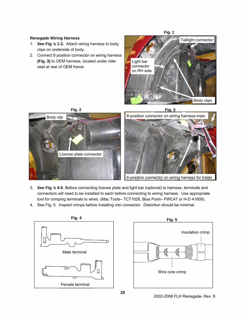
Renegade Wiring Harness 1. See Fig.’s 1-2. Attach wiring harness to body
clips on underside of body. 2. Connect 8 position connector on wiring harness
(Fig. 3) to OEM harness, located under rider seat at rear of OEM frame.
3. See Fig.’s 4-5. Before connecting license plate and light bar (optional) to harness, terminals and connectors will need to be installed to each before connecting to wiring harness. Use appropriate tool for crimping terminals to wires. (Mac Tools– TCT1028, Blue Point– PWC47 or H-D 41609).
4. See Fig. 5. Inspect crimps before installing into connector. Distortion should be minimal.
29
Fig. 3 8-position connector on wiring harness-main
6-position connector on wiring harness for trailer
Fig. 1
Body clips
Light bar connector on RH side
Taillight connector
Fig. 2
Body clip
License plate connector
Fig. 4
Male terminal
Female terminal
Fig. 5
Wire core crimp
Insulation crimp

2002-2008 FLH Renegade- Rev. 8
30
Fig. 5
Fig. 6
6 position connector for trailer-GH0023-2
8 position connector under seat-GH0023-1
License plate connector-GH0023-3
Right brake light-GH0023-3
Light bar-GH0023-5
Left brake light-GH0023-4
Left turn signal-GH0023-4
Right turn signal-GH0023-4
Included in bag
Wiring Diagram
Purple
Blue
Orange/White Tracer
Brown Black
Red/White Tracer
Black
Orange/White Tracer

2002-2008 FLH Renegade- Rev. 8
Body Installation 1. See Fig. 1. Bolt side cover bracket to body using
1/4” X 1” button head bolts and 1/4” flat washers on outside of body. Use 1/4” fender washers and 1/4” lock nuts on inside of fender.
2. Route emergency trunk release cable along H-D frame and secure behind LH side cover.
3. Set body roughly in place on trike frame. 4. See Fig. 2. Attach side covers to frame and body
in following order: • Lower pin, then upper pin into side cover
mount • Upper forward pin into motorcycle frame
4. Center body from side-to-side and front-to-back using a carpenter square against tire. Make sure side covers have an even gap on both sides and do not rub on body.
5. From underside of body, drill a 1/4” hole in body through each of four mounting tabs. Keep hole centered in slot of each of tabs.
6. Fasten body to Lehman frame as follows: Head of bolt will be inside trunk. • (4) 1/4” x 1-1/2” Button Head Bolts- CS4031 • (4) 1/4” x 1 1/4” Fender Washers- CW2108 • (4) Foam Sealing Washers- FG1002 • (4) 1/4” Flat Washers- CW2007 • (4) 1/4” Lock Nuts- CN3041
7. See Fig. 5. Install upper body braces (LB1235) by at-taching slotted side on top of Lehman frame using the following hardware. Leave hardware loose. • (2) Body Brace– LB1235 • (2) 5/16” x 1” Bolts– CB1161 • (2) 5/16” Lock Washers– CW2047 • (2) 5/16” Flat Washers– CW2010
8. Slide bracket against trunk, mark and drill 1/4” hole. 9. Attach bracket to body using the following hardware.
• (2) 1/4” x 1-1/2” button head bolts- CS4031 • (2) 1/4” x 1 1/4” fender washers CW2108 • (2) Foam Sealing Washers FG1002 • (2) 1/4” Flat Washers- CW2007 • (2) 1/4” Lock Nuts- CN3041
10. Tighten 5/16” hardware into place on trike frame. 11. Verify all body mounting hardware is tight.
31
Fig. 1
LH Side cover bracket
Fig. 2
Side cover installed
Fig. 3
Body brace attached to frame

2002-2008 FLH Renegade- Rev. 8
32
Trunk Door Installation Note: Lip on weather seal will face away from door opening; top of seal is flush with top of door. 1. See Fig. 1. Install door seal around edge of
body, starting at center on bottom and following trunk opening. Trim seal ends straight with scis-sors; glue ends together when finished.
• (6’) Door Seal– CW2536 2. See Fig. 2. Insert lanyard through top bend on
cable stop bracket. Make a small loop in the end of lanyard and crimp using aluminum clip (see inset in Fig. 2). There should be 7-1/2” be-tween the crimp and pre-made end of lanyard. Verify both lanyards match before crimping.
• (2) Door Lanyard– S001686 • (2) Cable Bracket– FB1036 • (2) Aluminum Crimp– CC1900
3. Apply masking tape to body just below hinge mounting holes to prevent scratching of paint by hinges.
4. See Fig. 3.Install door hinges and stop cable brackets to body with hinge gaskets underneath hinge using 10/32” x 1” screws and plated star nuts.
• (2) Door Hinge– GH0903 • (2) Hinge Gaskets– FG1003 • (4) 10/32” x 1” Phillips Screws– CS4024-0 • (4) Plated Star Lock Nuts– CN1898
5. Fasten door to hinges using 10/32” x 3/8” screws.
• (4) 10/32 x 3/8” Phillips Screws– CS4024-1 6. Attach lanyard to door using shoulder screws
with M6 flat washer under cable end.
• (2) 1/4” x .438 Shoulder Screws– CB1151 • (2) M6 Flat Washer– CW2172
7. See Fig. 3.Torque shoulder screws to 6 ft-lbs using 5/32” Allen socket.
Fig. 1
Fig. 2
Lip on weather seal
Top of seal is flush with door opening
7 1/2”
Insert through bracket
Loop and crimp
Fig. 3
Shoulder Screw
Washer under cable end

2002-2008 FLH Renegade- Rev. 8
8. See Fig. 4 Install key switch through body.
9. See Fig. 4 Install latch cable bracket onto key switch.
10. See Fig. 4 Install large nut to rear door key switch using 7/8” wrench and adjust bracket in an upright position.
11. See Fig. 4.Attach cable to key mechanism while key is in vertical position with head of screw from cable facing out.
12. See Fig. 5. Install striker pin to striker bracket using 5/16” lock nut . • (1) Striker Pin– GL2041 • (1) Striker Bracket– LB1297 • (1) 5/16” Lock Nut– CN3045
13. Attach striker pin bracket to door using 1/4” lock washers and 1/4” bolts . • (2) 1/4” x 1/2” Bolts– CB1075 • (2) 1/4” Lock Washers– CW2040
14. Install Renegade badge to bottom right side of door. Install Lehman badge GB1320 to bottom left side of door. • (1) Renegade Badge– GB1324 • (1) Lehman Badge– GB1320
15. Cut license plate wire from body to length to reach body wiring as needed.
16. Install shrink tubing over license plate wires. 17. Strip and solder ends of license plate wires from
the body and door together. 18. Slide shrink tubing over soldered connections
and heat. 19. Solder and heat shrink light wiring to trunk wiring
harness. Attach wire as follows-
• White wire on light to Black wire on trunk harness
• Gray wire on light to Red wire on trunk harness
20. Secure wiring to trunk door.
33
Fig. 5
Striker pin and bracket
Fig. 4
Key switch
Cable bracket

2002-2008 FLH Renegade- Rev. 8
Door Adjustment Procedures
34
Fig. 6

2002-2008 FLH Renegade- Rev. 8
35
Fig. 7
Fig. 8

2002-2008 FLH Renegade- Rev. 8
TOUR PACK MOUNTING IS DIFFERENT BETWEEN 2002-05 and 2006-08 MODELS. PLEASE FOL-LOW INSTRUCTIONS THAT MATCH YEAR OF MOTORCYCLE YOU ARE WORKING ON. 2002-2005 FLH TOUR PACK MOUNTING 1. Bottom of tour pack has ribs that match up with ribs on Renegade body. 2. Take flat weather seal (1/16” X 1 1/2” X 24”) and cut two pieces 10 1/2” long. Place foam seals on
three center ribs with short left-over piece on middle rib. Note: If tour pack is too far forward, this may cause interference with front trunk wall when drill-ing mounting holes into body. 3. Set tour pack into place where it will be comfortable for passengers. Seat may be set in place to
help locate tour pack. Make sure side-to-side and front to back measurements are equal before drill-ing. Carefully open tour pack and locate (8) holes in metal plate in floor. Drill forward (4) mounting holes in tour pack plate and body to 21/64”.
4. Attach tour pack using (4) 5/16” X 2” bolts, lock washers, flat washers and tour pack supports (LS1028) inside trunk. Now that tour pack is installed on fiberglass instead of steel, a new ground wire must be added. Run an appropriate ground wire from tour pack plate to motorcycle chassis.
5. Install tour pack liner inside tour pack.
36

2002-2008 FLH Renegade- Rev. 8
2006-2008 FLH TOUR PACK MOUNTING 1. Use original H-D chrome tour pack frame. 2. See Fig. 1. Cut both sides of frame 3/4” ahead of
leading edge of forward hole. 3. Drill out LH (2) and RH (2) chrome frame holes to
21/64”. 4. Insert supplied chrome plugs (GP0106) into cut end
of tour pack frame. 5. Drill out (4) aluminum H-D tour pack spacers to
21/64”. 6. See Fig. 2. Drill forward (4) mounting holes in tour
pack plate to 21/64”. 7. Use (2) 5/16” bolts in rear holes to line up chrome
rail to bottom of tour pack and place it on body such that rear of chrome rail is just behind center body rib.
3. Set tour pack into place where it will be comfortable for passengers. Seat may be set in place to help locate tour pack. Make sure side-to-side and front to back measurements are equal before drilling.
Note: If tour pack is too far forward, this may cause interference with front trunk wall when drilling mounting holes into body. 9. Drill (2) front mounting holes. Center rear hole is not
used. 10. Remove short 5/16” bolts from rear holes and place them in front. Drill rear holes. 11. Place aluminum HD spacers onto body. 13. Place modified frame onto spacers. Place tour pack on top and install with (4) 5/16” X 2” bolts, lock
washers, flat washers and tour pack supports . 14. Mount liner back into tour pack. Note: There will be left-over fasteners as bolt bag is universal and fits various model years.
37
Fig. 1
Fig. 2
Tour pack drilling locations
Drill holes to 21/64”
Trim frame

2002-2008 FLH Renegade- Rev. 8
Final Assembly 1. Install seat to fender using original H-D mounting hardware. Note: Make sure insert in fender is free of paint before installing screw. 2. Install wheels. Torque wire wheel lug nuts to 75 ft.-lbs. and aluminum wheel lug nuts to 85 ft.-lbs.
Install center caps (if applicable). Caution: Do not use an impact wrench when installing lug nuts. 3. Reflectors can be installed to body. See Fig. 1. Install rear reflectors 3” below taillights on body.
See Fig. 2. Install side reflectors using wheel center caps as a reference, 1/4” above wheel opening on body.
38
Fig. 1 Fig. 2

2002-2008 FLH Renegade- Rev. 8
Neck Race Preload, Steering head should be approximately twice as tight as factory specifications for a trike conversion. Refer to H-D service manual for adjustment procedure. Caution: Do not tighten bolts past factory specifications. Only bearing adjustment collar should be tightened past factory settings. Adjusting Motor Mounts The front and top motor mounts may need to be adjusted to achieve correct vertical alignment, and to center differential housing to frame. To do this, trike must be sitting on a level surface. Refer to H-D service manual for correct procedure on adjusting motor mount assemblies.
39

2002-2008 FLH Renegade- Rev. 8
Renegade Torque Specifications
Swingarm pivot shaft (H-D) 45 ft. lbs.
Swingarm plates (H-D) 42 ft. lbs.
Axle flange bolts 38 ft. lbs.
Park brake bracket to swingarm 35 ft. lbs.
Differential brace to swingarm 35 ft. lbs.
Pinch block bolts 25 ft. lbs.
Adapter plate to swingarm 35 ft. lbs.
Banjo bolts 16 ft. lbs.
Torque link to frame 22 ft. lbs.
Torque link to engine 33 ft.-lbs.
Lehman frame to H-D frame 78 ft. lbs.
Frame plate bolts 19 ft. lbs.
Frame brace 35 ft. lbs.
Shock bolts 40 ft. lbs.
Wheels/aluminum 85 ft. lbs.
Wheels/wire 75 ft. lbs.
Caliper to bracket bolts 38 ft. lbs.
Caliper bracket to axle flange bolts 38ft. lbs.
Differential housing plate bolts 17ft. lbs.
Axle tube bolts 38ft. lbs
Differential brace to housing 17 ft. lbs.
40

2002-2008 FLH Renegade- Rev. 8
Final Trike Inspection
Good Rework 1. Reflectors Installed □ □ 2. Lights and horn work □ □ 3. Park brake operation □ □ 4. Engine/Transmission oil levels □ □ 5. Belt tension 5/16”-3/8” □ □ 6. Wheel torque 85 ft. lbs. (75 ft. lbs.-wire) □ □ 7. Rear tire pressure 26 psi □ □ 8. Front tire pressure 36 psi □ □ 9. Trunk clean and dry □ □ 10. Trunk door seals and operates smoothly □ □ 11. Shocks set @ mid setting □ □ 12. Heat shields, side covers □ □ 13. Renegade/Lehman badge installed □ □
14. Accessories (if applicable) □ □
15. No paint defects □ □
16. Warranty/owner’s manual included □ □
41