2001 Chevrolet Corvette 2001 DRIVE AXLES Axle Shafts ... · Remove the spindle nut retaining the...
47
2001 DRIVE AXLES Axle Shafts - Corvette DESCRIPTION & OPERATION AXLE SHAFTS Axle shafts are flexible assemblies consisting of an inner and outer Constant Velocity (CV) joint connected by an axle shaft. See Fig. 1 . The inner joint is completely flexible, and can move in and out. The outer joint is also flexible, but cannot move in and out. These drive axles are used to transmit rotational force from the rear axle differential to the rear tire and wheel assemblies. Boot & Clamp The axle shaft assemblies use inboard and outboard joint boots made of thermoplastic material, and clamps made of stainless steel. The functions of the boots are as follows: The boots protect the internal parts of the inboard and outboard joints. A. They protect the joint lubricating grease from surrounding detrimental atmospheric conditions (such as extreme temperatures, ozone gas, etc.). B. They protect the joint lubricating grease from foreign materials (such as stones, dirt, water, salt, etc.). The boots facilitate angular and axial movement of the inboard joint. The boots facilitate angular movement of the outboard joint. The function of the clamps is to provide a leak proof connection at both the housing and the axle shaft for the inboard and outboard joints. The thermoplastic material performs well against normal handing, operational wear and conditions. This material however, is not strong enough to withstand abusive handling or damage due to objects such as sharp tools or the sharp edge of any other surrounding component on the vehicle. Inner Joint The inner joints are of the enhanced double offset design. The inner joints use a female spline which is installed over a stub shaft protruding from the rear axle differential. Outer Joint 2001 Chevrolet Corvette 2001 DRIVE AXLES Axle Shafts - Corvette 2001 Chevrolet Corvette 2001 DRIVE AXLES Axle Shafts - Corvette
Transcript of 2001 Chevrolet Corvette 2001 DRIVE AXLES Axle Shafts ... · Remove the spindle nut retaining the...
2001 DRIVE AXLES
Axle Shafts - Corvette
DESCRIPTION & OPERATION
AXLE SHAFTS
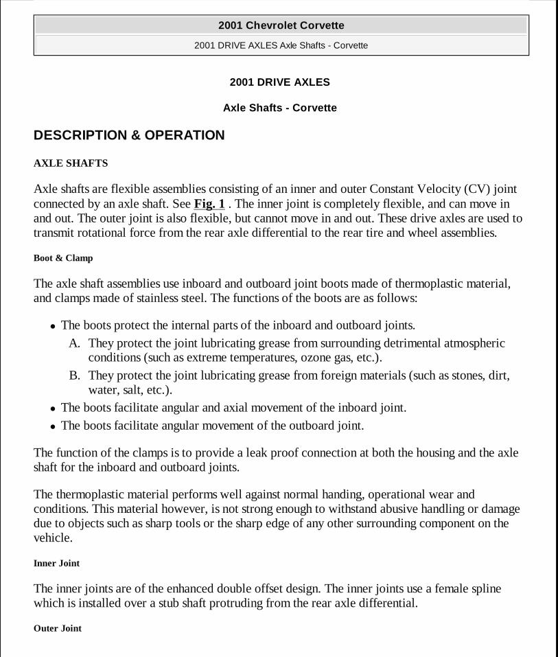
Axle shafts are flexible assemblies consisting of an inner and outer Constant Velocity (CV) joint connected by an axle shaft. See Fig. 1 . The inner joint is completely flexible, and can move in and out. The outer joint is also flexible, but cannot move in and out. These drive axles are used to transmit rotational force from the rear axle differential to the rear tire and wheel assemblies.
Boot & Clamp
The axle shaft assemblies use inboard and outboard joint boots made of thermoplastic material, and clamps made of stainless steel. The functions of the boots are as follows:
� The boots protect the internal parts of the inboard and outboard joints. A. They protect the joint lubricating grease from surrounding detrimental atmospheric
conditions (such as extreme temperatures, ozone gas, etc.). B. They protect the joint lubricating grease from foreign materials (such as stones, dirt,
water, salt, etc.). � The boots facilitate angular and axial movement of the inboard joint. � The boots facilitate angular movement of the outboard joint.
The function of the clamps is to provide a leak proof connection at both the housing and the axle shaft for the inboard and outboard joints.
The thermoplastic material performs well against normal handing, operational wear and conditions. This material however, is not strong enough to withstand abusive handling or damage due to objects such as sharp tools or the sharp edge of any other surrounding component on the vehicle.
Inner Joint
The inner joints are of the enhanced double offset design. The inner joints use a female spline which is installed over a stub shaft protruding from the rear axle differential.
Outer Joint
2001 Chevrolet Corvette
2001 DRIVE AXLES Axle Shafts - Corvette
2001 Chevrolet Corvette
2001 DRIVE AXLES Axle Shafts - Corvette
MY
Monday, April 06, 2009 2:39:45 PM Page 1 © 2005 Mitchell Repair Information Company, LLC.
MY
Monday, April 06, 2009 2:39:53 PM Page 1 © 2005 Mitchell Repair Information Company, LLC.
The outer joints are of the Rzeppa joint design. The splined shaft end which mates with the knuckle and hub assembly, incorporates a helical spline to assure a tight, press-type fit. This design assures that no end play will exist between the hub bearing and the axle shaft assembly for added durability and reduced bearing noise.
COMPONENT LOCATION
2001 Chevrolet Corvette
2001 DRIVE AXLES Axle Shafts - Corvette
MY
Monday, April 06, 2009 2:39:46 PM Page 2 © 2005 Mitchell Repair Information Company, LLC.
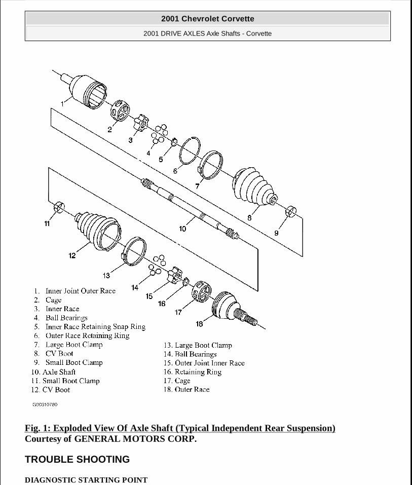
Fig. 1: Exploded View Of Axle Shaft (Typical Independent Rear Suspension) Courtesy of GENERAL MOTORS CORP.
TROUBLE SHOOTING
DIAGNOSTIC STARTING POINT
2001 Chevrolet Corvette
2001 DRIVE AXLES Axle Shafts - Corvette
MY
Monday, April 06, 2009 2:39:46 PM Page 3 © 2005 Mitchell Repair Information Company, LLC.
Axle Shafts
Begin the axle shaft system diagnosis with VIBRATION DIAGNOSIS & CORRECTION under DIAGNOSTIC STARTING POINT in VIBRATION - DRIVETRAIN article in GENERAL INFORMATION. The use of the Diagnostic Starting Point will determine if the concern is axle shaft related. When instructed to exit the Vibration Diagnosis and Correction diagnostic and return to the Axle Shafts Diagnostic Starting Point, proceed to AXLE SHAFTS under DESCRIPTION & OPERATION in order to become familiar with the design of the axle shaft.
The axle shafts in this vehicle may not exhibit the same noise symptoms as axle shafts in front wheel drive vehicles. Since the vehicle is a rear wheel drive design, the axle shafts are not subjected to the same input forces and may not make any discernible noises if they are damaged. Thoroughly inspect the entire axle shaft for visible damage, leaking joint boots, and missing seal clamps. Replace these components as necessary. See AXLE SHAFT INNER JOINT & BOOT or AXLE SHAFT OUTER JOINT & BOOT under OVERHAUL.
After the inspection reveals no visual signs of wear or damage, it may be necessary to manipulate the inner and outer Constant Velocity (CV) joints in order to detect internal damage. Any binding or impeded movement of the CV joints may indicate damage requiring repair or replacement. See AXLE SHAFT INNER JOINT & BOOT or AXLE SHAFT OUTER JOINT & BOOT under OVERHAUL.
SYMPTOMS
1. Review VIBRATION DIAGNOSIS & CORRECTION under DIAGNOSTIC STARTING POINT in VIBRATION - DRIVETRAIN article in GENERAL INFORMATION.
2. Perform the VIBRATION ANALYSIS -- ROAD TESTING in VIBRATION - DRIVETRAIN article in GENERAL INFORMATION in order to effectively diagnose the concern.
3. Review the system operation in order to become familiar with the system function. See AXLE SHAFTS in DESCRIPTION & OPERATION.
Visual Inspection
� Inspect for aftermarket equipment and modifications which could affect the operation of the axle shafts or other rotating components.
� Inspect the easily accessible or visible system components for obvious damage or conditions
NOTE: Complete the following steps prior to beginning the axle shaft diagnosis.
2001 Chevrolet Corvette
2001 DRIVE AXLES Axle Shafts - Corvette
MY
Monday, April 06, 2009 2:39:46 PM Page 4 © 2005 Mitchell Repair Information Company, LLC.
which could cause the symptom. � Thoroughly inspect the entire axle shaft for visible damage, leaking joint boots, and missing
boot clamps. � Inspect the axle shaft seals for cuts, tears, or other damage which may allow the loss of
lubricant and the entry of contaminates.
Physical Inspection
After performing the Visual/Inspection and no visual signs of damage or other interference impairing the axle shaft function is apparent, it may be necessary to remove the axle shaft from the vehicle and manipulate the joints manually. Any binding or otherwise impeded movement of the joints may indicate damage which could contribute to the concern.
REMOVAL & INSTALLATION
AXLE SHAFTS
Removal
1. Shift the transmission into Park (A/T) or Neutral (M/T). 2. Apply the parking brake. 3. Raise and suitably support the vehicle. 4. Remove the tire and wheel assembly.
CAUTION: Use the correct fastener in the correct location. Replacement fasteners must be the correct part number for that application. Fasteners requiring replacement or fasteners requiring the use of thread locking compound or sealant are identified in the service procedure. Do not use paints, lubricants, or corrosion inhibitors on fasteners or fastener joint surfaces unless specified. These coatings affect fastener torque and joint clamping force and may damage the fastener. Use the correct tightening sequence and specifications when installing fasteners in order to avoid damage to parts and systems.
NOTE: Special Tools Required: Transverse Spring Compressor (J-33432-A), Slide Hammer (J-2619-01), Extension (J-29794), Axle Shaft Remover (J-42128) & Rear Hub Spindle Remover (J-42129).
2001 Chevrolet Corvette
2001 DRIVE AXLES Axle Shafts - Corvette
MY
Monday, April 06, 2009 2:39:46 PM Page 5 © 2005 Mitchell Repair Information Company, LLC.
5. Insert a drift or punch into the brake rotor cooling fins and against the brake caliper to prevent the wheel hub and bearing from turning. See Fig. 2 .
6. Remove the spindle nut retaining the rear axle shaft to the hub. 7. Remove the drift or punch. 8. Release the parking brake. 9. Refer to the following steps for removal of the rear transverse spring.
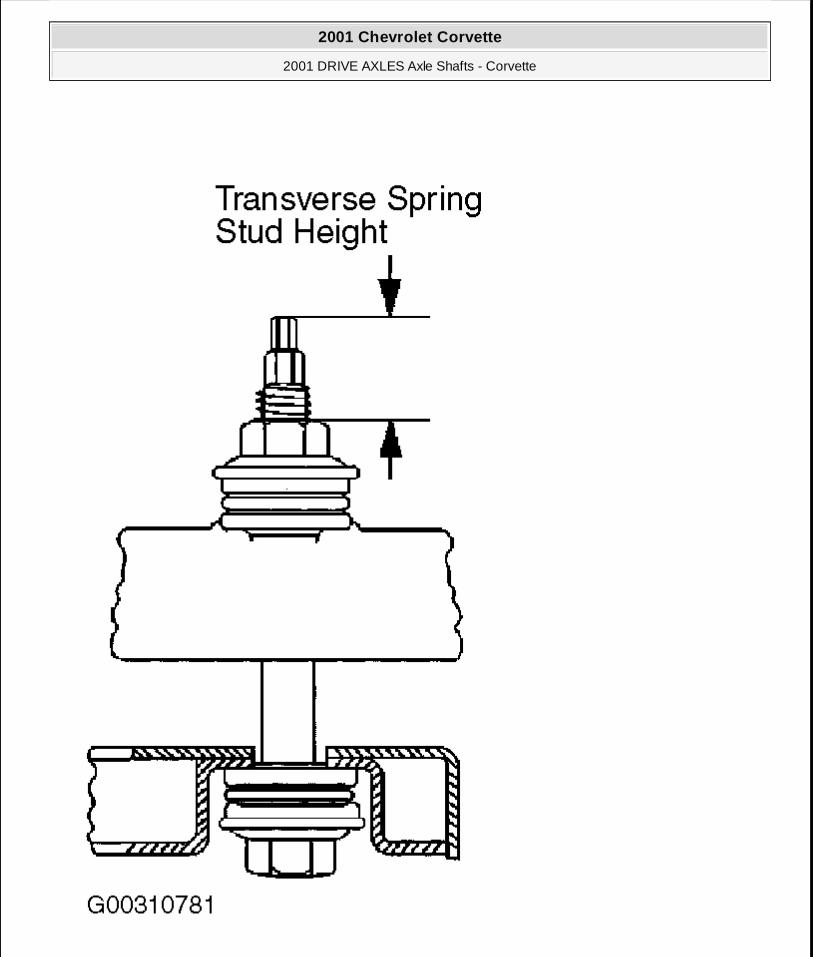
A. Measure the transverse spring stud height. See Fig. 3 . This measurement will be used in the installation to set-up the vehicle trim height.
B. Install transverse spring compressor to the rear transverse spring, and compress the spring. See Fig. 4 .
C. Remove the retainers, nuts, bolts and insulators retaining the transverse spring to the lower control arms. See Fig. 5 .
D. Remove the rear transverse spring mounting bolts, spring spacers and insulators from the crossmember.
E. Remove the rear transverse spring from the vehicle. F. If the transverse spring is to be replaced, release and remove transverse spring
compressor from the transverse spring.
10. Separate the outer tie rod end from the knuckle and reposition the tie rod toward the rear of the vehicle.
11. Disconnect the wheel speed sensor electrical connector.
12. Disconnect the parking brake cable from the parking brake lever. See Fig. 6 . 13. Remove the parking brake cable from the bracket and reposition toward the rear. 14. Install rear hub spindle remover onto the wheel hub and secure with wheel nuts. 15. Begin to disengage the axle shaft from the wheel hub and bearing. This will provide
additional clearance to the lower ball joint nut. 16. Disconnect Electronic Suspension Control (ESC) position sensor link and shock absorber
solenoid electrical connector, if equipped, from suspension knuckle. See Fig. 7 and Fig. 8 . Remove brake rotor, if necessary. See REAR BRAKE ROTOR for 2001 or REAR BRAKE ROTOR for 2002 under REMOVAL & INSTALLATION in DISC BRAKES
NOTE: During this procedure, use care not to scratch the rear transverse spring.
NOTE: DO NOT loosen the outer tie rod jam nut.
2001 Chevrolet Corvette
2001 DRIVE AXLES Axle Shafts - Corvette
MY
Monday, April 06, 2009 2:39:46 PM Page 6 © 2005 Mitchell Repair Information Company, LLC.
article in HYDRAULIC - MECHANICAL in BRAKES. Separate the lower ball joint from the suspension knuckle.
17. Disengage the axle shaft completely from the wheel hub and bearing.
18. Support the axle shaft. 19. Support the suspension knuckle and upper control arm and reposition the knuckle toward
the front of the vehicle. 20. Assemble the slide hammer, extension and axle shaft remover. 21. Install the axle shaft remover evenly onto the rear beveled surface of the axle shaft inner
joint housing. 22. Disengage the axle shaft from the rear axle differential using the tool assembly, then remove
the tool assembly. 23. Remove the axle shaft from the vehicle. 24. Remove rear hub spindle remover from the wheel hub.
NOTE: Be sure to support the axle shaft until it is removed.
2001 Chevrolet Corvette
2001 DRIVE AXLES Axle Shafts - Corvette
MY
Monday, April 06, 2009 2:39:46 PM Page 7 © 2005 Mitchell Repair Information Company, LLC.
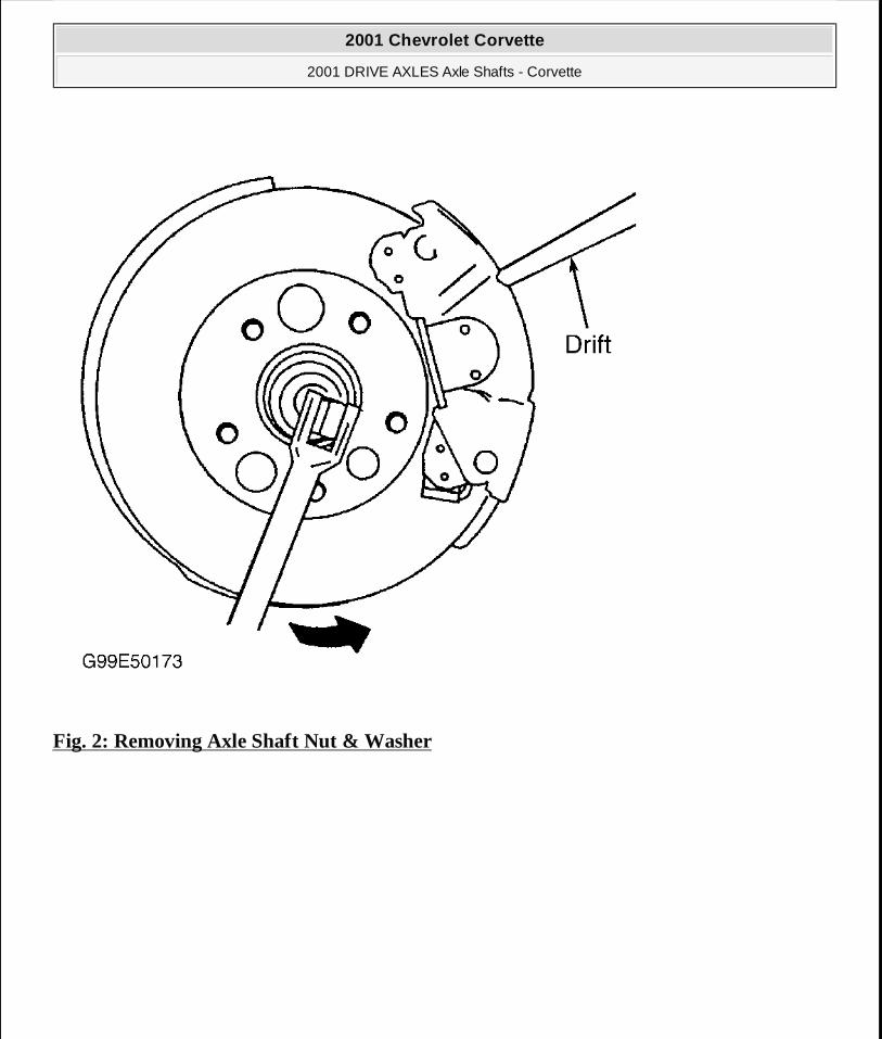
Fig. 2: Removing Axle Shaft Nut & Washer
2001 Chevrolet Corvette
2001 DRIVE AXLES Axle Shafts - Corvette
MY
Monday, April 06, 2009 2:39:46 PM Page 8 © 2005 Mitchell Repair Information Company, LLC.
2001 Chevrolet Corvette
2001 DRIVE AXLES Axle Shafts - Corvette
MY
Monday, April 06, 2009 2:39:46 PM Page 9 © 2005 Mitchell Repair Information Company, LLC.
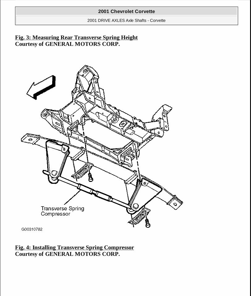
Fig. 3: Measuring Rear Transverse Spring Height Courtesy of GENERAL MOTORS CORP.
Fig. 4: Installing Transverse Spring Compressor Courtesy of GENERAL MOTORS CORP.
2001 Chevrolet Corvette
2001 DRIVE AXLES Axle Shafts - Corvette
MY
Monday, April 06, 2009 2:39:46 PM Page 10 © 2005 Mitchell Repair Information Company, LLC.

Fig. 5: Identifying Transverse Spring-To-Lower Control Arm Components Courtesy of GENERAL MOTORS CORP.
2001 Chevrolet Corvette
2001 DRIVE AXLES Axle Shafts - Corvette
MY
Monday, April 06, 2009 2:39:46 PM Page 11 © 2005 Mitchell Repair Information Company, LLC.
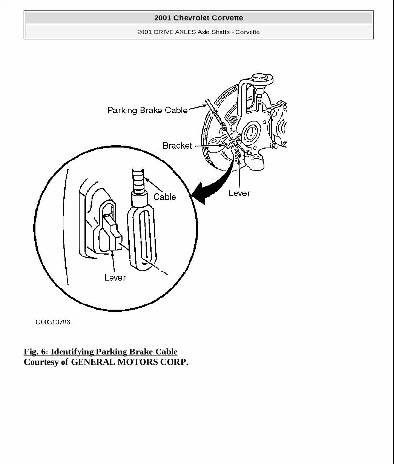
Fig. 6: Identifying Parking Brake Cable Courtesy of GENERAL MOTORS CORP.
2001 Chevrolet Corvette
2001 DRIVE AXLES Axle Shafts - Corvette
MY
Monday, April 06, 2009 2:39:46 PM Page 12 © 2005 Mitchell Repair Information Company, LLC.
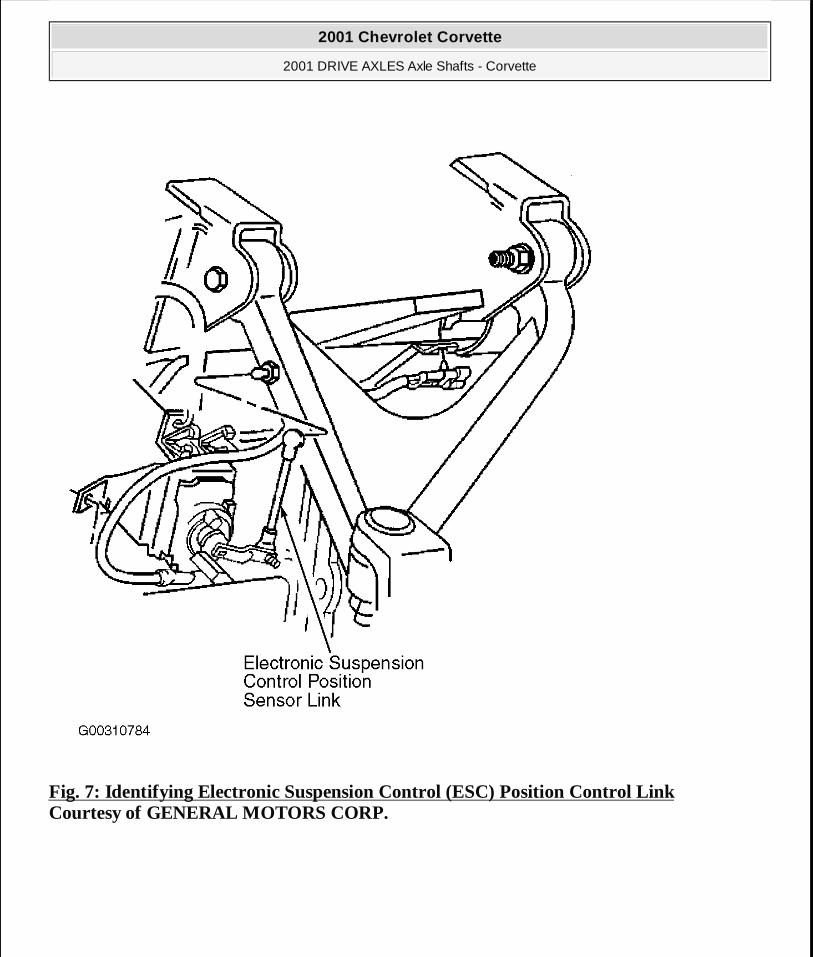
Fig. 7: Identifying Electronic Suspension Control (ESC) Position Control Link Courtesy of GENERAL MOTORS CORP.
2001 Chevrolet Corvette
2001 DRIVE AXLES Axle Shafts - Corvette
MY
Monday, April 06, 2009 2:39:46 PM Page 13 © 2005 Mitchell Repair Information Company, LLC.
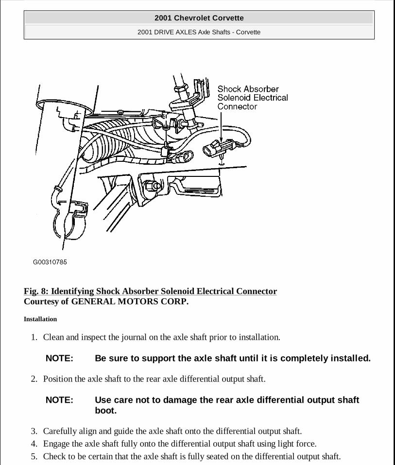
Fig. 8: Identifying Shock Absorber Solenoid Electrical Connector Courtesy of GENERAL MOTORS CORP.
Installation
1. Clean and inspect the journal on the axle shaft prior to installation.
2. Position the axle shaft to the rear axle differential output shaft.
3. Carefully align and guide the axle shaft onto the differential output shaft. 4. Engage the axle shaft fully onto the differential output shaft using light force. 5. Check to be certain that the axle shaft is fully seated on the differential output shaft.
NOTE: Be sure to support the axle shaft until it is completely installed.
NOTE: Use care not to damage the rear axle differential output shaft boot.
2001 Chevrolet Corvette
2001 DRIVE AXLES Axle Shafts - Corvette
MY
Monday, April 06, 2009 2:39:46 PM Page 14 © 2005 Mitchell Repair Information Company, LLC.
6. Begin to position the suspension knuckle to the axle shaft. 7. Align and carefully guide the axle shaft into the wheel hub and bearing but DO NOT seat
fully. This will provide additional clearance to the lower ball joint nut. 8. Connect the lower ball joint to the suspension knuckle. Connect Electronic Suspension
Control (ESC) position sensor link and shock absorber solenoid electrical connector, if equipped to suspension knuckle. See Fig. 7 -Fig. 8 . Install brake rotor, if removed. See REAR BRAKE ROTOR for 2001 or REAR BRAKE ROTOR for 2002 under REMOVAL & INSTALLATION in DISC BRAKES article in HYDRAULIC - MECHANICAL in BRAKES.
9. Install the parking brake cable into the bracket. See Fig. 6 . 10. Connect the parking brake cable to the parking brake lever. 11. Connect the wheel speed sensor electrical connector. 12. Connect the outer tie rod end to the suspension knuckle. 13. Refer to the following steps for installation of the rear transverse spring.
A. If the transverse spring is a replacement, install transverse spring compressor to the transverse spring and compress the spring. See Fig. 4 .
B. Install the rear transverse spring to the vehicle. C. Install the rear transverse spring spacers, insulators and mounting brackets to the
crossmember. See Fig. 5 . Tighten the rear transverse spring mounting bracket bolts to specification. See TORQUE SPECIFICATIONS .
D. Position the transverse spring to the lower control arms and install the spring bolts, insulators and nuts.
E. Release and remove transverse spring compressor from the transverse spring.
F. Set the transverse spring stud height to the height measured during removal. See Fig. 3 .
G. Install the retainers to the bolts. 14. Set the parking brake. 15. Insert a drift or punch into the brake rotor cooling fins and against the caliper to prevent the
wheel hub and bearing from turning. 16. Begin to install the axle shaft retaining nut onto the axle shaft by hand. 17. Slowly tighten the nut to draw the axle shaft to the wheel hub and bearing. Tighten the axle
NOTE: The rear transverse spring stud bolt must have a minimum of 2 threads showing above the nut.
2001 Chevrolet Corvette
2001 DRIVE AXLES Axle Shafts - Corvette
MY
Monday, April 06, 2009 2:39:46 PM Page 15 © 2005 Mitchell Repair Information Company, LLC.
shaft spindle nut to specification. See TORQUE SPECIFICATIONS . 18. Remove the drift or punch. 19. Release the parking brake. 20. Install the tire and wheel assembly. Tighten wheel lug nuts in a criss-cross pattern to
specification. See TORQUE SPECIFICATIONS . 21. Lower the vehicle. 22. Adjust the rear wheel toe as necessary and tighten the rear suspension adjustment link lock
nut to specification. See TORQUE SPECIFICATIONS .
OVERHAUL
AXLE SHAFT INNER JOINT & BOOT
CAUTION: Use the correct fastener in the correct location. Replacement fasteners must be the correct part number for that application. Fasteners requiring replacement or fasteners requiring the use of thread locking compound or sealant are identified in the service procedure. Do not use paints, lubricants, or corrosion inhibitors on fasteners or fastener joint surfaces unless specified. These coatings affect fastener torque and joint clamping force and may damage the fastener. Use the correct tightening sequence and specifications when installing fasteners in order to avoid damage to parts and systems.
NOTE: During the 2001 Model Year, there was a first and second design style of large diameter clamp used. The first design uses an Omega style large diameter clamp, while the second design uses a low profile large diameter clamp. This incorporates different tools and instruction to repair. Before following repair procedures, verify the style of clamp used.
NOTE: This procedure is to be performed only after the axle shaft has been removed from the vehicle. See AXLE SHAFTS under REMOVAL & INSTALLATION.
NOTE: Special Tools Required: Axle Shaft Seal Clamp Pliers (J-42572).
2001 Chevrolet Corvette
2001 DRIVE AXLES Axle Shafts - Corvette
MY
Monday, April 06, 2009 2:39:46 PM Page 16 © 2005 Mitchell Repair Information Company, LLC.
Disassembly (First Design)
1. Wrap a shop towel around the axle shaft. For an exploded view of axle shaft, see Fig. 1 . 2. Place the axle shaft horizontally in a bench vise. 3. Remove the large boot retaining clamp from the CV joint seal. Use a side cutter or other
suitable tool and discard the clamp. 4. Remove the small boot retaining clamp from the joint seal. Use a side cutter or other
suitable tool and discard the clamp. 5. Separate the boot from the joint outer race at the large diameter end. 6. Position the boot behind the joint face. 7. Position the axle shaft vertically in the bench vise so the inner joint is up. 8. Slide the joint outer race down toward the vise. 9. Disengage the outer race retaining ring.
A. Insert a small flat-bladed screwdriver between the retaining ring and the outer race. B. Remove the retaining ring from the outer race. C. Position the retaining ring along the axle shaft away from the outer race.
10. Remove the outer race from the axle shaft. See Fig. 9 . A. Use the boot to catch any balls which are not retained by grease. B. Lift the outer race off the axle shaft.
11. Remove any remaining balls from the cage and inner race. See Fig. 9 . Remove any balls caught by the boot.
12. Position the axle shaft horizontally in the bench vise.
13. Remove the outer race retaining ring from the axle shaft. See Fig. 9 . 14. Remove the snap ring from the axle shaft. 15. Align the cage lands with the inner race ball tracks. 16. Reposition the cage along the axle shaft away from the inner race. 17. Wipe the grease from the inner race.
18. Remove the inner race from the axle shaft using a 3 jaw puller. See Fig. 9 . 19. Remove the cage from the axle shaft. 20. Remove the boot from the axle shaft.
NOTE: The balls may fall out of the cage and inner race when the outer race is removed.
2001 Chevrolet Corvette
2001 DRIVE AXLES Axle Shafts - Corvette
MY
Monday, April 06, 2009 2:39:46 PM Page 17 © 2005 Mitchell Repair Information Company, LLC.
21. Remove the axle shaft from the bench vise.
22. Clean the following thoroughly with clean solvent: � The inner race. � The outer race. � The cage. � The balls. � The axle shaft exposed end.
23. Thoroughly air dry all the parts.
NOTE: All traces of old grease and any contaminates must be removed.
2001 Chevrolet Corvette
2001 DRIVE AXLES Axle Shafts - Corvette
MY
Monday, April 06, 2009 2:39:46 PM Page 18 © 2005 Mitchell Repair Information Company, LLC.
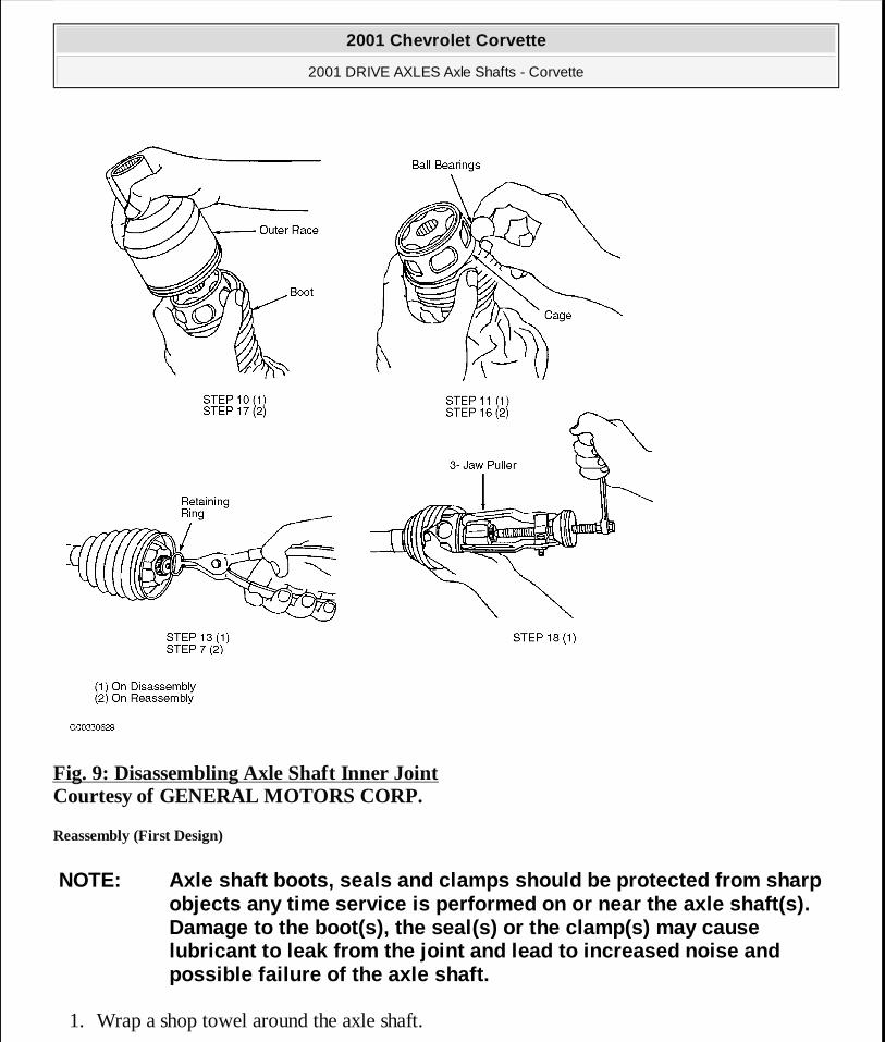
Fig. 9: Disassembling Axle Shaft Inner Joint Courtesy of GENERAL MOTORS CORP.
Reassembly (First Design)
1. Wrap a shop towel around the axle shaft.
NOTE: Axle shaft boots, seals and clamps should be protected from sharp objects any time service is performed on or near the axle shaft(s). Damage to the boot(s), the seal(s) or the clamp(s) may cause lubricant to leak from the joint and lead to increased noise and possible failure of the axle shaft.
2001 Chevrolet Corvette
2001 DRIVE AXLES Axle Shafts - Corvette
MY
Monday, April 06, 2009 2:39:46 PM Page 19 © 2005 Mitchell Repair Information Company, LLC.
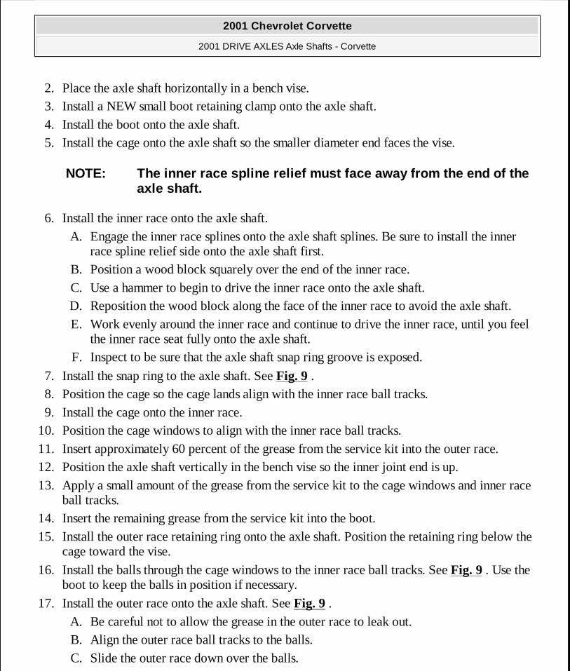
2. Place the axle shaft horizontally in a bench vise. 3. Install a NEW small boot retaining clamp onto the axle shaft. 4. Install the boot onto the axle shaft. 5. Install the cage onto the axle shaft so the smaller diameter end faces the vise.
6. Install the inner race onto the axle shaft. A. Engage the inner race splines onto the axle shaft splines. Be sure to install the inner
race spline relief side onto the axle shaft first. B. Position a wood block squarely over the end of the inner race. C. Use a hammer to begin to drive the inner race onto the axle shaft. D. Reposition the wood block along the face of the inner race to avoid the axle shaft. E. Work evenly around the inner race and continue to drive the inner race, until you feel
the inner race seat fully onto the axle shaft. F. Inspect to be sure that the axle shaft snap ring groove is exposed.
7. Install the snap ring to the axle shaft. See Fig. 9 . 8. Position the cage so the cage lands align with the inner race ball tracks. 9. Install the cage onto the inner race.
10. Position the cage windows to align with the inner race ball tracks. 11. Insert approximately 60 percent of the grease from the service kit into the outer race. 12. Position the axle shaft vertically in the bench vise so the inner joint end is up. 13. Apply a small amount of the grease from the service kit to the cage windows and inner race
ball tracks. 14. Insert the remaining grease from the service kit into the boot. 15. Install the outer race retaining ring onto the axle shaft. Position the retaining ring below the
cage toward the vise.
16. Install the balls through the cage windows to the inner race ball tracks. See Fig. 9 . Use the boot to keep the balls in position if necessary.
17. Install the outer race onto the axle shaft. See Fig. 9 . A. Be careful not to allow the grease in the outer race to leak out. B. Align the outer race ball tracks to the balls. C. Slide the outer race down over the balls.
NOTE: The inner race spline relief must face away from the end of the axle shaft.
2001 Chevrolet Corvette
2001 DRIVE AXLES Axle Shafts - Corvette
MY
Monday, April 06, 2009 2:39:46 PM Page 20 © 2005 Mitchell Repair Information Company, LLC.
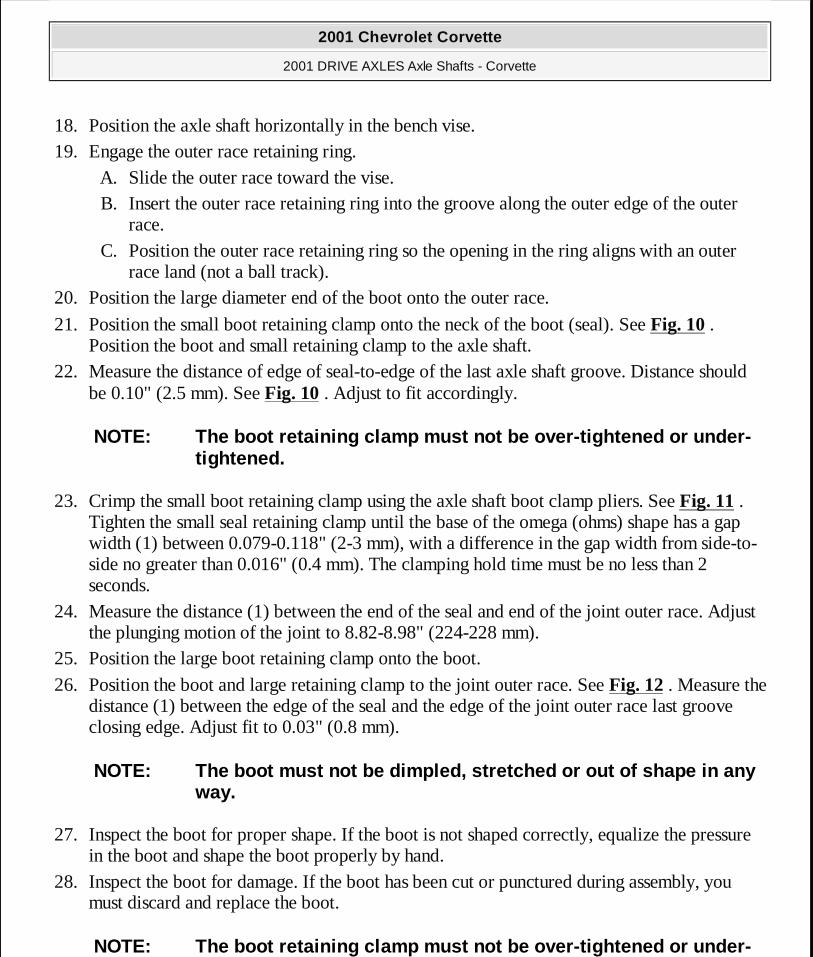
18. Position the axle shaft horizontally in the bench vise. 19. Engage the outer race retaining ring.
A. Slide the outer race toward the vise. B. Insert the outer race retaining ring into the groove along the outer edge of the outer
race. C. Position the outer race retaining ring so the opening in the ring aligns with an outer
race land (not a ball track). 20. Position the large diameter end of the boot onto the outer race.
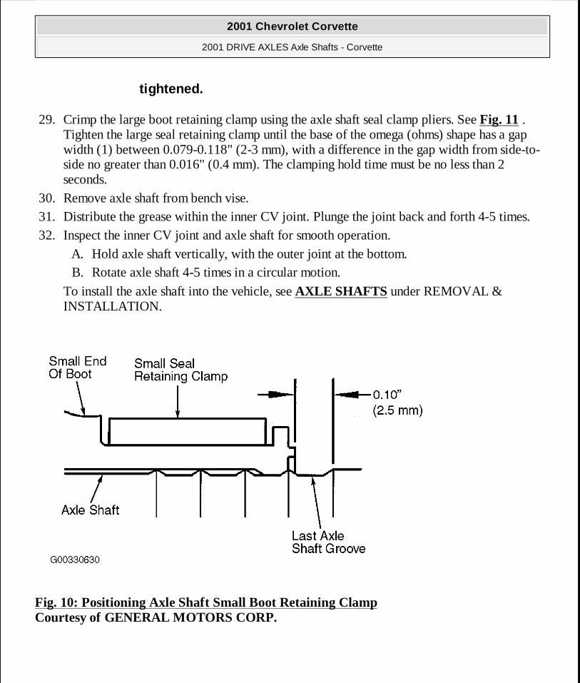
21. Position the small boot retaining clamp onto the neck of the boot (seal). See Fig. 10 . Position the boot and small retaining clamp to the axle shaft.
22. Measure the distance of edge of seal-to-edge of the last axle shaft groove. Distance should be 0.10" (2.5 mm). See Fig. 10 . Adjust to fit accordingly.
23. Crimp the small boot retaining clamp using the axle shaft boot clamp pliers. See Fig. 11 . Tighten the small seal retaining clamp until the base of the omega (ohms) shape has a gap width (1) between 0.079-0.118" (2-3 mm), with a difference in the gap width from side-to-side no greater than 0.016" (0.4 mm). The clamping hold time must be no less than 2 seconds.
24. Measure the distance (1) between the end of the seal and end of the joint outer race. Adjust the plunging motion of the joint to 8.82-8.98" (224-228 mm).
25. Position the large boot retaining clamp onto the boot.
26. Position the boot and large retaining clamp to the joint outer race. See Fig. 12 . Measure the distance (1) between the edge of the seal and the edge of the joint outer race last groove closing edge. Adjust fit to 0.03" (0.8 mm).
27. Inspect the boot for proper shape. If the boot is not shaped correctly, equalize the pressure in the boot and shape the boot properly by hand.
28. Inspect the boot for damage. If the boot has been cut or punctured during assembly, you must discard and replace the boot.
NOTE: The boot retaining clamp must not be over-tightened or under-tightened.
NOTE: The boot must not be dimpled, stretched or out of shape in any way.
NOTE: The boot retaining clamp must not be over-tightened or under-
2001 Chevrolet Corvette
2001 DRIVE AXLES Axle Shafts - Corvette
MY
Monday, April 06, 2009 2:39:46 PM Page 21 © 2005 Mitchell Repair Information Company, LLC.
29. Crimp the large boot retaining clamp using the axle shaft seal clamp pliers. See Fig. 11 . Tighten the large seal retaining clamp until the base of the omega (ohms) shape has a gap width (1) between 0.079-0.118" (2-3 mm), with a difference in the gap width from side-to-side no greater than 0.016" (0.4 mm). The clamping hold time must be no less than 2 seconds.
30. Remove axle shaft from bench vise. 31. Distribute the grease within the inner CV joint. Plunge the joint back and forth 4-5 times. 32. Inspect the inner CV joint and axle shaft for smooth operation.
A. Hold axle shaft vertically, with the outer joint at the bottom. B. Rotate axle shaft 4-5 times in a circular motion.
To install the axle shaft into the vehicle, see AXLE SHAFTS under REMOVAL & INSTALLATION.
Fig. 10: Positioning Axle Shaft Small Boot Retaining Clamp Courtesy of GENERAL MOTORS CORP.
tightened.
2001 Chevrolet Corvette
2001 DRIVE AXLES Axle Shafts - Corvette
MY
Monday, April 06, 2009 2:39:46 PM Page 22 © 2005 Mitchell Repair Information Company, LLC.
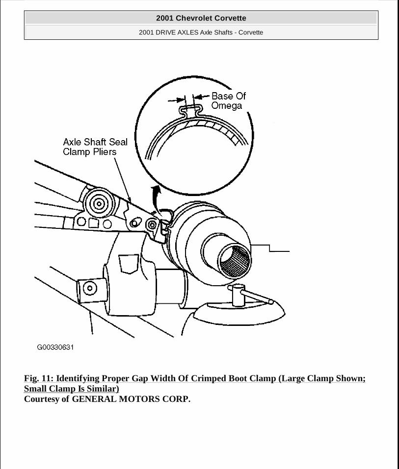
Fig. 11: Identifying Proper Gap Width Of Crimped Boot Clamp (Large Clamp Shown; Small Clamp Is Similar) Courtesy of GENERAL MOTORS CORP.
2001 Chevrolet Corvette
2001 DRIVE AXLES Axle Shafts - Corvette
MY
Monday, April 06, 2009 2:39:46 PM Page 23 © 2005 Mitchell Repair Information Company, LLC.
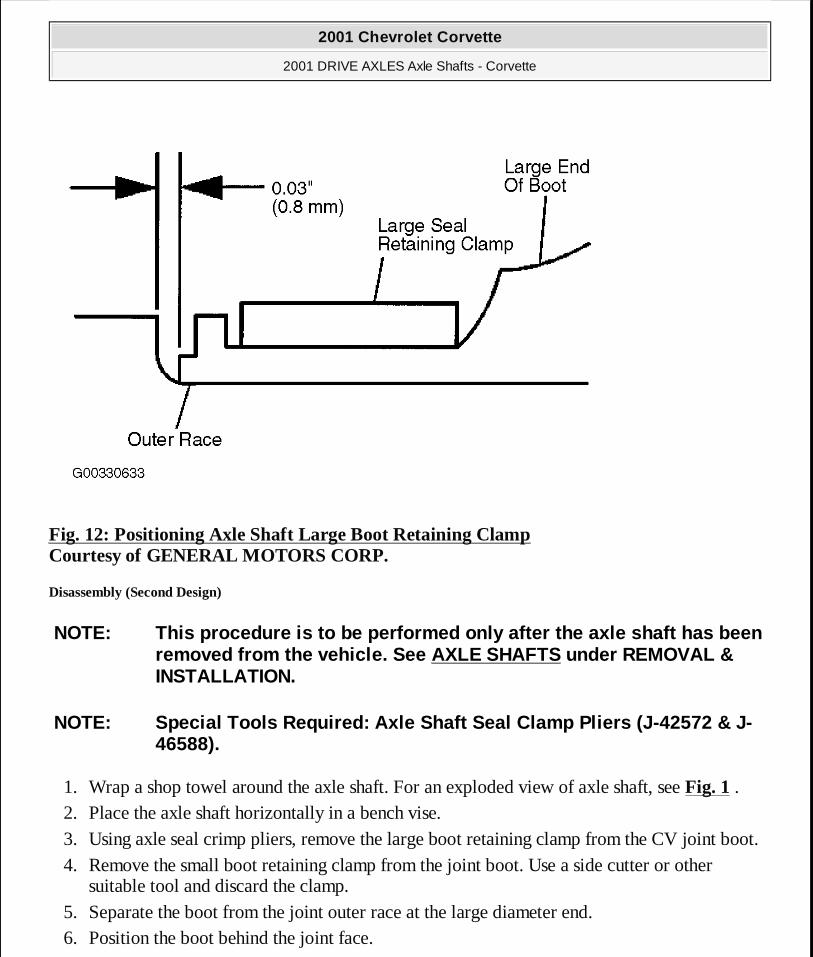
Fig. 12: Positioning Axle Shaft Large Boot Retaining Clamp Courtesy of GENERAL MOTORS CORP.
Disassembly (Second Design)
1. Wrap a shop towel around the axle shaft. For an exploded view of axle shaft, see Fig. 1 . 2. Place the axle shaft horizontally in a bench vise. 3. Using axle seal crimp pliers, remove the large boot retaining clamp from the CV joint boot. 4. Remove the small boot retaining clamp from the joint boot. Use a side cutter or other
suitable tool and discard the clamp. 5. Separate the boot from the joint outer race at the large diameter end. 6. Position the boot behind the joint face.
NOTE: This procedure is to be performed only after the axle shaft has been removed from the vehicle. See AXLE SHAFTS under REMOVAL & INSTALLATION.
NOTE: Special Tools Required: Axle Shaft Seal Clamp Pliers (J-42572 & J-46588).
2001 Chevrolet Corvette
2001 DRIVE AXLES Axle Shafts - Corvette
MY
Monday, April 06, 2009 2:39:46 PM Page 24 © 2005 Mitchell Repair Information Company, LLC.
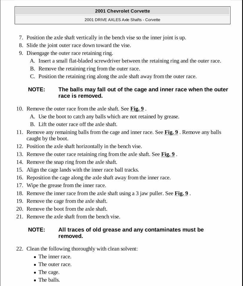
7. Position the axle shaft vertically in the bench vise so the inner joint is up. 8. Slide the joint outer race down toward the vise. 9. Disengage the outer race retaining ring.
A. Insert a small flat-bladed screwdriver between the retaining ring and the outer race. B. Remove the retaining ring from the outer race. C. Position the retaining ring along the axle shaft away from the outer race.
10. Remove the outer race from the axle shaft. See Fig. 9 . A. Use the boot to catch any balls which are not retained by grease. B. Lift the outer race off the axle shaft.
11. Remove any remaining balls from the cage and inner race. See Fig. 9 . Remove any balls caught by the boot.
12. Position the axle shaft horizontally in the bench vise.
13. Remove the outer race retaining ring from the axle shaft. See Fig. 9 . 14. Remove the snap ring from the axle shaft. 15. Align the cage lands with the inner race ball tracks. 16. Reposition the cage along the axle shaft away from the inner race. 17. Wipe the grease from the inner race.
18. Remove the inner race from the axle shaft using a 3 jaw puller. See Fig. 9 . 19. Remove the cage from the axle shaft. 20. Remove the boot from the axle shaft. 21. Remove the axle shaft from the bench vise.
22. Clean the following thoroughly with clean solvent: � The inner race. � The outer race. � The cage. � The balls.
NOTE: The balls may fall out of the cage and inner race when the outer race is removed.
NOTE: All traces of old grease and any contaminates must be removed.
2001 Chevrolet Corvette
2001 DRIVE AXLES Axle Shafts - Corvette
MY
Monday, April 06, 2009 2:39:46 PM Page 25 © 2005 Mitchell Repair Information Company, LLC.
� The axle shaft exposed end. 23. Thoroughly air dry all the parts.
Reassembly (Second Design)
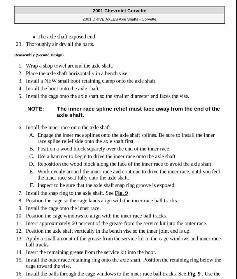
1. Wrap a shop towel around the axle shaft. 2. Place the axle shaft horizontally in a bench vise. 3. Install a NEW small boot retaining clamp onto the axle shaft. 4. Install the boot onto the axle shaft. 5. Install the cage onto the axle shaft so the smaller diameter end faces the vise.
6. Install the inner race onto the axle shaft. A. Engage the inner race splines onto the axle shaft splines. Be sure to install the inner
race spline relief side onto the axle shaft first. B. Position a wood block squarely over the end of the inner race. C. Use a hammer to begin to drive the inner race onto the axle shaft. D. Reposition the wood block along the face of the inner race to avoid the axle shaft. E. Work evenly around the inner race and continue to drive the inner race, until you feel
the inner race seat fully onto the axle shaft. F. Inspect to be sure that the axle shaft snap ring groove is exposed.
7. Install the snap ring to the axle shaft. See Fig. 9 . 8. Position the cage so the cage lands align with the inner race ball tracks. 9. Install the cage onto the inner race.
10. Position the cage windows to align with the inner race ball tracks. 11. Insert approximately 60 percent of the grease from the service kit into the outer race. 12. Position the axle shaft vertically in the bench vise so the inner joint end is up. 13. Apply a small amount of the grease from the service kit to the cage windows and inner race
ball tracks. 14. Insert the remaining grease from the service kit into the boot. 15. Install the outer race retaining ring onto the axle shaft. Position the retaining ring below the
cage toward the vise.
16. Install the balls through the cage windows to the inner race ball tracks. See Fig. 9 . Use the
NOTE: The inner race spline relief must face away from the end of the axle shaft.
2001 Chevrolet Corvette
2001 DRIVE AXLES Axle Shafts - Corvette
MY
Monday, April 06, 2009 2:39:46 PM Page 26 © 2005 Mitchell Repair Information Company, LLC.
boot to keep the balls in position if necessary.
17. Install the outer race onto the axle shaft. See Fig. 9 . A. Be careful not to allow the grease in the outer race to leak out. B. Align the outer race ball tracks to the balls. C. Slide the outer race down over the balls.
18. Position the axle shaft horizontally in the bench vise. 19. Engage the outer race retaining ring.
A. Slide the outer race toward the vise. B. Insert the outer race retaining ring into the groove along the outer edge of the outer
race. C. Position the outer race retaining ring so the opening in the ring aligns with an outer
race land (not a ball track). 20. Position the large diameter end of the boot onto the outer race.
21. Position the small boot retaining clamp onto the neck of the boot (seal). See Fig. 10 . Position the boot and small retaining clamp to the axle shaft.
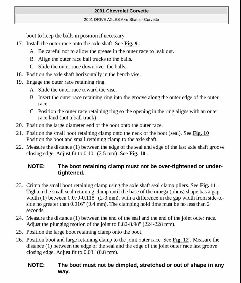
22. Measure the distance (1) between the edge of the seal and edge of the last axle shaft groove closing edge. Adjust fit to 0.10" (2.5 mm). See Fig. 10 .
23. Crimp the small boot retaining clamp using the axle shaft seal clamp pliers. See Fig. 11 . Tighten the small seal retaining clamp until the base of the omega (ohms) shape has a gap width (1) between 0.079-0.118" (2-3 mm), with a difference in the gap width from side-to-side no greater than 0.016" (0.4 mm). The clamping hold time must be no less than 2 seconds.
24. Measure the distance (1) between the end of the seal and the end of the joint outer race. Adjust the plunging motion of the joint to 8.82-8.98" (224-228 mm).
25. Position the large boot retaining clamp onto the boot.
26. Position boot and large retaining clamp to the joint outer race. See Fig. 12 . Measure the distance (1) between the edge of the seal and the edge of the joint outer race last groove closing edge. Adjust fit to 0.03" (0.8 mm).
NOTE: The boot retaining clamp must not be over-tightened or under-tightened.
NOTE: The boot must not be dimpled, stretched or out of shape in any way.
2001 Chevrolet Corvette
2001 DRIVE AXLES Axle Shafts - Corvette
MY
Monday, April 06, 2009 2:39:46 PM Page 27 © 2005 Mitchell Repair Information Company, LLC.
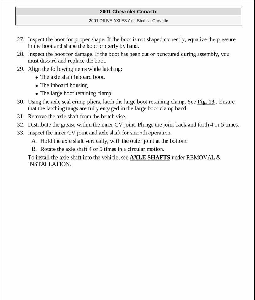
27. Inspect the boot for proper shape. If the boot is not shaped correctly, equalize the pressure in the boot and shape the boot properly by hand.
28. Inspect the boot for damage. If the boot has been cut or punctured during assembly, you must discard and replace the boot.
29. Align the following items while latching: � The axle shaft inboard boot. � The inboard housing. � The large boot retaining clamp.
30. Using the axle seal crimp pliers, latch the large boot retaining clamp. See Fig. 13 . Ensure that the latching tangs are fully engaged in the large boot clamp band.
31. Remove the axle shaft from the bench vise. 32. Distribute the grease within the inner CV joint. Plunge the joint back and forth 4 or 5 times. 33. Inspect the inner CV joint and axle shaft for smooth operation.
A. Hold the axle shaft vertically, with the outer joint at the bottom. B. Rotate the axle shaft 4 or 5 times in a circular motion.
To install the axle shaft into the vehicle, see AXLE SHAFTS under REMOVAL & INSTALLATION.
2001 Chevrolet Corvette
2001 DRIVE AXLES Axle Shafts - Corvette
MY
Monday, April 06, 2009 2:39:46 PM Page 28 © 2005 Mitchell Repair Information Company, LLC.
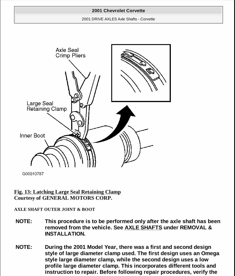
Fig. 13: Latching Large Seal Retaining Clamp Courtesy of GENERAL MOTORS CORP.
AXLE SHAFT OUTER JOINT & BOOT
NOTE: This procedure is to be performed only after the axle shaft has been removed from the vehicle. See AXLE SHAFTS under REMOVAL & INSTALLATION.
NOTE: During the 2001 Model Year, there was a first and second design style of large diameter clamp used. The first design uses an Omega style large diameter clamp, while the second design uses a low profile large diameter clamp. This incorporates different tools and instruction to repair. Before following repair procedures, verify the
2001 Chevrolet Corvette
2001 DRIVE AXLES Axle Shafts - Corvette
MY
Monday, April 06, 2009 2:39:46 PM Page 29 © 2005 Mitchell Repair Information Company, LLC.
Disassembly (First Design)
1. Wrap a shop towel around the axle shaft. 2. Place axle shaft horizontally in a bench vise. 3. Remove large boot retaining clamp from the CV joint seal. Use a side cutter or other
suitable tool and discard the clamp. 4. Remove small boot retaining clamp from the joint seal. Use a side cutter or other suitable
tool and discard the clamp. 5. Separate boot from the joint outer race at the large diameter end. 6. Position the boot behind the joint face. 7. Wipe the grease from the face of the joint inner race, cage, balls, etc. 8. Remove the outer joint from the axle shaft.
A. Have an assistant hold the joint housing. B. Position a wood block between the boot and the joint (along the joint face). C. Strike the wood block with a hammer to compress the axle shaft retaining clip. D. Continue to strike the wood block to remove the outer joint from the axle shaft.
9. Remove the axle shaft retaining ring from the axle shaft. 10. Remove the boot from the axle shaft. 11. Remove the axle shaft from the vise. 12. Wrap a shop towel around the joint outer race splined shaft.
13. Place the outer race vertically in a bench vise. See Fig. 14 . 14. Make a ball accessible for removal. Tap gently on the joint cage, using a brass drift and a
hammer, in order to drive a ball toward the bottom of its track. See Fig. 14 . The opposing ball will be made accessible for removal.
15. Remove the exposed ball. Use a small screwdriver to aid in removal if necessary. 16. Position the cage and inner race so they are level.
17. Repeat steps 14 -16 in the removal sequence as shown until you remove all 6 balls. See Fig. 15 .
18. Position the cage and the inner race 90 degrees to the centerline of the outer race. 19. Position the cage and the inner race 90 degrees to the centerline of the outer race.
style of clamp used.
NOTE: Special Tools Required: Axle Shaft Seal Clamp Pliers (J-42572).
2001 Chevrolet Corvette
2001 DRIVE AXLES Axle Shafts - Corvette
MY
Monday, April 06, 2009 2:39:46 PM Page 30 © 2005 Mitchell Repair Information Company, LLC.
20. Lift to remove the cage and the inner race from the outer race. 21. Position the cage and inner race so that the larger radius corners of the cage windows are
up.
22. Rotate the inner race 90 degrees to the centerline of the cage. See Fig. 16 . 23. Align the lands of the inner race with the windows of the cage. 24. Insert an inner race land into a cage window. 25. Pivot the inner race down and remove it from the cage.
26. Clean the following thoroughly with clean solvent: � The inner race. � The outer race. � The cage. � The balls. � The axle shaft exposed end.
27. Thoroughly air dry all the parts.
NOTE: All traces of old grease and any contaminates must be removed.
2001 Chevrolet Corvette
2001 DRIVE AXLES Axle Shafts - Corvette
MY
Monday, April 06, 2009 2:39:46 PM Page 31 © 2005 Mitchell Repair Information Company, LLC.
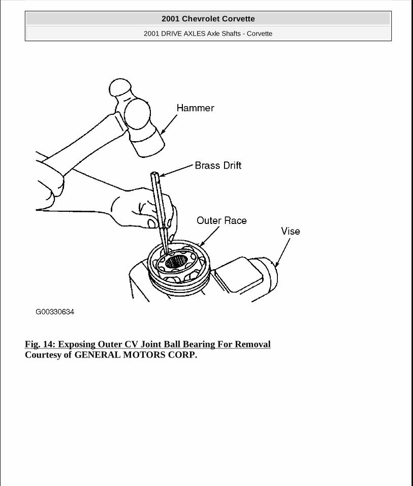
Fig. 14: Exposing Outer CV Joint Ball Bearing For Removal Courtesy of GENERAL MOTORS CORP.
2001 Chevrolet Corvette
2001 DRIVE AXLES Axle Shafts - Corvette
MY
Monday, April 06, 2009 2:39:46 PM Page 32 © 2005 Mitchell Repair Information Company, LLC.
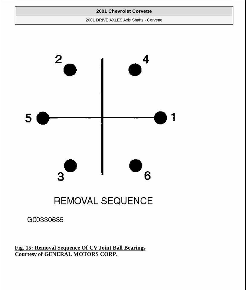
Fig. 15: Removal Sequence Of CV Joint Ball Bearings Courtesy of GENERAL MOTORS CORP.
2001 Chevrolet Corvette
2001 DRIVE AXLES Axle Shafts - Corvette
MY
Monday, April 06, 2009 2:39:46 PM Page 33 © 2005 Mitchell Repair Information Company, LLC.
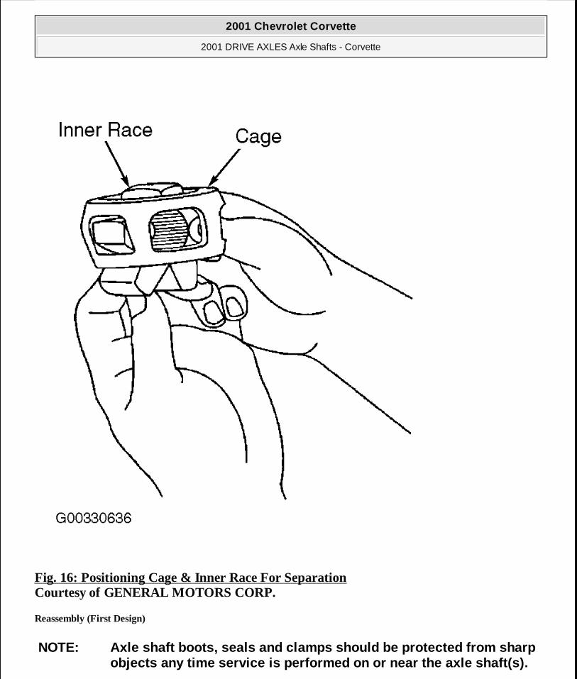
Fig. 16: Positioning Cage & Inner Race For Separation Courtesy of GENERAL MOTORS CORP.
Reassembly (First Design)
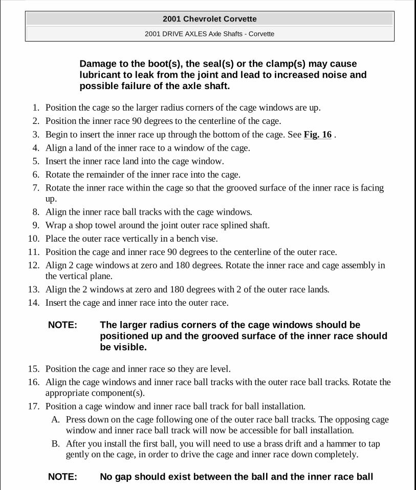
NOTE: Axle shaft boots, seals and clamps should be protected from sharp objects any time service is performed on or near the axle shaft(s).
2001 Chevrolet Corvette
2001 DRIVE AXLES Axle Shafts - Corvette
MY
Monday, April 06, 2009 2:39:46 PM Page 34 © 2005 Mitchell Repair Information Company, LLC.
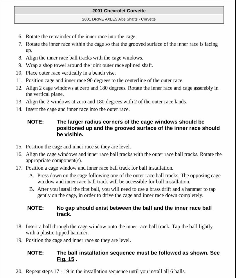
1. Position the cage so the larger radius corners of the cage windows are up. 2. Position the inner race 90 degrees to the centerline of the cage.
3. Begin to insert the inner race up through the bottom of the cage. See Fig. 16 . 4. Align a land of the inner race to a window of the cage. 5. Insert the inner race land into the cage window. 6. Rotate the remainder of the inner race into the cage. 7. Rotate the inner race within the cage so that the grooved surface of the inner race is facing
up. 8. Align the inner race ball tracks with the cage windows. 9. Wrap a shop towel around the joint outer race splined shaft.
10. Place the outer race vertically in a bench vise. 11. Position the cage and inner race 90 degrees to the centerline of the outer race. 12. Align 2 cage windows at zero and 180 degrees. Rotate the inner race and cage assembly in
the vertical plane. 13. Align the 2 windows at zero and 180 degrees with 2 of the outer race lands. 14. Insert the cage and inner race into the outer race.
15. Position the cage and inner race so they are level. 16. Align the cage windows and inner race ball tracks with the outer race ball tracks. Rotate the
appropriate component(s). 17. Position a cage window and inner race ball track for ball installation.
A. Press down on the cage following one of the outer race ball tracks. The opposing cage window and inner race ball track will now be accessible for ball installation.
B. After you install the first ball, you will need to use a brass drift and a hammer to tap gently on the cage, in order to drive the cage and inner race down completely.
Damage to the boot(s), the seal(s) or the clamp(s) may cause lubricant to leak from the joint and lead to increased noise and possible failure of the axle shaft.
NOTE: The larger radius corners of the cage windows should be positioned up and the grooved surface of the inner race should be visible.
NOTE: No gap should exist between the ball and the inner race ball
2001 Chevrolet Corvette
2001 DRIVE AXLES Axle Shafts - Corvette
MY
Monday, April 06, 2009 2:39:46 PM Page 35 © 2005 Mitchell Repair Information Company, LLC.
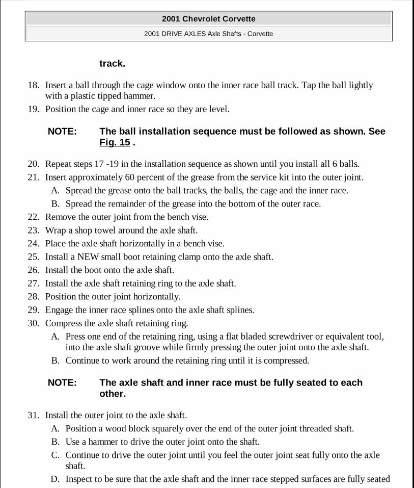
18. Insert a ball through the cage window onto the inner race ball track. Tap the ball lightly with a plastic tipped hammer.
19. Position the cage and inner race so they are level.
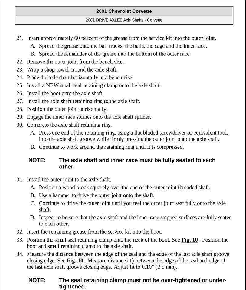
20. Repeat steps 17 -19 in the installation sequence as shown until you install all 6 balls. 21. Insert approximately 60 percent of the grease from the service kit into the outer joint.
A. Spread the grease onto the ball tracks, the balls, the cage and the inner race. B. Spread the remainder of the grease into the bottom of the outer race.
22. Remove the outer joint from the bench vise. 23. Wrap a shop towel around the axle shaft. 24. Place the axle shaft horizontally in a bench vise. 25. Install a NEW small boot retaining clamp onto the axle shaft. 26. Install the boot onto the axle shaft. 27. Install the axle shaft retaining ring to the axle shaft. 28. Position the outer joint horizontally. 29. Engage the inner race splines onto the axle shaft splines. 30. Compress the axle shaft retaining ring.
A. Press one end of the retaining ring, using a flat bladed screwdriver or equivalent tool, into the axle shaft groove while firmly pressing the outer joint onto the axle shaft.
B. Continue to work around the retaining ring until it is compressed.
31. Install the outer joint to the axle shaft. A. Position a wood block squarely over the end of the outer joint threaded shaft. B. Use a hammer to drive the outer joint onto the shaft. C. Continue to drive the outer joint until you feel the outer joint seat fully onto the axle
shaft. D. Inspect to be sure that the axle shaft and the inner race stepped surfaces are fully seated
track.
NOTE: The ball installation sequence must be followed as shown. See Fig. 15 .
NOTE: The axle shaft and inner race must be fully seated to each other.
2001 Chevrolet Corvette
2001 DRIVE AXLES Axle Shafts - Corvette
MY
Monday, April 06, 2009 2:39:46 PM Page 36 © 2005 Mitchell Repair Information Company, LLC.
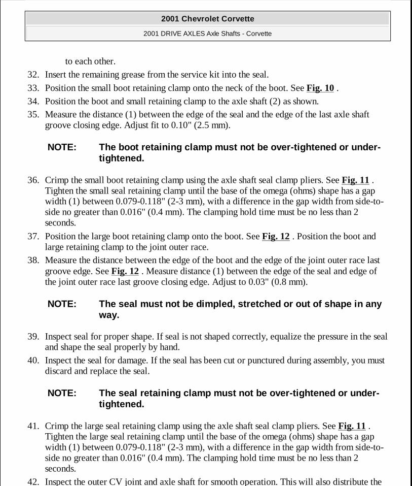
to each other. 32. Insert the remaining grease from the service kit into the seal.
33. Position the small boot retaining clamp onto the neck of the boot. See Fig. 10 . 34. Position the boot and small retaining clamp to the axle shaft (2) as shown. 35. Measure the distance (1) between the edge of the seal and the edge of the last axle shaft
groove closing edge. Adjust fit to 0.10" (2.5 mm).
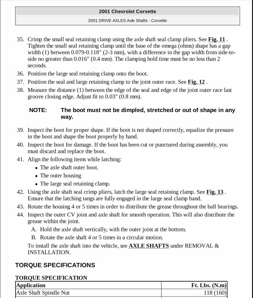
36. Crimp the small boot retaining clamp using the axle shaft seal clamp pliers. See Fig. 11 . Tighten the small seal retaining clamp until the base of the omega (ohms) shape has a gap width (1) between 0.079-0.118" (2-3 mm), with a difference in the gap width from side-to-side no greater than 0.016" (0.4 mm). The clamping hold time must be no less than 2 seconds.
37. Position the large boot retaining clamp onto the boot. See Fig. 12 . Position the boot and large retaining clamp to the joint outer race.
38. Measure the distance between the edge of the boot and the edge of the joint outer race last groove edge. See Fig. 12 . Measure distance (1) between the edge of the seal and edge of the joint outer race last groove closing edge. Adjust to 0.03" (0.8 mm).
39. Inspect seal for proper shape. If seal is not shaped correctly, equalize the pressure in the seal and shape the seal properly by hand.
40. Inspect the seal for damage. If the seal has been cut or punctured during assembly, you must discard and replace the seal.
41. Crimp the large seal retaining clamp using the axle shaft seal clamp pliers. See Fig. 11 . Tighten the large seal retaining clamp until the base of the omega (ohms) shape has a gap width (1) between 0.079-0.118" (2-3 mm), with a difference in the gap width from side-to-side no greater than 0.016" (0.4 mm). The clamping hold time must be no less than 2 seconds.
42. Inspect the outer CV joint and axle shaft for smooth operation. This will also distribute the
NOTE: The boot retaining clamp must not be over-tightened or under-tightened.
NOTE: The seal must not be dimpled, stretched or out of shape in any way.
NOTE: The seal retaining clamp must not be over-tightened or under-tightened.
2001 Chevrolet Corvette
2001 DRIVE AXLES Axle Shafts - Corvette
MY
Monday, April 06, 2009 2:39:46 PM Page 37 © 2005 Mitchell Repair Information Company, LLC.
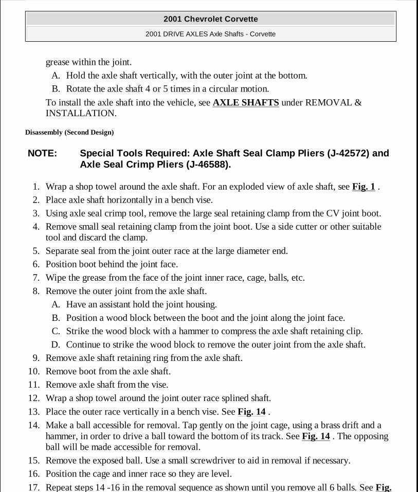
grease within the joint. A. Hold the axle shaft vertically, with the outer joint at the bottom. B. Rotate the axle shaft 4 or 5 times in a circular motion.
To install the axle shaft into the vehicle, see AXLE SHAFTS under REMOVAL & INSTALLATION.
Disassembly (Second Design)
1. Wrap a shop towel around the axle shaft. For an exploded view of axle shaft, see Fig. 1 . 2. Place axle shaft horizontally in a bench vise. 3. Using axle seal crimp tool, remove the large seal retaining clamp from the CV joint boot. 4. Remove small seal retaining clamp from the joint boot. Use a side cutter or other suitable
tool and discard the clamp. 5. Separate seal from the joint outer race at the large diameter end. 6. Position boot behind the joint face. 7. Wipe the grease from the face of the joint inner race, cage, balls, etc. 8. Remove the outer joint from the axle shaft.
A. Have an assistant hold the joint housing. B. Position a wood block between the boot and the joint along the joint face. C. Strike the wood block with a hammer to compress the axle shaft retaining clip. D. Continue to strike the wood block to remove the outer joint from the axle shaft.
9. Remove axle shaft retaining ring from the axle shaft. 10. Remove boot from the axle shaft. 11. Remove axle shaft from the vise. 12. Wrap a shop towel around the joint outer race splined shaft.
13. Place the outer race vertically in a bench vise. See Fig. 14 . 14. Make a ball accessible for removal. Tap gently on the joint cage, using a brass drift and a
hammer, in order to drive a ball toward the bottom of its track. See Fig. 14 . The opposing ball will be made accessible for removal.
15. Remove the exposed ball. Use a small screwdriver to aid in removal if necessary. 16. Position the cage and inner race so they are level.
17. Repeat steps 14 -16 in the removal sequence as shown until you remove all 6 balls. See Fig.
NOTE: Special Tools Required: Axle Shaft Seal Clamp Pliers (J-42572) and Axle Seal Crimp Pliers (J-46588).
2001 Chevrolet Corvette
2001 DRIVE AXLES Axle Shafts - Corvette
MY
Monday, April 06, 2009 2:39:46 PM Page 38 © 2005 Mitchell Repair Information Company, LLC.
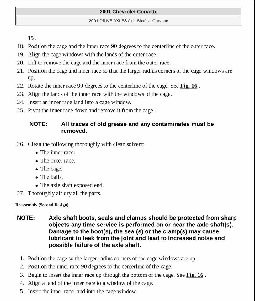
15 . 18. Position the cage and the inner race 90 degrees to the centerline of the outer race. 19. Align the cage windows with the lands of the outer race. 20. Lift to remove the cage and the inner race from the outer race. 21. Position the cage and inner race so that the larger radius corners of the cage windows are
up.
22. Rotate the inner race 90 degrees to the centerline of the cage. See Fig. 16 . 23. Align the lands of the inner race with the windows of the cage. 24. Insert an inner race land into a cage window. 25. Pivot the inner race down and remove it from the cage.
26. Clean the following thoroughly with clean solvent: � The inner race. � The outer race. � The cage. � The balls. � The axle shaft exposed end.
27. Thoroughly air dry all the parts.
Reassembly (Second Design)
1. Position the cage so the larger radius corners of the cage windows are up. 2. Position the inner race 90 degrees to the centerline of the cage.
3. Begin to insert the inner race up through the bottom of the cage. See Fig. 16 . 4. Align a land of the inner race to a window of the cage. 5. Insert the inner race land into the cage window.
NOTE: All traces of old grease and any contaminates must be removed.
NOTE: Axle shaft boots, seals and clamps should be protected from sharp objects any time service is performed on or near the axle shaft(s). Damage to the boot(s), the seal(s) or the clamp(s) may cause lubricant to leak from the joint and lead to increased noise and possible failure of the axle shaft.
2001 Chevrolet Corvette
2001 DRIVE AXLES Axle Shafts - Corvette
MY
Monday, April 06, 2009 2:39:46 PM Page 39 © 2005 Mitchell Repair Information Company, LLC.
6. Rotate the remainder of the inner race into the cage. 7. Rotate the inner race within the cage so that the grooved surface of the inner race is facing
up. 8. Align the inner race ball tracks with the cage windows. 9. Wrap a shop towel around the joint outer race splined shaft.
10. Place outer race vertically in a bench vise. 11. Position cage and inner race 90 degrees to the centerline of the outer race. 12. Align 2 cage windows at zero and 180 degrees. Rotate the inner race and cage assembly in
the vertical plane. 13. Align the 2 windows at zero and 180 degrees with 2 of the outer race lands. 14. Insert the cage and inner race into the outer race.
15. Position the cage and inner race so they are level. 16. Align the cage windows and inner race ball tracks with the outer race ball tracks. Rotate the
appropriate component(s). 17. Position a cage window and inner race ball track for ball installation.
A. Press down on the cage following one of the outer race ball tracks. The opposing cage window and inner race ball track will be accessible for ball installation.
B. After you install the first ball, you will need to use a brass drift and a hammer to tap gently on the cage, in order to drive the cage and inner race down completely.
18. Insert a ball through the cage window onto the inner race ball track. Tap the ball lightly with a plastic tipped hammer.
19. Position the cage and inner race so they are level.
20. Repeat steps 17 - 19 in the installation sequence until you install all 6 balls.
NOTE: The larger radius corners of the cage windows should be positioned up and the grooved surface of the inner race should be visible.
NOTE: No gap should exist between the ball and the inner race ball track.
NOTE: The ball installation sequence must be followed as shown. See Fig. 15 .
2001 Chevrolet Corvette
2001 DRIVE AXLES Axle Shafts - Corvette
MY
Monday, April 06, 2009 2:39:46 PM Page 40 © 2005 Mitchell Repair Information Company, LLC.
21. Insert approximately 60 percent of the grease from the service kit into the outer joint. A. Spread the grease onto the ball tracks, the balls, the cage and the inner race. B. Spread the remainder of the grease into the bottom of the outer race.
22. Remove the outer joint from the bench vise. 23. Wrap a shop towel around the axle shaft. 24. Place the axle shaft horizontally in a bench vise. 25. Install a NEW small seal retaining clamp onto the axle shaft. 26. Install the boot onto the axle shaft. 27. Install the axle shaft retaining ring to the axle shaft. 28. Position the outer joint horizontally. 29. Engage the inner race splines onto the axle shaft splines. 30. Compress the axle shaft retaining ring.
A. Press one end of the retaining ring, using a flat bladed screwdriver or equivalent tool, into the axle shaft groove while firmly pressing the outer joint onto the axle shaft.
B. Continue to work around the retaining ring until it is compressed.
31. Install the outer joint to the axle shaft. A. Position a wood block squarely over the end of the outer joint threaded shaft. B. Use a hammer to drive the outer joint onto the shaft. C. Continue to drive the outer joint until you feel the outer joint seat fully onto the axle
shaft. D. Inspect to be sure that the axle shaft and the inner race stepped surfaces are fully seated
to each other. 32. Insert the remaining grease from the service kit into the boot.
33. Position the small seal retaining clamp onto the neck of the boot. See Fig. 10 . Position the boot and small retaining clamp to the axle shaft.
34. Measure the distance between the edge of the seal and the edge of the last axle shaft groove closing edge. See Fig. 10 . Measure distance (1) between the edge of the seal and edge of the last axle shaft groove closing edge. Adjust fit to 0.10" (2.5 mm).
NOTE: The axle shaft and inner race must be fully seated to each other.
NOTE: The seal retaining clamp must not be over-tightened or under-tightened.
2001 Chevrolet Corvette
2001 DRIVE AXLES Axle Shafts - Corvette
MY
Monday, April 06, 2009 2:39:47 PM Page 41 © 2005 Mitchell Repair Information Company, LLC.
35. Crimp the small seal retaining clamp using the axle shaft seal clamp pliers. See Fig. 11 . Tighten the small seal retaining clamp until the base of the omega (ohms) shape has a gap width (1) between 0.079-0.118" (2-3 mm), with a difference in the gap width from side-to-side no greater than 0.016" (0.4 mm). The clamping hold time must be no less than 2 seconds.
36. Position the large seal retaining clamp onto the boot.
37. Position the seal and large retaining clamp to the joint outer race. See Fig. 12 . 38. Measure the distance (1) between the edge of the seal and edge of the joint outer race last
groove closing edge. Adjust fit to 0.03" (0.8 mm).
39. Inspect the boot for proper shape. If the boot is not shaped correctly, equalize the pressure in the boot and shape the boot properly by hand.
40. Inspect the boot for damage. If the boot has been cut or punctured during assembly, you must discard and replace the boot.
41. Align the following items while latching: � The axle shaft outer boot. � The outer housing � The large seal retaining clamp.
42. Using the axle shaft seal crimp pliers, latch the large seal retaining clamp. See Fig. 13 . Ensure that the latching tangs are fully engaged in the large seal clamp band.
43. Rotate the housing 4 or 5 times in order to distribute the grease throughout the ball bearings. 44. Inspect the outer CV joint and axle shaft for smooth operation. This will also distribute the
grease within the joint. A. Hold the axle shaft vertically, with the outer joint at the bottom. B. Rotate the axle shaft 4 or 5 times in a circular motion.
To install the axle shaft into the vehicle, see AXLE SHAFTS under REMOVAL & INSTALLATION.
TORQUE SPECIFICATIONS
TORQUE SPECIFICATION
NOTE: The boot must not be dimpled, stretched or out of shape in any way.
Application Ft. Lbs. (N.m)Axle Shaft Spindle Nut 118 (160)
2001 Chevrolet Corvette
2001 DRIVE AXLES Axle Shafts - Corvette
MY
Monday, April 06, 2009 2:39:47 PM Page 42 © 2005 Mitchell Repair Information Company, LLC.
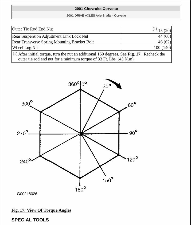
Fig. 17: View Of Torque Angles
SPECIAL TOOLS
Outer Tie Rod End Nut (1) 15 (20)Rear Suspension Adjustment Link Lock Nut 44 (60)Rear Transverse Spring Mounting Bracket Bolt 46 (62)Wheel Lug Nut 100 (140)(1) After initial torque, turn the nut an additional 160 degrees. See Fig. 17 . Recheck the
outer tie rod end nut for a minimum torque of 33 Ft. Lbs. (45 N.m).
2001 Chevrolet Corvette
2001 DRIVE AXLES Axle Shafts - Corvette
MY
Monday, April 06, 2009 2:39:47 PM Page 43 © 2005 Mitchell Repair Information Company, LLC.
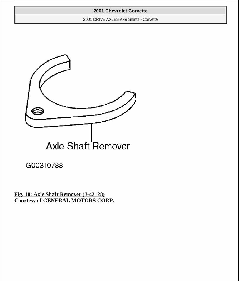
Fig. 18: Axle Shaft Remover (J-42128) Courtesy of GENERAL MOTORS CORP.
2001 Chevrolet Corvette
2001 DRIVE AXLES Axle Shafts - Corvette
MY
Monday, April 06, 2009 2:39:47 PM Page 44 © 2005 Mitchell Repair Information Company, LLC.
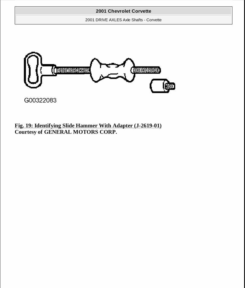
Fig. 19: Identifying Slide Hammer With Adapter (J-2619-01) Courtesy of GENERAL MOTORS CORP.
2001 Chevrolet Corvette
2001 DRIVE AXLES Axle Shafts - Corvette
MY
Monday, April 06, 2009 2:39:47 PM Page 45 © 2005 Mitchell Repair Information Company, LLC.
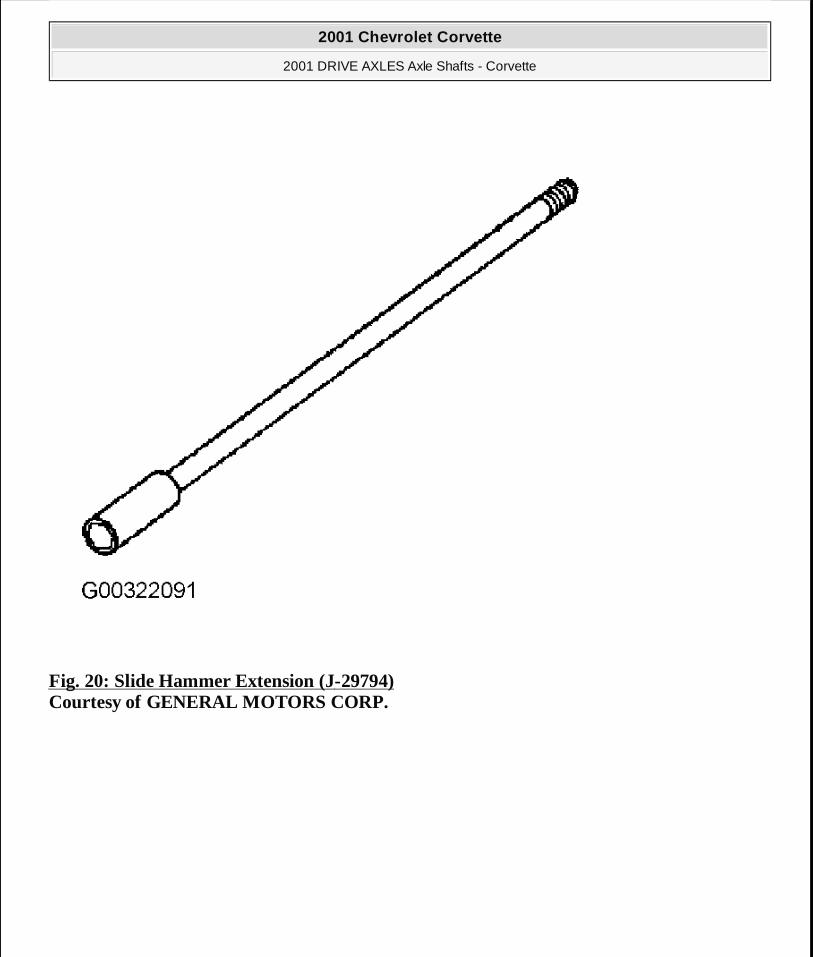
Fig. 20: Slide Hammer Extension (J-29794) Courtesy of GENERAL MOTORS CORP.
2001 Chevrolet Corvette
2001 DRIVE AXLES Axle Shafts - Corvette
MY
Monday, April 06, 2009 2:39:47 PM Page 46 © 2005 Mitchell Repair Information Company, LLC.
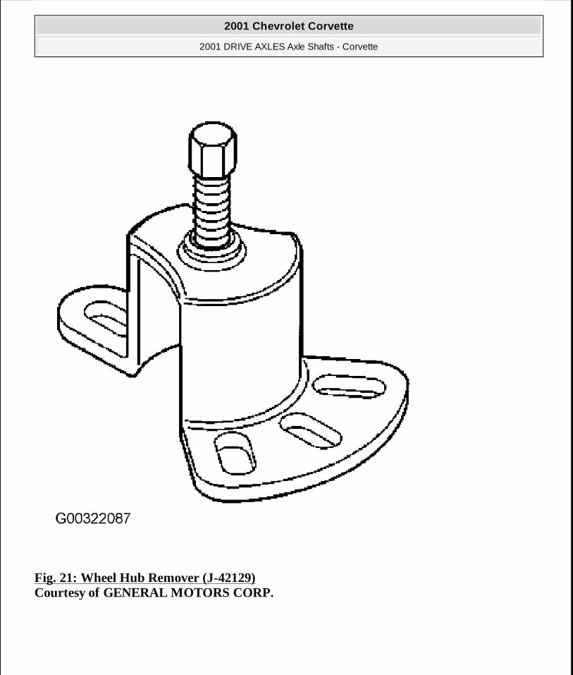
Fig. 21: Wheel Hub Remover (J-42129) Courtesy of GENERAL MOTORS CORP.
2001 Chevrolet Corvette
2001 DRIVE AXLES Axle Shafts - Corvette
MY
Monday, April 06, 2009 2:39:47 PM Page 47 © 2005 Mitchell Repair Information Company, LLC.