©2001-2006 Dynojet Research, Inc. All Rights Reserved. · • Microsoft® Windows 2000/XP •...
36
Transcript of ©2001-2006 Dynojet Research, Inc. All Rights Reserved. · • Microsoft® Windows 2000/XP •...
©2001-2006 Dynojet Research, Inc. All Rights Reserved.
Tuning Link User Guide
This manual is copyrighted by Dynojet Research, Inc., hereafter referred to as Dynojet, and all rights are reserved. This manual, as well as the software described in it, is furnished under license and may only be used or copied in accordance with the terms of such license. This manual is furnished for informational use only, is subject to change without notice, and should not be construed as a commitment by Dynojet. Dynojet assumes no responsibility or liability for any error or inaccuracies that may appear in this manual. Except as permitted by such license, no part of this manual may be reproduced, stored in a retrieval system, or transmitted, in any form or by any means, electronic, mechanical, recording, or otherwise, without the prior written permission of Dynojet.
The Dynojet logo is a trademark of Dynojet Research, Inc.
Any trademarks, trade names, service marks, or service names owned or registered by any other company and used in this guide are the property of their respective companies.
Dynojet Research, Inc., 2191 Mendenhall Drive, North Las Vegas, Nevada 89081, USA.
Printed in USA.
Part Number: 98128103 Version 02 (08/2006)

TABLE OF CONTENTS
Chapter 1 InstallationIntroduction . . . . . . . . . . . . . . . . . . . . . . . . . . . . . . . . . . . . . . . . . . . . . . . . . .1-2
Computer Specifications . . . . . . . . . . . . . . . . . . . . . . . . . . . . . . . . . . . . . .1-2Conventions Used In This Manual . . . . . . . . . . . . . . . . . . . . . . . . . . . . . . .1-3Technical Support . . . . . . . . . . . . . . . . . . . . . . . . . . . . . . . . . . . . . . . . . . .1-3
Installation . . . . . . . . . . . . . . . . . . . . . . . . . . . . . . . . . . . . . . . . . . . . . . . . . . .1-4
Chapter 2 Software FeaturesMain Window . . . . . . . . . . . . . . . . . . . . . . . . . . . . . . . . . . . . . . . . . . . . . . . .2-2Configuration Window . . . . . . . . . . . . . . . . . . . . . . . . . . . . . . . . . . . . . . . . .2-4Menu Choices . . . . . . . . . . . . . . . . . . . . . . . . . . . . . . . . . . . . . . . . . . . . . . . .2-6
File Menu . . . . . . . . . . . . . . . . . . . . . . . . . . . . . . . . . . . . . . . . . . . . . . . . .2-6Edit Menu . . . . . . . . . . . . . . . . . . . . . . . . . . . . . . . . . . . . . . . . . . . . . . . . .2-6View Menu . . . . . . . . . . . . . . . . . . . . . . . . . . . . . . . . . . . . . . . . . . . . . . . .2-7Tools Menu . . . . . . . . . . . . . . . . . . . . . . . . . . . . . . . . . . . . . . . . . . . . . . .2-10Commander Port Menu . . . . . . . . . . . . . . . . . . . . . . . . . . . . . . . . . . . . . .2-12Dynamometer Port Menu . . . . . . . . . . . . . . . . . . . . . . . . . . . . . . . . . . . .2-12Mode Menu . . . . . . . . . . . . . . . . . . . . . . . . . . . . . . . . . . . . . . . . . . . . . .2-13Help Menu . . . . . . . . . . . . . . . . . . . . . . . . . . . . . . . . . . . . . . . . . . . . . . .2-14
Basic Software Features . . . . . . . . . . . . . . . . . . . . . . . . . . . . . . . . . . . . . . .2-16Bike Break-in/Warm Up . . . . . . . . . . . . . . . . . . . . . . . . . . . . . . . . . . . . . .2-16Steady State Fuel Mapping . . . . . . . . . . . . . . . . . . . . . . . . . . . . . . . . . . .2-16Roll-On Fuel Mapping . . . . . . . . . . . . . . . . . . . . . . . . . . . . . . . . . . . . . . .2-17
Index . . . . . . . . . . . . . . . . . . . . . . . . . . . . . . . . . . . . . . . . . . . . . . . . . Index-i
Tuning Link User Guidei


C H A P T E R
1INSTALLATION
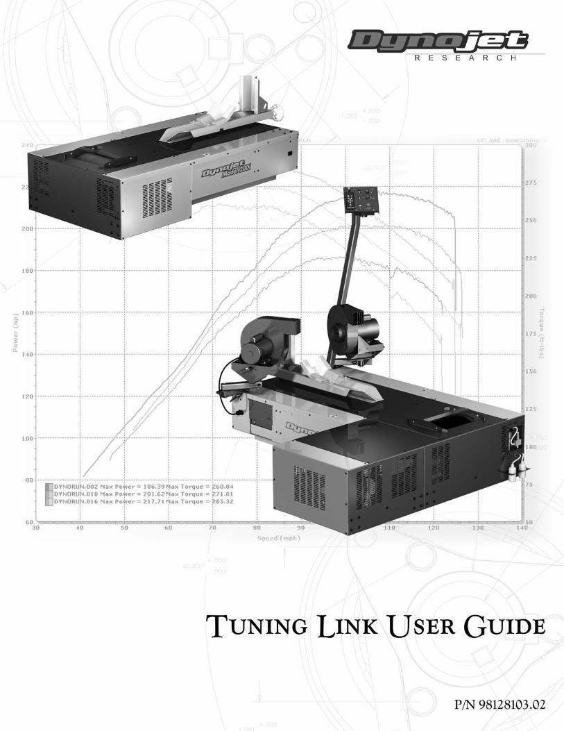
Thank you for purchasing Tuning Link, Dynojet’s Fuel Injection Mapping System. Tuning Link is an innovative piece of software that allows the automatic fuel curve optimization of a Power Commander equipped motorcycle.
This document provides instructions for using Tuning Link. This document will walk you through software installation and program features. To ensure safety and accuracy in the procedures, perform the procedures as they are described.
Document Part Number: 98128103
Version 2
Last Updated: 08-31-06
This chapter is divided into the following categories:
• Introduction, page 1-2
• Installation, page 1-4
Tuning Link User Guide1-1

C H A P T E R 1Introduction
. . . . . . . . . . . . . . . . . . . . . . . . . . . . . . . . . . .INTRODUCTION
The Tuning Link software interfaces the Power Commander with a Dynojet Load Control Dynamometer controlling both the Dynamometer and the Power Commander at the same time.
By utilizing the Dynojet “Real Time” air/fuel ratio monitoring equipment and latest load control dynamometer technology, Tuning Link monitors the current air/fuel ratio. At the same time, Tuning Link automatically calculates the correct fuel adjustment to achieve the user desired air/fuel ratio. Once calculated, Tuning Link uploads these new fuel values to the Power Commander and saves a copy of the file.
Tuning Link has the ability to map fuel curves in both “static” and “dynamic” modes. This assures that the generated fuel curves are correct for both steady state cruising as well as during aggressive on/off throttle movements. This technology allows the dyno operator to accurately optimize the motorcycle in a very short time, regardless of the motorcycle’s modifications.
The Tuning Link software operates in three modes:
• Bike Break-in/Warm Up
• Steady State Fuel Mapping
• Roll-On Fuel Mapping
COMPUTER SPECIFICATIONS
You will need to provide a computer system to run the Tuning Link software.
minimum system requirements recommended systems requirements
• Microsoft® Windows 2000/XP • Microsoft® Windows 2000/XP
• Pentium 800 MHz Processor • 2.4 GHz Processor or greater
• 256 MB of available RAM • 256 MB of available RAM or greater
• two COM ports, one USB port • two COM ports, one USB port
• 800x600, 256 color monitor (SVGA) • 1280x1024 256 color monitor (SVGA) or better
• 1.2 gigabyte hard drive • 1.2 gigabyte hard drive
• 30 MB of available hard-disk space • 100 MB of available hard-disk space
• CD ROM and floppy disk drive • CD ROM and floppy disk drive
• printer, if hard copies are needed • printer (preferably HP DeskJet®)
Tuning Link User Guide1-2
I N S T A L L A T I O NIntroduction
CONVENTIONS USED IN THIS MANUAL
The conventions used in this manual are designed to protect both the user and the equipment.
TECHNICAL SUPPORT
For assistance, please contact Dynojet Technical Support at 1-800-992-3525, or write to Dynojet at 2191 Mendenhall Drive, North Las Vegas, NV 89081.
Visit us on the World Wide Web at www.dynojet.com where Dynojet provides state of the art technical support, on-line shopping, and press releases about our latest product lines.
example of convention description
The Warning icon indicates potential harm to the person performing a procedure and/or the dynamometer equipment.
Bold Highlights items you can select on in the software interface, including buttons and menus.
The arrow indicates a menu choice. For example, “select File Open” means “select the File menu, then select the Open choice on the File menu.”
Version 2 Tuning Link User Guide1-3
C H A P T E R 1Installation
. . . . . . . . . . . . . . . . . . . . . . . . . . . . . . . . . . .INSTALLATION
Use the following instructions to install Tuning Link on your computer.
Note: It is strongly recommended that you exit all other Windows programs before running this install program.
1 Insert the Tuning Link CD in your CD-ROM drive. The launch program will run automatically.
If auto-run is disabled, do one of the following:
• Open the CD and double-click Launch.exe.• Click Start on the Windows® task bar, and click Run. Type D:\Launch.exe,
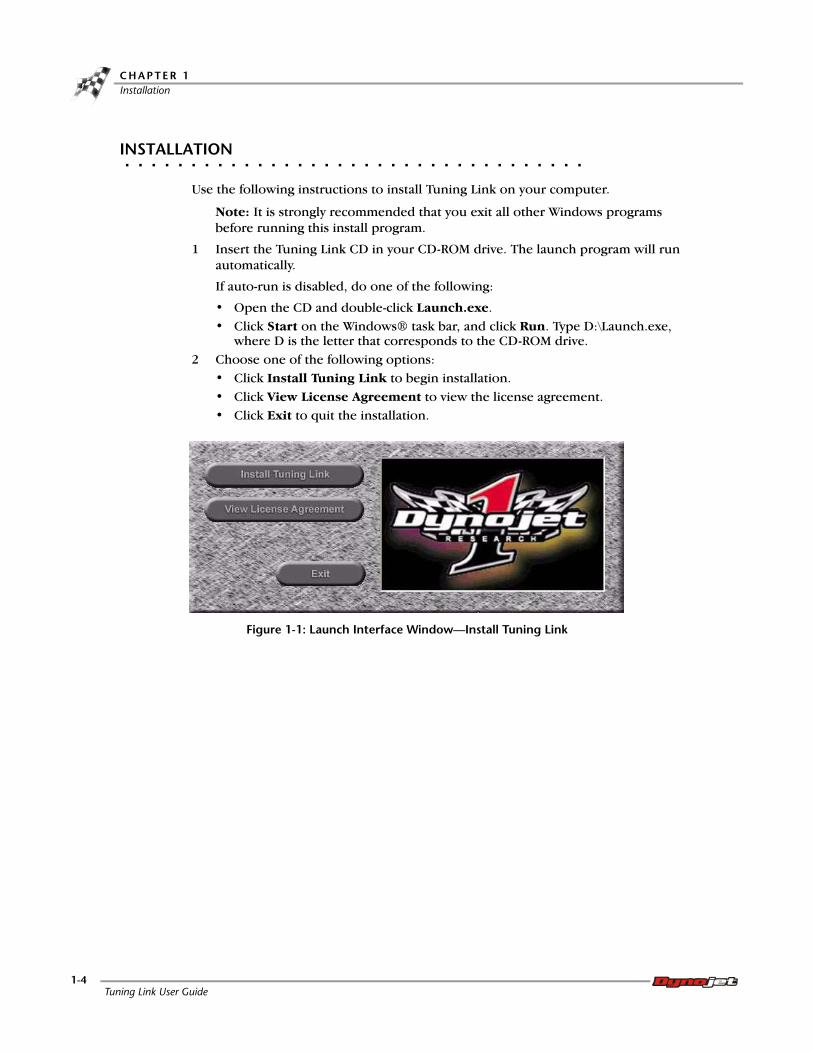
where D is the letter that corresponds to the CD-ROM drive.2 Choose one of the following options:
• Click Install Tuning Link to begin installation.• Click View License Agreement to view the license agreement.• Click Exit to quit the installation.
Figure 1-1: Launch Interface Window—Install Tuning Link
Tuning Link User Guide1-4

I N S T A L L A T I O NInstallation
3 Read the Welcome window and click Next to continue.
Figure 1-2: Welcome Window
4 Carefully read the Tuning Link license agreement and click Yes to continue.
To install Tuning Link, you must accept this agreement. If you choose No, Setup will close.
Note: Be sure to read and understand the license agreement. This license is only for a one year term.
Figure 1-3: Software License Agreement
Version 2 Tuning Link User Guide1-5
C H A P T E R 1Installation
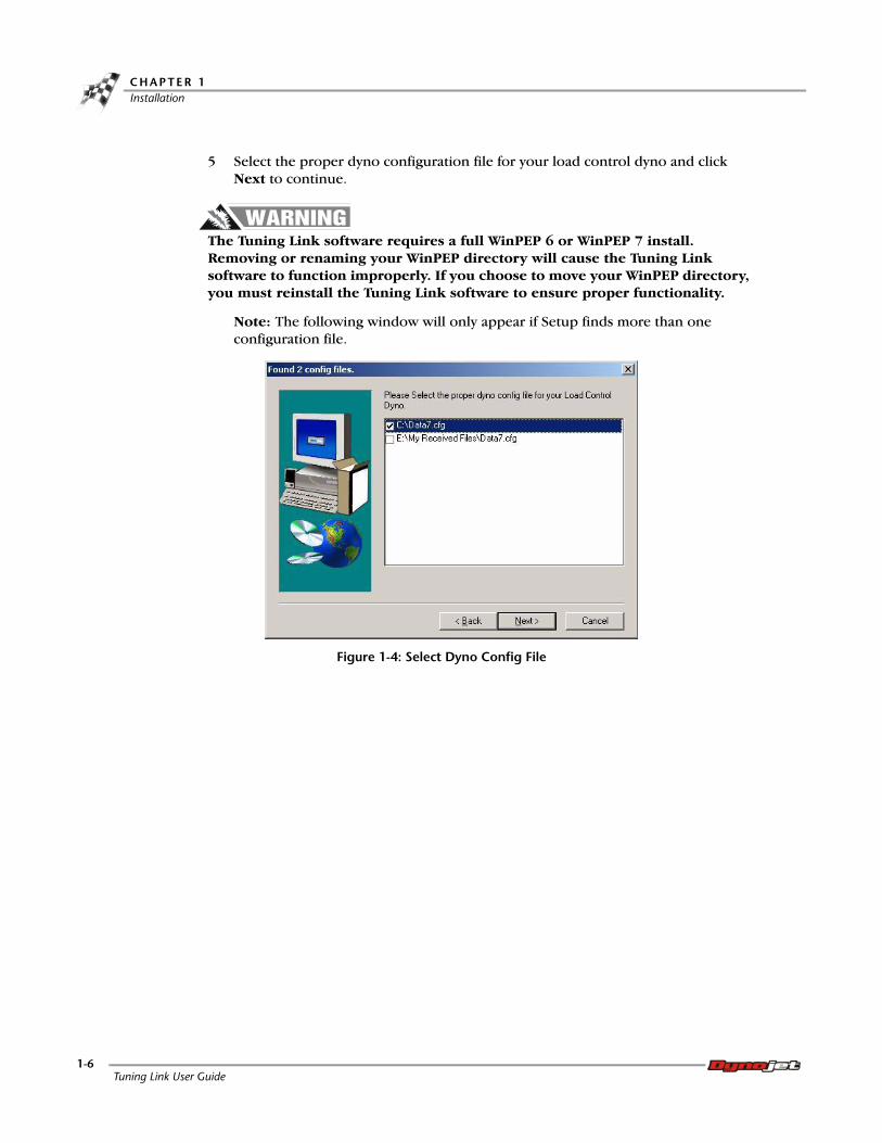
5 Select the proper dyno configuration file for your load control dyno and click Next to continue.
The Tuning Link software requires a full WinPEP 6 or WinPEP 7 install. Removing or renaming your WinPEP directory will cause the Tuning Link software to function improperly. If you choose to move your WinPEP directory, you must reinstall the Tuning Link software to ensure proper functionality.
Note: The following window will only appear if Setup finds more than one configuration file.
Figure 1-4: Select Dyno Config File
Tuning Link User Guide1-6

I N S T A L L A T I O NInstallation
6 Select a location for your Tuning Link software to be installed and click Next to
continue.Note: Dynojet recommends that you do not change the default destination folder.
Figure 1-5: Choose Installation Location
7 Setup will automatically add program icons to the Program Folder. You may type a new folder name or select one from the Existing Folders list. Click Next to continue.
Figure 1-6: Select Program Folder
Version 2 Tuning Link User Guide1-7

C H A P T E R 1Installation
8 Review your current settings and click Next to continue; Setup will copy the program files.
Or
Click Back to review or change any settings.
Figure 1-7: Review Current Settings
9 Click Finish to complete Setup.
Figure 1-8: Setup Complete
The installation is complete. You may now run Tuning Link by double-clicking the program icon installed.
Note: The Launch Interface window, Figure 1-1, will still be running; you will need to exit the window.
Tuning Link User Guide1-8

C H A P T E R
2SOFTWARE FEATURES
This chapter provides information about Tuning Link software features.
This chapter is divided into the following categories:
• Main Window, page 2-2
• Configuration Window, page 2-4
• Menu Choices, page 2-6
• Basic Software Features, page 2-16
Tuning Link User Guide2-1
C H A P T E R 2Main Window
. . . . . . . . . . . . . . . . . . . . . . . . . . . . . . . . . . .MAIN WINDOW
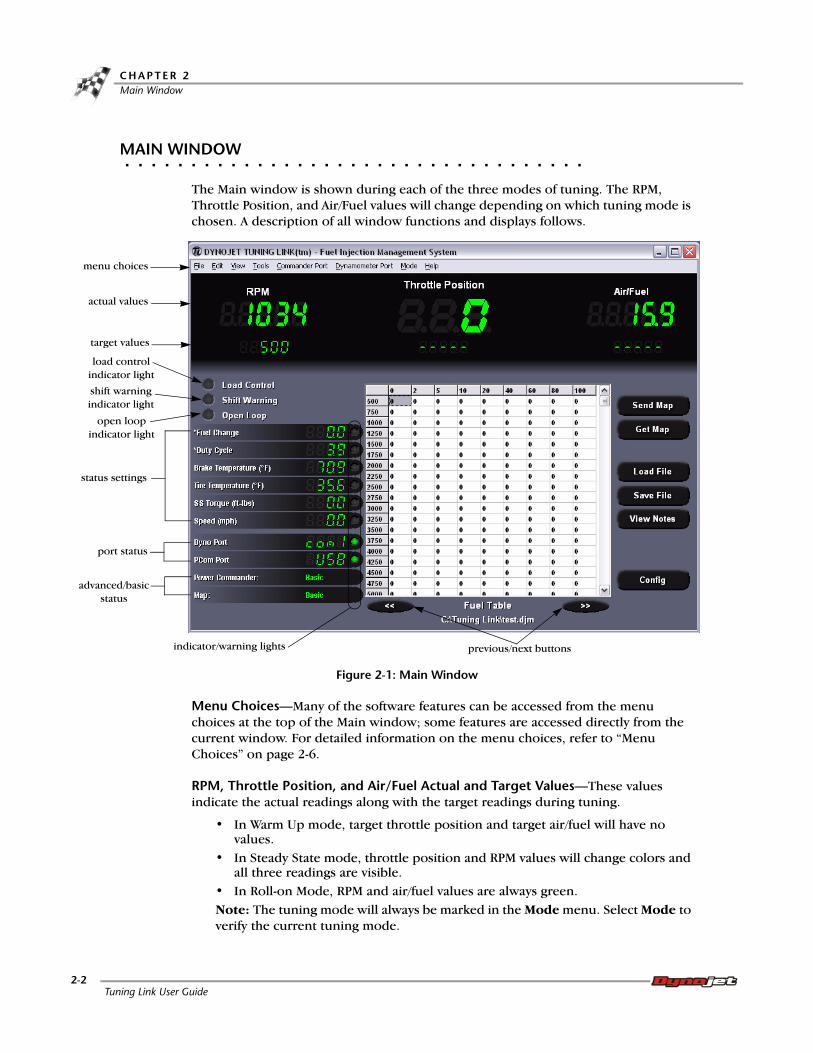
The Main window is shown during each of the three modes of tuning. The RPM, Throttle Position, and Air/Fuel values will change depending on which tuning mode is chosen. A description of all window functions and displays follows.
Figure 2-1: Main Window
Menu Choices—Many of the software features can be accessed from the menu choices at the top of the Main window; some features are accessed directly from the current window. For detailed information on the menu choices, refer to “Menu Choices” on page 2-6.
RPM, Throttle Position, and Air/Fuel Actual and Target Values—These values indicate the actual readings along with the target readings during tuning.
• In Warm Up mode, target throttle position and target air/fuel will have no values.
• In Steady State mode, throttle position and RPM values will change colors and all three readings are visible.
• In Roll-on Mode, RPM and air/fuel values are always green.Note: The tuning mode will always be marked in the Mode menu. Select Mode to verify the current tuning mode.
target values
load control indicator light
status settings
port status
indicator/warning lights
menu choices
actual values
shift warning indicator light
advanced/basic status
previous/next buttons
open loop indicator light
Tuning Link User Guide2-2

S O F T W A R E F E A T U R E SMain Window
Send Map—sends the entire map to the Power Commander.
Get Map—retrieves the entire map from the Power Commander.
Load File/Save File—will load/save the existing file.
View Notes—will show/hide the notes.
Config—displays the Configuration window. Refer to “Configuration Window” on page 2-4 for more information.
Load Control Light—indicates the eddy current brake is activated and will apply load to the vehicle to hold it at the target RPM. Activate the eddy current brake by pressing the green button on the pendant or by pressing L on the keyboard.
Note: The eddy current brake can be applied at 100% by pressing the red button on the pendant or by pressing the space bar on the keyboard. This is an emergency brake feature and will highlight the grid in red.
Shift Warning Light—indicates the eddy current brake is working too hard to maintain the target RPM; shift the bike to another gear. Refer to “Status Settings” on page 2-4 for more information.
Open Loop Indicator Light—is used with BMW Power Commander. The indicator light turns green when the bike goes into open loop.
Note: Tuning Link is not able to adjust the fuel curve while the bike is in closed loop.
Status Settings—monitors and shows the status of various conditions. A red warning light will come on when any condition reaches its warning or danger zone. Refer to “Status Settings” on page 2-4 to set warning and danger values.
Dyno/PCom Port—monitors the port connections. A green indicator light signifies a working connection; a red indicator light signifies communication has been lost.
Fuel Table—The fuel table, or map, lists the RPM values in the left column and throttle positions in the top row. Adjustments made during tuning will appear in the corresponding columns and rows. Changes to the Map Setting and Power Mode Target Air/Fuel Ratio values are made from the Configuration window. Refer to “Map Settings” on page 2-5 for more information. Use the next and previous buttons located at the bottom of the map to browse through additional map tables if applicable.
Version 2 Tuning Link User Guide2-3
C H A P T E R 2Configuration Window
. . . . . . . . . . . . . . . . . . . . . . . . . . . . . . . . . . .CONFIGURATION WINDOW
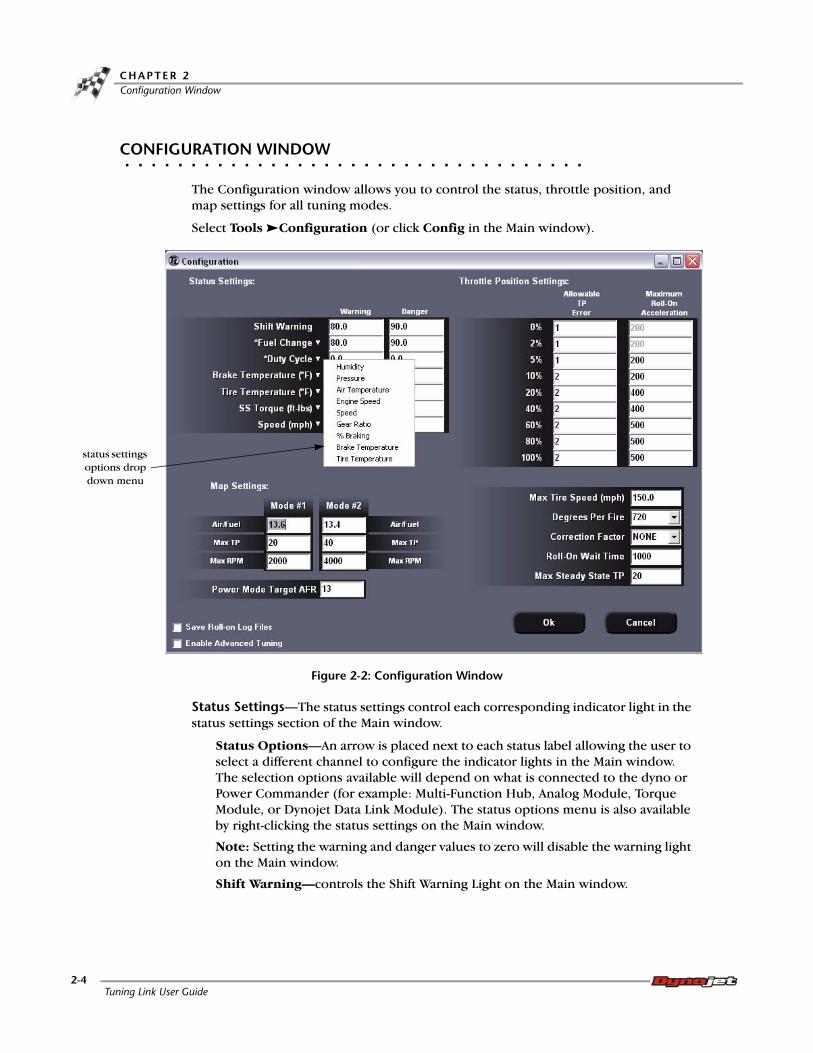
The Configuration window allows you to control the status, throttle position, and map settings for all tuning modes.
Select Tools Configuration (or click Config in the Main window).
Figure 2-2: Configuration Window
Status Settings—The status settings control each corresponding indicator light in the status settings section of the Main window.
Status Options—An arrow is placed next to each status label allowing the user to select a different channel to configure the indicator lights in the Main window. The selection options available will depend on what is connected to the dyno or Power Commander (for example: Multi-Function Hub, Analog Module, Torque Module, or Dynojet Data Link Module). The status options menu is also available by right-clicking the status settings on the Main window.
Note: Setting the warning and danger values to zero will disable the warning light on the Main window.
Shift Warning—controls the Shift Warning Light on the Main window.
status settings options drop down menu
Tuning Link User Guide2-4

S O F T W A R E F E A T U R E SConfiguration Window
Map Settings—controls the target air/fuel ratio (AFR) for all tuning modes. The map can be separated into three modes as specified by Map Settings in the Configuration window, refer to Figure 2-2.
Figure 2-3: Configuration Window—Map Settings
Save Roll-on Log Files—saves the roll-on runs as a .dlf file to be viewed in WinPEP 7.
Enable Advanced Tuning—allows advanced mapping ability. With advanced tuning enabled, you can tune basic or advanced (individual cylinders).
Throttle Position (TP) Settings—Each row in this table allows you to set the allowed error between the target and actual throttle positions and the roll-on acceleration for a roll-on in that throttle position range (RPM/Sec.).
Note: Roll-on Tuning is not allowed at 0% and 2% throttle; these values are not adjustable.
Max Tire Speed—controls the warning light on the Main window and the warning flasher on the dyno electronics.
Degrees Per Fire—controls the RPM reading. Degrees Per Fire represents the number of degrees of crank rotation between RPM pulses.
Correction Factor—adjusts the horsepower reading of the roll-on log files when viewing them in WinPEP 7.
Roll-on Wait Time—is the number of milliseconds (1000 milliseconds equals one second) that the software allows the bike to settle before starting a roll-on tuning run.
Max Steady State TP—the upper TP limit that can be tuned using the steady state mode.
Version 2 Tuning Link User Guide2-5

C H A P T E R 2Menu Choices
. . . . . . . . . . . . . . . . . . . . . . . . . . . . . . . . . . .MENU CHOICES
The menu choices are accessible from the Main window. A description of all menu choices and functions follows.
FILE MENU
Select File New
New Map allows you to type in information specific to that bike and create a new map to work with along with placing it in the appropriate location.
Select File Open/Save/Print
These commands allow you to open an existing map, save the current map, or print the current map.
Select File Exit to exit Tuning Link.
EDIT MENU
Select Edit Copy/Paste
These commands allow you to copy or paste individual cells or the entire current map.
Select Edit Select All
This command allows you to select all of the current map.
Tuning Link User Guide2-6

S O F T W A R E F E A T U R E SMenu Choices
VIEW MENU
Select View Power Commander Info
The Power Commander Info window allows you to view all of the power commander related information.
Figure 2-4: Power Commander Information
power commander information description
serial number the serial number of the power commander currently being tuned
production date the date the power commander was produced
version firmware version number
fuel revision fuel firmware revision number
mode the mode the power commander is in, basic or advanced
production notes any production notes stored in the hardware
module information the information relating to each module on the power commander
Version 2 Tuning Link User Guide2-7

C H A P T E R 2Menu Choices
Select View Dynamometer Info
The Dynamometer Info window allows you to view the dynamometer related information.
Figure 2-5: Dynamometer Info
dynamometer information description
dyno serial number the dynamometer serial number
dyno electronics serial number the electronics (CPU module) serial number
version the firmware version numberdyno electronics born on the born on or production date
lease expire date the date the Tuning Link lease will expire
lease time remain the number of days remaining until the Tuning Link lease expire date
brake setting the jumper setting on the breakout board
number of modules the number of modules in the dyno electronics
modules lists the available modules in the dyno electronics
The Air/Fuel module must be installed in order to use Tuning Link.
Tuning Link User Guide2-8

S O F T W A R E F E A T U R E SMenu Choices
Select View Environment Options
The Environment Options window allows you to control various options such as language, pendant type, and display units.
Figure 2-6: Environment Options
Version 2 Tuning Link User Guide2-9

C H A P T E R 2Menu Choices
TOOLS MENU
Select Tools Configuration
The Configuration window allows you to control the status, throttle position, and map settings for all tuning modes. Refer to “Configuration Window” on page 2-4 for more information.
Select Tools PID Control Parameters
PID Control Parameters are used to control the responsiveness of the eddy current brake. Use the values specified during your power commander training course or in the help files.
Figure 2-7: PID Control Parameters
Select Tools Throttle Position Settings
The Set Throttle Position window allows you to initialize the throttle position table in the power commander.
1 With the throttle completely closed, click Set TP Closed.
You will see a number change in the box to the left of the button.
2 With the throttle completely open, click Set TP Open. Note: You may need to set the eddy current brake to hold the engine at a safe RPM if you are doing this sequence with the bike running.
Figure 2-8: Set Throttle Position
Tuning Link User Guide2-10

S O F T W A R E F E A T U R E SMenu Choices
Select Tools Map Search
Map Search allows you to search for power commander maps using defined variables or specific words.
Figure 2-9: Power Commander Map Search
Select Tools Promote Map to Advanced
Promote Map to Advanced promotes a map allowing individual cylinder mapping. Advanced Tuning will adjust the fuel change for each cylinder.
Note: This type of tuning requires the ability to sample exhaust gas from each cylinder separately (an O2 sensor in each primary in the header, or equivalent).
Promoting a map only changes the map to an advanced map. To change the mode of the Power Commander, you must send the map to the Power Commander.
Version 2 Tuning Link User Guide2-11

C H A P T E R 2Menu Choices
Select Tools Demote Map to Basic
Demote Map to Basic allows you to demote an advanced map to a basic map. You will be asked to use values from a single fuel table or the average of all the advanced map fuel tables.
Demoting a map only changes the map to a basic map. To change the mode of the Power Commander, you must send the map to the Power Commander.
Figure 2-10: Demote Map to Basic
COMMANDER PORT MENU
Use this menu option to select which communications port the Power Commander will communicate through.
Select the Commander Port menu and choose a Com Port, the USB port, Auto, or None.
DYNAMOMETER PORT MENU
Use this menu option to select which communications port the dynamometer will communicate through.
Select the Dynamometer Port menu and choose a Com Port, Auto, or None.
Tuning Link User Guide2-12

S O F T W A R E F E A T U R E SMenu Choices
MODE MENU
For detailed information on the mode menu choices, refer to “Basic Software Features” on page 2-16.
Select Mode Bike Break-in/Warm Up
Warm Up mode allows you to bring the dyno, bike, and any other equipment (air/fuel sensor, etc.) to the proper operating temperature. For detailed information on warm up mode, refer to “Bike Break-in/Warm Up” on page 2-16.
Select Mode Steady State Fuel Mapping
Steady State Fuel Mapping, or Steady State Tuning, mode allows you to tune specific portions of the map using the eddy current brake to hold the bike steady at a particular RPM while you control the throttle position (TP). For detailed information on steady state tuning, refer to “Steady State Fuel Mapping” on page 2-16.
Select Mode Roll-On Fuel Mapping
Roll-On Fuel Mapping, or Roll-On Tuning, allows you to quickly tune the major portions of the map using similar techniques to the roll-on runs that you are accustomed to using in WinPEP to measure power and torque. For detailed information on roll-on tuning, refer to “Roll-On Fuel Mapping” on page 2-17.
Version 2 Tuning Link User Guide2-13

C H A P T E R 2Menu Choices
HELP MENU
Select Help About Tuning Link
You may view Tuning Link version numbers from within the Tuning Link software.
Figure 2-11: About Tuning Link
Select Help View License Agreement
You may view your license agreement from within the Tuning Link software.
Figure 2-12: View License Agreement
about tuning link description
Tuning Link version the version of the Tuning Link executable file (main program version)
Data32.dll version the version of the data manipulation libraryResource.dll version the language/translation library
Power Commander communications classes
the power commander communications library
Tuning Link User Guide2-14

S O F T W A R E F E A T U R E SMenu Choices
Select Help View Tech Bulletins
You may view information regarding specifics on how to tune particular makes and models. Check www.powercommander.com/centermail.shtml for updates.
Figure 2-13: View Tech Bulletins
Version 2 Tuning Link User Guide2-15

C H A P T E R 2Basic Software Features
. . . . . . . . . . . . . . . . . . . . . . . . . . . . . . . . . . .BASIC SOFTWARE FEATURES
The Tuning Link software operates in three different modes; these modes are available only when load control is turned on. Each mode is described below.
BIKE BREAK-IN/WARM UP
Select Mode Bike Break-in/Warm Up
Warm Up mode allows you to bring the dyno, bike, and any other equipment (air/fuel sensor, etc.) to the proper operating temperature. The brake is active in this mode and may be used to load the bike until it reaches operating temperature. Warm Up mode is critical since many bikes will operate differently when they are too cold. While in this mode, the software will not attempt to make any fuel changes.
Note: If you tune the bike when it is too cold, the bike may not run properly once it has reached operating temperature.
STEADY STATE FUEL MAPPING
Select Mode Steady State Fuel Mapping
Steady State Fuel Mapping, or Steady State Tuning, mode allows you to tune specific portions of the map using the eddy current brake to hold the bike steady at a particular RPM while you control the throttle position (TP). Steady State Tuning mode is particularly useful for tuning cruise modes to achieve optimum fuel mileage. This mode is also used to fix problem areas in the low RPM ranges that occur on modified high-revving sport bikes.
While in Steady State Tuning mode, you can expect to see one of the following behaviors. These behaviors allow different styles of tuning but will achieve similar results.
• When the Max Steady State TP is set to a value higher than the current TP value, the software will tune the current cell and move to the cell directly to the right of the current cell and continue tuning horizontally across each row. After tuning the last cell at the end of the row (Current TP equals Max Steady State TP), the software will move to the first cell of the next row.
Figure 2-14: Steady State Tuning—Max Steady State TP Set Higher Than Current TP
config window—max steady state TP value tune current cell
tuning will continue horizontally across each row
Tuning Link User Guide2-16

S O F T W A R E F E A T U R E SBasic Software Features
• When the Max Steady State TP is set to zero, or any value smaller than the current
cell, the software will tune the current cell and move to the cell directly below the current cell and continue moving vertically down each column.
Figure 2-15: Steady State Tuning—Max Steady State TP Set To Zero
ROLL-ON FUEL MAPPING
Select Mode Roll-On Fuel Mapping
Roll-On Fuel Mapping, or Roll-On Tuning, allows you to quickly tune the major portions of the map using similar techniques to the roll-on runs that you are accustomed to using in WinPEP to measure power and torque. This type of tuning closely simulates driving conditions and tunes an entire RPM range at any throttle position.
1 Set the starting point of the roll-on by clicking on the appropriate cell in the grid.
The software will hold the bike’s RPM just slightly below your start point. Once your TP matches the target TP, the software will wait for a short time (to allow the state of the bike to settle) and then allow the bike to accelerate at the rate you set in the Configuration window.
Figure 2-16: Roll-On Tuning—Set Acceleration Values
config window—max steady state TP value
set to zerotune current cell
tuning will continue vertically down each column
acceleration values set in the configuration window
Version 2 Tuning Link User Guide2-17

C H A P T E R 2Basic Software Features
If you allow the TP value outside the allowed error for that Target TP, the run will end and the software will return the bike’s RPM to the start point you selected.
Upon completion of the run, an air/fuel ratio (AFR) vs. RPM graph will appear in the window. The following is an example of a typical first run AFR graph.
Figure 2-17: Roll-On Tuning—First Run AFR Graph
2 To make changes to the graph, press Enter or click on the graph. You will see the software change some of or all of the values in the column you are tuning.
Figure 2-18: Roll-On Tuning—Changes To The Fuel Map
changed values
Tuning Link User Guide2-18

S O F T W A R E F E A T U R E SBasic Software Features
3 Repeat these steps until you reach an end graph result similar to the graph shown
below.
Figure 2-19: Roll-On Tuning—Final AFR Graph
4 To keep the graph the same and make no further changes to your map, press Esc to end the tuning on this column. Note: You may tune any TP from 5% to 100%; however, 0% and 2% cannot be tuned using Roll-On Tuning.
Version 2 Tuning Link User Guide2-19


INDEX
Aabout tuning link 2-14actual values
air/fuel 2-2RPM 2-2throttle position 2-2
AFR vs. RPM graph 2-18air/fuel
actual values 2-2target values 2-2
Bbasic software features 2-16–2-19
bike break-in/warm up 2-16roll-on fuel mapping 2-17steady state fuel mapping 2-16
bike break-in 2-13, 2-16brake setting 2-8
Ccommander port menu 2-12computer specifications 1-2config 2-3configuration 2-10configuration window 2-4–2-5
correction factor 2-5degrees per fire 2-5enable advanced tuning 2-5map settings 2-5max steady state tp 2-5max tire speed 2-5roll-on wait time 2-5save roll-on log files 2-5shift warning 2-4status options 2-4status settings 2-4throttle position settings 2-5
conventions 1-3correction factor 2-5
Ddegrees per fire 2-5demote map to basic 2-12document part number 1-1dynamometer info
brake setting 2-8dyno electronics born on 2-8dyno electronics serial number 2-8dyno serial number 2-8lease expire date 2-8lease time remain 2-8modules 2-8number of modules 2-8version 2-8
dynamometer port menu 2-12dyno config file 1-6dyno electronics born on 2-8dyno electronics serial number 2-8dyno port 2-3dyno serial number 2-8
Eedit menu 2-6
copy 2-6paste 2-6select all 2-6
enable advanced tuning 2-5
Ffile menu 2-6
exit 2-6new 2-6open 2-6print 2-6save 2-6
fuel revision 2-7fuel table 2-3
Gget map 2-3
Tuning Link User GuideIndex-i

I N D E X
Hhelp menu 2-14
about tuning link 2-14view license agreement 2-14view tech bulletins 2-15
Iinstallation 1-4
Llease expire date 2-8lease time remain 2-8load control light 2-3load file 2-3
Mmain window 2-2–2-3
air/fuel 2-2config 2-3dyno port 2-3fuel table 2-3get map 2-3load control light 2-3load file 2-3map 2-3menu choices 2-2open loop light 2-3pcom port 2-3RPM 2-2save file 2-3send map 2-3set throttle position 2-11shift warning light 2-3status section 2-3target values 2-2throttle position 2-2view notes 2-3
map 2-3map search 2-11map settings 2-5max steady state tp 2-5, 2-16max tire speed 2-5menu choices 2-6–2-15
commander port 2-12dynamometer port 2-12edit menu 2-6file menu 2-6help menu 2-14mode menu 2-13tools menu 2-10view menu 2-7
mode 2-7mode menu 2-13
bike break-in/warm up 2-13roll-on fuel mapping 2-13steady state fuel mapping 2-13
module information 2-7modules 2-8
Nnumber of modules 2-8
Oopen loop light 2-3
Ppcom port 2-3PID control parameters 2-10power commander info
fuel revision 2-7mode 2-7module information 2-7production date 2-7production notes 2-7serial number 2-7version 2-7
production date 2-7production notes 2-7promote map to advanced 2-11
Rroll-on fuel mapping 2-13roll-on tuning 2-17roll-on wait time 2-5RPM
actual values 2-2target values 2-2
Ssave file 2-3save roll-on log files 2-5send map 2-3serial number 2-7set throttle position 2-11shift warning 2-4shift warning light 2-3status options 2-4status section 2-3status settings 2-4
status options 2-4steady state fuel mapping 2-13, 2-16steady state tuning 2-16
Tuning Link User GuideIndex-ii

Ttarget values
air/fuel 2-2RPM 2-2throttle position 2-2
technical support 1-3throttle position
actual values 2-2target values 2-2
throttle position settings 2-5, 2-10tools menu 2-10
configuration 2-10demote map to basic 2-12map search 2-11PID control parameters 2-10promote map to advanced 2-11throttle position settings 2-10
Vversion
dynamometer 2-8power commander 2-7
view license agreement 2-14view menu 2-7
dynamometer info 2-8environment options 2-9power commander info 2-7
view notes 2-3view tech bulletins 2-15
Wwarm up 2-13, 2-16
Version 2 Tuning Link User GuideIndex-iii