2000 F-Super Duty/Excursion/Motorhome Chassis Workshop...
33
Engine SECTION 303-01C: Engine — 7.3L Diesel 2000 F -Super Duty/Excursion/Motorhome Chassis Workshop Manual ASSEMBLY Procedure revision date: 09/30/2002 Special Tool(s) Cylinder Head Lifting Tool (D94T-6000-B) 303-D098 Damper Remover/Replacer Tool (T83T-6316-A) 303-S215 Dial Indicator with Bracketry 100-002 (D78P-4201-B) or equivalent Fuel Injector Installer Tool 303-492 (T94T-9000-AH2) Part of 303-S490 Heavy Duty Floor Crane 014-00072 Piston Ring Compressor (D81L-6002-C) 303-D032 Plastigage® (D81L-6002-B) 303-D031 Page 1 of 33 2000 F-Super Duty/Excursion/Motorhome Chassis Workshop Manual 8/30/2004 file://C:\TSO\tsocache\DELL- LAPTOP_1888\SYO~us~en~file=SYO31C26.htm~gen~ref....
Transcript of 2000 F-Super Duty/Excursion/Motorhome Chassis Workshop...

Engine
SECTION 303-01C: Engine — 7.3L Diesel 2000 F-Super Duty/Excursion/Motorhome Chassis Workshop Manual ASSEMBLY Procedure revision date: 09/30/2002
Special Tool(s)
Cylinder Head Lifting Tool (D94T-6000-B) 303-D098
Damper Remover/Replacer Tool (T83T-6316-A) 303-S215
Dial Indicator with Bracketry 100-002 (D78P-4201-B) or equivalent
Fuel Injector Installer Tool 303-492 (T94T-9000-AH2) Part of 303-S490
Heavy Duty Floor Crane 014-00072
Piston Ring Compressor (D81L-6002-C) 303-D032
Plastigage® (D81L-6002-B) 303-D031
Page 1 of 332000 F-Super Duty/Excursion/Motorhome Chassis Workshop Manual
8/30/2004file://C:\TSO\tsocache\DELL-LAPTOP_1888\SYO~us~en~file=SYO31C26.htm~gen~ref....

All vehicles
1. Install the anti-drainback check ball.
Engine Mounting Bracket 303-D097 (D94T-6000-A)
Driver Handle 205-153 (T80T-4000-W)
Service Set, Crankshaft Rear Oil Seal 303-S485 (T94T-6701-AH)
Remover/Replacer Tube 308-052 (T77J-7025-B)
Forcing Screw 308-092 (T84T-7025-B)
Clutch Aligner (6-speed) 308-421
Page 2 of 332000 F-Super Duty/Excursion/Motorhome Chassis Workshop Manual
8/30/2004file://C:\TSO\tsocache\DELL-LAPTOP_1888\SYO~us~en~file=SYO31C26.htm~gen~ref....

2. Install the spring.
3. Install the anti-drainback check ball retainer cap.
4. NOTE: All eight piston oil cooling jets are installed the same way. Only one jet is shown.
Install the piston oil cooling jets. 1. Install the cooling jet. 2. Install the bolts.
Page 3 of 332000 F-Super Duty/Excursion/Motorhome Chassis Workshop Manual
8/30/2004file://C:\TSO\tsocache\DELL-LAPTOP_1888\SYO~us~en~file=SYO31C26.htm~gen~ref....

5. Install the upper halves of the main bearing into the bearing bores. l Coat the main bearing halves with Ford Engine Assembly Lubricant D9AZ -19579-D or
equivalent meeting Ford specification ESR-M99C80-A after installing them into the bearing bores.
6. Install the crankshaft into the cylinder block.
7. NOTE: Do not turn the crankshaft while performing the main bearing clearance check.
Install the special tool 303-D031 (D81L-6002-B). 1. Install the lower main bearing halves into the main bearing caps. 2. Place a piece of special tool in the center of each main bearing journal on the crankshaft, and
install the main bearing caps. 3. Tighten the main bearing cap bolts to specification.
8. Remove the main bearing caps and measure the clearance. l Install a new main bearing if not within specification.
Page 4 of 332000 F-Super Duty/Excursion/Motorhome Chassis Workshop Manual
8/30/2004file://C:\TSO\tsocache\DELL-LAPTOP_1888\SYO~us~en~file=SYO31C26.htm~gen~ref....

9. Install the main bearing caps. 1. Coat the main bearing halves with Ford Engine Assembly Lubricant D9AZ -19579-D or
equivalent meeting Ford specification ESR-M99C80-A. Position the main bearing caps. 2. Install the bolts.
10. Tighten the main bearing cap bolts in the sequence shown in two stages. l Stage 1: Tighten the bolts to 102 Nm (76 lb-ft). l Stage 2: Tighten the bolts to 129 Nm (96 lb-ft).
Page 5 of 332000 F-Super Duty/Excursion/Motorhome Chassis Workshop Manual
8/30/2004file://C:\TSO\tsocache\DELL-LAPTOP_1888\SYO~us~en~file=SYO31C26.htm~gen~ref....

11. Using the special tool, measure the crankshaft end play by prying the crankshaft forward and back. l If end play is not within specification, loosen the number 5 main bearing cap bolts. Center the
main bearing by prying back and forth on the crankshaft. Tighten the main bearing cap bolts to specification. Check end play. If still out of specification, remove and inspect the bearings.
12. Install new piston rings. l The intermediate compression ring is identified with two indentation marks and a square
profile. l The top compression ring is identified with one indentation mark and has a 15-degree
keystone profile.
Page 6 of 332000 F-Super Duty/Excursion/Motorhome Chassis Workshop Manual
8/30/2004file://C:\TSO\tsocache\DELL-LAPTOP_1888\SYO~us~en~file=SYO31C26.htm~gen~ref....

13. NOTE: All eight piston and connecting rods are installed into the cylinder block the same way. Only one piston and connecting rod is shown.
Install the piston and rod assemblies. 1. Using the special tool, insert the piston into the Piston Ring Compressor. Position the piston,
connecting rod and Piston Ring Compressor into the correct cylinder bore. 2. Coat the inside diameter of the ring compressor with clean engine oil. Using a wood or plastic
hammer handle, push the connecting rod and piston assembly down into the cylinder bore.
14. NOTE: Do not turn the crankshaft while performing the rod bearing clearance check.
NOTE: All eight rod bearings are checked the same way. Only one rod bearing is shown.
Check the rod bearing clearance. 1. Insert the upper rod bearing half into the connecting rod. Install the lower rod bearing half into
the rod cap. 2. Place a piece of special tool 303-D031 (D81L-6002-B) in the center of the rod bearing journal
on the crankshaft. Install the connecting rod cap and nuts.
Page 7 of 332000 F-Super Duty/Excursion/Motorhome Chassis Workshop Manual
8/30/2004file://C:\TSO\tsocache\DELL-LAPTOP_1888\SYO~us~en~file=SYO31C26.htm~gen~ref....

15. Remove the rod bearing cap and measure the clearance. Install a new rod bearing if not within specification.
16. NOTE: All eight connecting rod caps are installed the same way. Only one rod cap is shown.
Install the connecting rod cap. 1. Coat the connecting rod bearing half with Ford Engine Assembly Lubricant D9AZ-19579-D or
equivalent meeting Ford specification ESR-M99C80-A. Position the connecting rod cap onto the connecting rod and seat the cap onto the crankshaft journal.
2. Install the nuts. Tighten the nuts in two stages. n Stage 1: Tighten the nuts to 71 Nm (53 lb-ft). n Stage 2: Tighten the nuts to 108 Nm (80 lb-ft).
17. Using a feeler gage, measure connecting rod to crankshaft assembled side clearance.
Page 8 of 332000 F-Super Duty/Excursion/Motorhome Chassis Workshop Manual
8/30/2004file://C:\TSO\tsocache\DELL-LAPTOP_1888\SYO~us~en~file=SYO31C26.htm~gen~ref....

18. NOTE: Thoroughly coat the camshaft bearing journals with Ford Engine Assembly Lubricant D9AZ-19579-D or equivalent meeting Ford specification ESR-M99C80 -A before installing the camshaft into the engine block.
Install the camshaft. 1. Gently insert the camshaft into the engine block. 2. NOTE: It may be necessary to rotate the camshaft during installation to aid in inserting the
camshaft through the camshaft bearings.
Before seating the camshaft drive gear with the crankshaft driven gear, rotate the crankshaft driven gear until the timing mark is in the 12 O'clock position. Align the timing mark on the camshaft drive gear with the timing mark on the crankshaft driven gear. Seat the camshaft drive gear with the crankshaft driven gear.
3. Install the two camshaft retaining bolts.
19. NOTE: All sixteen lifters are installed the same way. Only two lifters are shown.
NOTE: Before installing the lifters into the lifter bores, thoroughly coat the lifters using Ford Engine Assembly Lubricant D9AZ-19579-D or equivalent meeting Ford specification ESR-M99C80-A.
Page 9 of 332000 F-Super Duty/Excursion/Motorhome Chassis Workshop Manual
8/30/2004file://C:\TSO\tsocache\DELL-LAPTOP_1888\SYO~us~en~file=SYO31C26.htm~gen~ref....

Install the lifters. 1. Insert the lifters into the lifter bores. 2. Install the retainer plate. 3. Install the retaining bolt.
20. CAUTION: Use caution when installing the engine rear cover. If the cover is bent, engine oil leaks will occur.
CAUTION: Use care not to use too much RTV sealant on the engine rear cover. Too much sealant can cause engine oil contamination and engine failure.
NOTE: The engine rear cover must be installed within three minutes after applying the RTV sealant to it. If the cover is not installed within three minutes, the RTV sealant must be removed and a new bead of RTV sealant must be applied.
Install the engine rear cover. 1. Apply a bead of RTV Silicone Sealant F5TZ-19G204-AB or equivalent meeting Navistar
specification D15-5012 Type 2. Position the engine rear cover and install the bolts finger tight. 2. Tighten the bolts.
21. NOTE: The engine front cover must be installed within three minutes after applying the RTV sealant. If the engine front cover is not installed within three minutes, the RTV sealant must be removed and a new bead of RTV sealant must be applied.
Install the gaskets. 1. Apply a bead of RTV Silicone Sealant F5TZ-19G204-AB or equivalent meeting Ford
specification NAVSTR D15-5012 Type II to the sealing surfaces not in contact with the gasket. 2. Install the gaskets.
n A small amount of RTV Silicone Sealant F5TZ-19G204-AB or equivalent meeting Ford specification NAVSTR D15-5012 Type II can be applied in several spots on the gaskets
Page 10 of 332000 F-Super Duty/Excursion/Motorhome Chassis Workshop Manual
8/30/2004file://C:\TSO\tsocache\DELL-LAPTOP_1888\SYO~us~en~file=SYO31C26.htm~gen~ref....

to aid in the installation of the engine front cover.
22. Install the engine front cover and bolts. Do not tighten at this time.
23. Install a new seal.
Page 11 of 332000 F-Super Duty/Excursion/Motorhome Chassis Workshop Manual
8/30/2004file://C:\TSO\tsocache\DELL-LAPTOP_1888\SYO~us~en~file=SYO31C26.htm~gen~ref....
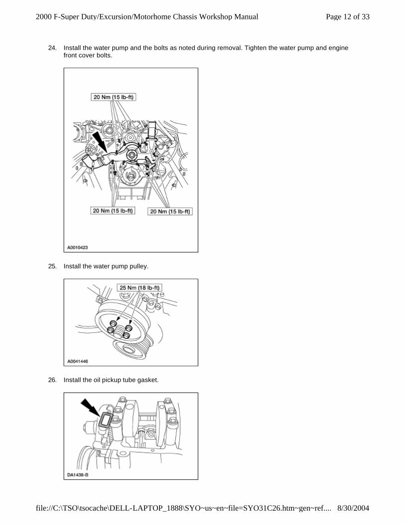
24. Install the water pump and the bolts as noted during removal. Tighten the water pump and engine front cover bolts.
25. Install the water pump pulley.
26. Install the oil pickup tube gasket.
Page 12 of 332000 F-Super Duty/Excursion/Motorhome Chassis Workshop Manual
8/30/2004file://C:\TSO\tsocache\DELL-LAPTOP_1888\SYO~us~en~file=SYO31C26.htm~gen~ref....

27. Install the oil pickup tube. 1. Position the oil pickup tube and install the bolts. 2. Align the support bracket and install the nut.
28. NOTE: The oil pan must be installed within three minutes after applying the RTV sealant. If the oil pan is not installed within three minutes, the RTV sealant must be removed and a new bead of RTV sealant must be applied.
NOTE: A larger amount of RTV Silicone Sealant will be required on the front and rear areas of the oil pan.
Apply RTV Silicone Sealant F5TZ-19G204-AB or equivalent meeting Ford specification NAVSTR SLR, to the oil pan.
1. Apply a bead of sealant. 2. Apply a bead of sealant.
29. Install the oil pan. 1. Position the oil pan. 2. Install the oil pan bolts.
Page 13 of 332000 F-Super Duty/Excursion/Motorhome Chassis Workshop Manual
8/30/2004file://C:\TSO\tsocache\DELL-LAPTOP_1888\SYO~us~en~file=SYO31C26.htm~gen~ref....

30. NOTE: Both the left and the right engine mounts are installed the same way. Only the left side is shown.
Install the engine mounts. 1. Position the engine mounts. 2. Install the three bolts.
31. CAUTION: The inner gerotor must be installed with the words "Out" or "Damper" facing away from the engine.
NOTE: The outer gerotor gear must be installed into the oil pump housing before the oil pump is installed onto the engine front cover.
Install the oil pump inner gerotor.
32. Install the oil pump. 1. Lubricate the oil pump with clean engine oil. With a new O-ring, position the oil pump housing
with the outer gerotors onto the engine front cover. 2. Install the four bolts.
Page 14 of 332000 F-Super Duty/Excursion/Motorhome Chassis Workshop Manual
8/30/2004file://C:\TSO\tsocache\DELL-LAPTOP_1888\SYO~us~en~file=SYO31C26.htm~gen~ref....

33. Install the crankshaft vibration damper. 1. Using a Damper Remover/Replacer Tool, install the vibration damper onto the crankshaft. 2. Install the vibration damper bolt and washer. l Apply RTV Silicone Sealant, F5TZ-19G204-AB or equivalent meeting Ford specification
NAVSTR SLR to the washer.
34. Install the camshaft position (CMP) sensor. 1. Install the sensor into the engine front cover. 2. Install the bolt. 3. Tighten bolt to specification.
35. Install the exhaust back pressure sensor and tube. 1. Position the sensor and tube. 2. Install the nut.
Page 15 of 332000 F-Super Duty/Excursion/Motorhome Chassis Workshop Manual
8/30/2004file://C:\TSO\tsocache\DELL-LAPTOP_1888\SYO~us~en~file=SYO31C26.htm~gen~ref....

36. Install the high pressure oil pump. 1. With a new gasket, position the high pressure oil pump. 2. Install the bolts.
37. CAUTION: Make sure that the drive gear is fully seated on the high-pressure oil pump before installing the bolt and washer. Otherwise, the drive gear may not seat correctly, causing binding or slippage resulting in a no oil flow condition.
Install the high pressure oil pump drive gear. l Position the drive gear onto the high pressure oil pump. Install the bolt and washer.
38. Check the high pressure oil pump drive gear backlash. 1. Position the special tool onto the drive gear. 2. Rock the drive gear and record the reading.
n Install a new drive gear if not within specification.
Page 16 of 332000 F-Super Duty/Excursion/Motorhome Chassis Workshop Manual
8/30/2004file://C:\TSO\tsocache\DELL-LAPTOP_1888\SYO~us~en~file=SYO31C26.htm~gen~ref....
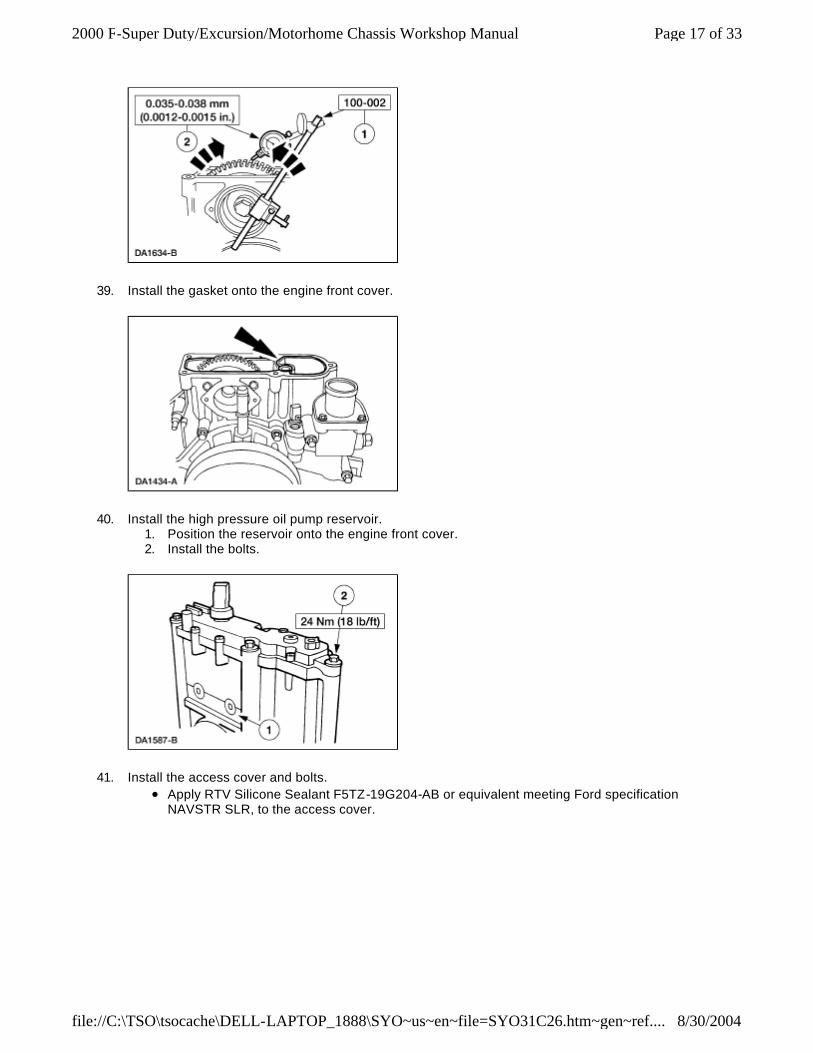
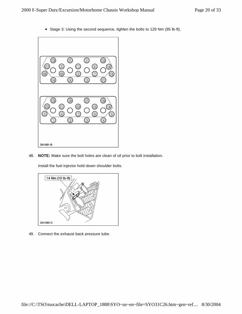
39. Install the gasket onto the engine front cover.
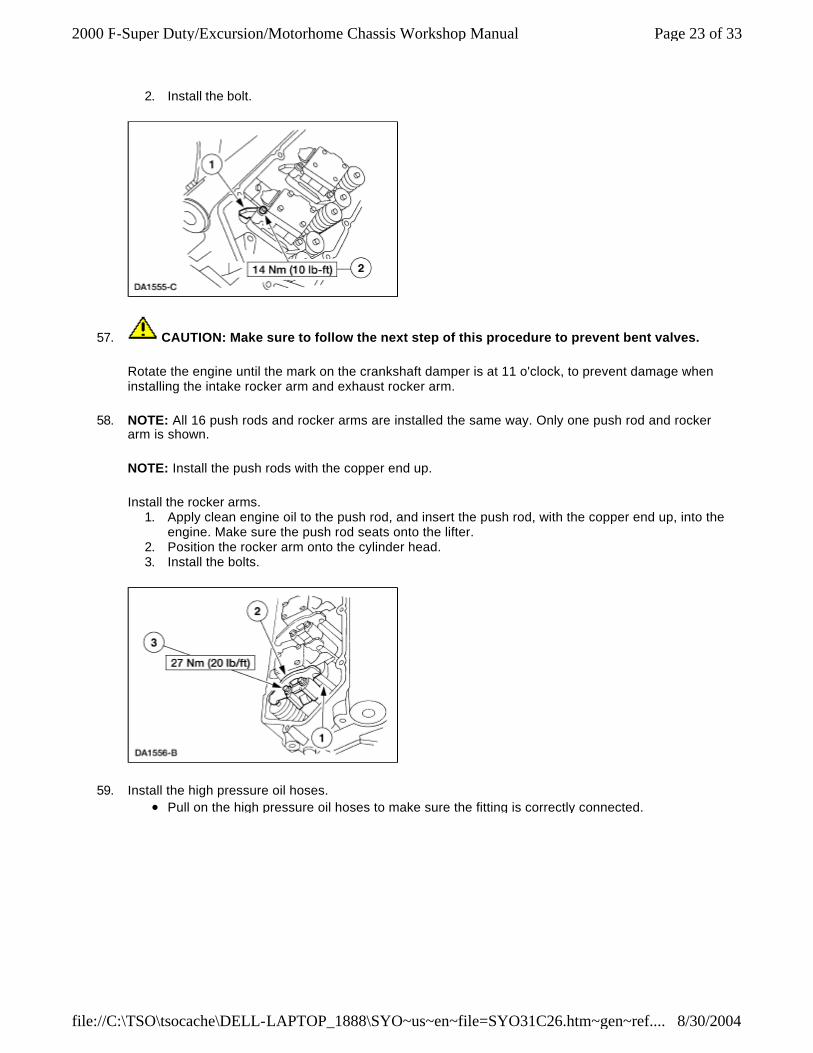
40. Install the high pressure oil pump reservoir. 1. Position the reservoir onto the engine front cover. 2. Install the bolts.
41. Install the access cover and bolts. l Apply RTV Silicone Sealant F5TZ-19G204-AB or equivalent meeting Ford specification
NAVSTR SLR, to the access cover.
Page 17 of 332000 F-Super Duty/Excursion/Motorhome Chassis Workshop Manual
8/30/2004file://C:\TSO\tsocache\DELL-LAPTOP_1888\SYO~us~en~file=SYO31C26.htm~gen~ref....

42. Install the fuel filter/water separator assembly. 1. Position the fuel filter/water separator assembly. 2. Install the bolts.
43. Position the fuel drain tube and install the bolt.
44. Install the engine oil cooler. 1. Position the two header gaskets and the oil cooler. 2. Install the five bolts.
Page 18 of 332000 F-Super Duty/Excursion/Motorhome Chassis Workshop Manual
8/30/2004file://C:\TSO\tsocache\DELL-LAPTOP_1888\SYO~us~en~file=SYO31C26.htm~gen~ref....

45. Position the cylinder head gasket onto the engine block.
46. NOTE: Both the left side and right side heads are installed in the same way. Only the right side cylinder head is shown.
Using the special tools, install the cylinder head.
47. CAUTION: Do not use too much engine oil on the threads of the cylinder head bolts, or damage to the threads and poor sealing can result. Do not use anti-seize compounds, grease or any other lubricants except engine oil on the cylinder head bolt threads because they will affect the true torque value reading of the bolts.
Install the 18 cylinder head bolts. l Lightly lubricate the cylinder head bolt threads and flanges with clean engine oil. l Tighten the bolts in the sequence shown in three stages. l Stage 1: Using the first sequence, tighten the bolts to 88 Nm (65 lb-ft). l Stage 2: Using the first sequence, tighten the bolts to 115 Nm (85 lb-ft).
Page 19 of 332000 F-Super Duty/Excursion/Motorhome Chassis Workshop Manual
8/30/2004file://C:\TSO\tsocache\DELL-LAPTOP_1888\SYO~us~en~file=SYO31C26.htm~gen~ref....
l Stage 3: Using the second sequence, tighten the bolts to 129 Nm (95 lb-ft).
48. NOTE: Make sure the bolt holes are clean of oil prior to bolt installation.
Install the fuel injector hold-down shoulder bolts.
49. Connect the exhaust back pressure tube.
Page 20 of 332000 F-Super Duty/Excursion/Motorhome Chassis Workshop Manual
8/30/2004file://C:\TSO\tsocache\DELL-LAPTOP_1888\SYO~us~en~file=SYO31C26.htm~gen~ref....

50. Install the fuel tube. 1. Position the fuel tube clamp onto the right hand cylinder head stud bolt. 2. Install the nut.
51. Install the fuel supply tubes onto the cylinder heads.
52. Install the glow plugs.
Page 21 of 332000 F-Super Duty/Excursion/Motorhome Chassis Workshop Manual
8/30/2004file://C:\TSO\tsocache\DELL-LAPTOP_1888\SYO~us~en~file=SYO31C26.htm~gen~ref....

53. Install new O-ring seals and new copper gaskets on the fuel injectors. Lubricate fuel injectors, O-ring seals and copper gaskets with clean engine oil.
54. NOTE: All eight fuel injectors are installed the same way. Only one fuel injector is shown.
NOTE: Thoroughly coat the fuel injector O-ring seal with clean engine oil to aid in installation.
Install the fuel injector. 1. Insert the fuel injector into the cylinder head fuel injector bore. 2. Using the special tool, seat the fuel injector into the cylinder head fuel injector bore.
55. NOTE: Make sure the bolt holes are clean of oil prior to bolt installation.
Install the fuel injector hold-down bolts.
56. NOTE: All eight oil deflectors are installed the same way. Only one oil deflector is shown.
Install the oil deflector. 1. Position the oil deflector.
Page 22 of 332000 F-Super Duty/Excursion/Motorhome Chassis Workshop Manual
8/30/2004file://C:\TSO\tsocache\DELL-LAPTOP_1888\SYO~us~en~file=SYO31C26.htm~gen~ref....
2. Install the bolt.
57. CAUTION: Make sure to follow the next step of this procedure to prevent bent valves.
Rotate the engine until the mark on the crankshaft damper is at 11 o'clock, to prevent damage when installing the intake rocker arm and exhaust rocker arm.
58. NOTE: All 16 push rods and rocker arms are installed the same way. Only one push rod and rocker arm is shown.
NOTE: Install the push rods with the copper end up.
Install the rocker arms. 1. Apply clean engine oil to the push rod, and insert the push rod, with the copper end up, into the
engine. Make sure the push rod seats onto the lifter. 2. Position the rocker arm onto the cylinder head. 3. Install the bolts.
59. Install the high pressure oil hoses. l Pull on the high pressure oil hoses to make sure the fitting is correctly connected.
Page 23 of 332000 F-Super Duty/Excursion/Motorhome Chassis Workshop Manual
8/30/2004file://C:\TSO\tsocache\DELL-LAPTOP_1888\SYO~us~en~file=SYO31C26.htm~gen~ref....

60. NOTE: Both the left side and the right side valve cover gaskets are installed the same way. Only the right side gasket is shown.
Install the valve cover gasket. 1. Position the gasket onto the cylinder head. 2. Install the four glow plug electrical leads. 3. Install the four fuel injector electrical connectors.
61. NOTE: Both the left side and the right side valve covers are installed the same way. Only the right side valve cover is shown.
Install the valve cover. 1. Position the valve cover onto the cylinder head. 2. Install the bolts.
62. Install the oil level indicator tube. 1. Position the indicator tube into the oil pan. 2. Position the indicator tube retainer into the stud bolt. 3. Install the nut.
Page 24 of 332000 F-Super Duty/Excursion/Motorhome Chassis Workshop Manual
8/30/2004file://C:\TSO\tsocache\DELL-LAPTOP_1888\SYO~us~en~file=SYO31C26.htm~gen~ref....

63. Install the air inlet duct tube mounting bracket.
64. Install two new O-ring seals onto the engine.
65. Install the turbocharger pedestal. 1. Position the turbocharger pedestal. 2. Install the bolts.
66. Position the engine harness onto the engine.
67. Connect the camshaft position (CMP) sensor electrical connector.
Page 25 of 332000 F-Super Duty/Excursion/Motorhome Chassis Workshop Manual
8/30/2004file://C:\TSO\tsocache\DELL-LAPTOP_1888\SYO~us~en~file=SYO31C26.htm~gen~ref....

68. Position the engine harness and attach the pushpin retainer.
69. Install the glow plug relay/intake air heater relay and bracket assembly and two nuts. Connect the electrical leads.
l Install the cover.
70. Connect the exhaust back pressure sensor and engine coolant temperature (ECT) sensor electrical connectors.
Page 26 of 332000 F-Super Duty/Excursion/Motorhome Chassis Workshop Manual
8/30/2004file://C:\TSO\tsocache\DELL-LAPTOP_1888\SYO~us~en~file=SYO31C26.htm~gen~ref....

71. Connect the engine oil pressure sensor electrical connector.
72. Connect the engine oil temperature sensor electrical connector.
73. Connect the injection oil pressure sensor electrical connector.
Page 27 of 332000 F-Super Duty/Excursion/Motorhome Chassis Workshop Manual
8/30/2004file://C:\TSO\tsocache\DELL-LAPTOP_1888\SYO~us~en~file=SYO31C26.htm~gen~ref....

74. Connect the injection pressure regulator (IPR) electrical connector.
75. Connect the fuel heater/water separator electrical connector.
76. Connect the exhaust back pressure solenoid electrical connector.
77. NOTE: Both the left side and the right side nine pin connectors are installed the same way. Only the right side is shown.
Connect the fuel injector/glow plug nine pin connector, engage the retaining clip.
Page 28 of 332000 F-Super Duty/Excursion/Motorhome Chassis Workshop Manual
8/30/2004file://C:\TSO\tsocache\DELL-LAPTOP_1888\SYO~us~en~file=SYO31C26.htm~gen~ref....

78. Install the exhaust adapter pipes. 1. Position the pipes. 2. Install the four mounting bolts and nuts.
Vehicles with air conditioning
79. Install the A/C compressor mounting bracket and the mounting bolts.
Page 29 of 332000 F-Super Duty/Excursion/Motorhome Chassis Workshop Manual
8/30/2004file://C:\TSO\tsocache\DELL-LAPTOP_1888\SYO~us~en~file=SYO31C26.htm~gen~ref....

80. Remove the engine from the work stand and remove the engine mounting bracket.
81. Install the engine adapter plate. 1. Install the adapter plate. 2. Install the retainer.
82. NOTE: The crankshaft rear oil seal and wear sleeve are installed as an assembly.
Apply RTV Silicone Sealant F5TZ-19G204-AB, or equivalent meeting Ford specification NAVSTR SLR to the rear oil seal retaining ring and the crankshaft rear oil seal.
83. Using the special tool, install the crankshaft rear oil seal.
Page 30 of 332000 F-Super Duty/Excursion/Motorhome Chassis Workshop Manual
8/30/2004file://C:\TSO\tsocache\DELL-LAPTOP_1888\SYO~us~en~file=SYO31C26.htm~gen~ref....

Vehicles with automatic transmission
84. Install the flexplate, spacers and bolts.
Vehicles with manual transmission
85. Install the flywheel. 1. Install the guide studs. 2. Install the flywheel and ring gear assembly, and the reinforcing ring (7.3L). 3. Install the bolts. 4. Remove the guide studs. Install and tighten the bolts to specification.
86. CAUTION: Sometimes, when removing the transmission, the input shaft will remove a considerable amount of lubricant from the transmission input shaft pilot bearing.
Lubricate the transmission input shaft pilot bearing, as necessary. l Use High-Temperature 4x4 Front Axle and Wheel Bearing Grease E8TZ-19590-A or
equivalent meeting Ford specification ESA-M1C198-A.
Page 31 of 332000 F-Super Duty/Excursion/Motorhome Chassis Workshop Manual
8/30/2004file://C:\TSO\tsocache\DELL-LAPTOP_1888\SYO~us~en~file=SYO31C26.htm~gen~ref....
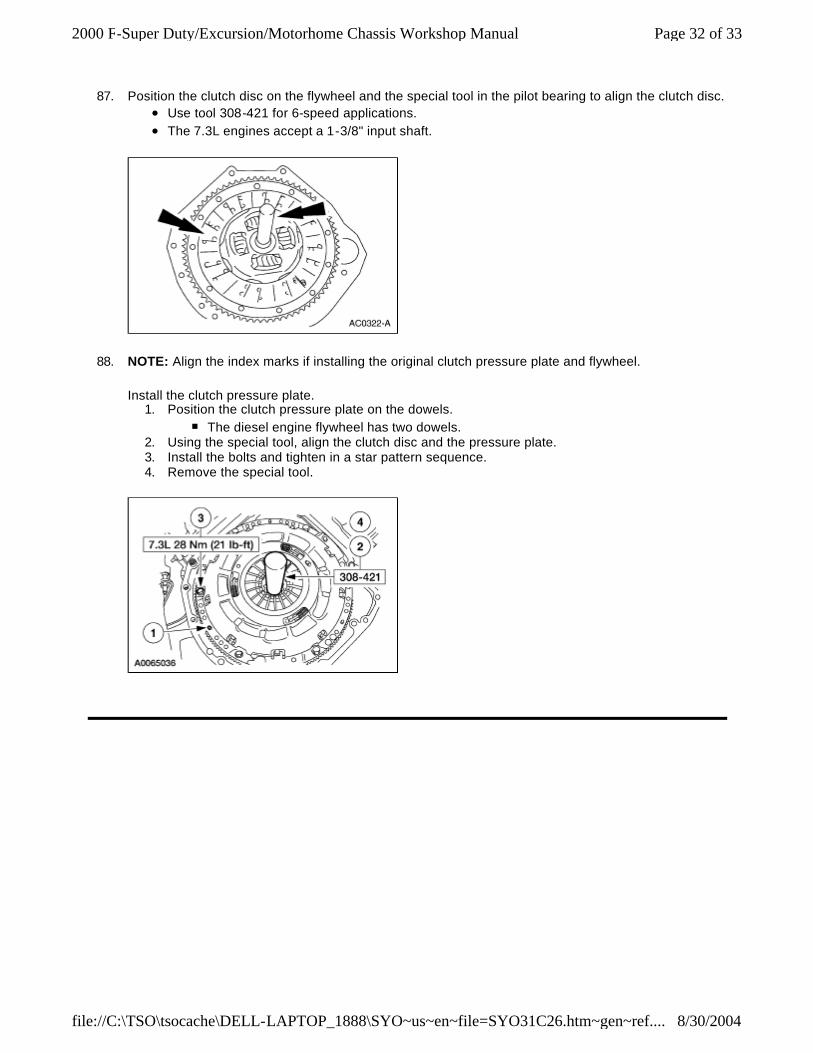
87. Position the clutch disc on the flywheel and the special tool in the pilot bearing to align the clutch disc. l Use tool 308-421 for 6-speed applications. l The 7.3L engines accept a 1-3/8" input shaft.
88. NOTE: Align the index marks if installing the original clutch pressure plate and flywheel.
Install the clutch pressure plate. 1. Position the clutch pressure plate on the dowels.
n The diesel engine flywheel has two dowels. 2. Using the special tool, align the clutch disc and the pressure plate. 3. Install the bolts and tighten in a star pattern sequence. 4. Remove the special tool.
Page 32 of 332000 F-Super Duty/Excursion/Motorhome Chassis Workshop Manual
8/30/2004file://C:\TSO\tsocache\DELL-LAPTOP_1888\SYO~us~en~file=SYO31C26.htm~gen~ref....

Page 33 of 332000 F-Super Duty/Excursion/Motorhome Chassis Workshop Manual
8/30/2004file://C:\TSO\tsocache\DELL-LAPTOP_1888\SYO~us~en~file=SYO31C26.htm~gen~ref....