
200 Cubic Feet Maximum CLASS I APPLICATIONS M · PDF fileCLASS I APPLICATIONS 200 Cubic Feet...
32
MODEL 2004 TYPE X RAPID EXCHANGE ® PURGING SYSTEM INSTALLATION & OPERATION MANUAL CLASS I APPLICATIONS 200 Cubic Feet Maximum FA Style (Fully Automatic) STD Style (Standard) Pepperl+Fuchs ® Inc. • Telephone (330) 486-0002 • FAX (330) 425-4607 • E-mail: [email protected] • www.bebcoeps.com "Terms & Conditions of Sale" information is printed on every order acknowledgement; copies are available upon request. We reserve the right to make modifications and no guarantee of the accuracy of the information contained herein is given. © 2004 Pepperl+Fuchs ® Inc., Twinsburg, Ohio 512592, Dwg No. 129-0213 (Supercedes 2004-IOM) Printed in U.S.A BEBCO EPS
Transcript of 200 Cubic Feet Maximum CLASS I APPLICATIONS M · PDF fileCLASS I APPLICATIONS 200 Cubic Feet...
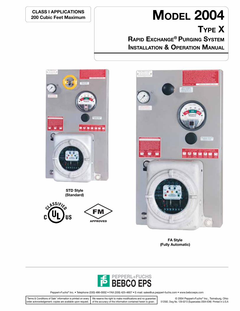
MODEL 2004TYPE X
RAPID EXCHANGE® PURGING SYSTEM
INSTALLATION & OPERATION MANUAL
CLASS I APPLICATIONS200 Cubic Feet Maximum
FA Style(Fully Automatic)
STD Style(Standard)
Pepperl+Fuchs® Inc. • Telephone (330) 486-0002 • FAX (330) 425-4607 • E-mail: [email protected] • www.bebcoeps.com
"Terms & Conditions of Sale" information is printed on everyorder acknowledgement; copies are available upon request.
We reserve the right to make modifications and no guaranteeof the accuracy of the information contained herein is given.
© 2004 Pepperl+Fuchs® Inc., Twinsburg, Ohio512592, Dwg No. 129-0213 (Supercedes 2004-IOM) Printed in U.S.A
BEBCO EPS

BEBCO EPSPepperl+Fuchs®Inc. • 1600 Enterprise Parkway • Twinsburg, Ohio 44087-2245 • www.bebcoeps.comTelephone (330) 486-0002 • FAX (330) 425-4607 • E-Mail: [email protected]
Page 15 Electrical Supply RequirementsGeneral Wiring Requirements, EPCU Power & AlarmSignal, Enclosure Wiring Methods & Connections
Page 16 Electrical Power Control UnitGeneral Layout & Conduit Connection Points
Page 17 EPCU Power RatingPower Rating Nameplate, Assembled Electronics
Page 18 Electrical & Pneumatic DiagramsLH, RH, TM, BM, WM, FM, & PM Configurations
Page 19 Conduit InstallationEPCU Electrical Conduit, Optional Intrinsic Safety BarrierConduit and EPCU Conduit Connection Parts
Page 20 Power Modules & Wiring DiagramEPCU 120/220 VAC & 24-48 VDC Power Modules
Page 21 Logic Module & Barrier WiringOptional ISB Wiring Requirements & Diagram,EPCU Power Control Modes
Page 22 Barriers & Field AdjustmentsISB Description & Factory Programming, LED DisplayIndicators,Timer Functions & Settings
Page 23 Set-Up ProcedureRapid Exchange® Purging Set-up
Page 24 Set-Up Procedure (cont.)Rapid Exchange® Purging Set-up
Page 25 Operating SequenceClass I Purging Operation
Page 26 Trouble - Shooting ProceduresPage 27 Warranty and Liability Statements
Warranty Notes, General Terms, Limitations
Pages 28 & 29 System Maintenance
Pages 30 & 31 Customer Notes
Page 32 Systems Identification & Application Information
Important Notes
One (1) permanent file copy and one (1) operations copy of this Manualmust be studied and retained by the operator of this System. User’sAgents are responsible for transferring this Manual to the user, prior tostart-up.
The contents of this manual have been arranged to allow the use of thisproduct as a stand-alone device on equipment and enclosuressupplied by the user or its agents. The Manual’s parameters encompassboth National Fire Protection Association (NFPA) requirements andPepperl+Fuchs requirements. Pepperl+Fuchs therefore acknowledgesthe use of NFPA 496 as a guideline, that we have enhanced certainNFPA requirements and that additional information has been compiledto complete this document. The Manual is intended as a completeguide and must be considered, unless specifically stated otherwise,that all directives contained herein are Pepperl+Fuchs requirementsfor safe, practical and efficient use of this product.
This System is not intended for use to protect enclosures or deviceswhich contain ignitable concentrations of gases or vapors. Thisexclusion generally applies to process or product analyzing systemsequipment.
All specifications are subject to change without notice.
Table of Contents
Page 2 System Purpose and DescriptionPurpose, System Description, Important Notes
Page 3 Identifying Your SystemDefines specific features of the system
Page 4 General InformationSystem & Material Specifications, System Accessories,Spare Parts, Tools & Test Equipment
Page 5 Enclosure and Device DesignDesign Requirements, Adjacent Enclosures, DeviceVentilation, Temperature Limitations
Page 6 Installation OverviewInstallation Diagram
Page 7 Getting StartedEstablishing Connection Sizes, Determining EnclosureInlet & Outlet Connection Locations
Page 8 System MountingLH, RH, TM, BM & WM Configurations,FM & PM Configurations
Page 9 Hardware MountingEnclosure Protection Vent, Warning Nameplates
Page 10 Mounting Plate DimensionsMounting Plate Dimension Diagrams
Page 11 Mounting Plate Dimensions (cont.)Mounting Plate Dimension Diagrams
Page 12 Pneumatic Tubing RequirementsProtective Gas Supply Requirements, PneumaticConnection Requirements
Page 13 Tubing Connection PointsLH, RH, TM, BM, WM, FM, & PM Configurations
Page 14 Tubing InstallationLH, RH, TM, BM, WM, FM & PM Tubing Configurations
Purpose
The Pepperl+Fuchs Enclosure Protection System’s purpose is toallow the use of general purpose or nonrated electrical or electronicdevices, with exception to devices which produce excessive heat,utilize combustible gas, or expose arcing contacts to the hazardousatmosphere, in Type 4 or 12 enclosures in the place of explosion proofType 7 enclosures.
Description
Model 2004 Rapid Exchange® purging system operates on a supplyof compressed instrument air or inert gas. It regulates and monitorspressure of sealed (protected) enclosure(s), in order to rapidly removeand prevent flammable vapor accumulation within the enclosure(s).The system is designed to accomplish four air exchanges andmaintain a "safe" (0.25") pressure on one or more enclosures notexceeding a total volume of two hundred cubic feet. An EPV-4Enclosure Protection Vent is required for proper operation. In addition,the system includes an electrical power control unit (EPCU) thatmonitors system operation and controls enclosure power. All start-up requirements must be satisfied before the EPCU will energizepower to the enclosure(s). This process reduces the Hazardous(Classified) Area Rating within the enclosure(s), in accordance with theNEC - NFPA 70, Article 500, NFPA 496 and ISA 12.4.

BEBCO EPSPepperl+Fuchs®Inc. • 1600 Enterprise Parkway • Twinsburg, Ohio 44087-2245 • www.bebcoeps.comTelephone (330) 486-0002 • FAX (330) 425-4607 • E-Mail: [email protected] 3
This Enclosure Protection System is offered in various styles. For proper installation and operation, examine the SystemModel Number Nameplate to identify the System Style, Area Classification, and Type, as noted below.
To assist you through the installation and operation of your Rapid Exchange® purge system, Pepperl+Fuchs hasprovided the following information boxes throughout this manual. This information is intended to clarify certain
differences between the model styles and configurations and to warn the user / installer of potential dangers of electricalshock or enclosure over pressurization.
Model 2004-STD-CI Type X200 CUBIC FEET MAXIMUM ENCLOSURE VOLUME
CLASS I, DIVISION 1, GROUPS C & D TO NONHAZARDOUS
PURGE CONTROL FOR USE IN HAZARDOUS LOCATIONS. CLASSIFIED BY UNDERWRITERS LABORATORIESINC . ® IN ACCORDANCE WITH THE NATIONAL FIRE PROTECTION ASSOCIATIONSTANDARD FOR PURGED AND PRESSURIZED ENCLOSURES FOR ELECTRICAL EQUIPMENT
NFPA 496- 2003 7L93
APPROVED BY FACTORY MUTUAL AS ASSOCIATED TYPE X PRESSURIZATION CONTROLEQUIPMENT FOR USE IN HAZARDOUS LOCATIONS. REDUCES THE INTERNAL AREAOF A CONNECTED ENCLOSURE IN ACCORDANCE WITH DRAWING NUMBER 129-0213.
MAXIMUMTOTAL
ENCLOSUREVOLUME
Defines totalprotected
enclosure(s)volume capacity for
this particularsystem. Totalenclosure(s)
volume must becalculated without
regard forconsumed volume
SERIESMODEL NUMBER
Identifying Your System
HELPFUL HINT WARNING
T3C
SYSTEM TYPE
Type X
Reduces the internalenclosure area
Division rating fromDivision 1 to
nonhazardous
AREACLASSIFICATION
Defines the areaclassification for
which the system issuitable for operation
IMPORTANT NOTE
APPROVALMARKINGS &DEFINITIONS
Identifies the currentthird party approvals
for this system
SYSTEM STYLE
STD - StandardSA - Semi-AutomaticFA - Fully Automatic
SYSTEM CLASS RATING
Defines Class & Group rating forProtection System’s method of use
CI - Class I Purging system (Groups C&D)
IB - Class I Purging system (Group B)
BEBCO EPSPepperl+Fuchs®Inc. • 1600 Enterprise Parkway • Twinsburg, Ohio 44087-2245 • www.bebcoeps.comTelephone (330) 486-0002 • FAX (330) 425-4607 • E-Mail: [email protected]
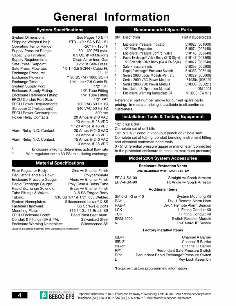
System Specifications
System Dimensions: See Pages 10 & 11Shipping Weight (Lbs.): STD - 49 / SA & FA - 51Operating Temp. Range: -20° F - 120° FSupply Pressure Range: 80 - 120 PSI max.Capacity & Filtration: 8.5 Oz. @ 40 MicronsSupply Requirements: Clean Air or Inert GasSafe Press. Setpoint: 0.25" @ Safe Press.Safe Press. Flowrate: * 0.1 - 3.5 SCFH / Cubic Ft.Exchange Pressure: 3" - 5"Exchange Flowrate: ** 30 SCFM / 1800 SCFHExchange Time: 1 Minute / 7.5 Cubic Ft.System Supply Port: 1/2" FPTEnclosure Supply Fitting: 1/2" Tube FittingEnclosure Reference Fitting: 1/4" Tube FittingEPCU Conduit Port Size: 1/2" FPTEPCU Power Requirements: 120 VAC 60 Hz 1Ø(European 220 voltage only) 240 VAC 50 Hz 1ØEPCU Power Consumption: 500 mAPower Relay Contacts: 20 Amps @ 240 VAC
20 Amps @ 28 VDC*** 20 Amps @ 48 VDC
Alarm Relay N.O. Contact: 20 Amps @ 240 VAC20 Amps @ 28 VDC
Alarm Relay N.C. Contact: 15 Amps @ 240 VAC10 Amps @ 28 VDC
* Enclosure integrity determines actual flow rate** With regulator set to 80 PSI min. during exchange
Material Specifications
Filter Regulator Body: Zinc w/ Enamel FinishRegulator Handle & Bowl: PolycarbonateEnclosure Pressure Gauge: Alum. w/ Enamel FinishRapid Exchange Gauge: Poly Case & Brass TubeRapid Exchange Solenoid: Brass w/ Enamel FinishTube Fittings & Valves: 316 SS Forged BodyTubing: 316 SS 1/4" & 1/2" .035 WeldedSystem Nameplates: Silkscreened Lexan® & SSFastener Hardware: SS Screws & BoltsMounting Plate: 316 14 Ga #3 Brush SSEPCU Enclosure Body: Bead Blast Cast Alum.Conduit & Fittings (SA & FA): Galvanized SteelEnclosure Warning Nameplate: Silkscreened SSLexan® is a registered trademark of the General Electric Corporation
Recommended Spare Parts
Qty Description Part # (supercedes)
1 Enclosure Pressure Indicator 510023 (001000)1 1/2" Filter Regulator 510074 (002140)1 Enclosure Pressure Control Valve 510145 (003840)1 Rapid Exchange® Valve Body (STD Style) 510147 (003860)1 1/2" Solenoid Valve Body (SA & FA Style) 510077 (002240)1 Safe Pressure Switch 510356 (005200)1 Rapid Exchange® Pressure Switch 510358 (005210)1 Series 2000 Logic Module-Ver. 2.0 510279 (005000)1 Series 2000 VAC Power Module 510304 (0050201 Series 2000 VDC Power Module 510305 (005021)1 Installation & Operation Manual IOM 20041 Enclosure Warning Nameplate-CI 513008 (EWN-1)
Reference part number above for current spare partspricing. Immediate pricing is available to all confirmedcustomers.
Installation Tools & Testing Equipment
1/2" chuck drillComplete set of drill bits1/2" & 1 1/2" conduit knockout punch or 2" hole sawComplete set of tubing, conduit bending, instrument fittingand electrical craftsman hand tools0 - 5" differential pressure gauge or manometer (connectedto the protected enclosure to measure maximum pressure)
Model 2004 System Accessories
Enclosure Protection VentsONE REQUIRED WITH EACH SYSTEM
EPV-4-SA-00 Straight w/ Spark ArrestorEPV-4-SA-90 Rt Angle w/ Spark Arrestor
Additional Items
SMK -2, -3 or -10 System Mounting KitRAH Div. 1 Remote Alarm HornRAB-1 Div. 1 Remote Alarm BeaconLCK L Fitting Conduit KitTCK T Fitting Conduit KitSRM-4000 Switch Resistor ModuleNJ... P+F NAMUR Sensor
Factory Installed Items
ISB-1 Channel A BarrierISB-2* Channel B BarrierISB-3* Channel C BarrierRP1 Redundant Safe Pressure SwitchRP2 Redundant Rapid Exchange® Pressure SwitchL Key Lock Assembly
*Requires custom programming information
General Information

BEBCO EPSPepperl+Fuchs®Inc. • 1600 Enterprise Parkway • Twinsburg, Ohio 44087-2245 • www.bebcoeps.comTelephone (330) 486-0002 • FAX (330) 425-4607 • E-Mail: [email protected] 5
Enclosure Design Requirements
1. All windows must be shatterproof and sized as small aspossible.
2. All NFPA 496 required markings must be placed on ornear all enclosure doors and covers.
3. The enclosure must withstand an internal pressure offive (5) inches of water without sustaining permanentdeformation and resist all corrosive elements in thesurrounding atmosphere.
4. All lightweight objects in the enclosure, such as paper orinsulation, must be firmly secured.
5. The enclosure should be constructed from materialssuch as metal or anti-static polycarbonate to meet orexceed Type 4 or 12 performance requirements, butdoes not require third party approval.
6. The installation of obstructions or other barriers whichblock or impede the flow of protective gas must beavoided.
7. The creation of air pockets or other areas which trapflammable gases within the enclosure or devices mustbe avoided.
8. The enclosure should be located in an area whereimpact hazards are minimal.
9. If the enclosure is nonmetallic and contains equipmentwhich utilizes or switches power loads greater than 2500VA, it must be constructed from substantiallynoncombustible materials, such as materials designedto meet or exceed ANSI/UL94 ratings of 94 V-0 or 94 5V.
Adjacent Enclosures
1. Adjacent enclosures must be protected by one of thefollowing means:
a) purged or pressurized in series with the protectedenclosure;
b) purged or pressurized separately; or
c) protected by other means; e.g. explosion proofenclosures, hermetically sealed devices or intrinsicsafe circuits.
2. Adjacent purged or pressurized enclosures must bedesigned to meet all construction requirements above.
Enclosure & Device DesignTotal Volume Calculation
1. The total volume of all pressurized enclosures, devicesand wireways must be considered.
2. All enclosure, device and wireway volumes must becalculated without consideration of internally consumedspace.
Device Ventilation
1. Enclosed devices within the protected enclosure whichdo not exceed 1.22 cubic inches of free volume do notrequire ventilation to the protected enclosure.
2. If the free volume of an internal device exceeds 1.22cubic inches it must be protected by one of the followingmeans:
a) ventilated on the top and bottom sides with one (1)square inch of opening for each four hundred (400)cubic inches of volume within the internal protectedenclosure, at a minimum diameter of one (1) quarterinch;
b) purged in series with the protected enclosure or bepurged separately; or
c) protected by other means; e.g. explosion proofdevices, hermetically sealed housings or intrinsicsafe circuits.
Temperature Limitations
1. The enclosure must have no surface area which exceeds80 percent of the flammable or ignitable substance’sauto-ignition temperature.
2. Internal devices which exceed this temperature must beprotected by one of the following manners.
a) The device is enclosed in a chamber which is cUL orFM listed as a hermetically sealed device whichprohibits the entrance of flammable or ignitablesubstance, and maintains a surface temperaturebelow temperature limits.
b) It can be proven by testing that the devices will notignite the substance involved.
c) The device is purged in a separate enclosure thatbears an ETW (Enclosure Temperature WarningNameplate). Devices may only be accessed afterpower has been removed and the device has beenallowed to cool to safe temperature, or the area ispositively known to be nonhazardous.

BEBCO EPSPepperl+Fuchs®Inc. • 1600 Enterprise Parkway • Twinsburg, Ohio 44087-2245 • www.bebcoeps.comTelephone (330) 486-0002 • FAX (330) 425-4607 • E-Mail: [email protected]
Installation OverviewTypical Left Hand Configuration Installation Diagram
Model 2002-STD-CI-LH Shown
ENCLOSUREPROTECTION
VENT(required)
PROTECTEDENCLOSURE
ENCLOSURESUPPLY TUBING
ENCLOSUREREFERENCE
TUBING
ENCLOSURECONNECTION
FITTINGS
ENCLOSUREWARNING
NAMEPLATE
ENCLOSUREPROTECTION
SYSTEM
SYSTEMSUPPLY TUBING
EPCU BREATHERDRAIN FITTING
EPCU POWER & ALARM SIGNALWIRING CONDUIT & SEAL
PROTECTIVEGAS SUPPLY
SERVICEVALVE

BEBCO EPSPepperl+Fuchs®Inc. • 1600 Enterprise Parkway • Twinsburg, Ohio 44087-2245 • www.bebcoeps.comTelephone (330) 486-0002 • FAX (330) 425-4607 • E-Mail: [email protected] 7
Getting StartedEstablishing Connection Sizes, Lengths & Bends
TYPICAL SINGLE PROTECTED ENCLOSURE CONNECTIONS
PROTECTEDENCLOSURE
C
B
ENCLOSURE PROTECTION VENT(Required)
E
SUPPLY
REFERENCE
1/2"PROTECTIVEGAS SUPPLY
HEADER
ENCLOSUREPROTECTION
SYSTEM
Maximum Tubing / Pipe Length andMaximum Number of Bends / Elbows
1/2" O.D. TubingFully Reamed
20 Feet10 Bends
1/2" O.D. TubingFully Reamed
Description
*Tubing or Pipe Diameter
EnclosureSupply
SystemSupply Tubing
EnclosureReference
1/4" O.D. TubingFully Reamed
5 Feet5 Bends
20 Feet10 Bends
Multi - EnclosureConnections
1 1/2" I.D. PipeFully Reamed
10 Feet5 Elbows
Optional RemoteVenting
1 1/2" I.D. PipeFully Reamed
30 Feet5 Elbows
A B EDC
INLET
ENCLOSUREPROTECTION
SYSTEM
PROTECTEDENCLOSURE
PROTECTEDENCLOSURE
D
SUPPLY
REFERENCE
INLET
Connections for Heavier thanAir Gases and Vapors
OUTLET
OUTLET
B
TYPICAL MULTIPLE PROTECTED ENCLOSURE CONNECTIONS
1/2"PROTECTIVEGAS SUPPLY
HEADER
A
A
D
C
Connections for Lighter thanAir Gases and Vapors
HELPFUL HINTS
If flammable gases are lighter than air, the inletconnection to each enclosure must enter near abottom corner. The outlet connection, for an optionalenclosure protection vent or piping to an adjacentprotected enclosure, must exit near an extremeopposite top corner. See diagrams to the left.
If flammable gases are heavier than air, inlet andoutlet connections must be reversed.
In all cases, the most prevalent gas must determinethe location of inlet and outlet connections.
Determining Enclosure Inlet & Outlet Connection Locations
HELPFUL HINTS
To ensure adequate protective gas flow to protected enclosure(s), all piping and tubing must be fully reamed.
Precautions must be taken to prevent crimping and other damage to protective gas piping and tubing.
When protecting multiple enclosures with a single enclosure protection system, the enclosures must beconnected in series from the smallest to the largest to ensure adequate protective gas flow.
PROTECTEDENCLOSURE
*NOTE: Tube and pipe sizes are trade sizes and are not equal in inside diameter.DO NOT substitute tube for pipe with same trade size.

BEBCO EPSPepperl+Fuchs®Inc. • 1600 Enterprise Parkway • Twinsburg, Ohio 44087-2245 • www.bebcoeps.comTelephone (330) 486-0002 • FAX (330) 425-4607 • E-Mail: [email protected]
System MountingIMPORTANT NOTES
Determine the mounting configuration of your systemusing the diagrams on pages 10 & 11.
Remove and save the manila envelope (containingthe enclosure warning nameplate) which may betaped to the outer surface of the mounting flange.
Although all systems are factory tested and calibrated,we strongly suggest a bench test of basic functionsprior to installation.
3. Secure the system to the enclosure, or other mountingsurface, using one (1) SMK-3 or equivalent - six (6) 3/8"x 3/4" stainless steel bolts, nuts and lock washers.
*WM requires one (1) SMK-2 or equivalent - four (4)3/8" x 3/4" stainless steel bolts, nuts and lock washers.
4. Deburr all cutout surfaces.
5. Secure system to enclosure using SMK-10, or equivalent- ten (10) 1/4" x 3/4" stainless steel nuts, bolts, mountingclips and lock washers.
The system should be mounted at EYE LEVEL.
Care must be taken to ensure the system and allprotruding components are clear of all enclosureaccesses (doors and covers) and conduit, pipe, tubingor cable entries.
LH, RH, TM, BM and WM configurations are intendedfor mounting adjacent to the protected enclosure.
LH, RH, TM & BM configurations are also suitable for2" schedule 40 pipe mounting.
1 . Transfer hole pattern of System mounting plate tointended surface.
2. Check for obstructions hindering bolt fastening, drill andream the mounting holes before mounting the system.
1. Transfer panel cutout pattern to the intended surface
2. Check for obstructions which could prohibit bolt fasteningor system pneumatic and electrical connections.
3. Cut panel cutout pattern on the intended surface.
Mounting LH, RH, TM, BM & WM Configurations
Mounting FM & PM Configurations
HELPFUL HINTS
FM and PM configurations are designed to mount through a panel cutout one (1) inch smaller than the overallheight and width of the system mounting plate, using clips and fasteners provided with SMK -10. This designfeature eliminates the need to drill the system mounting bolt holes in the protected enclosure.
FM configurations are intended for mounting adjacent to the protected enclosure.
PM configurations are intended for mounting through a cutout in the protected enclosure surface.
Typical Examples of Surface, Pipe, Panel & Frame Mounted Systems
Typical Surface Mounted System(Model 1002-LPS-LH Type Z shown)
Typical Pipe Mounted System(Model 1002-LPS-LH Type Z shown)
Typical Panel/Frame Mounted System(Model 1002-LPS-PM Type Z shown)

BEBCO EPSPepperl+Fuchs®Inc. • 1600 Enterprise Parkway • Twinsburg, Ohio 44087-2245 • www.bebcoeps.comTelephone (330) 486-0002 • FAX (330) 425-4607 • E-Mail: [email protected] 9
Hardware MountingWarning Nameplate(s)
An EWN (Enclosure Warning Nameplate) must be located ina prominent position on or near all enclosure accesses(doors and covers).
One (1) EWN is provided with each system, located in themanila envelope taped to the mounting flange of the system.Additional EWN’s are available from Pepperl+Fuchs.
All EWNs provide labeled spaces allowing the customer tomark the protected enclosure with: 1) a T Code (temperatureidentification number), 2) Class, Group and Division ofsurrounding area, and 3) NFPA pressurization Type X, Y or Z,as may be required by plant and local codes and is requiredby NFPA 496.
An ETW (Enclosure Temperature Warning nameplate) mustbe located in a prominent position on or near all enclosureaccesses (doors and covers) when the temperature of aninternal component exceeds 80 percent of the ignitiontemperature of the flammable vapor, gas or dust involved.
An ETW warns the operator to deenergize all equipment fora specified length of time, allowing the protected equipmentto cool before opening the protected enclosure. The lengthof time required is determined by the customer and can befactory or field engraved.
All EWNs and ETWs are furnished with an adhesive back, butshould also be riveted or screwed to the protected enclosure.
Enclosure Temperature Warning Nameplate
Enclosure Warning Nameplate - Class II
Enclosure Warning Nameplate - Class I
Required Enclosure Protection Vent
All configurations must be mounted in a true vertical position.
The vent must be located to provide access for routinetesting of the vent’s flapper assembly. A minimum 8"clearance is required below the vent opening.
1. Determine the vent’s mounting configuration, i.e.;-00 vertical mount or -90 side mount. (See photos below)
2. Determine vent location and layout vent mounting holeon the protected enclosure. (As determined on page 7,“Getting Started”)
3. Using a 2" hole saw or 1 1/2" conduit punch, drill anddeburr the enclosure protection vent mounting hole.
4. Remove the hub mounting nut from the vent hub andplace the hub, with O-ring intact, through the mountinghole. The O-ring must be on the outside of the protectedenclosure.
5. Reinstall the hub mounting nut to the mounting hub frominside the protected enclosure and tighten.
EPV - 4 - SA - 00Vertical Mount
EPV - 4 - SA - 90Side Mount

BEBCO EPSPepperl+Fuchs®Inc. • 1600 Enterprise Parkway • Twinsburg, Ohio 44087-2245 • www.bebcoeps.comTelephone (330) 486-0002 • FAX (330) 425-4607 • E-Mail: [email protected]
Mounting Plate DimensionsModel 2004
24"
13.5"
SA & FAStyles Only
SA & FAStyles Only
4.25"
22"
11.75"
.6875"
3.5625"
12"
.375" O.D.TYP. 6
15.25"
24"
14"
SA & FAStyles Only
4.25"
21.5"
11.75"
12.5"
.68
75
"
.375" O.D.TYP. 6
3.5
62
5"
15.25"
24"
13.5"
SA & FAStyles Only
SA & FAStyles Only
4.25"
23.32"
11.75"
.6875"
3.5625"
12"
.375" O.D.TYP. 6
15.25"
2004-RH(Right Hand Configuration)
2004-LH(Left Hand Configuration)
2004-TM(Top Mount Configuration)
IMPORTANT NOTE
Dimensions DO NOT include Systems ordered with anArea Classification of IB (Class I, Division 1, Group B).Consult factory for mounting plate dimensions.

BEBCO EPSPepperl+Fuchs®Inc. • 1600 Enterprise Parkway • Twinsburg, Ohio 44087-2245 • www.bebcoeps.comTelephone (330) 486-0002 • FAX (330) 425-4607 • E-Mail: [email protected] 11
Mounting Plate Dimensions (cont.)Model 2004
2004-FM & 2004-PM(Frame & Panel Mount Configuration)
24"
14"
SA & FAStyles Only
4.25"
23.3125"
11.75"
12.5".68
75
"
.375" O.D.TYP. 6
3.5
62
5"
15.25"
2004-BM(Bottom Mount Configuration)
2004-WM(Wall Mount Configuration)
9.5"
2" 1"
.375" O.D.TYP. 4
TYPICAL -WMMOUNTING FLANGE
24"
13.5"
Add 4" to bothdimensions forSA & FA Styles
22"
6"
12.5"
IMPORTANT NOTE
Dimensions DO NOT include Systems ordered with anArea Classification of IB (Class I, Division 1, Group B).Consult factory for mounting plate dimensions.
14.5"Panel Cutout
Panel Cutout25"
.25" O.D.TYP. 10
26"
15.5"
1.25"
SA & FA Style
10.25"
14.5"

BEBCO EPSPepperl+Fuchs®Inc. • 1600 Enterprise Parkway • Twinsburg, Ohio 44087-2245 • www.bebcoeps.comTelephone (330) 486-0002 • FAX (330) 425-4607 • E-Mail: [email protected]
Pneumatic Tubing RequirementsProtective Gas Supply Requirements
The protective gas supply to the protection system must bea clean, instrument quality compressed air or nitrogen andmust contain no more than trace amounts of flammable gas,vapor or dust.
The protective gas supply compressor intake must originatein a nonhazardous location. Suction duct passing through ahazardous location and the protection system tubing andpiping must be fabricated from noncombustible materialssuitable for prevailing hazards and environmental conditions.
The protective gas supply must originate from a dedicatedinstrument quality compressed air header (1/2" pipe orlarger), no farther than twenty (20) feet from the protectionsystem. Local compressors and gas cylinders should not beused before consulting with Pepperl+Fuchs.
The protective gas supply to the protection system must beregulated from 120 psi maximum to 80 psi minimum.
Pneumatic Connection Requirements
ALL FITTINGS MAY BE CUSTOMER OR FACTORY FURNISHED
1. For system supply, one (1) SC-8 1/2" Male StraightConnector or one (1) NC-8 1/2" Male Elbow Connectoror equivalent fitting per system.
One (1) similar fitting which will connect the inert gassupply tubing to the inert gas supply header connectionpoint and one (1) lot of 1/2" O.D., .035" wall thickness,welded or seamless stainless steel tubing.
2. For enclosure supply, one (1) EFC-8 1/2" FlushConnector, or one (1) EBC-8 1/2" Feed-ThroughConnector or equivalent fitting per system.
3. For enclosure reference, one (1) EFC-4 1/4" FlushConnector, or one (1) EBC-4 1/4" Feed-ThroughConnector or equivalent fitting per system.
4. One (1) lot of 1/4" O.D., .035" wall thickness, welded orseamless stainless steel tubing.
5. For multiple enclosure connections, two (2) EPC-14 1 1/2" Pipe Mounting Hubs or equivalent and 1 1/2" 150#rated pipe couplings & unions per interconnection.One (1) lot 150# rating 1 1/2" galvanized or aluminumpipe and fittings, fully reamed and unrestricted.
PM Pneumatic Connection Requirements
In addition to item numbers 1, 4 and 5 above, thefollowing fittings are required for all PM configurations.
1. For system supply on PM configurations, one (1)additional EBC-8 or equivalent 1/2" Through BulkheadFitting per system is required.
2. For atmospheric reference, one (1) PRB-4 or equivalent1/4" female bulkhead fitting and stainless steel sinteredelement is required.
SC-8 NC-8
EBC-4 & EBC-8EFC-4 & EFC-8
EPC-14
PRB-4
ENCLOSURE SUPPLY & REFERENCE FITTINGS
SYSTEM SUPPLY FITTINGS
MULTIPLE ENCLOSURE CONNECTION FITTING
SYSTEM ATMOSPHERIC REFERENCE FITTING

BEBCO EPSPepperl+Fuchs®Inc. • 1600 Enterprise Parkway • Twinsburg, Ohio 44087-2245 • www.bebcoeps.comTelephone (330) 486-0002 • FAX (330) 425-4607 • E-Mail: [email protected] 13
Tubing Connection PointsLH, RH, TM, BM, WM & FM Configuration Connection Points
PM Configuration Connection Points
HELPFUL HINT
RapidExchange®
ControlValve
SystemSupply
Inlet
FilterRegulator
EnclosureSupplyOutlet
MountingPlate
VenturiOrifice
EnclosurePressureGauge
EnclosureReference
Inlet
EnclosurePressureControlValve
EPCUPressure
ReferenceTubing
FlameArrestorFitting
RapidExchange®
SolenoidValv
SystemSupply Inlet
FilterRegulator
EnclosureSupplyOutlet
RESVConduit
MountingPlate
VenturiOrifice
(not visible)
EnclosurePressureGauge
EnclosureReference
Inlet
EnclosurePressureControlValve
EPCUPressure
ReferenceTubing
FlameArrestorFitting
Pneumatic Connectionsare bolded.
EnclosurePressureGauge
AtmosphericReference
Inlet
EnclosurePressureControlValve
EPCUAtmosphericReference
Tubing
FlameArrestorFittings
RapidExchange®
ControlValve
SystemSupply Inlet
FilterRegulator
EnclosureSupplyOutlet
RESVConduit
MountingPlate
STD Style SA & FA Style(with Rapid Exchange®
Solenoid Valve)

BEBCO EPSPepperl+Fuchs®Inc. • 1600 Enterprise Parkway • Twinsburg, Ohio 44087-2245 • www.bebcoeps.comTelephone (330) 486-0002 • FAX (330) 425-4607 • E-Mail: [email protected]
Tubing Installation
System Supply Connections
1. Select or install a protective gas supply header tap, fittedwith the proper tube size fitting and located withintwenty (20) feet of the enclosure protection system.
2. If a service valve is placed between the protective gassupply header and the enclosure protection system, itmust be installed in close proximity of the protectedenclosure and be labeled in accordance with NFPA 496,2003 edition.
3. Select the appropriate fittings required to connect theprotective gas supply to the protection system regulatoras determined on page 12, “Pneumatic TubingRequirements”.
4. Determine appropriate tubing route from the protectivegas supply header to the protection system regulator.
5. Bend tubing using industrial grade benders, check tubingfit to ensure proper seating between the tubing andfittings. Fully ream all tubing ends.
6. Install tubing and tighten all fittings to fittingmanufacturer’s specifications. Secure tubing toappropriate structural supports as required.
Enclosure Bulkhead Fittings
1. Select the fittings required to install the System Supply,System Supply Bulkhead Fitting and AtmosphericReference Bulkhead Fitting, (see page 12, “PneumaticTubing Requirements”).
2. Choose location for the system supply bulkhead fitting.This fitting allows the protective gas supply to passthrough the wall of a protected enclosure to the protectionsystem’s regulator supply inlet connection.
3. Choose location for the atmospheric reference bulkheadfitting. This fitting allows the enclosure pressure gaugeand Electrical Power Control Unit (EPCU) to referenceatmospheric pressure.
4. Drill and deburr system supply and reference bulkheadfitting holes in the protected enclosure. Mount thefittings.
Enclosure Supply & Reference Connections
1. Choose location for the enclosure supply connection(s)based on the requirements on page 7, “Getting Started”.
2. Place the enclosure reference connection fitting directlybehind the enclosure protection system wheneverpossible. For systems protecting multiple enclosures inseries, the enclosure reference connection fittingmust be placed on the last enclosure in the series.(See page 7, “Getting Started”)
3. Drill and deburr enclosure supply and reference fittingholes on the protected enclosure. Mount the fittings.
4. Determine appropriate route for the enclosure supplyand reference tubing.
5. Bend tubing using industrial grade benders, check tubingfit to ensure proper seating between the tubing andfittings. Fully ream all tubing ends.
6. Install tubing and tighten all fittings to fittingmanufacturer’s specifications. Secure tubing toappropriate structural supports as required.
System Supply & Reference Connections
1. Select or install a protective gas supply header tap, fittedwith the proper tube size fitting and located withintwenty (20) feet of the enclosure protection system.
2. If a service valve is placed between the protective gassupply header and the protection system, it must be inclose proximity of the protected enclosure and labeledin accordance with NFPA 496.
3. Determine appropriate tubing route from the protectivegas supply header to the system supply bulkhead fitting.
4. Determine appropriate tubing route from the systemsupply bulkhead fitting to the protection system regulator.
5. Determine appropriate tubing route from the atmosphericreference bulkhead fitting to the enclosure pressuregauge’s reference inlet connection.
6. Bend tubing using industrial grade benders, check tubingfit to ensure proper seating between the tubing andfittings. Fully ream all tubing ends.
7. Install tubing and tighten all fittings to fittingmanufacturer’s specifications. Secure tubing as required.
Tubing PM Configurations
HELPFUL HINTS
Tubing LH, RH, TM, BM, WM & FM Configurations
All work must be performed by technicians qualified in pneumatic tubing and electrical conduit installation.
Pepperl+Fuchs recommends the use of .035" wall thickness, welded or seamless stainless steel tubing.If flexible tubing is used, it must be installed in a manner which will protect it from damage and corrosion.

BEBCO EPSPepperl+Fuchs®Inc. • 1600 Enterprise Parkway • Twinsburg, Ohio 44087-2245 • www.bebcoeps.comTelephone (330) 486-0002 • FAX (330) 425-4607 • E-Mail: [email protected] 15
AdjacentPressurized
Device
Electrical Supply Requirements
ExplosionProof Device
Typical Enclosure Wiring Methods
In a general sense, protected enclosures should be wiredsimilar to explosion proof enclosures, in accordance withArticle 500 of the National Electric Code - NFPA 70.
Single conductor wiring should be placed in rigid metalconduit, seal-flex conduit or other mediums approved foruse in the hazardous location surrounding the protectedenclosure. Additionally, NFPA 496 requires the use ofapproved seals on all pressurized enclosure conduit wiringentries, in accordance with NFPA 70. Furthermore, the useof an approved seal is simply the most practical way toprevent excessive leakage through conduit connections.
However, while explosion proof enclosures require conduitseals on all cable entries, in accordance with NFPA 70. Othermethods of sealed cable entries that are suitable for hazardouslocations can be used, such as compression glands.
In conclusion, there are two primary goals. First, the installershould ensure that all associated wiring and cable is protectedby pressurization or other means, such as explosion proofconduit or intrinsic safety barriers. Secondly, the installershould ensure that all associated conduit and wireways aresealed to conserve protective gas, unless they are used tosupply protective gas to other enclosures or devices.
Typical Enclosure Wiring Connections
Seal
IntrinsicallySafe Or FiberOptic Device
IndependentlyPressurized
Device
IntrinsicallySafe Or FiberOptic Device
Seal
Conduit
Conduit
Conduit
GlandFitting
Cable
Seal
PressurizedRaceway
Protected EnclosureOr Device
General Wiring Requirements
WARNING
THIS DEVICE CONTAINS ELECTRICAL PARTS WHICHCAN CAUSE SHOCK OR INJURY
All electrical connections, conduit and fittings on the protectedenclosure must be suitable for the hazardous location in whichthey are installed. In addition, all conduit and wire must beinstalled in accordance with NEC as required and all relevantplant and local codes.
Conduit seals must be utilized on all electrical conduitconnections and poured with an approved compound priorto operation of the protection system.
Exception: Do not use seals on conduit used as a protected“wireway” to supply protective gas to adjacent protectedenclosures. The same conduit can be utilized for bothelectrical and pneumatic service to an adjacent protectedenclosure(s), provided the conduit is oversized to allow aminimum free clearance equal to or larger than the pipe sizerequired between multiple enclosures as stated on page 7,“Getting Started”.
HELPFUL HINT
Pepperl+Fuchs recognizes it may be impractical topour all electrical conduit seals prior to installation inthe field. However, all conduit connections must besealed for proper testing and operation of theEnclosure Protection System. Therefore,Pepperl+Fuchs recommends the use of temporaryseals such as duct seal or masking tape for bench orshop testing, prior to final field installation.
EPCU Power Requirements
The Electrical Power Control Unit's (EPCU) electrical powersource must originate from a circuit breaker or fuseddisconnect suitable for the hazardous location in which it isinstalled. The power source should be uninterrupted and theswitch must be located within fifty (50) feet of the protectedenclosure(s) and the enclosure protection system and beproperly marked. For EPCU power specifications see page4, "System's Specifications".
Alarm Signal Requirements
Pepperl+Fuchs strongly recommends use of the optionalalarm system contacts of the EPCU, connected to an alarmsystem located in a constantly attended location to indicatethe failure of the enclosure protection system. For EPCUalarm signal specifications see page 4, "System'sSpecifications".
Typical Enclosure Wiring Connections
BEBCO EPSPepperl+Fuchs®Inc. • 1600 Enterprise Parkway • Twinsburg, Ohio 44087-2245 • www.bebcoeps.comTelephone (330) 486-0002 • FAX (330) 425-4607 • E-Mail: [email protected]
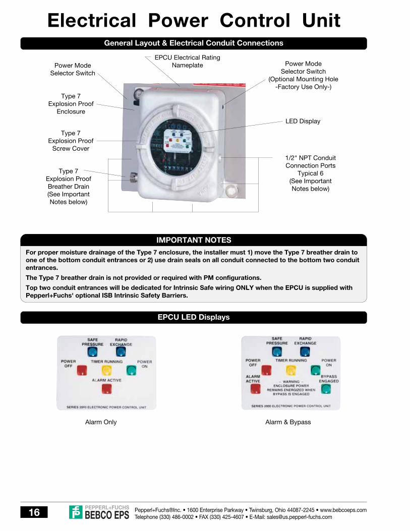
Electrical Power Control Unit
Alarm Only Alarm & Bypass
General Layout & Electrical Conduit Connections
EPCU LED Displays
Power ModeSelector Switch
Type 7Explosion Proof
Screw Cover
Type 7Explosion Proof
Enclosure
Power ModeSelector Switch
(Optional Mounting Hole-Factory Use Only-)
1/2" NPT ConduitConnection Ports
Typical 6(See ImportantNotes below)
LED Display
Type 7Explosion ProofBreather Drain(See ImportantNotes below)
EPCU Electrical RatingNameplate
IMPORTANT NOTES
For proper moisture drainage of the Type 7 enclosure, the installer must 1) move the Type 7 breather drain toone of the bottom conduit entrances or 2) use drain seals on all conduit connected to the bottom two conduitentrances.
The Type 7 breather drain is not provided or required with PM configurations.
Top two conduit entrances will be dedicated for Intrinsic Safe wiring ONLY when the EPCU is supplied withPepperl+Fuchs' optional ISB Intrinsic Safety Barriers.

BEBCO EPSPepperl+Fuchs®Inc. • 1600 Enterprise Parkway • Twinsburg, Ohio 44087-2245 • www.bebcoeps.comTelephone (330) 486-0002 • FAX (330) 425-4607 • E-Mail: [email protected] 17
The EPCU (Electrical Power Control Unit) of this Type "X" Rapid Exchange® purging system is offered in various styles. Forproper installation and operation, begin by examining the EPCU Electrical Rating Nameplate to identify the System Inputvoltage and power requirements, enclosure power and alarm contact ratings and third party approval markings. Next, matchthe LED display of your EPCU with one of the displays shown on page 16. The EPCU LED Display will help identify the optionsfeatured on your system e.g. Normal Running mode or Conditional Bypass.
EPCU Power Rating
MODEL 2000 ELECTRICAL POWER CONTROL UNITCAUTION: OPEN CIRCUIT BEFORE REMOVING COVER
SERIAL NO. INPUT VOLTAGE & POWER REQUIREMENTS
CSA Encl. 3CLASS I, DIV. 1, Gr C&DCLASS II, DIV. 1, Gr E, F, G HASUL & FM APPROVALS ONLY
ENCL POWER & ALARM CONTACTSARE RATED 120/240 VAC, 20 AMPS
120 SINGLE PHASE, 60 CYCLE, 1 AMP240 SINGLE PHASE, 50 CYCLE, 1 AMP
XXXXXX
EPCU INPUT POWERREQUIREMENTS
Factory set at time of order
AREA CLASSIFICATION
Defines the area classifications forwhich the EPCU is suitable for
operation
REQUIRED WARNINGSTATEMENTS
EPCU SERIALNUMBER
Assembled EPCU Electronics Module
EPCU Electrical Power Rating Nameplate
Logic Module
120/240 VACPower Module
Power ModuleCable
Pressure SwitchModule

BEBCO EPSPepperl+Fuchs®Inc. • 1600 Enterprise Parkway • Twinsburg, Ohio 44087-2245 • www.bebcoeps.comTelephone (330) 486-0002 • FAX (330) 425-4607 • E-Mail: [email protected]
Electrical & Pneumatic DiagramsLH, RH, TM, BM, WM & FM Configurations
PM Configurations
Required EnclosureProtection Vent
Electrical PowerControl Unit
EnclosurePressure Gauge
SystemSupply
BreatherDrain
EnclosureSupplyTubing
SinteredVent
EnclosureReference
Tubing Enclosure ReferenceBulkhead Fitting
Electrical PowerSupply Conduit
HubConduit SealUnionConduit Seal Union
VenturiOrifice
SystemSupply
Atmospheric PressureReference Bulkhead
Fitting
System SupplyBulkhead Fitting
Inlet
Conduit Seal Union Conduit Seal
Required EnclosureProtection Vent
Electrical PowerSupply Conduit
Hub
Electrical PowerControl Unit
AtmosphericReference
Tubing
Electrical PowerConduit
Enclosure PressureGauge
UnionElectricalPower toEnclosure
EnclosurePressure
Reference
EnclosurePressure
Reference
Protected Enclosure
SystemSupplyTubing
RegulatorProtected Enclosure
Enclosure SupplyBulkhead Fitting
Rapid Exchange®
Pressure Gauge*Rapid Exchange®
Control Valve
Enclosure PressureControl Valve
EnclosureSupply
Discharge
SystemSupplyTubing
Regulator
Rapid Exchange®
Pressure Gauge*Rapid Exchange®
Control Valve
Enclosure PressureControl Valve
System SupplyConnection Fitting
System SupplyConnection Fitting
* Solenoid onSA & FA Styles
* Solenoid onSA & FA Styles

BEBCO EPSPepperl+Fuchs®Inc. • 1600 Enterprise Parkway • Twinsburg, Ohio 44087-2245 • www.bebcoeps.comTelephone (330) 486-0002 • FAX (330) 425-4607 • E-Mail: [email protected] 19
Conduit InstallationEPCU Electrical Conduit
Unplug the four unlabeled conduit entrances located on thesides and bottom of the EPCU enclosure (See page 16,"EPCU Layout" for conduit entrance layout).
The installer must mount the Type 7 drain fitting suppliedwith the system (except for PM configurations) in one of thebottom conduit entrances of the EPCU, or utilize drain sealson all conduit connected to the bottom two (2) conduitentrances of the EPCU.
Following the instructions listed below, install all conduit,fittings and seals (or drain seals if utilized) between theEPCU, alarm system (if utilized) and the protectedenclosure(s). Plug all remaining EPCU conduit entrances.
1. Choose the location for the enclosure’s electrical conduitconnection(s) based on the requirements on page 15,“Electrical Supply Requirements”.
2. Drill and deburr enclosure conduit fitting holes in theprotected enclosure. Mount the fittings.
3. Determine appropriate route for the enclosure electricalenclosure and alarm signal conduit.
4. Measure, cut and thread conduit, check conduit fit toinsure proper seating. Fully ream all conduit.
5. Install conduit and tighten all fittings to fittingmanufacturers specifications. Secure conduit toappropriate structural supports as required.
6. Seal all conduit with an approved compound prior tooperation of the protection system.
Optional Intrinsic Safety Barrier Conduit
Systems supplied with optional Intrinsic Safety Barriers (ISB)will be supplied with clearly labeled isolated conduit entries,a solid body wireway with snap cover and plexiglass wiringpartitions. These accessories provide a fully isolated wiringpath to the barrier wiring terminal located on the lower leftcorner of the EPCU Logic Module. All IS wiring must beisolated.
1. Choose the location for the enclosure’s IS conduitconnection(s) based on the requirements on page 15,“Electrical Supply Requirements”.
2. Drill and deburr enclosure conduit fitting holes in theprotected enclosure. Mount the fittings.
3. Determine appropriate route for the IS conduit.
4. Measure, cut and thread conduit, check conduit fit toinsure proper seating. Fully ream all conduit.
5. Install conduit and tighten all fittings to fittingmanufacturers specifications. Secure conduit toappropriate structural supports as required.
6. Seal all conduit with an approved compound prior tooperation of the protection system.
LCK “L” FittingConduit Kit
TCK “T” FittingConduit Kit
EPCU Conduit Connection Parts
Fitting Kits Can Be Bebco Furnished
1. To connect enclosure power from the EPCU to theprotected enclosure, one (1) LCK (L fitting Conduit Kit) orequivalent conduit elbow, coupling and seal fittings.
2. For EPCU to enclosure wiring connection with one (1)additional conduit connection path, one (1) TCK (T fittingConduit Kit) or equivalent conduit tee, coupling and sealfittings.
IMPORTANT NOTE
Model LCK & TCK are offered primarily to OEM'sattempting to achieve a "field ready" installation. Inall cases, limited pipe fitting skills will be required.Pre-cut 150# galvanized steel pipe nipples can beacquired from local plumbing shops, but a hole saw orpunch and wrenches are required to install kits.

BEBCO EPSPepperl+Fuchs®Inc. • 1600 Enterprise Parkway • Twinsburg, Ohio 44087-2245 • www.bebcoeps.comTelephone (330) 486-0002 • FAX (330) 425-4607 • E-Mail: [email protected]
VAC & VDC Power Module Electrical Wiring Diagram
Power Modules & Wiring DiagramEPCU 120/240 VAC Power Module Layout
Isolated CoilVoltage Transformer
Power Control SwitchCable Header
Pressure SwitchCable Header
Logic ModuleCable Header
Redundant SafePressure Relay
Alarm Relay
EnclosurePower Relays
Power ModuleWiring Terminal
Voltage Input SelectorHeader (factory set for
120 VAC power)
1 Amp Input Fuse
Rapid Exchange®
Solenoid Valve (RESV)Relay
RESV Factory WiringTerminal
20 Amp EnclosurePower Fuse
EPCU 120/240 VACPower Module
1 2 3 4 5 6 7 8 9 10
121212
111
20 AMPFUSES
IsolatedEnclosure
Power Relays
IsolatedAlarmRelay
NeuNeu
HotHot
GndGnd
NO Com NC
Remote AlarmRelay Terminals
OutInIn Out
EnclosurePowerSupply
Terminals
Field WiredPower Module
Terminals
Using 12 gauge maximum to 16 gauge minimum wire only,check EPCU power requirements (See page 15) and wire tothe EPCU power source and alarm system (if utilized). Thenroute power source(s) through the EPCU power in and outterminals to all non-rated devices within the protectedenclosure(s).
* European Single Phase 240 VAC only.
Power and alarm terminals are feed-thru dry switch contacts.
Caution should be exercised to ensure that the EPCU wiringis properly connected.
All terminal connections to the EPCU should be wired withspade or round lugs.
NO NO NO NC
EPCU PowerSupply Terminals
120 VAC*240 VAC (Optional voltage)

BEBCO EPSPepperl+Fuchs®Inc. • 1600 Enterprise Parkway • Twinsburg, Ohio 44087-2245 • www.bebcoeps.comTelephone (330) 486-0002 • FAX (330) 425-4607 • E-Mail: [email protected] 21
Logic Module & Barrier WiringEPCU Logic Module & Pressure Switch Module
Barrier CSocket
Barrier B(Installed)
Barrier ASocket
BarrierWiring
Terminal
Pressure SwitchCalibration Access
Barrier Fault & ActiveStatus Indicators
FactoryPrograming
Header
RedundantController
(GAL)
Power ModuleCable Header
EDT, SLT &RET Timers
EPCU Logic Module
Optional ISB Wiring Requirements
A B C
INTRINSICALLY SAFE AUXILIARY INPUTS
- + - + - +
( - ) BLUE ( + ) BROWN
All optional intrinsic safety (IS) wiring must be isolated fromall other electrical wiring using the dedicated IS conduitentrances and wireway of the EPCU, (See "Optional ISBConduit Installation" on page 19 for more details). In addition,all wiring must be installed in accordance with the NEC andall relevant local and plant codes.
The ISB Intrinsic Safety Barriers are designed to function inconjunction with a customer furnished switch and ModelSRM-4000 Switch Resistor Module, or an NJ...NAMURSensor. The customer supplied switch must have drycontacts which contain no inductance or capacitance.
The SRM-4000 Switch Resistor Module and the NJ...NAMURSensor are supplied with approximately ten (10) feet ofwiring. Using 16 to 18 gauge shielded wire, the cable lengthscan be extended to a maximum of 100 feet.
In all applications, the module of the Switch Resistor ModuleCable must be installed as close to the customer suppliedswitch as possible for proper operation.
Wiring lugs are not recommended for Intrinsic Safety Barrierwiring connections.
See page 22 for barrier operation and factory programing.
Primary SafePressure Switch
LED StatusDisplay
EPCU PressureSwitch Module
EPCU Power Control Modes
NORMAL RUNNING (NR) MODEEPCU features an on-off push-button power control switchto activate control functions. Switch must be depressed toinitiate start-up. After completion of start-up, safe pressuremust be lost or switch must be depressed to deenergizeenclosure power relays.
CONDITIONAL BYPASS (CB) MODEEPCU features an on-off-bypass power control switch toactivate control functions. Switch must be set to "on" positionto initiate start-up. After enclosure power is energized, safepressure must be lost or switch must be set to "off" positionto deenergize enclosure power. After enclosure power isenergized, switch may be set to "bypass" position, totemporarily latch enclosure power relays. A flashing LEDthen indicates bypass engaged, and the enclosure can thenbe accessed without deenergizing power (performed underspecific conditions). Following access, safe pressure mustbe reestablished to resume normal operation. At that time,the switch may be reset to the on position, without disruptionof enclosure power. Alarm relay normally deenergizes onlyupon loss of safe pressure, but can be factory programmedto deenergize when bypass is engaged, if specified at timeof order.
PrimaryMicroprocessor
Space for OptionalRedundant SafePressure Switch
Space for OptionalRedundant RapidExchange® Switch
Rapid Exchange®
Switch

BEBCO EPSPepperl+Fuchs®Inc. • 1600 Enterprise Parkway • Twinsburg, Ohio 44087-2245 • www.bebcoeps.comTelephone (330) 486-0002 • FAX (330) 425-4607 • E-Mail: [email protected]
Barriers & Field AdjustmentsOptional Intrinsic Safety Barriers DescriptionThe EPCU Logic Module can accommodate up to threeintrinsic safety barriers, to interact with remote devices andaffect operation of the EPCU. The barriers are installed andprogrammed by the factory at time of order, and they aredesigned to function either in conjunction with a customerfurnished switch and a Pepperl+Fuchs furnished resistornetwork cable, or a Pepperl+Fuchs furnished proximitydetector. Each barrier develops a low power signal, to createa two wire closed loop circuit. Operational status of eachbarrier is indicated by a green LED to show active (closedswitch) status, and by a red LED to show faulted (linebreakage) cable status. All barriers can be reprogrammed toduplicate other barrier functions as required, upon specificrequest.
Optional ISB Factory ProgramingBarrier A Function - when switch opensDisables start-up cycleDeenergizes enclosure power and alarm relayFunctions parallel to safe pressure switch
Barrier B Function - when switch opensDisables Rapid Exchange® cycleFunctions parallel to Rapid Exchange® pressure switch
Barrier C Function - when switch closesEnergizes Rapid Exchange® solenoid valve relay
LED Display Indicators
Power Off: Enclosure Power Relays DeenergizedPower On: Enclosure Power Relays EnergizedSafe Pressure: Enclosure Pressure > 0.15" or 0.50" w.c.Rapid Exchange: Enclosure Pressure > 2.0" w.c.Timer Running: Rapid Exchange® Timer ActiveAlarm Active: Enclosure Pressure < 0.15" w.c.Bypass Engaged: Control Bypass Active - CB Mode
Field Adjustable Timer FunctionsEDT (Exchange Delay Timer) (FA Style only) provides a timedelay to prevent Rapid Exchange® solenoid valve fromenergizing until safe pressure can be stabilized.
SLT (Solenoid Latching Timer) (FA Style only) provides a timedelay to keep the Rapid Exchange® solenoid valve energizeduntil Rapid Exchange® pressure is detected. If the pressureis not detected by completion of the time cycle, the EPCU willreset.
RET (Rapid Exchange® Timer) provides a time delay afterRapid Exchange® pressure is detected, to allow four volumeexchanges (ten volumes for motors) prior to energizing theenclosure power relays. If Rapid Exchange® pressure is lostor interrupted during time delay cycle, the EPCU will reset.
POSITION TIME IN SECONDS POSITION TIME IN MINUTES
0 5 0 51 10 1 102 15 2 153 20 3 204 25 4 255 30 5 306 35 6 357 40 7 408 45 8 459 50 9 50A 55 A 55B 60 B 60C 65 C 65D 70 D 70E 75 E 75F 80 F 80
NOTE: Power must be removed from the EPCU via the localdisconnect for approximately 10 seconds for timeradjustments to reset.
0 12
3
4
5
6789
A
B
C
D
EF
Rotary SwitchBody
EDT, SLT & RET Timer Settings
EDT & SLT Timer RET Timer

BEBCO EPSPepperl+Fuchs®Inc. • 1600 Enterprise Parkway • Twinsburg, Ohio 44087-2245 • www.bebcoeps.comTelephone (330) 486-0002 • FAX (330) 425-4607 • E-Mail: [email protected] 23
Set-up ProcedureIMPORTANT NOTES
The volume exchange rate is based on a four (4)enclosure volume exchange. Multiply the requiredexchange time by 2.5 for applications requiring a ten(10) volume exchange (motors).
The Start-Up Instruction Nameplate Exchange TimeSlot will feature the standard factor for this system"ONE MINUTE PER 7.5 CUBIC FOOT", but the unit mayfeature a set of direct factor nameplates with self-adhesive backing such as “TEN MINUTES”, forapplication to the start-up instructions, dependent onhow the system was specified and purchased. Fieldmodification of this nameplate, to show a direct factor,is acceptable as noted above if the method used tomark the nameplate does not deface the instructionslisted. Materials used for the marking must be indelibleand withstand prevailing environmental conditions.
Regardless of any condition, the Type X RapidExchange® System is designed to automaticallywithhold power to the protected enclosure whileinducing Rapid Exchange®, for at least five (5) minutes.Normal exchange times should be doubled if largeobstructions block inert gas flow.
To test the vent’s operation, gently prod the ventflapper open with a soft pointed object, ( example:eraser end of a pencil) ensuring that the vent valveworks freely. On vertically configured vents, this canbe accomplished from within the protected enclosure.Side mounted -90 configured vents can be tested byremoving the pipe plug at the bottom of the mountingtee. Multiple operations require only one test per dayif enclosure is not opened or left unattended.
Model 2004 Rapid Exchange® Purging Set-up
1. Close the Enclosure Pressure Control Valve (all Styles)and Rapid Exchange® Control Valve (STD Style only) fullyby turning clockwise (CW).
2. Connect the inert gas supply to the System Supply Inletand set the Rapid Exchange® Pressure Gauge to 80 psi.
3. Temporarily connect a 0-5 inch water column pressuregauge or manometer to the protected enclosure.
4. Check operation of Enclosure Protection Vent as detailedabove. (see "Important Notes")
5. Seal enclosure(s) and adjust Enclosure Pressure ControlValve by opening slowly counterclockwise (CCW) to seta “Safe” pressure on the Enclosure Pressure Gauge.
Note: If pressure setting is difficult to stabilize or set,(see page 26, “Trouble-Shooting Procedures”).
6. STD Styles - Open Rapid Exchange® Control Valve fullyby turning 90° CCW and quickly ensure the EnclosureProtection Vent opens.
SA & FA Styles - With the aid of an assistant having two1/2" combination wrenches on hand, place left hand onsystem mounting plate and pull Rapid Exchange® ManualOperator firmly with right hand and quickly ensure theEnclosure Protection Vent opens. If Enclosure ProtectionVent operates properly, have assistant carefully placethe open end of both wrenches behind handle to hold themanual operator in the out position temporarily.
Note: The Enclosure Pressure Gauge should movequickly off scale to the right, this is normal for all RapidExchange® purging systems.
7. Readjust the regulator to 80 psi minimum, while inducingRapid Exchange®, the test gauge should then readapproximately 2 inches of pressure and should notfluctuate. (insufficient enclosure pressure will cause theEnclosure Protection Vent to "shuttle") DO NOT exceed5 inches of pressure within the protected enclosure.
8. Close Enclosure Pressure Control Valve and RapidExchange® Control Valve (STD Styles) or Remove thetwo 1/2" combination wrenches from behind the handle.
Note: The Rapid Exchange® Pressure Gauge may nowindicate a higher set pressure than was originally set, thisis normal for all Rapid Exchange® purging systems.
9. Set RET timer (see page 21 for timer location andsettings) for required exchange time based on Systemexchange rate of ONE MINUTE PER 7.5 CUBIC FEET,five (5) minute minimum.
10. Install and tighten cover of EPCU. Ensure the conduit issealed with approved compounds.
11. Depress the On-Off push-button (NR mode) or turnselector switch to the On position (CB mode). Each LEDshould illuminate fully for two seconds (self test), then allLEDs should turn off except Power Off (solid red) andAlarm Activated (flashing red) LEDs.
12. Turn Enclosure Pressure Control Valve slowly CW to setthe Enclosure Pressure Indicator to a "Safe" 0.25 inchpressure. The Safe Pressure LED should be on, theAlarm Active LED should turn off. Check for a 0.10 to0.15 inch trip point by slowly stroking the indicator from0.10 to 0.25 inch readings. The Safe Pressure and AlarmActive LEDs should turn on and off when the indicatorreads between 0.10 and 0.15 inches.
Note: FA Style only - Rapid Exchange® Solenoid Valvewill engage automatically upon time out of the EDTTimer. Should the operator require additional time to seta stable Safe Pressure on the enclosure pressureindicator, reset the EDT timer setting as described onpage 22.
Set-Up Procedure continued on page 24.

BEBCO EPSPepperl+Fuchs®Inc. • 1600 Enterprise Parkway • Twinsburg, Ohio 44087-2245 • www.bebcoeps.comTelephone (330) 486-0002 • FAX (330) 425-4607 • E-Mail: [email protected]
Set-up Procedure (cont.)Model 2004 Rapid Exchange® Purging Set-up
13. STD Style - Open Rapid Exchange® Control Valve fullyby turning 90° CCW and quickly ensure the EnclosureProtection Vent opens. The Rapid Exchange® and TimerActive LEDs should be on. Check for trip point by turningRapid Exchange® Control Valve on and off. The RapidExchange® and Timer Running LEDs should turn on andoff as exchange is engaged and disengaged, withoutdisturbing the status of the Safe Pressure LED.
SA Style - Place left hand on system mounting plate andpull Rapid Exchange® Manual Operator firmly with righthand, until solenoid latches (to hold valve openautomatically) then quickly ensure the EnclosureProtection Vent opens. The Rapid Exchange® and TimerActive LEDs should be on. Check for trip point by turningEPCU power switch off and on (to reset unit). The RapidExchange® and Timer Running LEDs should not turn onuntil valve is more than half open. Allow System to runthrough RET timer cycle and watch for solenoid todisengage. The valve should be able to shut off withoutdisturbing the status of the Safe Pressure LED.
FA Style - Rapid Exchange® Solenoid Valve will engageautomatically upon time out of the EDT Timer, thenquickly ensure the Enclosure Protection Vent opens.The Rapid Exchange® and Timer Active LEDs should beon and SLT Timer will be running. Check for trip point byturning EPCU power switch off and on (to reset unit). TheRapid Exchange® and Timer Running LEDs should notturn on until valve is more than half open. Starting again,allow System to run through EDT, SLT and RET timercycles and watch for solenoid to disengage. The valveshould be able to shut off without disturbing the statusof the Safe Pressure LED.
14. Having ensured that the Safe Pressure and Timer RunningLEDs are functioning properly, Operating Procedureslocated on page 25 may now be followed to step througha complete start up cycle, ensuring that the Systemfunctions normally during all phases of operation.
15. Cease testing and remove test equipment .
Model 2004-STD-CB-LHFront View
Start - UpInstructionNameplate
EnclosurePressureGauge
RapidExchange®
PressureGauge
EnclosurePressureControlValve
LED StatusNameplate
EXP EPCUEnclosure
EXPBreather
Drain
ModelIdentificationNameplate
RapidExchange®
ControlValve
RapidExchange®
PressureGauge
BypassOperating
Instructions
EPCUPower
SelectorSwitch
System LEDDisplay
RapidExchange®
ManualOperator
Start - UpInstructionNameplate
EnclosurePressureGauge
LED StatusNameplate
EPCU PowerSelectorSwitch
System LEDDisplay
EXP EPCUEnclosure
Model 2004-FA-CB-LHFront View
BEBCO EPSPepperl+Fuchs®Inc. • 1600 Enterprise Parkway • Twinsburg, Ohio 44087-2245 • www.bebcoeps.comTelephone (330) 486-0002 • FAX (330) 425-4607 • E-Mail: [email protected] 25
Operating Sequence
7. Standby until the EPCU RET Timer completes the timingcycle and energizes enclosure power. Safe PressureLED should stay on, Timer Running LED should turn offand Power On LED should turn on.
8. STD Style - Close Rapid Exchange® Control Valve fullyby turning 90° CW. The Rapid Exchange® and TimerActive LEDs should be off.
SA & FA Styles - After completion of the RET timimgcycle, Timmer Running LED should turn off and Poweron LED should turn on. At the same time, the RapidExchange® Solenoid Valve should deenergize and theRapid Exchange® LED should turn off.
9. Ensure the Protection System Enclosure PressureIndicator maintains a “Safe” 0.25 inch pressure for one(1) minute. Readjust Enclosure Pressure Control Valveif required.
10. If "Safe" 0.25 inch pressure is lost, the EPCU willdeenergize enclosure power and activate alarm system(if utilized).
With the inert gas supply on, RET Timer set properly(STD and SA Styles), EDT, SLT and RET Timers setproperly (FA Styles), EPCU power and alarm systemenergized (if utilized) . .
1. Carefully read Start-Up Instruction Nameplate on system.
2. Check operation of the Enclosure Protection Vent, EPV-4, opening it manually several times (see page 23,“Helpful Hint”).
3. Seal protected enclosure(s).
4. Depress the On-Off push-button (NR mode) or turnselector switch to the On position (CB mode). Each LEDshould illuminate fully for two seconds as a self test, thenall LEDs should turn off except Power Off (solid red) andAlarm Activated (flashing red) LEDs.
5. Turn Enclosure Pressure Control Valve slowly CCW toset the Enclosure Pressure Indicator to a "Safe" 0.25inch pressure. The Safe Pressure LED should be on, theAlarm Active LED should turn off.
6. STD Style - Open Rapid Exchange® Control Valve fullyby turning 90° CCW and quickly ensure the EnclosureProtection Vent opens. The Rapid Exchange® and TimerActive LEDs should turn on.
SA Style - Place left hand on system mounting plate andpull Rapid Exchange® Manual Operator firmly with righthand, until solenoid latches (to hold valve openautomatically) then quickly ensure the EnclosureProtection Vent opens. The Rapid Exchange® and TimerActive LEDs should turn on.
FA Style - Rapid Exchange® Solenoid Valve will engageautomatically upon time out of the EDT Timer, thenquickly ensure the Enclosure Protection Vent opens.The Rapid Exchange® and Timer Active LEDs should beon and SLT Timer will be running.
Note: On all Styles, if the Safe Pressure or TimerRunning LEDs blink on and off or "flicker" during thiscycle, EPCU will reset RET timer.
WARNINGDo not exceed a “Safe” pressure with the Enclosure Pressure Control Valve.
Operators must follow step-by-step sequence of the Start-Up Instructions Nameplate on the Protection System.
Do not use the Bypass Modes without first securing a "Hot Work" permit.
Never leave the system unattended in Bypass Modes.
Rapid Exchange® Purging Operation

BEBCO EPSPepperl+Fuchs®Inc. • 1600 Enterprise Parkway • Twinsburg, Ohio 44087-2245 • www.bebcoeps.comTelephone (330) 486-0002 • FAX (330) 425-4607 • E-Mail: [email protected]
Problem or Fault
Enclosure pressure controlvalve will not hold a safe .25inch pressure.
Enclosure pressure indicatorreading is difficult to stabilize.
Enclosure Protection Vent"Shuttles" or Flutters"
Enclosure Pressure Indicatorreads a "Safe" pressure butthe Safe Pressure LED is notilluminated.
Rapid Exchange® LED doesnot iluminate when RapidExchange® is engaged.
FA Style only - The RapidExchange® solenoid continuesto cycle without starting theRET timer.
Problems persists, or if thesystem does not appear to beoperating properly.
Trouble - Shooting ProceduresPossible Causes
Leakage around gasketing,covers, seams, piping andtubing connections, conduitconnections and electricalconduit seals of the enclosure.
Insufficient enclosure leakageor opening of the venturi orificeis crimped too small.
Excessive leakage fromprotected enclosure.
Insuffcient protective gassupply header pressure.
Conduit seal between EPCU andprotected enclosure is notpoured or is leaking pressureback into the EPCU.
EPCU breather drain is clogged(all systems except PMconfigurations).
Safe Pressure switch is out ofcalibration.
Conduit seal between EPCU andprotected enclosure is notpoured or is leaking pressureback into the EPCU.
EPCU breather drain is clogged(all systems except PMconfigurations).
Rapid Exchange® Pressureswitch is out of calibration.
Persisting problems.
This section covers the most common problems documented with these systems. Any problems not covered in thissection should be addressed directly to our factory. Please address all service needs to Pepperl+Fuchs, Inc. - CustomerService Department at (330) 486-0002.
Corrective Action
Tighten enclosure latches: Where tightening is notfeasible, and gasketing materials are not practical,holes or gaps can be closed with silicone sealantapplied from inside the protected enclosure.
Remove the orifice, cut off the crimped end andream the tube, then recrimp and reinstall the tubeto note effect. As tube is shortened, reamed, andrecrimped, sensitivity decreases, allowing easieradjustment of setpoint on the enclosure.
Check all points above and verify a minimum 60 psiinjection pressure reading on the Rapid Exchange®
Pressure Indicator during Rapid Exchange®.
With a 0.0" - 5" water column test gauge installedproperly (see "Set-Up Procedures" page 23), slowlyincrease the Rapid Exchange® Injection pressurewith the Rapid Exchange® valve engaged until thiseffect is eliminated. Do not exceed 3 inches ofpressure within the protected enclosure.
With area positively known to be non-hazardous,remove screw cover of the EPCU and attempt acomplete start-up procedure. If the system worksproperly, check enclosure power conduit seal forleakage and the EPCU breather drain for blockage.If the system does not operate properly, calibratethe Safe Pressure switch.
Calibrate by slowly adjusting CCW to decrease thesetpoint, and CW to raise the setpoint.
(Do not attempt to calibrate the switch until all effortsto make the switch respond properly have failed)
With area positively known to be non-hazardous,remove screw cover of the EPCU and attempt acomplete start-up procedure. If the system worksproperly, check enclosure power conduit seal forleakage and the EPCU breather drain for blockage.If the system does not operate properly, calibratethe Rapid Exchange® Pressure switch.
With Rapid Exchange® engaged, calibrate by slowlyadjusting counterclockwise to decrease thesetpoint, and clockwise to raise the setpoint.
(Do not attempt to calibrate the switch until all effortsto make the switch respond properly have failed)
Contact Pepperl+Fuchs Applications/CustomerService Department at (330) 486-0002 for moreinformation.

BEBCO EPSPepperl+Fuchs®Inc. • 1600 Enterprise Parkway • Twinsburg, Ohio 44087-2245 • www.bebcoeps.comTelephone (330) 486-0002 • FAX (330) 425-4607 • E-Mail: [email protected] 27
Warranty Terms and ConditionsPEPPERL+FUCHS STANDARD 24-MONTH WARRANTY
1. Limited Warranty. Pepperl + Fuchs, Inc. (“P+F”) warrants Purge Units and components for Purge Units manufactured byP+F (“Product” or “Products”) to be free from defects in material and workmanship under Normal Use for a period oftwenty-four (24) months from the date of shipment of such Products from P+F’s warehouse or place of manufacture (orfrom P+F’s authorized representative or distributor). Only the original purchaser of such Products (the “Customer”) shallbe entitled to the benefit of the foregoing Limited Warranty. No representative, agent or salesman of P+F is authorized togive or provide any warranty or make any representation contrary to or in addition to the foregoing Limited Warranty.
2. Inspection and Claims. Customer must inspect and test all Products upon receipt. All claims under the Limited Warrantyprovided herein must be made within thirty (30) days of the discovery of the defect. Customer must obtain shippinginstructions from P+F prior to returning any Product, which Product must be returned at Customer’s expense inaccordance with P+F’s instructions.
3. Limitations and Exclusions. “Normal Use” shall mean use and operation within rated capacities, at the correct voltage, andwith any required maintenance as provided in the applicable P+F Operating Manuals. The Limited Warranty providedherein does not apply to (i) any Products which have been altered or modified in any way or disassembled by theCustomer or anyone else, (ii) any Products which have been subject to misuse, negligence or accident, or improperlyinstalled, changed, substituted or replaced, (iii) any part or component not manufactured by P+F, or (iv) any part orcomponent that is subject to wear or consumption. For parts or components not manufactured by P+F, the Customer orany other user or owner shall have only the warranty provided by the manufacturer of such part or component. TheLimited Warranty set forth herein is also subject to the following:
(1) The Limited Warranty is limited to electronic and mechanical performance only, as expressly detailed inthe product specifications, and does not apply to cosmetic appearance;
(2) The Limited Warranty shall not apply to any cables attached to, or integrated with, any Products.
(3) The Limited Warranty shall not apply to any Products which are stored, or utilized, in harsh environmentalor electrical conditions outside P+F’s written specifications.
THE LIMITED WARRANTY SET FORTH HEREIN IS THE ONLY WARRANTY MADE BY P+F WITH RESPECT TO THEPRODUCTS. IT IS EXPRESSLY AGREED AND UNDERSTOOD THAT P+F MAKES NO WARRANTY OFMERCHANTABILITY OR FITNESS FOR A PARTICULAR PURPOSE. EXCEPT FOR THE LIMITED WARRANTY SET FORTHHEREIN, THERE IS NO OTHER WARRANTY, EXPRESS, IMPLIED OR STATUTORY; AND THERE IS NO AFFIRMATION OFFACT OR PROMISE BY P+F WITH REFERENCE TO THE PRODUCTS. IN NO EVENT SHALL P+F BE LIABLE FORACTUAL OR ANTICIPATED LOST PROFITS OR FOR INCIDENTAL OR CONSEQUENTIAL OR PUNITIVE DAMAGES ORFOR DAMAGES RESULTING FROM BUSINESS INTERRUPTION, OR INJURY OR DEATH OF PERSONS, OR INJURY TOPROPERTY. P+F’S LIABILITY ON ANY CLAIM OF ANY KIND ARISING OUT OF, CONNECTED WITH OR RESULTINGFROM THE DESIGN, MANUFACTURE, SALE, REPAIR OR OPERATION OF A PRODUCT, SHALL NOT EXCEED THEPRICE ALLOCABLE TO THAT PRODUCT OR THE PART THEREOF WHICH GIVES RISE TO THE CLAIM. THE REMEDYSET FORTH IN THIS LIMITED WARRANTY CONSTITUTES THE SOLE AND EXCLUSIVE REMEDY OF THE CUSTOMER.P+F SHALL NOT BE LIABLE FOR PENALTIES OF ANY DESCRIPTION.
4. Limitation of Remedies. In the event of P+F’s liability, whether on this Limited Warranty or based on contract, tort(including, but not limited to, negligence and strict liability) or otherwise, Customer’s sole and exclusive remedy will belimited to, at P+F’s option, the repair or replacement (f/o/b P+F’s place of manufacture) by P+F of any non-conformingitems for which claim is made by Customer in accordance with paragraph 2, or the repayment of the portion of thepurchase price paid by Customer attributable to the non-conforming item.
5. Responsibility of Customer: Safety and Protection Precautions. P+F takes great care to design and build reliable anddependable Products; however, some Products can fail eventually. Customer must take precautions to design itsequipment to prevent property damage and personal injury in the unlikely event of a failure. AS A MATTER OF POLICY,P+F DOES NOT RECOMMEND THE INSTALLATION OF PRODUCTS AS THE SOLE DEVICE FOR THE PROTECTION OFPERSONNEL OR PROPERTY AND, THEREFORE, THE CUSTOMER SHOULD BUILD IN REDUNDANCY OR DUALCONTROL USING APPROVED SAFETY DEVICES FOR THESE APPLICATIONS.
6. Conflicts. In the event there is any conflict between the provisions of this Limited Warranty and any provisions contained inany orders, offers, acceptances or other writings or statements provided or made by Customer to P+F, the provisions ofthis Limited Warranty shall prevail, and the contract between P+F and the Customer shall be deemed formed only uponthe provisions set forth in this Limited Warranty, and any additional or conflicting provision inserted by Customer shall beof no force or effect.

BEBCO EPSPepperl+Fuchs®Inc. • 1600 Enterprise Parkway • Twinsburg, Ohio 44087-2245 • www.bebcoeps.comTelephone (330) 486-0002 • FAX (330) 425-4607 • E-Mail: [email protected]
Performed by
MAINTENANCE SCHEDULEDate Work Performed
System MaintenanceRegular Maintenance
Drain the Protection System Regulator frequently and clean System with non-solvent cleaning agents only.
Long Term Maintenance
Calibrate the enclosure pressure indicator to 0 inches by venting the purge pressure reference port and the protectedenclosure to atmosphere and adjusting the calibration screw in the lower center portion of the indicator’s face.
Fully open the enclosure pressure control regulator, to blow out any deposits around the tip of the valve and to ensure thatthe enclosure protection vent is operating properly, then carefully readjust system according to the set-up procedure andoperating sequence on pages 23 through 25. Replace or tighten stem packing nut as required to prohibit stem packingleakage.
Carefully disassemble the enclosure protection vent by loosening the two bottom hex nuts that hold the unit together.(DO NOT REMOVE CAP NUTS ON TOP OF VENT BODY)Carefully clean the flapper valve and vent body seats with warm soap and water, being careful not to extend the vent valvebeyond its normal opening point, and being careful not to exert any stress on the valve hinge.
Examine the entire Protection System and the protected enclosure(s), and replace any defective parts during routineshutdown of the protected enclosure(s). Parts are available from Pepperl+Fuchs on immediate notice as required.

BEBCO EPSPepperl+Fuchs®Inc. • 1600 Enterprise Parkway • Twinsburg, Ohio 44087-2245 • www.bebcoeps.comTelephone (330) 486-0002 • FAX (330) 425-4607 • E-Mail: [email protected] 29
Performed by
MAINTENANCE SCHEDULEDate Work Performed

BEBCO EPSPepperl+Fuchs®Inc. • 1600 Enterprise Parkway • Twinsburg, Ohio 44087-2245 • www.bebcoeps.comTelephone (330) 486-0002 • FAX (330) 425-4607 • E-Mail: [email protected]
CUSTOMER NOTES

BEBCO EPSPepperl+Fuchs®Inc. • 1600 Enterprise Parkway • Twinsburg, Ohio 44087-2245 • www.bebcoeps.comTelephone (330) 486-0002 • FAX (330) 425-4607 • E-Mail: [email protected] 31
CUSTOMER NOTES

BEBCO EPSPepperl+Fuchs®Inc. • 1600 Enterprise Parkway • Twinsburg, Ohio 44087-2245 • www.bebcoeps.comTelephone (330) 486-0002 • FAX (330) 425-4607 • E-Mail: [email protected]
Date of Installation
Unit Serial #
Item
Customer P.O.#
Customer Project#
Service
Type
Features
Application
SYSTEMS IDENTIFICATION & APPLICATION INFORMATION
Local Sales Representative
NOTES:


