20 SERIES... · OperatiOn Manual MOde d’eMplOi Bedienungsanleitung MOdO de eMpleO 20 SERIES...
40
O PERATION M ANUAL M ODE D ’ EMPLOI B EDIENUNGSANLEITUNG M ODO DE EMPLEO 20 SERIES EQUALIZER/LIMITER with TYPE III NR
Transcript of 20 SERIES... · OperatiOn Manual MOde d’eMplOi Bedienungsanleitung MOdO de eMpleO 20 SERIES...

OperatiOn Manual
MOde d’eMplOi
Bedienungsanleitung
MOdO de eMpleO
20 SERIESE Q U A L I Z E R / L I M I T E R
w i t h T Y P E I I I N R

IMPORTANT SAFETY INFORMATION
WARNING FOR YOUR PROTECTIONREAD THE FOLLOWING:
KEEP THESE INSTRUCTIONSHEED ALL WARNINGS
FOLLOW ALL INSTRUCTIONS
THE APPARATUS SHALL NOT bE ExPOSED TO DRIPPING OR SPLASHING LIqUID AND NO ObjECT FILLED WITH LIqUID, SUCH AS vASES, SHALL bE PLACED ON THE APPARATUS.
CLEAN ONLY WITH A DRY CLOTH.
DO NOT bLOCK ANY OF THE vENTILATION OPENINGS. INSTALL IN AC-CORDANCE WITH THE MANUFACTURER’S INSTRUCTIONS.
DO NOT INSTALL NEAR ANY HEAT SOURCES SUCH AS RADIATORS, HEAT REGISTERS, STOvES, OR OTHER APPARATUS (INCLUDING AMPLI-FIERS) THAT PRODUCE HEAT.
ONLY USE ATTACHMENTS/ACCESSORIES SPECIFIED bY THE MANUFAC-TURER.
UNPLUG THIS APPARATUS DURING LIGHTNING STORMS OR WHEN UNUSED FOR LONG PERIODS OF TIME.
Do not defeat the safety purpose of the polarized or grounding-type plug. A polarized plug has two blades with one wider than the other. A grounding type plug has two blades and a third grounding prong. The wide blade or third prong are provided for your safety. If the provided plug does not fit your outlet, consult an electrician for replacement of the obsolete outlet.
Protect the power cord from being walked on or pinched particularly at plugs, convenience receptacles, and the point where they exit from the apparatus.
Use only with the cart stand, tripod bracket, or table specified by the manufac-ture, or sold with the apparatus. When a cart is used, use caution when moving the cart/apparatus combination to avoid injury from tip-over.
Refer all servicing to qualified service personnel. Servicing is required when the apparatus has been damaged in any way, such as power-supply cord or plug is damaged, liquid has been spilled or objects have fallen into the apparatus, the apparatus has been exposed to rain or moisture, does not operate normally, or has been dropped.
POWER ON/OFF SWITCH: If the equipment has a Power switch, the Power switch used in this piece of equipment DOES NOT break the connection from the mains.
MAINS DISCONNECT: The plug shall remain readily operable. For rack-mount or installation where plug is not accessible, an all-pole mains switch with a contact separation of at least 3 mm in each pole shall be incorporated into the electrical installation of the rack or building.
FOR UNITS EqUIPPED WITH ExTERNALLY ACCESSIbLE FUSE RECEPTA-CLE: Replace fuse with same type and rating only.
MULTIPLE-INPUT vOLTAGE: This equipment may require the use of a different line cord, attachment plug, or both, depending on the available power source at installation. Connect this equipment only to the power source indicated on the equipment rear panel. To reduce the risk of fire or electric shock, refer servicing to qualified service personnel or equivalent.
If connected to 240v supply, a suitable CSA/UL certified power cord shall be used for this supply.
This Equipment Is Intended For Rack Mount Use Only.
Safety InStructIonS
Notice For customers iF Your uNit is equipped With A poWer cord.
WArNiNG: this AppLiANce shALL Be coNNected to A mAiNs socKet outLet With A protectiVe eArthiNG coNNectioN.
the cores in the mains lead are coloured in accordance with the following code:
GREEN and YELLOW - Earth BLUE - Neutral BROWN - Live
As colours of the cores in the mains lead of this appliance may not correspond with the coloured markings identifying the terminals in your plug, proceed as follows:
• the core which is coloured green and yellow must be connected to the terminal in the plug marked with the letter e, or with the earth symbol, or coloured green, or green and yellow.
• the core which is coloured blue must be connected to the terminal marked N or coloured black.
• the core which is coloured brown must be connected to the terminal marked L or coloured red.
this equipment may require the use of a different line cord, attachment plug, or both, depending on the available power source at installation. if the attachment plug needs to be changed, refer servicing to qualified service personnel who should refer to the table below. the green/yellow wire shall be connected directly to the units chassis.
CONDUCTOR WIRE COLORNormal Alt
L LIVE BROWN BLACKN NEUTRAL BLUE WHITE
E EARTH GNDGREEN/
YELGREEN
WARNING: if the ground is defeated, certain fault conditions in the unit or in the system to which it is connected can result in full line voltage between chassis and earth ground. severe injury or death can then result if the chassis and earth ground are touched simultaneously.
the symbols shown above are internationally accepted symbols that warn of potential hazards with electrical products. the lightning flash with arrowpoint in an equilateral triangle means that there are dangerous voltages present within the unit. the exclamation point in an equilateral triangle indicates that it is nec-essary for the user to refer to the owner’s manual.
these symbols warn that there are no user serviceable parts inside the unit. do not open the unit. do not attempt to service the unit yourself. refer all servic-ing to qualified personnel. opening the chassis for any reason will void the manufacturer’s warranty. do not get the unit wet. if liquid is spilled on the unit, shut it off immediately and take it to a dealer for service. disconnect the unit during storms to prevent damage.
CAUT ION
ATTENT I ON: RI SQUE DE CHO C ELECTRI Q UE - NE PAS OUVRI R
WARNI NG: TO REDUCE THE R I SK OF F I RE OR ELECTRI CS H O C K D O N OT E XPO SE TH I S EQUI PM ENT TO RA I N OR M OI STURE
RI SK OF ELECTRI C SHOCKDO NO T O PEN

LITHIUM BATTERYWARNING
CAUTION!This product may contain a lithium battery. There is danger of explosion if the battery is incorrectly replaced. Replace only with an Eveready CR 2032 or equivalent. Make sure the battery is installed with the correct polarity. Discard used batteries according to manufacturer’s instructions.ADVARSEL!Lithiumbatteri - Eksplosjonsfare. ved utskifting benyttes kun batteri som anbefalt av apparatfabrikanten. brukt batteri returneres appa-ratleverandøren.ADVARSEL!Lithiumbatteri - Eksplosionsfare ved fejlagtig håndtering. Udskiftning må kun ske med batteri av samme fabrikat og type. Levér det brugte batteri tilbage til leverandøren.VAROITUS!Paristo voi räjähtää, jos se on virheellisesti asennettu. vaihda paristo ainoastaan laitevalmistajan suosittelemaan tyyppin. Hävitä käytetty paristo valmistajan ohjeiden mukaisesti.VARNING!Explosionsfara vid felaktigt batteribyte. Använd samma batterityp eller en ekvivalent typ som rekommenderas av apparattillverkaren. Kassera använt batteri enligt fabrikantens instruktion.
IMPORTANT SAFETY INFORMATION
U.K. MAINS PLUG WARNINGA molded mains plug that has been cut off from the cord is unsafe. Discard the mains plug at a suitable disposal facility. NEVER UNDER ANY CIRCUMSTANCES SHOULD YOU INSERT A DAMAGED OR CUT MAINS PLUG INTO A 13 AMP POWER SOCKET. Do not use the mains plug without the fuse cover in place. Replacement fuse covers can be obtained from your local retailer. Replacement fuses are 13 amps and MUST be ASTA approved to BS1362.
ELECTROMAGNETIC COMPATIBILITY This unit conforms to the Product Specifications noted on the Declaration of Conformity. Operation is sub-ject to the following two conditions: •thisdevicemaynotcauseharmfulinterference,and •this device must accept any interference received,
including interference that may cause undesired operation.
Operation of this unit within significant electromagnetic fields should be avoided. •useonlyshieldedinterconnectingcables.
Manufacturer’s Name: dbx Professional ProductsManufacturer’s Address: 8760 S. Sandy Parkway Sandy, Utah 84070, USA
declares that the product:
Product name: dbx 2031, dbx2215 and dbx2231 Note: Product name may be suffixed by the letters-EU.
Product option: None
conforms to the following Product Specifications:
Safety: IEC 60065 -01+Amd 1 EMC: EN 55022:2006 (N/A; Analog Product) IEC61000-4-2 IEC61000-4-3 IEC61000-4-4 IEC61000-4-5 IEC61000-4-6 IEC61000-4-8 IEC61000-4-11
Supplementary Information:
The product herewith complies with the requirements of the: Low Voltage Directive 2006/95/EC EMC Directive 2004/108/EC. RoHS Directive 2002/95/EC WEEE Directive 2002/96/EC
With regard to Directive 2005/32/EC and EC Regulation 1275/2008 of 17 December 2008, this product is designed, produced, and classified as Professional Audio Equipment and thus is exempt from this Directive.
Roger Johnsen Director, Engineering Signal Processing 8760 S. Sandy Parkway Sandy, Utah 84070, USA Date: November 19, 2010
European Contact: Your local dbx Sales and Service Office or
Harman Music Group 8760 South Sandy Parkway Sandy, Utah 84070 USA Ph: (801) 566-8800 Fax: (801) 568-7583
DECLARATION OF CONFORMITY
If you want to dispose this product, do not mix it with general household waste. There is a separate collection system for used electronic products in accordance with legislation that requires proper treatment, recovery and recycling.
Private household in the 25 member states of the EU, in Switzerland and Norway may return their used electronic products free of charge to designated collection facilities or to a retailer (if you purchase a similar new one).
For Countries not mentioned above, please contact your local authorities for a correct method of disposal.
By doing so you will ensure that your disposed product undergoes the necessary treatment, recovery and recycling and thus prevent potential negative effects on the environment and human health.
WarrantyThis warranty is valid only for the original purchaser and only in the United States.
1. The warranty registration card that accompanies this product must be mailed within 30 days after purchase date to validate this warranty. You can also register online at www.dbxpro.com. Proof-of-purchase is considered to be the responsibility of the consumer. A copy of the original purchase receipt must be provided for any warranty service.
2. dbx warrants this product, when bought and used solely within the U.S., to be free from defects in materials and workmanship under normal use and service.
3. dbx liability under this warranty is limited to repairing or, at our discretion, replacing defective materials that show evidence of defect, provided the product is returned to dbx WITH RETURN AUTHORIZATION from the factory, where all parts and labor will be covered up to a period of two years. A Return Authorization number must first be obtained from dbx. The company shall not be liable for any consequential damage as a result of the product’s use in any circuit or assembly.
4. dbx reserves the right to make changes in design or make additions to or improvements upon this product without incurring any obligation to install the same additions or improve-ments on products previously manufactured.
5. The foregoing is in lieu of all other warranties, expressed or implied, and dbx neither assumes nor authorizes any person to assume on its behalf any obligation or liability in con-nection with the sale of this product. In no event shall dbx or its dealers be liable for special or consequential damages or from any delay in the performance of this warranty due to causes beyond their control.


OPERATION MANUAL
1
20 SERIES GRAPHIC EQUALIZERS
Manual Contents
English . . . . . . . . . . . . . . . . . . . . . . . . . . . . . . . . . . . . . . . . . . . . . . . . . . . . . 2 Français . . . . . . . . . . . . . . . . . . . . . . . . . . . . . . . . . . . . . . . . . . . . . . . . . . . . . 7
DEutsch . . . . . . . . . . . . . . . . . . . . . . . . . . . . . . . . . . . . . . . . . . . . . . . . . . . . . 15 Español . . . . . . . . . . . . . . . . . . . . . . . . . . . . . . . . . . . . . . . . . . . . . . . . . . . . . 23
english Contents
introDuction . . . . . . . . . . . . . . . . . . . . . . . . . . . . . . . . . . . . . . . . . . . . . . . . . . 2 inspEction . . . . . . . . . . . . . . . . . . . . . . . . . . . . . . . . . . . . . . . . . . . . . . . . . . . . 2
opErating controls . . . . . . . . . . . . . . . . . . . . . . . . . . . . . . . . . . . . . . . . . . . 2 connEcting thE EQ to your systEm . . . . . . . . . . . . . . . . . . . . . . . . . . . . . . 4 rEar panEl DEscriptions . . . . . . . . . . . . . . . . . . . . . . . . . . . . . . . . . . . . . . . . 4
installation consiDErations . . . . . . . . . . . . . . . . . . . . . . . . . . . . . . . . . . . . 5 opEration anD applications notEs . . . . . . . . . . . . . . . . . . . . . . . . . . . . . . . 6
tEchnical support / Factory sErvicE . . . . . . . . . . . . . . . . . . . . . . . . . . . . . 6
spEciFications . . . . . . . . . . . . . . . . . . . . . . . . . . . . . . . . . . . . . . . . . . . . . . . . . 32
Block Diagram . . . . . . . . . . . . . . . . . . . . . . . . . . . . . . . . . . . . . . . . . . . . . . . . 33

2
OPERATION MANUAL
introduCtionCongratulations on your purchase of a dbx graphic equalizer. All dbx graphic equalizers are high performance multi-functional units designed to deliver all the flexibility and power that professional users demand. We recommend that you take a moment to read through this operation manual. It provides information that will assist you from system set-up to EQ applications. The 20 Series Equalizers include the following features:
•RevolutionarydbxTYPEIII™NoiseReductioncapableofrestoringupto20dBS/Nratio •Proprietarypatent-pendingPeakPlus™Limiterforsystemprotection •Switchablerangebetween±6dBand±15dB •Balancedinputsandoutputs •XLR,BarrierStrip,and1/4”TRSconnectors •-12dB/+12dBinputgainrange •18dB/octave40HzBesselLow-Cutfilter •Chassis/signalgroundliftcapability •Internalpowersupplytransformer •Power-offhard-wirerelaybypasswith2-secondpower-updelay
inspeCtionVerify that the equalizer’s package contains the following:
•Equalizerunitmatchingserialnumbermarkedonpackage •ACpowercord •OperationManual •RegistrationCard •Fourrackmountscrewsandwashers
If any of these items are missing please contact dbx customer service at the number provided on the back cover of this manual.
operating ControlsFront Panels
2031-singlechannel31bandgraphicequalizer
2231-dualchannel31bandgraphicequalizer
RANGE
GAINREDUCTION (dB)
OUTPUTLEVEL (dBu)
LOWCUT
EQBYPASS
TYPE IIINR
INPUTGAIN
dB-12
0
+12
PeakPlusTHRESHOLD
dBu0 OFF
+20+5
+15+10+/-6
+/-15CLIP
1
0
-6
+6
20 25 31.5 40 50 63 80 500400315250 1.6k1.25k1k800 5k4k3.15k2.5k 16k12.5k10k8k6.3k 20k2k630100 125 160 200
0
-15
+153610+18+100-10
2031Equalizer/Limiterwith TYPE III NR
85-2564-A0 2031 FRONT ART 12-16-96
2231Equalizer/Limiterwith TYPE III NR
20 25 31.5 40 50 63 80 500400315250 1.6k1.25k1k800 5k4k3.15k2.5k 16k12.5k10k8k6.3k 20k2k630100 125 160 200
RANGE
GAINREDUCTION (dB)
OUTPUTLEVEL (dBu)
LOWCUT
EQBYPASS
TYPE IIINR
INPUTGAIN
dB-12
0
+12
PeakPlusTHRESHOLD
dBu0 OFF
+20+5
+15+10+/-6
+/-15CLIP
13610+18+100-10
RANGE
GAINREDUCTION (dB)
OUTPUTLEVEL (dBu)
LOWCUT
EQBYPASS
TYPE IIINR
INPUTGAIN
dB-12
0
+12
PeakPlusTHRESHOLD
dBu0 OFF
+20+5
+15+10+/-6
+/-15CLIP
13610+18+100-10
0
-15
+15
0
-15
+15
0
-6
+6
0
-6
+6
85-2568-A0 2231 FRONT ART 12-16-96

OPERATION MANUAL
3
20 SERIES GRAPHIC EQUALIZERS
2215-dualchannel15bandgraphicequalizer
Input Gain Control: Thiscontrolsetsthesignalleveltotheequalizer.Itiscapableof-12dBto+12dBofgain.ItseffectisapparentbyviewingtheOUTPUTLEVELBARGRAPH.
EQ Bypass: Thisswitchremovesthegraphicequalizersectionfromthesignalpath.(SeeBlockdiagramonPage32.)TheBYPASSswitchdoesnot,however,affecttheINPUTGAIN,orLOWCUTfilters.
EQ Bypass LED:ThisredLEDlightswhentheEQisinbypassmode.Notethatbypassmodeonlyeffectsthegraphic equalizer section of the 20 Series EQs. TheINPUTGAIN and and LOWCUT controls remain unaffected when the EQ is bypassed.
Boost/Cut Range Selection Switch and LEDs: Thisswitchselectswhichofthetwoboost/cutrangestheequalizerwilluse,either±6dBor±15dB.TheredLEDlightswhenthe±15dBrangeisselected,andtheyellowLEDlightswhenthe±6dBrangeisselected.NotethattheBOOST/CUTswitchisslightlyrecessed.Thisistopreventacciden-talactivationoftheswitch,possiblycausingdamagetoothersoundsystemcomponents.
Output Level Bar Graph: ThesefourLEDsindicateoutputleveloftheequalizer.TheredLEDis3dBbelowclip-pingandismarkedas+18dBu.Itmonitorsthelevelattheoutputoftheequalizerafterallotherprocessing,includ-ing the limiter.
Clip LED: ThisLEDlightswheneveranyinternalsignallevelreaches3dBbelowclippingwhichmayoccurwhenanyofthefollowinghappen:1)theinputsignalis“hotter”than+22dBu,2)excessivegainisappliedbytheinputgaincontrol,or3)excessiveboostisappliedusingthefrequencysliders.
Gain Reduction Meter: ThesefourLEDsindicatetheamountofgainreductionbeinginducedbythesettingofthePeakPlus™LIMITERTHRESHOLDcontrol as the signal level from the graphic EQ section exceeds this limiter threshold setting.
PeakPlus™ Limiter Threshold Control:ThiscontrolengagesthePeakPlus™limiter.Itsetsthethresholdlevelatwhich ∞:1gainreductionwillbegintooccur.Itsdesignisborrowedfromthepatent-pendingPeakStopPlus™Limiterfoundonthepopulardbx1066and1046compressor/limiters.Itiscapableofarangeof0dButhrough“OFF”(+24dBu).Whenthethresholdcontrolissetto“OFF”,thelimiteriseffectivelydisabled,andnogainreduc-tion will occur.
dbx Type III™ Noise Reduction Switch: TheswitchengagesthedbxTypeIII™NoiseReductioncircuitwithinthe EQ.
dbx Type III™ Noise Reduction LED:TheyellowLEDlightswhenthedbxTypeIII™NoiseReductioncircuitisactivated via theNOISEREDUCTIONSwitch.
Frequency Band Slider Controls: Each one of these slider potentiometers will boost or cut at its noted frequency by±6dBor±15dB,dependinguponthepositionoftheBOOST/CUTRANGEswitch.Whenalltheslidersareinthecenterdetentedpositiontheoutputoftheequalizerisflat.Thefrequencybandcentersofthe2031andthe2231aremarkedat1/3rdofanoctaveintervalsonISOstandardspacings,whilethefrequencybandcentersofthe2215aremarkedat2/3rdsofanoctaveintervalsonISOstandardspacings.
Low Cut Enable Switch: TheLOW-CUTswitchinsertsorremovesthe18dB/octave40HzBessellow-cutfilterfromthesignalpath.WhentheLOW-CUTswitchispushedin,theLOW-CUTfilterisINtheaudiopath.
RANGE
GAINREDUCTION (dB)
OUTPUTLEVEL (dBu)
LOWCUT
EQBYPASS
TYPE IIINR
INPUTGAIN
dB-12
0
+12
PeakPlusTHRESHOLD
dBu0 OFF
+20+5
+15+10+/-6
+/-15CLIP
1
0
-6
+6
25 40 63 100 160 250 400 16k10k6.3k4k630 1k 1.6k 2.5k
3610+18+100-10
2215Equalizer/Limiterwith TYPE III NR
85-XXXX-A0 2215 FRONT ART 12-16-96
0
-15
+15
RANGE
GAINREDUCTION (dB)
OUTPUTLEVEL (dBu)
LOWCUT
EQBYPASS
TYPE IIINR
INPUTGAIN
dB-12
0
+12
PeakPlusTHRESHOLD
dBu0 OFF
+20+5
+15+10+/-6
+/-15CLIP
1
0
-6
+6
25 40 63 100 160 250 400 16k10k6.3k4k630 1k 1.6k 2.5k
3610+18+100-10
0
-15
+15

4
OPERATION MANUAL
ConneCting the eQ to your systeMThe 20 Series Equalizers have balanced inputs and outputs that can be used with any balanced or unbalanced line-leveldevice.Formorespecificinformationaboutcablingpossibilities,pleaserefertothesectionentitledInstallation Considerations, Page 5.
To connect the equalizer to your sound system refer to the following steps:
• Turn off all equipment before making connections. • Mount equalizer in a standard-width rack. Install the EQs in a rack with the rack screws provided. It can be mounted above or below anything that does
notgenerateexcessiveheat.Ambienttemperaturesshouldnotexceed113°F(45°C)whenequipmentisinuse.Althoughtheunit’schassisisshieldedagainstradiofrequencyandelectromagneticinterference,extremelyhighfieldsofRFandEMIshouldbeavoided.
• Make audio connections via XLR, barrier strip, or 1/4” TRS jacks (according to application needs) All three types of connectors for the inputs and outputs can be used for balanced or unbalanced connections.
Theuseofmorethanoneconnectoratatimefortheinputscouldunbalancebalancedlines,causephasecancel-lation,shortaconductortoground,orcausedamagetootherequipmentconnectedtotheequalizer.Morethanoneoutputmaybeusedsimultaneouslyaslongasthecombinedparallelloadisgreaterthan600ΩΩ.
• Select the operating range with the BOOST/CUT RANGE SELECTION switch Note: Be sure to reduce audio levels at the power amplifiers when changing the setting of this switch as it may generate an audible transient.
• apply power to the equalizer ConnecttheACpowercordtotheACpowerreceptacleonthebackoftheequalizer.RoutetheACpowercord
to a convenient power outlet away from audio lines. The unit may be turned on and off from the rear panel power switch or a master equipment power switch. Since the 20 Series Equalizers consume a relatively small amountofpower,theunitsmaybeleftoncontinuously.
rear panel desCriptionsRear Panels
2031-singlechannel31bandgraphicequalizer
2231-dualchannel31bandgraphicequalizer
4
#85-1565-P1 2031 REAR ART (12-10-96) buyoff
15 WATTS
POWER
OUTPUT
-+INPUT
- +
OUTPUT INPUT
PHONE:TIPRINGSLEEVE
XLR:PIN 1PIN 2PIN 3
CONNECTOR POLARITY
INPUTOUTPUT
100V 50/60Hz120V 60Hz
PROFESSIONAL PRODUCTSA HARMAN INTERNATIONALCOMPANYSALT LAKE CITY, UTAHMADE IN USAMODEL 2031EQUALIZER/LIMITER WITHTYPE III NOISE REDUCTION
MANUFACTURED UNDER ONE OR MORE OF THE FOLLOWINGU.S. PATENTS: 4,234,804 4,316,107 4,329,598 4,331,931 4,377,7924,403,199 4,409,500 4,425,551 4,434,380 4,454,433 4,471,3244,473,793 OTHER PATENTS PENDING
WARNING: TO REDUCE THE R ISK OF F IRE OR ELECTRICSHOCK DO NOT EXPOSE TH IS EQUIPMENT TO RA IN OR MOISTURE
RISK OF ELECTRIC SHOCKDO NOT OPEN
ATTENT ION: R ISQUE DE CHOC ELECTRIQUE - NE PAS OUVRIR
C A UT I ON: TO REDUCETHE R ISK OF F IRE REPLACEONLY WITH SAME TYPE FUSE.
A TTENT I ON: UTIL ISERUN FUSIBLE DE RECHANGE DEMEME TYPE.
#85-2569-P0 2231 REAR ART (12-10-96) buyoff
28 WATTS
OUTPUT INPUT
PHONE:TIPRINGSLEEVE
XLR:PIN 1PIN 2PIN 3
CONNECTOR POLARITY
INPUTOUTPUT
OUTPUT INPUT
INPUTOUTPUT
100V 50/60Hz120V 60Hz
PROFESSIONAL PRODUCTSA HARMAN INTERNATIONALCOMPANYSALT LAKE CITY, UTAHMADE IN USAMODEL 2231EQUALIZER/LIMITER WITHTYPE III NOISE REDUCTION
WARNING: TO REDUCE THE R ISK OF F IRE OR ELECTRICSHOCK DO NOT EXPOSE TH IS EQUIPMENT TO RA IN OR MOISTURE
RISK OF ELECTRIC SHOCKDO NOT OPEN
ATTENT ION: R ISQUE DE CHOC ELECTRIQUE - NE PAS OUVRIR
C A UT I ON: TO REDUCETHE R ISK OF F IRE REPLACEONLY WITH SAME TYPE FUSE.
A TTENT I ON: UTIL ISERUN FUSIBLE DE RECHANGE DEMEME TYPE.
POWER
MANUFACTURED UNDER ONE OR MORE OF THE FOLLOWINGU.S. PATENTS: 4,234,804 4,316,107 4,329,598 4,331,931 4,377,7924,403,199 4,409,500 4,425,551 4,434,380 4,454,433 4,471,3244,473,793 OTHER PATENTS PENDING
OUTPUT
-+INPUT
- +
OUTPUT
-+INPUT
- +

OPERATION MANUAL
5
20 SERIES GRAPHIC EQUALIZERS
2215-dualchannel15bandgraphicequalizer
Power Cord Receptacle: Connects AC power to the equalizer.
Power Switch: Switches the power on and off. Always make audio connections with the power switch in the OFFposition.
Input Connectors: Threetypesofinputconnectorsareprovidedforinputconnections:femalelockingXLRtypeconnectors,1/4”tip-ring-sleevephonejackconnectors,andabarrierstrip.Themaximuminputlevelthattheequal-izercanacceptis+22dBu(ref:0.775Vrms).
Output Connectors:Threetypesofoutputconnectorsareprovidedforoutputconnections:maleXLRtypecon-nectors,1/4”tip-ring-sleevephonejackconnectorsandabarrierstrip.
Chassis Ground Lift Strap: Byremovingthejumperconnectingthetwoscrewsonthebarrierstrip,thechassisgroundisseparatedfromthecircuitgroundoftheequalizer.Thisissometimesnecessarytoprevent“groundloops”inasoundsystem.Whenliftingthegroundstrap,youmustmakeaconnectionfromthecircuitground(+ +
+++
+
+ +
Without Jumper in Place With Jumper in Place
jumper
optional
circuitground
chassisground
circuitground
chassisground
to systemground
optional
WIRING CONNECTIONS WITH GROUND
Input Cable
Output Cable
Input Cable
Output Cable
) terminal to some other ground point in your audio system in order for the equalizer to function properly.
installation ConsiderationsHookups and Cabling: The20SeriesEqualizersaredesignedfornominal+4dBulevels.Theequalizerscanbeusedwitheitherbalancedorunbalancedsources,andtheoutputscanbeusedwitheitherbalancedorunbalancedloads,providedthepropercablingisused.
A balanced line is defined as two-conductor shielded cable with the two center conductors carrying the same signal but of opposite polarity when referenced to ground. An unbalanced line is generally a single-conductor shielded cable with the center conductor carrying the signal and the shield at ground potential.
Input Cable Configurations:Theequalizerhasaninputimpedanceof40kΩ balanced and 20kΩ unbalanced. This makes the 20 Series Equalizers’ audio inputs suitable for use with virtually any low source impedance (under 2kΩ).
Output Cable Configurations: Theequalizer’soutputiscapableofdrivinga600Ωloadto+18dBu.Formaximumhumrejectionwithabalancedsource,avoidcommongroundingattheequalizer’sinputsandoutputs.Mostbal-anced (3-conductor) cables have the shield connected at both ends. This can result in ground loops which cause hum.Ifhumpersiststrydisconnectingtheshieldononeormoreofthecablesinthesystem,preferablyattheinputofadevice,notattheoutput.
5
#85-2563-P2 2215 REAR ART (12-17-96) buyoff
OUTPUT
-+INPUT
- +
OUTPUT INPUT
PHONE:TIPRINGSLEEVE
XLR:PIN 1PIN 2PIN 3
CONNECTOR POLARITY
INPUTOUTPUT
OUTPUT
-+INPUT
- +
OUTPUT INPUT
INPUTOUTPUT
PROFESSIONAL PRODUCTSA HARMAN INTERNATIONALCOMPANYSALT LAKE CITY, UTAHMADE IN USAMODEL 2215EQUALIZER/LIMITER WITHTYPE III NOISE REDUCTION
MANUFACTURED UNDER ONE OR MORE OF THE FOLLOWINGU.S. PATENTS: 4,234,804 4,316,107 4,329,598 4,331,931 4,403,1994,409,500 4,425,551 4,434,380 4,454,433 4,471,324 4,473,793OTHER PATENTS PENDING
WARNING: TO REDUCE THE R ISK OF F IRE OR EL ECTRICSHOCK DO NOT EXPOSE TH IS EQUIPMENT TO RA IN OR MOISTURE
RISK OF ELECTRIC SHOCKDO NOT OPEN
ATTENT ION: R ISQUE DE CHOC ELECTRIQUE - NE PAS OUVRIR
C A UT I ON: TO REDUCETHE R ISK OF F IRE REPLACEONLY WITH SAME TYPE FUSE.
A TTENT I ON: UTIL ISERUN FUSIBLE DE RECHANGE DEMEME TYPE.
28 WATTS
POWER
100V 50/60Hz120V 60Hz
+ +
+++
+
+ +
Without Jumper in Place With Jumper in Place
jumper
optional
circuitground
chassisground
circuitground
chassisground
to systemground
optional
WIRING CONNECTIONS WITH GROUND
Input Cable
Output Cable
Input Cable
Output Cable
Wiring Connections With Ground

6
OPERATION MANUAL
operation and appliCation notesThedbx20SeriesGraphicEqualizersareusefulaudiosignalprocessingtoolsinsituationswhereprecisefrequencycontrol is required across the audible frequency spectrum.
When used with an audio spectrum analyzer the EQs can tune any acoustical environment -- from the studio to the concerthall--tostopringing,increaseclarity,andflattentheoverallfrequencyresponseoftheenvironment.Areal-time spectrum analyzer or other types of audio environment analyzers are very useful in determining the amount of equalization needed.
Insert the graphic equalizer between the signal source (usually a mixer) and the power amplifiers (or the crossover if thereisone).Adjustthelevelandequalizationasrequiredtoyieldthedesiredsystemresponse.Thelongthrowfad-ers of the EQs allow very precise settings of the equalization for accurate equalization curves.
Foroptimumsignal-to-noiseresponse,thegainstructureofthesoundsystemmustbeproperlysetup.Eachcompo-nentofthesoundsystemshouldbesetatitsnominaloperatinglevel,startingwiththefirstelementinthesystem,usually a mixing console. Each element should be run at its nominal operating level in order to take advantage of themaximumsignal-to-noisepropertiesofthatelement.Loudspeakeramplifiers,asthelastelementinthechain,shouldbesetonlyasloudasnecessary,inordertoavoidinducingunnecessarynoiseintothesystem.
Allactiveequalizers,bynatureofdesign,addnoisewhenboostingorcuttingthatcaneasilydegradetheotherwiseacceptablesignal-to-noiseratioofasoundsystem.Drasticequalizationcanresultinalossof20dBormoresignal-to-noise.dbxTypeIII™NoiseReductionwasengineeredspecificallyforapplicationssuchasthis.Itprovidesupto20dBofnoisereduction,thusrestoringthedynamicrangenecessaryforeventhemostdemandingprofessionalsoundsystems.Thecombinationofproperwiring,propergainstructureandTYPEIII™NoiseReductionshouldrender your sound system virtually noise free.
teChniCal support / FaCtory serviCeThe dbx 20 Series EQs are all solid-state products with components chosen for high performance and excellent reli-ability.Eachunithasbeentestedandburned-inatthefactory.Noadjustmentofanytypeshouldberequiredthroughout the life of the unit.
Ifcircumstancesarisewhichnecessitaterepair,werecommendthatyourEQbereturnedtothefactory.ThiscanonlybedonebyreceivingaRETURNAUTHORIZATIONnumberfromdbxcustomerservice.
IfyourequiretechnicalsupportcontactCustomerService.Bepreparedtoaccuratelydescribetheproblem.Knowthe serial number of your unit (printed on a sticker attached to the chassis of the unit).
Contact information is printed on the back cover of this manual.

OPERATION MANUAL
7
20 SERIES GRAPHIC EQUALIZERS
FRANÇAIS

®
®
®
®
®
®
ATTENTION POUR VOTRE PROTECTION, LISEZ CE QUI SUIT :
EAU ET MOISISSURE : L’appareil ne doit pas être utilisé près d’une source d’eau (par exemple près d’une baignoire, cuvette, évier, dans un sous-sol humide, ou près d’une piscine, etc.). Faire attention à ce qu’aucun objet ou liquide ne pénètre dans l’appareil par certaines ouvertures.ALIMENTATION : Veiller à respecter la tension secteur correspondante.MASSE ET POLARITE : Prendre soin de respecter la polarité et la mise à la masse.CORDON SECTEUR : Le cordon secteur doit être placé de manière à éviter d’être coin-cé par d’autres appareils et qu’on ne puisse pas marcher dessus, vérifier bien le cordon à son embase et à sa prise.DEPANNAGE : Pour éviter le risque d’incendie et de choc électrique, l’utilisateur ne doit pas tenter de dépanner l’appareil en dehors des instructions indiquées dans le manuel d’uti-lisation. En cas de panne, s’adresser à un technicien qualifié.POUR LES APPAREILS EQUIPES D’UN FUSIBLE ACCESSIBLE DE L’EXTERIEUR : Remplacer le fusible par un fusible de même type et de même valeur.
INSTRUCTIONS DE SECURITENOTE CONCERNANT LES APPAREILS MUNIS D’UN CORDON SECTEUR
ATTENTION : L’APPAREIL DOIT ETRE RELIE A LA TERRE
Les conducteurs du câble secteur sont identifiés comme suit :Vert/Jaune TerreBleu NeutreBrun Phase
Si la couleur des conducteurs du câble secteur de cet appareil ne correspond pas à la couleur des conducteurs de la prise, procéder comme suit :
• Le conducteur vert/jaune doit être relié au fil vert ou vert/jaune ou marqué avec la lettre E, ou avec le symbole Terre.
• Le conducteur bleu doit être relié au fil noir ou marqué avec la lettre N.• Le conducteur brun doit être relié au fil rouge ou marqué avec la lettre L.
ATTENTION : si la mise à la terre est absente, certains problèmes peuvent apparaître dans l’appareil ou le système auquel il est connecté en cas de tension importante entre le châssis et la terre. De sérieux risques de blessures graves et même de mort existent en cas de contact simultané de la masse châssis et de la terre.
COMPATIBILITE ELECTROMAGNETIQUE
L’appareil est conforme aux normes indiquées sur la Déclaration de conformité. • cet appareil ne provoquera pas de parasites nuisibles • cet appareil supporte tout parasite, même un parasite qui pourrait causer un
dysfonctionnement. L’utilisation de cet appareil dans un champ électromagnétique important doit être évitée.
CAUT ION
ATTENT ION: RISQ UE DE CHOC ELECT RIQUE - NE PAS OUVRIR
WARNING: TO RED UCE T HE R ISK OF F IRE OR ELECT RICSHOCK DO NOT EXPOSE T H IS EQUIPMENT T O RA IN OR MOISTURE
RIS K OF ELECT RIC SHOCKDO NOT OPEN
Les symboles montrés ci-dessus sont internationaux et concernent les appareils électriques. Le symbole de gauche vous avertit de la présence d’une tension dangereuse, suffisante pour provoquer un choc électrique. Le symbole de droite vous avertit que les instructions de fonc-tionnement sont importantes. Prenez soin de lire le manuel.Ces symboles indiquent qu’aucune pièce n’est accessible à l’intérieur de l’appareil. Ne pas ouvrir l’appareil. Ne pas essayer de dépanner. S’adresser à un technicien qualifié. L’ouverture de l’appareil sans raison annulera la garantie constructeur. Ne pas mouiller l’appareil. Si un liquide est renversé dessus, éteindre immédiatement l’appareil et le porter chez le distributeur pour dépannage. Débrancher l’appareil en cas d’orage pour éviter des dommages.
PHASE
E
NEUTRE
TERRE
CONDUCTEUR
L
N
BRUN
BLEU
JAUNE/VERT
NOIR
Normal AUTRE
COULEUR
BLANC
VERT
Nom du fabricant: dbx Professional ProductsAdresse du fabricant: 8760 S. Sandy Parkway Sandy, Utah 84070, USA
Déclare que le produit:
Nom du produit: dbx 2031, dbx2215 and dbx2231 Option du produit: Non communiquée
est conforme aux caractéristiques suivantes :
Sécurité: IEC 60065 -01+Amd 1
EMC: EN 55022:2006 (N/A; Analog Product) IEC61000-4-2 IEC61000-4-3 IEC61000-4-4 IEC61000-4-5 IEC61000-4-6 IEC61000-4-8 IEC61000-4-11
Informations supplémentaires:
Ce produit est conforme aux exigences de: Low Voltage Directive 2006/95/EC EMC Directive 2004/108/EC. RoHS Directive 2002/95/EC WEEE Directive 2002/96/EC
En ce qui concerne la Directive 2005/32/EC et Règlement de CE 1275/2008 du 17 décembre 2008, ce produit est conçu, est produit, et est classifié comme Equipement Audio Professionnel et est ainsi exempt de cette Directive.
Roger Johnsen Director, Engineering Signal Processing 8760 S. Sandy Parkway Sandy, Utah 84070, USA Date: November 19, 2010 Contact européen: Votre revendeur local dbx ou
Harman Music Group 8760 South Sandy Parkway Sandy, Utah 84070 USA (801) 566-8800 (801) 568-7583
DÉCLARATION DE CONFORMITÉ

OPERATION MANUAL
9
20 SERIES GRAPHIC EQUALIZERS
table des Matières
introDuction . . . . . . . . . . . . . . . . . . . . . . . . . . . . . . . . . . . . . . . . . . . . . . . . . . 10 vériFication . . . . . . . . . . . . . . . . . . . . . . . . . . . . . . . . . . . . . . . . . . . . . . . . . . 10
réglagEs . . . . . . . . . . . . . . . . . . . . . . . . . . . . . . . . . . . . . . . . . . . . . . . . . . . . . 10 raccorDEmEnt Du corrEctEur à votrE systèmE . . . . . . . . . . . . . . . . . . . . . 12 pannEau arrièrE . . . . . . . . . . . . . . . . . . . . . . . . . . . . . . . . . . . . . . . . . . . . . . . 12
consiDErations sur l’installation . . . . . . . . . . . . . . . . . . . . . . . . . . . . . . . 13 utilisation Et notEs DE FonctionnEmEnt . . . . . . . . . . . . . . . . . . . . . . . . . . . 14
caractéristiQuEs tEchniQuEs . . . . . . . . . . . . . . . . . . . . . . . . . . . . . . . . . . . . 31
synoptiQuE . . . . . . . . . . . . . . . . . . . . . . . . . . . . . . . . . . . . . . . . . . . . . . . . . . . 32

10
OPERATION MANUAL
introduCtionNousvousfélicitonsd’avoirchoisilecorrecteurgraphiquedbx.Touslescorrecteursgraphiquesdbxsontdesappar-eilsdehauteperformanceetfonctionnels,conçuspourdesutilisateursprofessionnels.Nousvousinvitonsàlirecemanuelpourtirerlemeilleurprofitdevotreappareil.Lescorrecteursdelasérie20affichentlescaractéristiquessui-vantes :
•RéductiondebruitrévolutionnairedbxTYPEIII™capablederestaurerunrapportsignal/bruitde20dB
•SystèmeexclusifdelimitationdbxPeakPlus™pouruneprotectionaccrue •Sélectiondelaplaged’efficacité(entre±6dBet±15dB) •Entréesetsortiessymétriques •ConnexionsparXLR,bornieretJacks6,35mm •Plagedegaind’entréede-12dB/+12dB •Filtrecoupe-bas18dB/octaveà40HzdetypeBessel •Possibilitédedécouplagedelaterreetduchâssis •Transformateurd’alimentationintégré •By-passdemisehorstensionparrelaisetretardde2sec.àlamisesoustension
vériFiCationAssurez-vous que l’emballage contient les articles suivants :
•Correcteurgraphique(avecnumérodesérieidentiqueàceluiportésurl’emballage) •Cordond’alimentation •Moded’emploi •Quatrevisdemontageenrackavecrondelles
réglagesFaces avant
2031-Correcteurgraphiquemonophonique31bandes
2231-Doublecorrecteurgraphique31bandes
2231Equalizer/Limiterwith TYPE III NR
20 25 31.5 40 50 63 80 500400315250 1.6k1.25k1k800 5k4k3.15k2.5k 16k12.5k10k8k6.3k 20k2k630100 125 160 200
RANGE
GAINREDUCTION (dB)
OUTPUTLEVEL (dBu)
LOWCUT
EQBYPASS
TYPE IIINR
INPUTGAIN
dB-12
0
+12
PeakPlusTHRESHOLD
dBu0 OFF
+20+5
+15+10+/-6
+/-15CLIP
13610+18+100-10
RANGE
GAINREDUCTION (dB)
OUTPUTLEVEL (dBu)
LOWCUT
EQBYPASS
TYPE IIINR
INPUTGAIN
dB-12
0
+12
PeakPlusTHRESHOLD
dBu0 OFF
+20+5
+15+10+/-6
+/-15CLIP
13610+18+100-10
0
-15
+15
0
-15
+15
0
-6
+6
0
-6
+6
85-2568-A0 2231 FRONT ART 12-16-96
RANGE
GAINREDUCTION (dB)
OUTPUTLEVEL (dBu)
LOWCUT
EQBYPASS
TYPE IIINR
INPUTGAIN
dB-12
0
+12
PeakPlusTHRESHOLD
dBu0 OFF
+20+5
+15+10+/-6
+/-15CLIP
1
0
-6
+6
20 25 31.5 40 50 63 80 500400315250 1.6k1.25k1k800 5k4k3.15k2.5k 16k12.5k10k8k6.3k 20k2k630100 125 160 200
0
-15
+153610+18+100-10
2031Equalizer/Limiterwith TYPE III NR
85-2564-A0 2031 FRONT ART 12-16-96

OPERATION MANUAL
11
20 SERIES GRAPHIC EQUALIZERS
2215-Doublecorrecteurgraphique15bandes
Réglage du gain d’entrée (Input Gain) : Ceréglageadapteleniveaudusignald’entréeaucorrecteur. Laplagedegainvariede-12dBà+12dB.SonactionestvisualisablesurleVumètreOUTPUTLEVEL.
EQ Bypass : Ceboutonlaissepasserlesignalsanscorrection(voirsynoptiqueenpage32).LeboutonBYPASSn’affectepaslegaind’entréeoulesfiltrescoupe-bas.
Led EQ Bypass :CetteLedrouges’allumelorsquelecorrecteurestenmode”bypass”.Notezquelemode”bypass”n’affectequelasectioncorrecteurgraphique.Lesréglages”INPUTGAIN”et”LOWCUT” restent sans effetlorsquelecorrecteurestplacéenmode”bypass”.
Sélecteur ”Range” et Leds : Ceboutondéfinitl’amplitudedel’atténuation/accentuationducorrecteur:±6dBou±15dB.LaLedrouges’allumepourvousindiquerlasélectiondelaplage±15dB,laLedjaunevousindiquantlasélectiondelaplage±6dB.Notezquelebouton”Range”estplacélégèrementenretraitpourévitertoutefaussemanipulationdangereusepourvosmatérielsaudio.
VUmètre Output Level : CesquatreLedsindiquentleniveaudesortieducorrecteur.LaLedrouges’allumeà3dBendessousdel’écrêtage(marquée+18dBu).LeVUmètreafficheleniveaudusignalensortieducorrecteur,enavaldetouslestraitements,limitationcomprise.
Led de saturation Clip : CetteLEDs’allumedèsqu’unsignalinterneatteint3dBendessousdelasaturation.Celle-cipeutsurvenirdanslescassuivants:1)lesignald’entréeestsupérieurà+22dBu, 2)leréglagedegaind’entréeestexcessif,3)ilyauneaccentuationexcessivedusignalsurlestirettesdefréquence.
VUmètre Gain Reduction : CesquatreLedsindiquentlaréductiondegainappliquéeausignalparleréglagedeseuilTHRESHOLDdulimiteurPeakPlus™dèsqueleniveaudusignalensortieducorrecteurexcèdeceseuil.
Réglage de seuil du limiteur PeakPlus™ :CeréglageactivelelimiteurPeakPlus™.Ildéfinitleseuilau-delàduqueluneréductionde∞:1seraappliquée.SaconceptionestissueducircuitdelimitationbrevetéPeakStopPlus™quel’ontrouvesurlescompresseurs/limiteursdbx1066et1046.Sonefficacitévariesuruneplageallantde0dBuà“OFF”(+24dBu).Lorsqueleréglagedeseuilestsur“OFF”,lelimiteurestinopérant,aucuneréductiondegainn’étantappliquée.
Bouton de réduction de bruit dbx Type III™ : CeboutonactivelecircuitderéductiondebruitdbxTypeIII™.
Led du réducteur de bruit dbx Type III™ :LaLedjaunes’allumelorsquelecircuitderéductiondebruitdbxTypeIII™estactivéparleboutonTYPEIIINR.
Tirettes de fréquence : Chacunedecestirettesatténueouaccentuelesignalàlafréquencespécifiéede±6dBou±15dB,enfonctiondelapositionduboutonRANGE.Lorsquetouteslestirettessontenpositioncentrale(crantée),laréponseducorrecteurestplate.Lesfréquencesajustablessurlesmodèles2031et2231sontespacéesd’1/3d’octave(valeurISO),alorsquelesfréquencesajustablesdumodèle2215sontespacéesde2/3d’octave(valeurISO).
Bouton Low Cut : LeboutonLOW-CUTactiveoudésactivelefiltrecoupe-bas40Hzde18dB/octavedetypeBessel.LorsqueleboutonLOW-CUTestenclenché,lefiltrecoupe-basdevientactif.
RANGE
GAINREDUCTION (dB)
OUTPUTLEVEL (dBu)
LOWCUT
EQBYPASS
TYPE IIINR
INPUTGAIN
dB-12
0
+12
PeakPlusTHRESHOLD
dBu0 OFF
+20+5
+15+10+/-6
+/-15CLIP
1
0
-6
+6
25 40 63 100 160 250 400 16k10k6.3k4k630 1k 1.6k 2.5k
3610+18+100-10
2215Equalizer/Limiterwith TYPE III NR
85-XXXX-A0 2215 FRONT ART 12-16-96
0
-15
+15
RANGE
GAINREDUCTION (dB)
OUTPUTLEVEL (dBu)
LOWCUT
EQBYPASS
TYPE IIINR
INPUTGAIN
dB-12
0
+12
PeakPlusTHRESHOLD
dBu0 OFF
+20+5
+15+10+/-6
+/-15CLIP
1
0
-6
+6
25 40 63 100 160 250 400 16k10k6.3k4k630 1k 1.6k 2.5k
3610+18+100-10
0
-15
+15

12
OPERATION MANUAL
raCCordeMent du CorreCteur à votre systèMeLescorrecteursdelasérie20sontéquipésdeconnecteursentrée/sortiesymétriques,maispeuventêtreutilisésavecn’importequelappareilàconnexionssymétriquesouasymétriquestravaillantàniveauligne.Pourobtenirdeplusamplesrenseignementssurlespossibilitésdecâblage,consultezlechapitreConsidérations sur l’installation en page 13.
Pourraccorderlecorrecteuràvotresystèmeaudio,suivezlesétapesci-dessous:
• avant tout branchement, éteignez tous vos appareils. • Installez le correcteur dans un rack standard.Montezlecorrecteuràl’aidedesvisfournies.IIpeutêtreinstallésurousoustoutappareilnedégageantpasde
chaleurexcessive.Latempératureambiantenedoitpasdépasser45°Clorsdel’utilisation.Malgréqueleboîtiersoitblindécontrelesfréquencesradioetautresinterférencesélectromagnétiques,évitezlaproximitéd’appareilspouvantêtresourcesdecetyped’interférences.
• Réalisez les connexions audio par les XLR, bornier, ou Jacks 6,35 mm (en fonction des besoins de l’application).
Cestroistypesdeconnexionsd’entréeetdesortiepeuventêtreutilisésindifféremmentpourdesraccordementssymétriquesouasymétriques.L’utilisationsimultanéedeplusd’unconnecteurd’entréepourraitasymétriserlaconnexion,causerdesannulationsdephase,court-circuiterdeuxconducteurs,voireendommagerlesappareilsraccordésaucorrecteur.Vouspouvezutilisersimultanémentplusieurssortiestantquelerésultatdelachargeparallèlenedépassepas600Ω.
• Sélectionnez la plage d’atténuation/accentuation avec le bouton RANGE Note : Veillez à réduire le niveau de vos amplificateurs avant de modifier ce réglage car il est source de transitoire audible.
• Mettez le correcteur sous tension Connectezlecordonsecteuraudosducorrecteur.Raccordezlapriseauréseauparuneprisedepuissancesuf-
fisanteéloignéedescâblesaudio.Vouspouvezmaintenantallumerouéteindrelecorrecteurparl’interrupteursituéenfacearrière,ouparuninterrupteurgénéraldéporté.Etantdonnélafaibleconsommationdescorrecteursdelasérie20,ceux-cipeuventresterconstammentsoustension.
panneau arrièrePanneaux arrières
2031-Correcteurgraphiquemonophonique31bandes
2231-Correcteurgraphiqueàdeuxcanaux31bandes#85-1565-P1 2031 REAR ART (12-10-96) buyoff
15 WATTS
POWER
OUTPUT
-+INPUT
- +
OUTPUT INPUT
PHONE:TIPRINGSLEEVE
XLR:PIN 1PIN 2PIN 3
CONNECTOR POLARITY
INPUTOUTPUT
100V 50/60Hz120V 60Hz
PROFESSIONAL PRODUCTSA HARMAN INTERNATIONALCOMPANYSALT LAKE CITY, UTAHMADE IN USAMODEL 2031EQUALIZER/LIMITER WITHTYPE III NOISE REDUCTION
MANUFACTURED UNDER ONE OR MORE OF THE FOLLOWINGU.S. PATENTS: 4,234,804 4,316,107 4,329,598 4,331,931 4,377,7924,403,199 4,409,500 4,425,551 4,434,380 4,454,433 4,471,3244,473,793 OTHER PATENTS PENDING
WARNING: TO REDUCE THE R ISK OF F IRE OR ELECTRICSHOCK DO NOT EXPOSE TH IS EQUIPMENT TO RA IN OR MOISTURE
RISK OF ELECTRIC SHOCKDO NOT OPEN
ATTENT ION: R ISQUE DE CHOC ELECTRIQUE - NE PAS OUVRIR
C A UT I ON: TO REDUCETHE R ISK OF F IRE REPLACEONLY WITH SAME TYPE FUSE.
A TTENT I ON: UTIL ISERUN FUSIBLE DE RECHANGE DEMEME TYPE.
#85-2569-P0 2231 REAR ART (12-10-96) buyoff
28 WATTS
OUTPUT INPUT
PHONE:TIPRINGSLEEVE
XLR:PIN 1PIN 2PIN 3
CONNECTOR POLARITY
INPUTOUTPUT
OUTPUT INPUT
INPUTOUTPUT
100V 50/60Hz120V 60Hz
PROFESSIONAL PRODUCTSA HARMAN INTERNATIONALCOMPANYSALT LAKE CITY, UTAHMADE IN USAMODEL 2231EQUALIZER/LIMITER WITHTYPE III NOISE REDUCTION
WARNING: TO REDUCE THE R ISK OF F IRE OR ELECTRICSHOCK DO NOT EXPOSE TH IS EQUIPMENT TO RA IN OR MOISTURE
RISK OF ELECTRIC SHOCKDO NOT OPEN
ATTENT ION: R ISQUE DE CHOC ELECTRIQUE - NE PAS OUVRIR
C A UT I ON: TO REDUCETHE R ISK OF F IRE REPLACEONLY WITH SAME TYPE FUSE.
A TTENT I ON: UTIL ISERUN FUSIBLE DE RECHANGE DEMEME TYPE.
POWER
MANUFACTURED UNDER ONE OR MORE OF THE FOLLOWINGU.S. PATENTS: 4,234,804 4,316,107 4,329,598 4,331,931 4,377,7924,403,199 4,409,500 4,425,551 4,434,380 4,454,433 4,471,3244,473,793 OTHER PATENTS PENDING
OUTPUT
-+INPUT
- +
OUTPUT
-+INPUT
- +
OPERATION MANUAL
13
20 SERIES GRAPHIC EQUALIZERS
2215-Correcteurgraphiqueàdeuxcanaux15bandes
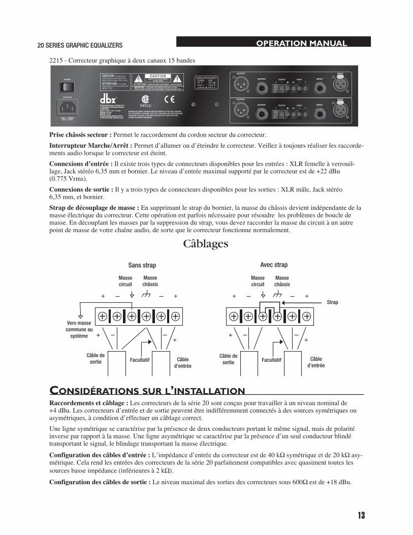
Prise châssis secteur :Permetleraccordementducordonsecteurducorrecteur.Interrupteur Marche/Arrêt : Permetd’allumeroud’éteindrelecorrecteur.Veillezàtoujoursréaliserlesraccorde-mentsaudiolorsquelecorrecteurestéteint.
Connexions d’entrée : Ilexistetroistypesdeconnecteursdisponiblespourlesentrées:XLRfemelleàverrouil-lage,Jackstéréo6,35mmetbornier.Leniveaud’entréemaximalsupportéparlecorrecteurestde+22dBu(0.775Vrms).
Connexions de sortie :Ilyatroistypesdeconnecteursdisponiblespourlessorties:XLRmâle,Jackstéréo6,35mm,etbornier.
Strap de découplage de masse : Ensupprimantlestrapdubornier,lamasseduchâssisdevientindépendantedelamasseélectriqueducorrecteur.Cetteopérationestparfoisnécessairepourrésoudrelesproblèmesdeboucledemasse.Endécouplantlesmassesparlasuppressiondustrap,vousdevezraccorderlamasseducircuitàunautrepointdemassedevotrechaîneaudio,desortequelecorrecteurfonctionnenormalement.
Considérations sur l’installationRaccordements et câblage : Lescorrecteursdelasérie20sontconçuspourtravailleràunniveaunominalde+4dBu.Lescorrecteursd’entréeetdesortiepeuventêtreindifféremmentconnectésàdessourcessymétriquesouasymétriques,àconditiond’effectueruncâblagecorrect.
Unelignesymétriquesecaractériseparlaprésencededeuxconducteursportantlemêmesignal,maisdepolaritéinverseparrapportàlamasse.Uneligneasymétriquesecaractériseparlaprésenced’unseulconducteurblindétransportantlesignal,leblindagetransportantlamasseélectrique.
Configuration des câbles d’entrée :L’impédanced’entréeducorrecteurestde40kΩsymétriqueetde20kΩ asy-métrique.Celarendlesentréesdescorrecteursdelasérie20parfaitementcompatiblesavecquasimenttouteslessourcesbasseimpédance(inférieuresà2kΩ).
Configuration des câbles de sortie : Leniveaumaximaldessortiesdescorrecteurssous600Ω estde+18dBu.
#85-2563-P2 2215 REAR ART (12-17-96) buyoff
OUTPUT
-+INPUT
- +
OUTPUT INPUT
PHONE:TIPRINGSLEEVE
XLR:PIN 1PIN 2PIN 3
CONNECTOR POLARITY
INPUTOUTPUT
OUTPUT
-+INPUT
- +
OUTPUT INPUT
INPUTOUTPUT
PROFESSIONAL PRODUCTSA HARMAN INTERNATIONALCOMPANYSALT LAKE CITY, UTAHMADE IN USAMODEL 2215EQUALIZER/LIMITER WITHTYPE III NOISE REDUCTION
MANUFACTURED UNDER ONE OR MORE OF THE FOLLOWINGU.S. PATENTS: 4,234,804 4,316,107 4,329,598 4,331,931 4,403,1994,409,500 4,425,551 4,434,380 4,454,433 4,471,324 4,473,793OTHER PATENTS PENDING
WARNING: TO REDUCE THE R ISK OF F IRE OR ELECTRICSHOCK DO NOT EXPOSE TH IS EQUIPMENT TO RA IN OR MOISTURE
RISK OF ELECTRIC SHOCKDO NOT OPEN
ATTENT ION: R ISQUE DE CHOC ELECTRIQUE - NE PAS OUVRIR
C A UT I ON: TO REDUCETHE R ISK OF F IRE REPLACEONLY WITH SAME TYPE FUSE.
A TTENT I ON: UTIL ISERUN FUSIBLE DE RECHANGE DEMEME TYPE.
28 WATTS
POWER
100V 50/60Hz120V 60Hz
+ +
+++
+
+ +
Without Jumper in Place With Jumper in Place
jumper
optional
circuitground
chassisground
circuitground
chassisground
to systemground
optional
WIRING CONNECTIONS WITH GROUND
Input Cable
Output Cable
Input Cable
Output Cable
Câblages
Sans strap Avec strap
Massechâssis
Massechâssis
Massecircuit
Massecircuit
Strap
Vers massecommune au
système
Facultatif Câble d’entrée
Câble de sortie
Câble de sortie Facultatif Câble
d’entrée

14
OPERATION MANUAL
Pourunrejetoptimaldesronflements,évitezderaccorderlesmassesdusignald’entréeetdusignaldesortieducorrecteur.Laplupartdescâblessymétriques(3-conducteurs)ontleurmasseconnectéeauxdeuxextrémités.Cecipeutinduiredesbouclesdemasseetdesronflements.Silesronflementspersistent,essayezdedéconnecterlamassed’unouplusieurscâblesdelachaîneaudio,depréférenceducôtéentréeetnonducôtésortiedel’appareil.
utilisation et notes de FonCtionneMentLescorrecteursgraphiquesdbxdelasérie20sontdesoutilsdetraitementdusignalutiliséslorsqu’uncontôleprécisdelafréquences’avèrenécessairesurtoutel’étendueduspectresonore.
Utilisésconjointementavecunanalyseurdespectre,lescorrecteurspeuventpermettred’adapterunsystèmeaudioàl’environnementacoustique(dustudioàlasalledeconcert)évitantainsilesrésonnances,d’améliorerlaclartéetd’aplanirlaréponseglobaleenfréquencedel’environnement.L’analyseurdespectreentempsréelestunoutiltrèsutilepourdéterminerlacorrectionàappliquer.
Insérezlecorrecteurgraphiqueentrelesignalsource(généralementlaconsole)etlesamplificateursdepuissance(oulefiltreactifsic’estlecas).Ajustezleniveauetlacorrectionnécessairepourobtenirlacourbederéponserecherchée.Lespotentiomètresàcourselonguedescorrecteurspermettentdesréglagesprécisdelacourbederéponse.
Pourobtenirunrapportsignal/bruitoptimisé,lesréglagesdegaindesélémentsdelachaîneaudiodoiventêtrecor-rectementeffectués.Chaqueélémentdecettechaînedoitêtreréglésursonniveaudefonctionnementnominalencommençantparlepremiermaillon,engénérallaconsoledemixage.Chaqueélémentdoittravailleràsonniveaunominalpourobtenirunrapportsignal/bruitoptimaldecetélément.Lesamplificateursdepuissance,derniersélé-mentsdelachaîne,doiventêtreréglésàpuissancemaximaledisponiblepourévitertoutegénérationdebruitdanslachaîne.
Touslescorrecteursactifs,deparleurnature,induisentdubruitlorsdel’atténuationoudel’amplificationdesbandesdefréquence,quialtèrelerapportsignal/bruitdusystèmeaudiopourtantdéjàoptimisé.Unecorrectionexcessivepeutinduireunepertede20dBouplusdurapportsignal/bruit.LeréducteurdebruitdbxTypeIII™aétéspécialementconçupourdetellesapplications.Cecircuitaméliorelaréductiondebruitàhauteurde20dB,rétablissantainsilaplagedynamiquerequiseparlessystèmesaudioprofessionnelslesplusexigeants.Laconjonc-tiond’uncâblageadapté,d’unebonnegestiondesgainsassociéeàl’utilisationdelaréductiondegaindbxTYPEIII™vouspermettradesupprimertoutbruitdefonddevotresystèmeaudio.

OPERATION MANUAL
15
20 SERIES GRAPHIC EQUALIZERS
DEUTSCH

®
®
®
®
®
®
WARNUNGBEACHTEN SIE ZU IHRER EIGENEN SICHERHEIT BITTE FOLGENDES:
WASSER UND FEUCHTIGKEIT: Benutzen Sie das Gerät nicht in feuchter Umgebung (z.B. in der Nähe von Badewannen, Waschbecken, Spülbecken, Waschtrögen, in feuchten Kellerräumen oder neben einem Schwimmbecken). Achten Sie darauf, daß keine Gegenstände oder Flüssigkeiten in das Innere des Gerätes gelangen.NETZGERÄT: Schliessen Sie das Gerät nur an das in der Bedienungsanleitung bzw. am Gerät ange-gebene Netzgerät an.SCHUTZERDE UND PHASENUMSCHALTER: Achten Sie darauf, den Erd anschluss des Gerätes nicht zu unterbrechen und den Phasenumschalter nicht zu deaktivieren.SCHUTZ DES NETZKABELS: Verlegen Sie alle Netzkabel immer so, dass möglichst niemand darauf treten und die Netzkabel durch darauf oder daneben gestellte Gegenstände nicht gequetscht werden können. Dies gilt besonders in der unmittelbaren Umgebung der Netzstecker, Netzsteckdosen und des Kabelaustritts am jeweiligen Gerät.SERVICE: Um Brände oder elektrische Schläge zu vermeiden, versuchen Sie nicht, andere Servicearbeiten als die in dieser Bedienungsanleitung beschriebenen am Gerät durchzuführen. Wenden Sie sich für diese Arbeiten an einen qualifizierten Techniker.GERÄTE MIT VON AUSSEN ZUGÄNGLICHEM SICHERUNGSHALTER: Ersetzen Sie durchgebrannte Sicherungen nur durch Sicherungen desselben Typs.NETZSPANNUNGEN: Je nach Art des am Einsatzort vorhandenen Netzanschlusses kann ein anderer Netzstecker, ein anderes Netzkabel oder beides erforderlich sein. Schliessen Sie das Gerät nur an die an der Rückseite des Gerätes angegebene Netzspannung an. Um Brände oder elektrische Schläge zu vermeiden, wenden Sie sich für Reparaturen an einen qualifizierten Techniker.
SICHERHEITSHINWEISEWICHTIGER HINWEIS BEI GERÄTEN MIT NETZKABEL:
ACHTUNG: DIESES GERÄT MUSS MIT EINER SCHUTZERDUNG VERSEHEN SEIN.
Die Adern des Netzkabels sind wie folgt farbcodiert:
GRÜN/GELB = Erde BLAU = Nulleiter BRAUN= Phase
Da die Farben der Adern des Netzkabels nicht unbedingt mit den Farbmarkierungen der Kontaktstifte in Ihrem Netzstecker übereinstimmen, gehen Sie bitte wie folgt vor:
• Schliessen Sie die grün/gelbe Ader an den mit dem Erdsymbol, dem Buchstaben "E", einem grünen oder grün/gelben Farbpunkt gekennzeichneten Kontaktstift an.
• Schliessen Sie die blaue Ader an den mit dem Buchstaben "N" oder einem schwar-zen Farbpunkt gekennzeichneten Kontakstift an.
• Schliessen Sie die braune Ader an den mit dem Buchstaben "L" oder einem roten Farbpunkt gekennzeichneten Kontaktstift an.
Je nach Art des am Einsatzort vorhandenen Netzanschlusses wird möglicherweise ein ande-res Netzkabel bzw. ein anderer Netzstecker oder beides erforderlich sein. Der Netzstecker darf nur von einem qualifizierten Techniker anhand untenstehender Tabelle getauscht werden. Dabei ist die grün/gelbe Ader direkt mit Gehäusemasse zu verbinden.
WARNUNG: Bei unterbrochener Schutzerdung können bestimmte Fehler im Gerät oder in der Anlage, an die das Gerät angeschlossen ist, dazu führen, daß zwischen Gehäusemasse
und Erde die volle Netzspannung anliegt. Das gleichzeitige Berühren des Gehäuses und eines Erdpunkts kann in diesem Fall zu schweren Verletzungen oder zum Tod führen.
NETZSTECKERVerwenden Sie aus Sicherheitsgründen vom Netzkabel abgeschnittene mitgespritzte Netzstecker nie weiter, sondern entsorgen Sie sie entsprechend den lokalen Entsorgungsvorschriften.
Schließen Sie beschädigte Netzstecker niemals an eine Netzsteckdose an.
CAUT ION
ATTENT ION: RIS QUE DE CHOC ELECT RIQUE - NE PAS OUVRIR
WARNING: TO RE DUCE T HE R ISK OF F IRE OR ELECT RICSHOCK DO NOT EXPOS E T H IS EQUIPMENT T O RA IN OR MOISTURE
R ISK OF ELECT RIC SHOCKDO NOT OPEN
Die obigen Symbole sind international üblich und dienen als Gefahrenhinweise bei Elektrogeräten. Das Blitzsymbol links oben weist auf gefährliche Spannungen im Gerät hin. Das Rufzeichen rechts oben weist auf wichtige Punkte hin, die unbedingt in der Bedienungsanleitung nachzulesen sind.Diese Symbole bedeuten auch, daß sich im Gerät keine vom Anwender reparierbaren Teile befinden. Öffnen Sie das Gerät auf keinen Fall und versuchen Sie nicht, es selbst zu reparieren. Lassen Sie Reparaturen ausschließlich von einem qualifizierten Techniker durchführen. Wenn Sie das Gerät öff-nen, erlischt automatisch die Garantie des Herstellers. Machen Sie das Gerät nicht naß. Wenn den-noch eine Flüssigkeit auf oder in das Gerät gelangt, schalten Sie es sofort aus und bringen Sie es zu einem Händler zur Überprüfung. Ziehen Sie bei Gewittern zum Schutz vor Beschädigungen des Geräts das Netzkabel ab.
ELEKTROMAGNETISCHE VERTRÄGLICHKEITDieses Gerät entspricht den in der Konformitätserklärung angeführten Spezifikationen. Voraussetzung für den Betrieb des Gerätes ist die Erfüllung folgender Bedingungen:
• Das Gerät darf keine schädliche Störstrahlung abgeben.• Das Gerät darf durch empfangene Störstrahlung einschliesslich Störstrahlungen, die
Betriebsstörungen hervorrufen können, nicht beschädigt werden.Der Betrieb des Geräts in starken elektromagnetischen Feldern ist zu vermeiden. • Verwenden Sie ausschliesslich geschirmte Verbindungskabel.
garantiebedingungen
Wir gewähren 1 Jahr Garantie ab Verkaufsdatum auf nachweisbare Material- und Fabrikationsfehler (ausgenommen externe Netzgeräte). Der Garantieanspruch erlischt bei unsachgemässer Handhabung, elektrischer oder mechanischer Beschädigung durch miss-bräuchliche Anwendung sowie bei unsachgemässer Reparatur durch nichtautorisierte Werkstätten. Zur Inanspruchnahme der angeführten Garantieleistungen ist der Nachweis des Kaufes (ordentliche Rechnung des Verkäufers) erforderlich. Transport- und Portospesen, welche aus der Einsendung des Gerätes zur Garantiereparatur erwachsen, können von dbx nicht über-nommen werden, das Risiko der Zusendung trägt der Kunde. Die Garantie wird ausschliesslich für den Erstkäufer geleistet.
PHASE
E
NULLLEITER
SCHUTZERDE
ADER
L
N
BRAUN
BLAU
GRÜN/GELB
SCHWARZ
Standard Alt.
FARBE
WEISS
GRÜN
Name des Herstellers: dbx Professional ProductsAdresse des Herstellers: 8760 S. Sandy Parkway Sandy, Utah 84070, USA
erklärt, daß das Produkt:
erklärt, daß das Produkt: dbx 2031, dbx 2215 and dbx 2231 Ausstattungen des Produktes: keine Angaben
sich den folgenden Produktangaben angleicht: Sicherheit: IEC 60065 -01+Amd 1
EMC : EN 55022:2006 (N/A; Analog Product) IEC61000-4-2 IEC61000-4-3 IEC61000-4-4 IEC61000-4-5 IEC61000-4-6 IEC61000-4-8 IEC61000-4-11Zusätzliche Informationen:
Dieses Produkt entspricht den: Low Voltage Directive 2006/95/EC EMC Directive 2004/108/EC. RoHS Directive 2002/95/EC WEEE Directive 2002/96/EC
Mit Beachtung zu Direktive 2005/32/EC und EC Regelung 1275/2008 von 17 Dezember 2008, ist dieses Produkt entworfen, ist hergestellt, und ist als Berufliche Tongeräte klassifiziert und ist fol glich frei von dieser Direktive.
Roger Johnsen Director, Engineering Signal Processing 8760 S. Sandy Parkway Sandy, Utah 84070, USA Date: November 19, 2010
Kontakt in Europa: Ihr nächster Digitech Fachhandel oder Kundendienst oder
Harman Music Group 8760 South Sandy Parkway Sandy, Utah 84070 USA (801) 566-8800 (801) 568-7583
ÜBEREINSTIMMUNGS- ERKLÄRUNG

OPERATION MANUAL
17
20 SERIES GRAPHIC EQUALIZERS
inhalt
EinlEitung . . . . . . . . . . . . . . . . . . . . . . . . . . . . . . . . . . . . . . . . . . . . . . . . . . . . 18 kontrollE . . . . . . . . . . . . . . . . . . . . . . . . . . . . . . . . . . . . . . . . . . . . . . . . . . . 18
BEDiEnElEmEntE . . . . . . . . . . . . . . . . . . . . . . . . . . . . . . . . . . . . . . . . . . . . . . . 18 anschliEssEn DEs EQualizErs an ihrE anlagE . . . . . . . . . . . . . . . . . . . . . . 20 rücksEitE . . . . . . . . . . . . . . . . . . . . . . . . . . . . . . . . . . . . . . . . . . . . . . . . . . . . 20
anschlusshinwEisE. . . . . . . . . . . . . . . . . . . . . . . . . . . . . . . . . . . . . . . . . . . . . 21 BEDiEnungs- unD anwEnDungshinwEisE . . . . . . . . . . . . . . . . . . . . . . . . . . . . 22
sErvicE unD kunDEnDiEnst . . . . . . . . . . . . . . . . . . . . . . . . . . . . . . . . . . . . . . 22
tEchnischE DatEn . . . . . . . . . . . . . . . . . . . . . . . . . . . . . . . . . . . . . . . . . . . . . 31
BlockschaltBilD . . . . . . . . . . . . . . . . . . . . . . . . . . . . . . . . . . . . . . . . . . . . . . 32

18
OPERATION MANUAL
einleitungWirdankenIhnen,daßSiesichfüreinenEqualizervondbxentschiedenhaben.DiegraphischenEqualizervondbxsindmultifunktionaleGerätemitderFlexibilitätundLeistungsfähigkeit,diefürprofessionelleAnwendungenerford-erlichsind.BittenehmenSiesichetwasZeit,dieBedienungsanleitungdurchzulesen.SiefindendarinwichtigeHinweisevomAnschließendesGerätesbishinzuAnwendungsbeispielen.DieHauptmerkmalederSerie20sind:
•dbxTYPEIII™RauschunterdrückungzumAufholenvonbiszu20dBRauschabstand •PeakPlus™Limiter(Patentangemeldet)zumSchutzIhrerAnlage •Regelbereichzwischen±6dBund±12dBumschaltbar •SymmetrischeEin-undAusgänge •AnschlüsseanXLR-undStereoklinkenbuchsensowieKlemmleisten •Eingangsverstärkungvon-12dBbis+12dBeinstellbar •Bessel-Trittschallfiltermit18dB/Oktavebei40Hz •SignalmassevonGehäusemassetrennbar •eingebauterNetztrafo •AutomatischerBypassbeiAbschaltenbzw.NetzausfallüberRelaismit2sEinschaltverzögerung.
KontrolleKontrollierenSiebitte,obderKarton,indemIhrEqualizergeliefertwurde,folgendeTeileenthält:
•Equalizer(entsprechendderSeriennummeramKarton) •Netzkabel •Bedienungsanleitung •Registrierungskarte •4Stk.BefestigungsschraubenundUnterlegscheiben
Fallsetwasfehlt,wendenSiesichbitteanIhreAKG-Vertretung(s.letzteSeite).
bedieneleMenteFrontplatte
Einkanaliger31-bandigergraphischerEqualizer2031
Zweikanaliger31-bandigergraphischerEqualizer2
RANGE
GAINREDUCTION (dB)
OUTPUTLEVEL (dBu)
LOWCUT
EQBYPASS
TYPE IIINR
INPUTGAIN
dB-12
0
+12
PeakPlusTHRESHOLD
dBu0 OFF
+20+5
+15+10+/-6
+/-15CLIP
1
0
-6
+6
20 25 31.5 40 50 63 80 500400315250 1.6k1.25k1k800 5k4k3.15k2.5k 16k12.5k10k8k6.3k 20k2k630100 125 160 200
0
-15
+153610+18+100-10
2031Equalizer/Limiterwith TYPE III NR
85-2564-A0 2031 FRONT ART 12-16-96
2231Equalizer/Limiterwith TYPE III NR
20 25 31.5 40 50 63 80 500400315250 1.6k1.25k1k800 5k4k3.15k2.5k 16k12.5k10k8k6.3k 20k2k630100 125 160 200
RANGE
GAINREDUCTION (dB)
OUTPUTLEVEL (dBu)
LOWCUT
EQBYPASS
TYPE IIINR
INPUTGAIN
dB-12
0
+12
PeakPlusTHRESHOLD
dBu0 OFF
+20+5
+15+10+/-6
+/-15CLIP
13610+18+100-10
RANGE
GAINREDUCTION (dB)
OUTPUTLEVEL (dBu)
LOWCUT
EQBYPASS
TYPE IIINR
INPUTGAIN
dB-12
0
+12
PeakPlusTHRESHOLD
dBu0 OFF
+20+5
+15+10+/-6
+/-15CLIP
13610+18+100-10
0
-15
+15
0
-15
+15
0
-6
+6
0
-6
+6
85-2568-A0 2231 FRONT ART 12-16-96

OPERATION MANUAL
19
20 SERIES GRAPHIC EQUALIZERS
Zweikanaliger15-bandigergraphischerEqualizer2215
INPUT GaIN-Regler:StelltdenSignalpegelfürdieEqualizerschaltungein.DerRegelbereichbeträgt-12dBbis+12dBVerstärkung.DieWirkungderjeweiligenEinstellungwirddurchdieOUTPUTLEVEL-LEDsangezeigt.
EQ BYPASS-Taste:MitdieserTastekönnenSiesämtlicheSchiebereglerwegschalten(sieheBlockschaltbildaufSeiteX).DieINPUTGAIN-undLOWCUT-Reglerbleibenjedochwirksam.
EQ BYPaSS-LED:ZeigtdurchLeuchtenan,dassderEqualizerteilabgeschaltetist.BeachtenSie,dassbeiallenEqualizernderSerie20dieEQBYPASS-TastenuraufdengraphischenEqualizerteilwirkt.DieINPUTGAIN- und LOWCUT-ReglerbleibenauchbeigedrückterEQ-BYPASS-Tastewirksam.
RaNGE-Taste und -LEDs:SchaltetdenRegelbereichderSchiebereglerzwischen±6dBund±15dBum.WennSieauf±15dBschalten,leuchtetdieroteLED,bei±6dBdiegelbe.BeachtenSie,dassdieRANGE-Tasteleichtversen-ktangebrachtist.Diesmachtesschwerer.dieTasteunabsichtlichzudrücken,wasunterUmständenzuSchädenananderenGerätenIhrerAnlageführenkönnte.
OUTPUT LEVEL-LEDs:Diese4LEDszeigendenAusgangspegeldesEqualizersan.DieroteLEDmitderBezeichnung”+18dBu”leuchtetbei3dBunterClippingauf.AngezeigtwirdderAusgangspegelnachsämtlichenProzessorschaltungen,alsoauchnachdemLimiter.
CLIP-LED:DieseLEDleuchtetauf,solbaldderinterneSignalpegelanirgendeinerStelleauf3dBunterClippingsteigt.DieskanninfolgendenFällengeschehen:1)dasEingangssignaliststärkerals+22dBu,2)derINPUTGAIN-Regleristzuhochaufgedrehtoder3)dieFrequenzband-Schiebereglersindzuweitaufgezogen.
GaIN REDUCTION-anzeige:Diese4LEDszeigendasAusmassderSignaldämpfungan,dieerfolgt,wennderAusgangssignalpegeldesEqualizerteilsdenmitdemLIMITERTHRESHOLD-ReglerdesPeakPlus™Limitersein-gestelltenWertübersteigt.
PeakPlus ThREShOLD-Regler:SchaltetdenPeakPlus™Limiterzu.DerReglerstelltdenPegelein,abdemdasSignalimVerhältnis∞:1gedämpftwird.DieSchaltungentsprichtimwesentlichendemvondenKompressor/Limiterndbx1066und1046herbekanntenPeakStopPlus™Limiter(Pat.ang.).DerRegelumfangreichtvon0dBubis “OFF”(+24dBu).InStellung”OFF”istderLimiterpraktischabgeschaltetundeserfolgtkeineSignaldämpfung.
TYPE III NR-Taste: SchaltetdiedbxTypeIII™RauschunterdrückungdesEqualizerseinundaus.
TYPE III NR-LED:DiesegelbeLEDleuchtet,solangediedbxTypeIII™Rauschunterdrückungeingeschaltetist(TYPEIIINR-Tastegedrückt).
Frequenzband-Schieberegler:MitdenSchiebereglernkönnenSiediejeweilsangegebeneFrequenzjenachStellungderRANGE-Tasteum±6dBoder±15dBanhebenoderabsenken.WennsichalleSchiebereglerinderger-astetenMittelstellungbefinden,istderFrequenzgangdesAusgangssignalslinear.DerAbstandzwischendenMittenfrequenzenderFrequenzbänderdesdbx2031und2231beträgtjeweils1/3OktavenachISO.DerAbstandzwischendenMittenfrequenzendesdbx2215beträgtjeweils2/3OktavennachISO.
LOw CUT-TaSTE: DieLOWCUT-TasteschaltetdasBessel-Trittschallfiltermit18dB/Oktavebei40HzindenSignalwegeinundausdemSignalwegheraus.BeihineingedrückterLOWCUT-TasteistdasFilereingeschaltet.
RANGE
GAINREDUCTION (dB)
OUTPUTLEVEL (dBu)
LOWCUT
EQBYPASS
TYPE IIINR
INPUTGAIN
dB-12
0
+12
PeakPlusTHRESHOLD
dBu0 OFF
+20+5
+15+10+/-6
+/-15CLIP
1
0
-6
+6
25 40 63 100 160 250 400 16k10k6.3k4k630 1k 1.6k 2.5k
3610+18+100-10
2215Equalizer/Limiterwith TYPE III NR
85-XXXX-A0 2215 FRONT ART 12-16-96
0
-15
+15
RANGE
GAINREDUCTION (dB)
OUTPUTLEVEL (dBu)
LOWCUT
EQBYPASS
TYPE IIINR
INPUTGAIN
dB-12
0
+12
PeakPlusTHRESHOLD
dBu0 OFF
+20+5
+15+10+/-6
+/-15CLIP
1
0
-6
+6
25 40 63 100 160 250 400 16k10k6.3k4k630 1k 1.6k 2.5k
3610+18+100-10
0
-15
+15

20
OPERATION MANUAL
ansChliessen des eQualizers an ihre anlageDieEqualizerderSerie20besitzensymmetrischeEin-undAusgängeundkönnendaherzusammenmitjedemLine-Pegel-Geräteingesetztwerden.NähereInformationenzurVerkabelungfindenSieimKapitel"Anschlusshinweise" auf Seite 21.BeiderVerkabelungbeachtenSiebitte:
•Schalten Sie immer alle Geräte aus, bevor Sie eine Kabelverbindung herstellen.•Montieren Sie den Equalizer in einem 19"-Rack (optional).MontierenSiedenEqualizermitdenmitgeliefertenBefestigungsschrauben.SiekönnendasGerätoberhalb
oderunterhalbvonanderenGerätenmontieren,dienichtzuvielWärmeabgeben.BeieingeschaltetenGerätendarfdieUmgebungstemperatur45°Cnichtübersteigen.DasGehäuseistzwargegenHF-undBrummeinstreuungenabgeschirmt,stellenSiedasGerätabertrotzdemnichtinderNäheextremstarkerHF-oderelektromagnetischerFelderauf.
• Stellen Sie die gewünschten audioverbindungen mittels XLR- oder Stereoklinkensteckern bzw. über die Klemmleisten her (je nach anwendung).AnalledreiArtenvonEin-undAusgängenkönnenSiesowohlsymmetrischealsauchasymmetrischeGeräteanschliessen.WennSiemehrereAnschlüssedesselbenEin-oderAusgangsgleichzeitigbenützen,könnendadurchsymmetrischeVerbindungenasymmetrischwerden,Phasenauslöschungenentstehen,dasSignalgegenMassekurzgeschlossenoderdasangeschlosseneGerätbeschädigtwerden.WennSiemehralseinenAusgangsanschlussgleichzeitigbelegen,achtenSiedarauf,dassdieGesamt-Lastimpedanzderparallelange-schlossenenGerätemehrals600Ωbeträgt.
• Stellen Sie mit der RaNGE-Taste den gewünschten Regelbereich der Schieberegler ein. Anmerkung: Da beim Drücken dieser Taste ein Schaltknack entstehen kann, reduzieren Sie vorher unbedingt die Lautstärke der Endverstärker.
• Schalten Sie den Equalizer ein. SchließenSiedasNetzkabelandieNetzanschlussbuchseanderRückseitedesGerätesan.FührenSiedas
NetzkabelzueinergutzugänglichenNetzsteckdose,inderenNähesichkeineAudioleitungenbefinden.SiekönnendenEqualizermitdemNetzschalteranderFrontplatteodereinemAnlagenhauptschalterein-undauss-chalten.
rüCKseiteAnschlüsse und Bedienelemente
Einkanaliger31-bandigergraphischerEqualizer2031
Zweikanaliger31-bandigergraphischerEqualizer2231#85-1565-P1 2031 REAR ART (12-10-96) buyoff
15 WATTS
POWER
OUTPUT
-+INPUT
- +
OUTPUT INPUT
PHONE:TIPRINGSLEEVE
XLR:PIN 1PIN 2PIN 3
CONNECTOR POLARITY
INPUTOUTPUT
100V 50/60Hz120V 60Hz
PROFESSIONAL PRODUCTSA HARMAN INTERNATIONALCOMPANYSALT LAKE CITY, UTAHMADE IN USAMODEL 2031EQUALIZER/LIMITER WITHTYPE III NOISE REDUCTION
MANUFACTURED UNDER ONE OR MORE OF THE FOLLOWINGU.S. PATENTS: 4,234,804 4,316,107 4,329,598 4,331,931 4,377,7924,403,199 4,409,500 4,425,551 4,434,380 4,454,433 4,471,3244,473,793 OTHER PATENTS PENDING
WARNING: TO REDUCE THE R ISK OF F IRE OR ELECTRICSHOCK DO NOT EXPOSE TH IS EQUIPMENT TO RA IN OR MOISTURE
RISK OF ELECTRIC SHOCKDO NOT OPEN
ATTENT ION: R ISQUE DE CHOC ELECTRIQUE - NE PAS OUVRIR
C A UT I ON: TO REDUCETHE R ISK OF F IRE REPLACEONLY WITH SAME TYPE FUSE.
A TTENT I ON: UTIL ISERUN FUSIBLE DE RECHANGE DEMEME TYPE.
#85-2569-P0 2231 REAR ART (12-10-96) buyoff
28 WATTS
OUTPUT INPUT
PHONE:TIPRINGSLEEVE
XLR:PIN 1PIN 2PIN 3
CONNECTOR POLARITY
INPUTOUTPUT
OUTPUT INPUT
INPUTOUTPUT
100V 50/60Hz120V 60Hz
PROFESSIONAL PRODUCTSA HARMAN INTERNATIONALCOMPANYSALT LAKE CITY, UTAHMADE IN USAMODEL 2231EQUALIZER/LIMITER WITHTYPE III NOISE REDUCTION
WARNING: TO REDUCE THE R ISK OF F IRE OR ELECTRICSHOCK DO NOT EXPOSE TH IS EQUIPMENT TO RA IN OR MOISTURE
RISK OF ELECTRIC SHOCKDO NOT OPEN
ATTENT ION: R ISQUE DE CHOC ELECTRIQUE - NE PAS OUVRIR
C A UT I ON: TO REDUCETHE R ISK OF F IRE REPLACEONLY WITH SAME TYPE FUSE.
A TTENT I ON: UTIL ISERUN FUSIBLE DE RECHANGE DEMEME TYPE.
POWER
MANUFACTURED UNDER ONE OR MORE OF THE FOLLOWINGU.S. PATENTS: 4,234,804 4,316,107 4,329,598 4,331,931 4,377,7924,403,199 4,409,500 4,425,551 4,434,380 4,454,433 4,471,3244,473,793 OTHER PATENTS PENDING
OUTPUT
-+INPUT
- +
OUTPUT
-+INPUT
- +

OPERATION MANUAL
21
20 SERIES GRAPHIC EQUALIZERS
Zweikanaliger15-bandigergraphischerEqualizer2215
Netzanschlussbuchse:IEC-KaltgerätebuchsezumAnschlußdesmitgeliefertenNetzkabels.POwER-Schalter: SchaltetdasGeräteinundaus.SchaltenSiedasGerätimmeraus,bevorSieAudioverbindungen herstellen.
INPUT-anschlüsse:ProEingangstehendreiverschiedeneAnschlüssezurVerfügung:verriegelbareXLR-Buchsen,6,3-mm-StereoklinkenbuchsenundeineKlemmleiste.DermaximalzulässigeEingangspegelfürdenEqualizerbeträgt+22dBu(bezogenauf0,775Veff.)
OUTPUT-anschlüsse:ProAusgangstehendreiverschiedeneAnschlüssezurVerfügung:verriegelbareXLR-Buchsen,6,3-mm-StereoklinkenbuchsenundeineKlemmleiste.
GROUND LIFT-Drahtbrücke:DurchEntfernenderDrahtbrückezwischendenbeidenSchraubklemmenkönnenSiedieGehäusemassevonderSignalmassedesEqualizerstrennen.Diesistmanchmalnotwendig,umineinerBeschallungsanlage"Erdschleifen"zuverhindern.IndiesemFallmüssenSiedenSignalmasseanschluss(+ +
+++
+
+ +
Without Jumper in Place With Jumper in Place
jumper
optional
circuitground
chassisground
circuitground
chassisground
to systemground
optional
WIRING CONNECTIONS WITH GROUND
Input Cable
Output Cable
Input Cable
Output Cable
) mit einemanderenErdanschluss innerhalb IhrerAnlageverbinden, damit IhrEqualizer einwandfrei funk- tioniert.
ansChlusshinWeise
Verbindungen und Kabel:DieEqualizerderSerie20sindfüreinenNennpegelvon+4dBuausgelegt.Vorausgesetzt,dieKabelsindrichtigbeschaltet,könnenSiedieEqualizersowohlansymmetrischealsauchasym-metrischeSignalquellenundandieAusgängesymmetrischeroderasymmetrischerGeräteanschliessen.
SymmetrischeKabelsindzweipolige,geschirmteKabel,beidenendiebeidenInnenleiterdasselbeSignalführen,jedochmitjeweilsentgegengesetzterPolaritätbezogenaufMasse.AsymmetrischeKabelsindeinpoligegeschirmteKabel,derenInnenleiterdasSignalführt,währenddieAbschirmunganMasseliegt.
Eingangsbeschaltung:DieEingangsimpedanzdesEqualizersbeträgt40kΩ symmetrisch und 20kΩ asymmetrisch. DadurchkönnenSiedieSerie20anpraktischallenniederohmigen(unter2kΩ) Quellen betreiben.
Ausgangsbeschaltung:DermaximaleAusgangspegeldesEqualizersbeträgt+18dBuan600ΩLastimpedanz.BeimBetriebmitsymmetrischbeschaltetenSignalquellenisteinemaximaleBrummunterdrückungnurdanngewährleistet,wennderEqualizerunddieSignalquellebzw.dasnachgeschalteteGerätnichtgemeinsamgeerdetsind.Beidenmeistensymmetrischen(2-poliggeschirmten)KabelnistdieAbschirmungbeidseitigangeschlossen.
#85-2563-P2 2215 REAR ART (12-17-96) buyoff
OUTPUT
-+INPUT
- +
OUTPUT INPUT
PHONE:TIPRINGSLEEVE
XLR:PIN 1PIN 2PIN 3
CONNECTOR POLARITY
INPUTOUTPUT
OUTPUT
-+INPUT
- +
OUTPUT INPUT
INPUTOUTPUT
PROFESSIONAL PRODUCTSA HARMAN INTERNATIONALCOMPANYSALT LAKE CITY, UTAHMADE IN USAMODEL 2215EQUALIZER/LIMITER WITHTYPE III NOISE REDUCTION
MANUFACTURED UNDER ONE OR MORE OF THE FOLLOWINGU.S. PATENTS: 4,234,804 4,316,107 4,329,598 4,331,931 4,403,1994,409,500 4,425,551 4,434,380 4,454,433 4,471,324 4,473,793OTHER PATENTS PENDING
WARNING: TO REDUCE THE R ISK OF F IRE OR ELECTRICSHOCK DO NOT EXPOSE TH IS EQUIPMENT TO RA IN OR MOISTURE
RISK OF ELECTRIC SHOCKDO NOT OPEN
ATTENT ION: R ISQUE DE CHOC ELECTRIQUE - NE PAS OUVRIR
C A UT I ON: TO REDUCETHE R ISK OF F IRE REPLACEONLY WITH SAME TYPE FUSE.
A TTENT I ON: UTIL ISERUN FUSIBLE DE RECHANGE DEMEME TYPE.
28 WATTS
POWER
100V 50/60Hz120V 60Hz
+ +
+++
+
+ +
Without Jumper in Place With Jumper in Place
jumper
optional
circuitground
chassisground
circuitground
chassisground
to systemground
optional
WIRING CONNECTIONS WITH GROUND
Input Cable
Output Cable
Input Cable
Output Cable
Masseanschlüsse
Ohne Drahtbrücke Mit Drahtbrücke
Signal-masse
Gehäuse-masse
Signal-masse
Gehäuse-masse
Drahtbrücke
Zur Anlagen-Erde
Ausgangs-kabel fakultativ Eingangs-
kabelAusgangs-
kabelfakultativ Eingangs-
kabel

22
OPERATION MANUAL
DadurchkönnenErdschleifenentstehen,diewiederumBrummeinstreuungenhervorrufen.WenndieBrummgeräuschebleiben,lötenSiebeieinemodermehrerenVerbindungskabelnderAnlagedieAbschirmungab,undzwarjeweilsameingangsseitigen(NICHTamausgangsseitigen)Stecker.
bedienungs- und anWendungshinWeiseDiegraphischenEqualizerderSerie20vondbxbewährensichüberalldort,woeineexakteEinstellungdesFrequenzgangsüberdasgesamteAudiospektrumerforderlichist.
InVerbindungmiteinemAudioSpectrumAnalyzerkönnenSiedieSerie30überall-vomStudiobiszumKonzertsaal-zurAbstimmungderAkustikeinsetzen,umRückkopplungenzubekämpfen,dieVerständlichkeitzuerhöhenunddenFrequenzgangdesRaumszubegradigen.Echtzeit-Spectrum-AnalyzeroderähnlicheAudio-AnalysatoreneignensichhervorragendzurBestimmungdererforderlichenEntzerrung.
SchaltenSiedenEqualizerzwischendieSignalquelle(meisteinMischpult)unddieEndverstärkerfürdieLautsprecher(oderdieFrequenzweiche,fallsvorhanden).StellenSiedenPegelunddieEntzerrungsoein,daßderFrequenzgangderAnlageIhrenVorstellungenentspricht.MitdenLanghub-SchiebereglernkönnenSiedieeinzelnenFrequenzbänderexaktentsprechenddergewünschtenEntzerrungskurveeinstellen.
DeroptimaleRauschabstandhängtvondenrichtigenPegelverhältnisseninnerhalbderAnlageab.StellenSiealleKomponentenderAnlage,beginnendmitdemerstenGliedderÜbertragungskette-meisteinMischpult-aufNennpegelein.NursokönnenSiedenmaximalenRauschabstandjedesGerätesausnützen.UmunnötigesRauschenzuvermeiden,stellenSiedieLautsprecher-EndstufenalsletztesGliedderÜbertragungskettenursolautwieunbedingtnötigein.
AlleaktivenEqualizerhebendurchdieAnhebungbzw.AbsenkungvonFrequenzbändernprinzipbedingtauchdasRauschenmitanundkönnensodenVorteileinerrauscharmenBeschallungsanlagewettmachen.DrastischeEntzerrungkanndenRauschabstandumbiszu20dBverschlechtern.SpeziellfürdiesenFallentwickeltedbxdieTypeIII™Rauschunterdrückung.MiteinerRauschminderungumbiszu20dBstelltdiesesSystemselbstdiefüranspruchsvollsteprofessionelleBeschallungsanlagengeforderteDynamikwiederher.MitfachgerechterVerkabelung,richtigenPegelverhältnissenundderTypeIII™RauschunterdrückungsollteIhreAnlagepraktischrauschfrei arbeiten.
serviCe und KundendienstDieEqualizervondbxsindvolltransistorisierteGerätemitBauteilenvonhöchsterQualitätundZuverlässigkeit.JedesGerätwirdimWerkaufQualitätundFunktiongeprüftundabgeglichen.NormalerweisesinddaherwährenddergesamtenLebensdauerdesGeräteskeinerleiweitereEinstellarbeitenerforderlich.
ImServicefalllesenSiebittezuerstinderBedienungsanleitungnachundwendenSiesicherstdannanIhrendbx-Händler.
FürdenFall,daßIhrHändlerIhrGerätzurReparaturandasWerkeinsendenmuß,hebenSiebittedenOriginalkartonauf.WennSiedasnichtmöchten,entsorgenSiedasVerpackungsmaterialnachdeninIhremLandgültigenEntsorgungsvorschriften.
FallsSieweitereFragenhaben,wendenSiesichbitteanIhredbx-Vertretung.DerenAdresse,Telefon-undFaxnummerfindenSieaufderletztenSeite.

OPERATION MANUAL
23
20 SERIES GRAPHIC EQUALIZERS
ESPAÑOL

®
®
®
®
®
®
ATENCIONPARA SU PROTECCIÓN TENGA A BIEN LEER LO QUE SIGUE:AGUA Y HUMEDAD: El aparato no debe ser utilizado cerca del agua (p.ej. cerca de una bañera, lavabo, sumidero de cocina, tuba de lavadero, en un sótano húmedo o cerca de una piscina, etc.). Debe impedirse caigan objetos sobre la caja y que se derramen líquidos a través de las aberturas.FUENTES DE ALIMENTACION: El aparato debe conectarse sólo a una fuente de aliment-ación del tipo descrito en las instrucciones o que esté marcada en el aparato.PUESTA A TIERRA O POLARIZACION: Deben tomarse precauciones para que los medios de puesta a tierra o de polarización del aparato no queden invalidados.PROTECCION DEL CORDON DE ALIMENTACION: Los cordones de alimentación deben disponerse de tal forma que no se puedan pisar o que no sean aplastados por objetos coloca-dos sobre o contra ellos, poniendo atención particular en los cordones en enchufes, en los tomacor-rientes y el lugar en que estos salen del aparato.SERVICIO TECNICO: Para reducir el riesgo de incendio o electrochoque, el usuario no debe intentar reparar el aparato, aparte de lo que se describe en las instrucciones. Todo otro servicio téc-nico debe ser encargado a personal técnico calificado.PARA UNIDADES CON RECEPTACULOS DE FUSIBLES ACCESIBLES DEL EXTERIOR:Reemplazar el fusible por otro del mismo tipo y potencia.TENSION DE ENTRADA MULTIPLE: Puede ser que este equipo necesite un cordón de ali-mentación o un enchufe tomacorriente diferentes o ambos, dependiendo de la fuente de aliment-ación disponible cuando se hace la instalación. Conectar este equipo sólo a la fuente de aliment-ación indicada en el panel posterior del aparato. Para reducir el riesgo de incendio o electrochoque, acuda, para el servicio técnico, a personal calificado o equivalente.
REINO UNIDO: ADVERTENCIA SOBRE EL ENCHUFE TOMACORRIENTEUn enchufe tomacorriente moldeado que haya sido cortado del cordón ya no es seguro. Debe desecharse en un servicio apropiado de eliminación de desechos. EN NINGUN CASO DEBE INSERTARSE UN ENCHUFE TOMACORRIENTE DAÑADO O CORTADO EN UN ZOCALO DE POTENCIA DE 13 A. No debe utilizarse el enchufe tomacorriente sin que esté en su lugar la cubierta del fusible. Las cubiertas de fusible de repuesto las puede obtener de su distribuidor local. Los fusibles de repuesto deben tener 13 A y ser aprobados por ASTA según BS 1362.
CAUT ION
ATTENT ION: RIS QUE DE CHOC ELECT RIQUE - NE PAS OUVRIR
WARNING: TO RE DUCE T HE R ISK OF F IRE OR ELECT RICSHOCK DO NOT EXPOS E T H IS EQUIPMENT T O RA IN OR MOISTURE
R ISK OF ELECT RIC SHOCKDO NOT OPEN
Los símbolos indicados arriba son símbolos internacionalmente aceptados que advierten contra posibles peligros con productos eléctricos. El rayo con punta de flecha en un triángulo equilátero significa que hay voltajes peligrosos en el aparato. El signo de exclamación en un triángulo equi-látero indica que es necesario que el usuario haga referencia al Manual de Instrucciones.Estos símbolos indican que no hay piezas de fácil mantenimiento técnico por parte del usuario en el interior de la unidad. No debe abrirse el aparato. No trate de reparar el aparato usted mismo. Acuda a personal calificado para todo lo relativo al servicio técnio. El abrir el chasis por cualquier razón deja inválida la garantía del fabricante. No moje la unidad. Si se derrama líquido sobre el aparato, desconéctelo inmediatamente y llévelo adonde su representante o distribuidor para someterlo a servicio técnico. Desconecte la unidad durante tormentas para impedir averías.
COMPATIBILIDAD ELECTROMAGNETICAEsta unidad se conforma a las Especificaciones de Productos indicadas en la Declaración de Conformidad. Puede ponerse en funcionamiento si se cumplen las dos condiciones siguientes: • este dispositivo no debe causar interferencia nociva y • este dispositivo debe aceptar toda interferencia recibida, incluyendo la interferencia
que pueda causar un funcionamiento no deseado.Debe evitarse el funcionamiento de esta unidad con campos electromagnéticos fuertes. • Utilizar sólo cables de interconexión blindados.
INSTRUCCIONES DE SEGURIDADAVISO A LOS CLIENTES QUE TIENEN UN APARATO EQUIPADO CON UN CORDON DE ALIMENTACION.
ATENCION: ESTE APARATO DEBE ESTAR PUESTO A TIERRA.
Las almas en el conductor principal tienen colores según el código siguiente:
VERDE y AMARILLO - tierra AZUL - neutral MARRON - vivo
Como los colores de las almas del conductor principal de este aparato pueden quizás no corresponder a las marcas coloreadas que identifican los terminales en su enchufe, proceda como sigue: • El alma de color de verde y amarillo debe conectarse al terminal en el enchufe mar-
cado con la letra E, o con el símbolo de tierra, o coloreado de verde o de verde y amarillo.
• El alma de color de azul debe conectarse al terminal marcado con N o coloreado de negro.
• El alma de color marrón debe conectarse al terminal marcado con la letra L o col-oreado de rojo.
Este equipo puede requerir la utilización de un cordón de alimentación o de un enchufe tomacorriente diferentes, o de ambos, dependiendo de la fuente de alimentación disponible cuando se hace la instalación. Si el enchufe tomacorriente tiene que cambiarse, recurra a personal de servicio técnico calificado, quien a su vez debe hacer referencia al cuadro indicado a continuación. El alambre verde/amarillo debe conectarse directamente al chasis de la unidad.
ATENCION: Si la puesta a tierra queda inactivada, ciertas condiciones de fallo de la uni-dad o del sistama al que está conectado pueden dar como resultado el voltaje total de línea entre el chasis y el punto en que se toma tierra. El resultado de ello pueden ser lesiones graves o muerte si el chasis y el punto de toma de tierra se tocan al mismo tiempo.
VIVO
E
NEUTRAL
TIERRA
CONDUCTOR
L
N
MARRON
AZUL
VERDE/AMARILLO
NEGRO
Normal Alt.
COLOR
BLANCO
VERDE
Nombre del fabricante: dbx Professional ProductsDirección del fabricante: 8760 S. Sandy Parkway Sandy, Utah 84070, USA
declara que el producto:
Nombre de producto: dbx 2031, dbx2215 and dbx2231 Opciones del producto: N/A
cumple con las siguientes Espeficicaciones de Producto:
Seguridad: IEC 60065 -01+Amd 1
EMC: EN 55022:2006 (N/A; Analog Product) IEC61000-4-2 IEC61000-4-3 IEC61000-4-4 IEC61000-4-5 IEC61000-4-6 IEC61000-4-8 IEC61000-4-11
Información complementaria:
El aparato citado anteriormente cumple con los requisitos de la: Low Voltage Directive 2006/95/EC EMC Directive 2004/108/EC. RoHS Directive 2002/95/EC WEEE Directive 2002/96/EC
Con respecto a la Directriz 2005/32/EC y la Regulación de EC 1275/2008 de 17 diciembre 2008, este producto es diseñado, es producido, y es clasificado como Equipo Profesional de Audio y así es exento de esta Directriz.
Roger Johnsen Director, Engineering Signal Processing 8760 S. Sandy Parkway Sandy, Utah 84070, USA Date: November 19, 2010
Contacto en Europa: Su distribuidor dbx local o
Harman Music Group 8760 South Sandy Parkway Sandy, Utah 84070 USA (801) 566-8800 (801) 568-7583
DECLARACION DE CONFORMIDAD

OPERATION MANUAL
25
20 SERIES GRAPHIC EQUALIZERS
Contenido del Manual
introDucción . . . . . . . . . . . . . . . . . . . . . . . . . . . . . . . . . . . . . . . . . . . . . . . . . 26
inspEcción . . . . . . . . . . . . . . . . . . . . . . . . . . . . . . . . . . . . . . . . . . . . . . . . . . . . 26
controlEs DE manEjo . . . . . . . . . . . . . . . . . . . . . . . . . . . . . . . . . . . . . . . . . . . 26
conExion DEl EcualizaDor a su sistEma . . . . . . . . . . . . . . . . . . . . . . . . . . . 28
DEscripcion DE los panElEs postEriorEs . . . . . . . . . . . . . . . . . . . . . . . . . . . 28
consiDEracionEs para la instalacion . . . . . . . . . . . . . . . . . . . . . . . . . . . . . 29
notas soBrE opEracion y aplicacionEs . . . . . . . . . . . . . . . . . . . . . . . . . . . . 30
apoyo tEcnico / sErvicio DE FaBrica . . . . . . . . . . . . . . . . . . . . . . . . . . . . . . . 30
Diagrama En BloQuEs . . . . . . . . . . . . . . . . . . . . . . . . . . . . . . . . . . . . . . . . . . 31
EspEciFicacionEs . . . . . . . . . . . . . . . . . . . . . . . . . . . . . . . . . . . . . . . . . . . . . . . 32

26
OPERATION MANUAL
introduCCionEnhorabuenaporlacompradeunEcualizadorGráficodbx.Todoslosecualizadoresgráficosdedbxsonunidadesmultifuncionales de alto rendimiento destinados a proporcionar toda la flexibilidad y potencia exigidas por los usua-riosprofesionales.RecomendamosquesetomeunosmomentosparaleertodoelManualdeoperaciones.EsteleproporcionaráinformaciónquelebrindaráayudadesdeelmontajehastalasaplicacionesdesuEQ.LosEcualizadores de la Serie 20 presentan las características siguientes:
•RevolucionariareducciónderuidoTYPEIII™dedbx,capazderestablecerunarelaciónS/Rperdidadehasta20dB
•LimitadorconpatentependientePeakPlus™paraproteccióndelsistema •Gamaconmutableentre±6dBy±15dB •Entradasysalidasbalanceadas •ConectoresXLR,regletadebornesyjackestéreo6,3mm •Gamadegananciadeentradade-12dB/+12dB •FiltrodebajosdeBesselpara18dB/octavaa40Hz •Capacidaddeseparacióndemasachasis/señal •Transformadorinternodesuministrodecorriente •Reléparabypassautomáticocuandosecortalacorriente,conretardodeconexiónde2segun-
dos.
inspeCCionVerifiquequeelembalajedelecualizadorcontengalosiguiente:
•Unidaddelecualizadorconnúmerodeseriecorrespondientealanotadoenelpaquete •CordóndealimentaciónparaCA •Manualdeoperaciones •Tarjetaderegistro •Cuatrotornillosparamontajeenbastidoryarandelas
Sifaltaalgunodeestosartículos,sírvaseponerseencontactoconelServiciodeclientesdedbxenelnúmeroindi-cado en el dorso de este manual.
Controles de ManejoPaneles frontales
2031-Ecualizadorgráficode31bandasycanalúnico
2231-Ecualizadorgráficode31bandasydoscanales
2231Equalizer/Limiterwith TYPE III NR
20 25 31.5 40 50 63 80 500400315250 1.6k1.25k1k800 5k4k3.15k2.5k 16k12.5k10k8k6.3k 20k2k630100 125 160 200
RANGE
GAINREDUCTION (dB)
OUTPUTLEVEL (dBu)
LOWCUT
EQBYPASS
TYPE IIINR
INPUTGAIN
dB-12
0
+12
PeakPlusTHRESHOLD
dBu0 OFF
+20+5
+15+10+/-6
+/-15CLIP
13610+18+100-10
RANGE
GAINREDUCTION (dB)
OUTPUTLEVEL (dBu)
LOWCUT
EQBYPASS
TYPE IIINR
INPUTGAIN
dB-12
0
+12
PeakPlusTHRESHOLD
dBu0 OFF
+20+5
+15+10+/-6
+/-15CLIP
13610+18+100-10
0
-15
+15
0
-15
+15
0
-6
+6
0
-6
+6
85-2568-A0 2231 FRONT ART 12-16-96
RANGE
GAINREDUCTION (dB)
OUTPUTLEVEL (dBu)
LOWCUT
EQBYPASS
TYPE IIINR
INPUTGAIN
dB-12
0
+12
PeakPlusTHRESHOLD
dBu0 OFF
+20+5
+15+10+/-6
+/-15CLIP
1
0
-6
+6
20 25 31.5 40 50 63 80 500400315250 1.6k1.25k1k800 5k4k3.15k2.5k 16k12.5k10k8k6.3k 20k2k630100 125 160 200
0
-15
+153610+18+100-10
2031Equalizer/Limiterwith TYPE III NR
85-2564-A0 2031 FRONT ART 12-16-96

OPERATION MANUAL
27
20 SERIES GRAPHIC EQUALIZERS
2215-Ecualizadorgráficode15bandasydoscanales
Control INPUT GAIN:Estecontrolfijaelniveldeseñalparaelecualizadorgráfico.Puedeobtenerunagananciade-12dBhasta+12dB.SuefectoesaparentealmirarlosLEDsOUTPUTLEVEL.
EQ BYPASS:Esteconmutadorquitalaseccióndelecualizadorgráficodelcaminodelaseñal(véaseelDiagramaenbloque).ElconmutadorBYPASSnoafecta,sinembargoelcontrolINPUTGAINolosfiltrosdeatenuacióndebajos.
LED de EQ Bypass:EsteLEDrojoseiluminacuandoelEQestáenmodobypass.CabenotarqueelmodobypassafectasólolaseccióndelecualizadorgráficodelosEcualizadoresdelaSerie20.LoscontrolesINPUTGAINyLOWCUTnosevenafectadoscuandoelecualizadorseponeenderivación.
Conmutador RANGE y LEDs:Esteconmutadordeterminacualdelasdosgamasderefuerzo/cortevaautilizarelecualizador,asaberlade±6dBolade±15dB.ElLEDrojoseiluminacuandoseseleccionalagamade±15dByelamarilloseiluminacuandoseseleccionalagamade±6dB.ElconmutadorRANGEestáligeramenteempotrado.Estoesparaimpedirunaactivaciónaccidentaldelconmutador,loquepodríacausardañoaotroscomponentesdelsistema sonoro.
LEDs OUTPUT LEVEL:EstoscuatrosLEDsindicanelniveldesalidadelecualizador.ElLEDrojoestáen3dBpordebajodelrecorteyestámarcadoen+18dBu.Indicanelnivelenlasalidadelecualizadordespuésdehaberserealizado todo el procesamiento incluso el limitador.
LED Clip:EsteLEDseiluminacadavezqueunniveldeseñalinternallegaa3dBpordebajodelrecorte,loquepuedeproducirsecuandosucedealgodeloquesigue:1)laseñaldeentradaestámásaltaque+22dBu,2)seaplicaganancia excesiva con el controlINPUTGAINo 3) se aplica un refuerzo excesivo utilizando los deslizadores de frecuencia.
Medidor GAIN REDUCTION:EstoscuatroLEDsindicanlacantidaddereduccióndegananciaqueestásiendoinducidaporlaregulacióndelcontrolLIMITERTHRESHOLDdellimitadorPeakPluscuandoelniveldeseñaldelaseccióndeEQgráficoexcedeesteajustedeumbraldellimitador.
Control PeakPlus THRESHOLD:EstecontrolaccionaellimitadorPeakPlus.Fijaelniveldeumbralenelcualcomenzaráaproducirselareduccióndeganancia∞:1.EldiseñohasidotomadodellimitadorPeakStopPlus que seencuentraenlospopularescompresores/limitadores1066y1046dedbx.Puedetenerunagamade0dBuatravésde"OFF"(+24dBu).Cuandoelcontrolseponeen"OFF"ellimitadorestáefectivamenteinutilizadoynoseprodu-ciráningunareduccióndeganancia.
ConmutadorTYPE II NR:EsteconmutadoraccionaelcircuitodereducciónderuidodbxTypeIII™dentrodelEQ.
LED TYPE III NR:ElLEDamarilloseiluminacuandoseaccionaelcircuitodereducciónderuidodbxTypeIII™pormediodelconmutadorTYPEIIINR.
Controles de deslizador de banda de frecuencia:Cadaunodeestospotenciómetrosdedeslizadorpuedereforzaro cortar su frecuencia anotada en ±6dBo±15dB,dependiendodelaposicióndelconmutadorRANGE.Cuandotodoslosdeslizadoresestánenlaposicióndereténlasalidadelecualizadoreslinear.Loscentrosdebandadefre-cuenciadel2031y2231estánmarcadosen1/3deintervalosdeoctavaporespaciosnormalizadosporISO,mientrasqueloscentrosdebandadefrecuenciadel2215estánmarcadosen2/3deintervalosdeoctavaenespaciosnorma-lizadosporISO.
Conmutador LOW CUT:ElconmutadorLOWCUTapartaelfiltrodebajosdeBesselde40Hzde18dB/octavadelcaminodelaseñal.CuandoestápulsadoelconmutadorLOW-CUTelfiltroestáENelcaminoaudio.
RANGE
GAINREDUCTION (dB)
OUTPUTLEVEL (dBu)
LOWCUT
EQBYPASS
TYPE IIINR
INPUTGAIN
dB-12
0
+12
PeakPlusTHRESHOLD
dBu0 OFF
+20+5
+15+10+/-6
+/-15CLIP
1
0
-6
+6
25 40 63 100 160 250 400 16k10k6.3k4k630 1k 1.6k 2.5k
3610+18+100-10
2215Equalizer/Limiterwith TYPE III NR
85-XXXX-A0 2215 FRONT ART 12-16-96
0
-15
+15
RANGE
GAINREDUCTION (dB)
OUTPUTLEVEL (dBu)
LOWCUT
EQBYPASS
TYPE IIINR
INPUTGAIN
dB-12
0
+12
PeakPlusTHRESHOLD
dBu0 OFF
+20+5
+15+10+/-6
+/-15CLIP
1
0
-6
+6
25 40 63 100 160 250 400 16k10k6.3k4k630 1k 1.6k 2.5k
3610+18+100-10
0
-15
+15

28
OPERATION MANUAL
Conexion del eQualizador a su sisteMaLosecualizadoresdelaSerie20tienenentradasysalidasbalanceadasquepuedenserutilizadasconcualesquieradelosdispositivosdeniveldelíneabalanceadosodesbalanceados.Paraunainformaciónmásconcretasobrelasposi-bilidadesdecableado,sírvasereferirsealaseccióntituladaConsideracionesparalaInstalación.
Paraconectarelecualizadorasusistemasonorosigalospasossiguientes:
• Desconecte todo el equipo antes de hacer las conexiones. • Monte el ecualizador en un bastidor de ancho estándar.
Instalelosecualizadoresenunbastidorconlostornillossuministrados.Puedemontarseencimaodebajodecualquierequipoquenogeneredemasiadocalor.Latemperaturaambientenodebeexceder113°F(45°C)cuandoestéenusoelequipo.Aunqueelchasisdelaparatoestáprotegidocontraradiofrecuenciaeinterferenciaelectromagnética,debenevitarsecamposdemuyaltaRFyIEM.
• haga las conexiones audio por medio de las conexiones XLR, regleta de bornes o jack estéreo 6,3 mm (según las aplicaciones):
Lostrestiposdeconectoresparalasentradasysalidaspuedenserutilizadosparaconexionesbalanceadasydesbalanceadas.Lautilizacióndemásdeunconectoralavezparalasentradaspuededesequilibrarlíneasbal-anceadas,causarcancelacióndefase,cortocircuitarunconductorocausardañoaotrosequiposconectadosalecualizador.Puedeutilizarsemásdeunasalidaenformasimultáneasiempreycuandolacargaparalelacombi-nadaseamayorque600Ω.
• Seleccione la gama de refuerzo/corte con el conmutador RaNGE Nota: Cerciórese de que se hayan reducido los niveles audio en los amplificadores de potencia cuando se cambie el ajuste de este conmutador,
ya que puede generar un ruido transitorio audible.
• aplique potencia al ecualizador ConecteelcordóndealimentacióndeCAaltomacorrientedeCAenlapartedeatrásdelecualizador.Dirijael
cordóndealimentacióndeCAauntomacorrientealejadodelaslíneasdeaudio.Launidadpuedeencenderseyapagarseconelinterruptordealimentaciónenelpanelposterioromedianteuninterruptormaestroparatodoelequipo.ComolosecualizadoresdelaSerie20consumenrelativamentepocaenergía,lasunidadespuedenper-manecer encendidas continuamente.
desCripCiones de los paneles posterioresPaneles posteriores
2031-Ecualizadorgráficode31bandasycanalúnico
2231-Ecualizadorgráficode31bandasydoscanales#85-1565-P1 2031 REAR ART (12-10-96) buyoff
15 WATTS
POWER
OUTPUT
-+INPUT
- +
OUTPUT INPUT
PHONE:TIPRINGSLEEVE
XLR:PIN 1PIN 2PIN 3
CONNECTOR POLARITY
INPUTOUTPUT
100V 50/60Hz120V 60Hz
PROFESSIONAL PRODUCTSA HARMAN INTERNATIONALCOMPANYSALT LAKE CITY, UTAHMADE IN USAMODEL 2031EQUALIZER/LIMITER WITHTYPE III NOISE REDUCTION
MANUFACTURED UNDER ONE OR MORE OF THE FOLLOWINGU.S. PATENTS: 4,234,804 4,316,107 4,329,598 4,331,931 4,377,7924,403,199 4,409,500 4,425,551 4,434,380 4,454,433 4,471,3244,473,793 OTHER PATENTS PENDING
WARNING: T O R E D U C E T H E R IS K O F F IR E O R ELECTRICS H O C K D O N O T E X P O S E T H IS E Q U IP ME N T T O R A IN OR MOISTURE
R IS K O F E L E C T R IC S H O C KD O N O T O P E N
ATTENT ION: R IS Q U E D E C H O C E L E C T R IQ U E - NE PAS OUVRIR
CAUT ION: TO REDUCETHE R ISK OF F IRE REPLACEONLY WITH SAME TYPE FUSE.
AT T E NT ION: UTIL ISERUN FUSIBLE DE RECHANGE DEMEME TYPE.
#85-2569-P0 2231 REAR ART (12-10-96) buyoff
28 WATTS
OUTPUT INPUT
PHONE:TIPRINGSLEEVE
XLR:PIN 1PIN 2PIN 3
CONNECTOR POLARITY
INPUTOUTPUT
OUTPUT INPUT
INPUTOUTPUT
100V 50/60Hz120V 60Hz
PROFESSIONAL PRODUCTSA HARMAN INTERNATIONALCOMPANYSALT LAKE CITY, UTAHMADE IN USAMODEL 2231EQUALIZER/LIMITER WITHTYPE III NOISE REDUCTION
WARNING: T O R E D U C E T H E R IS K O F F IR E O R ELECTRICS H O C K D O N O T E X P O S E T H IS E Q U IP ME N T T O R A IN OR MOISTURE
R IS K O F E L E C T R IC S H O C KD O N O T O P E N
ATTENT ION: R IS Q U E D E C H O C E L E C T R IQ U E - NE PAS OUVRIR
CAUT ION: TO REDUCETHE R ISK OF F IRE REPLACEONLY WITH SAME TYPE FUSE.
AT T E NT ION: UTIL ISERUN FUSIBLE DE RECHANGE DEMEME TYPE.
POWER
MANUFACTURED UNDER ONE OR MORE OF THE FOLLOWINGU.S. PATENTS: 4,234,804 4,316,107 4,329,598 4,331,931 4,377,7924,403,199 4,409,500 4,425,551 4,434,380 4,454,433 4,471,3244,473,793 OTHER PATENTS PENDING
OUTPUT
-+INPUT
- +
OUTPUT
-+INPUT
- +

OPERATION MANUAL
29
20 SERIES GRAPHIC EQUALIZERS
2215-Ecualizadorgráficode15bandasydoscanales
Tomacorriente para el cordón de alimentación:ConectalaenergíaeléctricadeCAalecualizador.Interruptor POWER:Conectaydesconectalacorrienteeléctrica.LasconexionesaudiodebenhacersesiempreconelinterruptorPOWERenposiciónOFF.
Conectores de entrada:Paralasconexionesdeentradaseproporcionantrestiposdeconectores:conectorenclava-dorhembratipoXLR,jackestéreo6,3mmyunaregletadebornes.Elniveldeentradamáximoquepuedeaceptarelecualizadores+22dbu(ref:0,775Vrms).
Conectores de salida:Paralasconexionesdesalidaseproporcionantrestiposdeconectores:conectormachotipoXLR,jackestéreo6,3mmyunaregletadebornes.
Puente de conexión de masa del chasis:Alquitarelpuentequeconectalosdostornillosenlaregletadebornes,lamasadelchasisquedaseparadadelamasadelaseñaldelecualizador.Avecesestoesnecesarioparaimpedir"caminoscerradosdetierra"enunsistemasonoro.Cuandosesuprimeelpuentedeconexiónalamasahayquehacerunaconexióndesdeelterminaldemasadelaseñal(+ +
+++
+
+ +
Without Jumper in Place With Jumper in Place
jumper
optional
circuitground
chassisground
circuitground
chassisground
to systemground
optional
WIRING CONNECTIONS WITH GROUND
Input Cable
Output Cable
Input Cable
Output Cable
)aalgúnotropuntodemasaenelsistemaaudioparaque funcione correctamente el ecualizador.
ConsideraCiones para la instalaCionInterconexiones y cableado:LosecualizadoresdelaSerie20estándiseñadosparanivelesnominalesde+4dBu.Losecualizadorespuedenutilizarseconfuentesbalanceadasodesbalanceadasylassalidas,concargasbalanceadasodesbalanceadas,siempreycuandoseutiliceelcableadoadecuado.
Unalíneabalanceadasedefinecomouncableblindadodedosconductoresenquelosdosconductorescentralesllevanlamismaseñal,peroconpolaridadopuestacuandoestánreferenciadosamasa.Unalíneadesbalanceadaesgeneralmenteuncableblindadodeunsoloconductor,enqueelconductorcentralllevalaseñalyelblindajeelpotencial de masa.
Configuraciones de los cables de entrada:Elecualizadortieneunaimpedanciadeentradade40kΩ balanceado y 20kΩ desbalanceado. Esto hace que las entradas audio de los ecualizadores de la Serie 20 puedan ser utilizados con prácticamentecualquierimpedanciabajadefuente(inferiora2kΩ).
#85-2563-P2 2215 REAR ART (12-17-96) buyoff
OUTPUT
-+INPUT
- +
OUTPUT INPUT
PHONE:TIPRINGSLEEVE
XLR:PIN 1PIN 2PIN 3
CONNECTOR POLARITY
INPUTOUTPUT
OUTPUT
-+INPUT
- +
OUTPUT INPUT
INPUTOUTPUT
PROFESSIONAL PRODUCTSA HARMAN INTERNATIONALCOMPANYSALT LAKE CITY, UTAHMADE IN USAMODEL 2215EQUALIZER/LIMITER WITHTYPE III NOISE REDUCTION
MANUFACTURED UNDER ONE OR MORE OF THE FOLLOWINGU.S. PATENTS: 4,234,804 4,316,107 4,329,598 4,331,931 4,403,1994,409,500 4,425,551 4,434,380 4,454,433 4,471,324 4,473,793OTHER PATENTS PENDING
WARNING: TO REDUCE THE R ISK OF F IRE OR ELECTRICSHOCK DO NOT EXPOSE TH IS EQUIPMENT TO RA IN OR MOISTURE
RISK OF ELECTRIC SHOCKDO NOT OPEN
ATTENT ION: R ISQUE DE CHOC ELECTRIQUE - NE PAS OUVRIR
C A UT I ON: TO REDUCETHE R ISK OF F IRE REPLACEONLY WITH SAME TYPE FUSE.
A TTENT I ON: UTIL ISERUN FUSIBLE DE RECHANGE DEMEME TYPE.
28 WATTS
POWER
100V 50/60Hz120V 60Hz
+ +
+++
+
+ +
Without Jumper in Place With Jumper in Place
jumper
optional
circuitground
chassisground
circuitground
chassisground
to systemground
optional
WIRING CONNECTIONS WITH GROUND
Input Cable
Output Cable
Input Cable
Output Cable
Conexiones del cableado a masa
Sin la conexión en puente Con la conexión en puente
masa de señal
masa de chasis masa de señal
masa de chasis
puente
a la masa del sistema
cable de sali-da
opcionalcable de entrada
cable de sal-ida
opcional cable de entrada

30
OPERATION MANUAL
Configuraciones de los cables de salida:Lasalidadelecualizadorpuedeexcitarunacargade600Ωhasta+18dBu.Paraobtenerunaatenuaciónmáximadezumbidoconunafuentebalanceadahayqueevitarunapuestaatierracomúnenlasentradasysalidasdelecualizador.Lamayoríadeloscablesbalanceados(de3conductores)tienenelblindajeconectadoenambosextremos.Estopuededarcomoresultadocaminoscerradosatierraqueproducenzum-bido.Sipersisteelzumbidohayquetratardedesconectarelblindajeenunoomásdeloscablesenelsistema,depreferencia en la entrada de un dispositivo y no en la salida.
notas sobre operaCion y apliCaCionesLosecualizadoresgráficosdelaSerie20sonmuyútilesinstrumentosdeprocesamientodeseñalensituacionesenqueserequiereuncontrolprecisodelafrecuenciaatravésdelespectrodefrecuenciaaudible.
Cuandoseutilizanconunanalizadordeescpectroaudio,losecualizadorespuedenadaptarcualquierentornoacústi-co-desdeelestudiohastalasaladeconciertos-paraquedejedeoscilar,aumentelaclaridadyseaplanelarespue-stageneraldefrecuenciaentodoelentorno.Unanalizadordeespectrodetiemporeal,oalgúnotrotipodeanaliza-dordelentornoaudiosondispositivosmuyútilesparadeterminarlacantidaddeecualizaciónnecesaria.
Inserteelecualizadorgráficoentrelafuentedeseñal(generalmenteunmezclador)ylosamplificadoresdepotencia(oelfiltrodefrecuencia,siesquelohubiere).Ajustarelnivelylaecualizacióncuantoseanecesarioparaobtenerlarespuestadeseadadelsistema.Losadeslizadoresdecarreralargadelosecualizadorespermitenhacerajustesmuyprecisosdelaecualizaciónparaobtenercurvasexactasdeecualización.
Paraobtenerunarespuestaseñalaruidoóptima,laestructuradegananciadelsistemasonorodebeestablecersecor-rectamente.Cadacomponentedelsistemasonorodebeserajustadoasunivelnominaldeoperación,comenzandoconelprimerelementodelsistema,queesgeneralmenteelpupitremezclador.Cadaelementodebehacersefuncio-narasuniveloperacionalnominalparaaprovecharalmáximolaspropiedadesseñalaruidodedichoelemento.Losamplificadoresdealtavoz,quesonelúltimoelementoenlacadena,debenregularsesólolomásfuertequeseanecesarioparaevitarlainducciónderuidoinnecesarioenelsistema.
Todoslosecualilzadoresactivos,pornaturalezadesudiseño,añadenruidocuandorefuerzanocortan,loquefácil-mentepuededegradarlarelaciónseñalaruidonormalmenteaceptableenunsistemasonoro.Unaecualizacióndrá-sticapuedetenercomoresultadounapérdidAde20dBomásdelaseñalaruido.LaReducciondeRuidodbx TypeIII™fuediseñadaespecíficamenteparaaplicacionesdeestaíndole.Proporcionaunareducciónderuidodehasta20dB,restaurandodeestaformalagamadinámicanecesariaparaelsistemasonoroprofesionalaúnmásexi-gente.Lacombinacióndelcableadoapropiado,laestructuraapropiadadegananciaylaReducciondeRuido Type IIIdeberíandejarsusistemaprácticamentelibrederuidos.
apoyo teCniCo / serviCio de FabriCaLosecualizadoresdelaSerie20dedbxsontodosproductoscompletamentetransistorizados,cuyoscomponenteshansidoelegidosporsualtorendimientoyexcelentefiabilidad.Cadaunidadhasidoensayadaenlafábrica.Nosenecesitaningúnajusteulteriordurantelavidaútildelaunidad.
Sillegaranasurgircircunstanciasquehicierannecesariaunareparación,recomendamosqueenvíesuecualizadoralafábrica.EstopuedehacerseúnicamentehabiendorecibidoelnúmerodelaAUTORIZACIONDEDEVOLUCIONdelServiciodeclientesdedbx.
Sinecesitaapoyotécnico,póngaseencontactoconelServiciodeclientes.Debeestarencondicionesdepoderdescribirconexactitudelproblemayconocerelnúmerodeseriedesuaparato(impresoenunaetiquetapegadaalchasis de la unidad).
Lainformaciónnecesariaparaponerseencontactoconelserviciotécnicoestáimpresaeneldorsodeestemanual.

OPERATION MANUAL
31
20 SERIES GRAPHIC EQUALIZERS
db
x 2
031
Gra
ph
ic E
qu
aliz
erB
lock
Dia
gram
.....
VCA
VCA
40H
zG
RAPH
ICEQ
Peak
Plus
TMLi
mite
rD
etec
tor/
Tim
ing
TYPE
III N
RD
etec
tor/
Tim
ing
Peak
Plus
TMTh
resh
old
20H
z20
kHz
EQBy
pass
±6dB
±15d
B
Rang
e
CLIP
Inpu
tG
ain
Inpu
t
Out
put
Leve
l
Gai
nRe
duct
ion
RF F
ilter
RF F
ilter
Out
put

32
OPERATION MANUAL
Inputs / Entrées / Eingänge / EntradasConnectors: 1/4”TRS,femaleXLR(pin2hot),andbarrierterminalstripConnecteurs: Jacks6,35mm,XLRfemelle(pointchaud=broche2)etbornierAnschlüsse: 6,3-mm-Stereoklinkenbuchsen,XLR-Buchsenweibl.(Inphase=Stift2)undKlemmleisteConectores: Clavijasjackestéreo6,3mm,XLRhembra(espiga2=enfase)yregletadebornesType: Electronicallybalanced/unbalanced,RFfilteredType: Symétrie,asymétrieélectroniques,filtréescontrelesinterférencesradioSchaltung: Elektronischsymmetriert/asymmetrisch,HF-geschütztTipo: Electrónicamentebalanceado/desbalanceado,confiltroRFImpedance: Balanced40kΩ,unbalanced20kΩMaxInputLevel: >+21dBubalancedorunbalancedCMRR: >40dB,typically>55dBat1kHz
Outputs / Sorties / Ausgänge / SalidasConnectors: 1/4”TRS,maleXLR(pin2hot),andbarrierterminalstripConnecteurs: Jacks6,35mm,XLRfemelle(pointchaud=broche2)etbornierAnschlüsse: 6,3-mm-Stereoklinkenbuchsen,XLR-Buchsenmännl.(Inphase=Stift2)undKlemmleisteConectores: Clavijasjackestéreo6,3mm,XLRmacho(espiga2=enfase)yregletadebornesType: Balanced/unbalanced,RFfilteredType: Symétrique,asymétriqueSchaltung: Impedanzsymmetriert/asymmetrisch,HF-geschütztTipo: Balanceadoporimpedancia/desbalanceado,confiltroRFImpedance: Balanced120Ω,unbalanced60ΩMaxOutputLevel: >+21dBubalanced/unbalancedinto2kΩ or greater >+18dBmbalanced/unbalanced(into600Ω)
System Performance / Caractéristiques système / audiodaten / Datos audioBandwidth: 20Hzto20kHz,+0.5/-1dBFrequencyResponse: <10Hzto>50kHz,+0.5/-3dBNoiseReductionIn (+/-6and+/-15dBrange):Signal-to-Noise: >100dB,unweighted,ref:+4dBu,22kHzmeasurementbandwidthDynamicRange: >118dB,unweightedNoiseReductionOut: (+/-6dBrange):Signal-to-Noise: >94dB,unweighted,ref:+4dBu,22kHzmeasurementbandwidthDynamicRange: >112dB,unweightedNoiseReductionOut: (+/-15dBrange):Signal-to-Noise: >90dB,unweighted,ref:+4dBu,22kHzmeasurementbandwidthDynamicRange: >108dB,unweightedTHD+Noise: <0.04%,0.02%typicalat+4dBu,1kHz <0.5%at1kHzwith15dBgainreductionInterchannelCrosstalk: <-80dB,20Hzto20kHz(2215/2231)NoiseReduction: Upto20dBofdynamicbroadbandnoisereduction
Function Switches / Touches de fonction / Funktionstasten / Selectores de funciones TYPE III NR: ActivatesdbxTypeIII™NoiseReduction ActivelaréductiondebruitdbxTypeIII™ SchaltetdbxTypeIII™Rauschunterdrückungeinundaus ActivalaReduccióndeRuidodbxTypeIII™ EQ BYPASS: Bypassesthegraphicequalizersectioninthesignalpath ”Bypasse”lasectioncorrecteurgraphique Schaltet den graphischen Equalizerteil aus dem Signalweg aus Haceunaderivacióndelaseccióndeecualizadorgráficoenelcaminodelaseñal LOW CUT(recessed): Activatesthe40Hz18dB/octaveBesselhigh-passfilter (enfoncé): Activelefiltrepasse-haut40Hz18dB/octavedetypeBessel (versenkt): SchaltetdasBessel-Hochpassfilter(40Hz,18dB/Oktave)einundaus (empotrado): ActivaelfiltrodepasoaltodeBesselde40Hz,18dB/octava RANGE (recessed): Selectseither+/-6dBor+/-15dBsliderboost/cutrange (enfoncé): Sélectionnelaplaged’atténuation/accentuation+/-6dBou+/-15dB (versenkt): SchaltetdenRegelbereichderSchiebereglerzwischen+/-6dBund+/-15dBum. (empotrado): Seleccionaunadelasdosgamasrefuerzo/cortedelosdeslizadores:+/-6dBó+/-15dB
speCiFiCations / CaraCtéristiQues teChniQues / teChnisChe daten / espeCiFiCaCiones

OPERATION MANUAL
33
20 SERIES GRAPHIC EQUALIZERS
Indicators / Témoins / anzeigen / Indicadores OUTPUT LEVEL: 4-LEDbargraph(Green,Green,Yellow,Red)at-10,0,+10,and+18dBu VUmètre4-Leds(verte,verte,jaune,rouge)à-10,0,+10,et+18dBu 4-teiligeLED-Zeile(grün-grün-gelb-rot)bei-10,0.+10,+18dBu 4LEDs(verde,verde,amarillo,rojo)a-10,0,+10y+18dBu GAIN REDUCTION: 4-LEDbargraph(allRed)at0,3,6,and10dB VUmètre4-Leds(toutesrouges)à0,3,6,et10dB 4-teiligeLED-Zeile(4xrot)bei0,3,6,10dB 4LEDsrojosa0,3,6y10dB TYPE III NR: 1LED:yellow/jaune/gelb/amarillo EQ BYPASS: 1LED:red/rouge/rot/rojo CLIP: 1LED:red/rouge/rot/rojo LOW CUT: 1LED:red/rouge/rot/rojo +/-6dB: 1LED:yellow/jaune/gelb/amarillo +/-15dB: 1LED:red/rouge/rot/rojo
Power Supply / Secteur / Netzteil / alimentación de corrienteOperatingVoltage: 100VAC50/60Hz,120VAC60Hz;230VAC50/60HzTension: Netzspannung: Tensiónderegimen:PowerConsumption: 203115W;221528W;223128WConsommation:Leistungsaufnahme:Consumo de energía: MainsConnection: IECreceptacleConnecteursecteur: PrisechâssisIECNetzanschluss: IEC-KaltgerätebuchseConexióndered: tomacorrienteIEC
Physical / Données physiques / abmessungen und Gewicht / Dimensiones físicasDimensions: 2031/2215:3.5”HX19”WX7.9”D(8.9cmx48.3cmx20.1cm) 2231:5.25”HX19”WX7.9”D(13.4cmx48.3cmx20.1cm)Dimensions(hxlxp):Abmessungen(HxBxT):Dimensiones(alxanxprf: 2031/2215:89x483x201mm 2231:134x483x201mmWeight: 2031:7.5lbs. 2215:8.5lbs. 2231:10.6lbs.Poids: 2031:3.4kgNettogewicht: 2215:3.9kgPesoneto 2231:4.8kgShippingWeight: 2031:8.5lbs. 2215:9.5lbs. 2231:11.6lbs.Poidsàl’expédition: 2031:3,8kgBruttogewicht: 2215:4,3kgPesodeembarque: 2231:5,3kg
Note:Specificationssubjecttochange.Note:Caractéristiquessujettesàmodifications.Anm.: Technische Änderungen vorbehalten.Nota:Especificacionessujetasacambio.

OPERATION MANUAL
notes:

OPERATION MANUAL20 SERIES GRAPHIC EQUALIZERS
notes:

8760 South Sandy Parkway • Sandy, Utah 84070Phone: (801) 568-7660 • Fax (801) 568-7662
Int’l Fax: (801) 568-7583Questions or comments?
Contact us at www.dbxpro.com
Part No: 18-2276V-C - Printed in China