2.0 FACILITY DESCRIPTION - deq.utah.gov · ATK Launch Systems Part B Operation Plan NIROP Facility...
33
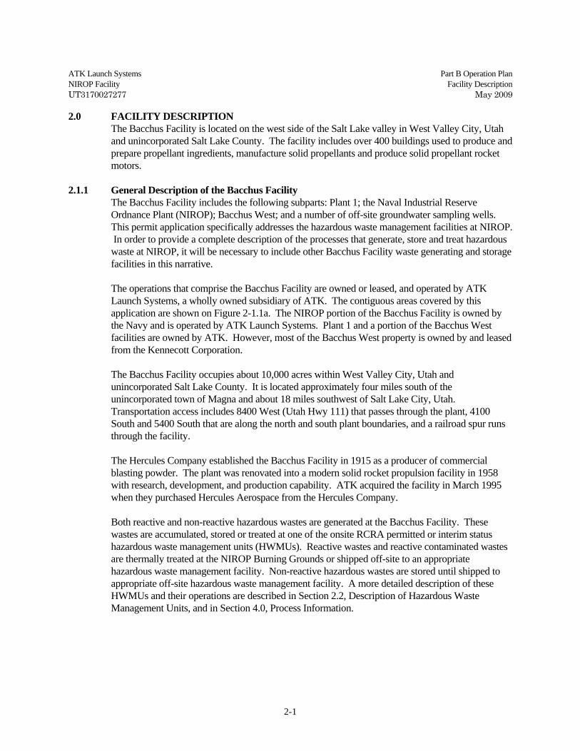
ATK Launch Systems Part B Operation Plan NIROP Facility Facility Description UT3170027277 May 2009 2-1 2.0 FACILITY DESCRIPTION The Bacchus Facility is located on the west side of the Salt Lake valley in West Valley City, Utah and unincorporated Salt Lake County. The facility includes over 400 buildings used to produce and prepare propellant ingredients, manufacture solid propellants and produce solid propellant rocket motors. 2.1.1 General Description of the Bacchus Facility The Bacchus Facility includes the following subparts: Plant 1; the Naval Industrial Reserve Ordnance Plant (NIROP); Bacchus West; and a number of off-site groundwater sampling wells. This permit application specifically addresses the hazardous waste management facilities at NIROP. In order to provide a complete description of the processes that generate, store and treat hazardous waste at NIROP, it will be necessary to include other Bacchus Facility waste generating and storage facilities in this narrative. The operations that comprise the Bacchus Facility are owned or leased, and operated by ATK Launch Systems, a wholly owned subsidiary of ATK. The contiguous areas covered by this application are shown on Figure 2-1.1a. The NIROP portion of the Bacchus Facility is owned by the Navy and is operated by ATK Launch Systems. Plant 1 and a portion of the Bacchus West facilities are owned by ATK. However, most of the Bacchus West property is owned by and leased from the Kennecott Corporation. The Bacchus Facility occupies about 10,000 acres within West Valley City, Utah and unincorporated Salt Lake County. It is located approximately four miles south of the unincorporated town of Magna and about 18 miles southwest of Salt Lake City, Utah. Transportation access includes 8400 West (Utah Hwy 111) that passes through the plant, 4100 South and 5400 South that are along the north and south plant boundaries, and a railroad spur runs through the facility. The Hercules Company established the Bacchus Facility in 1915 as a producer of commercial blasting powder. The plant was renovated into a modern solid rocket propulsion facility in 1958 with research, development, and production capability. ATK acquired the facility in March 1995 when they purchased Hercules Aerospace from the Hercules Company. Both reactive and non-reactive hazardous wastes are generated at the Bacchus Facility. These wastes are accumulated, stored or treated at one of the onsite RCRA permitted or interim status hazardous waste management units (HWMUs). Reactive wastes and reactive contaminated wastes are thermally treated at the NIROP Burning Grounds or shipped off-site to an appropriate hazardous waste management facility. Non-reactive hazardous wastes are stored until shipped to appropriate off-site hazardous waste management facility. A more detailed description of these HWMUs and their operations are described in Section 2.2, Description of Hazardous Waste Management Units, and in Section 4.0, Process Information.
Transcript of 2.0 FACILITY DESCRIPTION - deq.utah.gov · ATK Launch Systems Part B Operation Plan NIROP Facility...
ATK Launch Systems Part B Operation Plan NIROP Facility Facility Description UT3170027277 May 2009
2-1
2.0 FACILITY DESCRIPTION The Bacchus Facility is located on the west side of the Salt Lake valley in West Valley City, Utah and unincorporated Salt Lake County. The facility includes over 400 buildings used to produce and prepare propellant ingredients, manufacture solid propellants and produce solid propellant rocket motors.
2.1.1 General Description of the Bacchus Facility The Bacchus Facility includes the following subparts: Plant 1; the Naval Industrial Reserve
Ordnance Plant (NIROP); Bacchus West; and a number of off-site groundwater sampling wells. This permit application specifically addresses the hazardous waste management facilities at NIROP. In order to provide a complete description of the processes that generate, store and treat hazardous waste at NIROP, it will be necessary to include other Bacchus Facility waste generating and storage facilities in this narrative.
The operations that comprise the Bacchus Facility are owned or leased, and operated by ATK
Launch Systems, a wholly owned subsidiary of ATK. The contiguous areas covered by this application are shown on Figure 2-1.1a. The NIROP portion of the Bacchus Facility is owned by the Navy and is operated by ATK Launch Systems. Plant 1 and a portion of the Bacchus West facilities are owned by ATK. However, most of the Bacchus West property is owned by and leased from the Kennecott Corporation.
The Bacchus Facility occupies about 10,000 acres within West Valley City, Utah and
unincorporated Salt Lake County. It is located approximately four miles south of the unincorporated town of Magna and about 18 miles southwest of Salt Lake City, Utah. Transportation access includes 8400 West (Utah Hwy 111) that passes through the plant, 4100 South and 5400 South that are along the north and south plant boundaries, and a railroad spur runs through the facility.
The Hercules Company established the Bacchus Facility in 1915 as a producer of commercial blasting powder. The plant was renovated into a modern solid rocket propulsion facility in 1958 with research, development, and production capability. ATK acquired the facility in March 1995 when they purchased Hercules Aerospace from the Hercules Company.
Both reactive and non-reactive hazardous wastes are generated at the Bacchus Facility. These
wastes are accumulated, stored or treated at one of the onsite RCRA permitted or interim status hazardous waste management units (HWMUs). Reactive wastes and reactive contaminated wastes are thermally treated at the NIROP Burning Grounds or shipped off-site to an appropriate hazardous waste management facility. Non-reactive hazardous wastes are stored until shipped to appropriate off-site hazardous waste management facility. A more detailed description of these HWMUs and their operations are described in Section 2.2, Description of Hazardous Waste Management Units, and in Section 4.0, Process Information.

ATK Launch Systems Part B Operation Plan NIROP Facility Facility Description UT3170027277 May 2009
2-2
2.1.2 Facility Security The facility is secured by chain link and barbed wire fencing that surrounds the active site. The
perimeter fence has warning signs posted at about 500 ft intervals, at corners, and at each gate. The warning signs display the words "Danger Explosives, No Trespassing.” In addition, the HWMUs have warning signs to inform employees and discourage unauthorized access.
The facility has three primary access points through the Main, Bacchus West and NIROP gates
which are shown on Figure 2-1.1b. The Main and Bacchus West gates are manned during normal business hours and the NIROP gate is manned on an as needed basis. All gates are either locked or controlled by card readers when security personnel are not present. The facility is patrolled by security guards.
2.1.3 NIROP NIROP was originally built by the Air Force for production of Minuteman Stage III rocket motors.
It is located immediately north of Plant 1. When Minuteman motor production finished, the facilities were temporarily converted to the production of mini-mine explosives. NIROP now supports Navy programs and other production programs permitted by the Navy. The processes conducted at NIROP are similar to those described at Plant 1, and includes activities such as propellant ingredient preparation and handling, motor curing and storage, final assembly, inspection, machining and shipment.
Laboratory facilities at Bacchus Facility once involved many buildings at Plant 1 and NIROP, but
most labs were relocated to the ATK-Promontory Facility in 2001-2002. Laboratory activities include, but are not limited to propellant research, process development, materials development, destructive and nondestructive testing, standards measurement, and applied physics research.
2.1.4 Plant 1 Plant 1 supports manufacturing, production testing, shipping, and research and development
functions. Production facilities comprise the largest area and occupy the greatest number of buildings at Plant 1. The activities conducted in the production facilities include the preparation of empty rocket motor chambers, preparation and handling of propellant ingredients, mixing and curing of propellant ingredients, propellant mold assembly/disassembly, propellant machining, in-process storage, final assembly, and shipping.
2.1.5 Bacchus West The Bacchus West facility is adjacent to and contiguous with Plant 1, and is located west of 8400
West. It consists of buildings where large solid propellant rocket motors are manufactured. The processes conducted at Bacchus West are similar to those at Plant 1 and NIROP, but generally operate under automated control. Closed ingredient handling systems are used in all possible applications to prevent contamination of the processes, products, and environment.
ATK Launch Systems Part B Operation Plan NIROP Facility Facility Description UT3170027277 May 2009
2-3
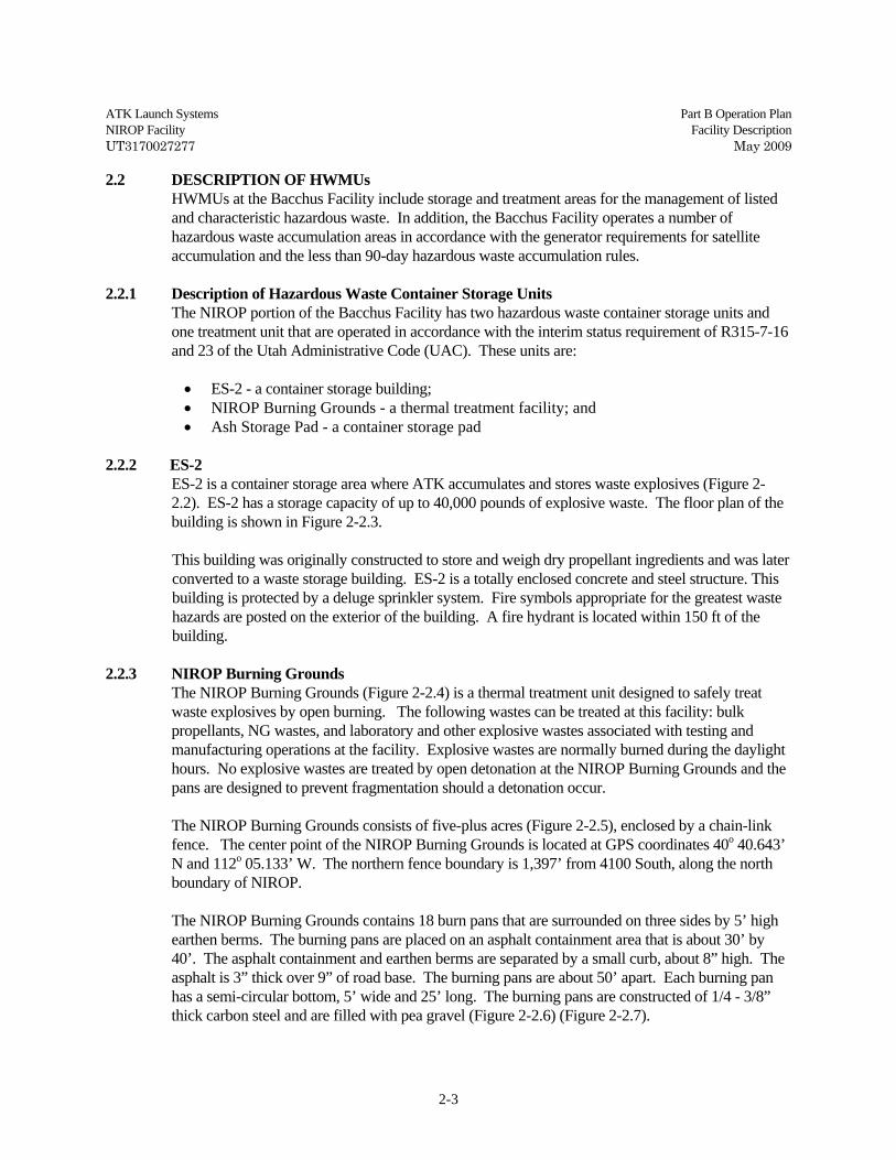
2.2 DESCRIPTION OF HWMUs HWMUs at the Bacchus Facility include storage and treatment areas for the management of listed
and characteristic hazardous waste. In addition, the Bacchus Facility operates a number of hazardous waste accumulation areas in accordance with the generator requirements for satellite accumulation and the less than 90-day hazardous waste accumulation rules.
2.2.1 Description of Hazardous Waste Container Storage Units The NIROP portion of the Bacchus Facility has two hazardous waste container storage units and
one treatment unit that are operated in accordance with the interim status requirement of R315-7-16 and 23 of the Utah Administrative Code (UAC). These units are:
• ES-2 - a container storage building; • NIROP Burning Grounds - a thermal treatment facility; and • Ash Storage Pad - a container storage pad
2.2.2 ES-2
ES-2 is a container storage area where ATK accumulates and stores waste explosives (Figure 2-2.2). ES-2 has a storage capacity of up to 40,000 pounds of explosive waste. The floor plan of the building is shown in Figure 2-2.3. This building was originally constructed to store and weigh dry propellant ingredients and was later converted to a waste storage building. ES-2 is a totally enclosed concrete and steel structure. This building is protected by a deluge sprinkler system. Fire symbols appropriate for the greatest waste hazards are posted on the exterior of the building. A fire hydrant is located within 150 ft of the building.
2.2.3 NIROP Burning Grounds The NIROP Burning Grounds (Figure 2-2.4) is a thermal treatment unit designed to safely treat waste explosives by open burning. The following wastes can be treated at this facility: bulk propellants, NG wastes, and laboratory and other explosive wastes associated with testing and manufacturing operations at the facility. Explosive wastes are normally burned during the daylight hours. No explosive wastes are treated by open detonation at the NIROP Burning Grounds and the pans are designed to prevent fragmentation should a detonation occur.
The NIROP Burning Grounds consists of five-plus acres (Figure 2-2.5), enclosed by a chain-link fence. The center point of the NIROP Burning Grounds is located at GPS coordinates 40o 40.643’ N and 112o 05.133’ W. The northern fence boundary is 1,397’ from 4100 South, along the north boundary of NIROP.
The NIROP Burning Grounds contains 18 burn pans that are surrounded on three sides by 5’ high earthen berms. The burning pans are placed on an asphalt containment area that is about 30’ by 40’. The asphalt containment and earthen berms are separated by a small curb, about 8” high. The asphalt is 3” thick over 9” of road base. The burning pans are about 50’ apart. Each burning pan has a semi-circular bottom, 5’ wide and 25’ long. The burning pans are constructed of 1/4 - 3/8” thick carbon steel and are filled with pea gravel (Figure 2-2.6) (Figure 2-2.7).

ATK Launch Systems Part B Operation Plan NIROP Facility Facility Description UT3170027277 May 2009
2-4
The burn pans are designed to collect precipitation and water used to cool hot spots after a burn. Leachate is removed by connecting a vacuum truck hose to a Camlock fitting attached to the bottom of each pan. The leachate is accumulated in storage tanks prior to being discharged to a POTW or shipped to an off-site TSDF disposal facility.
In addition to the burn pans, the NIROP Burning Grounds has one burn cage (Cage 19) (Figure 2-
2.8) that is used to treat DOT restricted explosive packing materials. The cage dimensions are 12’ high x 12’ wide x 14’ long. Three-inch diameter schedule 40 steel pipe is used as the support structure for the cage. The cage is covered with a metal fabric on the sides and top. The cage has a large access door on the south side and a small access door on the north side. Cage 19 also has a leachate collection system similar to the system used on burn pans.
The burning grounds have several small storage sheds for the storage of base grain, diesel, extra slum pots, squibs, and other necessary tools. A buried electrical firing system is used to remotely ignite each of the burning pans or cage. The control panel for this system is located inside a locked control room outside the fenced treatment area.
Water is available inside the burning grounds to quench burning pan residues when necessary or to
eliminate "hot spots" that remain from the previous day’s burn. Telephone service is available in the control room and near the main gate of the NIROP Burning
Grounds. NIROP Burning Ground operators will always have a means of contacting emergency services, whenever ATK personnel are inside the NIROP Burning Grounds. Fire extinguisher and fire blankets are strategically located near burning pans for emergency use. The NIROP Burning Grounds is equipped with a pole-mounted red rotating light and siren. The siren is used to signal a pending burn prior to ignition and the red light is illuminated prior to ignition. Three fire hydrants are located along the eastern boundary of the NIROP Burning Ground.
Only authorized personnel are permitted on the NIROP Burning Grounds site. Visitors to the area
must be approved and escorted by Environmental Operations' personnel. The NIROP Burning Grounds is located 1,650’ from Highway 111 and 1,397’ from 4100 South.
These roads form the west and north plant boundaries, respectively. Because of the proximity of the burning grounds to these roads, ATK conducted a hazards evaluation of the operations and its location. Based on the evaluation findings, the NIROP Burning Grounds operations were determined to be located at a sufficient distance from the property lines to protect human health and the environment from any imminent danger.
In 1989-90, the Navy evaluated the location and operation of the NIROP Burning Grounds in
relation to their quantity/distance (Q/D) requirements. The evaluation was conducted according to NAVSEA OP5, Volume 1, Revision 4, Paragraph 11-3.2. The criteria in this guidance determined that the safe setback distance for the NIROP Burning Grounds, where non-fragmenting explosives are treated by open burning, must be located at a distance where the peak positive incident pressures are less than or equal to 1.0 psi.
ATK Launch Systems Part B Operation Plan NIROP Facility Facility Description UT3170027277 May 2009
2-5
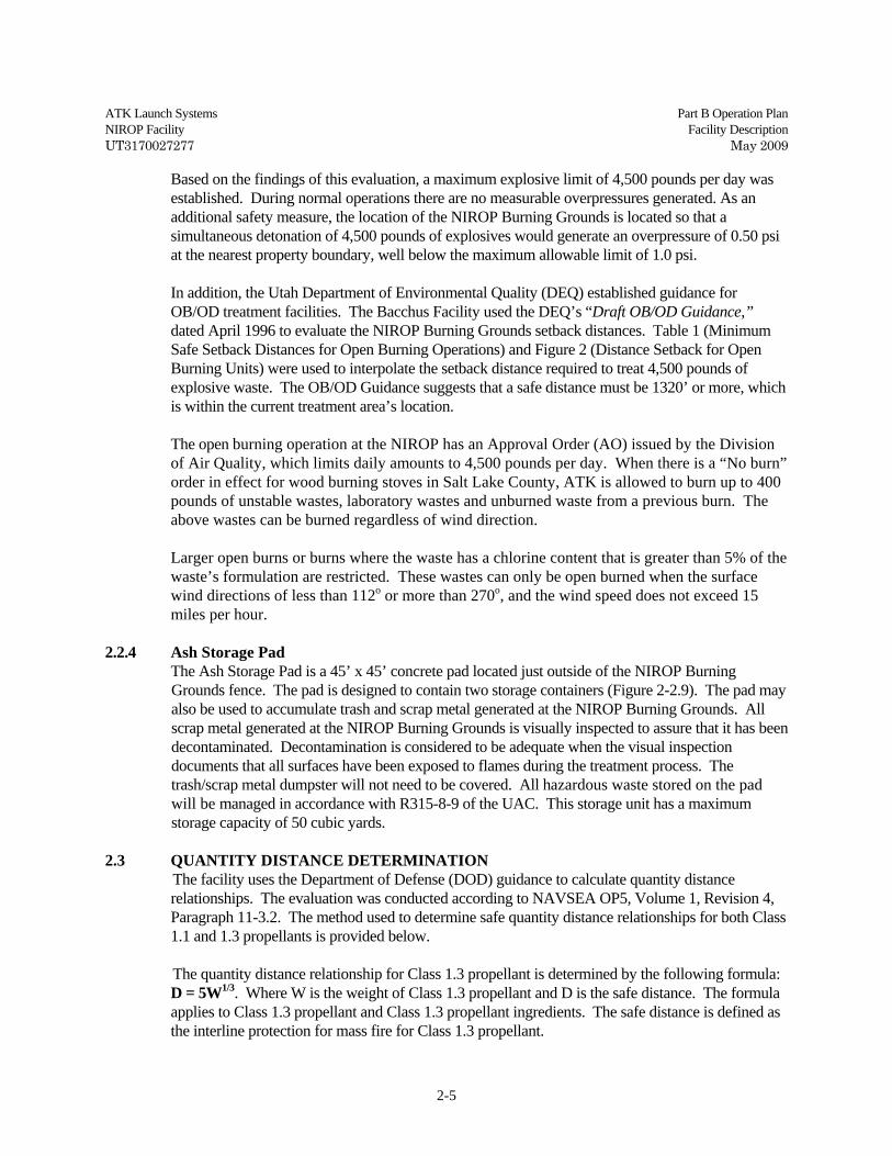
Based on the findings of this evaluation, a maximum explosive limit of 4,500 pounds per day was established. During normal operations there are no measurable overpressures generated. As an additional safety measure, the location of the NIROP Burning Grounds is located so that a simultaneous detonation of 4,500 pounds of explosives would generate an overpressure of 0.50 psi at the nearest property boundary, well below the maximum allowable limit of 1.0 psi.
In addition, the Utah Department of Environmental Quality (DEQ) established guidance for
OB/OD treatment facilities. The Bacchus Facility used the DEQ’s “Draft OB/OD Guidance,” dated April 1996 to evaluate the NIROP Burning Grounds setback distances. Table 1 (Minimum Safe Setback Distances for Open Burning Operations) and Figure 2 (Distance Setback for Open Burning Units) were used to interpolate the setback distance required to treat 4,500 pounds of explosive waste. The OB/OD Guidance suggests that a safe distance must be 1320’ or more, which is within the current treatment area’s location.
The open burning operation at the NIROP has an Approval Order (AO) issued by the Division of Air Quality, which limits daily amounts to 4,500 pounds per day. When there is a “No burn” order in effect for wood burning stoves in Salt Lake County, ATK is allowed to burn up to 400 pounds of unstable wastes, laboratory wastes and unburned waste from a previous burn. The above wastes can be burned regardless of wind direction. Larger open burns or burns where the waste has a chlorine content that is greater than 5% of the waste’s formulation are restricted. These wastes can only be open burned when the surface wind directions of less than 112o or more than 270o, and the wind speed does not exceed 15 miles per hour.
2.2.4 Ash Storage Pad The Ash Storage Pad is a 45’ x 45’ concrete pad located just outside of the NIROP Burning
Grounds fence. The pad is designed to contain two storage containers (Figure 2-2.9). The pad may also be used to accumulate trash and scrap metal generated at the NIROP Burning Grounds. All scrap metal generated at the NIROP Burning Grounds is visually inspected to assure that it has been decontaminated. Decontamination is considered to be adequate when the visual inspection documents that all surfaces have been exposed to flames during the treatment process. The trash/scrap metal dumpster will not need to be covered. All hazardous waste stored on the pad will be managed in accordance with R315-8-9 of the UAC. This storage unit has a maximum storage capacity of 50 cubic yards.
2.3 QUANTITY DISTANCE DETERMINATION The facility uses the Department of Defense (DOD) guidance to calculate quantity distance
relationships. The evaluation was conducted according to NAVSEA OP5, Volume 1, Revision 4, Paragraph 11-3.2. The method used to determine safe quantity distance relationships for both Class 1.1 and 1.3 propellants is provided below.
The quantity distance relationship for Class 1.3 propellant is determined by the following formula:
D = 5W1/3. Where W is the weight of Class 1.3 propellant and D is the safe distance. The formula applies to Class 1.3 propellant and Class 1.3 propellant ingredients. The safe distance is defined as the interline protection for mass fire for Class 1.3 propellant.

ATK Launch Systems Part B Operation Plan NIROP Facility Facility Description UT3170027277 May 2009
2-6
The quantity distance relationship for Class 1.1 propellant is determined by the following
formula: D = 18W1/3. Where W is the weight of a Class 1.1 explosive and D is the safe distance. The formula applies to Class 1.1 propellant and Class 1.1 propellant ingredients. The safe distance is defined as the unbarricaded interline protection for Class 1.1 propellant. Refer to Figure 2-3.10 for safe distances for the hazardous waste storage facilities and significant 90-day accumulation areas identified in this application.
The quantity distance relationship for ES-2 is based on the more conservative requirement for a
Class 1.1 explosive. 2.4 ACCUMULATION STATIONS The NIROP maintains less than 90-day storage areas and wastewater collection tanks. 2.4.1 Accumulation Stations Waste accumulation stations support most of the waste-producing operating buildings at the
NIROP. Waste handling processes are discussed in more detail in Section 4. The number of accumulation stations varies according to need. Accumulation stations at explosive generating operations are referred to as “slum sheds”. Slum sheds are three-sided wooden structures, typically 6’ x 17’ x 8’ high (Figure 2-4.11). They are built on a concrete pad open to the north to protect explosive wastes from southern sun exposure. A similar structure is used at nearly every accumulation station but the design is not necessarily standardized.
2.4.2 Wastewater Collection Tanks
Wastewater collection tanks are used to collect process and building wash water. There are approximately 10 tanks located at individual buildings on the NIROP. The majority of the wastewater collected on the NIROP is collected and discharged to the sewer after being processed at the Plant 1 Waste Water Treatment Plant (WWTP). The piping for most of the tanks is above ground, however, when underground piping is necessary it is double-walled. Cloth filters are used, where applicable, to prevent propellant or explosives particulates from entering the tank. Filters contaminated with explosives are thermally treated at the NIROP Burning Grounds. All tanks have level indicators, and use either secondary containment leak detection or visual confirmation where leaks can be visually identified.
2.5 LOCATION INFORMATION The following sections contain information relating to the surface topography of the facility,
consideration for potential seismic activity, floodplain location, and on-site traffic control. 2.5.1 Topographic Map Information
Figure 2-5.12 and Figure 2-1.1b are topographic and physiographic maps of the Bacchus Facility that shows the location of Plant 1, NIROP, and Bacchus West. These maps combined also show the surface contours, surface water flow and drainage directions, plant facilities, security fences and gates, and the hazardous waste management facilities

ATK Launch Systems Part B Operation Plan NIROP Facility Facility Description UT3170027277 May 2009
2-7
2.5.2 Surface Run-on/Run-off
Highly fractured limestone and quartzite, and permeable alluvial deposits near the mountain front, allow most of the run-off originating in the Oquirrh Mountains to infiltrate into the subsurface before it reaches the facility. Therefore, run-off from the Oquirrh Mountains to the valley floor is limited. Stream flow from the Oquirrh’s is intermittent and occurs primarily during the spring and summer run-off months from snowmelt and precipitation. Streams that flow across the facility originate in the Oquirrh Mountains to the west. The main streams that contribute surface water to the facility are Coon Creek and an unnamed stream in Harkers Canyon. These streams converge immediately upstream of the facility. The stream is known as Coon Creek below the confluence. The Coon Creek drainage enters the Bacchus Facility via a culvert under State Highway 111, and exits to the south of 4100 South or can divert through the flood detention basin before discharge. Except for Coon Creek, no major drainages enters or crosses the Bacchus Facility. Run-off from most areas on the site occurs as overland flow that collects in small northeast trending channels that follow the local topography.
2.5.3 Surface Springs Several small intermittent springs originate from a cut slope both south and east of the NIROP Burning Ground. Dependent upon local precipitation the springs may flow all year, or cease producing for a period of time. Flow from the springs enters the drainage basin, eventually feeding into the Coon Creek channel south of 4100 South. Depending on the location of the spring, the flow is channeled to the east around the NIROP Burning Grounds or enters a culvert that passes beneath the NIROP Burning Grounds. The drainage/detention basin is present in an excavation created decades ago during gravel mining operations. This area has since become a natural wetlands-type environment. The springs near the NIROP Burning Grounds contain reportable concentrations of perchlorate. However, since no recordable concentrations have been identified in the surface water discharged from the detention basin into Coon Creek, it is believed that the low concentration contaminants are being accumulated in the vegetation, degraded biologically by bacteria and microorganisms naturally, or diluted by uncontaminated water sources.
2.5.4 Floodplain Boundary Between 1983 and 1986, the region surrounding the facility experienced a cycle of above-normal precipitation. The increased run-off accelerated erosion of Coon Creek and other minor channels. The channel surface for Coon Creek degraded to levels that in a few locations are now several feet below the previous channel surface. The most current map published September 21, 2001 (Figure 2-5.13) by the Federal Emergency Management Agency (FEMA) showing the 100-year floodplain boundary, does not indicate a change in the delineation of the floodplain boundary. An independent engineer has reviewed the floodplain boundary (reference: R.B. White, letter to R.A. Bowlin, “Review of Floodplain Information in Bacchus Facility - Plant 1, Part B Permit Application,” February 13, 2006). A visual inspection of the Coon Creek channel also does not indicate any apparent erosional floodplain concerns.

ATK Launch Systems Part B Operation Plan NIROP Facility Facility Description UT3170027277 May 2009
2-8
2.5.4.1 Floodplain Considerations
A copy of the FEMA Flood Insurance Rate Map for the area of the NIROP that includes the Burning Grounds, Ash Storage Pad, and ES-2 is presented as Figure 2-5.13. None of the hazardous waste management areas on the NIROP are located within or immediately adjacent to a 100-year flood plain (Zone A designation).
2.5.5 Wind Direction The wind rose (Figure 2-5.14) for the Salt Lake Valley shows the distribution of wind speeds
and the frequency of the varying winds directions. The wind rose presents data collected from the Salt Lake City Airport (WBAN Station 24127) between 1988 and 1992, during the ozone season (May through September). The wind rose was taken from the USEPA website for NAAQS-Ozone. The predominant wind direction is from the north-northeast, 15.8% of the time, at a speed of 16 knots (18.4 miles per hour) or less. Total northerly wind frequency is about 40%. The next most predominant wind direction is from the south-southeast, 14.5% of the time, at a speed of 21 knots (24 miles per hour) or less. Total southerly wind frequency is about 27%.
2.5.6 Miscellaneous Facilities A production well and water storage tank are located in the foothills above (approximately 1-mile
west) the Bacchus West production facilities. This withdraw well is currently not in use, but could be brought into service if required. This system was designed to supply pressurized potable water to the facilities and for fire protection (deluge) systems and hydrants throughout the entire plant. This system is accessed by a system of internal roads that connect the buildings and facilities at the Bacchus Facility. Fire control water is supplied through underground water lines.
The facility sanitary sewage system consists of sewage collection and septic systems, specific to
areas in each plant. A domestic sewage collection system connects the Plant 1 and NIROP buildings and a few production buildings to the Magna sewer. Individual septic tank and drain field systems serve the majority of buildings in the NIROP, Plant 1, and Bacchus West operating areas.
2.5.7 Seismic Considerations
The location and potential affect an earthquake within the local Intermountain Seismic Belt (ISB), more specifically the Wasatch Front, could have on the facility has been evaluated. The general consensus is that a Magnitude 6.5 or greater earthquake may occur along the Salt Lake Valley segment of the Wasatch Fault at any time.
2.5.7.1 Location The facility is located within the Salt Lake Valley at the eastern edge of the Basin and Range Physiographic Province. More specifically, the site is located within the Magna Block, just east of the Oquirrh Mountains (Tooker, E.W. and Roberts, Ralph J., 1961). In Utah, the ISB coincides with the boundary between the Basin and Range Physiographic Province to the west and the Colorado Plateau to the east. The Basin and Range Physiographic Province is characterized by north-south trending normal faults, caused by spreading from lateral tension and local uplift. In addition to deep-seated basement faulting, the spreading of the valleys also causes sympathetic and antithetic faulting in the sediments overlying the basement structures.

ATK Launch Systems Part B Operation Plan NIROP Facility Facility Description UT3170027277 May 2009
2-9
The Magna Block and northern Oquirrh stratigraphy are part of the upthrust portion of the North Oquirrh Thrust Fault. The Oquirrh Mountains are a tilted fault block associated with the eastern portion of the Basin and Range Physiographic Province. Faulting associated with Basin and Range along the local uplifted mountain ranges, i.e. Wasatch, Oquirrh, and Stansbury, occurs only on the western side of the ranges (Utah Geological Survey, 2003, Map 193DM). There are no documented faults on the east side of the Oquirrh Mountains associated with Basin and Range or other Tertiary and early Quaternary tectonic activity (Tooker and Roberts, 1961). The only documented sympathetic and antithetic faulting in the Salt Lake Valley near the facility is the West Valley Fault Zone (Figure 2-5.15 and 2-5.16). The faults in this zone primarily dip toward the east in antithetic response to weakness in the valley sediments caused by movement along the Salt Lake City section of the Wasatch Fault Line. No documentation has been found to suggest that the West Valley Fault Zone is tectonic in nature (basement controlled).
2.5.7.2 Geologic Control Tooker and Roberts produced the “Geologic Map of the Magna Quadrangle, Salt Lake County, Utah (1971)”. The map shows a northeast trending normal fault, downthrown to the east, which passes within 0.4 miles of the NIROP Burning Grounds. This fault is associated with pre-uplift of the Oquirrh’s and is extended to the northeast based on a small outcrop of the Kessler Canyon Formation just east of Magna. There is no evidence that this fault was active during the formation of the Basin and Range Physiographic Province. However, the “Interim Geologic Map of the Magna Quadrangle”, Open File 424, UGS, August 2004, does not show this fault to be present. One of the primary linear surface features is Coon Creek. An earlier impression was that the location of Coon Creek might have been fault controlled, however, a current review of the data does not support this conclusion. None of the published geologic maps indicates a fault structure near the surface in the area of Coon Creek that would effect the direction of drainage. Coon Creek appears to be controlled by folds in the geologic substrate as it exits the Oquirrh Mountains. From this it can be concluded that the direction of flow is within the preferred path of erosion. The upper portion of Coon Creek is in a structural synclinal trough that is perpendicular to faulting throughout most of its course. The redirection from east-northeast to a northerly trend on Plant 1 is not believed to be fault controlled. The majority of the faults shown in the Tooker/Roberts map, are associated with the Oquirrh Mountains, and are compressional or shear features of pre-Tertiary age. Only a few of the faults appear to be extensional and associated with horst and graben release. Stratigraphic information collected by ATK suggests that Coon Creek has maintained its approximate line prior to and following the presence of Lake Bonneville. Borings at the site and north of 4100 South have occasionally encountered Tertiary sediments of volcanic origin. About 8000 feet north of the site, the borings for groundwater monitoring wells GW-79, 80, 81, and 82 encountered a Tertiary volcanic material at varying depths. It was initially thought that this change in depth of the upper contact was related to faulting. However, this would mean that a total vertical fault displacement of more than 150 feet, more than any known Holocene fault in the valley, had occurred. The volcanic material appears to be at least 60 feet thick, based on borings. However, none of the borings have penetrated this unit to confirm the thickness of this geologic unit.

ATK Launch Systems Part B Operation Plan NIROP Facility Facility Description UT3170027277 May 2009
2-10
Borings along the northern boundary of the site seem to indicate a similar subsurface condition. Although borings for GW-53 and GW-54 did not encounter the volcanic unit near the termination depth, the boring logs document that volcanic material and cobbles are present at a depth similar to where they appear in the boring logs of GW-79, 81, and 82. No volcanic debris was identified in the next boring to the west (GW-52), which was terminated at a depth approximately 60 feet deeper than GW-53 and 54. It is believed that the streams eventually cut through the volcanic layer exposing the Tertiary sediments below. Later with the formation of Lake Bonneville, sediments covered the volcanic material to the present surface, allowing the current upper and lower water bearing sediments to be in contact. A recent review of the data concluded that this is not a fault-induced graben, but simply an erosional feature. The volcanic layer appears to have been deposited as a flow from somewhere in the southern Oquirrh’s during mid-Tertiary time. A trough identified during the installation of GW-80 appears to have been cut by erosion from stream running out of the Coon and Harkers canyons which followed the topography northward, bound on the west by the uplifted Oquirrh’s, near the location of present day Coon Creek.
2.5.7.3 Local Faulting Various faults and linears are documented or inferred to be present near the facility. Some of the more pertinent ones are discussed below. The Granger fault, as named by Marine and Price (1964) and evaluated by Keaton and others (1987), is the nearest Holocene age fault with possible recent displacement. It is located about five miles east-northeast of the site. The Granger and Taylorsville faults to the east comprise the West Valley Fault Zone (Figure 2-5.15). Slentz (1955) refers to a suspected east-trending fault passing south of the old gravel pits. The evidence used to infer the existence of such a fault consisted of steep dips in rocks of the Salt Lake Group as exposed in the gravel pits, warm water from rising groundwater in the bottom of the gravel pits, and the east-trending landform on which the Provo Level Shoreline of the ancient Lake Bonneville has been eroded.
Cook and Berg (1961) found a northeast-trending, southeast-facing gravity anomaly they interpreted to represent a fault close to the Oquirrh Mountains south of the site and swinging northeastward through the site. They used Slentz's evidence to support their interpretation of the gravity anomaly. There is no surface expression or documentation to verify the existence of this fault.
Examination of stereoscopic aerial photographs dating from 1946 to 1965 revealed that Lake Bonneville shoreline features across the site were continuous and showed no evidence of disturbance by fault offset. Since the shoreline features at the site are greater than 10,000 years old, absence of fault offset clearly indicates the absence of Holocene faults within the 3,000 ft radius. Observations of the distribution of bedrock exposures in the area made during site reconnaissance supports the interpretation of the aerial photographs and further indicates that the presence of a possible east-trending fault south of the old gravel pits, as inferred by Slentz (1955), certainly does

ATK Launch Systems Part B Operation Plan NIROP Facility Facility Description UT3170027277 May 2009
2-11
not affect Lake Bonneville deposits and probably does not exist. Figure 2-5.17 presents geologic features identified at Bacchus Facility during field reconnaissance. A geologic map of the area included in Sterns (1984) shows five faults relatively close to the Bacchus Facility. The largest of these faults has been named the Principal Marginal Fault. The other four faults, which are not named, are shown to pass through or within 3,000 ft of the Bacchus Facility. However, the faults identified by Stearns (1984) are in the extreme northeastern portion of the Bacchus Facility and are not within 3000 ft from the NIROP Burning Grounds, Ash Storage Pad, or ES-2. The geologic cross-section included in Sterns (1984) shows the upper surface of the Salt Lake Group and the lower part of the Lake Bonneville deposits to be faulted. Such an interpretation would indicate that the most recent movement of the faults was younger than late Pleistocene, and possibly Holocene.
2.5.7.4 Seismic Activity Seismic activity has been documented in 1962 and later years, clustered north of the Bacchus Facility in the Magna area. Based on an evaluation of published geologic data supplemented by examination of stereoscopic aerial photographs and field reconnaissance, no faults that have had displacement in Holocene time (<10,000 years before present [b.p.]) are present within 3,000 ft of any hazardous waste management facilities at the facility. Furthermore, published geologic studies pertaining to the site area do not indicate the presence of Holocene faults within five miles of the site. A major earthquake of > 6.5M could still possibly generate ground shaking and potential liquefaction at the facility. The intensity of ground shaking caused by the vibrations of passing seismic waves is dependant on the location and magnitude of the earthquake and the geologic conditions of the site. The most recent publication on ground shaking in the Salt Lake Valley area is “Earthquake Scenario & Probabilistic Ground Shaking Maps for the Salt Lake City, Utah, Metropolitan Area”, Utah Geological Survey, Miscellaneous Publication 02-5, 2002 (MP 02-5). The MP 02-5 report presents hazard maps that show the frequency-dependent amplification of unconsolidated sediments in the Salt Lake Valley. In summary, locations along the bench areas near the Wasatch Fault will exhibit the highest peak accelerations, while the central portion of the valley will show lower peak accelerations due to damping. The site is situated on, what is termed in the report as, lacustrine alluvial gravels (Figure 2-5.18). This material, along with a shallowing of the sediments near the Oquirrh Mountains would cause an increase in ground shaking. The study estimates the peak horizontal ground acceleration (PGA) in the site area to be between 0.5g and 0.6g (Figure 2-5.19). This level of PGA is considered moderate to heavy, with slight damage to specially designed structures and considerable damage to ordinary buildings. Long-term explosive storage building ES-2 is a large timber, wood framed structure. ES-2 is surrounded and supported on three sides by earthen bunkers. Evaluation by our Facility Engineering Department indicates that because of the size, light ground loading, building construction, and earthen bunkers, this building should fare well should ground shaking from a Wasatch Fault earthquake occur. The NIROP Burning Grounds and the Ash Storage Pad do not contain any significant structures, and are not considered to pose a significant risk due to seismic activity.

ATK Launch Systems Part B Operation Plan NIROP Facility Facility Description UT3170027277 May 2009
2-12
Liquefaction occurs when water-saturated sandy soils are subjected to ground shaking and loss of bearing strength during an earthquake, generally of at least a magnitude of 5.0. The likelihood of liquefaction caused damage is greatest where the groundwater is shallow. Damage can be either subsidence in nature or induced ground/slope failure (landslides). The most recent publication on liquefaction in the Salt Lake Valley area is “Geologic Evaluation and Hazard Potential of Liquefaction-Induced Landslides along the Wasatch Front, Utah”, Utah Geological Survey, Special Study 104 (SS104). Liquefaction is not generally a life-threatening hazard. However, failures initiated by liquefaction can present a hazard to life as well as property. Thirteen liquefaction-induced landslides have been identified along the Wasatch Front (SS104). There are no published reports on subsidence or landslides along the eastern slopes of the Oquirrh Mountains. Liquefaction generally occurs in areas of shallow groundwater (generally less than 30 ft deep) and loose sandy soils. Earthquake-induced liquefaction may cause four principal ground-failure types: 1) loss of bearing strength on relatively flat ground, 2) ground oscillation where the ground slope is less than 0.1 percent, 3) later-spread landslides where slopes range between 0.1 and 5.0 percent, and 4) flow failures where slopes exceed 5.0 percent (SS104). Only the first two failure types could possibly occur at the NIROP facility. Depth to groundwater varies significantly across the NIROP. Beneath the Burning Grounds and the Ash Storage Pad the groundwater is about four feet below ground surface, whereas, at ES-2 the groundwater is about 140 feet below ground surface. Because of the shallow depth to groundwater beneath the Burning Grounds and the Ash Storage Pad, liquefaction may cause differential settling of the asphalt and concrete slabs. Since there are no significant structures at either unit, no significant concerns of release are present. Beneath ES-2, the depth to groundwater is deep enough to mitigate potential vertical sand blows and lateral spreads that could cause settlement of the ground surface due to liquefaction. Therefore, liquefaction should not pose any serious risk to the waste storage units at the facility
2.6 ACCESS CONTROL AND TRAFFIC The Bacchus Facility can be accessed from 8400 West (Utah Highway 111) that passes through
the plant and from 4100 South and 5400 South that are along the north and south plant boundaries. A railroad spur used by both ATK and Kennecott also accesses the plant.
The Bacchus Facility is secured by chain link and barbed wire fencing that surrounds the site. The
perimeter fence has warning signs posted at about 500 ft intervals, at corners, and at each gate. The warning signs display the words "Danger Explosives, No Trespassing.” In addition, the operating HWMUs have warning signs that comply with R315-8-2.5(c) of the UAC to inform employees and discourage unauthorized access.
The Bacchus Facility has three primary access points - the Main, Bacchus West and NIROP
gates. The Main and Bacchus West gates are manned during normal business hours, and the NIROP gate is manned on an as needed basis. All gates are locked or controlled by magnetic card readers when security personnel are not present. The site is also patrolled by security guards on a 24-hour basis.
Roads to the operating HWMUs are surfaced with asphalt or compacted road base. Minimum
design loading criteria is based on 8,000 pounds per wheel (16,000 pounds per single axle and

ATK Launch Systems Part B Operation Plan NIROP Facility Facility Description UT3170027277 May 2009
2-13
32,000 pounds per tandem axle). Each operating HWMU has parking and maneuvering space to facilitate the unloading and loading of wastes. See Figure 2-1.1b for details.
2.7 SAFETY RESTRICTIONS No unusual traffic patterns exist. Main, secondary, and other roads are controlled by stop signs.
Speed limits are posted throughout the Bacchus Facility. Bacchus Facility personnel operating motor vehicles must possess a valid Utah State driver’s license. Forklift operators must pass additional classroom and operating exams for each individual forklift they are assigned to operate. Disciplinary action may be taken for any traffic violation.

Figure 2-1.1aATK - Bacchus

NIROP Burning Grounds/ Ash Storage Pad
ES-2
HS-1
ES-1
Segment Storage
RH-1
Coon Creek(Flows South to
North)
Figure 2-1.1bATK Bacchus Facility
NGate 10
Plant 1 Main Gate
Bacchus West
Main Gate
Security Fence

Figure 2-2.2 ES-2 Explosive Storage Building

DO
OR
DOOR
DO
OR
DO
OR
DOOR
DO
OR
30.5 ft
40 ft
20 ft
20 ft
AdditionalStorage
“SLID Storage”Loading Dock
0 10
Approximate Scale in Feet
N
Figure 2-2.3ES-2 Floor Plan
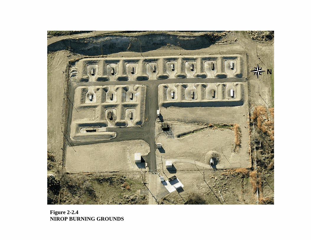
Figure 2-2.4NIROP BURNING GROUNDS
N

N
Telephone, Sirens, Flashing Lights
Fire Blankets
Fire Hydrant
Hose Bibs, Hose, and Racks
Figure 2-2.5NIROP Burning Grounds
Cage 19
17
16
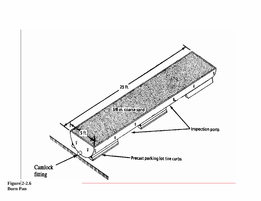
Figure 2-2.6 Burn Pan

2’ 10 5/8”
CL
2’ 4”Typ
1’ 6”
3’
PL 3/8”3” Stiffeningbracket
Figure 2-2.7Burn Pan Cross-section
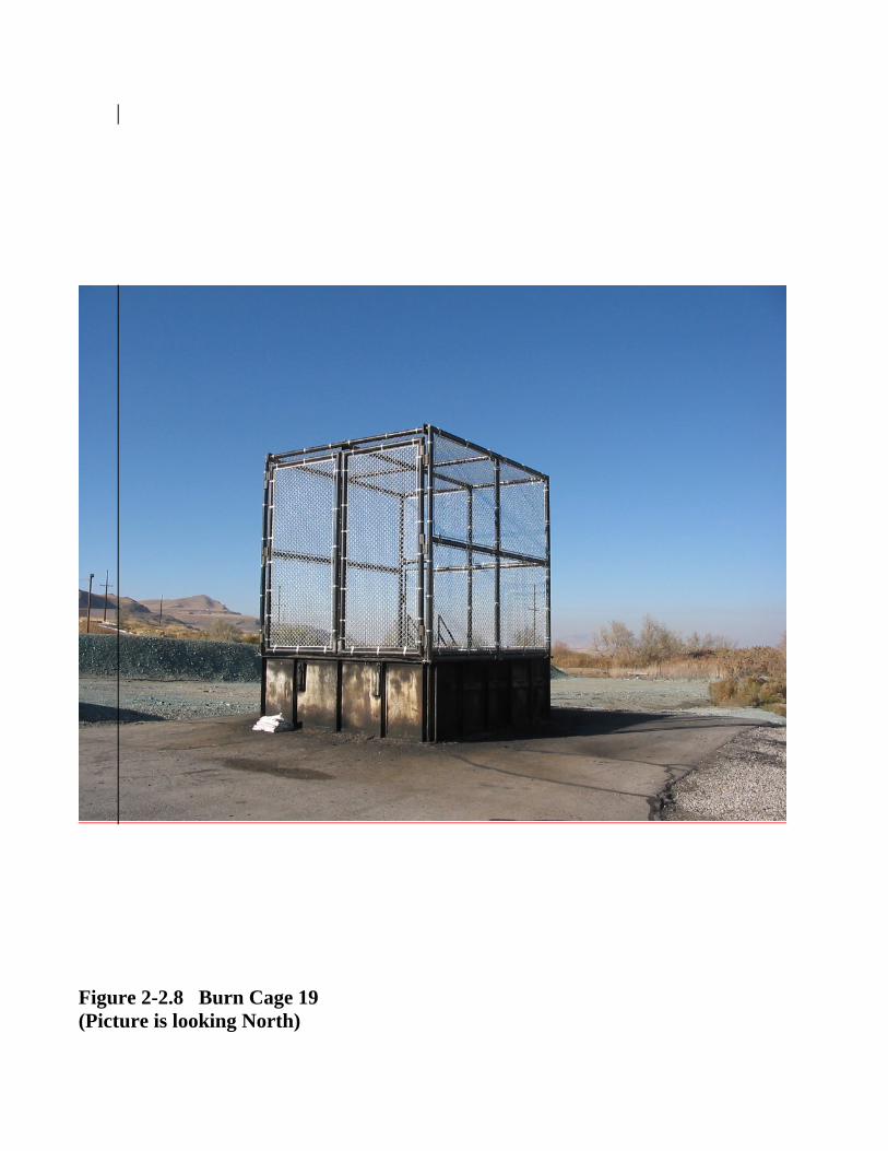
Figure 2-2.8 Burn Cage 19 (Picture is looking North)

Figure 2-2.9Ash Storage Pad
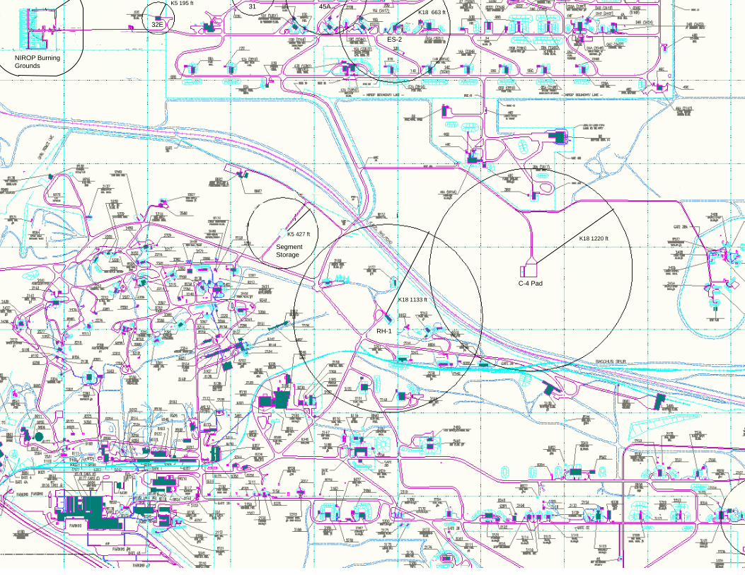
C-4 Pad
K18 1220 ft
RH-1
K18 1133 ft
K5 427 ft
SegmentStorage
ES-2
K18 663 ft45A31
32E
K5 195 ft
NIROP Burning Grounds

EXPLOSIVEWASTE
17 ft Typ
6 ftTyp
8 ftTyp
5 ft Typ 5 ft Typ 7 ft Typ
8 ftTyp
6 ft Typ
Front View (looking south)Side View (looking east)
“Slum Pot”
Top View
2 ftTyp
ConcreteApron
(Not To Scale)
N
Figure 2-4.11Hazardous Waste Collection (SLUM) Shed
Construction• Wood or Metal• 6-in. typ concrete floor w/2-ft apron in front
of shed• Compartments may number from 2 to 4• Compartment sizes are typical• Signs that specify type of waste are posted
in each compartment• All sides enclosed except north
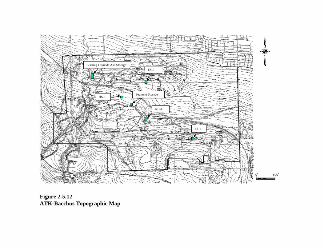
Figure 2-5.12 ATK-Bacchus Topographic Map
ES-1
RH-1
Segment StorageHS-1
Burning Grounds Ash StorageES-2
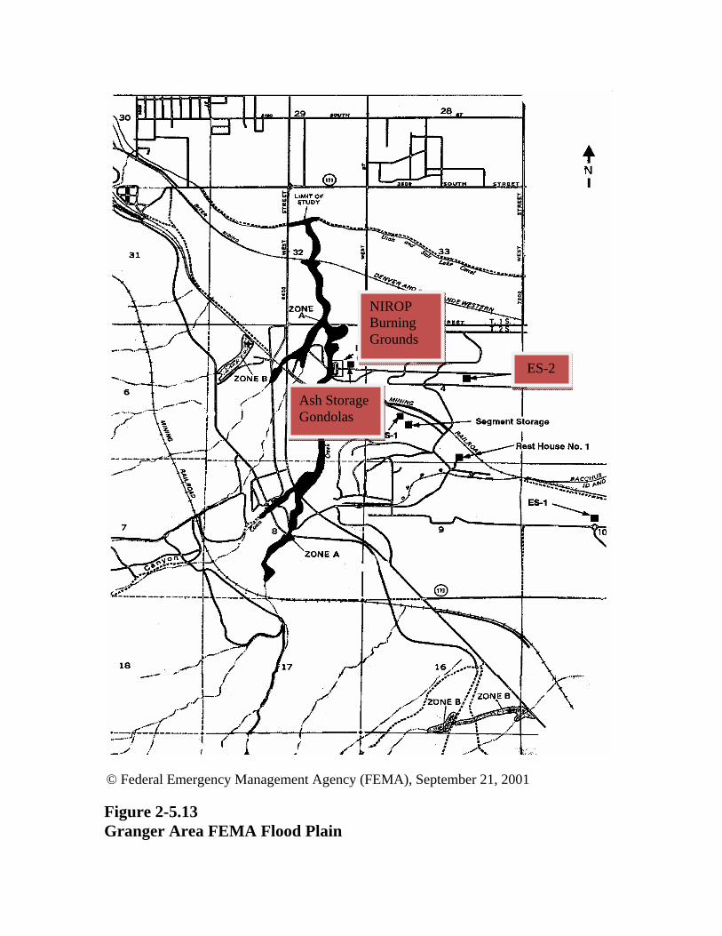
© Federal Emergency Management Agency (FEMA), September 21, 2001
Figure 2-5.13 Granger Area FEMA Flood Plain
ES-2
NIROP Burning Grounds
Ash Storage Gondolas

Figure 2-5.14 Salt Lake Valley Wind Rose
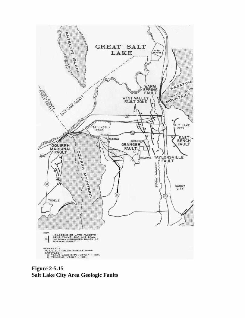
Figure 2-5.15 Salt Lake City Area Geologic Faults
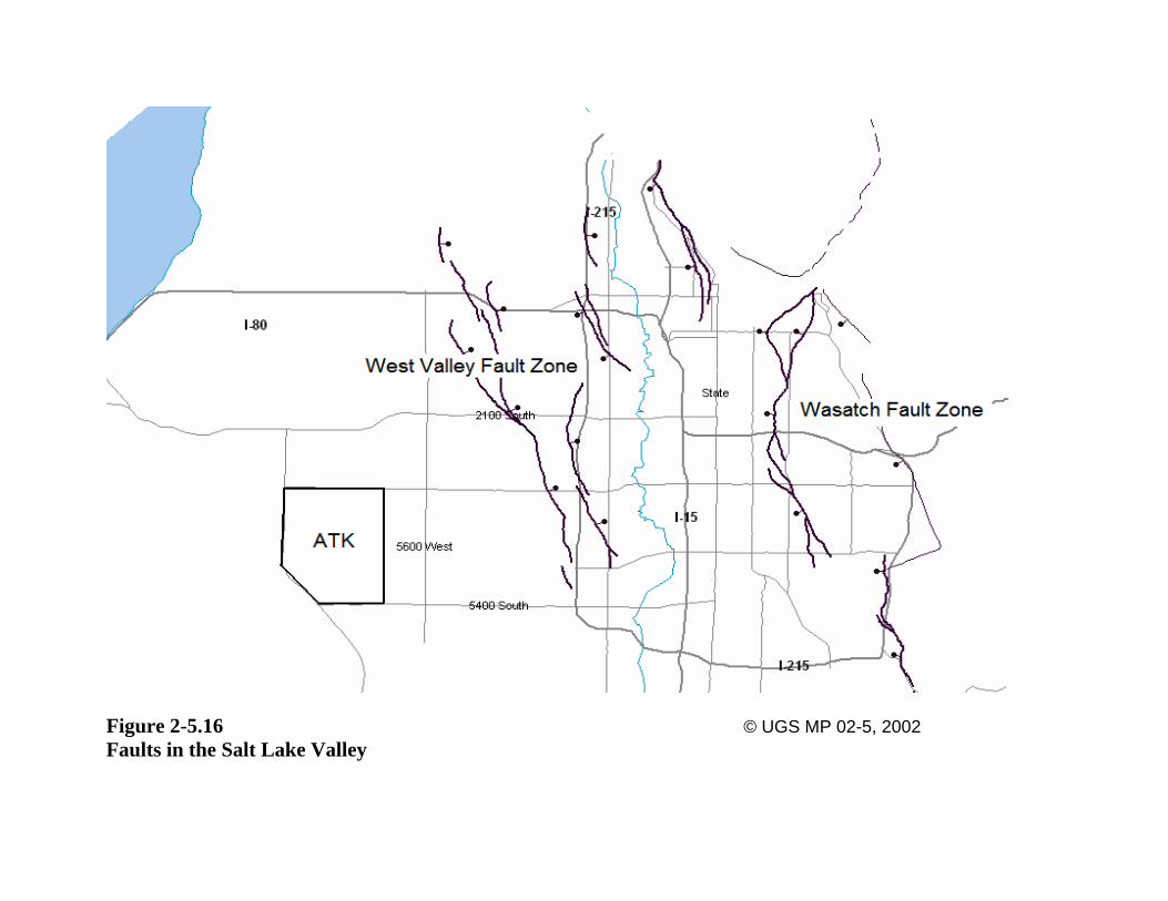
Figure 2-5.16 © UGS MP 02-5, 2002 Faults in the Salt Lake Valley
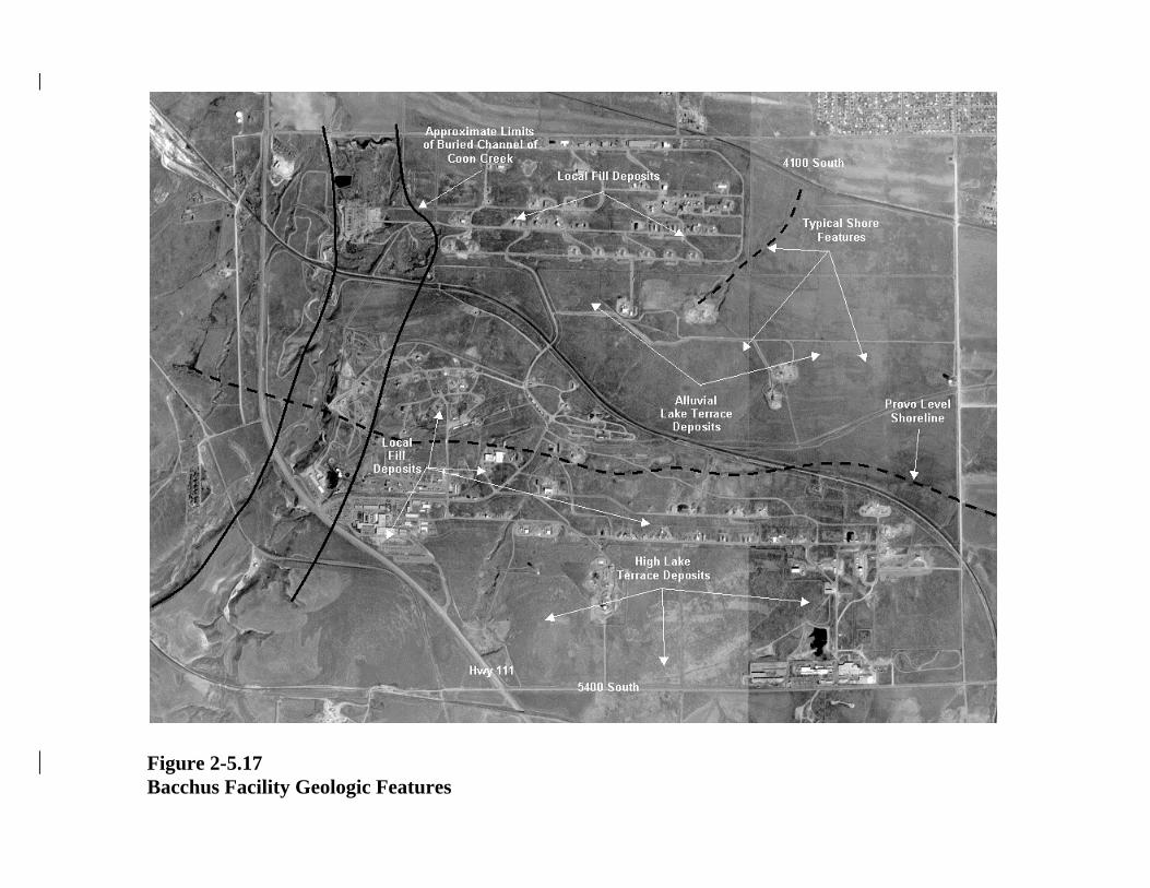
Figure 2-5.17 Bacchus Facility Geologic Features
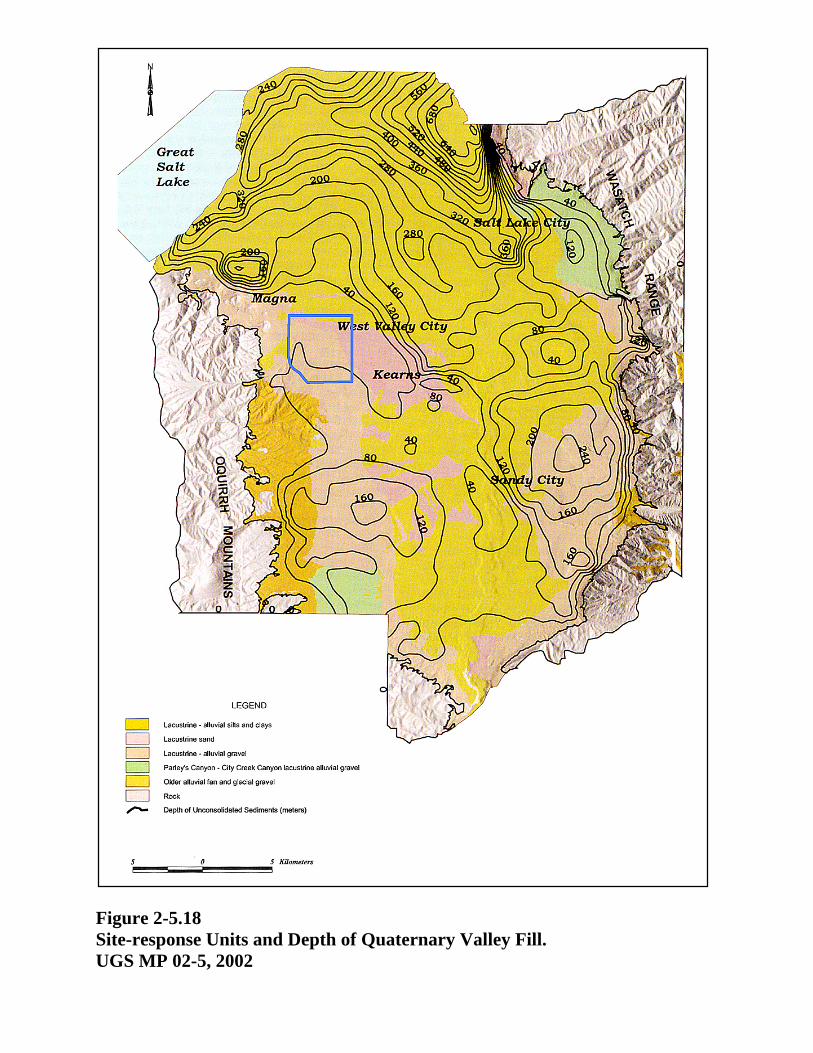
Figure 2-5.18 Site-response Units and Depth of Quaternary Valley Fill. UGS MP 02-5, 2002
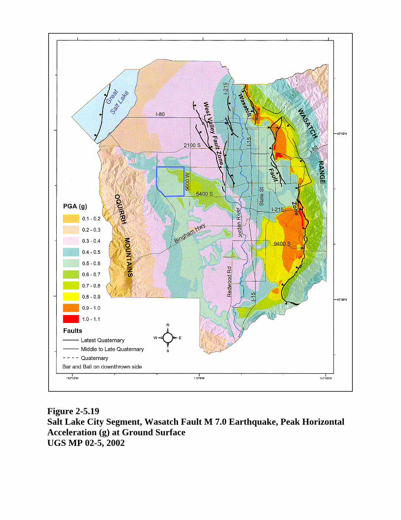
Figure 2-5.19 Salt Lake City Segment, Wasatch Fault M 7.0 Earthquake, Peak Horizontal Acceleration (g) at Ground Surface UGS MP 02-5, 2002