2 WAY STEREO CROSSOVER OWNERS MANUAL - BBE Sound
12
2 WAY STEREO CROSSOVER OWNERS MANUAL
Transcript of 2 WAY STEREO CROSSOVER OWNERS MANUAL - BBE Sound
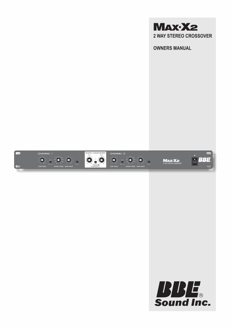
2 WAY STEREO CROSSOVER
OWNERS MANUAL

– � –
The symbol is used to indicate that some hazardous live terminals are involved within this apparatus, even under the normal operating conditions.
The symbol is used in the service documentation to indicate that a specific component shall be only replaced by the component specified in that documentation for safety reasons.
Protective grounding terminal.
Alternating current /voltage.
Hazardous live terminal.
ON: Denotes the apparatus is turned on.
OFF: Denotes the apparatus is turned off, because it uses the single pole switch, be sure to unplug the AC power to prevent any electric shock before you proceed with your service.
WARNING: Describes precautions that should be observed to prevent the danger of injury or death to the user.
CAUTION: Describes precautions that should be observed to prevent danger of the apparatus.
WARNING
• Power Supply
Ensures the source voltage matches the voltage of the power supply before turning ON the apparatus. Unplug this apparatus during lightning storms or when unused for long periods of time.
• External Connect�on
The external wiring connected to the output hazardous live terminals requires installation by an instructed person, or the use of ready-made leads or cords.
• Do not Remove any Cover
There are maybe some areas with high voltages inside, to reduce the risk of electric shock, do not remove any cover if the power supply is connected. The cover should be removed by qualified personnel only.
No user serviceable parts inside.
• Fuse
To prevent a fire, make sure to use fuses with specified standard (current, voltage, type). Do not use a different fuse or short circuit the fuse holder.
Before replacing the fuse, turn OFF the apparatus and disconnect the power source.
• Protect�ve Ground�ng
Make sure to connect the protective grounding to prevent any electric shock before turning ON the apparatus. Never cut off the internal or external
protective grounding wire or disconnect the wiring of protective grounding terminal.
• Operat�ng Cond�t�ons
This apparatus shall not be exposed to dripping or splashing and that no objects filled with liquids, such as vases, shall be placed on this apparatus.
To reduce the risk of fire or electric shock, do not expose this apparatus to rain or moisture.
Do not use this apparatus near water. Install in accordance with the manufacturer’s instructions.
Do not install near any heat sources such as radiators, heat registers, stoves, or other apparatus (including amplifiers) that produce heat.
Do not block any ventilation openings.
No naked flame sources, such as lighted candles, should be placed on the apparatus.
IMPORTANT SAFETY INSTRUCTIONS
• Read these instructions.
• Heed all warnings.
• Follow all instructions.
• Keep these instructions.
Only use attachments/accessories specified by the manufacturer.
• Power Cord and Plug
Do not defeat the safety purpose of the polarized or grounding type plug. A polarized plug has two blades with one wider than the other. A grounding type plug has two blades and a third grounding prong. The wide blade or the third prong are provided for your safety. If the provided plug does not fit into your outlet, consult an electrician for replacement of the obsolete outlet. Protect the power cord from being walked on or pinched particularly at the plug, convenience receptacles, and the point where they exit from the apparatus.
• Clean�ng
When the apparatus needs a cleaning, you can blow off dust from the apparatus with a blower or clean with a rag etc. Don’t use solvents such as benzol, alcohol, or other fluids with very strong volatility and flammability for cleaning the apparatus body. Clean only with a dry cloth.
• Serv�c�ng
Refer all servicing to qualified personnel. To reduce the risk of electric shock, do not perform any servicing other than that contained in the operating instructions unless you are qualified to do so.
Servicing is required when the apparatus has been damaged in any way, such as the power supply cord or plug is damaged, liquid has been spilled or objects have fallen into the apparatus, the apparatus has been exposed to rain or moisture, does not operate normally, or has been dropped.
SAFETY RELATED SYMBOLS

– �� –
CONTENTS
SPECIFICATIONS Max-X2 ……………………………………………………………………………… III
INTRODUCTION ………………………………………………………………………………………… 1
GETTING STARTED …………………………………………………………………………………… 1
READ BEFORE USING ………………………………………………………………………… 1
FEATURE LIST …………………………………………………………………………………… 1
SONIC MAXIMIZER……………………………………………………………………………… 1
PHASE INvERSION …………………………………………………………………………… 1
MAX-X2 FRONT PANEL ………………………………………………………………………………… 2
CONTROLS ……………………………………………………………………………………… 2
MAX-X2 REAR PANEL ………………………………………………………………………………… 3
MAX-X2 TyPICAL SETUP ……………………………………………………………………………… 4
CONNECTION CABLES ………………………………………………………………………………… 5
SERvICE ………………………………………………………………………………………………… 6
WARRANTy ……………………………………………………………………………………………… 6
MAINTENANCE ………………………………………………………………………………………… 6

– ��� –
SPECIFICATIONS Max-X2
CROSSOVER TYPE ………………………………………………………………………………………… Stereo 2 way
CROSSOVER FREQUENCY
LOW-HIGH ………………………………………………………………………………… 250Hz-6KHz
FILTER TyPE (SLOPE) ……………………………………………………… 2nd Order, 12dB/Octave
INPUTS: TyPE ………………………………………………………………………… XLR and unbalanced 1/4”
IMPEDANCE …………………………………………………………………………………… 100KOhms
OUTPUTS: TyPE …………………………………………………………………………………… Unbalanced 1/4”
IMPEDANCE …………………………………………………………………………………… 600 Ohms
LOW CUT FILTERS ………………………………………………………………………………… 30HZ, 12dB/Octave
FREQUENCY RESPONSE ………………………………………………………………………………20Hz - 25KHz
TOTAL HARMONIC DISTORTION (THD) ……………………………………………………………………… <.05%
S/N RATIO ………………………………………………………………………………………………………… >95dB
FUSE: 95-120v AC: ……………………………………………………………… 200mA 250vAC (slow-blow)
210-240v AC: ………………………………………………………… T100mAL 250vAC (slow-blow)
DIMENSIONS ……………………………………… 483mm(W) 194.5(D) 44mm(H) /19.01”(W) 7.66”(D) 1.73”(H)
WEIGHT ………………………………………………………………………………………………………2.5Kg (5.51lb)
SPECIFICATIONS

INTRODUCTIONCongratulations and thank you for your purchase of the BBE Max-X2. you have acquired an extremely simple to
use and universal stereo crossover with an integral BBE® Sonic Maximizer™.
Gett�ng Started
READ BEFORE USING
Before starting to use the crossover in your sound system there is some information you should know and pro-cedures you should follow.
Caution : To prevent malfunctioning and/or possible equipment damage: Before plug-ging the unit into the power source: (1) the voltage selector switch should be set for the correct voltage for your area (115V or 230V) and (2) all equipment connected to the crossover outputs should be turned off or all the inputs turned down.
FEATURE LIST
• Single rack unit (1U)
• Robust and compact design
• XLR inputs and 1/4” inputs/outputs.
• Designed for the most precise accurate control
• Top audio performances with high slew rate circuity
• Over than 115dB dynamic range for transparent sound
• Manufactured Under ISO9001 Certified management system
SONIC MAXIMIZER
Loudspeakers have difficulty working with the electronic signals supplied by an amplifier. These difficulties cause such major phase and amplitude distortion that the sound reproduced by speaker differs significantly from the sound produced by the original source.
In the past, these problems proved unsolvable and were thus delegated to a position of secondary importance in audio system design. However, phase and amplitude integrity is essential to accurate sound reproduction. Research shows that the information which the listener translates into the recognizable characteristics of a live performance are intimately tied into complex time and amplitude relationships between the fundamental and harmonic components of a given musical note or sound. These relationships define a sound’s “sound”.
When these complex relationships pass through a speaker, the proper order is lost. The higher frequencies are delayed. A lower frequency may reach the listener’s ear first or perhaps simultaneously with that of a higher frequency. In some cases, the fundamental components may be so time-shifted that they reach the listener’s ear ahead of some or all of the harmonic components.
This change in the phase and amplitude relationship on the harmonic and fundamental frequencies is techni-cally called “envelope distortion.” The listener perceives this loss of sound integrity in the reproduced sound as “muddy” and “smeared.” In the extreme, it can become difficult to tell the difference between musical instru-ments, for example, an oboe and a clarinet.
BBE Sound, Inc. conducted extensive studies of numerous speaker systems over a ten year period. With this knowledge, it became possible to identify the characteristics of an ideal speaker and to distill the corrections necessary to return the fundamental and harmonic frequency structures to their correct order. While there are differences among various speaker designs in the magnitude of their correction, the overall pattern of correction needed is remarkably consistent.
PHASE INVERSION
These phase inversion switches reverse the audio signal’s phase by 180°. Normally you won’t need this switch, however, in some cases, it might be necessary. For example, the inversion of the pins of the XLR connector may be necessary to alter the audio phase to compensate for phase cancellation.
GETTING STARTED
– � –

Max-X2 FRONT PANEL
CONTROLS
�. LOW GAIN CONTROLS:
These are used to adjust the LOW GAIN level of each channel.
2. LOW CUT SWITCHES:
These insert low cut filters in the LOW GAIN of each stereo channel with a 12dB/Octave, 30Hz HPF to mini-mize problems from subsonic frequencies in the signal, to suppress hum and to prevent low frequency speaker resonance.
3. XOVER FREQ (crossover frequency controls):
These select the crossover frequencies for the LOW and HIGH outputs. They are a low cut for the HIGH and a high cut for the LOW. you can select the frequencies between 250 Hz and 6 KHz.
4. HIGH GAIN controls:
These are used to adjust the HIGH output level.
5. PHASE sw�tches:
These allow switching the polarity to invert the signal phase on the HIGH outputs. This is done after the output levels are set to correct audible phase problems.
Caution: Before pressing the PHASE switches, always lower the outputs of your power amplifiers to avoid possible speaker damage.
6. BBE PROCESS controls
When the knob is in its minimum position, completely counterclockwise, no process is taking effect and the circuit is in its noise suppression mode. Turning the knob clockwise will introduce the BBE Process. Adjust the knob to mix the desired amount of process to suit your taste. Generally a good place to start the BBE process is to set the knob to it’s 12 o’clock position, then adjust accordingly.
7. BBE LO CONTOUR controls
This control is a low frequency adjustment for the BBE Process. It provides a boost of 12dBu when turned to its maximum position (clockwise) at 50Hz. When turned to its minimum position (counter-clockwise) it would be flat or no change.
8. BBE ON/OFF SWITCH
This switch engages the BBE Process as indicated by the green LED. When in the “OUT” position, the green LED will not illuminate, indicating that the BBE Process has been disengaged.
9. POWER SWITCH
Caution: Always turn the Crossover ON before the amplifier, and turn it OFF after the amplifier or transients harmful to the speakers may result.
FRONT PANEL
6
7
� 3 5
2 4
9� 3 5
2 4
6
7
8
– 2 –

Max-X2 REAR PANEL
�. AC JACK & AC FUSE HOLDER
Please note that, depending on the main voltage supplied to the unit, the correct fuse type and rating must be installed.
2. HIGH OUTPUT CONNECTORS:
Connect to your amplifiers via these unbalanced 1/4” output jacks.
3. LOW OUTPUT CONNECTORS:
Connect to your amplifiers via these unbalanced 1/4” output jacks.
4. STEREO INPUT CONNECTORS:
Connect your L/R stereo input signal to either the XLR or the 1/4” input jacks.
REAR PANEL
2 43� 2 43
– 3 –

– 4 –
Max-X2 TYPICAL SETUP
INSTALLATION
PMAHGIH
PMAWOL

– 5 –
CONNECTION CABLESIn this chapter you’ll find the wiring diagrams for the connectors to be used with your crossover. Take care of the connector cable. Always holding them by the connectors and avoiding knots and twists when coiling them: this gives the advantage of increasing their life and reliability, which is always to your advantage . Periodically check that your cables are in good condition, that they are correctly wired and that all their contact are perfectly efficient: a great number of problems (faulty contacts, ground hum , discharges, etc.) are caused entirely by using unsuitable or faulty cables
INSTALLATION
XLR Male Jack unbalanced link
XLR Female Jack unbalanced linkXLR Female Jack unbalanced link
Balanced XLR-M
Balanced XLR-F
Balanced 1/4” Plug

– 6 –
SERVICE
We recommend that if at all possible, a BBE Max-X2 which requires service be sent to our facility in Huntington Beach, California. We request that a “RETURN AUTHORIZATION” be issued by the dealer from whom you pur-chased the unit. If this is not possible, call BBE Sound, Inc. directly at (714) 897-6766, extension 116 to obtain a “RETURN AUTHORIZATION”. Include a copy of the bill of sale with the unit when it is shipped to BBE Sound, Inc. so that the service can be expedited.
As the repair turnaround time is minimal, we request that the unit be sent to BBE Sound, Inc. We also need to add reliability data to our files so that future revisions may be undertaken, if necessary, to improve the product. If unit has been purchased outside the US, please contact your national distributor.
WARRANTY
Warranty registration of the unit to BBE Sound, Inc. is not necessary. It is strongly recommended that you retain a copy of the bill of sale for future reference.
IT IS THE SOLE RESPONSIBILITy OF THE END USER TO PROvIDE THE BILL OF SALE OR OTHER MEANS OF PROOF OF PURCHASE TO vALIDATE THE WARRANTy IF WARRANTy SERvICE IS REQUESTED.
The BBE Max-X2 is warranted against defects in material and workmanship for a period of two (2) years from date of purchase from BBE Sound Inc. or from an authorized dealer. During this period, we will repair units free of charge providing that they are shipped prepaid to BBE Sound, Inc., 5381 Production Drive, Huntington Beach, CA 92649. We will pay return UPS shipping charges within the USA. All charges related to non-UPS shipping, including customs clearance, will be billed. The warranty will be honored for the longer of either 90 days from the date of any service or the remainder of the original 2 year factory warranty.
This warranty will be considered null and void by BBE Sound, Inc. if any of the following is found:
1. The equipment has been physically damaged.
2. The equipment shows signs of abuse.
3. The equipment has been electrically damaged by improper connection or attempted repair by the customer or a third party.
4. The equipment has been modified without authorization.
5. The bill of sales indicates that the purchase date of the equipment is not within the warranty period.
All non-warranty repairs are warranted for a period of 90 days from the date of service.
BBE Sound, Inc. is NOT LIABLE FOR CONSEQUENTIAL DAMAGES. Should the unit fail to operate for any reason, our sole obligation is to repair it as described above.
DO NOT RETURN ANY PRODUCT TO THE ABOVE ADDRESS WITHOUT INSTRUCTIONS AND AUTHORIZATION ISSUED BY THE ABOVE LOCATION.
MAINTENANCE
Maintenance of the BBE Max-X2 is limited to proper cleaning of the unit with mild household cleaner such as Formula 409™ or Windex™. The chassis, front panel and cover are steel finished with a durable polyurethane paint.
There are no user replaceable parts and the unit should not be opened for any reason unless you are a quali-fied technician. Calibration should be performed if parts are replaced or if a performance check-out indicates a problem with calibration. Long term use has shown that over the life of this unit there is little or no drift of the components in the BBE Max-X2 which would cause a change in calibration. A very conservative design philoso-phy has resulted in a piece of equipment which runs very cool and should give years of trouble-free service.
WARRANTY


538� PRODUCTION DRIVEHUNTINGTON BEACH, CA 926497�4-897-6766 • FAX 7�4-896-0736
WWW.BBESOUND.COM
COvERED By U.S. PATENT 5,736,897 AND OTHER U.S. AND FOREIGN PATENTS PENDING.BBE IS THE REGISTERED TRADEMARK OF BBE SOUND, INC.
REv 3: 9.2.2010