2-way cartridge valves; Replaces: 06.98 pressure … · 2/68 Bosch Rexroth Corp. | Industrial...
68
RA 21 050/02.03 Replaces: 06.98 Electric Drives and Controls Hydraulics Linear Motion and Assembly Technologies Pneumatics Service 2-way cartridge valves; pressure functions Function, section, symbols – General 2 – Pressure relief function 2 – Pressure reducing function 2, 3 – Pressure sequencing function 3 – Cavity and porting pattern 4 Pressure relief function: – Cartridge valve type LC . DB…: • Ordering details 5 • Symbols 5 • Technical data 5 • Characteristic curves 6 – 11 • Seal kits 12 • Compression springs 12 • Preferred types 12 – Control cover type LFA . DB…: • Ordering details (general) 13 – 14 • Technical data 14 • Pilot valves 15 • Symbols (basic symbols) 16 • R-rings for pilot oil connections 17 • Seal kits 17 • Fixing screws 17 • Orifice dimensions 17 Ordering details, symbols and unit dimensions: – Type DB 18 – 20 – Types DBW; DBS 21 – 25 – Type DBWD 26 – 28 – Type DBU2 29 – 32 – Type DBU3D 33 – 37 – Type DBE 38 – Type DBEM 39 – 42 Pressure reducing function: – Cartridge valve type LC . DR…: • Ordering details 43 • Symbol 43 • Technical data 43 • Characteristic curves 44 – 46 • Seal kits 47 • Compression springs 47 – Control cover type LFA . DR…: • Ordering details (general) 48 • Symbol 48 • Technical data 49 • Pilot valve 49 • Symbols (basic symbols) 50 Continued on page 2 H/A/D 5593 Models LC and LFA Nominal sizes 16 to 100 Series 6X; 7X Maximum operating pressure 420 bar (6092 PSI) Maximum flow 7000 L/min (1850 GPM) Table of contents Contents Page Contents Page 1/68
Transcript of 2-way cartridge valves; Replaces: 06.98 pressure … · 2/68 Bosch Rexroth Corp. | Industrial...
RA 21 050/02.03Replaces: 06.98
Electric Drivesand Controls Hydraulics
Linear Motion andAssembly Technologies Pneumatics Service
2-way cartridge valves;
pressure functions
Function, section, symbols
– General 2
– Pressure relief function 2
– Pressure reducing function 2, 3
– Pressure sequencing function 3
– Cavity and porting pattern 4
Pressure relief function:
– Cartridge valve type LC . DB…:
• Ordering details 5
• Symbols 5
• Technical data 5
• Characteristic curves 6 – 11
• Seal kits 12
• Compression springs 12
• Preferred types 12
– Control cover type LFA . DB…:
• Ordering details (general) 13 – 14
• Technical data 14
• Pilot valves 15
• Symbols (basic symbols) 16
• R-rings for pilot oil connections 17
• Seal kits 17
• Fixing screws 17
• Orifi ce dimensions 17
Ordering details, symbols and unit dimensions:
– Type DB 18 – 20
– Types DBW; DBS 21 – 25
– Type DBWD 26 – 28
– Type DBU2 29 – 32
– Type DBU3D 33 – 37
– Type DBE 38
– Type DBEM 39 – 42
Pressure reducing function:
– Cartridge valve type LC . DR…:
• Ordering details 43
• Symbol 43
• Technical data 43
• Characteristic curves 44 – 46
• Seal kits 47
• Compression springs 47
– Control cover type LFA . DR…:
• Ordering details (general) 48
• Symbol 48
• Technical data 49
• Pilot valve 49
• Symbols (basic symbols) 50
Continued on page 2
H/A/D 5593
Models LC and LFA
Nominal sizes 16 to 100Series 6X; 7XMaximum operating pressure 420 bar (6092 PSI)Maximum flow 7000 L/min (1850 GPM)
Table of contents
Contents Page Contents Page
1/68
F**
X
A
YB
X**T
B
A
X Y
X** F**
A
4
6
1
3
2
5
B
Overview of contents
Contents Page
• R-rings for the pilot oil connections 51
• Fixing screws 51
• General dimensions 52
Ordering details, symbols and unit dimensions:
– Type DR 53, 54
– Type DRW 55 – 56
– Types DREV; DREZ 57, 58
– Types DREWV; DREWZ
Contents Page
Pressure sequencing function:
– Control cover type LFA . DZ…:
• Ordering details (general) 61
• Symbols (basic symbols) 61
• Technical data 62
• R-rings for the pilot oil connections 62
• Seal kits 63
• Fixing screws 63
• Orifi ce dimensions 63
Ordering details, symbols and unit dimensions:
– Type DZ 64, 65
– Type DZW 66, 67
Function, section, symbols
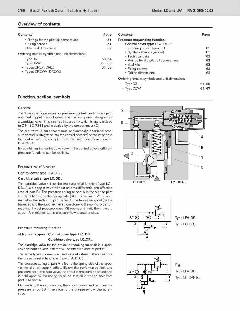
General
The 2-way cartridge valves for pressure control functions are pilot
operated poppet or spool valves. The main component designed as
a cartridge valve (1) is inserted into a cavity which is standardised
to DIN ISO 7368 and is sealed by the control cover (2).
The pilot valve (4) for either manual or electrical proportional pres-
sure control is integrated into the control cover (2) or mounted onto
the control cover (2) as a pilot valve with interface connections to
DIN 24 340.
By combining the cartridge valve with the control covers different
pressure functions can be realised.
LC..DB.D... LC..DB.E...
Pressure relief function
Control cover type LFA..DB...
Cartridge valve type LC..DB...
The cartridge valve (1) for the pressure relief function (type LC .
DB…) is a poppet valve without an area differential (no effective
area at port B). The pressure acting at port A is fed via the pilot
supply orifi ce (5) to the spring side (6) of the element. At pressu-
res below the setting of pilot valve (4) the forces on spool (3) are
balanced and the spool remains closed due to the spring force. On
reaching the set pressure, spool (3) opens and limits the pressure
at port A in relation to the pressure-fl ow characteristics.
Pressure reducing function
a) Normally open: Control cover type LFA..DB...
Cartridge valve type LC..DR...
The cartridge valve for the pressure reducing function is a spool
valve without an area differential (no effective area at port B).
The same types of cover are used as pilot valves that are used for
the pressure relief functions (type LFA..DB...).
The pressure acting at port A is fed to the spring side of the spool
via the pilot oil supply orifi ce. Below the performance limit and
pressure set at the pilot valve, the spool is pressure-balanced and
is held open by the spring force, so that oil is free to fl ow from
port B to port A.
On reaching the set pressure, the spool closes and reduces the
pressure at port A in relation to the pressure-fl ow characteri-
stics.
Type LFA..DB...
Type LC..DB...
E.g.
Type LFA..DB...
Type LC..DR40...
2/68 Bosch Rexroth Corp. | Industrial Hydraulics Models LC and LFA RA 21050/02.03
X Y
X** F**
M
A
BZ2
X
A
B
YZ2 Z1
HD ND
pS
RV
X
A
B
YZ2 Z1
Function, symbols
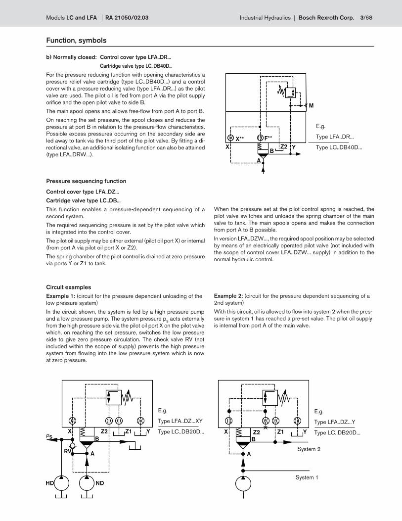
b) Normally closed: Control cover type LFA..DR...
Cartridge valve type LC..DB40D...
For the pressure reducing function with opening characteristics a
pressure relief valve cartridge (type LC..DB40D...) and a control
cover with a pressure reducing valve (type LFA..DR...) as the pilot
valve are used. The pilot oil is fed from port A via the pilot supply
orifi ce and the open pilot valve to side B.
The main spool opens and allows free-fl ow from port A to port B.
On reaching the set pressure, the spool closes and reduces the
pressure at port B in relation to the pressure-fl ow characteristics.
Possible excess pressures occurring on the secondary side are
led away to tank via the third port of the pilot valve. By fi tting a di-
rectional valve, an additional isolating function can also be attained
(type LFA..DRW...).
Example 2: (circuit for the pressure dependent sequencing of a
2nd system)
With this circuit, oil is allowed to fl ow into system 2 when the pres-
sure in system 1 has reached a pre-set value. The pilot oil supply
is internal from port A of the main valve.
System 2
Circuit examples
Example 1: (circuit for the pressure dependent unloading of the
low pressure system)
In the circuit shown, the system is fed by a high pressure pump
and a low pressure pump. The system pressure pS acts externally
from the high pressure side via the pilot oil port X on the pilot valve
which, on reaching the set pressure, switches the low pressure
side to give zero pressure circulation. The check valve RV (not
included within the scope of supply) prevents the high pressure
system from fl owing into the low pressure system which is now
at zero pressure.
Pressure sequencing function
Control cover type LFA..DZ...
Cartridge valve type LC..DB...
This function enables a pressure-dependent sequencing of a
second system.
The required sequencing pressure is set by the pilot valve which
is integrated into the control cover.
The pilot oil supply may be either external (pilot oil port X) or internal
(from port A via pilot oil port X or Z2).
The spring chamber of the pilot control is drained at zero pressure
via ports Y or Z1 to tank.
System 1
E.g.
Type LFA..DR...
Type LC..DB40D...
E.g.
Type LFA..DZ...Y
Type LC..DB20D...
E.g.
Type LFA..DZ...XY
Type LC..DB20D...
When the pressure set at the pilot control spring is reached, the
pilot valve switches and unloads the spring chamber of the main
valve to tank. The main spools opens and makes the connection
from port A to B possible.
In version LFA..DZW..., the required spool position may be selected
by means of an electrically operated pilot valve (not included with
the scope of control cover LFA..DZW... supply) in addition to the
normal hydraulic control.
Models LC and LFA RA 21050/02.03 Industrial Hydraulics | Bosch Rexroth Corp. 3/68
L1
L2±0,2
L5±0,2
L4
±0
,2L4
±0
,2
L4±0,2L4±0,2
L3
±0
,2
L1
4 x D5; H4
ØD7H13; 10 ØD6 max.
(X,Y,Z1,Z2)
Z1
YX
Z2
L2
±0
,2L5
±0
,2
ØD6 max.
(X,Y,Z1,Z2)
ØD7H13; 10
5
8L3±0,2
6
8 x D5; H4
ØD7H13; 10
ØD6 max.
(X,Y,Z1,Z2)
L2
±0
,3
L1
35°22.5°
45°
Z1
Y
Z2
X
5
X
Y
AØD1H7
W
T
H8 15
°
H1
(H1
*)
ØD
3(D
3*)
15°
H9
A
B
ØD2
ØD4H7
H7
H6
H5
H3
±0
,1
H2
+0
,1
A0.05
Z
Z
Z
7 1
7 13 2 4
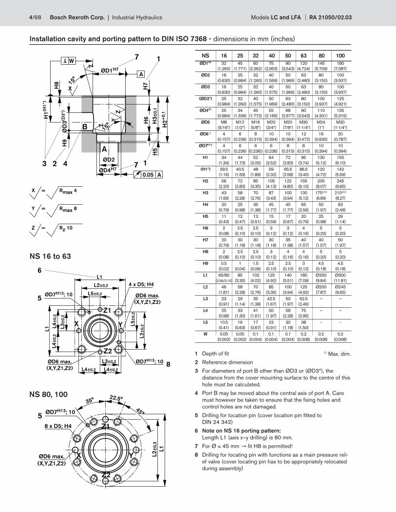
Installation cavity and porting pattern to DIN ISO 7368 - dimensions in mm (inches)
NS 80, 100
NS 16 to 63
1 Depth of fi t
2 Reference dimension
3 For diameters of port B other than ØD3 or (ØD3*), the
distance from the cover mounting surface to the centre of this
hole must be calculated.
4 Port B may be moved about the central axis of port A. Care
must however be taken to ensure that the fi xing holes and
control holes are not damaged.
5 Drilling for location pin (cover location pin fi tted to
DIN 24 342)
6 Note on NS 16 porting pattern:
Length L1 (axis x–y drilling) is 80 mm.
7 For Ø ≤ 45 mm → fi t H8 is permitted!
8 Drilling for locating pin with functions as a main pressure reli-
ef valve (cover locating pin has to be appropriately relocated
during assembly)
1) Max. dim.
NS 16 25 32 40 50 63 80 100
ØD1H7 32 45 60 75 90 120 145 180
(1.260) (1.771) (2.362) (2.953) (3.543) (4.724) (5.709) (7.087)
ØD2 16 25 32 40 50 63 80 100
(0.630) (0.984) (1.260) (1.569) (1.969) (2.480) (3.150) (3.937)
ØD3 16 25 32 40 50 63 80 100
(0.630) (0.984) (1.260) (1.575) (1.969) (2.480) (3.150) (3.937)
(ØD3*) 25 32 40 50 63 80 100 125
(0.984) (1.260) (1.575) (1.969) (2.480) (3.150) (3.937) (4.921)
ØD4H7 25 34 45 55 68 90 110 135
(0.984) (1.339) (1.772) (2.165) (2.677) (3.543) (4.331) (5.315)
ØD5 M8 M12 M16 M20 M20 M30 M24 M30
(5/16“) (1/2“) (5/8“) (3/4“) (7/8“) (1-1/4“) (1“) (1-1/4“)
ØD6 1) 4 6 8 10 10 12 16 20
(0.157) (0.236) (0.315) (0.394) (0.394) (0.472) (0.630) (0.787)
ØD7H13 4 6 6 6 8 8 10 10
(0.157) (0.236) (0.236)) (0.236) (0.315) (0.315) (0.394) (0.394)
H1 34 44 52 64 72 95 130 155
(1.34) (1.73) (2.05) (2.52) (2.83) (3.74) (5.12) (6.10)
(H1*) 29.5 40.5 48 59 65.5 86.5 120 142
(1.16) (1.59) (1.89) (2.32) (2.58) (3.40) (4.72) (5.59)
H2 56 72 85 105 122 155 205 245
(2.20) (2.83) (3.35) (4.13) (4.80) (6.10) (8.07) (9.65)
H3 43 58 70 87 100 130 175±0.2 210±0.2
(1.69) (2.28) (2.76) (3.43) (3.94) (5.12) (6.89) (8.27)
H4 20 25 35 45 45 65 50 63
(0.79) (0.98) (1.38) (1.77) (1.77) (2.56) (1.97) (2.48)
H5 11 12 13 15 17 20 25 29
(0.43) (0.47) (0.51) (0.59) (0.67) (0.79) (0.98) (1.14)
H6 2 2.5 2.5 3 3 4 5 5
(0.08) (0.10) (0.10) (0.12) (0.12) (0.16) (0.20) (0.20)
H7 20 30 30 30 35 40 40 50
(0.79) (1.18) (1.18) (1.18) (1.38) (1.57) (1.57) (1.97)
H8 2 2.5 2.5 3 4 4 5 5
(0.08) (0.10) (0.10) (0.12) (0.16) (0.16) (0.20) (0.20)
H9 0.5 1 1.5 2.5 2.5 3 4.5 4.5
(0.02) (0.04) (0.06) (0.10) (0.10) (0.12) (0.18) (0.18)
L1 65/80 85 102 125 140 180 Ø250 Ø300
(2.56/3.15) (3.35) (4.02) (4.92) (5.51) (7.09) (9.84) (11.81)
L2 46 58 70 85 100 125 Ø200 Ø245
(1.81) (2.28) (2.76) (3.35) (3.94) (4.92) (7.87) (9.65)
L3 23 29 35 42.5 50 62.5 – –
(0.91) (1.14) (1.38) (1.67) (1.97) (2.46)
L4 25 33 41 50 58 75 – –
(0.98) (1.30) (1.61) (1.97) (2.28) (2.95)
L5 10.5 16 17 23 30 38 – –
(0.41) (0.63) (0.67) (0.91) (1.18) (1.50)
W 0.05 0.05 0.1 0.1 0.1 0.2 0.2 0.2
(0.002) (0.002) (0.004) (0.004) (0.004) (0.008) (0.008) (0.008)
X = Rmax 4
Y = Rmax 8
Z = Rz 10
4/68 Bosch Rexroth Corp. | Industrial Hydraulics Models LC and LFA RA 21050/02.03
A
B
A
B
A
B
A
B
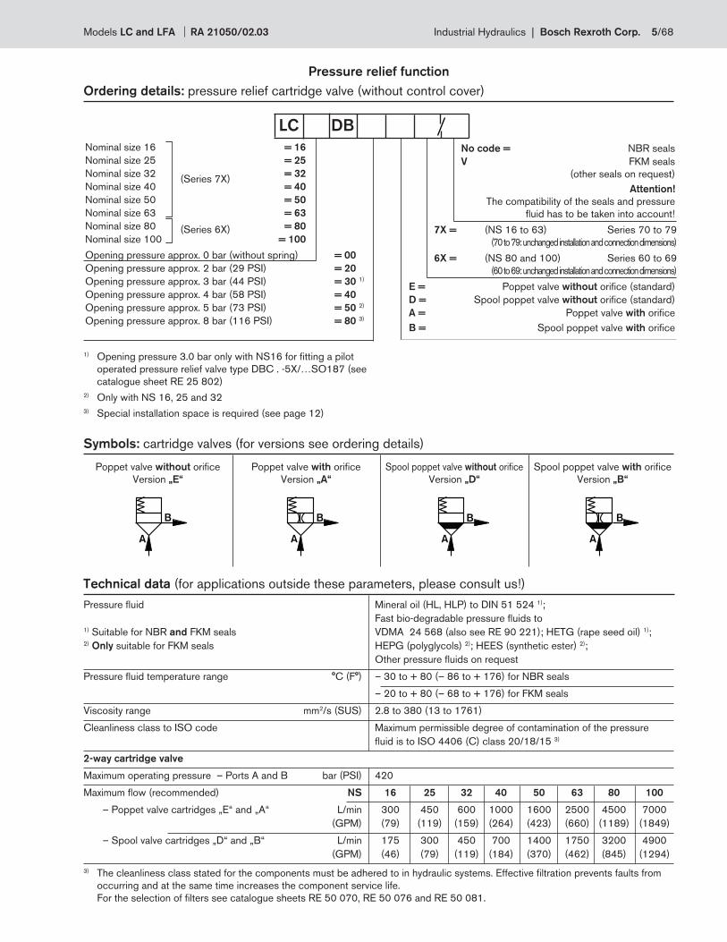
Pressure relief function
Ordering details: pressure relief cartridge valve (without control cover)
No code = NBR seals
V FKM seals
(other seals on request)
Attention!
The compatibility of the seals and pressure
fl uid has to be taken into account!
7X = (NS 16 to 63) Series 70 to 79
(70 to 79: unchanged installation and connection dimensions)
6X = (NS 80 and 100) Series 60 to 69
(60 to 69: unchanged installation and connection dimensions)
E = Poppet valve without orifi ce (standard)
D = Spool poppet valve without orifi ce (standard)
A = Poppet valve with orifi ce
B = Spool poppet valve with orifi ce
Nominal size 16 = 16
Nominal size 25 = 25
Nominal size 32 = 32
Nominal size 40 = 40
Nominal size 50 = 50
Nominal size 63 = 63
Nominal size 80 = 80
Nominal size 100 = 100
Opening pressure approx. 0 bar (without spring) = 00
Opening pressure approx. 2 bar (29 PSI) = 20
Opening pressure approx. 3 bar (44 PSI) = 30 1)
Opening pressure approx. 4 bar (58 PSI) = 40
Opening pressure approx. 5 bar (73 PSI) = 50 2)
Opening pressure approx. 8 bar (116 PSI) = 80 3)
(Series 7X)
(Series 6X)
LC DB
1) Opening pressure 3.0 bar only with NS16 for fi tting a pilot
operated pressure relief valve type DBC . -5X/…SO187 (see
catalogue sheet RE 25 802)
2) Only with NS 16, 25 and 32
3) Special installation space is required (see page 12)
Symbols: cartridge valves (for versions see ordering details)
Poppet valve without orifi ce
Version „E“
Poppet valve with orifi ce
Version „A“
Spool poppet valve without orifi ce
Version „D“
Spool poppet valve with orifi ce
Version „B“
Pressure fl uid Mineral oil (HL, HLP) to DIN 51 524 1);
Fast bio-degradable pressure fl uids to 1) Suitable for NBR and FKM seals VDMA 24 568 (also see RE 90 221); HETG (rape seed oil) 1); 2) Only suitable for FKM seals HEPG (polyglycols) 2); HEES (synthetic ester) 2);
Other pressure fl uids on request
Pressure fl uid temperature range °C (F°) – 30 to + 80 (– 86 to + 176) for NBR seals
– 20 to + 80 (– 68 to + 176) for FKM seals
Viscosity range mm2/s (SUS) 2.8 to 380 (13 to 1761)
Cleanliness class to ISO code Maximum permissible degree of contamination of the pressure
fl uid is to ISO 4406 (C) class 20/18/15 3)
2-way cartridge valve
Maximum operating pressure – Ports A and B bar (PSI) 420
Maximum fl ow (recommended) NS 16 25 32 40 50 63 80 100
– Poppet valve cartridges „E“ and „A“ L/min 300 450 600 1000 1600 2500 4500 7000
(GPM) (79) (119) (159) (264) (423) (660) (1189) (1849)
– Spool valve cartridges „D“ and „B“ L/min 175 300 450 700 1400 1750 3200 4900
(GPM) (46) (79) (119) (184) (370) (462) (845) (1294)
Technical data (for applications outside these parameters, please consult us!)
3) The cleanliness class stated for the components must be adhered to in hydraulic systems. Effective fi ltration prevents faults from
occurring and at the same time increases the component service life.
For the selection of fi lters see catalogue sheets RE 50 070, RE 50 076 and RE 50 081.
Models LC and LFA RA 21050/02.03 Industrial Hydraulics | Bosch Rexroth Corp. 5/68
..DB40..
..DB20..
15 (218)
350 (5076)
300 (4351)
250 (3626)
200 (2901)
150 (2176)
100 (1450)
50 (725)
00 50
(13)
100
(26)
150
(40)
200
(53)
250
(66)
50
(13)
100
(26)
150
(40)
200
(53)
250
(66)
10 (145)
5 (73)
..DB40..
..DB20..
15 (218)
350 (5076)
300 (4351)
250 (3626)
200 (2901)
150 (2176)
100 (1450)
50 (725)
00 50
(13)
100
(26)
150
(40)
200
(53)
250
(66)
50
(13)
100
(26)
150
(40)
200
(53)
250
(66)
10 (145)
5 (73)
..DB40..
..DB20..
15 (218)
350 (5076)
300 (4351)
250 (3626)
200 (2901)
150 (2176)
100 (1450)
50 (725)
00 50
(13)
100
(26)
150
(40)
200
(53)
250
(66)
50
(13)
100
(26)
150
(40)
200
(53)
250
(66)
10 (145)
5 (73)
..DB40..
..DB20..
15 (218)
350 (5076)
300 (4351)
250 (3626)
200 (2901)
150 (2176)
100 (1450)
50 (725)
00 50
(13)
100
(26)
150
(40)
200
(53)
250
(66)
50
(13)
100
(26)
150
(40)
200
(53)
250
(66)
10 (145)
5 (73)
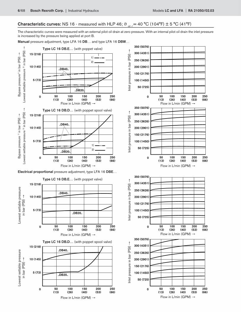
Characteristic curves: NS 16 - measured with HLP 46; ϑ oil -/
= 40 °C (104°F) ± 5 °C (41°F)
The characteristic curves were measured with an external pilot oil drain at zero pressure. With an internal pilot oil drain the inlet pressure
is increased by the pressure being applied at port B.
Manual pressure adjustment, type LFA 16 DB… and type LFA 16 DBW…
Type LC 16 DB.E… (with poppet valve)
Byp
ass p
ressure
1) i
n b
ar
(PS
I) →
Low
est
sett
ab
le p
ressure
2) i
n b
ar
(PS
I) →
Flow in L/min (GPM) → Flow in L/min (GPM) →
Inle
t p
ressure
in b
ar
(PS
I) →
Type LC 16 DB.D… (with poppet spool valve)
Byp
ass p
ressure
1) i
n b
ar
(PS
I) →
Low
est
sett
ab
le p
ressure
2) i
n b
ar
(PS
I) →
Flow in L/min (GPM) → Flow in L/min (GPM) →
Inle
t p
ressure
in b
ar
(PS
I) →
Electrical proportional pressure adjustment, type LFA 16 DBE…
Type LC 16 DB.E… (with poppet valve)
Low
est
sett
ab
le p
ressure
in b
ar
(PS
I) →
Flow in L/min (GPM) → Flow in L/min (GPM) →
Inle
t p
ressure
in b
ar
(PS
I) →
Type LC 16 DB.D… (with poppet spool valve)
Flow in L/min (GPM) → Flow in L/min (GPM) →
Inle
t p
ressure
in b
ar
(PS
I) →
Low
est
sett
ab
le p
ressure
in b
ar
(PS
I) →
1)
2)
1)
2)
6/68 Bosch Rexroth Corp. | Industrial Hydraulics Models LC and LFA RA 21050/02.03
..DB40..
..DB20..
100
(26)
200
(53)
300
(79)
400
(106)
50
(13)
100
(26)
150
(40)
200
(53)
250
(66)
300
(79)
350
(92)
400
(105)
15 (218)
350 (5076)
300 (4351)
250 (3626)
200 (2901)
150 (2176)
100 (1450)
50 (725)
00
10 (145)
5 (73)
..DB40..
..DB20..
15 (218)
350 (5076)
300 (4351)
250 (3626)
200 (2901)
150 (2176)
100 (1450)
50 (725)
00
10 (145)
5 (73)
100
(26)
200
(53)
300
(79)
400
(106)
50
(13)
100
(26)
150
(40)
200
(53)
250
(66)
300
(79)
350
(92)
400
(105)
..DB40..
..DB20..
100
(26)
200
(53)
300
(79)
400
(106)
50
(13)
100
(26)
150
(40)
200
(53)
250
(66)
300
(79)
350
(92)
400
(105)
15 (218)
350 (5076)
300 (4351)
250 (3626)
200 (2901)
150 (2176)
100 (1450)
50 (725)
00
10 (145)
5 (73)
..DB40..
..DB20..
15 (218)
350 (5076)
300 (4351)
250 (3626)
200 (2901)
150 (2176)
100 (1450)
50 (725)
00 100
(26)
200
(53)
300
(79)
400
(106)
50
(13)
100
(26)
150
(40)
200
(53)
250
(66)
300
(79)
350
(92)
400
(105)
10 (145)
5 (73)
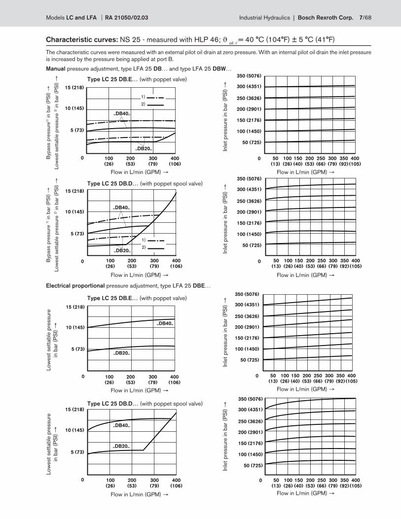
Characteristic curves: NS 25 - measured with HLP 46; ϑ oil -/
= 40 °C (104°F) ± 5 °C (41°F)
The characteristic curves were measured with an external pilot oil drain at zero pressure. With an internal pilot oil drain the inlet pressure
is increased by the pressure being applied at port B.
Manual pressure adjustment, type LFA 25 DB… and type LFA 25 DBW…
Type LC 25 DB.E… (with poppet valve)
Type LC 25 DB.D… (with poppet spool valve)
Electrical proportional pressure adjustment, type LFA 25 DBE…
Type LC 25 DB.E… (with poppet valve)
Type LC 25 DB.D… (with poppet spool valve)
1)
2)
1)
2)
Byp
ass p
ressure
1) i
n b
ar
(PS
I) →
Low
est
sett
ab
le p
ressure
2) i
n b
ar
(PS
I) →
Flow in L/min (GPM) → Flow in L/min (GPM) →
Byp
ass p
ressure
1) i
n b
ar
(PS
I) →
Low
est
sett
ab
le p
ressure
2) i
n b
ar
(PS
I) →
Flow in L/min (GPM) → Flow in L/min (GPM) →
Low
est
sett
ab
le p
ressure
in b
ar
(PS
I) →
Flow in L/min (GPM) → Flow in L/min (GPM) →
Flow in L/min (GPM) → Flow in L/min (GPM) →
Low
est
sett
ab
le p
ressure
in b
ar
(PS
I) →
Inle
t p
ressure
in b
ar
(PS
I) →
Inle
t p
ressure
in b
ar
(PS
I) →
Inle
t p
ressure
in b
ar
(PS
I) →
Inle
t p
ressure
in b
ar
(PS
I) →
Models LC and LFA RA 21050/02.03 Industrial Hydraulics | Bosch Rexroth Corp. 7/68
..DB40..
..DB20..
15 (218)
350 (5076)
300 (4351)
250 (3626)
200 (2901)
150 (2176)
100 (1450)
50 (725)
00 100
(26)
200
(53)
300
(79)
400
(106)
500
(132)
600
(159)
100
(26)
200
(53)
300
(79)
400
(106)
500
(132)
600
(159)
10 (145)
5 (73)
..DB40..
..DB20..
15 (218)
350 (5076)
300 (4351)
250 (3626)
200 (2901)
150 (2176)
100 (1450)
50 (725)
00 100
(26)
200
(53)
300
(79)
400
(106)
500
(132)
600
(159)100
(26)
200
(53)
300
(79)
400
(106)
500
(132)
600
(159)
10 (145)
5 (73)
..DB40..
..DB20..
15 (218)
350 (5076)
300 (4351)
250 (3626)
200 (2901)
150 (2176)
100 (1450)
50 (725)
00 100
(26)
200
(53)
300
(79)
400
(106)
500
(132)
600
(159)
100
(26)
200
(53)
300
(79)
400
(106)
500
(132)
600
(159)
10 (145)
5 (73)
..DB40..
..DB20..
15 (218)
350 (5076)
300 (4351)
250 (3626)
200 (2901)
150 (2176)
100 (1450)
50 (725)
00 100
(26)
200
(53)
300
(79)
400
(106)
500
(132)
600
(159)
100
(26)
200
(53)
300
(79)
400
(106)
500
(132)
600
(159)
10 (145)
5 (73)
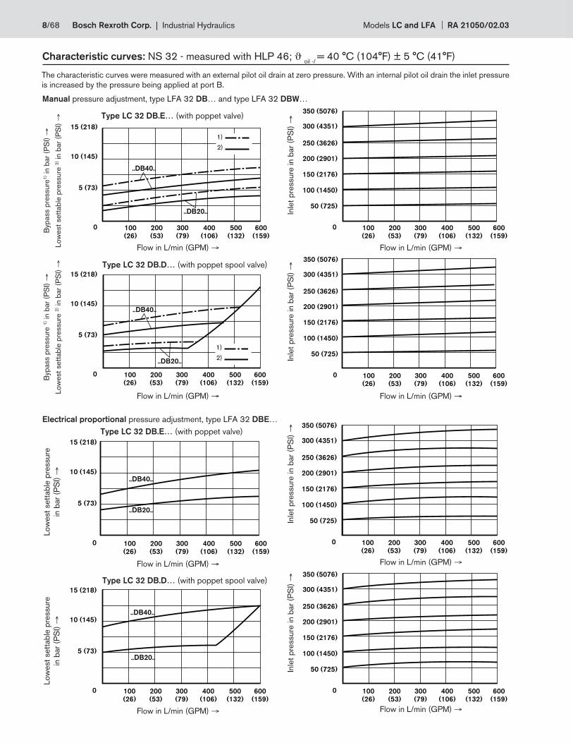
Characteristic curves: NS 32 - measured with HLP 46; ϑ oil -/
= 40 °C (104°F) ± 5 °C (41°F)
The characteristic curves were measured with an external pilot oil drain at zero pressure. With an internal pilot oil drain the inlet pressure
is increased by the pressure being applied at port B.
Manual pressure adjustment, type LFA 32 DB… and type LFA 32 DBW…
Type LC 32 DB.E… (with poppet valve)
Type LC 32 DB.D… (with poppet spool valve)
Electrical proportional pressure adjustment, type LFA 32 DBE…
Type LC 32 DB.E… (with poppet valve)
Type LC 32 DB.D… (with poppet spool valve)
1)
2)
1)
2)
Byp
ass p
ressure
1) i
n b
ar
(PS
I) →
Low
est
sett
ab
le p
ressure
2) i
n b
ar
(PS
I) →
Flow in L/min (GPM) → Flow in L/min (GPM) →
Byp
ass p
ressure
1) i
n b
ar
(PS
I) →
Low
est
sett
ab
le p
ressure
2) i
n b
ar
(PS
I) →
Flow in L/min (GPM) → Flow in L/min (GPM) →
Low
est
sett
ab
le p
ressure
in b
ar
(PS
I) →
Flow in L/min (GPM) → Flow in L/min (GPM) →
Flow in L/min (GPM) → Flow in L/min (GPM) →
Low
est
sett
ab
le p
ressure
in b
ar
(PS
I) →
Inle
t p
ressure
in b
ar
(PS
I) →
Inle
t p
ressure
in b
ar
(PS
I) →
Inle
t p
ressure
in b
ar
(PS
I) →
Inle
t p
ressure
in b
ar
(PS
I) →
8/68 Bosch Rexroth Corp. | Industrial Hydraulics Models LC and LFA RA 21050/02.03
..DB40..
..DB20..
15 (218)
20 (290) 350 (5076)
300 (4351)
250 (3626)
200 (2901)
150 (2176)
100 (1450)
50 (725)
00 200
(53)
400
(106)
600
(159)
800
(211)
1000
(264)
200
(53)
400
(106)
600
(159)
800
(211)
10
(26
10 (145)
5 (73)
..DB20..
..DB40..15 (218)
20 (290) 350 (5076)
300 (4351)
250 (3626)
200 (2901)
150 (2176)
100 (1450)
50 (725)
00 200
(53)
400
(106)
600
(159)
800
(211)
1000
(264)
200
(53)
400
(106)
600
(159)
800
(211)
10
(26
10 (145)
5 (73)
..DB20..
..DB40..
15 (218)
20 (290) 350 (5076)
300 (4351)
250 (3626)
200 (2901)
150 (2176)
100 (1450)
50 (725)
00 200
(53)
400
(106)
600
(159)
800
(211)
1000
(264)
200
(53)
400
(106)
600
(159)
800
(211)
10
(26
10 (145)
5 (73)
..DB40..
..DB20..
15 (218)
20 (290) 350 (5076)
300 (4351)
250 (3626)
200 (2901)
150 (2176)
100 (1450)
50 (725)
00 200
(53)
400
(106)
600
(159)
800
(211)
1000
(264)
200
(53)
400
(106)
600
(159)
800
(211)
10
(26
10 (145)
5 (73)
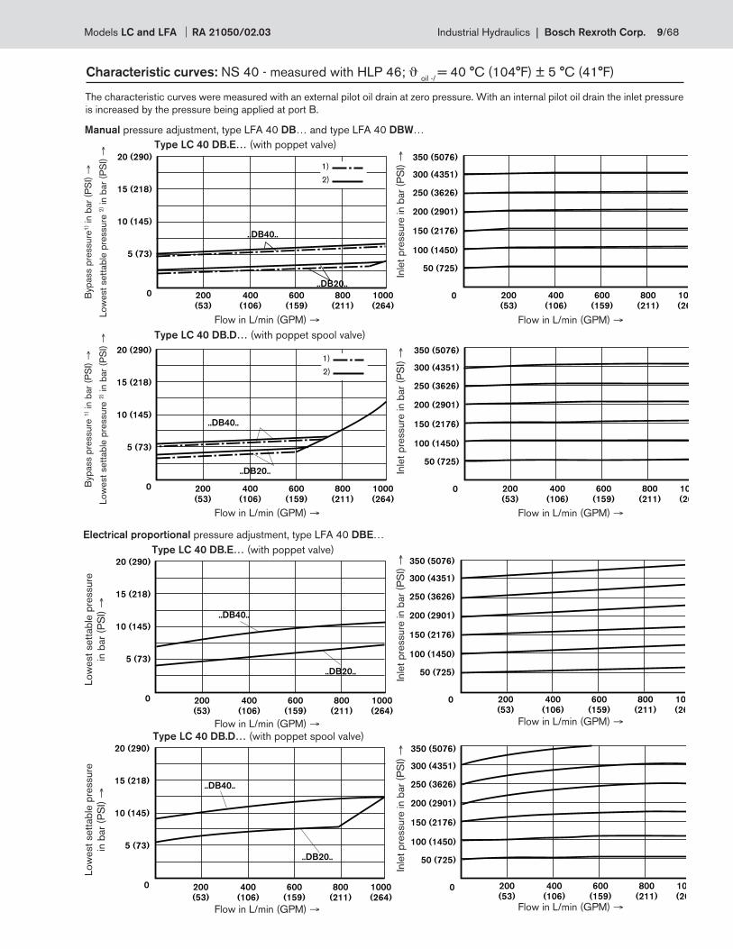
Characteristic curves: NS 40 - measured with HLP 46; ϑ oil -/
= 40 °C (104°F) ± 5 °C (41°F)
The characteristic curves were measured with an external pilot oil drain at zero pressure. With an internal pilot oil drain the inlet pressure
is increased by the pressure being applied at port B.
Manual pressure adjustment, type LFA 40 DB… and type LFA 40 DBW…
Type LC 40 DB.E… (with poppet valve)
Type LC 40 DB.D… (with poppet spool valve)
Electrical proportional pressure adjustment, type LFA 40 DBE…
Type LC 40 DB.E… (with poppet valve)
Type LC 40 DB.D… (with poppet spool valve)
1)
2)
1)
2)
Byp
ass p
ressure
1) i
n b
ar
(PS
I) →
Low
est
sett
ab
le p
ressure
2) i
n b
ar
(PS
I) →
Flow in L/min (GPM) → Flow in L/min (GPM) →
Byp
ass p
ressure
1) i
n b
ar
(PS
I) →
Low
est
sett
ab
le p
ressure
2) i
n b
ar
(PS
I) →
Flow in L/min (GPM) → Flow in L/min (GPM) →
Low
est
sett
ab
le p
ressure
in b
ar
(PS
I) →
Flow in L/min (GPM) → Flow in L/min (GPM) →
Flow in L/min (GPM) → Flow in L/min (GPM) →
Low
est
sett
ab
le p
ressure
in b
ar
(PS
I) →
Inle
t p
ressure
in b
ar
(PS
I) →
Inle
t p
ressure
in b
ar
(PS
I) →
Inle
t p
ressure
in b
ar
(PS
I) →
Inle
t p
ressure
in b
ar
(PS
I) →
Models LC and LFA RA 21050/02.03 Industrial Hydraulics | Bosch Rexroth Corp. 9/68
..DB40..
..DB20..
15 (218)
20 (290)
25 (363)
30 (435) 350 (5076)
300 (4351)
250 (3626)
200 (2901)
150 (2176)
100 (1450)
50 (725)
00 1000
(264)
500
(132)
1500
(396)
2000
(528)1000
(264)
500
(132)
1500
(396)
2000
(528)
10 (145)
5 (73)
..DB40..
..DB20..
15 (218)
20 (290)
25 (363)
30 (435) 350 (5076)
300 (4351)
250 (3626)
200 (2901)
150 (2176)
100 (1450)
50 (725)
00 1000
(264)
500
(132)
1500
(396)
2000
(528)
1000
(264)
500
(132)
1500
(396)
2000
(528)
10 (145)
5 (73)
..DB20..
..DB40..
15 (218)
20 (290)
25 (363)
30 (435) 350 (5076)
300 (4351)
250 (3626)
200 (2901)
150 (2176)
100 (1450)
50 (725)
00 1000
(264)
500
(132)
1500
(396)
2000
(528)1000
(264)
500
(132)
1500
(396)
2000
(528)
10 (145)
5 (73)
..DB20..
..DB40..
15 (218)
20 (290)
25 (363)
30 (435) 350 (5076)
300 (4351)
250 (3626)
200 (2901)
150 (2176)
100 (1450)
50 (725)
00 1000
(264)
500
(132)
1500
(396)
2000
(528)
1000
(264)
500
(132)
1500
(396)
2000
(528)
10 (145)
5 (73)
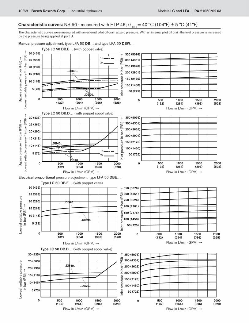
Characteristic curves: NS 50 - measured with HLP 46; ϑ oil -/
= 40 °C (104°F) ± 5 °C (41°F)
The characteristic curves were measured with an external pilot oil drain at zero pressure. With an internal pilot oil drain the inlet pressure is increased
by the pressure being applied at port B.
Manual pressure adjustment, type LFA 50 DB… and type LFA 50 DBW…
Type LC 50 DB.E… (with poppet valve)
Type LC 50 DB.D… (with poppet spool valve)
Electrical proportional pressure adjustment, type LFA 50 DBE…
Type LC 50 DB.E… (with poppet valve)
Type LC 50 DB.D… (with poppet spool valve)
1)
2)
1)
2)
Byp
ass p
ressure
1) i
n b
ar
(PS
I) →
Low
est
sett
ab
le p
ressure
2) i
n b
ar
(PS
I) →
Flow in L/min (GPM) → Flow in L/min (GPM) →
Byp
ass p
ressure
1) i
n b
ar
(PS
I) →
Low
est
sett
ab
le p
ressure
2) i
n b
ar
(PS
I) →
Flow in L/min (GPM) → Flow in L/min (GPM) →
Low
est
sett
ab
le p
ressure
in b
ar
(PS
I) →
Flow in L/min (GPM) → Flow in L/min (GPM) →
Flow in L/min (GPM) → Flow in L/min (GPM) →
Low
est
sett
ab
le p
ressure
in b
ar
(PS
I) →
Inle
t p
ressure
in b
ar
(PS
I) →
Inle
t p
ressure
in b
ar
(PS
I) →
Inle
t p
ressure
in b
ar
(PS
I) →
Inle
t p
ressure
in b
ar
(PS
I) →
10/68 Bosch Rexroth Corp. | Industrial Hydraulics Models LC and LFA RA 21050/02.03
..DB20..
..DB40..
15 (218)
20 (290)
25 (363)
30 (435) 350 (5076)
300 (4351)
250 (3626)
200 (2901)
150 (2176)
100 (1450)
50 (725)
00 1000
(264)
500
(132)
1500
(396)
2000
(528)
2500
(660)
1000
(264)
500
(132)
1500
(396)
2000
(528)
2500
(660)
10 (145)
5 (73)
..DB40..
..DB20..
15 (218)
20 (290)
25 (363)
30 (435) 350 (5076)
300 (4351)
250 (3626)
200 (2901)
150 (2176)
100 (1450)
50 (725)
00 1000
(264)
500
(132)
1500
(396)
2000
(528)
2500
(660)
1000
(264)
500
(132)
1500
(396)
2000
(528)
2500
(660)
10 (145)
5 (73)
..DB40..
..DB20..
15 (218)
20 (290)
25 (363)
30 (435) 350 (5076)
300 (4351)
250 (3626)
200 (2901)
150 (2176)
100 (1450)
50 (725)
00 1000
(264)
500
(132)
1500
(396)
2000
(528)
2500
(660)1000
(264)
500
(132)
1500
(396)
2000
(528)
2500
(660)
10 (145)
5 (73)
..DB20..
..DB40..
15 (218)
20 (290)
25 (363)
30 (435) 350 (5076)
300 (4351)
250 (3626)
200 (2901)
150 (2176)
100 (1450)
50 (725)
00 1000
(264)
500
(132)
1500
(396)
2000
(528)
2500
(660)1000
(264)
500
(132)
1500
(396)
2000
(528)
2500
(660)
10 (145)
5 (73)
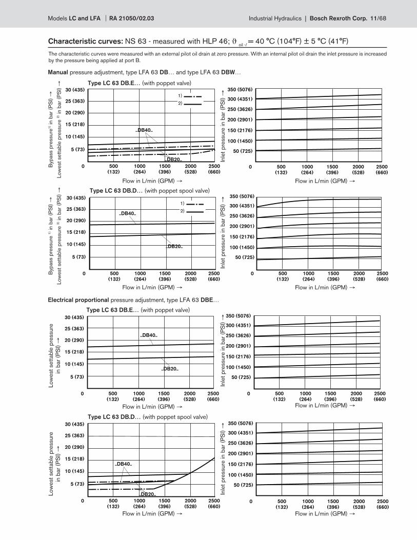
Characteristic curves: NS 63 - measured with HLP 46; ϑ oil -/
= 40 °C (104°F) ± 5 °C (41°F)
The characteristic curves were measured with an external pilot oil drain at zero pressure. With an internal pilot oil drain the inlet pressure is increased
by the pressure being applied at port B.
Manual pressure adjustment, type LFA 63 DB… and type LFA 63 DBW…
Type LC 63 DB.E… (with poppet valve)
Type LC 63 DB.D… (with poppet spool valve)
Electrical proportional pressure adjustment, type LFA 63 DBE…
Type LC 63 DB.E… (with poppet valve)
Type LC 63 DB.D… (with poppet spool valve)
1)
2)
1)
2)
Byp
ass p
ressure
1) i
n b
ar
(PS
I) →
Low
est
sett
ab
le p
ressure
2) i
n b
ar
(PS
I) →
Flow in L/min (GPM) → Flow in L/min (GPM) →
Byp
ass p
ressure
1) i
n b
ar
(PS
I) →
Low
est
sett
ab
le p
ressure
2) i
n b
ar
(PS
I) →
Flow in L/min (GPM) → Flow in L/min (GPM) →
Low
est
sett
ab
le p
ressure
in b
ar
(PS
I) →
Flow in L/min (GPM) → Flow in L/min (GPM) →
Flow in L/min (GPM) → Flow in L/min (GPM) →
Low
est
sett
ab
le p
ressure
in b
ar
(PS
I) →
Inle
t p
ressure
in b
ar
(PS
I) →
Inle
t p
ressure
in b
ar
(PS
I) →
Inle
t p
ressure
in b
ar
(PS
I) →
Inle
t p
ressure
in b
ar
(PS
I) →
Models LC and LFA RA 21050/02.03 Industrial Hydraulics | Bosch Rexroth Corp. 11/68
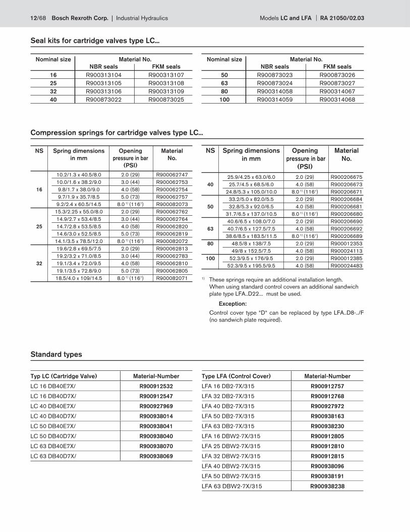
Seal kits for cartridge valves type LC...
Nominal size Material No.
NBR seals FKM seals
16 R900313104 R900313107
25 R900313105 R900313108
32 R900313106 R900313109
40 R900873022 R900873025
Nominal size Material No.
NBR seals FKM seals
50 R900873023 R900873026
63 R900873024 R900873027
80 R900314058 R900314067
100 R900314059 R900314068
Compression springs for cartridge valves type LC...
NS Spring dimensions Opening Material
in mm pressure in bar No.
(PSI)
10.2/1.3 x 40.5/8.0 2.0 (29) R900062747
10.0/1.6 x 38.2/9.0 3.0 (44) R900062753
16 9.8/1.7 x 38.0/9.0 4.0 (58) R900062754
9.7/1.9 x 35.7/8.5 5.0 (73) R900062757
9.2/2.4 x 60.5/14.5 8.0 1) (1161) R900082073
15.3/2.25 x 55.0/8.0 2.0 (29) R900062762
14.9/2.7 x 53.4/8.5 3.0 (44) R900062764
25 14.7/2.8 x 53.5/8.5 4.0 (58) R900062820
14.6/3.0 x 52.5/8.5 5.0 (73) R900062819
14.1/3.5 x 78.5/12.0 8.0 1) (1161) R900082072
19.6/2.8 x 69.5/7.5 2.0 (29) R900062813
19.2/3.2 x 71.0/8.5 3.0 (44) R900062783
32 19.1/3.4 x 72.0/9.5 4.0 (58) R900062810
19.1/3.5 x 72.8/9.0 5.0 (73) R900062805
18.5/4.0 x 109/14.5 8.0 1) (1161) R900082071
NS Spring dimensions Opening Material
in mm pressure in bar No.
(PSI)
25.9/4.25 x 63.0/6.0 2.0 (29) R900206675
40 25.7/4.5 x 68.5/6.0 4.0 (58) R900206673
24.8/5.3 x 105.0/10.0 8.0 1) (1161) R900206671
33.2/5.0 x 82.0/5.5 2.0 (29) R900206684
50 32.8/5.3 x 92.0/6.5 4.0 (58) R900206681
31.7/6.5 x 137.0/10.5 8.0 1) (1161) R900206680
40.6/6.5 x 108.0/7.0 2.0 (29) R900206690
63 40.7/6.5 x 127.5/7.5 4.0 (58) R900206692
38.6/8.5 x 183.5/11.5 8.0 1) (1161) R900206689
80 48.5/8 x 138/7.5 2.0 (29) R900012353
49/8 x 152.5/7.5 4.0 (58) R900024113
100 52.3/9.5 x 176/9.5 2.0 (29) R900012385
52.3/9.5 x 195.5/9.5 4.0 (58) R900024483
1) These springs require an additional installation length.
When using standard control covers an additional sandwich
plate type LFA..D22... must be used.
Exception:
Control cover type “D“ can be replaced by type LFA..D8-../F
(no sandwich plate required).
Standard types
Typ LC (Cartridge Valve) Material-Number
LC 16 DB40E7X/ R900912532
LC 16 DB40D7X/ R900912547
LC 40 DB40E7X/ R900927969
LC 40 DB40D7X/ R900938014
LC 50 DB40E7X/ R900938041
LC 50 DB40D7X/ R900938040
LC 63 DB40E7X/ R900938070
LC 63 DB40D7X/ R900938069
Type LFA (Control Cover) Material-Number
LFA 16 DB2-7X/315 R900912757
LFA 32 DB2-7X/315 R900912768
LFA 40 DB2-7X/315 R900927972
LFA 50 DB2-7X/315 R900938163
LFA 63 DB2-7X/315 R900938230
LFA 16 DBW2-7X/315 R900912805
LFA 25 DBW2-7X/315 R900912810
LFA 32 DBW2-7X/315 R900912815
LFA 40 DBW2-7X/315 R900938096
LFA 50 DBW2-7X/315 R900938191
LFA 63 DBW2-7X/315 R900938238
12/68 Bosch Rexroth Corp. | Industrial Hydraulics Models LC and LFA RA 21050/02.03
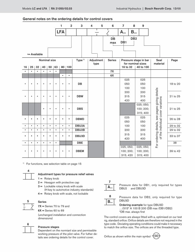
Nominal size Type 1) Adjustment Series Pressure stage in bar Seal Page
type for nominal sizes material
16 25 32 40 50 63 80 100 16 to 32 40 to 100
• • • • • • 7X
• • 6X
025 025
• • • • • • • • DB 050 050 18 to 20
100 100
200 200
• • • • • • • • DBW 315 315 21 to 25
420 400
025; 050;
• • • • • DBS 100; 200; 21 to 25
315; 400
• • • • • • • • DBWD
025 025 26 to 28
050 050
• • • • • • • • DBU2A 100 100 29 to 32
• • • • • • • • DBU2B 200 200 29 to 32
• • • • • • • • DBU3D
315 315 33 to 37
420 400
• • • • • • DBE 38
025; 050; 025; 050;
• • • • • • • • DBEM 100; 200; 100; 200; 39 to 42
315; 420 315; 400
LFA A... B...
4
6
7
A...
B...
8
5
General notes on the ordering details for control covers
1 2 3 4 5 6 7 8 9
Fo
r o
rdering
deta
ils, see p
ag
es g
ivin
g d
eta
ils
of th
e ind
ivid
ual co
ver
variatio
ns
DB2DB
max DB1
Adjustment types for pressure relief valves
1 = Rotary knob
2 = Hexagon with protective cap
3 = Lockable rotary knob with scale
(H-key to automotive industry standards)
4 = Rotary knob with scale, not lockable
Series
7X = Series 70 to 79 and
6X = Series 60 to 69
(unchanged installation and connection
dimensions)
Pressure stages
Dependent on the normianl size and permissible
working pressure of the pilot valve. For futher de-
tails see ordering details for the control cover.
Pressure data for DB1, only required for types
DBU2 and DBU3D
Pressure data for DB2, only required for type
DBU3D
Ordering example for type DBU3D
…/315* A 100 B 200 (DB max /DB1/DB2)
*DB max. always fi rst
1) For functions, see selection table on page 15
•= Available
The control covers are always fi tted with a, optimised on our test
rig, standard orifi ce. Orifi ce details are therefore not required in the
type code. Deviating operating conditions could make it necessary
to match the orifi ce size. The orifi ces are of the threaded type.
Orifi ce as shown within the main symbol
Models LC and LFA RA 21050/02.03 Industrial Hydraulics | Bosch Rexroth Corp. 13/68
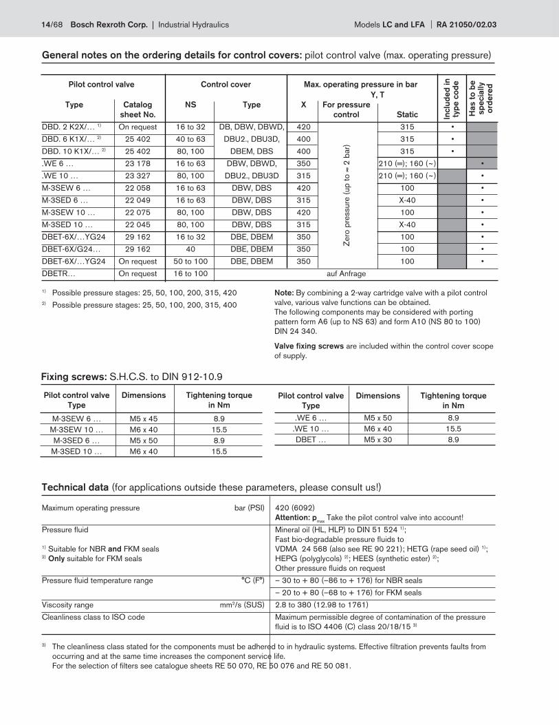
Technical data (for applications outside these parameters, please consult us!)
General notes on the ordering details for control covers: pilot control valve (max. operating pressure)
1) Possible pressure stages: 25, 50, 100, 200, 315, 420
2) Possible pressure stages: 25, 50, 100, 200, 315, 400
Pilot control valve Control cover Max. operating pressure in bar
Y, T
Type Catalog NS Type X For pressure
sheet No. control Static
DBD. 2 K2X/… 1) On request 16 to 32 DB, DBW, DBWD, 420 315 •
DBD. 6 K1X/… 2) 25 402 40 to 63 DBU2., DBU3D, 400 315 •
DBD. 10 K1X/… 2) 25 402 80, 100 DBEM, DBS 400 315 •
.WE 6 … 23 178 16 to 63 DBW, DBWD, 350 210 (=); 160 (~) •
.WE 10 … 23 327 80, 100 DBU2., DBU3D 315 210 (=); 160 (~) •
M-3SEW 6 … 22 058 16 to 63 DBW, DBS 420 100 •
M-3SED 6 … 22 049 16 to 63 DBW, DBS 315 X-40 •
M-3SEW 10 … 22 075 80, 100 DBW, DBS 420 100 •
M-3SED 10 … 22 045 80, 100 DBW, DBS 315 X-40 •
DBET-6X/…YG24 29 162 16 to 32 DBE, DBEM 350 100 •
DBET-6X/G24… 29 162 40 DBE, DBEM 350 100 •
DBET-6X/…YG24 On request 50 to 100 DBE, DBEM 350 100 •
DBETR… On request 16 to 100 auf Anfrage
Inclu
de
d in
ty
pe
co
de
Has t
o b
e
sp
ecia
lly
ord
ere
d
Zero
pre
ssure
(up
to ≈
2 b
ar)
Note: By combining a 2-way cartridge valve with a pilot control
valve, various valve functions can be obtained.
The following components may be considered with porting
pattern form A6 (up to NS 63) and form A10 (NS 80 to 100)
DIN 24 340.
Valve fi xing screws are included within the control cover scope
of supply.
Fixing screws: S.H.C.S. to DIN 912-10.9
Pilot control valve Dimensions Tightening torque
Type in Nm
M-3SEW 6 … M5 x 45 8.9
M-3SEW 10 … M6 x 40 15.5
M-3SED 6 … M5 x 50 8.9
M-3SED 10 … M6 x 40 15.5
Pilot control valve Dimensions Tightening torque
Type in Nm
.WE 6 … M5 x 50 8.9
.WE 10 … M6 x 40 15.5
DBET … M5 x 30 8.9
Maximum operating pressure bar (PSI) 420 (6092)
Attention: pmax
Take the pilot control valve into account!
Pressure fl uid Mineral oil (HL, HLP) to DIN 51 524 1);
Fast bio-degradable pressure fl uids to 1) Suitable for NBR and FKM seals VDMA 24 568 (also see RE 90 221); HETG (rape seed oil) 1); 2) Only suitable for FKM seals HEPG (polyglycols) 2); HEES (synthetic ester) 2);
Other pressure fl uids on request
Pressure fl uid temperature range °C (F°) – 30 to + 80 (–86 to + 176) for NBR seals
– 20 to + 80 (–68 to + 176) for FKM seals
Viscosity range mm2/s (SUS) 2.8 to 380 (12.98 to 1761)
Cleanliness class to ISO code Maximum permissible degree of contamination of the pressure
fl uid is to ISO 4406 (C) class 20/18/15 3)
3) The cleanliness class stated for the components must be adhered to in hydraulic systems. Effective fi ltration prevents faults from
occurring and at the same time increases the component service life.
For the selection of fi lters see catalogue sheets RE 50 070, RE 50 076 and RE 50 081.
14/68 Bosch Rexroth Corp. | Industrial Hydraulics Models LC and LFA RA 21050/02.03
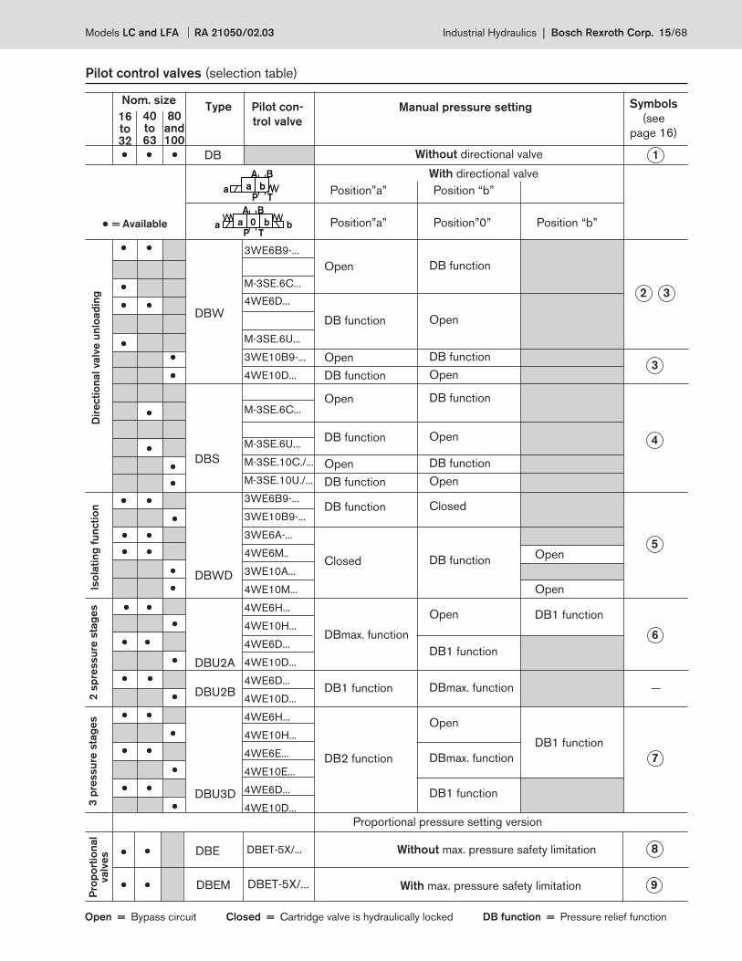
= Available
BA
P T
a b0a b
BA
P Ta a b
Pilot control valves (selection table)
Dir
ecti
on
al valv
e u
nlo
ad
ing
DBW
DBS
DBWD
DBU2A
DBU2B
DBU3D
3WE6B9-...
M-3SE.6C...
4WE6D...
M-3SE.6U...
3WE10B9-...
4WE10D...
M-3SE.6C...
M-3SE.6U...
M-3SE.10C./...
M-3SE.10U./...
3WE6B9-...
3WE10B9-...
3WE6A-...
4WE6M..
3WE10A...
4WE10M...
4WE6H...
4WE10H...
4WE6D...
4WE10D...
4WE6D...
4WE10D...
4WE6H...
4WE10H...
4WE6E...
4WE10E...
4WE6D...
4WE10D...
Open
DB function
Open
DB function
Open
DB function
Open
DB function
DB function
Closed
Iso
lati
ng
fu
ncti
on
16to32
40to63
80 and100
Nom. sizeType Pilot con-
trol valve
Manual pressure setting Symbols
(see
page 16)
Position”a” Position “b”
Without directional valve
DB function
Open
DB function
Open
DB function
Open
DB function
Open
Closed
DB function
Open
DB1 function
Open
Open
DB1 function
DB1 function
DBmax. function
Open
DBmax. function
DB1 function
Without max. pressure safety limitation
With max. pressure safety limitation
Proportional pressure setting version
Open = Bypass circuit Closed = Cartridge valve is hydraulically locked DB function = Pressure relief function
Pro
po
rtio
nal
valv
es
3 p
ressu
re s
tag
es
2 s
pre
ssu
re s
tag
es
DBmax. function
DB1 function
DB2 function
Position”a” Position”0” Position “b”
DBE
DBEM
DBET-5X/...
DBET-5X/...
With directional valve
1DB
2 3
3
4
5
6
7
8
9
Models LC and LFA RA 21050/02.03 Industrial Hydraulics | Bosch Rexroth Corp. 15/68
P T
A
F**
X
A
YB
X
P**B
D**Y
P T
A B
D**
F**
X
X
A
Y
Y
B
X**
P**
T
a
F**
X
X
A
YB
X**T
P T
A B
D**
F**
X
A
Y
Y
B
a
X
A**
X
A
YB
D**P**
X**
YX
F**
P T
X
A
YB
D**P**
X**
YX
F**
X
A
YB
D**
P**
P T
A Ba
DB max
DB 1
A T
X**
DB 2
F**
X
A
YB
D**
P**
P T
A Ba
DB max
DB 1
B
A T
P**
F**
X
A
Y
Y
B
X**
B**
P T
A Ba
X
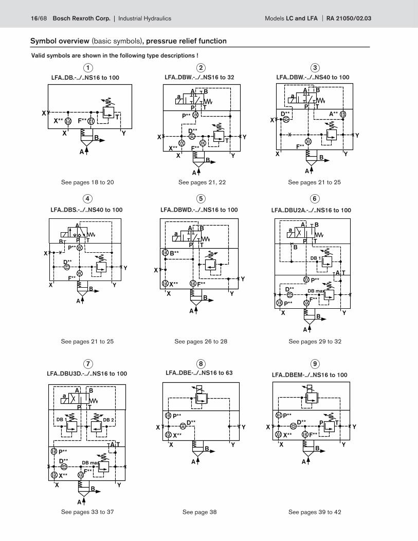
Valid symbols are shown in the following type descriptions !
1 2 3
4 5 6
7 8 9
LFA..DB.-../..NS16 to 100 LFA..DBW.-../..NS16 to 32 LFA..DBW.-../..NS40 to 100
LFA..DBS.-../..NS40 to 100 LFA..DBWD.-../..NS16 to 100 LFA..DBU2A.-../..NS16 to 100
LFA..DBU3D.-../..NS16 to 100 LFA..DBE-../..NS16 to 63 LFA..DBEM-../..NS16 to 100
See pages 18 to 20 See pages 21, 22 See pages 21 to 25
See pages 21 to 25 See pages 26 to 28 See pages 29 to 32
See pages 33 to 37 See page 38 See pages 39 to 42
Symbol overview (basic symbols), pressrue relief function
16/68 Bosch Rexroth Corp. | Industrial Hydraulics Models LC and LFA RA 21050/02.03
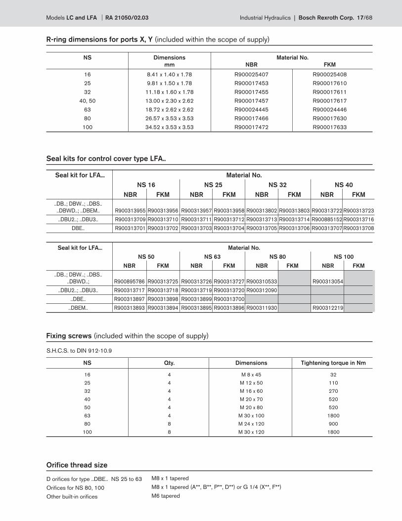
NS Dimensions Material No.
mm NBR FKM
16 8.41 x 1.40 x 1.78 R900025407 R900025408
25 9.81 x 1.50 x 1.78 R900017453 R900017610
32 11.18 x 1.60 x 1.78 R900017455 R900017611
40, 50 13.00 x 2.30 x 2.62 R900017457 R900017617
63 18.72 x 2.62 x 2.62 R900024445 R900024446
80 26.57 x 3.53 x 3.53 R900017466 R900017630
100 34.52 x 3.53 x 3.53 R900017472 R900017633
Seal kits for control cover type LFA..
Seal kit for LFA... Material No.
NS 16 NS 25 NS 32 NS 40
NBR FKM NBR FKM NBR FKM NBR FKM
..DB..; DBW..; ..DBS..
..DBWD..; ..DBEM.. R900313955 R900313956 R900313957 R900313958 R900313802 R900313803 R900313722 R900313723
..DBU2..; ..DBU3.. R900313709 R900313710 R900313711 R900313712 R900313713 R900313714 R900885152 R900313716
DBE.. R900313701 R900313702 R900313703 R900313704 R900313705 R900313706 R900313707 R900313708
Seal kit for LFA... Material No.
NS 50 NS 63 NS 80 NS 100
NBR FKM NBR FKM NBR FKM NBR FKM
..DB..; DBW..; ..DBS..
..DBWD..; R900895786 R900313725 R900313726 R900313727 R900310533 R900313054
..DBU2..; ..DBU3.. R900313717 R900313718 R900313719 R900313720 R900312090
..DBE.. R900313897 R900313898 R900313899 R900313700
..DBEM.. R900313893 R900313894 R900313895 R900313896 R900311930 R900312219
M8 x 1 tapered
M8 x 1 tapered (A**, B**, P**, D**) or G 1/4 (X**, F**)
M6 tapered
D orifi ces for type ..DBE.. NS 25 to 63
Orifi ces for NS 80, 100
Other built-in orifi ces
Orifi ce thread size
Fixing screws (included within the scope of supply)
S.H.C.S. to DIN 912-10.9
NS Qty. Dimensions Tightening torque in Nm
16 4 M 8 x 45 32
25 4 M 12 x 50 110
32 4 M 16 x 60 270
40 4 M 20 x 70 520
50 4 M 20 x 80 520
63 4 M 30 x 100 1800
80 8 M 24 x 120 900
100 8 M 30 x 120 1800
R-ring dimensions for ports X, Y (included within the scope of supply)
Models LC and LFA RA 21050/02.03 Industrial Hydraulics | Bosch Rexroth Corp. 17/68
F**
X
X
A
YB
X**T
D**
With NS 16, 25
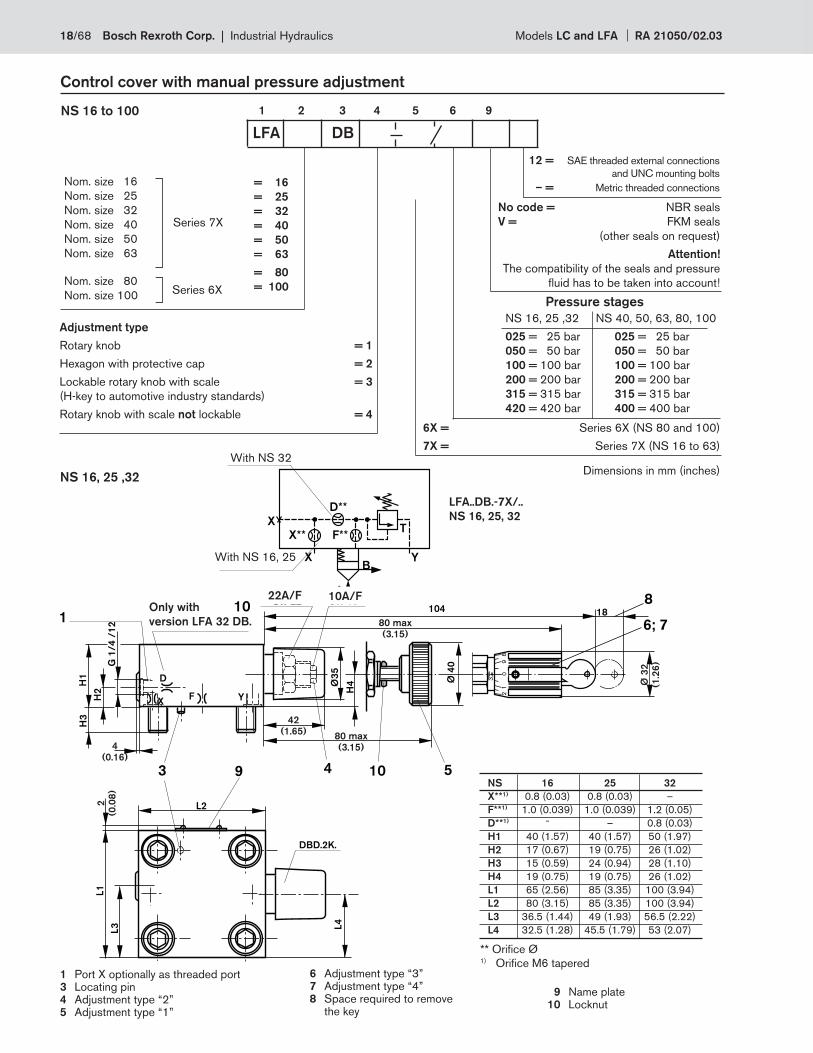
Control cover with manual pressure adjustment
1 2 3 4 5 6 9NS 16 to 100
LFA DB
Nom. size 16
Nom. size 25
Nom. size 32
Nom. size 40
Nom. size 50
Nom. size 63
Nom. size 80
Nom. size 100
= 16
= 25
= 32
= 40
= 50
= 63
= 80
= 100
Series 7X
Series 6X
Adjustment type
Rotary knob = 1
Hexagon with protective cap = 2
Lockable rotary knob with scale = 3
(H-key to automotive industry standards)
Rotary knob with scale not lockable = 4
No code = NBR seals
V = FKM seals
(other seals on request)
Attention!
The compatibility of the seals and pressure
fl uid has to be taken into account!
NS 16, 25 ,32
025 = 25 bar
050 = 50 bar
100 = 100 bar
200 = 200 bar
315 = 315 bar
420 = 420 bar
NS 40, 50, 63, 80, 100
025 = 25 bar
050 = 50 bar
100 = 100 bar
200 = 200 bar
315 = 315 bar
400 = 400 bar
Pressure stages
6X = Series 6X (NS 80 and 100)
7X = Series 7X (NS 16 to 63)
NS 16, 25 ,32
LFA..DB.-7X/..
NS 16, 25, 32
With NS 32
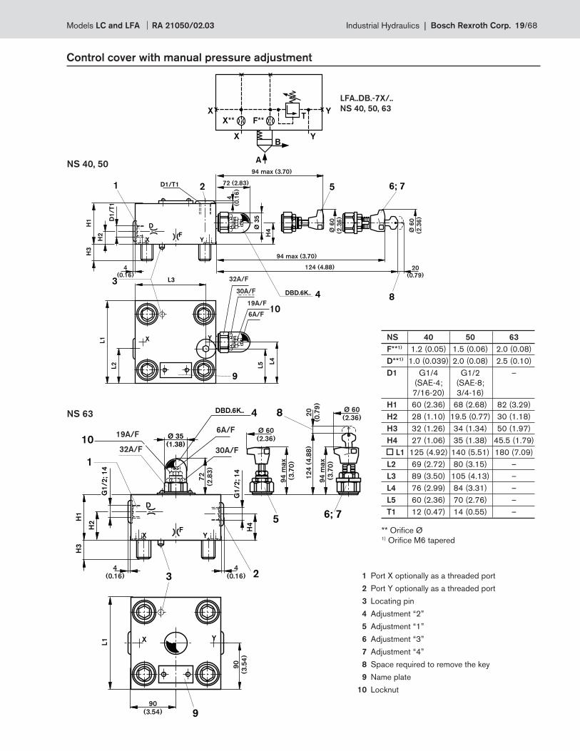
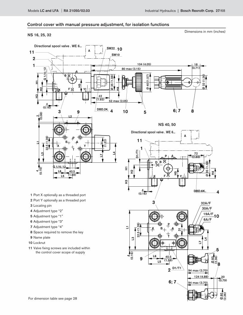
1 Port X optionally as threaded port 3 Locating pin4 Adjustment type “2” 5 Adjustment type “1”
6 Adjustment type “3”7 Adjustment type “4”8 Space required to remove the key
9 Name plate 10 Locknut
Dimensions in mm (inches)
3
82
91
9 43
DBD.2K.
L4
L2
G 1
/4
/1
2
H2
H1
H3
D
XF Y
10SW 22 SW 10
104
L1
L3
18
8
6; 71
10 5
H4Ø
35
Ø 4
0
0
42
(1.65)
Ø 3
2
(1.2
6)
2
(0.0
8)
80 max
(3.15)
80 max
(3.15)
4
(0.16)
Only with
version LFA 32 DB.
22A/F 10A/F
NS 16 25 32
X**1) 0.8 (0.03) 0.8 (0.03) –
F**1) 1.0 (0.039) 1.0 (0.039) 1.2 (0.05)
D**1) – – 0.8 (0.03)
H1 40 (1.57) 40 (1.57) 50 (1.97)
H2 17 (0.67) 19 (0.75) 26 (1.02)
H3 15 (0.59) 24 (0.94) 28 (1.10)
H4 19 (0.75) 19 (0.75) 26 (1.02)
L1 65 (2.56) 85 (3.35) 100 (3.94)
L2 80 (3.15) 85 (3.35) 100 (3.94)
L3 36.5 (1.44) 49 (1.93) 56.5 (2.22)
L4 32.5 (1.28) 45.5 (1.79) 53 (2.07)
12 = SAE threaded external connections
and UNC mounting bolts
– = Metric threaded connections
** Orifi ce Ø1) Orifi ce M6 tapered
18/68 Bosch Rexroth Corp. | Industrial Hydraulics Models LC and LFA RA 21050/02.03
SW6
SW19
SW30
SW32
10
D1
/T
1
H2
H1
H3
Ø 3
5
H4
6; 75
8DBD.6K.. 4
D
XF
Y
D1/T1 2
3
X Y
L3
L4
L5
9
L1
L2
1 72 (2.83)
Ø 6
0
(2.3
6)
Ø 6
0
(2.3
6)
124 (4.88)
94 max (3.70)
94 max (3.70)
20
(0.79)
4
(0.16)
4
(0.1
6)
32A/F
30A/F
19A/F
6A/F
F**
X
X
A
YB
TY
X**
LFA..DB.-7X/..
NS 40, 50, 63
Control cover with manual pressure adjustment
NS 40, 50
** Orifi ce Ø1) Orifi ce M6 tapered
G1
/2
; 1
4
H2
H1
H3
Ø 35
(1.38)
H4
DBD.6K..
D
XF
Y
3
X Y
9
L1
4
G1
/2
; 1
4
8
2
6; 75
1
SW6SW19
SW30SW32
10
Ø 60
(2.36)
Ø 60
(2.36)
94
max
(3.7
0)
12
4 (
4.8
8)
72
(2.8
3)
94
max
(3.7
0)
90
(3.54)
90
(3.5
4)
20
(0.7
9)
4
(0.16)
4
(0.16)
19A/F
32A/F
6A/F
30A/F
NS 63
1 Port X optionally as a threaded port
2 Port Y optionally as a threaded port
3 Locating pin
4 Adjustment “2”
5 Adjustment “1”
6 Adjustment “3”
7 Adjustment “4”
8 Space required to remove the key
9 Name plate
10 Locknut
NS 40 50 63
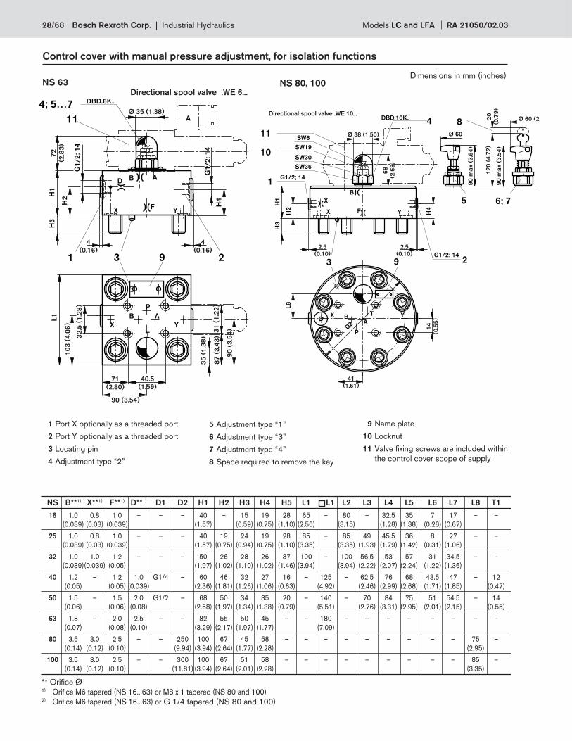
F**1) 1.2 (0.05) 1.5 (0.06) 2.0 (0.08)
D**1) 1.0 (0.039) 2.0 (0.08) 2.5 (0.10)
D1 G1/4 G1/2 –
(SAE-4; (SAE-8;
7/16-20) 3/4-16)
H1 60 (2.36) 68 (2.68) 82 (3.29)
H2 28 (1.10) 19.5 (0.77) 30 (1.18)
H3 32 (1.26) 34 (1.34) 50 (1.97)
H4 27 (1.06) 35 (1.38) 45.5 (1.79)
L1 125 (4.92) 140 (5.51) 180 (7.09)
L2 69 (2.72) 80 (3.15) –
L3 89 (3.50) 105 (4.13) –
L4 76 (2.99) 84 (3.31) –
L5 60 (2.36) 70 (2.76) –
T1 12 (0.47) 14 (0.55) –
Models LC and LFA RA 21050/02.03 Industrial Hydraulics | Bosch Rexroth Corp. 19/68
H2
H1
H3
5
DBD.10K..
3
9
1
8
2
6; 7
4
L8
YFX
D2
YFX
H4
G1/2; 14
1G1/2; 14
5
G1/2; 14
SW36
SW30
SW19
SW6
10
4
2.5
(0.10)
2.5
(0.10)
Ø 38
(1.50)
Ø 60
(2.36)
Ø 60
(2.36)
90
max
(3.5
4)
90
max
(3.5
4)
12
0 (
4.7
2)
20
(0.7
9)
68
(2.6
8)
19A/F
30A/F
36A/F 6A/F
F**
X
X
A
YB
TY
X**
Control cover with manual pressure adjustment
NS 80, 100
LFA...DB.-6X/...
NS 80, 100
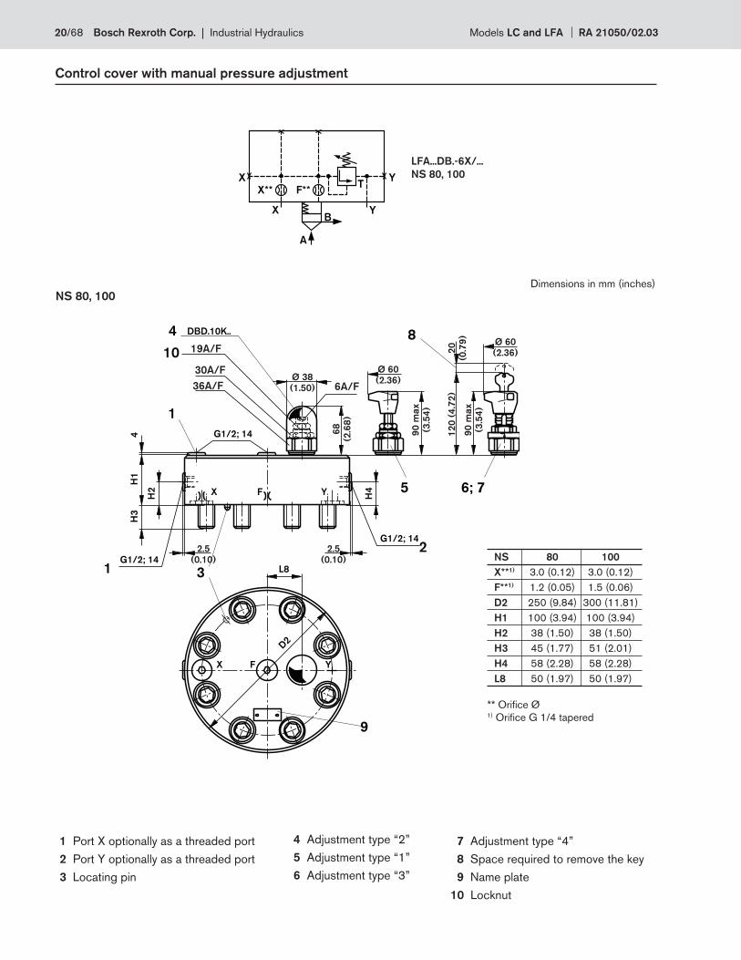
1 Port X optionally as a threaded port
2 Port Y optionally as a threaded port
3 Locating pin
4 Adjustment type “2”
5 Adjustment type “1”
6 Adjustment type “3”
7 Adjustment type “4”
8 Space required to remove the key
9 Name plate
10 Locknut
** Orifi ce Ø1) Orifi ce G 1/4 tapered
Dimensions in mm (inches)
NS 80 100
X**1) 3.0 (0.12) 3.0 (0.12)
F**1) 1.2 (0.05) 1.5 (0.06)
D2 250 (9.84) 300 (11.81)
H1 100 (3.94) 100 (3.94)
H2 38 (1.50) 38 (1.50)
H3 45 (1.77) 51 (2.01)
H4 58 (2.28) 58 (2.28)
L8 50 (1.97) 50 (1.97)
20/68 Bosch Rexroth Corp. | Industrial Hydraulics Models LC and LFA RA 21050/02.03
P T
A Ba
P T
A
P T
A
P T
A
P T
A Ba
P T
A
P T
A
D**
F**
X
X
A
Y
P
Y
T
A B
B
X**
P**
T
a
F**
X
A
Y
Y
B
B**
P T
A Ba
XD**
F**
X
A
Y
P T
A
BX
P**B
D**Y
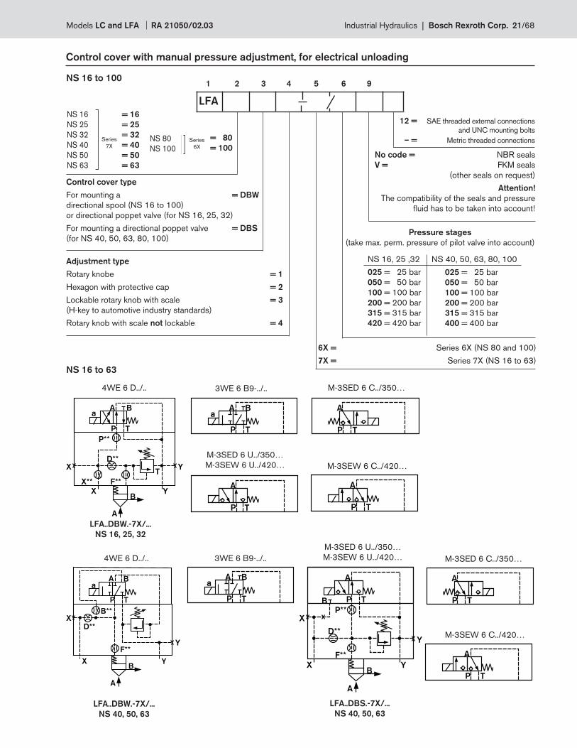
Control cover with manual pressure adjustment, for electrical unloading
1 2 3 4 5 6 9NS 16 to 100
LFA
NS 16
NS 25
NS 32
NS 40
NS 50
NS 63
Series
7X
= 16
= 25
= 32
= 40
= 50
= 63
NS 80
NS 100Series
6X
= 80
= 100
Control cover type
For mounting a = DBW
directional spool (NS 16 to 100)
or directional poppet valve (for NS 16, 25, 32)
For mounting a directional poppet valve = DBS
(for NS 40, 50, 63, 80, 100)
Adjustment type
Rotary knobe = 1
Hexagon with protective cap = 2
Lockable rotary knob with scale = 3
(H-key to automotive industry standards)
Rotary knob with scale not lockable = 4
No code = NBR seals
V = FKM seals
(other seals on request)
Attention!
The compatibility of the seals and pressure
fl uid has to be taken into account!
NS 16, 25 ,32
025 = 25 bar
050 = 50 bar
100 = 100 bar
200 = 200 bar
315 = 315 bar
420 = 420 bar
NS 40, 50, 63, 80, 100
025 = 25 bar
050 = 50 bar
100 = 100 bar
200 = 200 bar
315 = 315 bar
400 = 400 bar
Pressure stages
(take max. perm. pressure of pilot valve into account)
6X = Series 6X (NS 80 and 100)
7X = Series 7X (NS 16 to 63)NS 16 to 63
LFA..DBW.-7X/...
NS 16, 25, 32
4WE 6 D../.. 3WE 6 B9-../.. M-3SED 6 C../350…
M-3SEW 6 C../420…
M-3SED 6 U../350…
M-3SEW 6 U../420…
4WE 6 D../.. 3WE 6 B9-../..
M-3SED 6 U../350…
M-3SEW 6 U../420… M-3SED 6 C../350…
M-3SEW 6 C../420…
LFA..DBS.-7X/...
NS 40, 50, 63
LFA..DBW.-7X/...
NS 40, 50, 63
12 = SAE threaded external connections
and UNC mounting bolts
– = Metric threaded connections
Models LC and LFA RA 21050/02.03 Industrial Hydraulics | Bosch Rexroth Corp. 21/68
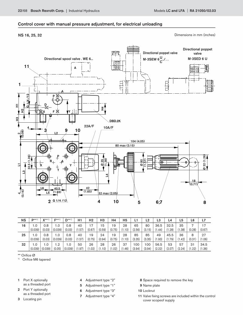
Control cover with manual pressure adjustment, for electrical unloading
NS 16, 25, 32 Dimensions in mm (inches)
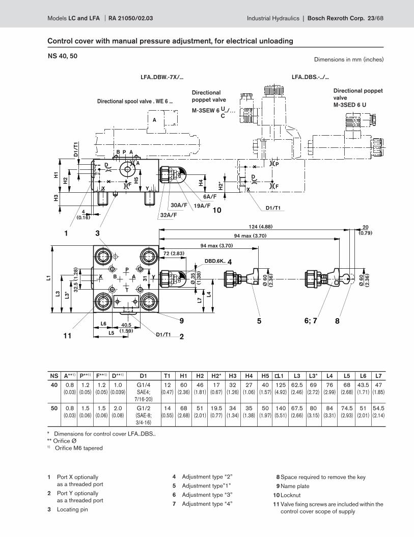
1 Port X optionally
as a threaded port
2 Port Y optionally
as a threaded port
3 Locating pin
4 Adjustment type “2”
5 Adjustment type “1”
6 Adjustment type “3”
7 Adjustment type “4”
8 Space required to remove the key
9 Name plate
10 Locknut
11 Valve fi xing screws are included within the control
cover scopeof supply
** Orifi ce Ø1) Orifi ce M6 tapered
NS P**1) X**1) F**1) D**1) H1 H2 H3 H4 H5 L1 L2 L3 L4 L5 L6 L7
16 1.0 0.8 1.0 0.8 40 17 15 19 28 65 80 36.5 32.5 35 7 17
(0.039) (0.03) (0.039) (0.03) (1.57) (0.67) (0.59) (0.75) (1.10) (2.56) (3.15) (1.44) (1.28) (1.38) (0.28) (0.67)
25 1.0 0.8 1.0 0.8 40 19 24 19 28 85 85 49 45.5 36 8 27
(0.039) (0.03) (0.039) (0.03) (1.57) (0.75) (0.94) (0.75) (1.10) (3.35) (3.35) (1.93) (1.79) (1.42) (0.31) (1.06)
32 1.0 1.0 1.2 1.0 50 26 28 26 37 100 100 56.5 53 57 31 34.5
(0.039) (0.039) (0.05) (0.039) (1.97) (1.02) (1.10) (1.02) (1.46) (3.94) (3.94) (2.22) (2.07) (2.24) (1.22) (1.36)
85 6;7
3
21
98
0
SW 10SW 22
L5
L6
G 1/4 /12
L2
4
L3
L1
X
P
A
T
B
Y
L4
1042
3 109
H3
H1
H2
G 1
/4
/1
2
D
FX
P
A
Y
H4
1
DBD.2K
11 A
80 max (3.15)
52 max (2.05)
Ø 4
0
(1.5
7)
2
(0.0
8)
4
(0.1
6)
Ø 3
2 (
1.2
6)
32
.5 (
1.2
8)
Ø 3
5
(1
.38
)
40.5
(1.59)
42
(1.65)
18
(0.71)
104 (4.05)
Directional spool valve . WE 6...
Directional poppet valve
M-3SEW 6 ../…
Directional poppet
valve
M-3SED 6 UU
C
22A/F 10A/F
22/68 Bosch Rexroth Corp. | Industrial Hydraulics Models LC and LFA RA 21050/02.03
NS A**1) P**1) F**1) D**1) D1 T1 H1 H2 H2* H3 H4 H5 L1 L3 L3* L4 L5 L6 L7
40 0.8 1.2 1.2 1.0 G1/4 12 60 46 17 32 27 40 125 62.5 69 76 68 43.5 47
(0.03) (0.05) (0.05) (0.039) SAE4; (0.47) (2.36) (1.81) (0.67) (1.26) (1.06) (1.57) (4.92) (2.46) (2.72) (2.99) (2.68) (1.71) (1.85)
7/16-20)
50 0.8 1.5 1.5 2.0 G1/2 14 68 51 19.5 34 35 50 140 67.5 80 84 74.5 51 54.5
(0.03) (0.06) (0.06) (0.08) (SAE-8; (0.55) (2.68) (2.01) (0.77) (1.34) (1.38) (1.97) (5.51) (2.66) (3.15) (3.31) (2.93) (2.01) (2.14)
3/4-16)
Control cover with manual pressure adjustment, for electrical unloading
NS 40, 50
* Dimensions for control cover LFA..DBS..
** Orifi ce Ø1) Orifi ce M6 tapered
1 Port X optionally
as a threaded port
2 Port Y optionally
as a threaded port
3 Locating pin
4 Adjustment type “2”
5 Adjustment type”1”
6 Adjustment type “3”
7 Adjustment type “4”
8 Space required to remove the key
9 Name plate
10 Locknut
11 Valve fi xing screws are included within the
control cover scope of supply
SW3210
H2H
1H
3
H4
6; 75
DBD.6K..
D
XF
Y
3
X Y
L5
L4
L7
2
L1
L3
A
A
B A
P
T
31
L3
*
L6 9
11
4
1
SW30 SW19
SW6
H5
H2
*
D
F
P
X
A
8
D1/T1
D1/T1
D1
/T
1
PB
20
(0.79)
Ø 6
0
(2.3
6)
Ø 6
0
(2.3
6)
124 (4.88)
94 max (3.70)
94 max (3.70)
32
.5 (
1.2
8)
Ø 3
5
(1
.38
)
40.5
(1.59)
72 (2.83)
4
(0.16)
LFA..DBS.-../...LFA..DBW.-7X/...
Directional
poppet valve
M-3SEW 6 ../…U
C
Directional poppet
valve
M-3SED 6 UDirectional spool valve . WE 6 ...
32A/F
30A/F
6A/F
19A/F
Dimensions in mm (inches)
Models LC and LFA RA 21050/02.03 Industrial Hydraulics | Bosch Rexroth Corp. 23/68
B A
P
T
G1
/2
; 1
4
DBD.6K..
D
X F Y
3
X Y
9
G1
/2
; 1
4
2
A
11
4
SW19
SW6
10
AB
8
6; 75
SW30
SW32
1
45
(1.7
7)
12
4 (
4.8
8)
90
(3
.54
)
94
max (
3.7
0)
94
max (
3.7
0)
87
(3
.43
)
90 (3 54)
72
(2
.83
)8
2 (
3.2
9)
50
(1
.97
)
55
(2.1
7)
31
(1
.22
)
20
(0.7
9)
Ø 60
(2.36)
Ø 60
(2.36)
35
(1
.38
)
40.5
(1.59)
71
(2.80)
32
.5 (
1.2
8)
18
0 (
7.0
9)
10
3 (
4.0
6)
Ø 35
(1.38)
4
(0.16)
4
(0.16)
Directional spool valve WE 6...
6A/F
19A/F
30A/F
32A/F
P
F
D
Control cover with manual pressure adjustment, for electrical unloading
NS 63
LFA..DBW.-7X/...
LFA..DBS.-.../...
Directional poppet valve
M-3SED 6 U
Directional poppet valve
M-3SEW 6 ../…U
C
** Orifi ce Ø1) Orifi ce M6 tapered
1 Port X optionally
as a threaded port
2 Port Y optionally
as a threaded port
3 Locating pin
4 Adjustment type “2”
5 Adjustment type “1”
6 Adjustment type “3”
7 Adjustment type “4”
8 Space required to remove
the key
9 Name plate
10 Locknut
11 Valve fi xing screws are included
within the control cover scope of
supply
A**1) P**1) F**1) D**1)
DBW 1.0 – 2.0 2.5
(0.039) (0.08) (0.10)
DBS – 1.8 2.0 2.0
(0.07) (0.08) (0.08)
Dimensions in mm (inches)
24/68 Bosch Rexroth Corp. | Industrial Hydraulics Models LC and LFA RA 21050/02.03
B A
P
T
H2
H1
H3
DBD.10K..
3 9
2
YFX
D2
Y
F
X
H4
G1/2; 14
1
SW36
SW30
SW19
SW6
10
4
B A
L8
11
5
8
6; 75X
G1/2; 14
A
31
(1.22)
20
(0.7
9)
14
(0.5
5)
68
(2.6
8)
90
max (
3.5
4)
90
max (
3.5
4)
12
0 (
4.7
2)
Ø 60
(2.36)
Ø 60
(2.36)
Ø 38
(1.50)
2.5
(0.10)
2.5
(0.10)
Directional poppet valve
M-3SED 10 UDirectional poppet valve
M-3SEW 10 ../…U
C
Directional spool valve WE 10...
6A/F
19A/F
30A/F
36A/F
P T
A Ba
P T
A
P T
Aa
F**X
A
Y
P T
A
BX
A**
Y
B**
Ba
F**X
A
Y
P T
A
BX
P**
YX**
a
Control cover with manual pressure adjustment, for electrical unloading
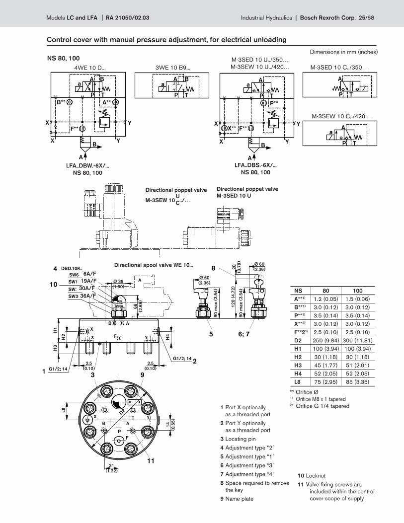
NS 80, 100
4WE 10 D...
M-3SED 10 U../350…
M-3SEW 10 U../420… M-3SED 10 C../350…
M-3SEW 10 C../420…
3WE 10 B9...
LFA..DBS.-6X/...
NS 80, 100
LFA..DBW.-6X/...
NS 80, 100
10 Locknut
11 Valve fi xing screws are
included within the control
cover scope of supply
1 Port X optionally
as a threaded port
2 Port Y optionally
as a threaded port
3 Locating pin
4 Adjustment type “2”
5 Adjustment type “1”
6 Adjustment type “3”
7 Adjustment type “4”
8 Space required to remove
the key
9 Name plate
** Orifi ce Ø1) Orifi ce M8 x 1 tapered2) Orifi ce G 1/4 tapered
NS 80 100
A**1) 1.2 (0.05) 1.5 (0.06)
B**1) 3.0 (0.12) 3.0 (0.12)
P**1) 3.5 (0.14) 3.5 (0.14)
X**2) 3.0 (0.12) 3.0 (0.12)
F**21) 2.5 (0.10) 2.5 (0.10)
D2 250 (9.84) 300 (11.81)
H1 100 (3.94) 100 (3.94)
H2 30 (1.18) 30 (1.18)
H3 45 (1.77) 51 (2.01)
H4 52 (2.05) 52 (2.05)
L8 75 (2.95) 85 (3.35)
Dimensions in mm (inches)
Models LC and LFA RA 21050/02.03 Industrial Hydraulics | Bosch Rexroth Corp. 25/68
P T
A Ba
P T
A Ba b
P T
A Ba
P T
A Ba b
F**
X
A
Y
Y
B
X**
B**
P T
A Ba
F**
X
A
Y
Y
B
X**
B**
P T
A Ba
X
F**
X
A
Y
Y
B
B**
P T
A Ba
XD**
F**
X
A
Y
Y
B
X**
B**
P T
A Ba
X
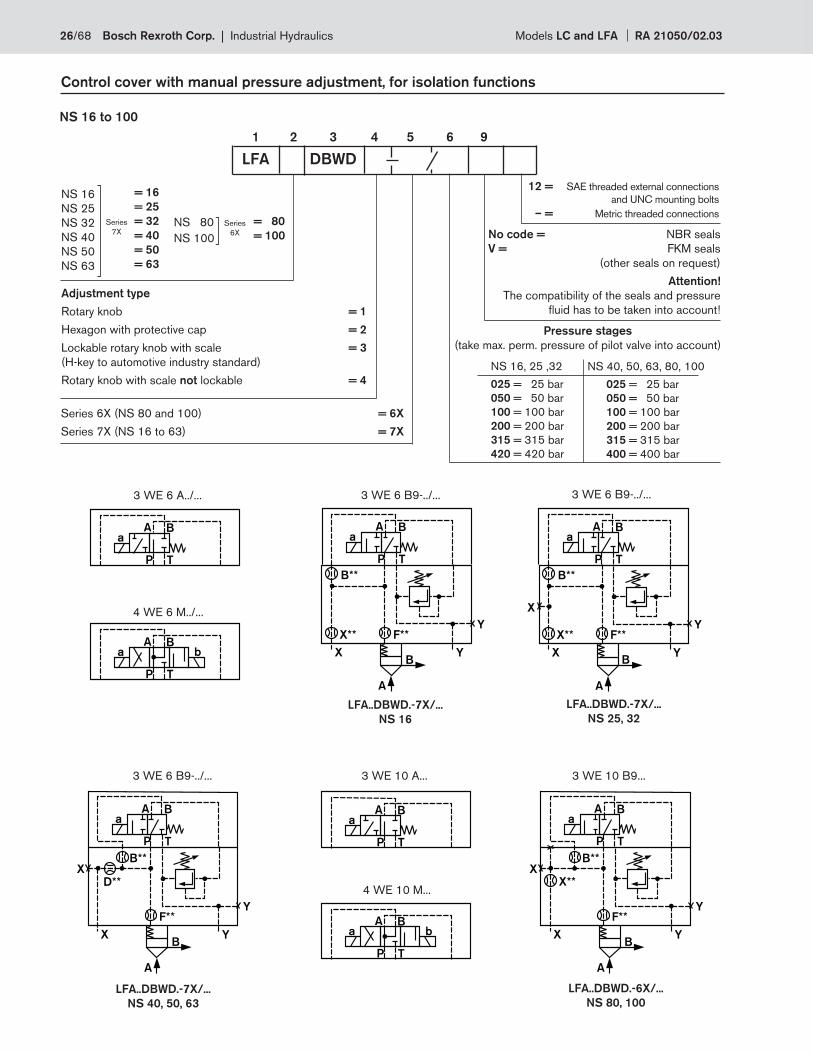
Control cover with manual pressure adjustment, for isolation functions
1 2 3 4 5 6 9
NS 16 to 100
LFA DBWD
NS 16
NS 25
NS 32
NS 40
NS 50
NS 63
Series
7X
= 16
= 25
= 32
= 40
= 50
= 63
NS 80
NS 100
Series
6X
= 80
= 100 No code = NBR seals
V = FKM seals
(other seals on request)
Attention!
The compatibility of the seals and pressure
fl uid has to be taken into account!
NS 16, 25 ,32
025 = 25 bar
050 = 50 bar
100 = 100 bar
200 = 200 bar
315 = 315 bar
420 = 420 bar
NS 40, 50, 63, 80, 100
025 = 25 bar
050 = 50 bar
100 = 100 bar
200 = 200 bar
315 = 315 bar
400 = 400 bar
Pressure stages
(take max. perm. pressure of pilot valve into account)
Adjustment type
Rotary knob = 1
Hexagon with protective cap = 2
Lockable rotary knob with scale = 3
(H-key to automotive industry standard)
Rotary knob with scale not lockable = 4
Series 6X (NS 80 and 100) = 6X
Series 7X (NS 16 to 63) = 7X
3 WE 6 A../...
4 WE 6 M../...
3 WE 6 B9-../...
LFA..DBWD.-7X/...
NS 25, 32
LFA..DBWD.-7X/...
NS 16
LFA..DBWD.-6X/...
NS 80, 100
LFA..DBWD.-7X/...
NS 40, 50, 63
4 WE 10 M...
3 WE 6 B9-../... 3 WE 10 A... 3 WE 10 B9...
3 WE 6 B9-../...
12 = SAE threaded external connections
and UNC mounting bolts
– = Metric threaded connections
26/68 Bosch Rexroth Corp. | Industrial Hydraulics Models LC and LFA RA 21050/02.03
3
82
90
1
9 43DBD.2K.
G 1
/4
; 1
2
H2
H1
H3
X F Y
10SW22
SW10
86; 7
1
10 5
H4
L2
L1
L3
AB
P
T
YX
L6
L5
G 1/4; 12
L4
L7
B
A
H5
11 A
2
80 max (3.15)
52 max (2.05)
2
(0.0
8)
4
(0.1
6)
4
(0.16)
31
(1.2
2)
Ø 3
2 (
1.2
6)
Ø 4
0 (
1.5
7)
32
.5 (
1.2
8)
40.5
(1.59)
42
(1.65)
18
(0.71)
104 (4.05)
Ø 3
5 (
1.3
8)
Directional spool valve . WE 6...
Control cover with manual pressure adjustment, for isolation functions
NS 16, 25, 32
NS 40, 50
For dimension table see page 28
1 Port X optionally as a threaded port
2 Port Y optionally as a threaded port
3 Locating pin
4 Adjustment type “2”
5 Adjustment type “1”
6 Adjustment type “3”
7 Adjustment type “4”
8 Space required to remove the key
9 Name plate
10 Locknut
11 Valve fi xing screws are included within
the control cover scope of supply
SW6
10
D1
/T
1
H2H
1H
3
H4
DBD.6K..
D
X F Y
3
X
Y
L5
L4
L7
L1
L3
1
AP
A
B A
P
T
31
L69
4
H5
B
SW19
SW30
SW32
D1/T12
11
5
6; 7
8
94 max (3.70)
94 max (3.70)
20
(0.79)
4
(0.1
6)
4
(0.16)
32
.5 (
1.2
8)
40.5
(1.59)
124 (4.88)
Ø 3
5 (
1.3
8)
72
(2.83)
Ø 6
0
(2.3
6)
Ø 6
0
(2.3
6)
Directional spool valve . WE 6...
32A/F
30A/F
19A/F
6A/F
Dimensions in mm (inches)
Models LC and LFA RA 21050/02.03 Industrial Hydraulics | Bosch Rexroth Corp. 27/68
G1
/2
; 1
4
B A
P
T
G1
/2
; 1
4
H2
H1
H3
H4
DBD.6K..
D
XF
Y
3
X Y
9
L1
1 2
A
4; 5…7
11
AB
4
(0.16)
4
(0.16)
32
.5 (
1.2
8)
10
3 (
4.0
6)
40.5
(1.59)
71
(2.80)
35
(1
.38
)
31
(1
.22
)8
7 (
3.4
3)
90
(3
.54
)
90 (3.54)
Ø 35 (1.38)
72
(2.8
3)
Control cover with manual pressure adjustment, for isolation functions
NS 63
** Orifi ce Ø1) Orifi ce M6 tapered (NS 16...63) or M8 x 1 tapered (NS 80 and 100)2) Orifi ce M6 tapered (NS 16...63) or G 1/4 tapered (NS 80 and 100)
NS 80, 100Directional spool valve .WE 6...
1 Port X optionally as a threaded port
2 Port Y optionally as a threaded port
3 Locating pin
4 Adjustment type “2”
BA
P
T
H2
H1
H3
DBD.10K..
3 9 2
YFX
D2
YX
H4
G1/2; 14
1G1/2; 14
SW36
SW30
SW19
SW6
10
4
B
L8
11
5
8
6; 7X
Ø 60
20
(0.7
9)
68
(2.6
8)
14
(0.5
5)
90
ma
x (
3.5
4)
12
0 (
4.7
2)
90
ma
x (
3.5
4)
41
(1.61)
2.5
(0.10)
2.5
(0.10)
Ø 38 (1.50)
Ø 60 (2.Directional spool valve .WE 10...
Dimensions in mm (inches)
NS B**1) X**1) F**1) D**1) D1 D2 H1 H2 H3 H4 H5 L1 L1 L2 L3 L4 L5 L6 L7 L8 T1
16 1.0 0.8 1.0 – – – 40 – 15 19 28 65 – 80 – 32.5 35 7 17 – –
(0.039) (0.03) (0.039) (1.57) (0.59) (0.75) (1.10) (2.56) (3.15) (1.28) (1.38) (0.28) (0.67)
25 1.0 0.8 1.0 – – – 40 19 24 19 28 85 – 85 49 45.5 36 8 27 – –
(0.039) (0.03) (0.039) (1.57) (0.75) (0.94) (0.75) (1.10) (3.35) (3.35) (1.93) (1.79) (1.42) (0.31) (1.06)
32 1.0 1.0 1.2 – – – 50 26 28 26 37 100 – 100 56.5 53 57 31 34.5 – –
(0.039) (0.039) (0.05) (1.97) (1.02) (1.10) (1.02) (1.46) (3.94) (3.94) (2.22) (2.07) (2.24) (1.22) (1.36)
40 1.2 – 1.2 1.0 G1/4 – 60 46 32 27 16 – 125 – 62.5 76 68 43.5 47 – 12
(0.05) (0.05) (0.039) (2.36) (1.81) (1.26) (1.06) (0.63) (4.92) (2.46) (2.99) (2.68) (1.71) (1.85) (0.47)
50 1.5 – 1.5 2.0 G1/2 – 68 50 34 35 20 – 140 – 70 84 75 51 54.5 – 14
(0.06) (0.06) (0.08) (2.68) (1.97) (1.34) (1.38) (0.79) (5.51) (2.76) (3.31) (2.95) (2.01) (2.15) (0.55)
63 1.8 – 2.0 2.5 – – 82 55 50 45 – – 180 – – – – – – – –
(0.07) (0.08) (0.10) (3.29) (2.17) (1.97) (1.77) (7.09)
80 3.5 3.0 2.5 – – 250 100 67 45 58 – – – – – – – – – 75 –
(0.14) (0.12) (0.10) (9.94) (3.94) (2.64) (1.77) (2.28) (2.95)
100 3.5 3.0 2.5 – – 300 100 67 51 58 – – – – – – – – – 85 –
(0.14) (0.12) (0.10) (11.81) (3.94) (2.64) (2.01) (2.28) (3.35)
5 Adjustment type “1”
6 Adjustment type “3”
7 Adjustment type “4”
8 Space required to remove the key
9 Name plate
10 Locknut
11 Valve fi xing screws are included within
the control cover scope of supply
28/68 Bosch Rexroth Corp. | Industrial Hydraulics Models LC and LFA RA 21050/02.03
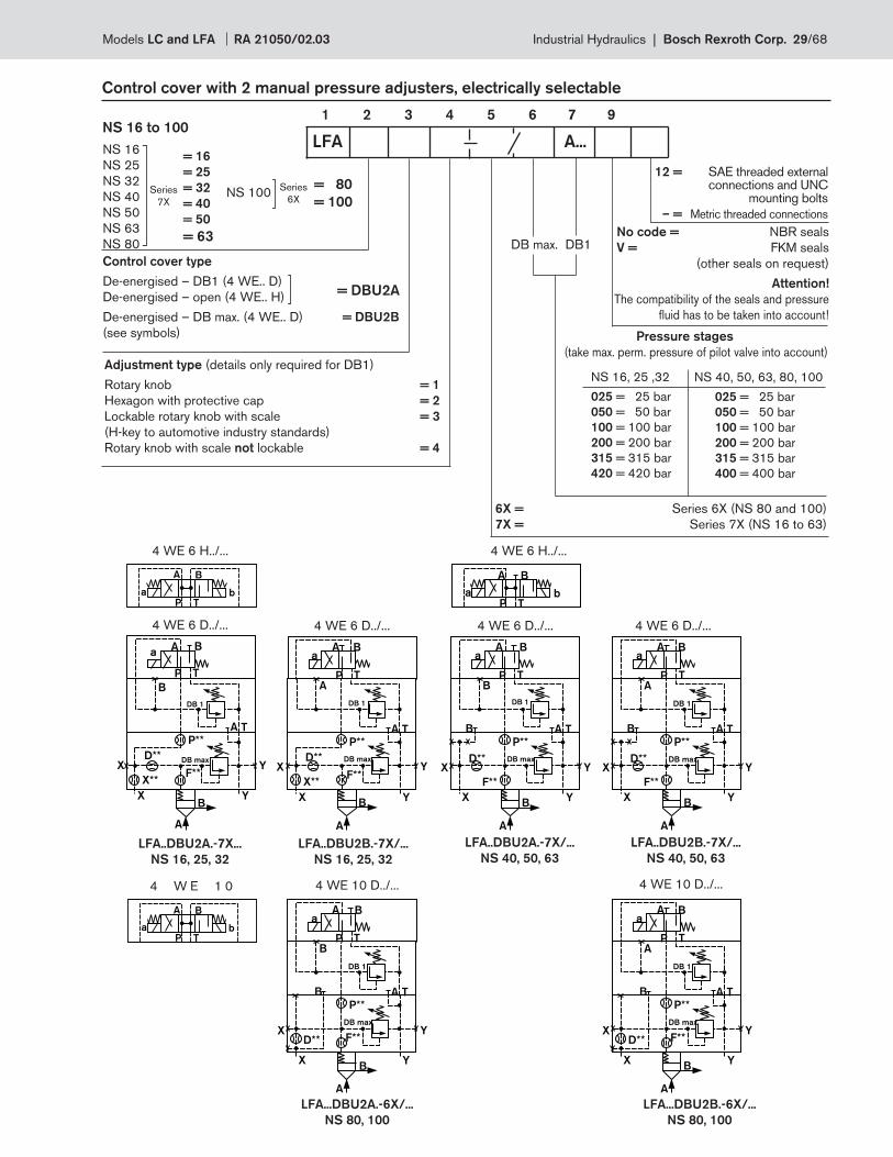
Control cover with 2 manual pressure adjusters, electrically selectable
1 2 3 4 5 6 7 9NS 16 to 100
DB1DB max. No code = NBR seals
V = FKM seals
(other seals on request)
Attention!
The compatibility of the seals and pressure
fl uid has to be taken into account!
NS 16, 25 ,32
025 = 25 bar
050 = 50 bar
100 = 100 bar
200 = 200 bar
315 = 315 bar
420 = 420 bar
NS 40, 50, 63, 80, 100
025 = 25 bar
050 = 50 bar
100 = 100 bar
200 = 200 bar
315 = 315 bar
400 = 400 bar
Pressure stages
(take max. perm. pressure of pilot valve into account)
6X = Series 6X (NS 80 and 100)
7X = Series 7X (NS 16 to 63)
LFA A...NS 16
NS 25
NS 32
NS 40
NS 50
NS 63
NS 80
Series
7X
= 16
= 25
= 32
= 40
= 50
= 63
NS 100 Series
6X
= 80
= 100
Adjustment type (details only required for DB1)
Rotary knob = 1
Hexagon with protective cap = 2
Lockable rotary knob with scale = 3
(H-key to automotive industry standards)
Rotary knob with scale not lockable = 4
Control cover type
De-energised – DB1 (4 WE.. D)
De-energised – open (4 WE.. H)
De-energised – DB max. (4 WE.. D) = DBU2B
(see symbols)
= DBU2A
P T
A B
a bP T
A B
a b
P T
A B
a b
F**
X
A
YB
D**
P**
P T
A Ba
DB max
DB 1
B
A T
X**
YXF**
X
A
YB
D**
P**
P T
A Ba
DB max
DB 1
A
A T
X**
YX
F**
X
A
Y
Y
B
D**
P**
P T
A Ba
XDB max
DB 1
B
B A T
F**
X
A
Y
Y
B
D**
P**
P T
A Ba
XDB max
DB 1
A
B A T
F**
X
A
Y
Y
B
D**
P**
P T
A Ba
XDB max
DB 1
B
B A T
F**
X
A
Y
Y
B
D**
P**
P T
A Ba
XDB max
DB 1
A
B A T
LFA..DBU2A.-7X...
NS 16, 25, 32
LFA...DBU2B.-6X/...
NS 80, 100
LFA...DBU2A.-6X/...
NS 80, 100
LFA..DBU2B.-7X/...
NS 40, 50, 63
LFA..DBU2A.-7X/...
NS 40, 50, 63
LFA..DBU2B.-7X/...
NS 16, 25, 32
4 WE 10 D../... 4 W E 1 0
4 WE 6 H../...
4 WE 6 D../...
4 WE 6 H../...
4 WE 6 D../...
4 WE 10 D../...
4 WE 6 D../... 4 WE 6 D../...
12 = SAE threaded external connections and UNC mounting bolts
– = Metric threaded connections
Models LC and LFA RA 21050/02.03 Industrial Hydraulics | Bosch Rexroth Corp. 29/68
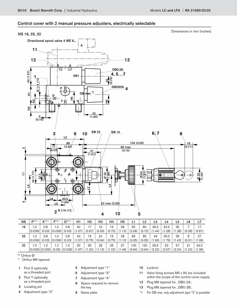
Control cover with 2 manual pressure adjusters, electrically selectable
NS 16, 25, 32
1 Port X optionally
as a threaded port
2 Port Y optionally
as a threaded port
3 Locating pin
4 Adjustment type “2”
5 Adjustment type “1”
6 Adjustment type “3”
7 Adjustment type “4”
8 Space required to remove
the key
9 Name plate
10 Locknut
11 Valve fi xing screws M5 x 90 are included
within the scope of the control cover supply
12 Plug M6 tapered for ..DBU 2A..
13 Plug M6 tapered for ..DBU 2B..
*) For DB max. only adjustment type “2” is possible
NS P**1) X**1) F**1) D**1) H1 H2 H3 H4 H5 L1 L2 L3 L4 L5 L6 L7
16 1.0 0.8 1.0 0.8 40 17 15 19 28 65 80 36.5 32.5 35 7 17
(0.039) (0.03) (0.039) (0.03) (1.57) (0.67) (0.59) (0.75) (1.10) (2.56) (3.15) (1.44) (1.28) (1.38) (0.28) (0.67)
25 1.0 0.8 1.0 0.8 40 19 24 19 28 85 85 49 45.5 36 8 27
(0.039) (0.03) (0.039) (0.03) (1.57) (0.75) (0.94) (0.75) (1.10) (3.35) (3.35) (1.93) (1.79) (1.42) (0.31) (1.06)
32 1.0 1.0 1.2 1.0 50 26 28 26 37 100 100 56.5 53 57 31 34.5
(0.039) (0.039) (0.05) (0.039) (1.97) (1.02) (1.10) (1.02) (1.46) (3.94) (3.94) (2.22) (2.07) (2.24) (1.22) (1.36)
3
82
90
1
9
4
3
DBDS2K.
H4
L2
G 1
/4
/1
2
H2
H1
H3
D
XF Y
12
SW 22 SW 10
2L1
L3
86; 7
1
10 5
L4
P
H5
AB
P
T
Y
X
10
L6
L5
4
A
2G 1/4 /12
AB
DB1
13
4
DBD.2K.
4, 5…7
L7
11
DB max *)
20
(0.7
9)
52 max (2.05)
42
(1.65)
Ø 3
5
(1.3
8)
80 max
(3.15)
88
(3.46)
41
(1.61)
18
(0.71)11
(0.43)
Ø 4
0
(1.5
7)
Ø 3
2
(1.2
6)
40.5
(1.59)
104 (4.09)
32
.5
(1.2
8)
40
(1
.57
)
45
(1
.77
)
4
(0.16)
Directional spool valve 4 WE 6...
** Orifi ce Ø1) Orifi ce M6 tapered
Dimensions in mm (inches)
30/68 Bosch Rexroth Corp. | Industrial Hydraulics Models LC and LFA RA 21050/02.03
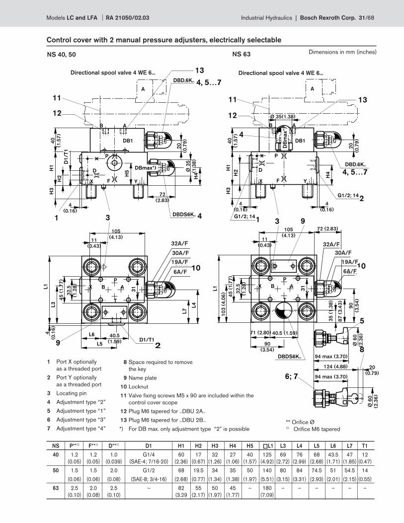
SW610
D1
/T
1
H2
H1
H3
H4
DBDS6K..
D
X F Y
3
X
Y
L5
L4
L7
L1
L3
11
A
P
B
A
B A
P
T
31
L6
9
4
H5
SW19
SW30
SW32
D1/T1
2
DBD.6K.. 4, 5…7
1
12
13
DB1
DBmax*)
45
(1
.77
)
72
(2.83)
4
(0.1
6)
20
(0.7
9)
40.5
(1.59)
40
(1.5
7)
Ø 3
5
(1.3
8)
32
.5
(1.2
8)
11
(0.43)
105
(4.13)
4
(0.16)
A
SW610
H2H
1H
3
H4
D
X F Y
3
X
Y
L1
11
A
P
B
B A
P
T3
1
9
SW19
SW30
SW32
DBD.6K..
4, 5…7
1
12
13
DB1
DB
max*)
G1/2; 14
2G1/2; 14
4
5
6; 7
8DBDS6K..
11
(0.43)
90
(3.5
4)
90
(3.54)2
0
(0.7
9)
20
(0.79)
71 (2.80) 40.5 (1.59)
72 (2.83)
Ø 6
0
(2.3
6)
Ø 6
0
(2.3
6)
94 max (3.70)
124 (4.88)
94 max (3.70)
Ø 35(1.38)
87
(3
.43
)
32
.5
(1.2
8)
40
(1.5
7)
45
(1
.77
)
10
3 (
4.0
6)
105
(4.13)
4
(0.16)
4
(0.16)
35
(1
.38
)
Control cover with 2 manual pressure adjusters, electrically selectable
NS 40, 50 NS 63
8 Space required to remove
the key
9 Name plate
10 Locknut
11 Valve fi xing screws M5 x 90 are included within the
control cover scope
12 Plug M6 tapered for ..DBU 2A..
13 Plug M6 tapered for ..DBU 2B..
*) For DB max. only adjustment type “2” is possible
1 Port X optionally
as a threaded port
2 Port Y optionally
as a threaded port
3 Locating pin
4 Adjustment type “2”
5 Adjustment type “1”
6 Adjustment type “3”
7 Adjustment type “4”
Directional spool valve 4 WE 6... Directional spool valve 4 WE 6...
NS P**1) F**1) D**1) D1 H1 H2 H3 H4 H5 L1 L3 L4 L5 L6 L7 T1
40 1.2 1.2 1.0 G1/4 60 17 32 27 40 125 69 76 68 43.5 47 12
(0.05) (0.05) (0.039) (SAE-4; 7/16-20) (2.36) (0.67) (1.26) (1.06) (1.57) (4.92) (2.72) (2.99) (2.68) (1.71) (1.85) (0.47)
50 1.5 1.5 2.0 G1/2 68 19.5 34 35 50 140 80 84 74.5 51 54.5 14
(0.06) (0.06) (0.08) (SAE-8; 3/4-16) (2.68) (0.77) (1.34) (1.38) (1.97) (5.51) (3.15) (3.31) (2.93) (2.01) (2.15) (0.55)
63 2.5 2.0 2.5 – 82 55 50 45 – 180 – – – – – –
(0.10) (0.08) (0.10) (3.29 (2.17) (1.97) (1.77) (7.09)
32A/F
30A/F
19A/F
6A/F
32A/F
30A/F
19A/F
6A/F
** Orifi ce Ø1) Orifi ce M6 tapered
Dimensions in mm (inches)
Models LC and LFA RA 21050/02.03 Industrial Hydraulics | Bosch Rexroth Corp. 31/68
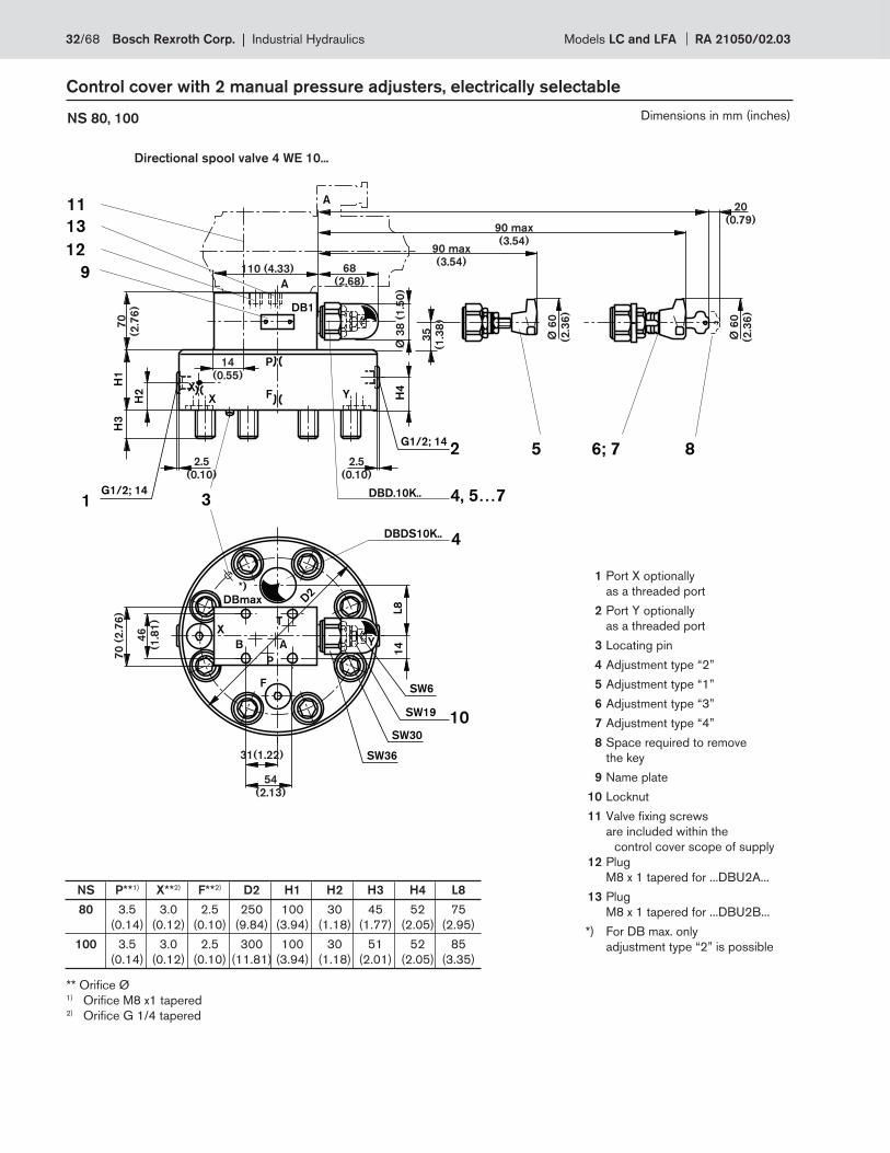
B A
P
T
H2
H1
H3
DBDS10K..
3
2
YFX
D2
Y
F
X
H4
G1/2; 14
1G1/2; 14
4
A
14
11
6; 75 8
P
X
12
9
13
L8
*)
DBmax
DBD.10K.. 4, 5…7
DB1
SW36
SW30
SW19
SW6
10
A
2.5
(0.10)
2.5
(0.10)
Ø 3
8 (
1.5
0)
90 max
(3.54)
90 max
(3.54)
20
(0.79)
Ø 6
0
(2.3
6)
Ø 6
0
(2.3
6)
110 (4.33)
54
(2.13)
70
(2.7
6)
70
(2
.76
)
35
(1.3
8)
31(1.22)
14
(0.55)
46
(1.8
1)
68
(2.68)
Control cover with 2 manual pressure adjusters, electrically selectable
NS 80, 100
** Orifi ce Ø1) Orifi ce M8 x1 tapered2) Orifi ce G 1/4 tapered
1 Port X optionally
as a threaded port
2 Port Y optionally
as a threaded port
3 Locating pin
4 Adjustment type “2”
5 Adjustment type “1”
6 Adjustment type “3”
7 Adjustment type “4”
8 Space required to remove
the key
9 Name plate
10 Locknut
11 Valve fi xing screws
are included within the
control cover scope of supply
12 Plug
M8 x 1 tapered for ...DBU2A...
13 Plug
M8 x 1 tapered for ...DBU2B...
*) For DB max. only
adjustment type “2” is possible
Directional spool valve 4 WE 10...
NS P**1) X**2) F**2) D2 H1 H2 H3 H4 L8
80 3.5 3.0 2.5 250 100 30 45 52 75
(0.14) (0.12) (0.10) (9.84) (3.94) (1.18) (1.77) (2.05) (2.95)
100 3.5 3.0 2.5 300 100 30 51 52 85
(0.14) (0.12) (0.10) (11.81) (3.94) (1.18) (2.01) (2.05) (3.35)
Dimensions in mm (inches)
32/68 Bosch Rexroth Corp. | Industrial Hydraulics Models LC and LFA RA 21050/02.03
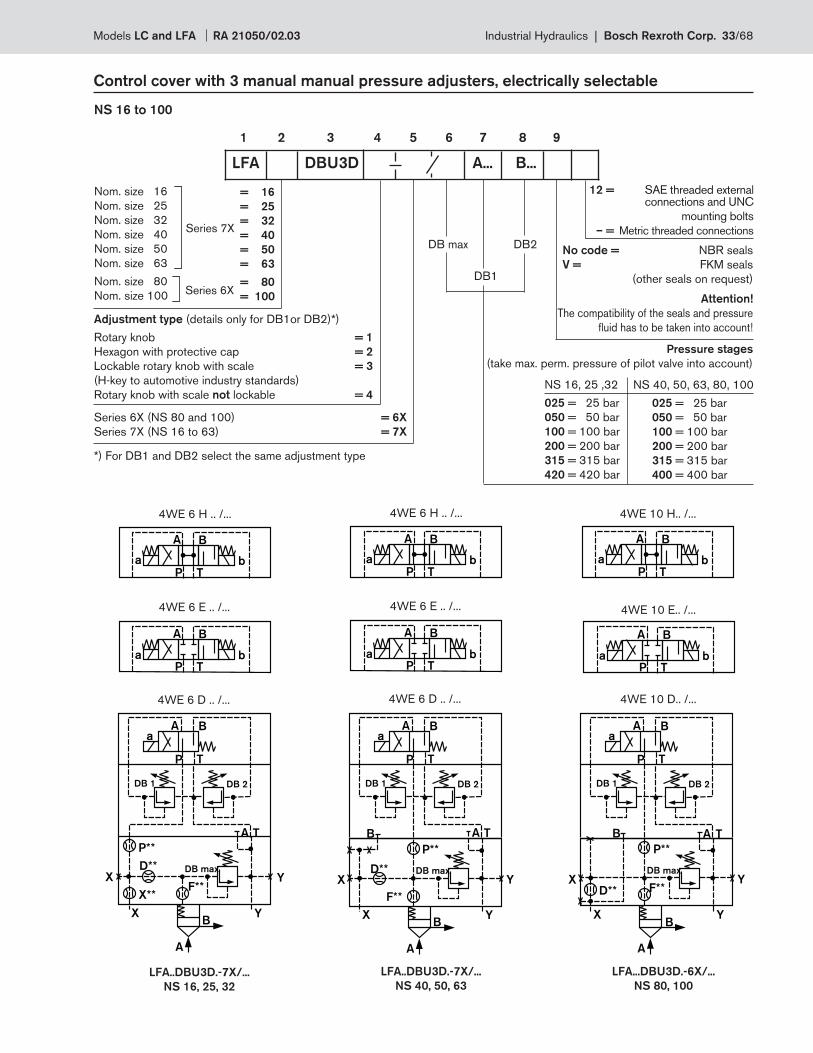
Nom. size 16
Nom. size 25
Nom. size 32
Nom. size 40
Nom. size 50
Nom. size 63
Nom. size 80
Nom. size 100
= 16
= 25
= 32
= 40
= 50
= 63
= 80
= 100
Series 7X
Series 6X
Adjustment type (details only for DB1or DB2)*)
Rotary knob = 1
Hexagon with protective cap = 2
Lockable rotary knob with scale = 3
(H-key to automotive industry standards)
Rotary knob with scale not lockable = 4
Control cover with 3 manual manual pressure adjusters, electrically selectable
1 2 3 4 5 6 7 8 9
NS 16 to 100
No code = NBR seals
V = FKM seals
(other seals on request)
Attention!
The compatibility of the seals and pressure
fl uid has to be taken into account!
NS 16, 25 ,32
025 = 25 bar
050 = 50 bar
100 = 100 bar
200 = 200 bar
315 = 315 bar
420 = 420 bar
NS 40, 50, 63, 80, 100
025 = 25 bar
050 = 50 bar
100 = 100 bar
200 = 200 bar
315 = 315 bar
400 = 400 bar
Pressure stages
(take max. perm. pressure of pilot valve into account)
LFA DBU3D A... B...
DB2
DB1
DB max
Series 6X (NS 80 and 100) = 6X
Series 7X (NS 16 to 63) = 7X
*) For DB1 and DB2 select the same adjustment type
P T
A B
a b
P T
A B
a b
P T
A B
a b
P T
A B
a b
P T
A B
a b
P T
A B
a b
F**
X
A
YB
D**
P**
P T
A Ba
DB max
DB 1
A T
X**
DB 2
YX
P T
A Ba
DB 1
A T
DB 2
F**
X
A
Y
Y
B
D**
P**
XDB max
B
P T
A Ba
DB 1 DB 2
F**
X
A
Y
Y
B
D**
P**
XDB max
B A T
4WE 6 H .. /...
4WE 6 E .. /...
4WE 6 D .. /...
4WE 10 H.. /...
4WE 10 E.. /...
4WE 10 D.. /...
LFA..DBU3D.-7X/...
NS 16, 25, 32
LFA..DBU3D.-7X/...
NS 40, 50, 63
LFA...DBU3D.-6X/...
NS 80, 100
4WE 6 H .. /...
4WE 6 E .. /...
4WE 6 D .. /...
12 = SAE threaded external connections and UNC
mounting bolts
– = Metric threaded connections
Models LC and LFA RA 21050/02.03 Industrial Hydraulics | Bosch Rexroth Corp. 33/68
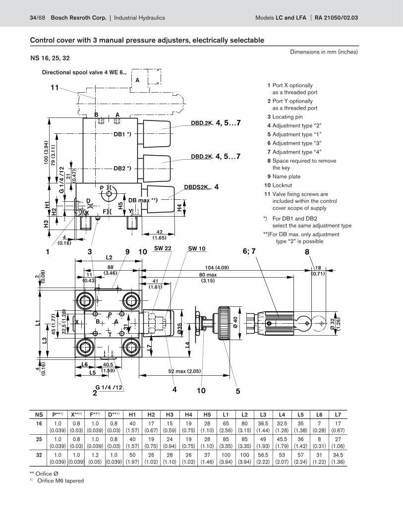
3
82
90
1
9
4
3
DBDS2K...
H4
L2
G 1
/4
/1
2
H2
H1
H3
D
X F Y
SW 22 SW 10
L1
L3
86; 71
Ø 4
0
10 5
L4
Ø3
5
P
H5
AB
P
TY
X
10
L6
L5
A
2G 1/4 /12
AB
DB1 *)
DB max **)
4
DBD.2K. 4, 5…73
1
L7
DBD.2K. 4, 5…7
DB2 *)
11
88
(3.46)
52 max (2.05)
4
(0.16)
45
(1
.77
)
42
(1.65)
Ø 3
2
(1.2
6)
80 max
(3.15)
4
(0.1
6)
2
(0.0
8)
11
(0.43)
21
(0.4
7)
18
(0.71)
32
.5 (
1.2
8)
40.5
(1.59)
41
(1.61)
104 (4.09)
10
0 (
3.9
4)
79
(3
.11
)
Control cover with 3 manual pressure adjusters, electrically selectable
NS 16, 25, 32
** Orifi ce Ø1) Orifi ce M6 tapered
Directional spool valve 4 WE 6...
1 Port X optionally
as a threaded port
2 Port Y optionally
as a threaded port
3 Locating pin
4 Adjustment type “2”
5 Adjustment type “1”
6 Adjustment type “3”
7 Adjustment type “4”
8 Space required to remove
the key
9 Name plate
10 Locknut
11 Valve fi xing screws are
included within the control
cover scope of supply
*) For DB1 and DB2
select the same adjustment type
**) For DB max. only adjustment
type “2” is possible
NS P**1) X**1) F**1) D**1) H1 H2 H3 H4 H5 L1 L2 L3 L4 L5 L6 L7
16 1.0 0.8 1.0 0.8 40 17 15 19 28 65 80 36.5 32.5 35 7 17
(0.039) (0.03) (0.039) (0.03) (1.57) (0.67) (0.59) (0.75) (1.10) (2.56) (3.15) (1.44) (1.28) (1.38) (0.28) (0.67)
25 1.0 0.8 1.0 0.8 40 19 24 19 28 85 85 49 45.5 36 8 27
(0.039) (0.03) (0.039) (0.03) (1.57) (0.75) (0.94) (0.75) (1.10) (3.35) (3.35) (1.93) (1.79) (1.42) (0.31) (1.06)
32 1.0 1.0 1.2 1.0 50 26 28 26 37 100 100 56.5 53 57 31 34.5
(0.039) (0.039) (0.05) (0.039) (1.97) (1.02) (1.10) (1.02) (1.46) (3.94) (3.94) (2.22) (2.07) (2.24) (1.22) (1.36)
Dimensions in mm (inches)
34/68 Bosch Rexroth Corp. | Industrial Hydraulics Models LC and LFA RA 21050/02.03
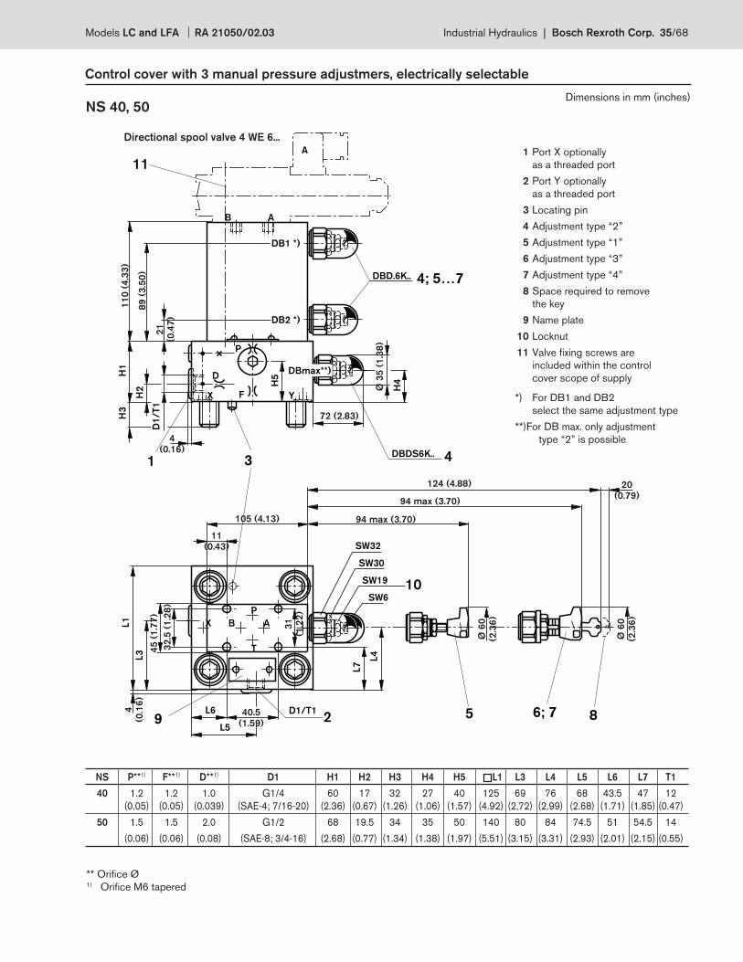
D1
/T
1
H2
H1
H3
H4
DBDS6K..
D
X F Y
3
11
A
P
B
A
4
H5
DBD.6K.. 4; 5…7
1
DB2 *)
DBmax**)
DB1 *)
SW6
10
X
Y
L5
L4
L7
L1
L3
B A
P
T
L69
SW19
SW30
SW32
D1/T12 6; 75 8
72 (2.83)
124 (4.88)
105 (4.13)
94 max (3.70)
94 max (3.70)
32
.5 (
1.2
8)
45
(1
.77
)
Ø 3
5 (
1.3
8)
21
(0.4
7)
4
(0.1
6)
31
(1.2
2)
20
(0.79)
Ø 6
0
(2.3
6)
Ø 6
0
(2.3
6)
40.5
(1.59)
11
0 (
4.3
3)
89
(3
.50
)
4
(0.16)
11
(0.43)
Control cover with 3 manual pressure adjustmers, electrically selectable
NS 40, 50
Directional spool valve 4 WE 6...
1 Port X optionally
as a threaded port
2 Port Y optionally
as a threaded port
3 Locating pin
4 Adjustment type “2”
5 Adjustment type “1”
6 Adjustment type “3”
7 Adjustment type “4”
8 Space required to remove
the key
9 Name plate
10 Locknut
11 Valve fi xing screws are
included within the control
cover scope of supply
*) For DB1 and DB2
select the same adjustment type
**) For DB max. only adjustment
type “2” is possible
** Orifi ce Ø1) Orifi ce M6 tapered
Dimensions in mm (inches)
NS P**1) F**1) D**1) D1 H1 H2 H3 H4 H5 L1 L3 L4 L5 L6 L7 T1
40 1.2 1.2 1.0 G1/4 60 17 32 27 40 125 69 76 68 43.5 47 12
(0.05) (0.05) (0.039) (SAE-4; 7/16-20) (2.36) (0.67) (1.26) (1.06) (1.57) (4.92) (2.72) (2.99) (2.68) (1.71) (1.85) (0.47)
50 1.5 1.5 2.0 G1/2 68 19.5 34 35 50 140 80 84 74.5 51 54.5 14
(0.06) (0.06) (0.08) (SAE-8; 3/4-16) (2.68) (0.77) (1.34) (1.38) (1.97) (5.51) (3.15) (3.31) (2.93) (2.01) (2.15) (0.55)
Models LC and LFA RA 21050/02.03 Industrial Hydraulics | Bosch Rexroth Corp. 35/68
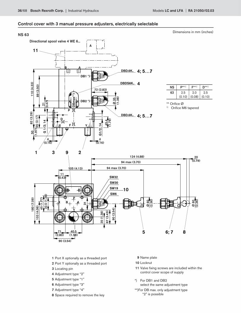
SW6
10
G 1
/2
; 1
4
D
X F Y
3
X
Y
11
A
P
B
A
B A
P
T
31
SW19
SW30
SW32
DBD.6K.. 4; 5…7
1
DB2 *)
DB1 *)D
Bm
ax**
)
G1
/2
; 1
4
2
DBD.6K.. 4; 5…7
DBDS6K.. 4
9
6; 75 8
72 (2.83)
124 (4.88)
90 (3.54)
105 (4.13)
94 max (3.70)
94 max (3.70)
87
(3
.43
)
90
(3
.54
)32
.5 (
1.2
8)
45
(1
.77
)
Ø 3
5
(1
.38
)
21
(0.4
7)
45
.4
(1.7
9)
20
(0.79)
Ø 6
0
(2.3
6)
Ø 6
0
(2.3
6)
35
(1
.38
)
40.5
(1.59)
71
(2.80)
11
0 (
4.3
3)
89
(3
.50
)
18
0 (
7.0
9)
10
3 (
4.0
6)
82
(3
.29
)
55
(2
.17
)
50
(1.9
7)
4
(0.16)
4
(0.16)
11
(0.43)
Control cover with 3 manual pressure adjusters, electrically selectable
NS 63
Directional spool valve 4 WE 6...
** Orifi ce Ø1) Orifi ce M6 tapered
1 Port X optionally as a threaded port
2 Port Y optionally as a threaded port
3 Locating pin
4 Adjustment type “2”
5 Adjustment type “1”
6 Adjustment type “3”
7 Adjustment type “4”
8 Space required to remove the key
9 Name plate
10 Locknut
11 Valve fi xing screws are included within the
control cover scope of supply
*) For DB1 and DB2
select the same adjustment type
**) For DB max. only adjustment type
“2” is possible
NS P**1) F**1) D**1)
63 2.5 2.0 2.5
(0.10) (0.08) (0.10)
Dimensions in mm (inches)
36/68 Bosch Rexroth Corp. | Industrial Hydraulics Models LC and LFA RA 21050/02.03
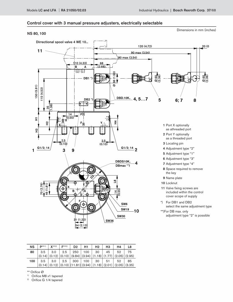
B A
P
T
H2
H1
H3
DBDS10K..
3 2
YFX
D2
Y
F
X
H4
G1/2; 141
G1/2; 14
4
B A
11
P
X
L8
DBmax **)
DBD.10K.. 4, 5…7
9
DB2 *)
DB1 *)
SW6
SW19
SW30
SW36
10
5 6; 7 8
2.5
(0.10)
2.5
(0.10)
68
(2.68)
110 (4.33)
120 (4.72) 20 (0
Ø 6
0
(2.3
6)
Ø 6
0
(2.3
6)
54 (2.13)
31 (1.22)
14
(0.55)
70
(2
.76
)
14
(0.5
5)
90 max (3.54)
90 max (3.54)
35
(1.3
8)
15
0 (
5.9
1)
11
5 (
4.5
3)
Ø 3
8 (
1.5
0)
46
(1
.81
)
Control cover with 3 manual pressure adjusters, electrically selectable
NS 80, 100
** Orifi ce Ø1) Orifi ce M8 x1 tapered2) Orifi ce G 1/4 tapered
1 Port X optionally
as athreaded port
2 Port Y optionally
as a threaded port
3 Locating pin
4 Adjustment type “2”
5 Adjustment type “1”
6 Adjustment type “3”
7 Adjustment type “4”
8 Space required to remove
the key
9 Name plate
10 Locknut
11 Valve fi xing screws are
included within the control
cover scope of supply
*) For DB1 and DB2
select the same adjustment type
**) For DB max. only
adjustment type “2” is possible
Dirrectional spool valve 4 WE 10...
NS P**1) X**2) F**2) D2 H1 H2 H3 H4 L8
80 3.5 3.0 2.5 250 100 30 45 52 75
(0.14) (0.12) (0.10) (9.84) (3.94) (1.18) (1.77) (2.05) (2.95)
100 3.5 3.0 2.5 300 100 30 51 52 85
(0.14) (0.12) (0.10) (11.81) (3.94) (1.18) (2.01) (2.05) (3.35)
Dimensions in mm (inches)
Models LC and LFA RA 21050/02.03 Industrial Hydraulics | Bosch Rexroth Corp. 37/68
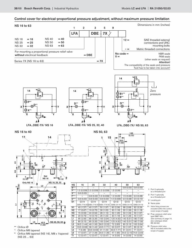
D1
/T
1
H2
H1
H3
D1
/T
1
H4
D
XF
Y
3
X
Y
L4
L6
9
L1
L3
1
P
B A
P
T
31
L5 NG 40, 50, 63
11 14
9NG 16, 25, 32
Not
NS 16
Only NS 16
L2
24
(0.16)
4
(0.16)
40.5
(1.59)
32
.5
(1.2
8)
2
(0.0
8)
D1
/T
1
H2
H1
H3
D1
/T
1
H4
D
X F Y
1L5
1539.5
(1.56)
50
(1.9
7)
146
(5.75)
–
Control cover for electrical-proportional pressure adjustment, without maximum pressure limitation
1 2 3 5 9NS 16 to 63
LFA DBE 7X
NS 16
NS 25
NS 32
= 16
= 25
= 32
NS 40
NS 50
NS 63
= 40
= 50
= 63
No code = NBR seals V = FKM seals (other seals on request) Attention!
The compatibility of the seals and pressure fl uid has to be taken into account!
Series 7X (NS 16 to 63) = 7X
For mounting a proportional pressure relief valve
without electrical feedback = DBE
NS 16 to 40 NS 50, 63
X
A
YB
D**P**
X**
YX
14
X
A
YB
D**P**
F**
YX
14
X
A
YB
D**
B**
F**
YX
14
B1**
LFA...DBE-7X/ NS 50, 63LFA...DBE-7X/ NS 25, 32, 40LFA...DBE-7X/ NS 16
Zero
pressure
** Orifi ce Ø1) Orifi ce M6 tapered2) Orifi ce M6 tapered (NS 16), M8 x 1tapered
(NS 25 ... 63)
NS 16 25 32 40 50 63
B**1) – – – – 0.8 (0.03) 0.8 (0.03)
P**1) 1.0 (0.039) 1.0 (0.039) 1.0 (0.039) 1.5 (0.06) – –
X**1) 0.8 (0.03) – – – – –
F**1) – 0.8 (0.03) 1.0 (0.039) 1.2 (0.05) 1.5 (0.06) 2.0 (0.08)
D**2) 0.8 (0.03) 0.8 (0.03) 0.8 (0.03) 1.0 (0.039) 2.0 (0.08) 2.5 (0.10)
D1 G1/4 G1/4 G1/4 G1/2 G1/2 G1/2
(SAE4; 7/16-20) (SAE4; 7/16-20) (SAE4; 7/16-20) (SAE8; 3/4-16) (SAE8; 3/4-16) (SAE8; 3/4-16)
H1 40 (1.57) 40 (1.57) 50 (1.97) 60 (2.36) 68 (2.68) 82 (3.29)
H2 17 (0.67) 19 (0.75) 26 (1.02) 30 (1.18) 32 (1.26) 30 (1.18)
H3 15 (0.59) 24 (0.94) 28 (1.10) 32 (1.26) 34 (1.34) 50 (1.97)
H4 20 (0.79) 19 (0.75) 26 (1.02) 30 (1.18) 32 (1.26) 40 (1.57)
L1 65 (2.56) 85 (3.35) 100 (3.94) 125 (4.92) 140 (5.51) 180 (7.09)
L2 80 (3.15) 85 (3.35) 100 (3.94) 125 (4.92) 140 (5.51) 180 (7.09)
L3 36.5 (1.44) 49 (1.93) 56.5 (2.22) 72 (2.83) 80 (3.15) 100 (3.94)
L4 23.5 (0.93) 36 (1.42) 43.5 (1.71) 53 (2.07) 50 (1.97) 80 (3.15)
L5 7 (0.28) 23.5 (0.93) 31 (1.22) 43.5 (1.71) 51 (2.01) 71 (2.01)
L6 17 (0.67) 27 (1.06) 34.5 (1.36) 47 (1.85) 54.5 (2.15) 74.5 (2.93)
T1 12 (0.47) 12 (0.47) 12 (0.47) 14 (0.55) 14 (0.55) 14 (0.55)
1 Port X optionally
as a threaded port
2 Port Y optionally
as a threaded port
3 Locating pin
9 Name plate
11 Valve fi xing screws are
included within the control
cover scope of supply
14 Prop. pressure relief valve
type DBET-6X/...
(see summary on page 14,
also catalogue sheet
RE 29162)
15 Pressure relief valve
NS 6 (included within the
scope of supply)
Dimensions in mm (inches)
12 = SAE threaded external connections and UNC mounting bolts
– = Metric threaded connections
38/68 Bosch Rexroth Corp. | Industrial Hydraulics Models LC and LFA RA 21050/02.03
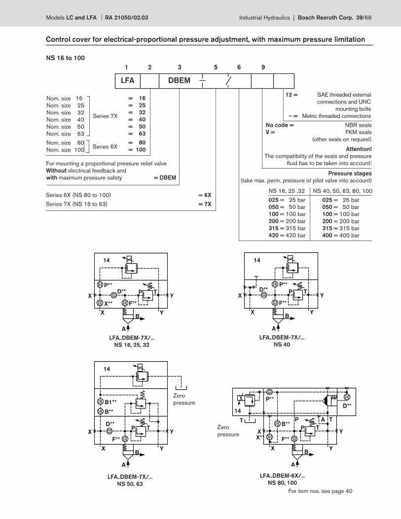
X
A
YB
D**P**
X**
YX
14
F**
P T
14
X
A
YB
D**P**
YX
F**
P T
B**
B1**
14
X
A
YB
D**
YX
F**
P T
P**
14
X
A
YB
X**YX
F**
P TB**
T TAP
D**
Control cover for electrical-proportional pressure adjustment, with maximum pressure limitation
NS 16 to 100
Nom. size 16
Nom. size 25
Nom. size 32
Nom. size 40
Nom. size 50
Nom. size 63
Nom. size 80
Nom. size 100
= 16
= 25
= 32
= 40
= 50
= 63
= 80
= 100
Series 7X
Series 6X
1 2 3 5 6 9
No code = NBR seals
V = FKM seals
(other seals on request)
Attention!
The compatibility of the seals and pressure
fl uid has to be taken into account!
NS 16, 25 ,32
025 = 25 bar
050 = 50 bar
100 = 100 bar
200 = 200 bar
315 = 315 bar
420 = 420 bar
NS 40, 50, 63, 80, 100
025 = 25 bar
050 = 50 bar
100 = 100 bar
200 = 200 bar
315 = 315 bar
400 = 400 bar
Pressure stages
(take max. perm. pressure of pilot valve into account)
LFA DBEM
Series 6X (NS 80 to 100) = 6X
Series 7X (NS 16 to 63) = 7X
For mounting a proportional pressure relief valve
Without electrical feedback and
with maximum pressure safety = DBEM
LFA..DBEM-7X/...
NS 50, 63
LFA..DBEM-7X/...
NS 40
LFA..DBEM-7X/...
NS 16, 25, 32
LFA..DBEM-6X/...
NS 80, 100
Zero
pressure
Zero
pressure
For item nos. see page 40
12 = SAE threaded external
connections and UNC
mounting bolts
– = Metric threaded connections
Models LC and LFA RA 21050/02.03 Industrial Hydraulics | Bosch Rexroth Corp. 39/68
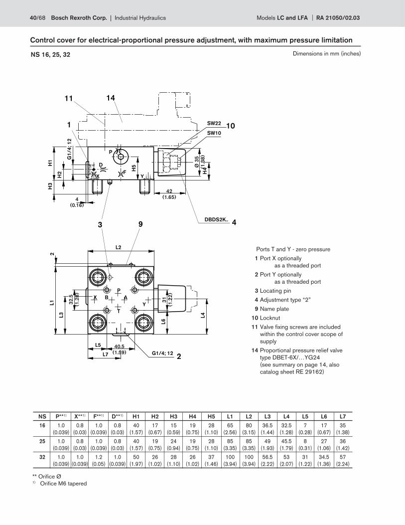
G1
/4
; 1
2
H2
H1
H3
H4
D
XF
Y
3
X
Y
L4
L6
L1
L3
1
P
B A
P
T
L5
11 14
9
L2
L7 2G1/4; 12
H5
DBDS2K..4
SW10
SW2210
2
Ø 3
5
(1.3
8)
31
(1.2
2)
42
(1.65)4
(0.16)
40.5
(1.59)
32
.5
(1.2
8)
NS 16, 25, 32
Control cover for electrical-proportional pressure adjustment, with maximum pressure limitation
** Orifi ce Ø1) Orifi ce M6 tapered
Ports T and Y - zero pressure
1 Port X optionally
as a threaded port
2 Port Y optionally
as a threaded port
3 Locating pin
4 Adjustment type “2”
9 Name plate
10 Locknut
11 Valve fi xing screws are included
within the control cover scope of
supply
14 Proportional pressure relief valve
type DBET-6X/…YG24
(see summary on page 14, also
catalog sheet RE 29162)
NS P**1) X**1) F**1) D**1) H1 H2 H3 H4 H5 L1 L2 L3 L4 L5 L6 L7
16 1.0 0.8 1.0 0.8 40 17 15 19 28 65 80 36.5 32.5 7 17 35
(0.039) (0.03) (0.039) (0.03) (1.57) (0.67) (0.59) (0.75) (1.10) (2.56) (3.15) (1.44) (1.28) (0.28) (0.67) (1.38)
25 1.0 0.8 1.0 0.8 40 19 24 19 28 85 85 49 45.5 8 27 36
(0.039) (0.03) (0.039) (0.03) (1.57) (0.75) (0.94) (0.75) (1.10) (3.35) (3.35) (1.93) (1.79) (0.31) (1.06) (1.42)
32 1.0 1.0 1.2 1.0 50 26 28 26 37 100 100 56.5 53 31 34.5 57
(0.039) (0.039) (0.05) (0.039) (1.97) (1.02) (1.10) (1.02) (1.46) (3.94) (3.94) (2.22) (2.07) (1.22) (1.36) (2.24)
Dimensions in mm (inches)
40/68 Bosch Rexroth Corp. | Industrial Hydraulics Models LC and LFA RA 21050/02.03
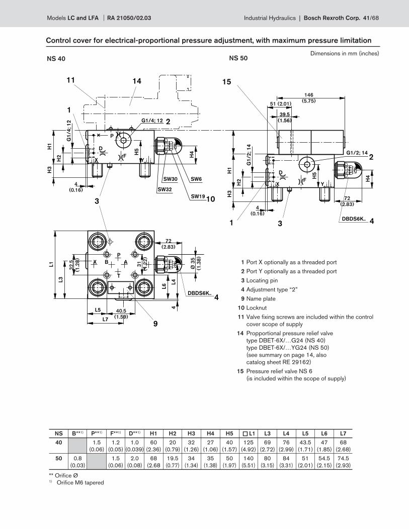
G1
/4
; 1
2
H2
H1
H3
H4
D
XF
Y
3
X
Y
L4
L6
L1
L3
1
P
B A
P
T
L5
11 14
H5
L7
4
DBDS6K..4
9
SW6
SW19
SW30
SW32
10
G1/4; 12 2
G1
/2
; 1
4
H2
H1
H3
H4
D
XF
Y
1
39.5
(1.56)
H5
DBDS6K.. 43
G1/2; 142
15
Ø 3
5
(1.3
8)
4
(0.16)
72
(2.83)4
(0.16)
146
(5.75)51 (2.01)
32
.5
(1.2
8)
72
(2.83)
40.5
(1.59)
31
(1.2
2)
NS 40
Control cover for electrical-proportional pressure adjustment, with maximum pressure limitation
NS 50
1 Port X optionally as a threaded port
2 Port Y optionally as a threaded port
3 Locating pin
4 Adjustment type “2”
9 Name plate
10 Locknut
11 Valve fi xing screws are included within the control
cover scope of supply
14 Propportional pressure relief valve
type DBET-6X/…G24 (NS 40)
type DBET-6X/…YG24 (NS 50)
(see summary on page 14, also
catalog sheet RE 29162)
15 Pressure relief valve NS 6
(is included within the scope of supply)
NS B**1) P**1) F**1) D**1) H1 H2 H3 H4 H5 L1 L3 L4 L5 L6 L7
40 1.5 1.2 1.0 60 20 32 27 40 125 69 76 43.5 47 68
(0.06) (0.05) (0.039) (2.36) (0.79) (1.26) (1.06) (1.57) (4.92) (2.72) (2.99) (1.71) (1.85) (2.68)
50 0.8 1.5 2.0 68 19.5 34 35 50 140 80 84 51 54.5 74.5
(0.03) (0.06) (0.08) (2.68 (0.77) (1.34) (1.38) (1.97) (5.51) (3.15) (3.31) (2.01) (2.15) (2.93)
** Orifi ce Ø1) Orifi ce M6 tapered
Dimensions in mm (inches)
Models LC and LFA RA 21050/02.03 Industrial Hydraulics | Bosch Rexroth Corp. 41/68
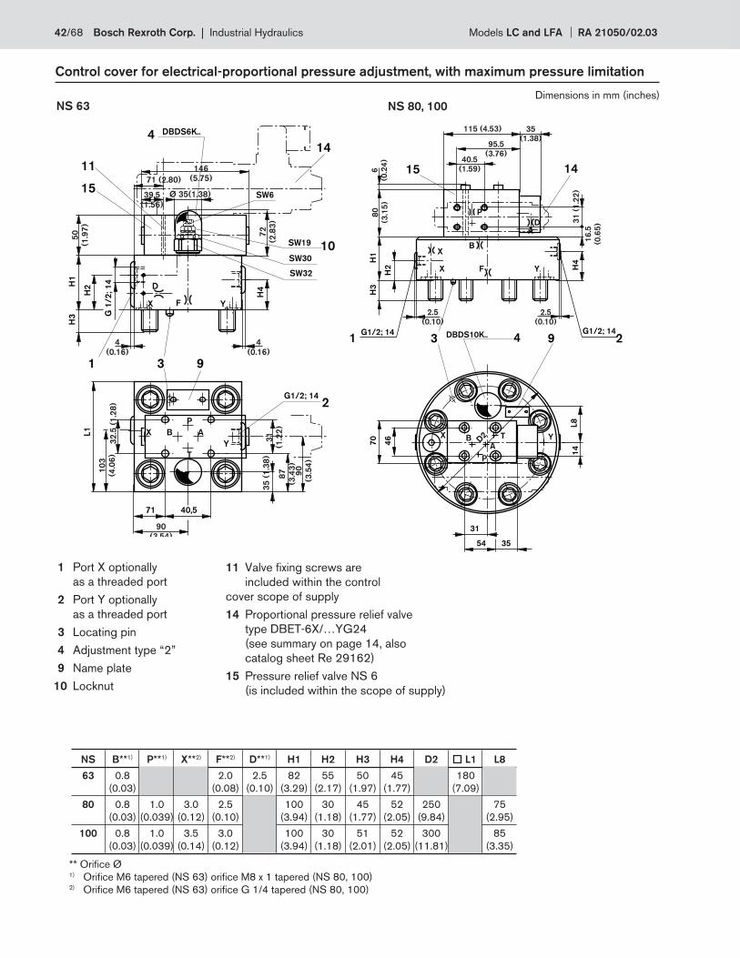
NS B**1) P**1) X**2) F**2) D**1) H1 H2 H3 H4 D2 L1 L8
63 0.8 2.0 2.5 82 55 50 45 180
(0.03) (0.08) (0.10) (3.29) (2.17) (1.97) (1.77) (7.09)
80 0.8 1.0 3.0 2.5 100 30 45 52 250 75
(0.03) (0.039) (0.12) (0.10) (3.94) (1.18) (1.77) (2.05) (9.84) (2.95)
100 0.8 1.0 3.5 3.0 100 30 51 52 300 85
(0.03) (0.039) (0.14) (0.12) (3.94) (1.18) (2.01) (2.05) (11.81) (3.35)
NS 63
Control cover for electrical-proportional pressure adjustment, with maximum pressure limitation
NS 80, 100
** Orifi ce Ø1) Orifi ce M6 tapered (NS 63) orifi ce M8 x 1 tapered (NS 80, 100)2) Orifi ce M6 tapered (NS 63) orifi ce G 1/4 tapered (NS 80, 100)
1 Port X optionally
as a threaded port
2 Port Y optionally
as a threaded port
3 Locating pin
4 Adjustment type “2”
9 Name plate
10 Locknut
11 Valve fi xing screws are
included within the control
cover scope of supply
14 Proportional pressure relief valve
type DBET-6X/…YG24
(see summary on page 14, also
catalog sheet Re 29162)
15 Pressure relief valve NS 6
(is included within the scope of supply)
H2
H1
H3
DBDS10K..3 9 2
YFX
D2 YX
H4
G1/2; 141
G1/2; 144
B
46
14
31
15
X
P
D
T
AB
P
70
54 35
L8
14
16
.5
(0.6
5)
95.5
(3.76)40.5
(1.59)
115 (4.53) 35
(1.38)
31
(1
.22
)
2.5
(0.10)
2.5
(0.10)
6
(0.2
4)
80
(3.1
5)
14
G 1
/2
; 1
4
H2H
1H
3
H4D
X F Y
3
X
Y
L1
11
B A
P
T
71 40,5
1
DBDS6K..4
G1/2; 142
9
15SW6
SW19
SW30
SW32
10
Ø 35(1.38)
90
(3.5
4)
87
(3.4
3)
90
(3 54)
4
(0.16)
4
(0.16)
32
.5 (
1.2
8)
71 (2.80)
72
(2.8
3)
39.5
(1.56)
50
(1.9
7)
35
(1
.38
)3
1
(1.2
2)
10
3
(4.0
6)
146
(5.75)
Dimensions in mm (inches)
42/68 Bosch Rexroth Corp. | Industrial Hydraulics Models LC and LFA RA 21050/02.03
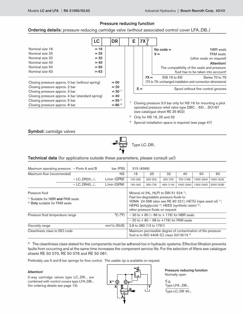
B
A
B
A
X Y
X** F**
Maximum operating pressure – Ports A and B bar (PSI) 315 (4569)
Maximum fl ow (recommended) NS 16 25 32 40 50 63
– LC..DR20.../.. L/min (GPM) 100 (26) 200 (53) 300 (79) 750 (198) 1000 (264) 1600 (423)
– LC..DR40.../.. L/min (GPM) 150 (40) 300 (79) 450 (119) 1000 (264) 1300 (343) 2000 (528)
Pressure fl uid Mineral oil (HL, HLP) to DIN 51 524 1);
Fast bio-degradable pressure fl uids to
VDMA 24 568 (also see RE 90 221); HETG (rape seed oil) 1);
HEPG (polyglycols) 2); HEES (synthetic ester) 2);
other pressure fl uids on request
Pressure fl uid temperature range °C (°F) – 30 to + 80 (– 86 to + 176) for NBR seals
– 20 to + 80 – 68 to +176) for FKM seals
Viscosity range mm2/s (SUS) 2.8 to 380 (13 to 1761)
Cleanliness class to ISO code Maximum permissible degree of contamination of the pressure
fl uid is to ISO 4406 (C) class 20/18/15 3)
3) The cleanliness class stated for the components must be adhered too in hydraulic systems. Effective fi ltration prevents
faults from occurring and at the same time increases the component service life. For the selection of fi lters see catalogue
sheets RE 50 070, RE 50 076 and RE 50 081.
Preferably use 5 and 8 bar springs for fl ow control. The usable Δp is available on request.
Pressure reducing function
Ordering details: pressure reducing cartridge valve (without associated control cover LFA..DB..)
No code = NBR seals
V = FKM seals
(other seals on request)
Attention!
The compatibility of the seals and pressure
fl uid has to be taken into account!
7X = (NS 16 to 63) Series 70 to 79
(70 to 79: unchanged installation and connection dimensions)
E = Spool without fi ne control grooves
Nominal size 16 = 16
Nominal size 25 = 25
Nominal size 32 = 32
Nominal size 40 = 40
Nominal size 50 = 50
Nominal size 63 = 63
Closing pressure approx. 0 bar (without spring) = 00
Closing pressure approx. 2 bar = 20
Closing pressure approx. 3 bar = 30 1)
Closing pressure approx. 4 bar (standard spring) = 40
Closing pressure approx. 5 bar = 50 2)
Closing pressure approx. 8 bar = 80 3)
LC DR E 7X
1) Closing pressure 3.0 bar only for NS 16 for mounting a pilot
operated pressure relief valve type DBC . -5X/…SO187
(see catalogue sheet RE 25 802)
2) Only for NS 16, 25 and 32
3) Special installation space is required (see page 47)
Symbol: cartridge valves
Technical data (for applications outside these parameters, please consult us!)
Pressure reducing function
Normally openAttention!
2-way cartridge valves type LC..DR... are
combined with control covers type LFA..DB...
(for ordering details see page 13).
Type LC..DR..
E.g.
Type LFA...DB...
Type LC..DR 40...
1) Suitable for NBR and FKM seals2) Only suitable for FKM seals
Models LC and LFA RA 21050/02.03 Industrial Hydraulics | Bosch Rexroth Corp. 43/68
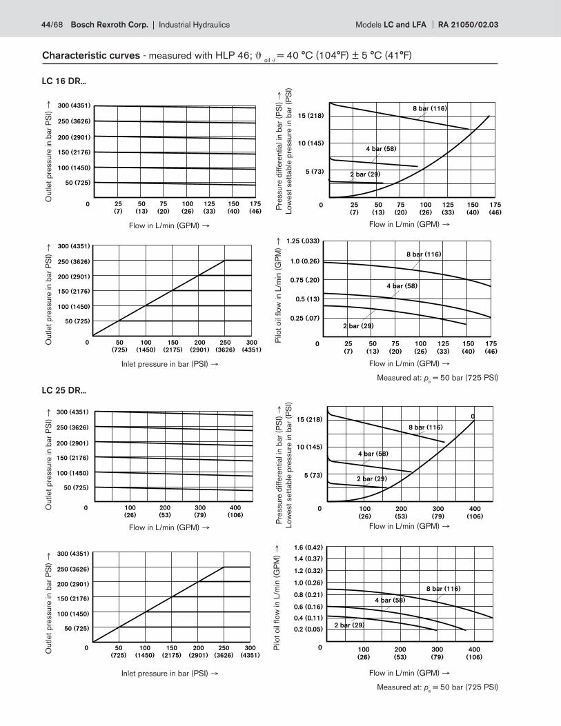
50
(13)
25
(7)
100
(26)
125
(33)
175
(46)
75
(20)
150
(40)
0
15 (218)
10 (145)
5 (73)
8 bar (116)
4 bar (58)
2 bar (29)
50
(13)
25
(7)
100
(26)
125
(33)
175
(46)
75
(20)
150
(40)
300 (4351)
250 (3626)
200 (2901)
150 (2176)
100 (1450)
50 (725)
0
300 (4351)
250 (3626)
200 (2901)
150 (2176)
100 (1450)
50 (725)
0 50
(725)
100
(1450)
150
(2175)
200
(2901)
250
(3626)
300
(4351)
8 bar (116)
4 bar (58)
2 bar (29)
50
(13)
25
(7)
100
(26)
125
(33)
175
(46)
75
(20)
150
(40)
1.25 (.033)
0
1.0 (0.26)
0.75 (.20)
0.5 (13)
0.25 (.07)
300 (4351)
250 (3626)
200 (2901)
150 (2176)
100 (1450)
50 (725)
0 100
(26)
200
(53)
300
(79)
400
(106)
300 (4351)
250 (3626)
200 (2901)
150 (2176)
100 (1450)
50 (725)
0 50
(725)
100
(1450)
150
(2175)
200
(2901)
250
(3626)
300
(4351)
0
15 (218)
10 (145)
5 (73)
100
(26)
200
(53)
300
(79)
400
(106)
0
8 bar (116)
4 bar (58)
2 bar (29)
8 bar (116)
4 bar (58)
2 bar (29)
100
(26)
200
(53)
300
(79)
400
(106)
0
0.4 (0.11)
0.2 (0.05)
0.8 (0.21)
0.6 (0.16)
1.2 (0.32)
1.0 (0.26)
1.6 (0.42)
1.4 (0.37)
Characteristic curves - measured with HLP 46; ϑ oil -/
= 40 °C (104°F) ± 5 °C (41°F)
LC 16 DR...
LC 25 DR...
Flow in L/min (GPM) → Flow in L/min (GPM) →
Outlet
pre
ssure
in b
ar
PS
I) →
Pre
ssure
diffe
rential in
bar
(PS
I) →
Low
est
sett
ab
le p
ressure
in b
ar
(PS
I)
Inlet pressure in bar (PSI) →
Measured at: pa = 50 bar (725 PSI)
Outlet
pre
ssure
in b
ar
PS
I) →
Outlet
pre
ssure
in b
ar
PS
I) →
Outlet
pre
ssure
in b
ar
PS
I) →
Pre
ssure
diffe
rential in
bar
(PS
I) →
Low
est
sett
ab
le p
ressure
in b
ar
(PS
I)
Flow in L/min (GPM) →
Flow in L/min (GPM) → Flow in L/min (GPM) →
Inlet pressure in bar (PSI) →
Measured at: pa = 50 bar (725 PSI)
Flow in L/min (GPM) →
Pilo
t oil
fl ow
in L
/min
(G
PM
) →
Pilo
t oil
fl ow
in L
/min
(G
PM
) →
44/68 Bosch Rexroth Corp. | Industrial Hydraulics Models LC and LFA RA 21050/02.03
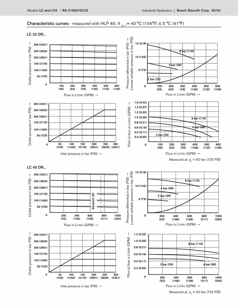
300 (4351)
250 (3626)
200 (2901)
150 (2176)
100 (1450)
50 (725)
0100
(26)
200
(53)
300
(79)
400
(106)
500
(132)
600
(159)
0
300 (4351)
200 (2901)
250 (3626)
150 (2176)
100 (1450)
50 (725)
50
(725)
100
(1450)
150
(2176)
200
(2901)
250
(3626)
300
(4351)
0
15 (218)
10 (145)
5 (73)
100
(26)
200
(53)
300
(79)
400
(106)
500
(132)
600
(159)
8 bar (116)
4 bar (58)
2 bar (29)
8 bar (116)
4 bar (58)
2 bar (29)
0
0.4 (0.11)
0.2 (0.05)
0.8 (0.21)
0.6 (0.16)
1.2 (0.32)
1.0 (0.26)
1.6 (0.42)
1.4 (0.37)
100
(26)
200
(53)
300
(79)
400
(106)
500
(132)
600
(159)
300 (4351)
250 (3626)
200 (2901)
150 (2176)
100 (1450)
50 (725)
0 50
(725)
100
(1450)
150
(2175)
200
(2901)
250
(3626)
300
(4351)
200
(53)
400
(106)
600
(159)
800
(211)
1000
(264)
300 (4351)
250 (3626)
200 (2901)
150 (2176)
100 (1450)
50 (725)
0 0
15 (218)
10 (145)
5 (73)
200
(53)
400
(106)
600
(159)
800
(211)
1000
(264)
8 bar (116)
4 bar (58)
2 bar (29)
8 bar (116)
4 bar (58)2 bar (29)
0
0.4 (0.11)
0.2 (0.05)
0.8 (0.21)
0.6 (0.16)
1.2 (0.32)
1.0 (0.26)
200
(53)
400
(106)
600
(159)
800
(211)
1000
(264)
Characteristic curves - measured with HLP 46; ϑ oil -/
= 40 °C (104°F) ± 5 °C (41°F)
LC 32 DR...
LC 40 DR...
Ve
rsio
n 2
0Flow in L/min (GPM) → Flow in L/min (GPM) →
Outlet
pre
ssure
in b
ar
PS
I) →
Pre
ssure
diffe
rential in
bar
(PS
I) →
Low
est
sett
ab
le p
ressure
in b
ar
(PS
I)
Inlet pressure in bar (PSI) →
Pilo
t oil
fl ow
in L
/min
(G
PM
) →
Measured at: pa = 50 bar (725 PSI)
Outlet
pre
ssure
in b
ar
PS
I) →
Outlet
pre
ssure
in b
ar
PS
I) →
Outlet
pre
ssure
in b
ar
PS
I) →
Pre
ssure
diffe
rential in
bar
(PS
I) →
Low
est
sett
ab
le p
ressure
in b
ar
(PS
I)
Flow in L/min (GPM) →
Flow in L/min (GPM) → Flow in L/min (GPM) →
Inlet pressure in bar (PSI) →
Measured at: pa = 50 bar (725 PSI)
Flow in L/min (GPM) →
Pilo
t oil
fl ow
in L
/min
(G
PM
) →
Models LC and LFA RA 21050/02.03 Industrial Hydraulics | Bosch Rexroth Corp. 45/68
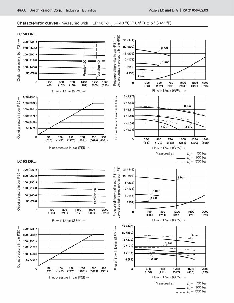
0
300 (4351)
200 (2901)
250 (3626)
150 (2176)
100 (1450)
50 (725)
50
(725)
100
(1450)
150
(2176)
200
(2901)
250
(3626)
300
(4351)
0
300 (4351)
200 (2901)
250 (3626)
150 (2176)
100 (1450)
50 (725)
50
(725)
100
(1450)
150
(2176)
200
(2901)
250
(3626)
300
(4351)
0
300 (4351)
200 (2901)
250 (3626)
150 (2176)
100 (1450)
50 (725)
250
(66)
500
(132)
750
(198)
1000
(264)
1250
(330)
1500
(396)
8 bar
4 bar
2 bar
0
24 (348)
16 (232)
20 (290)
12 (174)
8 (116)
4 (58)
250
(66)
500
(132)
750
(198)
1000
(264)
1250
(330)
1500
(396)
400
(106)
800
(211)
1200
(317)
1600
(423)
2000
(528)0
300 (4351)
200 (2901)
250 (3626)
150 (2176)
100 (1450)
50 (725)
8 bar
4 bar
2 bar
0
24 (348)
16 (232)
20 (290)
12 (174)
8 (116)
4 (58)
400
(106)
800
(211)
1200
(317)
1600
(423)
2000
(528)
8 bar
4 bar
2 bar
0
24 (348)
16 (232)
20 (290)
12 (174)
8 (116)
4 (58)
400
(106)
800
(211)
1200
(317)
1600
(423)
2000
(528)
Characteristic curves - measured with HLP 46; ϑ oil -/
= 40 °C (104°F) ± 5 °C (41°F)
LC 50 DR...
LC 63 DR...
Ve
rsio
n 4
0
Ve
rsio
n 2
0
Ve
rsio
n 2
0
Measured at: pa = 50 bar
pe = 100 bar
pe = 350 bar
8 bar
4 bar2 bar
0
12 (3.17)
8 (2.11)
10 (2.64)
6 (1.59)
4 (1.06)
2 (0.53)
250
(66)
500
(132)
750
(198)
1000
(264)
1250
(330)
1500
(396)
Flow in L/min (GPM) → Flow in L/min (GPM) →
Outlet
pre
ssure
in b
ar
PS
I) →
Pre
ssure
diffe
rential in
bar
(PS
I) →
Low
est
sett
ab
le p
ressure
in b
ar
(PS
I)
Inlet pressure in bar (PSI) →
Pilo
t oil
fl ow
in L
/min
(G
PM
) →
Outlet
pre
ssure
in b
ar
PS
I) →
Outlet
pre
ssure
in b
ar
PS
I) →
Outlet
pre
ssure
in b
ar
PS
I) →
Pre
ssure
diffe
rential in
bar
(PS
I) →
Low
est
sett
ab
le p
ressure
in b
ar
(PS
I)
Flow in L/min (GPM) →
Flow in L/min (GPM) → Flow in L/min (GPM) →
Inlet pressure in bar (PSI) → Flow in L/min (GPM) →
Pilo
t oil
fl ow
in L
/min
(G
PM
) →
Measured at: pa = 50 bar
pe = 100 bar
pe = 350 bar
46/68 Bosch Rexroth Corp. | Industrial Hydraulics Models LC and LFA RA 21050/02.03
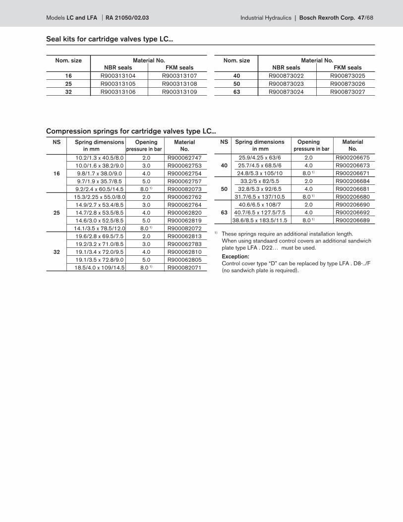
Seal kits for cartridge valves type LC...
Nom. size Material No.
NBR seals FKM seals
16 R900313104 R900313107
25 R900313105 R900313108
32 R900313106 R900313109
Nom. size Material No.
NBR seals FKM seals
40 R900873022 R900873025
50 R900873023 R900873026
63 R900873024 R900873027
Compression springs for cartridge valves type LC...
NS Spring dimensions Opening Material
in mm pressure in bar No.
10.2/1.3 x 40.5/8.0 2.0 R900062747
10.0/1.6 x 38.2/9.0 3.0 R900062753
16 9.8/1.7 x 38.0/9.0 4.0 R900062754
9.7/1.9 x 35.7/8.5 5.0 R900062757
9.2/2.4 x 60.5/14.5 8.0 1) R900082073
15.3/2.25 x 55.0/8.0 2.0 R900062762
14.9/2.7 x 53.4/8.5 3.0 R900062764
25 14.7/2.8 x 53.5/8.5 4.0 R900062820
14.6/3.0 x 52.5/8.5 5.0 R900062819
14.1/3.5 x 78.5/12.0 8.0 1) R900082072
19.6/2.8 x 69.5/7.5 2.0 R900062813
19.2/3.2 x 71.0/8.5 3.0 R900062783
32 19.1/3.4 x 72.0/9.5 4.0 R900062810
19.1/3.5 x 72.8/9.0 5.0 R900062805
18.5/4.0 x 109/14.5 8.0 1) R900082071
NS Spring dimensions Opening Material
in mm pressure in bar No.
25.9/4.25 x 63/6 2.0 R900206675
40 25.7/4.5 x 68.5/6 4.0 R900206673
24.8/5.3 x 105/10 8.0 1) R900206671
33.2/5 x 82/5.5 2.0 R900206684
50 32.8/5.3 x 92/6.5 4.0 R900206681
31.7/6.5 x 137/10.5 8.0 1) R900206680
40.6/6.5 x 108/7 2.0 R900206690
63 40.7/6.5 x 127.5/7.5 4.0 R900206692
38.6/8.5 x 183.5/11.5 8.0 1) R900206689
1) These springs require an additional installation length.
When using standaard control covers an additional sandwich
plate type LFA . D22… must be used.
Exception:
Control cover type “D” can be replaced by type LFA . D8-../F
(no sandwich plate is required).
Models LC and LFA RA 21050/02.03 Industrial Hydraulics | Bosch Rexroth Corp. 47/68
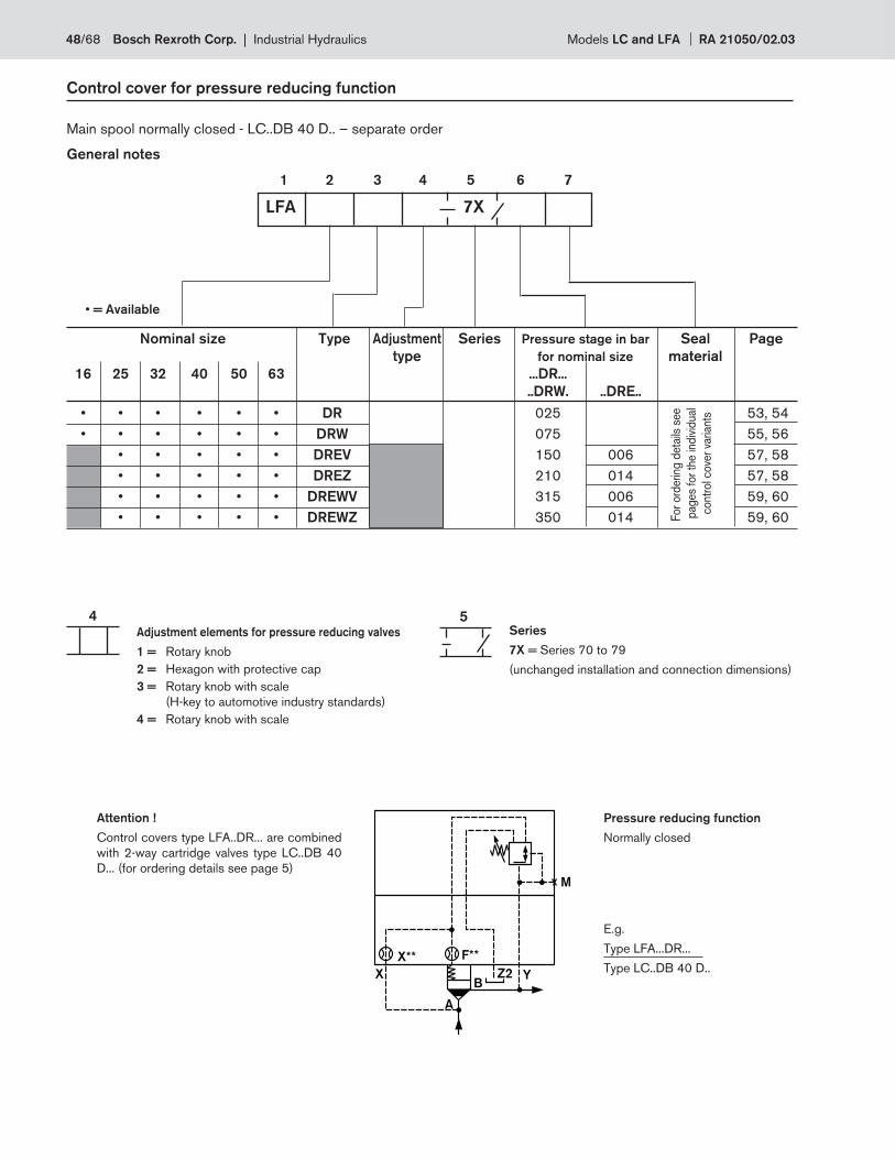
X Y
X** F**
M
A
BZ2
54
Control cover for pressure reducing function
1 2 3 4 5 6 7
Nominal size Type Adjustment Series Pressure stage in bar Seal Page
type for nominal size material
16 25 32 40 50 63 ...DR...
..DRW. ..DRE..
• • • • • • DR 025 53, 54
• • • • • • DRW 075 55, 56
• • • • • DREV 150 006 57, 58
• • • • • DREZ 210 014 57, 58
• • • • • DREWV 315 006 59, 60
• • • • • DREWZ 350 014 59, 60For
ord
erin
g d
eta
ils s
ee
pag
es
for
the in
div
idual
contr
ol c
ove
r va
riants
Adjustment elements for pressure reducing valves
1 = Rotary knob
2 = Hexagon with protective cap
3 = Rotary knob with scale
(H-key to automotive industry standards)
4 = Rotary knob with scale
Series
7X = Series 70 to 79
(unchanged installation and connection dimensions)
Main spool normally closed - LC..DB 40 D.. – separate order
LFA 7X
• = Available
General notes
Pressure reducing function
Normally closed
Attention !
Control covers type LFA..DR... are combined
with 2-way cartridge valves type LC..DB 40
D... (for ordering details see page 5)
E.g.
Type LFA...DR...
Type LC..DB 40 D..
48/68 Bosch Rexroth Corp. | Industrial Hydraulics Models LC and LFA RA 21050/02.03
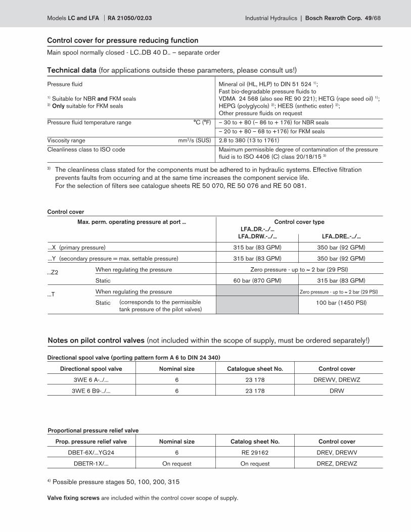
Control cover for pressure reducing function
Main spool normally closed - LC..DB 40 D.. – separate order
Technical data (for applications outside these parameters, please consult us!)
Control cover
Notes on pilot control valves (not included within the scope of supply, must be ordered separately!)
Pressure fl uid Mineral oil (HL, HLP) to DIN 51 524 1);
Fast bio-degradable pressure fl uids to 1) Suitable for NBR and FKM seals VDMA 24 568 (also see RE 90 221); HETG (rape seed oil) 1); 2) Only suitable for FKM seals HEPG (polyglycols) 2); HEES (snthetic ester) 2);
Other pressure fl uids on request
Pressure fl uid temperature range °C (°F) – 30 to + 80 (– 86 to + 176) for NBR seals
– 20 to + 80 – 68 to +176) for FKM seals
Viscosity range mm2/s (SUS) 2.8 to 380 (13 to 1761)
Cleanliness class to ISO code Maximum permissible degree of contamination of the pressure
fl uid is to ISO 4406 (C) class 20/18/15 3)
Max. perm. operating pressure at port ... Control cover type
LFA..DR.-../...
LFA..DRW.-../... LFA..DRE..-../...
...X (primary pressure) 315 bar (83 GPM) 350 bar (92 GPM)
...Y (secondary pressure = max. settable pressure) 315 bar (83 GPM) 350 bar (92 GPM)
When regulating the pressure Zero pressure - up to ≈ 2 bar (29 PSI)
Static 60 bar (870 GPM) 315 bar (83 GPM)
When regulating the pressure Zero pressure - up to ≈ 2 bar (29 PSI)
Static 100 bar (1450 PSI)(corresponds to the permissible
tank pressure of the pilot valves)
...Z2
...T
Directional spool valve (porting pattern form A 6 to DIN 24 340)
Proportional pressure relief valve
Valve fi xing screws are included within the control cover scope of supply.
4) Possible pressure stages 50, 100, 200, 315
Directional spool valve Nominal size Catalogue sheet No. Control cover
3WE 6 A-../... 6 23 178 DREWV, DREWZ
3WE 6 B9-../... 6 23 178 DRW
Prop. pressure relief valve Nominal size Catalog sheet No. Control cover
DBET-6X/...YG24 6 RE 29162 DREV, DREWV
DBETR-1X/... On request On request DREZ, DREWZ
3) The cleanliness class stated for the components must be adhered to in hydraulic systems. Effective fi ltration
prevents faults from occurring and at the same time increases the component service life.
For the selection of fi lters see catalogue sheets RE 50 070, RE 50 076 and RE 50 081.
Models LC and LFA RA 21050/02.03 Industrial Hydraulics | Bosch Rexroth Corp. 49/68
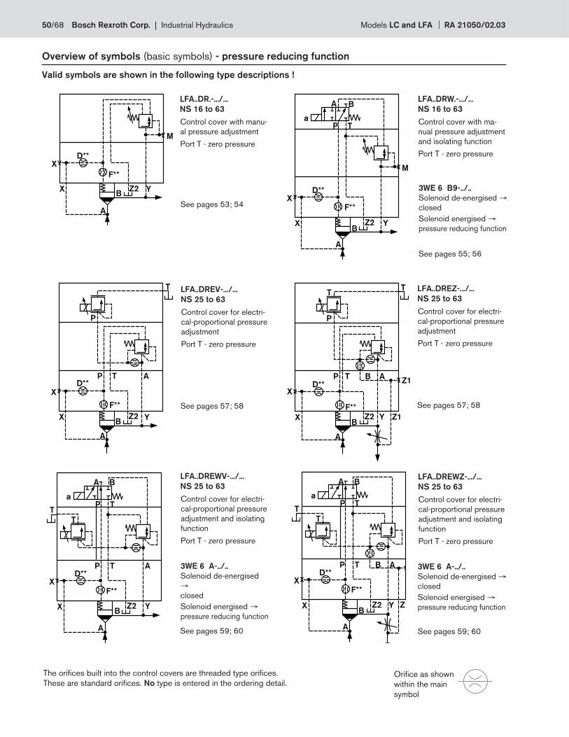
D**
F**
X
X
A
BZ2 Y
M
D**
F**
X
X
A
BZ2 Y
T
P
P T AD**
F**
X
X
A
BZ2 Y
T
P
P T ABZ1
Z1
T
D**
F**X
X
A
BZ2 Y
TP
P T AB
Z1
T
A B
a
T
D**
F**
X
X
A
BZ2 Y
TP
P T A
T
A B
a
T
D**
F**X
X
A
BZ2 Y
P T
A B
a
M
Overview of symbols (basic symbols) - pressure reducing function
Valid symbols are shown in the following type descriptions !
The orifi ces built into the control covers are threaded type orifi ces.
These are standard orifi ces. No type is entered in the ordering detail. Orifi ce as shown
within the main
symbol
LFA..DREWV-.../...
NS 25 to 63
Control cover for electri-
cal-proportional pressure
adjustment and isolating
function
Port T - zero pressure
See pages 59; 60
LFA..DREWZ-.../...
NS 25 to 63
Control cover for electri-
cal-proportional pressure
adjustment and isolating
function
Port T - zero pressure
See pages 59; 60
LFA..DREV-.../...
NS 25 to 63
Control cover for electri-
cal-proportional pressure
adjustment
Port T - zero pressure
See pages 57; 58
LFA..DREZ-.../...
NS 25 to 63
Control cover for electri-
cal-proportional pressure
adjustment
Port T - zero pressure
See pages 57; 58
LFA..DR.-.../...
NS 16 to 63
Control cover with manu-
al pressure adjustment
Port T - zero pressure
See pages 53; 54
LFA..DRW.-.../...
NS 16 to 63
Control cover with ma-
nual pressure adjustment
and isolating function
Port T - zero pressure
3WE 6 B9-../..
Solenoid de-energised →closed
Solenoid energised →pressure reducing function
See pages 55; 56
3WE 6 A-../..
Solenoid de-energised
→closed
Solenoid energised →pressure reducing function
3WE 6 A-../..
Solenoid de-energised →closed
Solenoid energised →pressure reducing function
50/68 Bosch Rexroth Corp. | Industrial Hydraulics Models LC and LFA RA 21050/02.03
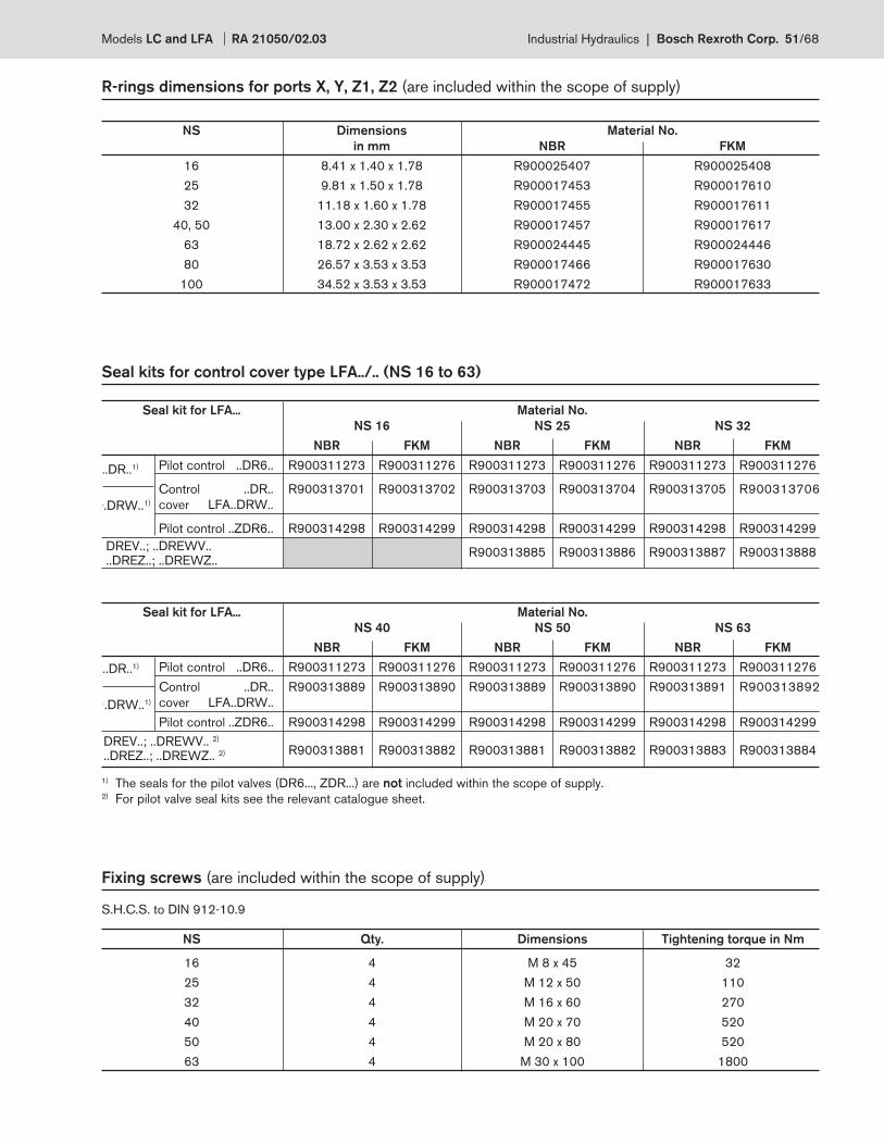
R-rings dimensions for ports X, Y, Z1, Z2 (are included within the scope of supply)
NS Dimensions Material No.
in mm NBR FKM
16 8.41 x 1.40 x 1.78 R900025407 R900025408
25 9.81 x 1.50 x 1.78 R900017453 R900017610
32 11.18 x 1.60 x 1.78 R900017455 R900017611
40, 50 13.00 x 2.30 x 2.62 R900017457 R900017617
63 18.72 x 2.62 x 2.62 R900024445 R900024446
80 26.57 x 3.53 x 3.53 R900017466 R900017630
100 34.52 x 3.53 x 3.53 R900017472 R900017633
Seal kits for control cover type LFA../.. (NS 16 to 63)
Fixing screws (are included within the scope of supply)
S.H.C.S. to DIN 912-10.9
NS Qty. Dimensions Tightening torque in Nm
16 4 M 8 x 45 32
25 4 M 12 x 50 110
32 4 M 16 x 60 270
40 4 M 20 x 70 520
50 4 M 20 x 80 520
63 4 M 30 x 100 1800
1) The seals for the pilot valves (DR6..., ZDR...) are not included within the scope of supply.2) For pilot valve seal kits see the relevant catalogue sheet.
Seal kit for LFA... Material No.
NS 16 NS 25 NS 32
NBR FKM NBR FKM NBR FKM
Pilot control ..DR6.. R900311273 R900311276 R900311273 R900311276 R900311273 R900311276
Control ..DR.. R900313701 R900313702 R900313703 R900313704 R900313705 R900313706
cover LFA..DRW..
Pilot control ..ZDR6.. R900314298 R900314299 R900314298 R900314299 R900314298 R900314299
R900313885 R900313886 R900313887 R900313888DREV..; ..DREWV....DREZ..; ..DREWZ..
Seal kit for LFA... Material No.
NS 40 NS 50 NS 63
NBR FKM NBR FKM NBR FKM
Pilot control ..DR6.. R900311273 R900311276 R900311273 R900311276 R900311273 R900311276
Control ..DR.. R900313889 R900313890 R900313889 R900313890 R900313891 R900313892
cover LFA..DRW..
Pilot control ..ZDR6.. R900314298 R900314299 R900314298 R900314299 R900314298 R900314299
R900313881 R900313882 R900313881 R900313882 R900313883 R900313884DREV..; ..DREWV.. 2)
..DREZ..; ..DREWZ.. 2)
..DR..1)
..DRW..1)
..DR..1)
..DRW..1)
Models LC and LFA RA 21050/02.03 Industrial Hydraulics | Bosch Rexroth Corp. 51/68
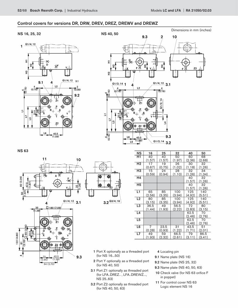
H2
H1
H3
D
XF
Y
4
X Y
L7
L1
L3
1
B A
P
T
L6
9.2
L2
3.1G1/4; 12
Z1
Z2
G1/4; 12
9.1
4
(0.1
6)
32
.5
(1.2
8)
4
(0.16)
40.5
(1.59)
2
(0.08)
Y
H2
H1
H3
D
X F
4
X Y
L7
L1
L3
9.3
B A
P
T
L6
L2
3.1G1/4; 12
Z1
Z2
3.2G1/2; 14
1G1/2; 14
L4
G1
/2
; 1
4
2
H4
H5
L5
9.3
F Z2
10
40.5
(1.59)
32
.5
(1.2
8)
4
(0.1
6)
4
(0.1
6)
4
(0.16)
4
(0.16)
Y
D
X
F
4
X Y
11
BA
P
T
3.1G1/4; 12
Z1
Z2
4
10
A
9.3
D F
3.2G3/4; 16
Z2
40.5
(1.59)75
(2.95)
32
.5
(1.2
8)
50
(1.9
7)
32
(1.2
6)
35
(1.38)
47
.5
(1.8
7)
82
(3
.29
)
180 (7.09)
81
(3.1
9)
94 (3.70)
65
(2
.56
)
12
2 (
4.8
0)
NS 16, 25, 32
Control covers for versions DR, DRW, DREV, DREZ, DREWV and DREWZ
NS 40, 50
NS 63 NS 16 25 32 40 50 H1 40 40 50 60 68 (1.57) (1.57) (1.97) (2.36) (2.68) H2 17 19 26 30 32 (0.67) (0.75) (1.02) (1.18) (1.26) H3 15 24 28 32 34 (0.59) (0.94) (1.10) (1.26) (1.34) H4 40 32 (1.57) (1.26) H5 40 32 (1.57) (1.26) L1 65 85 100 125 140 (2.56) (3.35) (3.94) (4.92) (5.51) L2 80 85 100 125 140 (3.15) (3.35) (3.94) (4.92) (5.51) L3 36.5 49 56.5 72 80 (1.44) (1.93) (2.22) (2.83) (3.15) L4 62.5 70 (2.46) (2.76) L5 62.5 70 (2.46) (2.76) L6 7 23.5 31 43.5 51 (0.28) (0.93) (1.22) (1.71) (2.01) L7 49 59 66.5 79 86.5 (1.93) (2.32) (2.61) (3.11) (3.41)
1 Port X optionally as a threaded port
(for NS 16...50)
2 Port Y optionally as a threaded port
(for NS 40, 50)
3.1 Port Z1 optionally as threaded port
(for LFA..DREZ.. , LFA..DREWZ...,
NS 25..63)
3.2 Port Z2 optionally as threaded port
(for NS 40, 50, 63)
4 Locating pin
9.1 Name plate (NS 16)
9.2 Name plate (NS 25, 32)
9.3 Name plate (NS 40, 50, 63)
10 Check valve (for NS 63 orifi ce F
in poppet)
11 For control cover NS 63
Logic element NS 16
Dimensions in mm (inches)
52/68 Bosch Rexroth Corp. | Industrial Hydraulics Models LC and LFA RA 21050/02.03
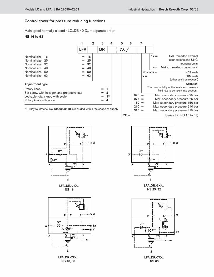
X
A
D**
X**
YZ2B
M
X
ATP
D**
X
F**
A
YZ2B
M
X
ATP
D**
F**
Z2
Y
X
A
YZ2B
M
X
ATP
D**
F**Z2
A**
A
YZ2B
M
X
ATP
Control cover for pressure reducing functions
Main spool normally closed - LC..DB 40 D.. – separate order
NS 16 to 63
Nominal size 16 = 16
Nominal size 25 = 25
Nominal size 32 = 32
Nominal size 40 = 40
Nominal size 50 = 50
Nominal size 63 = 63
1 2 3 4 5 6 7
No code = NBR seals
V = FKM seals
(other seals on request)
Attention!
The compatibility of the seals and pressure
fl uid has to be taken into account!
LFA DR 7X
LFA..DR.-7X/...
NS 40, 50
LFA..DR.-7X/...
NS 25, 32
LFA..DR.-7X/...
NS 16
LFA..DR.-7X/...
NS 63
025 = Max. secondary pressure 25 bar
075 = Max. secondary pressure 75 bar
150 = Max. secondary pressure 150 bar
210 = Max. secondary pressure 210 bar
315 = Max. secondary pressure 315 bar
7X = Series 7X (NS 16 to 63)
1) H-key to Material No. R900008158 is included within the scope of supply
Adjustment type
Rotary knob = 1
Set screw with hexagon and protective cap = 2
Lockable rotary knob with scale = 31)
Rotary knob with scale = 4
12 = SAE threaded external
connections and UNC
mounting bolts
– = Metric threaded connections
Models LC and LFA RA 21050/02.03 Industrial Hydraulics | Bosch Rexroth Corp. 53/68
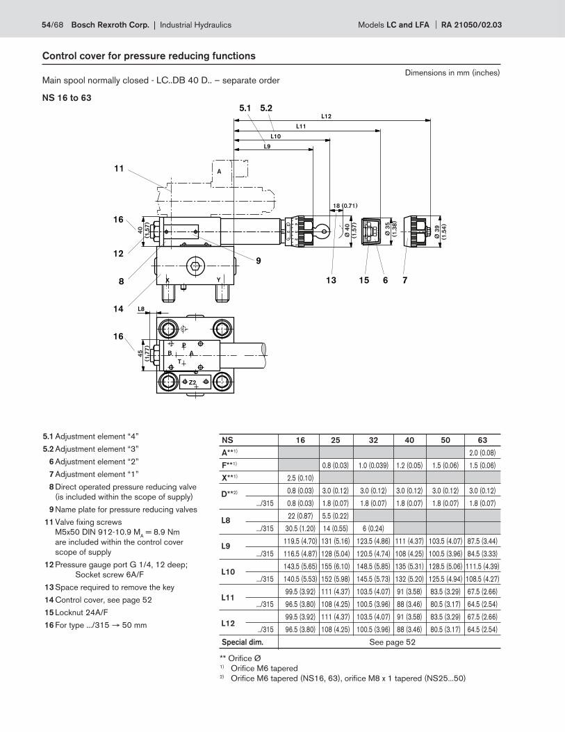
Control cover for pressure reducing functions
Main spool normally closed - LC..DB 40 D.. – separate order
NS 16 to 63
5.1 Adjustment element “4”
5.2 Adjustment element “3”
6 Adjustment element “2”
7 Adjustment element “1”
8 Direct operated pressure reducing valve
(is included within the scope of supply)
9 Name plate for pressure reducing valves
11 Valve fi xing screws
M5x50 DIN 912-10.9 MA = 8.9 Nm
are included within the control cover
scope of supply
12 Pressure gauge port G 1/4, 12 deep;
Socket screw 6A/F
13 Space required to remove the key
14 Control cover, see page 52
15 Locknut 24A/F
16 For type .../315 → 50 mm
L8
L9
L10
L11
L12
D**2)
** Orifi ce Ø1) Orifi ce M6 tapered 2) Orifi ce M6 tapered (NS16, 63), orifi ce M8 x 1 tapered (NS25...50)
NS 16 25 32 40 50 63
A**1) 2.0 (0.08)
F**1) 0.8 (0.03) 1.0 (0.039) 1.2 (0.05) 1.5 (0.06) 1.5 (0.06)
X**1) 2.5 (0.10)
0.8 (0.03) 3.0 (0.12) 3.0 (0.12) 3.0 (0.12) 3.0 (0.12) 3.0 (0.12)
.../315 0.8 (0.03) 1.8 (0.07) 1.8 (0.07) 1.8 (0.07) 1.8 (0.07) 1.8 (0.07)
22 (0.87) 5.5 (0.22)
.../315 30.5 (1.20) 14 (0.55) 6 (0.24)
119.5 (4.70) 131 (5.16) 123.5 (4.86) 111 (4.37) 103.5 (4.07) 87.5 (3.44)
.../315 116.5 (4.87) 128 (5.04) 120.5 (4.74) 108 (4.25) 100.5 (3.96) 84.5 (3.33)
143.5 (5.65) 155 (6.10) 148.5 (5.85) 135 (5.31) 128.5 (5.06) 111.5 (4.39)
.../315 140.5 (5.53) 152 (5.98) 145.5 (5.73) 132 (5.20) 125.5 (4.94) 108.5 (4.27)
99.5 (3.92) 111 (4.37) 103.5 (4.07) 91 (3.58) 83.5 (3.29) 67.5 (2.66)
.../315 96.5 (3.80) 108 (4.25) 100.5 (3.96) 88 (3.46) 80.5 (3.17) 64.5 (2.54)
99.5 (3.92) 111 (4.37) 103.5 (4.07) 91 (3.58) 83.5 (3.29) 67.5 (2.66)
../315 96.5 (3.80) 108 (4.25) 100.5 (3.96) 88 (3.46) 80.5 (3.17) 64.5 (2.54)
Special dim. See page 52
Dimensions in mm (inches)
54/68 Bosch Rexroth Corp. | Industrial Hydraulics Models LC and LFA RA 21050/02.03
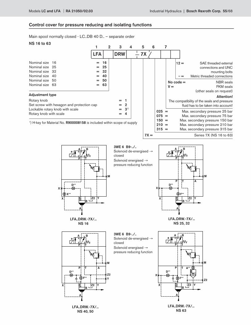
X
A
D**
X**
YZ2B
M
X
A B
P T
a
Z2
Y
P T A
F**
A
D**
YZ2B
M
X
A B
P T
a
Z2
A**
F**X
A
D**
YZ2B
M
X
A B
P T
a
P T
F**
X
A
D**
YZ2B
M
X
A B
P T
a
P T A
Control cover for pressure reducing and isolating functions
Main spool normally closed - LC..DB 40 D.. – separate order
NS 16 to 63
Nominal size 16 = 16
Nominal size 25 = 25
Nominal size 32 = 32
Nominal size 40 = 40
Nominal size 50 = 50
Nominal size 63 = 63
1 2 3 4 5 6 7
No code = NBR seals
V = FKM seals
(other seals on request)
Attention!
The compatibility of the seals and pressure
fl uid has to be taken into account!
LFA DRW 7X
LFA..DRW.-7X/...
NS 40, 50
LFA..DRW.-7X/...
NS 25, 32
LFA..DRW.-7X/...
NS 16
LFA..DRW.-7X/...
NS 63
Adjustment type
Rotary knob = 1
Set screw with hexagon and protection cap = 2
Lockable rotary knob with scale = 31)
Rotary knob with scale = 4 025 = Max. secondary pressure 25 bar
075 = Max. secondary pressure 75 bar
150 = Max. secondary pressure 150 bar
210 = Max. secondary pressure 210 bar
315 = Max. secondary pressure 315 bar
7X = Series 7X (NS 16 to 63)
1) H-key for Material No. R900008158 is included within scope of supply
3WE 6 B9-../..
Solenoid de-energised →closed
Solenoid energised →pressure reducing function
3WE 6 B9-../..
Solenoid de-energised →closed
Solenoid energised →pressure reducing function
12 = SAE threaded external
connections and UNC
mounting bolts
– = Metric threaded connections
Models LC and LFA RA 21050/02.03 Industrial Hydraulics | Bosch Rexroth Corp. 55/68
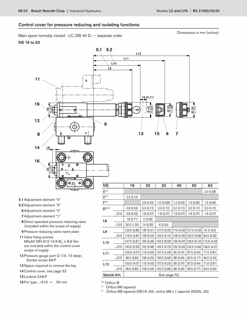
Control cover for pressure reducing and isolating functions
Main spool normally closed - LC..DB 40 D.. – separate order
NS 16 to 63
L8
L9
L10
L11
L12
D**2)
** Orifi ce Ø1) Orifi ce M6 tapered2) Orifi ce M6 tapered (NS16, 63), orifi ce M8 x 1 tapered (NS25...50)
5.1 Adjustment element “4”
5.2 Adjustment element “3”
6 Adjustment element “2”
7 Adjustment element “1”
8 Direct operated pressure reducing valve
(included within the scope of supply)
9 Pressure reducing valve name plate
11 Valve fi xing screws
M5x50 DIN 912-10.9 MA = 8.9 Nm
are included within the control cover
scope of supply
12 Pressure gauge port G 1/4, 12 deep;
Socket screw 6A/F
13 Space required to remove the key
14 Control cover, see page 52
15 Locknut 24A/F
16 For type .../315 → 50 mm
NS 16 25 32 40 50 63
A**1) 2.0 (0.08)
X**1) 2.5 (0.10)
F**1) 0.8 (0.03) 1.0 (0.039) 1.2 (0.05) 1.5 (0.06) 1.5 (0.06)
0.8 (0.03) 3.0 (0.12) 3.0 (0.12) 3.0 (0.12) 3.0 (0.12) 3.0 (0.12)
.../315 0.8 (0.03) 1.8 (0.07) 1.8 (0.07) 1.8 (0.07) 1.8 (0.07) 1.8 (0.07)
18 (0.71) 2 (0.08)
.../315 30.5 (1.20) 14 (0.55) 6 (0.24)
123.5 (4.86) 135 (5.31) 127.5 (5.02) 115 (4.53) 107.5 (4.23) 91.5 (3.6)
.../315 116.5 (4.87) 128 (5.04) 120.5 (4.74) 108 (4.25) 100.5 (3.96) 84.5 (3.33)
147.5 (5.81) 159 (6.26) 152.5 (6.00) 139 (5.47) 129.5 (5.10) 112.5 (4.43)
.../315 140.5 (5.53) 152 (5.98) 145.5 (5.73) 132 (5.20) 125.5 (4.94) 108.5 (4.27)
103.5 (4.07) 115 (4.53) 107.5 (4.23) 95 (3.74) 87.5 (3.44) 71.5 (2.81)
.../315 96.5 (3.80) 108 (4.25) 100.5 (3.96) 88 (3.46) 80.5 (3.17) 64.5 (2.54)
103.5 (4.07) 115 (4.53) 107.5 (4.23) 95 (3.74) 87.5 (3.44) 71.5 (2.81)
../315 96.5 (3.80) 108 (4.25) 100.5 (3.96) 88 (3.46) 80.5 (3.17) 64.5 (2.54)
Special dim. See page 52
Dimensions in mm (inches)
56/68 Bosch Rexroth Corp. | Industrial Hydraulics Models LC and LFA RA 21050/02.03
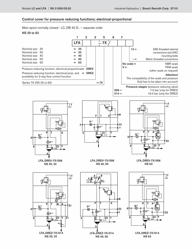
D**
F**
X
X
A
BZ2 Y
T
P T A
D**
F**
Z2
Y
X
A
YZ2B
M
X
ATP
D**
F**
X
X
A
BZ2 Y
T
P T A**
Z2
D**
F**
X
X
A
BZ2 Y
T
P T ABZ1
Z1
D**
F**
X
X
A
BZ2 Y
T
P T A**
Z2
Z2
Y
P T A
F**
A
D**
YZ2B
M
X
A B
P T
a
Control cover for pressure reducing functions; electrical-proportional
Main spool normally closed - LC..DB 40 D.. – separate order
NS 25 to 63
1 2 3 5 6 7
Series 7X (NS 25 to 63) = 7X
Pressure stages (pressure reducing valve)
006 = 7.0 bar (only for DREV)
014 = 16.0 bar (only fl or DREZ)
Nominal size 25 = 25
Nominal size 32 = 32
Nominal size 40 = 40
Nominal size 50 = 50
Nominal size 63 = 63 No code = NBR seals
V = FKM seals
(other seals on request)
Attention!
The compatibility of the seals and pressure
fl uid has to be taken into account!
LFA 7X
Pressure reducing function; electrical-proportional = DREV
Pressure reducing function; electrical-prop. and = DREZ
possibility for 2-way fl ow control function
LFA..DREV-7X/006
NS 63
LFA..DREV-7X/006
NS 40, 50
LFA..DREV-7X/006
NS 25, 32
LFA..DREZ-7X/014
NS 25, 32
LFA..DREZ-7X/014
NS 40, 50
LFA..DREZ-7X/014
NS 63
12 = SAE threaded external
connections and UNC
mounting bolts
– = Metric threaded connections
Models LC and LFA RA 21050/02.03 Industrial Hydraulics | Bosch Rexroth Corp. 57/68
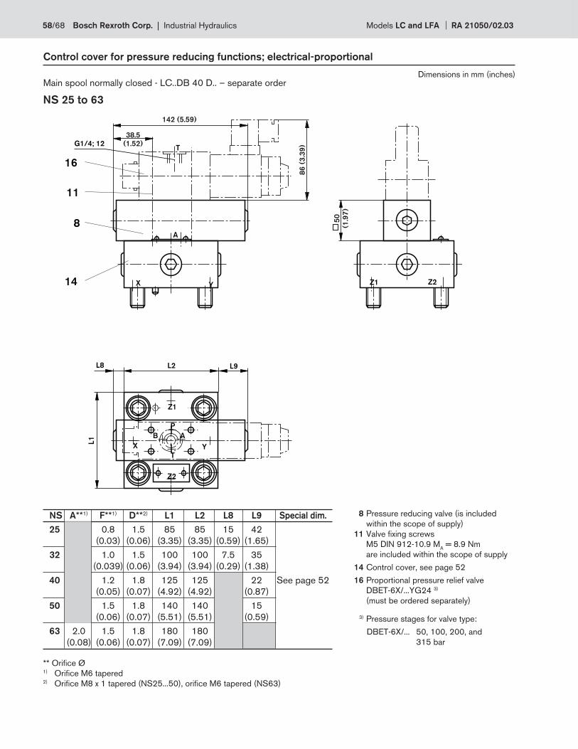
NS A**1) F**1) D**2) L1 L2 L8 L9 Special dim.
25 0.8 1.5 85 85 15 42
(0.03) (0.06) (3.35) (3.35) (0.59) (1.65)
32 1.0 1.5 100 100 7.5 35
(0.039) (0.06) (3.94) (3.94) (0.29) (1.38)
40 1.2 1.8 125 125 22 See page 52
(0.05) (0.07) (4.92) (4.92) (0.87)
50 1.5 1.8 140 140 15
(0.06) (0.07) (5.51) (5.51) (0.59)
63 2.0 1.5 1.8 180 180
(0.08) (0.06) (0.07) (7.09) (7.09)
YX
X Y
B A
P
T
L2
Z1
Z2
Z2
16
Z1
L8
L1
A
TG1/4; 12
11
14
8
L9
38.5
(1.52)
86
(3
.39
)
50
(1.9
7)
142 (5.59)
Control cover for pressure reducing functions; electrical-proportional
Main spool normally closed - LC..DB 40 D.. – separate order
NS 25 to 63
8 Pressure reducing valve (is included
within the scope of supply)
11 Valve fi xing screws
M5 DIN 912-10.9 MA = 8.9 Nm
are included within the scope of supply
14 Control cover, see page 52
16 Proportional pressure relief valve
DBET-6X/...YG24 3)
(must be ordered separately)
3) Pressure stages for valve type:
DBET-6X/... 50, 100, 200, and
315 bar
** Orifi ce Ø1) Orifi ce M6 tapered 2) Orifi ce M8 x 1 tapered (NS25...50), orifi ce M6 tapered (NS63)
Dimensions in mm (inches)
58/68 Bosch Rexroth Corp. | Industrial Hydraulics Models LC and LFA RA 21050/02.03
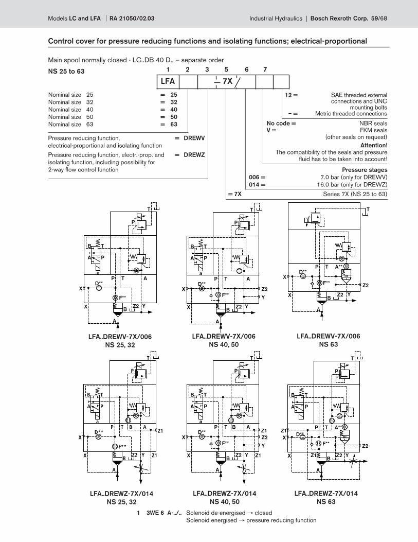
Control cover for pressure reducing functions and isolating functions; electrical-proportional
Main spool normally closed - LC..DB 40 D.. – separate order
NS 25 to 63 1 2 3 5 6 7
= 7X Series 7X (NS 25 to 63)
Pressure stages
006 = 7.0 bar (only for DREWV)
014 = 16.0 bar (only for DREWZ)
Nominal size 25 = 25
Nominal size 32 = 32
Nominal size 40 = 40
Nominal size 50 = 50
Nominal size 63 = 63 No code = NBR seals V = FKM seals
(other seals on request)
Attention!
The compatibility of the seals and pressure fl uid has to be taken into account!
LFA 7X
Pressure reducing function, = DREWV
electrical-proportional and isolating function
Pressure reducing function, electr.-prop. and = DREWZ
isolating function, including possibility for
2-way fl ow control function
D**
F**
X
X
A
BZ2 Y
P T A
A
B
a
P
T
P
T
D**
F**
X
X
A
BZ2
P T A
Z2
Y
Y
A
B
a
P
T
P
T
D**
F**
X
X
A
BZ2 Y
T
P T A**
Z2
D**
F**
X
X
A
BZ2 Y
P T A
A
B
a
P
T
P
T
Z1
Z1
BD**
F**
X
X
A
BZ2
P T A
Z2
Y
Y
A
B
a
P
T
P
T
Z1
Z1
B
D**
F**
X
X
A
BZ2 Y
P T A**
Z2
A
B
P
T
P
T
Z1
Z1
LFA..DREWV-7X/006
NS 25, 32
LFA..DREWV-7X/006
NS 40, 50
LFA..DREWV-7X/006
NS 63
LFA..DREWZ-7X/014
NS 63
LFA..DREWZ-7X/014
NS 40, 50
LFA..DREWZ-7X/014
NS 25, 32
1 3WE 6 A-../.. Solenoid de-energised → closed
Solenoid energised → pressure reducing function
12 = SAE threaded external connections and UNC mounting bolts – = Metric threaded connections
Models LC and LFA RA 21050/02.03 Industrial Hydraulics | Bosch Rexroth Corp. 59/68
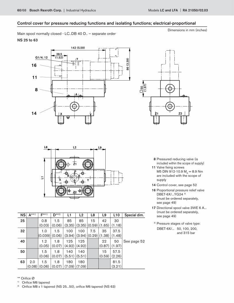
NS A**1) F**1) D**2) L1 L2 L8 L9 L10 Special dim.
25 0.8 1.5 85 85 15 42 30
(0.03) (0.06) (3.35) (3.35) (0.59) (1.65) (1.18)
32 1.0 1.5 100 100 7.5 35 37.5
(0.039) (0.06) (3.94) (3.94) (0.29) (1.38) (1.48)
40 1.2 1.8 125 125 22 50 See page 52
(0.05) (0.07) (4.92) (4.92) (0.87) (1.97)
50 1.5 1.8 140 140 15 57.5
(0.06) (0.07) (5.51) (5.51) (0.59) (2.26)
63 2.0 1.5 1.8 180 180 81.5
(0.08) (0.06) (0.07) (7.09) (7.09) (3.21)
YX
X Y
B A
P
T
L2
Z1
Z2
Z2
16
Z1
L8
L1
A
TG1/4; 12
11
14
8
L9
38.5
(1.52)
86
(3
.39
)
50
(1.9
7)
142 (5.59)
Control cover for pressure reducing functions and isolating functions; electrical-proportional
Main spool normally closed - LC..DB 40 D.. – separate order
NS 25 to 63
8 Pressured reducing valve (is
included within the scope of supply)
11 Valve fi xing screws
M5 DIN 912-10.9 MA = 8.9 Nm
are included with the scope of
supply
14 Control cover, see page 52
16 Proportional pressure relief valve
DBET-6X/...YG24 3)
(must be ordered separately,
see page 49)
17 Directional spool valve 3WE 6 A...
(must be ordered separately,
see page 49)
3) Pressure stages of valve type:
DBET-6X/... 50, 100, 200,
and 315 bar
** Orifi ce Ø1) Orifi ce M6 tapered 2) Orifi ce M8 x 1 tapered (NS 25...50), orifi ce M6 tapered (NS 63)
Dimensions in mm (inches)
60/68 Bosch Rexroth Corp. | Industrial Hydraulics Models LC and LFA RA 21050/02.03
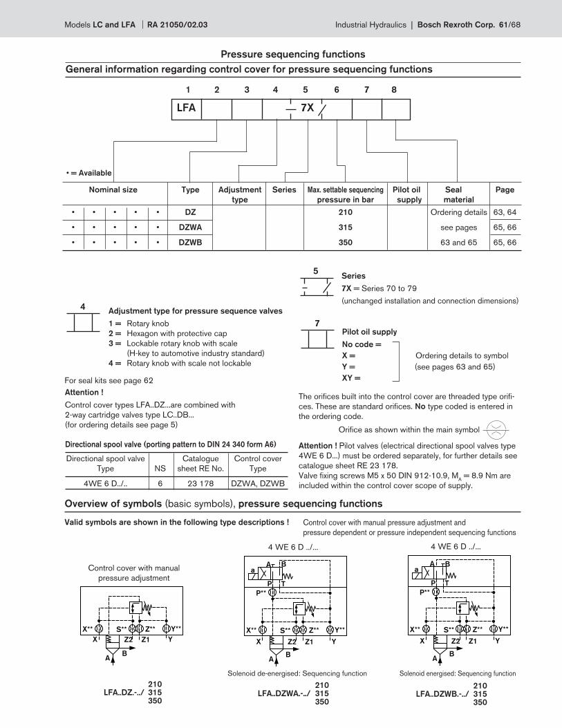
X
A
YZ1
B
Z2
X** S** Z** Y**
X
A
YZ1
B
P T
A Ba
Z2
X** S** Z** Y**
P**
X
A
YZ1
B
P T
A Ba
Z2
X** S** Z** Y**
P**
5
7
4
Pressure sequencing functions
General information regarding control cover for pressure sequencing functions
Overview of symbols (basic symbols), pressure sequencing functions
1 2 3 4 5 6 7 8
Nominal size Type Adjustment Series Max. settable sequencing Pilot oil Seal Page
type pressure in bar supply material
• • • • • DZ 210 Ordering details 63, 64
• • • • • DZWA 315 see pages 65, 66
• • • • • DZWB 350 63 and 65 65, 66
Adjustment type for pressure sequence valves
1 = Rotary knob
2 = Hexagon with protective cap
3 = Lockable rotary knob with scale
(H-key to automotive industry standard)
4 = Rotary knob with scale not lockable
Series
7X = Series 70 to 79
(unchanged installation and connection dimensions)
LFA 7X
• = Available
Pilot oil supply
No code =
X = Ordering details to symbol
Y = (see pages 63 and 65)
XY =
Orifi ce as shown within the main symbol
The orifi ces built into the control cover are threaded type orifi -
ces. These are standard orifi ces. No type coded is entered in
the ordering code.
Attention !
Control cover types LFA..DZ...are combined with
2-way cartridge valves type LC..DB...
(for ordering details see page 5)
For seal kits see page 62
Directional spool valve (porting pattern to DIN 24 340 form A6)
Directional spool valve Catalogue Control cover
Type NS sheet RE No. Type
4WE 6 D../.. 6 23 178 DZWA, DZWB
Attention ! Pilot valves (electrical directional spool valves type
4WE 6 D...) must be ordered separately, for further details see
catalogue sheet RE 23 178.
Valve fi xing screws M5 x 50 DIN 912-10.9, MA = 8.9 Nm are
included within the control cover scope of supply.
Control cover with manual pressure adjustment and
pressure dependent or pressure independent sequencing functions
4 WE 6 D ../... 4 WE 6 D ../...
Control cover with manual
pressure adjustment
Solenoid energised: Sequencing functionSolenoid de-energised: Sequencing function
210LFA..DZ.-../ 315 350
210LFA..DZWA.-../ 315 350
210LFA..DZWB.-../ 315 350
Valid symbols are shown in the following type descriptions !
Models LC and LFA RA 21050/02.03 Industrial Hydraulics | Bosch Rexroth Corp. 61/68
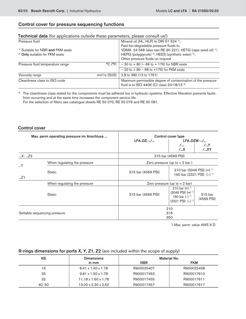
Control cover for pressure sequencing functions
Technical data (for applications outside these parameters, please consult us!)
Control cover
Pressure fl uid Mineral oil (HL, HLP) to DIN 51 524 1);
Fast bio-degradable pressure fl uids to 1) Suitable for NBR and FKM seals VDMA 24 568 (also see RE 90 221); HETG (rape seed oil) 1); 2) Only suitable for FKM seals HEPG (polyglycols) 2); HEES (synthetic ester) 2);
Other pressure fl uids on request
Pressure fl uid temperature range °C (°F) – 30 to + 80 (– 86 to + 176) for NBR seals
– 20 to + 80 – 68 to +176) for FKM seals
Viscosity range mm2/s (SUS) 2.8 to 380 (13 to 1761)
Cleanliness class to ISO code Maximum permissible degree of contamination of the pressure
fl uid is to ISO 4406 (C) class 20/18/15 3)
Max. perm operating pressure im Anschluss ... Control cover type
LFA..DZ.-../... LFA..DZW.-../...
/.... /...Y
/...X /...XY
...X; ...Z2 315 bar (4569 PSI)
When regulating the pressure Zero pressure (up to ≈ 2 bar )
Static
315 bar (4569 PSI)
When regulating the pressure Zero pressure (up to ≈ 2 bar)
Static 315 bar (4569 PSI) 315 bar
(4569 PSI)
210
Settable sequencing pressure 315
350
...Y
...Z1
210 bar (3046 PSI) (=) 1)
160 bar (2321 PSI) (∼) 1)
1) Max. perm. value 4WE 6 D
R-rings dimensions for ports X, Y, Z1, Z2 (are included within the scope of supply)
NS Dimensions Material No.
in mm NBR FKM
16 8.41 x 1.40 x 1.78 R900025407 R900025408
25 9.81 x 1.50 x 1.78 R900017453 R900017610
32 11.18 x 1.60 x 1.78 R900017455 R900017611
40, 50 13.00 x 2.30 x 2.62 R900017457 R900017617
3) The cleanliness class stated for the components must be adhered too in hydraulic systems. Effective fi lteration prevents faults
from occurring and at the same time increases the component service life.
For the selection of fi lters see catalogue sheets RE 50 070, RE 50 076 and RE 50 081.
210 bar (=) 1)
(3046 PSI) (=) 1)
160 bar (∼) 1)
(2321 PSI) (∼) 1)
62/68 Bosch Rexroth Corp. | Industrial Hydraulics Models LC and LFA RA 21050/02.03
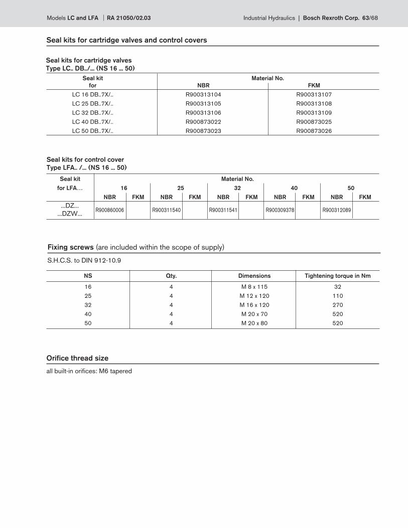
Seal kits for cartridge valves and control covers
Seal kits for cartridge valves
Type LC.. DB../... (NS 16 ... 50)
Seal kits for control cover
Type LFA.. /... (NS 16 ... 50)
Fixing screws (are included within the scope of supply)
S.H.C.S. to DIN 912-10.9
NS Qty. Dimensions Tightening torque in Nm
16 4 M 8 x 115 32
25 4 M 12 x 120 110
32 4 M 16 x 120 270
40 4 M 20 x 70 520
50 4 M 20 x 80 520
Orifi ce thread size
all built-in orifi ces: M6 tapered
Seal kit Material No.
for NBR FKM
LC 16 DB..7X/.. R900313104 R900313107
LC 25 DB..7X/.. R900313105 R900313108
LC 32 DB..7X/.. R900313106 R900313109
LC 40 DB..7X/.. R900873022 R900873025
LC 50 DB..7X/.. R900873023 R900873026
Seal kit Material No.
for LFA… 16 25 32 40 50
NBR FKM NBR FKM NBR FKM NBR FKM NBR FKM
R900860006 R900311540 R900311541 R900309378 R900312089 ...DZ...
...DZW...
Models LC and LFA RA 21050/02.03 Industrial Hydraulics | Bosch Rexroth Corp. 63/68
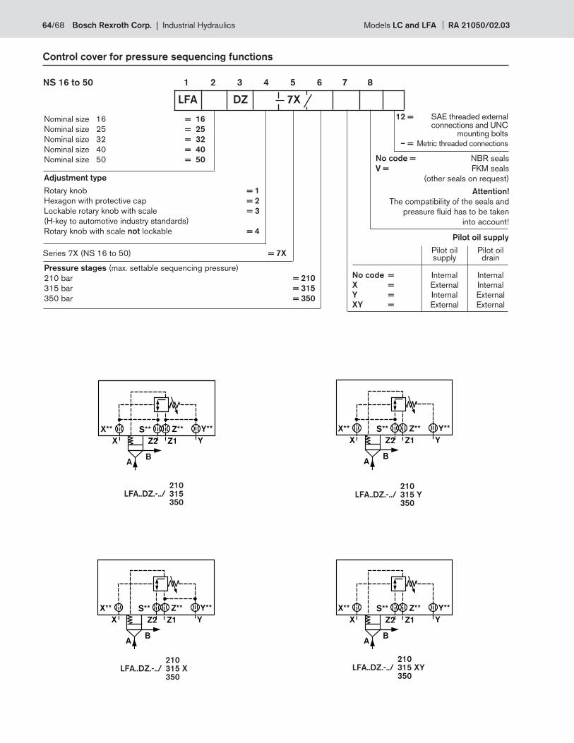
X
A
YZ1
B
Z2
X** S** Z** Y**
X
A
YZ1
B
Z2
X** S** Z** Y**
X
A
YZ1
B
Z2
X** S** Z** Y**
X
A
YZ1
B
Z2
X** S** Z** Y**
Control cover for pressure sequencing functions
1 2 3 4 5 6 7 8NS 16 to 50
No code = NBR seals
V = FKM seals
(other seals on request)
Attention!
The compatibility of the seals and
pressure fl uid has to be taken
into account!
LFA DZ 7X
Adjustment type
Rotary knob = 1
Hexagon with protective cap = 2
Lockable rotary knob with scale = 3
(H-key to automotive industry standards)
Rotary knob with scale not lockable = 4
Nominal size 16 = 16
Nominal size 25 = 25
Nominal size 32 = 32
Nominal size 40 = 40
Nominal size 50 = 50
Series 7X (NS 16 to 50) = 7X
Pressure stages (max. settable sequencing pressure)
210 bar = 210
315 bar = 315
350 bar = 350
Pilot oil supply
Pilot oil Pilot oil supply drain
No code = Internal Internal
X = External Internal
Y = Internal External
XY = External External
210LFA..DZ.-../ 315 350
210LFA..DZ.-../ 315 X 350
210LFA..DZ.-../ 315 Y 350
210LFA..DZ.-../ 315 XY 350
12 = SAE threaded external connections and UNC mounting bolts
– = Metric threaded connections
64/68 Bosch Rexroth Corp. | Industrial Hydraulics Models LC and LFA RA 21050/02.03
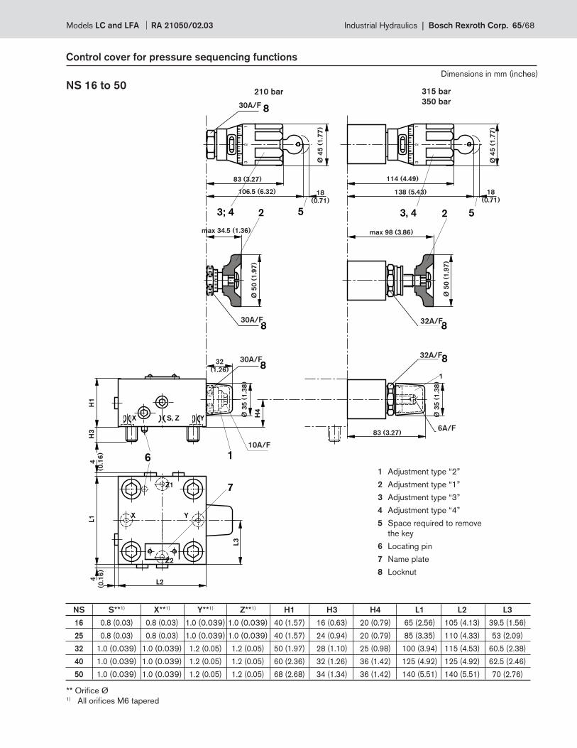
Z2
H1
H3
H4
X
6
7
13
2
YS, Z1
32
L1 X Y
Z1
1
SW30
SW308
2
SW30 8
3; 4 5
SW328
23, 4 5
8
SW328
SW6
1
SW10
L2
L3
4
(0.1
6)
106.5 (6.32)
4
(0.1
6)
18
(0.71)
83 (3.27) 114 (4.49)
138 (5.43)
max 98 (3.86)max 34.5 (1.36)
83 (3.27)Ø
35
(1
.38
)
Ø 3
5 (
1.3
8)
Ø 4
5 (
1.7
7)
18
(0.71)
Ø 4
5 (
1.7
7)
Ø 5
0 (
1.9
7)
Ø 5
0 (
1.9
7)
32
(1.26)
30A/F
30A/F
30A/F
10A/F
32A/F
32A/F
6A/F
NS 16 to 50
Control cover for pressure sequencing functions
210 bar 315 bar
350 bar
1 Adjustment type “2”
2 Adjustment type “1”
3 Adjustment type “3”
4 Adjustment type “4”
5 Space required to remove
the key
6 Locating pin
7 Name plate
8 Locknut
NS S**1) X**1) Y**1) Z**1) H1 H3 H4 L1 L2 L3
16 0.8 (0.03) 0.8 (0.03) 1.0 (0.039) 1.0 (0.039) 40 (1.57) 16 (0.63) 20 (0.79) 65 (2.56) 105 (4.13) 39.5 (1.56)
25 0.8 (0.03) 0.8 (0.03) 1.0 (0.039) 1.0 (0.039) 40 (1.57) 24 (0.94) 20 (0.79) 85 (3.35) 110 (4.33) 53 (2.09)
32 1.0 (0.039) 1.0 (0.039) 1.2 (0.05) 1.2 (0.05) 50 (1.97) 28 (1.10) 25 (0.98) 100 (3.94) 115 (4.53) 60.5 (2.38)
40 1.0 (0.039) 1.0 (0.039) 1.2 (0.05) 1.2 (0.05) 60 (2.36) 32 (1.26) 36 (1.42) 125 (4.92) 125 (4.92) 62.5 (2.46)
50 1.0 (0.039) 1.0 (0.039) 1.2 (0.05) 1.2 (0.05) 68 (2.68) 34 (1.34) 36 (1.42) 140 (5.51) 140 (5.51) 70 (2.76)
** Orifi ce Ø1) All orifi ces M6 tapered
Dimensions in mm (inches)
Models LC and LFA RA 21050/02.03 Industrial Hydraulics | Bosch Rexroth Corp. 65/68
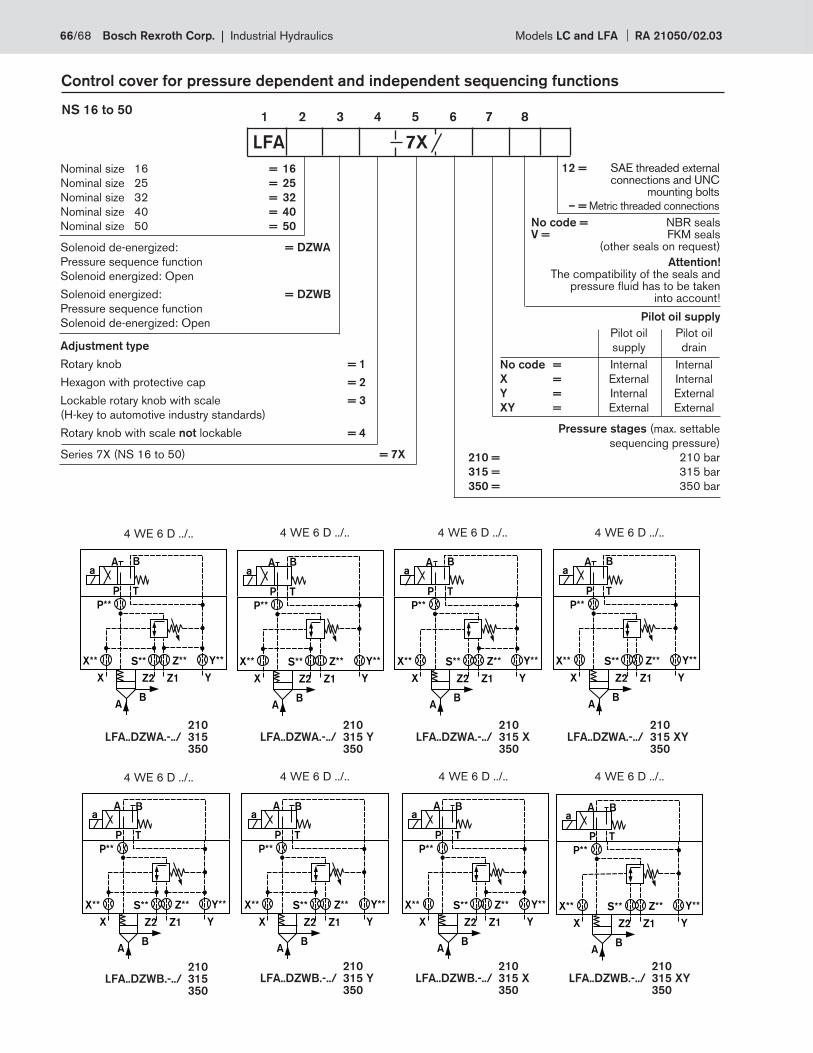
Control cover for pressure dependent and independent sequencing functions
1 2 3 4 5 6 7 8NS 16 to 50
No code = NBR seals V = FKM seals (other seals on request)
Attention!The compatibility of the seals and
pressure fl uid has to be taken into account!
LFA 7X
Adjustment type
Rotary knob = 1
Hexagon with protective cap = 2
Lockable rotary knob with scale = 3
(H-key to automotive industry standards)
Rotary knob with scale not lockable = 4
Nominal size 16 = 16
Nominal size 25 = 25
Nominal size 32 = 32
Nominal size 40 = 40
Nominal size 50 = 50
Series 7X (NS 16 to 50) = 7X
Pressure stages (max. settable
sequencing pressure)
210 = 210 bar
315 = 315 bar
350 = 350 bar
Pilot oil supply
Pilot oil Pilot oil
supply drain
No code = Internal Internal
X = External Internal
Y = Internal External
XY = External External
Solenoid de-energized: = DZWA
Pressure sequence function
Solenoid energized: Open
Solenoid energized: = DZWB
Pressure sequence function
Solenoid de-energized: Open
X
A
YZ1
B
P T
A Ba
Z2
X** S** Z** Y**
P**
X
A
YZ1
B
P T
A Ba
Z2
X** S** Z** Y**
P**
X
A
YZ1
B
P T
A Ba
Z2
X** S** Z** Y**
P**
X
A
YZ1
B
P T
A Ba
Z2
X** S** Z** Y**
P**
X
A
YZ1
B
P T
A Ba
Z2
X** S** Z** Y**
P**
X
A
YZ1
B
P T
A Ba
Z2
X** S** Z** Y**
P**
X
A
YZ1
B
P T
A Ba
Z2
X** S** Z** Y**
P**
X
A
YZ1
B
P T
A Ba
Z2
X** S** Z** Y**
P**
4 WE 6 D ../..
210LFA..DZWA.-../ 315 350
210LFA..DZWB.-../ 315 350
210LFA..DZWA.-../ 315 Y 350
210LFA..DZWA.-../ 315 X 350
210LFA..DZWA.-../ 315 XY 350
210LFA..DZWB.-../ 315 Y 350
210LFA..DZWB.-../ 315 X 350
210LFA..DZWB.-../ 315 XY 350
4 WE 6 D ../.. 4 WE 6 D ../.. 4 WE 6 D ../..
4 WE 6 D ../.. 4 WE 6 D ../.. 4 WE 6 D ../.. 4 WE 6 D ../..
12 = SAE threaded external connections and UNC mounting bolts
– = Metric threaded connections
66/68 Bosch Rexroth Corp. | Industrial Hydraulics Models LC and LFA RA 21050/02.03
4
(0.1
6)
4
(0.16)
Z2
H1
H3
H4
X
6
7
13
2
YS, Z
13
2
L1
X Y
Z1
1SW30
SW308
2
SW30 8
3, 4 5
SW328
23, 4 5
8
SW328
SW6
1
SW10
P
B A
B A
P
T
9
11
10
L6
L3
L2
L7
max 98 (3.86)
106.5 (6.32)
4
(0.1
6)
32
.5 (
1.2
8)
40.5
(1.59)
18
(0.71)
83 (3.27) 114 (4.49)
138 (5.43)
83 (3.27)
Ø 3
5 (
1.3
8)
Ø 3
5 (
1.3
8)
Ø 4
5 (
1.7
7)
18
(0.71
Ø 4
5 (
1.7
7)
Ø 5
0 (
1.9
7)
Ø 5
0 (
1.9
7)
max 34.5 (1.36)
32
(1.26)
NS 16 to 50
Control cover for pressure dependent and indpendent sequencing functions
210 bar 315 bar
350 bar
** Orifi ce Ø1) All orifi ces 6 tapered
1 Adjustment type “2”
2 Adjustment type “1”
3 Adjustment type “3”
4 Adjustment type “4”
5 Space required to remove the key
6 Locating pin
7 Name plate
8 Locknut
9 Plug M6 tapered for DZWA..
10 Plug M6 tapered for DZWB..
11 Valve fi xing screws are included
within the control cover scope of supply
Directional spool valve . WE 6 D...
30A/F
30A/F
30A/F10A/F
32A/F
32A/F
6A/F
NS S**1) X**1) Y**1) Z**1) H1 H3 H4 L1 L2 L3 L6 L7
16 0.8 (0.03) 0.8 (0.03) 1.0 (0.039) 1.0 (0.039) 40 (1.57) 16 (0.63) 20 (0.79) 65 (2.56) 105 (4.13) 39.5 (1.56) 16 (0.63) 49 (1.93)
25 0.8 (0.03) 0.8 (0.03) 1.0 (0.039) 1.0 (0.039) 40 (1.57) 24 (0.94) 20 (0.79) 85 (3.35) 110 (4.33) 53 (2.09) 21 (0.47) 59 (2.32)
32 1.0 (0.039) 1.0 (0.039) 1.2 (0.05) 1.2 (0.05) 50 (1.97) 28 (1.10) 25 (0.98) 100 (3.94) 115 (4.53) 60.5 (2.38) 26.5 (1.04) 66.5 (2.61)
40 1.0 (0.039) 1.0 (0.039) 1.2 (0.05) 1.2 (0.05) 60 (2.36) 32 (1.26) 36 (1.42) 125 (4.92) 125 (4.92) 62.5 (2.46) 55 (2.17) 76.4 (3.01)
50 1.0 (0.039) 1.0 (0.039) 1.2 (0.05) 1.2 (0.05) 68 (2.68) 34 (1.34) 36 (1.42) 140 (5.51) 140 (5.51) 70 (2.76) 70 (2.76) 84 (3.31)
Dimensions in mm (inches)
Models LC and LFA RA 21050/02.03 Industrial Hydraulics | Bosch Rexroth Corp. 67/68
68/68 Bosch Rexroth Corp. | Industrial Hydraulics Models LC and LFA RA 21050/02.03
Bosch Rexroth Corp.
Industrial Hydraulics
2315 City Line Road
Bethlehem, PA 18017-2131
USA
Telephone (610) 684-8300
Facsimile (610) 694-8467
www.boschrexroth-us.com
© 2004 Bosch Rexroth Corporation
All rights reserved. Neither this document nor any part of it may be reproduced,
duplicated circulated or disseminated, whether by copy, electronic format or
any other means, without the prior consent and authorization of Bosch Rexroth
Cor po ra tion.
The data and illustrations in this brochure/data sheet are intended only to
describe or depict the products. No representation or warranty, either express
or implied, relating to merchantability or fi tness for intended use, is given or
intended by virtue of the information contained in this brochure/data sheet. The
information contained in this brochure/data sheet in no way relieves the user of it
obligation to insure the proper use of the products for a specifi c use or applica-
tion. All products contained in this brochure/data sheet are subject to normal
wear and tear from usage.
Subject to change.