(2) Settings, Configuration & Instruments Guide · PDF file(2) Settings, Configuration &...
83
(2) Settings, Configuration & Instruments Guide 7SR224 Appendix 3) The copyright and other intellectual property rights in this document, and in any model or article produced from it (and including any registered or unregistered design rights) are the property of Siemens Protection Devices Limited. No part of this document shall be reproduced or modified or stored in another form, in any data retrieval system, without the permission of Siemens Protection Devices Limited, nor shall any model or article be reproduced from this document unless Siemens Protection Devices Limited consent. While the information and guidance given in this document is believed to be correct, no liability shall be accepted for any loss or damage caused by any error or omission, whether such error or omission is the result of negligence or any other cause. Any and all such liability is disclaimed. ©2009 Siemens Protection Devices Limited (2) Settings, Configuration & Instruments Guide Appendix 3: Relay Settings (Software Version 2435H80011R3d-2b) RECLOSER-M CONTROLLER 7SR224
Transcript of (2) Settings, Configuration & Instruments Guide · PDF file(2) Settings, Configuration &...

(2) Settings, Configuration & Instruments Guide 7SR224 Appendix 3)
The copyright and other intellectual property rights in this document, and in any model or article produced from it (and including any registered or unregistered design rights) are the property of Siemens Protection Devices Limited. No part of this document shall be reproduced or modified or stored in another form, in any data retrieval system, without the permission of Siemens Protection Devices Limited, nor shall any model or article be reproduced from this document unless Siemens Protection Devices Limited consent. While the information and guidance given in this document is believed to be correct, no liability shall be accepted for any loss or damage caused by any error or omission, whether such error or omission is the result of negligence or any other cause. Any and all such liability is disclaimed. ©2009 Siemens Protection Devices Limited
(2) Settings, Configuration & Instruments Guide
Appendix 3: Relay Settings (Software Version 2435H80011R3d-2b)
RECLOSER-M CONTROLLER 7SR224

(2) Settings, Configuration & Instruments Guide 7SR224 Appendix 3)
Page 2 of 83 ©2009 Siemens Protection Devices Limited
DOCUMENT RELEASE HISTORY This document is issue 2008/11. The list of revisions up to and including this issue is: 2008/11 First issue

(2) Settings, Configuration & Instruments Guide 7SR224 Appendix 3)
©2009 Siemens Protection Devices Limited Page 3 of 83
TABLE OF CONTENTS DOCUMENT RELEASE HISTORY...............................................................................2 1. FUNCTION DIAGRAM .............................................................................................6 2. MENU STRUCTURE................................................................................................7
2.1. RELAY SETTINGS...........................................................................................8 2.2. SYSTEM CONFIG............................................................................................8 2.3. CT/VT CONFIG................................................................................................9 2.4. FUNCTION CONFIG........................................................................................9 2.5. CURRENT PROT'N .......................................................................................11 2.5.1. PHASE OVERCURRENT......................................................................11
2.5.1.1. 51-1...........................................................................................12 2.5.1.2. 51-2...........................................................................................12 2.5.1.3. 51-3...........................................................................................13 2.5.1.4. 51-4...........................................................................................13 2.5.1.5. 50-1...........................................................................................14 2.5.1.6. 50-2...........................................................................................14 2.5.1.7. 50-3...........................................................................................14 2.5.1.8. 50-4...........................................................................................15
2.5.2. VOLTAGE CONT O/C ...........................................................................15 2.5.3. COLD LOAD ..........................................................................................15 2.5.4. MEASURED G/F ...................................................................................17
2.5.4.1. 51G-1 ........................................................................................17 2.5.4.2. 51G-2 ........................................................................................18 2.5.4.3. 51G-3 ........................................................................................18 2.5.4.4. 51G-4 ........................................................................................19 2.5.4.5. 50G-1 ........................................................................................19 2.5.4.6. 50G-2 ........................................................................................19 2.5.4.7. 50G-3 ........................................................................................20 2.5.4.8. 50G-4 ........................................................................................20
2.5.5. SENSITIVE G/F .....................................................................................20 2.5.5.1. 51SGF-1....................................................................................21 2.5.5.2. 51SGF-2....................................................................................21 2.5.5.3. 51SGF-3....................................................................................22 2.5.5.4. 51SGF-4....................................................................................22 2.5.5.5. 50SGF-1....................................................................................22 2.5.5.6. 50SGF-2....................................................................................23 2.5.5.7. 50SGF-3....................................................................................23 2.5.5.8. 50SGF-4....................................................................................23
2.5.6. RESTRICTED G/F.................................................................................24 2.5.7. NPS OVERCURRENT...........................................................................24
2.5.7.1. 46IT...........................................................................................24 2.5.7.2. 46DT .........................................................................................24
2.5.8. UNDER CURRENT................................................................................24 2.5.8.1. 37-1...........................................................................................24 2.5.8.2. 37-2...........................................................................................25
2.5.9. THERMAL..............................................................................................25 2.6. VOLTAGE PROT'N ........................................................................................25 2.6.1. PHASE U/O VOLTAGE .........................................................................25
2.6.1.1. 27/59-1......................................................................................25 2.6.1.2. 27/59-2......................................................................................26

(2) Settings, Configuration & Instruments Guide 7SR224 Appendix 3)
Page 4 of 83 ©2009 Siemens Protection Devices Limited
2.6.1.3. 27/59-3......................................................................................26 2.6.1.4. 27/59-4......................................................................................26
2.6.2. Vx U/O VOLTAGE .................................................................................27 2.6.3. NPS OVERVOLTAGE ...........................................................................27
2.6.3.1. 47-1...........................................................................................27 2.6.3.2. 47-2...........................................................................................28
2.6.4. NEUTRAL OVERVOLTAGE..................................................................28 2.6.4.1. 59NIT ........................................................................................28 2.6.4.2. 59NDT.......................................................................................28
2.6.5. U/O FREQUENCY.................................................................................28 2.6.5.1. 81-1...........................................................................................28 2.6.5.2. 81-2...........................................................................................29 2.6.5.3. 81-3...........................................................................................29 2.6.5.4. 81-4...........................................................................................30
2.7. SUPERVISION...............................................................................................30 2.7.1. CB FAIL .................................................................................................30 2.7.2. VT SUPERVISION.................................................................................30 2.7.3. CT SUPERVISION ................................................................................31 2.7.4. BROKEN CONDUCTOR .......................................................................31 2.7.5. TRIP CCT SUPERVISION.....................................................................31 2.7.6. INRUSH DETECTOR ............................................................................32 2.7.7. BATTERY TEST ....................................................................................32 2.7.8. CAPACITOR TEST................................................................................32 2.7.9. POWER QUALITY.................................................................................32
2.7.9.1. 27SAG ......................................................................................33 2.7.9.2. 59SWELL..................................................................................33
2.7.10. DEMAND ...............................................................................................33 2.7.11. CONTROL & LOGIC..............................................................................33 2.7.12. AUTORECLOSE PROT'N .....................................................................33 2.7.13. AUTORECLOSE CONFIG.....................................................................34
2.7.13.1.P/F SHOTS..............................................................................35 2.7.13.2.G/F SHOTS .............................................................................35 2.7.13.3.SGF SHOTS ............................................................................36 2.7.13.4.EXTERN SHOTS.....................................................................37
2.7.14. MANUAL CLOSE...................................................................................37 2.7.15. CIRCUIT BREAKER ..............................................................................38 2.7.16. LOV AUTOMATION...............................................................................38 2.7.17. QUICK LOGIC .......................................................................................39
2.8. INPUT CONFIG .............................................................................................46 2.8.1. INPUT MATRIX .....................................................................................46 2.8.2. FUNCTION KEY MATRIX......................................................................56 2.8.3. BINARY INPUT CONFIG.......................................................................56 2.8.4. FUNCTION KEY CONFIG .....................................................................57 2.8.5. GENERAL ALARMS..............................................................................58
2.9. OUTPUT CONFIG..........................................................................................58 2.9.1. OUTPUT MATRIX .................................................................................58 2.9.2. BINARY OUTPUT CONFIG...................................................................74 2.9.3. LED CONFIG.........................................................................................75 2.9.4. PICKUP CONFIG ..................................................................................75
2.10. CB MAINTENANCE .......................................................................................75 2.10.1. CB COUNTERS.....................................................................................75

(2) Settings, Configuration & Instruments Guide 7SR224 Appendix 3)
©2009 Siemens Protection Devices Limited Page 5 of 83
2.10.2. I^2T CB WEAR ......................................................................................76 2.11. DATA STORAGE ...........................................................................................76 2.12. COMMUNICATIONS......................................................................................77
3. RELAY INSTRUMENTATION.................................................................................79

(2) Settings, Configuration & Instruments Guide 7SR224 Appendix 3)
Page 6 of 83 ©2009 Siemens Protection Devices Limited
1. FUNCTION DIAGRAM

(2) Settings, Configuration & Instruments Guide 7SR224 Appendix 3)
©2009 Siemens Protection Devices Limited Page 7 of 83
2. MENU STRUCTURE

(2) Settings, Configuration & Instruments Guide 7SR224 Appendix 3)
Page 8 of 83 ©2009 Siemens Protection Devices Limited
2.1. RELAY SETTINGS
2.2. SYSTEM CONFIG Description Range Default Setting
Language Setting Selects the language in which the relay text will be displayed.
English, USA-English English
Active Group Selects which settings group is currently activated
1,2…8 1
System Frequency Selects the Power System Frequency from 50 or 60 Hz
50, 60 50Hz
View/Edit Group Selects which settings group is currently being displayed
1,2…8 1
Setting Dependencies When enabled only active settings are displayed and all others hidden
Disabled, Enabled Enabled
Favorite Meters Timer Selects the time delay after which, if no key presses have been detected, the relay will begin to poll through any screens which have been selected as favorite instruments
Off, 1, 2, 5, 10, 15, 30, 60 60min
Backlight timer Controls when the LCD backlight turns off
Off, 1, 2, 5, 10, 15, 30, 60 5min
Date Sets the date, this setting can only be changed on the fascia or via Relay->Control->Set Time and Date
dd/mm/yyyy 1/1/2000
Time Sets the time, this setting can only be changed on the fascia or via Relay->Control->Set Time and Date
hh:mm:ss 00:00:00
Curr Set Display Select whether the Pickup values are shown in terms of x Nominal, Primary or Secondary values on the Relay Fascia
xNom, Primary, Secondary xNom
G/F Curr Set Display As Above
xNom, Primary, Secondary xNom
Export Power/Lag VAr Selects the signs required for exporting power and lagging VArs
+ve/+ve, +ve/-ve, -ve/+ve, -ve/-ve +ve/+ve
Select Grp Mode Mode of operation of the group change from status input. Edge triggered ignores the status input once it has changed to the relevant group, where as with Level triggered the relay will only stay in the group it has changed to whilst the status input is being driven, after which it returns to the previous group.
Edge triggered, Level triggered Edge triggered
Clock Sync. From BI Real time clock may be synchronised using a binary input (See Clock Sync. in Binary Input Menu)
Disabled, Seconds, Minutes Minutes
Operating Mode Selects the current operating mode of the relay. This can also be changed by a binary input mode selection.
Out Of Service, Local, Remote, Local Or Remote
Local Or Remote
Setting Password Allows a 4 character alpha code to be entered as the password. Note that the display shows a password dependant encrypted code on the second line of the display
(Password) NONE
Control Password As Above
(Password) NONE
Trip Alert When Enabled the occurance of a Trip will cause the relay to display the Trip Alert Screen, the only way to leave this screen is by acknowledging the trip through the TEST/RESET button on the relay fascia
Disabled, Enabled Enabled

(2) Settings, Configuration & Instruments Guide 7SR224 Appendix 3)
©2009 Siemens Protection Devices Limited Page 9 of 83
Description Range Default Setting
Relay Identifier An alphanumeric string shown on the LCD normally used to identifier the circuit the relay is attached to or the relays purpose
(16 Character String) RECLOSER-M 7SR22
2.3. CT/VT CONFIG Description Range Default Setting
Phase Nom Voltage Selects the nominal voltage setting Vn of the voltage input
40, 40.1 ... 159.9, 160 63.5V
Phase Voltage Trim Magnitude Allows trimming of voltage magnitude, the setting value should be the voltage required to be added to get back to Phase Nom Voltage.
0, 0.1 ... 19.9, 20 0V
Phase Voltage Trim Angle Allows trimming of voltage angle, the setting value is added to the current voltage angle
-45, -44.9 ... 44.9, 45 0deg
Phase Voltage Config Required to allow for different types of physical VT connections.
Van,Vbn,Vcn, Vab,Vbc,3V0, Va,Vb,Vc
Van,Vbn,Vcn
Phase VT Ratio VT ratio to scale primary voltage instrument
3300:40, 3300:40.5 ... 500000:159.5, 500000:160
132000:110
Vx Nom Voltage Selects the nominal voltage setting Vn of the voltage input
40, 40.1 ... 159.9, 160 63.5V
Vx Voltage Trim Magnitude Allows trimming of voltage magnitude, the setting value should be the voltage required to be added to get back to Vx Nom Voltage.
0, 0.1 ... 19.9, 20 0V
Vx Voltage Trim Angle Allows trimming of voltage angle, the setting value is added to the current voltage angle
-45, -44.9 ... 44.9, 45 0deg
Vx VT Ratio VT ratio to scale primary voltage instrument
3300:40, 3300:40.5 ... 500000:159.5, 500000:160
132000:110
Phase Current Input Selects whether 1 or 5 Amp terminals are being used for phase inputs
1, 5 1A
Phase CT Ratio Phase CT ratio to scale primary current instruments
1:0.2, 1:0.21 ... 5000:6.9, 5000:7 2000:1
Ground Current Input Selects whether 1 or 5 Amp terminals are being used for Measured Ground inputs
1, 5 1A
Ground CT Ratio Measured Ground CT ratio to scale primary current instruments
1:0.2, 1:0.21 ... 5000:6.9, 5000:7 2000:1
2.4. FUNCTION CONFIG Description Range Default Setting
Gn Phase Overcurrent When set to Disabled, no Phase Overcurrent elements will be functional and all associated settings will be hidden. (The Setting Dependencies setting being set to Disabled will make all settings visible but will not allow them to operate).
Enabled, Disabled Disabled
Gn Voltage Cont O/C When set to Disabled, no Voltage Cont O/C elements will be functional and all associated settings will be hidden. (The Setting Dependencies setting being set to Disabled will make all settings visible but will not allow them to operate).
Enabled, Disabled Disabled

(2) Settings, Configuration & Instruments Guide 7SR224 Appendix 3)
Page 10 of 83 ©2009 Siemens Protection Devices Limited
Description Range Default Setting
Gn Cold Load When set to Disabled, no Cold Load elements will be functional and all associated settings will be hidden. (The Setting Dependencies setting being set to Disabled will make all settings visible but will not allow them to operate).
Enabled, Disabled Disabled
Gn Measured G/F When set to Disabled, no Measured G/F elements will be functional and all associated settings will be hidden. (The Setting Dependencies setting being set to Disabled will make all settings visible but will not allow them to operate).
Enabled, Disabled Disabled
Gn Sensitive G/F When set to Disabled, no Sensitive G/F elements will be functional and all associated settings will be hidden. (The Setting Dependencies setting being set to Disabled will make all settings visible but will not allow them to operate).
Enabled, Disabled Disabled
Gn Restricted G/F When set to Disabled, no Restricted G/F elements will be functional and all associated settings will be hidden. (The Setting Dependencies setting being set to Disabled will make all settings visible but will not allow them to operate).
Enabled, Disabled Disabled
Gn NPS Overcurrent When set to Disabled, no NPS Overcurrent elements will be functional and all associated settings will be hidden. (The Setting Dependencies setting being set to Disabled will make all settings visible but will not allow them to operate).
Enabled, Disabled Disabled
Gn Under Current When set to Disabled, no Under Current elements will be functional and all associated settings will be hidden. (The Setting Dependencies setting being set to Disabled will make all settings visible but will not allow them to operate).
Enabled, Disabled Disabled
Gn Thermal When set to Disabled, no Thermal elements will be functional and all associated settings will be hidden. (The Setting Dependencies setting being set to Disabled will make all settings visible but will not allow them to operate).
Enabled, Disabled Disabled
Gn Phase U/O Voltage When set to Disabled, no Phase U/O Voltage elements will be functional and all associated settings will be hidden. (The Setting Dependencies setting being set to Disabled will make all settings visible but will not allow them to operate).
Enabled, Disabled Disabled
Gn Vx U/O Voltage When set to Disabled, no Vx U/O Voltage elements will be functional and all associated settings will be hidden. (The Setting Dependencies setting being set to Disabled will make all settings visible but will not allow them to operate).
Enabled, Disabled Disabled
Gn NPS Overvoltage When set to Disabled, no NPS Overvoltage elements will be functional and all associated settings will be hidden. (The Setting Dependencies setting being set to Disabled will make all settings visible but will not allow them to operate).
Enabled, Disabled Disabled
Gn Neutral Overvoltage When set to Disabled, no Neutral Overvoltage elements will be functional and all associated settings will be hidden. (The Setting Dependencies setting being set to Disabled will make all settings visible but will not allow them to operate).
Enabled, Disabled Disabled
Gn U/O Frequency When set to Disabled, no U/O Frequency elements will be functional and all associated settings will be hidden. (The Setting Dependencies setting being set to Disabled will make all settings visible but will not allow them to operate).
Enabled, Disabled Disabled
Gn CB Fail When set to Disabled, no CB Fail elements will be functional and all associated settings will be hidden. (The Setting Dependencies setting being set to Disabled will make all settings visible but will not allow them to operate).
Enabled, Disabled Disabled
Gn VT Supervision When set to Disabled, no VT Supervision elements will be functional and all associated settings will be hidden. (The Setting Dependencies setting being set to Disabled will make all settings visible but will not allow them to operate).
Enabled, Disabled Disabled

(2) Settings, Configuration & Instruments Guide 7SR224 Appendix 3)
©2009 Siemens Protection Devices Limited Page 11 of 83
Description Range Default Setting
Gn CT Supervision When set to Disabled, no CT Supervision elements will be functional and all associated settings will be hidden. (The Setting Dependencies setting being set to Disabled will make all settings visible but will not allow them to operate).
Enabled, Disabled Disabled
Gn Broken Conductor When set to Disabled, no Broken Conductor elements will be functional and all associated settings will be hidden. (The Setting Dependencies setting being set to Disabled will make all settings visible but will not allow them to operate).
Enabled, Disabled Disabled
Gn Trip Cct Supervision When set to Disabled, no Trip Cct Supervision elements will be functional and all associated settings will be hidden. (The Setting Dependencies setting being set to Disabled will make all settings visible but will not allow them to operate).
Enabled, Disabled Disabled
Gn Inrush Detector When set to Disabled, no Inrush Detector elements will be functional and all associated settings will be hidden. (The Setting Dependencies setting being set to Disabled will make all settings visible but will not allow them to operate).
Enabled, Disabled Disabled
Gn CB Counters When set to Disabled, no Gn CB Counter elements will be functional and all associated settings will be hidden. (The Setting Dependencies setting being set to Disabled will make all settings visible but will not allow them to operate).
Enabled, Disabled Disabled
Gn I^2t CB Wear When set to Disabled, no Gn I^2t CB Wear elements will be functional and all associated settings will be hidden. (The Setting Dependencies setting being set to Disabled will make all settings visible but will not allow them to operate).
Enabled, Disabled Disabled
Gn Battery Test When set to Disabled, no Battery Test elements will be functional and all associated settings will be hidden. (The Setting Dependencies setting being set to Disabled will make all settings visible but will not allow them to operate).
Enabled, Disabled Disabled
Gn Capacitor Test When set to Disabled, no Capacitor Test elements will be functional and all associated settings will be hidden. (The Setting Dependencies setting being set to Disabled will make all settings visible but will not allow them to operate).
Enabled, Disabled Disabled
Gn LOV Automation When set to Disabled, no LOV Automation elements will be functional and all associated settings will be hidden. (The Setting Dependencies setting being set to Disabled will make all settings visible but will not allow them to operate).
Enabled, Disabled Disabled
Gn 27Sag & 59Swell When set to Disabled, no 27Sag & 59Swell elements will be functional and all associated settings will be hidden. (The Setting Dependencies setting being set to Disabled will make all settings visible but will not allow them to operate).
Enabled, Disabled Disabled
Gn Demand When set to Disabled, no Demand elements will be functional and all associated settings will be hidden. (The Setting Dependencies setting being set to Disabled will make all settings visible but will not allow them to operate).
Enabled, Disabled Disabled
2.5. CURRENT PROT'N
2.5.1. PHASE OVERCURRENT Description Range Default Setting
Gn 67 Char Angle Maximum torque angle for phase overcurrent elements
-95, -94 ... 94, 95 45deg
Gn 67 Minimum Voltage Selects the directional elements minimum voltage, below which the element will be inhibited
1, 1.5 ... 19.5, 20 1V

(2) Settings, Configuration & Instruments Guide 7SR224 Appendix 3)
Page 12 of 83 ©2009 Siemens Protection Devices Limited
Description Range Default Setting
Gn 67 2-out-of-3 Logic Selects whether 2 out of 3 voting logic is enabled for phase overcurrent elements
Enabled, Disabled Disabled
Gn 51/50 Measurement Selects whether the RMS value used by the 51 & 50 elements is True RMS or only calculated at fundamental frequency
RMS, Fundamental RMS
2.5.1.1. 51-1 Description Range Default Setting
Gn 51-1 Element Selects whether the 51-1 IDMTL Overcurrent element is enabled
Disabled, Enabled Disabled
Gn 51-1 Dir. Control Selects whether 51-1 element is non-directional, forward or reverse
Non-Dir, Forward, Reverse Non-Dir
Gn 51-1 Setting Pickup level
0.05, 0.1 ... 2.45, 2.5 1xIn
Gn 51-1 TCC Selects characteristic curve to be IEC or ANSI IDMTL or DTL
DTL, IEC-NI ... 201, 202 IEC-NI
Gn 51-1 Time Mult (IEC/ANSI) Time multiplier (applicable to IEC and ANSI curves but not DTL selection)
0.025, 0.05 ... 1.575, 1.6 1
Gn 51-1 Delay (DTL) Delay (applicable only when DTL is selected for characteristic)
0, 0.01 ... 19.99, 20 5s
Gn 51-1 Min Operate Time Minimum operate time of element.
0, 0.01 ... 19.99, 20 0s
Gn 51-1 Additional Time Additional definite time added after characteristic time
0, 0.01 ... 19.99, 20 0s
Gn 51-1 Reset Selects between an ANSI decaying reset characteristic or a definite time reset
(ANSI) Decaying, 0 ... 59, 60 0s
Gn 51-1 VTS Action Selects whether 51-1 element is blocked or made non-directional when VTS operates
Off, Inhibit, Non-Dir Off
Gn 51-1 Inrush Action Selects if the 51-1 element is blocked from operating when 2nd Harmonic Inrush Detector operates
Off, Inhibit Off
2.5.1.2. 51-2 Description Range Default Setting
Gn 51-2 Element Selects whether the 51-2 IDMTL Overcurrent element is enabled
Disabled, Enabled Disabled
Gn 51-2 Dir. Control Selects whether 51-2 element is non-directional, forward or reverse
Non-Dir, Forward, Reverse Non-Dir
Gn 51-2 Setting Pickup level
0.05, 0.1 ... 2.45, 2.5 1xIn
Gn 51-2 TCC Selects characteristic curve to be IEC or ANSI IDMTL or DTL
DTL, IEC-NI ... 201, 202 IEC-NI
Gn 51-2 Time Mult (IEC/ANSI) Time multiplier (applicable to IEC and ANSI curves but not DTL selection)
0.025, 0.05 ... 1.575, 1.6 1
Gn 51-2 Delay (DTL) Delay (applicable only when DTL is selected for characteristic)
0, 0.01 ... 19.99, 20 5s
Gn 51-2 Min Operate Time Minimum operate time of element.
0, 0.01 ... 19.99, 20 0s
Gn 51-2 Additional Time Additional definite time added after characteristic time
0, 0.01 ... 19.99, 20 0s

(2) Settings, Configuration & Instruments Guide 7SR224 Appendix 3)
©2009 Siemens Protection Devices Limited Page 13 of 83
Description Range Default Setting
Gn 51-2 Reset Selects between an ANSI decaying reset characteristic or a definite time reset
(ANSI) Decaying, 0 ... 59, 60 0s
Gn 51-2 VTS Action Selects whether 51-2 element is blocked or made non-directional when VTS operates
Off, Inhibit, Non-Dir Off
Gn 51-2 Inrush Action Selects if the 51-2 element is blocked from operating when 2nd Harmonic Inrush Detector operates
Off, Inhibit Off
2.5.1.3. 51-3 Description Range Default Setting
Gn 51-3 Element Selects whether the 51-3 IDMTL Overcurrent element is enabled
Disabled, Enabled Disabled
Gn 51-3 Dir. Control Selects whether 51-3 element is non-directional, forward or reverse
Non-Dir, Forward, Reverse Non-Dir
Gn 51-3 Setting Pickup level
0.05, 0.1 ... 2.45, 2.5 1xIn
Gn 51-3 TCC Selects characteristic curve to be IEC or ANSI IDMTL or DTL
DTL, IEC-NI ... 201, 202 IEC-NI
Gn 51-3 Time Mult (IEC/ANSI) Time multiplier (applicable to IEC and ANSI curves but not DTL selection)
0.025, 0.05 ... 1.575, 1.6 1
Gn 51-3 Delay (DTL) Delay (applicable only when DTL is selected for characteristic)
0, 0.01 ... 19.99, 20 5s
Gn 51-3 Min Operate Time Minimum operate time of element.
0, 0.01 ... 19.99, 20 0s
Gn 51-3 Additional Time Additional definite time added after characteristic time
0, 0.01 ... 19.99, 20 0s
Gn 51-3 Reset Selects between an ANSI decaying reset characteristic or a definite time reset
(ANSI) Decaying, 0 ... 59, 60 0s
Gn 51-3 VTS Action Selects whether 51-3 element is blocked or made non-directional when VTS operates
Off, Inhibit, Non-Dir Off
Gn 51-3 Inrush Action Selects if the 51-3 element is blocked from operating when 2nd Harmonic Inrush Detector operates
Off, Inhibit Off
2.5.1.4. 51-4 Description Range Default Setting
Gn 51-4 Element Selects whether the 51-4 IDMTL Overcurrent element is enabled
Disabled, Enabled Disabled
Gn 51-4 Dir. Control Selects whether 51-4 element is non-directional, forward or reverse
Non-Dir, Forward, Reverse Non-Dir
Gn 51-4 Setting Pickup level
0.05, 0.1 ... 2.45, 2.5 1xIn
Gn 51-4 TCC Selects characteristic curve to be IEC or ANSI IDMTL or DTL
DTL, IEC-NI ... 201, 202 IEC-NI
Gn 51-4 Time Mult (IEC/ANSI) Time multiplier (applicable to IEC and ANSI curves but not DTL selection)
0.025, 0.05 ... 1.575, 1.6 1
Gn 51-4 Delay (DTL) Delay (applicable only when DTL is selected for characteristic)
0, 0.01 ... 19.99, 20 5s

(2) Settings, Configuration & Instruments Guide 7SR224 Appendix 3)
Page 14 of 83 ©2009 Siemens Protection Devices Limited
Description Range Default Setting
Gn 51-4 Min Operate Time Minimum operate time of element.
0, 0.01 ... 19.99, 20 0s
Gn 51-4 Additional Time Additional definite time added after characteristic time
0, 0.01 ... 19.99, 20 0s
Gn 51-4 Reset Selects between an ANSI decaying reset characteristic or a definite time reset
(ANSI) Decaying, 0 ... 59, 60 0s
Gn 51-4 VTS Action Selects whether 51-4 element is blocked or made non-directional when VTS operates
Off, Inhibit, Non-Dir Off
Gn 51-4 Inrush Action Selects if the 51-4 element is blocked from operating when 2nd Harmonic Inrush Detector operates
Off, Inhibit Off
2.5.1.5. 50-1 Description Range Default Setting
Gn 50-1 Element Selects whether the INST/ DTL Overcurrent element is enabled
Disabled, Enabled Disabled
Gn 50-1 Dir. Control Selects whether 50-1 element is non-directional, forward or reverse
Non-Dir, Forward, Reverse Non-Dir
Gn 50-1 Setting Pickup level
0.05, 0.1 ... 49.5, 50 1xIn
Gn 50-1 Delay Sets operate delay time
0, 0.01 ... 14300, 14400 0s
Gn 50-1 VTS Action Selects whether 50-1 element is blocked or made non-directional when VTS operates
Off, Inhibit, Non-Dir Off
Gn 50-1 Inrush Action Selects if the 50-1 element is blocked from operating when 2nd Harmonic Inrush Detector operates
Off, Inhibit Off
2.5.1.6. 50-2 Description Range Default Setting
Gn 50-2 Element Selects whether the INST/ DTL Overcurrent element is enabled
Disabled, Enabled Disabled
Gn 50-2 Dir. Control Selects whether 50-2 element is non-directional, forward or reverse
Non-Dir, Forward, Reverse Non-Dir
Gn 50-2 Setting Pickup level
0.05, 0.1 ... 49.5, 50 1xIn
Gn 50-2 Delay Sets operate delay time
0, 0.01 ... 14300, 14400 0s
Gn 50-2 VTS Action Selects whether 50-2 element is blocked or made non-directional when VTS operates
Off, Inhibit, Non-Dir Off
Gn 50-2 Inrush Action Selects if the 50-2 element is blocked from operating when 2nd Harmonic Inrush Detector operates
Off, Inhibit Off
2.5.1.7. 50-3 Description Range Default Setting
Gn 50-3 Element Selects whether the INST/ DTL Overcurrent element is enabled
Disabled, Enabled Disabled

(2) Settings, Configuration & Instruments Guide 7SR224 Appendix 3)
©2009 Siemens Protection Devices Limited Page 15 of 83
Description Range Default Setting
Gn 50-3 Dir. Control Selects whether 50-3 element is non-directional, forward or reverse
Non-Dir, Forward, Reverse Non-Dir
Gn 50-3 Setting Pickup level
0.05, 0.1 ... 49.5, 50 1xIn
Gn 50-3 Delay Sets operate delay time
0, 0.01 ... 14300, 14400 0s
Gn 50-3 VTS Action Selects whether 50-3 element is blocked or made non-directional when VTS operates
Off, Inhibit, Non-Dir Off
Gn 50-3 Inrush Action Selects if the 50-3 element is blocked from operating when 2nd Harmonic Inrush Detector operates
Off, Inhibit Off
2.5.1.8. 50-4 Description Range Default Setting
Gn 50-4 Element Selects whether the INST/ DTL Overcurrent element is enabled
Disabled, Enabled Disabled
Gn 50-4 Dir. Control Selects whether 50-4 element is non-directional, forward or reverse
Non-Dir, Forward, Reverse Non-Dir
Gn 50-4 Setting Pickup level
0.05, 0.1 ... 49.5, 50 1xIn
Gn 50-4 Delay Sets operate delay time
0, 0.01 ... 14300, 14400 0s
Gn 50-4 VTS Action Selects whether 50-4 element is blocked or made non-directional when VTS operates
Off, Inhibit, Non-Dir Off
Gn 50-4 Inrush Action Selects if the 50-4 element is blocked from operating when 2nd Harmonic Inrush Detector operates
Off, Inhibit Off
2.5.2. VOLTAGE CONT O/C Description Range Default Setting
Gn 51V Element Selects whether the Voltage Controlled Overcurrent element is enabled
Disabled, Enabled Disabled
Gn 51V Setting The voltage below which 51V operates
5, 5.5 ... 199.5, 200 30V
Gn 51V VTS Action Selects whether or not the 51V element is blocked when VTS operates
Off, Inhibit Off
Gn 51-1 Multiplier Multiplier applied to the 51-1 element when VCO element has operated
0.25, 0.3, 0.35, 0.4, 0.45, 0.5, 0.55, 0.6, 0.65, 0.7, 0.75, 0.8, 0.85, 0.9, 0.95, 1
0.5
Gn 51-2 Multiplier Multiplier applied to the 51-2 element when VCO element has operated
0.25, 0.3, 0.35, 0.4, 0.45, 0.5, 0.55, 0.6, 0.65, 0.7, 0.75, 0.8, 0.85, 0.9, 0.95, 1
0.5
Gn 51-3 Multiplier Multiplier applied to the 51-3 element when VCO element has operated
0.25, 0.3, 0.35, 0.4, 0.45, 0.5, 0.55, 0.6, 0.65, 0.7, 0.75, 0.8, 0.85, 0.9, 0.95, 1
0.5
Gn 51-4 Multiplier Multiplier applied to the 51-4 element when VCO element has operated
0.25, 0.3, 0.35, 0.4, 0.45, 0.5, 0.55, 0.6, 0.65, 0.7, 0.75, 0.8, 0.85, 0.9, 0.95, 1
0.5
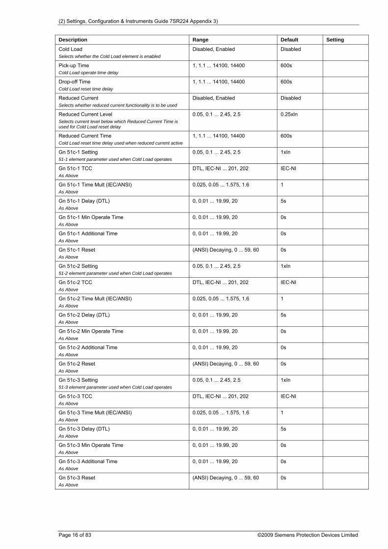
2.5.3. COLD LOAD Description Range Default Setting
(2) Settings, Configuration & Instruments Guide 7SR224 Appendix 3)
Page 16 of 83 ©2009 Siemens Protection Devices Limited
Description Range Default Setting
Cold Load Selects whether the Cold Load element is enabled
Disabled, Enabled Disabled
Pick-up Time Cold Load operate time delay
1, 1.1 ... 14100, 14400 600s
Drop-off Time Cold Load reset time delay
1, 1.1 ... 14100, 14400 600s
Reduced Current Selects whether reduced current functionality is to be used
Disabled, Enabled Disabled
Reduced Current Level Selects current level below which Reduced Current Time is used for Cold Load reset delay
0.05, 0.1 ... 2.45, 2.5 0.25xIn
Reduced Current Time Cold Load reset time delay used when reduced current active
1, 1.1 ... 14100, 14400 600s
Gn 51c-1 Setting 51-1 element parameter used when Cold Load operates
0.05, 0.1 ... 2.45, 2.5 1xIn
Gn 51c-1 TCC As Above
DTL, IEC-NI ... 201, 202 IEC-NI
Gn 51c-1 Time Mult (IEC/ANSI) As Above
0.025, 0.05 ... 1.575, 1.6 1
Gn 51c-1 Delay (DTL) As Above
0, 0.01 ... 19.99, 20 5s
Gn 51c-1 Min Operate Time As Above
0, 0.01 ... 19.99, 20 0s
Gn 51c-1 Additional Time As Above
0, 0.01 ... 19.99, 20 0s
Gn 51c-1 Reset As Above
(ANSI) Decaying, 0 ... 59, 60 0s
Gn 51c-2 Setting 51-2 element parameter used when Cold Load operates
0.05, 0.1 ... 2.45, 2.5 1xIn
Gn 51c-2 TCC As Above
DTL, IEC-NI ... 201, 202 IEC-NI
Gn 51c-2 Time Mult (IEC/ANSI) As Above
0.025, 0.05 ... 1.575, 1.6 1
Gn 51c-2 Delay (DTL) As Above
0, 0.01 ... 19.99, 20 5s
Gn 51c-2 Min Operate Time As Above
0, 0.01 ... 19.99, 20 0s
Gn 51c-2 Additional Time As Above
0, 0.01 ... 19.99, 20 0s
Gn 51c-2 Reset As Above
(ANSI) Decaying, 0 ... 59, 60 0s
Gn 51c-3 Setting 51-3 element parameter used when Cold Load operates
0.05, 0.1 ... 2.45, 2.5 1xIn
Gn 51c-3 TCC As Above
DTL, IEC-NI ... 201, 202 IEC-NI
Gn 51c-3 Time Mult (IEC/ANSI) As Above
0.025, 0.05 ... 1.575, 1.6 1
Gn 51c-3 Delay (DTL) As Above
0, 0.01 ... 19.99, 20 5s
Gn 51c-3 Min Operate Time As Above
0, 0.01 ... 19.99, 20 0s
Gn 51c-3 Additional Time As Above
0, 0.01 ... 19.99, 20 0s
Gn 51c-3 Reset As Above
(ANSI) Decaying, 0 ... 59, 60 0s

(2) Settings, Configuration & Instruments Guide 7SR224 Appendix 3)
©2009 Siemens Protection Devices Limited Page 17 of 83
Description Range Default Setting
Gn 51c-4 Setting 51-4 element parameter used when Cold Load operates
0.05, 0.1 ... 2.45, 2.5 1xIn
Gn 51c-4 TCC As Above
DTL, IEC-NI ... 201, 202 IEC-NI
Gn 51c-4 Time Mult (IEC/ANSI) As Above
0.025, 0.05 ... 1.575, 1.6 1
Gn 51c-4 Delay (DTL) As Above
0, 0.01 ... 19.99, 20 5s
Gn 51c-4 Min Operate Time As Above
0, 0.01 ... 19.99, 20 0s
Gn 51c-4 Additional Time As Above
0, 0.01 ... 19.99, 20 0s
Gn 51c-4 Reset As Above
(ANSI) Decaying, 0 ... 59, 60 0s
2.5.4. MEASURED G/F Description Range Default Setting
Gn 67G Char Angle Maximum torque angle for measured ground fault elements
-95, -94 ... 94, 95 -15deg
Gn 67G Minimum Voltage Selects the directional elements minimum voltage, below which the element will be inhibited
0.33, 0.5, 1, 1.5, 2, 2.5, 3 0.33V
Gn 51G/50G Measurement Selects whether the RMS value used by the 51G & 50G elements is True RMS or only calculated at fundamental frequency
RMS, Fundamental RMS
2.5.4.1. 51G-1 Description Range Default Setting
Gn 51G-1 Element Selects whether the 51G-1 IDMTL measured Ground Fault element is enabled
Disabled, Enabled Disabled
Gn 51G-1 Dir. Control Selects whether 51G-1 element is non-directional, forward or reverse
Non-Dir, Forward, Reverse Non-Dir
Gn 51G-1 Setting Pickup level
0.005, 0.01 ... 0.995, 1 0.5xIn
Gn 51G-1 TCC Selects characteristic curve to be IEC or ANSI IDMTL or DTL
DTL, IEC-NI ... 201, 202 IEC-NI
Gn 51G-1 Time Mult (IEC/ANSI) Time multiplier (applicable to IEC and ANSI curves but not DTL selection)
0.025, 0.05 ... 1.575, 1.6 1
Gn 51G-1 Delay (DTL) Delay (applicable only when DTL is selected for characteristic)
0, 0.01 ... 19.99, 20 5s
Gn 51G-1 Min Operate Time Minimum operate time of element.
0, 0.01 ... 19.99, 20 0s
Gn 51G-1 Additional Time Additional definite time added after characteristic time
0, 0.01 ... 19.99, 20 0s
Gn 51G-1 Reset Selects between an ANSI decaying reset characteristic or DTL reset
(ANSI) Decaying, 0 ... 59, 60 0s
Gn 51G-1 VTS Action Selects whether 51G-1 element is blocked or made non-directional when VTS operates
Off, Inhibit, Non-Dir Off
Gn 51G-1 Inrush Action Selects if the 51G-1 element is blocked from operating when 2nd Harmonic Inrush Detector operates
Off, Inhibit Off

(2) Settings, Configuration & Instruments Guide 7SR224 Appendix 3)
Page 18 of 83 ©2009 Siemens Protection Devices Limited
2.5.4.2. 51G-2 Description Range Default Setting
Gn 51G-2 Element Selects whether the 51G-2 IDMTL measured Ground Fault element is enabled
Disabled, Enabled Disabled
Gn 51G-2 Dir. Control Selects whether 51G-2 element is non-directional, forward or reverse
Non-Dir, Forward, Reverse Non-Dir
Gn 51G-2 Setting Pickup level
0.005, 0.01 ... 0.995, 1 0.5xIn
Gn 51G-2 TCC Selects characteristic curve to be IEC or ANSI IDMTL or DTL
DTL, IEC-NI ... 201, 202 IEC-NI
Gn 51G-2 Time Mult (IEC/ANSI) Time multiplier (applicable to IEC and ANSI curves but not DTL selection)
0.025, 0.05 ... 1.575, 1.6 1
Gn 51G-2 Delay (DTL) Delay (applicable only when DTL is selected for characteristic)
0, 0.01 ... 19.99, 20 5s
Gn 51G-2 Min Operate Time Minimum operate time of element.
0, 0.01 ... 19.99, 20 0s
Gn 51G-2 Additional Time Additional definite time added after characteristic time
0, 0.01 ... 19.99, 20 0s
Gn 51G-2 Reset Selects between an ANSI decaying reset characteristic or DTL reset
(ANSI) Decaying, 0 ... 59, 60 0s
Gn 51G-2 VTS Action Selects whether 51G-2 element is blocked or made non-directional when VTS operates
Off, Inhibit, Non-Dir Off
Gn 51G-2 Inrush Action Selects if the 51G-2 element is blocked from operating when 2nd Harmonic Inrush Detector operates
Off, Inhibit Off
2.5.4.3. 51G-3 Description Range Default Setting
Gn 51G-3 Element Selects whether the 51G-3 IDMTL measured Ground Fault element is enabled
Disabled, Enabled Disabled
Gn 51G-3 Dir. Control Selects whether 51G-3 element is non-directional, forward or reverse
Non-Dir, Forward, Reverse Non-Dir
Gn 51G-3 Setting Pickup level
0.005, 0.01 ... 0.995, 1 0.5xIn
Gn 51G-3 TCC Selects characteristic curve to be IEC or ANSI IDMTL or DTL
DTL, IEC-NI ... 201, 202 IEC-NI
Gn 51G-3 Time Mult (IEC/ANSI) Time multiplier (applicable to IEC and ANSI curves but not DTL selection)
0.025, 0.05 ... 1.575, 1.6 1
Gn 51G-3 Delay (DTL) Delay (applicable only when DTL is selected for characteristic)
0, 0.01 ... 19.99, 20 5s
Gn 51G-3 Min Operate Time Minimum operate time of element.
0, 0.01 ... 19.99, 20 0s
Gn 51G-3 Additional Time Additional definite time added after characteristic time
0, 0.01 ... 19.99, 20 0s
Gn 51G-3 Reset Selects between an ANSI decaying reset characteristic or DTL reset
(ANSI) Decaying, 0 ... 59, 60 0s
Gn 51G-3 VTS Action Selects whether 51G-3 element is blocked or made non-directional when VTS operates
Off, Inhibit, Non-Dir Off

(2) Settings, Configuration & Instruments Guide 7SR224 Appendix 3)
©2009 Siemens Protection Devices Limited Page 19 of 83
Description Range Default Setting
Gn 51G-3 Inrush Action Selects if the 51G-3 element is blocked from operating when 2nd Harmonic Inrush Detector operates
Off, Inhibit Off
2.5.4.4. 51G-4 Description Range Default Setting
Gn 51G-4 Element Selects whether the 51G-4 IDMTL measured Ground Fault element is enabled
Disabled, Enabled Disabled
Gn 51G-4 Dir. Control Selects whether 51G-4 element is non-directional, forward or reverse
Non-Dir, Forward, Reverse Non-Dir
Gn 51G-4 Setting Pickup level
0.005, 0.01 ... 0.995, 1 0.5xIn
Gn 51G-4 TCC Selects characteristic curve to be IEC or ANSI IDMTL or DTL
DTL, IEC-NI ... 201, 202 IEC-NI
Gn 51G-4 Time Mult (IEC/ANSI) Time multiplier (applicable to IEC and ANSI curves but not DTL selection)
0.025, 0.05 ... 1.575, 1.6 1
Gn 51G-4 Delay (DTL) Delay (applicable only when DTL is selected for characteristic)
0, 0.01 ... 19.99, 20 5s
Gn 51G-4 Min Operate Time Minimum operate time of element.
0, 0.01 ... 19.99, 20 0s
Gn 51G-4 Additional Time Additional definite time added after characteristic time
0, 0.01 ... 19.99, 20 0s
Gn 51G-4 Reset Selects between an ANSI decaying reset characteristic or DTL reset
(ANSI) Decaying, 0 ... 59, 60 0s
Gn 51G-4 VTS Action Selects whether 51G-4 element is blocked or made non-directional when VTS operates
Off, Inhibit, Non-Dir Off
Gn 51G-4 Inrush Action Selects if the 51G-4 element is blocked from operating when 2nd Harmonic Inrush Detector operates
Off, Inhibit Off
2.5.4.5. 50G-1 Description Range Default Setting
Gn 50G-1 Element Selects whether the DTL measured Ground fault element is enabled
Disabled, Enabled Disabled
Gn 50G-1 Dir. Control Selects whether 50G-1 element is non-directional, forward or reverse
Non-Dir, Forward, Reverse Non-Dir
Gn 50G-1 Setting Pickup level
0.005, 0.01 ... 24.995, 25 0.5xIn
Gn 50G-1 Delay Sets operate delay time
0, 0.01 ... 14300, 14400 0s
Gn 50G-1 VTS Action Selects whether 50G-1 element is blocked or made non-directional when VTS operates
Off, Inhibit, Non-Dir Off
Gn 50G-1 Inrush Action Selects if the 50G-1 element is blocked from operating when 2nd Harmonic Inrush Detector operates
Off, Inhibit Off
2.5.4.6. 50G-2 Description Range Default Setting
Gn 50G-2 Element Selects whether the DTL measured Ground fault element is enabled
Disabled, Enabled Disabled

(2) Settings, Configuration & Instruments Guide 7SR224 Appendix 3)
Page 20 of 83 ©2009 Siemens Protection Devices Limited
Description Range Default Setting
Gn 50G-2 Dir. Control Selects whether 50G-2 element is non-directional, forward or reverse
Non-Dir, Forward, Reverse Non-Dir
Gn 50G-2 Setting Pickup level
0.005, 0.01 ... 24.995, 25 0.5xIn
Gn 50G-2 Delay Sets operate delay time
0, 0.01 ... 14300, 14400 0s
Gn 50G-2 VTS Action Selects whether 50G-2 element is blocked or made non-directional when VTS operates
Off, Inhibit, Non-Dir Off
Gn 50G-2 Inrush Action Selects if the 50G-2 element is blocked from operating when 2nd Harmonic Inrush Detector operates
Off, Inhibit Off
2.5.4.7. 50G-3 Description Range Default Setting
Gn 50G-3 Element Selects whether the DTL measured Ground fault element is enabled
Disabled, Enabled Disabled
Gn 50G-3 Dir. Control Selects whether 50G-3 element is non-directional, forward or reverse
Non-Dir, Forward, Reverse Non-Dir
Gn 50G-3 Setting Pickup level
0.005, 0.01 ... 24.995, 25 0.5xIn
Gn 50G-3 Delay Sets operate delay time
0, 0.01 ... 14300, 14400 0s
Gn 50G-3 VTS Action Selects whether 50G-3 element is blocked or made non-directional when VTS operates
Off, Inhibit, Non-Dir Off
Gn 50G-3 Inrush Action Selects if the 50G-3 element is blocked from operating when 2nd Harmonic Inrush Detector operates
Off, Inhibit Off
2.5.4.8. 50G-4 Description Range Default Setting
Gn 50G-4 Element Selects whether the DTL measured Ground fault element is enabled
Disabled, Enabled Disabled
Gn 50G-4 Dir. Control Selects whether 50G-4 element is non-directional, forward or reverse
Non-Dir, Forward, Reverse Non-Dir
Gn 50G-4 Setting Pickup level
0.005, 0.01 ... 24.995, 25 0.5xIn
Gn 50G-4 Delay Sets operate delay time
0, 0.01 ... 14300, 14400 0s
Gn 50G-4 VTS Action Selects whether 50G-4 element is blocked or made non-directional when VTS operates
Off, Inhibit, Non-Dir Off
Gn 50G-4 Inrush Action Selects if the 50G-4 element is blocked from operating when 2nd Harmonic Inrush Detector operates
Off, Inhibit Off
2.5.5. SENSITIVE G/F Description Range Default Setting
Gn 67SGF Char Angle Maximum torque angle for sensitive ground fault elements
-95, -94 ... 94, 95 -15deg

(2) Settings, Configuration & Instruments Guide 7SR224 Appendix 3)
©2009 Siemens Protection Devices Limited Page 21 of 83
Description Range Default Setting
Gn 67SGF Minimum Voltage Selects the directional elements minimum voltage, below which the element will be inhibited
0.33, 0.5, 1, 1.5, 2, 2.5, 3 0.33V
2.5.5.1. 51SGF-1 Description Range Default Setting
Gn 51SGF-1 Element Selects whether the 51SGF-1 IDMTL derived Ground Fault element is enabled
Disabled, Enabled Disabled
Gn 51SGF-1 Dir. Control Selects whether 51SGF-1 element is non-directional, forward or reverse
Non-Dir, Forward, Reverse Non-Dir
Gn 51SGF-1 Setting Pickup level
0.005, 0.01 ... 0.995, 1 0.2xIn
Gn 51SGF-1 TCC Selects characteristic curve to be IEC or ANSI IDMTL or DTL
DTL, IEC-NI ... 201, 202 IEC-NI
Gn 51SGF-1 Time Mult (IEC/ANSI) Time multiplier (applicable to IEC and ANSI curves but not DTL selection)
0.025, 0.05 ... 1.575, 1.6 1
Gn 51SGF-1 Delay (DTL) Delay (applicable only when DTL is selected for characteristic)
0, 0.01 ... 19.99, 20 5s
Gn 51SGF-1 Min Operate Time Minimum operate time of element.
0, 0.01 ... 19.99, 20 0s
Gn 51SGF-1 Additional Time Additional definite time added after characteristic time
0, 0.01 ... 19.99, 20 0s
Gn 51SGF-1 Reset Selects between an ANSI decaying reset characteristic or DTL reset
(ANSI) Decaying, 0 ... 59, 60 0s
Gn 51SGF-1 VTS Action Selects whether 51SGF-1 element is blocked or made non-directional when VTS operates
Off, Inhibit, Non-Dir Off
2.5.5.2. 51SGF-2 Description Range Default Setting
Gn 51SGF-2 Element Selects whether the 51SGF-2 IDMTL derived Ground Fault element is enabled
Disabled, Enabled Disabled
Gn 51SGF-2 Dir. Control Selects whether 51SGF-2 element is non-directional, forward or reverse
Non-Dir, Forward, Reverse Non-Dir
Gn 51SGF-2 Setting Pickup level
0.005, 0.01 ... 0.995, 1 0.2xIn
Gn 51SGF-2 TCC Selects characteristic curve to be IEC or ANSI IDMTL or DTL
DTL, IEC-NI ... 201, 202 IEC-NI
Gn 51SGF-2 Time Mult (IEC/ANSI) Time multiplier (applicable to IEC and ANSI curves but not DTL selection)
0.025, 0.05 ... 1.575, 1.6 1
Gn 51SGF-2 Delay (DTL) Delay (applicable only when DTL is selected for characteristic)
0, 0.01 ... 19.99, 20 5s
Gn 51SGF-2 Min Operate Time Minimum operate time of element.
0, 0.01 ... 19.99, 20 0s
Gn 51SGF-2 Additional Time Additional definite time added after characteristic time
0, 0.01 ... 19.99, 20 0s
Gn 51SGF-2 Reset Selects between an ANSI decaying reset characteristic or DTL reset
(ANSI) Decaying, 0 ... 59, 60 0s
Gn 51SGF-2 VTS Action Selects whether 51SGF-2 element is blocked or made non-directional when VTS operates
Off, Inhibit, Non-Dir Off

(2) Settings, Configuration & Instruments Guide 7SR224 Appendix 3)
Page 22 of 83 ©2009 Siemens Protection Devices Limited
2.5.5.3. 51SGF-3 Description Range Default Setting
Gn 51SGF-3 Element Selects whether the 51SGF-3 IDMTL derived Ground Fault element is enabled
Disabled, Enabled Disabled
Gn 51SGF-3 Dir. Control Selects whether 51SGF-3 element is non-directional, forward or reverse
Non-Dir, Forward, Reverse Non-Dir
Gn 51SGF-3 Setting Pickup level
0.005, 0.01 ... 0.995, 1 0.2xIn
Gn 51SGF-3 TCC Selects characteristic curve to be IEC or ANSI IDMTL or DTL
DTL, IEC-NI ... 201, 202 IEC-NI
Gn 51SGF-3 Time Mult (IEC/ANSI) Time multiplier (applicable to IEC and ANSI curves but not DTL selection)
0.025, 0.05 ... 1.575, 1.6 1
Gn 51SGF-3 Delay (DTL) Delay (applicable only when DTL is selected for characteristic)
0, 0.01 ... 19.99, 20 5s
Gn 51SGF-3 Min Operate Time Minimum operate time of element.
0, 0.01 ... 19.99, 20 0s
Gn 51SGF-3 Additional Time Additional definite time added after characteristic time
0, 0.01 ... 19.99, 20 0s
Gn 51SGF-3 Reset Selects between an ANSI decaying reset characteristic or a definite time reset
(ANSI) Decaying, 0 ... 59, 60 0s
Gn 51SGF-3 VTS Action Selects whether 51SGF-3 element is blocked or made non-directional when VTS operates
Off, Inhibit, Non-Dir Off
2.5.5.4. 51SGF-4 Description Range Default Setting
Gn 51SGF-4 Element Selects whether the 51SGF-4 IDMTL derived Ground Fault element is enabled
Disabled, Enabled Disabled
Gn 51SGF-4 Dir. Control Selects whether 51SGF-4 element is non-directional, forward or reverse
Non-Dir, Forward, Reverse Non-Dir
Gn 51SGF-4 Setting Pickup level
0.005, 0.01 ... 0.995, 1 0.2xIn
Gn 51SGF-4 TCC Selects characteristic curve to be IEC or ANSI IDMTL or DTL
DTL, IEC-NI ... 201, 202 IEC-NI
Gn 51SGF-4 Time Mult (IEC/ANSI) Time multiplier (applicable to IEC and ANSI curves but not DTL selection)
0.025, 0.05 ... 1.575, 1.6 1
Gn 51SGF-4 Delay (DTL) Delay (applicable only when DTL is selected for characteristic)
0, 0.01 ... 19.99, 20 5s
Gn 51SGF-4 Min Operate Time Minimum operate time of element.
0, 0.01 ... 19.99, 20 0s
Gn 51SGF-4 Additional Time Additional definite time added after characteristic time
0, 0.01 ... 19.99, 20 0s
Gn 51SGF-4 Reset Selects between an ANSI decaying reset characteristic or a definite time reset
(ANSI) Decaying, 0 ... 59, 60 0s
Gn 51SGF-4 VTS Action Selects whether 51SGF-4 element is blocked or made non-directional when VTS operates
Off, Inhibit, Non-Dir Off
2.5.5.5. 50SGF-1 Description Range Default Setting

(2) Settings, Configuration & Instruments Guide 7SR224 Appendix 3)
©2009 Siemens Protection Devices Limited Page 23 of 83
Description Range Default Setting
Gn 50SGF-1 Element Selects whether the DTL measured Ground fault element is enabled
Disabled, Enabled Disabled
Gn 50SGF-1 Dir. Control Selects whether 50SGF-1 element is non-directional, forward or reverse
Non-Dir, Forward, Reverse Non-Dir
Gn 50SGF-1 Setting Pickup level
0.005, 0.01 ... 4.995, 5 0.2xIn
Gn 50SGF-1 Delay Sets operate delay time
0, 0.01 ... 14300, 14400 0s
Gn 50SGF-1 VTS Action Selects whether 50SGF-1 element is blocked or made non-directional when VTS operates
Off, Inhibit, Non-Dir Off
2.5.5.6. 50SGF-2 Description Range Default Setting
Gn 50SGF-2 Element Selects whether the DTL measured Ground fault element is enabled
Disabled, Enabled Disabled
Gn 50SGF-2 Dir. Control Selects whether 50SGF-2 element is non-directional, forward or reverse
Non-Dir, Forward, Reverse Non-Dir
Gn 50SGF-2 Setting Pickup level
0.005, 0.01 ... 4.995, 5 0.2xIn
Gn 50SGF-2 Delay Sets operate delay time
0, 0.01 ... 14300, 14400 0s
Gn 50SGF-2 VTS Action Selects whether 50SGF-2 element is blocked or made non-directional when VTS operates
Off, Inhibit, Non-Dir Off
2.5.5.7. 50SGF-3 Description Range Default Setting
Gn 50SGF-3 Element Selects whether the DTL measured Ground fault element is enabled
Disabled, Enabled Disabled
Gn 50SGF-3 Dir. Control Selects whether 50SGF-3 element is non-directional, forward or reverse
Non-Dir, Forward, Reverse Non-Dir
Gn 50SGF-3 Setting Pickup level
0.005, 0.01 ... 4.995, 5 0.2xIn
Gn 50SGF-3 Delay Sets operate delay time
0, 0.01 ... 14300, 14400 0s
Gn 50SGF-3 VTS Action Selects whether 50SGF-3 element is blocked or made non-directional when VTS operates
Off, Inhibit, Non-Dir Off
2.5.5.8. 50SGF-4 Description Range Default Setting
Gn 50SGF-4 Element Selects whether the DTL measured Ground fault element is enabled
Disabled, Enabled Disabled
Gn 50SGF-4 Dir. Control Selects whether 50SGF-4 element is non-directional, forward or reverse
Non-Dir, Forward, Reverse Non-Dir
Gn 50SGF-4 Setting Pickup level
0.005, 0.01 ... 4.995, 5 0.2xIn
Gn 50SGF-4 Delay Sets operate delay time
0, 0.01 ... 14300, 14400 0s

(2) Settings, Configuration & Instruments Guide 7SR224 Appendix 3)
Page 24 of 83 ©2009 Siemens Protection Devices Limited
Description Range Default Setting
Gn 50SGF-4 VTS Action Selects whether 50SGF-4 element is blocked or made non-directional when VTS operates
Off, Inhibit, Non-Dir Off
2.5.6. RESTRICTED G/F Description Range Default Setting
Gn 64H Element High impedance restricted ground fault current element
Disabled, Enabled Disabled
Gn 64H Setting Pickup level
0.005, 0.01 ... 0.945, 0.95 0.2xIn
Gn 64H Delay Sets operate delay time
0, 0.01 ... 14300, 14400 0s
2.5.7. NPS OVERCURRENT 2.5.7.1. 46IT Description Range Default Setting
Gn 46IT Element Selects whether the 46IT IDMTL/DTL negative phase sequence current element is enabled
Disabled, Enabled Disabled
Gn 46IT Setting Pickup level
0.05, 0.06 ... 2.49, 2.5 0.25xIn
Gn 46IT TCC Selects characteristic curve to be IEC or ANSI IDMTL or DTL
DTL, IEC-NI, IEC-VI, IEC-EI, IEC-LTI, ANSI-MI, ANSI-VI, ANSI-EI
IEC-NI
Gn 46IT Time Mult (IEC/ANSI) Time multiplier (applicable to IEC and ANSI curves but not DTL selection)
0.025, 0.05 ... 1.575, 1.6 1
Gn 46IT Delay (DTL) Delay (applicable only when DTL is selected for characteristic)
0, 0.01 ... 19.99, 20 5s
Gn 46IT Reset Selects between an ANSI decaying reset characteristic or a definite time reset
(ANSI) Decaying, 0 ... 59, 60 0s
2.5.7.2. 46DT Description Range Default Setting
Gn 46DT Element Selects whether the 46DT INST/DTL negative sequence current element is enabled
Disabled, Enabled Disabled
Gn 46DT Setting Pickup level
0.05, 0.06 ... 3.99, 4 0.1xIn
Gn 46DT Delay Sets operate delay time
0, 0.01 ... 14300, 14400 0.02s
2.5.8. UNDER CURRENT 2.5.8.1. 37-1 Description Range Default Setting
Gn 37-1 Element Phase under current element 37-1
Disabled, Enabled Disabled
Gn 37-1 Setting Pickup level
0.05, 0.1 ... 4.95, 5 0.25xIn
Gn 37-1 Delay Sets operate delay time
0, 0.01 ... 14300, 14400 0s

(2) Settings, Configuration & Instruments Guide 7SR224 Appendix 3)
©2009 Siemens Protection Devices Limited Page 25 of 83
2.5.8.2. 37-2 Description Range Default Setting
Gn 37-2 Element Phase under current element 37-2
Disabled, Enabled Disabled
Gn 37-2 Setting Pickup level
0.05, 0.1 ... 4.95, 5 0.25xIn
Gn 37-2 Delay Sets operate delay time
0, 0.01 ... 14300, 14400 0s
2.5.9. THERMAL Description Range Default Setting
Gn 49 Thermal Overload Selects whether the thermal overload protection element is enabled
Disabled, Enabled Disabled
Gn 49 Overload Setting Pickup level
0.1, 0.11 ... 2.99, 3 1.05xIn
Gn 49 Time Constant Thermal time constant
1, 1.5 ... 999.5, 1000 10m
Gn 49 Capacity Alarm Selects whether thermal capacity alarm enabled
Disabled, 50 ... 99, 100 Disabled%
49 Reset Therm State Control that allows thermal state to be manually reset
No, Yes No
2.6. VOLTAGE PROT'N 2.6.1. PHASE U/O VOLTAGE Description Range Default Setting
Gn Voltage Input Mode Selects Ph-Ph or Ph-N voltages for U/V guard element & 27/59 elements operation.
Ph-N, Ph-Ph Ph-N
Gn 27/59 U/V Guard Setting Selects voltage level below which the guard element is applied.
1, 1.5 ... 199.5, 200 5V
2.6.1.1. 27/59-1 Description Range Default Setting
Gn 27/59-1 Element Selects whether the Under/Over voltage element stage 1 is enabled
Disabled, Enabled Disabled
Gn 27/59-1 Operation Selects between Undervoltage and Overvoltage pickup for this element
Under, Over Over
Gn 27/59-1 Setting Under or over voltage pickup level
5, 5.5 ... 199.5, 200 80V
Gn 27/59-1 Hysteresis Sets the pickup to dropoff thresholds e.g. 3% on Overlevel picks up above pickup setting and drops off below 97% of setting, 3% on Underlevel picks up below setting and drops off above 103% of setting
0, 0.1 ... 79.9, 80 3%
Gn 27/59-1 Delay Sets operate delay time
0, 0.01 ... 14300, 14400 0.1s
Gn 27/59-1 U/V Guarded Selects whether U/V Guard element can block the operation of this element
No, Yes No
Gn 27/59-1 VTS Inhibit Selects whether element is blocked or not when VTS operates
No, Yes No

(2) Settings, Configuration & Instruments Guide 7SR224 Appendix 3)
Page 26 of 83 ©2009 Siemens Protection Devices Limited
Description Range Default Setting
Gn 27/59-1 O/P Phases Selects whether element operates for any phase picked up or only when all phases are picked up
Any, All Any
2.6.1.2. 27/59-2 Description Range Default Setting
Gn 27/59-2 Element Selects whether the Under/Over voltage element stage 2 is enabled
Disabled, Enabled Disabled
Gn 27/59-2 Operation Selects between Undervoltage and Overvoltage pickup for this element
Under, Over Over
Gn 27/59-2 Setting Under or over voltage pickup level
5, 5.5 ... 199.5, 200 80V
Gn 27/59-2 Hysteresis Sets the pickup to dropoff thresholds e.g. 3% on Overlevel picks up above pickup setting and drops off below 97% of setting, 3% on Underlevel picks up below setting and drops off above 103% of setting
0, 0.1 ... 79.9, 80 3%
Gn 27/59-2 Delay Sets operate delay time
0, 0.01 ... 14300, 14400 0.1s
Gn 27/59-2 U/V Guarded Selects whether U/V Guard element can block the operation of this element
No, Yes No
Gn 27/59-2 VTS Inhibit Selects whether element is blocked or not when VTS operates
No, Yes No
Gn 27/59-2 O/P Phases Selects whether element operates for any phase picked up or only when all phases are picked up
Any, All Any
2.6.1.3. 27/59-3 Description Range Default Setting
Gn 27/59-3 Element Selects whether the Under/Over voltage element stage 3 is enabled
Disabled, Enabled Disabled
Gn 27/59-3 Operation Selects between Undervoltage and Overvoltage pickup for this element
Under, Over Under
Gn 27/59-3 Setting Under or over voltage pickup level
5, 5.5 ... 199.5, 200 50V
Gn 27/59-3 Hysteresis Sets the pickup to dropoff thresholds e.g. 3% on Overlevel picks up above pickup setting and drops off below 97% of setting, 3% on Underlevel picks up below setting and drops off above 103% of setting
0, 0.1 ... 79.9, 80 3%
Gn 27/59-3 Delay Sets operate delay time
0, 0.01 ... 14300, 14400 0.1s
Gn 27/59-3 U/V Guarded Selects whether U/V Guard element can block the operation of this element
No, Yes Yes
Gn 27/59-3 VTS Inhibit Selects whether element is blocked or not when VTS operates
No, Yes No
Gn 27/59-3 O/P Phases Selects whether element operates for any phase picked up or only when all phases are picked up
Any, All Any
2.6.1.4. 27/59-4 Description Range Default Setting

(2) Settings, Configuration & Instruments Guide 7SR224 Appendix 3)
©2009 Siemens Protection Devices Limited Page 27 of 83
Description Range Default Setting
Gn 27/59-4 Element Selects whether the Under/Over voltage element stage 4 is enabled
Disabled, Enabled Disabled
Gn 27/59-4 Operation Selects between Undervoltage and Overvoltage pickup for this element
Under, Over Under
Gn 27/59-4 Setting Under or over voltage pickup level
5, 5.5 ... 199.5, 200 50V
Gn 27/59-4 Hysteresis Sets the pickup to dropoff thresholds e.g. 3% on Overlevel picks up above pickup setting and drops off below 97% of setting, 3% on Underlevel picks up below setting and drops off above 103% of setting
0, 0.1 ... 79.9, 80 3%
Gn 27/59-4 Delay Sets operate delay time
0, 0.01 ... 14300, 14400 0.1s
Gn 27/59-4 U/V Guarded Selects whether U/V Guard element can block the operation of this element
No, Yes Yes
Gn 27/59-4 VTS Inhibit Selects whether element is blocked or not when VTS operates
No, Yes No
Gn 27/59-4 O/P Phases Selects whether element operates for any phase picked up or only when all phases are picked up
Any, All Any
2.6.2. VX U/O VOLTAGE Description Range Default Setting
Gn Vx 27/59 Element Selects whether the Under/Over voltage element for Vx is enabled
Disabled, Enabled Disabled
Gn Vx 27/59 Operation Selects between Undervoltage and Overvoltage pickup for this element
Under, Over Over
Gn Vx 27/59 Setting Under or over voltage pickup level
5, 5.5 ... 199.5, 200 80V
Gn Vx 27/59 Hysteresis Sets the pickup to dropoff thresholds e.g. 3% on Overlevel picks up above pickup setting and drops off below 97% of setting, 3% on Underlevel picks up below setting and drops off above 103% of setting
0, 0.1 ... 79.9, 80 3%
Gn Vx 27/59 Delay Sets operate delay time
0, 0.01 ... 14300, 14400 0.1s
2.6.3. NPS OVERVOLTAGE 2.6.3.1. 47-1 Description Range Default Setting
Gn 47-1 Element Selects whether the definite time NPS overvoltage element is enabled
Disabled, Enabled Disabled
Gn 47-1 Setting Pickup level
1, 1.5 ... 89.5, 90 20V
Gn 47-1 Hysteresis Sets the pickup to drop-off thresholds e.g. 3% picks up at setting and drops off below 97% of setting
0, 0.1 ... 79.9, 80 3%
Gn 47-1 Delay Sets operate delay time
0, 0.01 ... 14300, 14400 1s

(2) Settings, Configuration & Instruments Guide 7SR224 Appendix 3)
Page 28 of 83 ©2009 Siemens Protection Devices Limited
2.6.3.2. 47-2 Description Range Default Setting
Gn 47-2 Element Selects whether the definite time NPS overvoltage element is enabled
Disabled, Enabled Disabled
Gn 47-2 Setting Pickup level
1, 1.5 ... 89.5, 90 20V
Gn 47-2 Hysteresis Sets the pickup to drop-off thresholds e.g. 3% picks up at setting and drops off below 97% of setting
0, 0.1 ... 79.9, 80 3%
Gn 47-2 Delay Sets operate delay time
0, 0.01 ... 14300, 14400 0.5s
2.6.4. NEUTRAL OVERVOLTAGE Description Range Default Setting
Gn 59N Voltage Source Selects voltage source between calculated 3V0 (Vn) or measured 3V0 through Vx input
Vn, Vx Vn
2.6.4.1. 59NIT Description Range Default Setting
Gn 59NIT Element Selects whether the inverse time neutral over voltage element is enabled
Disabled, Enabled Disabled
Gn 59NIT Setting Pickup level
1, 1.5 ... 99.5, 100 5V
Gn 59NIT TCC Selects characteristic curve to be IDMTL or DTL
DTL, IDMTL IDMTL
Gn 59NIT Time Mult (IDMTL) Time multiplier (applicable to IDMTL curve but not DTL selection)
0.1, 0.2 ... 139.5, 140 1
Gn 59NIT Delay (DTL) Delay (applicable only when DTL is selected for characteristic)
0, 0.01 ... 19.99, 20 5s
Gn 59NIT Reset Selects between an instantaneous reset characteristic or a definite time reset
(ANSI) Decaying, 0 ... 59, 60 0s
2.6.4.2. 59NDT Description Range Default Setting
Gn 59NDT Element Selects whether the definite time neutral over voltage element is enabled
Disabled, Enabled Disabled
Gn 59NDT Setting Pickup level
1, 1.5 ... 99.5, 100 5V
Gn 59NDT Delay Sets operate delay time
0, 0.01 ... 14300, 14400 0.01s
2.6.5. U/O FREQUENCY Description Range Default Setting
Gn 81 U/V Guard Setting Selects voltage level below which the guard element is applied.
5, 5.5 ... 199.5, 200 5V
2.6.5.1. 81-1 Description Range Default Setting

(2) Settings, Configuration & Instruments Guide 7SR224 Appendix 3)
©2009 Siemens Protection Devices Limited Page 29 of 83
Description Range Default Setting
Gn 81-1 Element Selects whether the Under/Over frequency element stage 1 is enabled
Disabled, Enabled Disabled
Gn 81-1 Operation Selects between Underfrequency and Overfrequency pickup for this element
Under, Over Under
Gn 81-1 Setting Under or over frequency pickup level
40, 40.01 ... 69.98, 69.99 49.5Hz
Gn 81-1 Hysteresis Sets the pickup to dropoff thresholds e.g. 3% on Overlevel picks up above pickup setting and drops off below 97% of setting, 3% on Underlevel picks up below setting and drops off above 103% of setting
0, 0.1 ... 79.9, 80 0.1%
Gn 81-1 Delay Sets operate delay time
0, 0.1 ... 14300, 14400 1s
Gn 81-1 U/V Guarded Selects whether U/V Guard element can block the operation of this element
No, Yes Yes
2.6.5.2. 81-2 Description Range Default Setting
Gn 81-2 Element Selects whether the Under/Over frequency element stage 2 is enabled
Disabled, Enabled Disabled
Gn 81-2 Operation Selects between Underfrequency and Overfrequency pickup for this element
Under, Over Under
Gn 81-2 Setting Under or over frequency pickup level
40, 40.01 ... 69.98, 69.99 49Hz
Gn 81-2 Hysteresis Sets the pickup to dropoff thresholds e.g. 3% on Overlevel picks up above pickup setting and drops off below 97% of setting, 3% on Underlevel picks up below setting and drops off above 103% of setting
0, 0.1 ... 79.9, 80 0.1%
Gn 81-2 Delay Sets operate delay time
0, 0.1 ... 14300, 14400 0.8s
Gn 81-2 U/V Guarded Selects whether U/V Guard element can block the operation of this element
No, Yes Yes
2.6.5.3. 81-3 Description Range Default Setting
Gn 81-3 Element Selects whether the Under/Over frequency element stage 3 is enabled
Disabled, Enabled Disabled
Gn 81-3 Operation Selects between Underfrequency and Overfrequency pickup for this element
Under, Over Under
Gn 81-3 Setting Under or over frequency pickup level
40, 40.01 ... 69.98, 69.99 48Hz
Gn 81-3 Hysteresis Sets the pickup to dropoff thresholds e.g. 3% on Overlevel picks up above pickup setting and drops off below 97% of setting, 3% on Underlevel picks up below setting and drops off above 103% of setting
0, 0.1 ... 79.9, 80 0.1%
Gn 81-3 Delay Sets operate delay time
0, 0.1 ... 14300, 14400 0.6s
Gn 81-3 U/V Guarded Selects whether U/V Guard element can block the operation of this element
No, Yes Yes

(2) Settings, Configuration & Instruments Guide 7SR224 Appendix 3)
Page 30 of 83 ©2009 Siemens Protection Devices Limited
2.6.5.4. 81-4 Description Range Default Setting
Gn 81-4 Element Selects whether the Under/Over frequency element stage 4 is enabled
Disabled, Enabled Disabled
Gn 81-4 Operation Selects between Underfrequency and Overfrequency pickup for this element
Under, Over Under
Gn 81-4 Setting Under or over frequency pickup level
40, 40.01 ... 69.98, 69.99 47.5Hz
Gn 81-4 Hysteresis Sets the pickup to dropoff thresholds e.g. 3% on Overlevel picks up above pickup setting and drops off below 97% of setting, 3% on Underlevel picks up below setting and drops off above 103% of setting
0, 0.1 ... 79.9, 80 0.1%
Gn 81-4 Delay Sets operate delay time
0, 0.1 ... 14300, 14400 0.4s
Gn 81-4 U/V Guarded Selects whether U/V Guard element can block the operation of this element
No, Yes Yes
2.7. SUPERVISION 2.7.1. CB FAIL Description Range Default Setting
Gn 50BF Element Selects whether the Circuit Breaker Fail element is enabled
Disabled, Enabled Disabled
Gn 50BF Setting Breaker Fail Current Pickup level. If the current falls below this level then the CB is deemed to have opened and the element is reset.
0.05, 0.055 ... 1.995, 2 0.2xIn
Gn 50BF-1 Delay Delay before Circuit Breaker Fail stage 1 operates
0, 5 ... 59995, 60000 60ms
Gn 50BF-2 Delay Delay before Circuit Breaker Fail stage 2 operates
0, 5 ... 59995, 60000 120ms
2.7.2. VT SUPERVISION Description Range Default Setting
Gn 60VTS Element Selects whether the VT supervision element is enabled
Disabled, Enabled Disabled
Gn 60VTS Component Selects whether NPS or ZPS quantities are used by the VT supervision element
NPS, ZPS NPS
Gn 60VTS V Level above which there is a possible 1 or 2 phase VT fuse failure
7, 8 ... 109, 110 7V
Gn 60VTS I Level above which a 1 or 2 phase fault condition is assumed so VTS inhibited
0.05, 0.1, 0.15, 0.2, 0.25, 0.3, 0.35, 0.4, 0.45, 0.5, 0.55, 0.6, 0.65, 0.7, 0.75, 0.8, 0.85, 0.9, 0.95, 1
0.1xIn
Gn 60VTS Vpps Level below which there is a possible 3 phase VT fuse failure
1, 2 ... 109, 110 15V
Gn 60VTS Ipps Load Level current must be above before 3 phase VTS will be issued
0.05, 0.1, 0.15, 0.2, 0.25, 0.3, 0.35, 0.4, 0.45, 0.5, 0.55, 0.6, 0.65, 0.7, 0.75, 0.8, 0.85, 0.9, 0.95, 1
0.1xIn
Gn 60VTS Ipps Fault Level above which 3 phase fault is assumed so VTS inhibited
0.05, 0.1 ... 19.95, 20 10xIn

(2) Settings, Configuration & Instruments Guide 7SR224 Appendix 3)
©2009 Siemens Protection Devices Limited Page 31 of 83
Description Range Default Setting
Gn 60VTS Delay Sets operate delay time
0.03, 0.04 ... 14300, 14400 10s
Gn 60VTS-X Element Selects whether the VT supervision element is enabled
Disabled, Enabled Disabled
Gn 60VTS-X Component Selects whether NPS or ZPS quantities are used by the VT supervision element
NPS, ZPS NPS
Gn 60VTS-X V Level above which there is a possible 1 or 2 phase VT fuse failure
7, 8 ... 109, 110 7V
Gn 60VTS-X I Level above which a 1 or 2 phase fault condition is assumed so VTS inhibited
0.05, 0.1, 0.15, 0.2, 0.25, 0.3, 0.35, 0.4, 0.45, 0.5, 0.55, 0.6, 0.65, 0.7, 0.75, 0.8, 0.85, 0.9, 0.95, 1
0.1xIn
Gn 60VTS-X Vpps Level below which there is a possible 3 phase VT fuse failure
1, 2 ... 109, 110 15V
Gn 60VTS-X Ipps Load Level current must be above before 3 phase VTS will be issued
0.05, 0.1, 0.15, 0.2, 0.25, 0.3, 0.35, 0.4, 0.45, 0.5, 0.55, 0.6, 0.65, 0.7, 0.75, 0.8, 0.85, 0.9, 0.95, 1
0.1xIn
Gn 60VTS-X Ipps Fault Level above which 3 phase fault is assumed so VTS inhibited
0.05, 0.1 ... 19.95, 20 10xIn
Gn 60VTS-X Delay Sets operate delay time
0.03, 0.04 ... 14300, 14400 10s
2.7.3. CT SUPERVISION Description Range Default Setting
Gn 60CTS Element Selects whether the CT supervision element is enabled (NPS current in the absence of NPS voltage)
Disabled, Enabled Disabled
Gn 60CTS Inps Arm if NPS Current (Inps) is above this level
0.05, 0.1, 0.15, 0.2, 0.25, 0.3, 0.35, 0.4, 0.45, 0.5, 0.55, 0.6, 0.65, 0.7, 0.75, 0.8, 0.85, 0.9, 0.95, 1
0.1xIn
Gn 60CTS Vnps Inhibit if NPS Voltage (Vnps) is above this level
7, 8 ... 109, 110 10V
Gn 60CTS Delay CTS Operate delay
0.03, 0.04 ... 14300, 14400 10s
2.7.4. BROKEN CONDUCTOR Description Range Default Setting
Gn 46BC Element Selects whether the definite time broken conductor element is enabled
Disabled, Enabled Disabled
Gn 46BC Setting NPS Current to PPS Current ratio
20, 21 ... 99, 100 20%
Gn 46BC Delay Sets operate delay time
0.03, 0.04 ... 14300, 14400 20s
2.7.5. TRIP CCT SUPERVISION Description Range Default Setting
Gn 74TCS-1 Selects whether the trip circuit supervision element 74TCS-1 is enabled
Disabled, Enabled Disabled
Gn 74TCS-1 Delay Time delay before trip circuit supervision operates
0, 0.02 ... 59.98, 60 0.4s

(2) Settings, Configuration & Instruments Guide 7SR224 Appendix 3)
Page 32 of 83 ©2009 Siemens Protection Devices Limited
Description Range Default Setting
Gn 74TCS-2 Selects whether the trip circuit supervision element 74TCS-2 is enabled
Disabled, Enabled Disabled
Gn 74TCS-2 Delay Time delay before trip circuit supervision operates
0, 0.02 ... 59.98, 60 0.4s
Gn 74TCS-3 Selects whether the trip circuit supervision element 74TCS-3 is enabled
Disabled, Enabled Disabled
Gn 74TCS-3 Delay Time delay before trip circuit supervision operates
0, 0.02 ... 59.98, 60 0.4s
2.7.6. INRUSH DETECTOR Description Range Default Setting
Gn 81HBL2 Element Selects whether the phase inrush detector 81HBL2 is enabled
Disabled, Enabled Disabled
Gn 81HBL2 Bias Selects the bias method used for magnetising inrush. Phase – Segregated, each phase blocks itself. Cross – Blocked, each phase can block the operation of other phases. Sum - Of Squares, each phase blocks itself using the square root of the sum of squares of the 2nd harmonic.
Phase, Cross, Sum Cross
Gn 81HBL2 Setting The magnetising inrush detector operates when the 2nd harmonic current exceeds a set percentage of the fundamental current
0.1, 0.11 ... 0.49, 0.5 0.2xI
2.7.7. BATTERY TEST Description Range Default Setting
Battery Element Selects whether the Battery Element is enabled
Disabled, Enabled Disabled
Battery Nominal Voltage Selects battery nominal voltage
24, 30, 48, 110, 220 48V
Battery Test Rate Frequency of battery tests
Every 12 Hours, Every Day ... Every Nov 1st, Every Dec 1st
Every Month 1st
Battery Test Time Hour of the day at which test will take place
0, 1 ... 22, 23 12
Battery Test Load Load resistance applied during test
2.5, 2.6 ... 99.9, 100 6.8ohms
Battery Volts Drop Max step change in voltage allowed when test load is applied.
0.5, 0.75, 1, 1.25, 1.5, 1.75, 2, 2.25, 2.5, 2.75, 3, 3.25, 3.5
2.5V
2.7.8. CAPACITOR TEST Description Range Default Setting
Cap Element Selects whether the Capacitor Element is enabled
Disabled, Enabled Disabled
Cap Holdup Time If capacitor test load applied for this time & capacitor is still above test threshold the load test will be classed as a pass.
0, 0.02 ... 9.9, 10 5s
2.7.9. POWER QUALITY Description Range Default Setting
Gn Voltage Input Mode Selects Ph-Ph or Ph-N voltages elements operation.
Ph-N, Ph-Ph Ph-N

(2) Settings, Configuration & Instruments Guide 7SR224 Appendix 3)
©2009 Siemens Protection Devices Limited Page 33 of 83
2.7.9.1. 27SAG Description Range Default Setting
Gn 27Sag Element Selects whether the 27Sag Element is enabled
Disabled, Enabled Disabled
Gn 27Sag SARFI Threshold Percentage of nominal voltage below which 27Sag SARFI is raised.
10, 20, 30, 40, 50, 60, 70, 80, 90 70%
Gn 27Sag VTS Block Selects whether element is blocked or not when VTS operates
Disabled, Enabled Disabled
Gn 27Sag SIARFI Delay Time below which the SIARFI count is incremented.
0, 0.01 ... 55, 60 0.5s
Gn 27Sag SMARFI Delay Time below which the SMARFI count is incremented, if greater than SIARFI Delay.
0, 0.01 ... 55, 60 5s
Gn 27Sag STARFI Delay Time below which the STARFI count is incremented, if greater than SMARFI Delay. If voltage dip longer than this time it is classed as an interruption.
0, 0.01 ... 55, 60 60s
2.7.9.2. 59SWELL Description Range Default Setting
Gn 59Swell Element Selects whether the 59Swell Element is enabled
Disabled, Enabled Disabled
Gn 59Swell SARFI Threshold Percentage of nominal voltage above which 59 SARFI is raised.
110, 120, 130, 140 120%
Gn 59Swell SIARFI Delay Time below which the SIARFI count is incremented.
0, 0.01 ... 55, 60 0.5s
Gn 59Swell SMARFI Delay Time below which the SMARFI count is incremented, if greater than SIARFI Delay.
0, 0.01 ... 55, 60 5s
Gn 59Swell STARFI Delay Time below which the STARFI count is incremented, if greater than SMARFI Delay.
0, 0.01 ... 55, 60 60s
2.7.10.DEMAND Description Range Default Setting
Gn Demand Element Selects whether the Demand Element is enabled
Disabled, Enabled Disabled
Gn Demand Reset Reset all Demand values
Gn Demand Log Time Sync When set to Enabled the Demand update period is determined by the “Data Log Period”, in “DATA STORAGE” menu, in place of “Demand Update Period”.
Disabled, Enabled Enabled
Gn Demand Update Period Determines the Demand calculation update period.
1, 2, 3, 4, 5, 10, 15, 30, 45, 60 5mins
Gn Demand Window The time window over which the Min, Max and Mean values are calculated
1, 2 ... 23, 24 24hrs
Gn Demand Window Type Method used to calculate Demand values.
Fixed, Peak Fixed
2.7.11.CONTROL & LOGIC
2.7.12.AUTORECLOSE PROT'N Description Range Default Setting

(2) Settings, Configuration & Instruments Guide 7SR224 Appendix 3)
Page 34 of 83 ©2009 Siemens Protection Devices Limited
Description Range Default Setting
Gn 79 P/F Fast Trips Selects which phase fault protection elements are classed as Fast elements and start an autoreclose sequence. These will be blocked from operating during Delayed autoreclose sequences. See autoreclose section of manual for detail of what elements can cause only Delayed protection to be used.
Combination of ( 51-1, 51-2, 51-3, 51-4, 50-1, 50-2, 50-3, 50-4 )
--------
Gn 79 G/F Fast Trips Selects which ground fault protection elements are classed as Fast elements and start an autoreclose sequence. These will be blocked from operating during Delayed autoreclose sequences. See autoreclose section of manual for detail of what elements can cause only Delayed protection to be used.
Combination of ( 51G-1, 51G-2, 51G-3, 51G-4, 50G-1, 50G-2, 50G-3, 50G-4 )
--------
Gn 79 SGF Fast Trips Selects which sensitive ground fault protection elements are classed as Fast elements and start an autoreclose sequence. These will be blocked from operating during Delayed autoreclose sequences. See autoreclose section of manual for detail of what elements can cause only Delayed protection to be used.
Combination of ( 51SGF-1, 51SGF-2, 51SGF-3, 51SGF-4, 50SGF-1, 50SGF-2, 50SGF-3, 50SGF-4 )
--------
Gn 79 P/F Delayed Trips Selects which phase fault protection are classed as Delayed elements, any selected elements operating will start an autoreclose sequence.
Combination of ( 51-1, 51-2, 51-3, 51-4, 50-1, 50-2, 50-3, 50-4 )
51-1, 51-2, 51-3, 51-4, 50-1, 50-2, 50-3, 50-4
Gn 79 G/F Delayed Trips Selects which ground fault protection are classed as Delayed elements, any selected elements operating will start an autoreclose sequence.
Combination of ( 51G-1, 51G-2, 51G-3, 51G-4, 50G-1, 50G-2, 50G-3, 50G-4 )
51G-1, 51G-2, 51G-3, 51G-4, 50G-1, 50G-2, 50G-3, 50G-4
Gn 79 SGF Delayed Trips Selects which sensitive ground fault elements are classed as Delayed elements, any selected elements operating will start an autoreclose sequence.
Combination of ( 51SGF-1, 51SGF-2, 51SGF-3, 51SGF-4, 50SGF-1, 50SGF-2, 50SGF-3, 50SGF-4 )
51SGF-1, 51SGF-2, 51SGF-3, 51SGF-4, 50SGF-1, 50SGF-2, 50SGF-3, 50SGF-4
Gn 79 P/F HS Trips Selects which phase fault elements are classed as High Set elements, any selected elements operating will start an autoreclose sequence.
Combination of ( 50-1, 50-2, 50-3, 50-4 )
----
Gn 79 G/F HS Trips Selects which ground fault elements are classed as High Set elements, any selected elements operating will start an autoreclose sequence.
Combination of ( 50G-1, 50G-2, 50G-3, 50G-4 )
----
2.7.13.AUTORECLOSE CONFIG Description Range Default Setting
Gn 79 Autoreclose If disabled then all attempts to control the AR IN/OUT status will fail and the AR will be permanently Out Of Service. When enabled the AR IN/OUT state may be controlled via the CONTROL MODE menu option, via Binary Input or via local or remote communications.
Disabled, Enabled Disabled
Gn 79 Num Shots Selects the number of auto-reclose attempts before the Autorecloser locks out
1, 2, 3, 4 1
Gn 79 Retry Enable Selects whether the Retry close functionality is enabled
Disabled, Enabled Disabled
Gn 79 Retry Attempts Selects the number of retries allowed per shot
0, 1, 2, 3, 4, 5, 6, 7, 8, 9, 10 1
Gn 79 Retry Interval Time delay between retries
0, 1 ... 599, 600 60s
Gn 79 Reclose Blocked Delay Specifies the maximum time that the Autorecloser can be blocked before proceeding to the lockout state. (NOTE: The block delay timer only starts after the Deadtime.)
0, 1 ... 599, 600 60s

(2) Settings, Configuration & Instruments Guide 7SR224 Appendix 3)
©2009 Siemens Protection Devices Limited Page 35 of 83
Description Range Default Setting
Gn 79 Sequence Fail Timer Time before lockout occurs on an incomplete reclose sequence. (i.e Trip & starter conditions have not been cleared after Sequence Fail Time.)
0, 1 ... 599, 600 60s
Gn 79 Minimum LO Delay The time after entering lockout before any further external close commands are allowed.
0, 1 ... 599, 600 2s
Gn 79 Reset LO By Timer Select whether Lockout is automatically reset after a time delay.
Disabled, Enabled Enabled
Gn 79 Sequence Co-ord Selects whether Sequence co-ordination functionality is used or not.
Disabled, Enabled Enabled
Gn 79 Cold Load Action Selects whether whist Cold Load is active the relay will perform only Delayed Trips or not.
Off, Delayed Off
2.7.13.1. P/F SHOTS Description Range Default Setting
Gn 79 P/F Prot'n Trip 1 Selects whether the first phase fault trip is Fast or Delayed. When set to Delayed all P/F Fast Trips will be Inhibited for this shot.
Fast, Delayed Fast
Gn 79 P/F Deadtime 1 Time period between the fault being cleared and the close pulse being issued
0.08, 0.1 ... 14300, 14400 5s
Gn 79 P/F Prot'n Trip 2 Selects whether the second phase fault trip is Fast or Delayed. When set to Delayed all P/F Fast Trips will be Inhibited for this shot.
Fast, Delayed Fast
Gn 79 P/F Deadtime 2 Time period between the fault being cleared and the close pulse being issued
2, 2.1 ... 14300, 14400 5s
Gn 79 P/F Prot'n Trip 3 Selects whether the third phase fault trip is Fast or Delayed. When set to Delayed all P/F Fast Trips will be Inhibited for this shot.
Fast, Delayed Delayed
Gn 79 P/F Deadtime 3 Time period between the fault being cleared and the close pulse being issued
2, 2.1 ... 14300, 14400 5s
Gn 79 P/F Prot'n Trip 4 Selects whether the fourth phase fault trip is Fast or Delayed. When set to Delayed all P/F Fast Trips will be Inhibited for this shot.
Fast, Delayed Delayed
Gn 79 P/F Deadtime 4 Time period between the fault being cleared and the close pulse being issued
30, 30.1 ... 14300, 14400 30s
Gn 79 P/F Prot'n Trip 5 Selects whether the fifth phase fault trip is Fast or Delayed. When set to Delayed all P/F Fast Trips will be Inhibited for this shot.
Fast, Delayed Delayed
Gn 79 P/F HS Trips To Lockout Selects how many High Set trips are allowed before going to Lockout
1, 2, 3, 4, 5 5
Gn 79 P/F Delayed Trips To Lockout Selects how many Delayed trips are allowed before going to Lockout
1, 2, 3, 4, 5 5
2.7.13.2. G/F SHOTS Description Range Default Setting

(2) Settings, Configuration & Instruments Guide 7SR224 Appendix 3)
Page 36 of 83 ©2009 Siemens Protection Devices Limited
Description Range Default Setting
Gn 79 G/F Prot'n Trip 1 Selects whether the first ground fault trip is Fast or Delayed. When set to Delayed all G/F Fast Trips will be Inhibited for this shot.
Fast, Delayed Fast
Gn 79 G/F Deadtime 1 Time period between the fault being cleared and the close pulse being issued
0.08, 0.1 ... 14300, 14400 5s
Gn 79 G/F Prot'n Trip 2 Selects whether the second ground fault trip is Fast or Delayed. When set to Delayed all G/F Fast Trips will be Inhibited for this shot.
Fast, Delayed Fast
Gn 79 G/F Deadtime 2 Time period between the fault being cleared and the close pulse being issued
2, 2.1 ... 14300, 14400 5s
Gn 79 G/F Prot'n Trip 3 Selects whether the third ground fault trip is Fast or Delayed. When set to Delayed all G/F Fast Trips will be Inhibited for this shot.
Fast, Delayed Delayed
Gn 79 G/F Deadtime 3 Time period between the fault being cleared and the close pulse being issued
2, 2.1 ... 14300, 14400 5s
Gn 79 G/F Prot'n Trip 4 Selects whether the fourth ground fault trip is Fast or Delayed. When set to Delayed all G/F Fast Trips will be Inhibited for this shot.
Fast, Delayed Delayed
Gn 79 G/F Deadtime 4 Time period between the fault being cleared and the close pulse being issued
30, 30.1 ... 14300, 14400 30s
Gn 79 G/F Prot'n Trip 5 Selects whether the fifth ground fault trip is Fast or Delayed. When set to Delayed all G/F Fast Trips will be Inhibited for this shot.
Fast, Delayed Delayed
Gn 79 G/F HS Trips To Lockout Selects how many High Set trips are allowed before going to Lockout
1, 2, 3, 4, 5 5
Gn 79 G/F Delayed Trips To Lockout Selects how many Delayed trips are allowed before going to Lockout
1, 2, 3, 4, 5 5
2.7.13.3. SGF SHOTS Description Range Default Setting
Gn 79 SGF Prot'n Trip 1 Selects whether the first sensitive ground fault trip is Fast or Delayed. When set to Delayed all SGF Fast Trips will be Inhibited for this shot.
Fast, Delayed Fast
Gn 79 SGF Deadtime 1 Time period between the fault being cleared and the close pulse being issued
0.08, 0.1 ... 14300, 14400 5s
Gn 79 SGF Prot'n Trip 2 Selects whether the second sensitive ground fault trip is Fast or Delayed. When set to Delayed all SGF Fast Trips will be Inhibited for this shot.
Fast, Delayed Fast
Gn 79 SGF Deadtime 2 Time period between the fault being cleared and the close pulse being issued
2, 2.1 ... 14300, 14400 5s
Gn 79 SGF Prot'n Trip 3 Selects whether the third sensitive ground fault trip is Fast or Delayed. When set to Delayed all SGF Fast Trips will be Inhibited for this shot.
Fast, Delayed Delayed
Gn 79 SGF Deadtime 3 Time period between the fault being cleared and the close pulse being issued
2, 2.1 ... 14300, 14400 5s

(2) Settings, Configuration & Instruments Guide 7SR224 Appendix 3)
©2009 Siemens Protection Devices Limited Page 37 of 83
Description Range Default Setting
Gn 79 SGF Prot'n Trip 4 Selects whether the fourth sensitive ground fault trip is Fast or Delayed. When set to Delayed all SGF Fast Trips will be Inhibited for this shot.
Fast, Delayed Delayed
Gn 79 SGF Deadtime 4 Time period between the fault being cleared and the close pulse being issued
30, 30.1 ... 14300, 14400 30s
Gn 79 SGF Prot'n Trip 5 Selects whether the fifth sensitive ground fault trip is Fast or Delayed. When set to Delayed all SGF Fast Trips will be Inhibited for this shot.
Fast, Delayed Delayed
Gn 79 SGF Delayed Trips To Lockout Selects how many Delayed trips are allowed before going to Lockout
1, 2, 3, 4, 5 5
2.7.13.4. EXTERN SHOTS Description Range Default Setting
Gn 79 Extern Prot'n Trip 1 Selects whether the first external trip is Fast or Delayed
Not Blocked, Blocked Not Blocked
Gn 79 Extern Deadtime 1 Time period between the fault being cleared and the close pulse being issued
0.08, 0.1 ... 14300, 14400 5s
Gn 79 Extern Prot'n Trip 2 Selects whether the second external trip is Fast or Delayed
Not Blocked, Blocked Not Blocked
Gn 79 Extern Deadtime 2 Time period between the fault being cleared and the close pulse being issued
2, 2.1 ... 14300, 14400 5s
Gn 79 Extern Prot'n Trip 3 Selects whether the third external trip is Fast or Delayed
Not Blocked, Blocked Not Blocked
Gn 79 Extern Deadtime 3 Time period between the fault being cleared and the close pulse being issued
2, 2.1 ... 14300, 14400 5s
Gn 79 Extern Prot'n Trip 4 Selects whether the fourth external trip is Fast or Delayed
Not Blocked, Blocked Not Blocked
Gn 79 Extern Deadtime 4 Time period between the fault being cleared and the close pulse being issued
30, 30.1 ... 14300, 14400 30s
Gn 79 Extern Prot'n Trip 5 Selects whether the fifth external trip is Fast or Delayed
Not Blocked, Blocked Not Blocked
Gn 79 Extern Trips To Lockout Selects how many external trips are allowed before going to Lockout
1, 2, 3, 4, 5 5
2.7.14.MANUAL CLOSE Description Range Default Setting
Gn Line Check Trip Selects whether line check trip is enabled, if enabled no AR sequence initiated
Disabled, Enabled Enabled
Gn P/F Line Check Trip Selects whether a phase fault line check trip is Fast or Delayed. When set to Delayed all P/F Fast Trips will be Inhibited for this shot.
Fast, Delayed Fast
Gn G/F Line Check Trip Selects whether an ground fault line check trip is Fast or Delayed. When set to Delayed all G/F Fast Trips will be Inhibited for this shot.
Fast, Delayed Fast
Gn SGF Line Check Trip Selects whether a sensitive ground fault line check trip is Fast or Delayed. When set to Delayed all SGF Fast Trips will be Inhibited for this shot.
Fast, Delayed Fast

(2) Settings, Configuration & Instruments Guide 7SR224 Appendix 3)
Page 38 of 83 ©2009 Siemens Protection Devices Limited
Description Range Default Setting
Gn Extern Line Check Trip Selects whether an external line check trip is Fast or Delayed
Not Blocked, Blocked Not Blocked
2.7.15.CIRCUIT BREAKER Description Range Default Setting
Gn Close CB Delay Delay between a Close CB control being received and the Close CB contacts being operated to allow operator walk away.
0, 1 ... 59900, 60000 10000ms
Gn Close CB Pulse Specifies the duration of the circuit breaker close pulse
0.1, 0.2 ... 59.9, 60 2s
Gn Reclaim Timer The period of time after a CB has closed and remained closed before the reclosure is deemed to be successful and the AR is re-initialised. If the CB remains open at the end of the reclaim time then the AR goes to lockout.
0, 1 ... 599, 600 2s
Gn Blocked Close Delay Selects the maximum time that the manual Close CB may be blocked by interlocking before the command or control is cancelled. The relay will signal “Blocked by Interlocking”.
0, 1 ... 599, 600 5s
Gn Open CB Delay Delay between an Open CB control being received and the Open CB contacts being operated.
0, 1 ... 59900, 60000 10000ms
Gn Open CB Pulse Selects the maximum time of the Open CB pulse. If the CB is not closed when this timer expires then an alarm will be raised to signify failure to close.
0.1, 0.2, 0.3, 0.4, 0.5, 0.6, 0.7, 0.8, 0.9, 1, 1.1, 1.2, 1.3, 1.4, 1.5, 1.6, 1.7, 1.8, 1.9, 2
1s
Gn CB Travel Alarm Selects the maximum time that the CB should take to either Open or Close before a failure is recorded.
0.01, 0.02 ... 1.99, 2 1s
Gn CB Controls Latched Selects whether Binary Input triggers of Close CB and Open CB are latched.
Disabled, Enabled Enabled
2.7.16.LOV AUTOMATION Description Range Default Setting
Gn LOV-A Live Voltage above which the A Side is classed as Live.
5, 5.5 ... 79.5, 80 50V
Gn LOV-A Dead Voltage below which the A Side is classed as Dead.
5, 5.5 ... 79.5, 80 10V
Gn LOV-X Live Voltage above which the X Side is classed as Live.
5, 5.5 ... 79.5, 80 50V
Gn LOV-X Dead Voltage below which the X Side is classed as Dead.
5, 5.5 ... 79.5, 80 10V
Gn LOV Automation Selects whether the LOV Automation Element is enabled
Disabled, Enabled Disabled
Gn LOV Plant Device Type Selects the appropriate functionality for the type of device
NOP(TIE), Feeder, Recloser Recloser
Gn LOV Primed Time Time that the primed condition has to be present for before the LOV Automation is classed as primed.
0, 1 ... 599, 600 5s
Gn LOV Recloser Opening Select if a Recloser Type should open after LOV and reclose once voltage is restored or stay closed whilst waiting for voltage to be restored.
Disabled, Enabled Disabled
Gn LOV Action Delay After Loss of Voltage for this length of time the LOV action starts. (Recloser & Feeder)
0, 1 ... 599, 600 60s

(2) Settings, Configuration & Instruments Guide 7SR224 Appendix 3)
©2009 Siemens Protection Devices Limited Page 39 of 83
Description Range Default Setting
Gn LOV-A Action Select whether the NOP is to operate for Loss of voltage on the A Side.
Disabled, Enabled Enabled
Gn LOV-A Action Delay After the Loss of Voltage on the A Side for this length of time the LOV action starts. (NOP)
0, 1 ... 599, 600 60s
Gn LOV-X Action Select whether the NOP is to operate for Loss of voltage on the X Side.
Disabled, Enabled Enabled
Gn LOV-X Action Delay After the Loss of Voltage on the X Side for this length of time the LOV action starts. (NOP)
0, 1 ... 599, 600 60s
Gn LOV Sequence Time Time allowed after LOV Action Delay for a NOP to close and Voltage to reappear.
0, 1 ... 599, 600 60s
Gn LOV Reclose Delay When “Gn LOV Recloser Opening” is Enabled, the voltage must be re-established for this length of time before the Recloser will close.
0, 1 ... 599, 600 5s
Gn LOV SOTF Time For this length of time after a recloser has been closed, due to an LOV Automation operation, all Fast protections will be allowed to operate.
0, 1 ... 599, 600 5s
Gn LOV Reclaim Time For this length of time after the “Gn LOV SOTF Time“ all Fast protections will be inhibited.
0, 1 ... 599, 600 60s
Gn LOV Memory Time Length of time that NOP will remain primed for after losing voltage on both sides.
0, 1 ... 599, 600 60s
2.7.17.QUICK LOGIC Description Range Default Setting
Quick Logic Enable or Disable all logic equations
Disabled, Enabled Disabled
E1 Equation Enable or Disable logic equation E1
Disabled, Enabled Disabled
E1 Specify logic equations of the form En = <Operand><Operator><Operand>using the following:0123456789=Digit() = Parenthesis! = NOT operation. = AND operation^ = EXCLUSIVE OR operationE(followed by a digit) = Equation numberF (Followed by a digit) = Function Key numberI(Followed by a digit) = Binary Input numberL(Followed by a digit) = LED numberO(Followed by a digit) = output relay numberV(Followed by a digit) =Virtual Input/Output number.ExamplesMake a function key LED toggle when function key is pressed (requires E1 to drive L11 in output matrix)E1 = F3^L11
(20 Character String)
E1 Pickup Delay Time before equation output operates, after equation satisfied
0, 0.01 ... 14300, 14400 0s
E1 Dropoff Delay Time before equation output resets, after equation nolonger satisfied
0, 0.01 ... 14300, 14400 0s
E1 Counter Target Select number of times equation must be satisfied before equation output operates
1, 2 ... 998, 999 1
E1 Counter Reset Mode Select type of counter reset mode
Off, Multi-shot, Single-shot Off
E1 Counter Reset Time Select counter reset time
0, 0.01 ... 14300, 14400 0s
E2 Equation Enable or Disable logic equation E2
Disabled, Enabled Disabled

(2) Settings, Configuration & Instruments Guide 7SR224 Appendix 3)
Page 40 of 83 ©2009 Siemens Protection Devices Limited
Description Range Default Setting
E2 Specify logic equations of the form En = <Operand><Operator><Operand>using the following:0123456789=Digit() = Parenthesis! = NOT operation. = AND operation^ = EXCLUSIVE OR operationE(followed by a digit) = Equation numberF (Followed by a digit) = Function Key numberI(Followed by a digit) = Binary Input numberL(Followed by a digit) = LED numberO(Followed by a digit) = output relay numberV(Followed by a digit) =Virtual Input/Output number.ExamplesMake a function key LED toggle when function key is pressed (requires E1 to drive L11 in output matrix)E1 = F3^L11
(20 Character String)
E2 Pickup Delay Time before equation output operates, after equation satisfied
0, 0.01 ... 14300, 14400 0s
E2 Dropoff Delay Time before equation output resets, after equation nolonger satisfied
0, 0.01 ... 14300, 14400 0s
E2 Counter Target Select number of times equation must be satisfied before equation output operates
1, 2 ... 998, 999 1
E2 Counter Reset Mode Select type of counter reset mode
Off, Multi-shot, Single-shot Off
E2 Counter Reset Time Select counter reset time
0, 0.01 ... 14300, 14400 0s
E3 Equation Enable or Disable logic equation E3
Disabled, Enabled Disabled
E3 Specify logic equations of the form En = <Operand><Operator><Operand>using the following:0123456789=Digit() = Parenthesis! = NOT operation. = AND operation^ = EXCLUSIVE OR operationE(followed by a digit) = Equation numberF (Followed by a digit) = Function Key numberI(Followed by a digit) = Binary Input numberL(Followed by a digit) = LED numberO(Followed by a digit) = output relay numberV(Followed by a digit) =Virtual Input/Output number.ExamplesMake a function key LED toggle when function key is pressed (requires E1 to drive L11 in output matrix)E1 = F3^L11
(20 Character String)
E3 Pickup Delay Time before equation output operates, after equation satisfied
0, 0.01 ... 14300, 14400 0s
E3 Dropoff Delay Time before equation output resets, after equation nolonger satisfied
0, 0.01 ... 14300, 14400 0s
E3 Counter Target Select number of times equation must be satisfied before equation output operates
1, 2 ... 998, 999 1
E3 Counter Reset Mode Select type of counter reset mode
Off, Multi-shot, Single-shot Off
E3 Counter Reset Time Select counter reset time
0, 0.01 ... 14300, 14400 0s
E4 Equation Enable or Disable logic equation E4
Disabled, Enabled Disabled
E4 Specify logic equations of the form En = <Operand><Operator><Operand>using the following:0123456789=Digit() = Parenthesis! = NOT operation. = AND operation^ = EXCLUSIVE OR operationE(followed by a digit) = Equation numberF (Followed by a digit) = Function Key numberI(Followed by a digit) = Binary Input numberL(Followed by a digit) = LED numberO(Followed by a digit) = output relay numberV(Followed by a digit) =Virtual Input/Output number.ExamplesMake a function key LED toggle when function key is pressed (requires E1 to drive L11 in output matrix)E1 = F3^L11
(20 Character String)
E4 Pickup Delay Time before equation output operates, after equation satisfied
0, 0.01 ... 14300, 14400 0s

(2) Settings, Configuration & Instruments Guide 7SR224 Appendix 3)
©2009 Siemens Protection Devices Limited Page 41 of 83
Description Range Default Setting
E4 Dropoff Delay Time before equation output resets, after equation nolonger satisfied
0, 0.01 ... 14300, 14400 0s
E4 Counter Target Select number of times equation must be satisfied before equation output operates
1, 2 ... 998, 999 1
E4 Counter Reset Mode Select type of counter reset mode
Off, Multi-shot, Single-shot Off
E4 Counter Reset Time Select counter reset time
0, 0.01 ... 14300, 14400 0s
E5 Equation Enable or Disable logic equation E5
Disabled, Enabled Disabled
E5 Specify logic equations of the form En = <Operand><Operator><Operand>using the following:0123456789=Digit() = Parenthesis! = NOT operation. = AND operation^ = EXCLUSIVE OR operationE(followed by a digit) = Equation numberF (Followed by a digit) = Function Key numberI(Followed by a digit) = Binary Input numberL(Followed by a digit) = LED numberO(Followed by a digit) = output relay numberV(Followed by a digit) =Virtual Input/Output number.ExamplesMake a function key LED toggle when function key is pressed (requires E1 to drive L11 in output matrix)E1 = F3^L11
(20 Character String)
E5 Pickup Delay Time before equation output operates, after equation satisfied
0, 0.01 ... 14300, 14400 0s
E5 Dropoff Delay Time before equation output resets, after equation nolonger satisfied
0, 0.01 ... 14300, 14400 0s
E5 Counter Target Select number of times equation must be satisfied before equation output operates
1, 2 ... 998, 999 1
E5 Counter Reset Mode Select type of counter reset mode
Off, Multi-shot, Single-shot Off
E5 Counter Reset Time Select counter reset time
0, 0.01 ... 14300, 14400 0s
E6 Equation Enable or Disable logic equation E6
Disabled, Enabled Disabled
E6 Specify logic equations of the form En = <Operand><Operator><Operand>using the following:0123456789=Digit() = Parenthesis! = NOT operation. = AND operation^ = EXCLUSIVE OR operationE(followed by a digit) = Equation numberF (Followed by a digit) = Function Key numberI(Followed by a digit) = Binary Input numberL(Followed by a digit) = LED numberO(Followed by a digit) = output relay numberV(Followed by a digit) =Virtual Input/Output number.ExamplesMake a function key LED toggle when function key is pressed (requires E1 to drive L11 in output matrix)E1 = F3^L11
(20 Character String)
E6 Pickup Delay Time before equation output operates, after equation satisfied
0, 0.01 ... 14300, 14400 0s
E6 Dropoff Delay Time before equation output resets, after equation nolonger satisfied
0, 0.01 ... 14300, 14400 0s
E6 Counter Target Select number of times equation must be satisfied before equation output operates
1, 2 ... 998, 999 1
E6 Counter Reset Mode Select type of counter reset mode
Off, Multi-shot, Single-shot Off
E6 Counter Reset Time Select counter reset time
0, 0.01 ... 14300, 14400 0s
E7 Equation Enable or Disable logic equation E7
Disabled, Enabled Disabled

(2) Settings, Configuration & Instruments Guide 7SR224 Appendix 3)
Page 42 of 83 ©2009 Siemens Protection Devices Limited
Description Range Default Setting
E7 Specify logic equations of the form En = <Operand><Operator><Operand>using the following:0123456789=Digit() = Parenthesis! = NOT operation. = AND operation^ = EXCLUSIVE OR operationE(followed by a digit) = Equation numberF (Followed by a digit) = Function Key numberI(Followed by a digit) = Binary Input numberL(Followed by a digit) = LED numberO(Followed by a digit) = output relay numberV(Followed by a digit) =Virtual Input/Output number.ExamplesMake a function key LED toggle when function key is pressed (requires E1 to drive L11 in output matrix)E1 = F3^L11
(20 Character String)
E7 Pickup Delay Time before equation output operates, after equation satisfied
0, 0.01 ... 14300, 14400 0s
E7 Dropoff Delay Time before equation output resets, after equation nolonger satisfied
0, 0.01 ... 14300, 14400 0s
E7 Counter Target Select number of times equation must be satisfied before equation output operates
1, 2 ... 998, 999 1
E7 Counter Reset Mode Select type of counter reset mode
Off, Multi-shot, Single-shot Off
E7 Counter Reset Time Select counter reset time
0, 0.01 ... 14300, 14400 0s
E8 Equation Enable or Disable logic equation E8
Disabled, Enabled Disabled
E8 Specify logic equations of the form En = <Operand><Operator><Operand>using the following:0123456789=Digit() = Parenthesis! = NOT operation. = AND operation^ = EXCLUSIVE OR operationE(followed by a digit) = Equation numberF (Followed by a digit) = Function Key numberI(Followed by a digit) = Binary Input numberL(Followed by a digit) = LED numberO(Followed by a digit) = output relay numberV(Followed by a digit) =Virtual Input/Output number.ExamplesMake a function key LED toggle when function key is pressed (requires E1 to drive L11 in output matrix)E1 = F3^L11
(20 Character String)
E8 Pickup Delay Time before equation output operates, after equation satisfied
0, 0.01 ... 14300, 14400 0s
E8 Dropoff Delay Time before equation output resets, after equation nolonger satisfied
0, 0.01 ... 14300, 14400 0s
E8 Counter Target Select number of times equation must be satisfied before equation output operates
1, 2 ... 998, 999 1
E8 Counter Reset Mode Select type of counter reset mode
Off, Multi-shot, Single-shot Off
E8 Counter Reset Time Select counter reset time
0, 0.01 ... 14300, 14400 0s
E9 Equation Enable or Disable logic equation E9
Disabled, Enabled Disabled
E9 Specify logic equations of the form En = <Operand><Operator><Operand>using the following:0123456789=Digit() = Parenthesis! = NOT operation. = AND operation^ = EXCLUSIVE OR operationE(followed by a digit) = Equation numberF (Followed by a digit) = Function Key numberI(Followed by a digit) = Binary Input numberL(Followed by a digit) = LED numberO(Followed by a digit) = output relay numberV(Followed by a digit) =Virtual Input/Output number.ExamplesMake a function key LED toggle when function key is pressed (requires E1 to drive L11 in output matrix)E1 = F3^L11
(20 Character String)
E9 Pickup Delay Time before equation output operates, after equation satisfied
0, 0.01 ... 14300, 14400 0s

(2) Settings, Configuration & Instruments Guide 7SR224 Appendix 3)
©2009 Siemens Protection Devices Limited Page 43 of 83
Description Range Default Setting
E9 Dropoff Delay Time before equation output resets, after equation nolonger satisfied
0, 0.01 ... 14300, 14400 0s
E9 Counter Target Select number of times equation must be satisfied before equation output operates
1, 2 ... 998, 999 1
E9 Counter Reset Mode Select type of counter reset mode
Off, Multi-shot, Single-shot Off
E9 Counter Reset Time Select counter reset time
0, 0.01 ... 14300, 14400 0s
E10 Equation Enable or Disable logic equation E10
Disabled, Enabled Disabled
E10 Specify logic equations of the form En = <Operand><Operator><Operand>using the following:0123456789=Digit() = Parenthesis! = NOT operation. = AND operation^ = EXCLUSIVE OR operationE(followed by a digit) = Equation numberF (Followed by a digit) = Function Key numberI(Followed by a digit) = Binary Input numberL(Followed by a digit) = LED numberO(Followed by a digit) = output relay numberV(Followed by a digit) =Virtual Input/Output number.ExamplesMake a function key LED toggle when function key is pressed (requires E1 to drive L11 in output matrix)E1 = F3^L11
(20 Character String)
E10 Pickup Delay Time before equation output operates, after equation satisfied
0, 0.01 ... 14300, 14400 0s
E10 Dropoff Delay Time before equation output resets, after equation nolonger satisfied
0, 0.01 ... 14300, 14400 0s
E10 Counter Target Select number of times equation must be satisfied before equation output operates
1, 2 ... 998, 999 1
E10 Counter Reset Mode Select type of counter reset mode
Off, Multi-shot, Single-shot Off
E10 Counter Reset Time Select counter reset time
0, 0.01 ... 14300, 14400 0s
E11 Equation Enable or Disable logic equation E11
Disabled, Enabled Disabled
E11 Specify logic equations of the form En = <Operand><Operator><Operand>using the following:0123456789=Digit() = Parenthesis! = NOT operation. = AND operation^ = EXCLUSIVE OR operationE(followed by a digit) = Equation numberF (Followed by a digit) = Function Key numberI(Followed by a digit) = Binary Input numberL(Followed by a digit) = LED numberO(Followed by a digit) = output relay numberV(Followed by a digit) =Virtual Input/Output number.ExamplesMake a function key LED toggle when function key is pressed (requires E1 to drive L11 in output matrix)E1 = F3^L11
(20 Character String)
E11 Pickup Delay Time before equation output operates, after equation satisfied
0, 0.01 ... 14300, 14400 0s
E11 Dropoff Delay Time before equation output resets, after equation nolonger satisfied
0, 0.01 ... 14300, 14400 0s
E11 Counter Target Select number of times equation must be satisfied before equation output operates
1, 2 ... 998, 999 1
E11 Counter Reset Mode Select type of counter reset mode
Off, Multi-shot, Single-shot Off
E11 Counter Reset Time Select counter reset time
0, 0.01 ... 14300, 14400 0s
E12 Equation Enable or Disable logic equation E12
Disabled, Enabled Disabled

(2) Settings, Configuration & Instruments Guide 7SR224 Appendix 3)
Page 44 of 83 ©2009 Siemens Protection Devices Limited
Description Range Default Setting
E12 Specify logic equations of the form En = <Operand><Operator><Operand>using the following:0123456789=Digit() = Parenthesis! = NOT operation. = AND operation^ = EXCLUSIVE OR operationE(followed by a digit) = Equation numberF (Followed by a digit) = Function Key numberI(Followed by a digit) = Binary Input numberL(Followed by a digit) = LED numberO(Followed by a digit) = output relay numberV(Followed by a digit) =Virtual Input/Output number.ExamplesMake a function key LED toggle when function key is pressed (requires E1 to drive L11 in output matrix)E1 = F3^L11
(20 Character String)
E12 Pickup Delay Time before equation output operates, after equation satisfied
0, 0.01 ... 14300, 14400 0s
E12 Dropoff Delay Time before equation output resets, after equation nolonger satisfied
0, 0.01 ... 14300, 14400 0s
E12 Counter Target Select number of times equation must be satisfied before equation output operates
1, 2 ... 998, 999 1
E12 Counter Reset Mode Select type of counter reset mode
Off, Multi-shot, Single-shot Off
E12 Counter Reset Time Select counter reset time
0, 0.01 ... 14300, 14400 0s
E13 Equation Enable or Disable logic equation E13
Disabled, Enabled Disabled
E13 Specify logic equations of the form En = <Operand><Operator><Operand>using the following:0123456789=Digit() = Parenthesis! = NOT operation. = AND operation^ = EXCLUSIVE OR operationE(followed by a digit) = Equation numberF (Followed by a digit) = Function Key numberI(Followed by a digit) = Binary Input numberL(Followed by a digit) = LED numberO(Followed by a digit) = output relay numberV(Followed by a digit) =Virtual Input/Output number.ExamplesMake a function key LED toggle when function key is pressed (requires E1 to drive L11 in output matrix)E1 = F3^L11
(20 Character String)
E13 Pickup Delay Time before equation output operates, after equation satisfied
0, 0.01 ... 14300, 14400 0s
E13 Dropoff Delay Time before equation output resets, after equation nolonger satisfied
0, 0.01 ... 14300, 14400 0s
E13 Counter Target Select number of times equation must be satisfied before equation output operates
1, 2 ... 998, 999 1
E13 Counter Reset Mode Select type of counter reset mode
Off, Multi-shot, Single-shot Off
E13 Counter Reset Time Select counter reset time
0, 0.01 ... 14300, 14400 0s
E14 Equation Enable or Disable logic equation E14
Disabled, Enabled Disabled
E14 Specify logic equations of the form En = <Operand><Operator><Operand>using the following:0123456789=Digit() = Parenthesis! = NOT operation. = AND operation^ = EXCLUSIVE OR operationE(followed by a digit) = Equation numberF (Followed by a digit) = Function Key numberI(Followed by a digit) = Binary Input numberL(Followed by a digit) = LED numberO(Followed by a digit) = output relay numberV(Followed by a digit) =Virtual Input/Output number.ExamplesMake a function key LED toggle when function key is pressed (requires E1 to drive L11 in output matrix)E1 = F3^L11
(20 Character String)
E14 Pickup Delay Time before equation output operates, after equation satisfied
0, 0.01 ... 14300, 14400 0s

(2) Settings, Configuration & Instruments Guide 7SR224 Appendix 3)
©2009 Siemens Protection Devices Limited Page 45 of 83
Description Range Default Setting
E14 Dropoff Delay Time before equation output resets, after equation nolonger satisfied
0, 0.01 ... 14300, 14400 0s
E14 Counter Target Select number of times equation must be satisfied before equation output operates
1, 2 ... 998, 999 1
E14 Counter Reset Mode Select type of counter reset mode
Off, Multi-shot, Single-shot Off
E14 Counter Reset Time Select counter reset time
0, 0.01 ... 14300, 14400 0s
E15 Equation Enable or Disable logic equation E15
Disabled, Enabled Disabled
E15 Specify logic equations of the form En = <Operand><Operator><Operand>using the following:0123456789=Digit() = Parenthesis! = NOT operation. = AND operation^ = EXCLUSIVE OR operationE(followed by a digit) = Equation numberF (Followed by a digit) = Function Key numberI(Followed by a digit) = Binary Input numberL(Followed by a digit) = LED numberO(Followed by a digit) = output relay numberV(Followed by a digit) =Virtual Input/Output number.ExamplesMake a function key LED toggle when function key is pressed (requires E1 to drive L11 in output matrix)E1 = F3^L11
(20 Character String)
E15 Pickup Delay Time before equation output operates, after equation satisfied
0, 0.01 ... 14300, 14400 0s
E15 Dropoff Delay Time before equation output resets, after equation nolonger satisfied
0, 0.01 ... 14300, 14400 0s
E15 Counter Target Select number of times equation must be satisfied before equation output operates
1, 2 ... 998, 999 1
E15 Counter Reset Mode Select type of counter reset mode
Off, Multi-shot, Single-shot Off
E15 Counter Reset Time Select counter reset time
0, 0.01 ... 14300, 14400 0s
E16 Equation Enable or Disable logic equation E16
Disabled, Enabled Disabled
E16 Specify logic equations of the form En = <Operand><Operator><Operand>using the following:0123456789=Digit() = Parenthesis! = NOT operation. = AND operation^ = EXCLUSIVE OR operationE(followed by a digit) = Equation numberF (Followed by a digit) = Function Key numberI(Followed by a digit) = Binary Input numberL(Followed by a digit) = LED numberO(Followed by a digit) = output relay numberV(Followed by a digit) =Virtual Input/Output number.ExamplesMake a function key LED toggle when function key is pressed (requires E1 to drive L11 in output matrix)E1 = F3^L11
(20 Character String)
E16 Pickup Delay Time before equation output operates, after equation satisfied
0, 0.01 ... 14300, 14400 0s
E16 Dropoff Delay Time before equation output resets, after equation nolonger satisfied
0, 0.01 ... 14300, 14400 0s
E16 Counter Target Select number of times equation must be satisfied before equation output operates
1, 2 ... 998, 999 1
E16 Counter Reset Mode Select type of counter reset mode
Off, Multi-shot, Single-shot Off
E16 Counter Reset Time Select counter reset time
0, 0.01 ... 14300, 14400 0s

(2) Settings, Configuration & Instruments Guide 7SR224 Appendix 3)
Page 46 of 83 ©2009 Siemens Protection Devices Limited
2.8. INPUT CONFIG
2.8.1. INPUT MATRIX Description Range Default Setting
Inhibit 51-1 Selects which inputs inhibit the 51-1 element
Combination of ( BI1, BI2, BI3, BI4, BI5, BI6, BI7, BI8, BI9, BI10, BI11, BI12, BI13, V1, V2, V3, V4, V5, V6, V7, V8, V9, V10, V11, V12, V13, V14, V15, V16 )
-----------------------------
Inhibit 51-2 Selects which inputs inhibit the 51-2 element
Combination of ( BI1, BI2, BI3, BI4, BI5, BI6, BI7, BI8, BI9, BI10, BI11, BI12, BI13, V1, V2, V3, V4, V5, V6, V7, V8, V9, V10, V11, V12, V13, V14, V15, V16 )
-----------------------------
Inhibit 51-3 Selects which inputs inhibit the 51-3 element
Combination of ( BI1, BI2, BI3, BI4, BI5, BI6, BI7, BI8, BI9, BI10, BI11, BI12, BI13, V1, V2, V3, V4, V5, V6, V7, V8, V9, V10, V11, V12, V13, V14, V15, V16 )
-----------------------------
Inhibit 51-4 Selects which inputs inhibit the 51-4 element
Combination of ( BI1, BI2, BI3, BI4, BI5, BI6, BI7, BI8, BI9, BI10, BI11, BI12, BI13, V1, V2, V3, V4, V5, V6, V7, V8, V9, V10, V11, V12, V13, V14, V15, V16 )
-----------------------------
Inhibit 50-1 Selects which inputs inhibit the 50-1 element
Combination of ( BI1, BI2, BI3, BI4, BI5, BI6, BI7, BI8, BI9, BI10, BI11, BI12, BI13, V1, V2, V3, V4, V5, V6, V7, V8, V9, V10, V11, V12, V13, V14, V15, V16 )
-----------------------------
Inhibit 50-2 Selects which inputs inhibit the 50-2 element
Combination of ( BI1, BI2, BI3, BI4, BI5, BI6, BI7, BI8, BI9, BI10, BI11, BI12, BI13, V1, V2, V3, V4, V5, V6, V7, V8, V9, V10, V11, V12, V13, V14, V15, V16 )
-----------------------------
Inhibit 50-3 Selects which inputs inhibit the 50-3 element
Combination of ( BI1, BI2, BI3, BI4, BI5, BI6, BI7, BI8, BI9, BI10, BI11, BI12, BI13, V1, V2, V3, V4, V5, V6, V7, V8, V9, V10, V11, V12, V13, V14, V15, V16 )
-----------------------------
Inhibit 50-4 Selects which inputs inhibit the 50-4 element
Combination of ( BI1, BI2, BI3, BI4, BI5, BI6, BI7, BI8, BI9, BI10, BI11, BI12, BI13, V1, V2, V3, V4, V5, V6, V7, V8, V9, V10, V11, V12, V13, V14, V15, V16 )
-----------------------------
Inhibit 51G-1 Selects which inputs inhibit the 51G-1 element
Combination of ( BI1, BI2, BI3, BI4, BI5, BI6, BI7, BI8, BI9, BI10, BI11, BI12, BI13, V1, V2, V3, V4, V5, V6, V7, V8, V9, V10, V11, V12, V13, V14, V15, V16 )
-----------------------------
Inhibit 51G-2 Selects which inputs inhibit the 51G-2 element
Combination of ( BI1, BI2, BI3, BI4, BI5, BI6, BI7, BI8, BI9, BI10, BI11, BI12, BI13, V1, V2, V3, V4, V5, V6, V7, V8, V9, V10, V11, V12, V13, V14, V15, V16 )
-----------------------------
Inhibit 51G-3 Selects which inputs inhibit the 51G-3 element
Combination of ( BI1, BI2, BI3, BI4, BI5, BI6, BI7, BI8, BI9, BI10, BI11, BI12, BI13, V1, V2, V3, V4, V5, V6, V7, V8, V9, V10, V11, V12, V13, V14, V15, V16 )
-----------------------------
Inhibit 51G-4 Selects which inputs inhibit the 51G-4 element
Combination of ( BI1, BI2, BI3, BI4, BI5, BI6, BI7, BI8, BI9, BI10, BI11, BI12, BI13, V1, V2, V3, V4, V5, V6, V7, V8, V9, V10, V11, V12, V13, V14, V15, V16 )
-----------------------------

(2) Settings, Configuration & Instruments Guide 7SR224 Appendix 3)
©2009 Siemens Protection Devices Limited Page 47 of 83
Description Range Default Setting
Inhibit 50G-1 Selects which inputs inhibit the 50G-1 element
Combination of ( BI1, BI2, BI3, BI4, BI5, BI6, BI7, BI8, BI9, BI10, BI11, BI12, BI13, V1, V2, V3, V4, V5, V6, V7, V8, V9, V10, V11, V12, V13, V14, V15, V16 )
-----------------------------
Inhibit 50G-2 Selects which inputs inhibit the 50G-2 element
Combination of ( BI1, BI2, BI3, BI4, BI5, BI6, BI7, BI8, BI9, BI10, BI11, BI12, BI13, V1, V2, V3, V4, V5, V6, V7, V8, V9, V10, V11, V12, V13, V14, V15, V16 )
-----------------------------
Inhibit 50G-3 Selects which inputs inhibit the 50G-3 element
Combination of ( BI1, BI2, BI3, BI4, BI5, BI6, BI7, BI8, BI9, BI10, BI11, BI12, BI13, V1, V2, V3, V4, V5, V6, V7, V8, V9, V10, V11, V12, V13, V14, V15, V16 )
-----------------------------
Inhibit 50G-4 Selects which inputs inhibit the 50G-4 element
Combination of ( BI1, BI2, BI3, BI4, BI5, BI6, BI7, BI8, BI9, BI10, BI11, BI12, BI13, V1, V2, V3, V4, V5, V6, V7, V8, V9, V10, V11, V12, V13, V14, V15, V16 )
-----------------------------
Inhibit 51SGF-1 Selects which inputs inhibit the 51SGF-1 element
Combination of ( BI1, BI2, BI3, BI4, BI5, BI6, BI7, BI8, BI9, BI10, BI11, BI12, BI13, V1, V2, V3, V4, V5, V6, V7, V8, V9, V10, V11, V12, V13, V14, V15, V16 )
-----------------------------
Inhibit 51SGF-2 Selects which inputs inhibit the 51SGF-2 element
Combination of ( BI1, BI2, BI3, BI4, BI5, BI6, BI7, BI8, BI9, BI10, BI11, BI12, BI13, V1, V2, V3, V4, V5, V6, V7, V8, V9, V10, V11, V12, V13, V14, V15, V16 )
-----------------------------
Inhibit 51SGF-3 Selects which inputs inhibit the 51SGF-3 element
Combination of ( BI1, BI2, BI3, BI4, BI5, BI6, BI7, BI8, BI9, BI10, BI11, BI12, BI13, V1, V2, V3, V4, V5, V6, V7, V8, V9, V10, V11, V12, V13, V14, V15, V16 )
-----------------------------
Inhibit 51SGF-4 Selects which inputs inhibit the 51SGF-4 element
Combination of ( BI1, BI2, BI3, BI4, BI5, BI6, BI7, BI8, BI9, BI10, BI11, BI12, BI13, V1, V2, V3, V4, V5, V6, V7, V8, V9, V10, V11, V12, V13, V14, V15, V16 )
-----------------------------
Inhibit 50SGF-1 Selects which inputs inhibit the 50SGF-1 element
Combination of ( BI1, BI2, BI3, BI4, BI5, BI6, BI7, BI8, BI9, BI10, BI11, BI12, BI13, V1, V2, V3, V4, V5, V6, V7, V8, V9, V10, V11, V12, V13, V14, V15, V16 )
-----------------------------
Inhibit 50SGF-2 Selects which inputs inhibit the 50SGF-2 element
Combination of ( BI1, BI2, BI3, BI4, BI5, BI6, BI7, BI8, BI9, BI10, BI11, BI12, BI13, V1, V2, V3, V4, V5, V6, V7, V8, V9, V10, V11, V12, V13, V14, V15, V16 )
-----------------------------
Inhibit 50SGF-3 Selects which inputs inhibit the 50SGF-3 element
Combination of ( BI1, BI2, BI3, BI4, BI5, BI6, BI7, BI8, BI9, BI10, BI11, BI12, BI13, V1, V2, V3, V4, V5, V6, V7, V8, V9, V10, V11, V12, V13, V14, V15, V16 )
-----------------------------
Inhibit 50SGF-4 Selects which inputs inhibit the 50SGF-4 element
Combination of ( BI1, BI2, BI3, BI4, BI5, BI6, BI7, BI8, BI9, BI10, BI11, BI12, BI13, V1, V2, V3, V4, V5, V6, V7, V8, V9, V10, V11, V12, V13, V14, V15, V16 )
-----------------------------
Inhibit 64H Selects which inputs inhibit the 64H element
Combination of ( BI1, BI2, BI3, BI4, BI5, BI6, BI7, BI8, BI9, BI10, BI11, BI12, BI13, V1, V2, V3, V4, V5, V6, V7, V8, V9, V10, V11, V12, V13, V14, V15, V16 )
-----------------------------

(2) Settings, Configuration & Instruments Guide 7SR224 Appendix 3)
Page 48 of 83 ©2009 Siemens Protection Devices Limited
Description Range Default Setting
Inhibit 46IT Selects which inputs inhibit the 46IT element
Combination of ( BI1, BI2, BI3, BI4, BI5, BI6, BI7, BI8, BI9, BI10, BI11, BI12, BI13, V1, V2, V3, V4, V5, V6, V7, V8, V9, V10, V11, V12, V13, V14, V15, V16 )
-----------------------------
Inhibit 46DT Selects which inputs inhibit the 46DT element
Combination of ( BI1, BI2, BI3, BI4, BI5, BI6, BI7, BI8, BI9, BI10, BI11, BI12, BI13, V1, V2, V3, V4, V5, V6, V7, V8, V9, V10, V11, V12, V13, V14, V15, V16 )
-----------------------------
Inhibit 37-1 Selects which inputs inhibit the 37-1 element
Combination of ( BI1, BI2, BI3, BI4, BI5, BI6, BI7, BI8, BI9, BI10, BI11, BI12, BI13, V1, V2, V3, V4, V5, V6, V7, V8, V9, V10, V11, V12, V13, V14, V15, V16 )
-----------------------------
Inhibit 37-2 Selects which inputs inhibit the 37-2 element
Combination of ( BI1, BI2, BI3, BI4, BI5, BI6, BI7, BI8, BI9, BI10, BI11, BI12, BI13, V1, V2, V3, V4, V5, V6, V7, V8, V9, V10, V11, V12, V13, V14, V15, V16 )
-----------------------------
Inhibit 49 Selects which inputs inhibit the 49 thermal element
Combination of ( BI1, BI2, BI3, BI4, BI5, BI6, BI7, BI8, BI9, BI10, BI11, BI12, BI13, V1, V2, V3, V4, V5, V6, V7, V8, V9, V10, V11, V12, V13, V14, V15, V16 )
-----------------------------
Reset 49 Selects which inputs resets the 49 thermal model element
Combination of ( BI1, BI2, BI3, BI4, BI5, BI6, BI7, BI8, BI9, BI10, BI11, BI12, BI13, V1, V2, V3, V4, V5, V6, V7, V8, V9, V10, V11, V12, V13, V14, V15, V16 )
-----------------------------
Inhibit 27/59-1 Selects which inputs inhibit the 27/59-1 element
Combination of ( BI1, BI2, BI3, BI4, BI5, BI6, BI7, BI8, BI9, BI10, BI11, BI12, BI13, V1, V2, V3, V4, V5, V6, V7, V8, V9, V10, V11, V12, V13, V14, V15, V16 )
-----------------------------
Inhibit 27/59-2 Selects which inputs inhibit the 27/59-2 element
Combination of ( BI1, BI2, BI3, BI4, BI5, BI6, BI7, BI8, BI9, BI10, BI11, BI12, BI13, V1, V2, V3, V4, V5, V6, V7, V8, V9, V10, V11, V12, V13, V14, V15, V16 )
-----------------------------
Inhibit 27/59-3 Selects which inputs inhibit the 27/59-3 element
Combination of ( BI1, BI2, BI3, BI4, BI5, BI6, BI7, BI8, BI9, BI10, BI11, BI12, BI13, V1, V2, V3, V4, V5, V6, V7, V8, V9, V10, V11, V12, V13, V14, V15, V16 )
-----------------------------
Inhibit 27/59-4 Selects which inputs inhibit the 27/59-4 element
Combination of ( BI1, BI2, BI3, BI4, BI5, BI6, BI7, BI8, BI9, BI10, BI11, BI12, BI13, V1, V2, V3, V4, V5, V6, V7, V8, V9, V10, V11, V12, V13, V14, V15, V16 )
-----------------------------
Inhibit Vx 27/59 Selects which inputs inhibit the Vx 27/59 element
Combination of ( BI1, BI2, BI3, BI4, BI5, BI6, BI7, BI8, BI9, BI10, BI11, BI12, BI13, V1, V2, V3, V4, V5, V6, V7, V8, V9, V10, V11, V12, V13, V14, V15, V16 )
-----------------------------
Inhibit 47-1 Selects which inputs inhibit the 47-1 element
Combination of ( BI1, BI2, BI3, BI4, BI5, BI6, BI7, BI8, BI9, BI10, BI11, BI12, BI13, V1, V2, V3, V4, V5, V6, V7, V8, V9, V10, V11, V12, V13, V14, V15, V16 )
-----------------------------
Inhibit 47-2 Selects which inputs inhibit the 47-2 element
Combination of ( BI1, BI2, BI3, BI4, BI5, BI6, BI7, BI8, BI9, BI10, BI11, BI12, BI13, V1, V2, V3, V4, V5, V6, V7, V8, V9, V10, V11, V12, V13, V14, V15, V16 )
-----------------------------

(2) Settings, Configuration & Instruments Guide 7SR224 Appendix 3)
©2009 Siemens Protection Devices Limited Page 49 of 83
Description Range Default Setting
Inhibit 59NIT Selects which inputs inhibit the 59N IDMTL/DTL element
Combination of ( BI1, BI2, BI3, BI4, BI5, BI6, BI7, BI8, BI9, BI10, BI11, BI12, BI13, V1, V2, V3, V4, V5, V6, V7, V8, V9, V10, V11, V12, V13, V14, V15, V16 )
-----------------------------
Inhibit 59NDT Selects which inputs inhibit the 59N INST/DTL element
Combination of ( BI1, BI2, BI3, BI4, BI5, BI6, BI7, BI8, BI9, BI10, BI11, BI12, BI13, V1, V2, V3, V4, V5, V6, V7, V8, V9, V10, V11, V12, V13, V14, V15, V16 )
-----------------------------
Inhibit 81-1 Selects which inputs inhibit the 81-1 element
Combination of ( BI1, BI2, BI3, BI4, BI5, BI6, BI7, BI8, BI9, BI10, BI11, BI12, BI13, V1, V2, V3, V4, V5, V6, V7, V8, V9, V10, V11, V12, V13, V14, V15, V16 )
-----------------------------
Inhibit 81-2 Selects which inputs inhibit the 81-2 element
Combination of ( BI1, BI2, BI3, BI4, BI5, BI6, BI7, BI8, BI9, BI10, BI11, BI12, BI13, V1, V2, V3, V4, V5, V6, V7, V8, V9, V10, V11, V12, V13, V14, V15, V16 )
-----------------------------
Inhibit 81-3 Selects which inputs inhibit the 81-3 element
Combination of ( BI1, BI2, BI3, BI4, BI5, BI6, BI7, BI8, BI9, BI10, BI11, BI12, BI13, V1, V2, V3, V4, V5, V6, V7, V8, V9, V10, V11, V12, V13, V14, V15, V16 )
-----------------------------
Inhibit 81-4 Selects which inputs inhibit the 81-4 element
Combination of ( BI1, BI2, BI3, BI4, BI5, BI6, BI7, BI8, BI9, BI10, BI11, BI12, BI13, V1, V2, V3, V4, V5, V6, V7, V8, V9, V10, V11, V12, V13, V14, V15, V16 )
-----------------------------
Inhibit 60CTS Selects which inputs inhibit the CT Supervision element
Combination of ( BI1, BI2, BI3, BI4, BI5, BI6, BI7, BI8, BI9, BI10, BI11, BI12, BI13, V1, V2, V3, V4, V5, V6, V7, V8, V9, V10, V11, V12, V13, V14, V15, V16 )
-----------------------------
Inhibit 46BC Selects which inputs inhibit the 46 Broken Conductor element
Combination of ( BI1, BI2, BI3, BI4, BI5, BI6, BI7, BI8, BI9, BI10, BI11, BI12, BI13, V1, V2, V3, V4, V5, V6, V7, V8, V9, V10, V11, V12, V13, V14, V15, V16 )
-----------------------------
74TCS-1 Selects which inputs are monitoring trip circuits
Combination of ( BI1, BI2, BI3, BI4, BI5, BI6, BI7, BI8, BI9, BI10, BI11, BI12, BI13, V1, V2, V3, V4, V5, V6, V7, V8, V9, V10, V11, V12, V13, V14, V15, V16 )
-----------------------------
74TCS-2 As Above
Combination of ( BI1, BI2, BI3, BI4, BI5, BI6, BI7, BI8, BI9, BI10, BI11, BI12, BI13, V1, V2, V3, V4, V5, V6, V7, V8, V9, V10, V11, V12, V13, V14, V15, V16 )
-----------------------------
74TCS-3 As Above
Combination of ( BI1, BI2, BI3, BI4, BI5, BI6, BI7, BI8, BI9, BI10, BI11, BI12, BI13, V1, V2, V3, V4, V5, V6, V7, V8, V9, V10, V11, V12, V13, V14, V15, V16 )
-----------------------------
Inhibit LOV
Combination of ( BI1, BI2, BI3, BI4, BI5, BI6, BI7, BI8, BI9, BI10, BI11, BI12, BI13, V1, V2, V3, V4, V5, V6, V7, V8, V9, V10, V11, V12, V13, V14, V15, V16 )
-----------------------------
Trig Trip Contacts Selects which inputs will trigger the Trip contacts
Combination of ( BI1, BI2, BI3, BI4, BI5, BI6, BI7, BI8, BI9, BI10, BI11, BI12, BI13, V1, V2, V3, V4, V5, V6, V7, V8, V9, V10, V11, V12, V13, V14, V15, V16 )
-----------------------------

(2) Settings, Configuration & Instruments Guide 7SR224 Appendix 3)
Page 50 of 83 ©2009 Siemens Protection Devices Limited
Description Range Default Setting
Inhibit 50BF Selects which inputs inhibit the 50BF element
Combination of ( BI1, BI2, BI3, BI4, BI5, BI6, BI7, BI8, BI9, BI10, BI11, BI12, BI13, V1, V2, V3, V4, V5, V6, V7, V8, V9, V10, V11, V12, V13, V14, V15, V16 )
-----------------------------
50BF Ext Trip Selects which inputs can also start the 50BF element
Combination of ( BI1, BI2, BI3, BI4, BI5, BI6, BI7, BI8, BI9, BI10, BI11, BI12, BI13, V1, V2, V3, V4, V5, V6, V7, V8, V9, V10, V11, V12, V13, V14, V15, V16 )
-----------------------------
Inhibit 60VTS Selects which inputs inhibit the VT Supervision element
Combination of ( BI1, BI2, BI3, BI4, BI5, BI6, BI7, BI8, BI9, BI10, BI11, BI12, BI13, V1, V2, V3, V4, V5, V6, V7, V8, V9, V10, V11, V12, V13, V14, V15, V16 )
-----------------------------
Ext Trig 60VTS Selects MCB inputs to VT Supervision element
Combination of ( BI1, BI2, BI3, BI4, BI5, BI6, BI7, BI8, BI9, BI10, BI11, BI12, BI13, V1, V2, V3, V4, V5, V6, V7, V8, V9, V10, V11, V12, V13, V14, V15, V16 )
-----------------------------
Ext Reset 60VTS Selects which inputs reset the VT Supervision element
Combination of ( BI1, BI2, BI3, BI4, BI5, BI6, BI7, BI8, BI9, BI10, BI11, BI12, BI13, V1, V2, V3, V4, V5, V6, V7, V8, V9, V10, V11, V12, V13, V14, V15, V16 )
-----------------------------
Inhibit 60VTS-X Selects which inputs inhibit the VT Supervision element on the xyz VTs
Combination of ( BI1, BI2, BI3, BI4, BI5, BI6, BI7, BI8, BI9, BI10, BI11, BI12, BI13, V1, V2, V3, V4, V5, V6, V7, V8, V9, V10, V11, V12, V13, V14, V15, V16 )
-----------------------------
Ext Trig 60VTS-X Selects MCB inputs to VT Supervision element on the xyz VTs
Combination of ( BI1, BI2, BI3, BI4, BI5, BI6, BI7, BI8, BI9, BI10, BI11, BI12, BI13, V1, V2, V3, V4, V5, V6, V7, V8, V9, V10, V11, V12, V13, V14, V15, V16 )
-----------------------------
Ext Reset 60VTS-X Selects which inputs reset the VT Supervision element on the xyz VTs
Combination of ( BI1, BI2, BI3, BI4, BI5, BI6, BI7, BI8, BI9, BI10, BI11, BI12, BI13, V1, V2, V3, V4, V5, V6, V7, V8, V9, V10, V11, V12, V13, V14, V15, V16 )
-----------------------------
Reset CB Total Trip Selects which inputs Reset the CB Total Trip count
Combination of ( BI1, BI2, BI3, BI4, BI5, BI6, BI7, BI8, BI9, BI10, BI11, BI12, BI13, V1, V2, V3, V4, V5, V6, V7, V8, V9, V10, V11, V12, V13, V14, V15, V16 )
-----------------------------
Reset CB Delta Trip Selects which inputs Reset the CB Delta Trip count
Combination of ( BI1, BI2, BI3, BI4, BI5, BI6, BI7, BI8, BI9, BI10, BI11, BI12, BI13, V1, V2, V3, V4, V5, V6, V7, V8, V9, V10, V11, V12, V13, V14, V15, V16 )
-----------------------------
Reset ARBlock Count Selects which inputs Reset the AR Block count
Combination of ( BI1, BI2, BI3, BI4, BI5, BI6, BI7, BI8, BI9, BI10, BI11, BI12, BI13, V1, V2, V3, V4, V5, V6, V7, V8, V9, V10, V11, V12, V13, V14, V15, V16 )
-----------------------------
Reset Freq Ops Count Selects which inputs Reset the Frequent Ops count
Combination of ( BI1, BI2, BI3, BI4, BI5, BI6, BI7, BI8, BI9, BI10, BI11, BI12, BI13, V1, V2, V3, V4, V5, V6, V7, V8, V9, V10, V11, V12, V13, V14, V15, V16 )
-----------------------------
Reset CB LO Count Selects which inputs Reset the CB Lockout operations count
Combination of ( BI1, BI2, BI3, BI4, BI5, BI6, BI7, BI8, BI9, BI10, BI11, BI12, BI13, V1, V2, V3, V4, V5, V6, V7, V8, V9, V10, V11, V12, V13, V14, V15, V16 )
-----------------------------

(2) Settings, Configuration & Instruments Guide 7SR224 Appendix 3)
©2009 Siemens Protection Devices Limited Page 51 of 83
Description Range Default Setting
Reset I^2t CB Wear Selects which inputs Reset the I^2t CB Wear element
Combination of ( BI1, BI2, BI3, BI4, BI5, BI6, BI7, BI8, BI9, BI10, BI11, BI12, BI13, V1, V2, V3, V4, V5, V6, V7, V8, V9, V10, V11, V12, V13, V14, V15, V16 )
-----------------------------
Trigger I^2t CB Wear Selects which inputs will cause an external trigger of the I^2t CB Wear element
Combination of ( BI1, BI2, BI3, BI4, BI5, BI6, BI7, BI8, BI9, BI10, BI11, BI12, BI13, V1, V2, V3, V4, V5, V6, V7, V8, V9, V10, V11, V12, V13, V14, V15, V16 )
-----------------------------
General Alarm 1 Selects which inputs will activate the General Alarm 1 text
Combination of ( BI1, BI2, BI3, BI4, BI5, BI6, BI7, BI8, BI9, BI10, BI11, BI12, BI13, V1, V2, V3, V4, V5, V6, V7, V8, V9, V10, V11, V12, V13, V14, V15, V16 )
-----------------------------
General Alarm 2 Selects which inputs will activate the General Alarm 2 text
Combination of ( BI1, BI2, BI3, BI4, BI5, BI6, BI7, BI8, BI9, BI10, BI11, BI12, BI13, V1, V2, V3, V4, V5, V6, V7, V8, V9, V10, V11, V12, V13, V14, V15, V16 )
-----------------------------
General Alarm 3 Selects which inputs will activate the General Alarm 3 text
Combination of ( BI1, BI2, BI3, BI4, BI5, BI6, BI7, BI8, BI9, BI10, BI11, BI12, BI13, V1, V2, V3, V4, V5, V6, V7, V8, V9, V10, V11, V12, V13, V14, V15, V16 )
-----------------------------
General Alarm 4 Selects which inputs will activate the General Alarm 4 text
Combination of ( BI1, BI2, BI3, BI4, BI5, BI6, BI7, BI8, BI9, BI10, BI11, BI12, BI13, V1, V2, V3, V4, V5, V6, V7, V8, V9, V10, V11, V12, V13, V14, V15, V16 )
-----------------------------
General Alarm 5 Selects which inputs will activate the General Alarm 5 text
Combination of ( BI1, BI2, BI3, BI4, BI5, BI6, BI7, BI8, BI9, BI10, BI11, BI12, BI13, V1, V2, V3, V4, V5, V6, V7, V8, V9, V10, V11, V12, V13, V14, V15, V16 )
-----------------------------
General Alarm 6 Selects which inputs will activate the General Alarm 6 text
Combination of ( BI1, BI2, BI3, BI4, BI5, BI6, BI7, BI8, BI9, BI10, BI11, BI12, BI13, V1, V2, V3, V4, V5, V6, V7, V8, V9, V10, V11, V12, V13, V14, V15, V16 )
-----------------------------
General Alarm 7 Selects which inputs will activate the General Alarm 7 text
Combination of ( BI1, BI2, BI3, BI4, BI5, BI6, BI7, BI8, BI9, BI10, BI11, BI12, BI13, V1, V2, V3, V4, V5, V6, V7, V8, V9, V10, V11, V12, V13, V14, V15, V16 )
-----------------------------
General Alarm 8 Selects which inputs will activate the General Alarm 8 text
Combination of ( BI1, BI2, BI3, BI4, BI5, BI6, BI7, BI8, BI9, BI10, BI11, BI12, BI13, V1, V2, V3, V4, V5, V6, V7, V8, V9, V10, V11, V12, V13, V14, V15, V16 )
-----------------------------
General Alarm 9 Selects which inputs will activate the General Alarm 9 text
Combination of ( BI1, BI2, BI3, BI4, BI5, BI6, BI7, BI8, BI9, BI10, BI11, BI12, BI13, V1, V2, V3, V4, V5, V6, V7, V8, V9, V10, V11, V12, V13, V14, V15, V16 )
-----------------------------
General Alarm 10 Selects which inputs will activate the General Alarm 10 text
Combination of ( BI1, BI2, BI3, BI4, BI5, BI6, BI7, BI8, BI9, BI10, BI11, BI12, BI13, V1, V2, V3, V4, V5, V6, V7, V8, V9, V10, V11, V12, V13, V14, V15, V16 )
-----------------------------
General Alarm 11 Selects which inputs will activate the General Alarm 11 text
Combination of ( BI1, BI2, BI3, BI4, BI5, BI6, BI7, BI8, BI9, BI10, BI11, BI12, BI13, V1, V2, V3, V4, V5, V6, V7, V8, V9, V10, V11, V12, V13, V14, V15, V16 )
-----------------------------

(2) Settings, Configuration & Instruments Guide 7SR224 Appendix 3)
Page 52 of 83 ©2009 Siemens Protection Devices Limited
Description Range Default Setting
General Alarm 12 Selects which inputs will activate the General Alarm 12 text
Combination of ( BI1, BI2, BI3, BI4, BI5, BI6, BI7, BI8, BI9, BI10, BI11, BI12, BI13, V1, V2, V3, V4, V5, V6, V7, V8, V9, V10, V11, V12, V13, V14, V15, V16 )
-----------------------------
BatteryTestRequired Selects which inputs will initiate a Battery test
Combination of ( BI1, BI2, BI3, BI4, BI5, BI6, BI7, BI8, BI9, BI10, BI11, BI12, BI13, V1, V2, V3, V4, V5, V6, V7, V8, V9, V10, V11, V12, V13, V14, V15, V16 )
-----------------------------
ExtPowerGood Selects which inputs are used to indicate External power to battery is good.
Combination of ( BI1, BI2, BI3, BI4, BI5, BI6, BI7, BI8, BI9, BI10, BI11, BI12, BI13, V1, V2, V3, V4, V5, V6, V7, V8, V9, V10, V11, V12, V13, V14, V15, V16 )
-----------------------------
InhibitBatteryTest Selects which inputs will inhibit a Battery test.
Combination of ( BI1, BI2, BI3, BI4, BI5, BI6, BI7, BI8, BI9, BI10, BI11, BI12, BI13, V1, V2, V3, V4, V5, V6, V7, V8, V9, V10, V11, V12, V13, V14, V15, V16 )
-----------------------------
CapMon Input 1 Selects which inputs will monitor Capacitor level 1
Combination of ( BI1, BI2, BI3, BI4, BI5, BI6, BI7, BI8, BI9, BI10, BI11, BI12, BI13, V1, V2, V3, V4, V5, V6, V7, V8, V9, V10, V11, V12, V13, V14, V15, V16 )
-----------------------------
CapMon Input 2 Selects which inputs will monitor Capacitor level 2
Combination of ( BI1, BI2, BI3, BI4, BI5, BI6, BI7, BI8, BI9, BI10, BI11, BI12, BI13, V1, V2, V3, V4, V5, V6, V7, V8, V9, V10, V11, V12, V13, V14, V15, V16 )
-----------------------------
Capacitor Test Selects which inputs will initiate a Capacitor test.
Combination of ( BI1, BI2, BI3, BI4, BI5, BI6, BI7, BI8, BI9, BI10, BI11, BI12, BI13, V1, V2, V3, V4, V5, V6, V7, V8, V9, V10, V11, V12, V13, V14, V15, V16 )
-----------------------------
Inhibit Cap Test Selects which inputs will inhibit a Capacitor test.
Combination of ( BI1, BI2, BI3, BI4, BI5, BI6, BI7, BI8, BI9, BI10, BI11, BI12, BI13, V1, V2, V3, V4, V5, V6, V7, V8, V9, V10, V11, V12, V13, V14, V15, V16 )
-----------------------------
Reset SagSwell Count Selects which inputs willreset the 27Sag & 59Swell counts.
Combination of ( BI1, BI2, BI3, BI4, BI5, BI6, BI7, BI8, BI9, BI10, BI11, BI12, BI13, V1, V2, V3, V4, V5, V6, V7, V8, V9, V10, V11, V12, V13, V14, V15, V16 )
-----------------------------
Inhibit 27Sag Selects which inputs will inhibitthe 27Sag elements
Combination of ( BI1, BI2, BI3, BI4, BI5, BI6, BI7, BI8, BI9, BI10, BI11, BI12, BI13, V1, V2, V3, V4, V5, V6, V7, V8, V9, V10, V11, V12, V13, V14, V15, V16 )
-----------------------------
Inhibit 59Swell Selects which inputs will inhibitthe 59Swell elements
Combination of ( BI1, BI2, BI3, BI4, BI5, BI6, BI7, BI8, BI9, BI10, BI11, BI12, BI13, V1, V2, V3, V4, V5, V6, V7, V8, V9, V10, V11, V12, V13, V14, V15, V16 )
-----------------------------
Reset Demand
Combination of ( BI1, BI2, BI3, BI4, BI5, BI6, BI7, BI8, BI9, BI10, BI11, BI12, BI13, V1, V2, V3, V4, V5, V6, V7, V8, V9, V10, V11, V12, V13, V14, V15, V16 )
-----------------------------
Close CB Selects which inputs will issue a manual close to the circuit breaker.
Combination of ( BI1, BI2, BI3, BI4, BI5, BI6, BI7, BI8, BI9, BI10, BI11, BI12, BI13, V1, V2, V3, V4, V5, V6, V7, V8, V9, V10, V11, V12, V13, V14, V15, V16 )
-----------------------------

(2) Settings, Configuration & Instruments Guide 7SR224 Appendix 3)
©2009 Siemens Protection Devices Limited Page 53 of 83
Description Range Default Setting
Block Close CB Selects which inputs will block the manual closing of the circuit breaker.
Combination of ( BI1, BI2, BI3, BI4, BI5, BI6, BI7, BI8, BI9, BI10, BI11, BI12, BI13, V1, V2, V3, V4, V5, V6, V7, V8, V9, V10, V11, V12, V13, V14, V15, V16 )
-----------------------------
Open CB Selects which inputs will issue an open to the circuit breaker.
Combination of ( BI1, BI2, BI3, BI4, BI5, BI6, BI7, BI8, BI9, BI10, BI11, BI12, BI13, V1, V2, V3, V4, V5, V6, V7, V8, V9, V10, V11, V12, V13, V14, V15, V16 )
-----------------------------
CB Closed Selects which inputs are connected to the circuit breaker closed contacts
Combination of ( BI1, BI2, BI3, BI4, BI5, BI6, BI7, BI8, BI9, BI10, BI11, BI12, BI13, V1, V2, V3, V4, V5, V6, V7, V8, V9, V10, V11, V12, V13, V14, V15, V16 )
-----------------------------
CB Open Selects which inputs are connected to the circuit breaker open contacts
Combination of ( BI1, BI2, BI3, BI4, BI5, BI6, BI7, BI8, BI9, BI10, BI11, BI12, BI13, V1, V2, V3, V4, V5, V6, V7, V8, V9, V10, V11, V12, V13, V14, V15, V16 )
-----------------------------
79 Out Selects which inputs will switch the Auto-recloser out of service
Combination of ( BI1, BI2, BI3, BI4, BI5, BI6, BI7, BI8, BI9, BI10, BI11, BI12, BI13, V1, V2, V3, V4, V5, V6, V7, V8, V9, V10, V11, V12, V13, V14, V15, V16 )
-----------------------------
79 In Selects which inputs will switch the Auto-recloser in service
Combination of ( BI1, BI2, BI3, BI4, BI5, BI6, BI7, BI8, BI9, BI10, BI11, BI12, BI13, V1, V2, V3, V4, V5, V6, V7, V8, V9, V10, V11, V12, V13, V14, V15, V16 )
-----------------------------
79 Trip & Reclose Selects which inputs will trigger a trip & reclose
Combination of ( BI1, BI2, BI3, BI4, BI5, BI6, BI7, BI8, BI9, BI10, BI11, BI12, BI13, V1, V2, V3, V4, V5, V6, V7, V8, V9, V10, V11, V12, V13, V14, V15, V16 )
-----------------------------
79 Trip & Lockout Selects which inputs will trigger a trip & lockout
Combination of ( BI1, BI2, BI3, BI4, BI5, BI6, BI7, BI8, BI9, BI10, BI11, BI12, BI13, V1, V2, V3, V4, V5, V6, V7, V8, V9, V10, V11, V12, V13, V14, V15, V16 )
-----------------------------
79 Ext Trip Selects which input will start an external Auto-relose sequence
Combination of ( BI1, BI2, BI3, BI4, BI5, BI6, BI7, BI8, BI9, BI10, BI11, BI12, BI13, V1, V2, V3, V4, V5, V6, V7, V8, V9, V10, V11, V12, V13, V14, V15, V16 )
-----------------------------
79 Ext Pickup Selects which input should be connected to the pickup of the external elements required to start an Auto-reclose sequence
Combination of ( BI1, BI2, BI3, BI4, BI5, BI6, BI7, BI8, BI9, BI10, BI11, BI12, BI13, V1, V2, V3, V4, V5, V6, V7, V8, V9, V10, V11, V12, V13, V14, V15, V16 )
-----------------------------
79 Block Reclose Selects which inputs will block the Auto-recloser
Combination of ( BI1, BI2, BI3, BI4, BI5, BI6, BI7, BI8, BI9, BI10, BI11, BI12, BI13, V1, V2, V3, V4, V5, V6, V7, V8, V9, V10, V11, V12, V13, V14, V15, V16 )
-----------------------------
79 Reset Lockout Selects which inputs will force the Auto-recloser into the Lockout state
Combination of ( BI1, BI2, BI3, BI4, BI5, BI6, BI7, BI8, BI9, BI10, BI11, BI12, BI13, V1, V2, V3, V4, V5, V6, V7, V8, V9, V10, V11, V12, V13, V14, V15, V16 )
-----------------------------
79 Line Check Selects which inputs will start the Line Check functionality of the Auto-recloser
Combination of ( BI1, BI2, BI3, BI4, BI5, BI6, BI7, BI8, BI9, BI10, BI11, BI12, BI13, V1, V2, V3, V4, V5, V6, V7, V8, V9, V10, V11, V12, V13, V14, V15, V16 )
-----------------------------

(2) Settings, Configuration & Instruments Guide 7SR224 Appendix 3)
Page 54 of 83 ©2009 Siemens Protection Devices Limited
Description Range Default Setting
79 Lockout Selects which inputs will force the Auto-recloser into the Lockout state
Combination of ( BI1, BI2, BI3, BI4, BI5, BI6, BI7, BI8, BI9, BI10, BI11, BI12, BI13, V1, V2, V3, V4, V5, V6, V7, V8, V9, V10, V11, V12, V13, V14, V15, V16 )
-----------------------------
Hot Line Out Selects which inputs will switch out Hot Line Working
Combination of ( BI1, BI2, BI3, BI4, BI5, BI6, BI7, BI8, BI9, BI10, BI11, BI12, BI13, V1, V2, V3, V4, V5, V6, V7, V8, V9, V10, V11, V12, V13, V14, V15, V16 )
-----------------------------
Hot Line In Selects which inputs will switch in Hot Line Working
Combination of ( BI1, BI2, BI3, BI4, BI5, BI6, BI7, BI8, BI9, BI10, BI11, BI12, BI13, V1, V2, V3, V4, V5, V6, V7, V8, V9, V10, V11, V12, V13, V14, V15, V16 )
-----------------------------
Fast Prot'n Out Selects which inputs will switch out the fast protection elements
Combination of ( BI1, BI2, BI3, BI4, BI5, BI6, BI7, BI8, BI9, BI10, BI11, BI12, BI13, V1, V2, V3, V4, V5, V6, V7, V8, V9, V10, V11, V12, V13, V14, V15, V16 )
-----------------------------
Fast Prot'n In Selects which inputs will switch in the fast protection elements
Combination of ( BI1, BI2, BI3, BI4, BI5, BI6, BI7, BI8, BI9, BI10, BI11, BI12, BI13, V1, V2, V3, V4, V5, V6, V7, V8, V9, V10, V11, V12, V13, V14, V15, V16 )
-----------------------------
G/F Out Selects which inputs will switch out the G/F protection elements
Combination of ( BI1, BI2, BI3, BI4, BI5, BI6, BI7, BI8, BI9, BI10, BI11, BI12, BI13, V1, V2, V3, V4, V5, V6, V7, V8, V9, V10, V11, V12, V13, V14, V15, V16 )
-----------------------------
G/F In Selects which inputs will switch in the G/F protection elements
Combination of ( BI1, BI2, BI3, BI4, BI5, BI6, BI7, BI8, BI9, BI10, BI11, BI12, BI13, V1, V2, V3, V4, V5, V6, V7, V8, V9, V10, V11, V12, V13, V14, V15, V16 )
-----------------------------
SGF Out Selects which inputs will switch out the SGF protection elements
Combination of ( BI1, BI2, BI3, BI4, BI5, BI6, BI7, BI8, BI9, BI10, BI11, BI12, BI13, V1, V2, V3, V4, V5, V6, V7, V8, V9, V10, V11, V12, V13, V14, V15, V16 )
-----------------------------
SGF In Selects which inputs will switch in the SGF protection elements
Combination of ( BI1, BI2, BI3, BI4, BI5, BI6, BI7, BI8, BI9, BI10, BI11, BI12, BI13, V1, V2, V3, V4, V5, V6, V7, V8, V9, V10, V11, V12, V13, V14, V15, V16 )
-----------------------------
LOV Out Selects which inputs will switch out the LOV Automation.
Combination of ( BI1, BI2, BI3, BI4, BI5, BI6, BI7, BI8, BI9, BI10, BI11, BI12, BI13, V1, V2, V3, V4, V5, V6, V7, V8, V9, V10, V11, V12, V13, V14, V15, V16 )
-----------------------------
LOV In Selects which inputs will switch in the LOV Automation.
Combination of ( BI1, BI2, BI3, BI4, BI5, BI6, BI7, BI8, BI9, BI10, BI11, BI12, BI13, V1, V2, V3, V4, V5, V6, V7, V8, V9, V10, V11, V12, V13, V14, V15, V16 )
-----------------------------
Trigger Wave Rec Selects which inputs can trigger a waveform record
Combination of ( BI1, BI2, BI3, BI4, BI5, BI6, BI7, BI8, BI9, BI10, BI11, BI12, BI13, V1, V2, V3, V4, V5, V6, V7, V8, V9, V10, V11, V12, V13, V14, V15, V16 )
-----------------------------
Trigger Fault Rec Selects which inputs can trigger a fault record
Combination of ( BI1, BI2, BI3, BI4, BI5, BI6, BI7, BI8, BI9, BI10, BI11, BI12, BI13, V1, V2, V3, V4, V5, V6, V7, V8, V9, V10, V11, V12, V13, V14, V15, V16 )
-----------------------------

(2) Settings, Configuration & Instruments Guide 7SR224 Appendix 3)
©2009 Siemens Protection Devices Limited Page 55 of 83
Description Range Default Setting
Select Group 1 Switches active setting group to group 1
Combination of ( BI1, BI2, BI3, BI4, BI5, BI6, BI7, BI8, BI9, BI10, BI11, BI12, BI13, V1, V2, V3, V4, V5, V6, V7, V8, V9, V10, V11, V12, V13, V14, V15, V16 )
-----------------------------
Select Group 2 Switches active setting group to group 2
Combination of ( BI1, BI2, BI3, BI4, BI5, BI6, BI7, BI8, BI9, BI10, BI11, BI12, BI13, V1, V2, V3, V4, V5, V6, V7, V8, V9, V10, V11, V12, V13, V14, V15, V16 )
-----------------------------
Select Group 3 Switches active setting group to group 3
Combination of ( BI1, BI2, BI3, BI4, BI5, BI6, BI7, BI8, BI9, BI10, BI11, BI12, BI13, V1, V2, V3, V4, V5, V6, V7, V8, V9, V10, V11, V12, V13, V14, V15, V16 )
-----------------------------
Select Group 4 Switches active setting group to group 4
Combination of ( BI1, BI2, BI3, BI4, BI5, BI6, BI7, BI8, BI9, BI10, BI11, BI12, BI13, V1, V2, V3, V4, V5, V6, V7, V8, V9, V10, V11, V12, V13, V14, V15, V16 )
-----------------------------
Select Group 5 Switches active setting group to group 5
Combination of ( BI1, BI2, BI3, BI4, BI5, BI6, BI7, BI8, BI9, BI10, BI11, BI12, BI13, V1, V2, V3, V4, V5, V6, V7, V8, V9, V10, V11, V12, V13, V14, V15, V16 )
-----------------------------
Select Group 6 Switches active setting group to group 6
Combination of ( BI1, BI2, BI3, BI4, BI5, BI6, BI7, BI8, BI9, BI10, BI11, BI12, BI13, V1, V2, V3, V4, V5, V6, V7, V8, V9, V10, V11, V12, V13, V14, V15, V16 )
-----------------------------
Select Group 7 Switches active setting group to group 7
Combination of ( BI1, BI2, BI3, BI4, BI5, BI6, BI7, BI8, BI9, BI10, BI11, BI12, BI13, V1, V2, V3, V4, V5, V6, V7, V8, V9, V10, V11, V12, V13, V14, V15, V16 )
-----------------------------
Select Group 8 Switches active setting group to group 8
Combination of ( BI1, BI2, BI3, BI4, BI5, BI6, BI7, BI8, BI9, BI10, BI11, BI12, BI13, V1, V2, V3, V4, V5, V6, V7, V8, V9, V10, V11, V12, V13, V14, V15, V16 )
-----------------------------
Out Of Service Mode Selects which inputs will put the relay into Out Of Service Mode
Combination of ( BI1, BI2, BI3, BI4, BI5, BI6, BI7, BI8, BI9, BI10, BI11, BI12, BI13, V1, V2, V3, V4, V5, V6, V7, V8, V9, V10, V11, V12, V13, V14, V15, V16 )
-----------------------------
Local Mode Selects which inputs will put the relay into Local Mode
Combination of ( BI1, BI2, BI3, BI4, BI5, BI6, BI7, BI8, BI9, BI10, BI11, BI12, BI13, V1, V2, V3, V4, V5, V6, V7, V8, V9, V10, V11, V12, V13, V14, V15, V16 )
-----------------------------
Remote Mode Selects which inputs will put the relay into Remote Mode
Combination of ( BI1, BI2, BI3, BI4, BI5, BI6, BI7, BI8, BI9, BI10, BI11, BI12, BI13, V1, V2, V3, V4, V5, V6, V7, V8, V9, V10, V11, V12, V13, V14, V15, V16 )
-----------------------------
Local Or Remote Mode Selects which inputs will put the relay into Local Or Remote Mode
Combination of ( BI1, BI2, BI3, BI4, BI5, BI6, BI7, BI8, BI9, BI10, BI11, BI12, BI13, V1, V2, V3, V4, V5, V6, V7, V8, V9, V10, V11, V12, V13, V14, V15, V16 )
-----------------------------
Clock Sync. Selects which input is used to synchronise the real time clock
Combination of ( BI1, BI2, BI3, BI4, BI5, BI6, BI7, BI8, BI9, BI10, BI11, BI12, BI13, V1, V2, V3, V4, V5, V6, V7, V8, V9, V10, V11, V12, V13, V14, V15, V16 )
-----------------------------

(2) Settings, Configuration & Instruments Guide 7SR224 Appendix 3)
Page 56 of 83 ©2009 Siemens Protection Devices Limited
Description Range Default Setting
Reset LEDs & O/Ps Selects which inputs will reset the latched LEDs and binary outputs
Combination of ( BI1, BI2, BI3, BI4, BI5, BI6, BI7, BI8, BI9, BI10, BI11, BI12, BI13, V1, V2, V3, V4, V5, V6, V7, V8, V9, V10, V11, V12, V13, V14, V15, V16 )
-----------------------------
2.8.2. FUNCTION KEY MATRIX Description Range Default Setting
Open CB Selects which function key will issue an open to the circuit breaker.
Combination of ( 1, 2, 3, 4, 5, 6 ) ------
Close CB Selects which function key will issue a close to the circuit breaker.
Combination of ( 1, 2, 3, 4, 5, 6 ) ------
79 In/Out Selects which function key will toggle Autoreclose In & Out
Combination of ( 1, 2, 3, 4, 5, 6 ) ------
79 Trip & Reclose Selects which inputs will trigger a trip & reclose
Combination of ( 1, 2, 3, 4, 5, 6 ) ------
79 Trip & Lockout Selects which inputs will trigger a trip & lockout
Combination of ( 1, 2, 3, 4, 5, 6 ) ------
Hot Line Work In/Out Selects which function key will toggle Hot Line Working In & Out
Combination of ( 1, 2, 3, 4, 5, 6 ) ------
G/F In/Out Selects which function key will toggle G/Fprotection In & Out
Combination of ( 1, 2, 3, 4, 5, 6 ) ------
SGF In/Out Selects which function key will toggle SGF protection In & Out
Combination of ( 1, 2, 3, 4, 5, 6 ) ------
Fast Prot'n In/Out Selects which function key will toggle Fast protection elements In & Out
Combination of ( 1, 2, 3, 4, 5, 6 ) ------
LOV In/Out Selects which function key will toggle LOV Automation In & Out
Combination of ( 1, 2, 3, 4, 5, 6, 7, 8, 9, 10, 11, 12 )
------
BatteryTestRequired Selects which function key will initiate a battery test sequence.
Combination of ( 1, 2, 3, 4, 5, 6 ) ------
2.8.3. BINARY INPUT CONFIG Description Range Default Setting
Inverted Inputs Selects which inputs pickup when voltage is removed.
Combination of ( 1, 2, 3, 4, 5, 6, 7, 8, 9, 10, 11, 12, 13 )
-------------
BI 1 Pickup Delay Delay on pickup of DC Binary Input 1
0, 0.005 ... 14300, 14400 0.02s
BI 1 Dropoff Delay Delay on dropoff of DC Binary Input 1
0, 0.005 ... 14300, 14400 0s
BI 2 Pickup Delay Delay on pickup of DC Binary Input 2
0, 0.005 ... 14300, 14400 0.02s
BI 2 Dropoff Delay Delay on dropoff of DC Binary Input 2
0, 0.005 ... 14300, 14400 0s
BI 3 Pickup Delay Delay on pickup of DC Binary Input 3
0, 0.005 ... 14300, 14400 0.02s
BI 3 Dropoff Delay Delay on dropoff of DC Binary Input 3
0, 0.005 ... 14300, 14400 0s
BI 4 Pickup Delay Delay on pickup of DC Binary Input 4
0, 0.005 ... 14300, 14400 0.02s
BI 4 Dropoff Delay Delay on dropoff of DC Binary Input 4
0, 0.005 ... 14300, 14400 0s

(2) Settings, Configuration & Instruments Guide 7SR224 Appendix 3)
©2009 Siemens Protection Devices Limited Page 57 of 83
Description Range Default Setting
BI 5 Pickup Delay Delay on pickup of DC Binary Input 5
0, 0.005 ... 14300, 14400 0.02s
BI 5 Dropoff Delay Delay on dropoff of DC Binary Input 5
0, 0.005 ... 14300, 14400 0s
BI 6 Pickup Delay Delay on pickup of DC Binary Input 6
0, 0.005 ... 14300, 14400 0.02s
BI 6 Dropoff Delay Delay on dropoff of DC Binary Input 6
0, 0.005 ... 14300, 14400 0s
BI 7 Pickup Delay Delay on pickup of DC Binary Input 7
0, 0.005 ... 14300, 14400 0.02s
BI 7 Dropoff Delay Delay on dropoff of DC Binary Input 7
0, 0.005 ... 14300, 14400 0s
BI 8 Pickup Delay Delay on pickup of DC Binary Input 8
0, 0.005 ... 14300, 14400 0.02s
BI 8 Dropoff Delay Delay on dropoff of DC Binary Input 8
0, 0.005 ... 14300, 14400 0s
BI 9 Pickup Delay Delay on pickup of DC Binary Input 9
0, 0.005 ... 14300, 14400 0.02s
BI 9 Dropoff Delay Delay on dropoff of DC Binary Input 9
0, 0.005 ... 14300, 14400 0s
BI 10 Pickup Delay Delay on pickup of DC Binary Input 10
0, 0.005 ... 14300, 14400 0.02s
BI 10 Dropoff Delay Delay on dropoff of DC Binary Input 10
0, 0.005 ... 14300, 14400 0s
BI 11 Pickup Delay Delay on pickup of DC Binary Input 11
0, 0.005 ... 14300, 14400 0.02s
BI 11 Dropoff Delay Delay on dropoff of DC Binary Input 11
0, 0.005 ... 14300, 14400 0s
BI 12 Pickup Delay Delay on pickup of DC Binary Input 12
0, 0.005 ... 14300, 14400 0.02s
BI 12 Dropoff Delay Delay on dropoff of DC Binary Input 12
0, 0.005 ... 14300, 14400 0s
BI 13 Pickup Delay Delay on pickup of DC Binary Input 13
0, 0.005 ... 14300, 14400 0.02s
BI 13 Dropoff Delay Delay on dropoff of DC Binary Input 13
0, 0.005 ... 14300, 14400 0s
2.8.4. FUNCTION KEY CONFIG Description Range Default Setting
Function Key 1 Text User definable text that will be used in the HMI function key confirmation screen when Function key 1 is pressed.
(20 Character String) Function Key 1
Function Key 2 Text User definable text that will be used in the HMI function key confirmation screen when Function key 2 is pressed.
(20 Character String) Function Key 2
Function Key 3 Text User definable text that will be used in the HMI function key confirmation screen when Function key 3 is pressed.
(20 Character String) Function Key 3
Function Key 4 Text User definable text that will be used in the HMI function key confirmation screen when Function key 4 is pressed.
(20 Character String) Function Key 4
Function Key 5 Text User definable text that will be used in the HMI function key confirmation screen when Function key 5 is pressed.
(20 Character String) Function Key 5
Function Key 6 Text User definable text that will be used in the HMI function key confirmation screen when Function key 6 is pressed.
(20 Character String) Function Key 6

(2) Settings, Configuration & Instruments Guide 7SR224 Appendix 3)
Page 58 of 83 ©2009 Siemens Protection Devices Limited
2.8.5. GENERAL ALARMS Description Range Default Setting
General Alarm-1 Defines the text to be displayed for General Alarm 1
(16 Character String) ALARM 1
General Alarm-2 Defines the text to be displayed for General Alarm 2
(16 Character String) ALARM 2
General Alarm-3 Defines the text to be displayed for General Alarm 3
(16 Character String) ALARM 3
General Alarm-4 Defines the text to be displayed for General Alarm 4
(16 Character String) ALARM 4
General Alarm-5 Defines the text to be displayed for General Alarm 5
(16 Character String) ALARM 5
General Alarm-6 Defines the text to be displayed for General Alarm 6
(16 Character String) ALARM 6
General Alarm-7 Defines the text to be displayed for General Alarm 7
(16 Character String) ALARM 7
General Alarm-8 Defines the text to be displayed for General Alarm 8
(16 Character String) ALARM 8
General Alarm-9 Defines the text to be displayed for General Alarm 9
(16 Character String) ALARM 9
General Alarm-10 Defines the text to be displayed for General Alarm 10
(16 Character String) ALARM 10
General Alarm-11 Defines the text to be displayed for General Alarm 11
(16 Character String) ALARM 11
General Alarm-12 Defines the text to be displayed for General Alarm 12
(16 Character String) ALARM 12
2.9. OUTPUT CONFIG
2.9.1. OUTPUT MATRIX Description Range Default Setting
Protection Healthy Relays selected are energised whilst relay self-monitoring does NOT detect any hardware or software errors and DC Supply is healthy. A changeover contact or normally closed contact may be used to generate Protection Defective from this output
Combination of ( BO1, BO2, BO3, BO4, BO5, BO6, BO7, BO8, BO9, BO10, BO11, BO12, BO13, BO14, L1, L2, L3, L4, L5, L6, L7, L8, L9, L10, L11, L12, L13, L14, V1, V2, V3, V4, V5, V6, V7, V8, V9, V10, V11, V12, V13, V14, V15, V16 )
BO1
51-1 51-1 IDMTL/DTL Overcurrent operated
Combination of ( BO1, BO2, BO3, BO4, BO5, BO6, BO7, BO8, BO9, BO10, BO11, BO12, BO13, BO14, L1, L2, L3, L4, L5, L6, L7, L8, L9, L10, L11, L12, L13, L14, V1, V2, V3, V4, V5, V6, V7, V8, V9, V10, V11, V12, V13, V14, V15, V16 )
--------------------------------------------
51-2 51-2 IDMTL/DTL Overcurrent operated
Combination of ( BO1, BO2, BO3, BO4, BO5, BO6, BO7, BO8, BO9, BO10, BO11, BO12, BO13, BO14, L1, L2, L3, L4, L5, L6, L7, L8, L9, L10, L11, L12, L13, L14, V1, V2, V3, V4, V5, V6, V7, V8, V9, V10, V11, V12, V13, V14, V15, V16 )
--------------------------------------------

(2) Settings, Configuration & Instruments Guide 7SR224 Appendix 3)
©2009 Siemens Protection Devices Limited Page 59 of 83
Description Range Default Setting
51-3 51-3 IDMTL/DTL Overcurrent operated
Combination of ( BO1, BO2, BO3, BO4, BO5, BO6, BO7, BO8, BO9, BO10, BO11, BO12, BO13, BO14, L1, L2, L3, L4, L5, L6, L7, L8, L9, L10, L11, L12, L13, L14, V1, V2, V3, V4, V5, V6, V7, V8, V9, V10, V11, V12, V13, V14, V15, V16 )
--------------------------------------------
51-4 51-4 IDMTL/DTL Overcurrent operated
Combination of ( BO1, BO2, BO3, BO4, BO5, BO6, BO7, BO8, BO9, BO10, BO11, BO12, BO13, BO14, L1, L2, L3, L4, L5, L6, L7, L8, L9, L10, L11, L12, L13, L14, V1, V2, V3, V4, V5, V6, V7, V8, V9, V10, V11, V12, V13, V14, V15, V16 )
--------------------------------------------
50-1 50-1 INST/DTL Overcurrent operated
Combination of ( BO1, BO2, BO3, BO4, BO5, BO6, BO7, BO8, BO9, BO10, BO11, BO12, BO13, BO14, L1, L2, L3, L4, L5, L6, L7, L8, L9, L10, L11, L12, L13, L14, V1, V2, V3, V4, V5, V6, V7, V8, V9, V10, V11, V12, V13, V14, V15, V16 )
--------------------------------------------
50-2 50-2 INST/DTL Overcurrent operated
Combination of ( BO1, BO2, BO3, BO4, BO5, BO6, BO7, BO8, BO9, BO10, BO11, BO12, BO13, BO14, L1, L2, L3, L4, L5, L6, L7, L8, L9, L10, L11, L12, L13, L14, V1, V2, V3, V4, V5, V6, V7, V8, V9, V10, V11, V12, V13, V14, V15, V16 )
--------------------------------------------
50-3 50-3 INST/DTL Overcurrent operated
Combination of ( BO1, BO2, BO3, BO4, BO5, BO6, BO7, BO8, BO9, BO10, BO11, BO12, BO13, BO14, L1, L2, L3, L4, L5, L6, L7, L8, L9, L10, L11, L12, L13, L14, V1, V2, V3, V4, V5, V6, V7, V8, V9, V10, V11, V12, V13, V14, V15, V16 )
--------------------------------------------
50-4 50-4 INST/DTL Overcurrent operated
Combination of ( BO1, BO2, BO3, BO4, BO5, BO6, BO7, BO8, BO9, BO10, BO11, BO12, BO13, BO14, L1, L2, L3, L4, L5, L6, L7, L8, L9, L10, L11, L12, L13, L14, V1, V2, V3, V4, V5, V6, V7, V8, V9, V10, V11, V12, V13, V14, V15, V16 )
--------------------------------------------
51G-1 51G-1 IDMTL/DTL measured Ground Fault operated
Combination of ( BO1, BO2, BO3, BO4, BO5, BO6, BO7, BO8, BO9, BO10, BO11, BO12, BO13, BO14, L1, L2, L3, L4, L5, L6, L7, L8, L9, L10, L11, L12, L13, L14, V1, V2, V3, V4, V5, V6, V7, V8, V9, V10, V11, V12, V13, V14, V15, V16 )
L4
51G-2 51G-2 IDMTL/DTL measured Ground Fault operated
Combination of ( BO1, BO2, BO3, BO4, BO5, BO6, BO7, BO8, BO9, BO10, BO11, BO12, BO13, BO14, L1, L2, L3, L4, L5, L6, L7, L8, L9, L10, L11, L12, L13, L14, V1, V2, V3, V4, V5, V6, V7, V8, V9, V10, V11, V12, V13, V14, V15, V16 )
L4
51G-3 51G-3 IDMTL/DTL measured Ground Fault operated
Combination of ( BO1, BO2, BO3, BO4, BO5, BO6, BO7, BO8, BO9, BO10, BO11, BO12, BO13, BO14, L1, L2, L3, L4, L5, L6, L7, L8, L9, L10, L11, L12, L13, L14, V1, V2, V3, V4, V5, V6, V7, V8, V9, V10, V11, V12, V13, V14, V15, V16 )
L4
51G-4 51G-4 IDMTL/DTL measured Ground Fault operated
Combination of ( BO1, BO2, BO3, BO4, BO5, BO6, BO7, BO8, BO9, BO10, BO11, BO12, BO13, BO14, L1, L2, L3, L4, L5, L6, L7, L8, L9, L10, L11, L12, L13, L14, V1, V2, V3, V4, V5, V6, V7, V8, V9, V10, V11, V12, V13, V14, V15, V16 )
L4

(2) Settings, Configuration & Instruments Guide 7SR224 Appendix 3)
Page 60 of 83 ©2009 Siemens Protection Devices Limited
Description Range Default Setting
50G-1 50G-1 INST/DTL measured Ground Fault operated
Combination of ( BO1, BO2, BO3, BO4, BO5, BO6, BO7, BO8, BO9, BO10, BO11, BO12, BO13, BO14, L1, L2, L3, L4, L5, L6, L7, L8, L9, L10, L11, L12, L13, L14, V1, V2, V3, V4, V5, V6, V7, V8, V9, V10, V11, V12, V13, V14, V15, V16 )
L4
50G-2 50G-2 INST/DTL measured Ground Fault operated
Combination of ( BO1, BO2, BO3, BO4, BO5, BO6, BO7, BO8, BO9, BO10, BO11, BO12, BO13, BO14, L1, L2, L3, L4, L5, L6, L7, L8, L9, L10, L11, L12, L13, L14, V1, V2, V3, V4, V5, V6, V7, V8, V9, V10, V11, V12, V13, V14, V15, V16 )
L4
50G-3 50G-3 INST/DTL measured Ground Fault operated
Combination of ( BO1, BO2, BO3, BO4, BO5, BO6, BO7, BO8, BO9, BO10, BO11, BO12, BO13, BO14, L1, L2, L3, L4, L5, L6, L7, L8, L9, L10, L11, L12, L13, L14, V1, V2, V3, V4, V5, V6, V7, V8, V9, V10, V11, V12, V13, V14, V15, V16 )
L4
50G-4 50G-4 INST/DTL measured Ground Fault operated
Combination of ( BO1, BO2, BO3, BO4, BO5, BO6, BO7, BO8, BO9, BO10, BO11, BO12, BO13, BO14, L1, L2, L3, L4, L5, L6, L7, L8, L9, L10, L11, L12, L13, L14, V1, V2, V3, V4, V5, V6, V7, V8, V9, V10, V11, V12, V13, V14, V15, V16 )
L4
51SGF-1 51SGF-1 IDMTL/DTL sensitive Ground Fault operated
Combination of ( BO1, BO2, BO3, BO4, BO5, BO6, BO7, BO8, BO9, BO10, BO11, BO12, BO13, BO14, L1, L2, L3, L4, L5, L6, L7, L8, L9, L10, L11, L12, L13, L14, V1, V2, V3, V4, V5, V6, V7, V8, V9, V10, V11, V12, V13, V14, V15, V16 )
L5
51SGF-2 51SGF-2 IDMTL/DTL sensitive Ground Fault operated
Combination of ( BO1, BO2, BO3, BO4, BO5, BO6, BO7, BO8, BO9, BO10, BO11, BO12, BO13, BO14, L1, L2, L3, L4, L5, L6, L7, L8, L9, L10, L11, L12, L13, L14, V1, V2, V3, V4, V5, V6, V7, V8, V9, V10, V11, V12, V13, V14, V15, V16 )
L5
51SGF-3 51SGF-3 IDMTL/DTL sensitive Ground Fault operated
Combination of ( BO1, BO2, BO3, BO4, BO5, BO6, BO7, BO8, BO9, BO10, BO11, BO12, BO13, BO14, L1, L2, L3, L4, L5, L6, L7, L8, L9, L10, L11, L12, L13, L14, V1, V2, V3, V4, V5, V6, V7, V8, V9, V10, V11, V12, V13, V14, V15, V16 )
L5
51SGF-4 51SGF-4 IDMTL/DTL sensitive Ground Fault operated
Combination of ( BO1, BO2, BO3, BO4, BO5, BO6, BO7, BO8, BO9, BO10, BO11, BO12, BO13, BO14, L1, L2, L3, L4, L5, L6, L7, L8, L9, L10, L11, L12, L13, L14, V1, V2, V3, V4, V5, V6, V7, V8, V9, V10, V11, V12, V13, V14, V15, V16 )
L5
50SGF-1 50SGF-1 INST/DTL sensitive Ground Fault operated
Combination of ( BO1, BO2, BO3, BO4, BO5, BO6, BO7, BO8, BO9, BO10, BO11, BO12, BO13, BO14, L1, L2, L3, L4, L5, L6, L7, L8, L9, L10, L11, L12, L13, L14, V1, V2, V3, V4, V5, V6, V7, V8, V9, V10, V11, V12, V13, V14, V15, V16 )
L5
50SGF-2 50SGF-2 INST/DTL sensitive Ground Fault operated
Combination of ( BO1, BO2, BO3, BO4, BO5, BO6, BO7, BO8, BO9, BO10, BO11, BO12, BO13, BO14, L1, L2, L3, L4, L5, L6, L7, L8, L9, L10, L11, L12, L13, L14, V1, V2, V3, V4, V5, V6, V7, V8, V9, V10, V11, V12, V13, V14, V15, V16 )
L5

(2) Settings, Configuration & Instruments Guide 7SR224 Appendix 3)
©2009 Siemens Protection Devices Limited Page 61 of 83
Description Range Default Setting
50SGF-3 50SGF-3 INST/DTL sensitive Ground Fault operated
Combination of ( BO1, BO2, BO3, BO4, BO5, BO6, BO7, BO8, BO9, BO10, BO11, BO12, BO13, BO14, L1, L2, L3, L4, L5, L6, L7, L8, L9, L10, L11, L12, L13, L14, V1, V2, V3, V4, V5, V6, V7, V8, V9, V10, V11, V12, V13, V14, V15, V16 )
L5
50SGF-4 50SGF-4 INST/DTL sensitive Ground Fault operated
Combination of ( BO1, BO2, BO3, BO4, BO5, BO6, BO7, BO8, BO9, BO10, BO11, BO12, BO13, BO14, L1, L2, L3, L4, L5, L6, L7, L8, L9, L10, L11, L12, L13, L14, V1, V2, V3, V4, V5, V6, V7, V8, V9, V10, V11, V12, V13, V14, V15, V16 )
L5
64H 64H Restricted Ground Fault element operated
Combination of ( BO1, BO2, BO3, BO4, BO5, BO6, BO7, BO8, BO9, BO10, BO11, BO12, BO13, BO14, L1, L2, L3, L4, L5, L6, L7, L8, L9, L10, L11, L12, L13, L14, V1, V2, V3, V4, V5, V6, V7, V8, V9, V10, V11, V12, V13, V14, V15, V16 )
--------------------------------------------
Cold Load Active Cold Load settings are active
Combination of ( BO1, BO2, BO3, BO4, BO5, BO6, BO7, BO8, BO9, BO10, BO11, BO12, BO13, BO14, L1, L2, L3, L4, L5, L6, L7, L8, L9, L10, L11, L12, L13, L14, V1, V2, V3, V4, V5, V6, V7, V8, V9, V10, V11, V12, V13, V14, V15, V16 )
--------------------------------------------
46IT IDMTL/DTL NPS Overcurrent operated
Combination of ( BO1, BO2, BO3, BO4, BO5, BO6, BO7, BO8, BO9, BO10, BO11, BO12, BO13, BO14, L1, L2, L3, L4, L5, L6, L7, L8, L9, L10, L11, L12, L13, L14, V1, V2, V3, V4, V5, V6, V7, V8, V9, V10, V11, V12, V13, V14, V15, V16 )
--------------------------------------------
46DT INST/DTL NPS Overcurrent operated
Combination of ( BO1, BO2, BO3, BO4, BO5, BO6, BO7, BO8, BO9, BO10, BO11, BO12, BO13, BO14, L1, L2, L3, L4, L5, L6, L7, L8, L9, L10, L11, L12, L13, L14, V1, V2, V3, V4, V5, V6, V7, V8, V9, V10, V11, V12, V13, V14, V15, V16 )
--------------------------------------------
37-1 37-1 Under Current operated
Combination of ( BO1, BO2, BO3, BO4, BO5, BO6, BO7, BO8, BO9, BO10, BO11, BO12, BO13, BO14, L1, L2, L3, L4, L5, L6, L7, L8, L9, L10, L11, L12, L13, L14, V1, V2, V3, V4, V5, V6, V7, V8, V9, V10, V11, V12, V13, V14, V15, V16 )
--------------------------------------------
37-2 37-2 Under Current operated
Combination of ( BO1, BO2, BO3, BO4, BO5, BO6, BO7, BO8, BO9, BO10, BO11, BO12, BO13, BO14, L1, L2, L3, L4, L5, L6, L7, L8, L9, L10, L11, L12, L13, L14, V1, V2, V3, V4, V5, V6, V7, V8, V9, V10, V11, V12, V13, V14, V15, V16 )
--------------------------------------------
49 Trip Thermal capacity trip operated
Combination of ( BO1, BO2, BO3, BO4, BO5, BO6, BO7, BO8, BO9, BO10, BO11, BO12, BO13, BO14, L1, L2, L3, L4, L5, L6, L7, L8, L9, L10, L11, L12, L13, L14, V1, V2, V3, V4, V5, V6, V7, V8, V9, V10, V11, V12, V13, V14, V15, V16 )
--------------------------------------------
49 Alarm Thermal capacity alarm operated
Combination of ( BO1, BO2, BO3, BO4, BO5, BO6, BO7, BO8, BO9, BO10, BO11, BO12, BO13, BO14, L1, L2, L3, L4, L5, L6, L7, L8, L9, L10, L11, L12, L13, L14, V1, V2, V3, V4, V5, V6, V7, V8, V9, V10, V11, V12, V13, V14, V15, V16 )
--------------------------------------------

(2) Settings, Configuration & Instruments Guide 7SR224 Appendix 3)
Page 62 of 83 ©2009 Siemens Protection Devices Limited
Description Range Default Setting
27/59-1 Under/Overvoltage stage 1 operated
Combination of ( BO1, BO2, BO3, BO4, BO5, BO6, BO7, BO8, BO9, BO10, BO11, BO12, BO13, BO14, L1, L2, L3, L4, L5, L6, L7, L8, L9, L10, L11, L12, L13, L14, V1, V2, V3, V4, V5, V6, V7, V8, V9, V10, V11, V12, V13, V14, V15, V16 )
--------------------------------------------
27/59-2 Under/Overvoltage stage 2 operated
Combination of ( BO1, BO2, BO3, BO4, BO5, BO6, BO7, BO8, BO9, BO10, BO11, BO12, BO13, BO14, L1, L2, L3, L4, L5, L6, L7, L8, L9, L10, L11, L12, L13, L14, V1, V2, V3, V4, V5, V6, V7, V8, V9, V10, V11, V12, V13, V14, V15, V16 )
--------------------------------------------
27/59-3 Under/Overvoltage stage 3 operated
Combination of ( BO1, BO2, BO3, BO4, BO5, BO6, BO7, BO8, BO9, BO10, BO11, BO12, BO13, BO14, L1, L2, L3, L4, L5, L6, L7, L8, L9, L10, L11, L12, L13, L14, V1, V2, V3, V4, V5, V6, V7, V8, V9, V10, V11, V12, V13, V14, V15, V16 )
--------------------------------------------
27/59-4 Under/Overvoltage stage 4 operated
Combination of ( BO1, BO2, BO3, BO4, BO5, BO6, BO7, BO8, BO9, BO10, BO11, BO12, BO13, BO14, L1, L2, L3, L4, L5, L6, L7, L8, L9, L10, L11, L12, L13, L14, V1, V2, V3, V4, V5, V6, V7, V8, V9, V10, V11, V12, V13, V14, V15, V16 )
--------------------------------------------
Vx 27/59 Under/Overvoltage Vx stage operated
Combination of ( BO1, BO2, BO3, BO4, BO5, BO6, BO7, BO8, BO9, BO10, BO11, BO12, BO13, BO14, L1, L2, L3, L4, L5, L6, L7, L8, L9, L10, L11, L12, L13, L14, V1, V2, V3, V4, V5, V6, V7, V8, V9, V10, V11, V12, V13, V14, V15, V16 )
--------------------------------------------
47-1 INST/DTL NPS Overvoltage stage 1 operated
Combination of ( BO1, BO2, BO3, BO4, BO5, BO6, BO7, BO8, BO9, BO10, BO11, BO12, BO13, BO14, L1, L2, L3, L4, L5, L6, L7, L8, L9, L10, L11, L12, L13, L14, V1, V2, V3, V4, V5, V6, V7, V8, V9, V10, V11, V12, V13, V14, V15, V16 )
--------------------------------------------
47-2 INST/DTL NPS Overvoltage stage 2 operated
Combination of ( BO1, BO2, BO3, BO4, BO5, BO6, BO7, BO8, BO9, BO10, BO11, BO12, BO13, BO14, L1, L2, L3, L4, L5, L6, L7, L8, L9, L10, L11, L12, L13, L14, V1, V2, V3, V4, V5, V6, V7, V8, V9, V10, V11, V12, V13, V14, V15, V16 )
--------------------------------------------
59NIT Neutral Overvoltage IDMTL/DTL operated
Combination of ( BO1, BO2, BO3, BO4, BO5, BO6, BO7, BO8, BO9, BO10, BO11, BO12, BO13, BO14, L1, L2, L3, L4, L5, L6, L7, L8, L9, L10, L11, L12, L13, L14, V1, V2, V3, V4, V5, V6, V7, V8, V9, V10, V11, V12, V13, V14, V15, V16 )
--------------------------------------------
59NDT Neutral Overvoltage INST/DTL operated
Combination of ( BO1, BO2, BO3, BO4, BO5, BO6, BO7, BO8, BO9, BO10, BO11, BO12, BO13, BO14, L1, L2, L3, L4, L5, L6, L7, L8, L9, L10, L11, L12, L13, L14, V1, V2, V3, V4, V5, V6, V7, V8, V9, V10, V11, V12, V13, V14, V15, V16 )
--------------------------------------------
81-1 Under/Over frequency stage 1 operated
Combination of ( BO1, BO2, BO3, BO4, BO5, BO6, BO7, BO8, BO9, BO10, BO11, BO12, BO13, BO14, L1, L2, L3, L4, L5, L6, L7, L8, L9, L10, L11, L12, L13, L14, V1, V2, V3, V4, V5, V6, V7, V8, V9, V10, V11, V12, V13, V14, V15, V16 )
--------------------------------------------

(2) Settings, Configuration & Instruments Guide 7SR224 Appendix 3)
©2009 Siemens Protection Devices Limited Page 63 of 83
Description Range Default Setting
81-2 Under/Over frequency stage 2 operated
Combination of ( BO1, BO2, BO3, BO4, BO5, BO6, BO7, BO8, BO9, BO10, BO11, BO12, BO13, BO14, L1, L2, L3, L4, L5, L6, L7, L8, L9, L10, L11, L12, L13, L14, V1, V2, V3, V4, V5, V6, V7, V8, V9, V10, V11, V12, V13, V14, V15, V16 )
--------------------------------------------
81-3 Under/Over frequency stage 3 operated
Combination of ( BO1, BO2, BO3, BO4, BO5, BO6, BO7, BO8, BO9, BO10, BO11, BO12, BO13, BO14, L1, L2, L3, L4, L5, L6, L7, L8, L9, L10, L11, L12, L13, L14, V1, V2, V3, V4, V5, V6, V7, V8, V9, V10, V11, V12, V13, V14, V15, V16 )
--------------------------------------------
81-4 Under/Over frequency stage 4 operated
Combination of ( BO1, BO2, BO3, BO4, BO5, BO6, BO7, BO8, BO9, BO10, BO11, BO12, BO13, BO14, L1, L2, L3, L4, L5, L6, L7, L8, L9, L10, L11, L12, L13, L14, V1, V2, V3, V4, V5, V6, V7, V8, V9, V10, V11, V12, V13, V14, V15, V16 )
--------------------------------------------
60CTS CT Supervision element operated
Combination of ( BO1, BO2, BO3, BO4, BO5, BO6, BO7, BO8, BO9, BO10, BO11, BO12, BO13, BO14, L1, L2, L3, L4, L5, L6, L7, L8, L9, L10, L11, L12, L13, L14, V1, V2, V3, V4, V5, V6, V7, V8, V9, V10, V11, V12, V13, V14, V15, V16 )
--------------------------------------------
46BC 46 Broken Conductor element operated
Combination of ( BO1, BO2, BO3, BO4, BO5, BO6, BO7, BO8, BO9, BO10, BO11, BO12, BO13, BO14, L1, L2, L3, L4, L5, L6, L7, L8, L9, L10, L11, L12, L13, L14, V1, V2, V3, V4, V5, V6, V7, V8, V9, V10, V11, V12, V13, V14, V15, V16 )
--------------------------------------------
74TCS-1 Selects which inputs are monitoring trip circuits
Combination of ( BO1, BO2, BO3, BO4, BO5, BO6, BO7, BO8, BO9, BO10, BO11, BO12, BO13, BO14, L1, L2, L3, L4, L5, L6, L7, L8, L9, L10, L11, L12, L13, L14, V1, V2, V3, V4, V5, V6, V7, V8, V9, V10, V11, V12, V13, V14, V15, V16 )
--------------------------------------------
74TCS-2 As Above
Combination of ( BO1, BO2, BO3, BO4, BO5, BO6, BO7, BO8, BO9, BO10, BO11, BO12, BO13, BO14, L1, L2, L3, L4, L5, L6, L7, L8, L9, L10, L11, L12, L13, L14, V1, V2, V3, V4, V5, V6, V7, V8, V9, V10, V11, V12, V13, V14, V15, V16 )
--------------------------------------------
74TCS-3 As Above
Combination of ( BO1, BO2, BO3, BO4, BO5, BO6, BO7, BO8, BO9, BO10, BO11, BO12, BO13, BO14, L1, L2, L3, L4, L5, L6, L7, L8, L9, L10, L11, L12, L13, L14, V1, V2, V3, V4, V5, V6, V7, V8, V9, V10, V11, V12, V13, V14, V15, V16 )
--------------------------------------------
General Pickup General Pickup operated
Combination of ( BO1, BO2, BO3, BO4, BO5, BO6, BO7, BO8, BO9, BO10, BO11, BO12, BO13, BO14, L1, L2, L3, L4, L5, L6, L7, L8, L9, L10, L11, L12, L13, L14, V1, V2, V3, V4, V5, V6, V7, V8, V9, V10, V11, V12, V13, V14, V15, V16 )
--------------------------------------------

(2) Settings, Configuration & Instruments Guide 7SR224 Appendix 3)
Page 64 of 83 ©2009 Siemens Protection Devices Limited
Description Range Default Setting
LOV-A Live The A Side is classed as Live
Combination of ( BO1, BO2, BO3, BO4, BO5, BO6, BO7, BO8, BO9, BO10, BO11, BO12, BO13, BO14, L1, L2, L3, L4, L5, L6, L7, L8, L9, L10, L11, L12, L13, L14, L15, L16, L17, L18, L19, L20, V1, V2, V3, V4, V5, V6, V7, V8, V9, V10, V11, V12, V13, V14, V15, V16 )
--------------------------------------------
LOV-X Live The X Side is classed as Live
Combination of ( BO1, BO2, BO3, BO4, BO5, BO6, BO7, BO8, BO9, BO10, BO11, BO12, BO13, BO14, L1, L2, L3, L4, L5, L6, L7, L8, L9, L10, L11, L12, L13, L14, L15, L16, L17, L18, L19, L20, V1, V2, V3, V4, V5, V6, V7, V8, V9, V10, V11, V12, V13, V14, V15, V16 )
--------------------------------------------
LOV In Progress Loss Of Voltage Automation is in progress.
Combination of ( BO1, BO2, BO3, BO4, BO5, BO6, BO7, BO8, BO9, BO10, BO11, BO12, BO13, BO14, L1, L2, L3, L4, L5, L6, L7, L8, L9, L10, L11, L12, L13, L14, L15, L16, L17, L18, L19, L20, V1, V2, V3, V4, V5, V6, V7, V8, V9, V10, V11, V12, V13, V14, V15, V16 )
--------------------------------------------
LOV Fail Loss Of Voltage Automation did not complete successfully.
Combination of ( BO1, BO2, BO3, BO4, BO5, BO6, BO7, BO8, BO9, BO10, BO11, BO12, BO13, BO14, L1, L2, L3, L4, L5, L6, L7, L8, L9, L10, L11, L12, L13, L14, L15, L16, L17, L18, L19, L20, V1, V2, V3, V4, V5, V6, V7, V8, V9, V10, V11, V12, V13, V14, V15, V16 )
--------------------------------------------
50BF-1 Circuit Breaker Fail stage 1 operated
Combination of ( BO1, BO2, BO3, BO4, BO5, BO6, BO7, BO8, BO9, BO10, BO11, BO12, BO13, BO14, L1, L2, L3, L4, L5, L6, L7, L8, L9, L10, L11, L12, L13, L14, V1, V2, V3, V4, V5, V6, V7, V8, V9, V10, V11, V12, V13, V14, V15, V16 )
--------------------------------------------
50BF-2 Circuit Breaker Fail stage 2 operated
Combination of ( BO1, BO2, BO3, BO4, BO5, BO6, BO7, BO8, BO9, BO10, BO11, BO12, BO13, BO14, L1, L2, L3, L4, L5, L6, L7, L8, L9, L10, L11, L12, L13, L14, V1, V2, V3, V4, V5, V6, V7, V8, V9, V10, V11, V12, V13, V14, V15, V16 )
--------------------------------------------
60VTS VT Supervision element operated
Combination of ( BO1, BO2, BO3, BO4, BO5, BO6, BO7, BO8, BO9, BO10, BO11, BO12, BO13, BO14, L1, L2, L3, L4, L5, L6, L7, L8, L9, L10, L11, L12, L13, L14, V1, V2, V3, V4, V5, V6, V7, V8, V9, V10, V11, V12, V13, V14, V15, V16 )
--------------------------------------------
60VTS-X VT Supervision element for x,y.x phases operated.
Combination of ( BO1, BO2, BO3, BO4, BO5, BO6, BO7, BO8, BO9, BO10, BO11, BO12, BO13, BO14, L1, L2, L3, L4, L5, L6, L7, L8, L9, L10, L11, L12, L13, L14, L15, L16, L17, L18, L19, L20, V1, V2, V3, V4, V5, V6, V7, V8, V9, V10, V11, V12, V13, V14, V15, V16 )
--------------------------------------------
CB Total Trip Count Total CB trip count exceeded
Combination of ( BO1, BO2, BO3, BO4, BO5, BO6, BO7, BO8, BO9, BO10, BO11, BO12, BO13, BO14, L1, L2, L3, L4, L5, L6, L7, L8, L9, L10, L11, L12, L13, L14, V1, V2, V3, V4, V5, V6, V7, V8, V9, V10, V11, V12, V13, V14, V15, V16 )
--------------------------------------------

(2) Settings, Configuration & Instruments Guide 7SR224 Appendix 3)
©2009 Siemens Protection Devices Limited Page 65 of 83
Description Range Default Setting
CB Delta Trip Count Delta CB trip count exceeded
Combination of ( BO1, BO2, BO3, BO4, BO5, BO6, BO7, BO8, BO9, BO10, BO11, BO12, BO13, BO14, L1, L2, L3, L4, L5, L6, L7, L8, L9, L10, L11, L12, L13, L14, V1, V2, V3, V4, V5, V6, V7, V8, V9, V10, V11, V12, V13, V14, V15, V16 )
--------------------------------------------
CB Count To ARBlock Count To AR Block CB trip count exceeded
Combination of ( BO1, BO2, BO3, BO4, BO5, BO6, BO7, BO8, BO9, BO10, BO11, BO12, BO13, BO14, L1, L2, L3, L4, L5, L6, L7, L8, L9, L10, L11, L12, L13, L14, V1, V2, V3, V4, V5, V6, V7, V8, V9, V10, V11, V12, V13, V14, V15, V16 )
--------------------------------------------
CB Freq Ops Count CB Frequent Operations count exceeded
Combination of ( BO1, BO2, BO3, BO4, BO5, BO6, BO7, BO8, BO9, BO10, BO11, BO12, BO13, BO14, L1, L2, L3, L4, L5, L6, L7, L8, L9, L10, L11, L12, L13, L14, V1, V2, V3, V4, V5, V6, V7, V8, V9, V10, V11, V12, V13, V14, V15, V16 )
--------------------------------------------
CB LO Handle Ops CB Lockout Handle Operations count exceeded
Combination of ( BO1, BO2, BO3, BO4, BO5, BO6, BO7, BO8, BO9, BO10, BO11, BO12, BO13, BO14, L1, L2, L3, L4, L5, L6, L7, L8, L9, L10, L11, L12, L13, L14, V1, V2, V3, V4, V5, V6, V7, V8, V9, V10, V11, V12, V13, V14, V15, V16 )
--------------------------------------------
I^2t CB Wear I^2t CB Wear limit exceeded
Combination of ( BO1, BO2, BO3, BO4, BO5, BO6, BO7, BO8, BO9, BO10, BO11, BO12, BO13, BO14, L1, L2, L3, L4, L5, L6, L7, L8, L9, L10, L11, L12, L13, L14, V1, V2, V3, V4, V5, V6, V7, V8, V9, V10, V11, V12, V13, V14, V15, V16 )
--------------------------------------------
Battery Test Battery Test is in progress. This can be used to disable battery charger during a battery test.
Combination of ( BO1, BO2, BO3, BO4, BO5, BO6, BO7, BO8, BO9, BO10, BO11, BO12, BO13, BO14, L1, L2, L3, L4, L5, L6, L7, L8, L9, L10, L11, L12, L13, L14, V1, V2, V3, V4, V5, V6, V7, V8, V9, V10, V11, V12, V13, V14, V15, V16 )
--------------------------------------------
Battery Load Test Battery Load Test is in progress. This can be used to apply the battery test load during a battery test.
Combination of ( BO1, BO2, BO3, BO4, BO5, BO6, BO7, BO8, BO9, BO10, BO11, BO12, BO13, BO14, L1, L2, L3, L4, L5, L6, L7, L8, L9, L10, L11, L12, L13, L14, V1, V2, V3, V4, V5, V6, V7, V8, V9, V10, V11, V12, V13, V14, V15, V16 )
--------------------------------------------
Battery Test Pass Indicates whether the last battery test passed.
Combination of ( BO1, BO2, BO3, BO4, BO5, BO6, BO7, BO8, BO9, BO10, BO11, BO12, BO13, BO14, L1, L2, L3, L4, L5, L6, L7, L8, L9, L10, L11, L12, L13, L14, V1, V2, V3, V4, V5, V6, V7, V8, V9, V10, V11, V12, V13, V14, V15, V16 )
--------------------------------------------
Battery Test Fail Indicates whether the last battery test failed.
Combination of ( BO1, BO2, BO3, BO4, BO5, BO6, BO7, BO8, BO9, BO10, BO11, BO12, BO13, BO14, L1, L2, L3, L4, L5, L6, L7, L8, L9, L10, L11, L12, L13, L14, V1, V2, V3, V4, V5, V6, V7, V8, V9, V10, V11, V12, V13, V14, V15, V16 )
--------------------------------------------
Recovery Fail Indicates whether the battery failed to recover back to its pre-test voltage after last battery test.
Combination of ( BO1, BO2, BO3, BO4, BO5, BO6, BO7, BO8, BO9, BO10, BO11, BO12, BO13, BO14, L1, L2, L3, L4, L5, L6, L7, L8, L9, L10, L11, L12, L13, L14, V1, V2, V3, V4, V5, V6, V7, V8, V9, V10, V11, V12, V13, V14, V15, V16 )
--------------------------------------------

(2) Settings, Configuration & Instruments Guide 7SR224 Appendix 3)
Page 66 of 83 ©2009 Siemens Protection Devices Limited
Description Range Default Setting
Ext. Power Good Indicates whether the the external battery supply ok.
Combination of ( BO1, BO2, BO3, BO4, BO5, BO6, BO7, BO8, BO9, BO10, BO11, BO12, BO13, BO14, L1, L2, L3, L4, L5, L6, L7, L8, L9, L10, L11, L12, L13, L14, V1, V2, V3, V4, V5, V6, V7, V8, V9, V10, V11, V12, V13, V14, V15, V16 )
--------------------------------------------
Battery Healthy Indicates whether the current battery voltage is healthy
Combination of ( BO1, BO2, BO3, BO4, BO5, BO6, BO7, BO8, BO9, BO10, BO11, BO12, BO13, BO14, L1, L2, L3, L4, L5, L6, L7, L8, L9, L10, L11, L12, L13, L14, V1, V2, V3, V4, V5, V6, V7, V8, V9, V10, V11, V12, V13, V14, V15, V16 )
--------------------------------------------
Capacitor Ready Indicates whether the current capacitor status is ready to trip and close.
Combination of ( BO1, BO2, BO3, BO4, BO5, BO6, BO7, BO8, BO9, BO10, BO11, BO12, BO13, BO14, L1, L2, L3, L4, L5, L6, L7, L8, L9, L10, L11, L12, L13, L14, V1, V2, V3, V4, V5, V6, V7, V8, V9, V10, V11, V12, V13, V14, V15, V16 )
--------------------------------------------
CapacitorSupplyFail Indicates whether the current capacitor status is Supply Failed.
Combination of ( BO1, BO2, BO3, BO4, BO5, BO6, BO7, BO8, BO9, BO10, BO11, BO12, BO13, BO14, L1, L2, L3, L4, L5, L6, L7, L8, L9, L10, L11, L12, L13, L14, V1, V2, V3, V4, V5, V6, V7, V8, V9, V10, V11, V12, V13, V14, V15, V16 )
--------------------------------------------
Capacitor Only Trip Indicates whether the current capacitor status is Only Trip
Combination of ( BO1, BO2, BO3, BO4, BO5, BO6, BO7, BO8, BO9, BO10, BO11, BO12, BO13, BO14, L1, L2, L3, L4, L5, L6, L7, L8, L9, L10, L11, L12, L13, L14, V1, V2, V3, V4, V5, V6, V7, V8, V9, V10, V11, V12, V13, V14, V15, V16 )
--------------------------------------------
Capacitor DBI Indicates whether the current capacitor status is DBI condition.
Combination of ( BO1, BO2, BO3, BO4, BO5, BO6, BO7, BO8, BO9, BO10, BO11, BO12, BO13, BO14, L1, L2, L3, L4, L5, L6, L7, L8, L9, L10, L11, L12, L13, L14, V1, V2, V3, V4, V5, V6, V7, V8, V9, V10, V11, V12, V13, V14, V15, V16 )
--------------------------------------------
Cap Test Active Indicates whether the current capacitor status is Supply Failed.
Combination of ( BO1, BO2, BO3, BO4, BO5, BO6, BO7, BO8, BO9, BO10, BO11, BO12, BO13, BO14, L1, L2, L3, L4, L5, L6, L7, L8, L9, L10, L11, L12, L13, L14, V1, V2, V3, V4, V5, V6, V7, V8, V9, V10, V11, V12, V13, V14, V15, V16 )
--------------------------------------------
Cap Test Pass Indicates whether the capacitor test passed.
Combination of ( BO1, BO2, BO3, BO4, BO5, BO6, BO7, BO8, BO9, BO10, BO11, BO12, BO13, BO14, L1, L2, L3, L4, L5, L6, L7, L8, L9, L10, L11, L12, L13, L14, V1, V2, V3, V4, V5, V6, V7, V8, V9, V10, V11, V12, V13, V14, V15, V16 )
--------------------------------------------
Cap Test Fail Indicates whether the capacitor test failed.
Combination of ( BO1, BO2, BO3, BO4, BO5, BO6, BO7, BO8, BO9, BO10, BO11, BO12, BO13, BO14, L1, L2, L3, L4, L5, L6, L7, L8, L9, L10, L11, L12, L13, L14, V1, V2, V3, V4, V5, V6, V7, V8, V9, V10, V11, V12, V13, V14, V15, V16 )
--------------------------------------------
Cap Recovery Fail Indicates whether the capacitor voltage failed to recover after the last capacitor test.
Combination of ( BO1, BO2, BO3, BO4, BO5, BO6, BO7, BO8, BO9, BO10, BO11, BO12, BO13, BO14, L1, L2, L3, L4, L5, L6, L7, L8, L9, L10, L11, L12, L13, L14, V1, V2, V3, V4, V5, V6, V7, V8, V9, V10, V11, V12, V13, V14, V15, V16 )
--------------------------------------------

(2) Settings, Configuration & Instruments Guide 7SR224 Appendix 3)
©2009 Siemens Protection Devices Limited Page 67 of 83
Description Range Default Setting
27Sag Pole1 SARFI Voltage has dropped below the defined SARFI level on Pole 1.
Combination of ( BO1, BO2, BO3, BO4, BO5, BO6, BO7, BO8, BO9, BO10, BO11, BO12, BO13, BO14, L1, L2, L3, L4, L5, L6, L7, L8, L9, L10, L11, L12, L13, L14, V1, V2, V3, V4, V5, V6, V7, V8, V9, V10, V11, V12, V13, V14, V15, V16 )
--------------------------------------------
27Sag Pole2 SARFI Voltage has dropped below the defined SARFI level on Pole 2.
Combination of ( BO1, BO2, BO3, BO4, BO5, BO6, BO7, BO8, BO9, BO10, BO11, BO12, BO13, BO14, L1, L2, L3, L4, L5, L6, L7, L8, L9, L10, L11, L12, L13, L14, V1, V2, V3, V4, V5, V6, V7, V8, V9, V10, V11, V12, V13, V14, V15, V16 )
--------------------------------------------
27Sag Pole3 SARFI Voltage has dropped below the defined SARFI level on Pole 3.
Combination of ( BO1, BO2, BO3, BO4, BO5, BO6, BO7, BO8, BO9, BO10, BO11, BO12, BO13, BO14, L1, L2, L3, L4, L5, L6, L7, L8, L9, L10, L11, L12, L13, L14, V1, V2, V3, V4, V5, V6, V7, V8, V9, V10, V11, V12, V13, V14, V15, V16 )
--------------------------------------------
59Swell Pole1 SARFI Voltage has risen above the defined SARFI level on Pole 1.
Combination of ( BO1, BO2, BO3, BO4, BO5, BO6, BO7, BO8, BO9, BO10, BO11, BO12, BO13, BO14, L1, L2, L3, L4, L5, L6, L7, L8, L9, L10, L11, L12, L13, L14, V1, V2, V3, V4, V5, V6, V7, V8, V9, V10, V11, V12, V13, V14, V15, V16 )
--------------------------------------------
59Swell Pole2 SARFI Voltage has risen above the defined SARFI level on Pole 2.
Combination of ( BO1, BO2, BO3, BO4, BO5, BO6, BO7, BO8, BO9, BO10, BO11, BO12, BO13, BO14, L1, L2, L3, L4, L5, L6, L7, L8, L9, L10, L11, L12, L13, L14, V1, V2, V3, V4, V5, V6, V7, V8, V9, V10, V11, V12, V13, V14, V15, V16 )
--------------------------------------------
59Swell Pole3 SARFI Voltage has risen above the defined SARFI level on Pole 2.
Combination of ( BO1, BO2, BO3, BO4, BO5, BO6, BO7, BO8, BO9, BO10, BO11, BO12, BO13, BO14, L1, L2, L3, L4, L5, L6, L7, L8, L9, L10, L11, L12, L13, L14, V1, V2, V3, V4, V5, V6, V7, V8, V9, V10, V11, V12, V13, V14, V15, V16 )
--------------------------------------------
Phase A A phase A element operated
Combination of ( BO1, BO2, BO3, BO4, BO5, BO6, BO7, BO8, BO9, BO10, BO11, BO12, BO13, BO14, L1, L2, L3, L4, L5, L6, L7, L8, L9, L10, L11, L12, L13, L14, V1, V2, V3, V4, V5, V6, V7, V8, V9, V10, V11, V12, V13, V14, V15, V16 )
L1
Phase B A phase B element operated
Combination of ( BO1, BO2, BO3, BO4, BO5, BO6, BO7, BO8, BO9, BO10, BO11, BO12, BO13, BO14, L1, L2, L3, L4, L5, L6, L7, L8, L9, L10, L11, L12, L13, L14, V1, V2, V3, V4, V5, V6, V7, V8, V9, V10, V11, V12, V13, V14, V15, V16 )
L2
Phase C A phase C element operated
Combination of ( BO1, BO2, BO3, BO4, BO5, BO6, BO7, BO8, BO9, BO10, BO11, BO12, BO13, BO14, L1, L2, L3, L4, L5, L6, L7, L8, L9, L10, L11, L12, L13, L14, V1, V2, V3, V4, V5, V6, V7, V8, V9, V10, V11, V12, V13, V14, V15, V16 )
L3
Forward P/F The Phase fault is in the forward direction. Note this output is presented EVEN when relay elements are set to be non-directional.
Combination of ( BO1, BO2, BO3, BO4, BO5, BO6, BO7, BO8, BO9, BO10, BO11, BO12, BO13, BO14, L1, L2, L3, L4, L5, L6, L7, L8, L9, L10, L11, L12, L13, L14, V1, V2, V3, V4, V5, V6, V7, V8, V9, V10, V11, V12, V13, V14, V15, V16 )
--------------------------------------------

(2) Settings, Configuration & Instruments Guide 7SR224 Appendix 3)
Page 68 of 83 ©2009 Siemens Protection Devices Limited
Description Range Default Setting
Reverse P/F The Phase fault is in the reverse direction. Note this output is presented EVEN when relay elements are set to be non-directional.
Combination of ( BO1, BO2, BO3, BO4, BO5, BO6, BO7, BO8, BO9, BO10, BO11, BO12, BO13, BO14, L1, L2, L3, L4, L5, L6, L7, L8, L9, L10, L11, L12, L13, L14, V1, V2, V3, V4, V5, V6, V7, V8, V9, V10, V11, V12, V13, V14, V15, V16 )
--------------------------------------------
Forward G/F The fault is in the forward direction. Note this output is presented EVEN when relay elements are set to be non-directional.
Combination of ( BO1, BO2, BO3, BO4, BO5, BO6, BO7, BO8, BO9, BO10, BO11, BO12, BO13, BO14, L1, L2, L3, L4, L5, L6, L7, L8, L9, L10, L11, L12, L13, L14, V1, V2, V3, V4, V5, V6, V7, V8, V9, V10, V11, V12, V13, V14, V15, V16 )
--------------------------------------------
Reverse G/F The fault is in the reverse direction. Note this output is presented EVEN when relay elements are set to be non-directional.
Combination of ( BO1, BO2, BO3, BO4, BO5, BO6, BO7, BO8, BO9, BO10, BO11, BO12, BO13, BO14, L1, L2, L3, L4, L5, L6, L7, L8, L9, L10, L11, L12, L13, L14, V1, V2, V3, V4, V5, V6, V7, V8, V9, V10, V11, V12, V13, V14, V15, V16 )
--------------------------------------------
Forward SGF The fault is in the forward direction. Note this output is presented EVEN when relay elements are set to be non-directional.
Combination of ( BO1, BO2, BO3, BO4, BO5, BO6, BO7, BO8, BO9, BO10, BO11, BO12, BO13, BO14, L1, L2, L3, L4, L5, L6, L7, L8, L9, L10, L11, L12, L13, L14, V1, V2, V3, V4, V5, V6, V7, V8, V9, V10, V11, V12, V13, V14, V15, V16 )
--------------------------------------------
Reverse SGF The fault is in the reverse direction. Note this output is presented EVEN when relay elements are set to be non-directional.
Combination of ( BO1, BO2, BO3, BO4, BO5, BO6, BO7, BO8, BO9, BO10, BO11, BO12, BO13, BO14, L1, L2, L3, L4, L5, L6, L7, L8, L9, L10, L11, L12, L13, L14, V1, V2, V3, V4, V5, V6, V7, V8, V9, V10, V11, V12, V13, V14, V15, V16 )
--------------------------------------------
Close CB Blocked Indicates that the Close CB control is blocked by its interlocking logic.
Combination of ( BO1, BO2, BO3, BO4, BO5, BO6, BO7, BO8, BO9, BO10, BO11, BO12, BO13, BO14, L1, L2, L3, L4, L5, L6, L7, L8, L9, L10, L11, L12, L13, L14, V1, V2, V3, V4, V5, V6, V7, V8, V9, V10, V11, V12, V13, V14, V15, V16 )
--------------------------------------------
Open CB Open pulse due to Manual open being issued
Combination of ( BO1, BO2, BO3, BO4, BO5, BO6, BO7, BO8, BO9, BO10, BO11, BO12, BO13, BO14, L1, L2, L3, L4, L5, L6, L7, L8, L9, L10, L11, L12, L13, L14, V1, V2, V3, V4, V5, V6, V7, V8, V9, V10, V11, V12, V13, V14, V15, V16 )
--------------------------------------------
CB Closed Indicates that the circuit breaker is in the closed position.
Combination of ( BO1, BO2, BO3, BO4, BO5, BO6, BO7, BO8, BO9, BO10, BO11, BO12, BO13, BO14, L1, L2, L3, L4, L5, L6, L7, L8, L9, L10, L11, L12, L13, L14, V1, V2, V3, V4, V5, V6, V7, V8, V9, V10, V11, V12, V13, V14, V15, V16 )
--------------------------------------------
CB Open Indicates that the circuit breaker is in the open position.
Combination of ( BO1, BO2, BO3, BO4, BO5, BO6, BO7, BO8, BO9, BO10, BO11, BO12, BO13, BO14, L1, L2, L3, L4, L5, L6, L7, L8, L9, L10, L11, L12, L13, L14, V1, V2, V3, V4, V5, V6, V7, V8, V9, V10, V11, V12, V13, V14, V15, V16 )
--------------------------------------------
CB Alarm Indicates the CB is either in an illegal state or is stuck neither open or closed.
Combination of ( BO1, BO2, BO3, BO4, BO5, BO6, BO7, BO8, BO9, BO10, BO11, BO12, BO13, BO14, L1, L2, L3, L4, L5, L6, L7, L8, L9, L10, L11, L12, L13, L14, V1, V2, V3, V4, V5, V6, V7, V8, V9, V10, V11, V12, V13, V14, V15, V16 )
--------------------------------------------

(2) Settings, Configuration & Instruments Guide 7SR224 Appendix 3)
©2009 Siemens Protection Devices Limited Page 69 of 83
Description Range Default Setting
Manual Close CB Close pulse due to Manual close being issued
Combination of ( BO1, BO2, BO3, BO4, BO5, BO6, BO7, BO8, BO9, BO10, BO11, BO12, BO13, BO14, L1, L2, L3, L4, L5, L6, L7, L8, L9, L10, L11, L12, L13, L14, V1, V2, V3, V4, V5, V6, V7, V8, V9, V10, V11, V12, V13, V14, V15, V16 )
--------------------------------------------
79 AR Close CB Close pulse due to auto-reclose sequence
Combination of ( BO1, BO2, BO3, BO4, BO5, BO6, BO7, BO8, BO9, BO10, BO11, BO12, BO13, BO14, L1, L2, L3, L4, L5, L6, L7, L8, L9, L10, L11, L12, L13, L14, V1, V2, V3, V4, V5, V6, V7, V8, V9, V10, V11, V12, V13, V14, V15, V16 )
--------------------------------------------
79 Trip & Reclose Indicates that a trip & reclose has been issued
Combination of ( BO1, BO2, BO3, BO4, BO5, BO6, BO7, BO8, BO9, BO10, BO11, BO12, BO13, BO14, L1, L2, L3, L4, L5, L6, L7, L8, L9, L10, L11, L12, L13, L14, V1, V2, V3, V4, V5, V6, V7, V8, V9, V10, V11, V12, V13, V14, V15, V16 )
--------------------------------------------
79 Trip & Lockout Indicates that a trip & lockout has been issued
Combination of ( BO1, BO2, BO3, BO4, BO5, BO6, BO7, BO8, BO9, BO10, BO11, BO12, BO13, BO14, L1, L2, L3, L4, L5, L6, L7, L8, L9, L10, L11, L12, L13, L14, V1, V2, V3, V4, V5, V6, V7, V8, V9, V10, V11, V12, V13, V14, V15, V16 )
--------------------------------------------
79 Lockout Indicates that the Auto-recloser is in the Lockout state
Combination of ( BO1, BO2, BO3, BO4, BO5, BO6, BO7, BO8, BO9, BO10, BO11, BO12, BO13, BO14, L1, L2, L3, L4, L5, L6, L7, L8, L9, L10, L11, L12, L13, L14, V1, V2, V3, V4, V5, V6, V7, V8, V9, V10, V11, V12, V13, V14, V15, V16 )
--------------------------------------------
79 Out Of Service Indicates the auto-recloser is out of service
Combination of ( BO1, BO2, BO3, BO4, BO5, BO6, BO7, BO8, BO9, BO10, BO11, BO12, BO13, BO14, L1, L2, L3, L4, L5, L6, L7, L8, L9, L10, L11, L12, L13, L14, V1, V2, V3, V4, V5, V6, V7, V8, V9, V10, V11, V12, V13, V14, V15, V16 )
--------------------------------------------
79 In Service Indicates the auto-recloser is in service
Combination of ( BO1, BO2, BO3, BO4, BO5, BO6, BO7, BO8, BO9, BO10, BO11, BO12, BO13, BO14, L1, L2, L3, L4, L5, L6, L7, L8, L9, L10, L11, L12, L13, L14, V1, V2, V3, V4, V5, V6, V7, V8, V9, V10, V11, V12, V13, V14, V15, V16 )
--------------------------------------------
79 In Progress Indicates an auto-reclose sequence is in progress
Combination of ( BO1, BO2, BO3, BO4, BO5, BO6, BO7, BO8, BO9, BO10, BO11, BO12, BO13, BO14, L1, L2, L3, L4, L5, L6, L7, L8, L9, L10, L11, L12, L13, L14, V1, V2, V3, V4, V5, V6, V7, V8, V9, V10, V11, V12, V13, V14, V15, V16 )
--------------------------------------------
79 Block Extern Indicates that Extern for the current shot has been selected to be delayed. (This may be used to block external tripping elements in the same way as the internal protection elements are blocked to achieve Fast / Delayed operation.)
Combination of ( BO1, BO2, BO3, BO4, BO5, BO6, BO7, BO8, BO9, BO10, BO11, BO12, BO13, BO14, L1, L2, L3, L4, L5, L6, L7, L8, L9, L10, L11, L12, L13, L14, V1, V2, V3, V4, V5, V6, V7, V8, V9, V10, V11, V12, V13, V14, V15, V16 )
--------------------------------------------
79 CB Fail To Close Indicates the CB was not closed at the end of the Close Pulse
Combination of ( BO1, BO2, BO3, BO4, BO5, BO6, BO7, BO8, BO9, BO10, BO11, BO12, BO13, BO14, L1, L2, L3, L4, L5, L6, L7, L8, L9, L10, L11, L12, L13, L14, V1, V2, V3, V4, V5, V6, V7, V8, V9, V10, V11, V12, V13, V14, V15, V16 )
--------------------------------------------

(2) Settings, Configuration & Instruments Guide 7SR224 Appendix 3)
Page 70 of 83 ©2009 Siemens Protection Devices Limited
Description Range Default Setting
79 Close Onto Fault Indicates an element starter or trip operated during the Close Pulse
Combination of ( BO1, BO2, BO3, BO4, BO5, BO6, BO7, BO8, BO9, BO10, BO11, BO12, BO13, BO14, L1, L2, L3, L4, L5, L6, L7, L8, L9, L10, L11, L12, L13, L14, V1, V2, V3, V4, V5, V6, V7, V8, V9, V10, V11, V12, V13, V14, V15, V16 )
--------------------------------------------
79 Successful AR Indicates that after a reclose and at the end of the Reclaim time the CB was closed and there were no auto-reclose trip elements operated. (This is issued for 2 secs)
Combination of ( BO1, BO2, BO3, BO4, BO5, BO6, BO7, BO8, BO9, BO10, BO11, BO12, BO13, BO14, L1, L2, L3, L4, L5, L6, L7, L8, L9, L10, L11, L12, L13, L14, V1, V2, V3, V4, V5, V6, V7, V8, V9, V10, V11, V12, V13, V14, V15, V16 )
--------------------------------------------
Successful Man Close Indicates that after a manual close and at the end of the Reclaim time the CB was closed and there were no auto-reclose trip elements operated. (This is issued for 2 secs)
Combination of ( BO1, BO2, BO3, BO4, BO5, BO6, BO7, BO8, BO9, BO10, BO11, BO12, BO13, BO14, L1, L2, L3, L4, L5, L6, L7, L8, L9, L10, L11, L12, L13, L14, V1, V2, V3, V4, V5, V6, V7, V8, V9, V10, V11, V12, V13, V14, V15, V16 )
--------------------------------------------
Hot Line Working Indicates that Hot LineWorking functionality has been selected
Combination of ( BO1, BO2, BO3, BO4, BO5, BO6, BO7, BO8, BO9, BO10, BO11, BO12, BO13, BO14, L1, L2, L3, L4, L5, L6, L7, L8, L9, L10, L11, L12, L13, L14, V1, V2, V3, V4, V5, V6, V7, V8, V9, V10, V11, V12, V13, V14, V15, V16 )
--------------------------------------------
Fast Prot'n Out Indicates that the fast protection elements are switched out.
Combination of ( BO1, BO2, BO3, BO4, BO5, BO6, BO7, BO8, BO9, BO10, BO11, BO12, BO13, BO14, L1, L2, L3, L4, L5, L6, L7, L8, L9, L10, L11, L12, L13, L14, V1, V2, V3, V4, V5, V6, V7, V8, V9, V10, V11, V12, V13, V14, V15, V16 )
--------------------------------------------
G/F Out Indicates that the G/F protection elements are switched out.
Combination of ( BO1, BO2, BO3, BO4, BO5, BO6, BO7, BO8, BO9, BO10, BO11, BO12, BO13, BO14, L1, L2, L3, L4, L5, L6, L7, L8, L9, L10, L11, L12, L13, L14, V1, V2, V3, V4, V5, V6, V7, V8, V9, V10, V11, V12, V13, V14, V15, V16 )
--------------------------------------------
SGF Out Indicates that the SGF protection elements are switched out.
Combination of ( BO1, BO2, BO3, BO4, BO5, BO6, BO7, BO8, BO9, BO10, BO11, BO12, BO13, BO14, L1, L2, L3, L4, L5, L6, L7, L8, L9, L10, L11, L12, L13, L14, V1, V2, V3, V4, V5, V6, V7, V8, V9, V10, V11, V12, V13, V14, V15, V16 )
--------------------------------------------
LOV Out Indicates that the LOV Automation is switched out.
Combination of ( BO1, BO2, BO3, BO4, BO5, BO6, BO7, BO8, BO9, BO10, BO11, BO12, BO13, BO14, L1, L2, L3, L4, L5, L6, L7, L8, L9, L10, L11, L12, L13, L14, L15, L16, L17, L18, L19, L20, V1, V2, V3, V4, V5, V6, V7, V8, V9, V10, V11, V12, V13, V14, V15, V16 )
--------------------------------------------
New Wave Stored The waveform recorder has stored new information Note: this is a pulsed output
Combination of ( BO1, BO2, BO3, BO4, BO5, BO6, BO7, BO8, BO9, BO10, BO11, BO12, BO13, BO14, L1, L2, L3, L4, L5, L6, L7, L8, L9, L10, L11, L12, L13, L14, V1, V2, V3, V4, V5, V6, V7, V8, V9, V10, V11, V12, V13, V14, V15, V16 )
--------------------------------------------

(2) Settings, Configuration & Instruments Guide 7SR224 Appendix 3)
©2009 Siemens Protection Devices Limited Page 71 of 83
Description Range Default Setting
New Fault Stored The fault recorder has stored new information Note: this is a pulsed output
Combination of ( BO1, BO2, BO3, BO4, BO5, BO6, BO7, BO8, BO9, BO10, BO11, BO12, BO13, BO14, L1, L2, L3, L4, L5, L6, L7, L8, L9, L10, L11, L12, L13, L14, V1, V2, V3, V4, V5, V6, V7, V8, V9, V10, V11, V12, V13, V14, V15, V16 )
--------------------------------------------
Out Of Service Mode Indicates that the relay is in Out Of Service Mode
Combination of ( BO1, BO2, BO3, BO4, BO5, BO6, BO7, BO8, BO9, BO10, BO11, BO12, BO13, BO14, L1, L2, L3, L4, L5, L6, L7, L8, L9, L10, L11, L12, L13, L14, V1, V2, V3, V4, V5, V6, V7, V8, V9, V10, V11, V12, V13, V14, V15, V16 )
--------------------------------------------
Local Mode Indicates that the relay is in Local Mode
Combination of ( BO1, BO2, BO3, BO4, BO5, BO6, BO7, BO8, BO9, BO10, BO11, BO12, BO13, BO14, L1, L2, L3, L4, L5, L6, L7, L8, L9, L10, L11, L12, L13, L14, V1, V2, V3, V4, V5, V6, V7, V8, V9, V10, V11, V12, V13, V14, V15, V16 )
--------------------------------------------
Remote Mode Indicates that the relay is in Remote Mode
Combination of ( BO1, BO2, BO3, BO4, BO5, BO6, BO7, BO8, BO9, BO10, BO11, BO12, BO13, BO14, L1, L2, L3, L4, L5, L6, L7, L8, L9, L10, L11, L12, L13, L14, V1, V2, V3, V4, V5, V6, V7, V8, V9, V10, V11, V12, V13, V14, V15, V16 )
--------------------------------------------
BI 1 Operated DC Binary Input 1 has operated
Combination of ( BO1, BO2, BO3, BO4, BO5, BO6, BO7, BO8, BO9, BO10, BO11, BO12, BO13, BO14, L1, L2, L3, L4, L5, L6, L7, L8, L9, L10, L11, L12, L13, L14, V1, V2, V3, V4, V5, V6, V7, V8, V9, V10, V11, V12, V13, V14, V15, V16 )
--------------------------------------------
BI 2 Operated DC Binary Input 2 has operated
Combination of ( BO1, BO2, BO3, BO4, BO5, BO6, BO7, BO8, BO9, BO10, BO11, BO12, BO13, BO14, L1, L2, L3, L4, L5, L6, L7, L8, L9, L10, L11, L12, L13, L14, V1, V2, V3, V4, V5, V6, V7, V8, V9, V10, V11, V12, V13, V14, V15, V16 )
--------------------------------------------
BI 3 Operated DC Binary Input 3 has operated
Combination of ( BO1, BO2, BO3, BO4, BO5, BO6, BO7, BO8, BO9, BO10, BO11, BO12, BO13, BO14, L1, L2, L3, L4, L5, L6, L7, L8, L9, L10, L11, L12, L13, L14, V1, V2, V3, V4, V5, V6, V7, V8, V9, V10, V11, V12, V13, V14, V15, V16 )
--------------------------------------------
BI 4 Operated DC Binary Input 4 has operated
Combination of ( BO1, BO2, BO3, BO4, BO5, BO6, BO7, BO8, BO9, BO10, BO11, BO12, BO13, BO14, L1, L2, L3, L4, L5, L6, L7, L8, L9, L10, L11, L12, L13, L14, V1, V2, V3, V4, V5, V6, V7, V8, V9, V10, V11, V12, V13, V14, V15, V16 )
--------------------------------------------
BI 5 Operated DC Binary Input 5 has operated
Combination of ( BO1, BO2, BO3, BO4, BO5, BO6, BO7, BO8, BO9, BO10, BO11, BO12, BO13, BO14, L1, L2, L3, L4, L5, L6, L7, L8, L9, L10, L11, L12, L13, L14, V1, V2, V3, V4, V5, V6, V7, V8, V9, V10, V11, V12, V13, V14, V15, V16 )
--------------------------------------------
BI 6 Operated DC Binary Input 6 has operated
Combination of ( BO1, BO2, BO3, BO4, BO5, BO6, BO7, BO8, BO9, BO10, BO11, BO12, BO13, BO14, L1, L2, L3, L4, L5, L6, L7, L8, L9, L10, L11, L12, L13, L14, V1, V2, V3, V4, V5, V6, V7, V8, V9, V10, V11, V12, V13, V14, V15, V16 )
--------------------------------------------

(2) Settings, Configuration & Instruments Guide 7SR224 Appendix 3)
Page 72 of 83 ©2009 Siemens Protection Devices Limited
Description Range Default Setting
BI 7 Operated DC Binary Input 7 has operated
Combination of ( BO1, BO2, BO3, BO4, BO5, BO6, BO7, BO8, BO9, BO10, BO11, BO12, BO13, BO14, L1, L2, L3, L4, L5, L6, L7, L8, L9, L10, L11, L12, L13, L14, V1, V2, V3, V4, V5, V6, V7, V8, V9, V10, V11, V12, V13, V14, V15, V16 )
--------------------------------------------
BI 8 Operated DC Binary Input 8 has operated
Combination of ( BO1, BO2, BO3, BO4, BO5, BO6, BO7, BO8, BO9, BO10, BO11, BO12, BO13, BO14, L1, L2, L3, L4, L5, L6, L7, L8, L9, L10, L11, L12, L13, L14, V1, V2, V3, V4, V5, V6, V7, V8, V9, V10, V11, V12, V13, V14, V15, V16 )
--------------------------------------------
BI 9 Operated DC Binary Input 9 has operated
Combination of ( BO1, BO2, BO3, BO4, BO5, BO6, BO7, BO8, BO9, BO10, BO11, BO12, BO13, BO14, L1, L2, L3, L4, L5, L6, L7, L8, L9, L10, L11, L12, L13, L14, V1, V2, V3, V4, V5, V6, V7, V8, V9, V10, V11, V12, V13, V14, V15, V16 )
--------------------------------------------
BI 10 Operated DC Binary Input 10 has operated
Combination of ( BO1, BO2, BO3, BO4, BO5, BO6, BO7, BO8, BO9, BO10, BO11, BO12, BO13, BO14, L1, L2, L3, L4, L5, L6, L7, L8, L9, L10, L11, L12, L13, L14, V1, V2, V3, V4, V5, V6, V7, V8, V9, V10, V11, V12, V13, V14, V15, V16 )
--------------------------------------------
BI 11 Operated DC Binary Input 11 has operated
Combination of ( BO1, BO2, BO3, BO4, BO5, BO6, BO7, BO8, BO9, BO10, BO11, BO12, BO13, BO14, L1, L2, L3, L4, L5, L6, L7, L8, L9, L10, L11, L12, L13, L14, V1, V2, V3, V4, V5, V6, V7, V8, V9, V10, V11, V12, V13, V14, V15, V16 )
--------------------------------------------
BI 12 Operated DC Binary Input 12 has operated
Combination of ( BO1, BO2, BO3, BO4, BO5, BO6, BO7, BO8, BO9, BO10, BO11, BO12, BO13, BO14, L1, L2, L3, L4, L5, L6, L7, L8, L9, L10, L11, L12, L13, L14, V1, V2, V3, V4, V5, V6, V7, V8, V9, V10, V11, V12, V13, V14, V15, V16 )
--------------------------------------------
BI 13 Operated DC Binary Input 13 has operated
Combination of ( BO1, BO2, BO3, BO4, BO5, BO6, BO7, BO8, BO9, BO10, BO11, BO12, BO13, BO14, L1, L2, L3, L4, L5, L6, L7, L8, L9, L10, L11, L12, L13, L14, V1, V2, V3, V4, V5, V6, V7, V8, V9, V10, V11, V12, V13, V14, V15, V16 )
--------------------------------------------
E1 Quick Logic equation 1 operated
Combination of ( BO1, BO2, BO3, BO4, BO5, BO6, BO7, BO8, BO9, BO10, BO11, BO12, BO13, BO14, L1, L2, L3, L4, L5, L6, L7, L8, L9, L10, L11, L12, L13, L14, V1, V2, V3, V4, V5, V6, V7, V8, V9, V10, V11, V12, V13, V14, V15, V16 )
--------------------------------------------
E2 Quick Logic equation 2 operated
Combination of ( BO1, BO2, BO3, BO4, BO5, BO6, BO7, BO8, BO9, BO10, BO11, BO12, BO13, BO14, L1, L2, L3, L4, L5, L6, L7, L8, L9, L10, L11, L12, L13, L14, V1, V2, V3, V4, V5, V6, V7, V8, V9, V10, V11, V12, V13, V14, V15, V16 )
--------------------------------------------
E3 Quick Logic equation 3 operated
Combination of ( BO1, BO2, BO3, BO4, BO5, BO6, BO7, BO8, BO9, BO10, BO11, BO12, BO13, BO14, L1, L2, L3, L4, L5, L6, L7, L8, L9, L10, L11, L12, L13, L14, V1, V2, V3, V4, V5, V6, V7, V8, V9, V10, V11, V12, V13, V14, V15, V16 )
--------------------------------------------

(2) Settings, Configuration & Instruments Guide 7SR224 Appendix 3)
©2009 Siemens Protection Devices Limited Page 73 of 83
Description Range Default Setting
E4 Quick Logic equation 4 operated
Combination of ( BO1, BO2, BO3, BO4, BO5, BO6, BO7, BO8, BO9, BO10, BO11, BO12, BO13, BO14, L1, L2, L3, L4, L5, L6, L7, L8, L9, L10, L11, L12, L13, L14, V1, V2, V3, V4, V5, V6, V7, V8, V9, V10, V11, V12, V13, V14, V15, V16 )
--------------------------------------------
E5 Quick Logic equation 5 operated
Combination of ( BO1, BO2, BO3, BO4, BO5, BO6, BO7, BO8, BO9, BO10, BO11, BO12, BO13, BO14, L1, L2, L3, L4, L5, L6, L7, L8, L9, L10, L11, L12, L13, L14, V1, V2, V3, V4, V5, V6, V7, V8, V9, V10, V11, V12, V13, V14, V15, V16 )
--------------------------------------------
E6 Quick Logic equation 6 operated
Combination of ( BO1, BO2, BO3, BO4, BO5, BO6, BO7, BO8, BO9, BO10, BO11, BO12, BO13, BO14, L1, L2, L3, L4, L5, L6, L7, L8, L9, L10, L11, L12, L13, L14, V1, V2, V3, V4, V5, V6, V7, V8, V9, V10, V11, V12, V13, V14, V15, V16 )
--------------------------------------------
E7 Quick Logic equation 7 operated
Combination of ( BO1, BO2, BO3, BO4, BO5, BO6, BO7, BO8, BO9, BO10, BO11, BO12, BO13, BO14, L1, L2, L3, L4, L5, L6, L7, L8, L9, L10, L11, L12, L13, L14, V1, V2, V3, V4, V5, V6, V7, V8, V9, V10, V11, V12, V13, V14, V15, V16 )
--------------------------------------------
E8 Quick Logic equation 8 operated
Combination of ( BO1, BO2, BO3, BO4, BO5, BO6, BO7, BO8, BO9, BO10, BO11, BO12, BO13, BO14, L1, L2, L3, L4, L5, L6, L7, L8, L9, L10, L11, L12, L13, L14, V1, V2, V3, V4, V5, V6, V7, V8, V9, V10, V11, V12, V13, V14, V15, V16 )
--------------------------------------------
E9 Quick Logic equation 9 operated
Combination of ( BO1, BO2, BO3, BO4, BO5, BO6, BO7, BO8, BO9, BO10, BO11, BO12, BO13, BO14, L1, L2, L3, L4, L5, L6, L7, L8, L9, L10, L11, L12, L13, L14, V1, V2, V3, V4, V5, V6, V7, V8, V9, V10, V11, V12, V13, V14, V15, V16 )
--------------------------------------------
E10 Quick Logic equation 10 operated
Combination of ( BO1, BO2, BO3, BO4, BO5, BO6, BO7, BO8, BO9, BO10, BO11, BO12, BO13, BO14, L1, L2, L3, L4, L5, L6, L7, L8, L9, L10, L11, L12, L13, L14, V1, V2, V3, V4, V5, V6, V7, V8, V9, V10, V11, V12, V13, V14, V15, V16 )
--------------------------------------------
E11 Quick Logic equation 11 operated
Combination of ( BO1, BO2, BO3, BO4, BO5, BO6, BO7, BO8, BO9, BO10, BO11, BO12, BO13, BO14, L1, L2, L3, L4, L5, L6, L7, L8, L9, L10, L11, L12, L13, L14, V1, V2, V3, V4, V5, V6, V7, V8, V9, V10, V11, V12, V13, V14, V15, V16 )
--------------------------------------------
E12 Quick Logic equation 12 operated
Combination of ( BO1, BO2, BO3, BO4, BO5, BO6, BO7, BO8, BO9, BO10, BO11, BO12, BO13, BO14, L1, L2, L3, L4, L5, L6, L7, L8, L9, L10, L11, L12, L13, L14, V1, V2, V3, V4, V5, V6, V7, V8, V9, V10, V11, V12, V13, V14, V15, V16 )
--------------------------------------------
E13 Quick Logic equation 13 operated
Combination of ( BO1, BO2, BO3, BO4, BO5, BO6, BO7, BO8, BO9, BO10, BO11, BO12, BO13, BO14, L1, L2, L3, L4, L5, L6, L7, L8, L9, L10, L11, L12, L13, L14, V1, V2, V3, V4, V5, V6, V7, V8, V9, V10, V11, V12, V13, V14, V15, V16 )
--------------------------------------------

(2) Settings, Configuration & Instruments Guide 7SR224 Appendix 3)
Page 74 of 83 ©2009 Siemens Protection Devices Limited
Description Range Default Setting
E14 Quick Logic equation 14 operated
Combination of ( BO1, BO2, BO3, BO4, BO5, BO6, BO7, BO8, BO9, BO10, BO11, BO12, BO13, BO14, L1, L2, L3, L4, L5, L6, L7, L8, L9, L10, L11, L12, L13, L14, V1, V2, V3, V4, V5, V6, V7, V8, V9, V10, V11, V12, V13, V14, V15, V16 )
--------------------------------------------
E15 Quick Logic equation 15 operated
Combination of ( BO1, BO2, BO3, BO4, BO5, BO6, BO7, BO8, BO9, BO10, BO11, BO12, BO13, BO14, L1, L2, L3, L4, L5, L6, L7, L8, L9, L10, L11, L12, L13, L14, V1, V2, V3, V4, V5, V6, V7, V8, V9, V10, V11, V12, V13, V14, V15, V16 )
--------------------------------------------
E16 Quick Logic equation 16 operated
Combination of ( BO1, BO2, BO3, BO4, BO5, BO6, BO7, BO8, BO9, BO10, BO11, BO12, BO13, BO14, L1, L2, L3, L4, L5, L6, L7, L8, L9, L10, L11, L12, L13, L14, V1, V2, V3, V4, V5, V6, V7, V8, V9, V10, V11, V12, V13, V14, V15, V16 )
--------------------------------------------
2.9.2. BINARY OUTPUT CONFIG Description Range Default Setting
Trip Contacts The Binary Outputs selected by this setting are classed as Trip contacts. (When any of these BOs operate the Trip LED is lit, CB Fail is started, if enabled, & a Fault Record is stored)
Combination of ( BO1, BO2, BO3, BO4, BO5, BO6, BO7, BO8, BO9, BO10, BO11, BO12, BO13, BO14 )
--------------
Hand Reset Outputs Relays selected, as Hand Reset will remain latched until manually reset from front panel or via communications link or by removing DC Supply. By default relays are Self Resetting and will reset when the driving signal is removed.
Combination of ( BO1, BO2, BO3, BO4, BO5, BO6, BO7, BO8, BO9, BO10, BO11, BO12, BO13, BO14, L1, L2, L3, L4, L5, L6, L7, L8, L9, L10, L11, L12, L13, L14 )
L1, L2, L3, L4, L5, L6, L7, L8, L9, L10, L11, L12, L13, L14
Min Operate Time 1 Minimum operate time of output relay 1
0, 0.01 ... 59, 60 0.1s
Min Operate Time 2 Minimum operate time of output relay 2
0, 0.01 ... 59, 60 0.1s
Min Operate Time 3 Minimum operate time of output relay 3
0, 0.01 ... 59, 60 0.1s
Min Operate Time 4 Minimum operate time of output relay 4
0, 0.01 ... 59, 60 0.1s
Min Operate Time 5 Minimum operate time of output relay 5
0, 0.01 ... 59, 60 0.1s
Min Operate Time 6 Minimum operate time of output relay 6
0, 0.01 ... 59, 60 0.1s
Min Operate Time 7 Minimum operate time of output relay 7
0, 0.01 ... 59, 60 0.1s
Min Operate Time 8 Minimum operate time of output relay 8
0, 0.01 ... 59, 60 0.1s
Min Operate Time 9 Minimum operate time of output relay 9
0, 0.01 ... 59, 60 0.1s
Min Operate Time 10 Minimum operate time of output relay 10
0, 0.01 ... 59, 60 0.1s
Min Operate Time 11 Minimum operate time of output relay 11
0, 0.01 ... 59, 60 0.1s
Min Operate Time 12 Minimum operate time of output relay 12
0, 0.01 ... 59, 60 0.1s
Min Operate Time 13 Minimum operate time of output relay 13
0, 0.01 ... 59, 60 0.1s

(2) Settings, Configuration & Instruments Guide 7SR224 Appendix 3)
©2009 Siemens Protection Devices Limited Page 75 of 83
Description Range Default Setting
Min Operate Time 14 Minimum operate time of output relay 14
0, 0.01 ... 59, 60 0.1s
2.9.3. LED CONFIG Description Range Default Setting
Green LEDs Selects which LEDs will be green when driven
Combination of ( 1, 2, 3, 4, 5, 6, 7, 8, 9, 10, 11, 12, 13, 14 )
--------------
Red LEDs Selects which LEDs will be red when driven
Combination of ( 1, 2, 3, 4, 5, 6, 7, 8, 9, 10, 11, 12, 13, 14 )
1, 2, 3, 4, 5, 6, 7, 8, 9, 10, 11, 12, 13, 14
2.9.4. PICKUP CONFIG Description Range Default Setting
Gn P/F Pickups When any of the selected pickups operate General Pickup is driven.
Combination of ( 51-1, 51-2, 51-3, 51-4, 50-1, 50-2, 50-3, 50-4 )
51-1, 51-2, 51-3, 51-4, 50-1, 50-2, 50-3, 50-4
Gn G/F Pickups As Above
Combination of ( 51G-1, 51G-2, 51G-3, 51G-4, 50G-1, 50G-2, 50G-3, 50G-4 )
51G-1, 51G-2, 51G-3, 51G-4, 50G-1, 50G-2, 50G-3, 50G-4
Gn SGF/RGF Pickups As Above
Combination of ( 51SGF-1, 51SGF-2, 51SGF-3, 51SGF-4, 50SGF-1, 50SGF-2, 50SGF-3, 50SGF-4, 64H )
51SGF-1, 51SGF-2, 51SGF-3, 51SGF-4, 50SGF-1, 50SGF-2, 50SGF-3, 50SGF-4, 64H
Gn Voltage Pickups As Above
Combination of ( 27/59-1, 27/59-2, 27/59-3, 27/59-4, Vx 27/59, 47-1, 47-2, 59NIT, 59NDT )
27/59-1, 27/59-2, 27/59-3, 27/59-4, Vx 27/59, 47-1, 47-2, 59NIT, 59NDT
Gn Freq Pickups As Above
Combination of ( 81-1, 81-2, 81-3, 81-4 )
81-1, 81-2, 81-3, 81-4
Gn Misc Pickups As Above
Combination of ( 46IT, 46DT, 37-1, 37-2 )
46IT, 46DT, 37-1, 37-2
2.10. CB MAINTENANCE
2.10.1.CB COUNTERS Description Range Default Setting
Gn CB Total Trip Count Selects whether the CB Total Trip Count counter is enabled
Disabled, Enabled Disabled
Gn CB Total Trip Count Target Selects the number of CB trips allowed before CB Total Trip Count counter output operates
0, 1 ... 9999, 10000 100
Gn CB Total Trip Count Reset Resets CB Total Trip Count counter
No, Yes No
Gn CB Delta Trip Count Selects whether the CB Delta Trip Count counter is enabled
Disabled, Enabled Disabled
Gn CB Delta Trip Count Target Selects the number of CB trips allowed before CB Delta Trip Count counter output operates
0, 1 ... 9999, 10000 100

(2) Settings, Configuration & Instruments Guide 7SR224 Appendix 3)
Page 76 of 83 ©2009 Siemens Protection Devices Limited
Description Range Default Setting
Gn CB Delta Trip Count Reset Resets CB Delta Trip Count counter
No, Yes No
Gn CB Count To AR Block Selects whether the CB Count To AR Block counter is enabled
Disabled, Enabled Disabled
Gn CB Count To AR Block Target Selects the number of CB trips allowed before CB Count To AR Block counter output operates. While count is above target the Autorecloser will only perform 1 x Delayed Shot and Lockout
0, 1 ... 9999, 10000 100
Gn CB Count To AR Block Reset Resets CB Count To AR Block counter
No, Yes No
Gn CB Freq Ops Count Selects whether the CB Frequent Operations Counter is enabled
Disabled, Enabled Disabled
Gn CB Freq Ops Count Target Selects the number of CB trips allowed before CB Frequent Operations Counter output operates. While count is above target the Autorecloser will only perform 1 x Delayed Shot and Lockout
0, 1 ... 9999, 10000 10
Gn CB Freq Ops Count Reset Resets CB Frequent Operations Counter
No, Yes No
Gn CB LO Handle Ops Selects whether the CB Lockout operations Counter is enabled
Disabled, Enabled Disabled
Gn CB LO Handle Ops Target Selects the number of CB Lockout handle operations allowed before CB LO Handle Ops Count counter output operates
0, 1 ... 9999, 10000 100
Gn CB LO Handle Ops Reset Resets CB Lockout Handle Operations Counter.
No, Yes No
2.10.2.I^2T CB WEAR Description Range Default Setting
Gn I^2t Counter Selects whether the I^2t CB Wear monitor is enabled
Disabled, Enabled Disabled
Gn Alarm Limit Sets limit before alarm is issued
10, 11 ... 99000, 100000 10MA^2s
Gn Separation Time Sets the time for CB mechanism to start moving, time before contacts start to separate
0, 0.001 ... 0.199, 0.2 0.02s
Gn Clearance Time Time for CB to clear fault
0, 0.001 ... 0.199, 0.2 0.04s
Reset I^2t Count Reset the CB wear count
No, Yes No
2.11. DATA STORAGE Description Range Default Setting
Gn P/F Trig Storage Select which elements trigger a waveform record
Combination of ( 51-1, 51-2, 51-3, 51-4, 50-1, 50-2, 50-3, 50-4 )
51-1, 51-2, 51-3, 51-4, 50-1, 50-2, 50-3, 50-4
Gn G/F Trig Storage As Above
Combination of ( 51G-1, 51G-2, 51G-3, 51G-4, 50G-1, 50G-2, 50G-3, 50G-4 )
51G-1, 51G-2, 51G-3, 51G-4, 50G-1, 50G-2, 50G-3, 50G-4

(2) Settings, Configuration & Instruments Guide 7SR224 Appendix 3)
©2009 Siemens Protection Devices Limited Page 77 of 83
Description Range Default Setting
Gn SGF/RGF Trig Storage As Above
Combination of ( 51SGF-1, 51SGF-2, 51SGF-3, 51SGF-4, 50SGF-1, 50SGF-2, 50SGF-3, 50SGF-4, 64H )
51SGF-1, 51SGF-2, 51SGF-3, 51SGF-4, 50SGF-1, 50SGF-2, 50SGF-3, 50SGF-4, 64H
Gn Misc Current Storage As Above
Combination of ( 46IT, 46DT, 37-1, 37-2, 49 Trip, 49 Alarm )
------
Gn Voltage Trig Storage As Above
Combination of ( 27/59-1, 27/59-2, 27/59-3, 27/59-4, Vx 27/59, 47-1, 47-2, 59NIT, 59NDT )
---------
Gn Freq Trig Storage As Above
Combination of ( 81-1, 81-2, 81-3, 81-4 )
----
Pre-trigger Storage Select Percentage of waveform record stored before the fault is triggered
10, 20, 30, 40, 50, 60, 70, 80, 90 20%
Record Duration Select waveform record duration
10 Rec x 1 Sec, 5 Rec x 2 Sec, 2 Rec x 5 Sec, 1 Rec x 10 Sec
10 Rec x 1 Sec
Trigger Waveform Trigger waveform storage
No, Yes No
Clear Waveforms Clear all stored waveform records
No, Yes No
Gn Max Fault Rec Time Maximum time Fault record information will be stored and classed as same fault
0, 1 ... 59900, 60000 2000ms
Clear Faults Clear all stored fault records
No, Yes No
Clear Events Clear all stored event records
No, Yes No
Data Log Selects whether the Data Logger is enabled
Disabled, Enabled Disabled
Data Log Period Selects period between stored samples
1, 2, 3, 4, 5, 6, 7, 8, 9, 10, 15, 20, 25, 30, 35, 40, 45, 50, 55, 60
1min
Clear Data Log Clear the Data Log
No, Yes No
Clear Energy Clear all energy values
No, Yes No
2.12. COMMUNICATIONS Description Range Default Setting
Station Address IEC 60870-5-103 Station Address
0 … 254 0
DNP3 Unsolicited Events Allows unsolicited event support in the relay. When Enabled, unsolicited event transmission can be controlled by the Master. When Disabled, Master requests are ignored.
Disabled, Enabled Disabled
DNP3 Destination Address The address of the master to which unsolicited events will be sent.
0 … 65534 0
COM1-RS485 Protocol Selects protocol to use for COM1-RS485
OFF, IEC60870-5-103, MODBUS-RTU, DNP3 IEC60870-5-103
COM1-RS485 Baud Rate Sets the communications baud rate for COM1-RS485
75 110 150 300 600 1200 2400 4800 9600 19200 38400 19200
COM1-RS485 Parity Selects whether parity information is used
NONE, ODD, EVEN EVEN

(2) Settings, Configuration & Instruments Guide 7SR224 Appendix 3)
Page 78 of 83 ©2009 Siemens Protection Devices Limited
Description Range Default Setting
COM2-USB Protocol Selects protocol to use for COM2-USB
OFF, IEC60870-5-103, MODBUS-RTU, ASCII, DNP3 IEC60870-5-103
COM3 Protocol Selects protocol to use for COM3
OFF, IEC60870-5-103, MODBUS-RTU, DNP3
IEC6-0870-5-103
COM3 Baud Rate Sets the communications baud rate for COM3
75 110 150 300 600 1200 2400 4800 9600 19200 38400 57600 115200
57600
COM3 Parity Selects whether parity information is used
NONE, ODD, EVEN EVEN
COM3 Line Idle Selects the communications line idle sense
LIGHT ON, LIGHT OFF LIGHT OFF
COM3 Data Echo Enables echoing of data from RX port to TX port when operating relays in a Fibre Optic ring configuration
ON, OFF OFF
COM4 Protocol Selects protocol to use for COM4
OFF, IEC60870-5-103, MODBUS-RTU, DNP3 OFF
COM4 Baud Rate Sets the communications baud rate for COM4
75 110 150 300 600 1200 2400 4800 9600 19200 38400 19200
COM4 Parity Selects whether parity information is used
NONE, OFF, EVEN EVEN
COM4 Line Idle Selects the communications line idle sense
LIGHT ON, LIGHT OFF LIGHT OFF
COM4 Data Echo Enables echoing of data from RX port to TX port when operating relays in a Fibre Optic ring configuration
ON, OFF OFF

(2) Settings, Configuration & Instruments Guide 7SR224 Appendix 3)
©2009 Siemens Protection Devices Limited Page 79 of 83
3. RELAY INSTRUMENTATION
Instrument Description FAVORITE METERS
→to view
This allows the user to view his previously constructed list of ‘favorite meters’ by pressing TEST/RESET ► button and the READ DOWN button to scroll though the meters added to this sub-group
To construct a sub-group of favorite meters, first go to the desired meter then press ENTER this will cause a message to appear on the LCD ‘Add To Favorites YES pressing ENTER again will add this to the FAVORITE METERS Sub-menu. To remove a meter from the FAVORITE METERS sub-menu go to that meter each in the FAVORITE METERS sub-menu or at its Primary location press ENTER and the message ‘Remove From Favorites’ will appear press ENTER again and this meter will be removed from the FAVORITE METERS sub-group
CURRENT METERS
→to view
This is the sub-group that includes all the meters that are associated with Current TEST/RESET ► allows access to this sub-group
Primary Current Ia 0.00kA Ib 0.00kA Ic 0.00kA
Displays the 3 phase currents Primary RMS values
Secondary Current Ia 0.00A Ib 0.00A Ic 0.00A
Displays the 3 phase currents Secondary RMS values
Nom Current Ia 0.00xIn ----o Ib 0.00xIn ----o Ic 0.00xIn ----o
Displays the 3 Phase currents Nominal RMS values & phase angles with respect to PPS voltage.
Pri Ground Current In 0.000kA Ig 0.000kA Isgf 0.000kA
Displays the 3 Ground currents Primary RMS values
Sec Ground Current In 0.000kA Ig 0.000kA Isgf 0.000kA
Displays the 3 Ground currents Secondary RMS values
Nom Ground Current In 0.000xIn----o Ig 0.000xIn----o Isgf 0.000xIn---- o
Displays the 3 Ground currents Nominal RMS values & phase angles with respect to PPS voltage.
I Seq Components Izps 0.00xIn----o Ipps 0.00xIn----o Inps 0.00xIn----o
Displays the Current Sequence components Nominal RMS values & phase angles with respect to PPS voltage.
2nd Harmonic Current Ia 0.00xIn Ib 0.00xIn Ic 0.00xIn
Displays the 3 phase currents’ 2nd Harmonic components Nominal RMS values.

(2) Settings, Configuration & Instruments Guide 7SR224 Appendix 3)
Page 80 of 83 ©2009 Siemens Protection Devices Limited
VOLTAGE METERS
→to view
This is the sub-group that includes all the meters that are associated with Voltage TEST/RESET ► allows access to this sub-group
Prim Ph-Ph Voltage Vab 0.00kV Vbc 0.00kV Vca 0.00kV
Displays the Phase to Phase Voltage Primary RMS values
Sec Ph-Ph Voltage Vab 0.00V ----o Vbc 0.00V ----o Vca 0.00V ----o
Displays the Phase to Phase Voltage Secondary RMS values & Angles with respect to PPS voltage.
Nominal Ph-Ph Voltage Vab 0.00V Vbc 0.00V Vca 0.00V
Displays the Phase to Phase Voltage Nominal RMS values
Prim Ph-N Voltage Va 0.00kV Vb 0.00kV Vc 0.00kV
Displays the Phase to Neutral Voltage Primary RMS values
Sec Ph-N Voltage Va 0.00V ----o Vb 0.00V ----o Vc 0.00V ----o
Displays the Phase to Neutral Voltage Secondary RMS values & Angles with respect to PPS voltage.
Nom Ph-N Voltage Va 0.00V Vb 0.00V Vc 0.00V
Displays the Phase to Neutral Voltage Nominal RMS values
V Seq Components Izps 0.00V ----o Ipps 0.00V ----o Inps 0.00V ----o
Displays the Voltage Sequence components Nominal RMS values & phase angles with respect to PPS voltage.
Calc Ground Voltage Pri 0.00kV Sec 0.00V ----o
Displays the calculated Ground voltage both primary and secondary which also shows the secondary angle
CS/NVD Voltage (Vx) Pri 0.00kV Sec 0.00V ---- o
Displays the 4th voltage (Vx) both primary and secondary which also shows the secondary angle. This voltage can be used for NVD, Vx 27/59 or where available Checksync.
FREQUENCY METERS
→to view
This is the sub-group that includes all the meters that are associated with Frequency TEST/RESET ► allows access to this sub-group
Frequency 00.000Hz Displays the power system frequency.

(2) Settings, Configuration & Instruments Guide 7SR224 Appendix 3)
©2009 Siemens Protection Devices Limited Page 81 of 83
POWER METERS
→to view
This is the sub-group that includes all the meters that are associated with Power TEST/RESET ► allows access to this sub-group
Phase A 0.0MW Phase B 0.0MW Phase C 0.0MW P (3P) 0.0MW
Displays Real Power
Phase A 0.0MVAr Phase B 0.0MVAr Phase C 0.0MVAr Q (3P) 0.0MVAr
Displays Reactive Power
Phase A 0.0MVA Phase B 0.0MVA Phase C 0.0MVA S (3P) 0.0MVA
Displays Apparent Power
PF A 0.00 PF B 0.00 PF C 0.00 PF (3P) 0.00
Displays Power factor
ENERGY METERS
→to view
This is the sub-group that includes all the meters that are associated with Energy TEST/RESET ► allows access to this sub-group
Active Energy Exp 0.00MWh Imp 0.00MWh
Displays both imported and exported Active Energy
Reactive Energy Exp 0.00MVArh Imp 0.00MVArh
Displays both imported and exported Reactive Energy
DIRECTIONAL METERS
→to view
This is the sub-group that includes all the meters that are associated with Directional elements TEST/RESET ► allows access to this sub-group. Only seen on models that have the 67 option
P/F Dir (67) ------------------------------------------------------ No Dir, PhA Fwd, PhA Rev, PhB Fwd, PhB Rev, PhC Fwd, PhC Rev
The appropriate values from the selection will be displayed.
Meas G/F Dir (67G) ------------------------------------------------------ No Dir, G/F Fwd, G/F Rev
The appropriate values from the selection will be displayed.
SGF Dir (67SGF) ------------------------------------------------------ No Dir, SGF Fwd, SGF Rev
The appropriate values from the selection will be displayed.
THERMAL METERS
→to view
This is the sub-group that includes all the meters that are associated with Thermal TEST/RESET ► allows access to this sub-group
Thermal Status Phase A 0.0% Phase B 0.0% Phase C 0.0%
Displays the thermal capacity

(2) Settings, Configuration & Instruments Guide 7SR224 Appendix 3)
Page 82 of 83 ©2009 Siemens Protection Devices Limited
AUTORECLOSE METERS
→to view
This is the sub-group that includes all the meters that are associated with Autoreclose TEST/RESET ► allows access to this sub-group. Only seen on models that have the 79 option
79 AR State AR Close Shot 0
MAINTENANCE METERS
→to view
This is the sub-group that includes all the meters that are associated with Maintenance TEST/RESET ► allows access to this sub-group
CB Total Trips Count 0 Target 100
Displays the number of CB trips experienced by the CB
CB Delta Trips Count 0 Target 100
Displays the number of CB trips experienced by the CB
CB Count To AR Block Count 0 Target 100
Displays the number of CB trips experienced by the CB. When the target is reached the relay will only do 1 Delayed Trip to Lockout.
CB Freq Ops Count Count 0 Target 10
Displays the number of CB trips experienced by the CB over the last rolling 1 hr period. When the target is reached the relay will only do 1 Delayed Trip to Lockout.
CB LO Handle Ops Count 0 Target 10
Displays the number of CB Lockout Handle operations since last reset.
CB Wear Phase A 0.00MA^2s Phase B 0.00MA^2s Phase C 0.00MA^2s
Displays the current measure of circuit breaker wear.
GENERAL ALARM METERS
→to view
This is the sub-group that includes all the meters that are associated with the Binary inputs TEST/RESET ► allows access to this sub-group
General Alarms ALARM 1 Cleared
Displays the state of General Alarm
General Alarms ALARM 2 Cleared
General Alarms ALARM 3 Cleared
General Alarms ALARM 4 Cleared
General Alarms ALARM 5 Cleared
General Alarms ALARM 6 Cleared
General Alarms ALARM 7 Cleared
General Alarms ALARM 8 Cleared
General Alarms ALARM 9 Cleared
General Alarms ALARM 10 Cleared
General Alarms ALARM 11 Cleared
General Alarms ALARM 12 Cleared

(2) Settings, Configuration & Instruments Guide 7SR224 Appendix 3)
©2009 Siemens Protection Devices Limited Page 83 of 83
BINARY INPUT METERS
→to view
This is the sub-group that includes all the meters that are associated with the Binary inputs TEST/RESET ► allows access to this sub-group
BI 1-8 ---- ---- BI 9-13 ---- -
Displays the state of DC binary inputs 1 to 8 (The number of binary inputs may vary depending on model)
BINARY OUTPUT METERS
→to view
This is the sub-group that includes all the meters that are associated with the Binary Outputs TEST/RESET ► allows access to this sub-group
BO 1-8 ---- ---- BO 9-14 ---- --
Displays the state of DC binary Outputs 1 to 8. (The number of binary outputs may vary depending on model)
VIRTUAL METERS
→to view
This is the sub-group that shows the state of the virtual status inputs in the relay TEST/RESET ► allows access to this sub-group
V 1-8 ---- ---- V 9-16 ---- ----
Displays the state of Virtual Outputs 1 to 16 (The number of virtual inputs will vary depending on model)
COMMUNICATION METERS
→to view
This is the sub-group that includes all the meters that are associated with Communications ports TEST/RESET ► allows access to this sub-group
COM1 COM2 COM3 COM4
Displays which com ports are currently active
COM1 TRAFFIC Tx1 0 Rx1 0 Rx1 Errors 0
Displays traffic on Com1
COM2 TRAFFIC Tx2 0 Rx2 0 Rx2 Errors 0
Displays traffic on Com2
COM3 TRAFFIC Tx3 0 Rx3 0 Rx3 Errors 0
Displays traffic on Com3
COM4 TRAFFIC Tx4 0 Rx4 0 Rx4 Errors 0
Displays traffic on Com4
MISCELLANEOUS METERS
→to view
This is the sub-group that includes indication such as the relays time and date, the amount of fault and waveform records stored in the relay TEST/RESET ► allows access to this sub-group
Date 01/01/2000 Time 22:41:44 Waveform Recs 0 Fault Recs 0
This meter displays the date and time and the number of Fault records and Event records stored in the relay
Event Recs 0 Data Log Recs 0