
2 Search by product series
52
3, 4, 5-port valve (pilot operated) P.1 to Small/medium/large valve Cylinders up to ø250 ■ Power consumption: 1.8 to 6 W ISO compliant master valve Cylinders up to ø160 ISO Standards compliant valve Cylinders up to ø160 ■ Power consumption: 1.0, 1.2 W ISO Standards compliant valve Cylinders up to ø160 ■ Power consumption: 1.2 W 8 series lined-up / 5-port valve 4F (pneumatic valve) Model No. Specifications/port size Page Discrete valve 4F0 to 3 Body piping M5, Rp1/8 to Rp3/8 1372 4F4 to 7 Sub-plate piping Rc1/4 to Rc1 1386 Individual wiring manifold M4F0 to 3 Body piping M5, Rp1/8 to Rp3/8 1410 M4F4 to 7 Sub-plate piping Rc1/4 to Rc3/4 1438 Valve width 38 to 50 mm / 5-port valve PV5S-0 (ISO compliant master valve) Model No. Specifications/port size Page PV5S-6-0 Rc1/4, Rc3/8 1528 PV5S-8-0 Rc3/8, Rc1/2, Rc3/4 * A4F0 . . . Model No. for the 4F0 single type. Valve width 38 to 50 mm / 5-port valve PV5G/GMF (DIN terminal box) Model No. Specifications/port size Page Discrete valve (sub-plate piping) PV5G-6 ISO size 1 Rc1/4, Rc3/8 1472 PV5G-8 ISO size 2 Rc3/8 to Rc3/4 1478 Individual wiring manifold GMF1 ISO size 1 Rc1/4, Rc3/8 1484 GMF2 ISO size 2 Rc3/8, Rc1/2 1488 Mix manifold GMFZ ISO sizes 1/2 Mix manifold 1492 Valve width 38 to 50 mm / 5-port valve PV5/GMF (I/O connector) Model No. Specifications/port size Page Discrete valve (sub-plate piping) PV5-6R ISO size 1 Rc1/4, Rc3/8 1500 PV5-8R ISO size 2 Rc3/8 to Rc3/4 1506 Individual wiring manifold GMF1 ISO size 1 Rc1/4, Rc3/8 1512 GMF2 ISO size 2 Rc3/8, Rc1/2 1516 Mix manifold GMFZ ISO sizes 1/2 Mix manifold 1520 Compact 3, 4, 5-port valve 4KA/4KB (pneumatic valve) Model No. No. of Ports Specifications/port size Page Discrete valve 3KA1 4KA 3 5 Body piping M5 to ø12 1264 4KB 5 Sub-plate piping Rc1/8 to Rc1/2 1282 Individual wiring manifold/metal base M3KA1 M4KA 3 5 Body piping M5 to ø12 1298 M4KB 4 5 Sub-plate piping M5 to ø12 1310 Individual wiring manifold/block MN4KB 5 Sub-block piping ø4 to ø10 1330 Small/medium/large valve (valve width 15/18/23/29 mm) Cylinders up to ø160 ■ Power consumption 1.8 W Select from external appearance and product description of each series. Search by product series 2 indicates models added to the 9th edition. NEW NEW P.1365 on Page P.1527 on Page P.1471 on Page P.1499 on Page P.1257 on Page Intro 7
Transcript of 2 Search by product series

3, 4, 5-port valve (pilot operated) P.1 toSmall/medium/large valve
Cylinders up to ø250 ■ Power consumption: 1.8 to 6 W
ISO compliant master valve
Cylinders up to ø160
ISO Standards compliant valve
Cylinders up to ø160 ■ Power consumption: 1.0, 1.2 W
ISO Standards compliant valve
Cylinders up to ø160 ■ Power consumption: 1.2 W
8 series lined-up / 5-port valve
4F (pneumatic valve)Model No. Specifications/port size Page
Discrete valve4F0 to 3 Body piping
M5, Rp1/8 to Rp3/8 1372
4F4 to 7 Sub-plate pipingRc1/4 to Rc1 1386
Individual wiring manifoldM4F0 to 3 Body piping
M5, Rp1/8 to Rp3/8 1410
M4F4 to 7 Sub-plate pipingRc1/4 to Rc3/4 1438
Valve width 38 to 50 mm / 5-port valve
PV5S-0 (ISO compliant master valve)Model No. Specifications/port size Page
PV5S-6-0 Rc1/4, Rc3/81528
PV5S-8-0 Rc3/8, Rc1/2, Rc3/4
* A4F0 . . . Model No. for the 4F0 single type.
Valve width 38 to 50 mm / 5-port valve
PV5G/GMF (DIN terminal box)Model No. Specifications/port size Page
Discrete valve (sub-plate piping)PV5G-6 ISO size 1
Rc1/4, Rc3/8 1472
PV5G-8 ISO size 2Rc3/8 to Rc3/4 1478
Individual wiring manifoldGMF1 ISO size 1
Rc1/4, Rc3/8 1484
GMF2 ISO size 2Rc3/8, Rc1/2 1488
Mix manifoldGMFZ ISO sizes 1/2
Mix manifold 1492
Valve width 38 to 50 mm / 5-port valve
PV5/GMF (I/O connector)Model No. Specifications/port size Page
Discrete valve (sub-plate piping)PV5-6R ISO size 1
Rc1/4, Rc3/8 1500
PV5-8R ISO size 2Rc3/8 to Rc3/4 1506
Individual wiring manifoldGMF1 ISO size 1
Rc1/4, Rc3/8 1512
GMF2 ISO size 2Rc3/8, Rc1/2 1516
Mix manifoldGMFZ ISO sizes 1/2
Mix manifold 1520
Compact 3, 4, 5-port valve
4KA/4KB (pneumatic valve)Model No. No. of Ports Specifications/port size PageDiscrete valve3KA14KA
35
Body pipingM5 to ø12 1264
4KB 5 Sub-plate pipingRc1/8 to Rc1/2 1282
Individual wiring manifold/metal baseM3KA1M4KA
35
Body pipingM5 to ø12 1298
M4KB 4 5
Sub-plate pipingM5 to ø12 1310
Individual wiring manifold/blockMN4KB 5 Sub-block piping
ø4 to ø10 1330
Small/medium/large valve (valve width 15/18/23/29 mm)
Cylinders up to ø160 ■ Power consumption 1.8 W
Select from external appearance and product description of each series.
Search by product series2 indicates models added to the 9th edition.NEWNEW
P.1365 on Page
P.1527 on Page
P.1471 on Page
P.1499 on Page
P.1257 on Page
Intro 7
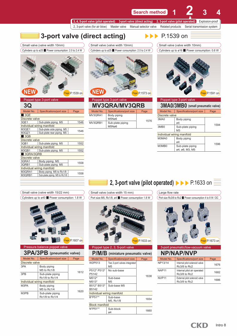
3-port valve (direct acting)
2, 3-port valve (pilot operated)
P.1539 on
P.1633 on
Small valve (valve width 10mm)
Cylinders up to ø25 ■ Power consumption: 2.0 to 2.4 W
Small valve (valve width 10mm)
Cylinders up to ø16 ■ Power consumption: 0.6 W
Small valve (valve width 10mm)
Cylinders up to ø25 ■ Power consumption: 2.0 to 2.4 W
Small valve (valve width 15 mm)
Port size M5, Rc1/8, ø4 ■ Power consumption 1.8 W
Small valve (valve width 15/22 mm)
Cylinders up to ø40 ■ Power consumption: 1.8 W
Large flow rate
Port size Rc3/8 to Rc2 ■ Power consumption 4 to 8 W / DC
Poppet type 3-port valve
MV3QRA/MV3QRBModel No. Specifications/port size Page
MV3QRA1 Body pipingM5Nø6
1576MV3QRB1 Sub-plate piping
M5Nø6
Poppet type 3-port valve
3MA0/3MB0 (small pneumatic valve)Model No. Specifications/port size Page
Discrete valve3MA0 Body piping
ø41594
3MB0 Sub-plate pipingM3
Individual wiring manifoldM3MA0 Body piping
ø41596
M3MB0 Sub-plate pipingø4, ø6, M3, M5
Poppet type 2, 3, 5-port valve
P/M/B (miniature pneumatic valve)Model No. Specifications/port size Page
W2P513 Two 3-port valves integratedM5
1638
P512* P513*P5142
No sub-base
M512*M513*
Sub-baseM5
B512* B513*B5142
Sub-base M5
Individual wiring manifoldB*P51** Sub-base
M5, Rc1/8 1654
Block manifoldN*P51** Sub-block
ø4 1660
Pressure balance poppet valve
3PA/3PB (pneumatic valve)Model No. Specifications/port size Page
Discrete valve3PA Body piping
M5 to Rc1/81612
3PB Sub-plate pipingRc1/8 to Rc1/4
Individual wiring manifoldM3PA Body piping
M5 to Rc1/41620
M3PB Sub-plate pipingRc1/8 to Rc1/4
3-port pneumatic/low-vacuum valve
NP/NAP/NVPModel No. Specifications/port size Page
NP13/14 Internal pilot solenoid valveRc3/8 to Rc2 1676
NAP11 Internal pilot air operatedRc3/8 to Rc2 1682
NVP11 External pilot solenoid valveRc3/8 to Rc2 1686
Poppet type 3-port valve
3QModel No. Specifications/port size Page
■ 3QEDiscrete valve3QE1 Sub-plate piping M5 1546Individual wiring manifoldM3QE1 Sub-plate side piping M5 1546M3QZ1 Sub-plate rear piping M5■ 3QBDiscrete valve3QB1 Sub-plate piping M5 1552Individual wiring manifoldM3QB1 Sub-plate piping M5 1552■ 3QRA/3QRBDiscrete valve3QRA1 Body piping M5 15583QRB1 Sub-plate piping M5Individual wiring manifoldM3QRA1 Body piping M5 to Rc1/8 1558M3QRB1 Sub-plate piping M5 to Rc1/8
Search method 1 2 3 43, 4, 5-port valve (pilot operated) 3-port valve (direct acting) 2, 3-port valve (pilot operated) Explosion-proof2, 3-port valve (for air blow) Master valve Manual selector valve Related products Serial transmission system
P.1633 on Page
P.1573 on PageP.1539 on Page P.1591 on Page
P.1673 on PageP.1607 on Page
NEWNEWNEWNEW
Intro 8

Explosion-proof P.1697 onPilot operated 5-port valve
Cylinders up to ø250 ■ Power consumption: 4 to 4.5 W
Pilot operated 5-port valve
Cylinders up to ø250 ■ Power consumption: 4 to 4.5 W
Pressure and explosion-proof performance ExdⅡBT4
4F**0EX (pneumatic valve)Model No. Specifications/port size Page
Discrete valve4F3*0EX Body piping
Rp1/4 to Rp3/8 1782
4F *0EX Sub-plate pipingRc1/4 to Rc1 1782
ManifoldM4F3*0EX Body piping
Rp1/4 to Rp3/8 1794
M4F *0EX Sub-plate pipingRc1/4 to Rc3/4 1794
Pressure and explosion proof enclosure d2G4 type
4F**0E (pneumatic valve)Model No. Specifications/port size Page
Discrete valve4F3*0E Body piping
Rp1/4 to Rp3/8 1810
4F *0E Sub-plate pipingRc1/4 to Rc1 1810
ManifoldM4F3*0E Body piping
Rp1/4 to Rp3/8 1824
M4F *0E Sub-plate pipingRc1/4 to Rc3/4 1824
4to 7
4to 7
4to 7
4to 7
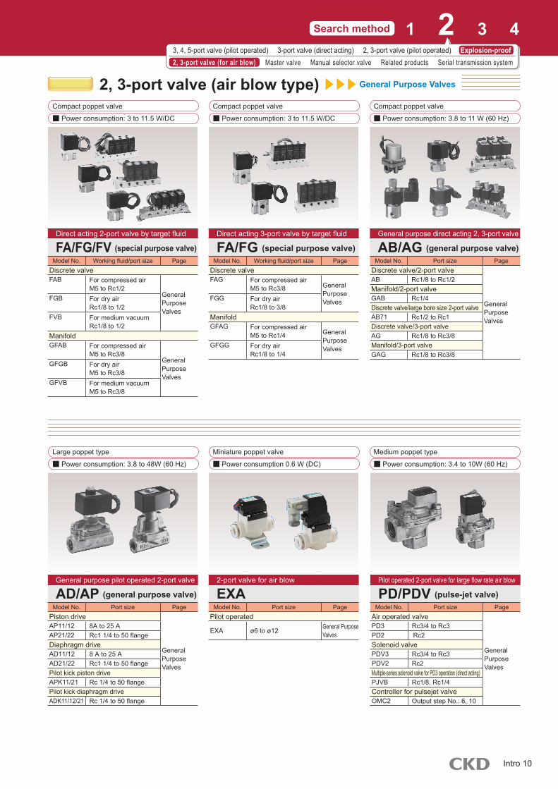
Explosion-proof 2, 3-port valve General Purpose Valves
Direct acting poppet type 2, 3-port valve
■ Power consumption: 6.7 to 17 W (60 Hz)
Pilot operated poppet type 2-port valve
■ Power consumption: 6.7 to 17 W (60 Hz)
Poppet type 2-port valve
■ Power consumption: 7 W (60 Hz)
Pressure and explosion proof enclosure d2G4/d2G2 type
AB/AG (general purpose valve)Model No. Port size Page
2-port valveAB4*E4 Rc1/4, Rc3/8
General PurposeValvesAB41E2 Rc1/4, Rc3/8
AB41E4-Z Rc1/4, Rc3/83-port valveAG4*E4 Rc1/4, Rc3/8 General Purpose
ValvesAG4*E4-Z Rc1/4, Rc3/8
Pressure and explosion proof enclosure d2G4/d2G2 type
AD/AP (general purpose valve)Model No. Port size Page
AP**E4 Rc 1/2 to 50 flangeGeneral PurposeValves
AD**E4 Rc 1/2 to 50 flangeADK**E4 Rc1/2 to Rc1AP**E2 Rc 1/2 to 50 flange
Pressure and explosion proof enclosure d2G4 type for air blow
PDVE4 (pulse-jet valve)Model No. Port size Page
PDVE4 Rc3/4 to Rc2 General PurposeValves
Small/medium/large valve (10/15/18/24 mm)
Cylinders up to ø160 ■ Power consumption: 0.6 W
Intrinsically safe explosion-proof performance Ex ib ⅡC T4 Gb
4GD/4GE*0EJModel No. No. of ports Specifications/port size Page
Discrete valve
3GD1 to 2*0EJ4GD1 to 4*0EJ
35
Body piping ø1.8 to ø12, M5, Rc1/8 to Rc3/8
1700
3GE1 to 2*0EJ4GE1 to 4*0EJ
35
Base pipingRc1/8 to Rc1/2 1720
Individual wiring manifold
M3GD1 to 2*0EJM4GD1 to 4*0EJ
35
Body piping ø1.8 to ø12, M5, Rc1/8 to Rc3/8
1740
MN3GE1 to 2*0EJMN4GE1 to 3*0EJ
35
Base piping ø1.8 to ø12, M5, Rc1/8 to Rc1/2
1748
Select from external appearance and product description of each series.
Search by product series2 indicates models added to the 9th edition.NEWNEW
P.1779 on PageP.1697 on Page P.1807 on PageNEWNEWNEWNEW
Intro 9
General Purpose Valves
Direct acting 2-port valve by target fluid
FA/FG/FV (special purpose valve)Model No. Working fluid/port size Page
Discrete valveFAB For compressed air
M5 to Rc1/2General Purpose Valves
FGB For dry airRc1/8 to 1/2
FVB For medium vacuumRc1/8 to 1/2
ManifoldGFAB For compressed air
M5 to Rc3/8General Purpose Valves
GFGB For dry airM5 to Rc3/8
GFVB For medium vacuumM5 to Rc3/8
General purpose pilot operated 2-port valve
AD/AP (general purpose valve)Model No. Port size Page
Piston drive
General Purpose Valves
AP11/12 8A to 25 AAP21/22 Rc1 1/4 to 50 flangeDiaphragm driveAD11/12 8 A to 25 AAD21/22 Rc1 1/4 to 50 flangePilot kick piston driveAPK11/21 Rc 1/4 to 50 flangePilot kick diaphragm driveADK11/12/21 Rc 1/4 to 50 flange
2-port valve for air blow
EXAModel No. Port size Page
Pilot operated
EXA ø6 to ø12 General Purpose Valves
Pilot operated 2-port valve for large flow rate air blow
PD/PDV (pulse-jet valve)Model No. Port size Page
Air operated valve
General Purpose Valves
PD3 Rc3/4 to Rc3PD2 Rc2Solenoid valvePDV3 Rc3/4 to Rc3PDV2 Rc2Multiple-series solenoid valve for PD3 operation (direct acting)PJVB Rc1/8, Rc1/4Controller for pulsejet valveOMC2 Output step No.: 6, 10
Direct acting 3-port valve by target fluid
FA/FG (special purpose valve)Model No. Working fluid/port size Page
Discrete valveFAG For compressed air
M5 to Rc3/8 General Purpose ValvesFGG For dry air
Rc1/8 to 3/8ManifoldGFAG For compressed air
M5 to Rc1/4 General Purpose ValvesGFGG For dry air
Rc1/8 to 1/4
General purpose direct acting 2, 3-port valve
AB/AG (general purpose valve)Model No. Port size Page
Discrete valve/2-port valve
General Purpose Valves
AB Rc1/8 to Rc1/2Manifold/2-port valveGAB Rc1/4Discrete valve/large bore size 2-port valveAB71 Rc1/2 to Rc1Discrete valve/3-port valveAG Rc1/8 to Rc3/8Manifold/3-port valveGAG Rc1/8 to Rc3/8
2, 3-port valve (air blow type)Compact poppet valve
■ Power consumption: 3 to 11.5 W/DC
Compact poppet valve
■ Power consumption: 3 to 11.5 W/DC
Compact poppet valve
■ Power consumption: 3.8 to 11 W (60 Hz)
Large poppet type
■ Power consumption: 3.8 to 48W (60 Hz)
Miniature poppet valve
■ Power consumption 0.6 W (DC)
Medium poppet type
■ Power consumption: 3.4 to 10W (60 Hz)
Search method 1 2 3 43, 4, 5-port valve (pilot operated) 3-port valve (direct acting) 2, 3-port valve (pilot operated) Explosion-proof2, 3-port valve (for air blow) Master valve Manual selector valve Related products Serial transmission system
Intro 10

Master valve
Manual selector valve Related products
3, 5-port valve
Cylinders of ø20 to ø100
Manual override switching 4-port valve
Cylinders of ø20 to ø160 With push-in fitting ø25 to ø125 cylinder
3, 5-port valve
Cylinders of ø20 to ø160
5-port valve
Cylinders of ø10 to ø250
4GModel No. Specifications/port size Page
Discrete valve3GA4GA
Body pipingø4 to Rc1/4 324
4GB Base pipingRc1/8 to Rc3/8 334
ManifoldM3GAM4GA
Body pipingø4 to Rc1/4 324
M4GB Base pipingø4 to Rc1/4 334
Slide valve, manual switching valve
HMV/HSVModel No. Port size Page
HMV MiniatureRc1/4 1840
HSV StandardRc1/4 to 3/4 1840
Quick valve
2QV/3QVModel No. Port size Page
2QV 2-way valve1846
3QV 3-way valve
Shock absorbing valve
SKHModel No. Specifications Page
SKH Variable speed unit1858SKH Deceleration unit
SKH Single-side deceleration unit
4K (pneumatic valve)Model No. Specifications/port size Page
Discrete valve3KA14KA
Body pipingM5 to ø12 1350
4KB Sub-plate pipingRc1/8 to Rc1/2 1356
ManifoldM3KA1M4KA
Body pipingM5 to ø12 1350
M4KB Sub-plate pipingM5 to ø12 1356
4F (pneumatic valve)Model No. Specifications/port size Page
Discrete valve4F0 to 3 Body piping
14544F4 to 7 Sub-plate pipingManifold(A)M4F0 to 3 Body piping
1454M4F4 to 7 Sub-plate piping
Select from external appearance and product description of each series.
Search by product series2 indicates models added to the 9th edition.NEWNEW
P.321 on Page
P.1837 on Page
P.1349 on Page
P.1845 on Page
P.1453 on Page
P.1855 on Page
NEWNEW
Intro 11

Model No. Specifications PageOPP2 Degree of protection (IP64)
Intro Page 31
OPP3 Flat cable compatible slave unitOPP4 Thin shapeOPP5 Degree of protection (IP65)
I/O block compatibleOPP6 Miniature 32 point compatibleOPP7 Thin 32 point compatibleOPP8 Thin 32 point compatible (IP65)
Related products
Total air systems[Total air systems]
Model No. Specifications/port size PageDetector (mechanical valve)
1901
MS Small Rc1/8, ø4MM Medium Rc1/8, ø4MAVL Large Rc1/4Circuit device (logic valve)
ø4
Total air systems[Gamma system]
PagePLC components
1943Signal control components
Serial transmission system
NEWNEWNEWNEW
SilencerSeries Piping bore size Page
Metering valve with silencerSMW2 R1/8, 1/4 1878FMS M5
1880SMW R3/8, 1/2Small bore sizeSL M5 1882Resin bodySLW R1/8, 1/4, 3/8, 1/2 1882SLW-*A-H R1/4, 3/8, 1/2 1884Large flow rate/small bore size/resin bodySLW-*L R1/4, 3/8 1885High noise reduction/compact
SLW-*SR1/8, 1/4 1886R3/4 1887
Push-inSLW-H R1/4, 3/8, 1/2 1888MiniatureSLM M3, M5 1889Aluminum bodySL R1/4 to 2 1890Outdoor SeriesSL-W Rc1/4, 3/8, 1/2 1892Exhaust cleanerFA*31 Rc3/8 to 2 1896
NEWNEW
Search method 1 2 3 43, 4, 5-port valve (pilot operated) 3-port valve (direct acting) 2, 3-port valve (pilot operated) Explosion-proof2, 3-port valve (for air blow) Master valve Manual selector valve Related products Serial transmission system
P.1875 on Page
Intro 12

Recommended alternative products
Production of the series below has been discontinued. Select recommended alternative products instead.
Discontinued
■ 3, 5-port pilot operated valve (small pneumatic valve)
4SA1/4SB1 Series
■ Direct acting 3, 5-port valve
FS/FD Series
■ Pilot operated 5-port valve (ISO valve)
CMF Series
■ Pilot operated 3, 5-port valve
4G Series
■ Pilot operated 4, 5-port valve
4TB Series
■ Pilot operated 5-port valve
4L2 Series
■ Pilot operated 3, 5-port valve
4G R Series
■ Pilot operated 5-port valve
4F Series
■ Pilot operated 5-port valve (ISO valve)
GMF Series
■ Pilot operated 3, 5-port valve
4G R Series
■ Pilot operated 3, 5-port valve (plug-in manifold)
W4G Series
■ Pilot operated 3, 5-port valve (plug-in manifold)
W4G Series
Intro 13
Recommended alternative product
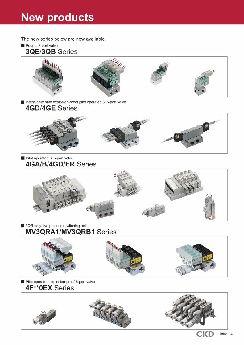
New products
The new series below are now available.
■ Pilot operated 3, 5-port valve
4GA/B/4GD/ER Series
■ 3QR negative pressure switching unit
MV3QRA1/MV3QRB1 Series
■ Intrinsically safe explosion-proof pilot operated 3, 5-port valve
4GD/4GE Series
■ Poppet 3-port valve
3QE/3QB Series
■ Pilot operated explosion-proof 5-port valve
4F**0EX Series
Intro 14
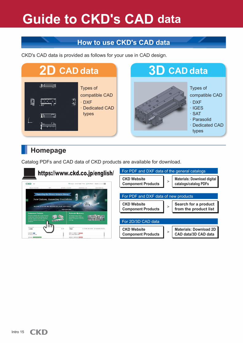
Guide to CKD's CAD dataGuide to CKD's CAD data
CKD's CAD data is provided as follows for your use in CAD design.
CAD data2D CAD data3D
How to use CKD's CAD data
Homepage
Types of compatible CAD· DXF· Dedicated CAD
types
Types of compatible CAD· DXF· IGES· SAT· Parasolid· Dedicated CAD
types
Catalog PDFs and CAD data of CKD products are available for download.
https://www.ckd.co.jp/english/ For PDF and DXF data of the general catalogs
CKD Website Component Products
Materials: Download digital catalogs/catalog PDFs>
For PDF and DXF data of new products
Search for a product from the product list
CKD Website Component Products >
For 2D/3D CAD data
Materials: Download 2D CAD data/3D CAD data
CKD Website Component Products >
Intro 15

Guide to the model selection systemGuide to the model selection system
The CKD system supports selection of the following items for your use during model selection and design.
Catalog PDFSelection results
A variety of services such as CKD product catalogs, PDFs, CAD data, and model selection are available.
Feel free to try them.
https://www.ckd.co.jp/english
How to use the model selection system
Registration not required - available at any time!
Selection results are linked with catalog PDFs and CAD data!
● Cylinder selection● Rotary/oscillating cylinder selection● Shock absorber selection● Clean air (F.R.L.) component selection● Dryer selection● Technical calculations
Available systems
2D CAD
Intro 16

Search by flow characteristics C3 Ideal model with flow characteristics C can be selected.P
ort
Series
Wiring method
Model No. Port size
Flow characteristics C [dm3/(bar)] Page
Sing
le un
it Manifold
Individ
ual
wiring
Redu
ced
wiring
Eff. X-sectional area (mm2)
2-po
rt
Pilot operated 2-port miniature pneumatic valve
P512*B512*M512*B*P512*N*P512*
● P512* -
1633● B512* M5, Rc1/8
● M512* M5
● B*P512* M5, Rc1/8
● N*P512* ø4 Push-in fitting
3-po
rt
Direct acting 3-port small pneumatic valve
3M Series
● 3MA0 ø4 Barbed fitting (M3)
1591● 3MB0 M3
● M3MA0 ø4 Barbed fitting (M5)
● M3MB0M3, M5ø4 Push-in fittingø4, ø6 Barbed fitting
Pilot operated 3-port miniature pneumatic valve
P513*B513*M513*B*P513*N*P513*
● P513* -
1633● B513* M5 × 0.8, Rc1/8
● M513* M5
● B*P513* M5, Rc1/8
● N*P513* ø4 Push-in fitting
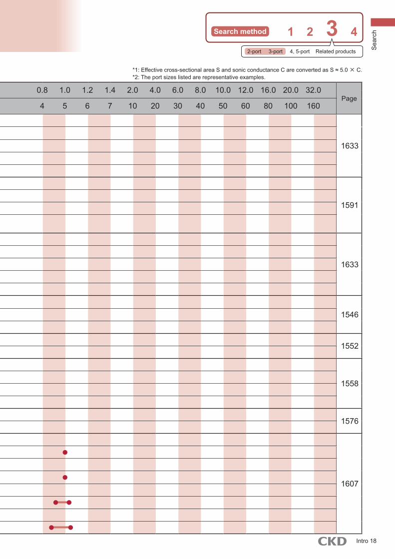
Direct acting 3-port valve3QE Series
● 3QE1 M5
1546● M3QE1 M5
● M3QZ1 M5
Direct acting 3-port valve3QB Series
● 3QB1 M51552
● M3QB1 M5
Direct acting 3-port valve3QR Series
● 3QRA1 M5
1558● 3QRB1 M5
● M3QRA1 M5, Rc1/8
● M3QRB1 M5, Rc1/8
Direct acting 3-port valveMV3QR Series
● MV3QRA1 M5ø4, ø6 Push-in fitting 1576
● MV3QRB1 M5ø4, ø6 Push-in fitting
Direct acting 3-port pneumatic valve
3P Series
● 3PA1 M5ø4, ø6 Push-in fitting
1607
● 3PA2 Rc1/8ø6, ø8 Push-in fitting
● 3PB1 Rc1/8
● 3PB2 Rc1/8, Rc1/4
● M3PA1 M5ø4, ø6 Push-in fitting
● M3PA2 Rc1/8ø6, ø8 Push-in fitting
● M3PB1 Rc1/8, ø4, ø6 Push-in fitting
● M3PB2 Rc1/8, ø6, ø8 Push-in fitting
0 0.2 0.4 0.6 0.8 1.0 1.2 1.4 2.0 4.0 6.0 8.0 10.0 12.0 16.0 20.0 32.0
0 1 2 3 4 5 6 7 10 20 30 40 50 60 80 100 160
Intro 17
Search method 1 2 3 4
Por
t
Series
Wiring method
Model No. Port size
Flow characteristics C [dm3/(bar)] Page
Sing
le un
it Manifold
Individ
ual
wiring
Redu
ced
wiring
Eff. X-sectionalarea (mm2)
2-po
rt
Pilot operated 2-port miniature pneumatic valve
P512*B512*M512*B*P512*N*P512*
● P512* -
1633● B512* M5, Rc1/8
● M512* M5
● B*P512* M5, Rc1/8
● N*P512* ø4 Push-in fitting
3-po
rt
Direct acting 3-port small pneumatic valve
3M Series
● 3MA0 ø4 Barbed fitting (M3)
1591● 3MB0 M3
● M3MA0 ø4 Barbed fitting (M5)
● M3MB0M3, M5ø4 Push-in fittingø4, ø6 Barbed fitting
Pilot operated 3-port miniature pneumatic valve
P513*B513*M513*B*P513*N*P513*
● P513* -
1633● B513* M5 × 0.8, Rc1/8
● M513* M5
● B*P513* M5, Rc1/8
● N*P513* ø4 Push-in fitting
Direct acting 3-port valve3QE Series
● 3QE1 M5
1546● M3QE1 M5
● M3QZ1 M5
Direct acting 3-port valve3QB Series
● 3QB1 M51552
● M3QB1 M5
Direct acting 3-port valve3QR Series
● 3QRA1 M5
1558● 3QRB1 M5
● M3QRA1 M5, Rc1/8
● M3QRB1 M5, Rc1/8
Direct acting 3-port valveMV3QR Series
● MV3QRA1 M5ø4, ø6 Push-in fitting 1576
● MV3QRB1 M5ø4, ø6 Push-in fitting
Direct acting 3-port pneumatic valve
3P Series
● 3PA1 M5ø4, ø6 Push-in fitting
1607
● 3PA2 Rc1/8ø6, ø8 Push-in fitting
● 3PB1 Rc1/8
● 3PB2 Rc1/8, Rc1/4
● M3PA1 M5ø4, ø6 Push-in fitting
● M3PA2 Rc1/8ø6, ø8 Push-in fitting
● M3PB1 Rc1/8, ø4, ø6 Push-in fitting
● M3PB2 Rc1/8, ø6, ø8 Push-in fitting
*1: Effective cross-sectional area S and sonic conductance C are converted as S ≈ 5.0 × C.*2: The port sizes listed are representative examples.
0 0.2 0.4 0.6 0.8 1.0 1.2 1.4 2.0 4.0 6.0 8.0 10.0 12.0 16.0 20.0 32.0
0 1 2 3 4 5 6 7 10 20 30 40 50 60 80 100 160
2-port 3-port 4, 5-port Related products Sea
rch
Intro 18

Search by flow characteristics C3 Ideal model with flow characteristics C can be selected.P
ort
Series
Wiring method
Model No. Port size
Flow characteristics C [dm3/(bar)] Page
Sing
le un
it Manifold
Individ
ual
wiring
Redu
ced
wiring Eff. X-sectional
area (mm2)
3-po
rt
Pilot operated 3-port valveMN3E Series
● MN3E00 M3ø1.8, ø3, ø4
863● ● MN3E0 M5ø1.8, ø4, ø6 Push-in fitting
● ● Two 3-port valves integrated MN3E0
M5ø1.8, ø4, ø6 Push-in fitting
Pilot operated 3-port pneumatic valve
4K Series
● 3KA1 M5ø4, ø6 Push-in fitting
1257● M3KA1 M5
ø4, ø6 Push-in fitting
Pilot operated 3-port pneumatic valve
MN4S0 Series
● ● MN3S0MT3S0
M5ø4, ø6 Push-in fitting
1191● ●
Two 3-port valves integratedMN3SOMT3SO
M5ø4, ø6 Push-in fitting
Pilot operated 3-port valve4G Series
● 3G 1 M5ø1.8, ø4, ø6 Push-in fitting
7
● 3G 2 Rc1/8,1/8NPT,G1/8ø4, ø6, ø8 Push-in fitting
● 3G 3 Rc1/4, 1/4NPT, G1/4ø6, ø8, ø10 Push-in fitting
● ● M3G 1 M5ø1.8, ø4, ø6 Push-in fitting
● ● M3G 2 Rc1/8, 1/8NPT, G1/8ø4, ø6, ø8 Push-in fitting
● ● M3G 3 Rc1/4, 1/4NPT, G1/4ø6, ø8, ø10 Push-in fitting
● ● MN3G 1 M5ø1.8, ø4, ø6 Push-in fitting
988● ● MN3G 2 Rc1/8, 1/8NPT, G1/8
ø4, ø6, ø8 Push-in fitting
Pilot operated 3-port valveW4G2 Series ● MW3GA2
Rc1/8ø4, ø6, ø8 Push-in fitting
965
Intrinsically safe explosion-proof pilot operated 3-port valve
3GD/E EJ Series
● 3GD1 M5ø1.8, ø4, ø6 Push-in fitting
1697
● 3GD2 Rc1/8ø4, ø6, ø8 Push-in fitting
● M3GD1 M5ø1.8, ø4, ø6 Push-in fitting
● M3GD2 Rc1/8ø4, ø6, ø8 Push-in fitting
● 3GE1 Rc1/8
● 3GE2 Rc1/4
● M3GE1 M5ø1.8, ø4, ø6 Push-in fitting
● M3GE2 Rc1/8ø4, ø6, ø8 Push-in fitting
Large flow rate 3-port valveNP Series ●
NP13NP14NAP11NVP11
Rc3/8 to Rc2 1673
0 0.2 0.4 0.6 0.8 1.0 1.2 1.4 2.0 4.0 6.0 8.0 10.0 12.0 16.0 20.0 32.0
0 1 2 3 4 5 6 7 10 20 30 40 50 60 80 100 160
AD
AD
AD
AD
AD
AD
AD
AD
Intro 19

Search method 1 2 3 4
*1: Effective cross-sectional area S and sonic conductance C are converted as S ≈ 5.0 × C.*2: The port sizes listed are representative examples.
Por
t
Series
Wiring method
Model No. Port size
Flow characteristicsC [dm3/(bar)] Page
Sing
le un
it Manifold
Individ
ual
wiring
Redu
ced
wiring Eff. X-sectional
area (mm2)
3-po
rt
Pilot operated 3-port valveMN3E Series
● MN3E00 M3ø1.8, ø3, ø4
863● ● MN3E0 M5ø1.8, ø4, ø6 Push-in fitting
● ● Two 3-port valves integrated MN3E0
M5ø1.8, ø4, ø6 Push-in fitting
Pilot operated 3-port pneumatic valve
4K Series
● 3KA1 M5ø4, ø6 Push-in fitting
1257● M3KA1 M5
ø4, ø6 Push-in fitting
Pilot operated 3-port pneumatic valve
MN4S0 Series
● ● MN3S0MT3S0
M5ø4, ø6 Push-in fitting
1191● ●
Two 3-port valves integratedMN3SOMT3SO
M5ø4, ø6 Push-in fitting
Pilot operated 3-port valve4G Series
● 3G 1 M5ø1.8, ø4, ø6 Push-in fitting
7
● 3G 2 Rc1/8,1/8NPT,G1/8ø4, ø6, ø8 Push-in fitting
● 3G 3 Rc1/4, 1/4NPT, G1/4ø6, ø8, ø10 Push-in fitting
● ● M3G 1 M5ø1.8, ø4, ø6 Push-in fitting
● ● M3G 2 Rc1/8, 1/8NPT, G1/8ø4, ø6, ø8 Push-in fitting
● ● M3G 3 Rc1/4, 1/4NPT, G1/4ø6, ø8, ø10 Push-in fitting
● ● MN3G 1 M5ø1.8, ø4, ø6 Push-in fitting
988● ● MN3G 2 Rc1/8, 1/8NPT, G1/8
ø4, ø6, ø8 Push-in fitting
Pilot operated 3-port valveW4G2 Series ● MW3GA2
Rc1/8ø4, ø6, ø8 Push-in fitting
965
Intrinsically safe explosion-proof pilot operated 3-port valve
3GD/E EJ Series
● 3GD1 M5ø1.8, ø4, ø6 Push-in fitting
1697
● 3GD2 Rc1/8ø4, ø6, ø8 Push-in fitting
● M3GD1 M5ø1.8, ø4, ø6 Push-in fitting
● M3GD2 Rc1/8ø4, ø6, ø8 Push-in fitting
● 3GE1 Rc1/8
● 3GE2 Rc1/4
● M3GE1 M5ø1.8, ø4, ø6 Push-in fitting
● M3GE2 Rc1/8ø4, ø6, ø8 Push-in fitting
Large flow rate 3-port valveNP Series ●
NP13NP14NAP11NVP11
Rc3/8 to Rc2 1673
0 0.2 0.4 0.6 0.8 1.0 1.2 1.4 2.0 4.0 6.0 8.0 10.0 12.0 16.0 20.0 32.0
0 1 2 3 4 5 6 7 10 20 30 40 50 60 80 100 160
2-port 3-port 4, 5-port Related products
660
Sea
rch
Intro 20

Search by flow characteristics C3 Ideal model with flow characteristics C can be selected.P
ort
SeriesWiring method
Model No. Port size
Flow characteristics C [dm3/(bar)] Page
Single
unit Manifold
Individ
ual
wiring
Reduc
ed wir
ing Eff. X-sectional area (mm2)
4, 5
-por
t val
ve
Pilot operated 5-port miniature pneumatic valve
P514*B514*W2P513*B*P514*N*P514*
● W2P513* M5
1633
● P5142 _
● B5142 M5
● B*P5142 M5Rc1/8
● N*P5142 ø4 Push-in fitting
Pilot operated 5-port small pneumatic valve
4S0 Series● 4SA0
M3
1231
ø4 Barbed fitting
● 4SB0 M5
● M4SA0M3
ø4 Barbed fitting
● ● M4SB0M5ø4 Push-in fittingø4, ø6 Barbed fitting
Pilot operated 4-port valveMN4E Series
● MN4E00 M3ø1.8, ø3, ø4 863
● ● MN4E0 M5ø1.8, ø4, ø6 Push-in fitting
Pilot operated 4-port pneumatic valve
MN4S0 Series
● ● MN4S0 M5ø4, ø6 Push-in fitting
1191● ● MT4S0
Pilot operated 5-port valve4G Series
● 4G 1 M5ø1.8, ø4, ø6 Push-in fitting
7
● 4G 2 Rc1/8, 1/8NPT, G1/8ø4, ø6, ø8 Push-in fitting
● 4G 3 Rc1/4, 1/4NPT, G1/4ø6, ø8, ø10 Push-in fitting
● 4G 4 Rc3/8, 3/8NPT, G3/8ø8, ø10, ø12 Push-in fitting
● ● M4G 1 M5ø1.8, ø4, ø6 Push-in fitting
● ● M4G 2 Rc1/8, 1/8NPT, G1/8ø4, ø6, ø8 Push-in fitting
● ● M4G 3 Rc1/4, 1/4NPT, G1/4ø6, ø8, ø10 Push-in fitting
● ● M4GA4 Rc3/8, 3/8NPT, G3/8ø8, ø10, ø12 Push-in fitting
● 4G 1 Rc1/8, 1/8NPT, G1/8
● 4G 2 Rc1/4, 1/4NPT, G1/4
● 4G 3 Rc1/4, 1/4NPT, G1/4Rc3/8, 3/8NPT, G3/8
● ● 4GB4 Rc3/8, 3/8NPT, G3/8Rc1/2, 1/2NPT, G1/2
● ● M4G 1 M5ø1.8, ø4, ø6 Push-in fitting
● ● M4G 2 Rc1/8, 1/8NPT, G1/8ø4, ø6, ø8 Push-in fitting
● ● M4G 3 Rc1/4, 1/4NPT, G1/4ø6, ø8, ø10 Push-in fitting
● ● M4GB41/4(RC, NPT, G),3/8(RC, NPT, G),1/2(RC, NPT, G)ø8, ø10, ø12 push-in fitting
0 0.2 0.4 0.6 0.8 1.0 1.2 1.4 2.0 4.0 6.0 8.0 10.0 12.0 16.0 20.0 32.0
0 1 2 3 4 5 6 7 10 20 30 40 50 60 80 100 160
ADADADAD
ADADAD
BEBEBE
BEBEBE
Intro 21
Search method 1 2 3 4
*1: Effective cross-sectional area S and sonic conductance C are converted as S ≈ 5.0 × C.*2: The port sizes listed are representative examples.
Por
t
SeriesWiring method
Model No. Port size
Flow characteristicsC [dm3/(bar)] Page
Single
unit Manifold
Individ
ual
wiring
Reduc
edwir
ing Eff. X-sectionalarea (mm2)
4, 5
-por
t val
ve
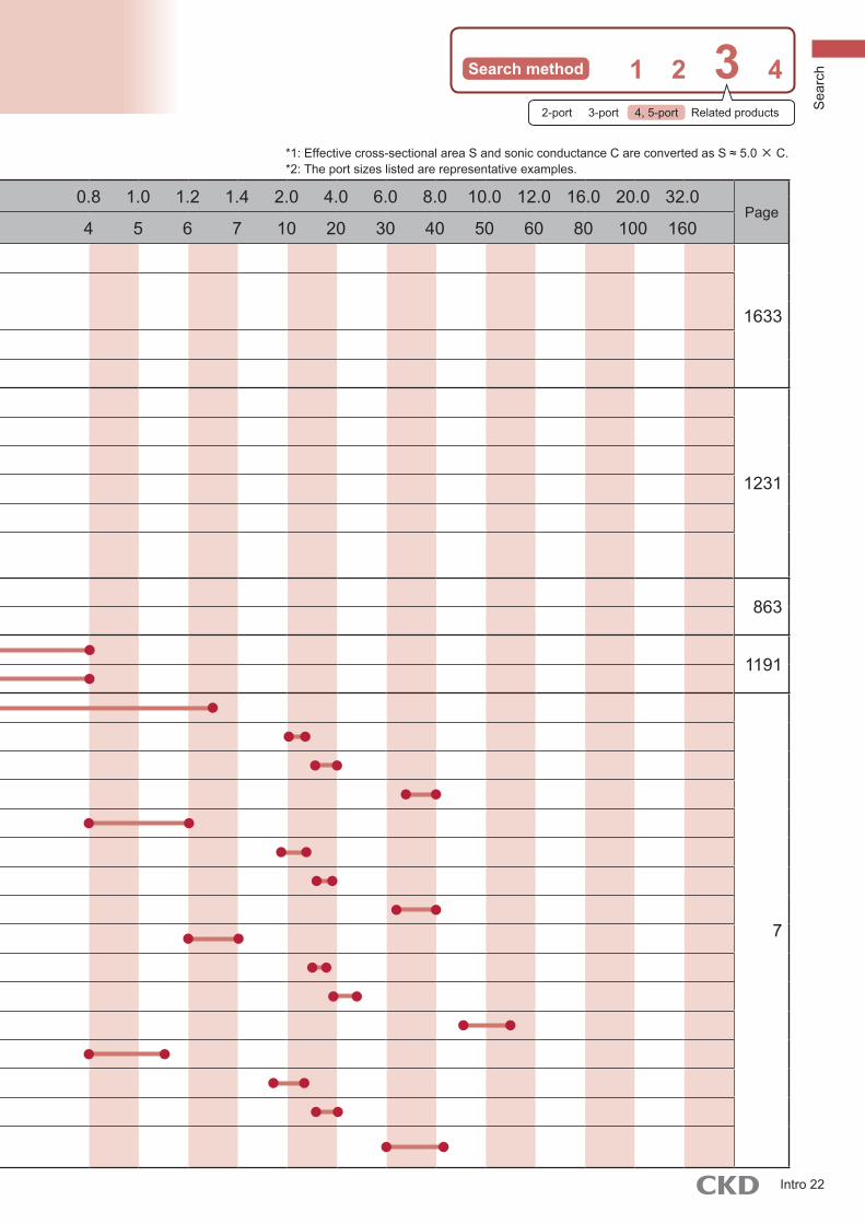
Pilot operated 5-port miniature pneumatic valve
P514*B514*W2P513*B*P514*N*P514*
● W2P513* M5
1633
● P5142 _
● B5142 M5
● B*P5142 M5Rc1/8
● N*P5142 ø4 Push-in fitting
Pilot operated 5-port small pneumatic valve
4S0 Series● 4SA0
M3
1231
ø4 Barbed fitting
● 4SB0 M5
● M4SA0M3
ø4 Barbed fitting
● ● M4SB0M5ø4 Push-in fittingø4, ø6 Barbed fitting
Pilot operated 4-port valveMN4E Series
● MN4E00 M3ø1.8, ø3, ø4 863
● ● MN4E0 M5ø1.8, ø4, ø6 Push-in fitting
Pilot operated 4-port pneumatic valve
MN4S0 Series
● ● MN4S0 M5ø4, ø6 Push-in fitting
1191● ● MT4S0
Pilot operated 5-port valve4G Series
● 4G 1 M5ø1.8, ø4, ø6 Push-in fitting
7
● 4G 2 Rc1/8, 1/8NPT, G1/8ø4, ø6, ø8 Push-in fitting
● 4G 3 Rc1/4, 1/4NPT, G1/4ø6, ø8, ø10 Push-in fitting
● 4G 4 Rc3/8, 3/8NPT, G3/8ø8, ø10, ø12 Push-in fitting
● ● M4G 1 M5ø1.8, ø4, ø6 Push-in fitting
● ● M4G 2 Rc1/8, 1/8NPT, G1/8ø4, ø6, ø8 Push-in fitting
● ● M4G 3 Rc1/4, 1/4NPT, G1/4ø6, ø8, ø10 Push-in fitting
● ● M4GA4 Rc3/8, 3/8NPT, G3/8ø8, ø10, ø12 Push-in fitting
● 4G 1 Rc1/8, 1/8NPT, G1/8
● 4G 2 Rc1/4, 1/4NPT, G1/4
● 4G 3 Rc1/4, 1/4NPT, G1/4Rc3/8, 3/8NPT, G3/8
● ● 4GB4 Rc3/8, 3/8NPT, G3/8Rc1/2, 1/2NPT, G1/2
● ● M4G 1 M5ø1.8, ø4, ø6 Push-in fitting
● ● M4G 2 Rc1/8, 1/8NPT, G1/8ø4, ø6, ø8 Push-in fitting
● ● M4G 3 Rc1/4, 1/4NPT, G1/4ø6, ø8, ø10 Push-in fitting
● ● M4GB41/4(RC, NPT, G),3/8(RC, NPT, G),1/2(RC, NPT, G)ø8, ø10, ø12 push-in fitting
0 0.2 0.4 0.6 0.8 1.0 1.2 1.4 2.0 4.0 6.0 8.0 10.0 12.0 16.0 20.0 32.0
0 1 2 3 4 5 6 7 10 20 30 40 50 60 80 100 160
2-port 3-port 4, 5-port Related products Sea
rch
Intro 22

Search by flow characteristics C3 Ideal model with flow characteristics C can be selected.P
ort
Series
Wiring method
Model No. Port size
Flow characteristics C [dm3/(bar)]
0 0.2 0.4 0.6 0.8 1.0 1.2 1.4 2.0 4.0 6.0 8.0 10.0 12.0 16.0 20.0 32.0Page
Sing
le un
it Manifold
Individ
ual
wiring
Redu
ced
wiring
Eff. X-sectional area (mm2) 0 1 2 3 4 5 6 7 10 20 30 40 50 60 80 100 160
4 , 5
-por
t val
ve
Pilot operated 5-port valve4G Series
● ● MN4G 1 M5ø4, ø6 Push-in fitting
7● ● MN4G 2 Rc1/8, 1/8NPT, G1/8
ø4, ø6, ø8 Push-in fitting
● ● MN4G 1 ø4, ø6 Push-in fitting
● ● MN4G 2 ø4, ø6, ø8 Push-in fitting
Pilot operated 5-port valveW4G2 Series
● W4GB2 Rc1/4
965● ● MW4GA2 Rc1/8
ø4, ø6, ø8 Push-in fitting
● ● MW4GB2 ø4, ø6, ø8 Push-in fitting
● ● MW4GZ2 ø4, ø6, ø8 Push-in fitting
Pilot operated 5-port valveW4G4 Series
● W4GB4 Rc1/4, Rc3/8 *3
1111● W4GZ4 Rc1/4, Rc3/8 *3
● ● MW4GB4 Rc1/4, Rc3/8ø8, ø10, ø12 push-in *3
Pilot operated 5-port pneumatic valve
4K Series
● 4KA1 M5ø4, ø6 Push-in fitting
1257
● 4KA2 Rc1/8ø6, ø8 Push-in fitting
● 4KA3 Rc1/4ø8, ø10 Push-in fitting
● 4KA4 Rc3/8ø10, ø12 Push-in fitting
● M4KA1 M5ø4, ø6 Push-in fitting
● M4KA2 Rc1/8ø6, ø8 Push-in fitting
● M4KA3 Rc1/4ø8, ø10 Push-in fitting
● M4KA4 Rc3/8ø10, ø12 Push-in fitting
● 4KB1 Rc1/8
● 4KB2 Rc1/8, Rc1/4
● 4KB3 Rc1/4, Rc3/8
● 4KB4 Rc3/8, Rc1/2
● M4KB1 M5, Rc1/8ø6 Push-in fitting
● M4KB2 Rc1/8, Rc1/4ø6, ø8 Push-in fitting
● M4KB3 Rc1/4, Rc3/8ø8, ø10 Push-in fitting
● M4KB4 Rc3/8, Rc1/2ø10, ø12 Push-in fitting
● MN4KB1 ø4, ø6, ø8 Push-in fitting
● MN4KB2 ø6, ø8, ø10 Push-in fitting
ADADBEBE
Intro 23

Search method 1 2 3 4
Por
t
Series
Wiring method
Model No. Port size
Flow characteristicsC [dm3/(bar)]
0 0.2 0.4 0.6 0.8 1.0 1.2 1.4 2.0 4.0 6.0 8.0 10.0 12.0 16.0 20.0 32.0Page
Sing
le un
it Manifold
Individ
ual
wiring
Redu
ced
wiring
Eff. X-sectionalarea (mm2) 0 1 2 3 4 5 6 7 10 20 30 40 50 60 80 100 160
4, 5
-por
t val
ve
Pilot operated 5-port valve4G Series
● ● MN4G 1 M5ø4, ø6 Push-in fitting
7● ● MN4G 2 Rc1/8, 1/8NPT, G1/8
ø4, ø6, ø8 Push-in fitting
● ● MN4G 1 ø4, ø6 Push-in fitting
● ● MN4G 2 ø4, ø6, ø8 Push-in fitting
Pilot operated 5-port valveW4G2 Series
● W4GB2 Rc1/4
965● ● MW4GA2 Rc1/8
ø4, ø6, ø8 Push-in fitting
● ● MW4GB2 ø4, ø6, ø8 Push-in fitting
● ● MW4GZ2 ø4, ø6, ø8 Push-in fitting
Pilot operated 5-port valveW4G4 Series
● W4GB4 Rc1/4, Rc3/8 *3
1111● W4GZ4 Rc1/4, Rc3/8 *3
● ● MW4GB4 Rc1/4, Rc3/8ø8, ø10, ø12 push-in *3
Pilot operated 5-port pneumatic valve
4K Series
● 4KA1 M5ø4, ø6 Push-in fitting
1257
● 4KA2 Rc1/8ø6, ø8 Push-in fitting
● 4KA3 Rc1/4ø8, ø10 Push-in fitting
● 4KA4 Rc3/8ø10, ø12 Push-in fitting
● M4KA1 M5ø4, ø6 Push-in fitting
● M4KA2 Rc1/8ø6, ø8 Push-in fitting
● M4KA3 Rc1/4ø8, ø10 Push-in fitting
● M4KA4 Rc3/8ø10, ø12 Push-in fitting
● 4KB1 Rc1/8
● 4KB2 Rc1/8, Rc1/4
● 4KB3 Rc1/4, Rc3/8
● 4KB4 Rc3/8, Rc1/2
● M4KB1 M5, Rc1/8ø6 Push-in fitting
● M4KB2 Rc1/8, Rc1/4ø6, ø8 Push-in fitting
● M4KB3 Rc1/4, Rc3/8ø8, ø10 Push-in fitting
● M4KB4 Rc3/8, Rc1/2ø10, ø12 Push-in fitting
● MN4KB1 ø4, ø6, ø8 Push-in fitting
● MN4KB2 ø6, ø8, ø10 Push-in fitting
*1: Effective cross-sectional area S and sonic conductance C are converted as S ≈ 5.0 × C.*2: The port sizes listed are representative examples.*3: G threads and NPT threads are also compatible.
2-port 3-port 4, 5-port Related products Sea
rch
Intro 24
Search by flow characteristics C3 Ideal model with flow characteristics C can be selected.P
ort
Series
Wiring method
Model No. Port size
Flow characteristics C [dm3/(bar)]
0 0.2 0.4 0.6 0.8 1.0 1.2 1.4 2.0 4.0 6.0 8.0 10.0 12.0 16.0 20.0 32.0Page
Sing
le un
it Manifold
Indivi
dual
wirin
gRe
duce
d wi
ring Eff. X-sectional
area (mm2) 0 1 2 3 4 5 6 7 10 20 30 40 50 60 80 100 160
4 , 5
-por
t val
ve
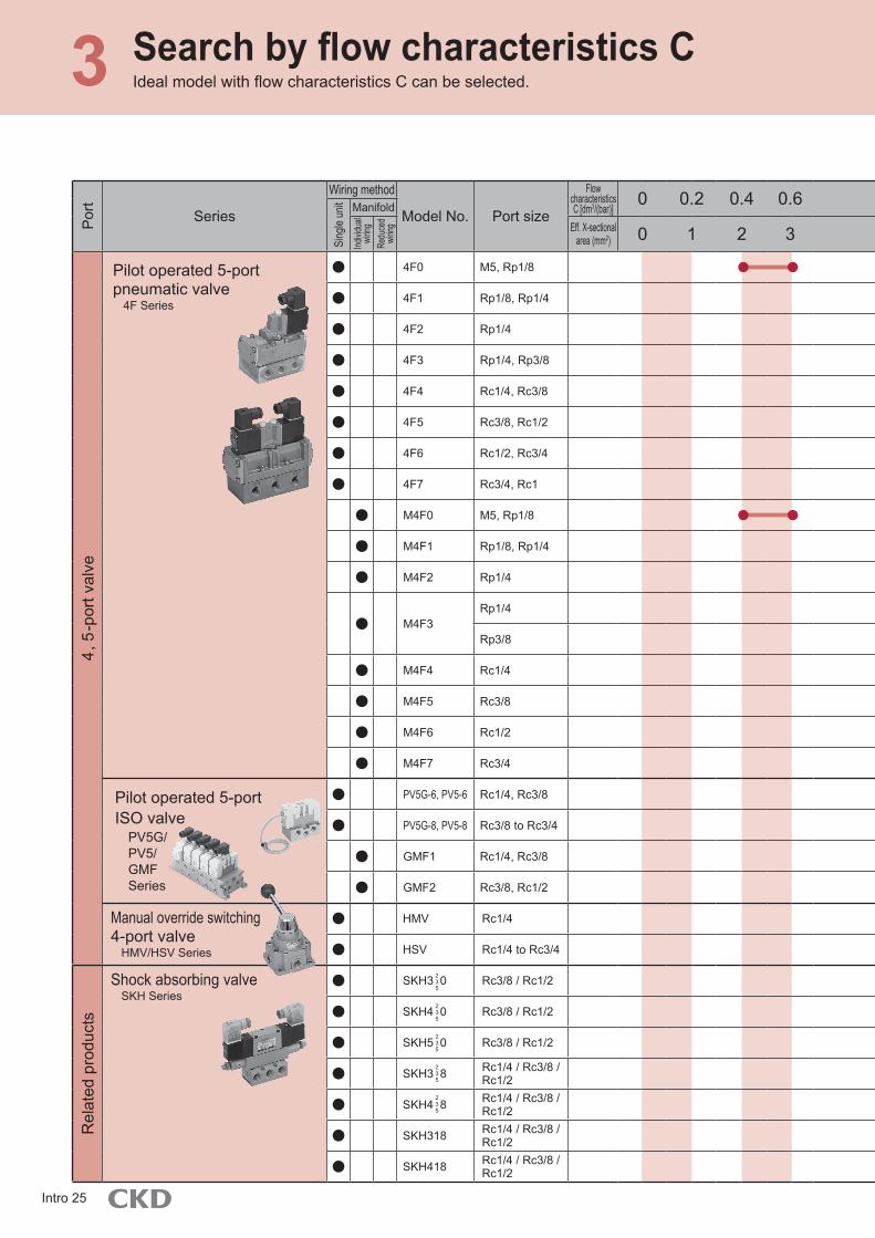
Pilot operated 5-port pneumatic valve
4F Series
● 4F0 M5, Rp1/8
1365
● 4F1 Rp1/8, Rp1/4
● 4F2 Rp1/4
● 4F3 Rp1/4, Rp3/8
● 4F4 Rc1/4, Rc3/8
● 4F5 Rc3/8, Rc1/2
● 4F6 Rc1/2, Rc3/4
● 4F7 Rc3/4, Rc1
● M4F0 M5, Rp1/8
● M4F1 Rp1/8, Rp1/4
● M4F2 Rp1/4
● M4F3Rp1/4
Rp3/8
● M4F4 Rc1/4
● M4F5 Rc3/8
● M4F6 Rc1/2
● M4F7 Rc3/4
Pilot operated 5-port ISO valve
PV5G/ PV5/ GMF Series
● PV5G-6, PV5-6 Rc1/4, Rc3/8
1465● PV5G-8, PV5-8 Rc3/8 to Rc3/4
● GMF1 Rc1/4, Rc3/8
● GMF2 Rc3/8, Rc1/2
Manual override switching 4-port valve
HMV/HSV Series
● HMV Rc1/41837
● HSV Rc1/4 to Rc3/4
Rel
ated
pro
duct
s
Shock absorbing valveSKH Series
● SKH3 0 Rc3/8 / Rc1/2
1855
● SKH4 0 Rc3/8 / Rc1/2
● SKH5 0 Rc3/8 / Rc1/2
● SKH3 8 Rc1/4 / Rc3/8 / Rc1/2
● SKH4 8 Rc1/4 / Rc3/8 / Rc1/2
● SKH318 Rc1/4 / Rc3/8 / Rc1/2
● SKH418 Rc1/4 / Rc3/8 / Rc1/2
2
3
5
2
3
5
2
3
5
2
3
5
2
3
5
Intro 25

Search method 1 2 3 4
*1: Effective cross-sectional area S and sonic conductance C are converted as S ≈ 5.0 × C.*2: The port sizes listed are representative examples.
Por
t
Series
Wiring method
Model No. Port size
Flow characteristics C [dm3/(bar)]
0 0.2 0.4 0.6 0.8 1.0 1.2 1.4 2.0 4.0 6.0 8.0 10.0 12.0 16.0 20.0 32.0Page
Sing
le un
it Manifold
Indivi
dual
wirin
gRe
duce
d wi
ring Eff. X-sectional
area (mm2) 0 1 2 3 4 5 6 7 10 20 30 40 50 60 80 100 160
4, 5
-por
t val
ve
Pilot operated 5-port pneumatic valve
4F Series
● 4F0 M5, Rp1/8
1365
● 4F1 Rp1/8, Rp1/4
● 4F2 Rp1/4
● 4F3 Rp1/4, Rp3/8
● 4F4 Rc1/4, Rc3/8
● 4F5 Rc3/8, Rc1/2
● 4F6 Rc1/2, Rc3/4
● 4F7 Rc3/4, Rc1
● M4F0 M5, Rp1/8
● M4F1 Rp1/8, Rp1/4
● M4F2 Rp1/4
● M4F3Rp1/4
Rp3/8
● M4F4 Rc1/4
● M4F5 Rc3/8
● M4F6 Rc1/2
● M4F7 Rc3/4
Pilot operated 5-port ISO valve
PV5G/PV5/GMF Series
● PV5G-6, PV5-6 Rc1/4, Rc3/8
1465● PV5G-8, PV5-8 Rc3/8 to Rc3/4
● GMF1 Rc1/4, Rc3/8
● GMF2 Rc3/8, Rc1/2
Manual override switching 4-port valve
HMV/HSV Series
● HMV Rc1/41837
● HSV Rc1/4 to Rc3/4
Rel
ated
pro
duct
s
Shock absorbing valveSKH Series
● SKH3 0 Rc3/8 / Rc1/2
1855
● SKH4 0 Rc3/8 / Rc1/2
● SKH5 0 Rc3/8 / Rc1/2
● SKH3 8 Rc1/4 / Rc3/8 / Rc1/2
● SKH4 8 Rc1/4 / Rc3/8 / Rc1/2
● SKH318 Rc1/4 / Rc3/8 / Rc1/2
● SKH418 Rc1/4 / Rc3/8 / Rc1/2
2-port 3-port 4, 5-port Related products Sea
rch
Intro 26
Search by flow characteristics C3 Ideal model with flow characteristics C can be selected.P
ort
Series
Wiring method
Model No. Port size
Flow characteristics C [dm3/(bar)]
0 0.2 0.4 0.6 0.8 1.0 1.2 1.4 2.0 4.0 6.0 8.0 10.0 12.0 16.0 20.0 32.0Page
Sing
le un
it Manifold
Indivi
dual
wirin
gRe
duce
d wi
ring Effective cross-sectional
area (mm2) 0 1 2 3 4 5 6 7 10 20 30 40 50 60 80 100 160
4, 5
-por
t
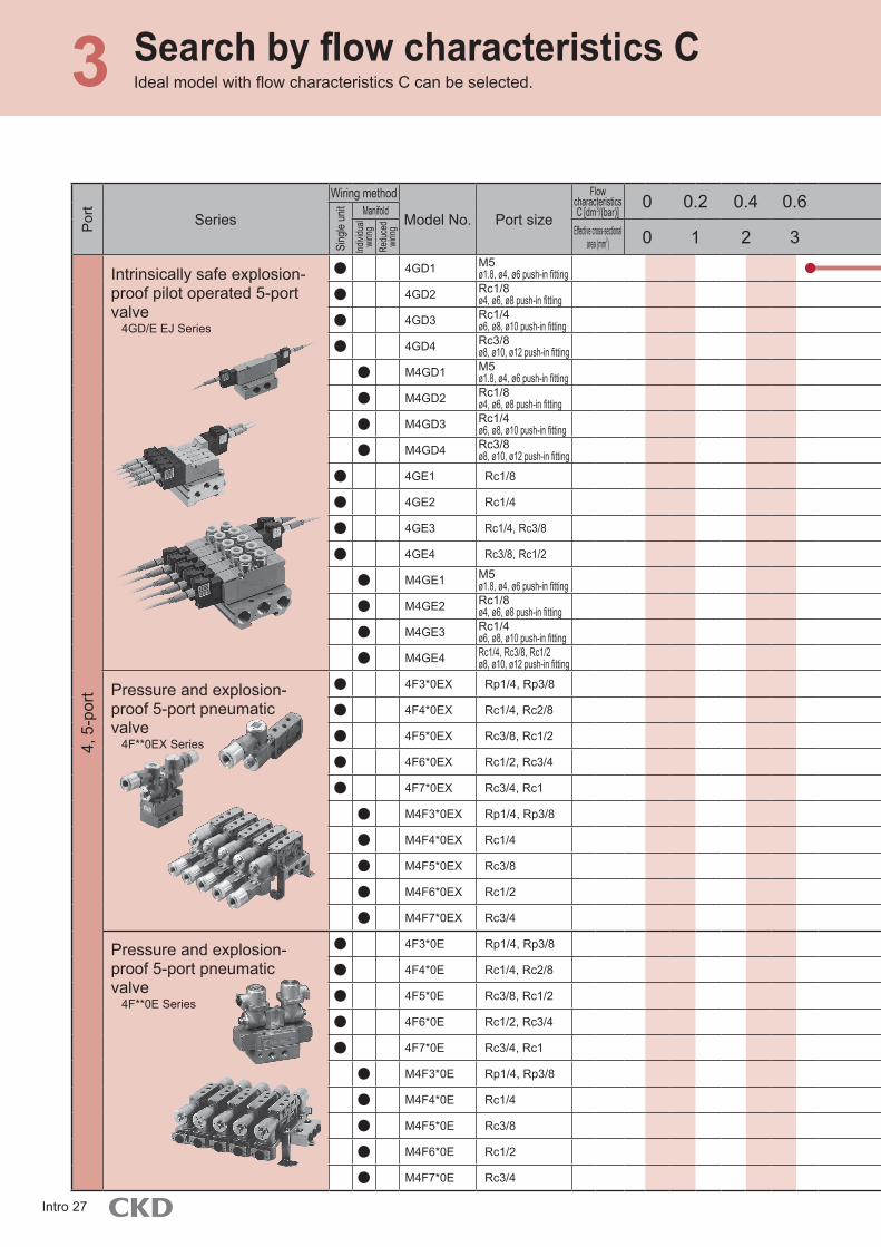
Intrinsically safe explosion-proof pilot operated 5-port valve
4GD/E EJ Series
● 4GD1 M5ø1.8, ø4, ø6 push-in fitting
1697
● 4GD2 Rc1/8ø4, ø6, ø8 push-in fitting
● 4GD3 Rc1/4ø6, ø8, ø10 push-in fitting
● 4GD4 Rc3/8ø8, ø10, ø12 push-in fitting
● M4GD1 M5ø1.8, ø4, ø6 push-in fitting
● M4GD2 Rc1/8ø4, ø6, ø8 push-in fitting
● M4GD3 Rc1/4ø6, ø8, ø10 push-in fitting
● M4GD4 Rc3/8ø8, ø10, ø12 push-in fitting
● 4GE1 Rc1/8
● 4GE2 Rc1/4
● 4GE3 Rc1/4, Rc3/8
● 4GE4 Rc3/8, Rc1/2
● M4GE1 M5ø1.8, ø4, ø6 push-in fitting
● M4GE2 Rc1/8ø4, ø6, ø8 push-in fitting
● M4GE3 Rc1/4ø6, ø8, ø10 push-in fitting
● M4GE4 Rc1/4, Rc3/8, Rc1/2ø8, ø10, ø12 push-in fitting
Pressure and explosion-proof 5-port pneumatic valve
4F**0EX Series
● 4F3*0EX Rp1/4, Rp3/8
1779
● 4F4*0EX Rc1/4, Rc2/8
● 4F5*0EX Rc3/8, Rc1/2
● 4F6*0EX Rc1/2, Rc3/4
● 4F7*0EX Rc3/4, Rc1
● M4F3*0EX Rp1/4, Rp3/8
● M4F4*0EX Rc1/4
● M4F5*0EX Rc3/8
● M4F6*0EX Rc1/2
● M4F7*0EX Rc3/4
Pressure and explosion-proof 5-port pneumatic valve
4F**0E Series
● 4F3*0E Rp1/4, Rp3/8
1807
● 4F4*0E Rc1/4, Rc2/8
● 4F5*0E Rc3/8, Rc1/2
● 4F6*0E Rc1/2, Rc3/4
● 4F7*0E Rc3/4, Rc1
● M4F3*0E Rp1/4, Rp3/8
● M4F4*0E Rc1/4
● M4F5*0E Rc3/8
● M4F6*0E Rc1/2
● M4F7*0E Rc3/4
Intro 27

Search method 1 2 3 4
Por
t
Series
Wiring method
Model No. Port size
Flow characteristicsC [dm3/(bar)]
0 0.2 0.4 0.6 0.8 1.0 1.2 1.4 2.0 4.0 6.0 8.0 10.0 12.0 16.0 20.0 32.0Page
Sing
le un
it Manifold
Indivi
dual
wirin
gRe
duce
d wi
ring Effective cross-sectional
area (mm2) 0 1 2 3 4 5 6 7 10 20 30 40 50 60 80 100 160
4, 5
-por
t
Intrinsically safe explosion-proof pilot operated 5-port valve
4GD/E EJ Series
● 4GD1 M5ø1.8, ø4, ø6 push-in fitting
1697
● 4GD2 Rc1/8ø4, ø6, ø8 push-in fitting
● 4GD3 Rc1/4ø6, ø8, ø10 push-in fitting
● 4GD4 Rc3/8ø8, ø10, ø12 push-in fitting
● M4GD1 M5ø1.8, ø4, ø6 push-in fitting
● M4GD2 Rc1/8ø4, ø6, ø8 push-in fitting
● M4GD3 Rc1/4ø6, ø8, ø10 push-in fitting
● M4GD4 Rc3/8ø8, ø10, ø12 push-in fitting
● 4GE1 Rc1/8
● 4GE2 Rc1/4
● 4GE3 Rc1/4, Rc3/8
● 4GE4 Rc3/8, Rc1/2
● M4GE1 M5ø1.8, ø4, ø6 push-in fitting
● M4GE2 Rc1/8ø4, ø6, ø8 push-in fitting
● M4GE3 Rc1/4ø6, ø8, ø10 push-in fitting
● M4GE4 Rc1/4, Rc3/8, Rc1/2ø8, ø10, ø12 push-in fitting
Pressure and explosion-proof 5-port pneumatic valve
4F**0EX Series
● 4F3*0EX Rp1/4, Rp3/8
1779
● 4F4*0EX Rc1/4, Rc2/8
● 4F5*0EX Rc3/8, Rc1/2
● 4F6*0EX Rc1/2, Rc3/4
● 4F7*0EX Rc3/4, Rc1
● M4F3*0EX Rp1/4, Rp3/8
● M4F4*0EX Rc1/4
● M4F5*0EX Rc3/8
● M4F6*0EX Rc1/2
● M4F7*0EX Rc3/4
Pressure and explosion-proof 5-port pneumatic valve
4F**0E Series
● 4F3*0E Rp1/4, Rp3/8
1807
● 4F4*0E Rc1/4, Rc2/8
● 4F5*0E Rc3/8, Rc1/2
● 4F6*0E Rc1/2, Rc3/4
● 4F7*0E Rc3/4, Rc1
● M4F3*0E Rp1/4, Rp3/8
● M4F4*0E Rc1/4
● M4F5*0E Rc3/8
● M4F6*0E Rc1/2
● M4F7*0E Rc3/4
*1: Effective cross-sectional area S and sonic conductance C are converted as S ≈ 5.0 × C.*2: The port sizes listed are representative examples.
2-port 3-port 4, 5-port Related products Sea
rch
Intro 28
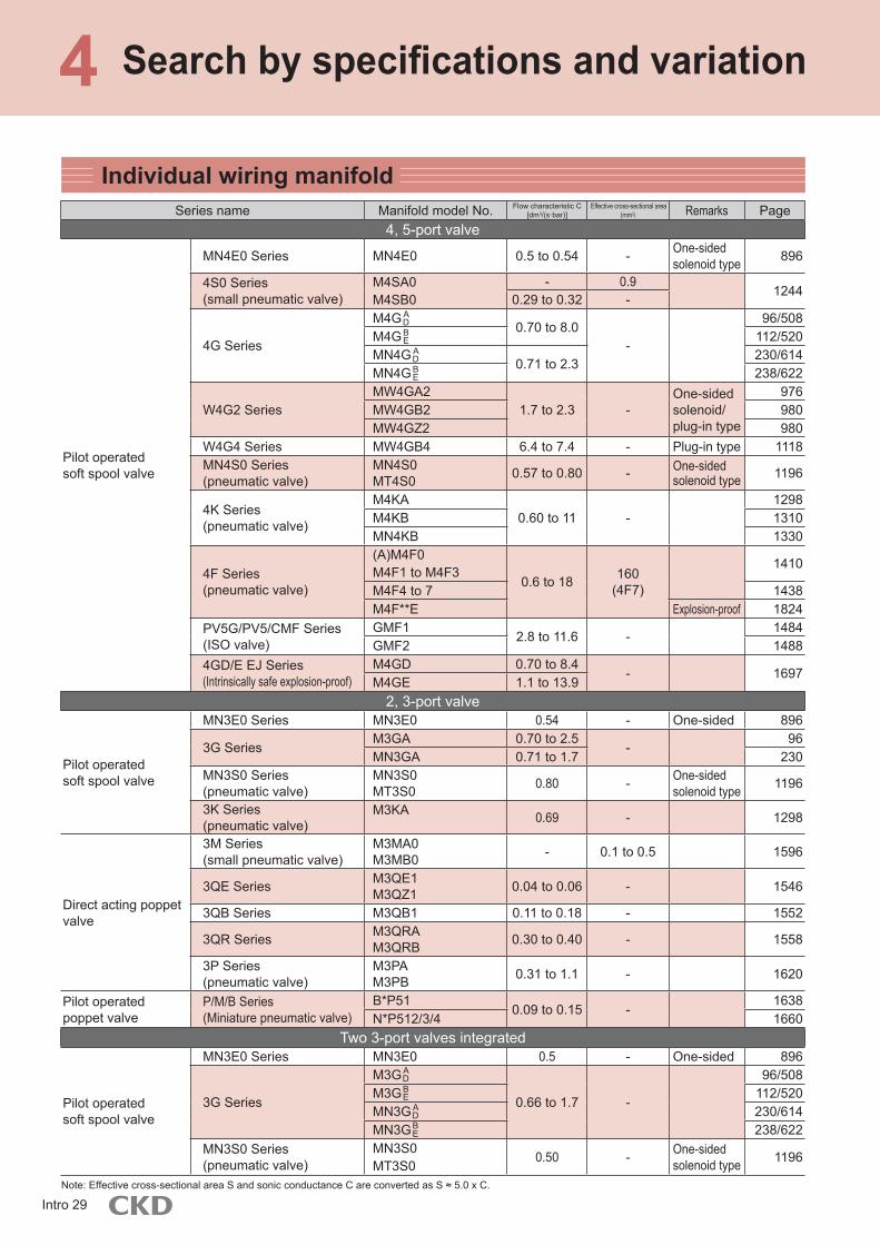
Search by specifications and variation4Individual wiring manifold
Series name Manifold model No. Flow characteristic C [dm3/(s·bar)]
Effective cross-sectional area (mm2) Remarks Page
4, 5-port valve
Pilot operated soft spool valve
MN4E0 Series MN4E0 0.5 to 0.54 - One-sided solenoid type 896
4S0 Series(small pneumatic valve)
M4SA0M4SB0
- 0.912440.29 to 0.32 -
4G Series
M4G0.70 to 8.0
-
96/508M4G 112/520MN4G
0.71 to 2.3230/614
MN4G 238/622
W4G2 SeriesMW4GA2
1.7 to 2.3 -One-sided solenoid/plug-in type
976MW4GB2 980MW4GZ2 980
W4G4 Series MW4GB4 6.4 to 7.4 - Plug-in type 1118MN4S0 Series(pneumatic valve)
MN4S0MT4S0 0.57 to 0.80 - One-sided
solenoid type 1196
4K Series(pneumatic valve)
M4KA0.60 to 11 -
1298M4KB 1310MN4KB 1330
4F Series(pneumatic valve)
(A)M4F0M4F1 to M4F3
0.6 to 18 160(4F7)
1410
M4F4 to 7 1438M4F**E Explosion-proof 1824
PV5G/PV5/CMF Series(ISO valve)
GMF12.8 to 11.6 -
1484GMF2 1488
4GD/E EJ Series (Intrinsically safe explosion-proof)
M4GD 0.70 to 8.4- 1697
M4GE 1.1 to 13.92, 3-port valve
Pilot operated soft spool valve
MN3E0 Series MN3E0 0.54 - One-sided 896
3G SeriesM3GA 0.70 to 2.5
-96
MN3GA 0.71 to 1.7 230MN3S0 Series(pneumatic valve)
MN3S0MT3S0 0.80 - One-sided
solenoid type 1196
3K Series(pneumatic valve)
M3KA 0.69 - 1298
Direct acting poppet valve
3M Series(small pneumatic valve)
M3MA0M3MB0 - 0.1 to 0.5 1596
3QE Series M3QE1M3QZ1 0.04 to 0.06 - 1546
3QB Series M3QB1 0.11 to 0.18 - 1552
3QR Series M3QRAM3QRB 0.30 to 0.40 - 1558
3P Series(pneumatic valve)
M3PAM3PB 0.31 to 1.1 - 1620
Pilot operated poppet valve
P/M/B Series(Miniature pneumatic valve)
B*P510.09 to 0.15 -
1638N*P512/3/4 1660
Two 3-port valves integrated
Pilot operated soft spool valve
MN3E0 Series MN3E0 0.5 - One-sided 896
3G Series
M3G
0.66 to 1.7 -
96/508M3G 112/520MN3G 230/614MN3G 238/622
MN3S0 Series(pneumatic valve)
MN3S0MT3S0
0.50 - One-sided solenoid type 1196
Note: Effective cross-sectional area S and sonic conductance C are converted as S ≈ 5.0 x C.
ADBE
BE
AD
ADBE
BE
AD
Intro 29

Search method 1 2 3 4
Series name Manifold model No. Flow characteristic C [dm3/(s·bar)] Remarks Page
4, 5-port valve
Pilot operated soft spool valve
MN4E SeriesMN4E00 0.32 One-sided
solenoid type872
MN4E0 0.50 to 0.54 8964S0 Series(small pneumatic valve) M4SB0 0.29 to 0.32 1248
4G Series
M4G0.70 to 8.0
136/534M4G 158/554MN4G
0.71 to 2.3246/630
MN4G 262/646
W4G2 SeriesMW4GA2
1.7 to 2.3One-sided solenoid/plug-in type
988MW4GB2 1010MW4GZ2 1010
W4G4 Series MW4GB4 6.4 to 7.4 Plug-in type 1128
MN4S0 Series(pneumatic valve)
MN4S0MT4S0
0.57 to 0.80 One-sided solenoid type 1196
3-port valve
Pilot operated soft spool valve
MN3E SeriesMN3E00 0.32 One-sided
solenoid type872
MN3E0 0.54 896
3G SeriesM3G 0.70 to 2.5 136/534MN3G 0.71 to 1.7 246/630
W3G2 Series MW3GA2 1.7 One-sided solenoid type 988
MN3S0 Series(pneumatic valve)
MN3S0MT3S0
0.80 One-sided solenoid type 1196
Two 3-port valves integrated
Pilot operated soft spool valve
MN3E SeriesMN3E00 0.32 One-sided
solenoid type872
MN3E0 0.50 896
3G Series
M3G
0.66 to 1.7
136/534M3G 158/554MN3G 246/630MN3G 262/646
MN3S0 Series(pneumatic valve)
MN3S0MT3S0
0.50 One-sided solenoid type 1196
Note: Effective cross-sectional area S and sonic conductance C are converted as S ≈ 5.0 x C.
Reduced wiring manifolds
ADBE
BE
AD
AD
AD
AD
AD
BE
BE
Individual wiring manifolds, reduced wiring manifolds, reduced wiring slave units, reduced wiring blocks, copper and PTFE free,
ozone-proof specifications, rechargeable batteries, clean-room specifications, coolant proof products, manual switching valves
Sea
rch
Intro 30

Search by specifications and variation4
PLC manufacturer Communication system Wiring block model No. Slave unit series Incorporated valve
CC-Link PartnerAssociation
Mitsubishi Electric Corporation
CC-Link(ver1.10)
T6G1 OPP2 Series MW4G4, MN4TB, M4TB, LMF0T6G1 OPP3 Series MN4S0, MN4E, MN4G, M4GT7G1 OPP4 Series MN4G
T8G1/2/7 OPP5 Series MW4G2T7G1/2 OPP6 Series MN4ET8G1/2
OPP7 Series M4G, MN4GT8GP1/2
CC-Link IEF BasicT8EB1/2
OPP7 Series M4G, MN4GT8EBP1/2
ODVA OMRON Corporation DeviceNet
T6D1 OPP2 Series MW4G4T7D1 OPP4 Series MN4G
T8D1/2/7 OPP5 Series MW4G2T7D1/2 OPP6 Series MN4ET8D1/2 OPP7 Series MN4G
T7D1/2/7 OPP8 Series MW4GOMRON Corporation CompoBus/S T7D1/2 OPP5 Series MN4E
Japan Profibus Association SIEMENS Corporation
PROFIBUS-DPT8D1/2
OPP7 Series MN4GT7D1/2/7
PROFINETT8EP1/2
T8EPP1/2OPP7 Series M4G, MN4G
OMRON Corporation Beckhoff Automation
EtherCAT
T8EC1/2OPP7 Series M4G, MN4G
T8ECP1/2T7EC1/2
OPP8 Series MW4GT7ECP1/2
ODVA TAG JAPAN EtherNet/IPT8EN1/2
OPP7 Series M4G, MN4GT8ENP1/2
SUNX S-LINK V T7N1/2 OPP6 Series MN4EOntec SAVENET T7L1 OPP4 Series MN4G
---Port size VoltageStation No.Option
M: ManifoldMN: Block manifold
Wiring block model No.
T7D1(Example) MN4GA210-
*2 The shape of the slave unit is as follows.
● Contact CKD for information on compatibility with other networks.
*1 When making arrangements for a reduced wiring manifold, the wiring block model No. will be displayed in the following manner.
OPP2 Degree of protection (IP65) OPP3 Flat cable compatible slave unitOPP4 Thin shape
OPP5 Degree of protection (IP65), connector connectionsOPP6 Miniature 32 point compatible
Reduced wiring slave unit
Intro 31

Search method 1 2 3 4
Reduced wiring slave unit
(serial transmission)
Serial transmission (OPP3)● The valve and slave unit can be
easily connected with connectors.● Low-profile slave unit with
height kept low. (At assembly)
Serial transmission (OPP4)● Thin slave unit● Easily connected/detached
with the slot-in system.
Serial transmission (OPP6)● Compact close contact type● Low-profile slave unit with height
kept the lowest in the series,compatible with up to 32 points.
Serial transmission (OPP7)● Thin slave unit● Easily connected/detached
with the slot-in system.
Serial transmission (OPP5)● Dust-proof/jet-proof protective
structure (IP65).● Power supply wires and communication wires
can be easily connected with connectors.
Serial transmission (OPP8)● High speed EtherCAT
communication supported● A protective structure equivalent
to IP65 rating has beenprepared.
Individual wiring manifolds, reduced wiring manifolds, reduced wiring slave units, reduced wiring blocks, copper and PTFE free,
ozone-proof specifications, rechargeable batteries, clean-room specifications, coolant proof products, manual switching valves
Sea
rch
Intro 32

Search by specifications and variation4Reduced wiring block
Reduced wiring block
Wiring method Wiring block model No. Incorporated valve model No. RemarksIncorporated valve Page
D sub-connector T30/R (24-pin) MN4EMN4G, M4GMW4G2 (*1)
MN4SO (*2)
*1) MW4G2 is not compatible withT50 and T52.
*2) MN4SO is not compatiblewith T51 and T52.
863
Flat cable connectorT50/R (with power supply terminal 16 points)T51/R (18-pin)T52/R (8-pin)
1965
1191Multi-connector T20 (16-pin) MW4G2 965
Common terminalT10/R (M3 screw system)T11/R (clamping system)
MN4G, M4GMW4G2 (*2)
MW4G4 (*2)
MN4SO
*2) MW4G2 and MW4G4 arenot compatible with T11.
1965
11111191
Intermediate wiring blockTM1A (10-pin)TM1C (5-pin)TM52 (8-pin)
MN4E TM**: RITS connectorTM52: Flat cable connector 863
Common terminal block (T1*)● Valve wiring only requires
signal wires and a singlecommon wire
● A relay terminal block is notrequired
Flat cable connector (T5*)● Quick connections using cables
with connectors● Processing of relay terminal block
and common wiring is not required● An amplification circuit
embedded is also available
D sub-connector (T3*)● Quick connections using cables
with connectors● Processing of relay terminal
block and common wiring isnot required
Intermediate wiring block (TM*)● Reduced wiring connection to
the center of the manifold ispossible.
● 10P flat cable connector and 6PRITS connectors are available.
● No more trouble withinsufficient control points.
固定時リテナは 方向に寄せレールに爪掛け
確認後1.4N・mでねじ固定して下さい。
固定時リテナは 方向に寄せレールに爪掛け
確認後1.4N・mでねじ固定して下さい。
Intro 33
Search method 1 2 3 4
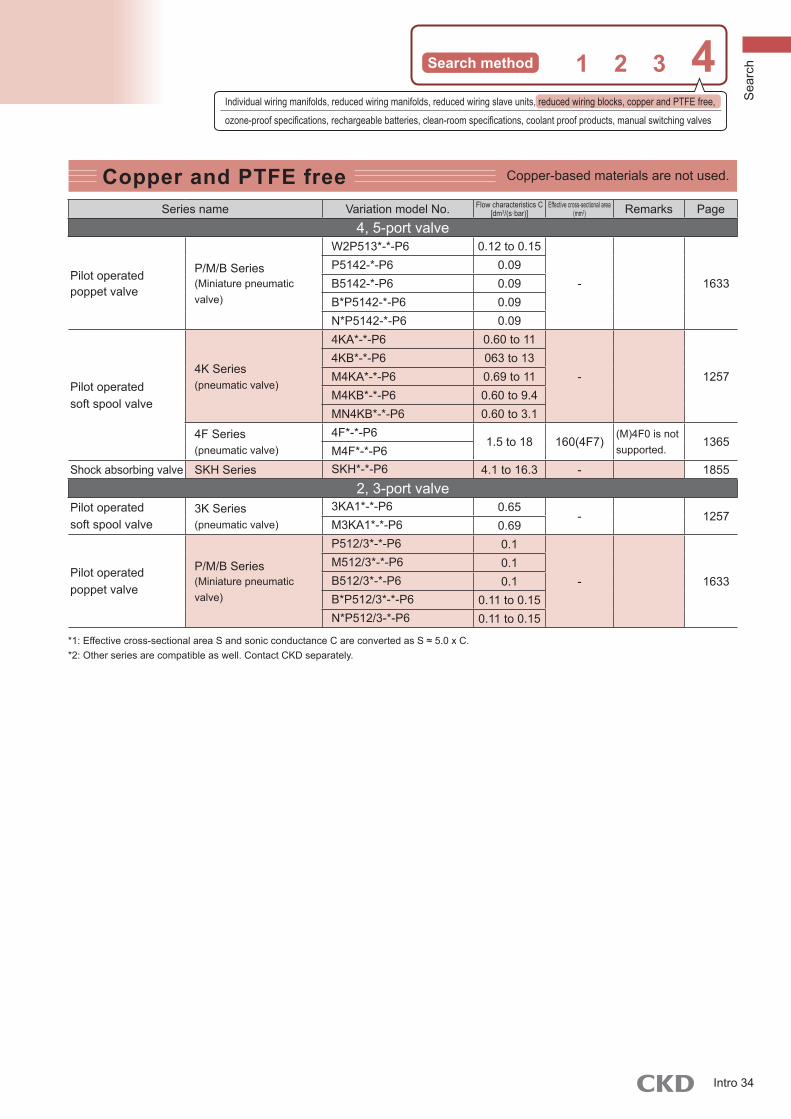
Copper and PTFE free Copper-based materials are not used.
Series name Variation model No. Flow characteristics C[dm3/(s·bar)]
Effective cross-sectional area (mm2) Remarks Page
4, 5-port valve
Pilot operated poppet valve
P/M/B Series(Miniature pneumatic valve)
W2P513*-*-P6 0.12 to 0.15
- 1633P5142-*-P6 0.09B5142-*-P6 0.09B*P5142-*-P6 0.09N*P5142-*-P6 0.09
Pilot operated soft spool valve
4K Series(pneumatic valve)
4KA*-*-P6 0.60 to 11
- 12574KB*-*-P6 063 to 13M4KA*-*-P6 0.69 to 11M4KB*-*-P6 0.60 to 9.4MN4KB*-*-P6 0.60 to 3.1
4F Series(pneumatic valve)
4F*-*-P61.5 to 18 160(4F7)
(M)4F0 is notsupported.
1365M4F*-*-P6
Shock absorbing valve SKH Series SKH*-*-P6 4.1 to 16.3 - 18552, 3-port valve
Pilot operated soft spool valve
3K Series(pneumatic valve)
3KA1*-*-P6 0.65- 1257
M3KA1*-*-P6 0.69
Pilot operated poppet valve
P/M/B Series(Miniature pneumatic valve)
P512/3*-*-P6 0.1
- 1633M512/3*-*-P6 0.1B512/3*-*-P6 0.1B*P512/3*-*-P6 0.11 to 0.15N*P512/3-*-P6 0.11 to 0.15
*1: Effective cross-sectional area S and sonic conductance C are converted as S ≈ 5.0 x C.*2: Other series are compatible as well. Contact CKD separately.
Individual wiring manifolds, reduced wiring manifolds, reduced wiring slave units, reduced wiring blocks, copper and PTFE free,
ozone-proof specifications, rechargeable batteries, clean-room specifications, coolant proof products, manual switching valves
Sea
rch
Intro 34

Search by specifications and variation4Main rubber parts used are ozone proof items
Ozone-proof specification productSeries name Variation model No. Flow characteristics C
[dm3/(s·bar)]Effective cross-sectional area
(mm2) Remarks Page4, 5-port valve
Pilot operated soft spool valve
MN4E0 Series MN4E0*-*-A-* 0.50 to 0.54 - One-sided solenoid type 863
4S0 Series(small pneumatic valve)
4SA0*-*-P11 - 0.90
12314SB0*-*-P11 0.29 to 0.33 -M4SA0*-*-P11 - 0.90M4SB0*-*-P11 0.29 to 0.32 -
4G Series
4G *-*-A-* 0.70 to 8.0
- 1
4G *-*-A-* 1.1 to 11M4G *-*-A-* 0.70 to 8.0M4G *-*-A-* 0.70 to 8.3MN4G *-*-A-* 0.71 to 2.3MN4G *-*-A-* 0.71 to 2.2
W4G2 Series
W4GB2*-*-A-* 2.1 to 2.5
-One-sided solenoid type
965MW4GA2*-*-A-* 1.7 to 2.3MW4GB2*-*-A-* 1.7 to 2.3MW4GZ2*-*-A-* 1.7 to 2.3
W4G4 SeriesW4GB4*-*-A-*
6.4 to 7.3- 1111W4GZ4*-*-A-*
MW4GB4*-*-A-* 6.4 to 7.4
MN4S0 Series(pneumatic valve)
MN4S0*-*-P11MT4S0*-*-P11
0.57 to 0.80 -One-sided solenoid type
1191
4K Series(pneumatic valve)
4KA*-*-P11 0.60 to 11
- 12574KB*-*-P11 0.63 to 13M4KA*-*-P11 0.69 to 11M4KB*-*-P11 0.60 to 9.4MN4KB*-*-P11 0.60 to 3.1
● Ozone-proof components are available as a custom order. (However, the MN4E0 series, 4G series, W4G2 series, and W4G4 series are available as options.)Note: Effective cross-sectional area S and sonic conductance C are converted as S ≈ 5.0 x C.
ADBE
ADBE
ADBE
Intro 35

Search method 1 2 3 4
Main rubber parts used are ozone proof items
Ozone-proof specification productSeries name Variation model No. Flow characteristics C
[dm3/(s·bar)]Effective cross-sectional area
(mm2) Remarks Page3-port valve
Pilot operated soft spool valve
MN3E0 Series MN3E0*-*-A-* 0.54 One-sided solenoid type 863
3G Series3G *-*-A-* 0.70 to 3.9
- 1M3G *-*-A-* 0.66 to 3.3MN3G *-*-A-* 0.68 to 2.3
W3G2 Series MW3GA2*-*-A-* 1.7 to 2.3 - One-sided solenoid type 965
MN3S0 Series(pneumatic valve)
MN3S0-*-*-P110.80 -
One-sided solenoid type
1191MT3S0-*-*-P11
3K Series(pneumatic valve)
3KA*-*-P11 0.65- 1257
M3KA*-*-P11 0.69
Direct acting poppet valve
3M Series(small pneumatic valve)
3MA0*-*-P11
- 0.1 to 0.15 15913MB0*-*-P11M3MA0*-*-P11M3MB0*-*-P11
3P Series(pneumatic valve)
3PA*-*-P11 0.34 to 1.1
- 16073PB*-*-P11 0.33 to 1.0M3PA*-*-P11 0.37 to 1.1M3PB*-*-P11 0.32 to 0.93
Two 3-port valves integrated
Pilot operated soft spool valve
MN3E0 Series MN3E0*-*-A-* 0.50 - One-sided solenoid type 863
3G Series
3G *-*-A-* 0.66 to 1.8
- 1
3G *-*-A-* 0.92 to 1.7M3G *-*-A-* 0.66 to 1.7M3G *-*-A-* 0.67 to 1.6MN3G *-*-A-* 0.68 to 1.6MN3G *-*-A-* 0.66 to 1.6
● Ozone-proof components are available as a custom order. (However, the MN4E0 series, 4G series, and W4G2 series are available as options.)Note: Effective cross-sectional area S and sonic conductance C are converted as S ≈ 5.0 x C.
AD
AD
AD
ADBE
AD
AD
BE
BE
Individual wiring manifolds, reduced wiring manifolds, reduced wiring slave units, reduced wiring blocks, copper and PTFE free,
ozone-proof specifications, rechargeable batteries, clean-room specifications, coolant proof products, manual switching valves
Sea
rch
Intro 36
Search by specifications and variation4
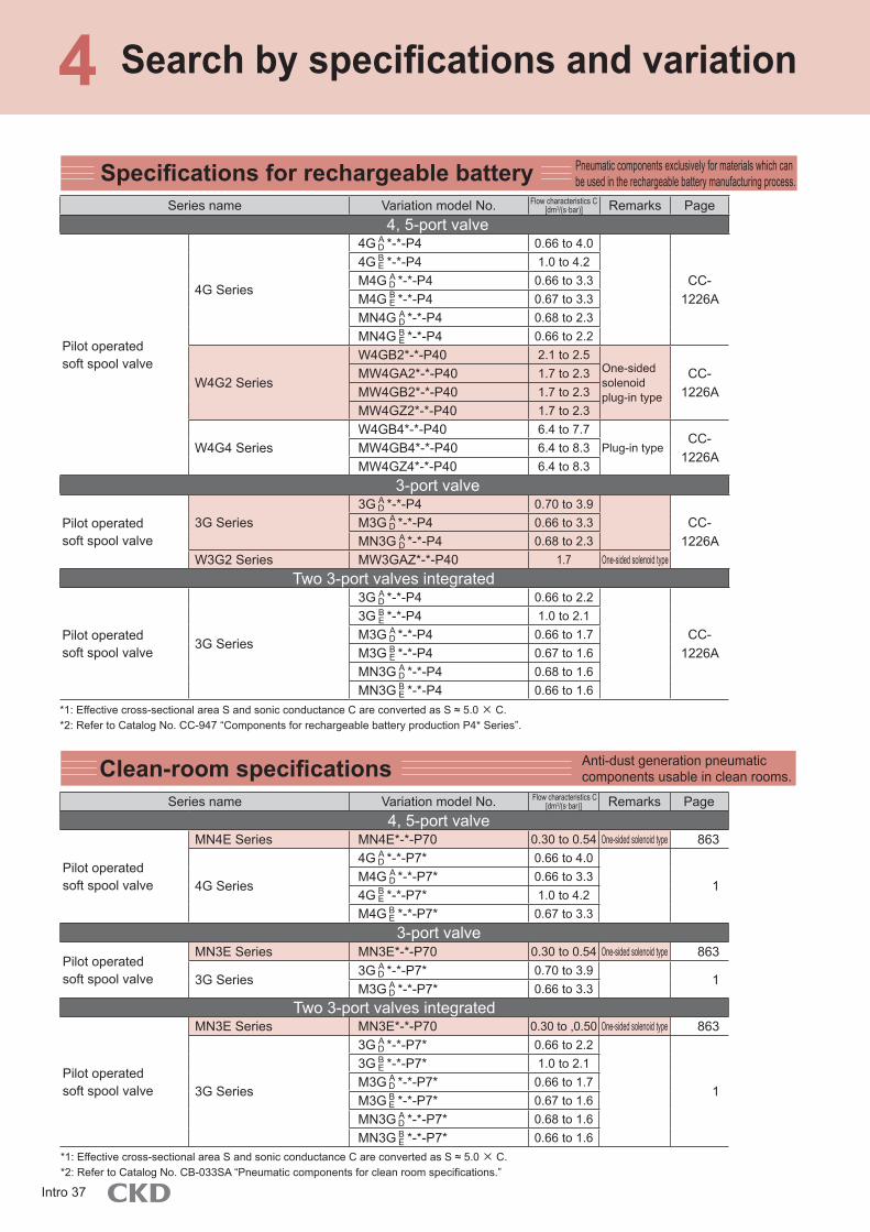
Clean-room specifications
Specifications for rechargeable battery Pneumatic components exclusively for materials which can be used in the rechargeable battery manufacturing process.
Series name Variation model No. Flow characteristics C[dm3/(s·bar)] Remarks Page
4, 5-port valve
Pilot operated soft spool valve
4G Series
4G *-*-P4 0.66 to 4.0
CC-1226A
4G *-*-P4 1.0 to 4.2M4G *-*-P4 0.66 to 3.3M4G *-*-P4 0.67 to 3.3MN4G *-*-P4 0.68 to 2.3MN4G *-*-P4 0.66 to 2.2
W4G2 Series
W4GB2*-*-P40 2.1 to 2.5One-sided solenoid plug-in type
CC-1226A
MW4GA2*-*-P40 1.7 to 2.3MW4GB2*-*-P40 1.7 to 2.3MW4GZ2*-*-P40 1.7 to 2.3
W4G4 SeriesW4GB4*-*-P40 6.4 to 7.7
Plug-in typeCC-
1226AMW4GB4*-*-P40 6.4 to 8.3MW4GZ4*-*-P40 6.4 to 8.3
3-port valve
Pilot operated soft spool valve
3G Series3G *-*-P4 0.70 to 3.9
CC-1226A
M3G *-*-P4 0.66 to 3.3MN3G *-*-P4 0.68 to 2.3
W3G2 Series MW3GAZ*-*-P40 1.7 One-sided solenoid type
Two 3-port valves integrated
Pilot operated soft spool valve
3G Series
3G *-*-P4 0.66 to 2.2
CC-1226A
3G *-*-P4 1.0 to 2.1M3G *-*-P4 0.66 to 1.7M3G *-*-P4 0.67 to 1.6MN3G *-*-P4 0.68 to 1.6MN3G *-*-P4 0.66 to 1.6
*1: Effective cross-sectional area S and sonic conductance C are converted as S ≈ 5.0 × C.*2: Refer to Catalog No. CC-947 “Components for rechargeable battery production P4* Series”.
Anti-dust generation pneumatic components usable in clean rooms.
Series name Variation model No. Flow characteristics C[dm3/(s·bar)] Remarks Page
4, 5-port valve
Pilot operated soft spool valve
MN4E Series MN4E*-*-P70 0.30 to 0.54 One-sided solenoid type 863
4G Series
4G *-*-P7* 0.66 to 4.0
1M4G *-*-P7* 0.66 to 3.34G *-*-P7* 1.0 to 4.2M4G *-*-P7* 0.67 to 3.3
3-port valve
Pilot operated soft spool valve
MN3E Series MN3E*-*-P70 0.30 to 0.54 One-sided solenoid type 863
3G Series3G *-*-P7* 0.70 to 3.9
1M3G *-*-P7* 0.66 to 3.3
Two 3-port valves integrated
Pilot operated soft spool valve
MN3E Series MN3E*-*-P70 0.30 to ,0.50 One-sided solenoid type 863
3G Series
3G *-*-P7* 0.66 to 2.2
1
3G *-*-P7* 1.0 to 2.1M3G *-*-P7* 0.66 to 1.7M3G *-*-P7* 0.67 to 1.6MN3G *-*-P7* 0.68 to 1.6MN3G *-*-P7* 0.66 to 1.6
*1: Effective cross-sectional area S and sonic conductance C are converted as S ≈ 5.0 × C.*2: Refer to Catalog No. CB-033SA “Pneumatic components for clean room specifications.”
AD
ADBE
ADBE
BE
ADBE
ADBE
ADBE
AD
AD
AD
BE
BE
BE
AD
AD
AD
AD
AD
BE
BE
AD
AD
Intro 37

Search method 1 2 3 4
Coolant proof product Pneumatic components using valve materials with excellent oil resistance and water resistance.
Series name Variation model No. Flow characteristics C[dm3/(s·bar)] Remarks Page
4, 5-port valve
Pilot operated soft spool valve
4G Series
4G *-*-A-* 0.70 to 8.0
1
4G *-*-A-* 1.1 to 11M4G *-*-A-* 0.70 to 8.0M4G *-*-A-* 0.70 to 8.3MN4G *-*-A-* 0.71 to 2.3MN4G *-*-A-* 0.71 to 2.2
W4G2 Series
W4GB2*-*-A-* 2.1 to 2.5One-sided solenoid/Plug-in type
965MW4GA2*-*-A-* 1.7 to 2.3MW4GB2*-*-A-* 1.7 to 2.3MW4GZ2*-*-A-* 1.7 to 2.3
W4G4 Series W4GB4*-*-A-* 6.4 to 7.3Plug-in type 1111MW4GB4*-*-A-* 6.4 to 7.4
4K Series(pneumatic valve)
4KA*-*-A 0.60 to 114KB*-*-A 0.63 to 13
PV5G/PV5 Series(ISO valve)
PV5G-*-*-*-A-* 2.8 to 6.9 1465PV5-*-*-A-*-TC3-port valve
Pilot operated soft spool valve
3G Series3G *-*-A-* 0.70 to 3.9
1M3G *-*-A-* 0.66 to 3.3MN3G *-*-A-* 0.68 to 2.3
W3G2 Series MW3GA2*-*-A-* 1.7 One-sided solenoid type 965
3K Series(pneumatic valve)
3KA1*-*-A 0.65
Two 3-port valves integrated
Pilot operated soft spool valve
3G Series
3G *-*-A-* 0.66 to 1.8
1
3G *-*-A-* 0.92 to 1.7M3G *-*-A-* 0.66 to 1.7M3G *-*-A-* 0.67 to 1.6MN3G *-*-A-* 0.68 to 1.6MN3G *-*-A-* 0.66 to 1.6
*1: Effective cross-sectional area S and sonic conductance C are converted as S ≈ 5.0 × C.
Manual selector valveSeries name Model No. Flow characteristic
C[dm3/(s·bar)] Eff. X-sectional area (mm2) Remarks Page4-port valve
Miniature HMV 1.5 to 1.6 - 1837Standard HSV 7.2 to 10.3 -3-port valve
Compact mechanical valve MS - 1.6 to 2.5 Detector total air system
1901Medium mechanical valve MM - 1.6 to 2.5Large mechanical valve MAVL - 31Quick valve 3QV - - ø4 to ø12 1845
2-port valveQuick valve 2QV - - ø4 to ø12 1845
ADBE
AD
AD
BE
BE
AD
AD
AD
AD
AD
AD
BE
BE
BE
Individual wiring manifolds, reduced wiring manifolds, reduced wiring slave units, reduced wiring blocks, copper and PTFE free,
ozone-proof specifications, rechargeable batteries, clean-room specifications, coolant proof products, manual switching valves
Sea
rch
Intro 38

System selectionSystem selectionEven beginners can easily make a model selection.
How to make a system selection
An overview of the selection is available with the following two conditions.
Operation time
Workpiece
Bore sizeLoad conditions
Workpiece
Bore sizeOperation speed
When selecting peripheral pneumatic components, having determined cylinder bore size and operation speed
To Intro Page 40
When selecting peripheral pneumatic components, having determined bore size from cylinder load and operating time
To Intro Page 51Intro 39

* The relationship of the cylinder bore size and speed for the valve (4G Series/4K Series) is shown in a graph."A combination of the valve and the cylinder's standard system" (Example) IntroPages 49 to 50
Refer to Table 3, and select a component with a [max. flow rate] higher than the [Required flow rate] value.When controlling multiple cylinders with a set of clean air system components, select the clean air system component having a [max. flow rate] higher than the [total of required flow rates].
Select the clean air system components
From to Table 3
Select appropriate fluid control components from bore size and theoretical reference speed, and select [required flow rate]
From to Table 2
Select the theoretical reference speed
From Table 1(1) Bore size ø□(2) Operation speed Low speed/medium speed/
high speed/ultra-high speed
Using Table 1 as a reference, select the theoretical reference speed of the cylinder.
Whether the cylinder bore size and cylinder being used are driven with relative high or low speed is determined as a condition.Check cylinder tube bore size
and cylinder operation speed
[Confirming conditions]
Refer to Table 2 and select appropriate fluid control components (valve, speed controller, silencer, piping) and [required flow rate] for corresponding cylinder bore size and theoretical reference speed.
(1) The cylinder average speed is obtained from the combination of the valve and piping system. It is expressed as the cylinder'spiston speed calculated by dividing the stroke length by the time that the piston rod takes from start to end of movement with thecylinder rod installed facing upward. When the load factor is 50%, the average speed should be approximately the cylinder'spiston speed multiplied by 0.5. (Refer to Intro Page 53 for the relation of load factor and theoretical reference speed. )
(2) The cylinder theoretical reference speed is the value of when one cylinder moves independently.(3) The valve's effective cross-sectional area used in the calculation for Table 2 is the 2-position value.(4) This selection guide is for reference. With the CKD sizing program, confirm conditions to be actually used.
Selecting from cylinder bore size and operation speed
Selecting from the load value and operation time
Selecting from cylinder bore size and operation speed
Sel
ectio
n
Intro 40

System selection
Bore size (mm)Theoretical reference
speed (mm/s) Note)
Required flow rate (ℓ/min) (ANR)
Required composite effective cross-sectional area
(mm2)
Suitable control componentsValve Pneumatic auxiliary components Piping *1
Single solenoid Double solenoid Speed controller Silencer Piping (between valve and cylinder)
ø6 500 5 0.1 MN4E0104SA010/4SB010
MN4E0204SA020/4SB020 SC3W-M5-4 SLM-M5,SLM-M3 ø4 x ø2.5 nylon tube
ø10 500 14 0.2 MN4E0104SA010/4SB010
MN4E0204SA020/4SB020 SC3W-M5-4 SLM-M5,SLM-M3 ø4 x ø2.5 nylon tube
ø16 500 36 0.5 MN4E0104SA010/4SB010
MN4E0204SA020/4SB020 SC3W-M5-4 SLM-M5,SLM-M3 ø4 x ø2.5 nylon tube
ø20
250 29 0.5 4KA110/4KB1104GA110R/4GB110R
4KA120/4KB1204GA120R/4GB120R
SC3W-6-6SCL2-06-H66 SLM-M5,SLW-6A ø6 x ø4 nylon tube
500 56 0.94KA110/4KB110 4KA120/4KB120
750 84 1.44GA110R/4GB110R 4GA120R/4GB120R
SC3W-6-6SLM-M5,SLW-6A ø6 x ø4 nylon tube
1,000 112 1.8SCL2-06-H66
ø25
250 44 0.8 4KA110/4KB110 4KA120/4KB120 SC3W-6-6
500 88 1.4 4GA110R/4GB110R 4GA120R/4GB120R SCL2-06-H66SLM-M5,SLW-6A ø6 x ø4 nylon tube
750 132 2.1 4KB110/4GB110R 4KB120/4GB120R SC1-6 SLW-6A,SL-M5 ø8 x ø5.7 nylon tube
1,000 175 2.8 4KB210/4GB210R 4KB220/4GB220R SCL2-08-H88 SLW-6S,SLW-6A ø8 x ø5.7 nylon tube
ø32
250 73 1.3 4KA110/4KB1104GA110R/4GB110R
4KA120/4KB1204GA120R/4GB120R
SC3W-6-6SCL2-06-H66 SLM-M5,SLW-6A ø6 x ø4 nylon tube
500 143 2.94KA210/4KB210 4KA220/4KB220
750 215 3.54GA210R/4GB210R 4GA220R/4GB220R
SC1-6SLW-6S,SLW-6A ø8 x ø5.7 nylon tube
1,000 286 4.6SCL2-08-H88
Note) The above table indicates theoretical reference speed at cylinder bore size.Refer to the individual specifications of each model for the working piston speed range.
Table 1
Table 2
STEP1 Conditions confirmation/theoretical reference speed selection
STEP2 Fluid control components selection
Ultra high speed
1,000
High speed
750
Medium speed
500
Low speed
250Theoretical reference speed (mm/s)
Degree of cylinder speed
Select appropriate fluid control components (valve, speed controller, silencer, piping) and [required flow rate] for bore size and theoretical reference speed selected from Table 1.
As a condition, it is predetermined whether bore size and cylinder are to be operated at a relatively high speed or at a relatively low speed.
Intro 41

Bore size (mm)Theoretical reference
speed (mm/s)Note)
Required flow rate (ℓ/min) (ANR)
Required composite effective cross-sectional area
(mm2)
Suitable control componentsValve Pneumatic auxiliary components Piping *1
Single solenoid Double solenoid Speed controller Silencer Piping (between valve and cylinder)
ø6 500 5 0.1 MN4E0104SA010/4SB010
MN4E0204SA020/4SB020 SC3W-M5-4 SLM-M5,SLM-M3 ø4 x ø2.5 nylon tube
ø10 500 14 0.2 MN4E0104SA010/4SB010
MN4E0204SA020/4SB020 SC3W-M5-4 SLM-M5,SLM-M3 ø4 x ø2.5 nylon tube
ø16 500 36 0.5 MN4E0104SA010/4SB010
MN4E0204SA020/4SB020 SC3W-M5-4 SLM-M5,SLM-M3 ø4 x ø2.5 nylon tube
ø20
250 29 0.5 4KA110/4KB1104GA110R/4GB110R
4KA120/4KB1204GA120R/4GB120R
SC3W-6-6SCL2-06-H66 SLM-M5,SLW-6A ø6 x ø4 nylon tube
500 56 0.94KA110/4KB110 4KA120/4KB120
750 84 1.44GA110R/4GB110R 4GA120R/4GB120R
SC3W-6-6SLM-M5,SLW-6A ø6 x ø4 nylon tube
1,000 112 1.8SCL2-06-H66
ø25
250 44 0.8 4KA110/4KB110 4KA120/4KB120 SC3W-6-6
500 88 1.4 4GA110R/4GB110R 4GA120R/4GB120R SCL2-06-H66SLM-M5,SLW-6A ø6 x ø4 nylon tube
750 132 2.1 4KB110/4GB110R 4KB120/4GB120R SC1-6 SLW-6A,SL-M5 ø8 x ø5.7 nylon tube
1,000 175 2.8 4KB210/4GB210R 4KB220/4GB220R SCL2-08-H88 SLW-6S,SLW-6A ø8 x ø5.7 nylon tube
ø32
250 73 1.3 4KA110/4KB1104GA110R/4GB110R
4KA120/4KB1204GA120R/4GB120R
SC3W-6-6 SCL2-06-H66 SLM-M5,SLW-6A ø6 x ø4 nylon tube
500 143 2.94KA210/4KB210 4KA220/4KB220
750 215 3.54GA210R/4GB210R 4GA220R/4GB220R
SC1-6SLW-6S,SLW-6A ø8 x ø5.7 nylon tube
1,000 286 4.6SCL2-08-H88
*1: Refer to Intro Page 57 for piping specifications.
STEP1 Conditions confirmation/theoretical reference speed selection
STEP2 Fluid control components selection
Selecting from cylinder bore size and operation speed
Selecting from the load value and operation time
Sel
ectio
n
Intro 42
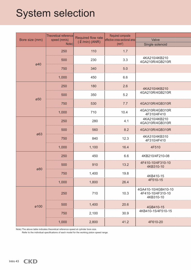
System selection
Bore size (mm)Theoretical reference
speed (mm/s) Note)
Required flow rate (ℓ/min) (ANR)
Required composite effective cross-sectional area
(mm2)
Suitable control componentsValve Pneumatic auxiliary components Piping *1
Single solenoid Double solenoid Speed controller Silencer Piping (between valve and cylinder)
ø40
250 110 1.7 SC3W-6-6SCL2-06-H66 SLM-M5,SLW-6A ø6 x ø4 nylon tube
500 230 3.3 4KA210/4KB2104GA210R/4GB210R
4KA220/4KB2204GA220R/4GB220R
SC1-6SCL2-08-H88 SLW-6S,SLW-6A ø8 x ø5.7 nylon tube
750 340 5.0 SC1-8 SLW-8A,SLW-6A ø10 x ø7.2 nylon tube
1,000 450 6.6 SC1-8 SLW-8A,SLW-8S ø10 x ø7.2 nylon tube
ø50
250 180 2.64KA210/4KB210
4GA210R/4GB210R4KA220/4KB220
4GA220R/4GB220R
SC1-6SCL2-08-H88 SLW-6A,SLW-6S ø8 x ø5.7 nylon tube
500 350 5.2 SC1-8 SLW-8A,SLW-6A ø10 x ø7.2 nylon tube
750 530 7.7 4GA310R/4GB310R 4GA320R/4GB320R SCL2-10-H1010 SLW-8A,SLW-8S ø10 x ø7.2 nylon tube
1,000 710 10.4 4GA310R/4GB310R4F310/4F410
4GA320R/4GB320R4F320/4F420 SC1-10 SLW-10A ø15 x ø11.5 nylon tube or
Rc3/8 steel pipe
ø63
250 280 4.1 4KA210/4KB2104GA310R/4GB310R
4KA220/4KB2204GA320R/4GB320R
SC1-6SCL2-08-H88 SLW-6S,SLW-6A ø8 x ø5.7 nylon tube
500 560 8.2 4GA310R/4GB310R 4GA320R/4GB320R SC1-8SCL2-10-H1010 SLW-8A,SLW-8S ø10 x ø7.2 nylon tube
750 840 12.3 4KA310/4KB3104F310/4F410
4KA320/4KB3204F320/4F420 SC1-10 SLW-10A ø15 x ø11.5 nylon tube or
Rc3/8 steel pipe
1,000 1,100 16.4 4F510 4F520 SC1-15 SLW-15A Rc1/2 steel pipe
ø80
250 450 6.6 4KB210/4F210-08 4KB220/4F220-08 SC1-8SCL2-10-H1010 SLW-8A,SLW-8S ø10 x ø7.2 nylon tube
500 910 13.2 4F410-10/4F310-104KB310-10
4F420-10/4F320-104KB320-10 SC1-10 SLW-10A ø15 x ø11.5 nylon tube or
Rc3/8 steel pipe
750 1,400 19.84KB410-154F510-15
4KB420-154F520-15
SC1-15 SLW-15A Rc1/2 steel pipe
1,000 1,800 26.4 SC-20A SLW-15A Rc1/2 steel pipe
ø100
250 710 10.34GA410-10/4GB410-10
4F410-10/4F310-104KB310-10
4GA420-10/4GB420-104F420-10/4F320-10
4KB320-10SC1-10 SLW-10A ø15 x ø11.5 nylon tube or
Rc3/8 steel pipe
500 1,400 20.64GB410-15
4KB410-15/4F510-154GB420-15
4KB420-15/4F520-15
SC1-15 SLW-15A Rc1/2 steel pipe
750 2,100 30.9 SC-20A SLW-15A Rc1/2 steel pipe
1,000 2,800 41.2 4F610-20 4F620-20 SC-20A SL-20A,SLW-20S Rc3/4 steel pipe
Note) The above table indicates theoretical reference speed at cylinder bore size.Refer to the individual specifications of each model for the working piston speed range.
Intro 43

Bore size (mm)Theoretical reference
speed (mm/s)Note)
Required flow rate (ℓ/min) (ANR)
Required composite effective cross-sectional area
(mm2)
Suitable control componentsValve Pneumatic auxiliary components Piping *1
Single solenoid Double solenoid Speed controller Silencer Piping (between valve and cylinder)
ø40
250 110 1.7 SC3W-6-6SCL2-06-H66 SLM-M5,SLW-6A ø6 x ø4 nylon tube
500 230 3.3 4KA210/4KB2104GA210R/4GB210R
4KA220/4KB2204GA220R/4GB220R
SC1-6SCL2-08-H88 SLW-6S,SLW-6A ø8 x ø5.7 nylon tube
750 340 5.0 SC1-8 SLW-8A,SLW-6A ø10 x ø7.2 nylon tube
1,000 450 6.6 SC1-8 SLW-8A,SLW-8S ø10 x ø7.2 nylon tube
ø50
250 180 2.64KA210/4KB210
4GA210R/4GB210R4KA220/4KB220
4GA220R/4GB220R
SC1-6SCL2-08-H88 SLW-6A,SLW-6S ø8 x ø5.7 nylon tube
500 350 5.2 SC1-8 SLW-8A,SLW-6A ø10 x ø7.2 nylon tube
750 530 7.7 4GA310R/4GB310R 4GA320R/4GB320R SCL2-10-H1010 SLW-8A,SLW-8S ø10 x ø7.2 nylon tube
1,000 710 10.4 4GA310R/4GB310R4F310/4F410
4GA320R/4GB320R4F320/4F420 SC1-10 SLW-10A ø15 x ø11.5 nylon tube or
Rc3/8 steel pipe
ø63
250 280 4.1 4KA210/4KB2104GA310R/4GB310R
4KA220/4KB2204GA320R/4GB320R
SC1-6SCL2-08-H88 SLW-6S,SLW-6A ø8 x ø5.7 nylon tube
500 560 8.2 4GA310R/4GB310R 4GA320R/4GB320R SC1-8SCL2-10-H1010 SLW-8A,SLW-8S ø10 x ø7.2 nylon tube
750 840 12.3 4KA310/4KB3104F310/4F410
4KA320/4KB3204F320/4F420 SC1-10 SLW-10A ø15 x ø11.5 nylon tube or
Rc3/8 steel pipe
1,000 1,100 16.4 4F510 4F520 SC1-15 SLW-15A Rc1/2 steel pipe
ø80
250 450 6.6 4KB210/4F210-08 4KB220/4F220-08 SC1-8SCL2-10-H1010 SLW-8A,SLW-8S ø10 x ø7.2 nylon tube
500 910 13.2 4F410-10/4F310-104KB310-10
4F420-10/4F320-104KB320-10 SC1-10 SLW-10A ø15 x ø11.5 nylon tube or
Rc3/8 steel pipe
750 1,400 19.84KB410-154F510-15
4KB420-154F520-15
SC1-15 SLW-15A Rc1/2 steel pipe
1,000 1,800 26.4 SC-20A SLW-15A Rc1/2 steel pipe
ø100
250 710 10.34GA410-10/4GB410-10
4F410-10/4F310-104KB310-10
4GA420-10/4GB420-104F420-10/4F320-10
4KB320-10SC1-10 SLW-10A ø15 x ø11.5 nylon tube or
Rc3/8 steel pipe
500 1,400 20.64GB410-15
4KB410-15/4F510-154GB420-15
4KB420-15/4F520-15
SC1-15 SLW-15A Rc1/2 steel pipe
750 2,100 30.9 SC-20A SLW-15A Rc1/2 steel pipe
1,000 2,800 41.2 4F610-20 4F620-20 SC-20A SL-20A,SLW-20S Rc3/4 steel pipe
*1: Refer to Intro Page 57 for piping specifications.
Selecting from cylinder bore size and operation speed
Selecting from the load value and operation time
Sel
ectio
n
Intro 44

System selection
Bore size (mm)Theoretical reference
speed (mm/s) Note)
Required flow rate (ℓ/min) (ANR)
Required composite effective cross-sectional area
(mm2)
Suitable control componentsValve Pneumatic auxiliary components Piping *1
Single solenoid Double solenoid Speed controller Silencer Piping (between valve and cylinder)
ø125
250 1,100 16.14GB410-15
4KB410-15/4F510-154GB420-15
4KB420-15/4F520-15
SC1-15 SLW-15A Rc1/2 steel pipe
500 2,200 32.2 SC-20A SLW-15A Rc1/2 steel pipe
750 3,300 48.24F610-20 4F620-20
SC-20A SL-20A,SLW-20S Rc3/4 steel pipe
1,000 4,400 64.4 SC-20A SL-20A Rc3/4 steel pipe
ø140
250 1,400 20.2 4GB410-154KB410-15/4F510-15
4GB420-154KB420-15/4F520-15 SC1-15 SLW-15A Rc1/2 steel pipe
500 2,800 40.44F610-20 4F620-20 SC-20A
SL-20A,SLW-20S Rc3/4 steel pipe
750 4,200 60.5 SL-20A Rc3/4 steel pipe
1,000 5,500 80.8 4F710-25 4F720-25 SC-20A SL-25A Rc1 steel pipe
ø160
250 1,800 26.3 4GB410-154KB410-15/4F510-15
4GB420-154KB420-15/4F520-15 SC-20A SLW-15A Rc1/2 steel pipe
500 3,600 52.6 4F610-20 4F620-20 SC-20A SL-20A Rc3/4 steel pipe
750 5,400 79.0 4F710-20 4F720-20 SC-20A SL-20A Rc3/4 steel pipe
1,000 7,200 104.7 - - - - -
ø180
250 2,300 33.3 4KB410-154F510-15
4KB420-154F520-15 SC-20A SLW-15A Rc1/2 steel pipe
500 4,600 66.6 4F710-20 4F720-20 SC-20A SL-20A Rc3/4 steel pipe
750 6,900 100.0 4F710-25 4F720-25 SC-25A SL-25A Rc1 steel pipe
1,000 9,200 132.5 - - - - -
ø200
250 2,800 41.2 4F610-20 4F620-20 SC-20A SL-20A,SLW-20S Rc3/4 steel pipe
500 5,600 82.4 4F710-25 4F720-25 SC-25A SL-25A Rc1 steel pipe
750 8,400 122.7 - - - - -
1,000 11,200 163.6 - - - - -
ø250
250 4,400 64.3 4F710-20 4F720-20 SC-20A SL-20A Rc3/4 steel pipe
400 7,000 103.0 4F710-25 4F720-25 SC-25A SL-25A Rc1 steel pipe
750 13,200 191.7 - - - - -
1,000 17,600 255.6 - - - - -
Intro 45

Bore size (mm)Theoretical reference
speed (mm/s)Note)
Required flow rate (ℓ/min) (ANR)
Required composite effective cross-sectional area
(mm2)
Suitable control componentsValve Pneumatic auxiliary components Piping *1
Single solenoid Double solenoid Speed controller Silencer Piping (between valve and cylinder)
ø125
250 1,100 16.14GB410-15
4KB410-15/4F510-154GB420-15
4KB420-15/4F520-15
SC1-15 SLW-15A Rc1/2 steel pipe
500 2,200 32.2 SC-20A SLW-15A Rc1/2 steel pipe
750 3,300 48.24F610-20 4F620-20
SC-20A SL-20A,SLW-20S Rc3/4 steel pipe
1,000 4,400 64.4 SC-20A SL-20A Rc3/4 steel pipe
ø140
250 1,400 20.2 4GB410-154KB410-15/4F510-15
4GB420-154KB420-15/4F520-15 SC1-15 SLW-15A Rc1/2 steel pipe
500 2,800 40.44F610-20 4F620-20 SC-20A
SL-20A,SLW-20S Rc3/4 steel pipe
750 4,200 60.5 SL-20A Rc3/4 steel pipe
1,000 5,500 80.8 4F710-25 4F720-25 SC-20A SL-25A Rc1 steel pipe
ø160
250 1,800 26.3 4GB410-154KB410-15/4F510-15
4GB420-154KB420-15/4F520-15 SC-20A SLW-15A Rc1/2 steel pipe
500 3,600 52.6 4F610-20 4F620-20 SC-20A SL-20A Rc3/4 steel pipe
750 5,400 79.0 4F710-20 4F720-20 SC-20A SL-20A Rc3/4 steel pipe
1,000 7,200 104.7 - - - - -
ø180
250 2,300 33.3 4KB410-154F510-15
4KB420-154F520-15 SC-20A SLW-15A Rc1/2 steel pipe
500 4,600 66.6 4F710-20 4F720-20 SC-20A SL-20A Rc3/4 steel pipe
750 6,900 100.0 4F710-25 4F720-25 SC-25A SL-25A Rc1 steel pipe
1,000 9,200 132.5 - - - - -
ø200
250 2,800 41.2 4F610-20 4F620-20 SC-20A SL-20A,SLW-20S Rc3/4 steel pipe
500 5,600 82.4 4F710-25 4F720-25 SC-25A SL-25A Rc1 steel pipe
750 8,400 122.7 - - - - -
1,000 11,200 163.6 - - - - -
ø250
250 4,400 64.3 4F710-20 4F720-20 SC-20A SL-20A Rc3/4 steel pipe
400 7,000 103.0 4F710-25 4F720-25 SC-25A SL-25A Rc1 steel pipe
750 13,200 191.7 - - - - -
1,000 17,600 255.6 - - - - -
*1: Refer to Intro Page 57 for piping specifications.
Selecting from cylinder bore size and operation speed
Selecting from the load value and operation time
Sel
ectio
n
Intro 46

System selection
Explanation of technical terms
VO: Theoretical reference speed (mm/s)A: Cylinder sectional area (cm2)S: Composite effective cross-sectional area of circuit (exhaust air side) (mm2)D: Cylinder bore size (cm)
VO=1920 × =2445 × (1)
[Theoretical reference speed]: indicates degree of cylinder speed, expressed as the following formula.(This value coincides with speed at no load. When load is applied, speed drops considerably.)
SA
SD2
* Note/t1 and t2 differ depending on load. At no load, this can be ignored to no ill effect.
When expressed as a graph, the theoretical reference speed is the speed within the range where the cylinder moves at a uniform speed
t1: Time until movement startst2: Time of primary delayt3: Operating time with constant velocity : Stroke length
VO= (mm/s)t3
Table 3
Select a component with a max. flow rate equal to or higher than the [required flow rate] value in Table 2.When controlling multiple cylinders with a single set of clean air system components, select the clean air system component with [max. flow rate] higher than [total required flow rates].
F.R.L kit F.R. unit
Model No. Port sizeMax flow
ℓ/min Atm press conv value
Model No. Port sizeMax flow
ℓ/min Atm press conv value
C1000-6-W Rc1/8 450 W1000-6-W Rc1/8 800
C1000-8-W Rc1/4 630 W1000-8-W Rc1/4 1,150
C2000-8-W Rc1/4 1,200 W2000-8-W Rc1/4 1,500
C2000-10-W Rc3/8 1,700 W2000-10-W Rc3/8 2,000
C2500-8-W Rc1/4 1,200 W3000-8-W Rc1/4 2,150
C2500-10-W Rc3/8 1,700 W3000-10-W Rc3/8 2,430
C3000-8-W Rc1/4 1,280 W4000-8-W Rc1/4 2,500
C3000-10-W Rc3/8 1,750 W4000-10-W Rc3/8 4,350
C4000-8-W Rc1/4 1,430 W4000-15-W Rc1/2 4,750
C4000-10-W Rc3/8 2,400 W8000-20-W Rc3/4 10,000
C4000-15-W Rc1/2 3,000 W8000-25-W Rc1 10,000
C6500-20-W Rc3/4 4,500 B7019-1C Rc1/8 500
C6500-25-W Rc1 5,000 B7019-2C Rc1/4 900
C8000-20-W Rc3/4 7,000
C8000-25-W Rc1 7,500
K60570-1C-GB Rc1/8 200
K60570-2C-GB Rc1/4 300
( ) ( )
Stro
ke ℓ
Time
STEP 3 Clean air system components selection
Intro 47
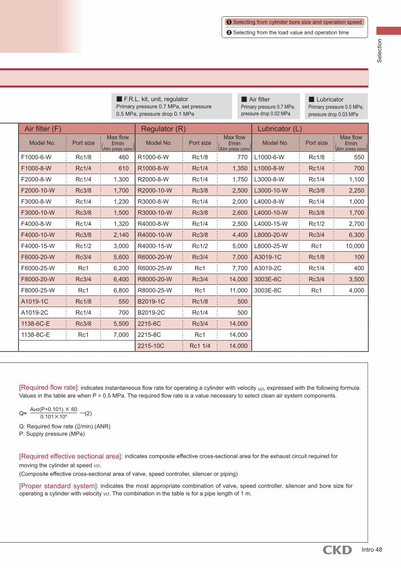
[Required effective sectional area]: indicates composite effective cross-sectional area for the exhaust circuit required for moving the cylinder at speed VO.(Composite effective cross-sectional area of valve, speed controller, silencer or piping)
[Proper standard system]: indicates the most appropriate combination of valve, speed controller, silencer and bore size for operating a cylinder with velocity VO. The combination in the table is for a pipe length of 1 m.
[Required flow rate]: indicates instantaneous flow rate for operating a cylinder with velocity VO, expressed with the following formula.Values in the table are when P = 0.5 MPa. The required flow rate is a value necessary to select clean air system components.
Q: Required flow rate ( /min) (ANR)P: Supply pressure (MPa)
Avo(P+0.101) × 600.101×104Q≈ (2)
F.R.L kit F.R. unit Air filter (F) Regulator (R) Lubricator (L)
Model No. Port sizeMax flow
ℓ/minAtm press conv value
Model No. Port sizeMax flow
ℓ/minAtm press conv value
Model No. Port sizeMax flow
ℓ/min Atm press conv
Model No. Port sizeMax flow
ℓ/min Atm press conv
Model No. Port sizeMax flow
ℓ/min Atm press conv
C1000-6-W Rc1/8 450 W1000-6-W Rc1/8 800 F1000-6-W Rc1/8 460 R1000-6-W Rc1/8 770 L1000-6-W Rc1/8 550
C1000-8-W Rc1/4 630 W1000-8-W Rc1/4 1,150 F1000-8-W Rc1/4 610 R1000-8-W Rc1/4 1,350 L1000-8-W Rc1/4 700
C2000-8-W Rc1/4 1,200 W2000-8-W Rc1/4 1,500 F2000-8-W Rc1/4 1,300 R2000-8-W Rc1/4 1,750 L3000-8-W Rc1/4 1,100
C2000-10-W Rc3/8 1,700 W2000-10-W Rc3/8 2,000 F2000-10-W Rc3/8 1,700 R2000-10-W Rc3/8 2,500 L3000-10-W Rc3/8 2,250
C2500-8-W Rc1/4 1,200 W3000-8-W Rc1/4 2,150 F3000-8-W Rc1/4 1,230 R3000-8-W Rc1/4 2,000 L4000-8-W Rc1/4 1,000
C2500-10-W Rc3/8 1,700 W3000-10-W Rc3/8 2,430 F3000-10-W Rc3/8 1,500 R3000-10-W Rc3/8 2,600 L4000-10-W Rc3/8 1,700
C3000-8-W Rc1/4 1,280 W4000-8-W Rc1/4 2,500 F4000-8-W Rc1/4 1,320 R4000-8-W Rc1/4 2,500 L4000-15-W Rc1/2 2,700
C3000-10-W Rc3/8 1,750 W4000-10-W Rc3/8 4,350 F4000-10-W Rc3/8 2,140 R4000-10-W Rc3/8 4,400 L8000-20-W Rc3/4 6,300
C4000-8-W Rc1/4 1,430 W4000-15-W Rc1/2 4,750 F4000-15-W Rc1/2 3,000 R4000-15-W Rc1/2 5,000 L8000-25-W Rc1 10,000
C4000-10-W Rc3/8 2,400 W8000-20-W Rc3/4 10,000 F6000-20-W Rc3/4 5,600 R6000-20-W Rc3/4 7,000 A3019-1C Rc1/8 100
C4000-15-W Rc1/2 3,000 W8000-25-W Rc1 10,000 F6000-25-W Rc1 6,200 R6000-25-W Rc1 7,700 A3019-2C Rc1/4 400
C6500-20-W Rc3/4 4,500 B7019-1C Rc1/8 500 F8000-20-W Rc3/4 6,400 R8000-20-W Rc3/4 14,000 3003E-6C Rc3/4 3,500
C6500-25-W Rc1 5,000 B7019-2C Rc1/4 900 F8000-25-W Rc1 6,800 R8000-25-W Rc1 11,000 3003E-8C Rc1 4,000
C8000-20-W Rc3/4 7,000 A1019-1C Rc1/8 550 B2019-1C Rc1/8 500
C8000-25-W Rc1 7,500 A1019-2C Rc1/4 700 B2019-2C Rc1/4 500
K60570-1C-GB Rc1/8 200 1138-6C-E Rc3/8 5,500 2215-6C Rc3/4 14,000
K60570-2C-GB Rc1/4 300 1138-8C-E Rc1 7,000 2215-8C Rc1 14,000
2215-10C Rc1 1/4 14,000
■ LubricatorPrimary pressure 0.5 MPa, pressure drop 0.03 MPa
■ F.R.L. kit, unit, regulatorPrimary pressure 0.7 MPa, set pressure0.5 MPa, pressure drop 0.1 MPa
■ Air filterPrimary pressure 0.7 MPa, pressure drop 0.02 MPa
( ) ( ) ( )
STEP 3 Clean air system components selection
Selecting from cylinder bore size and operation speed
Selecting from the load value and operation time
Sel
ectio
n
Intro 48
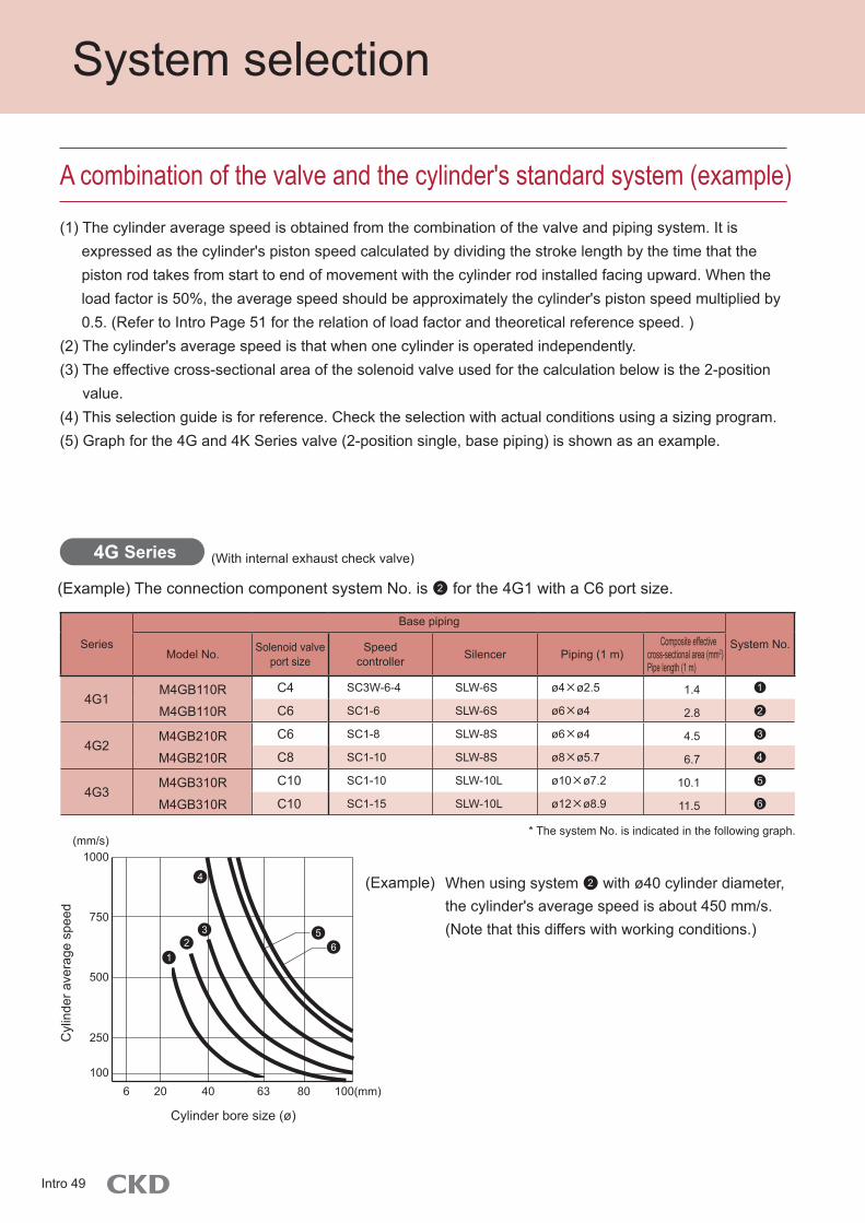
System selection
A combination of the valve and the cylinder's standard system (example)
(1) The cylinder average speed is obtained from the combination of the valve and piping system. It isexpressed as the cylinder's piston speed calculated by dividing the stroke length by the time that thepiston rod takes from start to end of movement with the cylinder rod installed facing upward. When theload factor is 50%, the average speed should be approximately the cylinder's piston speed multiplied by0.5. (Refer to Intro Page 51 for the relation of load factor and theoretical reference speed. )
(2) The cylinder's average speed is that when one cylinder is operated independently.(3) The effective cross-sectional area of the solenoid valve used for the calculation below is the 2-position
value.(4) This selection guide is for reference. Check the selection with actual conditions using a sizing program.(5) Graph for the 4G and 4K Series valve (2-position single, base piping) is shown as an example.
4G Series
* The system No. is indicated in the following graph.
(With internal exhaust check valve)
(Example) The connection component system No. is ●2 for the 4G1 with a C6 port size.
When using system ●2 with ø40 cylinder diameter, the cylinder's average speed is about 450 mm/s.(Note that this differs with working conditions.)
Series
Base piping
System No.Model No. Solenoid valve
port sizeSpeed
controller Silencer Piping (1 m)Composite effective
cross-sectional area (mm2)Pipe length (1 m)
4G1M4GB110R
M4GB110R
C4 SC3W-6-4 SLW-6S ø4×ø2.5 1.4 ●
C6 SC1-6 SLW-6S ø6×ø4 2.8 ●
4G2M4GB210R
M4GB210R
C6 SC1-8 SLW-8S ø6×ø4 4.5 ●
C8 SC1-10 SLW-8S ø8×ø5.7 6.7 ●
4G3M4GB310R
M4GB310R
C10 SC1-10 SLW-10L ø10×ø7.2 10.1 ●
C10 SC1-15 SLW-10L ø12×ø8.9 11.5 ●
(Example)
1
2
3
4
5
6
(mm/s)
250
1000
750
500
100
Cylinder bore size (ø)
20 100(mm)8063406
Cyl
inde
r ave
rage
spe
ed
●6●5
●4
●3●2
●1
Intro 49

4K Series
MN4G Series
* The system No. is indicated in the following graph.
* The system No. is indicated in the following graph.* This graph applies to common exhaust.
(With internal exhaust check valve)
Series Solenoid valve port size Speed controller Piping (1 m) Common exhaust piping Composite effective
X-sectional area (mm2) System No.
MN4G1
C4 SC3W-M5-4 ø4×ø2.5 ø6×ø4×3 m 0.9 ●
C4 SC3W-6-4 ø4×ø2.5 ø6×ø4×3 m 1.4 ●
C6 SC1-6 ø6×ø4 ø8×ø5.7×3 m 2.8 ●
MN4G2C6 SC1-6 ø6×ø4 ø8×ø5.7×3 m 3.8 ●
C8 SC1-8 ø8×ø5.7 ø10×ø7.2×3 m 6.0 ●
Series Solenoid valve port size Speed controller Silencer Piping (1 m) Composite effective
X-sectional area (mm2) System No.
4KB110 C6 SC1-6 SLW-6S ø6×ø4 3.2 ●
4KB210 C8 SC1-8 SLW-8S ø8×ø5.7 7.7 ●
4KB310 C10 SC1-10 SLW-10L ø10×ø7.2 14.1 ●
4KB410 C15 SC1-15 SLW-15A ø12×ø8.9 23.6 ●
1
1
2
2
3
3
4
4
5
Selecting from cylinder bore size and operation speed
Selecting from the load value and operation time
1000
750
500
0
250
20 30 40 50 63 (mm)
Cyl
inde
r ave
rage
spe
ed
Cylinder bore size (ø)
●4●3●2●1
●5●4●3●2
●1
200
400
600
800
1000
Cyl
inde
r ave
rage
spe
ed
(mm/s)
Cylinder bore size (ø)
(mm)18016014012510080635040322016106
(mm/s)
Sel
ectio
n
Intro 50

Selecting from the load value and operation time
System selection
When load (N) and cylinder required operation time (S) are already decided, use [System selection 2] to select an appropriate model. Follow the following procedures.
■ How to select
(1) Load F= □ (N)(2) Required operation time t = □ (s)(3) Stroke L= □ (mm)(4) Pressure P= □ (MPa)
M : Weight of body (kg)μ : Friction coefficient (normally μ≈ 0.3)F : Load (N)g : 9.8 m/s2
● Horizontal
F=μMg
● Vertical
F=Mg
Selecting cylinder bore size
From Graph 1
Load value (N), Required operation time (S)
[Confirming conditions]
Selecting suitable components
From Table 1
Selecting a suitable system
From Graph 3
Selecting theoretical reference speed
From Graph 2
STEP 1 Confirming conditions
Intro 51

Selecting from cylinder bore size and operation speed
Selecting from the load value and operation time
Graph 1 Nomogram to find cylinder bore size
According to the nomogram for cylinder bore size, select the cylinder bore size and read the load factor at the same time. (Normally, for value F of “Step 1 Confirming conditions”, read the cylinder bore size whose load factor is close to 50% )Cylinder bore size D = ø□
(Example) When F = 800N , P = 0.5 MPa , cylinder bore size is ø63 at Load factor 50% .
STEP 2 Selecting cylinder bore size
800
Load factor Load factor Load factor
Sel
ectio
n
Intro 52

Load factor 0% Load factor 25%
Ope
ratio
n tim
e t (
s)
Ope
ratio
n tim
e t (
s)
Stroke lengthStroke length
Cylinder theoretical reference speed Cylinder theoretical reference speed
System selection
According to t-vo graph, read vo value to obtain the required operation time t (sec).
vo=□
(Example) When Load factor 50% and Stroke length of 200mm cylinder operate with 1.0sec ,
theoretical reference speed is 450 mm/s .
Graph 2 t-vo graph
STEP 3 Selecting theoretical reference speed
Pipe length 1 m Pipe length 1 m
Intro 53
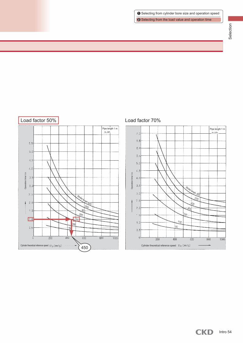
Selecting from cylinder bore size and operation speed
Selecting from the load value and operation time
Load factor 70%
Ope
ratio
n tim
e t (
s)
Ope
ratio
n tim
e t (
s)
Stroke lengthStroke length
Cylinder theoretical reference speed Cylinder theoretical reference speed
STEP 3 Selecting theoretical reference speed
450
Pipe length 1 mPipe length 1 m
Load factor 50%
Sel
ectio
n
Intro 54
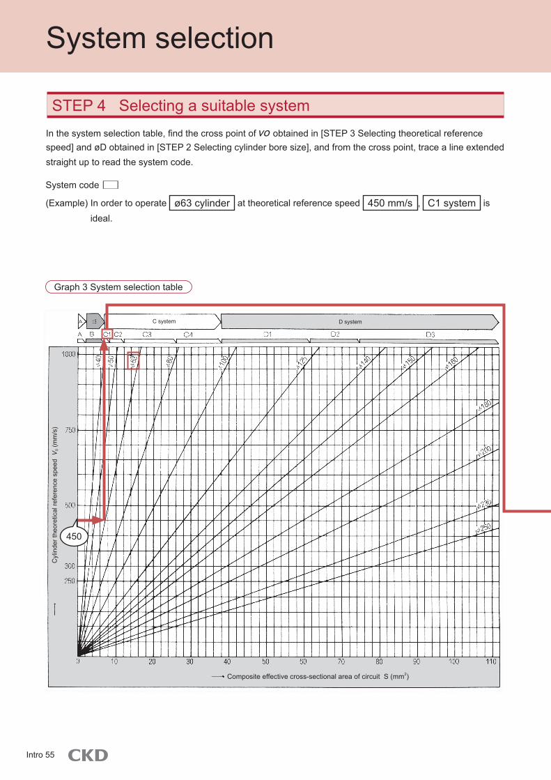
Cyl
inde
r the
oret
ical
refe
renc
e sp
eed
V0 (
mm
/s)
C system D system
Composite effective cross-sectional area of circuit S (mm2)
System selection
System code □
(Example) In order to operate ø63 cylinder at theoretical reference speed 450 mm/s , C1 system is ideal.
Graph 3 System selection table
In the system selection table, find the cross point of vo obtained in [STEP 3 Selecting theoretical reference speed] and øD obtained in [STEP 2 Selecting cylinder bore size], and from the cross point, trace a line extended straight up to read the system code.
STEP 4 Selecting a suitable system
450
Intro 55

Selecting from cylinder bore size and operation speed
Selecting from the load value and operation time
Standard system
No.
Valve Speed controller
Silencer PipingComposite eff X-sect area
(mm2) pipe 1 mSingle solenoid Double solenoid
A4SB010-M5
4KA110-GS4
4SB020-M5
4KA120-GS4
SC3W-M5-4
(SC-M5)SLM-M5
ø4 × ø2.5
Nylon tube0.9
B14KA110-GS6
4KB110-06
4KA120-GS6
4KB120-06
SC3W-6-6
SCL2-06-H66
SLM-M5
SLW-6A
ø6×ø4
Nylon tube2.0
B24KB110-06
4GB110R-064KB120-06
SC1-6
SCL2-08-H88
SL-M5
SLW-6A
ø8 × ø5.7
Nylon tube3.0
B34GB210R-06
4KB210-06 4KB220-06
SC1-6
SCL2-08-H88
SLW-6A
SLW-6S
ø8 × ø5.7
Nylon tube5.2
B44GB210R-08
4KB210-08
4GB220R-08
4KB220-08
SC1-8
SCL2-10-H1010
SLW-6A
SLW-8A
ø10×ø7.2
Nylon tube6.4
C14GB210R-08
4KB210-08
4F210-08
4GB220R-08
4KB220-08
4F220-08
SC1-8
SCL2-10-H1010
SLW-8A
SLW-8S
ø10×ø7.2
Nylon tube7.8
C24GB310R-10
4F310-10
4KB310-10
4GB320R-10
4F320-10
4KB320-10
SC1-10 SLW-10A
ø10 × ø7.2
Nylon tube or Rc3/8
steel pipe
12
C34GB410-15
4F510-15
4KB410-15
4GB420-15
4F520-15
4KB420-15
SC1-15 SLW-15A Rc1/2 steel pipe 27
C44GB410-15
4F510-15
4KB410-15
4GB420-15
4F520-15
4KB420-15
SC-20A SLW-15A Rc1/2 steel pipe 38
D1 4F610-20 4F620-20 SC-20A SL-20A Rc3/4 steel pipe 64
D2 4F710-20 4F720-20 SC-20A SL-20A Rc3/4 steel pipe 80
D3 4F710-25 4F720-25 SC-25A SL-25A Rc1 steel pipe 112
Table 1 Standard system table
According to the standard system table, confirm the model No. of proper system components with the code found in [STEP 4 Selecting a suitable system].
STEP 5 Selecting suitable components
(Example) CI system
Valve □ Valve: Single 4KB210-08 or 4GB310R-08Double 4KB220-08 or 4GB320R-08
Speed controller □ Speed controller: SCI-8
Silencer □ Silencer: SLW-8A
Piping □ Piping: ø10 x ø7.2 nylon tube 1 m
Sel
ectio
n
Intro 56
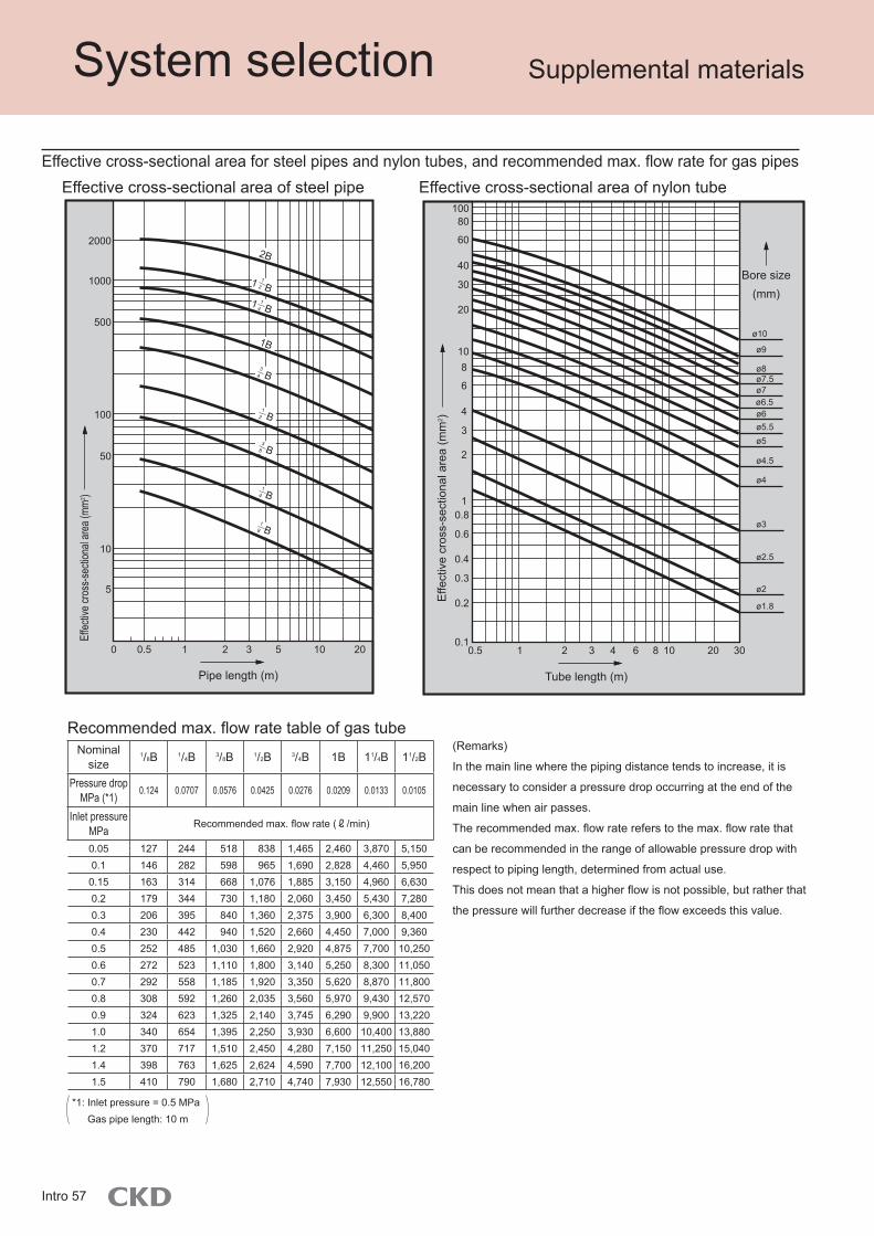
System selection Supplemental materials
*1: Inlet pressure = 0.5 MPa Gas pipe length: 10 m
(Remarks)
In the main line where the piping distance tends to increase, it is
necessary to consider a pressure drop occurring at the end of the
main line when air passes.
The recommended max. flow rate refers to the max. flow rate that
can be recommended in the range of allowable pressure drop with
respect to piping length, determined from actual use.
This does not mean that a higher flow is not possible, but rather that
the pressure will further decrease if the flow exceeds this value.
Recommended max. flow rate table of gas tubeNominal
size1/8B 1/4B 3/8B 1/2B 3/4B 1B 11/4B 11/2B
Pressure drop MPa (*1)
0.124 0.0707 0.0576 0.0425 0.0276 0.0209 0.0133 0.0105
Inlet pressure MPa
Recommended max. flow rate (ℓ/min)
0.05 127 244 518 838 1,465 2,460 3,870 5,1500.1 146 282 598 965 1,690 2,828 4,460 5,9500.15 163 314 668 1,076 1,885 3,150 4,960 6,6300.2 179 344 730 1,180 2,060 3,450 5,430 7,2800.3 206 395 840 1,360 2,375 3,900 6,300 8,4000.4 230 442 940 1,520 2,660 4,450 7,000 9,3600.5 252 485 1,030 1,660 2,920 4,875 7,700 10,2500.6 272 523 1,110 1,800 3,140 5,250 8,300 11,0500.7 292 558 1,185 1,920 3,350 5,620 8,870 11,8000.8 308 592 1,260 2,035 3,560 5,970 9,430 12,5700.9 324 623 1,325 2,140 3,745 6,290 9,900 13,2201.0 340 654 1,395 2,250 3,930 6,600 10,400 13,8801.2 370 717 1,510 2,450 4,280 7,150 11,250 15,0401.4 398 763 1,625 2,624 4,590 7,700 12,100 16,2001.5 410 790 1,680 2,710 4,740 7,930 12,550 16,780
Effective cross-sectional area for steel pipes and nylon tubes, and recommended max. flow rate for gas pipesEffective cross-sectional area of steel pipe Effective cross-sectional area of nylon tube
B
B
B
B
B
1 B1 B
Effec
tive c
ross
-secti
onal
area
(mm2 )
Pipe length (m)
5 20102
5
10
50
100
500
1000
20002B
1B
310.50
Effe
ctiv
e cr
oss-
sect
iona
l are
a (m
m2 )
Bore size (mm)
Tube length (m)
8643 3010 2020.1
0.2
0.3
0.4
0.6
0.81
2
80100
3
4
6
810
20
30
40
60
10.5
ø1.8
ø2
ø2.5
ø3
ø4
ø4.5
ø5 ø5.5ø6 ø6.5ø7 ø7.5ø8
ø9
ø10
12
12
38
14
14
18
34
Intro 57
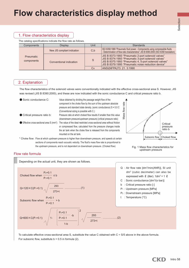
Mas
s flo
w ra
teCritical pressure ratio b
Choked flowSubsonic flow
Fig. 1 Mass flow characteristics for upstream pressure
2. Explanation
1-b
2
-b1-
P2+0.1
P1+0.1 ………………(2)Q=600×C(P1+0.1)
293
273+t
293
273+t
………………(1)Q=120×C(P1+0.1)
Subsonic flow when > bP2+0.1
P1+0.1
Choked flow when ≤ bP2+0.1
P1+0.1
Depending on the actual unit, they are shown as follows.
To calculate effective cross-sectional area S, substitute the value C obtained with C = S/5 above in the above formula.For subsonic flow, substitute b = 0.5 in formula (2).
Flow rate formula
● Sonic conductance C: Value obtained by dividing the passage weight flow of the component in the choke flow by the sum of the upstream absolute pressure and standard state density. (sonic conductance) S ≈ 5.0 C (Conventional sizing is possible with C.)
● Critical pressure ratio b: Pressure ratio at which choked flow results if smaller than this value (downstream pressure/upstream pressure) (critical pressure ratio)
● Effective cross-sectional area S (mm2): The value of the ideal restricted cross-sectional area without friction or compressed flow, calculated from the pressure changes inside the air tank when the choke flow is released from the components mounted on the air tank.
* Choke flow: Flow at which upstream pressure is higher than downstream pressure, and speeds at certain sections of components reach acoustic velocity. The fluid’s mass flow rate is proportional to the upstream pressure, and is not dependent on downstream pressure. (Choked flow)
The flow characteristics of the solenoid valves were conventionally indicated with the effective cross-sectional area S. However, JIS was revised (JIS B 8390:2000), and these are now indicated with the sonic conductance C and critical pressure ratio b.
The catalog specifications indicate the flow rate as follows.
Flow characteristics display method
1. Flow characteristics display
Components Display Unit Standards
Pneumatic components
New JIS compliant indication C,b ISO 6358:1989 “Pneumatic fluid power - Components using compressible fluids - Determination of flow-rate characteristics” JIS B 8390:2000 (ISO 6358 translation)
Conventional indicationS
JIS B 8373:1993 “Pneumatic 2-port solenoid valves”JIS B 8374:1993 “Pneumatic 3-port solenoid valves”JIS B 8375:1993 “Pneumatic 4, 5-port solenoid valves”JIS B 8379:1995 “Pneumatic noise reduction device”
Cv ANSI(NFPA)T3. 21. 3:1990
Q : Air flow rate [dm3/min(ANR)], SI unit dm3 (cubic decimeter) can also be expressed with ℓ (liter). 1dm3 = 1 ℓ
C : Sonic conductance [dm3/(s·bar)]b : Critical pressure ratio [-]P1 : Upstream pressure [MPa]P2 : Downstream pressure [MPa]t : Temperature (°C)
Sel
ectio
n
Intro 58