2. OSI Systems Management and the Telecommunications ...gpavlou/Publications/Other/phd/04... · 2....
70
19 2. OSI Systems Management and the Telecommunications Management Network 2.1 Introduction Chapter 2 of this thesis introduces first OSI Systems Management (OSI-SM) [X700][X701] and the Telecommunications Management Network (TMN) [M3010]. It then proposes a number of modifications and extensions to the TMN architectural framework which aim to enhance and simplify it considerably, without sacrificing any important aspects for open interoperable telecommunications management. These modifications and extensions are supported by relevant analysis in this chapter and are also backed up by experimental results presented in Chapter 3. OSI-SM is currently the base technology for the TMN, which provides the architectural framework for telecommunications network and service management. A relevant introduction is important since the thesis proposes a novel approach for the realisation of OSI-SM/TMN systems through distributed object-oriented software platforms. This makes a detailed understanding of both OSI-SM and TMN necessary for following the rest of the thesis. While this presentation is based on the relevant standards, it tries to shed light on a number of issues, explaining the reasons behind the various architectural choices and associating them to the underlying requirements. This differentiates it from other presentations in the literature and, as such, it constitutes to some extent a research contribution in its own right. The presentation of the TMN framework in particular extends beyond the relevant standards or other presentations in the literature and presents a number of clarifications in a way that has never been attempted before. The last part of this chapter proposes a number of extensions and modifications to the TMN model and architecture. These include the introduction of the OSI Directory [X500] to support distribution and discovery services and the simplification of the framework through the removal of the Q x and F interfaces. While the former emanates from the requirements of the TMN as a large scale distributed system, the latter relates to the fact that Chapter 3 of the thesis shows that full scale OSI-SM/TMN technology based on Q 3 interfaces is feasible, performant and relatively
Transcript of 2. OSI Systems Management and the Telecommunications ...gpavlou/Publications/Other/phd/04... · 2....
19
2. OSI Systems Management and theTelecommunications ManagementNetwork
2.1 Introduction
Chapter 2 of this thesis introduces first OSI Systems Management (OSI-SM) [X700][X701] and
the Telecommunications Management Network (TMN) [M3010]. It then proposes a number of
modifications and extensions to the TMN architectural framework which aim to enhance and
simplify it considerably, without sacrificing any important aspects for open interoperable
telecommunications management. These modifications and extensions are supported by relevant
analysis in this chapter and are also backed up by experimental results presented in Chapter 3.
OSI-SM is currently the base technology for the TMN, which provides the architectural
framework for telecommunications network and service management. A relevant introduction is
important since the thesis proposes a novel approach for the realisation of OSI-SM/TMN systems
through distributed object-oriented software platforms. This makes a detailed understanding of
both OSI-SM and TMN necessary for following the rest of the thesis. While this presentation is
based on the relevant standards, it tries to shed light on a number of issues, explaining the reasons
behind the various architectural choices and associating them to the underlying requirements.
This differentiates it from other presentations in the literature and, as such, it constitutes to some
extent a research contribution in its own right. The presentation of the TMN framework in
particular extends beyond the relevant standards or other presentations in the literature and
presents a number of clarifications in a way that has never been attempted before.
The last part of this chapter proposes a number of extensions and modifications to the TMN
model and architecture. These include the introduction of the OSI Directory [X500] to support
distribution and discovery services and the simplification of the framework through the removal
of the Qx and F interfaces. While the former emanates from the requirements of the TMN as a
large scale distributed system, the latter relates to the fact that Chapter 3 of the thesis shows that
full scale OSI-SM/TMN technology based on Q3 interfaces is feasible, performant and relatively

Chapter 2: OSI-SM and the TMN
20
economical to provide in terms of both required resources and development time. This obviates
the need for lightweight interfaces which necessitate special support in order to be able to cope
with the resulting heterogeneity. The architectural revision of the TMN and the clarification of a
number of related issues constitute the key research contribution of this chapter.
This chapter is organised as a “super-chapter” in a similar fashion to chapters 3 and 4 of this
thesis, in the sense that sections 2.2, 2.3 and 2.4 can be considered as “sub-chapters” within a
chapter.
Section 2.2 presents OSI-SM model. It starts by summarising relevant work in the literature and
discusses management requirements in terms of the management functional areas (section 2.2.1).
It then presents the manager-agent model (section 2.2.2), which is subsequently elaborated in
terms of the information modelling aspects (section 2.2.3) and information access aspects (section
2.2.4). Generic management functionality emanating from the management functional areas is
finally presented in section 2.2.1.
Section 2.3 presents the TMN framework and principles. It starts by summarising relevant work
in the literature and positioning the TMN in the Broadband ISDN context (section 2.3.1). It then
presents various aspects of the TMN architecture (section 2.3.2), including the functional and
physical architectures (sections 2.3.2.1 and 2.3.2.2), the logical layering aspects (section 2.3.2.3),
the interface specification methodology (section 2.3.2.4) and the decomposition of TMN
applications into constituent components (section 2.3.2.5).
Section 2.4 presents the modifications and extensions to the TMN model and architecture. It first
explains the issues behind providing distribution and discovery services using the OSI Directory
(section 2.4.1). It then discusses issues on adaptation and mediation and proposes the removal of
the Qx interface (section 2.4.2). It subsequently discusses issues on the F interface and proposes
its removal (section 2.4.3). The TMN architecture is then revisited and simplified (section 2.4.4).
The section closes with a final discussion on the TMN framework.
Finally, section 2.5 highlights the research contributions in this chapter and paves the way to
Chapter 3.

2.2. OSI Systems Management
21
2.2 OSI Systems Management
In this section we examine the ISO/ITU-T OSI Systems Management (OSI-SM) [X701]
approach to network management which is currently the base technology for the TMN. This is an
overview that explains the reasons for the various architectural decisions and associates them to
the relevant requirements. A basic understanding of data network principles and in particular of
the 7 layer OSI Reference Model (OSI-RM) [X200] is assumed. A good general introduction can
be found in [Tanen96].
OSI-SM was the last set of OSI application layer standards to be addressed and, as such, it
received considerable attention. The relevant standardisation effort lasted for almost a decade and
it was the first OSI application to adopt fully object-oriented information specification and access
principles. The OSI Directory [X500] was another OSI application that had adopted similar
concepts but it fell short of true object-orientation. A number of tutorial and survey papers in the
literature and also books have addressed OSI-SM, these are briefly summarised below.
[Kler88], [Jeff88], [Slum89], [Coll89] and [Smith90] all provide early descriptions of the OSI-
SM framework and the developing standards at the time. [Kler93] and [Yemi93] provide better
overviews since the relevant standards were by that time fairly mature, the first concentrating on
information modelling aspects and the second addressing the framework as a whole. A number of
books have also addressed OSI-SM. Among those, [Jeff92] addresses the subject best in the
author’s opinion. Three of the authors of that book have also contributed chapters to [Slom94].
[Lang94] covers the model and standards, [Tuck94] concentrates in the structure of management
information and [Jeff94] covers the Guidelines for the Definition of Managed Objects. [Stal94] is
another book that addresses partly the subject but it is brief in its description, concentrating
mainly on the Simple Network Management Protocol (SNMP) [SNMP].
The material in this section is based to a large extent on [Pav97a], a chapter in [Aida97] which
presents a comparative study of OSI-SM, Internet SNMP and ODP / OMG CORBA as
technologies for telecommunications network management.
2.2.1 Management Functional Areas
OSI Systems Management standardisation followed a top-down approach, with a number of
functional areas identified first. The reason for identifying those was not to describe exhaustively
all relevant types of management activity but rather to investigate their key requirements and to
address those through generic management infrastructure. The identified areas were Fault,

Chapter 2: OSI-SM and the TMN
22
Configuration, Accounting, Performance and Security Management [X700] and are collectively
referred to as FCAPS from their initials. Their generic requirements are supported by the Systems
Management Functions (SMF) [SMF]. The same functional areas have also being adopted by the
TMN. We present here the typical activities in each functional area, identify their generic
requirements and list the relevant SMFs.
Fault Management addresses the generation of error specific notifications (alarms), the logging
of error notifications at source and the testing of network resources in order to trace and identify
faults. Fault management systems should undertake alarm surveillance activities (analysis,
filtering and correlation), perform resource testing and provide fault localisation and correction
functions. The key requirements are event-based operation, a well-defined generic set of alarms
and a testing framework. The relevant SMFs are event reporting [X734], logging [X735], alarm
reporting [X733] and testing [X737][X745].
Configuration Management deals with initialisation, installation and provisioning activities. It
allows the collection of configuration and status information on demand, provides inventory
facilities and supports the announcement of configuration changes through relevant notifications.
The key requirements are event-based operation, control of change, generic resource state and
relationship representation, scheduling, time management, software distribution and system
discovery facilities. The relevant SMFs are event reporting [X734], logging [X735], object
[X730], state [X731] and relationship [X.732] management, scheduling [X746], time
management [X743], software distribution [X744] and shared management knowledge [X750].
Accounting Management deals with the collection of accounting information and its processing
for charging and billing purposes. It should enable accounting limits to be set and costs to be
combined when multiple resources are used in the context of a service. The key requirements are
event based operation, in particular logging, and a generic usage metering framework. The
relevant SMFs are event reporting [X734], logging [X735] and accounting metering [X742].
Performance Management addresses the availability of information in order to determine
network and system load under both natural and artificial conditions. It also supports the
collection of performance information periodically in order to provide statistics and allow for
capacity planning activities. Performance management needs access to a large quantity of
network information and an important issue is to provide the latter with a minimum impact on the
managed network. Key requirements are the ability to convert raw traffic information to traffic
rates with thresholds and tidemarks applied to them; the periodic summarisation of a variety of
performance information for trend identification and capacity planning; the periodic scheduling of

2.2. OSI Systems Management
23
information collection; and the ability to determine the response time between network nodes. The
relevant SMFs are event reporting [X734], logging [X735], metric monitoring [X739],
summarisation [X738], scheduling [X746] and response time monitoring [X748].
Security Management is concerned with two aspects of systems security. The management of
security, which requires the ability to monitor and control the availability of security facilities and
to report security threats or breaches. And the security of management, which requires the ability
to authenticate management users and applications, to guarantee the confidentiality and integrity
of management exchanges and to prevent unauthorised access to management information.
Authentication, integrity and confidentiality services are common to all OSI applications and are
addressed for the whole of the OSI framework in [X800][GULS]. The key requirements in OSI
management are support for security alarms, facilities for security audit trail and the provision of
access control. The relevant SMFs are event reporting [X734], logging [X735], security alarm
reporting [X736], security audit trail [X737] and access control [X741].
A common requirement in all the functional areas is event-driven management through event
reporting and logging facilities. The systems management functions [SMF] are described in
section 2.2.5.
2.2.2 The Manager-Agent Model
M
application in Manager role application in Agent role
A
performing operations
emitting notifications
management communication protocol
managed object
other internal object
Figure 2-1 The Manager-Agent Model
OSI management has introduced the manager-agent model. A simplified version of this model has
also been adopted by the Internet SNMP [SNMP]. According to the model, manageable resources
are modelled by managed objects at different levels of abstraction. Managed objects encapsulate
the underlying resource and offer an abstract access interface at the object boundary. The
management aspects of entities such as network elements and distributed applications are

Chapter 2: OSI-SM and the TMN
24
modelled through “clusters” of managed objects, seen collectively across a management interface.
The latter is defined through the formal specification of the relevant managed object types or
classes and the associated access mechanism, i.e. the management access service and supporting
protocol stack. Management interfaces can be thought as “exported” by applications in agent
roles and “imported” by applications in manager roles. Manager applications access managed
objects across interfaces in order to implement management policies. Distribution aspects are
orthogonal to management interactions and are supported by other means.
OSI management is primarily a communications framework. Standardisation affects the way in
which management information is modelled and carried across systems, leaving deliberately
unspecified aspects of their internal structure. The manager-agent model is shown in Figure 2-1.
Note that manager and agent applications contain other internal objects that support the
implementation of relevant functionality. These are not visible externally, so they are depicted
with dotted lines.
The management access service and protocol carries the parameters of operations to managed
objects and returns relevant results, so it can be loosely described as a “remote method execution”
protocol (in object-oriented systems, an object’s procedure is called a “method”). The relevant
parameters and results are a superset of those available at the object boundary, allowing to de-
reference an object by name and to select a number of objects to perform an operation. In fact,
the agent offers an object-oriented database-like facility which has the effect that one operation
across the network may result in many operations to managed objects inside the agent, with a
“consolidated” result passed back. In the other direction, notifications emitted by managed objects
are discriminated internally within the agent, based on criteria preset by manager applications.
This mechanism eliminates unwanted notifications at source and forwards useful notifications
directly to interested managers.
The above facilities result in less management traffic and increase the timeliness of retrieved
management information. These are key requirements in most management environments and, in
particular, architectural requirements for the TMN as it will be described in section 2.3.2. In fact,
the manager-agent model was designed for the purpose of supporting such facilities. Briefly
positioning this model in the Open Distributed Processing (ODP) [ODP] framework that will be
described in Chapter 4, an OSI agent acts as a naming server, trader, notification server and
object access server with respect to the managed objects it administers. All these facilities are
tightly coupled with the associated managed objects within the same network node. Chapter 4

2.2. OSI Systems Management
25
explores relevant relationships with ODP in more detail and explains how this model can be
transposed onto the ODP framework.
The manager and agent roles are not fixed and management applications may act in both roles.
This is the case in hierarchical management architectures such as the TMN [M3010]. In
hierarchical management models, managed objects exist also in the agent aspect of management
applications, offering views of the managed network, services and applications at higher levels of
abstraction. Management functionality may be organised in different layers of management
responsibility: element, network, service and business management according to the TMN model.
Management applications may act in dual manager-agent roles, in either peer-to-peer or
hierarchical relationships. Figure 2-2 shows three types of management organisation: centralised,
flat and hierarchical. The hierarchical model is best exemplified by TMN which uses OSI-SM as
its base technology. Note that in both flat and hierarchical models, management applications are
hybrid, assuming both the manager and agent roles.
manager to agent relationshipmanaged element (agent)management center (manager)management application (manager-agent)
centralized flat hierarchical
Figure 2-2 Models of Management Organisation
2.2.3 The Management Information Model
The OSI-SM Management Information Model (MIM) is defined in [X720] and uses object-
oriented principles. A systematic introduction to object-oriented systems is given in section 3.2.1
of Chapter 3. A reader with no relevant exposure is advised to read that section first, since
relevant terms and concepts are used in this section.
An OSI Management Information Base (MIB) defines a set of Managed Object Classes (MOCs)
and a schema which defines the possible containment relationships between instances of those
classes. There may be many types of relationships between classes and their instances but
containment is treated as a primary relationship and is used to yield unique names. The smallest

Chapter 2: OSI-SM and the TMN
26
re-usable entity of management specification is not the object class, as is the case in other O-O
frameworks, but the package. Object classes are characterised by one or more mandatory
packages while they may also comprise conditional ones. An instance of a class must always
contain the mandatory packages while it may or may not contain conditional ones. The latter
depends upon conditions defined in the class specification. Managing functions may request that
particular conditional packages are present when they create a managed object instance.
A package is a collection of attributes, actions, notifications and associated behaviour. Attributes
have associated syntaxes specified in ASN.1 [X208] which may be of arbitrary complexity. A
number of generic attribute types have been defined in [X721], namely counter, gauge, threshold
and tidemark; resource-specific types may be derived from these. The fact that attributes may be
of arbitrary syntax provides useful flexibility, albeit at the cost of additional complexity. For
example, it allows the definition of complex attributes such as threshold, whose syntax include
fields to indicate whether the threshold is currently active or not and its current comparison value.
OSI managed object classes and packages may have associated actions that accept arguments and
return results. Arbitrary ASN.1 syntaxes may be used for the arguments and results, in a similar
fashion to attributes, providing a fully flexible “remote method” execution paradigm. Exceptions
with MOC-defined error information may be emitted as a result of an action. The same is also
possible as a result of operations to attributes under conditions that signify an error for which
special information should be generated. Object classes and packages may also have associated
notifications, specifying the condition under which they are emitted and their syntax. The latter
may be again of an arbitrary ASN.1 type. By behaviour, one means the semantics of classes,
packages, attributes, actions and notifications and the way they relate as well as their relationship
to the entity modelled by the class.
OSI Management follows a fully O-O paradigm and makes use of concepts such as inheritance.
Managed object classes may be specialised through subclasses that inherit and extend the
characteristics of superclasses. The use of inheritance and packages allows re-usability and
extensibility of specifications. It may also result in software reusability if an object-oriented
design and development methodology is used, as explained in Chapter 3. As an example of
inheritance, a transport protocol entity class (tpProtocolEntity) may inherit from an abstract
protocol entity class (protocolEntity) which models generic properties of protocol entities, e.g. the
operational state, the service access point through which services can be accessed, etc. By
abstract class it is meant a class that is never instantiated but serves inheritance purposes only. In
the same fashion, an abstract connection class may model generic properties of connection-type

2.2. OSI Systems Management
27
entities such as the local and remote service access points, the connection state, emit creation and
deletion notifications, etc. The inheritance hierarchy for those classes is shown in the left part of
Figure 2-3, using the Object Modelling Technique (OMT) notation [Rumb91].
It should be noted that conditional packages allow for dynamic (i.e. run-time) specialisation of an
object instance while inheritance allows only for static (i.e. compile-time) specialisation through
new classes. As pointed out in [Tuck94], in order to achieve the same effect with inheritance
instead of packages, N conditional packages would necessitate the definition of 2N additional
classes! Any requirements for further subclassing would make the combinatorial explosion even
worse.
top
x25VCx25ProtEntity
element protEntitysubsystem connection
objClass=elementelementId=x25switch-A
objClass=subsystemsubsystemId=network
objClass=x25ProtEntity protEntityId=x25
objClass=x25VCconnectionId=123
objClass=x25VCconnectionId=456
is contained by
example local name: {subsystemId=network, protEntityId=x25, connectionId=123}
inherits from
x25ProtEntity2
Figure 2-3 Example OSI Inheritance and Containment Hierarchies
The specification of manageable entities through generic classes which are used only for
inheritance and re-usability purposes may result in generic managing functions in manager
applications through polymorphism across a management interface. For example, it is possible to
provide a generic connection-monitor application that is developed with the knowledge of the
generic connection class only. This may monitor connections in different contexts, e.g. X.25,
ATM, etc. disregarding the specialisation of a particular context. That way, reusability is
extended to managing functions as well as managed object classes and their implementations.
In OSI management, a derived class may extend a parent class through the addition of new
attributes, actions and notifications; through the extension or restriction of the value ranges; and
through the addition of arguments to actions and notifications. Multiple inheritance is also
allowed and it has been used extensively by information model designers in standards bodies.
Despite the elegant modelling that is possible through multiple inheritance, such models cannot be

Chapter 2: OSI-SM and the TMN
28
easily mapped onto relevant facilities in O-O programming environments (e.g. C++ multiple
inheritance) as discussed in Chapter 3. Multiple inheritance is a powerful O-O specification
technique but increases complexity.
A particularly important aspect behind the use of object-oriented specification principles in OSI
management is that they may result in the allomorphic behaviour of object instances.
Allomorphism is similar to polymorphism but has the inverse effect: in polymorphism, a
managing function knows the semantics of a parent class in an inheritance branch and performs
an operation on an instance which responds as the leaf class. In allomorphism, that instance
should respond as the parent class, hiding completely the fact it belongs to the leaf class. For
example, a polymorphic connection monitor application can be programmed to know the
semantics of the connection class and only the syntax of specific derived classes through meta-
data. When it sends a “read all the attributes” message to a specific connection object instance,
e.g. x25Vc, atmVcc, etc., it wants to retrieve all the attributes of that instance, despite the fact it
does not understand the semantics of the specific “leaf” attributes. In allomorphism, a managing
system programmed to know a x25ProtocolEntity class should be able to manage instances of a
derived x25ProtocolEntity2 class without knowing of this extension. In this case, operations
should be performed to the x25ProtocolEntity2 instance as if it were an instance of the parent
x25ProtocolEntity class, since the derived class may have changed the ranges of values, added
new attributes, arguments to actions, etc.
Polymorphism is a property automatically supported by O-O programming environments while
allomorphism is not and has to be explicitly supported by management infrastructures as
explained in Chapter 3. Allomorphic behaviour may be enforced by sending a message to an
object instance and passing to it the object class as an additional parameter, essentially requesting
the object to behave as if it were an instance of that class. When no class is made available at the
object boundary, the instance behaves as the actual class i.e. the leaf class in the inheritance
branch. Allomorphic behaviour is very important since it allows the controlled migration of
management systems to newer versions by extensions of the relevant object models through
inheritance, while still maintaining compatibility with previous versions. This is particularly
important in management environments since requirements and understanding of the problem
space are expected to be continuously evolving. Allomorphism hides extensions at the agent end
of the manager-agent model. Extensions in managing systems should be hidden by programming
them in advance to be able to revert to the “base” information model if this is what it is supported
across a management interface. Though possible, this requires additional effort and increases
complexity.

2.2. OSI Systems Management
29
The root of the OSI inheritance hierarchy is the top class which contains attributes self-describing
an object instance. These attributes are the objectClass, whose value is the actual or leaf-most
class; packages, which contains the list of the conditional packages present in that instance;
allomorphs, which contains a list of classes the instance may behave as; and nameBinding, which
shows where this instance is in the naming tree as explained next. For example, in the instance of
the x25ProtocolEntity2 class mentioned before, objectClass would have the value
x25ProtocolEntity2 and allomorphs would have the value { x25ProtocolEntity }1. When an
instance is created by a managing function, the conditional packages may be requested to be
present by initialising accordingly the value of the packages attribute, which has “set by create”
properties.
Managed object classes and all their aspects such as packages, attributes, actions, notifications,
exception parameters and behaviour are formally specified in a notation known as Guidelines for
the Definition of Managed Objects (GDMO) [X722]. GDMO is a formal object-oriented
information specification language which consists of a set of templates. A “piecemeal” approach
is followed, with separate templates used for the different aspects of an object class i.e. class,
package, attribute, action, notification, parameter and behaviour templates. GDMO specifies
formally only syntactic aspects of managed object classes. Semantic aspects, i.e. the contents of
behaviour templates, are expressed in natural language. The formalisation of managed object
behaviour has been a research topic that attracted considerable attention [Fest93] [Fest95]
[Katch95]. Recently, the use of formal specification techniques such as System Definition
Language [Z100] and Z [Spiv89] are considered by the ITU-T in order to reduce the possibility
of ambiguities and misinterpretations and to increase the degree of code automation.
OSI-SM managed object instances are named through a mechanism borrowed from the OSI
Directory [X500]. Managed object classes have many relationships but containment is treated as
a primary relationship that yields unique names. Instances of managed object classes can be
thought as logically containing other instances. As such, the full set of managed object instances
available across a management interface is organised in a Management Information Tree (MIT).
This requires that an attribute of each instance serves as the “naming attribute”. The tuple of the
attribute and its value form a Relative Distinguished Name (RDN), e.g. connectionId=123. This
should be unique for all the object instances at the first level below a containing instance. If these
1 The angular brackets indicate a set, since allomorphs is a set- or multi-valued attribute.

Chapter 2: OSI-SM and the TMN
30
instances belong to the same class, then it is the value of the naming attribute that distinguishes
them i.e. the “key”.
The containment schema is defined by the name-binding GDMO templates which specify the
allowable classes in a superior/subordinate relationship and identify the naming attribute. Name
bindings and naming attributes are typically defined for classes in the first level of the inheritance
hierarchy, immediately under top, so that they are “inherited” by specific derived classes. An
example of a containment tree is shown in the right part of Figure 2-3, modelling connections
contained by protocol entities, contained by layer subsystems, contained by a network element. A
managed object name, also known as a Local Distinguished Name (LDN), consists of the
sequence of all the relative names starting after the root of the tree down to the particular object,
e.g. {subsystemId=network, protocolEntityId=x25, connectionId=123} .
OSI management names are assigned to objects at creation time and last for the lifetime of the
object. An OSI managed object has exactly one name, i.e. the naming architecture does not allow
for multiple names.
2.2.4 The Access Paradigm
In OSI-SM environments, managing functions, or objects, implement management policies by
accessing managed objects. By access paradigm, we mean the access and communication aspects
between managing and managed objects. Access aspects include both the remote execution of
operations on managed objects and the dissemination of notifications emitted by them. OSI-SM
follows a protocol-based approach, with a message-passing protocol modelling operations on
managed objects across a management interface. The operations and parameters supported by the
protocol are a superset of those available at the managed object boundary, with the additional
features supporting managed object discovery and multiple object access. The protocol operations
are addressed essentially to the agent administering the managed objects which acts as a naming,
trading, notification and object access server as already discussed.

2.2. OSI Systems Management
31
Note: There exist many OSI Network/DataLink protocol combinations
Network
Data Link
Transport
Session
Presentation
Application
OSI SP
OSI PP
OSI TP
CMISEACSE
ROSE
Note
Note
SE: Service ElementACSE: Association Control SEROSE: Remote Operations SECMISE: Common Mgmt Information SE
PP: Presentation ProtocolSP: Session ProtocolTP: Transport Protocol
Figure 2-4 OSI-SM Protocol Stack
OSI-SM was designed with generality in mind and as such it uses a connection-oriented reliable
transport. The relevant management service / protocol, the Common Management Information
Service / Protocol (CMIS/P) [X710/11], operate over a full 7 layer OSI stack using the reliable
OSI transport service; the latter can be provided over a variety of transport and network protocol
combinations, including the Internet TCP/IP using the RFC1006 method [Rose87]. A more
detailed view of the CMIP protocol stack is presented in Chapter 3 while a simplified view is
depicted in Figure 2-4. End-to-end interoperability over networks with different combinations of
data link and network layer protocols is supported either through network-level relaying or
transport-level bridging as specified in [Q811]. The upper layer part is always the same and
comprises the OSI session and presentation protocols, while the application layer part comprises
the Association Control Service Element (ACSE) and the CMIS Element over the Remote
Operation Service Element (ROSE) [Q812]. The benefit of a robust and reliable protocol stack is
out-weighted partially by the fact that full 7 layer infrastructure is required even at devices such
as routers, switches, etc., which typically run only lower layer protocols. In addition, application
level associations need to be established and maintained prior to management operations and
event notifications.
The OSI management model distinguishes between systems management, which uses the full OSI
7 layer stack, and layer management, which may use shorter stacks for efficiency or because
higher layer communications are broken [Kler88]. Though layer management exists as a concept
in the OSI framework, it has not been populated by layer management protocols. The only effort
Chapter 2: OSI-SM and the TMN
32
to date is CMIS/P Over Logical Link Control (CMOL) [Black92]. This is a lightweight CMIS/P-
based link layer management protocol that attempted to dethrone SNMP from the private network
market without success. The TMN has adopted OSI Systems Management as its base technology,
so we are examining OSI-SM in this section.
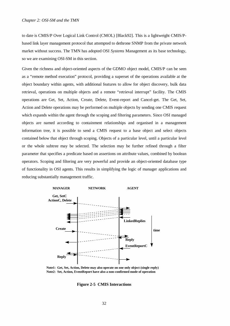
Given the richness and object-oriented aspects of the GDMO object model, CMIS/P can be seen
as a “remote method execution” protocol, providing a superset of the operations available at the
object boundary within agents, with additional features to allow for object discovery, bulk data
retrieval, operations on multiple objects and a remote “retrieval interrupt” facility. The CMIS
operations are Get, Set, Action, Create, Delete, Event-report and Cancel-get. The Get, Set,
Action and Delete operations may be performed on multiple objects by sending one CMIS request
which expands within the agent through the scoping and filtering parameters. Since OSI managed
objects are named according to containment relationships and organised in a management
information tree, it is possible to send a CMIS request to a base object and select objects
contained below that object through scoping. Objects of a particular level, until a particular level
or the whole subtree may be selected. The selection may be further refined through a filter
parameter that specifies a predicate based on assertions on attribute values, combined by boolean
operators. Scoping and filtering are very powerful and provide an object-oriented database type
of functionality in OSI agents. This results in simplifying the logic of manager applications and
reducing substantially management traffic.
Get, SetCActionC, Delete
LinkedReplies
EventReportC
Create
MANAGER NETWORK AGENT
Note1: Get, Set, Action, Delete may also operate on one only object (single reply)Note2: Set, Action, EventReport have also a non-confirmed mode of operation
time
Reply
Reply
Figure 2-5 CMIS Interactions

2.2. OSI Systems Management
33
When applying an operation to multiple objects through scoping and filtering, atomicity may be
requested through a synchronisation parameter. The result/error for each managed object is
passed back in a separate packet, which results in a series of linked replies and an empty
terminator packet. A manager application may interrupt a series of linked replies through the
Cancel-get facility. Finally, the Set, Action, Delete and Event-report operations may also be
performed in an unconfirmed fashion. While this is typical for event reports (the underlying
transport will guarantee their delivery in most cases), it is not so common for intrusive operations
as the manager will not know if they succeeded or failed. Nevertheless, such a facility is provided
and might be used when the network is congested or when the manager is not interested in the
results/errors of the operation. Figure 2-5 depicts the interactions between applications in
manager and agent roles using CMIS, apart from Cancel-get.
The event reporting model in OSI management is very sophisticated, allowing for very fine
control of emitted notifications. Special support objects known as Event Forwarding
Discriminators (EFDs) [X734] can be created and manipulated in agent applications in order to
control the level of event reporting. EFDs contain the identity of the manager(s) who wants to
receive notifications prescribed through a filter attribute. The filter may contain assertions on the
type of the event, the class and name of the managed object that emitted it, the time it was emitted
and other notification-specific attributes, e.g. for an attributeValueChange notification, the
attribute that changed and its new and old values. In addition, an emitted notification may be
logged locally by being converted to a log record. The latter is contained in a log object created
by a manager, which contains a filter attribute to control the level of logging. In summary, OSI
management provides very powerful mechanisms to deal with asynchronous notifications and
reduces substantially the need for polling-based management.
An example
We will consider now a concrete example in order to demonstrate the use of the OSI-SM access
facilities. Assume we would like to find all the routes in the routing table of a network element
that “point” to a particular next hop address. The manager application must know the logical
name of the network element agent which it will map to the presentation address by using
directory-based distribution facilities, which are explained in detail in section 2.4.1. The manager
application will then connect to that address and request the relevant table entries through scoping
and filtering in the following fashion:
Get ( objName={subsystemId=nw,protEntityId=clnp,tableId=route},
scope=1stLevel, filter=(nextHopAddr=X),
attrIdList={routeDest, routeMetric} )

Chapter 2: OSI-SM and the TMN
34
The results will be returned in a series of back-to-back linked replies, as shown in Figure 2-5.
The overall CMIS traffic will be kept fairly low: N linked replies for the matching entries
together with the request and the final linked reply terminator packets i.e. N+2 in total. The
overall latency will be slightly bigger than that of a single retrieval. It should be noted that traffic
would be much more without filtering, since the manager would have to retrieve all the routing
entries and perform the filtering locally. Finally, association establishment and release is also
necessary to the element agent. This does not happen though on a per operation basis but
associations may be “cached”.
The manager application would also like to be informed of new route entries “pointing” to the
next hop address X. This could be done by using the event reporting facilities provided by OSI
management. The manager will have to create an EFD with filter:
(eventType=objectCreation AND objectClass=routeEntry AND nextHopAddr=X)
It will also need to set as destination its own name. After that, notifications will be discriminated
within the agent and the ones matching the filter will be forwarded to the manager. Note that if
there is no association to the manager, the element agent will establish it by going through the
same procedure and mapping the logical manager name to an address through the directory. The
previous observations about association caching and address mappings also hold in this case.
2.2.5 Generic Management Functionality
One key aspect of the OSI-SM framework is it follows a “large common denominator” approach
to management standardisation, resulting in a large set of common object specifications that
should be globally supported. A number of generic management functions are addressed in order
to provide a well-defined framework for dealing with common tasks and to achieve reusability
and genericity. These specifications emanate from the five functional areas (FCAPS) and are
collectively known as the Systems Management Functions (SMFs) [SMF].
We can classify the OSI SMFs into four distinct categories:
i. those that provide generic definitions of management attributes, notifications and
actions only; these are the Object Management [X730], State Management [X731],
Relationship Management [X732] and Alarm Reporting [X733] SMFs;
ii. those that provide system definitions which complement the management access service
by providing a controlled mechanism to deal with notifications; these are the Event
Reporting [X734] and Log Control [X735] SMFs; and

2.2. OSI Systems Management
35
iii. those that provide miscellaneous definitions that are used to support the management
system itself; we can categorise here the security-related SMFs: Access Control [X741],
Security Alarm Reporting [X736], and Security Audit Trail [X740]; and
iv. those that provide generic definitions of managed object classes that are used for
common management tasks.
A full list of the current OSI SMFs is shown in Table 2-1.
ITU-T | ISO Number Systems Management Function
X.730 | 10164-1 Object Management Function
X.731 | 10164-2 State Management Function
X.732 | 10164-3 Attributes for Representing Relationships
X.733 | 10164-4 Alarm Reporting Function
X.734 | 10164-5 Event Management Function
X.735 | 10164-6 Log Control Function
X.736 | 10164-7 Security Alarm Reporting Function
X.740 | 10164-8 Security Audit Trail Function
X.741 | 10164-9 Objects and Attributes for Access Control
X.739 | 10164-11 Metric Objects and Attributes
X.738 | 10164-13 Summarisation Function
X.742 | 10164-10 Accounting Meter Function
X.745 | 10164-12 Test Management Function
X.737 | 10164-14 Confidence and Diagnostic Testing
X.746 | 10164-15 Scheduling Function
X.744 | 10164-18 Software Management Function
X.743 | 10164-20 Time Management Function
X.748 | 10164-22 Response Time Monitoring Function
X.750 | 10164-16 Management Knowledge Management Function
Table 2-1 OSI Systems Management Functions

Chapter 2: OSI-SM and the TMN
36
Starting from the third category first, the relevant functionality is important for security of
management. These functions support controlled access to management information [X741],
support the generation of security alarms when relevant breaches are detected [X736] and provide
the framework and mechanism to conduct security audit trails [X740].
The functions of the second category are extremely important since they provide the means for
event-driven as opposed to polling-based management. We term these system definitions since
they make it possible to deal with notifications emitted from managed objects and control their
forwarding to applications in manager roles through the Event-report CMIS primitive. As such,
they complement the OSI System Management access service. You may recall that in the
discussion of section 2.2.1 on the Management Functional Areas, event reporting and logging
facilities were identified as an important requirement in all the five functional areas.
Functions of the first category are particularly important. Object Management [X730] provides
three generic notifications related to configuration management that all OSI managed objects
should support, namely object creation, object deletion and attribute value change. State
Management [X731] provides a number of generic state attributes (administrative, operational,
usage state, etc.) and a state change notification. It also prescribes state transition tables
according to a well-defined state model. Relationship Management [X732] defines a relationship
model based on pointer attributes i.e. attributes whose value is the distinguished name of another
object. Relationships may also be represented by separate objects, as proposed by the more recent
General Relationship Model (GRM) [X725]. Finally, Alarm Reporting [X732] provides a set of
generic alarm notifications which cover the requirements for all possible types of alarms: quality
of service, communications, equipment, environmental and processing error alarm.
Other MIB specifications should use the above definitions to model object, state, alarm and
relationship aspects. Generic configuration, state or alarm managers may be written in a fashion
that makes them independent from the semantics of a particular MIB. For example, a
configuration monitor could be an application that connects to managed elements and requests all
the object creation, deletion, attribute value and state change notifications in order to display
changes to the human manager. Such an application can be written once and be reused: it only
needs to be “told” the formal specification of the element MIBs in order to be able to display
meaningful information for the objects emitting those notifications. OSI management platforms
typically provide a set of generic applications that are based on those common specifications.
2.2. OSI Systems Management
37
The relevant GDMO/ASN.1 specifications in the first and second category SMFs are compiled
together in the Definition of Management Information [DMI] recommendation, which also
specifies the properties of Count, Gauge, Threshold and Tide-Mark generic attributes.
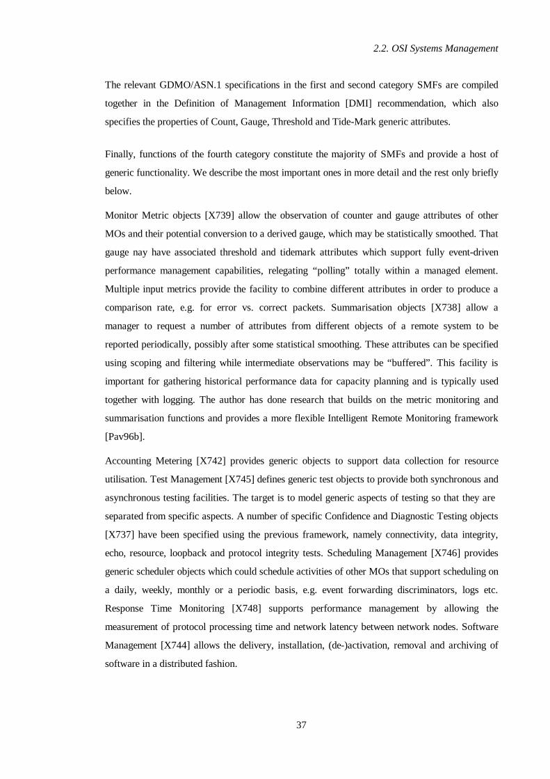
Finally, functions of the fourth category constitute the majority of SMFs and provide a host of
generic functionality. We describe the most important ones in more detail and the rest only briefly
below.
Monitor Metric objects [X739] allow the observation of counter and gauge attributes of other
MOs and their potential conversion to a derived gauge, which may be statistically smoothed. That
gauge nay have associated threshold and tidemark attributes which support fully event-driven
performance management capabilities, relegating “polling” totally within a managed element.
Multiple input metrics provide the facility to combine different attributes in order to produce a
comparison rate, e.g. for error vs. correct packets. Summarisation objects [X738] allow a
manager to request a number of attributes from different objects of a remote system to be
reported periodically, possibly after some statistical smoothing. These attributes can be specified
using scoping and filtering while intermediate observations may be “buffered”. This facility is
important for gathering historical performance data for capacity planning and is typically used
together with logging. The author has done research that builds on the metric monitoring and
summarisation functions and provides a more flexible Intelligent Remote Monitoring framework
[Pav96b].
Accounting Metering [X742] provides generic objects to support data collection for resource
utilisation. Test Management [X745] defines generic test objects to provide both synchronous and
asynchronous testing facilities. The target is to model generic aspects of testing so that they are
separated from specific aspects. A number of specific Confidence and Diagnostic Testing objects
[X737] have been specified using the previous framework, namely connectivity, data integrity,
echo, resource, loopback and protocol integrity tests. Scheduling Management [X746] provides
generic scheduler objects which could schedule activities of other MOs that support scheduling on
a daily, weekly, monthly or a periodic basis, e.g. event forwarding discriminators, logs etc.
Response Time Monitoring [X748] supports performance management by allowing the
measurement of protocol processing time and network latency between network nodes. Software
Management [X744] allows the delivery, installation, (de-)activation, removal and archiving of
software in a distributed fashion.
Chapter 2: OSI-SM and the TMN
38
Management Knowledge Management [X750] provides mechanisms for the dynamic acquisition
of shared management knowledge, including repertoire knowledge (which managed object
classes, conditional packages and name bindings a system supports), instance knowledge (the
names of the available managed object instances) and definition knowledge (the formal MIB
specification in GDMO). This knowledge is provided both through managed objects and through
OSI Directory [X500] objects. These directory objects support also global naming and
distribution facilities as it will be discussed in detail in section 2.4.1. The author has contributed
research work towards the distribution and discovery aspects of [X750].
The OSI SMFs were depicted in Table 2-1. Note there exist more SMFs under development e.g.
Domain and Policy Management [X749], Changeover Function [X752], Command Sequencer
[X753] etc. In summary, SMFs increase the intelligence and capabilities of applications in agent
roles. They provide useful generic facilities which most agent systems should support and enforce
a common style of operation which may result in generic managing. The relevant objects are
known as Support or Systems Managed Objects (SMOs) [X701] since they describe resources of
the management system itself. In Chapter 3 we propose an object-oriented realisation model for
the OSI SMFs that results in software reuse and makes available the relevant expressive power to
management applications at a minimal cost.

2.3. The Telecommunications Management Network
39
2.3 The Telecommunications Management Network
This section provides an introduction to the Telecommunications Management Network (TMN)
[M3010] which is the framework developed by the ITU-T for managing telecommunications
networks and services. This is more than just an overview since it positions the TMN in the
context of the Broadband Integrated Services Digital Network (B-ISDN) Reference Model
[BISDN], presents the underlying requirements and explains the various architectural choices.
While the basic TMN recommendations have been available since 1990, there have been rather
few tutorial or survey papers and relevant books in the literature. [Sahi88] provides an early view
of the emerging architectural framework; [Bern93] discusses general issues related to the
management of telecommunications networks; [Shrew95] provides an interesting overview
(“TMN in a nutshell”) but is biased towards the Network Management Forum OMNIPoint
interpretation of TMN [OmniPnt], [Murr95]; finally [Glith95] and [Sidor95] provide easy-to-
read tutorial overviews. In terms of books, [Aida94] is a collection of chapters by different
authors addressing TMN issues, in which [Sahi94] and [John94] address the framework and
standards bodies work. [Cohen94] is a chapter in [Slom94] that provides a fairly complete but
rather dry overview of the TMN architectural framework.
The material in this section is based to a large extent on [Pav94a], [Pav96a] and [Pav97c].
2.3.1 The TMN in the Broadband ISDN Context
The purpose of a Telecommunications Management Network (TMN) [M3010] is to support
operators in managing telecommunications networks and services. This means support for
planning, provisioning, installing, maintaining and administering these. Management refers to set
of capabilities related to the five functional areas described in section 2.2.1 and it is an integral
part of the operation of networks and services.
Management becomes particularly important for the new generation of broadband
telecommunications networks based on the Synchronous Digital Hierarchy (SDH) / Synchronous
Optical Network (SONET) transmission and Asynchronous Transfer Mode (ATM) switching.
These technologies offer advanced multiplexing capabilities that need to be exploited and
harnessed through sophisticated management systems. Another important aspect that makes
TMN a necessity is the advent of a new generation of telecommunications services that break
away from basic telephony. Advanced services supporting multimedia, multi-party and mobility
features need comprehensive service management facilities and Quality of Service (QoS) control,

Chapter 2: OSI-SM and the TMN
40
especially as they may be sold according to QoS agreements. The TMN provides a framework
that tries to address these issues through a management model based on hierarchical
decomposition and abstraction and through the deployment of object-oriented information
specification and access principles that result in reusability and genericity.
The TMN is a data network carrying management traffic. It is logically separate from the
telecommunications network being managed but interfaces to it at several distinct points in order
to monitor and control its operation. A TMN may use, for its communication requirements, parts
of the telecommunications network itself. The basic concept behind the TMN is to provide a
framework in order to achieve the interoperation between management applications, which in
TMN language are called Operations Systems (OSs), and the telecommunications equipment
being managed. This is achieved through an architecture with standardised interfaces that support
object-oriented message exchanges over well-defined protocol stacks. It should be possible for
operators (or administrations in TMN parlance) to put together TMN systems that comprise
equipment and operations systems from different suppliers, reducing costs and achieving rapid
deployment and support for new services.
Control Plane
Management Plane
Figure 2-6 TMN Relationship to a Telecommunications Network (from [M3010])
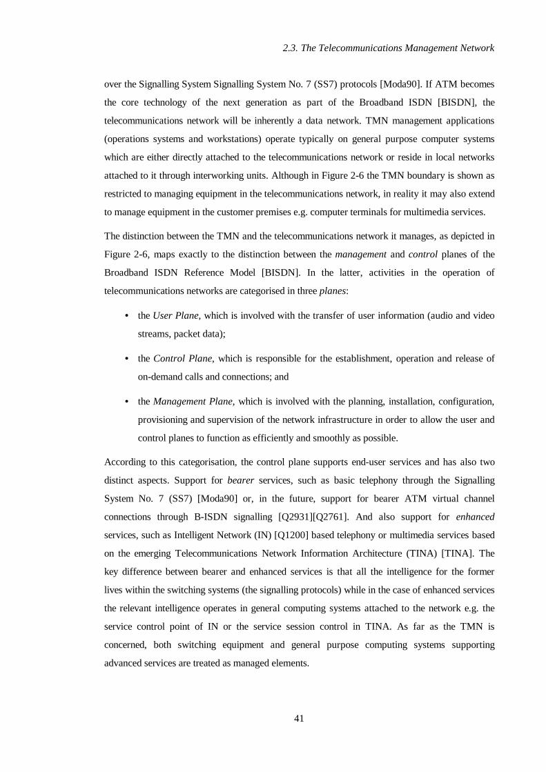
Figure 2-6 shows the relationship between the TMN and the telecommunications network being
managed. The user plane of the current generation of telecommunications networks supports raw
transmission only, so a data network capability needs to be provided over them for
communicating management traffic. This capability can be provided through the control plane
2.3. The Telecommunications Management Network
41
over the Signalling System Signalling System No. 7 (SS7) protocols [Moda90]. If ATM becomes
the core technology of the next generation as part of the Broadband ISDN [BISDN], the
telecommunications network will be inherently a data network. TMN management applications
(operations systems and workstations) operate typically on general purpose computer systems
which are either directly attached to the telecommunications network or reside in local networks
attached to it through interworking units. Although in Figure 2-6 the TMN boundary is shown as
restricted to managing equipment in the telecommunications network, in reality it may also extend
to manage equipment in the customer premises e.g. computer terminals for multimedia services.
The distinction between the TMN and the telecommunications network it manages, as depicted in
Figure 2-6, maps exactly to the distinction between the management and control planes of the
Broadband ISDN Reference Model [BISDN]. In the latter, activities in the operation of
telecommunications networks are categorised in three planes:
• the User Plane, which is involved with the transfer of user information (audio and video
streams, packet data);
• the Control Plane, which is responsible for the establishment, operation and release of
on-demand calls and connections; and
• the Management Plane, which is involved with the planning, installation, configuration,
provisioning and supervision of the network infrastructure in order to allow the user and
control planes to function as efficiently and smoothly as possible.
According to this categorisation, the control plane supports end-user services and has also two
distinct aspects. Support for bearer services, such as basic telephony through the Signalling
System No. 7 (SS7) [Moda90] or, in the future, support for bearer ATM virtual channel
connections through B-ISDN signalling [Q2931][Q2761]. And also support for enhanced
services, such as Intelligent Network (IN) [Q1200] based telephony or multimedia services based
on the emerging Telecommunications Network Information Architecture (TINA) [TINA]. The
key difference between bearer and enhanced services is that all the intelligence for the former
lives within the switching systems (the signalling protocols) while in the case of enhanced services
the relevant intelligence operates in general computing systems attached to the network e.g. the
service control point of IN or the service session control in TINA. As far as the TMN is
concerned, both switching equipment and general purpose computing systems supporting
advanced services are treated as managed elements.

Chapter 2: OSI-SM and the TMN
42
From the above discussion it is should be clear that the TMN does not aim to support on-demand
end-user services which are the subject of the control plane. The TMN supports management
services which are primarily used by the operators and human managers of the
telecommunications network. It also supports management services which are used by end-users,
such as service subscription, accounting, service profile customisation and the provision of
Virtual Private Network (VPN) [Reil96] management services.
The relationship between the TMN and the control plane bears a very good analogy to the
relationship between a managed object and the associated real resource. The TMN provides
management functions and facilities in an orthogonal fashion to the operation of the control plane
but these management functions affect the way in which the control plane operates. The TMN
influences operation of the latter by configuring operational parameters, for example routing table
entries, according to management decisions. The TMN monitors the network, makes decisions
based on network conditions and other information, such as management policy and knowledge of
future events, and feeds back management actions to the control plane in order to influence its
future behaviour. This relationship allows the network to operate as intelligently as possible
without burdening the network elements with sophisticated features. In essence, management
intelligence operates “outside” the network, in a similar fashion to enhanced service control
frameworks such as IN and TINA. Finally, it should be added that since the TMN is not involved
in on-demand end-user service control, it has less stringent requirements on real time response
than control plane functions.
Note: The terms control and management defined above are sometimes used in a different
fashion. By control it is meant functions embedded in network elements that are implemented in
hardware/firmware, use signalling protocols and provide fast real-time response. By management
it is meant functions operating in general purpose computing equipment, realised as software
programs, which use general purpose data communication protocols and provide slower response.
This is a physical categorisation as opposed to the functional one presented above. In the author’s
view, the former maps better to the B-ISDN reference model and it will be used consistently for
the rest of the thesis.

2.3. The Telecommunications Management Network
43
2.3.2 TMN Architecture
In this section we examine the TMN architecture starting from the relevant requirements. We
then present the functional architecture, explain the role of the various reference points and
interfaces, discuss the logical layering aspects and finally examine the decomposition of an
Operation System Function (OSF) into functional components.
Since we use the term architecture extensively in the rest of the chapter and the thesis as a whole,
it is worth attempting to define it first. The definition is taken from the UK Alvey programme’s
Advanced Networked Systems Architecture (ANSA) project [ANSA89a]. There it is described as
“an engineering discipline of design with a common framework and a consistency of style”. It
embraces concepts and terms for explaining systems, models for reasoning about them, the
specification of basic building blocks and a defined process and framework for putting systems
together.
The TMN intends to support a wide variety of management activities which cover the planning,
installation, operation, administration, maintenance and provisioning of telecommunications
networks and services. The TMN should support the open exchange of information between
management applications and managed elements and between management applications
themselves. The latter should take place both within a TMN and across TMNs so that automated
co-operation of different administrations is possible. Also customers will be offered access to
management services through electronic interfaces.
Key requirements for TMN systems include the ability to:
• minimise the management reaction times to significant network events;
• minimise load caused by management traffic, especially when the telecommunications
network is used to carry it;
• allow for geographic dispersion of management functions over a wide area e.g. a
country-wide telecommunications network;
• be able to cope with very large scale sizes of manageable entities;
• provide automated isolation mechanisms for faults and invoke recovery procedures; and;
• improve service assistance and interaction with customers through electronic interfaces.
To provide the expected functionality and meet the relevant requirements, the TMN provides
three architectural views [M3010]:
Chapter 2: OSI-SM and the TMN
44
• The Functional Architecture refers to the distribution of TMN functionality into
categories of “function blocks” interconnected via “reference points”.
• The Information Architecture adopts OSI-SM object-oriented information specification
and access principles. Managed resources are represented by managed objects at
different levels of abstraction and are observed and modified by applications in managing
roles in hierarchical or peer-to-peer manager-agent relationships. OSI-SM was explained
in detail in section 2.2.
• The Physical Architecture maps combinations of functional blocks to physical blocks
based on non functional requirements such as performance, ownership etc. In this view,
some of the reference points become interoperable interfaces.
It is interesting to observe that the OSI-SM information specification and access framework has
been adopted as the basis for the information architecture because it addresses some of the key
objectives:
• It provides a highly configurable event model of fine granularity. This minimises reaction
times to network events and keeps management traffic low with suppression of unwanted
events at source.
• It provides intelligent information retrieval facilities based on scoping and filtering which
keep management traffic low and provide better timeliness of management information.
• It allows for wide-area geographic distribution when combined with the OSI Directory
Service [X500] which supports federation.
• It can cope with large scale of manageable entities in network elements as discussed in
Chapter 3.
Despite the fact the information architecture currently uses OSI-SM principles, the TMN is not
tied to the OSI-SM framework [X700]. Discussion is presently underway in the ITU-T Study
Group IV to consider the use of Open Distributed Processing (ODP) [ODP] technologies, such as
OMG CORBA [CORBA], as alternatives to OSI-SM. Chapter 4 of this thesis examines the
feasibility of this assertion and proposes a solution.

2.3. The Telecommunications Management Network
45
2.3.2.1 Functional Architecture
The TMN management functions are realised by the following types or classes of function
blocks:
• Operations Systems Functions (OSF),
• Workstation Functions (WSF),
• Mediation Functions (MF),
• Q-Adapter Functions (QAF), and
• Network Element Functions (NEF).
A Network Element Function models telecommunications and support equipment which
communicates with the TMN for the purpose of being monitored and controlled. The NEF
includes only those equipment aspects that are subject to management, i.e. the representation of
relevant resources as managed objects and the necessary access mechanism. Control plane
aspects are outside the scope of the TMN and, as such, are not modelled by the NEF. A NEF is
typically an application operating in agent role according to the OSI-SM manager-agent model.
The Q-Adapter Function connects to the TMN those NEFs which do not support standardised
TMN reference points. The responsibility of a QAF is to translate between a TMN and a non-
TMN (e.g. proprietary) reference point. The main intra-TMN reference point is the q reference
point, hence the name Q-Adapter. A QAF provides both protocol and information model
translation and is typically a proxy agent-manager application according to the manager-agent
model. Issues on Q Adaptation are discussed in more detail in section 2.4.2.
The Mediation Function acts on information passing between NEFs and OSFs in order to
enhance the capabilities of “weak” NEFs. There are two types of q reference points, a fully
capable q3 and a “not quite q3” one, called qx. Mediation functions convert qx to q3 and may store,
adapt, filter, threshold and condense information. They may be implemented in a hierarchical
fashion in which qx reference points are enhanced in various stages until q3 is achieved. A MF
may provide protocol conversion and information model translation and enhancement and is
typically a proxy manager-agent application in a similar fashion to a QAF. Issues on mediation
are discussed in more detail in section 2.4.2.
The Workstation Function provides the means for the human user to interpret TMN information,
e.g. a network manager, and allow him/her to influence management decisions. The WSF
interfaces to the OSF and MF and complements decisions based on human heuristics with logic
Chapter 2: OSI-SM and the TMN
46
that checks their validity and consistency. Note that it is not permitted for a human user to
interface directly to a NEF or QAF, since relevant directives should always be checked by
automated management logic. The WSF is typically an application in the manager role according
to the manager-agent model. Issues on WSs are discussed in more detail in section 2.4.3.
The Operations Systems Function constitutes the heart of the TMN and processes information
related to telecommunications management activities. OSFs access NEFs either directly or
indirectly through MFs. They may also access foreign elements through QAFs. OSFs interact
with each other in either peer-to-peer or hierarchical relationships. The latter are governed by the
TMN logical layered architecture which prescribes a hierarchical structure in element, network,
service and business management layers. The OSF is typically an application in both manager
and agent roles according to the manager-agent model. The internal structure of the OSF is
addressed in detail in section 2.3.2.5.
T0 40 389 0-93
g g
W SF
OSF
MF
QAFNEF
W SF
O S F
MF
QAF N E F
f f
ff x xq
x
q
3
q
q 33
xq
q 3
q xq 3
q 3
q 3
q x
q 3q x
q x
m m
TMN TMN
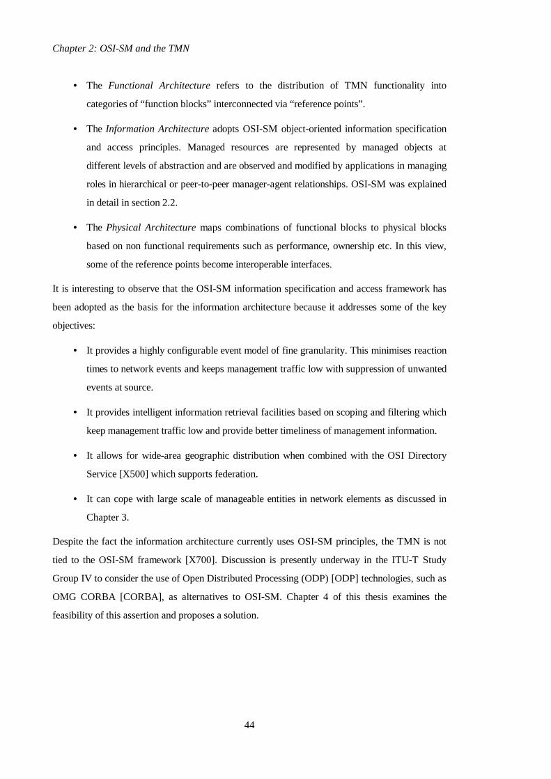
Figure 2-7 TMN Function Blocks and Reference Points (from [M3010])
In the discussion above we already introduced the q3 and qx reference points while discussing Q-
adapter and mediation functions. The TMN defines a number of reference points which
interconnect the function blocks presented above. The function blocks and reference points taken
together define a reference model for the TMN. The logical functionality of any TMN can be
described in a reference configuration by some arrangement of those function blocks and
2.3. The Telecommunications Management Network
47
reference points. Figure 2-7 shows the relationship between function blocks and their
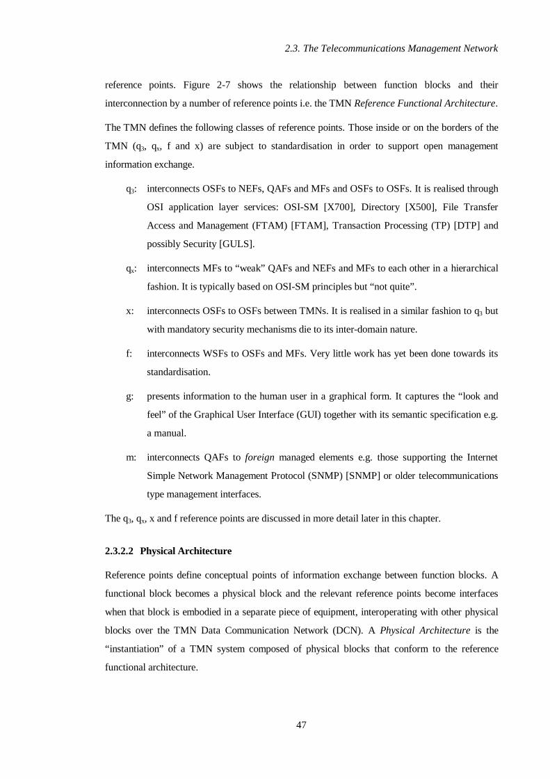
interconnection by a number of reference points i.e. the TMN Reference Functional Architecture.
The TMN defines the following classes of reference points. Those inside or on the borders of the
TMN (q3, qx, f and x) are subject to standardisation in order to support open management
information exchange.
q3: interconnects OSFs to NEFs, QAFs and MFs and OSFs to OSFs. It is realised through
OSI application layer services: OSI-SM [X700], Directory [X500], File Transfer
Access and Management (FTAM) [FTAM], Transaction Processing (TP) [DTP] and
possibly Security [GULS].
qx: interconnects MFs to “weak” QAFs and NEFs and MFs to each other in a hierarchical
fashion. It is typically based on OSI-SM principles but “not quite”.
x: interconnects OSFs to OSFs between TMNs. It is realised in a similar fashion to q3 but
with mandatory security mechanisms die to its inter-domain nature.
f: interconnects WSFs to OSFs and MFs. Very little work has yet been done towards its
standardisation.
g: presents information to the human user in a graphical form. It captures the “look and
feel” of the Graphical User Interface (GUI) together with its semantic specification e.g.
a manual.
m: interconnects QAFs to foreign managed elements e.g. those supporting the Internet
Simple Network Management Protocol (SNMP) [SNMP] or older telecommunications
type management interfaces.
The q3, qx, x and f reference points are discussed in more detail later in this chapter.
2.3.2.2 Physical Architecture
Reference points define conceptual points of information exchange between function blocks. A
functional block becomes a physical block and the relevant reference points become interfaces
when that block is embodied in a separate piece of equipment, interoperating with other physical
blocks over the TMN Data Communication Network (DCN). A Physical Architecture is the
“instantiation” of a TMN system composed of physical blocks that conform to the reference
functional architecture.

Chapter 2: OSI-SM and the TMN
48
Interfaces are characterised by two facets, a conceptual facet and a physical facet, with the
conceptual facet effectively defined by the reference point. The conceptual facet is characterised
by the M-Part (Message Part) while the physical facet is characterised by the P-Part (Protocol
Part) [Embry91]. In the case of OSI-SM which is currently adopted in the TMN, the M-Part
defines the structure of the message sent to or received from a managed object i.e. a Common
Management Information Service (CMIS) message [X710]. The P-Part defines the protocol stack
used to transfer the message and this will involve the selection of the profile to support the
Common Management Information Protocol (CMIP) [Q3]. Reference points are denoted by lower
case letters (e.g. q3) while interfaces are denoted by upper case letters (e.g. Q3). The relationship
between reference points and interfaces is shown in Figure 2-8.
Interface
Conceptual Facet Reference Point
Physical Facet
P-PartM-Part
Figure 2-8 Relationship of Reference Points and Interfaces
It may be the case that more than one function block are combined together to form a physical
block because of non-functional requirements. For example, two OSFs may constitute a single
Operations System (OS), a MF and a QAF may constitute a Mediation Device / Q-Adapter (MD-
QA) block, and so on. In this case their functional separation should still hold while their
interactions should conform to a well-defined reference point. The actual realisation of that
reference point becomes a proprietary issue since it remains internal within a network node.
2.3.2.3 Logical Layering
One of the key aspects of the TMN as a management framework is that it transforms the old
centralised or flat management paradigm to a hierarchical distributed one (see also Figure 2-2
Models of Management Organisation). We will examine here the aspects and issues behind the
TMN hierarchical decomposition.
In the hierarchical model projected by the TMN, management functionality is layered, offering
increased abstraction and encapsulation in higher layers. The functionality of each layer builds on
the functionality offered by the layer below. Each layer may contain additional sub-layers. The

2.3. The Telecommunications Management Network
49
functionality of each layer (or sub-layer) is supported by a one or more Operation System
Functions (OSFs). These may have peer-to-peer relationships when in the same layer or
hierarchical ones when in different layers (or sub-layers). Each OSF presents an information
model to superior OSFs which build on it and present different information models of higher
abstraction to their superiors. As such, a layer in this architecture builds on the information
model presented by the layer below and presents its own information model to the layer above.
T0402690-92
M A M A
S y s te m A S ys tem B S ys te m CIn fo rm a tio n m od el B
M IB M IB
C M IS C M IS C M IS C M IS
C M IP C M IP
R e s o urc e
R eso urce
s ee s s e e s
In fo rm a tion m od el C(N o te )
O S Ip roto c ol
s tac k
O S Ipro to c ol
s ta ck
O S Iprot oco l
s tac k
O S Ip ro toco ls ta ck
Figure 2-9 Cascaded Hierarchical Communication (from [M3010])
This hierarchical decomposition and the cascaded interactions in manager-agent roles with
different information models at each level are depicted in Figure 2-9. The information models at
each level represent manageable resources at different levels of abstraction. At the lowest level of
that hierarchy, managed network elements contain resources of the finest granularity, representing
aspects of the local system, e.g. access points, interfaces, call endpoints etc. At higher levels,
objects represent resources of higher abstraction that can be mapped onto lower level resources,
e.g. subnetworks, networks, services etc.
The TMN layers correspond essentially to different levels of abstraction in the information
architecture. The mapping between information models at adjacent levels is accomplished through
information conversion functions within OSFs. It should be noted that the use of OSI-SM as
depicted in Figure 2-9 extends the OSI-SM model defined in [X701]. In the latter, managed
objects are considered modelling resources in the various layers of the communications protocol
stack. In the TMN this holds only for the lowest level of the management hierarchy i.e. the NEFs.
Managed objects in higher TMN layers are more abstract views of the lowest layer objects.
TMN layering is not strict in the sense that an OSF may access directly OSFs in layers below the
adjacent underlying layer. This may be the case, for example, between the service management

Chapter 2: OSI-SM and the TMN
50
and element management layers regarding historical QoS data, accounting records etc. The key
aspect that characterises the TMN hierarchical organisation is that each layer is a fully
incremental addition of the functionality provided by the layers below. As such, lower layers are
essentially unaware of the presence of higher layers; they simply respond to management requests
which are always initiated by the higher layers. Manager-agent interactions are only top-down or
peer-to-peer in this layered hierarchy. Note that event notifications are always requested first (i.e.
configured) by the superior system.
Another way to view the hierarchical nature of OSFs and the manager-agent relationships is
depicted in Figure 2-10. This is known as the TMN Logical Layered Architecture (LLA). The
LLA uses a recursive approach to decompose a particular management activity into a series of
nested functional domains. Each functional domain becomes a management domain under the
control of an Operation System Function (OSF). A domain may contain other OSF domains to
allow further layering and/or may represent logical or physical resources as managed objects at
the lowest level of the hierarchy within that domain. When the OSF domain is at the top of the
layered architecture, there is no superior OSF.
A
M
x
A
A
AM
q q
qM
O SF domain
OutsideTMN Inside TMN
OSF dom ain
Figure 2-10 Logical Layered Architecture (from [M3010])
All the interactions within a domain take place at generic q reference points. Interactions between
peer domains, i.e. crossing the OSF domain boundary can take place at a q or x reference point.
Reference points may become interfaces depending on the physical realisation. The essence of the
LLA is that at each point of interaction with an OSF domain, all the other subordinate OSF

2.3. The Telecommunications Management Network
51
domains used to accomplish a management task can be thought as encapsulated (contained) by
that domain. The user of a management service or sub-service offered by that OSF does not see
its realisation.
The 1991 version of [M3010] indicated a potential decomposition of TMN layered functions in
element, network, service and business management layers. These were influenced by British
Telecommunications’ Communications Network Architecture for Management (CNA-M)
[Milh89]. This layered decomposition was only informative and not normative since the initial
idea behind the TMN was that only Q3 interfaces to network elements and X interfaces were to be
standardised. In the 1996 version of [M3010] this layered decomposition became normative,
which means that Q3 interfaces within the TMN are also going to be standardised. The potential
functions of the TMN layers of management activity are the following.
The Element Management Layer (EML) comprises functions related to either a single or a small
number of network elements located in a small geographical area. These functions are concerned
with the day-to-day management of elements in terms of configuration, faults and maintenance,
performance monitoring, historical data etc. An abstract view of elements is presented to the
network management layer so that the latter is shielded from unnecessary complexity and detail.
These functions are predominantly technology dependent and do not take into account network-
wide aspects as they have only a limited view of other parts of the network, if at all.
The Network Management Layer (NML) is concerned with keeping the network capabilities at
some operational optimum. Human and automatic decision making processes may be used to
optimise the network resources. This layer supports the management of the whole network which
may span a large geographical area e.g. a whole country. The network is typically partitioned
hierarchically into subnetworks, with complete visibility of the whole network provided at the
top-most level. A technology independent view is presented to the service management layer. At
this level, provision, cessation and modification of network capabilities are provided in order to
support services. Statistical data are kept for the whole of the network concerning performance,
usage, availability, faults etc.
The Service Management Layer (SML) is concerned with functions supporting services.
Customer facing (provision, cessation, subscription, accounting, QoS, fault reporting) and
interfacing with other administrations for the provision of end-to-end services are aspects of this
layer. Additional tasks include the control of interaction between services, service order,

Chapter 2: OSI-SM and the TMN
52
complaint handling and invoicing. At this level, a technology independent view of the network is
possible i.e. the network is treated as a “cloud” with a set of capabilities.
The Business Management Layer (BML) is concerned with the implementation of policies and
strategies within the organisation which owns and operates the services and possibly the network
itself. Business management functionality is typically proprietary and this subsequently means
there is no x reference point at this level. Business decisions may be influenced by higher level
controls such as legislation or macro-economic factors. They may address tariffing policies,
quality maintenance strategies guidance on service operation, and so on. As an example, BT’s
“friends and family” package involves a business decision which affects the charging schemes in
the service management layer and aims at attracting new subscribers (or keeping existing ones). It
seems unlikely that the majority of business management functions will be automated in the near
future.
TMN
OSF
MF
NEF QAF
WSFQ F
OSF: Operation System FunctionWSF: WorkStation FunctionQAF/MF: Q-Adaptor / Mediation FunctionNE: Network Element Function
BusinessManagement
ServiceManagement
NetworkManagement
ElementManagement
NetworkElements
Manager to Agent relationshipOperations SystemNetwork Element
X
Figure 2-11 TMN Functional and Example Layered Physical Architecture
Figure 2-11 shows in the left part a simplified view of the TMN functional architecture as
presented in Figure 2-7 which maps to an example physical architecture in the right part; the
latter demonstrates the TMN layers discussed above. Note that in the above example physical
architecture, all the network elements are considered Q3-capable i.e. there are no mediation
devices or Q adapters; workstations have also been omitted for simplicity. The reason for the
conical shape of the physical depiction is that higher sub-layers or layers comprise typically
fewer OSs.

2.3. The Telecommunications Management Network
53
OSFB
OSFE
OSFB
OSFSOSFS
OSFN OSFN
OSFE
NEF NEF
qbs qbs
qsn qsn
qne
qem
qne
qem
qbb
qss
qnn
qee
xss
xnn
xee
TMN
Figure 2-12 Classes of q and x Reference Points
The TMN functional architecture defines generic classes of q and x reference points for
management information exchange. Given the hierarchical decomposition of the TMN into
element, network, service and business management layers, specific classes of those reference
points can be defined between layers and within a layer. Figure 2-12 depicts a hierarchical
taxonomy of the relevant classes as presented in [GOM].
It should be noted it is unlikely that qee and xee will exist in reality. This is because element
management OSFs typically follow strict hierarchical as opposed to peer-to-peer relationships. In
addition, it may be the case that there will exist x reference points between different TMN layers
and not only between the same layer. As an example, there may be network providers that offer
pure transport only, with service providers buying those transport facilities to offer services. A
service provider’s TMN SM layer will need to interact with the network provider’s TMN NM or
even EM layers through xsn and xse reference points respectively. These types of cross-layer
TMN interactions are not shown in Figure 2-12. Finally we mentioned previously that there may
exist interactions between non-adjacent layers within a TMN e.g. between the service and element
management layers. In this case, the qne reference point is used as “qse”.
An interesting aspect that deserves some discussion is that an intra-layer reference point, e.g. qnn,
is in principle the same with the inter-layer interface to the layer above, e.g. qsn. This is because
only one information model is typically standardised for the whole layer, addressing the “agent
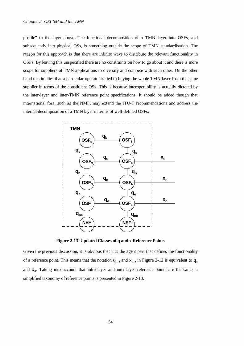
Chapter 2: OSI-SM and the TMN
54
profile” to the layer above. The functional decomposition of a TMN layer into OSFs, and
subsequently into physical OSs, is something outside the scope of TMN standardisation. The
reason for this approach is that there are infinite ways to distribute the relevant functionality in
OSFs. By leaving this unspecified there are no constraints on how to go about it and there is more
scope for suppliers of TMN applications to diversify and compete with each other. On the other
hand this implies that a particular operator is tied to buying the whole TMN layer from the same
supplier in terms of the constituent OSs. This is because interoperability is actually dictated by
the inter-layer and inter-TMN reference point specifications. It should be added though that
international fora, such as the NMF, may extend the ITU-T recommendations and address the
internal decomposition of a TMN layer in terms of well-defined OSFs.
OSFB
OSFE
OSFB
OSFSOSFS
OSFN OSFN
OSFE
NEF NEF
qs qs
qn qn
qe
qne
qe
qne
qb
qs
qn
qe
xs
xn
xe
TMN
Figure 2-13 Updated Classes of q and x Reference Points
Given the previous discussion, it is obvious that it is the agent part that defines the functionality
of a reference point. This means that the notation qma and xma in Figure 2-12 is equivalent to qa
and xa. Taking into account that intra-layer and inter-layer reference points are the same, a
simplified taxonomy of reference points is presented in Figure 2-13.

2.3. The Telecommunications Management Network
55
The reference points identified in Figure 2-13 are further specialised for a particular network
technology and management service. At the time of writing (end of 1997), the following reference
points have been addressed:
• qne-sdh: management for Synchronous Digital Hierarchy (SDH) elements - the ITU-T
G.774 recommendation [G774].
• qne-atm: management for Asynchronous Transfer Mode (ATM) elements - the ITU-T
I.751 recommendation [I751].
• qne-ss7: management for Signalling System No. 7 (SS7) elements - the ITU-T Q.751
recommendation [Q751].
• qne-gsm: management for Global System for Mobile (GSM) elements - the ETSI GSM12
specifications.
• qn: technology-independent network layer management - the ETSI Generic Object Model
(GOM) [GOM]and the equivalent emerging ITU-T network information model.
• xs-coop and xs-user: inter-domain service management for path provisioning - the
EURESCOM Xcoop (provider-to-provider) and Xuser (user-to-provider) specifications.
More reference points are being currently addressed by various groups.
2.3.2.4 Interface Specification Methodology
TMN interface specifications are typically produced by ITU-T, ETSI and NMF groups. They
contain the formal description of managed object classes in GDMO together with usage scenarios
that follow possibly the NMF “Ensemble” style [NMF-025]. The latter proposes scenarios that
demonstrate how the supported management functions are accomplished through CMIS message
exchanges with objects of the defined classes.
Interface specifications are produced in a top-down rather than a bottom-up approach. [M3020]
describes a methodology to be applied when designing TMN interfaces. According to this, TMN
designers start from the management services they would like to achieve, they decompose these
to management service components, possibly recursively in more than one step. The finest
granularity service components are further decomposed into management functions, which are
then mapped onto managed object classes through an object-modelling phase. A consolidation
phase is then necessary to make sure that the original management services are supported by the
object classes the designer arrived at. The management information schema is finally produced in

Chapter 2: OSI-SM and the TMN
56
terms of name bindings for those classes. Additional notions such as the management context,
management roles and management goals are also taken into account in the design process.
The management services and functions information model designers have come across are
documented in [M3200] and [M3400], but these are informative rather than normative. Since
TMN interfaces are object-oriented, new interface specifications should take into account the
Generic Network Information Model [M3100] which specifies technology-independent generic
classes to be specialised through inheritance. They should also take into account the functionality
already offered by the OSI systems management functions [SMF].
[Sylor89] presents a set of guidelines for structuring manageable entities. RACE projects such as
ICM [ICM] and PREPARE [PREPARE] have extended and refined the [M3020] methodology
with the results fed back to the ITU-T. The author has contributed research work towards the
ICM methodology described in [Grif96a].
2.3.2.5 Functional Components
[M3010] defines a number of functional components as constituents of TMN function blocks.
These are not subject to standardisation but help to understand the internal functionality of the
various function blocks. Reference points only are standardised and these are supported by
Message Communication Function (MCF) components, which “understand” the structure of the
relevant messages.
Since the Operation System Function is the most important and complex function block of the
TMN, its structure in terms of functional components is shown in Figure 2-14. The Management
Application Function in agent role, OSF-MAF(A), provides support for the information model
exported across the q and x reference points. It receives messages that request operations on
managed objects and returns results. It also emits asynchronous event reports according to
defined preconditions in the relevant GDMO model specification. In a similar fashion, the
Workstation Support Function (WSSF) understands the semantics of f messages and responds to
relevant requests. The Security Function (SF) makes sure that only authorised entities
communicate with the OSF (authentication) and controls the level of access to management
information (access control).

2.3. The Telecommunications Management Network
57
OSF-MAF (A)
OSF-MAF (M)
ICF
MCFq
SF
MCFqMCFx
Intra-TMNInter-TMN
OSF
x
M -> A
q3 (to OSF / MF / NEF)
MCFx
x (from OSF)
(to OSF)
MCFf
q3 (from OSF)
WSSF
f (from WSF)
Figure 2-14 OSF Decomposition into Functional Components
The Management Application Function in manager role, OSF-MAF-M, provides the OSF’s
management intelligence by accessing subordinate information models in OSFs, QAFs and NEFs
or peer ones in adjacent OSFs. It performs operations on managed objects and receives
asynchronous event reports. Collection of statistics, alarm correlation and decision functions are
typically located there. The Information Conversion Function (ICF) provides information
translation functions that link the OSF-MAF-A and OSF-MAF-M. Operations on OSF-MAF-A
managed objects may need to be mapped on operations to subordinate or peer information
models. For example, a “path establishment” action on a network managed object in a network
configuration management OSF will need to be mapped to operations on element manager OSFs
to request relevant cross-connections. This mapping can be very complex since a relevant route
needs to be identified that both satisfies the requested QoS characteristics (e.g. end-to-end
latency, bandwidth, etc.) and can be accommodated through the existing resources. In the
opposite direction, a link problem (e.g. fibre break) will cause alarms from many network
elements since a large number of paths will typically be affected. Early correlation will take place
in element manager OSFs but a network fault management OSF will have to perform the final
correlation and generate a consolidated alarm announcing that the link is at fault. These are
functions provided by the OSF-MAF-M and the ICF. They can be very complex, making use
intelligent techniques such as rule based systems, learning processes based on neural networks,

Chapter 2: OSI-SM and the TMN
58
etc. This duality of operation in both manager / agent roles and the increased abstraction of
management information in higher layers constitute in fact the essence of the TMN.
Table 2-2 presents the relationship of all the TMN function blocks to functional components. The
MF and QAF are very similar to the OSF while the NEF acts in plain agent role. The WSF is the
only different one, containing a User Interface Support Function (UISF) which requests and
receives messages across the f reference point in order to drive the graphical display.
Function Block Functional Components Associated MessageCommunication Functions
WSF UISF, SF MCFf
OSF OSF-MAF(A/M), ICF, WSSF, SF MCFq3, MCFx, MCFf
MF OSF-MAF(A/M), ICF, WSSF, SF MCFq3, MCFqx, MCFf
QAF OSF-MAF(A/M), ICF, SF MCFq3 or MCFqx, MCFm
NEF OSF-MAF(A), SF MCFq3 or MCFqx
Table 2-2 Relationship of Function Blocks and Functional Components

2.4. Modifications and Extensions to the TMN Architecture
59
2.4 Modifications and Extensions to the TMN Modeland Architecture
2.4.1 Distribution and Discovery Aspects
The initial version of the TMN architecture as described in the 1991 version of [M3010] did not
support distribution and discovery services. The defined reference points (q, x, f) supported only
management information exchange, assuming information about the location and precise
capabilities of other applications was acquired through ad-hoc mechanisms. Today’s first
generation of commercial TMN systems are still based on the 1991 TMN architectural principles
and use static information in local databases to describe the location of applications. This
approach makes it difficult to ensure global consistency and does not support distribution in
terms of location transparency. Distribution transparencies are discussed in more detail in
Chapter 4. [ODP] and in particular [X903] define location transparency as “hiding the
topological details when identifying and binding to distributed objects” and [ANSA89a] defines it
as “hiding the location of a distributed program component, enabling components to be located
anywhere in a distributed system”.
Given the fact that the TMN is based on OSI-SM technology, it is natural to try to use OSI
naming services to support location transparency. In an OSI environment, the Directory [X500]
provides a distributed naming service but, until 1993, it was not clear how to use the OSI
Directory in order to name and locate TMN applications and associated managed objects.
Research in the RACE ICM [Stath93] and PREPARE [Tschi93] projects and elsewhere
[Sylor93] resulted in efforts to provide open mechanisms for distribution and discovery services.
The author was substantially involved in the research and design behind the ICM approach which
is described in detail in this section. The ICM and PREPARE approaches were harmonised and
constituted the main input to the [X750] Management Knowledge Management Function. Before
we examine the relevant issues, we will describe briefly the OSI Directory.
The OSI Directory [X500] provides a federated hierarchical object-oriented database. The latter
lives in many Directory Service Agents (DSAs) that administer parts of a global Directory
Information Tree (DIT). Parts of the global DIT belong to different Autonomous Administrative
Areas (AAAs) and start at Autonomous Administrative Points (AAPs). DSAs are accessed by
applications in Directory User Agent (DUA) roles via the Directory Access Service / Protocol
(DAS/P) [X511] while DSAs communicate with each other via the Directory System Protocol
(DSP). Accessing the local DSA is enough to search for information anywhere in the global DIT.

Chapter 2: OSI-SM and the TMN
60
Figure 2-15 depicts the operational model of the directory and the global DIT. Directory Entries
or Objects (DOs) are named using distinguished names that express containment relationships, in
the same fashion as OSI managed objects. In fact, the directory naming architecture preceded that
of OSI management and was essentially reused in the latter. The key difference between the
Directory and OSI-SM information models is that directory objects are plain information objects
containing only attributes i.e. they do not have behaviour, do not accept actions and do not emit
notifications. A DIB is a fairly static database, i.e. directory objects do not change often, while a
MIB is a dynamic management information store. Another key difference is the federated nature
of the directory and the support of a unified DIB across all the DSAs.
DUA
DSA
DSA
DSA DSA
DSA
Directory SystemProtocol
TheDirectory
Directory Access Protocol
AAP
AAP AAP AAP
= AAP entry
= AAA
= non-AAP entry
DSA: Directory Service AgentDUA: Directory User Agent
AAA: Autonomous Administrative AreaAAP: Autonomous Administrative Point
Figure 2-15 X.500 Directory Organisational and Administrative Model
The Directory Access Protocol (DAP) bears many similarities to CMIS. There exist bind and
unbind operations to support connect and disconnect operations respectively. The read operation
is equivalent to a CMIS M-Get without scope and filter. The list operation returns the first level
subordinates of a particular object, so it is equivalent to a M-Get with scope=1stLevel and no
attributes requested. The search operation returns information from a number of objects
according to scope and filter parameters, so it is generally equivalent to a M-Get. It should be
noted that the equivalent “scope” parameter supports only the 1stLevel and wholeSubtree options
i.e. there are no NthLevel and baseToNthLevel options as in CMIS. The compare operation
compares a supplied attribute value with a directory attribute for which the user may not have
access, so it is equivalent to M-Get with filter and no attributes requested. All the above
operations may be cancelled when outstanding with the abandon operation, which is equivalent to
the M-CancelGet. The addEntry operation is equivalent to M-Create and the removeEntry to the

2.4. Modifications and Extensions to the TMN Architecture
61
M-Delete. Finally, the modifyEntry operation may be used to change the attributes of an object,
so it is equivalent to the M-Set.
The first thoughts behind the issues of using the directory in an OSI-SM/TMN environment for
naming, discovery and location transparency services took place during the first year of the
RACE ICM and PREPARE projects in 1992. The partners involved in this work were UCL and
ICS in ICM and GMD Fokus in PREPARE. UCL was actually a common partners in both
projects, so it tried to achieve a harmonisation of the approaches. The common aspect is the
representation of the TMN applications through directory objects and the unification of the
directory and management name spaces, but there are also important differences. The PREPARE
approach is described in [Tschi93] and [Bjer94]. Its key feature is the unification of CMIS/P and
DAP as access methods through the Management Information Service (MIS), with the directory
used to store general management information of static nature e.g. TMN customer records and
contracts. On the other hand, the ICM approach uses the directory only as a repository of
information about the location and capabilities of TMN applications. The ICM approach is
described in [Stath93], [Stath95], [Pav95a] and [Pav96a]. The common aspects of the two
approaches became input to the [X750] recommendation and are described below.
A key aspect of the directory is its hierarchical naming architecture which is similar to that of
OSI management. As such, it has been proposed to unify the two spaces in one global name
space, considering management as an extension of the directory name space. The concept is
depicted in Figure 2-16 which presents the extended manager-agent model through the use of the
directory. Managed objects in an application in agent role, such as a TMN OS, may be addressed
either through local names, e.g. {logId=1, logRecordId=1234}, or through global names starting
from the root of the directory tree, e.g. {c=GB, o=UCL, ou=CS, cn=NM-OS, systemId=NM-OS,
logId=1, logRecordId=1234}.
OSI-SM applications in manager, agent or hybrid roles are called Systems Management
Application Processes (SMAPs) and are referred to through logical names e.g. NM-OS. Their
management interfaces are known as Systems Management Application Entities (SMAEs) and
each is associated to a, location dependent, OSI presentation address. The key issue for achieving
location transparency is to decouple the SMAP name from the SMAE address and use the
directory as a naming service that resolves a relevant name to the corresponding address(es). This
can be done by modelling a SMAP through a directory object, the latter containing other directory
objects modelling its SMAEs. SMAE directory objects contain addressing information as well as
information regarding other aspects of that interface, termed Shared Management Knowledge

Chapter 2: OSI-SM and the TMN
62
(SMK) [X750]. Since the same hierarchical naming architecture is used for both the OSI
directory and management, the two name spaces can be unified. This can be achieved by
considering a “logical” or “virtual” link between the topmost MIT object of an agent and the
corresponding SMAP directory object.
The universal name space is shown in Figure 2-16 through the extended manager-agent model.
The manager application may address objects through their global names, starting from the root
of the directory tree, e.g. {c=GB, o=UCL, ou=CS, cn=NM-OS, systemId=NM-OS, logId=1,
logRecordId=5}. The underlying infrastructure will identify the directory portion of the name i.e.
{c=GB, o=UCL, ou=CS, cn=ATM-NM-OS}, will locate the relevant DO and will retrieve
attributes of the contained SMAE DO, including the OSI presentation address of the relevant
interface. It will then connect to that interface and access the required managed object through its
local name i.e. {logId=1, logRecordId=5}. Note that applications in manager roles are also
addressed through directory names for the forwarding of event reports, since the destination
address in EFDs contains the directory name of the relevant manager.
systemId=NM-OS
Managed Objects (MOs)
Directory Interface (DAS/P)
Management Interface (CMIS/P)
“logical” name space link
M A
application in Manager role application in Agent role
(X.700)
c=GB
o=UCL
ou=CS
cn=NM-OS
Directory Objects (DOs)
The Directory (X.500)
logId=1
cn=SMAE-A
example global name: { c=GB, o=UCL, ou=CS, cn=NM-OS, systemId=NM-OS, logId=1 }
Figure 2-16 The Universal Directory and Management Name Space
[Sylor93] proposes a similar approach that uses a single directory object instead of the SMAP /
SMAE separation. This directory object “mirrors” the class of the root MIT MO and its naming
attribute, e.g. its class would be system in the above example instead of applicationProcess and
the naming attribute would be systemId instead of commonName (or cn abbreviated). This object

2.4. Modifications and Extensions to the TMN Architecture
63
contains information related to the management interface, including the presentation address.
Both the directory and the root MIT MO are called junction objects since they model the same
entity and unify the two name spaces. An advantage of this approach is that the relative name of
the directory application is not repeated in the global name e.g. {c=GB, o=UCL, ou=CS,
systemId=NM-OS, logId=1}. On the other hand, a number of new directory classes need to be
defined for every managed object class that can be in the root of a MIT e.g. system,
managedElement etc. All of these would contain exactly the same information apart from the
naming attribute and this is not a good object-oriented design practice. Another disadvantage is
that an application is modelled only by one directory object and, as such, it may only have one
management interface. This means that a hybrid manager-agent application with two interfaces
needs to be modelled through two distinct directory objects.
The technique of unifying two name spaces that use the same naming principles is termed
grafting in [Zatti94]. The latter contains also a nice tutorial overview of the OSI Directory and
discusses in general issues of name management.
Let’s examine now the mechanics of using the directory for naming in more detail. A management
application needs to know beforehand the domain in which it operates, e.g. {c=GB, o=UCL,
ou=CS}, its logical name, e.g. NM-OS, and the address of the local DSA. This information does
not need to be hardwired in its logic but can be obtained from some local configuration
repository. When it starts up, it forms its SMAP name and tries to access the relevant directory
object through a read DAP operation. If it fails, it is probably the first time it is started up in that
domain and it creates the SMAP and SMAE objects through addEntry operations. If it succeeds,
it simply creates the SMAE objects for its interfaces. Finally, when it terminates, it deletes the
relevant SMAE objects. If it terminates abnormally, e.g. it crashes, the SMAE object will contain
inconsistent information until it is either deleted by a SMK “consistency checker” application or
until the application is restarted. The SMAE relative name is a matter of local policy while parts
of the presentation address, e.g. the selectors and ports, could be produced randomly to avoid
clashes with other OSI applications running on that node.
When a management application needs to contact another one in order to perform operations on
managed objects or forward event reports, it needs to know the SMAP name of the target
application. It then has to perform a search operation, retrieving attributes of the SMAE objects
in the first level below, including the presentationAddress and mitMoList attributes. If there exist
two SMAE objects, one for an agent and one for a manager interface, it needs to identify which is
the one it is looking for. This can be done by examining the mitMoList attribute, which contains

Chapter 2: OSI-SM and the TMN
64
the list of managed object classes the interface supports and the names of (static) object instances
for every class [X750]. A non-empty mitMoList attribute signifies an agent interface. It should be
noted that in the final version of [X750], the mitMoList attribute was left optional, despite the
relevant complaints of the author and other ICM reviewers. This means that it may not be
possible to determine the type of a management interface from the relevant directory information.
In this case, trial and error is the only way to find this out. In the initial ICM approach [Stath93],
there was an additional mandatory managementRole attribute that should take one of the values
agent, manager and agent-manager. Unfortunately, this was not included in [X750].
In this universal naming scheme, managed objects may be addressed through global names which
also implicitly denote the name of the application that contains the object. Global names
guarantee location transparency since they remain the same even if the application moves because
of availability, load balancing or other non-functional reasons. In this case, only the presentation
address attribute of the relevant SMAE directory object needs to change. It should be noted that
an application typically moves within an administrative domain e.g. within {c=GB, o=UCL,
ou=CS}. When administrative boundaries are crossed, the name of the application and of the
contained managed objects will have to change. This is acceptable since in this case a number of
other things will need to change as well given the fact that the management system is restructured.
This naming architecture is built around the OSI-SM “managed object cluster” model, with a
MIT handled by an application in agent role being the unit of distribution. A limitation of this
architecture is that a managed object cannot move between agent applications and still retain its
name. This is acceptable in the current TMN paradigm where applications contain managed
objects that do not migrate. Future TMN systems may comprise active managed objects that act
as mobile agents [Vass95][Vass97]. In this case, a migrating object will need to notify its clients
when moving since its name is going to be different in the new hosting application.
We will now examine some aspects of this naming scheme in a TMN context. At the lowest level
of the TMN hierarchy, network elements will have SMAP names denoting the particular element
e.g. cn=switch-X. These applications will typically run always at the same network address but
element managers will address them through their logical name, resolving it to an address through
the directory. Q adapters adapting for a foreign network element should appear to element
managers as if they were the element itself, e.g. cn=switch-Z, hiding the existence of the
adaptation function. Mediation functions mediating for a number of elements should present
separate views of the different elements, hiding the fact that the elements are dealt with together.
In this case, there will be separate SMAP objects for each mediated element but the presentation

2.4. Modifications and Extensions to the TMN Architecture
65
address of the relevant SMAE will be the same i.e. the address of the node where the mediation
device runs. The mediation device itself may appear as a separate SMAP through which it could
be configured e.g. cn=MD-A. Finally, operations systems may take logical names such as
cn=EM-OS-X or cn=NM-OS-Conf.
When a TMN OS is developed, it sees an information model in subordinate or peer systems and
supports an information model for peer or superior systems as explained in 2.3.2.3 Logical
Layering. During its development, no assumption should be made that instances of the relevant
classes exist in a particular subordinate or peer system; this knowledge can be acquired
dynamically, at run time. When it starts up, it should be “told” the SMAP names of the
subordinate or peer systems to access, each of which may support a portion of the relevant
information model. The relevant SMAE directory objects will contain the supported classes and
possibly instance names, so the operation system will access the directory, retrieve this
information and will be able to tailor its operation accordingly. As already mentioned in section
2.3.2.3, the TMN does not prescribe how to group physically the functionality of a TMN layer in
terms of co-operating operations systems. The directory SMAE objects may be used to assist the
dynamic discovery of the relevant information through the SMAE mitMoList information.
Country
countryName=GB
Organization
organizationName=PTT
applicationProcess Group of NamescommonName=SMAP-X
commonName=Domain-Z
applicationEntity Member sMASE, cMISE OwnercommonName=SMAE-X
presentationAddresssupportedApplicationContextsupportedCMIPVersionsupportCmisFunctionalUnitssupportedSmasFunctionalUnitsmitMOList
Directory Structural ClassDirectory Auxiliary ClassRelative Distinguished Name
KEY:
Sample contained attributes
Figure 2-17 The Directory Schema for Distribution and Discovery (from [X750])
The described approach to distribution and discovery services for OSI-SM based environments
was standardised in [X750] during 1995. The SMAP is modelled through the applicationProcess

Chapter 2: OSI-SM and the TMN
66
directory structural class and contains no significant information. The SMAE is modelled through
the applicationEntity structural class and the cMISE and sMASE auxiliary classes. A relevant
DO instance contains the presentation address and mitMoList attributes that have already been
described. It also contains, among other, attributes describing the supported application context,
the supported CMIP version, the supported CMIS functional units (scoping, filtering, cancel-get),
and the supported SMFs (SMAS - Systems Management Application Service functional units).
The directory schema for distribution and discovery is shown in Figure 2-17.
Note that application processes may be grouped together. This grouping is modelled through a
groupOfNames directory object that contains the SMAP names of the group members. An
application in manager role may be told initially the name of a groupOfNames object and access
this one first in order to get the names of the SMAPs it should interact with. [Stath95] proposes a
much more elaborate scheme for finding out dynamically which management systems contain the
right managed object instances a manager application needs to work with. While such approaches
are useful, it is very difficult to devise a truly generic scheme and standardise it. The approach
taken in [X750] is that of a least common denominator. The scheme that was finally standardised
may have minor deficiencies but goes a long way towards supporting distribution and discovery
services in TMN environments.
An implementation of the initial ICM approach described in [Stath93] was undertaken in 1993,
using the QUIPU directory system [QUIPU] [Kill91]. This was made available as part of the
OSIMIS-3.3 release in early 1994. The system was re-implemented in 1995 to reflect closely the
emerging [X750] standard and became part of the OSIMIS-4.1 release. The relevant realisation
issues are discussed in Chapter 3. The TMN architecture [M3010] was also updated to suggest
the use of the OSI Directory as the means for discovery and shared management knowledge
services. The relevant implications on the TMN architecture are discussed in section 2.4.4.
While it has almost been three years since this approach was standardised by the ITU-T, the
author is not aware of any commercial TMN applications that make use of the directory. Many
TMN vendors talk of forthcoming support and it may happen given the recent revived interest in
OSI Directory technology and the expressed commitment of companies such as Microsoft and
Netscape. On the other hand, though the directory is another OSI application, it is different
technology to OSI-SM. Vendors of OSI-SM platform infrastructure are not typically involved in
the OSI directory market and do not have relevant know-how. This means that operators who
deploy TMN systems need also to buy and operate directory technology separately. This
increases both the cost and the complexity of a comprehensive TMN solution.

2.4. Modifications and Extensions to the TMN Architecture
67
The reason the OSI Directory was chosen to support naming services was mainly because it
provides federation and because it is considered complementary technology to OSI-SM. On the
other hand, OSI-SM has all the relevant properties apart from federation and could be also used
to support naming services. As an analogy, OMG CORBA uses naming services based on
CORBA technology while it tries to solve the federation problem by other means. Had a similar
approach been followed in the TMN, discovery facilities might have been commonplace in
today’s TMN systems.
Finally, it should be mentioned that despite the fact that the CMIP protocol [X711] does not
mention federation across OSI-SM agents, a number of commercial TMN platforms offer such
federation. This is simply achieved through special “junction” managed objects which are in
effect logical links to the root MIT instance of a subordinate agent. The relevant agents treat
those instances in a special fashion, forwarding requests to the subordinate agent by adjusting
only the CMIS scope parameter so that the latter reflects the already searched levels [Pav97e]. A
manager application may get the view of a global MIT which is in effect realised by different
agents. In summary, OSI-SM could have been used to provide federated naming services,
providing one homogeneous technology for the TMN and reducing both the complexity and cost
of relevant solutions.
2.4.2 Issues on Adaptation and Mediation
TMN Adaptation and Mediation are similar concepts as they both perform information and
protocol conversion and enhancement functions as discussed in 2.3.2.1. The key difference is that
adaptation converts from reference points which are entirely non-compliant with the TMN i.e.
various types of m, while mediation enhances various classes of “weak” qx reference points to full
q3. Adaptation may yield either q3 or qx reference points; in the latter case, an additional level of
mediation is needed to complement adaptation. Both adaptation and mediation are used to protect
investment in network elements without TMN Q3 interfaces.
2.4.2.1 Aspects of adaptation
The Q-Adaptor Function is used to connect to the TMN network elements that do not support the
standard TMN interfaces. Q-Adapters provide information conversion functions from a
proprietary information model and the associated access protocol to a TMN compliant
information model and protocol. The proprietary information model may be object-oriented,
simply object-based (e.g. SNMP) or there may be no distinct information model at all, which is
the case with procedural management protocols. Examples of typical older telecom-type

Chapter 2: OSI-SM and the TMN
68
interfaces are TL-1 (Transaction Language 1) and TBOS (Telemetry Byte-Oriented Serial
protocol). The Q-Adaptor Function should convert a proprietary m model to the TMN equivalent
q3 or a qx one. Powerful querying aspects of the Q3 access service such as scoping/filtering may
need to be emulated through a series of operations across the existing M interface.
The nature of adaptation is depicted in the upper part of Figure 2-18. This is similar to the nature
of class C mediation which is explained in the next section. Both adapter and class C mediation
functions are hybrid units with respect to the manager-agent model: they access a lower level
information model through m or qx (MAF-M) and convert it to a qx/q3 or q3 reference point
respectively (MAF-A), through an Information Conversion Function (ICF).
q3 qx
MF NEF/QAF
QAF
q3/qx mICF
MAF-A
MAF-M
non-TMN NEF
Adaptation
Mediation class C
ICF
MAF-A
MAF-M
MAF-A
M to A
Figure 2-18 Adaptation and Mediation Class B
Ideally, automatic conversion between information models and associated access mechanisms is
desirable in order to be used to automate the Q-Adaptation mechanism. This is only feasible for
management frameworks of a similar nature. In principle, if Z is the target framework (i.e. OSI-
SM in the case of TMN) and X a proprietary one, generic adaptation is possible if and only if X
is a pure subset of Z in terms of expressive power, both in terms of the information model and the
associated access service. In this case, X can be converted to the equivalent features of Z while
some of the additional features may be provided in the adapter through mappings on simpler X
features. Conversion in the opposite direction is problematic: some of the additional features of Z
will remain unused while others can be mapped to equivalent X features only by using human
heuristics.

2.4. Modifications and Extensions to the TMN Architecture
69
A relationship between two management frameworks that has been extensively researched is that
between OSI-SM and the Internet SNMP [SNMP]. A good general comparison can be found in
[Geri94]. In this case, a pure subset relationship holds [Pav93c][IIMC]. The SNMP object model
is a subset of the OSI-SM one, while CMIS/P offers access features that are a pure superset of
the SNMP ones [Pav97a]. Additional features of CMIS/P such as scoping and filtering may be
provided through multiple mappings on relevant SNMP features (get / get-next). The mapping in
the opposite direction “wastes” OSI-SM facilities such as scoping, filtering and fine-grain event
control. Additional problems are related to the conversion between the information models. Since
SNMP does not support imperative actions, a GDMO action could be emulated through SNMP
set and get primitives that pass the action parameters and retrieve the results. The mapping of the
parameters and results to SNMP objects is something that can be done in many ways, requiring
human intervention in the translation process and making difficult to automate adaptation units.
The author has been involved in early research investigating the relationship between the two
frameworks and trying to identify generic rules for the unidirectional mapping between the two
[Pav93c]. The latter involves the automatic conversion of a SNMP information model to the
equivalent GDMO one and the automatic translation between CMIS/P and SNMP messages in
the adapter unit that supports the resulting GDMO information model. This work culminated in
relevant Network Management Forum specifications under the name ISO/ITU-T and Internet
Management Coexistence (IIMC) [IIMC]. The author has also been involved in the design and
implementation of a generic adapter that verified and validated the relevant concepts [McCar95].
The latter has been the first adapter of this type and has been made publicly available through the
OSIMIS-3.3 (1994) and OSIMIS-4.0 (1995) [Pav95b] releases. It should be noted that only
recently (1997) have similar products been announced in the marketplace.
Generic conversion rules between OSI-SM and any other non TMN compliant technology can
result in fully automated adaptation which is economical to provide since it is not necessary to
implement specific adapters for every interface of that technology. This makes possible the cost-
effective integration of “foreign” elements and applications in a TMN environment. An important
aspect is that the resulting “raw” information model from the automatic translation can be
augmented and enhanced through the generic capabilities of the OSI Systems Management
Functions [SMF], as for any other TMN interface.
The drawback of the generic adaptation approach is that the resulting information model, though
semantically similar, is bound to be syntactically different to the equivalent TMN model due to
the generic nature of the conversion. For example, translating the SNMP ATM element

Chapter 2: OSI-SM and the TMN
70
information model as in the RFC 1695 will result in a GDMO model that is syntactically very
different to that of the equivalent ITU-T I.751 recommendation [I751]. The resulting reference
point is qx rather than a q3 one as explained in the next section, so a further mediation step is
necessary. Ideally, one would like to investigate generic mechanisms (e.g. a meta-language) that
describe the relationship between a specific information model in two different frameworks and
use them to automatically generate the adaptation unit; this is an interesting topic for further
research.
While the TMN framework positions adaptation functions between NEs and Element
Management OSs (2.3.2.1), in reality it may be the case that adaptation functions will take place
elsewhere in the TMN hierarchy. For example, most elements with non-TMN management
interfaces are typically supplied together with the associated element manager. Adapting for such
elements means that new TMN-compliant EM-OSs need to be purchased, which is not cost-
effective. An alternative solution is to convert the old element manager to a partly-compliant
“EM-OS”, with a Q3 interface to the network management layer, while retaining the M interface
to the network element. This approach is proposed in [Glith96] and termed Q-Addition. Though
not fully TMN-compliant according to [M3010], it is a pragmatic approach for retaining existing
investment and migrating gradually towards a full TMN solution.
We close this section with a final remark on adaptation. Adaptation may be used to protect
investment in non TMN-compliant elements and management systems if and only if the latter
provide interfaces with similar expressive power to the TMN prescribed interfaces. In other
words, if the relevant features are not present in the native “foreign” interface, they cannot be
supported in the adapter. This implies that it may not be possible to fully integrate some of the
older foreign elements into a TMN environment.
2.4.2.2 Aspects and taxonomy of types of mediation
According to the precise TMN definition, mediation functions may “adapt, store, filter, threshold
and condense information”. A mediation function acts on information passing between an OSF
and NEF or QAF and essentially enhances a qx reference point to produce either a more capable
qx or a fully capable q3 one. This procedure may take several iterations, with intermediate levels
of qx reference points and a recursive cascaded structure of the relevant mediation functions. This
explains the MF to MF interaction in the TMN functional architecture of Figure 2-7.
The idea behind the qx reference point is that it is simpler than the “fully capable” q3 one and, as
such, easier to provide in network elements with limited computing resources. In addition, qx

2.4. Modifications and Extensions to the TMN Architecture
71
would result in reduced investment in the relevant software/firmware development by equipment
suppliers, enabling the early introduction of TMN-capable network elements. The difference
between the qx and m reference points is that the former is a TMN endorsed interface, using some
form of TMN information model representation and access mechanisms (GDMO/CMIS).
Various qx reference points would be endorsed by the ITU-T, as proposed by equipment suppliers
with relevant products.
There has never been a taxonomy of possible types of qx reference points and relevant interfaces,
either by the ITU-T or in the literature, apart from [Pav96a]. The author proposes the following
classes of Qx interfaces and, subsequently, classes of mediation:
A. The protocol stack is not standard in comparison to the general requirements for the Q3
interface [Q3] in general (Class A);
B. The CMIS [X710] and SMAS [SMF] capabilities are not fully supported as dictated by
the relevant Q3 specification for that type of interface (Class B); and
C. The relevant information model is not fully standard, again as dictated by the relevant Q3
specification for that type of interface (Class C).
Class A points to data network protocol interworking. It should be noted that this is higher layer
protocol interworking, any lower layer interworking due to different data network technologies
that support the Q3 interface [Q811] should be transparently addressed either by network layer
relays or transport bridges. Examples of non-standard Qx protocol stacks include CMIS/P Over
LLC (CMOL) [Black92] or the early lightweight mapping of CMIS/P over TCP/IP (CMOT)
[Besa89]. There exist also other non-standard mappings, used by various equipment suppliers.
Full OSI stack
Convergence stack
Mediation
Q3 Qx
Figure 2-19 Mediation Class A
This type of mediation device provides either pure CMIS service conversion or combined service
and protocol conversion. When the Qx protocol stack provides equivalent functionality to the Q3
Chapter 2: OSI-SM and the TMN
72
one, e.g. connection-oriented reliable packet service, service conversion is only necessary. This
means that CMIS and association control primitives are simply copied between the two stacks, in
a trivial fashion. If the Qx stack is of lesser functionality, e.g. connectionless unreliable as is the
case with CMOL, then protocol conversion is necessary to provide reliability and appropriate
mappings for association management. In both cases, the required mediation device is relatively
simple. This type of mediation device is depicted in Figure 2-19. Note that a different mediation
device is necessary for each different type of Qx.
Mediation Class B is necessary to overcome the inability of Qx to support required CMIS and
SMAS capabilities: scoping and filtering [X710], storage (logging - [X734]), thresholding (metric
monitoring - [X739]) and condensing (summarisation - [X738]) attributes of mediation. The
functionality of this type of mediation device involves “mirroring” the relevant Qx information
model and enhancing it with the missing properties in order to become Q3. This enhancement may
take place through a series of cascaded devices, each possibly grouping a number of similar
elements together. Since the functionality of the missing function is well-known, it is possible to
produce generic mediation devices of this type. If we wanted to depict pictorially this class of
mediation function, it would be similar to Class C (Figure 2-18) but the two information models
would be exactly the same.
Class C means that the information model is different to the TMN prescribed one for the
particular technology. This is typical of early TMN-capable elements, implementing early views
of relevant developing standards with proprietary changes/additions to fill in gaps and to provide
the desired functionality. The mediation device required in this case is depicted in the lower part
of Figure 2-18. This class of mediation is similar to adaptation but the key difference is that the
access mechanism is CMIS/P and the information model is described in GDMO/ASN.1.
Converting this type of Qx to Q3 cannot be easily automated. Given the fact the two models are
semantically equivalent, it should be possible to describe their relationship in a meta-language
which could be parsed to produce the mediation logic, as discussed in the previous section. The
problem is that this is a research problem that has not yet been solved. As a consequence, a
specific mediation device needs to be developed for every network element with this type of Qx
interface. Given the fact there exist almost infinite variations of non-standard information models
from different suppliers, it becomes both difficult and expensive to deal with this type of
heterogeneity through mediation devices.
It should be finally mentioned that a Qx interface may belong to more than one of the identified
classes. Table 2-3 shows the various aspects of M, Qx and Q3 interfaces. M does not have any q

2.4. Modifications and Extensions to the TMN Architecture
73
reference point aspects (CMIS/GDMO) and, as such, it has none of the three interface aspects as
well. Qx has the q reference point aspects, though it does not have all the aspects of the Q3
interface. As such, we can actually characterise 7 types of Qx: one that has none of those three
aspects, three that have one only and three that have two.
I/F characteristic M Q x Q3
q reference point x m m
a. standard CMIP stack x o m
b. required CMIS and SMAS FUs x o m
c. required GDMO model x o m
x: not present o: optional m: mandatory
Table 2-3 Characteristics of the M, Qx and Q3 Interfaces
In summary, Class A of mediation is relatively straightforward to provide since it only requires
service and protocol conversion. A different type of such a mediation device is necessary for
every type of Qx protocol stack. Class B is more difficult to provide but, in principle, it could be
dealt with in a generic fashion. Class C is problematic as there exist almost infinite variations of
non fully standard Qx models and it cannot be dealt with in a generic fashion. In any case, the
existence of Qx necessitates the use of mediation devices which require additional investment.
Because of this, operators deploying TMN systems are typically locked into buying the EM-OS
together with the Qx-capable element, which is against the principle of a fully open, multi-vendor
TMN system.
The above analysis was first published in [Pav96a] and was also passed as input to the ITU-T
Study Group IV that addresses the TMN architecture. It was also proposed to avoid
standardising the qx reference point / Qx interface and remove qx from the TMN functional
architecture together with the mediation function. The main reason for the existence of Qx was the
fact that Q3 was considered expensive and heavyweight to provide circa 1990, when the first
version of the TMN architectural framework was produced. The evolution of technology in the
mean time, in terms of cheap processing power and memory, together with research for the
provision of efficient TMN development environments such as OSIMIS, has invalidated to a
large extent those reasons. Chapter 3 of this thesis shows that the overhead of a full Q3 interface
is much less than widely believed, both in terms of computing resources and in terms of required
Chapter 2: OSI-SM and the TMN
74
development time. As such, it is perfectly possible to provide direct Q3 interface capabilities for
telecommunications network elements. It still might not make sense to deploy a Q3 interface in a
LAN repeater or bridge, but telecommunications network elements are typically much more
capable and sophisticated (exchanges, multiplexors, switches, intelligent peripherals etc.).
2.4.3 Workstations and the F Interface
Workstation functions (WSFs) provide the means to support human users of management
services in realising management decisions or performing supervisory activities. They essentially
provide the means to interpret TMN information to be presented to the human user and vice-
versa. A separate reference point and corresponding interface (f and F respectively) realise the
logical and physical communication between workstation functions and operations system or
mediation functions.
According to the TMN functional architecture, workstation functions are not connected to either
network element or q-adaptation functions. The reason for this restriction is that human users
should not be allowed direct access to elements but only through the use of management functions
provided by OSFs so that their decisions are implemented in a controlled fashion. [M3010]
suggests that MFs may support decision functions and, as such, WSFs may connect to MFs
through a f reference point (Figure 2-11). The analysis in the previous section suggests that there
are no such aspects of mediation but only qx to q3 enhancement. As such, WSFs should not
interface to MFs but only to OSFs.
While the f reference point and F interface have been an integral part of the TMN architecture
from its early stages, there have never been serious efforts towards their standardisation within
the ITU-T. The first tangible output has been recommendation [M3300] which explains further
the workstation concept and presents a number of management capabilities required at the F
interface in the various functional areas. The latest draft [M3010] reflects the most recent views
of the ITU-T regarding the F interface. According to this, the relevant functionality is a superset
of the Q3 functionality in terms of the information model involved. Potential F information in
addition to Q3 managed objects could be display support (e.g. maps), information on GUI
function and command initiation, help text etc. While this is the intention, it is a really challenging
problem to propose an approach for F that is generic enough not to constraint implementations
and also able to cope with the needs of different types of WSs.
Another reason behind the existence of the F interface was that WSs should be able to run on
inexpensive equipment with limited resources e.g. laptop PCs etc. The protocol part of the F

2.4. Modifications and Extensions to the TMN Architecture
75
interface could be a lightweight mapping, supporting this capability. The analysis in the previous
section for the Qx interface holds also for F in this respect: inexpensive equipment does not
necessarily imply limited resources anymore while, in addition, a full Q3 protocol stack is not
expensive in terms of required resources as it will be shown in Chapter 3.
In the absence of standards for the F interface, the following assumptions can be made:
• f, F are transaction-oriented in a similar fashion to q, Q; and
• interactions across f, F can be always mapped onto q, Q.
The key assumption is that all the necessary information to support workstation functionality can
be derived from management information in Q3 form. In other words, Q3 models can be defined in
such a way to be able to support all the necessary information for the human TMN user.
From an architectural point of view, this implicitly means that direct workstation access is
allowed to any q-capable function block, including mediation, adaptation and network element
functions. Given the previous discussion though, WSFs should have intrusive access only to
OSFs: security services should be used to restrict direct intrusive access to MFs, QAFs and
NEFs.
WSSF OSF UISF WSF
MAF (A) OSF
f
q3
MAF (M)
f
g
gWSSF UISF WSF
OSF
WS-OSF
MAF (A) OSF MAF (M) UISF
gq3
ICF
Figure 2-20 The WS-OSF Function Block
Given the fundamental assumption that f can be derived from q3, we propose the configuration for
workstation applications depicted in Figure 2-20. The upper part depicts the notion of a WS as in
[M3010]. The mapping of f to q3 can be supported by an OSF in managing role. The Workstation
Support Function (WSSF) in the latter receives f messages and through a Management

Chapter 2: OSI-SM and the TMN
76
Application Function in Manager role (MAF-M) converts these to q3 messages (middle part of
Figure 2-20). This mapping may not be one-to-one but should be always possible if the necessary
information is available in q3 form. Taking this concept a step further, we introduce a new TMN
function block called Workstation-Operation System Function (WS-OSF). The latter comprises a
User Interface Support Function (UISF), an Information Conversion Function (ICF) and a MAF-
M functional component and may interact with OSFs across q3 (lower part of Figure 2-20). As a
consequence, the TMN WSSF functional component is no longer necessary, being replaced by
the ICF.
According to the approach described above, interoperability between WS-OSs in manager roles
and OSs in agent roles is based on Q3 interfaces. For this architectural modification we have also
taken into account the fact that full Q3 support is not expensive, as it will be shown in Chapter 3.
The f reference point remains internal within a WS-OS and becomes a matter of design discipline
rather than a TMN architectural prescription. In other words, it is up to the designer of a WS-OS
application to separate GUI support functionality (UISF) from the application’s management
intelligence (ICF/MAF-M). Such a separation can be effected through a well-defined internal
software interface (i.e. a f reference point) rather than a “on the wire” interoperable F interface.
This separation provides for a cleaner design and makes possible to change the technology used
for the GUI without affecting the rest of the WS-OS application. According to our experience,
this separation is possible and desirable but it is not easy to make the f reference point
independent of the application-specific functionality. This is one of the reasons that we believe
interoperability should be based on the Q3 interface and, as a consequence, we suggest that the f
reference point should not be standardised [Pav96d].
Finally, it should be possible to run workstation displays on platforms without Q3 stack support
for reasons other than cost. For example, it should be possible to use a string-based CMIS
encapsulated in Hypertext Transfer Protocol (HTTP) [HTTP] packets to drive WWW GUIs, etc.
These are essentially class A Qx protocols as explained in the previous section and a protocol
converter is required to translate them to Q3. Such converters are essentially “mediation
functions” that operate in the opposite direction and can be thought as part of the broader WS-OS
physical block. It should be finally mentioned that OSs might directly support such “Qx”
interfaces in addition to Q3, which is the practice with a number of commercial products. In this
case, the WS-OS is typically sold together with the vendor’s OS.
In summary, we propose that ITU-T does not address the standardisation of the F interface so
that full flexibility is possible in providing TMN workstations. The bottom line for

2.4. Modifications and Extensions to the TMN Architecture
77
interoperability should be the Q3 interface, which has led us to define a more specific WS-OSF
block that replaces the WSF block. As a consequence, the WSSF functional component is no
longer necessary. The above analysis was first documented in [Pav96a] and [Pav96d] and has
also been provided as input to the ITU-T TMN architecture group.
2.4.4 The Architecture Revisited
In the previous three sections we presented a number of modifications and extensions to the TMN
architecture. These covered the following:
• the use of the OSI Directory for distribution and discovery services;
• the taxonomy of classes of mediation and the suggestion, after a relevant analysis, that qx
/ Qx should not be standardised; and
• the introduction of the WS-OSF block that replaces the WSF and the suggestion that f /
F should not be standardised since they can be derived from q3 / Q3.
The impact of the last two on the TMN reference functional architecture is evident: no qx and
subsequently no MF; and no f and the replacement of WSF by the new WS-OSF block. The first
one though suggests the introduction of a new technology in the TMN, namely the OSI Directory
technology, and it raises the question of how the latter is integrated in the TMN from an
architectural point of view.
Since the introduction of the directory to the TMN was initially proposed by the RACE projects
ICM [ICM] and PREPARE [PREPARE], they both included relevant integration schemes. The
PREPARE approach is documented in [Bjer94]. According to this, a new function block is
introduced, the Directory System Function (DSF). All the other TMN function blocks connect to
the DSF through a d reference point, which embodies discovery facilities through the directory
access service. The drawback of this approach is that it does not address the DSF to DSF
interaction either within a TMN or across TMNs. Is there another reference point to model the
directory system service between DSFs? [Bjer94] stays moot on this point.
The ICM approach was developed by the author and is documented in [Pav96a]. It is similar to
the PREPARE approach in terms of the new DSF function block but differs in the sense that
access to the DSF is provided through the q3 reference point within a TMN or through the x
reference point across TMNs. These model, in this case, the directory access service. In addition,
DSFs may communicate with each other either through q3 or x, which in this case model the
directory system service.

Chapter 2: OSI-SM and the TMN
78
DAF
TMNFunction Block
DSF
OSF-like Block
DSF
OSF-like Block
DSF
OSF-like Block
OSF-likeFunction Block outside TMNsTMN A
TMN B
q
x
x
q
DAF: Directoty Access FunctionDSF: Directory System FunctionOSF: Operation System Function
Figure 2-21 TMN and Directory Integration
Both above approaches were submitted to the ITU-T TMN architecture group which finally
decided on a third variation that has minimal impact on the existing architecture, as depicted in
Figure 2-21. This is closer to the author’s approach in the sense that no new reference points are
introduced but on the other hand it does not introduce a new function block. Directory system
functionality is provided by OSF-like function blocks which model, in this case, passive directory
databases. The relevant functionality is supported internally by the Directory System Function
which becomes now a functional component. Other TMN blocks that need access to discovery
services contain a Directory Access Function (DAF) component. Access to OSF-like directory
blocks may take place within a TMN of across TMNs, in a similar fashion to the author’s
approach described above.
The approach adopted by the ITU-T will appear in the new version of [M3010] which is still in
draft form (end 1997). The author feels this approach is elegant and general while it aligns better
with the possibility of a TMN based on distributed object technologies instead of X.700/X.500.
For example, a CORBA Naming Server [COSS] is a part of the distributed computing
infrastructure, realised as a CORBA object while access to it is provided through the standard
CORBA mechanisms and protocols. As such, naming and discovery services should not be
treated in a special fashion through separate reference points and function blocks. Issues related
to the architectural evolution of the TMN due to the future use of distributed object technologies
are discussed in Chapter 4.

2.4. Modifications and Extensions to the TMN Architecture
79
Given these modifications, we propose the revised TMN functional architecture presented in
Figure 2-22. It is interesting to observe its simplicity compared to the original architecture
presented in Figure 2-11. The key important changes are the removal of qx and MF, the removal
of f and the replacement of the WSF by the WS-OSF. A key point that needs to be emphasised is
that now there exist special types of OSFs that act as directory servers. As a result of this, the q3
and x reference points are “overloaded” with directory access and directory system
communication aspects. NEFs, QAFs, WS-OSFs and non-directory OSFs contact the “directory”
OSFs to inform them of their location and capabilities or to discover the location and capabilities
of other blocks they need to communicate with. Directory OSFs communicate with each other and
with similar function outside TMNs to provide the unified global directory information tree.
WS-OSF
QAF NEF
q3
q3
OSFq3
x
g
m
TMN
q3
Figure 2-22 Revised TMN Functional Architecture
Table 2-4 shows the revised relationship between function blocks and functional components,
updating Table 2-2. All the function blocks contain a DAF functional component while the OSF
may contain also a DSF component when behaving as a directory server. Note also that there are
no more WSSF, MCFqx and MCFf.

Chapter 2: OSI-SM and the TMN
80
Function Block Functional Components Associated MessageCommunication Functions
WS-OSF UISF, ICF, MAF(M), DAF, SF MCFq3
OSF OSF-MAF(A/M), ICF, DAF, DSF, SF MCFq3, MCFx
QAF OSF-MAF(A/M), ICF, DAF, SF MCFq3, MCFm
NEF OSF-MAF(A), DAF, SF MCFq3
Table 2-4 Revised Relationship of Function Blocks and Functional Components
OSF-MAF (A)
OSF-MAF (M)
ICF
MCFxMCFq
SF
MCFqMCFx
Intra-TMNInter-TMN
OSF
x
M -> A
q3
(to OSF)
x (from OSF)
(to OSF)
q3 (from OSF / WS-OSF)
q3
(to OSF / QAF / NEF)
MCFq
q3
(to OSF-like directory server)
DAF
Figure 2-23 Revised OSF Decomposition into Functional Components
Figure 2-23 shows the revised decomposition of an OSF into functional components which was
initially depicted in Figure 2-14. We are going to explain this in some detail. The WSSF
component and the associated MCFf that supported f message exchanges has been removed. A
DAF component has been added that supports distribution and discovery functions by accessing
OSF-like blocks that offer directory services via a MCFq. The OSF-MAF-A implements the
agent functionality of the OSF, supporting the managed objects required by the q3 and x reference
points. The same physical Management Information Tree (MIT) supports both q3 and x
interactions, though different views may be presented through access control functions [X741].
The latter are realised by the SF together with authentication, data integrity and possibly
confidentiality services [GULS]. The SF essentially provides secure access to the MIT across the

2.4. Modifications and Extensions to the TMN Architecture
81
q3 and x reference points. The OSF-MAF-A needs to update the directory through the DAF about
its location and capabilities when it is first started. Subsequently, it will have to resolve the names
of other OSFs that appear as destinations in event forwarding discriminators to addresses through
the DAF.
In the next chapter, we will show how the internal structure of an OS can be supported by a
object-oriented development environment, achieving reusability, supporting a rapid development
cycle and not sacrificing performance. We will then revisit the decomposition of Figure 2-23 and
we will associate it to the relevant concrete engineering abstractions.
Coming back to the revisions we have proposed to the TMN architecture, it should be noted that
the ITU-T has recently agreed to remove the qx reference point and the mediation function from
the forthcoming new version of [M3010] but they have not (yet) decided to remove the f reference
point. On the other hand, the existence of very little work supporting the F interface and the
proliferation of WSs based on various diverse technologies suggest a potential future removal.
The initial TMN architectural framework was complicated and difficult to understand and
explain. The proposed changes simplify it without sacrificing any important aspects for open
interoperable telecommunications management.

Chapter 2: OSI-SM and the TMN
82
2.4.5 Discussion
Having first introduced the TMN architectural framework and subsequently presented a number
of modifications and extensions to it, we will now discuss some salient features and clarify
further a number of issues. Let’s first qualify exactly how a TMN interface is specified and how
the overall capabilities of a TMN physical block should be expressed in terms of both exported
and imported interfaces (the latter for blocks other than NE and QA).
A Q3 or X interface has typically a manager-agent or client-server duality: an interface is
exported by an application in agent role or it is imported by another application that acts in
manager role. Interfaces are only specified from the agent or server side but the capabilities of a
TMN application with dual nature such as an OS are expressed through both exported and
imported interfaces; the latter are necessary for it to accomplish its management functions. As
such, a TMN application with managing aspects other than NE/QA is qualified through the
description of both exported and imported interfaces.
Since TMN interfaces are transaction-oriented, specifying the capabilities of a Q3 or X interface
has two aspects:
• specifying the entities that are made available across the interface in terms of their syntax
and semantics, e.g. management and directory objects, files; and
• specifying the protocols used to convey these entities between systems.
The second aspect should specify the exact protocol stack profile. The upper layer stack profile is
always the same [Q3][Q812] while it should be stated which of the lower layer profiles of
[Q3][Q811] that interface supports. The first aspect should specify the management, directory
and file information model for file transfer.
The management part of a Q3 or X interface is specified in terms of a GDMO model which
constitutes an “ensemble” [NMF-025], i.e. the relevant object instances collectively provide a
management capability. The exact features implemented should be mentioned, i.e. optional
aspects included etc. The latter information should be also made available through the directory
as shared management knowledge.
The directory aspects of Q3 and X involve the use of the directory service to either notify/update
it with its location and capabilities or to learn about these with respect to other applications.
Recall that all TMN applications have OSI Application Process names which map onto a unique
directory name, e.g. {c=GB, o=UCL, ou=CS, cn=ATM-OS}. The directory information model

2.4. Modifications and Extensions to the TMN Architecture
83
for shared management knowledge activities has been specified in X.750, so it suffices to mention
that an application supports it.
A key aspect in the TMN is that its functional entities are essentially composite computational
components or building blocks for management services, presenting capabilities through a
managed object cluster made available at the exported interface(s). Internally, within each such
functional entity there may exist other computational entities which are not visible externally.
These require additional object modelling by OSF designers. The properties of managed objects
are specified in GDMO while the Object Modelling Technique (OMT) [Rumb91] may be used as
an additional notational technique. Any internal computational entities may be also described
using OMT. It should be added that the modelling and placement of computational logic can be
arbitrary, in the sense that managed objects may also have computational properties and not be
simple information objects. The computational aspects of all these objects, i.e. internal behaviour,
state and response to stimuli can be specified using formal description tools such as SDL [Z100].
The mapping of these objects to concrete engineering depends on the relevant engineering
infrastructure. Chapter 4 of this thesis proposes an object-oriented environment for the rapid and
efficient realisation of TMN systems, in which managed and other internal computational objects
are mapped onto C++ object instances.
One particularly important aspect of the object cluster model used in the TMN is the existence of
generic functionality available at every management interface. This functionality is provided by
the OSI Systems Management Functions (SMFs) which specify generic support managed objects
that may be instantiated to offer such functionality. Some of these can be thought of as
“enhancing” the information model available at every interface. As an example, metric
monitoring, summarisation and logging can enhance raw data such as transmitted and discarded
octets across an interface to provide throughput and error rates, QoS alarms and historical trend
data over time. This information can be provided by simply instantiating the relevant support
managed objects and initiating the relevant functions.
An accusation often directed to the TMN is the lack of precise computational specifications
complementing the GDMO interface definitions. It should be mentioned that according to the
ITU-T, the TMN is first and foremost a communications concept. As such, the lack of such
specifications is deliberate; specifications are concerned with what is available at a management
interface rather than how this functionality is provided internally. There has already been a lot of
research work towards formalising GDMO behaviour, as already mentioned in section 2.2.3,
while ITU-T is considering languages such as Z [Spiv89] and SDL [Z100]. Even in this case

Chapter 2: OSI-SM and the TMN
84
though, additional computational intelligence will be required to support, for example, alarm
correlation functions, information conversion functions etc.
Another limitation of the TMN has to do with the inherent asymmetry of the manager-agent
model adopted in its information architecture, especially for peer-to-peer interactions. It is true
that this model can be limiting if the underlying engineering concepts separate completely the
manager and agent aspects. In flexible object-oriented support environments such as the one
proposed in Chapter 4, this separation is not strong at all: a managed object may as well act as a
managing object at the same time.
In summary, the TMN is a hierarchically-structured environment of co-operating distributed
applications, each containing a managed object cluster or ensemble in the form of a management
information tree. The unit of distribution is the TMN physical block (i.e. OS), while there exist
typically more than one OSs in every TMN layer in peer-to-peer or top-down hierarchical
relationships. The units of re-usability can be the managed object class, the managed object
cluster that models a management service component, the OS physical block and finally the
management service realised by a set of co-operating OSs.
2.5 Summary
85
2.5 Summary
2.5.1 Research Contribution
In this chapter we have presented first a detailed overview of OSI-SM and TMN. This has been
largely based on the relevant ITU-T recommendations but the author has presented those through
his own point of view, explaining the reasons behind the various architectural decisions and
clarifying a number of issues. As such, there are aspects of this presentation that constitute a
research contribution. The relevant contributions in the introductory sections 2.2 and 2.3 are the
following.
• The association of the requirements in each of the FCAPS functional areas with the
systems management functions in section 2.2.1.
• The discussion on the use of polymorphism across a management interface through
generic MOCs and its relationship to allomorphism in section 2.2.3.
• The taxonomy of the SMFs according to their functionality in section 2.2.5.
• The positioning of the TMN in the B-ISDN reference model and the discussion of the
different aspects of control and management in section 2.3.1.
• The association of the TMN requirements with those aspects of OSI-SM that justify its
choice as the supporting base technology in section 2.3.2.
• The discussion on the relationship and aspects of the intra-layer and inter-layer TMN
reference points and the proposed taxonomy in section 2.3.2.3.
• The description of the functionality and relationships of the various functional
components that constitute an OSF in section 2.3.2.5.
The third part of this chapter (section 2.4) proposed a number of modifications and extensions to
the TMN model and architecture and constitutes the major research contribution of this chapter.
The specific research contributions are the following.
• The introduction of the OSI directory as the technology to support TMN distribution and
discovery services. This includes the issues behind a relevant directory information model
and the exact mechanism for name resolution and location transparency described in
section 2.4.1.
Chapter 2: OSI-SM and the TMN
86
• The discussion on the aspects of adaptation in section 2.4.2.1. In particular, the
discussion on the aspects of generic adaptation and the conclusion that the latter typically
results in Qx interfaces, necessitating an additional mediation function which partially
out-weights the relevant advantages.
• The discussion of the aspects of Qx interfaces and the taxonomy of the mediation
functions into three generic classes with particular characteristics in section 2.4.2.2. In
addition, the proposal that Qx interfaces should not be standardised and the subsequent
removal of the MF from the functional architecture.
• The discussion on the relevant aspects of the workstation functions and the F interface in
section 2.4.3. The suggestion that the F interface can be derived from Q3, and the
subsequent proposal that the F interface should not be standardised. This leads to the
replacement of the WSF by the WS-OSF function block in the functional architecture.
• The discussion on the possible approaches for integrating the OSI Directory in the TMN
functional architecture in section 2.4.4.
• The simplification of the TMN functional architecture depicted in Figure 2-22.
• The simplification of the internal structure of the OSF function block in Figure 2-23.
• The final discussion on the TMN framework as a whole in section 2.4.5 which, among
other, explains the exact nature of the TMN Q3 and X interfaces.
Since most of the research work described in this thesis has been conducted in a collaborative
research project environment, it has inevitably involved other researchers. We clarify here which
of the research work in this chapter has been performed in a collaborative fashion and separate
the credits between the author and the researchers involved.
• The identification of the different aspects of control and management have been based on
lengthy discussions and exchange of ideas with D. Griffin, formerly with ICS, Crete,
Greece and currently with UCL.
• The idea that the F interface should not be standardised and the introduction of the WS-
OSF function block was conceived in collaboration with D. Griffin. The credit on the
concept is equal while the author worked out the precise architectural details presented in
section 2.4.3 and documented the relevant concept in [Pav96a] and [Pav96d].

2.5. Summary
87
• The use of the OSI Directory in the TMN in order to support distribution and discovery
services was worked out in collaboration with C. Stathopoulos and D. Griffin of ICS,
Crete, Greece. In addition, the above group of people had discussions with M.
Tschichholtz and A. Dittrich of GMD Fokus who masterminded the PREPARE
approach. The details of the directory information model and the access principles fir
location transparency were devised by the author and C. Stathopoulos. Regarding the
relevant software design and implementation, C. Stathopoulos implemented the directory
access aspects while the author integrated it in OSIMIS and devised the naming scheme
for the SMAE directory objects. These aspects are described in more detail in Chapter 3.
It should be also mentioned that the contribution to the Shared Management Knowledge ITU-T
recommendation [X750] was put together mainly by A. Dittrich of GMD Fokus, unifying the
ICM and PREPARE approaches. The author and C. Stathopoulos commented on the various
drafts.
All the other research contributions presented in this chapter are the author’s alone.
2.5.2 Towards the Realisation of the TMN
Having simplified the TMN architectural framework, the key objective of this thesis is to
demonstrate that it can be mapped onto object-oriented programming environments through
platform abstractions similar to those of distributed object-oriented frameworks. The relevant
realisation should retain the presented powerful characteristics but it should be also performant,
efficient in terms of required computing resources, it should scale and it should support the rapid
development of TMN applications.
Based on the analysis in this chapter and the TMN characteristics as depicted in Figure 2-22 and
Figure 2-23, the relevant software environment should support the following:
• it should support the development of TMN applications in the agent role of the OSI-SM
model, i.e. NEFs and QAFs;
• it should support the development of TMN applications in manager roles, i.e. WS-OSFs;
• it should support the development of TMN applications in hybrid manager-agent roles,
i.e. OSFs; in addition
◊ the manager-agent roles should not be separated in engineering terms so that peer-
to-peer interactions are supported in a natural fashion;

Chapter 2: OSI-SM and the TMN
88
• it should support distribution and discovery aspects through the OSI directory; and
• it should support secure management information exchanges, especially for inter-domain
interactions across the X interface.
A key aspect for all those objectives is the realisation of the Q3 / X protocol stack and its
encapsulation in object-oriented infrastructure in a “harness and hide” fashion. Managed objects
should be “first class citizens” of the resulting software infrastructure based on the OSI-SM
GDMO information modelling framework. Managing objects should be able to access those in a
natural fashion, disregarding physical distribution and being shielded from protocol aspects.
Finally, the powerful information access aspects of the OSI-SM/TMN technology, i.e. scoping,
filtering and fine-grain event reporting, should be available in a natural, easy-to-use fashion.
While WS-OSs interoperate with OSs based on Q3 interfaces, it may be necessary to realise GUIs
in scripting languages with built-in relevant support such as Tcl/Tk [Oust94] and Java [Sun96].
This implies that a string version of an access API might be also desirable. Such an API
essentially implements a string-based CMIS service and could be mapped onto protocols such as
HTTP in order to drive WWW displays, as discussed in section 2.4.3.
The issues behind the object-oriented software realisation of the TMN framework are examined
in detail in Chapter 3.