2. Legislation and Policy - Glen Innes Severn
31
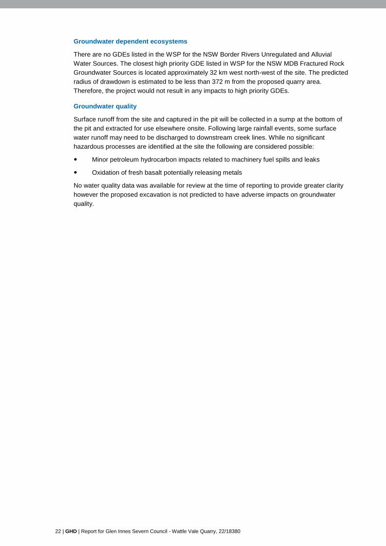
i i i i i MATHESON GLEN INNES G WYD IR HI G H W A Y MA LB O O N A R OAD R O S E H ILL RO A D Lot 133 DP753274 Lot 134 DP753274 Lot 113 DP753319 Lot 249 DP753319 Lot 87 DP753319 Lot 174 DP753319 Lot 1 DP728579 Lot 101 DP753319 Lot 175 DP753319 Lot 253 DP753319 BAC K P LAIN C R E E K PIN E CR E EK © Land and Property Information 2015 Figure 1-2 G:\22\18380\GIS\Maps\Deliverables\SouthernQuarryEIS\2218380_SQEIS002_SiteOverview_A.mxd 0 160 320 480 640 80 Metres LEGEND ©2016. Whilst every care has been taken to prepare this map, GHD, LPI, GISSC and Geoscience Australia make no representations or warranties about its accuracy, reliability, completeness or suitability for any particular purpose and cannot accept liability and responsibility of any kind (whether in contract, tort or otherwise) for any expenses, losses, damages and/or costs (including indirect or consequential damage) which are or may be incurred by any party as a result of the map being inaccurate, incomplete or unsuitable in any way and for any reason. Job Number Revision A 22-18380 Date 14 Nov 2016 o Glen Innes Severn Council Wattle Vale Quarry Environmental Impact Statement Site overview Data source: LPI: DCDB & DTDB, 2012,Aerial Imagery, 2016; Geoscience Australia: 250k Topographic Data Series 3, 2006; GISSC: Quarry data, 2016. Created by: fmackay Level 3, GHD Tower, 24 Honeysuckle Drive, Newcastle NSW 2300 T 61 2 4979 9999 F 61 2 4979 9988 E [email protected] W www.ghd.com.au Map Projection: Transverse Mercator Horizontal Datum: GDA 1994 Grid: GDA 1994 MGA Zone 56 DRAFT Paper Size A4 Project boundary Cadastre Watercourse Waterbody Disturbance area Site access Existing access i Residences Site Location S w a n B r o o k B e a r d yW a t er s W e l l i n g r o v e C re e k N EW E N G L A N D H I G H W A Y G W YDI R HIGHW A Y E M M AV I L L E R O A D MATHESON WELLINGROVE FURRACABAD GLEN INNES LOCALITY
Transcript of 2. Legislation and Policy - Glen Innes Severn

i
i
i
i
i
MATHESON
GLEN INNES
GWYDIR HIGHWAY
MALBOONA ROAD
R
O SE HILL ROAD
Lot 133DP753274
Lot 134DP753274
Lot 113DP753319
Lot 249DP753319
Lot 87DP753319
Lot 174DP753319
Lot 1DP728579
Lot 101DP753319
Lot 175DP753319
Lot 253DP753319
BACK
PLAINCRE EK
PINE CREEK
© Land and Property Information 2015
Figure 1-2G:\22\18380\GIS\Maps\Deliverables\SouthernQuarryEIS\2218380_SQEIS002_SiteOverview_A.mxd
0 160 320 480 64080
Metres
LEGEND
©2016. Whilst every care has been taken to prepare this map, GHD, LPI, GISSC and Geoscience Australia make no representations or warranties about its accuracy, reliability, completeness or suitability for any particular purpose and cannot accept liability and responsibility of any kind (whether in contract, tort or otherwise) for any expenses, losses, damages and/or costs (including indirect or consequential damage) which are or may be incurred by any party as a result of the map being inaccurate, incomplete or unsuitable inany way and for any reason.
Job NumberRevision A
22-18380
Date 14 Nov 2016oGlen Innes Severn CouncilWattle Vale QuarryEnvironmental Impact Statement
Site overview
Data source: LPI: DCDB & DTDB, 2012,Aerial Imagery, 2016; Geoscience Australia: 250k Topographic Data Series 3, 2006; GISSC: Quarry data, 2016. Created by: fmackay
Level 3, GHD Tower, 24 Honeysuckle Drive, Newcastle NSW 2300 T 61 2 4979 9999 F 61 2 4979 9988 E [email protected] W www.ghd.com.au
Map Projection: Transverse MercatorHorizontal Datum: GDA 1994Grid: GDA 1994 MGA Zone 56
DRAFTPaper Size A4
Project boundaryCadastreWatercourseWaterbody
Disturbance areaSite accessExisting access
i Residences
Site Location
Swan BrookBe
ardy W
ater s
WellingroveC ree k
NEW
ENG L
AND
HIGH
WAYGWYDIR HIGHWAY
EMMAVI LLE ROAD
MATHESON
WELLINGROVE
FURRACABAD
GLEN INNES
LOCALITY

4 | GHD | Report for Glen Innes Severn Council - Wattle Vale Quarry, 22/18380
2. Legislation and Policy
2.1 Legislation
2.1.1 Water Act 1912
The Water Act 1912 governs access, trading and allocation of licences associated with both
surface and underground water sources where a Water Sharing Plan (WSP) does not yet exist.
The elements to which the Water Act 1912 applies include extraction of water from a river,
extraction of water from underground sources, aquifer interference and capture of surface runoff
in dams.
A WSP for the NSW Murray Darling Basin (MDB) Fractured Rock Groundwater Sources
commenced in January 2012. Additionally, a WSP for the NSW Border Rivers Unregulated and
Alluvial Water Sources commenced in June 2012. The commencement of both these WSPs
render the governance of Water Act 1912 redundant and the act therefore no longer applies to
extraction or interception of groundwater at the site.
2.1.2 Water Management Act 2000
The Water Management Act 2000 (WM Act), administered by Department of Primary Industries
Water (WaterNSW), is intended to ensure that water resources are conserved and properly
managed for sustainable use to the benefit of both present and future generations. It provides a
formal means for the protection and enhancement of the environmental qualities of waterways
and their in-stream uses as well as to provide for protection of catchment conditions.
An amendment to the WM Act (Section 60I) came into effect on 1 March 2013. Under this
amendment it is an offence to take, remove or divert water from a water source or relocate
water from one part of an aquifer to another part of an aquifer in the course of carrying out a
mining activity without an access licence. Various activities are captured by the provisions of the
amendment including mining, mineral exploration and petroleum exploration.
The site is covered by the Water Sharing Plan (WSP) for the NSW Macquarie Darling Basin
(MDB) Fractured Rock Groundwater Sources which regulates the interception and extraction of
groundwater from the fractured rock aquifer. As defined by this WSP, the site is located within
the New England Fold Belt MDB Groundwater Source.
The WSP for the NSW Border Rivers Unregulated and Alluvial Water Sources regulates
extraction of alluvial groundwater within the site boundary. As defined by this WSP, the site is
located within the Glen Innes Water Source.
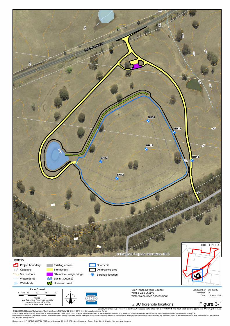
The water collected in the sediment basin, shown in Figure 3-1, is within the “maximum
harvestable right dam capacity” (MHRDC) for the site, so a Water Access Licence (WAL) is not
be required (refer to Section 4.1.2).
2.2 Policy
2.2.1 NSW Aquifer Interference Policy
The NSW Aquifer Interference Policy was finalised in September 2012 and clarifies the water
licencing and approval requirements for aquifer interference activities in NSW, including the
taking of water from an aquifer in the course of carrying out mining. Many aspects of this Policy
will be given legal effect in the future through an Aquifer Interference Regulation. Stage 1 of the
Aquifer Interference Regulation commenced 30 June 2011.
GHD | Report for Glen Innes Severn Council - Wattle Vale Quarry, 22/18380 | 5
This Policy outlines the water licensing requirements under the WM Act. A water licence is
required whether water is taken for consumptive use or whether it is taken incidentally by the
aquifer interference activity (such as groundwater filling a void) even where that water is not
being used consumptively as part of the activity’s operation. Under the WM Act, a water licence
gives its holder a share of the total entitlement available for extraction from the groundwater
source. The water access licence must hold sufficient share component and water allocation to
account for the take of water from the relevant water source at all times.
Sufficient access licences must be held to account for all water taken from a groundwater or
surface water source as a result of an aquifer interference activity, both for the life of the activity
and after the activity has ceased. Many mining operations continue to take water from
groundwater sources after operations have ceased (for example an open pit filling with
groundwater). This take of water continues until an aquifer system reaches equilibrium and must
be licensed.
The NSW Aquifer Interference Policy requires that potential impacts on groundwater sources,
including their users and groundwater dependent ecosystems (GDEs), be assessed against
minimal impact considerations, outlined in Table 1 of the Policy. If the predicted impacts are less
than the Level 1 minimal impact considerations, then these impacts will be considered as
acceptable. The minimal impact considerations relevant to the Project are outlined in
Section 4.2.3.
2.2.2 NSW State Groundwater Policy
The objective of the NSW State Groundwater Policy Framework Document (NSW Government
1997) is to manage the State’s groundwater resources so that they can sustain environmental,
social and economic uses for the people of NSW. NSW groundwater policy has three
component parts:
NSW Groundwater Quantity Protection Policy
NSW Groundwater Quality Protection Policy
NSW Groundwater Dependent Ecosystem Policy
NSW Groundwater Quantity Protection Policy
The principles of this policy include:
Maintain total groundwater use within the sustainable yield of the aquifer from which it is
withdrawn.
Groundwater extraction shall be managed to prevent unacceptable local impacts.
All groundwater extraction for water supply is to be licensed. Transfers of licensed entitlements
may be allowed depending on the physical constraints of the groundwater system.
NSW Groundwater Quality Protection Policy
The objective of this policy is the ecologically sustainable management of the State’s
groundwater resources so as to:
Slow, halt or reverse any degradation to groundwater resources.
Direct potentially polluting activities to the most appropriate local geological setting so as
to minimise the risk to groundwater.

6 | GHD | Report for Glen Innes Severn Council - Wattle Vale Quarry, 22/18380
Establish a methodology for reviewing new developments with respect to their potential
impact on water resources that will provide protection to the resource commensurate with
both the threat that the development poses and the value of the resource.
Establish triggers for the use of more advanced groundwater protection tools such as
groundwater vulnerability maps or groundwater protection zones.
NSW Groundwater Dependent Ecosystems Policy
This policy was designed to protect ecosystems which rely on groundwater for survival so that,
wherever possible, the ecological processes and biodiversity of these dependent ecosystems
are maintained or restored for the benefit of present and future generations.
GHD | Report for Glen Innes Severn Council - Wattle Vale Quarry, 22/18380 | 7
3. Existing Conditions
3.1 Topography
Elevations within the site vary from 1193 m AHD at the southern extent of the site to 1093 m
AHD at the northern extent of the site. The southern extent of the site is located on a ridgeline
with elevations generally decreasing to the north, east and west.
3.2 Geology
The 1:250,000 Grafton Geological Map indicates that the site is underlain by Tertiary basalt. To
the north, east and west of the site lie mapped areas of Quaternary alluvium associated with
creek lines.
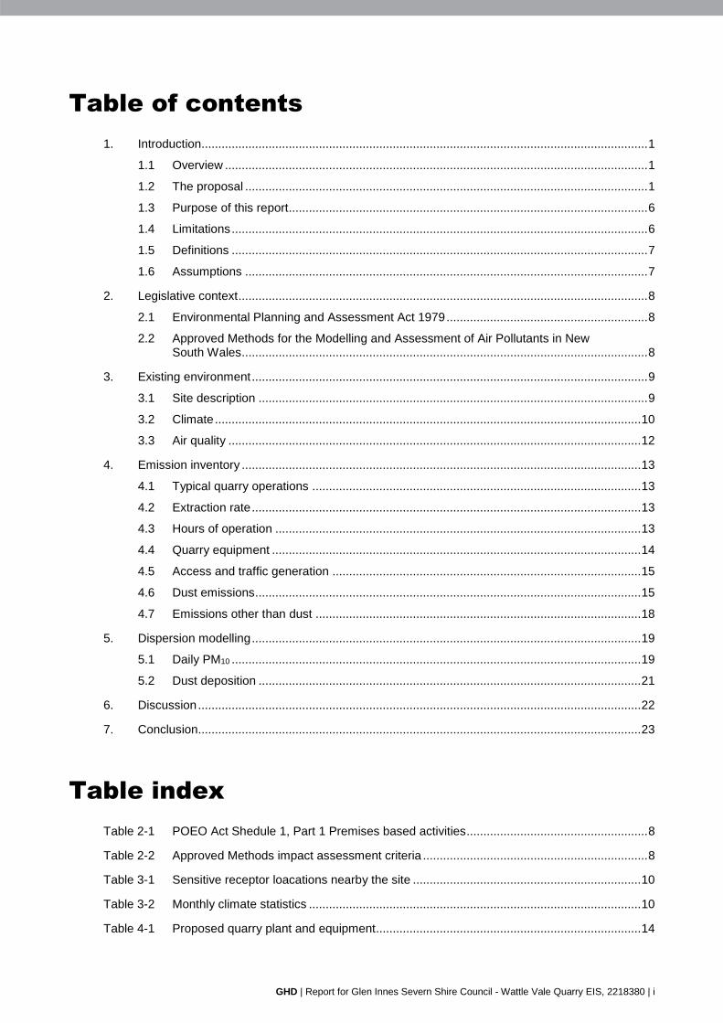
Geological investigations (SMEC, 2016) included drilling of a number of boreholes in the vicinity
of the proposed quarry area. The location of the proposed quarry area is shown in Figure 1-2.
Borehole records indicate the site is underlain by thin layer of silty clay that extends to up to
1.7 m deep in the vicinity of the proposed quarry area. This is in turn underlain by a thick layer
of basalt that extended to the base of the boreholes (18 to 25 m below ground level).
3.3 Hydrology
An intermittent unnamed tributary of Backplain Creek runs through the Project site. The tributary
only flows following rainfall events although there are a number of small farm dams located
throughout the Project site that hold water. Backplain Creek is a tributary of the Wellingrove
Creek flowing into the Severn River to the north.
The water quality of the unnamed tributary is unknown but due to the cleared, agricultural use of
the catchment it is expected to be contaminated with anthropogenic sources (e.g. sediments,
nutrients, manure).
3.4 Hydrogeology
3.4.1 Groundwater sources
Geological investigations undertaken by SMEC (2016) included drilling eight boreholes three of
which were located in the vicinity of the proposed pit. The three boreholes were drilled to depths
of 18 m to 25 m below ground level (approximately 4 m to 13 m below the base of the proposed
pit). Groundwater inflows were not noted during drilling however some water was noted in the
bores on completion of drilling and was attributed to drilling fluid residues (SMEC, 2016).
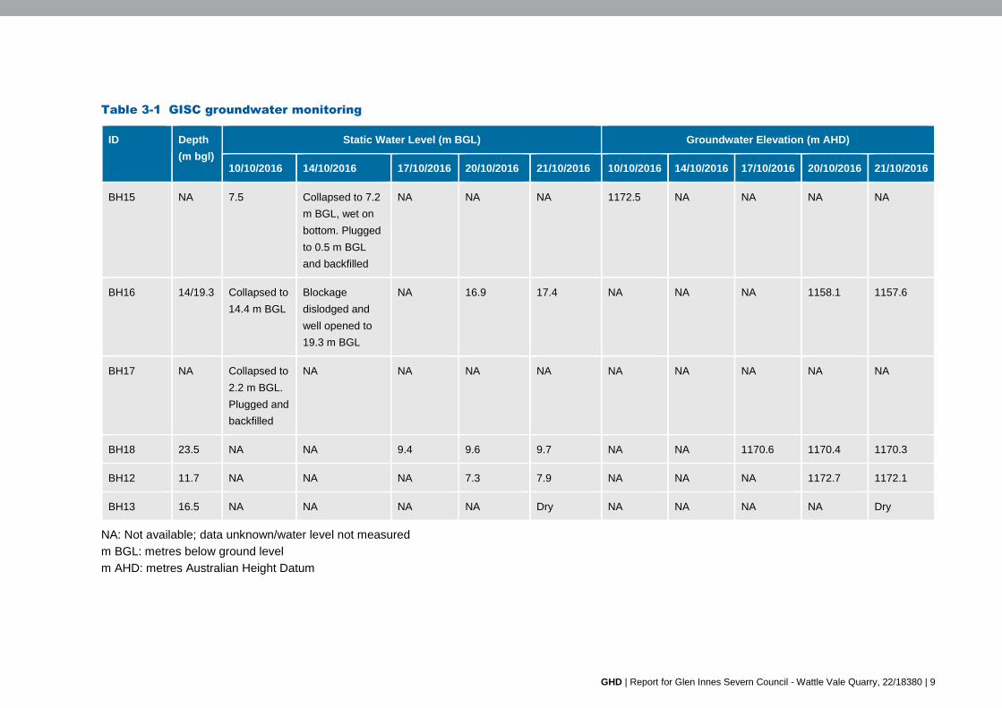
Groundwater investigations undertaken by GISC between 10 October 2016 and 21 October
2016 included drilling six boreholes in the footprint of the proposed quarry area (Figure 3-1).
Four of which intercepted groundwater at depths ranging 7.5 to 17.4 m BGL (1172.5-1157.6 m
AHD). It is noted however that this investigation proceeded after a period of above (double)
average rainfall1. The floor of the proposed quarry is 1170 m AHD, indicating that groundwater
may be intercepted by the quarry.
1 Recorded rainfall between June 2016 and September 2016 (the four months preceding groundwater monitoring by GISC) at
the Glen Innes Agricultural Weather Station [Bureau of Meteorology (BoM) station number 056013] was 427 mm. Based on a review of long term rainfall recorded at this station between 1910 and 2016, average rainfall from June to September was 212 mm and 95th percentile recorded rainfall from June to September was 361 mm.

8 | GHD | Report for Glen Innes Severn Council - Wattle Vale Quarry, 22/18380
As stated in Section 3.1, the proposed pit is located on a ridgeline. The GISC results indicate
perched groundwater is present along the ridgeline. Based on the GISC data, groundwater
levels within the proposed quarry area vary from approximately 1173 m AHD to approximately
1158 m AHD. Monitoring data indicates a groundwater flow direction from the top of the
ridgeline towards the north. The groundwater deposit would be directly recharged by rainfall and
discharge at lower elevations on the slopes and drainage lines to the north in the vicinity of the
proposed quarry area and the site. GHD considers it is likely that GISC observed groundwater
levels above typical levels due to above average rainfall. Following periods of lower rainfall,
groundwater levels in the vicinity of the quarry area would be lower. The groundwater
intercepted as part of groundwater investigations undertaken by GISC is considered to be an
isolated deposit of perched groundwater that is separate from the regional groundwater. The
regional groundwater table is not expected to be intercepted by the quarry.
The results of the registered bore search, outlined in Section 3.4.2, indicate that the yield from
the basalt aquifer is typically less than 2 L/s.
The mapped alluvial sediments are located outside the site boundary. The alluvial sediments lie
at lower elevations along creek lines. The proposed extraction will not extract groundwater from
the alluvial sediments.
GHD | Report for Glen Innes Severn Council - Wattle Vale Quarry, 22/18380 | 9
Table 3-1 GISC groundwater monitoring
ID Depth
(m bgl)
Static Water Level (m BGL) Groundwater Elevation (m AHD)
10/10/2016 14/10/2016 17/10/2016 20/10/2016 21/10/2016 10/10/2016 14/10/2016 17/10/2016 20/10/2016 21/10/2016
BH15 NA 7.5 Collapsed to 7.2
m BGL, wet on
bottom. Plugged
to 0.5 m BGL
and backfilled
NA NA NA 1172.5 NA NA NA NA
BH16 14/19.3 Collapsed to
14.4 m BGL
Blockage
dislodged and
well opened to
19.3 m BGL
NA 16.9 17.4 NA NA NA 1158.1 1157.6
BH17 NA Collapsed to
2.2 m BGL.
Plugged and
backfilled
NA NA NA NA NA NA NA NA NA
BH18 23.5 NA NA 9.4 9.6 9.7 NA NA 1170.6 1170.4 1170.3
BH12 11.7 NA NA NA 7.3 7.9 NA NA NA 1172.7 1172.1
BH13 16.5 NA NA NA NA Dry NA NA NA NA Dry
NA: Not available; data unknown/water level not measured
m BGL: metres below ground level
m AHD: metres Australian Height Datum
10 | GHD | Report for Glen Innes Severn Council - Wattle Vale Quarry, 22/18380
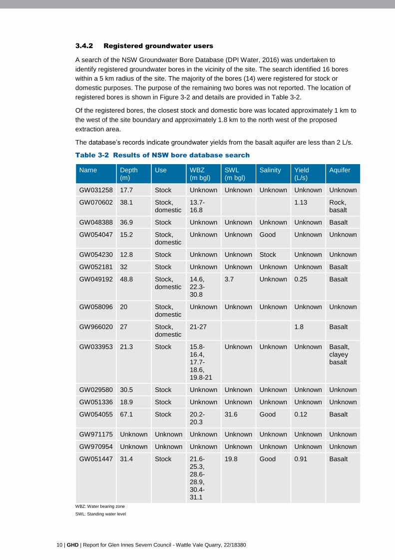
3.4.2 Registered groundwater users
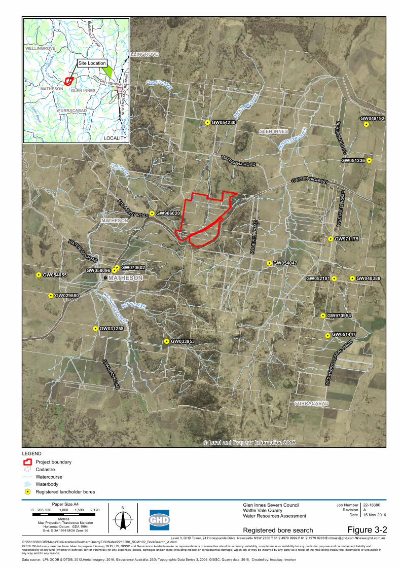
A search of the NSW Groundwater Bore Database (DPI Water, 2016) was undertaken to
identify registered groundwater bores in the vicinity of the site. The search identified 16 bores
within a 5 km radius of the site. The majority of the bores (14) were registered for stock or
domestic purposes. The purpose of the remaining two bores was not reported. The location of
registered bores is shown in Figure 3-2 and details are provided in Table 3-2.
Of the registered bores, the closest stock and domestic bore was located approximately 1 km to
the west of the site boundary and approximately 1.8 km to the north west of the proposed
extraction area.
The database’s records indicate groundwater yields from the basalt aquifer are less than 2 L/s.
Table 3-2 Results of NSW bore database search
Name Depth (m)
Use WBZ (m bgl)
SWL (m bgl)
Salinity Yield (L/s)
Aquifer
GW031258 17.7 Stock Unknown Unknown Unknown Unknown Unknown
GW070602 38.1 Stock, domestic
13.7-16.8
1.13 Rock, basalt
GW048388 36.9 Stock Unknown Unknown Unknown Unknown Basalt
GW054047 15.2 Stock, domestic
Unknown Unknown Good Unknown Unknown
GW054230 12.8 Stock Unknown Unknown Stock Unknown Unknown
GW052181 32 Stock Unknown Unknown Unknown Unknown Basalt
GW049192 48.8 Stock, domestic
14.6, 22.3-30.8
3.7 Unknown 0.25 Basalt
GW058096 20 Stock, domestic
Unknown Unknown Unknown Unknown Unknown
GW966020 27 Stock, domestic
21-27 1.8 Basalt
GW033953 21.3 Stock 15.8-16.4, 17.7-18.6, 19.8-21
Unknown Unknown Unknown Basalt, clayey basalt
GW029580 30.5 Stock Unknown Unknown Unknown Unknown Unknown
GW051336 18.9 Stock Unknown Unknown Unknown Unknown Unknown
GW054055 67.1 Stock 20.2-20.3
31.6 Good 0.12 Basalt
GW971175 Unknown Unknown Unknown Unknown Unknown Unknown Unknown
GW970954 Unknown Unknown Unknown Unknown Unknown Unknown Unknown
GW051447 31.4 Stock 21.6-25.3, 28.6-28.9, 30.4-31.1
19.8 Good 0.91 Basalt
WBZ: Water bearing zone
SWL: Standing water level

GHD | Report for Glen Innes Severn Council - Wattle Vale Quarry, 22/18380 | 11
3.4.3 Groundwater dependent ecosystems
The closest high priority GDE listed in WSP for the NSW MDB Fractured Rock Groundwater
Sources is located approximately 32 km west north-west of the site. There are no high priority
GDEs listed in the WSP for the NSW Border Rivers Unregulated and Alluvial Water Sources.
@A
@A
@A
@A
@A
@A
GWYDIR HIGHWAY
1180
1175
1165
1160
11551150
1145
1140
1185
1155
115511
55
1140
1135
BH12
BH13
BH15
BH16
BH17
BH18
© Land and Property Information 2015
Figure 3-1G:\22\18380\GIS\Maps\Deliverables\SouthernQuarryEIS\Water\2218380_SQW103_BoreholeLocations_A.mxd
0 25 50 75 10012.5
Metres
LEGEND
©2016. Whilst every care has been taken to prepare this map, GHD, GISSC and LPI make no representations or warranties about its accuracy, reliability, completeness or suitability for any particular purpose and cannot accept liability and responsibility of any kind (whether in contract, tort or otherwise) for any expenses, losses, damages and/or costs (including indirect or consequential damage) which are or may be incurred by any party as a result of the map being inaccurate, incomplete or unsuitable inany way and for any reason.
Job NumberRevision A
22-18380
Date 15 Nov 2016oGlen Innes Severn CouncilWattle Vale QuarryWater Resources Assessment
GISC borehole locations
Data source: LPI: DCDB & DTDB, 2012,Aerial Imagery, 2016; GISSC: Aerial Imagery / Quarry Data, 2016. Created by: fmackay, tmorton
Level 3, GHD Tower, 24 Honeysuckle Drive, Newcastle NSW 2300 T 61 2 4979 9999 F 61 2 4979 9988 E [email protected] W www.ghd.com.au
Map Projection: Transverse MercatorHorizontal Datum: GDA 1994Grid: GDA 1994 MGA Zone 56
Paper Size A4
Project boundaryCadastre5m contoursWatercourseWaterbody
Existing accessSite accessSite office / weigh bridgeBasin (3000m2)Diversion bund
Quarry pitDisturbance area
@A Borehole location
SHEET INDEX
!.
!.
!.
!.
!.
!.
!.
!.
!.
!.
!.
!.
!.
!.
!.
!.
MATHESON
WELLINGROVE
FURRACABAD
GLEN INNES
I LPARRANROAD
WATERLOO ROADRO
SEHI
LLRO
AD
PITLOCH RY ROAD
GWYDIR HIGHWAY
BEAUFORT ROAD
MALBOONA ROAD
WEST
FIELD
ROA
D
WEST
FURR
ACAB
AD ROAD
MATHESON
WELLINGROVE CRE EK
BOYDS CREEK
BACK
PLAIN CREEK
PIN ECREEK
PUNCHSCREEK
REDDESTONE CRE EK
GW031258
GW070602GW048388
GW054047
GW054230
GW052181
GW049192
GW058096
GW966020
GW033953
GW029580
GW051336
GW054055
GW971175
GW970954
GW051447
© Land and Property Information 2015
Figure 3-2G:\22\18380\GIS\Maps\Deliverables\SouthernQuarryEIS\Water\2218380_SQW102_BoreSearch_A.mxd
0 530 1,060 1,590 2,120265
Metres
LEGEND
©2016. Whilst every care has been taken to prepare this map, GHD, LPI, GISSC and Geoscience Australia make no representations or warranties about its accuracy, reliability, completeness or suitability for any particular purpose and cannot accept liability and responsibility of any kind (whether in contract, tort or otherwise) for any expenses, losses, damages and/or costs (including indirect or consequential damage) which are or may be incurred by any party as a result of the map being inaccurate, incomplete or unsuitable inany way and for any reason.
Job NumberRevision A
22-18380
Date 15 Nov 2016oGlen Innes Severn CouncilWattle Vale QuarryWater Resources Assessment
Registered bore search
Data source: LPI: DCDB & DTDB, 2012,Aerial Imagery, 2016; Geoscience Australia: 250k Topographic Data Series 3, 2006; GISSC: Quarry data, 2016. Created by: fmackay, tmorton
Level 3, GHD Tower, 24 Honeysuckle Drive, Newcastle NSW 2300 T 61 2 4979 9999 F 61 2 4979 9988 E [email protected] W www.ghd.com.au
Map Projection: Transverse MercatorHorizontal Datum: GDA 1994Grid: GDA 1994 MGA Zone 56
DRAFTPaper Size A4
Project boundaryCadastreWatercourseWaterbody
!. Registered landholder bores
Site Location
Swan BrookBe
ardy W
ater s
WellingroveC ree k
NEW
ENG L
AND
HIGH
WAYGWYDIR HIGHWAY
EMMAVI LLE ROAD
MATHESON
WELLINGROVE
FURRACABAD
GLEN INNES
LOCALITY
14 | GHD | Report for Glen Innes Severn Council - Wattle Vale Quarry, 22/18380
4. Impact assessment
4.1 Surface water
Potential risks at the site with relation to surface water were identified based on the nature of the
works and the surrounding receiving environment. The key risks identified were:
Insufficient water available to meet site demands
Discharge of sediment-laden water
Modification of downstream flow volumes and regimes
Based on these potential risks it was determined that the key components of the assessment
would be the development of a water balance and assessment of erosion and sediment control.
The methodology for these key elements of the assessment is detailed in the sub-sections
below.
It was noted that due to the nature of the activities onsite, no significant water quality risks are
expected other than in relation to erosion and sediment control. Management of potential
hydrocarbon spills was considered as a component of the erosion and sediment control
assessment.
It was also noted that the location of the proposed works is not adjacent to any major waterway,
is located near the top of the catchment and is therefore not considered to have a significant risk
of flooding from nearby waterways.
4.1.1 Water Balance
A daily time-step water balance model was simulated. This quantified the expected water
transfers in the system on a daily basis. The model allowed for estimation of likely volumes of:
Runoff entering the pit
Groundwater inflow (2.92ML/year)
Infiltration out the base of the pit
Collection of pit runoff in a 4,000 m3 basin
Evaporation from the basin
Dust suppression demand (if required)
Topping up of the pit with external water to satisfy demands (if required)
Rainfall data from 1974 was simulated to allow a prediction of the range of potential future
climatic conditions. The daily transfers were simulated based on input parameters and
operational rules such as catchment area (i.e. 6 hectares) and trigger levels (i.e. 10%) below
which top up with external water would occur.
Runoff was estimated using an initial loss and runoff coefficient model based on available
literature and experience with previous sites.
Site demands were estimated based on available plant information. Dust suppression demand
was estimated based on the assumption that the difference between evaporation and rainfall is
applied over 500 metres length of road associated with the proposal.
The general structure of the water balance is indicated on the water cycle schematic Figure 4-1.

GHD | Report for Glen Innes Severn Council - Wattle Vale Quarry, 22/18380 | 15
Figure 4-1 Water balance schematic
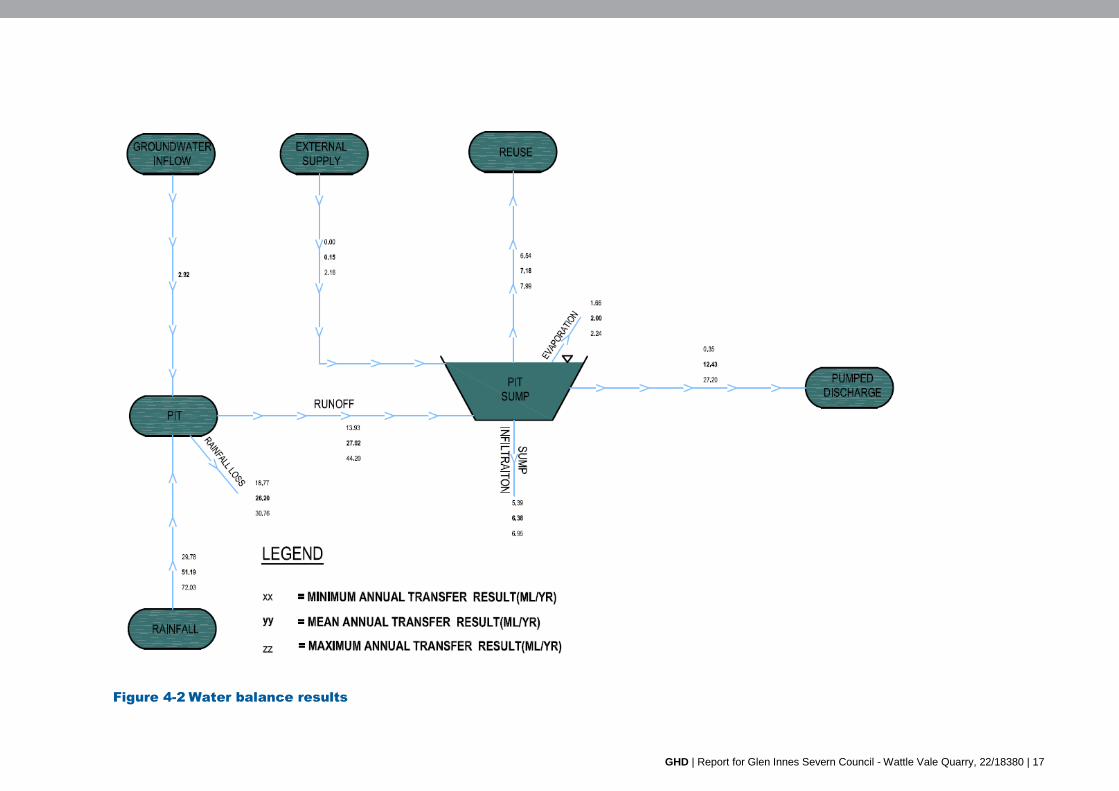
Once the water balance was simulated, results were exported and plotted on the water cycle
schematic in terms of minimum, mean and maximum annual transfer rates, allowing
representation of a range of potential annual transfers for varying climate conditions.
The results of the water balance are indicated on Figure 4-2 with a summary of key results
below:
Based on the size of the basin, the quarry would have insufficient runoff volumes during an
average and dry year to supply the operational demands of the quarry. The volume of
external water required is estimated to be 0.15ML/year in an average year and 2.18ML/year
in a dry year.
The site would discharge water during all scenarios modelled, although this would be less
than without the quarry.
It is likely that the external water use will be even less than the model indicates because water
resources would be used more conservatively when the supply is limited. The model is also
based on a catchment area of six hectares, so if water supply is limited, diversion drains could
be used to increase the catchment area. Likewise, the size of the basin could be increased to
hold more runoff. As a last resort, the external water would be sourced from other dams on site
or from the existing Glen Innes quarry. It is therefore considered the quarry would have
sufficient water supply to operate.
Due to the quarry being located in the upper catchment and the lack of sensitive environments
downstream, the reduction in the volume of water is not expected to result in a significant
volumetric impact on downstream waterways in comparison with natural flow regimes. This is
supported by the maximum harvestable rights, as discussed in Section 4.1.2.

16 | GHD | Report for Glen Innes Severn Council - Wattle Vale Quarry, 22/18380
4.1.2 Maximum harvestable rights
The maximum harvestable rights for the Project site was determined using the WaterNSW
maximum harvestable rights dam capacity online calculator. This indicated the Project site has a
maximum harvestable right of 16 ML. The Project site has a number of small dams, as shown
on Figure 1-2, but these, combined with the proposed 3 ML basin are less than 16 ML. A water
access license is therefore not required.
GHD | Report for Glen Innes Severn Council - Wattle Vale Quarry, 22/18380 | 17
Figure 4-2 Water balance results
GHD | Report for Glen Innes Severn Council - Wattle Vale Quarry, 22/18380
4.1.3 Erosion and Sediment Control
The erosion and sediment control assessment was conducted in accordance with Managing
Urban Stormwater: Soils and Construction Volume 1 and Volume 2E (Mines and Quarries)
(Landcom, 2005). In particular, sediment generation estimates were calculated in accordance
with the Revised Universal Soil Loss Equation (RUSLE) using the predicted rainfall erosivity,
soil type and management practices for the site.
The RUSLE indicated the rate of sediment generation from the quarry and access roads will be
less than 150 cubic metres per year, meaning that a sediment basin is not required in
accordance with Landcom (2005). However, a 1.2 ML sediment basin has been calculated, in
accordance with Landcom (2005), to collect water from the quarry pit. This would collect runoff
up to the design rainfall event of 38 mm.
Water quality runoff from the remainder of the site would be managed via controls in
accordance with Landcom (2005).
4.2 Groundwater
Based on reported groundwater elevations (discussed in Section 3.4) and a pit floor elevation of
1170 m AHD, it is possible that groundwater will be intercepted during excavation of the
proposed quarry area.
Preliminary groundwater inflow estimates have been calculated using the analytical equations
and approach outlined in Marinelli and Niccoli (2000). The equations presented by Marinelli and
Niccoli (2000) provide a simple means of estimating steady state or long term average inflows to
a pit. The modelling methodology is outlined in Appendix A.
4.2.1 Input data
Data sources and assumptions used to derive input values for each of the parameters required
for the equations developed by Marinelli and Niccoli (2000) are outlined below.
Initial (pre-construction) saturated thickness (ho)
The initial (pre-construction) saturated thickness was taken as the maximum level recorded
(1172.7 m AHD) and is considered to be highly conservative.
Saturated thickness at pit wall (hp)
The excavations are assumed to be fully dewatered throughout the period of mining. Therefore
the saturated thickness at pit wall (hp) was put to zero.
Distributed recharge flux (W)
The WSP for the for the NSW MDB Fractured Rock Groundwater Sources assumes a recharge
rate of four per cent of annual average rainfall in the New England Fold Belt MDB Groundwater
Source (DPI Water, 2012a). The net recharge rate of four per cent of long term average rainfall
recorded at the Glen Innes Agricultural Weather Station ( BoM station number 056013) was
adopted for the assessment. This station was adopted based on its proximity to the site and the
length and the quality of the data record . Long term average annual rainfall over the period
1910 to 2015 was 843.1 mm/year. A net recharge rate of four per cent gives an estimated long
term average recharge rate of 33.7 mm/year or 9.24 × 10⁻⁵ m/day.
GHD | Report for Glen Innes Severn Council - Wattle Vale Quarry, 22/18380 | 19
Hydraulic conductivity Zones 1 and 2 (Kh1, Kh2 and Kv2)
Boreholes indicate that the site is underlined by basalt. Hydraulic conductivity values for the
fractured rock aquifer have therefore been assumed equal to generally accepted values for
volcanic rock (0.05 m/day2). Based on the Horizontal hydraulic conductivity has been assumed
10 times greater than vertical hydraulic conductivity.
Effective radius (rp)
Effective pit radius for the quarry was determined based on the proposed area of the pit. The
area of each pit was input into the formulae for the area of a circle (ie A = πrp2) in order to
calculate the effective radius. The calculated radius for the southern pit was 136 metres.
Radius of influence (ro)
The radius of influence (ro) of groundwater abstraction is influenced by the hydraulic conductivity
of the strata, the rate of recharge. The radius of influence is therefore affected by flow
boundaries be they active (such as throughflow or outflow from surface waters) or inactive (no
flow boundaries such as geological boundaries). In the absence of site specific test data, the
area of influence cannot be accurately estimated.
The radius of influence has been estimated from the analytical equations.
4.2.2 Predicted groundwater inflow and radius of influence
Groundwater inflows have been estimated for the proposed pit using the analytical equations
developed by Marinelli and Niccoli (2000) as described in Appendix A. Groundwater inflows
have been estimated for the following six scenarios:
Scenario 1 - Base case, whereby the best estimate for hydraulic conductivity, mean
recharge and initial saturated thickness (height of groundwater level above pit floor) were
used in the assessment.
Scenario 2 - Recharge sensitivity where recharge was reduced to 2 per cent of the long
term average rainfall.
Scenario 3 – Conductivity sensitivity where K was doubled relative to Scenario 1.
Scenario 4 - Conductivity sensitivity where K was increased to 20 times that of
Scenario 1.
Scenario 5 - Conductivity sensitivity where K was decreased by 5 times relative to
Scenario 1.
Scenario 6 – Saturated thickness sensitivity where h was reduced by 2 metres relative to
scenario 1. As discussed in Section 3.4, groundwater levels were monitored following a
period of above average rainfall and Scenario 6 is intended to model a period of average
or below average rainfall.
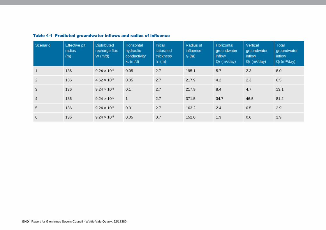
The results presented in Table 4-1 indicate that groundwater inflows could be between
1.9 m3/day and 81.2 m3/day with the most likely estimate considered to be 8.0 m3/day (based on
scenario 1). Note that the groundwater inflow rates are average long term rates and no
groundwater inflow will occur until the quarry pit intercepts the water table.
The radius of influence on groundwater from the proposed quarry is estimated to be between
152 m and 372 m. The most likely estimate for radius of influence is considered to be 195 m
(based on scenario 1).
2 Hydraulic conductivity values for volcanic rock presented in Kruseman and de Ridder (1994) range almost zero to 1 × 10³
metres per day.
GHD | Report for Glen Innes Severn Council - Wattle Vale Quarry, 22/18380
Table 4-1 Predicted groundwater inflows and radius of influence
Scenario Effective pit
radius
(m)
Distributed
recharge flux
W (m/d)
Horizontal
hydraulic
conductivity
kh (m/d)
Initial
saturated
thickness
ho (m)
Radius of
influence
ro (m)
Horizontal
groundwater
inflow
Q1 (m3/day)
Vertical
groundwater
inflow
Q2 (m3/day)
Total
groundwater
inflow
Qt (m3/day)
1 136 9.24 × 10⁻⁵ 0.05 2.7 195.1 5.7 2.3 8.0
2 136 4.62 × 10⁻⁵ 0.05 2.7 217.9 4.2 2.3 6.5
3 136 9.24 × 10⁻⁵ 0.1 2.7 217.9 8.4 4.7 13.1
4 136 9.24 × 10⁻⁵ 1 2.7 371.5 34.7 46.5 81.2
5 136 9.24 × 10⁻⁵ 0.01 2.7 163.2 2.4 0.5 2.9
6 136 9.24 × 10⁻⁵ 0.05 0.7 152.0 1.3 0.6 1.9

GHD | Report for Glen Innes Severn Council - Wattle Vale Quarry, 22/18380
4.2.3 Aquifer interference policy
Assessment criteria
The NSW Aquifer Interference Policy requires that potential impacts on groundwater sources,
including their users and GDEs, be assessed against minimal impact considerations, outlined in
Table 1 of the Policy. If the predicted impacts are less than the Level 1 minimal impact
considerations, then these impacts will be considered as acceptable. Based on the reported
yield of registered bores in the vicinity of the site, discussed in Section 3.4.2, the Level 1
minimal impact considerations for Less Productive Fractured Groundwater Sources have been
adopted for this groundwater impact assessment and are as follows:
Water table: less than or equal to 10% cumulative variation in the water table, allowing for
typical climatic ‘post-water sharing plan’ variations, at a distance of 40 m from any high
priority groundwater dependent ecosystem or high priority culturally significant site listed
in the schedule of the relevant WSP. A maximum of a 2 m water table decline
cumulatively at any water supply work.
– If more than 10% cumulative variation in the water table, allowing for typical climatic
“post-water sharing plan” variations, 40 m from any high priority groundwater
dependent ecosystem; or high priority culturally significant site; listed in the schedule
of the relevant water sharing plan then appropriate studies (including the
hydrogeology, ecological condition and cultural function) will need to demonstrate to
the Minister’s satisfaction that the variation will not prevent the long-term viability of
the dependent ecosystem or significant site. If more than 2 m decline cumulatively at
any water supply work then make good provisions should apply.
Water pressure: a cumulative pressure head decline of not more than a 2 m decline at
any water supply work.
– If the predicted pressure head decline is greater than the requirement above, then
appropriate studies are required to demonstrate to the Minister’s satisfaction that the
decline will not prevent the long-term viability of the affected water supply works
unless make good provisions apply.
Water quality: any change in the groundwater quality should not lower the beneficial use
category of the groundwater source beyond 40 m from the activity.
– If the predicted change in water quality is greater than the requirement above, then
appropriate studies will need to demonstrate to the Minister’s satisfaction that the
change in groundwater quality will not prevent the long term viability of groundwater
ecosystems, significant sites or affected water supply works.
Impact assessment
Water supply works
The closest landholder bore is located approximately 1.8 km from the proposed extraction area.
The predicted radius of drawdown is estimated to be less than 372 m from the proposed quarry
area. Therefore, the proposed quarry construction and operation is not predicted to impact any
water supply works.
High priority culturally significant site
There are no high priority culturally significant sites listed in the WSP for the NSW Border Rivers
Unregulated and Alluvial Water Sources or the WSP for the NSW MDB Fractured Rock
Groundwater Sources. Therefore, the project would not result in impacts to any culturally
significant sites.
22 | GHD | Report for Glen Innes Severn Council - Wattle Vale Quarry, 22/18380
Groundwater dependent ecosystems
There are no GDEs listed in the WSP for the NSW Border Rivers Unregulated and Alluvial
Water Sources. The closest high priority GDE listed in WSP for the NSW MDB Fractured Rock
Groundwater Sources is located approximately 32 km west north-west of the site. The predicted
radius of drawdown is estimated to be less than 372 m from the proposed quarry area.
Therefore, the project would not result in any impacts to high priority GDEs.
Groundwater quality
Surface runoff from the site and captured in the pit will be collected in a sump at the bottom of
the pit and extracted for use elsewhere onsite. Following large rainfall events, some surface
water runoff may need to be discharged to downstream creek lines. While no significant
hazardous processes are identified at the site the following are considered possible:
Minor petroleum hydrocarbon impacts related to machinery fuel spills and leaks
Oxidation of fresh basalt potentially releasing metals
No water quality data was available for review at the time of reporting to provide greater clarity
however the proposed excavation is not predicted to have adverse impacts on groundwater
quality.
GHD | Report for Glen Innes Severn Council - Wattle Vale Quarry, 22/18380 | 23
5. Mitigation measures
5.1 General
An environmental protection licence (EPL) will be obtained for the quarry. All relevant
conditions relating to soil and water management will be implemented as required by the
EPL.
An Environmental Management Plan will be compiled for the works which will contain a
Soil and Erosion Management Plan. Training will be provided to all quarry staff including
relevant sub-contractors on erosion and sediment control practices and the requirements
of the Plans through inductions, toolboxes and targeted training.
If groundwater is intercepted, WaterNSW is to be contacted and a groundwater water
access licence (WAL) obtained. Based on the most likely estimate for groundwater inflow
of 8.0 m3/day, an annual allocation of 2.9 ML/year will need to be licenced under the WM
Act.
5.2 Water supply
A 4,000 m3 basin will be required for water supply. Where available, and of appropriate
quality, the quarry operation will use recycled runoff for quarry activities.
5.3 Erosion and sedimentation control
Implement erosion and sediment controls in accordance with Managing Urban
Stormwater Soils and Construction – Volume 2e Mines and quarries (Landcom, 2004)
Increase the size of the water supply basin by 1.2 ML to act as a sediment basin.
5.4 Material storage and management
Designated impervious bunded facilities will be provided for cleaning and/or maintenance
of vehicles, plant or equipment. These facilities will be located at least 20 metres away
from natural and built drainage lines.
All chemicals and fuels associated with the quarry will be stored in roofed and bunded
areas. Spill kits will be provided at all chemical storage facilities/compound sites.
Where refuelling is required onsite, the following management practices will be
implemented:
– Refuelling will be undertaken on level ground and at least 20 metres from drainage
lines, waterways and/or environmentally sensitive areas
– Refuelling will be undertaken within the designated refuelling areas with appropriate
bunding and/or absorbent material
– Refuelling will be via a designated refuelling truck
– Will be attended at all times
– Spill kits will be readily available and all personnel trained in their use. A spill kit will be
kept on the refuelling truck at all times
– Hand tools will be refuelled within lined trays of site vehicles wherever possible
– An emergency spill kit (such as oil absorbent material) will be available onsite at all
times to contain and clean up any accidental hydrocarbon spill
– Any contaminated material will be disposed at an appropriately licensed facility and
used spill kit materials replaced

24 | GHD | Report for Glen Innes Severn Council - Wattle Vale Quarry, 22/18380
Regular checks of vehicles working at the quarry will be conducted to ensure that no oils
or fuels are leaking.
5.5 Monitoring
The basin is to be monitored to confirm it complies with the EPL and Managing Urban
Stormwater Soils and Construction – Volume 2e Mines and quarries (Landcom, 2004)
requirements.
To confirm groundwater levels, a series of groundwater wells should be established
around the quarry pit.
A routine monitoring program should be established to include regular inspections and
maintenance of erosion controls, especially after rain.

GHD | Report for Glen Innes Severn Council - Wattle Vale Quarry, 22/18380 | 25
Appendices
26 | GHD | Report for Glen Innes Severn Council - Wattle Vale Quarry, 22/18380
Appendix A – Groundwater modelling methodology
GHD | Report for Glen Innes Severn Council - Wattle Vale Quarry, 22/18380 | 27
Preliminary groundwater inflow estimates have been calculated using the analytical equations
and approach outlined in Marinelli and Niccoli (2000). The equations presented by Marinelli and
Niccoli (2000) provide a simple means of estimating steady state or long term average inflows to
a pit.
The solutions presented consider:
The effect of decreased saturated thickness near the pit walls.
Distributed recharge to the water table.
Upward flow through the pit bottom.
As discussed in Section 3.4, the groundwater intercepted by the quarry is considered to be
representative of an isolated perched aquifer. The calculated groundwater inflow rate has been
calculated for a groundwater table that is representative of a regional aquifer (groundwater flow
is consistent over time) as this is a more conservative estimate of potential groundwater inflow.
Separate calculations are undertaken to estimate inflow via pit walls (Q1, Zone 1) and the base
of the pit (Q2, Zone 2) (refer to Figure A-1). Assumptions made in the flow calculation for Zone 1
include:
Pit walls are approximated as a circular cylinder;
Groundwater flow is horizontal (Dupuit - Forchheimer approximation is valid).
The static (pre-mining) water table is horizontal.
Groundwater flow towards the pit is axially symmetric.
Uniform distributed recharge occurs across the site as a result of surface infiltration.
All recharge in the radius of influence is captured by the pit.
The aquifer extends below the base of the pit.
Assumptions made in the flow calculation to Zone 2 include:
Hydraulic head is initially uniform throughout the zone. Initial head is equal to the
elevation of the initial water table in Zone 1.
The disk sink has a constant hydraulic head equal to the elevation of the pit lake water
surface. If the pit is completely dewatered the disk sink is equal to the elevation of the pit
bottom.
Flow to the disk sink is three dimensional and axially symmetric.
Materials within Zone 2 are anisotropic and the principal co-ordinate directions for
hydraulic conductivity are horizontal and vertical.

28 | GHD | Report for Glen Innes Severn Council - Wattle Vale Quarry, 22/18380
Figure A-1 Pit inflow hydraulic model (Marinelli and Niccoli 2000)
Relevant equations presented in Marinelli and Niccoli (2000) are as follows:
Where:
ho = initial (pre-mining (cutting)) saturated thickness (metres above base of pit)
hp = saturated thickness at pit wall (metres above base of pit)
W = distributed recharge flux (metres per day)
Kh1 = Horizontal hydraulic conductivity Zone 1 (metres per day)
Kh2 = Horizontal hydraulic conductivity Zone 2 (metres per day)
Kv2 = Vertical hydraulic conductivity Zone 2 (metres per day)
rp = Effective pit radius (metres)
ro = Radius of influence (metres)
d = Depth of the pit lake (metres)
2
2
2
2
2
2
22
1
22
2
1
2
4
2ln
v
h
o
h
p
po
po
p
o
o
h
po
K
Km
dhm
KrQ
rrWQ
rr
r
rr
K
Whh
GHD
Level 3 GHD Tower 24 Honeysuckle Drive Newcastle NSW 2300 PO Box 5403 Hunter Region Mail Centre NSW 2310 T: (02) 4979 9999 F: (02) 4979 9988 E: [email protected]
© GHD 2016
This document is and shall remain the property of GHD. The document may only be used for the purpose for which it was commissioned and in accordance with the Terms of Engagement for the commission. Unauthorised use of this document in any form whatsoever is prohibited.
\\ghdnet\ghd\AU\Newcastle\Projects\22\18380\WP\113573.docx
Document Status
Revision Author Reviewer Approved for Issue
Name Signature Name Signature Date
0 I Gilmore/R Towner
A Barron M Walker 10/10/2016
1 I Gilmore/R Towner
A Barron J. McPherson 23/12/2016
rfearle
Typewritten text
A Barron

www.ghd.com

Appendix G Air Quality Impact Assessment

Glen Innes Severn Shire Council
Wattle Vale Quarry EIS
Air Quality Assessment December 2016
GHD | Report for Glen Innes Severn Shire Council - Wattle Vale Quarry EIS, 2218380 | i
Table of contents
1. Introduction..................................................................................................................................... 1
1.1 Overview .............................................................................................................................. 1
1.2 The proposal ........................................................................................................................ 1
1.3 Purpose of this report........................................................................................................... 6
1.4 Limitations ............................................................................................................................ 6
1.5 Definitions ............................................................................................................................ 7
1.6 Assumptions ........................................................................................................................ 7
2. Legislative context .......................................................................................................................... 8
2.1 Environmental Planning and Assessment Act 1979 ............................................................ 8
2.2 Approved Methods for the Modelling and Assessment of Air Pollutants in New South Wales ......................................................................................................................... 8
3. Existing environment ...................................................................................................................... 9
3.1 Site description .................................................................................................................... 9
3.2 Climate ............................................................................................................................... 10
3.3 Air quality ........................................................................................................................... 12
4. Emission inventory ....................................................................................................................... 13
4.1 Typical quarry operations .................................................................................................. 13
4.2 Extraction rate .................................................................................................................... 13
4.3 Hours of operation ............................................................................................................. 13
4.4 Quarry equipment .............................................................................................................. 14
4.5 Access and traffic generation ............................................................................................ 15
4.6 Dust emissions ................................................................................................................... 15
4.7 Emissions other than dust ................................................................................................. 18
5. Dispersion modelling .................................................................................................................... 19
5.1 Daily PM10 .......................................................................................................................... 19
5.2 Dust deposition .................................................................................................................. 21
6. Discussion .................................................................................................................................... 22
7. Conclusion.................................................................................................................................... 23
Table index
Table 2-1 POEO Act Shedule 1, Part 1 Premises based activities ...................................................... 8
Table 2-2 Approved Methods impact assessment criteria ................................................................... 8
Table 3-1 Sensitive receptor loacations nearby the site .................................................................... 10
Table 3-2 Monthly climate statistics ................................................................................................... 10
Table 4-1 Proposed quarry plant and equipment ............................................................................... 14