
2 Journal of 2 Regular paper Electrical Electrical...
12
* Corresponding author: Ricardo Martins e-mail: [email protected] 1 Center for Integrated Manufacturing and Technology CIMATEC SENAI – zip code 41650-010, Salvador, BA, Brazil 2 FEEVALE University – P.O. Box 3004, zip code 93525-075, Novo Hamburgo, RS, Brazil 3Metal Forming Laboratory LdTM – Federal University of Rio Grande do Sul – P.O. Box 15.021, zip code 15021 – Campus do Vale, CEP 91501-970, Porto Alegre, RS, Brazil W. H. D. Luna, e-mail: [email protected]; S. D. Bittencourt, e-mail: [email protected]; M. M. Dias, e-mail: [email protected]; P. M. Aquim, e-mail: [email protected]; R. M. Martins, e-mail: [email protected]; L. Schaeffer, e-mail: [email protected] Copyright © JES 2017 on-line : journal/esrgroups.org/je W. H. D. Luna 1 , S. D. Bittencourt 3 , M. M. Dias 2 , P. M. Aquim 2 , R. M. Martins 2 , L. Schaeffer 3 J. Electrical Systems 13-4 (2017): 767-778 Regular paper PROCESSING OF SOFT MAGNETIC MATERIALS BY POWDER METALLURGY AND ANALYSIS OF THEIR PERFORMANCE IN ELECTRICAL MACHINES JES Journal of Journal of Journal of Journal of Electrical Electrical Electrical Electrical Systems Systems Systems Systems This article presents the use of finite elements to analyze the yield of electric machines based on the use of different soft magnetic materials for the rotor and the stator, in order to verify the performance in electric machine using powder metallurgy. Traditionally, the cores of electric machines are built from rolled steel plates, thus the cores developed in this work are obtained from an alternative process known as powder metallurgy, where powders of soft magnetic materials are compacted and sintered. The properties of interest were analyzed (magnetic, electric and mechanical properties) and they were introduced into the software database. The topology of the rotor used was 400 W three-phase synchronous motor manufactured by WEG Motors. The results show the feasibility to replace the metal sheets of the electric machines by solid blocks obtained by powder metallurgy process with only 0.37% yield losses. In addition, the powder metallurgical process reduces the use of raw materials and energy consumption per kg of raw material processed. Keywords: Powder metallurgy; electric machines; magnetic materials; simulation; magnetization; torque Article history: Received 31 August 2016, Accepted 10 November 2017 1. INTRODUCTION Rotating electrical machines can function as a motor or generator and consist of two basic parts, namely the stator and rotor cores. These cores, with rare exceptions, are made from sheet metal (low carbon steel sheets) less than 1 mm thick that are stacked together. Some better performing machines, such as generators, are made from silicon steel sheets of approximately 3% silicon. The entire manufacturing process for these cores basically consists of lamination, stamping, electrical insulation between adjacent sheets, stacking and setting. As to the low carbon steel sheets, the isolation process consists of thermal treatment, where the sheet packages are placed in ovens for some time. Besides relieving stresses, it occurs an oxidation of the sheet surface and, consequently, the formation of an isolating layer of iron oxide between the adjacent sheets. Some types of silicon-steel sheets are supplied by the manufacturers with an oxide based coating on one of the surfaces [1, 2].
Transcript of 2 Journal of 2 Regular paper Electrical Electrical...
* Corresponding author: Ricardo Martins e-mail: [email protected]
1 Center for Integrated Manufacturing and Technology CIMATEC SENAI – zip code 41650-010, Salvador, BA,
Brazil
2 FEEVALE University – P.O. Box 3004, zip code 93525-075, Novo Hamburgo, RS, Brazil 3Metal Forming Laboratory LdTM – Federal University of Rio Grande do Sul – P.O. Box 15.021, zip code
15021 – Campus do Vale, CEP 91501-970, Porto Alegre, RS, Brazil
W. H. D. Luna, e-mail: [email protected]; S. D. Bittencourt, e-mail: [email protected]; M. M.
Dias, e-mail: [email protected]; P. M. Aquim, e-mail: [email protected]; R. M. Martins, e-mail:
[email protected]; L. Schaeffer, e-mail: [email protected]
Copyright © JES 2017 on-line : journal/esrgroups.org/je
W. H. D. Luna1,
S. D. Bittencourt3,
M. M. Dias2,
P. M. Aquim2,
R. M. Martins2,
L. Schaeffer3
J. Electrical Systems 13-4 (2017): 767-778
Regular paper
PROCESSING OF SOFT MAGNETIC
MATERIALS BY POWDER METALLURGY
AND ANALYSIS OF THEIR PERFORMANCE
IN ELECTRICAL MACHINES
JES
Journal of Journal of Journal of Journal of Electrical Electrical Electrical Electrical SystemsSystemsSystemsSystems
This article presents the use of finite elements to analyze the yield of electric machines based on the use of different soft magnetic materials for the rotor and the stator, in order to verify the performance in electric machine using powder metallurgy. Traditionally, the cores of electric machines are built from rolled steel plates, thus the cores developed in this work are obtained from an alternative process known as powder metallurgy, where powders of soft magnetic materials are compacted and sintered. The properties of interest were analyzed (magnetic, electric and mechanical properties) and they were introduced into the software database. The topology of the rotor used was 400 W three-phase synchronous motor manufactured by WEG Motors. The results show the feasibility to replace the metal sheets of the electric machines by solid blocks obtained by powder metallurgy process with only 0.37% yield losses. In addition, the powder metallurgical process reduces the use of raw materials and energy consumption per kg of raw material processed.
Keywords: Powder metallurgy; electric machines; magnetic materials; simulation; magnetization;
torque
Article history: Received 31 August 2016, Accepted 10 November 2017
1. INTRODUCTION
Rotating electrical machines can function as a motor or generator and consist of
two basic parts, namely the stator and rotor cores. These cores, with rare exceptions, are
made from sheet metal (low carbon steel sheets) less than 1 mm thick that are stacked
together. Some better performing machines, such as generators, are made from silicon steel
sheets of approximately 3% silicon. The entire manufacturing process for these cores
basically consists of lamination, stamping, electrical insulation between adjacent sheets,
stacking and setting. As to the low carbon steel sheets, the isolation process consists of
thermal treatment, where the sheet packages are placed in ovens for some time. Besides
relieving stresses, it occurs an oxidation of the sheet surface and, consequently, the
formation of an isolating layer of iron oxide between the adjacent sheets. Some types of
silicon-steel sheets are supplied by the manufacturers with an oxide based coating on one of
the surfaces [1, 2].

J. Electrical Systems 13-4 (2017): 767-778
768
The rotor and stator cores are surrounded by windings powered by a sometimes
alternating electric current, and are subject to the action of induced currents, also known as
eddy or Foucault currents, which are responsible for appreciable power loss in these cores.
The construction of these magnetic cores from electrically insulated steel sheets partially
reduces eddy currents, representing the classic solution for minimizing eddy current losses.
However, reduction of induced currents can also be achieved by increasing the electrical
resistivity of the core material [1].
It is important to note that, in addition to eddy currents losses, magnetic losses in
electromagnetic devices also include hysteresis loss. Thus, alternative materials are
currently being investigated to construct these cores as single solid blocks. Desirable
primary characteristics for such materials are low hysteresis losses and high electrical
resistivity. Moreover, they should also display high saturation induction and magnetic
permeability, as well as sufficient ductility to withstand mechanical efforts and the
vibration of electrical machine cores [1].
Concerning the soft magnetic materials, these ones are obtained through Powder
Metallurgy (P/M) technique in order to replace the traditional stacked laminated steel
employed in the rotor and stator cores of rotating electrical machines. More competitive
magnetic properties, as some types of small engines with complex geometry and
servomotors that operate at high frequency, have been developed using these materials.
When one compares electrical machine cores made from electrically insulated iron powders
with those constructed using laminated steel sheets, some advantages can be assigned for
the former, particularly regarding its isotropic nature in conjunction with unique geometry
possibilities, enabling three-dimensional designs [3,4].
Soft magnetic composite materials have two basic structures: resin-coated and
microencapsulated materials, with some variations depending on the process used to obtain
these materials. Resin-coated magnetic materials are a mixture of powders of ferromagnetic
material, such as pure iron, and phenolic resin powders, typically thermoset ones. During
the process, the iron powders and resin are mixed, compressed into dies and placed in ovens
to cure or plasticize the resin. Thus, the resins act both as an adhesive and electrical
insulation between iron particles, increasing the electrical resistivity of the material and
reducing Foucault currents (for use in electrical motor cores). In turn, microencapsulated
materials consist of depositing some type of electrical insulation, such as a polymer or
oxide, on the surface of iron powder particles in the form of films. The procedures
employed to deposit insulation are kept secret by manufacturers. For the purpose of
forming, the microencapsulated powders are compacted into matrices and placed into ovens
for thermal treatment. A variation of both the aforementioned processes is compression
molding, in which the forming and consolidation processes occur simultaneously [5].
Concerning the construction, changes in the form and operation of the electrical
machines are at the limit of technological improvement and only drastic changes in the
materials used for construction of cores will improve their performance, according to
information given by design engineers of electrical machines of manufacturers in southern
Brazil (WEG Motors and EBERLE Motors).
Therefore, using the Powder Metallurgy processes (P/M), it is possible to construct
magnetic cores for electrical machines in massive blocks, with high magnetic permeability
(characteristic of magnetic steels) and greater electrical resistivity. However, considering
the stator core of an electrical machine, the construction of this package of sheets results in

W. H. D. Luna et al: PROCESSING OF SOFT MAGNETIC MATERIALS BY POWDER METALLURGY…
769
machines with a higher yield and less loss through eddy current until the frequency of 400
Hz (electrical currents) whenever compared with massives blocks. After 400 Hz, Foucault’s
current losses in massive cores obtained by M/P become smaller [6,7]. It should be
emphasized that certain three-phasic synchronous machines with permanent magnets, as the
servomotors, operate with electrical currents of frequencies above 400 Hz.
Another advantage of the use of PM processes is that there are less stages in the
manufacturing process of certain parts of the machine (rotor and stator cores), which
reduces production costs in manufacturing processes.
In order to predict the performance results of the machines, simulations were done
using finite element software FEMM 4.2 (Finite Element Method Magnetics). This is a
method that produces purely numerical results. The solution is typically comprised of
thousands of points that describe the machine [8]. Yetgin and Turan [9, 10] have been
applied the referred method so as to optimize the efficiency of a slitted-core induction
motor concerning the slitted structure of the motor.
It should be pointed out that the materials used to construct the stator and rotor
cores should present properties such as high relative magnetic permeability, low magnetic
coercivity, high electrical resistivity and high induction of saturation.
Thus, in this study it was employed the finite element software (FEMM 4.2) to
analyze the yield of electric machines based on the use of different soft magnetic materials
for the rotor and stator, built by means of Powder Metallurgy process.
2. MATERIALS AND METHODS
2.1. Procedure to Obtain the Material
Several manufacturing processes are used to obtain magnetic materials. They
include foundry and powder metallurgy, which should be mentioned because they are
relatively recent processes in this field [11,12].
There are four basic stages concerning the Powder Metallurgy: manufacturing the
powder, mixing, compaction and sintering. Sometimes it is necessary milling to perform as
a further stage before compaction. In P/M, the powder is compacted into rigid dies where it
acquires the shape of the die cavity. After this, the powders are placed in sintering ovens to
increase the density and mechanical resistance. It should be mentioned that powders with
different chemical natures can be mixed and compacted and a new material is relatively
easy to obtain [11,12]. Thus, in this paper, powders with different compositions were
obtained by P/M and the properties of the samples obtained are in Table 1. The
specification sample 1 (not shown in Table 1) refers to cores with laminated steel sheets.
Where Br is retentivity, Hc coercivity, ρ electrical resistivity, µr relative magnetic
permeability, B (µr) and H (µr) are respectively magnetic induction and field for to
calculate permeability.

J. Electrical Systems 13-4 (2017): 767-778
770
Table 1 – Sintered materials used in the simulations.
Sample Sintered alloy Br Hc B (µr) H (µr) µr Ρ
[T] [A/m] [T] [A/m] [mΩ.m]
1 M45 - - - - - 0.370
2 Pure iron 0.355 250 0.230 310 589 0.140
3 Fe-50%Ni 0.108 86 0.055 66 659 0.254
4 Fe-1%P 0.677 320 0.182 98 1.468 0.309
5 Fe-3%Si 0.443 170 0.388 281 1.098 0.196
6 Fe-81%Ni-2%Mo 0.111 52 0.108 81 1.063 0.259
7 Fe-50%Co 0.200 352 0.411 630 518 0.108
2.2. Characteristics of the Materials Applied and the Machine Used.
The relative magnetic permeability, µ r, of materials is defined as Equation 1.
o
rH
B
µ
µµµ =⇒= Equation (1)
where µ is the real permeability of the material and µ0 = 4πx10-7 H/m is the permeability of
air. These data are used in simulations.
Ferromagnetic materials have high relative magnetic permeability, which is much
greater than 1. So the ferromagnetic materials are extremely important in the construction
of electromagnetic devices cores as the rotating electrical machines, transformers and
reactors, which work with high magnetic flux for a good performance [13]. Particularly,
related to the permanent magnets used in rotor part, they present the following
characteristics: 23x3 mm dimensions, 40,5 mm of radius of curvature, 1.23 T of magnetic
flux density, 1.099 of relative permeability, 625,000 S/m of bulk conductivity and -
890,000 A/m of magnetic coercivity.
Another characteristic of this type of material is that the relative permeability, µr,
(shown in Table 1), depends on the magnitude of the magnetic field |H| in the material. This
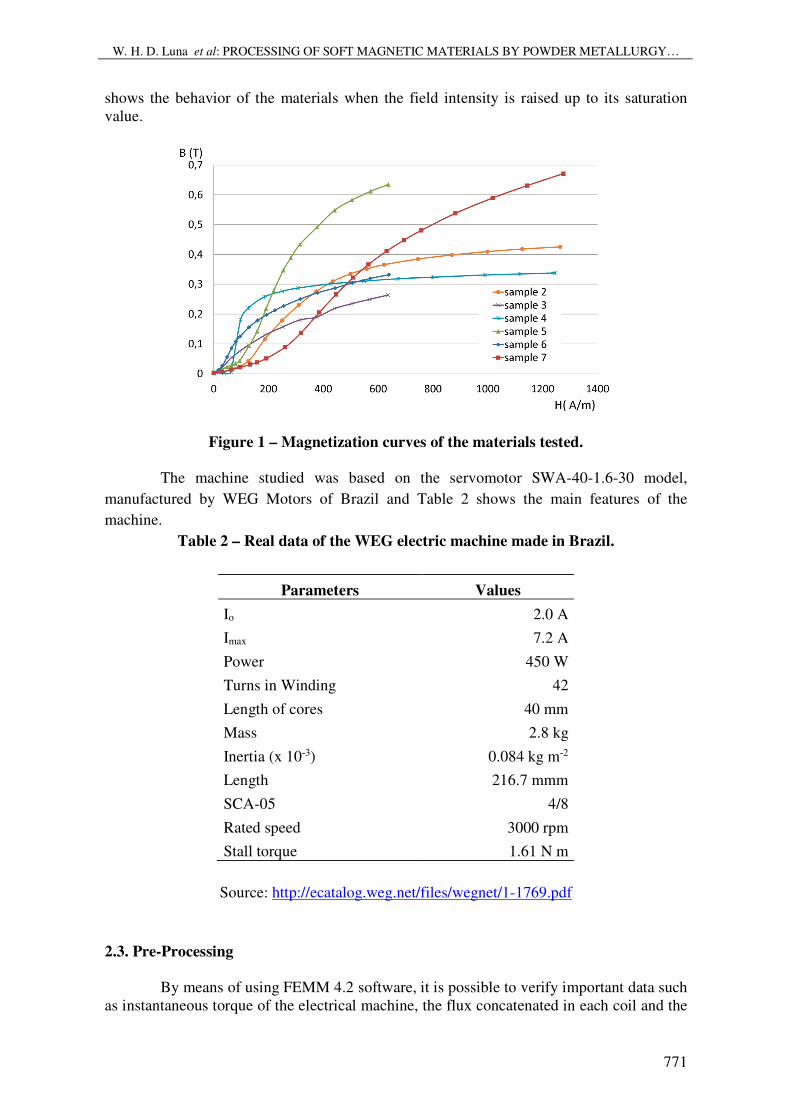
phenomenon is known as the non-linear magnetic behavior and it can be seen in Figure 1
(magnetization curves).
The magnetic properties used in the software are obtained from the magnetization
curve that relates magnetic field H applied to a material to the resulting magnetic induction
B. Curves B x H for the soft magnetic materials (samples from 2 to 7) analyzed are shown
in Figure 1. The test was performed in ring-shaped samples, with primary and secondary
windings.with a density of turns in the primary winding of 1319 and 266 turns in the
secondary one. The magnetic field H [A/m] was calculated from relation H.l = N.I, where l
[m] is the perimeter of the ring, I [A] is the primary electrical current and N is the primary
number of turns. The induction B [T] was measured in a cross-section of the samples of 0.2
cm2 with a Fluxmeter model TLHP-FLX. It should be mentioned that the referred figure
W. H. D. Luna et al: PROCESSING OF SOFT MAGNETIC MATERIALS BY POWDER METALLURGY…
771
shows the behavior of the materials when the field intensity is raised up to its saturation
value.
Figure 1 – Magnetization curves of the materials tested.
The machine studied was based on the servomotor SWA-40-1.6-30 model,
manufactured by WEG Motors of Brazil and Table 2 shows the main features of the
machine.
Table 2 – Real data of the WEG electric machine made in Brazil.
Parameters Values
Io 2.0 A
Imax 7.2 A
Power 450 W
Turns in Winding 42
Length of cores 40 mm
Mass 2.8 kg
Inertia (x 10-3) 0.084 kg m-2
Length 216.7 mmm
SCA-05 4/8
Rated speed 3000 rpm
Stall torque 1.61 N m
Source: http://ecatalog.weg.net/files/wegnet/1-1769.pdf
2.3. Pre-Processing
By means of using FEMM 4.2 software, it is possible to verify important data such
as instantaneous torque of the electrical machine, the flux concatenated in each coil and the

J. Electrical Systems 13-4 (2017): 767-778
772
losses through Foucault current. Once these results are known, the designer can verify the
efficiency of the machine and the properties that should be worked on in order to reach the
ideal working point.
There are two common sources of magnetic fields (both used in simulation): one
of them generated by the current that runs through the copper wires and the other generated
by the permanent magnets. One considers a copper wire wrapped over a highly permeable
piece of material, called core, in this case applied in the stator. The current that flows
through the coil produces a magnetic field which it can be found through the application of
the Ampère’s law [8]. In the stator of the simulated electrical machine the current applied to
circuit 1 and 2 is 2 A and in circuits from 3 to 6 the current is -1 A (the signal represents the
direction). Figure 2 shows the details of the configuration of the coils in the machine.
Figure 2 – Configuration of the coils used in the stator.
In FEMM, the domain of the solution is subdivided or “discretized” into small
regions called “finite elements”. For instance, in 2D applications, the domain can be
discretized into groups of finite areas formed by triangles. The points that define the
triangles are the “nodes” or “degrees of freedom”, while the triangle is the “element” itself
[13]. The ensemble of elements is called “Mesh”. In the model tested, 100743 nodes and
201173 elements were tested to generate the “mesh”, as it can be seen on Figure 3.
Figure 3 – Mesh generated during pre-processing.

W. H. D. Luna et al: PROCESSING OF SOFT MAGNETIC MATERIALS BY POWDER METALLURGY…
773
2.4. Data Processing
The torque produced by a magnetic field is based on a macroscopic point of view.
The principle used is the concept of energy conservation. This method requires all
electrical, magnetic and mechanical losses in the motor (or electrical machine) to be
modeled as an external factor to the motor, described in Equation 2. In this meaning, a
conservative system is reached, where no energy is lost [8].
me dWdWdW += Equation (2)
where dWe, dW, and dWm are differential of energy quantities: electrical, magnetic and
mechanical, respectively.
The Maxwell stress tensor describes the force per unit of area produced by the
magnetic field on a surface. The differential force produced is described in Equation 3.
[ ])()()(2
1BHnnHBnBHdF •−•+•= Equation (3)
where n denotes the normal direction from the surface to the point of interest [14].
The weighted stress tensor block or simply weighted tensor (Figure 4) is an
integral version of volume of the Maxwell stress tensor which automatically chooses an
ensemble of pathways to integration, which generates yield results. This approach is similar
to the Stress Tensor Approach (WST Weighed Stress Tensor) described in Henrotte [14].
The torque on (0.0) is calculated using the approach of the same weighting function [15].
Figure 4 – Torque obtained from the stress tensor (on the left); on the right, the detail
of the simulated tensor.

J. Electrical Systems 13-4 (2017): 767-778
774
The Weighted Stress Tensor integration is also shown in Figure 4, by patter, as
orange flux lines.
3. RESULTS AND DISCUSSION
According to data obtained, it is possible to observe the torque originated by the
stress tensor and the torque via weighted stress tensor (Figure 5). The comparative study of
the electrical machines will be based on the torque via weighted stress tensor, since its
value best represents the yield and it is also the one that comes closer to the nominal value
of the electric machine represented.
Sample 1 (M45 – silicon steel) which is part of the database of FEMM 4.2 is used
as a reference in the simulations since there is a proptotype model based on this sample.
The rotor behavior using this material is similar to the real one. Based on this, it was
obtained the first results in Figure 5.
Figure 5 – Torque via weighted stress Tensor vs torque from stress tensor.
Once the torque of sample 3 is very low, if compared to other materials, the yield
of the machine under the original conditions (Sample 1) still prevails over other materials.
It may be stressed that the samples 5, 6 and 7 are those that have their values closest to the
ones related to the reference (Sample 1).
The magnetic potential gradient does not have any physical significance. Its
definition comes from a vector calculus law which states that the divergence of a rotational
of any vector function is nil. The magnetic potential gradient is known as the magnetic
potential vector and its size unit is Wb/m in the International System of Units [16].
The group of samples 1, 2, 4, 5, 6 and 7 presented almost the same two-
dimensional field behavior, as it can be observed in Figure 6. These values are directly
related to magnetic permeability.

W. H. D. Luna et al: PROCESSING OF SOFT MAGNETIC MATERIALS BY POWDER METALLURGY…
775
Figure 6 – Measured potential in the airgap,
B.n integral returns the total flux passing normal to the contour. This integral is
useful for determining the total flux in a bulk flux path [10]. In Figure 7, a similar behavior
is observed as a function of the differences among the materials.
Figure 7 – B.n integral showing the total flux in a bulk flux path.
Figure 8 shows the magnitude of flux density. In this case the relation of sample 3
is half that of the others, which would in fact eliminate any application of the material in
machines. It should be stressed that in this figure, the materials are subject to an intensity
field generated by the own rotor.
This type of results rules out a huge number of possibilities that, from the point of
view of production, would be almost impossible to analyze.

J. Electrical Systems 13-4 (2017): 767-778
776
Figure 8 – Magnitude of flux density, in a ratio of 1:2 between the sample 3 and other
samples.
All of the previous analysis was performed based on the substitution of the rotor
materials. In Figure 9, the material of the stator is also replaced by the material obtained by
P/M. In the same figure, the grey columns indicate the torque which can clearly have at
most the same yield as the machine where the stator was not changed. In the case of the
reference sample (sample 1), and sample 5, there was no difference; on the other hand, in
samples 2 and 4 there was a significant decrease in yield.
Figure 9 – Analyses of torque from stress tensor in samples 1, 2, 4, 5, 6 and 7. In the
black columns, the machines with a rotor obtained by PM and in the grey columns the
machines with rotor and stator obtained by PM.
The manufacturing processes of powder metallurgy are much cheaper than the
conventional manufacturing processes. The metallic powder is a fraction more expensive
than the sheet material, but it can be compensated by diminishing stages in the process of
core manufacturing, and by the speed concerning the production of the produced pieces.

W. H. D. Luna et al: PROCESSING OF SOFT MAGNETIC MATERIALS BY POWDER METALLURGY…
777
The powder metallurgy is a process with high level of utilization of raw material, reaching
95% with an energy consumption of 29 MJ per kg processed; on the other hand, machining
processes have losses of up to 50% of raw material consumption and up to 82 MJ of energy
per kg processed [17].
Losses due to parasite currents in a massive core are considerably greater than the
losses in the cores obtained from electrically isolated sheets. The smaller the thickness of
the sheets, the less the parasite currents and the less potency is lost in these cores [1, 2]. In
the case of sintered materials, porosity is a typical characteristic. This porosity can be
controlled to determine the mechanical properties, but also the magnetic properties, since
porosity can increase the electrical resistance of the material, and, consequently, has a
relative control of the parasite currents.
4. CONCLUSION
Replacing the stator by materials from powder metallurgy process leads to a
slightly decrease in the yield of the machines in almost all cases, although this parameter
remained the same for the sample number 5. However, it is possible a reduction of the costs
in the manufacturing process owing due to a high level of utilization of raw material and
low energy consumption if compared to machining processes.
ACKNOWLEDGMENTS
The authors would like to thank The Brazilian National Council for Scientific and
Technological Development (CNPq) for financial support and to the Federal university of
Rio Grande do Sul (UFRGS) - Metal Forming Laboratory (LdTM) for the use of their
facilities, without which this research would not have been possible.
REFERENCES
[1] – S.A. Nasar. Handbook of Electric Machines. New York: McGraw-Hill, 1987.
[2] – A.E. Fitzgerald, Jr. C. Kingsley, S.D. Umans. Electric Machinery. McGraw-Hill
(inc.), 1990: 599.
[3] – Y.G. Guo, J.G. Zhu, Z.W. Lin, J.J. Zhong. 3D Vector Magnetic Properties of
Softmagnetic Composite Material. Journal of Magnetism and Magnetic Materials 302,
2006: 511–516.
[4] – E. Enescu, P. Lungu, S. Marinescu, P. Dragoi. The Effect of Processing Conditions on
Magnetic and Electric Properties of Composite Materials Used in Nonconventional
Magnetic Circuits. Journal of Optoelectronics and Advanced Materials 8 2006: 745–748.
[5] – M.M. Dias, H.J. Mozetic, J.S. Barboza, R.M. Martins, L. Pelegrini, L. Schaeffer.
Influence of Resin Type and Content on Electrical and Magnetic Properties of Soft
Magnetic Composites (SMCs). Powder Technology 237, 2013: 213-220.
[6] – P. Jansson. Soft Magnetic Materials for A.C. Applications. Hoeganes A.B., Hoeganes
Swed." Powder Metallurgy, 1992: 63-66.
[7] – R.F. Krause, J.H. Bularzik, H.R. Kokal. Soft Magnetic Material for AC and DC Motor
Applications. Journal of Materials Engineering and Performance v.6, n. 6, 1997: 710-712.
[8] – D.C. Hanselman. Brushless Permanent-Magnet Motor Design. USA: McGraw-Hill,
1994.
[9] – A.G. Yetgin, M. Turan. A Novel Slitted Tooth Core Design to Improve the Torque-
speed Characteristic of Squirrel Cage Induction Motor. International Journal of Research
in Engineering and Technology. v. 5, n. 5, 2016: 480-487.

J. Electrical Systems 13-4 (2017): 767-778
778
[10] – A.G. Yetgin, M. Turan. Efficiency Optimization of Slitted-core Induction Motor.
Journal of Electrical Engineering, v. 65, n. 1, 2014: 60-64.
[11] – S. Bradbury. Powder Metallurgy Equipament Manual. New Yersey: MPIF, 1986.
[12] – R.M. German. Powder Metallurgy Science. New Yersey: Metal Powder Industries
Federation, 1984.
[13] – J.P.A. Bastos, N. Sadowski. Electromagnetic modeling by finite element methods.
USA: Marcel Dekker, Inc., 2003.
[14] – F. Henrotte, G. Deliege, K. Hameyer. The eggshell method for the computation of
electromagnetic forces on rigid bodies in 2D and 3D. CEFC, Perugia, Italy, 2002: 16-18.
[15] – D. Meeker. Finite Element Method Magnetics. 2008.
[16] – A. Nicolaide. Magnetism and Magnetic Materials. Transilvania University Press,
Braşov, 2001.
[17] – M.A.T. Pallini, M.A.T. Carvalho. Cost reduction in the Automotive Industry
through Sintering. Society of Automotive Engineers, 2006: 01-06.


![J. Electrical Systems 13-4 (2017): 723-741 E J S Amjad J ...journal.esrgroups.org/jes/papers/13_4_9.pdfperformed by (Indra Ferdiansyah and etal) in [10]. Speed observer and reduced](https://static.fdocuments.us/doc/165x107/5aad08db7f8b9a2b4c8df27a/j-electrical-systems-13-4-2017-723-741-e-j-s-amjad-j-by-indra-ferdiansyah.jpg)

![A DSP-Based Space Vector Modulation Direct Torque …journal.esrgroups.org/jes/papers/5_3_4.pdf · complex. In [10, 11], discrete space vector modulation DTC approach is used to reduce](https://static.fdocuments.us/doc/165x107/5a953d657f8b9adb5c8c5e69/a-dsp-based-space-vector-modulation-direct-torque-in-10-11-discrete-space.jpg)

