2 into voids along dilational faults
51
Chaotic breccia zones on the Pembroke Peninsula, South Wales: evidence for collapse 1 into voids along dilational faults 2 3 N.H. Woodcock , * , A.V.M. Miller, C.D. Woodhouse 4 5 Department of Earth Sciences, University of Cambridge, Cambridge CB2 3EQ, UK 6 7 * Corresponding author: [email protected], +441223 333430 8 9 10 Abstract 11 12 Chaotic breccias and megabreccias – locally called gash breccias – hosted within the 13 Pembroke Limestone Group (Visean, Mississippian, lower Carboniferous) of southwest 14 Wales are re-mapped along with spatially-related crackle and mosaic breccias. Of thirteen 15 studied megabreccia bodies, seven lie along steep, NNW- or NNE-striking strike-slip faults 16 originating during north-south Variscan (late Carboniferous) shortening, though reactivated 17 during later extension. Four bodies are conformable with E-W striking, steeply-dipping 18 bedding, and two have irregular or indeterminate margins. The bedding-parallel zones are 19 interpreted as the dilational tips of listric normal faults, and the cross-strike faults as 20 transtensional transfer zones. Sub-horizontal clast fabrics suggest brecciation by gravitational 21 collapse into opening fissures rather than by cataclasis along the faults. Most fissures have 22 geometrically matched margins produced by this dilational faulting, and only locally have the 23 indented margins indicating solutional processes. The most likely age for the main fissure 24 extension and fill is late Triassic, based on analogous dated fills at the eastern end of the 25 *Manuscript Click here to view linked References
Transcript of 2 into voids along dilational faults

Chaotic breccia zones on the Pembroke Peninsula, South Wales: evidence for collapse 1
into voids along dilational faults 2
3
N.H. Woodcock, *
, A.V.M. Miller, C.D. Woodhouse 4
5
Department of Earth Sciences, University of Cambridge, Cambridge CB2 3EQ, UK 6
7
* Corresponding author: [email protected], +441223 333430 8
9
10
Abstract 11
12
Chaotic breccias and megabreccias – locally called gash breccias – hosted within the 13
Pembroke Limestone Group (Visean, Mississippian, lower Carboniferous) of southwest 14
Wales are re-mapped along with spatially-related crackle and mosaic breccias. Of thirteen 15
studied megabreccia bodies, seven lie along steep, NNW- or NNE-striking strike-slip faults 16
originating during north-south Variscan (late Carboniferous) shortening, though reactivated 17
during later extension. Four bodies are conformable with E-W striking, steeply-dipping 18
bedding, and two have irregular or indeterminate margins. The bedding-parallel zones are 19
interpreted as the dilational tips of listric normal faults, and the cross-strike faults as 20
transtensional transfer zones. Sub-horizontal clast fabrics suggest brecciation by gravitational 21
collapse into opening fissures rather than by cataclasis along the faults. Most fissures have 22
geometrically matched margins produced by this dilational faulting, and only locally have the 23
indented margins indicating solutional processes. The most likely age for the main fissure 24
extension and fill is late Triassic, based on analogous dated fills at the eastern end of the 25
*ManuscriptClick here to view linked References

Bristol Channel Basin. The Pembroke megabreccias blur the distinction between fault rocks 26
formed by deformation and those formed by redeposition along fault zones. 27
28
Keywords: megabreccia, fault rocks, dilational fault, Bristol Channel Basin. 29
30
31
32
1. Introduction 33
34
Breccias, rocks made of coarse angular fragments, form by a range of sedimentary, magmatic 35
and deformational processes (e.g. Laznicka, 1988). They commonly have a high porosity and 36
permeability, and are therefore economically important as hosts and conduits for 37
groundwater, hydrocarbons or mineralization. The origin of some breccias can be deduced 38
from their texture, composition and context but the origin, or even the three-dimensional 39
geometry, of other breccias is uncertain. 40
One problematic breccia formation mechanism is gravitational collapse into voids formed 41
by solution (Loucks, 1999) or by mismatch of fault walls (e.g. Woodcock et al., 2006; Ferrill 42
et al., 2011; Walker et al., 2011). This collapse mechanism grades into other processes: 43
confined implosion at pressure-release zones along faults (e.g. Sibson, 1986) and phreato-44
magmatic explosion in igneous and hydrothermal settings. One area where all these 45
mechanisms have been proposed for the same suite of breccias is the Pembroke Peninsula, 46
south Wales (review by Walsh et al., 2008) where chaotic megabreccias (e.g. Fig. 4d, e), 47
locally called gash breccias, are hosted within lower Carboniferous (Mississippian) 48
limestones. This paper reports new work on the megabreccias and on spatially related fault 49
breccias that clarifies the origin of many of the occurrences. 50

51
52
2. Geological setting of the studied breccias 53
54
The Pembroke Peninsula, west Wales, lies close to the northern limit of strong Variscan 55
(late Carboniferous) deformation in Britain (Fig. 1b; British Geological Survey, 1996). The 56
mid-Ordovician to late Carboniferous sequence is deformed into E-W trending upright folds 57
with kilometric wavelengths (Fig. 1a). The studied breccias occur in the Pembroke Limestone 58
Group (Tournaisian and Visean), which crops out in three major synclines: the St Florence, 59
Pembroke and Bullslaughter Bay Synclines. The folds are cut by two conjugate sets of strike-60
slip faults striking NNW and NNE (Fig. 1a). The peninsula is geologically bounded to the 61
north by the steeply S-dipping Ritec Fault, with a reverse throw of 0.5 to 1 kilometre. 62
63
[Figure 1 about here] 64
65
Thirty localities have been studied, all but two of them coastal. Most are accessible either 66
at shore level or at the top of the 50 metre high cliffs, although some can only be reached or 67
viewed from the sea. 68
The stratigraphic distribution of breccias within the Pembroke Group reflects its 69
lithological contrasts (Fig. 2). No megabreccias occur in the lower units, which are 70
dominantly shale-prone thin- or medium-bedded limestone. Megabreccias are common where 71
mechanically strong thick-bedded limestone dominates: particularly in the High Tor and 72
Cornelly formations (Arundian to Holkerian) of the northern areas and the Stackpole and 73
Oxwich Head formations (Holkerian to Asbian) of the southern area. However, overlying 74

thinner-bedded units are also brecciated: the Stormy Limestone Formation (Holkerian) in the 75
north and the Oystermouth Formation (Brigantian) in the south. 76
77
[Figure 2 about here] 78
79
3. Previous work and hypotheses 80
81
The history of research on the Pembrokeshire megabreccias has been reviewed by Walsh et 82
al. (2008). Early research produced two genetic hypotheses. Dixon (1921) envisaged karstic 83
solution of limestone, producing large voids into which wall and roof rocks progressively 84
collapsed (Fig. 3a). By contrast, Hancock (1964) and Thomas (1970, 1971) proposed 85
formation by tectonic fragmentation along faults (Fig. 3b). Walsh et al. (2008) concluded that 86
the megabreccias were formed by more than one mechanism, and suggested a third: phreatic 87
explosion due to upward escape of thermally-driven superheated fluids (Fig. 3d). Rowberry et 88
al. (2014) and Błażejowski and Walsh (2013) showed that, at Bullslaughter Bay (localities 3 89
and 4), chemically aggressive fluids, either deep or meteoric, have produced substantial 90
residual deposits, which apparently overprint chaotic breccias and bedded sequences. 91
92
[Figure 3 about here] 93
94
Recent studies on chaotic breccia hosted within Carboniferous limestone elsewhere in the 95
UK provide analogues for the Pembrokeshire examples. Woodcock et al. (2006) attributed 96
megabreccia along the Dent Fault, northwest England, to collapse of voids produced by 97
dilational fault displacement (Fig. 3c). Wright et al. (2009) studied strike-slip cross faults in 98
the Pembroke Group of the Gower Peninsula, there contain void-filling veins and breccias 99

produced during active faulting rather than by solution. One of the westernmost faults 100
contains megabreccia identical to the Pembrokeshire examples. Eastward from Gower, 101
sediment-filled extensional fissures cut the Pembroke Group in the Mendip Hills (Wall and 102
Jenkyns, 2004). Rather than megabreccia, these fills are dominated by Triassic and Early 103
Jurassic sediment infiltrated from the contemporary land surface. 104
105
106
4. Breccia zone lithologies 107
108
4.1 Terminology 109
110
The studied zones contain a range of breccias, particularly some with very large clasts (over 111
1 metre in diameter) referred to informally as megabreccias. Sedimentologically, such large-112
clast breccias would be termed boulder breccia. The genetic term gash breccia is avoided, as 113
pre-supposing that the breccias formed in an open void. 114
The breccias are classified using the non-genetic scheme developed for cave-collapse 115
zones (e.g. Loucks, 1999) as modified for fault zones (Mort and Woodcock, 2008; Woodcock 116
and Mort, 2008). The spectrum from crackle breccia through mosaic breccia to chaotic 117
breccia simply reflects increasing disaggregation of the protolith, and therefore decreasing 118
percentage of large (>2 mm) clasts in the overall rock volume. Breccias can either contain a 119
fine-grained matrix or carbonate cement. This classification is suitable for any breccia and its 120
use here does not pre-judge whether or not the Pembrokeshire breccias were formed along 121
faults. 122
123

4.2 Crackle and mosaic breccia 124
125
Crackle and mosaic breccia has angular clasts with a fitted-fabric texture and only limited 126
separation and rotation of clasts. In crackle breccia (Fig. 4a) the porosity between large 127
(>2 mm) clasts is less than 25% of the rock volume, whereas in mosaic breccia (Fig. 4b) it is 128
about 25-40%. The porosity is filled either by crystalline carbonate cement or by fine 129
(<2 mm) matrix, both detailed below (section 4.5, 4.6). Crackle and mosaic breccia typically 130
occur at the gradational margins to chaotic breccia zones, with calcite cement between the 131
clasts. Pods of crackle and mosaic breccia may be interleaved on a scale too fine to 132
distinguish separately on the maps of individual fault zones (sections 6 to 9). 133
134
[Figure 4 about here] 135
136
137
4.3 Chaotic breccia and megabreccia 138
139
Chaotic breccia and megabreccia (Fig. 4c) has angular to sub angular clasts that lack a fitted-140
fabric texture. Clasts have been rotated and translated enough to obscure any match with each 141
other. Nevertheless, all the chaotic breccias zones are monomict; that is their large clasts are 142
entirely derived from the Pembroke Group. Indeed, in all but one zone, the clasts derive from 143
the same limestone formation that hosts the breccia. The exception is at Trevallen (locality 7) 144
where a breccia hosted in thickly-bedded Stackpole and Oxwich Head limestones also 145
contains clasts from the overlying thinner-bedded Oystermouth Formation. Very large (1 to 146
10 metre) clasts in megabreccia may be equidimensional, or more typically bedded slabs with 147
their long dimension parallel to their bedding (Figs 4d, e). As in mosaic breccia, the porosity 148

in chaotic breccia can be filled either by carbonate cement or by fine-grained matrix, both 149
detailed below (section 4.5, 4.6), or remain unfilled. 150
151
4.4 Cataclasite 152
153
The cores of some faults have thin (<1 metre) zones of cataclasite or fine matrix-rich chaotic 154
breccia (Fig. 4f). On the fault-rock scheme of Woodcock and Mort (2008), the boundary 155
between these two rocks types is at 2 mm average clast size, although other authors have used 156
a smaller clast size, for instance Higgins (1971) at 0.2 mm and the North American Geologic-157
map Data Model (2004) at 0.1 mm. These fault rocks lack a foliation, although they may be 158
cut by anastomosing principal slip surfaces within the fault core. 159
160
4.5 Carbonate cement 161
162
The dominant cement is calcite, occurring in two growth forms. Blocky calcite (Fig. 5a) 163
comprises equidimensional crystals about 1 cm in diameter. Elongate blocky calcite (Fig. 5a, 164
b) forms acicular crystals up to 5 cm long. Both forms have euhedral crystal terminations, 165
showing that they grew into fluid-filled voids. Both calcite types nucleate on clasts and void 166
walls, with the elongate calcite forming conspicuous radiating crystal masses. In places, 167
clasts in 2D view are completely surrounded by radiating cement, forming spar balls (Fig 168
5b), although the possibility that such clasts are supported by other clasts in the third 169
dimension cannot be ruled out. If not, the formation of these structures is problematic (Genna 170
et al., 1996; Frenzel and Woodcock, in press). 171
Growth of equant, rather than elongate, crystals reflects high nucleation rates from 172
hydrothermal fluids, probably due to fluid supersaturation (Oliver and Bons, 2001), arising 173

from arrest of a rising mass of fluid (Bons, 2001) or by a rapid drop in fluid pressure during 174
hydraulic fracture (Phillips, 1972). Because cements are void-filling rather than keeping pace 175
with void opening, opening rates must have exceeded precipitation rates. 176
Although most carbonate cement is non-ferroan, small volumes of ferroan calcite fill late-177
stage porosity or form thin cross-cutting veins. Ferroan dolomite nodules occur (Walsh et al., 178
2008) in the breccia zones at Draught (locality 13, Fig. 2). The nodules are brecciated and 179
recemented by calcite. 180
181
[Figure 5 about here] 182
183
4.6 Sediment matrix and laminated infill 184
185
Where breccia clasts have a matrix (<2 mm) infill, this typically comprises calcitic particles 186
between silt and medium sand grade (Fig. 5c). Most sediment is coloured red by hematite or 187
brown by limonite. Lamination is typically visible wherever voids are wider than a few 188
centimetres. It has a concave-up catenary form (Fig. 5c) consistent with lamina-by-lamina 189
deposition within each void. Where sediment and cement occur together within a void, the 190
sediment is the earlier fill. The sediment occupies the lower part of voids or has accumulated 191
above tabular clasts (Fig. 5d), and the contact of the sediment and overlying cement forms a 192
geopetal indicator. All geopetal and way-up evidence suggests that the host breccia zones 193
have not been significantly rotated since they were formed. 194
Several laminated sediment fills are of particular significance. 195
Laminated and thinly-bedded crinoidal grainstone occurs at Draught (locality 13). The 196
crinoids cannot be dated. Their articulated and non-corroded shapes might question 197
reworking from local well-cemented Carboniferous rocks although Rowberry et al. (2014) 198
record crinoid ossicles and Brigantian conodonts (Błażejowski and Walsh, 2013) in karstic 199
weathering residues at Bullslaughter south (locality 4). Alternatively, Mesozoic crinoids are a 200
conspicuous component of the Mendips fissure fills (Wall and Jenkyns, 2004), where they 201
infiltrated in sediment from the Mesozoic sea floor. 202
Well-cemented laminated micrite forms prominent catenary-bedded sheets at some 203
localities (e.g. Draught), where it is more resistant to weathering than wall rocks (Fig. 5e). In 204
thin section it is seen to comprise calcite debris cemented by ferroan calcite and dolomite. 205
This is the lithology confusingly termed ‗stalagmite‘ by Dixon (1921) and also by Thomas 206
(1971) and Walsh et al. (2008). However, the latter authors consider that the deposits are not 207
phreatic zone speleothem but rather a form of hot-water travertine. By contrast, we do not 208
attach any special significance to these sediments: they are merely well-cemented examples 209
of normal sediment infill. 210
211
212
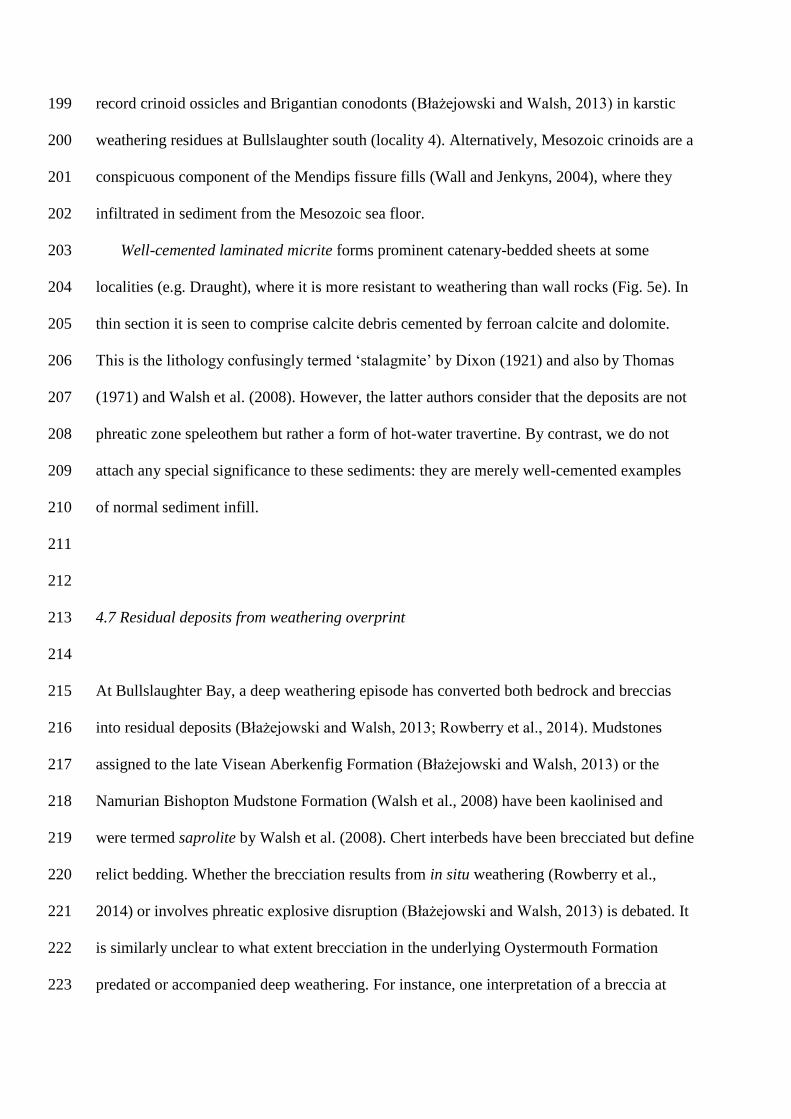
4.7 Residual deposits from weathering overprint 213
214
At Bullslaughter Bay, a deep weathering episode has converted both bedrock and breccias 215
into residual deposits (Błażejowski and Walsh, 2013; Rowberry et al., 2014). Mudstones 216
assigned to the late Visean Aberkenfig Formation (Błażejowski and Walsh, 2013) or the 217
Namurian Bishopton Mudstone Formation (Walsh et al., 2008) have been kaolinised and 218
were termed saprolite by Walsh et al. (2008). Chert interbeds have been brecciated but define 219
relict bedding. Whether the brecciation results from in situ weathering (Rowberry et al., 220
2014) or involves phreatic explosive disruption (Błażejowski and Walsh, 2013) is debated. It 221
is similarly unclear to what extent brecciation in the underlying Oystermouth Formation 222
predated or accompanied deep weathering. For instance, one interpretation of a breccia at 223

Bullslaughter south (locality 4, Fig. 5f) is as a laminated sand deposited in a void, and 224
punctured by limestone ‗dropstones‘ from the hanging wall. An alternative explanation 225
(Błażejowski and Walsh, 2013; Rowberry et al., 2014) is that the lamination is inherited from 226
decalcified limestone, with the blocks as less weathered relicts. Such textures are termed 227
ghost karst (Dubois et al., 2014). The context of the residual deposits at Bullslaughter Bay is 228
discussed later (Sections 6.2, 9). 229
230
231
5. Distribution and context of breccia bodies 232
233
Figure 6 shows which lithologies are important at each locality, grouped according to its 234
structural setting. Most lithologies occur in every setting, but chaotic megabreccias do not 235
occur along thrusts, and cataclasites do not occur in irregular breccia bodies. The tabulated 236
widths of zones vary from 5 to 200 metres, and do not correlate closely with structural 237
setting. 238
239
[Figure 6 about here] 240
241
Three end-member structural settings can be recognised (Fig. 7): 242
a) zones that strike parallel to bedding (roughly east-west), either parallel also to bedding dip 243
or to cross-cutting thrust faults; 244
b) zones along steep NNW or NNE-striking faults that cut across bedding strike; and 245
c) zones with irregular margins that parallel neither faults nor bedding. 246
A triangular diagram (Fig. 7) shows semiquantitatively the range of geometry between 247
the three end members. Three breccia zones have geometries too uncertain to plot but, of the 248

27 plotted examples, over half (15) are closely related to cross-strike faults, 5 parallel 249
bedding and 3 parallel thrust-faults. The remaining 4 have mostly irregular margins. These 250
groupings provide a framework for detailing the structural geometry of representative breccia 251
zones (sections 6 to 9). 252
253
[Figure 7 about here] 254
255
256
6. Breccias associated with cross-strike faults 257
258
6.1. Cross-fault zones with simple geometry 259
260
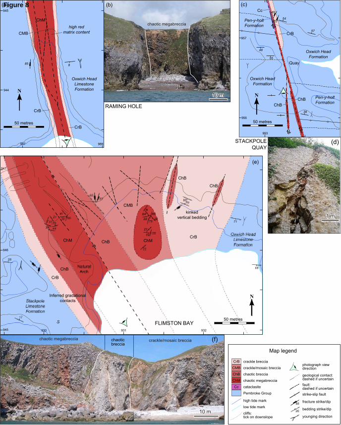
Nine vertical cross-strike fault zones have simple geometries and cluster at the top corner of 261
Figure 7. Maps of three examples (Fig. 8a-d and 9a) show that one or both margins grade 262
inwards from crackle through mosaic breccia into a fault core of chaotic breccia or 263
megabreccia. Typically one principal slip surface cut through or bounds this central fault 264
core. Fine-grained cataclasite occurs in the core in one only case (Stackpole, Fig. 8c, d). 265
266
[Figure 8 about here] 267
268
Six steeply-dipping cross-strike fault zones have complex geometries, with greater 269
outcrop widths and more than one mappable fault core. The example at Flimston Bay (loc. 1, 270
Fig. 8e, f) occurs along a NNW-striking fault with at least 500 m of dextral strike-slip offset 271
of the Bullslaughter Bay Syncline. The example at Bullslaughter east (loc. 3, Fig. 10a, c) has 272
three principal slip surfaces marked by chaotic breccia and megabreccia, separated by screens 273

of intact limestone. Draught Cove (loc. 14, not illustrated) contains at least nine principal slip 274
surfaces, seven chaotic breccias zones, three cataclasite zones and two zones of chaotic 275
megabreccia. 276
In general then, the cross-strike faults host the thickest and most complex breccia zones 277
(Fig. 6). They coincide with cross-faults mapped in the detailed survey by Dixon (1921). 278
Independent evidence of strike-slip displacement is available where the faults laterally 279
displace fold axial planes, for instance at localities 1, 2, 3, 4 and 12, and on about ten other 280
faults detailed by Dixon (1921, 181-185). The sense of displacement is dextral on the NNW 281
faults and sinistral on the NNE faults. This pattern is so well defined that it was the main 282
example cited by Anderson (1951) for his classic stress interpretation of conjugate sets of 283
strike-slip faults. The faults formed in response to north-south directed maximum principal 284
stress during the Variscan event. These faults would have been transpressional during 285
Variscan shortening, and not natural hosts for chaotic breccias that require dilation of the 286
fault zone. An extensional phase during latest Variscan or later time is implied by regional 287
evidence (Section 12.5). 288
Sub-horizontal slickensides and slickencrysts are additional evidence that the breccia 289
zones coincide with strike-slip faults. Examples have been observed at localities 1, 5 and 14, 290
and Dixon (1921, p. 182) states that ―all the slickensiding that has been examined along the 291
faults shows either horizontality or only a gentle inclination in the striae or fluting produced 292
by the movement.‖ It might still be argued that some of the chaotic breccias are a later infill 293
to karstic solution cavities along the faults. However, examples such as the low displacement 294
splay fault at Stackpole Quay (loc. 12, Fig. 8c, d) argue against solution as a general genetic 295
model. The fault walls and enclosed fragments fit back together perfectly, in contrast to the 296
irregular, sculpted and mismatching fissure walls that would be produced by solution of the 297
limestone. 298

299
300
7. Breccias associated with thrust faults 301
302
Breccia zones that parallel bedding strike (Fig. 7, bottom left) fall into two types. Three 303
zones, described in this section, are clearly associated with faults, in that they cut across the 304
dip of bedding, show stratigraphic displacement, host cataclasite zones, or contain 305
slickensided surfaces. A further five zones, (section 8) lack these four criteria and are 306
conformable with bedding dip as well as strike. 307
The best example of a strike-parallel thrust zone is at Tenby east (loc. 25, Fig. 9a), where 308
the 19 km long Ritec Fault meets the coast. It dips steeply southward, with a reverse throw of 309
about 450 m in the east of Pembrokeshire and 900 m in the west (Dixon, 1921). At Tenby a 310
zone of crackle and mosaic breccia contains two 10-30 m wide thrust zones of cataclasite. 311
Other possible thrust faults have lower displacements. At Barafundle Bay (loc. 11), a small 312
south-dipping fault with chaotic and crackle breccia may be a minor limb thrust near a fold 313
hinge (Dixon, 1921, p. 180). 314
The relative rarity of chaotic breccia and absence of megabreccia, along thrust faults is 315
notable. It suggests that a dilational component to faults is necessary for megabreccia 316
formation. 317
318
[Figure 9 about here] 319
320

8. Bedding sub-parallel breccias 321
322
By contrast with its absence in thrust zones, megabreccia is hosted in four out of five zones 323
with contacts that parallel bedding dip as well as strike (Fig. 7). A typical zone at Nanna‘s 324
Cave (loc. 29, Fig. 9b, c) has a central zone of chaotic megabreccia bordered by several 325
metres of chaotic breccia. The flanking limestone beds, which dip about 80°, are scarcely 326
brecciated, with just a 3m wide zone of crackle breccia within the northern wall, hosts an 327
open angular kink fold of bedding (Fig. 9c). 328
Lydstep Point (loc. 16, Fig. 9d, g) and Whitesheet (loc. 15, Fig. 9d, e, f) are wider zones 329
with the same basic geometry, including non-brecciated, but kinked wall rock south of the 330
Whitesheet mass (Fig. 9e). The two breccia bodies do not appear to join up along strike, but 331
are terminated by cross faults. The Whitesheet breccia is itself cut by later cross-strike faults, 332
one hosting cataclasite. Although most margins of the five breccias zones in this category 333
precisely parallel bedding, those at Trevallen (loc. 7, not illustrated) weakly transgress the 334
bedding, particularly in the hangingwall. This is probably related to the lower bedding dips 335
(40° to 70°) in this example. 336
The sharp planar contacts and the lack of brecciation in the adjacent limestones to the 337
bedding-parallel breccia zones suggest that they formed by extension perpendicular to 338
bedding rather than by shear parallel to it or solution within it. The angular kink folds at the 339
margins of several zones indicate one way in which bedded limestone beds collapsed during 340
extension. The amount of extension was small enough that it could dissipate in a short 341
distance along strike or at a synchronous cross fault. 342
343

9. Irregular breccia masses 344
345
Four breccia zones have irregular margins, not obviously concordant with either bedding 346
or faults (Fig. 7, bottom right). Incomplete exposure leaves open the possibility that some of 347
their margins are more regular. 348
The largest such zone, at Bullslaughter west (loc. 2, Fig. 10a, b), maps out as an 349
equidimensional pod of chaotic megabreccia, grading laterally into chaotic breccia. The 350
southern and eastern margins are faulted, but with different fault strikes. Three separate 351
breccia bodies are designated as Bullslaughter south (loc. 4, Fig. 10a). The northernmost 352
body is an E-W matrix-rich megabreccia zone with a faulted northern margin. The central 353
body comprises the crackle-brecciated, kaolinised cherty mudstones, termed saprolite by 354
Walsh et al. (2008). The consensus is now that these are deeply weathered late Visean 355
mudstones in the hinge zone of the Bullslaughter Bay Syncline (Dixon, 1921; Thomas, 1971; 356
Walsh et al., 2008; Błażejowski and Walsh, 2013; Rowberry et al., 2014), with bedding 357
obliterated by kaolinisation and brecciation. The southern breccia zone is of chaotic breccia 358
and hematitic sand (Fig. 5f). The body has irregular contacts with the host limestones, 359
transecting an anticline-syncline pair. This is the deposit already discussed (Section 4.7) in 360
which the structures could either be interpreted as due to sedimentation and collapse into a 361
void or as in situ weathering to give ghost karst . 362
363
[Figure 10 about here] 364
365
It is difficult to generalise from the breccia bodies with irregular margins, and it is 366
possible that each of the examples at Bullslaughter Bay has contrasting origins. Irregular 367
margins are characteristic of solutional processes, whether to form voids for subsequent 368
breccia infill, to generate in situ brecciation by heterogeneous weathering, or to overprint 369
earlier structures and textures. The good examples of solutional processes at Bullslaughter 370
Bay contrast with the general paucity of such processes in other breccia zones in 371
Pembrokeshire. 372
373
374
10. Geometric clues to megabreccia formation 375
376
Dixon (1921 p.158) and Walsh et al. (2008 p.139) regarded the clast fabric in the chaotic 377
breccias as random. However, we observe a weak tendency for bedded slabs to have low 378
dips, as for instance at St Margaret‘s Island (loc. 26, Fig. 4e), rather than the typical high dips 379
of host bedrock sequences. This tendency has been tested at eight localities by plotting poles 380
to slab bedding (Fig. 11) and computing the three eigenvectors of the orientation tensor, 381
effectively the axes of maximum, minimum and intermediate concentration of the bedding 382
poles. The distributions have not been rotated in any way, given the evidence that a) the 383
conjugate subvertical cross-faults remain in the orientation in which they were formed, with 384
their mutual intersection vertical and b) geopetal indicators in the breccias are still horizontal. 385
Using the test of Woodcock and Naylor (1983), all the distributions of poles are 386
significantly non-random at the 99% confidence level, except Draught and Bullslaughter 387
west, which are significant at the 95% level. The mean bedding poles mostly lie within 30° of 388
vertical (Fig. 11d), indicating that the bedded slabs themselves lie within 30° of horizontal. 389
Bullslaughter east and Giltar east show slightly higher mean dips, though with confidence 390
areas that allow for 30° mean dips or less. Only at Draught, with a small sample size, do slabs 391
show significantly higher dips. 392

If slabs had been aligned by shear strains parallel to the host fault or bedding plane, then 393
the slabs would tend to align parallel to this controlling shear zone (Fig. 3b), indicated by the 394
great circle on the stereoplots (Figs 11a, b, c). Actually, slabs tend to be oriented more 395
perpendicular than parallel to the controlling zone. The tendency for the slabs to have low 396
dips strongly suggests accumulation under gravity, by collapse of wall rock slabs into an 397
open void formed by karstic solution (Fig. 3a) or, as suggested in this paper, by dilational 398
faulting (Fig. 3c). 399
400
[Figure 11 about here] 401
402
403
11. Discussion 404
405
11.1. Karstic solution and collapse origin for chaotic breccias and megabreccias? 406
407
This discussion first compares the new observations from the Pembrokeshire breccia zones 408
against the three main formation hypotheses (Walsh et al., 2008). The first comparison is 409
with the original hypothesis of Dixon (1921) that the chaotic breccias and megabreccias 410
represent collapse of the roof and walls of fissures formed by groundwater dissolution of 411
Carboniferous limestone in the Triassic. 412
The present study has certainly found small (0.1 to 1 metre scale) irregular sediment-413
filled cavities within some breccia zones – for instance at Frank‘s Shore (loc. 18) and 414
Valleyfield East (loc. 20) – that can be ascribed to phreatic solution. However, our mapping 415
has confirmed the observations of Thomas (1971) and Walsh et al. (2008) that the margins of 416
the breccia zones lack fluted and scalloped solution surfaces. Instead they are either smooth 417
bedding or fault planes, or grade out through mosaic and crackle breccia into intact limestone. 418
Slickensided clasts are found within some breccias, but derived fluted surfaces are not. 419
Although karstic solution alone is an unlikely origin for the breccia-filled fissures, our 420
measured sub-horizontal clast fabrics (Section 10, Fig. 11) are strong evidence for the second 421
component of Dixon‘s (1921) hypothesis: gravitational collapse of blocks and slabs into an 422
open void. We merely prefer a dilational tectonic origin for those voids. However, given the 423
increased solubility of fractured limestone in acidic groundwater, such fault zones might 424
naturally suffer localised solution. 425
Bullslaughter Bay (locs 2, 3, 4) has received recent attention (Walsh et al., 2008; 426
Błażejowski and Walsh, 2013; Rowberry et al., 2014) because of a solutional overprint on 427
earlier formed breccias. It is significant that none of the eleven other sites of deep weathering 428
recorded by Rowberry et al. (2014) are associated with chaotic breccias, but rather occur in 429
normally bedded limestones. We therefore regard the solutional overprint at Bullslaughter 430
Bay as affecting breccias formed in the same way as elsewhere in Pembrokeshire: by 431
dilational tectonics followed by collapse. 432
433
11.2. Phreatic explosion origin for chaotic breccias and megabreccias? 434
435
The second hypothesis is that of Walsh et al. (2008) that brecciation was due to phreatic 436
explosion. Phreatic activity results from the interaction of magma with external water, 437
creating overpressure that brecciates then erupts the country rock (Tămaş and Milési, 2003). 438
However, their diagnostic criteria for phreatic brecciation do not match well the 439
Pembrokeshire examples:- 440
1. Pembroke Group breccia bodies lack the typical shape of phreatic bodies: conical pipes, 441
narrowing downwards, with irregular finger-like contacts. Rather, most bodies are planar 442

(Fig. 7), with only 4 out of 27 being irregular, and none being demonstrably conical. Many 443
have at least some planar contacts. 444
2. Clasts in the studied breccias are mostly angular, whereas phreatic breccias typically have 445
some rounded fragments. 446
3. The studied breccias lack the pervasive siliceous cementation and alteration characteristic 447
of phreatic breccias. 448
4. The matrix in phreatic breccias is the fine-grained fraction from rock brecciation, 449
necessarily deposited at the same time as the larger fragments. By contrast, much of the 450
interclast matrix in the studied breccias is laminated (e.g. Fig. 5c, d) and therefore 451
introduced after the clasts. 452
This evidence, together with the absence of the requisite magmatic heat source in this area, 453
argues against the phreatic brecciation model. 454
455
11.3. Dilational faulting and collapse origin for chaotic breccias and megabreccias? 456
457
―Tectonic‖ hypotheses for Pembroke Group breccia formation were initiated by Thomas 458
(1971) although he was unspecific about the process involved. We suggest that the chaotic 459
breccias and megabreccias resulted from collapse of the walls and roofs of voids formed 460
along dilational faults during regional extension. Minor solutional widening of the void is 461
possible, but no evidence for large-volume solution has been observed. The collapse could 462
have been at the same time as fault displacement, or could have happened between fault 463
episodes. Evidence of polyphase brecciation and cementation is consistent with repeated 464
displacement on some fault zones. Most interclast matrix infiltrated later from above, and 465
residual void space was then filled by carbonate cement. 466

An important factor in the collapse hypothesis is that the final width of the breccia zone is 467
predicted to be over three times the width of the primary fissure (Loucks, 1999). If the wall 468
rocks have zero initial porosity and collapse into a planar void of width Wv, the final width of 469
the breccia body Wb is given by Wb = Wv/Φb, where Φb is the porosity of the collapse 470
breccia. With a breccia porosity Φb = 0.3, a 1 m aperture void would generate a 3.3 m 471
thickness of chaotic breccia. Even a 1 metre wide void exceeds the likely average fault 472
displacement in this area. Using an empirical determined fault displacement/length factor of 473
6.5 × 10⁻⁵
(Sibson, 1989; Scholz, 2002) Pembrokeshire faults of the order of 5 km would 474
have a maximum displacement of 0.325 m. Wide zones of collapse breccia would require 475
repeated fault displacements, evidenced by the observed polyphase brecciation and 476
cementation. 477
Evidence for collapse into fault-induced voids is:- 478
1. Most of the breccia zones are related to cross-strike faults, marked by dilational crackle 479
and mosaic breccias and by principal slip surfaces, some with low-plunge slickensides. 480
2. Clasts of crackle and mosaic breccia are common in the chaotic breccias, representing 481
fragments of faulted wall rock collapsed into the fault void. 482
3. Slickensided clasts from the fault walls occur in the chaotic breccias. 483
4. The bedded slabs in the megabreccias tend to lie at low dips rather than parallel to 484
margins of the breccia zone, precluding alignment due to zone-parallel fault shear. 485
5. Kinked bedding bordering some breccia zones shows one way in which wall rock 486
collapsed into voids. 487
Dilational faulting is less compatible with megabreccia formation during Variscan shortening 488
than during later regional extension. In Section 12.5 Below (section 12.5) we suggest a 489
Triassic or later extension age, coeval with formation of the Bristol Channel Basin. 490

We deduce that dilation occurred on two main types of fault in response to north-south 491
extension. Dilational strike-slip faults reactivated the conjugate Variscan faults striking NNE 492
and NNW (Fig. 12a) (Thomas, 1971). For a 60° dihedral angle between faults, every metre of 493
north-south extension across one of these faults would resolve into cos 30° = 0.87 metres of 494
strike-slip and sin 30° = 0.5 metres of dilation. The east-west bedding-parallel breccia zones 495
are seen as the steep segments of dilational normal faults opening perpendicular to regional 496
north-south extension (Fig. 12b). We envisage them having listric geometry (Fig. 12c), so 497
dipping less steeply at depth and maybe rooting into reactivated Variscan thrusts. Dilational 498
normal faults are well understood (e.g. Ferrill and Morris, 2003) and have been postulated for 499
sediment-filled fissures in the Pembroke Group of the Mendip Hills, 200 kilometres to the 500
east (Wall and Jenkyns, 2004). 501
502
[Figure 12 about here] 503
504
Most examples of breccia-filled dilational normal faults (localities 15, 16, 26, 29) occur 505
along the steep southern limb of the Pembroke Syncline. Clearly, bed-normal north-south 506
extension will be greatest in these steeply-dipping beds. In moderately-dipping panels of 507
stratigraphy, deep-seated normal faults probably propagated by bedding-plane slip, with less 508
bed-normal dilation. 509
510
11.4. Objections to a “tectonic” origin for the megabreccia voids? 511
512
Walsh et al. (2008) have raised a number of objections to the tectonic origin of breccia-513
filled voids, which we now address. 514

1. A solutional origin for the voids explains why studied megabreccias are restricted to the 515
Pembroke Limestone Group. Walsh et al. (2008) ask why, if the voids are produced by 516
faulting, are they “absent in the equally brittle rocks and complicated Variscan 517
structures in the adjacent Old Red Sandstone outcrop?” The same question can be 518
extended to include the later Carboniferous Marros and Coal Measures groups. An 519
answer is that, although all these units suffered the same Variscan deformation, they are 520
not equally ―brittle‖. The units above and below the Pembroke Limestone Group are 521
dominated by sandstone and shale. Sandstones tend to be less well cemented than 522
limestones, and therefore to have lower compressive strengths (70 rather than 100 Mpa), 523
tensile strengths (5 rather than 10 MPa) and shear strengths (15 rather than 30 Mpa) 524
(Waltham, 2002). The lower strength of the sandstones means that they tend to creep 525
ductilely, that brittle fractures nucleate at closer spacings, and that any one fracture is less 526
likely to produce a large void. The greater proportion of shale in the Old Red Sandstone 527
and upper Carboniferous units further weakens them. The concentration of breccias 528
within the the strong shale-poor lithologies in the Pembroke Group (Fig. 2) is predicted 529
from other studies of fault rock control by mechanical stratigraphy (e.g. Ferrill and 530
Morris, 2008; Woodcock et al., 2008) 531
2. “Why are [megabreccia-filled voids] also absent in the Carboniferous Limestone 532
outcrops west of the Flimston Fault, in SE Ireland and in the Gower Peninsula?” In 533
section 12.5, we argue that the void-forming event was the Triassic or later extension that 534
formed the Bristol Channel Basin. Southeast Ireland is more remote from such Mesozoic 535
basins, and the western end of the Pembroke Peninsula seems to have been just outside 536
the zone of basin extension. The Gower Peninsula does have one megabreccia zone at 537
Mewslade (Wright et al., 2009) and many other sediment- and vein-filled dilational 538
faults. 539

3. Why, if the breccia bodies “are largely controlled by the main-phase Variscan fold 540
geometry” do the breccias not “follow the cross-faults and fold axes as sheet-like or 541
wall-like bodies?” We have shown that about 23 out of 30 mapped zones are indeed 542
planar sheets. However some geometries are problematic, particularly the relationship of 543
the Whitesheet and Lydstep Point breccia bodies (Fig. 9d) cited by Walsh et al. (2008). 544
These masses involve collapse of two slightly different stratigraphic horizons, which we 545
envisage as overlapping (Fig. 12b) or being separated by cross-strike transfer faults (Fig. 546
9c), like that cutting the Whitesheet mass. 547
4. We agree with Walsh et al. that the size and arrangement of the blocks in a megabreccia 548
body such as Trevallen ―implies a lodgement from free-fall conditions into a large pre-549
existing cavity and, as such, is incompatible with Thomas‘s origin by ―rock-bursting in 550
compressional zones‖. We differ from Thomas (1971) in proposing breccia formation 551
during regional extension. 552
553
554
11.5. Regional pattern of dilational faulting 555
556
The conclusion that the chaotic breccias were due to fissure collapse during north-south 557
extension begs the question of the age of this event. The geopetal matrix/cement contacts 558
(Fig. 5c) show that fault fissure formation post-dated Variscan (late Carboniferous) folding, 559
and predated a truncating Mid-Miocene planation surface (Walsh et al., 2008). Within this 560
time window, evidence for polyphase breccia formation includes clasts of earlier breccia and 561
their calcite cement, and successive cements of contrasting composition. However regional 562
correlations with analogous extensional fracture systems consistently suggest a late Triassic 563
to early Jurassic age. 564

565
[Figure 13 about here] 566
567
A map of southwest England and south Wales (Fig. 13) plots the location of extensional 568
fracture systems associated with breccias, finer sediments or hydrothermal cements 569
analogous to the Pembroke examples. All but the three southern sites are hosted in Pembroke 570
Group, from Pembrokeshire to the Mendip Hills. The sites border or lie within the Mesozoic 571
Bristol Channel Basin in four main groups. 572
The Gower Peninsula, about 30-50 km east of the Pembroke Peninsula, is crossed by the 573
same conjugate strike-slip Variscan cross faults (George, 1940). These faults have also been 574
reactivated in the Pembroke Group with a dilational component, and filled mostly with 575
hematite-calcite veins and laminated red sediment (Wright et al., 2009). One locality 576
(Mewslade, Fig. 14a) has a megabreccia similar to those of the Pembroke Peninsula. The age 577
of the Gower fault fissures is unproven. Wright et al.(2009) suggested a late Variscan age, 578
but we favour the Triassic age suggested by Strahan (1907) on the basis of supposedly 579
Triassic red sandstones unconformably overlying the Pembroke Group at Port Eynon. A later 580
age cannot be ruled out. 581
582
[Figure 14 about here] 583
584
The Vale of Glamorgan, about 20-60 km further east again, has a well-dated Triassic to 585
Jurassic cover (Waters and Lawrence, 1987; Wilson et al., 1990) and underlying fissures in 586
the Pembroke Group filled with red sandstone and mudstone (Fig. 13). Some fissures are 587
notable for their vertebrate remains (Benton and Spencer, 1995). Whiteside and Marshall 588
(2008) conclude that most of these fills and analogous examples around Bristol and the 589

Mendips are Rhaetian (latest Triassic). The tectonic setting of the Glamorgan examples is 590
poorly understood, though most seem to be associated with dilational faults (Wilson et al., 591
1990; Wall and Jenkyns, 2004) with the same Variscan template as further west. No 592
megabreccia has been described. Faults cutting Early Jurassic units are consistent with 593
extension of the Bristol Channel Basin continuing at least till Late Jurassic (Glen et al., 2005) 594
or Early Cretaceous (Holford et al., 2005) time. 595
The Mendip Hills lie 15-60 km ESE of Glamorgan, where the Bristol Channel Basin 596
merges with the Wessex Basin (Fig. 13). The eastern Mendips contain sedimentary fissure 597
fills descended from the contemporary land surface or sea bed, or derived from collapse of 598
the fissure walls (Wall and Jenkyns, 2004). There are some chaotic breccias, but no 599
megabreccias. The fills range through late Triassic and early Jurassic. Wall and Jenkyns 600
make a strong case that the fissures are the steep segments of dilational normal faults rather 601
than solution cavities. They deduce a roughly NE-SW maximum extension direction from the 602
spread of late Triassic fissure directions. However, reactivated Variscan strike-slip cross 603
faults have not been distinguished from east-west dip-slip faults, and the kinematic pattern 604
may be simpler than Wall and Jenkyns suggest. Where the Mendip Hills meet the coast (Fig. 605
13, locations Bre, Wor & San), we have observed fault fissures with fills that include calcite-606
cemented crackle to chaotic breccia, bedded red sandstone, and bedded chaotic breccia (Fig. 607
14b). The fissures comprise both north-south cross faults and east-west dilational normal 608
faults apparently reactivating north-dipping Variscan thrusts. Fissure sediments in boreholes 609
south of the Mendips (Fig. 13, locations Can, Dar & Bru) are undated (e.g. Holloway and 610
Chadwick, 1984). 611
The Bristol area, to the north of the Mendips, has sediment-filled fissures containing 612
vertebrate remains (review by Whiteside and Marshall, 2008) at localities such as 613
Tytherington, Cromhall and Durdham Down (Fig. 13). Whiteside and Marshall prefer a 614

solutional origin for these fissures and a late Triassic age for the faunas. The fissures have 615
more irregular margins than the Mendips examples, although some do follow E-W or NW-SE 616
fractures. Boreholes at Beachley and Filton have red marl fissure fill below the Triassic 617
unconformity (Whittard, 1947). A blue clay fissure fill at Lulsgate has a lower Sinemurian 618
(Jurassic) fauna (Donovan, 1958). 619
In addition to the probable late Triassic fissure-fill sites associated with the Bristol 620
Channel Basin, a fifth group, around Torbay occurs on the south-western fringe of the 621
Wessex Basin (Fig. 13). These fills are hosted in Middle Devonian Torquay and Brixham 622
Limestone formations. However, the fills include similar red sediment, sparry calcite and 623
cemented or matrix-rich breccias (Fig. 14c) to those in the Pembroke Group. The Shoalstone 624
example was studied in detail by Richter (1966). Matching fissure margins imply an origin as 625
dilational fractures, and cross-cutting relationships between predominant ENE-striking and 626
N-striking sets preclude a solutional origin. Our observations at the other two localities 627
confirm these conclusions, though the main extensional fractures strike more ESE at Hope‘s 628
Nose. The Triassic age for the sediment fill is based only on a lithological match with the 629
unconformably overlying cover. 630
The conclusion from this regional survey is that dilational fractures at most localities on 631
Figure 13, including Pembrokeshire, formed during Mesozoic extension of the Bristol 632
Channel and Wessex basins. A latest Triassic (Rhaetian) age is favoured for the main 633
extension and sediment fill, though extension probably continued at least till Early 634
Cretaceous. Sand and mud from the Mesozoic land surface infiltrated down the extensional 635
fractures and formed laminated fissure fills or matrix to limestone breccias derived by 636
collapse of the fissure walls. Calcite and hematite were deposited from circulating fluids, 637
probably sourced both hydrothermally and from groundwater. 638
639

640
12. Conclusions 641
642
1. The studied breccia zones each contain several of the following lithologies: crackle and 643
mosaic breccia, chaotic breccia and megabreccia, laminated sediment and matrix, and 644
carbonate cement. 645
2. Of the 30 localities described, 21 have significant bodies of chaotic breccia and 13 of 646
megabreccia. 647
3. Of the 27 breccia examples with clear contacts, over half are related to cross-strike faults 648
that originated as Variscan strike-slip faults. Five breccia zones parallel moderately to 649
steeply dipping bedding, three zones parallel east-west thrust-faults, and the remaining 650
four zones have irregular margins. 651
4. The margins of some of the fault-hosted chaotic breccias and of all the bedding-parallel 652
breccias are sharp and match across the breccia zone, arguing for dilational faulting rather 653
than a solutional origin. 654
5. Slickensides within cross-strike breccia zones and polyphase brecciation and cementation 655
also favour the fault-related origin. 656
6. Megabreccia slabs tend to have low dips rather than to parallel the host-rock bedding or 657
the breccia-zone margins. This geometry suggests collapse of the walls of open voids 658
along the dilational faults. 659
7. Episodes of karstic weathering that overprint breccias at Bullslaughter Bay are not 660
observed in other breccia zones, and are not the primary reason for their formation. 661
8. The structural template for the breccia zones was the Variscan (late Carboniferous) east-662
west folds and thrust faults and the strike-slip cross faults, all due to north-south 663
shortening. The dilational faulting resulted from later north-south extension, reactivating 664

the cross-faults in transtension, and using the folded bedding for the steep dilational 665
segments of listric normal faults. 666
9. The Pembroke Peninsula fissures have geometric analogues along-strike to the east, in 667
Gower, Glamorgan, the Mendips and around Bristol. The eastern examples are due to late 668
Triassic north-south extension of the Bristol Channel Basin, and this is proposed as the 669
most likely age for the Pembrokeshire fissures. 670
671
672
Acknowledgements 673
674
This paper derives from undergraduate projects by Alex Miller and Chris Woodhouse, 675
coordinated by Nigel Woodcock. We thank Tony Abrahams, Nick Butterfield, Jason Day, 676
Tony Dickson, Liz Harper, Chris Jeans and Martin Walker for laboratory assistance, Peter 677
Walsh, Matt Rowberry, Richard Walker and Błażej Błażejowski for helpful discussions, Sid 678
Howells for supplying coastal photography and for enabling observation of breccia bodies 679
from kayaks, and Richard Walker and David Ferrill for helpful reviews. 680
681
682
683

References 684
685
Anderson, E.M., 1951. The dynamics of faulting, 2nd ed. Oliver & Boyd, Edinburgh, 686
London. 687
Benton, M., Spencer, P.S., 1995. Fossil reptiles of Great Britain, Geological Conservation 688
Review Series,. Joint Nature Conservation Committee, Peterborough, p. 386. 689
Błażejowski, B., Walsh, P., 2013. A Visean (Brigantian) conodont assemblage preserved in 690
the dissolution residue component of a breccia matrix at Bullslaughter Bay, South 691
Wales. Neues Jahrbuch fu r Geologie und Pala ontologie 267, 239-254. 692
Bons, P.D., 2001. The formation of large quartz veins by rapid ascent of fluids in mobile 693
hydrofractures. Tectonophysics 336, 1-17. 694
British Geological Survey, 1977. Pembroke and Linney Head, England & Wales Sheet 244 695
& 245, 1:50,000 Series. British Geological Survey, Keyworth, Nottingham. 696
British Geological Survey, 1996. Tectonic map of Britain, Ireland and adjacent areas. British 697
Geological Survey, Keyworth, Nottingham. 698
Dixon, E.E.L., 1921. The geology of the South Wales Coalfield, Part XIII: The country 699
around Pembroke and Tenby, Memoir, Geological Survey of the United Kingdom. 700
H.M.S.O. 701
Donovan, D.T., 1958. Easter Field Meeting: The lower and middle Jurassic rocks of the 702
Bristol district. Proceedings of the Geologists' Association 69, 130-140. 703
Dubois, C., Quinif, Y., Baele, J.-M., Barriquand, L., Bini, A., Bruxelles, L., Dandurand, G., 704
Havron, C., Kaufmann, O., Lans, B., Maire, R., Martin, J., Rodet, J., Rowberry, M.D., 705
Tognini, P., Vergari, A., 2014. The process of ghost rock karstification and its role in 706
the formation of cave systems. Earth Science Reviews 131, 116-148. 707

Ferrill, D.A., Morris, A.P., 2003. Dilational normal faults. Journal of Structural Geology 25, 708
183-196. 709
Ferrill, D.A., Morris, A.P., 2008. Fault zone deformation controlled by carbonate mechanical 710
stratigraphy, Balcones fault system, Texas. American Association of Petroleum 711
Geologists Bulletin 92, 359-380. 712
Ferrill, D.A., Wyrick, D.Y., Smart, K.J., 2011. Coseismic, dilational-fault and extension-713
fracture related pit chain formation in Iceland: analog for pit chains on Mars. 714
Lithosphere 3, 133-142. 715
Frenzel, M., Woodcock, N.H., in press. Cockade breccia: product of mineralisation along 716
dilational faults. Journal of Structural Geology. 717
Genna, A., Jébrak, M., Marcoux, E., Milési, J.P., 1996. Genesis of cockade breccias in the 718
tectonic evolution of the Cirotan epithermal gold system, West Java. Canadian 719
Journal of Earth Sciences 33, 93-102. 720
George, T.N., 1940. The structure of Gower. Quarterly Journal of the Geological Society, 721
London 96, 131-198. 722
Glen, R.A., Hancock, P.L., Whittaker, A., 2005. Basin inversion by distributed deformation: 723
the southern margin of the Bristol Channel Basin, England. Journal of Structural 724
Geology 27, 2113–2134. 725
Hancock, P.L., 1964. The relations between folds and late-formed joints in South 726
Pembrokeshire. Geological Magazine 101, 174-184. 727
Higgins, M.W., 1971. Cataclastic rocks, Professional Paper, United States Geological Survey, 728
p. 97. 729
Holford, S.P., Turner, J.P., Green, P.F., 2005. Reconstructing the Mesozoic–Cenozoic 730
exhumation history of the Irish Sea basin system using apatite fission track analysis 731
and vitrinite reflectance data, in: Doré, A.G., Vining, B.A. (Eds.), Petroleum Geology: 732

North-West Europe and Global Perspectives — Proceedings of the 6th Petroleum 733
Geology Conference. Geological Society, London, pp. 1095–1107. 734
Holloway, S., Chadwick, R.A., 1984. The IGS Bruton borehole (Somerset, England) and its 735
regional structural significance. Proceedings of the Geologists' Association 95, 165-736
174. 737
Laznicka, P., 1988. Breccias and coarse fragmentites. Petrology, environments, associations, 738
ores. Developments in Economic Geology, 25. 739
Loucks, R.G., 1999. Paleocave carbonate reservoirs: origins, burial-depth modifications, 740
spatial complexity, and reservoir implications. American Association of Petroleum 741
Geologists Bulletin 83, 1795-1834. 742
Mort, K., Woodcock, N.H., 2008. Quantifying fault breccia geometry: Dent Fault, NW 743
England. Journal of Structural Geology 30, 701-709. 744
North American Geologic-map Data Model Science Language Technical Team, 2004. Report 745
on progress to develop a North American science-language standard for digital 746
geologic-map databases, in: Soller, D.R. (Ed.), U. S. Geological Survey Open File 747
Report, http://www.nadm-geo.org/sltt/products.html ed, pp. 85-94. 748
Oliver, N.H.S., Bons, P.D., 2001. Mechanisms of fluid flow and fluid-rock interaction in 749
fossil metamorphic hydrothermal systems inferred from vein-wallrock patterns, 750
geometry and microstructure. Geofluids 1, 137-162. 751
Phillips, W.J., 1972. Hydraulic fracturing and mineralization. Journal of the Geological 752
Society, London 128, 337-359. 753
Richter, D., 1966. On the New Red Sandstone dykes of the Tor Bay area (Devonshire). 754
Proceedings of the Geologists' Association 77, 173-186. 755
Rowberry, M.D., Battiau-Queney, Y., Walsh, P., Błażejowski, B., Bout-Roumazeilles, V., 756
Trentesaux, A., Křížová, L., Griffiths, H., 2014. The weathered Carboniferous 757

Limestone at Bullslaughter Bay, South Wales: the first example of ghost rock 758
recorded in the British Isles. Geologica Belgica 17, 33-42. 759
Scholz, C.H., 2002. The mechanics of earthquakes and faulting, 2nd Edition ed. Cambridge 760
University Press, Cambridge. 761
Sibson, R.H., 1986. Brecciation processes in fault zones: inferences from earthquake 762
rupturing. Pure and Applied Geophysics 124, 159-175. 763
Sibson, R.H., 1989. Earthquake faulting as a structural process. Journal of Structural Geology 764
11, 1-14. 765
Strahan, A., 1907. The geology of the South Wales Coalfield, Part IX, West Gower, and the 766
country around Pembrey, Memoir, Geological Survey of Great Britain. H.M.S.O., 767
London. 768
Tămaş, C.G., Milési, J.-P., 2003. Hydrothermal breccia pipe structures – general features and 769
genetic criteria – II. Phreatic breccias. Studia Universitatis Babeş-Bolyai, Geologia 770
48, 55-66. 771
Thomas, T.M., 1970. Field meeting of the South Wales group on the Stack Rocks to 772
Bullslaughter Bay section of the South Pembrokeshire coast. Proceedings of the 773
Geologists' Association 81, 241-248. 774
Thomas, T.M., 1971. Gash-breccias of South Pembrokeshire: fossil karstic phenomena? 775
Transactions of the Institute of British Geographers 54, 89-100. 776
Walker, R.J., Holdsworth, R.E., Imber, J., Ellis, D., 2011. The development of cavities and 777
clastic infills along fault-related fractures in Tertiary basalts on the NE Atlantic 778
margin. Journal of Structural Geology 33, 92-106. 779
Wall, G.R.T., Jenkyns, H.C., 2004. The age, origin and tectonic significance of Mesozoic 780
sediment-filled fissures in the Mendip Hills (SW England): implications for extension 781
models and Jurassic sea-level curves. Geological Magazine 141, 471-504. 782

Walsh, P., Battiau-Queney, Y., Howells, S., Ollier, C., Rowberry, M., 2008. The gash 783
breccias of the Pembroke Peninsula, SW Wales. Geology Today 24, 137-145. 784
Waltham, A.C., 2002. Foundations of engineering geology. 2nd edition. Taylor & Francis, 785
London. 786
Waters, R.A., Lawrence, D.J.D., 1987. Geology of the South Wales Coalfield, Part III, the 787
country around Cardiff. Memoir, British Geological Survey, Her Majesty's Stationery 788
Office, London. 789
Whiteside, D.I., Marshall, J.E.A., 2008. The age, fauna and palaeoenvironment of the Late 790
Triassic fissure deposits of Tytherington, South Gloucestershire, UK. Geological 791
Magazine 145, 105-147. 792
Whittard, W.F., 1947. Records of boreholes sunk for the new Severn and Wye bridges. 793
Proceedings of the Bristol Naturalists' Society 27, 311-328. 794
Wilson, D., Davies, J.R., Fletcher, C.J.N., Smith, M., 1990. Geology of the South Wales 795
Coalfield, Part VI, the country around Bridgend. Memoir, British Geological Survey, 796
Her Majesty's Stationery Office, London. 797
Woodcock, N.H., 1977. Specification of fabric shapes using an eigenvalue method. 798
Geological Society of America Bulletin 88, 1231-1236. 799
Woodcock, N.H., Mort, K., 2008. Classification of fault breccias and related fault rocks. 800
Geological Magazine 145, 435-440. 801
Woodcock, N.H., Naylor, M.A., 1983. Randomness testing in three-dimensional orientation 802
data. Journal of Structural Geology 5, 539-548. 803
Woodcock, N.H., Omma, J.E., Dickson, J.A.D., 2006. Chaotic breccia along the Dent Fault, 804
NW England: implosion or collapse of a fault void? Journal of the Geological Society, 805
London 163, 431-446. 806

Woodcock, N.H., Sayers, N.J., Dickson, J.A.D., 2008. Fluid flow history from damage zone 807
cements near the Dent and Rawthey faults, NW England. Journal of the Geological 808
Society, London 165, 829-837. 809
Wright, V., Woodcock, N.H., Dickson, J.A.D., 2009. Fissure fills along faults: Variscan 810
examples from Gower, South Wales. Geological Magazine 146, 890-902. 811
812
813

814
Figure captions 815
816
Fig. 1. a) Geological map of the Pembroke Peninsula, southwest Wales, with breccia 817
localities discussed in the text. Map based on British Geological Survey (1977) but with the 818
Flimston Bay Fault modified to join to the NNW with the easternmost Castlemartin Fault 819
rather than the Freshwater West Fault. b) Location and geological context of main map 820
821
Fig. 2. Stratigraphic distribution of breccia in a) the St Florence and Pembroke Synclines and 822
b) the Bullslaughter Bay Syncline. Key and scale (inset bottom right) applies to both areas. 823
824
Fig. 3. Schematic diagram of four types of breccia formation mechanism. 825
826
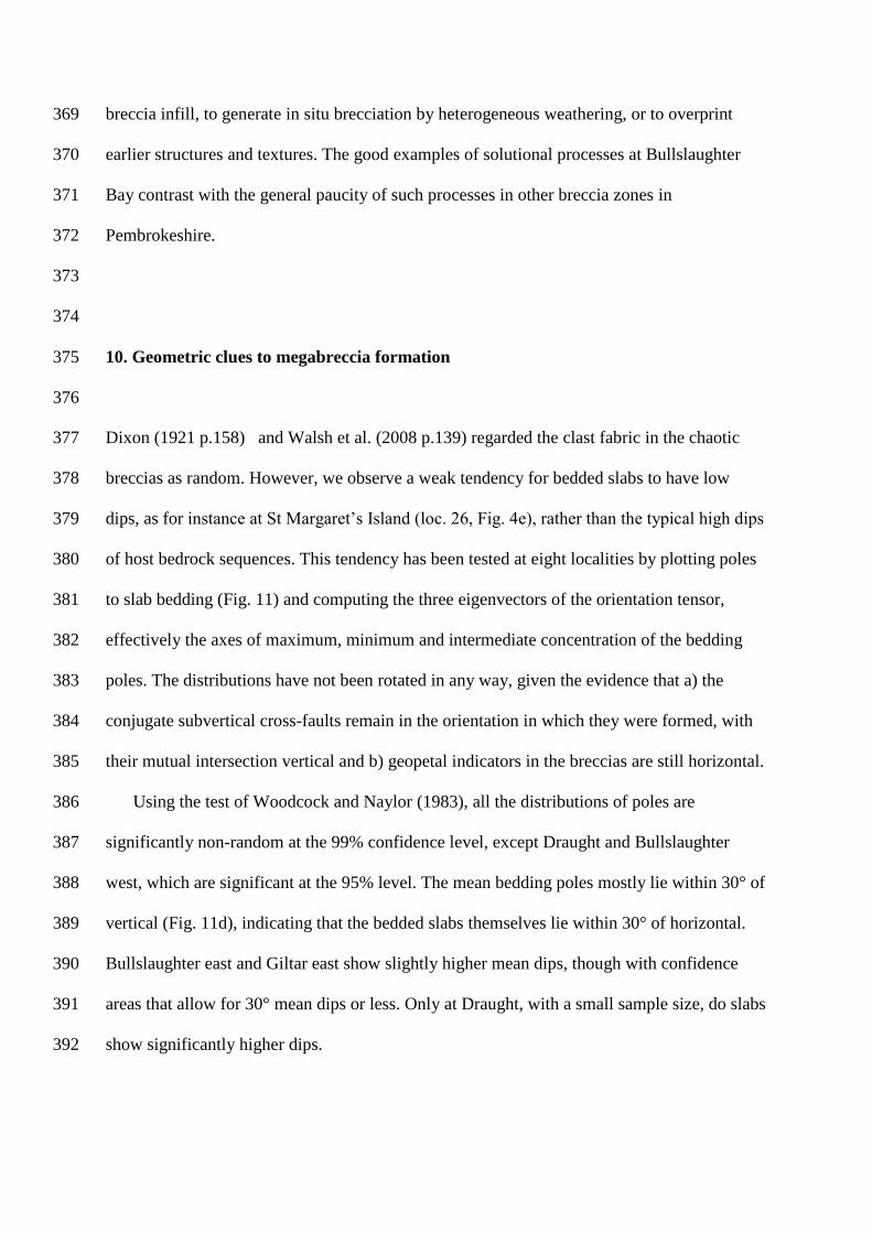
Fig. 4. Examples of breccia zone lithologies. a) crackle breccia, Proud Giltar (loc. 17); b) 827
mosaic breccia, Giltar West (loc. 21); c) chaotic breccia, Bullslaughter east (loc. 3); d) 828
chaotic megabreccia, Trevallen (loc. 7); e) chaotic megabreccia, St Margaret‘s Island (loc. 829
26); f) cataclasite, Stackpole Quay (loc. 12). 830
831
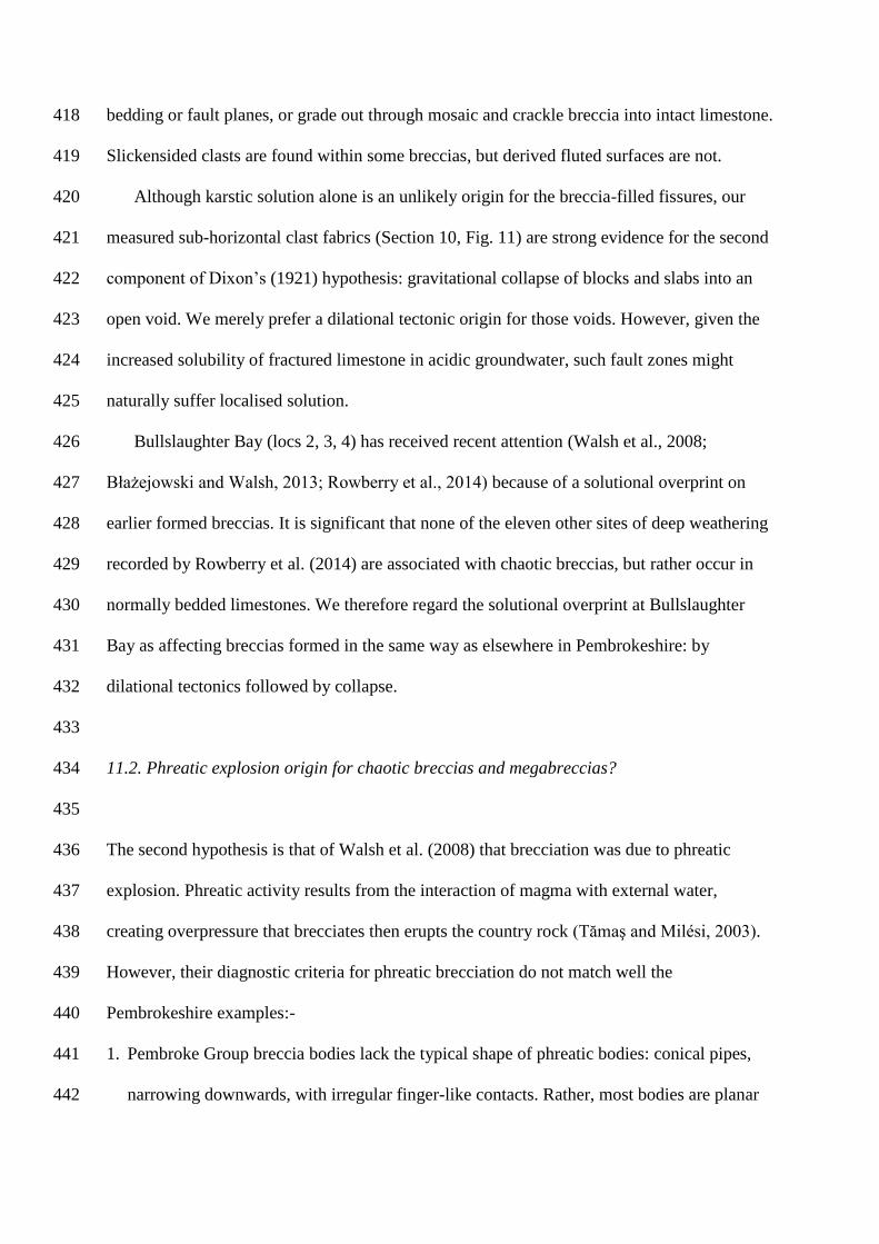
Fig. 5. Examples of cement and matrix infill to breccia bodies. a) blocky calcite(left) and 832
elongate calcite (right), Valleyfield East (loc. 20); b) calcite spar ball, Whitesheet (loc. 15); c) 833
laminated (catenary) sand/silt infill to breccia, Bullslaughter south (loc. 4); d) geopetal 834
sediment and cement infill to breccia, Trevallen (loc. 7); e) catenary-bedded micrite, Draught 835
Cove (loc. 14); f) either ‗ghost karst‘ or bedded sediment with dropstones (see text), 836
Bullslaughter south (loc. 4). 837
838

Fig. 6. Breccia zone characteristics and infill lithologies at each of the studied localities 839
(numbered on Fig. 1), arranged by structural setting (see text). 840
841
Fig. 7. Triangular diagram of contact relations of the studied breccia bodies, as numbered on 842
Fig. 1. End member geometries are illustrated by thumbnail geological maps. 843
844
Fig. 8. Maps and photographs of representative breccia zones related to vertical cross faults. 845
a) and b) Raming Hole (loc. 10); c) and d) Stackpole Quay (loc 12); e) and f) Flimston (loc. 846
1). All photos taken looking north. Photos (b) and (f) were taken by Sid Howells. 847
848
Fig. 9. Maps and photos of strike-parallel breccia zones: a) Tenby east (loc. 25) (with the 849
Tenby west, loc. 24, simple strike-slip zone); b) and c) Nanna‘s Cave (loc. 29); d-g) 850
Whitesheet (loc. 15) and Lydstep Point (loc 16). Photos (c), (d) and (g) were taken looking 851
west and photo (f) looking east. Photo (g) was taken by Sid Howells. 852
853
Fig. 10. a) Map of the breccia zones at Bullslaughter Bay west, east and south (locs 2, 3 & 854
4). b) and c) Photo-montages of Bullslaughter Bay west (b) and east (c). Photos were taken 855
by Sid Howells. 856
857
Fig. 11. Lower hemisphere equal-area plots of poles to bedded slabs in a) cross-strike fault 858
zones b) irregular zones, and c) bedding sub-parallel zones. Mean bedding poles and their 859
95% confidence areas are shown for each distribution, and d) aggregated on one comparison 860
plot. e) The shape and strength of each distribution shown on a plot of the ratios of their 861
eigenvalues (Woodcock, 1977). 862
863

Fig. 12. a) Diagrammatic map of folds and conjugate strike-slip faults formed by north-south 864
Variscan shortening. b) Map of postulated post-Variscan north-south extensional reactivation 865
of Variscan faults and steepened bedding. c) Cross-section across a dilational normal fault 866
that steepens to parallel bedding at shallow depths. 867
868
Fig. 13. Map of the depositional limits and faults of the Mesozoic Bristol Channel Basin and 869
the western end of the Wessex Basin, with localities of probable late Triassic fissure fills. 870
Faults are from British Geological Survey (1996), and fissure localities mainly from Wall and 871
Jenkyns (2004), Whiteside and Marshall (2008) and Wright et al. (2009). 872
873
Fig. 14. Field photographs of probable late Triassic fissure fills from other areas around the 874
Bristol Channel and Wessex Basins (Fig. 13). a) Chaotic megabreccia, Mewslade, Gower 875
Peninsula; b) Bedded chaotic breccia in dilational fault, Worlebury shore, Somerset; d) 876
Sediment fills and calcite-hematite veins in Devonian limestone, Berry Head Quarry, Devon. 877
878

Avon5and5Pembroke5Limestone5groupsTournaisianWandWVisean
breccia5localities
fold5axial5traces
Pembrokeshire5Peninsula
FORELAND
VARISCANWOROGEN
Variscan5Front
WG
'
EM
IR
-WD
StWGovan'sWHead
WW
'D
GI GRG-
G(
CaldeyWIsland
WE WM WI
WRW-W(GDGWGG
G' GE
WG
W'
Ww5Flimston5Bay
WGw5Stackpole5QuayWWw5Barafundle5Bay
(w5Box5Bay-w5Broad5HavenRw5TrevallenIw5Newton5QuarryMw5Crickmail
Gw5Bullslaughter5west
W'w5Pembroke5CastleWEw5Draught5CoveWMw5WhitesheetWIw5Lydstep5PointWRw5Proud5GiltarW-w5FrankBs5ShoreW(w5Valleyfield5TopGDw5Valleyfield5EastGWw5Giltar5westGGw5Giltar5eastG'w5Trefloyne5QuarriesGEw5Tenby5west
GIw5St5MargaretBs5IslandGRw5Little5SoundG-w5Rubbishy5CornerG(w5NannaBs5Cave'Dw5BullumBs5Bay
'w5Bullslaughter5eastEw5Bullslaughter5south
GDDW(MW(DW-M GDM
W-M
W(D
W(M
GDD
GDM
GWD GWM
preNCarboniferous5
Marros5and5Coal5Measures5groupsNamurianWandWWestphalian
GM
GMw5Tenby5east
ybS
yaS
(
WDw5Raming5HolestrikeNslip5faults
Variscan5Front
thrust5faults
MilfordWHaven
LinneyWHead
N
M5km
FLIM
ST
ON
5FA
ULT
BAY5SYNCLINE
PEMBROKE5SYNCLINE
SYNCLINE
RITEC5FAULT
RIDGEWAY5ANTICLINE
EAST5ANTICLINE
FRESHWATER
BULLSLAUGHTER
CASTLEMARTIN5CORSE5ANTICLINE
ORIELTON5SYNCLINE
ST5FLORENCE
ANGLE5SYNCLINE
Figure 1

Avon Group
Courceyan
Courceyan
Tourn
ais
ian
Tourn
ais
ian
Vis
ea
nV
isean
nN
am
Avon Group
Black Rock Limestone Subgroup
Black Rock LimestoneSubgroup
Linney Head Fmn
Chadian
Chadian
Arundian
Arundian
Holkerian
Holkerian
Brigantian
Pendleian
D2
D2
D1
D1
S2
S2
C2
Z
Z
C2
C1
K
K
C1
S1
S1
Brigantian Ta) S FLORENCE AND PEMBROKE SYNCLINES
b) BULLSLAUGHTER BAY SYNCLINE
Asbian
Asbian
Gully Oolite Formation
Pen-y-holt LimestoneFormation
thick-bedded limestone
thin-bedded limestone
siliceousmudstone
localitieswithoutmegabreccia
localities withmegabreccia
High Tor Lst Formation
Cornelly OoliteFormation
Stormy LimestoneFormation
Stackpole LimestoneFormation
Oxwich Head Lst Fm
Oxwich Head Lst Fmn
Oystermouth Formation
Aberkenfig Formation
Oystermouth Formation
Hobbyhorse Bay Lst Fm
Caswell Bay Mudstone Fm
100m
1. F
limst
on
2. B
ulls
laughte
r w
est
3. B
ulls
laughte
r east
4. B
ulls
laughte
r so
uth
5. C
rick
6. N
ew
ton Q
uarr
y
7. T
reva
llen
8. B
road H
ave
n
9. B
ox
Bay
10. R
am
ing H
ole
11. B
ara
fundle
12. S
tack
pole
13.
Pem
bro
ke
14.
Dra
ugh
t
15.
White
sh
ee
t
16.
Lyd
step
Po
int
17.
Pro
ud
Gilt
ar
18.
Fra
nk’
s S
ho
re
19.
Valle
yfie
ld T
op
20.
Valle
yfie
ld E
ast
26.
St
Marg
are
t’s Isl
an
d
21.
Gilt
ar
We
st
22.
Gilt
ar
Ea
st
27.
Litt
le S
ou
nd
23. T
reflo
yne
Qu
arr
ies
28.
Rubbis
hy
Co
rne
r
24/2
5. Te
nb
y
29.
Nanna
’s C
ave
30.
Bullu
m’s
Ba
y
Figure 2

fault initiation
eruption of volcan-ically heated steam
hydraulic fragmentation
solution wideningof fracture
a) karstic solution then collapse
b) fault displace-ment and frag-mentation
c) dilational faulting then collapse
d) phreatic explosion
displacement andfragmentation
dilational faulting creates void
collapse of solution void
collapse of fault void
Figure 3
(a)(a)(a)
(c)(c)(c)
(b)(b)(b)
(f)(f)(f)
10 cm10 cm10 cm
10 cm10 cm10 cm
10 cm10 cm10 cm
10 cm10 cm10 cm
50 cm50 cm50 cm
5 m5 m5 m
(d)(d)(d)
(e(e))(e)
Figure 4
(d)(d)(d)
(e)(e)(e)
(c)(c)(c) (f)(f)(f)
5 cm5 cm5 cm
1 m1 m1 m
5 cm5 cm5 cm50 cm50 cm50 cm
(a)(a)(a)
10 cm10 cm10 cm
(b)(b)(b)
1cm1cm1cm
Figure 5

crackle breccia
cross-strike faults bedding-parallel faults thrusts irregular indeterminate
cataclasite
carbonate cement
sediment matrix
zone width (metres)number of fault cores
approx. bedding dipdip direction
mosaic breccia
chaotic breccia
chaotic megabreccia
1. F
limst
on B
ay
2. B
ulls
laughte
r w
est
3. B
ulls
laughte
r east
4. B
ulls
laughte
r so
uth
5. C
rick
6. N
ew
ton Q
uarr
y
7. T
reva
llen
8. B
road H
ave
n
10
. R
am
ing
Ho
le
9.
Bo
x B
ay
11. B
ara
fundle
Bay
12. S
tack
pole
Quay
13. P
em
bro
ke C
ast
le
14. D
raught C
ove
15. W
hite
sheet
16. Lyd
step P
oin
t
17. P
roud G
iltar
18. F
rank'
s S
hore
19. V
alle
yfie
ld T
op
20. V
alle
yfie
ld E
ast
21. G
iltar
west
22. G
iltar
east
23. T
reflo
yne Q
uarr
ies
24. Te
nby
west
25. Te
nby
east
26. S
t M
arg
are
t's Isl
and
27. Litt
le S
ound
28. R
ubbis
hy
Corn
er
29. N
anna's
Cave
30. B
ullu
m's
Bay
70S
20?
15/75S
2004
75S
502
50N
50?
70N
202
20N
501
50N
601
55N
51
10S
351
10S
301
62S
101
85S
51
20S
170?
85S
2009
85N
703
85N
701
65S
201
65S
3501
55S
301
50S
801
50S
2002
45S
802
25S
201
80N
402
80N
110?
80N
401
80N
1101
90
301
90
1002
90
802
Figure 6

breccia zone oncross-strike faultchaotic megabreccia
coarsest breccia type
localities with indeterminate
boundaries
chaotic breccia
crackle/mosaic breccia
breccia zone striking parallel to bedding
Figure 2 gives key to locality numbers
thrust faults locality
29
15
30
26
13
23
2827
22
21
20
6
18910
5 24
1217
14
1
3
25
11
16 7 19
84
2
irregular breccia zone
Figure 7
ChB
wYK
wFp
wF/
wFm
w:p w::
wFm
wFF
wmp
wm/
wwY
wYP wYU
885
57
48
55
38
5485
49
85
kinkedQverticalQbedding
InferredQgradationalQcontacts
high2red2
matrix2content
Oxwich2Head
Limestone2
Formation
Quay
Pen-y-holt
Formation
NcGNaG
NeG
Cc
ChM ChM
ChM
ChB
ChB
CMB
ChB
ChB
CMB
CrB
CrB
CrB
CrB
ChB
Pen-y-holt
Formation
Oxwich2Head
Formation
Oxwich2Head
Formation
RAMINGQHOLE
STACKPOLEQUAY
FLIMSTONQBAY
CrB
chaoticQmegabreccia
NfGchaoticQbreccia
crackleTmosaicQbrecciachaoticQmegabreccia
NdG
NbG
NN
N
UK
cataclasite
chaoticQmegabreccia
PembrokeQGroupQ
crackleQbreccia
Cc
CrB
ChM
crackleTmosaicQbrecciaCMB
chaoticQbrecciaChB geologicalQcontact-dashedQifQuncertain
beddingQstrikeTdipcliffs-QtickQonQdownslopeQ
fault-dashedQifQuncertain
highQtideQmarkQ
lowQtideQmarkQ
strikeEslipQfault
fractureQstrikeTdip
MapQlegend
youngingQdirection
photographQviewdirection
mKQmetres
mKQmetres mKQmetres
Figure 8

relationshipofLfaultLzonesisLunexposed
verticalLcross-strikeLfaultLzone
thrustLfaultLzoneLdipsLsteeplyLsouth
CrB
ChB//W
:vx
:v.
//y
RITECkFAULT
cdok
-/kmetres
CMB
N
CHB
ChM
xS
kinkedkbedding
bedkparallelkcontacts
brecciawallkrock
wallrock
ccocbocao
ceo cfo cgo
:WQSx/
CHB
85
-/
cataclasite
chaotickmegabreccia
PembrokekGroupk
cracklekbreccia
Cc
CrB
ChM
crackleumosaickbrecciaCMB
chaotickbrecciaChBgeologicalkcontactNdashedkifkuncertain
beddingkstrikeudip
cliffsNktickkonkdownslopek
faultNdashedkifkuncertain
highktidekmarkk
lowktidekmarkkstrikePslipkfault
fracturekstrikeudipphotographkviewdirection
/S- /Sv/S:Sxx
SxQ
Sxy
CrB
CornellyLOoliteFormation
ChB
ChMChM
ChM
CC
CHB
CC
CornellyLOoliteLFormation
HighLTorLLimestoneLFormation
WhitesheetkRock
photographLe
photographLf
CMBCHB
.v
LydstepkPointLydstepkPoint
ph
oto
gra
ph
Lg
LydstepQuarry
/SW
StormyLLimestoneLFormation
PoorkinlandkexposureGkFaultsktracedkfromkaerialkphotographsGkLithostratigraphickcontactskapproximateG
.y
.y
.x
WHITESHEET
TENBYkWESTkakEAST NANNAlSkCAVE
LYDSTEPkPOINT
y/kmetres
N
y/kmetres
N
brecciawallkrock wallkrock
brecciakinked
wallkrock
wallkrock
breccia wallkrock
Figure 9

85
2.beddingTstrikeFdip
fractureTstrikeFdip
5.Tmetres
5.m
photograph b
photograph c
synclineTaxialTtrace
chaoticTmegabreccia
chaoticbreccia
chaoticbreccia
synclineTaxialTtrace
mainTfaultTcores synclineTaxialTtraceanticlineT
axialTtrace
38
70
32
53 7175
78
19
62
8160
23
44
6 81
78
7649
65
58
76
61 12
5
52
13
39
70
45
13
82
9
66
44
84
31
27
1854
4737
79
57
52
50
56
29
33
kinkedTbedding
OF
OF
gradationalTcontacts
AF
NoTexposure
redTbeddedTmatrixTformsT9.MTinfill
BullslaughterTBayTSynclineOHF
OF
ThirdTCove
OF
OHF
Ga:
ChB
ChB
ChB
ChB
ChB
CMBCrB
ChM
ChM
ChM
ChM
OHF
OF
OF
OF
??
N
chaoticTmegabreccia
PembrokeTGroupT
crackleTbrecciaCrB
ChM
crackleFmosaicTbrecciaCMB
chaoticTbrecciaChB
geologicalTcontact:dashedTifTuncertain
cliffs:TtickTonTdownslopeT
fault:TdashedTifTuncertain
highTtideTmarkT
lowTtideTmarkT
strikeOslipTfault
Legend
OxwichTHeadTFmHT
OystermouthTFmHT
OHF
OF
AberkenfigTFmHTAF
Gb:
Gc:
Figure 10
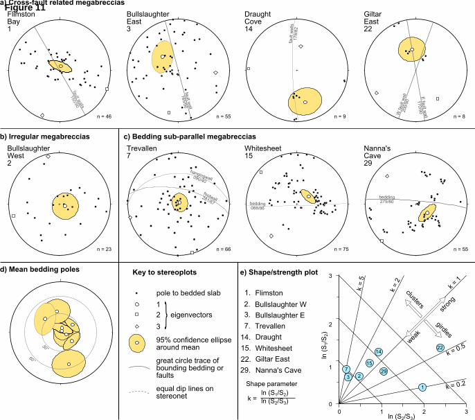
BullslaughterGE
Trevallen
Flimston
BullslaughterGW
c % q
ShapeGparameter
kG=GlnG8S%.SblnG8S.Sqb
GiltarGEast
Whitesheet
Draught
Nanna7sGCave
faul
tGwal
ls%7
8.8
bedding75.8cbedding
c88.86
faultGwalls
%5c.9c
faultGwall
%65.9c
footwall8%.67
hangingwallc9c.yc
GEGfaultGw
all
%7c.9c
WGfa
ultGw
all
cc.
9c
q
%
7
%5
%y
9
q4
74
%4
4
4
%54
%y4
94
30°
60°
poleGtoGbeddedGslab
%
GGGGGeigenvectors
q
95fGconfidenceGellipsearoundGmean
greatGcircleGtraceGofGboundingGbeddingGorfaults
equalGdipGlinesGonGstereonet
FlimstonBay%
BullslaughterEastq
DraughtGCove%y
GiltarEast
BullslaughterGWest
Trevallen7
Whitesheet%5
Nanna7sCave9
lnG8S.Sqb
lnG8
S%.
Sb
clusters
girdles
stron
g
weak
kG=
G5
kG=G
kG=G%
kG=Gc45
kG=Gc4
c
%
q
a) Cross-fault related megabreccias
b) Irregular megabreccias c) Bedding sub-parallel megabreccias
nG=Gq nG=G66 nG=G75 nG=G55
nG=Gy6 nG=G55 nG=G9 nG=G8
d) Mean bedding poles e) Shape/strength plotKey to stereoplots
Figure 11

E-W folds
conjugatestrike-slip
faults
dilationalstrike-slip
fault
dilationalstrike-slip
fault
dilationalnormal fault
steep dilationalsegment of normal fault
steep dilationalsegment of normal fault
dip-slipsegment of normal fault
dip-slipsegment of normal fault
steep bedding
fold axial surface
fold axial surface
breccia infill to fault
breccia infill to fault
steep b
eddin
g
MAP
SECTIONSECTION
MAP
(a) Variscan shortening
(b) late or post-Variscan extension
(c)
1 km
50 m
50 m50 m
Figure 12

Sho
Hop
Ber
BruDar
Hol
Bat
Emb
WinCan
Ben
Rut PanStB
Ban
San
BreWor Lul
DurCli
Fil
Tyt
Cro
Bea
50 N°
51 N°
5 W° 4 W° 3 W° 2°W2°W
Bul
Ten
Nan
Fra
Mew LimOxw PobWhi
PembrokePeninsulaPembrokePeninsula
PembrokePeninsula
Fissurelocalities
Gower PeninsulaGower Peninsula
GowerPeninsula
Vale of GlamorganVale of Glamorgan
Vale of Glamorgan
BRISTOL CHANNEL BASINBRISTOL CHANNEL BASIN
CORNUBIAN MASSIFCORNUBIAN MASSIF
WELSH MASSIFWELSH MASSIF
WESSEX BASINWESSEX BASIN
WO
RC
ES
TE
R G
RA
BE
NW
OR
CE
ST
ER
GR
AB
EN
PEWSEY SUB-BASINPEWSEY SUB-BASIN
PORTLAND-WIGHT SUB-BASIN
PORTLAND-WIGHT SUB-BASIN
DORSET SUB-BASIN
DORSET SUB-BASIN
START-COTENTIN RIDGESTART-COTENTIN RIDGE
TorbayTorbay
Torbay
Mendip HillsMendip HillsMendip Hills
Bristolarea
Bristolarea
Bristol areaSta
Emborough
Filton BH
Holwell
Lulsgate
Pant-y-ffynonRuthin
Sand Point
St Brides Island
Banwell BH
Bullslaughter Bay
with dateable fossilsin Carbonifer-ous limestone
in Devonian limestone
post-Carboniferous basins
pre-Permian massifs
Tytherington
Windsor HillWorle Hill
Durdham DownCromhallFrank’s Shore
no dateable fossils
Clifton
Whitesheet
Shoalstone
Beachley BH
Mewslade
Bendrick Bay
Nanna’s CaveStackpole Quay
Berry Head
Cannington BH
Tenby
Hope’s Nose
Darshill BH
BatscombeLimeslade
Bruton BHPobbles Beach
Brean DownOxwich Fault
50 km
Figure 13

(a)(a)(a)
(b)(b)(b)
(c)(c)(c)
1 m1 m1 m
1 m1 m1 m
1 m1 m1 m
Figure 14