Lehmann G 2009 North Syria and Cilicia (Sagona Volume)-Libre
Upload
harsha-nath-jhaCategory
view
786download
4
User Description, Radio NetworkParameters and Cell Design Data for
Ericsson's GSM Systems
USER DESCRIPTION
222/1553-HSC 103 12/16 Uen B
Copyright
© Copyright Ericsson AB 2009-2010. All rights reserved.
Disclaimer
No part of this document may be reproduced in any form without the writtenpermission of the copyright owner.
The contents of this document are subject to revision without notice due tocontinued progress in methodology, design, and manufacturing. Ericsson shallhave no liability for any error or damage of any kind resulting from the useof this document.
Trademark List
Ericsson is a trademark owned by Telefonaktiebolaget LMEricsson.
All other product or service names mentioned in thisUser Description are trademarks of their respectivecompanies.
222/1553-HSC 103 12/16 Uen B | 2010-06-18

Contents
Contents
1 General Information 1
1.1 Main Changes in Ericsson GSM System BSS G10B 1
1.2 Main Changes in Ericsson GSM System BSS G10A 2
1.3 Main Changes in Ericsson GSM System BSS 09A 3
1.4 Introduction 3
1.5 CDD Structure 4
1.6 Conventions 5
2 Site Data 9
2.1 Common Site Data 9
3 Cell Data 11
3.1 Common Data 11
3.2 Neighbouring Cell Relation Data 37
3.3 Idle Mode Behaviour 41
3.4 Locating 63
3.5 GPRS/EGPRS Idle Mode Behaviour 104
3.6 GPRS/EGPRS Cell Reselection 106
3.7 Channel Administration/Immediate Assignment on TCH 111
3.8 GPRS/EGPRS Channel Administration 120
3.9 Dynamic MS Power Control 136
3.10 GPRS/EGPRS Dynamic MS Power Control 145
3.11 Dynamic BTS Power Control 146
3.12 Discontinuous Transmission 154
3.13 Frequency Hopping 155
3.14 Intra Cell Handover 162
3.15 Assignment to Other Cell 168
3.16 Overlaid/Underlaid Subcells / Subcell Load Distribution /Tight BCCH Frequency Reuse 170
3.17 Hierarchical Cell Structures 177
3.18 Extended Range 185
3.19 Double BA Lists 187
3.20 Idle Channel Measurements 189
3.21 Cell Load Sharing 192
222/1553-HSC 103 12/16 Uen B | 2010-06-18

User Description, Radio Network Parameters and Cell Design Data for Ericsson's GSM Systems
3.22 Multiband Operation 195
3.23 Differential Channel Allocation 200
3.24 Enhanced Multi-Level Precedence and Preemption Service(eMLPP) 211
3.25 Adaptive Configuration of Logical Channels 218
3.26 GSM - UMTS - LTE Cell Reselection and Handover 221
3.27 Adaptive Multi Rate 241
3.28 EGPRS Link Quality Control 245
3.29 GPRS Link Adaptation 249
3.30 GPRS/EGPRS Quality of Service 250
3.31 Interference Rejection Combining 259
3.32 Multi Band Cell 259
3.33 GPRS/EGPRS Connection Control and Transfer 262
3.34 Antenna Hopping 269
3.35 Synchronized Radio Networks 269
3.36 Channel Allocation Optimization 271
3.37 Dual Transfer Mode (DTM) 283
3.38 Flexible Abis (FLAB) 285
3.39 Voice Group Call Service 288
3.40 Tandem Free Operation (TFO) 291
3.41 Handover and Signalling Robustness 293
3.42 Find Faulty Antenna Features 294
3.43 Abis over IP 295
3.44 Abis Optimization 307
3.45 PGW Load Distribution 312
3.46 Reduced Power Consumption in GSM RAN 313
3.47 Adaptive Multi Rate Wide Band 316
3.48 Abis Local Connectivity 321
3.49 BSC Capacity Supervision 322
3.50 A-Interface over IP 322
3.51 Automatic FLP/Automatic IRC Tuning 325
3.52 Multi Operator in BSS 329
4 Hardware Characteristics 331
4.1 Allocation Data for Transceiver Group 331
4.2 BSC Exchange Property Data 338
5 CDD Forms 339
222/1553-HSC 103 12/16 Uen B | 2010-06-18

User Description, Radio Network Parameters and Cell Design Data for Ericsson's GSM Systems
6 Index 349
6.1 Index to Parameters 349
6.2 Index to Commands 368
6.3 Cross-Reference: MML-Command Parameters 378
7 Concepts 385
Glossary 387
Reference List 389
222/1553-HSC 103 12/16 Uen B | 2010-06-18

User Description, Radio Network Parameters and Cell Design Data for Ericsson's GSM Systems
222/1553-HSC 103 12/16 Uen B | 2010-06-18

General Information
1 General Information
1.1 Main Changes in Ericsson GSM System BSS G10B
This UD is based on the document 222/1553–HSC 103 12/15 Uen. Thechanges between the above document and this document are as follows:
Removed information regarding RBS 200.
Added commands RFIMI, RFIMC, RFIMP, RFIME, RLBRI, RLBRC, RLBRE,RLBRP, RLMRI, RLMRC, RLMRE, RLMRP, RRAII and RRAIE.
Note that to be able to use AMR and AMR-WB together with A-Interface overIP other parameters need to be set, see Section 3.50 on page 322.
New, changed and removed parameter due to features: Automatic FLP,A-Interface over IP, Reduced Power Level after Handover.
New parameters Changed parameters Removed parameters
AFLP BSPWRB CTEI
AIRCT BSPWRT TXID
BSCAFLP
BSCAIRCT
BSRPWROFFSETN
BSRPWROFFSETP
CONFMODE
DSCP1
HOMTD
IMSIPAT
MAXTGCL
MBT
MCIMALG
MPS
MSRPWROFFSETN
MSRPWROFFSETP
NCCPERM (BSC)
SET
1222/1553-HSC 103 12/16 Uen B | 2010-06-18

User Description, Radio Network Parameters and Cell Design Data for Ericsson's GSM Systems
New parameters Changed parameters Removed parameters
TIME
1.2 Main Changes in Ericsson GSM System BSS G10A
This UD is based on the document 222/1553–HSC 103 12/14 Uen. Thechanges between the above document and this document are as follows:
New, changed and removed parameter due to features: AMR-WBEnhancements, EDGE Evolution - Dual Carrier DL, Multiple CCCH, BTS PSEnhancements, Timeslot Power Savings, GSM-UMTS-LTE Cell Reselection.
New parameters Changed parameters Removed parameters
AMRWBDHA BTSPSHYST DYNULDLACT
CCCH
CCCHCMD
DCDLACT
DHRAABISTHRWB
DTHAMRWB
EARFCN
ETCHTN
FDDARFCN
HPRIO
HPRIOTHR
ICMODE
LPRIOTHR
MEASTHR
MINCHBW
MINREQTCH
PAGBUNDLE
PCID
PCIDG
PCIDP
PCIDPS
PRIOTHR
2 222/1553-HSC 103 12/16 Uen B | 2010-06-18

General Information
New parameters Changed parameters Removed parameters
QRXLEVMINE
QRXLEVMINU
RATPRIO
SDHRAABISTHRWB
TIMESLOTPS
TNBCCH
TRES
1.3 Main Changes in Ericsson GSM System BSS 09A
New, changed and removed parameter due to features: A-Interface over IP,PS Switched Capacity Locks, Improved Ack/Nack
New parameters Changed parameters Removed parameters
DSCP AQMRTTCONST
FASTRET3GNC2 IPDEVNO
GBCAPALARMACT GPRSPRIO
GBCAPWARNTHR
IAN
JBS
PCMLAW
1.4 Introduction
The present document explains the Cell Design Data (CDD) that must beprovided for each cell in an Ericsson GSM system, G10B. This data is loaded inthe corresponding BSC by means of a Data Transcript file.
When a new Ericsson GSM system is built or when new cells are added orchanged in an existing Ericsson GSM system, the cell planner provides theoperator with a document for each cell containing data for the insertion of thecell in the radio network. The data from all such documents is then convertedinto a data transcript tape and loaded into the corresponding BSC.
A data transcript media contains not only CDD information but also other dataneeded for the complete configuration of the BSC and its BTSs. A descriptionof such information is out of the scope of this document.
3222/1553-HSC 103 12/16 Uen B | 2010-06-18

User Description, Radio Network Parameters and Cell Design Data for Ericsson's GSM Systems
In addition to the above-mentioned BSC cell parameters, some of the radiorelated MSC parameters and exchange properties are included in thisdocument. These parameters are included in order to present a more completepicture of the parameters that influence the design and evaluation of a radionetwork.
Note: The MSC parameters are only defined for Ericsson Mobile ServicesSwitching Centres. These parameters may have another name or maynot exist at all in MSCs manufactured by others than Ericsson.
This document gives references to GSM Recommendations.
This document provides short descriptions of Ericsson's GSM system G10Bparameters. For a full understanding of each of them, it is essential to study thedescription of each particular feature.
Note: The availability of a feature could depend on commercial agreements.Due to this it is possible that certain parameters are not supportedby an exchange.
The topics where GSM 800, GSM 900, GSM 1800 and GSM 1900 differ areindicated.
This document assumes that the reader is acquainted with the channel structurefor GSM 800, GSM 900, GSM 1800 and GSM 1900, the TDMA concept andthe locating algorithm for Ericsson's GSM systems.
1.5 CDD Structure
The parameters in this document are organized according to radio networkfeatures. The aim with this structure is to facilitate a more feature oriented cellplanning and network optimization.
In each radio network feature section, the parameters are grouped intosub-sections defined by the network entity where the parameter is defined. thisis described more elaborately in Section 1.4 on page 3.
The CDD is also arranged in a structure that corresponds to the subcellstructure shown in Figure 1. Therefore some parameters appear in more thanone part of the CDD.
4 222/1553-HSC 103 12/16 Uen B | 2010-06-18

General Information
Cell
Underlaid
Subcell
Overlaid
Subcell
Channelgroup
Channelgroup
. . . Channelgroup
Channelgroup
. . .
Figure 1 The Subcell Structure Supported by Ericsson's GSM System
A subcell is a set of channels that share some specific characteristics. Anoverlaid subcell serves a smaller part of the area of an underlaid subcell.
A cell always has an underlaid (UL) subcell, whereas the overlaid (OL) subcellis optional. A subcell structure exists when there is an overlaid subcell defined.The notation “cell/subcell data” (see Section 1.6 on page 5) is used in order toclarify that these parameters may be defined per subcell.
Each subcell is divided into channel groups, which include a subset of thefrequencies defined for a cell. A channel group can not be shared betweendifferent subcells. Same frequency can be defined in two channel groups withinthe cell but it must not be used at the same time.
1.6 Conventions
In this section, rules and conventions for the parameter section in the CDDdocument are issued.
“The parameter is /valid for/set per/ XXXX”
MSC The parameter is valid for all cells inthe MSC.
BSC The parameter is valid for all cells inthe BSC.
BSC exchange property The exchange properties are changedby means of a generic command,but they are essentially the same asregular parameters.
5222/1553-HSC 103 12/16 Uen B | 2010-06-18
User Description, Radio Network Parameters and Cell Design Data for Ericsson's GSM Systems
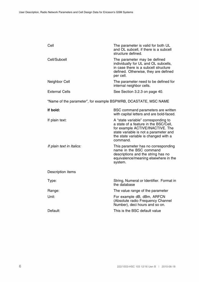
Cell The parameter is valid for both ULand OL subcell, if there is a subcellstructure defined.
Cell/Subcell The parameter may be definedindividually for UL and OL subcells,in case there is a subcell structuredefined. Otherwise, they are definedper cell.
Neighbor Cell The parameter need to be defined forinternal neighbor cells.
External Cells See Section 3.2.3 on page 40.
“Name of the parameter”, for example BSPWRB, DCASTATE, MSC NAME
If bold: BSC command parameters are writtenwith capital letters and are bold-faced.
If plain text: A “state variable” corresponding toa state of a feature in the BSC/Cell,for example ACTIVE/INACTIVE. Thestate variable is not a parameter andthe state variable is changed with acommand.
If plain text in Italics: This parameter has no correspondingname in the BSC commanddescriptions and the string has noequivalence/meaning elsewhere in thesystem.
Description items
Type: String, Numeral or Identifier. Format inthe database
Range: The value range of the parameter
Unit: For example dB, dBm, ARFCN(Absolute radio Frequency ChannelNumber), deci hours and so on.
Default: This is the BSC default value
6 222/1553-HSC 103 12/16 Uen B | 2010-06-18
General Information
Command: The parameter is initiated/affected/printed by this/these MML commands.
Different types of commands:
xxxxI: Initiate.
xxxxC: Change.
xxxxE: End.
xxxxP: Print.
O&M: Possible impact of the parameterchange to the service state.
Comments: Clarifying notes about the parameter.
7222/1553-HSC 103 12/16 Uen B | 2010-06-18

User Description, Radio Network Parameters and Cell Design Data for Ericsson's GSM Systems
8 222/1553-HSC 103 12/16 Uen B | 2010-06-18

Site Data
2 Site Data
2.1 Common Site Data
The common site data is the same for all cells in a site.
RSITE
Type: String
Range: 3 to 15 characters
Unit: -
Default: -
Command: RXMOI, RXMOC
RXMSC, RXMOP
O&M: -
Comments: Radio Site. Identity of the radio sitewhere the transceiver group (TG) islocated.
9222/1553-HSC 103 12/16 Uen B | 2010-06-18

User Description, Radio Network Parameters and Cell Design Data for Ericsson's GSM Systems
10 222/1553-HSC 103 12/16 Uen B | 2010-06-18
Cell Data
3 Cell Data
3.1 Common Data
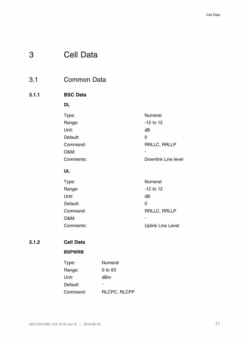
3.1.1 BSC Data
DL
Type: Numeral
Range: -12 to 12
Unit: dB
Default: 0
Command: RRLLC, RRLLP
O&M: -
Comments: Downlink Line level
UL
Type: Numeral
Range: -12 to 12
Unit: dB
Default: 0
Command: RRLLC, RRLLP
O&M: -
Comments: Uplink Line Level.
3.1.2 Cell Data
BSPWRB
Type: Numeral
Range: 0 to 63
Unit: dBm
Default: -
Command: RLCPC, RLCPP
11222/1553-HSC 103 12/16 Uen B | 2010-06-18
User Description, Radio Network Parameters and Cell Design Data for Ericsson's GSM Systems
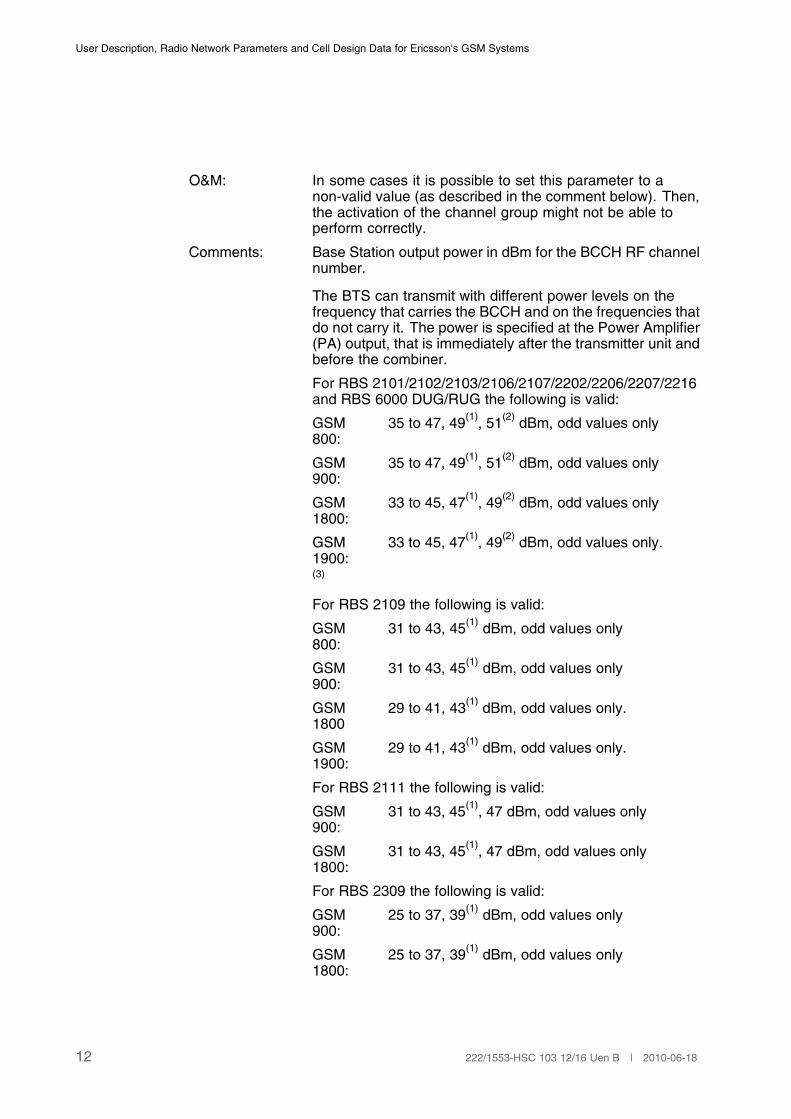
O&M: In some cases it is possible to set this parameter to anon-valid value (as described in the comment below). Then,the activation of the channel group might not be able toperform correctly.
Comments: Base Station output power in dBm for the BCCH RF channelnumber.
The BTS can transmit with different power levels on thefrequency that carries the BCCH and on the frequencies thatdo not carry it. The power is specified at the Power Amplifier(PA) output, that is immediately after the transmitter unit andbefore the combiner.
For RBS 2101/2102/2103/2106/2107/2202/2206/2207/2216and RBS 6000 DUG/RUG the following is valid:
GSM800:
35 to 47, 49(1)
, 51(2)
dBm, odd values only
GSM900:
35 to 47, 49(1)
, 51(2)
dBm, odd values only
GSM1800:
33 to 45, 47(1)
, 49(2)
dBm, odd values only
GSM1900:
33 to 45, 47(1)
, 49(2)
dBm, odd values only.
(3)
For RBS 2109 the following is valid:
GSM800:
31 to 43, 45(1)
dBm, odd values only
GSM900:
31 to 43, 45(1)
dBm, odd values only
GSM1800
29 to 41, 43(1)
dBm, odd values only.
GSM1900:
29 to 41, 43(1)
dBm, odd values only.
For RBS 2111 the following is valid:
GSM900:
31 to 43, 45(1)
, 47 dBm, odd values only
GSM1800:
31 to 43, 45(1)
, 47 dBm, odd values only
For RBS 2309 the following is valid:
GSM900:
25 to 37, 39(1)
dBm, odd values only
GSM1800:
25 to 37, 39(1)
dBm, odd values only
12 222/1553-HSC 103 12/16 Uen B | 2010-06-18
Cell Data
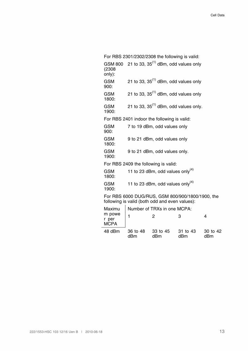
For RBS 2301/2302/2308 the following is valid:
GSM 800(2308only):
21 to 33, 35(1)
dBm, odd values only
GSM900:
21 to 33, 35(1)
dBm, odd values only
GSM1800:
21 to 33, 35(1)
dBm, odd values only
GSM1900:
21 to 33, 35(1)
dBm, odd values only.
For RBS 2401 indoor the following is valid:
GSM900:
7 to 19 dBm, odd values only
GSM1800:
9 to 21 dBm, odd values only
GSM1900:
9 to 21 dBm, odd values only.
For RBS 2409 the following is valid:
GSM1800:
11 to 23 dBm, odd values only(4)
GSM1900:
11 to 23 dBm, odd values only(4)
For RBS 6000 DUG/RUS, GSM 800/900/1800/1900, thefollowing is valid (both odd and even values):
Number of TRXs in one MCPA:Maximum power perMCPA
1 2 3 4
48 dBm 36 to 48dBm
33 to 45dBm
31 to 43dBm
30 to 42dBm
13222/1553-HSC 103 12/16 Uen B | 2010-06-18
User Description, Radio Network Parameters and Cell Design Data for Ericsson's GSM Systems
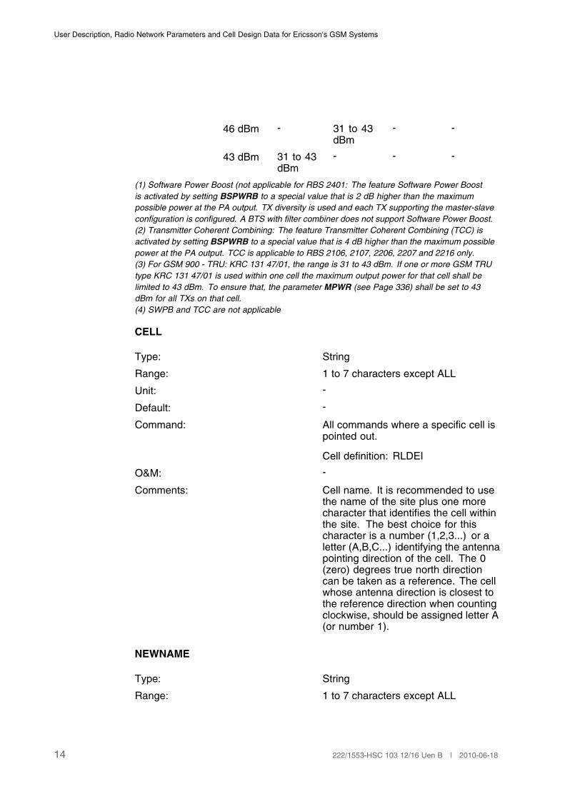
46 dBm - 31 to 43dBm
- -
43 dBm 31 to 43dBm
- - -
(1) Software Power Boost (not applicable for RBS 2401: The feature Software Power Boost
is activated by setting BSPWRB to a special value that is 2 dB higher than the maximum
possible power at the PA output. TX diversity is used and each TX supporting the master-slave
configuration is configured. A BTS with filter combiner does not support Software Power Boost.
(2) Transmitter Coherent Combining: The feature Transmitter Coherent Combining (TCC) is
activated by setting BSPWRB to a special value that is 4 dB higher than the maximum possible
power at the PA output. TCC is applicable to RBS 2106, 2107, 2206, 2207 and 2216 only.
(3) For GSM 900 - TRU: KRC 131 47/01, the range is 31 to 43 dBm. If one or more GSM TRU
type KRC 131 47/01 is used within one cell the maximum output power for that cell shall be
limited to 43 dBm. To ensure that, the parameter MPWR (see Page 336) shall be set to 43
dBm for all TXs on that cell.
(4) SWPB and TCC are not applicable
CELL
Type: String
Range: 1 to 7 characters except ALL
Unit: -
Default: -
Command: All commands where a specific cell ispointed out.
Cell definition: RLDEI
O&M: -
Comments: Cell name. It is recommended to usethe name of the site plus one morecharacter that identifies the cell withinthe site. The best choice for thischaracter is a number (1,2,3...) or aletter (A,B,C...) identifying the antennapointing direction of the cell. The 0(zero) degrees true north directioncan be taken as a reference. The cellwhose antenna direction is closest tothe reference direction when countingclockwise, should be assigned letter A(or number 1).
NEWNAME
Type: String
Range: 1 to 7 characters except ALL
14 222/1553-HSC 103 12/16 Uen B | 2010-06-18
Cell Data
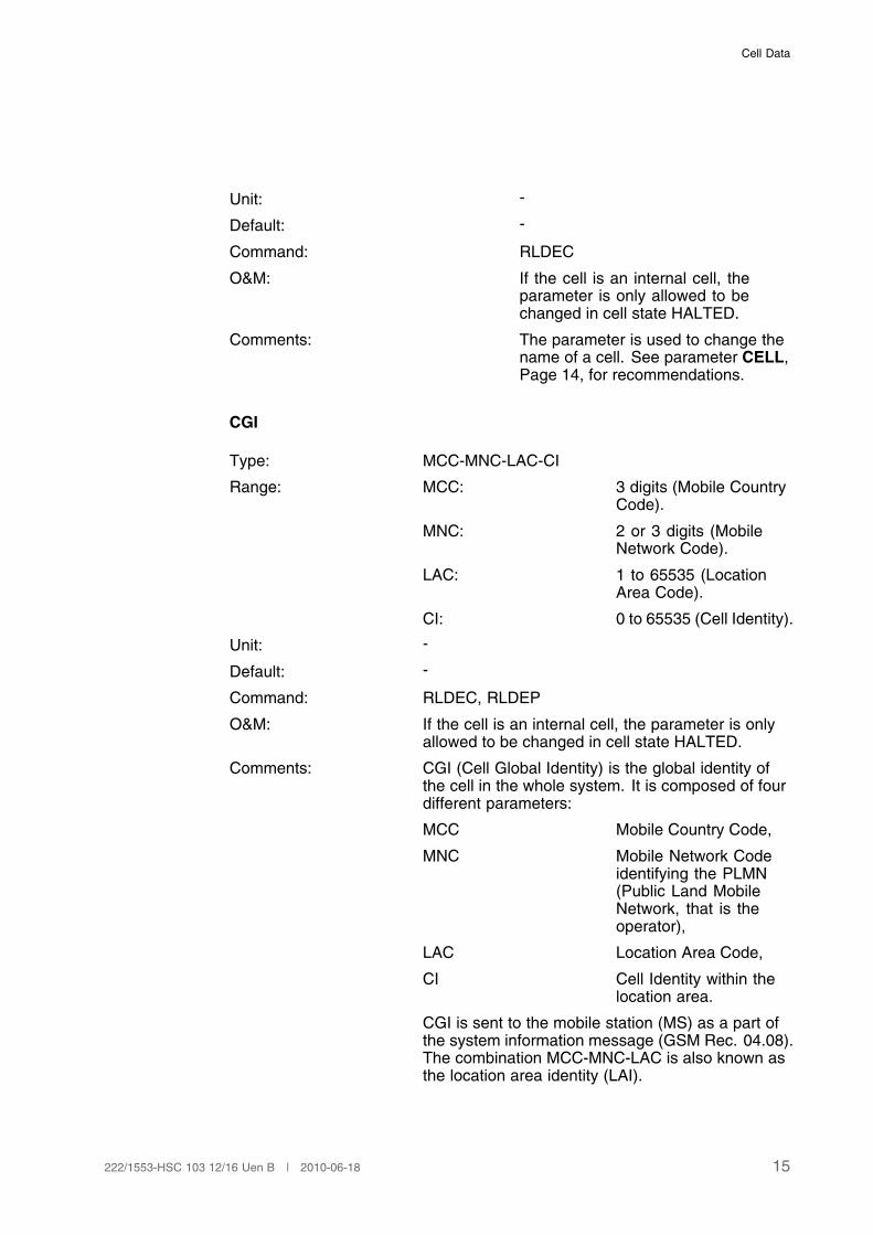
Unit: -
Default: -
Command: RLDEC
O&M: If the cell is an internal cell, theparameter is only allowed to bechanged in cell state HALTED.
Comments: The parameter is used to change thename of a cell. See parameter CELL,Page 14, for recommendations.
CGI
Type: MCC-MNC-LAC-CI
Range: MCC: 3 digits (Mobile CountryCode).
MNC: 2 or 3 digits (MobileNetwork Code).
LAC: 1 to 65535 (LocationArea Code).
CI: 0 to 65535 (Cell Identity).
Unit: -
Default: -
Command: RLDEC, RLDEP
O&M: If the cell is an internal cell, the parameter is onlyallowed to be changed in cell state HALTED.
Comments: CGI (Cell Global Identity) is the global identity ofthe cell in the whole system. It is composed of fourdifferent parameters:
MCC Mobile Country Code,
MNC Mobile Network Codeidentifying the PLMN(Public Land MobileNetwork, that is theoperator),
LAC Location Area Code,
CI Cell Identity within thelocation area.
CGI is sent to the mobile station (MS) as a part ofthe system information message (GSM Rec. 04.08).The combination MCC-MNC-LAC is also known asthe location area identity (LAI).
15222/1553-HSC 103 12/16 Uen B | 2010-06-18
User Description, Radio Network Parameters and Cell Design Data for Ericsson's GSM Systems
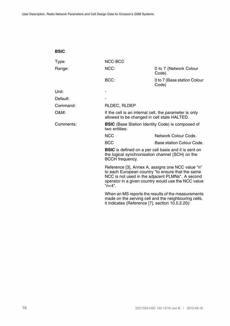
BSIC
Type: NCC-BCC
Range: NCC: 0 to 7 (Network ColourCode).
BCC: 0 to 7 (Base station ColourCode)
Unit: -
Default: -
Command: RLDEC, RLDEP
O&M: If the cell is an internal cell, the parameter is onlyallowed to be changed in cell state HALTED.
Comments: BSIC (Base Station Identity Code) is composed oftwo entities:
NCC Network Colour Code.
BCC Base station Colour Code.
BSIC is defined on a per cell basis and it is sent onthe logical synchronisation channel (SCH) on theBCCH frequency.
Reference [3], Annex A, assigns one NCC value "n"to each European country "to ensure that the sameNCC is not used in the adjacent PLMNs". A secondoperator in a given country would use the NCC value"n+4".
When an MS reports the results of the measurementsmade on the serving cell and the neighbouring cells,it indicates (Reference [7], section 10.5.2.20):
16 222/1553-HSC 103 12/16 Uen B | 2010-06-18

Cell Data
The measured signal levels on the serving cell.
The measured levels, the BSIC and the BCCHfrequency of the neighbouring cells.
Only measurements from cells with allowed NCC arereported (see parameter NCCPERM, Page 50).
The colour code NCC is then used to discriminatecells that use the same frequency. Though mainlyintended for the purpose of differentiating PLMNs, italso serves to distinguish cells within one PLMN thatuse the same frequency provided they have beenassigned different NCC. If there are two operators ina country, they can use more than two PLMN colourcodes each one, provided that in border areas onlythe values "n" and "n+4" are used.
What is stated here should be considered as generalguidelines. Of course any type of NCC assignmentmust be decided by agreements between operatorsand countries.
Regarding the protection against co-channelinterference, the MS reports the BCC value sothat the BSC can distinguish among differentcells transmitting on the same frequency. For thispurpose the BCC must be allocated as wisely aspossible. If frequency reuse clusters are used thenit is recommended that all BTSs in a given clusteruse the same BCC. In this way the reuse distanceof a certain BCC can be maximised according to thefrequency reuse distance.
(1)
(1) Only 8 different values (BCC: 0 to 7) are used for the purpose of recognizing co-channel
interference.
BCCHNO
Type: Numeral
Range: 128 to 251 (GSM 800).
1 to 124 (GSM 900, P-band).
0, 975 to 1023 (GSM 900, G1-band).
512 to 885 (GSM 1800).
512 to 810 (GSM 1900)
Unit: -
17222/1553-HSC 103 12/16 Uen B | 2010-06-18

User Description, Radio Network Parameters and Cell Design Data for Ericsson's GSM Systems
Default: -
Command: RLDEC, RLDEP
O&M: -
Comments: Absolute RF channel number forBCCH.
Absolute RF channel number alreadydefined for a dedicated channel cannot be used.
The frequency carrying the BCCH(Broadcast Control Channel) in acell, is defined by the Absolute RadioFrequency Channel Number, ARFCN,with the parameter BCCHNO. Thedefined ARFCN must be unique withinthe cell.
According to the GSM 800recommendations the channelsare numbered as follows:
fl(n) = 824.2 + 0.2*(n–128) in MHz,where n (Absolute Radio FrequencyChannel Number, ARFCN) goes from128 to 251 and fl is a frequency in thelower band, BTS receiver.
fu(n) = fl(n) + 45 in MHz, where n goesfrom 128 to 251 and fu is a frequencyin the upper band, BTS transmitter.
According to the GSM 900recommendations the channelsare numbered as follows:
18 222/1553-HSC 103 12/16 Uen B | 2010-06-18
Cell Data
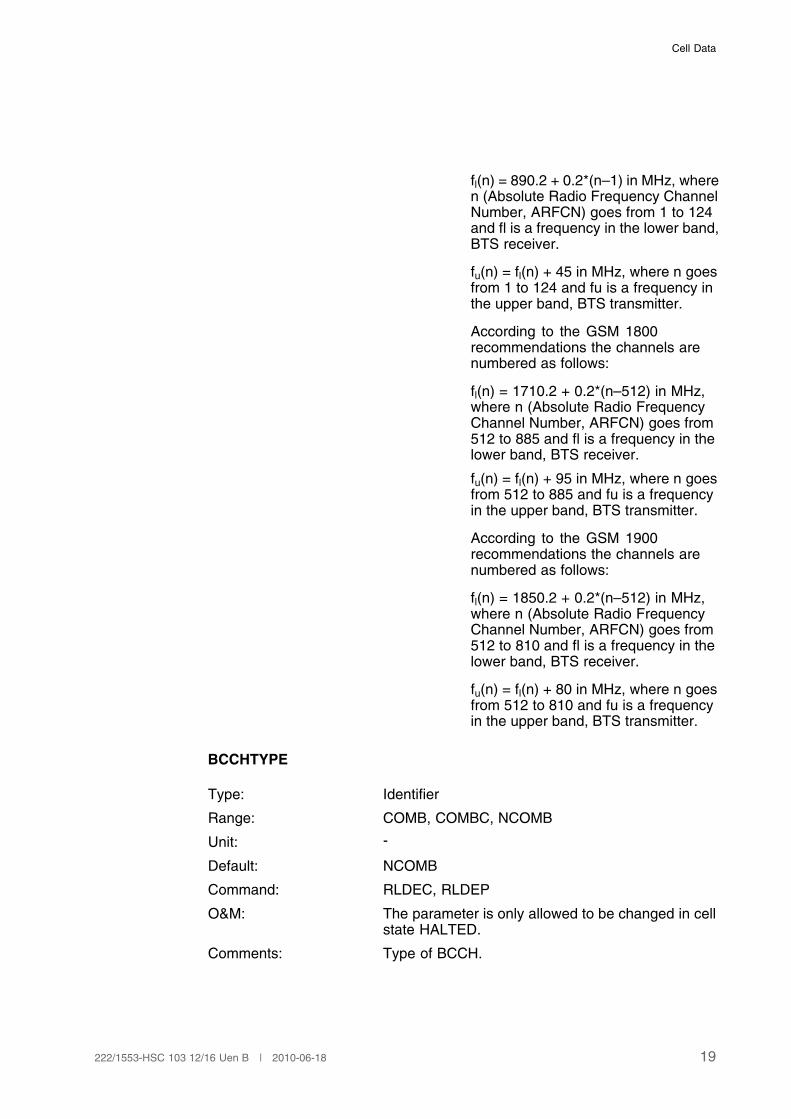
fl(n) = 890.2 + 0.2*(n–1) in MHz, wheren (Absolute Radio Frequency ChannelNumber, ARFCN) goes from 1 to 124and fl is a frequency in the lower band,BTS receiver.
fu(n) = fl(n) + 45 in MHz, where n goesfrom 1 to 124 and fu is a frequency inthe upper band, BTS transmitter.
According to the GSM 1800recommendations the channels arenumbered as follows:
fl(n) = 1710.2 + 0.2*(n–512) in MHz,where n (Absolute Radio FrequencyChannel Number, ARFCN) goes from512 to 885 and fl is a frequency in thelower band, BTS receiver.
fu(n) = fl(n) + 95 in MHz, where n goesfrom 512 to 885 and fu is a frequencyin the upper band, BTS transmitter.
According to the GSM 1900recommendations the channels arenumbered as follows:
fl(n) = 1850.2 + 0.2*(n–512) in MHz,where n (Absolute Radio FrequencyChannel Number, ARFCN) goes from512 to 810 and fl is a frequency in thelower band, BTS receiver.
fu(n) = fl(n) + 80 in MHz, where n goesfrom 512 to 810 and fu is a frequencyin the upper band, BTS transmitter.
BCCHTYPE
Type: Identifier
Range: COMB, COMBC, NCOMB
Unit: -
Default: NCOMB
Command: RLDEC, RLDEP
O&M: The parameter is only allowed to be changed in cellstate HALTED.
Comments: Type of BCCH.
19222/1553-HSC 103 12/16 Uen B | 2010-06-18
User Description, Radio Network Parameters and Cell Design Data for Ericsson's GSM Systems
COMB indicates that the cellhas a combined BCCHand SDCCH/4 (seeparameter SDCCH,Page 34).
COMBC indicates that the cell hasa combined BCCH andSDCCH/4 with a CBCHsubchannel.
NCOMB indicates that the celldoes not have any typeof combined BCCH andSDCCH/4.
The BCCH is always allocated to time slot number 0(TN0) in the defined ARFCN.
The CBCH is used for transmission of the messageswhen the function Short Messages Service CellBroadcast (SMSCB) is activated in the cell. SMSCBenables the operator to submit short messages forbroadcasting to a specific area within the PLMN.
AGBLK
Type: Numeral
Range: 0 to 7 if non-combined BCCH is used.
0 to 2 if combined BCCH andSDCCH/4 is used
Unit: -
Default: 1
Command: RLDEC, RLDEP
O&M: The parameter is only allowed to bechanged in cell state HALTED.
20 222/1553-HSC 103 12/16 Uen B | 2010-06-18
Cell Data
Comments: Number of reserved access grantblocks.
Number of CCCH blocks reservedfor the access grant channel. Theremaining CCCH blocks are used forthe paging channel.
In each downlink non-combinedSDCCH 51 frames multiframe thereare 9 different CCCH blocks and in thecombined BCCH/SDCCH there are 3different blocks. They can be used to:
• Send paging messages, that is usedas a Paging Channel.
• Send access granted messages, thatis used as an Access Grant Channel.
After an MS tunes to the BCCH/CCCHchannel and decodes the SystemInformation, it performs an evaluationthat, taking into account the MS'sown IMSI (International Mobile StationIdentity) number, determines to whichparticular CCCH block in the physicalchannel it should listen (Reference[8]). Every CCCH in the physicalchannel (Paging Subchannel) sendspaging messages to a certain group ofMSs that are called its paging group.The reason for the existence of suchpaging groups is that the MSs cansave batteries because it only needsto listen to its own Paging Subchannelmessages.
The physical channel (PagingSubchannel) sends paging messagesto a certain group of MSs. Asmentioned before these very sameCCCH blocks are also used to sendAccess Grant messages to the MSs,that is to answer a Random Accessmessage that an MS wanting to accessthe system has sent to the system,and to send notifications on the NCH.
The structure of the BCCH regardingPaging messages and Access Grantmessages can be controlled by thetwo parameters AGBLK and MFRMS.
21222/1553-HSC 103 12/16 Uen B | 2010-06-18
User Description, Radio Network Parameters and Cell Design Data for Ericsson's GSM Systems
AGBLK tells how many of the CCCHblocks that should be reserved forthe Access Grant messages andNCH information. In Ericsson's GSMsystem, Access Grant messages aregiven priority over Paging messages.Together with MFRMS, AGBLKindicates how many paging groupsthere will be.
With a non-combined BCCH andAGBLK = 1, there are 8 CCCH blocksin each multiframe. This means that itis possible to have 16 to 72 differentPaging Subchannels, that is PagingGroups. (Since MFRMS can takevalues between 2 and 9.)
With a combined BCCH/SDCCH andAGBLK = 1, there are 2 CCCH blocksin each multiframe. In this case itis possible to have 4 to 18 differentPaging Groups.
(1)
(1) AGBLK must not be 0 when SI 7 and 8 have to be sent, when short message service cell
broadcast (SMSCB) is in use on a cell not using combined BCCH and SDCCH/4 (GSM05.02) or
when Voice Group Call Service is used in the cell.
MFRMS
Type: Numeral
Range: 2 to 9
Unit: CCCH multiframes
Default: 6
Command: RLDEC, RLDEP
O&M: The parameter is only allowed to bechanged in cell state HALTED.
22 222/1553-HSC 103 12/16 Uen B | 2010-06-18
Cell Data
Comments: Multiframes period. Defines period oftransmission for PAGING REQUESTmessages to the same pagingsubgroup.
Together with AGBLK, MFRMSdetermines the number of paginggroups.
MFRMS is also used by the MS todetermine downlink signalling failurein idle mode (Reference [9]). Thedownlink signalling failure criterion isbased on the downlink signalling failurecounter DSC. When the MS campson a cell, DSC shall be initialised toa value equal to the nearest integerto 90/N where N is the MFRMSparameter for that cell. Thereafter,whenever the MS attempts to decodea message in its paging subchannel;if a message is successfully decodedDSC is increased by 1, (howevernever beyond the nearest integer to90/N), otherwise DSC is decreased by4. When DSC reaches 0, a downlinksignalling failure shall be declared. Adownlink signalling failure shall resultin cell reselection.
MFRMS is also used by the MS tocontrol monitoring of received BCCHcarrier level (Reference [9]). Whilstin idle mode an MS shall continue tomonitor all BCCH carriers as indicatedin the BCCH allocation list (BA list). Arunning average of received level inthe preceding 5 to
Max{5, ((5*N+6) div 7)*MFRMS/4}
seconds shall be maintained for eachcarrier in the BCCH allocation. N isthe number of non-serving cell BCCHcarriers in BA.
FNOFFSET
Type: Numeral
Range: 0 to 1325
23222/1553-HSC 103 12/16 Uen B | 2010-06-18
User Description, Radio Network Parameters and Cell Design Data for Ericsson's GSM Systems
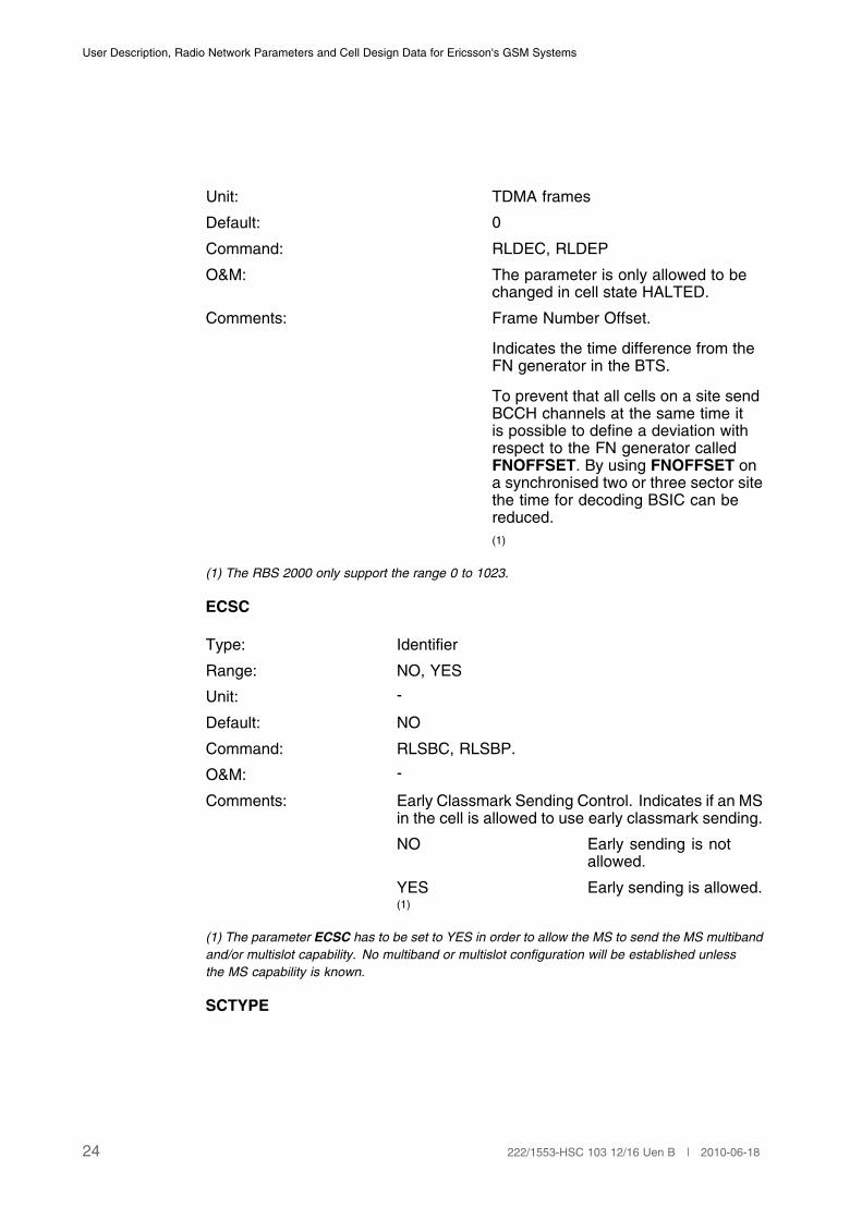
Unit: TDMA frames
Default: 0
Command: RLDEC, RLDEP
O&M: The parameter is only allowed to bechanged in cell state HALTED.
Comments: Frame Number Offset.
Indicates the time difference from theFN generator in the BTS.
To prevent that all cells on a site sendBCCH channels at the same time itis possible to define a deviation withrespect to the FN generator calledFNOFFSET. By using FNOFFSET ona synchronised two or three sector sitethe time for decoding BSIC can bereduced.
(1)
(1) The RBS 2000 only support the range 0 to 1023.
ECSC
Type: Identifier
Range: NO, YES
Unit: -
Default: NO
Command: RLSBC, RLSBP.
O&M: -
Comments: Early Classmark Sending Control. Indicates if an MSin the cell is allowed to use early classmark sending.
NO Early sending is notallowed.
YES Early sending is allowed.(1)
(1) The parameter ECSC has to be set to YES in order to allow the MS to send the MS multiband
and/or multislot capability. No multiband or multislot configuration will be established unless
the MS capability is known.
SCTYPE
24 222/1553-HSC 103 12/16 Uen B | 2010-06-18
Cell Data
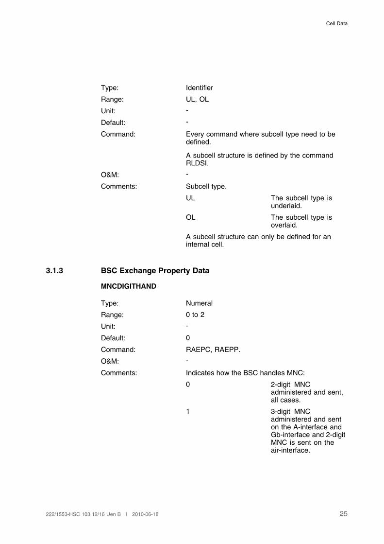
Type: Identifier
Range: UL, OL
Unit: -
Default: -
Command: Every command where subcell type need to bedefined.
A subcell structure is defined by the commandRLDSI.
O&M: -
Comments: Subcell type.
UL The subcell type isunderlaid.
OL The subcell type isoverlaid.
A subcell structure can only be defined for aninternal cell.
3.1.3 BSC Exchange Property Data
MNCDIGITHAND
Type: Numeral
Range: 0 to 2
Unit: -
Default: 0
Command: RAEPC, RAEPP.
O&M: -
Comments: Indicates how the BSC handles MNC:
0 2-digit MNCadministered and sent,all cases.
1 3-digit MNCadministered and senton the A-interface andGb-interface and 2-digitMNC is sent on theair-interface.
25222/1553-HSC 103 12/16 Uen B | 2010-06-18
User Description, Radio Network Parameters and Cell Design Data for Ericsson's GSM Systems
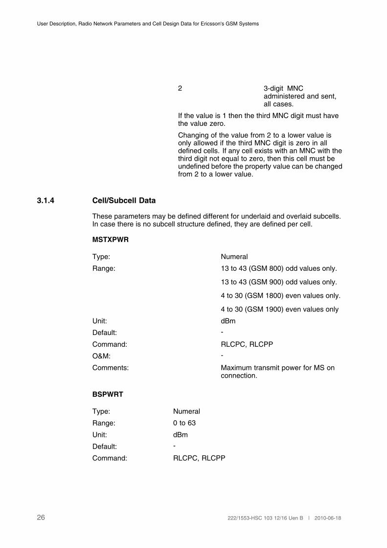
2 3-digit MNCadministered and sent,all cases.
If the value is 1 then the third MNC digit must havethe value zero.
Changing of the value from 2 to a lower value isonly allowed if the third MNC digit is zero in alldefined cells. If any cell exists with an MNC with thethird digit not equal to zero, then this cell must beundefined before the property value can be changedfrom 2 to a lower value.
3.1.4 Cell/Subcell Data
These parameters may be defined different for underlaid and overlaid subcells.In case there is no subcell structure defined, they are defined per cell.
MSTXPWR
Type: Numeral
Range: 13 to 43 (GSM 800) odd values only.
13 to 43 (GSM 900) odd values only.
4 to 30 (GSM 1800) even values only.
4 to 30 (GSM 1900) even values only
Unit: dBm
Default: -
Command: RLCPC, RLCPP
O&M: -
Comments: Maximum transmit power for MS onconnection.
BSPWRT
Type: Numeral
Range: 0 to 63
Unit: dBm
Default: -
Command: RLCPC, RLCPP
26 222/1553-HSC 103 12/16 Uen B | 2010-06-18

Cell Data
O&M: In some cases it is possible to set this parameter to anon valid value (as described in the comment below).Then, the activation of the channel group might not beable to perform correctly.
Comments: Base Station output power in dBm for the non-BCCHRF channel numbers.
The power is specified at the Power Amplifier (PA)output, that is immediately after the transmitter unitand before the combiner.
For RBS 2101/2102/2103/2106/2107/2202/2206/2207/2216 and RBS 6000 DUG/RUG the following isvalid:
GSM 800: 35 to 47, 49(1)
, 51(2)
dBm, odd values only
GSM 900: 35 to 47, 49(1)
, 51(2)
dBm, odd values only
GSM1800:
33 to 45, 47(1)
, 49(2)
dBm, odd values only
GSM1900:
33 to 45, 47(1)
, 49(2)
dBm, odd valuesonly.
(3)
For RBS 2109 the following is valid:
GSM 800: 31 to 43, 45(1)
dBm, odd values only
GSM 900: 31 to 43, 45(1)
dBm, odd values only
GSM1800:
29 to 41, 43(1)
dBm, odd values only.
GSM1900:
29 to 41, 43(1)
dBm, odd values only.
For RBS 2111 the following is valid:
GSM 900: 31 to 43, 45(1)
, 47 dBm, odd values only
GSM1800:
31 to 43, 45(1)
, 47 dBm, odd values only
For RBS 2309 the following is valid:
GSM 900: 25 to 37, 39(1)
dBm, odd values only
GSM1800:
25 to 37, 39(1)
dBm, odd values only
GSM1900:
25 to 37, 39(1)
dBm, odd values only.
For RBS 2301/2302/2308 the following is valid:
27222/1553-HSC 103 12/16 Uen B | 2010-06-18

User Description, Radio Network Parameters and Cell Design Data for Ericsson's GSM Systems
GSM 800(2308only):
21 to 33, 35(1)
dBm, odd values only
GSM 900: 21 to 33, 35(1)
dBm, odd values only
GSM1800:
21 to 33, 35(1)
dBm, odd values only
For RBS 2401 indoor the following is valid:
GSM 900: 7 to 19 dBm, odd values only
GSM1800:
9 to 21 dBm, odd values only
GSM1900:
9 to 21 dBm, odd values only
For RBS 2409 the following is valid:
GSM1800:
11 to 23 dBm, odd values only(4)
GSM1900:
11 to 23 dBm, odd values only(4)
For RBS 6000 DUG/RUS, GSM 800/900/1800/1900,the following is valid (both odd and even values):
Number of TRXs in one MCPA:Maximumpower perMCPA
1 2 3 4
48 dBm 36 to 48dBm
33 to 45dBm
31 to 43dBm
30 to 42dBm
46 dBm - 31 to 43dBm
- -
43 dBm 31 to 43dBm
- - -
(1) Software Power Boost (not applicable for RBS 2401): The feature Software Power Boost
is activated by setting BSPWRT to a special value that is 2 dB higher than the maximum
possible power at the PA output. TX diversity is used and each TX supporting the master-slave
configuration is configured. A BTS with filter combiner does not support Software Power Boost.
(2) Transmitter Coherent Combining (TCC): The feature Transmitter Coherent Combining (TCC)
is activated by setting BSPWRT to a special value that is 4 dB higher than the maximum possible
power at the PA output. TCC is applicable to RBS 2106, 2107, 2206, 2207 and 2216 only.
(3) For GSM 900 - TRU: KRC 131 47/01, the range is 31 to 43 dBm. If one or more GSM TRU
type KRC 131 47/01 is used within one cell the maximum output power for that site shall be limited
to 43 dBm. To ensure that, the parameter MPWR shall be set to 43 dBm for all TXs on that cell.
(4) SWPB and TCC are not applicable
28 222/1553-HSC 103 12/16 Uen B | 2010-06-18
Cell Data
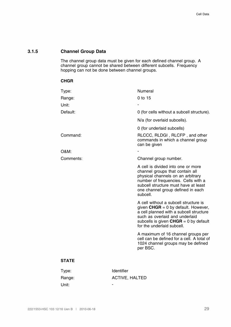
3.1.5 Channel Group Data
The channel group data must be given for each defined channel group. Achannel group cannot be shared between different subcells. Frequencyhopping can not be done between channel groups.
CHGR
Type: Numeral
Range: 0 to 15
Unit: -
Default: 0 (for cells without a subcell structure).
N/a (for overlaid subcells).
0 (for underlaid subcells)
Command: RLCCC, RLDGI , RLCFP , and othercommands in which a channel groupcan be given
O&M: -
Comments: Channel group number.
A cell is divided into one or morechannel groups that contain allphysical channels on an arbitrarynumber of frequencies. Cells with asubcell structure must have at leastone channel group defined in eachsubcell.
A cell without a subcell structure isgiven CHGR = 0 by default. However,a cell planned with a subcell structuresuch as overlaid and underlaidsubcells is given CHGR = 0 by defaultfor the underlaid subcell.
A maximum of 16 channel groups percell can be defined for a cell. A total of1024 channel groups may be definedper BSC.
STATE
Type: Identifier
Range: ACTIVE, HALTED
Unit: -
29222/1553-HSC 103 12/16 Uen B | 2010-06-18

User Description, Radio Network Parameters and Cell Design Data for Ericsson's GSM Systems
Default: -
Command: RLSTC, RLSTP
O&M: -
Comments: Cell or Channel Group state:
ACTIVE The cell or channel groupis active.
HALTED The cell or channel groupis halted.
HOP
Type: Identifier
Range: ON, OFF
Unit: -
Default: OFF
Command: RLCHC, RLCFP
O&M: When changing the parameter from OFF to ONall ongoing calls in the channel group might bedropped.
Comments: Frequency hopping status:
ON The hopping status forthe channel group ishopping for TCH andSDCCH.
OFF The hopping status forthe channel group is nonhopping.
SDCCHs as well as TCHs can hop. A BCCH will nothop even if it belongs to a channel group definedas hopping.
HSN
Type: Numeral
Range: 0 to 63
Unit: -
Default: -
Command: RLCHC, RLCFP.
O&M: Changing of this parameter might cause all ongoingcalls in the channel group to be dropped.
30 222/1553-HSC 103 12/16 Uen B | 2010-06-18

Cell Data
Comments: Hopping sequence number.
The hopping BPC is transmitted on a set offrequencies included in a Hopping Frequency Set(HFS). The order of the frequencies to transmit on isdefined by the hopping sequence number HSN, asdescribed in Reference [8].
HSN = 0 cyclic hopping sequence.
HSN = 1 to 63 pseudo randomsequences.
NUMREQBPC
Type: Numeral / Identifier
Range: 8 to 128 in steps of 8, SYSDEF
Unit: -
Default: SYSDEF
Command: RLBDC, RLBDP.
O&M: -
Comments: The number of required basic physical channels(BPCs) in a channel group.
SYSDEF System defined limit.The number of BPCs isdefined by the number offrequencies in a channelgroup.
DCHNO
Type: Numeral
Range: 128 to 251 (GSM 800).
1 to 124 (GSM 900, P-band).
0, 975 to 1023 (GSM 900, G1-band).
512 to 885 (GSM 1800).
512 to 810 (GSM 1900)
Unit: ARFCN
Default: -
Command: RLCFI, RLCFE, RLCFP
31222/1553-HSC 103 12/16 Uen B | 2010-06-18
User Description, Radio Network Parameters and Cell Design Data for Ericsson's GSM Systems
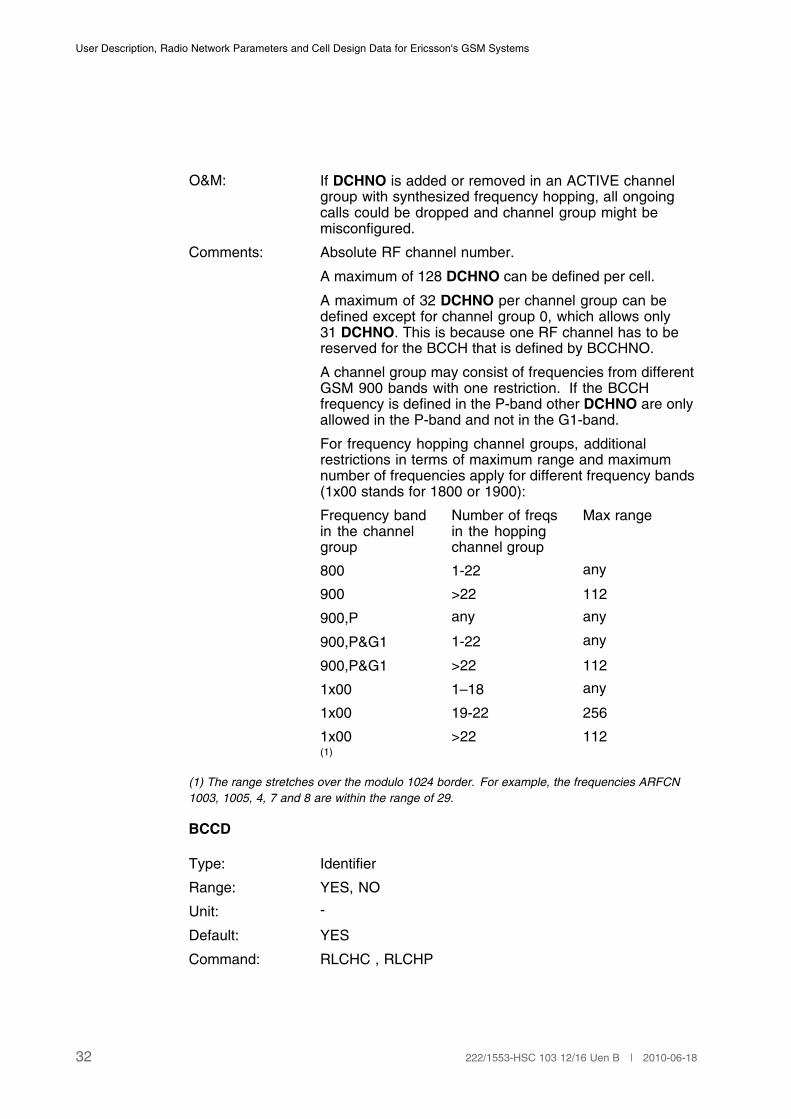
O&M: If DCHNO is added or removed in an ACTIVE channelgroup with synthesized frequency hopping, all ongoingcalls could be dropped and channel group might bemisconfigured.
Comments: Absolute RF channel number.
A maximum of 128 DCHNO can be defined per cell.
A maximum of 32 DCHNO per channel group can bedefined except for channel group 0, which allows only31 DCHNO. This is because one RF channel has to bereserved for the BCCH that is defined by BCCHNO.
A channel group may consist of frequencies from differentGSM 900 bands with one restriction. If the BCCHfrequency is defined in the P-band other DCHNO are onlyallowed in the P-band and not in the G1-band.
For frequency hopping channel groups, additionalrestrictions in terms of maximum range and maximumnumber of frequencies apply for different frequency bands(1x00 stands for 1800 or 1900):
Frequency bandin the channelgroup
Number of freqsin the hoppingchannel group
Max range
800 1-22 any
900 >22 112
900,P any any
900,P&G1 1-22 any
900,P&G1 >22 112
1x00 1–18 any
1x00 19-22 256
1x00 >22 112(1)
(1) The range stretches over the modulo 1024 border. For example, the frequencies ARFCN
1003, 1005, 4, 7 and 8 are within the range of 29.
BCCD
Type: Identifier
Range: YES, NO
Unit: -
Default: YES
Command: RLCHC , RLCHP
32 222/1553-HSC 103 12/16 Uen B | 2010-06-18

Cell Data
O&M: -
Comments: Defines if the channel group frequencies are allowed (YES)or not (NO) for Immediate Assignment.
It might not be possible to set BCCD=YES for all channelgroups in the cell. This is due to restrictions on themaximum number of hopping frequencies allowed forImmediate Assignment and their maximum ranges fordifferent frequency bands (1x00 stands for 1800 or 1900):
Frequencyband(s) in thecell
Number ofhopping freqsfor ImmAss
Max range
800 1–22 any
800 23–64 112
900,P 1–64 any
900,P&G1 1–22 any
900,P&G1 23–64 112
1x00 1–18 any
1x00 19–22 256
1x00 23–64 112
800 & 900,P 1–22 any
800 & 900,P 23–64 112
800 & 900,P&G1 1–18 any
800 & 900,P&G1 19–22 256
800 & 900,P&G1 23–64 112
800 & 1x00 1–16 any
800 & 1x00 17–18 512
900,P & 1x00 1–16 any
900,P & 1x00 17–18 512
900,P & 1x00 19–22 256
900,P&G1 & 1x00 1–16 any
900,P&G1 & 1x00 17–18 512
900,P&G1 & 1x00 19–22 256
900,P&G1 & 1x00 23–64 112(1)
(1) The range stretches over the modulo 1024 border. For example, the frequencies ARFCN
1003,1005, 4, 7 and 8 are within the range of 29.
33222/1553-HSC 103 12/16 Uen B | 2010-06-18
User Description, Radio Network Parameters and Cell Design Data for Ericsson's GSM Systems
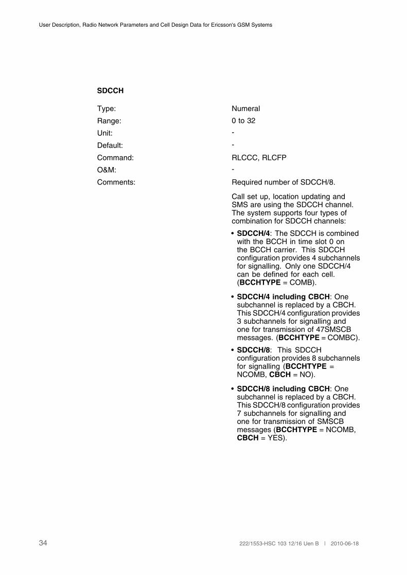
SDCCH
Type: Numeral
Range: 0 to 32
Unit: -
Default: -
Command: RLCCC, RLCFP
O&M: -
Comments: Required number of SDCCH/8.
Call set up, location updating andSMS are using the SDCCH channel.The system supports four types ofcombination for SDCCH channels:
• SDCCH/4: The SDCCH is combinedwith the BCCH in time slot 0 onthe BCCH carrier. This SDCCHconfiguration provides 4 subchannelsfor signalling. Only one SDCCH/4can be defined for each cell.(BCCHTYPE = COMB).
• SDCCH/4 including CBCH: Onesubchannel is replaced by a CBCH.This SDCCH/4 configuration provides3 subchannels for signalling andone for transmission of 47SMSCBmessages. (BCCHTYPE = COMBC).
• SDCCH/8: This SDCCHconfiguration provides 8 subchannelsfor signalling (BCCHTYPE =NCOMB, CBCH = NO).
• SDCCH/8 including CBCH: Onesubchannel is replaced by a CBCH.This SDCCH/8 configuration provides7 subchannels for signalling andone for transmission of SMSCBmessages (BCCHTYPE = NCOMB,CBCH = YES).
34 222/1553-HSC 103 12/16 Uen B | 2010-06-18
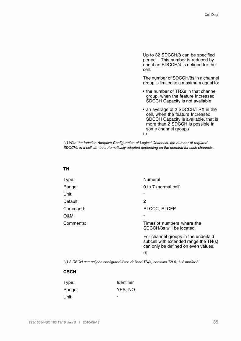
Cell Data
Up to 32 SDCCH/8 can be specifiedper cell. This number is reduced byone if an SDCCH/4 is defined for thecell.
The number of SDCCH/8s in a channelgroup is limited to a maximum equal to:
• the number of TRXs in that channelgroup, when the feature IncreasedSDCCH Capacity is not available
• an average of 2 SDCCH/TRX in thecell, when the feature IncreasedSDCCH Capacity is available, that ismore than 2 SDCCH is possible insome channel groups
(1)
(1) With the function Adaptive Configuration of Logical Channels, the number of required
SDCCHs in a cell can be automatically adapted depending on the demand for such channels.
TN
Type: Numeral
Range: 0 to 7 (normal cell)
Unit: -
Default: 2
Command: RLCCC, RLCFP
O&M: -
Comments: Timeslot numbers where theSDCCH/8s will be located.
For channel groups in the underlaidsubcell with extended range the TN(s)can only be defined on even values.
(1)
(1) A CBCH can only be configured if the defined TN(s) contains TN 0, 1, 2 and/or 3.
CBCH
Type: Identifier
Range: YES, NO
Unit: -
35222/1553-HSC 103 12/16 Uen B | 2010-06-18
User Description, Radio Network Parameters and Cell Design Data for Ericsson's GSM Systems
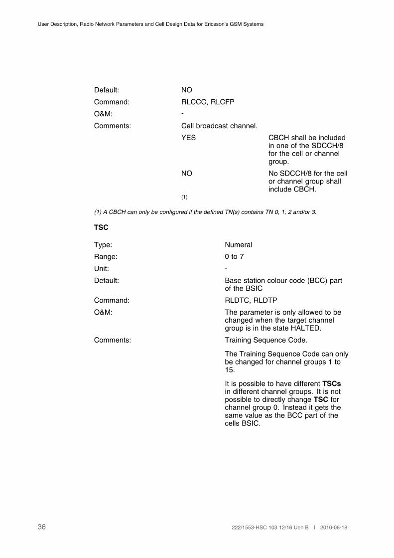
Default: NO
Command: RLCCC, RLCFP
O&M: -
Comments: Cell broadcast channel.
YES CBCH shall be includedin one of the SDCCH/8for the cell or channelgroup.
NO No SDCCH/8 for the cellor channel group shallinclude CBCH.
(1)
(1) A CBCH can only be configured if the defined TN(s) contains TN 0, 1, 2 and/or 3.
TSC
Type: Numeral
Range: 0 to 7
Unit: -
Default: Base station colour code (BCC) partof the BSIC
Command: RLDTC, RLDTP
O&M: The parameter is only allowed to bechanged when the target channelgroup is in the state HALTED.
Comments: Training Sequence Code.
The Training Sequence Code can onlybe changed for channel groups 1 to15.
It is possible to have different TSCsin different channel groups. It is notpossible to directly change TSC forchannel group 0. Instead it gets thesame value as the BCC part of thecells BSIC.
36 222/1553-HSC 103 12/16 Uen B | 2010-06-18
Cell Data
3.2 Neighbouring Cell Relation Data
3.2.1 Neighbouring Cell Relation Data
Note: Within this chapter, only relations to GSM neighbouring cell aredescribed. For the description of relations to UMTS neighbouring cells,see parameter CELLR, Page 234.
There are two types of parameters that can be defined for each neighbouringcell relation; Hysteresis and Offset parameters. It is possible to define up to64 neighbours for each cell. A total of up to 32768 neighbouring cell relations(internal and external) can be defined per BSC, from which a maximum of32768 can be external.
CELLR
Type: String
Range: 1 to 7 characters except ALL
Unit: -
Default: -
Command: RLNRI, RLNRC, RLNRE, RLNRP
O&M: -
Comments: Related cell designation.
The identity of the neighbouring cellfor which the set of parameters shouldbe applied is specified by means ofCELLR. The name of the neighbouringcell must be specified here.
All internal neighbor relations aremutual unless explicitly specified.
Example: If cell B is defined as aneighbor to cell A (CELLR = B) withcertain values for the hysteresisand offset parameters then cell A isautomatically defined as a neighbor tocell B with the same hysteresis values(symmetric relation) and the sameabsolute values but opposite sign forthe offset parameters (asymmetricrelation).
CTYPE
37222/1553-HSC 103 12/16 Uen B | 2010-06-18
User Description, Radio Network Parameters and Cell Design Data for Ericsson's GSM Systems
Type: String
Range: EXT, Omitted
Unit: -
Default: Omitted
Command: RLDEI, RLLHP, RLDEP
O&M: -
Comments: External cell.
If the neighbouring cell belongs to another BSC thenthis must be specified explicitly by means of CTYPE.
EXT The neighbouring cell isexternal.
Omitted The neighbouring cell isinternal.
In addition CGI, BSIC, LAYER, LAYERTHR,LAYERHYST, PSSTEMP, PTIMTEMP, BCCHNO,BSPWR, BSTXPWR, BSRXMIN, BSRXSUFF,MSTXPWR, MSRXMIN, MSRXSUFF, AW, SCHO,MISSNM and EXTPEN must be specified for anexternal neighbouring cell. These parameters arealso defined in the neighbouring cell's home BSC.
RELATION
Type: String
Range: SINGLE, Omitted
Unit: -
Default: Omitted
Command: RLNRI
O&M: -
Comments: The parameter is only specified whenthe relation is one way cell →cellr.This means that offset and hysteresisparameters are only defined in onedirection.
RELATION is always set to single forexternal cells, that is neighbouringcells that belong to another BSC.
CS
38 222/1553-HSC 103 12/16 Uen B | 2010-06-18

Cell Data
Type: String
Range: YES, NO
Unit: -
Default: NO
Command: RLNRC, RLNRP
O&M: -
Comments: Co-site, which indicates if a cell shares the samesite as its neighbor.
YES Cell is co-sited withneighbor.
NO Cell is not co-sited withneighbor.
3.2.2 Additional Parameters Defined for Neighbour Cell Relations
These parameters need to be defined, together with the parameters in Section3.2.1 on page 37, for neighbor cell relations. They are defined by means ofthe command RLNRC.
BQOFFSET
BQOFFSETAFR
BQOFFSETAWB
AWOFFSET
CAND
Ericsson 1 locating algorithm:
TRHYST
KHYST
LHYST
TROFFSET
KOFFSET
LOFFSET
Ericsson 3 locating algorithm:
HIHYST
39222/1553-HSC 103 12/16 Uen B | 2010-06-18
User Description, Radio Network Parameters and Cell Design Data for Ericsson's GSM Systems
LOHYST
HYSTSEP
OFFSET
3.2.3 External Neighbor Cell Data
Note: Within this chapter, only external GSM neighbouring cell are described.For the description of external UMTS neighbouring cells, see parameterCELL, Page 228.
These parameters need to be defined, together with the parameters in Section3.2.1 on page 37 and Section 3.2.2 on page 39, for external neighbouring cells.If applicable, also values for the cell locating hierarchical data (see Section 3.17on page 177) shall be given.
A total of up to 2048 external cells can be defined per BSC.
CGI
BSIC
BCCHNO
MISSNM
EXTPEN
SCHO
BSPWR
BSTXPWR
MSTXPWR
BSRXMIN
MSRXMIN
BSRXSUFF
MSRXSUFF
AW
LAYER
LAYERTHR
LAYERHYST
40 222/1553-HSC 103 12/16 Uen B | 2010-06-18
Cell Data
PSSTEMP
PTIMTEMP
3.3 Idle Mode Behaviour
3.3.1 Paging - MSC data
PAGREP1LA
Type: Numeral
Range: 0 to 3
Unit: -
Default: 2
Command: DBTSP:TAB=AXEPARS, SETNAME=GSMMMSC
O&M: -
Comments: Repeated paging in one location area.
The parameter is optional.
This parameter defines in case of mobile terminatingcalls how the paging in one location area is repeated.
0 Paging in one locationarea is not repeated.
1 Paging in one locationarea is repeated witheither TMSI or IMSI.
2 Paging in one locationarea is repeated withIMSI.
3 Paging is repeated asglobal paging with IMSI.
(1)
(1) This parameter is only defined for Ericsson MSCs.
PAGREPGLOB
Type: Numeral
Range: 0 to 1
Unit: -
Default: 0
41222/1553-HSC 103 12/16 Uen B | 2010-06-18
User Description, Radio Network Parameters and Cell Design Data for Ericsson's GSM Systems
Command: DBTSP:TAB=AXEPARS, SETNAME=GSMMMSC
O&M: -
Comments: Repeated global paging.
The parameter is optional.
This parameter defines how the global paging isrepeated if the first paging attempt was global.
0 Global paging is notrepeated.
1 Global paging isrepeated with IMSI.
(1)
(1) This parameter is only defined for Ericsson MSCs.
PAGNUMBERLA
Type: Numeral
Range: 1 to 3
Unit: -
Default: 1
Command: MGEPC , MGEPP.
O&M: -
Comments: Number of location areas in a pagingmessage.
This parameter indicates the maximumpermitted amount of location areasthat can be included in a pagingmessage.
The parameter is optional.
A parameter with a value > 1 is onlyvalid if all BSCs connected to anMSC/VLR support a paging messagewith a list of location areas.
(1)
(1) This parameter is only defined for Ericsson MSCs.
PAGTIMEFRST1LA
Type: Numeral
Range: 2 to 10
42 222/1553-HSC 103 12/16 Uen B | 2010-06-18

Cell Data
Unit: s
Default: 4
Command: MGEPC , MGEPP.
O&M: -
Comments: Time supervision for the first paging inone location area.
This parameter defines the timesupervision for the page response ofthe first paging attempt in one locationarea. After expiration of this timerthe paging is repeated accordingto parameter PAGREP1LA. Theparameter is optional.
(1)
(1) This parameter is only defined for Ericsson MSCs.
PAGTIMEFRSTGLOB
Type: Numeral
Range: 2 to 10
Unit: s
Default: 4
Command: MGEPC , MGEPP.
O&M: -
Comments: Time supervision for the first globalpaging.
This parameter defines the timesupervision for the page response ofthe first global paging attempt. Afterexpiration of this timer the pagingis repeated according to parameterPAGREPGLOB. The parameter isoptional.
(1)
(1) This parameter is only defined for Ericsson MSCs.
PAGTIMEREP1LA
Type: Numeral
Range: 2 to 10
43222/1553-HSC 103 12/16 Uen B | 2010-06-18
User Description, Radio Network Parameters and Cell Design Data for Ericsson's GSM Systems
Unit: s
Default: 7
Command: MGEPC , MGEPP
O&M: -
Comments: Time supervision for the repeatedpaging in one location area.
The parameter is optional.
This parameter defines the timesupervision for the page response ofrepeated paging in one location area.After expiration of this timer no newpaging repetition for this call is done.
(1)
(1) This parameter is only defined for Ericsson MSCs
PAGTIMEREPGLOB
Type: Numeral
Range: 2 to 10
Unit: s
Default: 7
Command: MGEPC , MGEPP
O&M: -
Comments: Time supervision for the repeatedglobal paging.
The parameter is optional.
This parameter defines the timesupervision for page responseof repeated global paging. Afterexpiration of this timer no new pagingrepetition for this call is done.
(1)
(1) This parameter is only defined for Ericsson MSCs
3.3.2 LATA Administration - MSC Data
The following exchange properties are valid only if the function Equal Accessand Transit Network Selection in MSC/VLR and GMSC is implemented. This isan optional GSM1900 function.
44 222/1553-HSC 103 12/16 Uen B | 2010-06-18

Cell Data
LATAUSED
Type: Numeral
Range: 0, 1
Unit: -
Default: 0
Command: MGEPC , MGEPP.
O&M: -
Comments: Defines the usage of LATA administration.
0 LATA administration isnot used.
1 LATA administration isused. The parameter isoptional.
(1)
(1) This parameter is only defined for Ericsson MSCs.
PAGLATA
Type: Numeral
Range: 0, 1
Unit: -
Default: 0
Command: DBTSP:TAB=AXEPARS,SETNAME=GSMMMSC.
O&M: -
Comments: Indicates if LATA paging is used for mobileterminating calls or not.
0 LATA paging is not used.
1 LATA paging is used.
This parameter is only valid if parameter LATAUSED= 1. The parameter is optional.
(1)
(1) This parameter is only defined for Ericsson MSCs.
PAGREPCT1LA
Type: Numeral
Range: 0 to 3
Unit: -
45222/1553-HSC 103 12/16 Uen B | 2010-06-18
User Description, Radio Network Parameters and Cell Design Data for Ericsson's GSM Systems
Default: 2
Command: DBTSP:TAB=AXEPARS,SETNAME=GSMMMSC.
O&M: -
Comments: Defines how the paging is repeated in one locationarea.
0 Paging in one locationarea is not repeated.
1 Paging in one locationarea is repeated witheither TMSI or IMSI.
2 Paging in one locationarea is repeated withTMSI.
3 Paging is repeatedas call delivery LATApaging with IMSI.
This parameter is only valid if parameter PAGLATA= 1. The parameter is optional.
(1)
(1) This parameter is only defined for Ericsson MSCs.
PAGTIMEREPLATA
Type: Numeral
Range: 2 to 10
Unit: s
Default: 7
Command: MGEPC , MGEPP.
O&M: -
Comments: Defines the time supervision for pageresponse of repeated LATA paging.After expiration of this timer no newpaging repetition for this call is done.
This parameter is only valid ifparameter PAGLATA = 1. Theparameter is optional.
(1)
(1) This parameter is only defined for Ericsson MSCs.
46 222/1553-HSC 103 12/16 Uen B | 2010-06-18
Cell Data
3.3.3 Implicit Detach - MSC Data
BTDM
Type: Numeral
Range: 6 to 1530 in steps of 6, OFF
Unit: min
Default: OFF
Command: MGIDP , MGIDI.
O&M: -
Comments: Base time duration of implicit detachof a mobile subscriber by the network.
BTDM must be as long as the longestperiodic updating time (T3212) in theinterworking BSCs.
The supervision time is the sum ofBTDM and GTDM.
(1)
(1) This parameter is only defined for Ericsson MSCs.
GTDM
Type: Numeral
Range: 0 to 255
Unit: min
Default: -
Command: MGIDP , MGIDI.
O&M: -
Comments: Guard time duration.
The guard time is used to preventunnecessary marking of MS as implicitdetached.
(1)
(1) This parameter is only defined for Ericsson MSCs.
3.3.4 Automatic Deregistration - MSC Data
TDD
47222/1553-HSC 103 12/16 Uen B | 2010-06-18

User Description, Radio Network Parameters and Cell Design Data for Ericsson's GSM Systems
Type: Numeral
Range: 1 to 255, OFF
Unit: days
Default: OFF
Command: MGADI.
O&M: -
Comments: Automatic deregistration supervisiontime.
Offers the possibility to automaticallyderegister mobile subscribers thathave had no radio contact during acertain period of time in the MSC/VLR.
(1)
(1) This parameter is only defined for Ericsson MSCs.
3.3.5 Idle Mode Behaviour - Cell Data
These parameters are sent in the System Information on BCCH & SACCH.
Note: Within this chapter, only parameters that are used in GSM cell selectionand reselection are described. For the description of parameters usedin GSM - UMTS cell reselection, see parameter UMFI, Page 223.
ACCMIN
Type: Numeral
Range: 47 to 110
Unit: See comments
Default: 110
Command: RLSSC, RLSSP
O&M: -
Comments: Minimum received signal level in dBm at the MS forpermission to access the system.
47 greater than –48dBm
(level 63)
48 –49 to –48 dBm (level 62)
...
108 –109 to –108dBm
(level 2)
48 222/1553-HSC 103 12/16 Uen B | 2010-06-18
Cell Data
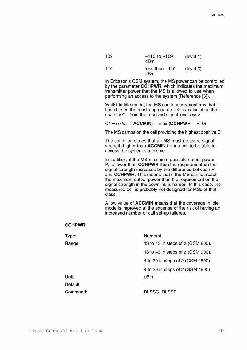
109 –110 to –109dBm
(level 1)
110 less than –110dBm
(level 0)
In Ericsson's GSM system, the MS power can be controlledby the parameter CCHPWR, which indicates the maximumtransmitter power that the MS is allowed to use whenperforming an access to the system (Reference [6]).
Whilst in idle mode, the MS continuously confirms that ithas chosen the most appropriate cell by calculating thequantity C1 from the received signal level rxlev:
C1 = (rxlev —ACCMIN) —max (CCHPWR —P, 0)
The MS camps on the cell providing the highest positive C1.
The condition states that an MS must measure signalstrength higher than ACCMIN from a cell to be able toaccess the system via this cell.
In addition, if the MS maximum possible output power,P, is lower than CCHPWR then the requirement on thesignal strength increases by the difference between Pand CCHPWR. This means that if the MS cannot reachthe maximum output power then the requirement on thesignal strength in the downlink is harder. In this case, themeasured cell is probably not designed for MSs of thatclass.
A low value of ACCMIN means that the coverage in idlemode is improved at the expense of the risk of having anincreased number of call set-up failures.
CCHPWR
Type: Numeral
Range: 13 to 43 in steps of 2 (GSM 800).
13 to 43 in steps of 2 (GSM 900).
4 to 30 in steps of 2 (GSM 1800).
4 to 30 in steps of 2 (GSM 1900)
Unit: dBm
Default: -
Command: RLSSC, RLSSP
49222/1553-HSC 103 12/16 Uen B | 2010-06-18
User Description, Radio Network Parameters and Cell Design Data for Ericsson's GSM Systems
O&M: -
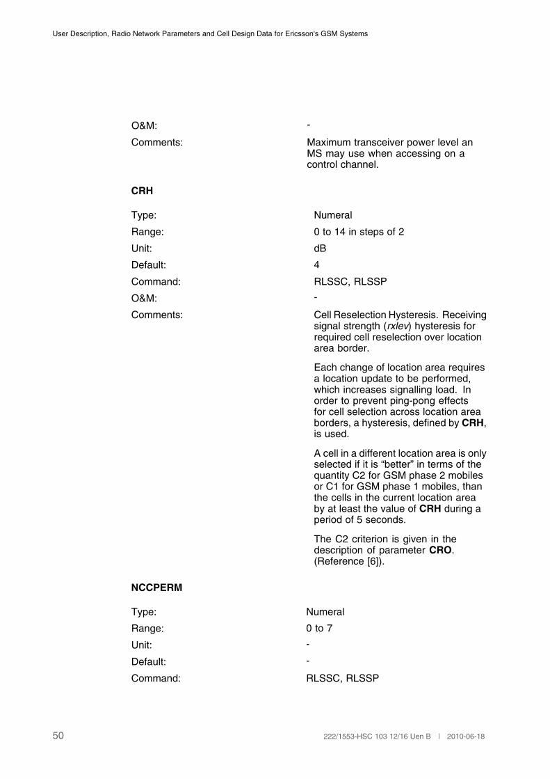
Comments: Maximum transceiver power level anMS may use when accessing on acontrol channel.
CRH
Type: Numeral
Range: 0 to 14 in steps of 2
Unit: dB
Default: 4
Command: RLSSC, RLSSP
O&M: -
Comments: Cell Reselection Hysteresis. Receivingsignal strength (rxlev) hysteresis forrequired cell reselection over locationarea border.
Each change of location area requiresa location update to be performed,which increases signalling load. Inorder to prevent ping-pong effectsfor cell selection across location areaborders, a hysteresis, defined by CRH,is used.
A cell in a different location area is onlyselected if it is “better” in terms of thequantity C2 for GSM phase 2 mobilesor C1 for GSM phase 1 mobiles, thanthe cells in the current location areaby at least the value of CRH during aperiod of 5 seconds.
The C2 criterion is given in thedescription of parameter CRO.(Reference [6]).
NCCPERM
Type: Numeral
Range: 0 to 7
Unit: -
Default: -
Command: RLSSC, RLSSP
50 222/1553-HSC 103 12/16 Uen B | 2010-06-18

Cell Data
O&M: -
Comments: PLMN (NCC) Permitted.
Defines the allowed NCCs (NetworkColour Code) on the BCCH carriersfor which the MS is permitted to sendmeasurement reports.
Up to 8 NCCs can be defined(Reference [7], section 10.5.2.27). Seealso parameter BSIC, Page 16.(1)
(1) NCCPERM is not changeable if a Competitor Coverage Evaluation Active BA-list Recording
is ongoing.
SIMSG
Type: Numeral
Range: 1, 7, 8
Unit: -
Default: -
Command: RLSMC, RLSMP
O&M: -
Comments: System Information BCCH Message.
When the cell is connected to a BTS equipmentthat supports GSM phase 2 system information, it ispossible to turn on or off the distribution of SystemInformation Messages 1, 7, and 8.
SIMSG is the pointer which specifies the SystemInformation Message to be turned on or off by theparameter MSGDIST.
MSGDIST must be specified for each one of theSystem Information Messages.
(1)
Example of parametersettings:
SIMSG = 1 MSGDIST = ON
SIMSG = 7 MSGDIST = OFF
SIMSG = 8 MSGDIST = OFF
(1) The parameter AGBLK must not be zero when system information types 7 and 8 are sent.
MSGDIST
51222/1553-HSC 103 12/16 Uen B | 2010-06-18
User Description, Radio Network Parameters and Cell Design Data for Ericsson's GSM Systems
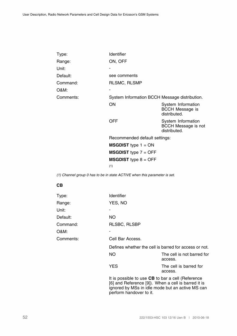
Type: Identifier
Range: ON, OFF
Unit: -
Default: see comments
Command: RLSMC, RLSMP
O&M: -
Comments: System Information BCCH Message distribution.
ON System InformationBCCH Message isdistributed.
OFF System InformationBCCH Message is notdistributed.
Recommended default settings:
MSGDIST type 1 = ON
MSGDIST type 7 = OFF
MSGDIST type 8 = OFF
(1)
(1) Channel group 0 has to be in state ACTIVE when this parameter is set.
CB
Type: Identifier
Range: YES, NO
Unit: -
Default: NO
Command: RLSBC, RLSBP
O&M: -
Comments: Cell Bar Access.
Defines whether the cell is barred for access or not.
NO The cell is not barred foraccess.
YES The cell is barred foraccess.
It is possible to use CB to bar a cell (Reference[6] and Reference [9]). When a cell is barred it isignored by MSs in idle mode but an active MS canperform handover to it.
52 222/1553-HSC 103 12/16 Uen B | 2010-06-18

Cell Data
CBQ
Type: Identifier
Range: HIGH, LOW
Unit: -
Default: HIGH
Command: RLSBC, RLSBP
O&M: -
Comments: Cell Bar Qualify.
HIGH The cell has high priority
LOW The cell has low priority
For GSM phase 2 MSs, a cell can be given twolevels of priority. This is controlled by the parameterCBQ in conjunction with CB, as shown in belowtable.
The interpretation of CB and CBQ varies dependingon whether the MS is a phase 1 MS or a phase 2MS. For phase 2 MSs the behaviour is also differentin cell selection compared to cell reselection.
CBQ CB Phase 2 MS Phase 1 MS
Cell sel. Cell resel. Cell sel./resel.
HIGH NO normal normal normal
HIGH YES barred barred barred
LOW NO low priority normal normal
LOW YES low priority normal normal
In idle mode the MS looks for suitablecells to camp on by checking cells indescending order of received signalstrength. If a suitable cell is found,the MS camps on it. At cell selectionwith a phase 2 MS, cells can have twolevels of priority, suitable cells whichare of low priority are only camped onif there are no other suitable cells ofnormal priority (Reference [6]).
ACC
53222/1553-HSC 103 12/16 Uen B | 2010-06-18
User Description, Radio Network Parameters and Cell Design Data for Ericsson's GSM Systems
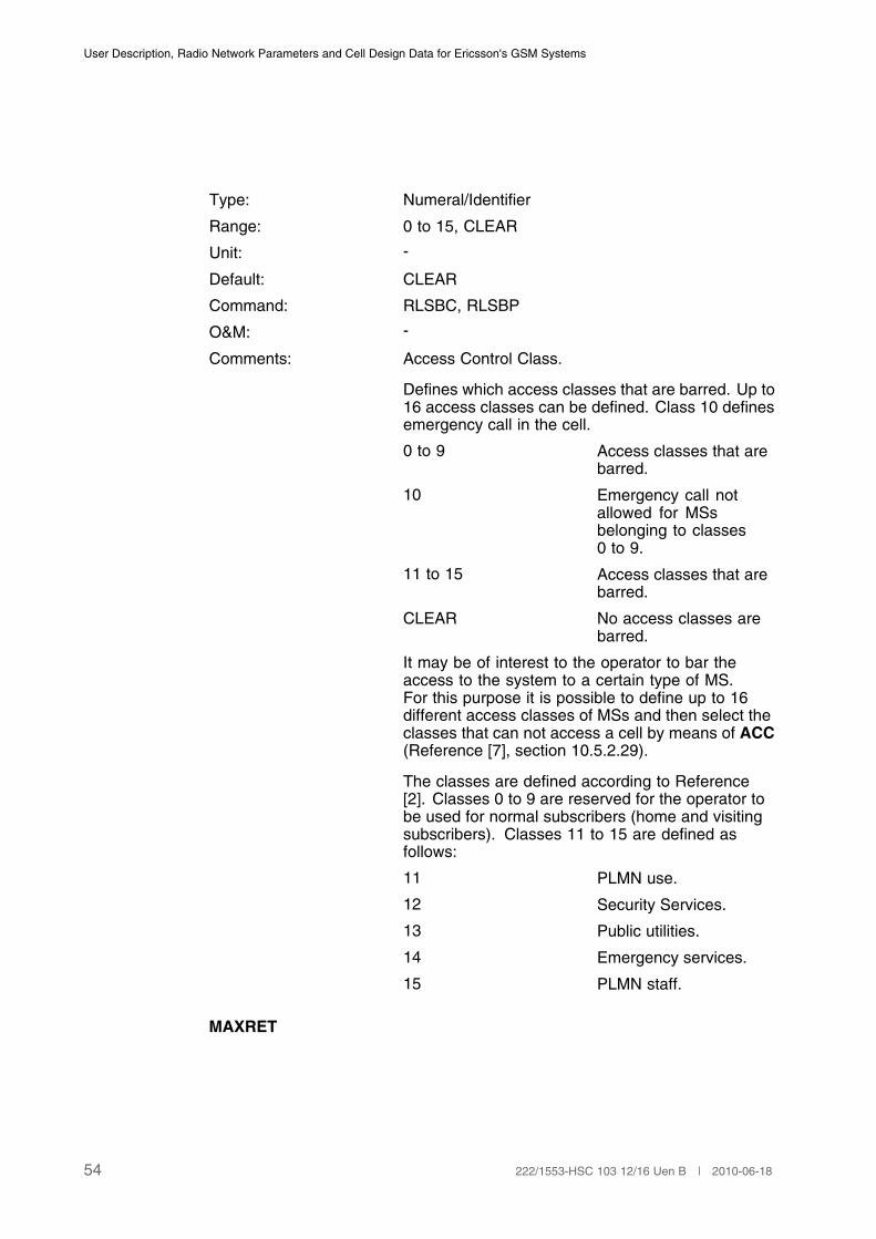
Type: Numeral/Identifier
Range: 0 to 15, CLEAR
Unit: -
Default: CLEAR
Command: RLSBC, RLSBP
O&M: -
Comments: Access Control Class.
Defines which access classes that are barred. Up to16 access classes can be defined. Class 10 definesemergency call in the cell.
0 to 9 Access classes that arebarred.
10 Emergency call notallowed for MSsbelonging to classes0 to 9.
11 to 15 Access classes that arebarred.
CLEAR No access classes arebarred.
It may be of interest to the operator to bar theaccess to the system to a certain type of MS.For this purpose it is possible to define up to 16different access classes of MSs and then select theclasses that can not access a cell by means of ACC(Reference [7], section 10.5.2.29).
The classes are defined according to Reference[2]. Classes 0 to 9 are reserved for the operator tobe used for normal subscribers (home and visitingsubscribers). Classes 11 to 15 are defined asfollows:
11 PLMN use.
12 Security Services.
13 Public utilities.
14 Emergency services.
15 PLMN staff.
MAXRET
54 222/1553-HSC 103 12/16 Uen B | 2010-06-18
Cell Data
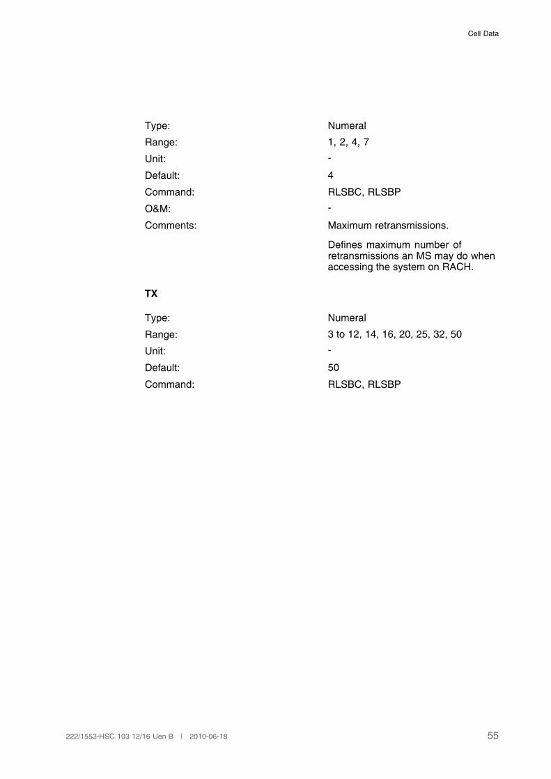
Type: Numeral
Range: 1, 2, 4, 7
Unit: -
Default: 4
Command: RLSBC, RLSBP
O&M: -
Comments: Maximum retransmissions.
Defines maximum number ofretransmissions an MS may do whenaccessing the system on RACH.
TX
Type: Numeral
Range: 3 to 12, 14, 16, 20, 25, 32, 50
Unit: -
Default: 50
Command: RLSBC, RLSBP
55222/1553-HSC 103 12/16 Uen B | 2010-06-18
User Description, Radio Network Parameters and Cell Design Data for Ericsson's GSM Systems
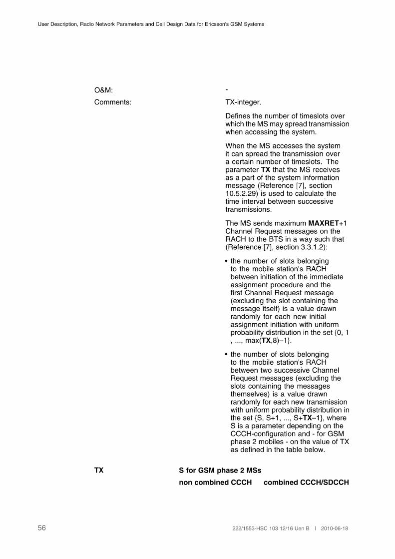
O&M: -
Comments: TX-integer.
Defines the number of timeslots overwhich the MS may spread transmissionwhen accessing the system.
When the MS accesses the systemit can spread the transmission overa certain number of timeslots. Theparameter TX that the MS receivesas a part of the system informationmessage (Reference [7], section10.5.2.29) is used to calculate thetime interval between successivetransmissions.
The MS sends maximum MAXRET+1Channel Request messages on theRACH to the BTS in a way such that(Reference [7], section 3.3.1.2):
• the number of slots belongingto the mobile station's RACHbetween initiation of the immediateassignment procedure and thefirst Channel Request message(excluding the slot containing themessage itself) is a value drawnrandomly for each new initialassignment initiation with uniformprobability distribution in the set {0, 1, ..., max(TX,8)–1}.
• the number of slots belongingto the mobile station's RACHbetween two successive ChannelRequest messages (excluding theslots containing the messagesthemselves) is a value drawnrandomly for each new transmissionwith uniform probability distribution inthe set {S, S+1, ..., S+TX–1}, whereS is a parameter depending on theCCCH-configuration and - for GSMphase 2 mobiles - on the value of TXas defined in the table below.
TX S for GSM phase 2 MSs
non combined CCCH combined CCCH/SDCCH
56 222/1553-HSC 103 12/16 Uen B | 2010-06-18

Cell Data
3, 8, 14, 50 55 41
4, 9, 16 76 52
5, 10, 20 109 58
6, 11, 25 163 86
7, 12, 32 217 115
Example (GSM phase 2 MS): If thecell has a non combined CCCH andTX=7 then the interval between eachretransmission may be
1 second (217 RACH slots),
1 sec. + 4.615 ms,
1 sec. + 2*4.615 ms,
...
1 sec. + 6*4.615 ms
For GSM phase 1 mobiles, S takes thefollowing values:
0.25 seconds in case of non-combinedCCCH.
0.35 seconds in case of combinedCCCH/SDCCH.
ATT
Type: Identifier
Range: YES, NO
Unit: -
Default: YES
Command: RLSBC, RLSBP
O&M: -
Comments: Attach-detach allowed.
NO MSs in the cell are notallowed to apply IMSIattach and detach.
57222/1553-HSC 103 12/16 Uen B | 2010-06-18

User Description, Radio Network Parameters and Cell Design Data for Ericsson's GSM Systems
YES MSs in the cell shouldapply IMSI attach anddetach.
ATT tells the MS if it is allowed to apply IMSI attachand detach, that is if the MS is allowed to send amessage to the system every time it is turned on oroff (Reference [7], section 10.5.2.11).
T3212
Type: Numeral
Range: 0 to 255
Unit: Deci hours
Default: 40
Command: RLSBC, RLSBP
O&M: -
Comments: T3212 time-out value.(1)
Defines the time-out value that controls the locationupdating procedure, that is when notifying theavailability of the MS to the network. (Reference [7],section 10.5.2.11).
0 Infinite time-out.
1 0.1 hours.
...
255 25.5 hours.
(1) See the corresponding MSC parameter BTDM, Page 47.
CRO
Type: Numeral
Range: 0 to 63
Unit: dB
Default: 0
Command: RLSBC, RLSBP
O&M: -
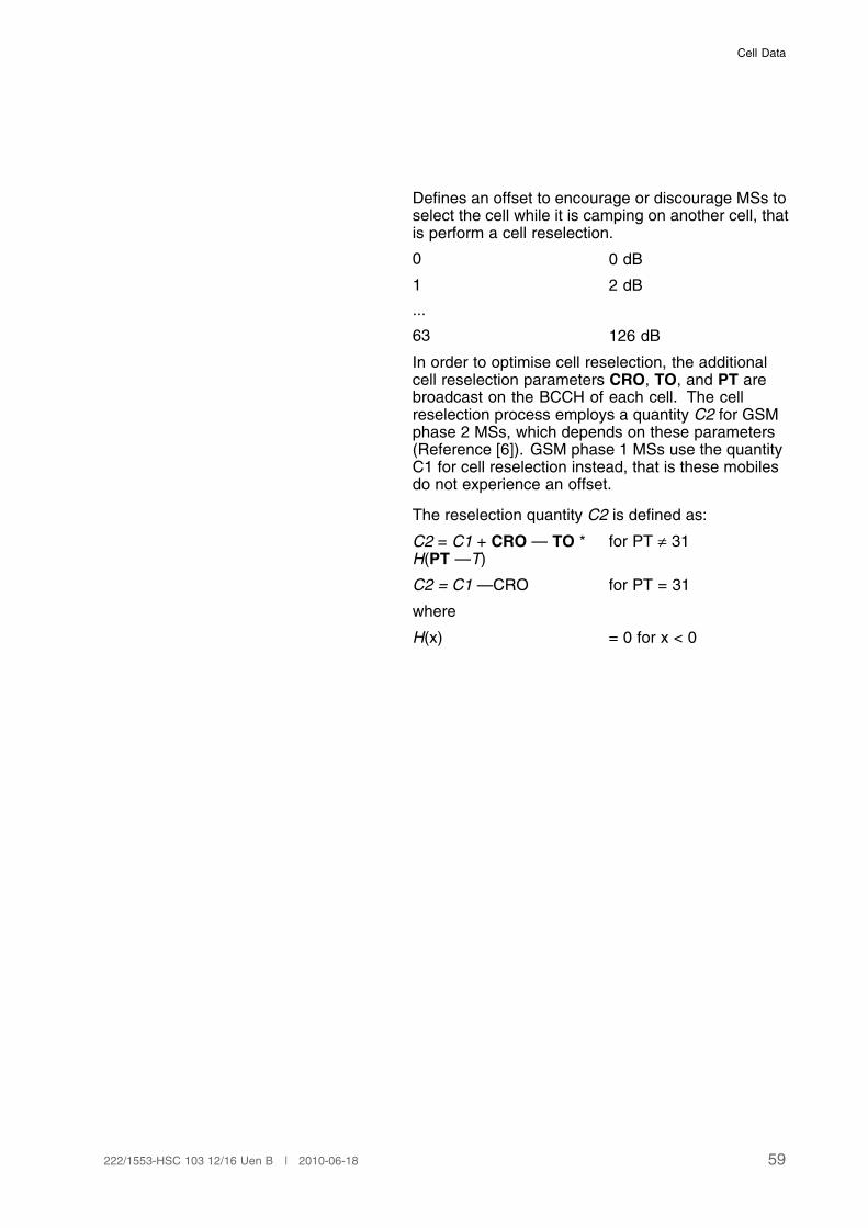
Comments: Cell Reselection Offset.
58 222/1553-HSC 103 12/16 Uen B | 2010-06-18
Cell Data
Defines an offset to encourage or discourage MSs toselect the cell while it is camping on another cell, thatis perform a cell reselection.
0 0 dB
1 2 dB
...
63 126 dB
In order to optimise cell reselection, the additionalcell reselection parameters CRO, TO, and PT arebroadcast on the BCCH of each cell. The cellreselection process employs a quantity C2 for GSMphase 2 MSs, which depends on these parameters(Reference [6]). GSM phase 1 MSs use the quantityC1 for cell reselection instead, that is these mobilesdo not experience an offset.
The reselection quantity C2 is defined as:
C2 = C1 + CRO — TO *H(PT —T)
for PT ≠ 31
C2 = C1 —CRO for PT = 31
where
H(x) = 0 for x < 0
59222/1553-HSC 103 12/16 Uen B | 2010-06-18
User Description, Radio Network Parameters and Cell Design Data for Ericsson's GSM Systems
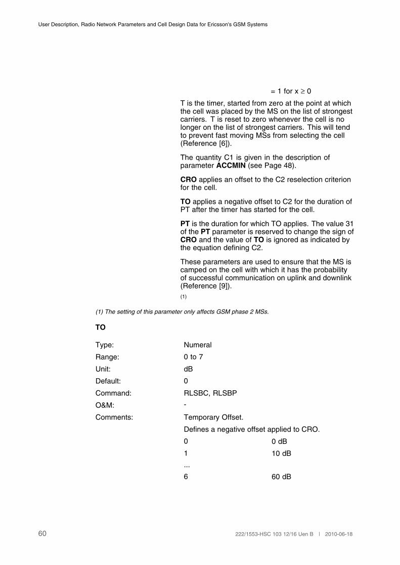
= 1 for x ≥ 0
T is the timer, started from zero at the point at whichthe cell was placed by the MS on the list of strongestcarriers. T is reset to zero whenever the cell is nolonger on the list of strongest carriers. This will tendto prevent fast moving MSs from selecting the cell(Reference [6]).
The quantity C1 is given in the description ofparameter ACCMIN (see Page 48).
CRO applies an offset to the C2 reselection criterionfor the cell.
TO applies a negative offset to C2 for the duration ofPT after the timer has started for the cell.
PT is the duration for which TO applies. The value 31of the PT parameter is reserved to change the sign ofCRO and the value of TO is ignored as indicated bythe equation defining C2.
These parameters are used to ensure that the MS iscamped on the cell with which it has the probabilityof successful communication on uplink and downlink(Reference [9]).
(1)
(1) The setting of this parameter only affects GSM phase 2 MSs.
TO
Type: Numeral
Range: 0 to 7
Unit: dB
Default: 0
Command: RLSBC, RLSBP
O&M: -
Comments: Temporary Offset.
Defines a negative offset applied to CRO.
0 0 dB
1 10 dB
...
6 60 dB
60 222/1553-HSC 103 12/16 Uen B | 2010-06-18

Cell Data
7 infinite.(1)
(1) The setting of this parameter only affects GSM phase 2 MSs.
PT
Type: Numeral
Range: 0 to 31
Unit: -
Default: 0
Command: RLSBC, RLSBP
O&M: -
Comments: Penalty Time.
Defines duration for which TO is applied.
0 20 seconds
1 40 seconds
...
31 620 seconds
The value 31 indicates that the cell reselection offsetis negative and that the temporary offset is ignored.
(1)
(1) The setting of this parameter only affects GSM phase 2 MSs.
CCCH
Type: Numeral
Range: 1-4
Unit: -
Default: 1
Command: RLCCC
O&M: -
Comment: The required number of CCCHs. If the parameterCCCH is set to 1, the feature CCCH is not activated.
TNBCCH
Type: String
Range: GPRS, EGPRS
61222/1553-HSC 103 12/16 Uen B | 2010-06-18
User Description, Radio Network Parameters and Cell Design Data for Ericsson's GSM Systems
Unit: -
Default: GPRS
Command: RLBDC, RLBDP
O&M: -
Comment: Indicates if a Timeslot Number (TN) preceding aTN with a CCCH should be possible to configuresupporting EGPRS or GPRS only.
3.3.6 BSC Exchange Property Data
PAGBUNDLE
Type: Numeral
Range: 0-100
Unit: ms
Default: 50
Command: ROEPC
O&M: -
Comment: The parameter is used to set bundling time forpaging messages sent on the Abis interface toMultiple CCCH capable RBSs.
3.3.7 Hardware Characteristics Data
CCCHCMD
Type: String
Range: NORMAL, BCCHMOVE
Unit: -
Default: NORMAL
Command: RXMOC, RXMSC
O&M: -
Comment: The parameter indicates if it is allowed to move theBCCH and configure it on another TRX in order tofulfill the requirements on the number of CCCHs inthe cell (e.g. the original TRX is not Multiple CCCHcapable).
62 222/1553-HSC 103 12/16 Uen B | 2010-06-18

Cell Data
3.4 Locating
3.4.1 Intra-MSC Handover - MSC Data
Intra-MSC handover is a handover between BSCs within the MSC. Theseparameters are valid both for anchor and non-anchor MSCs.
HNDRELCHINTRAM
Type: Numeral
Range: 0, 1
Unit: -
Default: 1
Command: AXE Parameter.
O&M: -
Comments: Channel release in intra-MSC inter-BSC handover.
HNDRELCHINTRAM defines the release ofthe original channel after expiration of thetimer TIMHNDCMDINTRAM for handover timesupervision in intra-MSC inter-BSC handover.
0 The handover signallingis terminated and the callcontinues on the originalchannel.
1 The original channel isreleased.
(1)
(1) This parameter is only defined for Ericsson MSCs.
HNDSDCCHM
Type: Numeral
Range: 0, 1
Unit: -
Default: 1
Command: AXE Parameter.
O&M: -
63222/1553-HSC 103 12/16 Uen B | 2010-06-18

User Description, Radio Network Parameters and Cell Design Data for Ericsson's GSM Systems
Comments: Intra-MSC inter-BSC handover on signallingchannels.
HNDSDCCHM determines if intra-MSC inter-BSChandover is allowed on signalling channels:
0 Intra-MSC inter-BSChandover is not allowedon signalling channels.
1 Intra-MSC inter-BSChandover is allowed onsignalling channels.
(1)
(1) This parameter is only defined for Ericsson MSCs.
HNDSDCCHTCHM
Type: Numeral
Range: 0, 1
Unit: -
Default: 1
Command: AXE Parameter.
O&M: -
Comments: Intra-MSC inter-BSC handover from signalling totraffic channel.
HNDSDCCHTCHM determines if intra-MSCinter-BSC handover is allowed from signalling totraffic channel:
0 Intra-MSC inter-BSChandover is not allowedfrom signalling to trafficchannel.
1 Intra-MSC inter-BSChandover is allowedfrom signalling to trafficchannel.
(1)
(1) This parameter is only defined for Ericsson MSCs.
TIMHNDCMDINTRAM
Type: Numeral
Range: 5 to 120
64 222/1553-HSC 103 12/16 Uen B | 2010-06-18
Cell Data
Unit: Seconds with 1 sec intervals
Default: 15
Command: AXE Parameter.
O&M: -
Comments: Time supervision in intra-MSCinter-BSC handover.
TIMHNDCMDINTRAM describesthe time between the HANDOVERCOMMAND and HANDOVERCOMPLETE messages in intra-MSCinter-BSC handover (according toReference [4]).
(1)
(1) This parameter is only defined for Ericsson MSCs.
HNDTGSOPINTRA
Type: Numeral
Range: 0 to 2500
Unit: Milliseconds with 20 ms intervals
Default: 80
Command: AXE Parameter.
O&M: -
Comments: Time supervision of switching moment of the groupswitch (GS) in the MSC at intra-MSC inter-BSChandover. The parameter is only valid and can onlybe changed if the time supervision is used to definethe operation point of the GS. Timer is started atsending of Handover Command message.
65222/1553-HSC 103 12/16 Uen B | 2010-06-18
User Description, Radio Network Parameters and Cell Design Data for Ericsson's GSM Systems
0 no time supervisionwhich means GS ischanged at receptionof “handover detect”message or “handovercomplete” message.
The path in the GS in the MSC will be changed atthe first occurrence of the following event:
• timer expiry.
• reception of HANDOVER DETECT from the targetBSC.
• reception of HANDOVER COMPLETE from thetarget BSC.
(1)
(1) This parameter is only defined for Ericsson MSCs.
3.4.2 Inter-MSC Handover in Anchor MSC - MSC Data
HNDSDCCHINTOM
Type: Numeral
Range: 0, 1
Unit: -
Default: 1
Command: AXE Parameter.
O&M: -
Comments: Outgoing inter-MSC handover on signallingchannels in anchor MSC.
It determines if outgoing inter-MSC handover isallowed on signalling channels in anchor MSC. Theparameter is only valid if the inter-MSC handoverdialogue is established with MAP version 2.
0 Outgoing inter-MSChandover is not allowedon signalling channels.
1 Outgoing inter-MSChandover is allowed onsignalling channels.
(1)
(1) This parameter is only defined for Ericsson MSCs.
66 222/1553-HSC 103 12/16 Uen B | 2010-06-18
Cell Data
HNDBEFOREBANSWM
Type: Numeral
Range: 0, 1
Unit: -
Default: 1
Command: AXE Parameter.
O&M: -
Comments: Handover before B-answer. The parameterindicates if an inter-MSC handover is allowed ontraffic channels before answer from B-subscriber.
0 Not allowed.
1 Handover allowed.(1)
(1) This parameter is only defined for Ericsson MSCs.
3.4.3 Inter-MSC Handover in Non-Anchor MSC - MSC Data
HNDSDCCHINTI
Type: Numeral
Range: 0, 1
Unit: -
Default: 1
Command: MGEPC, MGEPP.
O&M: -
Comments: Incoming inter-MSC handover on signallingchannels in non-anchor MSC.
It determines if incoming inter-MSC handoveris allowed on signalling channels in non-anchorMSC. The parameter is only valid if the inter-MSChandover dialogue has been established with MAPversion 2 by the anchor MSC.
0 Incoming inter-MSChandover is not allowedon signalling channels.
67222/1553-HSC 103 12/16 Uen B | 2010-06-18
User Description, Radio Network Parameters and Cell Design Data for Ericsson's GSM Systems
1 Incoming inter-MSChandover is allowed onsignalling channels.
(1)
(1) This parameter is only defined for Ericsson MSCs.
3.4.4 BSC Exchange Property Data
FASTASSIGN
Type: Numeral
Range: 0, 1
Unit: -
Default: 0
Command: RAEPC, RAEPP.
O&M: -
Comments: FASTASSIGN specifies if Locating shall wait untilreception of the first measurement results beforesending the requested candidate list.
0 Wait for measurementresults.
1 Do not wait formeasurement results.
If no measurements are available and FASTASSIGN= 1, a candidate list that only contains the servingcell is created and sent.
NOOFPHYSINFOMSG
Type: Numeral
Range: 0 to 254
Unit: -
Default: 35
Command: RAEPC, RAEPP.
68 222/1553-HSC 103 12/16 Uen B | 2010-06-18
Cell Data
O&M: In order to make the parameter changeactive, it is needed to halt and activateall cells in the BSC.
Comments: NOOFPHYSINFOMSG indicates themaximum number of repetitions ofphysical information messages duringthe handover procedure (NY1, seeReference [7], section 3.4.4).
TIMER3105
Type: Numeral
Range: 2 to 255
Unit: deci seconds
Default: 6
Command: RAEPC, RAEPP.
O&M: -
Comments: TIMER3105 indicates the timebetween repetition of physicalinformation messages during thehandover procedure (T3105, seeReference [7], section 3.4.4).
3.4.5 Algorithm Selection - BSC Data
EVALTYPE
Type: Numeral
Range: 1, 3
Unit: -
Default: 3
Command: RLLBC, RLLBP
O&M: -
Comments: Evaluation type.
EVALTYPE allows for the use of two different typesof locating algorithm.
1 Cell ranking by theEricsson1 locatingalgorithm.
69222/1553-HSC 103 12/16 Uen B | 2010-06-18
User Description, Radio Network Parameters and Cell Design Data for Ericsson's GSM Systems
3 Cell ranking by theEricsson3 locatingalgorithm.
The Ericsson3 locating algorithm is simplifiedcompared to the Ericsson1 algorithm.
3.4.6 Flow Control - BSC Data
TINIT
Type: Numeral
Range: 0 to 120
Unit: SACCH periods (480 ms)
Default: 10
Command: RLLBC, RLLBP
O&M: -
Comments: Minimum time before handover isallowed on an initial call or afterhandover.
The locating comparison is performedevery SACCH period (480 ms), exceptfor certain periods for which themaximum lengths are specified bythe parameters: TINIT, TALLOC andTURGEN. They apply to differentsituations.
The locating process is suspendedduring a time specified by TINIT.
TALLOC
Type: Numeral
Range: 0 to 120
Unit: SACCH periods (480 ms)
Default: 2
Command: RLLBC, RLLBP
70 222/1553-HSC 103 12/16 Uen B | 2010-06-18

Cell Data
O&M: -
Comments: Minimum time between allocationattempts when there is a better cellcondition and when the first allocationattempt has failed.
In the case a handover, intra cellhandover or overlaid/underlaid subcellchange fails due to congestion,the locating process continues butno handover candidate list will beprepared before the timer TALLOChas expired, unless an urgency stateis detected.
TURGEN
Type: Numeral
Range: 0 to 120
Unit: SACCH periods (480 ms)
Default: 2
Command: RLLBC, RLLBP
O&M: -
Comments: Minimum time between allocationattempts at an urgency condition andwhen the first allocation attempt hasfailed.
In the case an urgency handoverattempt fails due to congestion, thelocating process will proceed andeven a handover candidate list will beprepared. However the candidate listwill not be transferred to the handoverfunction during the time specified bythe parameter TURGEN, unless thecandidate list contains a better cell.
3.4.7 Filter Control - BSC Data
TAAVELEN
Type: Numeral
Range: 1 to 20
71222/1553-HSC 103 12/16 Uen B | 2010-06-18
User Description, Radio Network Parameters and Cell Design Data for Ericsson's GSM Systems
Unit: -
Default: 4
Command: RLLBC, RLLBP
O&M: -
Comments: Timing advance average length.Number of values in the averaging oftiming advance.
For the evaluation of timing advancethe algorithm uses a sliding window,the length of which is determined byTAAVELEN. TAAVELEN determinesthe total number of values to be usedin the moving average.
3.4.8 Filter Control - Cell Data
The measurement results are sent from the BTS to the BSC every SACCHperiod (480 ms) starting when the MS is assigned an SDCCH. Themeasurement results are stored and filtered in the BSC. The signal strengthand quality measurements are filtered in order to smooth out measurementnoise. In addition, some fading components of a duration of about the same asthe filter response time, are filtered out.
When filtering measurements for a cell, always the filters that are assignedto the cell are used. This means that serving cell and neighbouring cellmeasurements can be evaluated by different filters, if different filters areassigned to the different cells.
The locating filters are numbered from 1 to 9, and correspond to different filtertypes:
1–5 General FIR filters.
6 Straight average filter.
7 Exponential filter.
8 First order Butterworth filter.
9 Median filter.
Note: For a multislot configuration, only the main channel is evaluated. Thereported downlink quality measurement on the main channel is theworst quality measured among all the uni-directional channels and themain channel.
SSEVALSD
72 222/1553-HSC 103 12/16 Uen B | 2010-06-18

Cell Data
Type: Numeral
Range: 1 to 9
Unit: -
Default: 6
Command: RLLFC, RLLFP
O&M: -
Comments: Signal strength filter for speech/data.
The filters for down- and uplink signalstrength in serving cell and downlinksignal strength from neighbouring cellsare selected by SSEVALSD for thechannel mode speech/data.
QEVALSD
Type: Numeral
Range: 1 to 9
Unit: -
Default: 6
Command: RLLFC, RLLFP
O&M: -
Comments: Quality filter for speech/data.
The filters for quality in down- anduplink in the serving cell are selectedby QEVALSD for the channel modespeech/data.
SSEVALSI
Type: Numeral
Range: 1 to 9
Unit: -
Default: 6
Command: RLLFC, RLLFP
73222/1553-HSC 103 12/16 Uen B | 2010-06-18

User Description, Radio Network Parameters and Cell Design Data for Ericsson's GSM Systems
O&M: -
Comments: Signal strength filter for signalling only.
The filters for down- and uplink signalstrength in serving cell and downlinksignal strength from neighbouring cellsare selected by SSEVALSI for thechannel mode signalling only.
QEVALSI
Type: Numeral
Range: 1 to 9
Unit: -
Default: 6
Command: RLLFC, RLLFP
O&M: -
Comments: Quality filter for signalling only.
The filters for quality in down- anduplink in the serving cell are selectedby QEVALSI for the channel modesignalling only.
SSLENSD
Type: Numeral
Range: 1 to 20
Unit: SACCH periods (480 ms)
Default: 10
Command: RLLFC, RLLFP
O&M: -
Comments: Length of signal strength filter forspeech/data.
SSLENSD shall be specified onlywhen SSEVALSD is in the range 6 to9.
QLENSD
Type: Numeral
Range: 1 to 20
74 222/1553-HSC 103 12/16 Uen B | 2010-06-18

Cell Data
Unit: SACCH periods (480 ms)
Default: 10
Command: RLLFC, RLLFP
O&M: -
Comments: Length of quality filter for speech/data.
QLENSD shall be specified only whenQEVALSD is in the range 6 to 9.
SSLENSI
Type: Numeral
Range: 1 to 20
Unit: SACCH periods (480 ms)
Default: 4
Command: RLLFC, RLLFP
O&M: -
Comments: Length of signal strength filter forsignalling only.
SSLENSI shall be specified only whenSSEVALSI is in the range 6 to 9.
QLENSI
Type: Numeral
Range: 1 to 20
Unit: SACCH periods (480 ms)
Default: 4
Command: RLLFC, RLLFP
O&M: -
Comments: Length of quality filter for signallingonly.
QLENSI shall be specified only whenQEVALSI is in the range 6 to 9.
SSRAMPSD
Type: Numeral
Range: 1 to 20
75222/1553-HSC 103 12/16 Uen B | 2010-06-18
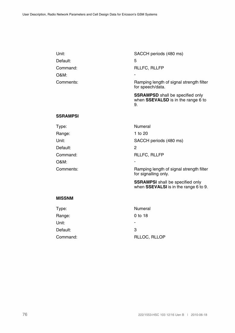
User Description, Radio Network Parameters and Cell Design Data for Ericsson's GSM Systems
Unit: SACCH periods (480 ms)
Default: 5
Command: RLLFC, RLLFP
O&M: -
Comments: Ramping length of signal strength filterfor speech/data.
SSRAMPSD shall be specified onlywhen SSEVALSD is in the range 6 to9.
SSRAMPSI
Type: Numeral
Range: 1 to 20
Unit: SACCH periods (480 ms)
Default: 2
Command: RLLFC, RLLFP
O&M: -
Comments: Ramping length of signal strength filterfor signalling only.
SSRAMPSI shall be specified onlywhen SSEVALSI is in the range 6 to 9.
MISSNM
Type: Numeral
Range: 0 to 18
Unit: -
Default: 3
Command: RLLOC, RLLOP
76 222/1553-HSC 103 12/16 Uen B | 2010-06-18
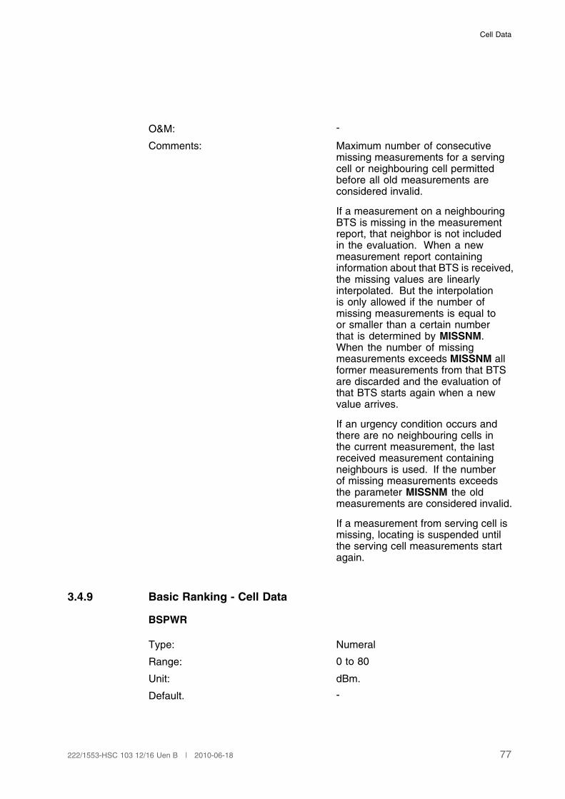
Cell Data
O&M: -
Comments: Maximum number of consecutivemissing measurements for a servingcell or neighbouring cell permittedbefore all old measurements areconsidered invalid.
If a measurement on a neighbouringBTS is missing in the measurementreport, that neighbor is not includedin the evaluation. When a newmeasurement report containinginformation about that BTS is received,the missing values are linearlyinterpolated. But the interpolationis only allowed if the number ofmissing measurements is equal toor smaller than a certain numberthat is determined by MISSNM.When the number of missingmeasurements exceeds MISSNM allformer measurements from that BTSare discarded and the evaluation ofthat BTS starts again when a newvalue arrives.
If an urgency condition occurs andthere are no neighbouring cells inthe current measurement, the lastreceived measurement containingneighbours is used. If the numberof missing measurements exceedsthe parameter MISSNM the oldmeasurements are considered invalid.
If a measurement from serving cell ismissing, locating is suspended untilthe serving cell measurements startagain.
3.4.9 Basic Ranking - Cell Data
BSPWR
Type: Numeral
Range: 0 to 80
Unit: dBm.
Default. -
77222/1553-HSC 103 12/16 Uen B | 2010-06-18
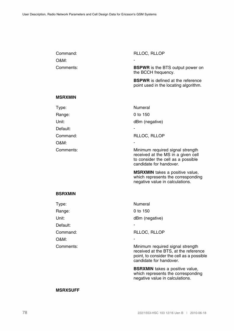
User Description, Radio Network Parameters and Cell Design Data for Ericsson's GSM Systems
Command: RLLOC, RLLOP
O&M: -
Comments: BSPWR is the BTS output power onthe BCCH frequency.
BSPWR is defined at the referencepoint used in the locating algorithm.
MSRXMIN
Type: Numeral
Range: 0 to 150
Unit: dBm (negative)
Default: -
Command: RLLOC, RLLOP
O&M: -
Comments: Minimum required signal strengthreceived at the MS in a given cellto consider the cell as a possiblecandidate for handover.
MSRXMIN takes a positive value,which represents the correspondingnegative value in calculations.
BSRXMIN
Type: Numeral
Range: 0 to 150
Unit: dBm (negative)
Default: -
Command: RLLOC, RLLOP
O&M: -
Comments: Minimum required signal strengthreceived at the BTS, at the referencepoint, to consider the cell as a possiblecandidate for handover.
BSRXMIN takes a positive value,which represents the correspondingnegative value in calculations.
MSRXSUFF
78 222/1553-HSC 103 12/16 Uen B | 2010-06-18

Cell Data
Type: Numeral
Range: 0 to 150
Unit: dBm (negative)
Default: -
Command: RLLOC, RLLOP
O&M: -
Comments: Sufficient signal strength received atthe MS to consider the cell selectablefor further ranking according to themagnitude of the path loss.
MSRXSUFF takes a positive valuethat represents the correspondingnegative value in calculations.
BSRXSUFF
Type: Numeral
Range: 0 to 150
Unit: dBm (negative)
Default: -
Command: RLLOC, RLLOP
O&M: -
Comments: Sufficient signal strength received atthe BTS, at the reference point, toconsider the cell selectable for furtherranking according to the magnitude ofthe path loss.
BSRXSUFF takes a positive value,which represents the correspondingnegative value in calculations.
3.4.10 Basic Ranking - Cell/Subcell Data
This parameter may be defined different for underlaid and overlaid subcell. Incase there is no subcell structure defined, it is defined per cell.
BSTXPWR
Type: Numeral
Range: 0 to 80
79222/1553-HSC 103 12/16 Uen B | 2010-06-18

User Description, Radio Network Parameters and Cell Design Data for Ericsson's GSM Systems
Unit: dBm
Default: -
Command: RLLOC, RLLOP
O&M: -
Comments: BSTXPWR is the BTS output poweron all frequencies other than theBCCH frequency.
BSTXPWR is defined at the referencepoint used in the locating algorithm.
3.4.11 Basic Ranking - Neighbor Cell Data
Parameters for the Ericsson1 Locating Algorithm
KHYST
Type: Numeral
Range: 0 to 63
Unit: dB
Default: 3
Command: RLNRC, RLNRP
O&M: -
Comments: Signal strength hysteresis whenevaluating K-cells.
KHYST is the hysteresis for cellborders defined by the signal strengthcriterion. It is defined as a cell-to-cellrelation. that is in each cell it can bedefined individually for each neighborthat has been defined for that cell.KHYST is a symmetrical relationparameter, that is the same valueapplies for both directions of thecell-to-cell relation.
(1)
(1) KHYST is only valid for the Ericsson1 locating algorithm.
LHYST
Type: Numeral
Range: 0 to 63
80 222/1553-HSC 103 12/16 Uen B | 2010-06-18

Cell Data
Unit: dB
Default: 3
Command: RLNRC, RLNRP
O&M: -
Comments: Path loss hysteresis when evaluatingL-cells.
LHYST is the hysteresis for cellborders defined by the path losscriterion. It is defined as a cell-to-cellrelation. that is in each cell it can bedefined individually for each neighborthat has been defined for that cell.LHYST is a symmetrical relationparameter, that is the same valueapplies for both directions of thecell-to-cell relation.
(1)
(1) LHYST is only valid for the Ericsson1 locating algorithm.
TRHYST
Type: Numeral
Range: 0 to 63
Unit: dB
Default: 2
Command: RLNRC, RLNRP
O&M: -
Comments: Signal strength hysteresis for a K- andL-cell border segment.
(1)
(1) TRHYST is only valid for the Ericsson1 locating algorithm.
KOFFSET
Type: Numeral
Range: -63 to 63
Unit: dB
Default: 0
Command: RLNRC, RLNRP
81222/1553-HSC 103 12/16 Uen B | 2010-06-18
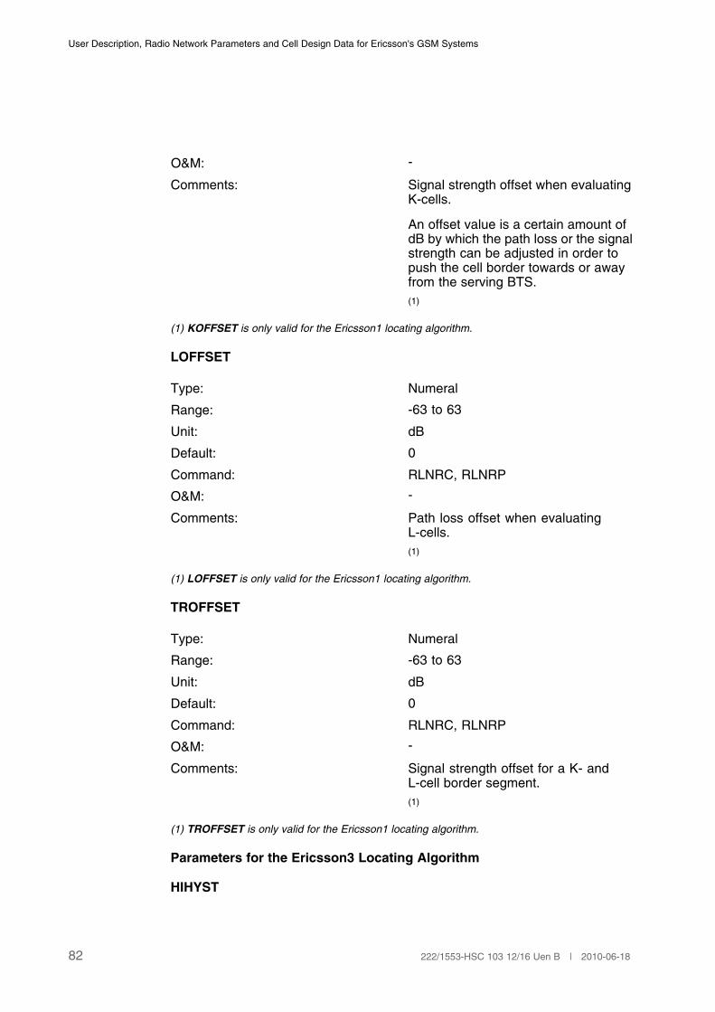
User Description, Radio Network Parameters and Cell Design Data for Ericsson's GSM Systems
O&M: -
Comments: Signal strength offset when evaluatingK-cells.
An offset value is a certain amount ofdB by which the path loss or the signalstrength can be adjusted in order topush the cell border towards or awayfrom the serving BTS.
(1)
(1) KOFFSET is only valid for the Ericsson1 locating algorithm.
LOFFSET
Type: Numeral
Range: -63 to 63
Unit: dB
Default: 0
Command: RLNRC, RLNRP
O&M: -
Comments: Path loss offset when evaluatingL-cells.
(1)
(1) LOFFSET is only valid for the Ericsson1 locating algorithm.
TROFFSET
Type: Numeral
Range: -63 to 63
Unit: dB
Default: 0
Command: RLNRC, RLNRP
O&M: -
Comments: Signal strength offset for a K- andL-cell border segment.
(1)
(1) TROFFSET is only valid for the Ericsson1 locating algorithm.
Parameters for the Ericsson3 Locating Algorithm
HIHYST
82 222/1553-HSC 103 12/16 Uen B | 2010-06-18
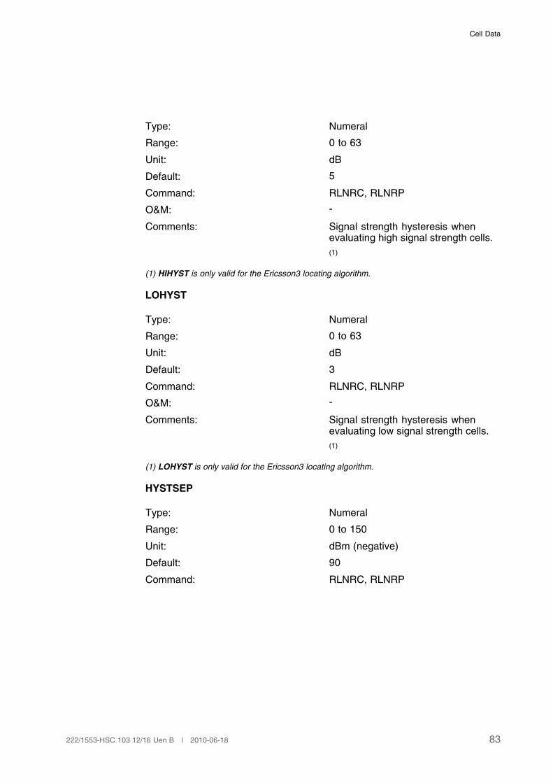
Cell Data
Type: Numeral
Range: 0 to 63
Unit: dB
Default: 5
Command: RLNRC, RLNRP
O&M: -
Comments: Signal strength hysteresis whenevaluating high signal strength cells.
(1)
(1) HIHYST is only valid for the Ericsson3 locating algorithm.
LOHYST
Type: Numeral
Range: 0 to 63
Unit: dB
Default: 3
Command: RLNRC, RLNRP
O&M: -
Comments: Signal strength hysteresis whenevaluating low signal strength cells.
(1)
(1) LOHYST is only valid for the Ericsson3 locating algorithm.
HYSTSEP
Type: Numeral
Range: 0 to 150
Unit: dBm (negative)
Default: 90
Command: RLNRC, RLNRP
83222/1553-HSC 103 12/16 Uen B | 2010-06-18
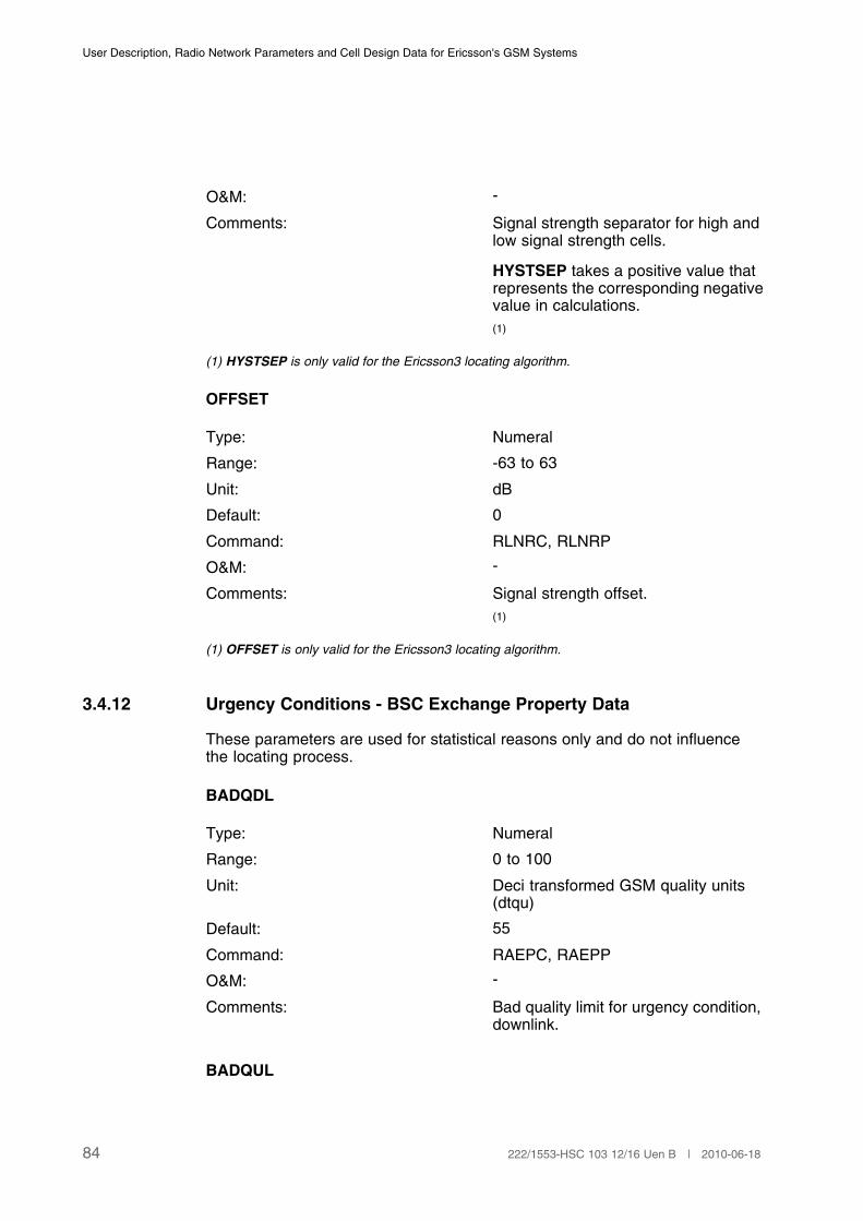
User Description, Radio Network Parameters and Cell Design Data for Ericsson's GSM Systems
O&M: -
Comments: Signal strength separator for high andlow signal strength cells.
HYSTSEP takes a positive value thatrepresents the corresponding negativevalue in calculations.
(1)
(1) HYSTSEP is only valid for the Ericsson3 locating algorithm.
OFFSET
Type: Numeral
Range: -63 to 63
Unit: dB
Default: 0
Command: RLNRC, RLNRP
O&M: -
Comments: Signal strength offset.
(1)
(1) OFFSET is only valid for the Ericsson3 locating algorithm.
3.4.12 Urgency Conditions - BSC Exchange Property Data
These parameters are used for statistical reasons only and do not influencethe locating process.
BADQDL
Type: Numeral
Range: 0 to 100
Unit: Deci transformed GSM quality units(dtqu)
Default: 55
Command: RAEPC, RAEPP
O&M: -
Comments: Bad quality limit for urgency condition,downlink.
BADQUL
84 222/1553-HSC 103 12/16 Uen B | 2010-06-18
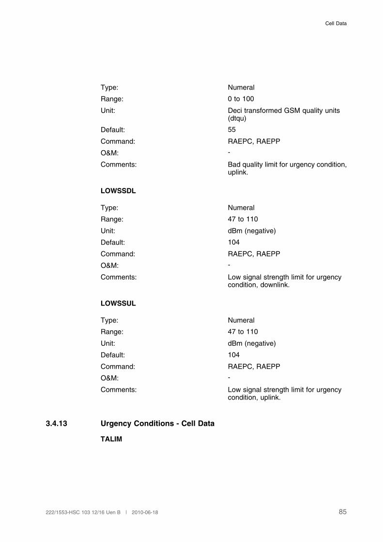
Cell Data
Type: Numeral
Range: 0 to 100
Unit: Deci transformed GSM quality units(dtqu)
Default: 55
Command: RAEPC, RAEPP
O&M: -
Comments: Bad quality limit for urgency condition,uplink.
LOWSSDL
Type: Numeral
Range: 47 to 110
Unit: dBm (negative)
Default: 104
Command: RAEPC, RAEPP
O&M: -
Comments: Low signal strength limit for urgencycondition, downlink.
LOWSSUL
Type: Numeral
Range: 47 to 110
Unit: dBm (negative)
Default: 104
Command: RAEPC, RAEPP
O&M: -
Comments: Low signal strength limit for urgencycondition, uplink.
3.4.13 Urgency Conditions - Cell Data
TALIM
85222/1553-HSC 103 12/16 Uen B | 2010-06-18
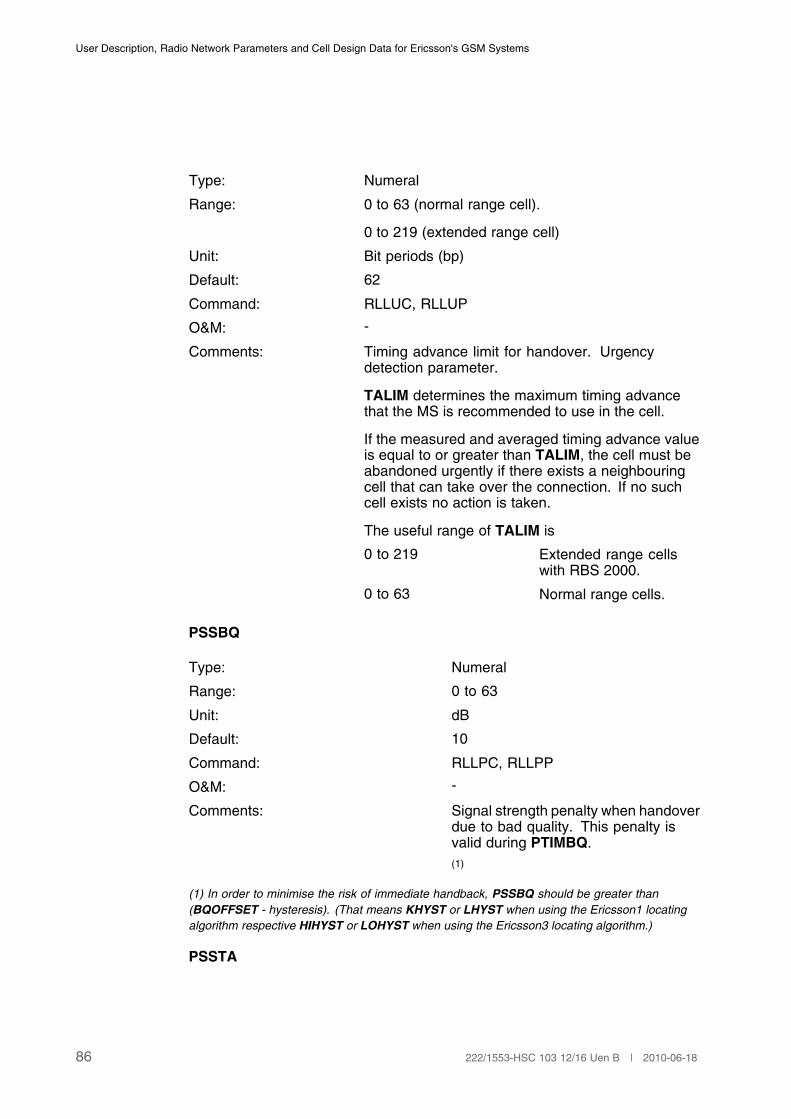
User Description, Radio Network Parameters and Cell Design Data for Ericsson's GSM Systems
Type: Numeral
Range: 0 to 63 (normal range cell).
0 to 219 (extended range cell)
Unit: Bit periods (bp)
Default: 62
Command: RLLUC, RLLUP
O&M: -
Comments: Timing advance limit for handover. Urgencydetection parameter.
TALIM determines the maximum timing advancethat the MS is recommended to use in the cell.
If the measured and averaged timing advance valueis equal to or greater than TALIM, the cell must beabandoned urgently if there exists a neighbouringcell that can take over the connection. If no suchcell exists no action is taken.
The useful range of TALIM is
0 to 219 Extended range cellswith RBS 2000.
0 to 63 Normal range cells.
PSSBQ
Type: Numeral
Range: 0 to 63
Unit: dB
Default: 10
Command: RLLPC, RLLPP
O&M: -
Comments: Signal strength penalty when handoverdue to bad quality. This penalty isvalid during PTIMBQ.
(1)
(1) In order to minimise the risk of immediate handback, PSSBQ should be greater than
(BQOFFSET - hysteresis). (That means KHYST or LHYST when using the Ericsson1 locating
algorithm respective HIHYST or LOHYST when using the Ericsson3 locating algorithm.)
PSSTA
86 222/1553-HSC 103 12/16 Uen B | 2010-06-18
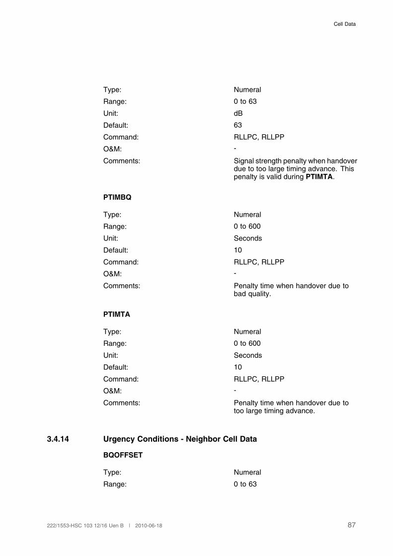
Cell Data
Type: Numeral
Range: 0 to 63
Unit: dB
Default: 63
Command: RLLPC, RLLPP
O&M: -
Comments: Signal strength penalty when handoverdue to too large timing advance. Thispenalty is valid during PTIMTA.
PTIMBQ
Type: Numeral
Range: 0 to 600
Unit: Seconds
Default: 10
Command: RLLPC, RLLPP
O&M: -
Comments: Penalty time when handover due tobad quality.
PTIMTA
Type: Numeral
Range: 0 to 600
Unit: Seconds
Default: 10
Command: RLLPC, RLLPP
O&M: -
Comments: Penalty time when handover due totoo large timing advance.
3.4.14 Urgency Conditions - Neighbor Cell Data
BQOFFSET
Type: Numeral
Range: 0 to 63
87222/1553-HSC 103 12/16 Uen B | 2010-06-18

User Description, Radio Network Parameters and Cell Design Data for Ericsson's GSM Systems
Unit: dB
Default: 3
Command: RLNRC, RLNRP
O&M: -
Comments: Signal strength region for bad qualityurgency handovers.
For AMR FR connections, theparameter BQOFFSETAFR is used.
For AMR WB connections theparameter BQOFFSETAWB is used.
(1)
(1) BQOFFSET is defined as a cell-to-cell relation and is a symmetrical parameter.
BQOFFSETAFR
Type: Numeral
Range: 0 to 63
Unit: dB
Default: 3
Command: RLNRC, RLNRP
O&M: -
Comments: Signal strength region for bad qualityurgency handovers for AMR FRconnections.
(1)
(1) BQOFFSETAFR is defined as a cell-to-cell relation and is a symmetrical parameter.
BQOFFSETAWB
Type: Numeral
Range: 0–63
Unit: dB
Default: 3
Command: RLNRC, RLNRP
88 222/1553-HSC 103 12/16 Uen B | 2010-06-18

Cell Data
O&M: -
Comment: Signal strength region for bad qualityurgency handover for AMR-WBconnections.
(1)
(1) BQOFFSETAWB is defined as a cell-to-cell relation and is a symmetrical parameter.
3.4.15 Urgency Conditions - External Neighbor Cell Data
EXTPEN
Type: Identifier
Range: ON, OFF
Unit: -
Default: OFF
Command: RLLOC, RLLOP
89222/1553-HSC 103 12/16 Uen B | 2010-06-18

User Description, Radio Network Parameters and Cell Design Data for Ericsson's GSM Systems
O&M: -
Comments: Handover penalty support.
The parameter EXTPEN shall be usedfor external neighbouring cells, anddefines whether the penalty can bereceived by that cell (that is the BSCcontrolling that cell). It tells whetherthe target BSC (and MSC) supportsthe penalty handling or not. Thevalue OFF activates an inter-BSChandling at urgency handover thatallows urgency handover to a cellin another BSC only if the mobile iswithin a distance radio wise of KHYSTor LHYST (Ericsson 1) or HIHYSTor LOHYST (Ericsson 3) from theaverage cell border, that is withouthysteresis.
The value ON activates the penaltyhandling that consists of sending ahandover cause value to the targetBSC.
The cause value is interpreted by thetarget BSC as “urgency handover”.Both TA urgency as well as bad qualityurgency can be recognised. Thetarget BSC carries out the punishmentof the cell in the old BSC that wasabandoned. However, it uses thepenalty parameter value and penaltytime of the new cell.
(1)
(1) EXTPEN should be set to OFF if the external neighbouring cell belongs to a BSC from
another vendor.
3.4.16 Urgency Conditions - Cell/Subcell Data
These parameters may be defined different for underlaid and overlaid subcells.In case there is no subcell structure defined, they are defined per cell.
QLIMDL
Type: Numeral
Range: 0 to 100
90 222/1553-HSC 103 12/16 Uen B | 2010-06-18
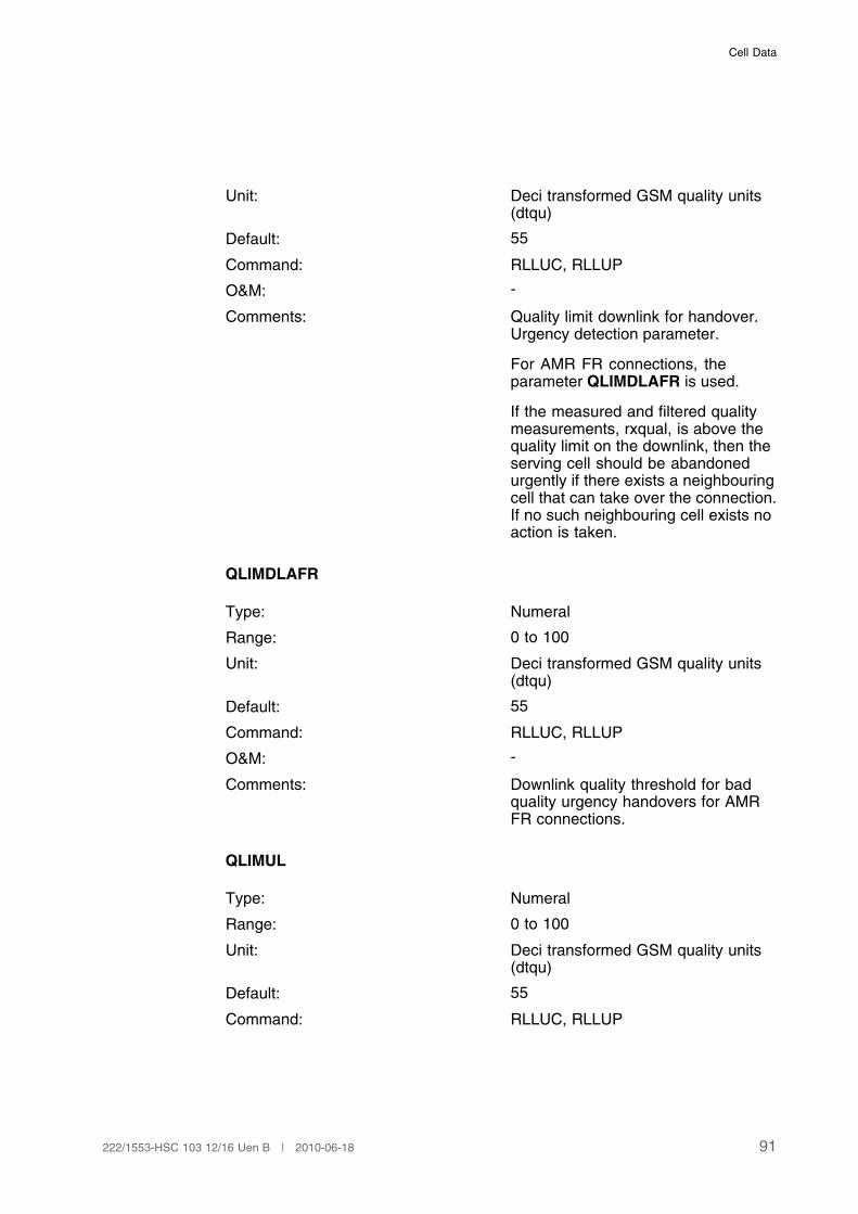
Cell Data
Unit: Deci transformed GSM quality units(dtqu)
Default: 55
Command: RLLUC, RLLUP
O&M: -
Comments: Quality limit downlink for handover.Urgency detection parameter.
For AMR FR connections, theparameter QLIMDLAFR is used.
If the measured and filtered qualitymeasurements, rxqual, is above thequality limit on the downlink, then theserving cell should be abandonedurgently if there exists a neighbouringcell that can take over the connection.If no such neighbouring cell exists noaction is taken.
QLIMDLAFR
Type: Numeral
Range: 0 to 100
Unit: Deci transformed GSM quality units(dtqu)
Default: 55
Command: RLLUC, RLLUP
O&M: -
Comments: Downlink quality threshold for badquality urgency handovers for AMRFR connections.
QLIMUL
Type: Numeral
Range: 0 to 100
Unit: Deci transformed GSM quality units(dtqu)
Default: 55
Command: RLLUC, RLLUP
91222/1553-HSC 103 12/16 Uen B | 2010-06-18
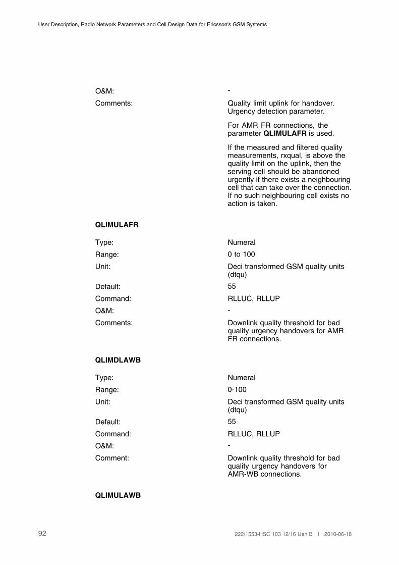
User Description, Radio Network Parameters and Cell Design Data for Ericsson's GSM Systems
O&M: -
Comments: Quality limit uplink for handover.Urgency detection parameter.
For AMR FR connections, theparameter QLIMULAFR is used.
If the measured and filtered qualitymeasurements, rxqual, is above thequality limit on the uplink, then theserving cell should be abandonedurgently if there exists a neighbouringcell that can take over the connection.If no such neighbouring cell exists noaction is taken.
QLIMULAFR
Type: Numeral
Range: 0 to 100
Unit: Deci transformed GSM quality units(dtqu)
Default: 55
Command: RLLUC, RLLUP
O&M: -
Comments: Downlink quality threshold for badquality urgency handovers for AMRFR connections.
QLIMDLAWB
Type: Numeral
Range: 0-100
Unit: Deci transformed GSM quality units(dtqu)
Default: 55
Command: RLLUC, RLLUP
O&M: -
Comment: Downlink quality threshold for badquality urgency handovers forAMR-WB connections.
QLIMULAWB
92 222/1553-HSC 103 12/16 Uen B | 2010-06-18
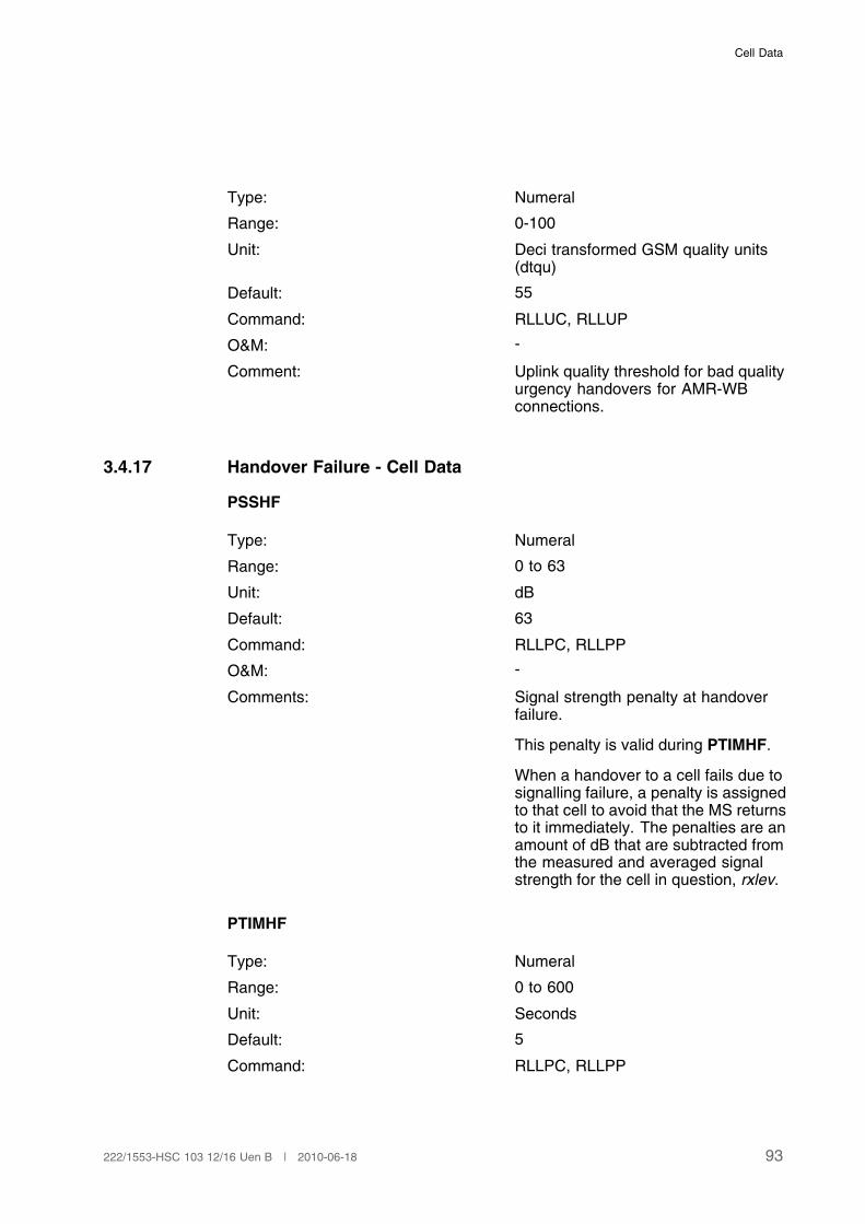
Cell Data
Type: Numeral
Range: 0-100
Unit: Deci transformed GSM quality units(dtqu)
Default: 55
Command: RLLUC, RLLUP
O&M: -
Comment: Uplink quality threshold for bad qualityurgency handovers for AMR-WBconnections.
3.4.17 Handover Failure - Cell Data
PSSHF
Type: Numeral
Range: 0 to 63
Unit: dB
Default: 63
Command: RLLPC, RLLPP
O&M: -
Comments: Signal strength penalty at handoverfailure.
This penalty is valid during PTIMHF.
When a handover to a cell fails due tosignalling failure, a penalty is assignedto that cell to avoid that the MS returnsto it immediately. The penalties are anamount of dB that are subtracted fromthe measured and averaged signalstrength for the cell in question, rxlev.
PTIMHF
Type: Numeral
Range: 0 to 600
Unit: Seconds
Default: 5
Command: RLLPC, RLLPP
93222/1553-HSC 103 12/16 Uen B | 2010-06-18
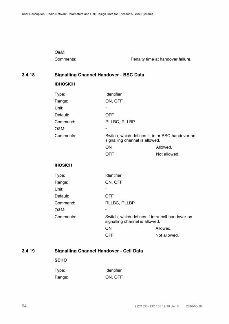
User Description, Radio Network Parameters and Cell Design Data for Ericsson's GSM Systems
O&M: -
Comments: Penalty time at handover failure.
3.4.18 Signalling Channel Handover - BSC Data
IBHOSICH
Type: Identifier
Range: ON, OFF
Unit: -
Default: OFF
Command: RLLBC, RLLBP
O&M: -
Comments: Switch, which defines if, inter BSC handover onsignalling channel is allowed.
ON Allowed.
OFF Not allowed.
IHOSICH
Type: Identifier
Range: ON, OFF
Unit: -
Default: OFF
Command: RLLBC, RLLBP
O&M: -
Comments: Switch, which defines if intra-cell handover onsignalling channel is allowed.
ON Allowed.
OFF Not allowed.
3.4.19 Signalling Channel Handover - Cell Data
SCHO
Type: Identifier
Range: ON, OFF
94 222/1553-HSC 103 12/16 Uen B | 2010-06-18

Cell Data
Unit: -
Default: OFF
Command: RLLOC, RLLOP
O&M: -
Comments: SDCCH handover switch.
SCHO is used to identify if handovers on SDCCHare allowed in the cell. The handover procedure isthe same as for handover on the TCH, that is thelocating function prepares a ranking list and sends itto the handover function.
ON Handovers on SDCCHare allowed. This appliesto both handovers fromand to the cell.
OFF Handovers on SDCCHare not allowed.Handovers from aswell as to the cell areinhibited.
(1)
(1) To allow handover on SDCCH between two cells, both cells must have SCHO = ON.
3.4.20 TRH RP Load - Cell Data
CELLQ
Type: Identifier
Range: HIGH, LOW
Unit: -
Default: HIGH
Command: RLLUC, RLLUP
O&M: -
Comments: Cell quality. CELLQ defines whether the cell issuitable for TRH RP regulation or not.
HIGH The cell is a cell whereminor changes of radiotransmission quality canbe expected.
95222/1553-HSC 103 12/16 Uen B | 2010-06-18
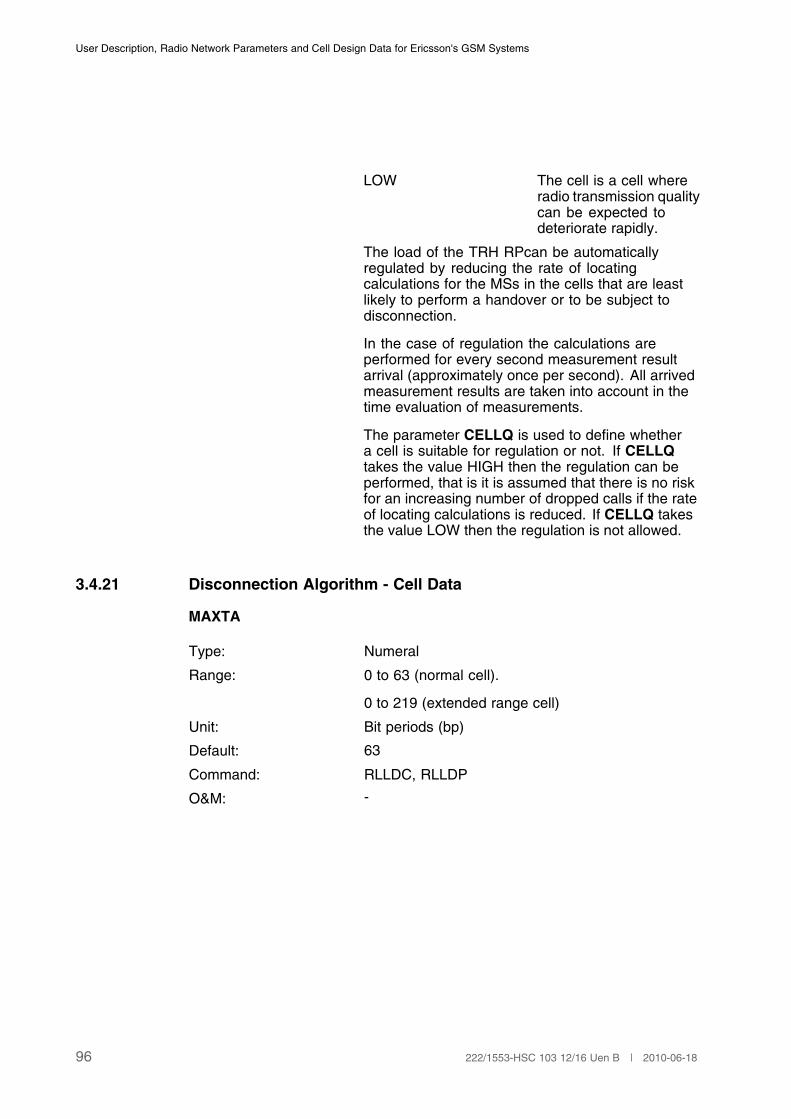
User Description, Radio Network Parameters and Cell Design Data for Ericsson's GSM Systems
LOW The cell is a cell whereradio transmission qualitycan be expected todeteriorate rapidly.
The load of the TRH RPcan be automaticallyregulated by reducing the rate of locatingcalculations for the MSs in the cells that are leastlikely to perform a handover or to be subject todisconnection.
In the case of regulation the calculations areperformed for every second measurement resultarrival (approximately once per second). All arrivedmeasurement results are taken into account in thetime evaluation of measurements.
The parameter CELLQ is used to define whethera cell is suitable for regulation or not. If CELLQtakes the value HIGH then the regulation can beperformed, that is it is assumed that there is no riskfor an increasing number of dropped calls if the rateof locating calculations is reduced. If CELLQ takesthe value LOW then the regulation is not allowed.
3.4.21 Disconnection Algorithm - Cell Data
MAXTA
Type: Numeral
Range: 0 to 63 (normal cell).
0 to 219 (extended range cell)
Unit: Bit periods (bp)
Default: 63
Command: RLLDC, RLLDP
O&M: -
96 222/1553-HSC 103 12/16 Uen B | 2010-06-18

Cell Data
Comments: Maximum timing advance before an MS isconsidered lost.
If the measured timing advance value for an accessburst is equal to or greater than MAXTA, then theconnection set-up signalling is terminated by thesystem.
If the measured and averaged timing advance valuefor an ongoing call is equal or greater than MAXTA,the call is released.
The useful range of MAXTA is
0 to 219 Extended range cellswith RBS2000.
0 to 63 Normal range cells.(1)
(1) MAXTA should always be greater than the parameter TALIM (see Page 85). MAXTA is a
hard limit compared to TALIM, which is a soft limit.
RLINKUP
Type: Numeral
Range: 1 to 63
Unit: SACCH periods (480 ms)
Default: 16
Command: RLLDC, RLLDP
97222/1553-HSC 103 12/16 Uen B | 2010-06-18
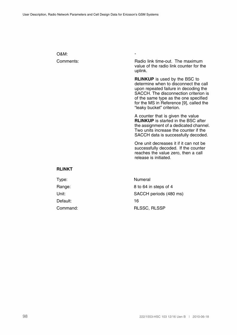
User Description, Radio Network Parameters and Cell Design Data for Ericsson's GSM Systems
O&M: -
Comments: Radio link time-out. The maximumvalue of the radio link counter for theuplink.
RLINKUP is used by the BSC todetermine when to disconnect the callupon repeated failure in decoding theSACCH. The disconnection criterion isof the same type as the one specifiedfor the MS in Reference [9], called the“leaky bucket” criterion.
A counter that is given the valueRLINKUP is started in the BSC afterthe assignment of a dedicated channel.Two units increase the counter if theSACCH data is successfully decoded.
One unit decreases it if it can not besuccessfully decoded. If the counterreaches the value zero, then a callrelease is initiated.
RLINKT
Type: Numeral
Range: 8 to 64 in steps of 4
Unit: SACCH periods (480 ms)
Default: 16
Command: RLSSC, RLSSP
98 222/1553-HSC 103 12/16 Uen B | 2010-06-18

Cell Data
O&M: -
Comments: Radio Link time-out. The maximumvalue of the radio downlink counter.
RLINKT is used by the MS todetermine when to disconnect the callupon repeated failure in decoding theSACCH. The disconnection criterion isthe “leaky bucket” criterion specified inReference [9].
A counter that is given the valueRLINKT is started in the MS after theassignment of a dedicated channel.Two units increase the counter if theSACCH data is successfully decoded.One unit decreases it if it cannot besuccessfully decoded. If the counterreaches the value zero, then the callrelease is initiated.
RLINKTAFR
Type: Numeral
Range: 8 to 64 in steps of 4
Unit: SACCH periods (480 ms)
Default: 16
Command: RLSSC, RLSSP
99222/1553-HSC 103 12/16 Uen B | 2010-06-18
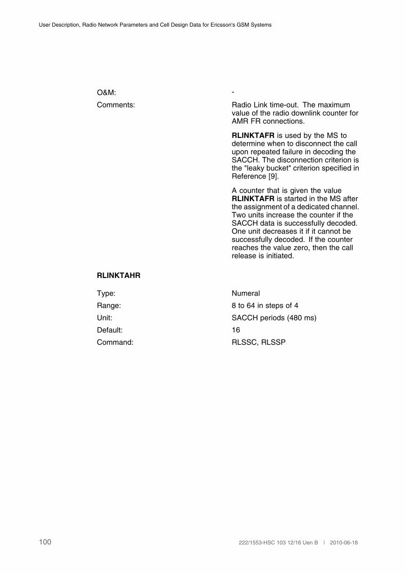
User Description, Radio Network Parameters and Cell Design Data for Ericsson's GSM Systems
O&M: -
Comments: Radio Link time-out. The maximumvalue of the radio downlink counter forAMR FR connections.
RLINKTAFR is used by the MS todetermine when to disconnect the callupon repeated failure in decoding theSACCH. The disconnection criterion isthe "leaky bucket" criterion specified inReference [9].
A counter that is given the valueRLINKTAFR is started in the MS afterthe assignment of a dedicated channel.Two units increase the counter if theSACCH data is successfully decoded.One unit decreases it if it cannot besuccessfully decoded. If the counterreaches the value zero, then the callrelease is initiated.
RLINKTAHR
Type: Numeral
Range: 8 to 64 in steps of 4
Unit: SACCH periods (480 ms)
Default: 16
Command: RLSSC, RLSSP
100 222/1553-HSC 103 12/16 Uen B | 2010-06-18

Cell Data
O&M: -
Comment: Radio Link time-out. The maximumvalue of the radio downlink counter forAMR HR connections.
RLINKTAHR is used by the MS todetermine when to disconnect the callupon repeated failure in decoding theSACCH. The disconnection criterion isthe "leaky bucket" criterion specified inReference [9].
A counter that is given the valueRLINKTAHR is started in the MS afterthe assignment of a dedicated channel.Two units increase the counter if theSACCH data is successfully decoded.One unit decreases it if it cannot besuccessfully decoded. If the counterreaches the value zero, then the callrelease is initiated.
RLINKUPAFR
Type: Numeral
Range: 1 to 63
Unit: SACCH periods (480 ms)
Default: 16
Command: RLLDC, RLLDP
101222/1553-HSC 103 12/16 Uen B | 2010-06-18

User Description, Radio Network Parameters and Cell Design Data for Ericsson's GSM Systems
O&M -
Comment: Radio link time-out. The maximumvalue of the radio link counter on theuplink for AMR FR connections.
RLINKUPAFR is used by the BSC todetermine when to disconnect the callupon repeated failure in decoding theSACCH. The disconnection criterion isof the same type as the one specifiedfor the MS in Reference [9], called the"leaky bucket" criterion.
A counter that is given the valueRLINKUPAFR is started in theBSC after the assignment of adedicated channel. Two unitsincrease the counter if the SACCHdata is successfully decoded.Oneunit decreases it if it can not besuccessfully decoded. If the counterreaches the value zero, then a callrelease is initiated.
RLIKUPAHR
Type: Numeral
Range: 1 to 63
Unit: SACCH periods (480 ms)
Default: 16
Command: RLLDC, RLLDP
102 222/1553-HSC 103 12/16 Uen B | 2010-06-18

Cell Data
O&M -
Comment: Radio link time-out. The maximumvalue of the radio link counter on theuplink for AMR HR connections.
RLINKUPAHR is used by the BSC todetermine when to disconnect the callupon repeated failure in decoding theSACCH. The disconnection criterion isof the same type as the one specifiedfor the MS in Reference [9], called the"leaky bucket" criterion.
A counter that is given the valueRLINKUPAHR is started in theBSC after the assignment of adedicated channel. Two unitsincrease the counter if the SACCHdata is successfully decoded.Oneunit decreases it if it can not besuccessfully decoded. If the counterreaches the value zero, then a callrelease is initiated.
RLINKTAWB
Type: Numeral
Range: 8–64 (in steps of 4)
Unit: SACCH periods (480 ms)
Default: 16
Command: RLSSC, RLSSP
O&M: -
Comment: Radio link time-out downlink. Themaximum value of the radio downlinkcounter for AMR-WB connections.
RLINKUPAWB
Type: Numeral
Range: 1-63
Unit: SACCH periods (480 ms)
Default: 16
Command: RLLDC, RLLDP
103222/1553-HSC 103 12/16 Uen B | 2010-06-18
User Description, Radio Network Parameters and Cell Design Data for Ericsson's GSM Systems
O&M: -
Comment: Radio link time-out uplink. Themaximum value of the radio linkcounter on the uplink for AMR-WBconnections.
3.4.22 Handover Power Boost - Cell Data
HPBSTATE
Type: Identifier
Range: ACTIVE, INACTIVE
Unit: -
Default: INACTIVE
Command: RLPBI, RLPBP , RLPBE.
O&M: -
Comments: Handover Power Boost State.
ACTIVE Handover power boostactive.
INACTIVE Handover power boostinactive.
If the feature Handover Power Boost is activated, theoriginating BTS and the MS are ordered to transmitwith maximum allowed power during the handover.
3.5 GPRS/EGPRS Idle Mode Behaviour
3.5.1 Cell Data
PRACHBLK
Type: Numeral
Range: 1 to 12
Unit: -
Default: 2
Command: RLPDC, RLPDP
104 222/1553-HSC 103 12/16 Uen B | 2010-06-18
Cell Data
O&M: -
Comments: Defines the minimum number ofreserved radio block periods forPRACH.
MAXSBLK
Type: Numeral
Range: 1 to 4
Unit: -
Default: 2
Command: RLPDC, RLPDP
O&M: -
Comments: Defines the maximum value thatBS_PBCCH_BLKS is allowed tohave, that is the maximum number ofreserved radio blocks to be used forthe PBCCH.
MAXSMSG
Type: Numeral
Range: 1 to 16
Unit: -
Default: 7
Command: RLPDC, RLPDP
O&M: -
Comments: Defines maximum number of PSImessages that preferably shall bescheduled on one PBCCH block.
TRAFBLK
Type: Numeral
Range: 0 to 10
Unit: -
Default: 0
Command: RLPDC, RLPDP
105222/1553-HSC 103 12/16 Uen B | 2010-06-18
User Description, Radio Network Parameters and Cell Design Data for Ericsson's GSM Systems
O&M: -
Comments: Defines the value of BS_PAG_BLKS_RES, that is the number of blockswithin a multiframe where neitherpaging nor PSI messages shallappear.
CBCHD
Type: Identifier
Range: YES, NO
Unit: -
Default: NO
Command: RLPDC, RLPDP
O&M: -
Comments: Defines if CBCH description, thatis, PSI8 shall be transferred on thePBCCH or not.
3.6 GPRS/EGPRS Cell Reselection
3.6.1 BSC Exchange Property Data
PSCELLPLAN
Type: Numeral
Range: 0, 1
Unit: -
Default: 0
Command: RAEPC, RAEPP
O&M: -
Comments: Activates (1) or deactivates (0) thefeature Packet Specific Cell Plan.
NACCACT
Type: Numeral
Range: 0, 1
Unit: -
106 222/1553-HSC 103 12/16 Uen B | 2010-06-18

Cell Data
Default: 0
Command: RAEPC, RAEPP
O&M: -
Comments: Activates (1) or deactivates (0) thefeature Network Assisted Cell Change(NACC).
3.6.2 Cell Data
PLAYER
Type: Numeral
Range: MAPPED, 1 to 8
Unit: -
Default. MAPPED
Command: RLPSC, RLPSP
O&M: -
Comments: Hierarchical cell layer forGPRS/EGPRS traffic for cellswith defined PBCCH.
The value MAPPED specifies thatthe cell layer is mapped from CSparameters.
PHCSTHR
Type: Numeral
Range: MAPPED, 48, 50, 110
Unit: dBm (negative)
Default: MAPPED
Command: RLPSC, RLPSP
107222/1553-HSC 103 12/16 Uen B | 2010-06-18
User Description, Radio Network Parameters and Cell Design Data for Ericsson's GSM Systems
O&M: -
Comments: Hierarchical cell threshold forGPRS/EGPRS traffic for cellswith defined PBCCH. It takes apositive value, which representsthe corresponding negative value incalculations.
The value MAPPED specifies thatthe threshold is mapped from CSparameters.
NCRPT
Type: Numeral
Range: 0.48, 0.96, 1.92, 3.84, 7.68, 15.36,30.72, 61.44
Unit: Seconds
Default: 1.92
Command: RLMNC, RLMNP
O&M: -
Comments: This parameter tells the MS howoften it should send the PacketMeasurement Report (PMR)message.
NCPROF
Type: Numeral
Range: 1 to 255
Unit: -
Default: -
Command: RLNPI, RLNPE, RLNPP
O&M: -
Comments: This parameter initiate, end and printthe status of the NC2 profile.
3.6.3 Neighbor Cell Data
GPRSVALID
108 222/1553-HSC 103 12/16 Uen B | 2010-06-18

Cell Data
Type: Identifier
Range: YES, NO
Unit: -
Default: YES
Command: RLGNC, RLGNP
O&M: -
Comments: Defines if the neighbor relation is valid forGPRS/EGPRS traffic for cells with defined PBCCH:
YES GPRS/EGPRS cellreselections are allowed.
NO GPRS/EGPRS cellreselections are notallowed.
PROFFSET
Type: Numeral
Range: MAPPED, 0, 1, ..., 31
Unit: -
Default: MAPPED
Command: RLGNC, RLGNP
O&M: -
Comments: GPRS/EGPRS cell reselection offset for cells withdefined PBCCH. The value of this parameter isused in calculations of the cell reselection offset,as follows.
The value MAPPED specifies that the offset ismapped from CS parameters.
0 –52 dB
1 –48 dB
...
9 –16 dB
10 –12 dB
11 –10 dB
12 –8 dB
...
21 10 dB
109222/1553-HSC 103 12/16 Uen B | 2010-06-18
User Description, Radio Network Parameters and Cell Design Data for Ericsson's GSM Systems
22 12 dB
23 16 dB
24 20 dB
...
30 44 dB
31 48 dB(1)
(1) Between –52 dB and –12 dB the step is 4 dB, between –12 dB and 12 dB the step is 2 dB and
between 12 dB and 48 dB the step is 4dB.
3.6.4 External Cell Data
RAC
Type: Numeral
Range: 0 to 255
Unit: -
Default: 1
Command: RLDEC, RLDEP
O&M: -
Comments: The Routing Area Code (RAC) is, together with the Cell Identity(CI), used for routing of RAN-INFORMATION messagesbetween BSCs.
0 OFF
1 ON
RIMNACC
Type: Numeral
Range: 0, 1
Unit: -
Default: 0
Command: RLDEC, RLDEP
O&M: -
Comments: The parameter is used to activate and deactivate NACC forexternal neighbors.
0 OFF
1 ON
110 222/1553-HSC 103 12/16 Uen B | 2010-06-18
Cell Data
3.7 Channel Administration/Immediate Assignment onTCH
3.7.1 MSC Controlling Parameters
CRT
Type: RCR-SCRT
Range: RCR:
SCRT:
FR, DFR, DHR.
FR, HR, DFRC, DHRC, DFRN, DHRN, DRSC,DRSN
Unit: -
Default: -
Command: MGTEI, MGTEP.
O&M: -
Comments: Channel Rate and Type.
CRT is used to specify the channel rate and type preference foreach Radio Channel Requirement that can be received fromthe MS. The parameter is set for the teleservices Telephony,Auxiliary telephony and Emergency call.
The following allowed RCR-SCRT combinations may be usedfor CRT:
RCR:
FR Full Rate channel.
DFR Dual rate, Full Rate preferred.
DHR Dual rate, Half Rate preferred.
SCRT:
FR Full Rate channel.
HR Half Rate channel.
DFRC Dual rate, Full Rate preferred, Change allowedafter first channel allocation as a result of therequest.
DHRC Dual rate, Half Rate preferred, Change allowedafter first channel allocation as a result of therequest.
DFRN Dual rate, Full Rate preferred, change not allowedafter first channel allocation as a result of therequest.
111222/1553-HSC 103 12/16 Uen B | 2010-06-18

User Description, Radio Network Parameters and Cell Design Data for Ericsson's GSM Systems
DHRN Dual rate, Half Rate preferred, change notallowed after first channel allocation as a resultof the request.
DRSC Dual Rate, channel preference indicated by thespeech coder preference, changes betweenfull rate and half rate allowed after first channelallocation as a result of the request.
DRSN Dual Rate, channel preference indicated by thespeech coder preference, changes between fullrate and half rate not allowed after first channelallocation as a result of the request.
Example: CRT=FR-FR, DFR-DFRN, DHR-DHRC(1)
(1) RCR FR can only be combined with SCRT FR.
PSCVL
Type: Identifier
Range: FRV1, FRV2, FRV3, FRV5, HRV1, HRV2, HRV3
Unit: -
Default: -
Command: MGTEI, MGTEP.
O&M: -
Comments: Provided Speech Coder Version List.
The parameter is set for the teleservices Telephony, Auxiliarytelephony, Emergency call and Alternate speech/facsimile.
FRV1 Full Rate speech Version1.
FRV2 Full Rate speech Version2.
FRV3 Full Rate speech Version3.
FRV5 Full Rate speech Version5.
HRV1 Half Rate speech Version1.
HRV2 Half Rate speech Version2.
HRV3 Half Rate speech Version3.
PSCVL must be specified in accordance with the SCRT partof CRT.
3.7.2 BSC Exchange Property Data
EBANDINCLUDED
112 222/1553-HSC 103 12/16 Uen B | 2010-06-18
Cell Data
Type: Numeral
Range: 0 and 1
Unit: -
Default: 0
Command: RAEPC, RAEPP.
O&M: -
Comments: EBANDINCLUDED is used to decide whetherchannels in the P-GSM 900 band only or whetheralso GSM 900 G1 channels are to be considered forhandling of the radio features:
• Half Rate Packing/Dynamic Half Rate Allocation/Dynamic Half Rate-Full Rate Mode Adaptation
• Cell Load Sharing
• BTS Power Savings
• Subcell Load Distribution
• Adaptive Configuration of Logical Channels
• GPRS/EGPRS
• GSM - UMTS Cell Reselection and Handover
• Hierarchical Cell Structure (HCS)
The following values are available:
0 Only channels in theP-GSM 900 band areconsidered.
1 Channels in all availableGSM 900 bands areconsidered.
MAXCHDATARATE
Type: Numeral
Range: 96 and 144
Unit: -
Default: 96
Command: RAEPC, RAEPP
O&M: -
113222/1553-HSC 103 12/16 Uen B | 2010-06-18

User Description, Radio Network Parameters and Cell Design Data for Ericsson's GSM Systems
Comments: MAXCHDATARATE indicates the maximumchannel data rate allowed in the BSC. The channeldata rates are 9.6 kbit/s (=96) and 14.4 kbit/s (=144).
96 Max allowed data rate is9.6 kbit/s per channel.
144 Max allowed data rate is14.4 kbit/s per channel.
SPEECHVERUSED
Type: Numeral
Range: 0 and 1
Unit: -
Default: 1
Command: RAEPC, RAEPP
O&M: -
Comments: SPEECHVERUSED is used to decide if the usedspeech version shall be placed at the top in the listof allowed speech version at handover.
0 Do not place the usedspeech version at thetop in the list of allowedspeech versions.
1 The used speech versionshall be plated at the topof the list of allowedspeech versions.
AMRSPEECHVERUSE
Type: Numeral
Range: 0 and 1
Unit: -
Default: 1
Command: RAEPC, RAEPP.
O&M: -
Comments: AMRSPEECHVERUSE is used to decide if the usedspeech version for AMR shall be placed at the top inthe list of allowed speech version at handover.
114 222/1553-HSC 103 12/16 Uen B | 2010-06-18

Cell Data
0 Do not place the usedspeech version for AMRat the top in the list ofallowed speech versions.
1 The used speech versionfor AMR shall be platedat the top of the list ofallowed speech versions.
HALFRATESUPP
Type: Numeral
Range: 0 and 1
Unit: -
Default: 0
Command: RAEPC, RAEPP
O&M: -
Comments: HALFRATESUPP indicates whethersupport for HR channels is activatedor not.
0 Support for HR channels is activated
1 Support for HR channels is notactivated
3.7.3 Multislot Configuration - BSC Data
BSCMC
Type: Identifier
Range: ON, OFF
Unit: -
Default: OFF
Command: RLCDC , RLCDP
O&M: -
Comments: BSCMC Multiple Channel Switch.
Identifies if more than one full rate TCH are allowedto be allocated for each MS connection in BSCinternal cells.
115222/1553-HSC 103 12/16 Uen B | 2010-06-18
User Description, Radio Network Parameters and Cell Design Data for Ericsson's GSM Systems
ON Multiple channels foreach MS connection areallowed in cells with theMultiple Channel switchMC set to ON.
OFF Multiple channels arenot allowed for anyMS connection in anycell, even if the MultipleChannel switch MC is setto ON.
3.7.4 Cell Data
CMDR
Type: Numeral
Range: 96 and 144
Unit: -
Default: 144
Command: RLDRC , RLDRP
O&M: -
Comments: Maximum channel data rate.
MDR is used to set the maximum channel datarate for the cell. The lowest value of CMDR andMAXCHDATARATE will be the actual channel datarate in the cell. The channel data rates are 9.6 kbit/s(=96) and 14.4 kbit/s (=144).
96 Max allowed data rate is9.6 kbit/s per channel.
144 Max allowed data rate is14.4 kbit/s per channel.
CHAP
Type: Numeral
Range: 0 to 13
Unit: -
Default: 0
Command: RLHPC , RLHPP
O&M: -
116 222/1553-HSC 103 12/16 Uen B | 2010-06-18
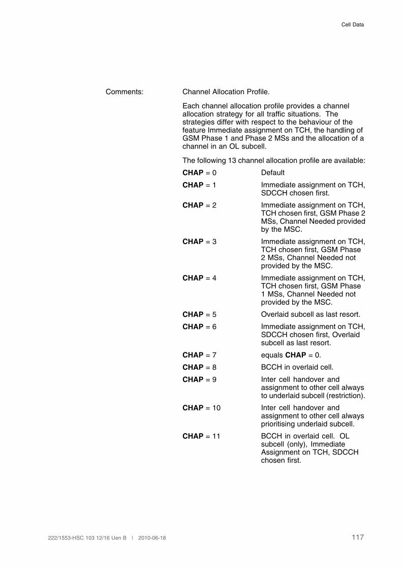
Cell Data
Comments: Channel Allocation Profile.
Each channel allocation profile provides a channelallocation strategy for all traffic situations. Thestrategies differ with respect to the behaviour of thefeature Immediate assignment on TCH, the handling ofGSM Phase 1 and Phase 2 MSs and the allocation of achannel in an OL subcell.
The following 13 channel allocation profile are available:
CHAP = 0 Default
CHAP = 1 Immediate assignment on TCH,SDCCH chosen first.
CHAP = 2 Immediate assignment on TCH,TCH chosen first, GSM Phase 2MSs, Channel Needed providedby the MSC.
CHAP = 3 Immediate assignment on TCH,TCH chosen first, GSM Phase2 MSs, Channel Needed notprovided by the MSC.
CHAP = 4 Immediate assignment on TCH,TCH chosen first, GSM Phase1 MSs, Channel Needed notprovided by the MSC.
CHAP = 5 Overlaid subcell as last resort.
CHAP = 6 Immediate assignment on TCH,SDCCH chosen first, Overlaidsubcell as last resort.
CHAP = 7 equals CHAP = 0.
CHAP = 8 BCCH in overlaid cell.
CHAP = 9 Inter cell handover andassignment to other cell alwaysto underlaid subcell (restriction).
CHAP = 10 Inter cell handover andassignment to other cell alwaysprioritising underlaid subcell.
CHAP = 11 BCCH in overlaid cell. OLsubcell (only), ImmediateAssignment on TCH, SDCCHchosen first.
117222/1553-HSC 103 12/16 Uen B | 2010-06-18

User Description, Radio Network Parameters and Cell Design Data for Ericsson's GSM Systems
CHAP = 12 BCCH in overlaid cell. OLsubcell (only), ImmediateAssignment on TCH, TCHchosen first.
CHAP = 13 Immediate assignment on TCH,TCH chosen first, Overlaidsubcell as last resort.
NECI
Type: Numeral
Range: 0 and 1
Unit: -
Default: 0
Command: RLSSC , RLSSP.
O&M: -
Comments: New establishments cause indicator.
NECI is used to indicate to a GSM phase 2 MSwhether to use GSM phase 1 establishment(NECI = 0) causes or the full set of GSM phase 2establishment causes (NECI = 1).
0 New establishmentcauses are NOTsupported.
1 New establishmentcauses are supported.
MC
Type: Identifier
Range: ON, OFF
Unit: -
Default: OFF
Command: RLCDC , RLCDP
O&M: -
Comments: Multiple Channel switch.
MC identifies if more than one full rate TCH areallowed to be allocated for each MS connection inthe cell.
118 222/1553-HSC 103 12/16 Uen B | 2010-06-18
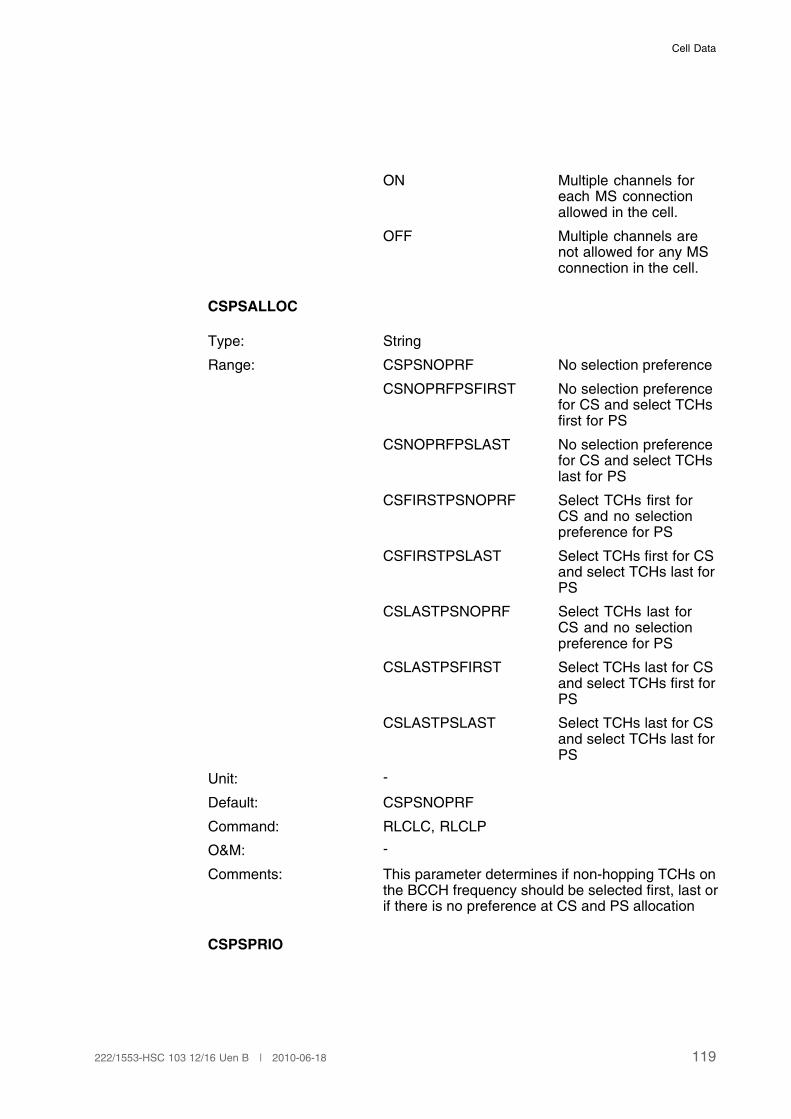
Cell Data
ON Multiple channels foreach MS connectionallowed in the cell.
OFF Multiple channels arenot allowed for any MSconnection in the cell.
CSPSALLOC
Type: String
Range: CSPSNOPRF No selection preference
CSNOPRFPSFIRST No selection preferencefor CS and select TCHsfirst for PS
CSNOPRFPSLAST No selection preferencefor CS and select TCHslast for PS
CSFIRSTPSNOPRF Select TCHs first forCS and no selectionpreference for PS
CSFIRSTPSLAST Select TCHs first for CSand select TCHs last forPS
CSLASTPSNOPRF Select TCHs last forCS and no selectionpreference for PS
CSLASTPSFIRST Select TCHs last for CSand select TCHs first forPS
CSLASTPSLAST Select TCHs last for CSand select TCHs last forPS
Unit: -
Default: CSPSNOPRF
Command: RLCLC, RLCLP
O&M: -
Comments: This parameter determines if non-hopping TCHs onthe BCCH frequency should be selected first, last orif there is no preference at CS and PS allocation
CSPSPRIO
119222/1553-HSC 103 12/16 Uen B | 2010-06-18
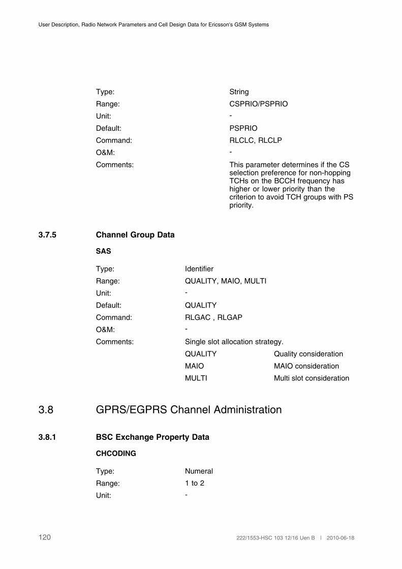
User Description, Radio Network Parameters and Cell Design Data for Ericsson's GSM Systems
Type: String
Range: CSPRIO/PSPRIO
Unit: -
Default: PSPRIO
Command: RLCLC, RLCLP
O&M: -
Comments: This parameter determines if the CSselection preference for non-hoppingTCHs on the BCCH frequency hashigher or lower priority than thecriterion to avoid TCH groups with PSpriority.
3.7.5 Channel Group Data
SAS
Type: Identifier
Range: QUALITY, MAIO, MULTI
Unit: -
Default: QUALITY
Command: RLGAC , RLGAP
O&M: -
Comments: Single slot allocation strategy.
QUALITY Quality consideration
MAIO MAIO consideration
MULTI Multi slot consideration
3.8 GPRS/EGPRS Channel Administration
3.8.1 BSC Exchange Property Data
CHCODING
Type: Numeral
Range: 1 to 2
Unit: -
120 222/1553-HSC 103 12/16 Uen B | 2010-06-18

Cell Data
Default: 2
Command: RAEPC, RAEPP.
O&M: -
Comments: CHCODING is used to the GPRS channel-codingscheme that will be used for the uplink:
1 CS-1
2 CS-2
The BTS capabilities will be taken into account whencalculation the actual channel coding scheme usedin the cell. All BTS version supporting GPRS alsosupport CS-2, with the exception of early versionsof RBS2301. If this is the case CS-1 will be usedregardless of the setting of this parameter.
A cell plan optimised for speech will give similar orbetter coverage for GPRS traffic for both CS-1 andCS-2 configurations.
GPRSEDAACT
Type: Numeral
Range: 0,1
Unit: -
Default: 0
Command: RAEPC, RAEPP
O&M: -
Comments: GPRS Extended Dynamic AllocationActivation.
This parameter indicates whether asupport for GPRS Extended DynamicAllocation is allowed or not.
0 = OFF
1 = ON
GPRSNWMODE
Type: Numeral
Range: 1 to 3
Unit: -
Default: 2
121222/1553-HSC 103 12/16 Uen B | 2010-06-18
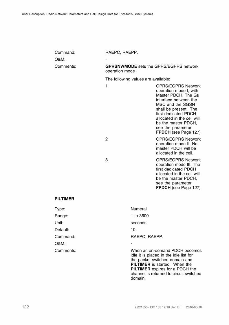
User Description, Radio Network Parameters and Cell Design Data for Ericsson's GSM Systems
Command: RAEPC, RAEPP.
O&M: -
Comments: GPRSNWMODE sets the GPRS/EGPRS networkoperation mode
The following values are available:
1 GPRS/EGPRS Networkoperation mode I, withMaster PDCH. The Gsinterface between theMSC and the SGSNshall be present. Thefirst dedicated PDCHallocated in the cell willbe the master PDCH,see the parameterFPDCH (see Page 127)
2 GPRS/EGPRS Networkoperation mode II. Nomaster PDCH will beallocated in the cell.
3 GPRS/EGPRS Networkoperation mode III. Thefirst dedicated PDCHallocated in the cell willbe the master PDCH,see the parameterFPDCH (see Page 127)
PILTIMER
Type: Numeral
Range: 1 to 3600
Unit: seconds
Default: 10
Command: RAEPC, RAEPP.
O&M: -
Comments: When an on-demand PDCH becomesidle it is placed in the idle list forthe packet switched domain andPILTIMER is started. When thePILTIMER expires for a PDCH thechannel is returned to circuit switcheddomain.
122 222/1553-HSC 103 12/16 Uen B | 2010-06-18

Cell Data
ONDEMANDGPHDEV
Type: Numeral
Range: 1 to 256
Unit: -
Default: 20
Command: RAEPC, RAEPP.
O&M: -
Comments: ONDEMANDGPHDEV is used forsetting the number of reserved GPHdevices in an RPP that can be usedfor on-demand PDCH only.
ONDEMANDGPHDG2
Type: Numeral
Range: 1 to 512
Unit: -
Default: 140
Command: RAEPC, RAEPP
O&M:
Comment:
TBFDLLIMIT
Type: Numeral
Range: 10 to 80
Unit: -
Default: 20
Command: RAEPC, RAEPP.
O&M: -
Comments: When all currently allocated PDCHhave the TBFDLLIMIT number ofTBFs allocated an allocation attemptof more on-demand PDCH is done. Ifthe allocation attempt fails, TBFs willbe allocated on the existing PDCH, upto and including the limit of 80, whencongestion occurs.
(1)
(1) This parameter has a decimal granularity, that is 20 represents value 2.0.
123222/1553-HSC 103 12/16 Uen B | 2010-06-18

User Description, Radio Network Parameters and Cell Design Data for Ericsson's GSM Systems
TBFULLIMIT
Type: Numeral
Range: 10 to 60
Unit: -
Default: 20
Command: RAEPC, RAEPP.
O&M: -
Comments: When all currently allocated PDCHhave the TBFULLIMIT number ofTBFs allocated an allocation attemptof more on-demand PDCH is done. Ifthe allocation attempt fails, TBFs willbe allocated on the existing PDCH, upto and including the limit of 60, whencongestion occurs.
(1)
(1) This parameter has a decimal granularity, that is 20 represents value 2.0.
PSETCHKPERIOD
Type: Numeral
Range: 0 to 60
Unit: minutes
Default: 5
Command: RAEPC, RAEPP.
O&M: -
Comments: Periodical check of GPRS dedicatedchannels. It sets how often a check willbe performed to verify that the GPRSdedicated channels are allocated onthe best possible TCH group in thecell.
GPRS5TSDLACT
Type: Numeral
Range: 0, 1
Unit: -
Default: 0
Command RAEPC, RAEPP
124 222/1553-HSC 103 12/16 Uen B | 2010-06-18

Cell Data
O&M: -
Comments: Indicates if support for MS multislotclasses 30–33 is available or not.
0 = MS multislot classes 30–33 notavailable
1 = MS multislot classes 30–33available
GPRSNEUTRALACT
Type: Numeral
Range: 0, 1
Unit: -
Default: 0
Command RAEPC, RAEPP
O&M: -
Comments: Indicates if support for the NeutralUL/DL state is available or not.
0 = Neutral UL/DL state not available
1 = Neutral UL/DL state available
TBFMODEACT
Type: Numeral
Range: 0 to 3
Unit: -
Default: 0
Command: RAEPC, RAEPP
125222/1553-HSC 103 12/16 Uen B | 2010-06-18
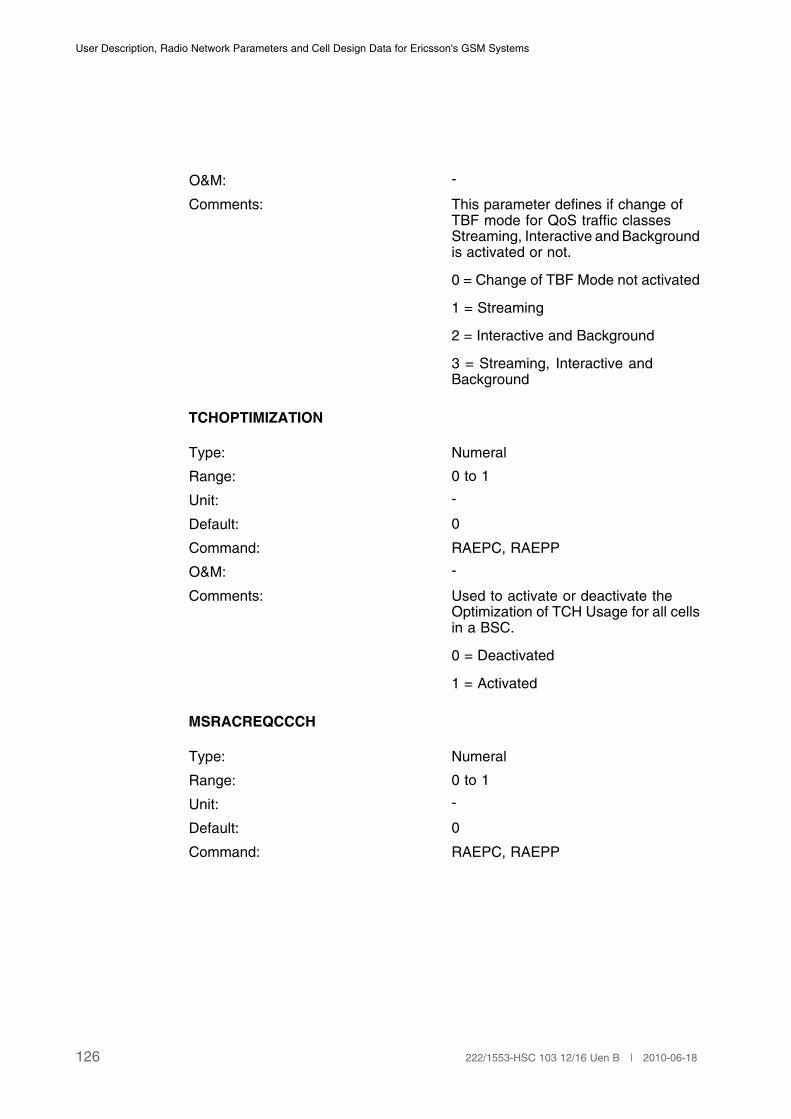
User Description, Radio Network Parameters and Cell Design Data for Ericsson's GSM Systems
O&M: -
Comments: This parameter defines if change ofTBF mode for QoS traffic classesStreaming, Interactive and Backgroundis activated or not.
0 = Change of TBF Mode not activated
1 = Streaming
2 = Interactive and Background
3 = Streaming, Interactive andBackground
TCHOPTIMIZATION
Type: Numeral
Range: 0 to 1
Unit: -
Default: 0
Command: RAEPC, RAEPP
O&M: -
Comments: Used to activate or deactivate theOptimization of TCH Usage for all cellsin a BSC.
0 = Deactivated
1 = Activated
MSRACREQCCCH
Type: Numeral
Range: 0 to 1
Unit: -
Default: 0
Command: RAEPC, RAEPP
126 222/1553-HSC 103 12/16 Uen B | 2010-06-18
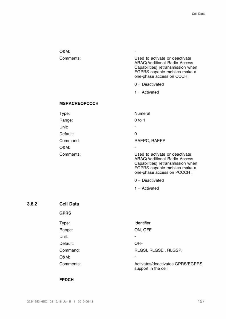
Cell Data
O&M: -
Comments: Used to activate or deactivateARAC(Additional Radio AccessCapabilities) retransmission whenEGPRS capable mobiles make aone-phase access on CCCH.
0 = Deactivated
1 = Activated
MSRACREQPCCCH
Type: Numeral
Range: 0 to 1
Unit: -
Default: 0
Command: RAEPC, RAEPP
O&M: -
Comments: Used to activate or deactivateARAC(Additional Radio AccessCapabilities) retransmission whenEGPRS capable mobiles make aone-phase access on PCCCH .
0 = Deactivated
1 = Activated
3.8.2 Cell Data
GPRS
Type: Identifier
Range: ON, OFF
Unit: -
Default: OFF
Command: RLGSI, RLGSE , RLGSP.
O&M: -
Comments: Activates/deactivates GPRS/EGPRSsupport in the cell.
FPDCH
127222/1553-HSC 103 12/16 Uen B | 2010-06-18
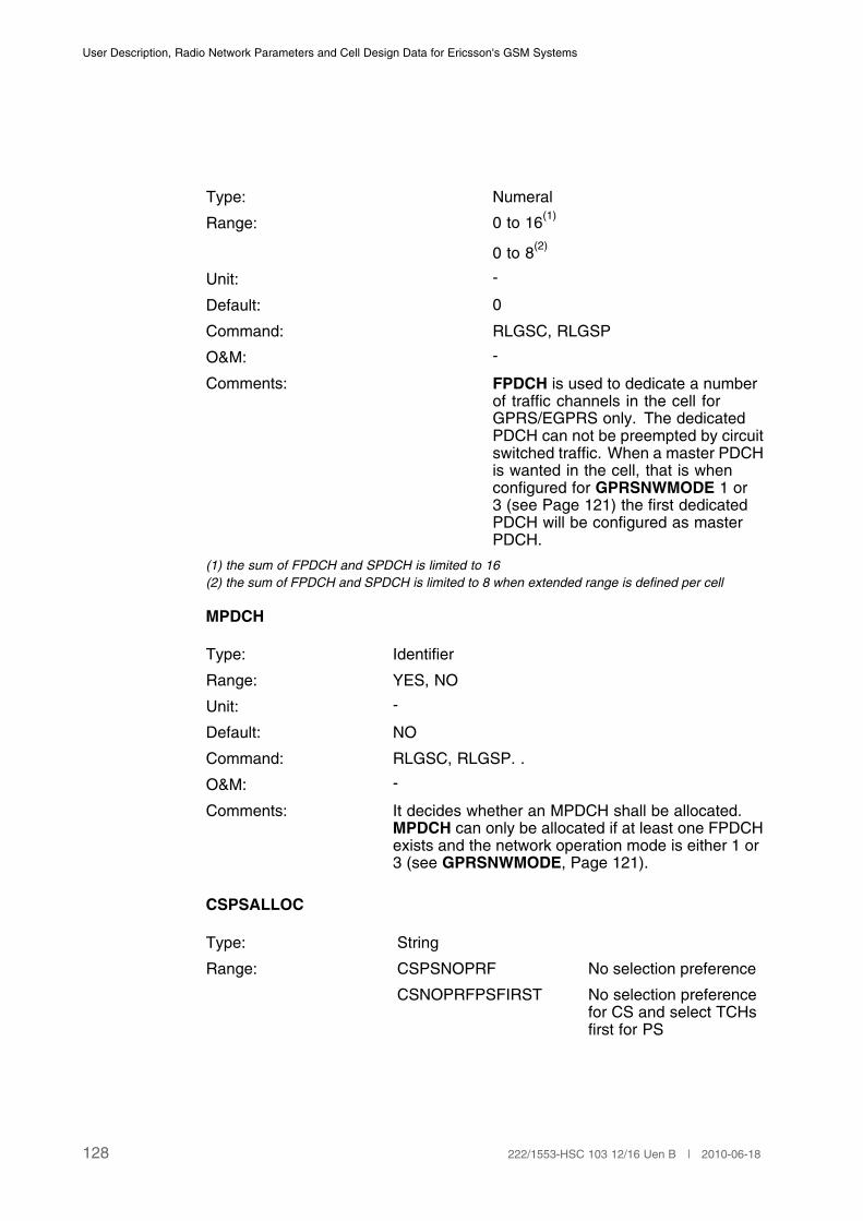
User Description, Radio Network Parameters and Cell Design Data for Ericsson's GSM Systems
Type: Numeral
Range: 0 to 16(1)
0 to 8(2)
Unit: -
Default: 0
Command: RLGSC, RLGSP
O&M: -
Comments: FPDCH is used to dedicate a numberof traffic channels in the cell forGPRS/EGPRS only. The dedicatedPDCH can not be preempted by circuitswitched traffic. When a master PDCHis wanted in the cell, that is whenconfigured for GPRSNWMODE 1 or3 (see Page 121) the first dedicatedPDCH will be configured as masterPDCH.
(1) the sum of FPDCH and SPDCH is limited to 16
(2) the sum of FPDCH and SPDCH is limited to 8 when extended range is defined per cell
MPDCH
Type: Identifier
Range: YES, NO
Unit: -
Default: NO
Command: RLGSC, RLGSP. .
O&M: -
Comments: It decides whether an MPDCH shall be allocated.MPDCH can only be allocated if at least one FPDCHexists and the network operation mode is either 1 or3 (see GPRSNWMODE, Page 121).
CSPSALLOC
Type: String
Range: CSPSNOPRF No selection preference
CSNOPRFPSFIRST No selection preferencefor CS and select TCHsfirst for PS
128 222/1553-HSC 103 12/16 Uen B | 2010-06-18
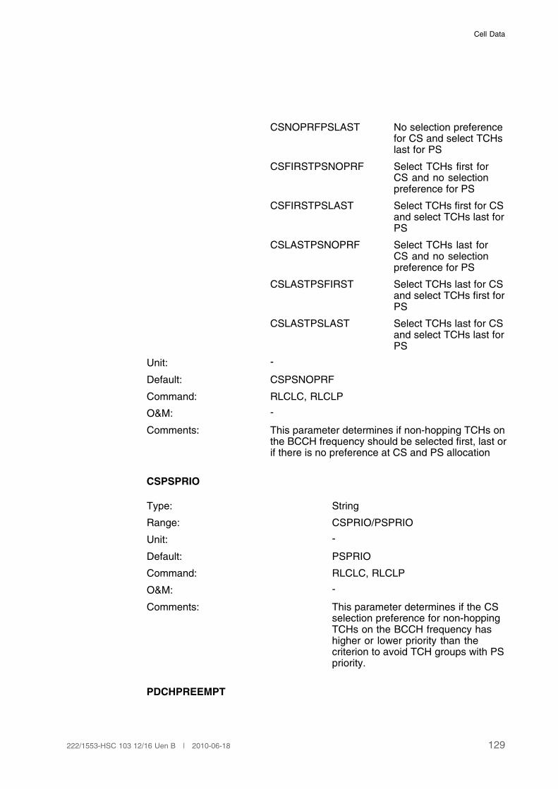
Cell Data
CSNOPRFPSLAST No selection preferencefor CS and select TCHslast for PS
CSFIRSTPSNOPRF Select TCHs first forCS and no selectionpreference for PS
CSFIRSTPSLAST Select TCHs first for CSand select TCHs last forPS
CSLASTPSNOPRF Select TCHs last forCS and no selectionpreference for PS
CSLASTPSFIRST Select TCHs last for CSand select TCHs first forPS
CSLASTPSLAST Select TCHs last for CSand select TCHs last forPS
Unit: -
Default: CSPSNOPRF
Command: RLCLC, RLCLP
O&M: -
Comments: This parameter determines if non-hopping TCHs onthe BCCH frequency should be selected first, last orif there is no preference at CS and PS allocation
CSPSPRIO
Type: String
Range: CSPRIO/PSPRIO
Unit: -
Default: PSPRIO
Command: RLCLC, RLCLP
O&M: -
Comments: This parameter determines if the CSselection preference for non-hoppingTCHs on the BCCH frequency hashigher or lower priority than thecriterion to avoid TCH groups with PSpriority.
PDCHPREEMPT
129222/1553-HSC 103 12/16 Uen B | 2010-06-18
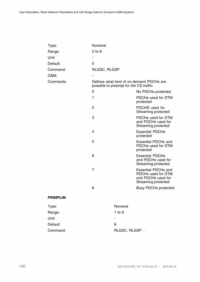
User Description, Radio Network Parameters and Cell Design Data for Ericsson's GSM Systems
Type: Numeral
Range: 0 to 8
Unit: -
Default: 0
Command: RLGSC, RLGSP.
O&M: -
Comments: Defines what kind of on-demand PDCHs arepossible to preempt for the CS traffic:
0 No PDCHs protected
1 PDCHs used for DTMprotected
2 PDCHS used forStreaming protected
3 PDCHs used for DTMand PDCHs used forStreaming protected
4 Essential PDCHsprotected
5 Essential PDCHs andPDCHs used for DTMprotected
6 Essential PDCHsand PDCHs used forStreaming protected
7 Essential PDCHs andPDCHs used for DTMand PDCHs used forStreaming protected
8 Busy PDCHs protected
PRIMPLIM
Type: Numeral
Range: 1 to 8
Unit: -
Default: 8
Command: RLGSC, RLGSP. .
130 222/1553-HSC 103 12/16 Uen B | 2010-06-18
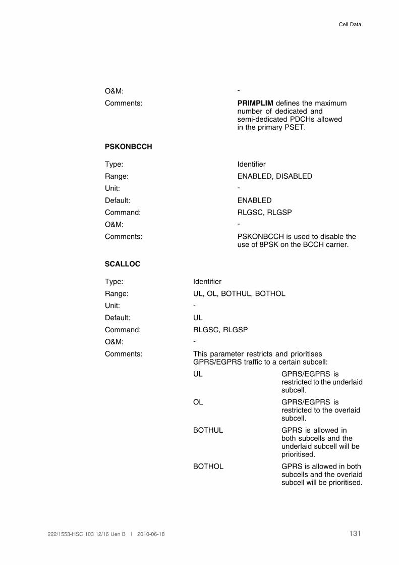
Cell Data
O&M: -
Comments: PRIMPLIM defines the maximumnumber of dedicated andsemi-dedicated PDCHs allowedin the primary PSET.
PSKONBCCH
Type: Identifier
Range: ENABLED, DISABLED
Unit: -
Default: ENABLED
Command: RLGSC, RLGSP
O&M: -
Comments: PSKONBCCH is used to disable theuse of 8PSK on the BCCH carrier.
SCALLOC
Type: Identifier
Range: UL, OL, BOTHUL, BOTHOL
Unit: -
Default: UL
Command: RLGSC, RLGSP
O&M: -
Comments: This parameter restricts and prioritisesGPRS/EGPRS traffic to a certain subcell:
UL GPRS/EGPRS isrestricted to the underlaidsubcell.
OL GPRS/EGPRS isrestricted to the overlaidsubcell.
BOTHUL GPRS is allowed inboth subcells and theunderlaid subcell will beprioritised.
BOTHOL GPRS is allowed in bothsubcells and the overlaidsubcell will be prioritised.
131222/1553-HSC 103 12/16 Uen B | 2010-06-18
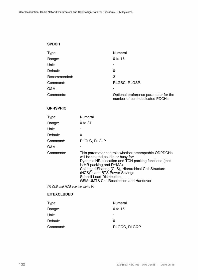
User Description, Radio Network Parameters and Cell Design Data for Ericsson's GSM Systems
SPDCH
Type: Numeral
Range: 0 to 16
Unit: -
Default: 0
Recommended: 2
Command: RLGSC, RLGSP.
O&M: -
Comments: Optional preference parameter for thenumber of semi-dedicated PDCHs.
GPRSPRIO
Type: Numeral
Range: 0 to 31
Unit: -
Default: 0
Command: RLCLC, RLCLP
O&M: -
Comments: This parameter controls whether preemptable ODPDCHswill be treated as idle or busy for:Dynamic HR allocation and TCH packing functions (thatis HR packing and DYMA)Cell Load Sharing (CLS), Hierarchical Cell Structure(HCS)
(1)and BTS Power Savings
Subcell Load DistributionGSM-UMTS Cell Reselection and Handover.
(1) CLS and HCS use the same bit
EITEXCLUDED
Type: Numeral
Range: 0 to 15
Unit: -
Default: 0
Command: RLGQC, RLGQP
132 222/1553-HSC 103 12/16 Uen B | 2010-06-18
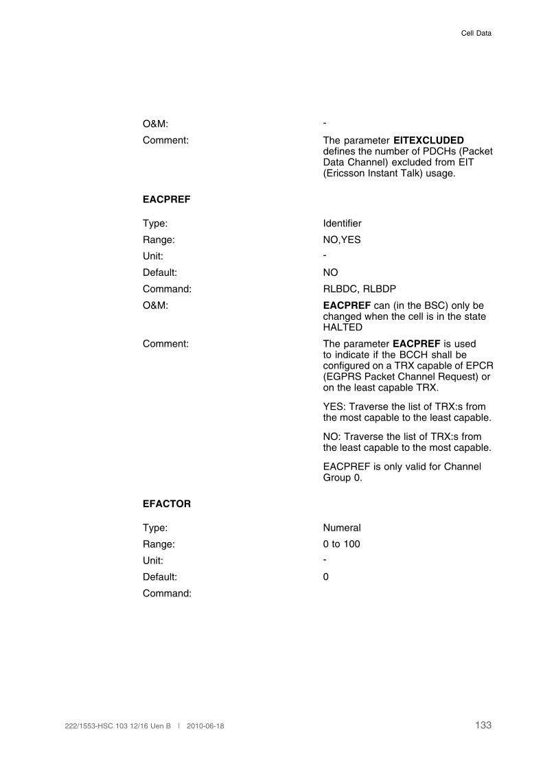
Cell Data
O&M: -
Comment: The parameter EITEXCLUDEDdefines the number of PDCHs (PacketData Channel) excluded from EIT(Ericsson Instant Talk) usage.
EACPREF
Type: Identifier
Range: NO,YES
Unit: -
Default: NO
Command: RLBDC, RLBDP
O&M: EACPREF can (in the BSC) only bechanged when the cell is in the stateHALTED
Comment: The parameter EACPREF is usedto indicate if the BCCH shall beconfigured on a TRX capable of EPCR(EGPRS Packet Channel Request) oron the least capable TRX.
YES: Traverse the list of TRX:s fromthe most capable to the least capable.
NO: Traverse the list of TRX:s fromthe least capable to the most capable.
EACPREF is only valid for ChannelGroup 0.
EFACTOR
Type: Numeral
Range: 0 to 100
Unit: -
Default: 0
Command:
133222/1553-HSC 103 12/16 Uen B | 2010-06-18
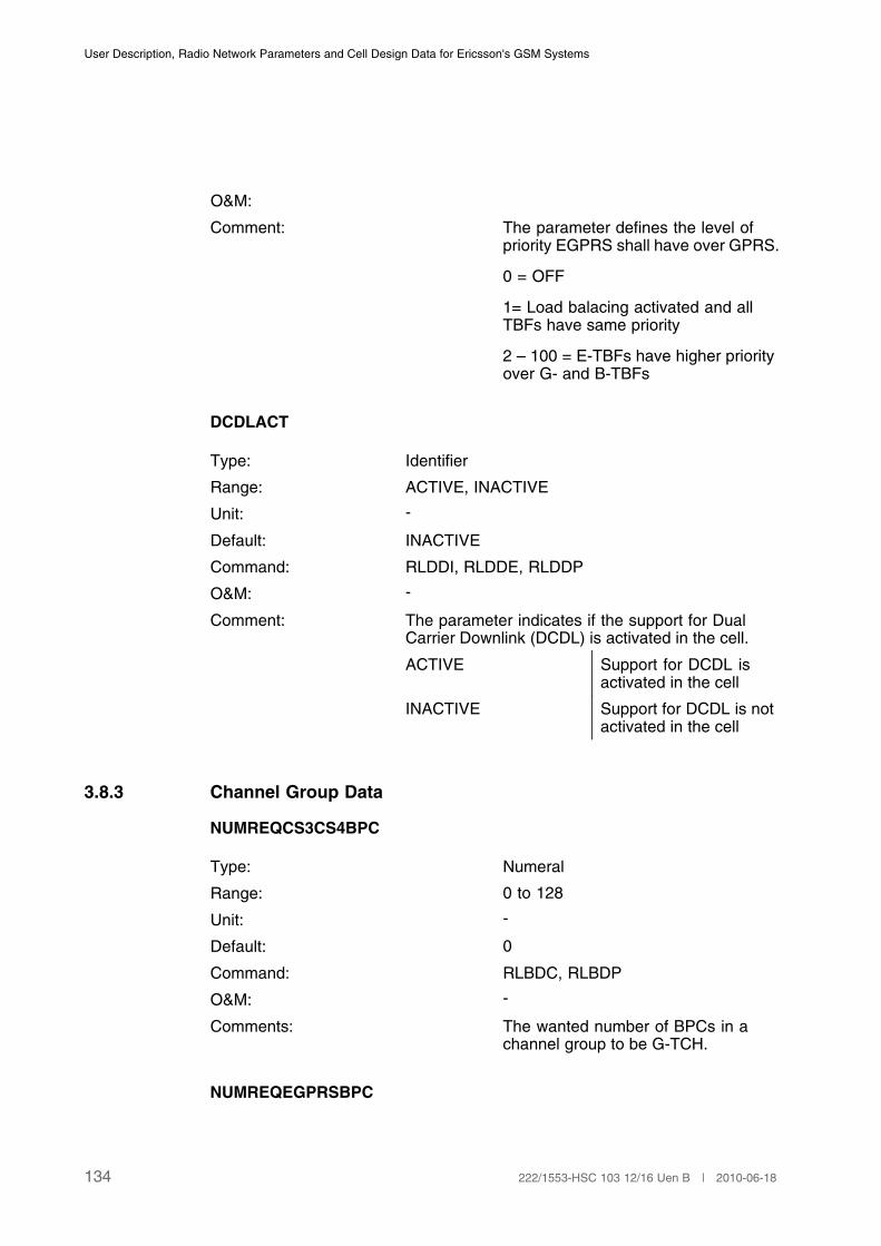
User Description, Radio Network Parameters and Cell Design Data for Ericsson's GSM Systems
O&M:
Comment: The parameter defines the level ofpriority EGPRS shall have over GPRS.
0 = OFF
1= Load balacing activated and allTBFs have same priority
2 – 100 = E-TBFs have higher priorityover G- and B-TBFs
DCDLACT
Type: Identifier
Range: ACTIVE, INACTIVE
Unit: -
Default: INACTIVE
Command: RLDDI, RLDDE, RLDDP
O&M: -
Comment: The parameter indicates if the support for DualCarrier Downlink (DCDL) is activated in the cell.
ACTIVE Support for DCDL isactivated in the cell
INACTIVE Support for DCDL is notactivated in the cell
3.8.3 Channel Group Data
NUMREQCS3CS4BPC
Type: Numeral
Range: 0 to 128
Unit: -
Default: 0
Command: RLBDC, RLBDP
O&M: -
Comments: The wanted number of BPCs in achannel group to be G-TCH.
NUMREQEGPRSBPC
134 222/1553-HSC 103 12/16 Uen B | 2010-06-18

Cell Data
Type: Numeral
Range: 0 to 128
Unit: -
Default: 0
Command: RLBDC, RLBDP
O&M: -
Comments: The wanted number of BPCs in achannel group to be E-TCH.
TN7BCCH
Type: Identifier
Range: EGPRS, GPRS
Unit: -
Default: GPRS
Command: RLBDC, RLBDP
O&M: -
Comments: Indicates if Timeslot Number 7 on the BCCHfrequency can be configured with TCHs supportingEGPRS and GPRS, or GPRS only.
TN7BCCH is only valid for the channel group 0.
EGPRS TN7 on the BCCHfrequency can beconfigured with TCHssupporting both EGPRSand GPRS.
GPRS TN7 on the BCCHfrequency can only beconfigured with TCHssupporting GPRS.
ODPDCHLIMIT
Type: Numeral
Range: 0–100
Unit: %
Default: 100
Command: RLGAC, RLGAP
135222/1553-HSC 103 12/16 Uen B | 2010-06-18

User Description, Radio Network Parameters and Cell Design Data for Ericsson's GSM Systems
O&M: -
Comments: This parameter limits the total numberof on-demand PDCHs in the channelgroup. The parameter indicatesa percentage value of number ofdeblocked FR TCHs in the channelgroup that can be allocated ason-demand PDCHs.
(1)
(1) The number of TCHs that can be used as on-demand PDCHs will be truncated to an integer.
ETCHTN
Type: Numeral
Range: 0 to 7
Unit: -
Default: 0 && 7
Command: RLBDC
O&M:
Comment: ETCHTN is a parameter to decide on which TNsthe EGPRS capable BPCs shall be configured. Iffor example TN 5&&7 is specified and the numberof EGPRS capable BPCs (NUMREQEGPRSBPC)is set to 6 then TN 5, 6 and 7 on two differentTCHGPRs will be configured as E-TCHs.
3.9 Dynamic MS Power Control
3.9.1 BSC Data
DTXFUL
Type: Numeral
Range: 0 to 40
Unit: SACCH periods (480 ms)
Default: 5
Command: RLMAC, RLMAP
136 222/1553-HSC 103 12/16 Uen B | 2010-06-18

Cell Data
O&M: -
Comments: Number of measurement periodsbefore the full set of measurementsare used.
The measurement results sent to theBSC every SACCH period (480 ms)include a full set of measurements anda subset of measurements. The fullset of measurements is performed oneach TDMA frame in a basic physicalchannel. The subset of measurementsis performed on those TDMA framesin the basic physical channel wheretransmission is guaranteed, seeReference [9].
The power control algorithm uses thesubset if either DTX is used on a TCHor during a time period after the callhas just been established on a TCH.This time period is specified by theparameter DTXFUL. In all other casesthe power control algorithm uses thefull set.
QLENUL
Type: Numeral
Range: 1 to 20
Unit: SACCH periods (480 ms)
Default: 3
Command: RLMAC, RLMAP
O&M: -
Comments: Length of the uplink quality filter.
REGINTUL
Type: Numeral
Range: 1 to 30
Unit: SACCH periods (480 ms)
Default: 1
Command: RLMAC, RLMAP
137222/1553-HSC 103 12/16 Uen B | 2010-06-18
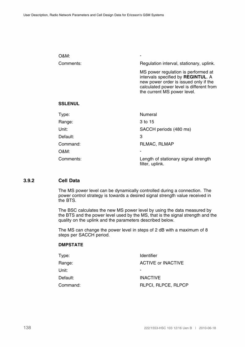
User Description, Radio Network Parameters and Cell Design Data for Ericsson's GSM Systems
O&M: -
Comments: Regulation interval, stationary, uplink.
MS power regulation is performed atintervals specified by REGINTUL. Anew power order is issued only if thecalculated power level is different fromthe current MS power level.
SSLENUL
Type: Numeral
Range: 3 to 15
Unit: SACCH periods (480 ms)
Default: 3
Command: RLMAC, RLMAP
O&M: -
Comments: Length of stationary signal strengthfilter, uplink.
3.9.2 Cell Data
The MS power level can be dynamically controlled during a connection. Thepower control strategy is towards a desired signal strength value received inthe BTS.
The BSC calculates the new MS power level by using the data measured bythe BTS and the power level used by the MS, that is the signal strength and thequality on the uplink and the parameters described below.
The MS can change the power level in steps of 2 dB with a maximum of 8steps per SACCH period.
DMPSTATE
Type: Identifier
Range: ACTIVE or INACTIVE
Unit: -
Default: INACTIVE
Command: RLPCI, RLPCE, RLPCP
138 222/1553-HSC 103 12/16 Uen B | 2010-06-18
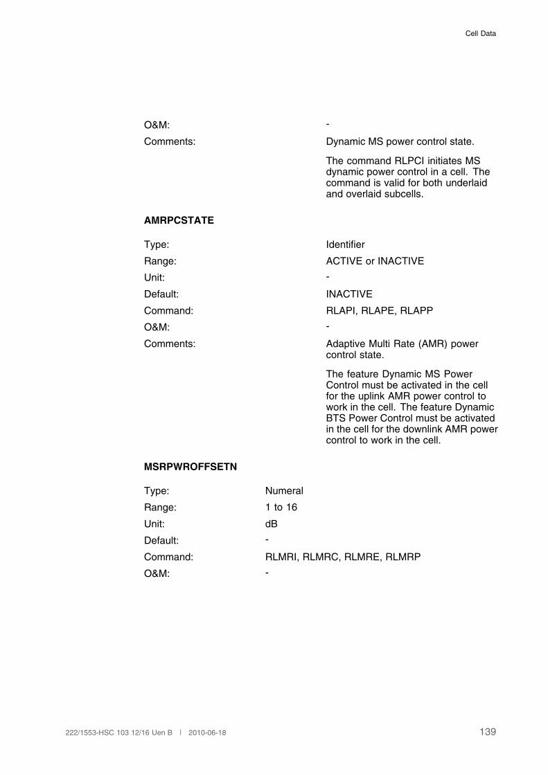
Cell Data
O&M: -
Comments: Dynamic MS power control state.
The command RLPCI initiates MSdynamic power control in a cell. Thecommand is valid for both underlaidand overlaid subcells.
AMRPCSTATE
Type: Identifier
Range: ACTIVE or INACTIVE
Unit: -
Default: INACTIVE
Command: RLAPI, RLAPE, RLAPP
O&M: -
Comments: Adaptive Multi Rate (AMR) powercontrol state.
The feature Dynamic MS PowerControl must be activated in the cellfor the uplink AMR power control towork in the cell. The feature DynamicBTS Power Control must be activatedin the cell for the downlink AMR powercontrol to work in the cell.
MSRPWROFFSETN
Type: Numeral
Range: 1 to 16
Unit: dB
Default: -
Command: RLMRI, RLMRC, RLMRE, RLMRP
O&M: -
139222/1553-HSC 103 12/16 Uen B | 2010-06-18

User Description, Radio Network Parameters and Cell Design Data for Ericsson's GSM Systems
Comments: Negative MS power offset. MSRPWROFFSETNisa cell parameter which applies an offset to the MSpower used on the originating channel when theinitial power, to be used on the target channel,is calculated when Reduced Power Level AfterHandover is activated. The parameter is appliedfor intra-cell handovers as well as for inter-cellhandovers in to the cell. This parameter is notprinted together with MSRPWROFFSETP.
1 2 dB
2 4 dB
3 6 dB
4 8 dB
5 10 dB
6 12 dB
7 14 dB
8 16 dB
9 18 dB
10 20 dB
11 22 dB
12 24 dB
13 26 dB
14 28 dB
15 30 dB
16 32 dB
MSRPWROFFSETP
Type: Numeral
Range: 0to 16
Unit: dB
Default: -
Command: RLMRI, RLMRC, RLMRE, RLMRP
O&M: -
140 222/1553-HSC 103 12/16 Uen B | 2010-06-18

Cell Data
Comments: Positive MS power offset. MSRPWROFFSETPisa cell parameter which applies an offset to the MSpower used on the originating channel when theinitial power, to be used on the target channel,is calculated when Reduced Power Level AfterHandover is activated. The parameter is appliedfor intra-cell handovers as well as for inter-cellhandovers in to the cell. This parameter is notprinted together with MSRPWROFFSETN.
0 0 dB
1 2 dB
2 4 dB
3 6 dB
4 8 dB
5 10 dB
6 12 dB
7 14 dB
8 16 dB
9 18 dB
10 20 dB
11 22 dB
12 24 dB
13 26 dB
14 28 dB
15 30 dB
16 32 dB
3.9.3 Cell/Subcell Data
These parameters may be defined different for underlaid and overlaid subcells.In case there is no subcell structure defined, they are defined per cell.
SSDESUL
Type: Numeral
Range: 47 to 110
Unit: dBm (negative)
Default: 92
141222/1553-HSC 103 12/16 Uen B | 2010-06-18
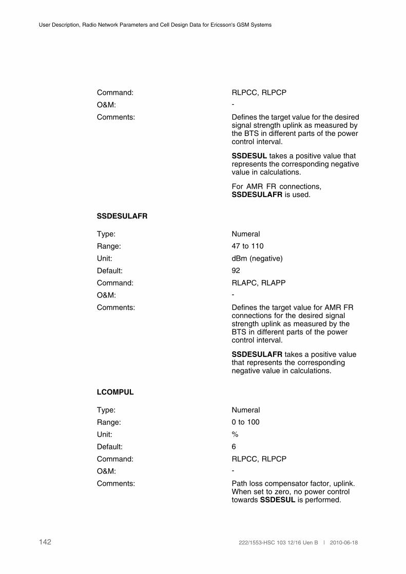
User Description, Radio Network Parameters and Cell Design Data for Ericsson's GSM Systems
Command: RLPCC, RLPCP
O&M: -
Comments: Defines the target value for the desiredsignal strength uplink as measured bythe BTS in different parts of the powercontrol interval.
SSDESUL takes a positive value thatrepresents the corresponding negativevalue in calculations.
For AMR FR connections,SSDESULAFR is used.
SSDESULAFR
Type: Numeral
Range: 47 to 110
Unit: dBm (negative)
Default: 92
Command: RLAPC, RLAPP
O&M: -
Comments: Defines the target value for AMR FRconnections for the desired signalstrength uplink as measured by theBTS in different parts of the powercontrol interval.
SSDESULAFR takes a positive valuethat represents the correspondingnegative value in calculations.
LCOMPUL
Type: Numeral
Range: 0 to 100
Unit: %
Default: 6
Command: RLPCC, RLPCP
O&M: -
Comments: Path loss compensator factor, uplink.When set to zero, no power controltowards SSDESUL is performed.
142 222/1553-HSC 103 12/16 Uen B | 2010-06-18

Cell Data
QDESUL
Type: Numeral
Range: 0 to 76
Unit: dtqu
Default: 30
Command: RLPCC, RLPCP
O&M: -
Comments: Desired quality, uplink.
For AMR FR connections,QDESULAFR is used.
QDESULAFR
Type: Numeral
Range: 0 to 76
Unit: dtqu
Default: 40
Command: RLAPC, RLAPP
O&M: -
Comments: Desired quality, uplink for AMR FRconnections.
QCOMPUL
Type: Numeral
Range: 0 to 100
Unit: %
Default: 75
Command: RLPCC, RLPCP
O&M: -
Comments: Quality deviation compensation factor,uplink. When set to zero, no qualitycompensation is performed.
SSDESULAHR
Type: Numeral
Range: 47 to 110
143222/1553-HSC 103 12/16 Uen B | 2010-06-18
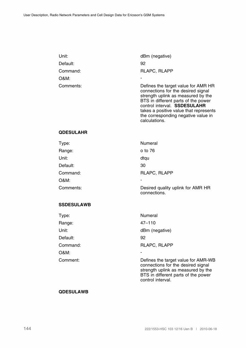
User Description, Radio Network Parameters and Cell Design Data for Ericsson's GSM Systems
Unit: dBm (negative)
Default: 92
Command: RLAPC, RLAPP
O&M: -
Comments: Defines the target value for AMR HRconnections for the desired signalstrength uplink as measured by theBTS in different parts of the powercontrol interval. SSDESULAHRtakes a positive value that representsthe corresponding negative value incalculations.
QDESULAHR
Type: Numeral
Range: o to 76
Unit: dtqu
Default: 30
Command: RLAPC, RLAPP
O&M: -
Comments: Desired quality uplink for AMR HRconnections.
SSDESULAWB
Type: Numeral
Range: 47–110
Unit: dBm (negative)
Default: 92
Command: RLAPC, RLAPP
O&M: -
Comment: Defines the target value for AMR-WBconnections for the desired signalstrength uplink as measured by theBTS in different parts of the powercontrol interval.
QDESULAWB
144 222/1553-HSC 103 12/16 Uen B | 2010-06-18
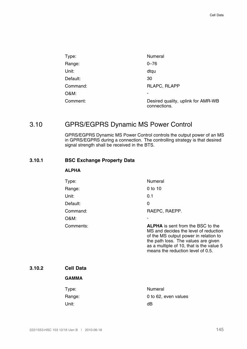
Cell Data
Type: Numeral
Range: 0–76
Unit: dtqu
Default: 30
Command: RLAPC, RLAPP
O&M: -
Comment: Desired quality, uplink for AMR-WBconnections.
3.10 GPRS/EGPRS Dynamic MS Power Control
GPRS/EGPRS Dynamic MS Power Control controls the output power of an MSin GPRS/EGPRS during a connection. The controlling strategy is that desiredsignal strength shall be received in the BTS.
3.10.1 BSC Exchange Property Data
ALPHA
Type: Numeral
Range: 0 to 10
Unit: 0.1
Default: 0
Command: RAEPC, RAEPP.
O&M: -
Comments: ALPHA is sent from the BSC to theMS and decides the level of reductionof the MS output power in relation tothe path loss. The values are givenas a multiple of 10, that is the value 5means the reduction level of 0.5.
3.10.2 Cell Data
GAMMA
Type: Numeral
Range: 0 to 62, even values
Unit: dB
145222/1553-HSC 103 12/16 Uen B | 2010-06-18

User Description, Radio Network Parameters and Cell Design Data for Ericsson's GSM Systems
Default: 0
Command: RLGSC, RLGSP
O&M: -
Comments: GAMMA is sent from the BSC tothe MS to give a target value for thereceived signal strength at the BTS.
3.11 Dynamic BTS Power Control
The BTS power level can be dynamically controlled during a connection. Thepower control strategy is towards a desired signal strength value received inthe MS.
The BSC calculates the new BTS power level by using the data measured bythe MS, that is the signal strength and the quality on the downlink TCH carriersand the parameters described below. A compensation is performed in the caseof frequency hopping, which takes into consideration that bursts received andmeasured by the MS may have been transmitted at different power levels. Thepower level on channels at the BCCH frequency is not controlled.
The BTS can change its power level in steps of 2 dB, while the maximumconfigurable change is 30 dB.
3.11.1 BSC Data
REGINTDL
Type: Numeral
Range: 1 to 10
Unit: SACCH periods (480 ms)
Default: 1
Command: RLBAC, RLBAP
O&M: -
Comments: Regulation interval, downlink.
Defines the minimum interval betweenpower order commands.
SSLENDL
Type: Numeral
Range: 3 to 15
146 222/1553-HSC 103 12/16 Uen B | 2010-06-18

Cell Data
Unit: SACCH periods (480 ms)
Default: 3
Command: RLBAC, RLBAP
O&M: -
Comments: Length of downlink signal strengthfilter.
QLENDL
Type: Numeral
Range: 1 to 20
Unit: SACCH periods (480 ms)
Default: 3
Command: RLBAC, RLMAC
O&M: -
Comments: Length of the downlink quality filter.
3.11.2 Cell Data
DBPSTATE
Type: Identifier
Range: ACTIVE/INACTIVE
Unit: -
Default: INACTIVE
Command: RLBCI, RLBCE, RLBCP
O&M: -
Comments: Dynamic BTS power control state.
The command RLBCI initiates BTSdynamic power control in a cell. Thecommand is valid for both underlaidand overlaid subcells.
AMRPCSTATE
Type: Identifier
Range: ACTIVE or INACTIVE
Unit: -
147222/1553-HSC 103 12/16 Uen B | 2010-06-18
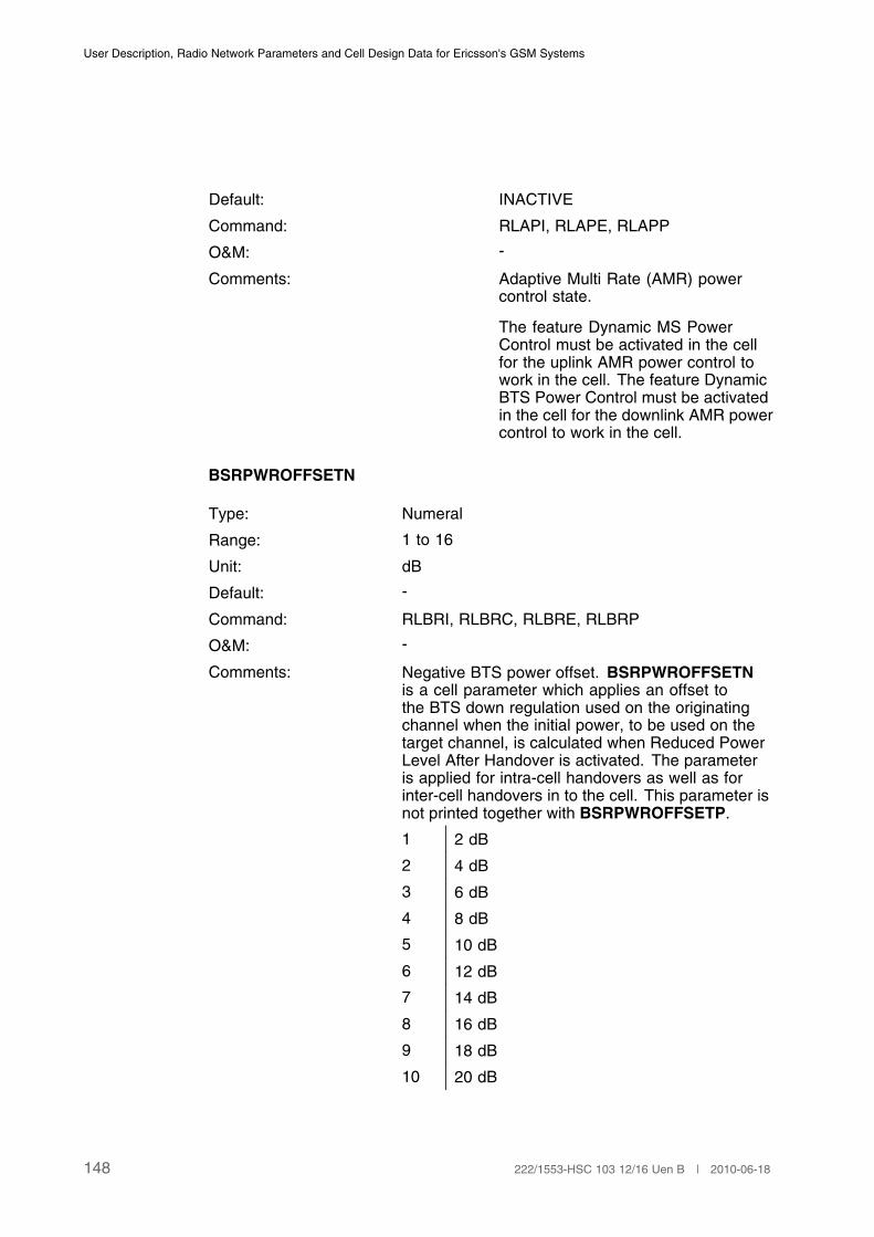
User Description, Radio Network Parameters and Cell Design Data for Ericsson's GSM Systems
Default: INACTIVE
Command: RLAPI, RLAPE, RLAPP
O&M: -
Comments: Adaptive Multi Rate (AMR) powercontrol state.
The feature Dynamic MS PowerControl must be activated in the cellfor the uplink AMR power control towork in the cell. The feature DynamicBTS Power Control must be activatedin the cell for the downlink AMR powercontrol to work in the cell.
BSRPWROFFSETN
Type: Numeral
Range: 1 to 16
Unit: dB
Default: -
Command: RLBRI, RLBRC, RLBRE, RLBRP
O&M: -
Comments: Negative BTS power offset. BSRPWROFFSETNis a cell parameter which applies an offset tothe BTS down regulation used on the originatingchannel when the initial power, to be used on thetarget channel, is calculated when Reduced PowerLevel After Handover is activated. The parameteris applied for intra-cell handovers as well as forinter-cell handovers in to the cell. This parameter isnot printed together with BSRPWROFFSETP.
1 2 dB
2 4 dB
3 6 dB
4 8 dB
5 10 dB
6 12 dB
7 14 dB
8 16 dB
9 18 dB
10 20 dB
148 222/1553-HSC 103 12/16 Uen B | 2010-06-18
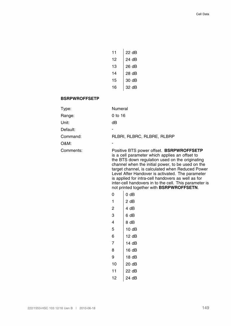
Cell Data
11 22 dB
12 24 dB
13 26 dB
14 28 dB
15 30 dB
16 32 dB
BSRPWROFFSETP
Type: Numeral
Range: 0 to 16
Unit: dB
Default: -
Command: RLBRI, RLBRC, RLBRE, RLBRP
O&M: -
Comments: Positive BTS power offset. BSRPWROFFSETPis a cell parameter which applies an offset tothe BTS down regulation used on the originatingchannel when the initial power, to be used on thetarget channel, is calculated when Reduced PowerLevel After Handover is activated. The parameteris applied for intra-cell handovers as well as forinter-cell handovers in to the cell. This parameter isnot printed together with BSRPWROFFSETN.
0 0 dB
1 2 dB
2 4 dB
3 6 dB
4 8 dB
5 10 dB
6 12 dB
7 14 dB
8 16 dB
9 18 dB
10 20 dB
11 22 dB
12 24 dB
149222/1553-HSC 103 12/16 Uen B | 2010-06-18

User Description, Radio Network Parameters and Cell Design Data for Ericsson's GSM Systems
13 26 dB
14 28 dB
15 30 dB
16 32 dB
3.11.3 Cell/Subcell Data
These parameters may be defined different for underlaid and overlaid subcells.In case there is no subcell structure defined, they are defined per cell.
SSDESDL
Type: Numeral
Range: 47 to 110
Unit: dBm (negative)
Default: 90
Command: RLBCC, RLBCP
O&M: -
Comments: Defines the target value for the desiredsignal strength downlink as measuredby the MS in different parts of thepower control interval.
SSDESDL takes a positive value thatrepresents the corresponding negativevalue in the calculations.
For AMR FR connections,SSDESDLAFR is used.
SSDESDLAFR
Type: Numeral
Range: 47 to 110
Unit: dBm (negative)
Default: 90
Command: RLAPC, RLAPP
150 222/1553-HSC 103 12/16 Uen B | 2010-06-18
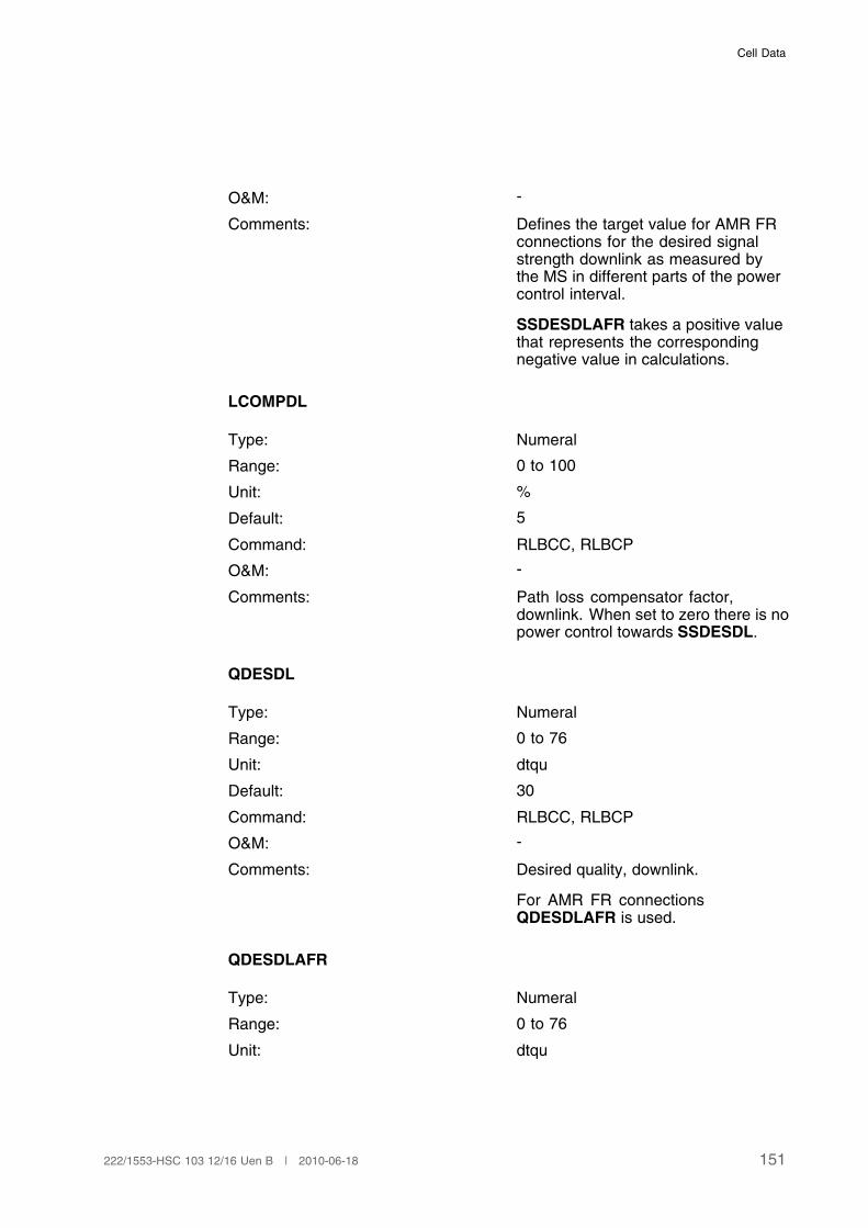
Cell Data
O&M: -
Comments: Defines the target value for AMR FRconnections for the desired signalstrength downlink as measured bythe MS in different parts of the powercontrol interval.
SSDESDLAFR takes a positive valuethat represents the correspondingnegative value in calculations.
LCOMPDL
Type: Numeral
Range: 0 to 100
Unit: %
Default: 5
Command: RLBCC, RLBCP
O&M: -
Comments: Path loss compensator factor,downlink. When set to zero there is nopower control towards SSDESDL.
QDESDL
Type: Numeral
Range: 0 to 76
Unit: dtqu
Default: 30
Command: RLBCC, RLBCP
O&M: -
Comments: Desired quality, downlink.
For AMR FR connectionsQDESDLAFR is used.
QDESDLAFR
Type: Numeral
Range: 0 to 76
Unit: dtqu
151222/1553-HSC 103 12/16 Uen B | 2010-06-18
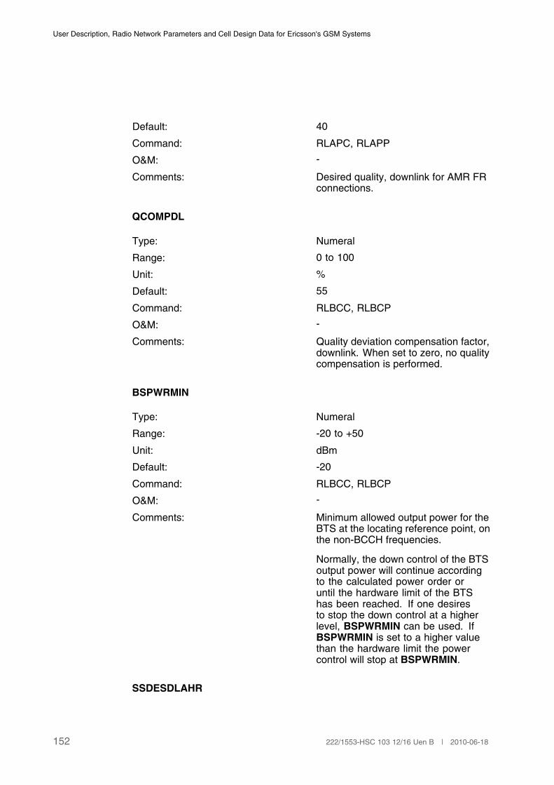
User Description, Radio Network Parameters and Cell Design Data for Ericsson's GSM Systems
Default: 40
Command: RLAPC, RLAPP
O&M: -
Comments: Desired quality, downlink for AMR FRconnections.
QCOMPDL
Type: Numeral
Range: 0 to 100
Unit: %
Default: 55
Command: RLBCC, RLBCP
O&M: -
Comments: Quality deviation compensation factor,downlink. When set to zero, no qualitycompensation is performed.
BSPWRMIN
Type: Numeral
Range: -20 to +50
Unit: dBm
Default: -20
Command: RLBCC, RLBCP
O&M: -
Comments: Minimum allowed output power for theBTS at the locating reference point, onthe non-BCCH frequencies.
Normally, the down control of the BTSoutput power will continue accordingto the calculated power order oruntil the hardware limit of the BTShas been reached. If one desiresto stop the down control at a higherlevel, BSPWRMIN can be used. IfBSPWRMIN is set to a higher valuethan the hardware limit the powercontrol will stop at BSPWRMIN.
SSDESDLAHR
152 222/1553-HSC 103 12/16 Uen B | 2010-06-18

Cell Data
Type: Numeral
Range: 47 to 110
Unit: dBm (negative)
Default: 90
Command: RLAPC, RLAPP
O&M: -
Comments: Defines the target value for AMR HRconnections for the desired signalstrength downlink as measured bythe MS in different parts of the powercontrol interval. SSDESDLAHRtakes a positive value that representsthe corresponding negative value incalculations.
QDESDLAHR
Type: Numeral
Range: o to 76
Unit: dtqu
Default: 30
Command: RLAPC, RLAPP
O&M: -
Comments: Desired quality downlink for AMR HRconnections.
QDESDLAWB
Type: Numeral
Range: 0–76
Unit: dtqu
Default: 30
Command: RLAPC, RLAPP
O&M: -
Comment: Desired quality, downlink for AMR-WBconnections.
SSDESDLAWB
153222/1553-HSC 103 12/16 Uen B | 2010-06-18
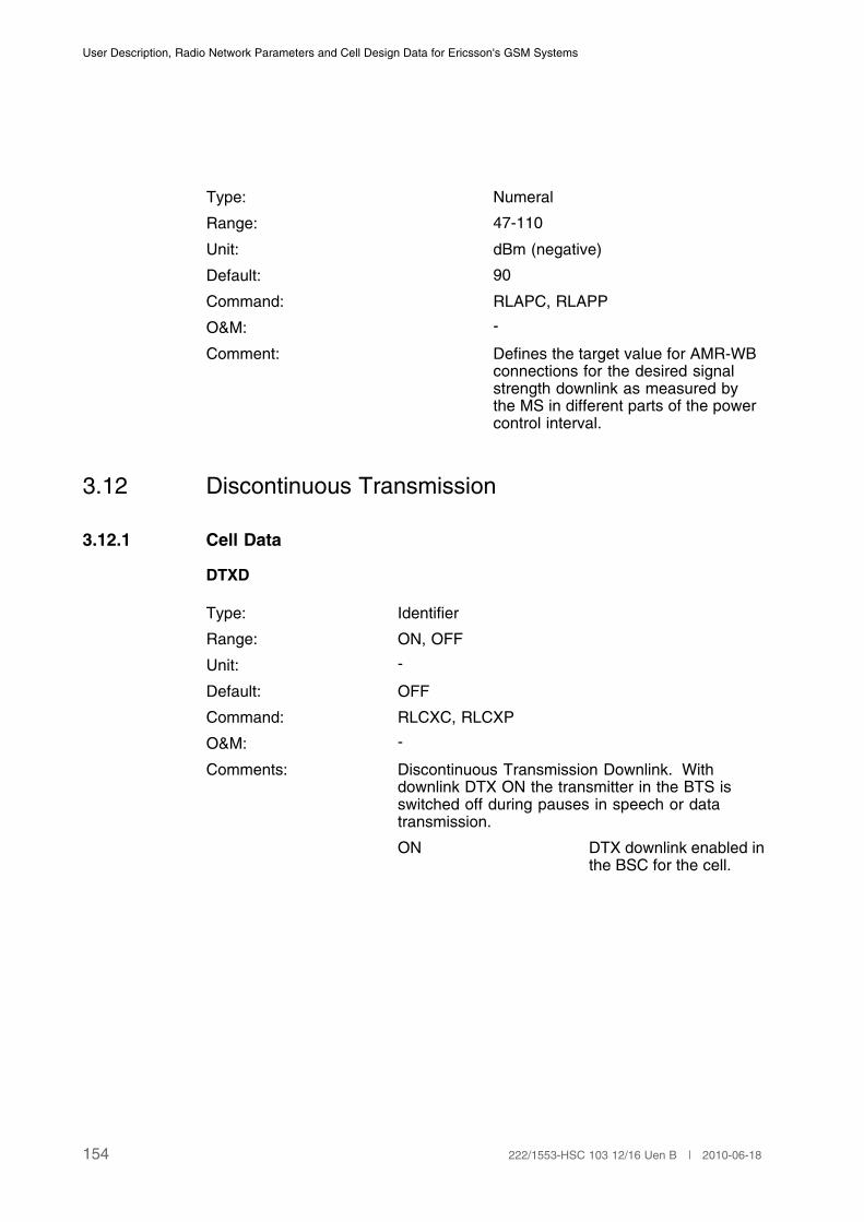
User Description, Radio Network Parameters and Cell Design Data for Ericsson's GSM Systems
Type: Numeral
Range: 47-110
Unit: dBm (negative)
Default: 90
Command: RLAPC, RLAPP
O&M: -
Comment: Defines the target value for AMR-WBconnections for the desired signalstrength downlink as measured bythe MS in different parts of the powercontrol interval.
3.12 Discontinuous Transmission
3.12.1 Cell Data
DTXD
Type: Identifier
Range: ON, OFF
Unit: -
Default: OFF
Command: RLCXC, RLCXP
O&M: -
Comments: Discontinuous Transmission Downlink. Withdownlink DTX ON the transmitter in the BTS isswitched off during pauses in speech or datatransmission.
ON DTX downlink enabled inthe BSC for the cell.
154 222/1553-HSC 103 12/16 Uen B | 2010-06-18
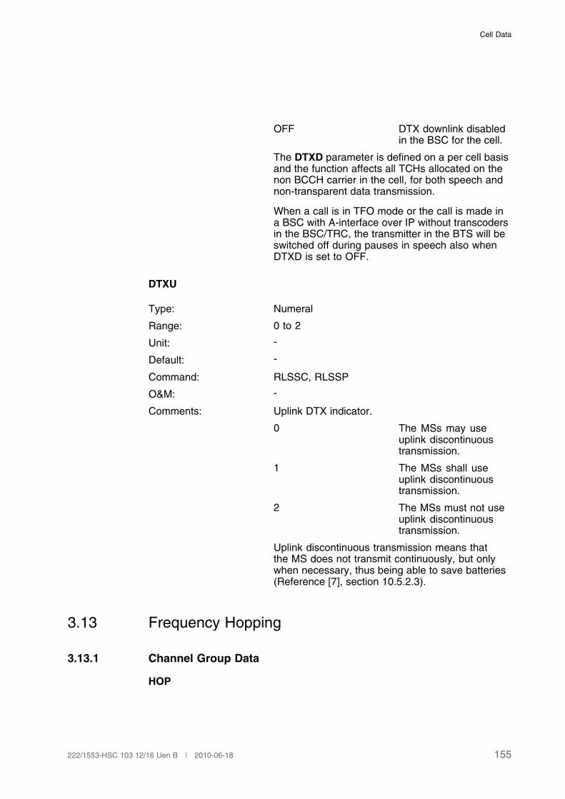
Cell Data
OFF DTX downlink disabledin the BSC for the cell.
The DTXD parameter is defined on a per cell basisand the function affects all TCHs allocated on thenon BCCH carrier in the cell, for both speech andnon-transparent data transmission.
When a call is in TFO mode or the call is made ina BSC with A-interface over IP without transcodersin the BSC/TRC, the transmitter in the BTS will beswitched off during pauses in speech also whenDTXD is set to OFF.
DTXU
Type: Numeral
Range: 0 to 2
Unit: -
Default: -
Command: RLSSC, RLSSP
O&M: -
Comments: Uplink DTX indicator.
0 The MSs may useuplink discontinuoustransmission.
1 The MSs shall useuplink discontinuoustransmission.
2 The MSs must not useuplink discontinuoustransmission.
Uplink discontinuous transmission means thatthe MS does not transmit continuously, but onlywhen necessary, thus being able to save batteries(Reference [7], section 10.5.2.3).
3.13 Frequency Hopping
3.13.1 Channel Group Data
HOP
155222/1553-HSC 103 12/16 Uen B | 2010-06-18

User Description, Radio Network Parameters and Cell Design Data for Ericsson's GSM Systems
Type: Identifier
Range: ON, OFF
Unit: -
Default: OFF
Command: RLCHC, RLCFP
O&M: When changing the parameter from OFF to ONall ongoing calls in the channel group might bedropped.
Comments: Frequency hopping status.
ON The hopping status forthe channel group ishopping for TCH andSDCCH.
OFF The hopping status forthe channel group is non-hopping.
SDCCHs as well as TCHs can hop. A BCCH will nothop even if it belongs to a channel group definedas hopping.
HSN
Type: Numeral
Range: 0 to 63
Unit: -
Default: -
Command: RLCHC, RLCFP.
O&M: Changing of this parameter might cause all ongoingcalls in the channel group to be dropped.
Comments: Hopping sequence number.
The hopping BPC is transmitted on a set offrequencies included in a Hopping Frequency Set(HFS). The order of the frequencies to transmit on isdefined by the hopping sequence number HSN, asdescribed in Reference [8].
HSN = 0 cyclic hopping sequence.
HSN = 1 to 63 random sequences.
BCCD
156 222/1553-HSC 103 12/16 Uen B | 2010-06-18
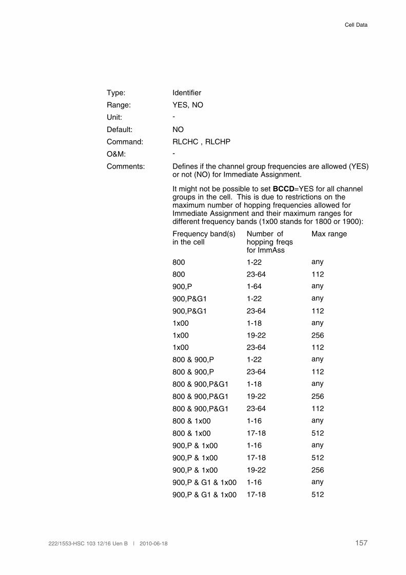
Cell Data
Type: Identifier
Range: YES, NO
Unit: -
Default: NO
Command: RLCHC , RLCHP
O&M: -
Comments: Defines if the channel group frequencies are allowed (YES)or not (NO) for Immediate Assignment.
It might not be possible to set BCCD=YES for all channelgroups in the cell. This is due to restrictions on themaximum number of hopping frequencies allowed forImmediate Assignment and their maximum ranges fordifferent frequency bands (1x00 stands for 1800 or 1900):
Frequency band(s)in the cell
Number ofhopping freqsfor ImmAss
Max range
800 1-22 any
800 23-64 112
900,P 1-64 any
900,P&G1 1-22 any
900,P&G1 23-64 112
1x00 1-18 any
1x00 19-22 256
1x00 23-64 112
800 & 900,P 1-22 any
800 & 900,P 23-64 112
800 & 900,P&G1 1-18 any
800 & 900,P&G1 19-22 256
800 & 900,P&G1 23-64 112
800 & 1x00 1-16 any
800 & 1x00 17-18 512
900,P & 1x00 1-16 any
900,P & 1x00 17-18 512
900,P & 1x00 19-22 256
900,P & G1 & 1x00 1-16 any
900,P & G1 & 1x00 17-18 512
157222/1553-HSC 103 12/16 Uen B | 2010-06-18
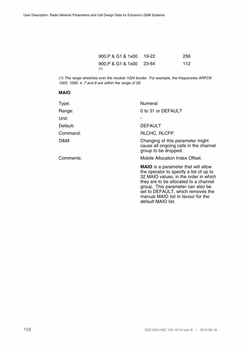
User Description, Radio Network Parameters and Cell Design Data for Ericsson's GSM Systems
900,P & G1 & 1x00 19-22 256
900,P & G1 & 1x00 23-64 112(1)
(1) The range stretches over the modulo 1024 border. For example, the frequencies ARFCN
1003, 1005, 4, 7 and 8 are within the range of 29.
MAIO
Type: Numeral
Range: 0 to 31 or DEFAULT
Unit: -
Default: DEFAULT
Command: RLCHC, RLCFP.
O&M: Changing of this parameter mightcause all ongoing calls in the channelgroup to be dropped.
Comments: Mobile Allocation Index Offset.
MAIO is a parameter that will allowthe operator to specify a list of up to32 MAIO values, in the order in whichthey are to be allocated to a channelgroup. This parameter can also beset to DEFAULT, which removes themanual MAIO list in favour for thedefault MAIO list.
158 222/1553-HSC 103 12/16 Uen B | 2010-06-18
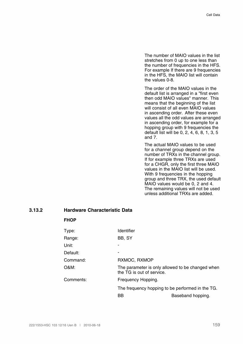
Cell Data
The number of MAIO values in the liststretches from 0 up to one less thanthe number of frequencies in the HFS.For example If there are 9 frequenciesin the HFS, the MAIO list will containthe values 0-8.
The order of the MAIO values in thedefault list is arranged in a "first eventhen odd MAIO values" manner. Thismeans that the beginning of the listwill consist of all even MAIO valuesin ascending order. After these evenvalues all the odd values are arrangedin ascending order, for example for ahopping group with 9 frequencies thedefault list will be 0, 2, 4, 6, 8, 1, 3, 5and 7.
The actual MAIO values to be usedfor a channel group depend on thenumber of TRXs in the channel group.If for example three TRXs are usedfor a CHGR, only the first three MAIOvalues in the MAIO list will be used.With 9 frequencies in the hoppinggroup and three TRX, the used defaultMAIO values would be 0, 2 and 4.The remaining values will not be usedunless additional TRXs are added.
3.13.2 Hardware Characteristic Data
FHOP
Type: Identifier
Range: BB, SY
Unit: -
Default: -
Command: RXMOC, RXMOP
O&M: The parameter is only allowed to be changed whenthe TG is out of service.
Comments: Frequency Hopping.
The frequency hopping to be performed in the TG.
BB Baseband hopping.
159222/1553-HSC 103 12/16 Uen B | 2010-06-18

User Description, Radio Network Parameters and Cell Design Data for Ericsson's GSM Systems
SY Synthesiser hopping.
Frequency hopping can be achieved by twomethods, baseband or synthesiser hopping. Theparameter FHOP indicates the frequency hoppingmode in the TG. When the TG is connected to afilter combiner only baseband hopping can be used.
When baseband hopping is performed each TX istransmitting on a fixed frequency, that is frequencyhopping for a basic physical channel (BPC) isobtained by switching TXs between each TDMAframe.
For synthesiser hopping the TX switches frequenciesfor every TDMA frame sent. In other words, eachBPC is carried by one single TX, except when aBCCH burst is transmitted. The BCCH burst is inthat case carried by the TX that transmits the BCCHfrequency.
COMB
Type: Identifier
Range: FLT, HYB
Unit: -
Default: -
Command: RXMOI, RXMOC, RXMOP
O&M: The parameter is only allowed to be changed whenthe TG is out of service.
Comments: Combiner type used in the TG.
FLT Filter combiner.
HYB Hybrid combiner.
In case of a filter combiner, only baseband hoppingcan be provided, while hybrid combiners supportboth baseband and synthesiser hopping.
CONFMD
Type: Identifier
Range: NODEL, CMD, FASTREC, MINDIST
Unit: -
Default: NODEL
Command: RXMSC, RXMOC, RXMOP
160 222/1553-HSC 103 12/16 Uen B | 2010-06-18

Cell Data
O&M: The parameter is only allowed to be changed whenthe TG is out of service.
Comments: Configuration method.
Indicates the method to configure BTS equipment.All configurations are done per channel group.Within a channel group, each hopping group isconfigured one by one. A hopping group is agroup of BPCs in the same cell, using the sametimeslot number in the TDMA frame but on differenttransceiver, configured so that they are all hoppingusing the same set of frequencies.
NODEL Indicates that no BPCcan be deleted as aresult of a commandordered hoppingfrequency set (HFS)extension. A commandordered HFS Extensionis not permitted forthe TG. No HFSExtension is performedwhen previouslyfaulty BTS equipmentrecovers. Consequently,recovered BTSequipment may notbe fully utilised.
CMD Indicates that acommand orderedHFS Extension canbe performed forthe TG. No HFSextension is performedwhen previouslyfaulty BTS equipmentrecovers. Consequently,recovered BTSequipment may notbe fully utilised. If a HFSExtension is orderedby command then allavailable BTS equipment(where required) is fullyutilised.
161222/1553-HSC 103 12/16 Uen B | 2010-06-18
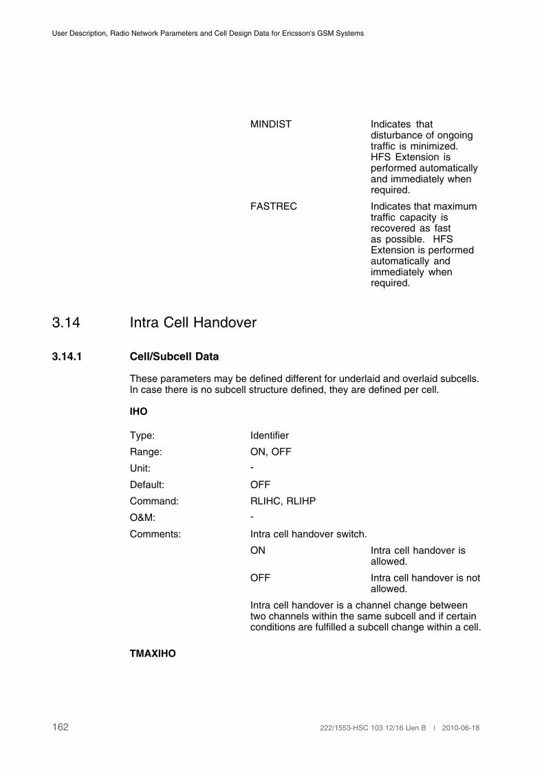
User Description, Radio Network Parameters and Cell Design Data for Ericsson's GSM Systems
MINDIST Indicates thatdisturbance of ongoingtraffic is minimized.HFS Extension isperformed automaticallyand immediately whenrequired.
FASTREC Indicates that maximumtraffic capacity isrecovered as fastas possible. HFSExtension is performedautomatically andimmediately whenrequired.
3.14 Intra Cell Handover
3.14.1 Cell/Subcell Data
These parameters may be defined different for underlaid and overlaid subcells.In case there is no subcell structure defined, they are defined per cell.
IHO
Type: Identifier
Range: ON, OFF
Unit: -
Default: OFF
Command: RLIHC, RLIHP
O&M: -
Comments: Intra cell handover switch.
ON Intra cell handover isallowed.
OFF Intra cell handover is notallowed.
Intra cell handover is a channel change betweentwo channels within the same subcell and if certainconditions are fulfilled a subcell change within a cell.
TMAXIHO
162 222/1553-HSC 103 12/16 Uen B | 2010-06-18
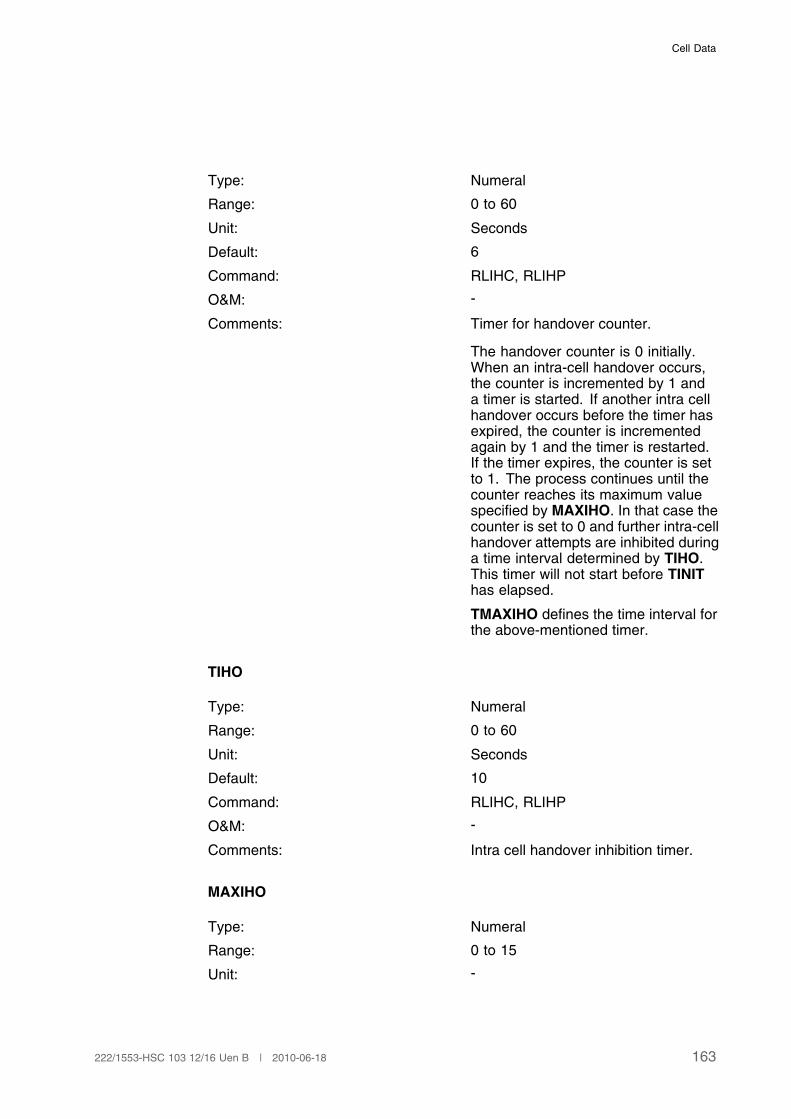
Cell Data
Type: Numeral
Range: 0 to 60
Unit: Seconds
Default: 6
Command: RLIHC, RLIHP
O&M: -
Comments: Timer for handover counter.
The handover counter is 0 initially.When an intra-cell handover occurs,the counter is incremented by 1 anda timer is started. If another intra cellhandover occurs before the timer hasexpired, the counter is incrementedagain by 1 and the timer is restarted.If the timer expires, the counter is setto 1. The process continues until thecounter reaches its maximum valuespecified by MAXIHO. In that case thecounter is set to 0 and further intra-cellhandover attempts are inhibited duringa time interval determined by TIHO.This timer will not start before TINIThas elapsed.
TMAXIHO defines the time interval forthe above-mentioned timer.
TIHO
Type: Numeral
Range: 0 to 60
Unit: Seconds
Default: 10
Command: RLIHC, RLIHP
O&M: -
Comments: Intra cell handover inhibition timer.
MAXIHO
Type: Numeral
Range: 0 to 15
Unit: -
163222/1553-HSC 103 12/16 Uen B | 2010-06-18
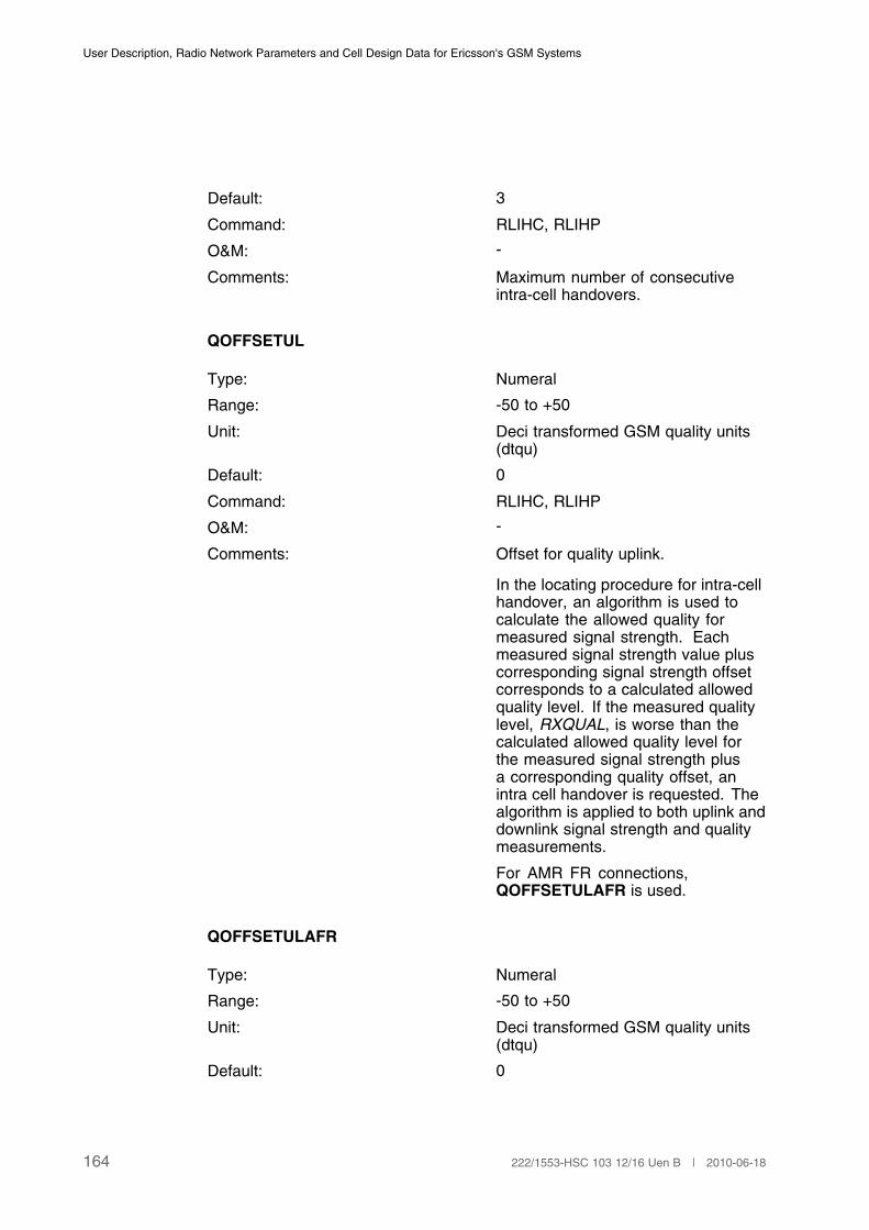
User Description, Radio Network Parameters and Cell Design Data for Ericsson's GSM Systems
Default: 3
Command: RLIHC, RLIHP
O&M: -
Comments: Maximum number of consecutiveintra-cell handovers.
QOFFSETUL
Type: Numeral
Range: -50 to +50
Unit: Deci transformed GSM quality units(dtqu)
Default: 0
Command: RLIHC, RLIHP
O&M: -
Comments: Offset for quality uplink.
In the locating procedure for intra-cellhandover, an algorithm is used tocalculate the allowed quality formeasured signal strength. Eachmeasured signal strength value pluscorresponding signal strength offsetcorresponds to a calculated allowedquality level. If the measured qualitylevel, RXQUAL, is worse than thecalculated allowed quality level forthe measured signal strength plusa corresponding quality offset, anintra cell handover is requested. Thealgorithm is applied to both uplink anddownlink signal strength and qualitymeasurements.
For AMR FR connections,QOFFSETULAFR is used.
QOFFSETULAFR
Type: Numeral
Range: -50 to +50
Unit: Deci transformed GSM quality units(dtqu)
Default: 0
164 222/1553-HSC 103 12/16 Uen B | 2010-06-18

Cell Data
Command: RLIHC, RLIHP
O&M: -
Comments: Offset for quality uplink for AMR FRconnections.
QOFFSETDL
Type: Numeral
Range: -50 to +50
Unit: Deci transformed GSM quality units(dtqu)
Default: 0
Command: RLIHC, RLIHP
O&M: -
Comments: Offset for quality downlink.
For AMR FR connections,QOFFSETDLAFR is used.
QOFFSETDLAFR
Type: Numeral
Range: -50 to +50
Unit: Deci transformed GSM quality units(dtqu)
Default: 0
Command: RLIHC, RLIHP
O&M: -
Comments: Offset for quality downlink for AMR FRconnections.
SSOFFSETUL
Type: Numeral
Range: -30 to +30
Unit: dB
Default: 0
Command: RLIHC, RLIHP
165222/1553-HSC 103 12/16 Uen B | 2010-06-18

User Description, Radio Network Parameters and Cell Design Data for Ericsson's GSM Systems
O&M: -
Comments: Offset for signal strength uplink.
For AMR FR connections,SSOFFSETULAFR is used.
SSOFFSETULAFR
Type: Numeral
Range: -30 to +30
Unit: dB
Default: 0
Command: RLIHC, RLIHP
O&M: -
Comments: Offset for signal strength uplink forAMR FR connections.
SSOFFSETDL
Type: Numeral
Range: -30 to +30
Unit: dB
Default: 0
Command: RLIHC, RLIHP
O&M: -
Comments: Offset for signal strength downlink.
For AMR FR connections,SSOFFSETDLAFR is used.
SSOFFSETDLAFR
Type: Numeral
Range: -30 to +30
Unit: dB
Default: 0
Command: RLIHC, RLIHP
O&M: -
Comments: Offset for signal strength downlink forAMR FR connections.
166 222/1553-HSC 103 12/16 Uen B | 2010-06-18

Cell Data
QOFFSETDLAWB
Type: Numeral
Range: -50 to +50
Unit: dtqu
Default: 0
Command: RLIHC, RLIHP
O&M: -
Comment: Offset for quality downlink for AMR-WBconnections
QOFFSETULAWB
Type: Numeral
Range: -50 to +50
Unit: dtqu
Default: 0
Command: RLIHC, RLIHP
O&M: -
Comment: Offset for quality uplink for AMR-WBconnections.
SSOFFSETDLAWB
Type: Numeral
Range: -30 to +30
Unit: dB
Default: 0
Command: RLIHC, RLIHP
O&M: -
Comment: Offset for signal strength downlink forAMR-WB connections.
SSOFFSETULAWB
Type: Numeral
Range: -30 to +30
Unit: dB
167222/1553-HSC 103 12/16 Uen B | 2010-06-18

User Description, Radio Network Parameters and Cell Design Data for Ericsson's GSM Systems
Default: 0
Command: RLIHC, RLIHP
O&M: -
Comment: Offset for signal strength uplink forAMR-WB connections.
3.15 Assignment to Other Cell
3.15.1 BSC Data
ASSOC
Type: Identifier
Range: ON, OFF
Unit: -
Default: OFF
Command: RLLBC, RLLBP
O&M: -
Comments: Switch which defines if assignment to cells otherthan serving cell is allowed, that is instead ofallocating a TCH within the serving cell a TCH isallocated in another cell during assignment.
ON Allowed.
OFF Not allowed.
IBHOASS
Type: Identifier
Range: ON, OFF
Unit: -
Default: OFF
Command: RLLBC, RLLBP
O&M: -
Comments: Switch, which defines if, inter BSC handover isallowed during assignment.
ON Allowed.
OFF Not Allowed.
168 222/1553-HSC 103 12/16 Uen B | 2010-06-18
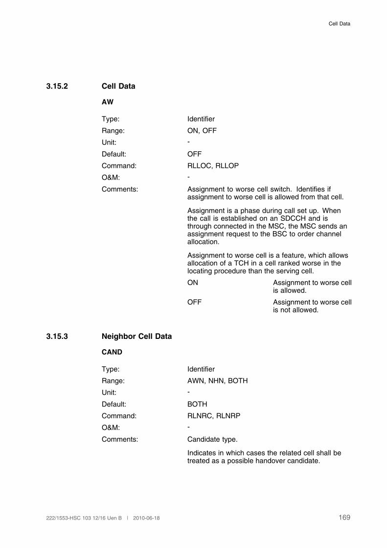
Cell Data
3.15.2 Cell Data
AW
Type: Identifier
Range: ON, OFF
Unit: -
Default: OFF
Command: RLLOC, RLLOP
O&M: -
Comments: Assignment to worse cell switch. Identifies ifassignment to worse cell is allowed from that cell.
Assignment is a phase during call set up. Whenthe call is established on an SDCCH and isthrough connected in the MSC, the MSC sends anassignment request to the BSC to order channelallocation.
Assignment to worse cell is a feature, which allowsallocation of a TCH in a cell ranked worse in thelocating procedure than the serving cell.
ON Assignment to worse cellis allowed.
OFF Assignment to worse cellis not allowed.
3.15.3 Neighbor Cell Data
CAND
Type: Identifier
Range: AWN, NHN, BOTH
Unit: -
Default: BOTH
Command: RLNRC, RLNRP
O&M: -
Comments: Candidate type.
Indicates in which cases the related cell shall betreated as a possible handover candidate.
169222/1553-HSC 103 12/16 Uen B | 2010-06-18
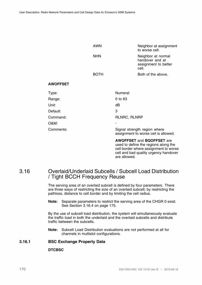
User Description, Radio Network Parameters and Cell Design Data for Ericsson's GSM Systems
AWN Neighbor at assignmentto worse cell.
NHN Neighbor at normalhandover and atassignment to bettercell.
BOTH Both of the above.
AWOFFSET
Type: Numeral
Range: 0 to 63
Unit: dB
Default: 3
Command: RLNRC, RLNRP
O&M: -
Comments: Signal strength region whereassignment to worse cell is allowed.
AWOFFSET and BQOFFSET areused to define the regions along thecell border where assignment to worsecell and bad quality urgency handoverare allowed.
3.16 Overlaid/Underlaid Subcells / Subcell Load Distribution/ Tight BCCH Frequency Reuse
The serving area of an overlaid subcell is defined by four parameters. Thereare three ways of restricting the size of an overlaid subcell; by restricting thepathloss, distance to cell border and by limiting the cell radius.
Note: Separate parameters to restrict the serving area of the CHGR 0 exist.See Section 3.16.4 on page 175.
By the use of subcell load distribution, the system will simultaneously evaluatethe traffic load in both the underlaid and the overlaid subcells and distributetraffic between the subcells.
Note: Subcell Load Distribution evaluations are not performed at all forchannels in multislot configurations.
3.16.1 BSC Exchange Property Data
DTCBSC
170 222/1553-HSC 103 12/16 Uen B | 2010-06-18
Cell Data
Type: Numeral
Range: 0, 1
Unit: -
Default: 0
Command: RAEPC, RAEPP.
O&M: -
Comments: Defines if the DTCB criterion is takeninto consideration during subcellchanges (1) or not (0).
3.16.2 SCLD Data
SCLD
Type: Identifier
Range: ON, OFF
Unit: -
Default: OFF
Command: RLLLC, RLLLP
O&M: -
Comments: Subcell Load Distribution status.
ON Cell active for SubcellLoad Distribution.
OFF Cell not active for SubcellLoad Distribution.
SCLDLUL
Type: Numeral
Range: 0 to 99
Unit: %
Default: 20
Command: RLLLC, RLLLP
171222/1553-HSC 103 12/16 Uen B | 2010-06-18

User Description, Radio Network Parameters and Cell Design Data for Ericsson's GSM Systems
O&M: -
Comments: Subcell Load Distribution Lower LimitUnderlaid subcell.
Percentage level of idle full ratecapable TCHs in the underlaid subcell,at or below which Subcell LoadDistribution from underlaid to overlaidsubcell will be attempted. No attemptto distribute traffic connections will bemade if the percentage of idle TCHs inthe overlaid subcell already is or wouldbecome equal to or less than the limitdefined by SCLDLOL.
SCLDLOL
Type: Numeral
Range: 0 to 99
Unit: %
Default: 20
Command: RLLLC, RLLLP
O&M: -
Comments: Subcell Load Distribution Lower LimitOverlaid subcell.
Percentage level of idle full ratecapable TCHs in the overlaid subcell,at or below which Subcell LoadDistribution from overlaid to underlaidsubcell will be attempted. No attemptto distribute traffic connections will bemade if the percentage of idle TCHsin the underlaid subcell already is orwould become equal to or less thanthe limit defined by SCLDLUL.
SCLDSC
Type: Identifier
Range: UL, OL
Unit: -
Default: UL
Command: RLLLC, RLLLP
172 222/1553-HSC 103 12/16 Uen B | 2010-06-18
Cell Data
O&M: -
Comments: Subcell Load Distribution Subcellpriority. Specifies which subcell that ispreferred at channel allocation.
UL: Underlaid subcell is preferred.
OL: Overlaid subcell is preferred.
3.16.3 Overlaid Subcell Data
LOL
Type: Numeral
Range: 0 to 200
Unit: dB
Default: -
Command: RLOLC, RLOLP
O&M: -
Comments: Pathloss threshold. It defines the OLsubcell coverage border in terms ofthe pathloss from the serving cell.
LOLHYST
Type: Numeral
Range: 0 to 63
Unit: dB
Default: 3
Command: RLOLC, RLOLP
O&M: -
Comments: Hysteresis for the pathloss criterionduring evaluations for the OL subcellcoverage.
DTCB
Type: Numeral
Range: -63 to 63
Unit: dB
Default: -63
173222/1553-HSC 103 12/16 Uen B | 2010-06-18
User Description, Radio Network Parameters and Cell Design Data for Ericsson's GSM Systems
Command: RLOLC, RLOLP
O&M: -
Comments: Distance to cell border threshold.It defines the OL subcell coverageborder in terms of the signal strengthdifference between the active channeland the strongest neighbouringBCCHs.
DTCBHYST
Type: Numeral
Range: 0 to 63
Unit: dB
Default: 2
Command: RLOLC, RLOLP
O&M: -
Comments: Hysteresis for the DTCB criterionduring evaluations for the OL subcellcoverage.
NDIST
Type: Numeral
Range: 0 to 63
Unit: dB
Default: 10
Command: RLOLC, RLOLP
O&M: -
Comments: Distance to cell border additionalthreshold. When added to DTCB,it defines the OL subcell coverageborder in terms of the signal strengthdifference between the activechannel and the strongest NNCELLSneighbouring BCCHs.
If NNCELLS is seto to 1, NDIST isobsolete.
NNCELLS
174 222/1553-HSC 103 12/16 Uen B | 2010-06-18
Cell Data
Type: Numeral
Range: 1 to 5
Unit: -
Default: 3
Command: RLOLC, RLOLP
O&M: -
Comments: Number of strongest neighbouringBCCHs for the DTCB criterion. Seethe comments for NDIST, see Page174.
TAOL
Type: Numeral
Range: 0 to 61
Unit: Bit periods (bp)
Default: -
Command: RLOLC, RLOLP
O&M: -
Comments: Timing advance threshold. It definesthe OL subcell timing advance border.
TAOLHYST
Type: Numeral
Range: 0 to 61
Unit: Bit periods (bp)
Default: 0
Command: RLOLC, RLOLP
O&M: -
Comments: Hysteresis for the timing advancecriterion during evaluations for the OLsubcell coverage.
3.16.4 Tight BCCH Frequency Reuse Cell Data
Note: Separate parameters to restrict the serving area of the CHGR 0 interms of cell radius (TA) and additional DTCB criterion using NNCELLSand NDIST are not available.
175222/1553-HSC 103 12/16 Uen B | 2010-06-18
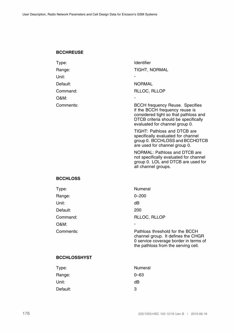
User Description, Radio Network Parameters and Cell Design Data for Ericsson's GSM Systems
BCCHREUSE
Type: Identifier
Range: TIGHT, NORMAL
Unit: -
Default: NORMAL
Command: RLLOC, RLLOP
O&M: -
Comments: BCCH frequency Reuse. Specifiesif the BCCH frequency reuse isconsidered tight so that pathloss andDTCB criteria should be specificallyevaluated for channel group 0.
TIGHT: Pathloss and DTCB arespecifically evaluated for channelgroup 0. BCCHLOSS and BCCHDTCBare used for channel group 0.
NORMAL: Pathloss and DTCB arenot specifically evaluated for channelgroup 0. LOL and DTCB are used forall channel groups.
BCCHLOSS
Type: Numeral
Range: 0–200
Unit: dB
Default: 200
Command: RLLOC, RLLOP
O&M: -
Comments: Pathloss threshold for the BCCHchannel group. It defines the CHGR0 service coverage border in terms ofthe pathloss from the serving cell.
BCCHLOSSHYST
Type: Numeral
Range: 0–63
Unit: dB
Default: 3
176 222/1553-HSC 103 12/16 Uen B | 2010-06-18

Cell Data
Command: RLLOC, RLLOP
O&M: -
Comments: Hysteresis for the pathloss criterionduring evaluations for the CHGR 0service coverage.
BCCHDTCB
Type: Numeral
Range: �63–63
Unit: dB
Default: �63
Command: RLLOC, RLLOP
O&M: -
Comments: Distance to cell border thresholdfor the BCCH channel group. Itdefines the CHGR 0 service coverageborder in terms of the signal strengthdifference between the active channeland the strongest neighbouring cells'BCCHs.
BCCHDTCBHYST
Type: Numeral
Range: 0–63
Unit: dB
Default: 2
Command: RLLOC, RLLOP
O&M: -
Comments: Hysteresis for the DTCB criterionduring evaluations for the CHGR 0service coverage.
3.17 Hierarchical Cell Structures
Note: In a bad quality urgency situation or at assignment if assignment toworse cell is permitted, HCS (Hierarchical Cell Structure) ranking isomitted.
177222/1553-HSC 103 12/16 Uen B | 2010-06-18
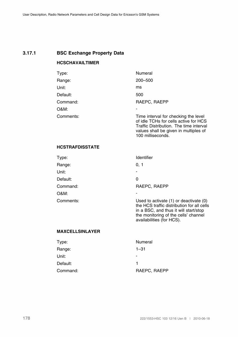
User Description, Radio Network Parameters and Cell Design Data for Ericsson's GSM Systems
3.17.1 BSC Exchange Property Data
HCSCHAVAILTIMER
Type: Numeral
Range: 200–500
Unit: ms
Default: 500
Command: RAEPC, RAEPP
O&M: -
Comments: Time interval for checking the levelof idle TCHs for cells active for HCSTraffic Distribution. The time intervalvalues shall be given in multiples of100 milliseconds.
HCSTRAFDISSTATE
Type: Identifier
Range: 0, 1
Unit: -
Default: 0
Command: RAEPC, RAEPP
O&M: -
Comments: Used to activate (1) or deactivate (0)the HCS traffic distribution for all cellsin a BSC, and thus it will start/stopthe monitoring of the cells’ channelavailabilities (for HCS).
MAXCELLSINLAYER
Type: Numeral
Range: 1–31
Unit: -
Default: 1
Command: RAEPC, RAEPP
178 222/1553-HSC 103 12/16 Uen B | 2010-06-18

Cell Data
O&M: -
Comments: Defines the number of cells of thesame layer that can be prioritized byHCS.
MAXDBDEVINLAYER
Type: Numeral
Range: 0–63
Unit: dB
Default: 3
Command: RAEPC, RAEPP
O&M: -
Comments: Defines the maximum value in dB thata cell in a layer can deviate from thestrongest cell in the same layer andstill be prioritized by HCS.
3.17.2 BSC data
HCSBANDHYST
Type: Numeral
Range: 0 to 63
Unit: dB
Default: 2
Command: RLHBC, RLHBP
O&M: -
Comments: HCS band hysteresis.
The signal strength hysteresis for theHCSBAND threshold.
THO
Type: Numeral
Range: 10 to 100
Unit: Seconds
Default: 30
Command: RLLBC, RLLBP
179222/1553-HSC 103 12/16 Uen B | 2010-06-18

User Description, Radio Network Parameters and Cell Design Data for Ericsson's GSM Systems
O&M: -
Comments: Time interval for measuring thenumber of handovers allowed (NHO)before an MS is considered as a fastmoving mobile.
This will only be performed if thefeature Handling of fast-movingmobiles is activated in the cell(FASTMSREG).
NHO
Type: Numeral
Range: 2 to 10
Unit: -
Default: 3
Command: RLLBC, RLLBP
O&M: -
Comments: Number of handovers during THOthat are allowed before an MS isconsidered as a fast moving mobile. Ifthe number exceeds or equals NHO,the MS attempts to go to the strongesthigher layer cell at the next handover.
This will only be performed if thefeature Handling of fast-movingmobiles is activated in the cell(FASTMSREG).
HCSBAND
Type: Numeral
Range: 1 to 8
Unit: -
Default: -
Command: RLHBC, RLHBP
O&M: -
Comments: Hierarchical Cell Structure band.
HCSBAND defines the priority for alayer or group of layers. HCS band 1has the highest priority.
180 222/1553-HSC 103 12/16 Uen B | 2010-06-18
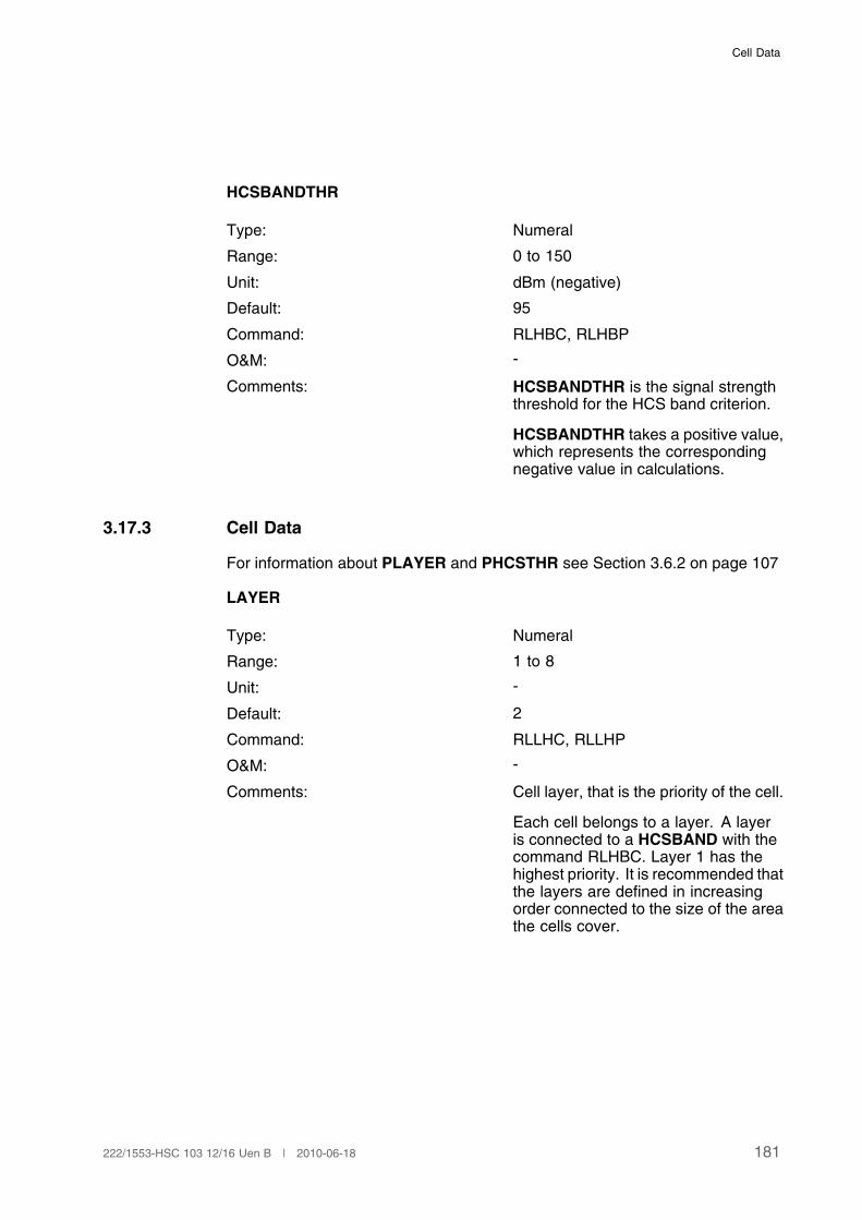
Cell Data
HCSBANDTHR
Type: Numeral
Range: 0 to 150
Unit: dBm (negative)
Default: 95
Command: RLHBC, RLHBP
O&M: -
Comments: HCSBANDTHR is the signal strengththreshold for the HCS band criterion.
HCSBANDTHR takes a positive value,which represents the correspondingnegative value in calculations.
3.17.3 Cell Data
For information about PLAYER and PHCSTHR see Section 3.6.2 on page 107
LAYER
Type: Numeral
Range: 1 to 8
Unit: -
Default: 2
Command: RLLHC, RLLHP
O&M: -
Comments: Cell layer, that is the priority of the cell.
Each cell belongs to a layer. A layeris connected to a HCSBAND with thecommand RLHBC. Layer 1 has thehighest priority. It is recommended thatthe layers are defined in increasingorder connected to the size of the areathe cells cover.
181222/1553-HSC 103 12/16 Uen B | 2010-06-18
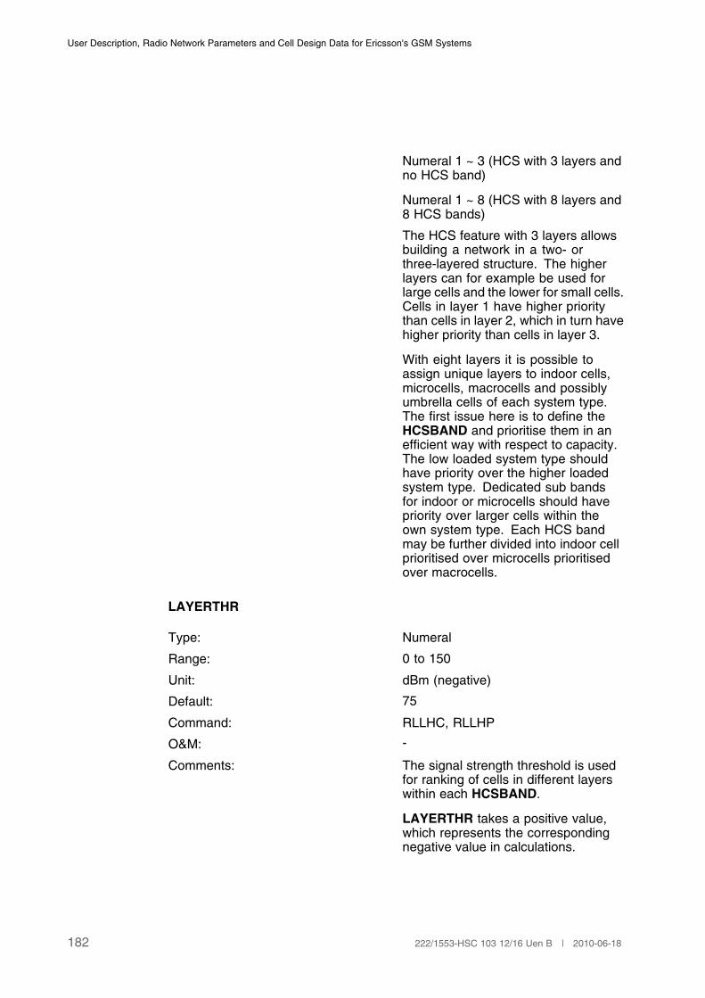
User Description, Radio Network Parameters and Cell Design Data for Ericsson's GSM Systems
Numeral 1 ~ 3 (HCS with 3 layers andno HCS band)
Numeral 1 ~ 8 (HCS with 8 layers and8 HCS bands)
The HCS feature with 3 layers allowsbuilding a network in a two- orthree-layered structure. The higherlayers can for example be used forlarge cells and the lower for small cells.Cells in layer 1 have higher prioritythan cells in layer 2, which in turn havehigher priority than cells in layer 3.
With eight layers it is possible toassign unique layers to indoor cells,microcells, macrocells and possiblyumbrella cells of each system type.The first issue here is to define theHCSBAND and prioritise them in anefficient way with respect to capacity.The low loaded system type shouldhave priority over the higher loadedsystem type. Dedicated sub bandsfor indoor or microcells should havepriority over larger cells within theown system type. Each HCS bandmay be further divided into indoor cellprioritised over microcells prioritisedover macrocells.
LAYERTHR
Type: Numeral
Range: 0 to 150
Unit: dBm (negative)
Default: 75
Command: RLLHC, RLLHP
O&M: -
Comments: The signal strength threshold is usedfor ranking of cells in different layerswithin each HCSBAND.
LAYERTHR takes a positive value,which represents the correspondingnegative value in calculations.
182 222/1553-HSC 103 12/16 Uen B | 2010-06-18

Cell Data
LAYERHYST
Type: Numeral
Range: 0 to 63
Unit: dB
Default: 2
Command: RLLHC, RLLHP
O&M: -
Comments: Layer hysteresis. The signal strengthhysteresis is used for rankingcells in different layers within eachHCSBAND.
PSSTEMP
Type: Numeral
Range: 0 to 63
Unit: dB
Default: 0
Command: RLLHC, RLLHP
O&M: -
Comments: Signal strength penalty temporaryoffset.
When a fast moving MS connectedto a higher layer (lower priority) cellpasses through a lower layer (higherpriority) cell's coverage area, it mightbe undesirable that the MS performsa handover to the lower layer cell.Therefore a penalty, PSSTEMP, canbe temporarily assigned to the lowerlayer cell while a timer is running. Thetimer starts when the lower layer cellis first reported as a neighbor and runsfor a period specified by PTIMTEMP.
PTIMTEMP
Type: Numeral
Range: 0 to 600
Unit: Seconds
183222/1553-HSC 103 12/16 Uen B | 2010-06-18
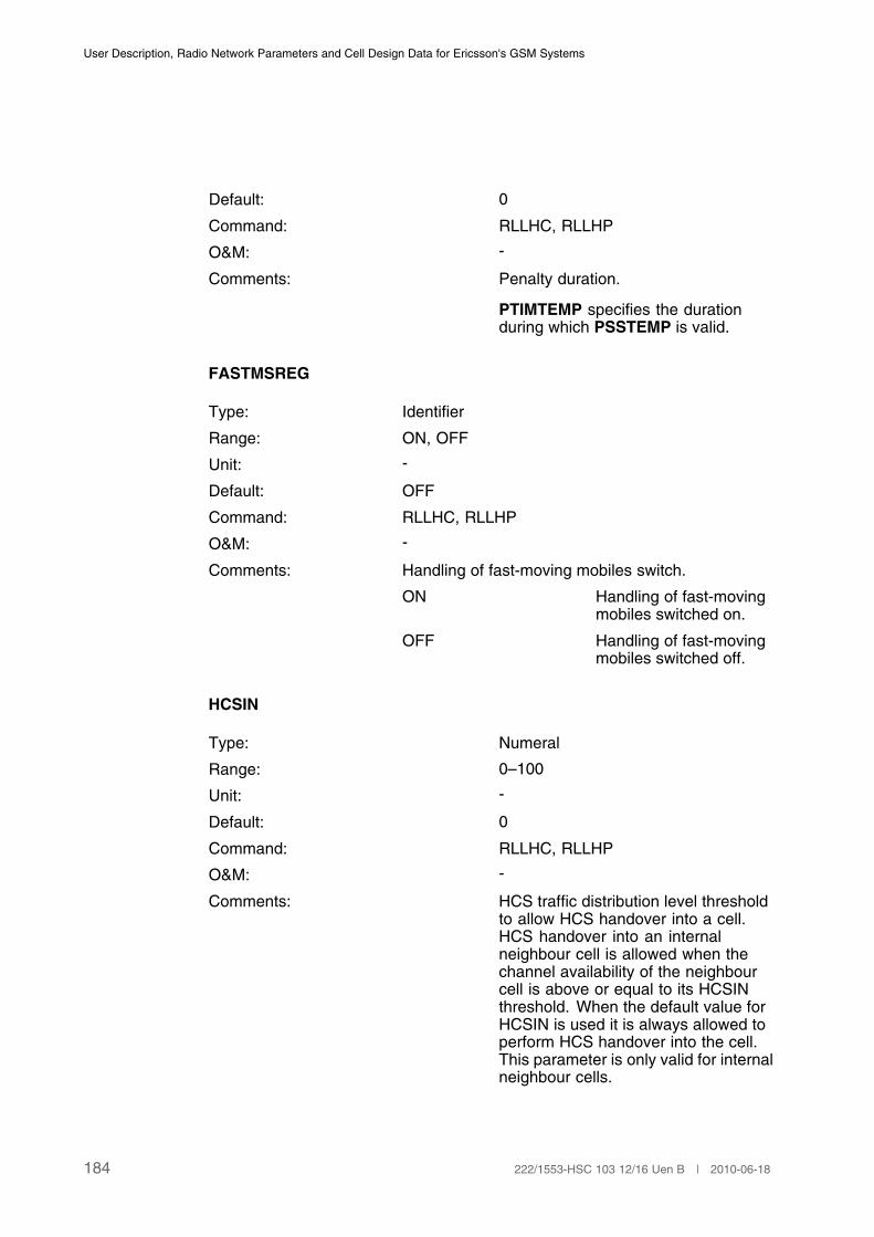
User Description, Radio Network Parameters and Cell Design Data for Ericsson's GSM Systems
Default: 0
Command: RLLHC, RLLHP
O&M: -
Comments: Penalty duration.
PTIMTEMP specifies the durationduring which PSSTEMP is valid.
FASTMSREG
Type: Identifier
Range: ON, OFF
Unit: -
Default: OFF
Command: RLLHC, RLLHP
O&M: -
Comments: Handling of fast-moving mobiles switch.
ON Handling of fast-movingmobiles switched on.
OFF Handling of fast-movingmobiles switched off.
HCSIN
Type: Numeral
Range: 0–100
Unit: -
Default: 0
Command: RLLHC, RLLHP
O&M: -
Comments: HCS traffic distribution level thresholdto allow HCS handover into a cell.HCS handover into an internalneighbour cell is allowed when thechannel availability of the neighbourcell is above or equal to its HCSINthreshold. When the default value forHCSIN is used it is always allowed toperform HCS handover into the cell.This parameter is only valid for internalneighbour cells.
184 222/1553-HSC 103 12/16 Uen B | 2010-06-18

Cell Data
HCSOUT
Type: Numeral
Range: 0–100
Unit: -
Default: 100
Command: RLLHC, RLLHP
O&M: -
Comments: HCS traffic distribution level thresholdto allow HCS handover out from a cell.HCS handover out from the servingcell is allowed when the channelavailability of the serving cell is belowor equal to its HCSOUT threshold.When the default value for HCSOUTis used it is always allowed to performHCS handover out from the cell.
3.18 Extended Range
3.18.1 Cell Data
XRANGE
Type: Identifier
Range: YES, NO
Unit: -
Default: NO
Command: RLDEC, RLDEP
O&M: The parameter is only allowed to be changed in cellstate HALTED.
Comments: Extended range cell.
If the cell is an extended range cell, traffic at adistance of greater than 35 km between the MS andthe BTS can be supported
YES The cell is an extendedrange cell.
NO The cell is a normal cell.
185222/1553-HSC 103 12/16 Uen B | 2010-06-18

User Description, Radio Network Parameters and Cell Design Data for Ericsson's GSM Systems
The purpose of the function Extended Range is toprovide Ericsson's GSM system with a possibilityto carry traffic at a larger distance from the basestation than the normal GSM range of 35 km. Insparsely populated areas such as deserts, coastalareas, maritime environments and so on, large cellscould be valuable.
In order to configure cells with both normal andextended range channels, a subcell structure shallbe used. The normal range channels will then beplaced in the overlaid cell, while the extended rangechannels will be in the underlaid cell.(1)
(1) This parameter can only be set for internal cells.
MAXTA
Type: Numeral
Range: 0 to 63 (normal cell).
0 to 219 (extended range cell)
Unit: Bit periods (bp)
Default: 63
Command: RLLDC, RLLDP
O&M: -
Comments: Maximum timing advance before an MS isconsidered lost.
If the measured timing advance value for an accessburst is equal to or greater than MAXTA, then theconnection set-up signalling is terminated by thesystem.
If the measured and averaged timing advance valuefor an ongoing call is equal or greater than MAXTA,the call is released.
The useful range of MAXTA is
0 to 219 Extended range cellswith RBS2000.
0 to 63 Normal range cells.(1)
(1) MAXTA should always be greater than the parameter TALIM (see Page 186). MAXTA is a
hard limit compared to TALIM, which is a soft limit.
TALIM
186 222/1553-HSC 103 12/16 Uen B | 2010-06-18
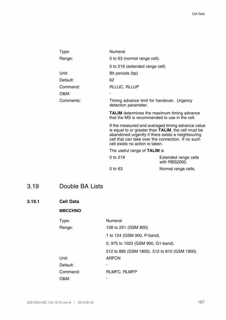
Cell Data
Type: Numeral
Range: 0 to 63 (normal range cell).
0 to 219 (extended range cell)
Unit: Bit periods (bp)
Default: 62
Command: RLLUC, RLLUP
O&M: -
Comments: Timing advance limit for handover. Urgencydetection parameter.
TALIM determines the maximum timing advancethat the MS is recommended to use in the cell.
If the measured and averaged timing advance valueis equal to or greater than TALIM, the cell must beabandoned urgently if there exists a neighbouringcell that can take over the connection. If no suchcell exists no action is taken.
The useful range of TALIM is
0 to 219 Extended range cellswith RBS2000.
0 to 63 Normal range cells.
3.19 Double BA Lists
3.19.1 Cell Data
MBCCHNO
Type: Numeral
Range: 128 to 251 (GSM 800).
1 to 124 (GSM 900, P-band).
0, 975 to 1023 (GSM 900, G1-band).
512 to 885 (GSM 1800). 512 to 810 (GSM 1900).
Unit: ARFCN
Default: -
Command: RLMFC, RLMFP
O&M: -
187222/1553-HSC 103 12/16 Uen B | 2010-06-18

User Description, Radio Network Parameters and Cell Design Data for Ericsson's GSM Systems
Comments: Absolute RF channel number for measurement onBCCH.
The number is the absolute RF channel number forthe BCCH for cells to be measured on by a mobilestation in the cell.
MBCCHNO is the BCCH allocation, that is it indicatesto the MS the frequencies that must be monitoredand measured in idle, active or both modes. Thisnumber is sent to MSs in the system informationmessages, on the BCCH channel in idle mode, andon the SACCH in active mode.
Up to 32 BCCH carriers can be defined by specifyingtheir ARFCN.
The measurement reports from the MS are sentto the BSC on the SACCH, indicating the signalstrength and quality of the serving link and the signalstrength, frequency, and BSIC from the six BTSs withstrongest signal strength. Only measurements fromneighbouring cells that fulfil the requirement that theirBCCH has a frequency as indicated by MBCCHNOand an NCC as indicated by NCCPERM are valid.To be allowed to perform a handover to any of themeasured cells it is also necessary that the measuredcell is defined as a neighbor to the serving cell. Up to64 different cells can be defined as neighbours.
LISTTYPE
Type: Identifier
Range: IDLE, ACTIVE, Omitted
Unit: -
Default: -
Command: RLMFC, RLMFP
O&M: -
Comments: This parameter identifies which type oflist the chosen frequencies will be on.When the MS is in idle or active mode,it will measure on the frequencies onthe corresponding list.
If LISTTYPE is not specified, both listsare affected.
MRNIC
188 222/1553-HSC 103 12/16 Uen B | 2010-06-18
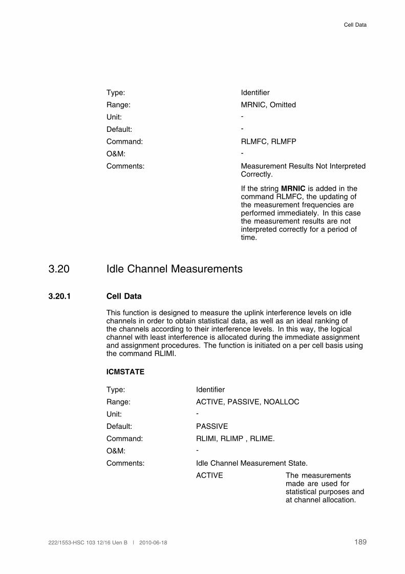
Cell Data
Type: Identifier
Range: MRNIC, Omitted
Unit: -
Default: -
Command: RLMFC, RLMFP
O&M: -
Comments: Measurement Results Not InterpretedCorrectly.
If the string MRNIC is added in thecommand RLMFC, the updating ofthe measurement frequencies areperformed immediately. In this casethe measurement results are notinterpreted correctly for a period oftime.
3.20 Idle Channel Measurements
3.20.1 Cell Data
This function is designed to measure the uplink interference levels on idlechannels in order to obtain statistical data, as well as an ideal ranking ofthe channels according to their interference levels. In this way, the logicalchannel with least interference is allocated during the immediate assignmentand assignment procedures. The function is initiated on a per cell basis usingthe command RLIMI.
ICMSTATE
Type: Identifier
Range: ACTIVE, PASSIVE, NOALLOC
Unit: -
Default: PASSIVE
Command: RLIMI, RLIMP , RLIME.
O&M: -
Comments: Idle Channel Measurement State.
ACTIVE The measurementsmade are used forstatistical purposes andat channel allocation.
189222/1553-HSC 103 12/16 Uen B | 2010-06-18

User Description, Radio Network Parameters and Cell Design Data for Ericsson's GSM Systems
PASSIVE No idle channelmeasurements aremade.
NOALLOC The measurementsare used for statisticalpurposes only.
NOALLOC
Type: Identifier
Range: NOALLOC, Omitted
Unit: -
Default: -
Command: RLIMI, RLIMP.
O&M: -
Comments: When this string is added tothe command RLIMI, then idlechannel measurements will not beused at channel allocation. Themeasurements are in this case usedmerely for statistical purposes.
INTAVE
Type: Numeral
Range: 1 to 31
Unit: SACCH periods (480 ms)
Default: 6
Command: RLIMC, RLIMP.
O&M: -
Comments: The number of measurements thatshould be used in the calculation ofthe interference band for a channel.
LIMITn
190 222/1553-HSC 103 12/16 Uen B | 2010-06-18

Cell Data
Type: Numeral
Range: LIMIT1: 0 to 59
LIMIT2: 1 to 60
LIMIT3: 2 to 61
LIMIT4: 3 to 62
Unit: -
Default: LIMIT1: 2
LIMIT2: 6
LIMIT3: 12
LIMIT4: 22
Command:
RLIMC, RLIMP.
O&M: -
Comments:
This parameter defines threshold limits for five differentinterference bands. The limits must be defined in ascending orderaccording to the following:
LIMIT1 < LIMIT2 < LIMIT3 < LIMIT4.
LIMIT1 Interference measurementsin band 1 which have valuesranging from LIMIT1 and below.
LIMIT2 Interference measurementsin band 2, which have valuesranging from LIMIT1 up to andincluding LIMIT2.
LIMIT3 Interference measurementsin band 3, which have valuesranging from LIMIT2 up to andincluding LIMIT3.
LIMIT4 Interference measurementsin band 4, which have valuesranging from LIMIT3 up to andincluding LIMIT4.
The values assigned to each threshold correspond to dBm valuesinternally.
0 < –110 dBm
1 –110 dBm to –109 dBm
2 –109 dBm to –108 dBm
...
191222/1553-HSC 103 12/16 Uen B | 2010-06-18

User Description, Radio Network Parameters and Cell Design Data for Ericsson's GSM Systems
61 –50 dBm to –49 dBm
62 –49 dBm to –48 dBm
3.21 Cell Load Sharing
Note: Cell load sharing evaluations are not performed at all for channels inmultislot configurations.
3.21.1 BSC Data
LSSTATE
Type: Identifier
Range: ACTIVE, INACTIVE
Unit: -
Default: INACTIVE
Command: RLLSI, RLLSE, RLLSP
O&M: -
Comments: Cell load sharing active/inactive in theBSC.
3.21.2 BSC Exchange Property Data
CLSTIMEINTERVAL
Type: Numeral
Range: 100 to 1000
Unit: ms
Default: 100
Command: RAEPC, RAEPP.
O&M: -
Comments: Time interval for checking the level ofidle TCHs for cells active for Cell loadsharing.
The time interval values shall be givenin multiples of 100 milliseconds.
192 222/1553-HSC 103 12/16 Uen B | 2010-06-18

Cell Data
3.21.3 Cell Data
CLSSTATE
Type: Identifier
Range: ACTIVE, INACTIVE
Unit: -
Default: INACTIVE
Command: RLLCI, RLLCE, RLLCP
O&M: -
Comments: Cell load sharing active/inactive foran individual cell. For CLSSTATEactivation to have effect, LSSTATEmust be activated.
CLSACC
Type: Numeral
Range: 1 to 100
Unit: %
Default: 40
Command: RLLCC. , RLLCP
O&M: -
Comments: Percentage of available full ratecapable traffic channels, in a targetcell, at or below which no handoversdue to Cell Load Sharing will beaccepted.
CLSLEVEL
Type: Numeral
Range: 0 to 99
Unit: %
Default: 20
Command: RLLCC, RLLCP
193222/1553-HSC 103 12/16 Uen B | 2010-06-18
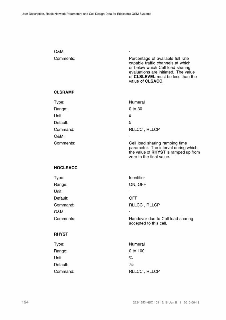
User Description, Radio Network Parameters and Cell Design Data for Ericsson's GSM Systems
O&M: -
Comments: Percentage of available full ratecapable traffic channels at whichor below which Cell load sharingevaluations are initiated. The valueof CLSLEVEL must be less than thevalue of CLSACC.
CLSRAMP
Type: Numeral
Range: 0 to 30
Unit: s
Default: 5
Command: RLLCC , RLLCP
O&M: -
Comments: Cell load sharing ramping timeparameter. The interval during whichthe value of RHYST is ramped up fromzero to the final value.
HOCLSACC
Type: Identifier
Range: ON, OFF
Unit: -
Default: OFF
Command: RLLCC , RLLCP
O&M: -
Comments: Handover due to Cell load sharingaccepted to this cell.
RHYST
Type: Numeral
Range: 0 to 100
Unit: %
Default: 75
Command: RLLCC , RLLCP
194 222/1553-HSC 103 12/16 Uen B | 2010-06-18

Cell Data
O&M: -
Comments: Hysteresis reduction parameter.Determines how much the hysteresisvalues can be reduced in the Cell loadsharing evaluation.
3.22 Multiband Operation
3.22.1 BSC Exchange Property Data
CLMRKMSG
Type: Numeral
Range: 0 to 3
Unit: -
Default: 0
Command: RAEPC, RAEPP
O&M: -
Comments: Classmark message handling.
This parameter indicates how the ClassmarkChange message shall be handled if received asfirst RR message from the MS.
0 The message 48.008Classmark Update isalways sent to the MSC,neither suppressed nordelayed.
1 The message 48.008Classmark Update isnever sent to the MSC.
195222/1553-HSC 103 12/16 Uen B | 2010-06-18

User Description, Radio Network Parameters and Cell Design Data for Ericsson's GSM Systems
2 The sending of 48.008Classmark Update tothe MSC is delayeduntil an Inter BSChandover. 48.008Classmark Update willbe sent before the GSMmessage HandoverRequired.
3 The sending of the48.008 ClassmarkUpdate to the MSCis delayed until a callset-up is performed. Themessage is also sentin case of an inter BSChandover at locationupdating.
3.22.2 BSC Data
MODE
Type: Identifier
Range: MULTI, SINGLE
Unit: -
Default: SINGLE
Command: RLOMC , RLOMP
O&M: -
Comments: The BSC band operation mode identifier.
MULTI The BSC multibandoperation mode isenabled.
SINGLE The BSC multibandoperation mode isdisabled.
GSYSTYPE
Type: Identifier
Range: GSM800, GSM900, GSM1800,GSM1900, MIXED
Unit: -
196 222/1553-HSC 103 12/16 Uen B | 2010-06-18

Cell Data
Default: -
Command: RLTYC, RLTYI, RLTYP
O&M: -
Comments: Specifies the system type for the BSC.Defining the parameter CSYSTYPE ismandatory if the global system type isMIXED.
3.22.3 Cell Data
CSYSTYPE
Type: Identifier
Range: GSM800, GSM900, GSM1800,GSM1900
Unit: -
Default: -
Command: RLDEI, RLDEP
O&M: -
Comments: In single band cells CSYSTYPEspecifies the system type for the cell.In multi band cells it specifies thefrequency band used for the BCCH.
The parameter CSYSTYPE ismandatory if the global system typeis MIXED. If the global system typeis other that MIXED, CSYSTYPE isoptional and will be accepted only if theparameter value is set to the same asthe global system type. If CSYSTYPEis omitted, it will automatically be setto the value of the global system type.
MBCR
Type: Numeral
Range: 0 to 3
Unit: -
Default: 0
Command: RLSSC , RLSSP
O&M: -
197222/1553-HSC 103 12/16 Uen B | 2010-06-18
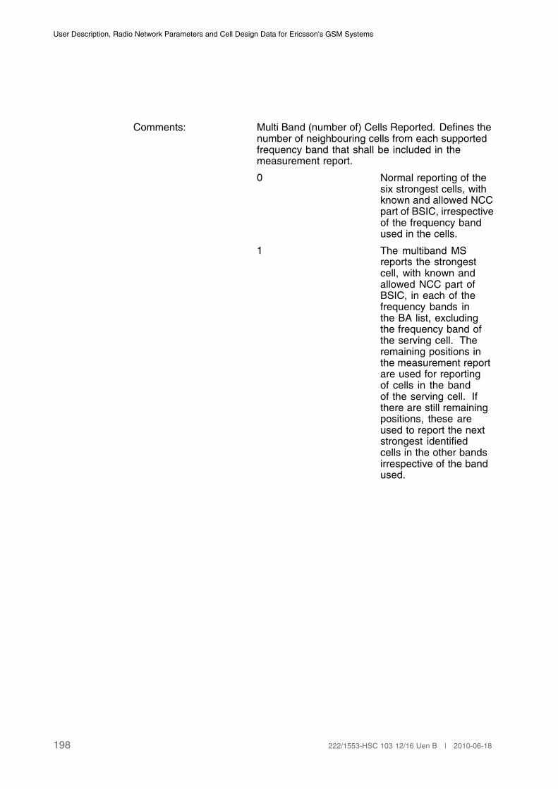
User Description, Radio Network Parameters and Cell Design Data for Ericsson's GSM Systems
Comments: Multi Band (number of) Cells Reported. Defines thenumber of neighbouring cells from each supportedfrequency band that shall be included in themeasurement report.
0 Normal reporting of thesix strongest cells, withknown and allowed NCCpart of BSIC, irrespectiveof the frequency bandused in the cells.
1 The multiband MSreports the strongestcell, with known andallowed NCC part ofBSIC, in each of thefrequency bands inthe BA list, excludingthe frequency band ofthe serving cell. Theremaining positions inthe measurement reportare used for reportingof cells in the bandof the serving cell. Ifthere are still remainingpositions, these areused to report the nextstrongest identifiedcells in the other bandsirrespective of the bandused.
198 222/1553-HSC 103 12/16 Uen B | 2010-06-18

Cell Data
2 The multiband MSreports the two strongestcells, with known andallowed NCC part ofBSIC, in each of thefrequency bands inthe BA list, excludingthe frequency band ofthe serving cell. Theremaining positions inthe measurement reportare used for reportingof cells in the bandof the serving cell. Ifthere are still remainingpositions, these areused to report the nextstrongest identifiedcells in the other bandsirrespective of the bandused.
3 The multiband MSreports the threestrongest cells, withknown and allowed NCCpart of BSIC, in eachof the frequency bandsin the BA list, excludingthe frequency band ofthe serving cell. Theremaining positions inthe measurement reportare used for reportingof cells in the bandof the serving cell. Ifthere are still remainingpositions, these areused to report the nextstrongest identifiedcells in the other bandsirrespective of the bandused.
(1)
(1) MBCR is not changeable if a Competitor Coverage Evaluation Active BA-list Recordig
is ongoing.
3.22.4 Hardware characteristics data
BAND
199222/1553-HSC 103 12/16 Uen B | 2010-06-18
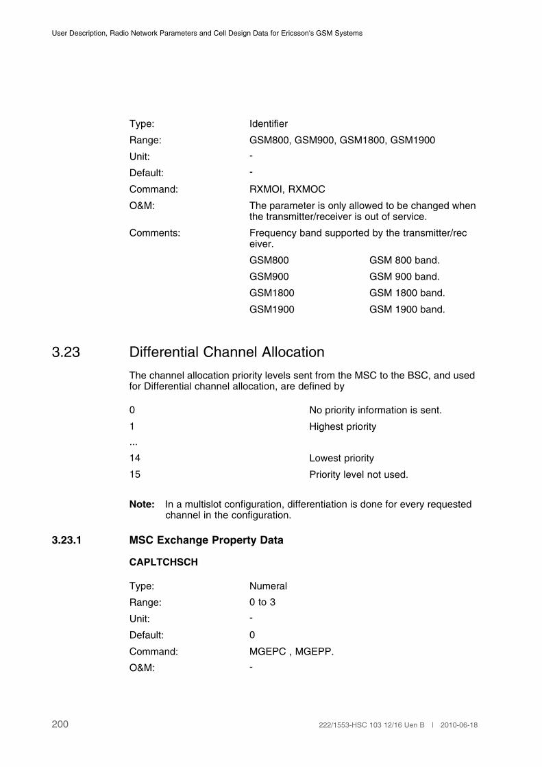
User Description, Radio Network Parameters and Cell Design Data for Ericsson's GSM Systems
Type: Identifier
Range: GSM800, GSM900, GSM1800, GSM1900
Unit: -
Default: -
Command: RXMOI, RXMOC
O&M: The parameter is only allowed to be changed whenthe transmitter/receiver is out of service.
Comments: Frequency band supported by the transmitter/receiver.
GSM800 GSM 800 band.
GSM900 GSM 900 band.
GSM1800 GSM 1800 band.
GSM1900 GSM 1900 band.
3.23 Differential Channel Allocation
The channel allocation priority levels sent from the MSC to the BSC, and usedfor Differential channel allocation, are defined by
0 No priority information is sent.
1 Highest priority
...
14 Lowest priority
15 Priority level not used.
Note: In a multislot configuration, differentiation is done for every requestedchannel in the configuration.
3.23.1 MSC Exchange Property Data
CAPLTCHSCH
Type: Numeral
Range: 0 to 3
Unit: -
Default: 0
Command: MGEPC , MGEPP.
O&M: -
200 222/1553-HSC 103 12/16 Uen B | 2010-06-18

Cell Data
Comments: Specifies if channel allocation priority level handlingis to be considered at initial TCH and/or at SDCCHassignment or not at all. The parameter is optional.
0 Channel allocationpriority level handling notconsidered.
1 Channel allocationpriority level handlingonly considered at initialTCH assignment.
2 Channel allocationpriority level handlingonly considered at initialSDCCH assignment.
3 Channel allocationpriority level handlingconsidered at initialSDCCH and initial TCHassignment.
(1)
(1) This parameter is only defined for Ericsson MSCs.
CAPLTCHEMER
Type: Numeral
Range: 0 to 15
Unit: -
Default: 0
Command: MGEPC , MGEPP.
O&M: -
Comments: Specifies a channel allocation prioritylevel in the MSC in case of anemergency call. The parameter isoptional.
The priority level for emergency callsneed to be defined in the BSC too, seeEMERGPRL in Page 207.
This parameter indicates the channelallocation priority level sent to the BSCat initial TCH assignment.(1)
(1) This parameter is only defined for Ericsson MSCs.
201222/1553-HSC 103 12/16 Uen B | 2010-06-18

User Description, Radio Network Parameters and Cell Design Data for Ericsson's GSM Systems
CAPLTCHMOVAL
Type: Numeral
Range: 0 to 15
Unit: -
Default: 0
Command: MGEPC , MGEPP.
O&M: -
Comments: Specifies a channel allocationpriority level to be used for mobileoriginated transactions when nopriority information has been receivedfrom HLR. The parameter is optional.
This parameter indicates the channelallocation priority level sent to the BSCat initial TCH assignment.(1)
(1) This parameter is only defined for Ericsson MSCs.
CAPLSCHMOVAL
Type: Numeral
Range: 0 to 15
Unit: -
Default: 0
Command: MGEPC , MGEPP.
O&M: -
Comments: Specifies a channel allocationpriority level to be used for mobileoriginated transactions when nopriority information has been receivedfrom HLR. The parameter is optional.
This parameter indicates the channelallocation priority level sent to the BSCat initial SDCCH assignment.(1)
(1) This parameter is only defined for Ericsson MSCs.
CAPLTCHMTVAL
202 222/1553-HSC 103 12/16 Uen B | 2010-06-18
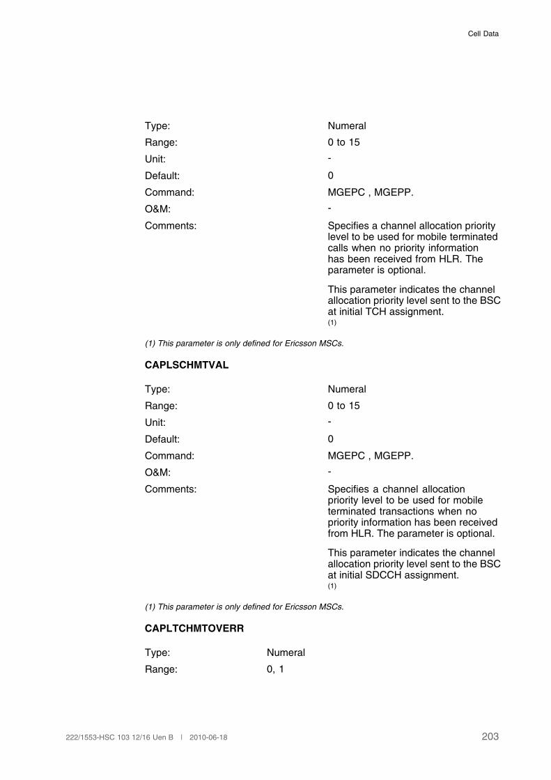
Cell Data
Type: Numeral
Range: 0 to 15
Unit: -
Default: 0
Command: MGEPC , MGEPP.
O&M: -
Comments: Specifies a channel allocation prioritylevel to be used for mobile terminatedcalls when no priority informationhas been received from HLR. Theparameter is optional.
This parameter indicates the channelallocation priority level sent to the BSCat initial TCH assignment.(1)
(1) This parameter is only defined for Ericsson MSCs.
CAPLSCHMTVAL
Type: Numeral
Range: 0 to 15
Unit: -
Default: 0
Command: MGEPC , MGEPP.
O&M: -
Comments: Specifies a channel allocationpriority level to be used for mobileterminated transactions when nopriority information has been receivedfrom HLR. The parameter is optional.
This parameter indicates the channelallocation priority level sent to the BSCat initial SDCCH assignment.(1)
(1) This parameter is only defined for Ericsson MSCs.
CAPLTCHMTOVERR
Type: Numeral
Range: 0, 1
203222/1553-HSC 103 12/16 Uen B | 2010-06-18
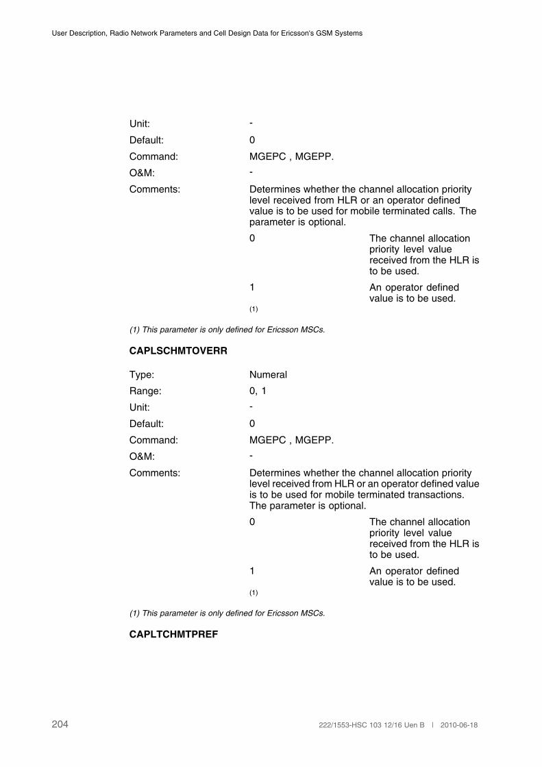
User Description, Radio Network Parameters and Cell Design Data for Ericsson's GSM Systems
Unit: -
Default: 0
Command: MGEPC , MGEPP.
O&M: -
Comments: Determines whether the channel allocation prioritylevel received from HLR or an operator definedvalue is to be used for mobile terminated calls. Theparameter is optional.
0 The channel allocationpriority level valuereceived from the HLR isto be used.
1 An operator definedvalue is to be used.
(1)
(1) This parameter is only defined for Ericsson MSCs.
CAPLSCHMTOVERR
Type: Numeral
Range: 0, 1
Unit: -
Default: 0
Command: MGEPC , MGEPP.
O&M: -
Comments: Determines whether the channel allocation prioritylevel received from HLR or an operator defined valueis to be used for mobile terminated transactions.The parameter is optional.
0 The channel allocationpriority level valuereceived from the HLR isto be used.
1 An operator definedvalue is to be used.
(1)
(1) This parameter is only defined for Ericsson MSCs.
CAPLTCHMTPREF
204 222/1553-HSC 103 12/16 Uen B | 2010-06-18
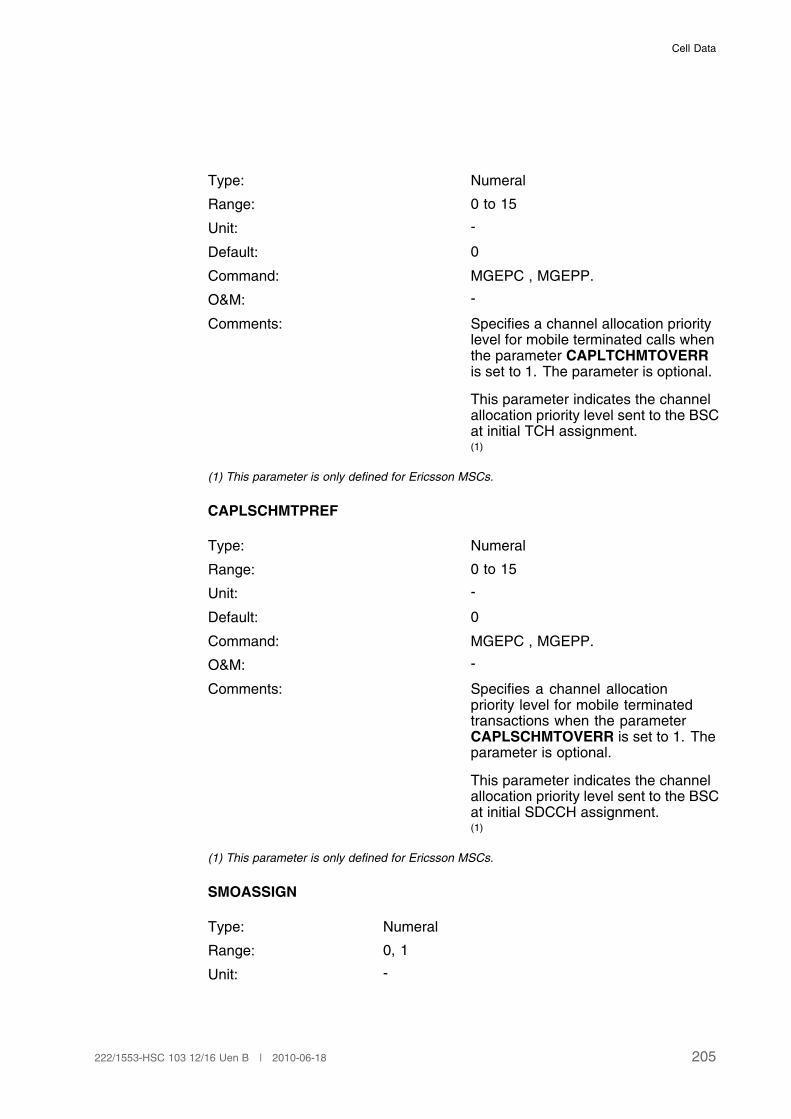
Cell Data
Type: Numeral
Range: 0 to 15
Unit: -
Default: 0
Command: MGEPC , MGEPP.
O&M: -
Comments: Specifies a channel allocation prioritylevel for mobile terminated calls whenthe parameter CAPLTCHMTOVERRis set to 1. The parameter is optional.
This parameter indicates the channelallocation priority level sent to the BSCat initial TCH assignment.(1)
(1) This parameter is only defined for Ericsson MSCs.
CAPLSCHMTPREF
Type: Numeral
Range: 0 to 15
Unit: -
Default: 0
Command: MGEPC , MGEPP.
O&M: -
Comments: Specifies a channel allocationpriority level for mobile terminatedtransactions when the parameterCAPLSCHMTOVERR is set to 1. Theparameter is optional.
This parameter indicates the channelallocation priority level sent to the BSCat initial SDCCH assignment.(1)
(1) This parameter is only defined for Ericsson MSCs.
SMOASSIGN
Type: Numeral
Range: 0, 1
Unit: -
205222/1553-HSC 103 12/16 Uen B | 2010-06-18
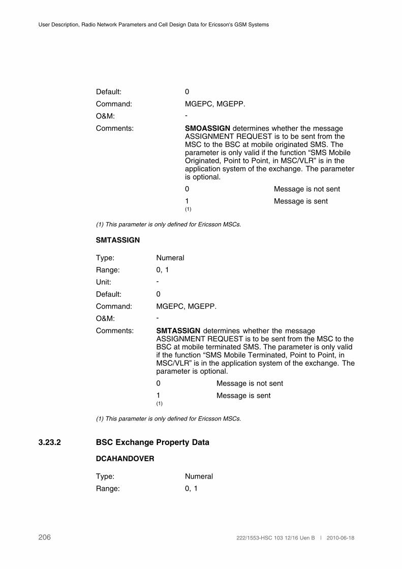
User Description, Radio Network Parameters and Cell Design Data for Ericsson's GSM Systems
Default: 0
Command: MGEPC, MGEPP.
O&M: -
Comments: SMOASSIGN determines whether the messageASSIGNMENT REQUEST is to be sent from theMSC to the BSC at mobile originated SMS. Theparameter is only valid if the function “SMS MobileOriginated, Point to Point, in MSC/VLR” is in theapplication system of the exchange. The parameteris optional.
0 Message is not sent
1 Message is sent(1)
(1) This parameter is only defined for Ericsson MSCs.
SMTASSIGN
Type: Numeral
Range: 0, 1
Unit: -
Default: 0
Command: MGEPC, MGEPP.
O&M: -
Comments: SMTASSIGN determines whether the messageASSIGNMENT REQUEST is to be sent from the MSC to theBSC at mobile terminated SMS. The parameter is only validif the function “SMS Mobile Terminated, Point to Point, inMSC/VLR” is in the application system of the exchange. Theparameter is optional.
0 Message is not sent
1 Message is sent(1)
(1) This parameter is only defined for Ericsson MSCs.
3.23.2 BSC Exchange Property Data
DCAHANDOVER
Type: Numeral
Range: 0, 1
206 222/1553-HSC 103 12/16 Uen B | 2010-06-18

Cell Data
Unit: -
Default: 0
Command: RAEPC , RAEPP.
O&M: -
Comments: Differential channel allocation at Intra-BSC inter-cellhandover.
0 OFF
1 ON
When the switch is ON, differentiation accordingto the stored priority level for the connection isapplied. When OFF, differentiation is not applied.The parameter is not valid at handover duringassignment.
3.23.3 BSC Data
DCASTATE
Type: Identifier
Range: ON, OFF
Unit: -
Default: OFF
Command: RLDCI, RLDCE , RLDCP.
O&M: -
Comments: Differential channel allocation switch.Activates/deactivates Differentialchannel allocation in the BSC.
EMERGPRL
Type: Numeral
Range: 1 to 15
Unit: -
Default: -
Command: RLDCI , RLDCP.
207222/1553-HSC 103 12/16 Uen B | 2010-06-18
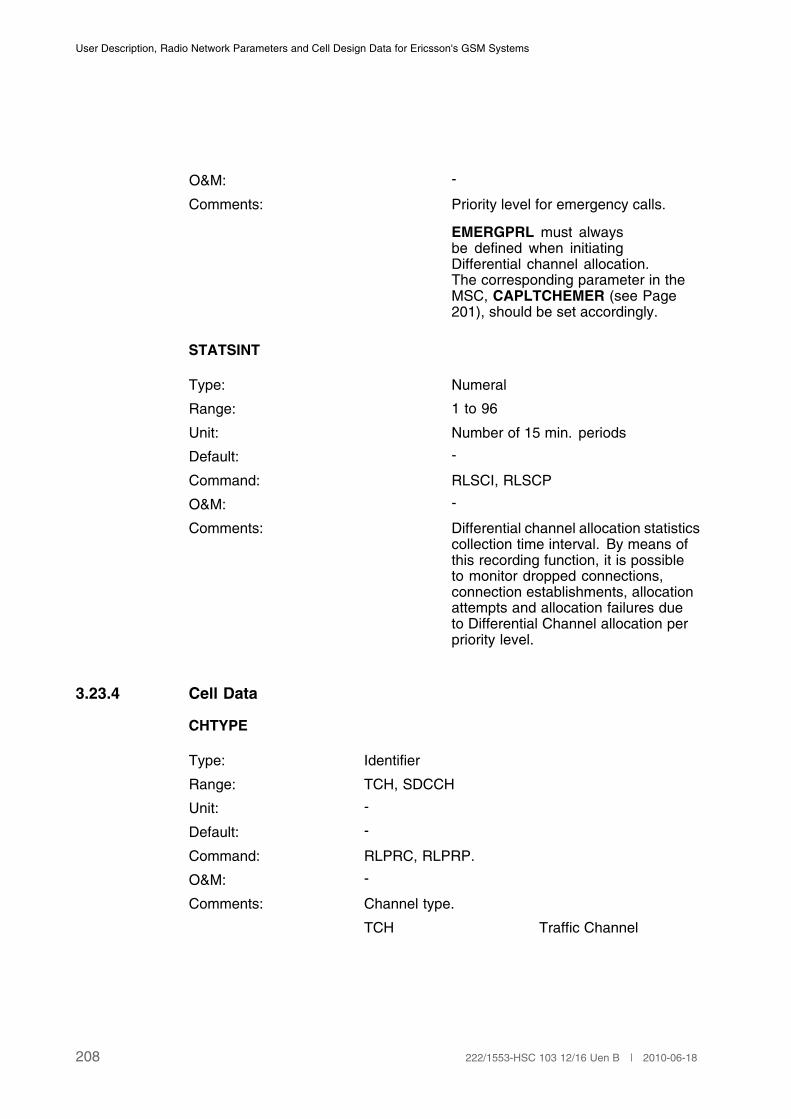
User Description, Radio Network Parameters and Cell Design Data for Ericsson's GSM Systems
O&M: -
Comments: Priority level for emergency calls.
EMERGPRL must alwaysbe defined when initiatingDifferential channel allocation.The corresponding parameter in theMSC, CAPLTCHEMER (see Page201), should be set accordingly.
STATSINT
Type: Numeral
Range: 1 to 96
Unit: Number of 15 min. periods
Default: -
Command: RLSCI, RLSCP
O&M: -
Comments: Differential channel allocation statisticscollection time interval. By means ofthis recording function, it is possibleto monitor dropped connections,connection establishments, allocationattempts and allocation failures dueto Differential Channel allocation perpriority level.
3.23.4 Cell Data
CHTYPE
Type: Identifier
Range: TCH, SDCCH
Unit: -
Default: -
Command: RLPRC, RLPRP.
O&M: -
Comments: Channel type.
TCH Traffic Channel
208 222/1553-HSC 103 12/16 Uen B | 2010-06-18

Cell Data
SDCCH Stand Alone DedicatedControl Channel
(1)
(1) As a printout parameter in other functions, CHTYPE can also have the values BCCH and
CBCH.
CHRATE
Type: Identifier
Range: FR, HR
Unit: -
Default: -
Command: RLPRC, RLPRP.
O&M: -
Comments: Channel rate.
FR The channel rate is FR(full rate).
HR The channel rate is HR(half rate).
Parameter CHRATE is only valid for channel typeTCH.
3.23.5 P P Resource Type Data
A P P Resource Type (RT) is a unique type of channel.
In Ericsson's GSM system R7, there are six possible P P RTs within a cell:
PPRT1.1: full-rate TCH in the overlaid subcell,
PPRT1.2: half-rate TCH in the overlaid subcell,
PPRT2.1: full-rate TCH in the underlaid subcell,
PPRT2.2: half-rate TCH in the underlaid subcell,
PPRT3: SDCCH in the overlaid subcell,
PPRT4: SDCCH in the underlaid subcell.
A Priority Profile (PP) is defined by means of the command RLPPI.
An RT is assigned a PP by means of the command RLPRC. The P P RT isspecified by means of SCTYPE, CHTYPE and CHRATE.
PP
209222/1553-HSC 103 12/16 Uen B | 2010-06-18
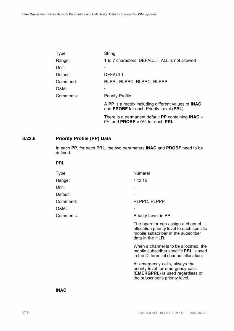
User Description, Radio Network Parameters and Cell Design Data for Ericsson's GSM Systems
Type: String
Range: 1 to 7 characters, DEFAULT. ALL is not allowed
Unit: -
Default: DEFAULT
Command: RLPPI, RLPPC, RLPRC, RLPPP
O&M: -
Comments: Priority Profile.
A PP is a matrix including different values of INACand PROBF for each Priority Level (PRL).
There is a permanent default PP containing INAC =0% and PROBF = 0% for each PRL.
3.23.6 Priority Profile (PP) Data
In each PP, for each PRL, the two parameters INAC and PROBF need to bedefined.
PRL
Type: Numeral
Range: 1 to 16
Unit: -
Default: -
Command: RLPPC, RLPPP
O&M: -
Comments: Priority Level in PP.
The operator can assign a channelallocation priority level to each specificmobile subscriber in the subscriberdata in the HLR.
When a channel is to be allocated, themobile subscriber specific PRL is usedin the Differential channel allocation.
At emergency calls, always thepriority level for emergency calls(EMERGPRL) is used regardless ofthe subscriber's priority level.
INAC
210 222/1553-HSC 103 12/16 Uen B | 2010-06-18
Cell Data
Type: Numeral
Range: 0 to 100
Unit: %
Default: 0
Command: RLPPC, RLPPP
O&M: -
Comments: Percentage of deblocked channelsthat are inaccessible for the PRL atdifferential channel allocation.
PROBF
Type: Numeral
Range: 0 to 100
Unit: %
Default: 0
Command: RLPPC, RLPPP
O&M: -
Comments: Probability of failure to allocate the lastremaining accessible channel for thepriority level.
3.24 Enhanced Multi-Level Precedence and PreemptionService (eMLPP)
The enhanced Multi-Level Precedence and Preemption (eMLPP) featureenables the operator to give high priority users good access to the network.This is achieved by preemption of one low-priority connection either byhandover or disconnection.
The BSS procedure uses a number of parameters defined for each eMLPPlevel, the Preemption Capability Indicator (PCI), the Preemption VulnerabilityIndicator (PVI), the Priority Level and the Queuing Allowed Indicator (QAI).These parameters are provided by the MSC.
3.24.1 BSC Exchange Property Data
PHSTATE
211222/1553-HSC 103 12/16 Uen B | 2010-06-18
User Description, Radio Network Parameters and Cell Design Data for Ericsson's GSM Systems
Type: Numeral
Range: 0 to 2
Unit: -
Default: 0
Command: RAEPC, RAEPP
O&M: -
Comments: Indicates if the feature Efficient Priority Handling isactivated or not.
The following values are available:
0 Efficient Priority Handlingis not activated
1 Efficient Priority Handlingis activated. The eMLPPparameters PCI and PVIare considered in thepreemption algorithm.
2 Efficient Priority Handlingis activated. Besides theeMLPP parameters PCIand PVI also the eMLPPparameter Priority Levelwill be considered in thepreemption algorithm.
MSQUEUING
Type: Numeral
Range: 0 to 2
Unit: -
Default: 0
Command: RAEPC, RAEPP
O&M: -
Comments: This parameter indicates whether the feature CallQueuing is activated or not.
0 Call Queuing notactivated
212 222/1553-HSC 103 12/16 Uen B | 2010-06-18
Cell Data
1 Call Queuing activated
2 Call Queuing activated.Voice Group Channelallocation andsubsequent Talkerallocation are allowed toprecede the queue.
MSQHOPRIO
Type: Numeral
Range: 0,1
Unit: -
Default: 0
Command: RAEPC, RAEPP
O&M: -
Comments: Indicates if a PC using a traffic channel will gethigher priority or not, due to handover, than queuedPC requests in the target cell:
0 No priority
1 Handover prioritised
3.24.2 MSC, eMLPP data
EMLPP
Type: Identifier
Range: A, B, 0 to 4
Unit: -
Default: -
Command: MGETC
O&M: -
Comments: Enhanced multi-level precedence and preemptionlevel.
A Highest level
B Second-highest level
0 Third-highest level
1 Forth-highest level
213222/1553-HSC 103 12/16 Uen B | 2010-06-18
User Description, Radio Network Parameters and Cell Design Data for Ericsson's GSM Systems
2 Fifth-highest level
3 Sixth-highest level
4 Lowest level
BAOCI
Type: Numeral
Range: 0,1
Unit: -
Default: 0
Command: MGETC
O&M: -
Comments: Barring of outgoing calls overriding indicator. Setper eMLPP level.
The following values are available:
0 Barring not overridden
1 Barring overridden
BOICI
Type: Numeral
Range: 0,1
Unit: -
Default: 0
Command: MGETC
O&M: -
Comments: Barring of outgoing international calls overridingindicator. Set per eMLPP level.
The following values are available:
0 Barring not overridden
1 Barring overridden
BOIEXHI
Type: Numeral
Range: 0,1
Unit: -
214 222/1553-HSC 103 12/16 Uen B | 2010-06-18

Cell Data
Default: 0
Command: MGETC
O&M: -
Comments: Barring of outgoing international calls except thoseto the home Public Land Mobile Network (PLMN)country overriding indicator. Set per eMLPP level.
The following values are available:
0 Barring not overridden
1 Barring overridden
PCI
Type: Numeral
Range: 0,1
Unit: -
Default: 0
Command: MGETC
O&M: -
Comments: Preemption capability indicator. Set per eMLPPlevel.
The following values are available
0 Allocation requestcannot preempt anexisting connection.
1 Allocation request canpreempt an existingconnection.
PVI
Type: Numeral
Range: 0,1
Unit: -
Default: 0
Command: MGETC
O&M: -
215222/1553-HSC 103 12/16 Uen B | 2010-06-18
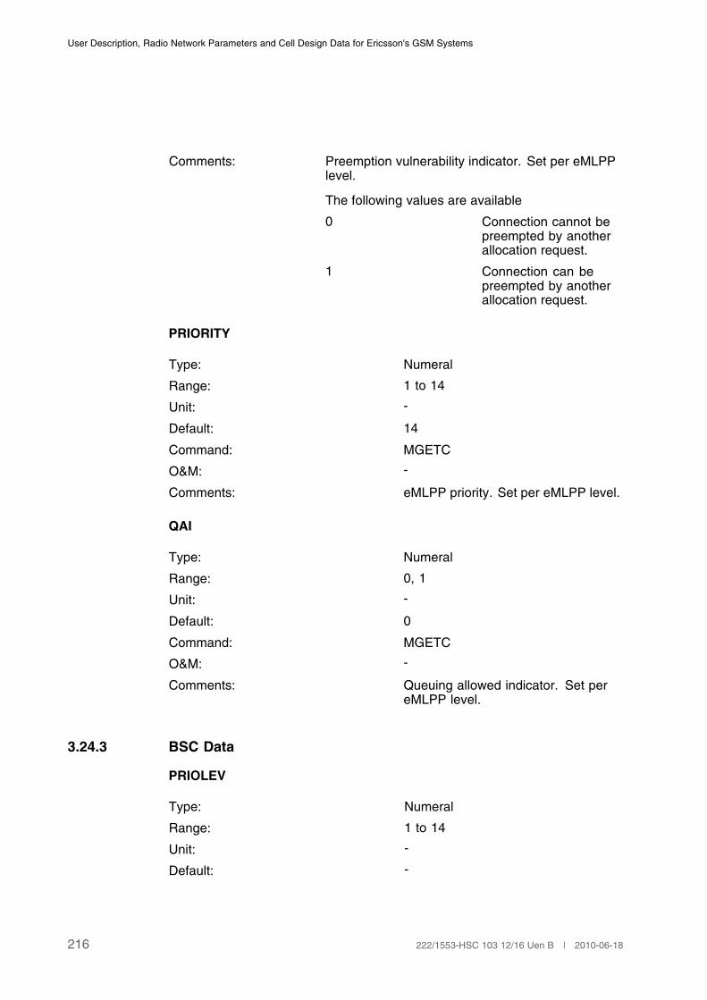
User Description, Radio Network Parameters and Cell Design Data for Ericsson's GSM Systems
Comments: Preemption vulnerability indicator. Set per eMLPPlevel.
The following values are available
0 Connection cannot bepreempted by anotherallocation request.
1 Connection can bepreempted by anotherallocation request.
PRIORITY
Type: Numeral
Range: 1 to 14
Unit: -
Default: 14
Command: MGETC
O&M: -
Comments: eMLPP priority. Set per eMLPP level.
QAI
Type: Numeral
Range: 0, 1
Unit: -
Default: 0
Command: MGETC
O&M: -
Comments: Queuing allowed indicator. Set pereMLPP level.
3.24.3 BSC Data
PRIOLEV
Type: Numeral
Range: 1 to 14
Unit: -
Default: -
216 222/1553-HSC 103 12/16 Uen B | 2010-06-18

Cell Data
Command: RLBQC, RLBQP
O&M: -
Comments: Priority level
This parameter determines the prioritylevel.
QASSTIME
Type: Numeral
Range: 1 to 60
Unit: -
Default: 28
Command: RLBQC, RLBQP
O&M: -
Comments: Assignment time
This parameter determines themaximum time it is allowed to doassignment for a priority connection.
3.24.4 Cell Data
QLENGTH
Type: Numeral
Range: 0 to 32
Unit: -
Default: 5
Command: RLMQC, RLMQP
O&M: -
Comments: Maximum queue length in a cell. Itdetermines the maximum number ofPriority Connections (PC) that can beinserted in the queue.
RESLIMIT
Type: Numeral
Range: 1 to 100
217222/1553-HSC 103 12/16 Uen B | 2010-06-18
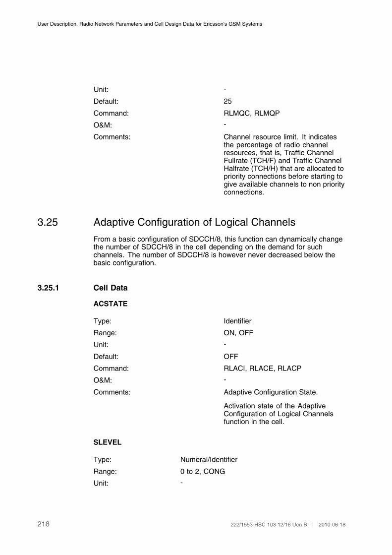
User Description, Radio Network Parameters and Cell Design Data for Ericsson's GSM Systems
Unit: -
Default: 25
Command: RLMQC, RLMQP
O&M: -
Comments: Channel resource limit. It indicatesthe percentage of radio channelresources, that is, Traffic ChannelFullrate (TCH/F) and Traffic ChannelHalfrate (TCH/H) that are allocated topriority connections before starting togive available channels to non priorityconnections.
3.25 Adaptive Configuration of Logical Channels
From a basic configuration of SDCCH/8, this function can dynamically changethe number of SDCCH/8 in the cell depending on the demand for suchchannels. The number of SDCCH/8 is however never decreased below thebasic configuration.
3.25.1 Cell Data
ACSTATE
Type: Identifier
Range: ON, OFF
Unit: -
Default: OFF
Command: RLACI, RLACE, RLACP
O&M: -
Comments: Adaptive Configuration State.
Activation state of the AdaptiveConfiguration of Logical Channelsfunction in the cell.
SLEVEL
Type: Numeral/Identifier
Range: 0 to 2, CONG
Unit: -
218 222/1553-HSC 103 12/16 Uen B | 2010-06-18
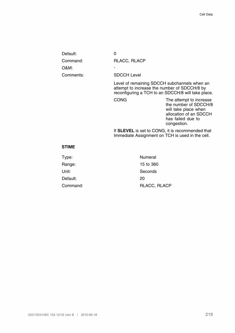
Cell Data
Default: 0
Command: RLACC, RLACP
O&M: -
Comments: SDCCH Level
Level of remaining SDCCH subchannels when anattempt to increase the number of SDCCH/8 byreconfiguring a TCH to an SDCCH/8 will take place.
CONG The attempt to increasethe number of SDCCH/8will take place whenallocation of an SDCCHhas failed due tocongestion.
If SLEVEL is set to CONG, it is recommended thatImmediate Assignment on TCH is used in the cell.
STIME
Type: Numeral
Range: 15 to 360
Unit: Seconds
Default: 20
Command: RLACC, RLACP
219222/1553-HSC 103 12/16 Uen B | 2010-06-18
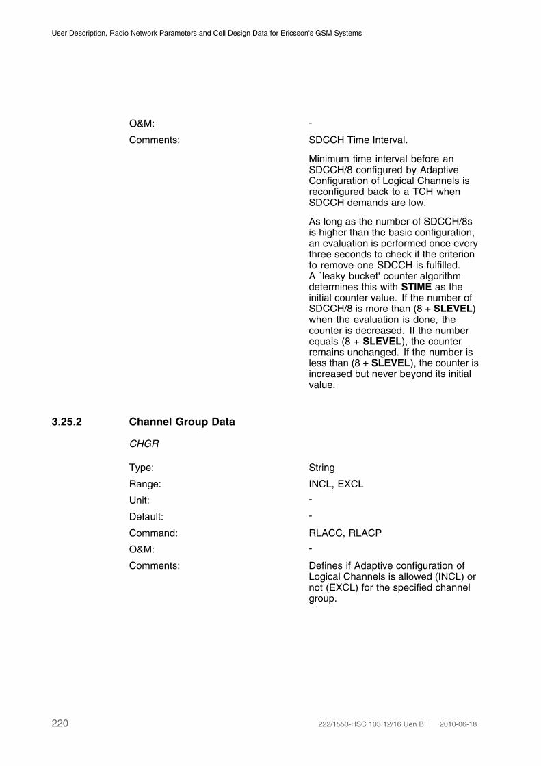
User Description, Radio Network Parameters and Cell Design Data for Ericsson's GSM Systems
O&M: -
Comments: SDCCH Time Interval.
Minimum time interval before anSDCCH/8 configured by AdaptiveConfiguration of Logical Channels isreconfigured back to a TCH whenSDCCH demands are low.
As long as the number of SDCCH/8sis higher than the basic configuration,an evaluation is performed once everythree seconds to check if the criterionto remove one SDCCH is fulfilled.A l` eaky bucket' counter algorithmdetermines this with STIME as theinitial counter value. If the number ofSDCCH/8 is more than (8 + SLEVEL)when the evaluation is done, thecounter is decreased. If the numberequals (8 + SLEVEL), the counterremains unchanged. If the number isless than (8 + SLEVEL), the counter isincreased but never beyond its initialvalue.
3.25.2 Channel Group Data
CHGR
Type: String
Range: INCL, EXCL
Unit: -
Default: -
Command: RLACC, RLACP
O&M: -
Comments: Defines if Adaptive configuration ofLogical Channels is allowed (INCL) ornot (EXCL) for the specified channelgroup.
220 222/1553-HSC 103 12/16 Uen B | 2010-06-18
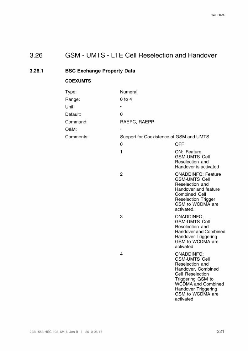
Cell Data
3.26 GSM - UMTS - LTE Cell Reselection and Handover
3.26.1 BSC Exchange Property Data
COEXUMTS
Type: Numeral
Range: 0 to 4
Unit: -
Default: 0
Command: RAEPC, RAEPP
O&M: -
Comments: Support for Coexistence of GSM and UMTS
0 OFF
1 ON: FeatureGSM-UMTS CellReselection andHandover is activated
2 ONADDINFO: FeatureGSM-UMTS CellReselection andHandover and featureCombined CellReselection TriggerGSM to WCDMA areactivated.
3 ONADDINFO;GSM-UMTS CellReselection andHandover and CombinedHandover TriggeringGSM to WCDMA areactivated
4 ONADDINFO;GSM-UMTS CellReselection andHandover, CombinedCell ReselectionTriggering GSM toWCDMA and CombinedHandover TriggeringGSM to WCDMA areactivated
221222/1553-HSC 103 12/16 Uen B | 2010-06-18
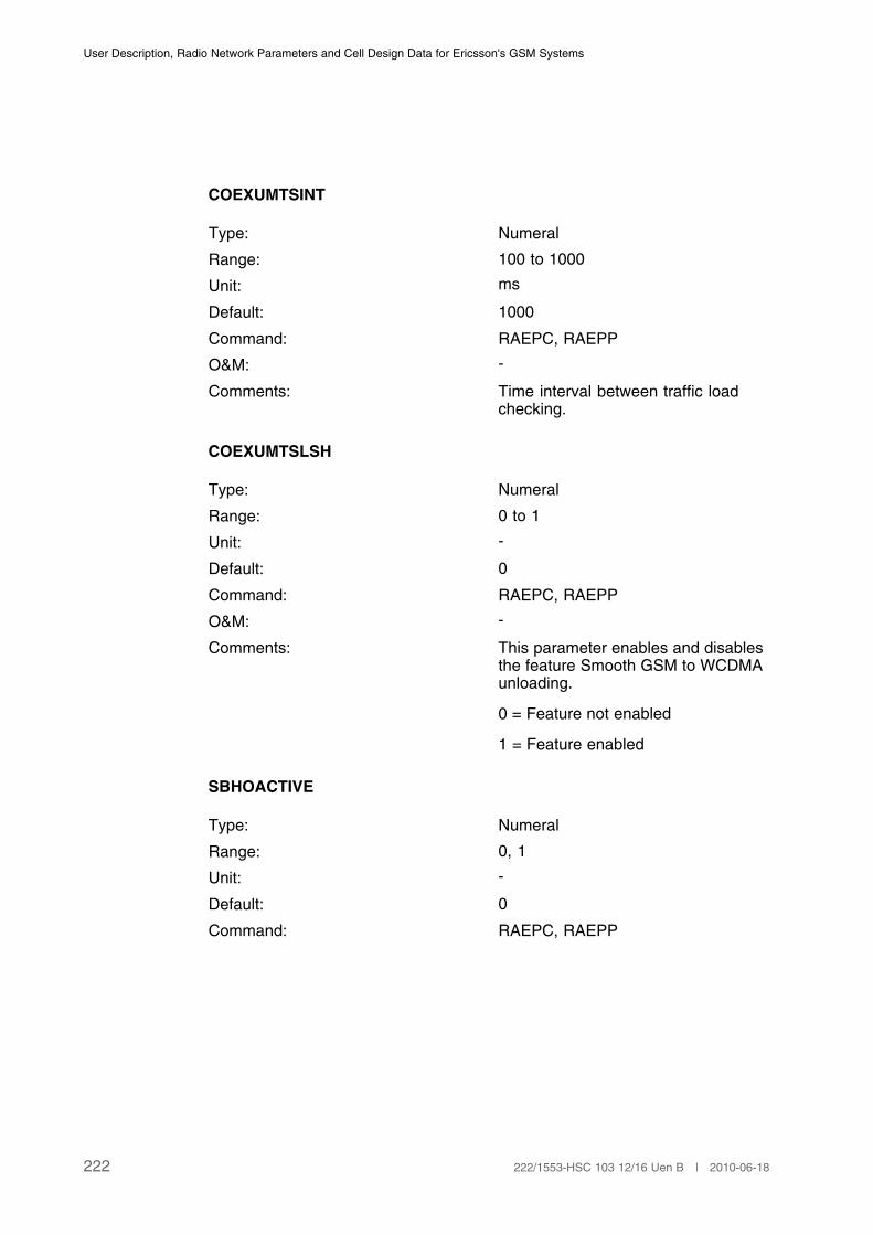
User Description, Radio Network Parameters and Cell Design Data for Ericsson's GSM Systems
COEXUMTSINT
Type: Numeral
Range: 100 to 1000
Unit: ms
Default: 1000
Command: RAEPC, RAEPP
O&M: -
Comments: Time interval between traffic loadchecking.
COEXUMTSLSH
Type: Numeral
Range: 0 to 1
Unit: -
Default: 0
Command: RAEPC, RAEPP
O&M: -
Comments: This parameter enables and disablesthe feature Smooth GSM to WCDMAunloading.
0 = Feature not enabled
1 = Feature enabled
SBHOACTIVE
Type: Numeral
Range: 0, 1
Unit: -
Default: 0
Command: RAEPC, RAEPP
222 222/1553-HSC 103 12/16 Uen B | 2010-06-18

Cell Data
O&M: -
Comments: This parameter enables and disablesthe feature Handover with Usage ofService Indicator.
0 = Feature not enabled
1 = Feature enabled
FASTRET3GNC2
Type: Numeral
Range: 0 to 1
Unit: -
Default: 0
Command: RAEPC
O&M: -
Comments: This exchange property indicates if the multi RadioAccess Technology (RAT) MSs will be redirectedimmediately to WCDMA cell at call release. Thisfunction is applicable for DTM connections in GSMcells with active Network Control Mode 2 (NC2)having WCDMA neighbors.
The availability of the exchange property valueother than the default one depends on commercialagreements.
0 ‘Fast Return to WCDMA at CallRelease’ is allowed for DTMconnections in cells with NC2switched on.
1 ‘Fast Return to WCDMA at CallRelease’ is not allowed for DTMconnections in cells with NC2switched on.
3.26.2 GSM - UMTS Cell Reselection - Cell Data
Note: The settings of the following parameters only affect Multi-RAT FDDUMTS capable MSs.
UMFI
223222/1553-HSC 103 12/16 Uen B | 2010-06-18

User Description, Radio Network Parameters and Cell Design Data for Ericsson's GSM Systems
Type: MFDDARFCN-MSCRCODE-DIVERSITY
Range: MFDDARFCN: 0 to 16383
MSCRCODE: 0 to 511
DIVERSITY: DIV or NODIV
Unit: -
Default: -
Command: RLUMC, RLUMP
O&M: -
Comments: UTRAN Measurement Frequency Information for cellreselection in GSM Idle Mode and GPRS/EGPRS Readyand Standby states.
(MFDDARFCN-MSCRCODE-DIVERSITY) defines thefrequency, scrambling code and diversity information for aUTRAN neighbouring cell.
MFDDARFCNMFDDARFCN indicates the absolute RFchannel number of the neighbouring UTRAN cell to bemeasured on by Multi-RAT MSs. Several frequency bandsexist and the absolute RF channel number representsthe center frequency within the frequency band. Allowedfrequency bands and absolute RF channel numbers aredescribed in detail in Reference [5].
MSCRCODE is the scrambling code for the neighbouringcell. The scrambling code has 512 values.
DIVERSITY indicates if diversity is applied for the UTRANcell, or not.
FDDQMIN
Type: Numeral
Range: 0 to 7
Unit: dB
Default: 0
Command: RLSUC, RLSUP
O&M: -
Comments: Minimum FDD quality.
Defines the minimum threshold for the "quality"measure Ec/No for cell reselection to UTRAN cells.
0 -20 dB
224 222/1553-HSC 103 12/16 Uen B | 2010-06-18
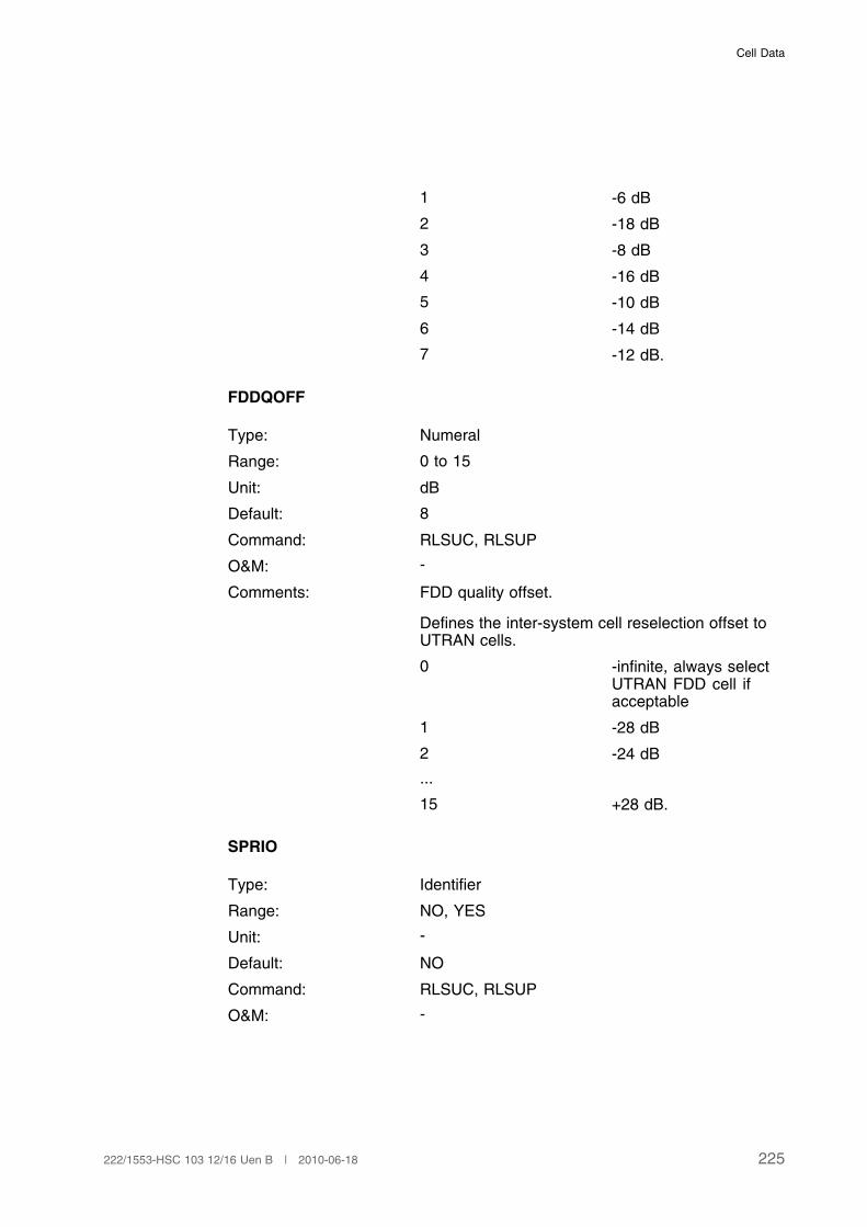
Cell Data
1 -6 dB
2 -18 dB
3 -8 dB
4 -16 dB
5 -10 dB
6 -14 dB
7 -12 dB.
FDDQOFF
Type: Numeral
Range: 0 to 15
Unit: dB
Default: 8
Command: RLSUC, RLSUP
O&M: -
Comments: FDD quality offset.
Defines the inter-system cell reselection offset toUTRAN cells.
0 -infinite, always selectUTRAN FDD cell ifacceptable
1 -28 dB
2 -24 dB
...
15 +28 dB.
SPRIO
Type: Identifier
Range: NO, YES
Unit: -
Default: NO
Command: RLSUC, RLSUP
O&M: -
225222/1553-HSC 103 12/16 Uen B | 2010-06-18
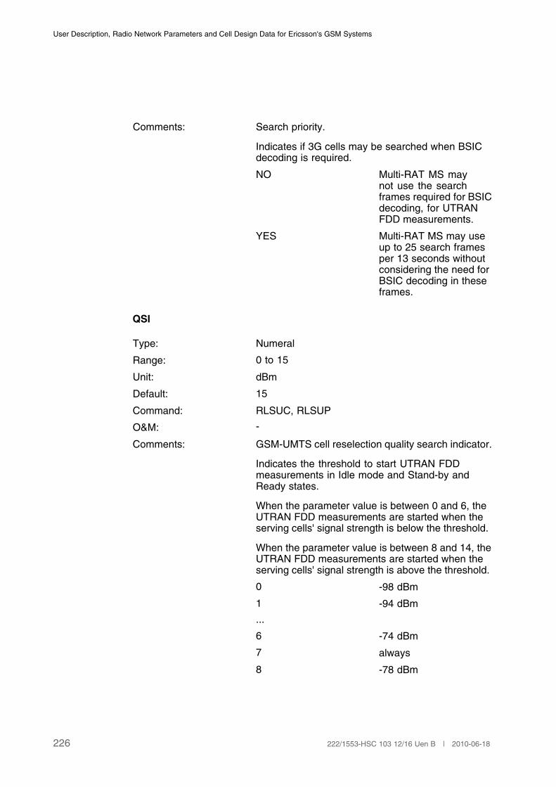
User Description, Radio Network Parameters and Cell Design Data for Ericsson's GSM Systems
Comments: Search priority.
Indicates if 3G cells may be searched when BSICdecoding is required.
NO Multi-RAT MS maynot use the searchframes required for BSICdecoding, for UTRANFDD measurements.
YES Multi-RAT MS may useup to 25 search framesper 13 seconds withoutconsidering the need forBSIC decoding in theseframes.
QSI
Type: Numeral
Range: 0 to 15
Unit: dBm
Default: 15
Command: RLSUC, RLSUP
O&M: -
Comments: GSM-UMTS cell reselection quality search indicator.
Indicates the threshold to start UTRAN FDDmeasurements in Idle mode and Stand-by andReady states.
When the parameter value is between 0 and 6, theUTRAN FDD measurements are started when theserving cells' signal strength is below the threshold.
When the parameter value is between 8 and 14, theUTRAN FDD measurements are started when theserving cells' signal strength is above the threshold.
0 -98 dBm
1 -94 dBm
...
6 -74 dBm
7 always
8 -78 dBm
226 222/1553-HSC 103 12/16 Uen B | 2010-06-18
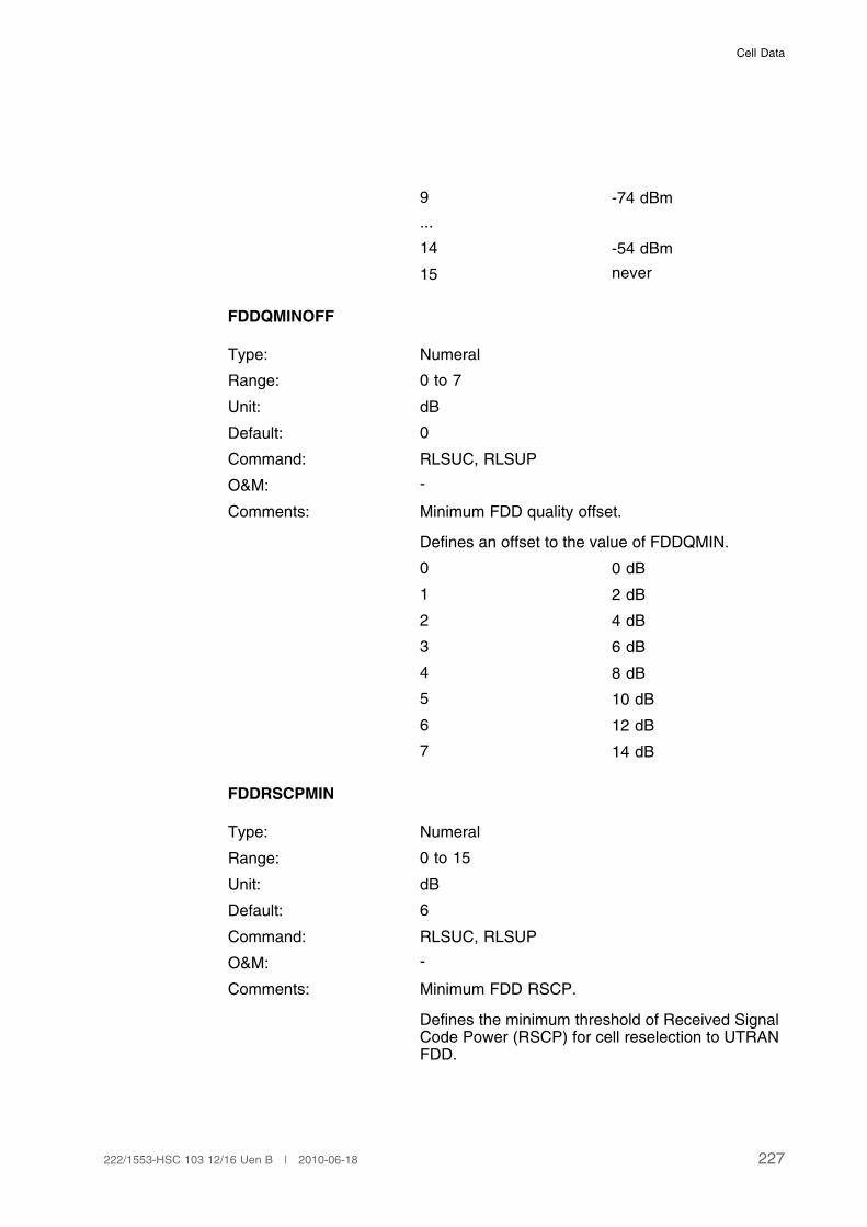
Cell Data
9 -74 dBm
...
14 -54 dBm
15 never
FDDQMINOFF
Type: Numeral
Range: 0 to 7
Unit: dB
Default: 0
Command: RLSUC, RLSUP
O&M: -
Comments: Minimum FDD quality offset.
Defines an offset to the value of FDDQMIN.
0 0 dB
1 2 dB
2 4 dB
3 6 dB
4 8 dB
5 10 dB
6 12 dB
7 14 dB
FDDRSCPMIN
Type: Numeral
Range: 0 to 15
Unit: dB
Default: 6
Command: RLSUC, RLSUP
O&M: -
Comments: Minimum FDD RSCP.
Defines the minimum threshold of Received SignalCode Power (RSCP) for cell reselection to UTRANFDD.
227222/1553-HSC 103 12/16 Uen B | 2010-06-18

User Description, Radio Network Parameters and Cell Design Data for Ericsson's GSM Systems
0 -114 dB
1 -112 dB
2 -110 dB
3 -108 dB
4 -106 dB
5 -104 dB
6 -102 dB
7 -100 dB
8 -98 dB
9 -96 dB
10 -94 dB
11 -92 dB
12 -90 dB
13 -88 dB
14 -86 dB
15 -84 dB
3.26.3 GSM - UMTS Handover - UTRAN Cell Data
CELL
Type: String
Range: 1 to 7 characters except ALL
Unit: -
Default: -
Command: All commands where a specific cell ispointed out.
Cell definition: RLDEI
O&M: -
Comments: Cell name of a external UTRAN cell.As UTRAN cells cannot belong to anyGSM BSC, they have always to bedefined as external.
NEWNAME
228 222/1553-HSC 103 12/16 Uen B | 2010-06-18

Cell Data
Type: String
Range: 1 to 7 characters except ALL
Unit: -
Default: -
Command: RLDEC
O&M: -
Comments: The parameter is used to change thename of a cell. See parameter CELLfor recommendations.
FDDARFCN
Type: Numeral
Range: 0 to 16383
Unit: -
Default: -
Command: RLDEC, RLDEP
O&M: -
Comments: Absolute RF channel number of the external UTRANcell.
The parameter indicates the absolute RF channelnumber of the neighbouring UTRAN cell in GSMactive mode. Several frequency bands exist andthe absolute RF channel number represents thecenter frequency within the frequency band. Allowedfrequency bands and absolute RF channel numbersare described in detail in Reference [5].
SCRCODE
Type: Numeral
Range: 0 to 511
Unit: -
Default: -
Command: RLDEC, RLDEP
O&M: -
Comments: The scrambling code of the externalUTRAN cell:
UTRANID
229222/1553-HSC 103 12/16 Uen B | 2010-06-18
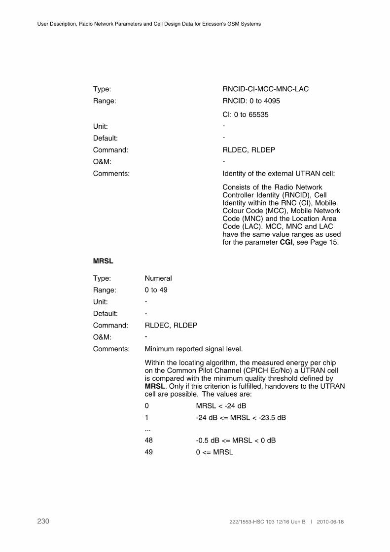
User Description, Radio Network Parameters and Cell Design Data for Ericsson's GSM Systems
Type: RNCID-CI-MCC-MNC-LAC
Range: RNCID: 0 to 4095
CI: 0 to 65535
Unit: -
Default: -
Command: RLDEC, RLDEP
O&M: -
Comments: Identity of the external UTRAN cell:
Consists of the Radio NetworkController Identity (RNCID), CellIdentity within the RNC (CI), MobileColour Code (MCC), Mobile NetworkCode (MNC) and the Location AreaCode (LAC). MCC, MNC and LAChave the same value ranges as usedfor the parameter CGI, see Page 15.
MRSL
Type: Numeral
Range: 0 to 49
Unit: -
Default: -
Command: RLDEC, RLDEP
O&M: -
Comments: Minimum reported signal level.
Within the locating algorithm, the measured energy per chipon the Common Pilot Channel (CPICH Ec/No) a UTRAN cellis compared with the minimum quality threshold defined byMRSL. Only if this criterion is fulfilled, handovers to the UTRANcell are possible. The values are:
0 MRSL < -24 dB
1 -24 dB <= MRSL < -23.5 dB
...
48 -0.5 dB <= MRSL < 0 dB
49 0 <= MRSL
230 222/1553-HSC 103 12/16 Uen B | 2010-06-18
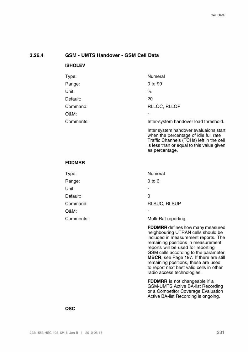
Cell Data
3.26.4 GSM - UMTS Handover - GSM Cell Data
ISHOLEV
Type: Numeral
Range: 0 to 99
Unit: %
Default: 20
Command: RLLOC, RLLOP
O&M: -
Comments: Inter-system handover load threshold.
Inter system handover evaluaions startwhen the percentage of idle full rateTraffic Channels (TCHs) left in the cellis less than or equal to this value givenas percentage.
FDDMRR
Type: Numeral
Range: 0 to 3
Unit: -
Default: 0
Command: RLSUC, RLSUP
O&M: -
Comments: Multi-Rat reporting.
FDDMRR defines how many measuredneighbouring UTRAN cells should beincluded in measurement reports. Theremaining positions in measurementreports will be used for reportingGSM cells according to the parameterMBCR, see Page 197. If there are stillremaining positions, these are usedto report next best valid cells in otherradio access technologies.
FDDMRR is not changeable if aGSM-UMTS Active BA-list Recordingor a Competitor Coverage EvaluationActive BA-list Recording is ongoing.
QSC
231222/1553-HSC 103 12/16 Uen B | 2010-06-18
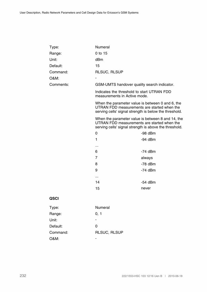
User Description, Radio Network Parameters and Cell Design Data for Ericsson's GSM Systems
Type: Numeral
Range: 0 to 15
Unit: dBm
Default: 15
Command: RLSUC, RLSUP
O&M: -
Comments: GSM-UMTS handover quality search indicator.
Indicates the threshold to start UTRAN FDDmeasurements in Active mode.
When the parameter value is between 0 and 6, theUTRAN FDD measurements are started when theserving cells' signal strength is below the threshold.
When the parameter value is between 8 and 14, theUTRAN FDD measurements are started when theserving cells' signal strength is above the threshold.
0 -98 dBm
1 -94 dBm
...
6 -74 dBm
7 always
8 -78 dBm
9 -74 dBm
...
14 -54 dBm
15 never
QSCI
Type: Numeral
Range: 0, 1
Unit: -
Default: 0
Command: RLSUC, RLSUP
O&M: -
232 222/1553-HSC 103 12/16 Uen B | 2010-06-18
Cell Data
Comments: Initial Quality search indicator.
QSCI defines the control of UTRAN measurementsafter entering active mode, before reading the firstQSC.
0 UTRAN measurementsare performed accordingto QSI until the first QSCis read.
1 UTRAN measurementsare always performeduntil the first QSC isread.
MAXISHO
Type: Numeral
Range: 1–100
Unit: -
Default: 2
Command: RLLOC, RLLOP
O&M: -
Comments: Defines maximum number of loadtriggered outgoing inter systemhandovers per second from thespecified cell
FDDREPTHR2
Type: Numeral
Range: 0-63
Unit: dBm
Default: 0
Command: RLSUC, RLSUP
O&M: -
Comment: Minimum FDD RSCP reportingthreshold. Defines a threshold for thenon reported 'signal strength' measureCPICH RSCP of UTRAN cells. TheMS includes a UTRAN cell in themeasurement reports only if the nonreporting threshold is exceeded.
(1)
233222/1553-HSC 103 12/16 Uen B | 2010-06-18
User Description, Radio Network Parameters and Cell Design Data for Ericsson's GSM Systems
0 Disabled
1 115 dBm
2 114 dBm
... ...
62 54 dBm
63 53 dBm
(1) The reporting entity in the measurement reports is CPICH Ec/No.
3.26.5 GSM - UMTS Handover - Neighbouring Cell Relation Data
There are no neighbor relation specific parameters that can be defined for eachGSM - UMTS neighbouring cell relation. It is possible to define up to 64 UTRANneighbours in addition to 64 GSM neighbours for each GSM cell. A total of upto 16384 UTRAN neighbouring cell relations can be defined per BSC.
CELLR
Type: String
Range: 1 to 7 characters except ALL
Unit: -
Default: -
Command: RLNRI, RLNRE, RLNRP, RLNCP
O&M: -
Comments: Related cell designation.
The identity of the neighbouringUTRAN is specified by means ofCELLR.
3.26.6 GSM-UMTS-LTE Cell Reselection - Cell Data
EARFCN
Type: Numeral
Range: 0 to 65535
Unit: -
Default: -
Command: RLEFC, RLEFP
234 222/1553-HSC 103 12/16 Uen B | 2010-06-18

Cell Data
O&M: -
Comment: Defines the E-UTRAN Absolute Radio FrequencyChannel Number to which cell reselection shall beperformed. This parameter is defined per GSM cell.
FDDARFCN
Type: Numeral
Range: 0 to 16383
Unit: -
Default: -
Command: RLSRC, RLSRP
O&M: -
Comment: Defines the UTRAN FDD Absolute Radio FrequencyChannel Number to which priority based cellreselection shall be performed. The value shallcorrespond to MFDDARFCN in UMFI. Thisparameter is defined per GSM cell.
HPRIO
Type: Numeral
Range: 0 to 3
Unit: dB
Default: 0
Command: RLSRC, RLSRP
O&M: -
Comment: Defines an offset to apply at a relative comparisonbetween GSM and inter-RAT frequencies whencell reselection to an inter-RAT frequency oflower priority than GSM is allowed. In 3GPP thisparameter is called H_PRIO. This parameter is setper GSM cell.
0 Rule disabled
1 5 dB
2 4 dB
3 3 dB
HPRIOTHR
235222/1553-HSC 103 12/16 Uen B | 2010-06-18
User Description, Radio Network Parameters and Cell Design Data for Ericsson's GSM Systems
Type: Numeral
Range: 0 to 31(1)
Unit: dB
Default: UMTS:
9 (18 dB)
LTE: 22 (44 dB)
Command: RLSRC, RLSRP
O&M: -
Comment: Defines the minimum threshold for reselectionto LTE and UMTS frequencies of higher prioritythan GSM. The value "measured RSCP value” -QRXLEVMINU for UMTS and “measured RSRPvalue” – QRXLEVMINE for LTE must be abovethe threshold. The parameter is defined perFDDARFCN for UMTS frequencies and perEARFCN for LTE frequencies. In 3GPP, thisparameter is called THRESH_FDD_high for UMTSand THRESH_E-UTRAN_high for LTE.
(1) 0 dB to 62 dB in steps of 2 dB.
LPRIOTHR
Type: Numeral
Range: 0 to 31(1)
Unit: dB
Default: UMTS:
9 (18 dB)
LTE: 22 (44 dB)
Command: RLSRC, RLSRP
O&M: -
Comment: Defines the minimum threshold for reselectionto LTE and UMTS frequencies of lower prioritythan GSM. The value "measured RSCP value” -QRXLEVMINU for UMTS and “measured RSRPvalue” – QRXLEVMINE for LTE must be abovethe threshold. The parameter is defined perFDDARFCN for UMTS frequencies and perEARFCN for LTE frequencies. In 3GPP, thisparameter is called THRESH_FDD_low for UMTSand THRESH_E-UTRAN_low for LTE.
(1) 0 dB to 62 dB in steps of 2 dB.
236 222/1553-HSC 103 12/16 Uen B | 2010-06-18
Cell Data
MEASTHR
Type: Numeral
Range: 0 to15
Unit: dBm
Default: 15
Command: RLSRC, RLSRP
O&M: -
Comment: Defines a threshold for the serving cell below whichmeasurements of inter-RAT frequencies with lowerpriority should be done. This parameter is definedper GSM cell. In 3GPP this parameter is calledTHRESH_priority_search.
0-14: -98 dBm to -56 dBm in steps of 3 dBm
15: Infinite (always)
MINCHBW
Type: Numeral
Range: 0 to 5
Unit: Nrb, Number of Resource Blocks
Default: 0
Command: RLSRC, RLSRP
O&M: -
Comment: Defines the minimum value of the channel bandwidthof all valid E-UTRAN cells on the specified EARFCN.This parameter is defined per EARFCN.
0: 6
1: 15
2: 25
3: 50
4: 75
5: 100
PCID
237222/1553-HSC 103 12/16 Uen B | 2010-06-18
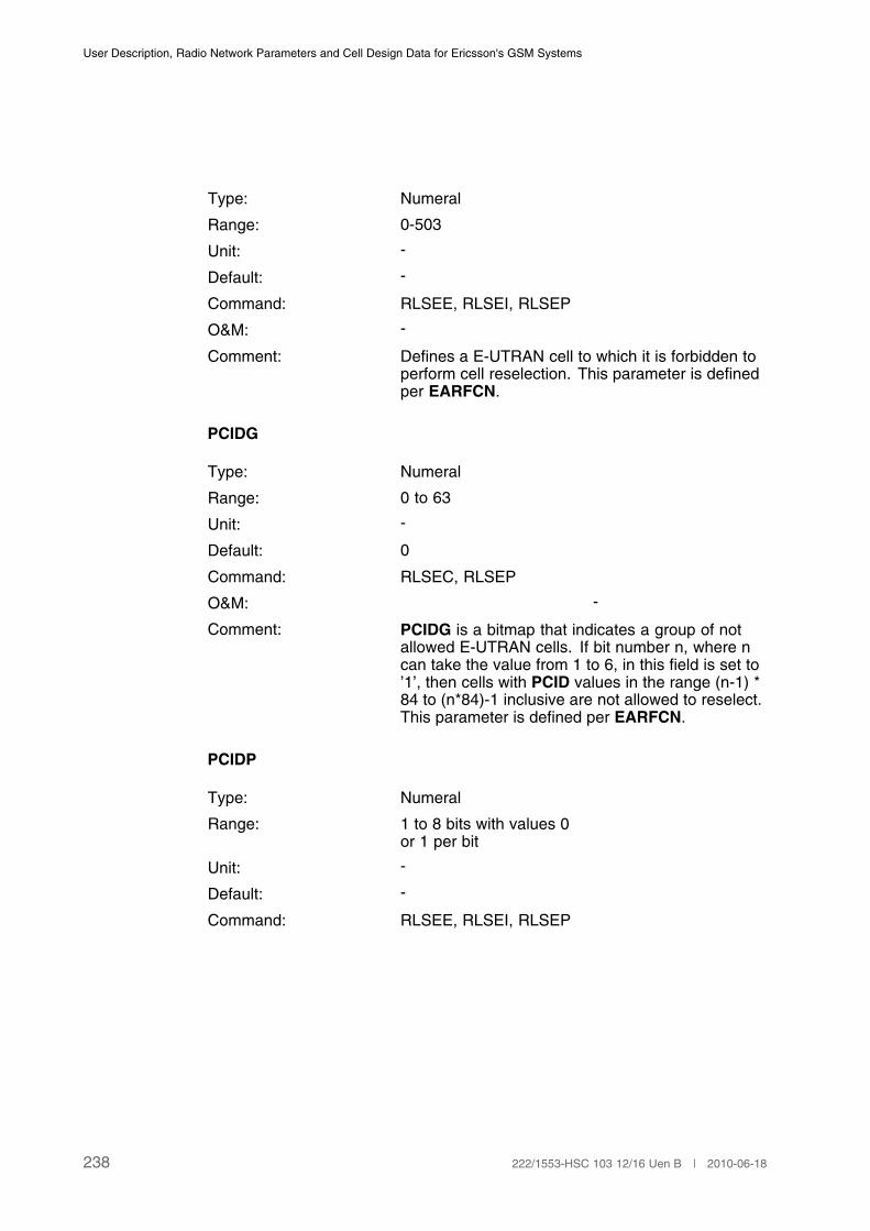
User Description, Radio Network Parameters and Cell Design Data for Ericsson's GSM Systems
Type: Numeral
Range: 0-503
Unit: -
Default: -
Command: RLSEE, RLSEI, RLSEP
O&M: -
Comment: Defines a E-UTRAN cell to which it is forbidden toperform cell reselection. This parameter is definedper EARFCN.
PCIDG
Type: Numeral
Range: 0 to 63
Unit: -
Default: 0
Command: RLSEC, RLSEP
O&M: -
Comment: PCIDG is a bitmap that indicates a group of notallowed E-UTRAN cells. If bit number n, where ncan take the value from 1 to 6, in this field is set to’1’, then cells with PCID values in the range (n-1) *84 to (n*84)-1 inclusive are not allowed to reselect.This parameter is defined per EARFCN.
PCIDP
Type: Numeral
Range: 1 to 8 bits with values 0or 1 per bit
Unit: -
Default: -
Command: RLSEE, RLSEI, RLSEP
238 222/1553-HSC 103 12/16 Uen B | 2010-06-18
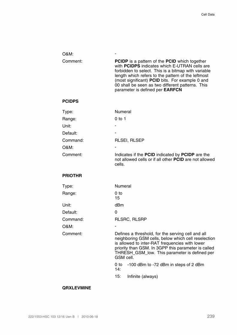
Cell Data
O&M: -
Comment: PCIDP is a pattern of the PCID which togetherwith PCIDPS indicates which E-UTRAN cells areforbidden to select. This is a bitmap with variablelength which refers to the pattern of the leftmost(most significant) PCID bits. For example 0 and00 shall be seen as two different patterns. Thisparameter is defined per EARFCN
PCIDPS
Type: Numeral
Range: 0 to 1
Unit: -
Default: -
Command: RLSEI, RLSEP
O&M: -
Comment: Indicates if the PCID indicated by PCIDP are thenot allowed cells or if all other PCID are not allowedcells.
PRIOTHR
Type: Numeral
Range: 0 to15
Unit: dBm
Default: 0
Command: RLSRC, RLSRP
O&M: -
Comment: Defines a threshold, for the serving cell and allneighboring GSM cells, below which cell reselectionis allowed to inter-RAT frequencies with lowerpriority than GSM. In 3GPP this parameter is calledTHRESH_GSM_low. This parameter is defined perGSM cell.
0 to14:
-100 dBm to -72 dBm in steps of 2 dBm
15: Infinite (always)
QRXLEVMINE
239222/1553-HSC 103 12/16 Uen B | 2010-06-18
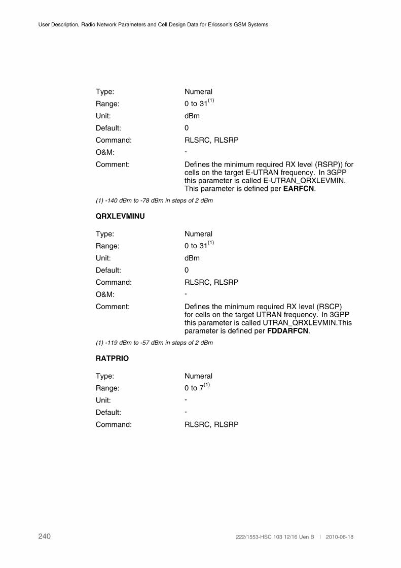
User Description, Radio Network Parameters and Cell Design Data for Ericsson's GSM Systems
Type: Numeral
Range: 0 to 31(1)
Unit: dBm
Default: 0
Command: RLSRC, RLSRP
O&M: -
Comment: Defines the minimum required RX level (RSRP)) forcells on the target E-UTRAN frequency. In 3GPPthis parameter is called E-UTRAN_QRXLEVMIN.This parameter is defined per EARFCN.
(1) -140 dBm to -78 dBm in steps of 2 dBm
QRXLEVMINU
Type: Numeral
Range: 0 to 31(1)
Unit: dBm
Default: 0
Command: RLSRC, RLSRP
O&M: -
Comment: Defines the minimum required RX level (RSCP)for cells on the target UTRAN frequency. In 3GPPthis parameter is called UTRAN_QRXLEVMIN.Thisparameter is defined per FDDARFCN.
(1) -119 dBm to -57 dBm in steps of 2 dBm
RATPRIO
Type: Numeral
Range: 0 to 7(1)
Unit: -
Default: -
Command: RLSRC, RLSRP
240 222/1553-HSC 103 12/16 Uen B | 2010-06-18
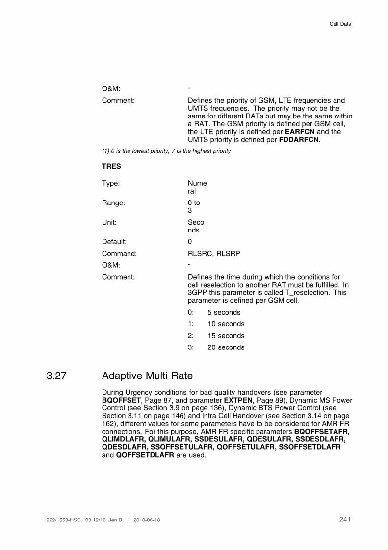
Cell Data
O&M: -
Comment: Defines the priority of GSM, LTE frequencies andUMTS frequencies. The priority may not be thesame for different RATs but may be the same withina RAT. The GSM priority is defined per GSM cell,the LTE priority is defined per EARFCN and theUMTS priority is defined per FDDARFCN.
(1) 0 is the lowest priority, 7 is the highest priority
TRES
Type: Numeral
Range: 0 to3
Unit: Seconds
Default: 0
Command: RLSRC, RLSRP
O&M: -
Comment: Defines the time during which the conditions forcell reselection to another RAT must be fulfilled. In3GPP this parameter is called T_reselection. Thisparameter is defined per GSM cell.
0: 5 seconds
1: 10 seconds
2: 15 seconds
3: 20 seconds
3.27 Adaptive Multi Rate
During Urgency conditions for bad quality handovers (see parameterBQOFFSET, Page 87, and parameter EXTPEN, Page 89), Dynamic MS PowerControl (see Section 3.9 on page 136), Dynamic BTS Power Control (seeSection 3.11 on page 146) and Intra Cell Handover (see Section 3.14 on page162), different values for some parameters have to be considered for AMR FRconnections. For this purpose, AMR FR specific parameters BQOFFSETAFR,QLIMDLAFR, QLIMULAFR, SSDESULAFR, QDESULAFR, SSDESDLAFR,QDESDLAFR, SSOFFSETULAFR, QOFFSETULAFR, SSOFFSETDLAFRand QOFFSETDLAFR are used.
241222/1553-HSC 103 12/16 Uen B | 2010-06-18
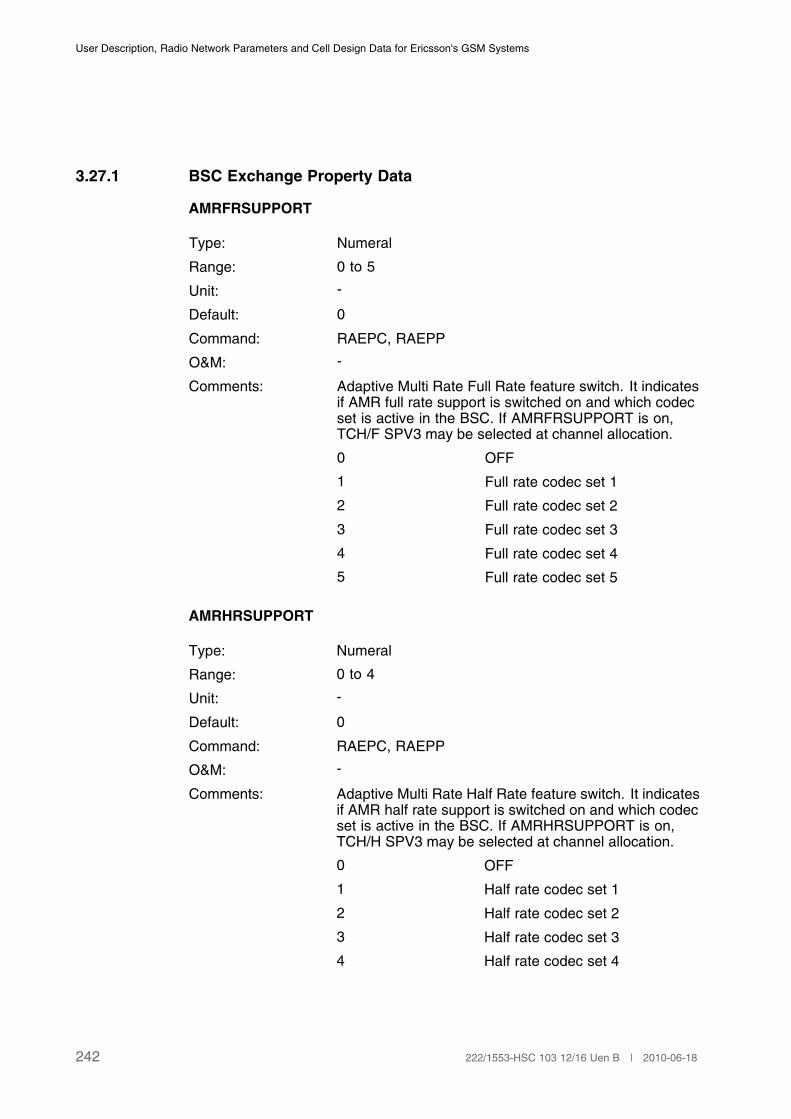
User Description, Radio Network Parameters and Cell Design Data for Ericsson's GSM Systems
3.27.1 BSC Exchange Property Data
AMRFRSUPPORT
Type: Numeral
Range: 0 to 5
Unit: -
Default: 0
Command: RAEPC, RAEPP
O&M: -
Comments: Adaptive Multi Rate Full Rate feature switch. It indicatesif AMR full rate support is switched on and which codecset is active in the BSC. If AMRFRSUPPORT is on,TCH/F SPV3 may be selected at channel allocation.
0 OFF
1 Full rate codec set 1
2 Full rate codec set 2
3 Full rate codec set 3
4 Full rate codec set 4
5 Full rate codec set 5
AMRHRSUPPORT
Type: Numeral
Range: 0 to 4
Unit: -
Default: 0
Command: RAEPC, RAEPP
O&M: -
Comments: Adaptive Multi Rate Half Rate feature switch. It indicatesif AMR half rate support is switched on and which codecset is active in the BSC. If AMRHRSUPPORT is on,TCH/H SPV3 may be selected at channel allocation.
0 OFF
1 Half rate codec set 1
2 Half rate codec set 2
3 Half rate codec set 3
4 Half rate codec set 4
242 222/1553-HSC 103 12/16 Uen B | 2010-06-18

Cell Data
3.27.2 BSC Data
SET
Type: Identifier
Range: FR3, FR4, HR3, HR4
Unit: -
Default: -
Command: RLADC, RLADP
O&M: -
Comments: Adaptive Multi Rate (AMR) codec set changed by theoperator.
FR3 Full Rate codec set 3
FR4 Full Rate codec set 4
HR3 Half Rate codec set 3
HR4 Half Rate codec set 4
MODE
Type: Numeral
Range: 1 to 5 (Half Rate)
1 to 8 (Full Rate)
Unit: -
Default: -
Command: RLADC, RLADP
O&M: -
Comments: Codec mode (the bit rate of the coded speech afterthe speech encoding).
Values for Half Rate:
1 4.75 Kbps
2 5.15 Kbps
3 5.90 Kbps
4 6.70 Kbps
5 7.40 Kbps
Values for Full rate:
1 4.75 Kbps
243222/1553-HSC 103 12/16 Uen B | 2010-06-18
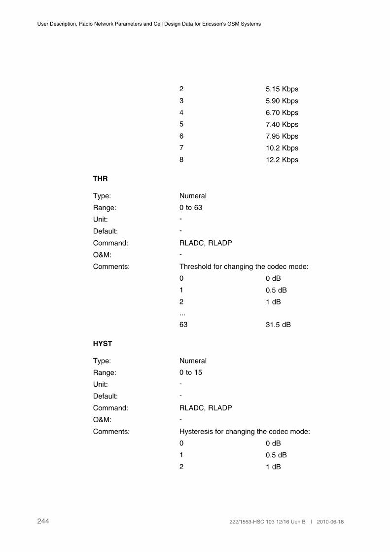
User Description, Radio Network Parameters and Cell Design Data for Ericsson's GSM Systems
2 5.15 Kbps
3 5.90 Kbps
4 6.70 Kbps
5 7.40 Kbps
6 7.95 Kbps
7 10.2 Kbps
8 12.2 Kbps
THR
Type: Numeral
Range: 0 to 63
Unit: -
Default: -
Command: RLADC, RLADP
O&M: -
Comments: Threshold for changing the codec mode:
0 0 dB
1 0.5 dB
2 1 dB
...
63 31.5 dB
HYST
Type: Numeral
Range: 0 to 15
Unit: -
Default: -
Command: RLADC, RLADP
O&M: -
Comments: Hysteresis for changing the codec mode:
0 0 dB
1 0.5 dB
2 1 dB
244 222/1553-HSC 103 12/16 Uen B | 2010-06-18
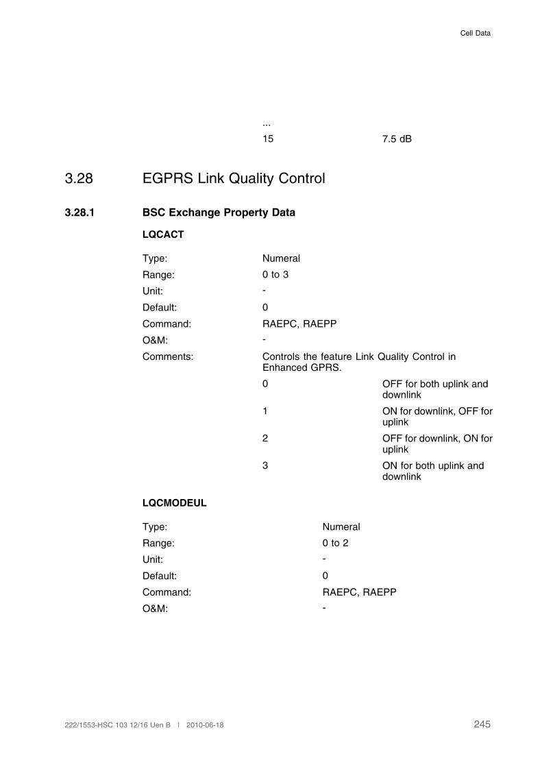
Cell Data
...
15 7.5 dB
3.28 EGPRS Link Quality Control
3.28.1 BSC Exchange Property Data
LQCACT
Type: Numeral
Range: 0 to 3
Unit: -
Default: 0
Command: RAEPC, RAEPP
O&M: -
Comments: Controls the feature Link Quality Control inEnhanced GPRS.
0 OFF for both uplink anddownlink
1 ON for downlink, OFF foruplink
2 OFF for downlink, ON foruplink
3 ON for both uplink anddownlink
LQCMODEUL
Type: Numeral
Range: 0 to 2
Unit: -
Default: 0
Command: RAEPC, RAEPP
O&M: -
245222/1553-HSC 103 12/16 Uen B | 2010-06-18
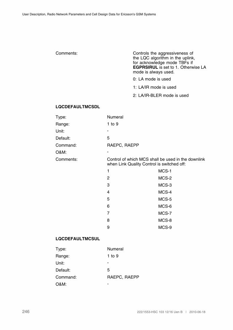
User Description, Radio Network Parameters and Cell Design Data for Ericsson's GSM Systems
Comments: Controls the aggressiveness ofthe LQC algorithm in the uplink,for acknowledge mode TBFs ifEGPRSIRUL is set to 1. Otherwise LAmode is always used.
0: LA mode is used
1: LA/IR mode is used
2: LA/IR-BLER mode is used
LQCDEFAULTMCSDL
Type: Numeral
Range: 1 to 9
Unit: -
Default: 5
Command: RAEPC, RAEPP
O&M: -
Comments: Control of which MCS shall be used in the downlinkwhen Link Quality Control is switched off:
1 MCS-1
2 MCS-2
3 MCS-3
4 MCS-4
5 MCS-5
6 MCS-6
7 MCS-7
8 MCS-8
9 MCS-9
LQCDEFAULTMCSUL
Type: Numeral
Range: 1 to 9
Unit: -
Default: 5
Command: RAEPC, RAEPP
O&M: -
246 222/1553-HSC 103 12/16 Uen B | 2010-06-18

Cell Data
Comments: Control of which MCS shall be used in the uplinkwhen Link Quality Control is switched off:
1 MCS-1
2 MCS-2
3 MCS-3
4 MCS-4
5 MCS-5
6 MCS-6
7 MCS-7
8 MCS-8
9 MCS-9
LQCHIGHMCS
Type: Numeral
Range: 1 to 9
Unit: -
Default: 9
Command: RAEPC, RAEPP
O&M: -
Comments: Maximum MCS that is supported:
1 MCS-1
2 MCS-2
3 MCS-3
4 MCS-4
5 MCS-5
6 MCS-6
7 MCS-7
8 MCS-8
9 MCS-9
LQCUNACK
Type: Numeral
Range: 0 to 2
Unit: -
247222/1553-HSC 103 12/16 Uen B | 2010-06-18
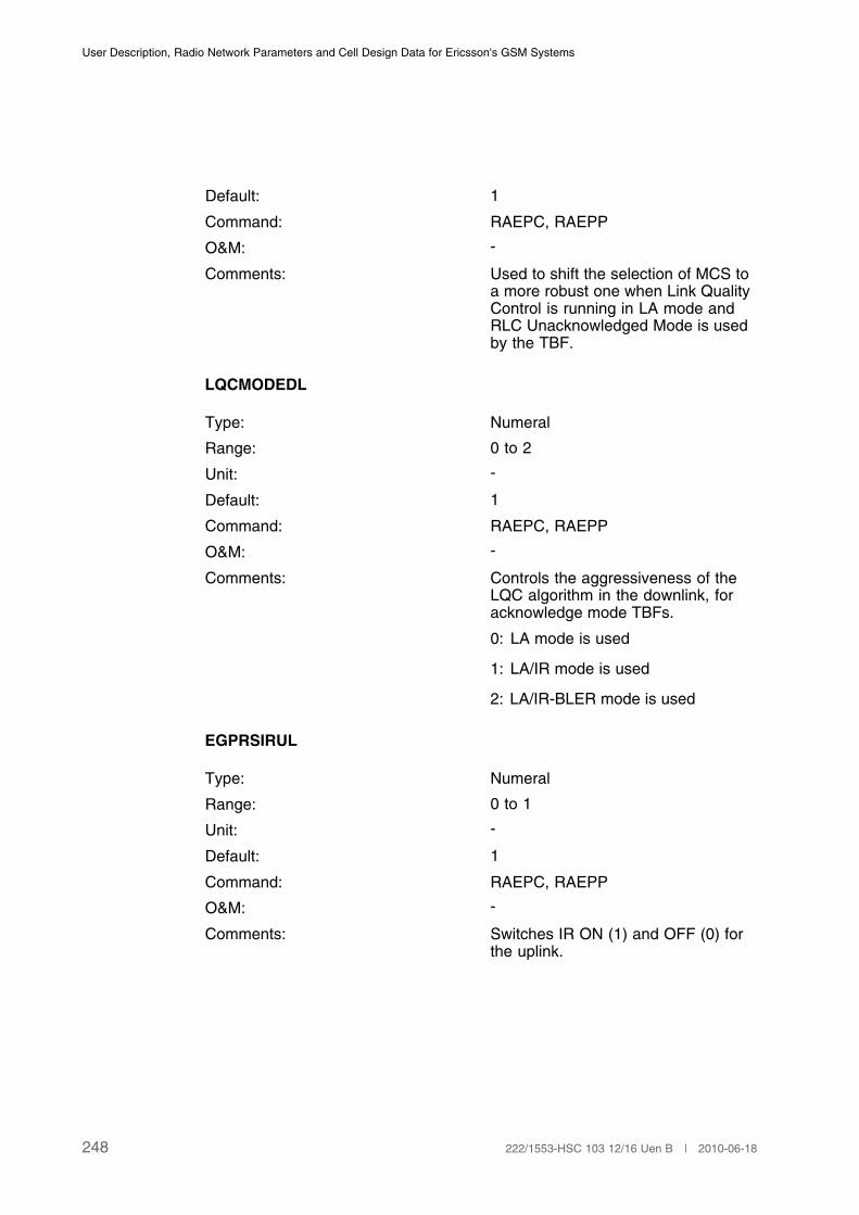
User Description, Radio Network Parameters and Cell Design Data for Ericsson's GSM Systems
Default: 1
Command: RAEPC, RAEPP
O&M: -
Comments: Used to shift the selection of MCS toa more robust one when Link QualityControl is running in LA mode andRLC Unacknowledged Mode is usedby the TBF.
LQCMODEDL
Type: Numeral
Range: 0 to 2
Unit: -
Default: 1
Command: RAEPC, RAEPP
O&M: -
Comments: Controls the aggressiveness of theLQC algorithm in the downlink, foracknowledge mode TBFs.
0: LA mode is used
1: LA/IR mode is used
2: LA/IR-BLER mode is used
EGPRSIRUL
Type: Numeral
Range: 0 to 1
Unit: -
Default: 1
Command: RAEPC, RAEPP
O&M: -
Comments: Switches IR ON (1) and OFF (0) forthe uplink.
248 222/1553-HSC 103 12/16 Uen B | 2010-06-18
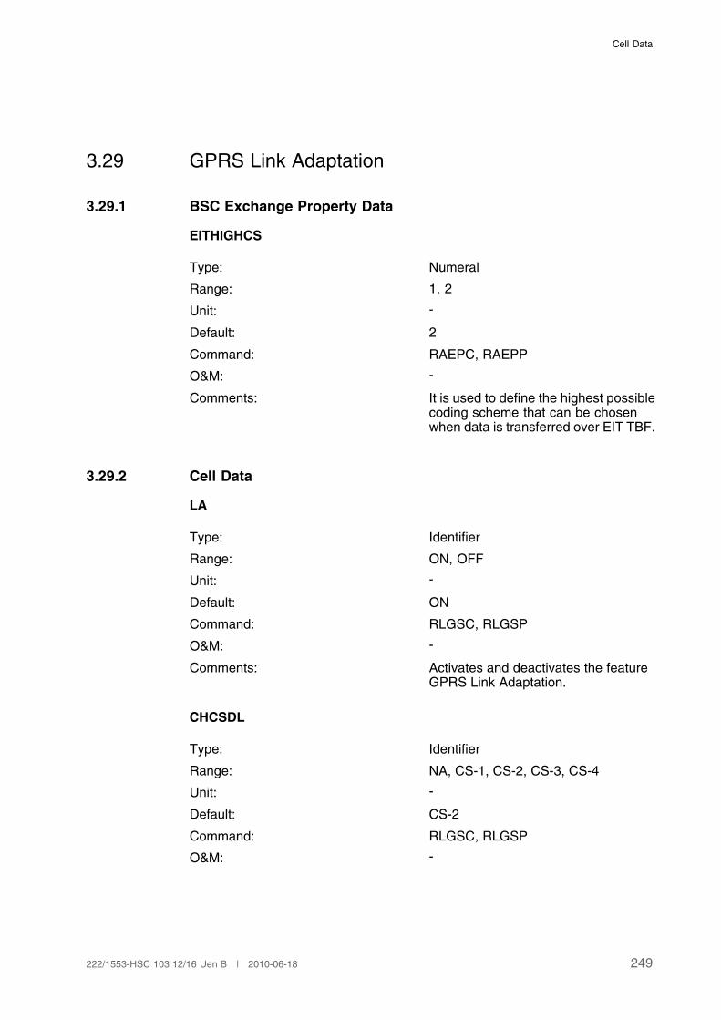
Cell Data
3.29 GPRS Link Adaptation
3.29.1 BSC Exchange Property Data
EITHIGHCS
Type: Numeral
Range: 1, 2
Unit: -
Default: 2
Command: RAEPC, RAEPP
O&M: -
Comments: It is used to define the highest possiblecoding scheme that can be chosenwhen data is transferred over EIT TBF.
3.29.2 Cell Data
LA
Type: Identifier
Range: ON, OFF
Unit: -
Default: ON
Command: RLGSC, RLGSP
O&M: -
Comments: Activates and deactivates the featureGPRS Link Adaptation.
CHCSDL
Type: Identifier
Range: NA, CS-1, CS-2, CS-3, CS-4
Unit: -
Default: CS-2
Command: RLGSC, RLGSP
O&M: -
249222/1553-HSC 103 12/16 Uen B | 2010-06-18

User Description, Radio Network Parameters and Cell Design Data for Ericsson's GSM Systems
Comments: Coding Scheme for the downlink.
Parameter CHCSDL defines the initialCS that will be used for the downlink. Ifset to NA, the parameter CHCODINGwill be used instead.
If GPRS Link Adaptation is not active,the selected initial CS will work asstatic.
If GPRS Link Adaptation is activeCHCSDL is used as the initial CS.(1)
(2)
(1) If CHCSDL is set to CS-3 or CS-4 and if GPRS TBF capability is (CS-1, CS-2), then CS-2 is
used.
(2) Parameter CHCODING is always used to define the uplink CS.
3.30 GPRS/EGPRS Quality of Service
3.30.1 BSC Exchange Property Data
PCUQOS
Type: Numeral
Range: 0, 1
Unit: -
Default: 0
Command: RAEPC, RAEPP
O&M: -
Comments: Activates (=1) and deactivates (=0) thefeature R99 GPRS/EGPRS Quality ofService.
PCUEIT
Type: Numeral
Range: 0, 1
Unit: -
Default: 0
Command: RAEPC, RAEPP
250 222/1553-HSC 103 12/16 Uen B | 2010-06-18
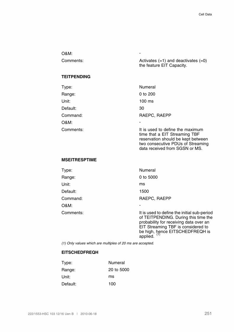
Cell Data
O&M: -
Comments: Activates (=1) and deactivates (=0)the feature EIT Capacity.
TEITPENDING
Type: Numeral
Range: 0 to 200
Unit: 100 ms
Default: 30
Command: RAEPC, RAEPP
O&M: -
Comments: It is used to define the maximumtime that a EIT Streaming TBFreservation should be kept betweentwo consecutive PDUs of Streamingdata received from SGSN or MS.
MSEITRESPTIME
Type: Numeral
Range: 0 to 5000
Unit: ms
Default: 1500
Command: RAEPC, RAEPP
O&M: -
Comments: It is used to define the initial sub-periodof TEITPENDING. During this time theprobability for receiving data over anEIT Streaming TBF is considered tobe high, hence EITSCHEDFREQH isapplied.
(1)
(1) Only values which are multiples of 20 ms are accepted.
EITSCHEDFREQH
Type: Numeral
Range: 20 to 5000
Unit: ms
Default: 100
251222/1553-HSC 103 12/16 Uen B | 2010-06-18
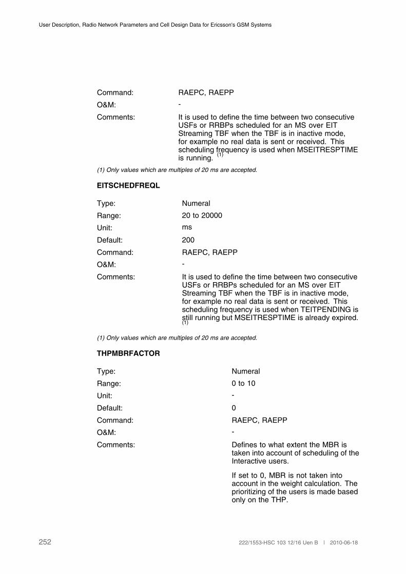
User Description, Radio Network Parameters and Cell Design Data for Ericsson's GSM Systems
Command: RAEPC, RAEPP
O&M: -
Comments: It is used to define the time between two consecutiveUSFs or RRBPs scheduled for an MS over EITStreaming TBF when the TBF is in inactive mode,for example no real data is sent or received. Thisscheduling frequency is used when MSEITRESPTIMEis running.
(1)
(1) Only values which are multiples of 20 ms are accepted.
EITSCHEDFREQL
Type: Numeral
Range: 20 to 20000
Unit: ms
Default: 200
Command: RAEPC, RAEPP
O&M: -
Comments: It is used to define the time between two consecutiveUSFs or RRBPs scheduled for an MS over EITStreaming TBF when the TBF is in inactive mode,for example no real data is sent or received. Thisscheduling frequency is used when TEITPENDING isstill running but MSEITRESPTIME is already expired.(1)
(1) Only values which are multiples of 20 ms are accepted.
THPMBRFACTOR
Type: Numeral
Range: 0 to 10
Unit: -
Default: 0
Command: RAEPC, RAEPP
O&M: -
Comments: Defines to what extent the MBR istaken into account of scheduling of theInteractive users.
If set to 0, MBR is not taken intoaccount in the weight calculation. Theprioritizing of the users is made basedonly on the THP.
252 222/1553-HSC 103 12/16 Uen B | 2010-06-18

Cell Data
QOSTHP1
Type: Numeral
Range: 1 to 10
Unit: -
Default: 3
Command: RAEPC, RAEPP
O&M: -
Comments: Determines the relative importanceof the THP-1 users compared to theTHP-3 users.
QOSTHP2
Type: Numeral
Range: 1 to 10
Unit: -
Default: 2
Command: RAEPC, RAEPP
O&M: -
Comments: Determines the relative importanceof the THP-2 users compared to theTHP-3 users.
QOSMAPPING
Type: Numeral
Range: 0, 1, 2
Unit: -
Default: 0
Command: RAEPC, RAEPP
O&M: -
Comments: Defines how the R97/98 Quality of Service is used:
0 R97/98 Quality of Service disabled
253222/1553-HSC 103 12/16 Uen B | 2010-06-18
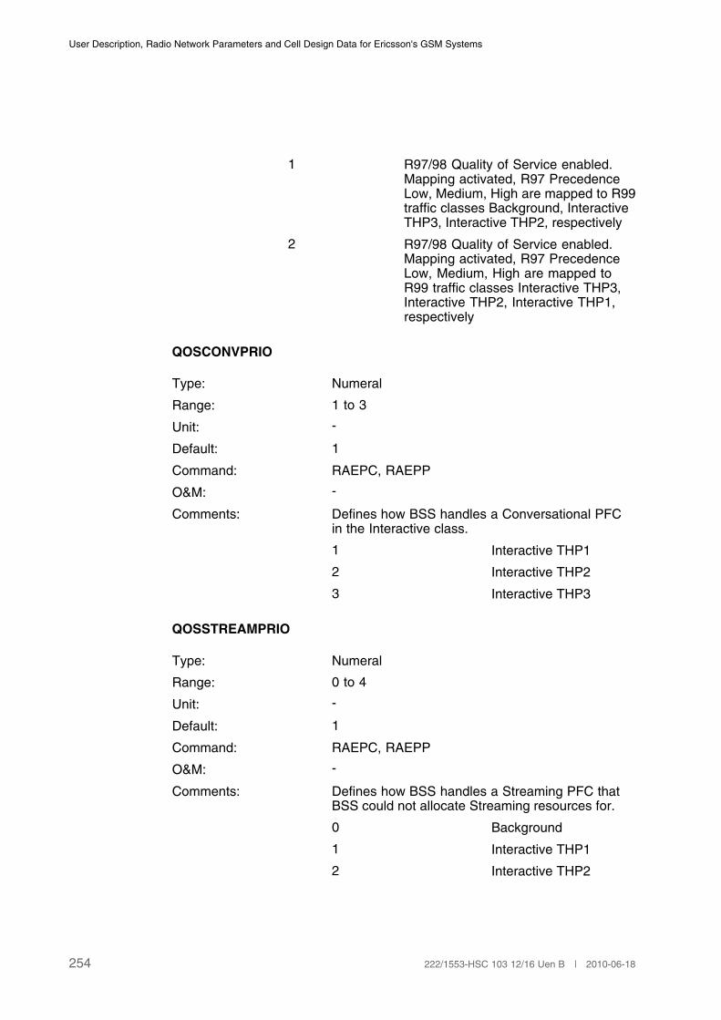
User Description, Radio Network Parameters and Cell Design Data for Ericsson's GSM Systems
1 R97/98 Quality of Service enabled.Mapping activated, R97 PrecedenceLow, Medium, High are mapped to R99traffic classes Background, InteractiveTHP3, Interactive THP2, respectively
2 R97/98 Quality of Service enabled.Mapping activated, R97 PrecedenceLow, Medium, High are mapped toR99 traffic classes Interactive THP3,Interactive THP2, Interactive THP1,respectively
QOSCONVPRIO
Type: Numeral
Range: 1 to 3
Unit: -
Default: 1
Command: RAEPC, RAEPP
O&M: -
Comments: Defines how BSS handles a Conversational PFCin the Interactive class.
1 Interactive THP1
2 Interactive THP2
3 Interactive THP3
QOSSTREAMPRIO
Type: Numeral
Range: 0 to 4
Unit: -
Default: 1
Command: RAEPC, RAEPP
O&M: -
Comments: Defines how BSS handles a Streaming PFC thatBSS could not allocate Streaming resources for.
0 Background
1 Interactive THP1
2 Interactive THP2
254 222/1553-HSC 103 12/16 Uen B | 2010-06-18
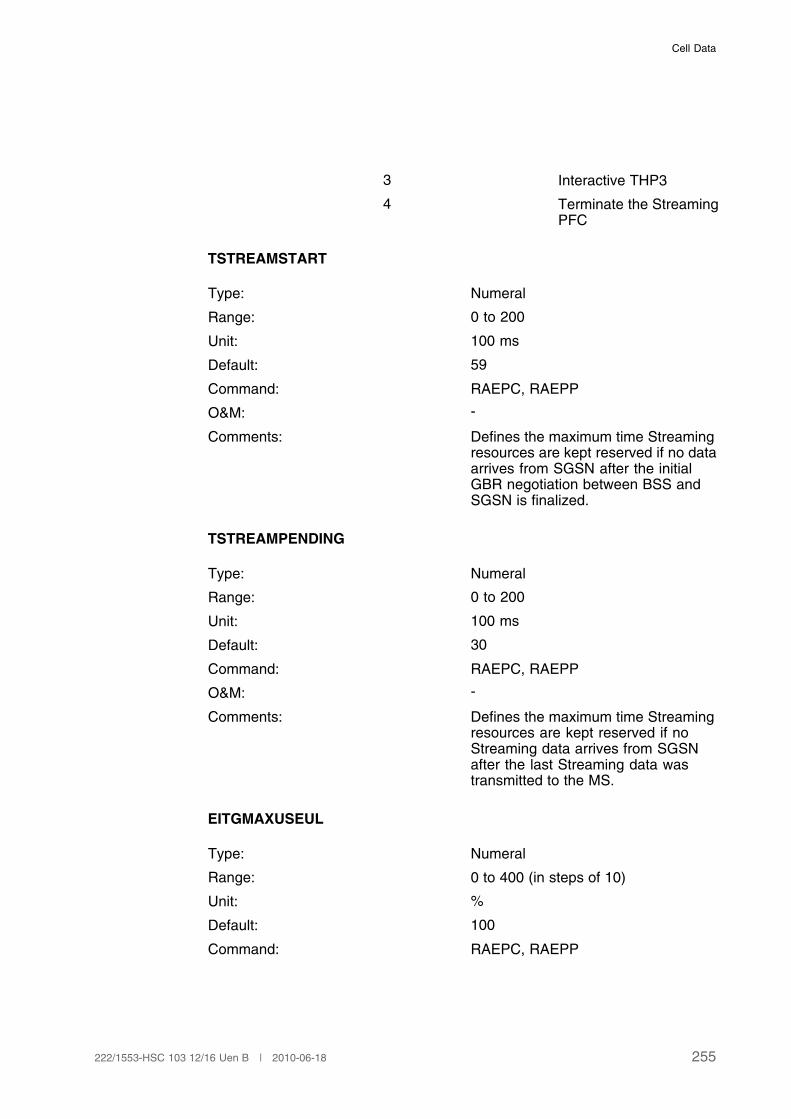
Cell Data
3 Interactive THP3
4 Terminate the StreamingPFC
TSTREAMSTART
Type: Numeral
Range: 0 to 200
Unit: 100 ms
Default: 59
Command: RAEPC, RAEPP
O&M: -
Comments: Defines the maximum time Streamingresources are kept reserved if no dataarrives from SGSN after the initialGBR negotiation between BSS andSGSN is finalized.
TSTREAMPENDING
Type: Numeral
Range: 0 to 200
Unit: 100 ms
Default: 30
Command: RAEPC, RAEPP
O&M: -
Comments: Defines the maximum time Streamingresources are kept reserved if noStreaming data arrives from SGSNafter the last Streaming data wastransmitted to the MS.
EITGMAXUSEUL
Type: Numeral
Range: 0 to 400 (in steps of 10)
Unit: %
Default: 100
Command: RAEPC, RAEPP
255222/1553-HSC 103 12/16 Uen B | 2010-06-18

User Description, Radio Network Parameters and Cell Design Data for Ericsson's GSM Systems
O&M: -
Comment: The parameter EITGMAXUSEULdefines the maximum usage for uplinkEIT (Ericsson Instant Talk) TBFs(Temporary Block Flow) for B- orG-TBF mode
EITEMAXUSEUL
Type: Numeral
Range: 0 to 400 (in steps of 10)
Unit: %
Default: 100
Command: RAEPC, RAEPP
O&M: -
Comment: The parameter EITEMAXUSEULdefines the maximum usage for uplinkEIT (Ericsson Instant Talk) TBFs(Temporary Block Flow) for E-TBFmode
EITGMAXUSEDL
Type: Numeral
Range: 0 to 200 (in steps of 10)
Unit: %
Default: 100
Command: RAEPC, RAEPP
O&M: -
Comment: The parameter EITGMAXUSEDLdefines the maximum usage fordownlink EIT (Ericsson Instant Talk)TBFs (Temporary Block Flow) for B- orG-TBF mode
EITEMAXUSEDL
Type: Numeral
Range: 0 to 200 (in steps of 10)
Unit: %
Default: 100
256 222/1553-HSC 103 12/16 Uen B | 2010-06-18
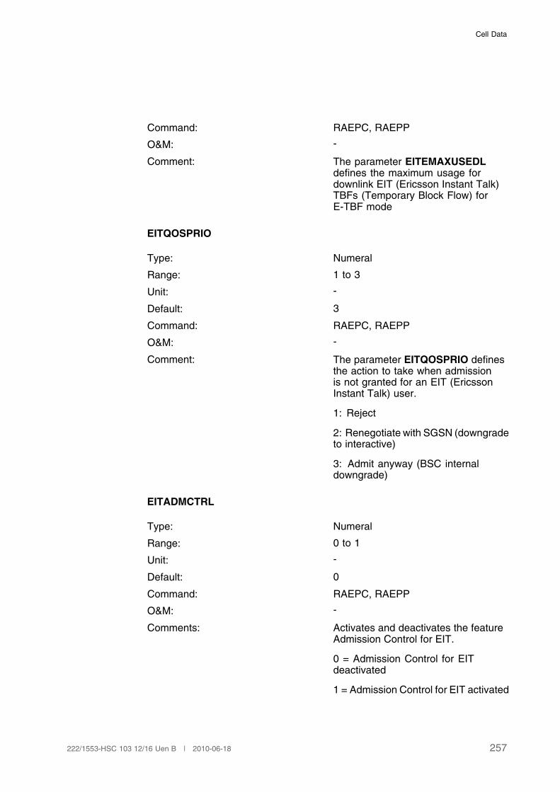
Cell Data
Command: RAEPC, RAEPP
O&M: -
Comment: The parameter EITEMAXUSEDLdefines the maximum usage fordownlink EIT (Ericsson Instant Talk)TBFs (Temporary Block Flow) forE-TBF mode
EITQOSPRIO
Type: Numeral
Range: 1 to 3
Unit: -
Default: 3
Command: RAEPC, RAEPP
O&M: -
Comment: The parameter EITQOSPRIO definesthe action to take when admissionis not granted for an EIT (EricssonInstant Talk) user.
1: Reject
2: Renegotiate with SGSN (downgradeto interactive)
3: Admit anyway (BSC internaldowngrade)
EITADMCTRL
Type: Numeral
Range: 0 to 1
Unit: -
Default: 0
Command: RAEPC, RAEPP
O&M: -
Comments: Activates and deactivates the featureAdmission Control for EIT.
0 = Admission Control for EITdeactivated
1 = Admission Control for EIT activated
257222/1553-HSC 103 12/16 Uen B | 2010-06-18

User Description, Radio Network Parameters and Cell Design Data for Ericsson's GSM Systems
3.30.2 Cell Data
BPDCHBR
Type: Numeral
Range: 1 to 12
Unit: kbps
Default: 12
Command: RLGQC, RLGQP
O&M: -
Comments: Defines the minimum estimated bitrateper B-PDCH in cell used for transfer ofthe traffic class Streaming.
GPDCHBR
Type: Numeral
Range: 1 to 20
Unit: kbps
Default: 14
Command: RLGQC, RLGQP
O&M: -
Comments: Defines the minimum estimated bitrateper G-PDCH in cell used for transfer ofthe traffic class Streaming.
EPDCHBR
Type: Numeral
Range: 1 to 60
Unit: kbps
Default: 20
Command: RLGQC, RLGQP
O&M: -
Comments: Defines the minimum estimated bitrateper E-PDCH in cell used for transfer ofthe traffic class Streaming.
STREAMSUP
258 222/1553-HSC 103 12/16 Uen B | 2010-06-18
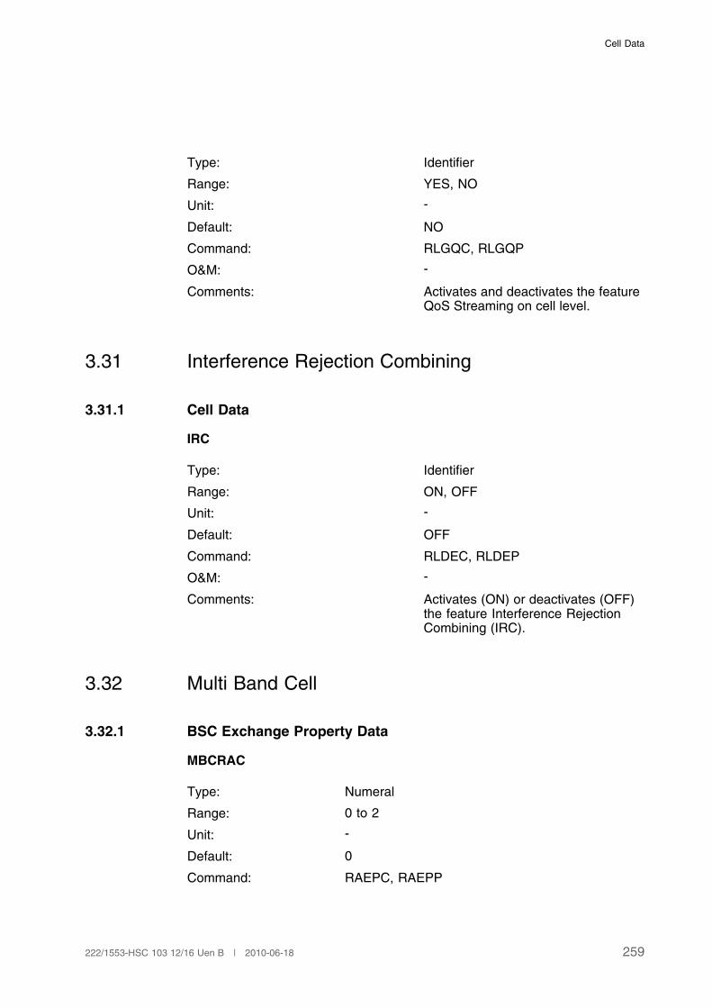
Cell Data
Type: Identifier
Range: YES, NO
Unit: -
Default: NO
Command: RLGQC, RLGQP
O&M: -
Comments: Activates and deactivates the featureQoS Streaming on cell level.
3.31 Interference Rejection Combining
3.31.1 Cell Data
IRC
Type: Identifier
Range: ON, OFF
Unit: -
Default: OFF
Command: RLDEC, RLDEP
O&M: -
Comments: Activates (ON) or deactivates (OFF)the feature Interference RejectionCombining (IRC).
3.32 Multi Band Cell
3.32.1 BSC Exchange Property Data
MBCRAC
Type: Numeral
Range: 0 to 2
Unit: -
Default: 0
Command: RAEPC, RAEPP
259222/1553-HSC 103 12/16 Uen B | 2010-06-18
User Description, Radio Network Parameters and Cell Design Data for Ericsson's GSM Systems
O&M: -
Comments: Defines the way that GPRS/EGPRS MS frequencyband capabilities are handled:
0 MS frequency capabilityis considered whenallocating and revisingchannels for TBFtransfers. If the MSfrequency capabilitiesare not available, onlythe BCCH frequencyband is available.
1 All GPRS/EGPRS MSsare assumed to becapable of all frequencybands. MS frequencycapability is consideredwhen allocating andreserving cahnnels forTBF transfers. If the MSfrequency capabilitiesare not available, allfrequency bands areavailable
2 All GPRS/EGPRS MSsare assumed to becapable of both GSM 900frequency sub-bands.MS frequency capabilityis considered whenallocating and reservingchannels for TBFtransfers. If the MSfrequency capabilitiesare not available, bothGSM 900 frequencysub-bands are available.(1)
(1) This parameter value is only applicable if the BCCH is configured in the P-GSM band.
FBCHALLOC
Type: Numeral
Range: 0 to 2
Unit: -
Default: 2
260 222/1553-HSC 103 12/16 Uen B | 2010-06-18
Cell Data
Command: RAEPC, RAEPP
O&M: -
Comments: It makes possible to determine if channels on BCCHfrequency band shall be selected first, last or if thereis no preference at channel allocation:
0 No selection preference.
1 Select channels inBCCH frequency,band/subband first
2 Select channels inBCCH frequency,band/subband last.
(1)
(2)
(1) FBCHALLOC does not influence the channel allocation for GPRS/EGPRS.
(2) The parameter is not applicable if there is only one frequency band per subcell.
3.32.2 Cell Data
FBOFFS
Type: Numeral
Range: -40 to 40
Unit: dB
Default: 0
Command: RLLOC, RLLOP
O&M: -
Comments: Defines the difference in pathlossbetween the BCCH frequency bandgroup and the non-BCCH frequencyband group. Positive values are usedwhen the BCCH frequency band groupis assumed to offer "better" coveragethan the non-BCCH frequency bandgroup.
3.32.3 Channel Group Data
BAND
261222/1553-HSC 103 12/16 Uen B | 2010-06-18
User Description, Radio Network Parameters and Cell Design Data for Ericsson's GSM Systems
Type: Identifier
Range: GSM800, GSM900, GSM1800, GSM1900
Unit: -
Default: -
Command: RLDGI , RLDGP
O&M: -
Comments: Frequency band used in the channel group.
GSM1800 and GSM1900 cannot be defined in thesame cell.
In multi band cells, CSYSTYPE defines thefrequency band used for the BCCH.
It is not possible to change BAND in single bandcells. In these cells CSYSTYPE defines thefrequency band used in the whole cell.
3.33 GPRS/EGPRS Connection Control and Transfer
3.33.1 BSC Exchange Property Data
DLDELAY
Type: Numeral
Range: 0 to 5000
Unit: ms
Default: 2200
Command: RAEPC, RAEPP
O&M: -
Comments: Defines the time to keep a downlinkTBF alive after the last downlink RLCdata block with real data is sent.
ULDELAY
Type: Numeral
Range: 0 to 5000
Unit: ms
Default: 1000
262 222/1553-HSC 103 12/16 Uen B | 2010-06-18
Cell Data
Command: RAEPC, RAEPP
O&M: -
Comments: Defines the time to keep an uplinkTBF in Extended UL TBF mode aliveafter the last uplink RLC data block isreceived.
ESDELAY
Type: Numeral
Range: 0 to 2000
Unit: ms
Default: 750
Command: RAEPC, RAEPP
O&M: -
Comments: Defines the time to keep an earlyset-up downlink TBF alive after it hasbeen set-up.
TFILIMIT
Type: Numeral
Range: 0 to 31
Unit: -
Default: 4
Command: RAEPC, RAEPP
O&M: -
Comments: Defines the minimum number of TFIsthat have to be available for the TBFkeep alive mechanism. If less TFIs areavailable TBFs will be released unlessthey carry real data.
USFLIMIT
Type: Numeral
Range: 0 to 7
Unit: -
Default: 2
Command: RAEPC, RAEPP
263222/1553-HSC 103 12/16 Uen B | 2010-06-18
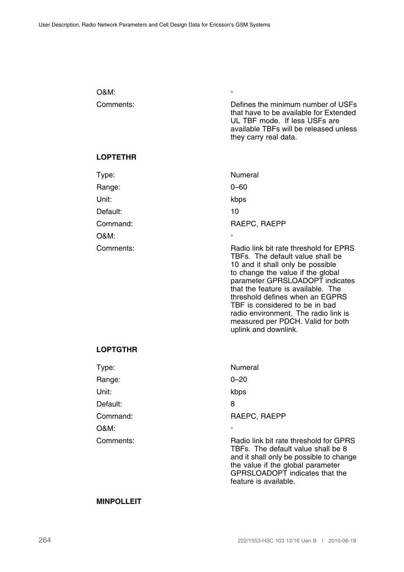
User Description, Radio Network Parameters and Cell Design Data for Ericsson's GSM Systems
O&M: -
Comments: Defines the minimum number of USFsthat have to be available for ExtendedUL TBF mode. If less USFs areavailable TBFs will be released unlessthey carry real data.
LOPTETHR
Type: Numeral
Range: 0–60
Unit: kbps
Default: 10
Command: RAEPC, RAEPP
O&M: -
Comments: Radio link bit rate threshold for EPRSTBFs. The default value shall be10 and it shall only be possibleto change the value if the globalparameter GPRSLOADOPT indicatesthat the feature is available. Thethreshold defines when an EGPRSTBF is considered to be in badradio environment. The radio link ismeasured per PDCH. Valid for bothuplink and downlink.
LOPTGTHR
Type: Numeral
Range: 0–20
Unit: kbps
Default: 8
Command: RAEPC, RAEPP
O&M: -
Comments: Radio link bit rate threshold for GPRSTBFs. The default value shall be 8and it shall only be possible to changethe value if the global parameterGPRSLOADOPT indicates that thefeature is available.
MINPOLLEIT
264 222/1553-HSC 103 12/16 Uen B | 2010-06-18
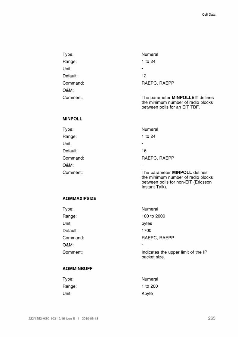
Cell Data
Type: Numeral
Range: 1 to 24
Unit: -
Default: 12
Command: RAEPC, RAEPP
O&M: -
Comment: The parameter MINPOLLEIT definesthe minimum number of radio blocksbetween polls for an EIT TBF.
MINPOLL
Type: Numeral
Range: 1 to 24
Unit: -
Default: 16
Command: RAEPC, RAEPP
O&M: -
Comment: The parameter MINPOLL definesthe minimum number of radio blocksbetween polls for non-EIT (EricssonInstant Talk).
AQMMAXIPSIZE
Type: Numeral
Range: 100 to 2000
Unit: bytes
Default: 1700
Command: RAEPC, RAEPP
O&M: -
Comment: Indicates the upper limit of the IPpacket size.
AQMMINBUFF
Type: Numeral
Range: 1 to 200
Unit: Kbyte
265222/1553-HSC 103 12/16 Uen B | 2010-06-18
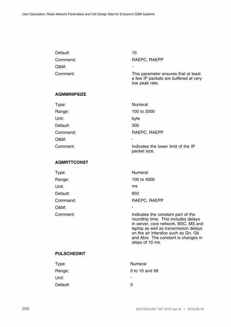
User Description, Radio Network Parameters and Cell Design Data for Ericsson's GSM Systems
Default: 10
Command: RAEPC, RAEPP
O&M: -
Comment: This parameter ensures that at leasta few IP packets are buffered at verylow peak rate.
AQMMINIPSIZE
Type: Numeral
Range: 100 to 2000
Unit: byte
Default: 300
Command: RAEPC, RAEPP
O&M: -
Comment: Indicates the lower limit of the IPpacket size.
AQMRTTCONST
Type: Numeral
Range: 100 to 4000
Unit: ms
Default: 850
Command: RAEPC, RAEPP
O&M: -
Comment: Indicates the constant part of theroundtrip time. This includes delaysin server, core network, BSC, MS andlaptop as well as transmission delayson the air interafce such as Gn, Gband Abis. The constant is changes insteps of 10 ms.
PULSCHEDINT
Type: Numeral
Range: 0 to 10 and 99
Unit: -
Default: 0
266 222/1553-HSC 103 12/16 Uen B | 2010-06-18
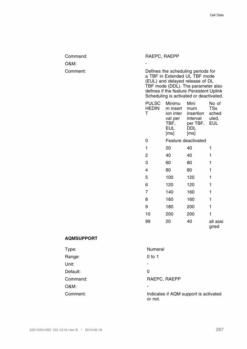
Cell Data
Command: RAEPC, RAEPP
O&M: -
Comment: Defines the scheduling periods fora TBF in Extended UL TBF mode(EUL) and delayed release of DLTBF mode (DDL). The parameter alsodefines if the feature Persistent UplinkScheduling is activated or deactivated.
PULSCHEDINT
Minimum insertion interval perTBF,EUL[ms]
Minimuminsertionintervalper TBF,DDL[ms]
No ofTSsscheduled,EUL
0 Feature deactivated
1 20 40 1
2 40 40 1
3 60 80 1
4 80 80 1
5 100 120 1
6 120 120 1
7 140 160 1
8 160 160 1
9 180 200 1
10 200 200 1
99 20 40 all assigned
AQMSUPPORT
Type: Numeral
Range: 0 to 1
Unit: -
Default: 0
Command: RAEPC, RAEPP
O&M: -
Comment: Indicates if AQM support is activatedor not.
267222/1553-HSC 103 12/16 Uen B | 2010-06-18
User Description, Radio Network Parameters and Cell Design Data for Ericsson's GSM Systems
0 = AQM not activated
1 = AQM activated
LOADOPT
Type: Numeral
Range: 0 to 2
Unit: -
Default: 0
Command RAEPC, RAEPP
O&M -
Comment Support for GPRS Load Optimization.
0: Feature OFF
1: Feature ON for Background
2: Feature ON for Background andInteractive
3.33.2 Cell Data
RTTI
Type: Identifier
Range: ACTIVE, INACTIVE
Unit: -
Default: INACTIVE
Command: RLGSC, RLGSP
O&M: -
Comment: This parameter defines whether Reduced TTI isactivated in the cell.
ACTIVE Reduced TTI is activated in the cell
INACTIVE Reduced TTI is not activated in thecell
IAN
Type: Identifier
Range: ACTIVE, INACTIVE
Unit: -
268 222/1553-HSC 103 12/16 Uen B | 2010-06-18
Cell Data
Default: INACTIVE
Command: RLGSC, RLGSP
O&M: -
Comment: The parameter defines whether Improved Ack/Nackis activated in the cell or not
ACTIVE Improved Ack/Nack isactivated in the cell.
INACTIVE Improved Ack/Nack isnot activated in the cell.
3.34 Antenna Hopping
3.34.1 Hardware Characteristic Data
AHOP
Type: Identifier
Range: ON, ONXC0, OFF
Unit: -
Default: OFF
Command: RXMOC, RXMOP., RXMSC, RXBFP
O&M: It is only possible to read the antenna hoppingadministrative state with RXMOP. With RXBFP both theadministrative and the operative feature states withinthe TG are shown.
Comments: Antenna Hopping. This parameter sets the antennahopping administrative state for a TG
ON Antenna Hopping enabled
ONXC0 Antenna Hopping enabledexcluding carrier zero frequency
OFF Antenna Hopping disabled
3.35 Synchronized Radio Networks
3.35.1 BSC Exchange Property Data
BSCFSOFFSETMSW
269222/1553-HSC 103 12/16 Uen B | 2010-06-18

User Description, Radio Network Parameters and Cell Design Data for Ericsson's GSM Systems
Type: Numeral
Range: 0 to 65535
Unit: symbol
Default: 0
Command: RAEPC, RAEPP
O&M: -
Comments: BSC Frame Start Offset, mostsignificant word.
The BSC Frame Start Offset adjuststhe frame start offset of transmittedTDMA frames relative the nominalposition for all cells realized by theBSC.
BSCFSOFFSETLSW
Type: Numeral
Range: 0 to 65535
Unit: symbol
Default: 0
Command: RAEPC, RAEPP
O&M: -
Comments: BSC Frame Start Offset, leastsignificant word.
The BSC Frame Start Offset adjuststhe frame start offset of transmittedTDMA frames relative the nominalposition for all cells realized by theBSC.
3.35.2 Channel Group Data
Related channel group parameters are HOP, HSN, MAIO (for more informationsee Page 155) and TSC (for more information see Page 36).
3.35.3 Cell/Subcell Data
Related cell/subcell parameters are FNOFFSET (see Page 23).
270 222/1553-HSC 103 12/16 Uen B | 2010-06-18
Cell Data
3.35.4 Hardware Characteristic Data
Related hardware characteristic data parameters are TFMODE and SYNCSRC.For more details, see Page 332.
FSOFFSET
Type: Numeral
Range: 0 to 65534, OFF (65535)
Unit: 1/4 symbol
Default: OFF
Command: RXMOI, RXMOC, RXMSC, RXMOP
O&M: -
Comments: Frame Start Offset states if the transmitted TDMAframes should be synchronized to the nominalposition with a defined offset or not synchronizedto the nominal position.
OFF No frame start offsetrelative the nominalposition of transmittedTDMA frames
Other A defined frame startoffset of the transmittedTDMA frames relativeto the BSC Frame StartOffset adjusted nominalposition
3.36 Channel Allocation Optimization
3.36.1 Cell Data
DMQB
Type: Identifier
Range: ON and OFF
Unit: -
Default: -
Command: RLDMC, RLDMP
271222/1553-HSC 103 12/16 Uen B | 2010-06-18
User Description, Radio Network Parameters and Cell Design Data for Ericsson's GSM Systems
O&M: -
Comments: Defines if the Dynamic Half Rate (HR)to Full Rate (FR) Mode Adaptation dueto bad quality is active (ON) or inactive(OFF).
DMQBAMR
Type: Numeral
Range: 0 to 100
Unit: dtqu
Default: -
Command: RLDMC, RLDMP
O&M: -
Comments: Channel quality threshold for AMRcapable mobiles using a HR trafficchannel. It determines when a changefrom HR to FR is initiated for DualRate mobiles capable of AMR if theDMQB parameter is set to ON. It canbe set per priority level if using SpeechQuality Priority.
DMQBNAMR
Type: Numeral
Range: 0 to 100
Unit: -
Default: -
Command: RLDMC, RLDMP
O&M: -
Comments: Channel quality threshold for mobilesnot capable of AMR using a HR trafficchannel. It determines when a changefrom HR to FR is initiated for DualRate mobiles not capable of AMR ifthe DMQB parameter is set to ON. Itcan be set per priority level if usingSpeech Quality Priority.
DMQG
272 222/1553-HSC 103 12/16 Uen B | 2010-06-18
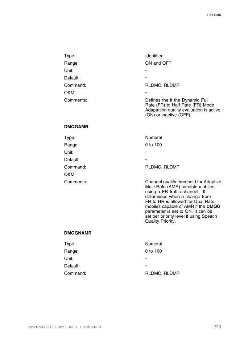
Cell Data
Type: Identifier
Range: ON and OFF
Unit: -
Default: -
Command: RLDMC, RLDMP
O&M: -
Comments: Defines the if the Dynamic FullRate (FR) to Half Rate (FR) ModeAdaptation quality evaluation is active(ON) or inactive (OFF).
DMQGAMR
Type: Numeral
Range: 0 to 100
Unit: -
Default: -
Command: RLDMC, RLDMP
O&M: -
Comments: Channel quality threshold for AdaptiveMulti Rate (AMR) capable mobilesusing a FR traffic channel. Itdetermines when a change fromFR to HR is allowed for Dual Ratemobiles capable of AMR if the DMQGparameter is set to ON. It can beset per priority level if using SpeechQuality Priority.
DMQGNAMR
Type: Numeral
Range: 0 to 100
Unit: -
Default: -
Command: RLDMC, RLDMP
273222/1553-HSC 103 12/16 Uen B | 2010-06-18
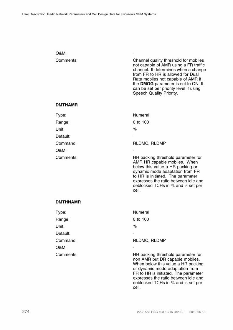
User Description, Radio Network Parameters and Cell Design Data for Ericsson's GSM Systems
O&M: -
Comments: Channel quality threshold for mobilesnot capable of AMR using a FR trafficchannel. It determines when a changefrom FR to HR is allowed for DualRate mobiles not capable of AMR ifthe DMQG parameter is set to ON. Itcan be set per priority level if usingSpeech Quality Priority.
DMTHAMR
Type: Numeral
Range: 0 to 100
Unit: %
Default: -
Command: RLDMC, RLDMP
O&M: -
Comments: HR packing threshold parameter forAMR HR capable mobiles. Whenbelow this value a HR packing ordynamic mode adaptation from FRto HR is initiated. The parameterexpresses the ratio between idle anddeblocked TCHs in % and is set percell.
DMTHNAMR
Type: Numeral
Range: 0 to 100
Unit: %
Default: -
Command: RLDMC, RLDMP
O&M: -
Comments: HR packing threshold parameter fornon AMR but DR capable mobiles.When below this value a HR packingor dynamic mode adaptation fromFR to HR is initiated. The parameterexpresses the ratio between idle anddeblocked TCHs in % and is set percell.
274 222/1553-HSC 103 12/16 Uen B | 2010-06-18
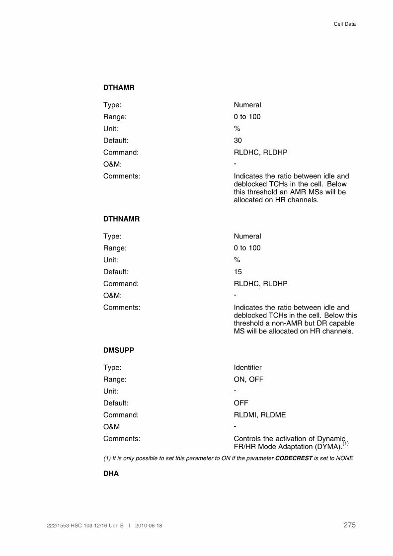
Cell Data
DTHAMR
Type: Numeral
Range: 0 to 100
Unit: %
Default: 30
Command: RLDHC, RLDHP
O&M: -
Comments: Indicates the ratio between idle anddeblocked TCHs in the cell. Belowthis threshold an AMR MSs will beallocated on HR channels.
DTHNAMR
Type: Numeral
Range: 0 to 100
Unit: %
Default: 15
Command: RLDHC, RLDHP
O&M: -
Comments: Indicates the ratio between idle anddeblocked TCHs in the cell. Below thisthreshold a non-AMR but DR capableMS will be allocated on HR channels.
DMSUPP
Type: Identifier
Range: ON, OFF
Unit: -
Default: OFF
Command: RLDMI, RLDME
O&M -
Comments: Controls the activation of DynamicFR/HR Mode Adaptation (DYMA).
(1)
(1) It is only possible to set this parameter to ON if the parameter CODECREST is set to NONE
DHA
275222/1553-HSC 103 12/16 Uen B | 2010-06-18
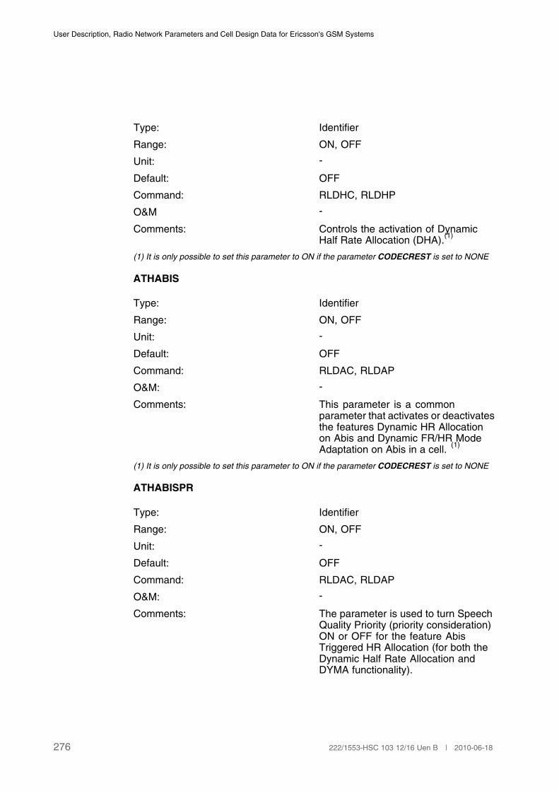
User Description, Radio Network Parameters and Cell Design Data for Ericsson's GSM Systems
Type: Identifier
Range: ON, OFF
Unit: -
Default: OFF
Command: RLDHC, RLDHP
O&M -
Comments: Controls the activation of DynamicHalf Rate Allocation (DHA).
(1)
(1) It is only possible to set this parameter to ON if the parameter CODECREST is set to NONE
ATHABIS
Type: Identifier
Range: ON, OFF
Unit: -
Default: OFF
Command: RLDAC, RLDAP
O&M: -
Comments: This parameter is a commonparameter that activates or deactivatesthe features Dynamic HR Allocationon Abis and Dynamic FR/HR ModeAdaptation on Abis in a cell.
(1)
(1) It is only possible to set this parameter to ON if the parameter CODECREST is set to NONE
ATHABISPR
Type: Identifier
Range: ON, OFF
Unit: -
Default: OFF
Command: RLDAC, RLDAP
O&M: -
Comments: The parameter is used to turn SpeechQuality Priority (priority consideration)ON or OFF for the feature AbisTriggered HR Allocation (for both theDynamic Half Rate Allocation andDYMA functionality).
276 222/1553-HSC 103 12/16 Uen B | 2010-06-18
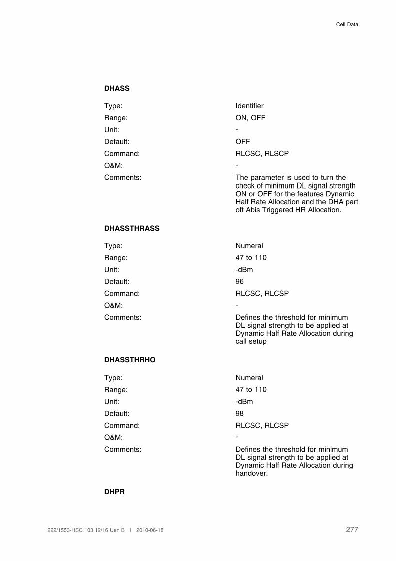
Cell Data
DHASS
Type: Identifier
Range: ON, OFF
Unit: -
Default: OFF
Command: RLCSC, RLSCP
O&M: -
Comments: The parameter is used to turn thecheck of minimum DL signal strengthON or OFF for the features DynamicHalf Rate Allocation and the DHA partoft Abis Triggered HR Allocation.
DHASSTHRASS
Type: Numeral
Range: 47 to 110
Unit: -dBm
Default: 96
Command: RLCSC, RLCSP
O&M: -
Comments: Defines the threshold for minimumDL signal strength to be applied atDynamic Half Rate Allocation duringcall setup
DHASSTHRHO
Type: Numeral
Range: 47 to 110
Unit: -dBm
Default: 98
Command: RLCSC, RLCSP
O&M: -
Comments: Defines the threshold for minimumDL signal strength to be applied atDynamic Half Rate Allocation duringhandover.
DHPR
277222/1553-HSC 103 12/16 Uen B | 2010-06-18

User Description, Radio Network Parameters and Cell Design Data for Ericsson's GSM Systems
Type: Identifier
Range: ON, OFF
Unit: -
Default: OFF
Command: RLDHC, RLDHP
O&M: -
Comments: The parameter is used to turn SpeechQuality Priority (priority consideration)ON or OFF for the feature DynamicHalf Rate Allocation.
DHPRL
Type: Numeral
Range: 1 to 15
Unit: -
Default: -
Command: RLDHC, RLDHP
O&M: -
Comments: Defines the priority level (1-14) forwhich the threshold parameters givenin the same command shall apply (oneor both of DTHAMR and DTHNAMR).The value 15 is used for calls with nopriority level assigned.
DMPR
Type: Identifier
Range: ON, OFF
Unit: -
Default: OFF
Command: RLDMC, RLDMI, RLDMP
O&M: -
Comments: The parameter is used to turn SpeechQuality Priority (priority consideration)ON or OFF for the feature DynamicFR/HR Adaptation.
DMPRL
278 222/1553-HSC 103 12/16 Uen B | 2010-06-18

Cell Data
Type: Numeral
Range: 1 to 15
Unit: -
Default: -
Command: RLDMC, RLDMP
O&M: -
Comments: Defines the priority level (1-14) forwhich the quality thresholds given inthe same command shall apply (one orseveral of DMQBAMR, DMQBNAMR,DMQGAMR and DMQGNAMR). Thevalue 15 is used for calls with nopriority level assigned.
DMTFAMR
Type: Numeral
Range: 0 to 100
Unit: %
Default: 100
Command: RLDMC, RLDMP
O&M: -
Comments: Threshold parameter for moving callsrun on AMR HR to FR. When the idlelevel is above this value a HR to FRadaptation is initiated. The parameterexpresses the ratio between idle anddeblocked TCHs in % and is set percell.
DMTFNAMR
Type: Numeral
Range: 0 to 100
Unit: %
Default: 100
Command: RLDMC, RLDMP
279222/1553-HSC 103 12/16 Uen B | 2010-06-18

User Description, Radio Network Parameters and Cell Design Data for Ericsson's GSM Systems
O&M: -
Comments: Threshold parameter for moving callsrun on non AMR HR to FR. Whenthe idle level is above this valuea HR to FR adaptation is initiated.The parameter expresses the ratiobetween idle and deblocked TCHs in% and is set per cell.
DTHAMRWB
Type: Numeral
Range: 0-100
Unit: %
Default: 10
Command: RLADC, RLADP
O&M: -
Comment: Dynamic HR Allocation threshold for AMR Wideband(AMR-WB) capable MSs This parameter changesa percentage value of number of unblocked FRTCHs in the AMR-WB capable cell when DynamicHR Allocation is activated and the MS supportsAMR-WB. If the number of idle FR TCHs in thecell is above or equal the value of this parameter,FR TCHs has precedence over HR TCHs. If thenumber of idle FR TCHs in the cell is below thevalue of this parameter, HR TCHs has precedenceover FR TCHs.
3.36.2 TG Data
DHRAABISTHR
Type: Numeral
Range: 0 to 100
Unit: %
Default: 0
Command: RXMOI, RXMOC, RXMSC, RXATC,RXATP
280 222/1553-HSC 103 12/16 Uen B | 2010-06-18

Cell Data
O&M: -
Comment: This parameter defines a thresholdvalue for the 16 kbps part of the Abispool for starting and stopping allocationof AMR HR and HR channels. Theparameter is set per TG.
DFRMAABISTHR
Type: Numeral
Range: 0 to 100
Unit: %
Default: 0
Command: RXMOI, RXMOC, RXMSC, RXATC,RXATP
O&M: -
Comment: This parameter defines a thresholdvalue for the 16 kbps part of the Abispath pool for starting and stoppingpacking of AMR HR and HR channelsand for starting and stopping move ofFR to HR channels, including AMR.The parameter is set per TG.
AHPRL
Type: Numeral
Range: 1 to 15
Unit: -
Default: -
Command: RXATC, RXATP
O&M: -
Comments: Defines the priority level (1-14) forwhich the threshold parametersgiven in the same commandshall apply (one or several ofDHRAABISTHR, SDHRAABISTHR,DAMRREDABISTHR andSDAMRREDABISTHR). The value 15is used for calls with no priority levelassigned.
DHRMAABISTHR
281222/1553-HSC 103 12/16 Uen B | 2010-06-18
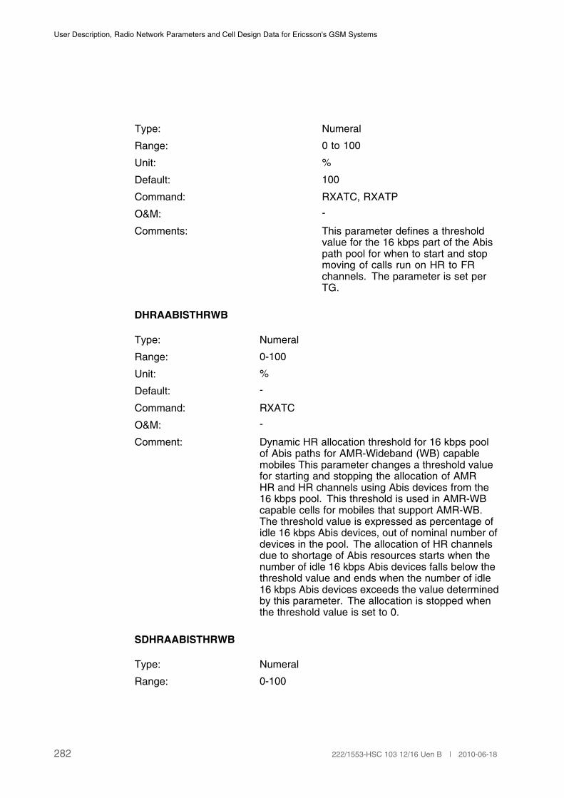
User Description, Radio Network Parameters and Cell Design Data for Ericsson's GSM Systems
Type: Numeral
Range: 0 to 100
Unit: %
Default: 100
Command: RXATC, RXATP
O&M: -
Comments: This parameter defines a thresholdvalue for the 16 kbps part of the Abispath pool for when to start and stopmoving of calls run on HR to FRchannels. The parameter is set perTG.
DHRAABISTHRWB
Type: Numeral
Range: 0-100
Unit: %
Default: -
Command: RXATC
O&M: -
Comment: Dynamic HR allocation threshold for 16 kbps poolof Abis paths for AMR-Wideband (WB) capablemobiles This parameter changes a threshold valuefor starting and stopping the allocation of AMRHR and HR channels using Abis devices from the16 kbps pool. This threshold is used in AMR-WBcapable cells for mobiles that support AMR-WB.The threshold value is expressed as percentage ofidle 16 kbps Abis devices, out of nominal number ofdevices in the pool. The allocation of HR channelsdue to shortage of Abis resources starts when thenumber of idle 16 kbps Abis devices falls below thethreshold value and ends when the number of idle16 kbps Abis devices exceeds the value determinedby this parameter. The allocation is stopped whenthe threshold value is set to 0.
SDHRAABISTHRWB
Type: Numeral
Range: 0-100
282 222/1553-HSC 103 12/16 Uen B | 2010-06-18

Cell Data
Unit: %
Default: -
Command: RXATC
O&M: -
Comment: Dynamic HR allocation threshold for SC forAMR-WB capable mobiles This parameter changesa threshold value for starting and stopping theallocation of AMR HR and HR channels, in case ofhigh transmission load on an SC. This thresholdis used in AMR-WB capable cells for mobiles thatsupport AMR-WB. The threshold value is expressedas percentage counted as the number of HDLCpackets transmitted through the SC divided by themaximum number of HDLC packets that can betransmitted within the timeframe. The allocation ofHR channels due to shortage of SC resources startswhen the number of transmitted HDLC packetsexceeds the threshold value and ends when thenumber of transmitted HDLC packets falls below thevalue determined by this parameter. The allocationis stopped when the threshold value is set to 100.
3.37 Dual Transfer Mode (DTM)
3.37.1 Cell Data
MAXLAPDM
Type: Numeral
Range: 5 to 12
Unit: LAPDm frames
Default: 5
Command: RLDUC, RLDUP
O&M: -
Comments: It is used to control the maximumlength of the GPRS signallingmessages sent on the FACCH.
ALLOCPREF
Type: String
Range: QUAL, PACK
283222/1553-HSC 103 12/16 Uen B | 2010-06-18
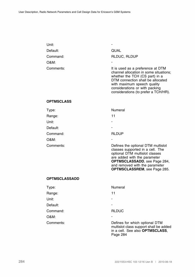
User Description, Radio Network Parameters and Cell Design Data for Ericsson's GSM Systems
Unit: -
Default: QUAL
Command: RLDUC, RLDUP
O&M: -
Comments: It is used as a preference at DTMchannel allocation in some situations;whether the TCH (CS part) in aDTM connection shall be allocatedwith maximum speech qualityconsiderations or with packingconsiderations (to prefer a TCH/HR).
OPTMSCLASS
Type: Numeral
Range: 11
Unit: -
Default: -
Command: RLDUP
O&M: -
Comments: Defines the optional DTM multislotclasses supported in a cell. Theoptional DTM multislot classesare added with the parameterOPTMSCLASSADD, see Page 284,and removed with the parameterOPTMSCLASSREM, see Page 285.
OPTMSCLASSADD
Type: Numeral
Range: 11
Unit: -
Default: -
Command: RLDUC
O&M: -
Comments: Defines for which optional DTMmultislot class support shall be addedin a cell. See also OPTMSCLASS,Page 284
284 222/1553-HSC 103 12/16 Uen B | 2010-06-18

Cell Data
OPTMSCLASSREM
Type: Numeral
Range: 11
Unit: -
Default: -
Command: RLDUC
O&M: -
Comments: Defines for which optional DTMmultislot class support shall beremoved in a cell. See alsoOPTMSCLASS, Page 284
3.38 Flexible Abis (FLAB)
3.38.1 BSC Exchange Property Data
ABISALLOC
Type: String
Range: FIXED, FLEXIBLE
Unit: -
Default: FIXED
Command: RXMOI, RXMOC, RXMSC, RXMOP.. .
O&M: -
Comments: Controls the way Abis paths areallocated to the TCHs capable of 64kbps. The parameter is set per TG.
PILTIMERFLEX
Type: Numeral
Range: 0 to 100
Unit: % of PILTIMER
Default: 50
Command: RAEPC, REAPP
285222/1553-HSC 103 12/16 Uen B | 2010-06-18

User Description, Radio Network Parameters and Cell Design Data for Ericsson's GSM Systems
O&M: -
Comments: The parameter is used to set howlong PDCHs allocated on G-TCHsand E-TCHs, with a flexible Abis, willkeep the 64 kbps Abis path beforeit is downgraded to 16 kbps. This isapplicable if FLEXHIGHGPRS = 0 andif there are GPRS traffic but no longerany EGPRS traffic on the PDCH. Thetime is decided by PILTIMERFLEX *PILTIMER/100.
ABIS64KTHR
Type: Numeral
Range: 0 to 100
Unit: %
Default: 0
Command: RXMOI, RXMOC, RXMSC
O&M: -
Comment: This parameter defines a thresholdvalue for packing of flexibly allocatedAbis paths in the 64 kbps part of theAbis path pool.
DAMRREDABISTHR
Type: Numeral
Range: 1 to 100
Unit: %
Default: 20
Command: RXMOI, RXMOC, RXMSC, RXATC,RXATP
O&M: -
Comment: This parameter defines a thresholdvalue for the 16 kbps part of the Abispath pool for starting and stoppingallocation of AMR FR channels withreduced codec set.
DAMRCR
286 222/1553-HSC 103 12/16 Uen B | 2010-06-18
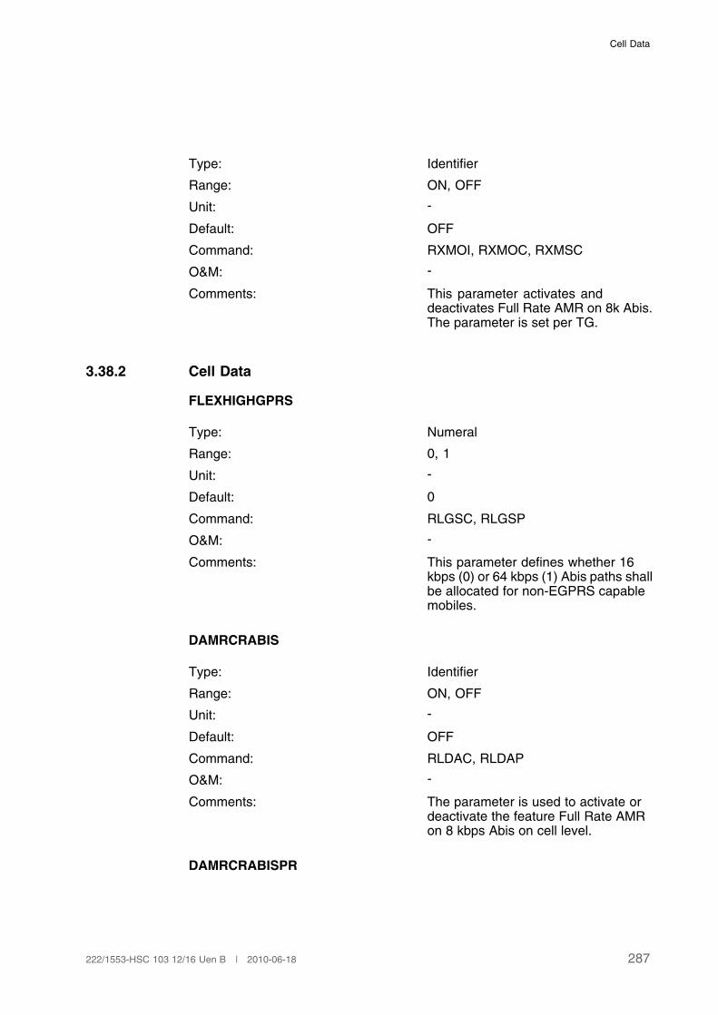
Cell Data
Type: Identifier
Range: ON, OFF
Unit: -
Default: OFF
Command: RXMOI, RXMOC, RXMSC
O&M: -
Comments: This parameter activates anddeactivates Full Rate AMR on 8k Abis.The parameter is set per TG.
3.38.2 Cell Data
FLEXHIGHGPRS
Type: Numeral
Range: 0, 1
Unit: -
Default: 0
Command: RLGSC, RLGSP
O&M: -
Comments: This parameter defines whether 16kbps (0) or 64 kbps (1) Abis paths shallbe allocated for non-EGPRS capablemobiles.
DAMRCRABIS
Type: Identifier
Range: ON, OFF
Unit: -
Default: OFF
Command: RLDAC, RLDAP
O&M: -
Comments: The parameter is used to activate ordeactivate the feature Full Rate AMRon 8 kbps Abis on cell level.
DAMRCRABISPR
287222/1553-HSC 103 12/16 Uen B | 2010-06-18
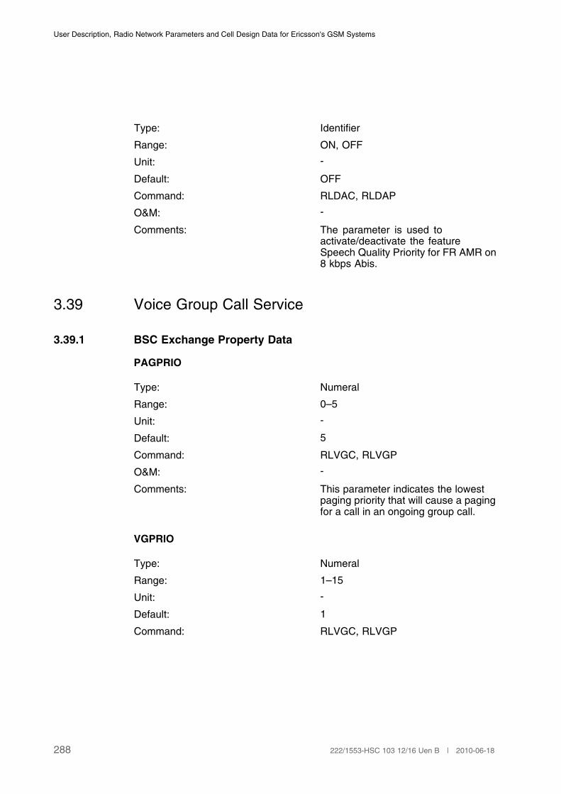
User Description, Radio Network Parameters and Cell Design Data for Ericsson's GSM Systems
Type: Identifier
Range: ON, OFF
Unit: -
Default: OFF
Command: RLDAC, RLDAP
O&M: -
Comments: The parameter is used toactivate/deactivate the featureSpeech Quality Priority for FR AMR on8 kbps Abis.
3.39 Voice Group Call Service
3.39.1 BSC Exchange Property Data
PAGPRIO
Type: Numeral
Range: 0–5
Unit: -
Default: 5
Command: RLVGC, RLVGP
O&M: -
Comments: This parameter indicates the lowestpaging priority that will cause a pagingfor a call in an ongoing group call.
VGPRIO
Type: Numeral
Range: 1–15
Unit: -
Default: 1
Command: RLVGC, RLVGP
288 222/1553-HSC 103 12/16 Uen B | 2010-06-18
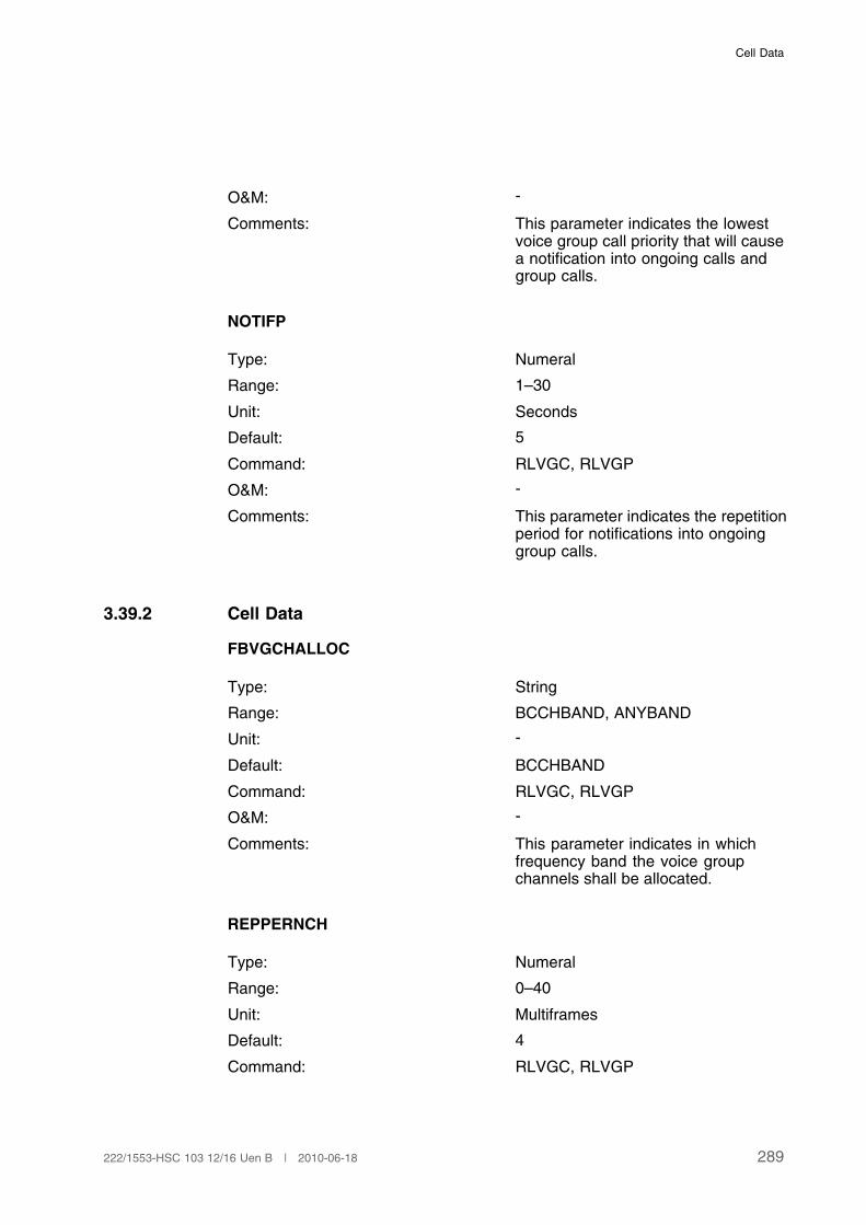
Cell Data
O&M: -
Comments: This parameter indicates the lowestvoice group call priority that will causea notification into ongoing calls andgroup calls.
NOTIFP
Type: Numeral
Range: 1–30
Unit: Seconds
Default: 5
Command: RLVGC, RLVGP
O&M: -
Comments: This parameter indicates the repetitionperiod for notifications into ongoinggroup calls.
3.39.2 Cell Data
FBVGCHALLOC
Type: String
Range: BCCHBAND, ANYBAND
Unit: -
Default: BCCHBAND
Command: RLVGC, RLVGP
O&M: -
Comments: This parameter indicates in whichfrequency band the voice groupchannels shall be allocated.
REPPERNCH
Type: Numeral
Range: 0–40
Unit: Multiframes
Default: 4
Command: RLVGC, RLVGP
289222/1553-HSC 103 12/16 Uen B | 2010-06-18

User Description, Radio Network Parameters and Cell Design Data for Ericsson's GSM Systems
O&M: -
Comments: This parameter indicates the repetitionperiod for notifications (the maximumtime between notifications) for ongoinggroup calls on NCH.
VGCHALLOC
Type: String
Range: NOPREF, BCCHPREF,BCCHNOPREF
Unit: -
Default: BCCHPREF
Command: RLVGC, RLVGP
O&M: -
Comments: This parameter determines if a voicegroup channel shall be allocatedpreferably on the BCCH frequency,preferably not on the BCCH frequencyor with no preference.
CHMAX
Type: Numeral
Range: 0 to 32
Unit: -
Default: 32
Command: RLVGC, RLVGP
O&M: -
Comments: This parameter indicatets the absolutenumber of allowed VGCHs per cell.
DYNVGCH
Type: String
Range: OFF, ON
Unit: -
Default: OFF
Command: RLVGC, RLVGP
290 222/1553-HSC 103 12/16 Uen B | 2010-06-18

Cell Data
O&M: -
Comments: This parameter indicates if the featureDynamic VGCH Handling is activatedor deactivated.
VGENCR
Type: String
Range: OFF, ON
Unit: -
Default: OFF
Command: RLVGC, RLVGP
O&M: -
Comments: This parameter indicates if the featureVGCS Channel Encryption is activatedor deactivated.
3.40 Tandem Free Operation (TFO)
3.40.1 BSC Exchange Property Data
PCMLAW
Type: Numeral
Range: 0–1
Unit: -
Default: 0
Command: RAEPC, RAEPP
O&M: -
Comments: This parameter is used to set thecorrect PCM law type on the Ainterface. The parameter is set perBSC.
0: A-Law
1: µ-Law
TFOCONFIGTRA
291222/1553-HSC 103 12/16 Uen B | 2010-06-18
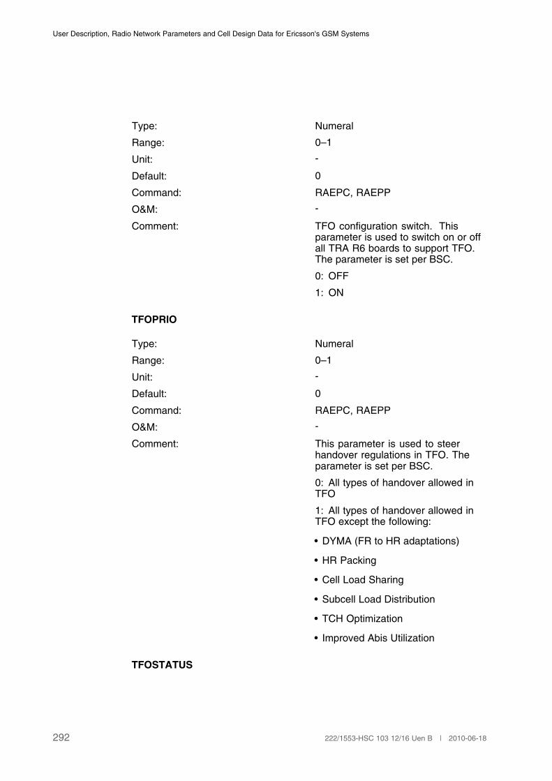
User Description, Radio Network Parameters and Cell Design Data for Ericsson's GSM Systems
Type: Numeral
Range: 0–1
Unit: -
Default: 0
Command: RAEPC, RAEPP
O&M: -
Comment: TFO configuration switch. Thisparameter is used to switch on or offall TRA R6 boards to support TFO.The parameter is set per BSC.
0: OFF
1: ON
TFOPRIO
Type: Numeral
Range: 0–1
Unit: -
Default: 0
Command: RAEPC, RAEPP
O&M: -
Comment: This parameter is used to steerhandover regulations in TFO. Theparameter is set per BSC.
0: All types of handover allowed inTFO
1: All types of handover allowed inTFO except the following:
• DYMA (FR to HR adaptations)
• HR Packing
• Cell Load Sharing
• Subcell Load Distribution
• TCH Optimization
• Improved Abis Utilization
TFOSTATUS
292 222/1553-HSC 103 12/16 Uen B | 2010-06-18

Cell Data
Type: Numeral
Range: 0–1
Unit: -
Default: 0
Command: RAEPC, RAEPP
O&M: -
Comment: This parameter is used to turn thefeature TFO ON (=1) or OFF (=0). Theparameter is set per BSC.
3.41 Handover and Signalling Robustness
3.41.1 BSC Data
REEST
Type: String
Range: ON, OFF
Unit: -
Default: -
Command: RFEHI, RFEHE, RFEHP
O&M: -
Comment: This parameter initiate, end and printthe status of Reestablish of Layer 2functionality.
REPFACCH
Type: String
Range: ON, OFF
Unit: -
Default: -
Command: RFEHI, RFEHE, RFEHP
O&M: -
Comment: This parameter initiate, end and printthe status of Repeated DownlinkFACCH.
293222/1553-HSC 103 12/16 Uen B | 2010-06-18

User Description, Radio Network Parameters and Cell Design Data for Ericsson's GSM Systems
SACCHDLTHR
Type: Numeral
Range: 1–63
Unit: -
Default: 8
Command: RFEAC, RFEAI, RFEAP
O&M: -
Comment: SACCHDLTHR is used to triggerRepeated SACCH mode on the DLwhen Enhanced AMR Coverage isactivated.
Repeated SACCH mode is triggeredper call and direction
SACCHULTHR
Type: Numeral
Range: 1–63
Unit: -
Default: 8
Command: RFEAC, RFEAI, RFEAP
O&M: -
Comment: SACCHULTHR is used to triggerRepeated SACCH mode on the ULwhen Enhanced AMR Coverage isactivated.
Repeated SACCH mode is triggeredper call and direction
3.42 Find Faulty Antenna Features
3.42.1 BSC Data
BSCFFAD
Type: Identifier
Range: ENABLED, DISBALED
Unit: -
294 222/1553-HSC 103 12/16 Uen B | 2010-06-18
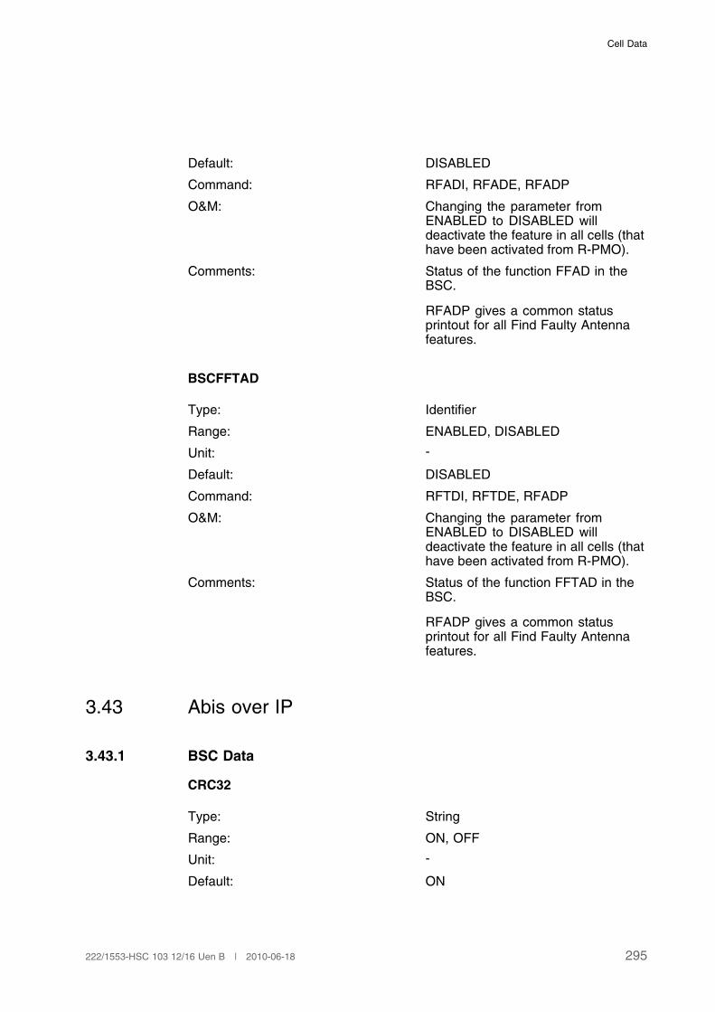
Cell Data
Default: DISABLED
Command: RFADI, RFADE, RFADP
O&M: Changing the parameter fromENABLED to DISABLED willdeactivate the feature in all cells (thathave been activated from R-PMO).
Comments: Status of the function FFAD in theBSC.
RFADP gives a common statusprintout for all Find Faulty Antennafeatures.
BSCFFTAD
Type: Identifier
Range: ENABLED, DISABLED
Unit: -
Default: DISABLED
Command: RFTDI, RFTDE, RFADP
O&M: Changing the parameter fromENABLED to DISABLED willdeactivate the feature in all cells (thathave been activated from R-PMO).
Comments: Status of the function FFTAD in theBSC.
RFADP gives a common statusprintout for all Find Faulty Antennafeatures.
3.43 Abis over IP
3.43.1 BSC Data
CRC32
Type: String
Range: ON, OFF
Unit: -
Default: ON
295222/1553-HSC 103 12/16 Uen B | 2010-06-18
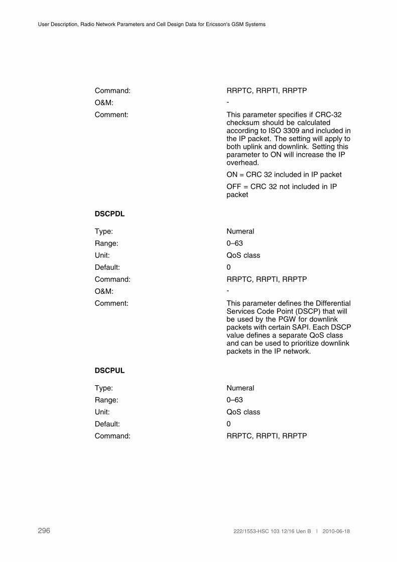
User Description, Radio Network Parameters and Cell Design Data for Ericsson's GSM Systems
Command: RRPTC, RRPTI, RRPTP
O&M: -
Comment: This parameter specifies if CRC-32checksum should be calculatedaccording to ISO 3309 and included inthe IP packet. The setting will apply toboth uplink and downlink. Setting thisparameter to ON will increase the IPoverhead.
ON = CRC 32 included in IP packet
OFF = CRC 32 not included in IPpacket
DSCPDL
Type: Numeral
Range: 0–63
Unit: QoS class
Default: 0
Command: RRPTC, RRPTI, RRPTP
O&M: -
Comment: This parameter defines the DifferentialServices Code Point (DSCP) that willbe used by the PGW for downlinkpackets with certain SAPI. Each DSCPvalue defines a separate QoS classand can be used to prioritize downlinkpackets in the IP network.
DSCPUL
Type: Numeral
Range: 0–63
Unit: QoS class
Default: 0
Command: RRPTC, RRPTI, RRPTP
296 222/1553-HSC 103 12/16 Uen B | 2010-06-18

Cell Data
O&M: -
Comment: This parameter defines the DifferentialServices Code Point (DSCP) that willbe used by STN for uplink packetswith certain SAPI. Each DSCP valuedefines a separate QoS class and canbe used to prioritize downlink packetsin the IP network.
IPDEVNO
Type: Numeral
Range: 0–127
Unit: —
Default: —
Command: RRIPC, RRIPI, RRIPP
O&M: -
Comment: This parameter defines the IP devicenumber.
IPDEV2NO
Type: Numeral
Range: 0–65535
Unit: —
Default: —
Command: RRIPC, RRIPI, RRIPP
O&M: -
Comment: This parameter defines the IP devicenumber.
IPDEVTYPE
Type: String 1–7
Range: RTIPPGW
Unit: —
Default: —
Command: RRIPC, RRIPI, RRIPP
297222/1553-HSC 103 12/16 Uen B | 2010-06-18
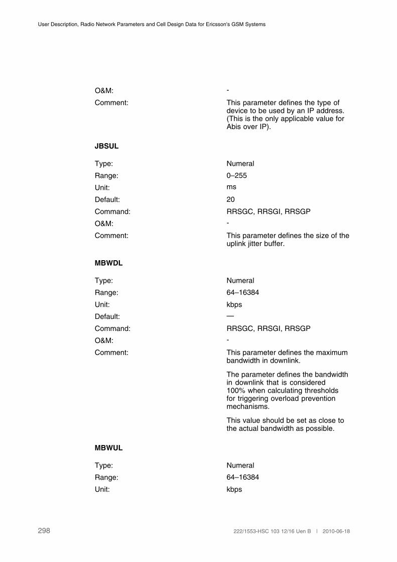
User Description, Radio Network Parameters and Cell Design Data for Ericsson's GSM Systems
O&M: -
Comment: This parameter defines the type ofdevice to be used by an IP address.(This is the only applicable value forAbis over IP).
JBSUL
Type: Numeral
Range: 0–255
Unit: ms
Default: 20
Command: RRSGC, RRSGI, RRSGP
O&M: -
Comment: This parameter defines the size of theuplink jitter buffer.
MBWDL
Type: Numeral
Range: 64–16384
Unit: kbps
Default: —
Command: RRSGC, RRSGI, RRSGP
O&M: -
Comment: This parameter defines the maximumbandwidth in downlink.
The parameter defines the bandwidthin downlink that is considered100% when calculating thresholdsfor triggering overload preventionmechanisms.
This value should be set as close tothe actual bandwidth as possible.
MBWUL
Type: Numeral
Range: 64–16384
Unit: kbps
298 222/1553-HSC 103 12/16 Uen B | 2010-06-18

Cell Data
Default: —
Command: RRSGC, RRSGI, RRSGP
O&M: -
Comment: This parameter defines the maximumbandwidth in uplink.
The parameter defines the bandwidthin uplink that is considered 100% whencalculating thresholds for triggeringoverload prevention mechanisms.
This value should be set slightly lessthan the actual bandwidth.
MODE
Type: String
Range: IPM, SCM
Unit: —
Default: -
Command: RRSCC, RRSCI, RRSCP
O&M: -
Comment: This parameter defines the mode forthe SCGR.
IPM = IP Mode
SCM = Super Channel Mode
OVLTH
Type: Numeral
Range: 0–1000
Unit: 1/10 of %
Default: 25
Command: RRBGC, RRBGI, RRBGP
299222/1553-HSC 103 12/16 Uen B | 2010-06-18
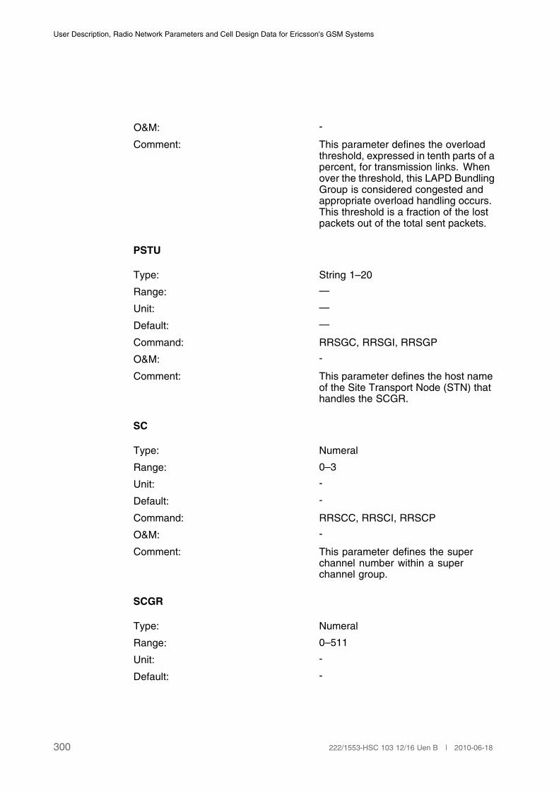
User Description, Radio Network Parameters and Cell Design Data for Ericsson's GSM Systems
O&M: -
Comment: This parameter defines the overloadthreshold, expressed in tenth parts of apercent, for transmission links. Whenover the threshold, this LAPD BundlingGroup is considered congested andappropriate overload handling occurs.This threshold is a fraction of the lostpackets out of the total sent packets.
PSTU
Type: String 1–20
Range: —
Unit: —
Default: —
Command: RRSGC, RRSGI, RRSGP
O&M: -
Comment: This parameter defines the host nameof the Site Transport Node (STN) thathandles the SCGR.
SC
Type: Numeral
Range: 0–3
Unit: -
Default: -
Command: RRSCC, RRSCI, RRSCP
O&M: -
Comment: This parameter defines the superchannel number within a superchannel group.
SCGR
Type: Numeral
Range: 0–511
Unit: -
Default: -
300 222/1553-HSC 103 12/16 Uen B | 2010-06-18
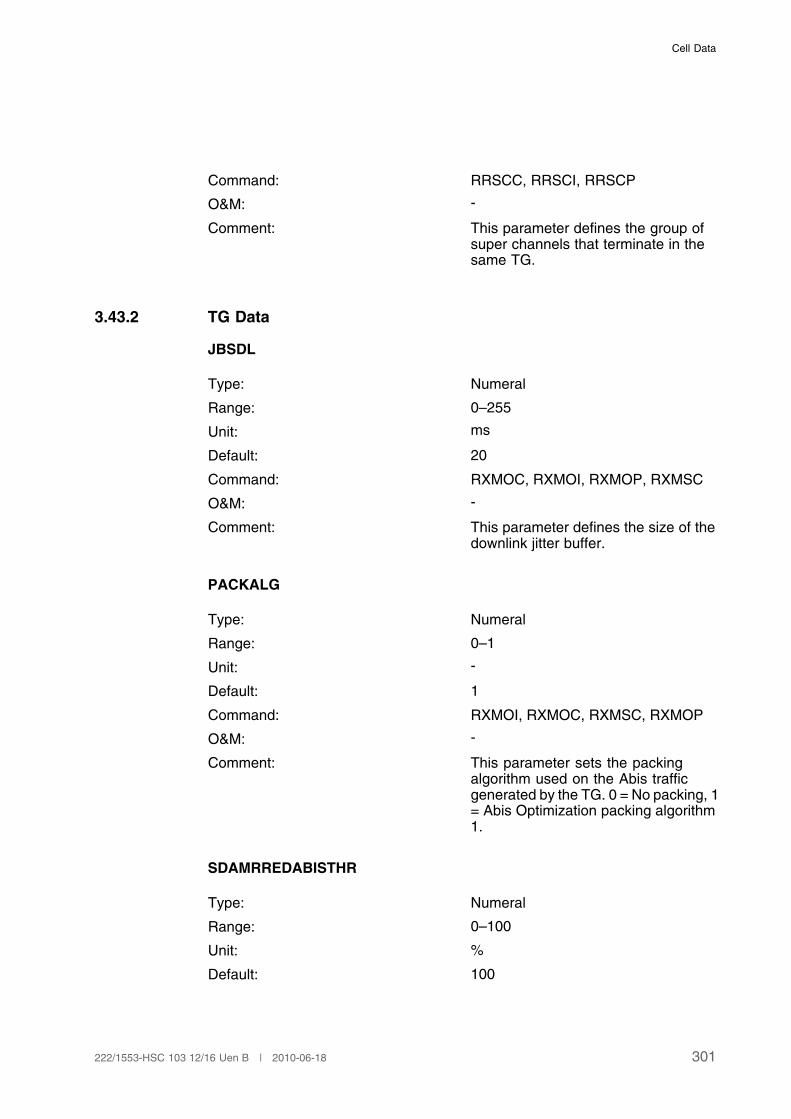
Cell Data
Command: RRSCC, RRSCI, RRSCP
O&M: -
Comment: This parameter defines the group ofsuper channels that terminate in thesame TG.
3.43.2 TG Data
JBSDL
Type: Numeral
Range: 0–255
Unit: ms
Default: 20
Command: RXMOC, RXMOI, RXMOP, RXMSC
O&M: -
Comment: This parameter defines the size of thedownlink jitter buffer.
PACKALG
Type: Numeral
Range: 0–1
Unit: -
Default: 1
Command: RXMOI, RXMOC, RXMSC, RXMOP
O&M: -
Comment: This parameter sets the packingalgorithm used on the Abis trafficgenerated by the TG. 0 = No packing, 1= Abis Optimization packing algorithm1.
SDAMRREDABISTHR
Type: Numeral
Range: 0–100
Unit: %
Default: 100
301222/1553-HSC 103 12/16 Uen B | 2010-06-18

User Description, Radio Network Parameters and Cell Design Data for Ericsson's GSM Systems
Command: RXMOI, RXMOC, RXMSC, RXMOP,RXATC, RXTAP
O&M: -
Comment: This parameter defines a thresholdvalue for starting and stopping theallocation of AMR FR channels withreduced codec set, in case of hightransmission load on a super channel.The allocation is stopped when thethreshold value is set to 100%. Theparameter is set per TG.
(1)
(1) This functionality is activated by the parameter DAMRCRABIS per cell.
SDFRMAABISTHR
Type: Numeral
Range: 0–100
Unit: %
Default: 100
Command: RXMOI, RXMOC, RXMSC, RXMOP
O&M: -
Comment: This parameter defines a thresholdvalue for starting and stopping of movefrom FR to HR channels, includingAMR, in case of high transmissionload on a super channel. The movingof channels is stopped when thethreshold value is set to 100%. Theparameter is set per TG.
(1)
(1) This functionality is activated by the parameter ATHABIS per cell.
SDHRAABISTHR
Type: Numeral
Range: 0–100
Unit: %
Default: 100
Command: RXMOI, RXMOC, RXMSC, RXMOP,RXATC, RXATP
302 222/1553-HSC 103 12/16 Uen B | 2010-06-18

Cell Data
O&M: -
Comment: This parameter defines a thresholdvalue for starting and stoppingthe allocation of AMR HR and HRchannels, in case of high transmissionload on a super channel. Theallocation is stopped when thethreshold value is set to 100%. Theparameter is set per TG.
(1)
(1) This functionality is activated by the parameter ATHABIS per cell.
TMODE
Type: String
Range: TDM, SCM
Unit: —
Default: —
Command: RXMOI, RXMOC, RXMSC, RXMOP
O&M: -
Comment: This parameter sets the TGTransmission Mode.
TDM = TG in Time Division MultiplexingMode
SCM = TG in Super Channel Mode
LBG
Type: Numeral
Range: 0–255
Unit: -
Default: -
Command: RRPTC, RRPTP
O&M: -
Comment: LAPD bundling group identity witin aTG.
MCLTDL
Type: Numeral
Range: 1–20
303222/1553-HSC 103 12/16 Uen B | 2010-06-18
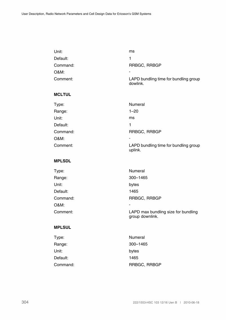
User Description, Radio Network Parameters and Cell Design Data for Ericsson's GSM Systems
Unit: ms
Default: 1
Command: RRBGC, RRBGP
O&M: -
Comment: LAPD bundling time for bundling groupdowlink.
MCLTUL
Type: Numeral
Range: 1–20
Unit: ms
Default: 1
Command: RRBGC, RRBGP
O&M: -
Comment: LAPD bundling time for bundling groupuplink.
MPLSDL
Type: Numeral
Range: 300–1465
Unit: bytes
Default: 1465
Command: RRBGC, RRBGP
O&M: -
Comment: LAPD max bundling size for bundlinggroup downlink.
MPLSUL
Type: Numeral
Range: 300–1465
Unit: bytes
Default: 1465
Command: RRBGC, RRBGP
304 222/1553-HSC 103 12/16 Uen B | 2010-06-18
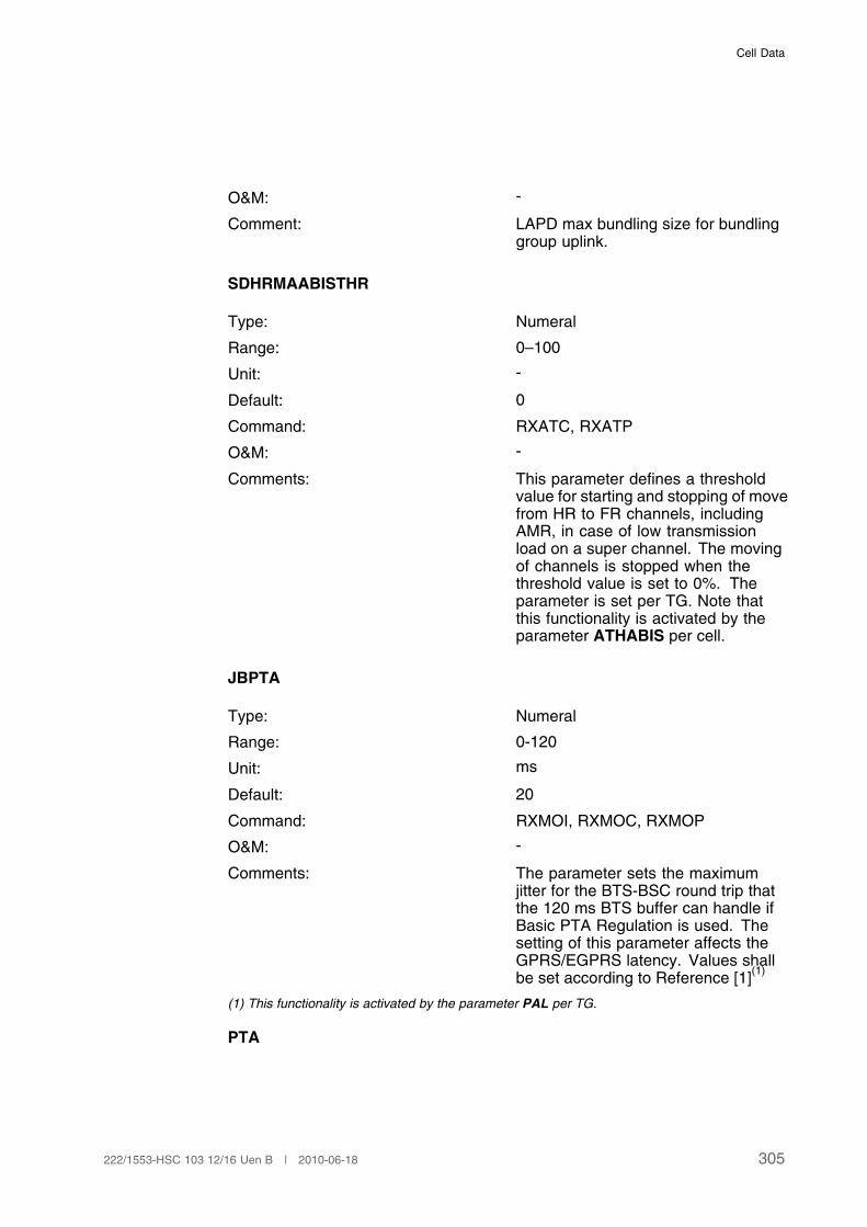
Cell Data
O&M: -
Comment: LAPD max bundling size for bundlinggroup uplink.
SDHRMAABISTHR
Type: Numeral
Range: 0–100
Unit: -
Default: 0
Command: RXATC, RXATP
O&M: -
Comments: This parameter defines a thresholdvalue for starting and stopping of movefrom HR to FR channels, includingAMR, in case of low transmissionload on a super channel. The movingof channels is stopped when thethreshold value is set to 0%. Theparameter is set per TG. Note thatthis functionality is activated by theparameter ATHABIS per cell.
JBPTA
Type: Numeral
Range: 0-120
Unit: ms
Default: 20
Command: RXMOI, RXMOC, RXMOP
O&M: -
Comments: The parameter sets the maximumjitter for the BTS-BSC round trip thatthe 120 ms BTS buffer can handle ifBasic PTA Regulation is used. Thesetting of this parameter affects theGPRS/EGPRS latency. Values shallbe set according to Reference [1]
(1)
(1) This functionality is activated by the parameter PAL per TG.
PTA
305222/1553-HSC 103 12/16 Uen B | 2010-06-18

User Description, Radio Network Parameters and Cell Design Data for Ericsson's GSM Systems
Type: Numeral
Range: 0–63
Unit: -
Default: 7
Command: RXMOI, RXMOC, RXMOP
O&M: -
Comment: This parameter indicates a factor forcounting the timing advance for thePacket-GSL protocol, P-GSL, usedby TGs in super channel mode. Thevalue should reflect the Abis round tripdelay. Values shall be set accordingto Reference [1].
PAL
Type: Numeral
Range: 0-1
Unit: -
Default: 0
Command RXMOI, RXMOC, RXMOP
O&M: -
Comment: PAL indicates if the feature AdaptiveTimers for Packet Abis is activated
0: The P-GSL timing advance ismanually set by the parameter PTA.
1: Automatic adjustment of the P-GSLtiming advance, the parameter JBPTAsets the buffer depth.
3.43.3 Super Channel Group Data
IPOV
Type: Identifier
Range: ON, OFF
Unit: -
Default: OFF
Command: RRSGI, RRSGC, RRSGP
306 222/1553-HSC 103 12/16 Uen B | 2010-06-18
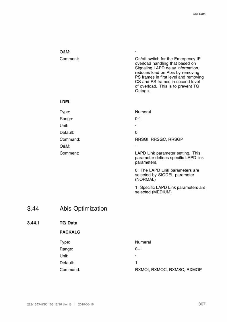
Cell Data
O&M: -
Comment: On/off switch for the Emergency IPoverload handling that based onSignaling LAPD delay information,reduces load on Abis by removingPS frames in first level and removingCS and PS frames in second levelof overload. This is to prevent TGOutage.
LDEL
Type: Numeral
Range: 0-1
Unit: -
Default: 0
Command: RRSGI, RRSGC, RRSGP
O&M: -
Comment: LAPD Link parameter setting. Thisparameter defines specific LAPD linkparameters.
0: The LAPD Link parameters areselected by SIGDEL parameter(NORMAL)
1: Specific LAPD Link parameters areselected (MEDIUM)
3.44 Abis Optimization
3.44.1 TG Data
PACKALG
Type: Numeral
Range: 0–1
Unit: -
Default: 1
Command: RXMOI, RXMOC, RXMSC, RXMOP
307222/1553-HSC 103 12/16 Uen B | 2010-06-18

User Description, Radio Network Parameters and Cell Design Data for Ericsson's GSM Systems
O&M: -
Comment: This parameter sets the packingalgorithm used in TG. For AbisOptimization this parameter shallalways be set to 1 to achieve optimalbandwidth savings.
SDAMRREDABISTHR
Type: Numeral
Range: 0–100
Unit: %
Default: 100
Command: RXMOI, RXMOC, RXMSC, RXMOP,RXATC, RXATP
O&M: -
Comment: This parameter defines a thresholdvalue for starting and stopping theallocation of AMR FR channels withreduced codec set, in case of hightransmission load on a super channel.The allocation is stopped when thethreshold value is set to 100%. Theparameter is set per TG.
(1)
(1) This functionality is activated by the parameter DAMRCRABIS per cell.
SDFRMAABISTHR
Type: Numeral
Range: 0–100
Unit: %
Default: 100
Command: RXMOI, RXMOC, RXMSC, RXMOP
O&M: -
Comment: This parameter defines a thresholdvalue for starting and stopping of movefrom FR to HR channels, includingAMR, in case of high transmissionload on a super channel. The movingof channels is stopped when thethreshold value is set to 100%. Theparameter is set per TG.
(1)
(1) This functionality is activated by the parameter ATHABIS per cell.
308 222/1553-HSC 103 12/16 Uen B | 2010-06-18
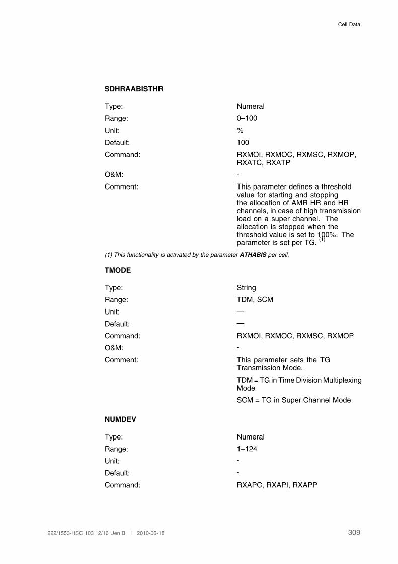
Cell Data
SDHRAABISTHR
Type: Numeral
Range: 0–100
Unit: %
Default: 100
Command: RXMOI, RXMOC, RXMSC, RXMOP,RXATC, RXATP
O&M: -
Comment: This parameter defines a thresholdvalue for starting and stoppingthe allocation of AMR HR and HRchannels, in case of high transmissionload on a super channel. Theallocation is stopped when thethreshold value is set to 100%. Theparameter is set per TG.
(1)
(1) This functionality is activated by the parameter ATHABIS per cell.
TMODE
Type: String
Range: TDM, SCM
Unit: —
Default: —
Command: RXMOI, RXMOC, RXMSC, RXMOP
O&M: -
Comment: This parameter sets the TGTransmission Mode.
TDM = TG in Time Division MultiplexingMode
SCM = TG in Super Channel Mode
NUMDEV
Type: Numeral
Range: 1–124
Unit: -
Default: -
Command: RXAPC, RXAPI, RXAPP
309222/1553-HSC 103 12/16 Uen B | 2010-06-18

User Description, Radio Network Parameters and Cell Design Data for Ericsson's GSM Systems
O&M: -
Comment: This parameter defines the number ofsubsequent PGW devices allocated bythe system (for the particular TG), tobe placed on one of the PGW-RPs.
SDHRMAABISTHR
Type: Numeral
Range: 0–100
Unit: -
Default: 0
Command: RXATC, RXATP
O&M:
Comments: This parameter defines a thresholdvalue for starting and stopping of movefrom HR to FR channels, includingAMR, in case of low transmissionload on a super channel. The movingof channels is stopped when thethreshold value is set to 0%. Theparameter is set per TG. Note thatthis functionality is activated by theparameter ATHABIS per cell.
PTA
Type: Numeral
Range: 0–63
Unit: -
Default: 7
Command: RXMOI, RXMOC, RXMOP
O&M: -
Comment: This parameter indicates a factor forcounting the timing advance for P-GSLwhen TG is in SCM transmissionmode. It is not recommended toset this parameter to less than thedefault value as it can impact theGPRS/EGPRS performance.
310 222/1553-HSC 103 12/16 Uen B | 2010-06-18

Cell Data
3.44.2 BSC Data
NUMDEV
Type: Numeral
Range: 8–31 (E1)
8–24 (T1)
Unit: -
Default: -
Command: RRSCC, RRSCI, RRSCP
O&M: -
Comment: This parameter defines the numberof subsequent PGW devices andRBLT devices that constitute the superchannel.
SC
Type: Numeral
Range: 0–3
Unit: -
Default: -
Command: RRSCC, RRSCI, RRSCP
O&M: -
Comment: This parameter defines the superchannel number within a superchannel group.
SCGR
Type: Numeral
Range: 0–511
Unit: -
Default: -
Command: RRSCC, RRSCI, RRSCP
O&M: -
Comment: This parameter defines the group ofsuper channels that terminate in thesame TG.
311222/1553-HSC 103 12/16 Uen B | 2010-06-18

User Description, Radio Network Parameters and Cell Design Data for Ericsson's GSM Systems
3.44.3 Cell Data
3.45 PGW Load Distribution
3.45.1 BSC Data
FORCE
Type: String
Range: <null> or FORCE
Unit: -
Default: no FORCE
Command: RRLRC, RRLRI, RRLRP
O&M: -
Comment: This parameter is used to initiatean unconditional rearrangementof SCGRs among available andnon-blocked PGW-RPs. If not givenwith the RRLRI command, there willonly be a rearrangement performedif there has been a trigger for a'Periodic Rearrangement', but theactual rearrangement has not beendone, because the 'lo-traffic'hours' hasnot yet occured.
MP
Type: Identifier
Range: 0–511
Unit: MP (Measuring Program)
Default: -
Command: RRLRC, RRLRI, RRLRP
O&M: -
Comment: This parameter is defining a MeasuringProgram (MP) to be used together withthe MP and TIME. In this way there isa link between this functionality andthe new 'Periodic Rearrangement'included in PGW Load Distribution.
RP
312 222/1553-HSC 103 12/16 Uen B | 2010-06-18
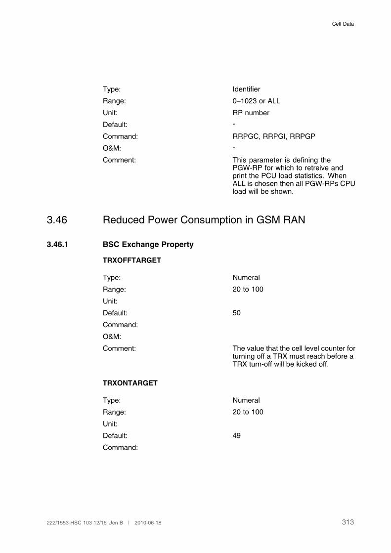
Cell Data
Type: Identifier
Range: 0–1023 or ALL
Unit: RP number
Default: -
Command: RRPGC, RRPGI, RRPGP
O&M: -
Comment: This parameter is defining thePGW-RP for which to retreive andprint the PCU load statistics. WhenALL is chosen then all PGW-RPs CPUload will be shown.
3.46 Reduced Power Consumption in GSM RAN
3.46.1 BSC Exchange Property
TRXOFFTARGET
Type: Numeral
Range: 20 to 100
Unit:
Default: 50
Command:
O&M:
Comment: The value that the cell level counter forturning off a TRX must reach before aTRX turn-off will be kicked off.
TRXONTARGET
Type: Numeral
Range: 20 to 100
Unit:
Default: 49
Command:
313222/1553-HSC 103 12/16 Uen B | 2010-06-18
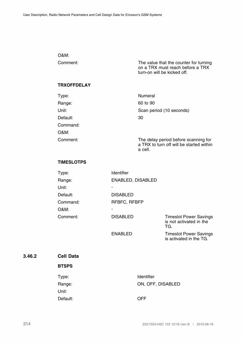
User Description, Radio Network Parameters and Cell Design Data for Ericsson's GSM Systems
O&M:
Comment: The value that the counter for turningon a TRX must reach before a TRXturn-on will be kicked off.
TRXOFFDELAY
Type: Numeral
Range: 60 to 90
Unit: Scan period (10 seconds)
Default: 30
Command:
O&M:
Comment: The delay period before scanning fora TRX to turn off will be started withina cell.
TIMESLOTPS
Type: Identifier
Range: ENABLED, DISABLED
Unit: -
Default: DISABLED
Command: RFBFC, RFBFP
O&M: -
Comment: DISABLED Timeslot Power Savingsis not activated in theTG.
ENABLED Timeslot Power Savingsis activated in the TG.
3.46.2 Cell Data
BTSPS
Type: Identifier
Range: ON, OFF, DISABLED
Unit:
Default: OFF
314 222/1553-HSC 103 12/16 Uen B | 2010-06-18

Cell Data
Command: RLSVI, RLSVC, RLSVE, RLSVP
O&M: BTSPS enters the DISABLED statedue to the activation of another feature,that requires that all TRXs are enabled.E.g. if BTSPS is ON at time of FFTADactivation. When FFTAD is inactivatedin the cell, BTSPS will be automaticallyrestored in accordance with the latestBTS Power Savings command.
Comment: BTS Power Savings state
OFF Base TransceiverStation (BTS)power savings isnot activated inthe cell
ON BTS powersavings isactivated in thecell
DISABLED BTS powersavings isdisabled in thecell
BTSPSHYST
Type: Numeral
Range: 1 to 1014
Unit:
Default: 4
Command: RLSVC
O&M:
Comment: This parameter changes the hysteresisfor BTS Power Savings. The value isexpressed as the number of idle FRTCHs.
PSVTYPE
Type: String
Range: BTSPS
Unit: -
315222/1553-HSC 103 12/16 Uen B | 2010-06-18
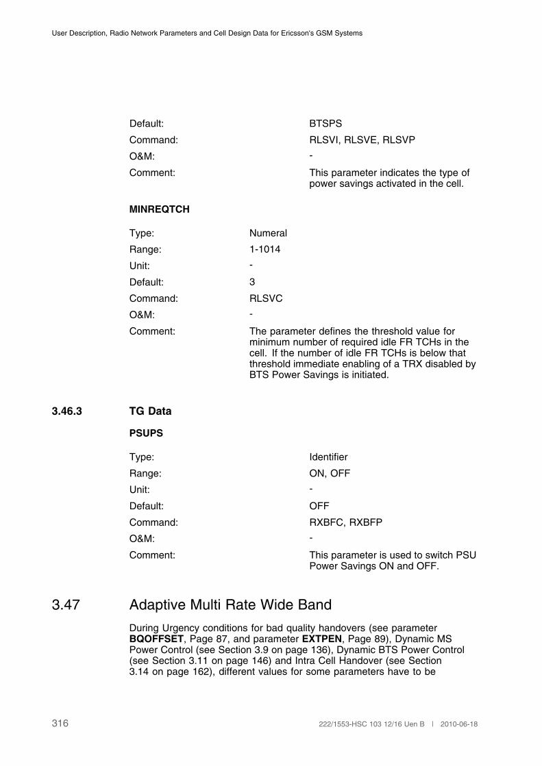
User Description, Radio Network Parameters and Cell Design Data for Ericsson's GSM Systems
Default: BTSPS
Command: RLSVI, RLSVE, RLSVP
O&M: -
Comment: This parameter indicates the type ofpower savings activated in the cell.
MINREQTCH
Type: Numeral
Range: 1-1014
Unit: -
Default: 3
Command: RLSVC
O&M: -
Comment: The parameter defines the threshold value forminimum number of required idle FR TCHs in thecell. If the number of idle FR TCHs is below thatthreshold immediate enabling of a TRX disabled byBTS Power Savings is initiated.
3.46.3 TG Data
PSUPS
Type: Identifier
Range: ON, OFF
Unit: -
Default: OFF
Command: RXBFC, RXBFP
O&M: -
Comment: This parameter is used to switch PSUPower Savings ON and OFF.
3.47 Adaptive Multi Rate Wide Band
During Urgency conditions for bad quality handovers (see parameterBQOFFSET, Page 87, and parameter EXTPEN, Page 89), Dynamic MSPower Control (see Section 3.9 on page 136), Dynamic BTS Power Control(see Section 3.11 on page 146) and Intra Cell Handover (see Section3.14 on page 162), different values for some parameters have to be
316 222/1553-HSC 103 12/16 Uen B | 2010-06-18
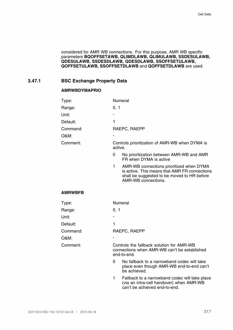
Cell Data
considered for AMR WB connections. For this purpose, AMR WB specificparameters BQOFFSETAWB, QLIMDLAWB, QLIMULAWB, SSDESULAWB,QDESULAWB, SSDESDLAWB, QDESDLAWB, SSOFFSETULAWB,QOFFSETULAWB, SSOFFSETDLAWB and QOFFSETDLAWB are used.
3.47.1 BSC Exchange Property Data
AMRWBDYMAPRIO
Type: Numeral
Range: 0, 1
Unit: -
Default: 1
Command: RAEPC, RAEPP
O&M: -
Comment: Controls prioritization of AMR-WB when DYMA isactive.
0 No prioritization between AMR-WB and AMRFR when DYMA is active
1 AMR-WB connections prioritized when DYMAis active. This means that AMR FR connectionsshall be suggested to be moved to HR beforeAMR-WB connections.
AMRWBFB
Type: Numeral
Range: 0, 1
Unit: -
Default: 1
Command: RAEPC, RAEPP
O&M: -
Comment: Controls the fallback solution for AMR-WBconnections when AMR-WB can’t be establishedend-to-end.
0 No fallback to a narrowband codec will takeplace even though AMR-WB end-to-end can’tbe achieved.
1 Fallback to a narrowband codec will take place(via an intra-cell handover) when AMR-WBcan’t be achieved end-to-end.
317222/1553-HSC 103 12/16 Uen B | 2010-06-18

User Description, Radio Network Parameters and Cell Design Data for Ericsson's GSM Systems
AMRWBPRIO
Type: Numeral
Range: 0, 1
Unit: -
Default: 0
Command: RAEPC, RAEPP
O&M: -
Comment: Controls optimization functions for AMR-WB.
0 Optimization functions will be allowed forAMR-WB connections.
1 Optimization functions will not be allowed forAMR-WB connections.
AMRWBSPVERUSE
Type: Numeral
Range: 0, 1
Unit: -
Default: 1
Command: RAEPC, RAEPP
O&M: -
Comment: AMRWBSPVERUSE is used to decide if channelservice for AMR-WB shall be placed at the top in thelist at change of channel, for example handover.
0 The list of channel services received from theMSC shall be used.
1 The channel service using AMR-WB shallbe placed at the top in the list at change ofchannel.
AMRWBSUPPORT
Type: Numeral
Range: 0, 1
Unit: -
Default: 0
Command: RAEPC, RAEPP
O&M: -
318 222/1553-HSC 103 12/16 Uen B | 2010-06-18

Cell Data
Comment: AMR-WB feature switch. Indicate if AMR-WBsupport is switched on or off.
0 AMR-WB switched off.
1 AMR-WB switched on.
HIGHFERDLAWB
Type: Numeral
Range: 0-96
Unit: FER
Default: 4
Command: RAEPC, RAEPP
O&M: -
Comment: Threshold value for high FER DL. Filtered FERmeasurements are compared to this threshold toevaluate urgency conditions.
HIGHFERULAWB
Type: Numeral
Range: 0-96
Unit: FER
Default: 4
Command: RAEPC, RAEPP
O&M: -
Comment: Threshold value for high FER UL. Filtered FERmeasurements are compared to this threshold toevaluate urgency conditions
AMRWBDHA
Type: Numeral
Range: 0-2
Unit: -
Default: 2
Command: ROEPC
O&M: -
319222/1553-HSC 103 12/16 Uen B | 2010-06-18
User Description, Radio Network Parameters and Cell Design Data for Ericsson's GSM Systems
Comment: This exchange property indicates if functionsDynamic HR Allocation and Dynamic HR Allocationpart of Abis Triggered HR Allocation are allowed forAMR WB connections.
0 Dynamic HR Allocationfunctions not allowed.
1 Dynamic HR Allocationfunctions allowed at callset up only.
2 Dynamic HR Allocationfunctions allowed at callset up and handover.
3.47.2 BSC Data
ICMODE
Type: Numeral
Range: 0-11
Unit: -
Default: -(1)
Command: RLADC, RLADP
O&M: -
Comment: The initial codec mode is the codec mode to beused at call setup and after a handover. The value0 indicates that the initital codec mode is set inaccordance with the design base rules.
For Full Rate (FR) codec sets the following bit ratescan be used:
1 4.75
2 5.15
3 5.90
4 6.70
5 7.40
6 7.95
7 10.2
8 12.2
For Half Rate (HR) codec sets the following bit ratescan be used.
320 222/1553-HSC 103 12/16 Uen B | 2010-06-18
Cell Data
1 4.75
2 5.15
3 5.90
4 6.70
5 7.40
For Wideband (WB) codec sets the following bitrates can be used.
9 6.60
10 8.85
11 12.65
(1) This parameter is not set to any default value. If initial codec mode is not defined it is chosen
in accordance with 3GPP 45.009.
3.48 Abis Local Connectivity
3.48.1 Cell Data
CODECREST
Type: String
Range: NONE, FR, HR, EFR
Unit: -
Default: NONE
Command: RLCLC, RLCLP
O&M: -
Comment: The CODECREST parameterdetermines if the speech codecselection in a cell shall be restrictedto a specified codec, and in that casewhich speech codec shall be used. Itis only possible to set CODECRESTFR, HR or EFR in cells where theparameters DMSUPP, DHA andATHABIS are all set to OFF.
321222/1553-HSC 103 12/16 Uen B | 2010-06-18

User Description, Radio Network Parameters and Cell Design Data for Ericsson's GSM Systems
3.49 BSC Capacity Supervision
3.49.1 BSC Exchange Property Data
GBCAPALARMACT
Type: Numeral
Range: 0-1
Unit: -
Default: 1
Command: RAEPC, RAEPP
O&M: -
Comment The parameter set to activate/deactivate possibilityof raising GB supervision alarms.
0 Not active
1 Active
GBCAPWARNTHR
Type: Numeral
Range: 50-95
Unit: %
Default: 80
Command: RAEPC, RAEPP
O&M: -
Comment The parameter sets the threshold value for initiationof observation alarms.
3.50 A-Interface over IP
A-Interface over IP is activated by issuing command RRAII and deactivated bycommand RRAIE. When A-Interface over IP is activated and AMR is to be usedthe following parameters shall be set: AMRFRSUPPORT set to 5, see Page242, AMRHRSUPPORT set to 2, see Page 242. If AMR-WB is to be used theparameterAMRWBSUPPORT shall be set to 0, see Page 318.
3.50.1 BSC Exchange Property Data
PCMLAW
322 222/1553-HSC 103 12/16 Uen B | 2010-06-18
Cell Data
Type: Numeral
Range: 0–1
Unit: -
Default: 0
Command: RAEPC, RAEPP
O&M: -
Comments: This parameter is used to set thecorrect PCM law type on the Ainterface. The parameter is set perBSC.
0: A-Law
1: µ-Law
3.50.2 BSC Data
DSCP
Type: Numeral
Range: 0-63
Unit: -
Default: 0
Command: RRAGC, RRAGP
O&M: -
Comment: This parameter specifies theDifferentiated Services Code Point(DSCP) that is used by the A-InterfaceGateway (AGW) for uplink Real-timeTransport Protocol (RTP) traffic. Theparameter is set per BSC.
JBS
Type: Numeral
Range: 0-255
Unit: ms
Default: 20
Command: RRAGC, RRAGP
323222/1553-HSC 103 12/16 Uen B | 2010-06-18

User Description, Radio Network Parameters and Cell Design Data for Ericsson's GSM Systems
O&M: -
Comment: The parameter defines the size of thedownlink jitter buffer.
IPDEVNO
Type: Numeral
Range: 0–127
Unit: —
Default: —
Command: RRIPC, RRIPI, RRIPP
O&M: -
Comment: This parameter defines the IP devicenumber.
IPDEVTYPE
Type: String 1–7
Range: RTIPAGW
Unit: -
Default: -
Command: RRIPC, RRIPI, RRIPP
O&M: -
Comment: This parameter defines the type ofdevice to be used by an IP address.(This is the only applicable value forA-interface over IP).
DSCP1
Type: Numeral
Range: 0-63
Unit: -
Default: 0
Command: RRAGC, RRAGP
324 222/1553-HSC 103 12/16 Uen B | 2010-06-18
Cell Data
O&M: -
Comment: This parameter specifies theDifferentiated Services Code Point(DSCP) that is used by the A-InterfaceGateway (AGW) for uplink Real-timeTransport Control Protocol (RTCP)traffic. The parameter is set per BSC.
MBT
Type: Numeral
Range: 0-5
Unit: ms
Default: 2
Command: RRAGC, RRAGP
O&M: -
Comment: This parameter specifies the maximumtime in milliseconds to wait beforesending a multiplexed packet that iscounted from the time when the firstspeech frame was inserted in thepacket. The parameter is set per BSC.
MPS
Type: Numeral
Range: 400-1500
Unit: bytes
Default: 1500
Command: RRAGC, RRAGP
O&M: -
Comment: This parameter specifies the maximumpacket size in bytes that can be sentin a multiplexing session includingIP header, UDP header, multiplexingheaders, RTP headers and payload.
3.51 Automatic FLP/Automatic IRC Tuning
The parameters HOMTD, MAXTGCL, MCIMALG, CONFMODE and TIME arecommon for Automatic FLP and Automatic IRC Tuning. The feature Automatic
325222/1553-HSC 103 12/16 Uen B | 2010-06-18
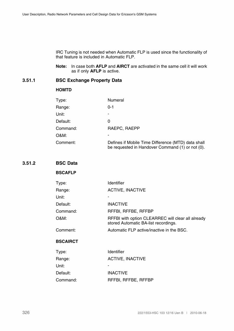
User Description, Radio Network Parameters and Cell Design Data for Ericsson's GSM Systems
IRC Tuning is not needed when Automatic FLP is used since the functionality ofthat feature is included in Automatic FLP.
Note: In case both AFLP and AIRCT are activated in the same cell it will workas if only AFLP is active.
3.51.1 BSC Exchange Property Data
HOMTD
Type: Numeral
Range: 0-1
Unit: -
Default: 0
Command: RAEPC, RAEPP
O&M: -
Comment: Defines if Mobile Time Difference (MTD) data shallbe requested in Handover Command (1) or not (0).
3.51.2 BSC Data
BSCAFLP
Type: Identifier
Range: ACTIVE, INACTIVE
Unit: -
Default: INACTIVE
Command: RFFBI, RFFBE, RFFBP
O&M: RFFBI with option CLEARREC will clear all alreadystored Automatic BA-list recordings.
Comment: Automatic FLP active/inactive in the BSC.
BSCAIRCT
Type: Identifier
Range: ACTIVE, INACTIVE
Unit: -
Default: INACTIVE
Command: RFFBI, RFFBE, RFFBP
326 222/1553-HSC 103 12/16 Uen B | 2010-06-18
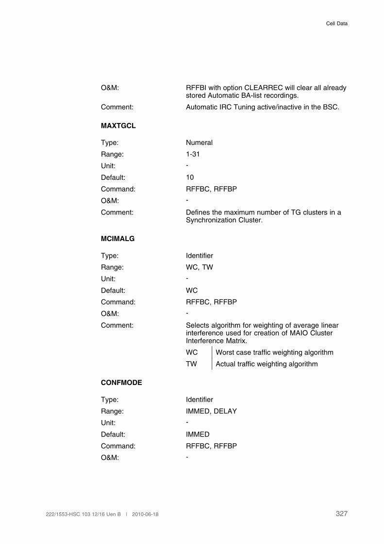
Cell Data
O&M: RFFBI with option CLEARREC will clear all alreadystored Automatic BA-list recordings.
Comment: Automatic IRC Tuning active/inactive in the BSC.
MAXTGCL
Type: Numeral
Range: 1-31
Unit: -
Default: 10
Command: RFFBC, RFFBP
O&M: -
Comment: Defines the maximum number of TG clusters in aSynchronization Cluster.
MCIMALG
Type: Identifier
Range: WC, TW
Unit: -
Default: WC
Command: RFFBC, RFFBP
O&M: -
Comment: Selects algorithm for weighting of average linearinterference used for creation of MAIO ClusterInterference Matrix.
WC Worst case traffic weighting algorithm
TW Actual traffic weighting algorithm
CONFMODE
Type: Identifier
Range: IMMED, DELAY
Unit: -
Default: IMMED
Command: RFFBC, RFFBP
O&M: -
327222/1553-HSC 103 12/16 Uen B | 2010-06-18
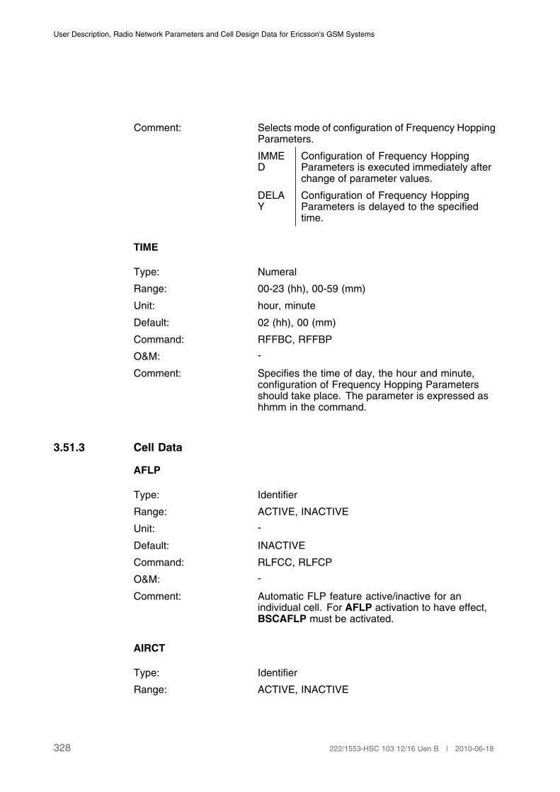
User Description, Radio Network Parameters and Cell Design Data for Ericsson's GSM Systems
Comment: Selects mode of configuration of Frequency HoppingParameters.
IMMED
Configuration of Frequency HoppingParameters is executed immediately afterchange of parameter values.
DELAY
Configuration of Frequency HoppingParameters is delayed to the specifiedtime.
TIME
Type: Numeral
Range: 00-23 (hh), 00-59 (mm)
Unit: hour, minute
Default: 02 (hh), 00 (mm)
Command: RFFBC, RFFBP
O&M: -
Comment: Specifies the time of day, the hour and minute,configuration of Frequency Hopping Parametersshould take place. The parameter is expressed ashhmm in the command.
3.51.3 Cell Data
AFLP
Type: Identifier
Range: ACTIVE, INACTIVE
Unit: -
Default: INACTIVE
Command: RLFCC, RLFCP
O&M: -
Comment: Automatic FLP feature active/inactive for anindividual cell. For AFLP activation to have effect,BSCAFLP must be activated.
AIRCT
Type: Identifier
Range: ACTIVE, INACTIVE
328 222/1553-HSC 103 12/16 Uen B | 2010-06-18
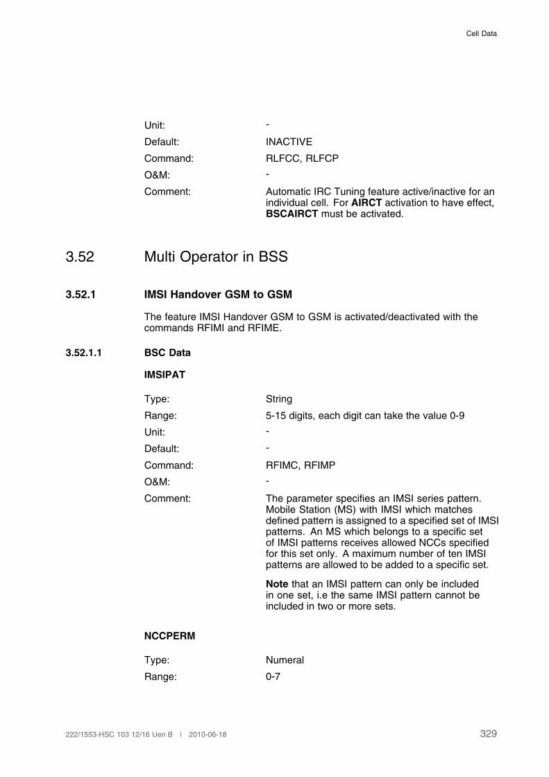
Cell Data
Unit: -
Default: INACTIVE
Command: RLFCC, RLFCP
O&M: -
Comment: Automatic IRC Tuning feature active/inactive for anindividual cell. For AIRCT activation to have effect,BSCAIRCT must be activated.
3.52 Multi Operator in BSS
3.52.1 IMSI Handover GSM to GSM
The feature IMSI Handover GSM to GSM is activated/deactivated with thecommands RFIMI and RFIME.
3.52.1.1 BSC Data
IMSIPAT
Type: String
Range: 5-15 digits, each digit can take the value 0-9
Unit: -
Default: -
Command: RFIMC, RFIMP
O&M: -
Comment: The parameter specifies an IMSI series pattern.Mobile Station (MS) with IMSI which matchesdefined pattern is assigned to a specified set of IMSIpatterns. An MS which belongs to a specific setof IMSI patterns receives allowed NCCs specifiedfor this set only. A maximum number of ten IMSIpatterns are allowed to be added to a specific set.
Note that an IMSI pattern can only be includedin one set, i.e the same IMSI pattern cannot beincluded in two or more sets.
NCCPERM
Type: Numeral
Range: 0-7
329222/1553-HSC 103 12/16 Uen B | 2010-06-18
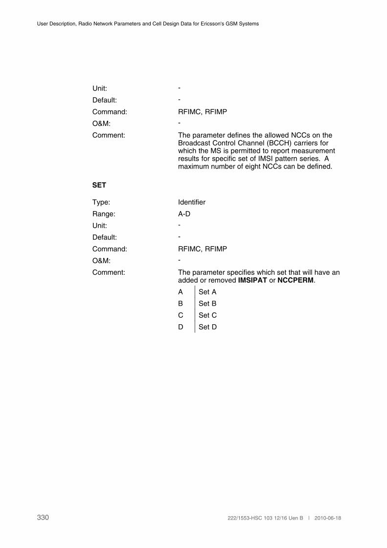
User Description, Radio Network Parameters and Cell Design Data for Ericsson's GSM Systems
Unit: -
Default: -
Command: RFIMC, RFIMP
O&M: -
Comment: The parameter defines the allowed NCCs on theBroadcast Control Channel (BCCH) carriers forwhich the MS is permitted to report measurementresults for specific set of IMSI pattern series. Amaximum number of eight NCCs can be defined.
SET
Type: Identifier
Range: A-D
Unit: -
Default: -
Command: RFIMC, RFIMP
O&M: -
Comment: The parameter specifies which set that will have anadded or removed IMSIPAT or NCCPERM.
A Set A
B Set B
C Set C
D Set D
330 222/1553-HSC 103 12/16 Uen B | 2010-06-18

Hardware Characteristics
4 Hardware Characteristics
Parameters in this section describe the configuration and characteristics of thehardware in the BTS.
4.1 Allocation Data for Transceiver Group
CHGR
See also Section 3.1.5 on page 29. If a cell has more than one channel groupthat are connected to the same transceiver group they can be defined in thesame table of the CDD, for example CHGR: 0&1.
Note: Due to HW differences, TRXs of RBS 2308/2309 and RBS 2302 mustbe dedicated to separate CHGRs.
TG
Type: Numeral
Range: RXOTG - TG (0 ≤ TG ≤ 511) for BTS logical modelG12(RBS 2000 series)
In the CDD only the TG part (0 to 511) of the full TGidentity is specified
Unit: -
Default: -
Command: RXMOI, RXMOE, RXMOC, RXMSC, RXESE, RXESI,RXTCI, RXTCE, RXBLE, RXBLI, RXPLI, RXPLE, RXAPI,RXAPE, RXMOP
O&M: -
Comments: Transceiver group (TG) identity. Each TG must be givena unique value of TG within a BSC. It is recommended tostart with TG = 0 and then increase TG one step at a time.
A TG is connected to a cell via one or more channelgroups. A TG can support maximum 16 channel groups.
If the BTS belongs to the RBS 2000 series, a TG cansupport channel groups in more than one cell, that is oneTG can serve all cells (maximum 3) at the site:
TG 0: CellA1, CellA2, CellA3
Each TG can contain up to:
331222/1553-HSC 103 12/16 Uen B | 2010-06-18

User Description, Radio Network Parameters and Cell Design Data for Ericsson's GSM Systems
RBS 2101 4 TRXs
RBS 2102 12 TRXs
RBS 2103 12 TRXs
RBS 2106 12 TRXs
RBS 2107 6 TRXs
RBS 2109 6 TRXs(1)
RBS 2111 6 TRXs
RBS 2202 12 TRXs
RBS 2206 12 TRXs
RBS 2207 6 TRXs
RBS 2216 12 TRXs
RBS 2301 2 TRXs
RBS 2302 6 TRXs
RBS 2308 12 TRXs
RBS 2309 6 TRXs(1)
RBS 2401 2 TRXs
RBS 2308 |RBS 2302
12 TRX (8 TRX | 4 TRX)(2)
RBS 2309 |RBS 2302
8 TRX (4 TRX | 4 TRX)(2)(3)
It is recommended to define one TG per site if not moreTRXs/TRUs than those specified above are required.
(1) Due to limitations in hardware, the 6 TRXs are located at instances 0–1, 4–5 and 8–9.
(2) Due to limitations in hardware, the TRXs for the RBS 2302 are located at instances 8–11
(3) Due to limitations in hardware, the TRXs for the RBS 2309 are located at instances 0–1, 4–5
TFMODE
Type: Identifier
Range: M, S, SA
Unit: -
Default: -
Command: RXMOI, RXMOC, RXMSC, RXMOP
O&M: The parameter is only allowed to be changed whenthe TF is out of service.
Comments: Timing Function Synchronisation Mode.
Mode of the timing function in the TG.
332 222/1553-HSC 103 12/16 Uen B | 2010-06-18

Hardware Characteristics
M Master. Synchronisedfrom the synchronisationsource and distributed toother TFs.
S Slave. Synchronisedfrom other TFs.
SA Standalone.Synchronised fromsynchronisation source.
The timing function is used for the synchronisationof the different TGs within a site. The master TG atthe site handles the synchronisation of the framenumbers within the site.
SYNCSRC
Type: Identifier
Range: INTI, INTE, PCM, DEFAULT
Unit: -
Default: DEFAULT
Command: RXMOI, RXMOC, RXMSC, RXMOP
O&M: The parameter is only allowed to be changed whenthe TF is out of service.
Comments: Timing function synchronisation source in the BSC.
This parameter is only valid for base stations of theRBS 2000 series.
INTI Synchronisation takenfrom internally calibrated,internal oscillatorreference.
INTE Synchronisationtaken from externallycalibrated, internaloscillator reference.
PCM Synchronisation takenfrom transport networkreference.
DEFAULT Synchronisation takenfrom source determinedby BTS capabilities.
ANT
333222/1553-HSC 103 12/16 Uen B | 2010-06-18
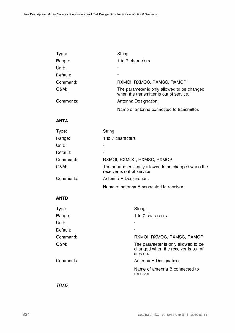
User Description, Radio Network Parameters and Cell Design Data for Ericsson's GSM Systems
Type: String
Range: 1 to 7 characters
Unit: -
Default: -
Command: RXMOI, RXMOC, RXMSC, RXMOP
O&M: The parameter is only allowed to be changedwhen the transmitter is out of service.
Comments: Antenna Designation.
Name of antenna connected to transmitter.
ANTA
Type: String
Range: 1 to 7 characters
Unit: -
Default: -
Command: RXMOI, RXMOC, RXMSC, RXMOP
O&M: The parameter is only allowed to be changed when thereceiver is out of service.
Comments: Antenna A Designation.
Name of antenna A connected to receiver.
ANTB
Type: String
Range: 1 to 7 characters
Unit: -
Default: -
Command: RXMOI, RXMOC, RXMSC, RXMOP
O&M: The parameter is only allowed to bechanged when the receiver is out ofservice.
Comments: Antenna B Designation.
Name of antenna B connected toreceiver.
TRXC
334 222/1553-HSC 103 12/16 Uen B | 2010-06-18
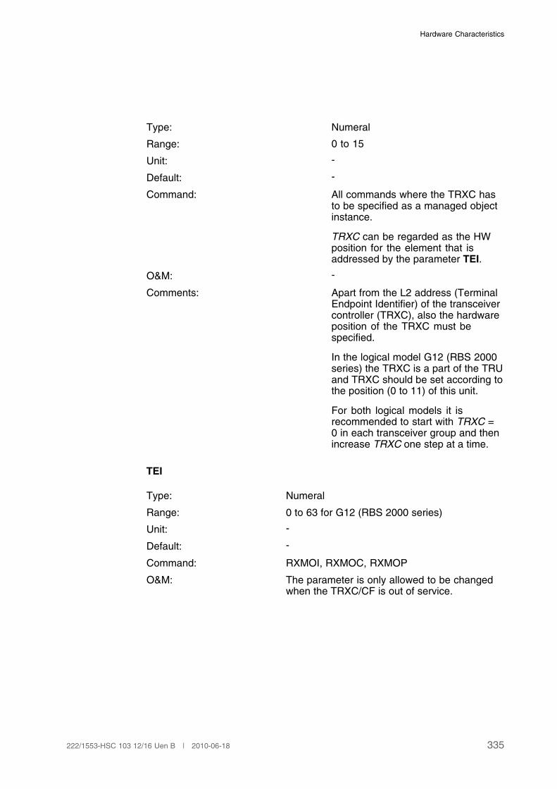
Hardware Characteristics
Type: Numeral
Range: 0 to 15
Unit: -
Default: -
Command: All commands where the TRXC hasto be specified as a managed objectinstance.
TRXC can be regarded as the HWposition for the element that isaddressed by the parameter TEI.
O&M: -
Comments: Apart from the L2 address (TerminalEndpoint Identifier) of the transceivercontroller (TRXC), also the hardwareposition of the TRXC must bespecified.
In the logical model G12 (RBS 2000series) the TRXC is a part of the TRUand TRXC should be set according tothe position (0 to 11) of this unit.
For both logical models it isrecommended to start with TRXC =0 in each transceiver group and thenincrease TRXC one step at a time.
TEI
Type: Numeral
Range: 0 to 63 for G12 (RBS 2000 series)
Unit: -
Default: -
Command: RXMOI, RXMOC, RXMOP
O&M: The parameter is only allowed to be changedwhen the TRXC/CF is out of service.
335222/1553-HSC 103 12/16 Uen B | 2010-06-18

User Description, Radio Network Parameters and Cell Design Data for Ericsson's GSM Systems
Comments: Terminal Endpoint Identifier.
LAPD element used for L2 addressing to aTRXC or CF.
It is recommended to use the same value ofTEI as the corresponding value of TRXC. Whenconfiguring a multidrop connection (RBS 2000only), the TEI for the CF (Central Functions)must be different for the different connectedTGs.
(1)
(1) TEI must also be defined in the BTS.
MPWR
Type: Numeral
Range: 0 to 63
Unit: dBm
Default: -
Command: RXMOI, RXMOC, RXMOP
O&M: The parameter is only allowed to bechanged when the transmitter is outof service.
Comments: Maximum Transmitter Power.
It is necessary to specify the capabilityof the transmitters available in the TG.This is done in order to prevent powerorders, which the transmitters cannothandle.
MPWR is the maximum transmitterpower of the TX at the power amplifier(PA) output. MPWR must be specifiedfor each transmitter in the TG.
RXD
Type: Identifier
Range: A, B, AB
Unit: -
Default: -
Command: RXMOI, RXMOC, RXMOP
O&M: The parameter is only allowed to be changed whenthe receiver is out of service.
336 222/1553-HSC 103 12/16 Uen B | 2010-06-18
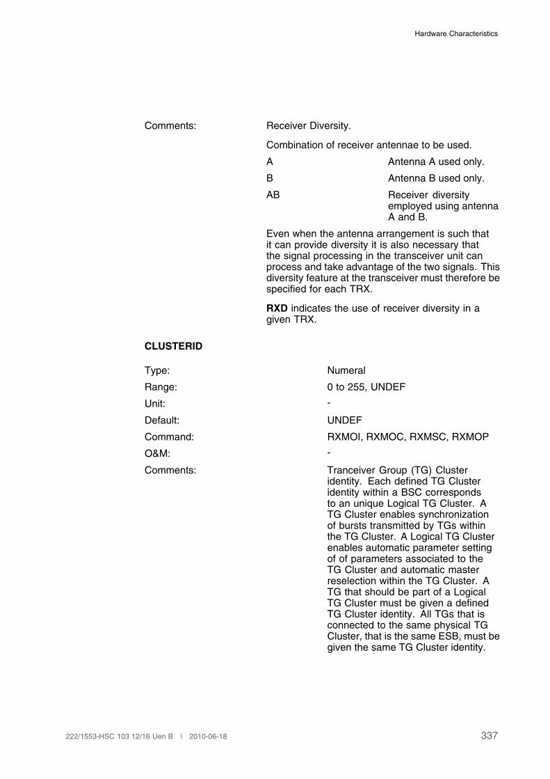
Hardware Characteristics
Comments: Receiver Diversity.
Combination of receiver antennae to be used.
A Antenna A used only.
B Antenna B used only.
AB Receiver diversityemployed using antennaA and B.
Even when the antenna arrangement is such thatit can provide diversity it is also necessary thatthe signal processing in the transceiver unit canprocess and take advantage of the two signals. Thisdiversity feature at the transceiver must therefore bespecified for each TRX.
RXD indicates the use of receiver diversity in agiven TRX.
CLUSTERID
Type: Numeral
Range: 0 to 255, UNDEF
Unit: -
Default: UNDEF
Command: RXMOI, RXMOC, RXMSC, RXMOP
O&M: -
Comments: Tranceiver Group (TG) Clusteridentity. Each defined TG Clusteridentity within a BSC correspondsto an unique Logical TG Cluster. ATG Cluster enables synchronizationof bursts transmitted by TGs withinthe TG Cluster. A Logical TG Clusterenables automatic parameter settingof of parameters associated to theTG Cluster and automatic masterreselection within the TG Cluster. ATG that should be part of a LogicalTG Cluster must be given a definedTG Cluster identity. All TGs that isconnected to the same physical TGCluster, that is the same ESB, must begiven the same TG Cluster identity.
337222/1553-HSC 103 12/16 Uen B | 2010-06-18

User Description, Radio Network Parameters and Cell Design Data for Ericsson's GSM Systems
4.2 BSC Exchange Property Data
EXMASTERRES
Type: Numeral
Range: 0 to 1
Unit: -
Default: 0
Command: RAEPC, RAEPP
O&M: -
Comments: Exchange Master Reselection. Thevalue 1 indicates that the functionalityfor automatic master reselection withina Logical TG Cluster is activated. Thevalue 0 indicates that the functionalityis deactivated.
338 222/1553-HSC 103 12/16 Uen B | 2010-06-18
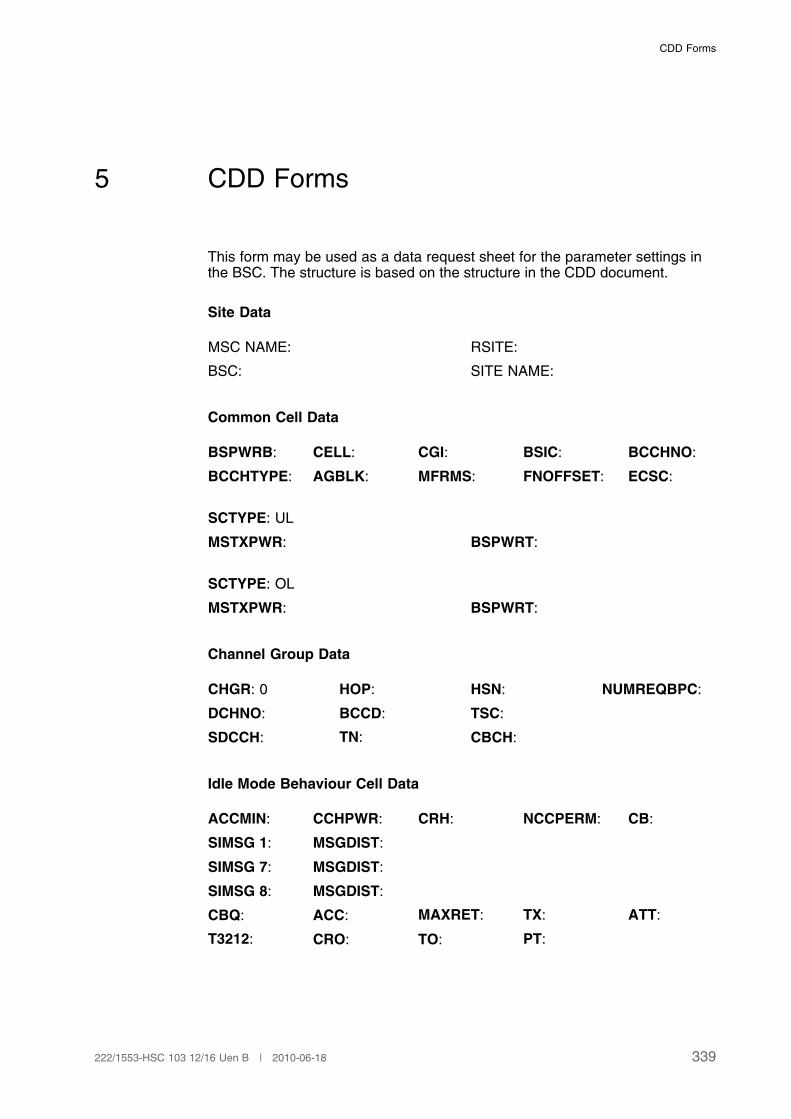
CDD Forms
5 CDD Forms
This form may be used as a data request sheet for the parameter settings inthe BSC. The structure is based on the structure in the CDD document.
Site Data
MSC NAME: RSITE:
BSC: SITE NAME:
Common Cell Data
BSPWRB: CELL: CGI: BSIC: BCCHNO:
BCCHTYPE: AGBLK: MFRMS: FNOFFSET: ECSC:
SCTYPE: UL
MSTXPWR: BSPWRT:
SCTYPE: OL
MSTXPWR: BSPWRT:
Channel Group Data
CHGR: 0 HOP: HSN: NUMREQBPC:
DCHNO: BCCD: TSC:
SDCCH: TN: CBCH:
Idle Mode Behaviour Cell Data
ACCMIN: CCHPWR: CRH: NCCPERM: CB:
SIMSG 1: MSGDIST:
SIMSG 7: MSGDIST:
SIMSG 8: MSGDIST:
CBQ: ACC: MAXRET: TX: ATT:
T3212: CRO: TO: PT:
339222/1553-HSC 103 12/16 Uen B | 2010-06-18
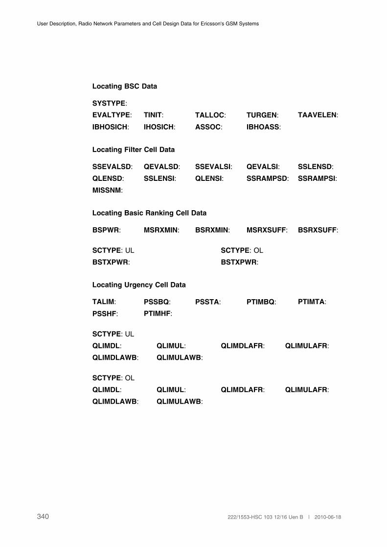
User Description, Radio Network Parameters and Cell Design Data for Ericsson's GSM Systems
Locating BSC Data
SYSTYPE:
EVALTYPE: TINIT: TALLOC: TURGEN: TAAVELEN:
IBHOSICH: IHOSICH: ASSOC: IBHOASS:
Locating Filter Cell Data
SSEVALSD: QEVALSD: SSEVALSI: QEVALSI: SSLENSD:
QLENSD: SSLENSI: QLENSI: SSRAMPSD: SSRAMPSI:
MISSNM:
Locating Basic Ranking Cell Data
BSPWR: MSRXMIN: BSRXMIN: MSRXSUFF: BSRXSUFF:
SCTYPE: UL SCTYPE: OL
BSTXPWR: BSTXPWR:
Locating Urgency Cell Data
TALIM: PSSBQ: PSSTA: PTIMBQ: PTIMTA:
PSSHF: PTIMHF:
SCTYPE: UL
QLIMDL: QLIMUL: QLIMDLAFR: QLIMULAFR:
QLIMDLAWB: QLIMULAWB:
SCTYPE: OL
QLIMDL: QLIMUL: QLIMDLAFR: QLIMULAFR:
QLIMDLAWB: QLIMULAWB:
340 222/1553-HSC 103 12/16 Uen B | 2010-06-18
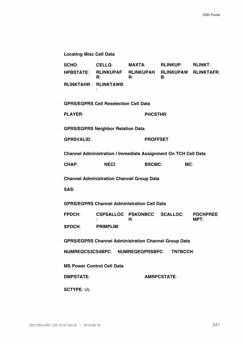
CDD Forms
Locating Misc Cell Data
SCHO: CELLQ: MAXTA: RLINKUP: RLINKT:
HPBSTATE: RLINKUPAFR:
RLINKUPAHR:
RLINKUPAWB:
RLINKTAFR:
RLINKTAHR: RLINKTAWB:
GPRS/EGPRS Cell Reselection Cell Data
PLAYER: PHCSTHR:
GPRS/EGPRS Neighbor Relation Data
GPRSVALID: PROFFSET
Channel Administration / Immediate Assignment On TCH Cell Data
CHAP: NECI: BSCMC: MC:
Channel Administration Channel Group Data
SAS:
GPRS/EGPRS Channel Administration Cell Data
FPDCH: CSPSALLOC:
PSKONBCCH:
SCALLOC: PDCHPREEMPT:
SPDCH: PRIMPLIM:
GPRS/EGPRS Channel Administration Channel Group Data
NUMREQCS3CS4BPC: NUMREQEGPRSBPC: TN7BCCH:
MS Power Control Cell Data
DMPSTATE: AMRPCSTATE:
SCTYPE: UL
341222/1553-HSC 103 12/16 Uen B | 2010-06-18

User Description, Radio Network Parameters and Cell Design Data for Ericsson's GSM Systems
SSDESUL: SSLENUL: LCOMPUL: QDESUL: QLENUL:
QCOMPUL: REGINTUL: DTXFUL: SSDESULAFR:
QDESULAFR:
SSDESULAHR:
QDESULAHR:
SSDESULAWB:
QDESULAWB:
SCTYPE: OL
SSDESUL: SSLENUL: LCOMPUL: QDESUL: QLENUL:
QCOMPUL: REGINTUL: DTXFUL: SSDESULAFR:
QDESULAFR:
SSDESULAHR:
QDESULAHR:
SSDESULAWB:
QDESULAWB:
GPRS/EGPRS MS Power Control Cell Data
GAMMA:
BTS Power Control Cell Data
DBPSTATE: AMRPCSTATE:
SCTYPE: UL
SDCCHREG: SSDESDL: REGINTDL: SSLENDL: LCOMPDL:
QDESDL: QCOMPDL: QLENDL: BSPWRMIN: SSDESDLAFR:
QDESDLAFR:
SSDESDLAHR:
QDESDLAHR:
SSDESDLAWB:
QDESDLAWB:
SCTYPE: OL .
SDCCHREG: SSDESDL: REGINTDL: SSLENDL: LCOMPDL:
QDESDL: QCOMPDL: QLENDL: BSPWRMIN: SSDESDLAFR:
QDESDLAFR:
SSDESDLAHR:
QDESDLAHR:
SSDESDLAWB:
QDESDLAWB:
DTX Cell Data
DTXD: DTXU:
342 222/1553-HSC 103 12/16 Uen B | 2010-06-18
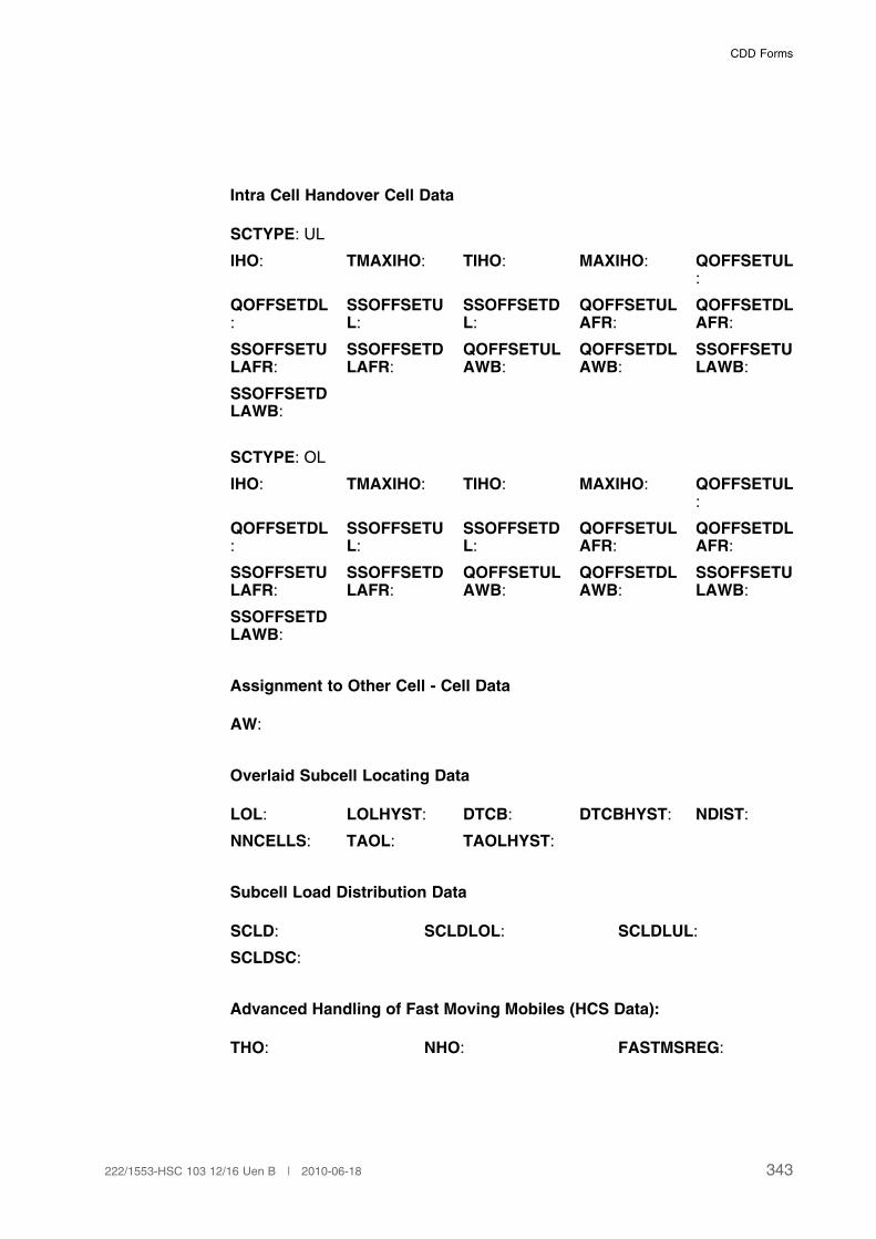
CDD Forms
Intra Cell Handover Cell Data
SCTYPE: UL
IHO: TMAXIHO: TIHO: MAXIHO: QOFFSETUL:
QOFFSETDL:
SSOFFSETUL:
SSOFFSETDL:
QOFFSETULAFR:
QOFFSETDLAFR:
SSOFFSETULAFR:
SSOFFSETDLAFR:
QOFFSETULAWB:
QOFFSETDLAWB:
SSOFFSETULAWB:
SSOFFSETDLAWB:
SCTYPE: OL
IHO: TMAXIHO: TIHO: MAXIHO: QOFFSETUL:
QOFFSETDL:
SSOFFSETUL:
SSOFFSETDL:
QOFFSETULAFR:
QOFFSETDLAFR:
SSOFFSETULAFR:
SSOFFSETDLAFR:
QOFFSETULAWB:
QOFFSETDLAWB:
SSOFFSETULAWB:
SSOFFSETDLAWB:
Assignment to Other Cell - Cell Data
AW:
Overlaid Subcell Locating Data
LOL: LOLHYST: DTCB: DTCBHYST: NDIST:
NNCELLS: TAOL: TAOLHYST:
Subcell Load Distribution Data
SCLD: SCLDLOL: SCLDLUL:
SCLDSC:
Advanced Handling of Fast Moving Mobiles (HCS Data):
THO: NHO: FASTMSREG:
343222/1553-HSC 103 12/16 Uen B | 2010-06-18
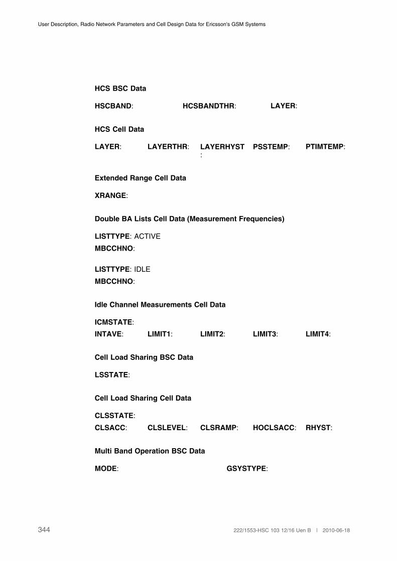
User Description, Radio Network Parameters and Cell Design Data for Ericsson's GSM Systems
HCS BSC Data
HSCBAND: HCSBANDTHR: LAYER:
HCS Cell Data
LAYER: LAYERTHR: LAYERHYST:
PSSTEMP: PTIMTEMP:
Extended Range Cell Data
XRANGE:
Double BA Lists Cell Data (Measurement Frequencies)
LISTTYPE: ACTIVE
MBCCHNO:
LISTTYPE: IDLE
MBCCHNO:
Idle Channel Measurements Cell Data
ICMSTATE:
INTAVE: LIMIT1: LIMIT2: LIMIT3: LIMIT4:
Cell Load Sharing BSC Data
LSSTATE:
Cell Load Sharing Cell Data
CLSSTATE:
CLSACC: CLSLEVEL: CLSRAMP: HOCLSACC: RHYST:
Multi Band Operation BSC Data
MODE: GSYSTYPE:
344 222/1553-HSC 103 12/16 Uen B | 2010-06-18
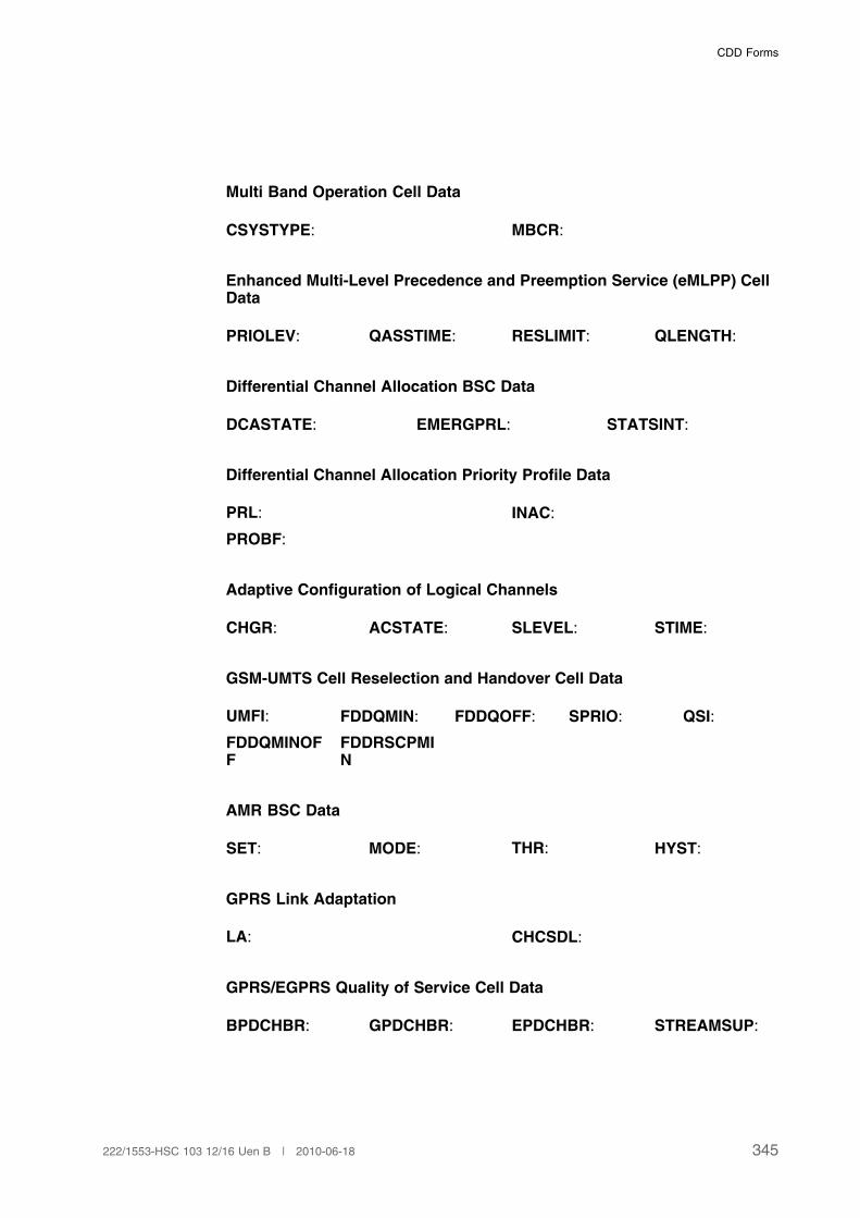
CDD Forms
Multi Band Operation Cell Data
CSYSTYPE: MBCR:
Enhanced Multi-Level Precedence and Preemption Service (eMLPP) CellData
PRIOLEV: QASSTIME: RESLIMIT: QLENGTH:
Differential Channel Allocation BSC Data
DCASTATE: EMERGPRL: STATSINT:
Differential Channel Allocation Priority Profile Data
PRL: INAC:
PROBF:
Adaptive Configuration of Logical Channels
CHGR: ACSTATE: SLEVEL: STIME:
GSM-UMTS Cell Reselection and Handover Cell Data
UMFI: FDDQMIN: FDDQOFF: SPRIO: QSI:
FDDQMINOFF
FDDRSCPMIN
AMR BSC Data
SET: MODE: THR: HYST:
GPRS Link Adaptation
LA: CHCSDL:
GPRS/EGPRS Quality of Service Cell Data
BPDCHBR: GPDCHBR: EPDCHBR: STREAMSUP:
345222/1553-HSC 103 12/16 Uen B | 2010-06-18
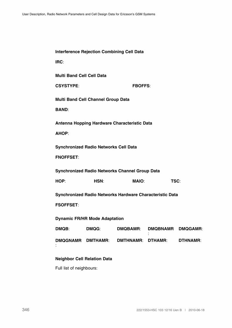
User Description, Radio Network Parameters and Cell Design Data for Ericsson's GSM Systems
Interference Rejection Combining Cell Data
IRC:
Multi Band Cell Cell Data
CSYSTYPE: FBOFFS:
Multi Band Cell Channel Group Data
BAND:
Antenna Hopping Hardware Characteristic Data
AHOP:
Synchronized Radio Networks Cell Data
FNOFFSET:
Synchronized Radio Networks Channel Group Data
HOP: HSN: MAIO: TSC:
Synchronized Radio Networks Hardware Characteristic Data
FSOFFSET:
Dynamic FR/HR Mode Adaptation
DMQB: DMQG: DMQBAMR: DMQBNAMR:
DMQGAMR:
DMQGNAMR:
DMTHAMR: DMTHNAMR: DTHAMR: DTHNAMR:
Neighbor Cell Relation Data
Full list of neighbours:
346 222/1553-HSC 103 12/16 Uen B | 2010-06-18

CDD Forms
CELLR: CTYPE: INT RELATION:
CS: CAND: AWOFFSET: BQOFFSET: BQOFFSETAFR:
BQOFFSETAWB:
If EVALTYPE=1:
KHYST: KOFFSET: LHYST:
LOFFSET: TRHYST: TROFFSET:
If EVALTYPE=3:
HIHYST: LOHYST: HYSTSEP: OFFSET:
CELLR: CTYPE: EXT RELATION:SINGLE
If EVALTYPE=1:
KHYST: KOFFSET: LHYST: LOFFSET:
TRHYST: TROFFSET:
If EVALTYPE=3:
HIHYST: LOHYST: HYSTSEP: OFFSET:
CGI: BSIC: BCCHNO: LAYER: LAYERTHR:
LAYERHYST:
PSSTEMP: PTIMTEMP: AW: MISSNM:
EXTPEN: BSPWR: BSTXPWR: BSRXMIN: BSRXSUFF:
SCHO: MSTXPWR: MSRXMIN: MSRXSUFF:
Allocation Data for Transceiver Group, Model G12
CHGR:
TG: COMB: TFMODE: SYNCSRC: FHOP:
ANT: ANTA: ANTB: BAND:
TRX data, MODEL G12
TRXC: TEI: RXD: MPWR:
347222/1553-HSC 103 12/16 Uen B | 2010-06-18

User Description, Radio Network Parameters and Cell Design Data for Ericsson's GSM Systems
348 222/1553-HSC 103 12/16 Uen B | 2010-06-18

Index
6 Index
6.1 Index to Parameters
A
ABIS64KTHR: Page 286
ABISALLOC: Page 285
ACC: Page 53
ACCMIN: Page 48
ACSTATE: Page 218
AFLP: Page 328
AGBLK: Page 20
AHOP: Page 269
AHPRL: Page 281
AIRCT: Page 328
ALLOCPREF: Page 283
ALPHA: Page 145
AMRFRSUPPORT: Page 242
AMRHRSUPPORT: Page 242
AMRPCSTATE: Page 139, Page 147
AMRSPEECHVERUSE: Page 114
AMRWBDHA: Page 319
AMRWBDYMAPRIO: Page 317
AMRWBFB: Page 317
AMRWBPRIO: Page 318
AMRWBSPVERUSE: Page 318
AMRWBSUPPORT: Page 318
ANT: Page 333
ANTA: Page 334
ANTB: Page 334
AQMMAXIPSIZE: Page 265
AQMMINBUFF: Page 265
AQMMINIPSIZE: Page 266
349222/1553-HSC 103 12/16 Uen B | 2010-06-18

User Description, Radio Network Parameters and Cell Design Data for Ericsson's GSM Systems
AQMRTTCONST: Page 266
AQMSUPPORT: Page 267
ASSOC: Page 168
ATHABIS: Page 276
ATHABISPR: Page 276
ATT: Page 57
AW: Page 40, Page 169
AWOFFSET: Page 39, Page 170
B
BADQDL: Page 84
BADQUL: Page 84
BAND: Page 199, Page 261
BAOCI: Page 214
BCCD: Page 32, Page 156
BCCHDTCB: Page 177
BCCHDTCBHYST: Page 177
BCCHLOSS: Page 176
BCCHLOSSHYST: Page 176
BCCHNO: Page 17, Page 40
BCCHREUSE: Page 176
BCCHTYPE: Page 19
BOICI: Page 214
BOIEXHI: Page 214
BPDCHBR: Page 258
BQOFFSET: Page 39, Page 87
BQOFFSETAFR: Page 39, Page 88
BQOFFSETAWB: Page 88, Page 39
BSCAFLP: Page 326
BSCAIRCT: Page 326
BSCFFAD: Page 294
BSCFFTAD: Page 295
BSCFSOFFSETLSW: Page 270
BSCFSOFFSETMSW: Page 269
350 222/1553-HSC 103 12/16 Uen B | 2010-06-18

Index
BSCMC: Page 115
BSIC: Page 16, Page 40
BSPWR: Page 40, Page 77
BSPWRB: Page 11
BSPWRMIN: Page 152
BSPWRT: Page 26
BSRPWROFFSETN: Page 148
BSRPWROFFSETP: Page 149
BSRXMIN: Page 40, Page 78
BSRXSUFF: Page 40, Page 79
BSTXPWR: Page 40, Page 79
BTDM: Page 47
BTSPS: Page 314
BTSPSHYST: Page 315
C
CAND: Page 39, Page 169
CAPLSCHMOVAL: Page 202
CAPLSCHMTOVERR: Page 204
CAPLSCHMTPREF: Page 205
CAPLSCHMTVAL: Page 203
CAPLTCHEMER: Page 201
CAPLTCHMOVAL: Page 202
CAPLTCHMTOVERR: Page 203
CAPLTCHMTPREF: Page 204
CAPLTCHMTVAL: Page 202
CAPLTCHSCH: Page 200
CB: Page 52
CBCH: Page 35
CBCHD: Page 106
CBQ: Page 53
CCCH: Page 61
CCCHCMD: Page 62
CCHPWR: Page 49
351222/1553-HSC 103 12/16 Uen B | 2010-06-18

User Description, Radio Network Parameters and Cell Design Data for Ericsson's GSM Systems
CELL: Page 14, Page 228
CELLQ: Page 95
CELLR: Page 37, Page 234
CGI: Page 15, Page 40
CHAP: Page 116
CHCODING: Page 120
CHCSDL: Page 249
CHGR: Page 29, Page 220, Page 331
CHMAX: Page 290
CHRATE: Page 209
CHTYPE: Page 208
CLMRKMSG: Page 195
CLSACC: Page 193
CLSLEVEL: Page 193
CLSRAMP: Page 194
CLSSTATE: Page 193
CLSTIMEINTERVAL: Page 192
CLUSTERID: Page 337
CMDR: Page 116
COEXUMTS: Page 221
COEXUMTSINT: Page 222
COEXUMTSLSH: Page 222
CODECREST: Page 321
COMB: Page 160
CONFMD: Page 160
CONFMODE: Page 327
CRC32: Page 295
CRH: Page 50
CRO: Page 58
CRT: Page 111
CS: Page 38
CSPSALLOC: Page 119, Page 128
CSPSPRIO: Page 119, Page 129
CSYSTYPE: Page 197
352 222/1553-HSC 103 12/16 Uen B | 2010-06-18
Index
CTYPE: Page 37
D
DAMRCR: Page 286
DAMRCRABIS: Page 287
DAMRCRABISPR: Page 287
DAMRREDABISTHR: Page 286
DBPSTATE: Page 147
DCAHANDOVER: Page 206
DCASTATE: Page 207
DCDLACT: Page 134
DCHNO: Page 31
DFRMAABISTHR: Page 281
DHA: Page 275
DHASS: Page 277
DHASSTHRASS: Page 277
DHASSTHRHO: Page 277
DHPR: Page 277
DHPRL: Page 278
DHRAABISTHR: Page 280
DHRAABISTHRWB: Page 282
DHRMAABISTHR: Page 281
DIVERSITY: Page 224
DL: Page 11
DLDELAY: Page 262
DMPR: Page 278
DMPRL: Page 278
DMPSTATE: Page 138
DMQB: Page 271
DMQBAMR: Page 272
DMQBNAMR: Page 272
DMQG: Page 272
DMQGAMR: Page 273
DMQGNAMR: Page 273
353222/1553-HSC 103 12/16 Uen B | 2010-06-18

User Description, Radio Network Parameters and Cell Design Data for Ericsson's GSM Systems
DMSUPP: Page 275
DMTFAMR: Page 279
DMTNAMR: Page 279
DMTHAMR: Page 274
DMTHNAMR: Page 274
DSCP: Page 323
DSCP1: Page 324
DSCPDL: Page 296
DSCPUL: Page 296
DTCB: Page 173
DTCBHYST: Page 174
DTCBSC: Page 170
DTHAMR: Page 275
DTHAMRWB: Page 280
DTHNAMR: Page 275
DTXD: Page 154
DTXFUL: Page 136
DTXU: Page 155
DYNVGCH: Page 290
E
EACPREF: Page 133
EARFCN: Page 234
EBANDINCLUDED: Page 112
ECSC: Page 24
EFACTOR: Page 133
EGPRSIRUL: Page 248
EITADMCTRL: Page 257
EITEMAXUSEDL: Page 256
EITEMAXUSEUL: Page 256
EITEXCLUDED: Page 132
EITGMAXUSEDL: Page 256
EITGMAXUSEUL: Page 255
EITHIGHCS: Page 249
354 222/1553-HSC 103 12/16 Uen B | 2010-06-18

Index
EITQOSPRIO: Page 257
EITSCHEDFREQH: Page 251
EITSCHEDFREQL: Page 252
EMERGPRL: Page 207
EMLPP: Page 213
EPDCHBR: Page 258
ESDELAY: Page 263
ETCHTN: Page 136
EVALTYPE: Page 69
EXMASTERRES: Page 338
EXTPEN: Page 40, Page 89
F
FASTASSIGN: Page 68
FASTMSREG: Page 184
FASTRET3GNC2: Page 223
FBCHALLOC: Page 260
FBOFFS: Page 261
FBVGCHALLOC: Page 289
FDDARFCN: Page 229, Page 235
FDDMRR: Page 231
FDDQMIN: Page 224
FDDQMINOFF: Page 227
FDDQOFF: Page 225
FDDREPTHR2: Page 233
FDDRSCPMIN: Page 227
FHOP: Page 159
FLEXHIGHGPRS: Page 287
FNOFFSET: Page 23, Page 270
FORCE: Page 312
FPDCH: Page 127
FSOFFSET: Page 271
G
355222/1553-HSC 103 12/16 Uen B | 2010-06-18

User Description, Radio Network Parameters and Cell Design Data for Ericsson's GSM Systems
GAMMA: Page 145
GBCAPALARMACT: Page 322
GBCAPWARNTHR: Page 322
GPDCHBR: Page 258
GPRS: Page 127
GPRS5TSDLACT: Page 124
GPRSEDAACT: Page 121
GPRSNEUTRALACT: Page 125
GPRSNWMODE: Page 121
GPRSPRIO: Page 132
GPRSVALID: Page 108
GSYSTYPE: Page 196
GTDM:Page 47
H
HALFRATESUPP: Page 115
HCSBAND: Page 180
HCSBANDHYST: Page 179
HCSBANDTHR: Page 181
HCSCHAVAILTIMER: Page 178
HCSIN: Page 184
HCSOUT: Page 185
HCSTRAFDISSTATE: Page 178
HIGHFERDLAWB: Page 319
HIGHFERULAWB: Page 319
HIHYST: Page 39, Page 82
HNDBEFOREBANSWM: Page 67
HNDRELCHINTRAM: Page 63
HNDSDCCHINTI: Page 67
HNDSDCCHINTOM: Page 66
HNDSDCCHM: Page 63
HNDSDCCHTCHM: Page 64
HNDTGSOPINTRA: Page 65
HOCLSACC: Page 194
356 222/1553-HSC 103 12/16 Uen B | 2010-06-18
Index
HOMTD: Page 326
HOP: Page 30, Page 155, Page 270
HPBSTATE: Page 104
HPRIO: Page 235
HPRIOTHR: Page 235
HSN: Page 30, Page 156, Page 270
HYST: Page 244
HYSTSEP: Page 40, Page 83
I
IAN: Page 268
IBHOASS: Page 168
IBHOSICH: Page 94
ICMODE: Page 320
ICMSTATE: Page 189
IHO: Page 162
IHOSICH: Page 94
IMSIPAT: Page 329
INAC: Page 210
INTAVE: Page 190
IPDEV2NO: Page 297
IPDEVNO: Page 297, Page 324
IPDEVTYPE: Page 297Page 324
IPOV: Page 306
IRC: Page 259
ISHOLEV: Page 231
J
JBPTA: Page 305
JBS: Page 323
JBSDL: Page 301
JBSUL: Page 298
K
357222/1553-HSC 103 12/16 Uen B | 2010-06-18
User Description, Radio Network Parameters and Cell Design Data for Ericsson's GSM Systems
KHYST: Page 80, Page 39
KOFFSET: Page 81, Page 39
L
LA: Page 249
LATAUSED: Page 45
LAYER: Page 40, Page 181
LAYERHYST: Page 40, Page 183
LAYERTHR: Page 40, Page 182
LBG: Page 303
LCOMPDL: Page 151
LCOMPUL: Page 142
LDEL: Page 307
LHYST: Page 80, Page 39
LIMIT1: Page 191
LIMIT2: Page 191
LIMIT3: Page 191
LIMIT4: Page 191
LISTTYPE: Page 188
LOADOPT: Page 268
LOFFSET: Page 39, Page 82
LOHYST: Page 40, Page 83
LOL: Page 173
LOLHYST: Page 173
LOPTETHR: Page 264
LOPTGTHR: Page 264
LOWSSDL: Page 85
LOWSSUL: Page 85
LPRIOTHR: Page 236
LQCACT: Page 245
LQCDEFAULTMCSDL: Page 246
LQCDEFAULTMCSUL: Page 246
LQCHIGHMCS: Page 247
LQCMODEDL: Page 248
358 222/1553-HSC 103 12/16 Uen B | 2010-06-18
Index
LQCMODEUL: Page 245
LQCUNACK: Page 247
LSSTATE: Page 192
M
MAIO: Page 158, Page 270
MAXCELLSINLAYER: Page 178
MAXCHDATARATE: Page 113
MAXDBDEVINLAYER: Page 179
MAXIHO: Page 163
MAXISHO: Page 233
MAXLAPDM: Page 283
MAXRET: Page 54
MAXSBLK: Page 105
MAXSMSG: Page 105
MAXTA: Page 96, Page 186
MAXTGCL: Page 327
MBCCHNO: Page 187
MBCR: Page 197
MBCRAC: Page 259
MBT: Page 325
MBWDL: Page 298
MBWUL: Page 298
MC: Page 118
MCIMALG: Page 327
MCLTDL: Page 303
MCLTUL: Page 304
MEASTHR: Page 237
MFDDARFCN: Page 224
MFRMS: Page 22
MINCHBW: Page 237
MINPOLL: Page 265
MINPOLLEIT: Page 264
MINREQTCH: Page 316
359222/1553-HSC 103 12/16 Uen B | 2010-06-18

User Description, Radio Network Parameters and Cell Design Data for Ericsson's GSM Systems
MISSNM: Page 40, Page 76
MNCDIGITHAND: Page 25
MODE: Page 299, Page 196, Page 243
MP: Page 312
MPDCH: Page 128
MPLSDL: Page 304
MPLSUL: Page 304
MPS: Page 325
MPWR: Page 336
MRNIC: Page 188
MRSL: Page 230
MSCRCODE: Page 224
MSEITRESPTIME: Page 251
MSGDIST: Page 51
MSQHOPRIO: Page 213
MSQUEUING: Page 212
MSRACREQCCCH: Page 126
MSRACREQPCCCH: Page 127
MSRPWROFFSETN: Page 139
MSRPWROFFSETP: Page 140
MSRXMIN: Page 40, Page 78
MSRXSUFF: Page 40, Page 78
MSTXPWR: Page 26, Page 40
N
NACCACT: Page 106
NCCPERM (Cell): Page 50
NCCPERM (BSC): Page 329
NCPROF: Page 108
NCRPT: Page 108
NDIST: Page 174
NECI: Page 118
NEWNAME: Page 14, Page 228
NHO: Page 180
360 222/1553-HSC 103 12/16 Uen B | 2010-06-18
Index
NOALLOC: Page 190
NOOFPHYSINFOMSG: Page 68
NOTIFP: Page 289
NUMDEV: Page 311, Page 309
NUMREQBPC: Page 31
NUMREQCS3CS4BPC: Page 134
NUMREQEGPRSBPC: Page 134
O
ODPDCHLIMIT: Page 135
OFFSET: Page 40, Page 84
ONDEMANDGPHDEV: Page 123
ONDEMANDGPHDG2: Page 123
OPTMSCLASS: Page 284
OPTMSCLASSADD: Page 284
OPTMSCLASSREM: Page 285
OVLTH: Page 299
P
PACKALG: Page 307, Page 301
PAGBUNDLE: Page 62
PAGLATA: Page 45
PAGNUMBERLA: Page 42
PAGPRIO: Page 288
PAGREP1LA: Page 41
PAGREPCT1LA: Page 45
PAGREPGLOB: Page 41
PAGTIMEFRST1LA: Page 42
PAGTIMEFRSTGLOB: Page 43
PAGTIMEREP1LA: Page 43
PAGTIMEREPGLOB: Page 44
PAGTIMEREPLATA: Page 46
PCI: Page 215
PCID: Page 237
361222/1553-HSC 103 12/16 Uen B | 2010-06-18
User Description, Radio Network Parameters and Cell Design Data for Ericsson's GSM Systems
PCIDG: Page 238
PCIDP: Page 238
PCIDPS: Page 239
PCMLAW: Page 291, Page 322
PCUEIT: Page 250
PCUQOS: Page 250
PDCHPREEMPT: Page 129
PHCSTHR: Page 107
PHSTATE: Page 211
PILTIMER: Page 122
PILTIMERFLEX: Page 285
PLAYER: Page 107
PP: Page 209
PRACHBLK: Page 104
PRIMPLIM: Page 130
PRIOLEV: Page 216
PRIORITY: Page 216
PRIOTHR: Page 239
PRL: Page 210
PROBF: Page 211
PROFFSET: Page 109
PSCELLPLAN: Page 106
PSCVL: Page 112
PSETCHKPERIOD: Page 124
PSKONBCCH: Page 131
PSSBQ: Page 86
PSSHF: Page 93
PSSTA: Page 86
PSSTEMP: Page 41, Page 183
PSTU: Page 300
PSUPS: Page 316
PSVTYPE: Page 315
PT: Page 61
PTA: Page 310, Page 305
362 222/1553-HSC 103 12/16 Uen B | 2010-06-18

Index
PTIMBQ: Page 87
PTIMHF: Page 93
PTIMTA: Page 87
PTIMTEMP: Page 41, Page 183
PULSCHEDINT: Page 266
PVI: Page 215
Q
QAI: Page 216
QASSTIME: Page 217
QCOMPDL: Page 152
QCOMPUL: Page 143
QDESDL: Page 151
QDESDLAFR: Page 151
QDESDLAHR: Page 153
QDESDLAWB: Page 153
QDESUL: Page 143
QDESULAFR: Page 143
QDESULAHR: Page 144
QDESULAWB: Page 144
QEVALSD: Page 73
QEVALSI: Page 74
QLENDL: Page 147
QLENGTH: Page 217
QLENSD: Page 74
QLENSI: Page 75
QLENUL: Page 137
QLIMDL: Page 90
QLIMDLAFR: Page 91
QLIMDLAWB: Page 92
QLIMUL: Page 91
QLIMULAFR: Page 92
QLIMULAWB: Page 92
QOFFSETDL: Page 165
363222/1553-HSC 103 12/16 Uen B | 2010-06-18

User Description, Radio Network Parameters and Cell Design Data for Ericsson's GSM Systems
QOFFSETDLAFR: Page 165
QOFFSETDLAWB: Page 167
QOFFSETUL: Page 164
QOFFSETULAFR: Page 164
QOFFSETULAWB: Page 167
QOSCONVPRIO: Page 254
QOSMAPPING: Page 253
QOSSTREAMPRIO: Page 254
QOSTHP1: Page 253
QOSTHP2: Page 253
QRXLEVMINE: Page 239
QRXLEVMINU: Page 240
QSC: Page 231
QSCI: Page 232
QSI: Page 226
R
RAC: Page 110
RATPRIO: Page 240
REEST: Page 293
REGINTDL: Page 146
REGINTUL: Page 137
RELATION: Page 38
REPFACCH: Page 293
REPPERNCH: Page 289
RESLIMIT: Page 217
RHYST: Page 194
RIMNACC: Page 110
RLINKT: Page 98
RLINKTAFR: Page 99
RLINKTAHR: Page 100
RLINKTAWB: Page 103
RLINKUP: Page 97
RLINKUPAFR: Page 101
364 222/1553-HSC 103 12/16 Uen B | 2010-06-18
Index
RLINKUPAHR: Page 102
RLINKUPAWB: Page 103
RP: Page 312
RSITE: Page 9
RTTI: Page 268
RXD: Page 336
S
SACCHDLTHR: Page 294
SACCHULTHR: Page 294
SAS: Page 120
SBHOACTIVE: Page 222
SC: Page 311, Page 300
SCALLOC:Page 131
SCGR: Page 311, Page 300
SCHO: Page 40, Page 94
SCLD: Page 171
SCLDLOL: Page 172
SCLDSC: Page 172
SCLDLUL: Page 171
SCRCODE: Page 229
SCTYPE: Page 24
SDAMRREDABISTHR: Page 308, Page 301
SDCCH: Page 34
SDFRMAABISTHR: Page 308, Page 302
SDHRAABISTHR: Page 309, Page 302
SDHRAABISTHRWB: Page 282
SDHRMAABISTHR: Page 305, Page 310
SET (AMR): Page 243
SET (IMSI HO): Page 330
SIMSG: Page 51
SLEVEL: Page 218
SMOASSIGN: Page 205
SMTASSIGN: Page 206
365222/1553-HSC 103 12/16 Uen B | 2010-06-18
User Description, Radio Network Parameters and Cell Design Data for Ericsson's GSM Systems
SPDCH: Page 132
SPEECHVERUSED: Page 114
SPRIO: Page 225
SSDESDL: Page 150
SSDESDLAFR: Page 150
SSDESDLAHR: Page 152
SSDESDLAWB: Page 153
SSDESUL: Page 141
SSDESULAFR: Page 142
SSDESULAHR: Page 143
SSDESULAWB: Page 144
SSEVALSD: Page 72
SSEVALSI: Page 73
SSLENDL: Page 146
SSLENSD: Page 74
SSLENSI: Page 75
SSLENUL: Page 138
SSOFFSETDL: Page 166
SSOFFSETDLAFR: Page 166
SSOFFSETDLAWB: Page 167
SSOFFSETUL: Page 165
SSOFFSETULAFR: Page 166
SSOFFSETULAWB: Page 167
SSRAMPSD: Page 75
SSRAMPSI: Page 76
STATE: Page 29
STATSINT: Page 208
STIME: Page 219
STREAMSUP: Page 258
SYNCSRC: Page 271, Page 333
T
T3212: Page 58
TAAVELEN: Page 71
366 222/1553-HSC 103 12/16 Uen B | 2010-06-18

Index
TALIM: Page 85, Page 186
TALLOC: Page 70
TAOL: Page 175
TAOLHYST: Page 175
TBFDLLIMIT: Page 123
TBFMODEACT: Page 125
TBFULLIMIT: Page 124
TCHOPTIMIZATION: Page 126
TDD: Page 47
TEI: Page 335
TEITPENDING: Page 251
TFILIMIT: Page 263
TFMODE: Page 332
TFOCONFIGTRA: Page 291
TFOPRIO: Page 292
TFOSTATUS: Page 292
TG: Page 331
THO: Page 179
THPMBRFACTOR: Page 252
THR: Page 244
TIHO: Page 163
TIME: Page 328
TIMER3105: Page 69
TIMESLOTPS: Page 314
TIMHNDCMDINTRAM: Page 64
TINIT: Page 70
TMAXIHO: Page 162
TMODE: Page 309, Page 303
TN: Page 35
TN7BCCH: Page 135
TNBCCH: Page 61
TO: Page 60
TRAFBLK: Page 105
TRES: Page 241
367222/1553-HSC 103 12/16 Uen B | 2010-06-18

User Description, Radio Network Parameters and Cell Design Data for Ericsson's GSM Systems
TRHYST: Page 39, Page 81
TROFFSET: Page 39, Page 82
TRXC: Page 334
TRXOFFDELAY: Page 314
TRXOFFTARGET: Page 313
TRXONTARGET: Page 313
TSC: Page 36
TSTREAMPENDING: Page 255
TSTREAMSTART: Page 255
TURGEN: Page 71
TX: Page 55
U
UL: Page 11
ULDELAY: Page 262
UMFI: Page 223
USFLIMIT: Page 263
UTRANID: Page 229
V
VGCHALLOC: Page 290
VGENCR: Page 291
VGPRIO: Page 288
X
XRANGE: Page 185
6.2 Index to Commands
M
MGADI: Page 48
MGEPC: Page 42, Page 43, Page 43, Page 44, Page 44, Page 45, Page46, Page 200, Page 201, Page 202, Page 202, Page 203, Page203, Page 204, Page 204, Page 205, Page 205, Page 206,Page 206
368 222/1553-HSC 103 12/16 Uen B | 2010-06-18

Index
MGEPP: Page 42, Page 43, Page 43, Page 44, Page 44, Page 45, Page46, Page 200, Page 201, Page 202, Page 202, Page 203, Page203, Page 204, Page 204, Page 205, Page 205, Page 206,Page 206
MGETC: Page 213, Page 214, Page 214, Page 215, Page 215, Page215, Page 216, Page 216
MGIDI: Page 47, Page 47
MGIDP: Page 47, Page 47
MGTEI: Page 111, Page 112
MGTEP: Page 111, Page 112
R
RAEPC: Page 25, Page 68, Page 68, Page 69, Page 84, Page 85, Page85, Page 85, Page 106, Page 107, Page 113, Page 113, Page114, Page 114, Page 121, Page 122,Page 122, Page 123, Page123, Page 124, Page 124, Page 145, Page 171, Page 192, Page195, Page 207, Page 212, Page 212, Page 213, Page 221, Page222, Page 242, Page 242, Page 245, Page 245, Page 246, Page246, Page 247, Page 248, Page 249, Page 250, Page 250, Page251, Page 251, Page 252, Page 252, Page 252, Page 253, Page253, Page 253, Page 254, Page 254, Page 255, Page 255, Page259, Page 261, Page 262, Page 263, Page 263, Page 263, Page263, Page 270, Page 270, Page 285, Page 121, Page 222, Page222, Page 264, Page 264, Page 178, Page 178, Page 178, Page179, Page 291, Page 292, Page 292, Page 255, Page 256, Page256, Page 257, Page 265, Page 265, Page 257, Page 265, Page266, Page 266, Page 266, Page 267, Page 124, Page 125, Page125, Page 126, Page 338, Page 267, Page 267, Page 248,Page 257, Page 268, Page 293, Page 127, Page 293, Page293, Page 317, Page 317, Page 318, Page 318, Page 318,Page 319, Page 319, Page 123, Page 322, Page 322, Page223, Page 323, Page 326
369222/1553-HSC 103 12/16 Uen B | 2010-06-18

User Description, Radio Network Parameters and Cell Design Data for Ericsson's GSM Systems
RAEPP: Page 25, Page 68, Page 68, Page 69, Page 84, Page 85, Page85, Page 85, Page 106, Page 107, Page 113, Page 113, Page114, Page 114, Page 121, Page 122, Page 122, Page 123, Page123, Page 124, Page 124, Page 145, Page 171, Page 192, Page195, Page 207, Page 212, Page 212, Page 213, Page 221, Page222, Page 242, Page 242, Page 245, Page 245, Page 246, Page246, Page 247, Page 248, Page 249, Page 250, Page 250, Page251, Page 251, Page 252, Page 252, Page 252, Page 253, Page253, Page 253, Page 254, Page 254, Page 255, Page 255, Page259, Page 261, Page 262, Page 263, Page 263, Page 263, Page263, Page 270, Page 270, Page 285, Page 121, Page 222, Page222, Page 264, Page 264, Page 178, Page 178, Page 178, Page179, Page 291, Page 292, Page 292, Page 255, Page 256, Page256, Page 257, Page 265, Page 265, Page 257, Page 265, Page266, Page 266, Page 266, Page 267, Page 124, Page 125, Page125, Page 126, Page 338, Page 267, Page 267, Page 248, Page257, Page 268, Page 293, Page 127, Page 293, Page 293, Page317, Page 317, Page 318, Page 318, Page 318, Page 319, Page319, Page 123, Page 322, Page 322, Page 323, Page 326
RFADE: Page 295
RFADI: Page 295
RFADP: Page 295, Page 295
RFEAC: Page 294, Page 294
RFEAI: Page 294, Page 294
RFEAP: Page 294, Page 294
RFEHE: Page 293, Page 304
RFEHI: Page 293, Page 304
RFEHP: Page 293, Page 293
RFFBC: Page 327, Page 327, Page 327, Page 328
RFFBE: Page 326, Page 326
RFFBI: Page 326, Page 326
RFFBP: Page 326, Page 326, Page 327, Page 327, Page 327, Page 328
RFIMC: Page 329, Page 330, Page 330
RFIME: Page 329
RFIMI: Page 329
RFIMP: Page 329, Page 330, Page 330
RFTDE: Page 295
RFTDI: Page 295
RLACC: Page 219, Page 219, Page 220
RLACE: Page 218
370 222/1553-HSC 103 12/16 Uen B | 2010-06-18

Index
RLACI: Page 218
RLACP: Page 218, Page 219, Page 219, Page 220
RLADC: Page 243, Page 243, Page 244, Page 244
RLADP: Page 243, Page 243, Page 244, Page 244
RLAPC: Page 142, Page 143, Page 150, Page 152, Page 144, Page 144,Page 153, Page 153, Page 154, Page 153, Page 145, Page 144
RLAPE: Page 139, Page 148
RLAPI: Page 139, Page 148
RLAPP: Page 139, Page 142, Page 143, Page 148, Page 150, Page 152,Page 144, Page 144, Page 153, Page 153, Page 154, Page153, Page 145, Page 144
RLBAC: Page 146, Page 147, Page 147
RLBAP Page 146, Page 147
RLBCC: Page 150, Page 151, Page 151, Page 152, Page 152
RLBCE: Page 147
RLBCI: Page 147
RLBCP: Page 147, Page 150, Page 151, Page 151, Page 152, Page 152
RLBDC: Page 31, Page 134, Page 135, Page 135, Page 133, Page 62,Page 136
RLBDP: Page 31, Page 134, Page 135, Page 135, Page 133
RLBQC: Page 217, Page 217
RLBQP: Page 217, Page 217
RLBRC: Page 148, Page 149
RLBRE: Page 148, Page 149
RLBRI: Page 148, Page 149
RLBRP: Page 148, Page 149
RLCCC: Page 29, Page 34, Page 35, Page 36
RLCDC: Page 115, Page 118
RLCDP: Page 115, Page 118
RLCFE: Page 31
RLCFI: Page 31
RLCFP: Page 29, Page 30, Page 30, Page 31, Page 34, Page 35, Page36, Page 156, Page 156, Page 158
RLCHC: Page 30, Page 30, Page 32, Page 156, Page 156, Page 157,Page 158
RLCHP: Page 32, Page 157
371222/1553-HSC 103 12/16 Uen B | 2010-06-18

User Description, Radio Network Parameters and Cell Design Data for Ericsson's GSM Systems
RLCLC: Page 132, Page 129, Page 119, Page 120, Page 129, Page 321
RLCLP: Page 132, Page 129, Page 119, Page 120, Page 129, Page 321
RLCPC: Page 11, Page 26, Page 26
RLCPP: Page 11, Page 26, Page 26
RLCSC: Page 277, Page 277, Page 277
RLCSP: Page 277, Page 277, Page 277
RLCXC: Page 154
RLCXP: Page 154
RLDAC: Page 276, Page 287, Page 276, Page 288
RLDAP: Page 276Page 287, Page 276, Page 288
RLDCE: Page 207
RLDCI: Page 207, Page 207
RLDCP: Page 207, Page 207
RLDEC: Page 15, Page 15, Page 16, Page 18, Page 19, Page 20, Page22, Page 24, Page 185, Page 229, Page 229, Page 229, Page230, Page 230, Page 259, Page 110, Page 110
RLDEI: Page 14, Page 38, Page 197, Page 228
RLDEP: Page 15, Page 16, Page 18, Page 19, Page 20, Page 22, Page24, Page 38, Page 185, Page 197, Page 229, Page 229, Page230, Page 230, Page 259, Page 110, Page 110
RLDGI: Page 29, Page 262
RLDGP: Page 262
RLDHC: Page 276, Page 275, Page 275, Page 278, Page 278
RLDHP: Page 276, Page 275, Page 275, Page 278, Page 278
RLDMC: Page 271, Page 272, Page 272, Page 273, Page 273, Page 273,Page 274, Page 274, Page 278, Page 279, Page 279, Page 279
RLDME: Page 275
RLDMI: Page 275Page 278
RLDMP: Page 271, Page 272, Page 272, Page 273, Page 273, Page 273,Page 274, Page 274, Page 278, Page 279, Page 279, Page 279
RLDRC: Page 116
RLDRP: Page 116
RLDSI: Page 25
RLDTC: Page 36
RLDTP: Page 36
RLDUC: Page 283, Page 284, Page 284, Page 285
372 222/1553-HSC 103 12/16 Uen B | 2010-06-18

Index
RLDUP: Page 283, Page 284, Page 284
RLEFC: Page 234
RLEFP: Page 234
RLFCC: Page 328, Page 329
RLFCP: Page 328, Page 329
RLGAC: Page 120, Page 135
RLGAP: Page 120, Page 135
RLGNC: Page 109, Page 109
RLGNP: Page 109, Page 109
RLGQC: Page 258, Page 258, Page 258, Page 259, Page 132
RLGQP: Page 258, Page 258, Page 258, Page 259, Page 132
RLGSC: Page 128, Page 128, Page 130, Page 130, Page 131, Page131, Page 132, Page 146, Page 249, Page 249, Page 287,Page 268, Page 269
RLGSE: Page 127
RLGSI: Page 127
RLGSP: Page 127, Page 128, Page 128, Page 130, Page 130, Page 131,Page 131, Page 132, Page 146, Page 249, Page 249, Page287, Page 269, Page 268
RLHBC: Page 179, Page 180, Page 181
RLHBP: Page 179, Page 180, Page 181
RLHPC: Page 116
RLHPP: Page 116
RLIHC: Page 162, Page 163, Page 163, Page 164, Page 164, Page 165,Page 165, Page 165, Page 165, Page 166, Page 166, Page 166,Page 167, Page 167, Page 167, Page 168
RLIHP: Page 162, Page 163, Page 163, Page 164, Page 164, Page 165,Page 165, Page 165, Page 165, Page 166, Page 166, Page 166,Page 167, Page 167, Page 167, Page 168
RLIMC: Page 190, Page 191
RLIME: Page 189
RLIMI: Page 189, Page 190
RLIMP: Page 189, Page 190, Page 190, Page 191
RLLBC: Page 69, Page 70, Page 70, Page 71, Page 72, Page 94, Page94, Page 168, Page 168, Page 179, Page 180
RLLBP: Page 69, Page 70, Page 70, Page 71, Page 72, Page 94, Page94, Page 168, Page 168, Page 179, Page 180
373222/1553-HSC 103 12/16 Uen B | 2010-06-18
User Description, Radio Network Parameters and Cell Design Data for Ericsson's GSM Systems
RLLCC: Page 193, Page 193, Page 194, Page 194, Page 194
RLLCE: Page 193
RLLCI: Page 193
RLLCP: Page 193, Page 193, Page 193, Page 194, Page 194, Page 194
RLLDC: Page 96, Page 97, Page 186, Page 101, Page 102, Page 103
RLLDP: Page 96, Page 97, Page 186, Page 101, Page 102, Page 103
RLLFC: Page 73, Page 73, Page 73, Page 74, Page 74, Page 75, Page75, Page 75, Page 76, Page 76
RLLFP: Page 73, Page 73, Page 73, Page 74, Page 74, Page 75, Page75, Page 75, Page 76, Page 76
RLLHC: Page 181, Page 182, Page 183, Page 183, Page 184, Page184, Page 184, Page 185
RLLHP: Page 38, Page 181, Page 182, Page 183, Page 183, Page 184,Page 184, Page 184, Page 185
RLLLC: Page 171, Page 171, Page 172, Page 172
RLLLP: Page 171, Page 171, Page 172, Page 172
RLLOC: Page 76, Page 78, Page 78, Page 78, Page 79, Page 79, Page80, Page 89, Page 95, Page 169, Page 231, Page 261, Page233, Page 176, Page 176, Page 177, Page 177, Page 177
RLLOP: Page 76, Page 78, Page 78, Page 78, Page 79, Page 79, Page80, Page 89, Page 95, Page 169, Page 231, Page 261, Page233, Page 176, Page 176, Page 177, Page 177, Page 177
RLLPC: Page 86, Page 87, Page 87, Page 87, Page 93, Page 93
RLLPP: Page 86, Page 87, Page 87, Page 87, Page 93, Page 93
RLLSE: Page 192
RLLSI: Page 192
RLLSP: Page 192
RLLUC: Page 86, Page 91, Page 91, Page 91, Page 92, Page 95, Page187, Page 92, Page 93
RLLUP: Page 86, Page 91, Page 91, Page 91, Page 92, Page 95, Page187, Page 92, Page 93
RLMAC: Page 137, Page 138, Page 136, Page 137, Page 147
RLMAP Page 137, Page 138, Page 136, Page 137
RLMFC: Page 187, Page 188, Page 189, Page 189
RLMFP: Page 187, Page 188, Page 189
RLMQC: Page 217, Page 218
RLMQP: Page 217, Page 218
374 222/1553-HSC 103 12/16 Uen B | 2010-06-18

Index
RLMRC: Page 139, Page 140
RLMRE: Page 139, Page 140
RLMRI: Page 139, Page 140
RLMRP: Page 139, Page 140
RLNCP: Page 234
RLNPE: Page 108
RLNPI: Page 108
RLNPP: Page 108
RLNRC: Page 37, Page 39, Page 39, Page 80, Page 81, Page 81, Page81, Page 82, Page 82, Page 83, Page 83, Page 83, Page 84,Page 88, Page 88, Page 169, Page 170, Page 88
RLNRE: Page 37, Page 234
RLNRI: Page 37, Page 38, Page 234
RLNRP: Page 37, Page 39, Page 80, Page 81, Page 81, Page 81, Page82, Page 82, Page 83, Page 83, Page 83, Page 84, Page 88,Page 88, Page 169, Page 170, Page 234, Page 88
RLOLC: Page 173, Page 173, Page 174, Page 174, Page 174, Page175, Page 175, Page 175
RLOLP: Page 173, Page 173, Page 174, Page 174, Page 174, Page175, Page 175, Page 175
RLOMC: Page 196
RLOMP: Page 196
RLPBE: Page 104
RLPBI: Page 104
RLPBP: Page 104
RLPCC: Page 142, Page 142, Page 143, Page 143
RLPCE: Page 138
RLPCI: Page 138
RLPCP: Page 138, Page 142, Page 142, Page 143, Page 143
RLPDC: Page 104, Page 105, Page 105, Page 105, Page 106
RLPDP: Page 104, Page 105, Page 105, Page 105, Page 106
RLPPC: Page 210, Page 210, Page 211, Page 211
RLPPI: Page 210
RLPPP: Page 210, Page 210, Page 211, Page 211
RLPRC: Page 208, Page 209, Page 210
RLPRP: Page 208, Page 209
375222/1553-HSC 103 12/16 Uen B | 2010-06-18
User Description, Radio Network Parameters and Cell Design Data for Ericsson's GSM Systems
RLPSC: Page 107, Page 107
RLPSP: Page 107, Page 107
RLSBC: Page 24, Page 52, Page 53, Page 54, Page 55, Page 55, Page57, Page 58, Page 58, Page 60, Page 61
RLSBP: Page 24, Page 52, Page 53, Page 54, Page 55, Page 55, Page57, Page 58, Page 58, Page 60, Page 61
RLSCI: Page 208
RLSCP: Page 208
RLSEE: Page 238, Page 238
RLSEC: Page 238
RLSEI: Page 238, Page 238, Page 239
RLSEP: Page 238, Page 238, Page 238, Page 239
RLSMC: Page 51, Page 52
RLSMP: Page 51, Page 52
RLSRC: Page 235, Page 235, Page 236, Page 236, Page 237, Page 237,Page 239, Page 240, Page 240, Page 240, Page 241
RLSRP: Page 235, Page 235, Page 236, Page 236, Page 237, Page 237,Page 239, Page 240, Page 240, Page 240, Page 241
RLSSC: Page 48, Page 49, Page 50, Page 50, Page 98, Page 118, Page155, Page 197, Page 100, Page 99, Page 103
RLSSP: Page 48, Page 49, Page 50, Page 50, Page 98, Page 118, Page155, Page 197, Page 100, Page 99, Page 103
RLSTC: Page 30
RLSTP: Page 30
RLSUC: Page 224, Page 225, Page 225, Page 226, Page 231, Page 232,Page 232, Page 227, Page 227
RLSUP: Page 224, Page 225, Page 225, Page 226, Page 231, Page 232,Page 232, Page 227, Page 227
RLSVC: Page 315, Page 315
RLSVE: Page 315, Page 316
RLSVI: Page 315, Page 316
RLSVP: Page 315, Page 316
RLTYC: Page 197
RLTYI: Page 197
RLTYP: Page 197
RLUMC: Page 224
376 222/1553-HSC 103 12/16 Uen B | 2010-06-18

Index
RLUMP: Page 224
RLVGC: Page 289, Page 288, Page 288, Page 289, Page 290, Page 289
RLVGP: Page 289, Page 288, Page 288, Page 289, Page 290, Page 289
RRAGC: Page 323, Page 323, Page 324, Page 325, Page 325
RRAGP: Page 323, Page 323, Page 324, Page 325, Page 325
RRAIE: Page 322
RRAII: Page 322
RRBGC: Page 304, Page 304, Page 304, Page 304
RRBGP: Page 304, Page 304, Page 304, Page 304
RRIPC: Page 297, Page 297, Page 297Page 324, Page 324
RRIPI: Page 297, Page 297, Page 297, Page 324, Page 324
RRIPP: Page 297, Page 297, Page 297, Page 324, Page 324
RRLLC: Page 11, Page 11
RRLLP: Page 11, Page 11
RRLRC: Page 312, Page 312
RRLRI: Page 312, Page 312
RRLRP: Page 312, Page 312
RRPGC: Page 313
RRPGI: Page 313
RRPGP: Page 313
RRPTC: Page 303, Page 296, Page 296Page 296
RRPTI: Page 296, Page 296, Page 296
RRPTP: Page 303, Page 296, Page 296Page 296
RRSCC: Page 311, Page 311, Page 311, Page 299, Page 300, Page 301,
RRSCI: Page 311, Page 311, Page 311, Page 299Page 300, Page 301
RRSCP: Page 311, Page 311, Page 311, Page 299Page 300, Page 301
RRSGC: Page 298, Page 298, Page 299, Page 306, Page 307, Page 300
RRSGI: Page 298, Page 298, Page 299, Page 306, Page 307, Page 300
RRSGP: Page 298, Page 298, Page 299, Page 306, Page 307, Page 300
RXAPC: Page 309
RXAPI: Page 331, Page 309
RXAPP: Page 309
RXATC: Page 280, Page 281, Page 281, Page 282, Page 308, Page 309,Page 302, Page 302, Page 286, Page 305, Page 310
377222/1553-HSC 103 12/16 Uen B | 2010-06-18

User Description, Radio Network Parameters and Cell Design Data for Ericsson's GSM Systems
RXATP: Page 280, Page 281, Page 281, Page 282, Page 308, Page 309,Page 302, Page 302, Page 286, Page 305, Page 310
RXBFC: Page 316
RXBFP: Page 269, Page 316
RXBLE: Page 331
RXBLI: Page 331
RXESI: Page 331
RXMOC: Page 9, Page 159, Page 160, Page 160, Page 200, Page 269,Page 271, Page 285, Page 331, Page 332, Page 333, Page 334,Page 334, Page 334, Page 335,Page 336, Page 336, Page 286,Page 280, Page 281, Page 286, Page 337, Page 287, Page 307,Page 308, Page 308, Page 309, Page 309, Page 301, Page301Page 302, Page 302, Page 302, Page 303, Page 305, Page306, Page 306, Page 310
RXMOE: Page 331
RXMOI: Page 9, Page 160, Page 200, Page 271, Page 285, Page 331,Page 332, Page 333, Page 334, Page 334, Page 334, Page 335,Page 336, Page 336, Page 286, Page 280, Page 281, Page 286,Page 337, Page 287, Page 307, Page 308, Page 308, Page 309,Page 309Page 301,Page 301 , Page 302, Page 302, Page 302,Page 303, Page 305, Page 306, Page 306, Page 310
RXMOP: Page 9, Page 159, Page 160, Page 160, Page 269, Page 271,Page 285, Page 331, Page 332, Page 333, Page 334, Page 334,Page 334, Page 335, Page 336, Page 337, Page 308, Page 308,Page 309, Page 309, Page 301, Page 301, Page 302, Page 302,Page 302, Page 303, Page 305, Page 306, Page 306, Page 310
RXMSC: Page 9, Page 160, Page 269, Page 271, Page 285, Page 331,Page 332, Page 333, Page 334, Page 334, Page 334, Page 286,Page 280, Page 281, Page 286, Page 337, Page 287, Page 307,Page 308, Page 308, Page 309, Page 309, Page 301, Page 301,Page 302, Page 302, Page 302, Page 303
RXPLI: Page 331
RXTCI: Page 331
6.3 Cross-Reference: MML-Command Parameters
This table describes a number of BSC MML-commands in the subsystem RCSand the parameters related to the command.
Note: This is not a complete list of MML-commands in RCS, it is merely a listfor the commands that influence the parameters in this document.
378 222/1553-HSC 103 12/16 Uen B | 2010-06-18

Index
RFIMC: {ADD, REM}, SET{[, IMSIPAT] [, NCCPERM...]};
RLACC: CELL{(, CHGR)(, ACSTATE)(, SLEVEL)(, STIME)};
RLACI: CELL;
RLACP: CELL;
RLADC: SET, MODE(, THR, HYST);
RLADP: SET;
RLAPC: CELL(, SCTYPE){(, SSDESDLAFR)(, QDESDLAFR)(,SSDESULAFR)(, QDESULAFR)(, SSDESDLAHR)(,QDESDLAHR)(, SSDESULAHR)(, QDESULAHR)(,SSDESDLAWB)(, QDESDLAWB)(, SSDESULAWB)(,QDESULAWB)};
RLBAC: {(REGINTDL)(, SSLENDL)(, QLENDL)};
RLBAP;
RLBCC CELL(, SCTYPE){(, SDCCHREG)(, SSDESDL)(, REGINTDL)(,SSLENDL)
(, LCOMPDL)(, QDESDL)(, QCOMPDL)(, QLENDL)
(, BSPWRMINP/BSPWRMINN)};
RLBCE: CELL;
RLBCI: CELL;
RLBCP: CELL;
RLBDC: CELL(, CHGR), NUMREQBPC (,NUMREQCS3CS4BPC)(,NUMREQEGPRSBPC) (,TN7BCCH)(,EACPREF);
RLBDP: CELL(, CHGR);
RLBQC: PRIOLEV, QASSTIME;
RLBQP;
RLBRC: CELL{, BSRPWROFFSETN, BSRPWROFFSETP};
RLBRP: CELL;
RLCCC: (, CHGR){(, TN)(, SDCCH)(, CBCH)};
RLCDC: BSCMC or RLCDC: CELL, MC;;
RLCDP: CELL;
RLCFE: CELL, DCHNO;
RLCFI: CELL(, CHGR)(,DCHNO);
RLCFP: CELL(, CHGR);
RLCHC: CELL(, CHGR), (BCCD)(, HOP)(, HSN)(,MAIO);
RLCLC CELL(,CSPSALLOC)(,CSPSPRIO)(,GPRSPRIO);
379222/1553-HSC 103 12/16 Uen B | 2010-06-18
User Description, Radio Network Parameters and Cell Design Data for Ericsson's GSM Systems
RLCLP CELL;
RLCPC: CELL(, SCTYPE){(, MSTXPWR)(, BSPWRT)(, BSPWRB)};
RLCPP: CELL(,EXT);
RLCXC: CELL, DTXD;
RLCXP: CELL;
RLDCE;
RLDCI: EMERGPRL;
RLDCP;
RLDEC: CELL{(, CGI)(, BSIC)(, BCCHNO)(, NEWNAME)(, AGBLK)(,MFRMS)(, BCCHTYPE)
(, FNOFFSET)(, XRANGE)(, FDDARFCN)(, SCRCODE)(,UTRANID)(, MRSL) (, IRC)};
RLDEE: CELL;
RLDEI: CELL(, CSYSTYPE)(, EXT(, UTRAN));
RLDEP: CELL; or RLDEP:CELL=ALL(CSYSTYPE(, EXT));
or RLDEP:CELL=ALL, EXT(, UTRAN);
or RLDEP:CELL=ALL, XRANGE;
RLDGC: CELL, CHGR, SCTYPE;
RLDGE: CELL, CHGR;
RLDGI: CELL, CHGR(, SCTYPE)(, BAND);
RLDGP: CELL;
RLDHC: CELL{(, DHA)(, DTHAMR)(, DTHNAMR)};
RLDHP: CELL;
RLDMC: CELL (,DMQB) (,DMQG) (,DMQBAMR) (,DMQBNAMR)(,DMQGAMR)
(,DMQGNAMR) (,DMTHAMR) (,DMTHNAMR);
RLDMP: CELL;
RLDTC: CELL, CHGR, TSC;
RLDTP: CELL;
RLDUC: CELL (,MAXLAPDM)(,ALLOCPREF)(,OPTMSCLASSADD /OPTMSCLASSREM);
RLDUP: CELL;
RLGAC: CELL (.CHGR) ,SAS;
RLGAP: CELL;
RLGNC: CELL (,GPRSVALID)(,PROFFSET);
380 222/1553-HSC 103 12/16 Uen B | 2010-06-18

Index
RLGNP: CELL;
RLGSC: CELL (,FPDCH) (,GAMMA) (,PSKONBCCH)(, LA)(, CHCSDL)(,MPDCH)(, SPDCH)(, PDCHPREEMPT) (, PRIMPLIM)(,FLEXHIGHGPRS);
RLGSE: CELL;
RLGSI: CELL;
RLGSP: CELL;
RLGQC: CELL (,BPDCHBR) (,GPDCHBR) (,EPDCHBR)(,STREAMSUP)(,EITEXCLUDED);
RLGQP: CELL;
RLHBC: (HCSBANDHYST) (,HCSBAND (,LAYER) (,HCSBANDTHR))
RLHBP;
RLHPC: CELL, CHAP;
RLHPP: CELL/CHAP;
RLIHC: CELL (, SCTYPE){(, IHO)(, MAXIHO)(, TMAXIHO)(, TIHO)
(, SSOFFSETULP/SSOFFSETULN)(, SSOFFSETULAFRP/SSOFFSETULAFRN)(, SSOFFSETULAWBP/SSOFFSETULAWBN)
(, SSOFFSETDLP/SSOFFSETDLN)(, SSOFFSETDLAFRP/SSOFFSETDLAFRN)(, SSOFFSETDLAWBP/SSOFFSETDLAWBN)
(, QOFFSETULP/QOFFSETULN)(, QOFFSETULAFRP/QOFFSETULAFRN)(, QOFFSETULAWBP/QOFFSETULAWBN)
(, QOFFSETDLP/QOFFSETDLN)(, QOFFSETDLAFRP/QOFFSETDLAFRN)(, QOFFSETDLAWBP/QOFFSETDLAWBN)};
RLIHP: CELL;
RLIMC: CELL{(, INTAVE)(, LIMIT1)(, LIMIT2)(, LIMIT3)(, LIMIT4)};
RLIME: CELL;
RLIMI: CELL(, NOALLOC);
RLIMP: CELL;
RLLBC: (SYSTYPE){(, TAAVELEN)(, TINIT)(, TALLOC)(, TURGEN)(,EVALTYPE)
( THO)(, NHO)(, ASSOC)(, IBHOASS)(, IBHOSICH)(,IHOSICH)};
RLLBP (:SYSTYPE);
RLLCC: CELL{(, CLSLEVEL)(, CLSACC)(, HOCLSACC)(, RHYST)(,CLSRAMP)};
RLLCE: CELL;
RLLCI: CELL;
381222/1553-HSC 103 12/16 Uen B | 2010-06-18

User Description, Radio Network Parameters and Cell Design Data for Ericsson's GSM Systems
RLLCP: CELL;
RLLDC: CELL{(,MAXTA)(,RLINKUP)(,RLINKUPAFR)(,RLINKUPAHR)(,RLINKUPAWB)};
RLLDP: CELL;
RLLFC: CELL{(, SSEVALSD)(, QEVALSD)(, SSEVALSI)(, QEVALSI)(,SSLENSD)
(, QLENSD)(, SSLENSI)(, QLENSI)(, SSRAMPSD)(,SSRAMPSI)};
RLLFP: CELL;
RLLHC: CELL{(, LAYER)(, LAYERTHR)(, LAYERHYST)(, PSSTEMP)(,PTIMTEMP)(, FASTMSREG)};
RLLHP: CELL{(, LAYER)(, EXT)};
RLLLC: CELL{(, SCLD)(, SCLDLUL)(, SCLDLOL)(, SCLDSC)};
RLLLP: CELL;
RLLOC: CELL (, SCTYPE){(, BSPWR)(, BSTXPWR)(, BSRXMIN)(,BSRXSUFF)(, MSRXMIN)(, MSRXSUFF)(, SCHO)(, MISSNM)(,AW)(, EXTPEN)(, HYSTSEP)(, ISHOLEV)(, MAXISHO)(,BCCHREUSE)(, BCCHLOSS)(, BCCHLOSSHYST)}
({(, FBOFFSP)(, FBOFFSN)})
(, BCCHDTCBHYST);
RLLOP: CELL(, EXT);
RLLPC: CELL{(, PTIMHF)(, PTIMBQ)(, PTIMTA)(, PSSHF)(, PSSBQ)(,PSSTA)};
RLLPP: CELL;
RLLSE;
RLLSI;
RLLSP;
RLLUC: CELL(, SCTYPE){(, QLIMUL)(, QLIMDL)(, QLIMULAFR)
(, QLIMDLAFR)(, QLIMULAWB)(, QLIMDLAWB)(, TALIM)(,CELLQ)};
RLLUP: CELL;
RLMAC: {(DTXFUL)(, REGINTUL)(, SSLENUL)(, QLENUL)};
RLMAP;
RLMFC: CELL, MBCCHNO(, LISTTYPE)(, MRNIC);
RLMFE: CELL, MBCCHNO(, LISTTYPE)(, MRNIC);
RLMFP: CELL(, LISTTYPE);
382 222/1553-HSC 103 12/16 Uen B | 2010-06-18

Index
RLMQC: CELL(, RESLIMIT)(, QLENGTH);
RLMQP: CELL;
RLMRC: CELL{, MSRPWROFFSETN, MSRPWROFFSETP};
RLMRP: CELL;
RLNRC: CELL, CELLR{(, CS)(, CAND)
(, KHYST)(, KOFFSETP/KOFFSETN)
(, LHYST)(, LOFFSETP/LOFFSETN)
(, TRHYST)(, TROFFSETP/TROFFSETN)
(, AWOFFSET)(, BQOFFSET)(, BQOFFSETAFR)(,BQOFFSETAWB)};
or RLNRC:CELL, CELLR{(, CS)(, CAND)
(, HIHYST)(, LOHYST)
(, HYSTSEP)(, OFFSETP/OFFSETN)
(, AWOFFSET)(, BQOFFSET)(, BQOFFSETAFR)(,BQOFFSETAWB)};
RLNRE: CELL, CELLR;
RLNRI: CELL, CELLR(, SINGLE);
RLNRP: CELL(, CELLR)(, NODATA);
RLOLC: CELL{(, LOL)(, LOLHYST)(, TAOL)(, TAOLHYST)(, DTCB)(,DTCBHYST)(, NDIST) (, NNCELLS)};
RLOLP: CELL;
RLOMC: MODE;
RLOMP;
RLPCC: CELL (, SCTYPE){(, SSDESUL)(, SSLENUL)(, LCOMPUL)(,QDESUL)(, QLENUL)
(, QCOMPUL)(, REGINTUL)(, DTXFUL)};
RLPCE: CELL;
RLPCI: CELL;
RLPCP: CELL;
RLPDC: CELL {(,MAXSBLK)(,MAXSMSG)(,TRAFBLK)(,PRACHBLK};
RLPPC: PP, PRL{(, INAC)(, PROBF)};
RLPPE: PP;
RLPPI: PP(, PP1);
RLPPP: PP;
383222/1553-HSC 103 12/16 Uen B | 2010-06-18
User Description, Radio Network Parameters and Cell Design Data for Ericsson's GSM Systems
RLPRC: CELL(, SCTYPE), CHTYPE, PP;
RLPRP: PP; or RLPRP:CELL(, CHTYPE);
RLPSC: CELL (,PLAYER)(,PHCSTHR);
RLPSP: CELL;
RLSBC: CELL{(, CB)(, ACC)(, MAXRET)(, TX)(, ATT)(, T3212)(, CBQ)(,CRO)
(, TO)(, PT)(, ECSC)};
RLSBP: CELL;
RLSCE;
RLSCI: STATSINT;
RLSCP;
RLSMC: CELL, SIMSG, MSGDIST;
RLSMP: CELL(, SIMSG)(, MSGDIST);
RLSUC: CELL{(, QSC)(, QSCI)(, QSI)(, FDDMRR)(, FDDQMIN)(,FDDQOFF)(, SPRIO)(, FDDQMINOFF)(, FDDRSCPMIN)};
RLSUP: CELL;
RLSSC: CELL{(, ACCMIN)(, CCHPWR)(, CRH)(, DTXU)(, NCCPERM)(,RLINKT)(,NECI)(,MBCR)(,RLINKTAFR)(,RLINKTAHR)(,RLINKTAWB)};
RLSSP: CELL;
RLSTC: CELL(,CHGR), STATE;
RLSTP: CELL(, STATE);
RLTYC: GSYSTYPE;
RLTYE;
RLTYI: GSYSTYPE;
RLTYP;
RLUMC: CELL, ADD/REM, UMFI;
RLUMP: CELL;
RLVGC: {(PAGPRIO)(,VGPRIO)(,NOTIFP)}
RLVGC: CELL{(,REPPERNCH)(,VGCHALLOC)(,FBVGCHALLOC)}
RLVGP:
RRAII:
RRDEP: DEV=dev...;
384 222/1553-HSC 103 12/16 Uen B | 2010-06-18

Concepts
7 Concepts
385222/1553-HSC 103 12/16 Uen B | 2010-06-18
User Description, Radio Network Parameters and Cell Design Data for Ericsson's GSM Systems
386 222/1553-HSC 103 12/16 Uen B | 2010-06-18

Glossary
Glossary
AMRAdaptive Multi Rate
CDDCell Design Data
DTMDual Transfer Mode
DYMADynamic FR/HR Mode Adaptation
FERFrame Erasure Rate
FRHalf Rate
GARP-2Generic Application Regional ProcessorBoard, version 2
HFSHopping Frequency Set
HRHalf Rate
IRCInterference Rejection Combining
LACLocation Area Code
MCCMobile Colour Code
MNCMobile Network Code
NACCNetwork Assisted Cell Change
PAPower Amplifier
PCPriority Connections
PLMNPublic Land Mobile Network
PPPriority Profile
RNCIDRadio Network Controller Identity
RPRegional Processor
RPPRegional Processor with PCI Interface
RTResource Type
SMSCBShort Messages Service Cell Broadcast
TCCTransmitter Coherent Combining
TFOTandem Free Operation
TRHTransceiver Handler
TRH RPAn RP running the TRH application
WBWide Band
387222/1553-HSC 103 12/16 Uen B | 2010-06-18

User Description, Radio Network Parameters and Cell Design Data for Ericsson's GSM Systems
388 222/1553-HSC 103 12/16 Uen B | 2010-06-18
Reference List
Reference List
User Descriptions
[1] User Description, Abis over IP
Standards
[2] 3GPP 22.011, (GSM Specification)
[3] 3GPP 23.003, (GSM Specification)
[4] 3GPP 23.009, (GSM Specification)
[5] 3GPP 25.101, (GSM Specification)
[6] 3GPP 43.022, (GSM Specification)
[7] 3GPP 44.018, (GSM Specification)
[8] 3GPP 45.002, (GSM Specification)
[9] 3GPP 45.008, (GSM Specification)
389222/1553-HSC 103 12/16 Uen B | 2010-06-18