2 Earthing Grounding
70
This document is the exclusive property of Alstom Grid and s hall not be transmitted by any means, copied, reproduced or modified without the prior written consent of Alstom Grid Technical Institute. All rights reserved. GRID Technical Institute Syst em E art hing
-
Upload
anonymous-ngxdt2bx -
Category
Documents
-
view
230 -
download
2
Transcript of 2 Earthing Grounding
7/29/2019 2 Earthing Grounding
http://slidepdf.com/reader/full/2-earthing-grounding 1/70
This document is the exclusive property of Alstom Grid and shall not betransmitted by any means, copied, reproduced or modified without the prior
written consent of Alstom Grid Technical Institute. All rights reserved.
GRID
Technical Institute
System Earthing
7/29/2019 2 Earthing Grounding
http://slidepdf.com/reader/full/2-earthing-grounding 2/70
> System Earthing 2
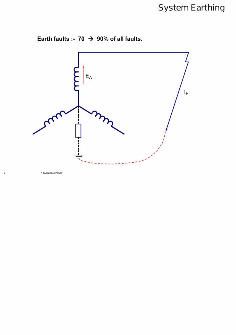
System Earthing
Earth faults :- 70
90% of all faults.
IF
E A
7/29/2019 2 Earthing Grounding
http://slidepdf.com/reader/full/2-earthing-grounding 3/70
> System Earthing 3
System Earthing
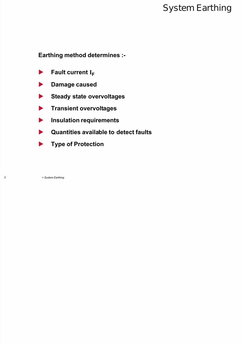
Earthing method determines :-
Fault current IF
Damage caused
Steady state overvoltages
Transient overvoltages
Insulation requirements
Quantities available to detect faults
Type of Protection
7/29/2019 2 Earthing Grounding
http://slidepdf.com/reader/full/2-earthing-grounding 4/70
> System Earthing 4
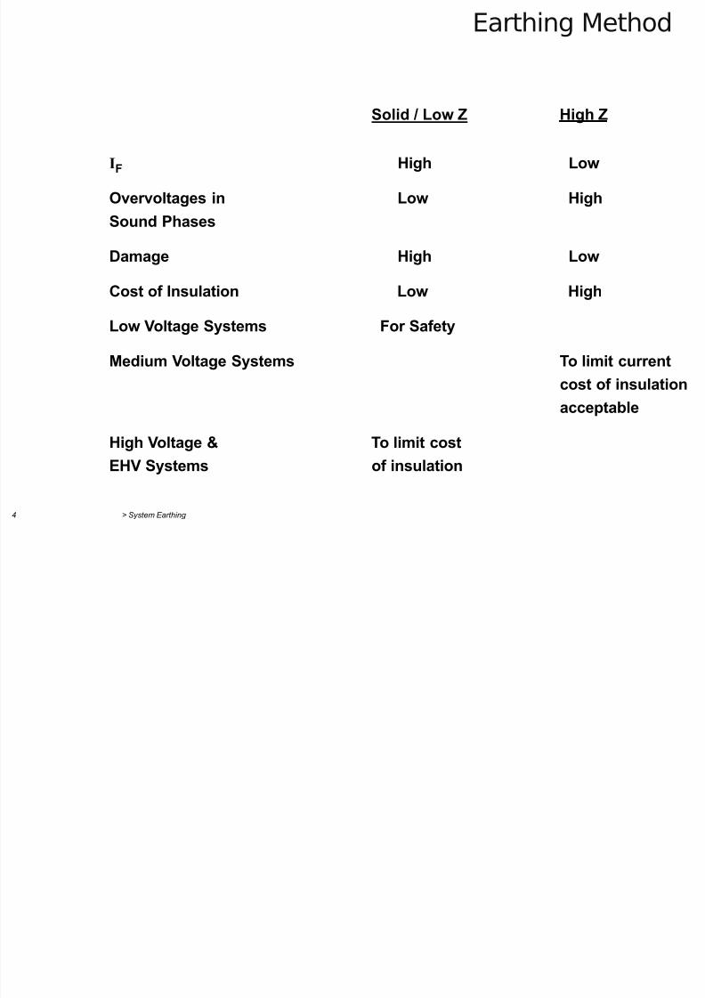
Earthing Method
Solid / Low Z High Z
IF High Low
Overvoltages in Low High
Sound Phases
Damage High Low
Cost of Insulation Low High
Low Voltage Systems For Safety
Medium Voltage Systems To limit currentcost of insulation
acceptable
High Voltage & To limit cost
EHV Systems of insulation
7/29/2019 2 Earthing Grounding
http://slidepdf.com/reader/full/2-earthing-grounding 5/70
> System Earthing 5
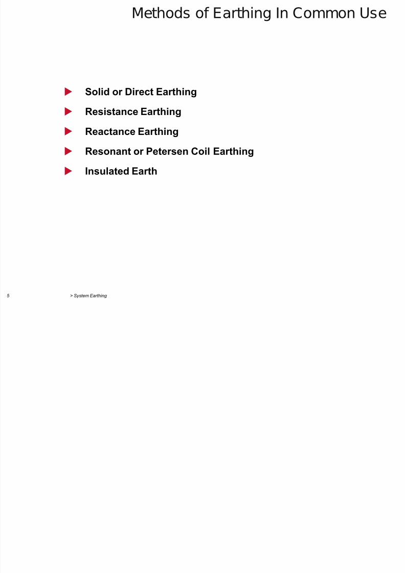
Methods of Earthing In Common Use
Solid or Direct Earthing
Resistance Earthing
Reactance Earthing
Resonant or Petersen Coil Earthing
Insulated Earth
7/29/2019 2 Earthing Grounding
http://slidepdf.com/reader/full/2-earthing-grounding 6/70
> System Earthing 6
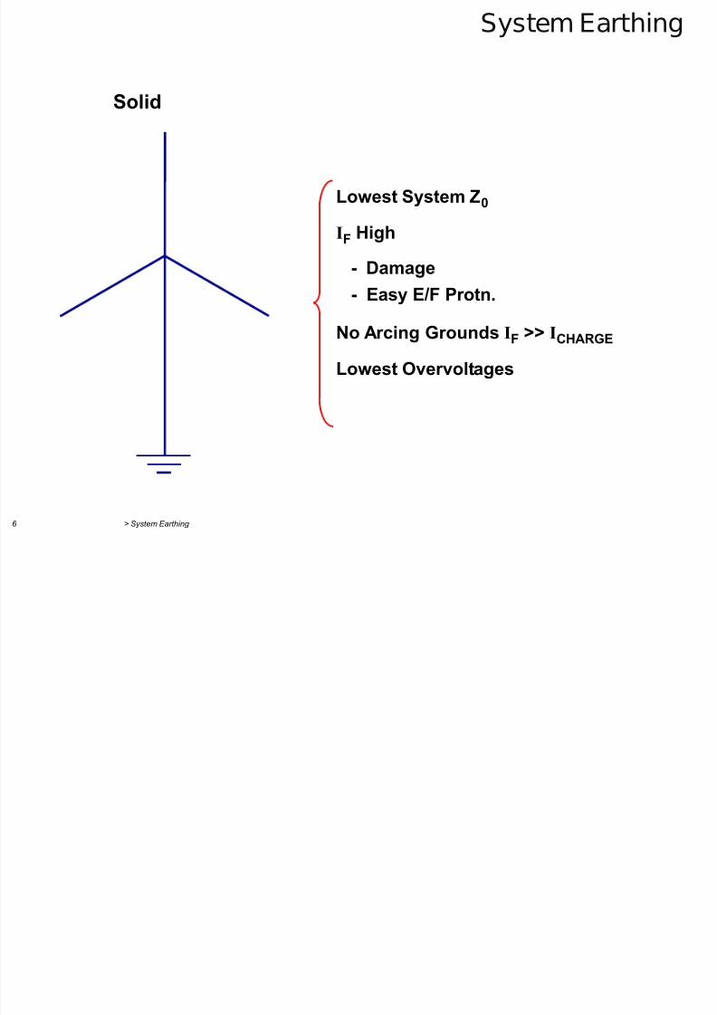
System Earthing
Solid
Lowest System Z0
IF High
- Damage
- Easy E/F Protn.
No Arcing Grounds IF >> ICHARGE
Lowest Overvoltages
7/29/2019 2 Earthing Grounding
http://slidepdf.com/reader/full/2-earthing-grounding 7/70> System Earthing 7
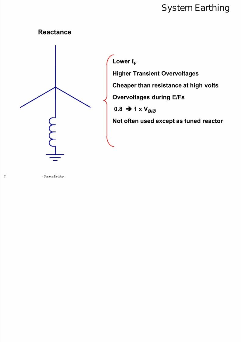
System Earthing
Reactance
Lower IF
Higher Transient Overvoltages
Cheaper than resistance at high volts
Overvoltages during E/Fs
0.8 1 x VØ/Ø
Not often used except as tuned reactor
7/29/2019 2 Earthing Grounding
http://slidepdf.com/reader/full/2-earthing-grounding 8/70> System Earthing 8
System Earthing
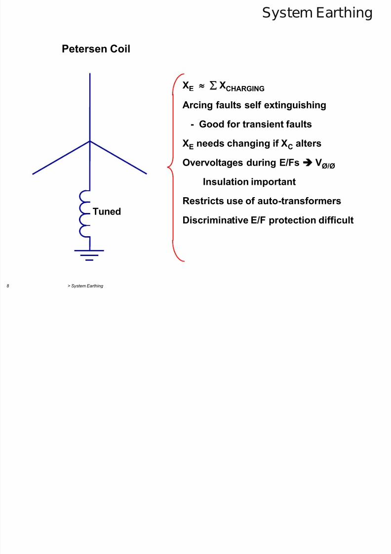
Petersen Coil
XE XCHARGING
Arcing faults self extinguishing
- Good for transient faults
XE needs changing if XC alters
Overvoltages during E/Fs VØ/Ø
Insulation important
Restricts use of auto-transformersDiscriminative E/F protection difficult
Tuned
7/29/2019 2 Earthing Grounding
http://slidepdf.com/reader/full/2-earthing-grounding 9/70> System Earthing 9
System Earthing
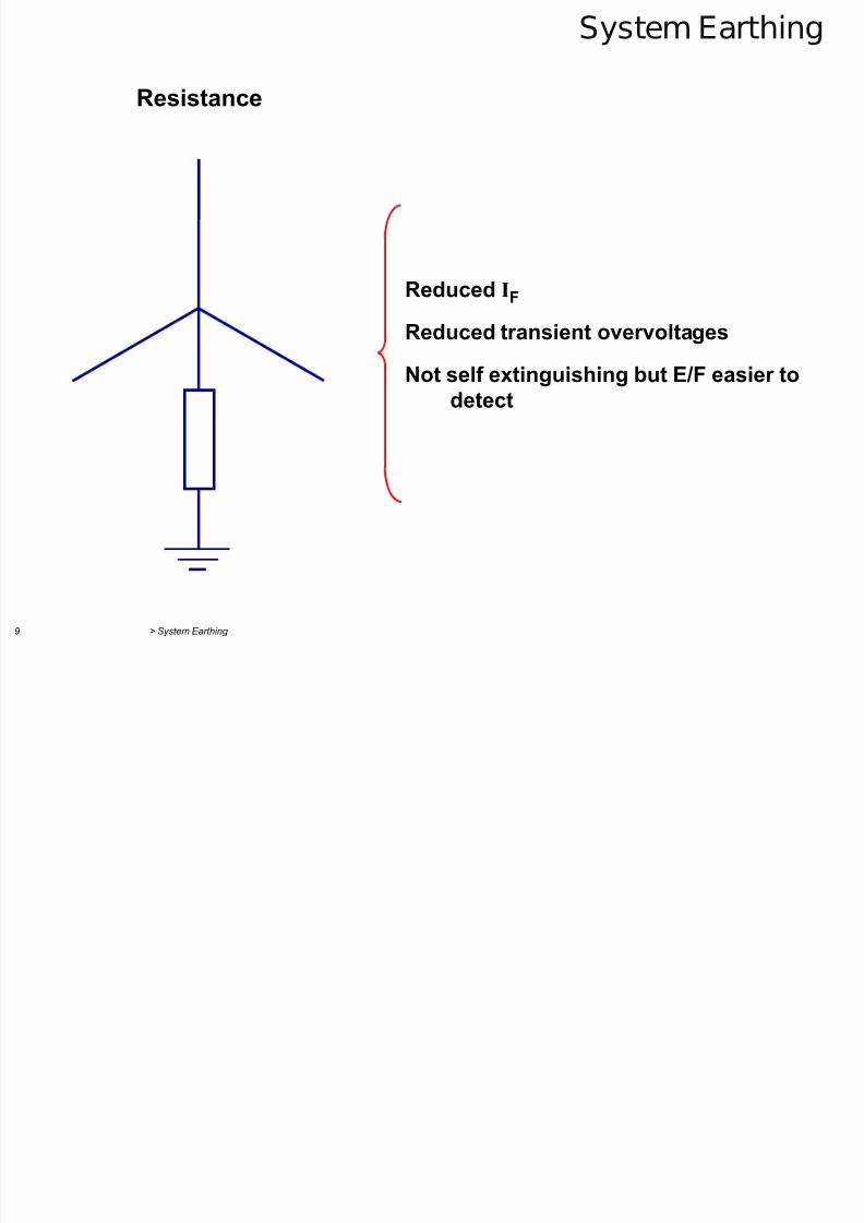
Resistance
Reduced IF
Reduced transient overvoltages
Not self extinguishing but E/F easier todetect
7/29/2019 2 Earthing Grounding
http://slidepdf.com/reader/full/2-earthing-grounding 10/70> System Earthing 10
System Earthing
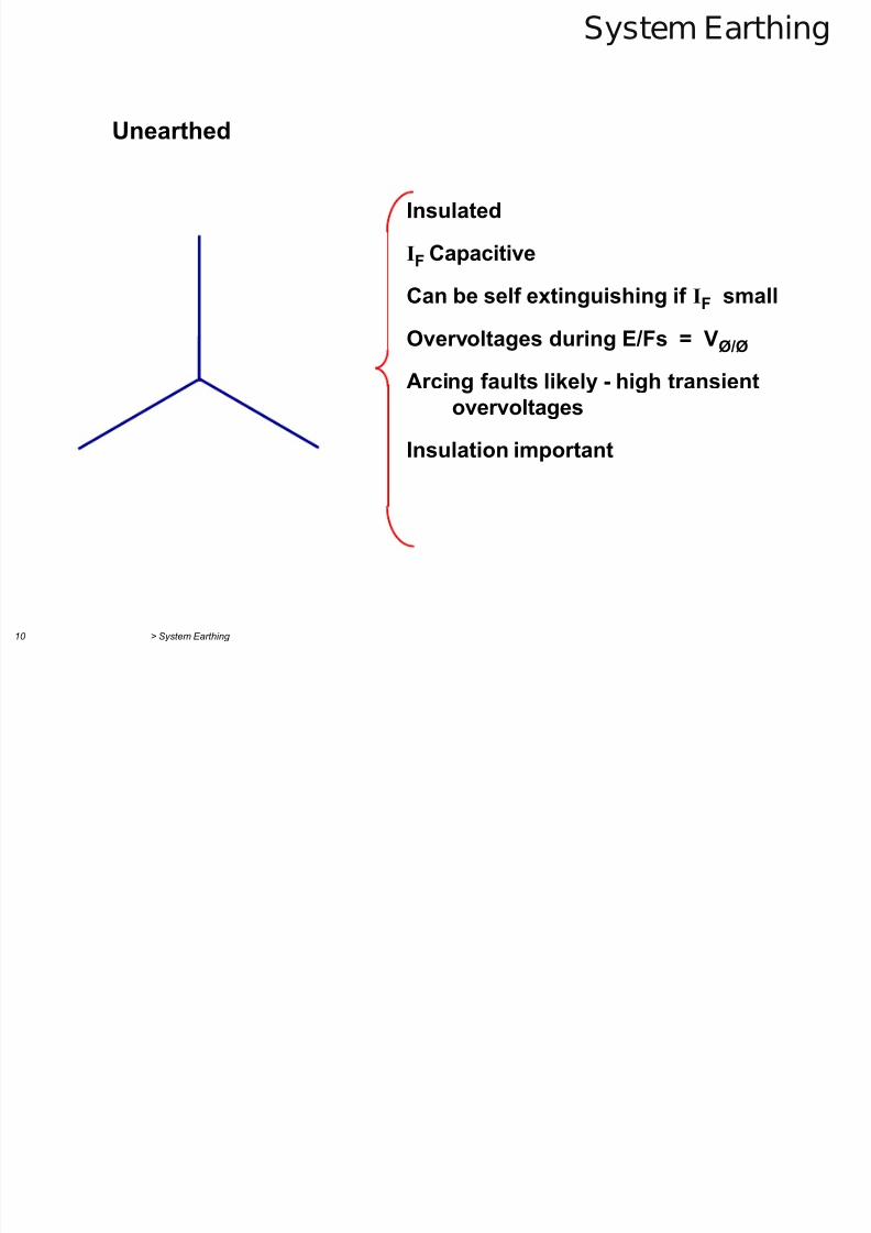
Unearthed
Insulated
IF Capacitive
Can be self extinguishing if IF small
Overvoltages during E/Fs = VØ/Ø
Arcing faults likely - high transientovervoltages
Insulation important
7/29/2019 2 Earthing Grounding
http://slidepdf.com/reader/full/2-earthing-grounding 11/70> System Earthing 11
System Earthing
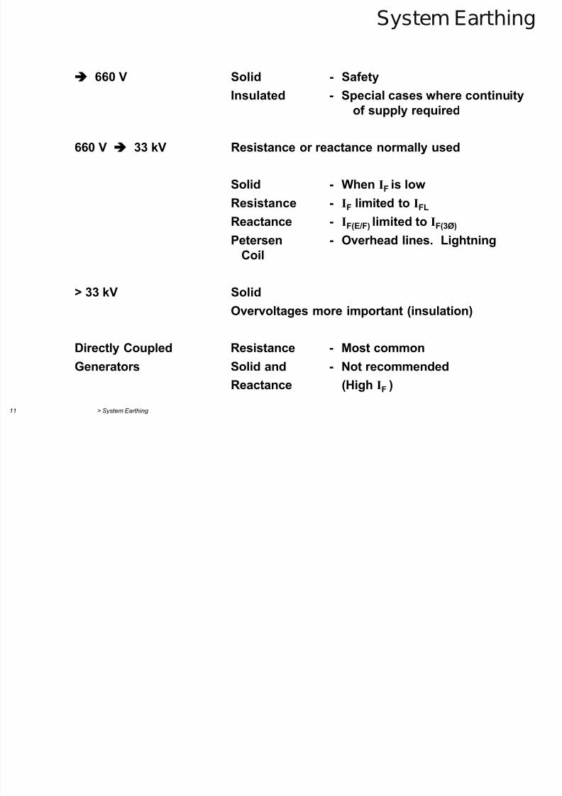
660 V Solid - Safety
Insulated - Special cases where continuityof supply required
660 V 33 kV Resistance or reactance normally used
Solid - When IF is low
Resistance - IF limited to IFL
Reactance - IF(E/F) limited to IF(3Ø)
Petersen - Overhead lines. LightningCoil
> 33 kV SolidOvervoltages more important (insulation)
Directly Coupled Resistance - Most common
Generators Solid and - Not recommended
Reactance (High IF
)
7/29/2019 2 Earthing Grounding
http://slidepdf.com/reader/full/2-earthing-grounding 12/70> System Earthing 12
System Earthing
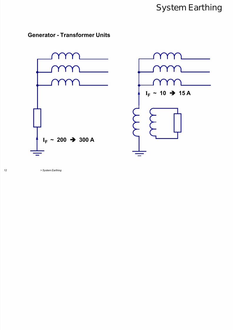
Generator - Transformer Units
IF ~ 200 300 A
IF ~ 10 15 A
7/29/2019 2 Earthing Grounding
http://slidepdf.com/reader/full/2-earthing-grounding 13/70> System Earthing 13
Low Voltage System Earthing
Safety :-
Power system neutral solidly earthed at transformer.
Metallic tools and appliances solidly earthed.
Sensitive protection by :-
RCD’s :- Residual current devices
ELCB’s :- Earth leakage circuit breakers
7/29/2019 2 Earthing Grounding
http://slidepdf.com/reader/full/2-earthing-grounding 14/70> System Earthing 14
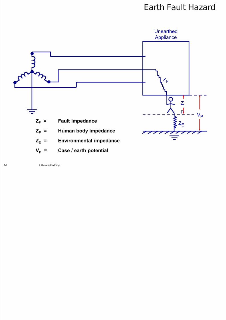
Earth Fault Hazard
ZF = Fault impedance
ZP = Human body impedance
ZE = Environmental impedance
VP = Case / earth potential
ZF
ZE
VP
Z
P
Unearthed
Appliance
7/29/2019 2 Earthing Grounding
http://slidepdf.com/reader/full/2-earthing-grounding 15/70> System Earthing 15
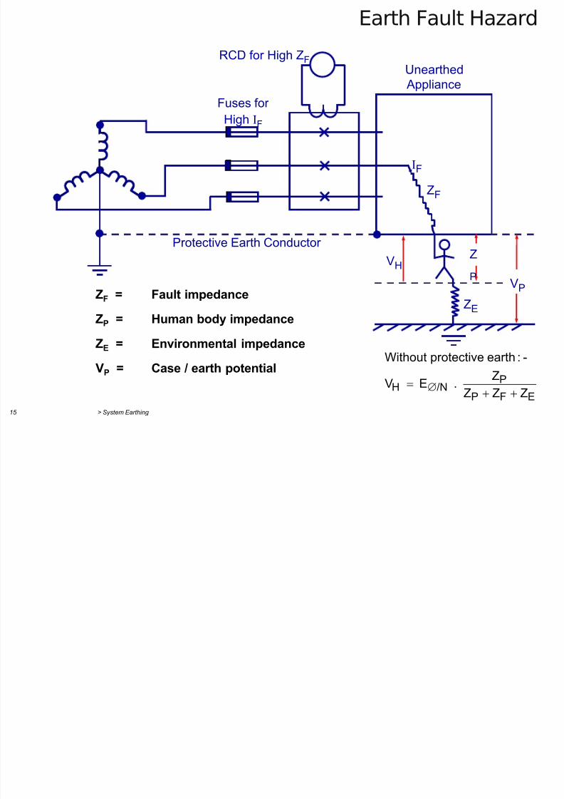
Earth Fault Hazard
ZF = Fault impedance
ZP = Human body impedance
ZE = Environmental impedance
VP = Case / earth potential
EFP
P/NH
ZZZ
Z . E V
-:earthprotectiveWithout
ZF
ZE
VP
Z
P
Unearthed
Appliance
IF
VH
RCD for High ZF
Fuses for
High IF
Protective Earth Conductor
7/29/2019 2 Earthing Grounding
http://slidepdf.com/reader/full/2-earthing-grounding 16/70> System Earthing 16
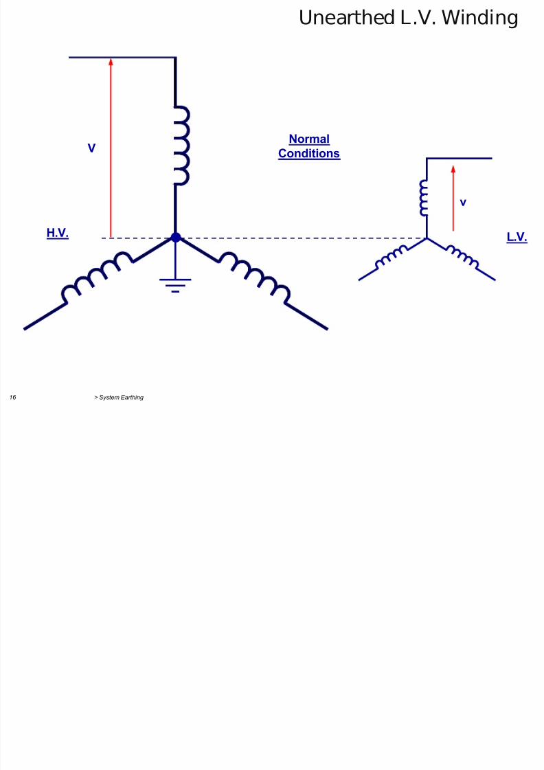
Unearthed L.V. Winding
NormalConditions
H.V.
V
v
L.V.
7/29/2019 2 Earthing Grounding
http://slidepdf.com/reader/full/2-earthing-grounding 17/70> System Earthing 17
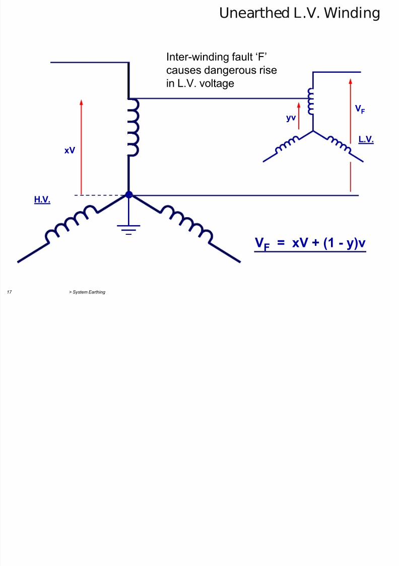
Unearthed L.V. Winding
H.V.
xV
yv
L.V.
VF
VF = xV + (1 - y)v
Inter-winding fault ‘F’
causes dangerous risein L.V. voltage
7/29/2019 2 Earthing Grounding
http://slidepdf.com/reader/full/2-earthing-grounding 18/70> System Earthing 18
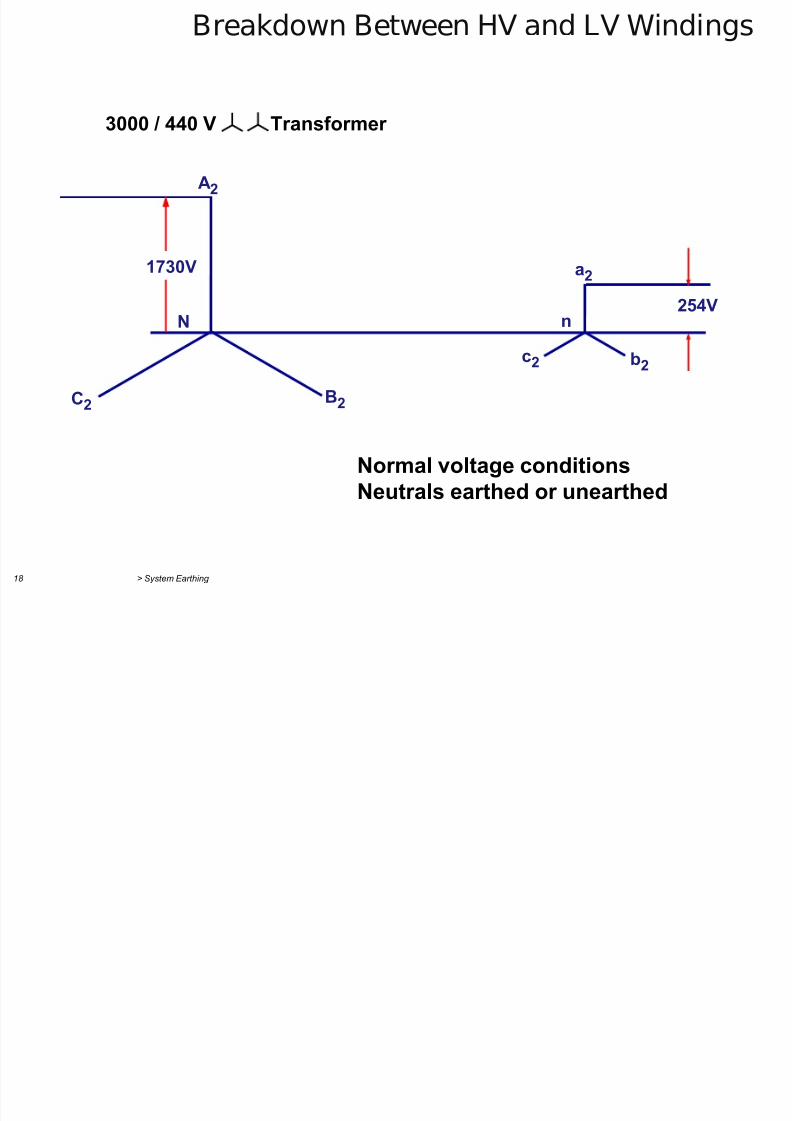
Breakdown Between HV and LV Windings
1730V
A2
B2 C2
N
c2 b2
a2 254V
n
3000 / 440 V Transformer
Normal voltage conditionsNeutrals earthed or unearthed
7/29/2019 2 Earthing Grounding
http://slidepdf.com/reader/full/2-earthing-grounding 19/70> System Earthing 19
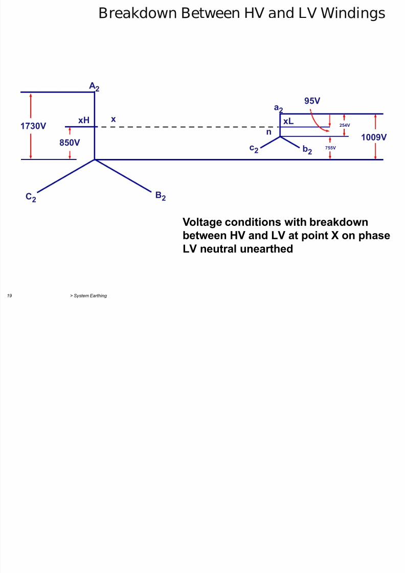
Breakdown Between HV and LV Windings
Voltage conditions with breakdownbetween HV and LV at point X on phaseLV neutral unearthed
1730V
850V
A2
B2 C2
xH x
n
c2 b2
a2
xL
755V
254V
1009V
95V
7/29/2019 2 Earthing Grounding
http://slidepdf.com/reader/full/2-earthing-grounding 20/70> System Earthing 20
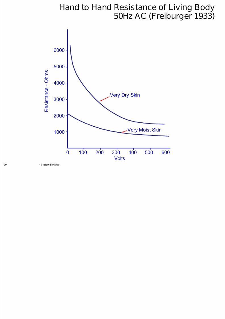
Hand to Hand Resistance of Living Body50Hz AC (Freiburger 1933)
6000
5000
4000
3000
2000
1000
0 100 200 300 400 500 600
Volts
R e s i s t a n c e - O h m s
Very Dry Skin
Very Moist Skin
7/29/2019 2 Earthing Grounding
http://slidepdf.com/reader/full/2-earthing-grounding 21/70> System Earthing 21
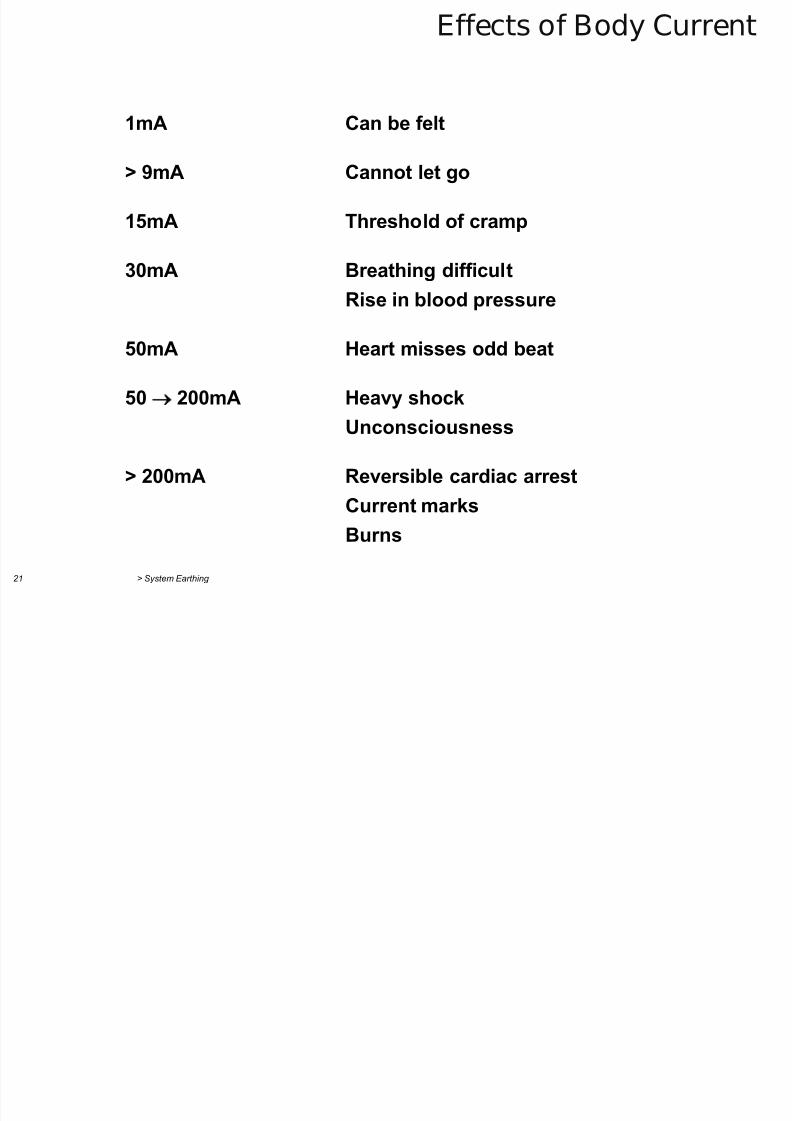
Effects of Body Current
1mA Can be felt
> 9mA Cannot let go
15mA Threshold of cramp
30mA Breathing difficultRise in blood pressure
50mA Heart misses odd beat
50 200mA Heavy shock
Unconsciousness
> 200mA Reversible cardiac arrest
Current marks
Burns
Eff f V i V l f B d C
7/29/2019 2 Earthing Grounding
http://slidepdf.com/reader/full/2-earthing-grounding 22/70> System Earthing 22
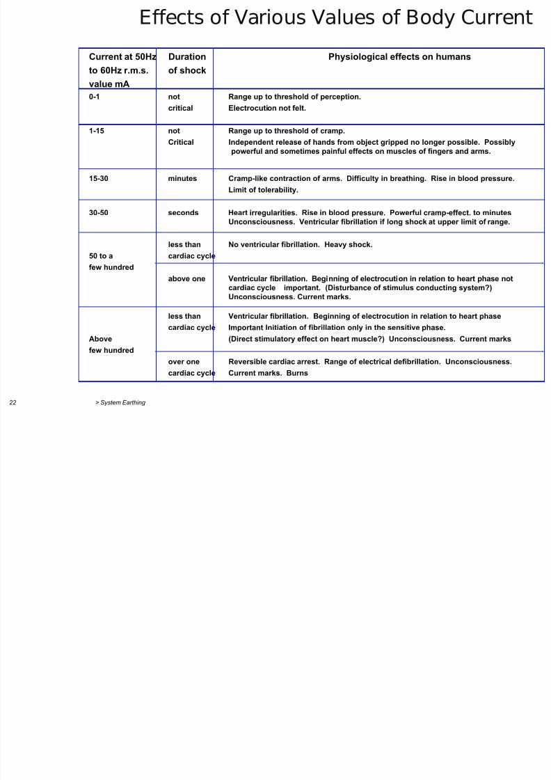
Current at 50Hz Duration Physiological effects on humans
to 60Hz r.m.s. of shock
value mA
0-1 not Range up to threshold of perception.critical Electrocution not felt.
1-15 not Range up to threshold of cramp.
Critical Independent release of hands from object gripped no longer possible. Possibly
powerful and sometimes painful effects on muscles of fingers and arms.
15-30 minutes Cramp-like contraction of arms. Difficulty in breathing. Rise in blood pressure.
Limit of tolerability.
30-50 seconds Heart irregularities. Rise in blood pressure. Powerful cramp-effect. to minutes
Unconsciousness. Ventricular fibrillation if long shock at upper limit of range.
less than No ventricular fibrillation. Heavy shock.
50 to a cardiac cycle
few hundred
above one Ventricular fibrillation. Beginning of electrocution in relation to heart phase not
cardiac cycle important. (Disturbance of stimulus conducting system?)Unconsciousness. Current marks.
less than Ventricular fibrillation. Beginning of electrocution in relation to heart phase
cardiac cycle Important Initiation of fibrillation only in the sensitive phase.
Above (Direct stimulatory effect on heart muscle?) Unconsciousness. Current marks
few hundred
over one Reversible cardiac arrest. Range of electrical defibrillation. Unconsciousness.
cardiac cycle Current marks. Burns
Effects of Various Values of Body Current
B d C / Ti d S i
7/29/2019 2 Earthing Grounding
http://slidepdf.com/reader/full/2-earthing-grounding 23/70
> System Earthing 23
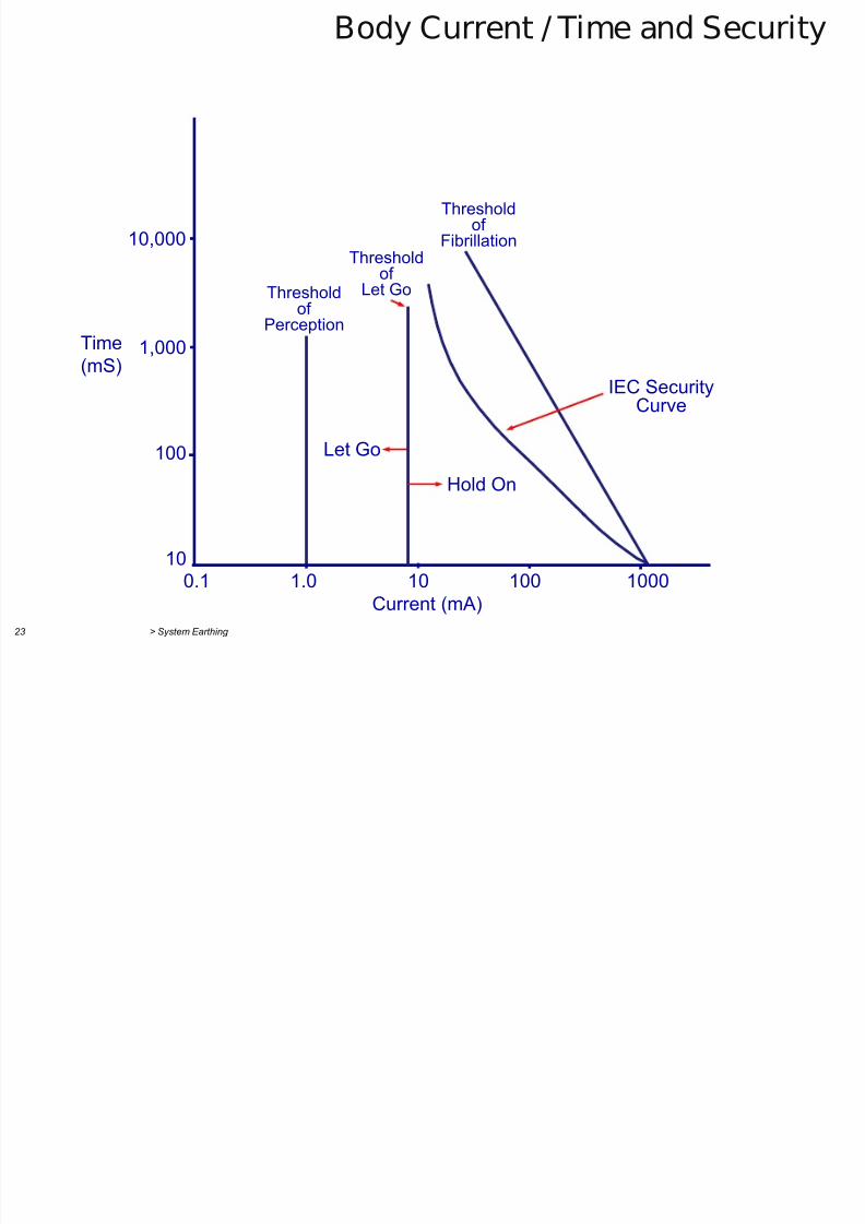
Body Current / Time and Security
10,000
1,000
100
10 0.1 1.0 10 100 1000
Current (mA)
Time
(mS)
Thresholdof
Perception
Thresholdof
Let Go
Let Go Hold On
IEC SecurityCurve
Thresholdof
Fibrillation
E thi I d Aff t T h & St P t ti l

7/29/2019 2 Earthing Grounding
http://slidepdf.com/reader/full/2-earthing-grounding 24/70
> System Earthing 25
Earthing Impedance Affects Touch & Step Potentials
Don’t forget
communicationscables etc.entering S/S !
Surface
True
Earth
RE Touch
VH VH
Step
E
RF IF
RG
IF
IF
True EarthRG
RG' = f(Distance)
d
!
'RRR
'R E V
GFE
GH
I t t d St (Zi Z ) E thi T f
7/29/2019 2 Earthing Grounding
http://slidepdf.com/reader/full/2-earthing-grounding 25/70
> System Earthing 26
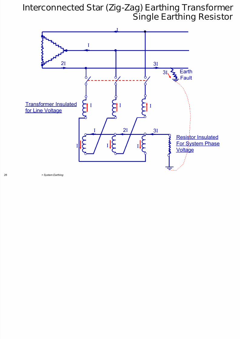
Interconnected Star (Zig-Zag) Earthing TransformerSingle Earthing Resistor
I
2I
I
3I
3I Earth
Fault
I IITransformer Insulated
for Line Voltage
Resistor Insulated
For System Phase
Voltage
3I2II
I II
I t t d St E thi T f
7/29/2019 2 Earthing Grounding
http://slidepdf.com/reader/full/2-earthing-grounding 26/70
> System Earthing 27
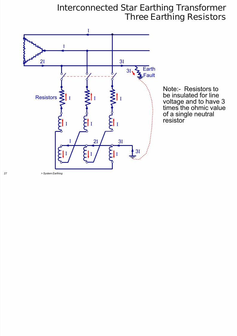
Interconnected Star Earthing Transformer Three Earthing Resistors
2I
I
I
3I
3IEarth
Fault
I II
3I2II
I II
I IIResistors
3I
Note:- Resistors tobe insulated for linevoltage and to have 3times the ohmic valueof a single neutralresistor
Di l t f N t l f E th
7/29/2019 2 Earthing Grounding
http://slidepdf.com/reader/full/2-earthing-grounding 27/70
> System Earthing 28
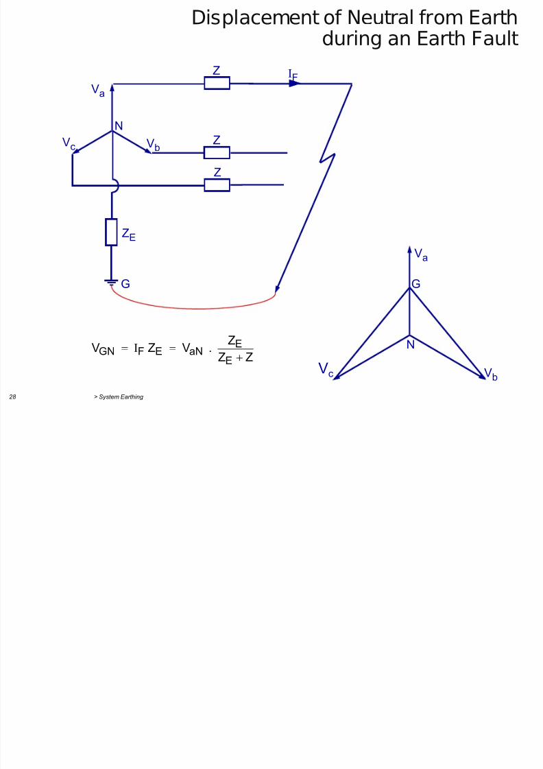
Displacement of Neutral from Earthduring an Earth Fault
Va
Vb Vc
ZE
N
Z
G
Z
Z
IF
Va
Vb Vc
G
NZZ
Z . V Z V
E
EaNEFGN
E th F lt S t ith I l t d E th
7/29/2019 2 Earthing Grounding
http://slidepdf.com/reader/full/2-earthing-grounding 28/70
> System Earthing 29
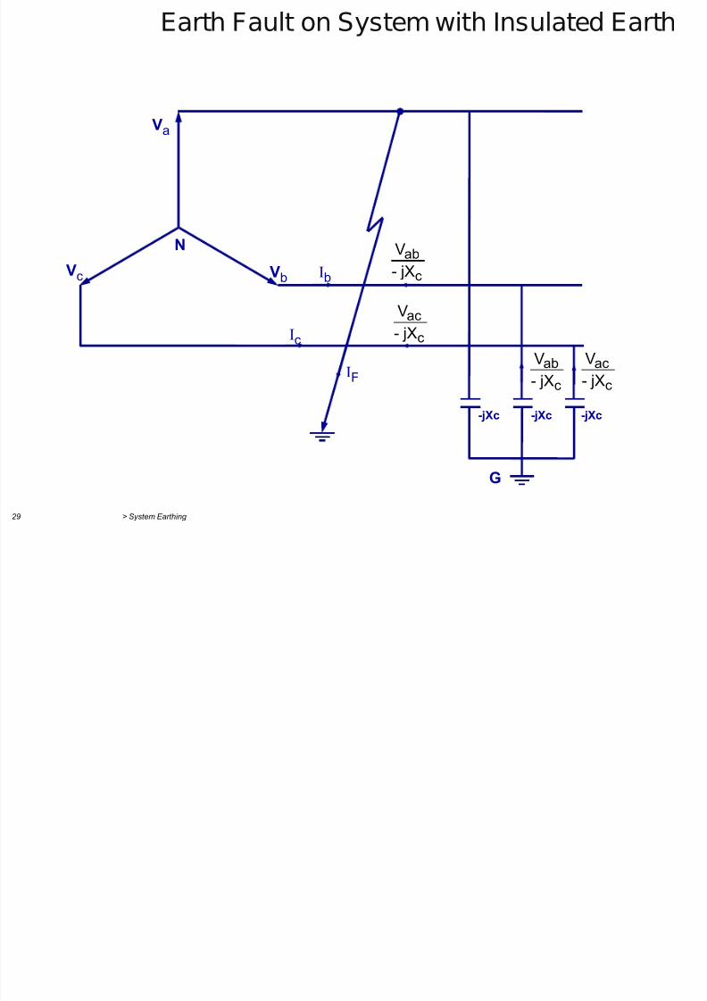
Earth Fault on System with Insulated Earth
Va
IF
Ic
Ib Vb Vc N
-jXc
G
-jXc -jXc
c
ab
jX-V
c
ac
jX-
V
c
ac
jX-
V
c
ab
jX-
V
E th F lt S t ith I l t d E th
7/29/2019 2 Earthing Grounding
http://slidepdf.com/reader/full/2-earthing-grounding 29/70
> System Earthing 30
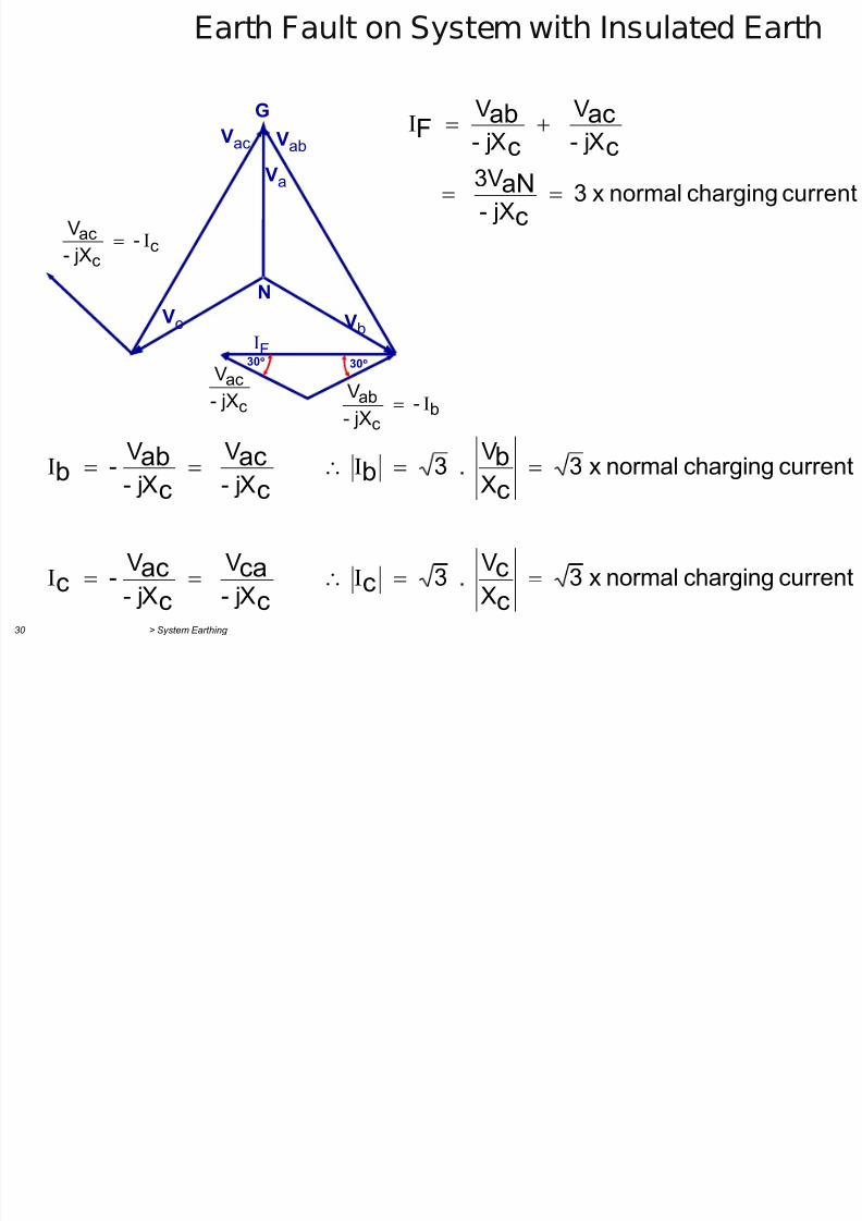
Earth Fault on System with Insulated Earth
G
Vab Vac
Va
Vb Vc N
IF 30 30
bc
ab - jX-
Vc
ac
jX-
V
cc
ac - jX-
V
currentchargingnormalx3 jX-
3V
jX-
V
jX-
V
c
aNc
ac
c
abF
currentchargingnormalx3
X
V . 3
jX-
V
jX-
V -
currentchargingnormalx3 XV . 3
jX-V
jX-V -
c
cc
c
ca
c
acc
cbb
cac
cabb
Earth Fault on System
7/29/2019 2 Earthing Grounding
http://slidepdf.com/reader/full/2-earthing-grounding 30/70
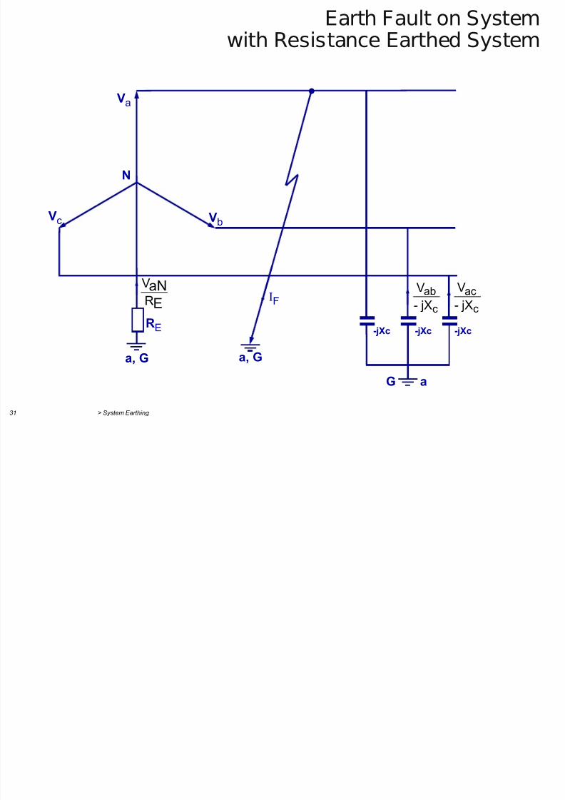
> System Earthing 31
Earth Fault on Systemwith Resistance Earthed System
Va
IF
Vb Vc
N
-jXc
G a
-jXc -jXc RE
a, G a, G
c
ac
jX-
V
c
ab
jX-
V
E
aN
R
V
Earth Fault on System
7/29/2019 2 Earthing Grounding
http://slidepdf.com/reader/full/2-earthing-grounding 31/70
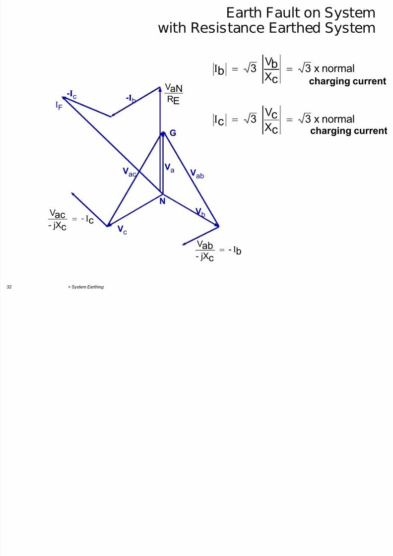
> System Earthing 32
Earth Fault on Systemwith Resistance Earthed System
G
Vab Vac Va
Vb
Vc
N
-Ib -Ic
IF
bc
ab - jX-
V
cc
ac - jX-
V
E
aNR
V
normalx3 X
V 3
normalx3 X
V
3
c
cc
c
bb
charging current
charging current
Earth Fault on System with Resonant
7/29/2019 2 Earthing Grounding
http://slidepdf.com/reader/full/2-earthing-grounding 32/70
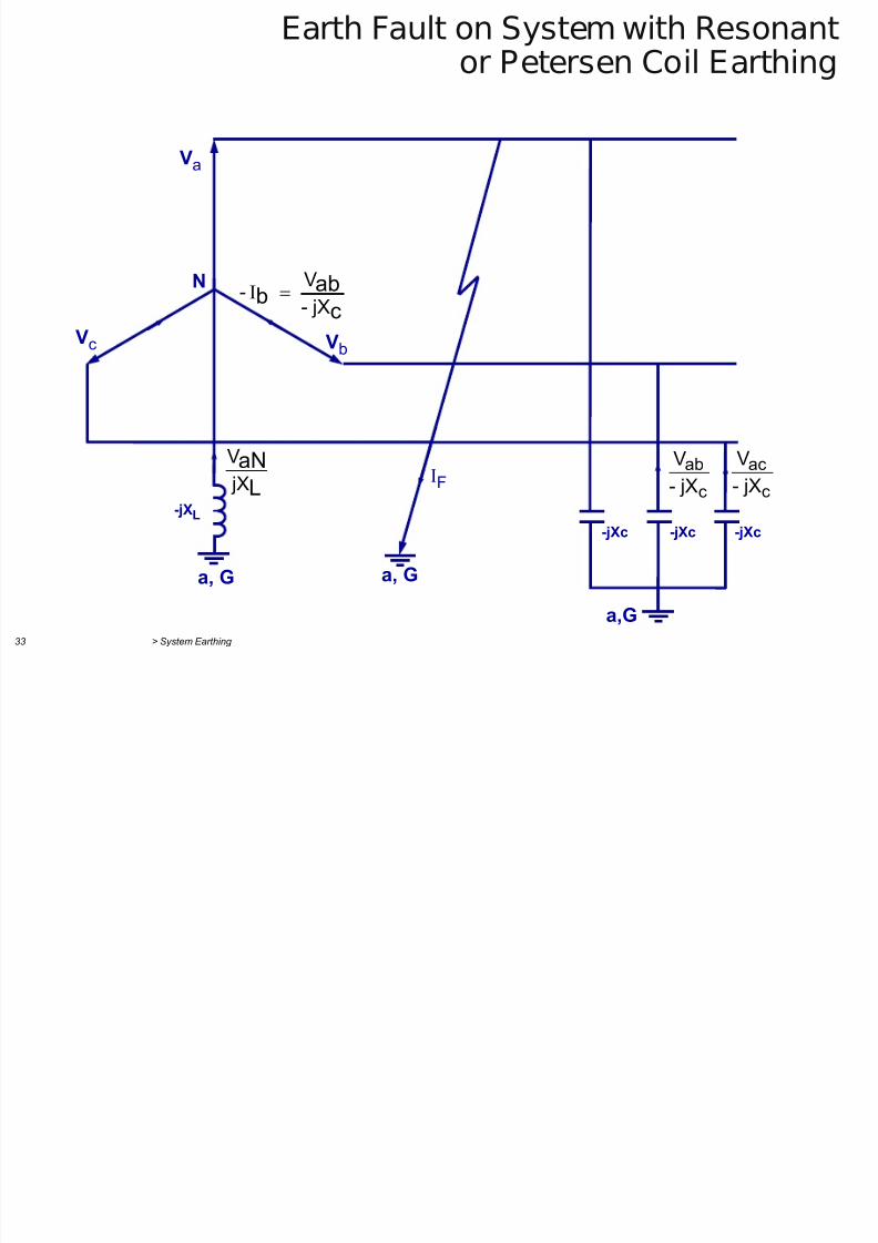
> System Earthing 33
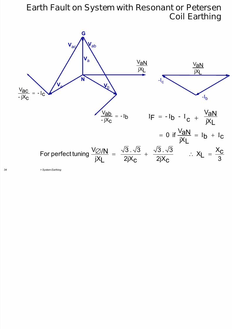
Earth Fault on System with Resonantor Petersen Coil Earthing
Va
IF
Vb Vc
N
-jXc
a,G
-jXc -jXc
a, G a, G
-jXL c
ac jX-V
c
ab jX-V
LaN jXV
c
abb
jX-
V -
Earth Fault on System with Resonant or Petersen
7/29/2019 2 Earthing Grounding
http://slidepdf.com/reader/full/2-earthing-grounding 33/70
> System Earthing 34
Earth Fault on System with Resonant or PetersenCoil Earthing
G
Vab Vac
Va
Vb Vc N -I
c
-Ib c
c
ac - jX-
V
b
c
ab - jX-
V
L
aN jX
V
L
aN jX
V
cbL
aNL
aN
cbF
jX
V if 0
jX
V - -
3
X X
2jX
3.3
2jX
3.3
jX
V tuningperfectFor c
L
ccL
/N
Sequence Impedances
7/29/2019 2 Earthing Grounding
http://slidepdf.com/reader/full/2-earthing-grounding 34/70
> System Earthing 35
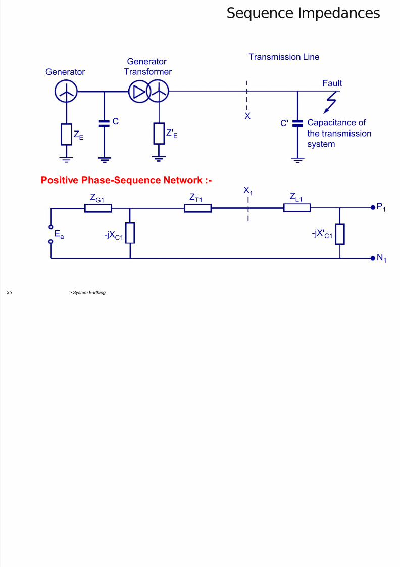
Sequence Impedances
ZL1 X1
X
ZT1 ZG1 P
1
-jX'C1 -jXC1 Ea
N1
Generator
Generator
Transformer
Transmission Line
Fault
Capacitance of
the transmission
system
C'C
ZE Z'E
Positive Phase-Sequence Network :-
Sequence Impedances
7/29/2019 2 Earthing Grounding
http://slidepdf.com/reader/full/2-earthing-grounding 35/70
> System Earthing 36
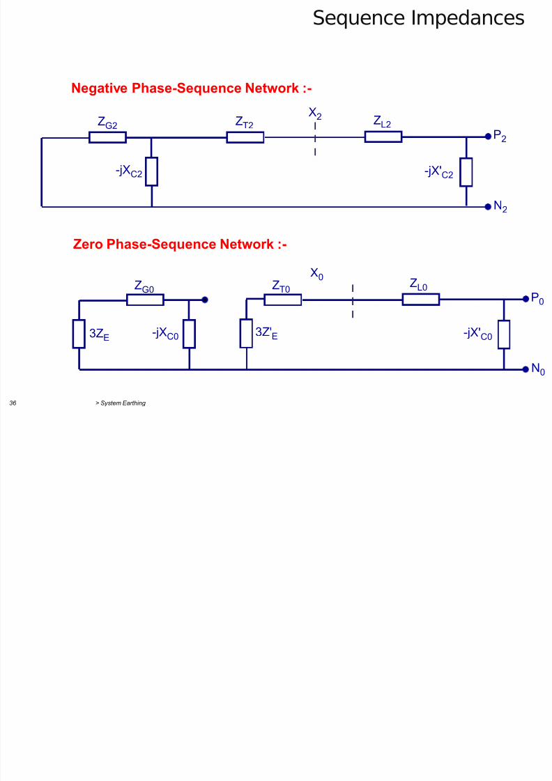
Sequence Impedances
Negative Phase-Sequence Network :-
X2 ZL2 ZT2 ZG2 P2
-jX'C2 -jXC2
N2
ZL0
X0
ZT0 ZG0
3ZE
P0
3Z'E -jX'C0 -jXC0
N0
Zero Phase-Sequence Network :-
Fault Currents and Voltages Analysis of Single
7/29/2019 2 Earthing Grounding
http://slidepdf.com/reader/full/2-earthing-grounding 36/70
> System Earthing 37
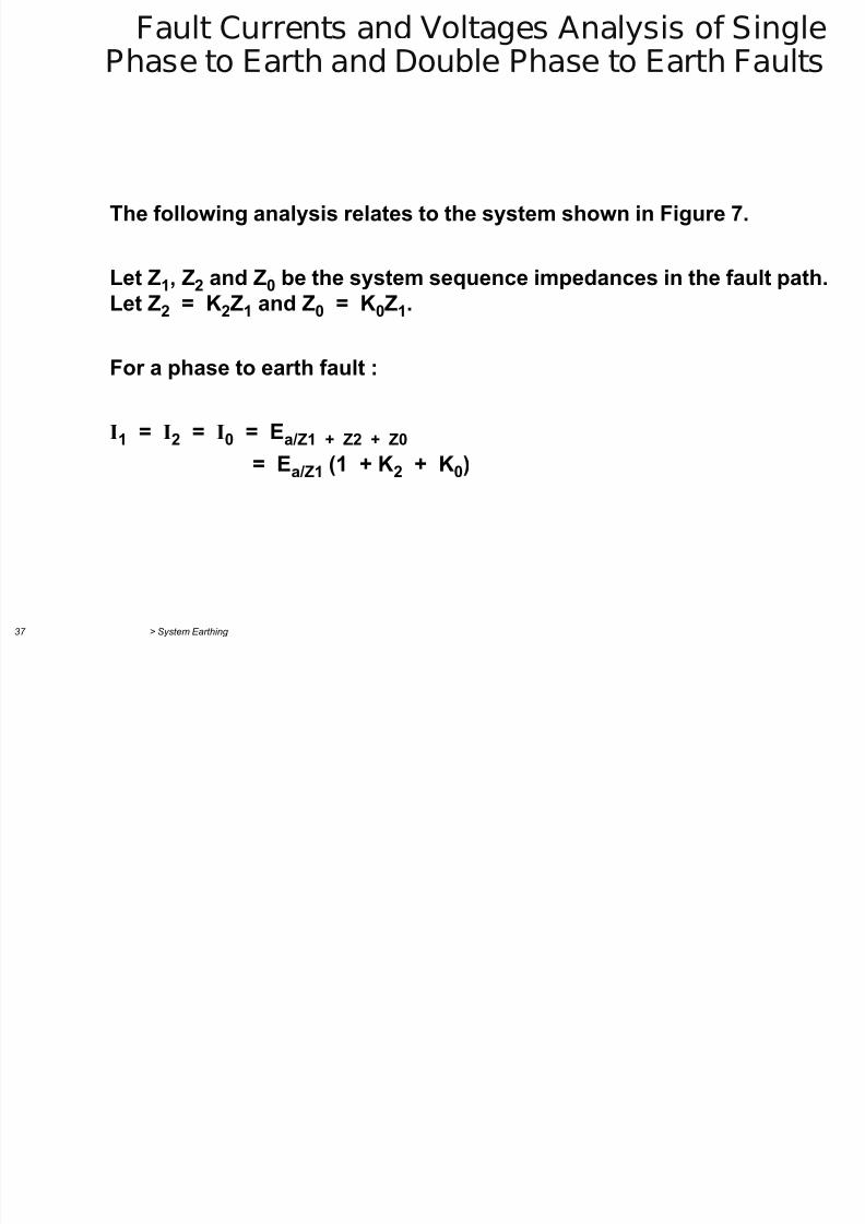
Fault Currents and Voltages Analysis of SinglePhase to Earth and Double Phase to Earth Faults
The following analysis relates to the system shown in Figure 7.
Let Z1, Z2 and Z0 be the system sequence impedances in the fault path.
Let Z2 = K2Z1 and Z0 = K0Z1.
For a phase to earth fault :
I1 = I2 = I0 = Ea/Z1 + Z2 + Z0
= Ea/Z1 (1 + K2 + K0)
Fault Currents and Voltages Analysis of Single
7/29/2019 2 Earthing Grounding
http://slidepdf.com/reader/full/2-earthing-grounding 37/70
> System Earthing 38
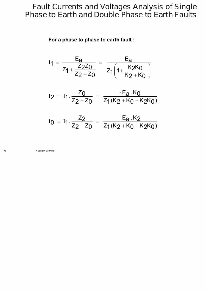
Fault Currents and Voltages Analysis of SinglePhase to Earth and Double Phase to Earth Faults
For a phase to phase to earth fault :
)KKK(KZ
K.E-
ZZ
Z .
)KKK(KZ
K.E-
ZZ
Z .
KK
KK
1Z
E
ZZ
ZZ Z
E
02021
2a
02
210
02021
0a
02
012
02
02
1
a
02
02
1
a1
Fault Currents and Voltages Analysis of Single
7/29/2019 2 Earthing Grounding
http://slidepdf.com/reader/full/2-earthing-grounding 38/70
> System Earthing 39
Fault Currents and Voltages Analysis of SinglePhase to Earth and Double Phase to Earth Faults
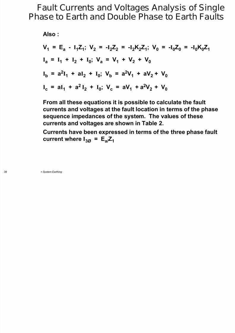
Also :
V1 = Ea - I1Z1; V2 = -I2Z2 = -I2K2Z1; V0 = -I0Z0 = -I0K0Z1
Ia = I1 + I2 + I0; Va = V1 + V2 + V0
Ib = a2I1 + aI2 + I0; Vb = a2V1 + aV2 + V0
Ic = aI1 + a2I2 + I0; Vc = aV1 + a2V2 + V0
From all these equations it is possible to calculate the faultcurrents and voltages at the fault location in terms of the phasesequence impedances of the system. The values of these
currents and voltages are shown in Table 2.Currents have been expressed in terms of the three phase faultcurrent where I3Ø = Ea/Z1
Sequence Connections for Phase to Earth Fault
7/29/2019 2 Earthing Grounding
http://slidepdf.com/reader/full/2-earthing-grounding 39/70
> System Earthing 40
-jX'C0
X0 3Z'E ZT0 ZL0
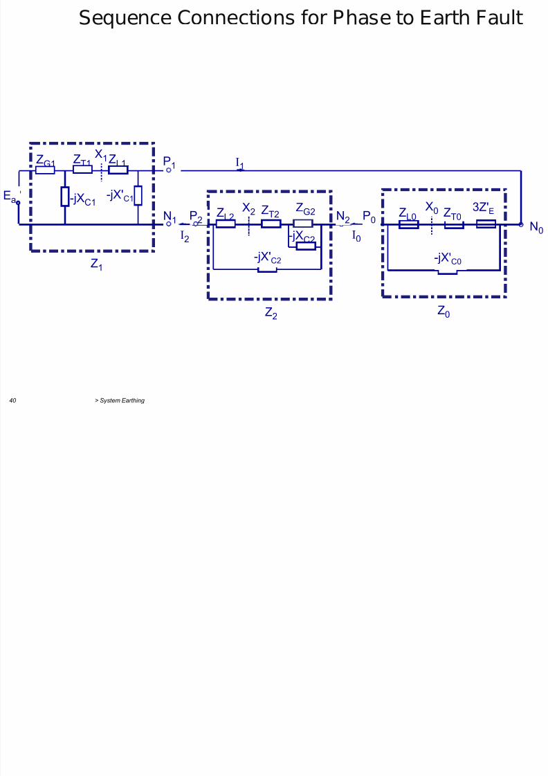
Sequence Connections for Phase to Earth Fault
P2 N1
P1
Z0 Z2
Z1
-jX'C1 -jXC1 Ea
X1 ZL1 ZT1 ZG1
-jX'C2
-jXC2
X2 ZG2 ZT2 ZL2 P0 N2 N0
I2 I0
I1
Phase to Earth Fault
7/29/2019 2 Earthing Grounding
http://slidepdf.com/reader/full/2-earthing-grounding 40/70
> System Earthing 41
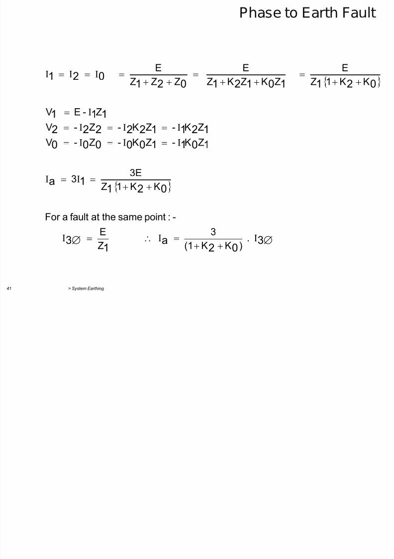
Phase to Earth Fault
302
a1
3
0211a
101100000
121122222
111
02110121021021
. )KK(1
3
Z
E
-:pointsametheatfaultaFor
KK1Z
3E 3
ZK- ZK- Z- V
ZK- ZK- Z- V
Z-E V
KK1ZE
ZKZKZE
ZZZE
Phase to Earth Fault
7/29/2019 2 Earthing Grounding
http://slidepdf.com/reader/full/2-earthing-grounding 41/70
> System Earthing 42
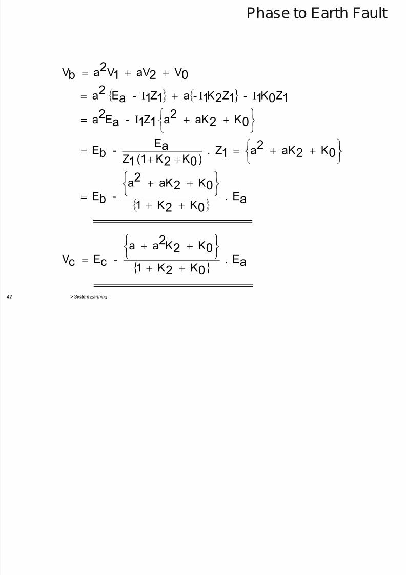
Phase to Earth Fault
a02
022
cc
a02
022
b
0221021
ab
022
11a2
10112111a2
0212
b
E . K K 1
K Ka a
- E V
E . K K 1
K aK a
- E
K aK a Z . )KK(1Z
E - E
K aK aZ - Ea
ZK - ZK-a Z - Ea
V aV Va V
Phase to Earth Fault
7/29/2019 2 Earthing Grounding
http://slidepdf.com/reader/full/2-earthing-grounding 42/70
> System Earthing 43
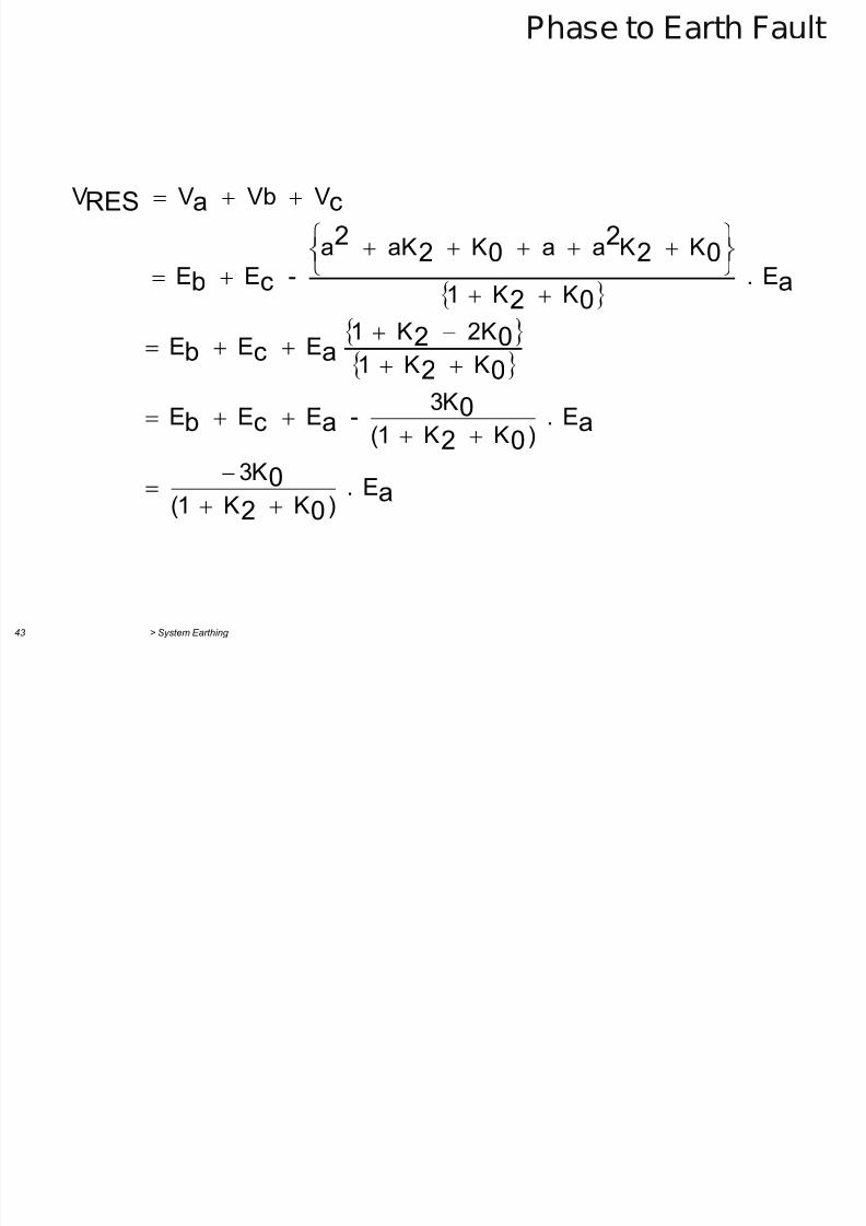
Phase to Earth Fault
a02
0
a02
0acb
02
02acb
a
02
022
022
cb
caRES
E . )K K 1(
K3
E . )K K 1(
K3 - E E E
K K 1
2K K 1 E E E
E . K K 1
K Ka a K aK a
- E E
V Vb V V
Sequence Connections for Phase
7/29/2019 2 Earthing Grounding
http://slidepdf.com/reader/full/2-earthing-grounding 43/70
> System Earthing 44
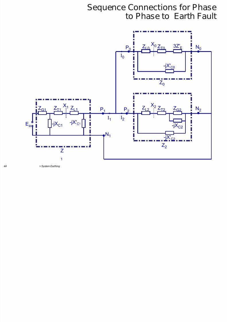
Sequence Connections for Phaseto Phase to Earth Fault
P2
N1
P1
Z0
Z2 Z
1
-jX'C1 -jXC1 Ea
X1 ZL1 ZT1 ZG1
-jX'C2
-jXC2
X2 ZG2 ZT2 ZL2
P0
N2
-jX'C0
X0 3Z'E ZT0 ZL0 N0
I
2
I0
I1
Steady-state Fault Currents and Voltages for
7/29/2019 2 Earthing Grounding
http://slidepdf.com/reader/full/2-earthing-grounding 44/70
> System Earthing 45
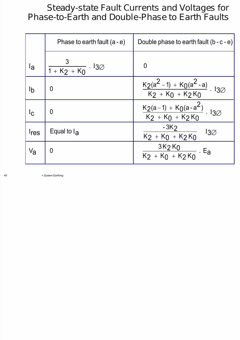
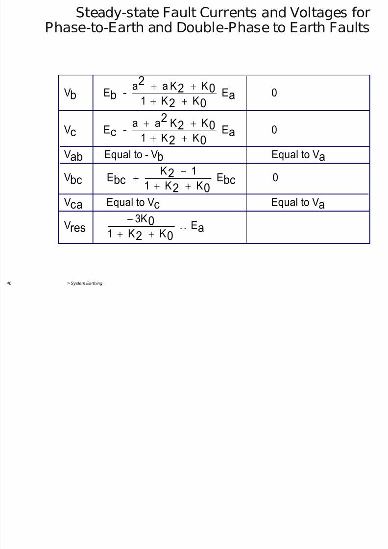
Steady state Fault Currents and Voltages forPhase-to-Earth and Double-Phase to Earth Faults
a0202
02a
30202
2ares
30202
202
c
30202
20
22b
302
a
E . KK K K
KK3 0 V
KK K K
3K- toEqual
. KK K K
)a-a(K )1(aK 0
. KK K K
a)-a(K )1(aK 0
0 . K K 1
3
e)-c-(bfaultearthtophaseDouble e)-(afaultearthtoPhase
Steady-state Fault Currents and Voltages for
7/29/2019 2 Earthing Grounding
http://slidepdf.com/reader/full/2-earthing-grounding 45/70
> System Earthing 46
Steady state Fault Currents and Voltages forPhase-to-Earth and Double-Phase to Earth Faults
E .. K K 1
K3 V
VtoEqual VtoEqual V
0 E K K 1
1 K E V
VtoEqual V-toEqual V
0 E K K 1
K Ka a - E V
0 E K K 1
K Ka a - E V
a02
0res
acca
bc02
2bcbc
ababa02
022
cc
a02
022
bb
7/29/2019 2 Earthing Grounding
http://slidepdf.com/reader/full/2-earthing-grounding 46/70
> System Earthing 47
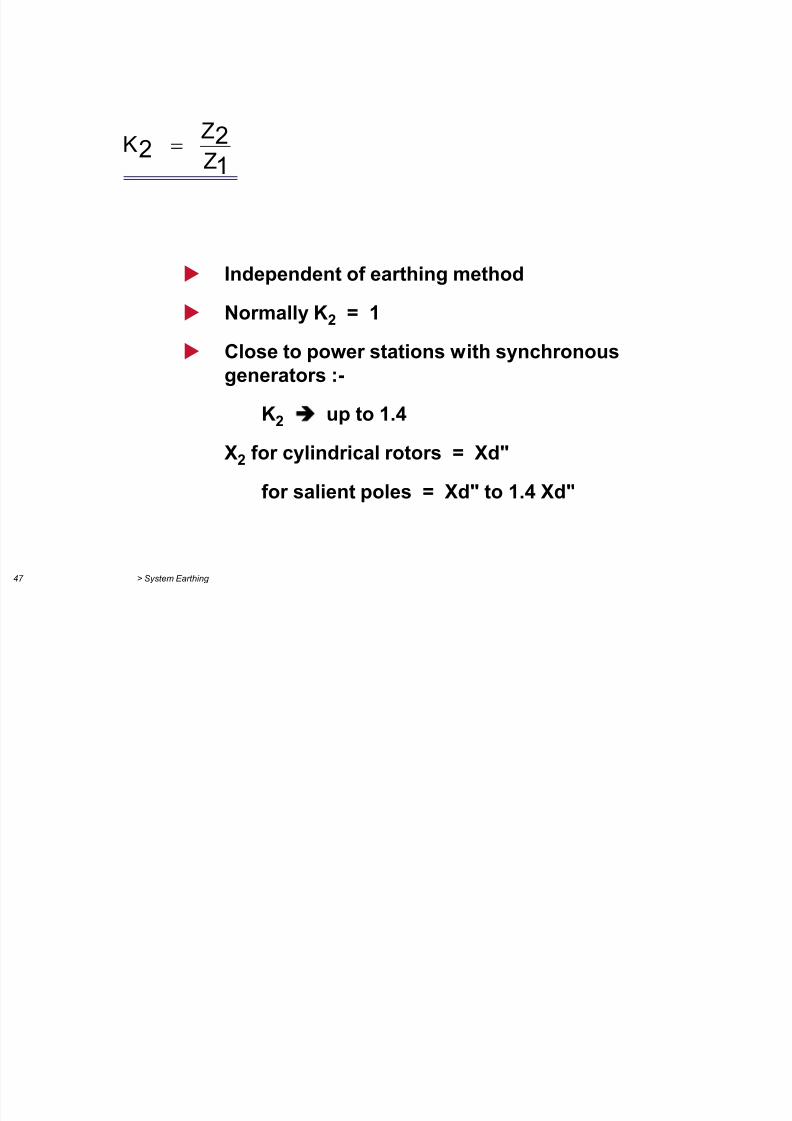
122 Z
Z K
Independent of earthing method
Normally K2 = 1
Close to power stations with synchronousgenerators :-
K2 up to 1.4
X2 for cylindrical rotors = Xd"
for salient poles = Xd" to 1.4 Xd"
7/29/2019 2 Earthing Grounding
http://slidepdf.com/reader/full/2-earthing-grounding 47/70
> System Earthing 48
1
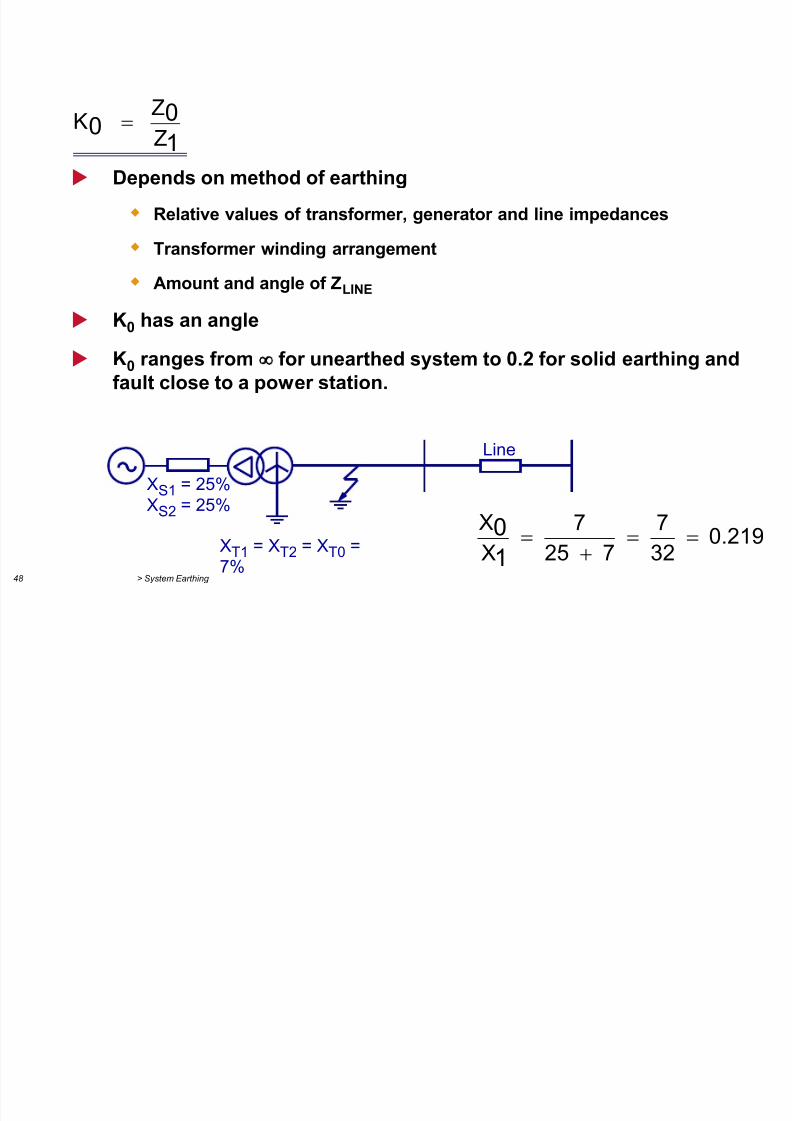
00
Z
Z K
Depends on method of earthing
Relative values of transformer, generator and line impedances
Transformer winding arrangement
Amount and angle of ZLINE
K0 has an angle
K0 ranges from for unearthed system to 0.2 for solid earthing andfault close to a power station.
Line
XS1 = 25%
XS2 = 25%
XT1
= XT2
= XT0
=
7%
0.219
32
7
7 25
7
X
X
1
0
Variation of Healthy Phase Voltages Due to
7/29/2019 2 Earthing Grounding
http://slidepdf.com/reader/full/2-earthing-grounding 48/70
> System Earthing 49
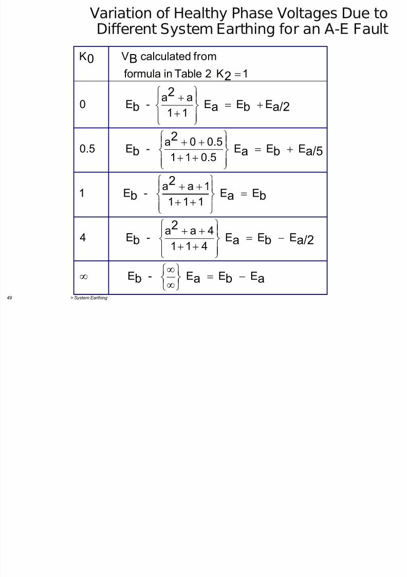
Variation of Healthy Phase Voltages Due toDifferent System Earthing for an A-E Fault
abab
a/2ba
2
b
ba
2
b
a/5ba
2
b
a/2ba
2
b
2
B0
E E E - E
E E E 411
4aa - E 4
E E 111
1aa - E 1
E E E 0.5110.50a - E 0.5
E E E 11
aa - E 0
1K 2Tableinformula
fromcalculatedVK
Variation of Healthy Phase Voltages Due to
7/29/2019 2 Earthing Grounding
http://slidepdf.com/reader/full/2-earthing-grounding 49/70
> System Earthing 50
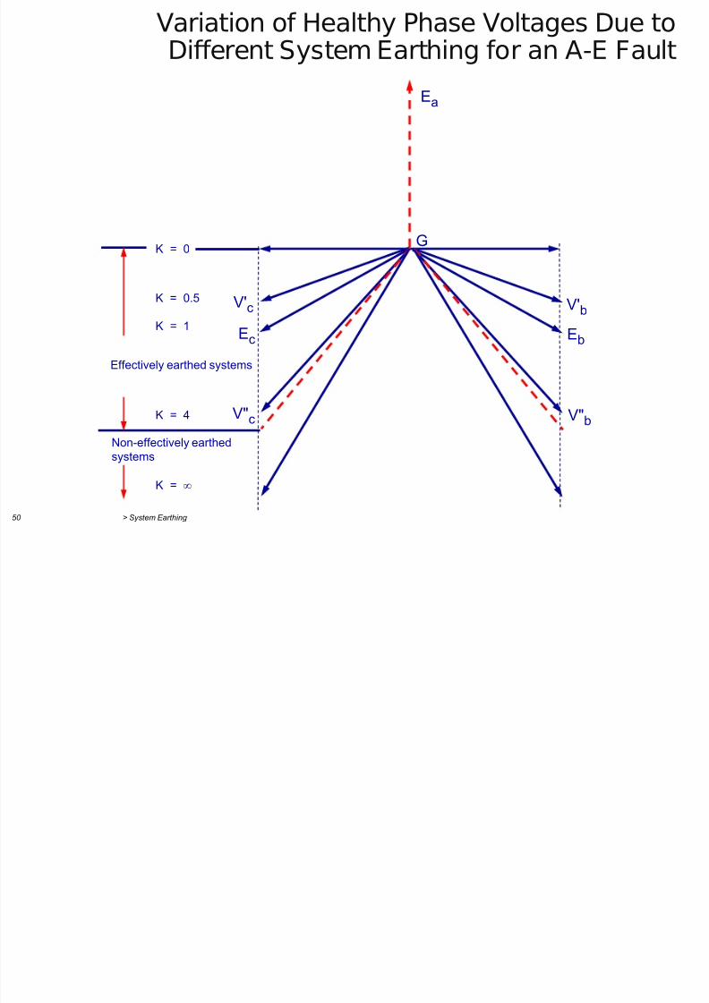
Variation of Healthy Phase Voltages Due toDifferent System Earthing for an A-E Fault
Ea
G
V'b
Eb
V"b
V'c
Ec
V"c
Effectively earthed systems
K = 0
K = 0.5
K = 1
K = 4
K =
Non-effectively earthed
systems
Healthy Phase Voltages during Earth Faults
7/29/2019 2 Earthing Grounding
http://slidepdf.com/reader/full/2-earthing-grounding 50/70
> System Earthing 51
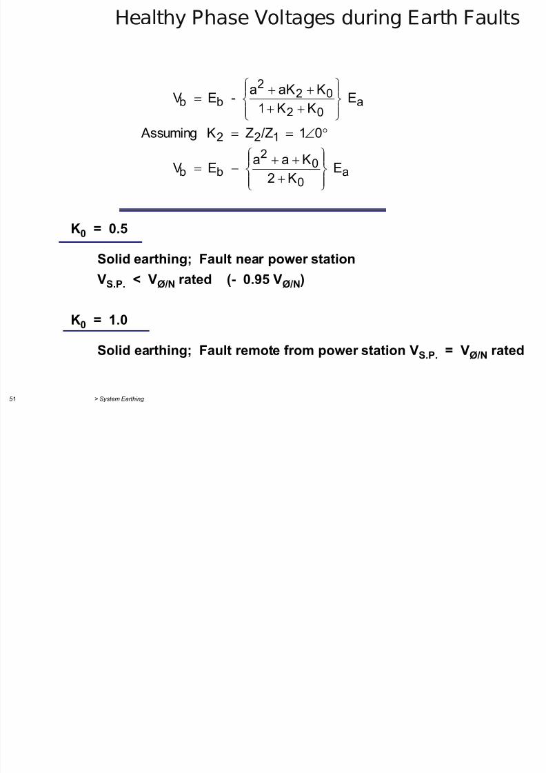
Healthy Phase Voltages during Earth Faults
a0
02
bb
122
a02
022
bb
E K2
Kaa E V
01 /ZZ K Assuming
E KK1
KaKa
- E V
K0 = 0.5
Solid earthing; Fault near power station
VS.P. < VØ/N rated (- 0.95 VØ/N)
K0 = 1.0
Solid earthing; Fault remote from power station VS.P. = VØ/N rated
Healthy Phase Voltages during Earth Faults
7/29/2019 2 Earthing Grounding
http://slidepdf.com/reader/full/2-earthing-grounding 51/70
> System Earthing 52
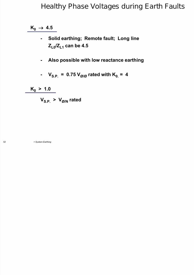
ea y ase o ages du g a au s
K0 4.5
- Solid earthing; Remote fault; Long line
ZL0 /ZL1 can be 4.5
- Also possible with low reactance earthing
- VS.P. = 0.75 VØ/Ø rated with K0. = 4
K0 > 1.0
VS.P.
> VØ/N
rated
Healthy Phase Voltages during Earth Faults
7/29/2019 2 Earthing Grounding
http://slidepdf.com/reader/full/2-earthing-grounding 52/70
> System Earthing 53
y g g
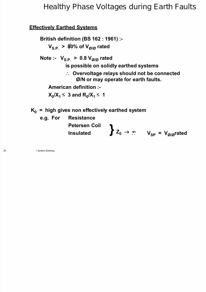
Effectively Earthed Systems
British definition (BS 162 : 1961) :-
VS.P. > 80% of VØ/Ø rated
Note :- VS.P. > 0.8 VØ/Ø rated
is possible on solidly earthed systems
Overvoltage relays should not be connectedØ/N or may operate for earth faults.
American definition :-
X0 /X1 3 and R0 /X1 1
K0 = high gives non effectively earthed systeme.g. For Resistance
Petersen Coil
Insulated VSP = VØ/Ørated Z0 }
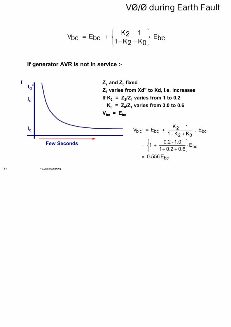
VØ/Ø during Earth Fault
7/29/2019 2 Earthing Grounding
http://slidepdf.com/reader/full/2-earthing-grounding 53/70
> System Earthing 54
/ g
bc02
2bcbc E
KK1
1 K E V
If generator AVR is not in service :-
Id"
Id'
Id
Few Seconds
I Z2 and Z0 fixedZ1 varies from Xd" to Xd, i.e. increases
If K2 = Z2 /Z1 varies from 1 to 0.2
K0 = Z0 /Z1 varies from 3.0 to 0.6
Vbc = Ebc
bc
bc
bc02
2bcc'b'
E0.556
E0.60.21
1.0-0.2 1
E . KK1
1 K E V
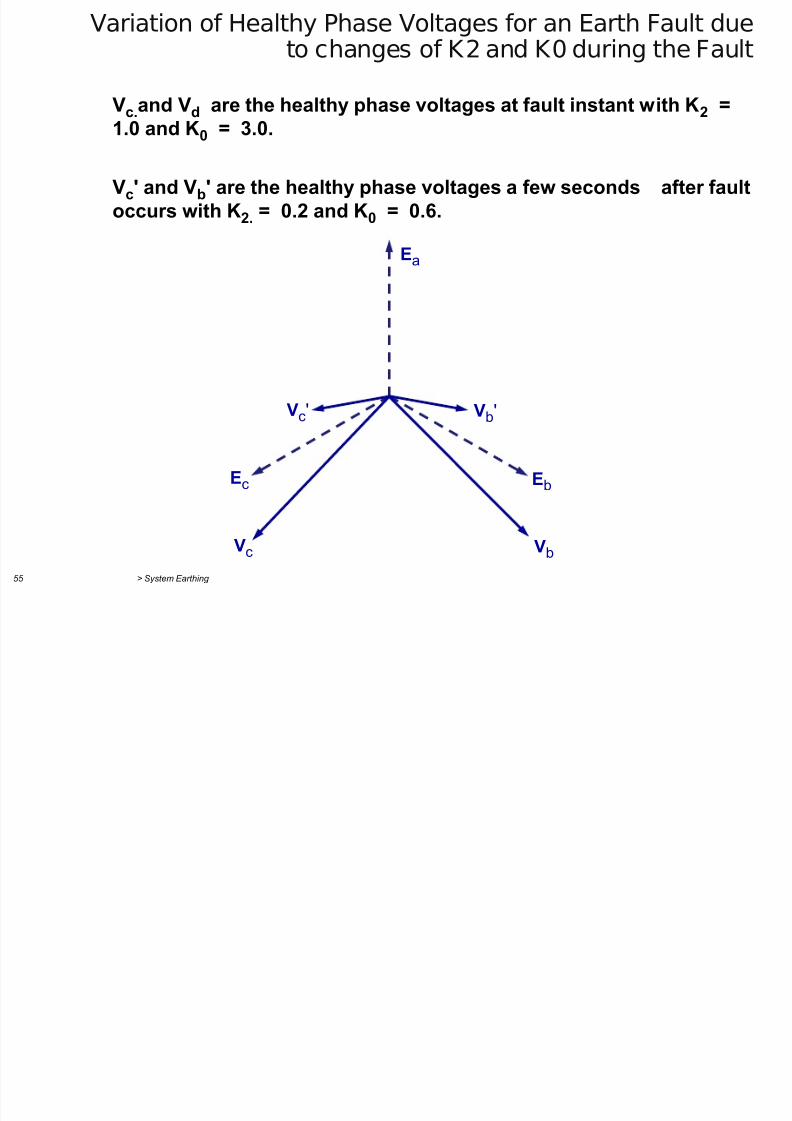
Variation of Healthy Phase Voltages for an Earth Fault due
7/29/2019 2 Earthing Grounding
http://slidepdf.com/reader/full/2-earthing-grounding 54/70
> System Earthing 55
to changes of K2 and K0 during the Fault
Vc.and Vd are the healthy phase voltages at fault instant with K2 =1.0 and K0 = 3.0.
Vc' and Vb' are the healthy phase voltages a few seconds after faultoccurs with K2. = 0.2 and K0 = 0.6.
Ea
Vb'V
c'
Eb Ec
Vb
Vc
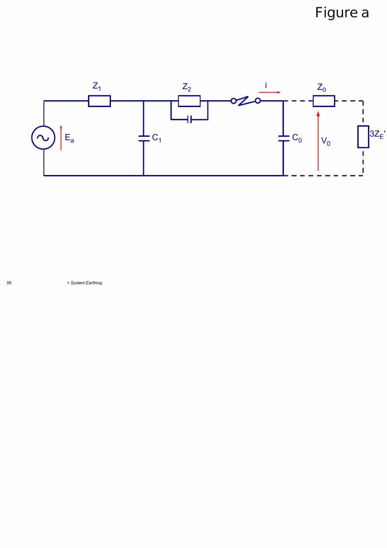
Figure a
7/29/2019 2 Earthing Grounding
http://slidepdf.com/reader/full/2-earthing-grounding 55/70
> System Earthing 56
Z1 Z2
Ea C1 C0 V0 3Z
E'
Z0 i
g
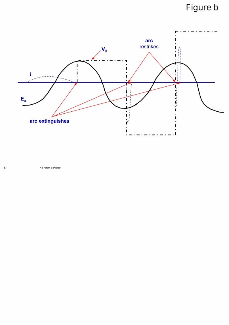
Figure b
7/29/2019 2 Earthing Grounding
http://slidepdf.com/reader/full/2-earthing-grounding 56/70
> System Earthing 57
g
Ea
i
V0 arc restrikes
arc extinguishes
7/29/2019 2 Earthing Grounding
http://slidepdf.com/reader/full/2-earthing-grounding 57/70
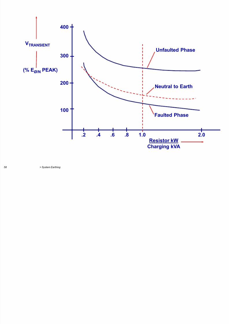
> System Earthing 58
VTRANSIENT
Neutral to Earth
Faulted Phase
Resistor kWCharging kVA
(% EØ/N PEAK)
Unfaulted Phase
400
300
200
100
.2 .4 .6 .8 1.0 2.0
7/29/2019 2 Earthing Grounding
http://slidepdf.com/reader/full/2-earthing-grounding 58/70
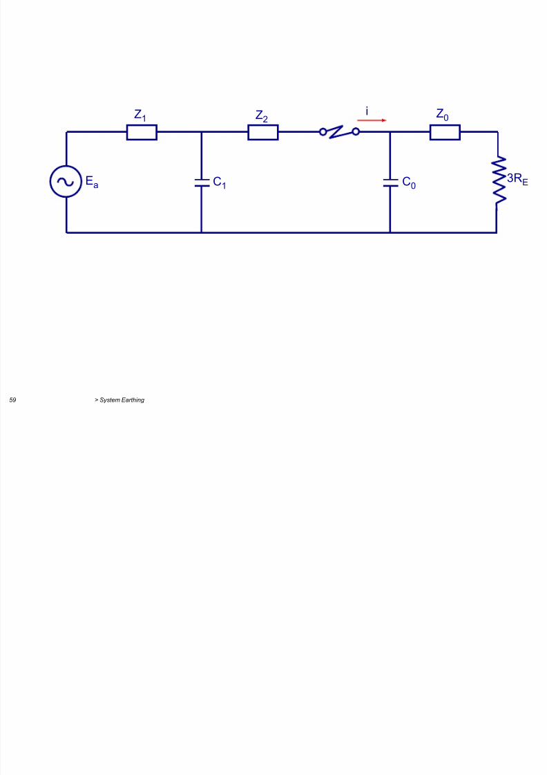
> System Earthing 59
Z1 Z2
C1 C0 3RE
Z0 i
Ea
7/29/2019 2 Earthing Grounding
http://slidepdf.com/reader/full/2-earthing-grounding 59/70
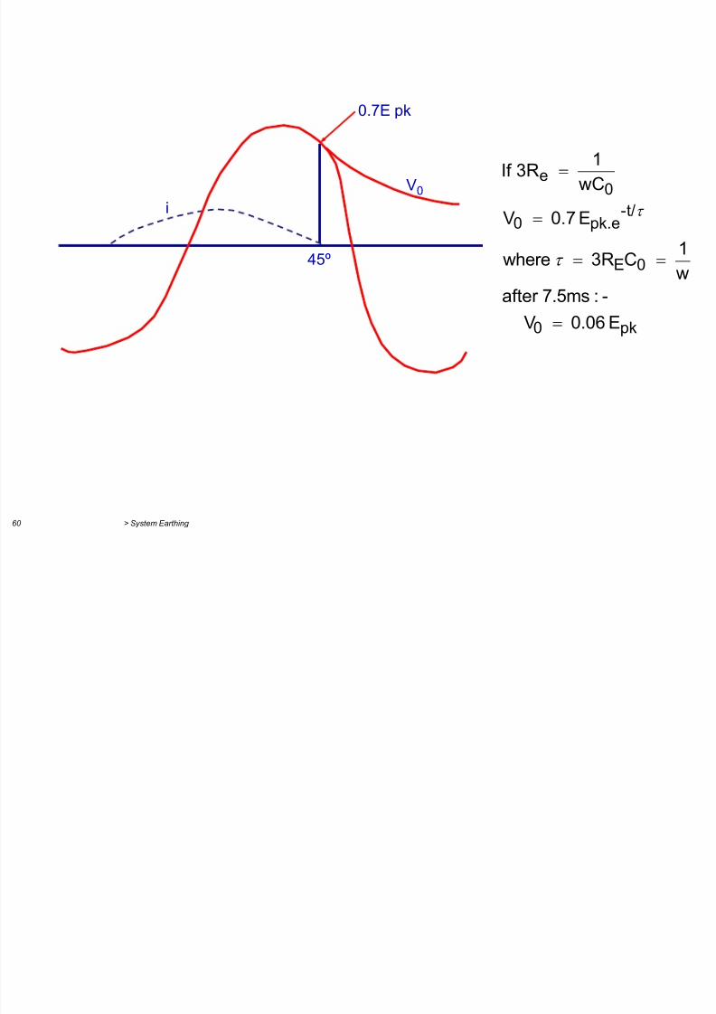
> System Earthing 60
V0
45º
i
0.7E pk
pk0
0E
t/-pk.e0
0e
E0.06 V
-:7.5msafter
w1 C3R where
E0.7 V
wC
1 3RIf
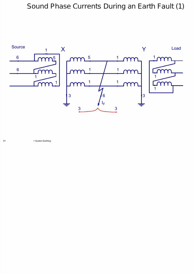
Sound Phase Currents During an Earth Fault (1)
7/29/2019 2 Earthing Grounding
http://slidepdf.com/reader/full/2-earthing-grounding 60/70
> System Earthing 61
IF
Source
6
6
5
1
1
1
1
1
1
1
1
3
33
63
LoadX Y1
1
1
5
Sound Phase Currents During an Earth Fault (2)
7/29/2019 2 Earthing Grounding
http://slidepdf.com/reader/full/2-earthing-grounding 61/70
> System Earthing 62
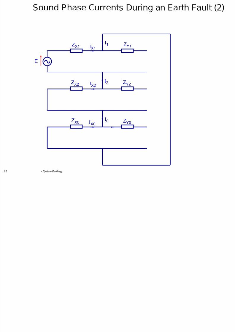
I1
I
2
I0
ZX1
ZX2
ZX0
IX1
IX2
IX0
ZY1
ZY2
ZY0
E
Sound Phase Currents During an Earth Fault (3)
7/29/2019 2 Earthing Grounding
http://slidepdf.com/reader/full/2-earthing-grounding 62/70
> System Earthing 63
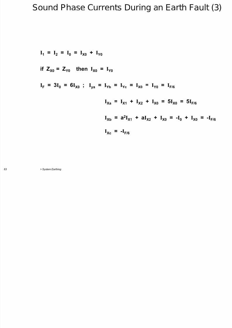
I1 = I2 = I0 = IX0 + I Y0
if ZX0 = Z Y0 then IX0 = I Y0
IF = 3I0 = 6IX0 ; Iya = I Yb = I Yc = IX0 = I Y0 = IF/6
IXa = IX1 + IX2 + IX0 = 5IX0 = 5IF/6
IXb = a2IX1 + aIX2 + IX0 = -I0 + IX0 = -IF/6
IXc = -IF/6
Parallel Generators (1)
7/29/2019 2 Earthing Grounding
http://slidepdf.com/reader/full/2-earthing-grounding 63/70
> System Earthing 64
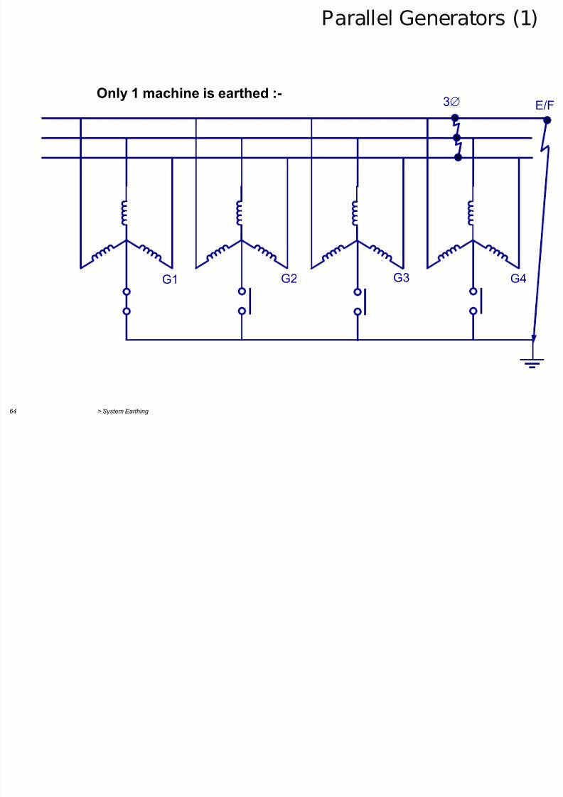
G3 G4 G1 G2
3 E/F
Only 1 machine is earthed :-
Parallel Generators (2)
7/29/2019 2 Earthing Grounding
http://slidepdf.com/reader/full/2-earthing-grounding 64/70
> System Earthing 65
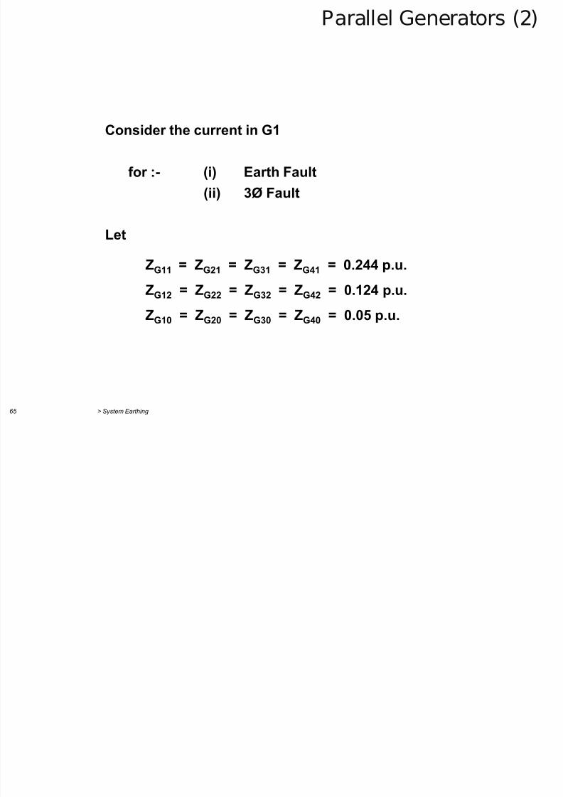
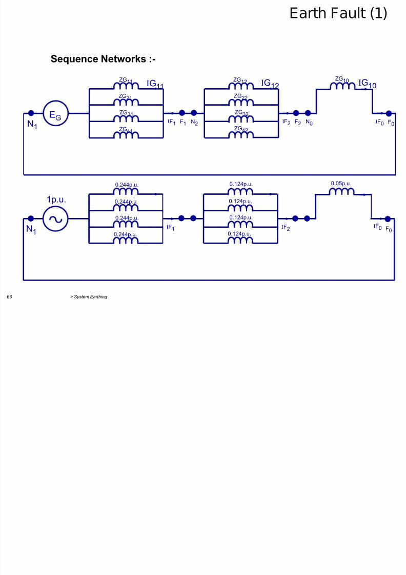
Consider the current in G1
for :- (i) Earth Fault
(ii) 3Ø Fault
Let
ZG11 = ZG21 = ZG31 = ZG41 = 0.244 p.u.
ZG12 = ZG22 = ZG32 = ZG42 = 0.124 p.u.
ZG10 = ZG20 = ZG30 = ZG40 = 0.05 p.u.
Earth Fault (1)
7/29/2019 2 Earthing Grounding
http://slidepdf.com/reader/full/2-earthing-grounding 65/70
> System Earthing 66
Sequence Networks :-
N1 EG
ZG11
ZG21
ZG31
ZG41
IG11 IG12 IG10 ZG12 ZG10
ZG22
ZG32
ZG42 F1 N2 IF1 F2 N0 IF2 F0 IF0
0.05p.u.
IF1 IF2 F0 IF0
0.244p.u.
0.244p.u.
0.244p.u.
0.124p.u.
0.124p.u.
0.124p.u.N1
1p.u.
0.244p.u. 0.124p.u.
Earth Fault (2)
7/29/2019 2 Earthing Grounding
http://slidepdf.com/reader/full/2-earthing-grounding 66/70
> System Earthing 67
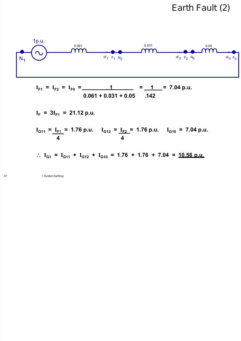
N1
0.061
1p.u.0.031 0.05
F1 N2 IF1 F2 N0 IF2 F0 IF0
IF1 = IF2 = IF0 = 1 = 1 = 7.04 p.u.0.061 + 0.031 + 0.05 .142
IF = 3IF1 = 21.12 p.u.
IG11 = IF1 = 1.76 p.u. IG12 = IF2 = 1.76 p.u. IG10 = 7.04 p.u.4 4
IG1 = IG11 + IG12 + IG10 = 1.76 + 1.76 + 7.04 = 10.56 p.u.
3Ø Fault
7/29/2019 2 Earthing Grounding
http://slidepdf.com/reader/full/2-earthing-grounding 67/70
> System Earthing 68
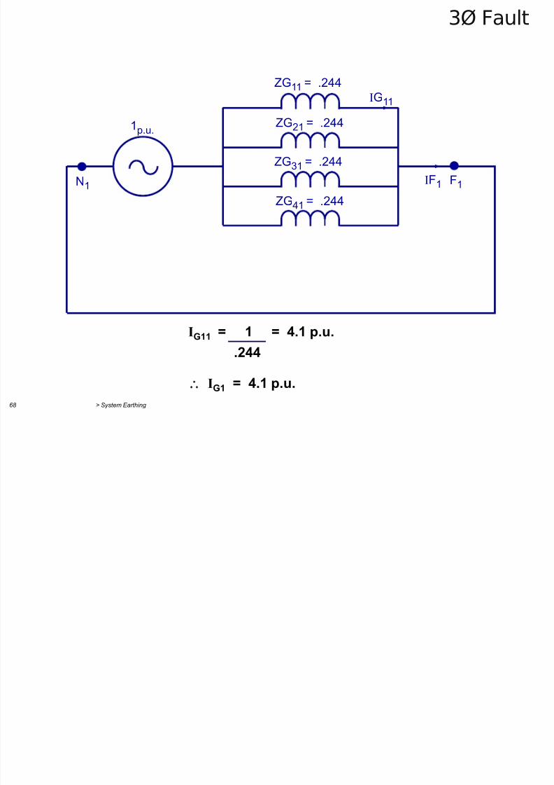
1p.u.
ZG11 = .244
IF1 F1
IG11
ZG21 = .244
ZG31 = .244
ZG41 = .244
N1
IG11 = 1 = 4.1 p.u.
.244
IG1 = 4.1 p.u.
Thermal Stress
7/29/2019 2 Earthing Grounding
http://slidepdf.com/reader/full/2-earthing-grounding 68/70
> System Earthing 69
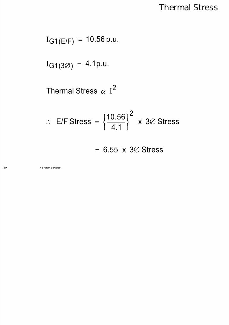
Stress3x6.55
Stress3x4.1
10.56
StressE/F
StressThermal
p.u.4.1
p.u.10.56
2
2
)(3G1
(E/F)G1
Methods of Neutral Earthing (1)

7/29/2019 2 Earthing Grounding
http://slidepdf.com/reader/full/2-earthing-grounding 69/70
> System Earthing 70
Aspect Solid Resistance Resistance & High value Low value Tuned Insulated
reactance reactor reactor reactor
Normal Suitable for Suitable for Suitable for phase Suitable for Suitable for If used for Suitable for line
insulation phase voltage phase voltage voltage line voltage for phase voltage operation with voltage for longcontinuously continuously continuously long periods continuously one line earthed
for long periods
insulation must
be suitable for
line voltage
Over voltages:
(a) Initiated by Not excessive Not excessive Not excessive provi- Can be very high Not excessive Not excessive if Arcing ground
faults, ding all three phases e.g. neutral no mutual coup- can give very
switching, etc are made or broken inversion ling between zero high voltagessimultaneously & positive seq-
uence networks
(b) Travelling Negative In general, “ Full reflection at Full reflection at Full reflection at Full reflection
waves reflection negative neutral neutral neutral at neutral
reflection at
neutral
Protection:(a) Automatic No difficulty No difficulty No difficulty, normal Extremely diffi- No difficulty By using special Extremely
segregation normal methods normal methods methods can be cult if more than normal methods technique can be difficult
of faulty zone can be used can be used used one zone can be used done satisfac-
involved torily
(b) Travelling Diverters rated In general, In general, diverters Diverters rated In general, Diverter rated Diverters rated
waves for phase volts diverters rated rated for line volts for line volts are diverters rated for for line volts are for line volts
are suitable for line voltage are essential essential line volts are essential are essential
are essential essential
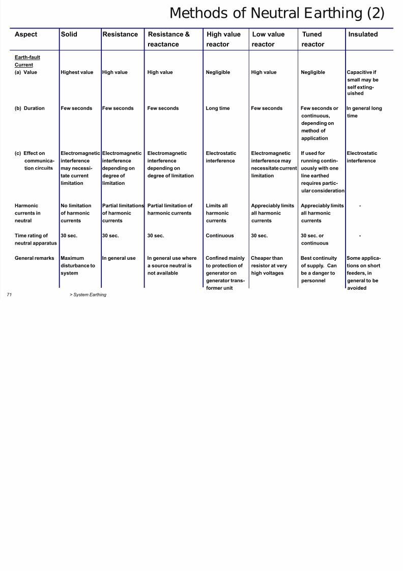
Methods of Neutral Earthing (2)
7/29/2019 2 Earthing Grounding
http://slidepdf.com/reader/full/2-earthing-grounding 70/70
Aspect Solid Resistance Resistance & High value Low value Tuned Insulated
reactance reactor reactor reactor
Earth-fault
Current
(a) Value Highest value High value High value Negligible High value Negligible Capacitive if
small may be
self exting-uished
(b) Duration Few seconds Few seconds Few seconds Long time Few seconds Few seconds or In general long
continuous, time
depending on
method of
application
(c) Effect on Electromagnetic Electromagnetic Electromagnetic Electrostatic Electromagnetic If used for Electrostatic
communica- interference interference interference interference interference may running contin- interference
tion circuits may necessi- depending on depending on necessitate current uously with one
tate current degree of degree of limitation limitation line earthed
limitation limitation requires partic-
ular consideration
Harmonic No limitation Partial limitations Partial limitation of Limits all Appreciably limits Appreciably limits -
currents in of harmonic of harmonic harmonic currents harmonic all harmonic all harmonic
neutral currents currents currents currents currents
Time rating of 30 sec. 30 sec. 30 sec. Continuous 30 sec. 30 sec. or -
neutral apparatus continuous
General remarks Maximum In general use In general use where Confined mainly Cheaper than Best continuity Some applica-
disturbance to a source neutral is to protection of resistor at very of supply. Can tions on short
system not available generator on high voltages be a danger to feeders in


![Metric References Grounding & Earthing Solutions - … · Grounding & Earthing Solutions GroundingSuperstore TM The METRIC VERSION (TXLYDOHQW 0HWULF 6L]H JLYHQ LQ > @ 0HWULF VL]HV](https://static.fdocuments.us/doc/165x107/5b79fa717f8b9a7f378ecbd4/metric-references-grounding-earthing-solutions-grounding-earthing-solutions.jpg)