2 CHANNEL POWER AMPLIFIER - Alpine · Position the BBX-T600 over the screw holes, and secure with...
13
FOR CAR USE ONLY BBX-T600 2 CHANNEL POWER AMPLIFIER ● OWNER’S MANUAL Please read this manual to maximize your enjoyment of the outstanding performance and feature capabilities of the equipment, then retain the manual for future reference. English CONTENTS WARNING .................................................................................................................................................................................................... 2 CAUTION ...................................................................................................................................................................................................... 3 INSTALLATION ............................................................................................................................................................................................. 4 ATTACHING THE TERMINAL COVERS .......................................................................................................................................................... 5 CONNECTIONS ............................................................................................................................................................................................. 6 CONNECTION CHECK LIST .......................................................................................................................................................................... 8 SWITCH SETTINGS ...................................................................................................................................................................................... 9 SYSTEM DIAGRAMS .................................................................................................................................................................................. 10 SPECIFICATIONS ....................................................................................................................................................................................... 12 ACCESSORIES • Self-Tapping Screw (M4 × 20) .................................................................................................................................................................. 4 • Terminal Cover .................................................................................................................................................................................. 1 SET • Screw (M3 × 12) ...................................................................................................................................................................................... 4 ALPINE ELECTRONICS MARKETING, INC. 1-1-8 Nishi Gotanda, Shinagawa-ku, Tokyo 141-0031, Japan Phone 03-5496-8231 ALPINE ELECTRONICS OF AMERICA, INC. 19145 Gramercy Place, Torrance, California 90501, U.S.A. Phone 1-800-ALPINE-1 (1-800-257-4631) ALPINE ELECTRONICS OF CANADA, INC. 777 Supertest Road, Toronto, Ontario M3J 2M9, Canada Phone 1-800-ALPINE-1 (1-800-257-4631) ALPINE ELECTRONICS OF AUSTRALIA PTY. LTD. 161-165 Princes Highway, Hallam Victoria 3803, Australia Phone 03-8787-1200 ALPINE ELECTRONICS GmbH Wilhelm-Wagenfeld-Straße 1-3, 80807 München, Germany Phone 089-32 42 640 ALPINE ELECTRONICS OF U.K. LTD. Alpine House Fletchamstead Highway, Coventry CV4 9TW, U.K. Phone 0870-33 33 763 ALPINE ITALIA S.p.A. Viale C. Colombo 8, 20090 Trezzano Sul Naviglio (MI), Italy Phone 02-484781 ALPINE ELECTRONICS DE ESPAÑA, S.A. Portal de Gamarra 36, Pabellón, 32 01013 Vitoria (Alava)-APDO 133, Spain Phone 945-283588 ALPINE ELECTRONICS FRANCE S.A.R.L. (RCS PONTOISE B 338 101 280) 98, Rue de la Belle Etoile, Z.I. Paris Nord Il, B.P. 50016, 95945 Roissy Charles de Gaulle Cedex, France Phone 01-48638989 Designed by Alpine Electronics (Europe) GmbH Printed in China
Transcript of 2 CHANNEL POWER AMPLIFIER - Alpine · Position the BBX-T600 over the screw holes, and secure with...

FOR CAR USE ONLY
BBX-T6002 CHANNEL POWER AMPLIFIER
● OWNER’S MANUALPlease read this manual to maximize your enjoyment of the outstanding performance and feature capabilities of the equipment, then retain the manual for future reference.
English
CONTENTSWARNING .................................................................................................................................................................................................... 2CAUTION ...................................................................................................................................................................................................... 3INSTALLATION ............................................................................................................................................................................................. 4ATTACHING THE TERMINAL COVERS .......................................................................................................................................................... 5CONNECTIONS ............................................................................................................................................................................................. 6CONNECTION CHECK LIST .......................................................................................................................................................................... 8SWITCH SETTINGS ...................................................................................................................................................................................... 9SYSTEM DIAGRAMS .................................................................................................................................................................................. 10SPECIFICATIONS ....................................................................................................................................................................................... 12
ACCESSORIES• Self-Tapping Screw (M4 × 20) .................................................................................................................................................................. 4• Terminal Cover .................................................................................................................................................................................. 1 SET• Screw (M3 × 12) ...................................................................................................................................................................................... 4
ALPINE ELECTRONICS MARKETING, INC.1-1-8 Nishi Gotanda,
Shinagawa-ku,Tokyo 141-0031, JapanPhone 03-5496-8231
ALPINE ELECTRONICS OF AMERICA, INC.19145 Gramercy Place, Torrance,
California 90501, U.S.A.Phone 1-800-ALPINE-1 (1-800-257-4631)
ALPINE ELECTRONICS OF CANADA, INC.777 Supertest Road, Toronto,
Ontario M3J 2M9, CanadaPhone 1-800-ALPINE-1 (1-800-257-4631)
ALPINE ELECTRONICS OF AUSTRALIA PTY. LTD.161-165 Princes Highway, Hallam
Victoria 3803, AustraliaPhone 03-8787-1200
ALPINE ELECTRONICS GmbHWilhelm-Wagenfeld-Straße 1-3, 80807 München,
GermanyPhone 089-32 42 640
ALPINE ELECTRONICS OF U.K. LTD.Alpine House
Fletchamstead Highway, Coventry CV4 9TW,U.K.
Phone 0870-33 33 763
ALPINE ITALIA S.p.A.Viale C. Colombo 8, 20090 Trezzano
Sul Naviglio (MI), ItalyPhone 02-484781
ALPINE ELECTRONICS DE ESPAÑA, S.A.Portal de Gamarra 36, Pabellón, 32
01013 Vitoria (Alava)-APDO 133, SpainPhone 945-283588
ALPINE ELECTRONICS FRANCE S.A.R.L.(RCS PONTOISE B 338 101 280)
98, Rue de la Belle Etoile, Z.I. Paris Nord Il,B.P. 50016, 95945 Roissy Charles de Gaulle
Cedex, FrancePhone 01-48638989
Designed by Alpine Electronics (Europe) GmbHPrinted in China

2
English
Introduction:Please read this OWNER’S MANUAL thoroughly to familiarize yourself with each control and function. We at ALPINE hope that your new BBX-T600 will give you many years of listening enjoyment.In case of problems when installing your BBX-T600, please contact your authorized ALPINE dealer.CAUTION: These controls are for tuning your system. Please consult your authorized Dealer for adjustment.
WARNING
This symbol means important instructions.Failure to heed them can result in serious injury or death.
CAUTION
This symbol means important instructions.Failure to heed them can result in injury or property damages.
WARNINGDO NOT OPERATE ANY FUNCTION THAT TAKES YOUR ATTENTION AWAY FROM SAFELY DRIVING YOUR VEHICLE. Any function that requires your prolonged attention should only be performed after coming to a complete stop. Always stop the vehicle in a safe location before performing these functions. Failure to do so may result in an accident.
KEEP THE VOLUME AT A LEVEL WHERE YOU CAN STILL HEAR OUTSIDE NOISES WHILE DRIVING.Excessive volume levels that obscure sounds such as emergency vehicle sirens or road warning signals (train crossings, etc.) can be dangerous and may result in an accident. LISTENING AT LOUD VOLUME LEVELS IN A CAR MAY ALSO CAUSE HEARING DAMAGE.
DO NOT DISASSEMBLE OR ALTER. Doing so may result in an accident, fire or electric shock.
USE THIS PRODUCT FOR MOBILE 12V APPLICATIONS. Use for other than its designed application may result in fire, electric shock or other injury.
USE THE CORRECT AMPERE RATING WHEN REPLACING FUSES. Failure to do so may result in fire or electric shock.
DO NOT BLOCK VENTS OR RADIATOR PANELS. Doing so may cause heat to build up inside and may result in fire.
MAKE THE CORRECT CONNECTIONS. Failure to make the proper connections may result in fire or product damage.
USE ONLY IN CARS WITH A 12 VOLT NEGATIVE GROUND. (Check with your dealer if you are not sure.)Failure to do so may result in fire, etc.
BEFORE WIRING, DISCONNECT THE CABLE FROM THE NEGATIVE BATTERY TERMINAL. Failure to do so may result in electric shock or injury due to electrical shorts.

3
EnglishDO NOT ALLOW CABLES TO BECOME ENTANGLED IN SURROUNDING OBJECTS. Arrange wiring and cables in compliance with the manual to prevent obstructions when driving. Cables or wiring that obstruct or hang up on places such as the steering wheel, gear lever, brake pedals, etc. can be extremely hazardous.
DO NOT SPLICE INTO ELECTRICAL CABLES. Never cut away cable insulation to supply power to other equipment. Doing so will exceed the current carrying capacity of the wire and result in fire or electric shock.
DO NOT DAMAGE PIPE OR WIRING WHEN DRILLING HOLES. When drilling holes in the chassis for installation, take precautions so as not to contact, damage or obstruct pipes, fuel lines, tanks or electrical wiring. Failure to take such precautions may result in fire.
DO NOT USE BOLTS OR NUTS IN THE BRAKE OR STEERING SYSTEMS TO MAKE GROUND CONNECTIONS. Bolts or nuts used for the brake or steering systems (or any other safety-related system), or tanks should NEVER be used for installations or ground connections. Using such parts could disable control of the vehicle and cause fire etc.
KEEP SMALL OBJECTS SUCH AS BATTERIES OUT OF THE REACH OF CHILDREN. Swallowing them may result in serious injury. If swallowed, consult a physician immediately.
CAUTIONHALT USE IMMEDIATELY IF A PROBLEM APPEARS. Failure to do so may cause personal injury or damage to the product. Return it to your authorized Alpine dealer or the nearest Alpine Service Center for repairing.
HAVE THE WIRING AND INSTALLATION DONE BY EXPERTS. The wiring and installation of this unit requires special technical skill and experience. To ensure safety, always contact the dealer where you purchased this product to have the work done.
USE SPECIFIED ACCESSORY PARTS AND INSTALL THEM SECURELY. Be sure to use only the specified accessory parts. Use of other than designated parts may damage this unit internally or may not securely install the unit in place. This may cause parts to become loose resulting in hazards or product failure.
ARRANGE THE WIRING SO IT IS NOT CRIMPED OR PINCHED BY A SHARP METAL EDGE. Route the cables and wiring away from moving parts (like the seat rails) or sharp or pointed edges. This will prevent crimping and damage to the wiring. If wiring passes through a hole in metal, use a rubber grommet to prevent the wire’s insulation from being cut by the metal edge of the hole.
DO NOT INSTALL IN LOCATIONS WITH HIGH MOISTURE OR DUST. Avoid installing the unit in locations with high incidence of moisture or dust. Moisture or dust that penetrates into this unit may result in product failure.

4
English
INSTALLATION
Due to the high power output of the BBX-T600, considerable heat is produced when the amplifier is in operation. For this reason, the amplifier should be mounted in a location which will allow for free circulation of air, such as inside the trunk. For alternate installation locations, please contact your authorized Alpine dealer.
1. Using the amplifier as a template, mark the four screw locations.2. Make sure there are no objects behind the surface that may become damaged during drilling.3. Drill the screw holes.4. Position the BBX-T600 over the screw holes, and secure with four self-tapping screws.
NOTE:To securely connect the ground lead, use an already installed screw on the metal part of the vehicle (marked (), sold separately). Be sure this is a good ground by checking continuity to the battery (–) terminal. As much as possible connect all equipment to the same ground point. These procedures will help eliminate noise.
a Self-Tapping Screws (M4 x 20)b Ground Leadc Chassisd Holes
1
2
4 Fig. 1
3
Fig.1

5
English
ATTACHING THE TERMINAL COVERS
Attach the terminal covers (supplied) after connections and confirmation of correct operation.Attaching the terminal covers will improve the appearance of the unit.
How to attach the terminal covers:Attach the left and right terminal covers using the supplied screws (M3 x 12), as shown in the figure below.
a Terminal coverb Screw (M3 x 12)
NOTE:Do not lift or carry the unit by the attached terminal covers.
Fig. 2
2
1
1
2
Fig.2

6
English
5
34
2
1
6 7
Fig. 3
CONNECTIONS
Before making connections, be sure to turn the power off to all audio components. Connect the yellow battery lead from the amp directly to the positive (+) terminal of the vehicle’s battery. Do not connect this lead to the fuse block.
To prevent external noise from entering the audio system.•Locate the unit and route the leads at least 10cm (3-15/16”) away from the car harness.•Keep the battery power leads as far away from other leads as possible.•Connect the ground lead securely to a bare metal spot (remove any paint or grease if necessary) of the car chassis.•If you add an optional noise suppressor, connect it as far away from the unit as possible. Your Alpine dealer carries various noise suppressors,
contact them for further information.•Your Alpine dealer knows best about noise prevention measures so consult your dealer for further information.

7
English
a Speaker Output TerminalThe BBX-T600 has one set of speaker outputs. Be sure to observe correct speaker output connections and phasing in relation to the other speakers in the system. Connect the positive output to the positive speaker terminal and the negative to negative. Do not connect the speaker (–) terminal to the vehicle’s chassis.
In the bridged mode, connect the left positive to the positive terminal on the speaker and the right negative to the negative terminal of the speaker. Do not use the speaker (–) terminals as a common lead between the left and right channels. Do not connect this lead to the vehicle’s chassis.
NOTES:1. Do not connect speaker leads together or to chassis ground.2. Use a Y-adaptor (sold separately) for the input when bridging the outputs. (Refer to the “Bridge Connections” on page 12)
b Power Supply Terminal
c Ground Lead (Sold Separately)Connect this lead securely to a clean, bare metal spot on the vehicle’s chassis. Verify this point to be a true ground by checking for continuity between that point and the negative (–) terminal of the vehicle’s battery. Ground all your audio components to the same point on the chassis to prevent ground loops. Only use 8mm2 (the wire gauge) for this connection.
d Remote Turn-On Lead (Sold Separately)Connect this lead to the remote turn-on or power antenna (positive trigger, (+) 12V only) lead of your head unit.
e Battery Lead (Sold Separately)Be sure to add a 25 amp fuse as close as possible to the battery’s positive (+) terminal. This fuse will protect your vehicle’s electrical system in case of a short circuit. If you need to extend this lead, only use 8mm2 (the wire gauge) for this connection.
f RCA Input JacksConnect these jacks to the line out leads on your head unit using RCA extension cables (sold separately). Be sure to observe correct channel connections; Left to Left and Right to Right. (Front to Front and Rear to Rear)
g RCA Pre Out JacksThese jacks provide a line level output. This is an ideal output for driving a second subwoofer amp. This output is full-range, and is not affected by the crossover.
NOTE:Use either RCA line level or speaker level inputs. Do not connect both at the same time.

8
BBX-T600
1
2
3
4
5
6
7
8
Fig. 4
English
CONNECTION CHECK LISTPlease check your head unit for the conditions listed below: (Fig. 4)
a. The head unit does not have a remote turn-on or power antenna lead.b. The head unit’s power antenna lead is activated only when the radio is on (turns off in the tape or CD Mode).c. The head unit’s power antenna lead is logic level output (+) 5V, negative trigger (grounding type), or cannot sustain (+) 12V when connected
to other equipment in addition to the vehicle’s power antenna. If any of the above conditions exist, the remote turn-on lead of your BBX-T600 must be connected to a switched power source (ignition) in the vehicle. Be sure to use a 3A fuse as close as possible to this ignition tap. Using this connection method, the BBX-T600 will turn on and stay on as long as the ignition switch is on.
If this is objectionable, a SPST (Single Pole, Single Throw) switch, in addition to the 3A fuse mentioned above, may be installed in-line on the BBX-T600 turn-on lead. This switch will then be used to turn on (and off) the BBX-T600. Therefore, the switch should be mounted so that is accessible by the driver. Make sure the switch is turned off when the vehicle is not running. Otherwise, the amplifier will remain on and drain the battery.
1 Blue/White2 Power Antenna3 Remote Turn-On Lead4 To other Alpine components’ Remote Turn-On Leads5 SPST Switch (optional)6 Fuse (3A)7 As close as possible to the vehicle’s ignition tap8 Ignition Source

9
English
Fig. 5
Fig. 5
8 9 10 11 12 Power Indicator
Protection
11 11 11
SWITCH SETTINGSh Input Gain Adjustment Control
Set the BBX-T600 input gain knobs to the minimum (8V) position. Using a loud CD/DVD as source, turn up the head unit volume until it distorts. Then, reduce the volume 1 step. You can then increase amplifier gain until the sound from the speakers becomes distorted.
i Bass EQ AdjustmentBoost the low frequency output of the amplifier from 0dB (flat) to +12dB.Adjust the Bass EQ (centered at 45Hz) to suit your personal taste.
j Low Pass FilterUse this control to adjust the crossover frequency between 50Hz to 250Hz.
k Crossover Mode Selector Switch
a) Set to the “LPF” position when the amplifier is used to drive a subwoofer. The frequencies above the crossover point will be attenuated at -12dB/octave.
b) Set to the “HPF” position when the amplifier is used to drive a tweeter/midrange system. The frequencies below the crossover point will be attenuated at -12dB/octave.
NOTE: In this case, the “Bass EQ” function is invalid.c) Set to the “OFF” position when the amplifier will be used for driving full-range speakers. The full frequency
bandwidth will be output to the speakers with no high or low frequency attenuation.
l HighPass FilterUse this control to adjust the crossover frequency between 80Hz to 1.2kHz.
Fig. 5
8 9 10 11 12 Power Indicator
Protection
11 11 11
Fig. 5
8 9 10 11 12 Power Indicator
Protection
11 11 11
Fig. 5
8 9 10 11 12 Power Indicator
Protection
11 11 11

10
English
SYSTEM DIAGRAMS
•TYPICAL SYSTEM CONNECTIONS
Full Range/Pleine bande/Pleno alcance
High Pass/Passe-haut/Paso alto
Low Pass/Passe-bas/Paso bajo
Fig. 6
L R
(Right side/Côté droit/Lado derecho)
(Left side/Côté gauche/Lado izquierdo)
5 3
154
L R
14
16Fig. 6
c Ground Lead (Sold Separately)d Remote Turn-On Lead (Sold Separately)e Battery Lead (Sold Separately)n RCA Extension Cable (Sold Separately)o Speakersp Head Unit, etc.
Full Range
High Pass
Low Pass
(Left side)(Right side)
11
English
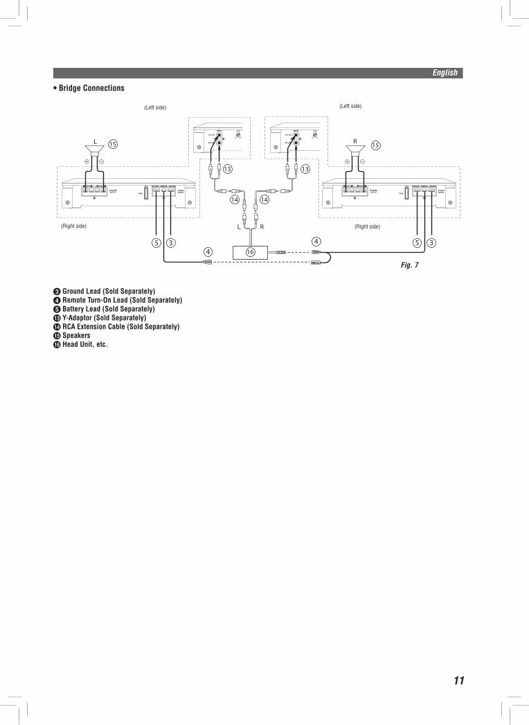
•Bridge Connections
(Left side/Côté gauche/Lado izquierdo)
Fig. 7
L
L R
(Right side/Côté droit/Lado derecho)
(Right side/Côté droit/Lado derecho)
(Right side/Côté droit/Lado derecho)
15 15
5 34
4
14
16
14
13 13
5 3
R
Fig. 7
c Ground Lead (Sold Separately)d Remote Turn-On Lead (Sold Separately)e Battery Lead (Sold Separately)m Y-Adaptor (Sold Separately)n RCA Extension Cable (Sold Separately)o Speakersp Head Unit, etc.
Full Range
(Left side)(Left side)
(Right side) (Right side)
12
English
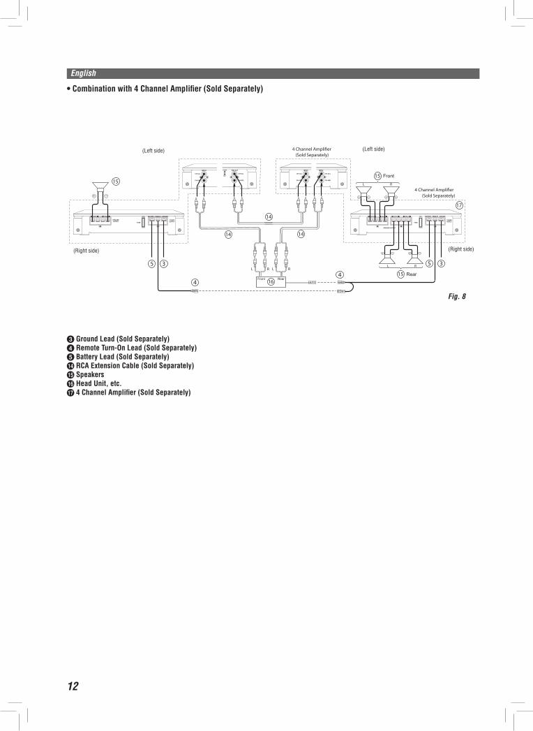
•Combination with 4 Channel Amplifier (Sold Separately)
Fig. 8
(Left side/Côté gauche/Lado izquierdo)
(Right side/Côté droit/Lado derecho)
(Right side/Côté droit/Lado derecho)
(Right side/Côté droit/
Lado derecho)
1515
5 3
44
14
16
5 3L R
L R
L R
15
17
(Sold Separately)4 Channel Ampli�er
(Sold Separately)4 Channel Ampli�er
L R
14
14
Front Rear
Front
Rear
c Ground Lead (Sold Separately)d Remote Turn-On Lead (Sold Separately)e Battery Lead (Sold Separately)n RCA Extension Cable (Sold Separately)o Speakersp Head Unit, etc.q 4 Channel Amplifier (Sold Separately)
(Left side)(Left side)
(Right side) (Right side)
13
English
SPECIFICATIONSRMS Continuous Power (at 14.4 V, 20 - 20kHz)•Per channel into 4 ohms (≤1% THD+N) ................................................................................................................................................................................50 W x 2•Per channel into 2 ohms (≤1% THD+N) ...............................................................................................................................................................................70 W x 2•Briged 4 ohms (≤1% THD+N) .............................................................................................................................................................................130 W x 1
Total MAX Power ............................................................................................................................................................ 600 WS/N Ratio•IHF A Weighted, Reference: rated power into 4 ohms ...................................................................................................................................................................> 95 dBA
Input Impedance•RCA IN .................................................................................................................................................................. 20k ohms
Frequency Response (+0dB, -3dB)...............................................................................................................................................................................5Hz - 50kHzCrossover Frequency (-12dB/octave)....................................................................................................................................................................... LP 50Hz - 250Hz...................................................................................................................................................................... HP 80Hz - 1.2kHzInput Sensitivity (RCA IN) ............................................................................................................................................ 0.2 - 8 VBASS EQ ...................................................................................................................................................45Hz, 0dB to +12dBDimensions•Lenght ............................................................................................................................................................ 200 (250) mm•Width ........................................................................................................................................................................240 mm•Height .........................................................................................................................................................................52 mm
Weight ............................................................................................................................................................................. 1.9 kg
NOTE:For product improvement, specifications and design are subject to change without notice.
SERVICE CAREShould you have any questions about warranty, please consult your store of purchase.