2, 1908. - John-Tom Engine Plans Engine 1908... · 8 The Model Engineer and Electrician.January 2,...
24
Transcript of 2, 1908. - John-Tom Engine Plans Engine 1908... · 8 The Model Engineer and Electrician.January 2,...


4
January 2, 1908. The Model Engineer and Electrician. 7
he should find a pleasure in acquiring mathemat-ical and scientific knowledge. He should have asufficient liking for working with tools to enable himeither to make machinery or apparatus himself, orto judge the workmanship of others who may becarrying his designs into practice. The training forsuch a lad should be a judicious combination ofpractical experience with workshop tools and pro-cesses and theoretical study. The latter ought toinclude practice in making engineering drawings andacquaintance with cost of materials and labour.
Thus three broad kinds of engineering careersare open to a lad, and each is divided into a varietyof branches. Commencement is easiest when thelad leaves school, say at about the age of sixteenyears, without having entered any other business.It becomes more difficult as age increases, thoughwith means a person may take up this occupationwhen he has reached years of manhood.
(To be continued.)
The Junior Institution of Engineers.
A NUMEROUSLY attended visit of this Institu-tion was recently paid to Woolwich Arsenal,
appropriately arranged to follow the strikingInaugural Address on “ Some Comparisons betweenFrench and English Artillery,” which had beendelivered by the newly-elected President (M.Gustave Canet), the eminent French artillerist.
The Chief Superintendent of Ordnance Factories(Mr. H. F. Donaldson), received the members, andunder the guidance of the chief mechanical engineer(Mr. Douglas Heap) and other officials, several hourswere spent by the visitors in an inspection of theinteresting processes of manufacture involved inthe production of metal time fuses ; bullets for themagazine rifle ; siege, field quick-firing and machine-gun carriages : mountings for heavy ordnance ;woodwork for carriages ; small arm and quick-firingammunition boxes ; wheels ; heavy breech-loadingguns, including the hoops and tubes for them.Rifling operations were shown, and working modelsof breech mechanisms of heavy breech-loading guns.The process of wire-winding was also seen, and inview of M. Canet’s observations on that topic in hisaddress, attracted particular attention.
The Chairman of the Institution (Mr. Frank R.Durham), expressed to Mr. Donaldson the members’appreciation of the special arrangements which hehad kindly made for their reception, enabling somuch to be seen in the limited time at disposal.
At the ensuing meeting on January 8th, a paperon “ Recent Improvements in Electric ConduitConstruction ” is to be read by Mr. FitzRoy Roose,of the London County Council Tramways Recon-struction Department.
ACCORDING to The American Machinist, the firstattempt to establish iron and steel works in India
has just been started by a rich firm in Bombay,supported by other wealthy individuals and bythe Government of India. The district in whichthe plant will be situated will be near Sini Junctionon the Bengal -Nagpur Railway, where there isabundance of water, and where iron ore, coal, andlimestone can be assembled at low cost of transit.
Design for a Model Motor FireEngine.
( With Coloured Supplement.)- - -
By F RANK F I N C H.
IN selecting the above subject for the design of thisyear’s supplement, the writer is assured of itsfavourable acceptance for two reasons-firstly,
because of the enthusiasm displayed for the fireengine by a.11 classes of individuals ; and, secondly,on account of it being something comparativelynew in so far as model engineering is concerned.The fire engine--in its own way-is as fascinatingto the general public as the railway locomotive.In actual fire fighting the now popular motor enginehas come to stay, and it is thought that the designand construction of models of this type, althoughscarcely thought of yet by readers of ” ours,”may develop an interest and popularity, at leastapproaching, that displayed in model locomotives.
There has not been published until now a design of amodel of this class of engine, although it must bestated that a few models of the old style, viz., horse-drawn engines, have been made and described in thesepages from time to time. By way of introduction,it is as well to study briefly the general principleadopted in the design. It may have alreadyappealed to the notice of readers that in generaloutline an effort has been made to resemble inminiature one of the now well-known Merryweathertypes ; although, so far as scale is concerned, ithas been found impossible to adhere strictlyon account of a great difficultyin securing the exactleading dimensions of the prototype-an obstaclewhich doubtless accounts for the lack of anyprevious designs of this nature. Generally, however,it is to a scale of 1-1/4 in. to 1 ft. An encroach-ment upon the proportional width of the enginehas been forced owing to the boiler space neces-sary to render the steaming powers of the modelefficient.
The location of the various featnres of an actualengine has been more or less maintained. Forinstance, the tanks to carry the supply of waterfor boiler-feed are situated on either side of boiler,and rest upon the frame (the water is fed intoboiler at intervals, by means of a simple hand-pumpin the right-hand tank, the two tanks being con-nected by a small tube across the front of boiler).The tank containing the methylated spirit forfiring the boiler through the five-wick lamp issituated as in the prototype, at the fore-end ofthe framework, under the driver’s box, and betweenthe front pair of wheels ; the admission of spiritto the wicks is via an air-valve actuated by a turnof the small handle at the back of the driver’sseat. Those who have studied the motor fire enginewill recognise that the position of engine and pumpsin the design corresponds with that of the original,but the double-acting pumps are necessarily morebulky in proportion. There are two simple enginecylinders, each 5/8in. bore by 7/8in. stroke, and theslide-valves and eccentrics are placed betweenthe cylinders : the piston-rods drive the pumpplungers direct through the medium of the slottedcrossheads shown in the drawing. It is thoughtthat the air-vessel, being of polished copper, willadd greatly to the attractiveness of the modelwhen completed, and for that reason it has not

8 The Model Engineer and Electrician. January 2, 1908.
been covered up by the wooden box arrangement,as in the case of many of the Merryweather classof engine. A continuous jet of water of 9 to 10 ft.will be thrown by this pump.
Propulsion is effected by a dual method, asf o l l o w s : To release the pump from the enginethe pump rods are unscrewed below the crossheads,and by means of a small clutch (to be subsequentlydescribed) a tooth wheel on the crankshaft is broughtinto gear with a similar wheel on a pinion below.On the said pinion is also a grooved wheel, which,in turn, transmits the power by a gut band to agrooved wheel attached on the inner side of therear wheel, as indicated in the drawing. A drivingwheel is shown on one side only, and a band brakeoccupies the corresponding portion on the oppositeside. Of course, a driver on either side would bemore effectual, in which case it is feared the bandbrake must be substituted for the block pattern
ness, it is proposed to make it of aluminium-thiswill answer the purpose equally as well as heaviermetal . The dimensions given are f inished sizes.Other cross members of the frame, it will be seen,are small pieces of angle brass attached to the sidesb y m e a n s of small angle brackets and riveted asindicated : the cross piece, shown about midway,should be a cast ing. No great difficulty p r e s e n t sitself in this piece of work, and by the time somehave completed it, the construction of a more in-teresting part wi l l be given.
(To be continued.)
G AS FROM MINERAL OILs.-T h e e x p e r i m e n t s a tthe C a l e d o n i a n B r a s s Works, B a r r h e a d , i n c o n -nection with a patent for the manufacture of gasfrom refined paraffin, petrol or other mineral oils,have been continued with success (says the G a s
Fig. I.-DETAIL OF MAIN FRAME FOR MODEL MOTOR FIRE ENGINE.
(Scale : One-third full size.)
.rim brake, usual on horse-drawn vehicles , and,indeed, the writer has observed them on some ofthe earl ier types of motor engines ; but of thismore anon. The principle of steering is copiedsomewhat, and is exceedingly simple, the frontwheels being actuated to the r ight or left by aslight turn, in the desired direction, of the hand-wheel , and clamped in any required posit ion bythe small “ compass ” screw shown dotted in thelongitudinal elevation. Thus are the main featuresof the model described.
In subsequent issues details will be dealt withmore fully. For the present, drawings are givenshowing construction of the framing.
Two lengths of brass channel section should beobtained from any metal merchant . The writer hasn o t been able to procure the exact sect ion-viz. ,1/2in. by 3/8in.-the nearest being1/2in. by 1/2 in.,which, being 1/8in. too wide, must be f i led down,unless the builder of the model does not object tothe deep channel. One end of each length is to beroundetl off as shown. A casting wil l form thefront end of the frame, and, for the sake of light-
Enginineers' Magazine). B y t h e B r u c e s y s t e m o fmanufacture and instal lat ion i t is c laimed thatit is possible to obtain gas from refined paraffinor petrol at a cost of a IS . per 1,000 cub. ft.,and that the l ight, besides being less trying tot h e e y e s i g h t , i s t w i c e a s p o w e r f u l a s t h a t o fordinary coal gas. The l ight is given off fromincandescent mantles.
A WRITER in a contemporary states that heexamined the envelope of a bal loon which burstat the International Exhibit ion at Milan in 1906A number of spots were visible’ on the envelope,and at these places the material could be easi lytorn, whereas at other parts it showed great resist-ance to tearing. These spots were found to haveb e e n c a u s e d b y p h o s p h o r i c a n d a r s e n i c a c i d s ,p r o d u c e d b y o x i d a t i o n f r o m arseniuretted a n dphosphoretted hydrogen contained in the hydrogengas. The presence of these impurit ies is due tothe use of impure materials in the preparation ofthe hydrogen, and the author recommends that thepreparation of the gas for filling balloons should beunder strict chemical control.
The Model Engineer and Electrician. January 30, 1908
arms mill work similar to a pair of calipers. Oninserting blade B between cam and body and througharms, and then passing cam down on the blade,it will be found to be quite rigid enough for practicalwork. Figs. 3, 4, 5 and 6 show the application ofthe tool for various purposes.
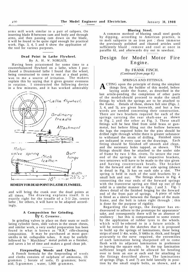
Dead Point in Lathe Flywheel.By A. H. W . NORGATE.
Having been accustomed for some time to acounterbalanced flywheel on a lathe, when I pur-chased a Drummond lathe I found that the wheel,being constructed to come to rest at a dead point,was to me a source of irritation. The makersexplain this by saying that it gives greater evennessin rotation. I constructed the following devicein a few minutes, and it has worked admirably
vy.Jve sprlnq T, ,
REMEDY FOR DEAD POINT IN LATHE FLYWHEEL.
and will bring the crank over the dead points atall times. The drawing explains itself . It isexactly right for the treadle of a 3-1/2in. centrelathe ; for others, it will have to be adapted accord-ingly.
A Composition for Grinding.By C. COVENTRY.
In grinding valves in place on their seats or oscil-lating cylinder faces, slide valves in the steam chests,and similar work, a very useful preparation has beenfound in what is known as “R.R.” rifle-cleaningcomposition. It may be purchased at most gun-smiths in 6d. collapsible tubes. It may be usefullyfollowed by “ Matchless” metal polish as a finisher,and saves a lot of time and makes a good clean job.
Fireproofing Woods and Cloths.A French formula for the fireproofing of woods
and cloths consists of sulphate of ammonia, 135grammes ; borate of soda, I5 grammes; boricacid, 5 grammes ; water, 1,000 grammes.
Blueing Steel.A common method of blueing small steel goods
by dipping, according to American practice, isto melt saltpetre in an iron pot ; then immersethe previously polished and cleaned articles untilsufficiently blued ; remove and cool at once inparaffin 61, and afterwards dry out in sawdust.
Design for Model Motor FireEngine.
By FRANK FINCH.(Continued from page 8.)
SPRINGS AND FITTINGS.
ACTING upon the principle of doing the simplestthings first, the builder of this model, beforelaying aside the frame, as described in the
last article-pending the completion of other partsof the model-should proceed to make the smallfittings by which the springs are to be attached tothe frame. Details of these, shown full size (Figs. 2.3, 4, and 5), are given herewith, and but a fewwords are needed concerning their construction.There are two brackets required for each of thesprings carrying the rear shaft-one as shownin Fig. 2, and the other as Fig. 3. These smallfittings will be best filed from solid brass or gun-metal, but before filing out the hollow betweenthe lugs the required holes for the pins should bedrilled right through whilst there is greater substanceto withstand the strain of drilling. Finished sizesare indicated in every case on the drawings. Eachfitting should be finished off smooth and clean,and the necessary holes tapped, as shown. Thefittings should then be attached to the under sideof frame by two 1/8in. rivets. To secure the rearend of the springs in their respective brackets,two setscrews will have to be made to the size givenand having countersunk heads. The bracketfor the forward end of the rear axle spring (shownin detail in Fig. 3) has on each side a slot. Thespring is held in each of the said brackets by asmall bolt and nut. The fittings shown in Fig. 4connecting the rear ends of the forward springswith the transverse spring are filed up out of thesolid in a similar manner to Figs. 2 and 3. Fig. 5shows detail of the finished forging for the forwardend of the front pair of springs. A piece of tubeis fitted as a sleeve between the flanges of the mainframe, and the bolt is taken right through ; thisis done for the purpose of rigidity.
Regarding the springs, the designer has en-deavoured to adhere to the prototype for appearance’sake, and consequently there will be an absence ofresiliency ; but this is compensated to some extentby the application of rubber tyres to the wheels.which wil l be referred to in a future article. Itwill he noticed by the sketches that it is proposedto build up the springs of laminations, these beingstrips of steel 1/4in. wide, 3/64ths in. thick, and forgedaccurately to the curve required, the extremitiesof each lamination being sharpened off to comeflush with its adjacent lamination in preferenceto leaving the square ends. In the top laminationsufficient length should be allowed for bendingover to form an eye at each end for attaching tothe fittings described above. The laminationsof springs (Figs. 6 and 7) are held laterally in posi-tion by the small staple bolts, as shown, and a

January 30, 1908. The Model Engineer and Electrician.
FIG. 2.-TWOTHUS FOR
REAR SPRINGS.(Full size.)
T.*. !
FIG. 4.-Two THUS FOR FORWARD SPRINGS.(Full size.)
FIG. 3.-Two THUSFOR FORWARD ENDSOF REAR SPRINGS.
(Full size. )
(Full size.)
FIG. S-TRANSVERSE SPRING. (Half full size.)
FIG.6.-FORWARD SPRING.(Full size.)
FIG. 7.-REAR SPRING.(Full size,)
DETAILS OF SPRINGS AND FITTINGS FOR MODEL MOTOR FIRE ENGINE.

4
102 The Model Engineer and Electrician. January 30, 1908
special washer to overlap on two sides. The is very noticeable with single locomotives is theirtransverse spring (Fig. 8) has a wide band encircling propensity to slip the driving wheels almost im-the body of laminations in the centre, and through perceptibly, but nevertheless continuously, whenthis is placed a single bolt, which holds the whole running on up grades. The weak point with thesespring to the cross-member of the frame. (See engines is that they cannot be relied upon to giveFig. I in the last article). Fig. 9 is an enlarged sec- such average good results as the coupled types,tion of the eight laminations, to show how each and with the heavy loads of the present day itedge of the strips should be chamfered ; this may is of the greatest moment that only locomotivesbe done with a file before bending, and will greatly which are able to do this with regularity shouldadd to the realistic effect of the spring. be employed.
It is perhaps hardly necessary to state that insteadof building up, as suggested, a casting in one piececould be used for the “ springs ” if preferred, frompatterns made in accordance with the dimensionsalready given.
(To be contimed.)
A quotation from a well-known text-book onthis subject is interesting here. This reads asfollows : “ The opinion is very commonly expressedthat this class of engine (the single-driver) mustsuffer from lack of adhesion, but this is really notthe case, except when starting. A modern enginehas generally about 18-1/2 tons on the driving wheels,and with the steam sanding apparatus a co-efficientof adhesion of 450 lbs. per ton can be relied on,giving an adhesive force of 8,325 Ibs. At a speedof 25 miles per hour this represents 555 effectivehorse-power at the rails. Supposing the mechanicalefficiency to be 80 per cent., this represents nearly700 i.h.-p., for which the boiler would be unableto supply steam at such an inefficiently low speed.Hence, at speeds of over 25 miles per hour the adhe-sion will be ample, and in modern expresswork thesmoother running and greater economy of this typemore than compensate for the slight loss at startmg.
Locomotive Notes.By CHAS. S. LAKE, A.M.1.Mech.E.
T H E C A P A C I T Y O F T H E “ S I N G L E- D R I V E R. ”A correspondent writes as follows : “ It seems
difficult to reconcile the generally held opinionthat the ‘ single-driver ’ type of locomotive isunsuitable for the needs of modern railway trafficwith the work which is being daily performedon the Midland, Great Western, and other lines byengines of this description. The train by whichI travelled northwards just before the Christmasholidays consisted of eight of the latest Midlandcorridor bogie carriages and two six-wheeled vehicles,with a four-wheeled guard’s van next the engine.This load would represent quite 270 tons behindthe tender with all aboard, and the weather wassuch as to hamper the engine in its work, whichconsisted of hauling this heavy train to Leicester,gg) miles, in 117 minutes. The engine was one ofthe 7 ft. 9-in. single-drivers (No. 2,602), with double-bogie tender, and the run was performed in theallotted time apparently without any difficultywhatever. The slight amount of slipping at start-ing had no effect on the observance of punctuality,and some of the passing times between Londonand Bedford were better than those I have ex-perienced with the more powerful coupled enginesof later design.”
The experience of this correspondent is onlywhat everyone will find who interest themselvesin the matter of locomotive performance to theextent of investigating what is daily being doneupon our railways. The single-driver type ofengine is in reality a highly efficient type, but theefficiency, it must be remembered, gains as thespeed increases. It is impossible to place sufficientadhesion weight on one able to make the enginereally reliable at starting, and rapidity and certaintyin accelerating heavy trains has to be dependedupon very largely for the punctual observanceof the scheduled timings. In the case referred toby the correspondent. as in many others, theengine made a good start, but the natural tendencyfor the single engine is to lose time in the initialstages by slipping of the driving wheels, due tolack of adhesion. With cylinders 19-1/2 ins. indiameter by 26-in. stroke, and under 19 tons ofadhesion, it would indeed be astonishing if undueslipping did not at times occur, and a thing which
- -
A NEW AMERICAN ” ATLANTIC ” LOCOMOTIVE.Towards the end of last year the American
Locomotive Company delivered to the New York,New Haven, and Hertford Railroad some “ At-lantic ” type express passenger locomotives whichthey had built at their Schenectady Works, and ofwhich one, No. 1,100, is illustrated on the oppositepage. The design, in all its general features, is similarto that of most American locomotives of the sametype, but the employment of Walschaerts’ valvegear actuating balanced slide-valves, workingon top of the cylinders, helps to distinguish theengine from others of equally recent build. Itis one of the most noteworthy indications of thedirection which thought is taking in the UnitedStates in connection with locomotive engineering-this general adoption of the Walschaerts’ valvegear for almost all classes of engine, for the practicehitherto observed in that country on all railwayshas been to use link motion, with rocking shafts.The Walschaerts’ gear is used to greatest advantagein conjunction with outside cylinders, or, rather,it is the best type of gear to carry on the outside ofthe frames ; and as nearly all American locomotiveshave outside cylinders only, the method is likely,having once started, to find the widest application.
The N.Y.N.H. and H. “Atlantic” locomotiveis fitted with a boiler of the coned pattern, havinga wide firebox. The total heating surface is large,and there is an ample area of firegrate, while ahigh working pressure is carried. The cylindershave a diameter of 21 ins. and a stroke of26 ins. The diameter of bogie wheels is 3 ft.,of coupled wheels 6 ft. 7 ins., and of trailingwheels 4 ft. 3 ins. The coupled wheelbase is7 ft. 3 ins., rigid base 16 ft. 9 ins., and total ofengine 28 ft. 2 ins. The boiler, outside first ring,is 5 ft. 7-1/4 ins. diameter, and it contains 347 charcoaliron tubes 16 ft. long by 2 ins. diameter. Theheating surface of the tubes is 3041.3 sq. ft., and

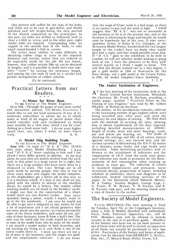
The Model Engineer and Electrician. March 26, 1908.
fortunate enough, by the courtesy of Messrs.Arkell, to be able to give photographs of the newboat, so that intending competitors may havean early glimpse of their new ‘rival. The twoMODEL ENGINEER medals gained in 1906 and 1907by the Moraima were also on view, and were muchadmired.
Another petrol motor boat on view was theSpeedwell, built by Mr. A. Shead. This has ahorizontal double-cylinder petrol motor, developing1-1/4 h.-p., and is fitted with tandem screws. Theboat is 7 ft. long, and her trials will be awaitedwith much interest.
The large model seen in the centre of the photo-graph of the exhibition room is the liner Fairholme,built by the Hon. Secretary of the Club, Mr. G. F.Young. She is a model of one of the Royal MailSteam Packet Company’s boats, and is IO ft. 6 ins.long. The propelling machinery consists of aSiemens enclosed type electric motor driven byaccumulators, and the speed obtained is 7 milesper hour. Mr. Young is evidently a lover of bigmodels, for he also exhibited another 10-ft. model,the Minnehaha ; this, as the name implies, beinga model of one of the Atlantic transport liners.It is also propelled by a Siemens electric motor,and gives a speed of 5 miles per hour. The scaleand general proportions of both these large modelsare excellent, and when they make a trip on theLong Pond they create something in the way ofa sensation among those visitors whose ideas ofmodels are limited to impressions gained fromtoy-shop windows. Mr. Young also had severalother models on view, including a pretty steamyacht and a fine scale model of H.M.S. Essex,this being 6 ft. long.
The Myra, a 4-ft. steamer, was shown by Mr.H. C. Saunders, and the fact that this was theClub’s fastest steamer of last season attractedconsiderable attention to this exhibit. The othersteam and electric models were all worthy ofcareful inspection, and redound greatly to the creditof the Club members in point of workmanshipand finish. Particular commendation may bebestowed on the torpedo destroyer, No. 44, a 5-ft.electric model, shown by Mr. G. A. Smith ; theracing boat, Damilr III, by Mr. Stowell ; theCunard liner models, Margaret, by Mr. H. C.Saunders, and Florida, by Mr. A. Lawson ; and abeautifully finished model of the destroyer, Thresher,with electric lighting installation, by Mr. F. G.Glover.
The model Thames tug, by Mr. Parkins, was anice piece of work, but suffered rather from thefact that above deck she did not resemble theprototype. The destroyer Ealing, shown by Mr.F. Bothwell, possessed two special points of interest.The first arose from the fact that at one time inher career she lay for eighteen months at thebottom of the Round Pond, Kensington, andwas afterwards recovered practically undamaged ;while the second was to be found in an ingeniouselectric buzzer with which she was fitted, andwhich was worked with great -effect from time totime during the exhibition.
Of pure engineering work there were severalgood examples, one of the best being a fine set oftwin-screw engines, made by Mr. J. W. Palmer.A very pretty and effective model of a Thameslock was constructed by Mr. T. Whitmore. Thiswas shown complete, with a dainty model electric
pleasure-launch, and a glass peephole in the lockretaining wall enabled the working of the launch’sscrew in the water to be very clearly seen, electriclight being fitted for this purpose.
The show of model sailing yachts was very fine,and, indeed, there were so many of really excellentworkmanship and design that it is difficult to selectany individual boats for mention. The presentexhibition showed conclusively that the ClaphamClub boats can bear comparison with those of anyother club. The sailing boats included 5-, IO- ,15-, and 20-rater cutters, as well as one 36- andone 42-rater. There was also one representativeof the metre class, and several schooners and punts.
In concluding this notice, we may say that theindefatigable Hon. Secretary, Mr. G. F. Young,and the Stewards, Messrs. G. Arthur Smith, A. J.Upton, H. C. Saunders, and T. Whitmore, are deserv-ing of every congratulation, both in the arrange-ment of the exhibits and of the success of the event.There were over 1,000 visitors on the Friday,while on the Saturday the doors had to be repeatedlyclosed to prevent overcrowding.
Design for Model Motor FireEngine.
By FRANK FINCH.(Continued from page 102.)
ROAD WHEELS.
HAVING dealt with the frame and springs inthe preceding articles, it is in order nowto describe the making of the road
wheels. According to the colouring of these onthe general arrangement drawing (presentationsupplement, January 2nd issue), they are indicatedas being made of brass or gun-metal: but there
FIG. IIa.SECTION THROUGH
REAR WHEEL SPOKES.
Section c.d.
K FIG. 10a.SECTION THROUGH
FRONT WHEEL SPOKES.
Section a.b.
is no reason why-for the sake of lightness-thewheels should not be cast in aluminium. Buildersof the model may suit their individual fancy inthis respect. The fact of departing from theprototype in so far as casting the wheels instead ofbuilding up of wood may displease the eye ofsome. Of course, as a rule the actual wheels ofa motor fire engine are built up of ash-boss, spokesand rim segments. Some who construct this model

-
March 26, 1908 The Model Engineer and Electrician. 307
1
may feel inclined to build up the wheels, but inthis case the dimensions may remain the same,Such a departure would entail much more work,and it is thought that most readers would prefercasting each wheel in one piece. The patterns-one for front wheels and one for the rear wheels
face of wheel, leaving the boss to the requireddimensions.
The groove shown in the faces of the wheels for theinsertion of tyres is turned out from the solid rim ofthe casting, as also the circular recesses in the bossesof each pair of wheels. Referring to the patterns again,
HUB COVER.
Inside Elevation.FIG. 10.-FORWARD WHEEL. (2 THUS.)
k_.._/ 16 Spokes
Inside Elevation.
FIG. II.-REAR WHEEL. (2 THUS.)
can be made from a piece of hard wood and, in thecase of the rear wheels, Fig. II, of sufficient thick-ness to embrace the face of boss and outside faceof wheel rim, and for the forward wheels, Fig. 10,the width of rim only. After marking off the rimand spokes, holes should be drilled between thelatter, and then by means of fret or bow saw, thecorners made sharp. The wood should then befixed in the lathe and turned down to the desired
Section.
dHUB COVER.
Section.
(Scale :Three-quarters full size.)
the spokes should be shaped to the sections shown fullsize in Figs. 10a and 11a. No difficulty will be pre-sented to the amateur in the moulding as the partingline would cut longitudinally through the centre of thespokes. The narrow ring shown round the spokes ofthe rear wheels is of no practical use on the model, butshould be added for appearance sake. A strip ofbrass, 1/8 in. wide, can be carefully bent round into acircle and attached by a spot of solder to each spoke.
308 The Model Engineer and Electrician. March 26, 1908.
One pattern will suffice for the caps of the hubs,and these are to be cast in gun-metal, and finally
that the wage of £2 per week is a bad wage, as thereis no society to pay and the work is light. I would
polished and left bright-being the only portionof the wheels unpainted on the prototypes. In
suggest that “H. S. S."” was not as successful in
one pair, six holes are drilled as indicated, each tothe business as he is in the present one, and as the
clear a I-16th in. screw, and in the other pair, eightbusiness is advancing by leaps and bounds, he would
similar holes are required. Corresponding holes aresoon be hopelessly out of the race. If your corre-
tapped in the outside face of the hubs, to takespondent writes to Kelso & Co., Glasgow, or the
small round-headed 1-16th in. screws.Britannia Model Works, Sunderland-the two largest
The writer must confess to some difficulty inpeople in the trade-I have no doubt they would
obtaining rubber rings or tyres of the requiredgive him a reply, and that would possibly assist him.If “ H
diameter and section, unless they are ordered toS S. ” goes to the exhibition to be held in. .
be especially made for the job. He has found,London, he will see whether model making is going
however, that rubber section 3/8in. sq. can be obtainedback or not. I have the pleasure to be busy with
in lengths, and it is possible to make one’s own com-several myself, so I think I ought to know. You
plete “ tyres ” by cutting the necessary length,will find the details worked out to a fine degree. I
and joining the two ends of each by a careful andgot a gold medal in 1904 at Newcastle for the
patient manipulation of rubber solution.brass fittings, and a gold medal at the Crvstal Palace,in 1906, for model complete.-Yours faithfully,
(To be continued). J. J. P.
Practical Letters from ourReaders.- - -
Re Motor for River Boat.To THE EDITOR OF The Model Engineer.
DEAR SIR, - Through the pages of your most usefuland instructive journal, THE MODEL ENGINEER, Iwould like to ask the kind assistance of any of itsnumerous subscribers to advise me as to whichmake or kind of oil engine or petrol motor theywould consider safe and recommend as beingmost suitable for a 14-ft. boat, which I use for troutfishing on a fresh water loch. I do not want higherspeed than, say, about 6 miles an hour.-Yourstruly, A. N.
- -Rc Model Ship Building Trade.
To THE EDITOR OF The Model Engineer.DEAR SIR, - In reply to “ H. B. H.” (No. 18,561)
who asks about Model Shipbuilding. I haveread “ H. S. S.‘s” letter replying to him and I amafraid I must differ greatly in opinion. In the firstplace, he says they are mostly drafted from the yard:well, in this point to a large extent he is right, butthere are a large number who have never been in ashipyard to work. The m eta1 fittings are in allcases made by outside people, who also in two orthree cases make and supply the model complete,as the shipbuilders get a better job in this way, asit is a business which, if a man is not, shall we say,gifted with the ability to imitate to the smallestdetail, he would be a failure. The models calledworking models are all made in the builders’ yards.I might say that in the construction of a ship’smodel there are two distinct trades. Your corre-spondent being a joiner, would, I expect, want togo in for the woodwork. I am sure he would notbe able to get into a shipyard as one, unless he hada lot of experience and I am afraid geometry doesnot enter much into the matter, as I know personallysome of the finest modellers, and some do not, out-side of their business, know B from a bull’s foot. Theonly way he could join the trade would be to writeto some of the model firms who do make all the model.I am myself a model maker in both branches, andam earning my living at it, and think it one of thenicest trades there is. I must say there are not alot of men in the business, and the wages are goodand the employment constant. I do not know
The Junior Institution of Engineers.
AT the last meeting of the Institution, held at theRoval United Service Institution, Whitehall,
the Chairman, Mr. Frank R. Durham, presiding, auseful paper, entitled “ Practical Notes on theTesting of Gas Engines,” was read by Mr. GilbertWhalley, of Walton-on-the-Naze.
The author,. in his introductory remarks, referredto the increasmg number of gas engines which werebeing installed year after year, and cited thenecessity for and objects of testing. He then dealtwith the methods of carrying out tests, showinghow to obtain expeditiously all the data required,including detailed measurements of cylinder,length of stroke, main and outer bearings, crank-pin and piston pin hearing, etc. The mode ofchecking the settings and lifts of all valves, electricignition settings, etc., was entered into, and thevarious systems of determining the B.H.-P. by meansof a dynamo, prony brake and rope brake wereillustrated. Some interesting particulars with re-ference to the attachment of indicators and thecomputation of I.H.-P. from the cards were given,and reference was made to processes for the deter-mination of fuel consumption when running onproducer or town gas. The reduction of resultsto standard temperatures and pressures, watercirculation details, preparation of report, includingschedule of conditions, charts and diagrams to besubmitted, formed concluding sections of thepaper. In the discussion which followed, Messrs.W. A. Tookey, Stanley Hughes, George Lyge, C.G. Evans, R. W. Brewer, W . H. Stevens, and R.H. Parsons took part, and the meeting closed witha vote of thanks to the author.
The Society of Model Engineers.FUTURE MEETINGS.-The next meeting is fixed
for Tuesday, April 7th, at the Cripplegate Institute,when a Sale of Models (finished and unfinished),Parts, Tools, Electrical Apparatus, etc., will beheld. Members only will be allowed to includearticles in the sale or to purchase goods. Membersof the Society who have not as yet been present atone of these sales will do well to attend, as apparatusof all kinds can usually be purchased at very lowprices. Particulars of the Society and forms of appli-cation Can he obtained from-HERBERT G. RIDDLE,Hon. Sec., 37, Minard Road, Hither Green, S.E.

64 The Model Engineer and Electrician. July 16, 1908.
Design for a Model Motor Fire Engine.
By FRANK FINCH.(Continued from page 308, Vol. XVIII)
STEERING GE A R.
H AVING d e a l t w i t h t h e w h e e l s i n the last article, it is as well now to describe in detailthe parts which are required for the steering
gear and front axle, seeing they are so closely
FIG. 15.
(Full size.)
associated with each other. A full-size drawing ofeach separate limb is given, and the constructionof the gear is so simple that it should not prove adifficult task to fit the respective limbs. Thefront axle is a steel forging with bifurcated ends(Fig. 12). Into eithcr end is fitted respectivelya right gunmetal casting as shown in Fig. 13,
One left hand thus.
FIG. 13.-GUN-METAL CASTING.
FIG. 17.
GUN-METAL BEARING
I
t-9
FOR STEERING ROD.
__/f"-;
(Full size.)I
FIG. 14. (Full size.) Fig. 16. -MAIN STEERING ROD.
DETAILS OF PARTS FOR MODEL MOTOR FIRE ENGINE.

July 16, 1908. The Model Engineer and Electrician. 6 5
and at c in Fig. 19; into the main bars a steelstud is screwed, upon which the front wheels revolve.The end of the arm in both cases is bifurcated, thelower lip being tapped for a small screw, whilstthe upper lip has a hole to clear the screw. Therod for connecting the right and left arms andthereby actuating the opposite wheel is a plainsteel bar as shown in Fig. 14, and at a in Fig. 19.Each end is inserted into the end of the curved armand kept in position by a setscrew which fits looselythrough the top lip and connecting-rod, and screwsinto the lower lip of arm. The fitting d is shownin detail at Fig. 15. and as will be seen, has oneend bifurcated, and at the opposite end a boss witha square hole, in order to securely hold the steeringrod. Connection is made between d. c and a by
retained by a small screw in the upper bearing, asshown in the coloured general arrangement drawing(see issue for January 4th, 1908). The hand-wheel(Fig. 18) to be fixed to the top of steering rod needsno description. It may be possible to secure a suit-able wheel from the " scrap ” box. A perspectivesketch (not to scale) is given in Fig. 20 in order tomake the arrangement more easily understood.
(To be continued.)
Practical Letters from OurReaders.
- - -[ The Editor Invites readers to make use of this column for the full
discussion of matters of practical and mutual interest. Lettersmay be signed with a nom-de-plume if desirred, but the fullname and address o/ the sender MUST invariably be attachedthough not neccssarily for publication.]
Model Screw Propellers,TO THE EDITOR OF The Model Engineer.
7
FIG. 19.-PLAN OF STEERING
GEAR ARRANGEMENT.
(Half full size.)
a plain strip b (Fig. 14), having a clearing hole ineach end. The main steermg rod (Fig. 16) isheld by two gun -metal bearings shown in detail{Fig. 17). The position of the steering angle is
FIG. 20.-PERSPECTIVE SKETCH OF PORTION OFSTEERING GEAR. (Not to scale.)
DEAR SIR,--I was glad to seeMr. Arkell’s expression of opinionanent above in your June 4th is-sue, and heartily re-echo his wishthat more readers would opentheir hearts on the subject. ofscrew propulsion.
But “ there’s the rub,” andmy case. How can they con-tribute their quota to progressif they follow the hit-and-missmethods advocated in twistingsheet-metal blades ?
If inverse dies of hardwoodare carefully swept up before-hand to likely data for thebending of the blades in the firstcase for a new propeller, andsubsequently altered to the ac-quired likelier data for increasedspeed, then I grant that a sheet-metal screw would be the betterjob, as a job, owing to the metal
being thinner than it could be cast, but this methodis not SO direct or interesting.
Simply bending by guesswork may be trickysport, but it is not educative to the individual,nor does it add to the collective sum of our scantyknowledge of basic principles.
After two or twenty misses one hit may be judgedto have been attained, but how is one to be sure thatfinality in efficiency has been reached, or profit by hislabours leading up to it, if he has no data to go upon.
He cannot be confident he has got the mostefficient screw for that individual boat, and maybe afraid to alter further without a guide in direc-tion in case he cannot go back on his tracks.
The nearer one gets to efficiency the less altera-tion is required, and therein lies the fascination,likewise the instruction and experience to be gained,by making cast screws according to the methodsshown. They would furnish the experimental experi-ences and data whereby one could progress in everysubsequent effort, and, not only that, but whatis very important from a collectively scientificstandpoint is that they would enable the studentto report progress, and how it was gained, for thebenefit of fellow-readers. I am convinced thatTHE MODEL ENGINEER and its steamer builderscould become a power in this connection.

November 12, 1908. The Model Engineer and Electrician. 459
,
.
(Continued from page 65.)
T HE part front elevation shown in Fig. 2 I shouldbe studied, together with Fig. 20 in the lastarticle ; it will assist in simplifying the
arrangement of rods, etc., for the steering gearand their relation to the front axle. The positions
Design for Model Motor FireEngine.
By F RANK F I N C H.
wire 5-7/8 ins. long (about 1-16th in. in diameter),soldered along the top edge of the sheet, will givea finish resembling the prototype. A quantity ofI-16th-in. brass wire should be obtained, as varioussmall lengths will be required to complete the model.For instance, the handles on each side of the frontplate are made of two 1-1/2-in. lengths ; the ends tobe filed flat on one side and bent over with a pairof round-nosed pliers, so that the flat sides can besoldered on to the plate in the position indicated.
The Boiler.-For the boiler shell a piece ofbrass tube 4 ins. diameter by 5 ins. long, No. 18B.W.G. should be obtained from the metal merchant,
L
FIG. 21.-VIEW SHOWING ARRANGEMENT OF FRONT PLATE, STEERING GEAR,AND FRONT AXLE. (Half full size.)
of bearings for supporting the vertical steering-rodare also indicated. It is very essential for theappearance of the model that the front plate shouldbe well curved and even. The sketch at the topof the figure gives the radii for this plate. A pieceof Russian iron about 18 B.W.G. will be of amplestrength, and it might be hammered round thefront casting of the frame, over which it is placedwhen in its final position. A strip of half-round
also a 2-in. length, which should be expanded outso that one end remains 4 ins. diameter and gradu-ally tapers to 4-1/2 ins. diameter. This forms thebottom or outside of firebox end of boiler. Thefoundation-ring, which is of brass, is shown infull size half-section at Fig. 22. The T-sectionring for connecting the upper and lower boilershells is shown in Fig. 23, and 1-16th-in. rivet holesare to be drilled right round, above and below the

460 The Model Engineer and Electrician. November 12, 1908.
4h
.- --
FI G. 26.-FIREBOX CR O W N.
i__l;.__lFIG. 27.-CASTING TO SECURE THE BOILER TO
THE MAIN FRAME.
(Two thus : Full size.)
F I G. 25.-CIRCULAR PLATE TO FORM SMOKEBOX. (Full size.)
I
FI G. 24-BOILER DOME. (Full size.)
FIG. 23.-T-SECTION BOILER RING. (Full size.)
+p I\\ \\ I
FIG. 22.-FOUNDATION RING. (Full size.)
BOILER AND FIREBOX DETAILS FOR MODEL FIRE ENGINE.
By FRANK FINCH.
I

November 12, 1908. The Model Engineer and Electrician. 461
middle web, about 3/8-in. centres. The boiler domeis, of course, a brass casting, and the half-sectiongives the finished sizes (Fig. 24). A set-off about5-16ths in. wide is turned on the circumference, inorder to bring the boiler shell flush with the dome.Holes are to be drilled and tapped for 3-32nds-in.
:
F i g . 28.-CHIMNEY PA R T S.
screw (about 5/8-in. centres) all round this recess,and corresponding holes must be drilled round theupper end of boiler shell.
T h e c i r c u l a r
Ir I Iplate shown in thecoloured plate, andforming the smoke-box, is also shownfull-size in Fig. 25.This is of stoutsheet copper 4-1/2 insdiameter by No. 16B.W.G., and maybe beaten into thedesired shape, thecentre ring to ber i v e t e d t o t h esmoke-flue, and theouter ring to bedrilled for 1-16th-inch rivets (about3/8-in. centres} for
outer bar re l . InFig. 26 is shown,in half-section, theplate forming thefirebox crown ; thisis of copper sheetabout 3-1/2ins. diam-
l-l /I I
lz 1//5II
III
i, _---- -’I
‘AHALF SECTIONAL
PLAN.
FIG. 29.-ENGINEER’S PLATFORM AND TOOL-BOXES.(Half full size.)
eter by No. 16 B.W.G. A ring of holes should bedrilled upon each flange similarly to the plate (Fig.25) and, in addition, upon a centre 1-7/8 ins. diameter,scribed from the centre, should be drilled at equaldistances twelve holes, to take the ends of twelvewater-tubes, as shown in the coloured plate, and asindicated in Fig. 26. To secure the boiler firmly tothe frame, castings should be made to the dimen-sions and shape shown in Fig. 27. One 1/8-in. screwwill be sufficient to attach each casting to the sideframe through the bottom of the water tanks.The curved surface should be brazed to the sideof the boiler. A 4-in. length of 1-in. diametercopper tube constitutes the smoke-flue, and shouldbe drilled top and bottom to coincide with themiddle flanges of Figs. 25 and 26. The fireboxwall may be formed from a 3-in. length or coppertube 2-3/4 ins. diameter, tapered out to 4 ins. diameter,and riveted right through the foundation-ring(Fig. 22). Twelve holes are to be drilled at equaldistances 3/4 in. from the bottom end of firebox,to take the other end of water-tubes. Each water-tube is 3-1/2 ins. long and bent to the shape as shownin the general arrangement. It is proposed toconstruct the chimney in parts, as shown in thedrawing (Fig. 28), especially to add to the effectof its appearance when finished. The main bodyis a piece of steel, turned down at each end as shown,the remainder of the circumference is left dull. Thetop ring is of copper and polished, whilst the capmay be turned from a piece of brass plate. Theform of superheater is clearly shown in thegeneralarrangement drawing. Boiler fittings are the usualstandard patterns obtainable from advertisers inT HE M ODEL E N G I N E E R , with the exception of thesafety valve, a detail drawing of which will be givenin a subsequent article.
The engineer’s platform and tool-boxes, whichare situated at the rear of the model, are detailswhich,, although simple, call for careful work-manship. It is often such minor accessoriesas these that spoil the effect of a model. Thedrawings given in Fig. 29 are half ful l size,and may be accurately measured off. The main
l=h---lCROSS SECTION
A. B
DETAIL OFback
H I N G E . o fbox
HALF PLAN.

462 The Model Engineer and Electrician. November 12; 1908.
piece or platform forms also the bottom of bothboxes. The sides for each box are constructed inone piece, allowance being made for the ends tooverlap at one corner for soldering. A simple formof hinge is shown in the enlarged sketch. These
should be cut in the lid, as indicated in the plan(Fig. 30). to allow for the top of pump to protrude.
Feed-pump.-Following the water tanks, weare now to deal with the hand-operated pump for
5’ Sectional Plan
FIG. 30.-DETAILS OF FEED-WATER TANKS.(Half full size.)
boxes are used for tools, etc., on the prototypes, andwill be found useful on the model for placing oddscrews, etc., when manipulating the model. Inthe general arrangement drawing a sling is shownby which this platform is suspended. A strip offlat metal, as shown, will suffice. To further steadythe platform, two small strips attach it to the foun-dation-ring of boiler, as indicated.
Dealing now with the water tanks, it will beobserved that these occupy the same position inthe model as in the real engines. The sketches(Fig. 30) are reproduced to exactly half full size,and may be scaled off; both tanks are alike,excepting that they are right- and left-handed.The curved side is obviously to fit round the boiler,and the radius should equal that of the boiler.The step-up portion in the bottom of tank is tocover the casting which supports the boiler, thescrew for same going right through bottom of tank,and thus securing the tank firmly. The smallpipe, screwed at ends, and connecting the tanks,also acts as a tie-rod. In the right-hand tankit is proposed to place the feed-pump, and inorder to do this the top of the tank should bemade in the form of a movable lid, which can beplaced on after the pump is in position. A hole
Section A.B.
‘C
SECTIONAL ELEVATION. C.D. END ELEVATION
PLAN a.b.
FIG. 31.-HAND-PUMP FOR FEEDING WATER TOBOILER. (Half full size.)
feeding the water as required, into the boiler.The pump is clearly shown in the drawings (Fig. 31),which are reproduced exactly to half full size.Little or no explanation is necessary for this.Suffice it to say that the two caps are screwed to.the pump body by two screws each, which go rightthrough to the foundation-plate: the latter isheld to the bottom of tank by three small screws..
(To be continued)

485 The Model Engineer and Electrician. November 19, 1908.1
SIDE ELEVATIONI u
FIG. 3Ib. ,z I?655 "u'n,*
z5.s &rod fl
FIG. 31b.-DETAIL OF DRIVER'S WOODEN SEAT
Fig. 32.--ARRANGEMENT OF SPIRIT RESERVOIR AND SUPPLY, SHOWING METHOD OF SUSPENSIONBETWEEN THE FRAMES.
i
November 19, 1908. The Model Engineer and Electrician. 489
Design for Model Motor FireEngine.
By FR A N K F I N C H.(Continued from page 462.)
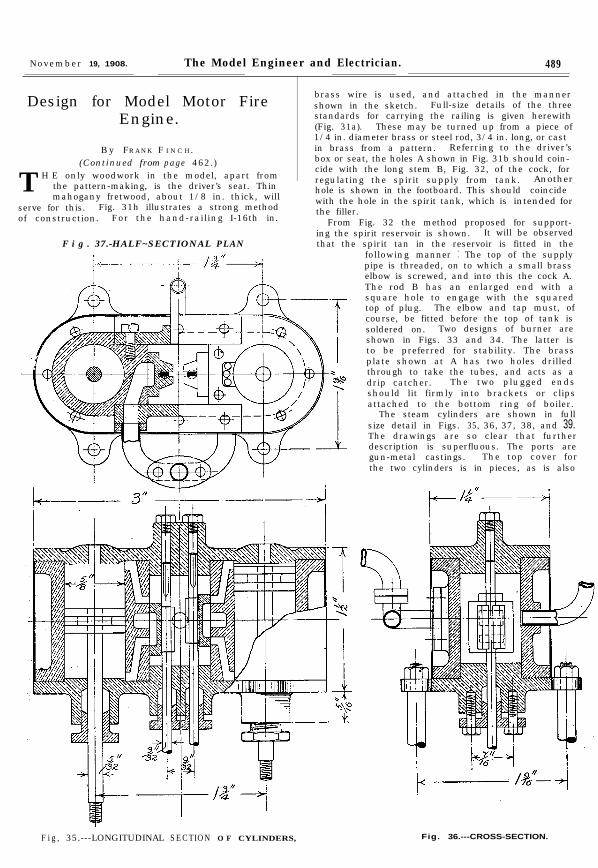
T H E only woodwork in the model, apart fromthe pattern-making, is the driver’s seat. Thinmahogany fretwood, about 1/8 in. thick, will
serve for this. Fig. 31h illustrates a strong methodof construction. For the hand-railing I-16th in.
F i g . 37.-HALF~SECTIONAL PLAN
brass wire is used, and attached in the mannershown in the sketch. Full-size details of the threestandards for carrying the railing is given herewith(Fig. 31a). These may be turned up from a piece of1/4 in. diameter brass or steel rod, 3/4 in. long, or castin brass from a pattern. Referring to the driver’sbox or seat, the holes A shown in Fig. 31b should coin-cide with the long stem B, Fig. 32, of the cock, forregulating the spirit supply from tank. Anotherhole is shown in the footboard. This should coincidewith the hole in the spirit tank, which is intended forthe filler.
From Fig. 32 the method proposed for support-ing the spirit reservoir is shown. It will be observedthat the spirit tan in the reservoir is fitted in the
F i g , 35.---LONGITUDINAL SECTION O F CYLINDERS, Fig. 36.---CROSS-SECTION.
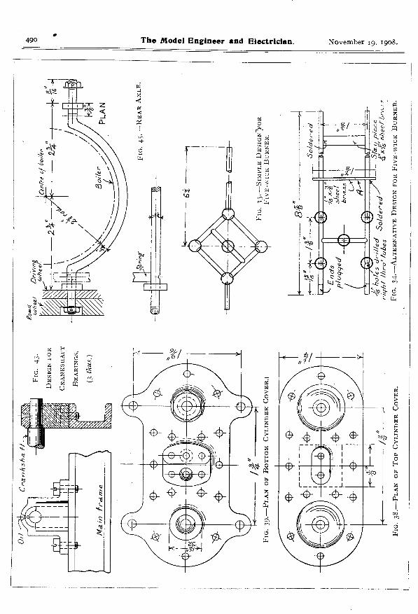
following manner : The top of the supplypipe is threaded, on to which a small brasselbow is screwed, and into this the cock A.The rod B has an enlarged end with asquare hole to engage with the squaredtop of plug. The elbow and tap must, ofcourse, be fitted before the top of tank issoldered on. Two designs of burner areshown in Figs. 33 and 34. The latter isto be preferred for stability. The brassplate shown at A has two holes drilledthrough to take the tubes, and acts as adrip catcher. The two plugged endsshould lit firmly into brackets or clipsattached to the bottom ring of boiler.
The steam cylinders are shown in fullsize detail in Figs. 35, 36, 37, 38, and 39.The drawings are so clear that furtherdescription is superfluous. The ports aregun-metal castings. The top cover forthe two cylinders is in pieces, as is also
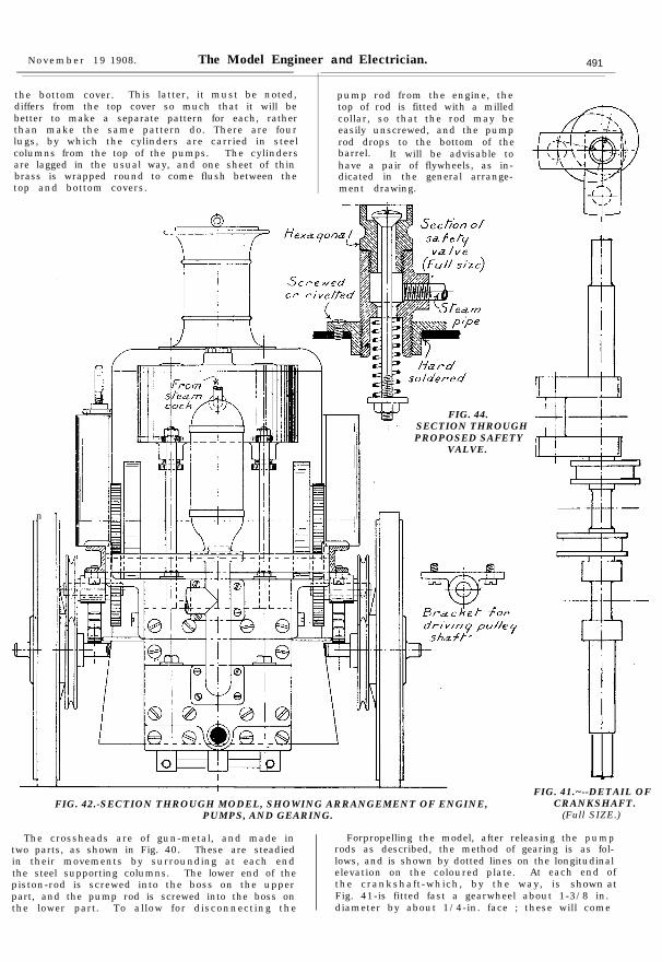
November 19 1908. The Model Engineer and Electrician. 491
the bottom cover. This latter, it must be noted,differs from the top cover so much that it will be
pump rod from the engine, thetop of rod is fitted with a milled
better to make a separate pattern for each, ratherthan make the same pattern do. There are four
collar, so that the rod may be
lugs, by which the cylinders are carried in steeleasily unscrewed, and the pumprod drops to the bottom of the
columns from the top of the pumps. The cylinders barrel. It will be advisable toare lagged in the usual way, and one sheet of thin have a pair of flywheels, as in-brass is wrapped round to come flush between thetop and bottom covers.
dicated in the general arrange-ment drawing.
n
FIG. 44.SECTION THROUGHPROPOSED SAFETY
VALVE.
FIG. 42.-SECTION THROUGH MODEL, SHOWING ARRANGEMENT OF ENGINE,PUMPS, AND GEARING.
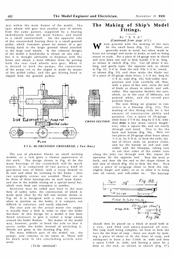
The crossheads are of gun-metal, and made intwo parts, as shown in Fig. 40. These are steadiedin their movements by surrounding at each endthe steel supporting columns. The lower end of thepiston-rod is screwed into the boss on the upperpart, and the pump rod is screwed into the boss onthe lower part. To allow for disconnecting the
FIG. 41.~--DETAIL OFCRANKSHAFT.
(Full SIZE.)
Forpropelling the model, after releasing the pumprods as described, the method of gearing is as fol-lows, and is shown by dotted lines on the longitudinalelevation on the coloured plate. At each end ofthe crankshaft-which, by the way, is shown atFig. 41-is fitted fast a gearwheel about 1-3/8 in.diameter by about 1/4-in. face ; these will come
492 The Model Engineer and Electrician. November 19. 1908
just within the main frames of the model. Thespur wheels will gear into another pair of wheelsfrom the same pattern, supported by a bearingimmediately below the main frames, and keyedto a small countershaft. On the opposite sideof this countershaft bearing there is a small groovedpulley, which transmits power by means of a gutdriving band to the larger grooved wheel attachedto the large road wheels. In the coloured designsof the model a band-brake is shown on one side ;but it is thought advisable to dispense with thebrake and obtain a more efficient drive by puttingboth the rear road wheels into gear. When itis desired to work the pumps, the connectionof the pump r o d to the engine is made by meansof the milled collar, and the gut driving band isslipped from the grooved pulleys.
PL A N
The Making of Ship’s ModelFittings.
(Continued from page 472.)E now proceed with the making of the oarsW for the small boats (Fig. 32.). These are
generally made in wood, but when made inbrass are stronger and easier to make, as well as beingnearer to scale. Put a piece of 14-gauge wire in chuckand turn down one end to form handle 1/8 in. long,as shown in sketch (Fig. 32). Cut off about 4 ins.long, and gently taper the opposite end, as shownin Fig. 32, 3/4 in. from the end. File 1/2 in. round,as shown (Fig. 33), and then make the blade outof a piece of 20-gauge sheet brass, 1-1/4 ins. long by
1/8 in. wide (Fig. 34). Soft-solder intoposition and trim carefully off. Now,with a piece of fine wire, serve the endof blade as shown in sketch, and soft-solder. This operation finishes the oars,which, as in the case of lifebuoys, arepainted white, and the served partpainted black.
CROSS SECTION
The next fitting we propose to con-struct is a hencoop (Fig. 35). Themaking of this fitting calls for a fairamount of constructive ability andpatience. Cut a piece of 20-gaugesheet brass 1-7/8 ins. long by 3/4 in. wide ;then draw ‘a line down centre length-wise, take a square file, and cut nearlythrough and bend. This is for theback and bottom (Fig. 36). Next cuttwo pieces of 20-gauge sheet brass about1/2 in. by 3/8 in. to form the ends, layone of these ends on pumice stone,and lay the bottom on end and soft-solder with the blowpipe, taking careto see that some of the solder runs
along the joint cut through with file; repeat theoperation for the opposite end. Now file level atback, and then tile the end to the shape shown inend view of sketch (Fig. 35) to form the feet. N o wtake a piece of so-gauge sheet to form the top,slightly longer and wider, so as to allow it to hangover all round, and soft-solder on. The hencoop
F I G. 40.-TRUNNION CROSSHEAD. ( Two thus.)
The use of plummer blocks on small workingmodels, as a rule gives a clumsy appearance tothe work. The design shown in Fig. 43 for themain bearings of the crankshaft will be muchneater. It is comprised of two parts-a kind ofgun-metal seat of block, with a strap formed tofit over and allow for screwing to the frame ; thustwo unsightly screws are avoided. There are tobe three of these bearings-one on each main frame,and one in the middle resting on a special metal bar,which rests from one crosspiece to another.
Attention may be called just here to the neatform of safety valve, the construction of which ismade quite clear by the full size section shown atFig. 44. It is designed with a view to neatnesswhen in position on the boiler; it is compact, notdifficult to construct, and easily adjusted.
The rear axle on the actual motor tire engineis usually bent a little in order to clear the boilerfire-door. In this design for a model it has beenfound necessary to give it rather a large sweeparound the boiler firebox. The maker of the modelmay, however, prefer to bend the axle so that itpasses under the boiler instead of encircling it.Details are given in the drawing (Fig. 45).
The most difficult part of the model, viz.. thepumps, now remains to be takeu in. These willbe dealt with in the concluding article nextweek.
( To be continued.\
By “ X. Y. Z.”
Fig,33.
should then be placed on a block of mood held ina vice, and filed and emery-papered all over.The coop itself being complete, we have to form thebars for the front of coop ; these are made by mak-ing a piece of sheet to fit the front of coop, andsetting-out to leave a bar I-16th in. wide and thena space I-16th in. wide, and leaving a piece for adoor at the end, as shown in sketch (Fig. 37)

516 The Model Engineer and Electrician. November 26, 1908.
Fig. 6 shows the connections of the electricbell transmitter, which is fitted up as follows:First the bell is removed, and then a small adjustablecontact-screw A is placed against the outside of thebell hammer to control its vibration, after whichit is connected up as shown in Fig. 6, where Mis the electro-magnet. B the contact-screw, and Cthe contact-spring.
The contact-spring is connected to terminal H:and thence to the aerial wire L. The contact-screw is connected to terminal H’ and to the otheraerial wire L’. D is a 4-volt accumulator, of threeor four batteries, and E is a Morse key (an ordinaryelectric bell-push will do instead of this).
Every time- I/A the key is
pressed acurrent flowsthrough thecoils of the
Fig. 4. magnet, anda spark ornumber o f
Fig. 3.
u
Fig 5:
sparks takeplace at thec o n t a c t -b r e a k e r .They causeelectrical os-cillations inthe wires
P
and L’, from which waves travel outwards, and inturn set up oscillations in the receiving aerials G andG’ of the receiver, and anyone listening at the tele-phone will hear a long or short buzzing noise, accord-ing to the signals being sent from the transmitter.
Of course, as with all other forms of wirelesstelegraph apparatus, much greater distances can
distance over about I mile this would be absolutelynecessary.
Design for Model Motor FireEngine.---
By FRANK F I N C H.
(Concluded from page 492.)
THE most difficult parts of the model we haveyet to deal with now are the pumps. Itis no easy matter to get a double-acting
two-cylinder pump in such a limited space. Threemain patterns must be made-one for the barrels,from which two castings will be required exactly
,1%A
--
be attained by earthing one terminal, and if thisis done H’ is the best terminal to connect to earth.
Fig. 5 shows a more powerful form of primaryspark transmitter. M is a large electric magnet,in front of which is’ a contact-breaker A B, the ironarmature C of which is fixed in the centre of thespring A. opposite to the iron core of the magnet.The vibration of the spring is controlled by an ad-justable screw D. E is a battery which is connectedto one end of the coil of the magnet F ; the otherend of the coil (G) isconnected to the contact-spring A.The circuit is completed through the contact-screw B. P is a Morse key, which is placed betweenthe battery and the contact-screw.
H and H’ are the two aerial terminals. H isthe best one to connect to earth.
The receiver can, if desired. be worked by thesecondary spark from an induction coil; for any
FI G. 47.--AIR VESSEL. (Full size.)
similar, and the upper and lower valve chambers.They are to be of gun-metal. With a view to light-ness, the upper and lower castings are connectedby a tube screwed at each end. The barrelsareclosed at the lower end by a screwed plug. Thevalve chambers are attached to the pump barrels bymeans of long cheese-headed screws, as shown inthe plan views. There are no less than eight valves,and small cycle bearing balls are advised for these.They are kept from going astray by the protrudingpiece at the end of each screwed plug. To grasp

November 26, 1908. The Model Engineer and Electrician. 517
9J
Section C.D.
Sectional Elevation A.B.
Plan
Sectional Plan E.F:
FIG. 46.-DETAILS OF TWO-CYLINDER DOUBLE-ACTING PUMPS.(Three-quarter size.)

c
518 The Model Engineer and Electrician. November 26, 1908.
the construction the various sections must bestudied in conjunction with each other. On thefront end elevation is shown the best method forcarrying the pumps. It is by means of a hookedbracket, which is fastened to the sides of the uppervalve chamber by two screws, and the bracketssimply rest upon the main frame sides.
The air-vessel on the prototypes is not usuallyseen, being covered up by the wood box which wecall the driver’s seat ; but a touch of polished copperlends a better effect to the model, and for this reasonit has been kept in a prominent position. Thedetail is shown in Fig. 47. The main body isa piece of tube 1-3/4 ins. by I in. diameter, turneddown and screwed for 1/8 in. at each end. The topcan be beaten to the required shape and the rimturned and screwed to fit one end of tube, likewisethe bottom end with flange. It may be mentioned,in concluding these articles, that there are numerousaccessories which, whilst insignificant, are essentialto the finished model. For instance, the hosepipe-small +-in. flexible metallic tubing-is a goodrepresentation. The bell which hangs in front canbe obtained from a toy dealers. Lamps are easilymade to good effect from wood or lead. When allis ready for painting, which, after all, is an impor-tant item when it refers to anything with thefire brigade, I cannot do better than refer myreaders to the excellent articles that have appearedin THE MODEL ENGINEER on painting and finishingmodels. The brilliant red familiar to all must be care-fully matched, and when the model is ready for thepaint, it is advisable to compare the colour at thenearest fire station before applying it to the model.It is hardly necessary to mention that the boileris left bright, also steam pipes, cylinders, and pumps.The parts to be coloured red include the wheels,main frame, water tank, front plate, spirit tank,and driver’s seat. A little lining, it properly done,will improve the decoration, and the words-“ T HEMODEL ENGINEER Fire Engine “-might be addedto the sides of the water tank.
The Colouring of Various Metalsby Lacquering, Bronzing, etc.- - -
By C. A. G. SIANDAGE.(Continued from page 401.)
- - -C HEMICAL F LUIDS FOR C OLOURING M ETALS.
For Colouring Brass Seimply by Immersion.No. I.-Brown tones to black :
I pt. water.
T HESE liquids are used simply by dippingthe metal article in them for a sufficientlylong time.
5 drachms nitrate of iron.No. a.-Brown and all shades to black :
I pt. of water.5 drachms of protochloride of iron.
No. 3.-Brown and all tones to red :I pt. of water.16 drachms nitrate of iron.16 hyposulphite of soda.
No. 4.--Brown and every shade to red :I pt. of water.16 drachms of hyposulphite of soda.I drachm of nitric acid.
No. S.-Brownish red :I pt. of water.I oz. nitrate of copper.I oz. oxalic acid.
No. 6.-Orange red :I pt. of water.I drachm of a solution of sulphide of potash.
No. 7.-Olive :2 pts. of water.2 drachms of perchloride of iron.
No. S.-Blue :I pt. of water.2 drachms of hyposulphite of soda.
Bronze powders are usually dusted on a surfacethat has been coated with some suitable agglutinantto cause the powder to adhere ; in some cases abronze paint is used, while in the case of leatherarticles a liquid bronzing fluid is employed.
Such a fluid is one of the easiest methods of bronz-ing, because the fluid is similar to a quick-dryingvarnish, that, when dry, exhibits a “ bronzed ”effect, which is generally due to the presence of asuperabundance of an aniline dye.
Success in the art of bronzing greatly dependson circumstances, such as the temperature of thealloy (metallic bronzing powder) or of the solution,the proportions of the metal used in forming thepowder, and the quality of the materials.
The moment at which to withdraw the goods,the drying of them, and many other little itemsrequire a care and attention in manipulationwhich experience alone can impart.
ANILINE B RONZING FL U I D.Take 10 parts of aniline red and 5 parts of aniline
purple, dissolve them in 100 parts of methylatedspirit at the heat of a water-bath.
As soon as the dyes are dissolved, add 5 partsof benzoic acid and raise the temperature of themixture to boiling point, and keep it at that heatfor five to ten minutes, until, in fact, the greenishcolour of the mixture is transformed into a finelight-coloured bronze.
This fluid is laid on with a brush, and is applicableto metals, wood, leather, etc.
Bronzing Fluid.Ingredients :
50 grains of red aniline.50 grains of violet aniline.2 ozs. of alcohol.50 grains of benzoic acid.
Dissolve the aniline colours in a bottle by theaid of heat (over a water-bath), add the benzoic acid,and heat the mixture until its colour is of a light-brownish bronze.
Brown Bronze Dip.Ingredients :
8 ozs. of iron scales.8 ozs. hydrochloric acid.1/2 oz. arsenic.1/2 oz. of zinc (solid).
Mix in a bottle and keep the zinc in the mixtureonly while the fluid is in use.
Green Bronze Dip.Ingredients :
4 ozs. of verdite green.4 ozs. of common salt.2 ozs. of sal-ammoniac.I oz. of alum.16 ozs. of French berries.4 qrts. of vinegar.
Boil all these ingredients together.

November 26, 1 9 0 8 .-
T h e Model Engineer and Electrician.
I-
Front End Eevation
.
Section G.H. Section J. K.
FIG. 46.-DETAILS OF TWO-CYLINDER DOUBLE-ACTING PUMPS. (Scale : three-quarter full size.)


![From.the.Caves.and. .[1908]](https://static.fdocuments.us/doc/165x107/577cbfcd1a28aba7118e2afc/fromthecavesandjunglesofhindostan1908.jpg)


![THE REGISTRATION ACT, 1908 Related... · THE REGISTRATION ACT, 1908 (ACT NO. XVI OF 1908). [ 18th December, 1908] 1. An Act to Consolidate the enactments relating to the Registration](https://static.fdocuments.us/doc/165x107/5e56ab1e4c078f4f1d329bb3/the-registration-act-related-the-registration-act-1908-act-no-xvi-of-1908.jpg)


![ACT NO. V OF 1908 [21st March 1908] PRELIMINARY OF CIVIL PROCEDURE 1908.pdf · V OF 1908 [21st March 1908] An Act to consolidate and amend the laws relating to the Procedure of the](https://static.fdocuments.us/doc/165x107/5a8a4cf57f8b9afe568bcac2/act-no-v-of-1908-21st-march-1908-preliminary-of-civil-procedure-1908pdfv-of.jpg)


![Companies (Consolidation) Act 1908 · Companies (Consolidation) Act 1908 1908 CHAPTER 69 An Act to consolidate the Companies Act, 1862, and the Acts amending it. [21st December 1908.]](https://static.fdocuments.us/doc/165x107/6035fa2b6f1ab8592550a79a/companies-consolidation-act-companies-consolidation-act-1908-1908-chapter-69.jpg)