Service · 2 16023030 Rev. 0 ©2004 Maytag Services Important Notices for Servicers and Consumers...
24
Compact Top Mount Refrigerators This Base Manual covers general information Refer to individual Technical Sheet for information on specific models This manual includes, but is not limited to the following: Maytag PCF1700ACW PCF2700ACW PCF4400ACW PCF8200ACW Service This manual is to be used by qualified appliance technicians only. Maytag does not assume any responsibility for property damage or personal injury for improper service procedures done by an unqualified person. 16023030 May 2004
Transcript of Service · 2 16023030 Rev. 0 ©2004 Maytag Services Important Notices for Servicers and Consumers...
CompactTop MountRefrigerators
This Base Manual covers general informationRefer to individual Technical Sheetfor information on specific models
This manual includes, but isnot limited to the following:
MaytagPCF1700ACWPCF2700ACWPCF4400ACWPCF8200ACW
ServiceThis manual is to be used by qualified appliancetechnicians only. Maytag does not assume anyresponsibility for property damage or personalinjury for improper service procedures done byan unqualified person.
16023030May 2004

2 16023030 Rev. 0 ©2004 Maytag Services
Important Notices for Servicers and ConsumersMaytag will not be responsible for personal injury or property damage from improper service procedures. Pride andworkmanship go into every product to provide our customers with quality products. It is possible, however, thatduring its lifetime a product may require service. Products should be serviced only by a qualified service technicianwho is familiar with the safety procedures required in the repair and who is equipped with the proper tools, parts,testing instruments and the appropriate service information. IT IS THE TECHNICIANS RESPONSIBILITY TOREVIEW ALL APPROPRIATE SERVICE INFORMATION BEFORE BEGINNING REPAIRS.
! WARNINGTo avoid risk of severe personal injury or death, disconnect power before working/servicing on appliance to avoidelectrical shock.
To locate an authorized servicer, please consult your telephone book or the dealer from whom you purchased thisproduct. For further assistance, please contact:
Customer Service Support Center
CAIR CenterWeb Site Telephone Number
WWW.AMANA.COM ............................................... 1-800-843-0304WWW.JENNAIR.COM ............................................ 1-800-536-6247WWW.MAYTAG.COM ............................................. 1-800-688-9900
CAIR Center in Canada .......................................... 1-800-688-2002Amana Canada Product .......................................... 1-866-587-2002
Recognize Safety Symbols, Words, and Labels
DANGER!DANGER—Immediate hazards which WILL result in severe personal injury or death.
WARNING!WARNING—Hazards or unsafe practices which COULD result in severe personal injury or death.
CAUTION!CAUTION—Hazards or unsafe practices which COULD result in minor personal injury, product or property
damage.
Important Information

©2004 Maytag Services 16023030 Rev. 0 3
Important Information .................................................... 2Component Testing ....................................................... 4Service Procedures ....................................................... 9Service Equipment ........................................................ 9Drier Replacement ........................................................ 9Refrigerant Precautions ................................................ 10Line Piercing Valves .....................................................10Open Lines .................................................................. 10Compressor Operational Test ....................................... 10Dehydrating Sealed Refrigeration System .................... 11Leak Testing ................................................................. 11
Testing Systems Containing aRefrigerant Charge ................................................. 11Testing Systems ContainingNo Refrigerant Charge ............................................ 11
Restrictions .................................................................. 12Symptoms ............................................................. 12Testing for Restrictions .......................................... 12
Evacuation and Charging .............................................. 13Evacuation ............................................................. 13Charging ................................................................ 14Refrigerant Charge ................................................. 14
HFC134a Service Information ....................................... 15Health, Safety, and Handling .................................. 15Comparison of CFC12 and HFC134a Properties .....15
Replacement Service Compressor ................................16Compressor Testing Procedures ............................ 16
Brazing ........................................................................ 16Troubleshooting Chart................................................17
Table of ContentsSystem Diagnosis ........................................................20Disassembly Procedures ............................................. 23
Fresh Food & Freezer Door ...................................23Refrigerator CompartmentLight Bulb ..............................................................23Light Bulb Socket ..................................................23Light Switch ...........................................................23Freezer CompartmentFreezer Back Panel ...............................................23Evaporator Fan / Evaporator Motor ........................ 23Defrost Terminator (thermostat) .............................. 23Defrost Heater ....................................................... 23Evaporator Removal (8.2 cubic models) .................24
Machine CompartmentCompressor ...........................................................24Overload/Relay/Capacitor ....................................... 24Condenser Removal ...............................................24Defrost Timer ......................................................... 24
Component Testing
! WARNING To avoid risk of electrical shock, personal injury, or death, disconnect electrical power source to unit, unless test procedures require power to be connected. Discharge capacitor through a resistor before attempting to service. Ensure all ground wires are connected before certifying unit as repaired and/or operational.
Component Description Test Procedures Compressor
When compressor electrical circuit is energized, the start winding current causes relay to heat. After an amount of starting time, the start winding circuit turns off. The relay will switch off the start winding circuit even though compressor has not started (for example, when attempting to restart after momentary power interruption). With “open” relay, compressor will not start because there is little or no current to start windings. Overload protection will open due to high locked rotor run winding current. With “shorted” relay or capacitor, compressor will start and overload protector will quickly open due to high current of combined run and start windings. With open or weak capacitor, compressor will start and run as normal but will consume more energy.
Resistance test 1. Disconnect power to unit. 2. Discharge capacitor by shorting across terminals with a resistor for 1 minute. NOTE: (Some compressors do not have a run capacitor.) 3. Remove leads from compressor terminals. 4. Set ohmmeter to lowest scale. 5. Check for resistance between Terminals “S” and “C”, start winding Terminals “R” and “C”, run winding
If either compressor winding reads open (infinite or very high resistance) or dead short (0 ohms), replace compressor.
Ground test 1. Disconnect power to refrigerator. 2. Discharge capacitor, if present, by shorting terminals through a resistor. 3. Remove compressor leads and use an ohmmeter set on highest scale. 4. Touch one lead to compressor body (clean point of contact) and other probe
to each compressor terminal. • If reading is obtained, compressor is grounded and must be replaced.
Operation test If voltage, capacitor, overload, and motor winding tests do not show cause for failure, perform the following test: 1. Disconnect power to refrigerator. 2. Discharge capacitor by shorting capacitor terminals through a resistor. 3. Remove leads from compressor terminals. 4. Wire a test cord to power switch. 5. Place time delayed fuse with UL rating equal to amp rating of motor in test
cord socket. (Refer to Technical Data Sheet) 6. Remove overload and relay. 7. Connect start, common and run leads of test cord on appropriate terminals of
compressor. 8. Attach capacitor leads of test cord together. If capacitor is used, attach
capacitor lead to a known good capacitor of same capacity.
Test configuration
9. Plug test cord into multimeter to determine start and run wattage and to check for low voltage, which can also be a source of trouble indications.
10. With power to multimeter, press start cord switch and release. • If compressor motor starts and draws normal wattage, compressor is okay
and trouble is in capacitor, relay/overload, freezer temperature control, or elsewhere in system.
• If compressor does not start when direct wired, recover refrigerant at high side. After refrigerant is recovered, repeat compressor direct wire test. If compressor runs after recovery but would not run when direct wired before recover, a restriction in sealed system is indicated.
• If compressor does not run when wired direct after recovery, replace faulty compressor.
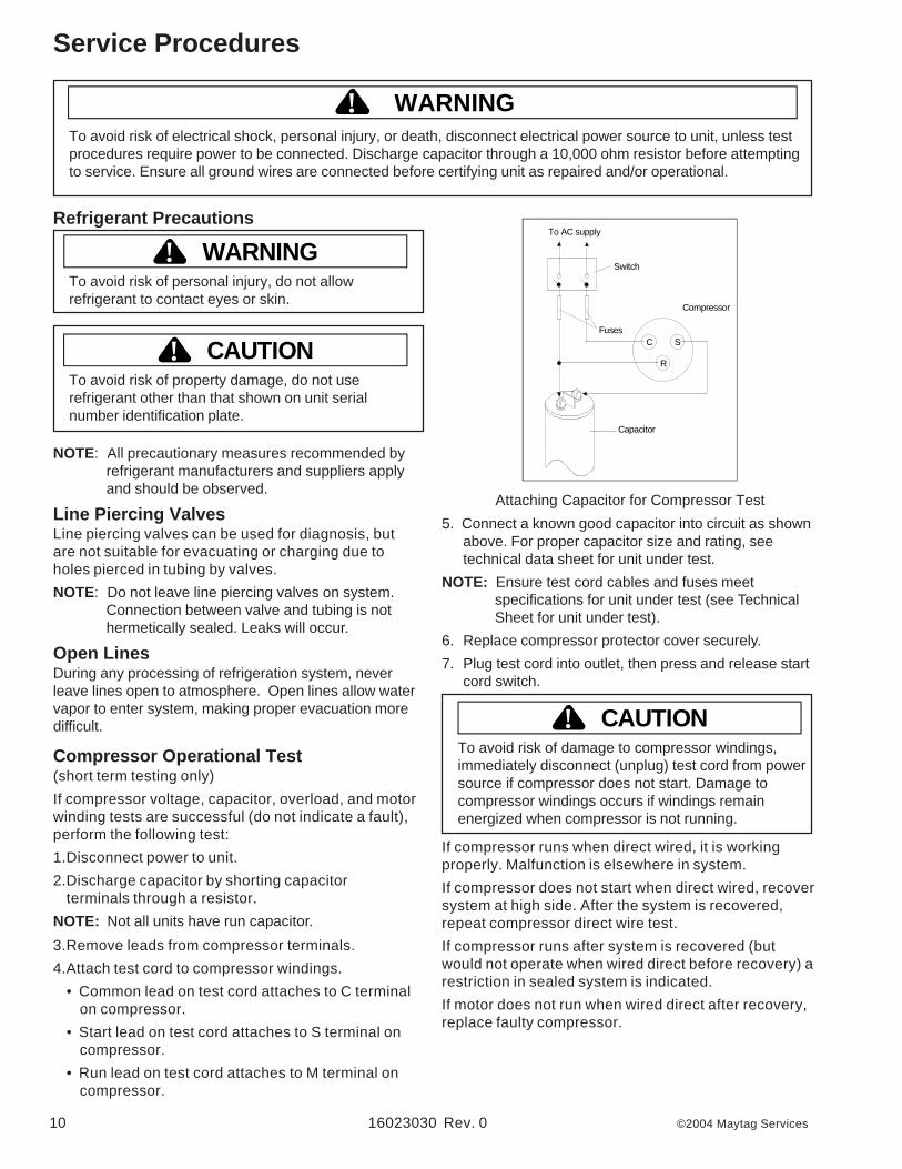
C
R
SFuses
Capacitor
Compressor
Switch
To AC supply
16023030 Rev. 0 ©2004 Maytag Services 4
Component Testing
! WARNING To avoid risk of electrical shock, personal injury, or death, disconnect electrical power source to unit, unless test procedures require power to be connected. Discharge capacitor through a resistor before attempting to service. Ensure all ground wires are connected before certifying unit as repaired and/or operational.
Component Description Test Procedures Capacitor
Run capacitor connects to relay terminal 3 and L side of line. Some compressors do not require a run capacitor; refer to the Technical Data Sheet for the unit being serviced.
1. Disconnect power to refrigerator. 2. Remove capacitor cover and disconnect capacitor wires. 3. Discharge capacitor by shorting across terminals with a resistor for 1 minute. 4. Check resistance across capacitor terminals with ohmmeter set on “X1K”
scale. • Good—needle swings to 0 ohms and slowly moves back to infinity. • Open—needle does not move. Replace capacitor. • Shorted—needle moves to zero and stays. Replace capacitor. • High resistance leak—needle jumps toward 0 and then moves back to
constant high resistance (not infinity).
Condenser Condenser is a tube and wire construction located on back of unit. Condenser is on high pressure discharge side of compressor. Condenser function is to transfer heat absorbed by refrigerantto ambient. Higher pressure gas is routed to condenser where, as gas temperature is reduced, gas condenses into a high pressure liquid state. Heat transfer takes place because discharged gas is at a higher temperature than air that is passing over condenser. It is very important that adequate air flow over condenser is maintained. Condenser is air cooled. If efficiency of heat transfer from condenser to surrounding air is impaired, condensing temperature becomes higher. High liquid temperature means liquid will not remove as much heat during boiling in evaporator as under normal conditions. This would be indicated by high than normal head pressures, long run time, and high wattage. Remove any lint or other accumulation, that would restrict normal air movement through condenser. From condenser the refrigerant flows into a post condenser loop which helps control exterior condensation on flange, center mullion, and around freezer door. Refrigerant the flows through the drier to evaporator and into compressor through suction line.
Leaks in condenser can usually be detected by using an electronic leak detector or soap solution. Look for signs of compressor oil when checking for leaks. A certain amount of compressor oil is circulated with refrigerant. Leaks in post condenser loop are rare because loop is a one-piece copper tube. For minute leaks 1. Separate condenser from rest of refrigeration system and pressurize
condenser up to a maximum of 235 PSI with a refrigerant and dry nitrogen combination.
2. Recheck for leaks.
WARNING! To avoid electrical shock which can cause severe personal injury or death, discharge capacitor through a resistor before handling.
WARNING!To avoid severe personal injury or death from sudden eruption of high pressures gases, observe the following:
Protect against a sudden eruption if high pressures are required for leak checking. Do not use high pressure compressed gases in refrigeration systems without a reliable pressure regulator and pressure relief valve in the lines.
©2004 Maytag Services 16023030 Rev. 0 5
Component Testing
! WARNING To avoid risk of electrical shock, personal injury, or death, disconnect electrical power source to unit, unless test procedures require power to be connected. Discharge capacitor through a resistor before attempting to service. Ensure all ground wires are connected before certifying unit as repaired and/or operational.
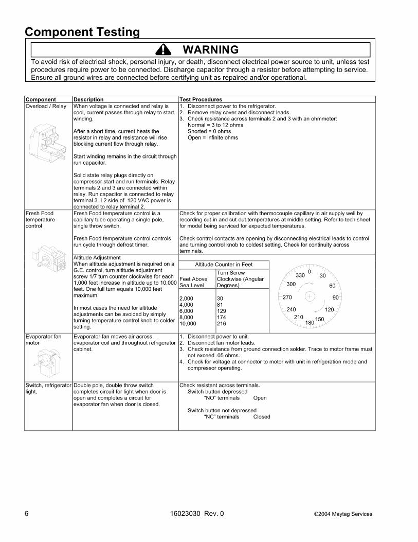
Component Description Test Procedures Overload / Relay
When voltage is connected and relay is cool, current passes through relay to start winding. After a short time, current heats the resistor in relay and resistance will rise blocking current flow through relay. Start winding remains in the circuit through run capacitor. Solid state relay plugs directly on compressor start and run terminals. Relay terminals 2 and 3 are connected within relay. Run capacitor is connected to relay terminal 3. L2 side of 120 VAC power is connected to relay terminal 2.
1. Disconnect power to the refrigerator. 2. Remove relay cover and disconnect leads. 3. Check resistance across terminals 2 and 3 with an ohmmeter: Normal = 3 to 12 ohms Shorted = 0 ohms Open = infinite ohms
Fresh Food temperature control is a capillary tube operating a single pole, single throw switch. Fresh Food temperature control controls run cycle through defrost timer.
Check for proper calibration with thermocouple capillary in air supply well by recording cut-in and cut-out temperatures at middle setting. Refer to tech sheet for model being serviced for expected temperatures. Check control contacts are opening by disconnecting electrical leads to control and turning control knob to coldest setting. Check for continuity across terminals.
Altitude Counter in Feet Feet Above Sea Level
Turn Screw Clockwise (Angular Degrees)
Fresh Food temperature control
Altitude Adjustment When altitude adjustment is required on a G.E. control, turn altitude adjustment screw 1/7 turn counter clockwise for each 1,000 feet increase in altitude up to 10,000 feet. One full turn equals 10,000 feet maximum. In most cases the need for altitude adjustments can be avoided by simply turning temperature control knob to colder setting.
2,000 4,000 6,000 8,000 10,000
30 81 129 174 216
Evaporator fan motor
Evaporator fan moves air across evaporator coil and throughout refrigerator cabinet.
1. Disconnect power to unit. 2. Disconnect fan motor leads. 3. Check resistance from ground connection solder. Trace to motor frame must
not exceed .05 ohms. 4. Check for voltage at connector to motor with unit in refrigeration mode and
compressor operating.
Switch, refrigerator light,
Double pole, double throw switch completes circuit for light when door is open and completes a circuit for evaporator fan when door is closed.
Check resistant across terminals. Switch button depressed “NO” terminals Open Switch button not depressed “NC” terminals Closed
0
300
270
240210
180150
120
90
60
30330
16023030 Rev. 0 ©2004 Maytag Services 6
Component Testing
! WARNING To avoid risk of electrical shock, personal injury, or death, disconnect electrical power source to unit, unless test procedures require power to be connected. Discharge capacitor through a resistor before attempting to service. Ensure all ground wires are connected before certifying unit as repaired and/or operational.
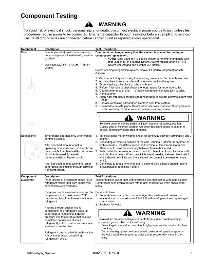
Component Description Test Procedures Drier
Drier is placed at post condenser loop outlet and passes liquefied refrigerant to capillary. Desiccant (20) 8 x 12 4AXH - 7 M>S> -Grams
Drier must be changed every time the system is opened for testing or compressor replacement. NOTE: Drier used in R12 sealed system is not interchangeable with drier used in R134a sealed system. Always replace drier in R134a system with Amana part number B2150504.
Before opening refrigeration system, recover HFC134a refrigerant for safe disposal.
1. Cut drier out of system using the following procedure. Do not unbraze drier. 2. Applying heat to remove drier will drive moisture into the system. 3. Score capillary tube close to drier and break. 4. Reform inlet tube to drier allowing enough space for large tube cutter. 5. Cut circumference of drier 1 ¼" below condenser inlet tube joint to drier. 6. Remove drier. 7. Apply heat trap paste on post condenser tubes to protect grommets from high
heat. 8. Unbraze remaining part of drier. Remove drier from system. 9. Discard drier in safe place. Do not leave drier with customer. If refrigerator is
under warranty, old drier must accompany warranty claim.
Defrost timer Timer motor operates only when freezer
control is closed.
1. To check timer motor winding, check for continuity between terminals 1 and 3 of timer.
2. Depending on rotating position of the cam, terminal 1 of timer is common to
CE
WARNING!To avoid death or severe personal injury, cut drier at correct location. Cutting drier at incorrect location will allow desiccant beads to scatter. If spilled, completely clean area of beads.
After specified amount of actual operating time, inner cam in timer throws the contacts from terminal 4, compressor circuit, to terminal 2, defrost thermostat/defrost heater circuit. After specified defrost cycle time, timer cam resets the circuitry through terminal 4 to compressor.
both terminal 2, the defrost mode, and terminal 4, the compressor mode. There should never be continuity between terminals 2 and 4.
3. With continuity between terminals 1 and 4, rotate timer knob clockwise until audible click is heard. When the click is heard, reading between terminals 1 and 4 should be infinite and there should be continuity between terminals 1 and 2.
4. Continuing to rotate time knob until a second click is heard should restore circuit between terminals 1 and 4.
omponent Description Test Procedures vaporator Inner volume of evaporator allows liquid
refrigerant discharged from capillary to expand into refrigerant gas. Expansion cools evaporator tube and fin temperature to approximately -20°F transferring heat from freezer section to refrigerant. Passing through suction line to compressor, the refrigerant picks up superheat (a relationship between pressure and temperature that assures complete vaporization of liquid refrigerant) as the result of capillary tube soldered to suction line. Refrigerant gas is pulled through suction line by compressor, completing refrigeration cycle.
Test for leaks in evaporator with electronic leak detector or with soap solution. Compressor oil is circulated with refrigerant; check for oil when checking for leaks. For minute leaks 1. Separate evaporator from rest of refrigeration system and pressurize
evaporator up to a maximum of 140 PSI with a refrigerant and dry nitrogen combination.
2. Recheck for leaks.
WARNING!To avoid severe personal injury or death from sudden eruption of high pressures gases, observe the following:
Protect against a sudden eruption if high pressures are required for leak checking. Do not use high pressure compressed gases in refrigeration systems without a reliable pressure regulator and pressure relief valve in the lines.
©2004 Maytag Services 16023030 Rev. 0 7

Component Testing
! WARNING To avoid risk of electrical shock, personal injury, or death, disconnect electrical power source to unit, unless test procedures require power to be connected. Discharge capacitor through a resistor before attempting to service. Ensure all ground wires are connected before certifying unit as repaired and/or operational.
16023030 Rev. 0 ©2004 Maytag Services 8
Evaporator heater (defrost)
Activated when defrost thermostat, defrost timer, and freezer control complete circuit through heater.
Check resistance across heater. To check defrost system : 1. Thermocouple defrost thermostat and plug refrigerator into wattmeter. 2. Turn into defrost mode. Wattmeter should read specified watts (according to
Technical Data Sheet). 3. When defrost thermostat reaches specified temperature ±5°F (see Technical
Data Sheet), thermostat should interrupt power to heater. Thermostat (defrost)
Thermostat is in a series circuit with terminal 2 of defrost timer, and defrost heater. Circuit is complete if evaporator fan motor operates when cold. Controls the circuit from freezer thermostat through defrost terminator to defrost heater. Opens and breaks circuit when thermostat senses preset high temperature.
Test continuity across terminals. With power off and evaporator coil below freezing, thermostat should show continuity when checked with ohmmeter. See “Heater, evaporator (defrost)” section for additional tests. After defrost thermostat opens, thermostat remains open until end of defrost cycle and refrigerator starts cooling again. Defrost thermostat senses a preset low temperature and resets (closes).

©2004 Maytag Services 16023030 Rev. 0 9
Drier ReplacementBefore opening refrigeration system, recoverHFC134a refrigerant for safe disposal.Every time sealed HFC134a system is repaired, drierfilter must be replaced with, part # B2150504.Cut drier out of system by completing the followingsteps. Do not unbraze drier filter. Applying heat toremove drier will drive moisture into system.
To avoid risk of severe personal injury or death, cutdrier at correct location. Cutting drier at incorrectlocation will allow desiccant beads to scatter.Completely clean area of beads, if spilled.
1. Score capillary tube close to drier and break.2. Reform inlet tube to drier allowing enough space
for large tube cutter.3. Cut circumference of drier at 1-1/4", below
condenser inlet tube joint to drier.4. Remove drier.5. Apply heat trap paste on post condenser tubes to
protect grommets from high heat.6. Unbraze remaining part of drier. Remove drier
from system.7. Discard drier in safe place. Do not leave drier with
customer. If refrigerator is under warranty, olddrier must accompany warranty claim.
Service Procedures
Service EquipmentListed below is equipment needed for proper servicingof HFC134a systems. Verify equipment is confirmedby manufacturer as being compatible with HFC134aand ester oil system.Equipment must be exclusively used for HFC134a.Exclusive use of equipment only applies to italic items.• Evacuation pump
Check with vacuum pump supplier to verify equipmentis compatible for HFC134a. Robinair, Model 15600
2 stage, 6 cubic feet per minute pump isrecommended.
• Four-way manifold gauge set, with low loss hoses• Leak detector• Charging cylinder• Line piercing saddle valve
(Schroeder valves). Seals must be HFC134a andester oil compatible. Line piercing valves may be usedfor diagnosis but are not suitable for evacuation orcharging, due to minute holes pierced in tubing. Donot leave mechanical access valves on system.Valves eventually will leak. Molecules of HFC134a aresmaller than other refrigerants and will leak whereother refrigerants would not.
• Swagging tools• Flaring tools• Tubing cutter• Flux• Sil-Fos• Silver solder• Oil for swagging and flaring
Use only part # R0157532• Copper tubing
Use only part # R0174075 and # R0174076• Dry nitrogen
99.5% minimum purity, with -40°F or lower dew point• Crimp tool• Tube bender• Micron vacuum gauge• Process tube adaptor kit• Heat trap paste• ICI appliance grade HFC134a
To avoid risk of electrical shock, personal injury, or death, disconnect electrical power source to unit, unless testprocedures require power to be connected. Discharge capacitor through a 10,000 ohm resistor before attemptingto service. Ensure all ground wires are connected before certifying unit as repaired and/or operational.
! WARNING
WARNING!
10 16023030 Rev. 0 ©2004 Maytag Services
Refrigerant Precautions
WARNING!To avoid risk of personal injury, do not allowrefrigerant to contact eyes or skin.
CAUTION!To avoid risk of property damage, do not userefrigerant other than that shown on unit serialnumber identification plate.
NOTE: All precautionary measures recommended byrefrigerant manufacturers and suppliers applyand should be observed.
Line Piercing ValvesLine piercing valves can be used for diagnosis, butare not suitable for evacuating or charging due toholes pierced in tubing by valves.NOTE: Do not leave line piercing valves on system.
Connection between valve and tubing is nothermetically sealed. Leaks will occur.
Open LinesDuring any processing of refrigeration system, neverleave lines open to atmosphere. Open lines allow watervapor to enter system, making proper evacuation moredifficult.
Compressor Operational Test(short term testing only)If compressor voltage, capacitor, overload, and motorwinding tests are successful (do not indicate a fault),perform the following test:1.Disconnect power to unit.2.Discharge capacitor by shorting capacitor
terminals through a resistor.NOTE: Not all units have run capacitor.3.Remove leads from compressor terminals.4.Attach test cord to compressor windings.
• Common lead on test cord attaches to C terminalon compressor.
• Start lead on test cord attaches to S terminal oncompressor.
• Run lead on test cord attaches to M terminal oncompressor.
Service Procedures
C
R
SFuses
Capacitor
Compressor
Switch
To AC supply
Attaching Capacitor for Compressor Test5. Connect a known good capacitor into circuit as shown
above. For proper capacitor size and rating, seetechnical data sheet for unit under test.
NOTE: Ensure test cord cables and fuses meetspecifications for unit under test (see TechnicalSheet for unit under test).
6. Replace compressor protector cover securely.7. Plug test cord into outlet, then press and release start
cord switch.
CAUTION!To avoid risk of damage to compressor windings,immediately disconnect (unplug) test cord from powersource if compressor does not start. Damage tocompressor windings occurs if windings remainenergized when compressor is not running.
If compressor runs when direct wired, it is workingproperly. Malfunction is elsewhere in system.If compressor does not start when direct wired, recoversystem at high side. After the system is recovered,repeat compressor direct wire test.If compressor runs after system is recovered (butwould not operate when wired direct before recovery) arestriction in sealed system is indicated.If motor does not run when wired direct after recovery,replace faulty compressor.
To avoid risk of electrical shock, personal injury, or death, disconnect electrical power source to unit, unless testprocedures require power to be connected. Discharge capacitor through a 10,000 ohm resistor before attemptingto service. Ensure all ground wires are connected before certifying unit as repaired and/or operational.
! WARNING

©2004 Maytag Services 16023030 Rev. 0 11
Dehydrating Sealed Refrigeration SystemMoisture in a refrigerator sealed system exposed toheat generated by the compressor and motor reactschemically with refrigerant and oil in the system andforms corrosive hydrochloric and hydrofluoric acids.These acids contribute to breakdown of motor windinginsulation and corrosion of compressor working parts,causing compressor failure.In addition, sludge, a residue of the chemical reaction,coats all surfaces of sealed system, and will eventuallyrestrict refrigerant flow through capillary tube.To dehydrate sealed system, evacuate system (seeparagraph Evacuation).
Leak Testing
DANGER!To avoid risk of serious injury or death from violentexplosions, NEVER use oxygen or acetylene forpressure testing or clean out of refrigerationsystems. Free oxygen will explode on contact withoil. Acetylene will explode spontaneously when putunder pressure.
It is important to check sealed system for refrigerantleaks. Undetected leaks can lead to repeated servicecalls and eventually result in system contamination,restrictions, and premature compressor failure.
Refrigerant leaks are best detected with halide orelectronic leak detectors.
Testing Systems Containing a Refrigerant Charge1. Stop unit operation (turn refrigerator off).2. Holding leak detector exploring tube as close to
system tubing as possible, check all piping, joints,and fittings.
NOTE: Use soap suds on areas leak detector cannotreach or reliably test.
Testing Systems Containing No Refrigerant Charge1. Connect cylinder of nitrogen, through gauge
manifold, to process tube of compressor and liquidline strainer.
2. Open valves on nitrogen cylinder and gauge manifold.Allow pressure to build within sealed system.
3. Check for leaks using soap suds.If a leak is detected in a joint, do not to attempt to repairby applying additional brazing material. Joint must bedisassembled, cleaned and rebrazed. Capture refrigerantcharge (if system is charged), unbraze joint, clean allparts, then rebraze.
If leak is detected in tubing, replace tubing. If leak isdetected in either coil, replace faulty coil.
Service Procedures
! WARNINGTo avoid risk of electrical shock, personal injury, or death, disconnect electrical power source to unit, unless testprocedures require power to be connected. Discharge capacitor through a 10,000 ohm resistor before attemptingto service. Ensure all ground wires are connected before certifying unit as repaired and/or operational.

12 16023030 Rev. 0 ©2004 Maytag Services
Service Procedures
! WARNINGTo avoid risk of electrical shock, personal injury, or death, disconnect electrical power source to unit, unless testprocedures require power to be connected. Discharge capacitor through a 10,000 ohm resistor before attemptingto service. Ensure all ground wires are connected before certifying unit as repaired and/or operational.
RestrictionsSymptomsRestrictions in sealed system most often occur atcapillary tube or filter drier, but can exist anywhere onliquid side of system.Restrictions reduce refrigerant flow rate and heatremoval rate. Wattage drops because compressor isnot circulating normal amount of refrigerants.Common causes of total restrictions are moisture,poorly soldered joints, or solid contaminants. Moisturefreezes at evaporator inlet end of capillary tube. Solidcontaminants collect in filter drier.If restriction is on low side, suction pressure will be in avacuum and head pressure will be near normal.If restriction is on high side, suction pressure will be ina vacuum and head pressure will be higher thannormal during pump out cycle.Refrigeration occurs on low pressure side of partialrestriction. There will be a temperature difference atthe point of restriction. Frost and/or condensation willbe present in most case at the point of restriction.Also, system requires longer to equalize.Slight or partial restriction can give the samesymptoms as refrigerant shortage including lower thannormal back pressure, head pressure, wattage, andwarmer temperatures.Total restriction on the discharge side of compressor,when restriction is between compressor and first halfof condenser, results in higher than normal headpressure and wattage while low side is being pumpedout.Testing for RestrictionsTo determine if a restriction exists:1. Attach gauge and manifold between suction and
discharge sides of sealed system.2. Turn unit on and allow pressure on each side to
stabilize. Inspect condenser side of system. Tubingon condenser should be warm and temperatureshould be equal throughout (no sudden drops at anypoint along tubing).• If temperature of condenser tubing is consistent
throughout, go to step 4.• If temperature of condenser tubing drops suddenly
at any point, tubing is restricted at point oftemperature drop (if restriction is severe, frost mayform at point of restriction and extend down indirection of refrigerant flow in system). Go to step 5.
3. Visually check system for kinks in refrigeration linewhich is causing restriction. Correct kink and repeatstep 2.
4. Turn unit off and time how long it takes high and lowpressure gauges to equalize:• If pressure equalization takes longer than 10
minutes, a restriction exists in the capillary tube ordrier filter. Go to step 5.
• If pressure equalization takes less than 10 minutes,system is not restricted. Check for other possiblecauses of malfunction.
5. Recover refrigerant in sealed system.NOTE: Before opening any refrigeration system,
capture refrigerant in system for safe disposal.6. Remove power from unit.
CAUTION!To avoid risk of personal injury or property damage,take necessary precautions against hightemperatures required for brazing.
7. Remove and replace restricted device.8. Evacuate sealed system.9. Charge system to specification.NOTE: Do not use captured or recycled refrigerant in
units. Captured or recycled refrigerant voids anycompressor manufacturer's warranty.
NOTE: Charge system with exact amount of refrigerant.Refer to unit nameplate for correct refrigerantcharge. Inaccurately charged system will causefuture problems.
©2004 Maytag Services 16023030 Rev. 0 13
Evacuation and Charging
CAUTION!To avoid risk of fire, sealed refrigeration systemmust be air free. To avoid risk of air contamination,follow evacuation procedures exactly.
NOTE: Before opening any refrigeration system, EPAregulations require refrigerant in system to becaptured for safe disposal.
Proper evacuation of sealed refrigeration system is animportant service procedure. Usable life andoperational efficiency greatly depends upon howcompletely air, moisture and other non-condensablesare evacuated from sealed system.Air in sealed system causes high condensingtemperature and pressure, resulting in increasedpower requirements and reduced performance.Moisture in sealed system chemically reacts withrefrigerant and oil to form corrosive hydrofluoric andhydrochloric acids. These acids attack motor windingsand parts, causing premature breakdown.Before opening system, evaporator coil must be atambient temperature to minimize moisture infiltrationinto system.EvacuationTo evacuate sealed refrigeration system:
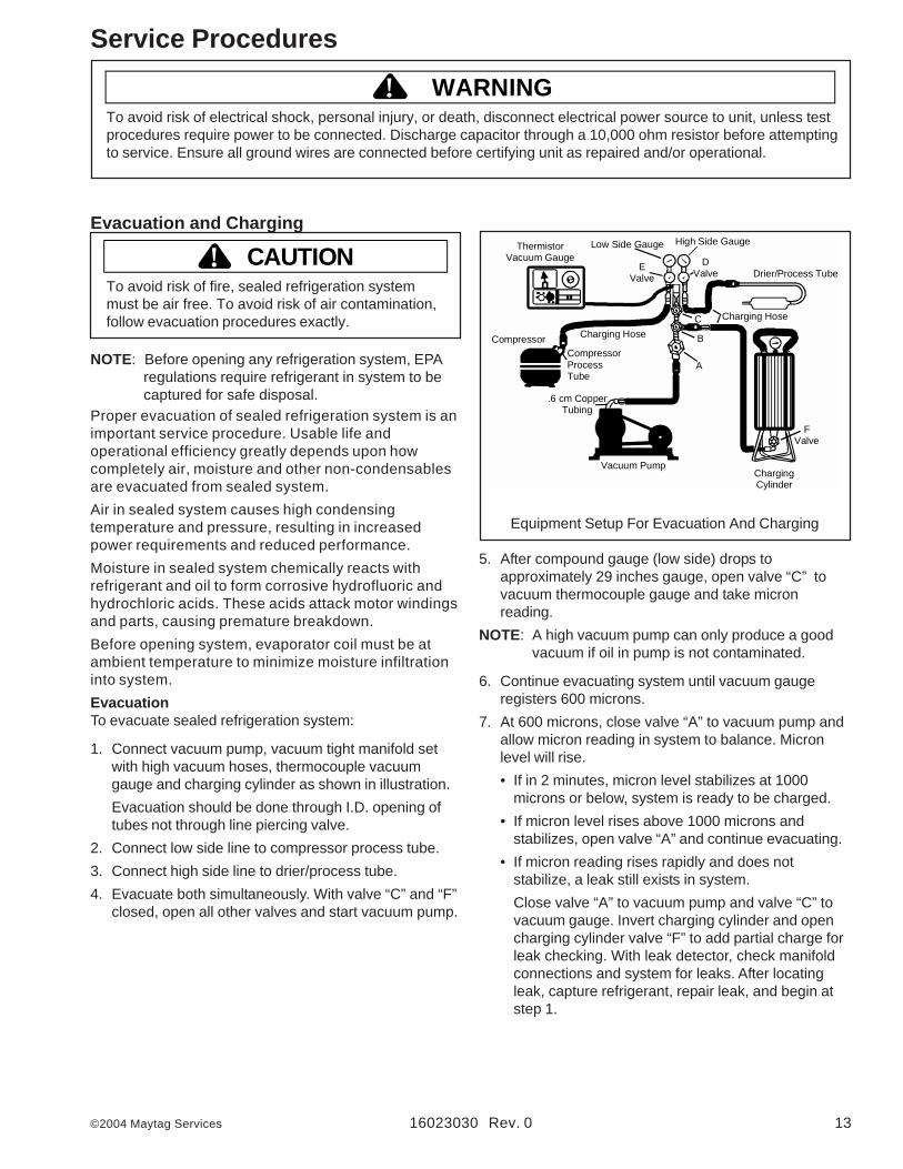
1. Connect vacuum pump, vacuum tight manifold setwith high vacuum hoses, thermocouple vacuumgauge and charging cylinder as shown in illustration.Evacuation should be done through I.D. opening oftubes not through line piercing valve.
2. Connect low side line to compressor process tube.3. Connect high side line to drier/process tube.4. Evacuate both simultaneously. With valve “C” and “F”
closed, open all other valves and start vacuum pump.
Vacuum Pump
.6 cm CopperTubing
CompressorCompressorProcessTube
Charging Hose
ThermistorVacuum Gauge
Low Side Gauge
EValve
B
DValve
High Side Gauge
Charging Hose
Drier/Process Tube
FValve
ChargingCylinder
C
A
Equipment Setup For Evacuation And Charging
5. After compound gauge (low side) drops toapproximately 29 inches gauge, open valve “C” tovacuum thermocouple gauge and take micronreading.
NOTE: A high vacuum pump can only produce a goodvacuum if oil in pump is not contaminated.
6. Continue evacuating system until vacuum gaugeregisters 600 microns.
7. At 600 microns, close valve “A” to vacuum pump andallow micron reading in system to balance. Micronlevel will rise.• If in 2 minutes, micron level stabilizes at 1000
microns or below, system is ready to be charged.• If micron level rises above 1000 microns and
stabilizes, open valve “A” and continue evacuating.• If micron reading rises rapidly and does not
stabilize, a leak still exists in system.Close valve “A” to vacuum pump and valve “C” tovacuum gauge. Invert charging cylinder and opencharging cylinder valve “F” to add partial charge forleak checking. With leak detector, check manifoldconnections and system for leaks. After locatingleak, capture refrigerant, repair leak, and begin atstep 1.
Service Procedures
! WARNINGTo avoid risk of electrical shock, personal injury, or death, disconnect electrical power source to unit, unless testprocedures require power to be connected. Discharge capacitor through a 10,000 ohm resistor before attemptingto service. Ensure all ground wires are connected before certifying unit as repaired and/or operational.
14 16023030 Rev. 0 ©2004 Maytag Services
ChargingNOTE: Do not use captured or recycled refrigerant in
units. Captured or recycled refrigerant voids anywarranty.
NOTE: Charge system with exact amount of refrigerant.Refer to unit serial plate for correct refrigerantcharge. Inaccurately charged system will causefuture problems.
To charge system:
1. Close valves “A” to vacuum pump and “C” to vacuumgauge and “E” to low side manifold gauge.
2. Set scale on dial-a-charge cylinder for correspondingHFC134a pressure reading.
3. Open valve “F” to charging cylinder and let exactamount of refrigerant flow from cylinder into system.Close valve.Low side gauge pressure should rise shortly afteropening charging cylinder valve as system pressureequalizes through capillary tube.If pressure does not equalize, a restriction typicallyexists at capillary/drier braze joint.
4. If pressure equalizes, open valve “E” to low sidemanifold gauge and pinch off high side drier processtube.
5. Start compressor and draw remaining refrigerant fromcharging hoses and manifold into compressorthrough compressor process tube.
6. To check high side pinch-off drier process tube. Closevalve “D” to high side gauge. If high side pressurerises, repeat high side pinch-off and open valve “D”.Repeat until high side pinch-off does not leak.
7. Pinch-off compressor process tube and removecharging hose. Braze stub closed while compressor isoperating.
8. Disconnect power. Remove charging hose and brazehigh side drier process tube closed.
9. Recheck for refrigerant leaks.
Service Procedures
! WARNINGTo avoid risk of electrical shock, personal injury, or death, disconnect electrical power source to unit, unless testprocedures require power to be connected. Discharge capacitor through a 10,000 ohm resistor before attemptingto service. Ensure all ground wires are connected before certifying unit as repaired and/or operational.
Refrigerant ChargeRefrigerant charge in all capillary tube systems iscritical and exact amount is required for properperformance. Factory charges are shown on serialplate.NOTE: Do not use refrigerant other than shown on
serial plate.

©2004 Maytag Services 16023030 Rev. 0 15
To minimize contamination, exercise extreme carewhen servicing HFC134A sealed systems.
• No trace of other refrigerants is allowed in HFC134asystems. Chlorinated molecules in other refrigerantssuch as CFC12, etc. will lead to capillary tubeplugging.
• Ester oil is used in HFC134a systems. Do not usemineral oil. HFC134a and mineral oils cannot bemixed. If mineral oils were used in HFC134a systems,lubricant would not return to compressor and wouldcause early compressor failure. If significant amount ofoil has been lost from compressor, replace oil ratherthan adding oil.
• Ester oils used in HFC134a systems are sohydroscopic that by the time an inadequate systemperformance is detected, oil will be saturated withmoisture.
• CFC12 has much higher tolerance to systemprocessing materials, such as drawing compounds,rust inhibitors, and cleaning compounds, thanHFC134a. Such materials are not soluble in HFC134asystems. If materials were to be washed from systemsurfaces by ester oils, they could accumulate andeventually plug capillary tube.
• Care must be taken to minimize moisture enteringHFC134a system. Do not leave compressor or systemopen to atmosphere for more than 10 minutes.Excessive moisture in HFC134a system will react withcompressor oil and generate acid.
• Compressor must be replaced when performing lowside leak repair.
• Drier filter must always be replaced with service drierfilter, part #B2150504.Important: Unbrazing drier filter from tubing will drivemoisture from desiccant and into system, causingacids to form. Do not unbraze filter drier from tubing. IfCFC12 service drier was installed in HFC134A system,drier could overload due to excessive moisture.
• HFC134a compatible copper tubing, part #R0174075(1/4" O.D. X 18" length) and part #R0174076 (5/16"O.D. X 24" length) must be used when replacingtubing.
• Avoid system contamination by using Towerdraw E610evaporating oil, part # R0157532, when flaring,swagging, or cutting refrigeration tubing.
Service Procedures
HFC134a Service InformationHFC134a is alternative refrigerant for CFC12.HFC134a has an ozone depletion potential (ODP)factor of 0.0 and a global warming potential (GWP)factor of 0.27. HFC134a is not flammable and hasacceptable toxicity levels. HFC134a is notinterchangeable with CFC12. There are significantdifferences between HFC134a and CFC12 which mustbe considered when handling and processingrefrigeration system.
Health, Safety, and HandlingHealth, safety and handling considerations forHFC134A are virtually no different than those forCFC12.
Comparison of CFC12 and HFC134a Properties
Health, Safety, andHandling
CFC12 HFC134a
Allowable overallexposure limit
1,000 ppm Same
Vapor exposure to skin No effect SameLiquid exposure to skin Can cause frostbite SameVapor exposure to eye Very slight eye irritant SameLiquid exposure to eye Can cause frostbite SameAbove minimum exposurelimit
Can cause Asphyxiation,Tachycardia, and CardiaArrhythmias
Same
Safety and handling Wear appropriate skinand eye protection. Usewith adequateventilation.
Same
Spill management Remove or extinguishignition or combustionsources. Evacuate orventilate area.
Same
Fire explosion hazards May decompose ifcontact with flames andheating elements.Container may explodeif heated due to resultingpressure rise.Combustion productsare toxic.
Same
Disposal procedures Recycle or reclaim. Same
To avoid risk of electrical shock, personal injury, or death, disconnect electrical power source to unit, unless testprocedures require power to be connected. Discharge capacitor through a 10,000 ohm resistor before attemptingto service. Ensure all ground wires are connected before certifying unit as repaired and/or operational.
! WARNING
CAUTION!
Properties/Characteristics CFC12 HFC134aOzone Depletion Potential(ODP)
1.0* 0.0*
Global Warming Potential(GPW)
3.2* 0.27*
Molecular weight 121 102Boiling point at 1 atmosphere -22°F (-30°C) -15°F (-
126°C)Vapor pressure at 77°F(25°C)
80 psig 82 psig
Liquid density at 77°F (25°C) 82 lb/ft3 75 lb/ft3
Flammability No NoHigh-side system operatingPressure at 65°F (18°C)
HFC134a approximately 3 psighigher than CFC12
Low-side system operatingPressure at 65°F (18°C)
HFC134a approximately 2 psiglower than CFC12
16 16023030 Rev. 0 ©2004 Maytag Services
To avoid death or severe personal injury, never useoxygen, air or acetylene for pressure testing orclean out of refrigeration system. Use of oxygen,air, or acetylene may result in violent explosion.Oxygen may explode on contact with oil andacetylene will spontaneously explode when underpressure.
Replacement Service CompressorHFC134a service compressors will be charged withester oil and pressurized with dry nitrogen. Beforereplacement compressor is installed, pull out 1 rubberplug. A pop from pressure release should be heard. Ifa pop sound is not heard, do not use compressor.Positive pressure in compressor is vital to keepmoisture out of ester oil. Do not leave compressoropen to atmosphere for more than 10 minutes.Compressor Testing Procedures
Refer to Technical Data Sheet “TemperatureRelationship Chart” for operating watts, test points,and temperature relationship test for unit being tested.• Temperature testing is accomplished by using 3 lead
thermocouple temperature tester in specific locations.Test point T-1 is outlet on evaporator coil and T-2 isinlet. Test point T-3 is suction tube temperaturemidway between where armaflex ends and suctionport of compressor (approximately 12 inches fromcompressor).
• Thermocouple tips should be attached securely tospecified locations.
• Do not test during initial pull down. Allow one off cycleor balanced temperature condition to occur beforeproceeding with testing.
• Refrigerator must operate minimum of 20 minutesafter thermocouples are installed.
• Turn control to colder to obtain required on time.• Wattage reading must be recorded in conjunction with
temperature test to confirm proper operation.• Suction and head pressures are listed on
“Temperature and Relationship Chart”. Normally theseare not required for diagnosis but used for confirmationon systems which have been opened.
Service Procedures
To avoid risk of electrical shock, personal injury, or death, disconnect electrical power source to unit, unless testprocedures require power to be connected. Discharge capacitor through a 10,000 ohm resistor before attemptingto service. Ensure all ground wires are connected before certifying unit as repaired and/or operational.
! WARNING
Brazing
CAUTION!To avoid risk of personal injury or property damage,take necessary precautions against hightemperatures required for brazing.
Satisfactory results require cleanliness, experience,and use of proper materials and equipment.Connections to be brazed must be properly sized, freeof rough edges, and clean.Generally accepted brazing materials are:• Copper to copper joints: SIL-FOS (alloy of 15
percent silver, 80 percent copper, and 5 percentphosphorous). Use without flux. Recommendedbrazing temperature is approximately 1400°F. Do notuse for copper to steel connection.
• Copper to steel joints: SILVER SOLDER (alloy of 30percent silver, 38 percent copper, 32 percent zinc).Use with fluoride based flux. Recommended brazingtemperature is approximately 1200°F.
• Steel to steel joints: SILVER SOLDER (see copperto steel joints).
• Brass to copper joints: SILVER SOLDER (seecopper to steel joints).
• Brass to steel joints: SILVER SOLDER (see copperto steel joints).
WARNING!

©2004 Maytag Services 16023030 Rev. 0 17
Troubleshooting Chart
Symptom Possible Causes Corrective ActionNo power to unit Check for power at outlet. Check
fuse box/circuit breaker for blownfuse or tripped breaker. Replace orreset.
Faulty power cord Check with test light at unit; if nocircuit and current is indicated atoutlet, replace or repair.
Low voltage Check input voltage for propervoltage. Take appropriate action tocorrect voltage supply problem.
Faulty motor or freezer temperaturecontrol
Check all connections are tight andsecure.Jumper across terminals of control. Ifunit runs, replace control.
Faulty timer Check with test light. Replace ifnecessary.
Faulty relay Check relay. Replace if necessary.Faulty compressor Check compressor motor windings
for opens/shorts.Perform compressor direct wiringtest.Replace if necessary.
Unit does not run
Faulty overload Check overload for continuity.NOTE: Ensurecompressor/overload are belowtrip temperature before testing.
Replace if necessary.Excessive door opening Consumer educationOverloading of shelves Consumer education
Warm or hot foods placed in cabinet Consumer education
Cold control set too warm Set control to colder setting.
Poor door seal Level cabinet. Adjust hinges.Replace gasket.
Refrigerator airflow Check damper is opening byremoving grille. With door open,damper should open. Replace iffaulty.Turn control knob to colder position.
Interior light remains on Check switch. Replace if necessary.
Faulty condenser fan or evaporatorfan
Check fan and wiring. Replace ifnecessary.
Refrigerator section too warm
Faulty compressor Replace compressor.
Troubleshooting chart on following pages contains symptoms that may be seen in malfunctioning units. Eachsymptom is accompanied by one or more possible causes and by a possible remedy or test to determine ifcomponents are working properly.
To avoid risk of electrical shock, personal injury, or death, disconnect electrical power source to unit, unless testprocedures require power to be connected. Discharge capacitor through a resistor before attempting to service.Ensure all ground wires are connected before certifying unit as repaired and/or operational.
! WARNING

18 16023030 Rev. 0 ©2004 Maytag Services
Symptom Possible Causes Corrective ActionRefrigerator temperature control settoo cold
Adjust refrigerator temperaturecontrol.
Refrigerator section too cold
Refrigerator airflow not properlyadjusted
Check air flow.
Temperature controls set too warm Reset temperature controls.Poor door seal Level cabinet. Adjust hinges.
Replace gasket.Dirty condenser or obstructed grille Check condenser and grille. Clean.Faulty control Test control. Replace if failed.
Freezer and refrigerator sections toowarm
Refrigerant shortage or restriction Check for leak or restriction. Repair,evacuate and recharge system.
Freezer temp control set too cold Adjust freezer temperature control.Faulty control Test control. Replace if failed.
Freezer section too cold
Cold control capillary not properlyclamped to evaporator
Reposition clamp and tighten.
Temperature control set too cold Adjust temperature control.Dirty condenser or obstructed grille Check condenser and grille. Clean.Poor door seal Level cabinet. Adjust hinges.
Replace gasket.Interior light remains on Check switch. Replace if necessary.Faulty condenser fan or evaporatorfan
Check fan and wiring. Replace ifnecessary.
Faulty control Test control. Replace if failed.Refrigerant shortage or restriction Check for leak or restriction. Repair,
evacuate and recharge system.Refrigerant overcharge Check for overcharge. Evacuate and
recharge system.
Unit runs continuously
Air in system Check for low side leak. Repair,evacuate and recharge system.
Unit runs continuously. Temperaturenormal.
Ice on evaporator See “Ice on evaporator”.
Unit runs continuously. Temperaturetoo cold.
Faulty defrost thermostat Check thermostat. Replace ifnecessary.
Loose flooring or floor not firm Repair floor or brace floor.Cabinet not level Level cabinet.Tubing in contact with cabinet, othertubing, or other metal
Adjust tubing.
Drip pan vibrating Adjust drain pan.Fan hitting another part Ensure fan properly aligned and all
attaching hardware and brackets aretight and not worn. Tighten orreplace.
Worn fan motor bearings Check motor for loss of lubricant orworn bearings. Replace if necessary.
Compressor mounting grommetsworn or missing. Mounting hardwareloose or missing
Tighten hardware. Replacegrommets if necessary.
Noisy operation
Free or loose parts causing orallowing noise during operation
Inspect unit for parts that may haveworked free or loose or missingscrews. Repair as required.
Troubleshooting Chart
To avoid risk of electrical shock, personal injury, or death, disconnect electrical power source to unit, unless testprocedures require power to be connected. Discharge capacitor through a resistor before attempting to service.Ensure all ground wires are connected before certifying unit as repaired and/or operational.
! WARNING

©2004 Maytag Services 16023030 Rev. 0 19
Symptom Possible Causes Corrective ActionDefrost thermostat faulty Check defrost thermostat. Replace if
failed.
Evaporator fan faulty Check fan motor. Replace if failed.
Defrost heater remains open Check defrost heater continuity.Replace if failed.
Defrost control faulty Check control and replace if failed.Open wire or connector Check wiring and connections.
Repair as necessary.
Frost or ice on evaporator
Refrigerant shortage or restriction Check for leak or restriction. Repair,evacuate and recharge system.
Loose wire or thermostatconnections
Check wiring and connections.Repair as necessary.
Supply voltage out of specification Check input voltage. Correct anysupply problems.
Overload protector open Check overload protector forcontinuity. If open, replace overload.
NOTE: Ensureoverload/compressor are belowtrip temperature before testing.
Faulty compressor motor capacitor(some compressors do not requiremotor capacitor)
Check capacitor for open/short.Replace if necessary.
NOTE: Discharge capacitorbefore testing.
Faulty fan motor Check fan motor. Replace if failed.Restricted air flow Check condenser and grille for dirt.
Clean.
Unit starts and stops frequently(cycles on and off)
Refrigerant shortage or restriction Check for leak or restriction. Repair,evacuate and recharge system.
Troubleshooting Chart
To avoid risk of electrical shock, personal injury, or death, disconnect electrical power source to unit, unless testprocedures require power to be connected. Discharge capacitor through a resistor before attempting to service.Ensure all ground wires are connected before certifying unit as repaired and/or operational.
! WARNING

System Diagnosis
20 16023030 Rev. 0 ©2004 Maytag Services
CONDITION
SUCTIONPRESSUREVARIATION
FROMNORMAL
HEADPRESSUREVARIATION
FROMNORMAL
T1 INLETTEMPERATURE
VARIATIONFROM NORMAL
T2 OUTLETTEMPERATURE
VARIATIONFROM NORMAL
T3 SUCTIONTEMPERATURE
VARIATIONFROM NORMAL
WATTAGEVARIATION
FROMNORMAL
RefrigerantOvercharge Increase Increase Warmer Warmer Colder Increase
Shortage ofRefrigerant Decrease
Decrease orIncreaseSee Text
Colder Warmer Warmer Decrease
PartialRestriction Decrease
Decrease orIncreaseSee TextNote 2
Colder Warmer Warmer Decrease
Air in System Near Normal Increase Warmer Warmer Warmer Increase
Low AmbientInstallations
(HighAmbients the
Reverse)
Decrease Decrease Colder Warmer Warmer Decrease
AdditionalHeat Load Increase Increase Warmer Warmer Warmer Increase
InefficientCompressor Increase Normal or
DecreaseWarmer or
Colder Warmer Warmer Decrease
Symptoms of an Overcharge• Above normal freezer temperatures.• Longer than normal or continuous run.• Freezing in refrigerator.• Higher than normal suction and head pressure.• Higher than normal wattage.• Evaporator inlet and outlet temperatures warmer than
normal.• Suction tube temperature below ambient. Always
check for separated heat exchanger when suctiontemperature is colder than ambient.
Various conditons could indicate an overcharge. Forexample, if the cooling coil is not defrosted at regularintervals, due to a failure of the defrost system, therefrigerant will "flood out" and cause the suction line tofrost or sweat. The cause of this problem should becorrected rather than to purge refrigerant from thesytem. Running the freezer section colder thannecessary (-2 to -1 F. is considered normal packagetemperatures) or continuous running of the compressorfor a variety of reasons, or the freezer fan motor notrunning, may give the indication of an overcharge.
Symptoms of Refrigeration Shortage• Rise in food product temperature in both
compartments. (See Note 1 below.)• Long or continuous run time.• Look for obvious traces of oil that would occur due to a
leak or cracked refrigerant line.• Lower than normal wattage.• Compressor will be hot to touch because of the heat
generated by the motor windings from long continuousrunning. It will not be as hot as it would be with a fullcharge and long run times for some other reason suchas a dirty condenser.
• Depending on the amount of the shortage, thecondenser will not be hot, but closer to roomtemperature. The capillary tube will be warmer thannormal from a slight shortage.
• If the leak is on the high side of the system, bothgauges will show lower than normal readings and willshow progressively lower readings as this chargebecomes less. The suction pressure guage willprobably indicate a vacuum.
• If the leak is on the low side of the system the suctionpressure guage will be lower than normal - probably ina vacuum - and the head pressure gauge will behigher than normal. It will probably continue tobecome higher because air drawn in through the leakis compressed by the compressor and accumulates in
System Diagnosis
©2004 Maytag Services 16023030 Rev. 0 21
the high side (condenser) of the system.• Only partial frosting of evaporator instead of even
frosting of entire coil.
NOTE 1: Usually the first thing that is noticed by theuser is a rise in temperature foods. Althoughtemperatures will rise in both the freezer sectionand the food compartment, the frozen meatsand vegetables will not thaw immediately. Thecustomer doesn't associate the problem withthe freezer section and will first notice that milkand other food beverages are not cold enough.
Under some circumstances, such as in the case offorced air meatkeeper model with a slight shortage ofrefrigerant, freezing in the food compartment may beexperienced due to the additional running time. With arefrigerant leak, however, it always gets worse and asthe refrigerant charge decreases the temperature willcontinue to rise.With a shortage of refrigerant the capillary line will nothave a full column of liquid. As a result, there is anoticeable hissing sound in the evaporator. This shouldnot be mistaken for the regular refrigerant boilingsounds that would be considered normal.
Symptoms of a RestrictionAlways remember refrigeration (cooling) occurs on thelow pressure side of a partial restriction (obviously atotal restriction will completely stop the circulation ofrefrigerant and no cooling will take place).Physically feel the refrigeration lines when a restrictionis suspected. The most common place for a restrictionis at the drier-filter or at the capillary tube inlet or outlet.If the restriction is not total there will be a temperaturedifference at the point of restriction, the area on theevaporator side will be cooler. In many cases frost and/or condensation will be present. A longer time isrequired for the system to equalize.Any kinked line will cause a restriction so the entiresystem should be visually checked.A slight restriction will give the same indications as arefrigerant shortage with lower than normal backpressure, head pressure, and wattage, warmer producttemperatures.
NOTE 2: If a total restriction is on the discharge side ofthe compressor, higher than normal headpressures and wattages would result. This istrue only while the low side is being pumped outand if the restriction was between thecompressor and the first half of the condenser.
To diagnose for a restriction versus a refrigerantshortage, discharge the system, replace the drier-filter,evacuate and recharge with the specified refrigerantcharge. If the unit performs normally three possibilitiesexist: 1) refrigerant loss, 2) partially restricted drier-filter, and 3) moisture in system.If the unit performs as it previously did you may have arestricted capillary line or condenser or kinked line.Find the point of restriction and correct it.A restriction reduces the flow rate of the refrigerant andconsequently reduces the rate of heat removal.Complete restriction may be caused by moisture, solidcontaminants in the system, or a poorly soldered joint.Moisture freezes at the evaporator inlet end of thecapillary tube or solid contaminants collect in the drier-filter. The wattage drops because the compressor is notcirculating the usual amount of refrigerant.As far as pressure readings are concerned, if therestriction, such as a kinked line or a joint soldered shutis anywhere on the low side, the suction pressure wouldprobably be in a vacuum while the head pressure will benear normal. If the restriction is on the high side, thesuction pressure, again, will probably be in a vacuumwhile the head pressure will be higher than normalduring the pump out period described earlier. In eithercase, it will take longer than the normal ten minutes orso for the head pressure to equalize with the low sideafter the compressor stops.
Symptoms of Air in SystemThis can result from a low side leak or improperservicing. If a leak should occur on the low side, thetemperature control would not be satisfied; thus,continuous running of the compressor would result. Thecompressor would eventually pump the low side into avacuum drawing air and moisture into the system. Airand R134A do not mix so the air pressure would beadded to the normal head pressure, resulting in higherthan normal head pressures.One way to determine if air is in the system is to readthe head pressure gauge with the product off andevaporator and condenser at the same temperature andthen take the temperature on the condenser outlet tube.This temperature should be within 3° or 4° F. of what thePressure-Temperature Relation chart shows for thegiven idle head pressure. If the temperature of thecondenser outlet is considerably lower than the idlehead pressure of the gauge this would indicate there isair in the system.Thorough leak checking is necessary. Correct thesource of the leak. Do not attempt to purge off the airbecause this could result in the system beingundercharged. It is best to discharge, replace drier,evacuate and recharge with the specified refrigerantcharge.

System Diagnosis
22 16023030 Rev. 0 ©2004 Maytag Services
Symptoms of Low or High AmbientTemperature InstallationLower ambient air temperature reduces the condensingtemperature and therefore reduces the temperature ofthe liquid entering the evaporator. The increase inrefrigeration effect due to operation in a lower ambientresults in a decrease in power consumption and runtime. At lower ambients there is a reduction in cabinetheat leak which is partially responsibile for lower powerconsumption and run time.An increase in refrigeration effect cannot be expectedbelow a certain minimum ambient temperature. Thistemperature varies with the type and design of theproduct.Generally speaking, ambient temperatures cannot belower than 60° F. without affecting operating efficiency.Conversely, the higher the ambient temperature thehigher the head pressure must be to raise the high siderefrigerant temperature above that of the condensingmedium. Therefore, head pressure will be higher as theambient temperature raises. Refrigerators installed inambient temperatures lower than 60° F. will not performas well because the pressures within the system aregenerally reduced and unbalanced. This means that thelower head pressure forces less liquid refrigerantthrough the capillary line. The result is the symptoms ofa refrigerant shortage. The lower the ambienttemperature the more pronounced this conditionbecomes.When a point where the ambient temperature is belowthe cut-in of the Temperature Control is reached, thecompressor won't run.The drain traps will freeze in ambient temperatures of32° F.Heat LoadA greater heat load can result from the addition of morethan normal supply of foods, such as after doing theweekly shopping. Other items contributing to anadditional heat load would be excessive door openings,poor door sealing, interior light remaining on, etc.An increase in heat being absorbed by the refrigerant inthe evaporator will affect the temperature and pressureof the gas returning to the compressor. Compartmenttemperatures, power consumption, discharge, andsuction pressures are all affected by heat load.Pressures will be higher than normal under heavy heatload.

Disassembly Procedures! WARNING
To avoid risk of electrical shock, personal injury, or death, disconnect electrical power source to unit, unless testprocedures require power to be connected. Discharge capacitor through a resistor before attempting to service.Ensure all ground wires are connected before certifying unit as repaired and/or operational.
©2004 Maytag Services 16023030 Rev. 0 23
Door RemovalFresh Food & Freezer Door1. Open both compartment doors. Remove door
buckets, all shelving and drawers from refrigeratorand freezer compartments. Place components on apadded surface to avoid damage.
2. Close both doors and tape them shut so they won’tfall off unexpectedly when hinges are removed.
NOTE: To minimize possibility of personal injury and/orproperty damage, make sure unit doors aretaped shut before you undertake the next steps:
3. On top of unit, remove cap and retain plastic cap fromdoor hinge.
4. Remove and retain screws from top door hinge.5. Pull tape off of door and lift door off unit. Set door on
a padded surface to prevent damage to finish.6. Remove and retain center hinge pin.
Refrigerator CompartmentLight Bulb (some models)1. Remove light cover by pushing in bottom tabs on
cover and lifting off cover.2. Unscrew light bulb.3. Reverse procedure to reassemble.
Light Bulb Socket (some models)1. After following procedure on removing light bulb.2. Disconnect wires to sockets.3. Squeeze tab on back side of socket to release it from
assembly.4. Reverse procedure to reassemble.
Light Switch (some models)1. Use a taped putty knife to carefully pry front edge of
light switch plastic housing.2. Disconnect wires from light switch.3. Reverse procedure to reassemble. Fresh Food Temperature Control (8.2 cubic models)1. Remove screw from rear edge of light shield.2. Squeeze lens to release lens cover and remove.3. With flat blade screwdriver release tabs in front of
cold control knob.4. Cold control assembly will drop down when released.5. Remove Knob by pulling off shaft.6. Disconnect wires from cold control.7. Release cold control capillary from retainers.8. Remove screws fom control to remove.9. Reverse procedure to reassemble.
Freezer Compartment
Freezer Back Panel (some models)NOTE: Freezer compartment should now be empty and
walls should be clear of anything that willobstruct removal of back panel.
1. Remove freezer shelf and twist icemaker afterremoving stop on left side of cabinet by removingscrew in stop.
2. Remove plug on top right side of freezer back toexpose screw.
3. Remove screw and gently pull down from the top torelease freezer back panel.
4. Reverse procedure to reassemble.Evaporator Fan, Evaporator Motor (some models)1. Follow instructions in removing freezer back panel.2. Remove screws that anchor evaporator fan bracket to
back wall of compartment. Pull fan and bracket out ofplace as a unit
3. Free fan bracket from wiring harness bydisconnecting wires to connector on cabinet.
4. Pull evaporator fan blade off motor shaft.5. Separate bracket and motor by squeezing lower
retainer bracket to release motor from bracket.6. Reverse procedure to reassemble.
Defrost Terminator (Thermostat)(some models)1. Terminator is fastened to evaporator tubing with a
clip.2. Unclip terminator off tubing and cut wires to
terminator.3. Remove terminator from unit.Defrost Heater (some models)1. Follow instructions in removing freezer back panel.2. Remove screws retaining evaporator to back cabinet
wall.3. Lift evaporator coil up and out to expose defrost
heater.4. Disconnect plugs from both sides of heater.5. Remove defrost heater.6. Reverse procedure to reassemble.

Disassembly Procedures! WARNING
To avoid risk of electrical shock, personal injury, or death, disconnect electrical power source to unit, unless testprocedures require power to be connected. Discharge capacitor through a resistor before attempting to service.Ensure all ground wires are connected before certifying unit as repaired and/or operational.
24 16023030 Rev. 0 ©2004 Maytag Services
Evaporator Removal (8.2 cubic models)NOTE: Reclaim refrigerant per instructions in “Service
Procedures” before attempting evaporatorremoval. To avoid system contamination, do notleave system open for more than 10 minutes.
1. Follow instructions in removing freezer back panel.2. Remove defrost thermostat. Refer to defrost
thermostat removal.3. Remove defrost heater. Refer to defrost heater
removal.4. Install protective cloth to prevent damage to cabinet
liner5. Unbraze suction copper fitting at evaporator.6. Score and break copper capillary at evaporator.7. Install new evaporator and reassemble taking care in
not kinking tubing when reassembling.
Machine Compartment
CompressorNOTE: Install new drier and compressor per
instructions in “Service Procedures.” Evacuateand recharge sealed system per instructions in“Service Procedures.”
1. Remove machine compartment cover.2. Remove drier.3. Disconnect all compressor wiring and overload/relay
assembly.4. Unbraze low and high pressure lines at compressor.5. Remove compressor mounting bolts.6. Lift compressor out of unit.Overload/Relay/Capacitor1. Remove machine compartment cover.2. Using fingers and standard screwdriver, press and
pry bale strap off the overload/relay assembly3. Disconnect wires from overload/relay assembly.
Reference wire location.4. Unplug overload/relay assembly from compressor.
Condenser Removal (8.2 cubic models)NOTE: Install new drier per instructions in “Service
Procedures.” Evacuate and recharge sealedsystem per instructions in “Service Procedures.”
1. Unbraze tubing going to PC loop and conpressordischarge.
2. Remove screws that attach condenser to back ofcabinet.
3. Remove condenser from cabinet4. Reverse procedure to reassemble.
Defrost Timer (some models)1. Remove two screws holding housing containing the
defrost timer.2. Remove screw holding timer to housing.3. Disconnect wires from timer noting location of wires.4. Reverse procedure to reassemble.