2 1 A C E - CNET Contentcdn.cnetcontent.com/4a/cd/4acdd6e5-df08-4d89-b9b7-a84108...Bouton coulissant...
2
Quick Start Guide LCD Console CL1000 © Copyright 2008 ATEN ® International Co., Ltd. ATEN and the ATEN logo are trademarks of ATEN International Co., Ltd. All rights reserved. All other trademarks are the property of their respective owners. This product is RoHS compliant. Manual Part No. PAPE-1223-370G Printing Date: 03/2008 CL1000 LCD Console Quick Start Guide Front View A 1. Handle 2. Slide Release 3. LCD Display 4. LCD Controls 5. Keyboard 6. Touchpad 7. Power LED 8. Rack Mounting Brackets 9. Lock LEDs 10. Reset Switch Rear View B 1. Power Socket 2. Power Switch 3. KVM Port System Requirements Switches and Computers • The CL1000 supports most KVM switches that have PS/2 console port connectors. • The integrated LCD monitor's maximum resolution is 1280 x 1024 @75Hz. Make sure that none of the resolution settings of the connected computers exceed the LCD monitor's maximum resolution. OS Support OS Version Microsoft Windows 2000 and higher Linux RedHat 7.1–7.3, 8.0, 9.0, Fedora Core 2–4 and higher SuSE 8.2, 9.3, 10 and higher Mandriva (Mandrake) 9, 2005 Limited Edition, 2006 and higher UNIX IBM AIX: 4.3, 5L and higher FreeBSD 4.2, 4.5 and higher Novell Netware: 5.0, 6.0 and higher Hardware Installation: Standard Rack Mounting C A standard rack mount kit is provided with your CL1000. The kit enables the switch to be mounted in rack with a depth of 42-72 cm. C-1 1. While one person positions the switch in the rack and holds it in place, the second person loosely screws the front brackets to the rack. C-2 2. While the first person still holds the switch in place, the second person slides the L brackets into the switch's side mounting brackets from the rear until the bracket flanges contact the rack, then screws the L brackets to the rack. C-3 3. After the L brackets have been secured, tighten the front bracket screws. Note: • It takes two people to mount the switch: one to hold it in place; the other to screw it in. • Optional mounting kits – including single person Easy Installation kits – are available with a separate purchase. Refer to the example installation diagram below as you perform the following steps: D Note: The diagrams are for example purposes. Depending on the KVM switch you are connecting, its rear panel layout may be somewhat different from the one shown in the diagrams. 1. Plug the SPHD connector end of the KVM cable provided with this unit into the CL1000's KVM port. 2. Plug the keyboard, monitor, and mouse connectors of the KVM cable into their respective ports on the Console Section of the KVM switch. 3. Plug the power cord into the CL1000's power socket and into a DC power source. 4. Power up your KVM installation. 5. Turn on the power to CL1000. Operation E Opening the console E-1 The CL1000's console is located under the top cover. To access the console, slide the console module out and raise the cover. Closing the console E-2 To slide the console module back in, close the cover and do the following: 1. Pull the safety catches on the unit's side rails toward you and push the module in until it stops. 2. Release the catches; pull the module slightly toward you; then push it all the way in. Guide de mise en route de la console LCD CL1000 fCL1000 LCDKonsole Kurzanleitung Consola con pantalla LCD CL1000 Guía rápida L Brackets Side Mountng Brackets Phillips I head M4 x 6 Vue avant A 1. Poignée 2. Bouton coulissant d'ouverture 3. Écran LCD 4. Commandes LCD 5. Clavier 6. Pavé tactile 7. Voyant d'alimentation 8. Supports de fixation pour montage sur rack 9. Voyants de verrouillage 10. Bouton de réinitialisation Vue arrière B 1. Prise d'alimentation 2. Bouton de mise sous/hors tension 3 Port KVM Configuration système Commutateurs et ordinateurs • Le CL1000 prend en charge la plupart des commutateurs KVM disposant de connecteurs de port de console PS/2. • La résolution maximale de l'écran LCD intégré est de 1280 x 1024, à 75 Hz. Vérifiez qu'aucun des paramètres de résolution des ordinateurs connectés ne dépasse la résolution maximale de l'écran LCD. Systèmes d'exploitation pris en charge Système d'exploitation Version Microsoft Windows : 2000 ou supérieur Linux RedHat 7.1–7.3, 8.0, 9.0, Fedora Core 2–4 et supérieur SuSE 8.2, 9.3, 10 et supérieur Mandriva (Mandrake) 9, 2005 Limited Edition, 2006 et supérieur UNIX IBM AIX : 4.3, 5L et supérieur FreeBSD 4.2, 4.5 et supérieur Novell Netware : 5.0, 6.0 et supérieur Installation du matériel Montage sur rack standard C Un kit de montage sur rack standard est fourni avec le CL1000. Ce kit permet de monter le commutateur sur rack, avec une profondeur de 42 à 72 cm. C-1 1. Pendant qu'une première personne positionne le commutateur dans le rack et le maintient en place, une deuxième visse les supports avant sur le bâti. C-2 2 Pendant que la première personne maintient toujours en place le commutateur, la deuxième fait glisser les supports en L dans les supports de montage latéraux du commutateur, à l'arrière, jusqu'à ce que les brides des supports entrent en contact avec le bâti, puis visse les supports en L sur le bâti. C-3 3. Une fois les supports en L sécurisés, serrez les vis des supports avant. Remarque : • Deux personnes sont nécessaires pour monter le commutateur : une pour le tenir en place et l’autre pour le visser. • Des kits de montage en option, y compris des kits faciles à installer par une seule personne, sont disponibles séparément. Reportezvous au schéma d'installation cidessous pour effectuer les étapes suivantes : D Remarque : les schémas ne sont fournis qu'à titre d'exemples. Selon le commutateur KVM que vous connectez, la disposition de son panneau arrière peut varier de celle illustrée par les schémas. 1. Branchez le connecteur SPHD à 15 broches du câble KVM fourni avec cette unité sur le port KVM du CL1000. 2. Branchez les connecteurs du clavier, du moniteur et de la souris du câble KVM sur les ports correspondants de la section de console du commutateur KVM. 3. Branchez le cordon d'alimentation sur la prise d'alimentation du CL1000 et sur une source de courant continu. 4. Allumez votre installation KVM. 5. Allumez le CL1000. Fonctionnement E Ouverture de la console E-1 La console du CL1000 se situe sous le panneau supérieur. Pour y accéder, faites glisser le module console vers l'extérieur et soulevez le panneau. Fermeture de la console E-2 Pour remettre le module console en place, replacez le panneau et procédez comme suit : 1. Tirez sur les loquets de sécurité des supports latéraux de l'unité vers vous et poussez le module vers l'intérieur jusqu'au fond. 2. Relâchez les loquets, tirez légèrement le module vers vous et poussezle jusqu'au fond. Vorderseitige Ansicht A 1. Griff 2. Ausziehentriegelung 3. LCDDisplay 4. LCDBedienelemente 5. Tastatur 6. Touchpad 7. LEDBetriebsanzeige 8. Arretierungen für RackMontage 9. VerriegelungsLEDs 10. Schalter zum Zurücksetzen Rückseitige Ansicht B 1. Netzeingangsbuchse 2. Netzschalter 3. KVMPort Systemvoraussetzungen Switches und Computer • Der CL1000 unterstützt die meisten KVMSwitches mit PS/2Konsolportanschlüsse • Die maximale Auflösung des eingebauten LCD Monitors beträgt 1280 x 1024 bei 75 Hz. Achten Sie darauf, dass die eingestellte Auflösung der angeschlossenen Computer nicht die maximale Auflösung des LCDMonitors überschreitet. Unterstützte Betriebssysteme Betriebssystem Version Microsoft Windows: 2000 oder höher Linux RedHat 7.1–7.3, 8.0, 9.0, Fedora Core 2–4 und höher SuSE 8.2, 9.3, 10 und höher Mandriva (Mandrake) 9, 2005 Limited Edition, 2006 und höher UNIX IBM AIX: 4.3, 5L und höher FreeBSD 4.2, 4.5 und höher Novell Netware: 5.0, 6.0 und höher Hardware installieren: StandardRackMontage C Mit dem CL1000 wird ein Montagekit für ein StandardRack mitgeliefert. Mit diesem Kit können Sie den Switch in ein Rack mit einer Tiefe von 42-72 cm einbauen. C-1 1. Während die eine Person den Switch in den Rack schiebt und festhält, setzt die zweite Person die Schrauben lose auf die Montageschienen. C-2 2. Während die erste Person den Switch nach wie vor festhält, schiebt die zweite die L-Schienen von hinten auf die seitlichen Montagerahmen des Switches, bis der Flansch den Rack berührt. Schrauben Sie die L-Schienen anschließend am Rack fest. C-3 3. Nachdem Sie die L-Schienen befestigt haben, ziehen Sie auch die Schrauben an der Vorderseite fest. Hinweis: • Zur Montage des Switches sind zwei Personen erforderlich: eine zum Festhalten und die andere zum Verschrauben der Einheit. • Optionale Montagekits – darunter auch solche, die durch eine Einzelperson installiert werden können – sind optional erhältlich. Für die Durchführung der folgenden Schritte, siehe die untenstehende Abbildung: D Hinweis: Die Diagramme dienen nur zur Veranschaulichung. Je nach KVMSwitch, das Sie anschließen, kann die Rückseite von den Abbildungen abweichen. 1. Verbinden Sie den 15poligen SPHDAnschluss des mitgelieferten KVMKabels mit dem KVMPort am CL1000. 2. Verbinden Sie die Tastatur, Monitor und Mausanschlüsse des KVMKabels mit den betreffenden Ports am Konsolabschnitt des KVMSwitches. 3. Verbinden Sie das Netzkabel mit der Stromeingangsbuchse dem CL1000 und dem Netzteil. 4. Schalten Sie die KVMInstallation ein. 5. Schalten Sie den CL1000 ein. Bedienung E Konsole öffnen E-1 Die Konsole des CL1000 befindet sich unter der oberen Abdeckung. Um sie zu erreichen, ziehen Sie das Konsolmodul heraus und klappen die Abdeckung hoch. Konsole schließen E-2 Um die Konsole wieder einzuschieben, schließen Sie die Abdeckung, und gehen Sie folgendermaßen vor: 1. Ziehen Sie die Sicherungslaschen seitlich an den Schienen zu sich hin, und schieben Sie das Modul hinein, bis es stoppt. 2. Lassen Sie die Laschen los, ziehen Sie das Modul leicht zu sich hin und anschließend ganz in den Schrank hinein. Vista frontal A 1. Asa 2. Desbloqueo retráctil 3. Pantalla LCD 4. Controles LCD 5. Teclado 6 Panel táctil 7. Indicador LED de alimentación 8. Muescas para montaje en rack 9. Indicadores LED de bloqueo 10. Interruptor de reseteo Vista posterior B 1. Entrada de alimentación 2. Interruptor de alimentación 3. Puerto KVM Requisitos del sistema Conmutadores y ordenadores • El CL1000 admite la mayoría de los conmutadores KVM que disponen de conectores de puerto de consola PS/2. • La resolución máxima de la pantalla LCD integrada es de 1280 x 1024 a 75 Hz. Asegúrese de que la resolución utilizada en los ordenadores conectados no exceda la resolución máxima de la pantalla LCD. Sistemas operativos admitidos Sistema operativo Versión Microsoft Windows: 2000 o superior Linux RedHat 7.1–7.3, 8.0, 9.0, Fedora Core 2–4 y superior SuSE 8.2, 9.3, 10 y superior Mandriva (Mandrake) 9, 2005 Limited Edition, 2006 y superior UNIX IBM AIX: 4.3, 5L y superior FreeBSD 4.2, 4.5 y superior Novell Netware: 5.0, 6.0 y superior Instalación del hardware: Montaje en rack estándar C Con el CL1000 viene un kit de montaje en rack estándar. Con este kit puede montarlo en un rack con una profundidad entre 42 y 72 cm. C-1 1. Mientras una persona coloca el conmutador en el rack y lo aguanta en su sitio, una segunda atornilla (sin apretar) la parte frontal de los raíles en el rack. C-2 2. Mientras la primera persona sigue aguantando el conmutador, la segunda desliza los raíles en L sobre el conmutador desde la parte trasera hasta que la pestaña del soporte haga contacto con el rack y luego atornilla los raíles en L al rack. C-3 3. Cuando tenga los raíles en L atornillados, apriete también los tornillos frontales de los raíles. Nota: • Hacen falta dos personas para instalar el concentrador: una que lo coloca en su sitio y la otra que lo atornilla. • Existen kits de montaje opcionales – incluyendo kits de montaje para una sola persona. Véase el diagrama de instalación siguiente cuando vaya a efectuar los pasos listados a continuación: D Nota: los diagramas sólo se incluyen como ejemplos. Según el conmutador KVM que vaya a conectar, la disposición de su panel posterior puede diferir del ilustrado en los diagramas. 1. Enchufe el conector SPHD de 15 patillas del cable KVM incluido al puerto KVM del CL1000. 2. Enchufe los conectores para teclado, monitor y ratón del cable KVM a los puertos respectivos de la sección de consola del conmutador KVM. Los puertos llevan el código de color estándar, además de un icono para su identificación. 3. Enchufe el cable de alimentación a la entrada de alimentación del CL1000 y a una fuente de corriente continua. 4. Encienda toda la instalación KVM. 5. Encienda el CL1000. Funcionamiento E Apertura de la consola E-1 La consola del CL1000 se encuentra debajo del panel superior. Para acceder a la consola, deslice el módulo de consola hacia fuera y levante el panel. Cierre de la consola E-2 Para volver a colocar el módulo de consola en su sitio, cierre el panel y proceda como se indica a continuación: 1. Tire los pestillos de seguridad de los raíles laterales de la unidad hacia usted y empuje el módulo hacia dentro hasta el fondo. 2. Suelte los pestillos, tire ligeramente el módulo hacia usted y empújelo hasta el fondo. C-1 C-2 C-3 E-1 E-2 A 5 9 8 10 3 4 2 2 1 6 7 B Front View Rear View 1 2 2 3 4 5 6 8 7 9 10 1 2 4 3 1 2 C E 5 1 4 2 3 The following contains information that relates to China: Online Registration International: http://support.aten.com North America: http://www.aten-usa.com/product_re gistration(ATEN TECH) http://support.aten.com(ATEN NJ) Technical Phone Support International: 886-2-86926959 North America: 1-888-999-ATEN (ATEN TECH) 1-732-356-1703 (ATEN NJ) D
Transcript of 2 1 A C E - CNET Contentcdn.cnetcontent.com/4a/cd/4acdd6e5-df08-4d89-b9b7-a84108...Bouton coulissant...

Quick Start Guide
LCD Console
CL1000
© Copyright 2008 ATEN® International Co., Ltd.ATEN and the ATEN logo are trademarks of ATEN International Co., Ltd. All rights reserved. All other trademarks are the property of their respective owners.
This product is RoHS compliant.
Manual Part No. PAPE-1223-370G Printing Date: 03/2008
CL1000 LCD Console Quick Start Guide
Front View A
1. Handle2. Slide Release3. LCD Display4. LCD Controls5. Keyboard6. Touchpad7. Power LED8. Rack Mounting Brackets9. Lock LEDs10. Reset Switch
Rear View B
1. Power Socket2. Power Switch3. KVM Port
System Requirements
Switches and Computers• TheCL1000supportsmostKVMswitchesthathavePS/2consoleportconnectors.• TheintegratedLCDmonitor'[email protected]
thatnoneoftheresolutionsettingsoftheconnectedcomputersexceedtheLCDmonitor'smaximumresolution.
OS Support
OS Version
Microsoft Windows 2000 and higher
Linux
RedHat 7.1–7.3, 8.0, 9.0, Fedora Core 2–4 and higher
SuSE 8.2, 9.3, 10 and higher Mandriva (Mandrake) 9, 2005 Limited Edition, 2006 and higher
UNIX IBM AIX: 4.3, 5L and higher
FreeBSD 4.2, 4.5 and higher
Novell Netware: 5.0, 6.0 and higher
Hardware Installation:
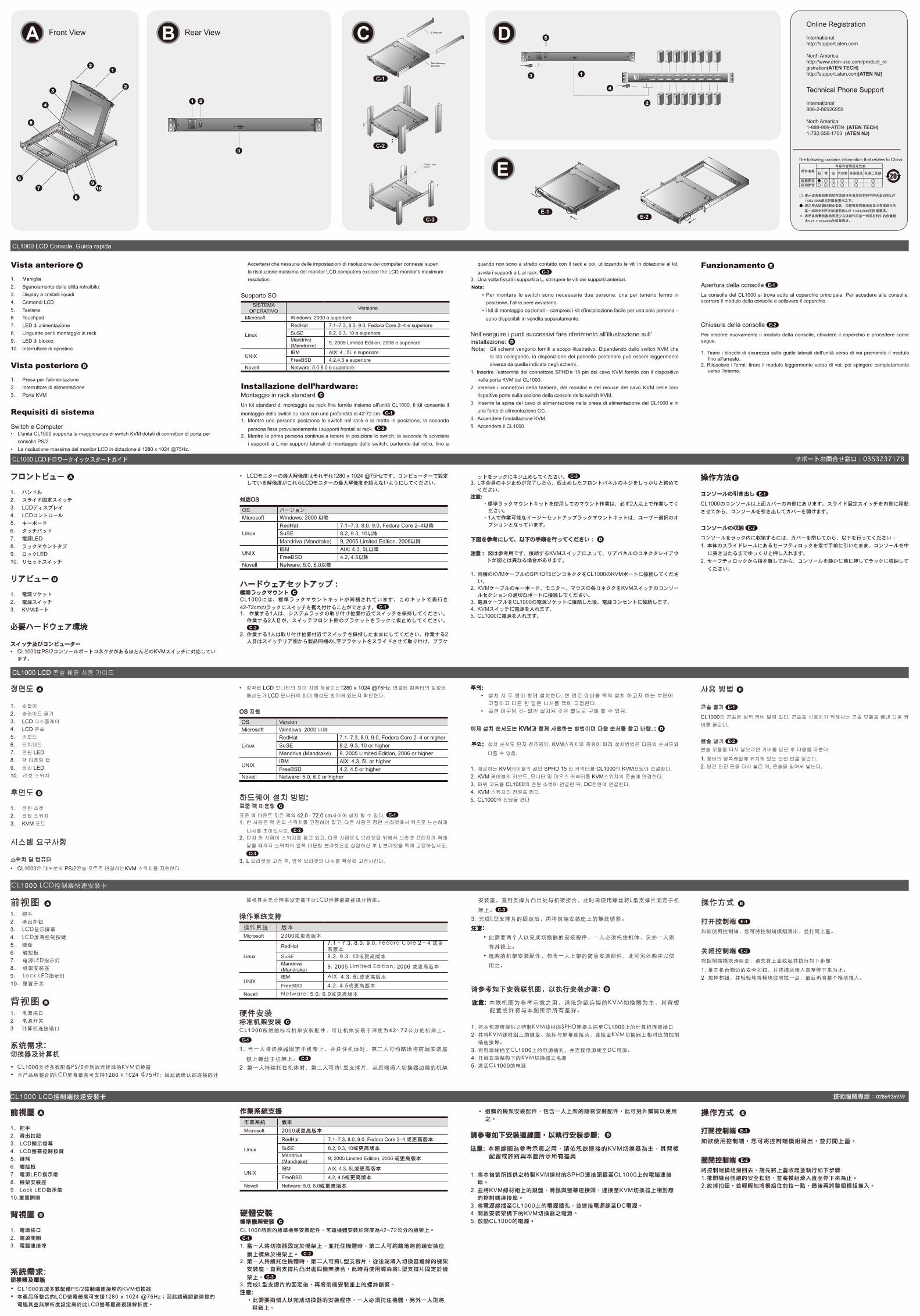
Standard Rack Mounting C
A standard rack mount kit is provided with your CL1000. The kit enables the switch to be
mounted in rack with a depth of 42-72 cm. C-1
1. While one person positions the switch in the rack and holds it in place, the second person
loosely screws the front brackets to the rack. C-22. While the first person still holds the switch in place, the second person slides the L
brackets intotheswitch'ssidemountingbracketsfromtherearuntil thebracketflanges
contact the rack, then screws the L brackets to the rack. C-33. After the L brackets have been secured, tighten the front bracket screws.
Note: •Ittakestwopeopletomounttheswitch:onetoholditinplace;theothertoscrewitin.•Optionalmountingkits–includingsinglepersonEasyInstallationkits–areavailable
with a separate purchase.
Refertotheexampleinstallationdiagrambelowasyouperformthefollowingsteps: D
Note: Thediagramsare forexamplepurposes.Dependingon theKVMswitchyouareconnecting, its rear panel layout may be somewhat different from the one shown in the diagrams.
1. PlugtheSPHDconnectorendoftheKVMcableprovidedwiththisunitintotheCL1000'sKVM port.
2. Plug the keyboard, monitor, and mouse connectors of the KVM cable into their respective ports on the Console Section of the KVM switch.
3. PlugthepowercordintotheCL1000'spowersocketandintoaDCpowersource.4. Power up your KVM installation.5. Turn on the power to CL1000.
Operation E
Opening the console E-1
TheCL1000'sconsole is locatedunder the topcover.Toaccess theconsole,slide theconsole module out and raise the cover.
Closing the console E-2
To slide the console module back in, close the cover and do the following:
1. Pullthesafetycatchesontheunit'ssiderailstowardyouandpushthemoduleinuntil itstops.
2. Releasethecatches;pullthemoduleslightlytowardyou;thenpushitallthewayin.
Guide de mise en route de la console LCD CL1000
fCL1000LCDKonsoleKurzanleitung
Consola con pantalla LCD CL1000 Guía rápida
L Brackets
Side MountngBrackets
Phillips I headM4 x 6
Vue avant A
1. Poignée2. Boutoncoulissantd'ouverture3. Écran LCD4. Commandes LCD5. Clavier6. Pavé tactile7. Voyantd'alimentation8. Supportsdefixationpourmontagesurrack9. Voyants de verrouillage10. Bouton de réinitialisation
Vue arrière B
1. Prised'alimentation2. Bouton de mise sous/hors tension3 Port KVM
Configuration système
Commutateurs et ordinateurs• LeCL1000prendenchargelaplupartdescommutateursKVMdisposantdeconnecteurs
de port de console PS/2. •Larésolutionmaximaledel'écranLCDintégréestde1280x1024,à75Hz.Vérifiezqu'aucundesparamètresderésolutiondesordinateursconnectésnedépasselarésolutionmaximaledel'écranLCD.
Systèmesd'exploitationprisenchargeSystèmed'exploitation Version
Microsoft Windows : 2000 ou supérieur
Linux
RedHat 7.1–7.3, 8.0, 9.0, Fedora Core 2–4 et supérieur
SuSE 8.2, 9.3, 10 et supérieur Mandriva (Mandrake) 9, 2005 Limited Edition, 2006 et supérieur
UNIX IBM AIX : 4.3, 5L et supérieur
FreeBSD 4.2, 4.5 et supérieur
Novell Netware : 5.0, 6.0 et supérieur
Installation du matérielMontage sur rack standard C
Un kit de montage sur rack standard est fourni avec le CL1000. Ce kit permet de monter le commutateursurrack,avecuneprofondeurde42à72cm. C-1
1. Pendantqu'unepremièrepersonnepositionnelecommutateurdansleracketlemaintientenplace,unedeuxièmevisselessupportsavantsurlebâti. C-2
2 Pendantque lapremièrepersonnemaintient toujoursenplace le commutateur, ladeuxième fait glisser lessupportsenLdans lessupportsdemontage latérauxducommutateur,àl'arrière,jusqu'àcequelesbridesdessupportsentrentencontactaveclebâti,puisvisselessupportsenLsurlebâti. C-3
3.UnefoislessupportsenLsécurisés,serrezlesvisdessupportsavant.
Remarque :•Deuxpersonnessontnécessairespourmonterlecommutateur:unepourleteniren
place et l’autre pour le visser.•Deskitsdemontageenoption,ycomprisdeskits facilesà installerparuneseule
personne, sont disponibles séparément.
Reportezvousauschémad'installationcidessouspoureffectuerlesétapessuivantes : D
Remarque : lesschémasnesontfournisqu'àtitred'exemples.SelonlecommutateurKVMquevousconnectez,ladispositiondesonpanneauarrièrepeutvarierdecelleillustrée par les schémas.
1. BranchezleconnecteurSPHDà15brochesducâbleKVMfourniaveccetteunitésurleport KVM du CL1000.
2.Branchez lesconnecteursduclavier,dumoniteuretde lasourisducâbleKVMsur lesports correspondants de la section de console du commutateur KVM.
3. Branchezlecordond'alimentationsurlaprised'alimentationduCL1000etsurunesourcede courant continu.
4. AllumezvotreinstallationKVM.5.AllumezleCL1000.
Fonctionnement E
Ouverture de la console E-1
La console du CL1000 se situe sous le panneau supérieur. Pour y accéder, faites glisser le moduleconsoleversl'extérieuretsoulevezlepanneau.
Fermeture de la console E-2
Pourremettrelemoduleconsoleenplace,replacezlepanneauetprocédezcommesuit:
1.Tirezsur les loquetsdesécuritédessupports latérauxdel'unitéversvousetpoussezlemoduleversl'intérieurjusqu'aufond.
2.Relâchezlesloquets,tirezlégèrementlemoduleversvousetpoussezlejusqu'aufond.
Vorderseitige Ansicht A
1. Griff2. Ausziehentriegelung3. LCDDisplay4. LCDBedienelemente5. Tastatur6. Touchpad7. LEDBetriebsanzeige8. Arretierungen für RackMontage9. VerriegelungsLEDs10. SchalterzumZurücksetzen
Rückseitige Ansicht B
1. Netzeingangsbuchse2. Netzschalter3. KVMPort
Systemvoraussetzungen
Switches und Computer• DerCL1000unterstütztdiemeistenKVMSwitchesmitPS/2Konsolportanschlüsse• DiemaximaleAuflösungdeseingebautenLCDMonitorsbeträgt1280x1024bei75Hz.
AchtenSiedarauf,dassdieeingestellteAuflösungderangeschlossenenComputernichtdiemaximaleAuflösungdesLCDMonitorsüberschreitet.
UnterstützteBetriebssysteme
Betriebssystem Version
Microsoft Windows:2000oderhöher
Linux
RedHat 7.1–7.3,8.0,9.0,FedoraCore2–4undhöher
SuSE 8.2,9.3,10undhöherMandriva (Mandrake) 9,2005LimitedEdition,2006undhöher
UNIX IBM AIX:4.3,5Lundhöher
FreeBSD 4.2,4.5undhöher
Novell Netware:5.0,6.0undhöher
Hardware installieren:StandardRackMontage C
MitdemCL1000wirdeinMontagekitfüreinStandardRackmitgeliefert.MitdiesemKitkönnen
Sie den Switch in ein Rack mit einer Tiefe von 42-72 cm einbauen. C-1
1.WährenddieeinePersondenSwitch indenRackschiebtundfesthält,setztdiezweite
Person die Schrauben lose auf die Montageschienen. C-22. WährenddieerstePersondenSwitchnachwievor festhält, schiebtdiezweitedie
L-Schienen von hinten auf die seitlichen Montagerahmen des Switches, bis der Flansch
den Rack berührt. Schrauben Sie die L-Schienen anschließend am Rack fest. C-33.NachdemSiedieL-Schienenbefestigthaben,ziehenSieauchdieSchraubenander
Vorderseite fest.
Hinweis: •ZurMontagedesSwitchessindzweiPersonenerforderlich:einezumFesthaltenunddieanderezumVerschraubenderEinheit.
•OptionaleMontagekits–darunterauchsolche,diedurcheineEinzelpersoninstalliertwerdenkönnen–sindoptionalerhältlich.
Für die Durchführung der folgenden Schritte, siehe die untenstehende Abbildung: D
Hinweis: DieDiagrammedienennurzurVeranschaulichung.JenachKVMSwitch,dasSieanschließen, kann die Rückseite von den Abbildungen abweichen.
1. Verbinden Sie den 15poligen SPHDAnschluss des mitgelieferten KVMKabels mit dem KVMPort am CL1000.
2. Verbinden Sie die Tastatur, Monitor und Mausanschlüsse des KVMKabels mit den betreffenden Ports am Konsolabschnitt des KVMSwitches.
3. VerbindenSiedasNetzkabelmitderStromeingangsbuchsedemCL1000unddemNetzteil.
4. Schalten Sie die KVMInstallation ein.5. Schalten Sie den CL1000 ein.
Bedienung E
Konsoleöffnen E-1
DieKonsoledesCL1000befindetsichunterderoberenAbdeckung.Umsiezuerreichen,ziehenSiedasKonsolmodulherausundklappendieAbdeckunghoch.
Konsole schließen E-2
UmdieKonsolewiedereinzuschieben, schließenSiedieAbdeckung,undgehenSiefolgendermaßen vor:
1.ZiehenSiedieSicherungslaschenseitlichandenSchienenzusichhin,undschiebenSiedas Modul hinein, bis es stoppt.
2.LassenSiedieLaschen los,ziehenSiedasModul leichtzusichhinundanschließendganzindenSchrankhinein.
Vista frontal A
1. Asa2. Desbloqueoretráctil3. Pantalla LCD4. Controles LCD5. Teclado6 Panel táctil7. Indicador LED de alimentación8. Muescasparamontajeenrack9. IndicadoresLEDdebloqueo10. Interruptor de reseteo
Vista posterior B
1. Entrada de alimentación2. Interruptor de alimentación3. Puerto KVM
Requisitos del sistema
Conmutadores y ordenadores• ElCL1000admitelamayoríadelosconmutadoresKVMquedisponendeconectoresde
puerto de consola PS/2.• LaresoluciónmáximadelapantallaLCDintegradaesde1280x1024a75Hz.Asegúresedequelaresoluciónutilizadaenlosordenadoresconectadosnoexcedala
resoluciónmáximadelapantallaLCD.
Sistemas operativos admitidosSistema operativo Versión
Microsoft Windows: 2000 o superior
Linux
RedHat 7.1–7.3, 8.0, 9.0, Fedora Core 2–4 y superior
SuSE 8.2, 9.3, 10 y superior Mandriva (Mandrake) 9, 2005 Limited Edition, 2006 y superior
UNIX IBM AIX: 4.3, 5L y superior
FreeBSD 4.2, 4.5 y superior
Novell Netware: 5.0, 6.0 y superior
Instalación del hardware:Montajeenrackestándar C
ConelCL1000vieneunkitdemontajeenrackestándar.Conestekitpuedemontarloenun
rack con una profundidad entre 42 y 72 cm. C-1
1. Mientras una persona coloca el conmutador en el rack y lo aguanta en su sitio, una
segunda atornilla (sin apretar) la parte frontal de los raíles en el rack. C-22. Mientras laprimerapersonasigueaguantandoelconmutador, lasegundadesliza los
raílesenLsobreelconmutadordesdelapartetraserahastaquelapestañadelsoporte
haga contacto con el rack y luego atornilla los raíles en L al rack. C-33. Cuando tenga los raíles en L atornillados, apriete también los tornillos frontales de los
raíles.
Nota:•Hacenfaltadospersonasparainstalarelconcentrador:unaquelocolocaensusitioylaotraqueloatornilla.
•Existenkitsdemontajeopcionales– incluyendokitsdemontajeparaunasolapersona.
Véase el diagrama de instalación siguiente cuando vaya a efectuar los pasos listados a continuación: D
Nota: losdiagramassóloseincluyencomoejemplos.SegúnelconmutadorKVMquevayaa conectar, la disposición de su panel posterior puede diferir del ilustrado en los diagramas.
1. Enchufe el conector SPHD de 15 patillas del cable KVM incluido al puerto KVM del CL1000.
2. Enchufe los conectores para teclado, monitor y ratón del cable KVM a los puertos respectivos de la sección de consola del conmutador KVM.
Lospuertosllevanelcódigodecolorestándar,ademásdeuniconoparasuidentificación.3. Enchufe el cable de alimentación a la entrada de alimentación del CL1000 y a una fuente
de corriente continua.4. Encienda toda la instalación KVM.5. Encienda el CL1000.
Funcionamiento E
Apertura de la consola E-1
LaconsoladelCL1000seencuentradebajodelpanelsuperior.Paraaccedera laconsola,deslice el módulo de consola hacia fuera y levante el panel.
Cierre de la consola E-2
Para volver a colocar el módulo de consola en su sitio, cierre el panel y proceda como se indica a continuación:
1.Tirelospestillosdeseguridaddelosraíleslateralesdelaunidadhaciaustedyempujeelmódulo hacia dentro hasta el fondo.
2.Sueltelospestillos,tireligeramenteelmódulohaciaustedyempújelohastaelfondo.
C-1
C-2
C-3
E-1
E-2
A
5
9
8
10
3
4
2
21
6
7
B
Front View
Rear View
12
23
4
5
6
8
79
10
1 2
43
1 2
C E
5
1
4
2
3 The following contains information that relates to China:
Online Registration
International:http://support.aten.com
North America:http://www.aten-usa.com/product_registration(ATEN TECH)http://support.aten.com(ATEN NJ)
Technical Phone Support
International:886-2-86926959
North America:1-888-999-ATEN (ATEN TECH)1-732-356-1703 (ATEN NJ)
D
サポートお問合せ窓口:0353237178
L Brackets
Side MountngBrackets
Phillips I headM4 x 6
CL1000 LCD Console Guida rapida
CL1000 LCDドロワークイックスタートガイド
CL1000 LCD 콘솔 빠른 사용 가이드
フロントビュー A
1. ハンドル
2. スライド固定スイッチ
3. LCDディスプレイ
4. LCDコントロール
5. キーボード
6. タッチパッド
7. 電源LED8. ラックマウントタブ
9. ロックLED10. リセットスイッチ
リアビュー B
1. 電源ソケット
2. 電源スイッチ
3. KVMポート
必要ハードウェア環境
スイッチ及びコンピューター• CL1000はPS/2コンソールポートコネクタがあるほとんどのKVMスイッチに対応してい
ます。
• LCDモニターの最大解像度はそれぞれ1280 x 1024 @75Hzです。コンピューターで設定している解像度がこれらLCDモニターの最大解像度を超えないようにしてください。
対応OS
OS バージョンMicrosoft Windows: 2000 以降
Linux RedHat 7.1–7.3, 8.0, 9.0, Fedora Core 2–4以降
SuSE 8.2, 9.3, 10以降
Mandriva (Mandrake) 9, 2005 Limited Edition, 2006以降
UNIX IBM AIX: 4.3, 5L以降
FreeBSD 4.2, 4.5以降 Novell Netware: 5.0, 6.0以降
ハードウェアセットアップ:標準ラックマウント CCL1000には、標準ラックマウントキットが同梱されています。このキットで奥行き
42-72cmのラックにスイッチを据え付けることができます。 C-11. 作業する1人は、システムラックの取り付け位置付近でスイッチを保持してください。
作業する2人目が、スイッチフロント側のブラケットをラックに仮止めしてください。C-2
2. 作業する1人は取り付け位置付近でスイッチを保持したままにしてください。作業する2人目はスイッチリア側から製品同梱のL字ブラケットをスライドさせて取り付け、ブラケ
ットをラックにネジ止めしてください。 C-33. L字金具のネジ止めが完了したら、仮止めしたフロントパネルのネジをしっかりと締めて
ください。注意:
・標準ラックマウントキットを使用してのマウント作業は、必ず2人以上で作業してください。
・1人で作業可能なイージーセットアップラックマウントキットは、ユーザー選択のオプションとなっています。
下図を参考にして、以下の手順を行ってください: D
注意: 図は参考用です。接続するKVMスイッチによって、リアパネルのコネクタレイアウトが図とは異なる場合があります。
1. 同梱のKVMケーブルのSPHD15ピンコネクタをCL1000のKVMポートに接続してください。
2. KVMケーブルのキーボード、モニター、マウスの各コネクタをKVMスイッチのコンソールセクションの適切なポートに接続してください。
3. 電源ケーブルをCL1000の電源ソケットに接続した後、電源コンセントに接続します。4. KVMスイッチに電源を入れます。5. CL1000に電源を入れます。
操作方法 E
コンソールの引き出し E-1
CL1000のコンソールは上面カバーの内側にあります。スライド固定スイッチを内側に移動
させてから、コンソールを引き出してカバーを開けます。
コンソールの収納 E-2
コンソールをラック内に収納するには、カバーを閉じてから、以下を行ってください:
1. 本体のスライドレールにあるセーフティロックを指で手前に引いたまま、コンソールを中
に突き当たるまでゆっくりと押し入れます。
2. セーフティロックから指を離してから、コンソールを静かに前に押してラックに収納して
ください。
정면도 A
1. 손잡이
2. 슬라이드 풀기3. LCD 디스플레이4. LCD 콘솔5. 키보드
6. 터치패드
7. 전원 LED8. 랙 마운팅 탭9. 잠김 LED10. 리셋 스위치
후면도 B
1. 전원 소켓2. 전원 스위치3. KVM 포트
시스템 요구사항
스위치 및 컴퓨터• CL1000은 대부분의 PS/2콘솔 포트로 연결하는KVM 스위치를 지원한다.
• 장착된 LCD 모니터의 최대 지원 해상도는1280 x 1024 @75Hz. 연결된 컴퓨터의 설정된 해상도가 LCD 모니터의 최대 해상도 범위에 있는지 확인한다.
OS 지원
OS Version Microsoft Windows: 2000 以降
Linux RedHat 7.1–7.3, 8.0, 9.0, Fedora Core 2–4 or higherSuSE 8.2, 9.3, 10 or higher Mandriva (Mandrake) 9, 2005 Limited Edition, 2006 or higher
UNIX IBM AIX: 4.3, 5L or higherFreeBSD 4.2, 4.5 or higher
Novell Netware: 5.0, 6.0 or higher
하드웨어 설치 방법:표준 랙 마운팅 C
표준 랙 마운트 킷은 랙의 42.0 - 72.0 cm사이에 설치 할 수 있다. C-11. 한 사람은 랙 안의 스위치를 고정하여 잡고, 다른 사람은 정면 브라켓에서 랙으로 느슨하게 나사를 조이십시오. C-2
2. 먼저 한 사람이 스위치를 잡고 있고, 다른 사람은 L 브라켓을 뒤에서 브라켓 프렌지가 랙에 닿을 때까지 스위치의 옆쪽 마운팅 브라켓으로 삽입하신 후 L 브라켓을 랙에 고정하십시오. C-3
3. L 브라켓을 고정 후, 앞쪽 브라켓의 나사를 확실히 고정시킨다.
주의:• 설치 시 두 명이 함께 설치한다. 한 명은 장비를 랙의 설치 하고자 하는 부분에 고정하고 다른 한 명은 나사를 랙에 고정한다.
• 옵션 마운팅 킷- 일인 설치용 킷은 별도로 구매 할 수 있음.
예제 설치 순서도는 KVM과 함께 사용하는 방법이며 다음 순서를 참고 바람. : D
주의: 설치 순서도 단지 참조용임. KVM스위치의 종류에 따라 설치방법은 다음의 순서도와
다를 수 있음.
1. 제공하는 KVM케이블의 끝인 SPHD 15 핀 커넥터를 CL1000의 KVM포트에 연결한다.2. KVM 케이블의 키보드, 모니터 및 마우스 커넥터를 KVM스위치의 콘솔에 연결한다.3. 파워 코드를 CL1000의 전원 소켓에 연결한 뒤, DC전원에 연결한다. 4. KVM 스위치의 전원을 켠다.5. CL1000의 전원을 켠다
사용 방법 E
콘솔 열기 E-1
CL1000의 콘솔은 상위 커버 밑에 있다. 콘솔을 사용하기 위해서는 콘솔 모듈을 빼낸 다음 커버를 올린다.
콘솔 닫기 E-2
콘솔 모듈을 다시 넣으려면 커버를 닫은 후 다음을 따른다:
1. 장비의 양쪽레일에 위치해 있는 안전 핀을 당긴다.2. 당긴 안전 핀을 다시 놓은 뒤, 콘솔을 밀어서 넣는다.
Vista anteriore A
1. Maniglia2. Sganciamento della slitta retraibile:3. Display a cristalli liquidi4. Comandi LCD5. Tastiera6 Touchpad7. LED di alimentazione8. Linguette per il montaggio in rack9. LED di blocco10. Interruttore di ripristino
Vista posteriore B
1. Presa per l’alimentazione2. Interruttore di alimentazione3. Porta KVM
Requisiti di sistema
Switch e Computer• L'unità CL1000 supporta la maggioranza di switch KVM dotati di connettori di porta per
consolle PS/2. • La risoluzione massima del monitor LCD in dotazione è 1280 x 1024 @75Hz.
Accertarsi che nessuna delle impostazioni di risoluzione dei computer connessi superi la risoluzione massima del monitor LCD.computers exceed the LCD monitor's maximum resolution.
Supporto SOSISTEMA
OPERATIVO Versione
Microsoft Windows: 2000 o superiore
Linux
RedHat 7.1–7.3, 8.0, 9.0, Fedora Core 2–4 e superioreSuSE 8.2, 9.3, 10 e superiore Mandriva (Mandrake) 9, 2005 Limited Edition, 2006 e superiore
UNIX IBM AIX: 4., 5L e superioreFreeBSD 4.2,4.5 e superiore
Novell Netware: 5.0 6.0 e superiore
Installazione dell’hardware:Montaggio in rack standard C
Un kit standard di montaggio su rack fine fornito insieme all'unità CL1000. Il kit consente il
montaggio dello switch su rack con una profondità di 42-72 cm. C-11. Mentre una persona posiziona lo switch nel rack e lo mette in posizione, la seconda
persona fissa provvisoriamente i supporti frontali al rack. C-22. Mentre la prima persona continua a tenere in posizione lo switch, la seconda fa scivolare
i supporti a L nei supporti laterali di montaggio dello switch, partendo dal retro, fino a
quando non sono a stretto contatto con il rack e poi, utilizzando le viti in dotazione al kit,
avvita i supporti a L al rack. C-33. Una volta fissati i supporti a L, stringere le viti dei supporti anteriori.Nota:
• Per montare lo switch sono necessarie due persone: una per tenerlo fermo in posizione, l’altra pere avviatarlo.
• I kit di montaggio opzionali – compresi i kit d’installazione facile per una sola persona – sono disponibili in vendita separatamente.
Nell’eseguire i punti successivi fare riferimento all’illustrazione sull’installazione: DNota: Gli schemi vengono forniti a scopo illustrativo. Dipendendo dallo switch KVM che
si sta collegando, la disposizione del pannello posteriore può essere leggermente diversa da quella indicata negli schemi.
1. Inserire l’estremità del connettore SPHD a 15 pin del cavo KVM fornito con il dispositivo nella porta KVM del CL1000.
2. Inserire i connettori della tastiera, del monitor e del mouse del cavo KVM nelle loro rispettive porte sulla sezione della console dello switch KVM.
3. Inserire la spina del cavo di alimentazione nella presa di alimentazione del CL1000 e in una fonte di alimentazione CC.
4. Accendere l’installazione KVM.5. Accendere il CL1000.
Funzionamento E
Apertura della consolle E-1
La consolle del CL1000 si trova sotto al coperchio principale. Per accedere alla consolle, scorrere il modulo della consolle e sollevare il coperchio.
Chiusura della consolle E-2
Per inserire nuovamente il modulo della consolle, chiudere il coperchio e procedere come segue:
1. Tirare i blocchi di sicurezza sulle guide laterali dell'unità verso di voi premendo il modulo fino all'arresto.
2. Rilasciare i fermi; tirare il modulo leggermente verso di voi; poi spingere completamente verso l'interno.
A
5
9
8
10
3
4
2
21
6
7
Front View
12
23
4
5
6
8
79
10
DB Rear View C
E
C-1
C-2
C-3E-1
E-2
5
1
4
2
3
The following contains information that relates to China:
Online Registration
International:http://support.aten.com
North America:http://www.aten-usa.com/product_registration(ATEN TECH)http://support.aten.com(ATEN NJ)
Technical Phone Support
International:886-2-86926959
North America:1-888-999-ATEN (ATEN TECH)1-732-356-1703 (ATEN NJ)
1 2
43
1 2