1x EV-DO Forward Link Physical and MAC Layer Overview
13
Worcester Polytechnic Institute DigitalCommons@WPI Computer Science Faculty Publications Department of Computer Science 8-1-2010 1x EV-DO Forward Link Physical and MAC Layer Overview Zhe Zhou Worcester Polytechnic Institute Mark Claypool Worcester Polytechnic Institute, [email protected] Robert Kinicki Worcester Polytechnic Institute, [email protected] Follow this and additional works at: hp://digitalcommons.wpi.edu/computerscience-pubs Part of the Computer Sciences Commons is Other is brought to you for free and open access by the Department of Computer Science at DigitalCommons@WPI. It has been accepted for inclusion in Computer Science Faculty Publications by an authorized administrator of DigitalCommons@WPI. Suggested Citation Zhou, Zhe , Claypool, Mark , Kinicki, Robert (2010). 1x EV-DO Forward Link Physical and MAC Layer Overview. . Retrieved from: hp://digitalcommons.wpi.edu/computerscience-pubs/12 brought to you by CORE View metadata, citation and similar papers at core.ac.uk provided by DigitalCommons@WPI
Transcript of 1x EV-DO Forward Link Physical and MAC Layer Overview

Worcester Polytechnic InstituteDigitalCommons@WPI
Computer Science Faculty Publications Department of Computer Science
8-1-2010
1x EV-DO Forward Link Physical and MAC LayerOverviewZhe ZhouWorcester Polytechnic Institute
Mark ClaypoolWorcester Polytechnic Institute, [email protected]
Robert KinickiWorcester Polytechnic Institute, [email protected]
Follow this and additional works at: http://digitalcommons.wpi.edu/computerscience-pubsPart of the Computer Sciences Commons
This Other is brought to you for free and open access by the Department of Computer Science at DigitalCommons@WPI. It has been accepted forinclusion in Computer Science Faculty Publications by an authorized administrator of DigitalCommons@WPI.
Suggested CitationZhou, Zhe , Claypool, Mark , Kinicki, Robert (2010). 1x EV-DO Forward Link Physical and MAC Layer Overview. .Retrieved from: http://digitalcommons.wpi.edu/computerscience-pubs/12
brought to you by COREView metadata, citation and similar papers at core.ac.uk
provided by DigitalCommons@WPI
WPI-CS-TR-10-13 August 2010
1x EV-DO Forward Link Physical and MAC LayerOverview
by
Zhe ZhouMark ClaypoolRobert Kinicki
Computer ScienceTechnical ReportSeriesWORCESTER POLYTECHNIC INSTITUTE
Computer Science Department100 Institute Road, Worcester, Massachusetts 01609-2280

1 Introduction
The past decade sees the rapid growth of mobile Internet technologies. Accessingthe Internet from smart phones or from laptops with mobile Internet access cardshas gained unprecedented popularity. The increasing bandwidth and responsivenessoffered by mobile technologies to end users foster a wider variety of Internet appli-cations. Applications such as video streaming, online gaming and file sharing thatwere not available but now widely supported on mobile devices. The gap betweenconsumer mobile and wireline Internet access has been increasingly closer, givingend users great flexibility to stay connected without constraints of venues, time, andselection of applications.
Among these mobile Internet technologies, Evolution-Data Optimized (EV-DO) iscurrently the most widely used technology in North and South America, Europe,Japan and South Korea [4]. EV-DO is standardized by the 3rd Generation Partner-ship Project 2 (3GPP2) as part of the CDMA2000 family of standards and has beenadopted by many mobile phone service providers around the world. As of August2007, the EV-DO Release 0 networks of 77 operators served more than 65 millionsubscribers in 46 countries worldwide.
Figure 1: World Wide Coverage of EV-DO [4]
The EV-DO standard has three revisions: Rev. 0, Rev. A and Rev. B. The firstrevision or Rev. 0 was developed by Qualcomm in 1999 and initially called High Data
1

Rate (HDR), but was renamed to 1xEV-DO after the ratification by the InternationalTelecommunication Union (ITU) and given the numerical designation TIA-856 (alsowritten as IS 856 TIA/EIA). The 1x prefix indicates 1xEV as the direct successorof the 1xRTT (1 times Radio Transmission Technology) air interface standard, butthen was conveniently dropped due to marketing purposes. EV-DO Rev. 0 supportsdata rates of up to 2.45Mbps on the forward link (or downlink) and 153Kbps on thereverse link (uplink). EV-DO Rev. A introduces a few additional forward link datarates and support for delay-sensitive low-rate applications such as VoIP by PacketDivision Multiply Access (PDMA), one-to-many Data Rate Control (DRC) indexmapping, and seamless server handoffs. EV-DO Rev. B is a multi-carrier version ofRev. A which further increases link capacity and reduces packet delays; however, dueto commercial reasons it is not widely deployed.
EV-DO uses a CDMA frequency carrier of 1.25 MHz separate from 1xRTT for theforward link and shares the carrier with CDMA2000 1xRTT for reverse link. Theforward link design is based on the premise that any combining of data and voiceresults in inefficiency due to their different nature. The design of the reverse linkcomes in with the observation that the reverse link and forward link bandwidth usageof broadband subscribers is usually asymmetric, with more bandwidth required onthe forward link and much less on the reverse link.
This white paper primarily focuses on the forward link of EV-DO and assumes Rev.A. A comprehensive comparison of EV-DO Rev. A and Rev. 0 can be found at [5].The rest of this paper abbreviates EV-DO by DO as other literatures do.
2 DO network architecture
Figure 2 shows the network architecture of DO network. Access terminals (ATs),typically handsets and laptops with data cards, connect to an access point (or AP,in this figure the Radio Node) to access the DO network. Each AP typically servesone cell1 and supports three sectors2. Higher layers of the 1xEV-DO protocol areprocessed at the Radio Network Controller (RNC), which also manages handoffs andpasses user data between the APs and the Packet Data Switch Network (PDSN).The PDSN is a wireless edge router that connects the Radio Access Network (RAN)to the Internet.
1The radio coverage area a fixed-location cellular tower provides.2A division of radio coverage area by using directional antennas. Typically a cell has 3 sectors.
2
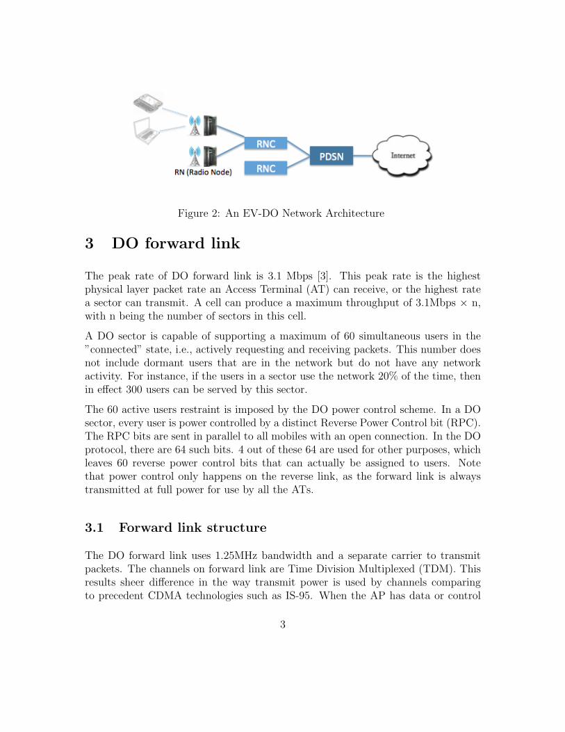
Figure 2: An EV-DO Network Architecture
3 DO forward link
The peak rate of DO forward link is 3.1 Mbps [3]. This peak rate is the highestphysical layer packet rate an Access Terminal (AT) can receive, or the highest ratea sector can transmit. A cell can produce a maximum throughput of 3.1Mbps × n,with n being the number of sectors in this cell.
A DO sector is capable of supporting a maximum of 60 simultaneous users in the”connected” state, i.e., actively requesting and receiving packets. This number doesnot include dormant users that are in the network but do not have any networkactivity. For instance, if the users in a sector use the network 20% of the time, thenin effect 300 users can be served by this sector.
The 60 active users restraint is imposed by the DO power control scheme. In a DOsector, every user is power controlled by a distinct Reverse Power Control bit (RPC).The RPC bits are sent in parallel to all mobiles with an open connection. In the DOprotocol, there are 64 such bits. 4 out of these 64 are used for other purposes, whichleaves 60 reverse power control bits that can actually be assigned to users. Notethat power control only happens on the reverse link, as the forward link is alwaystransmitted at full power for use by all the ATs.
3.1 Forward link structure
The DO forward link uses 1.25MHz bandwidth and a separate carrier to transmitpackets. The channels on forward link are Time Division Multiplexed (TDM). Thisresults sheer difference in the way transmit power is used by channels comparingto precedent CDMA technologies such as IS-95. When the AP has data or control
3
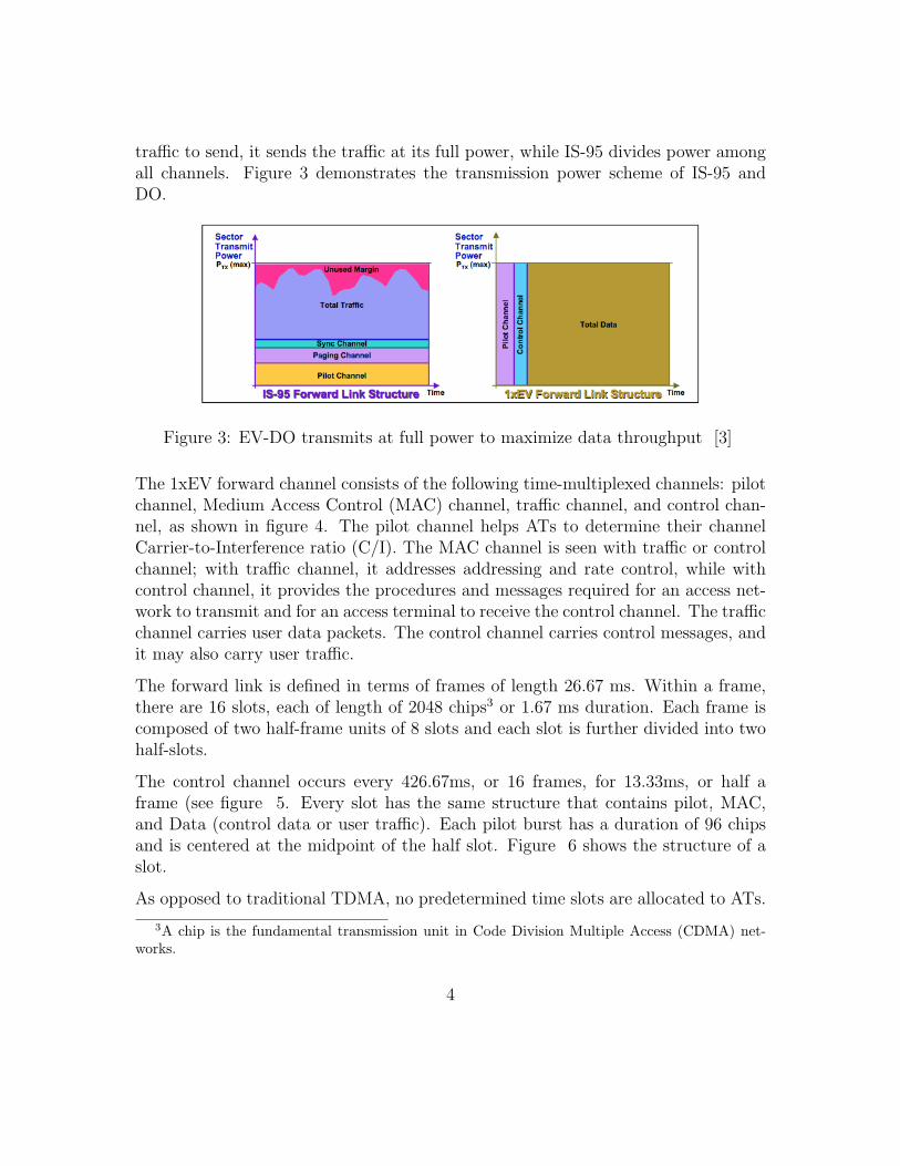
traffic to send, it sends the traffic at its full power, while IS-95 divides power amongall channels. Figure 3 demonstrates the transmission power scheme of IS-95 andDO.
Figure 3: EV-DO transmits at full power to maximize data throughput [3]
The 1xEV forward channel consists of the following time-multiplexed channels: pilotchannel, Medium Access Control (MAC) channel, traffic channel, and control chan-nel, as shown in figure 4. The pilot channel helps ATs to determine their channelCarrier-to-Interference ratio (C/I). The MAC channel is seen with traffic or controlchannel; with traffic channel, it addresses addressing and rate control, while withcontrol channel, it provides the procedures and messages required for an access net-work to transmit and for an access terminal to receive the control channel. The trafficchannel carries user data packets. The control channel carries control messages, andit may also carry user traffic.
The forward link is defined in terms of frames of length 26.67 ms. Within a frame,there are 16 slots, each of length of 2048 chips3 or 1.67 ms duration. Each frame iscomposed of two half-frame units of 8 slots and each slot is further divided into twohalf-slots.
The control channel occurs every 426.67ms, or 16 frames, for 13.33ms, or half aframe (see figure 5. Every slot has the same structure that contains pilot, MAC,and Data (control data or user traffic). Each pilot burst has a duration of 96 chipsand is centered at the midpoint of the half slot. Figure 6 shows the structure of aslot.
As opposed to traditional TDMA, no predetermined time slots are allocated to ATs.
3A chip is the fundamental transmission unit in Code Division Multiple Access (CDMA) net-works.
4

Figure 4: EV-DO Forward Link Structure
Figure 5: EV-DO Forward Link Demonstration [3]
Figure 6: EV-DO Forward Link Slot Structure
5

When an AT is actively using the link (sending and receiving data), it keeps listeningto all time slots for possible incoming data.
3.2 Physical Layer Packets
EV-DO forward link physical layer packets are defined by their transmission formats.The triple (s, t, p) defines the transmission format, in which s is the physical layerpacket size in bits, t is the nominal packet duration in slots, and p is the preamblelength in chips. For example, (256, 8, 1024) defines packets with 256-bit payload,8-slot nominal duration and a 1024-chip preamble. DO supports packet size of 128,256, 512, 1024, 2048, 3072, 4096, and 5120 bits, with nominal spans of one through16 slots, resulting in data rates ranging from 4.8 kb/s to 3.072 Mb/s.
3.3 Packet Data Rate
The 1xEV forward link supports dynamic data rates. ATs constantly measure thechannel C/I, then requests the appropriate data rate for the channel conditions every1.67 ms. The AP receives the ATs request for a particular data rate, and encodesthe forward link data at the highest rate that promises less than 1% Packet ErrorRate (PER) at the requested instant. With the maximum rate information beingupdated so frequently, the AP makes sure the data is sent to ATs at the maximumrate their varying channel conditions allow at any instant. For a DRC request, thefollowing steps are performed [3]:(a) AT measures received C/I’s from available sectors(b) AT selects the best serving sector(c) AT requests transmission at the highest possible data rate that sustains less than1% PER based on measured C/I(d) The selected sector transmits data to the AT at the requested data rate.
The Access Terminal continuously updates the Access Point on the DRC channel,indicating a specified data rate to be used on the forward link. Figure 7 shows theprocess of a DRC request.
Transmission formats, data rate, nominal slot duration, associated multi-user trans-missions formats for each DRC index value are listed in table 1.
6

Figure 7: Process of a DRC request [6]
3.4 Early Completion and Incremental Redundancy
As defined in physical layer transmission formats, Forward traffic channel and controlchannel can be transmitted in a span of 1 to 16 slots. If a packet is transmittedin more than 1 time slot, the encoding redundancy makes successful reception ofone slot possible for decoding the whole packet. Moreover, the reception of eachsuccessive slot improves the likelihood of successful decoding after combining. Withsuch an incremental redundancy coding scheme, the AT notifies the AP to terminatethe transmission as soon as the packet is decoded correctly. A 3 slots interleavingbetween such consecutive redundant slots allows AT to try decoding the packet andnotify the result to the AP. These 3 slots can have no data (contain only pilots)or have data for other ATs. For example, a packet of format (1024, 4, 256) thathas a nominal slot duration of 4 could be sent and decoded correctly by the ATreceiving only the first two slots. This gain in transmission efficiency is called earlycompletion.
Early completion gain exists because the estimation of the RF (Radio Frequency)environment at the handset is not perfect. The DRC index requested by the AT iscomputed from an estimated channel condition which is in turn calculated by a long-range fading channel prediction algorithm [7]. This algorithm produces conservativeestimations (to ensure less than 1% PER), and the mismatch between the data ratethat should be transmitted and the data rate that is requested by the handset iseffectively mitigated by early completion.
7
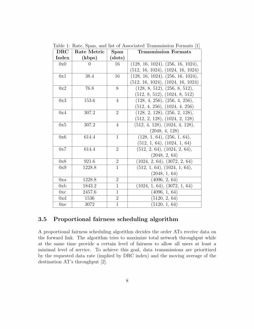
Table 1: Rate, Span, and list of Associated Transmission Formats [1]DRC Rate Metric Span Transmission FormatsIndex (kbps) (slots)0x0 0 16 (128, 16, 1024), (256, 16, 1024),
(512, 16, 1024), (1024, 16, 1024)0x1 38.4 16 (128, 16, 1024), (256, 16, 1024),
(512, 16, 1024), (1024, 16, 1024)0x2 76.8 8 (128, 8, 512), (256, 8, 512),
(512, 8, 512), (1024, 8, 512)0x3 153.6 4 (128, 4, 256), (256, 4, 256),
(512, 4, 256), (1024, 4, 256)0x4 307.2 2 (128, 2, 128), (256, 2, 128),
(512, 2, 128), (1024, 2, 128)0x5 307.2 4 (512, 4, 128), (1024, 4, 128),
(2048, 4, 128)0x6 614.4 1 (128, 1, 64), (256, 1, 64),
(512, 1, 64), (1024, 1, 64)0x7 614.4 2 (512, 2, 64), (1024, 2, 64),
(2048, 2, 64)0x8 921.6 2 (1024, 2, 64), (3072, 2, 64)0x9 1228.8 1 (512, 1, 64), (1024, 1, 64),
(2048, 1, 64)0xa 1228.8 2 (4096, 2, 64)0xb 1843.2 1 (1024, 1, 64), (3072, 1, 64)0xc 2457.6 1 (4096, 1, 64)0xd 1536 2 (5120, 2, 64)0xe 3072 1 (5120, 1, 64)
3.5 Proportional fairness scheduling algorithm
A proportional fairness scheduling algorithm decides the order ATs receive data onthe forward link. The algorithm tries to maximize total network throughput whileat the same time provide a certain level of fairness to allow all users at least aminimal level of service. To achieve this goal, data transmissions are prioritizedby the requested data rate (implied by DRC index) and the moving average of thedestination AT’s throughput [2].
8

Suppose a DO system with one AP and N ATs currently associated with the AP. LetRi(t) be the estimate of the average rate for AT i at slot t, i= 1,..,N. Also, supposethat at slot t, the current DRC (i.e., requested rate) from user i is DRCi(t), againi=l,..,N. The algorithm works as follows:1. Scheduling: The AT with the highest ratio of DRCi(t)/Ri(t) out of all N ATswill receive transmission at each decision time. Ties are broken randomly. Any ATfor whom there is no data to send is ignored in this calculation.2. Update Average Rate: For each AT i Ri(t+1) = (1-1/tc) Ri(t) + 1/tc * ri,where an AT that is not currently receiving service has 0 for its current rate oftransmission. Even ATs for whom the scheduler has no data to send get their averagerate updated.
Note that the scheduling step is executed each time a new transmission begins butthe update average rate is done in each slot, even if the slot is in the middle of amulti-slot transmission. The update of the average rate as specified here is done usinga low pass filter with a time constant of tc slots. tc determines how much impactpast throughput has on current likelihood of being served. With this schedulingalgorithm, ATs that are moving towards a better location are preferred, resulting ina total throughput gain by trying to serve each AT at its peak rate. This gain isalso known as multi-user diversity. Under the circumstances when user mobility ishigh, this scheduling algorithm exploits the channel condition variation and producespronounced gains. When users are stationary and their channel condition variation islow, the scheduling algorithm behaves closely to round-robin (except that the orderof each round of serving is determined randomly).
4 Other Features
4.1 Packet-division multiple access
PDMA, or packet-division multiple access, is the technique of packing and transmit-ting packets from multiply users in a single physical layer packet. Such a physicallayer packet that contains data for multiple AT’s (up to eight) is also called multi-user packet (MUP). PDMA enables DO to support a large number of low-rate delaysensitive applications. The forward link scheduler serves single-user packets (SUPs)using opportunistic scheduling to exploit multi-user diversity and decides when toserve MUPs.
9

4.2 Soft Handoff
DO supports soft handoff to another AP without interrupting existing connections.This is necessary to support delay-sensitive applications such as VoIP, Gaming, andvideo streaming. The key to achieve this goal is keeping a low packet latency andavoiding packet drop during handoffs.
During handoffs, a data queue is set up at the new AP for the AT and packetsdestined to the AT are rerouted to the new AP. The new AP will transmit packetsto the AT until this process is done. In DO, this is achieve by early notification fromAT to AP about the handoff event.
The Data Source Channel (DSC) is a physical layer channel from the AT to theaccess network that provides an early indication of handoff. When an AT decidesto handoff to a new AP, it signals the network by changing the DSC 64 slots beforeformalizing the handoff. The advance notice allows the network to queue data atthe new AP while continuing to serve the mobile from the original AP. When thehandoff is triggered, the AP is not served for 16 slots in a typical configuration. Theoutage during handoff of typically 16 slots translates to a delay of 27ms, a typicaltolerable delay by delay-sensitive applications.
5 Summary
1xEV provides wireline equivalent bandwidth to mobile users, giving them greaterfreedom in acquiring information from Internet. The standard efficiently makes useof a 1.25MHz frequency by adopting variable data rate, incremental redundancy,and a multi-user diversity scheduler for increasing throughput and by employingPDMA, flexible packet sizes, and soft handoff for delay-sensitive application opti-mization.
References
[1] 3GPP2. CDMA2000 High Rate Packet Data Air Interface Specification. 2004.
10
[2] A. Jalali, R. Padovani, R. Pankaj. Data Throughput of CDMA-HDR a HighEfficiency-High Data Rate Personal Communication Wireress System. VehicularTechnology Conference Proceedings, 38(7):70–77, 2000.
[3] Qualcomm Inc. 1xEV: 1x EVolution IS-856 TIA/EIA Standard Airlink Overview.2001.
[4] Qualcomm Inc. EV-DO Rev. A and B: Wireless Broadband for the Masses. 2007.
[5] Naga Bhushan, Chris Lott, Peter Black, Rashid Attar, Yu-Cheun Jou, MingxiFan, Donna Ghosh, and Jean Au. CDMA2000 1xEV-DO Revision A: A PhysicalLayer and MAC Layer Overview. IEEE Communications Magazine, 44(2):75–87,2006.
[6] Paul Bender, Peter Black, Matthew Grob, Roberto Padovani, NagabhushanaSindhushayana, and Andrew Viterbi. CDMA/HDR: A Bandwidth-Efficient High-Speed Wireless Data Service for Nomadic Users. IEEE Communications Maga-zine, 38(7):70–77, 2000.
[7] Qi Bi and Stan Vitebsky. Performance Analysis of 3G-1X EVDO High DataRate System. In IEEE Wireless Communications and Networking Conference,Orlando, FL, USA, March 2002.
11