Meridian Digital Telephones User Guide - McGill...User Guide ...
Visit www.rmspl.com.au for the latest product information.
Due to RMS continuous product improvement policy this information is subject to change without notice. 1S24_Guide/Iss F/18/06/2018
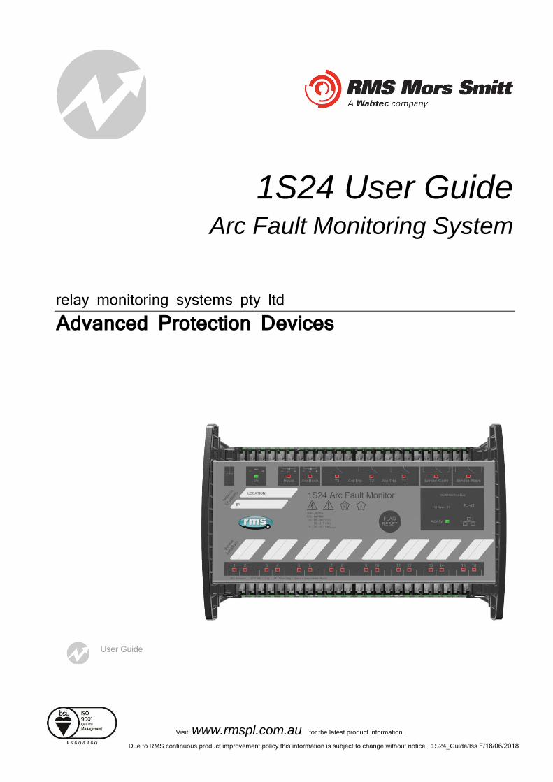
1S24 User Guide Arc Fault Monitoring System
relay monitoring systems pty ltd Advanced Protection Devices
User Guide
1S24 User Guide
About This Manual
This User Guide covers all 1S24 relays manufactured from August 2017. Earlier relays do not necessarily incorporate all the features described. Our policy of continuous development means that
extra features & functionality may have been added.
The 1S24 User Guide is designed as a generic document to describe the common operating parameters for all relays built on this platform. Some relay applications are described but for specific
model information the individual “K” number Product / Test manuals should be consulted.
The copyright and other intellectual property rights in this document, and in any model or article produced from it (and including any Registered or unregistered design rights) are the property of Relay Monitoring Systems
Pty Ltd. No part of this document shall be reproduced or modified or stored in another form, in any data retrieval system, without the permission of Relay Monitoring Systems Pty Ltd, nor shall any model or article
be reproduced from this document without consent from Relay Monitoring Systems Pty Ltd.
While the information and guidance given in this document is believed to be correct, no liability shall be accepted for any loss or damage caused by any error or omission, whether such error or omission is the
result of negligence or any other cause. Any and all such liability is disclaimed.
Contact Us
Relay Monitoring Systems Pty Ltd 2006-2013
6 Anzed Court • Mulgrave 3170 • AUSTRALIA
Phone 61 3 8544 1200 • Fax 61 3 8544 1201
Email [email protected] • Web www.rmspl.com.au
To download a PDF version of this guide: http://rmspl.com.au/wordpress/wp-content/uploads/2015/08/1S24_User_Guide.pdf
Visit www.rmspl.com.au for the latest product information.Page
Due to RMS continuous product improvement policy this information is subject to change without notice. 1S24_Guide/Iss F/18/06/2018
How this Guide is Organised
This guide is divided into three parts:
Part 1 Overview
Part 2 Documentation
Part 3 Application
Part
1

Visit www.rmspl.com.au for the latest product information.Page
Due to RMS continuous product improvement policy this information is subject to change without notice. 1S24_Guide/Iss F/18/06/2018
Documentation
Technical Bulletin
The detailed technical attributes, functional description & performance specifications for the 1S24 are described in the product Technical Bulletin. For the most up to date version go to:
http://rmspl.com.au/product/1s24/
http://rmspl.com.au/product/1s30/
http://rmspl.com.au/product/1s40/
The order of precedence for product information is as follows:
• Product Test Manual (PTM)
• Technical Bulletin
• User Guide
User Guide
This User Guide covers all 1S24 relay versions & describes the generic features & attributes common across all versions.
Different relay versions are required to cater for varying customer requirements such as auxiliary voltage range, I/O configuration, case style, relay functionality etc.
The product ordering code described in the Technical Bulletin is used to generate a unique version of the relay specification & is called a Type Number. This code takes the form 1S24Kxx where the Kxx is the “K” or version number. For a complete description of the RMS “K” number system refer to: www.rmspl.com.au/handbook/parta3.pdf
Product Test Manual
Each 1S24 version has a specific PTM which provides details on the unique attributes of the relay. Each PTM includes the following information:
• Specific technical variations from the standard model if applicable
• Wiring diagram
If you require a copy of the PTM for an RMS product the following options are available:
• Check the RMS web site at: http://rmspl.com.au/product-test-manuals/
• Contact RMS or a representative & request a hard copy or PDF by email.
Part
2
Page 1
Visit www.rmspl.com.au for the latest product information Page
Due to RMS continuous product improvement policy this information is subject to change without notice. 1S24_Guide/Iss F/18/06/2018
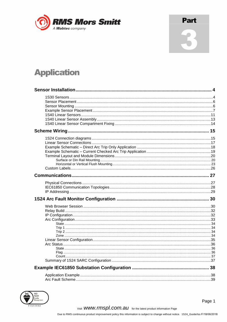
Application
1S30 Sensors ........................................................................................................................................ 4 Sensor Placement ................................................................................................................................. 6 Sensor Mounting ................................................................................................................................... 6 Example Sensor Placement .................................................................................................................. 7 1S40 Linear Sensors ........................................................................................................................... 11 1S40 Linear Sensor Assembly ............................................................................................................ 13 1S40 Linear Sensor Compartment Fixing ........................................................................................... 14
1S24 Connection diagrams ................................................................................................................. 15 Linear Sensor Connections ................................................................................................................. 17 Example Schematic – Direct Arc Trip Only Application ...................................................................... 18 Example Schematic – Current Checked Arc Trip Application ............................................................. 19 Terminal Layout and Module Dimensions ........................................................................................... 20
Surface or Din Rail Mounting ................................................................................................................... 20 Horizontal or Vertical Flush Mounting ...................................................................................................... 23
Custom Labels..................................................................................................................................... 26
Physical Connections .......................................................................................................................... 27 IEC61850 Communication Topologies ................................................................................................ 28 IP Addressing ...................................................................................................................................... 29
Web Browser Session ......................................................................................................................... 30 Relay Build .......................................................................................................................................... 32 IP Configuration ................................................................................................................................... 32 Arc Configuration ................................................................................................................................. 33
State ........................................................................................................................................................ 34 Trip 1 ....................................................................................................................................................... 34 Trip 2 ....................................................................................................................................................... 34 Zone ........................................................................................................................................................ 34
Linear Sensor Configuration ................................................................................................................ 35 Arc Status ............................................................................................................................................ 36
State ........................................................................................................................................................ 36 Flag ......................................................................................................................................................... 36 Count ....................................................................................................................................................... 37
Summary of 1S24 SARC Configuration .............................................................................................. 37
Application Example ............................................................................................................................ 38 Arc Fault Scheme ................................................................................................................................ 39
Part
3
Sensor Installation .......................................................................................................... 4
Scheme Wiring .............................................................................................................. 15
Communications ........................................................................................................... 27
1S24 Arc Fault Monitor Configuration ........................................................................ 30
Example IEC61850 Substation Configuration ............................................................ 38

Page 2
Visit www.rmspl.com.au for the latest product information Page
Due to RMS continuous product improvement policy this information is subject to change without notice. 1S24_Guide/Iss F/18/06/2018
1S24 SARC Allocation ........................................................................................................................ 41 Protection Zone Tripping ..................................................................................................................... 41 1S24 Source Arc Fault Detector Points .............................................................................................. 42 7SR22 Single Point Input GGIO Allocation ......................................................................................... 42 Creating an IEC61850 Project ............................................................................................................. 42 Populating IEDs In the IEC 61850 Project .......................................................................................... 45 System Configuration – Network View ................................................................................................ 51 System Configuration – Link View....................................................................................................... 54 Creating the 1S24 .cid File .................................................................................................................. 58
The .cid File ......................................................................................................................................... 59 FTP 1S24.cid File ................................................................................................................................ 59 Rebooting the 1S24 with the New 1S24.cid File ................................................................................. 61
Logic Configuration ............................................................................................................................. 65 User Output Allocation ........................................................................................................................ 65 Current Check Logic ............................................................................................................................ 66 Binary Output Allocation for Circuit Breaker Tripping.......................................................................... 67 Device Synchronization ....................................................................................................................... 67
Front Layout ........................................................................................................................................ 68 Power Up ............................................................................................................................................. 68 System Status ..................................................................................................................................... 69 Service Alarm ...................................................................................................................................... 69 Arc Sensor Indicators .......................................................................................................................... 70 Arc Sensor Circuit Supervision ............................................................................................................ 70 Arc Trip ................................................................................................................................................ 70 Global Arc Block .................................................................................................................................. 70 Flag Reset ........................................................................................................................................... 71 Reboot ................................................................................................................................................. 71 Reset to Factory Default ...................................................................................................................... 72
Introduction .......................................................................................................................................... 73 Firmware Package .............................................................................................................................. 73
License file not valid or present ........................................................................................................... 75 Invalid IP Address Specified in ICD File .............................................................................................. 77 System Status ..................................................................................................................................... 78
Commissioning Preliminaries .............................................................................................................. 79 Site Commissioning Verification Checklist .......................................................................................... 80
System Power Up .................................................................................................................................... 80 Sensor Failure Alarm Verification ............................................................................................................ 81 Arc Trip Testing ....................................................................................................................................... 81 Sensor Failure Alarm Trouble Shooting ................................................................................................... 82 ARC Trip Trouble Shooting...................................................................................................................... 83
1S24 IEC61850 Configuration ...................................................................................... 59
Subscribing Reyrolle 7SR22 IED Configuration ......................................................... 65
Monitor Indications ....................................................................................................... 68
Firmware Update ........................................................................................................... 73
Trouble Shooting .......................................................................................................... 75
Commissioning ............................................................................................................. 79

Page 3
Visit www.rmspl.com.au for the latest product information Page
Due to RMS continuous product improvement policy this information is subject to change without notice. 1S24_Guide/Iss F/18/06/2018
General Ethernet Communications Trouble Shooting ............................................................................. 83 IEC61850 GOOSE Message Trouble Shooting ....................................................................................... 84 Interpreting Vx Auxiliary Supply or Relay Healthy Indications ................................................................. 84 Using IED SCOUT IEC61850 GOOSE Message Trouble Shooting ........................................................ 86

Page 4
Visit www.rmspl.com.au for the latest product information Page
Due to RMS continuous product improvement policy this information is subject to change without notice. 1S24_Guide/Iss F/18/06/2018
Sensor Installation
1S30 Sensors
The 1S30 sensor is available as a single detector or dual detector package.
The 1S30A single detector version is depicted below showing the location of the detection window and the approximate coverage zone:
The recommended spacing for the 1S30A single detectors is approximately 5 - 6 m to ensure adequate detection overlap.
3m
Detection window
Coverage Zone
5 - 6 m

Page 5
Visit www.rmspl.com.au for the latest product information Page
Due to RMS continuous product improvement policy this information is subject to change without notice. 1S24_Guide/Iss F/18/06/2018
The 1S30B Dual detector version provides an additional detection window for dual zones of coverage as depicted below :
The recommended spacing for the 1S30B single detectors is approximately 5 - 6 m to ensure adequate detection overlap, this combination provides an overall coverage zone of approximately 10 - 12 m.
Detection windows 6m
10 - 12m
Page 6
Visit www.rmspl.com.au for the latest product information Page
Due to RMS continuous product improvement policy this information is subject to change without notice. 1S24_Guide/Iss F/18/06/2018
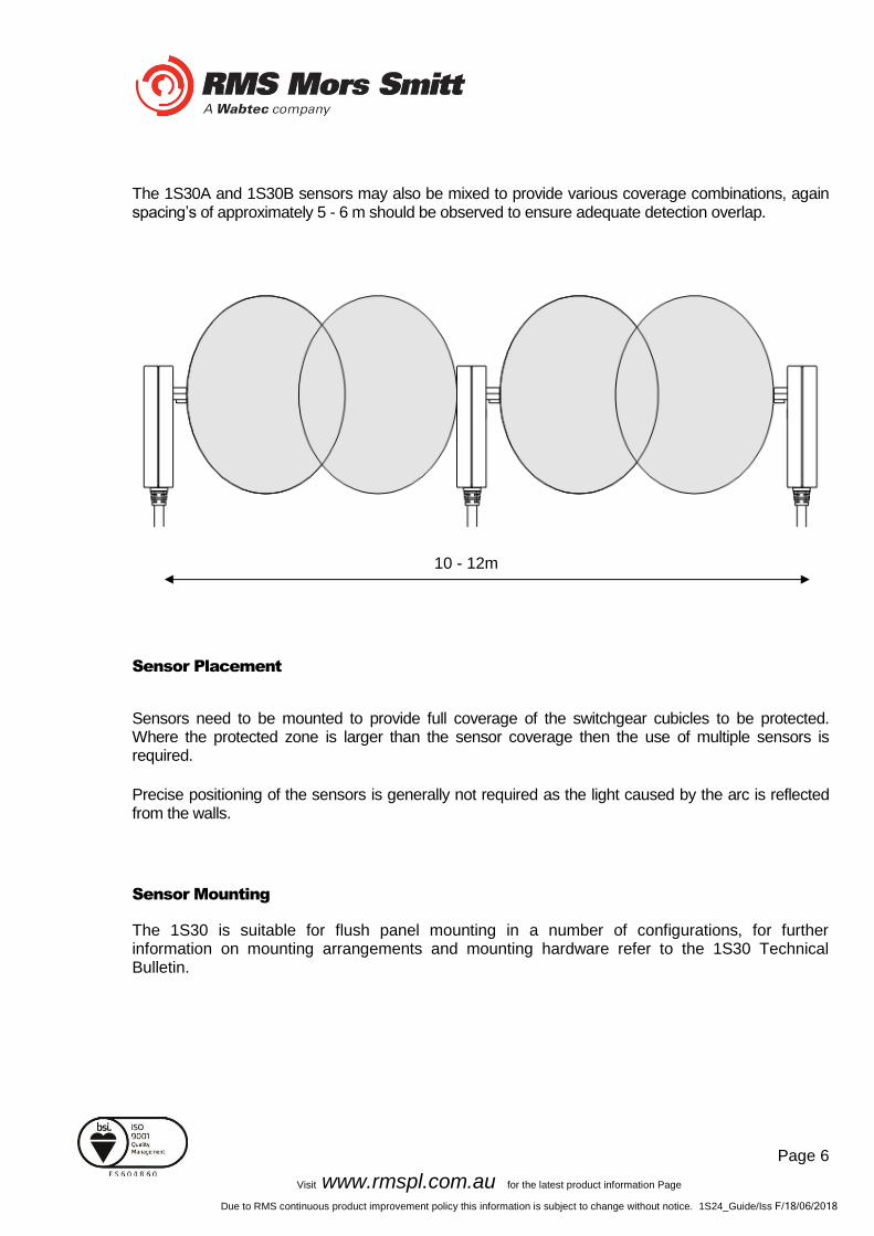
The 1S30A and 1S30B sensors may also be mixed to provide various coverage combinations, again spacing’s of approximately 5 - 6 m should be observed to ensure adequate detection overlap.
Sensor Placement
Sensors need to be mounted to provide full coverage of the switchgear cubicles to be protected. Where the protected zone is larger than the sensor coverage then the use of multiple sensors is required.
Precise positioning of the sensors is generally not required as the light caused by the arc is reflected from the walls.
Sensor Mounting
The 1S30 is suitable for flush panel mounting in a number of configurations, for further information on mounting arrangements and mounting hardware refer to the 1S30 Technical Bulletin.
10 - 12m

Page 7
Visit www.rmspl.com.au for the latest product information Page
Due to RMS continuous product improvement policy this information is subject to change without notice. 1S24_Guide/Iss F/18/06/2018
Example Sensor Placement
The following are some typical examples of sensor placement.
Sensor placement inside CB racking chamber
Sensor placement inside busbar chamber
Page 8
Visit www.rmspl.com.au for the latest product information Page
Due to RMS continuous product improvement policy this information is subject to change without notice. 1S24_Guide/Iss F/18/06/2018
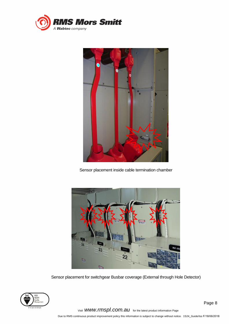
Sensor placement inside cable termination chamber
Sensor placement for switchgear Busbar coverage (External through Hole Detector)
Page 9
Visit www.rmspl.com.au for the latest product information Page
Due to RMS continuous product improvement policy this information is subject to change without notice. 1S24_Guide/Iss F/18/06/2018
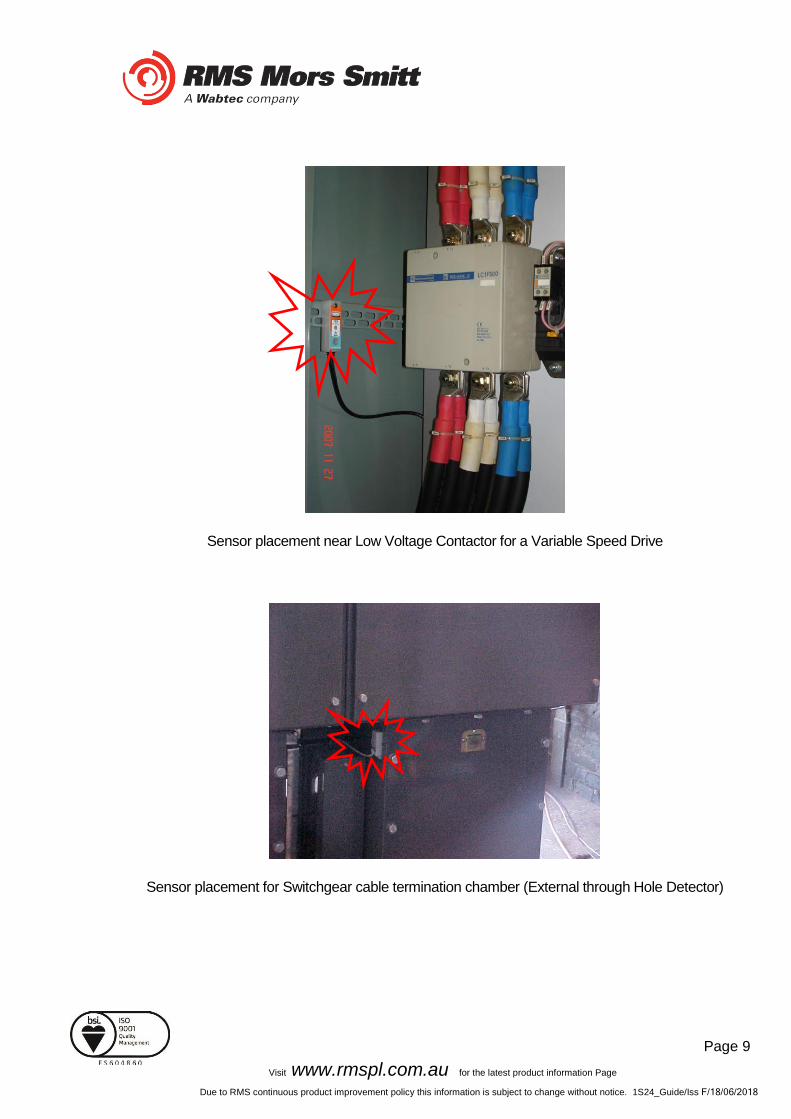
Sensor placement near Low Voltage Contactor for a Variable Speed Drive
Sensor placement for Switchgear cable termination chamber (External through Hole Detector)

Page 10
Visit www.rmspl.com.au for the latest product information Page
Due to RMS continuous product improvement policy this information is subject to change without notice. 1S24_Guide/Iss F/18/06/2018
Sensor placement for end of Bus chamber (External through Hole Detector)
Sensor placement for Switchgear cable termination chamber (External through Hole Detector)

Page 11
Visit www.rmspl.com.au for the latest product information Page
Due to RMS continuous product improvement policy this information is subject to change without notice. 1S24_Guide/Iss F/18/06/2018
1S40 Linear Sensors
The 1S40 linear sensor may be applied to protect large volumes where multiple point sensors would otherwise be required.
A separate 1S40 linear sensor is required for each segregated protection zone.
The linear sensor kits provide both a black link fibre and a translucent arc sensor fibre. The translucent fibre is located within the detection zone and black link fibres allow routing of the linear sensor back to the relay.
Translucent and black link fibres are joined through the use of optical fibre couplers. An optical fibre duplex connector is utilised for relay connection
For the most effective coverage it is preferable to loop the translucent fibre within the monitored compartment or chamber as shown in the diagrams above. A light intensity of >7,500 Lux over a length of 300mm is required to cause an arc trip.
Un-monitored CompartmentMonitored Compartment
Arc Fault Relay
Fibre Sen
sor
inp
uts
Black Link Fibre
Translucent Sensor Fibre
Optical fibre couplers
Optical fibre duplex
connector

Page 12
Visit www.rmspl.com.au for the latest product information Page
Due to RMS continuous product improvement policy this information is subject to change without notice. 1S24_Guide/Iss F/18/06/2018
The 1S40 kit comprises of lengths of black link fibre (pre-terminated with a duplex connector for relay connection), unterminated translucent fibre, 2 x optical fibre couplers and a fibre optic fibre cutter.
Black Link Fibre Assembly Translucent Sensor Fibre
Optic Fibre Couplers Optic Fibre Cutter
The individual components are combined per the diagram below :
Page 13
Visit www.rmspl.com.au for the latest product information Page
Due to RMS continuous product improvement policy this information is subject to change without notice. 1S24_Guide/Iss F/18/06/2018
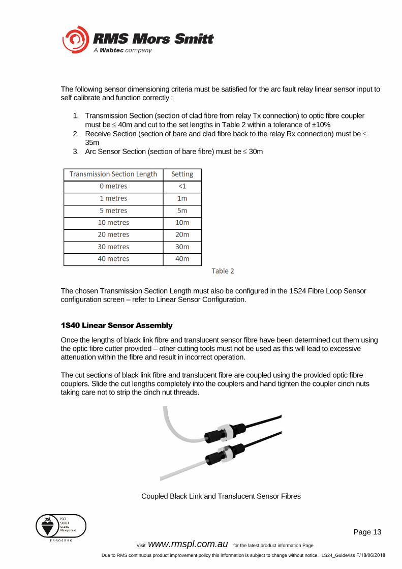
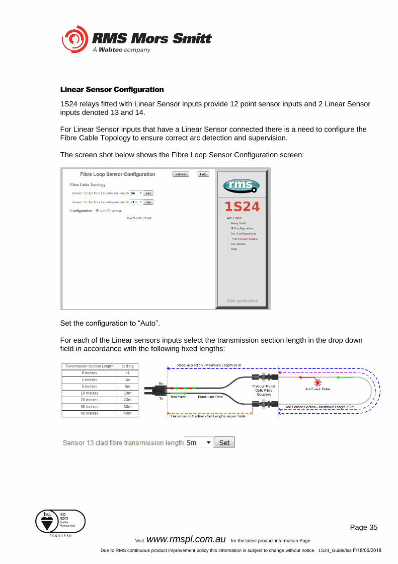
The following sensor dimensioning criteria must be satisfied for the arc fault relay linear sensor input to self calibrate and function correctly :
1. Transmission Section (section of clad fibre from relay Tx connection) to optic fibre coupler
must be 40m and cut to the set lengths in Table 2 within a tolerance of ±10%
2. Receive Section (section of bare and clad fibre back to the relay Rx connection) must be 35m
3. Arc Sensor Section (section of bare fibre) must be 30m
The chosen Transmission Section Length must also be configured in the 1S24 Fibre Loop Sensor configuration screen – refer to Linear Sensor Configuration.
1S40 Linear Sensor Assembly
Once the lengths of black link fibre and translucent sensor fibre have been determined cut them using the optic fibre cutter provided – other cutting tools must not be used as this will lead to excessive attenuation within the fibre and result in incorrect operation.
The cut sections of black link fibre and translucent fibre are coupled using the provided optic fibre couplers. Slide the cut lengths completely into the couplers and hand tighten the coupler cinch nuts taking care not to strip the cinch nut threads.
Coupled Black Link and Translucent Sensor Fibres

Page 14
Visit www.rmspl.com.au for the latest product information Page
Due to RMS continuous product improvement policy this information is subject to change without notice. 1S24_Guide/Iss F/18/06/2018
1S40 Linear Sensor Compartment Fixing
The optic fibre couplers may be positioned and held in place with the provided fixing nuts at a compartment interface.
The optic fibres may be retained using cable ties or silicon adhesive. When using silicon adhesive no more than 10% of the sensor fibre shall be masked by the silicon.
Care should be taken not to apply excessive force when fixing the 1S40 sensor. Excessive force or rough handling may result in damage to the fibre sensor.
Care should also be taken when bending the 1S40 sensor to ensure that the minimum bending radius of 50mm is adhered to.
Page 15
Visit www.rmspl.com.au for the latest product information Page
Due to RMS continuous product improvement policy this information is subject to change without notice. 1S24_Guide/Iss F/18/06/2018
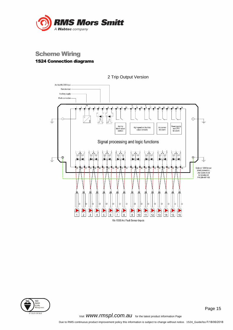
Scheme Wiring
1S24 Connection diagrams
2 Trip Output Version

Page 16
Visit www.rmspl.com.au for the latest product information Page
Due to RMS continuous product improvement policy this information is subject to change without notice. 1S24_Guide/Iss F/18/06/2018
3 Trip Output Version
The above diagrams show the 1S24 connections.
The connected sensor inputs need to be enabled and unused inputs disabled via the Web browser configuration tool. This is essential to:
• Allow connected sensor inputs to operate for an ARC Fault
• Allow connected sensor inputs to be supervised
• Ensure unconnected sensor inputs do not indicate an Arc sensor Alarm condition

Page 17
Visit www.rmspl.com.au for the latest product information Page
Due to RMS continuous product improvement policy this information is subject to change without notice. 1S24_Guide/Iss F/18/06/2018
Linear Sensor Connections
A unit with 1S24 Linear sensor connections is pictured below showing the connection points for the Linear sensors:
Linear Sensor equipped units provide inputs for 2 Linear sensors and 12 point sensors. Each Linear Sensor input provides a Transmit (TX) and Receive (RX) set of connections. For details of the Linear Sensor refer to the 1S40 Technical Bulletin.
Page 18
Visit www.rmspl.com.au for the latest product information Page
Due to RMS continuous product improvement policy this information is subject to change without notice. 1S24_Guide/Iss F/18/06/2018
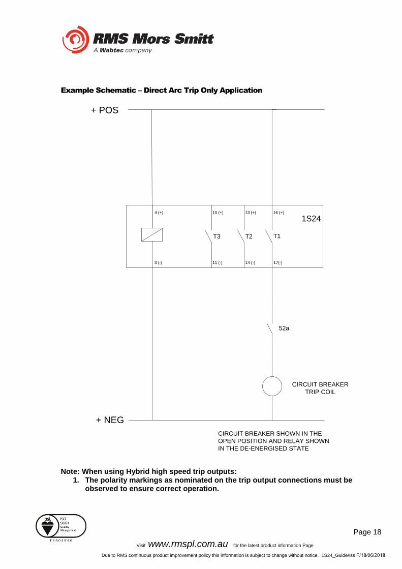
Example Schematic – Direct Arc Trip Only Application
Note: When using Hybrid high speed trip outputs: 1. The polarity markings as nominated on the trip output connections must be
observed to ensure correct operation.
CIRCUIT BREAKER
TRIP COIL
+ POS
1S24
CIRCUIT BREAKER SHOWN IN THE
OPEN POSITION AND RELAY SHOWN
IN THE DE-ENERGISED STATE
52a
3 (-) 11 (-) 14 (-) 17(-)
4 (+) 10 (+) 13 (+) 16 (+)
+ NEG
T1T2T3

Page 19
Visit www.rmspl.com.au for the latest product information Page
Due to RMS continuous product improvement policy this information is subject to change without notice. 1S24_Guide/Iss F/18/06/2018
Example Schematic – Current Checked Arc Trip Application
Note: When using Hybrid high speed trip outputs: 1. The polarity markings as nominated on the trip output connections must be
observed to ensure correct operation.
CIRCUIT BREAKER
TRIP COIL
+ POS
1S24
CIRCUIT BREAKER SHOWN IN THE
OPEN POSITION AND RELAY SHOWN
IN THE DE-ENERGISED STATE
52a
3 (-) 11 (-) 14 (-) 17(-)
4 (+) 10 (+) 13 (+) 16 (+)
+ NEG
T1T2T3
Current Check
RelayI>>
Page 20
Visit www.rmspl.com.au for the latest product information Page
Due to RMS continuous product improvement policy this information is subject to change without notice. 1S24_Guide/Iss F/18/06/2018
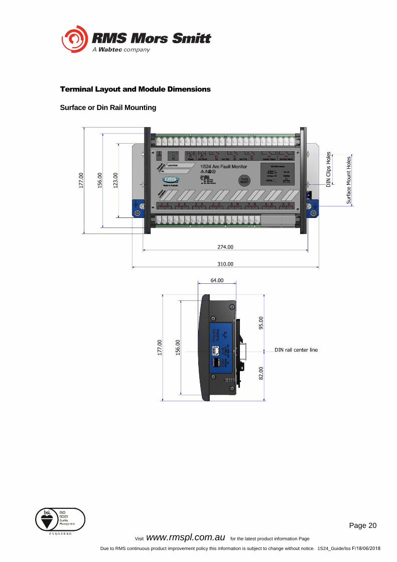
Terminal Layout and Module Dimensions
Surface or Din Rail Mounting
Page 21
Visit www.rmspl.com.au for the latest product information Page
Due to RMS continuous product improvement policy this information is subject to change without notice. 1S24_Guide/Iss F/18/06/2018
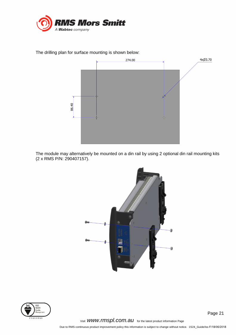
The drilling plan for surface mounting is shown below:
The module may alternatively be mounted on a din rail by using 2 optional din rail mounting kits (2 x RMS P/N: 290407157).

Page 22
Visit www.rmspl.com.au for the latest product information Page
Due to RMS continuous product improvement policy this information is subject to change without notice. 1S24_Guide/Iss F/18/06/2018
The recommended keep out zones to allow for cable terminations are shown below:

Page 23
Visit www.rmspl.com.au for the latest product information Page
Due to RMS continuous product improvement policy this information is subject to change without notice. 1S24_Guide/Iss F/18/06/2018
Horizontal or Vertical Flush Mounting The Horizontal or Vertical module options allow for rack frame or flush panel mounting.
Page 24
Visit www.rmspl.com.au for the latest product information Page
Due to RMS continuous product improvement policy this information is subject to change without notice. 1S24_Guide/Iss F/18/06/2018
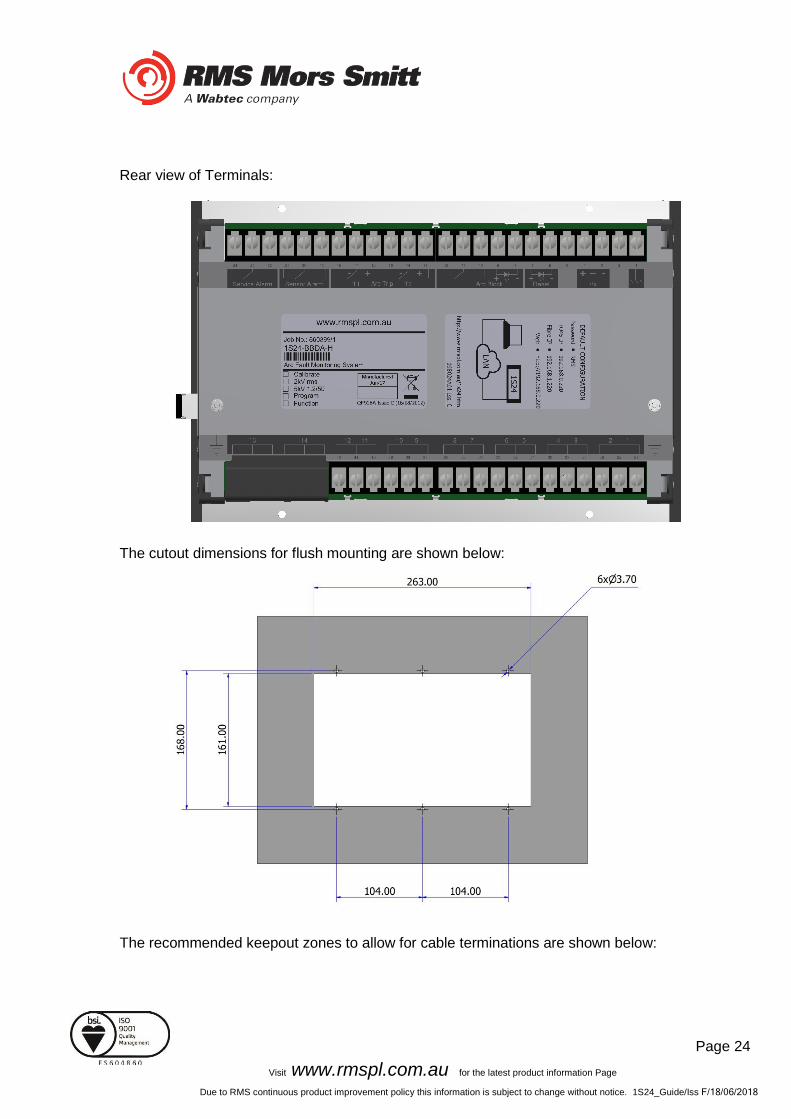
Rear view of Terminals:
The cutout dimensions for flush mounting are shown below:
The recommended keepout zones to allow for cable terminations are shown below:

Page 25
Visit www.rmspl.com.au for the latest product information Page
Due to RMS continuous product improvement policy this information is subject to change without notice. 1S24_Guide/Iss F/18/06/2018

Page 26
Visit www.rmspl.com.au for the latest product information Page
Due to RMS continuous product improvement policy this information is subject to change without notice. 1S24_Guide/Iss F/18/06/2018
Custom Labels
The 1S24 front panel makes provision for two (2) custom labels, one label identifies the sensor location and the remaining label provides IED identification and IP address details.
The default labels supplied with the relay may be marked up by hand or alternatively custom labels may be produced using the template provided on the RMS website, printed and slipped behind the clear windows on the front panel as depicted below.
Page 27
Visit www.rmspl.com.au for the latest product information Page
Due to RMS continuous product improvement policy this information is subject to change without notice. 1S24_Guide/Iss F/18/06/2018
Communications
Physical Connections
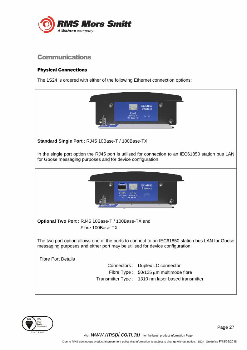
The 1S24 is ordered with either of the following Ethernet connection options:
Standard Single Port : RJ45 10Base-T / 100Base-TX
In the single port option the RJ45 port is utilised for connection to an IEC61850 station bus LAN for Goose messaging purposes and for device configuration.
Optional Two Port : RJ45 10Base-T / 100Base-TX and
Fibre 100Base-TX
The two port option allows one of the ports to connect to an IEC61850 station bus LAN for Goose messaging purposes and either port may be utilised for device configuration.
Fibre Port Details
Connectors : Duplex LC connector
Fibre Type : 50/125 m multimode fibre
Transmitter Type : 1310 nm laser based transmitter

Page 28
Visit www.rmspl.com.au for the latest product information Page
Due to RMS continuous product improvement policy this information is subject to change without notice. 1S24_Guide/Iss F/18/06/2018
IEC61850 Communication Topologies
The 1S24 IED employs IEC61850 Goose messaging to convey the operation of ARC Fault Sensors and may be used with one or many subscribing IEDs to deploy ARC Fault protection schemes.
A 1S24 or many 1S24 Arc Fault Monitors may be connected to a Station Bus Lan as shown below:
IEC61850 Station Bus Lan
1S241
1S24n
IEDn
IED1
The Station Bus Lan may be arranged using many different topologies, discussion of the various LAN topologies is beyond the scope of this user guide.

Page 29
Visit www.rmspl.com.au for the latest product information Page
Due to RMS continuous product improvement policy this information is subject to change without notice. 1S24_Guide/Iss F/18/06/2018
IP Addressing
The 1S24 IED comes preconfigured from the factory with the IP address 192.168.0.220. The default IP address may be used in a web browser session to undertake relay configuration. Full details of relay configuration are described in subsequent sections of the user guide.
Reconfiguration of the 1S24 IP address may be required according to the IP addressing defined in the IEC61850 substation configuration, any subsequent web browser sessions will need to utilise the reconfigured IP address.
Page 30
Visit www.rmspl.com.au for the latest product information Page
Due to RMS continuous product improvement policy this information is subject to change without notice. 1S24_Guide/Iss F/18/06/2018
1S24 Arc Fault Monitor Configuration
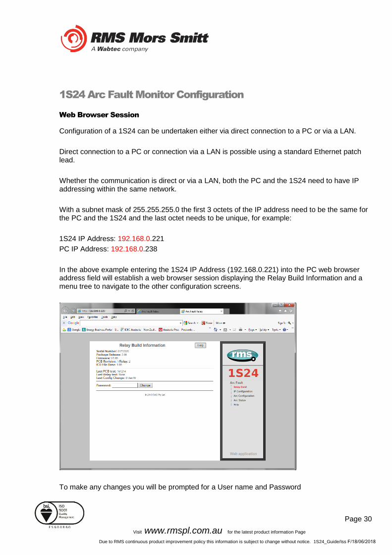
Web Browser Session
Configuration of a 1S24 can be undertaken either via direct connection to a PC or via a LAN.
Direct connection to a PC or connection via a LAN is possible using a standard Ethernet patch lead.
Whether the communication is direct or via a LAN, both the PC and the 1S24 need to have IP addressing within the same network.
With a subnet mask of 255.255.255.0 the first 3 octets of the IP address need to be the same for the PC and the 1S24 and the last octet needs to be unique, for example:
1S24 IP Address: 192.168.0.221
PC IP Address: 192.168.0.238
In the above example entering the 1S24 IP Address (192.168.0.221) into the PC web browser address field will establish a web browser session displaying the Relay Build Information and a menu tree to navigate to the other configuration screens.
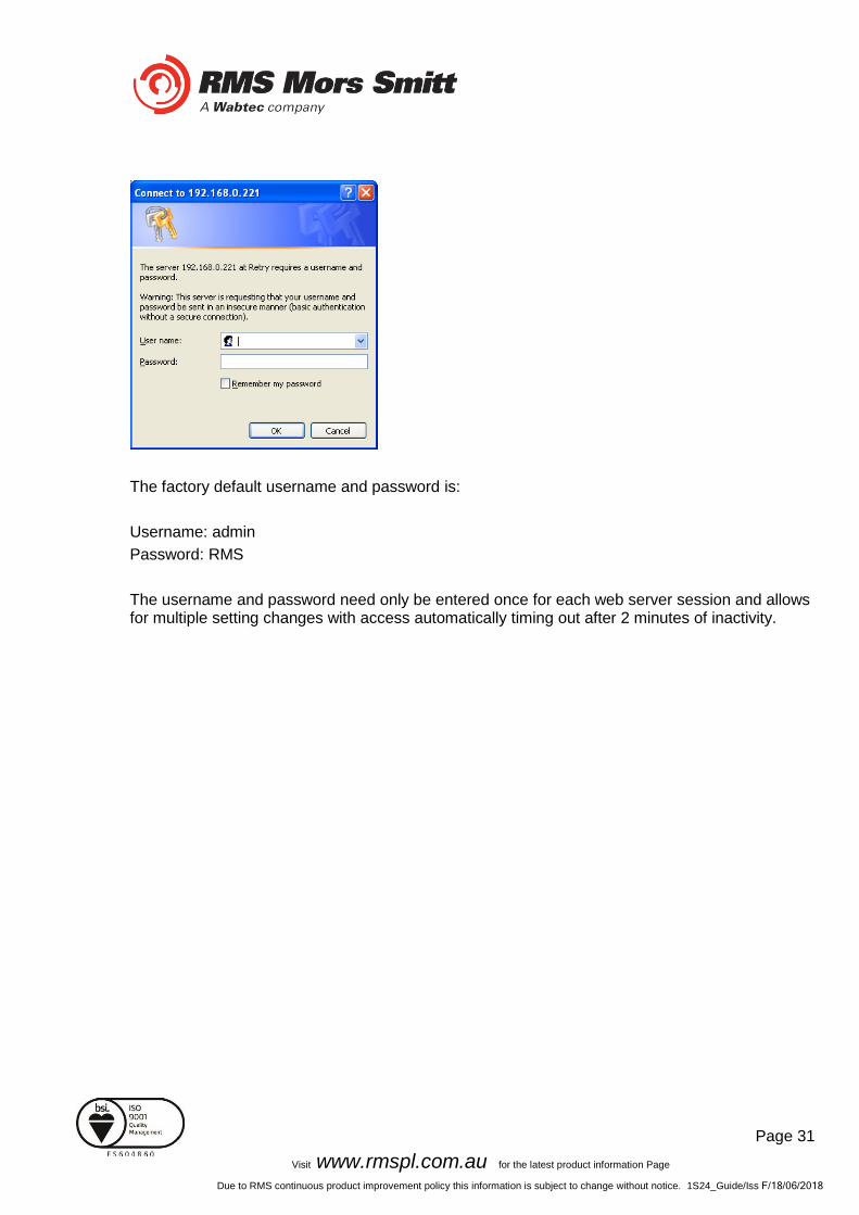
To make any changes you will be prompted for a User name and Password
Page 31
Visit www.rmspl.com.au for the latest product information Page
Due to RMS continuous product improvement policy this information is subject to change without notice. 1S24_Guide/Iss F/18/06/2018
The factory default username and password is:
Username: admin
Password: RMS
The username and password need only be entered once for each web server session and allows for multiple setting changes with access automatically timing out after 2 minutes of inactivity.
Page 32
Visit www.rmspl.com.au for the latest product information Page
Due to RMS continuous product improvement policy this information is subject to change without notice. 1S24_Guide/Iss F/18/06/2018
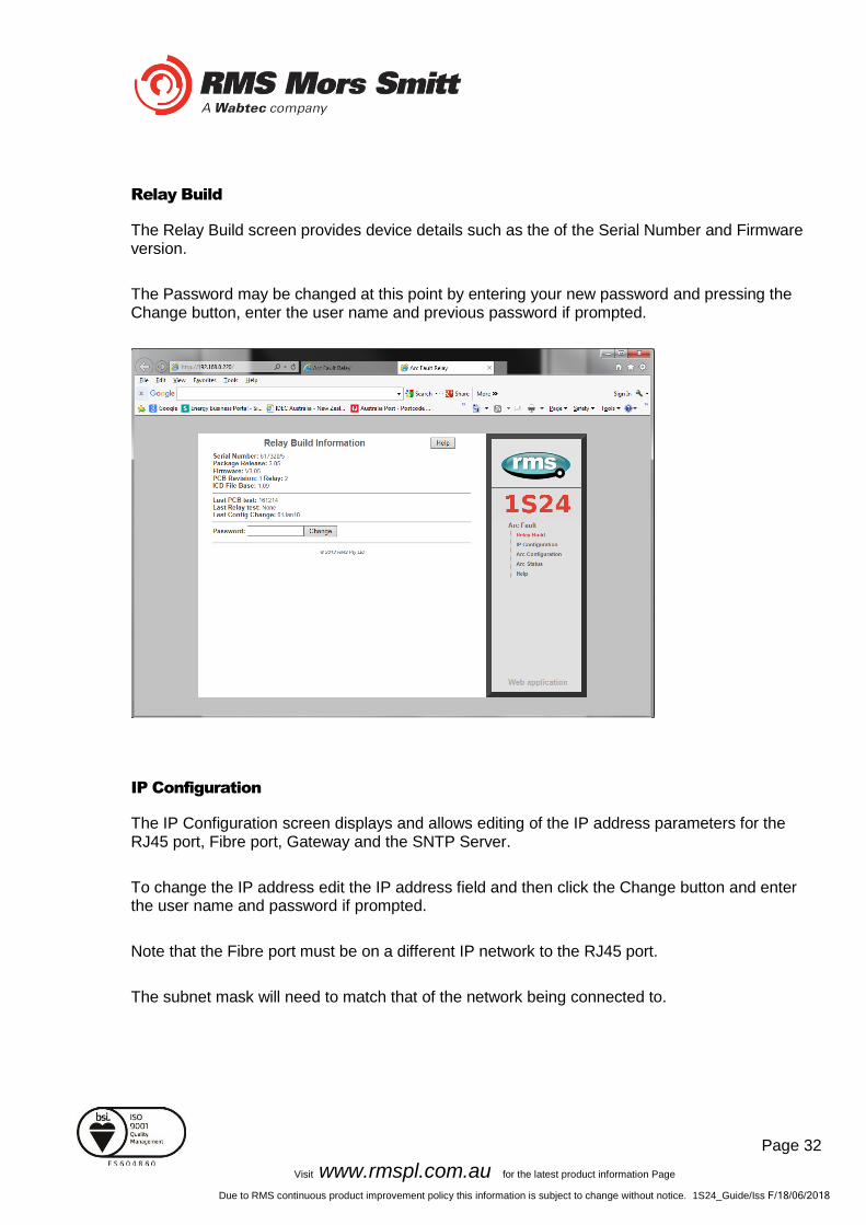
Relay Build
The Relay Build screen provides device details such as the of the Serial Number and Firmware version.
The Password may be changed at this point by entering your new password and pressing the Change button, enter the user name and previous password if prompted.
IP Configuration
The IP Configuration screen displays and allows editing of the IP address parameters for the RJ45 port, Fibre port, Gateway and the SNTP Server.
To change the IP address edit the IP address field and then click the Change button and enter the user name and password if prompted.
Note that the Fibre port must be on a different IP network to the RJ45 port.
The subnet mask will need to match that of the network being connected to.
Page 33
Visit www.rmspl.com.au for the latest product information Page
Due to RMS continuous product improvement policy this information is subject to change without notice. 1S24_Guide/Iss F/18/06/2018
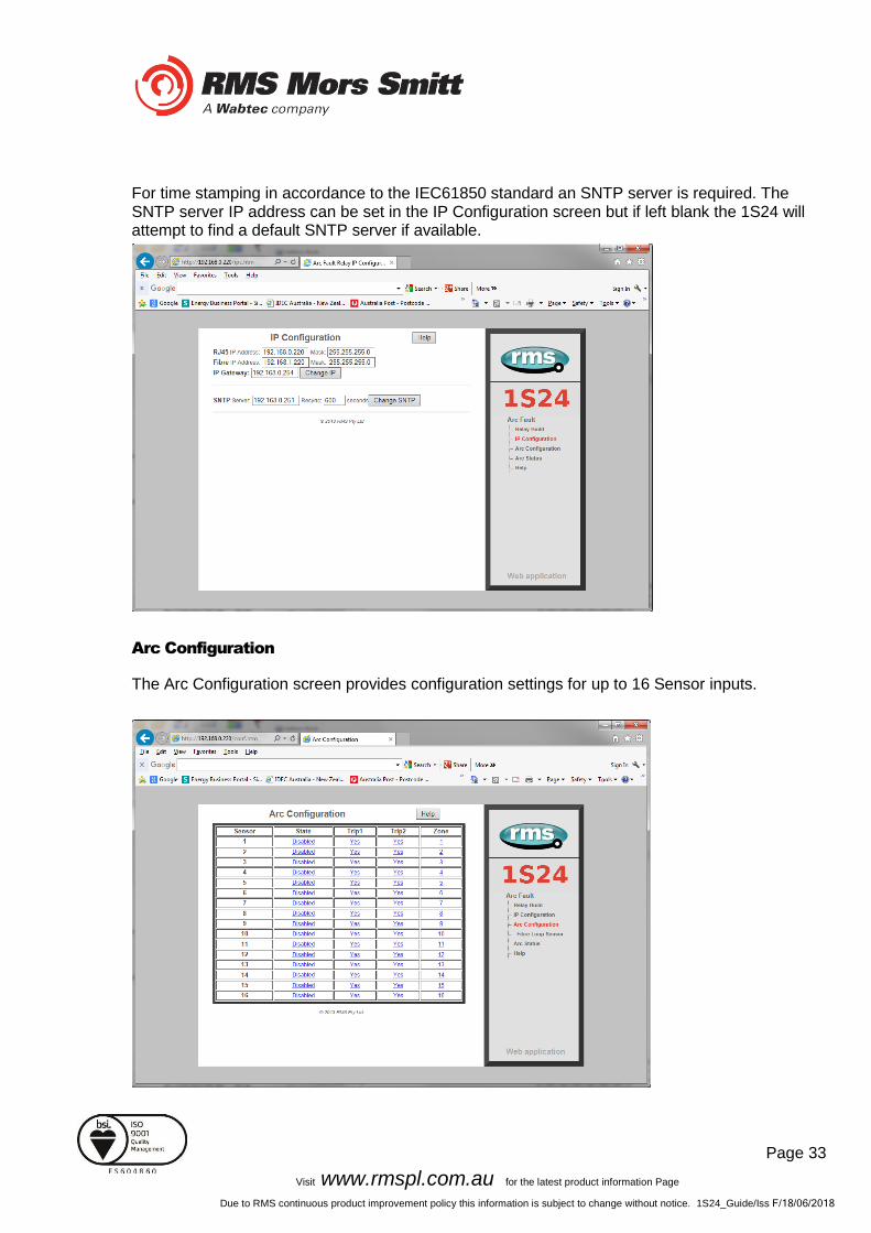
For time stamping in accordance to the IEC61850 standard an SNTP server is required. The SNTP server IP address can be set in the IP Configuration screen but if left blank the 1S24 will attempt to find a default SNTP server if available.
Arc Configuration
The Arc Configuration screen provides configuration settings for up to 16 Sensor inputs.

Page 34
Visit www.rmspl.com.au for the latest product information Page
Due to RMS continuous product improvement policy this information is subject to change without notice. 1S24_Guide/Iss F/18/06/2018
Each sensor input has 4 settable parameters:
State
Armed or disabled, defines if the Sensor input is enabled or disabled, click on the field to change the state and enter the user name and password if prompted.
Trip 1
Yes or No, determines if the Sensor input operates the Trip 1 output, click on the field to change the state and enter the user name and password if prompted.
Trip 2
Yes or No, determines if the Sensor input operates the Trip 2 output, click on the field to change the state and enter the user name and password if prompted.
Zone
The Zone Setting provides a means of improving Goose response time for simultaneous trips in a single Arc Fault tripping zone. The Zone setting ensures that a Goose is immediately broadcast without having to wait for the updating of all arc detectors in the same corresponding zone. Allowable Zone values are from 1 to 16. Set the Zone value the same for sensors located in the same zone. Click on the field to alter the Zone value.
Page 35
Visit www.rmspl.com.au for the latest product information Page
Due to RMS continuous product improvement policy this information is subject to change without notice. 1S24_Guide/Iss F/18/06/2018
Linear Sensor Configuration
1S24 relays fitted with Linear Sensor inputs provide 12 point sensor inputs and 2 Linear Sensor inputs denoted 13 and 14. For Linear Sensor inputs that have a Linear Sensor connected there is a need to configure the Fibre Cable Topology to ensure correct arc detection and supervision. The screen shot below shows the Fibre Loop Sensor Configuration screen:
Set the configuration to “Auto”. For each of the Linear sensors inputs select the transmission section length in the drop down field in accordance with the following fixed lengths:
Page 36
Visit www.rmspl.com.au for the latest product information Page
Due to RMS continuous product improvement policy this information is subject to change without notice. 1S24_Guide/Iss F/18/06/2018
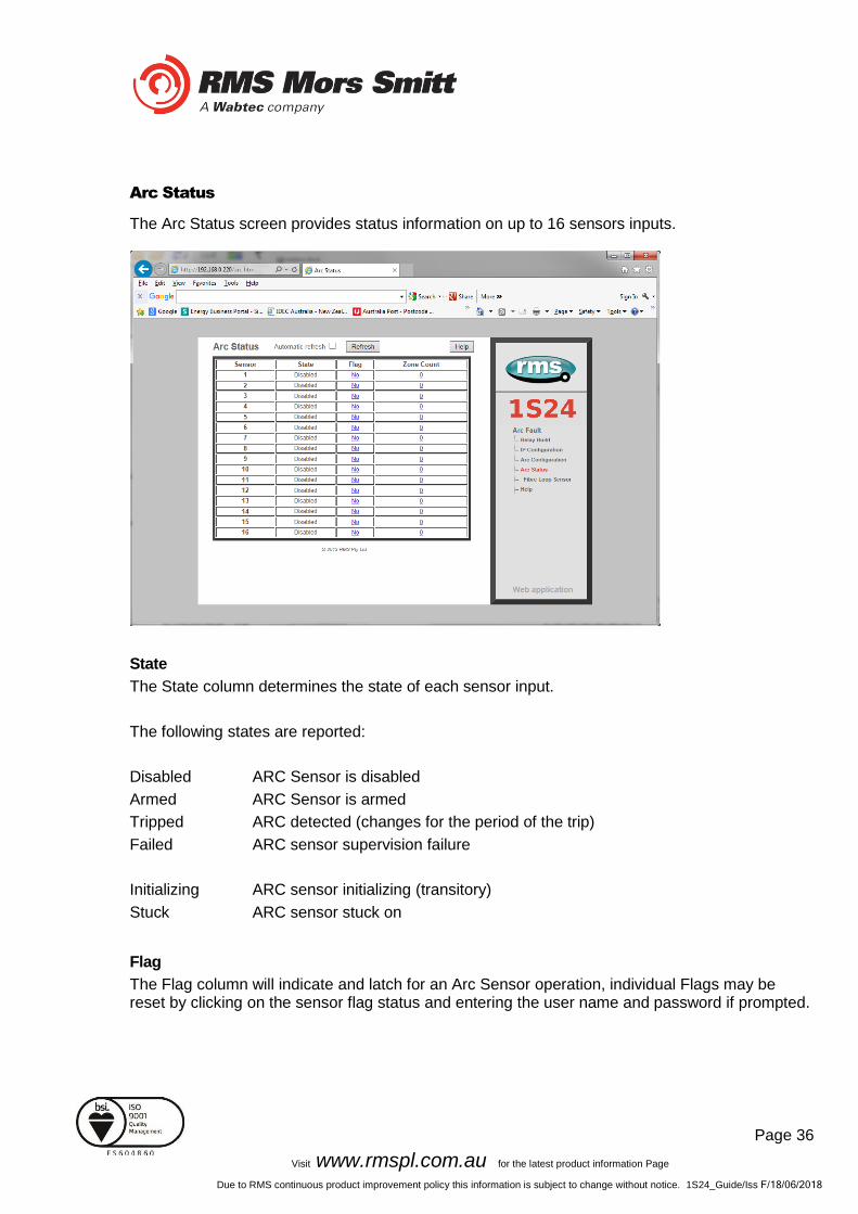
Arc Status
The Arc Status screen provides status information on up to 16 sensors inputs.
State
The State column determines the state of each sensor input.
The following states are reported:
Disabled ARC Sensor is disabled
Armed ARC Sensor is armed
Tripped ARC detected (changes for the period of the trip)
Failed ARC sensor supervision failure
Initializing ARC sensor initializing (transitory)
Stuck ARC sensor stuck on
Flag
The Flag column will indicate and latch for an Arc Sensor operation, individual Flags may be reset by clicking on the sensor flag status and entering the user name and password if prompted.
Page 37
Visit www.rmspl.com.au for the latest product information Page
Due to RMS continuous product improvement policy this information is subject to change without notice. 1S24_Guide/Iss F/18/06/2018
Count
The Count field provides a log of ARC sensor operations since power on or the last counter reset, the individual sensor counters may be reset to 0 by clicking on the count field and entering the user name and password if prompted.
Summary of 1S24 SARC Configuration
The following steps outline the 1S24 SARC Configuration:
✓ Establish a Web Browser session using the default IP address ✓ Set up the IP addressing for the SNTP server ✓ Arm the ARC Sensor inputs to be utilised in the application ✓ Set which outputs are to be operated by the respective ARC sensors
For installations not utilising IEC61850 Goose messaging that completes the configuration process.
For installations utilising IEC61850 follow the IEC61850 Substation Configuration process in the following sections.
Page 38
Visit www.rmspl.com.au for the latest product information Page
Due to RMS continuous product improvement policy this information is subject to change without notice. 1S24_Guide/Iss F/18/06/2018
Example IEC61850 Substation Configuration
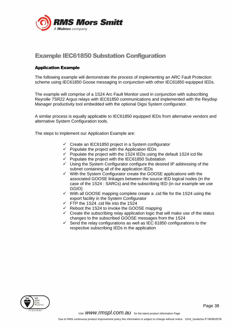
Application Example
The following example will demonstrate the process of implementing an ARC Fault Protection scheme using IEC61850 Goose messaging in conjunction with other IEC61850 equipped IEDs.
The example will comprise of a 1S24 Arc Fault Monitor used in conjunction with subscribing Reyrolle 7SR22 Argus relays with IEC61850 communications and implemented with the Reydisp Manager productivity tool embedded with the optional Digsi System configurator.
A similar process is equally applicable to IEC61850 equipped IEDs from alternative vendors and alternative System Configuration tools.
The steps to implement our Application Example are:
✓ Create an IEC61850 project in a System configurator ✓ Populate the project with the Application IEDs ✓ Populate the project with the 1S24 IEDs using the default 1S24 icd file ✓ Populate the project with the IEC61850 Substation ✓ Using the System Configurator configure the desired IP addressing of the
subnet containing all of the application IEDs ✓ With the System Configurator create the GOOSE applications with the
associated GOOSE linkages between the source IED logical nodes (in the case of the 1S24 : SARCs) and the subscribing IED (in our example we use GGIO)
✓ With all GOOSE mapping complete create a .cid file for the 1S24 using the export facility in the System Configurator
✓ FTP the 1S24 .cid file into the 1S24 ✓ Reboot the 1S24 to invoke the GOOSE mapping ✓ Create the subscribing relay application logic that will make use of the status
changes to the subscribed GOOSE messages from the 1S24 ✓ Send the relay configurations as well as IEC 61850 configurations to the
respective subscribing IEDs in the application
Page 39
Visit www.rmspl.com.au for the latest product information Page
Due to RMS continuous product improvement policy this information is subject to change without notice. 1S24_Guide/Iss F/18/06/2018
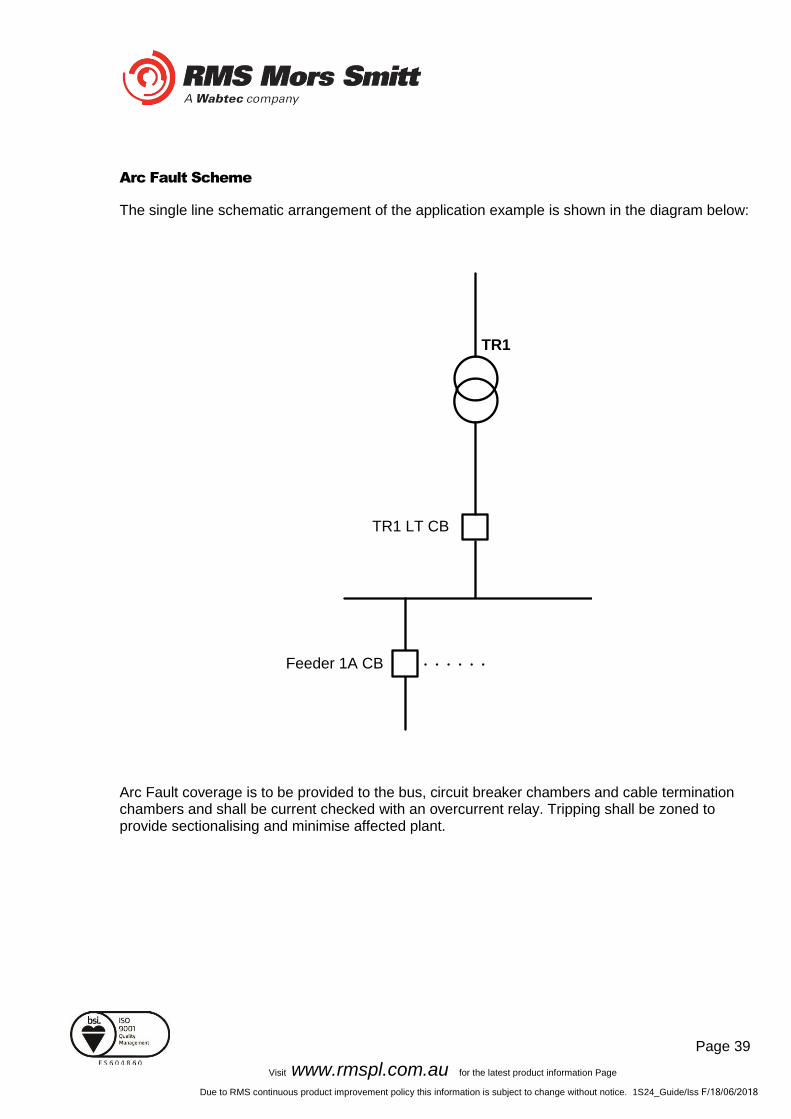
Arc Fault Scheme
The single line schematic arrangement of the application example is shown in the diagram below:
TR1
TR1 LT CB
Feeder 1A CB
Arc Fault coverage is to be provided to the bus, circuit breaker chambers and cable termination chambers and shall be current checked with an overcurrent relay. Tripping shall be zoned to provide sectionalising and minimise affected plant.

Page 40
Visit www.rmspl.com.au for the latest product information Page
Due to RMS continuous product improvement policy this information is subject to change without notice. 1S24_Guide/Iss F/18/06/2018
The proposed scheme is as follows:
1S24
TR1
7SR22
Sensor connections
to 1S24
Upstream Trip
Hardwired or
Goose
Downstream
Trip
Hardwired or
Goose
SARC Goose
The scheme comprises of 1S30 sensors connected to a 1S24 Arc Fault Monitor, providing ARC Fault coverage of the coloured protection zones.
The 1S24 provides the SARC Logical Node for the operation of Arc Fault Sensors.
The 7SR22 Overcurrent relay subscribes to SARC Goose messages and initiates the required protection tripping via an Overcurrent Check.
Tripping in this case will be carried out by hardwiring to respective circuit breakers and using binary outputs from the 7SR22 IED but could also be implemented via Goose by another subscribing IED.
Flexible tripping logic may be implemented in the 7SR22 according to specific application requirements and may also accommodate different operating arrangements in more complex applications.

Page 41
Visit www.rmspl.com.au for the latest product information Page
Due to RMS continuous product improvement policy this information is subject to change without notice. 1S24_Guide/Iss F/18/06/2018
1S24 SARC Allocation
In the proposed scheme we have 6 Arc Fault Sensors installed providing coverage for 5 distinct protection zones. The individual SARCs are allocated as follows:
Zone Coverage Colour Number of Sensors SARC Allocation
Feeder Exit Termination Chamber
1 SARC 1
Feeder CB Chamber 1 SARC 2
Bus 2 SARC 3 SARC 4
Incomer CB Chamber 1 SARC 5
Incomer Termination Chamber
1 SARC 6
Protection Zone Tripping
The required circuit breaker tripping is defined by the following tripping table:
SARC Operation Zone Coverage Colour Trip
SARC 1 Feeder Exit
Termination Chamber 1A CB
SARC 2 Feeder CB Chamber TR1 LT CB
SARC 3 or SARC 4 Bus TR1 LT CB
SARC 5 Incomer CB Chamber Upstream
SARC 6 Incomer Termination
Chamber Upstream
Page 42
Visit www.rmspl.com.au for the latest product information Page
Due to RMS continuous product improvement policy this information is subject to change without notice. 1S24_Guide/Iss F/18/06/2018
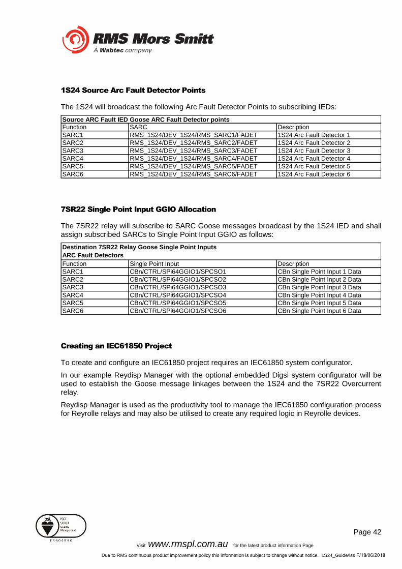
1S24 Source Arc Fault Detector Points
The 1S24 will broadcast the following Arc Fault Detector Points to subscribing IEDs:
Function SARC Description
SARC1 RMS_1S24/DEV_1S24/RMS_SARC1/FADET 1S24 Arc Fault Detector 1
SARC2 RMS_1S24/DEV_1S24/RMS_SARC2/FADET 1S24 Arc Fault Detector 2
SARC3 RMS_1S24/DEV_1S24/RMS_SARC3/FADET 1S24 Arc Fault Detector 3
SARC4 RMS_1S24/DEV_1S24/RMS_SARC4/FADET 1S24 Arc Fault Detector 4
SARC5 RMS_1S24/DEV_1S24/RMS_SARC5/FADET 1S24 Arc Fault Detector 5
SARC6 RMS_1S24/DEV_1S24/RMS_SARC6/FADET 1S24 Arc Fault Detector 6
Source ARC Fault IED Goose ARC Fault Detector points
7SR22 Single Point Input GGIO Allocation
The 7SR22 relay will subscribe to SARC Goose messages broadcast by the 1S24 IED and shall assign subscribed SARCs to Single Point Input GGIO as follows:
Function Single Point Input Description
SARC1 CBn/CTRL/SPi64GGIO1/SPCSO1 CBn Single Point Input 1 Data
SARC2 CBn/CTRL/SPi64GGIO1/SPCSO2 CBn Single Point Input 2 Data
SARC3 CBn/CTRL/SPi64GGIO1/SPCSO3 CBn Single Point Input 3 Data
SARC4 CBn/CTRL/SPi64GGIO1/SPCSO4 CBn Single Point Input 4 Data
SARC5 CBn/CTRL/SPi64GGIO1/SPCSO5 CBn Single Point Input 5 Data
SARC6 CBn/CTRL/SPi64GGIO1/SPCSO6 CBn Single Point Input 6 Data
Destination 7SR22 Relay Goose Single Point Inputs
ARC Fault Detectors
Creating an IEC61850 Project
To create and configure an IEC61850 project requires an IEC61850 system configurator.
In our example Reydisp Manager with the optional embedded Digsi system configurator will be used to establish the Goose message linkages between the 1S24 and the 7SR22 Overcurrent relay.
Reydisp Manager is used as the productivity tool to manage the IEC61850 configuration process for Reyrolle relays and may also be utilised to create any required logic in Reyrolle devices.
Page 43
Visit www.rmspl.com.au for the latest product information Page
Due to RMS continuous product improvement policy this information is subject to change without notice. 1S24_Guide/Iss F/18/06/2018
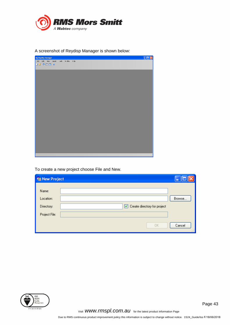
A screenshot of Reydisp Manager is shown below:
To create a new project choose File and New.

Page 44
Visit www.rmspl.com.au for the latest product information Page
Due to RMS continuous product improvement policy this information is subject to change without notice. 1S24_Guide/Iss F/18/06/2018
Fill in the details including where you want the project file to be stored and hit OK.
The new project has been created.
Page 45
Visit www.rmspl.com.au for the latest product information Page
Due to RMS continuous product improvement policy this information is subject to change without notice. 1S24_Guide/Iss F/18/06/2018
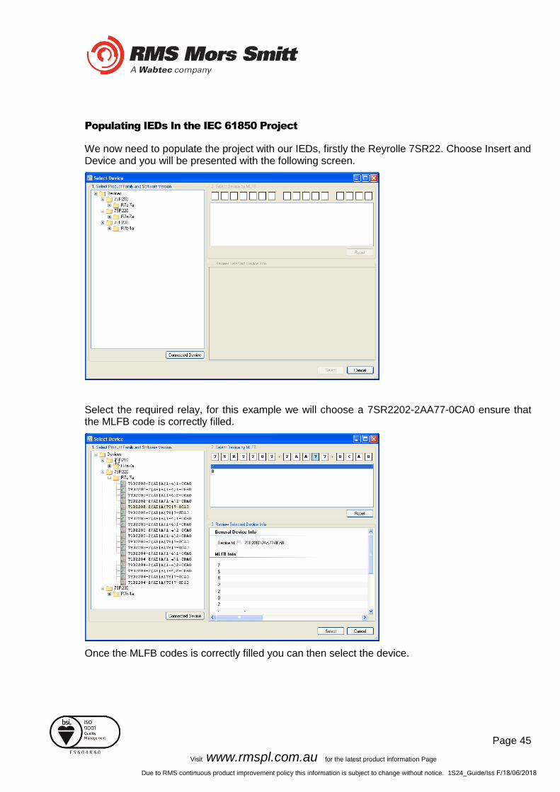
Populating IEDs In the IEC 61850 Project
We now need to populate the project with our IEDs, firstly the Reyrolle 7SR22. Choose Insert and Device and you will be presented with the following screen.
Select the required relay, for this example we will choose a 7SR2202-2AA77-0CA0 ensure that the MLFB code is correctly filled.
Once the MLFB codes is correctly filled you can then select the device.

Page 46
Visit www.rmspl.com.au for the latest product information Page
Due to RMS continuous product improvement policy this information is subject to change without notice. 1S24_Guide/Iss F/18/06/2018
The 7SR22 IED has been added to your project.
Continue adding Reyrolle IEDs as required using the same process.
Nominate a meaningful IED name for each IED by right clicking on the IED and choosing properties.
Page 47
Visit www.rmspl.com.au for the latest product information Page
Due to RMS continuous product improvement policy this information is subject to change without notice. 1S24_Guide/Iss F/18/06/2018
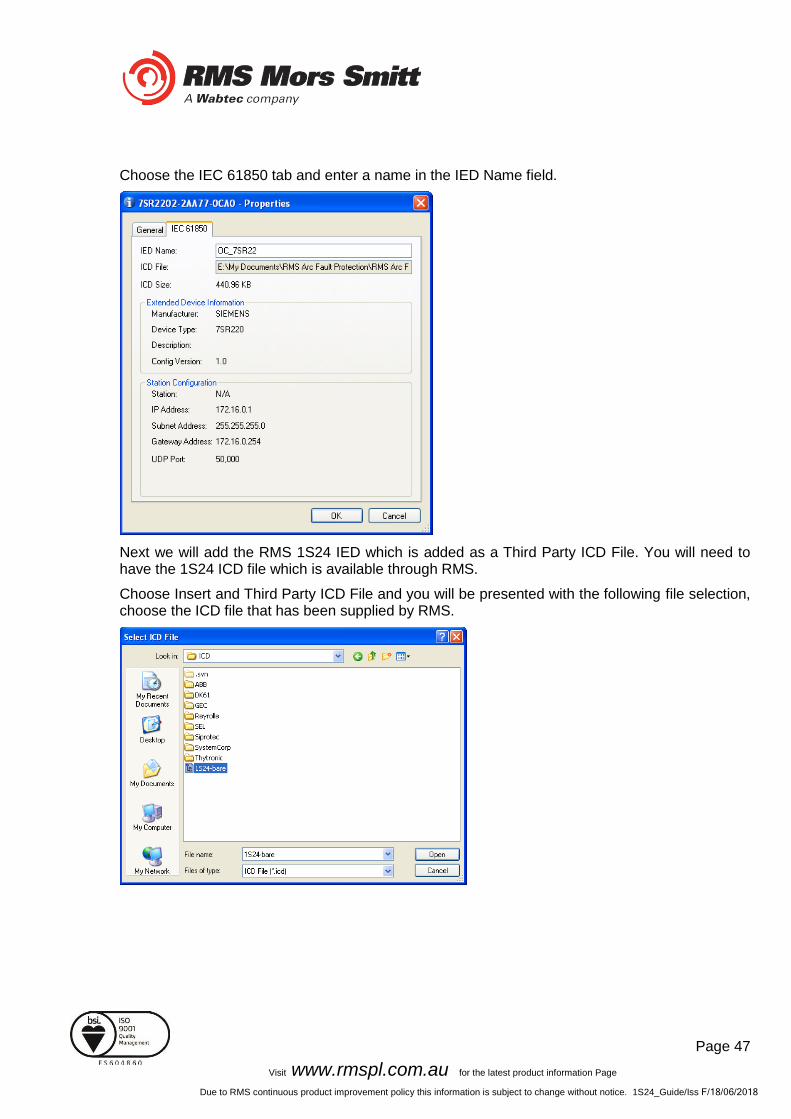
Choose the IEC 61850 tab and enter a name in the IED Name field.
Next we will add the RMS 1S24 IED which is added as a Third Party ICD File. You will need to have the 1S24 ICD file which is available through RMS.
Choose Insert and Third Party ICD File and you will be presented with the following file selection, choose the ICD file that has been supplied by RMS.

Page 48
Visit www.rmspl.com.au for the latest product information Page
Due to RMS continuous product improvement policy this information is subject to change without notice. 1S24_Guide/Iss F/18/06/2018
The 1S24 IED has now been added to your project.
You can nominate a meaningful IED name for the 1S24 IED by right clicking on the IED and choosing properties.
Now we will add an IEC61850 Station, choose Insert and Station.
Page 49
Visit www.rmspl.com.au for the latest product information Page
Due to RMS continuous product improvement policy this information is subject to change without notice. 1S24_Guide/Iss F/18/06/2018
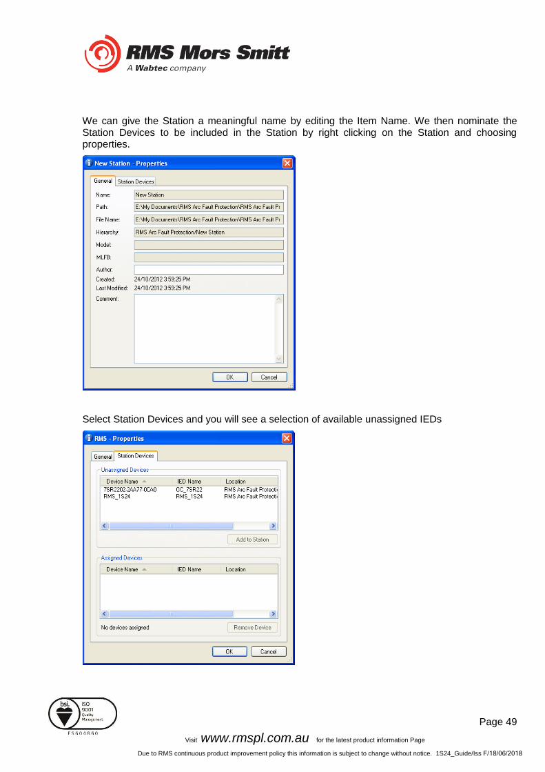
We can give the Station a meaningful name by editing the Item Name. We then nominate the Station Devices to be included in the Station by right clicking on the Station and choosing properties.
Select Station Devices and you will see a selection of available unassigned IEDs
Page 50
Visit www.rmspl.com.au for the latest product information Page
Due to RMS continuous product improvement policy this information is subject to change without notice. 1S24_Guide/Iss F/18/06/2018
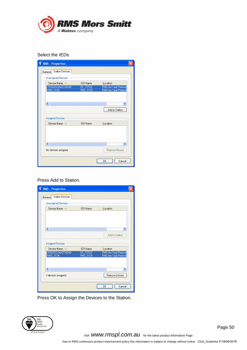
Select the IEDs
Press Add to Station.
Press OK to Assign the Devices to the Station.
Page 51
Visit www.rmspl.com.au for the latest product information Page
Due to RMS continuous product improvement policy this information is subject to change without notice. 1S24_Guide/Iss F/18/06/2018
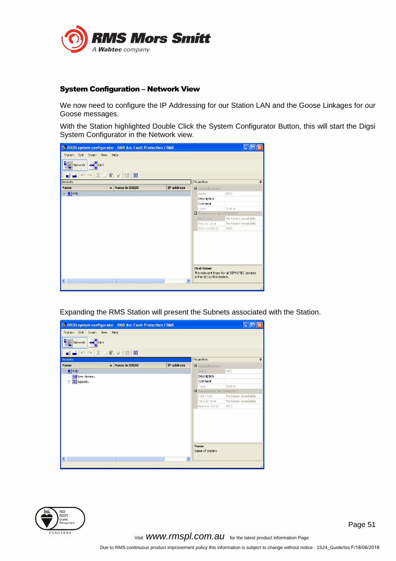
System Configuration – Network View
We now need to configure the IP Addressing for our Station LAN and the Goose Linkages for our Goose messages.
With the Station highlighted Double Click the System Configurator Button, this will start the Digsi System Configurator in the Network view.
Expanding the RMS Station will present the Subnets associated with the Station.

Page 52
Visit www.rmspl.com.au for the latest product information Page
Due to RMS continuous product improvement policy this information is subject to change without notice. 1S24_Guide/Iss F/18/06/2018
Clicking on the Subnet will reveal the IP Start address, Subnet mask and standard gateway settings.
We can set the IP start address for our network for convenience, in this case 192.168.0.1. The Standard Gateway may also be set at this point if one exists.

Page 53
Visit www.rmspl.com.au for the latest product information Page
Due to RMS continuous product improvement policy this information is subject to change without notice. 1S24_Guide/Iss F/18/06/2018
Expanding Subnet1 will reveal the IEDs that we previously assigned to the Station.
The individual devices may be selected to set their IP addresses.
Alternatively at the Subnet level the IP addressing may be automatically allocated starting at the IP start address previously set for the Subnet by pressing the auto IP button.
Page 54
Visit www.rmspl.com.au for the latest product information Page
Due to RMS continuous product improvement policy this information is subject to change without notice. 1S24_Guide/Iss F/18/06/2018
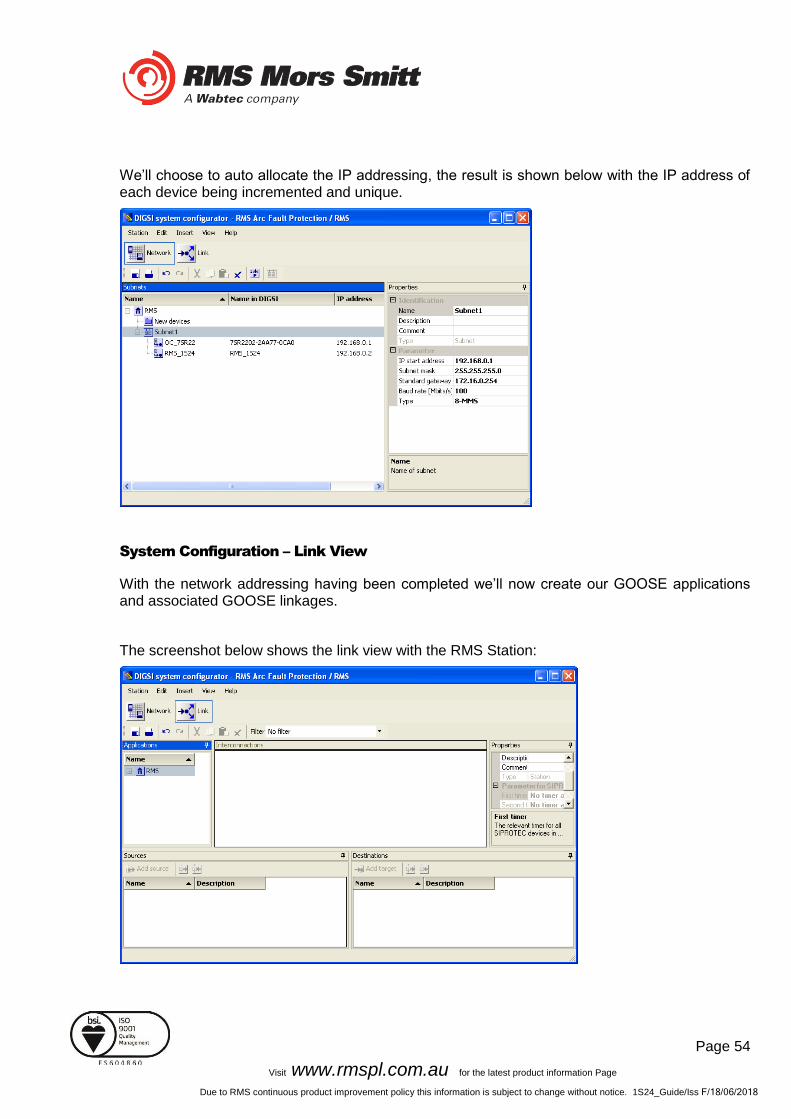
We’ll choose to auto allocate the IP addressing, the result is shown below with the IP address of each device being incremented and unique.
System Configuration – Link View
With the network addressing having been completed we’ll now create our GOOSE applications and associated GOOSE linkages.
The screenshot below shows the link view with the RMS Station:

Page 55
Visit www.rmspl.com.au for the latest product information Page
Due to RMS continuous product improvement policy this information is subject to change without notice. 1S24_Guide/Iss F/18/06/2018
The Applications window lists all the applications by Station, drilling down into the RMS station will reveal the Subnets and any associated reports or GOOSE applications.
An existing GOOSE application may be used or alternatively a New GOOSE application created.
For our example we’ll use the existing GOOSE application 1, selecting this application reveals the associated IEDs as sources and destinations.
Expanding the respective IEDs in the Sources and Destinations windows will show the Logical Nodes and their associated Data Objects.
Page 56
Visit www.rmspl.com.au for the latest product information Page
Due to RMS continuous product improvement policy this information is subject to change without notice. 1S24_Guide/Iss F/18/06/2018
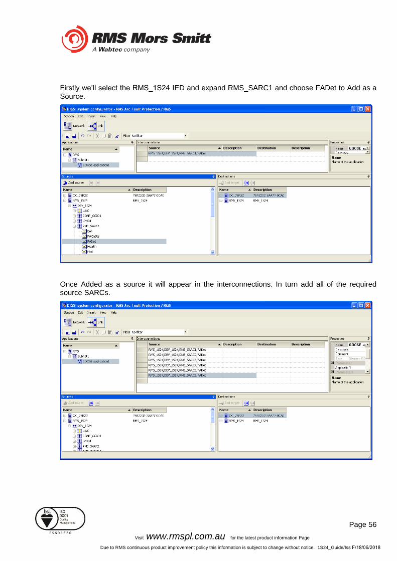
Firstly we’ll select the RMS_1S24 IED and expand RMS_SARC1 and choose FADet to Add as a Source.
Once Added as a source it will appear in the interconnections. In turn add all of the required source SARCs.

Page 57
Visit www.rmspl.com.au for the latest product information Page
Due to RMS continuous product improvement policy this information is subject to change without notice. 1S24_Guide/Iss F/18/06/2018
The SARCs are linked to the respective 7SR22 IED Single Point Input GGIO chosen from the Destinations window (refer also to the Allocation table in the earlier part of this example).
With the linkages complete save the configuration.
Page 58
Visit www.rmspl.com.au for the latest product information Page
Due to RMS continuous product improvement policy this information is subject to change without notice. 1S24_Guide/Iss F/18/06/2018
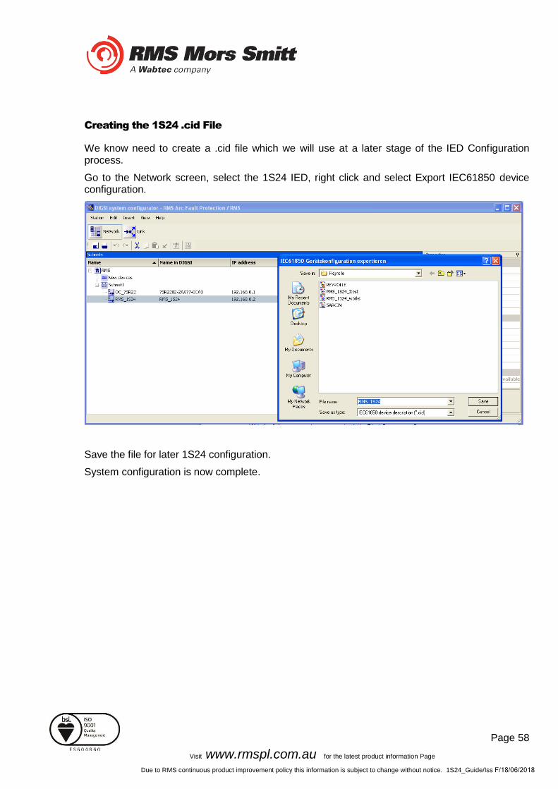
Creating the 1S24 .cid File
We know need to create a .cid file which we will use at a later stage of the IED Configuration process.
Go to the Network screen, select the 1S24 IED, right click and select Export IEC61850 device configuration.
Save the file for later 1S24 configuration.
System configuration is now complete.

Page 59
Visit www.rmspl.com.au for the latest product information Page
Due to RMS continuous product improvement policy this information is subject to change without notice. 1S24_Guide/Iss F/18/06/2018
1S24 IEC61850 Configuration
The .cid File
The 1S24 requires a .cid file that incorporates the IEC61850 Substation Project Configuration including the Report datasets that must be sent and where they are sent to.
The Project Configuration is contained in the .cid file for the 1S24 created earlier from our Substation configuration process example and needs to be loaded into the 1S24 IED.
FTP 1S24.cid File
We will be using the Beck’s @CHIPTOOL software utility to establish a terminal session with the 1S24 and to FTP the .cid file.
Download @CHIPTOOL for free from: http://www.beck-ipc.com/en/download/licence.asp?id=chiptool_install&l=1 Run @CHIPTOOL on the PC. The Tool will detect any 1S24 devices on the network as seen by the screen shot below:
Page 60
Visit www.rmspl.com.au for the latest product information Page
Due to RMS continuous product improvement policy this information is subject to change without notice. 1S24_Guide/Iss F/18/06/2018
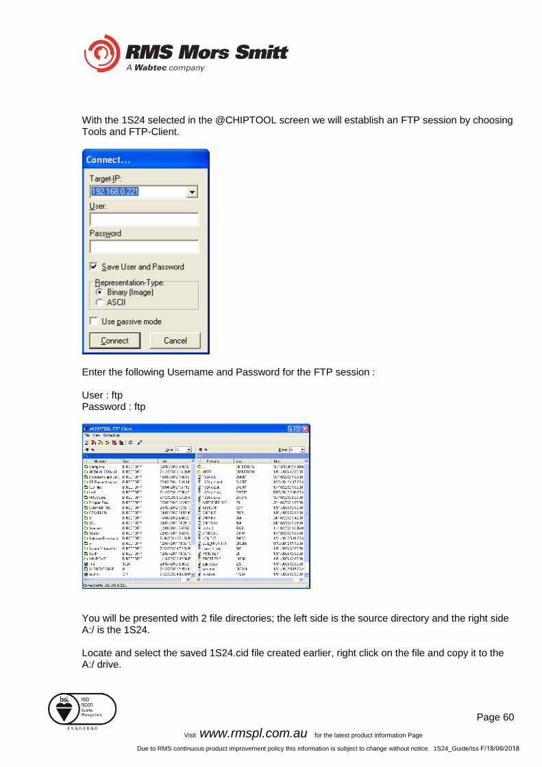
With the 1S24 selected in the @CHIPTOOL screen we will establish an FTP session by choosing Tools and FTP-Client.
Enter the following Username and Password for the FTP session : User : ftp Password : ftp
You will be presented with 2 file directories; the left side is the source directory and the right side A:/ is the 1S24. Locate and select the saved 1S24.cid file created earlier, right click on the file and copy it to the A:/ drive.
Page 61
Visit www.rmspl.com.au for the latest product information Page
Due to RMS continuous product improvement policy this information is subject to change without notice. 1S24_Guide/Iss F/18/06/2018
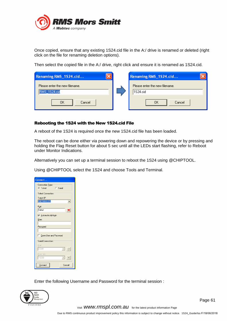
Once copied, ensure that any existing 1S24.cid file in the A:/ drive is renamed or deleted (right click on the file for renaming deletion options). Then select the copied file in the A:/ drive, right click and ensure it is renamed as 1S24.cid.
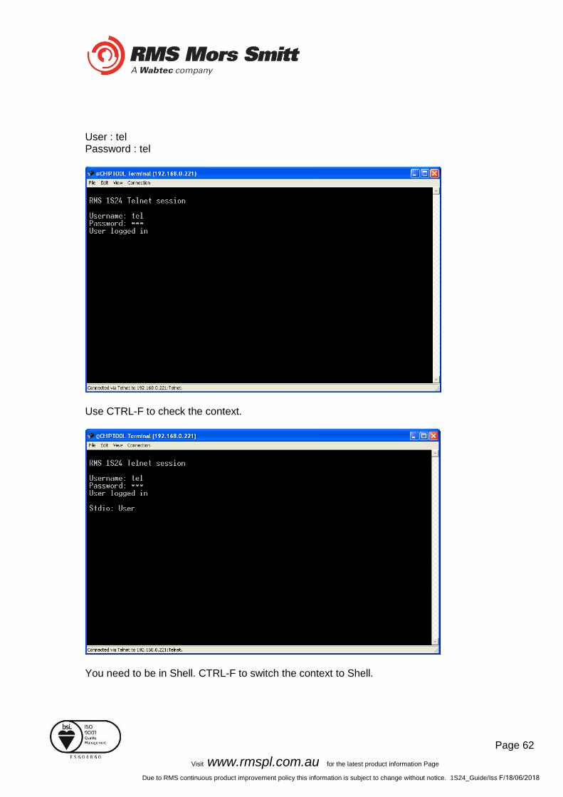
Rebooting the 1S24 with the New 1S24.cid File
A reboot of the 1S24 is required once the new 1S24.cid file has been loaded. The reboot can be done either via powering down and repowering the device or by pressing and holding the Flag Reset button for about 5 sec until all the LEDs start flashing, refer to Reboot under Monitor Indications. Alternatively you can set up a terminal session to reboot the 1S24 using @CHIPTOOL. Using @CHIPTOOL select the 1S24 and choose Tools and Terminal.
Enter the following Username and Password for the terminal session :
Page 62
Visit www.rmspl.com.au for the latest product information Page
Due to RMS continuous product improvement policy this information is subject to change without notice. 1S24_Guide/Iss F/18/06/2018
User : tel Password : tel
Use CTRL-F to check the context.
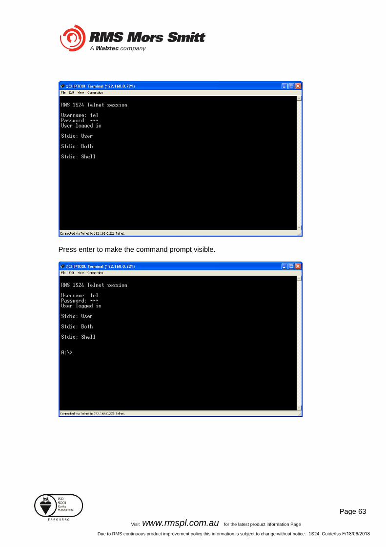
You need to be in Shell. CTRL-F to switch the context to Shell.
Page 63
Visit www.rmspl.com.au for the latest product information Page
Due to RMS continuous product improvement policy this information is subject to change without notice. 1S24_Guide/Iss F/18/06/2018
Press enter to make the command prompt visible.
Page 64
Visit www.rmspl.com.au for the latest product information Page
Due to RMS continuous product improvement policy this information is subject to change without notice. 1S24_Guide/Iss F/18/06/2018
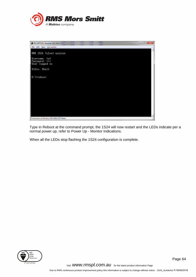
Type in Reboot at the command prompt, the 1S24 will now restart and the LEDs indicate per a normal power up, refer to Power Up - Monitor Indications. When all the LEDs stop flashing the 1S24 configuration is complete.
Page 65
Visit www.rmspl.com.au for the latest product information Page
Due to RMS continuous product improvement policy this information is subject to change without notice. 1S24_Guide/Iss F/18/06/2018
Subscribing Reyrolle 7SR22 IED Configuration
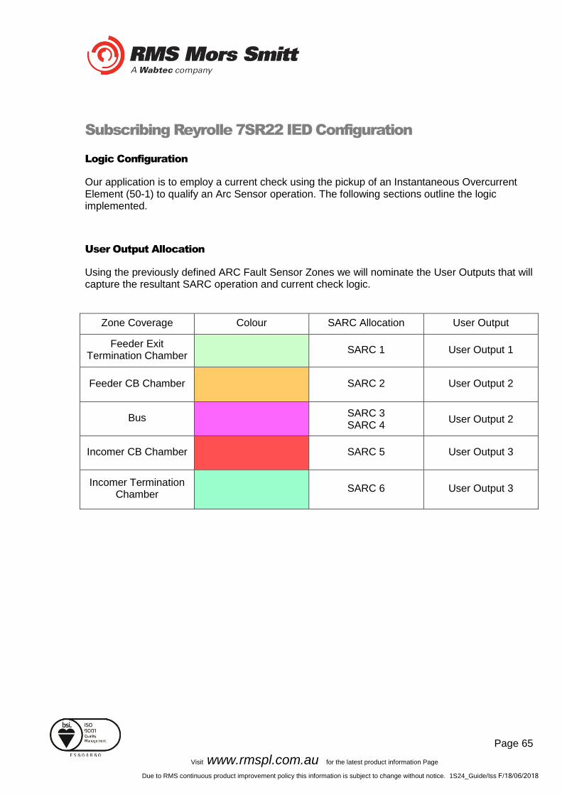
Logic Configuration
Our application is to employ a current check using the pickup of an Instantaneous Overcurrent Element (50-1) to qualify an Arc Sensor operation. The following sections outline the logic implemented.
User Output Allocation
Using the previously defined ARC Fault Sensor Zones we will nominate the User Outputs that will capture the resultant SARC operation and current check logic.
Zone Coverage Colour SARC Allocation User Output
Feeder Exit Termination Chamber
SARC 1 User Output 1
Feeder CB Chamber SARC 2 User Output 2
Bus SARC 3 SARC 4
User Output 2
Incomer CB Chamber SARC 5 User Output 3
Incomer Termination Chamber
SARC 6 User Output 3
Page 66
Visit www.rmspl.com.au for the latest product information Page
Due to RMS continuous product improvement policy this information is subject to change without notice. 1S24_Guide/Iss F/18/06/2018
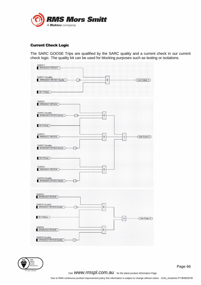
Current Check Logic
The SARC GOOSE Trips are qualified by the SARC quality and a current check in our current check logic. The quality bit can be used for blocking purposes such as testing or isolations.
Page 67
Visit www.rmspl.com.au for the latest product information Page
Due to RMS continuous product improvement policy this information is subject to change without notice. 1S24_Guide/Iss F/18/06/2018
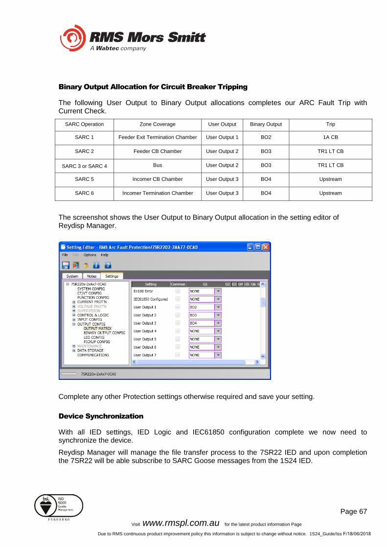
Binary Output Allocation for Circuit Breaker Tripping
The following User Output to Binary Output allocations completes our ARC Fault Trip with Current Check.
SARC Operation Zone Coverage User Output Binary Output Trip
SARC 1 Feeder Exit Termination Chamber User Output 1 BO2 1A CB
SARC 2 Feeder CB Chamber User Output 2 BO3 TR1 LT CB
SARC 3 or SARC 4 Bus User Output 2 BO3 TR1 LT CB
SARC 5 Incomer CB Chamber User Output 3 BO4 Upstream
SARC 6 Incomer Termination Chamber User Output 3 BO4 Upstream
The screenshot shows the User Output to Binary Output allocation in the setting editor of Reydisp Manager.
Complete any other Protection settings otherwise required and save your setting.
Device Synchronization
With all IED settings, IED Logic and IEC61850 configuration complete we now need to synchronize the device.
Reydisp Manager will manage the file transfer process to the 7SR22 IED and upon completion the 7SR22 will be able subscribe to SARC Goose messages from the 1S24 IED.

Page 68
Visit www.rmspl.com.au for the latest product information Page
Due to RMS continuous product improvement policy this information is subject to change without notice. 1S24_Guide/Iss F/18/06/2018
Monitor Indications
Front Layout
The picture below depicts the indications provided on the front of the Arc Fault Monitor.
Power Up
When powering up, all the Leds will flash once and then extinguish and then in turn sequentially illuminate 1 led at a time until all Leds are illuminated – the sequence takes about 30 secs during the boot cycle.
When the boot cycle is complete the 1S24 will indicate the current state.
Page 69
Visit www.rmspl.com.au for the latest product information Page
Due to RMS continuous product improvement policy this information is subject to change without notice. 1S24_Guide/Iss F/18/06/2018
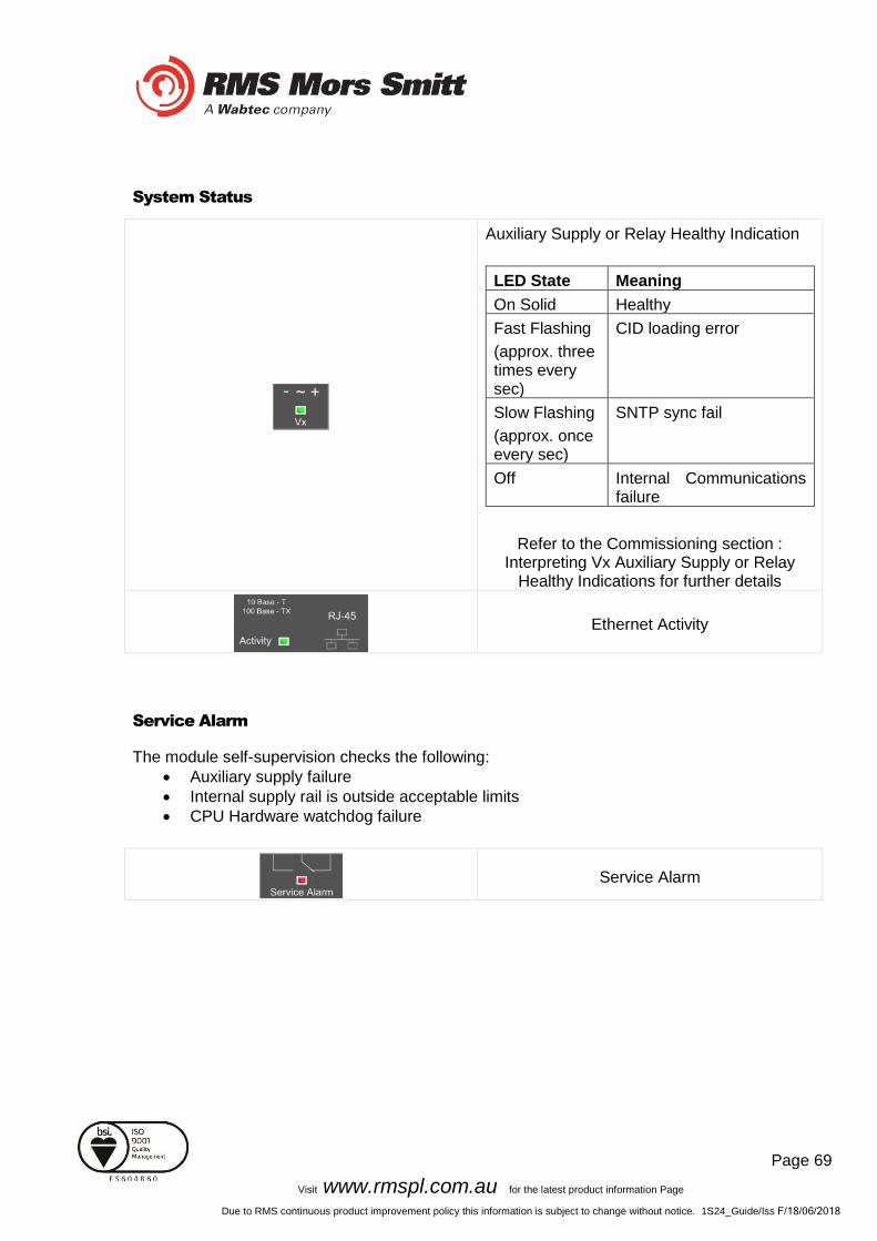
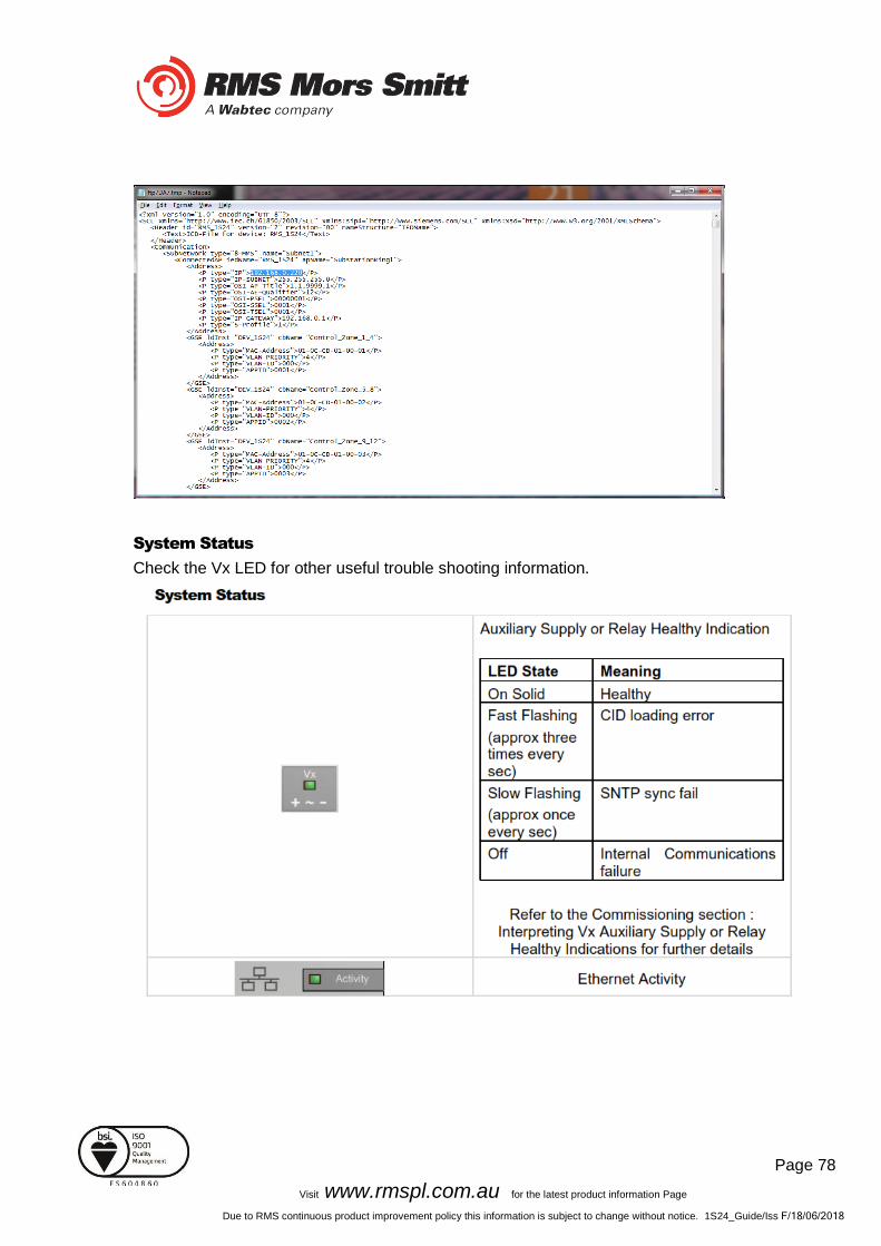
System Status
Auxiliary Supply or Relay Healthy Indication
LED State Meaning
On Solid Healthy
Fast Flashing
(approx. three times every sec)
CID loading error
Slow Flashing
(approx. once every sec)
SNTP sync fail
Off Internal Communications failure
Refer to the Commissioning section : Interpreting Vx Auxiliary Supply or Relay
Healthy Indications for further details
Ethernet Activity
Service Alarm
The module self-supervision checks the following:
• Auxiliary supply failure
• Internal supply rail is outside acceptable limits
• CPU Hardware watchdog failure
Service Alarm

Page 70
Visit www.rmspl.com.au for the latest product information Page
Due to RMS continuous product improvement policy this information is subject to change without notice. 1S24_Guide/Iss F/18/06/2018
Arc Sensor Indicators
Indicate solid when an Arc Sensor has detected an Arc, the LEDs are reset after pressing the Flag Reset.
Up to 16 Arc Sensor Indicators
A flashing Arc Sensor LED indicates a failure of the sensor; refer to the Sensor Alarm indicator description.
Arc Sensor Circuit Supervision
Indicates solid when an Arc Sensor has faulted either due to an open circuit, sustained short circuit
(>10 sec) or high ambient lighting.
Sensor Alarm
The affected sensor will be indicated by its front panel sensor LED 1-16 flashing.
The Sensor Alarm will self-reset upon the fault conditions being corrected.
Arc Trip
Indicate solid when the respective assigned self-reset Arc Trip contacts operate. The LEDs reset when the Arc Trip contacts self-reset.
Arc Trip
Global Arc Block
Indicate solid when the Global Arc Block input is energised, all Arc Trips are blocked (both IEC61850 and Arc Trip outputs).
Global Arc Block

Page 71
Visit www.rmspl.com.au for the latest product information Page
Due to RMS continuous product improvement policy this information is subject to change without notice. 1S24_Guide/Iss F/18/06/2018
Flag Reset
To reset the ARC Sensor LEDs
The ARC sensor LEDs may also be reset by energising the binary input
Reboot
A reboot is achieved by applying power to the relay, all the Leds will flash once and then extinguish and then in turn sequentially illuminate 1 led at a time until all Leds are illuminated – the sequence takes about 30 secs.
Alternatively if the relay is powered, hold down the Flag Reset button for about 6 sec until all of the Leds (except Service) start flashing, and then release the Flag Reset button. The LEDs will continue to flash for approx. 9 secs and then extinguish and then in turn sequentially illuminate 1 led at a time until all Leds are illuminated – the sequence takes another 20 secs approx.
When the boot cycle is complete the 1S24 will indicate the current state.
The reboot must be used after loading in new .icd files into the IED and restarting the software process with the new 61850 configurations.
The reboot may also be required if for some reason the 1S24 does not respond to web server commands or becomes unresponsive to ftp or terminal sessions.
Page 72
Visit www.rmspl.com.au for the latest product information Page
Due to RMS continuous product improvement policy this information is subject to change without notice. 1S24_Guide/Iss F/18/06/2018
Reset to Factory Default
With the relay unpowered, hold down the Flag Reset button and power up the relay, continue holding down the reset button until the Leds commence flashing rapidly (approx. 12 secs) then release the reset button. After releasing the reset button all of the Leds (except Service) will continue flashing rapidly and then extinguish (approx. 10 secs). The Leds will then in turn sequentially illuminate 1 led at a time until all Leds are illuminated – the sequence takes another 20 secs approx.
When the boot cycle is complete the 1S24 will indicate the current state.
The Cold Boot is used for reverting the IED back to factory default settings including default passwords.
Page 73
Visit www.rmspl.com.au for the latest product information Page
Due to RMS continuous product improvement policy this information is subject to change without notice. 1S24_Guide/Iss F/18/06/2018
Firmware Update
Introduction
An FTP tool is required to load firmware updates into the 1S24; @CHIPTOOL mentioned earlier in the manual allows HTTP, FTP and Telnet sessions.
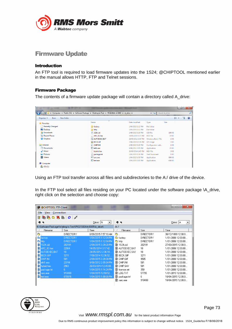
Firmware Package
The contents of a firmware update package will contain a directory called A_drive:
Using an FTP tool transfer across all files and subdirectories to the A:/ drive of the device.
In the FTP tool select all files residing on your PC located under the software package \A_drive, right click on the selection and choose copy:

Page 74
Visit www.rmspl.com.au for the latest product information Page
Due to RMS continuous product improvement policy this information is subject to change without notice. 1S24_Guide/Iss F/18/06/2018
These files will then transfer across to the 1S24.
Then reboot the device.
Set up a web browser session of the device, you should get a similar screen to the following:
All is well and the 1S24 has been upgraded!

Page 75
Visit www.rmspl.com.au for the latest product information Page
Due to RMS continuous product improvement policy this information is subject to change without notice. 1S24_Guide/Iss F/18/06/2018
Trouble Shooting
License file not valid or present
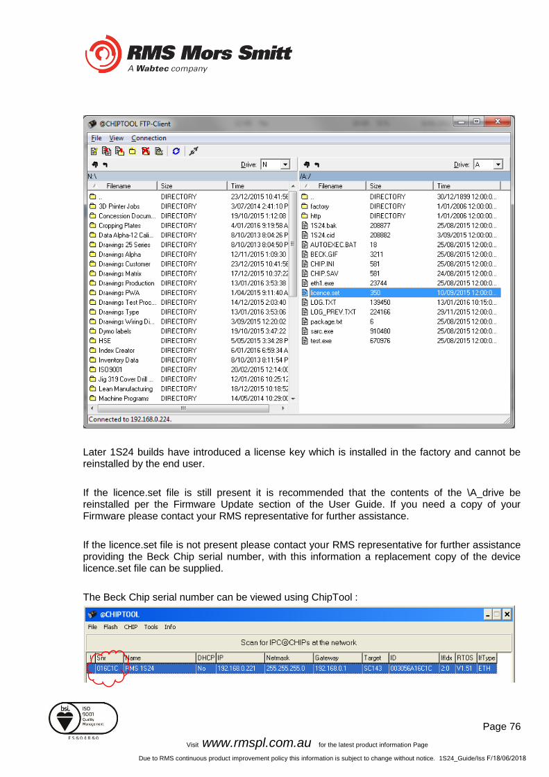
Using an FTP tool view the \A_drive and check whether the license.set file is present.
Page 76
Visit www.rmspl.com.au for the latest product information Page
Due to RMS continuous product improvement policy this information is subject to change without notice. 1S24_Guide/Iss F/18/06/2018
Later 1S24 builds have introduced a license key which is installed in the factory and cannot be reinstalled by the end user.
If the licence.set file is still present it is recommended that the contents of the \A_drive be reinstalled per the Firmware Update section of the User Guide. If you need a copy of your Firmware please contact your RMS representative for further assistance.
If the licence.set file is not present please contact your RMS representative for further assistance providing the Beck Chip serial number, with this information a replacement copy of the device licence.set file can be supplied.
The Beck Chip serial number can be viewed using ChipTool :

Page 77
Visit www.rmspl.com.au for the latest product information Page
Due to RMS continuous product improvement policy this information is subject to change without notice. 1S24_Guide/Iss F/18/06/2018
Invalid IP Address Specified in ICD File
If you get the above message displayed in the relay build screen then the IP address setting in the device is not in alignment with the ip address in the 1S24.cid file.
Either edit the 1S24.cid file or amend the ip configuration in the device so that the ip addresses are in alignment – if amending the 1S24.cid file be mindful that you may disable any Goose messages created during an earlier IEC61850 system configuration!
If editing the 1S24.cid file, there should only be one instance you need to change for example:
Page 78
Visit www.rmspl.com.au for the latest product information Page
Due to RMS continuous product improvement policy this information is subject to change without notice. 1S24_Guide/Iss F/18/06/2018
System Status
Check the Vx LED for other useful trouble shooting information.
Page 79
Visit www.rmspl.com.au for the latest product information Page
Due to RMS continuous product improvement policy this information is subject to change without notice. 1S24_Guide/Iss F/18/06/2018
Commissioning
Commissioning Preliminaries
Carefully examine the module to ensure that no damage has occurred during transit. Check that the model number and rating information are correct. Insulation The relay, and its associated wiring, may be insulation tested between:
- all electrically isolated circuits
- all circuits and earth An electronic or brushless insulation tester should be used, having a dc voltage not exceeding 1000V. Accessible terminals of the same circuit should first be strapped together. Deliberate circuit earthing links, removed for the tests, subsequently must be replaced. ARC Trip Verification ARC Trip Verification will require a flash source to initiate sensor operation. A high powered photographic flash is the most convenient means of initiating positive sensor operation. Note that mobile phone or small compact camera flashes may not have sufficient power to cause sensor operation. The RMS ‘Arc Flash Timing Test Guide’ outlines a suggested test setup to provide a flash source and determine ARC Trip times. The ‘Arc Flash Timing Test Guide’ is available on the RMS website: http://rmspl.com.au/wordpress/wp-content/uploads/2015/02/Arc_Flash_Timing_Test_Guide.pdf Arc only tests are conducted as per the section ‘Timing test of 1S25 (no current check)’ substituting the wiring for the 1S25 with equivalent wiring for the 1S24. Current check tests are conducted as per the section ‘Timing test of 1S26’, with the 1S30 connected to the 1S24, the current source connected to the current check relay and the 1S24 and subscribing current check relay connected via a IEC61850 Station Bus Lan for the transfer of Goose messages. The ‘Arc Flash Timing Test Guide’ only requires the use of a conventional test set; end users may also find it beneficial to have access to an IEC61850 equipped test set which can aid in the observation of GOOSE traffic, undertaking GOOSE timing tests and trouble shooting.

Page 80
Visit www.rmspl.com.au for the latest product information Page
Due to RMS continuous product improvement policy this information is subject to change without notice. 1S24_Guide/Iss F/18/06/2018
Note that the nominated RMS test guide makes use of conventional binary outputs for flash initiation, whilst this is convenient and will work with the majority of test sets the technique will introduce some minor delays in the timing test results due to the latency of the conventional binary output. Where more precise timing is required then specialised test equipment should be employed that utilises solid state outputs for arc flash initiation. There are commercially available test sets on the market that provide this capability.
Site Commissioning Verification Checklist
Observe all site specific standard safety procedures.
The following tests are undertaken following the completion of all 1S24 ARC Monitor and Overcurrent Relay IEC61850 Substation Configuration and associated IED configurations, scheme wiring and the wiring of all 1S30 sensors.
System Power Up
Item Description Complete
1 Confirm all necessary primary equipment isolations
2 Confirm all necessary secondary equipment isolations (including trip outputs)
3 Check fitment of 1S30 and or 1S40 optical sensors and cable condition
4 Check panel installation of the 1S24 monitor
5 Check for correct case earthing
6 Check the 1S24 is wired to the protection design schematic, connected to a Substation LAN and confirm all IEC61850 configurations
7 Confirm Fail alarm relay is closed (Terminals 23 and 24)
8 Apply correct Auxiliary voltage to power up the 1S24
9 Upon power up the relay enters a relay boot cycle, all the Leds will flash once and then extinguish and then in turn sequentially illuminate 1 led at a time until all Leds are illuminated – the sequence takes about 14 secs.
Observe that the green power LED remains illuminated (either solid or Flashing: refer to System Status section for complete description of indications) after the relay boot cycle.
10 Confirm Fail alarm relay is open (Terminals 23 and 24) and the associated LED is extinguished
11 Using a web browser check 1S24 configuration settings match protection setting specifications
Page 81
Visit www.rmspl.com.au for the latest product information Page
Due to RMS continuous product improvement policy this information is subject to change without notice. 1S24_Guide/Iss F/18/06/2018
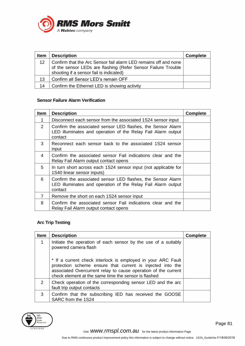
Item Description Complete
12 Confirm that the Arc Sensor fail alarm LED remains off and none of the sensor LEDs are flashing (Refer Sensor Failure Trouble shooting if a sensor fail is indicated)
13 Confirm all Sensor LED’s remain OFF
14 Confirm the Ethernet LED is showing activity
Sensor Failure Alarm Verification
Item Description Complete
1 Disconnect each sensor from the associated 1S24 sensor input
2 Confirm the associated sensor LED flashes, the Sensor Alarm LED illuminates and operation of the Relay Fail Alarm output contact
3 Reconnect each sensor back to the associated 1S24 sensor input
4 Confirm the associated sensor Fail indications clear and the Relay Fail Alarm output contact opens
5 In turn short across each 1S24 sensor input (not applicable for 1S40 linear sensor inputs)
6 Confirm the associated sensor LED flashes, the Sensor Alarm LED illuminates and operation of the Relay Fail Alarm output contact
7 Remove the short on each 1S24 sensor input
8 Confirm the associated sensor Fail indications clear and the Relay Fail Alarm output contact opens
Arc Trip Testing
Item Description Complete
1 Initiate the operation of each sensor by the use of a suitably powered camera flash
* If a current check interlock is employed in your ARC Fault protection scheme ensure that current is injected into the associated Overcurrent relay to cause operation of the current check element at the same time the sensor is flashed
2 Check operation of the corresponding sensor LED and the arc fault trip output contacts
3 Confirm that the subscribing IED has received the GOOSE SARC from the 1S24
Page 82
Visit www.rmspl.com.au for the latest product information Page
Due to RMS continuous product improvement policy this information is subject to change without notice. 1S24_Guide/Iss F/18/06/2018
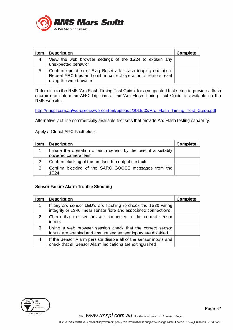
Item Description Complete
4 View the web browser settings of the 1S24 to explain any unexpected behavior
5 Confirm operation of Flag Reset after each tripping operation. Repeat ARC trips and confirm correct operation of remote reset using the web browser
Refer also to the RMS ‘Arc Flash Timing Test Guide’ for a suggested test setup to provide a flash source and determine ARC Trip times. The ‘Arc Flash Timing Test Guide’ is available on the RMS website: http://rmspl.com.au/wordpress/wp-content/uploads/2015/02/Arc_Flash_Timing_Test_Guide.pdf Alternatively utilise commercially available test sets that provide Arc Flash testing capability.
Apply a Global ARC Fault block.
Item Description Complete
1 Initiate the operation of each sensor by the use of a suitably powered camera flash
2 Confirm blocking of the arc fault trip output contacts
3 Confirm blocking of the SARC GOOSE messages from the 1S24
Sensor Failure Alarm Trouble Shooting
Item Description Complete
1 If any arc sensor LED’s are flashing re-check the 1S30 wiring integrity or 1S40 linear sensor fibre and associated connections
2 Check that the sensors are connected to the correct sensor inputs
3 Using a web browser session check that the correct sensor inputs are enabled and any unused sensor inputs are disabled
4 If the Sensor Alarm persists disable all of the sensor inputs and check that all Sensor Alarm indications are extinguished
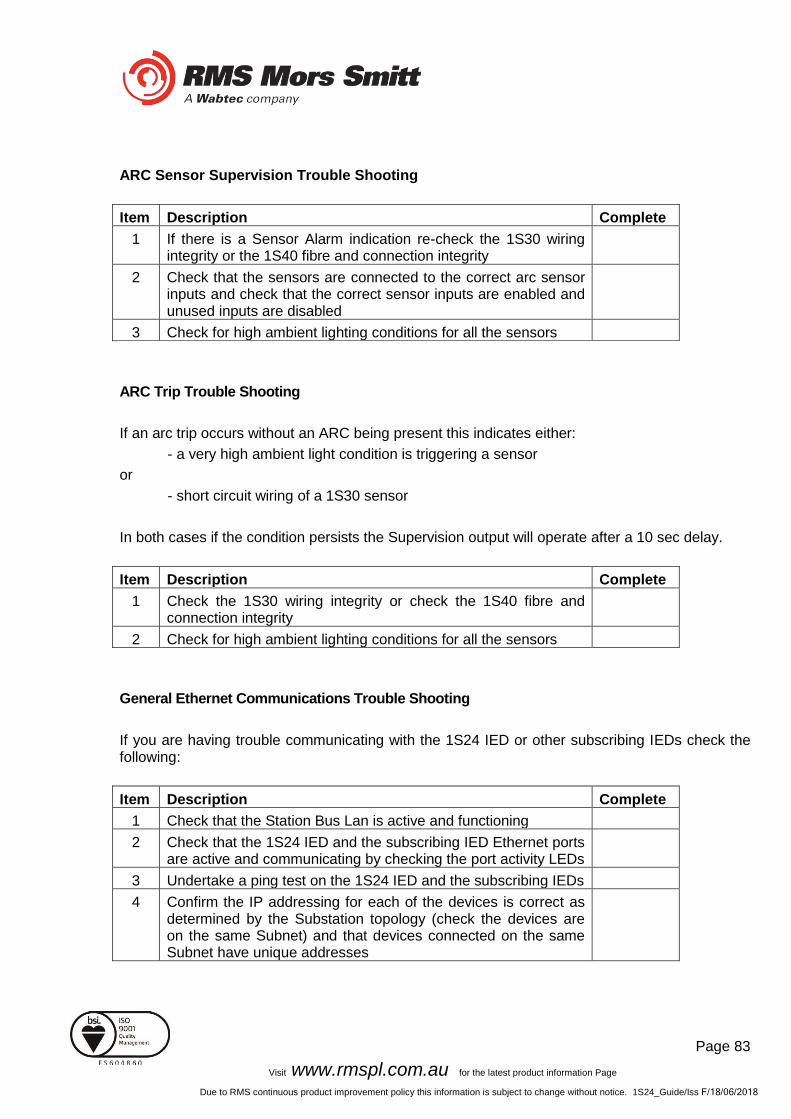
Page 83
Visit www.rmspl.com.au for the latest product information Page
Due to RMS continuous product improvement policy this information is subject to change without notice. 1S24_Guide/Iss F/18/06/2018
ARC Sensor Supervision Trouble Shooting
Item Description Complete
1 If there is a Sensor Alarm indication re-check the 1S30 wiring integrity or the 1S40 fibre and connection integrity
2 Check that the sensors are connected to the correct arc sensor inputs and check that the correct sensor inputs are enabled and unused inputs are disabled
3 Check for high ambient lighting conditions for all the sensors
ARC Trip Trouble Shooting
If an arc trip occurs without an ARC being present this indicates either:
- a very high ambient light condition is triggering a sensor
or
- short circuit wiring of a 1S30 sensor
In both cases if the condition persists the Supervision output will operate after a 10 sec delay.
Item Description Complete
1 Check the 1S30 wiring integrity or check the 1S40 fibre and connection integrity
2 Check for high ambient lighting conditions for all the sensors
General Ethernet Communications Trouble Shooting
If you are having trouble communicating with the 1S24 IED or other subscribing IEDs check the following:
Item Description Complete
1 Check that the Station Bus Lan is active and functioning
2 Check that the 1S24 IED and the subscribing IED Ethernet ports are active and communicating by checking the port activity LEDs
3 Undertake a ping test on the 1S24 IED and the subscribing IEDs
4 Confirm the IP addressing for each of the devices is correct as determined by the Substation topology (check the devices are on the same Subnet) and that devices connected on the same Subnet have unique addresses
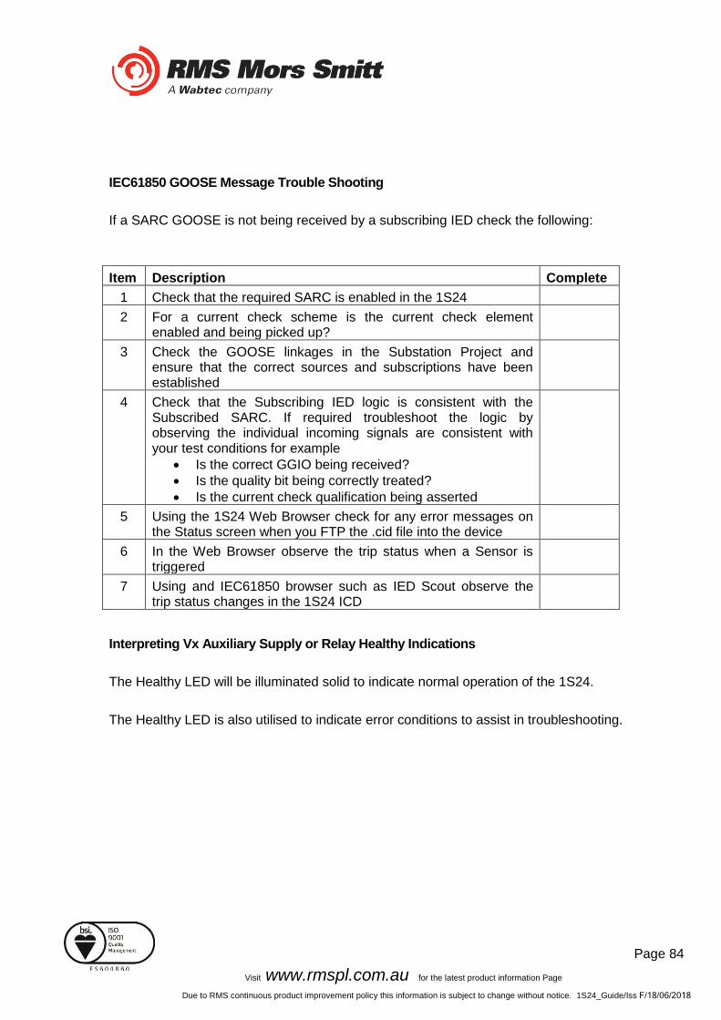
Page 84
Visit www.rmspl.com.au for the latest product information Page
Due to RMS continuous product improvement policy this information is subject to change without notice. 1S24_Guide/Iss F/18/06/2018
IEC61850 GOOSE Message Trouble Shooting
If a SARC GOOSE is not being received by a subscribing IED check the following:
Item Description Complete
1 Check that the required SARC is enabled in the 1S24
2 For a current check scheme is the current check element enabled and being picked up?
3 Check the GOOSE linkages in the Substation Project and ensure that the correct sources and subscriptions have been established
4 Check that the Subscribing IED logic is consistent with the Subscribed SARC. If required troubleshoot the logic by observing the individual incoming signals are consistent with your test conditions for example
• Is the correct GGIO being received?
• Is the quality bit being correctly treated?
• Is the current check qualification being asserted
5 Using the 1S24 Web Browser check for any error messages on the Status screen when you FTP the .cid file into the device
6 In the Web Browser observe the trip status when a Sensor is triggered
7 Using and IEC61850 browser such as IED Scout observe the trip status changes in the 1S24 ICD
Interpreting Vx Auxiliary Supply or Relay Healthy Indications
The Healthy LED will be illuminated solid to indicate normal operation of the 1S24.
The Healthy LED is also utilised to indicate error conditions to assist in troubleshooting.

Page 85
Visit www.rmspl.com.au for the latest product information Page
Due to RMS continuous product improvement policy this information is subject to change without notice. 1S24_Guide/Iss F/18/06/2018
The following table summarises all Healthy LED indications:
LED State Meaning
On Solid Healthy
Fast Flashing
(approx. three times every sec)
CID loading error (61850 stack problem)
The .cid file is in error or possibly corrupted, open a web server session where further information is reported on the Relay Build page
A common error is a mismatch of the ip address as set in the device compared to that entered in .cid file, refer to the section in the user guide titled: Invalid IP Address Specified in ICD File
Slow Flashing
(approx. once every sec)
SNTP sync fail
Check SNTP server is functioning or check that the SNTP Server address on the IP config screen is correct
Off Internal 1S24 Communications failure
A permanent Internal 1S24 Communications failure will assert the Service Alarm

Page 86
Visit www.rmspl.com.au for the latest product information Page
Due to RMS continuous product improvement policy this information is subject to change without notice. 1S24_Guide/Iss F/18/06/2018
Using IED SCOUT IEC61850 GOOSE Message Trouble Shooting
Status changes of the 1S24 ICD may be independently observed in more depth by using an IEC61850 browser such as IED Scout.
A free limited functionality version of IED Scout may be downloaded from the OMICRON website.
To view a 1S24 on a network start up IED Scout.
Go to Options and Configuration.
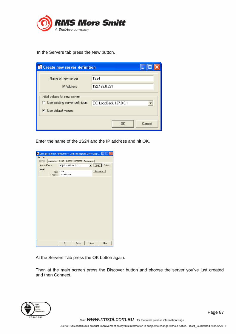
Page 87
Visit www.rmspl.com.au for the latest product information Page
Due to RMS continuous product improvement policy this information is subject to change without notice. 1S24_Guide/Iss F/18/06/2018
In the Servers tab press the New button.
Enter the name of the 1S24 and the IP address and hit OK.
At the Servers Tab press the OK botton again.
Then at the main screen press the Discover button and choose the server you’ve just created and then Connect.

Page 88
Visit www.rmspl.com.au for the latest product information Page
Due to RMS continuous product improvement policy this information is subject to change without notice. 1S24_Guide/Iss F/18/06/2018
You will now see that the 1S24 is available for viewing.
You can drill down in the Logical Node structure of the 1S24.
To view the Data for SARC1 double click RMS_SARC1
And then further drill down in to the status data for example to view the status of FADet.
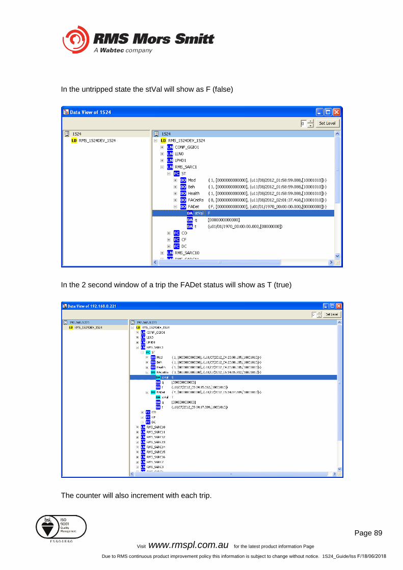
Page 89
Visit www.rmspl.com.au for the latest product information Page
Due to RMS continuous product improvement policy this information is subject to change without notice. 1S24_Guide/Iss F/18/06/2018
In the untripped state the stVal will show as F (false)
In the 2 second window of a trip the FADet status will show as T (true)
The counter will also increment with each trip.
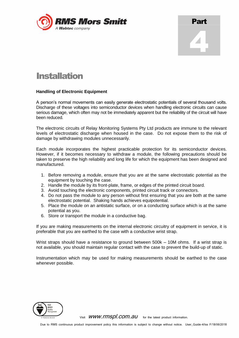
Visit www.rmspl.com.au for the latest product information.
Due to RMS continuous product improvement policy this information is subject to change without notice. User_Guide-4/Iss F/18/06/2018
Installation
Handling of Electronic Equipment
A person’s normal movements can easily generate electrostatic potentials of several thousand volts. Discharge of these voltages into semiconductor devices when handling electronic circuits can cause serious damage, which often may not be immediately apparent but the reliability of the circuit will have been reduced.
The electronic circuits of Relay Monitoring Systems Pty Ltd products are immune to the relevant levels of electrostatic discharge when housed in the case. Do not expose them to the risk of damage by withdrawing modules unnecessarily.
Each module incorporates the highest practicable protection for its semiconductor devices. However, if it becomes necessary to withdraw a module, the following precautions should be taken to preserve the high reliability and long life for which the equipment has been designed and manufactured.
1. Before removing a module, ensure that you are at the same electrostatic potential as the equipment by touching the case.
2. Handle the module by its front-plate, frame, or edges of the printed circuit board. 3. Avoid touching the electronic components, printed circuit track or connectors. 4. Do not pass the module to any person without first ensuring that you are both at the same
electrostatic potential. Shaking hands achieves equipotential. 5. Place the module on an antistatic surface, or on a conducting surface which is at the same
potential as you. 6. Store or transport the module in a conductive bag.
If you are making measurements on the internal electronic circuitry of equipment in service, it is preferable that you are earthed to the case with a conductive wrist strap.
Wrist straps should have a resistance to ground between 500k – 10M ohms. If a wrist strap is not available, you should maintain regular contact with the case to prevent the build-up of static.
Instrumentation which may be used for making measurements should be earthed to the case whenever possible.
Part
4

Visit www.rmspl.com.au for the latest product information.
Due to RMS continuous product improvement policy this information is subject to change without notice. User_Guide-4/ Iss F/18/06/2018
Safety Section
This Safety Section should be read before commencing any work on the equipment.
The information in the Safety Section of the product documentation is intended to ensure that products are properly installed and handled in order to maintain them in a safe condition. It is assumed that everyone who will be associated with the equipment will be familiar with the contents of the Safety Section.
Explanation of Symbols & Labels
The meaning of symbols and labels which may be used on the equipment or in the product documentation is given below.
Caution: refer to product information
Caution: risk of electric shock
Functional earth terminal
Note: this symbol may also be used for a
Protective/safety earth terminal if that terminal
is part of a terminal block or sub-assembly
eg. power supply.
!

Visit www.rmspl.com.au for the latest product information.
Due to RMS continuous product improvement policy this information is subject to change without notice. User_Guide-4/ Iss F/18/06/2018
Unpacking
Upon receipt inspect the outer shipping carton or pallet for obvious damage.
Remove the individually packaged relays and inspect the cartons for obvious damage.
To prevent the possible ingress of dirt the carton should not be opened until the relay is to be used. Refer to the following images for unpacking the relay:
Outer packing carton showing the shipping documentation pouch.
Address label on top of carton.
Example of the inner packing carton showing the front label detailing the serial number, relay part number & description.
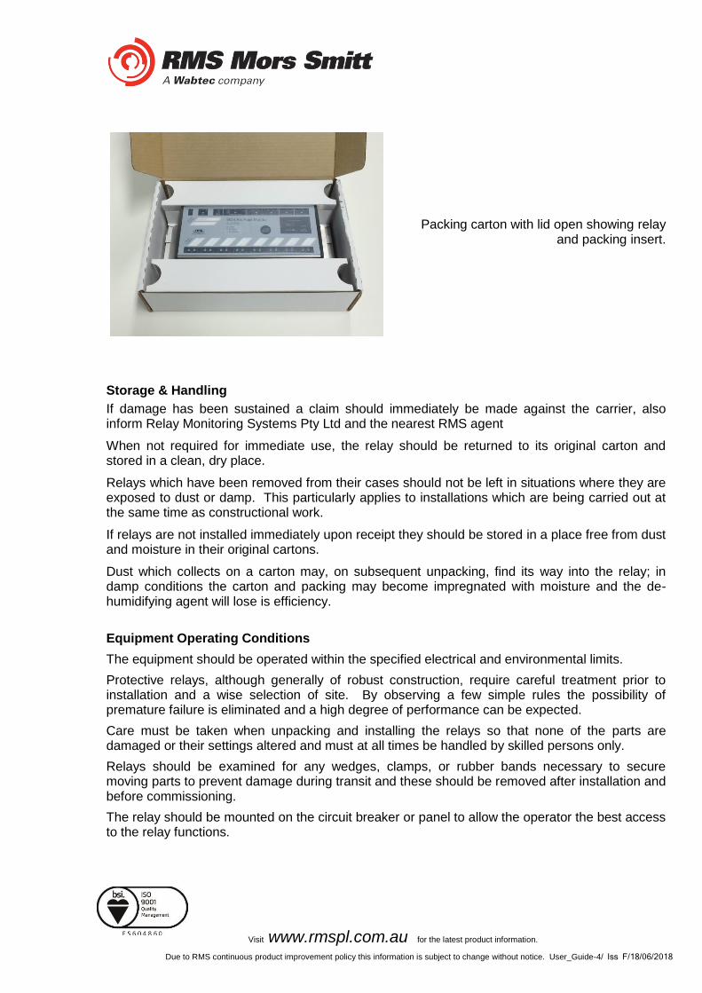
Visit www.rmspl.com.au for the latest product information.
Due to RMS continuous product improvement policy this information is subject to change without notice. User_Guide-4/ Iss F/18/06/2018
Packing carton with lid open showing relay and packing insert.
Storage & Handling
If damage has been sustained a claim should immediately be made against the carrier, also inform Relay Monitoring Systems Pty Ltd and the nearest RMS agent
When not required for immediate use, the relay should be returned to its original carton and stored in a clean, dry place.
Relays which have been removed from their cases should not be left in situations where they are exposed to dust or damp. This particularly applies to installations which are being carried out at the same time as constructional work.
If relays are not installed immediately upon receipt they should be stored in a place free from dust and moisture in their original cartons.
Dust which collects on a carton may, on subsequent unpacking, find its way into the relay; in damp conditions the carton and packing may become impregnated with moisture and the de-humidifying agent will lose is efficiency.
Equipment Operating Conditions
The equipment should be operated within the specified electrical and environmental limits.
Protective relays, although generally of robust construction, require careful treatment prior to installation and a wise selection of site. By observing a few simple rules the possibility of premature failure is eliminated and a high degree of performance can be expected.
Care must be taken when unpacking and installing the relays so that none of the parts are damaged or their settings altered and must at all times be handled by skilled persons only.
Relays should be examined for any wedges, clamps, or rubber bands necessary to secure moving parts to prevent damage during transit and these should be removed after installation and before commissioning.
The relay should be mounted on the circuit breaker or panel to allow the operator the best access to the relay functions.

Visit www.rmspl.com.au for the latest product information.
Due to RMS continuous product improvement policy this information is subject to change without notice. User_Guide-4/ Iss F/18/06/2018
Relay Dimensions & Other Mounting Accessories
Refer drawing in Technical Bulletin. Relevant Auto Cad files & details on other accessories such as 19 inch sub rack frames, semi projection mount kits & stud terminal kits may be down loaded from:
http://rmspl.com.au/product/m-series/
Equipment Connections
Personnel undertaking installation, commissioning or servicing work on this equipment should be aware of the correct working procedures to ensure safety. The product documentation should be consulted before installing, commissioning or servicing the equipment.
Terminals exposed during installation, commissioning and maintenance may present hazardous voltage unless the equipment is electrically isolated.
If there is unlocked access to the rear of the equipment, care should be taken by all personnel to avoid electric shock or energy hazards.
Voltage and current connections should be made using insulated crimp terminations to ensure that terminal block insulation requirements are maintained for safety. To ensure that wires are correctly terminated, the correct crimp terminal and tool for the wire size should be used.
Before energising the equipment it must be earthed using the protective earth terminal, or the appropriate termination of the supply plug in the case of plug connected equipment. Omitting or disconnecting the equipment earth may cause a safety hazard.
The recommended minimum earth wire size is 2.5mm2, unless otherwise stated in the technical data section of the product documentation.
Before energising the equipment, the following should be checked:
1. Voltage rating and polarity;
2. CT circuit rating and integrity of connections;
3. Protective fuse rating;
4. Integrity of earth connection (where applicable)
Visit www.rmspl.com.au for the latest product information.
Due to RMS continuous product improvement policy this information is subject to change without notice. User_Guide-4/ Iss F/18/06/2018
Current Transformer Circuits
Do not open the secondary circuit of a live CT since the high voltage produced may be lethal to personnel and could damage insulation.
External Resistors
Where external resistors are fitted to relays, these may present a risk of electric shock or burns, if touched.
Insulation & Dielectric Strength Testing
Insulation testing may leave capacitors charged up to a hazardous voltage. At the end of each part of the test, the voltage should be gradually reduced to zero, to discharge capacitors, before the test leads are disconnected.
Insertion of Modules
These must not be inserted into or withdrawn from equipment whilst it is energised, since this may result in damage.
Electrical Adjustments
Pieces of equipment which require direct physical adjustments to their operating mechanism to change current or voltage settings should have the electrical power removed before making the change, to avoid any risk of electric shock.
Mechanical Adjustments
The electrical power to the relay contacts should be removed before checking any mechanical settings, to avoid any risk of electric shock.
Draw Out Case Relays
Removal of the cover on equipment incorporating electromechanical operating elements may expose hazardous live parts such as relay contacts.
Insertion & Withdrawal of Heavy Current Test Plugs
When using a heavy current test plug, CT shorting links must be in place before insertion or removal, to avoid potentially lethal voltages.

Visit www.rmspl.com.au for the latest product information.
Due to RMS continuous product improvement policy this information is subject to change without notice. User_Guide-4/ Iss F/18/06/2018
Commissioning Preliminaries
Carefully examine the module and case to see that no damage has occurred during transit. Check that the relay serial number on the module, case and cover are identical, and that the model number and rating information are correct. Check that the external wiring is correct to the relevant relay diagram or scheme diagram. The relay diagram number appears inside the case. Note that shorting switches shown on the relay diagram are fitted internally across the relevant case terminals and close when the module is withdrawn. It is essential that such switches are fitted across all CT circuits. Earthing Ensure that the case earthing connection above the rear terminal block is used to connect the relay to a local earth bar. Insulation The relay, and its associated wiring, may be insulation tested between: - all electrically isolated circuits
- all circuits and earth An electronic or brushless insulation tester should be used, having a dc voltage not exceeding 1000V. Accessible terminals of the same circuit should first be strapped together. Deliberate circuit earthing links, removed for the tests, subsequently must be replaced. Commissioning Tests
If the relay is wired through a test block it is recommended that all secondary injection tests should be carried out using this block. Ensure that the main system current transformers are shorted before isolating the relay from the current transformers in preparation for secondary injection tests. DANGER DO NOT OPEN CIRCUIT THE SECONDAY CIRCUIT OF A CURRENT TRANSFORMER SINCE
THE HIGH VOLTAGE PRODUCED MAY BE LETHAL AND COULD DAMAGE INSULATION. It is assumed that the initial preliminary checks have been carried out. Relay CT shorting Check electrically that the CT is shorted before isolating CT secondaries.

Visit www.rmspl.com.au for the latest product information.
Due to RMS continuous product improvement policy this information is subject to change without notice. User_Guide-4/ Iss F/18/06/2018
Primary injection testings It is essential that primary injection testing is carried out to prove the correct polarity of current transformers. Before commencing any primary injection testing it is essential to ensure that the circuit is dead, isolated from the remainder of the system and that only those earth connections associated with the primary test equipment are in position. Decommissioning & Disposal
Decommissioning: The auxiliary supply circuit in the relay may include capacitors across the supply or to earth. To avoid electric shock or energy hazards, after completely isolating the supplies to the relay (both poles of any dc supply), the capacitors should be safely discharged via the external terminals prior to decommissioning.
Disposal: It is recommended that incineration and disposal to water courses is avoided. The product should be disposed of in a safe manner.

Visit www.rmspl.com.au for the latest product information.
Due to RMS continuous product improvement policy this information is subject to change without notice. User_Guide-5/Iss F/18/06/2018
Maintenance
Mechanical Inspection
Relay Assembly
Inspect the relay for obvious signs of damage or ingress of moisture or other contamination.
Relay Module
Isolate the relay, remove any securing screws where fitted and unplug the relay from the terminal base.
Inspect the relay for signs of any overheating or burn marks which may have been caused by overvoltage surge or transient conditions on the power supply.
Test Intervals
The maintenance tests required will largely depend upon experience and site conditions, but as a general rule it is recommended that the following inspection and tests are performed every twelve months.
Mechanical Inspection
Check of Connections
Insulation Resistance Test
Part
5

Visit www.rmspl.com.au for the latest product information.
Due to RMS continuous product improvement policy this information is subject to change without notice. User_Guide-5/Iss F/18/06/2018
Defect Report Form
Please copy this sheet and use it to report any defect which may occur.
Customers Name & Address: Contact Name:
Telephone No:
Fax No:
Supplied by:
Date when installed:
Site:
Circuit:
When Defect Found
Date: Commissioning? Maintenance? Systems Fault? Other, Please State:
Product Part No: Serial Number:
Copy any message displayed by the relay:
Describe Defect:
Describe any other action taken:
Signature:
Please Print Name: Date:
For RMS use only
Date Received: Contact Name: Reference No: Date Acknowledged: Date of Reply: Date Cleared: