1O-GHz Gunnplexer transceivers -...
17
what isa gunnplexe r7 The heart of the Gunnplexer is the Gunn diode oscillator, named aft er the IBM engineer wh o invent- ed it in 1963, John Gunn. While measuring the rests- M icrowave communica tio ns is one of the last frontiers of Amateur Radio; thanks to the Gunnprex- er transceiver module offe red by Microwave Associ- ates, it's now easier than ever to put together a prac- tical station for amat eur operation on the 10-GHz band. Only a few years ago a " simple" microwave setup required a rack-full of equipmen t and friends in the industry w ho could provide hard-to-find parts. With the Gunnprexer. an entire microwave system ca n now be held in one hand . It can be easily back- packed to the highest mountain tops, and it can be ope rated from a single 12-volt battery. As you receive it, the Gunnplexer module is not a complete transceiver; to put it on the air you need a de power supply, a simple speech amplifier, and an Im receiver. You can put together a working system in one evening. To build a complete transceiver like that described in this article w ill tak e a little longer. Discussion of the various aspects of Gunnplexer transceiver construction and operation, including two practical transceiver designs 1 O-G Hz Gunnplexer transceivers - construction and practice By James R. Fi sk . W1HR . ham rad io, Green- ville, New Hampshire 03048 26 flI janu ary 1979
Transcript of 1O-GHz Gunnplexer transceivers -...

what is a gunnplexer7The heart of the Gunnplexer is the Gunn diode
oscillator, named aft er the IBM engineer wh o invented it in 1963, John Gunn. While measuring the rests-
M icrowav e co mmunica tions is one of the lastfrontiers of Amateur Radio; thanks to the Gunnprexer transceiver mod ule offe red by Microwave Associates, it's now easier than ever to put together a practica l sta tion for amateu r operation on the 10-GHzband . Only a few years ago a " simple" micr owa vesetup required a rack-full of equipmen t and friends inthe industry w ho could provide hard-t o-fin d parts.With the Gunnprexe r. an entire microwave sys temca n now be held in one hand . It ca n be easily backpacked to the highest mountain tops, and it can beoperated from a single 12-volt battery.
As you receive it, the Gunnplexer modu le is not acomplete transceiver; to put it on the air you need ade power supply, a simple speech amplifi er, and anIm receiver. You can put together a w orking systemin one evening. To build a complete transceiver likethat described in this article w ill take a little longer.
Discussion of the
various aspects of
Gunnplexer transceiver
construction and operation ,
including two practical
transceiver designs
1O-GHz Gunnplexer transceivers constructionand practice
By James R. Fisk. W1HR . ham radio, Greenville, New Hampshire 03048
26 flI jan uary 1979
GIJNN OSCll LJlTOII
--
ranee of gallium arsenide (GaAsl , Gunn found thatw hen the voltage across a thin wafer of the materia lwas increased above a certain point , the curren t fluctua ted at microwave frequencies. The mechanismwhich caused this was a mystery at first , but Gunnsuspected a negative resistance due to elec tronmovements w ithin the gallium arsenide. This eventually proved 10 be the case (a detailed descrip tion ofthe Gunn diode phenomenon is contained in reference 11.
When a Gunn diode is placed in a resonant microwave cavity, small amountsof pow er can be obtainedat the desired frequency. The cavity can be tunedmechanically , or a voltage-variable capaci tor (veraclorl may be used to change the resonant frequencyof the cavity . The Gunnplexer (f ig . 1) uses bot h amechanical tuning screw and a veractor diode; frequency modulation is obtained by placing a smallmodulating voltage across the va ractor. Power iscoupled out of the cavity through an iris. The size ofthe iris must be determined experimentally f or thebest compromise between maximum pow er outputand isolation from changes in diode impedance andtoad.
In the Gunnplexer the Gunn oscillator providesboth the transmit pow er and the local-oscillato r injection for the mixer diode. The ferrite ci rculator couplesa small amount of energy into the low-noise Schottky mixer diode and isolates the transmit and receivefunctions. Since the Gunn oscillator fu nct ions asboth the transmitter and receive local oscillator, thei·f receiver at each end of the communications linkmust be tuned to the same f requen cy, and the f requencies of the Gunn oscillators at each end of thelink must be separated by the i-f .
M lcr ow av aA..oc la las 10-GHl Gunnplaxar.
fig , 1. C Ulaw ay view of tbe Micr ow a ve Ass odillas Gunr, .pluxer. Th e Gu nn di od e is mounled in a ruso na nl ca vitywhich is tu ned by II tu ning sc re w tcoaese luningla nd a VII ·racto r Ulne t uning ). Micr ow a ve e ne rgy is couplud ou t of Ih ecavi ty t hrough a n iris . The fe rrite -rod circulator coup les as m a ll a m ount of rf a ne rgy inlo the S chotlky m ixer diode;t he c irc ul a to r a llo il ol ate 5 the Iransmil a nd receive tu nc tion. a nd a llow l lu ll·du plex o pe ra t ion.
Confused? Take a look at fig , 2. Here Gunnplexer1 is tuned to the center of the 10-GHz amateur bandat 10250 MHz. If a 3O-M Hz j-f receiver is used, Gurmplexer 2 must be tuned either 30 MHz higher or lowerthan Gunnplexer 1. Assume it 's tuned 30 MHz higherat 10280 MHz ; its signal w ill mix w ith the 10250-MH zLO in Gunnplexer 1 to provide an output to thereceiver at 30 MHz. Conversely , the 10250·M Hztransmit signal from Gun nplexer 1 will mix wi th the10280·M Hz LO in Gunnplexer 2 to provide an outputat 30 MH z.
gunnplexer communications rangeOne of the f irst and most asked ques tions about
Gunnp1exers is, what is their maximum range? Sincemost microwave communications systems are basedon line-of-sight transmission , it's a relatively easymatter to determine the effe ctive communicationsrange of any Gunnplexer system . When the distancebetween the two stat ions is know n, path toss in dB isgiven by:
92 .5 dR +20 log ! (G/ h) + 20 log D (kilornrl en)
96,6 d B + 20 log ! (G/ Il ) + 20 log D (m iles)
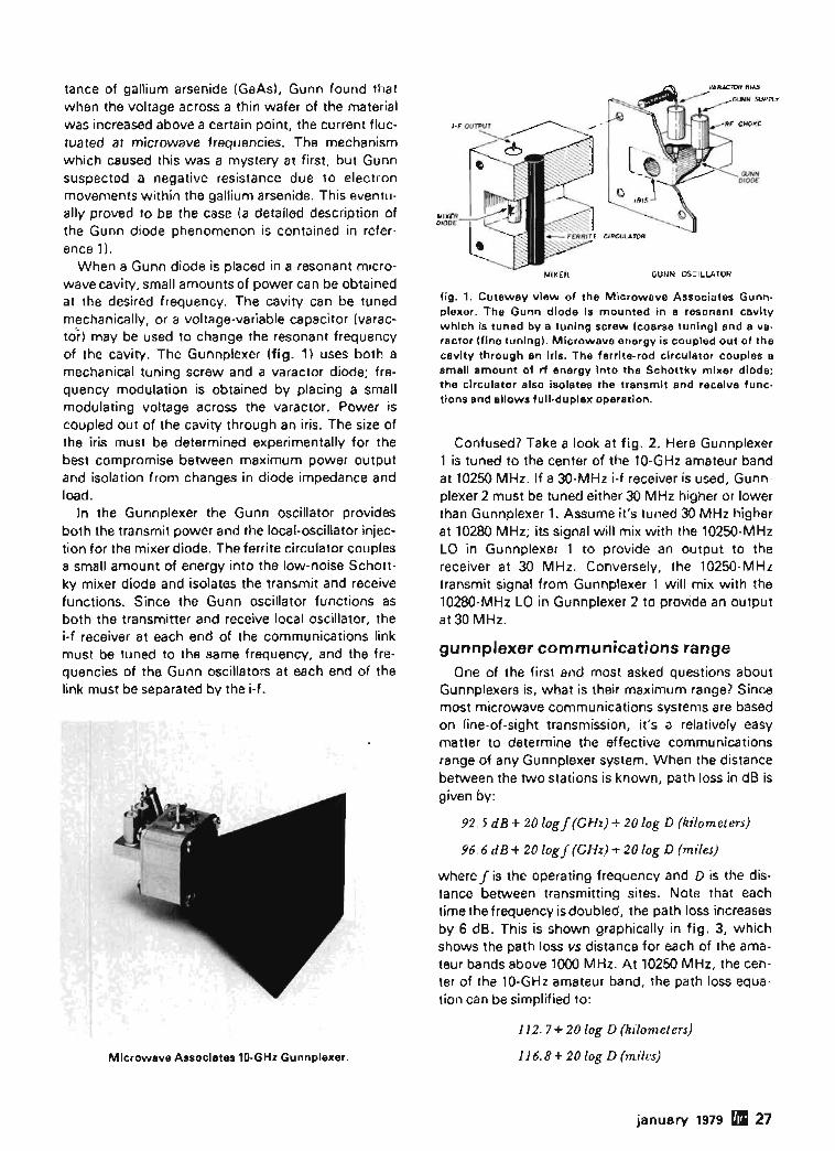
where J is the operating frequency and [) is the distance between transmitting sites. Note that eachtime the f requency isdoubl ed, the path loss increasesby 6 dB. This is show n graphically in fig . 3, w hichshows the path loss vs distance for each of the arne teur bands above 1000 M Hz. At 10250 MH z, the center of the 10-GHz amateur band , the path loss equation can be simp lified to:
112.7 + 20 log D (kiiornet t'rJ)
116.8 + 20 log D (miles)
j anuary 1979 rlI 27
-
V ."
....~V
."...... ....
~ V- --V Io-"~
t:::~~ V......~Io-"""IZA
-' /"f- -
." "....~~V ~Io-"~ /'!,... ..... ,0
."~
~~
~ ./
/'~ ~I
V ~~ ..... ~ ~ ."." ~ ~/ ......... z~d2 (.C
t>~
V~
..... ~~y
/'~ V~
.....10-"
::::V ~~-- f-
V VV /
170
fig . 3. Path loss vs distance for each of the six amateurm icrowave bands. Note that path loss increases 6 dB eacht ime the frequency or path length is doubled. Loss over 8
61.7-km path at 1215 MHz, for example, is 130 dB ; at twicethe frequency (2430 MHz) the lo ss is 6 dB greater; at 8 timesthe frequency, near the 10 GHz band. loss is more than 18dB greater. This graph assumes line of sight with no obstructions of any kind .
100I " 2 J 4 !j 6 r 8 9 10 1;5 20 30 40 50 60 80 100 (50 200
PATH LENGTH(km)
110
the path loss is 146.7 dB. The other item which isfixed is the thermal noise floor, at - 144 dBm, whichis set by the laws of nature and determines the ultimate sensitivity of the receiver.s
Beginning at the transmitting end of the link, wehave 15 mW power output ( + 11.8 dBm). To this isadded the 17-dB gain of the antenna. When the pathloss is subtracted, the signal level at the receiving siteis -117.9 dBm. The 17-dB-gain receiving antenna
PATH LENGTH (MILES)/52 56789 ,'0 ' 520 304050 10012'
II '1 11" I I 11 /"""
160
~ /40
~VIVI
~ /"O
zCf. /20
In other words, the path loss over a distance of 1km is 112.7 dB; it increases 6 dB each time the pathlength is doubled. The objective is to build enoughgain and sensitivity into the microwave system toovercome the loss over the desired path. This is afunction of transmitter power, antenna gain, receiversensitivity (noise figure), and receiver bandwidth, butit's not as complicated as it sounds because all thesefactors can be easily translated into dB.
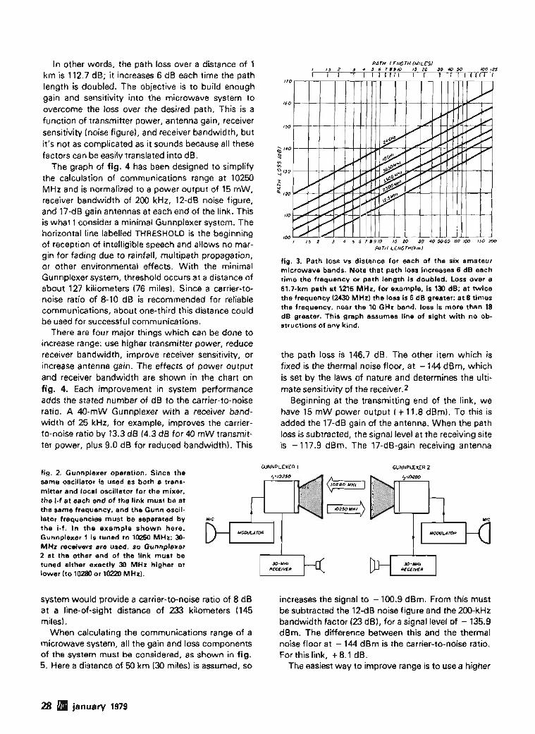
The graph of fig . 4 has been designed to simplifythe calculation of communications range at 10250MHz and is normalized to a power output of 15 mW,receiver bandwidth of 200 kHz, 12-dB noise figure,and 17-dB gain antennas at each end of the link. Thisis what I consider a minimal Gunnplexer system. Thehorizontal line labelled THRESHOLD is the beginningof reception of intelligible speech and allows no margin for fading due to rainfall, multipath propagation,or other environmental effects. With the minimalGunnplexer system, threshold occurs at a distance ofabout 127 kiliometers (76 miles). Since a carrier-tonoise ratio of 8-10 dB is recommended for reliablecommunications, about one-third this distance couldbe used for successful communications.
There are four major things which can be done toincrease range: use higher transmitter power, reducereceiver bandwidth, improve receiver sensitivity, orincrease antenna gain. The effects of power outputand receiver bandwidth are shown in the chart onfig. 4. Each improvement in system performanceadds the stated number of dB to the carrier-to -noiseratio . A 4O-mW Gunnplexer with a receiver bandwidth of 25 kHz, for example, improves the carrierto-noise ratio by 13.3 dB (4.3 dB for 40 mW transmitter power, plus 9.0 dB for reduced bandwidth). This
fig. 2. Gunnplexer operation. Since thesame oscillator is used as both a transm itter and local oscillator for the m ixer,the i-f at each end of the link must be atthe same frequency, and the Gunn oscillator frequencies must be separated bythe i-f . In the example shown here,Gunnplexer 1 is tuned to 10250 MHz; 30MHz receivers are used, so Gunnplexer2 at the other end of the link must betuned either exactly 30 MHz higher orlower (to 10280 or 10220 MHz).
GUNNPLEXER I GUNNPLEXER 2
system would provide a carrier-to-noise ratio of 8 dBat a line-of-sight distance of 233 kilometers (145miles).
When calculating the communications range of amicrowave system, all the gain and loss componentsof the system must be considered, as shown in fig.5. Here a distance of 50 km (30 miles) is assumed, so
increases the signal to - 100.9 dBm . From this mustbe subtracted the 12-dB noise figure and the 2oo-kHzbandwidth factor (23 dB), for a slqnal level of -135.9dBm. The difference between this and the thermalnoise floor at - 144 dBm is the carrier-to-noise ratio.For this link, +8.1 dB.
The easiestway to improve range is to use a higher
28 fII january 1979

gain antenna. Unlike the lower frequencies, whereantenna gain is hard to come by, on the microwavebands it's relatively easy. A 24-inch (61-cm) parabolicreflector, for example, yields 32 dBi gain. If used atonly one end of the system shown in fig. 5, thiswould have the effect of increasing the range to
fig. 4. Carrier-to-noise ratio vs distance for two 15-mWGunnplexers at 10250 MHz, equipped with 17-dB-gain hornantennas; receiver noise figure is assumed to be 12 dB with200 kHz bandwidth. The THRESHOLD line is the beginning ofthe reception of intelligence. At a distance of 127 km (76miles) the carrier is at the noise level or threshold; at a distance of about 40 km (25 miles) the carrier-to-noise ratio is10 dB, the minimum signal level recommended for reliablevoice communications. Range can be lengthened by increasing transmit power, decreasing bandwidth, or addingantenna gain (see text). Improvements in dB for increasedoutput and narrower bandwidth are shown.
r-... ~Rq~TPUT l}~t'iOWlPI!!
<, mW «e .Hz d8TO - ~8 250 - 1.0
r--.. 15 0 200 0
"r-. 20 + 1.3 IT5 + 0.6
25 + 2.2 150 + 1.230 + 3.0 125 + 2.0
35 + 3.7 100 + 3.0r--.. 40 + 4.3 75 + 4.3
'I'. 45 + 4.8 50 + 6.050 + 5.2 25 + 9.0
<, 55 + 5.6 15 + 11.2
'" 60+ 60 10 +13.0
]',!'-
THRESHOLD r-,
t-,....... t-,
tem which phase locks the Gunn oscillator to a crystal-controlled reference oscillator. The cost of aphase-locked system is somewhat less than that of acommercial parabolic reflector, but system gain isonly on the order of 12-13 dB when compared with asystem with 200-kHz receiving bandwidth. On theother hand, a phase-locked system permits the useof CW, which provides reliable communications withlower carrier-to-noise ratios than voice, so there maybe the equivalent of an additional 4-5 dB gainavailable.
For greater range you can also increase transmitteroutput or improve receiver noise figure, but both areexpensive and limited to a certain extent by the present state of the art .
gunnplexer performance
The Gunnplexer performance measurements discussed here were made by B. Chambers, G8AGN, ofthe Department of Electronic and Electrical Engineering at the University of Sheffield, England, who isalso a member of the Microwave Committee of theRadio Society of Great Britain. Front-end performance was not measured because, in practice,receiver sensitivity and noise figure are highly dependent on the operator's choice of i-f strip and thedegree of matching between the mixer diode and thei-f preamplifier. Therefore G8AGN made measurements only to check the performance of the Gunnoscillator.
When a variable voltage was connected to theGunn diode, it was found that rf power was produced with an applied voltage as low as 5 volts. Mostof the tests, however, were accomplished with + 10
100 200
100 200 400
50
RANGE (MILES)
10 20
/0 20 50RANGE (km)
5
2
2-10
I
+30
+40
B.ldB-"C/N
PATH LOSS
112.7d8+20LOGO- f46,7dB
TRANSMITTER r- ------ ... ~OJrm15mW
+1I.8dBm
~ANTENNA+l7dS
volts applied to the Gunn diode and + 4 volts bias onthe varactor diode.
Using a Systron-Donner model 6057 frequencycounter with an upper frequency limit of 18 GHz,G8AGN found that the Gunn oscillator drifted downin frequency by about 3 MHz during the initial onehour warm-up period. A further frequency check 15
Carrter-to-noise ratio:
fig. 5. Example of a path-loss calculation at 10250 MHz.With two 15-mW Gunnplexers equipped with H-dB gain antennas, and 12-dB noise figure in 2OO-kHz bandwidth, thecarrier-to-noise ratio at 50 km is 8.1 dB.
nearly 2000 km (1200 miles) for the same 8.1 dBcarrier-to-noise level! That's obviously well beyondline-of-sight for any two earth-based locations. Onedisadvantage of high antenna gain is antenna alignment; the 4-degree beamwidth of a 24-inch dishleaves little room for error when pointing the antennaat another station.
You can also increase range by reducing the bandwidth of your receiving system, but because of thethermal drift of the Gunnplexer, this requires a sys-
Transmitter power, 15 mWAdd transmitter antenna gainSubtract path lossAdd receiver antenna gainSubtract receiver noise figureSubtract 200 kHz bandwidth factorThermal noise floor
+ 11.8dBm+ 17.0 dBi
+ 146.7 dB+ 17.0 dB;-12.0 dB-23.0dB
+ 11.8dBm+28.8dBm
-117.9dBm-100.9dBm-112.9dBm-135.9dBm-144.0dBm
+8.1 dB
january 1979 mil 29

fig. 6. Typical variation of Gunnplexer output power as thefrequency is tuned mechanically through the 10-GHz amateur band. as measured by G8AGN. At all frequencies theoutput was well above the rated 25 mW.
minutes later showed that the oscillator was driftingdown in frequency by about 28 kHz per minute. Thisrate of drift is quite acceptable in practice unless anarrow-band system is being used and there is noprovision for AFC.
The mechanical tuning range of the oscillator waschecked next and found to extend from 9641 MHz upto 10764 MHz. The rf power output over this frequency range was measured with a Marconi model6460 power meter with a coaxial head, buffered by afixed 20-dB pad. This was preceded by a coax-towaveguide transition and slide-screw tuner whichwas adjusted before each reading to ensure that theoscillator was delivering power into a matched load.Fig. 6 shows the variation of rf output power overthe frequency range from 10.0-10.5 GHz. Rf powermeasurements at the extremities of the tuning rangeshowed 39 mW at 9641 MHz and 24 mW at 10764MHz.
For a given setting of the mechanical tuningscrew, the frequency of the Gunn oscillator may betuned electrically by changing the voltage applied toeither the Gunn diode or the varactor. Varying thevoltage of the Gunn diode over the range from + 5 to+ 11 volts produced a frequency change of 13.3 MHzabout a preset value of 10250 MHz. This representsapproximately 2.2 MHz per volt for frequency pushing and is well within the quoted specification.
With the Gunn diode held at + 10 volts, the varactor bias was varied from + 1 to + 12 volts and measurements were made of both frequency and rf poweroutput. Although up to +20 volts bias may be usedon the varactor. measurements were made only to+ 12 volts because this is the maximum voltage usually available for portable operation. Fig. 7 shows the
50
20
10
2 .3 4 5 6 ., 8 9 10 " /2VARACTOR VOL7~GE (VOLTS)
./V
J, ....-R.! "Y~'!. ..J.
V~,'" V,,I~/;-...,/
'#1/ ,,
A.l ,~
I ,) \
V I ,) \
Vx ..._--
JV
1021
1024
10.22
10.29
10.30
1027
1028
1020
10.23
~
~
'"- 10.26)..
~~ 1025
i<:
result of these measurements. It can be seen that themaximum electronic tuning range was approximately100 MHz, and that over this range the rf power output varied by about 3.5 dB.
The final set of Gunnplexer measurements madeby G8AGN were concerned with the frequency-pulling performance of the Gunn oscillator. To makethese measurements, the Gunnplexer was set up todeliver power to a load consisting of an adjustableshort circuit; therefore, by varying the axial positionof the short-circuit plane within the waveguide, awide range of load impedances would be seen by theoscillator. For an axial variation of the short-circuitplane of 20 mm (0.8 inch), corresponding to a distance just greater than A2/2 at 10250 MHz, the totalfrequency variation was found to be 12 MHz.
The result of this test suggested that the ferrite circulator should be "transparent" enough for theGunnplexer to be frequency locked using a cavitywavemeter, and this, in fact, proved to be the case. ATEOll mode transmission-type cavity wavemeterwith a quoted Q factor of 8000 was available. Thiswas simply bolted to the Gunnplexer assembly - theresulting separation between the wavemeter and thecoupling iris to the Gunn oscillator being about 6.5cm (2.6 inches). The wavemeter cavity had provisionfor attaching a waveguide diode holder, and this was
fig. 7. Frequency variation and measured power output withchanges in varactor bias. as measured by G8AGN. Poweroutput varies less than 3.5 dB over the nearly 100-MHztuning range.
10.510.410./ IO.J
FREQUENCY (GHzl10'
;>-- ,~ .....
I' 1,.", I'f.RFO'" '\ 4S U" f.O '1'1,.
~ 41<
, C'f" "" i'--,~ ,
\ ,\
L~§¥};~// ....>:I:>";> "" ;;;;;;
F« SPECIFIEDL:;"; PERFORMANCE <-:
k~~~o10.0
10
50
60
30 DI january 1979

J£-----~'W.~....-__oourpur+IOV,IA0'1
+12V IN o-~-------.,
the voltage on the built-in tuning varactor, the setting of the mechanical tuning screw, and the supplyvoltage to the Gunn diode. Unless otherwise specified, the Gunnplexer is mechanically tuned to 10250MHz at the factory with 10.0 volts on the Gunn diodeand 4.0 volts across the varactor. The output frequency of the Gunnplexer can be adjusted ± 100MHz with the tuning screw, but I don't recommendtouching the mechanical tuner unless you have access to a microwave frequency counter; you will findit difficult to accurately retune the unit to 10250, thecenter of most amateur activity on this band.
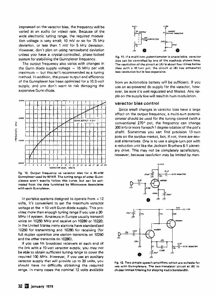
The Gunnplexer can also be electronically tuned byvarying the voltage across the varactor from 1 to 20volts; this is the preferred method, and a tuningrange of 60 MHz is guaranteed. Electronic tuningrange varies from unit to unit , but data is furnishedwith each Gunnplexer so you can easily estimate frequency output vs varactor voltage. Many units havean electronic tuning range of 100 MHz or more, soit's not necessary to touch the mechanical tuningscrew for most amateur applications.
Shown in fig. 10 is a plot of frequency output vsvaractor tuning voltage for a 4O-mW Gunnplexer thatI am using at my station. The tuning curve is quitenonlinear, with the greatest frequency change - 50MHz - occurring as the varactor voltage is increasedfrom 1 volt to 4 volts. An increase from 4 volts to 10volts moves the output frequency up 40 MHz, and achange from 10 volts to 20 volts increases the outputfrequency 46 MHz. The total frequency change is 136MHz. The tuning range of other Gunnplexers won'texactly follow this curve, but it gives you an idea ofwhat you can expect.
The varactor also provides a way of frequencymodulating the unit. If a small modulating voltage is
'Shortly after this article was written. Fairchi ld Semiconductor announcedthe }'A7BCOO series of 3-terminal voltage regulators which have rated out put current greater than 500 rnA. A 10-volt regulator. the }'A78Cl0C. isincluded in the series.
fig. 9. Simple + 10 volt regulator using readily availableparts, designed by W1SL. will supply up to 1 ampere. The723 regulator is available from Radio Shack (part number276·1740) as is the 2N3055 transistor (Radio Shack 276-16341.
o
fig. 8. Regulated Gunnplexer power supply can be adjustedto exactly + 10 volts; with proper heatsinking, this circuitwill provide current in excess of 500 rnA. The O.33'JLF capacitor at the input and 0.1 JLF at the output improve circuit performance.
used in conjunction with a sensitive milliammeter todetect when the cavity was tuned near resonance.
With a little practice, G8AGN found that it waspossible to hold the frequency of the Gunn oscillatorto within 1 kHz for periods of minutes at a time. Inview of this, it seems probable that the Gunnplexercould also be injection locked using a crystal controlled source, although this was not tried.
+ 12V TO __.---'~----,!--..-_-<>+20Vo- + IOV
power supplyThe first requirement for a Gunnplexer system is a
regulated + 10 volt power supply. Unfortunately,there aren't any readily available, high-current, threeterminal IC regulators with a 10-volt output (theLambda LAS1510 meets these requirements, but isdifficult to purchase in small quantities}. * Theanswer is the Fairchild ",A78MG 4-terminal requlator,which requires only two external resistors to set theregulated output voltage (see fig. 81. This regulatorwill provide in excess of 500 mA output, so it's adequate for most Gunnplexer systems.
For precise voltage adjustments, I have included aminiature 5OO-ohm pot between the two 4700-ohmresistors; this allows the output voltage to be setwithin a few millivolts of + 10 volts. If you're not thisfussy, you can connect the Ie's control terminal (pin4) directly to the junction of two 4700-ohm resistors- the output voltage should be within 5 per cent ofthe required 10 volts. This is probably close enoughfor most applications.
In many circuits using the ",A78MG regulator thebypass capacitors may not be required. However, forstable operation of the regulator IC over all voltageand current input ranges, bypassing is recommendedby the manufacturer (0.33 ",F at the input and 0.1 ",Fat the output). The input bypass is necessary if theregulator is located far from the filter capacitor in thepower supply; bypassing the output improves thetransient response of the regulator.
tuning rangeThe frequency of the Gunnplexer is controlled by
january 1979 mI 31
impressed on the varactor bias, the frequency will bevaried at an audio (or video) rate. Because of thewide electronic tuning range, the required modulation voltage is very small; 10 mV or so for 75 kHzdeviation, or less than 1 mV for 5 kHz deviation.However, don't plan on using narrowband deviationunless you have a crystal-controlled, phase-lockedsystem for stabilizing the Gunnplexer frequency.
The output frequency also varies with changes inthe Gunn diode supply voltage - 15 MHz per voltmaximum - but this isn't recommended as a tuningmethod. In addition, the power output and efficiencyof the Gunnplexer has been optimized for a 10.0-voltsupply, and you don't want to risk damaging theexpensive Gunn diode.
+101/
COARSEVARACTOR
•fig. 11. If a multi-turn potentiometer is unavailable, varactorbias can be controlled by one of the methods shown here.The resolution of the circuit at (A) is about four times betterthan with a lD-turn pot; the circuit at (B) has somewhatless resolution but is less expensive.
from an automobile battery will be sufficient. If youuse an ac-powered de supply for the varactor, however, be sure it's well regulated and filtered. Any ripple on the supply line will result in hum modulation.
toseo
10300
~
~
......~t> .......
t> GUNN SUPPLY=+IOV
1/""-,/
./
l/l/
V)
II
varactor bias controlSince small changes in varactor bias have a large
effect on the output frequency, a multi-turn potentiometer should be used for the tuning control (with aconventional 2700 pot, the frequency can change300 kHz ormore for each 1deqree rotation of the pot'sshaft). Sometimes you can find precision 10-turnpots on the surplus market, but, if not, there are several alternatives. One is to use a single-turn pot witha reduction unit like the Jackson Brothers 6:1 planetary drive. This may not be completely satisfactory,however, because resolution may be limited by man-
0.47
E---o ro VARACro/l
.70
100/0>
0 .•7
---.J~ ro VARACroR10tl~
......-..----......----.>--'\Nv--o+ f2V
~.l-03---1~+--l
/200
+1.2V
fig. 12. Two simple speech amplifiers which are suitable foruse with Gunnplexers. The two-transistor circuit at IB) includes limited filtering for shaping audio bandwidth.
In portable systems designed to operate from + 12volts, it's convenient to set the maximum varactorvoltage at the + la-volt Gunn diode supply. This provides more than enough tuning range if you use a 30MHz i-f system. Amateurs in Europe usually transmitvoice on 10250 MHz and receive on 10280 or 10220;in the United States many stations have standardized10250 for transmitting and 10280 for receiving (forfull duplex operation one station transmits on 10250and the other transmits on 10280).
If you use fm broadcast receivers at each end ofthe link with a 10-volt varactor supply, you may notbe able to obtain sufficient tuning range to cover therequired 100 MHz. However, if you use an auxiliaryvaractor supply that will provide up to 20 volts, youshould have no difficulty obtaining the requiredrange. In many cases the nominal 12 volts available
10200o I 2 J 4 5 6 7 89m II u ~ H ~ ~ " m 19m
VARACTOR BIAS, VOLTS
fig. 10. Output frequency vs varactor bias for a 4O-mWGunnplexer used by W1HR. The tuning range of other Gunn·plexers won't exactly follow this curve, but can be estimated from the data furnished by Microwave Associateswith each Gunnp'exer.
32 flI january 1979

Mlnlmll Gunnplexer , ." te m u..d by Wl HR Includ'" e 10-vol t Ie vollege reQulllor. , lmple .peech ImpUfler . end t one o. clll"or.A phono connector on tho bottom of tho chessi. i. pr ovi ded for th e fm rec e iver. A 10·turn pr eci ,lon potent iometer found o n lhe. urpl.... me.ket ISused for frequency cont ro l.
ufactur ing tolerances in the potentiometer's reslsranee element .
Tw o other possibilit ies for varactor control areshown in f ig. 11. The system in f ig. llA uses onedual potenti ometer for coarse adjustments and asingle-turn pot for fine luning. Resolution of this svs-
tern is about four times better than with a tn-tcm potand is suitable for the most demanding requirements.The bias control arrangement in f ig. 118 does notprovide as much resolution but is more economical.A disadvantage is that the resolut ion of the fineadjustment varies, and depends upon the sett ing of
january 1979 UI 33

+/j ;}; 2~J/F
.-------+ 2N:Er±:xLr Jt----H--4--t-l -- 1! 1 ra· 7
IN9/.
TOVARACTOR
fig. 14. Two-transistor speech amplifier for Gunnplexersfeatures high input impedance, good gain. clipping for improved audio punch, and a lowpass filter for limited audiobandwidth.
,,---~_------,---,,--<>+IOV
~0!--+-.1 --H
MIC .
the coarse control; when the coarse potentiometer isin the center of its range, resolution approximatesthat of a 10-turn pot.
speech amplifiersBecause of the high sensitivity of the varactor, a
very small modulation voltage (on the order of 10 mVpop) is required to obtain 75-kHz deviation for wideband frequency modulation of the Gunnplexer; thisgreatly simplifies the design of a suitable speech
mended. This 741 speech amplifier was designed byG8AGN/G8CZO for use with a Gunn diode transmitter. 3
In any frequency-modulation system the speechamplifier should, in addition to providing audio gain,include some form of speech processing to limitdynamic range so the audio signal doesn't exceedthe maximum frequency deviation. This can be donewith audio compression or by using a simple diodeclipper to limit the audio peaks. The two-stagespeech amplifier shown in fig. 14 includes a clipperand lowpass RC filter (47k resistor and 0.02-ILF capacitor) to reduce the harmonics produced by clipping. Iused 2N2222 transistors in this circuit because I hadthem in my junk box, but most high-gain NPN transistors should work. If you wish, the same diode clipper and RC filter can be added to the circuits of figs.12 and 13.
For most effective fm communications, the speechsystem should include a system for limiting bandwidth to 300-3000 Hz, and de-emphasis to correctthe speech frequency characteristic. A circuit which
ssoo 1800+
~oPFI
fig. 13. Speech amplifier circuit designed by G8AGN forGunnplexer operation uses a low-cost 741 op amp and offershigh input impedance.
tl Jf-P F
__-4-_--1
amplifier. In its simplest form , the Gunnplexerspeech amplifier requires only one transistor, asshown in fig. 12A. In this circuit the MPF102 fet exhibits high input impedance for a crystal, ceramic, ordynamic microphone, and provides more thanenough voltage gain for full 75-kHz deviation at 10.25GHz. Deviation is adjusted with the 10k potentiometer in the drain circuit.
The two-transistor speech amplifier in fig . 128 hasan input impedance of about 20 kilohms and includesfiltering to limit the speech bandwidth. For thosewho prefer to use ICs the circuit in fig. 13 is recom-
SPEECH AMPLIFIER22 00
CLIPPER ACTIVE ALTER DE- EMfflASIS
0 .47
1000+
22PF
1
1000 TRANSISTOR VOLTAGES"T'Z2J1F E B Cm 0 1 ,-:, 1~£2
Q2 / .7 2 .2 ~,7
0 3 2 .0 2.0 10.0
Q4 1.$ 1. 1 10 .0
Q~ $ .0 3 .$ 4 .1
I~' 047
eroo
fig. 15. High-performance fm speech amplifier uses heavy feedback for reduced audio distortion. It also includes an audio clipper, 300-3000 Hz active audio filter, and de-emphasis stage. Both input and output controls are provided. Circuit board for thiscircuit is shown in fig. 22.
34 UI january 1979

has a complete speech amplifier, clipper, active filter,and de-emphasis stage is shown in fig. 15.4 The firsttwo stages use heavy feedback to reduce distortionand improve frequency response. These stages arefollowed by a double-diode clipper and a two-stageactive filter that has a 500-3000 Hz passband. Thelast stage provides de-emphasis. This amplifier givesan output of 100 mV for an input of 2 mV across 300ohms; both input and output controls are provided. Ihave used this amplifier with good success at oneend of a wideband Gunnplexer link.
tone oscillatorWhen lining up two Gunnplexer systems, particu
larly if you're using high-gain parabolic reflectors, it'shelpful to continuously tone modulate your transmitter. There are several ways to generate an audiotone, but for minimum parts count I prefer the circuitof fig. 16, which uses a 555 timer IC. Total currentdrain with a 10-volt supply is only 10 mA. The 1-kHzsquarewave output swings from ground to + 10volts; this is reduced to manageable levels for Gunnplexer use with the series lOOk resistor and 2oo-ohmpot. The 10k resistor and 0.1-ILF capacitor form alowpass filter; in some applications the filter may notbe required.
If you have a memory keyer, it can be plugged intothe key jack and used to send your call sign, a seriesof vees, or your location. If you wish to send onlyyour call sign, you might consider the automatic CWID unit manufactured by Autocode. * Although thisunit was designed for automatically sending CWidentification for RTTY or vhf-fm transmissions, it isideal for Gunnplexer systems.
i-f receiverAlthough a 3O-MHz i-f receiver is recommended if
you want to work reliably over long distances, to getstarted with a Gunnplexer system many amateurs
r--_-----<l~---<>+IOV
8200 4 8
7
OUTPUT
fig. 16. A l000-Hz tone oscillator is very helpful when settingup a Gunnplexer link. It can also be used for MCW underweak-signal conditions.
have used low-cost fm broadcast receivers tunedaround 100 MHz. One popular unit is the Audiovoxfm converter; this receiver sells for less than $20, canbe completely converted to Gunnplexer use in oneevening, and is a good compromise unit for gettingstarted on 10 GHz with Gunnplexers. Complete conversion information is available from G. R. Whitehouse & Company. t The main disadvantage of an fmbroadcast receiver is i-f feedthrough. For best results
rr.;=~~~=====- TOP COVER
~rmi!l!iiili~~PC BOARa
~*==== BOTTOM COVER
MAIN CHASSIS
LONG 6-J2 (M3.5)SCREW
fig. 17. Method of mounting the DJ700 frn receiver withspacers and a long 6-32 IM3.51 screw. Similar mounting arrangements are used at the four corners of the fm receiverPC board.
you must pick a frequency that is clear of local fmbroadcasters. If you take this system mountain-topping, your problems with i-f feedthrough will increase dramatically, but it is still a good way to getstarted. Also, it's a simple matter to add a betterreceiver to your system later - no other parts of theset-up will have to be changed.
Another low-cost approach to the i-f receiver canbe found in the used two-way equipment market.Many of the fire, police, and public-service fmreceivers built 10 or more years ago can now be purchased for a few dollars. The receiver you want forGunnplexer use was originally designed to tune from30 to 50 MHz and is built for wideband fm. Many ofthe newer fm receivers for this band are for narrowband fm, so they are not suitable for Gunnplexer use.A number of companies marketed solid-state receivers of this type in the 1960s, including Lafayette,Radio Shack, and Regency. Some had provisions forcrystal control; this, if you can find one, is the typemost suited to Gunnplexer communications. Pricefor a receiver of this type is typically around $5; mostusers have switched to more portable narrow-bandreceivers with scanners, so the older, tunablereceivers have practically no commercial value.
*Autocode, 8116 Glider Avenue. Dept. H, Los Angeles, California 90045.
tG. R. Whitehouse stocks 15-, 25-. and 4O-mW Gunnplexers; his address isNewbury Drive, Amherst. New Hampshire 03031.
january 1979 rII 36

fig. 18. Gunnplexer AFC system designed by DJ700 for usewith his 3O-MH2: fm receiver. Circuit may be adapted toother fm receivers by changing the ratio of resistors R1 andR2. It may be desirable in some cases to replace R3 with atrimmer pot. In the center position of switch 51, the AFC isturned off, the two outer positions provide positive- andnegative-going AFC voltage with increasing frequency(see text).
The choice of 30 MHz for the i-f receiver meansthat you can set up your Gunnplexer on 10250 MHzand tune in stations either 30 MHz above or belowyour center frequency. Many Gunnplexers don'thave sufficient electronic tuning range to handle ani-f at 100 MHz with only + 10 volts of varactor bias. Ifyou have a +20 volt bias supply available, manyGunnplexers will tune the required 100 MHz, but thatprecludes most portable operation unless you provide additional batteries for the bias supply. For reasons mentioned previously, I don't recommend touching the mechanical tuning screw.
I have used both tunable and crystal-controlled 30MHz i-f receivers in Gunnplexer links, and the difference is like night and day. Tunable receivers are fineif you're interested .,Iy in working over short distances, but if you' .ant to communicate farther thanyou can shout, you have to use a crystal-controlledi-f receiver. Remember that the local oscillator foryour receiver is the Gunn oscillator at the other station; for communications, the receivers at both endsof the link must be tuned to exactly the same frequency. Even at 30 MHz, a tunable receiver that is offfrequency by only 1 per cent will be completely out ofthe passband of a wideband fm signal.
Automatic Frequency Control (AFC) is helpfulwhen you first turn on your Gunnplexer, but if bothstations are operating in essentially the same environment, I've found that frequency drift duringwarm-up is slow enough that it's an easy matter tokeep the other station tuned in. Once the two Gunnplexers have reached thermal equilibrium, they'll siton frequency for hours at a time.
The receiver I'm using in my Gunnplexer stationwas described by DJ700.51n addition to being crvs-
~PWARO ORIFT I
][ Jl[o 0
tal controlled, it has built-in provisions for a tuningmeter and signal strength meter; both are extremelyuseful in setting up Gunnplexer links over marginalpaths. Also, the output from the discriminator isavailable for AFC purposes. If you're interested in serious microwave communications, I highly recommend this receiver.
As supplied, the DJ700 receiver is built into a tinplated enclosure with no mounting tabs. If you wish,small L-shaped brackets could be soldered to theenclosure, or the receiver could be clamped intoplace. In my Gunnplexer transceiver I mounted theDJ700 receiver with spacers and long screws; thisseems to be more rugged than brackets or clamps,and, since the transceiver is designed for portableuse, I wanted something that would stand up tounintentional abuse (seefig. 17).
If you purchase a DJ700 i-f receiver, the onlyproblem you may have is obtaining knobs to fit thepotentiometer shafts. The diameter of these shafts is4 mm - too large for 1/8 inch shafts, and too smallfor 1/4 inch! The best solution is to purchase knobsfor 1/8 inch shafts and drill them out with a no. 22 or4 mm drill. You can also wind tape around the shaftsto build them up to 1/4 inch, but the knob will tendto feel sloppy and will probably be eccentric.
automatic frequency control
After a Gunnplexer is initially turned on, its outputfrequency drifts rapidly as the unit warms up. Thetypical drift rate is about 300 kHz per degree Celsius,and since the Gunnplexer temperature may go up 10degrees per minute after it's first turned on, total frequency drift is 3 MHz or more. As the unit reachesthermal equilibrium, however,. frequency drift slows,and, if the unit is shielded from wind currents, theoutput frequency is quite stable. If the Gunnplexersat opposite ends of a wideband fm communicationslink (!:if= 200 kHz) are in similar environments, theycan be used for voice communications over longperiods of time without any frequency adjustments.
fig. 19. Receiver passband showing upward frequency driftof Gunnplexers operating above (AI and below (81 a Gunnplexer with AFC. To maintain the received signal in the center of the passband requires AFC with positive sense in (AIand negative sense in (81.
TOVARACTOROIOOE
1°./ 1°47MOOULATIONVOLTAGE
R}}90
AFCVOLTAGE __ +IV4700
'0'
'0'
+IOV
36 fill january 1979

SPEECJ/ AMPLIFIER CLIPPER,....- .,- .,---<>+lOVREGVLATED
TOFMREr:ElII£:R
GUNNPL£X£R
VOLTAGEREGULATOR
!KXJ 78MGVIC .=2'---1r---<>+12TO+20 VOCtf INPtIT
4700
O'1R14 7
47. /ILlD1D GAIN
2112222 0.021 IO~047
lNg/ if
TPI.. '" c
6800
6~,_-~r -~ 1001 10
.1
MCW OSCILLATOR
fig. 20. Circuit for a Gunnplexer transceiver withouta built-in i-f receiver. In theoriginal model, this circuitwas built on perf board.Resistor R1 is adjusted forthe desired tone level; R2is set for a1-volt drop.
(After an initial warmup of 30 minutes, two enclosedGunnplexers in my shop remained on channel formore than a day.)
For closer frequency control you can either preheat the Gunnplexer (or use a proportional temperature control system as I suggested in an earlierarticlet) or use automatic frequency control (AFC).Gunnplexer temperature control would probably be agood choice for use at a base station, but because of
can be used with other fm receivers by simply changing the values of resistors R1 and R2. In some casesthe circuit will work as shown, but others will requiremore (or less) gain - which is set by the ratio of R1to R2. The only other adjustment is R3, which shouldbe set for a voltage drop of 1 volt.
In the center position of switch S1 the AFC is tu rnedoff; the two outer positions provide positive- andnegative-going AFC voltage with increasing frequen-
fig. 21. Complete Gunnplexer transceiver featuring high-performance speech amplifier with "IC
clipping and de-emphasis, crystal-controlled r--.----....~
3O-MHz receiver, and low-noise preamplifier.A circuit board for the speech amplifier, toneoscillator, AFC system, and regulated powersupply is shown in fig. 22.
the huge current drain of any heating system, AFC isbetter for portable use. In an AFC system any deviation in the average value of the i-f from the center frequency of the discriminator in the receiver will produce a dc voltage determined by the direction of thefrequency deviation. This dc voltage is applied to thevaractor in the Gunnplexer to bring it back on frequency. Note that the use of AFC must be limited toone end of a Gunnplexer link; the other end is allowedto run free.
In many cases, the AFC voltages for the Gunnplexer can be obtained from the i-f receiver. The AFC system shown in fig. 18 was designed by DJ700 for usewith his 3D-MHz receiver.f This same basic circuit
cy. Which is chosen depends upon whether the frequency of the Gunnplexer with AFC is above orbelow the free-running Gunnplexer without AFC.Assume the Gunnplexer with AFC is set to 10250MHz (see fig. 19). If the free-running Gunnplexer isat 10280 MHz and drifting higher, the incoming signal is moving upward through the receiver passband.Therefore, a positive AFC voltage is required to shiftthe 10250-MHz LO up to recenter the 10280·MHz signal on the middle of the passband. If the free-runningGunnplexer drifts downward, the opposite occurs. Ineither case, however, the sense of the AFC voltage isthe same (positive) as the necessary frequency shift.
Now consider what happens if the free-running
january 1979 fII 37

Widebend JO.M Hz fm receiver designed by DJ 70 0 for us.wi l h GUl'll'l plexe. , ys lem, (des cribe d In t he Au gu st . 1978.i. s ue of ham ".dio t. At t he leh Is Ihe mo" el lnput slege . fo l·lowe d by t he S042P c ryslel-c o l'ltr o lled loce l oscill" IO' endm ixe r. TDA 1047 I·' s nI p . e nd TAA611 e udi o pow .....m pU·fie r. The twO con nols ere for squelc h e nd eudio gein .
Gunnplexer is below the one with AFC at 10220 MH z.If it is drifting higher. the incoming signal is movingdown through the receiver passband, and a negativeAF C vol tage is required to move the 10250·MH z LOdown to shift the 10220-MHz signal to the center ofthe passband. Therefore, if the frequency of theGunnplexer with AFC is above that of the free-running Gunnplexer, the sense of the AFC voua qe isopposite (nagativel to the necessary frequency shift.
Obviously, the sense of the AFC voltage is extremely important. If the AFC sense is incorrect. ittends to chase the received signal out of the passband. In f ig. 19B , for example, if positive A FC isused, upward drift toward 10221 MH z will reduce theAFC voltage. moving the LO towa rd 10249 MH z the wrong directionllf the A FC has the wrong sense,you 'll find it almosl impossible to tune in the signal;in many cases the LO will actually oscilla te back andforth across Ihe receiver passband several times persecond. If you 've bui lt a Gunnplexer system withAFC and have experienced this problem, now youknow wha l caused it.
gunnplexer transce iversTo build a complete Gunnplexer transceiver. all
you have to do is combine some of the previous circuits and build them into a single enclosure. Twoexamples are shown in the accompanying photo-
38 a january 1979
graphs. The first, which I call the " minimal" Gunnplexer system, is built into a 125 )( 100 x 75 mm(5 x 4 )(3 inch) Minibox and doesn ' t include thereceiver (a phooc jack is provided so it can be usedwith a variety of external receivers). The other transceiver, wh ich is built into a 225 )( 150 x 125 mm19x 6 x 5 inchl aluminum utility box, includes a built ·in JO-M Hz receiver wi th a low-noise preamp andspeaker,
The circui t of the minimal Gurmplexer transceiveris shown in fig . 20. Basically. it consists of the twotransisto r speech amplifier If ig . 14). 1000-Hz toneoscillator If ig . 161, and regulated dc power supply.Note that the lowpass fi lter at the output of the toneoscillator is combined into the speech amplifier. Noreceiver was included because at the time I built thistransceiver I was still undecided about a receiver andwanted to try several options. Since it was bui lt it hasbeen used successfully with a variety of i-f receiversat 30 MH z, 100 MHz. and, more recently. 111 MH zIthe New England spot for retuned fm broadcastreceivers).
The Gunnplexer transceiver shown in f ig. 21 mightbe called the " deluxe" model. In addition to the buill in JO-MHz receiver and low -noise preampe, it teelu res the high-performance speech amplifier withclipping, audio shaping, and de-emphasis Uig . 151,
10-GHI GUl'lnp lexer sys te m s etu p by the W1FC grlNp onPe ck M on edl'lock In New Hempshire during t he Seplembervh f/ uhf cont..t . Two-we y co m m unlcetlons w e . e este b ·IIshed with Gunnple . er-8qu lpped stet lon, in Meine . NewHem p, hire . end Verm ont.

lig , 22. Co mponent layout 10'the p rinted· c irc u it boa rd fort he Gu nnple lte r trlln llceiver. Att he top of lh e b O.!Hd ill thes pe ech a mplifie r w ith clippinga nd de·emphasis. Below . right10 lefl. a re lh e 566 tone oscil·lator . 741 AFC a mp lifier . and78 GU1 voltage r e gul ator .IN o t e t h at th e 78GU1 ilmo unted on t he foil s ide of theboard . I In thft I pBflch a mplififlf".pOI Rl setl Ih e mi crophonegai n; pot R2 is used to set maxim um dev iation . Pot R3 letllh e tone vollage level int o lhesp trtrc h a mplif ie r; R4 is t he+ 10 voll ed jult. and R5 ill s e tfo r + 1 vo lt at TP1 . The ca pa chors In the a ud io amplifiere 'e ta nla lum types. ·
an AFC system, tone oscillator, and regulated powersupply. To save space and improve reliability, thesecircuits are built on a printed -circuit board l f ig. 221For improved heatsinking of the 7BGUl voltage regulator, this Ie is mounted on the foil side of the circuit
inch) thick. is moun ted in the bo ttom of the enclosure and tapped for a 1/ 4-20 screw. This is the standard thread for camera tripod s sold in the UnitedStates.
When sett ing up this transceiver. first set the 500·
fig . 23 . Full-l in printedcircuit la yout for the Gunn.pl eJl.e. s pe e c h a m plif ie r.tone Ollclila to r. A FC ampllfiftr. a nd vo lta ge ,egulator .Com ponftnt layou t II . how nin fig . 22.
' Comple te PlI,IS kit• . ind lld'''1/ PC~,d. 8" llV8,Isbie ' rom G, R.W M 8I'K1uoe. to NllWbury Dr....Am t>e" l. N..... Ha""","h" . 0:D3 1.
board. In addit ion, an aluminum mounting spacer isused to cond uct heat to the chassis. The result is avery cool-running voltage regulator, even wi th 500mA of output current . In the transceiver th is circuitboard is mounted on the rear wall of the util ity box. A100 x 100mm (4 x 4 inch) aluminum plate, 6 mm (1/4
ohm voltage adjust potentiometer, R4, fo r + 10.0volts at the Gunn diode , then adjust RS for 1.0 volt attest point 1 (TP1J . The tone output level adjustment.R3, is set fo r the same deviation as the microphone;this and the other audio adjustments are discussedlater.
january 1979 flII 39

H..d-on vi _ of lhe Gunnplell'" Ihowing ItIe mill'" d iode.lefl.•nd f....ril . c lrcul.IOO' lbt .ck cylind. r 10 righl l. Th. I mlllIC'_ which prolrudes Ihrough l he top of lhe w.veguid.il uaed 10 . djua l m ill.r Inj-elion .
One feature of the transceiver which is not shownon the schema tic should be mentioned : a small relayto turn off the speaker du ring voice transmiss ions.When communicating with a Gunnplexer system,the receiver detects both the signal from the d istantstati on and the local transmitted signal . In add ition tobeing annoying, this is sometimes the cause ofunwanted howls and squeals because of audio feedback . To solve this problem, some builders have installed a spdt switch to transfer the aud io outpu t to a4.7-ohm resistor . In mv transceiver I installed a min iatur e spdt relay which is operated by the PTT sw itchon the mic rophone (mos t 12-10'011 relays work Quite
Mler owev. Aaaoc" ' " 1o-GH , Gunnplell.r end 17·d B horn• n,.n,... A-eefv.r a.ctlon Is hou a.d in w . veo;J uid., • .,ct ionmechilMd from " rlile block of met.l. Th i. im p ro ves therm.1at.bility of lhe unit .
40 a j anua ry 1979
well on + 10 vottst. The speaker circuit isn 't affectedwhen the tone oscillator is used for CW, so I have abuilt -in CW sidetone system.
waveguide flange layout
If you wish to mou nt you r Gunnplexer inside analuminum Minibox, you must match the wa veguid eand mounting screws to a cu tout in the enclosure.There are feedthrough waveguide flanges on themarket , but they' re expensive and seldom make theirway into the surplus market. The only alternative isto carefully layout the mounting holes for the UG·39/U w aveguide flange and then hand file a cutou t tomatch the interior dimensions of the waveguide. Thisis difficult if you don ' t have access to a waveguidehandbook because the screw holes are not at thecorners of a square, as you might suppose, but areslightly offse t as shown in fi g . 24. This is done intentionally so it is impossible fo r a technician to crosspolarize sections of waveguide.
To locate the mou nting holes for the UG-39/ Uflange, prick punch the center and use a compass toSWing an arc w ith a radius of 15.5 mm 10.61 inchl asshown in f ig . 248 . Now use a carp enter's ormachinist's square to draw two vertical lines whichare tangen t to the arc l f ig . 24C). Using the samecenter poi nt , swing another arc with a radius of 16.3mm (0.64 inch) and use the square to draw two horizontal lines (f ig . 2401. The screw mounting holes arelocated at the intersect ions of the straight lines. Tocheck their loca tion, swing an arc w ith a radius of22.5 mm 10.884 inch) : it should cross the center pointof each of the hole locations l f ig . 24E). When youare sat isfied that the mounting holes are correctl ylocated, dr ill the holes with a number 18 (4.3 mm)drill for the 8-32 mou nt ing screws. Temporarilymount the Gunnpl exer to make sure the holes matewith the tapped holes in the Gunnplexer flange.
After the screw holes have been loca ted you canmake the rectangular cutout for th e wa veguide. Thiscutout measures exactly 0.4 to 0.9 inch and is centered on the same point as the mounting holes. Afterscribing the ou tline with a square, I found the bestapproach was to drill out the center point with an 8mm (5/ 16 inchl dr ill. This provides clearance for anAdel nibbl ing tool.
A w ord of w arning: don't try to make the finishedcutout w ith the nibbler: you 're sure to botch the job .Use the nibbler only to make the rough cutout w ithin abou t 1 mm tll32 inchl of the fin ished edge.Then carefu lly hand f ile the edges of the opening sothey match the wa veguide.
Temporarily install the Gunnplelle r to check pr o-gress. but carefully wipe off the metal f ilings f irst SO

they don't get into the Gunnplexer. And don't leavethe Gunnplexer in place while you're filing the opening - that's an open invitation to disaster!
setup and testThe easiest way to set up a Gunnplexer system is
to get together with a friend and set up your 10-GHzstations at the same time. With two Gunnplexers
pine lumber in front of the Gunnplexer reduces signalstrength by 10 or 12 dB. Once you have reduced signal strength to manageable levels, you can make thenecessary adjustments. First set one Gunnplexer upwith + 10 volts on the Gunn diode and + 4 volts onthe varactor; unless tuned specially by the manufacturer, the operating frequency will be close to 10250MHz. Now tune the other Gunnplexer to a frequency
O.f69Nr4.3mm)
HOLES," PLACES (NO. /8 DRILL)
•SWING0.64" ARC DRAW HORIZONTALLINES
,"-: <,
// i", \
0 .."~l\il'
\ /\ /<,
~ /
\..
,""/' ------- .>
--------/ ~ /
\0'/I \ /\~c ~~ \ I
[o ., \ 0%""+~'>
/+\\"
\ \-. / -. /<, / '-" ../'~- ---- ---- -
"• SWING 0.610" ARC FROM CENTER • DRAW VERTICAL LINES TANGENT TOPOINT 0610" ARC
---- ------$/ $ 0 0"I
I
0884"
I \(22.5mmJ
I ID\I + I
\I 1/ f--- 0.9" ---I
\
1t @ (B (±)./
• SWING 0.884" ARC TO CHECK HOLE • LOCATE AND CUTOUT 0.4X09"LOCATION CENTER
0.640·(l6.3mmJ
+• i'
Jel (~ .f--- - (j/;mmrl
e- ,[Sa 610 - 0.610"
II'., 5mm) fl5.5mmJ__ /-'/8' _
(4Imm)
STANDARD UG-39/U WAVEGUIDEFLANGE•
fig. 24. How to layout the chassis to match a UG-39/U waveguide flange (used on all Microwave Associates Gunnplexers).Note that the flange holes are not symmetrical. Step-by-step instructions are given in the text.
running on the bench, it takes only a few minutes toadjust the speech amplifier and tone oscillator forbest performance. Tests and adjustment of an AFC
system take longer, but most work can be done inone evening.
The only problem you're apt to encounter with twoGunnplexers in the same workshop is high signalstrength - if you have an S-meter, you can be sure itwill be against the pin, regardless of the direction youpoint your Gunnplexers. However, wood makes anexcellent microwave absorber, as does the conductive black plastic foam which is often used to protectCMOS integrated circuits. A small section of blackfoam placed across the waveguide will reduce theradiated signal by 30 dB or more; a section of 2 x 4
below the first where you hear the carrier, and carefully adjust the varactor bias for a zero reading on thecarrier meter (if your receiver doesn't have a zeroingmeter, adjust for maximum signal strength). Make anote of the varactor voltage; this Gunnplexer willnow be tuned to 10220 MHz if a 3D-MHz i-f is being used.
Now tune the second Gunnplexer above the firstuntil you hear the carrier and carefully center the carrier in the passband of the receiver. Make a note ofthe varactor voltage (Gunnplexer tuned to 10280MHz with a 3D-MHz i-f). If you wish, you can now setthe varactor voltage on this Gunnplexer to + 4 voltsand make similar measurements on the other unit. Ifyou use a turns-counting dial on the varactor bias
january 1979 rlI 41

table1.Audio frequencies which will produce a carriernullfor various amounts of frequency deviation (use 75 kHzdeviation for wideband fm receivers!.
RFC
CRYSTAL MIXERGUNNPLEXER SYSTEM
references
ham radio
fig. 25. Boomerang system devised by the San BernadinoMicrowave Society for testing microwave systems. It requires onlyan X-band diodemixerand 1to 2mWat 30 MHz.Themixershould beplaced 100 meters or sofrom the Gunnplexer to eliminate i-f feedthrough; if the X-band mixer istoo close to the Gunnplexer. radiation from the 3O-MHzsignal source will completely block the i-f receiver.
1. James R. Fisk. W1HR, "Solid-State Microwave RF Generators," hamradio. April. 1977, page 10.2. James R. Fisk, W1DTY, "Receiver Sensitivity, Noise Figure, andDynamic Range - What the Numbers Moan," ham radio, October, 1975,
page 8.3. Dain Evans, G3RPE, and C. Suckling, G3WDG, "A Simple 10-GHzReceiver with Transmitter Option," Radio Communications (England!.June, 1978, page 492.4. R. S. Hewes, G3TDR, and George R. Jessop, G6JP, NBFM Manua/,Radio Society of Great Britain, London, 1974, page 3. 14.5. Klaus H. Hirschelmann, DJ700, "10 GHz Transceiver for AmateurMicrowave Communications," ham radio, August, 1978, page 10.6. James R. Fisk, W1HR, "Low-Noise 30-MHz Preamplifier," ham radio,October, 1978, page 38,
La, be re-radiated, and picked up by the Gunnplexerreceiver. With this system you can make all theadjustments discussed previously.
When using the Boomerang system don't placethe X-band mixer too close to the Gunnplexer. If it istoo close, primary 30-MHz radiation from the La willfeed directly through to the i-f receiver. You can tellvery quickly if this is happening because the receiverwill be completely blocked.
radiation hazardAlthough 20 mW isn't usually considered to be
very much rf power, in the Gunnplexer it's concentrated at the small, open end of the waveguide, sopower density is about 6.2 mW per square em (up to19 mW/cm2 for higher-powered Gunnplexers). Thisis considerably above OSHA's 10 mW/cm2 safetylimit. Fortunately, rf power density falls off to safelevels with a few feet (2 meters), but remember thatyour eyes are especially susceptible to damage fromrf radiation - never look into the open end of aGunnplexer while it's operatinq.
3rdnull±23.52 kHz± 39.19 kHz±43.27 kHz±75.00 kHz±86.54 kHz
± 117.58kHz
deviation produced2ndnull
± 15.00 kHz±25.00 kHz±27.60kHz±47.84 kHz±55.20 kHz±75.00 kHz
1stnull±6.53kHz
± 10.89 kHz± 12.02 kHz±20.84 kHz±24.05kHz±32.67 kHz
modulationfrequency
2717.3 Hz4528.9 Hz5000.0 Hz8666.8 HzOO.0סס1 Hz13586.7 Hz
potentiometer, it's helpful when mountain-toppingto know which dial settings correspond to the operating frequencies of 10220, 10250, and 10280MHz.
Now tune the Gunnplexers to one another andcarefully center the carriers. Plug in your microphoneand increase the speech gain control. You will notethat the received audio signal will have excellent fidelity at a certain setting of the gain control, but, as gainis increased beyond that point, the signal becomesdistorted. Back down the gain control to a settingslightly below that which causes audible distortion.
If you wish to measure the actual deviation of yoursignal, you can use the Bessel function relationshipto determine the audio input frequencies at whichthe fm carrier will completely disappear; this technique is discussed in most of the popular vhf-fmbooks. Table 1 lists the audio frequencies for carriernulls at several popular deviations (use 75-kHz deviation for wideband fm receivers); it is not practical touse carrier nulls beyond the third.
In most cases it's not necessary to make an actualdeviation measurement; reliable fm microwave communications can be obtained by a simple adjustmentof the speech gain control for no audible distortion.Once the speech gain had been adjusted, turn on thetone oscillator and adjust the tone signal level for asignal strength approximately the same as for voice.If you have both input and output controls in yourspeech amplifier, set the output control for full deviation or minimum audio distortion with the microphone gain control set at about one-half full gain this will leave plenty of leeway for microphones withhigher or lower output. Set the tone oscillator levelas before.
If you don't have a friend with a Gunnplexer, youcan use the 800ff .09 system shown in fig. 25,which was originc .ed by the San Bernadino Microwave Society. All you need is an X-band crystal mixer and a 1 to 2 mW local-oscillator source at 30 MHz(if you're using a 3O-MHz i-f receiver). When settingup the mixer, be sure to provide a de return (rf choke)for the mixer diode. Place the mixer 100 meters (300feet) or so from the Gunnplexer. The transmitted signal from the Gunnplexer will mix with the 30-MHz
42 rII january 1979