1K-3 Preliminary In-Vivo Results for Spatially Coded...
5
General rights Copyright and moral rights for the publications made accessible in the public portal are retained by the authors and/or other copyright owners and it is a condition of accessing publications that users recognise and abide by the legal requirements associated with these rights. Users may download and print one copy of any publication from the public portal for the purpose of private study or research. You may not further distribute the material or use it for any profit-making activity or commercial gain You may freely distribute the URL identifying the publication in the public portal If you believe that this document breaches copyright please contact us providing details, and we will remove access to the work immediately and investigate your claim. Downloaded from orbit.dtu.dk on: Apr 27, 2019 Preliminary In-vivo Results For Spatially Coded Synthetic Transmit Aperture Ultrasound Based On Frequency Division Gran, Fredrik; Hansen, Kristoffer Lindskov; Jensen, Jørgen Arendt; Nielsen, Michael Bachmann Published in: Proceedings of the IEEE Ultrasonics Symposium Link to article, DOI: 10.1109/ULTSYM.2006.279 Publication date: 2006 Document Version Publisher's PDF, also known as Version of record Link back to DTU Orbit Citation (APA): Gran, F., Hansen, K. L., Jensen, J. A., & Nielsen, M. B. (2006). Preliminary In-vivo Results For Spatially Coded Synthetic Transmit Aperture Ultrasound Based On Frequency Division. In Proceedings of the IEEE Ultrasonics Symposium (pp. 1087-1090). IEEE. https://doi.org/10.1109/ULTSYM.2006.279
Transcript of 1K-3 Preliminary In-Vivo Results for Spatially Coded...
General rights Copyright and moral rights for the publications made accessible in the public portal are retained by the authors and/or other copyright owners and it is a condition of accessing publications that users recognise and abide by the legal requirements associated with these rights.
Users may download and print one copy of any publication from the public portal for the purpose of private study or research.
You may not further distribute the material or use it for any profit-making activity or commercial gain
You may freely distribute the URL identifying the publication in the public portal If you believe that this document breaches copyright please contact us providing details, and we will remove access to the work immediately and investigate your claim.
Downloaded from orbit.dtu.dk on: Apr 27, 2019
Preliminary In-vivo Results For Spatially Coded Synthetic Transmit ApertureUltrasound Based On Frequency Division
Gran, Fredrik; Hansen, Kristoffer Lindskov; Jensen, Jørgen Arendt; Nielsen, Michael Bachmann
Published in:Proceedings of the IEEE Ultrasonics Symposium
Link to article, DOI:10.1109/ULTSYM.2006.279
Publication date:2006
Document VersionPublisher's PDF, also known as Version of record
Link back to DTU Orbit
Citation (APA):Gran, F., Hansen, K. L., Jensen, J. A., & Nielsen, M. B. (2006). Preliminary In-vivo Results For Spatially CodedSynthetic Transmit Aperture Ultrasound Based On Frequency Division. In Proceedings of the IEEE UltrasonicsSymposium (pp. 1087-1090). IEEE. https://doi.org/10.1109/ULTSYM.2006.279
Preliminary in-vivo results for spatially codedsynthetic transmit aperture ultrasound based on
frequency divisionFredrik Gran1, Kristoffer Lindskov Hansen2, Michael Bachmann Nielsen2 and Jørgen Arendt Jensen1
1) Center for Fast Ultrasound Imaging, Ørsted•DTU, Bldg. 348,Technical University of Denmark, DK-2800 Kgs. Lyngby, Denmark
2) University Hospital of Copenhagen, Rigshospitalet, Blegdamsvej 9, DK-2100 Copenhagen
Abstract— This paper investigates the possibility of usingspatial coding based on frequency division for in-vivo synthetictransmit aperture (STA) ultrasound imaging. When using spatialencoding for STA, it is possible to use several transmitterssimultaneously and separate the signals at the receiver. Thisincreases the maximum transmit power compared to conventionalSTA, where only one transmitter can be active. The signal-to-noise-ratio can therefore be increased and better penetration canbe obtained. For frequency division, the coding is achieved bydesigning a number of transmit waveforms with disjoint spectralsupport, spanning the passband of the ultrasound transducer. Thesignals can therefore be separated at the receiver using matchedfiltering. The method is tested using a commercial linear arraytransducer with a center frequency of 9 MHz and 68% fractionalbandwidth. In this paper, the transmit waveforms are designed asnon-linear frequency modulated signals. This allows for efficientdesign of the amplitude spectrum of the signals. The durationof the signals was 25 µs and the bandwidth of each frequencyband was 2.8 MHz. Eight frequency bands were designed whichallowed for four transmitters to be active simultaneously. Themethod is compared to traditional STA with linear frequencymodulation as means of temporal coding. The reference waveformwas a 20 µs chirp at 9.37 MHz with a bandwidth of 11.3 MHz.Penetration and resolution is evaluated using a tissue mimickingphantom. The increase in penetration for the frequency divisionmethod was approximately 2 cm. The SNR was measured inthe same type of phantom and an increase in SNR at depthsbetween 3 cm and 10 cm of 7.2±3.6 dB was found. In-vivoexperiments were carried out by an experienced sonographer.First, the common carotid artery was scanned on a 27 yearold healthy male volunteer. The image quality was comparablefor the two methods. To compare penetration depth of the twomethods, the vesica fellea was scanned on the same volunteer.The frequency division method exhibited approximately 2 cmimprovement in penetration compared to conventional STA.
I. INTRODUCTION
Spatio-temporal encoding has been suggested to improvesignal-to-noise-ratio (SNR) in ultrasound systems [1]–[5]. Thepurpose of spatial encoding is to transmit acoustic wavesfrom several spatial locations simultaneously, and separate thesignals at the receiver. The transmitted power can thereby beincreased which results in improved SNR without influencingthe focusing capability of the system.
In [1] it was suggested to encode the different transmitsusing a Hadamard matrix. For a specific transmission, the
excitation waveforms on the different transmitters are pre-multiplied with the elements of a row (or column) of aHadamard matrix. In the next transmission, the next row (orcolumn) is used as pre-multiplier for the waveforms. When allrows have been covered, and if the target geometry is assumedto be static, due to the orthogonal and binary nature of theHadamard matrix, the decoding is reduced to simply addingand subtracting the different received signals. However, motionwill generate artifacts due to incomplete cancellation of thedifferent signals.
In [2] it was suggested to use orthogonal Golay codesequences as means of spatio-temporal encoding. The summedauto-correlation function of a set of Golay codes is a digitaldelta function. Two sets of Golay codes are said to beorthogonal if the summed cross-correlation is equal to zerofor all lags. By letting one transmitter be represented byone set and another by the other orthogonal set, the inter-transmitter interference can be totally canceled. Signal sepa-ration is achieved by simply correlating the received signalswith the code sequences and summing the results. At the sametime code compression is obtained due to the auto-correlationproperty of the Golay code. The approach assumes stationarityof the object between transmissions. Motion will result in notonly incomplete separation of the different signals, but alsodegradation in the code compression.
In [3] spatial coding by frequency division (FD) was pro-posed. Here, a number of narrowband signals were designed,covering the entire passband of the transducer. The differenttransmitters are represented by signals with approximatelydisjoint spectral support. At the receiver, the signals areseparated using matched filtering. To recover the maximumaxial resolution of the system, data is acquired over a numberof transmissions, so that the all frequency bands are covered,synthesizing broadband spectra for all transmitters. As forthe other methods, the broadband synthesis will suffer frommotion artifacts if the object under investigation is moving. Acritical difference to orthogonal Golay coding is, however, thatall inter-transmitter interference will be removed regardless ofmotion, since signal separation is obtained instantaneously atthe receiver.
In [4], [5] the method was extended to also encompasstemporal encoding in form of linear frequency modulation
1087©10510117/06/$20.00 2006 IEEE 2006 IEEE Ultrasonics Symposium
Authorized licensed use limited to: D anmarks Tekniske Informationscenter. D ownloaded on N ovember 28 , 2009 at 08:24 from IE E E X plore . R estrictions apply.
(LFM) and in [6] a simulation study was carried out to evaluateperformance in synthetic transmit aperture (STA) blood flowestimation.
In this paper, the temporal coding is done using non-linear frequency modulation. The narrowband waveforms aredesigned using the approach specified in [7]. The methoddescribed herein, offers flexibility for designing the amplitudespectrum which is crucial for creating a smooth synthesizedspectrum for good sidelobe properties. Performance is eval-uated experimentally using the RASMUS system [8] and in-vivo data are shown which were acquired by an experiencedsonographer.
II. METHODS AND MATERIALS
A. Equipment
The experimental ultrasound system RASMUS [8] wasused together with a BK8811 linear array transducer. Thecenter frequency of this transducer is 9-12 MHz. For thetransmitting aperture, virtual sources [9] were used. A virtualsource consisted of 16 adjacent transducer elements focusedbehind the surface of the transducer. The focusing provided anF-number of 1.5. The transmission sequence and the focusingstrategy can be found in [4].
B. Spatio-temporal encoding
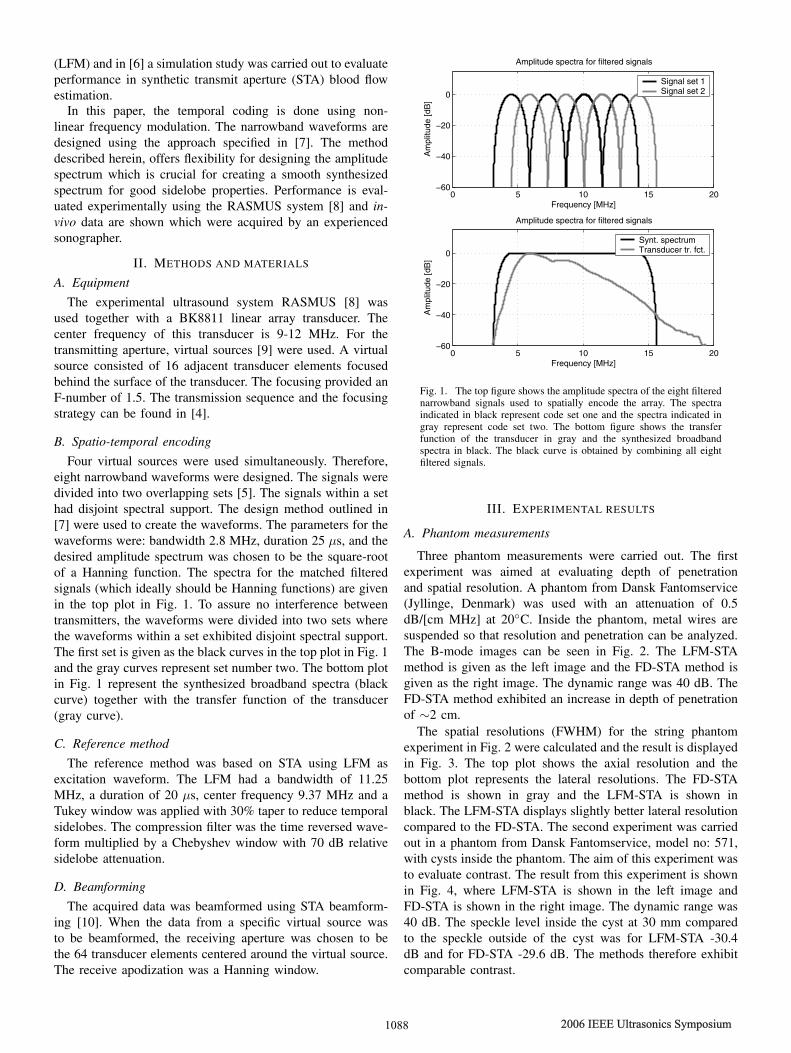
Four virtual sources were used simultaneously. Therefore,eight narrowband waveforms were designed. The signals weredivided into two overlapping sets [5]. The signals within a sethad disjoint spectral support. The design method outlined in[7] were used to create the waveforms. The parameters for thewaveforms were: bandwidth 2.8 MHz, duration 25 µs, and thedesired amplitude spectrum was chosen to be the square-rootof a Hanning function. The spectra for the matched filteredsignals (which ideally should be Hanning functions) are givenin the top plot in Fig. 1. To assure no interference betweentransmitters, the waveforms were divided into two sets wherethe waveforms within a set exhibited disjoint spectral support.The first set is given as the black curves in the top plot in Fig. 1and the gray curves represent set number two. The bottom plotin Fig. 1 represent the synthesized broadband spectra (blackcurve) together with the transfer function of the transducer(gray curve).
C. Reference method
The reference method was based on STA using LFM asexcitation waveform. The LFM had a bandwidth of 11.25MHz, a duration of 20 µs, center frequency 9.37 MHz and aTukey window was applied with 30% taper to reduce temporalsidelobes. The compression filter was the time reversed wave-form multiplied by a Chebyshev window with 70 dB relativesidelobe attenuation.
D. Beamforming
The acquired data was beamformed using STA beamform-ing [10]. When the data from a specific virtual source wasto be beamformed, the receiving aperture was chosen to bethe 64 transducer elements centered around the virtual source.The receive apodization was a Hanning window.
0 5 10 15 20!60
!40
!20
0
Frequency [MHz]
Am
plitu
de [d
B]
Amplitude spectra for filtered signals
Signal set 1Signal set 2
0 5 10 15 20!60
!40
!20
0
Frequency [MHz]
Am
plitu
de [d
B]
Amplitude spectra for filtered signals
Synt. spectrumTransducer tr. fct.
Fig. 1. The top figure shows the amplitude spectra of the eight filterednarrowband signals used to spatially encode the array. The spectraindicated in black represent code set one and the spectra indicated ingray represent code set two. The bottom figure shows the transferfunction of the transducer in gray and the synthesized broadbandspectra in black. The black curve is obtained by combining all eightfiltered signals.
III. EXPERIMENTAL RESULTS
A. Phantom measurements
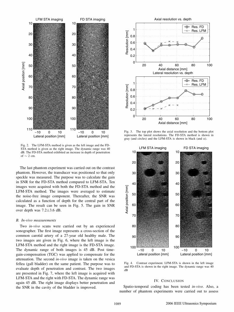
Three phantom measurements were carried out. The firstexperiment was aimed at evaluating depth of penetrationand spatial resolution. A phantom from Dansk Fantomservice(Jyllinge, Denmark) was used with an attenuation of 0.5dB/[cm MHz] at 20!C. Inside the phantom, metal wires aresuspended so that resolution and penetration can be analyzed.The B-mode images can be seen in Fig. 2. The LFM-STAmethod is given as the left image and the FD-STA method isgiven as the right image. The dynamic range was 40 dB. TheFD-STA method exhibited an increase in depth of penetrationof !2 cm.
The spatial resolutions (FWHM) for the string phantomexperiment in Fig. 2 were calculated and the result is displayedin Fig. 3. The top plot shows the axial resolution and thebottom plot represents the lateral resolutions. The FD-STAmethod is shown in gray and the LFM-STA is shown inblack. The LFM-STA displays slightly better lateral resolutioncompared to the FD-STA. The second experiment was carriedout in a phantom from Dansk Fantomservice, model no: 571,with cysts inside the phantom. The aim of this experiment wasto evaluate contrast. The result from this experiment is shownin Fig. 4, where LFM-STA is shown in the left image andFD-STA is shown in the right image. The dynamic range was40 dB. The speckle level inside the cyst at 30 mm comparedto the speckle outside of the cyst was for LFM-STA -30.4dB and for FD-STA -29.6 dB. The methods therefore exhibitcomparable contrast.
1088 2006 IEEE Ultrasonics Symposium
Authorized licensed use limited to: D anmarks Tekniske Informationscenter. D ownloaded on N ovember 28 , 2009 at 08:24 from IE E E X plore . R estrictions apply.
Lateral position [mm]
Axi
al p
ositi
on [m
m]
LFM STA imaging
!10 0 10
10
20
30
40
50
60
70
80
90
100
110
Lateral position [mm]
FD STA imaging
!10 0 10
10
20
30
40
50
60
70
80
90
100
110
Fig. 2. The LFM-STA method is given as the left image and the FD-STA method is given as the right image. The dynamic range was 40dB. The FD-STA method exhibited an increase in depth of penetrationof ! 2 cm.
The last phantom experiment was carried out on the contrastphantom. However, the transducer was positioned so that onlyspeckle was measured. The purpose was to calculate the gainin SNR for the FD-STA method compared to LFM-STA. Tenimages were acquired with both the FD-STA method and theLFM-STA method. The images were averaged to estimatethe noise-free image component. Thereafter, the SNR wascalculated as a function of depth for the central part of theimage. The result can be seen in Fig. 5. The gain in SNRover depth was 7.2±3.6 dB.
B. In-vivo measurements
Two in-vivo scans were carried out by an experiencedsonographer. The first image represents a cross-section of thecommon carotid artery of a 27-year old healthy male. Thetwo images are given in Fig. 6, where the left image is theLFM-STA method and the right image is the FD-STA image.The dynamic range of both images is 45 dB. Post time-gain-compensation (TGC) was applied to compensate for theattenuation. The second in-vivo image is taken on the vesicafellea (gall bladder) on the same patient. The purpose was toevaluate depth of penetration and contrast. The two imagesare presented in Fig. 7, where the left image is acquired withLFM-STA and the right with FD-STA. The dynamic range wasagain 45 dB. The right image displays better penetration andthe SNR in the cavity of the bladder is improved.
20 40 60 80 1000
0.2
0.4
0.6
0.8
1
Axial distance [mm]
Res
olut
ion
[mm
]
Axial resolution vs. depth
Res. FDRes. LFM
20 40 60 80 1000
0.2
0.4
0.6
0.8
1
Axial distance [mm]R
esol
utio
n [m
m]
Lateral resolution vs. depth
Res. FDRes. LFM
Fig. 3. The top plot shows the axial resolution and the bottom plotrepresents the lateral resolutions. The FD-STA method is shown ingray (and circles) and the LFM-STA is shown in black (and x).
Lateral position [mm]
Axi
al p
ositi
on [m
m]
LFM STA imaging
!10 0 10
10
20
30
40
50
60
70
80
90
100
Lateral position [mm]
FD STA imaging
!10 0 10
10
20
30
40
50
60
70
80
90
100
Fig. 4. Contrast experiment. LFM-STA is shown in the left imageand FD-STA is shown in the right image. The dynamic range was 40dB
IV. CONCLUSION
Spatio-temporal coding has been tested in-vivo. Also, anumber of phantom experiments were carried out to assess
1089 2006 IEEE Ultrasonics Symposium
Authorized licensed use limited to: D anmarks Tekniske Informationscenter. D ownloaded on N ovember 28 , 2009 at 08:24 from IE E E X plore . R estrictions apply.

40 50 60 70 80 900
5
10
15
Depth [mm]
Gai
n [d
B]
Measured SNR gain
Fig. 5. The measured gain in SNR in dB for the FD method comparedto LFM.
Lateral position [mm]
Axi
al p
ositi
on [m
m]
STA FD
!10 0 10
10
20
30
40
50
Lateral position [mm]
STA LFM
!10 0 10
10
20
30
40
50
Fig. 6. The left image is the LFM-STA method and the right imageis the FD-STA image. The dynamic range of both images is 45 dB.Post TGC was applied to compensate for the attenuation.
Lateral position [mm]
Axi
al p
ositi
on [m
m]
STA FD
!10 0 10
30
40
50
60
70
80
90
Lateral position [mm]
STA LFM
!10 0 10
30
40
50
60
70
80
90
Fig. 7. The left image is acquired with LFM-STA and the rightwith FD-STA. The dynamic range was again 45 dB. The right imagedisplays better penetration and the SNR in the cavity of the bladderis improved.
performance in terms of spatial resolution, contrast and SNR.It was concluded that the FD-STA method provides the sameimage quality as LFM-STA. The depth of penetration was
found to be increased significantly with the FD-STA methodwhen compared to LFM-STA. Future work will be focused onmaking a larger clinical study, comparing the two methods.This study should include several different patients, differentscans and a number of evaluating clinical experts.
V. ACKNOWLEDGMENT
This work was supported by grant 274-05-0327 from theDanish Research Agency, the Radio-parts foundation and byB-K Medical A/S, Denmark.
REFERENCES
[1] R. Y. Chiao, L. J. Thomas, and S. D. Silverstein, “Sparse array imagingwith spatially-encoded transmits,” in Proc. IEEE Ultrason. Symp., 1997,pp. 1679–1682.
[2] R. Y. Chiao and L. J. Thomas, “Synthetic transmit aperture usingorthogonal golay coded excitation,” in Proc. IEEE Ultrason. Symp.,2000, pp. 1469–1472.
[3] F. Gran and J. A. Jensen, “Multi element synthetic aperture transmissionusing a frequency division approach,” in Proc. IEEE Ultrason. Symp.,2003, pp. 1942–1946.
[4] F. Gran and J. A. Jensen, “Spatio-temporal encoding using narrow-bandlinearly frequency modulated signals in synthetic aperture ultrasoundimaging,” in Proc. SPIE - Progress in biomedical optics and imaging,2005, vol. 5750 (1), pp. 405–416.
[5] F. Gran and J. A. Jensen, “Frequency division transmission and syntheticaperture reconstruction,” IEEE Trans. Ultrason., Ferroelec., Freq. Contr.,vol. 53 (5), pp. 900–911, 2006.
[6] F. Gran and J. A. Jensen, “Directional velocity estimation using a spatio-temporal encoding technique based on frequency division for synthetictransmit aperture ultrasound,” IEEE Trans. Ultrason., Ferroelec., Freq.Contr., vol. 53 (7), pp. 1289–1299, 2006.
[7] F. Gran and J. A. Jensen, “Designing non-linear frequency modulatedsignals for ultrasound imaging,” in Proc. IEEE Ultrason. Symp., 2006,p. Accepted for publication.
[8] J. A. Jensen, O. Holm, L. J. Jensen, H. Bendsen, S. I. Nikolov, B. G.Tomov, P. Munk, M. Hansen, K. Salomonsen, J. Hansen, K. Gormsen,H. M. Pedersen, and K. L. Gammelmark, “Ultrasound research scan-ner for real-time synthetic aperture image acquisition,” IEEE Trans.Ultrason., Ferroelec., Freq. Contr., vol. 52 (5), May 2005.
[9] M. O’Donnell and L. J. Thomas, “Efficient synthetic aperture imagingfrom a circular aperture with possible application to catheter-basedimaging,” IEEE Trans. Ultrason., Ferroelec., Freq. Contr., vol. 39, pp.366–380, 1992.
[10] S. I. Nikolov, Synthetic aperture tissue and flow ultrasound imaging,Ph.D. thesis, Ørsted•DTU, Technical University of Denmark, 2800,Lyngby, Denmark, 2001.
1090 2006 IEEE Ultrasonics Symposium
Authorized licensed use limited to: D anmarks Tekniske Informationscenter. D ownloaded on N ovember 28 , 2009 at 08:24 from IE E E X plore . R estrictions apply.