1.IR for SMD Table 1 IR condition - cj-elec.com · 1.IR for SMD Table 1 IR condition Profile...
3
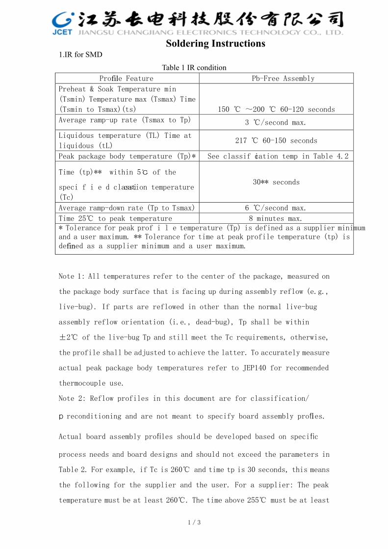
1.IR for SMD Table 1 IR condition Profile Feature Pb-Free Assembly Preheat & Soak Temperature min (Tsmin) Temperature max (Tsmax) Time (Tsmin to Tsmax)(ts) 150 ℃ ~200 ℃ 60-120 seconds Average ramp-up rate (Tsmax to Tp) 3 ℃/second max. Liquidous temperature (TL) Time at liquidous (tL) 217 ℃ 60-150 seconds Peak package body temperature (Tp)* See classifi cation temp in Table 4.2 Time (tp)** within 5℃ of the specified classi cation temperature (Tc) 30** seconds Average ramp-down rate (Tp to Tsmax) 6 ℃/second max. Time 25℃ to peak temperature 8 minutes max. * Tolerance for peak profile temperature (Tp) is defined as a supplier minimum and a user maximum. ** Tolerance for time at peak profile temperature (tp) is defined as a supplier minimum and a user maximum. Note 1: All temperatures refer to the center of the package, measured on the package body surface that is facing up during assembly reflow (e.g., live-bug). If parts are reflowed in other than the normal live-bug assembly reflow orientation (i.e., dead-bug), Tp shall be within ±2℃ of the live-bug Tp and still meet the Tc requirements, otherwise, the profile shall be adjusted to achieve the latter. To accurately measure actual peak package body temperatures refer to JEP140 for recommended thermocouple use. Note 2: Reflow profiles in this document are for classification/ preconditioning and are not meant to specify board assembly profi les. Actual board assembly profiles should be developed based on specific process needs and board designs and should not exceed the parameters in Table 2. For example, if Tc is 260℃ and time tp is 30 seconds, this means the following for the supplier and the user. For a supplier: The peak temperature must be at least 260℃. The time above 255℃ must be at least Soldering Instructions 1/3
Transcript of 1.IR for SMD Table 1 IR condition - cj-elec.com · 1.IR for SMD Table 1 IR condition Profile...
1.IR for SMD
Table 1 IR condition Profile Feature Pb-Free Assembly
Preheat & Soak Temperature min
(Tsmin) Temperature max (Tsmax) Time
(Tsmin to Tsmax)(ts) 150 ℃ ~200 ℃ 60-120 seconds
Average ramp-up rate (Tsmax to Tp) 3 ℃/second max.
Liquidous temperature (TL) Time at
liquidous (tL) 217 ℃ 60-150 seconds
Peak package body temperature (Tp)* See classification temp in Table 4.2
Time (tp)** within 5℃ of the
specified classi cation temperature (Tc)
30** seconds
Average ramp-down rate (Tp to Tsmax) 6 ℃/second max.
Time 25℃ to peak temperature 8 minutes max. * Tolerance for peak profile temperature (Tp) is defined as a supplier minimum and a user maximum. ** Tolerance for time at peak profile temperature (tp) is defined as a supplier minimum and a user maximum.
Note 1: All temperatures refer to the center of the package, measured on
the package body surface that is facing up during assembly reflow (e.g.,
live-bug). If parts are reflowed in other than the normal live-bug
assembly reflow orientation (i.e., dead-bug), Tp shall be within
±2℃ of the live-bug Tp and still meet the Tc requirements, otherwise,
the profile shall be adjusted to achieve the latter. To accurately measure
actual peak package body temperatures refer to JEP140 for recommended
thermocouple use.
Note 2: Reflow profiles in this document are for classification/
preconditioning and are not meant to specify board assembly profiles.
Actual board assembly profiles should be developed based on specific
process needs and board designs and should not exceed the parameters in
Table 2. For example, if Tc is 260℃ and time tp is 30 seconds, this means
the following for the supplier and the user. For a supplier: The peak
temperature must be at least 260℃. The time above 255℃ must be at least
2 2
Soldering Instructions
1/3
30 seconds. For user: The peak temperature must not exceed 260℃. The
time above 255℃ must not exceed 30 seconds.
Note 3: All components in the test load shall meet the classification
profile requirements.
Note 4: SMD packages classified to a given moisture sensitivity level by
using Procedures or Criteria defined within any previous version of
J-STD-020, JESD22-A112 (rescinded), IPC-SM-786 (rescinded) do not need
to be reclassified to the current revision unless a change in classification
level or a higher peak classification temperature is desired.
Table 2. Pb-Free Process -Classification Temperatures (Tc)
Package Thickness Volume mm3
<350
Volume mm3
350 -2000
Volume mm3
>2000
<1.6 mm 260 ℃ 260 ℃ 260 ℃
1.6 mm -2.5 mm 260 ℃ 250 ℃ 245 ℃
>2.5 mm 250 ℃ 245 ℃ 245 ℃
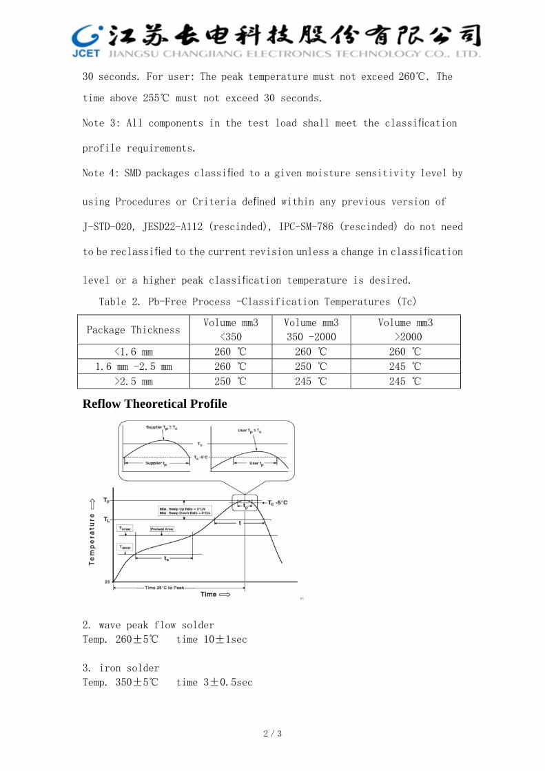
Reflow Theoretical Profile
2. wave peak flow solder
Temp. 260±5℃ time 10±1sec
3. iron solder
Temp. 350±5℃ time 3±0.5sec
2/3

TIME IN SECONDS
TMPE
RAT
UR
E ℃
图 1:
图 2:
TMPE
RAT
UR
E ℃
Lead free Infrared Reflow
Pb—Sn Infrared Reflow
30 60 90 120 150 180 210 240 270 300 330 360
100℃
235~240℃
183℃ 60s ~ 150s
150℃
217℃
250~260℃
60s ~150s
PREHEAT ZONE ACTIVATES S OLDER F LUX
ABOVE SOL DER
MELTING POINT
PREHEAT ZONE ACTIVATES SOLDER FLUX
ABOVE SOLDER
MELTING POINT
30 60 90 120 150 180 210 240 270 300 330 360
TIME IN SECONDS
The Temperature Curve Of Infrared Reflow
CUSTOMER:
APPROVED:
DRAWN:
CHECKED:
APPROVDED:
CHECKED:
3/3