1998 Electric Ranger Student Guide - EV Charger News Ranger EV Student... · 1998 Electric Ranger...
228
1998 Electric Ranger Student Guide 34n07t0
Transcript of 1998 Electric Ranger Student Guide - EV Charger News Ranger EV Student... · 1998 Electric Ranger...

1998 Electric RangerStudent Guide
34n07t0


IMPORTANT SAFETY NOTICE
Appropriate service methods and proper repair procedures are essential for the safe, reliable operation of all motor vehicles,as well as the personal safety of the individual doing the work. This manual provides general directions for accomplishingservice and repair work with tested, effective techniques. Following them will help assure reliability.
There are numerous variations in procedures, techniques, tools and parts for servicing vehicles, as well as in the skill of theindividual doing the work. This manual cannot possibly anticipate all such variations and provide advice or cautions as to each.Accordingly, anyone who departs from instructions provided in this manual must first establish that he compromises neitherhis personal safety nor the vehicle integrity by his choice of methods, tools or parts.
As you read through the procedures, you will come across NOTES, CAUTIONS, and WARNINGS. Each one is there for aspecific purpose. NOTES give you added information that will help you to complete a particular procedure. CAUTIONS aregiven to prevent you from making an error that could damage the vehicle. WARNINGS remind you to be especially carefulin those areas where carelessness can cause personal injury. The following list contains some general WARNINGS that youshould follow when you work on a vehicle.
The recommendations and suggestions contained in this manual are made to assist the dealer in improving his dealership partsand/or service department operations. These recommendations and suggestions do not supersede or override the provisions ofthe Warranty and Policy Manual, and in any cases where there may be a conflict, the provisions of the Warranty and Policy Manualshall govern.
The descriptions, testing procedures, and specifications in this handbook were in effect at the time the handbook wasapproved for printing. Ford Motor Company reserves the right to discontinue models at any time, or change specifications,design, or testing procedures without notice and without incurring obligation. Any reference to brand names in this manualis intended merely as an example of the types of tools, lubricants, materials, etc. recommended for use. Equivalents, ifavailable, may be used. The right is reserved to make changes at any time without notice.
WARNING: Many brake linings contain asbestos fibers. When working on brake components, avoid breathing the dust. Breathingthe asbestos dust can cause asbestosis and cancer.
Breathing asbestos dust is harmful to your health.
Dust and dirt present on car wheel brake and clutch assemblies may contain asbestos fibers that are hazardous to your health whenmade airborne by cleaning with compressed air or by dry brushing.
Wheel brake assemblies and clutch facings should be cleaned using a vacuum cleaner recommended for use with asbestos fibers.Dust and dirt should be disposed of in a manner that prevents dust exposure, such as sealed bags. The bag must be labeled perOSHA instructions and the trash hauler notified as to the contents of the bag.
If a vacuum bag suitable for asbestos is not available, cleaning should be done wet. If dust generation is still possible, techniciansshould wear government approved toxic dust purifying respirators.
OSHA requires areas where asbestos dust generation is possible to be isolated and posted with warning signs. Only techniciansconcerned with performing brake or clutch service should be present in the area.
Copyright © 1998 Ford Motor Company
• Always wear safety glasses for eye protection.
• Use safety stands whenever a procedure requires you tobe under the vehicle.
• Be sure that the ignition switch is always in the OFFposition, unless otherwise required by the procedure.
• Set the parking brake when working on the vehicle. If youhave an automatic transmission, set it in PARK unlessinstructed otherwise for a specific service operation. If youhave a manual transmission it should be in REVERSE(engine OFF) or NEUTRAL (engine ON) unless instructedotherwise for a specific service operation.
• Operate the engine only in a well-ventilated area to avoidthe danger of carbon monoxide.
• Keep yourself and your clothing away from moving partswhen the engine is running, especially the fan and belts.
• To prevent serious burns, avoid contact with hot metalparts such as the radiator, exhaust manifold, tail pipe,catalytic converter and muffler.
• Do not smoke while working on the vehicle.
• To avoid injury, always remove rings, watches, loosehanging jewelry, and loose clothing before beginning towork on a vehicle. Tie long hair securely behind yourhead.
• Keep hands and other objects clear of the radiator fanblades. Electric cooling fans can start to operate at anytime by an increase in underhood temperatures, eventhough the ignition is in the OFF position. Therefore, careshould be taken to ensure that the electric cooling fan iscompletely disconnected when working under the hood.
Produced and Coordinated byTechnical Service Support OperationsFord Customer Service Division
January, 1998

SERVICE STANDARDSMission Statement:All dealership personnel will treat every customer as a potential lifetime purchaser,communicating a professional image which embraces honesty and concern forcustomer wants and needs.
Dealer-to-Customer Service Standards:4. Vehicles serviced right on the
first visit.
5. Service status provided within oneminute of inquiry.
6. Vehicle ready at agreed upon time.
7. Thorough explanation of work done,coverages and changes.
1. Appointment available within oneday of the customer’s requestedservice day.
2. Write-up begins within four minutes ofarrival.
3. Service needs courteously identified,accurately recorded on RepairOrder, and verified with customer.
These seven service standards provide a process and product value that arecompelling reasons for owners to purchase and repurchase Ford or Lincoln-Mercuryproducts. These standards also help to attract new owners through favorabletestimonials and improved owner satisfaction.
Standard 4“Fix It Right the First Time, on Time.”The technician is the most important player when it comes to Standard #4.
WhyCustomers tell us “Fixing It Right the First Time, on Time” is one of the reasons they woulddecide to return to a dealer to buy a vehicle and get their vehicles serviced.
Technician TrainingIt is our goal to help the technician acquire all of the skills and knowledge necessary to“Fix it Right the First Time, on Time.” We refer to this as “competency.”
Technician’s RoleAcquire the skills and knowledge for competency in your specialty via
STST New Model— Self Study — Self Study— Ford Multimedia Training (FMT) — Instructor Led— Instructor Led
The BenefitsThe successful implementation of standards means
— Satisfied customers— Repeat vehicle sales— Repeat service sales— Recognition that Ford and Lincoln/Mercury technicians are
“the Best in the Business”

1998 Ranger EV New Model Training i
TABLE OF CONTENTS
LESSON 1: VEHICLE OVERVIEW .................................................................................................. 1-1Electric Vehicle (EV) History ........................................................................................................... 1-2Electric Ranger Introduction ............................................................................................................ 1-3Specifications................................................................................................................................... 1-4Battery System ................................................................................................................................. 1-5Traction Inverter Module (TIM) ..................................................................................................... 1-15Interface Adapter Assembly (IAA) ................................................................................................. 1-17Motor/Transaxle............................................................................................................................. 1-19High Voltage Power Distribution Box ............................................................................................1-24DC/DC Converter .......................................................................................................................... 1-25Liquid Cooling System .................................................................................................................. 1-26Power Steering System .................................................................................................................. 1-30Braking System .............................................................................................................................. 1-32Electronic Throttle Control ............................................................................................................. 1-36Climate Control System ................................................................................................................. 1-37Networks and Multiplexing ............................................................................................................ 1-42High Voltage Interlocks .................................................................................................................. 1-44Inertia Shutoff Switch .................................................................................................................... 1-45Current Leakage Detection ............................................................................................................ 1-46Suspension System......................................................................................................................... 1-47Traction Battery Charging Components ......................................................................................... 1-48High Voltage Wiring ....................................................................................................................... 1-52Activity 1 – Vehicle Overview – Component LocationActivity 1 – Worksheet A – Component Location
Student Answer Sheet ............................................................................................................ 1-59Activity 1 – Worksheet B – Component Function Exercise
Student Answer Sheet ................................................................................................................ 1-60Activity 1 – Worksheet C – Safety Feature Identification
Student Answer Sheet ................................................................................................................ 1-61
LESSON 2: VEHICLE OPERATION ................................................................................................ 2-1Vehicle Operation ............................................................................................................................. 2-2Instrument Cluster Gauges ............................................................................................................... 2-4Instrument Cluster Warning Lamps ................................................................................................ 2-15Economy Mode .............................................................................................................................. 2-34Traction Battery Charging .............................................................................................................. 2-35Driver Response to an Emergency Situation .................................................................................. 2-37Activity 2 – Vehicle FamiliarizationActivity 2 – Worksheet D – Operating Characteristics of the Electric Ranger
Student Answer Sheet ................................................................................................................ 2-39Activity 2 – Worksheet E – Warning and Indicator Lamps
Student Answer Sheet ................................................................................................................ 2-40Activity 2 – Worksheet F – Instrument Gauges and Lights
Student Answer Sheet ................................................................................................................ 2-41

TABLE OF CONTENTS
ii 1998 Ranger EV New Model Training
LESSON 3: SAFETY AND EMERGENCY INFORMATION ........................................................ 3-1Lead-Acid Battery Design ............................................................................................................... 3-2Lead-Acid Module Specifications .................................................................................................... 3-4High Voltage Color Coding .............................................................................................................. 3-5High Voltage Warnings .................................................................................................................... 3-5High Voltage Hazards ...................................................................................................................... 3-6Electrical Accidents .......................................................................................................................... 3-8Accident Prevention ......................................................................................................................... 3-9First Aid Procedures ....................................................................................................................... 3-12Fire Prevention ............................................................................................................................... 3-14Activity 3 – EV Safety and Emergency InformationActivity 3 –Worksheet G – Safety and Emergency Procedures
Student Answer Sheet ................................................................................................................ 3-17
LESSON 4: SPECIAL SERVICE TOOLS AND PROCEDURES ................................................ 4-1Special Service Tools and Equipment .............................................................................................. 4-2High Voltage Diagnostic and
Service Procedures .................................................................................................................... 4-19Towing Procedure .......................................................................................................................... 4-22Hoist Lift Points ............................................................................................................................ 4-24Service Publication Navigation ..................................................................................................... 4-26Activity 4 – Special Service Tools and ProceduresActivity 4 – Worksheet H – Special Tools and Service Procedures
Student Answer Sheet ................................................................................................................ 4-29Activity 4 – Worksheet I – Service Publication Navigation
Student Answer Sheet ................................................................................................................ 4-30Activity 4 – Worksheet J – Special Service Tools
Student Answer Sheet ................................................................................................................ 4-31Activity 4 – Worksheet J1 – Electrical Connector Identification
Student Answer Sheet ................................................................................................................ 4-32

1998 Ranger EV New Model Training iii
TABLE OF CONTENTS
LESSON 5: DIAGNOSIS .................................................................................................................... 5-1Introduction to Ranger EV Diagnosis and Service Procedures ........................................................ 5-2Symptom-to-System-to-Component-to-Cause Diagnosis ................................................................. 5-2Ranger EV Diagnostic Flowchart .................................................................................................... 5-4Multiplexing System Diagnosis ........................................................................................................ 5-6New Generation STAR Tester ......................................................................................................... 5-8Contactor Box Diagnosis ............................................................................................................... 5-11Activity 5 – Worksheet K – NGS Operation and Improperly Closed Contactor Relay Diagnosis
Student Answer Sheet ................................................................................................................ 5-13Charging Concerns ........................................................................................................................ 5-17Activity 6 – Worksheet L – Charging System Diagnosis
Student Answer Sheet ................................................................................................................ 5-20Power Control Station (PCS) Diagnostic Procedures ..................................................................... 5-22Traction Battery Removal .............................................................................................................. 5-25Activity 7 – Worksheet M – Traction Battery Removal
Student Answer Sheet ................................................................................................................ 5-27Activity 8 – Worksheet N – PTC Heater Diagnosis Demonstration
Student Answer Sheet ................................................................................................................ 5-31Activity 9 – Worksheet O – Power Steering and Air Conditioning Diagnosis
Student Answer Sheet ................................................................................................................ 5-33Activity 9 – Worksheet P – Air Conditioning Diagnosis
Student Answer Sheet ................................................................................................................ 5-35Electric Motor/Transaxle Diagnosis ............................................................................................... 5-36Traction Battery Pack Components Demonstration ........................................................................ 5-38Traction Battery Diagnosis ............................................................................................................. 5-40Activity 12 – Diagnosis – Worksheet Q – Current Leakage and Multiple Auxiliary Load
Failure DiagnosisStudent Answer Sheet ................................................................................................................ 5-43
Worksheet RStudent Answer Sheet ................................................................................................................ 5-44
Activity 13 – Worksheet S1 – Battery Sense Lead and EPO DiagnosisStudent Answer Sheet ................................................................................................................ 5-52
Activity 13 – Worksheet S2 – Battery and Sense Lead Diagnosis (Non-BDS)Student Answer Sheet ................................................................................................................ 5-53
Activity 13 – Worksheet T – EPO DiagnosisStudent Answer Sheet ................................................................................................................ 5-57

TABLE OF CONTENTS
iv 1998 Ranger EV New Model Training
GLOSSARYRanger EV Acronyms .......................................................................................................... Glossary-1
ACTIVITY SHEETSWritten Activity Sheet 1
Student Answer Sheet ............................................................................................. Activity Sheet-1Activity Sheet 2
Student Answer Sheet ............................................................................................. Activity Sheet-2Generic Worksheet ...................................................................................................... Activity Sheet-3

1998 Ranger EV New Model Training 1-1
LESSON 1: VEHICLE OVERVIEW
TECHNICIAN OBJECTIVES
• Identify major components and systems.
• Describe the operation of major components and systems.
CONTENTS
• Electric Vehicle (EV) History
• Electric Ranger Introduction
• Specifications
• Battery System
• Traction Inverter Module (TIM)
• Interface Adapter Assembly (IAA)
• Motor/Transaxle
• High Voltage Power Distribution Box
• DC/DC Converter
• Liquid Cooling System
• Power Steering System
• Braking System
• Electronic Throttle Control
• Climate Control System
• Networks and Multiplexing
• High Voltage Interlocks
• Inertia Shutoff Switch
• Current Leakage Detection
• Suspension System
• Traction Battery Charging Components
• High Voltage Wiring
• Activity 1 – Vehicle Overview – Component Location
• Worksheet A – Component Location
• Worksheet B – Component Function Exercise
• Worksheet C – Safety Feature Identification

LESSON 1: VEHICLE OVERVIEW
1-2 1998 Ranger EV New Model Training
ELECTRIC VEHICLE (EV) HISTORY
Current legistration requires the development and distribution of
zero-emission vehicles. Today, only electric vehicles qualify as
zero-emission vehicles. This legislation also states all automobile
manufacturers who sell over 5,000 vehicles a year in regulated states
must develop and manufacture electric vehicles.
Electric vehicles (EVs) were first developed in the early 1900s. These
early EVs traveled at low speeds (24 km/h [15 mph]) and had limited
range (48-64 kilometers [30-40 miles]).
Ford Motor Company began its recent EV development in 1982 with
the introduction of the ETX 1, a converted Lynx LN7. A lead-acid
battery and a 37-kW (50-hp) AC motor powered this experimental
vehicle. The ETX 2 followed. The ETX 2 is a converted Aerostar
using a refined 53-kW (70-hp) motor; several battery types were used
and tested.
In 1993, Ford began a demonstration program to help potential
customers gain real-world experience in the use of electric-powered
vehicles. With the participation of utility companies and other
commercial organizations, this program has now reached the one
million-mile mark in vehicle miles driven. The vehicle platform for
this demonstration is the Ecostar; a two-passenger electric vehicle
based on the European Ford Escort Van. This demonstration program
paved the way for production of the Electric Ranger.

LESSON 1: VEHICLE OVERVIEW
1998 Ranger EV New Model Training 1-3
ELECTRIC RANGER INTRODUCTION
The 1998 Electric Ranger is a low-volume production electric vehicle.
The Electric Ranger is built on the 1998 gasoline-powered Ranger
platform and is sold and serviced through Ford dealerships.
A traction battery mounted under the vehicle between the frame rails
supplies the electric power. The traction battery provides 312 volts
direct current (DC), which is converted to three-phase alternating
current (AC) that drives the motor/transaxle.
The Electric Ranger is a rear-wheel drive vehicle and operates much
like the gasoline-powered models.
The most noticeable difference between the Electric Ranger and the
gasoline-powered Ranger is the operating noise is very low. Because
of the quiet operation of the vehicle, a motor enabled gauge is
provided and is located on the right side of the instrument cluster. The
motor enabled gauge indicates ON with the ignition switch in the
RUN or START position and indicates OFF with the ignition switch
in the OFF position or the powertrain becomes disabled.
1998 Electric Ranger

LESSON 1: VEHICLE OVERVIEW
1-4 1998 Ranger EV New Model Training
SPECIFICATIONS
VehicleModel Year 1998
Body Style Styleside, Regular Cab Pick-Up
Wheelbase Short Wheelbase of 2,831 mm (111.4 inch)
Payload 315 kg (700 lb)
Dimensions Similar to 1998 Gasoline-Powered Ranger
Performance0-50 Mph 12.5 seconds
Top Speed 120 km/h (75 mph)
Range 93 kilometers (58 miles)(without A/C or Heater Operation)
PowertrainMotor High-Efficiency, 3-Phase AC Induction
Horsepower 67 kw (90 hp)
Transaxle Single-Speed Constant-Ratio
Drive Wheels Rear
Gear Ratio 12.518:1
EquipmentStandard Dual Air Bags
Electro-Hydraulic Power Steering
Regenerative Braking
4-Wheel ABS
Aluminum Wheels
Low Rolling Resistance Tires
Optional Air Conditioning
Battery Heater
Spare Tire and Jack

LESSON 1: VEHICLE OVERVIEW
1998 Ranger EV New Model Training 1-5
BATTERY SYSTEM
Battery System Warnings
WARNING: THE TRACTION BATTERY CAN DELIVER
312 VOLTS OF DC POWER. IMPROPER HANDLING
OF THE TRACTION BATTERY CAN RESULT IN
INJURY OR FATALITY. ONLY AUTHORIZED
PERSONNEL TRAINED TO WORK WITH TRACTION
BATTERY COMPONENTS ARE PERMITTED TO
HANDLE THE BATTERIES.
WARNING: BATTERIES NORMALLY PRODUCE
EXPLOSIVE GASES WHICH CAN CAUSE PERSONAL
INJURY OR DEATH. DO NOT ALLOW FLAMES,
SPARKS OR LIGHTED SUBSTANCES TO COME NEAR
THE BATTERIES. WHEN CHARGING OR WORKING
NEAR THE BATTERIES, ALWAYS SHIELD YOUR
FACE AND PROTECT YOUR EYES. ALWAYS
PROVIDE VENTILATION.
WARNING: LEAD-ACID BATTERIES CONTAIN
SULFURIC ACID. AVOID CONTACT WITH SKIN,
EYES OR CLOTHING. ALSO, SHIELD YOUR EYES
WHEN WORKING NEAR BATTERIES TO PROTECT
AGAINST POSSIBLE SPLASHING OF THE ACID
SOLUTION. IN CASE OF ACID CONTACT WITH THE
SKIN OR EYES, FLUSH IMMEDIATELY WITH
WATER FOR A MINIMUM OF FIFTEEN MINUTES
AND GET PROMPT MEDICAL ATTENTION. IF ACID
IS SWALLOWED, DRINK LARGE QUANTITIES OF
MILK OR WATER, FOLLOWED BY MILK OF
MAGNESIA, A BEATEN EGG, OR VEGETABLE OIL.
CALL A PHYSICIAN IMMEDIATELY.

LESSON 1: VEHICLE OVERVIEW
1-6 1998 Ranger EV New Model Training
WARNING: HIGH VOLTAGE COMPONENT SERVICE
SHOULD ONLY BE PERFORMED BY TRAINED
PERSONNEL. INCORRECTLY PERFORMING
SERVICE PROCEDURES MAY RESULT IN INJURY OR
DEATH. ALL HIGH VOLTAGE COMPONENTS ON
THIS VEHICLE ARE MARKED WITH THE
FOLLOWING WARNING LABEL.
High Voltage Warning Label

LESSON 1: VEHICLE OVERVIEW
1998 Ranger EV New Model Training 1-7
Traction Battery
Traction Battery
• The traction battery is located underneath the vehicle between the
frame rails.
• The traction battery consists of 39 8-volt lead-acid battery modules
stored in a supporting tray.
• The supporting tray is constructed of an extremely strong non-
conductive composite material with bonded metal mounting
brackets.
– The tray is about 8 feet long and weighs almost 900 kg (2000 lb)
with battery modules and associated components in place.
– The supporting tray has a cover which is bolted on. There are
individual battery modules and other components contained
within the traction battery supporting tray.
• The 39 battery modules are arranged in 2 levels, 12 on the upper
level and 27 on the lower level.
• The battery modules are wired in series and produce 312 volts DC.
• A battery control module is located in the upper level at the front of
the assembly.
– The battery control module is secured with Velcro®.
• A contactor box is located in the upper level at the rear of the assembly.
– The contractor box is secured with Velcro®.
• A cooling system and a (optional) heating system (for cold climate
areas) are used to maintain optimal temperature within the traction
battery.

LESSON 1: VEHICLE OVERVIEW
1-8 1998 Ranger EV New Model Training
Traction Battery Cooling System
Traction Battery Cooling System
• The traction battery cooling system consists of:
– four temperature sensors.
– a two-speed fan.
– a battery control module.
• The cooling fan is located in the center of the traction battery.
• The cooling function is controlled by the battery control module
(BCM).
• During charging, the cooling fan is used for ventilation and
cooling of the traction battery:
– For ventilation, the cooling fan operates at low speed all the
time.
– For cooling, the cooling fan operates at high speed based on the
temperature of the traction battery.
– For ventilation purposes, the cooling fan operates for 10 minutes
following the completion of the charge cycle.
• During driving, the cooling fan is used for cooling the traction
battery:
– For cooling, the cooling fan operates at high speed based on the
temperature of the traction battery.
– Air is drawn in from the rear of the traction battery and exits
through the front.
NOTE: Be sure vent openings are clear of obstructions before
connecting charger.

LESSON 1: VEHICLE OVERVIEW
1998 Ranger EV New Model Training 1-9
Traction Battery Heating System (Optional)
Optional Traction Battery Heating System
• To maintain proper temperature during charging in cold climates,
an optional traction battery-heating system is available.
• The lower level of battery modules is heated using a blanket
heater (B) to heat the entire lower level.
– The lower level blanket heater is located underneath the battery
modules.
• The upper level uses individual heating elements (A) wired in series.
– The upper level heating elements are mounted directly to the
side of each battery module.
• The battery heating function is controlled by the battery control
module.
– The module will activate the battery heating system if the
traction battery temperature falls below 15°C (59°F) while
connected to an activated charge station.
– Heating function is deactivated when the traction battery
temperature rises above 25°C (77°F). The upper and lower
heating elements may function independently based on input
from temperature sensors.

LESSON 1: VEHICLE OVERVIEW
1-10 1998 Ranger EV New Model Training
Traction Battery Wiring and Circuit Protection
Traction Battery Circuit Protection
• The traction battery uses low and high voltage wiring.
• The high voltage circuit is protected by a 400-volt 250 amp fuse
installed between batteries 20 and 21.
• If the fuse opens or is removed, the high voltage circuit is
interrupted.
• Two high voltage connectors connect the traction battery to the
vehicle systems.
• The primary power (2-pin) connector is located at the rear of the
battery tray and transfers power to the motor/transaxle.
• The auxiliary power (4-pin) connector is located near the front of
the battery tray on the passenger side. It transfers high voltage
power to the vehicle’s auxiliary high voltage circuits.
• Both high voltage circuits are part of the vehicle high voltage
interlock circuit (covered later in this lesson).
• The low voltage connector is located near the front of the battery
tray on the driver side and transfers low voltage to the vehicle’s
low voltage circuits.
– The low voltage connector is a 76-pin connector.

LESSON 1: VEHICLE OVERVIEW
1998 Ranger EV New Model Training 1-11
Contactor Box Assembly (CBA)
Contactor Box
• The contactor box assembly (CBA) (arrow) is located in the rear of
the traction battery at the upper left side.
• The contactor box serves as the on/off switches for the traction
battery.
• Relays are used to interrupt the flow of high voltage when the
driver’s key is turned to the OFF position, the inertia shutoff switch
is activated or the system is in shutdown mode actuated by an
electronic control module.
• The contactor box supports these additional functions:
– high voltage circuit precharging – the high voltage circuits
require precharging. Otherwise, the large voltage differential
might weld contactors as circuits are switched on. Precharging is
accomplished through two relays and two 20-ohm resistors
located in the contactor box.
– traction battery current sensing – the contactor box contains two
Hall effect sensors that monitor the current from the traction
battery. One sensor monitors the current flow into the traction
inverter module (TIM) (power for the motor/transaxle),
and the other monitors current flow into the high voltage
auxiliary circuits.
– high voltage circuit protection – the charging, battery heater and
high voltage auxiliary circuits are protected by three fuses in the
contactor box.

LESSON 1: VEHICLE OVERVIEW
1-12 1998 Ranger EV New Model Training
12-Volt Battery
12-Volt Battery Location
• The 12-volt battery is located in the left front corner of the
underhood compartment.
• The 12-volt battery is used for lighting and other low-voltage
circuits and systems.
• The DC/DC converter acts as an alternator to charge the
12-volt battery.
• The 12-volt battery in the Electric Ranger is different than that used
in the gasoline-powered Ranger.
– The Electric Ranger does not require large 12-volt battery
capacity due to the absence of a high current starter circuit.
– The Electric Ranger battery is a 31 amp-hour deep cycle battery.
NOTE: Never attempt to jump-start the 12-volt battery.

LESSON 1: VEHICLE OVERVIEW
1998 Ranger EV New Model Training 1-13
Battery Control Module (BCM)
Battery Control Module (BCM)
• The battery control module (BCM) (arrow) is located in the upper
front section of the traction battery.
• The BCM is a high and low voltage module that controls all battery
system operations.
• The BCM monitors the temperature and state of charge of the
39 battery modules in the traction battery.
• The BCM controls battery charging and cooling.
• The BCM controls the optional battery heating system operation
if equipped.

LESSON 1: VEHICLE OVERVIEW
1-14 1998 Ranger EV New Model Training
INPUTS
BATTERYCONTROLMODULE
(BCM)
OUTPUTS
Battery TemperatureSensor 1-4
Emergency Power Off(EPO)
Battery VoltageSensors
Battery Pack StateOf Charge (SOC)
Digital Transmission Range (DTR) Sensor
Charge Cord PluggedIn Signal
High Voltage PowerDistribution Box (HVDB)
Emergency Power Off(EPO)
Battery Heaters
Battery Charger
Battery Pack Cooling Fan
Charger Contactor Relay
Negative ContactorRelay

LESSON 1: VEHICLE OVERVIEW
1998 Ranger EV New Model Training 1-15
TRACTION INVERTER MODULE (TIM)
Traction Inverter Module (TIM)
• The traction inverter module (TIM) (arrow) is located underneath
the center rear of the vehicle.
• The TIM is a high and low voltage module that performs two
functions:
– vehicle powertrain control
– electric current conversion for the motor/transaxle
• The TIM controls the vehicle powertrain by processing driver,
module, and sensor inputs, and calculating a motor torque
command.
• The TIM converts high voltage DC from the traction battery into
three phase AC used by the motor/transaxle.
• The TIM consists of:
– three high power, high-speed insulated gate bipolar transistor
modules (IGBTs).
– four large filter capacitors (used during precharging functions).
– two-phase current sensors.
– a high-performance microcontroller.
– logic circuitry and control circuits.
ER011-A
HIGH VOLTAGE COMPONENT

LESSON 1: VEHICLE OVERVIEW
1-16 1998 Ranger EV New Model Training
• The IGBTs are used to switch on and off the three motor phases.
– As they switch on and off, the IGBTs produce voltage spikes
that have the potential to damage the TIM.
– Capacitors are used as a filters to protect the TIM and maintain
traction bus voltage during IGBT switching.
– These capacitors retain traction battery voltage and provide
current capability for instantaneous torque.
NOTE: The TIM is equipped with a bleed down system which
ensures that the capacitors are discharged to less than 50 volts within
two minutes after the driver’s key is turned to the OFF position.
• Be sure to allow for capacitor bleed down time before attempting
maintenance or repair.
INPUTS
TRACTIONINVERTERMODULE
(TIM)
OUTPUTS
Motor TemperatureSensor
Emergency Power Off(EPO)
Accelerator PedalSensors 1-3
Brake Pedal Sensor
Digital TransmissionRange (DTR) Sensor
Charge Cord Plugged In Signal
Anti-Lock Brake Module
Oil Pressure Sensor
Vehicle Speed Signal
Emergency Power Off(EPO)
Precharge ContactorRelay
Main Contactor Relay
Electric Motor/Transaxle
Oil Pump Relay

LESSON 1: VEHICLE OVERVIEW
1998 Ranger EV New Model Training 1-17
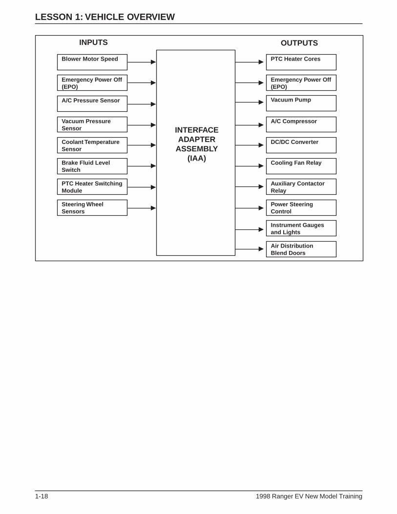
INTERFACE ADAPTER ASSEMBLY (IAA)
Interface Adapter Assembly (IAA)
• The interface adapter assembly (IAA) is located on the bulkhead
under the instrument panel, the same location as the gasoline-
powered Ranger EEC-V module.
• The IAA is a low voltage multi-function module that manages the
climate control system, the auxiliary systems and most instrument
cluster gauges and lamps.
• The IAA is networked with the TIM and the BCM to support
instrument cluster functions, contactor box operations, and
diagnostics.
• The IAA diagnostics are accessible through the OBD-II diagnostic
connector under the instrument panel next to the steering column.
• Diagnostic functions as well as parameter identification (PID) data
and active command modes are available.
• Based on operator and vehicle demands, the IAA controls these
functions:
– High voltage A/C compressor (optional).
– High voltage positive temperature coefficient (PTC) heater.
– Air distribution blend door and climate control blower fan
motor.
– Power steering.
– DC/DC converter.
– Vacuum pump.
– Liquid cooling system coolant pump and two-speed radiator fan.
– Instrument cluster operation.
LESSON 1: VEHICLE OVERVIEW
1-18 1998 Ranger EV New Model Training
INPUTS
INTERFACEADAPTER
ASSEMBLY(IAA)
OUTPUTS
Blower Motor Speed
Emergency Power Off(EPO)
A/C Pressure Sensor
Vacuum Pressure Sensor
Coolant TemperatureSensor
Brake Fluid Level Switch
PTC Heater Switching Module
Steering WheelSensors
PTC Heater Cores
Emergency Power Off(EPO)
Vacuum Pump
A/C Compressor
DC/DC Converter
Cooling Fan Relay
Auxiliary Contactor Relay
Power Steering Control
Instrument Gaugesand Lights
Air DistributionBlend Doors

LESSON 1: VEHICLE OVERVIEW
1998 Ranger EV New Model Training 1-19
MOTOR/TRANSAXLE
Motor/Transaxle Assembly
• The motor/transaxle is mounted just behind the traction battery.
• The motor/transaxle assembly consists of a:
– four-pole, three phase AC induction motor.
– single-speed transaxle with a planetary gearset.
• The motor/transaxle supplies power through halfshafts to the
rear wheels.
– A peak power of 67 kW (90 hp) is produced at 190 Nm
(140 lb ft) torque.
• The assembly is packaged in an aluminum case and weighs
approximately 91 kg (200 lb).

LESSON 1: VEHICLE OVERVIEW
1-20 1998 Ranger EV New Model Training
Motor
Motor Components
• The AC induction motor consists of a:
– stator (A).
– cast aluminum rotor (B).
– rotor speed sensor (C).
• The motor has a maximum operating speed of 13,000 rpm and
maximum current draw of 305 amps.
ER014-A
A B
C

LESSON 1: VEHICLE OVERVIEW
1998 Ranger EV New Model Training 1-21
• Alternating current is supplied from the TIM to the motor through
high voltage cables.
– Current flows through the stator windings generating a
magnetic field.
– The magnetic field causes the rotor to spin.
– Varying the amount of current controls torque.
– Varying the AC current frequency controls speed.
– During deceleration and braking, a negative torque is produced,
and the motor acts as a generator and regenerates charge in the
traction battery.

LESSON 1: VEHICLE OVERVIEW
1-22 1998 Ranger EV New Model Training
Transaxle
Transaxle Components
• The transaxle consists of a:
– two-stage direct reduction planetary gear system (similar to
other automatic transaxle planetary gear sets).
– 50/50 planetary differential.
• The transaxle is a constant-ratio (one-speed) unit and uses no apply
components.
– There are no clutches, bands, or valves as in multiple-speed
transaxle units.
• A cam-operated parking pawl is operated manually by the gear
selector assembly through the shift cable and shift lever.
• The cam has five detent positions:
– Park (P)
– Reverse (R)
– Neutral (N)
– Drive (D)
– Economy (E)
LESSON 1: VEHICLE OVERVIEW
1998 Ranger EV New Model Training 1-23
• Direction (clockwise or counterclockwise) and speed of the motor
are monitored by a speed sensor mounted inside the transaxle case.
– The speed sensor detects passing teeth on the speed wheel as it
rotates.
– The speed wheel is mounted to the input shaft.
– The speed (rpm) signal is sent to the TIM.
• The transaxle is lubricated by Tribolube-L6 (Pro Gear 21), a
synthetic, low-viscosity oil.
• A 12-volt DC oil pump mounted inside the case supplies oil to
lubricate the gears and bearings.
– The pump is controlled by the TIM.
– Normal pressure is approximately 103 kPa (15 psi).
– If pressure drops below 28 kPa (4 psi), the oil pressure switch
opens and signals the TIM.
• Motor/transaxle cooling is provided by the vehicle liquid cooling
system (covered later in this lesson).
NOTE: Adding transaxle oil is not a standard maintenance item.
Change transaxle oil at 3 year intervals.

LESSON 1: VEHICLE OVERVIEW
1-24 1998 Ranger EV New Model Training
HIGH VOLTAGE POWER DISTRIBUTION BOX
High Voltage Power Distribution Box
• The high voltage power distribution box (arrow) is located in the
underhood compartment on top of the battery charger.
• The high voltage power distribution box is similar in function to
the fuse box in your home.
– It distributes high voltage to components and systems.
– It contains fuses.
• The power distribution box directs fuse protected high voltage to:
– DC/DC converter.
– Heating system.
– Air conditioning system (optional).
– Power steering system.
– Battery charger.
• The power distribution box has a protective cover that is part of the
high voltage interlock circuit (covered later in this lesson).
– When the cover is removed, a limit switch will open the relays
in the contactor box, which interrupts high voltage to the
vehicle systems.
HIGH VOLTAGE COMPONENT
ER016-A

LESSON 1: VEHICLE OVERVIEW
1998 Ranger EV New Model Training 1-25
DC/DC CONVERTER
ER017-A
HIGH VOLTAGE COMPONENT
DC/DC Converter
• The DC/DC converter (arrow) is located in the underhood
compartment on the driver side of the battery charger.
• The DC/DC converter acts as an electronic alternator, charging the
12-volt battery and supplying power for low voltage components
and systems.
• The DC/DC converter steps down traction battery voltage from
312 volts to 12 volts.
• A temperature sensor mounted near the 12-volt battery tray allows
the converter to adjust voltage to the 12-volt battery as temperature
changes.
• The DC/DC converter is controlled by the IAA.
• The DC/DC converter operates when the key is in the ON position
and with the key in the OFF position when the vehicle is connected
to the power control station (PCS) for charging.

LESSON 1: VEHICLE OVERVIEW
1-26 1998 Ranger EV New Model Training
LIQUID COOLING SYSTEM
Liquid Cooling System Components
Item Description
1 Two-Speed Electric Cooling Fan
2 Radiator
• The high voltage electronics used on the Electric Ranger require
cooling under normal use.
• Excess heat is removed by a liquid cooling system controlled by
the IAA.
• The liquid cooling system cools the:
– TIM.
– motor/transaxle.
– DC/DC converter.
– A/C inverter motor controller.

LESSON 1: VEHICLE OVERVIEW
1998 Ranger EV New Model Training 1-27
• The liquid cooling system consists of:
– an Explorer radiator.
– a two-speed electric cooling fan.
– a 12-volt electric coolant pump.
– rubber coolant hoses.
– metal coolant tubes.
– a 50/50 mix of water and glycol Ford specification WSS-
M97B44-C. (Do not mix with previous specification.)
• The 12-volt coolant pump incorporates a:
– centrifugal impeller design.
– 12-volt DC motor.
– magnetic motor-to-impeller clutch.
NOTE: Adding coolant is not a standard maintenance item. Do not
mix the new glycol with the previous specification. Change coolant at
100,000 miles or 5 years whichever comes first.
LESSON 1: VEHICLE OVERVIEW
1-28 1998 Ranger EV New Model Training
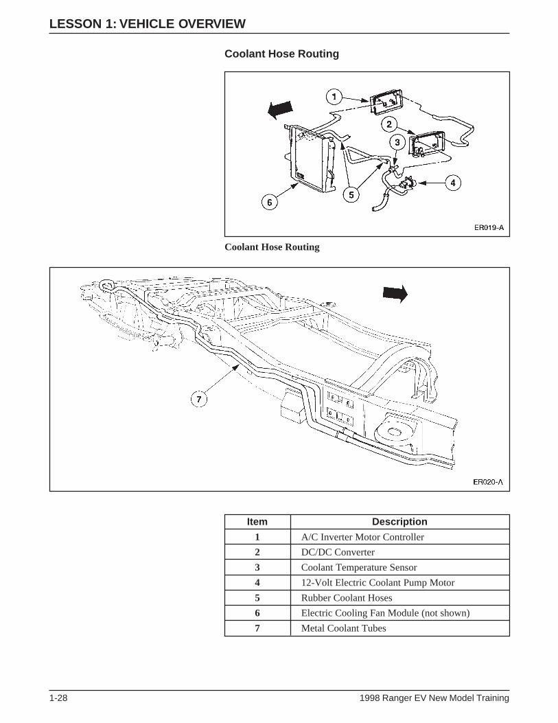
Coolant Hose Routing
Coolant Hose Routing
Item Description
1 A/C Inverter Motor Controller
2 DC/DC Converter
3 Coolant Temperature Sensor
4 12-Volt Electric Coolant Pump Motor
5 Rubber Coolant Hoses
6 Electric Cooling Fan Module (not shown)
7 Metal Coolant Tubes
LESSON 1: VEHICLE OVERVIEW
1998 Ranger EV New Model Training 1-29
• Coolant is circulated by the electric pump located below the
DC/DC converter.
• Rubber hoses carry coolant to the DC/DC converter and the
A/C inverter motor controller.
• Rubber hoses and metal tubes carry coolant to the motor/transaxle
and TIM.
• An electric cooling fan module is mounted on the lower right
section of the radiator.
• The coolant temperature sensor is located in the hose connector
above the electric pump.
• The liquid cooling system operates whenever the driver’s key in the
ON position.
– It also operates during battery charging if the DC/DC converter
is charging the 12-volt battery.

LESSON 1: VEHICLE OVERVIEW
1-30 1998 Ranger EV New Model Training
POWER STEERING SYSTEM
Power Steering System Components
Item Description
1 Power Steering Controller Assembly
2 Power Steering Gear and Linkage
• The power steering controller assembly is located on the right side
of the underhood compartment.
• The power steering controller assembly consists of an electric
controller attached to a high voltage AC electric motor and pump.
• The electronic controller has its own inverter to convert DC voltage
from the traction battery into the high voltage AC required by
the motor.
• The assembly has one high voltage connector and one low voltage
connector.
• The steering linkage and power steering gear are carryover from
gasoline-powered Ranger.
• The steering column is a Ranger tilt column to accommodate a
steering wheel rotation sensor that provides input for additional
power assist when the vehicle is at a stop.
LESSON 1: VEHICLE OVERVIEW
1998 Ranger EV New Model Training 1-31
NOTES

LESSON 1: VEHICLE OVERVIEW
1-32 1998 Ranger EV New Model Training
BRAKING SYSTEM
Braking System Components
• The base brake system is a conventional hydraulic/friction braking
system.
• The brake booster and master cylinder are carryover from the
gasoline-powered Ranger.
• The master cylinder includes a modified pressure sensor that
provides input for the regenerative braking system.
• The front and rear discs and calipers (above) are carryover
Explorer.
– The hubs are similar to those used on Thunderbird.

LESSON 1: VEHICLE OVERVIEW
1998 Ranger EV New Model Training 1-33
Motor Driven Vacuum Pump
• A motor driven vacuum pump is mounted beneath the
battery charger.
• The anti-lock braking system (ABS) is a 4-sensor 3-channel
system.
• ABS components include:
– an electronic control unit (ECU).
– an Explorer hydraulic control unit (HCU).
– a Ranger mounting bracket.
• The ABS system sends active line output to the TIM for use with
the regenerative braking system.
• All of the electric components in the braking system operate off
low voltage circuits.

LESSON 1: VEHICLE OVERVIEW
1-34 1998 Ranger EV New Model Training
Regenerative Braking System (RBS)
Regenerative Braking System (RBS)
• In a conventional friction braking system, the kinetic energy of
deceleration is transformed into heat.
– This heat is dissipated into the surrounding air.
• The function of the regenerative braking system (RBS) is to
recover some of this kinetic energy during deceleration and
improve overall vehicle efficiency.
• Regenerative braking is accomplished by using vehicle
deceleration to drive the motor/transaxle.
– This causes the motor to act as a generator and convert vehicle
kinetic energy into electrical energy that is stored by the traction
battery.
ER024-A
Electricalenergy
Kineticenergy

LESSON 1: VEHICLE OVERVIEW
1998 Ranger EV New Model Training 1-35
• The accelerator pedal and the brake pedal are inputs of the RBS.
• RBS supplements the hydraulic braking system.
• The RBS operates when the vehicle is moving either forward or
backward.
• It is possible for RBS motor torque to cause rear wheel slip in
certain circumstances.
– To prevent excessive wheel slip, the RBS is designed to work
with the anti-lock brake system (ABS) module.
– Whenever an ABS event occurs, the ABS module signals the
TIM, which reduces regenerative braking.
– The RBS is returned to its prior state after the ABS event.
NOTE: The IAA triggers the red BRAKE warning lamp in the
instrument cluster if an RBS fault occurs. The vehicle can be safely
operated without RBS.

LESSON 1: VEHICLE OVERVIEW
1-36 1998 Ranger EV New Model Training
ELECTRONIC THROTTLE CONTROL
ER025-A
1
2
Electronic Throttle Control Components
Item Description
1 Accelerator Position Sensor (APS)
2 Accelerator Pedal Assembly
• Electronic throttle control is in use on vehicles other than
Electric Ranger.
• On the Electric Ranger, electronic throttle control replaces the
cable between the accelerator pedal and the powertrain.
• Instead of a mechanical request for power, electronic throttle
control uses electrical signals.
• The sensing component of electronic throttle control is an
accelerator position sensor (APS) mounted to the accelerator
pedal assembly.
– Three potentiometers in the APS sense the position of the
accelerator pedal.
– The APS sends signals to the TIM, which commands the
motor/transaxle to respond accordingly.

LESSON 1: VEHICLE OVERVIEW
1998 Ranger EV New Model Training 1-37
CLIMATE CONTROL SYSTEM
Heating System Description
ER026-A
HIGH VOLTAGE COMPONENT
AB
Heating System
• In place of using engine coolant to heat the passenger
compartment, the Electric Ranger uses a positive temperature
coefficient (PTC) heater.
• A PTC switching module (A) provides high voltage to the
PTC heater.
• The PTC switching module is located in the underhood
compartment in front of the high voltage power distribution
box (B).
• The module is controlled by the IAA, and provides fault feedback
to the IAA, if any of the following faults occur:
– A short in the PTC switching module
– A heater core over-temperature condition
– A heater core fault
• Feedback is provided on heater core fault conditions (open, short,
or over current).

LESSON 1: VEHICLE OVERVIEW
1-38 1998 Ranger EV New Model Training
Heating System Operation
Heater Assembly
• The PTC heater is an electric resistance heater with a two-stage
heater core that operates on two separate circuits.
• The heater core uses high voltage DC from the traction battery to
defrost the windshield and heat the passenger compartment.
• The heater core is housed in the heater plenum under the
instrument panel.
– The plenum is modified from the gasoline-powered
Ranger assembly.
– The vacuum system, blend door actuator, fresh/recirculation
solenoid, over-temperature switch, and wiring harness are new,
and the seals are modified.
– The evaporator assembly is a modified gasoline-powered
Ranger assembly.
– The blower motor and serviceable air filter are new (the air filter
is replaced annually). Air filter is located inside the blower
motor housing.

LESSON 1: VEHICLE OVERVIEW
1998 Ranger EV New Model Training 1-39
• The manual control head is a modified gasoline-powered Ranger
design with a:
– mode switch.
– blower switch.
– temperature potentiometer.
• A new recirculation switch allows heat to be recirculated.
• The ambient and in-vehicle temperature sensors are carryover from
Explorer.
• Heating temperature in the passenger compartment is limited to
27°C (80°F) to conserve traction battery power.

LESSON 1: VEHICLE OVERVIEW
1-40 1998 Ranger EV New Model Training
Air Conditioning System
ER028-A
B
A
HIGH VOLTAGE COMPONENTS
Air Conditioning System Components
• The air conditioning compressor (B) is located in the lower center
of the under hood compartment.
• The absence of an internal combustion engine means there is no
drive belt to power a pulley-driven compressor.
• The Electric Ranger uses an AC high voltage variable-speed
compressor.
– The AC high voltage is supplied by the A/C inverter motor
controller (A).
– The A/C inverter motor controller has a case similar to the
design of the DC/DC converter and is located next to the battery
charger.
– The controller contains three IGBTs for high speed current
switching.

LESSON 1: VEHICLE OVERVIEW
1998 Ranger EV New Model Training 1-41
• The compressor is located in the lower center of the underhood
compartment and:
– is a 33 cc scroll design.
– has an integral 3.5 kW (4.7 hp) motor.
– has a maximum shaft speed of 7812 rpm.
• The A/C system is a modified Ranger clutch cycling orifice tube
(CCOT) system that:
– requires .8 kg (1.75 lb) of R134a
– uses a carryover gasoline-powered Ranger condenser unit.
– has refrigerant lines and evaporator/blower assemblies that are
new for Electric Ranger.
• The lower limit of the cooling temperature in the passenger
compartment is 18°C (65°F) to conserve traction battery power.

LESSON 1: VEHICLE OVERVIEW
1-42 1998 Ranger EV New Model Training
NETWORKS AND MULTIPLEXING
Multiplexing System
• A network is an electronic system composed of control module(s)
and/or diagnostic tester (scan tool) that are connected with at least
one wire. This hardware allows the modules to communicate with
each other.
• The use of networks provides several benefits. These include:
– Input sensor information can be shared between control
modules. This means that they do not have to be hard wired into
each module that requires the data they provide.
– Complex vehicle actions requiring the participation of more than
one module can be performed.
– Improved diagnostic capability is available over the network.

LESSON 1: VEHICLE OVERVIEW
1998 Ranger EV New Model Training 1-43
• Multiplexing is an operating strategy where control modules can
communicate with each other during normal vehicle operation.
• Multiplexing only occurs over the J1850 network.
• Modules that are multiplexed use the J1850 network and standard
corporate protocol (SCP) to communicate (a protocol is a type of
computer language).
• The International Standard Organization (ISO) 9141 network is
NOT a multiplexed network.
• The ISO 9141 network is only used for diagnostic purposes and is
not active during normal vehicle operation.
• In order for the ISO 9141 network to be active, a scan tool must be
connected to the network.
• The Electric Ranger has both a J1850 (SCP) and an ISO 9141
network.
• The J1850 (SCP) network consists of:
– a twisted pair of connecting wires (known as a data bus) in the
wiring harness (Circuits 914 and 915).
– traction inverter module (TIM).
– battery control module (BCM).
– interface adapter assembly (IAA).
– data link connector (DLC) (located next to the steering column).
• The ISO 9141 network consists of:
– a single wire data bus (circuit 70).
– anti-lock brake system (ABS) module.
– central timer module (CTM).
– electronic crash sensor (ECS) module.
– DLC.
• Diagnostics for both networks is accessed through the DLC using
New Generation STAR (NGS) Tester (covered in Lesson 5).

LESSON 1: VEHICLE OVERVIEW
1-44 1998 Ranger EV New Model Training
HIGH VOLTAGE INTERLOCKS
High Voltage Interlocks
• High voltage interlocks help prevent electrical accidents by
disabling high voltage power when:
– connectors are disconnected.
– the top cover (A) of the high voltage power distribution box (B)
is removed.
• The Electric Ranger has interlocks on the following components
and wiring:
– The high voltage power distribution box cover.
– The high voltage connector from the traction battery to the high
voltage power distribution box.
– The high voltage connector from the traction battery to the TIM.
ER030-A
A
B

LESSON 1: VEHICLE OVERVIEW
1998 Ranger EV New Model Training 1-45
INERTIA SHUTOFF SWITCH
ER031-A
Inertia Shutoff Switch Location
• The inertia shutoff switch (arrow) is located above the carpet line
and below the evaporator assembly on the passenger side of the
vehicle.
• The inertia shutoff switch on the Electric Ranger performs a similar
function as the inertia shutoff switch on the gasoline-powered
Ranger.
– On both vehicles, the inertia shutoff switch disables the vehicle
powertrain in the case of an accident.
– On the gasoline-powered Ranger, the inertia shutoff switch
disables the fuel pump.
– On the Electric Ranger, the inertia shutoff switch interrupts the
high voltage power to the vehicle systems.
• The POWER RESET lamp illuminates whenever the inertia shutoff
switch is triggered.
– The reset button is located on top of the inertia shutoff switch.
Emergency Power Off (EPO)
• The EPO is a fail-safe system designed to safeguard against
personal injury and prevent vehicle damage.
• EPO is activated when the inertia shutoff switch is triggered or a
high voltage interlock is disconnected.
– An EPO signal is sent to disable all high voltage loads and shut
down the vehicle.
– TIM, BCM, and IAA can initiate an EPO signal.

LESSON 1: VEHICLE OVERVIEW
1-46 1998 Ranger EV New Model Training
CURRENT LEAKAGE DETECTION
Current Leakage Detection
• The Electric Ranger uses a current leakage detection system to
monitor the integrity of the electrical system.
• The BCM monitors the high voltage system for current leakage by
checking the DC circuitry for a low impedance path.
• Current leakage detection is performed by relays, leakage current
shunts and current limiting resistors within the BCM.
• This internal circuitry interfaces with either terminal of the traction
battery to measure impedance path between the terminal and the
vehicle chassis.
• If the BCM detects severe leakage, the electric hazard warning
lamp in the instrument cluster will illuminate.
NOTE: If the electric hazard warning lamp remains illuminated after
lamp prove out, service the vehicle.

LESSON 1: VEHICLE OVERVIEW
1998 Ranger EV New Model Training 1-47
SUSPENSION SYSTEM
Rear Suspension Components
• The rear suspension system is designed specifically for the Electric
Ranger.
• The DeDion rear axle (B) consists of:
– a thick-walled aluminum tube.
– sand-cast aluminum ends with Bearing carriers and spring seats.
– aluminum ends that are welded to the aluminum tube.
• The rear axle utilizes a Watts linkage (A) for handling and control.
• The rear shock absorbers and jounce bumper brackets are unique.
• Composite single-rate leaf springs are used for weight reduction.
• Carryover Ranger spring mounts and shackles are used.
Front Suspension System
• The front suspension consists of Ranger 4x4 control arms and
modified Explorer 4x2 steering knuckle and spindle assemblies.
• A unique stabilizer bar is tuned for proper roll stiffness.
• Unique torsion bars and shock absorbers attach to carryover
Ranger mounts.
LESSON 1: VEHICLE OVERVIEW
1-48 1998 Ranger EV New Model Training
TRACTION BATTERY CHARGING COMPONENTS
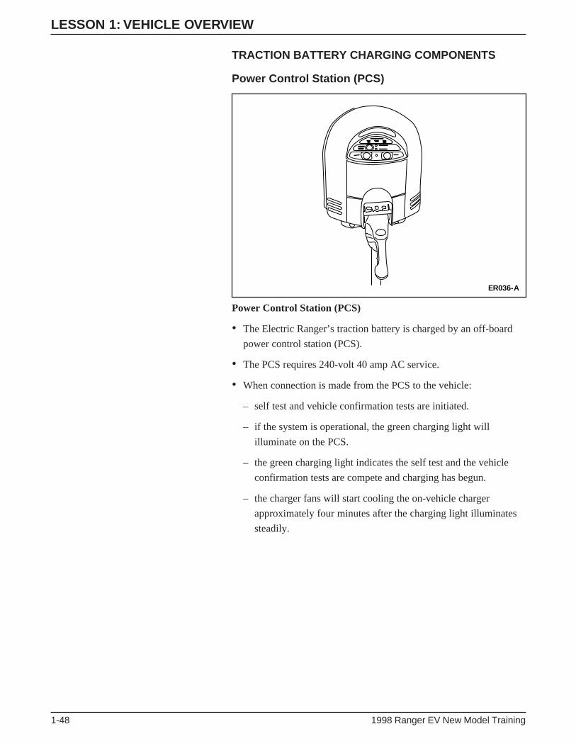
Power Control Station (PCS)
Power Control Station (PCS)
• The Electric Ranger’s traction battery is charged by an off-board
power control station (PCS).
• The PCS requires 240-volt 40 amp AC service.
• When connection is made from the PCS to the vehicle:
– self test and vehicle confirmation tests are initiated.
– if the system is operational, the green charging light will
illuminate on the PCS.
– the green charging light indicates the self test and the vehicle
confirmation tests are compete and charging has begun.
– the charger fans will start cooling the on-vehicle charger
approximately four minutes after the charging light illuminates
steadily.
ER036-A

LESSON 1: VEHICLE OVERVIEW
1998 Ranger EV New Model Training 1-49
• If the green START light goes out and the amber CHARGE
INTERRUPT light illuminates:
– operation has been discontinued by the Class A ground fault
detection system.
– due to the high sensitivity of this system, the charge operation
will be shut down if either the charge cord plug or the charge
inlet is wet or damp.
• Press the STOP button to reset the system.
– If further attempts are unsuccessful, it is likely that a ground
fault exists.
– If a ground fault exists, it must be repaired to continue the
charging operation.
• Complete charging procedure is covered in Lesson 2.

LESSON 1: VEHICLE OVERVIEW
1-50 1998 Ranger EV New Model Training
Charge Inlet
Charge Inlet
• The charge inlet is equivalent to the fuel filler port on a gasoline-
powered vehicle.
• The Electric Ranger receives power in the form of 240-volt
AC current.
• An EV industry standard plug fits into the charge inlet.
– Located between the headlights behind a grille access door.
• The high voltage wiring that connects the charge inlet to the
on board battery charger is energized only during charging.
ER037-A
HIGH VOLTAGE COMPONENT

LESSON 1: VEHICLE OVERVIEW
1998 Ranger EV New Model Training 1-51
Battery Charger
Battery Charger
• The on-board battery charger (arrow) is located in the underhood
compartment beneath the high voltage power distribution box.
• The on-board battery charger receives 240-volt 40 amp AC current
from the power control station (PCS) and converts it into DC
current.
• The on-board battery charger operates only with a charger cord
plugged into the charge inlet.
– The vehicle cannot be started or driven with the charger cord
attached to the charge inlet.
• Internal fans provide cooling during battery charger operation.
ER038-A
HIGH VOLTAGE COMPONENT

LESSON 1: VEHICLE OVERVIEW
1-52 1998 Ranger EV New Model Training
HIGH VOLTAGE WIRING
• All high voltage wiring is covered with color-coded with orange
convolute.
• High voltage wiring connects the following components:
A. From battery charger to high voltage power distribution box
B. From TIM to motor/transaxle
C. From traction battery to TIM
D. From high voltage power distribution box to DC/DC converter
E. From traction battery to high voltage power distribution box
F. From high voltage power distribution box to power steering
controller assembly
G. From A/C inverter motor controller to A/C compressor
H. From charge inlet to battery charger
I. From high voltage power distribution box to A/C inverter
motor controller
J. From high voltage power distribution box to PTC switching
module
K. From PTC switching module to PTC heater
• The illustrations on the following pages provide a reference for the
high voltage cables on the Electric Ranger.
High Voltage Wiring
ER039-A
A
CB
E
FG
HI
K
D
J

LESSON 1: VEHICLE OVERVIEW
1998 Ranger EV New Model Training 1-53
High Voltage Wiring from Charge Inlet (1) to Battery Charger (2)
High Voltage Wiring from Battery Charger (1) to High Voltage Power Distribution Box (2)

LESSON 1: VEHICLE OVERVIEW
1-54 1998 Ranger EV New Model Training
High Voltage Wiring from High Voltage Power Distribution Box (1) to Traction Battery
High Voltage Wiring from High Voltage Power Distribution Box (1) to
Power Steering Controller Assembly (2)
High Voltage Wiring from High Voltage Power Distribution Box (3) to DC/DC Converter (4)
ER043-A
3
4

LESSON 1: VEHICLE OVERVIEW
1998 Ranger EV New Model Training 1-55
High Voltage Wiring from Traction Battery (1) to TIM (2)
High Voltage Wiring from TIM (3) to Motor/Transaxle (4)
ER045-A
4
3

LESSON 1: VEHICLE OVERVIEW
1-56 1998 Ranger EV New Model Training
High Voltage Wiring from High Voltage Power Distribution Box (1) to PTC Switching Module (2)
High Voltage Wiring from PTC Switching Module (3) to PTC Heater
ER046-A
2
1
LESSON 1: VEHICLE OVERVIEW
1998 Ranger EV New Model Training 1-57
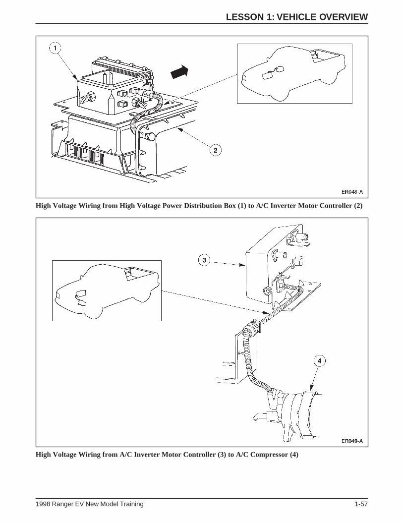
High Voltage Wiring from High Voltage Power Distribution Box (1) to A/C Inverter Motor Controller (2)
High Voltage Wiring from A/C Inverter Motor Controller (3) to A/C Compressor (4)

LESSON 1: VEHICLE OVERVIEW
1-58 1998 Ranger EV New Model Training
NOTES

LESSON 1: VEHICLE OVERVIEW
1998 Ranger EV New Model Training 1-59
ACTIVITY 1 – VEHICLE OVERVIEW – WORKSHEET ACOMPONENT LOCATION
STUDENT ANSWER SHEET
OBJECTIVE: To identify the location of EV Ranger components.
DIRECTIONS: Go to the classroom vehicles. You will find the components listed below have tags attached to
them. Write the letter/number on the tag that is attached to each of the listed components.
END OF WORKSHEET A
High Voltage Components
_____ A/C Compressor (H)
_____ A/C Inverter Motor Controller
_____ Charge Inlet
_____ DC/DC Converter
_____ Motor/Transaxle (H)
_____ High Voltage Power Distribution Box
_____ Power Steering Controller Assembly
_____ PTC Heater Core (inside of Chamber
Assembly-Heater Plenum)
_____ PTC Switching Module
_____ Traction Battery (includes BCM and
Contactor Box) (H)
_____ Battery Charger
_____ Traction Inverter Module (TIM) (H)
_____ Vacuum Pump
_____ Coolant Pump
_____ Auxiliary Battery
_____ Inertia Switch
1 2
4
35
EV151-A
6
8
910
11
12
13
14
15
7 16

LESSON 1: VEHICLE OVERVIEW
1-60 1998 Ranger EV New Model Training
ACTIVITY 1 – VEHICLE OVERVIEW – WORKSHEET BCOMPONENT FUNCTION EXERCISE
STUDENT ANSWER SHEET
OBJECTIVE: To identify the function of the Electric Ranger components and systems.
DIRECTIONS: Match the listed items with the correct definitions:
1. Interface Adapter Assembly (IAA)
2. Regenerative Braking System (RBS)
3. DC/DC Converter
4. Vacuum Pump
5. Contactor Box
6. PTC Switching Module
7. Traction Inverter Module (TIM)
8. Battery Charger
9. Electronic Throttle Control
10. Battery Control Module (BCM)
11. Auxiliary Battery
12. Multiplexing System
13. Inertia Switch
_____ manages all functions of the traction battery.
_____ charges the 12-volt battery.
_____ allows module to module communication during normal vehicle operation.
_____ converts high voltage DC into three-phase AC.
_____ interacts directly with the heating and braking system.
_____ replaces the accelerator cable.
_____ controls the PTC heating system.
_____ is cooled by internal cooling fans.
_____ contains two relays and two resistors for high voltage circuit precharging
_____ converts vehicle kinetic energy into electrical energy.
_____ is located directly in front of the high voltage power distribution box.
_____ powers the lighting system.
_____ interrupts power in the event of a collision.
END OF WORKSHEET B

LESSON 1: VEHICLE OVERVIEW
1998 Ranger EV New Model Training 1-61
ACTIVITY 1 – VEHICLE OVERVIEW – WORKSHEET CSAFETY FEATURE IDENTIFICATION
STUDENT ANSWER SHEET
OBJECTIVES: To describe the safety features found on the Electric Ranger.
DIRECTIONS: Select the correct response for each statement or question.
1. The inertia shutoff switch is located:
A. Beside the 12-volt battery in the underhood compartment.
B. Below the evaporator assembly in the passenger compartment.
C. Next to the diagnostic connector in the underhood compartment.
D. Above the TIM and close to the left rear fender.
2. When does the electric hazard warning lamp illuminate?
A. When the driver’s key is turned to the ON position (lamp prove-out).
B. When a high level of current leakage is detected.
C. When a high voltage interlock is disconnected.
D. All of the above.
3. What color identifies a high voltage cable?
A. Red.
B. Orange.
C. Yellow.
D. All of the above.
4. Which of the following is not equipped with a high voltage interlock?
A. The cover of the high voltage power distribution box.
B. The connector from the traction battery to the high voltage power distribution box (4-pin connector).
C. The connector from the traction battery to the TIM (2-pin connector).
D. The cover of the traction battery.
5. High voltage components are identified by:
A. Identification tags.
B. Red color coding.
C. Warning labels.
D. Plastic insulation.
END OF WORKSHEET C

NOTES

1998 Ranger EV New Model Training 2-1
LESSON 2: VEHICLE OPERATION
TECHNICIAN OBJECTIVES
• Describe vehicle operation.
• Identify instrument cluster components and functions.
• Describe the economy mode.
• Describe traction battery charging procedures.
CONTENTS
• Vehicle Operation
• Instrument Cluster Gauges
• Instrument Cluster Warning Lamps
• Economy Mode
• Traction Battery Charging
• Driver Response to an Emergency Situation
• Activity 2 – Vehicle Familiarization
• Worksheet D – Operating Characteristics of the Electric Ranger
• Worksheet E – Warning and Indicator Lamps
• Worksheet F – Instrument Gauges and Lights

LESSON 2: VEHICLE OPERATION
2-2 1998 Ranger EV New Model Training
VEHICLE OPERATION
Vehicle Controls
Vehicle Controls
• Driving the Electric Ranger is similar to operating a gasoline-
powered vehicle.
• The key positions are the same as other Ford vehicles (positions are
listed from full rearward to full forward):
– ACC
– LOCK
– OFF
– ON
– START
• The major controls are operated in the same manner as other
Ford vehicles.
– gear selector lever (except for unique economy mode)
– accelerator pedal
– brake pedal
– parking brake
ER051-A

LESSON 2: VEHICLE OPERATION
1998 Ranger EV New Model Training 2-3
• The instrument cluster has several new gauges and warning lamps
(covered later in this lesson).
• When the driver key is turned to the START position, there is no
starter motor noise (although the vehicle is activated).
• The Electric Ranger “creeps” forward like a gasoline-powered
vehicle with an automatic transmission that is in gear (after the
vehicle is “started” and the key remains in the ON position foot
off brake).
• During deceleration, a higher drag is felt due to the regenerative
braking system (covered later in this lesson).

LESSON 2: VEHICLE OPERATION
2-4 1998 Ranger EV New Model Training
INSTRUMENT CLUSTER GAUGES
Battery State of Charge Gauge
• The Battery State of Charge Gauge is the equivalent of the fuel
gauge on a gasoline-powered vehicle.
– F is indicated when the traction battery is fully charged.
– E is indicated when the traction battery is discharged to the point
where additional operation will reduce traction battery life.
• The BCM monitors the percent of charge of each battery module
and calculates the average state of charge of the traction battery.
• The BCM sends battery state of charge information to the IAA
through the J1850 (SCP) network.
• The IAA uses the Battery State of Charge Gauge to indicate the
traction battery state of charge.
Battery State of Charge Gauge
ER052-A
F
E
ECON
0
2
46
DISTANCETO EMPTY
kmMILES
0
00
0
50
100
20
10
30
40 50
60
70
80
0 0 0 0 0 0
20
40
60 80
100
120
MPH km/h
ON
OFF
H
CP R N D E
F
E

LESSON 2: VEHICLE OPERATION
1998 Ranger EV New Model Training 2-5
Battery State of Charge Gauge Inputs
NOTE: The POWER LIMIT and Low Fuel Warning Lamps flash
when the gauge reads empty. Vehicle performance will be extremely
limited at this point; the driver must pull over off the road (to the
shoulder) as quickly and safely as possible.
ER119-A
INSTRUMENT CLUSTER
BATTERY STATE OF CHARGE GAUGE
IAABCM
LESSON 2: VEHICLE OPERATION
2-6 1998 Ranger EV New Model Training
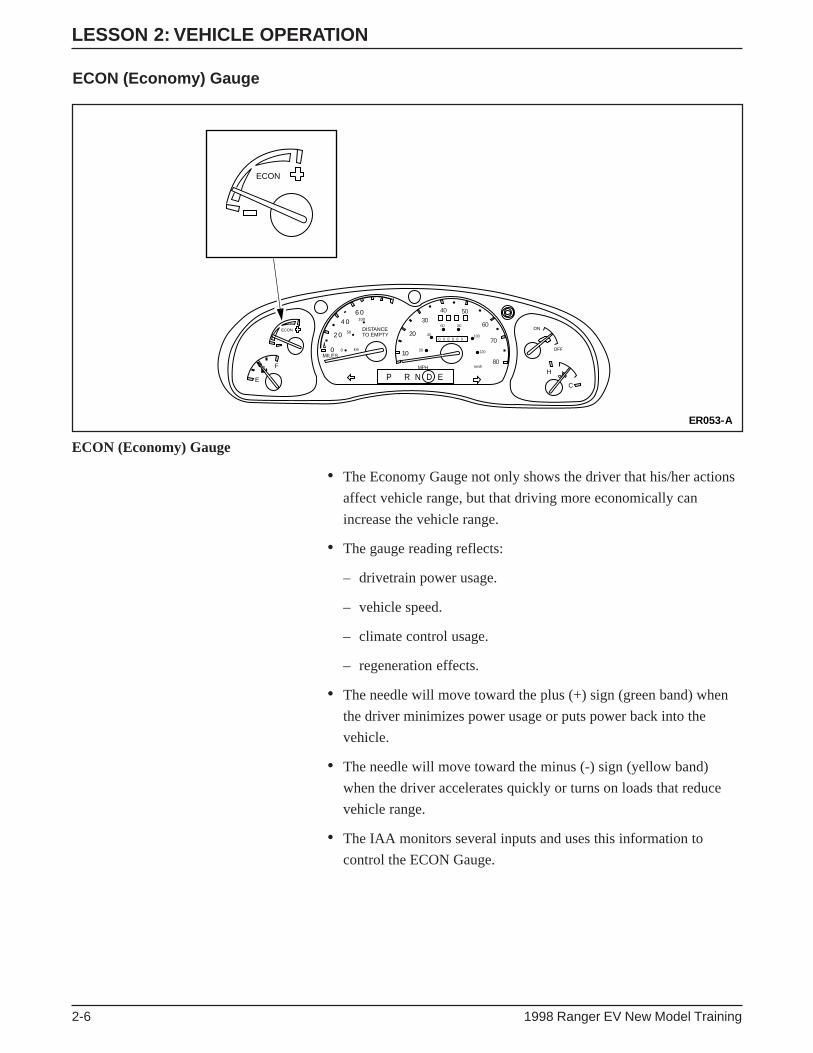
ECON (Economy) Gauge
ER053-A
F
E
ECON
0
2
46
DISTANCETO EMPTY
km
MILES
0
00
0
50
100
20
10
30
40 50
60
70
80
0 0 0 0 0 0
20
40
60 80
100
120
MPH km/h
ON
OFF
H
CP R N D E
ECON
ECON (Economy) Gauge
• The Economy Gauge not only shows the driver that his/her actions
affect vehicle range, but that driving more economically can
increase the vehicle range.
• The gauge reading reflects:
– drivetrain power usage.
– vehicle speed.
– climate control usage.
– regeneration effects.
• The needle will move toward the plus (+) sign (green band) when
the driver minimizes power usage or puts power back into the
vehicle.
• The needle will move toward the minus (-) sign (yellow band)
when the driver accelerates quickly or turns on loads that reduce
vehicle range.
• The IAA monitors several inputs and uses this information to
control the ECON Gauge.

LESSON 2: VEHICLE OPERATION
1998 Ranger EV New Model Training 2-7
ER120-A
TIM
INSTRUMENT CLUSTER
ECON GAUGE
IAA
HEATER/AC
REAR ABSSPEED SENSOR
ABS MODULE
Economy Gauge Inputs

LESSON 2: VEHICLE OPERATION
2-8 1998 Ranger EV New Model Training
DISTANCE TO EMPTY Gauge
DISTANCE TO EMPTY Gauge
• The DISTANCE TO EMPTY Gauge estimates the remaining
distance that can be traveled before the traction battery needs to be
recharged.
– This estimate is calculated by the BCM.
• The DISTANCE TO EMPTY Gauge is controlled by the IAA and
varies as driving conditions change.
• Some conditions that affect the DISTANCE TO EMPTY
Gauge are:
– city/highway driving.
– hilly terrain.
– climate control usage.
– driving habits.
• The BCM monitors power consumption and sends this information
to the IAA.
• The IAA controls the DISTANCE TO EMPTY Gauge based on
this information.
ER054-A
F
E
ECON
0
2
46
DISTANCETO EMPTY
km
MILES
0
00
0
50
100
20
10
30
40 50
60
70
80
0 0 0 0 0 0
20
40
60 80
100
120
MPH km/h
ON
OFF
H
CP R N D E
0
2
46
DISTANCETO EMPTY
kmMILES
0
00
0
50
100

LESSON 2: VEHICLE OPERATION
1998 Ranger EV New Model Training 2-9
DISTANCE TO EMPTY Gauge Inputs
ER121-A
INSTRUMENT CLUSTER
DISTANCE TO EMPTY GAUGE
BCM IAA
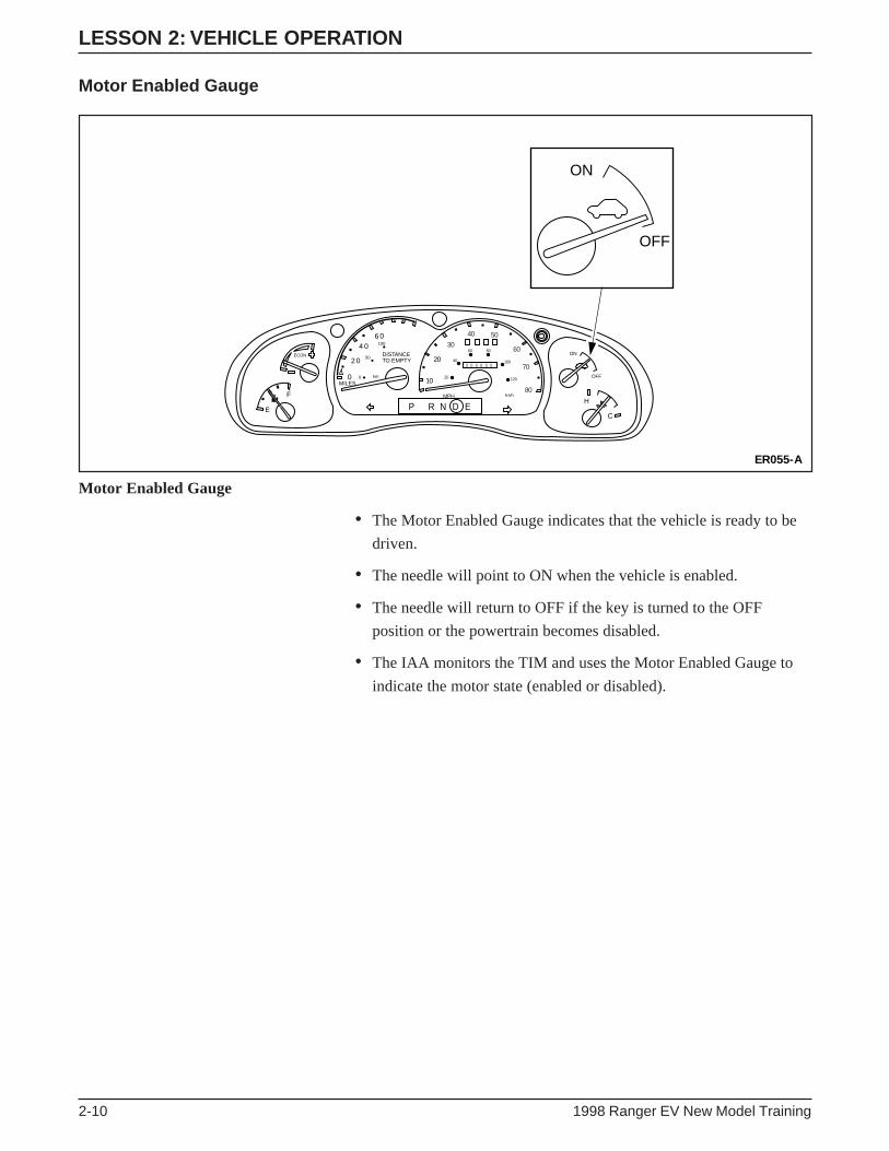
LESSON 2: VEHICLE OPERATION
2-10 1998 Ranger EV New Model Training
Motor Enabled Gauge
Motor Enabled Gauge
• The Motor Enabled Gauge indicates that the vehicle is ready to be
driven.
• The needle will point to ON when the vehicle is enabled.
• The needle will return to OFF if the key is turned to the OFF
position or the powertrain becomes disabled.
• The IAA monitors the TIM and uses the Motor Enabled Gauge to
indicate the motor state (enabled or disabled).
ER055-A
F
E
ECON
0
2
46
DISTANCETO EMPTY
km
MILES
0
00
0
50
100
20
10
30
40 50
60
70
80
0 0 0 0 0 0
20
40
60 80
100
120
MPH km/h
ON
OFF
H
CP R N D E
ON
OFF

LESSON 2: VEHICLE OPERATION
1998 Ranger EV New Model Training 2-11
Motor Enabled Gauge Inputs
ER122-A
IAA
INSTRUMENT CLUSTER
MOTOR ENABLEDGAUGE
TIM
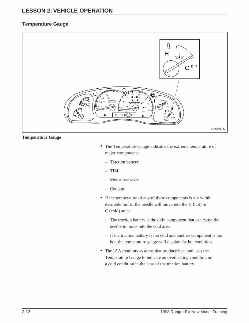
LESSON 2: VEHICLE OPERATION
2-12 1998 Ranger EV New Model Training
Temperature Gauge
• The Temperature Gauge indicates the extreme temperature of
major components:
– Traction battery
– TIM
– Motor/transaxle
– Coolant
• If the temperature of any of these components is not within
desirable limits, the needle will move into the H (hot) or
C (cold) areas.
– The traction battery is the only component that can cause the
needle to move into the cold area.
– If the traction battery is too cold and another component is too
hot, the temperature gauge will display the hot condition.
• The IAA monitors systems that produce heat and uses the
Temperature Gauge to indicate an overheating condition or
a cold condition in the case of the traction battery.
ER056-A
F
E
ECON
0
2
46
DISTANCETO EMPTY
km
MILES
0
00
0
50
100
20
10
30
40 50
60
70
80
0 0 0 0 0 0
20
40
60 80
100
120
MPH km/h
ON
OFF
H
CP R N D E
H
C
Temperature Gauge

LESSON 2: VEHICLE OPERATION
1998 Ranger EV New Model Training 2-13
Temperature Gauge Inputs
ER123-A
MOTOR/TRANSAXLE
TIM
TRACTION BATTERY
DC/DC CONVERTER COOLANT
IAA INSTRUMENT CLUSTER
TEMPERATURE GAUGE
AC INVERTER

LESSON 2: VEHICLE OPERATION
2-14 1998 Ranger EV New Model Training
Speedometer/Odometer/Tripmeter
Speedometer/Odometer/Tripmeter
• The speedometer (A) is an electronically driven 0-130 km/h
(0-80 mph) gauge with a carryover Ranger odometer (B) and
tripmeter.
• The IAA monitors the ABS module for input from the rear
anti-lock brake system speed sensor. This input is used to indicate
vehicle speed.
ER057-A
F
E
ECON
0
2
46
DISTANCETO EMPTY
kmMILES
0
00
0
50
100
20
10
30
40 50
60
70
80
0 0 0 0 0 0
20
40
60 80
100
120
MPH km/h
ON
OFF
H
CP R N D E
BA
ER136-A
REAR ABSSPEED SENSOR
IAA
INSTRUMENT CLUSTER
SPEEDOMETER/ODOMETER
ABSMODULE
Speedometer/Odometer/Tripmeter Inputs

LESSON 2: VEHICLE OPERATION
1998 Ranger EV New Model Training 2-15
INSTRUMENT CLUSTER WARNING LAMPS
Malfunction Indicator Lamp (MIL)
• The yellow MIL indicates a vehicle malfunction that requires
service.
• The MIL will illuminate during these conditions:
– a concern exists where long-term damage may result
– when a less serious concern occurs twice within five key cycles
• The IAA monitors the other “smart” modules and uses the MIL to
indicate a concern.
ER058-A
F
E
ECON
0
2
46
DISTANCETO EMPTY
kmMILES
0
00
0
50
100
20
10
30
40 50
60
70
80
0 0 0 0 0 0
20
40
60 80
100
120
MPH km/h
ON
OFF
H
CP R N D E
Malfunction Indicator Lamp (MIL)
ER124-A
IAA
INSTRUMENT CLUSTER
MIL
BCM TIM
MIL Inputs

LESSON 2: VEHICLE OPERATION
2-16 1998 Ranger EV New Model Training
Low Fuel Warning Lamp
Low Fuel Warning Lamp
• The Low Fuel Warning Lamp alerts the driver when the state of
charge is low.
• This lamp illuminates when the traction battery state of charge
reaches 10%.
– Limited operating strategy is in effect when the lamp is
illuminated to conserve remaining power.
• The Low Fuel Warning Lamp will flash when the battery state of
charge reaches 0% (the vehicle has very limited range at this point).
– Speed is limited to 10 km/h (6 mph).
ER135-A
F
E
ECON
0
2
46
DISTANCETO EMPTY
kmMILES
0
00
0
50
100
20
10
30
40 50
60
70
80
0 0 0 0 0 0
20
40
60 80
100
120
MPH km/h
ON
OFF
H
CP R N D E

LESSON 2: VEHICLE OPERATION
1998 Ranger EV New Model Training 2-17
Low Fuel Warning Lamp Inputs
NOTE: When this lamp flashes, range is very limited and the vehicle
should be returned to the repair facility. The Low Fuel Warning Lamp
will also illuminate or flash if a fault occurs in the system.
ER125-A
IAA
INSTRUMENT CLUSTER
LOW FUEL WARNING LAMP
BCM

LESSON 2: VEHICLE OPERATION
2-18 1998 Ranger EV New Model Training
POWER LIMIT Warning Lamp
POWER LIMIT Warning Lamp
• The IAA monitors input from the TIM through the J1850 (SCP)
network and uses the POWER LIMIT Warning Lamp to indicate
the vehicle’s performance is limited to conserve remaining battery
power (lamp illuminated).
• As the traction battery nears complete discharge, the lamp begins to
flash to indicate performance is further limited to allow for safe
parking of the vehicle before the battery is completely drained.
ER059-A
F
E
ECON
0
2
46
DISTANCETO EMPTY
kmMILES
0
00
0
50
100
20
10
30
40 50
60
70
80
0 0 0 0 0 0
20
40
60 80
100
120
MPH km/h
ON
OFF
H
CP R N D E
POWERLIMIT

LESSON 2: VEHICLE OPERATION
1998 Ranger EV New Model Training 2-19
POWER LIMIT Warning Lamp Inputs
ER126-A
IAA
INSTRUMENT CLUSTER
POWER LIMITLAMP
TIM

LESSON 2: VEHICLE OPERATION
2-20 1998 Ranger EV New Model Training
BRAKE Warning Lamp
BRAKE Warning Lamp
• The red BRAKE Warning Lamp will illuminate during the
following conditions:
– parking brake engaged.
– low brake fluid level in the master cylinder.
– regenerative braking system (RBS) malfunction.
– anti-lock brake system (ABS) malfunction.
• The IAA monitors several inputs and illuminates the red
BRAKE Warning Lamp if the parking brake is engaged,
there is a RBS failure, or there is a brake system concern.
ER060-A
F
E
ECON
0
2
46
DISTANCETO EMPTY
kmMILES
0
00
0
50
100
20
10
30
40 50
60
70
80
0 0 0 0 0 0
20
40
60 80
100
120
MPH km/h
ON
OFF
H
CP R N D E
BRAKE!

LESSON 2: VEHICLE OPERATION
1998 Ranger EV New Model Training 2-21
ER127-A
IAA
INSTRUMENT CLUSTER
MASTER CYLINDERPRESSURE SENSOR(LINE PRESSURE)
RED BRAKEWARNING LAMP
TIM (RBS)
PARKING BRAKE
MASTER CYLINDER(FLUID LEVEL)
ABS MODULE
BRAKE Warning Lamp Inputs
NOTE: If the lamp illuminates, be sure the parking brake is not
engaged and the brake fluid level is correct before attempting
further diagnosis.

LESSON 2: VEHICLE OPERATION
2-22 1998 Ranger EV New Model Training
Electric Hazard Warning Lamp
Electric Hazard Warning Lamp
• The red Electric Hazard Warning Lamp will illuminate during the
following conditions:
– severe current leakage is detected.
– a high voltage interlock is opened.
• If current leakage is detected, the vehicle will continue to operate.
• To prevent possible damage to the vehicle or personal injury, the
vehicle must be repaired immediately.
• If a high voltage interlock is opened, the emergency power off
(EPO) system will cause all high voltage to be disabled and shut
down the vehicle (for more information on EPO see Lesson 1).
• The BCM monitors for current leakage. If current leakage is
present or a high voltage interlock is open the BCM will signal the
IAA to illuminate the Electric Hazard Warning Lamp.
ER061-A
F
E
ECON
0
2
46
DISTANCETO EMPTY
kmMILES
0
00
0
50
100
20
10
30
40 50
60
70
80
0 0 0 0 0 0
20
40
60 80
100
120
MPH km/h
ON
OFF
H
CP R N D E

LESSON 2: VEHICLE OPERATION
1998 Ranger EV New Model Training 2-23
Electric Hazard Warning Lamp Inputs
NOTE: If an electrical hazard is present, the electric hazard warning
lamp only illuminates with the key in the START or ON position.
ER128-A
IAA
INSTRUMENT CLUSTER
ELECTRIC HAZARD WARNING LAMP
BCM

LESSON 2: VEHICLE OPERATION
2-24 1998 Ranger EV New Model Training
Charging Indicator Lamp
Charging Indicator Lamp
• The red Charging Indicator Lamp will illuminate during charging
if the key is turned to the START or ON position.
• The vehicle cannot be “started” and should not be moved while the
charging cord is plugged into the charge inlet.
• The IAA monitors several inputs to indicate if it is safe to charge
the traction battery.
• If the driver attempted to start the vehicle with the charger
connected the lamp will illuminate to indicate it is not possible to
operate the vehicle with the charger connected.
• The charging indicator lamp also indicates if it is not safe to charge
the battery pack.
– The lamp will flash if a charging fault exists.
ER062-A
F
E
ECON
0
2
46
DISTANCETO EMPTY
kmMILES
0
00
0
50
100
20
10
30
40 50
60
70
80
0 0 0 0 0 0
20
40
60 80
100
120
MPH km/h
ON
OFF
H
CP R N D E

LESSON 2: VEHICLE OPERATION
1998 Ranger EV New Model Training 2-25
Charging Indicator Lamp Inputs
NOTE: The Charging Indicator Lamp will flash when the key is in
the ON position and it is unsafe to charge (vehicle not in PARK [P]),
severe current leakage, open interlock or activated inertia
shutoff switch).
ER129-A
IAA
IGNITION SWITCH
DTR SWITCH
CHARGE INLET
INSTRUMENT CLUSTER
CHARGING INDICATOR LAMP

LESSON 2: VEHICLE OPERATION
2-26 1998 Ranger EV New Model Training
POWER RESET Indicator Lamp
POWER RESET Indicator Lamp
• The yellow POWER RESET Indicator Lamp will illuminate when
the inertia shutoff switch has been activated.
• When activated the inertia shutoff switch disables all high voltage
power to the vehicle electrical system.
• If no special service is required, pressing the reset button on top of
the inertia shutoff switch can restore power to the high voltage
circuits.
• The IAA monitors the inertia shutoff switch. If the switch is
activated, high voltage circuits are interrupted and the POWER
RESET Indicator Lamp is illuminated.
• The IAA opens the negative contactor relay and signals the BCM to
command the TIM to open the positive contactor relay.
• The IAA uses the J1850 (SCP) network to communicate these
commands to the other control modules.
ER063-A
F
E
ECON
0
2
46
DISTANCETO EMPTY
kmMILES
0
00
0
50
100
20
10
30
40 50
60
70
80
0 0 0 0 0 0
20
40
60 80
100
120
MPH km/h
ON
OFF
H
CP R N D E
POWERRESET

LESSON 2: VEHICLE OPERATION
1998 Ranger EV New Model Training 2-27
ER130-A
BCM TIM
IAA
INERTIA SHUTOFFSWITCH
CONTACTOR BOX
INSTRUMENT CLUSTER
POWER RESETINDICATOR LAMP
POWER RESET Indicator Lamp Inputs
NOTE: The inertia shutoff switch is located in the passenger
compartment, above the carpet line and below the evaporator
assembly.

LESSON 2: VEHICLE OPERATION
2-28 1998 Ranger EV New Model Training
ECON MODE Indicator Lamp
ECON MODE Indicator Lamp
• The green ECON MODE Indicator Lamp will illuminate when the
driver has selected the economy driving mode (E).
• The economy mode will increase the level of regenerative braking
to improve vehicle range.
• The brightness of this lamp is controlled by the instrument cluster
lamp dimmer control.
• The TIM monitors the DTR sensor and relays information to
the IAA.
• When the driver selects economy mode, the TIM informs the IAA
and the IAA illuminates the ECON MODE Indicator Lamp.
ER064-A
ECONMODE
F
E
ECON
0
2
46
DISTANCETO EMPTY
kmMILES
0
00
0
50
100
20
10
30
40 50
60
70
80
0 0 0 0 0 0
20
40
60 80
100
120
MPH km/h
ON
OFF
H
CP R N D E

LESSON 2: VEHICLE OPERATION
1998 Ranger EV New Model Training 2-29
ER132-A
P R N D E
TIM
DTR
ECON MODEINDICATOR LAMP
INSTRUMENT CLUSTER
IAA
ECON MODE Indicator Lamp Inputs

LESSON 2: VEHICLE OPERATION
2-30 1998 Ranger EV New Model Training
Auxiliary Battery Warning Lamp
Auxiliary Battery Warning Lamp
• The red Auxiliary Battery Warning Lamp will illuminate during the
following conditions:
– the auxiliary battery voltage exceeds 15.75 volts.
– the auxiliary battery voltage falls below 11.5 volts.
• If the auxiliary battery voltage warning lamp illuminates, the driver
must pull over to a safe area and have the vehicle repaired.
• The IAA monitors the auxiliary battery voltage. If voltage exceeds
15.75 volts or falls below 11.5 volts the IAA illuminates the
Auxiliary Battery Warning Lamp.
ER065-A
F
E
ECON
0
2
46
DISTANCETO EMPTY
kmMILES
0
00
0
50
100
20
10
30
40 50
60
70
80
0 0 0 0 0 0
20
40
60 80
100
120
MPH km/h
ON
OFF
H
CP R N D E
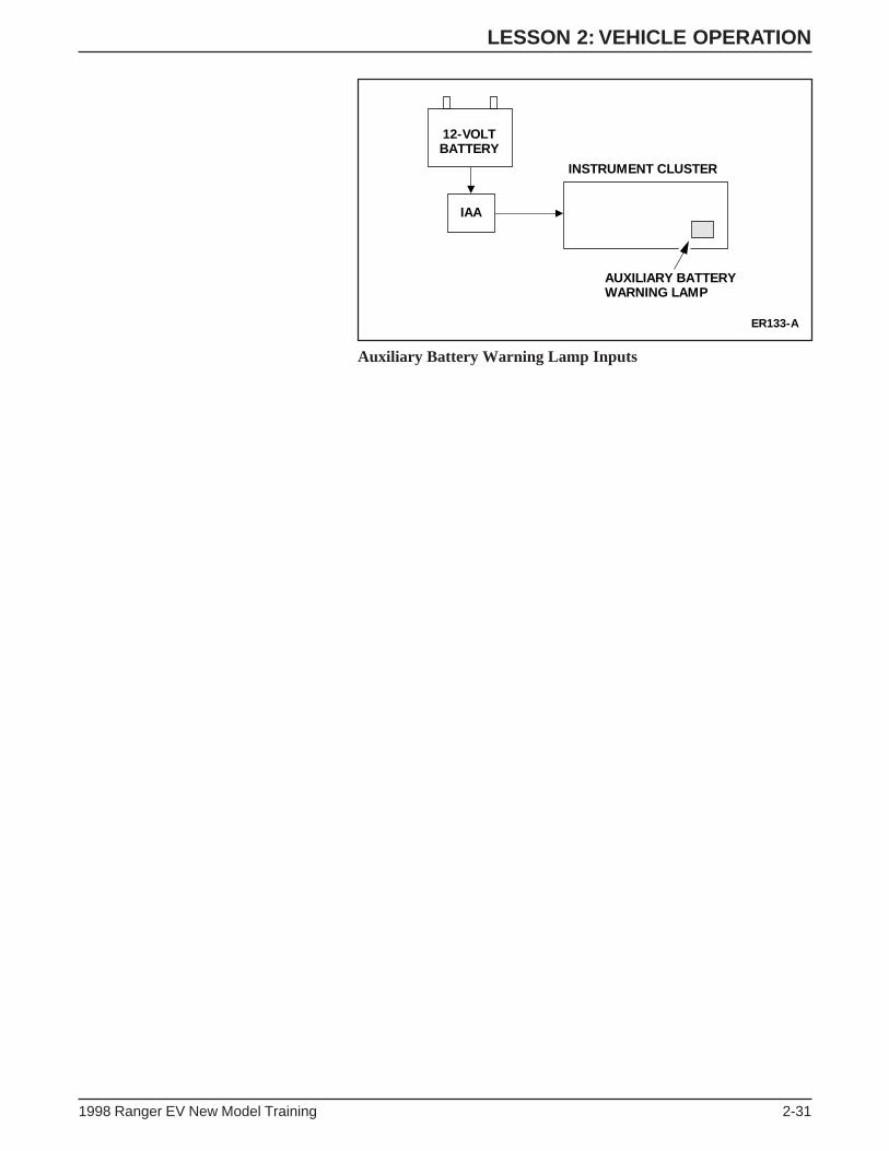
LESSON 2: VEHICLE OPERATION
1998 Ranger EV New Model Training 2-31
Auxiliary Battery Warning Lamp Inputs
ER133-A
12-VOLTBATTERY
AUXILIARY BATTERYWARNING LAMP
INSTRUMENT CLUSTER
IAA
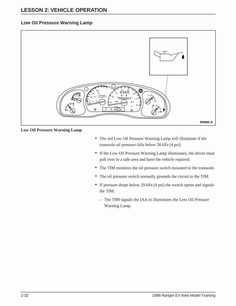
LESSON 2: VEHICLE OPERATION
2-32 1998 Ranger EV New Model Training
Low Oil Pressure Warning Lamp
Low Oil Pressure Warning Lamp
ER066-A
F
E
ECON
0
2
46
DISTANCETO EMPTY
kmMILES
0
00
0
50
100
20
10
30
40 50
60
70
80
0 0 0 0 0 0
20
40
60 80
100
120
MPH km/h
ON
OFF
H
CP R N D E
• The red Low Oil Pressure Warning Lamp will illuminate if the
transaxle oil pressure falls below 28 kPa (4 psi).
• If the Low Oil Pressure Warning Lamp illuminates, the driver must
pull over to a safe area and have the vehicle repaired.
• The TIM monitors the oil pressure switch mounted to the transaxle.
• The oil pressure switch normally grounds the circuit to the TIM.
• If pressure drops below 29 kPa (4 psi) the switch opens and signals
the TIM.
– The TIM signals the IAA to illuminates the Low Oil Pressure
Warning Lamp.

LESSON 2: VEHICLE OPERATION
1998 Ranger EV New Model Training 2-33
ER134-A
TIMTRANSAXLE
LOW OIL PRESSUREWARNING LAMP
INSTRUMENT CLUSTERTRANSAXLE OILPRESSURE SWITCH IAA
Low Oil Pressure Warning Lamp Inputs
Other Indicator Lamps
• The following indicator lamps operate in the same manner as those
used on gasoline-powered vehicles:
– ABS warning lamp
– air bag indicator lamp
– seat belt indicator lamp
– DOOR AJAR indicator lamp
– highbeam indicator lamp
– turn signal indicator lamps

LESSON 2: VEHICLE OPERATION
2-34 1998 Ranger EV New Model Training
ECONOMY MODE
Economy Mode
• When the driver selects the economy operating mode using the
gear selector lever, the regenerative brake function is enhanced to
increase vehicle range.
• The economy mode applies a higher regenerative motor torque to
the rear wheels, allowing more power to be recovered and stored in
the Traction Battery.
• The economy mode also limits the top speed of the vehicle to
104 km/h (65 mph).
ER067-A
P R N ED

LESSON 2: VEHICLE OPERATION
1998 Ranger EV New Model Training 2-35
TRACTION BATTERY CHARGING
Charge Cord Connection
• Traction Battery charging requires 240-volt 40 amp AC service.
• The 7.625-m (25-ft) charge cord plugs directly into the charge inlet
on the vehicle.
• Six to eight (6-8) hours are required to charge a fully-discharged
Traction Battery at 25°C (77°F).
WARNING: FOLLOW CHARGING PROCEDURES
AND DEVICE OPERATING INSTRUCTIONS
CAREFULLY. FAILURE TO DO SO MAY RESULT
IN INJURY OR DEATH.
WARNING: LEAD-ACID BATTERIES PRODUCE
HYDROGEN GAS WHICH, IN LARGE QUANTITIES,
IS EXPLOSIVE. AN OVERCHARGED LEAD-ACID
BATTERY MAY RELEASE EXCESS HYDROGEN GAS
THROUGH VENTS IN THE BATTERY CASE. ALWAYS
ENSURE THAT THE LEAD-ACID BATTERIES ARE
PROPERLY RECHARGED USING ONLY FORD-
SPECIFIED EQUIPMENT AND PROCEDURES.
NOTE: About four hours of equalization charging for the traction
battery modules can occur at three-week intervals.

LESSON 2: VEHICLE OPERATION
2-36 1998 Ranger EV New Model Training
Charging Procedure
Connecting Charging Cord
1. Place the front of the vehicle within 3 m (10 ft) of the charging
station.
2. Place the gear selector in Park (P) and set the parking brake.
3. Turn the key to the OFF position and remove the key.
4. Pull open the charge inlet access door.
5. Align the charge cord plug with the charge inlet and fully insert
the plug (A). Rotate down (B).
6. Push the charging station START button. Battery charging
will begin when the self tests are completed and the green
START light illuminates steadily.
NOTE: If the green charging light goes out and the amber charge
interrupt light illuminates, press the STOP button (the light will turn
off). Try to initiate the charging procedure again.
To Stop Charging
1. Push the STOP button on the charging station.
2. Depress the thumb button on the plug and disconnect the charge
cord plug from the charge inlet.
3. Close the charge inlet access door.

LESSON 2: VEHICLE OPERATION
1998 Ranger EV New Model Training 2-37
DRIVER RESPONSE TO AN EMERGENCY SITUATION
• If possible, perform the following steps in the event of a collision,
fire or some other emergency situation. However, never endanger
yourself or others near the vehicle.
1. Stop and put the gear selector in the Park (P) position.
2. Turn the key to the OFF position and remove the key.
3. Set the parking brake.
4. Exit the vehicle.
5. Contact crash/fire/rescue emergency personnel and inform them
of the type of vehicle (EV) and the nature of the emergency.

LESSON 2: VEHICLE OPERATION
2-38 1998 Ranger EV New Model Training
NOTES

LESSON 2: VEHICLE OPERATION
1998 Ranger EV New Model Training 2-39
ACTIVITY 2 – VEHICLE FAMILIARIZATION – WORKSHEET DOPERATING CHARACTERISTICS OF THE ELECTRIC RANGER
STUDENT ANSWER SHEET
OBJECTIVE: To identify the operating characteristics of the Electric Ranger.
DIRECTIONS: Use your experience driving the Electric Ranger to answer the questions below.
1. When you started the EV, how did you recognize that the vehicle was running? ______________________
______________________________________________________________________________________
2. What was your impression of the sound levels of the EV? ________________________________________
______________________________________________________________________________________
3. If you came to a stop and took your foot off the brake, what occurred? ______________________________
______________________________________________________________________________________
4. When you were coasting in the EV, what impressions did you get, and why? _________________________
______________________________________________________________________________________
5. How do you compare the acceleration to that of a conventional vehicle? ____________________________
______________________________________________________________________________________
6. How do you compare the handling compared to a conventional Ranger? ____________________________
______________________________________________________________________________________
7. What change in vehicle operation did you notice when operating in the ECON mode? _________________
______________________________________________________________________________________
8. What other differences did you notice between the Electric Ranger and a conventional vehicle?__________
______________________________________________________________________________________
9. What is your overall impression of the operating characteristics of the Electric Ranger? ________________
______________________________________________________________________________________
10. Run key through all positions. How many positions are there? ____________________________________
______________________________________________________________________________________
11. In what position will the shift lever move without having your foot on the brake? _____________________
______________________________________________________________________________________
END OF WORKSHEET D

LESSON 2: VEHICLE OPERATION
2-40 1998 Ranger EV New Model Training
ACTIVITY 2 – VEHICLE FAMILIARIZATION – WORKSHEET EWARNING AND INDICATOR LAMPS
STUDENT ANSWER SHEET
OBJECTIVE: To identify the warning and indicator lamp functions.
DIRECTIONS: Match each lamp with its correct definition.
Warning and Indicator Lamps
_____ indicates a general vehicle malfunction that requires service.
_____ flashes when the battery state of charge gauge reaches empty.
_____ is activated when current leakage is detected.
_____ indicates the highest performance level of the regenerative braking system.
_____ illuminates when the vehicle is charging (key in the RUN or START position).
_____ lights to indicate that the inertia shutoff switch has been triggered.
_____ reports a regenerative braking system malfunction.
_____ lights when the 12-volt battery voltage exceeds 15.75 volts or falls below 11.5 volts.
_____ indicates that the transaxle oil pressure has fallen below 28 kPa (4 psi).
END OF WORKSHEET E
ER070-A
A B C D
E F G H I
!BRAKE
ECONMODE
POWERLIMIT
POWERRESET

LESSON 2: VEHICLE OPERATION
1998 Ranger EV New Model Training 2-41
ACTIVITY 2 – VEHICLE FAMILIARIZATION – WORKSHEET FINSTRUMENT GAUGES AND LIGHTS
STUDENT ANSWER SHEET
OBJECTIVE: To describe various functions and indications of the gauges and instrument panel lights on the
Electric Ranger.
DIRECTIONS: Select the correct answer for each question.
1. Which of the following is not a step in the battery charging procedure?
A. Place the gear selector in Park (P) position and set the parking brake.
B. Turn the driver key to the ON position.
C. Pull open the charge inlet access door.
D. Align the charge cord plug with the charge inlet and fully insert the plug.
E. Push the charging station START button.
2. The needle on the gauge identified by a car icon is pointing towards ON. What does this indicate?
A. The traction battery is charging.
B. The driver key in the ACC position.
C. The 12-volt battery is charging.
D. The motor is enabled.
3. Which gauge can be overlooked when the CHECK GAUGE Warning Lamp illuminates?
A. ECON Gauge.
B. DISTANCE TO EMPTY Gauge.
C. Battery State of Charge Gauge.
D. Temperature Gauge.
4. Which component can move the needle of the Temperature Gauge to the “cold” area?
A. TIM.
B. DC/DC converter.
C. Traction battery.
D. Evaporator core.
5. Which of the following affect(s) the ECON Gauge?
A. Drivetrain power expenditure.
B. Climate control usage.
C. Regenerative braking.
D. All of the above.
WORKSHEET F CONTINUED ON NEXT PAGE
LESSON 2: VEHICLE OPERATION
2-42 1998 Ranger EV New Model Training
6. How many hours of charging are required to replenish a fully discharged Traction Battery at 25°C (77°F)?
A. 2-4 hours.
B. 6-8 hours.
C. 10-12 hours.
D. 14-16 hours.
7. What would cause the Distance to Empty Gauge reading to increase?
A. Accelerating to highway speed.
B. Driving up a steep grade.
C. Turning the A/C off.
D. A short to chassis ground in the high voltage power distribution box.
8. The Auxiliary Battery Warning Lamp illuminates:
A. If voltage exceeds 15.75 volts.
B. If voltage falls below 11.5 volts.
C. Either A or B.
D. None of the above
9. The IAA monitors input from the ________ to control the Battery State of Charge Gauge.
A. TIM.
B. 12-volt battery.
C. BCM.
D. EEC-V module.
ACTIVITY 2 – VEHICLE FAMILIARIZATION – WORKSHEET FINSTRUMENT GAUGES AND LIGHTS
STUDENT ANSWER SHEET (Continued)
WORKSHEET F CONTINUED ON NEXT PAGE
LESSON 2: VEHICLE OPERATION
1998 Ranger EV New Model Training 2-43
10. The ECON Mode Indicator Lamp illuminates:
A. during braking.
B. during deceleration.
C. if the driver selects the Economy Mode.
D. if Traction Battery state of charge falls below 50%.
11. The Battery State of Charge Gauge is equivalent to the _________ on a standard vehicle.
A. ammeter.
B. voltmeter.
C. fuel gauge.
D. Battery Warning Lamp.
ACTIVITY 2 – VEHICLE FAMILIARIZATION – WORKSHEET FINSTRUMENT GAUGES AND LIGHTS
STUDENT ANSWER SHEET (Continued)
END OF WORKSHEET F

NOTES

1998 Ranger EV New Model Training 3-1
LESSON 3: SAFETY AND EMERGENCY INFORMATION
TECHNICIAN OBJECTIVES
• Describe high voltage color coding.
• Recognize high voltage warnings.
• Identify the hazards associated with high voltages.
• Identify the causes of most electrical accidents.
• Identify safety rules that should be followed for accident
prevention.
• Describe the first aid procedures to be followed in case of acid
contact and/or electric shock.
• Describe what can be done to prevent fires.
• Identify the classes of fire and the types and ratings of fire
extinguishers.
CONTENTS
• Lead-Acid Battery Design
• Lead-Acid Module Specifications
• High Voltage Hazards
• Electrical Accidents
• Accident Prevention
• First Aid Procedures
• Fire Prevention
• Activity 3 – EV Safety and Emergency Information
• Worksheet G – Safety and Emergency Procedures

LESSON 3: SAFETY AND EMERGENCY INFORMATION
3-2 1998 Ranger EV New Model Training
LEAD-ACID BATTERY DESIGN
Lead-Acid Battery Modules
• The Electric Ranger uses advanced technology, valve-regulated,
starved electrolyte lead-acid batteries.
• The 39 individual battery modules in the Traction Battery are
sealed and maintenance-free.
• Each 8-volt battery is made up of a polypropylene case, stainless
steel terminals and sulfuric acid electrolyte.
• The electrolyte inside each battery is soaked in a cotton-like fiber,
and only seven or eight drops will drain from each of the four cells
in an individual battery.
ER071-A
18
17
21
6
73
4
5
20
19
21
25
28
29
30
15
14
33
32
31
12
13
34
35
36
11
10
39
38
37
9
8
26
27
16
24
23
22

LESSON 3: SAFETY AND EMERGENCY INFORMATION
1998 Ranger EV New Model Training 3-3
WARNING: LEAD-ACID BATTERIES CONTAIN
SULFURIC ACID. AVOID CONTACT WITH SKIN,
EYES OR CLOTHING. ALSO, SHIELD YOUR EYES
WHEN WORKING NEAR BATTERIES TO PROTECT
AGAINST POSSIBLE SPLASHING OF THE ACID
SOLUTION. IN CASE OF ACID CONTACT WITH THE
SKIN OR EYES, FLUSH IMMEDIATELY WITH
WATER FOR A MINIMUM OF FIFTEEN MINUTES
AND GET PROMPT MEDICAL ATTENTION. IF ACID
IS SWALLOWED, DRINK LARGE QUANTITIES OF
MILK OR WATER, FOLLOWED BY MILK OF
MAGNESIA, A BEATEN EGG, OR VEGETABLE OIL,
CALL A PHYSICIAN IMMEDIATELY.
WARNING: BATTERIES NORMALLY PRODUCE
EXPLOSIVE GASES WHICH CAN CAUSE PERSONAL
INJURY OR DEATH. DO NOT ALLOW FLAMES,
SPARKS OR LIGHTED SUBSTANCES TO COME NEAR
THE BATTERIES. WHEN CHARGING OR WORKING
NEAR THE BATTERIES, ALWAYS SHIELD YOUR
FACE AND PROTECT YOUR EYES. ALWAYS
PROVIDE VENTILATION.

LESSON 3: SAFETY AND EMERGENCY INFORMATION
3-4 1998 Ranger EV New Model Training
LEAD-ACID MODULE SPECIFICATIONSDimensions Length 399 mm (15.275 in)
Width 116 mm (5.567 in)
Height 175 mm (6.890 in)
Weight 19.5 kg (42 lb)
Terminals Stainless Steel Threads With Lead Contacts
Vent Mechanism Pressure Relief Valve[Activated at 13.8 kPa (2 psi)]
Contents Lead/Lead Oxide Plates (Electrodes)
Glass Mat Separator (Between Electrodes)
Sulfuric Acid Electrolyte
(Entrapped/Absorbed in Glass Mat Separator)
WARNING: CONCENTRATED SULFURIC ACID CAN
CAUSE BURNS TO SKIN AND EYES.
NOTE: For additional information regarding the electrolyte or any of
the other battery components, refer to the Material Safety Data Sheets
(MSDS) in your facility.

LESSON 3: SAFETY AND EMERGENCY INFORMATION
1998 Ranger EV New Model Training 3-5
HIGH VOLTAGE COLOR CODING
High Voltage Color Coding
• All high voltage cables on the Electric Ranger are orange-colored
by covering the cables with:
– orange-colored convolute.
– orange-colored insulation in the battery pack assembly.
HIGH VOLTAGE WARNINGS
High Voltage Warning Labels
• Warning labels identify components that are associated with high
voltage.

LESSON 3: SAFETY AND EMERGENCY INFORMATION
3-6 1998 Ranger EV New Model Training
HIGH VOLTAGE HAZARDS
This portion of the course will examine the three hazards associated
with high voltage. Later we’ll discuss how to avoid mistakes that can
lead to electrical accidents. The three high voltage hazards are shock,
arcing and blast.
Hazard One: Electric Shock
People are affected by electric shock in three ways:
1. Muscle Contraction – A 10 ma, 60 hertz current can cause
muscles to contract. A hand exposed to sufficient electrical
current is unable to release its grip. Chest muscles paralyze and
respiration ceases if sufficient current passes through the chest.
2. Fibrillation – Fibrillation is the disruption of a body’s normal
heartbeat. The heart beats because the brain sends it an electrical
signal to do so. Sixty (60) volts are enough to interrupt the
electrical signal from the brain and cause the heart to stop
pumping. The current must follow a path through the body
(hand-to-hand, etc.) in order for fibrillation to occur.
3. Tissue Damage – Tissues within the body and at the current exit
point can be damaged by electrical shock when the current
exceeds 5 amps. Damage to tissue is caused by heat generated
from the current flow. If the energy delivered by the electrical
shock is high, the heat cannot be dissipated and body tissue
is burned.
• Susceptibility to electric shock varies from person to person,
depending on their physical attributes (skin thickness, etc.).
• An open cut can reduce a person’s natural resistance, and moist
skin will increase the chances of an electric shock taking place.
Even a relatively small electric shock can cause serious injury. A
person’s involuntary muscle reaction to a current as low as 3 ma
can result in bruises, bone fractures, and possible death caused by a
collision or fall.

LESSON 3: SAFETY AND EMERGENCY INFORMATION
1998 Ranger EV New Model Training 3-7
Hazard Two: Arcing
An arc is a discharge of electricity across a circuit gap. The primary
danger of this hazard is the burn that a person can receive. The heat at
each end of an arc reaches up to and beyond 19,427°C (35,000°F), or
about 4 times the surface temperature of the sun. Arcing is a
significant concern in power plants and other areas of extremely high
voltage because arc size and length are proportionate to voltage.
Arcing is a potential hazard with lower voltages as well. It can result
in insulation damage, the melting of conductors, and vaporization of
metal.
Hazard Three: Blast
Electric blast is the pressure expansion caused by an arc. The
expansion is actually the rapid heating of the surrounding air and the
boiling of a metal, usually copper. Both expand at incredible
proportions under the intense heat of an arc. Copper expands by a
factor of 67,000 when vaporized.

LESSON 3: SAFETY AND EMERGENCY INFORMATION
3-8 1998 Ranger EV New Model Training
ELECTRICAL ACCIDENTS
Electrical accidents can usually be attributed to one or more of the
following causes:
• Unsafe Equipment or Installation – Serious problems can occur
when using improper equipment. Not only must equipment have a
safe design, but also it must be installed correctly.
• Unsafe Work Areas – Poor lighting, moisture, flammable liquids,
flammable gases, poor labeling and covered labels are all items of
concern around high voltage.
• Unsafe Acts by Workers – Failure to follow established procedures
can result in an electrical accident.
Personal injury from electricity can vary from trivial burns to
complete charring of the skin. Approximately 4,000 people in the
United States are injured by electricity each year and about 1,000 are
accidentally electrocuted. Five percent of admissions to burn centers
are related to electrical injury.
Whether an electric shock will cause injury or death is determined by
the amount, duration, and pathway of the current. A relatively large
amount of electrical energy may be harmless due to its inability to
penetrate dry, callused skin. A shock victim can be thrown back or
become paralyzed and remain in contact with the circuit. In either
case, extreme care should be taken when treating a person affected by
electricity. Symptoms of electric shock are loss of consciousness and
skin burns.

LESSON 3: SAFETY AND EMERGENCY INFORMATION
1998 Ranger EV New Model Training 3-9
ACCIDENT PREVENTION
The Electric Ranger operates on a system that is isolated from the
earth ground and its high voltage system is isolated from the vehicle
chassis ground. A person must join the positive and the negative to
become part of the high voltage circuit. As with any high voltage
system, assume nothing when working around an EV.
Safe practices will protect you and those around you. In fact, most
EV guidelines are the same as those used in home electrical repairs.
Keep in mind the following safety rules and share them with others:
1. Do not work when you are tired or taking medicine that makes
you drowsy.
2. Do not work under poor light.
3. Do not work in damp areas.
4. Use approved tools, equipment, and protective devices.
5. Do not work if you or your clothes are wet.
6. Remove all rings, bracelets, and metallic items.
7. Never assume that a circuit is open. Check it with a device or
piece of equipment that you are sure is operating properly.
8. Do not tamper with safety devices. Never defeat an interlock
switch. Verify that all interlocks operate properly.
9. Keep your tools and equipment in good condition. Use the
correct tool for the job.
10. Verify that capacitors have discharged.
11. Do not remove equipment grounds. Verify that all grounds
are intact.
12. Do not use adapters that defeat ground connections.
13. Use only an approved fire extinguisher. Water can conduct
electrical current and increase the hazards and damage.
Carbon dioxide (CO2) gas extinguishers are preferred for most
electrical fires.
14. Follow directions when using solvents and other chemicals.
Some may explode, ignite, or damage electrical circuits.
15. Certain electronic components affect the safe performance of
equipment. Always use the correct replacement parts.

LESSON 3: SAFETY AND EMERGENCY INFORMATION
3-10 1998 Ranger EV New Model Training
16. Do not attempt to work on complex equipment or circuits before
you’re fully trained. There may be hidden dangers.
17. Some of the best safety information for electrical and electric
equipment is in the literature prepared by the manufacturer.
Find and use it.
18. Always wear protective eyewear.
19. Never touch a shock victim with your bare hands if you suspect
that the person is still part of the electric circuit. First deactivate
the electricity at its source. If that is not possible, move the
victim away from the electrical source with a nonconductive
object (a wooden reach pole, a dry board, etc.).
20. Always wear the specified protective clothing and use insulated
voltage-rated special service tools and equipment when working
with an EV.
21. Always be with another individual when working on or around
high voltage components and circuitry. The other person can
seek help if an emergency arises.
22. When working around high voltage, wear high voltage gloves
and work with ONE HAND INSTEAD OF TWO to prevent your
body from becoming a conductor of electricity. Failure to do so
may result in personal injury.
23. Take the time to be safe. Don’t rush through a job.
24. Most electrical accidents are the result of incorrect or careless
action, not faulty equipment. Follow procedures exactly.
25. Don’t work around energized electrical equipment unless it’s
necessary. Perform the work only after a written and approved
procedure is available.
26. Keeping adequate distance between you and a high voltage
circuit will lessen the risk of injury by arc, blast, or flying debris
if an accident occurs.
27. Know the emergency procedures for your work area and
building. Remember emergency phone numbers in case of an
accident.
28. If you don’t know what something is, don’t touch it.
29. Electrical arcs will melt polyester clothing to the skin. The
recommended clothing materials for working around high
voltage are natural fabrics like cotton.

LESSON 3: SAFETY AND EMERGENCY INFORMATION
1998 Ranger EV New Model Training 3-11
30. Welding on an EV requires special procedures. Damage to
components can result if improper practices are used. Consult
with your supervisor to determine the correct procedure for your
specific application.
31. When performing a visual inspection, check for damaged wiring.
This includes exposed copper; damaged insulation; pinched, cut,
or bare cables, and damaged or crushed connectors.
32. Inspect tools and equipment for cracked, worn, or missing
insulation. If you believe that a tool or piece of equipment is
improperly insulated, repair or replace it; do not take a chance.
33. Have wooden reach poles situated around the areas where
personnel will be working with high voltage equipment. These
can be used to move energized electrical wires from harm’s way.
34. Know where the fire extinguishers, reach poles, and other safety
equipment are located when working on or observing an EV.
Be aware of your surroundings.

LESSON 3: SAFETY AND EMERGENCY INFORMATION
3-12 1998 Ranger EV New Model Training
FIRST AID PROCEDURES
In case of acid contact with the skin, eyes or clothing, flush
immediately with a mixture of clean water and baking soda for a
minimum of 15 minutes. Know where the first aid station is located.
If acid is accidentally swallowed, drink large quantities of milk or
water, followed by milk of magnesia, a beaten egg or vegetable oil.
Consult a physician immediately.
First Aid for Electric Shock
The longer a person remains in contact with an electrical current, the
less chance he or she has for survival. The victim’s breathing may
stop and his or her body may appear stiff.
1. Break the electrical connection as quickly as possible without
exposing yourself to the current.
2. If the current cannot be turned off, use a wooden reach pole or a
dry board to remove the wire or push the person away from the
wire. Stand on a dry surface while doing this. Do not touch the
person or wire with your bare hands until the electrical
connection is broken.
3. Summon medical aid.
4. If the person has stopped breathing or his/her heart has stopped
pumping, begin CPR procedures and continue until help arrives.
5. If the person must be moved, take proper precautions.
Be sure to immobilize injured parts. Pull the person lengthwise
(never sideways). If possible, use a stretcher or cot.

LESSON 3: SAFETY AND EMERGENCY INFORMATION
1998 Ranger EV New Model Training 3-13
Cardio-Pulmonary Resuscitation (CPR)
If a person has received an electric shock, it may be necessary to
administer CPR. The goal of CPR is to provide oxygen to the brain,
heart, and other vital organs until medical help arrives.
When to Use CPR
CPR should only be administered by a trained individual. Determining
the condition of the person is an important step in assessing cardiac
and breathing function to determine if CPR is necessary.
Unless it is absolutely necessary, do not move the victim if trauma to
the head or neck has been sustained. Emergency personnel properly
trained for these types of injuries should be on hand to administer aid
to the person.
Where to Get CPR Training
The American Red Cross offers CPR training on a regular basis.

LESSON 3: SAFETY AND EMERGENCY INFORMATION
3-14 1998 Ranger EV New Model Training
FIRE PREVENTION
General fire precautions should be observed at all times. Shop
cleanliness is a good fire preventative. Storage lockers, drawers and
partitions should be made of fire-resistant material. Flammable
materials should be kept at a safe distance from heating units and
open flames. Flammable liquids should be stored in approved safety
containers and, when not in use, stored in proper storage areas.
Whenever flammable liquids such as cleaning solvents, kerosene or
gasoline are used, the work area should be well ventilated and all
heating units (particularly open-flame torches) should be removed
from the job site.
Classes of Fire
All employees should know the location of fire alarm systems and
how to contact the fire department. They should know where the fire
extinguishers are located, how to operate them, and for what type of
fire they are designed.
Classes of fire are as follows:
Class A Typical fire: common combustibles, wood,paper, cloth, rubber and most plastics
Class B Chemical fire: flammable liquids, gasoline,kerosene, oil, grease, solvents and gases.
Class C Electrical fire: live electrical equipmentand wiring.
LESSON 3: SAFETY AND EMERGENCY INFORMATION
1998 Ranger EV New Model Training 3-15
Types of Fire Extinguishers
Listed below are common types of fire extinguishers:
Water Class A fires only. Inappropriate for Class Band C fires. Water can conduct electricalcurrent and increase the risk of severe injury.
Regular Dry Primarily sodium bicarbonate, effectiveChemical against Class B and C fires.
Multi-Purpose Monoammonium phosphate is effectiveDry Chemical against Class B and C fires.
Carbon Dioxide Effective against Class B and C fires,Gas (CO
2) often used in areas where contamination and
cleanup time are important.
Ratings of Fire Extinguishers
Fire extinguishers come with UL rating. The higher the rating number,
the more capacity for extinguishing the class of fire indicated.
The following is a general guide for selecting a fire extinguisher.
Minimum extinguisher ratings are listed. Cheek your local fire
department codes for detailed information:
Light Hazard 2A, 5B:C or greater(possibility of small fires)
Ordinary Hazard 2A, 10B:C or greater(possibility of moderate fires)
Extra Hazard 4A, 40B:C or greater(possibility of severe fires)
Fire Extinguisher Inspection
Fire extinguishers are pressurized devices. Monthly inspections
should be made to verify that all extinguishers have retained their
full charge.

LESSON 3: SAFETY AND EMERGENCY INFORMATION
3-16 1998 Ranger EV New Model Training
NOTES

LESSON 3: SAFETY AND EMERGENCY INFORMATION
1998 Ranger EV New Model Training 3-17
ACTIVITY 3 – EV SAFETY AND EMERGENCY INFORMATION – WORKSHEET GSAFETY AND EMERGENCY PROCEDURES
STUDENT ANSWER SHEET
OBJECTIVE: To describe the emergency instructions provided in this section.
DIRECTIONS: Write the correct answers in the blank spaces provided.
1. What should you do if lead-acid electrolyte comes in contact with your skin? ________________________
______________________________________________________________________________________
______________________________________________________________________________________
2. What method is used to identify high voltage cables on the Electric Ranger? _________________________
______________________________________________________________________________________
3. What clothing material is recommended for working around high voltage? __________________________
______________________________________________________________________________________
4. In what three ways are people affected by electrical shock?_______________________________________
______________________________________________________________________________________
5. Which of the following is a hazard associated with high voltage?
A. Electric shock.
B. Blast.
C. Arcing.
D. All of the above.
6. When working with high voltage why should you try to work with one hand instead of two? ____________
______________________________________________________________________________________
7. If a person is being shocked and is still in contact with an electric wire, what should you do?
A. Grab the person and pull them away from the wire.
B. Push the person away from the wire with a wooden pole.
C. Wait until a circuit breaker or fuse breaks the electrical circuit.
D. None of the above.
END OF WORKSHEET G

NOTES

1998 Ranger EV New Model Training 4-1
LESSON 4: SPECIAL SERVICE TOOLS AND PROCEDURES
TECHNICIAN OBJECTIVES
• Identify the special service tools and equipment required for repair
on the Ranger EV.
• Identify approved towing methods.
• Describe how to correctly hoist the vehicle.
CONTENTS
• Special Service Tools and Equipment
• High Voltage Diagnostic and Service Procedures
• Towing Procedure
• Hoist Lift Points
• Service Publication Navigation
• Activity 4 – Special Service Tools and Service Procedures
• Worksheet H – Special Tools and Service Procedures
• Worksheet I – Service Publication Navigation
• Worksheet J – Special Service Tools
• Worksheet J1 – Electrical Connector Identification

LESSON 4: SPECIAL SERVICE TOOLS AND PROCEDURES
4-2 1998 Ranger EV New Model Training
SPECIAL SERVICE TOOLS AND EQUIPMENT
GlobalTool Number Description
502-F002 Battery Lift Table
502-F003 Battery Lift Table Pallet
418-F205 Insulated Battery Post Torque Wrench
418-F206 Battery Module Lifting Tool (2 Required)
418-F207 Traction Battery High Voltage (HV) Lockoutand Diagnostic Tool
418-F208 Auxiliary Interlock Tool
211-F006 Power Steering Interlock Tool
418-F210 In-Line Bypass Battery Module
418-F211 Electric Motor/Transaxle Test Box
418-F212 BCM/TIM Breakout Box Adapter Cable
418-F213 Capacitor Discharge Tool
418-F214 8-Volt Battery Charger
418-F215 Battery Terminal Cap Opener
418-F220 BCM/TIM Breakout Box Overlay
100-F035 Face Shield
100-F036 High Voltage Insulated Safety Gloves
100-F037 Safety Cones
418-F216 Power Control Station (PCS)
418-F217 NGS Diagnostic Card (Ranger EV)
418-F218 Traction Battery High Voltage Service Cord
418-F219 Traction Battery Low Voltage Service Cord

LESSON 4: SPECIAL SERVICE TOOLS AND PROCEDURES
1998 Ranger EV New Model Training 4-3
Traction Battery Lift Table and Pallet
Battery Lift Table
Item Description
1 Battery Lift Table
2 Battery Lift Table Pallet
• The Battery Lift Table and Battery Lift Table Pallet are specially
designed for the Ranger EV.
– The Battery Lift Table uses pressure from a shop air source
to raise and lower the traction battery during removal and
installation.
– A mechanical adjustment screw next to the pressure gauges can
be used to adjust the angle of the Battery Lift Table Pallet.
NOTE: When the traction battery is carried on the Battery Lift Table,
the weight of the table and battery is more than 2,000 lb. Because of
this weight, the Battery Lift Table will roll very easily and will be
difficult to stop if it begins to roll. Always maneuver the Battery Lift
Table carefully.
ER074-A
1
2

LESSON 4: SPECIAL SERVICE TOOLS AND PROCEDURES
4-4 1998 Ranger EV New Model Training
Insulated Battery Post Torque Wrench
Insulated Battery Post Torque Wrench
• The Insulated Battery Post Torque Wrench enables you to safely
tighten the battery post connectors.
• The insulation on the wrench prevents arcing in the event of
inadvertent contact between a battery positive terminal and ground.
Battery Module Lifting Tools
ER137-A
ER138-A
Battery Module Lifting Tools
• The Battery Module Lifting Tools aid in lifting, carrying and
removing the battery module from the traction battery pack.
• Two lifting tools are required for battery lifting, carrying,
or removal.

LESSON 4: SPECIAL SERVICE TOOLS AND PROCEDURES
1998 Ranger EV New Model Training 4-5
Traction Battery High Voltage (HV) Lockout andDiagnostic Tool
ER139-A
Traction Battery High Voltage (HV) Lockout and Diagnostic Tool
• It is a dual-purpose tool that allows the vehicle to be powered up
when performing current leakage diagnostics.
• It is used as a safety device when the Traction Inverter Module
(TIM) is disconnected from the traction battery.
• It is connected to the HV two-pin connector located at the rear of
the traction battery pack.

LESSON 4: SPECIAL SERVICE TOOLS AND PROCEDURES
4-6 1998 Ranger EV New Model Training
Auxiliary Interlock Tool
ER140-A
Auxiliary Interlock Tool
• It is used to close the interlock loop on the vehicle during
diagnostics.
– After disconnecting the traction battery high-voltage auxiliary
load connector at the right front side of the traction battery,
connect this tool between the traction battery and in-line
interlock connector C1948 located behind the high voltage
power distribution box (HVPDB).

LESSON 4: SPECIAL SERVICE TOOLS AND PROCEDURES
1998 Ranger EV New Model Training 4-7
Power Steering Interlock Tool
Power Steering Interlock Tool
• The Power Steering Interlock Tool connects to the power steering
connector pigtail from the high voltage power distribution box
(HVPDB) to the power steering assembly.
• It is used to close the interlock loop when performing current
leakage diagnostics.
In-Line Bypass Battery Module
ER141-A
ER142-A
In-Line Bypass Battery Module
• The In-Line Bypass Battery Module is used when traction battery
module replacement is required.
• It is inserted into the traction battery pack at the location where the
replacement module is to be installed.
• The vehicle is then connected to the power control station (PCS),
and the traction battery pack is brought up to full charge.
• The In-line Bypass Battery Module tool is then removed and the
new, fully charged battery module is installed into the traction
battery pack.
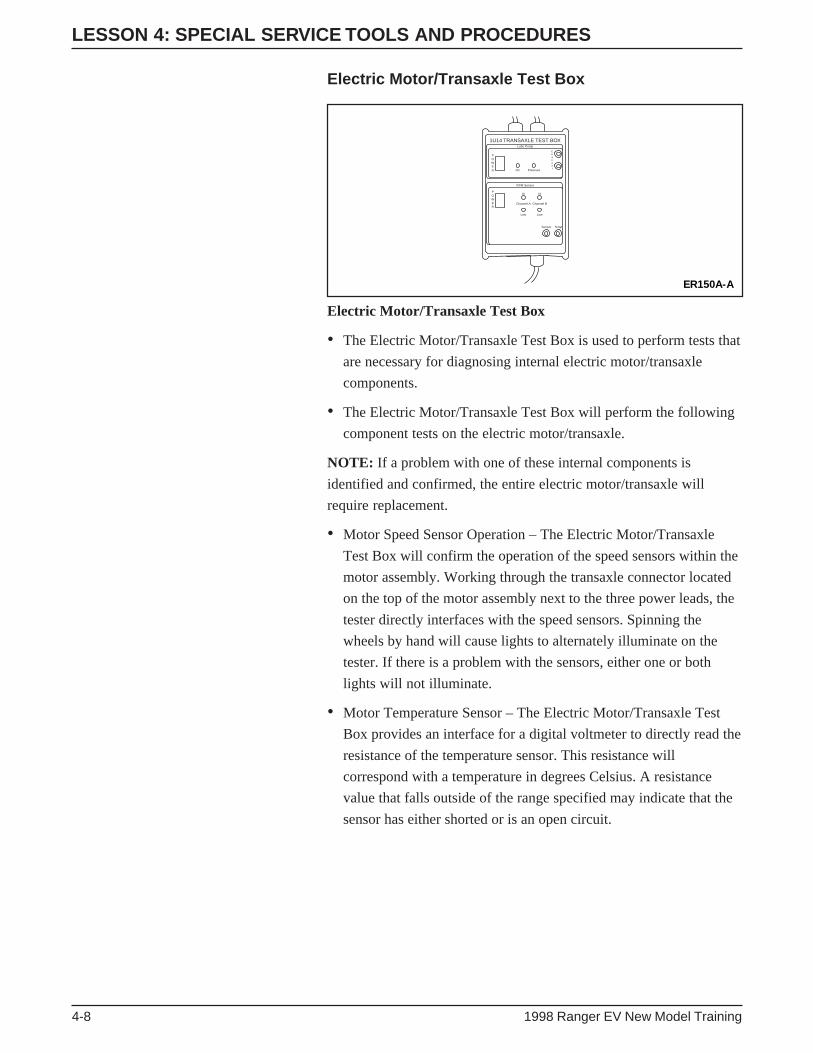
LESSON 4: SPECIAL SERVICE TOOLS AND PROCEDURES
4-8 1998 Ranger EV New Model Training
Electric Motor/Transaxle Test Box
Electric Motor/Transaxle Test Box
• The Electric Motor/Transaxle Test Box is used to perform tests that
are necessary for diagnosing internal electric motor/transaxle
components.
• The Electric Motor/Transaxle Test Box will perform the following
component tests on the electric motor/transaxle.
NOTE: If a problem with one of these internal components is
identified and confirmed, the entire electric motor/transaxle will
require replacement.
• Motor Speed Sensor Operation – The Electric Motor/Transaxle
Test Box will confirm the operation of the speed sensors within the
motor assembly. Working through the transaxle connector located
on the top of the motor assembly next to the three power leads, the
tester directly interfaces with the speed sensors. Spinning the
wheels by hand will cause lights to alternately illuminate on the
tester. If there is a problem with the sensors, either one or both
lights will not illuminate.
• Motor Temperature Sensor – The Electric Motor/Transaxle Test
Box provides an interface for a digital voltmeter to directly read the
resistance of the temperature sensor. This resistance will
correspond with a temperature in degrees Celsius. A resistance
value that falls outside of the range specified may indicate that the
sensor has either shorted or is an open circuit.
ER150A-A
1U14 TRANSAXLE TEST BOXLube Pump
POWER
POWER
RPM Sensor
On Pressure
Hi Hi
Low Low
Channel A
Channel
Channel B
Sensor Temp

LESSON 4: SPECIAL SERVICE TOOLS AND PROCEDURES
1998 Ranger EV New Model Training 4-9
• Oil Pressure Switch Operation – The Electric Motor/Transaxle Test
Box interfaces directly with the oil pressure switch. By manually
turning on and off the oil pump, the Electric Motor/Transaxle Test
Box turns a light on and off respectively.
• Oil Pump Operation – In addition to monitoring the oil pressure
switch, the Electric Motor/Transaxle Test Box also provides
information on oil pump operation. A manual switch to turn the oil
pump on and off is provided on the front of the tester along with an
interface for a digital voltmeter. This interface will provide the
technician with a voltage that is directly proportional to the current
flowing to the oil pump. This current will be checked to verify that
it is within a specified range for proper operation.
Equipment Hookup
• The Electric Motor/Transaxle Test Box connects to both the
transaxle connections and the cigar lighter socket.
– 9-Pin Transaxle Connector – Located on the top of the motor
assembly in front of the three power leads.
– Oil Pressure Switch Connector – Located on the lower rear of
the gear cover.
– Oil Pump Bulkhead Connector – On the gear cover in front of
the driver side halfshaft.

LESSON 4: SPECIAL SERVICE TOOLS AND PROCEDURES
4-10 1998 Ranger EV New Model Training
104-Pin Breakout Box (BOB) and BCM/TIMBreakout Box Adapter Cable and Overlay
BCM/TIM Breakout Box Adapter Cable
ER143-A
ER144-A
A1
A14
A27
A40 B1 B2 B3
B13 B14 B15 B16 B17 B18 B19 B20 B21 B22 B23 B24
B4 B5 B6 B7 B8 B9 B10 B11 B12
A2 A3 A4 A5 A6
A15 A16 A17 A18 A19 A20 A21 A22 A23 A24 A25 A26
A28 A29 A30 A31 A32 A33 A34 A35 A36 A37 A38 A39
A7 A8 A9 A10 A11 A12 A13
Breakout Box (BOB) Overlay
• The breakout box (BOB) is used in the same manner on the
Ranger EV as on conventional vehicles.
• When it is used on the Interface adapter assembly (IAA) module,
no adapter cable or overlay is required.
• When using the BOB for battery control module (BCM)/traction
inverter module (TIM) diagnostics, the, BCM/TIM Breakout Box
Adapter Cable and Overlay are required.
• It is utilized when performing low-voltage diagnostics on the
BCM or TIM.

LESSON 4: SPECIAL SERVICE TOOLS AND PROCEDURES
1998 Ranger EV New Model Training 4-11
Capacitor Discharge Tool
Capacitor Discharge Tool
• The Capacitor Discharge Tool is used to ensure that capacitors
have discharged prior to performing vehicle service.
• Connects to a Digital Volt-Ohmmeter (DVOM) to determine when
the voltage has completely discharged.
ER145-A

LESSON 4: SPECIAL SERVICE TOOLS AND PROCEDURES
4-12 1998 Ranger EV New Model Training
8-Volt Battery Charger
• It is used to charge the 8-volt battery modules of the traction
battery pack.
– It is only used when an individual battery module requires
charging prior to being inserted into the traction battery pack.
– Modules that have sat for more than seven days will require
charging before being installed into a battery pack.
– Charger automatically reduces voltage to a trickle when the
battery is fully charged.

LESSON 4: SPECIAL SERVICE TOOLS AND PROCEDURES
1998 Ranger EV New Model Training 4-13
Battery Terminal Cap Opener
Battery Terminal Cap Opener
• The Battery Terminal Cap Opener is a plastic device used to pry
open the battery module terminal cap covers to access the terminal
retaining nuts.
• The plastic composition of the terminal cap opener is non-
conductive.
• Never use metal tools, such as screwdrivers, to remove battery
terminal covers.
ER146-A
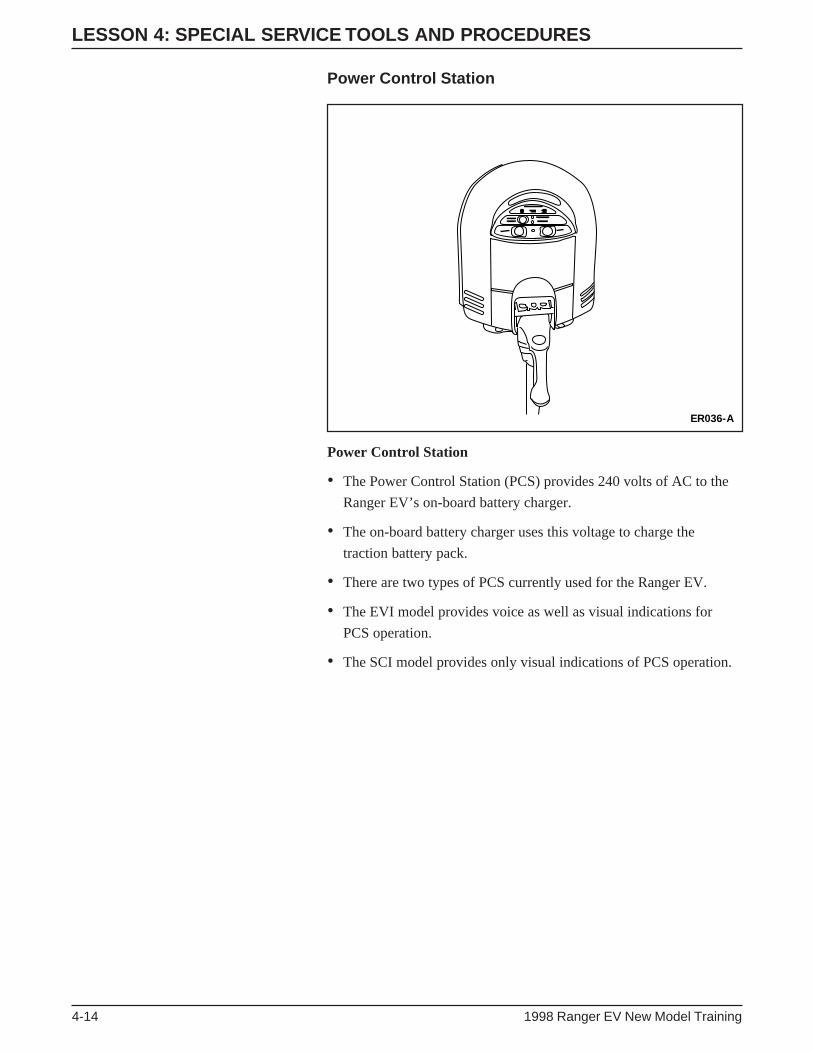
LESSON 4: SPECIAL SERVICE TOOLS AND PROCEDURES
4-14 1998 Ranger EV New Model Training
Power Control Station
Power Control Station
• The Power Control Station (PCS) provides 240 volts of AC to the
Ranger EV’s on-board battery charger.
• The on-board battery charger uses this voltage to charge the
traction battery pack.
• There are two types of PCS currently used for the Ranger EV.
• The EVI model provides voice as well as visual indications for
PCS operation.
• The SCI model provides only visual indications of PCS operation.
ER036-A

LESSON 4: SPECIAL SERVICE TOOLS AND PROCEDURES
1998 Ranger EV New Model Training 4-15
Traction Battery High Voltage Service Cord
Traction Battery High Voltage Service Cord
• It connects between the traction battery high-voltage auxiliary load
connector at the right front of the battery tray and the vehicle
harness.
• It used when performing diagnostic and service procedures when
the battery pack is removed from the vehicle.
ER147-A

LESSON 4: SPECIAL SERVICE TOOLS AND PROCEDURES
4-16 1998 Ranger EV New Model Training
Traction Battery Low Voltage Service Cord
Traction Battery Low Voltage Service Cord
• Connects between the traction battery low-voltage 76-pin connector
at the left front of the battery tray and the vehicle harness.
• Used when performing LV low-voltage diagnostic and service
procedures when the battery pack is removed from the vehicle.
ER148-A

LESSON 4: SPECIAL SERVICE TOOLS AND PROCEDURES
1998 Ranger EV New Model Training 4-17
High Voltage Insulated Safety Gloves
High Voltage Insulated Safety Gloves
• When working around high voltage circuits, High-Voltage
Insulated Safety Gloves (A) must be worn.
• The gloves specified for the Ranger EV are Class “O” rubber
gloves.
– These gloves are designed for working around equipment rated
up to 1,000 volts
• Rubber insulated safety gloves are protected by durable leather
gloves (B) that serve as an outer shell.
• Before putting on High Voltage Insulated Safety Gloves, inspect
them to ensure that there are no holes or breakage.
– Even a pinhole leak is enough to allow current to pass through.
• Inspect the gloves by rolling them up from their open end and
making sure that they retain air pressure with no leakage.
• If the gloves show any sign of wear and tear, the gloves should not
be used.
– Replacement gloves must meet all American Safety Testing
Materials Standards.
• High Voltage Insulated Safety Gloves must be recertified every
six months.
• Protective leather gloves must always be worn over the High
Voltage Insulated Safety Gloves.
• Chemicals can break down the rubber of the gloves. Never wash
them with chemicals or use them for washing parts.
• Never use the protective leather gloves without the High Voltage
Insulated Safety Gloves. Oil that may be on your hands can
contaminate the protective leather gloves and then be transferred
onto the High Voltage Insulated Safety Gloves.

LESSON 4: SPECIAL SERVICE TOOLS AND PROCEDURES
4-18 1998 Ranger EV New Model Training
Face Shield
Face Shield
• When working with energized high-voltage equipment, to protect
your face and eyes from the possibility of an electrical arc, debris,
or spark that could be generated from a short circuit, a non-
conductive, OSHA-approved face shield must be worn.

LESSON 4: SPECIAL SERVICE TOOLS AND PROCEDURES
1998 Ranger EV New Model Training 4-19
HIGH VOLTAGE DIAGNOSTIC ANDSERVICE PROCEDURES
• High voltage diagnostic and service procedures on the Ranger EV
require caution and strict adherence to service publication
warnings. It is essential that extra care be used when working with
high voltage equipment. The following pages provide you with
information that will aid you when diagnosing and servicing the
Ranger EV.
High Voltage Components
• The components that operate on high voltage are:
ER072-A
1 2
4
3
56
7
8
9
11
10
12
High Voltage Components
Item Description
1 Positive Temperature Coefficient (PTC) heater(inside of chamber assembly-heater plenum)
2 Traction Inverter Module (TIM)
3 Motor/Transaxle
4 DC/DC Converter
5 Battery Pack Assembly
6 Battery Charger
7 A/C Compressor
8 Power Steering Controller Assembly
9 Charge Inlet
10 A/C Inverter Motor Controller
11 PTC Switching Module
12 High Voltage Power Distribution Box (HVPDB)

LESSON 4: SPECIAL SERVICE TOOLS AND PROCEDURES
4-20 1998 Ranger EV New Model Training
High Voltage Wiring
High Voltage Wiring
ER073-A
A
CB
E
FG
HI
K
D
J
• Wiring that distributes high voltage to components that operate on
high voltage are connected as follows:
A. From the battery charger to the high voltage power distribution
box (HVPDB)
B. From the TIM to the motor/transaxle
C. From the traction battery to the TIM
D. From the HVPDB to the DC/DC converter
E. From the traction battery to the HVPDB
F. From the HVPDB to the power steering assembly
G. From the A/C inverter motor controller to the A/C compressor
H. From the charge inlet to the traction battery charger
I. From the HPVDB to the A/C inverter motor controller
J. From the HPVDB to the PTC switching module
K. From the PTC switching module to the PTC heater

LESSON 4: SPECIAL SERVICE TOOLS AND PROCEDURES
1998 Ranger EV New Model Training 4-21
Buffer Zone
Buffer Zone
• When interacting with a high voltage system, unnecessary
personnel in the work area pose a safety threat to those directly
involved in the repair of an EV.
• The area immediately surrounding the vehicle is designated as a
“buffer zone.”
– The boundaries of the buffer zone extend approximately
1 meter (3 feet) from the vehicle.
– These boundaries must be marked with clearly visible
orange cones.
• Only authorized personnel actively involved with high voltage
repair are permitted to enter the “buffer zone.”
• This “buffer zone” helps to protect technicians and observers from
possible personal injury.

LESSON 4: SPECIAL SERVICE TOOLS AND PROCEDURES
4-22 1998 Ranger EV New Model Training
TOWING PROCEDURE
Towing Procedure
• The towing procedure specified for the Ranger EV is similar to
those of other vehicles.
• Be sure to observe the following warnings and cautions when
towing a Ranger EV:
WARNING: TOW TRUCK OPERATORS SHOULD NOT
ATTEMPT TO SERVICE, RECHARGE OR OPERATE
THE VEHICLE UNDER ANY CIRCUMSTANCE. THIS
VEHICLE IS MADE UP OF COMPLEX ELECTRICAL
SYSTEMS, AND THESE OPERATIONS MUST BE
PERFORMED BY AUTHORIZED PERSONNEL ONLY.
IMPROPER HANDLING COULD RESULT IN VEHICLE
DAMAGE, PERSONAL INJURY OR DEATH.
WARNING: FAILURE TO TURN THE VEHICLE OFF
BEFORE SERVICING MAY RESULT IN PERSONAL
INJURY OR DEATH.
ER078-A
(Neutral only)
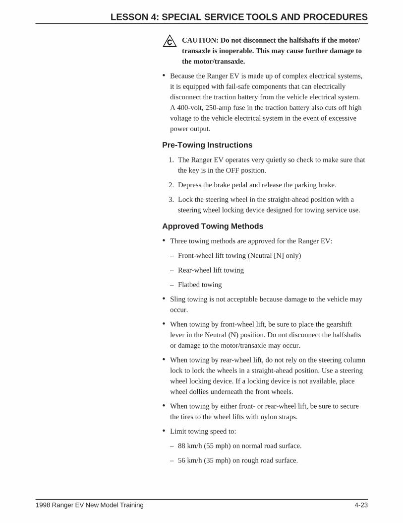
LESSON 4: SPECIAL SERVICE TOOLS AND PROCEDURES
1998 Ranger EV New Model Training 4-23
CAUTION: Do not disconnect the halfshafts if the motor/
transaxle is inoperable. This may cause further damage to
the motor/transaxle.
• Because the Ranger EV is made up of complex electrical systems,
it is equipped with fail-safe components that can electrically
disconnect the traction battery from the vehicle electrical system.
A 400-volt, 250-amp fuse in the traction battery also cuts off high
voltage to the vehicle electrical system in the event of excessive
power output.
Pre-Towing Instructions
1. The Ranger EV operates very quietly so check to make sure that
the key is in the OFF position.
2. Depress the brake pedal and release the parking brake.
3. Lock the steering wheel in the straight-ahead position with a
steering wheel locking device designed for towing service use.
Approved Towing Methods
• Three towing methods are approved for the Ranger EV:
– Front-wheel lift towing (Neutral [N] only)
– Rear-wheel lift towing
– Flatbed towing
• Sling towing is not acceptable because damage to the vehicle may
occur.
• When towing by front-wheel lift, be sure to place the gearshift
lever in the Neutral (N) position. Do not disconnect the halfshafts
or damage to the motor/transaxle may occur.
• When towing by rear-wheel lift, do not rely on the steering column
lock to lock the wheels in a straight-ahead position. Use a steering
wheel locking device. If a locking device is not available, place
wheel dollies underneath the front wheels.
• When towing by either front- or rear-wheel lift, be sure to secure
the tires to the wheel lifts with nylon straps.
• Limit towing speed to:
– 88 km/h (55 mph) on normal road surface.
– 56 km/h (35 mph) on rough road surface.

LESSON 4: SPECIAL SERVICE TOOLS AND PROCEDURES
4-24 1998 Ranger EV New Model Training
HOIST LIFT POINTS
ER079-A
C
D
B
A
FRONT
Hoist Lift Points
• Front lift point – front cab mount extension (A).
– Hoist pad in the lowest position.
CAUTION: Position the front hoist pads just outboard of
the torsion bars so they do not contact them.

LESSON 4: SPECIAL SERVICE TOOLS AND PROCEDURES
1998 Ranger EV New Model Training 4-25
• Rear lift point – rear leaf spring (B) at the front hanger eye (C).
– Hoist pad in the first raised position (D).
WARNING: USE CAUTION WHEN OPERATING THE
VEHICLE ON A HOIST. MOVING WHEELS COULD
CAUSE SEVERE PERSONAL INJURY OR DEATH.
CAUTION: Hoist the vehicle using only the approved
hoisting points. Never hoist the vehicle by unspecified
suspension components or the Traction Battery tray.
Vehicle damage may result from improper hoisting.
• Use only side-post hoists, which symmetrically locate the hoist
arms to the vehicle.
– Position the hoist pads only at the approved hoisting points.
– The rear hoist arms should have the pad extension raised to level
out the vehicle on the hoist.

LESSON 4: SPECIAL SERVICE TOOLS AND PROCEDURES
4-26 1998 Ranger EV New Model Training
SERVICE PUBLICATION NAVIGATION
• The service publications for the Ranger Electric Vehicle (EV) are
unique in many ways. When diagnosing and servicing the vehicle,
use the following guidelines:
– Use the Ranger Workshop Manual for diagnosing systems that
are not unique to the Ranger EV.
– Refer to the Ranger Electric Vehicle (EV) Electrical Vacuum
Troubleshooting Manual (EVTM) when performing diagnostic
procedures to note the differences in systems that are not unique
to the Ranger EV.
– Differences include fuse feeds, fuse ratings, wiring changes, etc.
• The format of the Ranger EV workshop manual supplement has
been changed to assist in the diagnosis of vehicle concerns. Note
the following differences when using this manual.
• The starting point for all diagnostics is Section 100-07, Electric
Vehicle (EV) Diagnostic Direction. Section 100-07 contains the
following sub-sections:
– Diagnostic Preface – This sub-section will spell out several of
the specific changes in the Ranger EV manual in contrast to
other Ford workshop manuals.
– Retrieving Diagnostic Trouble Codes (DTCs) – This sub-section
will provide directions on the correct procedure to follow when
retrieving DTCs. DTC retrieval on EVs is unique, and this sub-
section should be studied carefully before retrieving codes. It
contains valuable information on the correct sequence used to
retrieve DTCs and how to determine if a DTC is valid.
– Diagnostic Process (DP) series of pinpoint tests – These should
be followed whenever initially diagnosing a vehicle concern.
– Inspection and Verification sub-section – This sub-section
provides information on visual inspections and the correct
sections of the workshop manual to refer to when diagnosing a
unique EV system.
– DTC Index – The DTC index contains all DTCs that are
available on the Ranger EV. The index is divided by the modules
that will display them. It will provide information on the test
mode that the DTCs will appear in, a brief description of the
DTC, and the action to take if a DTC is retrieved.

LESSON 4: SPECIAL SERVICE TOOLS AND PROCEDURES
1998 Ranger EV New Model Training 4-27
– Parameter Identification (PID) Index – These charts will provide
a definition of the PIDs available in each module. They also give
an expected value for each PID.
– Miscellaneous Diagnostics – These diagnostics refer to DTCs
that are set and relate to the operating condition of the control
modules themselves.
• When a DTC is retrieved for a system, the DTC index will send
you to the section that pertains to the system that would set that
DTC. If no DTC is set, refer to Section 100-09 for symptom-based
diagnostic direction.
• If no diagnostics are available in Section 100-09 for a no DTC
concern, turn to the individual section for the component that has
malfunctioned.
• When in a specific section, you should first look in the symptom
chart.
• There is no separate DTC index in each section for the system with
the concern. The DTCs have been added to the symptom charts to
provide direction to the appropriate pinpoint test.
• A special tool chart precedes the pinpoint tests.
LESSON 4: SPECIAL SERVICE TOOLS AND PROCEDURES
4-28 1998 Ranger EV New Model Training
NOTES

LESSON 4: SPECIAL SERVICE TOOLS AND PROCEDURES
1998 Ranger EV New Model Training 4-29
ACTIVITY 4 – SPECIAL SERVICE TOOLS AND PROCEDURES – WORKSHEET HSPECIAL TOOLS AND SERVICE PROCEDURES
STUDENT ANSWER SHEET
OBJECTIVE: To identify special service procedures for the Ranger EV.
DIRECTIONS: Write the correct answers in the blank spaces provided. Note the page number where the
information was found.
1. What class of rubber insulating gloves is to be used, how often do the gloves need to be recertified, and
when do they need to be tested? ____________________________________________________________
______________________________________________________________________________________
PAGE # ____________
2. What are the methods of towing specified for the Ranger EV? ____________________________________
______________________________________________________________________________________
______________________________________________________________________________________
______________________________________________________________________________________
______________________________________________________________________________________
PAGE # ____________
3. What lift points and hoist pad positions are recommended for the Ranger EV? _______________________
______________________________________________________________________________________
______________________________________________________________________________________
PAGE # ____________
4. What is the correct buffer boundary that should be established around an EV, and how is this boundary
marked? _______________________________________________________________________________
______________________________________________________________________________________
PAGE # ____________
5. What is the tool number for the Power Steering Interlock Tool? ___________________________________
______________________________________________________________________________________
PAGE # ____________
6. What piece of equipment is specially designed for the Ranger EV battery pack removal and installation? __
______________________________________________________________________________________
PAGE # ____________
END OF WORKSHEET H

LESSON 4: SPECIAL SERVICE TOOLS AND PROCEDURES
4-30 1998 Ranger EV New Model Training
ACTIVITY 4 – SPECIAL SERVICE TOOLS AND PROCEDURES – WORKSHEET ISERVICE PUBLICATION NAVIGATION
STUDENT ANSWER SHEET
OBJECTIVE: Perform service publication navigation using Ranger EV service publications.
DIRECTIONS: Using the Ranger EV service publications and your student reference guide, answer the
following questions.
1. On what page of the service manual will you find directions for retrieving diagnostic trouble codes? ______
______________________________________________________________________________________
2. What information will the Diagnostic Preface provide you? ______________________________________
______________________________________________________________________________________
3. Which pinpoint test should you perform if you retrieve DTC C1184 after cycling the ignition on and off
quickly? _______________________________________________________________________________
______________________________________________________________________________________
4. What procedure does DP1 have you perform? _________________________________________________
______________________________________________________________________________________
5. What is the description of TIM DTC C1750? __________________________________________________
______________________________________________________________________________________
6. What is the description of BCM PID CCNTBCM? _____________________________________________
______________________________________________________________________________________
7. What is the meaning of IAA operation state (OPSTATE) PID 12? _________________________________
______________________________________________________________________________________
8. If a vehicle comes in that has no DTCs but will not charge, what section of the workshop manual should you
refer to for diagnostic direction based upon the symptom? _______________________________________
______________________________________________________________________________________
9. What diagnostic routine are you directed to for the symptom described in question 8? _________________
______________________________________________________________________________________
10. You have retrieved a DTC C1755 from the TIM. In which section and page number can the pinpoint test
you will need to perform be found?__________________________________________________________
______________________________________________________________________________________
END OF WORKSHEET I

LESSON 4: SPECIAL SERVICE TOOLS AND PROCEDURES
1998 Ranger EV New Model Training 4-31
ACTIVITY 4 – SPECIAL SERVICE TOOLS AND PROCEDURES – WORKSHEET JSPECIAL SERVICE TOOLSSTUDENT ANSWER SHEET
OBJECTIVE: To identify special service tools for Ranger EV.
DIRECTIONS: Go to the special service tools on the table. Find the tool that performs the function listed on
the right, write in the number/letter of the tag on the tool, and write in the tool’s name.
TAG # TOOL NAME DESCRIPTION
BCM/TIM Breakout Box Utilized when performing low voltage diagnostics on the
Adapter Cable and Overlay BCM or TIM.
In-line Bypass Battery Used when a traction battery module replacement is required.
Module
Traction Battery Connects between the traction battery LV 76-pin connector
Low Voltage Service Cord at the left front of the battery tray and the vehicle harness.
Capacitor Discharge Tool Used to ensure that capacitors have discharged prior to
performing vehicle service.
Auxiliary Interlock Tool Used to close the interlock loop on the vehicle during
diagnostics.
Electric Motor/ Confirm the operation of the speed sensors within the
Transaxle Test Box motor assembly.
Battery Module Lifting Aids in lifting, carrying, and removing the battery module
Tool from the traction battery pack.
Battery Lift Table Uses pressure from a shop air source to raise and lower the
traction battery.
Traction Battery Is used as a safety device when the TIM is disconnected
High Voltage (HV) Lockout from the traction battery.
and Diagnostic Tool
Traction Battery Connects between the traction battery auxiliary load
High Voltage HV connector at the right front of the battery tray and
Service Cord the vehicle harness.
Insulated Battery Post Allows safe tightening of battery post connectors.
Torque Wrench
Power Steering Used to close interlock loop at power steering connector
Interlock Tool during diagnostics.
END OF WORKSHEET J

LESSON 4: SPECIAL SERVICE TOOLS AND PROCEDURES
4-32 1998 Ranger EV New Model Training
ACTIVITY 4 – SPECIAL SERVICE TOOLS AND PROCEDURES – WORKSHEET J1ELECTRICAL CONNECTOR IDENTIFICATION
STUDENT ANSWER SHEET
OBJECTIVE: To locate and identify EV Ranger electrical connectors and determine if the circuits of that
connector contain high voltage.
DIRECTIONS: Your instructor has labeled several of the vehicle connectors. Locate the correct connector on
the vehicle or battery pack, note the tag letter/number, number of pins, and indicate if the
connector has any high voltage circuits.
HIGHCONNECTOR VOLTAGE CIRCUITS
TAG # NAME NUMBER OF PINS (YES/NO)
C1865 24 YES
C1866 40 YES
C1895 4 YES
C1914 4 YES
C1917 4 YES
C1920 4 YES
C1923 4 YES
C1935 4 YES
C1939 76 NO
C1945 104 NO
C3994 4 YES
C5000 7 YES
END OF WORKSHEET J1
1998 Ranger EV New Model Training 5-1
LESSON 5: DIAGNOSIS
TECHNICIAN OBJECTIVES
• Explain diagnostic strategy (symptom-to-system-to-component-to-
cause)
• Accurately and safely perform diagnostic and service procedures
on a 1998 Ranger EV.
CONTENTS
• Introduction to Ranger EV Diagnosis and Service Procedures
• Symptom-to-System-to-Component-to-Cause Diagnosis
• Ranger EV Diagnostic Flowchart
• Multiplexing System Diagnosis
• New Generation Star Tester
• Contractor Box Diagnosis
• Activity 5 – Worksheet K
• Charging Concerns
• Activity 6 – Worksheet L
• Power Control Station (PCS) Diagnostic Procedures
• Traction Battery Removal
• Activity 7 – Worksheet M
• Activity 8 – Worksheet N
• Activity 9 – Worksheet O
• Activity 9 – Worksheet P
• Electric Motor/Transaxle Diagnosis
• Activity 10 – Demonstration
• Traction Battery Pack Components Demonstration
• Activity 11 – Demonstration
• Traction Battery Diagnosis
• Activity 12 – Worksheet Q
• Activity 12 – Worksheet R
• Activity 13 – Worksheet S1 (BDS)
• Activity 13 – Worksheet S2 (NON-BDS)
• Activity 13 – Worksheet T
• Activity 14 – Worksheet U
LESSON 5: DIAGNOSIS
5-2 1998 Ranger EV New Model Training
INTRODUCTION TO RANGER EV DIAGNOSIS ANDSERVICE PROCEDURES
As you have seen, the 1998 Ranger EV is unique in many ways from
previous vehicles that you have seen. The differences in this vehicle
mean that the diagnosis and service procedures are also unique.
Ford’s service goal for all vehicles is to “Fix it Right the First Time,
On Time.” This goal also applies to the Ranger EV.
Although the 1998 Ranger EV is a completely new vehicle, service
procedures for some of its systems are similar to those with which you
are familiar. However, many systems on this vehicle are unique.
These systems require service procedures that will be completely new
to you. This portion of this course will show you the most accurate
and efficient methods of performing vehicle diagnosis and service.
SYMPTOM-TO-SYSTEM-TO-COMPONENT-TO-CAUSEDIAGNOSIS
When diagnosing an automotive system, you should always follow
standard procedures to locate clues to the cause of a concern. Using
these clues, you can then determine what component(s) must be
repaired or replaced in order to correct a concern. These clues can
usually be found by using a logical, time-effective method. The
“Symptom-to-System-to-Component-to-Cause” diagnostic technique
is very effective in locating and correcting vehicle concerns.
To use the “Symptom-to-System-to-Component-to-Cause” diagnostic
routine, all you have to do is follow the words in the title.
• First, determine the “Symptom” of the customer concern.
– Ensure you understand the customer concern.
• Next, determine which “System” on the vehicle could be causing
the symptom.
– By eliminating systems that cannot cause the concern, time is
saved by testing only systems that could cause the concern.
– For example, there’s not much sense in checking the air pressure
of the tires if the vehicle has no power.

LESSON 5: DIAGNOSIS
1998 Ranger EV New Model Training 5-3
• Once you identify the particular system, you then want to
determine which “Component(s)” within that system could be the
cause for the customer concern.
– This usually consists of a series of isolation tests.
– These specific tests and routines can be found in the Workshop
Manual or the Electrical and Vacuum Troubleshooting Manual
(EVTM).
• Once the failed component is identified, you should always try and
determine the “Cause” of the failure.
– When the faulty or damaged component is located, the cause of
the failure or damage must be identified and corrected to prevent
repeated component failure.
– For example, the component causing a system not to get power
may be a blown fuse, but if you don’t repair the short that caused
the fuse to fail, then the new fuse will fail as well.
• Diagnostic tests are usually isolation tests. The idea behind them is
to check the operation of a specific component, without other
components in the system affecting the component being tested. On
the Ranger EV, this requires product knowledge, skill, and your
ability to know how to use and interpret special tools.

LESSON 5: DIAGNOSIS
5-4 1998 Ranger EV New Model Training
RANGER EV DIAGNOSTIC FLOWCHART
Ranger EV Diagnostic Flowchart
The Ranger EV Diagnostic Flowchart will help provide you with a standardized procedure for diagnosing the
Ranger EV. In many instances following the steps outlined in the flowchart will help you locate and correct many
vehicle concerns.
ER094-A
• Verify Customer Concern• Perform Visual Inspection• Check for Non-Factory Add-On Equipment• Retrieve Continuous and On-Demand DTCs
(Retrieve in the following order: IAA, TIM, then BCM.)
Refer to Symptom-Based Diagnostics in Section 100-09 or in Symptom Chart at Beginning or Individual Section or Workshop Manual.
Go to DTC Index Chart.Preform Actions Described forDTC Retrieved.
Verify Repair, Clear DTCs and Return Vehicle to Customer
Contact Ford TechnicalHotline for Assistance.
Data Link Diagnostics Failed. Repair Network Concern First,Then Rerun on-Board Diagnostic Test.
Data Link Diagnostics Passed,Refer to 100-07 for “Phantom” Codes.
Are AnyNetwork
DTCsPresent?
Are AnyDTCs
Present?
Is ConcernCorrected?
Is ConcernCorrected?
NO
NO
NO
NO
YES
YES
YES
YES

LESSON 5: DIAGNOSIS
1998 Ranger EV New Model Training 5-5
Preliminary Diagnostic Procedures
As with all vehicles, when a Ranger EV is brought in with a concern
certain preliminary diagnostic procedures should always be
performed. These steps should include the following actions.
Verify the Concern – This step is critical in the diagnostic process.
It is important that you understand exactly what the concern is in
order for you to initiate the correct diagnostic steps.
• It is especially important that you determine if the customer
concern is actually a vehicle malfunction, or if the concern may
arise from the driver’s lack of familiarity with the vehicle.
• Since electric vehicles are new to the driving public, it is possible
that what the driver feels is a concern is just a normal operating
characteristic of the vehicle.
• If this is the case, take the time to explain how the vehicle operates.
Perform a Visual Inspection – The reason for this is self-
explanatory. Nothing is more frustrating than performing hours of
diagnostics only to find a disconnected wire that was easily visible if a
thorough visual inspection had been performed.
• Refer to Inspection and Verification in Section 100-07 of the
workshop manual supplement for additional information on areas
to focus on and what to look for during the visual inspection.
• During visual inspection check only the low voltage fuses.
Check for Non-Factory Add-On Equipment – Many calls that come
into the Ford Technical Hotline are the result of incorrectly installed
add-on equipment.
• Because the Ranger EV will be used in many fleets, add-ons such
as radios and light bars may be suspected causes of malfunctions.
Retrieve Diagnostic Trouble Codes (DTCs) – Retrieving DTCs
from the control modules of the Ranger EV is unique.
• DTCs must be retrieved from the modules in a specific order
(IAA, then TIM, then BCM).
• There are also other important considerations when retrieving
DTCs that are unique to the Ranger EV.
• Refer to Retrieving Diagnostic Trouble Codes (DTCs) and the
Diagnostic Process (DP Pinpoint Tests) in Section 100-07 of the
workshop manual supplement.

LESSON 5: DIAGNOSIS
5-6 1998 Ranger EV New Model Training
MULTIPLEXING SYSTEM DIAGNOSIS
Multiplexing System
Operation
• The Ranger EV uses two module communications networks.
– J1850 (SCP) network (two-way communication during normal
vehicle operation) used by the battery controller module (BCM),
interface adapter assembly (IAA) module, and traction inverter
module (TIM).
– International standards organization (ISO) 9141 network
communication used by the anti-lock brake system (ABS)
module, central timer module (CTM), and electronic crash
sensor (ECS) module operates air bag system.
• The SCP network consists of a twisted pair cable data bus.
– Circuit 914 data bus plus.
– Circuit 915 data bus minus.

LESSON 5: DIAGNOSIS
1998 Ranger EV New Model Training 5-7
• The SCP network may remain operational even if one of the bus
wires is open or shorted (to ground or power). However, all data
may be corrupt and the network should be repaired prior to
performing diagnostics.
– The fault will be detected and a DTC will be set in the host
module (IAA).
• The ISO 9141 network consists of a single wire, circuit 70.
– If the wire is open or shorted (to ground or power) diagnostic
communication between one or more of the modules will not
be possible.
Network Diagnosis
• Before running any NGS diagnostics, perform the data link
diagnostic test.
– If a network concern exists, DTC(s) may be inaccurate.
• To perform the diagnostic Data Link Diagnostic Test routine
(System Precheck) refer to the Ranger EV Workshop Manual,
Section 418-00.
– The System Precheck will direct you to the proper pinpoint test
or symptom chart, according to test results.
• When network concerns are resolved normal diagnostic routines
may be continued if needed.
– It is possible that a network problem may be the cause of the
original concern.
• For an electrical schematic, refer to the Electrical and Vacuum
Troubleshooting Manual (EVTM).

LESSON 5: DIAGNOSIS
5-8 1998 Ranger EV New Model Training
NEW GENERATION STAR TESTER
Ranger EV NGS Program Card Main Menu
New Generation STAR (NGS) Tester is essential to Ranger EV
diagnosis. While technicians are familiar with NGS tester use on
conventional vehicles, the Program Card for the Ranger EV has
unique features that will be covered in this lesson.
The Main Menu is similar to the conventional vehicle Program Card
Main Menu.
• The Ranger EV Program Card Main Menu selections are:
– VEHICLE AND ENGINE SELECTION
– DIAGNOSTIC DATA LINK
– VIEW RECORDER AREA
– DIGITAL MEASUREMENT SYSTEM
– GENERIC OBD II FUNCTIONS
– SPECIAL FUNCTIONS
– NEW GENERATION STAR SETUP
– INTERNAL SYSTEM TESTS
• The most noticeable difference is the Vehicle and Engine Selection
Function.
– The Ranger EV Program Card is dedicated to the Ranger EV and
no other selections are available.
Ranger EV Program Card Diagnostic Data Link Menu
To continue diagnostic routines, select DIAGNOSTIC DATA LINK.
• The Ranger EV Program Card Diagnostic Data Link Menu
Selections are:
– ABS-ANTI LOCK BRAKE MODULE
– BCM-BATTERY CONTROLLER MODULE
– CTM-CENTRAL TIMER MODULE
– ECS-ELECTRONIC CRASH SENSOR
– IAA-INTERFACE ADAPTER ASSEMBLY
– TIM-TRACTION INVERTER MODULE
– DATA LINK DIAGNOSTICS

LESSON 5: DIAGNOSIS
1998 Ranger EV New Model Training 5-9
• Before selecting any module test, select DATA LINK
DIAGNOSTICS and press the trigger. This will check the network
data bus to ensure that all the modules have good network
communication.
– If a module cannot communicate on the network it may be the
cause of the concern.
• If network concerns exist, they must be corrected before any other
NGS diagnostics can be performed.
– Circuits 914 and 915 are the data bus circuits for the J1850
(SCP) network.
– Circuit 70 is the data bus circuit for the ISO 1941 network.
Ranger EV Program Card Module Menu
Once the Data Link Diagnostics are performed and any network
concerns are repaired (if present) the suspect module may be selected.
The menu for each module is the same.
• Module Menu selections are:
– DIAGNOSTIC TEST MODES
– PID/DATA MONITOR AND RECORD
– ACTIVE COMMAND MODES
– MODULE IDENTIFICATION
– DIAGNOSTIC TROUBLE CODE LIBRARY
• The Module Menu selections and functions are similar to other
Ford vehicles and should be familiar to technicians.
NOTE: Use of parameter identification data (PID) is critical when
diagnosing a Ranger EV. Technicians who are unfamiliar with the
operation and utilization of the PID menu should refer to the New
Generation STAR Tester Reference Guide.
LESSON 5: DIAGNOSIS
5-10 1998 Ranger EV New Model Training
Parameter Identification Data (PID) Monitor andRecord
This menu will allow you to monitor and record the operation of
many of the vehicle’s components.
• Since there are so many PIDs available, there is also a definition
(DEFN) function that will tell you the meaning of the acronym
used to identify the component/function.
• Use of PIDs is critical when diagnosing the Ranger EV. If you are
unfamiliar with the operation and utilization of the PID menu, refer
to the New Generation STAR Tester Reference Guide.
• The PID Indices in Section 100-07 of the workshop manual
supplement will provide you with PID descriptions and expected
values.
Active Command Mode
The Active Command Modes menu of the NGS will enable you to
activate certain components of a vehicle system using the NGS to test
the function. This can save time by determining if the source of the
problem is in the component, or in the signaling system that activates it.
• For example, the Central Timing Unit Active Command Menu
allows you to command on the windshield wiper.
• If the NGS can activate the wiper, the problem is likely in the wiper
switch or circuits. If not, the wiper motor may need repair.
• As with PIDs, each module will have its own list of components
that can be commanded in this menu.
There is an active command function for the Ranger EV standard
corporate protocol (SCP) networked modules (IAA, BCM, and TIM)
called “packeted” commands.
• This function allows the SCP modules to send more than one active
command at the same time.
• This allows the NGS to enable multiple high voltage components
simultaneously (A/C, IMC, power steering controller assembly,
PTC, contactor box relays, etc.)
• In some cases it is required to use a packeted command series in
order to activate a component.
– For example, in order to activate the main contactor using the
active command, you must first close the precharge contactor, or
the NGS will not be able to perform the operation.

LESSON 5: DIAGNOSIS
1998 Ranger EV New Model Training 5-11
CONTACTOR BOX DIAGNOSIS
Contactor Box
• Diagnostic trouble code (DTC) C1862 is associated with the
Contactor Box and its circuits.
• The Contactor Box Assembly (CBA) is basically an on/off switch
for the traction battery.
• The CBA contains the high voltage contactor relays, fuses, and
resistors.
– The components of the CBA are controlled by the BCM, TIM,
IAA, ignition switch, and Emergency Power Off (EPO) function.
• The only replaceable components inside the CBA are the fuses.
– If any other component failure occurs the entire unit must
be replaced.
• A critical concern in the CBA is the occurrence of an
uncommanded contactor relay closure, resulting in high voltage
power from the traction battery present outside of the traction
battery assembly with the driver key in the OFF position.
– This condition creates a hazardous situation and must be
corrected before further diagnosis or repair is attempted.
• For complete diagnosis of the Contactor Box and circuits, refer to
Workshop Manual Supplement, Section 414-03.
ER096-A

LESSON 5: DIAGNOSIS
5-12 1998 Ranger EV New Model Training
NOTES

LESSON 5: DIAGNOSIS
1998 Ranger EV New Model Training 5-13
ACTIVITY 5 – DIAGNOSIS – WORKSHEET KNGS OPERATION AND IMPROPERLY CLOSED
CONTACTOR RELAY DIAGNOSISSTUDENT ANSWER SHEET
OBJECTIVE: The student will be able to navigate and utilize the various functions of the NGS, and be able
to verify contactor relay operation.
DIRECTIONS: Go to the assigned classroom vehicles and using the special tools supplied, and the publica-
tions provided, perform the tasks and answer the questions below.
1. Once the NGS is booted, what is the first item that must be programmed into the tester?________________
______________________________________________________________________________________
2. Which menu item must be selected to perform on-board diagnostic tests? ___________________________
______________________________________________________________________________________
3. Once you have entered this menu, which test should always be performed first? ______________________
______________________________________________________________________________________
Why? _________________________________________________________________________________
______________________________________________________________________________________
______________________________________________________________________________________
IRQ: The SCP network may be able to communicate with the scan tool even if one of the two data bus wires are
cut. However, tests are invalid because the information displayed may be inaccurate.
4. Perform the test indicated in question 3. List the results below. ____________________________________
______________________________________________________________________________________
______________________________________________________________________________________
5. Do the results of the test performed in question 4 indicate that the system is OK? _____________________
______________________________________________________________________________________
6. If this system has a fault, you should:
A. Ignore the fault and continue on-board diagnostics.
B. Repair the fault then retest the vehicle to see if the concern is corrected.
C. Jumper the circuit in question, then repeat the test to see if the fault clears.
D. Perform an active command to determine if the circuit is actually functional. If it is, continue with
on-board diagnostics.
7. Retrieve continuous and on-demand DTCs from the IAA, TIM, and BCM. Will all these modules support
these functions? _________________________________________________________________________
______________________________________________________________________________________
WORKSHEET K CONTINUED ON NEXT PAGE

LESSON 5: DIAGNOSIS
5-14 1998 Ranger EV New Model Training
WORKSHEET K CONTINUED ON NEXT PAGE
8. List any DTCs retrieved. __________________________________________________________________
______________________________________________________________________________________
9. If any continuous codes are stored in memory, the faults that set these DTCs:
A. may not be occurring now.
B. may be occurring now.
C. have occurred at some time in the last 40 drive cycles (intermittent).
D. all of the above.
IRQ: Review continuous DTCs.
10. Faults that set on-demand DTCs:
A. may not be occurring now.
B. are occurring now.
C. have occurred at some time in the last 40 drive cycles (intermittent).
D. all of the above.
IRQ: Review on-demand DTCs.
11. Return to the Diagnostic Data Link menu.
– Select IAA module.
– Select PID Data Monitor and record.
– KEY ON.
– Select VACPRES, CM_SPD, SET_TMP, PIDs.
– Press START.
– Randomly operate the climate control system by turning the temperature dial and A/C dial for 15 seconds.
– Press trigger to CAPTURE DATA.
– Again randomly operate the climate control system by turning the temperature dial and A/C dial for
15 seconds.
– Press trigger again to STORE DATA.
– Store data in area 2.
– Follow the directions on the NGS screen.
– Once data is stored, press cancel.
– After saving, return to STORE DATA menu and select VIEW RECORDING.
– Select all three PIDs to view.
ACTIVITY 5 – DIAGNOSIS – WORKSHEET KNGS OPERATION AND IMPROPERLY CLOSED
CONTACTOR RELAY DIAGNOSISSTUDENT ANSWER SHEET (Continued)

LESSON 5: DIAGNOSIS
1998 Ranger EV New Model Training 5-15
12. View the PID activity in the table mode. Press REW. How many seconds before you pressed the trigger is
data available? __________________________________________________________________________
______________________________________________________________________________________
13. Press PLAY. How many seconds after you pressed the trigger is data available? ______________________
______________________________________________________________________________________
14. Press CANCEL to exit the table mode. Enter the graph mode. How many PIDs can you view at the same
time? _________________________________________________________________________________
______________________________________________________________________________________
15. On the right and left sides there are numbers. What do these numbers indicate? _______________________
______________________________________________________________________________________
16. What NGS button do you press to move the graph forward? ______________________________________
______________________________________________________________________________________
What button do you press to move the graph backward? _________________________________________
______________________________________________________________________________________
17. Looking at these PIDs, do these sensors appear to be functioning normally? _________________________
______________________________________________________________________________________
18. In the workshop manual, refer to Negative Contactor Relay Control Pinpoint Test step A2 in Section 414-
03. Perform the test procedure described. What occurs to the voltage displayed? ______________________
______________________________________________________________________________________
19. What would it indicate if this PID indicated greater than 200 volts? ________________________________
______________________________________________________________________________________
IRQ: Explain that if voltage is not falling, main and negative contactors are stuck closed. Stuck contactors can
cause the vehicle not to recharge. This could cause a safety concern if you are disconnecting the traction battery
HV 2-pin connector C3994, because high voltage would be present at the connector. Whenever this connector is
open use the traction battery high voltage lockout and diagnostic tool.
20. While in the TIM active command mode select the following PIDs: BAT_PV, TPCCO, and TPMCO. Press
START. Highlight PRECHG IN and command it to close. What occurs to the BAT_PV and TPCCO PID?
______________________________________________________________________________________
______________________________________________________________________________________
ACTIVITY 5 – DIAGNOSIS – WORKSHEET KNGS OPERATION AND IMPROPERLY CLOSED
CONTACTOR RELAY DIAGNOSISSTUDENT ANSWER SHEET (Continued)
LESSON 5: DIAGNOSIS
5-16 1998 Ranger EV New Model Training
21. Highlight POS MAIN and send a closed command. What occurs? _________________________________
______________________________________________________________________________________
IRQ. Explain that if you try to close the main contactor (POS MAIN) before closing the precharge contactor
(PRECHG IN), the NGS will kick you out of the menu. The precharge contactor must close before main.
22. What are the definitions of the following PIDs?
BAT_PV ______________________________________________________________________________
______________________________________________________________________________________
TPCCO________________________________________________________________________________
______________________________________________________________________________________
TPMCO _______________________________________________________________________________
______________________________________________________________________________________
ACTIVITY 5 – DIAGNOSIS – WORKSHEET KNGS OPERATION AND IMPROPERLY CLOSED
CONTACTOR RELAY DIAGNOSISSTUDENT ANSWER SHEET (Continued)
END OF WORKSHEET K

LESSON 5: DIAGNOSIS
1998 Ranger EV New Model Training 5-17
CHARGING CONCERNS
The Power Control Station (PCS) recharges the traction battery.
Under normal conditions all the driver has to do is plug the vehicle
into the PCS, and the vehicle batteries will automatically be
recharged.
If the PCS is connected to the vehicle and the green start button on the
PCS is flashing, the vehicle is not charging.
Certain conditions may result in a failure of the recharging system.
Let’s look at some of the things that may cause a failure.
Determining the Source of a Charging Concern
The first thing that must be considered when diagnosing a charging
concern is to determine if the cause is a failure of the charging system,
or if it is the result of a Battery Control Module (BCM) strategy.
The BCM strategy is to prevent charging if:
• The battery is too hot or cold, as determined by signals sent from
the four battery pack temperature sensors to the BCM. Each sensor
monitors the temperature of the batteries in a certain region of the
pack, and transmits this information to the BCM. If the indicated
temperature is above 60°C (141ºF) or below -5° C (23ºF), BCM
strategy will prevent charging of the battery pack.
• The BCM loses the ability to monitor the voltage of more than five
battery modules, it will prevent the battery pack from charging.
• The state of charge of the battery is 99% or above, the BCM
prevents charging voltage from reaching the pack.
• There is a difference of 30°C (86ºF) between any of the battery
pack temperature sensors, the BCM strategy will prevent charging
of the battery pack.

LESSON 5: DIAGNOSIS
5-18 1998 Ranger EV New Model Training
• The BCM strategy is to prevent charging if:
– There is a failure of the high voltage auxiliary bus current sensor
in the contactor box it will also prevent charging of the battery
pack.
– A battery module fails open.
– A battery module internally shorts, the increased resistance will
significantly reduce recharging capability.
– The inertia switch is tripped, or there is an inertia switch fault.
– Current leakage exists between the traction battery and chassis
ground that reduces resistance to less than 10K ohms.
– The vent fan is inoperative.
– More than three battery pack temperature sensors fail.
– The vehicle is not in Park, or the digital transmission range
(DTR) sensor has a fault that indicates that it is not in Park.
If any of the above strategies are implemented, the BCM should store
a DTC to indicate the cause of the no charge condition.
No DTC Charging Diagnosis
In some cases a fault in the AC power charging system will not result
in a DTC being stored in the BCM memory. In these cases, certain
procedures should be followed.
• When diagnosing an “Unable to Charge” concern, (as with all
concerns), perform the preliminary diagnostic steps as described in
Section 100-07 of the Ranger EV workshop manual supplement.
• As with all concerns where no DTC is present, refer to the
symptom-based diagnostic procedures in Section 100-09, or to the
symptom chart in the individual section of the workshop manual
that pertains to the component that has malfunctioned.

LESSON 5: DIAGNOSIS
1998 Ranger EV New Model Training 5-19
NOTES

LESSON 5: DIAGNOSIS
5-20 1998 Ranger EV New Model Training
ACTIVITY 6 – DIAGNOSIS – WORKSHEET LCHARGING SYSTEM DIAGNOSIS
STUDENT ANSWER SHEET
OBJECTIVE: The student will accurately diagnose the cause of an “unable to charge” concern.
DIRECTIONS: Go to assigned classroom vehicle. Read the repair order, then using the special tools supplied,
and the publications provided, perform the tasks and answer the questions below.
1. What customer concern is listed on this repair order? (SYMPTOM) ________________________________
______________________________________________________________________________________
2. What section of the service publications should you refer to when performing preliminary diagnostic
procedures? ____________________________________________________________________________
______________________________________________________________________________________
3. What SYSTEM(S) is affected by this fault? ___________________________________________________
______________________________________________________________________________________
4. If a charging system DTC is stored, in which module would you expect to find it? ____________________
______________________________________________________________________________________
5. List any DTCs present. ___________________________________________________________________
______________________________________________________________________________________
6. If any DTCs are present, do they seem to be valid? _____________________________________________
IRQ: Discuss phantom DTCs (especially U prefixed DTCs) and point out that if DATA LINK Diagnostics
passes, U DTCs should generally be ignored.
7. Diagnose the concern. List the steps you perform and their results in the table below. NOTE: The number of
rows in the table does not indicate the number of steps in the diagnostic procedure. Use additional paper if
required.
DIAGNOSTIC STEP RESULT
100-09 GO TO POWERTRAIN DIAGNOSTIC
ROUTINES INDEX
POWERTRAIN DIAGNOSTIC ROUTINE 5
ROUTINES INDEX
5-1 YES, OPSTATE PID 99
5-17 YES
5-18 NO REPAIR CIRCUIT 3984 RED WIRE
8. What is the cause of this concern?___________________________________________________________
______________________________________________________________________________________
WORKSHEET L CONTINUED ON NEXT PAGE

LESSON 5: DIAGNOSIS
1998 Ranger EV New Model Training 5-21
9. List three possible causes that could cause a strategy to be implemented that will prevent the vehicle from
charging. ______________________________________________________________________________
______________________________________________________________________________________
______________________________________________________________________________________
10. What are the two types of PCS systems used with the Ranger EV? _________________________________
______________________________________________________________________________________
11. If a no charge condition is found to be caused by an on-vehicle component, what should you try and
determine once you’ve found the component that’s at fault? ______________________________________
______________________________________________________________________________________
ACTIVITY 6 – DIAGNOSIS – WORKSHEET LCHARGING SYSTEM DIAGNOSIS
STUDENT ANSWER SHEET (Continued)
END OF WORKSHEET L

LESSON 5: DIAGNOSIS
5-22 1998 Ranger EV New Model Training
POWER CONTROL STATION (PCS) DIAGNOSTICPROCEDURES
Power Control Station (PCS)
In some cases an unable to charge concern may be the result of a fault
in the PCS.
• If a vehicle is brought to you with this type of concern and its
charging system seems to operate correctly, diagnosis of the
customer PCS may be required.
• Be aware that Ford is not responsible for the operation, diagnosis,
or repair of customer power control stations.
• It is the responsibility of the customer and the PCS manufacturer to
ensure correct operation. However, the following procedures
should be used in the event a PCS failure is suspected.
• The following diagnostic procedures are divided by the
manufacturer of the PCS. The two PCS systems that are currently
used for the Ranger EV are the SCI and EVI systems.
ER036-A

LESSON 5: DIAGNOSIS
1998 Ranger EV New Model Training 5-23
Diagnostic Procedure for SCI Power Control Station
If the vehicle fails to charge, and it is connected to an SCI PCS,
use this procedure to determine if it is operating properly.
• Make note of any lights that are flashing or steadily illuminated
on the PCS.
• Determine if the charge connector is properly inserted in the
vehicle inlet and locked in place.
• If the Charge Interrupted Light is illuminated, the vehicle may have
undergone a series of faults which forced the PCS to terminate the
charge process.
– Push the Stop button.
– To clear the fault, unplug the charge connector from the vehicle
inlet.
– Inspect the charge cable and connector for any signs of possible
damage (i.e., cuts, tears, or breaks in the cable insulation).
– If damage is found, call the PCS manufacturer for repair.
– If the charge cable /connector are undamaged, reconnect the PCS
to the vehicle inlet.
– If the Charge Interrupted Light is still illuminated or flashing,
consult your local dealer to determine a possible vehicle fault.
• If the Service Light is illuminated:
– Disconnect the charge connector from the vehicle inlet.
– Turn off the power to your PCS at the service or disconnect
panel.
– Turning off the power may allow the PCS to clear the fault.
– Turn the power back on and reconnect the PCS to the vehicle
inlet.
– If the Service Light is still illuminated, call the PCS
manufacturer for repair or replacement.
• If the Immediate, Economy, or Charging light is illuminated, the
PCS is operating correctly and vehicle diagnostics should be
performed.
• If turning the PCS power on and off or unplugging and plugging
the charge connector in the vehicle inlet does not cause any of the
lights to illuminate on the PCS, the PCS has either failed or has a
damaged charge cord. Call the PCS manufacturer for repair or
replacement.

LESSON 5: DIAGNOSIS
5-24 1998 Ranger EV New Model Training
Diagnostic Procedure EVI Power Control Station
If the vehicle fails to charge, and it is connected to an EVI PCS,
use this procedure to determine if it is operating properly.
• Make note of any lights that are illuminated or any messages being
issued by your PCS.
• Determine if the charge connector is properly inserted in the
vehicle inlet and locked in place.
• If the Protection Light is illuminated, the vehicle may have
undergone a series of faults which forced the PCS to terminate the
charge process.
– Push the Stop button.
– To clear the fault, unplug the charge connector from the
vehicle inlet.
– Inspect the charge cable and connector for any signs of possible
damage ( i.e., cuts, tears, or breaks in the cable insulation).
– If damage is found, call the PCS manufacturer for repair.
– If the charge cable /connector are undamaged, reconnect the
PCS to the vehicle inlet.
– If the Protection Light is still illuminated or flashing, consult
your local dealer to determine a possible vehicle fault.
• If the Service Light is illuminated:
– Disconnect the charge connector from the vehicle inlet.
– Turn off the power to your PCS at the service or disconnect
panel.
– Turning off the power may allow the PCS to clear the fault.
– Turn the power back on and reconnect the PCS to the
vehicle inlet.
– If the Service Light is still illuminated, call the PCS
manufacturer for repair or replacement.
• If the Ready or Charging light is illuminated the PCS is operating
correctly and vehicle diagnostics should be performed.
• If turning the PCS power on and off or unplugging and plugging
the charge connector in the vehicle inlet does not cause any of the
lights to illuminate on the PCS, the PCS has either failed or
has a damaged charge cord. Call the PCS manufacturer for repair
or replacement.

LESSON 5: DIAGNOSIS
1998 Ranger EV New Model Training 5-25
TRACTION BATTERY REMOVAL
In the event diagnostic procedures require that the traction battery
must be removed from the vehicle for diagnostic and/or service
procedures, strict adherence to the service publication procedures
must be maintained.
Before removal of a the traction battery, read and follow the service
procedures in Section 100-05:
• Rubber insulating gloves testing
• Buffer zone
Follow the procedures specified in Section 414-03 for traction
battery removal.

LESSON 5: DIAGNOSIS
5-26 1998 Ranger EV New Model Training
NOTES

LESSON 5: DIAGNOSIS
1998 Ranger EV New Model Training 5-27
ACTIVITY 7 – DIAGNOSIS – WORKSHEET MTRACTION BATTERY REMOVAL
STUDENT ANSWER SHEET
OBJECTIVE: The student will remove the traction battery.
DIRECTIONS: Go to the assigned classroom vehicle. The instructor will designate students to perform
traction battery removal procedures. When not actually working on the vehicle, follow along
in the workshop manual supplement and answer the questions on this worksheet.
1. What is the purpose of establishing a buffer zone around the vehicle? ______________________________
______________________________________________________________________________________
2. What personal safety actions must be performed prior to traction battery removal? ____________________
______________________________________________________________________________________
3. What personal safety equipment must be worn during traction battery removal? ______________________
______________________________________________________________________________________
4. What is the first component that must be disconnected before removing the traction battery? ____________
______________________________________________________________________________________
5. What must be installed when the HV 2-pin connector is disconnected from the battery pack? ____________
______________________________________________________________________________________
6. What other electrical connectors must be removed prior to removing the traction battery from the vehicle?
______________________________________________________________________________________
7. Once the table is positioned under the vehicle and it is raised to contact the battery tray, the air controls of
the table should be held on until what air pressure is reached?_____________________________________
8. How many bolts hold the battery pack in the vehicle? ___________________________________________
9. What must you watch for when lowering the battery pack? _______________________________________
______________________________________________________________________________________

LESSON 5: DIAGNOSIS
5-28 1998 Ranger EV New Model Training
High Voltage Auxiliary Load System Diagnosis
The high voltage auxiliary load system includes all the high voltage
components connected to the high voltage power distribution box
(HVPDB).
These components include:
• the DC/DC converter (auxiliary battery charging).
• the A/C inverter motor controller (air conditioning).
• the positive temperature coefficient (PTC) switching module.
• the power steering controller assembly.
The failure of any of these high voltage systems may be caused by a
component in the individual system or linked to the HVPDB.
• The HVPDB is a fuse box that provides protection to these
systems.
• Always determine if one system connected to the HVPDB has
failed or if multiple systems have failed.
• This will help determine the cause of the concern. If more than one
system has failed, it may indicate a problem in the wiring or the
HVPDB itself.
• If only one system has failed, a failed system component or an
HVPDB fuse may be the cause of the failure.
As with all Ranger EV diagnostics, follow the diagnostic procedures
in the workshop manual supplement.
• Begin the diagnostic procedure by referring to Section 100-07.
• This section will direct you to the correct procedure for the system
you are diagnosing.
• Pinpoint tests must be performed exactly as written; do not
skip steps.
WARNING: STRICT ADHERENCE TO SAFETY
PROCEDURES IS MANDATORY WHEN
PERFORMING THESE TESTS. FAILURE TO DO SO
COULD RESULT IN SERIOUS PERSONAL INJURY
OR DEATH.

LESSON 5: DIAGNOSIS
1998 Ranger EV New Model Training 5-29
NOTES

LESSON 5: DIAGNOSIS
5-30 1998 Ranger EV New Model Training
NOTES

LESSON 5: DIAGNOSIS
1998 Ranger EV New Model Training 5-31
ACTIVITY 8 – DIAGNOSIS – WORKSHEET NPTC HEATER DIAGNOSIS DEMONSTRATION
STUDENT ANSWER SHEET
OBJECTIVE: This is a demonstration of the correct safety and diagnostic procedures to follow when diag-
nosing a vehicle with a PTC heater concern. It will also show correct safety procedures to
follow when diagnosing HV components that are connected to the HVPDB.
DIRECTIONS: As the diagnostic procedure is performed, monitor the procedure and answer the questions
below. Ask questions of the instructor as he performs this demonstration for any points that
you may have questions about.
1. What is the customer concern? _____________________________________________________________
______________________________________________________________________________________
2. What is the first section of the workshop manual that should be referenced to diagnose this system? ______
______________________________________________________________________________________
3. List the preliminary steps that are performed.
PRELIMINARY DIAGNOSTIC STEPS RESULTS
VERIFY CONCERN CONCERNED VERIFIED
PERFORM VISUAL INSPECTION NO PROBLEMS SEEN
CHECK FOR NON-FACTORY
INSTALLED EQUIPMENT NONE INSTALLED
RETRIEVE DTCS
(REVIEW DTC RETRIEVAL PROCEDURE) DTC 1776 PRESENT IN IAA
GO TO DTC INDEX GO TO SECTION 414-O2 FOR DIAGNOSTIC
DIRECTION
4. List the diagnostic steps performed and their results.
IRQ: PTC Heater Core operation is dependent on ambient temperature. Ambient temperature sensor under
hood provides input to determine if one or both cores need to be turned on. Above 40°F, one core on; below
40°F, two cores on. Cores take turns coming on with each key cycle. Turn the key on at least twice with the heater
on to ensure that both heaters have been actuated.
DIAGNOSTIC TEST STEP RESULT
E1 NO
E2 NO
E3 NO, REPLACE HEATER CORE
END OF WORKSHEET N

LESSON 5: DIAGNOSIS
5-32 1998 Ranger EV New Model Training
NOTES

LESSON 5: DIAGNOSIS
1998 Ranger EV New Model Training 5-33
ACTIVITY 9 – DIAGNOSIS – WORKSHEET OPOWER STEERING DIAGNOSIS
STUDENT ANSWER SHEET
OBJECTIVE: The student will safely and accurately diagnose a Ranger EV concern.
DIRECTIONS: Go to the workstation designated by your instructor. Read the repair order, then using the
Ranger EV service publications, perform the tasks and answer the questions below.
1. What is the customer concern listed on the repair order? _________________________________________
______________________________________________________________________________________
2. What section of the service publication should you refer to first? __________________________________
______________________________________________________________________________________
3. Can you verify this concern? _______________________________________________________________
______________________________________________________________________________________
4. When performing your visual inspection can you see any obvious reason for this concern?______________
______________________________________________________________________________________
5. Are any DTCs present having to do with this concern? __________________________________________
______________________________________________________________________________________
6A. If a DTC is present, what service publication section are you directed to? ___________________________
______________________________________________________________________________________
6B. If no DTC is present, what service publication section are you directed to? __________________________
______________________________________________________________________________________
7. When turning to this section, what chart should you refer to for diagnostic direction? __________________
______________________________________________________________________________________
8. What series of pinpoint tests are you directed to perform? ________________________________________
______________________________________________________________________________________
WORKSHEET O CONTINUED ON NEXT PAGE

LESSON 5: DIAGNOSIS
5-34 1998 Ranger EV New Model Training
9. Diagnose this concern using the procedures in the service publications. List the test steps you perform and
their results in the table below. (NOTE: The number of rows in the table do not indicate the number of steps
in the procedure. Use the back of the sheet if required.) FOLLOW ALL WARNINGS IN THE SERVICE
PUBLICATION DURING YOUR DIAGNOSIS.
DIAGNOSTIC TEST STEP RESULTS
A1 YES
A2 YES
A6 YES
A7 NO
A8 NO
A10 YES
A11 YES
A12 NO
A13 YES
A14 NO
A15 NO
A16 YES
A17 NO SYSTEM OK
ACTIVITY 9 – DIAGNOSIS – WORKSHEET OPOWER STEERING DIAGNOSIS
STUDENT ANSWER SHEET (Continued)
END OF WORKSHEET O
LESSON 5: DIAGNOSIS
1998 Ranger EV New Model Training 5-35
ACTIVITY 9 – DIAGNOSIS – WORKSHEET PAIR CONDITIONING DIAGNOSIS
STUDENT ANSWER SHEET
OBJECTIVE: The student will safely and accurately diagnose a Ranger EV concern.
DIRECTIONS: Go to the workstation designated by your instructor. Read the repair order, then using the
Ranger EV service publications, perform the tasks and answer the questions below.
1. What customer concern is listed on this repair order? ___________________________________________
______________________________________________________________________________________
2. List the preliminary diagnostic steps that you performed (NOTE: assume on the road test that the concern is
occurring as described by the customer.) _____________________________________________________
______________________________________________________________________________________
3. Are any DTCs present? ___________________________________________________________________
4. What SYSTEM(S) is affected by this fault? ___________________________________________________
5. Where does this system receive its high voltage power? _________________________________________
______________________________________________________________________________________
6. What workshop manual section would you refer to for diagnostic direction? _________________________
7. What is the next workshop manual section to which you are directed? ______________________________
______________________________________________________________________________________
8. While performing diagnostic tests, what personal safety procedures should always be performed? ________
______________________________________________________________________________________
9. List the test steps that you perform and their results below. (NOTE: The number of rows in the table do not
indicate the number of steps in the procedure. Use the back of the sheet if required.) Follow all warnings in
the service publication during your diagnosis.
DIAGNOSTIC TEST STEP RESULT
PPT D1 NO
PPT D3 YES
D7 YES
D14 YES
D15 NO
D16 YES REPLACE FUSE
D17 NO
D18 NO
D19 YES
D20 NO SYSTEM
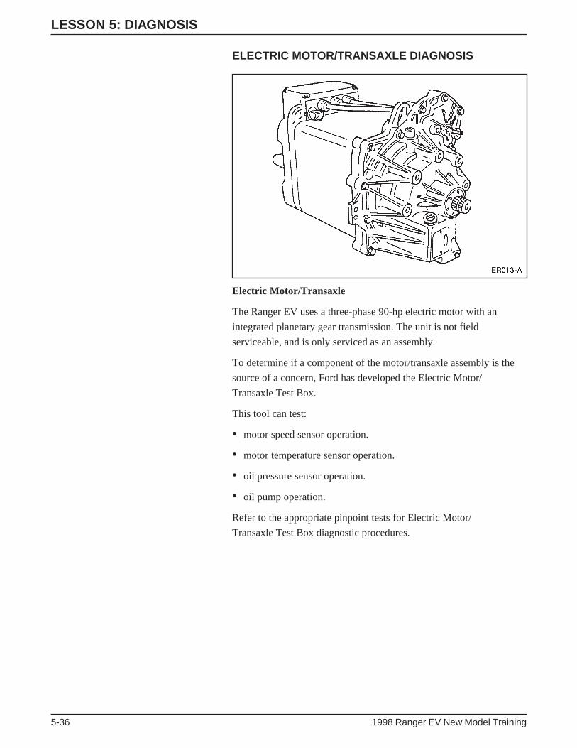
LESSON 5: DIAGNOSIS
5-36 1998 Ranger EV New Model Training
ELECTRIC MOTOR/TRANSAXLE DIAGNOSIS
Electric Motor/Transaxle
The Ranger EV uses a three-phase 90-hp electric motor with an
integrated planetary gear transmission. The unit is not field
serviceable, and is only serviced as an assembly.
To determine if a component of the motor/transaxle assembly is the
source of a concern, Ford has developed the Electric Motor/
Transaxle Test Box.
This tool can test:
• motor speed sensor operation.
• motor temperature sensor operation.
• oil pressure sensor operation.
• oil pump operation.
Refer to the appropriate pinpoint tests for Electric Motor/
Transaxle Test Box diagnostic procedures.

LESSON 5: DIAGNOSIS
1998 Ranger EV New Model Training 5-37
NOTES

LESSON 5: DIAGNOSIS
5-38 1998 Ranger EV New Model Training
TRACTION BATTERY PACK COMPONENTSDEMONSTRATION
The traction battery pack contains many different components. The
following is a list of these components. As your instructor points out
these components, note the workshop manual section where service
information on the components can be found.
• Thirty-nine 8-volt battery modules. SECTION ________________
• High voltage wiring that connects the battery modules in a series
circuit. SECTION_______________________________________
• A 250 amp busman fuse located between batteries 21 and 22.
SECTION _____________________________________________
• The contactor box. SECTION _____________________________
• The battery control module (BCM). SECTION________________
• Battery pack cooling system. SECTION _____________________
• One sense lead connects between each two battery modules, except
for modules 1 and 39, each of which has their own sense lead.
SECTION _____________________________________________
• Four temperature sensors to monitor battery operating
temperatures. SECTION _________________________________
• An optional battery heating system to maintain battery temperature
in cold climates. SECTION _______________________________
• A low-voltage wiring harness. SECTION ____________________

LESSON 5: DIAGNOSIS
1998 Ranger EV New Model Training 5-39
NOTES

LESSON 5: DIAGNOSIS
5-40 1998 Ranger EV New Model Training
TRACTION BATTERY DIAGNOSIS
Current Leakage Diagnosis
Current leakage is a condition that occurs if a short develops between
the traction battery positive and/or negative bus and chassis ground. If
this occurs, resistance is reduced due to the additional current path to
ground. This additional path can result in reduction of vehicle range.
Current leakage is monitored by the battery control module (BCM),
which monitors the resistance between the traction battery positive
and negative bus and chassis ground. Normal resistance is usually
greater than 100 K ohms.
The following symptoms may occur if current leakage is present.
• A short that reduces resistance between the traction battery and
chassis ground below 50 K ohms but above 10 K ohms will set a
DTC and illuminate the Electrical Hazard Warning Lamp.
• A short that reduces resistance between the traction battery and
chassis ground below 10 K ohms will set a DTC and illuminate the
Electrical Hazard Warning Lamp. If the vehicle is connected, the
Power Control Station (PCS) for charging the on-board charger will
not activate.
Multiple High Voltage Load Failure
Multiple high voltage load failure will cause the loss of all accessories
connected to the high voltage auxiliary circuit. These include:
• the DC/DC converter (auxiliary battery charging).
• the A/C inverter motor controller (air conditioning).
• the positive temperature coefficient (PTC) heater.
• the power steering controller assembly.
This type of failure can be caused by a failure in various vehicle
components including:
• the high voltage power distribution box (HVPDB).
• the high voltage wiring harness.
• the auxiliary load 40 amp fuse in the contactor box.
• the contactor box.
If a failure of this type occurs, the IAA module will store a DTC
relating to the cause of the failure.

LESSON 5: DIAGNOSIS
1998 Ranger EV New Model Training 5-41
NOTES

LESSON 5: DIAGNOSIS
5-42 1998 Ranger EV New Model Training
NOTES

LESSON 5: DIAGNOSIS
1998 Ranger EV New Model Training 5-43
ACTIVITY 12 – DIAGNOSIS – WORKSHEET QCURRENT LEAKAGE AND MULTIPLE AUXILIARY LOAD FAILURE DIAGNOSIS
STUDENT ANSWER SHEET
OBJECTIVE: The student will safely and accurately diagnose a Ranger EV concern.
DIRECTIONS: Go to the workstation as directed by your instructor. Read the repair order on the vehicle and
isolate the cause of the concern.
1. What customer concern is listed on this repair order? ___________________________________________
______________________________________________________________________________________
2. What section of the workshop manual should you look for diagnostic direction? ______________________
______________________________________________________________________________________
3. List the preliminary diagnostic steps that you performed (NOTE: assume on the road test that the concern is
occurring as described by the customer). _____________________________________________________
______________________________________________________________________________________
4. Are any DTCs present? ___________________________________________________________________
______________________________________________________________________________________
5. Perform the diagnostic test steps required to locate the cause of the concern. List the steps you perform and
their results below. NOTE: The number of rows in the table does not indicate the number of steps to
perform. Use the back of this sheet if required.
DIAGNOSTIC TEST STEPS RESULT
BCM DIAGNOSTIC TROUBLE CURRENT LEAKAGE
CODE INDEX DETECTION SECTION 414-03
GO DTC/SYMPTOM CHART PPT A
A1 YES
A15 YES
A16 REPLACE TIM
6. What is the cause of this concern?___________________________________________________________
______________________________________________________________________________________
7. What is the repair that should be performed? __________________________________________________
______________________________________________________________________________________
8. What should be done before the vehicle is returned? ____________________________________________
______________________________________________________________________________________
END OF WORKSHEET Q

LESSON 5: DIAGNOSIS
5-44 1998 Ranger EV New Model Training
ACTIVITY 12 – DIAGNOSIS – WORKSHEET RSTUDENT ANSWER SHEET
OBJECTIVE: The student will safely and accurately diagnose a Ranger EV concern.
DIRECTIONS: Go to the workstation as directed by the instructor. Read the repair order on the vehicle and
isolate the cause of the concern.
1. What customer concern is listed on this repair order? ___________________________________________
______________________________________________________________________________________
2. Perform the diagnostic test steps required to locate the cause of the concern. List the steps you perform and
their results below. NOTE: The number of rows in the table does not indicate the number of steps to
perform. _______________________________________________________________________________
______________________________________________________________________________________
DIAGNOSTIC TEST STEP RESULT
100-07 IAA DTC C1862
AUXILIARY CONTACTOR
RELAY CONTROL 414-03 SYMPTOM CHART
A1 NO
A2 YES
A3 NO FAULT EXISTS
A6 NO FAULT EXISTS
A14 NO
A15 YES
A18 YES
A19 YES
A20 YES
A21 YES
A22 YES
A23 YES REPLACE FUSE
3. What was the cause of the concern? _________________________________________________________
______________________________________________________________________________________
END OF WORKSHEET R

LESSON 5: DIAGNOSIS
1998 Ranger EV New Model Training 5-45
Battery Diagnostic System (BDS) Battery Module andSense Lead Diagnostics
Diagnosing a battery module or sense lead fault can be of critical
importance when a vehicle is brought in for service.
• It is important to note that a single bad module or single sense lead
will not usually illuminate any of the warning lights in the
instrument cluster.
• However, if signals from five or more modules are lost, an
emergency power off (EPO) condition will occur, which will result
in a power limit light illumination, no charging, and a vehicle
shutdown.
Because all the batteries in the battery pack are wired in series, a bad
module may cause a significant loss of range. Because of this series
arrangement, one weak module limits the energy output of the whole
pack.
However, sometimes the symptoms may not be very apparent.
Symptoms of module failure can vary depending on the severity of the
failure.
• For example, if a module’s capacity is only slightly lower than the
other modules in the pack, the vehicle’s range may only be
decreased slightly.
• If the customer never runs the battery pack below 40 or 50% state
of charge (SOC), they may not notice any decrease in vehicle
range.
• However, DTC C1671 (BATTERY VOLTAGE OUT OF RANGE)
will be stored in the BCM’s memory.
If an individual module’s capacity is significantly lower than the other
modules of the battery pack, its failure can cause a significant
decrease in vehicle range that will be readily apparent to most
customers.
• It should be noted that weak battery modules tend to occur one at
a time.
• A single battery sense lead failure will usually have no symptoms
at all. As with a bad module, no warning light in the instrument
cluster will illuminate, and the only way you may become aware of
the failure is that a DTC 1671 will be stored in the BCM’s memory.
• The rule for a sense lead failure is that a bad sense lead will cause a
fault to be indicated in two modules.

LESSON 5: DIAGNOSIS
5-46 1998 Ranger EV New Model Training
• This is due to the fact that each sense lead monitors the voltage of
two battery modules.
• For example, the sense lead that monitors the voltage for module
15 also monitors module 16’s voltage.
• So a failure of the sense lead will cause both modules to indicate
bad.
• The only exception is for battery modules 1 and 39, which are
monitored by their own individual sense lead.
Manual Method for Diagnosing Battery Modules andSense Leads
Early production versions of the NGS software may not support the
battery diagnostic system (BDS). If this is the case the manual method
of diagnosing battery modules and sense leads must be used. Use the
Battery Voltage Record Sheet (the next sub-section of this book) and
the following steps to locate the cause of a battery module or sense
lead concern.
• Enter the BCM PID menu. Review the BAT_FT (battery sense lead
fault) PID for each battery module.
• If there is a fault indicated, view the BAT_MV PID for that module
in BCM active command mode.
• If that module indicates less than 3-volts, view the voltage
indications of the modules around it. If the module voltage directly
connected to the module that sets the fault (for example, module 2
set a fault, and module 1 or 3 also has a fault), suspect that a sense
lead is bad.
• Operate the vehicle until the state of charge (SOC) PID indicates
that the battery pack SOC is 20%.

LESSON 5: DIAGNOSIS
1998 Ranger EV New Model Training 5-47
• Return the vehicle to the repair facility.
• Actuate heater/defroster mode on high fan and leave on headlamps
to discharge battery pack.
• When battery pack reaches 10% SOC, view BAT_MV PID for
each of the 39 battery modules.
• Using the BAT_MV PID, record the battery voltage on the Battery
Voltage Record Sheet. (A copy is provided on the next page. There
is also a copy included as part of Worksheet L, and another copy
that can be found in the Diagnostic Information Appendix.)
• Select the five lowest voltage battery modules.
• Return to the BAT_MV PID and record the voltages of the five
lowest voltage battery modules.
• From these five, compare the voltage readings of the lowest three
battery modules.
• If the lowest voltage battery is 0.1 less than the second lowest
voltage battery, replace the lowest voltage battery module.
• If the second lowest voltage battery is more than 0.08 volts less
than the third lowest voltage battery, replace the second lowest
voltage battery.
• Prior to replacing the module, verify the serviceability of the
battery’s sense lead (measure for resistance of 30.9 K ohms), and
verify the module’s voltage reading with a DVOM.
LESSON 5: DIAGNOSIS
5-48 1998 Ranger EV New Model Training
Battery Voltage Record Sheet
Directions
1. Enter BCM ACTIVE COMMANDS.
2. Enter BATTERY MODULE SELECT menu.
3. Enter PID menu.
4. Select BAT_MV PID.
5. Press START.
6. Press SETUP button (8).
7. Press AUTO (4).
8. Press CANCEL to return to ACTIVE COMMAND menu.
9. With battery module highlighted, press TRIGGER. This will shrink highlighted (darkened) area to only
include the battery module number.
10. Read and record voltage for battery module #1. Record the reading in the table below.
11. Rotate the scroll bar (center knob) and the module number will change. Read the voltage and record it.
12. Continue for each of the 39 battery modules. Record each reading in the table below.
BATTERY VOLTAGE BATTERY VOLTAGE BATTERY VOLTAGEREADINGS READINGS READINGS
1. 14. 27.
2. 15. 28.
3. 16. 29.
4. 17. 30.
5. 18. 31.
6. 19. 32.
7. 20. 33.
8. 21. 34.
9. 22. 35.
10. 23. 36.
11. 24. 37.
12. 25. 38.
13. 26. 39.
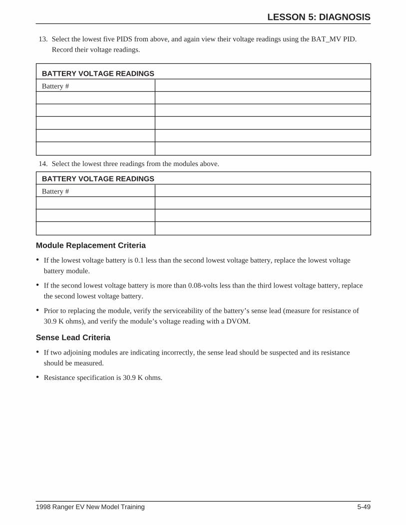
LESSON 5: DIAGNOSIS
1998 Ranger EV New Model Training 5-49
13. Select the lowest five PIDS from above, and again view their voltage readings using the BAT_MV PID.
Record their voltage readings.
BATTERY VOLTAGE READINGS
Battery #
14. Select the lowest three readings from the modules above.
BATTERY VOLTAGE READINGS
Battery #
Module Replacement Criteria
• If the lowest voltage battery is 0.1 less than the second lowest voltage battery, replace the lowest voltage
battery module.
• If the second lowest voltage battery is more than 0.08-volts less than the third lowest voltage battery, replace
the second lowest voltage battery.
• Prior to replacing the module, verify the serviceability of the battery’s sense lead (measure for resistance of
30.9 K ohms), and verify the module’s voltage reading with a DVOM.
Sense Lead Criteria
• If two adjoining modules are indicating incorrectly, the sense lead should be suspected and its resistance
should be measured.
• Resistance specification is 30.9 K ohms.

LESSON 5: DIAGNOSIS
5-50 1998 Ranger EV New Model Training
Emergency Power Off (EPO)
In the event an unsafe condition occurs that will disable an interlock or if the inertia switch is triggered, an EPO
signal will be sent to disable all high voltage loads.
• Can be set by IAA, BCM, or TIM.
• An EPO event will be accompanied by multiple instrument cluster lights illuminating and the vehicle shutting
down.
• If an EPO occurs, a DTC will be set that will aid you in locating the source of the concern. Refer to the Ranger
EV service publications for EPO diagnostic procedures.

LESSON 5: DIAGNOSIS
1998 Ranger EV New Model Training 5-51
NOTES

LESSON 5: DIAGNOSIS
5-52 1998 Ranger EV New Model Training
ACTIVITY 13 – DIAGNOSIS – WORKSHEET S1 (BDS)BATTERY AND SENSE LEAD DIAGNOSIS
STUDENT ANSWER SHEET
OBJECTIVE: The student will safely and accurately diagnose a Ranger EV concern.
DIRECTIONS: Go to the workstation as directed by the instructor. Perform the tasks and answer the question
below.
1. Retrieve DTCs from the classroom vehicle. In what order should the modules be checked for DTCs? _____
______________________________________________________________________________________
2. List any DTCs present and in which module you found them? ____________________________________
______________________________________________________________________________________
3. What section of the workshop manual will provide diagnostic direction? ____________________________
______________________________________________________________________________________
4. What does this DTC indicate? ______________________________________________________________
______________________________________________________________________________________
5. What section of the workshop manual contains the pinpoint tests required to diagnose this fault? _________
______________________________________________________________________________________
6. Perform the diagnostic steps and list your results in the table below.
DIAGNOSTIC STEP RESULT
PPT B1 NO
B2 NO, INTEGER 4 OR 5 IS PRESENT
B3 YES
B4 YES
B5 NO, REPLACE HARNESS IN QUESTION
B6 NO, SYSTEM OK
7. According to the service publications, what must be done before installing a new battery module?________
______________________________________________________________________________________
END OF WORKSHEET S1

LESSON 5: DIAGNOSIS
1998 Ranger EV New Model Training 5-53
ACTIVITY 13 – DIAGNOSIS – WORKSHEET S2 (NON-BDS)BATTERY AND SENSE LEAD DIAGNOSIS
STUDENT ANSWER SHEET
OBJECTIVE: The student will safely and accurately diagnose a Ranger EV concern.
DIRECTIONS: Go to the workstation as directed by the instructor. Read the repair order on the vehicle and
isolate the cause of the concern.
1. Retrieve DTCs from the classroom vehicle. In what order should the modules be checked for DTCs? _____
______________________________________________________________________________________
2. List any DTCs present and in which module you found them? ____________________________________
______________________________________________________________________________________
3. What section of the workshop manual will provide diagnostic direction? ____________________________
______________________________________________________________________________________
4. What does this DTC indicate? ______________________________________________________________
______________________________________________________________________________________
5. What is the next step you should perform? ____________________________________________________
______________________________________________________________________________________
6. Are there any indications of the source of the concern? __________________________________________
______________________________________________________________________________________
7. Is the vehicle at the correct state of charge to measure the battery voltage to determine if there is a battery
module fault? ___________________________________________________________________________
8. Exactly what is the state of charge of this vehicle? ______________________________________________
______________________________________________________________________________________
9. While monitoring SOC PID, turn heat on high for three minutes. What is the state of charge at the end of the
three minutes? __________________________________________________________________________
______________________________________________________________________________________
10. What is the state of charge supposed to be when testing for a bad battery module? ____________________
______________________________________________________________________________________

LESSON 5: DIAGNOSIS
5-54 1998 Ranger EV New Model Training
11. Check the individual voltage of all the battery modules. Use the attached Battery Module Record Sheet
found on the next page.
12. If any modules are suspect, list the module number. Module number will vary depending upon where bad
module is installed.
13. Does the information on the Battery Module Record Sheet indicate any other concerns are present? ______
______________________________________________________________________________________
______________________________________________________________________________________
14. In order to verify your diagnosis of the component(s) that are indicating a fault, what steps should you
perform?_______________________________________________________________________________
______________________________________________________________________________________
______________________________________________________________________________________
15. Perform the verification tests. Was your diagnosis correct? _______________________________________
16. Prior to installing a new battery module what should be done? ____________________________________
______________________________________________________________________________________
ACTIVITY 13 – DIAGNOSIS – WORKSHEET S2 (NON-BDS)BATTERY AND SENSE LEAD DIAGNOSISSTUDENT ANSWER SHEET (Continued)
END OF WORKSHEET S2 (NON-BDS)

LESSON 5: DIAGNOSIS
1998 Ranger EV New Model Training 5-55
Battery Module Record Sheet
Directions
1. Enter BCM ACTIVE COMMANDS.
2. Enter BATTERY MODULE SELECT menu.
3. Enter PID menu.
4. Select BAT_MV PID.
5. Press START.
6. Press SETUP button (8).
7. Press AUTO (4).
8. Press CANCEL to return to ACTIVE COMMAND menu.
9. With battery module highlighted, press TRIGGER. This will shrink highlighted (darkened) area to only
include the battery module number.
10. Read and record the voltage for battery module # 1. Record the reading in the table below.
11. Rotate the scroll bar (center knob) and the module number will change. Read the voltage and record it.
12. Continue for each of the 39 battery modules. Record each reading in the table below.
BATTERY VOLTAGE BATTERY VOLTAGE BATTERY VOLTAGEREADINGS READINGS READINGS
1. 14. 27.
2. 15. 28.
3. 16. 29.
4. 17. 30.
5. 18. 31.
6. 19. 32.
7. 20. 33.
8. 21. 34.
9. 22. 35.
10. 23. 36.
11. 24. 37.
12. 25. 38.
13. 26. 39.

LESSON 5: DIAGNOSIS
5-56 1998 Ranger EV New Model Training
13. Select the lowest five PIDS from above, and again view their voltage readings using the BAT_MV PID.
Record their voltage readings.
BATTERY VOLTAGE READINGS
Battery #
14. Select the lowest three readings from the modules above.
BATTERY VOLTAGE READINGS
Battery #
Module Replacement Criteria
• If the lowest voltage battery is 0.1 less than the second lowest voltage battery, replace the lowest voltage
battery module.
• If the second lowest voltage battery is more than 0.08-volts less than the third lowest voltage battery, replace
the second lowest voltage battery.
• Prior to replacing the module, verify the serviceability of the battery’s sense lead (measure for resistance of
30.9 K ohms), and verify the module’s voltage reading with a DVOM.
Sense Lead Criteria
• If two adjoining modules are indicating incorrectly, the sense lead should be suspected and its resistance
should be measured.
• Resistance specification is 30.9 K ohms.

LESSON 5: DIAGNOSIS
1998 Ranger EV New Model Training 5-57
ACTIVITY 13 – DIAGNOSIS – WORKSHEET TEPO DIAGNOSIS
STUDENT ANSWER SHEET
OBJECTIVE: The student will safely and accurately diagnose a Ranger EV concern.
DIRECTIONS: Go to the workstation as directed by the instructor. Read the repair order on the vehicle and
isolate the cause of the concern.
1. What customer concern is listed on this repair order? ___________________________________________
______________________________________________________________________________________
2. Can you verify the concern? _______________________________________________________________
3. Is there any visual indication of the cause of the fault? __________________________________________
4. Are any DTCs present? ___________________________________________________________________
______________________________________________________________________________________
5. Perform the diagnostic test steps required to locate the cause of the concern. List the steps you perform and
their results below. NOTE: The number of rows in the table does not indicate the number of steps to per-
form. Use the back of this sheet if required.
DIAGNOSTIC TEST STEPS RESULT
IAA DIAGNOSTIC TROUBLE CHART SAYS TO GO TO 412-02
CODE INDEX DIAGNOSTICS ARE IN 414-03
GO DTC/SYMPTOM CHART 414-05-05 PPT A
A1 YES
A2 NO
A3 NO
A4 YES
6. What is the cause of the concern? ___________________________________________________________
______________________________________________________________________________________
END OF WORKSHEET T

NOTES
GLOSSARY
1998 Ranger EV New Model Training Glossary-1
RANGER EV ACRONYMS
ABS – Anti-Lock Brake System
AC – Alternating Current
A/C – Air Conditioning
APS – Accelerator Position Sensor
BCM – Battery Controller Module
BOB – Breakout Box
CBA – Contactor Box Assembly
CPR – Cardio-Pulmonary Resuscitation
CTM – Central Timer Module
DC – Direct Current
DC/DC – Direct Current to Direct Current
DEFN – Definition
DTC – Diagnostic Trouble Code
DTE – Distance to Empty
DVOM – Digital Volt Ohmmeter
ECON MODE – Economy Mode
ECS – Electronic Crash Sensor
ECU – Electronic Control Unit
EEC – Electronic Engine Control
EPO – Emergency Power Off
ETC – Electronic Throttle Control
EV – Electric Vehicle
EVTM – Electrical and Vacuum Troubleshooting
Manual
GND – Ground (Electrical)
HV – High Voltage
HVPDB – High Voltage Power Distribution Box
IAA – Interface Adapter Assembly
ICE – Internal Combustion Engine
IGBT – Insulated Gate Bipolar Transistor
IMC – Inverter Motor Controller
LOS – Limited Operating Strategy
MCP – Master Cylinder Pressure
MIL – Malfunction Indicator Lamp
MSDS – Material Safety Data Sheets
NGS – New Generation STAR Tester
OBD-II – On Board Diagnostics-Second Generation
PCS – Power Control Station
PID – Parameter Identification
POST – Power On Self Test
PRNDE – Park/Reverse/Neutral/Drive/Economy
P/S – Power Steering
PTC – Positive Temperature Coefficient
RAM – Random Access Memory
RBS – Regenerative Braking System
ROM – Read Only Memory
SCP – Standard Corporate Protocol
SLI – Starting/Lighting/Ignition (12-Volt Battery)
SOC – State of Charge
TIM – Traction Inverter Module
VBC – Variable Blower Control
VSL – Voltage Sense Lead

NOTES

ACTIVITY SHEET
1998 Ranger EV New Model Training Activity Sheet-1
WRITTEN ACTIVITY SHEET 1STUDENT ANSWER SHEET
DIRECTIONS: Using the information provided in your Student Reference Guide and the appropriate service
publication read and answer the following questions.
1. What fuses inside the contactor box (and its cover) are serviceable? ________________________________
______________________________________________________________________________________
2. What indication would you see if more than one contactor relay is improperly closed? _________________
______________________________________________________________________________________
3. If a vehicle is brought to you with an “Unable to Charge” concern and no DTC is present, what PID would
you select to view?_______________________________________________________________________
______________________________________________________________________________________
4. If the PID above displayed a 101, what would it indicate? ________________________________________
______________________________________________________________________________________
5. What type of grease must be applied whenever electrical connectors are disconnected or worked on? _____
______________________________________________________________________________________
6. Why is the in-line bypass battery module used to charge the battery pack when a new battery module is
installed? ______________________________________________________________________________
______________________________________________________________________________________
7. What control module monitors battery leakage? ________________________________________________
______________________________________________________________________________________
8. To disable all the loads on the Ranger EV, where should you remove the ground connections? ___________
______________________________________________________________________________________
9. What does DTC C1862 indicate? ___________________________________________________________
______________________________________________________________________________________
10. What symptoms may occur if a DTC C1750 is set in the TIM? ____________________________________
______________________________________________________________________________________
11. Which diagnostic strategy does Ford recommend be used when diagnosing a vehicle? _________________
______________________________________________________________________________________
12. What personal safety steps should always be performed before working on the Ranger EV? _____________
______________________________________________________________________________________
END OF ACTIVITY SHEET 1

ACTIVITY SHEET
Activity Sheet-2 1998 Ranger EV New Model Training
ACTIVITY SHEET 2STUDENT ANSWER SHEET
DIRECTIONS: Using the information provided in your Student Reference Guide, read and answer the
following questions.
1. Which circuits are the data bus for the J1850 (SCP) network? _____________________________________
______________________________________________________________________________________
2. When testing for an improperly closed contactor relay, what PID should you monitor? _________________
______________________________________________________________________________________
3. The battery pack will not charge if the temperature sensors indicate the battery temperature is above
______________ or below ______________ .
4. What symptom will occur if the auxiliary contactor relay fails open? _______________________________
______________________________________________________________________________________
5. In order to discharge the high voltage capacitors in the auxiliary components, how long should you wait
before probing the connectors? _____________________________________________________________
______________________________________________________________________________________
6. What instrument cluster light will illuminate if a short reduces resistance between the traction battery and
ground below 50 K ohms? _________________________________________________________________
______________________________________________________________________________________
7. What connector is between the TIM and the traction contactor relay? _______________________________
______________________________________________________________________________________
8. Network DTCs should be repaired only if repairing the cause of other DTCs does not correct the concern
(circle one). TRUE or FALSE.
9. What symptoms will occur if the traction motor encoder circuit fails below 3 km/h (2 mph)? ____________
______________________________________________________________________________________
______________________________________________________________________________________
10. What personal safety steps should always be performed before working on the Ranger EV? _____________
______________________________________________________________________________________
11. What is the correct resistance for a battery sense lead? __________________________________________
______________________________________________________________________________________
12. What does DTC B1238 indicate? ___________________________________________________________
______________________________________________________________________________________
END OF ACTIVITY SHEET 2

ACTIVITY SHEET
1998 Ranger EV New Model Training Activity Sheet-3
GENERIC WORKSHEET
OBJECTIVE: The student will safely and accurately diagnose a Ranger EV concern.
DIRECTIONS: Go to the workstation as directed by the instructor. Read the repair order on the vehicle and
isolate the cause of the concern.
1. What customer concern is listed on this repair order? ___________________________________________
2. Perform the diagnostic test steps required to locate the cause of the concern. List the steps you perform and
their results below. NOTE: The number of rows in the table does not indicate the number of steps to
perform. Use the back of this sheet if required.
DIAGNOSTIC TEST STEP RESULT
3. What was the cause of the concern? _________________________________________________________
END OF WORKSHEET

NOTES