1992-8645 MODIFIED SWARM FIREFLY ALGORITHM METHOD … · relay coordination in this paper is to...
15
Journal of Theoretical and Applied Information Technology 31 st August 2014. Vol. 66 No.3 © 2005 - 2014 JATIT & LLS. All rights reserved . ISSN: 1992-8645 www.jatit.org E-ISSN: 1817-3195 741 MODIFIED SWARM FIREFLY ALGORITHM METHOD FOR DIRECTIONAL OVERCURRENT RELAY COORDINATION PROBLEM 1 M.H. HUSSAIN, 2 I. MUSIRIN, 3 A.F. ABIDIN, 4 S.R.A. RAHIM, 1,4 School of Electrical System Engineering, Universiti Malaysia Perlis 2,3 Faculty of Electrical Engineering, Universiti Teknologi MARA E-mail: 1 [email protected], 2 [email protected] ABSTRACT Computational intelligence method such as Nature Inspired Algorithms (NIA) or meta-heuristic algorithms based optimization methods known to be successful in coordination of directional overcurrent relay. It has also been reported that it outperformed the conventional approach. Due to its advantages, it has gained more popularity among the researchers. Some of the conventional optimization techniques such as linear programming method and non-linear programming method were proposed but these methods is time consuming and complex to achieve optimal solution. Thus, a search for better optimization technique to reduce computation burden has become urgency. This paper presents the implementation of Modified Swarm Firefly Algorithm (MSFA) in solving directional overcurrent relay coordination problem. The effect of population sizes were considered to investigate the performance of MSFA technique. The coordination of directional overcurrent relays is formulated as linear programming problem and the objective function is introduced to minimize the operating time of the primary relay. Operating time of the relay depends on time setting multiplier (TSM) which leads to no miscoordination between relay pairs. The proposed method have been applied and tested successfully on 8-Bus test system and 9-Bus test system. The results revealed that MSFA outperformed Particle Swarm Optimization (PSO) in terms of computation time. Keywords: Directional Overcurrent Relay (DOCR) Coordination, Modified Swarm Firefly Algorithm (MSFA), Particle Swarm Optimization (PSO), Time Setting Multiplier, Computation Time 1. INTRODUCTION Undesirable conditions such as faults, overvoltage, overcurrent, over frequency and under frequency conditions can occur frequently and leads to damaging equipment, interrupting power supply connected to the power system. When these situations occurred, the faulted components should be ready to isolated and maintain system stability. This is known as power system protection. Protection power system normally comprises of five components. There are current transformers, voltage transformers, protective relays, circuit breakers, batteries and fuses in a distribution system. By taking consideration of this undesirable condition, a reliable protective power system is required. The protective relay plays the most significant part in power system protection which senses the undesirable conditions with the aid of current transformers and circuit breaker. For protection system, Current Transformer (CT) usually designed to reproduce the largest current fault while the relay carries out the information provided by the CT in accordance with some predetermine logic and compares it with relay settings to take a trip or no- trip decision [1]. If fault happens, the relay initiates the operation of the Circuit Breaker (CB) by issues tripping signals to open the CB. This is to ensure the defected element will be isolate from the rest of the system. Nowadays, transmission system and distribution system are very complicated. Due to this, a large number of protective relays are required to cooperate with each other to ensure reliable and secure operation of a whole system. Protection system is organized accordingly which can be divided into several zone. Each of the zones may be implemented using different relaying principle [1]-[2]. In typical power system, there are many zones to be protected such as generator zone, bus zone, transformer zone, transmission line zone, etc. This system is called as main protection system. In order for the reliable protective relay to act accordingly if the main protection system failed, the
Transcript of 1992-8645 MODIFIED SWARM FIREFLY ALGORITHM METHOD … · relay coordination in this paper is to...

Journal of Theoretical and Applied Information Technology 31
st August 2014. Vol. 66 No.3
© 2005 - 2014 JATIT & LLS. All rights reserved.
ISSN: 1992-8645 www.jatit.org E-ISSN: 1817-3195
741
MODIFIED SWARM FIREFLY ALGORITHM METHOD FOR
DIRECTIONAL OVERCURRENT RELAY COORDINATION
PROBLEM
1M.H. HUSSAIN,
2I. MUSIRIN,
3A.F. ABIDIN,
4S.R.A. RAHIM,
1,4School of Electrical System Engineering, Universiti Malaysia Perlis
2,3Faculty of Electrical Engineering, Universiti Teknologi MARA
E-mail: [email protected], [email protected]
ABSTRACT
Computational intelligence method such as Nature Inspired Algorithms (NIA) or meta-heuristic algorithms based optimization methods known to be successful in coordination of directional overcurrent relay. It has also been reported that it outperformed the conventional approach. Due to its advantages, it has gained more popularity among the researchers. Some of the conventional optimization techniques such as linear programming method and non-linear programming method were proposed but these methods is time consuming and complex to achieve optimal solution. Thus, a search for better optimization technique to reduce computation burden has become urgency. This paper presents the implementation of Modified Swarm Firefly Algorithm (MSFA) in solving directional overcurrent relay coordination problem. The effect of population sizes were considered to investigate the performance of MSFA technique. The coordination of directional overcurrent relays is formulated as linear programming problem and the objective function is introduced to minimize the operating time of the primary relay. Operating time of the relay depends on time setting multiplier (TSM) which leads to no miscoordination between relay pairs. The proposed method have been applied and tested successfully on 8-Bus test system and 9-Bus test system. The results revealed that MSFA outperformed Particle Swarm Optimization (PSO) in terms of computation time.
Keywords: Directional Overcurrent Relay (DOCR) Coordination, Modified Swarm Firefly Algorithm
(MSFA), Particle Swarm Optimization (PSO), Time Setting Multiplier, Computation Time
1. INTRODUCTION
Undesirable conditions such as faults,
overvoltage, overcurrent, over frequency and under frequency conditions can occur frequently and leads to damaging equipment, interrupting power supply connected to the power system. When these situations occurred, the faulted components should be ready to isolated and maintain system stability. This is known as power system protection. Protection power system normally comprises of five components. There are current transformers, voltage transformers, protective relays, circuit breakers, batteries and fuses in a distribution system. By taking consideration of this undesirable condition, a reliable protective power system is required.
The protective relay plays the most significant part in power system protection which senses the undesirable conditions with the aid of current transformers and circuit breaker. For protection system, Current Transformer (CT) usually designed
to reproduce the largest current fault while the relay carries out the information provided by the CT in accordance with some predetermine logic and compares it with relay settings to take a trip or no-trip decision [1]. If fault happens, the relay initiates the operation of the Circuit Breaker (CB) by issues tripping signals to open the CB. This is to ensure the defected element will be isolate from the rest of the system. Nowadays, transmission system and distribution system are very complicated. Due to this, a large number of protective relays are required to cooperate with each other to ensure reliable and secure operation of a whole system.
Protection system is organized accordingly which can be divided into several zone. Each of the zones may be implemented using different relaying principle [1]-[2]. In typical power system, there are many zones to be protected such as generator zone, bus zone, transformer zone, transmission line zone, etc. This system is called as main protection system. In order for the reliable protective relay to act accordingly if the main protection system failed, the

Journal of Theoretical and Applied Information Technology 31
st August 2014. Vol. 66 No.3
© 2005 - 2014 JATIT & LLS. All rights reserved.
ISSN: 1992-8645 www.jatit.org E-ISSN: 1817-3195
742
backup protection system should operate to ensure reliability. Time grading margin or commonly known as time delay is the criteria to be considered for coordination when primary relays and backup relays coordinated together. It means that the operating time of backup relay must be delay by an appropriate time over that of the primary relay. When fault started to strike, both primary relay and backup relay start operating simultaneously. In case the main protection system operates successfully, the backup protection system resets without issuing a trip command. If main protection system fails to operate, the backup protection system waits until the main protection cleared the fault and then issues the trip command to its circuit breakers. According to [3]-[4], protective relays comprises of five types which are overcurrent relays, directional relays, differential relays, distance relays and pilot relays.
The most common relay used in power system is the overcurrent relay. This relay has two settings which are plug setting and time setting. The function of plug setting is to determine the current required for the relay to pick up while time setting is to decide the operating time of the relay [1], [3]-[4]. The overcurrent relay normally used for overcurrent protection and must de-energized the undesirable conditions as quickly as possible to protect the system. Basically, overcurrent relays have Current Setting Multiplier (CSM) starting from 50% until 200% in steps of 25% [4]. This is commonly known as Plug Setting (PS) which the value is determined by maximum load current and minimum fault current.
Several methods have been proposed and applied by the researchers for the last four decades. These methods can be categorized into trial and error, curve fitting, graph theoretical and optimization method [2]-[6]. In classical approach, fault analysis is conducted, after that ring network are break into radial type, relay which at far-end is set first and then backup relays are set. This process is repeated continuously until all the relays are taken into consideration. Due to the complexity of the power system, both trial and error approach, graph theoretical technique and topological technique is time consuming [2]-[3]. The optimization techniques outperformed the classical approach which one of its advantages is fast convergence rate to achieve a suitable relay setting and eliminate a breakpoint technique.
Urdaneta et. al in 1988 [7] did state that the proposed new methodology based optimization theory determines the optimal solution to the
coordination problem in efficient way. Indeed, optimization techniques are more efficient for the network with multisource and multi looped system.
In the last fifteen years, computational intelligence methods such as Evolutionary Computation (EC) are applied to solve overcurrent relays coordination problem. In [8]-[9], C.W. Soo et al. proposed Genetic Algorithm (GA) and Evolutionary Programming (EP). GA was implemented to overcome non-linear programming problem and EP produces two problems which are miscoordination occurred between primary/backup relays and discrete TSM relays changed to continuous. Thus, to overcome this problems, Razavi et al. in 2008 [10] introduced a new comprehensive GA to solve two main problems occurred by C.W. Soo et al. Although GA was implemented in this paper but for binary-coded GA, it needs to change to binary encoding, required longer time to converge and sometimes struck to local minimum solution [11].
Other category is Swarm Intelligence Algorithms which has becoming the most popular nature inspired optimization techniques used to solve engineering problems. In [12], algorithms based on nature have been said effective and efficient in order to solve difficult optimization problems. Modified Particle Swarm Optimization (MPSO) was proposed by H.H. Zieneldin et al. in 2006 [13] to compare with Particle Swarm Optimization (PSO). M.M. Mohamed et al. and M.H. Hussain et al. also were proposed the same method in [14]- [15]. According to [16], PSO have two major drawbacks which are suffers from premature convergence when problems with multiple optima are being optimized. The second drawback is the performance of PSO is very sensitive to parameter settings. Artificial Bees Colony was also reported in [17]-[18] and sometimes good at exploration (global search) but poor exploitation (local search) where it suffers to look for better solution. In [19], Honey Bee Algorithm (HBA) was proposed by V. Ratschi et al. but it has several parameters need to be tuned properly. Lately, Firefly Algorithm (FA) have been widely used in structural optimization and numerical optimization problems [20]-[21]. Although FA to seems to be better in speed of convergence but FA has some of disadvantage such as getting trapped into several local optima [22]. In [23], H. Zhang et al. stressed that Nature Inspired Algorithm (NIA) can be hybridized together with other algorithms to enhance itself to be more efficient, faster, robust and can reach global optima.

Journal of Theoretical and Applied Information Technology 31
st August 2014. Vol. 66 No.3
© 2005 - 2014 JATIT & LLS. All rights reserved.
ISSN: 1992-8645 www.jatit.org E-ISSN: 1817-3195
743
This paper presents Modified Swarm Firefly Algorithm (MSFA) method in solving Directional Overcurrent Relay Coordination problem. The study discovered that the new algorithm known as MSFA which integrates both PSO and a part of Firefly Algorithm (FA) can improve the performance of PSO. In order to verify its performance, MSFA is applied to minimize relay operating time accordingly with an optimal TSM and with a given pickup current settings. The results from the study revealed that the proposed technique outperformed the PSO technique in terms of computation time.
2. PROBLEM FORMULATION
Directional overcurrent relay coordination problem can be stated as a constraint optimization problem. Directional overcurrent relay coordination setting becomes more difficult when there are many overcurrent relays to be coordinated in a system. This is where optimization method is required to search an optimal setting for the overcurrent relays. A. Mahari and H. Seyedi in [24] stated that in linear model programming problem, only TDS or TSM are optimized while Ips are fixed at values between minimum fault current and maximum load current. In non-linear programming problem, TDS or TSM and Ips are optimized simultaneously. Therefore, the main objective of the directional overcurrent relay coordination in this paper is to find optimal TSM or TDS, objective function, relay characteristic, primary/backup relay pairs constraints, coordination constraints, type of relay that had been considered, boundary limits of the relays and discrete or continuous TSM or TDS relays. All of these requirements should be satisfied. In [14], M.M. Mohamed et al. did mentioned that directional overcurrent relay coordination allow for continuous TSM or TDS but discrete pickup current setting.
2.1 Objective Function
According to F. Razavi et al. in [10], the GA method cannot solve two major problems which are miscoordination problem between primary and backup relay pairs and discrete or continuous TSM of the relays. Thus, a new objective function and a new comprehensive GA are introduced to rectify the problems.
In order to solve heuristic optimization problem, a penalty method is used. This penalty method is introduced by adding penalty constraints
such as ∆t of primary and backup relay pairs to the original objective function. The penalty method is
set carefully with high of order, 105. The objective function used in this paper is given below [10, 15]:
∆−∆−∆+= ∑∑
==
2
1
22
1
2
1))((min
P
j
pbpbpb
N
i
i ttttOF βαα (1)
where
ti the i
th relay operating time for a fault near to the Circuit Breaker (CB) of the ith
relay
∆tpb
the operation time difference for relay pairs
N the number of relays
P the number of primary/backup relay pairs
i represents each relay and varies to N
α1 control the weight of
α2 control the weight of
β2 the parameter to consider miscoordination
In this study, the value of β2 is determined by using the heuristic technique. The convenience value of β2 is fit to the equation which miscoordination can be avoided. It should be noted that the objective of the directional overcurrent relay coordination problem is to minimize the summation operating times of primary relays, minimize the objective function and to avoid miscoordination problems occur between primary/backup relays.
2.2 Relay Characteristic
In this paper, the following equation (2) is used to approximately represent the inverse overcurrent relay characteristics and it is called the Sachdev model. It is assumed that all overcurrent relays have normally inverse overcurrent type and more commonly formulated by the following equation according to relay characteristics which are linearly proportional to TSM or TDS [10, 15, 25, 26].
4
5
3
4
2
32
1
)1()1()1(1 −
+
−
+
−
+
−
+=
M
a
M
a
M
a
M
aa
TSM
t (2)
where M or Plug Setting Multiplier (PSM) is the ratio of relay short circuit current to the actual
pickup current
pickup
sc
I
IM =
.
∑=
N
i
it
1
2
2
1
2))((∑
=
∆−∆−∆
P
j
pbpbpb ttt β
Journal of Theoretical and Applied Information Technology 31
st August 2014. Vol. 66 No.3
© 2005 - 2014 JATIT & LLS. All rights reserved.
ISSN: 1992-8645 www.jatit.org E-ISSN: 1817-3195
744
a1, a2, a3, a4 and a5 are the scalar quantities which characterized the particular device being simulated while t is the relay operating time.
Although today, digital relays or microprocessor relays with ANSI and IEC standard curves are used, however for static and electromechanical relays either ANSI or IEC standard formula or the equation 2 can be applied [10, 15, 26, 27].
2.3 Primary/Backup Relay Pairs and
Coordination Constraints
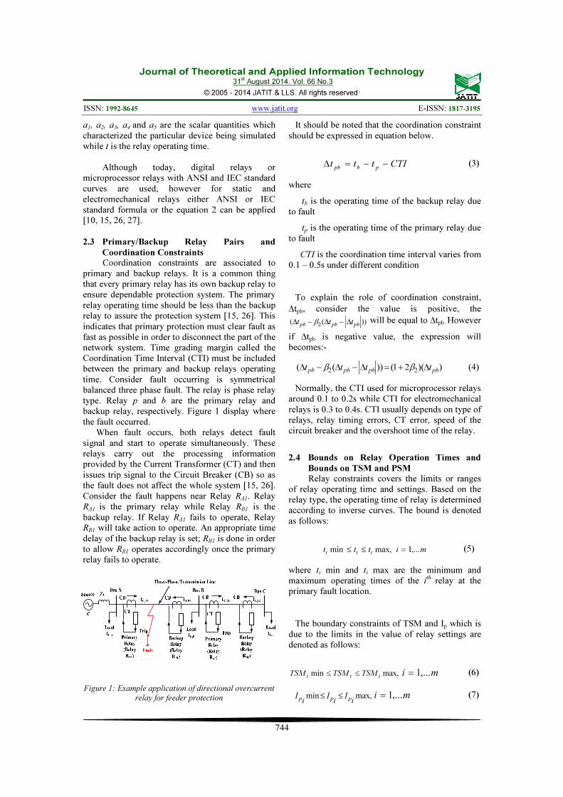
Coordination constraints are associated to primary and backup relays. It is a common thing that every primary relay has its own backup relay to ensure dependable protection system. The primary relay operating time should be less than the backup relay to assure the protection system [15, 26]. This indicates that primary protection must clear fault as fast as possible in order to disconnect the part of the network system. Time grading margin called the Coordination Time Interval (CTI) must be included between the primary and backup relays operating time. Consider fault occurring is symmetrical balanced three phase fault. The relay is phase relay type. Relay p and b are the primary relay and backup relay, respectively. Figure 1 display where the fault occurred.
When fault occurs, both relays detect fault signal and start to operate simultaneously. These relays carry out the processing information provided by the Current Transformer (CT) and then issues trip signal to the Circuit Breaker (CB) so as the fault does not affect the whole system [15, 26]. Consider the fault happens near Relay RA1. Relay RA1 is the primary relay while Relay RB1 is the backup relay. If Relay RA1 fails to operate, Relay RB1 will take action to operate. An appropriate time delay of the backup relay is set; RB1 is done in order to allow RB1 operates accordingly once the primary relay fails to operate.
Figure 1: Example application of directional overcurrent
relay for feeder protection
It should be noted that the coordination constraint should be expressed in equation below.
CTIttt pbpb −−=∆
(3)
where
tb is the operating time of the backup relay due to fault
tp is the operating time of the primary relay due to fault
CTI is the coordination time interval varies from 0.1 – 0.5s under different condition
To explain the role of coordination constraint,
∆tpb, consider the value is positive, the
))((2 pbpbpb ttt ∆−∆−∆ β will be equal to ∆tpb. However
if ∆tpb is negative value, the expression will becomes:-
))(21())((22 pbpbpbpb tttt ∆+=∆−∆−∆ ββ (4)
Normally, the CTI used for microprocessor relays around 0.1 to 0.2s while CTI for electromechanical relays is 0.3 to 0.4s. CTI usually depends on type of relays, relay timing errors, CT error, speed of the circuit breaker and the overshoot time of the relay.
2.4 Bounds on Relay Operation Times and
Bounds on TSM and PSM
Relay constraints covers the limits or ranges of relay operating time and settings. Based on the relay type, the operating time of relay is determined according to inverse curves. The bound is denoted as follows:
max,miniiittt ≤≤ mi ,...1=
(5)
where ti min and ti max are the minimum and maximum operating times of the i
th relay at the primary fault location.
The boundary constraints of TSM and Ip which is due to the limits in the value of relay settings are denoted as follows:
max,miniii
TSMTSMTSM ≤≤ mi ,...1=
(6)
max,mini
Ii
Ii
Ippp
≤≤ mi ,...1=
(7)
Journal of Theoretical and Applied Information Technology 31
st August 2014. Vol. 66 No.3
© 2005 - 2014 JATIT & LLS. All rights reserved.
ISSN: 1992-8645 www.jatit.org E-ISSN: 1817-3195
745
The load currents should be less than pickup current and the pickup current should be lower than the minimum fault current with a reasonable security margin [28].
2.5 Continuous or Discrete TSM or TDS Relays
In [10], the author stressed that in order to find optimal coordination for relays setting, the TSM’s or TDS’s are based on continuous form for continuous TSM or TDS method. If TSM’s or TDS’s of the relays are in discrete form, the output programming results for each relay is rounded to the next upper allowable discrete value of the relevant relay [10]. Moreover, this method may affect coordination between primary/backup relays and may produce inaccuracies value.
However, for discrete TSM or TDS method, the output programming results are discrete directly [10]. The TSM’s or TDS’s are to be said discrete inherently. This means that for each relay, the TSM or TDS is in binary code. Therefore, there is no solution for relays inherently if TSM or TDS are in continuous form [10].
3. MODIFIED SWARM FIREFLY
ALGORITHM (MSFA)
PSO was developed by Eberhart and Kennedy based on the analogy of swarm birds and schooling fish [29] but it suffers from a major drawback which is convergence to a local optimum and not to the global optimum. The premature convergence sometimes happened in a case of high dimension. The main reason why premature convergence happened is because the information flow between particles during optimization process can lead to increasing of being trapped in one of the local optimums [30]. In PSO, for the initial phase simulation, exploration is needed due to high velocities but after sufficient time, the velocities becomes smaller and even the nearest solution to the space is almost impossible to approach [31]. Many efforts have been made to address these issues. With the issues of having multiple local optima, it is proposed here that this problem can be addressed by modified the velocity equation so that the particles explore into region containing global best and converge to the best position.
In this paper, MSFA is developed and introduced to improve the search capability of PSO. The part of Firefly Algorithm (FA) which is the cartesian distance between two swarm fireflies is used in the PSO algorithm to accelerate convergence speed. In addition, MSFA is
developed to solve optimization problems and slow convergence occurred by PSO. Generally, MSFA is incorporated into directional overcurrent relay coordination problem. Firstly, the primary/backup relay pairs are identified. Then, for each primary/backup relay pairs, the short circuit currents are calculated. The followings are the parameters that had been used during initialization.
Step 1: Initialization
In the first step of MSFA process, the parameters are assigned within a certain limits to ensure the particles cannot overfly the region. The followings are some of the parameters during initialization:
ωmax maximum inertia weight
ωmin minimum inertia weight
c1 weight learning factor
c2 weight learning factor
α control parameter
Pa mutation probability, (0<Pa<1)
Both maximum and minimum inertia weight will be explained in Step 3 while two positive constant, c1 and c2 are the learning factors. In MSFA algorithm, c1 is a cognitive parameter which expresses the particle towards its own experience while c2, a social parameter reflects the particle’s confidence towards its neighbor.
According to Z. Wen and L. Yutian in [32], the setting with c1 = c2 indicates in both the pbest and gbest of the particles population are considered equally during the searching process. This condition is the best option in order to obtain the best solution. J. Kennedy and R. Eberhart in [28] defined that value of 2 is the most suitable value for the particles’ exploration in the search space.
The control parameter, α value is selected carefully to ensure the particles explore of the search space within region while the mutation probability, Pa, is selected as 0.9 [33]. The mutation probability task is to control the behavior of the algorithm and improve the performance of PSO. Furthermore, Pa is required to prevent the premature convergence of the PSO to suboptimal solutions.
Journal of Theoretical and Applied Information Technology 31
st August 2014. Vol. 66 No.3
© 2005 - 2014 JATIT & LLS. All rights reserved.
ISSN: 1992-8645 www.jatit.org E-ISSN: 1817-3195
746
The MSFA generate variable xi. This xi depends on the number of population size, number of dimensions and other variables. The value of N population sizes or particles varies from 50 to 150. This is to seek which population sizes in MSFA method produces better results for directional overcurrent relay coordination. Moreover, it is important that this parameter need to be addressed properly so as it can improve convergence speed. The dimension of the particles is referred to number of relays. The TSM’s sets, i.e. (TSM1, TSM2,…TSM14) which belong to relay R1, R2, …R14 are initially randomly selected. These TSM’s sets of relays are rounded.
Step 2: Generate maximum velocity
In the basic PSO, velocities of particles on each dimension are clamped to a maximum velocity, Vmax. The value of velocity is clamped between the range of –Vmax and Vmax to ensure the particles don’t fly out of the search space. According to [34], if the search space is defined by the bounds –Xmax and Xmax, the value of Vmax is set as follows:
maxmaxkxv =
(8)
where 11.0 ≤≤ k
Step 3: Generate an inertia weight
An inertia weight is assigned to enable the population of the particles to have a high chance in obtaining global optimum results [15, 35]. This parameter plays an important task to determine the probability of the particles to search for global optimum search. This inertia weight is determined using linearly decaying proposed by author in [36]. It can be calculated by using eq. (9) below:
kk
i×
−
−=
max
minmax
max
ωω
ωω
(9)
where ωmax and ωmin are the maximum and minimum inertia weight, while k and kmax are the current and maximum iteration respectively.
In [36], the inertia weight value for maximum is specified as 0.9 while the minimum inertia weight ends at 0.4. This inertia weight value is selected properly to ensure the particles of the MSFA tend
to have more global search ability in the beginning of initial searching.
Step 4: Fitness function evaluation
Each particle or population sizes in MSFA moves around in a multi-dimensional search space in order to look for the best solution. The swarm firefly memorizes its current position by evaluating the fitness function, the best position and the velocity during its searching space. This is referred as personal best or known as pbest. The pbest indicates the highest fitness value for that particle. The best position among all the pbest positions is commonly known as global best or gbest. M.M. Mohamed et al. in [14] explained that for minimizing a function, the position of having a smaller value is regarded as higher fitness.
Step 5: Update distance
In the FA, the distance between two fireflies’ increases when the brightness of one firefly is decreases compared to the other one. The parameters rij as the distance between the ith and jth firefly can be evaluated in the Cartesian framework. However, in the MSFA, the distance between position, xi and pbesti (in PSO algorithm) respectively is considered in the Cartesian framework:
∑=
−=
−=
D
k
kiki
iipx
xpbest
txpbestr
1
2,, )(
)(
(10)
where rpx is the distance between two swarm fireflies, pbest and xi
As in PSO algorithm, gbest is also taken into account. The distance between position, xi and gbesti can be evaluated in the Cartesian framework as follows:
∑=
−=
−=
D
k
kiki
iigx
xgbest
txgbestr
1
2,, )(
)(
(11)
where rgx is the distance between two swarm fireflies, gbest and xi

Journal of Theoretical and Applied Information Technology 31
st August 2014. Vol. 66 No.3
© 2005 - 2014 JATIT & LLS. All rights reserved.
ISSN: 1992-8645 www.jatit.org E-ISSN: 1817-3195
747
Step 6: Particle velocity calculation
When the value of pbest and gbest are determined, the velocity of particle is randomly mutated using MSFA equation (12):
−+−××+
−××+=
≤
−×+
−×+=
−
−
+
+
)5.0()(
)(
,)(
)(
)(
)(
1
2
11
2
2
randxgbesterand
xpbesterandvv
else
Prandxgbestrandc
xpbestrandcvv
k
ii
r
k
ii
rk
ik
i
ak
ii
k
ii
k
ik
i
gx
px
α
ω
ω
(12)
where vi
k is the earlier velocity of particle i, rand is the random numbers in the range of 0 and 1, c1, c2 are two positive constants, ω is the inertia weight, α is the control parameter.
Step 7: Update particle position
The new position of the particle can be calculated using equation (13) below:
11 ++
+=k
i
k
i
k
ivxx (13)
where k
ix is the old position of the particle i, 1+k
iv
is the new updated velocity of particle i.
Step 8: End condition
When the maximum number of iteration has been reached, MSFA will stop its processes. The complete algorithm of the MSFA into directional overcurrent relay coordination problem can be summarized in Fig. 2.
Figure 2: Complete Algorithm for MSFA
4. RESULTS AND DISCUSSION
The development of the MSFA method was simulated using MATLAB and executed on Intel Core i5 2.53 GHz with 4 GB RAM. The effectiveness of the proposed method was tested involving 8-Bus system and 9-Bus system. The effect of population or particle sizes to MSFA method is also investigated for both cases. In each case, the achieved results are compared with PSO algorithm.
To prove the effectiveness of MSFA technique, determination of α1, α2 and β2 are important factor in order to evaluate the objective function. The variations of α1, α2 and β2 are listed in Table 1.
Table 1: Parameter Variations.
Case
Number α1 α2 β2
Case 1 1 2 100
Case 2 1 2 0

Journal of Theoretical and Applied Information Technology 31
st August 2014. Vol. 66 No.3
© 2005 - 2014 JATIT & LLS. All rights reserved.
ISSN: 1992-8645 www.jatit.org E-ISSN: 1817-3195
748
It is assumed that the TSM’s of the relays varies from 0 to 1. The information of data network can be found in [10]. The characteristic coefficients; a1, a2, a3, a4 and a5 for the directional overcurrent which are dependent on the type of relay are given in Table 2.
Table 2: Characteristic Coefficients.
Case 1: Eight-Bus Test System
This case considers 8-Bus System which consists of 8 buses, 7 lines, 2 generators, 2 transformers and 14 overcurrent relays. The single line diagram of the test system is shown in Figure 3.
The short circuit current calculation for primary relay and backup relay is based on 100 MVA and 150 kV. The short circuit current of primary and backup relay is calculated for the fault near to the CB of the primary relay for each primary/backup relay. The units for primary relays and backup relays current are in Amperes. The information on pickup current settings for the 14 relays can be found in [27]. For phase protection, the pickup current is set 1.2 times maximum load current.
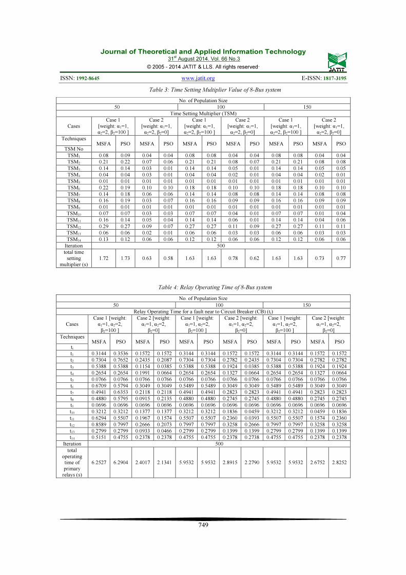
Table 3, Table 4 and Table 5 depicts the results of comparative studies between MSFA and PSO for Case 1, 8-Bus test system. These tables are considered as the best results among 30 runs for each population sizes and two cases of parameter variations with 500 iterations. Table 5 indicates the results for TSM values between different number of population size using MSFA and PSO techniques. For Case 1, when β2 is 100, both MSFA and PSO contributes total TSM’s with 1.63s. It can be observed that, the suitable population size is 100 compare to 50 and 150. This is due to lesser total TSM’s compare to 50 but for 150, it took more computation time to produce 1.63s. For Case 2, when β2 is not considered, the total TSM’s for PSO technique seems to be much lesser than MSFA when number of population is 50 and 100 but MSFA exhibits much lesser total TSM’s compare to PSO for 150 population size. By suitable selection of parameters values, Case 1 is considered the best choice in this study. This indicates that the selection of α1, α2 and β2 for Case 1 is correct in ensuring miscoordination is avoided.
Figure 3:8-Bus test system
a1 a2 a3 a4 a5
1.98772 8.57922 -0.46129 0.0364465 -0.0003199
Journal of Theoretical and Applied Information Technology 31
st August 2014. Vol. 66 No.3
© 2005 - 2014 JATIT & LLS. All rights reserved.
ISSN: 1992-8645 www.jatit.org E-ISSN: 1817-3195
749
Table 3: Time Setting Multiplier Value of 8-Bus system
No. of Population Size
50 100 150
Time Setting Multiplier (TSM)
Cases
Case 1
[weight: α1=1,
α2=2, β2=100 ]
Case 2
[weight: α1=1,
α2=2, β2=0]
Case 1
[weight: α1=1,
α2=2, β2=100 ]
Case 2
[weight: α1=1,
α2=2, β2=0]
Case 1
[weight: α1=1,
α2=2, β2=100 ]
Case 2
[weight: α1=1,
α2=2, β2=0]
Techniques MSFA PSO MSFA PSO MSFA PSO MSFA PSO MSFA PSO MSFA PSO
TSM No
TSM1 0.08 0.09 0.04 0.04 0.08 0.08 0.04 0.04 0.08 0.08 0.04 0.04
TSM2 0.21 0.22 0.07 0.06 0.21 0.21 0.08 0.07 0.21 0.21 0.08 0.08
TSM3 0.14 0.14 0.03 0.01 0.14 0.14 0.05 0.01 0.14 0.14 0.05 0.05
TSM4 0.04 0.04 0.03 0.01 0.04 0.04 0.02 0.01 0.04 0.04 0.02 0.01
TSM5 0.01 0.01 0.01 0.01 0.01 0.01 0.01 0.01 0.01 0.01 0.01 0.01
TSM6 0.22 0.19 0.10 0.10 0.18 0.18 0.10 0.10 0.18 0.18 0.10 0.10
TSM7 0.14 0.18 0.06 0.06 0.14 0.14 0.08 0.08 0.14 0.14 0.08 0.08
TSM8 0.16 0.19 0.03 0.07 0.16 0.16 0.09 0.09 0.16 0.16 0.09 0.09
TSM9 0.01 0.01 0.01 0.01 0.01 0.01 0.01 0.01 0.01 0.01 0.01 0.01
TSM10 0.07 0.07 0.03 0.03 0.07 0.07 0.04 0.01 0.07 0.07 0.01 0.04
TSM11 0.16 0.14 0.05 0.04 0.14 0.14 0.06 0.01 0.14 0.14 0.04 0.06
TSM12 0.29 0.27 0.09 0.07 0.27 0.27 0.11 0.09 0.27 0.27 0.11 0.11
TSM13 0.06 0.06 0.02 0.01 0.06 0.06 0.03 0.03 0.06 0.06 0.03 0.03
TSM14 0.13 0.12 0.06 0.06 0.12 0.12 0.06 0.06 0.12 0.12 0.06 0.06
Iteration 500
total time
setting
multiplier (s)
1.72 1.73 0.63 0.58 1.63 1.63 0.78 0.62 1.63 1.63 0.73 0.77
Table 4: Relay Operating Time of 8-Bus system
No. of Population Size
50 100 150
Relay Operating Time for a fault near to Circuit Breaker (CB) (ti)
Cases
Case 1 [weight:
α1=1, α2=2,
β2=100 ]
Case 2 [weight:
α1=1, α2=2,
β2=0]
Case 1 [weight:
α1=1, α2=2,
β2=100 ]
Case 2 [weight:
α1=1, α2=2,
β2=0]
Case 1 [weight:
α1=1, α2=2,
β2=100 ]
Case 2 [weight:
α1=1, α2=2,
β2=0]
Techniques MSFA PSO MSFA PSO MSFA PSO MSFA PSO MSFA PSO MSFA PSO
ti
t1 0.3144 0.3536 0.1572 0.1572 0.3144 0.3144 0.1572 0.1572 0.3144 0.3144 0.1572 0.1572
t2 0.7304 0.7652 0.2435 0.2087 0.7304 0.7304 0.2782 0.2435 0.7304 0.7304 0.2782 0.2782
t3 0.5388 0.5388 0.1154 0.0385 0.5388 0.5388 0.1924 0.0385 0.5388 0.5388 0.1924 0.1924
t4 0.2654 0.2654 0.1991 0.0664 0.2654 0.2654 0.1327 0.0664 0.2654 0.2654 0.1327 0.0664
t5 0.0766 0.0766 0.0766 0.0766 0.0766 0.0766 0.0766 0.0766 0.0766 0.0766 0.0766 0.0766
t6 0.6709 0.5794 0.3049 0.3049 0.5489 0.5489 0.3049 0.3049 0.5489 0.5489 0.3049 0.3049
t7 0.4941 0.6353 0.2118 0.2118 0.4941 0.4941 0.2823 0.2823 0.4941 0.4941 0.2823 0.2823
t8 0.4880 0.5795 0.0915 0.2135 0.4880 0.4880 0.2745 0.2745 0.4880 0.4880 0.2745 0.2745
t9 0.0696 0.0696 0.0696 0.0696 0.0696 0.0696 0.0696 0.0696 0.0696 0.0696 0.0696 0.0696
t10 0.3212 0.3212 0.1377 0.1377 0.3212 0.3212 0.1836 0.0459 0.3212 0.3212 0.0459 0.1836
t11 0.6294 0.5507 0.1967 0.1574 0.5507 0.5507 0.2360 0.0393 0.5507 0.5507 0.1574 0.2360
t12 0.8589 0.7997 0.2666 0.2073 0.7997 0.7997 0.3258 0.2666 0.7997 0.7997 0.3258 0.3258
t13 0.2799 0.2799 0.0933 0.0466 0.2799 0.2799 0.1399 0.1399 0.2799 0.2799 0.1399 0.1399
t14 0.5151 0.4755 0.2378 0.2378 0.4755 0.4755 0.2378 0.2738 0.4755 0.4755 0.2378 0.2378
Iteration 500
total
operating
time of
primary
relays (s)
6.2527 6.2904 2.4017 2.1341 5.9532 5.9532 2.8915 2.2790 5.9532 5.9532 2.6752 2.8252

Journal of Theoretical and Applied Information Technology 31
st August 2014. Vol. 66 No.3
© 2005 - 2014 JATIT & LLS. All rights reserved.
ISSN: 1992-8645 www.jatit.org E-ISSN: 1817-3195
750
From Table 4, there are fourteen relays operating time, t1 to t14. It is discovered that in Case 1 for 100 and 150 population sizes, both MSFA and PSO consumes same total operating time of primary relays, i.e. 5.9532s whereas MSFA and PSO consumes 6.2527s and 6.2904s for 50 population size. Both total operating time of primary relay using MSFA and PSO technique for population size 100 and 150 have been reduced to 4.79% and 5.34% compare to 50 population sizes respectively. This implies that both MSFA and PSO consume lesser time for 100 and 150 population sizes.
However, it can be observed that the suitable population size is 100 compare to 150 due to execution time. It is also discovered that for Case 2, both MSFA and PSO consumes lesser time for 50, 100 and 150 population sizes. For 50 population size, MSFA consumes 2.4017s and PSO consumes 2.1341s. It can be seen also that there is slightly difference time for both techniques in 100 and 150 population sizes. The range of time is between 0.15s to 0.61s. The results obtained indicate that for 150 population size, MSFA consumes lesser time compare to PSO.
Table 5: Relay Coordination Time for each Relay Pairs of 8-Bus system
No. of Population Size
50 100 150
Relay Coordination Time for each relay pairs, ∆tpb
Cases
Case 1
[weight: α1=1,
α2=2, β2=100 ]
Case 2 [weight:
α1=1, α2=2,
β2=0]
Case 1 [weight:
α1=1, α2=2,
β2=100 ]
Case 2 [weight:
α1=1, α2=2,
β2=0]
Case 1 [weight:
α1=1, α2=2,
β2=100 ]
Case 2 [weight:
α1=1, α2=2,
β2=0]
Techniques MSF
A PSO MSFA PSO MSFA PSO MSFA PSO MSFA PSO MSFA PSO
∆tpb
** ∆t89 0 0 0 0 0 0 0 0 0 0 0 0
∆t87 0.252 0.487 -0.002 -0.124 0.252 0.252 -0.022 -0.022 0.252 0.252 -0.022 -0.022
∆t27 0.003 0.292 -0.157 -0.122 0.003 0.003 -0.030 0.004 0.003 0.003 -0.030 -0.030
∆t21 0.067 0.182 -0.044 -0.009 0.067 0.067 -0.079 -0.044 0.067 0.067 -0.079 -0.079
∆t32 0.037 0.084 -0.189 -0.159 0.037 0.037 -0.220 -0.112 0.037 0.037 -0.220 -0.220
∆t43 0.045 0.045 -0.446 -0.415 0.045 0.045 -0.278 -0.415 0.045 0.045 -0.278 -0.212
∆t54 0.065 0.065 -0.070 -0.341 0.065 0.065 -0.205 -0.341 0.065 0.065 -0.205 -0.341
** ∆t65 0 0 0 0 0 0 0 0 0 0 0 0
∆t6,14 0.354 0.336 -0.047 -0.047 0.367 0.367 -0.047 -0.047 0.367 0.367 -0.047 -0.047
∆t14,1 0.318 0.512 -0.021 -0.021 0.357 0.357 -0.021 -0.021 0.357 0.357 -0.021 -0.021
** ∆t14,9 0 0 0 0 0 0 0 0 0 0 0 0
∆t16 0.203 0.038 -0.140 -0.140 0.036 0.036 -0.140 -0.140 0.036 0.036 -0.140 -0.140
∆t9,10 0.027 0.027 -0.256 -0.256 0.027 0.027 -0.185 -0.398 0.027 0.027 -0.398 -0.185
∆t10,11 0.115 0.011 -0.276 -0.328 0.011 0.011 -0.269 -0.393 0.011 0.011 -0.236 -0.269
∆t11,12 0.009 0.016 -0.274 -0.306 0.016 0.016 -0.242 -0.117 0.016 0.016 -0.163 -0.242
∆t12,14 0.156 0.107 -0.013 0.046 0.107 0.107 -0.072 -0.013 0.107 0.107 -0.072 -0.072
∆t12,13 0.180 0.239 -0.186 -0.367 0.239 0.239 -0.006 0.052 0.239 0.239 -0.006 -0.006
∆t13,8 0.021 0.152 -0.361 -0.139 0.021 0.021 -0.145 -0.145 0.021 0.021 -0.145 -0.145
** ∆t75 0 0 0 0 0 0 0 0 0 0 0 0
∆t7,13 0.613 0.472 -0.109 -0.306 0.613 0.613 0.071 0.071 0.613 0.613 0.071 0.071
Iteration 500
Computati
on
time (s)
126.3
3
123.6
1
142.94
9
174.77
7
217.89
7
224.43
6
288.71
4
269.44
5
359.37
1
370.09
0
383.57
5
450.65
6
Objective
Function
(s)
5.102 5.634 1.857 2.257 4.712 4.712 1.479 1.886 4.712 4.712 1.568 1.548
Table 5 indicates 20 relay pairs for 50, 100 and 150 population sizes with computation time and objective function for both MSFA and PSO techniques as well as two cases. For Case 1, the objective function for both MSFA and PSO with 100 population size is considered as the best results, i.e. 4.712s compare to 50 and 150 population sizes.
This is because 100 population sizes contribute less execution time. MSFA technique reaches global optimum after 275 iterations while PSO reach global optimum after 332 iterations. This shows that results by PSO technique reveal poor convergence compare to MSFA. In terms of computation time, MSFA exhibits 217.8976s which is 3% faster than PSO.

Journal of Theoretical and Applied Information Technology 31
st August 2014. Vol. 66 No.3
© 2005 - 2014 JATIT & LLS. All rights reserved.
ISSN: 1992-8645 www.jatit.org E-ISSN: 1817-3195
751
The convergence curves for each method with 100 population size can be illustrated in Fig. 4.
It can also be seen that from Table 5, some
values of ∆tpb are zero. For instance, the coordination time between relays 6 and 5 does not require coordination time as marked (**) in the table. This is due to relay 6 which is associated to a generator-transformer bus. In such case, coordination study is unnecessary [10]. Other
primary relays with ∆tpb equal to zero are also linked to generator-transformer buses such as relays 8 and 9, relays 14 and 9 and relays 7 and 5.
Figure 4: Convergence of MSFA and PSO for Case 1 with 100 population size 8-Bus test system
Case 2: Nine-Bus Test System
This case considers 9-Bus System which consists of 9 buses, 6 lines, 3 generators, 3 transformers and 12 overcurrent relays. The single line diagram of the test system is shown in Figure 5. The information on pickup current settings for the 12 relays can be found in [37]. For phase protection, the pickup current is set 1.5 times maximum load current.
Figure 5:9-Bus test system
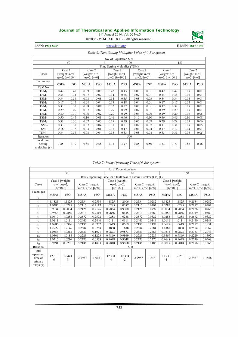
Table 6, Table 7 and Table 8 depicts the results of comparative studies between MSFA and PSO for Case 2, 9-Bus test system. These tables are considered as the best results among 30 runs for each population sizes and two cases of parameter variations with 500 iterations.
Table 6 indicates the results for TSM values between different number of population size using MSFA and PSO techniques. For Case 1, β2 is 100, MSFA contributes total TSM’s with 3.73s compare to PSO with 3.77s. It can be observed that, the suitable population size is 100 compare to 50 and 150. This is due to lesser total TSM’s compare to 50 but for 150, it took more computation time to produce 3.73s. For Case 2, when β2 is not considered, the total TSM’s for PSO technique seems to be lesser when number of population is increased from 50 to 150 but MSFA exhibits same total TSM’s which is 0.85s.
From Table 7, there are twelve relays operating time, t1 to t12. It is discovered that in Case 1 for 150 population size, both MSFA and PSO consumes same total operating time of primary relays, i.e. 12.2314s while PSO consumes 12.3742s and MSFA consumes 12.2314s for 100 population size. As for 50 population size, both MSFA and PSO consume 12.6196s and 12.4439s. This implies that both MSFA and PSO consume lesser time for 100 and 150 population sizes.
It is also discovered that for Case 2, MSFA consumes more total operating time of relays for 50, 100 and 150 population sizes compare to PSO technique.
0 50 100 150 200 250 300 350 400 450 5000
0.5
1
1.5
2
2.5
3x 10
5
Iteration
Ob
jec
tiv
e F
un
cti
on
, O
f
MSFA
PSO
Journal of Theoretical and Applied Information Technology 31
st August 2014. Vol. 66 No.3
© 2005 - 2014 JATIT & LLS. All rights reserved.
ISSN: 1992-8645 www.jatit.org E-ISSN: 1817-3195
752
Table 6: Time Setting Multiplier Value of 9-Bus system
No. of Population Size
50 100 150
Time Setting Multiplier (TSM)
Cases
Case 1
[weight: α1=1,
α2=2, β2=100 ]
Case 2
[weight: α1=1,
α2=2, β2=0]
Case 1
[weight: α1=1,
α2=2, β2=100 ]
Case 2
[weight: α1=1,
α2=2, β2=0]
Case 1
[weight: α1=1,
α2=2, β2=100 ]
Case 2
[weight: α1=1,
α2=2, β2=0]
Techniques MSFA PSO MSFA PSO MSFA PSO MSFA PSO MSFA PSO MSFA PSO
TSM No
TSM1 0.42 0.42 0.09 0.09 0.42 0.43 0.09 0.01 0.42 0.42 0.09 0.01
TSM2 0.34 0.34 0.07 0.07 0.34 0.35 0.07 0.01 0.34 0.34 0.07 0.01
TSM3 0.34 0.34 0.08 0.08 0.34 0.35 0.08 0.03 0.34 0.34 0.08 0.01
TSM4 0.17 0.17 0.04 0.04 0.17 0.18 0.04 0.01 0.17 0.17 0.04 0.01
TSM5 0.33 0.32 0.08 0.08 0.32 0.32 0.08 0.01 0.32 0.32 0.08 0.01
TSM6 0.29 0.29 0.07 0.07 0.29 0.29 0.07 0.01 0.29 0.29 0.07 0.01
TSM7 0.30 0.30 0.06 0.02 0.29 0.29 0.06 0.06 0.29 0.29 0.06 0.05
TSM8 0.50 0.47 0.10 0.01 0.46 0.46 0.10 0.10 0.46 0.46 0.10 0.08
TSM9 0.31 0.30 0.07 0.03 0.29 0.29 0.07 0.07 0.29 0.29 0.07 0.06
TSM10 0.33 0.32 0.07 0.04 0.31 0.31 0.07 0.07 0.31 0.31 0.07 0.05
TSM11 0.18 0.18 0.04 0.01 0.17 0.17 0.04 0.04 0.17 0.17 0.04 0.01
TSM12 0.34 0.34 0.08 0.04 0.33 0.33 0.08 0.08 0.33 0.33 0.08 0.05
Iteration 500
total time
setting
multiplier (s)
3.85 3.79 0.85 0.58 3.73 3.77 0.85 0.50 3.73 3.73 0.85 0.36
Table 7: Relay Operating Time of 9-Bus system
No. of Population Size
50 100 150
Relay Operating Time for a fault near to Circuit Breaker (CB) (ti)
Cases
Case 1 [weight:
α1=1, α2=2,
β2=100 ]
Case 2 [weight:
α1=1, α2=2, β2=0]
Case 1 [weight:
α1=1, α2=2,
β2=100 ]
Case 2 [weight:
α1=1, α2=2, β2=0]
Case 1 [weight:
α1=1, α2=2,
β2=100 ]
Case 2 [weight:
α1=1, α2=2, β2=0]
Technique MSFA PSO MSFA PSO MSFA PSO MSFA PSO MSFA PSO MSFA PSO
ti
t1 1.1825 1.1825 0.2534 0.2534 1.1825 1.2106 0.2534 0.0282 1.1825 1.1825 0.2534 0.0282
t2 1.0285 1.0285 0.2117 0.2117 1.0285 1.0587 0.2117 0.0302 1.0285 1.0285 0.2117 0.0302
t3 0.9034 0.9034 0.2126 0.2126 0.9034 0.9300 0.2126 0.0797 0.9034 0.9034 0.2126 0.0266
t4 0.9856 0.9856 0.2319 0.2319 0.9856 1.0435 0.2319 0.0580 0.9856 0.9856 0.2319 0.0580
t5 1.0610 1.0288 0.2572 0.2572 1.0288 1.0288 0.2572 0.0322 1.0288 1.0288 0.2572 0.0322
t6 1.0111 1.0111 0.2440 0.2440 1.0111 1.0111 0.2440 0.0349 1.0111 1.0111 0.2440 0.0349
t7 1.0986 1.0986 0.2197 0.0732 1.0619 1.0619 0.2197 0.2197 1.0619 1.0619 0.2197 0.1831
t8 1.2922 1.2146 0.2584 0.0258 1.1888 1.1888 0.2584 0.2584 1.1888 1.1888 0.2584 0.2067
t9 1.0554 1.0213 0.2383 0.1021 0.9873 0.9873 0.2383 0.2383 0.9873 0.9873 0.2383 0.2043
t10 1.0506 1.0188 0.2229 0.1273 0.9869 0.9869 0.2229 0.2229 0.9869 0.9869 0.2229 0.1592
t11 1.0216 1.0216 0.2270 0.0568 0.9648 0.9648 0.2270 0.2270 0.9648 0.9648 0.2270 0.0568
t12 0.9291 0.9291 0.2186 0.1093 0.9018 0.9018 0.2186 0.2186 0.9018 0.9018 0.2186 0.1366
Iteration 500
total
operating
time of
primary
relays (s)
12.619
6
12.443
9 2.7957 1.9053
12.231
4
12.374
2 2.7957 1.6481
12.231
4
12.231
4 2.7957 1.1568
Journal of Theoretical and Applied Information Technology 31
st August 2014. Vol. 66 No.3
© 2005 - 2014 JATIT & LLS. All rights reserved.
ISSN: 1992-8645 www.jatit.org E-ISSN: 1817-3195
753
Table 8: Relay Coordination Time for each Relay Pairs of 9-Bus system
No. of Population Size
50 100 150
Relay Coordination Time for each relay pairs, ∆tpb
Cases
Case 1 [weight:
α1=1, α2=2,
β2=100 ]
Case 2 [weight:
α1=1, α2=2,
β2=0]
Case 1 [weight:
α1=1, α2=2,
β2=100 ]
Case 2 [weight:
α1=1, α2=2,
β2=0]
Case 1 [weight:
α1=1, α2=2,
β2=100 ]
Case 2 [weight:
α1=1, α2=2,
β2=0]
Technique
s MSFA PSO MSFA PSO MSFA PSO MSFA PSO MSFA PSO MSFA PSO
∆tpb
∆t16 0.052 0.052 -0.258 -0.258 0.052 0.024 -0.258 -0.371 0.052 0.052 -0.258 -0.371
∆t21 0.014 0.014 -0.302 -0.302 0.014 0.018 -0.302 -0.395 0.014 0.014 -0.302 -0.395
∆t32 0.001 0.001 -0.344 -0.344 0.001 0.013 -0.344 -0.441 0.001 0.001 -0.344 -0.388
∆t43 0.019 0.019 -0.301 -0.301 0.019 0.003 -0.301 -0.334 0.019 0.019 -0.301 -0.416
∆t54 0.014 0.047 -0.310 -0.310 0.047 0.133 -0.310 -0.345 0.047 0.047 -0.310 -0.345
∆t65 0.053 0.009 -0.288 -0.288 0.009 0.009 -0.288 -0.390 0.009 0.009 -0.288 -0.390
∆t78 0.109 0.012 -0.298 -0.441 0.017 0.017 -0.298 -0.298 0.017 0.017 -0.298 -0.325
∆t89 0.027 0.050 -0.270 -0.259 0.020 0.020 -0.270 -0.270 0.020 0.020 -0.270 -0.273
∆t9,10 0.031 0.020 -0.323 -0.321 0.009 0.009 -0.323 -0.323 0.009 0.009 -0.323 -0.379
∆t10,11 0.024 0.056 -0.295 -0.445 0.006 0.006 -0.295 -0.295 0.006 0.006 -0.295 -0.477
∆t11,12 0.021 0.021 -0.287 -0.287 0.035 0.035 -0.287 -0.287 0.035 0.035 -0.287 -0.244
∆t12,7 0.037 0.037 -0.345 -0.418 0.019 0.019 -0.345 -0.345 0.019 0.019 -0.345 -0.308
∆t16 0.052 0.052 -0.258 -0.258 0.052 0.024 -0.258 -0.371 0.052 0.052 -0.258 -0.371
Iteration 500
Computa
tion
time (s)
80.361 93.601 87.889 86.641 153.45
0
164.18
1
152.52
0
139.23
8
249.59
3
238.96
4
255.70
3
257.26
6
Objective
Function
(s)
13.437 13.021 2.859 3.118 12.574 12.897 2.859 3.190 12.574 12.574 2.859 3.370
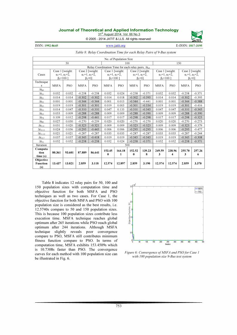
Table 8 indicates 12 relay pairs for 50, 100 and 150 population sizes with computation time and objective function for both MSFA and PSO techniques as well as two cases. For Case 1, the objective function for both MSFA and PSO with 100 population size is considered as the best results, i.e. 12.5740s compare to 50 and 150 population sizes. This is because 100 population sizes contribute less execution time. MSFA technique reaches global optimum after 265 iterations while PSO reach global optimum after 244 iterations. Although MSFA technique slightly reveals poor convergence compare to PSO, MSFA still contributes minimum fitness function compare to PSO. In terms of computation time, MSFA exhibits 153.4509s which is 10.7308s faster than PSO. The convergence curves for each method with 100 population size can be illustrated in Fig. 6.
Figure 6: Convergence of MSFA and PSO for Case 1 with 100 population size 9-Bus test system
0 50 100 150 200 250 300 350 400 450 5000
0.5
1
1.5
2
2.5
3
3.5x 10
5
Iteration
Ob
jec
tiv
e F
un
cti
on
, O
f
MSFA
PSO

Journal of Theoretical and Applied Information Technology 31
st August 2014. Vol. 66 No.3
© 2005 - 2014 JATIT & LLS. All rights reserved.
ISSN: 1992-8645 www.jatit.org E-ISSN: 1817-3195
754
5. CONCLUSION
This paper has presented the new method called as MSFA in solving directional overcurrent relay coordination problem. The effectiveness of MSFA was successfully implemented and tested on the 8-Bus test system and 9-Bus test system. From the results, it can be revealed that the proposed MSFA technique demonstrates significant results in 50, 100 and 150 population sizes for two cases to avoid miscoordination in relay operation as compared to PSO. As conclusion, the suitable population size for the two cases is 100 based on the less computation time and minimum fitness value for every simulation. In terms of computation time, MSFA is faster than PSO which is feasible to be implemented in a larger system.
ACKNOWLEDGEMENT
The authors would like to acknowledge The
Research Management Institute (RMI) UiTM, Shah
Alam and Ministry of Higher Education Malaysia
(MOHE) for the financial support of this research.
This research is supported by MOHE under the
Exploratory Research Grant Scheme (ERGS) with
project code: (File No: 600-RMI/ERGS
5/3(21/2013).
REFRENCES:
[1] Y. G. Painthakar and Bhide, S.R., "Fundamentals of Power System Protection," 5th ed: Prentice-Hall of India Private Limited, New Delhi, 2007.
[2] P.M. Anderson, “Power System Protection”, McGraw-Hill, New York, 1999.
[3] M.H. Hussain, I. Musirin, S.R.A. Rahim, and A.F. Abidin, “Computational Intelligence Based Technique in Optimal Overcurrent Relay Coordination: A Review”, The International
Journal of Engineering And Science (IJES), Vol.2, Issue 1, Jan 2013, pp. 01-09.
[4] M.H. Hussain, S.R.A. Rahim, I. Musirin, “Optimal Overcurrent Relay Coordination: A Review”, Procedia Engineering 53, 2013, pp. 332-336.
[5] S.A. Raza, T. Mahmood, S.B.A. Bukhari, M.K. Nawaz, “Application of Optimization Techniques in Overcurrent Relay Coordination – A Review”, World Applied Sciences Journal, vol 28, issue 2, 2013, pp. 259-265.
[6] V. S. Chaudhari, V.J. Upadhyay, "Coordination of overcurrent relay in interconnected power system protection," in National Conference on
Recent Trends in Engineering & Technology, 2011.
[7] A. J. Urdaneta, Nadira, R. and Perez, L., "Optimal coordination of directional overcurrent relay in interconnected power systems," IEEE Transactions on Power
Delivery, vol. 3, 1988, pp. 903-911.
[8] C. W. So, K.K. Li, K.T. Lai, K.Y. Fung, "Application of genetic algorithm for overcurrent relay coordination," in IEEE
Conference Developments in Power System
Protection, 1997, pp. 66-69.
[9] C. W. So, K.K. Li, "Overcurrent relay coordination by evolutionary programming," Electric Power Systems Research, vol. 53, 2000, pp. 83-90.
[10] F. Razavi, Abyaneh, H.A., Al-Dabbagh, M., Mohammadi, R., Torkaman, H. , "A new comprehensive genetic algorithm method for optimal overcurrent relays coordination " Electric Power Systems Research, vol. 78, 2008, pp. 713-720.
[11] D.P. Kothari, “Power System Optimization”, 2
nd National Conference on Computational
Intelligence and Signal Processing (CISP), 2012, pp. 18-21.
[12] J. Senthilnath, S.N. Omkar and V. Mani, “Clustering using Firefly Algorithm: Performance Study”, Swarm and Evolutionary
Computation, vol.1, 2011, pp. 164-171. [13] H. H. Zeineldin, E.F. El-Saadany, M.M.A.
Salama, "Optimal coordination of overcurrent relays using a modified particle swarm optimization," Electric Power Systems
Research, vol. 76, pp. 988-995, 2006. [14] M. M. Mohamed, Said, F.M., Nehad, E.E., "A
modified particle swarm optimizer for the coordination of directional overcurrent relays," IEEE Transactions on Power Delivery, vol. 22, 2007, pp. 1400-1410.
[15] M.H. Hussain, I. Musirin, S.R.A. Rahim, A.F. Abidin, A. Azmi, “Optimal Overcurrent Relay Coordination Using Particle Swarm Optimization”, 2013 International Conference
on Electrical, Control and Computer
Engineering, (InECCE 2013), 2013, pp.42-47. [16] A. Kordon and A.K. Kordon, “Swarm
Intelligence: The Benefits of Swarms”, Springer-Verlag Berlin Heidelberg, Applying
Computational Intelligence, pp. 145-174, 2010. [17] D. Uthitsunthorn, Pao-La-Or, P.,
Kulworawanichpong, T. , "Optimal overcurrent relay coordination using artificial bees colony algorithm " in ECTI-CON 2011 - 8th Electrical

Journal of Theoretical and Applied Information Technology 31
st August 2014. Vol. 66 No.3
© 2005 - 2014 JATIT & LLS. All rights reserved.
ISSN: 1992-8645 www.jatit.org E-ISSN: 1817-3195
755
Engineering/ Electronics, Computer,
Telecommunications and Information
Technology (ECTI) Association of Thailand -
Conference 2011, 2011, pp. 901-904. [18] M.El-Mesallamy, W. El-Khattam, A. Hassan,
H. Talaat, “Coordination of directional overcurrent relays using Artificial Bees Colony”, 22nd International Conference and
Exhibition on Electricity Distribution (CIRED
2013, 2013, pp. 1-4. [19] V. Rashtchi, Gholinezhad, J., Farhang, P. ,
"Optimal coordination of overcurrent relays using Honey Bee Algorithm " in 2010
International Congress on Ultra Modern
Telecommunications and Control Systems and
Workshops, ICUMT 2010 2010, pp. 401-405. [20] A.H. Gandomi, X.S. Yang, A.H. Alavi, “Mixed
variable structural optimization using Firefly Algorithm”, Journal Computer and Structures, vol. 89, 2011, pp. 2325-2336.
[21] S.L. Tilahun, H.C. Ong, “Modified Firefly Algorithm”, Journal of Applied Mathematics, Hindawi Publishing Corporation, vol. 2012, pp. 1-12.
[22] S.K. Pal, C.S. Rai, A.P. Singh, “Comparative Study of Firefly Algorithm and Particle Swarm Optimization for Noisy Non-Linear Optimization Problems”, International Journal
Intelligent Systems and Applications, 2012, pp. 50-57.
[23] H. Zang, S. Zhang and K. Hapeshi, “A Review of Nature-Inspired Algorithms”, Journal of
Bionic Engineering, vol.7, supplement, 2010, pp. S232-S237.
[24] A. Mahari, H. Seyedi, “An analytic approach for optimal coordination of overcurrent relays”, IET Generation, Transmission & Distribution, Vol.7, Issue 7, 2013, pp. 674-680.
[25] H. A. Abyaneh, M. Al-Dabbagh, H.K. Karegar, S.H,H Sadeghi and R.A.H. Khan, "A new optimal approach for coordination overcurrent relay s in interconnected power systems," IEEE
Transactions on Power Delivery, vol. 18, 2003, pp. 430-435.
[26] M.H. Hussain, I. Musirin, A.F. Abidin, S.R.A. Rahim, “Directional Overcurrent Relay Coordination Using Modified Swarm Firefly Algorithm Considering the Effect of Population Size”, 2014 IEEE 8
th International
Power Engineering and Optimization
Conference (PEOCO 2014), 2014, pp. 591-596.
[27] R. Mohammadi, Abyaneh, H.A., Razavi, F., Al-Dabbagh, M., Sadeghi, S.H.H., "Optimal relays coordination efficient method in
interconnected power systems," Journal of
Electrical Engineering, 2010, vol. 61, pp. 75-83.
[28] Amraee, T., “Coordination of Directional Overcurrent Relays Using Seeker Algorithm”, IEEE Transactions on Power Delivery, 2012, vol.27, pp. 1415-1422.
[29] J. Kennedy and R. Eberhart, “Particle Swarm Optimization”, Proceedings of IEEE
International Conference on Neural Networks
(ICNN’95) Perth, Australia: IEEE Press; Vol. IV, 1995, pp. 1942-1948.
[30] B. Yang and Q. Zhang, “Frame Sizing and
Topological Optimization Using a Modified
Particle Swarm Algorithm”, Second WRI Global Congress, Intelligent Systems (GCIS), 2010, pp. 43-46.
[31] F. Van Den Bergh and A.P. Engelbrecht, “A New Locally Convergent Particle Swarm Optimizer”, 2002 IEEE International Conference On Systems, Man and Cybernetics”, Vol.3, 2002.
[32] Z. Wen and L. Yutian, “Reactive power optimization based on PSO in practical power system”, IEEE Power Engineering Society
General Meeting, Vol.1, pp. 239-243, June 2004.
[33] Z. Pengjun, L. Sanyang and C. Guo, “Modified Particle Swarm Optimization for Optimization Problems”, Journal of Theoritical and Applied Information Technology, Vol. 46, No. 2, 2012, pp. 610-614.
[34] F.V.D. Bergh, “An analysis of particle swarm optimizer”, Ph. D. dissertation, University Pretoria, Pretoria, South Africa, 2001.
[35] L.Y. Wong, M.H. Sulaiman, S.R.A. Rahim & O. Aliman, “Optimal Distributed Generation Placement using Hybrid Genetic-Particle Swarm Optimization”, International Review of
Electrical Engineering (IREE), Vol.3, Issue 6, June 2011.
[36] Y. Shi and R. Eberhart, “Empirical study of particle swarm optimization”, Proceedings of
the 1999 congress on the Evolutionary
Computation, Vol.3, Washington DC, July 1999.
[37] S. Niyomphant, T. Kulworawanichpong, U. Leeton and N. Chomnawang, “Application of Linear Programming for Optimal Coordination of Directional Over-current Relays”, " in ECTI-CON 2012 - 9th Electrical Engineering/
Electronics, Computer, Telecommunications
and Information Technology (ECTI)
Association of Thailand - Conference 2012,
2012, pp. 978-981.