1985: A 15,000-ton Atmospheric Ammonia Storage Tank Roof ...
13
A 15,000-ton Atmospheric Ammonia Storage Tank Roof Rupture Safety devices for the tank failed to function after relatively trouble- free operation for 17 years. Their failure, repair and retrofitting are discussed. And criteria for protection at the time of fabrication are compared to the current criteria. Paul J. Badame Arcadian Corp., Geismar, LA 70734 Arcadian Corporation purchased Allied Corpo- ration's fertilizer business on June 4, 1984. Included in the purchase is a fertilizer com- plex located at Geismar, Louisiana which pro- duces anhydrous ammonia, nitric acid, and urea. The AN and urea are mixed to produce a 32% UAN solution or TIRANA). The Geismar site also includes a phosphate operation which produces sulfuric acid, phosphoric acid, superphosphoric acid (SPA), ammonium poly- phosphates (11-37-0 solution) or POLY-N^ and diammonium phosphate (DAP). The plant, which is located on the Mississippi River about 20 miles south of Baton Rouge, Louisiana, includes a 1,000 TPD M. W. Kellogg ammonia plant and a 15,000 ton atmospheric ammonia storage tank. The plant is not located in a populated area. There are very few residences in a two-mile area. The ammonia storage tank is located about 700 feet from the nearest public road. The ammonia storage tank experienced a cata- strophic failure of the wall to roof weld which extended approximately two-thirds of the tank circumference. Separation of the wall from the roof compression ring allowed significant wall flexure during failure. This exposed the tank to the risk of failure be- low the liquid leyel. The failed weld showed an extreme lack of penetration. Severe corrosion due to sur- rounding atmospheric conditions during the six days required for emptying and entry ob- literated the fracture surface of failure artifacts. The failure analysis, therefore, relied heavily on analytical analysis. An analog pressure recording at the time of failure showed an overpressure of unknown degree, as the pressure indication was off scale. Careful disassembly of the relief valves showed no malfunctions. Computer en- hancement of analog pressure recordings at the time of failure and at à subsequent plant outage exhibited identical pressure rise rates. This suggests that no abnormal pro^- cess or operational problems contributed to the failure. This rate of pressure rise, the vapor space ^at the time of failure and relief system capacity versus pressure characteris- tics determined by post failure testing show- ed the maximum obtained pressure to be 0.53 psig. Relative to the relief system set pressure of 0.5 psig, this is within normal overpressure limits. The weld was designed such that lack of pene- tration produced a bending moment which greatly increased stress. Stress analysis shows that the weld was highly stressed and was well above the fatigue endurance limit. The crack advanced in the weld by a low cycle high stress fatigue mechanism until sudden fracture. Upon breaking through the weld the crack propagated around the circumference in a sudden failure. 158
Transcript of 1985: A 15,000-ton Atmospheric Ammonia Storage Tank Roof ...
A 15,000-ton AtmosphericAmmonia Storage Tank
Roof Rupture
Safety devices for the tank failed to function after relatively trouble-free operation for 17 years. Their failure, repair and retrofitting arediscussed. And criteria for protection at the time of fabrication arecompared to the current criteria.
Paul J. BadameArcadian Corp., Geismar, LA 70734
Arcadian Corporation purchased Allied Corpo-ration's fertilizer business on June 4, 1984.Included in the purchase is a fertilizer com-plex located at Geismar, Louisiana which pro-duces anhydrous ammonia, nitric acid, andurea. The AN and urea are mixed to produce a32% UAN solution or TIRANA). The Geismarsite also includes a phosphate operationwhich produces sulfuric acid, phosphoric acid,superphosphoric acid (SPA), ammonium poly-phosphates (11-37-0 solution) or POLY-N^and diammonium phosphate (DAP).
The plant, which is located on theMississippi River about 20 miles south ofBaton Rouge, Louisiana, includes a 1,000 TPDM. W. Kellogg ammonia plant and a 15,000 tonatmospheric ammonia storage tank. The plantis not located in a populated area. Thereare very few residences in a two-mile area.The ammonia storage tank is located about 700feet from the nearest public road.
The ammonia storage tank experienced a cata-strophic failure of the wall to roof weldwhich extended approximately two-thirds ofthe tank circumference. Separation of thewall from the roof compression ring allowedsignificant wall flexure during failure. Thisexposed the tank to the risk of failure be-low the liquid leyel.
The failed weld showed an extreme lack ofpenetration. Severe corrosion due to sur-rounding atmospheric conditions during the
six days required for emptying and entry ob-literated the fracture surface of failureartifacts. The failure analysis, therefore,relied heavily on analytical analysis.
An analog pressure recording at the time offailure showed an overpressure of unknowndegree, as the pressure indication was offscale. Careful disassembly of the reliefvalves showed no malfunctions. Computer en-hancement of analog pressure recordings atthe time of failure and at à subsequent plantoutage exhibited identical pressure riserates. This suggests that no abnormal pro -cess or operational problems contributed tothe failure. This rate of pressure rise, thevapor space at the time of failure and reliefsystem capacity versus pressure characteris-tics determined by post failure testing show-ed the maximum obtained pressure to be 0.53psig. Relative to the relief system setpressure of 0.5 psig, this is within normaloverpressure limits.
The weld was designed such that lack of pene-tration produced a bending moment whichgreatly increased stress. Stress analysisshows that the weld was highly stressed andwas well above the fatigue endurance limit.The crack advanced in the weld by a low cyclehigh stress fatigue mechanism until suddenfracture. Upon breaking through the weld thecrack propagated around the circumference ina sudden failure.
158
The Initial indication of overpressureled to a hazard and operability analysis todetermine various failures and events whichcould lead to overpressurization. Numerousqualitative fault trees were constructed. Allpossibilities were discounted as contributingto the failure, however, the relative easewith which the tank could be overpressuredwas of concern. As a result, Arcadian de-signed and installed a relief system to ac-commodate worst case overpressure scenarios.
This paper reviews the design of the tank,tank history, the inspection procedures, re-pair procedures, testing procedures, insula-tion repair, schedule for the rehabilitationof the tank, and improvements made to thetank protection system prior to returning thetank to service. Also included are the find-ings of the root cause failure analysis.
INTRODUCTION
Events Leading to the Failure
In the early morning of October 2, 1984, vi-bration levels on the ammonia plant synthesisgas compressor (103-J) increased to the dangercondition. The unit was being closely moni-tored due to a problem with the 103-J lowpressure case. At approximately 5:00 AM the103-J was tripped in order to prevent damageto the 103-J and action was taken to shutdown the ammonia plant.
Operations attempted to start up the standbyrefrigeration compressor for the ammoniastorage tank normally in service when theammonia plant is down. Due to an oil leakand low oil level, the unit could not bestarted. After several hours the oil problemwas corrected and the compressor was put inservice.
Description of the Failure
When the ammonia plant was shut down the vaporpressure of the ammonia storage tank increaseduntil the relief valve opened and continued toincrease until the pressure recorder was offscale. The increasing vapor pressure was aresult of the shutdown of the refrigerationcompressor (105-J). This increase occurredover slightly more than an hour.
At approximately 6:05 AM the ammonia tank ex-perienced a catastrophic failure of the roofto wall welded joint. The fracture at thewelded seam encompassed approximately two-thirds of the circumference. When the weldfailed the walls and the roof flexed. A sec-
tion of the roof caught on the tension ring,during the flexing, forming two large adja-cent openings.
At the time of the failure, the ammoniastorage tank contained 9,200 tons of anhy-drous ammonia.
At approximately 6:30 AM, requests weremade to obtain barges to transfer the 9,200,tons of ammonia. The first barge arrived inless than three hours. The transfer of ammo-nia from the ammonia storage tank to thefirst barge was started and.the loading of800 tons was completed twelve hours from thetime the barges were requested. At 8:45 AMOctober 3, 1984, three additional bargesarrived and at 11:10 AM the loading of thefirst of the three ammonia barges was started.At 6:10 AM on October 5, 1984, (72 hours afterthe failure) the ammonia storage tank wasempty.
The immediate response by the Arcadianshift supervision and operators, guard cap-tain and guards, traffic personnel, and allother site personnel helped to "de-fuse" apotentially very hazardous situation. Therewere no injuries, nor interruption of otheroperations at the site and no evacuations.All local, state and federal agencies plusneighboring plants were notified of the inci-dent. Local law enforcement agencies andLouisiana state police set up roadblocks as asafety precaution. Site environmental per-sonnel monitored the perimeter and severalmiles down wind to determine ammonia concen-trations. The Baton Rouge press and three TVstations reported the incident without nega-tive comment.
Ammonia concentrations down v»j.nd of thetank were as follows:
900 ft. from tank - ranged from 400 to150 ppm depending on wind direction (firstsix hours).
0.7 miles from tank - ranged from 200ppm to 0 (first three hours).
5 miles from tank - ranged from 10 ppmto 0 (first three hours).
After emptying the ammonia storage tank,decommissioning activities commenced in orderto enter the tank and survey for extent ofdamages and prepare to repair tank. Duringthis period ammonia piping was revised to by-pass the ammonia storage tank. Tank carswere obtained to serve as surge capacity in
159
order to operate the ammonia plant without thestorage tank in service.
Operation of Ammonia Plant Without theAmmonia Storage Tank - The ammonia plant wasrestarted October 9, 1984, in approximatelyten hours and operated at full rates with allammonia product being distributed to urea,nitric acid, ammonium nitrate, POLY-N^ andDAP manufacture without the ammonia storagetank in service. Four rail cars were filledwith the excess during the period the tank wasout-of-service. (See Figure No. 1). Theammonia plant operated in this mode for twomonths while the ammonia storage tank was out-of-service.
TANK REHABILITATION
Tank Design
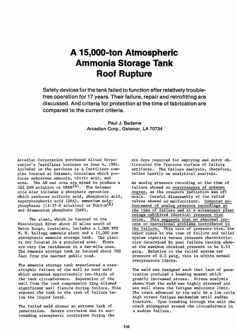
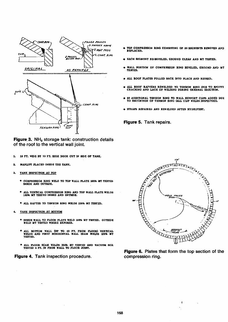
As shown in Figure No. 2, the 15,000.ton at-mospheric ammonia storage is 119 feet in dia-meter by 64 feet high, with a domed head ex-tending 15 feet 9 inches above the top courseof the tank. Figure No. 3 shows the construc-tion details of the roof to wall weld.
The tank was installed in 1966 by GATX as asub-contractor to the M. W. Kellogg Companyand has been in continuous service since 1967storing anhydrous ammonia at atmospheric pres-sure and -28OF temperature.
Inspection requirements were set forth in con-junction with "API Recommended Rules for De-sign and Construction of Large Welded, LowPressure Storage Tanks", American PetroleumInstitute Standard 620, 1963, and Appendix R -"Low Pressure Storage Tanks for RefrigeratedProducts", 1965. Certification of the install-ation was dated March 28, 1967 by GATX andApril 3, 1967 by a third party inspector (in-surance company). API Standard 620, 1963 wasthe design, materials, construction, workman-ship, inspection, and testing criterion forthe ammonia storage tank.
Tank History
An insulation failure in 1978 provided an op-portunity for tank inspection internally. Theinspection concentrated on the wall and floorwith particular emphasis on the welds. Allfloor internal welds and all wall-to-floorwelds both internal and external were 100%magnetic particle (MT) inspected. All wallinternal welds were visually inspected and25 percent were MT tested. In addition somewall welds were inspected with ultrasonics and
radiography. Some defects from original con-struction were noted. An engineering assess-ment using fracture mechanics indicated thewalls were probably structurally sound andacoustic emission testing was recommended forconfirmation. In 1979 the tank wall wasacoustic emission (A/E) tested by raisingliquid level to maximum operating level - alevel above that to which the tank had beensubjected in recent history. This liquidlevel stressed the walls allowing acousticemission testing. No growing defects weredetected and structural integrity of thewalls and wall-to-floor weld was confirmed.
In the 1978 inspection, the wall-to-roof weldwas not inspected because there was no knowncause for concern and inaccessibility pre-vented incidental discovery. The A/E testwas not designed to evaluate the subjectweld, again due to no known cause for con-cern. The weld was not stressed as is neces-sary for A/E testing and thus, incidentaldiscovery was prevented.
GATX Tank Division was purchased by BMT(Brown-Minneapolis Tank) in 1983; thus, BMTwas commissioned to inspect, repair and testtank before returning to service.
Tank Inspection
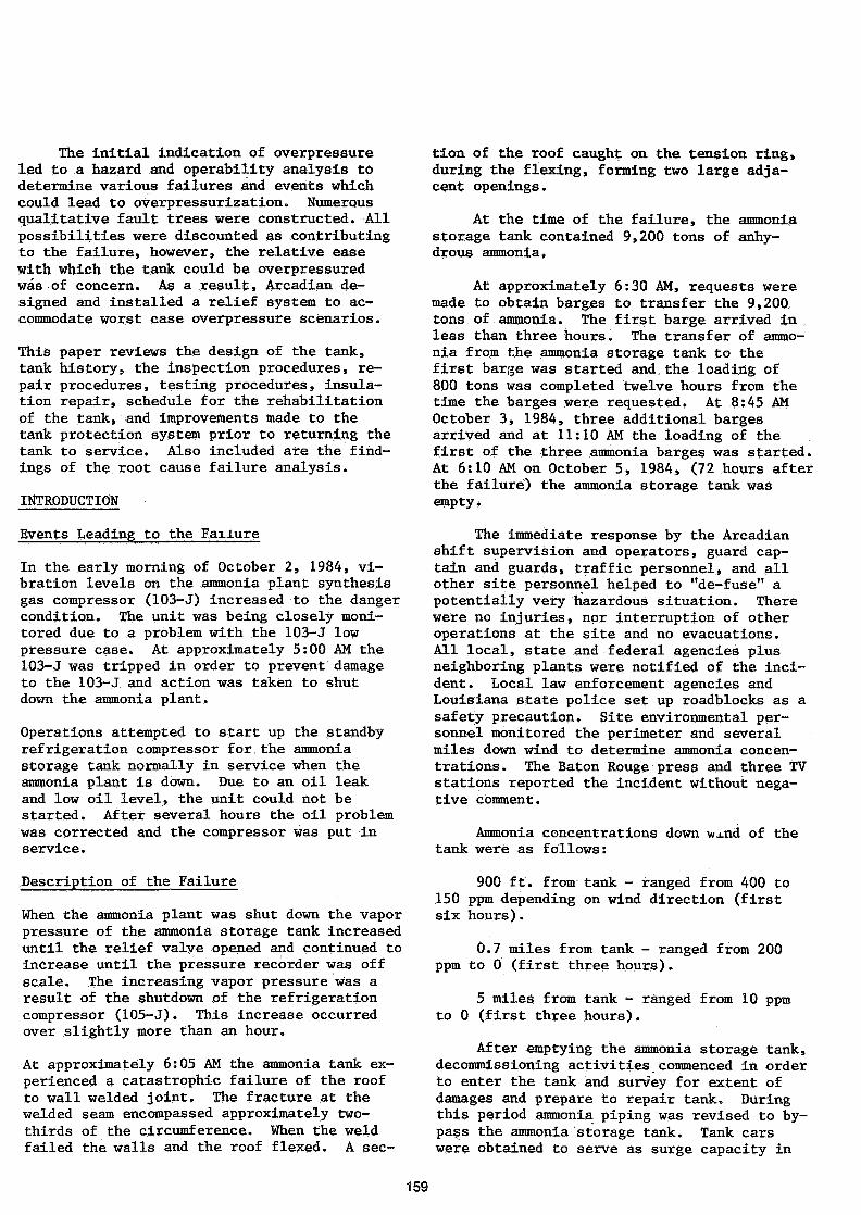
A 10 foot wide by 13 foot high door was cutin the side of the tank to facilitate the in-spection. A manlift was placed in the tankand used for the inspection and repair. Fig-ure Nc>. 4 summarizes the inspection proce-dure used to examine the welds at the top andbottom of the tank. The top compression ringweld to the top wall plate was inspected in-side and outside using the magnetic particletest (MT) procedure. All top wall and com-pression ring vertical welds were also MT in-spected. The inside wall to floor plate weldwas MT inspected its entire circumference.The first horizontal wall seam and all bottomwall vertical welds were MT, tested. Allfloor seam welds were tested using the vacuumbox technique.
Tank Repair
Scaffolds were erected at the top of the tankon the outside ana inside to make the re-pairs. Figure No. 5 summarizes the repairsthat were necessary. Figure No. 6 shows 50segments of the 12 inch wide by 90 inch longby three-fourth inch thick plates that formthe top section of the compression ring. Thefailure apparently started between plates #6
160
and #11 with the final weld failure occurringfrom plate #49 to plate #29. When the weldfailed the walls and 'roof flexed. A sectionof the roof caught on the tension ring, duringthe flexing, forming two large adjacent open-ings. All fifty of the plates were removedduring the repair. Fifteen of the plates weredamaged beyond repair and new plates were re-quired. All reused plates were air-gougedclean of weld metal, re-beveled, ground clean,and magnetic particle tested. The wall por-tion of the three-fourth inch compression ringwas beveled, ground, and MI tested. All roofplates were pulled back into place and reused.The tank wall had considerable distortion inthe plate #25 to #32 area and required thegreatest amount of time for refitting. Allroof rafters were rewelded (utilizing two weldpasses) to the tension ring due to spottycracking and lack of welding during originalerection. Approximately 20 additional tensionring to wall support clips were added due todistortion of the tension ring (all clip weldswere inspected).
Tank Testing
BMT, the tank vendor, recommended a hydro-static-pneumatic test which was performed.This test was certified by BMT and is based onAPI Standard 620, "Recommended Rules for De-sign and Construction of Large Welded, LowPressure Storage Tanks"., Appendix R, "LowPressure Storage Tanks for Refrigerated Pro-ducts", 7th Edition.
The tank was filled with water and pressuredwith nitrogen to 0.625 psig (17.3 inches ofwater). All relief-vacuum devices were check-ed and a "soap" test of all roof welds made.
Insulation Repair
During the failure, the three inch layer offoamed polyurethane insulation cracked andfailed in many places. In addition, all in-sulation was removed at the bottom of the tankin the area of the "straps". The straps actas anchors to fasten the tank to its founda-tion. Also, insulation was removed from thelower five feet of the roof for inspection andrepair purposes and around the top wall toweld clips to support scaffolding. All othercracked, wet or damaged insulation was re-moved .
The insulation repair by Solar Foam InsulationCompany consisted of preparing all metal sur-faces by sandblasting and priming, then foam-ing with polyurethane» After all the barespots of the tank were covered, an additional
one inch foam layer was applied to ensurethat all areas and cracks were covered. Thevapor barrier of a layer of butyl rubber andwhite reflecting urethane top coating werethen applied.
Schedule
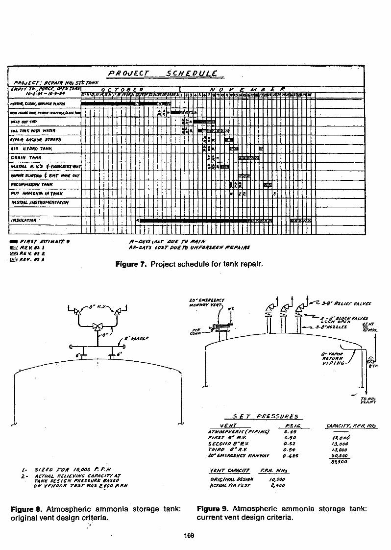
The Project Engineering Group at the plantwas responsible for the rehabilitation of thetank. Figure No. 7 shows project schedulefor all phases to return the tank to service.Total tine out of service for thé tank wasless tha-a two months.
Improvements to Tank Protection System
Immediately after the failure, it was notknown if the tank had been overpressured;thus, the existing tank protection system wasinvestigated. The original design criteriaprovided two eight-inch relief valves con-nected to a manifold. The manifold was con-nected to the tank by two six-inch nozzles.This design allowed only one eight-inch re-lief valve to be in service at any giventime. This configuration was such that it isdifficult to predict the relieving capacityof the system. A vendor testing this con-figuration estimated a pressure drop of 1.8psi would be required to obtain the reliefvalve capacity of 10,000 lbs./hr. with theabove configuration; thus, the pressure inthe storage tank would have to reach 1.8 psigto obtain full relieving capacity of the re-lief valve. The same vendor test using theabove configuration indicated a flow of 2,200lbs./hr. at the tank design pressure of 0.5psig. (Figure 8)
An outside consultant (Mr. C. Clay Haleof Huxtable-Hammond Engineering Company), whois recognized as an industry expert in ammo-nia storage tank design and protection sys-tems and has conducted numerous industry sur-veys, was retained to recommend the latestprotection system being utilized for atmos-pheric ammonia storage tanks. Also recommen-dations were obtained from the M. W. KolloggCompany and BMT. The consensus and calcula-tions as a result of the fault tree analysison minimum current protection is as follows :a pressure control vent, three eight-inchcombination relief—vacuum valves and a twentyinch emergency manway vent. This configura-tion is shown on Figure No. 9" along with thecapacities. The two six-inch relief valveconnections on the tank were removed and re-placed with three eight-inch relief valves,in addition to an atmospheric vent, plus atwenty-inch emergency manway vent which was
161
installed on an existing manhole.
FAILURE ANALYSIS FINDINGS
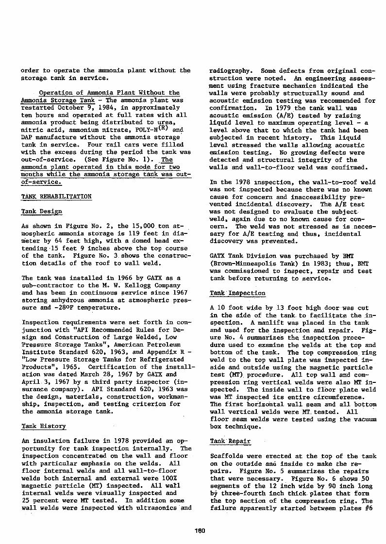
Samples of the fracture surface were re-moved for macroscopic, microscopic fracto-graphic and metallorgraphic evaluation. Thematerial of construction was ASTM A 201 B, asspecified, welded with E 7018 electrodes. Theroof to wall weldment was specified as 3/4",V-groove, full penetration with a 5/8" depthof penetration.
A visual inspection of the tank and exam-ination of three polished samples revealedlack of penetration and shallow fusion alongthe fractured weld. Sample #3 revealed anactual depth.of penetration of 0.20" to 0.25".Sample #2 revealed an average depth of pene-tration of 0.25". At the edge of the fracture,sample #1, depth of penetration was 0.50".The origin of the failure is believed to be inthe region of sample numbers 2 and 3. (Samplelocations are as marked on Figure No. 10.) Asa result of exposure to surrounding atmospher-ic conditions, the fracture surfaces wereseverely corroded. Microscopic features ofthe fractures were altered by the corrosion;,The fracture however was brittle in appear-ance. Micro-hardness measurements of the weldmetal, heat affected zone (HAZ) (at base), andbase metal ranged 150-190 (Vickers) corres-ponding to an estimated tensile strength ofthe HAZ (near surface) is due to quenchingduring solidification. Although this area isharder and stronger it is significantly more *brittle.
As previously stated the specificationsfor the roof to wall weldment call for a fullpenetration weld, single V—groove, securingthe 3/4" roof and wall plates. The roof platewas to be beveled to a 50° angle. Consideringthe difficulty of the location and the tight1/8" clearance between the roof and wall platethe weld as specified would be almost impossi-ble to make. The weld design prohibited afull penetration weld of appropriate depth andfusion. (See sketch No. 1 below.)
Stress Analysis of Roof to Wall Weld
Stress calculations for the roof to wallweld show that for a 0.20" - 0.25" depth ofpenetration the applied stress is 45.7 Ksi -73.6 Ksi at an ammonia tank vapor pressure of0.5 psig. If the roof to wall weld were thespecified 5/8" (0.625") the stress at 0.5 psipressure would be only 5.1 Ksi. Additionallyas the tank pressure increases, the stress in
reu.PCnSTDATtON
Sketch 1. Roof to wall weld design.
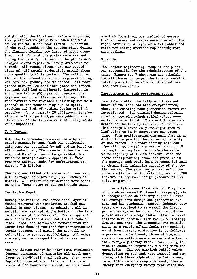
the roof to wall weld for a given weld pene-tration increases (see Plot No. 2 below).
Plot 2. Penetration, stress and pressure relation-ship.
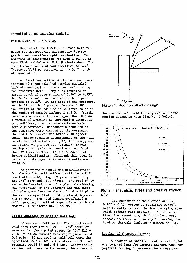
The reduction in weld cross section0.20" - 0.25" versus as specified 0.625",significantly reduces the load carrying areawhich reduces weld strength. At the sametime, the moment arm, which the load actsacross, is increased thereby increasing theload on the weld (reference sketch no. 3).
Results óf Physical Testing
A section of unfailed roof to wall joint'was removed from the ammonia storage tank forphysical testing to measure the stress re-
162
G =(U x C) / I
U-=MOMENT=r
C=C£MTROIO
I — MOMENT OF INERTIA
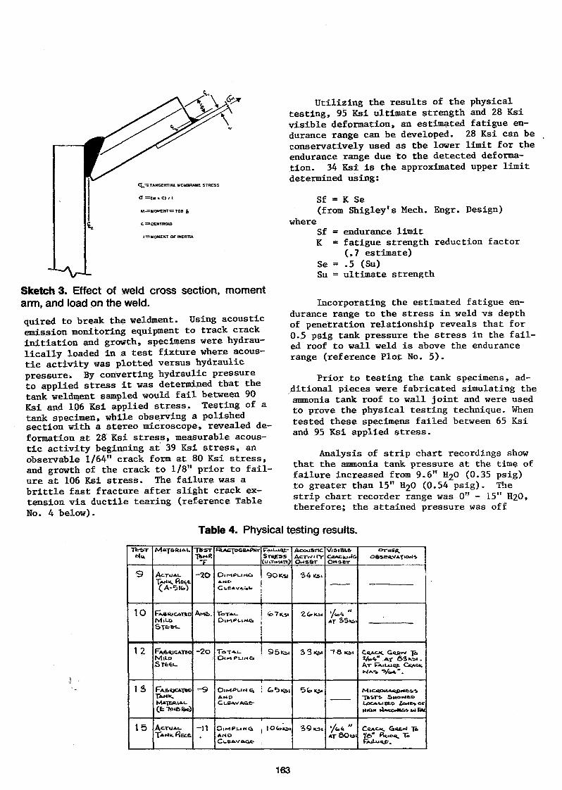
Utilizing the results of the physicaltesting, 95 Ksi ultimate strength and 28 Ksivisible deformation, an estimated fatigue en-durance range can be developed. 28 Ksi can beconservatively used as the lower limit for theendurance range due to the detected deforma-tion. 34 Ksi is the approximated upper limitdetermined using:
where
Sf = K Se(from Shigley's Mech. Engr. Design)
Sketch 3. Effect of weW cross section, momentarm, and load on the weld.
quired to break the weldment. Using acousticemission monitoring equipment to track crackinitiation and growth, specimens were hydrau-lically loaded in a test fixture where acous-tic activity was plotted versus hydraulicpressure. By converting hydraulic pressureto applied stress it was determined that thetank weldment sampled would fail between 90Ksi and 106 Ksi applied stress. Testing of atank specimen, while observing a polishedsection with a stereo microscope, revealed de-formation at 28 Ksi stress, measurable acous-tic activity beginning at 39 Ksi stress, anobservable 1/64" crack form at 80 Ksi stress,and growth of the crack to 1/8" prior to fail-ure at 106 Ksi stress. The failure was abrittle fast fracture after slight crack ex-tension via ductile tearing (reference TableNo. 4 below).
Sf = endurance limitK = fatigue strength reduction factor
(.7 estimate)Se = .5 (Su)Su = ultimate strength
Incorporating the estimated fatigue en-durance range to the stress in weld vs depthof penetration relationship reveals that for0.5 psig tank pressure the stress in the fail-ed roof to wall weld is above the endurancerange (reference Plot No. 5).
Prior to testing the tank specimens, ad-ditional pieces were fabricated simulating theammonia tank roof to wall joint and were usedto prove the physical testing technique. Whentested these specimens failed between 65 Ksiand 95 Ksi applied stress.
Analysis of strip chart recordings showthat the ammonia tank pressure at the time offailure increased from 9.6" H20 (0.35 psig)to greater than 15" 1 0 (0.54 psig). Thestrip chart recorder range was 0" - 15" H20,therefore; the attained pressure was off
Table 4. Physical testing results.
TfciT
Ha
10
12
la
15
MAT&ftlAU
AC.TUAI.T**«. Recfe
f-ABAICATtOMlU>
MlLOSTfctl-
ACTU
TfeSTM
-20
AMfc.
-20
-9
-11
Oii-iPi-i
C l-ÊA VA
9OKS1
TOT-.L
1 O Co 101
ACOUSTICAeTW'tY
34«.
39 KSI
VISIBLE-O«AC.K)>JOH SET
AT ÔOeii
oraen,
CltAC*. "Jo
AT
MlOOjaMA^pH&ï»-
ye"
163
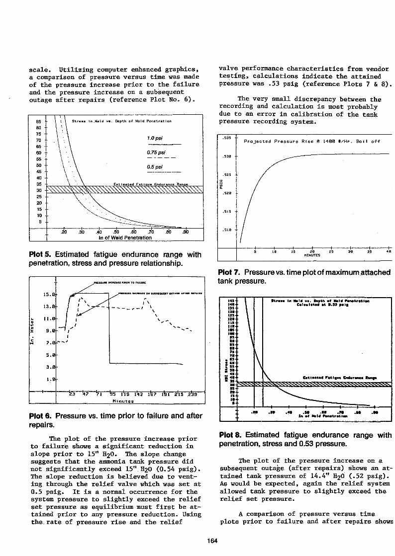
scale. Utilizing computer enhanced graphics,a comparison of pressure versus time was madeof the pressure increase prior to the failureand the pressure increase on a subsequentoutage after repairs (reference Plot No. 6).
85 •• 1 '. \ Stress In Held vs. Depth of Meld Penetration
80 -• \ '•
\ \70 - .\ ,65 •• \ .
.40 .50 .60 .70In of Weld Penetration
Plots. Estimated fatigue endurance range withpenetration, stress and pressure relationship.
Ma
ter
cM
-
15. B
13. B
1KB
3. B
7.0
5.0
3.0
I.B
PRESSURE t
/"•"•---:-//
(
23 '47 "71
MCREAttE PRIOR TO FAILURE
\
N -*. A
35 l'lS l'43 IS? 131 a'lS 333
Minutes
Plot 6. Pressure vs. time prior to failure and afterrepairs.
The plot of the pressure increase priorto failure shows a significant reduction inslope prior to 15" H2Û. The slope changesuggests that the ammonia tank pressure didnot significantly exceed 15" H£0 (0.54 psig).The slope reduction is believed due to vent-ing through the relief valve which was set at0.5 psig. It is a normal occurrence for thesystem pressure to slightly exceed the reliefset pressure as equilibrium must first be at-tained prior to any pressure reduction. Usingthe.rate of pressure rise and the relief
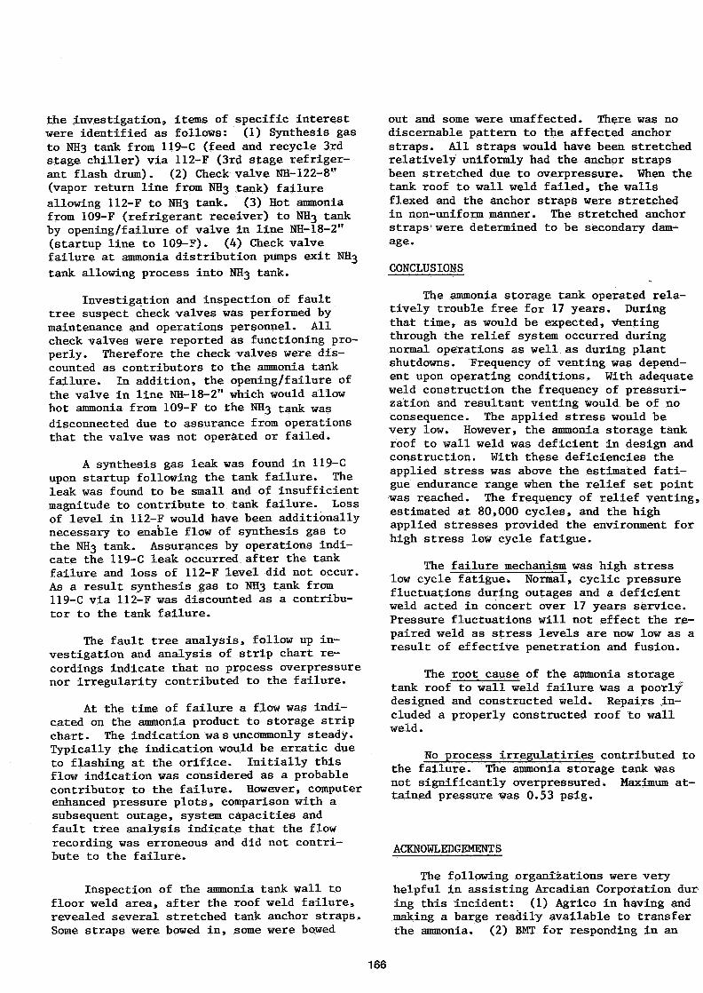
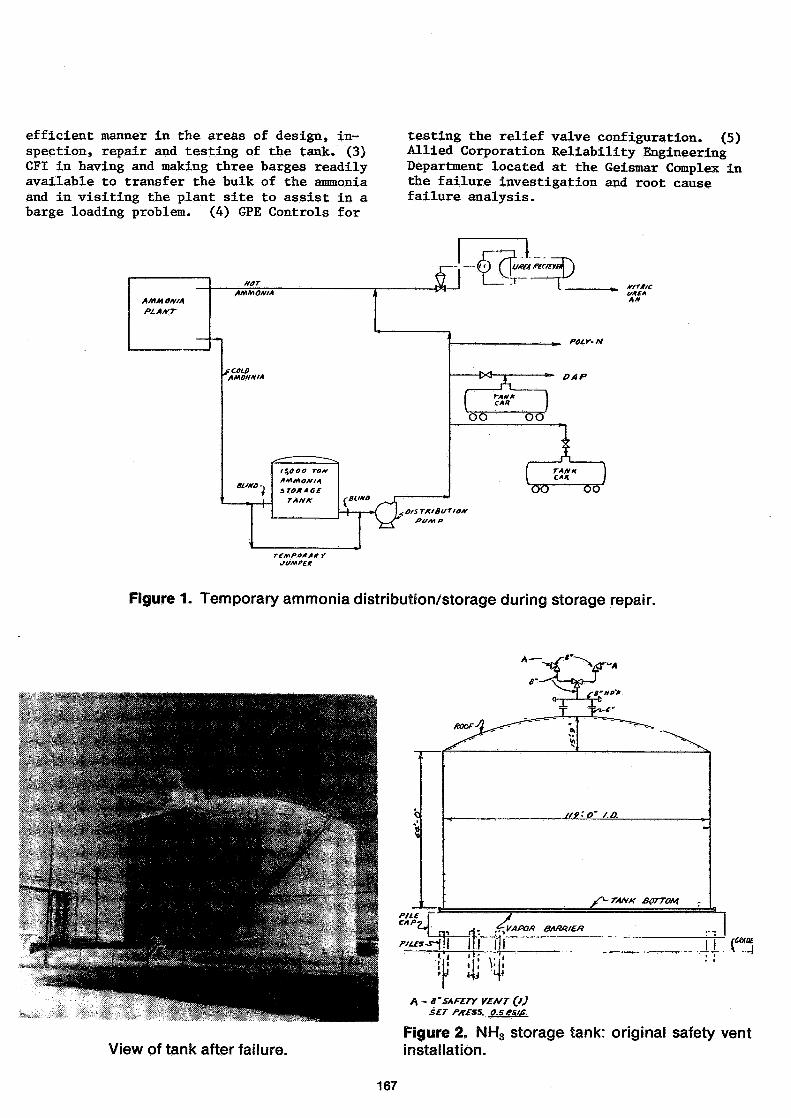
valve performance characteristics from vendortesting, calculations indicate the attainedpressure was .53 psig (reference Plots 7 & 8).
The very small discrepancy between therecording and calculation is most probablydue to an error in calibration of the tankpressure recording system.
Projected Pressure Rise 8 1400 t/Hr. B o i l off
Plot 7. Pressure vs. time plot of maximum attachedtank pressure.
Plots. Estimated fatigue endurance range withpenetration, stress and 0.53 pressure.
The plot of the pressure increase on asubsequent outage (after repairs) shows an at-tained tank pressure of 14.4" I O (.52 psig).As would be expected, again the relief systemallowed tank pressure to slightly exceed therelief set pressure.
A comparison of pressure versus timeplots prior to failure and after repairs shows
164
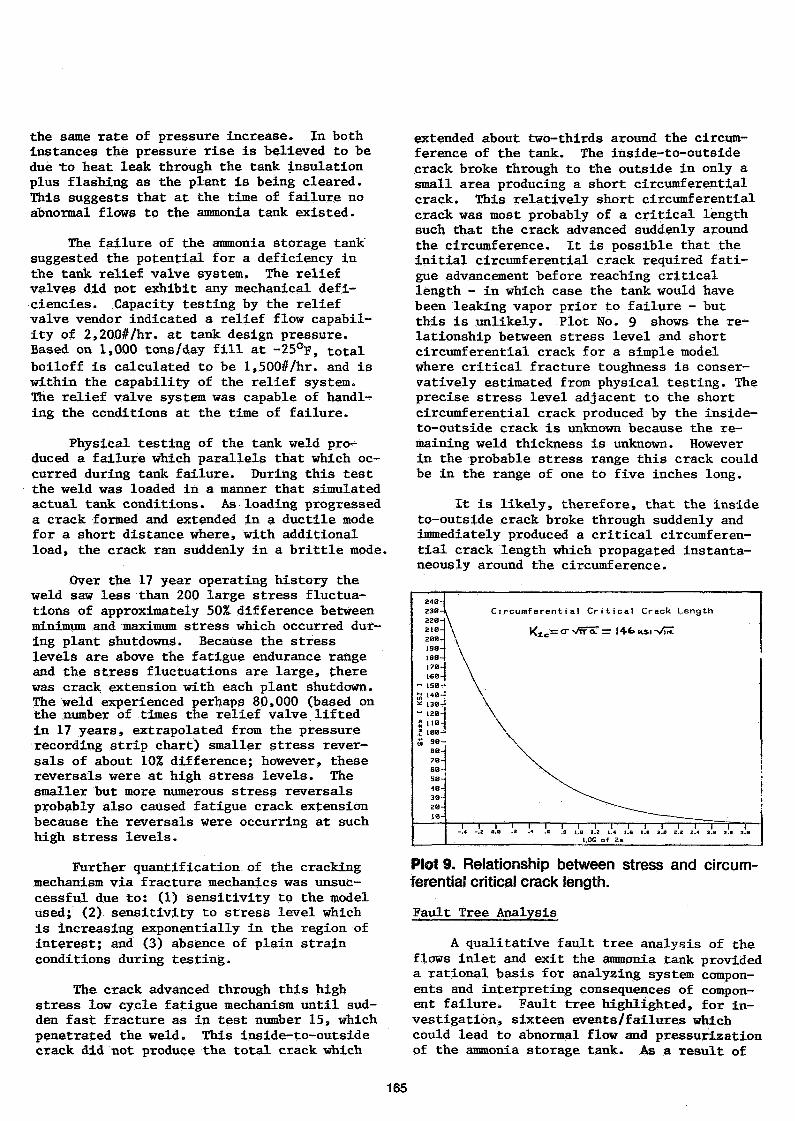
the same rate of pressure increase. In bothinstances the pressure rise is believed to bedue "to heat leak through the tank insulationplus flashing as the plant is being cleared.This suggests that at the time of failure noabnormal flows to the ammonia tank existed.
The failure of the ammonia storage tanksuggested the potential for a deficiency inthe tank relief valve system. The reliefvalves did not exhibit any mechanical defi-ciencies. Capacity testing by the reliefvalve vendor indicated a relief flow capabil-ity of 2,200#/hr. at tank design pressure.Based on 1,000 tons/day fill at -25°F, totalboiloff is calculated to be l,500#/hr. and iswithin the capability of the relief system.The relief valve system was capable of handl-ing the conditions at the time of failure.
Physical testing of the tank weld pro-duced a failure which parallels that which oc-curred during tank failure. During this testthe weld was loaded in a manner that simulatedactual tank conditions. As-loading progresseda crack formed and extended in a ductile modefor a short distance where, with additionalload, the crack ran suddenly in a brittle mode.
Over the 17 year operating history theweld saw less than 200 large stress fluctua-tions of approximately 50% difference betweenminimum and maximum stress which occurred dur-ing plant shutdowns. Because the stresslevels are above the fatigue endurance rangeand the stress fluctuations are large, therewas crack extension with each plant shutdown.The weld experienced perhaps 80,000 (based onthe number of times the relief valve liftedin 17 years, extrapolated from the pressurerecording strip chart) smaller stress rever-sals of about 10% difference; however, thesereversals were at high stress levels. Thesmaller but more numerous stress reversalsprobably also caused fatigue crack extensionbecause the reversals were occurring at suchhigh stress levels.
Further quantification of the crackingmechanism via fracture mechanics was unsuc-cessful due to: (1) sensitivity to the modelused; (2) sensitivity to stress level whichis increasing exponentially in the region ofinterest; and (3) absence of plain strainconditions during testing.
The crack advanced through this highstress low cycle fatigue mechanism until sud-den fast fracture as in test number 15, whichpenetrated the weld. This inside-to-outsidecrack did not produce the total crack which
extended about two-thirds around the circum-ference of the tank. The inside-to-outsidecrack broke through to the outside in only asmall area producing a short circumferentialcrack. This relatively short circumferentialcrack was most probably of a critical lengthsuch that the crack advanced suddenly aroundthe circumference. It is possible that theinitial circumferential crack required fati-gue advancement before reaching criticallength - in which case the tank would havebeen leaking vapor prior to failure - butthis is unlikely. Plot No. 9 shows the re-lationship between stress level and shortcircumferential crack for a simple modelwhere critical fracture toughness is conser-vatively estimated from physical testing. Theprecise stress level adjacent to the shortcircumferential crack produced by the inside-to-outside crack is unknown because the re-maining weld thickness is unknown. Howeverin the probable stress range this crack couldbe in the range of one to five inches long.
It is likely, therefore, that the insideto-outside crack broke through suddenly andimmediately produced a critical circumferen-tial crack length which propagated instanta-neously around the circumference.
Circumferential Critical Crack Length
V^lc= cr vtr <x n 14-fe KSI •>/!*
PIot9. Relationship between stress and circum-ferential critical crack length.
Fault Tree Analysis
A qualitative fault tree analysis of theflows inlet and exit the ammonia tank provideda rational basis for analyzing system compon-ents and interpreting consequences of compon-ent failure. Fault tree highlighted, for in-vestigation, sixteen events/failures whichcould lead to abnormal flow and pressurizationof the ammonia storage tank. As a result of
165
the investigation, items of specific interestwere identified as follows: (1) Synthesis gasto NH3 tank from 119-C (feed and recycle 3rdstage chiller) via 112-F (3rd stage refriger-ant flash drum) . (2) Check valve NH-122-8"(vapor return line from OTkj tank) failureallowing 112-F to NH3 tank. (3) Hot ammoniafrom 109-F (refrigerant receiver) to NÜ3 tankby opening/failure of valve in line NH-18-2"(startup line to 109-F). (4) Check valvefailure at ammonia distribution pumps exit
tank allowing process into NHß tank.
Investigation and inspection of faulttree suspect check valves was performed bymaintenance and operations personnel. Allcheck valves were reported as functioning pro-perly. Therefore the check valves were dis-counted as contributors to the ammonia tankfailure. In addition, the opening/failure ofthe valve in line NH-18-2" which would allowhot ammonia from 109-F to the NHg tank was
disconnected due to assurance from operationsthat the valve was not operated or failed.
A synthesis gas leak was found in 119-Cupon startup following the tank failure. Theleak was found to be small and of insufficientmagnitude to contribute to tank failure. Lossof level in 112-F would have been additionallynecessary to enable flow of synthesis gas tothe NH3 tank. Assurances by operations indi-cate the 119-C leak occurred after the tankfailure and loss of 112-F level did not occur.As a result synthesis gas to NH3 tank from119-C via 112-F was discounted as a contribu-tor to the tank failure.
The fault tree analysis, follow up in-vestigation and analysis of strip chart re-cordings indicate that no process overpressurenor irregularity contributed to the failure.
At the time of failure a flow was indi-cated on the ammonia product to storage stripchart. The indication wa s uncommonly steady.Typically the indication would be erratic dueto flashing at the orifice. Initially thisflow indication was considered as a probablecontributor to the failure. However, computerenhanced pressure plots, comparison with asubsequent outage, system capacities andfault tree analysis indicate that the flowrecording was erroneous and did not contri-bute to the failure.
Inspection of the ammonia tank wall tofloor weld area, after the roof weld failure,revealed several stretched tank anchor straps.Some straps were bowed in, some were bowed
out and some were unaffected. There was nodiscernable pattern to the affected anchorstraps. All straps would have been stretchedrelatively uniformly had the anchor strapsbeen stretched due to overpressure» When thetank roof to wall weld failed, the wallsflexed and the anchor straps were stretchedin non-uniform manner. The stretched anchorstraps' were determined to be secondary dam-age.
CONCLUSIONS
The ammonia storage tank operated rela-tively trouble free for 17 years. Duringthat time, as would be expected, ventingthrough the relief system occurred duringnormal operations as well as during plantshutdowns. Frequency of venting was depend-ent upon operating conditions. With adequateweld construction the frequency of pressuri-zation and resultant venting would be of noconsequence. The applied stress would bevery low. However, the ammonia storage tankroof to wall weld was deficient in design andconstruction. With these deficiencies theapplied stress was above the estimated fati-gue endurance range when the relief set pointwas reached. The frequency of relief venting,estimated at 80,000 cycles, and the highapplied stresses provided the environment forhigh stress low cycle fatigue.
The failure mechanism was high stresslow cycle fatigue. Normal, cyclic pressurefluctuations during outages and a deficientweld acted in concert over 17 years service.Pressure fluctuations will not effect the re-paired weld as stress levels are now low as aresult of effective penetration and fusion.
The root cause of the ammonia storagetank roof to wall weld failure was a poorl/designed and constructed weld. Repairs in-cluded a properly constructed roof to wallweld.
Wo process irregulatiries contributed tothe failure. The ammonia storage tank wasnot significantly overpressured. Maximum at-tained prèssure/was 0.53 psig.
ACKNOWLEDGEMENTS
The following organizations were veryhelpful in assisting Arcadian Corporation during this incident: (1) Agrico in having andmaking a barge readily available to transferthe ammonia. (2) BMT for responding in an
166
efficient manner in the areas of design, in-spection, repair and testing of the tank. (3)CFI in having and making three barges readilyavailable to transfer the bulk of the ammoniaand in visiting the plant site to assist in abarge loading problem. (4) GPE Controls for
testing the relief valve configuration. (5)Allied Corporation Reliability EngineeringDepartment located at the Geismar Complex inthe failure investigation and root causefailure analysis.
f COLO^AMOMMtA
-(O C\ummci^T\L>U-^_
f «u» r
-|—j—»7 I fu/$ TA/8V\*^S* 0t/SHP
POLY- N
ff/Tg/CVAt*AM
DAP
oo oo
oo OO
Figure 1. Temporary ammonia distribution/storage during storage repair.
77^fîl Î Î I Ï Î Î
f/9-O' /.Û.
BOTTOM
8Mft/£fl
View of tank after failure.
A - S'SAFCrf VEfifT OJSET /Vffss. o.ses/f.
Figure 2. NH3 storage tank: original safety ventinstallation.
167
AS KEPA/KBP
Figure 3. NH3 storage tank: construction detailsof the roof to the vertical wall joint.
• TOF COMPRESSION RING CONSISTING OF SO SEGMENTS BEHOVED ANDREPLACED.
EACH SEGMENT HE-BEVELED. GROUND CLEAN AND NT TESTED.
• WALL PORTION OF COMPRESSION RING BEVELED, GROUND AND M T•TESTED.
• ALL ROOF PLATES PULLED BACK INTO PLACE AND REUSED.
• ALL ROOF RAFTERS REW ELDED TO TENSION RING DUE TO SPOTTYCRACKING AND LACK OF WELDING DURING ORIGINAL ERECTION.
« 20 ADDITIONAL TENSION RING TO WALL SUPPORT CLIPS ADDED DUETO DISTORTION OF TENSION RING (ALL CLIP WELDS INSPECTED).
• STRAPS REPAIRED AND REKELDED AFTER HYDROTEST.
Figure 5. Tank repairs.
1. 10 FT. WIDE BY 13 FT. HIGH DOOR CUT IN SIDE OF TANK.
2. MANUFT PLACED INSIDE THE TANK.
3. TANK INSPECTION AT TOP
• COMPRESSION RING WELD TO TOP WALL PLATE 100% MT TESTEDINSIDE AND OUTSIDE.
• ALL VERTICAL COMPRESSION RING AND TOP WALL PLATE WELDS100% MT TESTED INSIDE AND OUTSIDE.
• ALL RAFTER TO TENSION RING WELDS 100% MT TESTED.
4. TANK INSPECTION AT BOTTOM
• INSIDE WALL TO FLOOR PLATE WELD 100% MT TESTED. OUTSIDEWELD MT TESTED WHERE EXPOSED.
• ALL BOTTOM WALL (UP TO 10 FT. FROM FLOOR) VERTICALWELDS AND FIRST HORIZONTAL WALL SEAM WELDS 100% MTTESTED.
• ALL FLOOR SEAM WELDS 100% MT TESTED AND VACUUM BOXTESTED 5 FT. IN FROM WALL TO FLOOR JOINT.
Figure 4. Tank inspection procedure.Figure 6. Plates that form the top section of thecompression ring.
168
Pftojfcr: KfpAin KHi srt TANKSM/TV TK..PttRG£, Off» TAM
ie-a-81 -fo-9-t*
Kewat, CitAM, «BUK« finns
«u /««««j «tt»esc«ffw«a«ic n«
wo» «or TUP
RIL TA* IC WW l»»«*
«MI« AMC00* «rww»
«IR Mr.DftjO TANK
DRAIN TANK
IN.S1RU. ff. v.'s f fMewewcr«»;
«WM- st**nt9 4 ««r M»»F ew
KKOHWISMH TANK
PUT AMMOW* fM r«flfH
INS7SU. JNSTKUMfHTATItH
iNsumrieH
P/?Ot/£Cr SCHEDULE.
o c r o e £ KW'ff'«j».Wj«
:
fi"'PWHMMM
i
1
!
r
•i/
•
/W*
-*
^*^«M
J
•Sj
A
;
ï
A
i l
S
R
n
tafad!
j
Af O y £île'i
É!AKAD
iiAKAR
ij
j
V.
«
R
4
•
S
•ta
|
6
auu«R
AK
r
l
Ulk\
8AK
«K
i fl
S
. «
t
tg
t
10
A
III
II
•*!
w
II
n
B
1
m
a
x
It
u
B
jj
Sl
K
X
X
2
MBS.17
>
W
&
w
s
a
k
a
(
a
3
ffi » 8 5 ti
> al
a
K
n
ft
M
s
•• f/xsr«&!!'/?£ K *ï
ES /f**'. Hi 3
eae raA*-DAYS tesr even
Figure 7. Project schedule for tank repair.
ZO" EMCKCVUCr
/.- sizeD FOK /o,ooo f. P.Hi- ACTUAL R£il£tf/NG CAPACITY AT
TANK PCS/GH rxessu/te SASCOOff vet/ooK T£sr WAS z*oo r.r.n
PRESSURES
M€NTA rMOSfM£/ttC (f/f/MCjf/ffsr e" ff. v.SECOND 8" If. Y.T n/ f e e* KV.gO'£MEKe/fCY MAfNAY
KS./.G.0.45o.so0-S2Û-S4-0.615
CAPACITY. P. ea. w*
13.00013.00013.00 OSO,SoO
CAPACITY P.P.*. A/'Ha
PESISH i' 0,OOO
49.500
ACTUAL
Figure 8. Atmospheric ammonia storage tank:original vent design criteria.
Figure 9. Atmospheric ammonia storage tank:current vent design criteria.
169
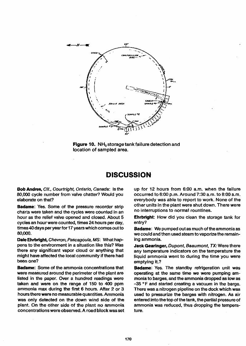
Figure 10. NH3 storage tank failure detection andlocation of sampled area.
DISCUSSION
Bob Andres, CIL, Courtright, Ontario, Canada: Is the80,000 cycle number from valve chatter? Would youelaborate on that?Badamè: Yes. Some of the pressure recorder stripcharts were taken and the cycles were counted in anhour as the relief valve opened and closed. About 5cycles an hour were counted, times 24 hours per day,ti mes 40 days per year f or 17 years which comes out to80,000.Dale Ehrbright, Chevron, Pascagoula, MS: What hap-pens to the environment in a situation like this? Wasthere any significant vapor cloud or anything thatmight have affected the local community if there hadbeen one?Badame: Some of the ammonia concentrations thatwere measured around the perimeter of the plant arelisted in the paper. Over a hundred readings weretaken and were on the range of 150 to 400 ppmammonia max during the first 6 hours. After 2 or 3hours there were no measurable quantities. Ammoniawas only detected on the down wind side of theplant. On the other side of the plant no ammoniaconcentrations were observed. A road block was set
up for 12 hours from 6:00 a.m. when the failureoccurred to 6:00 p.m. Around 7:30 a.m. to 8:00 a.m.everybody was able to report to work. None of theother units in the plant were shut down. There wereno interruptions to normal rountines.Ehrbright: How did you clean the storage tank forentry?Badame: We pumped out as much of the ammonia aswe could and then used steam to vaporize the remain-ing ammonia.Jack Gearinger, Dupont, Beaumont, TX: Were thereany temperature indicators on the temperature theliquid ammonia went to during the time you wereemptying it.?Badame: Yes. The standby refrigeration unit wasoperating at the same time we were pumping am-monia to barges, and the ammonia dropped as low as-35 °F and started creating a vacuum in the barge.There was a nitrogen pipeline on the dock which wasused to pressurize the barges with nitrogen. As airentered into the top of the tank, the partial pressure ofammonia was reduced, thus dropping the tempera-ture.
170