197/08 - Rohde & Schwarz
72
One of the most secure voice encryption devices for mobile phones on the market Fastest and most accurate medium-class signal ana- lyzer with 40 MHz analysis bandwidth For small budgets: EMI test receiver and full-featured spec- trum analyzer in a single instrument Accurate direction finder with comprehensive measurement and analysis functions Positively confidential: GENERAL PURPOSE EMC / FIELD STRENGTH RADIOMONITORING / RADIOLOCATION NEWS 197/08
Transcript of 197/08 - Rohde & Schwarz

One of the most secure voice encryption devices for mobile phones on the market
Fastest and most accurate medium-class signal ana-lyzer with 40 MHz analysis bandwidth
For small budgets: EMI test receiver and full-featured spec-trum analyzer in a single instrument
Accurate direction finder with comprehensive measurement and analysis functions
Positively confidential:
GENERAL PURPOSE EMC / FIELD STRENGTH RADIOMONITORING / RADIOLOCATION
NEWS197/08
NEWS
Published by Rohde & Schwarz GmbH&Co. KG Mühldorfstrasse 15 · 81671 München Europe, Africa, Middle East: +491805124242 or +4989412913774, [email protected] North America: 1-888-TEST-RSA (1-888-837-8772), [email protected] Latin America: +1-410-910-7988, [email protected] Asia / Pacific: +6565130488, [email protected] Editor and layout: Ludwig Drexl, Redaktion – Technik (German) English translation: Dept. 9MC7 Photos: Rohde & Schwarz Printed in Germany Volume 48 Circulation (German, English, French, Spanish and Chinese) 80000 approx. 4 times a year ISSN 0028-9108 Supply free of charge through your nearest Rohde & Schwarz representative Reproduction of extracts permitted if source is stated and copy sent to Rohde & Schwarz München. PD 5214.0676.72
R&S® is a registered trademark of Rohde & Schwarz GmbH&Co. KG. Trade names are trademarks of the owners. CDMA2000® is a registered trademark of Telecommunica-tions Industry Association (TIA USA). The Bluetooth® word mark and logos are owned by the Bluetooth SIG, Inc. and any use of such marks by Rohde & Schwarz is under license. WiMAX Forum” is a registered trademark of the WiMAX Forum. “WiMAX,” the WiMAX Forum logo, “WiMAX Forum Certified,” and the WiMAX Forum Certified logo are trade-marks of the WiMAX Forum. All other trademarks are the properties of their respective owners.
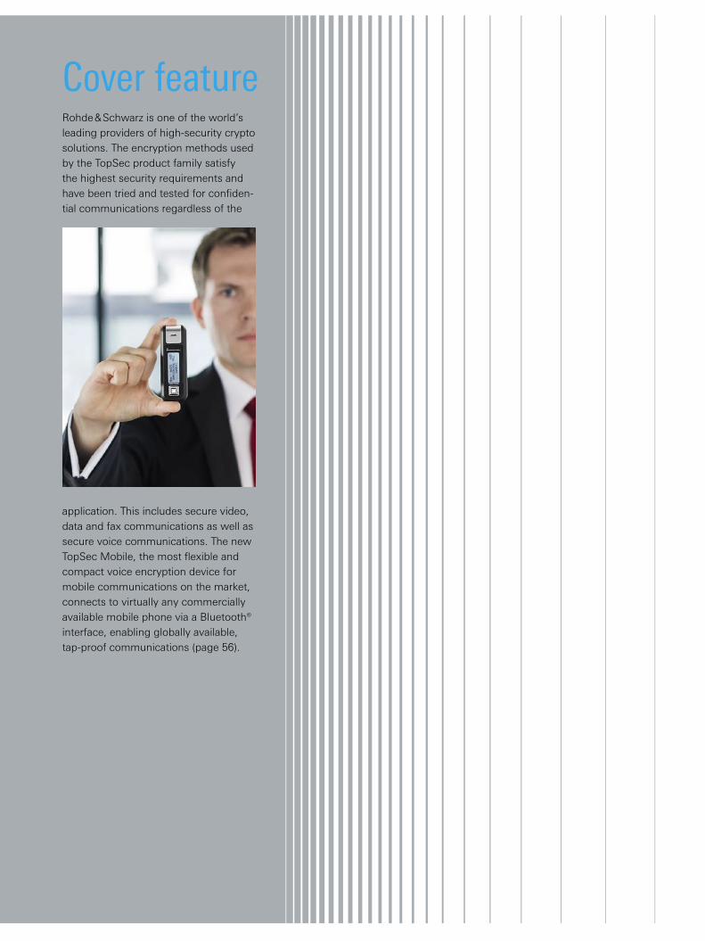
Cover featureRohde & Schwarz is one of the world’s leading providers of high-security crypto solutions. The encryption methods used by the TopSec product family satisfy the highest security requirements and have been tried and tested for confiden-tial communications regardless of the
application. This includes secure video, data and fax communications as well as secure voice communications. The new TopSec Mobile, the most flexible and compact voice encryption device for mobile communications on the market, connects to virtually any commercially available mobile phone via a Bluetooth® interface, enabling globally available, tap-proof communications (page 56).
4
Coverage measurement systems Radio network scanner with two receiver frontends and a digital I/Q data interface ..................................6
The first comprehensive drive test solution for WiMAX™ wireless communications networks .....9
Test cellsEarly verification of the air interface of wireless terminals .......................... 12
Radiocommunications testersVersatile and precise signals for the production of wireless devices .......... 15
WIRELESS TECHNOLOGIES EMC / FIELD STRENGTHGENERAL PURPOSE
ReferenceState-of-the-art: the German Armed Forces’ EMC test center .................... 34
Test receiversFavorably priced EMI measuring receiver for the development lab ....... 40
Signal analyzersThe fastest and most accurate signal and spectrum analyzer in the medium class..................................... 18
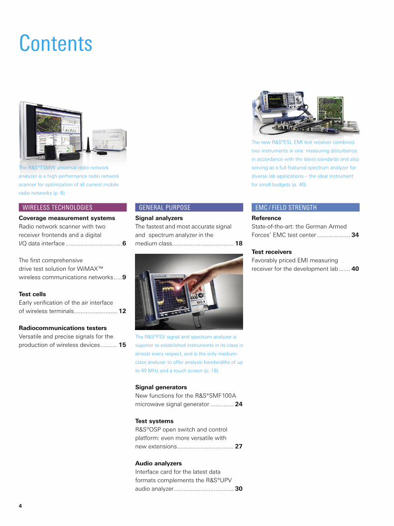
The R&S®TSMW universal radio network
analyzer is a high-performance radio network
scanner for optimization of all current mobile
radio networks (p. 6).
The R&S®FSV signal and spectrum analyzer is
superior to established instruments in its class in
almost every respect, and is the only medium-
class analyzer to offer analysis bandwidths of up
to 40 MHz and a touch screen (p. 18).
The new R&S®ESL EMI test receiver combines
two instruments in one: measuring disturbance
in accordance with the latest standards and also
serving as a full-featured spectrum analyzer for
diverse lab applications – the ideal instrument
for small budgets (p. 40).
Signal generatorsNew functions for the ¸SMF100A microwave signal generator .............. 24
Test systemsR&S®OSP open switch and control platform: even more versatile with new extensions .................................. 27
Audio analyzersInterface card for the latest data formats complements the ¸UPV audio analyzer .................................... 30
Contents
BROADCASTING
RADIOMONITORING / RADIOLOCATION
SECURE COMMUNICATIONS MISCELLANEOUS
Signal generatorsDigital video signal generator for testing state-of-the-art TV display equipment ......................................... 46
TV transmittersFast to market: TV transmitters for the Brazilian ISDB-TB standard ........... 50
Sound transmittersThe ¸SLA8000 low-power transmitter – a bundle of energy for DAB / T-DMB ...................................... 53
Crypto productsOne of the most secure voice encryption devices for mobile phones on the market ....................... 56
Direction finders¸DDF255 digital direction finder with measurement and analysis functions ............................................ 64
The compact R&S®SLA8000 low-power trans-
mitter is ideal for optimizing DAB and T-DMB
networks (p. 53).
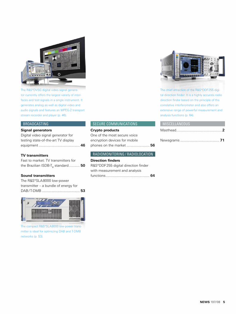
The chief attraction of the R&S®DDF255 digi-
tal direction finder: It is a highly accurate radio
direction finder based on the principle of the
correlative interferometer and also offers an
extensive range of powerful measurement and
analysis functions (p. 64).
The R&S®DVSG digital video signal genera-
tor currently offers the largest variety of inter-
faces and test signals in a single instrument. It
generates analog as well as digital video and
audio signals and features an MPEG-2 transport
stream recorder and player (p. 46).
Masthead ..............................................2
Newsgrams ....................................... 71
NEWS 197/08 5
6
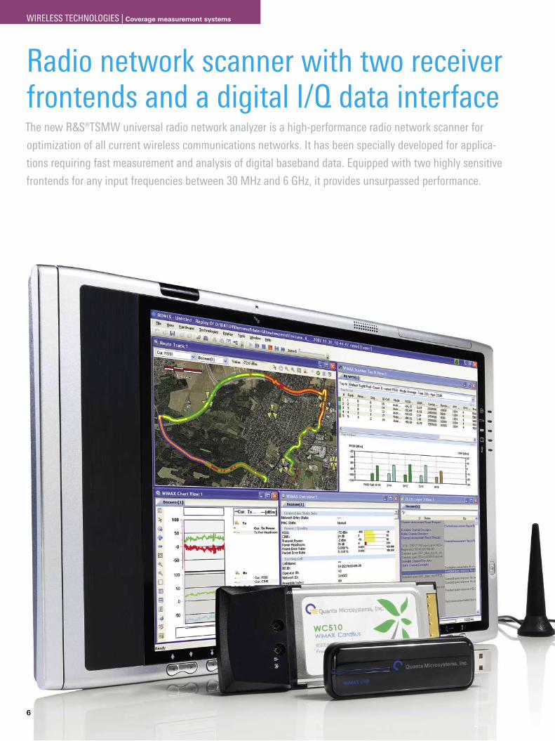
Radio network scanner with two receiver frontends and a digital I/Q data interfaceThe new ¸TSMW universal radio network analyzer is a high-performance radio network scanner for
optimization of all current wireless communications networks. It has been specially developed for applica-
tions requiring fast measurement and analysis of digital baseband data. Equipped with two highly sensitive
frontends for any input frequencies between 30 MHz and 6 GHz, it provides unsurpassed performance.
WIRELESS TECHNOLOGIES | Coverage measurement systems
Compact, upgradable platform for mobile baseband measurements
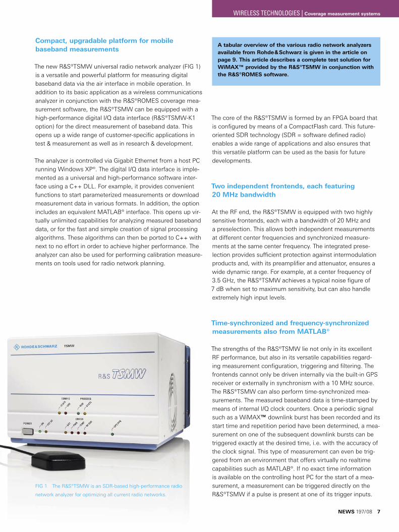
The new R&S®TSMW universal radio network analyzer (FIG 1) is a versatile and powerful platform for measuring digital baseband data via the air interface in mobile operation. In addition to its basic application as a wireless communications analyzer in conjunction with the ¸ROMES coverage mea-surement software, the ¸TSMW can be equipped with a high-performance digital I/Q data interface (R&S®TSMW-K1 option) for the direct measurement of baseband data. This opens up a wide range of customer-specific applications in test & measurement as well as in research & development.
The analyzer is controlled via Gigabit Ethernet from a host PC running Windows XP®. The digital I/Q data interface is imple-mented as a universal and high-performance software inter-face using a C++ DLL. For example, it provides convenient functions to start parameterized measurements or download measurement data in various formats. In addition, the option includes an equivalent MATLAB® interface. This opens up vir-tually unlimited capabilities for analyzing measured baseband data, or for the fast and simple creation of signal processing algorithms. These algorithms can then be ported to C++ with next to no effort in order to achieve higher performance. The analyzer can also be used for performing calibration measure-ments on tools used for radio network planning.
The core of the R&S®TSMW is formed by an FPGA board that is configured by means of a CompactFlash card. This future-oriented SDR technology (SDR = software defined radio) enables a wide range of applications and also ensures that this versatile platform can be used as the basis for future developments.
Two independent frontends, each featuring 20 MHz bandwidth
At the RF end, the R&S®TSMW is equipped with two highly sensitive frontends, each with a bandwidth of 20 MHz and a preselection. This allows both independent measurements at different center frequencies and synchronized measure-ments at the same center frequency. The integrated prese-lection provides sufficient protection against intermodulation products and, with its preamplifier and attenuator, ensures a wide dynamic range. For example, at a center frequency of 3.5 GHz, the R&S®TSMW achieves a typical noise figure of 7 dB when set to maximum sensitivity, but can also handle extremely high input levels.
Time-synchronized and frequency-synchronized measurements also from MATLAB®
The strengths of the R&S®TSMW lie not only in its excellent RF performance, but also in its versatile capabilities regard-ing measurement configuration, triggering and filtering. The frontends cannot only be driven internally via the built-in GPS receiver or externally in synchronism with a 10 MHz source. The R&S®TSMW can also perform time-synchronized mea-surements. The measured baseband data is time-stamped by means of internal I/Q clock counters. Once a periodic signal such as a WiMAX™ downlink burst has been recorded and its start time and repetition period have been determined, a mea-surement on one of the subsequent downlink bursts can be triggered exactly at the desired time, i. e. with the accuracy of the clock signal. This type of measurement can even be trig-gered from an environment that offers virtually no realtime capabilities such as MATLAB®. If no exact time information is available on the controlling host PC for the start of a mea-surement, a measurement can be triggered directly on the R&S®TSMW if a pulse is present at one of its trigger inputs.
FIG 1 The ¸TSMW is an SDR-based high-performance radio
network analyzer for optimizing all current radio networks.
A tabular overview of the various radio network analyzers available from Rohde & Schwarz is given in the article on page 9. This article describes a complete test solution for WiMAX™ provided by the ¸TSMW in conjunction with the ¸ROMES software.
NEWS 197/08 7
WIRELESS TECHNOLOGIES | Coverage measurement systems
8
Wide streaming bandwidth due to Gigabit Ethernet and data compression
To maximize measurement rates – even when using a note-book – measured data can be compressed into blocks of 2 × 8 / 12 / 16 / 20 bits per complex I/Q sample before it is transmitted to the host PC. Measurements can thus be con-figured either for maximum dynamic range or maximum mea-surement rate. This is particularly important for applications in which I/Q data has to be recorded over several minutes or even hours. A sampling rate of 5 Msample/s and compression into 2 × 8 bits per sample, for example, would generate only around 80 Mbits of measured data per second, a volume that can easily be handled by the Gigabit Ethernet interface.
High-sensitivity GPS receiver
The R&S®TSMW has an integrated, highly sensitive GPS receiver that can also easily be addressed via the C++ inter-face or MATLAB®. In addition to position determination, the GPS information can also be used for frequency and time syn-chronization. The inherent deviation of the local oscillators in the R&S®TSMW frontends from those in the wireless commu-nications transmitters can thereby be significantly reduced, which simplifies and speeds up synchronization with the radio network.
Compact design and flexible power supply
Despite the high versatility of the R&S®TSMW, its designers have managed to produce a compact device for mobile appli-cations. The analyzer’s wide input voltage range from 9 V to 18 V DC enables operation in vehicles. For battery operation, its total power consumption of approx. 70 W can be signifi-cantly reduced by using an optional operating mode that acti-vates only one of the frontends.
Dr. Markus Herdin
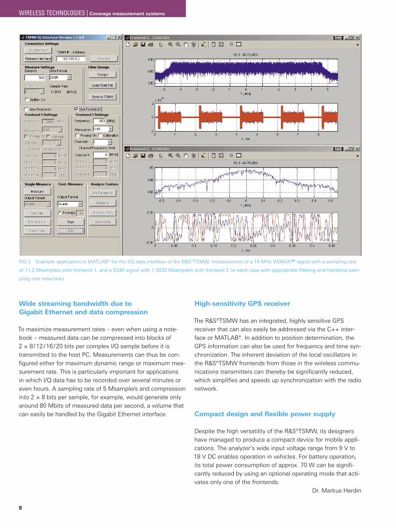
FIG 2 Example application in MATLAB® for the I/Q data interface of the ¸TSMW: measurement of a 10 MHz WiMAX™ signal with a sampling rate
of 11.2 Msample/s with frontend 1, and a GSM signal with 1.0833 Msample/s with frontend 2 (in each case with appropriate filtering and fractional sam-
pling rate reduction).
WIRELESS TECHNOLOGIES | Coverage measurement systems
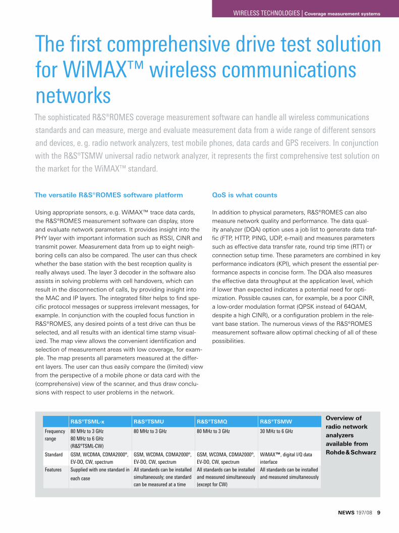
The first comprehensive drive test solution for WiMAX™ wireless communications networksThe sophisticated R&S®ROMES coverage measurement software can handle all wireless communications
standards and can measure, merge and evaluate measurement data from a wide range of different sensors
and devices, e. g. radio network analyzers, test mobile phones, data cards and GPS receivers. In conjunction
with the ¸TSMW universal radio network analyzer, it represents the first comprehensive test solution on
the market for the WiMAX™ standard.
The versatile ¸ROMES software platform
Using appropriate sensors, e. g. WiMAX™ trace data cards, the R&S®ROMES measurement software can display, store and evaluate network parameters. It provides insight into the PHY layer with important information such as RSSI, CINR and transmit power. Measurement data from up to eight neigh-boring cells can also be compared. The user can thus check whether the base station with the best reception quality is really always used. The layer 3 decoder in the software also assists in solving problems with cell handovers, which can result in the disconnection of calls, by providing insight into the MAC and IP layers. The integrated filter helps to find spe-cific protocol messages or suppress irrelevant messages, for example. In conjunction with the coupled focus function in R&S®ROMES, any desired points of a test drive can thus be selected, and all results with an identical time stamp visual-ized. The map view allows the convenient identification and selection of measurement areas with low coverage, for exam-ple. The map presents all parameters measured at the differ-ent layers. The user can thus easily compare the (limited) view from the perspective of a mobile phone or data card with the (comprehensive) view of the scanner, and thus draw conclu-sions with respect to user problems in the network.
QoS is what counts
In addition to physical parameters, R&S®ROMES can also measure network quality and performance. The data qual-ity analyzer (DQA) option uses a job list to generate data traf-fic (FTP, HTTP, PING, UDP, e-mail) and measures parameters such as effective data transfer rate, round trip time (RTT) or connection setup time. These parameters are combined in key performance indicators (KPI), which present the essential per-formance aspects in concise form. The DQA also measures the effective data throughput at the application level, which if lower than expected indicates a potential need for opti-mization. Possible causes can, for example, be a poor CINR, a low-order modulation format (QPSK instead of 64QAM, despite a high CINR), or a configuration problem in the rele-vant base station. The numerous views of the R&S®ROMES measurement software allow optimal checking of all of these possibilities.
¸TSML-x ¸TSMU ¸TSMQ ¸TSMW
Frequency range
80 MHz to 3 GHz 80 MHz to 6 GHz (¸TSML-CW)
80 MHz to 3 GHz 80 MHz to 3 GHz 30 MHz to 6 GHz
Standard GSM, WCDMA, CDMA2000®, EV-DO, CW, spectrum
GSM, WCDMA, CDMA2000®, EV-DO, CW, spectrum
GSM, WCDMA, CDMA2000®, EV-DO, CW, spectrum
WiMAX™, digital I/Q data interface
Features Supplied with one standard in
each case
All standards can be installed simultaneously; one standard can be measured at a time
All standards can be installed and measured simultaneously (except for CW)
All standards can be installed and measured simultaneously
Overview of radio network analyzers available from Rohde & Schwarz
NEWS 197/08 9
WIRELESS TECHNOLOGIES | Coverage measurement systems
10
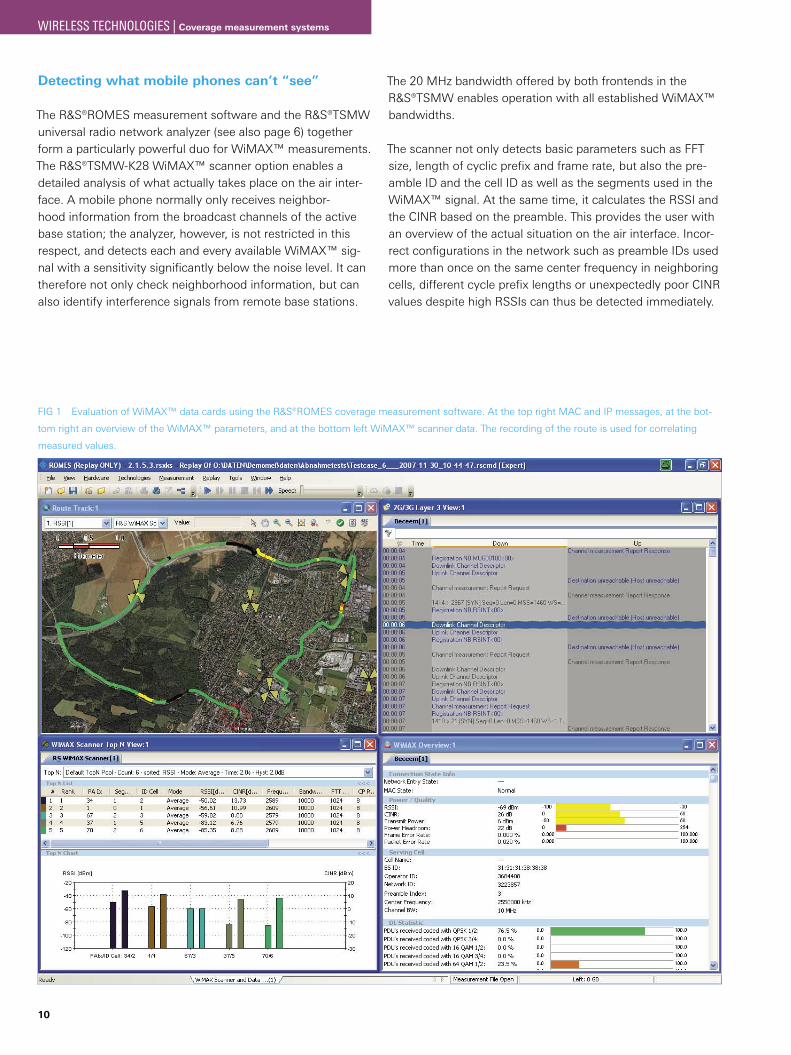
Detecting what mobile phones can’t “see”
The R&S®ROMES measurement software and the R&S®TSMW universal radio network analyzer (see also page 6) together form a particularly powerful duo for WiMAX™ measurements. The R&S®TSMW-K28 WiMAX™ scanner option enables a detailed analysis of what actually takes place on the air inter-face. A mobile phone normally only receives neighbor-hood information from the broadcast channels of the active base station; the analyzer, however, is not restricted in this respect, and detects each and every available WiMAX™ sig-nal with a sensitivity significantly below the noise level. It can therefore not only check neighborhood information, but can also identify interference signals from remote base stations.
The 20 MHz bandwidth offered by both frontends in the R&S®TSMW enables operation with all established WiMAX™ bandwidths.
The scanner not only detects basic parameters such as FFT size, length of cyclic prefix and frame rate, but also the pre-amble ID and the cell ID as well as the segments used in the WiMAX™ signal. At the same time, it calculates the RSSI and the CINR based on the preamble. This provides the user with an overview of the actual situation on the air interface. Incor-rect configurations in the network such as preamble IDs used more than once on the same center frequency in neighboring cells, different cycle prefix lengths or unexpectedly poor CINR values despite high RSSIs can thus be detected immediately.
FIG 1 Evaluation of WiMAX™ data cards using the ¸ROMES coverage measurement software. At the top right MAC and IP messages, at the bot-
tom right an overview of the WiMAX™ parameters, and at the bottom left WiMAX™ scanner data. The recording of the route is used for correlating
measured values.
WIRELESS TECHNOLOGIES | Coverage measurement systems
High sensitivity paired with high immunity to interference
Sensitivity, dynamic range and scanning speed are the key parameters of a radio network analyzer, fields in which the ¸TSMW offers outstanding performance. A noise figure of typically 7 dB at 3.5 GHz, for example, ensures high sensitiv-ity. This by no means compromises immunity to interference. The integrated preselection sufficiently attenuates interference signals outside the reception band and protects against unde-sired intermodulation products.
In order to achieve a high scanning speed, the R&S®TSMW has been equipped with two powerful frontends. This enables simultaneous scanning and demodulation on different cen-ter frequencies. The short switchover time of <5 ms between different center frequencies even enables the quasi-paral-lel reception on any number of carrier frequencies across the entire frequency range from 30 MHz to 6 GHz. The very good phase noise figure of the R&S®TSMW frontends, in conjunc-tion with the sophisticated signal processing, ensures unpar-alleled measurement performance.
A platform for all technologies
The R&S®TSMW-K28 WiMAX™ scanner option provides the first wireless communications standard for the R&S®TSMW. The R&S®TSMW universal radio network analyzer is prepared to handle all established standards, and can support all of these with a bandwidth of up to 20 MHz. This requires no hardware reconfiguration. Based on a software-defined archi-tecture (SDR), the R&S®TSMW can easily be expanded to include current and future standards such as LTE by adding the appropriate software options. This makes it a future-ori-ented investment. The multiplex capability of the R&S®TSMW also enables the parallel measurement of two or more stan-dards without any significant loss in performance. A fur-ther powerful advantage is provided by the integrated GPS receiver which can be used for synchronization via PPS and for determining the positions of base stations.
With its R&S®TSMW universal radio network analyzer and the R&S®ROMES universal software platform for drive tests, Rohde & Schwarz is the first manufacturer to offer a compre-hensive, seamless solution for the WiMAX™ standard.
Dr. Markus Herdin; Stefan Schindler
When is a test mobile phone used?When access to measurement data via the trace interface is JsufficientFor link-related measurements: J– Data throughput – Link quality – Soft and hard handover – Speech quality – Video quality – Detection of call interruptions – IP protocol analysisFor end-to end tests from the customer’s perspective J
Advantages offered by a radio network analyzerHigher measurement speed JHigh dynamic range and sensitivity JOperates independently of wireless communications network JIs capable of detecting missing or incorrect neighborhood JinformationCan be used for multiple applications and multiple wireless J communications networksCan be used as a measurement reference due to independence Jfrom chipsetsFuture-oriented investment due to upgradability via software JoptionsRequires no network resources JNo operating costs, since a SIM card is not necessary J
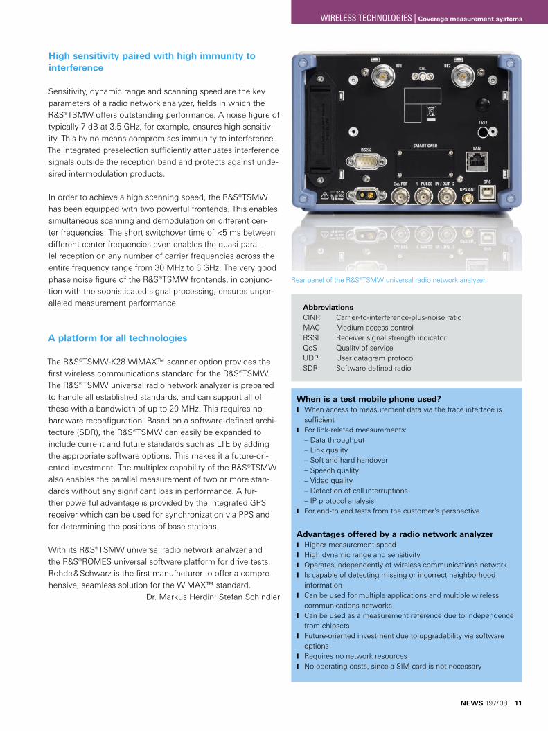
Rear panel of the ¸TSMW universal radio network analyzer.
AbbreviationsCINR Carrier-to-interference-plus-noise ratioMAC Medium access controlRSSI Receiver signal strength indicatorQoS Quality of serviceUDP User datagram protocolSDR Software defined radio
NEWS 197/08 11
WIRELESS TECHNOLOGIES | Coverage measurement systems
12
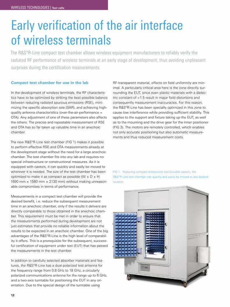
Early verification of the air interface of wireless terminalsThe ¸R-Line compact test chamber allows wireless equipment manufacturers to reliably verify the
radiated RF performance of wireless terminals at an early stage of development, thus avoiding unpleasant
surprises during the certification measurements.
Compact test chamber for use in the lab
In the development of wireless terminals, the RF characteris-tics have to be optimized by striking the best possible balance between reducing radiated spurious emissions (RSE), mini-mizing the specific absorption rate (SAR), and achieving high-quality antenna characteristics (over-the-air-performance = OTA). Any adjustment of one of these parameters also affects the others. The precise and repeatable measurement of RSE and OTA has so far taken up valuable time in an anechoic chamber.
The new ¸R-Line test chamber (FIG 1) makes it possible to perform effective RSE and OTA measurements already at the development stage without the need for a large anechoic chamber. The test chamber fits into any lab and requires no special infrastructure or constructional measures. As it is equipped with castors, it can quickly and easily be moved to wherever it is needed. The size of the test chamber has been optimized to make it as compact as possible (W × D × H: 1690 mm × 1560 mm × 2130 mm) without making unreason-able compromises in terms of performance.
Measurements in a compact test chamber will provide the desired benefit, i. e. reduce the subsequent measurement time in an anechoic chamber, only if the results it delivers are directly comparable to those obtained in the anechoic cham-ber. This requirement must be met in order to ensure that the measurements performed during development are not just estimates that provide no reliable information about the results to be expected in an anechoic chamber. One of the big advantages of the ¸R-Line is the high level of comparabil-ity it offers. This is a prerequisite for the subsequent, success-ful certification of equipment under test (EUT) that has passed the measurements in the test chamber.
In addition to carefully selected absorber materials and fea-tures, the ¸R-Line has a dual-polarized test antenna for the frequency range from 0.8 GHz to 18 GHz, a circularly polarized communications antenna for the range up to 6 GHz, and a two-axis turntable for positioning the EUT in any ori-entation. Due to the special design of the turntable using
RF-transparent material, effects on field uniformity are min-imal. A particularly critical area here is the zone directly sur-rounding the EUT, since even plastic materials with a dielec-tric constant of >1.5 result in major field distortions and consequently measurement inaccuracies. For this reason, the ¸R-Line has been specially optimized in this zone to cause low interference while providing sufficient stability. This applies to the support and fixture taking up the EUT, as well as to the mounting and the drive gear for the inner positioner (FIG 3). The motors are remotely controlled, which enables not only accurate positioning but also automatic measure-ments and thus reduced measurement costs.
FIG 1 Featuring compact dimensions and lockable castors, the
R&S®R-Line test chamber can quickly and easily be moved to any desired
location.
WIRELESS TECHNOLOGIES | Test cells
Demonstrably good RF characteristics
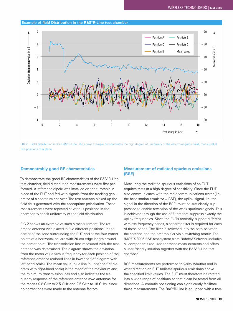
To demonstrate the good RF characteristics of the ¸R-Line test chamber, field distribution measurements were first per-formed. A reference dipole was installed on the turntable in place of the EUT and fed with signals from the tracking gen-erator of a spectrum analyzer. The test antenna picked up the field thus generated with the appropriate polarization. These measurements were repeated at various positions in the chamber to check uniformity of the field distribution.
FIG 2 shows an example of such a measurement. The ref-erence antenna was placed in five different positions: in the center of the zone surrounding the EUT and at the four corner points of a horizontal square with 20 cm edge length around the center point. The transmission loss measured with the test antenna was determined. The diagram shows the deviation from the mean value versus frequency for each position of the reference antenna (colored lines in lower half of diagram with left-hand scale). The mean value (blue line in upper half of dia-gram with right-hand scale) is the mean of the maximum and the minimum transmission loss and also indicates the fre-quency response of the reference antenna (two antennas for the ranges 0.8 GHz to 2.5 GHz and 2.5 GHz to 18 GHz), since no corrections were made to the antenna factors.
Measurement of radiated spurious emissions (RSE)
Measuring the radiated spurious emissions of an EUT requires tests at a high degree of sensitivity. Since the EUT also communicates with the radiocommunications tester (i. e. the base station emulator = BSE), the uplink signal, i. e. the signal in the direction of the BSE, must be sufficiently sup-pressed to enable reception of the weak spurious signals. This is achieved through the use of filters that suppress exactly the uplink frequencies. Since the EUTs normally support different wireless frequency bands, a separate filter is required for each of these bands. The filter is switched into the path between the antenna and the preamplifier via a switching matrix. The ¸TS8996 RSE test system from Rohde & Schwarz includes all components required for these measurements and offers a user-friendly solution together with the ¸R-Line test chamber.
RSE measurements are performed to verify whether and in what direction an EUT radiates spurious emissions above the specified limit values. The EUT must therefore be rotated into a wide range of positions so that it can be tested from all directions. Automatic positioning can significantly facilitate these measurements. The ¸R-Line is equipped with a two-
FIG 2 Field distribution in the ¸R-Line. The above example demonstrates the high degree of uniformity of the electromagnetic field, measured at
five positions of a plane.
10
8
6
4
2
0
– 2
– 4
0
Devi
atio
n fro
m m
ean
valu
e in
dB
– 20
– 30
– 40
– 50
– 60
– 70
– 80
– 90
Frequency in GHz
2 4 6 8 10 12 14 16 18
Mea
n va
lue
in d
B
Position A Position B
Position C Position D
Position E Mean value
Example of field Distribution in the ¸R-Line test chamber
NEWS 197/08 13
WIRELESS TECHNOLOGIES | Test cells
14
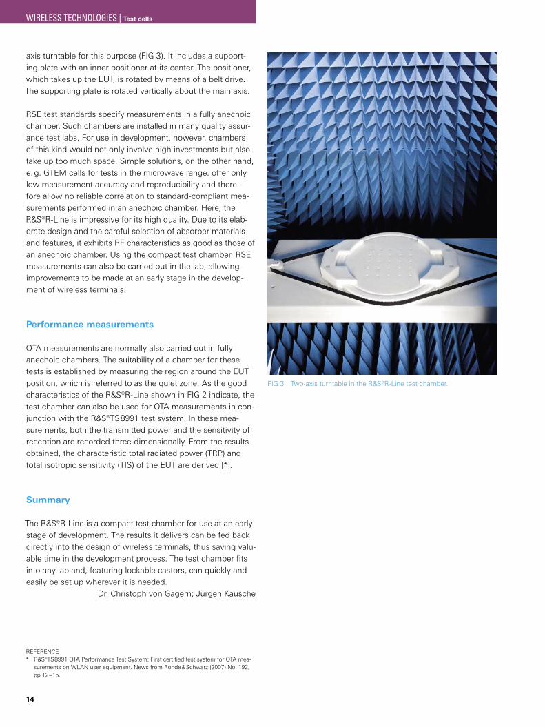
axis turntable for this purpose (FIG 3). It includes a support-ing plate with an inner positioner at its center. The positioner, which takes up the EUT, is rotated by means of a belt drive. The supporting plate is rotated vertically about the main axis.
RSE test standards specify measurements in a fully anechoic chamber. Such chambers are installed in many quality assur-ance test labs. For use in development, however, chambers of this kind would not only involve high investments but also take up too much space. Simple solutions, on the other hand, e. g. GTEM cells for tests in the microwave range, offer only low measurement accuracy and reproducibility and there-fore allow no reliable correlation to standard-compliant mea-surements performed in an anechoic chamber. Here, the ¸R-Line is impressive for its high quality. Due to its elab-orate design and the careful selection of absorber materials and features, it exhibits RF characteristics as good as those of an anechoic chamber. Using the compact test chamber, RSE measurements can also be carried out in the lab, allowing improvements to be made at an early stage in the develop-ment of wireless terminals.
Performance measurements
OTA measurements are normally also carried out in fully anechoic chambers. The suitability of a chamber for these tests is established by measuring the region around the EUT position, which is referred to as the quiet zone. As the good characteristics of the R&S®R-Line shown in FIG 2 indicate, the test chamber can also be used for OTA measurements in con-junction with the ¸TS8991 test system. In these mea-surements, both the transmitted power and the sensitivity of reception are recorded three-dimensionally. From the results obtained, the characteristic total radiated power (TRP) and total isotropic sensitivity (TIS) of the EUT are derived [*].
Summary
The ¸R-Line is a compact test chamber for use at an early stage of development. The results it delivers can be fed back directly into the design of wireless terminals, thus saving valu-able time in the development process. The test chamber fits into any lab and, featuring lockable castors, can quickly and easily be set up wherever it is needed.
Dr. Christoph von Gagern; Jürgen Kausche
FIG 3 Two-axis turntable in the ¸R-Line test chamber.
REFERENCE¸TS8991 OTA Performance Test System: First certified test system for OTA mea-* surements on WLAN user equipment. News from Rohde & Schwarz (2007) No. 192, pp 12–15.
WIRELESS TECHNOLOGIES | Test cells
Versatile and precise signals for the production of wireless devicesThe ¸CMW500 wideband radio communication tester generates complex signals exhibiting maximum
precision, speed and flexibility – characteristics that are of utmost importance for calibrating and testing
the quality of frontends in the production of wireless devices.
The specialist for production
Modern production of wireless devices requires versatile and accurate signals. The R&S®CMW500 wideband radio com-munication tester, featuring a highly precise RF module and the ¸CMW-B110A baseband generator module hardware option, is ideally equipped for this purpose. Its frequency range up to 3.3 GHz or 6 GHz (R&S®CMW-KB036 option) and its transmit-side IF bandwidth of 70 MHz meet virtually any requirement and also offer ample room for future wireless communications standards. The baseband generator module has two operating modes, the arbitrary waveform mode (ARB generator) and the realtime mode for the online generators.
ARB generator
In ARB waveform mode, the instrument processes I/Q data available as waveform files, allowing users to generate any application-specific modulation signals they desire. The ¸WinIQSIM2 waveform creation tool can create waveform files conveniently and directly. I/Q data can also be generated using commercial software tools such as MATLAB®, Mathcad® or ADS®, but this data must then be converted to the wave-form file format with the help of the MATLAB® transfer tool-box or the I/Q wizard from Rohde & Schwarz.
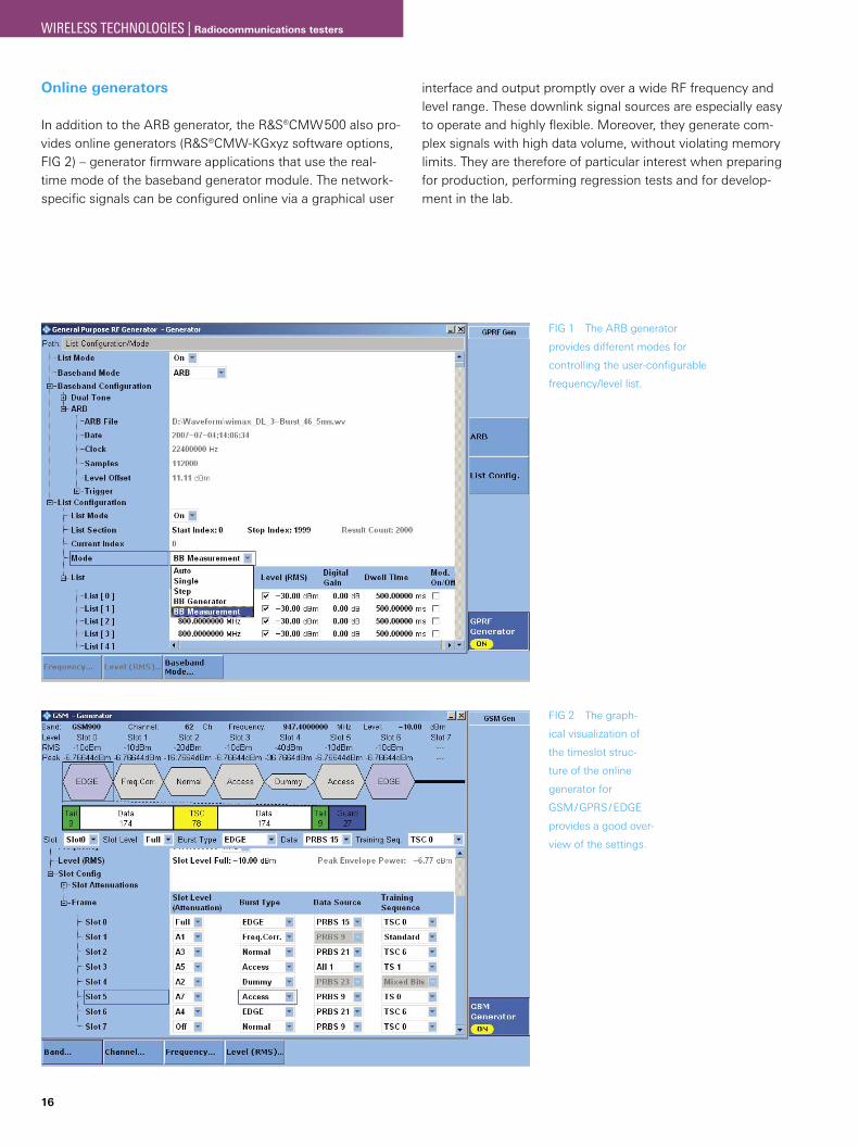
The use of multisegment waveform files makes it possible to achieve minimum switchover times between different modu-lation modes. To this end, the ARB generator provides various modes that control switching from one segment to another as required. In combination with a user-configurable frequency /level list (that can contain up to 2000 entries), the ARB gen-erator offers solutions for all production-typical requirements, e. g. for fast alignment of the wireless device receiver via pre-defined test sequences using the modern R&S®Smart Align-ment concept. You can switch from one entry to another in the frequency / level list in different ways, e. g. time-controlled (variable dwell time per list entry), or by means of marker sig-nals contained in the waveform file, or by internally gener-ated trigger signals from other firmware applications (FIG 1). A generously dimensioned waveform RAM offers sufficient memory capacity for playing even long and wideband signals.
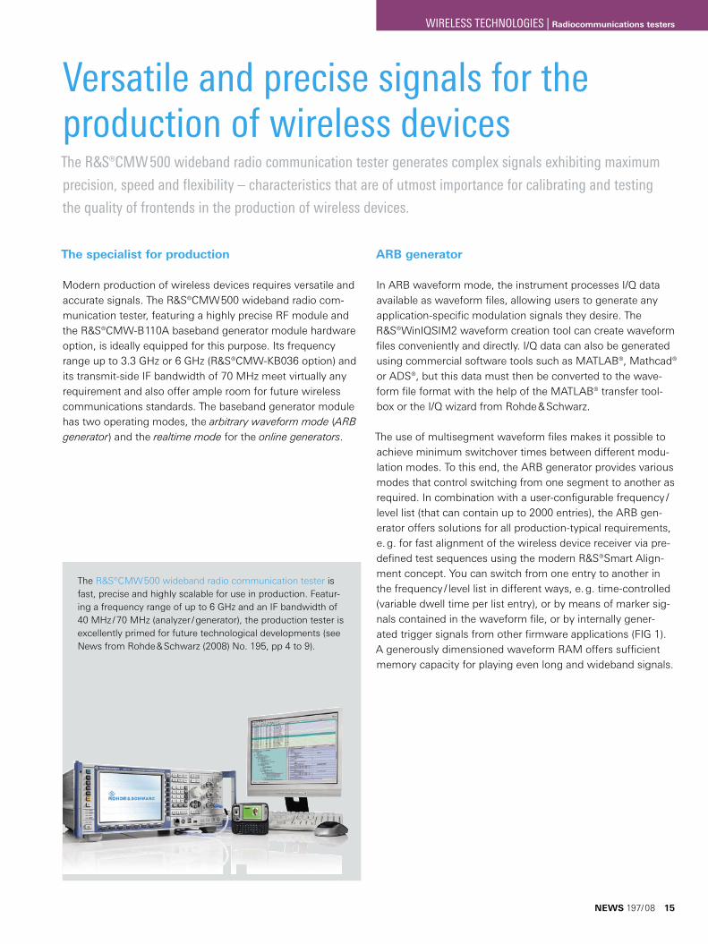
The ¸CMW500 wideband radio communication tester is fast, precise and highly scalable for use in production. Featur-ing a frequency range of up to 6 GHz and an IF bandwidth of 40 MHz / 70 MHz (analyzer / generator), the production tester is excellently primed for future technological developments (see News from Rohde & Schwarz (2008) No. 195, pp 4 to 9).
NEWS 197/08 15
WIRELESS TECHNOLOGIES | Radiocommunications testers
16
Online generators
In addition to the ARB generator, the ¸CMW500 also pro-vides online generators (¸CMW-KGxyz software options, FIG 2) – generator firmware applications that use the real-time mode of the baseband generator module. The network-specific signals can be configured online via a graphical user
FIG 2 The graph-
ical visualization of
the timeslot struc-
ture of the online
generator for
GSM / GPRS / EDGE
provides a good over-
view of the settings.
FIG 1 The ARB generator
provides different modes for
controlling the user-configurable
frequency/level list.
interface and output promptly over a wide RF frequency and level range. These downlink signal sources are especially easy to operate and highly flexible. Moreover, they generate com-plex signals with high data volume, without violating memory limits. They are therefore of particular interest when preparing for production, performing regression tests and for develop-ment in the lab.
WIRELESS TECHNOLOGIES | Radiocommunications testers
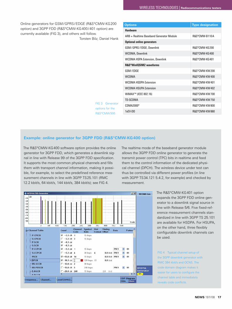
FIG 3 Generator
options for the
¸CMW500.
Options Type designation
Hardware
ARB + Realtime Baseband Generator Module ¸CMW-B110A
Optional online generators
GSM / GPRS / EDGE, Downlink ¸CMW-KG200
WCDMA, Downlink ¸CMW-KG400
WCDMA HSPA Extension, Downlink ¸CMW-KG401
¸WinIQSIM2 waveforms
GSM / EDGE ¸CMW-KW200
WCDMA ¸CMW-KW400
WCDMA HSDPA Extension ¸CMW-KW401
WCDMA HSUPA Extension ¸CMW-KW402
WiMAX™ (IEEE 802.16) ¸CMW-KW700
TD-SCDMA ¸CMW-KW750
CDMA2000® ¸CMW-KW800
1xEV-DO ¸CMW-KW880
The ¸CMW-KG400 software option provides the online generator for 3GPP FDD, which generates a downlink sig-nal in line with Release 99 of the 3GPP FDD specification. It supports the most common physical channels and fills them with transport channel information, making it possi-ble, for example, to select the predefined reference mea-surement channels in line with 3GPP TS25.101 (RMC 12.2 kbit/s, 64 kbit/s, 144 kbit/s, 384 kbit/s); see FIG 4.
The realtime mode of the baseband generator module allows the 3GPP FDD online generator to generate the transmit power control (TPC) bits in realtime and feed them to the control information of the dedicated physi-cal channel (DPCH). The wireless device under test can thus be controlled via different power profiles (in line with 3GPP TS34.121 5.4.2, for example) and checked by measurement.
The ¸CMW-KG401 option expands the 3GPP FDD online gen-erator to a downlink signal source in line with Release 5/6. Five fixed-ref-erence measurement channels stan-dardized in line with 3GPP TS 25.101 are available for HSDPA. For HSUPA, on the other hand, three flexibly configurable downlink channels can be used.
Online generators for GSM / GPRS / EDGE (¸CMW-KG200 option) and 3GPP FDD (¸CMW-KG400 / 401 option) are currently available (FIG 3), and others will follow.
Torsten Bilz; Daniel Hank
FIG 4 Typical channel setup of
the 3GPP downlink generator with
RMC 384 kbit/s and OCNS. The
code domain diagram makes it
easier for users to configure the
channel table and immediately
reveals code conflicts.
Example: online generator for 3GPP FDD (¸CMW-KG400 option)
NEWS 197/08 17
WIRELESS TECHNOLOGIES | Radiocommunications testers
18
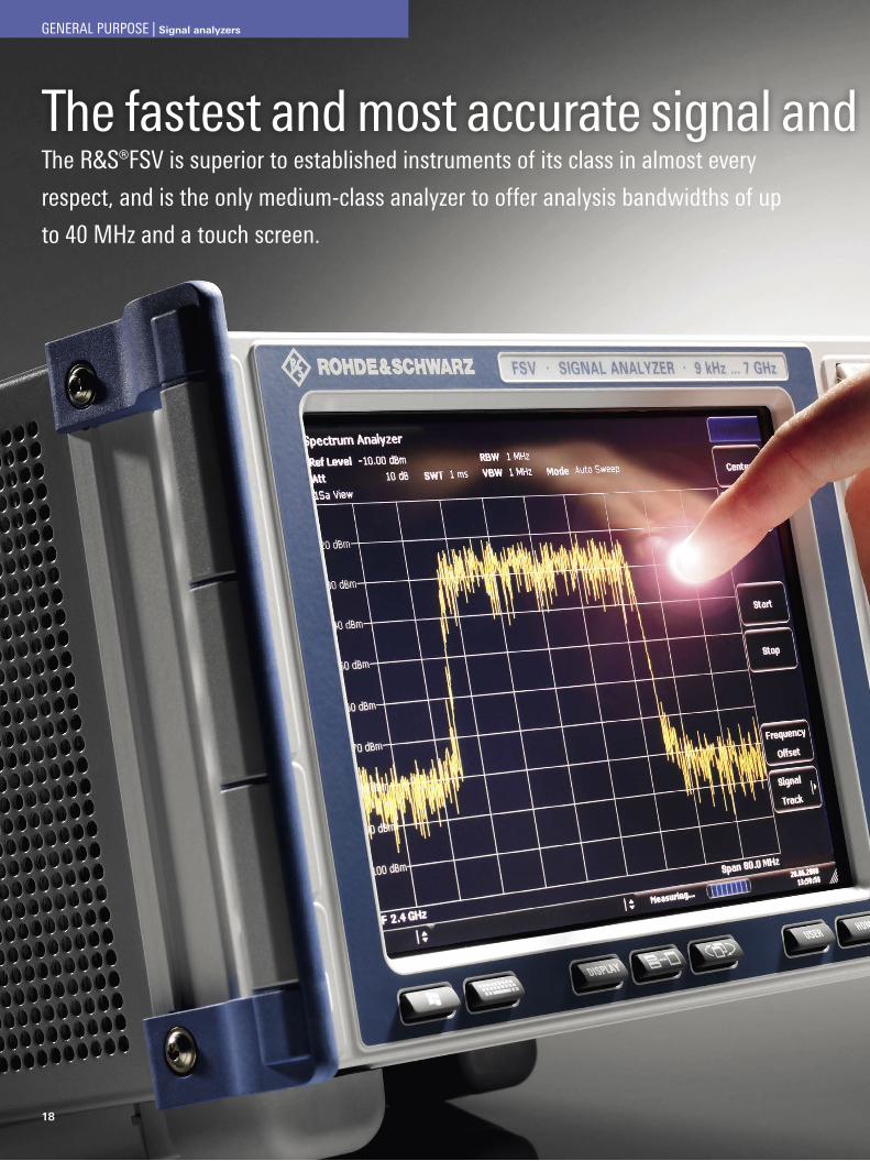
The fastest and most accurate signal and spectrum analyzer in the medium classThe R&S®FSV is superior to established instruments of its class in almost every
respect, and is the only medium-class analyzer to offer analysis bandwidths of up
to 40 MHz and a touch screen.
GENERAL PURPOSE | Signal analyzers
The fastest and most accurate signal and spectrum analyzer in the medium class
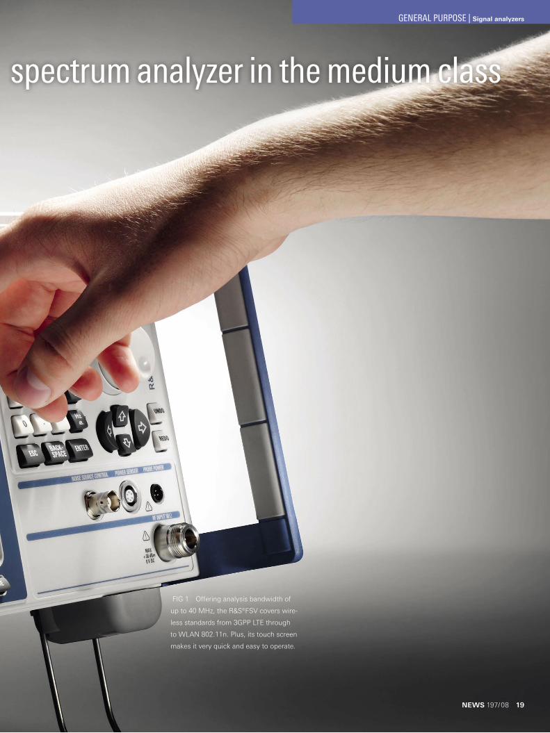
FIG 1 Offering analysis bandwidth of
up to 40 MHz, the R&S®FSV covers wire-
less standards from 3GPP LTE through
to WLAN 802.11n. Plus, its touch screen
makes it very quick and easy to operate.
NEWS 197/08 19
GENERAL PURPOSE | Signal analyzers
20
A signal analyzer that redefines the medium class
Manufacturers of wireless terminals are faced with an enor-mous cost pressure, and at the same time need to respond to the demand for innovation. This leads to the requirements for cutting development times by using more versatile and easier-to-operate T&M equipment, and for reducing production test times by using faster T&M equipment. Moreover, the steadily growing bandwidth requirements of modern wireless stan-dards call for ever increasing analysis bandwidths.
The new R&S®FSV signal analyzer (FIG 1) has been specially designed to meet these requirements. It is the fastest, most accurate and most versatile medium-class signal analyzer currently available to meet the needs of performance-ori-ented, cost-conscious users in the development, production, installation and servicing of RF systems. Superior in almost all respects to established devices in this class, it is the only medium-class analyzer to offer analysis bandwidth of 40 MHz. This enables it to cover wireless standards from 3GPP LTE through to WLAN 802.11n. Plus, its innovative operating con-cept featuring a touch screen makes it extremely easy to use.
The R&S®FSV comes in two models for the frequency ranges from 9 kHz to 3.6 GHz and 9 kHz to 7 GHz. Models for the microwave range will soon be available. The frequency range can be expanded down to 20 Hz for both models. At low fre-quencies, the R&S®FSV performs direct A/D conversion of the RF signal. This prevents a degradation of performance caused by local oscillator feedthrough and phase noise, as encoun-tered with many signal and spectrum analyzers.
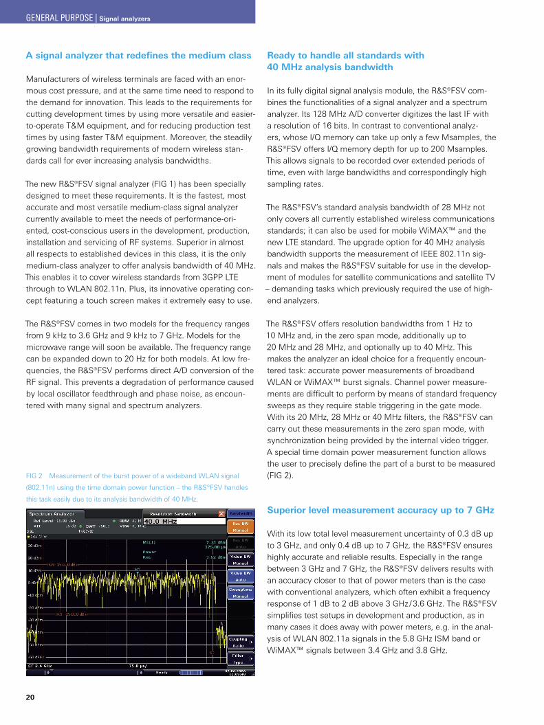
Ready to handle all standards with 40 MHz analysis bandwidth
In its fully digital signal analysis module, the R&S®FSV com-bines the functionalities of a signal analyzer and a spectrum analyzer. Its 128 MHz A/D converter digitizes the last IF with a resolution of 16 bits. In contrast to conventional analyz-ers, whose I/Q memory can take up only a few Msamples, the R&S®FSV offers I/Q memory depth for up to 200 Msamples. This allows signals to be recorded over extended periods of time, even with large bandwidths and correspondingly high sampling rates.
The R&S®FSV’s standard analysis bandwidth of 28 MHz not only covers all currently established wireless communications standards; it can also be used for mobile WiMAX™ and the new LTE standard. The upgrade option for 40 MHz analysis bandwidth supports the measurement of IEEE 802.11n sig-nals and makes the R&S®FSV suitable for use in the develop-ment of modules for satellite communications and satellite TV – demanding tasks which previously required the use of high-end analyzers.
The R&S®FSV offers resolution bandwidths from 1 Hz to 10 MHz and, in the zero span mode, additionally up to 20 MHz and 28 MHz, and optionally up to 40 MHz. This makes the analyzer an ideal choice for a frequently encoun-tered task: accurate power measurements of broadband WLAN or WiMAX™ burst signals. Channel power measure-ments are difficult to perform by means of standard frequency sweeps as they require stable triggering in the gate mode. With its 20 MHz, 28 MHz or 40 MHz filters, the R&S®FSV can carry out these measurements in the zero span mode, with synchronization being provided by the internal video trigger. A special time domain power measurement function allows the user to precisely define the part of a burst to be measured (FIG 2).
Superior level measurement accuracy up to 7 GHz
With its low total level measurement uncertainty of 0.3 dB up to 3 GHz, and only 0.4 dB up to 7 GHz, the R&S®FSV ensures highly accurate and reliable results. Especially in the range between 3 GHz and 7 GHz, the R&S®FSV delivers results with an accuracy closer to that of power meters than is the case with conventional analyzers, which often exhibit a frequency response of 1 dB to 2 dB above 3 GHz / 3.6 GHz. The R&S®FSV simplifies test setups in development and production, as in many cases it does away with power meters, e. g. in the anal-ysis of WLAN 802.11a signals in the 5.8 GHz ISM band or WiMAX™ signals between 3.4 GHz and 3.8 GHz.
FIG 2 Measurement of the burst power of a wideband WLAN signal
(802.11n) using the time domain power function – the R&S®FSV handles
this task easily due to its analysis bandwidth of 40 MHz.
GENERAL PURPOSE | Signal analyzers
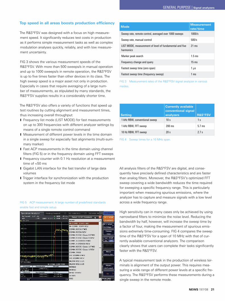
Top speed in all areas boosts production efficiency
The R&S®FSV was designed with a focus on high measure-ment speed. It significantly reduces test costs in production as it performs simple measurement tasks as well as complex modulation analyses quickly, reliably, and with low measure-ment uncertainty.
FIG 3 shows the various measurement speeds of the R&S®FSV. With more than 500 sweeps/s in manual operation and up to 1000 sweeps/s in remote operation, the R&S®FSV is up to five times faster than other devices in its class. The high sweep speed is a major asset not only in production. Especially in cases that require averaging of a large num-ber of measurements, as stipulated by many standards, the R&S®FSV supplies results in a considerably shorter time.
The R&S®FSV also offers a variety of functions that speed up test routines by cutting alignment and measurement times, thus increasing overall throughput:
Frequency list mode (LIST MODE) for fast measurements Jon up to 300 frequencies with different analyzer settings by means of a single remote control commandMeasurement of different power levels in the time domain Jin a single sweep for especially fast alignments (multi-sum-mary marker)Fast ACP measurements in the time domain using channel Jfilters (FIG 5) or in the frequency domain using FFT sweepsFrequency counter with 0.1 Hz resolution at a measurement Jtime of <50 msGigabit LAN interface for the fast transfer of large data JvolumesTrigger interface for synchronization with the production Jsystem in the frequency list mode
All analysis filters of the R&S®FSV are digital, and conse-quently have precisely defined characteristics and are faster than analog filters. Moreover, the R&S®FSV’s optimized FFT sweep covering a wide bandwidth reduces the time required for sweeping a specific frequency range. This is particularly important when measuring spurious emissions, where the analyzer has to capture and measure signals with a low level across a wide frequency range.
High sensitivity can in many cases only be achieved by using narrowband filters to minimize the noise level. Reducing the bandwidth by half, however, will increase the sweep time by a factor of four, making the measurement of spurious emis-sions extremely time-consuming. FIG 4 compares the sweep time of the R&S®FSV for a span of 10 MHz with that of cur-rently available conventional analyzers. The comparison clearly shows that users can complete their tasks significantly faster with the R&S®FSV.
A typical measurement task in the production of wireless ter-minals is alignment of the output power. This requires mea-suring a wide range of different power levels at a specific fre-quency. The R&S®FSV performs these measurements during a single sweep in the remote mode.
FIG 5 ACP measurement: A large number of predefined standards
enable fast and simple setup.
ModeMeasurement rate/time
Sweep rate, remote control, averaged over 1000 sweeps 1000/s
Sweep rate, manual control 500/s
LIST MODE, measurement of level of fundamental and five harmonics
21 ms
Marker peak search 1.5 ms
Frequency change and query 15 ms
Fastest sweep time (zero span) 1 μs
Fastest sweep time (frequency sweep) 1 ms
FIG 3 Measurement rates of the R&S®FSV signal analyzer in various
modes.
FIG 4 Sweep times for a 10 MHz span.
Setting
Currently available conventional signal analyzers R&S®FSV
1 kHz RBW, conventional sweep 10 s 1 s
1 kHz RBW, FFT sweep 200 ms 5.7 ms
10 Hz RBW, FFT sweep 20 s 2.7 s
NEWS 197/08 21
GENERAL PURPOSE | Signal analyzers
22
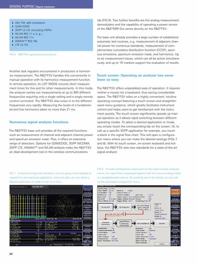
FIG 7 In several configurable windows, you can group result displays as
required for your particular application. Using the tabs, you can select a
desired application or mode in next to no time.
FIG 8 To make configuration easier even for the most complex measure-
ments, the signal flow is displayed together with the current settings listed
in a straightforward manner. By touching one of the blocks, you can call
up the associated configuration menu.
FIG 6 R&S®FSV signal analysis functions.
AM, FM, φM modulation JGSM / EDGE J3GPP UL/DL (including HSPA) JWLAN 802.11 a, b, g, j JWLAN 802.11n JWiMAX™ 802.16e JLTE UL / DL J
Another task regularly encountered in production is harmon-ics measurement. The R&S®FSV handles this conveniently in manual operation with its harmonics measurement function. In remote operation, its LIST MODE ensures short measure-ment times for this and for other measurements. In this mode, the analyzer carries out measurements at up to 300 different frequencies requiring only a single setting and a single remote control command. The R&S®FSV also tunes in to the different frequencies very rapidly. Measuring the levels of a fundamen-tal and five harmonics takes no more than 21 ms.
Numerous signal analysis functions
The R&S®FSV base unit provides all the required functions such as measurement of channel and adjacent channel power and spectrum emission mask. Plus, it offers an extensive range of detectors. Options for GSM/EDGE, 3GPP WCDMA, 3GPP LTE, WiMAX™ and WLAN analysis make the R&S®FSV an ideal development tool in the wireless communications
lab (FIG 6). Two further benefits are the analog measurement demodulator and the capability of operating a power sensor of the R&S®NRP-Zxx series directly on the R&S®FSV.
The base unit already provides a large number of established automatic test routines, e. g. measurement of adjacent chan-nel power for numerous standards, measurement of com-plementary cumulative distribution function (CCDF), spuri-ous emissions, spectrum emission mask, and harmonics. Up to six measurement traces, which can all be active simultane-ously, and up to 16 markers support the evaluation of results.
Touch screen: Operating an analyzer has never been so easy
The R&S®FSV offers unparalleled ease of operation. It requires neither a mouse nor a keyboard, thus saving considerable space. The R&S®FSV relies on a highly convenient, intuitive operating concept featuring a touch screen and straightfor-ward menu guidance, which greatly facilitates instrument control and helps users to get familiarized with the instru-ment quickly. The touch screen significantly speeds up man-ual operation as it allows rapid switching between different operating modes. To select a desired application or mode, you simply touch the corresponding tab on the screen. Or, to call up a specific 3GPP application for example, you touch a block in the signal flow chart: This will open a configura-tion menu where you can make the desired settings (FIGs 7 and 8). With its touch screen, on-screen keyboard and hot-keys, the R&S®FSV sets new standards for a state-of-the-art signal analyzer.
GENERAL PURPOSE | Signal analyzers
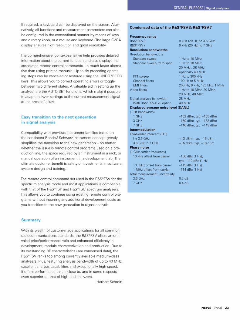
Condensed data of the R&S®FSV3 / R&S®FSV7
Frequency rangeR&S®FSV3 9 kHz (20 Hz) to 3.6 GHzR&S®FSV7 9 kHz (20 Hz) to 7 GHzResolution / bandwidthsResolution bandwidths Standard sweep 1 Hz to 10 MHz Standard sweep, zero span 1 Hz to 10 MHz, 20 MHz , 28 MHz, optionally 40 MHz FFT sweep 1 Hz to 300 kHz Channel filters 100 Hz to 5 MHz EMI filters 200 Hz, 9 kHz, 120 kHz, 1 MHzVideo filters 1 Hz to 10 MHz, 20 MHz, 28 MHz, 40 MHzSignal analysis bandwidth 28 MHz With R&S®FSV-B70 option 40 MHzDisplayed average noise level (DANL)(1 Hz bandwidth) 1 GHz –152 dBm, typ. –155 dBm 3 GHz –150 dBm, typ. –153 dBm 7 GHz –146 dBm, typ. –149 dBmIntermodulationThird-order intercept (TOI) f < 3.6 GHz +13 dBm, typ. +16 dBm 3.6 GHz to 7 GHz +15 dBm, typ. +18 dBmPhase noise(1 GHz carrier frequency) 10 kHz offset from carrier –106 dBc (1 Hz), typ. –110 dBc (1 Hz) 100 kHz offset from carrier –115 dBc (1 Hz) 1 MHz offset from carrier –134 dBc (1 Hz)Total measurement uncertainty 3.6 GHz 0.3 dB 7 GHz 0.4 dB
If required, a keyboard can be displayed on the screen. Alter-natively, all functions and measurement parameters can also be configured in the conventional manner by means of keys and a rotary knob, or a mouse and keyboard. The large SVGA display ensures high resolution and good readability.
The comprehensive, context-sensitive help provides detailed information about the current function and also displays the associated remote control commands – a much faster alterna-tive than using printed manuals. Up to six preceding operat-ing steps can be canceled or restored using the UNDO / REDO keys. This allows you to correct operating errors or toggle between two different states. A valuable aid in setting up the analyzer are the AUTO SET functions, which make it possible to adapt analyzer settings to the current measurement signal at the press of a key.
Easy transition to the next generation in signal analysis
Compatibility with previous instrument families based on the consistent Rohde & Schwarz instrument concept greatly simplifies the transition to the new generation – no matter whether the issue is remote control programs used on a pro-duction line, the space required by an instrument in a rack, or manual operation of an instrument in a development lab. The ultimate customer benefit is safety of investments in software, system design and training.
The remote control command set used in the R&S®FSV for the spectrum analysis mode and most applications is compatible with that of the R&S®FSP and R&S®FSU spectrum analyzers. This allows you to continue using existing remote control pro-grams without incurring any additional development costs as you transition to the new generation in signal analysis.
Summary
With its wealth of custom-made applications for all common radiocommunications standards, the R&S®FSV offers an unri-valed price/performance ratio and enhanced efficiency in development, module characterization and production. Due to its outstanding RF characteristics (see condensed data), the R&S®FSV ranks top among currently available medium-class analyzers. Plus, featuring analysis bandwidth of up to 40 MHz, excellent analysis capabilities and exceptionally high speed, it offers performance that is close to, and in some respects even superior to, that of high-end analyzers.
Herbert Schmitt
NEWS 197/08 23
GENERAL PURPOSE | Signal analyzers
24
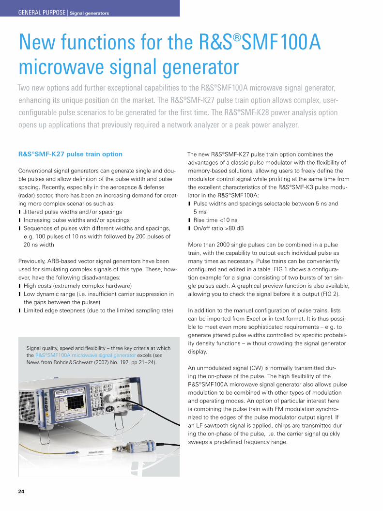
Signal quality, speed and flexibility – three key criteria at which the ¸SMF100A microwave signal generator excels (see News from Rohde & Schwarz (2007) No. 192, pp 21–24).
New functions for the ¸SMF100A microwave signal generatorTwo new options add further exceptional capabilities to the ¸SMF100A microwave signal generator,
enhancing its unique position on the market. The ¸SMF-K27 pulse train option allows complex, user-
configurable pulse scenarios to be generated for the first time. The ¸SMF-K28 power analysis option
opens up applications that previously required a network analyzer or a peak power analyzer.
¸SMF-K27 pulse train option
Conventional signal generators can generate single and dou-ble pulses and allow definition of the pulse width and pulse spacing. Recently, especially in the aerospace & defense (radar) sector, there has been an increasing demand for creat-ing more complex scenarios such as:
Jittered pulse widths and / or spacings JIncreasing pulse widths and / or spacings JSequences of pulses with different widths and spacings, Je. g. 100 pulses of 10 ns width followed by 200 pulses of 20 ns width
Previously, ARB-based vector signal generators have been used for simulating complex signals of this type. These, how-ever, have the following disadvantages:
High costs (extremely complex hardware) JLow dynamic range (i. e. insufficient carrier suppression in Jthe gaps between the pulses)Limited edge steepness (due to the limited sampling rate) J
The new ¸SMF-K27 pulse train option combines the advantages of a classic pulse modulator with the flexibility of memory-based solutions, allowing users to freely define the modulator control signal while profiting at the same time from the excellent characteristics of the ¸SMF-K3 pulse modu-lator in the ¸SMF100A:
Pulse widths and spacings selectable between 5 ns and J5 msRise time <10 ns JOn/off ratio >80 dB J
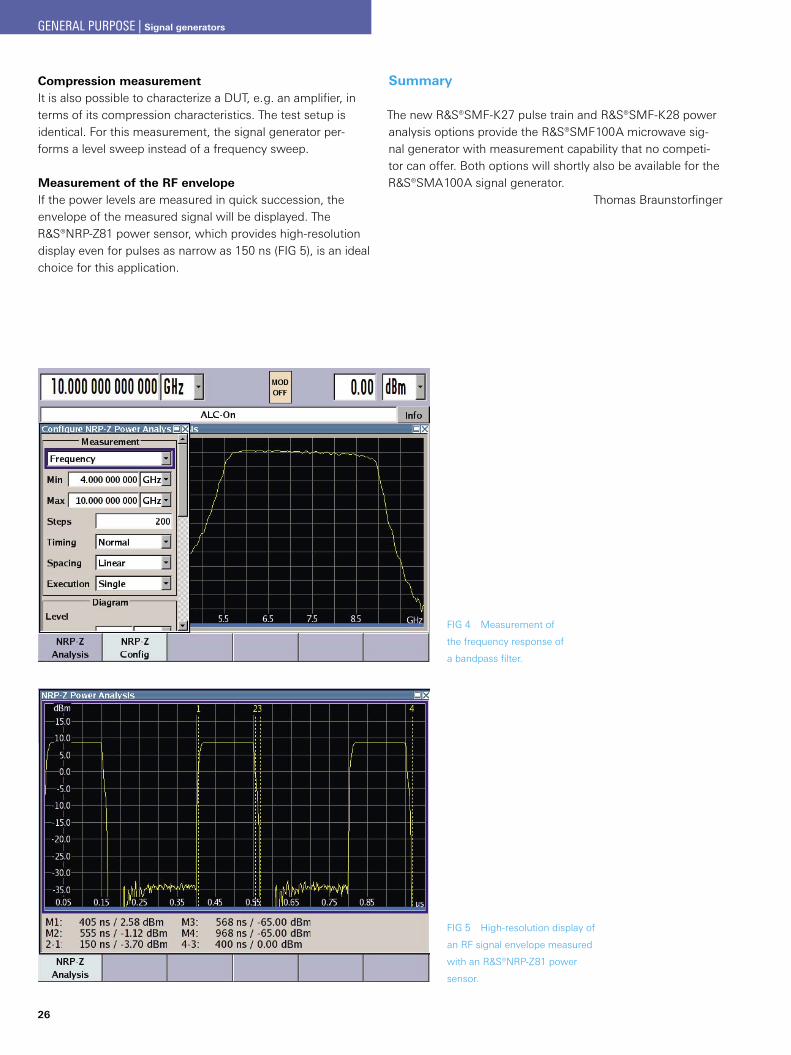
More than 2000 single pulses can be combined in a pulse train, with the capability to output each individual pulse as many times as necessary. Pulse trains can be conveniently configured and edited in a table. FIG 1 shows a configura-tion example for a signal consisting of two bursts of ten sin-gle pulses each. A graphical preview function is also available, allowing you to check the signal before it is output (FIG 2).
In addition to the manual configuration of pulse trains, lists can be imported from Excel or in text format. It is thus possi-ble to meet even more sophisticated requirements – e. g. to generate jittered pulse widths controlled by specific probabil-ity density functions – without crowding the signal generator display.
An unmodulated signal (CW) is normally transmitted dur-ing the on-phase of the pulse. The high flexibility of the ¸SMF100A microwave signal generator also allows pulse modulation to be combined with other types of modulation and operating modes. An option of particular interest here is combining the pulse train with FM modulation synchro-nized to the edges of the pulse modulator output signal. If an LF sawtooth signal is applied, chirps are transmitted dur-ing the on-phase of the pulse, i. e. the carrier signal quickly sweeps a predefined frequency range.
GENERAL PURPOSE | Signal generators
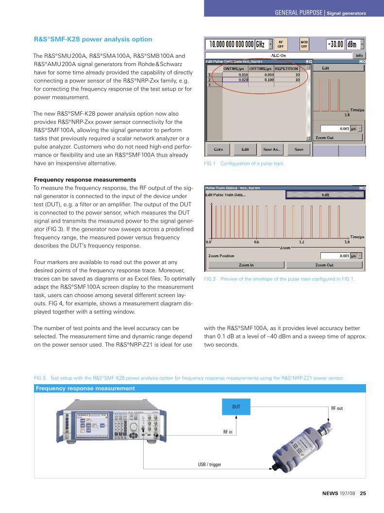
FIG 1 Configuration of a pulse train.
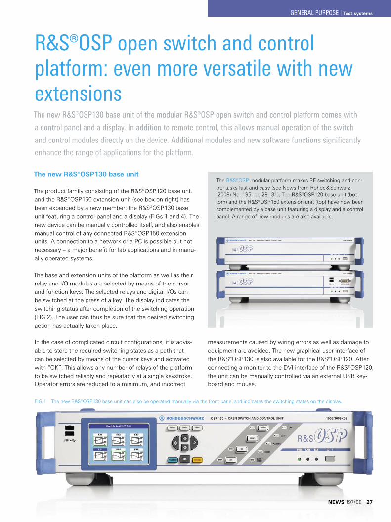
FIG 3 Test setup with the ¸SMF-K28 power analysis option for frequency response measurements using the ¸NRP-Z21 power sensor.
FIG 2 Preview of the envelope of the pulse train configured in FIG 1.
¸SMF-K28 power analysis option
The ¸SMU200A, ¸SMA100A, ¸SMB100A and ¸AMU200A signal generators from Rohde & Schwarz have for some time already provided the capability of directly connecting a power sensor of the ¸NRP-Zxx family, e. g. for correcting the frequency response of the test setup or for power measurement.
The new ¸SMF-K28 power analysis option now also provides ¸NRP-Zxx power sensor connectivity for the ¸SMF100A, allowing the signal generator to perform tasks that previously required a scalar network analyzer or a pulse analyzer. Customers who do not need high-end perfor-mance or flexibility and use an ¸SMF100A thus already have an inexpensive alternative.
Frequency response measurementsTo measure the frequency response, the RF output of the sig-nal generator is connected to the input of the device under test (DUT), e. g. a filter or an amplifier. The output of the DUT is connected to the power sensor, which measures the DUT signal and transmits the measured power to the signal gener-ator (FIG 3). If the generator now sweeps across a predefined frequency range, the measured power versus frequency describes the DUT’s frequency response.
Four markers are available to read out the power at any desired points of the frequency response trace. Moreover, traces can be saved as diagrams or as Excel files. To optimally adapt the ¸SMF100A screen display to the measurement task, users can choose among several different screen lay-outs. FIG 4, for example, shows a measurement diagram dis-played together with a setting window.
The number of test points and the level accuracy can be selected. The measurement time and dynamic range depend on the power sensor used. The ¸NRP-Z21 is ideal for use
DUT
RF in
RF out
USB / trigger
Frequency response measurement
with the ¸SMF100A, as it provides level accuracy better than 0.1 dB at a level of –40 dBm and a sweep time of approx. two seconds.
NEWS 197/08 25
GENERAL PURPOSE | Signal generators
26
FIG 4 Measurement of
the frequency response of
a bandpass filter.
FIG 5 High-resolution display of
an RF signal envelope measured
with an ¸NRP-Z81 power
sensor.
Compression measurementIt is also possible to characterize a DUT, e. g. an amplifier, in terms of its compression characteristics. The test setup is identical. For this measurement, the signal generator per-forms a level sweep instead of a frequency sweep.
Measurement of the RF envelopeIf the power levels are measured in quick succession, the envelope of the measured signal will be displayed. The ¸NRP-Z81 power sensor, which provides high-resolution display even for pulses as narrow as 150 ns (FIG 5), is an ideal choice for this application.
Summary
The new ¸SMF-K27 pulse train and ¸SMF-K28 power analysis options provide the ¸SMF100A microwave sig-nal generator with measurement capability that no competi-tor can offer. Both options will shortly also be available for the ¸SMA100A signal generator.
Thomas Braunstorfinger
GENERAL PURPOSE | Signal generators
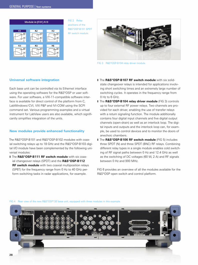
R&S®OSP open switch and control platform: even more versatile with new extensionsThe new ¸OSP130 base unit of the modular ¸OSP open switch and control platform comes with
a control panel and a display. In addition to remote control, this allows manual operation of the switch
and control modules directly on the device. Additional modules and new software functions significantly
enhance the range of applications for the platform.
The new ¸OSP130 base unit
The product family consisting of the ¸OSP120 base unit and the ¸OSP150 extension unit (see box on right) has been expanded by a new member: the ¸OSP130 base unit featuring a control panel and a display (FIGs 1 and 4). The new device can be manually controlled itself, and also enables manual control of any connected ¸OSP150 extension units. A connection to a network or a PC is possible but not necessary – a major benefit for lab applications and in manu-ally operated systems.
The base and extension units of the platform as well as their relay and I/O modules are selected by means of the cursor and function keys. The selected relays and digital I/Os can be switched at the press of a key. The display indicates the switching status after completion of the switching operation (FIG 2). The user can thus be sure that the desired switching action has actually taken place.
In the case of complicated circuit configurations, it is advis-able to store the required switching states as a path that can be selected by means of the cursor keys and activated with “OK”. This allows any number of relays of the platform to be switched reliably and repeatably at a single keystroke. Operator errors are reduced to a minimum, and incorrect
FIG 1 The new ¸OSP130 base unit can also be operated manually via the front panel and indicates the switching states on the display.
The ¸OSP modular platform makes RF switching and con-trol tasks fast and easy (see News from Rohde & Schwarz (2008) No. 195, pp 28–31). The ¸OSP120 base unit (bot-tom) and the ¸OSP150 extension unit (top) have now been complemented by a base unit featuring a display and a control panel. A range of new modules are also available.
measurements caused by wiring errors as well as damage to equipment are avoided. The new graphical user interface of the ¸OSP130 is also available for the ¸OSP120. After connecting a monitor to the DVI interface of the ¸OSP120, the unit can be manually controlled via an external USB key-board and mouse.
NEWS 197/08 27
GENERAL PURPOSE | Test systems
28
FIG 4 Rear view of the new ¸OSP130 base unit, equipped with three modules in this example.
FIG 2 Relay
positions of the
¸OSP-B101 SPDT
RF switch module.
Universal software integration
Each base unit can be controlled via its Ethernet interface using the operating software for the ¸OSP or user soft-ware. For user software, a VXI-11-compatible software inter-face is available for direct control of the platform from C, LabWindows / CVI, VXI P&P and IVI-COM using the SCPI command set. Various programming examples and a virtual instrument for LabView users are also available, which signifi-cantly simplifies integration of the units.
New modules provide enhanced functionality
The ¸OSP-B101 and ¸OSP-B102 modules with coax-ial switching relays up to 18 GHz and the ¸OSP-B103 digi-tal I/O module have been complemented by the following uni-versal modules:
The J ¸OSP-B111 RF switch module with six coax-ial changeover relays (SPDT) and the ¸OSP-B112 RF switch module with two coaxial multiposition relays (SP6T) for the frequency range from 0 Hz to 40 GHz per-form switching tasks in radar applications, for example.
The J ¸OSP-B107 RF switch module with six solid-state changeover relays is intended for applications involv-ing short switching times and an extremely large number of switching cycles. It operates in the frequency range from 0 Hz to 6 GHz.The J ¸OSP-B104 relay driver module (FIG 3) controls up to four external RF power relays. Two channels are pro-vided for each driver, enabling the use of transfer relays with a return signaling function. The module additionally contains four digital input channels and five digital output channels (open-drain) as well as an interlock loop. The digi-tal inputs and outputs and the interlock loop can, for exam-ple, be used to control devices and to monitor the doors of anechoic chambers.The J ¸OSP-B106 RF switch module (FIG 5) includes three SPDT (N) and three SPDT (BNC) RF relays. Combining different relay types in a single module enables cold switch-ing of RF signal paths between 0 Hz and 12.4 GHz as well as the switching of DC voltages (60 W, 2 A) and RF signals between 0 Hz and 900 MHz.
FIG 6 provides an overview of all the modules available for the ¸OSP open switch and control platform.
FIG 3 ¸OSP-B104 relay driver module.
GENERAL PURPOSE | Test systems
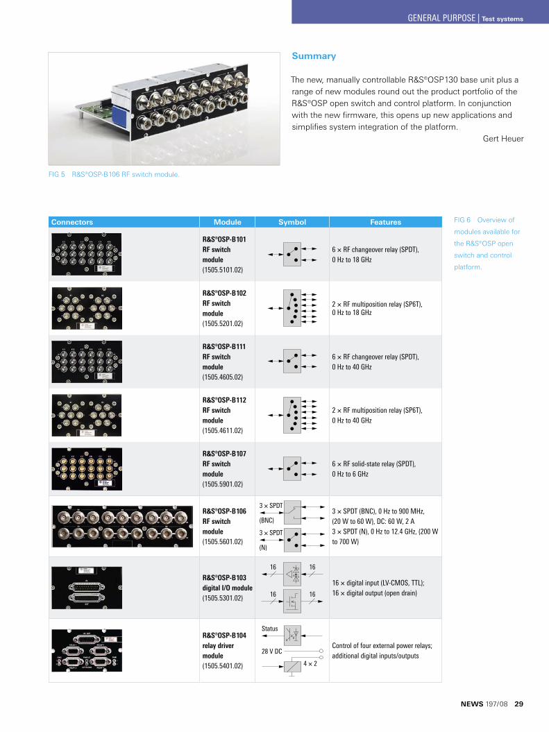
Connectors Module Symbol Features
¸OSP-B101 RF switch module(1505.5101.02)
6 × RF changeover relay (SPDT), 0 Hz to 18 GHz
¸OSP-B102 RF switch module(1505.5201.02)
2 × RF multiposition relay (SP6T), 0 Hz to 18 GHz
¸OSP-B111 RF switch module(1505.4605.02)
6 × RF changeover relay (SPDT), 0 Hz to 40 GHz
¸OSP-B112 RF switch module(1505.4611.02)
2 × RF multiposition relay (SP6T), 0 Hz to 40 GHz
¸OSP-B107 RF switch module(1505.5901.02)
6 × RF solid-state relay (SPDT), 0 Hz to 6 GHz
¸OSP-B106 RF switch module(1505.5601.02)
3 × SPDT
(N)
3 × SPDT
(BNC)3 × SPDT (BNC), 0 Hz to 900 MHz, (20 W to 60 W), DC: 60 W, 2 A 3 × SPDT (N), 0 Hz to 12.4 GHz, (200 W to 700 W)
¸OSP-B103 digital I/O module(1505.5301.02)
16
16
16
16
16 × digital input (LV-CMOS, TTL); 16 × digital output (open drain)
¸OSP-B104 relay driver module(1505.5401.02)
Status
4 × 2
28 V DCControl of four external power relays; additional digital inputs/outputs
FIG 6 Overview of
modules available for
the ¸OSP open
switch and control
platform.
Summary
The new, manually controllable ¸OSP130 base unit plus a range of new modules round out the product portfolio of the ¸OSP open switch and control platform. In conjunction with the new firmware, this opens up new applications and simplifies system integration of the platform.
Gert Heuer
FIG 5 ¸OSP-B106 RF switch module.
NEWS 197/08 29
GENERAL PURPOSE | Test systems
I2S data format
~ ~ ~ ~
~ ~ ~ ~
~ ~~ ~~ ~
BitClk
Fsync
DATA MSB LSB MSB
Word nRight channel
Word nLeft channel
Word n – 1Right channel
Word offset
Audio bits
Word length
30
Audioanalysatoren
Interface card for the latest data formats complements the ¸UPV audio analyzer
The compact ¸UPV audio analyzer easily handles all types of measurements in the audio sector, meeting the extreme demands of both analog technologies and high-resolution dig-ital media (see NEWS from Rohde & Schwarz (2008) No. 196, pp 36–38).
State-of-the-art circuits in multichannel audio systems, wireless communications applications and
Bluetooth® components use new data formats to transmit audio content. The top-class R&S®UPV audio
analyzer is already well prepared for these formats: Equipped with the new ¸UPV-B42 universal serial
interface, it can adapt virtually all existing audio data formats.
Increasing variety of digital audio interfaces
Nowadays, interconnecting digital audio equipment via stan-dardized interfaces is considered standard procedure. Profes-sional sound studios use the AES/EBU format, while devices for the consumer sector are equipped with electrical or opti-cal interfaces based on the S/P-DIF standard.
However, when looking inside such audio devices, i. e. at the circuitry interconnecting the various modules and compo-nents, primarily different serial data interfaces are used. Dual-channel, device-internal audio data transmission often utilizes the inter-IC sound (I²S) bus standard that has been estab-lished worldwide. The ¸UPV has supported this format for quite some time now with the ¸UPV-B41 I²S interface option.
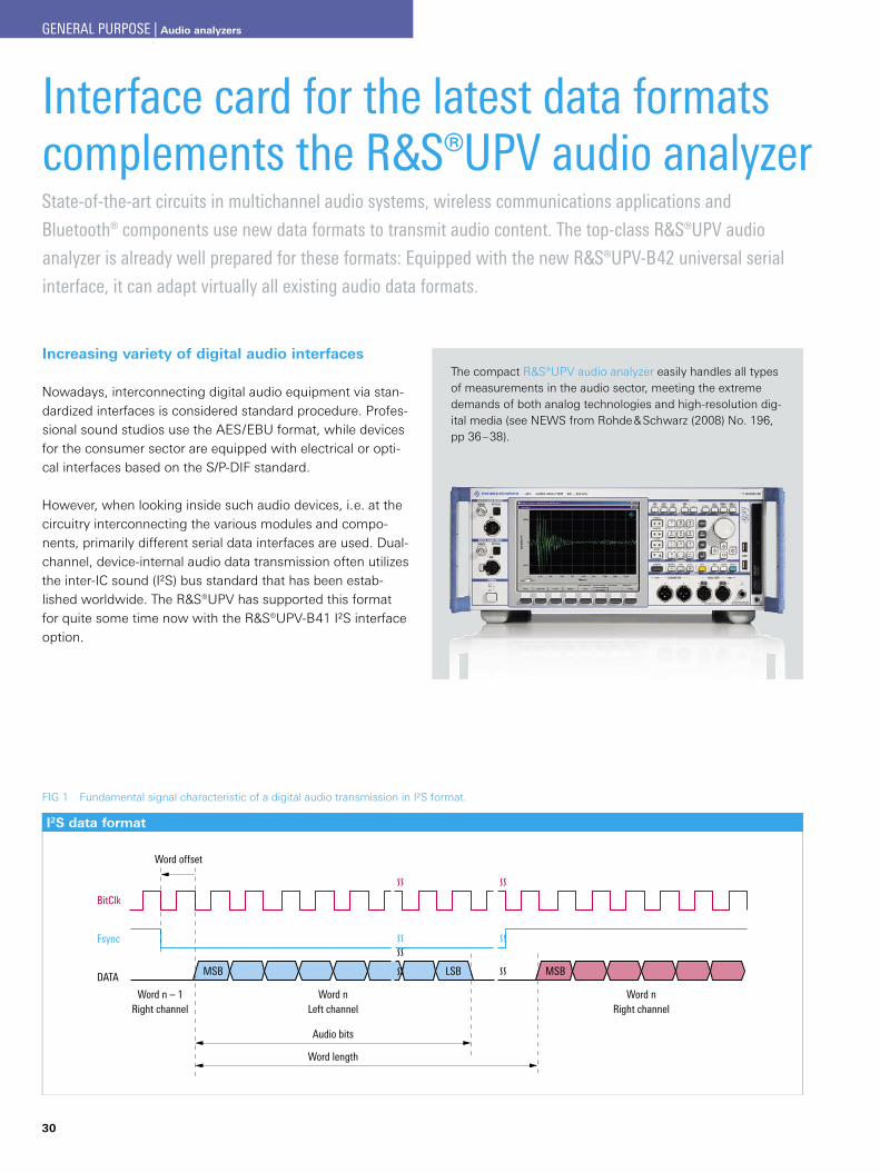
FIG 1 Fundamental signal characteristic of a digital audio transmission in I²S format.
GENERAL PURPOSE | Audio analyzers
BitClk
Fsync
SlotClk
DATA 1
DATA 2
DATA 3
DATA 4
1 frame, up to 256 slots
Signal 1 Signal 2 Signal 1
Signal 1
Signal 2Signal 2
Signal 1 Signal 1Signal 1
Signal 1 Signal 2
Signal 1 Signal 2
Signal 2 Signal 1
Signal 1 Signal 1Signal 1Signal 1
With new applications, however, the limits of the I²S bus have been reached. The widely spread use of surround sound tech-nology, for example, resulted in the development of multi-channel A/D and D/A converters. Plus, wireless communi-cations applications and audio transmission in Bluetooth® components demanded new data formats for transmitting audio content.
The new universal serial interface card (R&S®UPV-B42 option) for the R&S®UPV audio analyzer supports all of these develop-ments. Like all other options of the R&S®UPV-B4x series, this interface card is simply plugged into one of the two slots on the rear of the audio analyzer.
The I²S audio format – basis for numerous new developments
The new R&S®UPV-B42 interface card also supports the con-ventional I²S audio format, which is briefly described below, as many state-of-the-art developments are based on it. Three basic signals are defined with this standard: BitClk (bit clock), Fsync (frame synchronization) and DATA (FIG 1). With each period of the bit clock, one audio data bit is transmitted; DATA is a dual-channel, multiplexed, bit-serial data stream, and Fsync designates the start-of-word in the serial data stream and differentiates between the left and the right channel. Audio data is transmitted using the “MSB first” method in two’s complement format. Common word lengths are 16 bit, 24 bit and 32 bit, but operation with fewer audio bits is also
possible. Generally, the transmit IC generates the clock, frame synchronization and data; in more com-plex systems, the transmit IC can be synchronized by a central system clock referred to as the master clock.
Further developments in the transmission of serial digital audio data extend and modify many of these parameters, use more channels and higher clock rates, etc. The new R&S®UPV-B42 interface card offers even more functionalities than currently required.
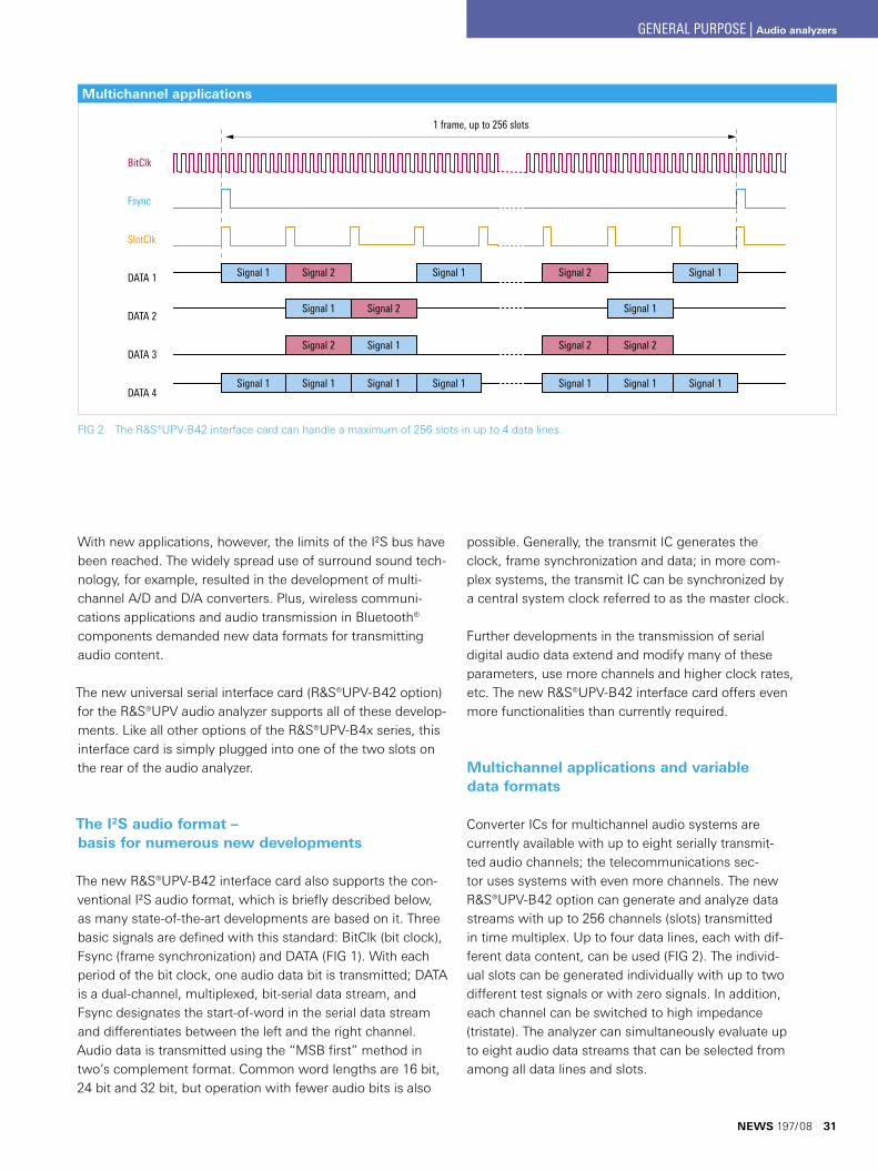
Multichannel applications and variable data formats
Converter ICs for multichannel audio systems are currently available with up to eight serially transmit-ted audio channels; the telecommunications sec-tor uses systems with even more channels. The new R&S®UPV-B42 option can generate and analyze data streams with up to 256 channels (slots) transmitted in time multiplex. Up to four data lines, each with dif-ferent data content, can be used (FIG 2). The individ-ual slots can be generated individually with up to two different test signals or with zero signals. In addition, each channel can be switched to high impedance (tristate). The analyzer can simultaneously evaluate up to eight audio data streams that can be selected from among all data lines and slots.
FIG 2 The ¸UPV-B42 interface card can handle a maximum of 256 slots in up to 4 data lines.
Multichannel applications
NEWS 197/08 31
GENERAL PURPOSE | Audio analyzers
32
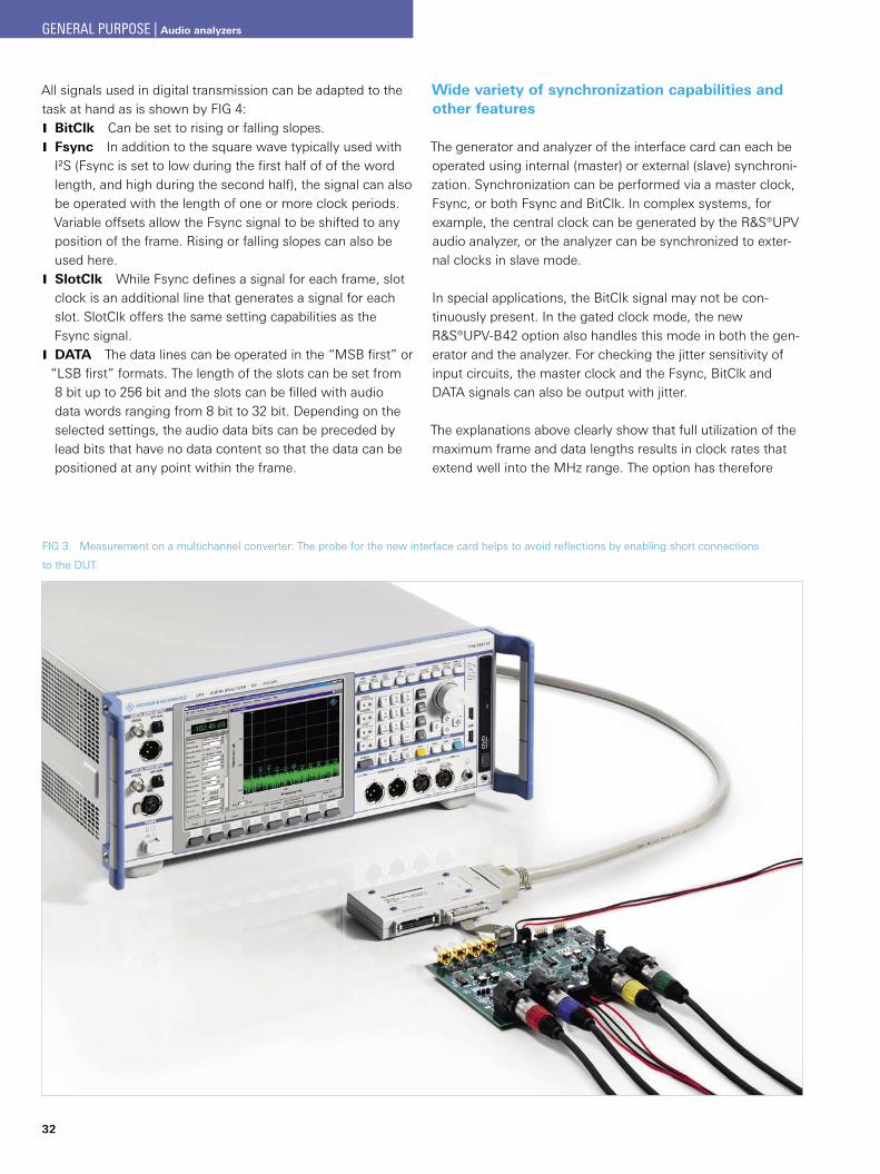
FIG 3 Measurement on a multichannel converter: The probe for the new interface card helps to avoid reflections by enabling short connections
to the DUT.
Wide variety of synchronization capabilities and other features
The generator and analyzer of the interface card can each be operated using internal (master) or external (slave) synchroni-zation. Synchronization can be performed via a master clock, Fsync, or both Fsync and BitClk. In complex systems, for example, the central clock can be generated by the R&S®UPV audio analyzer, or the analyzer can be synchronized to exter-nal clocks in slave mode.
In special applications, the BitClk signal may not be con-tinuously present. In the gated clock mode, the new R&S®UPV-B42 option also handles this mode in both the gen-erator and the analyzer. For checking the jitter sensitivity of input circuits, the master clock and the Fsync, BitClk and DATA signals can also be output with jitter.
The explanations above clearly show that full utilization of the maximum frame and data lengths results in clock rates that extend well into the MHz range. The option has therefore
All signals used in digital transmission can be adapted to the task at hand as is shown by FIG 4:
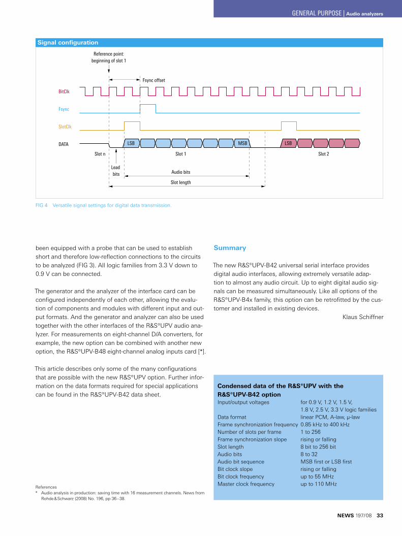
BitClk J Can be set to rising or falling slopes.Fsync J In addition to the square wave typically used with I²S (Fsync is set to low during the first half of of the word length, and high during the second half), the signal can also be operated with the length of one or more clock periods. Variable offsets allow the Fsync signal to be shifted to any position of the frame. Rising or falling slopes can also be used here.SlotClk J While Fsync defines a signal for each frame, slot clock is an additional line that generates a signal for each slot. SlotClk offers the same setting capabilities as the Fsync signal.DATA J The data lines can be operated in the “MSB first” or
“LSB first” formats. The length of the slots can be set from 8 bit up to 256 bit and the slots can be filled with audio data words ranging from 8 bit to 32 bit. Depending on the selected settings, the audio data bits can be preceded by lead bits that have no data content so that the data can be positioned at any point within the frame.
GENERAL PURPOSE | Audio analyzers
Reference point:beginning of slot 1
Fsync offset
BitClk
Fsync
SlotClk
DATA LSB MSB LSB
Slot 2Slot 1Slot n
Audio bits
Slot length
Lead bits
FIG 4 Versatile signal settings for digital data transmission.
Condensed data of the ¸UPV with the ¸UPV-B42 optionInput/output voltages for 0.9 V, 1.2 V, 1.5 V, 1.8 V, 2.5 V, 3.3 V logic familiesData format linear PCM, A-law, µ-lawFrame synchronization frequency 0.85 kHz to 400 kHzNumber of slots per frame 1 to 256Frame synchronization slope rising or fallingSlot length 8 bit to 256 bitAudio bits 8 to 32Audio bit sequence MSB first or LSB first Bit clock slope rising or fallingBit clock frequency up to 55 MHzMaster clock frequency up to 110 MHz
been equipped with a probe that can be used to establish short and therefore low-reflection connections to the circuits to be analyzed (FIG 3). All logic families from 3.3 V down to 0.9 V can be connected.
The generator and the analyzer of the interface card can be configured independently of each other, allowing the evalu-tion of components and modules with different input and out-put formats. And the generator and analyzer can also be used together with the other interfaces of the R&S®UPV audio ana-lyzer. For measurements on eight-channel D/A converters, for example, the new option can be combined with another new option, the R&S®UPV-B48 eight-channel analog inputs card [*].
This article describes only some of the many configurations that are possible with the new ¸UPV option. Further infor-mation on the data formats required for special applications can be found in the ¸UPV-B42 data sheet.
ReferencesAudio analysis in production: saving time with 16 measurement channels. News from * Rohde & Schwarz (2008) No. 196, pp 36–38.
Signal configuration
Summary
The new ¸UPV-B42 universal serial interface provides digital audio interfaces, allowing extremely versatile adap-tion to almost any audio circuit. Up to eight digital audio sig-nals can be measured simultaneously. Like all options of the ¸UPV-B4x family, this option can be retrofitted by the cus-tomer and installed in existing devices.
Klaus Schiffner
NEWS 197/08 33
GENERAL PURPOSE | Audio analyzers
34
In 1989, the German Armed
Forces (Bundeswehr)
contracted Rohde & Schwarz
to supply the entire test and
measurement equipment
for its EMC test center in
Greding, one of the largest
worldwide. Over the last
few years, in close collabo-
ration with the Bundeswehr
Technical Center for Infor-
mation Technology and
Electronics (WTD81), this
test center has been
completely updated with
the latest technology. It
relies on an elaborate
concept that satisfies
even the most challenging
demands placed on EMC
test centers.
State-of-the-art: the German Arme d Forces’ EMC test center
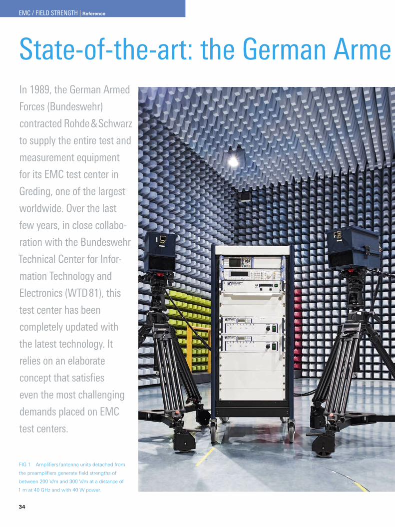
FIG 1 Amplifiers/antenna units detached from
the preamplifiers generate field strengths of
between 200 V/m and 300 V/m at a distance of
1 m at 40 GHz and with 40 W power.
EMC / FIELD STRENGTH | Reference
The decisive factors in EMC test centers: flexibility and 100 % versatility
EMC tests are indispensable in the development of electronic instruments and systems. In contrast to individual compo-nents, complex systems such as vehicles or radar systems can be subjected to EMC tests as complete functional units only at a relatively late stage in their development. In addition, the usually tight development schedules demand quick and flexible adjustment of test schedules, with the consequence that test center capacities are utilized to a constantly varying degree, which makes resource planning very difficult. More-over, the installed test equipment should be capable of testing a wide variety of equipment.
The EMC test center in the Bundeswehr Technical Center for Information Technology and Electronics (WTD81) in Greding, one of the largest worldwide, is a prime example of flexibil-ity, versatility and usability for fully automatic measurements. As early as 1989, Rohde & Schwarz installed a full range of T&M equipment, and in the last few years the center has been upgraded with the latest technology as part of a moderniza-tion and expansion program.
Elaborate design for optimal use of system resources
In every development project, the time schedule and conse-quently the scheduling of the associated EMC tests are sub-ject to frequent changes. Developers are permanently con-fronted with the issues of whether equipment under test (EUT) has to be modified, whether the modification can be performed on site, or whether an additional test date is neces-sary. In many cases, the time required for measurements can-not be precisely defined, which complicates test lab resource planning. State-of-the-art EMC test centers must therefore be designed to ensure maximum and efficient utilization of resources despite the fact that short-term planning of their test capacity is normally not possible.
These requirements formed the basis for the design of the WTD81 EMC test center. A large and a small anechoic cham-ber and a reverberation chamber are available for measure-ments. Each test chamber is permanently assigned a control room with a test receiver, signal generator, power meter, EUT monitoring and ¸EMC32 measurement software from Rohde & Schwarz (FIG 3). Amplifiers with powers of 5 kW and
State-of-the-art: the German Arme d Forces’ EMC test center
FIG 2 The amplifiers are accommodated in a central, shielded room and
can be assigned to the test chambers as required.
10 kW for frequencies between 9 kHz and 100 MHz and 2 kW and 5 kW for frequencies between 80 MHz and 1 GHz are provided in a central, shielded amplifier room (FIGs 2 and 4).
The necessary power depends on the test conditions and requirements in each case, e. g. the stipulated test sever-ity, the distance to the EUT, or the antenna used. The max-imum available power is not always needed in all cham-bers. The amplifiers can therefore be assigned as required to the individual test chambers or – for system tests and sys-tem calibration – to the load resistors, which ensures efficient
NEWS 197/08 35
EMC / FIELD STRENGTH | Reference
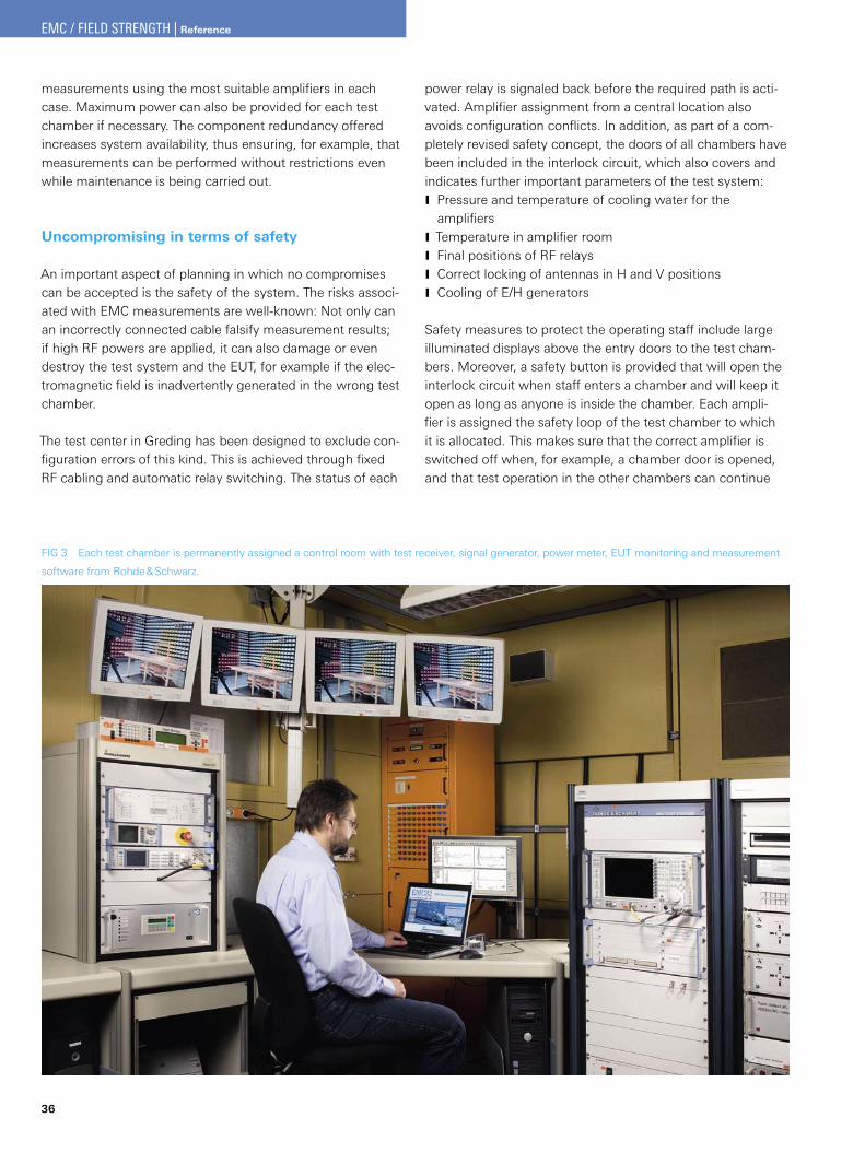
36
measurements using the most suitable amplifiers in each case. Maximum power can also be provided for each test chamber if necessary. The component redundancy offered increases system availability, thus ensuring, for example, that measurements can be performed without restrictions even while maintenance is being carried out.
Uncompromising in terms of safety
An important aspect of planning in which no compromises can be accepted is the safety of the system. The risks associ-ated with EMC measurements are well-known: Not only can an incorrectly connected cable falsify measurement results; if high RF powers are applied, it can also damage or even destroy the test system and the EUT, for example if the elec-tromagnetic field is inadvertently generated in the wrong test chamber.
The test center in Greding has been designed to exclude con-figuration errors of this kind. This is achieved through fixed RF cabling and automatic relay switching. The status of each
power relay is signaled back before the required path is acti-vated. Amplifier assignment from a central location also avoids configuration conflicts. In addition, as part of a com-pletely revised safety concept, the doors of all chambers have been included in the interlock circuit, which also covers and indicates further important parameters of the test system:
Pressure and temperature of cooling water for the JamplifiersTemperature in amplifier room JFinal positions of RF relays JCorrect locking of antennas in H and V positions JCooling of E/H generators J
Safety measures to protect the operating staff include large illuminated displays above the entry doors to the test cham-bers. Moreover, a safety button is provided that will open the interlock circuit when staff enters a chamber and will keep it open as long as anyone is inside the chamber. Each ampli-fier is assigned the safety loop of the test chamber to which it is allocated. This makes sure that the correct amplifier is switched off when, for example, a chamber door is opened, and that test operation in the other chambers can continue
FIG 3 Each test chamber is permanently assigned a control room with test receiver, signal generator, power meter, EUT monitoring and measurement
software from Rohde & Schwarz.
EMC / FIELD STRENGTH | Reference
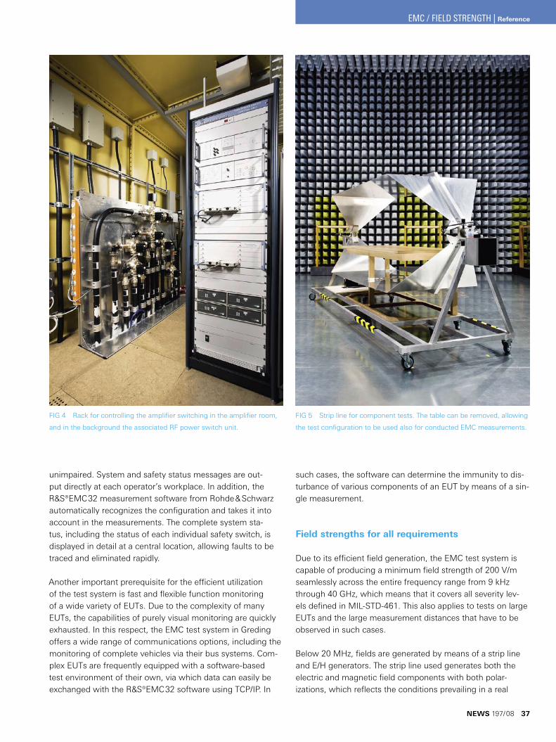
unimpaired. System and safety status messages are out-put directly at each operator’s workplace. In addition, the ¸EMC32 measurement software from Rohde & Schwarz automatically recognizes the configuration and takes it into account in the measurements. The complete system sta-tus, including the status of each individual safety switch, is displayed in detail at a central location, allowing faults to be traced and eliminated rapidly.
Another important prerequisite for the efficient utilization of the test system is fast and flexible function monitoring of a wide variety of EUTs. Due to the complexity of many EUTs, the capabilities of purely visual monitoring are quickly exhausted. In this respect, the EMC test system in Greding offers a wide range of communications options, including the monitoring of complete vehicles via their bus systems. Com-plex EUTs are frequently equipped with a software-based test environment of their own, via which data can easily be exchanged with the ¸EMC32 software using TCP/IP. In
such cases, the software can determine the immunity to dis-turbance of various components of an EUT by means of a sin-gle measurement.
Field strengths for all requirements
Due to its efficient field generation, the EMC test system is capable of producing a minimum field strength of 200 V/m seamlessly across the entire frequency range from 9 kHz through 40 GHz, which means that it covers all severity lev-els defined in MIL-STD-461. This also applies to tests on large EUTs and the large measurement distances that have to be observed in such cases.
Below 20 MHz, fields are generated by means of a strip line and E/H generators. The strip line used generates both the electric and magnetic field components with both polar-izations, which reflects the conditions prevailing in a real
FIG 4 Rack for controlling the amplifier switching in the amplifier room,
and in the background the associated RF power switch unit.
FIG 5 Strip line for component tests. The table can be removed, allowing
the test configuration to be used also for conducted EMC measurements.
NEWS 197/08 37
EMC / FIELD STRENGTH | Reference
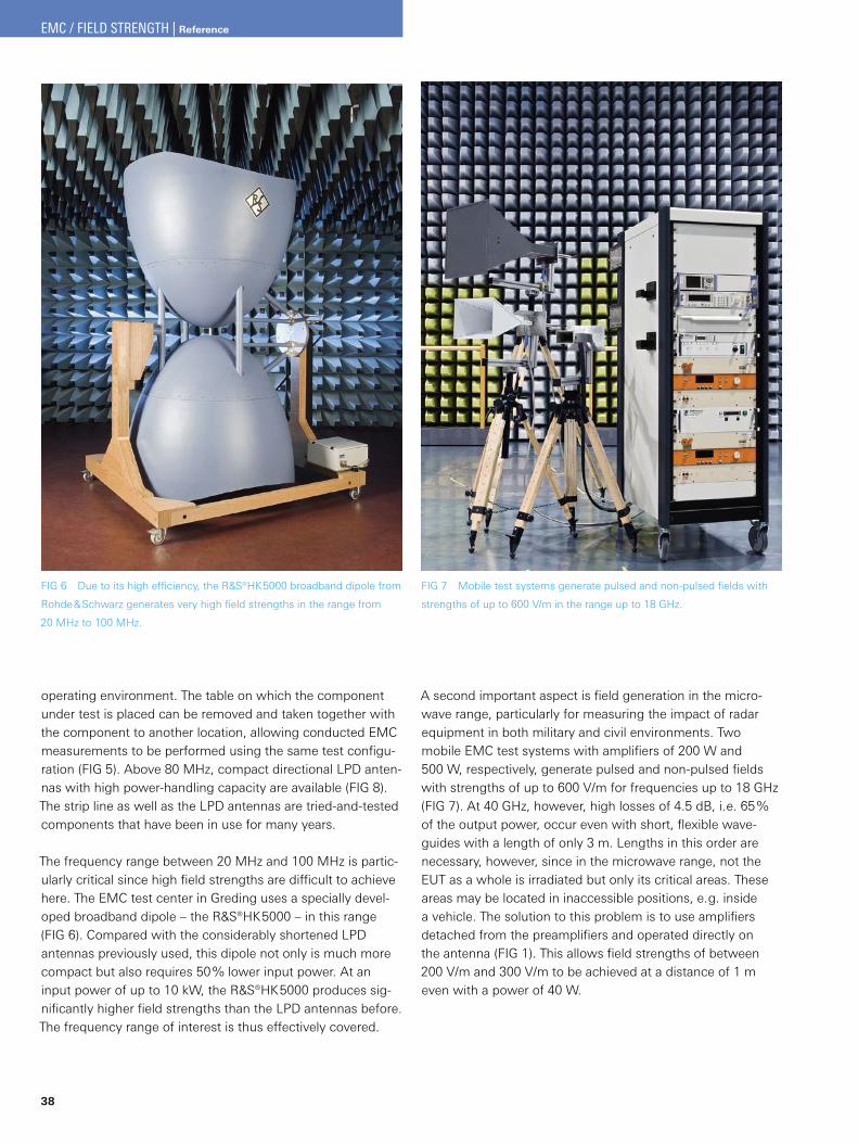
38
operating environment. The table on which the component under test is placed can be removed and taken together with the component to another location, allowing conducted EMC measurements to be performed using the same test configu-ration (FIG 5). Above 80 MHz, compact directional LPD anten-nas with high power-handling capacity are available (FIG 8). The strip line as well as the LPD antennas are tried-and-tested components that have been in use for many years.
The frequency range between 20 MHz and 100 MHz is partic-ularly critical since high field strengths are difficult to achieve here. The EMC test center in Greding uses a specially devel-oped broadband dipole – the ¸HK5000 – in this range (FIG 6). Compared with the considerably shortened LPD antennas previously used, this dipole not only is much more compact but also requires 50 % lower input power. At an input power of up to 10 kW, the ¸HK5000 produces sig-nificantly higher field strengths than the LPD antennas before. The frequency range of interest is thus effectively covered.
FIG 6 Due to its high efficiency, the ¸HK5000 broadband dipole from
Rohde & Schwarz generates very high field strengths in the range from
20 MHz to 100 MHz.
A second important aspect is field generation in the micro-wave range, particularly for measuring the impact of radar equipment in both military and civil environments. Two mobile EMC test systems with amplifiers of 200 W and 500 W, respectively, generate pulsed and non-pulsed fields with strengths of up to 600 V/m for frequencies up to 18 GHz (FIG 7). At 40 GHz, however, high losses of 4.5 dB, i. e. 65 % of the output power, occur even with short, flexible wave-guides with a length of only 3 m. Lengths in this order are necessary, however, since in the microwave range, not the EUT as a whole is irradiated but only its critical areas. These areas may be located in inaccessible positions, e. g. inside a vehicle. The solution to this problem is to use amplifiers detached from the preamplifiers and operated directly on the antenna (FIG 1). This allows field strengths of between 200 V/m and 300 V/m to be achieved at a distance of 1 m even with a power of 40 W.
FIG 7 Mobile test systems generate pulsed and non-pulsed fields with
strengths of up to 600 V/m in the range up to 18 GHz.
EMC / FIELD STRENGTH | Reference
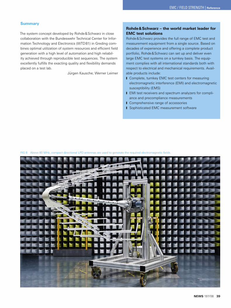
FIG 8 Above 80 MHz, compact directional LPD antennas are used to generate the required electromagnetic fields.
Summary
The system concept developed by Rohde & Schwarz in close collaboration with the Bundeswehr Technical Center for Infor-mation Technology and Electronics (WTD81) in Greding com-bines optimal utilization of system resources and efficient field generation with a high level of automation and high reliabil-ity achieved through reproducible test sequences. The system excellently fulfills the exacting quality and flexibility demands placed on a test lab.
Jürgen Kausche; Werner Leimer
Rohde & Schwarz – the world market leader for EMC test solutionsRohde & Schwarz provides the full range of EMC test and measurement equipment from a single source. Based on decades of experience and offering a complete product portfolio, Rohde & Schwarz can set up and deliver even large EMC test systems on a turnkey basis. The equip-ment complies with all international standards both with respect to electrical and mechanical requirements. Avail-able products include:
Complete, turnkey EMC test centers for measuring Jelectromagnetic interference (EMI) and electromagnetic susceptibility (EMS)EMI test receivers and spectrum analyzers for compli- Jance and precompliance measurementsComprehensive range of accessories JSophisticated EMC measurement software J
NEWS 197/08 39
EMC / FIELD STRENGTH | Reference
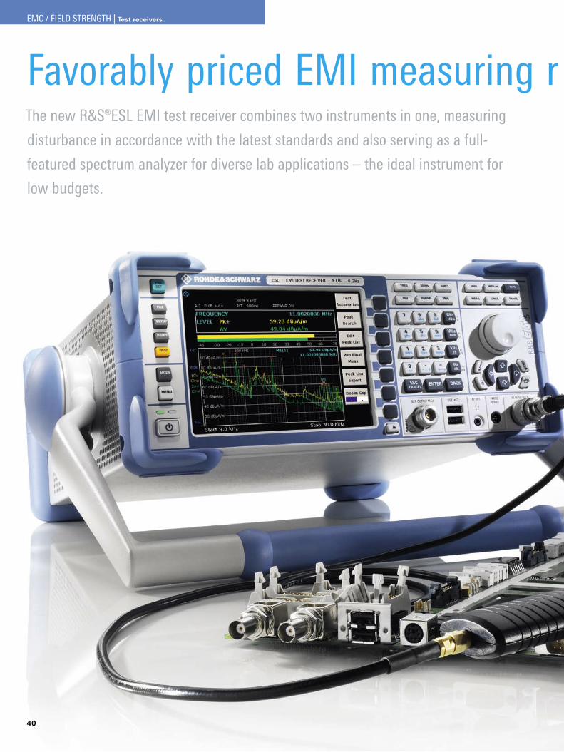
40
Favorably priced EMI measuring r eceiver for the development labThe new R&S®ESL EMI test receiver combines two instruments in one, measuring
disturbance in accordance with the latest standards and also serving as a full-
featured spectrum analyzer for diverse lab applications – the ideal instrument for
low budgets.
EMC / FIELD STRENGTH | Test receivers
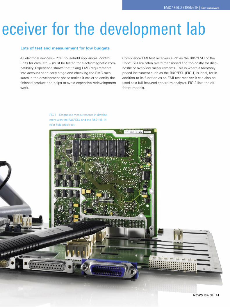
Favorably priced EMI measuring r eceiver for the development lab
FIG 1 Diagnostic measurements in develop-
ment with the R&S®ESL and the R&S®HZ-14
near-field probe set.
Lots of test and measurement for low budgets
All electrical devices – PCs, household appliances, control units for cars, etc. – must be tested for electromagnetic com-patibility. Experience shows that taking EMC requirements into account at an early stage and checking the EMC mea-sures in the development phase makes it easier to certify the finished product and helps to avoid expensive redevelopment work.
Compliance EMI test receivers such as the R&S®ESU or the R&S®ESCI are often overdimensioned and too costly for diag-nostic or overview measurements. This is where a favorably priced instrument such as the R&S®ESL (FIG 1) is ideal, for in addition to its function as an EMI test receiver it can also be used as a full-featured spectrum analyzer. FIG 2 lists the dif-ferent models.
NEWS 197/08 41
EMC / FIELD STRENGTH | Test receivers
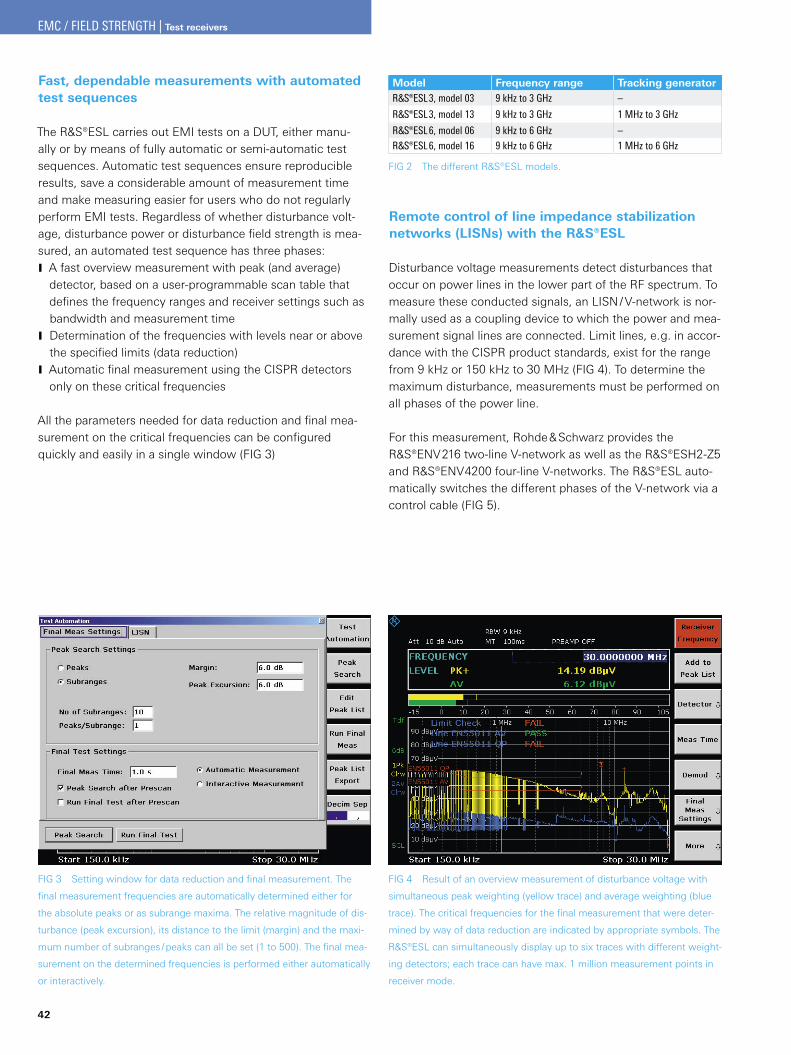
42
Fast, dependable measurements with automated test sequences
The R&S®ESL carries out EMI tests on a DUT, either manu-ally or by means of fully automatic or semi-automatic test sequences. Automatic test sequences ensure reproducible results, save a considerable amount of measurement time and make measuring easier for users who do not regularly perform EMI tests. Regardless of whether disturbance volt-age, disturbance power or disturbance field strength is mea-sured, an automated test sequence has three phases:
A fast overview measurement with peak (and average) Jdetector, based on a user-programmable scan table that defines the frequency ranges and receiver settings such as bandwidth and measurement timeDetermination of the frequencies with levels near or above Jthe specified limits (data reduction)Automatic final measurement using the CISPR detectors Jonly on these critical frequencies
All the parameters needed for data reduction and final mea-surement on the critical frequencies can be configured quickly and easily in a single window (FIG 3)
FIG 3 Setting window for data reduction and final measurement. The
final measurement frequencies are automatically determined either for
the absolute peaks or as subrange maxima. The relative magnitude of dis-
turbance (peak excursion), its distance to the limit (margin) and the maxi-
mum number of subranges / peaks can all be set (1 to 500). The final mea-
surement on the determined frequencies is performed either automatically
or interactively.
FIG 4 Result of an overview measurement of disturbance voltage with
simultaneous peak weighting (yellow trace) and average weighting (blue
trace). The critical frequencies for the final measurement that were deter-
mined by way of data reduction are indicated by appropriate symbols. The
R&S®ESL can simultaneously display up to six traces with different weight-
ing detectors; each trace can have max. 1 million measurement points in
receiver mode.
Model Frequency range Tracking generator¸ESL3, model 03 9 kHz to 3 GHz –
¸ESL3, model 13 9 kHz to 3 GHz 1 MHz to 3 GHz
¸ESL6, model 06 9 kHz to 6 GHz –¸ESL6, model 16 9 kHz to 6 GHz 1 MHz to 6 GHz
FIG 2 The different ¸ESL models.
Remote control of line impedance stabilization networks (LISNs) with the R&S®ESL
Disturbance voltage measurements detect disturbances that occur on power lines in the lower part of the RF spectrum. To measure these conducted signals, an LISN / V-network is nor-mally used as a coupling device to which the power and mea-surement signal lines are connected. Limit lines, e. g. in accor-dance with the CISPR product standards, exist for the range from 9 kHz or 150 kHz to 30 MHz (FIG 4). To determine the maximum disturbance, measurements must be performed on all phases of the power line.
For this measurement, Rohde & Schwarz provides the R&S®ENV216 two-line V-network as well as the R&S®ESH2-Z5 and R&S®ENV4200 four-line V-networks. The R&S®ESL auto-matically switches the different phases of the V-network via a control cable (FIG 5).
EMC / FIELD STRENGTH | Test receivers
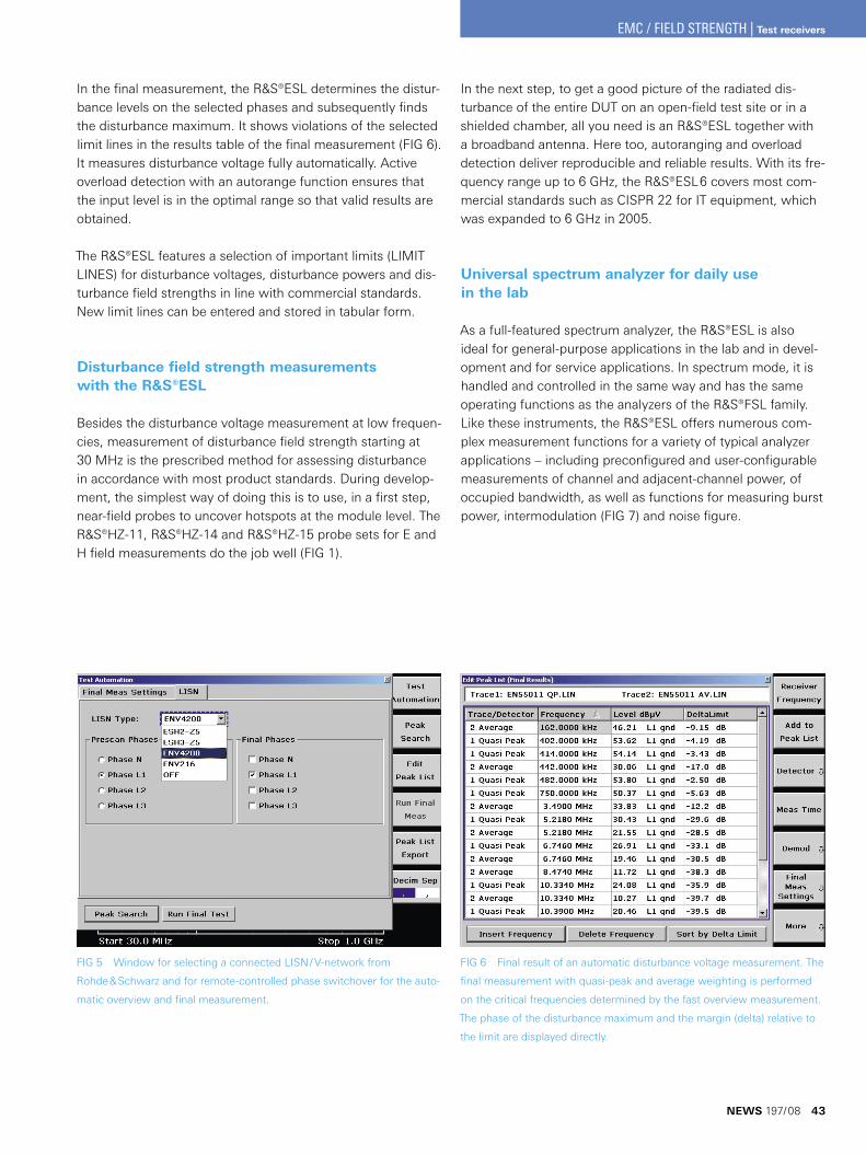
FIG 5 Window for selecting a connected LISN / V-network from
Rohde & Schwarz and for remote-controlled phase switchover for the auto-
matic overview and final measurement.
FIG 6 Final result of an automatic disturbance voltage measurement. The
final measurement with quasi-peak and average weighting is performed
on the critical frequencies determined by the fast overview measurement.
The phase of the disturbance maximum and the margin (delta) relative to
the limit are displayed directly.
In the next step, to get a good picture of the radiated dis-turbance of the entire DUT on an open-field test site or in a shielded chamber, all you need is an R&S®ESL together with a broadband antenna. Here too, autoranging and overload detection deliver reproducible and reliable results. With its fre-quency range up to 6 GHz, the R&S®ESL6 covers most com-mercial standards such as CISPR 22 for IT equipment, which was expanded to 6 GHz in 2005.
Universal spectrum analyzer for daily use in the lab
As a full-featured spectrum analyzer, the R&S®ESL is also ideal for general-purpose applications in the lab and in devel-opment and for service applications. In spectrum mode, it is handled and controlled in the same way and has the same operating functions as the analyzers of the R&S®FSL family. Like these instruments, the R&S®ESL offers numerous com-plex measurement functions for a variety of typical analyzer applications – including preconfigured and user-configurable measurements of channel and adjacent-channel power, of occupied bandwidth, as well as functions for measuring burst power, intermodulation (FIG 7) and noise figure.
In the final measurement, the R&S®ESL determines the distur-bance levels on the selected phases and subsequently finds the disturbance maximum. It shows violations of the selected limit lines in the results table of the final measurement (FIG 6). It measures disturbance voltage fully automatically. Active overload detection with an autorange function ensures that the input level is in the optimal range so that valid results are obtained.
The R&S®ESL features a selection of important limits (LIMIT LINES) for disturbance voltages, disturbance powers and dis-turbance field strengths in line with commercial standards. New limit lines can be entered and stored in tabular form.
Disturbance field strength measurements with the R&S®ESL
Besides the disturbance voltage measurement at low frequen-cies, measurement of disturbance field strength starting at 30 MHz is the prescribed method for assessing disturbance in accordance with most product standards. During develop-ment, the simplest way of doing this is to use, in a first step, near-field probes to uncover hotspots at the module level. The R&S®HZ-11, R&S®HZ-14 and R&S®HZ-15 probe sets for E and H field measurements do the job well (FIG 1).
NEWS 197/08 43
EMC / FIELD STRENGTH | Test receivers
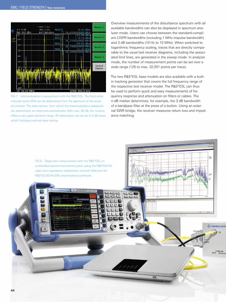
44
Overview measurements of the disturbance spectrum with all available bandwidths can also be displayed in spectrum ana-lyzer mode. Users can choose between the standard-compli-ant CISPR bandwidths (including 1 MHz impulse bandwidth) and 3 dB bandwidths (10 Hz to 10 MHz). When switched to logarithmic frequency scaling, traces that are directly compa-rable to the usual test receiver diagrams, including the associ-ated limit lines, are generated in the sweep mode. In analyzer mode, the number of measurement points can be set over a wide range (125 to max. 32,001 points per trace).
The two R&S®ESL base models are also available with a built-in tracking generator that covers the full frequency range of the respective test receiver model. The R&S®ESL can thus be used to perform quick and easy measurements of fre-quency response and attenuation on filters or cables. The n-dB marker determines, for example, the 3 dB bandwidth of a bandpass filter at the press of a button. Using an exter-nal SWR bridge, the receiver measures return loss and imped-ance matching.
FIG 7 Intermodulation measurement with the R&S®ESL: The third-order
intercept point (IP3) can be determined from the spectrum at the press
of a button. The data carriers, from which the intermodulation sidebands
are determined, are detected automatically. With max. 95 dB, the receiver
offers a very good dynamic range. RF attenuation can be set in 5 dB steps,
which facilitates optimal level setting.
FIG 8 Diagnostic measurement with the R&S®ESL on
unshielded telecommunications ports using the R&S®ENY81
eight-wire impedance stabilization network (ISN) and the
R&S®ES-SCAN EMI precompliance software.
EMC / FIELD STRENGTH | Test receivers
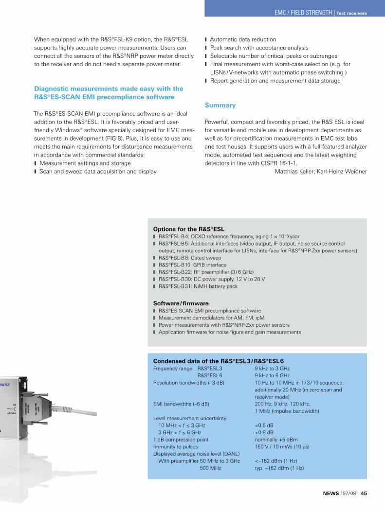
Options for the R&S®ESLR&S®FSL-B4: OCXO reference frequency, aging 1 × 10 J –7/yearR&S®FSL-B5: Additional interfaces (video output, IF output, noise source control J output, remote control interface for LISNs, interface for R&S®NRP-Zxx power sensors)R&S®FSL-B8: Gated sweep JR&S®FSL-B10: GPIB interface JR&S®FSL-B22: RF preamplifier (3 / 6 GHz) JR&S®FSL-B30: DC power supply, 12 V to 28 V JR&S®FSL-B31: NiMH battery pack J
Software / firmwareR&S®ES-SCAN EMI precompliance software JMeasurement demodulators for AM, FM, φM JPower measurements with R&S®NRP-Zxx power sensors JApplication firmware for noise figure and gain measurements J
When equipped with the R&S®FSL-K9 option, the R&S®ESL supports highly accurate power measurements. Users can connect all the sensors of the R&S®NRP power meter directly to the receiver and do not need a separate power meter.
Diagnostic measurements made easy with the R&S®ES-SCAN EMI precompliance software
The R&S®ES-SCAN EMI precompliance software is an ideal addition to the R&S®ESL. It is favorably priced and user-friendly Windows® software specially designed for EMC mea-surements in development (FIG 8). Plus, it is easy to use and meets the main requirements for disturbance measurements in accordance with commercial standards:
Measurement settings and storage JScan and sweep data acquisition and display J
Condensed data of the R&S®ESL3 / R&S®ESL6Frequency range R&S®ESL3 9 kHz to 3 GHz
R&S®ESL6 9 kHz to 6 GHzResolution bandwidths (–3 dB) 10 Hz to 10 MHz in 1 / 3 / 10 sequence, additionally 20 MHz (in zero span and receiver mode)EMI bandwidths (–6 dB) 200 Hz, 9 kHz, 120 kHz, 1 MHz (impulse bandwidth)Level measurement uncertainty 10 MHz < f ≤ 3 GHz <0.5 dB 3 GHz < f ≤ 6 GHz <0.8 dB1 dB compression point nominally +5 dBmImmunity to pulses 150 V / 10 mWs (10 μs)Displayed average noise level (DANL) With preamplifier 50 MHz to 3 GHz <–152 dBm (1 Hz)
500 MHz typ. –162 dBm (1 Hz)
Automatic data reduction JPeak search with acceptance analysis JSelectable number of critical peaks or subranges JFinal measurement with worst-case selection (e. g. for JLISNs / V-networks with automatic phase switching )Report generation and measurement data storage J
Summary
Powerful, compact and favorably priced, the R&S ESL is ideal for versatile and mobile use in development departments as well as for precertification measurements in EMC test labs and test houses. It supports users with a full-featured analyzer mode, automated test sequences and the latest weighting detectors in line with CISPR 16-1-1.
Matthias Keller; Karl-Heinz Weidner
NEWS 197/08 45
EMC / FIELD STRENGTH | Test receivers
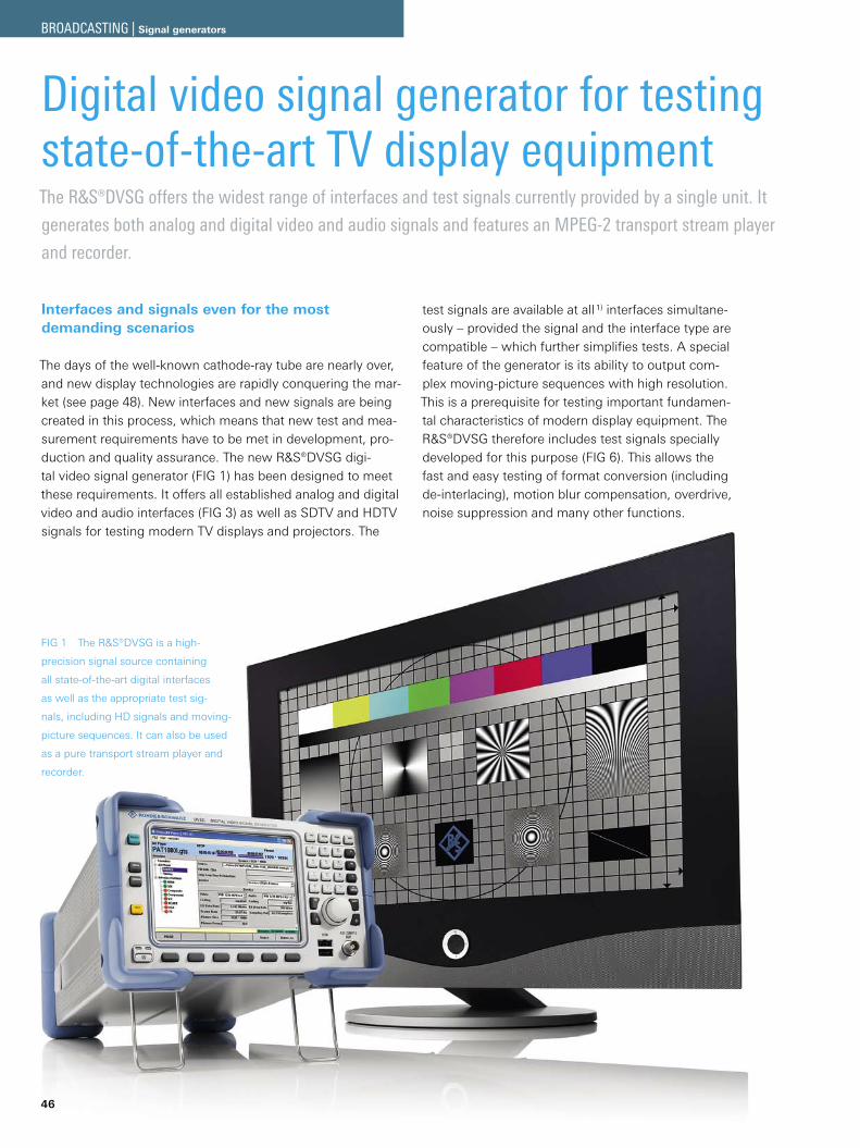
BILD 1 Nosto odit utpat aut
pratem zzriure volore cons alisisi
eratum velenim vel iureet praessi.
46
Digital video signal generator for testing state-of-the-art TV display equipmentThe R&S®DVSG offers the widest range of interfaces and test signals currently provided by a single unit. It
generates both analog and digital video and audio signals and features an MPEG-2 transport stream player
and recorder.
Interfaces and signals even for the most demanding scenarios
The days of the well-known cathode-ray tube are nearly over, and new display technologies are rapidly conquering the mar-ket (see page 48). New interfaces and new signals are being created in this process, which means that new test and mea-surement requirements have to be met in development, pro-duction and quality assurance. The new R&S®DVSG digi-tal video signal generator (FIG 1) has been designed to meet these requirements. It offers all established analog and digital video and audio interfaces (FIG 3) as well as SDTV and HDTV signals for testing modern TV displays and projectors. The
test signals are available at all 1) interfaces simultane-ously – provided the signal and the interface type are compatible – which further simplifies tests. A special feature of the generator is its ability to output com-plex moving-picture sequences with high resolution. This is a prerequisite for testing important fundamen-tal characteristics of modern display equipment. The R&S®DVSG therefore includes test signals specially developed for this purpose (FIG 6). This allows the fast and easy testing of format conversion (including de-interlacing), motion blur compensation, overdrive, noise suppression and many other functions.
FIG 1 The R&S®DVSG is a high-
precision signal source containing
all state-of-the-art digital interfaces
as well as the appropriate test sig-
nals, including HD signals and moving-
picture sequences. It can also be used
as a pure transport stream player and
recorder.
BROADCASTING | Signal generators
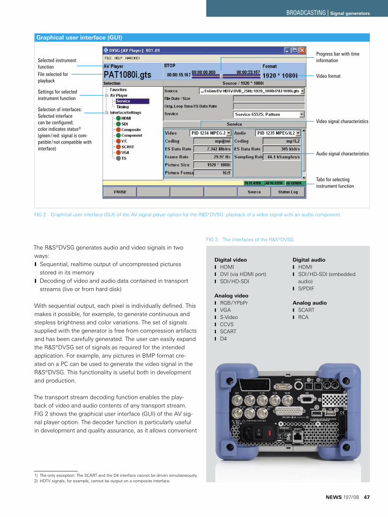
Graphical user interface (GUI)
The R&S®DVSG generates audio and video signals in two ways:
Sequential, realtime output of uncompressed pictures Jstored in its memoryDecoding of video and audio data contained in transport Jstreams (live or from hard disk)
With sequential output, each pixel is individually defined. This makes it possible, for example, to generate continuous and stepless brightness and color variations. The set of signals supplied with the generator is free from compression artifacts and has been carefully generated. The user can easily expand the R&S®DVSG set of signals as required for the intended application. For example, any pictures in BMP format cre-ated on a PC can be used to generate the video signal in the R&S®DVSG. This functionality is useful both in development and production.
The transport stream decoding function enables the play-back of video and audio contents of any transport stream. FIG 2 shows the graphical user interface (GUI) of the AV sig-nal player option. The decoder function is particularly useful in development and quality assurance, as it allows convenient
The only exception: The SCART and the D4 interface cannot be driven simultaneously.1) HDTV signals, for example, cannot be output on a composite interface.2)
Digital videoHDMI JDVI (via HDMI port) JSDI / HD-SDI J
Analog videoRGB / YPbPr JVGA JS-Video JCCVS JSCART JD4 J
Digital audioHDMI JSDI / HD-SDI (embedded Jaudio)S/PDIF J
Analog audioSCART JRCA J
FIG 3 The interfaces of the ¸DVSG
FIG 2 Graphical user interface (GUI) of the AV signal player option for the R&S®DVSG: playback of a video signal with an audio component.
Progress bar with time information
Video format
Audio signal characteristics
Tabs for selecting instrument function
Selected instrument functionFile selected for playback
Settings for selected instrument function
Selection of interfaces: Selected interface can be configured; color indicates status2) (green/ red: signal is com-patible/not compatible with interface)
Video signal characteristics
NEWS 197/08 47
BROADCASTING | Signal generators
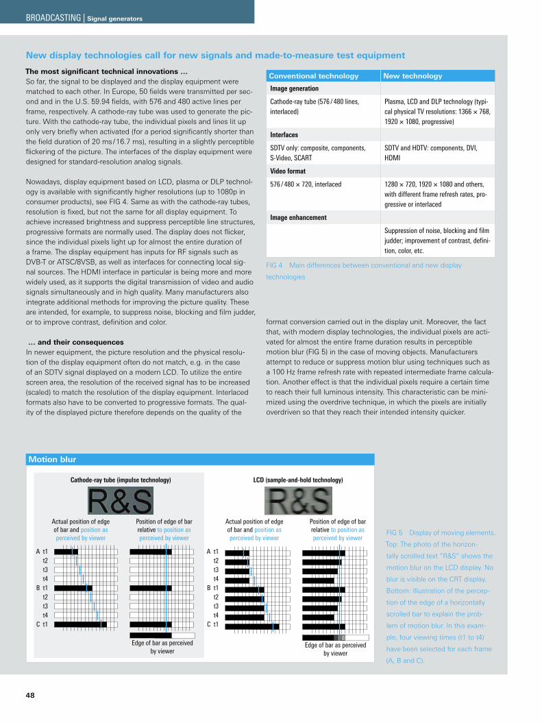
Motion blur
Cathode-ray tube (impulse technology) LCD (sample-and-hold technology)
Actual position of edgeof bar and position asperceived by viewer
Position of edge of barrelative to position asperceived by viewer
Actual position of edgeof bar and position asperceived by viewer
Position of edge of barrelative to position asperceived by viewer
A t1t2t3t4
B t1t2t3t4
C t1
Edge of bar as perceivedby viewer
A t1t2t3t4
B t1t2t3t4
C t1
Edge of bar as perceivedby viewer
48
The most significant technical innovations …So far, the signal to be displayed and the display equipment were matched to each other. In Europe, 50 fields were transmitted per sec-ond and in the U.S. 59.94 fields, with 576 and 480 active lines per frame, respectively. A cathode-ray tube was used to generate the pic-ture. With the cathode-ray tube, the individual pixels and lines lit up only very briefly when activated (for a period significantly shorter than the field duration of 20 ms / 16.7 ms), resulting in a slightly perceptible flickering of the picture. The interfaces of the display equipment were designed for standard-resolution analog signals.
Nowadays, display equipment based on LCD, plasma or DLP technol-ogy is available with significantly higher resolutions (up to 1080p in consumer products), see FIG 4. Same as with the cathode-ray tubes, resolution is fixed, but not the same for all display equipment. To achieve increased brightness and suppress perceptible line structures, progressive formats are normally used. The display does not flicker, since the individual pixels light up for almost the entire duration of a frame. The display equipment has inputs for RF signals such as DVB-T or ATSC/8VSB, as well as interfaces for connecting local sig-nal sources. The HDMI interface in particular is being more and more widely used, as it supports the digital transmission of video and audio signals simultaneously and in high quality. Many manufacturers also integrate additional methods for improving the picture quality. These are intended, for example, to suppress noise, blocking and film judder, or to improve contrast, definition and color.
… and their consequencesIn newer equipment, the picture resolution and the physical resolu-tion of the display equipment often do not match, e. g. in the case of an SDTV signal displayed on a modern LCD. To utilize the entire screen area, the resolution of the received signal has to be increased (scaled) to match the resolution of the display equipment. Interlaced formats also have to be converted to progressive formats. The qual-ity of the displayed picture therefore depends on the quality of the
format conversion carried out in the display unit. Moreover, the fact that, with modern display technologies, the individual pixels are acti-vated for almost the entire frame duration results in perceptible motion blur (FIG 5) in the case of moving objects. Manufacturers attempt to reduce or suppress motion blur using techniques such as a 100 Hz frame refresh rate with repeated intermediate frame calcula-tion. Another effect is that the individual pixels require a certain time to reach their full luminous intensity. This characteristic can be mini-mized using the overdrive technique, in which the pixels are initially overdriven so that they reach their intended intensity quicker.
Conventional technology New technology
Image generation
Cathode-ray tube (576 / 480 lines, interlaced)
Plasma, LCD and DLP technology (typi-cal physical TV resolutions: 1366 × 768, 1920 × 1080, progressive)
Interfaces
SDTV only: composite, components, S-Video, SCART
SDTV and HDTV: components, DVI, HDMI
Video format
576 / 480 × 720, interlaced 1280 × 720, 1920 × 1080 and others, with different frame refresh rates, pro-gressive or interlaced
Image enhancement
Suppression of noise, blocking and film judder; improvement of contrast, defini-tion, color, etc.
FIG 4 Main differences between conventional and new display
technologies
New display technologies call for new signals and made-to-measure test equipment
FIG 5 Display of moving elements.
Top: The photo of the horizon-
tally scrolled text “R&S” shows the
motion blur on the LCD display. No
blur is visible on the CRT display.
Bottom: Illustration of the percep-
tion of the edge of a horizontally
scrolled bar to explain the prob-
lem of motion blur. In this exam-
ple, four viewing times (t1 to t4)
have been selected for each frame
(A, B and C).
BROADCASTING | Signal generators
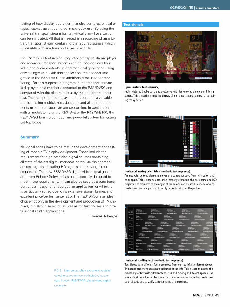
FIG 6 Numerous, often extremely sophisti-
cated, test sequences are included as stan-
dard in each R&S®DVSG digital video signal
generator.
testing of how display equipment handles complex, critical or typical scenes as encountered in everyday use. By using the universal transport stream format, virtually any live situation can be simulated. All that is needed is a recording of an arbi-trary transport stream containing the required signals, which is possible with any transport stream recorder.
The R&S®DVSG features an integrated transport stream player and recorder. Transport streams can be recorded and their video and audio contents utilized for signal generation using only a single unit. With this application, the decoder inte-grated in the R&S®DVSG can additionally be used for mon-itoring. For this purpose, a program in the transport stream is displayed on a monitor connected to the R&S®DVSG and compared with the picture output by the equipment under test. The transport stream player and recorder is a valuable tool for testing multiplexers, decoders and all other compo-nents used in transport stream processing. In conjunction with a modulator, e. g. the R&S®SFE or the R&S®SFE100, the R&S®DVSG forms a compact and powerful system for testing set-top boxes.
Summary
New challenges have to be met in the development and test-ing of modern TV display equipment. These include the requirement for high-precision signal sources containing all state-of-the-art digital interfaces as well as the appropri-ate test signals, including HD signals and moving-picture sequences. The new R&S®DVSG digital video signal gener-ator from Rohde & Schwarz has been specially designed to meet these requirements. It can also be used as a pure trans-port stream player and recorder, an application for which it is particularly suited due to its extensive signal libraries and excellent price/performance ratio. The R&S®DVSG is an ideal choice not only in the development and production of TV dis-plays, but also in servicing as well as for test houses and pro-fessional studio applications.
Thomas Tobergte
Horizontal moving color fields (synthetic test sequence)An area with colored elements moves at a constant speed from right to left and back again. This is used to assess the intensity of motion blur on plasma and LCD displays. The elements at the edges of the screen can be used to check whether pixels have been clipped and to verify correct scaling of the picture.
Horizontal scrolling text (synthetic test sequence)Text blocks with different font sizes move from right to left at different speeds. The speed and the font size are indicated at the left. This is used to assess the readability of text with different font sizes and moving at different speeds. The elements at the edges of the screen can be used to check whether pixels have been clipped and to verify correct scaling of the picture.
Opera (natural test sequence)Richly detailed background and costumes, with fast-moving dancers and flying spears. This is used to check the display of elements (static and moving) contain-ing many details.
Test signals
NEWS 197/08 49
BROADCASTING | Signal generators
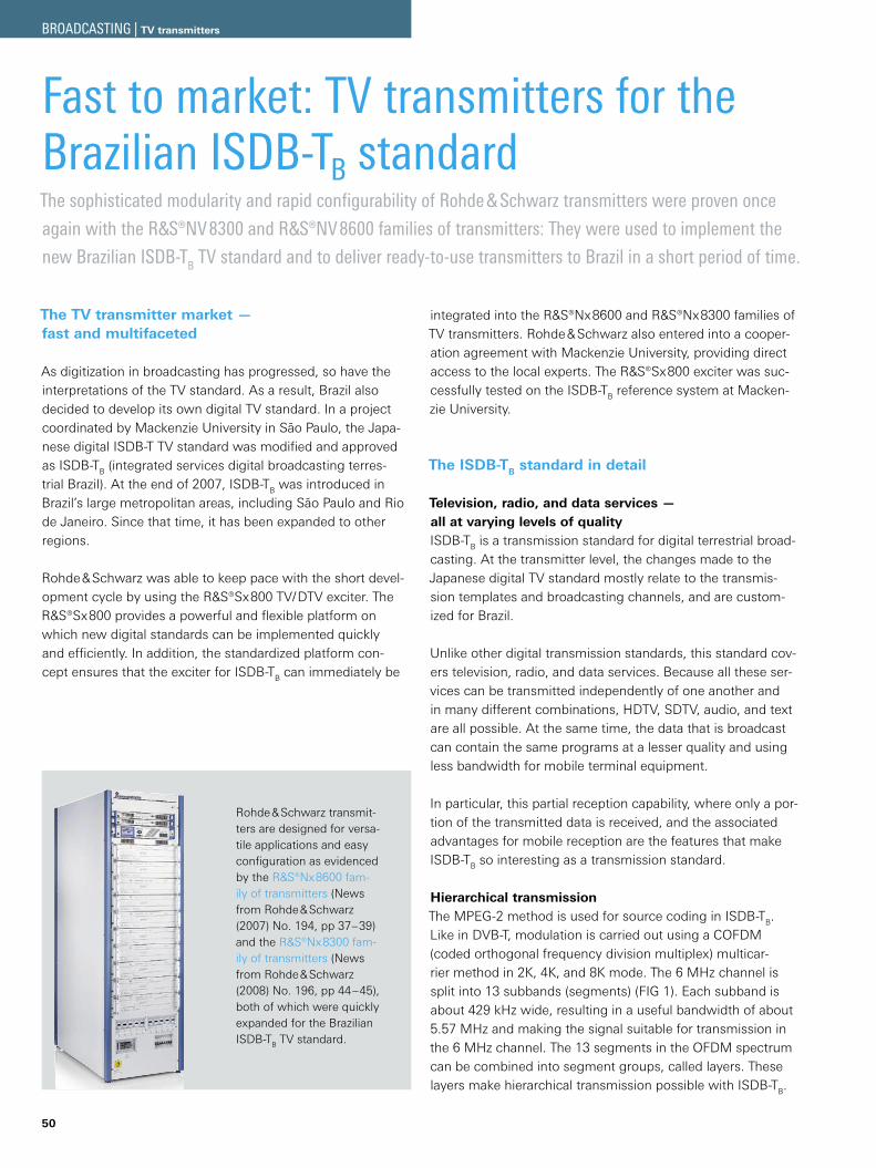
50
Fast to market: TV transmitters for the Brazilian ISDB-TB standard
Rohde & Schwarz transmit-ters are designed for versa-tile applications and easy configuration as evidenced by the ¸Nx8600 fam-ily of transmitters (News from Rohde & Schwarz (2007) No. 194, pp 37–39) and the ¸Nx8300 fam-ily of transmitters (News from Rohde & Schwarz (2008) No. 196, pp 44–45), both of which were quickly expanded for the Brazilian ISDB-TB TV standard.
The sophisticated modularity and rapid configurability of Rohde & Schwarz transmitters were proven once
again with the ¸NV8300 and ¸NV8600 families of transmitters: They were used to implement the
new Brazilian ISDB-TB TV standard and to deliver ready-to-use transmitters to Brazil in a short period of time.
The TV transmitter market — fast and multifaceted
As digitization in broadcasting has progressed, so have the interpretations of the TV standard. As a result, Brazil also decided to develop its own digital TV standard. In a project coordinated by Mackenzie University in São Paulo, the Japa-nese digital ISDB-T TV standard was modified and approved as ISDB-TB (integrated services digital broadcasting terres-trial Brazil). At the end of 2007, ISDB-TB was introduced in Brazil’s large metropolitan areas, including São Paulo and Rio de Janeiro. Since that time, it has been expanded to other regions.
Rohde & Schwarz was able to keep pace with the short devel-opment cycle by using the ¸Sx800 TV/DTV exciter. The ¸Sx800 provides a powerful and flexible platform on which new digital standards can be implemented quickly and efficiently. In addition, the standardized platform con-cept ensures that the exciter for ISDB-TB can immediately be
integrated into the ¸Nx8600 and ¸Nx8300 families of TV transmitters. Rohde & Schwarz also entered into a cooper-ation agreement with Mackenzie University, providing direct access to the local experts. The ¸Sx800 exciter was suc-cessfully tested on the ISDB-TB reference system at Macken-zie University.
The ISDB-TB standard in detail
Television, radio, and data services — all at varying levels of qualityISDB-TB is a transmission standard for digital terrestrial broad-casting. At the transmitter level, the changes made to the Japanese digital TV standard mostly relate to the transmis-sion templates and broadcasting channels, and are custom-ized for Brazil.
Unlike other digital transmission standards, this standard cov-ers television, radio, and data services. Because all these ser-vices can be transmitted independently of one another and in many different combinations, HDTV, SDTV, audio, and text are all possible. At the same time, the data that is broadcast can contain the same programs at a lesser quality and using less bandwidth for mobile terminal equipment.
In particular, this partial reception capability, where only a por-tion of the transmitted data is received, and the associated advantages for mobile reception are the features that make ISDB-TB so interesting as a transmission standard.
Hierarchical transmissionThe MPEG-2 method is used for source coding in ISDB-TB. Like in DVB-T, modulation is carried out using a COFDM (coded orthogonal frequency division multiplex) multicar-rier method in 2K, 4K, and 8K mode. The 6 MHz channel is split into 13 subbands (segments) (FIG 1). Each subband is about 429 kHz wide, resulting in a useful bandwidth of about 5.57 MHz and making the signal suitable for transmission in the 6 MHz channel. The 13 segments in the OFDM spectrum can be combined into segment groups, called layers. These layers make hierarchical transmission possible with ISDB-TB.
BROADCASTING | TV transmitters
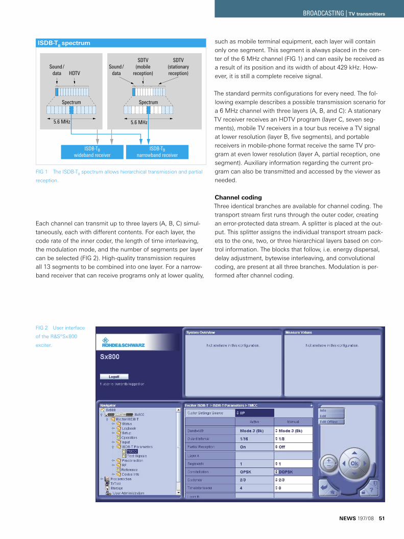
Each channel can transmit up to three layers (A, B, C) simul-taneously, each with different contents. For each layer, the code rate of the inner coder, the length of time interleaving, the modulation mode, and the number of segments per layer can be selected (FIG 2). High-quality transmission requires all 13 segments to be combined into one layer. For a narrow-band receiver that can receive programs only at lower quality,
FIG 1 The ISDB-TB spectrum allows hierarchical transmission and partial
reception.
such as mobile terminal equipment, each layer will contain only one segment. This segment is always placed in the cen-ter of the 6 MHz channel (FIG 1) and can easily be received as a result of its position and its width of about 429 kHz. How-ever, it is still a complete receive signal.
The standard permits configurations for every need. The fol-lowing example describes a possible transmission scenario for a 6 MHz channel with three layers (A, B, and C): A stationary TV receiver receives an HDTV program (layer C, seven seg-ments), mobile TV receivers in a tour bus receive a TV signal at lower resolution (layer B, five segments), and portable receivers in mobile-phone format receive the same TV pro-gram at even lower resolution (layer A, partial reception, one segment). Auxiliary information regarding the current pro-gram can also be transmitted and accessed by the viewer as needed.
Channel codingThree identical branches are available for channel coding. The transport stream first runs through the outer coder, creating an error-protected data stream. A splitter is placed at the out-put. This splitter assigns the individual transport stream pack-ets to the one, two, or three hierarchical layers based on con-trol information. The blocks that follow, i. e. energy dispersal, delay adjustment, bytewise interleaving, and convolutional coding, are present at all three branches. Modulation is per-formed after channel coding.
FIG 2 User interface
of the ¸Sx800
exciter.
Spectrum
Sound/data HDTV
Spectrum
SDTV(mobile
reception)
SDTV(stationaryreception)
Sound/data
5.6 MHz 5.6 MHz
ISDB-TBwideband receiver
ISDB-TBnarrowband receiver
ISDB-TB spectrum
NEWS 197/08 51
BROADCASTING | TV transmitters
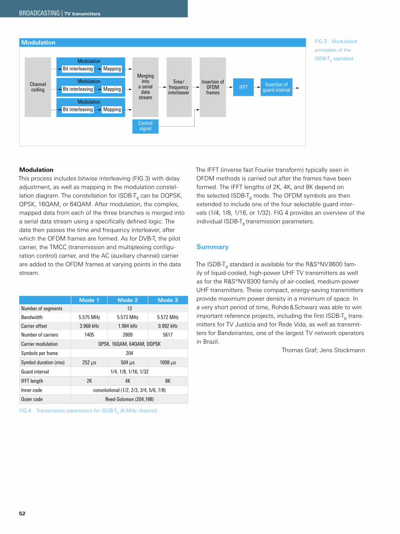
52
ModulationThis process includes bitwise interleaving (FIG 3) with delay adjustment, as well as mapping in the modulation constel-lation diagram. The constellation for ISDB-TB can be DQPSK, QPSK, 16QAM, or 64QAM. After modulation, the complex, mapped data from each of the three branches is merged into a serial data stream using a specifically defined logic. The data then passes the time and frequency interleaver, after which the OFDM frames are formed. As for DVB-T, the pilot carrier, the TMCC (transmission and multiplexing configu-ration control) carrier, and the AC (auxiliary channel) carrier are added to the OFDM frames at varying points in the data stream.
FIG 3 Modulation
principles of the
ISDB-TB standard.
Mode 1 Mode 2 Mode 3
Number of segments 13
Bandwidth 5.575 MHz 5.573 MHz 5.572 MHz
Carrier offset 3.968 kHz 1.984 kHz 0.992 kHz
Number of carriers 1405 2809 5617
Carrier modulation QPSK, 16QAM, 64QAM, DQPSK
Symbols per frame 204
Symbol duration (rms) 252 µs 504 µs 1008 µs
Guard interval 1/4, 1/8, 1/16, 1/32
IFFT length 2K 4K 8K
Inner code convolutional (1/2, 2/3, 3/4, 5/6, 7/8)
Outer code Reed-Solomon (204,188)
FIG 4 Transmission parameters for ISDB-TB (6 MHz channel).
MappingBit interleaving
Modulation
MappingBit interleavingModulation
MappingBit interleavingModulation
Channelcoding
Time/frequencyinterleaver
Insertion ofOFDMframes
IFFT Insertion ofguard interval
Controlsignal
Merging into
a serial data
stream
Modulation
The IFFT (inverse fast Fourier transform) typically seen in OFDM methods is carried out after the frames have been formed. The IFFT lengths of 2K, 4K, and 8K depend on the selected ISDB-TB mode. The OFDM symbols are then extended to include one of the four selectable guard inter-vals (1/4, 1/8, 1/16, or 1/32). FIG 4 provides an overview of the individual ISDB-TB transmission parameters.
Summary
The ISDB-TB standard is available for the ¸NV8600 fam-ily of liquid-cooled, high-power UHF TV transmitters as well as for the ¸NV8300 family of air-cooled, medium-power UHF transmitters. These compact, energy-saving transmitters provide maximum power density in a minimum of space. In a very short period of time, Rohde & Schwarz was able to win important reference projects, including the first ISDB-TB trans-mitters for TV Justicia and for Rede Vida, as well as transmit-ters for Bandeirantes, one of the largest TV network operators in Brazil.
Thomas Graf; Jens Stockmann
BROADCASTING | TV transmitters
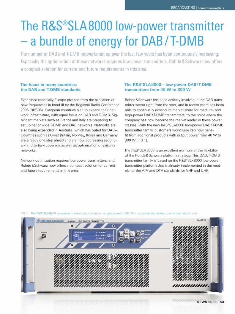
The ¸SLA8000 low-power transmitter – a bundle of energy for DAB / T-DMBThe number of DAB and T-DMB networks set up over the last few years has been continuously increasing.
Especially the optimization of these networks requires low-power transmitters. Rohde & Schwarz now offers
a compact solution for current and future requirements in this area.
FIG 1 The R&S®SLA8200 low-power transmitter provides an output power of 300 W in a cabinet that takes up only four height units.
The focus in many countries: the DAB and T-DMB standards
Ever since especially Europe profited from the allocation of new frequencies in band III by the Regional Radio Conference 2006 (RRC06), European countries plan to expand their net-work infrastruture, with equal focus on DAB and T-DMB. Sig-nificant markets such as France and Italy are preparing to set up nationwide T-DMB and DAB networks. Networks are also being expanded in Australia, which has opted for DAB+. Countries such as Great Britain, Norway, Korea and Germany are already one step ahead and are now addressing second-ary and tertiary coverage as well as optimization of existing networks.
Network optimization requires low-power transmitters, and Rohde & Schwarz now offers a compact solution for current and future requirements in this area.
The R&S®SLA8000 – low-power DAB / T-DMB transmitters from 40 W to 300 W
Rohde & Schwarz has been actively involved in the DAB trans-mitter sector right from the start, and in recent years has been able to continually expand its market share for medium- and high-power DAB / T-DMB transmitters, to the point where the company has now become the market leader in these power classes. With the new R&S®SLA8000 low-power DAB / T-DMB transmitter family, customers worldwide can now bene-fit from additional products with output power from 40 W to 300 W (FIG 1).
The R&S®SLA8000 is an excellent example of the flexibility of the Rohde & Schwarz platform strategy. This DAB / T-DMB transmitter family is based on the R&S®SLx8000 low-power transmitter platform that is already implemented in the mod-els for the ATV and DTV standards for VHF and UHF.
NEWS 197/08 53
BROADCASTING | Sound transmitters
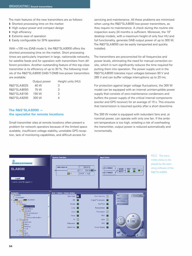
54
The main features of the new transmitters are as follows:Shortest processing time on the market JHigh output power and compact design JHigh efficiency JExtreme ease of operation JEasily configurable for SFN operation J
With <100 ms (DAB mode I), the R&S®SLA8000 offers the shortest processing time on the market. Short processing times are particularly important in large, nationwide networks, for satellite feeds and for operation with transmitters from dif-ferent providers. Another outstanding feature of this top-class transmitter is its efficiency of up to 30 %. The following mod-els of the R&S®SLA8000 DAB / T-DMB low-power transmitters are available: Output power Height units (HU)R&S®SLA8025 40 W 3R&S®SLA8050 75 W 3R&S®SLA8100 150 W 3R&S®SLA8200 300 W 4
The R&S®SLA8000 — the specialist for remote locations
Small transmitter sites at remote locations often present a problem for network operators because of the limited space available, insufficient voltage stability, unreliable GPS recep-tion, lack of monitoring capabilities, and difficult access for
servicing and maintenance. All these problems are minimized when using the R&S®SLA8000 low-power transmitters, as they require no maintenance. A check during the routine site inspection every 24 months is sufficient. Moreover, the 19" desktop models, with a maximum height of only four HU and full functionality, generate DAB output power of up to 300 W. The R&S®SLA8000 can be easily transported and quickly installed.
The transmitters are precorrected for all frequencies and power levels, eliminating the need for manual correction on-site, which in turn significantly reduces the time required for putting them into operation. The power supply unit in the R&S®SLA8000 tolerates input voltages between 90 V and 265 V and can buffer voltage interruptions up to 20 ms.
For protection against larger voltage fluctuations, the 300 W model can be equipped with an internal uninterruptible power supply that consists of zero-maintenance condensers and buffers the power supply of the critical internal components (exciter and GPS receiver) for an average of 10 s. This ensures that transmission is resumed quickly after a short downtime.
The 300 W model is equipped with redundant fans and, at nominal power, can operate with only one fan. If the ambi-ent temperature is too high, entailing a risk of overheating the transmitter, output power is reduced automatically and incrementally.
FIG 2 The trans-
mitter status is dis-
played by the oper-
ating software of the
R&S®SLA8000.
BROADCASTING | Sound transmitters
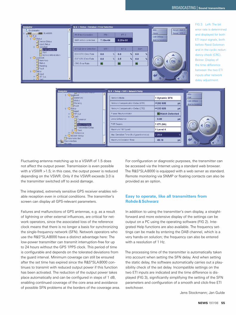
Fluctuating antenna matching up to a VSWR of 1.5 does not affect the output power. Transmission is even possible with a VSWR >1.5; in this case, the output power is reduced depending on the VSWR. Only if the VSWR exceeds 3.0 is the transmitter switched off to avoid damage.
The integrated, extremely sensitive GPS receiver enables reli-able reception even in critical conditions. The transmitter’s screen can display all GPS-relevant parameters.
Failures and malfunctions of GPS antennas, e. g. as a result of lightning or other external influences, are critical for net-work operators, since the associated loss of the reference clock means that there is no longer a basis for synchronizing the single-frequency network (SFN). Network operators who use the R&S®SLA8000 have a distinct advantage here: The low-power transmitter can transmit interruption-free for up to 24 hours without the GPS 1PPS clock. This period of time is configurable and depends on the tolerated deviations from the guard interval. Minimum coverage can still be ensured after the set time has expired since the R&S®SLA8000 con-tinues to transmit with reduced output power if this function has been activated. The reduction of the output power takes place automatically and can be configured in steps of 1 dB, enabling continued coverage of the core area and avoidance of possible SFN problems at the borders of the coverage area.
For configuration or diagnostic purposes, the transmitter can be accessed via the Internet using a standard web browser. The R&S®SLA8000 is equipped with a web server as standard. Remote monitoring via SNMP or floating contacts can also be provided as an option.
Easy to operate, like all transmitters from Rohde & Schwarz
In addition to using the transmitter’s own display, a straight-forward and more extensive display of the settings can be output on a PC using the operating software (FIG 2). Inte-grated Help functions are also available. The frequency set-tings can be made by entering the DAB channel, which is a very hands-on solution; the frequency can also be entered with a resolution of 1 Hz.
The processing time of the transmitter is automatically taken into account when setting the SFN delay. And when setting the static delay, the software automatically carries out a plau-sibility check of the set delay. Incompatible settings on the two ETI inputs are indicated and the time difference is dis-played (FIG 3), significantly simplifying the setting of the SFN parameters and configuration of a smooth and click-free ETI switchover.
Jens Stockmann; Jan Gulde
FIG 3 Left: The bit
error rate is determined
and displayed for both
ETI input signals, both
before Reed-Solomon
and in the cyclic redun-
dancy check (CRC).
Below: Display of
the time difference
between the two ETI
inputs after network
delay adjustment.
NEWS 197/08 55
BROADCASTING | Sound transmitters
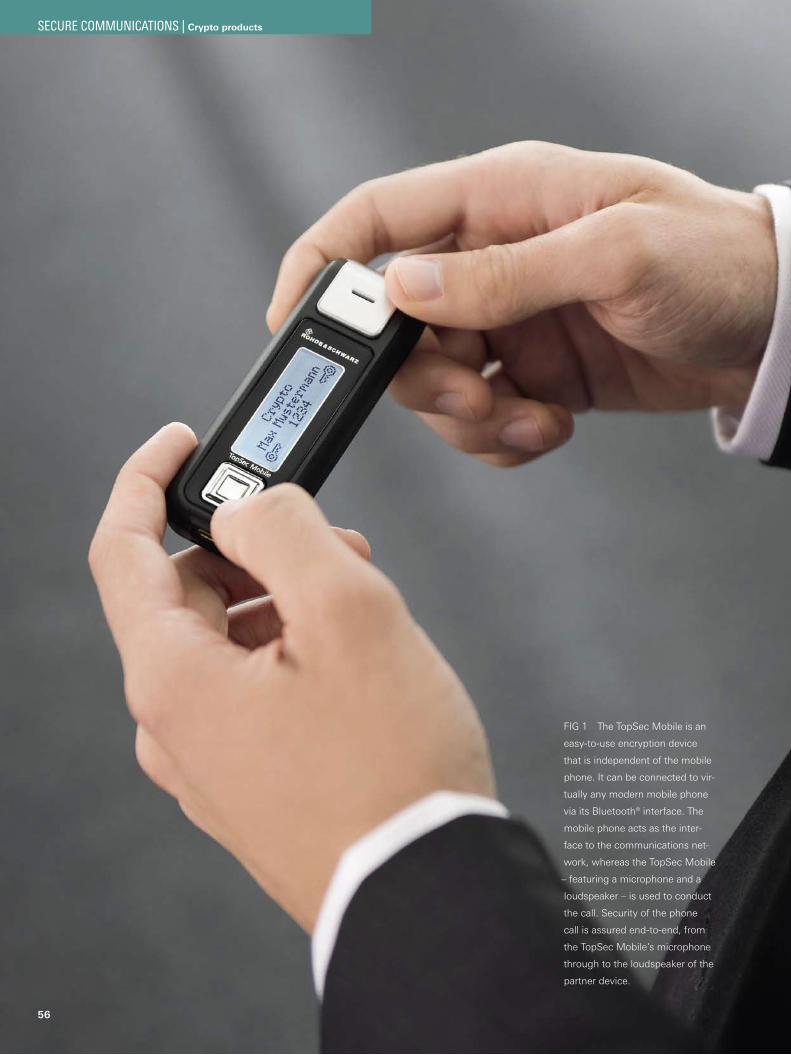
56
FIG 1 The TopSec Mobile is an
easy-to-use encryption device
that is independent of the mobile
phone. It can be connected to vir-
tually any modern mobile phone
via its Bluetooth® interface. The
mobile phone acts as the inter-
face to the communications net-
work, whereas the TopSec Mobile
– featuring a microphone and a
loudspeaker – is used to conduct
the call. Security of the phone
call is assured end-to-end, from
the TopSec Mobile’s microphone
through to the loudspeaker of the
partner device.
SECURE COMMUNICATIONS | Crypto products
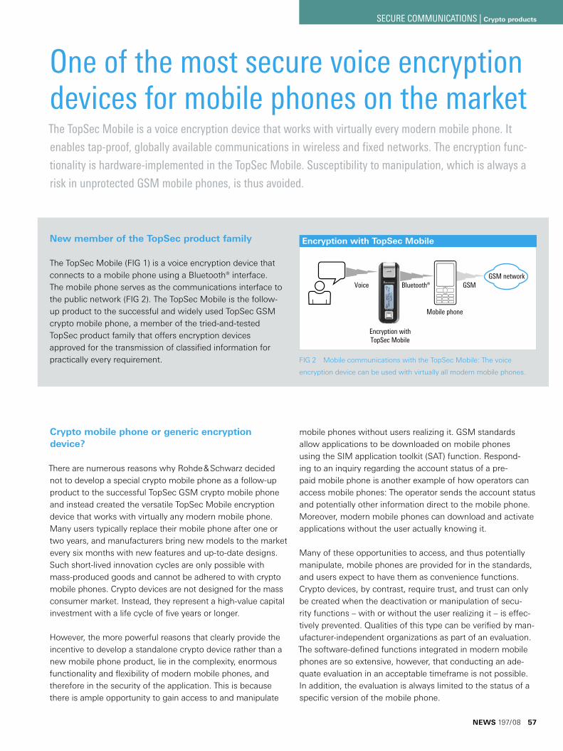
One of the most secure voice encryption devices for mobile phones on the marketThe TopSec Mobile is a voice encryption device that works with virtually every modern mobile phone. It
enables tap-proof, globally available communications in wireless and fixed networks. The encryption func-
tionality is hardware-implemented in the TopSec Mobile. Susceptibility to manipulation, which is always a
risk in unprotected GSM mobile phones, is thus avoided.
Crypto mobile phone or generic encryption device?
There are numerous reasons why Rohde & Schwarz decided not to develop a special crypto mobile phone as a follow-up product to the successful TopSec GSM crypto mobile phone and instead created the versatile TopSec Mobile encryption device that works with virtually any modern mobile phone. Many users typically replace their mobile phone after one or two years, and manufacturers bring new models to the market every six months with new features and up-to-date designs. Such short-lived innovation cycles are only possible with mass-produced goods and cannot be adhered to with crypto mobile phones. Crypto devices are not designed for the mass consumer market. Instead, they represent a high-value capital investment with a life cycle of five years or longer.
However, the more powerful reasons that clearly provide the incentive to develop a standalone crypto device rather than a new mobile phone product, lie in the complexity, enormous functionality and flexibility of modern mobile phones, and therefore in the security of the application. This is because there is ample opportunity to gain access to and manipulate
FIG 2 Mobile communications with the TopSec Mobile: The voice
encryption device can be used with virtually all modern mobile phones.
mobile phones without users realizing it. GSM standards allow applications to be downloaded on mobile phones using the SIM application toolkit (SAT) function. Respond-ing to an inquiry regarding the account status of a pre-paid mobile phone is another example of how operators can access mobile phones: The operator sends the account status and potentially other information direct to the mobile phone. Moreover, modern mobile phones can download and activate applications without the user actually knowing it.
Many of these opportunities to access, and thus potentially manipulate, mobile phones are provided for in the standards, and users expect to have them as convenience functions. Crypto devices, by contrast, require trust, and trust can only be created when the deactivation or manipulation of secu-rity functions – with or without the user realizing it – is effec-tively prevented. Qualities of this type can be verified by man-ufacturer-independent organizations as part of an evaluation. The software-defined functions integrated in modern mobile phones are so extensive, however, that conducting an ade-quate evaluation in an acceptable timeframe is not possible. In addition, the evaluation is always limited to the status of a specific version of the mobile phone.
Encryption with TopSec Mobile
GSM networkVoice GSM
Mobile phone
Bluetooth®
Encryption withTopSec Mobile
New member of the TopSec product family
The TopSec Mobile (FIG 1) is a voice encryption device that connects to a mobile phone using a Bluetooth® interface. The mobile phone serves as the communications interface to the public network (FIG 2). The TopSec Mobile is the follow-up product to the successful and widely used TopSec GSM crypto mobile phone, a member of the tried-and-tested TopSec product family that offers encryption devices approved for the transmission of classified information for practically every requirement.
NEWS 197/08 57
SECURE COMMUNICATIONS | Crypto products
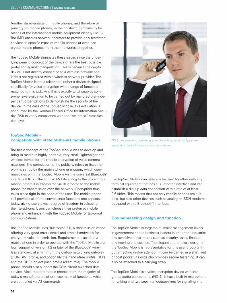
58
Another disadvantage of mobile phones, and therefore of pure crypto mobile phones, is their distinct identifiability by means of the international mobile equipment identity (IMEI). The IMEI enables network operators to provide only restricted services to specific types of mobile phones or even ban crypto mobile phones from their networks altogether.
The TopSec Mobile eliminates these issues since the under-lying generic concept of the device offers the best possible protection against manipulation. This is because the crypto device is not directly connected to a wireless network and is thus not registered with a wireless network provider. The TopSec Mobile is not a telephone, rather a device designed specifically for voice encryption with a range of functions matched to this task. And this is exactly what enables com-prehensive evaluation to be carried out by manufacturer-inde-pendent organizations to demonstrate the security of the device. In the case of the TopSec Mobile, this evaluation is conducted by the German Federal Office for Information Secu-rity (BSI) to verify compliance with the “restricted” classifica-tion level.
TopSec Mobile – compatible with state-of-the-art mobile phones
The basic concept of the TopSec Mobile was to develop and bring to market a highly portable, very small, lightweight and wireless device for the mobile encryption of voice commu-nications. The connection to the public wireless or fixed net-work is set up by the mobile phone or modem, which com-municates with the TopSec Mobile via the universal Bluetooth® interface (FIG 2). The TopSec Mobile encrypts the voice infor-mation before it is transferred via Bluetooth® to the mobile phone for transmission over the network. Encryption thus takes place right in the hand of the user. The mobile phone still provides all of the convenience functions one expects today, giving users a vast degree of freedom in selecting their telephone. Users can choose their preferred mobile phone and enhance it with the TopSec Mobile for tap-proof communications.
The TopSec Mobile uses Bluetooth® 2.0, a transmission mode offering very good error control and ample bandwidth for encrypted voice transmission. Requirements placed on a mobile phone in order to operate with the TopSec Mobile are few: support of version 1.2 or later of the Bluetooth® wire-less standard, at a minimum the dial-up networking gateway (DUN-GW) profile, and optionally the hands-free profile (HFP) and the OBEX object push profile (client role). The mobile phone should also support the GSM circuit-switched data service. Most modern mobile phones from the majority of today’s manufacturers offer these minimal functions, which are controlled via AT commands.
The TopSec Mobile can basically be used together with any terminal equipment that has a Bluetooth® interface and can establish a dial-up data connection with a rate of at least 9.6 kbit/s. This means that not only mobile phones are suit-able, but also other devices such as analog or ISDN modems equipped with a Bluetooth® interface.
Groundbreaking design and function
The TopSec Mobile is targeted at senior management levels in government and at business leaders in important industries and sensitive departments such as security, sales, finance, engineering and science. The elegant and timeless design of the TopSec Mobile is representative for this user group with-out attracting undue attention. It can be carried in a shirt, suit or coat pocket; its wide clip provides secure fastening. It can also be attached to a carrying strap.
The TopSec Mobile is a voice encryption device with inte-grated audio components (FIG 4). It has a built-in microphone for talking and two separate loudspeakers for signaling and
FIG 3 As simple to operate as a mobile phone, yet a highly secure
encryption device for mobile communications.
SECURE COMMUNICATIONS | Crypto products
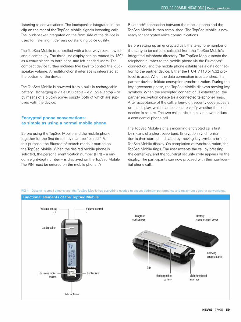
listening to conversations. The loudspeaker integrated in the clip on the rear of the TopSec Mobile signals incoming calls. The loudspeaker integrated on the front side of the device is used for listening; it delivers outstanding voice quality.
The TopSec Mobile is controlled with a four-way rocker switch and a center key. The three-line display can be rotated by 180° as a convenience to both right- and left-handed users. The compact device further includes two keys to control the loud-speaker volume. A multifunctional interface is integrated at the bottom of the device.
The TopSec Mobile is powered from a built-in rechargeable battery. Recharging is via a USB cable – e. g. on a laptop – or by means of a plug-in power supply, both of which are sup-plied with the device.
Encrypted phone conversations: as simple as using a normal mobile phone
Before using the TopSec Mobile and the mobile phone together for the first time, they must be “paired.” For this purpose, the Bluetooth® search mode is started on the TopSec Mobile. When the desired mobile phone is selected, the personal identification number (PIN) – a ran-dom eight-digit number – is displayed on the TopSec Mobile. The PIN must be entered on the mobile phone. A
Bluetooth® connection between the mobile phone and the TopSec Mobile is then established. The TopSec Mobile is now ready for encrypted voice communications.
Before setting up an encrypted call, the telephone number of the party to be called is selected from the TopSec Mobile’s integrated telephone directory. The TopSec Mobile sends the telephone number to the mobile phone via the Bluetooth® connection, and the mobile phone establishes a data connec-tion to the partner device. Either the ITU-T V.110 or V.32 pro-tocol is used. When the data connection is established, the partner devices initiate encryption synchronization. During the key agreement phase, the TopSec Mobile displays moving key symbols. When the encrypted connection is established, the partner encryption device (or a connected telephone) rings. After acceptance of the call, a four-digit security code appears on the display, which can be used to verify whether the con-nection is secure. The two call participants can now conduct a confidential phone call.
The TopSec Mobile signals incoming encrypted calls first by means of a short beep tone. Encryption synchroniza-tion is then started, indicated by moving key symbols on the TopSec Mobile display. On completion of synchronization, the TopSec Mobile rings. The user accepts the call by pressing the center key, and the four-digit security code appears on the display. The participants can now proceed with their confiden-tial phone call.
Functional elements of the TopSec Mobile
Microphone
Center keyFour-way rockerswitch
Volume control„+“
Volume control„–“
Loudspeaker
Multifunctional interface
Rechargeablebattery
Ringtoneloudspeaker
Battery compartment cover
Clip
Carrying strap fastener
FIG 4 Despite its small dimensions, the TopSec Mobile has everything needed to ensure optimum performance and maximum operator convenience.
NEWS 197/08 59
SECURE COMMUNICATIONS | Crypto products
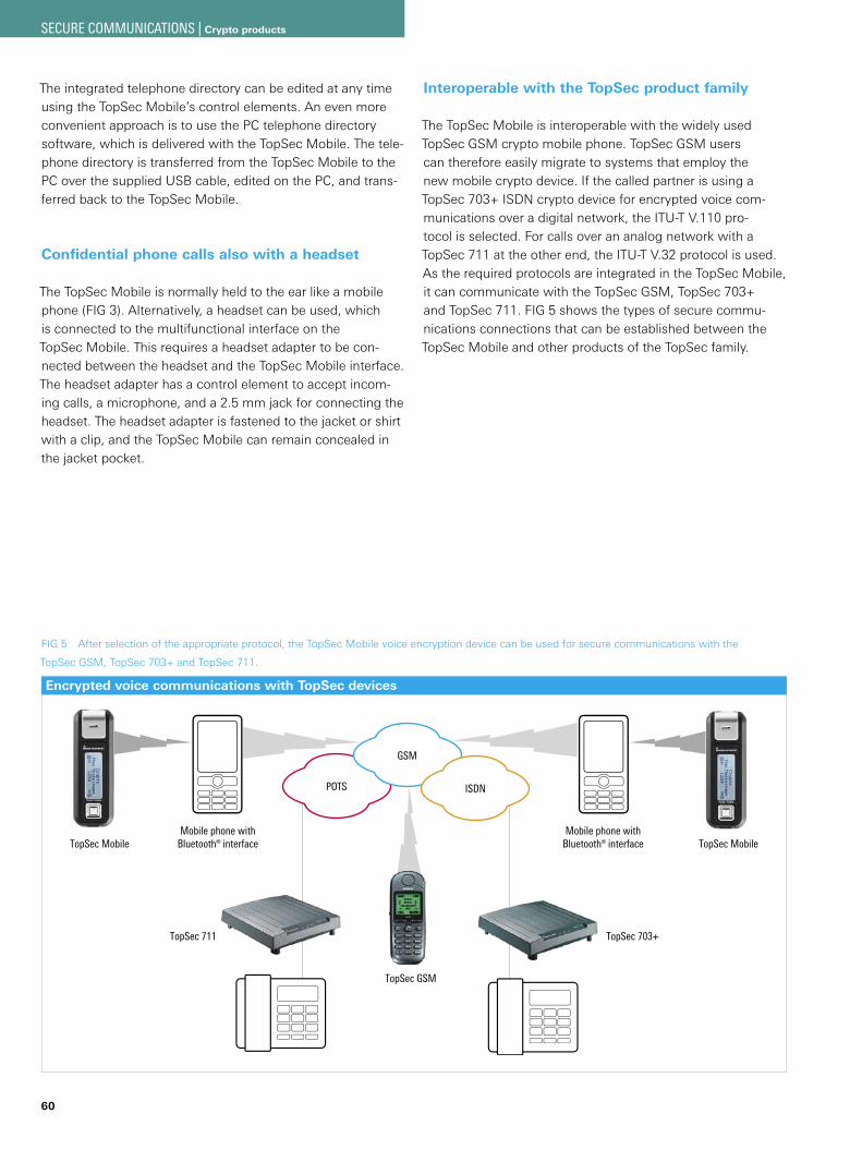
60
The integrated telephone directory can be edited at any time using the TopSec Mobile’s control elements. An even more convenient approach is to use the PC telephone directory software, which is delivered with the TopSec Mobile. The tele-phone directory is transferred from the TopSec Mobile to the PC over the supplied USB cable, edited on the PC, and trans-ferred back to the TopSec Mobile.
Confidential phone calls also with a headset
The TopSec Mobile is normally held to the ear like a mobile phone (FIG 3). Alternatively, a headset can be used, which is connected to the multifunctional interface on the TopSec Mobile. This requires a headset adapter to be con-nected between the headset and the TopSec Mobile interface. The headset adapter has a control element to accept incom-ing calls, a microphone, and a 2.5 mm jack for connecting the headset. The headset adapter is fastened to the jacket or shirt with a clip, and the TopSec Mobile can remain concealed in the jacket pocket.
Interoperable with the TopSec product family
The TopSec Mobile is interoperable with the widely used TopSec GSM crypto mobile phone. TopSec GSM users can therefore easily migrate to systems that employ the new mobile crypto device. If the called partner is using a TopSec 703+ ISDN crypto device for encrypted voice com-munications over a digital network, the ITU-T V.110 pro-tocol is selected. For calls over an analog network with a TopSec 711 at the other end, the ITU-T V.32 protocol is used. As the required protocols are integrated in the TopSec Mobile, it can communicate with the TopSec GSM, TopSec 703+ and TopSec 711. FIG 5 shows the types of secure commu-nications connections that can be established between the TopSec Mobile and other products of the TopSec family.
FIG 5 After selection of the appropriate protocol, the TopSec Mobile voice encryption device can be used for secure communications with the
TopSec GSM, TopSec 703+ and TopSec 711.
Encrypted voice communications with TopSec devices
POTS
GSM
ISDN
Mobile phone withBluetooth® interface
TopSec GSM
TopSec Mobile
TopSec 711 TopSec 703+
Mobile phone withBluetooth® interfaceTopSec Mobile
SECURE COMMUNICATIONS | Crypto products
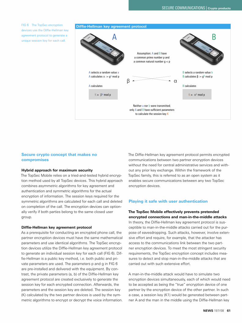
Secure crypto concept that makes no compromises
Hybrid approach for maximum securityThe TopSec Mobile relies on a tried-and-tested hybrid encryp-tion method used by all TopSec devices. This hybrid approach combines asymmetric algorithms for key agreement and authentication and symmetric algorithms for the actual encryption of information. The session keys required for the symmetric algorithms are calculated for each call and deleted on completion of the call. The encryption devices can option-ally verify if both parties belong to the same closed user group.
Diffie-Hellman key agreement protocolAs a prerequisite for conducting an encrypted phone call, the partner encryption devices must have the same mathematical parameters and use identical algorithms. The TopSec encryp-tion devices utilize the Diffie-Hellman key agreement protocol to generate an individual session key for each call (FIG 6). Dif-fie-Hellman is a public key method, i. e. both public and pri-vate parameters are used. The parameters p and g in FIG 6 are pre-installed and delivered with the equipment. By con-trast, the private parameters (a, b) of the Diffie-Hellman key agreement protocol are created exclusively to generate the session key for each encrypted connection. Afterwards, the parameters and the session key are deleted. The session key (K) calculated by the two partner devices is used by the sym-metric algorithms to encrypt or decrypt the voice information.
The Diffie-Hellman key agreement protocol permits encrypted communications between two partner encryption devices without the need for central administrative services and with-out any prior key exchange. Within the framework of the TopSec family, this is referred to as an open system as it enables secure communications between any two TopSec encryption devices.
Playing it safe with user authentication
The TopSec Mobile effectively prevents pretended encrypted connections and man-in-the-middle attacksIn theory, the Diffie-Hellman key agreement protocol is sus-ceptible to man-in-the-middle attacks carried out for the pur-pose of eavesdropping. Such attacks, however, involve exten-sive effort and require, for example, that the attacker has access to the communications link between the two part-ner encryption devices. To meet the most stringent security requirements, the TopSec encryption concept includes mea-sures to detect and stop man-in-the-middle attacks that are carried out with such extensive effort.
A man-in-the-middle attack would have to simulate two encryption devices simultaneously, each of which would need to be accepted as being the “true” encryption device of one partner by the encryption device of the other partner. In such a case, a session key (K1) would be generated between part-ner A and the man in the middle using the Diffie-Hellman key
FIG 6 The TopSec encryption
devices use the Diffie-Hellman key
agreement protocol to generate a
unique session key for each call.
A calculates
Assumption: A and B havea common prime number p anda common natural number g < p
B selects a random value bB calculates β := gb mod p
A B
A selects a random value aA calculates α := ga mod p
B calculates
Neither a nor b were transmitted;only A and B have sufficient parameters
to calculate the session key K
αβ
K = βa mod p K = αb mod p
Diffie-Hellman key agreement protocol
NEWS 197/08 61
SECURE COMMUNICATIONS | Crypto products
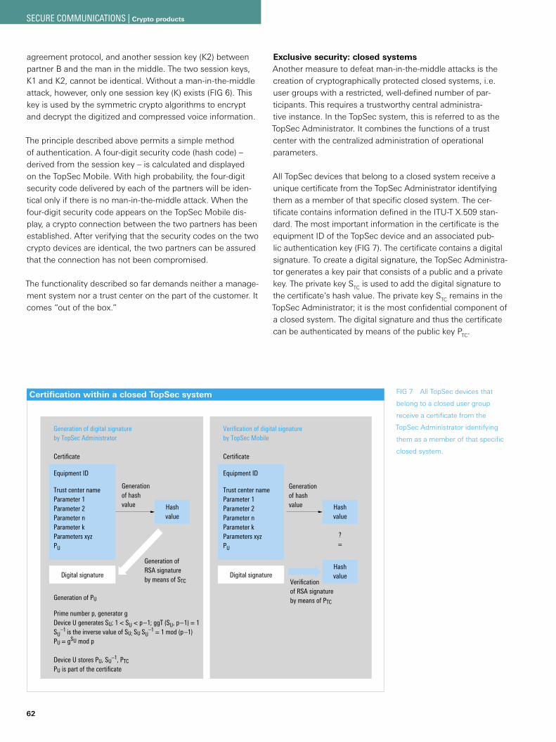
62
agreement protocol, and another session key (K2) between partner B and the man in the middle. The two session keys, K1 and K2, cannot be identical. Without a man-in-the-middle attack, however, only one session key (K) exists (FIG 6). This key is used by the symmetric crypto algorithms to encrypt and decrypt the digitized and compressed voice information.
The principle described above permits a simple method of authentication. A four-digit security code (hash code) – derived from the session key – is calculated and displayed on the TopSec Mobile. With high probability, the four-digit security code delivered by each of the partners will be iden-tical only if there is no man-in-the-middle attack. When the four-digit security code appears on the TopSec Mobile dis-play, a crypto connection between the two partners has been established. After verifying that the security codes on the two crypto devices are identical, the two partners can be assured that the connection has not been compromised.
The functionality described so far demands neither a manage-ment system nor a trust center on the part of the customer. It comes “out of the box.”
Exclusive security: closed systemsAnother measure to defeat man-in-the-middle attacks is the creation of cryptographically protected closed systems, i. e. user groups with a restricted, well-defined number of par-ticipants. This requires a trustworthy central administra-tive instance. In the TopSec system, this is referred to as the TopSec Administrator. It combines the functions of a trust center with the centralized administration of operational parameters.
All TopSec devices that belong to a closed system receive a unique certificate from the TopSec Administrator identifying them as a member of that specific closed system. The cer-tificate contains information defined in the ITU-T X.509 stan-dard. The most important information in the certificate is the equipment ID of the TopSec device and an associated pub-lic authentication key (FIG 7). The certificate contains a digital signature. To create a digital signature, the TopSec Administra-tor generates a key pair that consists of a public and a private key. The private key STC is used to add the digital signature to the certificate’s hash value. The private key STC remains in the TopSec Administrator; it is the most confidential component of a closed system. The digital signature and thus the certificate can be authenticated by means of the public key PTC.
FIG 7 All TopSec devices that
belong to a closed user group
receive a certificate from the
TopSec Administrator identifying
them as a member of that specific
closed system.
Certification within a closed TopSec system
Certificate
Equipment ID
Trust center name Parameter 1Parameter 2Parameter nParameter kParameters xyzPU
Digital signature
Generation of digital signature by TopSec Administrator
Hashvalue
Certificate
Equipment ID
Trust center name Parameter 1Parameter 2Parameter nParameter kParameters xyzPU
Digital signature
Verification of digital signature by TopSec Mobile
Generation of hash value Hash
value
?=
Generation of PU
Prime number p, generator gDevice U generates SU; 1 < SU < p–1; ggT (SU, p–1) = 1SU
–1 is the inverse value of SU; SU SU–1 = 1 mod (p–1)
PU = gSU mod p
Device U stores PU, SU–1, PTC
PU is part of the certificate
Hashvalue
Generation ofRSA signatureby means of STC Verification
of RSA signature by means of PTC
Generation of hash value
SECURE COMMUNICATIONS | Crypto products
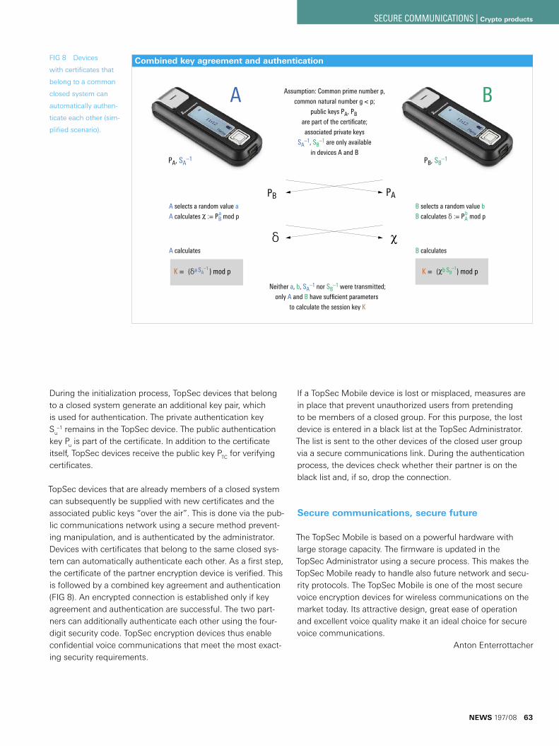
During the initialization process, TopSec devices that belong to a closed system generate an additional key pair, which is used for authentication. The private authentication key Su
–1 remains in the TopSec device. The public authentication key Pu is part of the certificate. In addition to the certificate itself, TopSec devices receive the public key PTC for verifying certificates.
TopSec devices that are already members of a closed system can subsequently be supplied with new certificates and the associated public keys “over the air”. This is done via the pub-lic communications network using a secure method prevent-ing manipulation, and is authenticated by the administrator. Devices with certificates that belong to the same closed sys-tem can automatically authenticate each other. As a first step, the certificate of the partner encryption device is verified. This is followed by a combined key agreement and authentication (FIG 8). An encrypted connection is established only if key agreement and authentication are successful. The two part-ners can additionally authenticate each other using the four-digit security code. TopSec encryption devices thus enable confidential voice communications that meet the most exact-ing security requirements.
If a TopSec Mobile device is lost or misplaced, measures are in place that prevent unauthorized users from pretending to be members of a closed group. For this purpose, the lost device is entered in a black list at the TopSec Administrator. The list is sent to the other devices of the closed user group via a secure communications link. During the authentication process, the devices check whether their partner is on the black list and, if so, drop the connection.
Secure communications, secure future
The TopSec Mobile is based on a powerful hardware with large storage capacity. The firmware is updated in the TopSec Administrator using a secure process. This makes the TopSec Mobile ready to handle also future network and secu-rity protocols. The TopSec Mobile is one of the most secure voice encryption devices for wireless communications on the market today. Its attractive design, great ease of operation and excellent voice quality make it an ideal choice for secure voice communications.
Anton Enterrottacher
FIG 8 Devices
with certificates that
belong to a common
closed system can
automatically authen-
ticate each other (sim-
plified scenario).
Combined key agreement and authentication
A B
PAPB
B calculates
Neither a, b, SA–1 nor SB
–1 were transmitted;
only A and B have sufficient parameters
to calculate the session key K
δ
B selects a random value b
B calculates δ := PA mod p
A selects a random value a
A calculates := PB mod p
A calculates
K = (δa ) mod p K = ( b ) mod p
Assumption: Common prime number p,
common natural number g < p;
public keys PA, PB are part of the certificate;
associated private keys
SA–1, SB
–1 are only available
in devices A and B
PA, SA–1 PB, SB
–1
a b
SB–1SA
–1
NEWS 197/08 63
SECURE COMMUNICATIONS | Crypto products
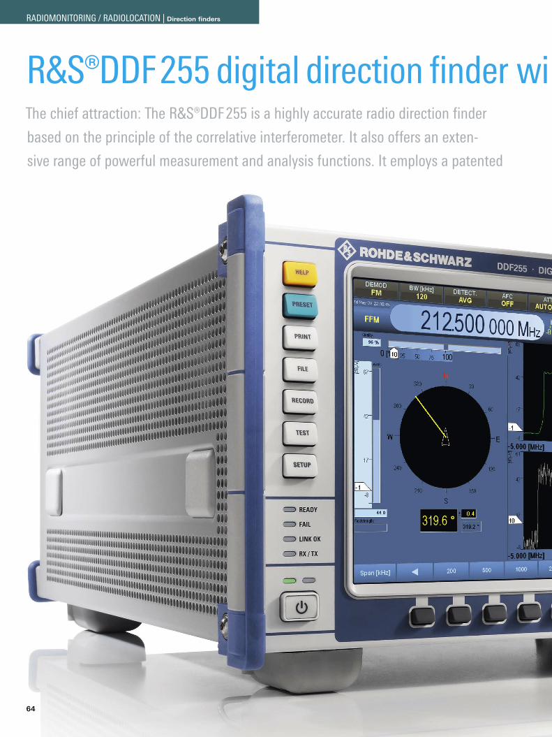
64
The chief attraction: The R&S®DDF255 is a highly accurate radio direction finder
based on the principle of the correlative interferometer. It also offers an exten-
sive range of powerful measurement and analysis functions. It employs a patented
R&S®DDF255 digital direction finder wi th measurement and analysis functions
RADIOMONITORING / RADIOLOCATION | Direction finders
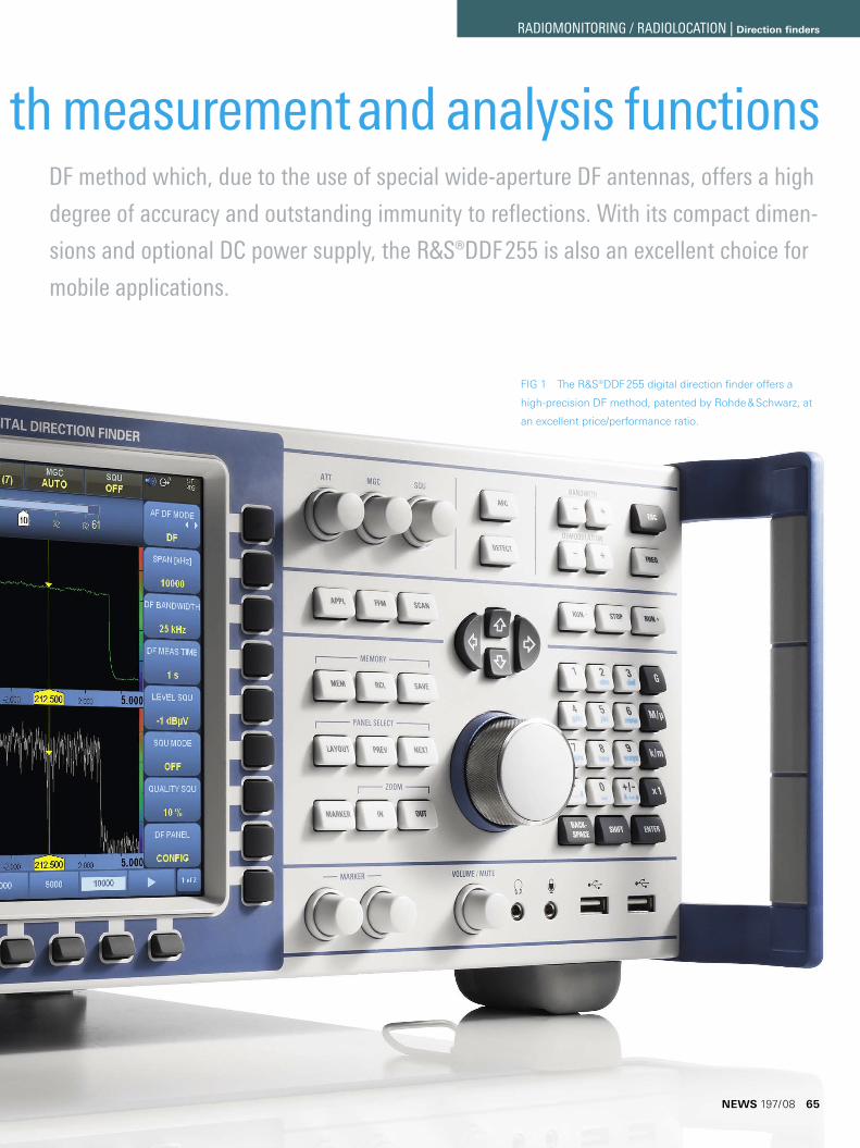
FIG 1 The R&S®DDF255 digital direction finder offers a
high-precision DF method, patented by Rohde & Schwarz, at
an excellent price/performance ratio.
DF method which, due to the use of special wide-aperture DF antennas, offers a high
degree of accuracy and outstanding immunity to reflections. With its compact dimen-
sions and optional DC power supply, the R&S®DDF255 is also an excellent choice for
mobile applications.
R&S®DDF255 digital direction finder wi th measurement and analysis functions
NEWS 197/08 65
RADIOMONITORING / RADIOLOCATION | Direction finders
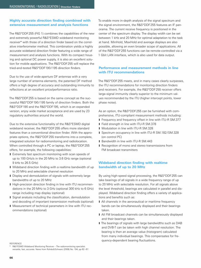
66
Highly accurate direction finding combined with extensive measurement and analysis functions
The R&S®DDF255 (FIG 1) combines the capabilities of the new and extremely powerful R&S®ESMD wideband monitoring receiver* with those of a direction finder based on the correl-ative interferometer method. This combination yields a highly accurate wideband direction finder featuring a wide range of measurement and analysis functions. With its compact hous-ing and optional DC power supply, it is also an excellent solu-tion for mobile applications. The R&S®DDF255 will replace the tried-and-tested R&S®DDF190 / 195 direction finders.
Due to the use of wide-aperture DF antennas with a very large number of antenna elements, the patented DF method offers a high degree of accuracy and outstanding immunity to reflections at an excellent price/performance ratio.
The R&S®DDF255 is based on the same concept as the suc-cessful R&S®DDF190 / 195 family of direction finders. Both the R&S®DDF190 and the R&S®DDF195, which is an expanded version, enjoy wide market acceptance and are used by 23 regulatory authorities around the world.
Due to the extensive functionality of the R&S®ESMD digital wideband receiver, the R&S®DDF255 offers more standard features than a conventional direction finder. With the appro-priate options, the R&S®DDF255 transforms into a complete, integrated solution for radiomonitoring and radiolocation. When controlled through a PC or laptop, the R&S®DDF255 offers, for example, the following capabilities:
Extremely fast spectrum monitoring with scan speeds of Jup to 100 GHz/s in the 20 MHz to 3.6 GHz range (optional 9 kHz to 26.5 GHz)Wideband direction finding with a realtime bandwidth of up Jto 20 MHz and selectable channel resolutionDisplay and demodulation of signals with extremely large Jbandwidths of up to 20 MHzHigh-precision direction finding in line with ITU recommen- Jdations in the 20 MHz to 3 GHz (optional 300 kHz to 6 GHz) range including map display (optional)Signal analysis including the classification, demodulation Jand decoding of important transmission methods (optional)Measurement of technical parameters in line with ITU rec- Jommendations (optional)
To enable more in-depth analysis of the signal spectrum and the signal environment, the R&S®DDF255 features an IF pan-orama. The current receive frequency is positioned in the center of the spectrum display. The display width can be set between 1 kHz and 20 MHz for optimal adaptation to the task at hand. MinHold, MaxHold and average displays are also possible, allowing an even broader scope of applications. All of the R&S®DDF255 functions can be remote-controlled via a 1 Gbit LAN interface, which is also used for data output.
Performance and measurement methods in line with ITU recommendations
The R&S®DDF255 meets, and in many cases clearly surpasses, the ITU recommendations for monitoring direction finders and receivers. For example, the R&S®DDF255 receiver offers large-signal immunity clearly superior to the minimum val-ues recommended by the ITU (higher intercept points, lower phase noise).
As an option, the R&S®DDF255 can be furnished with com-prehensive, ITU-compliant measurement methods including:
Frequency and frequency offset in line with ITU-R SM.377 JField strength in line with ITU-R SM.378 JModulation in line with ITU-R SM.328 JSpectrum occupancy in line with ITU-R SM.182/SM.328 J(on control PC)Bandwidth in line with ITU-R SM.443 JRecognition of mono and stereo transmissions from JFM broadcast transmitters
Wideband direction finding with realtime bandwidth of up to 20 MHz
By using high-speed signal processing, the R&S®DDF255 can take bearings of all signals in a wide frequency range of up to 20 MHz with selectable resolution. For all signals above the level threshold, bearings are calculated in parallel and dis-played. Wideband direction finding offers a variety of applica-tions and benefits such as:
All channels in the aeronautical or maritime frequency Jbands can be simultaneously displayed and their bearings taken.All FM broadcast channels can be simultaneously displayed Jand their bearings taken.The bearings of signals with large bandwidths such as DAB Jand DVB-T can be taken with high channel resolution. The bearing is then an average value (histogram) calculated from many individual bearings. This compensates for fre-quency-dependent bearing fluctuations.
REFERENCER&S®ESMD Wideband Monitoring Receiver – The radiomonitoring specialist: * versatile, fast, accurate. News from Rohde & Schwarz (2008) No. 194, pp 62–67.
RADIOMONITORING / RADIOLOCATION | Direction finders
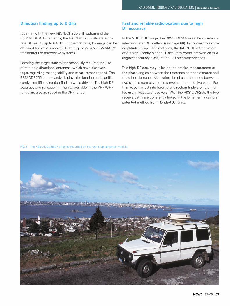
Direction finding up to 6 GHz
Together with the new R&S®DDF255-SHF option and the R&S®ADD075 DF antenna, the R&S®DDF255 delivers accu-rate DF results up to 6 GHz. For the first time, bearings can be obtained for signals above 3 GHz, e. g. of WLAN or WiMAX™ transmitters or microwave systems.
Locating the target transmitter previously required the use of rotatable directional antennas, which have disadvan-tages regarding manageability and measurement speed. The R&S®DDF255 immediately displays the bearing and signifi-cantly simplifies direction finding while driving. The high DF accuracy and reflection immunity available in the VHF / UHF range are also achieved in the SHF range.
Fast and reliable radiolocation due to high DF accuracy
In the VHF / UHF range, the R&S®DDF255 uses the correlative interferometer DF method (see page 68). In contrast to simple amplitude comparison methods, the R&S®DDF255 therefore offers significantly higher DF accuracy compliant with class A (highest accuracy class) of the ITU recommendations.
This high DF accuracy relies on the precise measurement of the phase angles between the reference antenna element and the other elements. Measuring the phase difference between two signals normally requires two coherent receive paths. For this reason, most interferometer direction finders on the mar-ket use at least two receivers. With the R&S®DDF255, the two receive paths are coherently linked in the DF antenna using a patented method from Rohde & Schwarz.
FIG 2 The R&S®ADD295 DF antenna mounted on the roof of an all-terrain vehicle.
NEWS 197/08 67
RADIOMONITORING / RADIOLOCATION | Direction finders
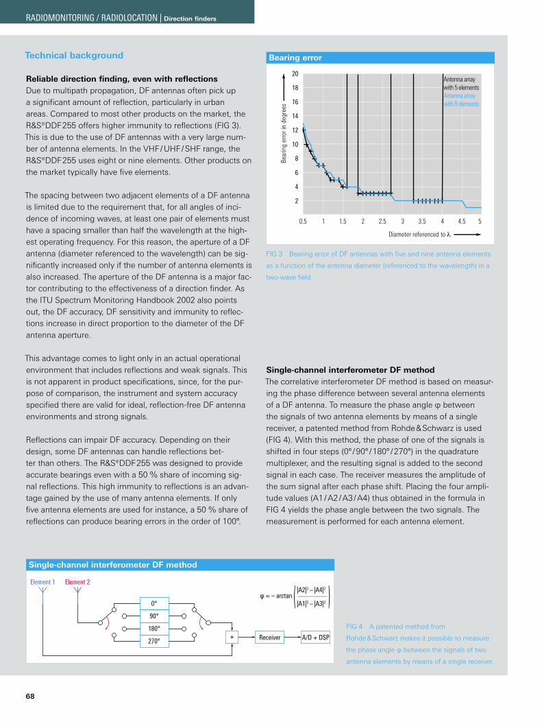
68
Technical background
Reliable direction finding, even with reflectionsDue to multipath propagation, DF antennas often pick up a significant amount of reflection, particularly in urban areas. Compared to most other products on the market, the R&S®DDF255 offers higher immunity to reflections (FIG 3). This is due to the use of DF antennas with a very large num-ber of antenna elements. In the VHF / UHF / SHF range, the R&S®DDF255 uses eight or nine elements. Other products on the market typically have five elements.
The spacing between two adjacent elements of a DF antenna is limited due to the requirement that, for all angles of inci-dence of incoming waves, at least one pair of elements must have a spacing smaller than half the wavelength at the high-est operating frequency. For this reason, the aperture of a DF antenna (diameter referenced to the wavelength) can be sig-nificantly increased only if the number of antenna elements is also increased. The aperture of the DF antenna is a major fac-tor contributing to the effectiveness of a direction finder. As the ITU Spectrum Monitoring Handbook 2002 also points out, the DF accuracy, DF sensitivity and immunity to reflec-tions increase in direct proportion to the diameter of the DF antenna aperture.
This advantage comes to light only in an actual operational environment that includes reflections and weak signals. This is not apparent in product specifications, since, for the pur-pose of comparison, the instrument and system accuracy specified there are valid for ideal, reflection-free DF antenna environments and strong signals.
Reflections can impair DF accuracy. Depending on their design, some DF antennas can handle reflections bet-ter than others. The R&S®DDF255 was designed to provide accurate bearings even with a 50 % share of incoming sig-nal reflections. This high immunity to reflections is an advan-tage gained by the use of many antenna elements. If only five antenna elements are used for instance, a 50 % share of reflections can produce bearing errors in the order of 100°.
Single-channel interferometer DF methodThe correlative interferometer DF method is based on measur-ing the phase difference between several antenna elements of a DF antenna. To measure the phase angle φ between the signals of two antenna elements by means of a single receiver, a patented method from Rohde & Schwarz is used (FIG 4). With this method, the phase of one of the signals is shifted in four steps (0° / 90° / 180° / 270°) in the quadrature multiplexer, and the resulting signal is added to the second signal in each case. The receiver measures the amplitude of the sum signal after each phase shift. Placing the four ampli-tude values (A1 / A2 / A3 / A4) thus obtained in the formula in FIG 4 yields the phase angle between the two signals. The measurement is performed for each antenna element.
FIG 3 Bearing error of DF antennas with five and nine antenna elements
as a function of the antenna diameter (referenced to the wavelength) in a
two-wave field.
FIG 4 A patented method from
Rohde & Schwarz makes it possible to measure
the phase angle φ between the signals of two
antenna elements by means of a single receiver.
Bearing error
Bear
ing
erro
r in
degr
ees
20
18
16
14
12
10
8
6
4
2
Diameter referenced to λ
0.5 1 1.5 2 2.5 3 3.5 4 4.5 5
Antenna array with 5 elementsAntenna array with 9 elements
Single-channel interferometer DF method
A/D + DSPReceiver+
0°
90°
180°
270°
Element 2Element 1
φ = – arctan ( )|A2|2 – |A4|2
–––––––––––––
|A1|2 – |A3|2
RADIOMONITORING / RADIOLOCATION | Direction finders
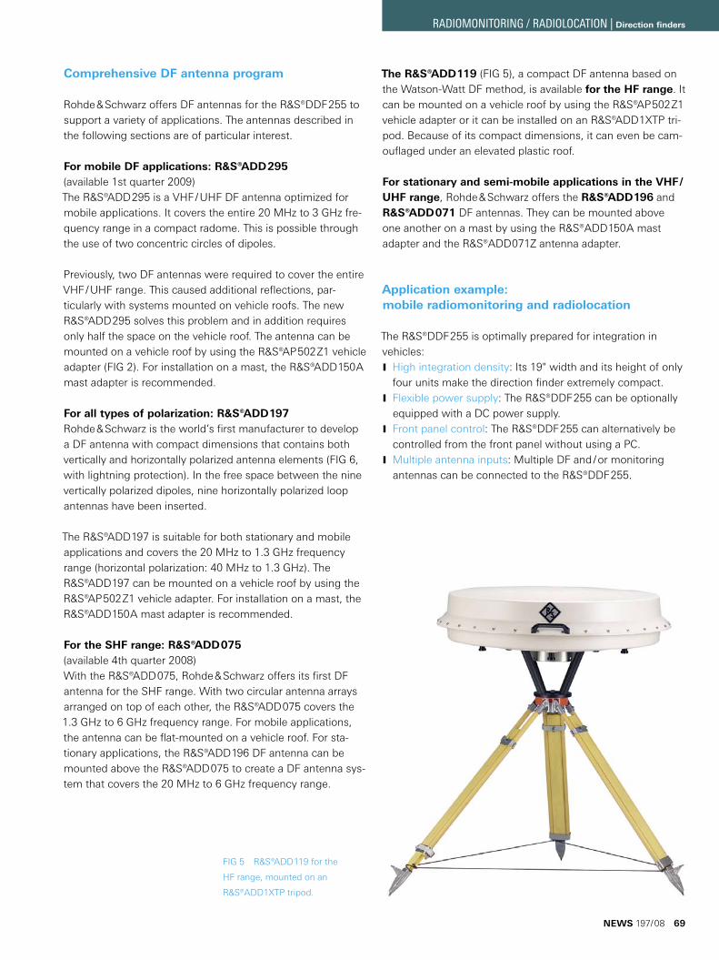
Comprehensive DF antenna program
Rohde & Schwarz offers DF antennas for the R&S®DDF255 to support a variety of applications. The antennas described in the following sections are of particular interest.
For mobile DF applications: R&S®ADD295(available 1st quarter 2009)The R&S®ADD295 is a VHF / UHF DF antenna optimized for mobile applications. It covers the entire 20 MHz to 3 GHz fre-quency range in a compact radome. This is possible through the use of two concentric circles of dipoles.
Previously, two DF antennas were required to cover the entire VHF / UHF range. This caused additional reflections, par-ticularly with systems mounted on vehicle roofs. The new R&S®ADD295 solves this problem and in addition requires only half the space on the vehicle roof. The antenna can be mounted on a vehicle roof by using the R&S®AP502Z1 vehicle adapter (FIG 2). For installation on a mast, the R&S®ADD150A mast adapter is recommended.
For all types of polarization: R&S®ADD197Rohde & Schwarz is the world’s first manufacturer to develop a DF antenna with compact dimensions that contains both vertically and horizontally polarized antenna elements (FIG 6, with lightning protection). In the free space between the nine vertically polarized dipoles, nine horizontally polarized loop antennas have been inserted.
The R&S®ADD197 is suitable for both stationary and mobile applications and covers the 20 MHz to 1.3 GHz frequency range (horizontal polarization: 40 MHz to 1.3 GHz). The R&S®ADD197 can be mounted on a vehicle roof by using the R&S®AP502Z1 vehicle adapter. For installation on a mast, the R&S®ADD150A mast adapter is recommended.
For the SHF range: R&S®ADD075(available 4th quarter 2008)With the R&S®ADD075, Rohde & Schwarz offers its first DF antenna for the SHF range. With two circular antenna arrays arranged on top of each other, the R&S®ADD075 covers the 1.3 GHz to 6 GHz frequency range. For mobile applications, the antenna can be flat-mounted on a vehicle roof. For sta-tionary applications, the R&S®ADD196 DF antenna can be mounted above the R&S®ADD075 to create a DF antenna sys-tem that covers the 20 MHz to 6 GHz frequency range.
The R&S®ADD119 (FIG 5), a compact DF antenna based on the Watson-Watt DF method, is available for the HF range. It can be mounted on a vehicle roof by using the R&S®AP502Z1 vehicle adapter or it can be installed on an R&S®ADD1XTP tri-pod. Because of its compact dimensions, it can even be cam-ouflaged under an elevated plastic roof.
For stationary and semi-mobile applications in the VHF /UHF range, Rohde & Schwarz offers the R&S®ADD196 and R&S®ADD071 DF antennas. They can be mounted above one another on a mast by using the R&S®ADD150A mast adapter and the R&S®ADD071Z antenna adapter.
Application example: mobile radiomonitoring and radiolocation
The R&S®DDF255 is optimally prepared for integration in vehicles:
High integration density J : Its 19" width and its height of only four units make the direction finder extremely compact.Flexible power supply J : The R&S®DDF255 can be optionally equipped with a DC power supply.Front panel control J : The R&S®DDF255 can alternatively be controlled from the front panel without using a PC.Multiple antenna inputs J : Multiple DF and / or monitoring antennas can be connected to the R&S®DDF255.
FIG 5 R&S®ADD119 for the
HF range, mounted on an
R&S®ADD1XTP tripod.
NEWS 197/08 69
RADIOMONITORING / RADIOLOCATION | Direction finders
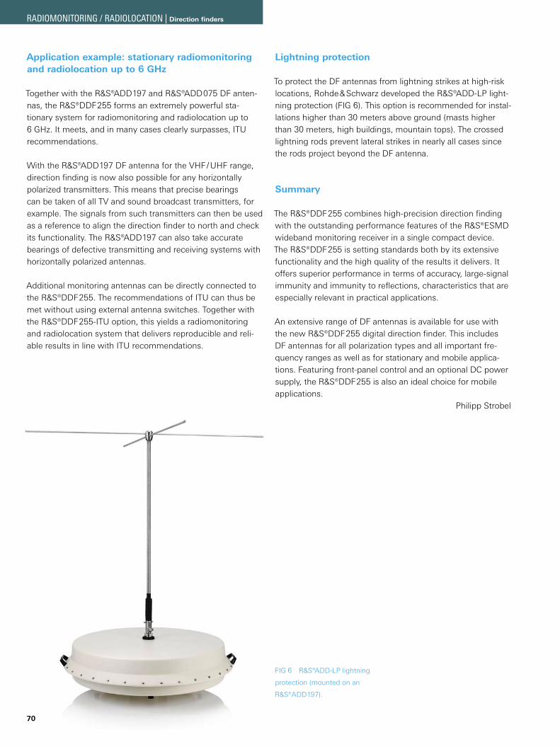
70
Application example: stationary radiomonitoring and radiolocation up to 6 GHz
Together with the R&S®ADD197 and R&S®ADD075 DF anten-nas, the R&S®DDF255 forms an extremely powerful sta-tionary system for radiomonitoring and radiolocation up to 6 GHz. It meets, and in many cases clearly surpasses, ITU recommendations.
With the R&S®ADD197 DF antenna for the VHF / UHF range, direction finding is now also possible for any horizontally polarized transmitters. This means that precise bearings can be taken of all TV and sound broadcast transmitters, for example. The signals from such transmitters can then be used as a reference to align the direction finder to north and check its functionality. The R&S®ADD197 can also take accurate bearings of defective transmitting and receiving systems with horizontally polarized antennas.
Additional monitoring antennas can be directly connected to the R&S®DDF255. The recommendations of ITU can thus be met without using external antenna switches. Together with the R&S®DDF255-ITU option, this yields a radiomonitoring and radiolocation system that delivers reproducible and reli-able results in line with ITU recommendations.
Lightning protection
To protect the DF antennas from lightning strikes at high-risk locations, Rohde & Schwarz developed the R&S®ADD-LP light-ning protection (FIG 6). This option is recommended for instal-lations higher than 30 meters above ground (masts higher than 30 meters, high buildings, mountain tops). The crossed lightning rods prevent lateral strikes in nearly all cases since the rods project beyond the DF antenna.
Summary
The R&S®DDF255 combines high-precision direction finding with the outstanding performance features of the R&S®ESMD wideband monitoring receiver in a single compact device. The R&S®DDF255 is setting standards both by its extensive functionality and the high quality of the results it delivers. It offers superior performance in terms of accuracy, large-signal immunity and immunity to reflections, characteristics that are especially relevant in practical applications.
An extensive range of DF antennas is available for use with the new R&S®DDF255 digital direction finder. This includes DF antennas for all polarization types and all important fre-quency ranges as well as for stationary and mobile applica-tions. Featuring front-panel control and an optional DC power supply, the R&S®DDF255 is also an ideal choice for mobile applications.
Philipp Strobel
FIG 6 R&S®ADD-LP lightning
protection (mounted on an
R&S®ADD197).
RADIOMONITORING / RADIOLOCATION | Direction finders
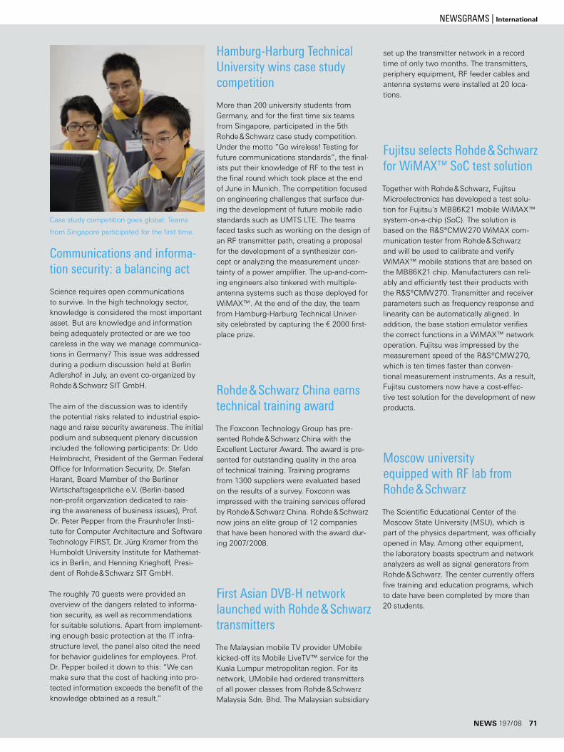
Hamburg-Harburg Technical University wins case study competition
More than 200 university students from Germany, and for the first time six teams from Singapore, participated in the 5th Rohde & Schwarz case study competition. Under the motto “Go wireless! Testing for future communications standards”, the final-ists put their knowledge of RF to the test in the final round which took place at the end of June in Munich. The competition focused on engineering challenges that surface dur-ing the development of future mobile radio standards such as UMTS LTE. The teams faced tasks such as working on the design of an RF transmitter path, creating a proposal for the development of a synthesizer con-cept or analyzing the measurement uncer-tainty of a power amplifier. The up-and-com-ing engineers also tinkered with multiple-antenna systems such as those deployed for WiMAX™. At the end of the day, the team from Hamburg-Harburg Technical Univer-sity celebrated by capturing the € 2000 first-place prize.
Rohde & Schwarz China earns technical training award
The Foxconn Technology Group has pre-sented Rohde & Schwarz China with the Excellent Lecturer Award. The award is pre-sented for outstanding quality in the area of technical training. Training programs from 1300 suppliers were evaluated based on the results of a survey. Foxconn was impressed with the training services offered by Rohde & Schwarz China. Rohde & Schwarz now joins an elite group of 12 companies that have been honored with the award dur-ing 2007/2008.
First Asian DVB-H network launched with Rohde & Schwarz transmitters
The Malaysian mobile TV provider UMobile kicked-off its Mobile LiveTV™ service for the Kuala Lumpur metropolitan region. For its network, UMobile had ordered transmitters of all power classes from Rohde & Schwarz Malaysia Sdn. Bhd. The Malaysian subsidiary
set up the transmitter network in a record time of only two months. The transmitters, periphery equipment, RF feeder cables and antenna systems were installed at 20 loca-tions.
Fujitsu selects Rohde & Schwarz for WiMAX™ SoC test solution
Together with Rohde & Schwarz, Fujitsu Microelectronics has developed a test solu-tion for Fujitsu’s MB86K21 mobile WiMAX™ system-on-a-chip (SoC). The solution is based on the R&S®CMW270 WiMAX com-munication tester from Rohde & Schwarz and will be used to calibrate and verify WiMAX™ mobile stations that are based on the MB86K21 chip. Manufacturers can reli-ably and efficiently test their products with the R&S®CMW270. Transmitter and receiver parameters such as frequency response and linearity can be automatically aligned. In addition, the base station emulator verifies the correct functions in a WiMAX™ network operation. Fujitsu was impressed by the measurement speed of the R&S®CMW270, which is ten times faster than conven-tional measurement instruments. As a result, Fujitsu customers now have a cost-effec-tive test solution for the development of new products.
Moscow university equipped with RF lab from Rohde & Schwarz
The Scientific Educational Center of the Moscow State University (MSU), which is part of the physics department, was officially opened in May. Among other equipment, the laboratory boasts spectrum and network analyzers as well as signal generators from Rohde & Schwarz. The center currently offers five training and education programs, which to date have been completed by more than 20 students.
Communications and informa-tion security: a balancing act
Science requires open communications to survive. In the high technology sector, knowledge is considered the most important asset. But are knowledge and information being adequately protected or are we too careless in the way we manage communica-tions in Germany? This issue was addressed during a podium discussion held at Berlin Adlershof in July, an event co-organized by Rohde & Schwarz SIT GmbH.
The aim of the discussion was to identify the potential risks related to industrial espio-nage and raise security awareness. The initial podium and subsequent plenary discussion included the following participants: Dr. Udo Helmbrecht, President of the German Federal Office for Information Security, Dr. Stefan Harant, Board Member of the Berliner Wirtschaftsgespräche e.V. ( Berlin-based non-profit organization dedicated to rais-ing the awareness of business issues), Prof. Dr. Peter Pepper from the Fraunhofer Insti-tute for Computer Architecture and Software Technology FIRST, Dr. Jürg Kramer from the Humboldt University Institute for Mathemat-ics in Berlin, and Henning Krieghoff, Presi-dent of Rohde & Schwarz SIT GmbH.
The roughly 70 guests were provided an overview of the dangers related to informa-tion security, as well as recommendations for suitable solutions. Apart from implement-ing enough basic protection at the IT infra-structure level, the panel also cited the need for behavior guidelines for employees. Prof. Dr. Pepper boiled it down to this: “We can make sure that the cost of hacking into pro-tected information exceeds the benefit of the knowledge obtained as a result.”
Case study competition goes global: Teams
from Singapore participated for the first time.
NEWS 197/08 71
NEWSGRAMS | International
Spectrum analyzers for any application and budget
The most comprehensive product portfolio on the market JShort innovation cycles, high safety of investment JMaximum number of functions and features integrated in Jeach instrumentExcellent global service network: JWe are always just around the corner.
4 product families, 30 models – the right spectrum analyzer for every requirement
www.rohde-schwarz.com
The Driving Force inSpectrum Analysis